sign and delineator design guidelines for local roadssdtown/doc/sign_delineation_design... ·...
TRANSCRIPT

SIGN AND DELINEATOR
DESIGN GUIDELINES
FOR LOCAL ROADS
2012
Connecting South Dakota and the Nation

2
TABLE OF CONTENTS
PREFACE .............................................................................................................................................. 5 LAWS .................................................................................................................................................... 5 INVENTORY ........................................................................................................................................ 5 ANALYSIS ............................................................................................................................................ 5 PLAN PREPARATION ......................................................................................................................... 5 SELECTION AND USE OF MATERIALS ........................................................................................... 6 SIGN PLACEMENT .............................................................................................................................. 9
Longitudinal Location: ....................................................................................................................... 9 Lateral Location: ............................................................................................................................. 10 Curve Signing: ................................................................................................................................. 10 Railroad Signing: ............................................................................................................................. 10 Intersection Signing: ........................................................................................................................ 10
Right-of-way Control Signs .......................................................................................................................... 10 Warning Signs ............................................................................................................................................... 10 Special Signing ............................................................................................................................................. 10
SIGN APPLICATION ......................................................................................................................... 11 Minimum Maintenance Roads .......................................................................................................... 11 Road Closures .................................................................................................................................. 11
Type III Barricades ....................................................................................................................................... 11 Type IV Object Markers (End of Road Markers).......................................................................................... 11
DELINEATION ................................................................................................................................... 12 Delineators ....................................................................................................................................... 12 Object Markers................................................................................................................................. 13
Type 2 OM’s ................................................................................................................................................. 13 Type 3 OM’s ................................................................................................................................................. 13 Type 4 OM’s ................................................................................................................................................. 13 Object Marker Mounting Height ................................................................................................................... 13
SIGN ASSEMBLY AND INSPECTION ............................................................................................. 14 STANDARD PLATES ......................................................................................................................... 15
#L01 – 30” Warning Signs ............................................................................................................... 15 #L02 – 36” and 48” Warning Signs ................................................................................................. 16 #L03 – Square or Rectangular Signs ............................................................................................... 17 #L04 – One Way Signs or Large Arrow Signs ................................................................................. 18 #L05 – 36” or 48” Yield Signs ......................................................................................................... 19 #L06 – 30” Stop or Yield Signs ........................................................................................................ 20 #L07 – 36” or 48” Stop Signs .......................................................................................................... 21 #L08 – No Pass Zone Pennant Sign ................................................................................................. 22 #L09 – Chevron Sign ........................................................................................................................ 23 #L20 – Breakaway Sign Supports .................................................................................................... 24 #L21 – Tubular Post Base Details – Soil Installation ...................................................................... 25 #L22 – Tubular Post Base Details – Flush Mount Breakaway Installation ..................................... 26 #L23 – Lateral Offset for Rural Sign Installations ........................................................................... 27 #L24 – Lateral Offset for Urban Sign Installations ......................................................................... 28 #L25 – Type 2 & 3 Object Markers .................................................................................................. 29 #L30 – Delineators ........................................................................................................................... 30
Sheet 1 of 2 ................................................................................................................................................... 30 Sheet 2 of 2 ................................................................................................................................................... 31
#L40 – Typical Layout Through Roads w/ Improved Sideroad Acute Angle ................................... 32 #L41 – Typical Layout Through Roads w/ Improved Sideroad ........................................................ 33 #L42 – Typical Layout Roads w/ Unimproved Sideroad .................................................................. 34 #L43 – Typical Layout Divided Roads w/ Sideroad ......................................................................... 35 #L44 – Typical Layout Divided Roads w/ Crossroad ....................................................................... 36 #L50 – Layout for Minimum Maintenance Road Sign ..................................................................... 37 #632.01 – Type 2 Object Markers (Direct Drive) ............................................................................ 38 #632.10 – Type 2 Object Marker Installation at Pipe Culverts, Box Culverts, and Cattle Passes .. 39 #632.30 – Non-Interstate Mileage Reference Markers .................................................................... 40 #632.40 – Delineation of Guardrail ................................................................................................. 41
Sheet 1 of 4 ................................................................................................................................................... 41 Sheet 2 of 4 ................................................................................................................................................... 42

3
Sheet 3 of 4 ................................................................................................................................................... 43 Sheet 4 of 4 ................................................................................................................................................... 44
#L70 – Guides for Traffic Control Devices ...................................................................................... 45 Road Closed For Hazard on Improved Roadway .......................................................................................... 45
#L71 – Guides for Traffic Control Devices ...................................................................................... 46 Road Closed For Obliterated or Unimproved Roadway................................................................................ 46
#634.99 – Breakaway Support Stub Clearance ................................................................................ 47 APPENDIX A .......................................................................................................................................... 48
SD State Codified Laws on Minimum Maintenance Roads .............................................................. 48 31-12-46. Minimum maintenance roads established. ................................................................................... 48 31-12-47. Posting notification of minimum maintenance road. .................................................................. 48 31-13-1. Township supervisors responsible for secondary roads. ............................................................... 48 31-13-1.1. Designation of minimum maintenance road--Level of maintenance. ........................................ 48 31-13-1.2. Posting of warning signs on minimum maintenance roads. ....................................................... 48
SD State Codified Laws on Local Roads .......................................................................................... 48 31-12-7. Divisions of system into sections--Recording in county road book. ............................................. 48 31-12-18. Width of culverts. ....................................................................................................................... 48 31-12-26. Responsibility for secondary roads in unorganized territory. ..................................................... 48 31-13-4. Width of highway grades. ............................................................................................................. 48 31-3-6. Power of county commissioners and township supervisors to vacate, change, or locate highway on petition - Contents of petition. ................................................................................................... 49 31-3-6.1. Exception--Access to public lands. .............................................................................................. 49 31-3-8. Resolution and order of board--Description of land--Map maintained by county auditor. ............. 49 31-3-13. Highway on township line--Joint resolution. ................................................................................ 49 31-3-18. Width of highway. ........................................................................................................................ 49 31-9-1. Relinquishment of highways in national parks--Cession of jurisdiction. ........................................ 49 31-9-4. County roads used by National Forest Service--Cooperative agreement for joint construction and use. .......................................................................................................................................... 49 31-14-2. County commissioners' responsibility for bridges and culverts. ................................................... 49 31-14-33. Inspection of township culverts--Duty of board of supervisors. ................................................. 49 31-14-34. Inspection of culverts on secondary highways and county highway system--Duty of county highway superintendent.................................................................................................................. 50 31-17-1. County highway system on state line--Agreements for assignment of responsibility. .................. 50 31-17-4. County highway system on county line--Effect of assignment to county. .................................... 50 31-17-5. Secondary highway on county line--Assignment of responsibility. .............................................. 50 31-17-6. Secondary highway on township line--Assignment of responsibility. .......................................... 50 31-17-7. Boundary line highways between organized townships--Equal contribution by townships required unless mutual agreement reached. .................................................................................... 50 31-17-16. Secondary highways on municipal boundaries--Assignment of responsibility. .......................... 50 31-18-1. Existence of section-line highways by operation of law. .............................................................. 50 31-18-2. Width of highways--Side from which taken. ................................................................................ 50 31-18-3. Vacation or change of location of highways. ................................................................................ 51 31-18-4. Relicted lands--Highway rights continue. ..................................................................................... 51 31-24-1. Duty of highway authorities to provide access to abutting property at public expense--New construction. ................................................................................................................................... 51 31-24-2. Approaches necessitated by highway construction--Maintenance. ............................................... 51 31-24-3. Limitation on number of farm entrances--Additional entrances at owner's expense. ................... 51 31-24-4. Additional entrances to property previously having more than one farm entrance--Limitations. . 51 31-28-6. Warning signs at points of danger--Maintenance--Violation as misdemeanor. ............................ 51 31-28-7. Railway crossing signs--Maintenance--Violation as misdemeanor. ............................................. 51 31-28-16. Arterial highways--Right-of-way--Violation as misdemeanor. .................................................. 52 31-28-28. Unauthorized possession of official signs or markers as misdemeanor. ..................................... 52 32-14-6. Restrictions respecting weight of vehicle--Duration of period of restriction--Signs designating restricted area. ................................................................................................................................ 52 32-14-7. Prohibiting trucks or commercial vehicles from use of designated highways--Erection of signs. 52 32-22-47. Maximum vehicle weight on bridges--Required and permissible signs--Exception. .................. 52 32-25-17. Posting stop signs at intersections with increased maximum--Illumination of stop signs. ......... 52 32-29-1. Indication of right-of-way by stop or yield signs. ......................................................................... 52 32-29-2. Stop and yield signs to designate through highways--Visibility at night. ..................................... 52 32-30-2.4. No-parking zones posted by department--Temporary zones--Signs--Violation as misdemeanor. ................................................................................................................................. 52 32-30-11.9. Signs to state penalties for illegal use of designated parking spaces--Certain penalties apply although not stated. ........................................................................................................................ 53
SD State Codified Laws on Speed Limits ......................................................................................... 53 32-25-1.1. Maximum daytime speed--Violation as misdemeanor. .............................................................. 53 32-25-9.1. Establishment of speed zones by county commissioners--Posting of zones. ............................. 53

4
32-25-9.2. Township road speed limit. ........................................................................................................ 53 32-25-12. Speed limit in unposted urban areas--Violation as misdemeanor. .............................................. 53 32-25-13. Speed limit at obstructed railway crossings--Violation as misdemeanor. ................................... 53 32-25-14. Speed limit in school zones--Violation as misdemeanor. ........................................................... 53 32-25-15. Speed limit at intersections with obstructed view--Violation as misdemeanor. .......................... 53 32-25-18. Special speed limits for bridges--Posting signs--Violation of posted speed limit as misdemeanor--Established speed as conclusive maximum safe speed. .......................................... 53
APPENDIX B .......................................................................................................................................... 55 County Sign Inventory Instructions .................................................................................................. 55

5
PREFACE This manual is intended to act as a guide in the design and installation of Highway Signing Devices. The information in not intended to overrule the current edition of the Manual of Uniform Traffic Control Devices (MUTCD), the Standard Highway Signs and Markings (SHSM) or any other official publication, specification, Regional practice or work orders. All installations shall be in accordance with the manufacture guidelines. The Secondary Roads Engineer should be consulted on questions you may have. To continue to provide clear and up-to-date information, your input as “hands on experts” is needed. Tables and diagrams are included in this manual for a quick reference. Periodic comparisons to official MUTCD, SHSM, standard notes, and standard plates shall be the designers’ responsibility to validate the information being used is correct.
LAWS The designers shall familiarize themselves with the specific codes from South Dakota Codified Law (Appendix A) that deal directly or indirectly with local roads and have some implication as to signing needs and requirements. These laws were in effect at date of publication but it is the duty of every designer to know the state law, research any changes, and research any applicable local ordinances and/or resolutions which may override any standard set forth by practice or published literature.
INVENTORY Survey, inspection, and recording of existing traffic control devices shall be conducted by the consultant by means of physically traveling each road, referencing landmarks, measuring distances, verifying sign sizes, referencing hazards, and ballbanking curves. Signs located within a given Right of Way (ROW) are owned by the governing body of the ROW and shall be included with their inventory unless documentation is provided identifying another entity with maintenance responsibility through a permit or other agreement. A copy of these exceptions shall be obtained by the consultant and retained with the project documentation. The DOT will provide a copy of the DOT Local Roads Inventory Software for each County project for the consultants use in the inventory process if they so desire. Instructions on use of this software are included in Appendix B. All signs less than 5 years of age can remain in place provided it is still applicable and properly located under all current standards and provisions. All signs should have a visible date sticker attached to the back of the sign. All signs with age between 5 and 12 years with high intensity sheeting and those signs with super high intensity sheeting signs less than 18 years of age shall be stockpiled for local entity reuse. If the sign is older than these values or the sticker is missing, then the sign shall be stockpiled for recycle. All salvaged or discarded signs remain the property of the local authority until such time they declare them as surplus and dispose as an entity to a recycling center – reference SDCL 31-28-28.
ANALYSIS Each consultant shall use and perform any Traffic Engineering Studies they deem necessary to properly analyze, apply national, state, and local laws/specification/standards, and sound Engineering Judgment in their recommendations for installation and removal of signs. Blanket replacement of existing devices will not be accepted without application of a Traffic Engineering Review.
PLAN PREPARATION Generally, a set of signing plans will be assembled in the following order (refer to the SDDOT Road Design Guide for additional information):
Title Sheet Estimate of Quantities General Notes Location Maps
o Show breakdown of municipal boundaries and townships o location of 0.0 MRM at western reference point for East-West routes and 0.0 MRM at the southern
reference point for North-South routes o all routes are to be classified as an East-West route or a North-South route o all towns and cities shall be detailed showing street names and MRM reference points
Tables o Permanent signing table shall include Route Name, MRM, sign size, Standard Highway Sign number,
direction facing, square footage of new sign, sheeting type, new post data, description of sign, remarks/action that needs to be taken, two blank columns for Field Construction use.
6
o Summary table shall include total quantity per each size of sign per each sign code per each sheeting type
Traffic Control – any special traffic control needs not covered by the MUTCD standard plates and/or special plan notes shall be detailed out in a plan drawing or addition of other standard plates.
Sign layouts o Typical layouts and standard details shall be included in the plans. o All special layouts or complicated intersections shall also be detailed in a drawing showing sign
placement o All non-standard highway sign shall be detailed showing exact placement of any symbols, legend,
and/or arrows in relation to the edge of the sign as well as color, border, and radius requirements. Other standard details
o Delineation standards o Mailbox standards (if applicable)
SELECTION AND USE OF MATERIALS 1. Existing Sign and Post Assemblies: All existing signing material shall remain the property of the governing entity
whose property they are installed upon. Plans shall designate contact information of each entity so the Contractor can arrange delivery upon removal. The plans shall also specify that the assemblies shall be taken apart and all bolts, nuts, and washers shall be placed in individual 5-gallon pails. Backing materials shall be separated from the signs and may be reused at the Contractor’s discretion. Wooden posts shall be carefully removed to avoid damage and cleaned of excess dirt and neatly stockpiled separate from the steel posts. Signs that have been determined to still have useful life in them shall be carefully stockpiled separate from those that are intended to be recycled.
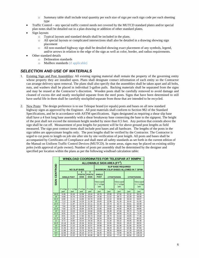
2. New Posts: The design preference is to use Telespar brand (or equals) posts and bases on all new standard
highway signs as approved by the Engineer. All post materials shall conform to Section 982 of the Standard Specifications, and be in accordance with ASTM specifications. Signs designated as requiring a shear slip base shall have a 4 foot long base assembly with a shear breakaway base connecting the base to the signpost. The height of the post shall not exceed the minimum height needed by more than 0.5 feet. Any portion that extends above the sign shall be cut off. Measurement of post lengths for payment will be for above ground post lengths as field measured. The sign post contract items shall include post bases and all hardware. The lengths of the posts in the sign tables are approximate lengths only. The post lengths shall be verified by the Contractor. The Contractor is urged to cut posts to length on job site after site by site verification of post length. All posts and bases shall be accompanied by Certificates of Compliance and shall meet all safety standards as set forth in the current edition of the Manual on Uniform Traffic Control Devices (MUTCD). In some areas, signs may be placed on existing utility poles (with approval of pole owner). Number of posts per assembly shall be determined by the designer and specified per location within the plans as per the following windload calculation table:
2 POSTS/
SIGN
3 POSTS/
SIGNSINGLE POST
2"x12ga perf.
2 1/2"x12ga
perf.2"x12ga
perf.2"x12ga
perf.
Telescoped 2 1/2"x12ga
with 2 1/
4"x12ga
perf.2 1/
2"x12ga
perf.
Telescoped 2 1/2"x12ga
with 2 1/
4"x12ga
perf.2 1/
2"x12ga
perf.
Telescoped 2 1/2"x12ga
with 2 1/
4"x12ga
perf.
16.5' 6.48 10.44 12.96 19.44 18.78 20.88 37.56 31.32 56.3416' 6.68 10.76 13.36 20.04 19.36 21.52 38.72 32.28 58.08
15.5' 6.90 11.11 13.80 20.70 19.99 22.22 39.98 33.33 59.9715' 7.13 11.48 14.26 21.39 20.65 22.96 41.30 34.44 61.95
14.5' 7.37 11.87 14.74 22.11 21.36 23.74 42.72 35.61 64.0814' 7.64 12.30 15.28 22.92 22.13 24.60 44.26 36.90 66.39
13.5' 7.92 12.75 15.84 23.76 22.95 25.50 45.90 38.25 68.8513' 8.22 13.24 16.44 24.66 23.83 26.48 47.66 39.72 71.49
12.5' 8.55 13.77 17.10 25.65 24.78 27.54 49.56 41.31 74.3412' 8.91 14.35 17.82 26.73 25.82 28.70 51.64 43.05 77.46
11.5' 9.30 14.97 18.60 27.90 26.94 29.94 53.88 44.91 80.8211' 9.72 15.65 19.44 29.16 28.16 31.30 56.32 46.95 84.48
10.5' 10.18 16.40 20.36 30.54 29.50 32.80 59.00 49.20 88.5010' 10.69 17.22 21.38 32.07 30.98 34.44 61.96 51.66 92.949.5' 11.25 18.12 22.50 33.75 32.61 36.24 65.22 54.36 97.839' 11.88 19.13 23.76 35.64 34.42 38.26 68.84 57.39 103.26
8.5' 12.58 20.26 25.16 37.74 36.45 40.52 72.90 60.78 109.358' 13.36 21.52 26.72 40.08 38.72 43.04 77.44 64.56 116.16
SIG
N C
EN
TR
OID
2 POSTS/SIGNSINGLE POST 3 POSTS/SIGN
NO SLIP BASESLIP BASE REQUIRED
MAXIMUM 3 SLIP BASES ALLOWED IN 7' SPAN
WINDLOAD COORDINATES FOR TELESPAR AT 90MPHALLOWABLE SIGN AREA (FT2)

7
3. New Signs: Details shall be provided within the plans identifying exact location of where new signs shall be installed and where existing signs are being replaced. Enough information shall be provided such that the Contractor can stake the signs and then be verified by the Engineer. Sheet Aluminum shall be as per Section 982 of the SD Standard Specifications for Roads and Bridges, 2004 Edition. The Contractor shall install a state/county/city furnished date decal on each new sign installed on the project and shall be detailed in the plans. When signs are vertically mounted in succession, they shall be 1-2 inches apart. Measurement of sign areas will include payment for the entire sign blank before trimming for rounded corners. The square unit measurement for each sign shall be as shown in the plans. Use the following square footage for these common shapes (all measurements are given in terms of inches):
48”x48”x36” = 5.6 SF (square feet) 36” 48” 24”x24” = 3.3 SF 30”x30” = 5.2 SF 36”x36” = 7.5 SF 30”x30” = 5.2 SF 30” 30” 30” 30”x30”x30” = 2.7 SF 36”x36”x36” = 3.9 SF 48”x48”x48” = 6.9 SF 30” 30” 36” diameter = 7.1 SF 48” diameter = 12.6 SF 36”
All legend and border utilizing the color black shall be vinyl or screen printed black, non-reflectorized material. All other legend and border shall be of same type of sheeting as the background of the same sign. All signs, except as noted below, shall have High Intensity Prismatic retroreflective background, Type IV as per ASTM designation ASTM D4956-09. The following signs shall have micro-cube corner prismatic reflectorized background, Type XI as per ASTM designation D4956-09:

8
R1-1 STOP R1-2 YIELD R5-1 DO NOT ENTER R5-1a WRONG WAY W1-6 LARGE ARROW W1-7 2 DIRECTION LARGE ARROW W1-8 CHEVRON W12-2 LOW CLEARANCE SIGN W12-2* Other Clearance Signs W3-1 STOP AHEAD (Words) W3-1A STOP AHEAD (Symbol) W3-2 YIELD AHEAD (Words) W3-2A YIELD AHEAD (Symbol) W3-3 SIGNAL AHEAD W13-2 EXIT ** MPH W13-3 RAMP ** MPH W13-5 CURVE ** MPH W14-3 NO PASSING ZONE W2 Series (1-8) Intersection Signs All overhead signing
School zone signs S1-1, S4-3P, W16-9P, and W16-7P shall be fluorescent yellow-green in color and meet or exceed standards for ASTM D 4956 classified Type IX diamond grade sheeting. Type III single sided barricades and posts shall be paid per foot based on the length of each complete barricade assembly being furnished and installed. Barricades shall be supplied in 6’ wide assemblies and shall include all three bars and two posts per assembly. Permanent (longer than 6 months) barricades shall be red and white in color.
Sign design and layout shall conform to the standards provided in the MUTCD and the SHSM. Any sign that is not a standard highway sign shall be cad drafted and submitted for approval to the Secondary Roads Engineer prior to manufacturing the sign.
4. Sign Backing: All signs of 36 inches or more in width shall have a pair of stiffeners. Signs less than 36 inches in width do not require stiffeners except where multiple signs are being installed on a single assembly and these stiffeners should be placed horizontally across the back of the signs. Width of stiffeners shall not be wider than the sign unless it is being used to attach multiple signs on one assembly but shall not be wider than the entire assembly as a whole. Width shall also not be less than 2” shorter than the width of the sign(s) at the installation point. Aluminum U-Channel stiffeners shall conform to Alloy 6063-T6 or 6061-T6. The U-Channel shall be 2 inches in width and free of holes. The U-Channel stiffeners shall also be used to connect various signs and perforated tube posts together so that an entire sign can be erected as a single installation. Stiffeners may be fastened to signs by use of 1/4” drive rivets with a minimum of one on each end and one centered between each post. Installation of the stiffeners shall be incidental to other contract items however the designer shall include an estimate of the quantity of material that will be needed in the plans for informational purposes. Placement of stiffener is as shown in the following diagrams.
SINGLE POST ASSEMBLY TWO POST ASSEMBLY WITH STIFFENERS WITH STIFFENERS 1/5 H 3/5 H H 1/5 H W 1/5 W 1/5 W

9
4. Hardware: All hardware shall be rust proof. The basic hardware used to erect signs consists of bolts, lag screws, washers (nylon, rust proof metal or plastic), clamps, fittings and brackets. Brackets of aluminum or steel are used when multiple sign installations, large signs, or wind conditions necessitate stronger attachment to the post as opposed to the single or double bolt. For circular aluminum or steel posts or pipe, the sign may be clamped or banded. High intensity signs should always be fastened with either a 3/8” flat metal and or a 3/8” fender metal washer over a neoprene washer against the sign face. Stiffeners may be fastened to signs by use of 1/4” drive rivets with a minimum of one on each end and one centered between each post. A 3/8” diameter straight bolt (Grade 8) shall be used in all breakaway shear bases for the 2.5” perforated tube posts. All other perforated tube signpost base material shall be fastened with 5/16” diameter corner bolts (Grade 2). All perforated tube signposts shall have a soil stabilizer attached to the base. Soil stabilizers shall be a green painted MPJ Sign Wedge manufactured by MPJ Enterprises, Inc., 304 Spring Ave. N., Lake Preston, SD 57249 or equal as approved by the Engineer.
5. Crash Testing: All sign assemblies installed within public Right-of-Way shall meet the requirements of NCHRP Report 350 and/or MASH crash testing requirements or shall be protected by a crash-worthy device.
SIGN PLACEMENT
Longitudinal Location: Stop & Yield signs may be located up to 50 feet (maximum) away from edge of shoulder of a major road on intersections that
have a wide throat. Warning signs should be placed as per the following table from the MUTCD and these should be used as minimum distances.
Table 2C-4. Guidelines for Advance Placement of Warning Signs Posted or
85th- Percentile
Speed
Advance Placement Distance1
Condition A: Speed reduction
and lane changing in
heavy traffic2
Condition B: Deceleration to the listed advisory speed (mph) for the condition
03
104 204 304 404 504
604 704
20mph 225ft 100 ft6 N/A5 - - - - - -25 mph 325ft 100 ft6 N/A5 N/A5 - - - - -
30 mph 460ft 100 ft6 N/A5 N/A5 - - - - -35 mph 565ft 100 ft6 N/A5 N/A5 N/A5 - - - -
40mph 670ft 125ft 100ft6 100 ft6 N/A5 - - - -45 mph 775ft 175ft 125ft 100 ft6 100 ft6 N/A5 - - -
50 mph 885ft 250ft 200ft 175ft 125ft 100 ft6 - - -55 mph 990ft 325ft 275ft 225ft 200ft 125 It N/A5 - -
60mph 1,100ft 400ft 350ft 325ft 275ft 200 It 100 ft6 - -65 mph 1,200 ft 475ft 450ft 400ft 350ft 275 It 200ft 100 ft6 -
70mph 1,250ft 550ft 525ft 500ft 450ft 375 It 275ft 150ft -75 mph 1,350 ft 650ft 625ft 600ft 550ft 475 It 375ft 250ft 100 ft6
1 The distances are adjusted for a sign legibility distance of 180 feet for Condition A. The distances for Condition B have been adjusted for a sign legibility distance of 250 feet, which is appropriate for an alignment warning symbol sign. For Conditions A and B, warning signs with less than 6-inch legend or more than four words, a minimum of 100 feet should be added to the advance placement distance to provide adequate legibility of the warning sign.
2 Typical conditions are locations where the road user must use extra time to adjust speed and change lanes in heavy traffic because of a complex driving situation. Typical signs are Merge and Right Lane Ends. The distances are determined by providing the driver a PRT of 14.0 to 14.5 seconds for vehicle maneuvers (2005 AASHTO Policy, Exhibit 3-3, Decision Sight Distance, Avoidance Maneuver E) minus the legibility distance of 180 feet for the appropriate sign.
3Typical condition is the warning of a potential stop situation. Typical signs are Stop Ahead, Yield Ahead, Signal Ahead, and Intersection Warning signs. The distances are based on the 2005 AASHTO Policy, Exhibit 3-1, Stopping Sight Distance, providing a PRT of 2.5 seconds, a deceleration rate of 11.2 feet/second2
, minus the sign legibility distance of 180 feet.
4 Typical conditions are locations where the road user must decrease speed to maneuver through the warned condition. Typical signs are Turn, Curve, Reverse Turn, or Reverse Curve. The distance is determined by providing a 2.5 second PRT, a vehicle deceleration rate of 10 feet/second2, minus the sign legibility distance of 250 feet.
5 No suggested distances are provided for these speeds, as the placement location is dependent on site conditions and other signing. An alignment warning sign may be placed anywhere from the point of curvature up to 100 feet in advance of the curve. However, the alignment warning sign should be installed in advance of the curve and at least 100 feet from any other signs.
6 The minimum advance placement distance is listed as 100 feet to provide adequate spacing between signs.

10
Lateral Location: Lateral clearance is the distance from the edge of the shoulder to the nearest edge of the sign post, except STOP &
YIELD signs, which are measured to the near edge of the sign from the edge of the driving lane (fog line). The minimum lateral offset shall be 12 feet from the edge of the shoulder (top of inslope). If a shoulder wider than 6
feet exists, the minimum lateral offset shall be 6 feet from the edge of the shoulder. On low volume roads (less than 400 ADT) an offset of 2’ minimum may be used where terrain, shrubbery, and/or trees prevent the above offset to be used.
On assemblies having more than one post, the lateral clearance is measured from the inside post (one closest to the road).
Signs should be erected individually on separate posts or mountings except where one sign supplements another or where route or directional signs must be grouped.
Sign location should optimize its’ night-time visibility.
Curve Signing: All routes with horizontal curves shall be ballbanked by the consultant to evaluate appropriate signing. If the Ball Bank Indicator shows readings of 10 degrees or more at a speed of 10 mph over the statutory/posted
speed limit, the appropriate alignment warning sign (winding road, reverse curve, curve or turn) shall be installed. Advisory speed plates - If the Ball Bank Indicator exceeds 10 degrees at speeds 5 mph less than the statutory/posted
speed an advisory speed plate shall be installed indicating the speed to the nearest 5 mph. (Example: Ball bank reading = 10 degrees at 52 mph on road posted at 55 mph. Advisory speed plate shows 50 mph.) Advisory speed plates should never be mounted without a warning sign.
Chevrons (W1-8) shall be installed for each direction of travel for every curve/turn that has an advisory speed 10 mph or more different than the statutory/posted speed except on Minimum Maintenance Roads.
On Minimum Maintenance Roads Large Arrow Signs (W1-6) shall be installed for each direction of travel for every curve/turn that has an advisory speed 15 mph or more different than the statutory/posted speed.
Railroad Signing: Railroad grade crossing advance warning signs shall be placed as per Section 5F.03 for low volume roads (less than 400 ADT) and Section 8B.06 of the MUTCD for all other roadways.
Intersection Signing: Right-of-way Control Signs Stop or Yield signs shall be installed on each approaching roadway to a roadway that has been designated as a through roadway if the through roadway has an increased speed (over statutory for type of road. If all directions of a given intersection are required to Stop or Yield, an All Way (R1-4) sign shall be installed under each Stop or Yield sign. All other applications of Stop or Yield signs shall conform to the requirements and recommendations of Section 5B.02 for low volume roadways and Section 2B.04 – 2B.10 of the MUTCD. Any engineering judgment or optional use of right-of-way control signs shall be documented by the consultant. Warning Signs Double Head Large Arrow signs (W1-7) shall be installed at the top of each T-intersection as detailed in the standard plates for intersection signing. Stop Ahead and/or Yield Ahead signs shall be used only where the Stop or Yield sign is not visible for a sufficient distance to permit the traveler to come to a complete stop. W2-1 through W2-6 Intersection Warning Signs should be used where there is not adequate sight distance of the intersecting roadway as per Condition B3 of Table 2C-4. A W2-4 sign shall not be used in advance of a Stop or Yield sign. Special Signing Increase sizes and/or additional intersection signing may be used at locations where a known accident history or other special circumstances exist upon request of the local road authority.

11
SIGN APPLICATION
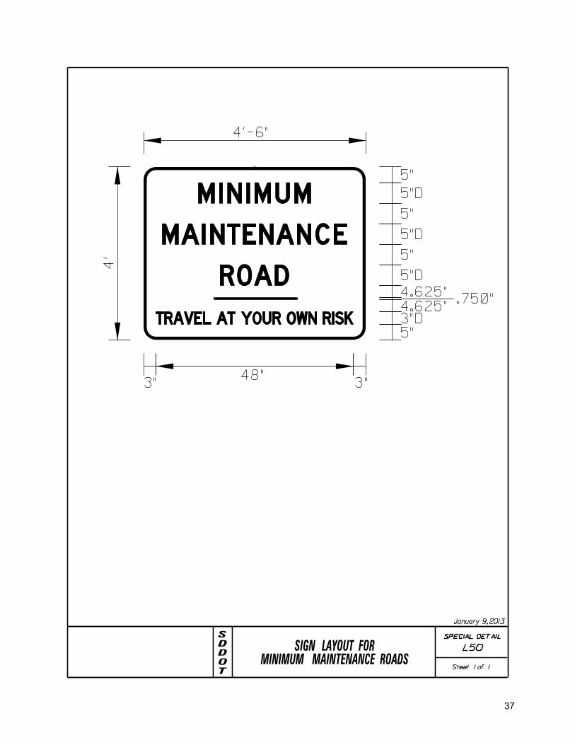
Minimum Maintenance Roads The designer shall obtain copies of resolutions and/or meeting minutes along with official map showing specific locations of roads that are designated as Minimum Maintenance by the local road authority. Minimum maintenance roads shall have the MINIMUM MAINTENANCE TRAVEL AT YOUR OWN RISK sign (W70-1) installed at each public access point to designated section. All “NO MAINTENANCE” signs shall be removed. An advisory speed plate should be installed with the W70-1 sign if the entire road section cannot be traveled at the statutory speed limit. Minimum Maintenance Roads shall be signed with all the regulatory and warning signs specified in this manual, the MUTCD, and special provisions unless specifically stated as not applicable for Minimum Maintenance Roads.
Road Closures If a section of road is under construction or is anticipated to be closed with no construction activity occurring for a duration of less than six (6) months, then all closure signing shall be considered temporary and shall conform to Part 6 of the MUTCD by the local road authority. Permanent signing projects shall not address temporary signs. If the closure is to last longer than six (6) months with no construction activity, then it shall be treated as a permanent closure and can be newly signed as permanent closures within a Traffic Safety Signing Project at the request of the local road authority. Additionally, if existing sections of roadway are permanently closed, they too can be eligible for review and replacement of signs. The local road authority must provide the consultant a copy of resolution and/or minutes of meeting in which official action has occurred for closing a roadway. Designers shall include standard permanent closure details within the plans where signing is being addressed on these closures with the project. Type III Barricades Type III Barricades shall be used to close a roadway where the appearance of an existing road or path exists beyond the closure point. Consultants shall use a local industry standard width of six (6) feet wide Type III barricade assemblies when application requires use of barricades. Permanent installation of barricades shall constitute the use of red and white colors as per the MUTCD. When a hazard exists on an existing roadway, the barricades shall be installed across the full width of the roadway as close as possible to the nearest useable landowner required access point to the hazard. If there is no useable access points then the full closure should occur at the nearest intersecting roadway. A Road Closed sign (R11-2) shall be installed with each full-width road closure. If the closure point is not located at the nearest intersection, then a single Type III barricade with a Road Closed XX Miles (or Feet) Ahead Local Traffic Only (R11-3) shall be installed on the shoulder at the nearest intersection. These sign assemblies shall be installed with breakaway fixed location sign posts. Skid mounts are not an acceptable option for permanent closures. If local authority access is needed to the area, a gate style of closure should be considered in lea of a barricade closure. Type IV Object Markers (End of Road Markers) Where a road has been completely obliterated such that it no longer could be construed as a road or has never had the appearance of a road, red Type IV OM’s should be installed across the roadway. A minimum of 3 assemblies should be installed on a 20’ wide road top. An additional sign assembly should be installed per every 5’ of width of road top. For added emphasis, additional signs can be mounted on each assembly; however, Traffic Safety Signing Projects will only pay for one sign per assembly.

12
DELINEATION
Delineators The Consultant shall include delineation notes and layout details within the plans and shall add a table showing per route delineation to the plan notes to provide any further detail to the Contractor to be able to install. No delineation is to be installed on Minimum Maintenance Roads. General rule of thumb of having visibility of at least 3 delineators on the same side of roadway at all times should be used to adjust delineator spacing up to the maximum distances specified. When normal spacing is interrupted by structures, crossroads, or ramps, delineators falling within such areas may be moved in either direction a distance not exceeding one-quarter of the standard spacing. Delineators still falling within such areas should be eliminated. Standard delineation shall be back-to-back installations except on one-way roadways. One Back-to-Back blue reflector may be left in-place at a private approach. Blue delineators shall not be used to mark county roads or field entrances. Installation of new blue delineators will not be addressed with these Traffic Safety Signing Projects, however, if additional blue delineators exists then the Consultant shall identify and include their removal within the plans as incidental work for the Contractor. Red reflectors placed illegally on right of way by property owners shall be noted by Consultant and removed by the Contractor via plan note. Intersection Delineation: Type IV delineators (4” round) shall be installed on all radii of intersecting roads (rule of thumb – if it has a stop/yield sign – it needs Type IV’s). Refer to Special Detail L30 (1&2 of 2). Guardrail Delineation: Where guardrail is present, guardrail delineation shall be installed as per Standard Plate 632.40 (1-4 of 4). Hazard Delineation: Any non-recoverable slope, non-transverable slope or where some other hazard is located within the clear zone and is not protected by guardrail shall have standard delineators installed at a maximum of 200’ spacing along the hazard. Curve Delineation: Delineators shall be installed on the outside of each curve with the degree of curve greater than 2.5 degrees and/or having a radius of less than 2300’, or where obstructions that block the line of sight along a curve less than 1,584 feet long. The spacing along the outside radius of horizontal curves and for three spaces in advance and for three spaces beyond the curve is given in the following table:
Max. Spacing for Delineators on Outside Radius of Horizontal Curves with Degree of Curvature Greater than 2.5
Degrees and/or Radius Less than 2300 Feet (Distance in Feet Rounded to the Nearest 5 Feet)
Spacing in Advance & Radius Spacing Beyond Curve (in feet) Of Curve On Curve 1st 2nd 3rd 50 20 40 65 125 150 30 60 90 180 250 40 85 125 250 300 50 95 145 290 400 55 110 170 300 500 65 125 190 300 600 70 140 210 300 700 75 150 230 300 800 80 165 245 300 900 85 175 260 300 1000 90 185 275 300
Spacing for specific radii not shown may be interpolated from table or computed from the formula S = 3 (R-50). The minimum spacing should be 20 feet. The spacing on curves should not exceed 300 feet. The spacing of the first delineator approaching a curve is 2xS, the second is 3xS and the third is 6xS but not to exceed 300 feet. If a spacing less than 300 feet is used approaching the curve, the distance shown above should be adjusted accordingly.
Structure Delineation: Bridges or culverts that the end falls within the clear zone and are not protected by guardrail shall have delineation installed and shall consist of a minimum of four (back-to-back) delineators on each side of the roadway spaced 50 feet apart. The delineators shall be located in a straight line beginning a minimum of 200 feet from the corner of the bridge and at the normal offset distance outside the shoulder edge and tapering to the inside edge of the obstruction.

13
Full Delineation: Full standard delineation includes all the above referenced delineation plus delineators on tangent sections and inside radius of curves. Full delineation is recommended to be installed on all improved two-lane (or greater) through roads (gravel/AC/PCCP surfaced with minimum of 20’ width and a 4’ shoulder) with an ADT of 50 or greater. Quantity shall be based on back-to-back delineation at a standard spacing of 528 feet in tangent sections on the same side of roadway and staggered placement with those on the opposite side of the road in those tangents. The spacing for delineators on the inside radius of curves shall also be 528 feet. If the local entity has objections to this recommendation, the Consultant is to refer that objection to the DOT for discussion.
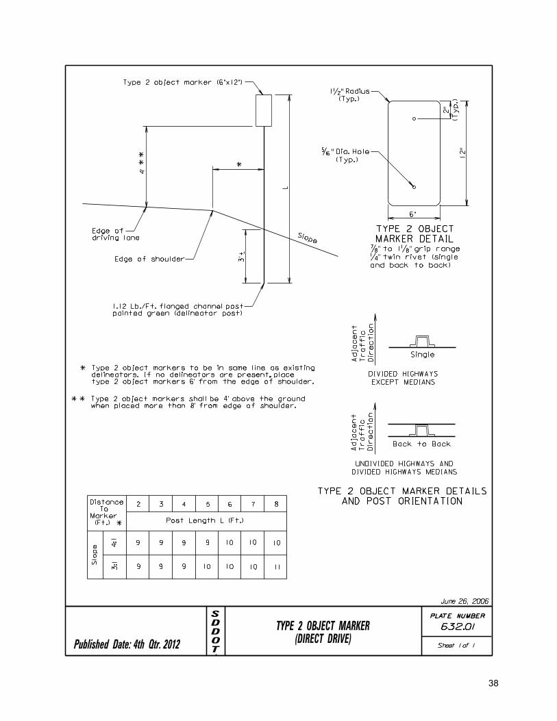
Object Markers Type 2 OM’s Type 2 Object Markers shall be installed at guardrail end terminals. If box culvert, pipe culvert or cattle pass ends are outside the shoulder area do the following:
If the ends are within the clear zone recovery area recommended in the SDDOT Local Roads Manual, measure the longitudinal opening width(s) (opening plus wall thickness) at the clear zone boundary or at the end of the pipe-end treatment(s), whichever is applicable and for box culvert, pipe culvert or cattle pass ends with outside dimensions:
o smaller than 30 inches install 1 yellow steel fence post on the upstream traffic-flow side of the pipe. o 30 inches or larger but less than 60 inches install 1 Type 2 double-sided marker on the upstream
traffic-flow side of the pipe or box opening. o for multiple pipes with a combined width of less than 60 inches, also install 1 Type 2 double-sided
marker on the upstream traffic-flow side of the pipe . For all box culverts, pipe culverts or multiple pipes, or cattle pass ends with outside dimensions greater than or
equal to 60 inches, install 4 single-sided posts, 1 at each of the four corners of the structure facing away from the structure.
For appurtenances smaller than 60 inches in diameter and outside the clear zone, mark with a single marker such as a steel post painted yellow at the discretion of the local road authority.
Type 2 object markers shall conform to Standard Specification Section 982. Payment for the Type 2 object markers shall be in conformance with Standard Specification 632.5C. Payment for yellow steel posts shall be incidental to other unit bid prices. The inner edge of the Type 2 object marker shall be installed at the opening of the pipe end section, box culvert, or cattle pass. Refer to Standard Plates 632.01, 632.10 and 632.40 for the placement of Type 2 object markers and post lengths.
Type 3 OM’s Type 3 Object Markers shall be installed if box culvert, pipe culvert or cattle pass ends are inside the shoulder break point and are not protected by guardrail, install a Type 3 object marker at the opening on both sides of the road, with the inside edge of the marker in line with the inner edge of the opening. No Type 3 object markers on bridge ends will be used when guardrail end terminal object markers are used or if the bridge width exceeds the width of road and shoulder area. All Type 3 OM’s installed with these Traffic Safety Projects shall consist of a flexible marker style design and shall conform to standard notes as provided to the Consultant. Type 4 OM’s See Road Closures for Type 4 Object Markers. Object Marker Mounting Height To mark appurtenances equal to or larger than 30 inches in diameter, mount object markers at the following heights in these circumstances:
To mark objects in the roadway or 8 feet or less from the shoulder or curb, make the mounting height to the bottom of the object marker or top of the steel post at 4 feet above the roadway with the following exception; if the overall width perpendicular to the centerline of the roadway is 40’ or less between two object markers, the height of the markers shall be adjusted such that the top of the marker or post does not exceed 3’ above the edge of the driving surface.
To mark objects more than 8 feet from the shoulder or curb, make the mounting height to the bottom of the object marker or top of steel post at 4 feet above the ground measured from the base of the post.

14
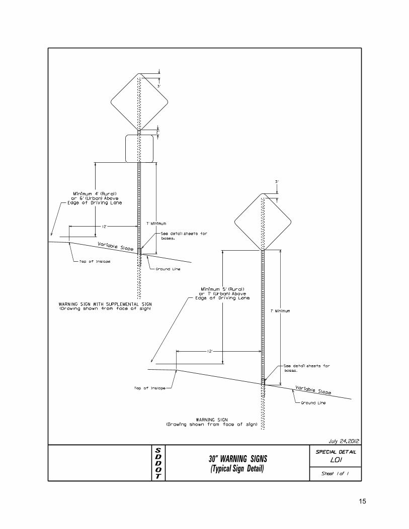
SIGN ASSEMBLY AND INSPECTION Installation of the support shall be accomplished by driving the post into the soil or drilling and backfilling after placement of the post. The depth to be drilled will depend on soil conditions and type of post being installed. Square tubular posts bases shall be placed to a depth of 4 feet. The breakaway plane of the post shall not exceed 4” in height above the ground measured from any point within a 60” radius of the post. Vertical plumb of the support should be checked during placement and/or backfill of the sign base. Appropriate measures shall be taken to ensure proper tamping of backfill material. Mound up soil around the base (not to exceed 4” in depth) to help moisture run off away from the base and minimize erosion. Signs shall not be overlapped. A 2 inch separation should be left between signs and a 4 inch separation between set of signs. Cardinal direction signs (if used) should be in proper order as shown in this manual and have matching colors. Hardware should not be over tightened. Signs of 30” and smaller are predrilled. New signs 36” and larger are not and must be drilled. Care should be taken to not scratch the new sign. Drilling should be on even inches to place the signs on metal predrilled supports. Plastic washer shall be used between a metal washer and the reflective sheeting.
Variable Slope
(Drawing shown from face of sign)
WARNING SIGN
Variable Slope
(Drawing shown from face of sign)
WARNING SIGN WITH SUPPLEMENTAL SIGN
12’
3"
3"
12’
7’ Minimum
2"
7’ Minimum
Edge of Driving Lane
or 7’ (Urban) Above
Minimum 5’ (Rural)
Edge of Driving Lane
or 6’ (Urban) Above
Minimum 4’ (Rural)
30" WARNING SIGNS(Typical Sign Detail)
bases.
bases.
Ground Line
Ground Line
Top of Inslope
Top of Inslope
See detail sheets for
See detail sheets for
TODDS
Sheet 1 of 1
SPECIAL DETAIL
July 24, 2012
L01
15
(Drawing shown from face of sign)
WARNING SIGN WITH SUPPLEMENTAL SIGN
2"
of 2 1/4 " or larger.
using a tubular post size
base shall be used when
This style of breakaway
Stiffeners
U-Channel
Aluminum
Variable Slope
1/5
W
3/5
W
1/5
W
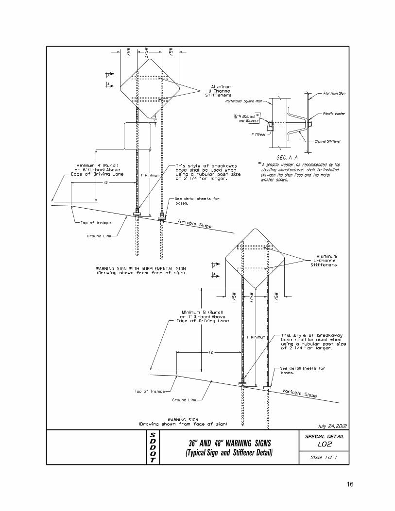
7’ Minimum
12’
Edge of Driving Lane
or 7’ (Urban) Above
Minimum 5’ (Rural)
36" AND 48" WARNING SIGNS
of 2 1/4 " or larger.
using a tubular post size
base shall be used when
This style of breakaway
Stiffeners
U-Channel
Aluminum
Variable Slope
1/5
W
3/5
W
1/5
W
7’ Minimum
12’
Edge of Driving Lane
or 6’ (Urban) Above
Minimum 4’ (Rural)
See detail sheets for
bases.
bases.
(Typical Sign and Stiffener Detail)
(Drawing shown from face of sign)
WARNING SIGN
A plastic washer, as recommended by the
between the sign face and the metal
washer shown.
sheeting manufacturer, shall be installed
A
A
A
A
TODDS
Sheet 1 of 1
Ground Line
Top of Inslope
Ground Line
Top of Inslope
See detail sheets for
1’’ Thread
�’’ Bolt, Nut
and Washers
-SEC. A A
Perforated Square Post
Channel Stiffener
Flat Alum. Sign
Plastic Washer
SPECIAL DETAIL
July 24, 2012
L02
16
of 2 1/4 " or larger.
using a tubular post size
base shall be used when
This style of breakaway
Stiffeners
U-Channel
Aluminum
Variable Slope
(Drawing shown from face of sign)
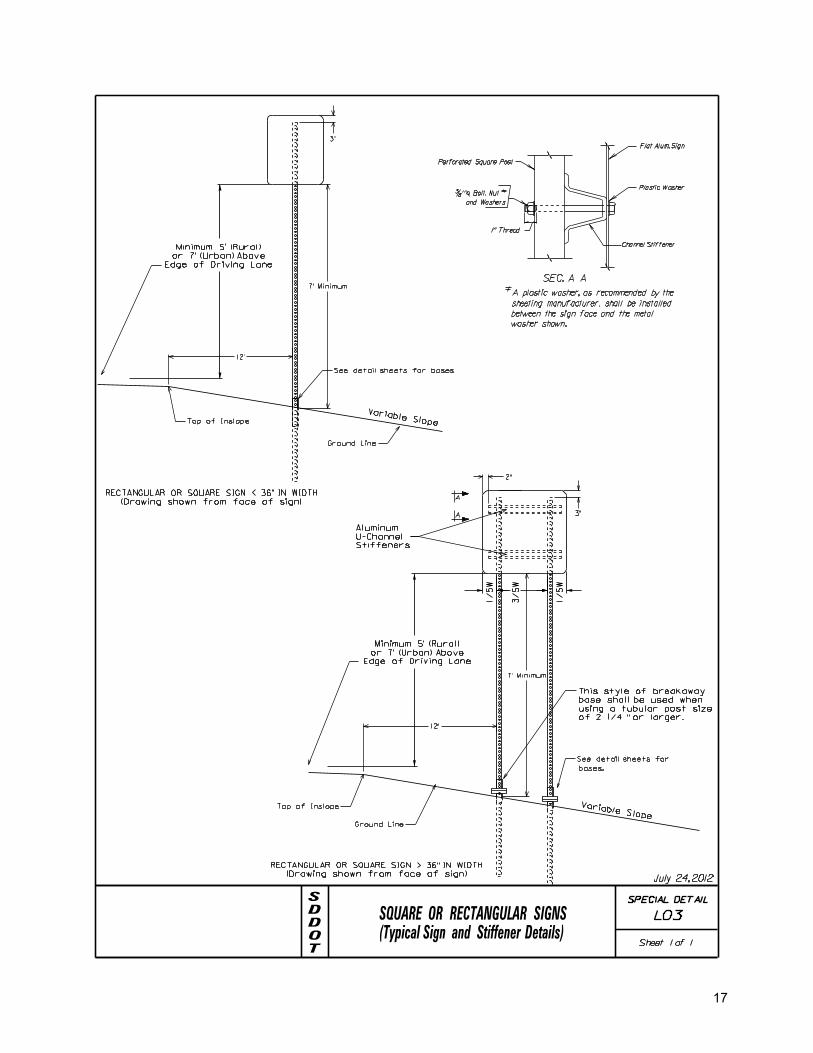
RECTANGULAR OR SQUARE SIGN > 36" IN WIDTH
(Drawing shown from face of sign)
RECTANGULAR OR SQUARE SIGN < 36" IN WIDTH
Variable Slope
1/5
W
3/5
W
1/5
W
7’ Minimum
12’
3"
3"
7’ Minimum
12’
2"
Edge of Driving Lane
or 7’ (Urban) Above
Minimum 5’ (Rural)
Edge of Driving Lane
or 7’ (Urban) Above
Minimum 5’ (Rural)
bases.
A
A
Ground Line
Ground Line
Top of Inslope
Top of Inslope
See detail sheets for bases.
See detail sheets for
TODDS
Sheet 1 of 1(Typical Sign and Stiffener Details)SQUARE OR RECTANGULAR SIGNS
A plastic washer, as recommended by the
between the sign face and the metal
washer shown.
sheeting manufacturer, shall be installed
1’’ Thread
�’’ Bolt, Nut
and Washers
-SEC. A A
Perforated Square Post
Channel Stiffener
Flat Alum. Sign
Plastic Washer
SPECIAL DETAIL
July 24, 2012
L03
17

ONE WAY SIGN OR LARGE ARROW SIGN
Stiffeners
U-Channel
Aluminum
Variable Slope
Side View
Face View
10"28"10"
48"
3"
18" or 24"
7’ Minimum
12’
3"
15"or21"
2"
Edge of Driving Lane
or 7’ (Urban) Above
Minimum 5’ (Rural)
bases.
A
A
TODDS
Sheet 1 of 1(Typical Sign and Stiffener Details)
Ground Line
Ground Line
Top of Inslope
See detail sheets for
A plastic washer, as recommended by the
between the sign face and the metal
washer shown.
sheeting manufacturer, shall be installed
1’’ Thread
�’’ Bolt, Nut
and Washers
-SEC. A A
Perforated Square Post
Channel Stiffener
Flat Alum. Sign
Plastic Washer
SPECIAL DETAIL
July 24, 2012
L04
18

Stiffeners
U-Channel
Aluminum
Variable Slope
(Drawing shown from face of sign)
1/5
W
3/5
W
1/5
W
3"
7’ Minimum
12’
36" or 48"
2"
Edge of Driving Lane
or 7’ (Urban) Above
Minimum 5’ (Rural)
36" OR 48" YIELD SIGN
A
A
A plastic washer, as recommended by the
between the sign face and the metal
washer shown.
sheeting manufacturer, shall be installed
TODDS
Sheet 1 of 1(Typical Sign and Stiffener Details)
Ground Line
Edge of Driving Lane
Top of Inslope
See detail sheets for bases.
1’’ Thread
�’’ Bolt, Nut
and Washers
-SEC. A A
Perforated Square Post
Channel Stiffener
Flat Alum. Sign
Plastic Washer
SPECIAL DETAIL
July 24, 2012
L05
19

30" STOP OR YIELD(Typical Sign Details)
for bases.
Variable Slope
(Drawing shown from face of sign)
30"
3"
7’ Minimum
12’
Edge of Driving Lane
or 7’ (Urban) Above
Minimum 5’ (Rural)
Variable Slope
(Drawing shown from face of sign)
3"
7’ Minimum
12’
Edge of Driving Lane
or 7’ (Urban) Above
Minimum 5’ (Rural)
for bases.
TODDS
Sheet 1 of 1
Edge of Driving Lane
Ground Line
Top of Inslope
See detail sheets
Edge of Driving Lane
Ground Line
Top of Inslope
See detail sheets
SPECIAL DETAIL
L06
30"
November 19, 2012
20

StiffenersU-ChannelAluminum
Variable Slope
3/5
W
1/5
W
1/5
W
tubular post size of 2 1/4" or larger.
shall be used when using a
This style of breakaway base
36 or 48"
2"
12’
7’ Minimum
Edge of Driving Lane
or 7’ (Urban) Above
Minimum 5’ (Rural)
36" OR 48" STOP SIGNS
(Drawing shown from face of sign)
A
A
A plastic washer, as recommended by the
between the sign face and the metal
washer shown.
sheeting manufacturer, shall be installed
Edge of Driving Lane
Ground Line
Top of Inslope
See detail sheets for bases.
TODDS
Sheet 1 of 1(Typical Sign and Stiffener Details)
1’’ Thread
�’’ Bolt, Nut
and Washers
-SEC. A A
Channel Stiffener
Flat Alum. Sign
Plastic Washer
Square PostPerforated
SPECIAL DETAIL
July 24, 2012
L07
21
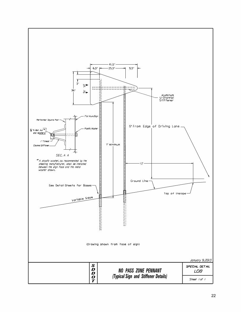
Variable
Slope
5" From Edge of Driving Lane
3"
36"
7’ Minimum
Ground Line
(Drawing shown from face of sign)
Top of Inslope
See Detail Sheets for Bases
12’
Stiffener
U-Channel
Aluminum
NO PASS ZONE PENNANT
A
A
A plastic washer, as recommended by the
between the sign face and the metal
washer shown.
sheeting manufacturer, shall be installed
TODDS
Sheet 1 of 1(Typical Sign and Stiffener Details)
1’’ Thread
�’’ Bolt, Nut
and Washers
-SEC. A A
Perforated Square Post
Channel Stiffener
Flat Alum. Sign
Plastic Washer
SPECIAL DETAIL
L08
41.5"
6.5" 25.5" 9.5"
January 9, 2013
22
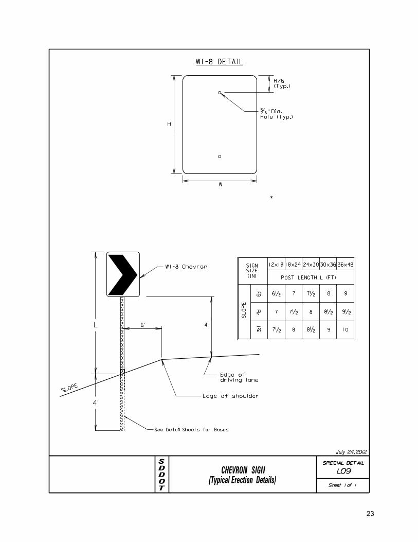
SL
OP
E
POST LENGTH L (FT)
4:1
3:1
Hole (Typ.)
�" Dia.
12x18 18x24 24x30 30x36 36x48
(IN)
SIZE
SIGN
6:1
8 976� 7�
8� 9�87�7
1098�87�
*
H
W
(Typ.)
H/6
4’
Edge of shoulder
driving lane
Edge of
6’
W1-8 Chevron
SLOPE
W1-8 DETAIL
L
4’
See Detail Sheets for Bases
CHEVRON SIGN(Typical Erection Details)
TODDS
Sheet 1 of 1
SPECIAL DETAIL
July 24, 2012
L09
23

furnished have essentially the same chemistry, mechanical properties and
geometry as that used in the FHWA tests, and that it will meet the FHWA
5. All hardware shall be galvanized in accordance with ASTM A153.
GENERAL NOTES-
4. All posts shall be galvanized in accordance with ASTM A653, Des. G-90.
1. Design Specification: AASHTO Standard Specifications for Structural
2. The manufacturer shall provide certification that the posts and hardware
system furnished will develop the full shear and bending yield strength
3. The manufacturer shall also provide certification that the breakaway
of the sign post section being spliced.
Top of Anchor Post
CL
Perforated
Square Post
C L
Perforate
d
Square Post
�’’ Corner Bolt
Sign Post
Perforated Square
Perforated Square
Anchor Post
ELEVATION
Anchor Post6’’
Embed
ment
CL
Square PostSign Post
Ground Line
60’’ 4’’
max.
BREAKAWAY SUPPORT STUB CLEARANCE DIAGRAM
chordline
NOTE: The top of anchor post shall NOT extend more than 4’’ max.
AA
change in velocity requirements.
Perforated Square
Stiffener Sleeve
2�" Perforated
CL
Perforated
Square Post
C L
Perforate
d
Square Post
Sign Post
Perforated Square
Nut, Flat Washers &
Flange Head Bolt,Top Subassembly
Release Bushings (Typ.)
8�’’
Line
Ground
2�’’
3�’’
4’-0" (min.)
(max.)
3’-0"
Minin
um
Concrete Footing
1’-3" Diameter
*
**
*
ELEVATION
Anchor Post
9’’
Embed
ment
CL
Square PostSign Post
BB
Line
Ground
4’-0" (min.)
3’-0"
Minin
um
Concrete Footing
1’-3" Diameter
*
*
Perforated
SEC. A-A
SEC. B-B
1 �’’
(min.)
Retainer Gasket
STUB POST DESIGNSLIP BASE DESIGN
Supports for Highway Signs, Luminaires and Traffic Signals, Latest Edition.
(As Required
by Manufacturer)
Perforated Steel Post w/ Concrete Footings
TODDS
Sheet 1 of 1
BREAKAWAY SIGN SUPPORTS
meet or exceed NCHRP 350 or MASH breakaway requirements and be FHWA approved.
Manufacturer recommended assembly parts and procedures. Sign installations must
Dimensions shown may vary by Manufacturer. The Contractor shall use
SPECIAL DETAIL
July 24, 2012
L20
24

2-piece (Hog Leg) assembly may also be used.
A 3-piece base assembly is shown, however, a
NOTE:
2�"
2�"
48"
12"
5"
5�"
9"
48"
5"
8"
4"
5"
3"
2 �"
160
110
4 �"
4 �"
TUBULAR POST BASE DETAILS(Typical Soil Installation)
SIGN BASE DETAILS FOR A 2" SIGN POST
MPJ SIGN WEDGE
�"
�"
SIGN BASE DETAILS FOR A 2�" SIGN POST
�" Dia. Corner Bolts
48" Base Section
Sign Post
Ground Line
MPJ Sign Wedge
18" Collar Section
Sign Post
Ground Line
Tubular Winged Anchor
48" Base Section�" Dia. Bolts
2�" Slip Base Breakaway Anchor
Breakaway Slip Base
TODDS
Sheet 1 of 1
SPECIAL DETAIL
L21
November 7, 2012
Painted Red
25

CONCRETE MODEL
2
A-36
PER ASTM
BAR
STEEL WELDED CLEAN OUT
.75 ROUND X 7 [20 ROUND X 175]
8 [200], 24 [600], AND 30 [760]
LONG STANDARD
3
1
CONCRETE MODELS ONLY
PER ASTM A-569
4" X 4" X .105" [65 x 65 x 5]
CAP
OPTIONAL WELDED STEEL BOTTOM
TUBULAR POST BASE DETAILS(Typical Flush Mount Breakaway Installation)
TODDS
Sheet 1 of 1
SPECIAL DETAIL
July 24, 2012
L22
26

12’ For All Other Signs
12’ For All Other Signs
LATERAL OFFSET(Typical Rural Sign Installations)
12’ For Stop & Yield Signs
12’ For Stop & Yield Signs Variable Slope
Edge of Shoulder
(Drawing shown from face of sign)RURAL LOCATION WITH 2 POSTS
Variable Slope
Edge of Shoulder
Edge of Driving Lane
Edge of Sign
Edge of SignEdge of Driving Lane
(Drawing shown from face of sign)RURAL LOCATION WITH 1 POST
Ground Line
Ground Line
TODDS
Sheet 1 of 1
SPECIAL DETAIL
July 24, 2012
L23
27

2’ Min.
2’ Min.
(Typical Urban Sign Installations)LATERAL OFFSET
Variable Slope
Face of Curb
Edge of Sign
Variable Slope
Face of Curb
Edge of Sign
(Drawing shown from face of sign)URBAN LOCATION WITH 2 POSTS
(Drawing shown from face of sign)URBAN LOCATION WITH 1 POST
Ground Line
Ground Line
TODDS
Sheet 1 of 1
SPECIAL DETAIL
July 24, 2012
L24
28

RW
BW
RW
BW
3’
#
BW = Bridge Width
RW = Road Width
Flexible Object Marker
Type 2 Object Marker
If BW = or < 40’, then # = 3’
If BW > 40’, then # = 4’
RW > BW and No Guardrail Present**
** If Guardrail is present, refer to Standard
TYPE 2 & 3 OBJECT MARKERS(Typical Installation Details)
(Includes Shoulders)
Plates 632.40 for installation of Type 2
Object Markers
RW < or = BW and No Guardrail Present**
TODDS
Sheet 1 of 1
SPECIAL DETAIL
July 24, 2012
L25
29

4"x4" DELINEATORS
DELINEATOR4"x4" (AMBER)4"x4" (WHITE)
DIRECTION OF TRAFFIC
PAVEMENTEDGE OF
SHOULDERTOP EDGE OF
4’- 0"
1"
4"
4"
4"
x�" Radius
VARIABLE SLOPE
2’
1"
1"
�" RAD.
2 HOLES
DIRECTION OF TRAFFIC
1"
green(delineator post)channel post painted
1.12 lb./ft. flanged
(TYPICAL)
CUTAWAY OF POST SHOWING FASTENENER
be �" diameterMounting Holes in all Delineators to
with Diamond Grade reflective sheeting with Diamond Grade reflective sheeting
SINGLE
BACK-TO-BACK
2" 2"
4"
Sch 40 PVC
4" TUBULAR DELINEATORS
4" TUBULAR (AMBER)4" TUBULAR (WHITE)
Centersat 1 Ince
3/8" Diameter30 Holes
2’-8’
.250".500"
.280"
.359"
*
POST
COLLAR
METAL SLEEVE
to depth of post.
Length varies according*
�" FASTENER
G
SHEAR POINT
1.656" MAX.
1.595" MIN.
G = GRIP RANGE
Twin Rivets, may be approved by the Engineer.
Alternative methods of fastening, such as �"- �"**
**
DELINEATORS
.250".500"
.280"
.359"
POST
COLLAR
�" FASTENER
G
SHEAR POINT
0.180" MAX.
0.150" MIN.
G = GRIP RANGE
**
**
WASHER
DELINEATOR
Engineer.
Blind Rivets with Collar, may be approved by the
Alternative methods of fastening, such as �"
DELINEATORS ON POSTDETAIL FOR SINGLE MOUNTING
TODDS
Sheet 1 of 2
DELINEATORS BACK TO BACK ON POSTDETAIL FOR MOUNTING 4"x4"
DELINEATORS(Typical Placement and Mounting Details)
SPECIAL DETAIL
L30
4"
October 15, 2012
30

Delineators.
See Erection Details for
Mount Delineator, Typical.
4"x4" (White) Single
Delineators.
See Erection Details for
Mount Delineator, Typical.
4"x4" (White) Back to Back
TRAFFIC
TRAFFIC
SHOULDER SHOULDER
8’ Max.
TRAFFIC
TRAFFIC
SHOULDER SHOULDER
8’ Max.
of 20’. See Erection Details for Delineators.
4/radius evenly spaced with a max. space
4" Tubular (White) Delineator, min.
of 20’. See Erection Details for Delineators.
4/radius evenly spaced with a max. space
4" Tubular (White) Delineator, min.
DELINEATORS(Typical Placement and Mounting Details)
SIDE ROAD - TWO-WAY TRAFFIC
SIDE ROAD - ONE-WAY TRAFFIC
TODDS
Sheet 2 of 2
SPECIAL DETAIL
July 24, 2012
L30
31

R1-1
W1-7
4’
EDGE OF DRIVING LANE
EDGE OF SHOULDER
EDGE OF SHOULDER
EDGE OF DRIVING LANE
20’
EDGE OF DRIVING LANE
12’
12’
SIDEROAD AT ACUTE ANGLEROADWAYS WITH IMPROVED
TYPICAL SIGN LAYOUT FOR THROUGH
TR
AFFIC
FL
OW
TR
AFFIC
A
B
A
B
FL
OW
TODDS
Sheet 1 of 1
*
Variable distance based on radius (max. 50’).*
SPECIAL DETAIL
July 24, 2012
L40
32

YIELD
R1-1
R1-2
W1-7
4’
EDGE OF DRIVING LANE
EDGE OF SHOULDER
2’
2’
EDGE OF SHOULDER
EDGE OF DRIVING LANE
EDGE OF DRIVING LANE
12’
12’
12’
IMPROVED SIDEROADTHROUGH ROADWAYS WITHTYPICAL SIGN LAYOUT FOR
TR
AFFIC
FL
OW
TR
AFFIC
A
B
B C
FL
OW
C
15’
Min.
TODDS
Sheet 1 of 1
A
SPECIAL DETAIL
July 24, 2012
L41
33

4’
20’
EDGE OF DRIVING LANE
EDGE OF SHOULDER
EDGE OF SHOULDER
EDGE OF DRIVING LANE
EDGE OF DRIVING LANE
12’
12’
ROADWAYS WITH UNIMPROVED SIDEROADTYPICAL SIGN LAYOUT FOR
R1-1
W1-7
YIELD
R1-2
or
(OPTIONAL)
TR
AFFIC
FL
OW
TR
AFFIC
FL
OW
B
TODDS
Sheet 1 of 1
A
A B
* Variable distance based on radius (max. 50’).
*
SPECIAL DETAIL
July 24, 2012
L42
34

ONE WAY
ONE WAY
R6-1
R6-1
EDGE OF DRIVING LANE
EDGE OF SHOULDER
EDGE OF DRIVING LANE
EDGE OF SHOULDER
EDGE OF DRIVING LANE
12’
12’
12’
12’
12’
12’
BACK TO BACK
R5-1(36x36)
60’
60’
(54x18)
(54x18)
DIVIDED
HIGHWAY
R1-1
R6-3
(36x36)
(24x18)
C
C
YIELD
ONE WAY
R1-2
R6-1
(36x36x36)
(54x18)
12’
12’
ROADWAYS WITH SIDEROADTYPICAL SIGN LAYOUT FOR DIVIDED
4’
12’
D
E
D ONE WAY
R6-1(54x18)
E ONE WAY
R6-1(54x18)
TR
AFFIC
FL
OW
TR
AFFIC
FL
OW
TR
AFFIC
FL
OW
TR
AFFIC
FL
OW
A
A
A
B
TODDS
Sheet 1 of 1
B
* Variable distance based on radius.
For medians greater than 30 feet wide.*****
**
**
**
SPECIAL DETAIL
July 24, 2012
L43
35

ONE WAY
ONE WAY
R6-1
R6-1
EDGE OF DRIVING LANE
EDGE OF SHOULDER
EDGE OF DRIVING LANE
EDGE OF SHOULDER
EDGE OF DRIVING LANE
12’
12’
12’
12’
12’
12’
12’
12’
BACK TO BACK
R5-1(36x36)
60’
60’
(54x18)
(54x18)
DIVIDED
HIGHWAY
R1-1
R6-3
(36x36)
(24x18)
C
C
C
YIELD
ONE WAY
ONE WAY
R1-2
R6-1
(36x36x36)
R6-1
BACK TO BACK
(54x18)
(54x18)
12’
12’
DIVIDED ROADWAYS WITH CROSSROADTYPICAL SIGN LAYOUT FOR
TODDS
Sheet 1 of 1
TR
AFFIC
FL
OW
TR
AFFIC
FL
OW
TR
AFFIC
FL
OW
TR
AFFIC
FL
OW
A
A
A
B
B
B
****
*
** Variable distance based on radius.
For medians greater than 30 feet wide.**
SPECIAL DETAIL
July 24, 2012
L44
36
TODDS
Sheet 1 of 1MINIMUM MAINTENANCE ROADS
SIGN LAYOUT FOR
48"
4’-6"
5"D
5"D
5"D
3"D
3"
.750"
3"
SPECIAL DETAIL
L50
4’
5"
5"
5"
4.625"
4.625"
5"
January 9, 2013
37
38

39

40

41

42

43

44

(48
"x4
8")
(48"x
48")
Type III BarricadeType III Barricade
CLOSED
ROAD
WATER
OVER
ROAD
AHEAD
ROAD
CLOSED
W2
0-
3
(48
"x4
8")
WATER
OVER
ROAD
(48"x
48")
AHEAD
ROAD
CLOSED
W20-3
LOCAL TRAFFIC ONLY
ROAD CLOSED
MILES AHEADXX
Speed
(M.P.H.)
Posted
500
750
350
3250 - 30
35 - 40
45 - 50
Spacing of
Advanced Warning
(A)
A
A
Buffer Space
Signs (Feet)
55 - 65
Buffer SpaceA
Full Road Closure
A
55
60
65
Speed(M.P.H.)
35
20
25
40
45
50
30
PostedLength of
Longitudinal
(Feet)Buffer Space
Recommended
115
155
200
250
305
360
425
495
570
645
6’ 6’
intersecting road.
in direction of travel at nearest
Install on Shoulder of driving lane
OVER ROAD
HAZARD ON/
*
*
* Optional advance warning
depicting specific hazard.
Type III Barricade
6’
Type III Barricade
6’
CL
site limintations.
Buffer Space dependant on
Type III Barricade (double-sided)
TODDS
GUIDES FOR TRAFFIC CONTROL DEVICES
Sheet 1 of 1
ROAD CLOSED FOR HAZARD
ON IMPROVED ROADWAY
SPECIAL DETAIL
July 24, 2012
L70
Install signs as applicable for each direction of travel.
45
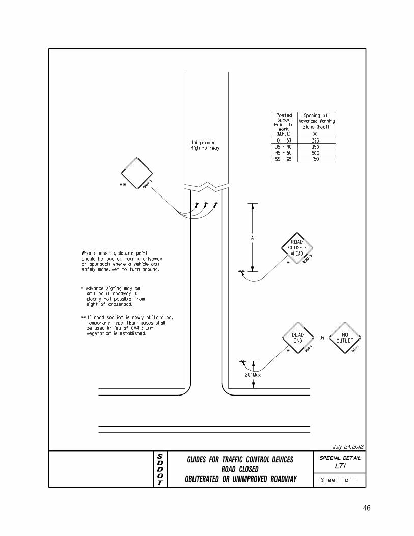
20’ Max
AHEAD
ROAD
CLOSED
W20-3
W14-1
DEAD
END
*
*
OR
W14-1
NO
OUTLET
Speed
(M.P.H.)
Prior toWork
Posted
500
750
350
3250 - 30
35 - 40
45 - 50
Spacing of
Advanced Warning
(A)
Signs (Feet)
55 - 65
A
Where possible, closure point
should be located near a driveway
or approach where a vehicle can
safely maneuver to turn around.
OM4-3
Unimproved
Right-Of-Way
* Advance signing may be
omitted if roadway is
clearly not passible from
sight of crossroad.
**
July 24, 2012
TODDS
GUIDES FOR TRAFFIC CONTROL DEVICES
ROAD CLOSED
Sheet 1 of 1OBLITERATED OR UNIMPROVED ROADWAY
SPECIAL DETAIL
L71
** If road section is newly obliterated,
temporary Type III Barricades shall
be used in lieu of OM4-3 until
vegetation is established.
46

47

48
Appendix A
SD State Codified Laws on Minimum Maintenance Roads 31-12-46. Minimum maintenance roads established. The board of county commissioners may designate any road on the county highway system as a minimum maintenance road if the board determines that the road or a segment of the road is used only occasionally or intermittently for passenger and commercial travel. The board shall identify the beginning and end points of the road designated as minimum maintenance. A minimum maintenance road may be maintained at a level less than the minimum standards for full maintenance roads, but shall be maintained at the level required to serve the occasional or intermittent traffic. 31-12-47. Posting notification of minimum maintenance road. The board of county commissioners shall post signs on a minimum maintenance road to notify the motoring public that it is a minimum maintenance road and that the public travels on the road at its own risk. The signs shall be posted at the entry points to and at regular intervals along a minimum maintenance road. A properly posted sign shall be prima facie evidence that adequate notice of a minimum maintenance road has been given to the motoring public. 31-13-1. Township supervisors responsible for secondary roads. The board of township supervisors shall construct, repair, and maintain all of the secondary roads within the township. The board shall, at its annual meeting, designate which secondary roads are full maintenance roads and which are minimum maintenance roads. The board of township supervisors shall publish any resolution designating a secondary road as minimum maintenance if such road is a school route. The designation shall be final, after a lapse of thirty days, unless appealed as provided in chapter 31-3. 31-13-1.1. Designation of minimum maintenance road--Level of maintenance. The board of township supervisors may designate a secondary road within the township as a minimum maintenance road if the board determines that the road or a segment of the road is used only occasionally or intermittently for passenger and commercial travel. The board shall identify the beginning and end points of the road designated as minimum maintenance. A minimum maintenance road may be maintained at a level less than the minimum standards for full maintenance roads, but shall be maintained at the level required to serve the occasional or intermittent traffic. 31-13-1.2. Posting of warning signs on minimum maintenance roads. The board of township supervisors shall post signs on a minimum maintenance road to notify the motoring public that it is a minimum maintenance road and that the public travels on the road at its own risk. The signs shall be posted at the entry points to and at regular intervals along a minimum maintenance road. A properly posted sign shall be prima facie evidence that adequate notice of a minimum maintenance road has been given to the motoring public.
SD State Codified Laws on Local Roads 31-12-7. Divisions of system into sections--Recording in county road book. The county highway superintendent shall maintain in a county road book a complete record of the divisions of the county highway system into sections, each section being designated by some appropriate number, name, or letter, and the starting point and terminus of each section being clearly designated at length. 31-12-18. Width of culverts. All culverts constructed on the county highway system shall have a clear roadway of not less than twenty-four feet. 31-12-26. Responsibility for secondary roads in unorganized territory. Each board of county commissioners and county superintendent of highways in organized counties shall construct, repair, and maintain all secondary roads within the counties not included in any municipality, organized civil township, improvement district organized pursuant to chapter 7-25A, or county road district organized pursuant to chapter 31-12A. 31-13-4. Width of highway grades. Plans and specifications for contracts let by the board of township supervisors shall provide that all highway grades shall be not less than twenty feet in width.

49
31-3-6. Power of county commissioners and township supervisors to vacate, change, or locate highway on petition - Contents of petition.
Upon receiving the petition of two or more voters of an organized civil township or of the number of voters equal to or greater than one percent of the ballots cast for the last gubernatorial election in the affected county, the board of supervisors of the township or the board of county commissioners wherein the highway is located or is proposed to be located may, except as provided in §§ 31-3-12 and 31-3-44, vacate, change, or locate any highway located or to be used within the township or county, if the public interest will be better served by the proposed vacating, changing, or locating of the highway. The petition of the voters shall set forth the beginning, course, and termination of the highway proposed to be located, changed, or vacated, together with the names of the owners of the land through which the highway may pass 31-3-6.1. Exception--Access to public lands. Notwithstanding any other provisions of this chapter, no county or township may vacate a highway which provides access to public lands. For the purposes of this section, public land does not include any school and public lands. 31-3-8. Resolution and order of board--Description of land--Map maintained by county auditor.
The resolution and order provided for in § 31-3-7 shall describe the highway vacated, changed, or located in general language by description of the land across which the highway extends, or by landmarks or survey designate the particular highway intended. The county auditor shall prepare and maintain a current map showing the course and location of all county highways within or on the border of the county. The county auditor shall, within thirty days of the resolution and order provided for in § 31-3-7, make those changes to the map as necessary to reveal the course and location of any county highway vacated, changed, or located. 31-3-13. Highway on township line--Joint resolution. In case the highway to be vacated, changed, or located is upon a township line, it shall be necessary that the board of supervisors of the adjoining civil township, or the board of county commissioners of the county, if the adjoining congressional township is unorganized, as the case may be, pass a like resolution and enter an order vacating, changing, or locating said highway. 31-3-18. Width of highway. All public highways located under §§ 31-3-6 to 31-3-37, inclusive, shall be not less than four rods in width, and may be six rods in width when all residents of land adjoining such highway shall petition for such width, except that highways not exceeding one-half mile in length and not located on section lines may be not less than two rods in width when, in the judgment of the board of county commissioners, such width will be sufficient to accommodate properly the travel thereon. Every order locating or changing any highway shall specify the width thereof. 31-9-1. Relinquishment of highways in national parks--Cession of jurisdiction. The Department of Transportation and the board of county commissioners of an affected county, may relinquish to the United States for use and construction and control of highways by the secretary of interior, acting through the national park service, all of the interest of the state and the county in such portions of public highways lying within the boundaries of national parks and national monuments. The relinquishment of interest in the highways shall operate as a cession to the United States of jurisdiction for highway purposes over such portions of the highways lying within said national parks or national monuments. 31-9-4. County roads used by National Forest Service--Cooperative agreement for joint construction and use.
The board of county commissioners may enter into cooperative agreements with the Forest Service of the United States Department of Agriculture for the joint construction, maintenance, and use of roads located within the boundaries of the county, where such roads are used by the Forest Service in the protection, administration, and utilization of the national forests and are also used by communities or persons within or adjacent to such national forests in the use and development of the resources thereof or where such roads otherwise serve the needs of the public. Costs incurred by the county pursuant to the provisions of this section shall be appropriated from the county general fund. 31-14-2. County commissioners' responsibility for bridges and culverts. The duty to construct and maintain all bridges and culverts throughout the county, except upon the state trunk highway system, is hereby imposed upon the board of county commissioners, subject to conditions relating to bridges and culverts on secondary highways in townships. 31-14-33. Inspection of township culverts--Duty of board of supervisors. The township board of supervisors shall have each culvert on the secondary highways within the township annually inspected and, if necessary, repaired.
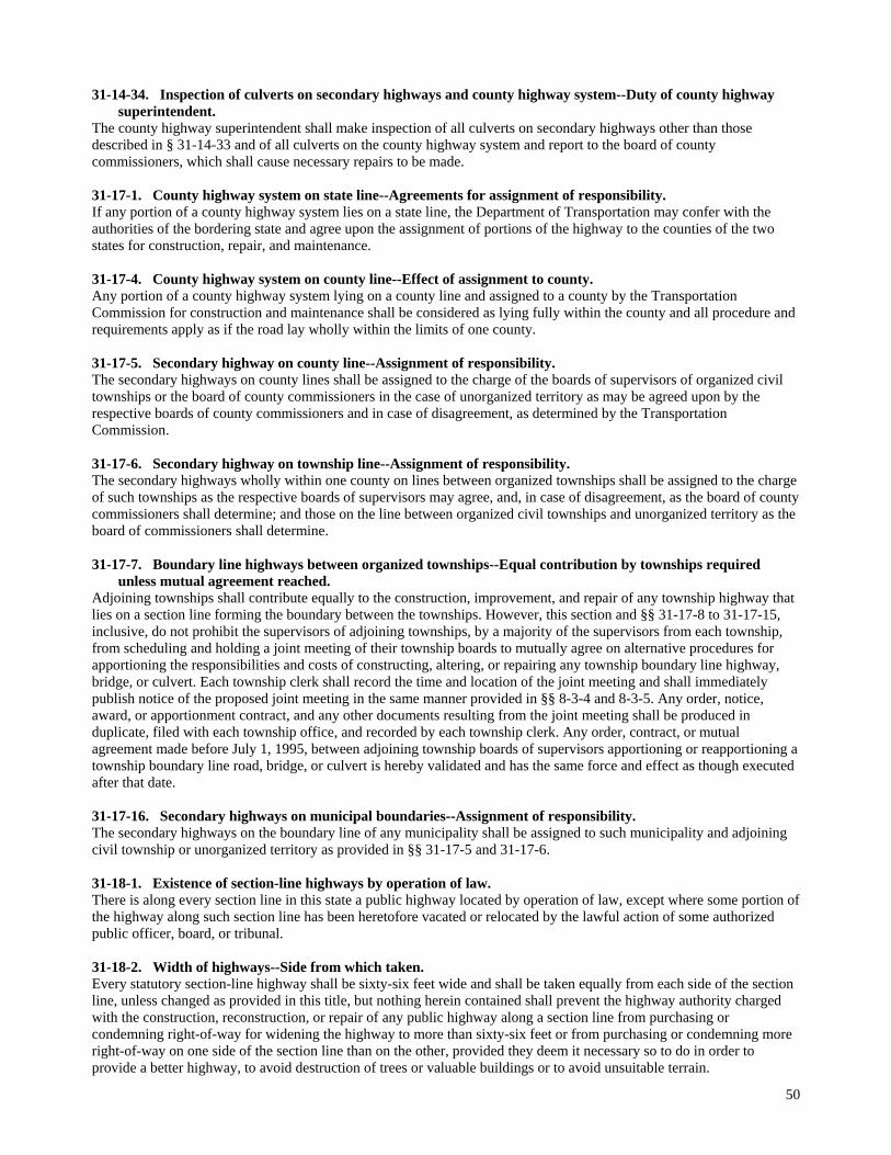
50
31-14-34. Inspection of culverts on secondary highways and county highway system--Duty of county highway
superintendent. The county highway superintendent shall make inspection of all culverts on secondary highways other than those described in § 31-14-33 and of all culverts on the county highway system and report to the board of county commissioners, which shall cause necessary repairs to be made. 31-17-1. County highway system on state line--Agreements for assignment of responsibility. If any portion of a county highway system lies on a state line, the Department of Transportation may confer with the authorities of the bordering state and agree upon the assignment of portions of the highway to the counties of the two states for construction, repair, and maintenance. 31-17-4. County highway system on county line--Effect of assignment to county. Any portion of a county highway system lying on a county line and assigned to a county by the Transportation Commission for construction and maintenance shall be considered as lying fully within the county and all procedure and requirements apply as if the road lay wholly within the limits of one county. 31-17-5. Secondary highway on county line--Assignment of responsibility. The secondary highways on county lines shall be assigned to the charge of the boards of supervisors of organized civil townships or the board of county commissioners in the case of unorganized territory as may be agreed upon by the respective boards of county commissioners and in case of disagreement, as determined by the Transportation Commission. 31-17-6. Secondary highway on township line--Assignment of responsibility. The secondary highways wholly within one county on lines between organized townships shall be assigned to the charge of such townships as the respective boards of supervisors may agree, and, in case of disagreement, as the board of county commissioners shall determine; and those on the line between organized civil townships and unorganized territory as the board of commissioners shall determine. 31-17-7. Boundary line highways between organized townships--Equal contribution by townships required
unless mutual agreement reached. Adjoining townships shall contribute equally to the construction, improvement, and repair of any township highway that lies on a section line forming the boundary between the townships. However, this section and §§ 31-17-8 to 31-17-15, inclusive, do not prohibit the supervisors of adjoining townships, by a majority of the supervisors from each township, from scheduling and holding a joint meeting of their township boards to mutually agree on alternative procedures for apportioning the responsibilities and costs of constructing, altering, or repairing any township boundary line highway, bridge, or culvert. Each township clerk shall record the time and location of the joint meeting and shall immediately publish notice of the proposed joint meeting in the same manner provided in §§ 8-3-4 and 8-3-5. Any order, notice, award, or apportionment contract, and any other documents resulting from the joint meeting shall be produced in duplicate, filed with each township office, and recorded by each township clerk. Any order, contract, or mutual agreement made before July 1, 1995, between adjoining township boards of supervisors apportioning or reapportioning a township boundary line road, bridge, or culvert is hereby validated and has the same force and effect as though executed after that date. 31-17-16. Secondary highways on municipal boundaries--Assignment of responsibility. The secondary highways on the boundary line of any municipality shall be assigned to such municipality and adjoining civil township or unorganized territory as provided in §§ 31-17-5 and 31-17-6. 31-18-1. Existence of section-line highways by operation of law. There is along every section line in this state a public highway located by operation of law, except where some portion of the highway along such section line has been heretofore vacated or relocated by the lawful action of some authorized public officer, board, or tribunal. 31-18-2. Width of highways--Side from which taken. Every statutory section-line highway shall be sixty-six feet wide and shall be taken equally from each side of the section line, unless changed as provided in this title, but nothing herein contained shall prevent the highway authority charged with the construction, reconstruction, or repair of any public highway along a section line from purchasing or condemning right-of-way for widening the highway to more than sixty-six feet or from purchasing or condemning more right-of-way on one side of the section line than on the other, provided they deem it necessary so to do in order to provide a better highway, to avoid destruction of trees or valuable buildings or to avoid unsuitable terrain.
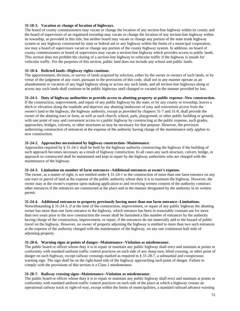
51
31-18-3. Vacation or change of location of highways. The board of county commissioners may vacate or change the location of any section-line highway within its county and the board of supervisors of an organized township may vacate or change the location of any section-line highway within its township, as provided in this title, but neither board may vacate or change any portion of the state trunk highway system or any highway constructed by state or federal aid or any highway within the limits of a municipal corporation, nor may a board of supervisors vacate or change any portion of the county highway system. In addition, no board of county commissioners or board of supervisors may vacate a section-line highway which provides access to public lands. This section does not prohibit the closing of a section-line highway to vehicular traffic if the highway is unsafe for vehicular traffic. For the purposes of this section, public land does not include any school and public lands. 31-18-4. Relicted lands--Highway rights continue. The apportionment, division, or survey of lands acquired by reliction, either by the owner or owners of such lands, or by virtue of the judgment of any court, pursuant to the provisions of this code, shall not in any manner operate as an abandonment or vacation of any legal highway along or across any such lands, and all section-line highways along or across any such lands shall continue to be public highways until changed or vacated in the manner provided by law. 31-24-1. Duty of highway authorities to provide access to abutting property at public expense--New construction. If the construction, improvement, and repair of any public highway by the state, or by any county or township, leaves a ditch or elevation along the roadside and deprives any abutting landowner of easy and convenient access from the owner's land to the highway, the highway authority, except as provided by chapters 31-7 and 31-8, shall provide the owner of the abutting tract or farm, as well as each church, school, park, playground, or other public building or ground, with one point of easy and convenient access to a public highway by constructing at the public expense, such grades, approaches, bridges, culverts, or other structures as may be necessary for that purpose. However, the provision authorizing construction of entrances at the expense of the authority having charge of the maintenance only applies to new construction. 31-24-2. Approaches necessitated by highway construction--Maintenance. Approaches required by § 31-24-1 shall be built by the highway authority constructing the highway if the building of such approach becomes necessary as a result of highway construction. In all cases any such structure, culvert, bridge, or approach so constructed shall be maintained and kept in repair by the highway authorities who are charged with the maintenance of the highway. 31-24-3. Limitation on number of farm entrances--Additional entrances at owner's expense. The owner, as a matter of right, is not entitled under § 31-24-1 to the construction of more than one farm entrance on any one tract or parcel of land at the expense of the public authority whose duty it is to maintain the highway. However, the owner may at the owner's expense upon making application to and receiving written consent of the authority construct other entrances if the entrances are constructed at the place and in the manner designated by the authority in its written permit. 31-24-4. Additional entrances to property previously having more than one farm entrance--Limitations. Notwithstanding § 31-24-3, if at the time of the construction, improvement, or repair of any public highway the abutting owner has more than one farm entrance to the highway, which entrance has been in reasonably constant use for more than two years prior to the new construction the owner shall be furnished a like number of entrances by the authority having charge of the construction, improvement, or repair, if the entrances do not materially add to the hazard of public travel on the highway. However, no owner of property adjoining the highway is entitled to more than two such entrances at the expense of the authority charged with the maintenance of the highway, on any one continuous half mile of adjoining property. 31-28-6. Warning signs at points of danger--Maintenance--Violation as misdemeanor. The public board or officer whose duty it is to repair or maintain any public highway shall erect and maintain at points in conformity with standard uniform traffic control practices on each side of any sharp turn, blind crossing, or other point of danger on such highway, except railway crossings marked as required in § 31-28-7, a substantial and conspicuous warning sign. The sign shall be on the right-hand side of the highway approaching such point of danger. Failure to comply with the provisions of this section is a Class 1 misdemeanor. 31-28-7. Railway crossing signs--Maintenance--Violation as misdemeanor. The public board or officer whose duty it is to repair or maintain any public highway shall erect and maintain at points in conformity with standard uniform traffic control practices on each side of the place at which a highway crosses an operational railway track or right-of-way, except within the limits of municipalities, a standard railroad advance warning

52
sign. The sign shall be on the right-hand side of the highway approaching such crossing and at a distance from the crossing as the department or other controlling body shall direct. Any legally abandoned or nonoperational track which is crossed by a public highway and at which the crossing has been properly marked as a railway grade crossing may be marked with a supplemental sign, meeting uniform traffic control practices, to inform drivers of vehicles identified in § 32-29-5 that a stop is not required at that crossing. Failure to comply with the provisions of this section is a Class 1 misdemeanor. 31-28-16. Arterial highways--Right-of-way--Violation as misdemeanor. The department and boards of county commissioners may designate certain state and county highways, or portions thereof, as preferential or arterial highways. The traffic upon any highway so designated shall have the right-of-way. Failure to comply with the provisions of this section is a Class 2 misdemeanor. 31-28-28. Unauthorized possession of official signs or markers as misdemeanor.
No person may possess any sign, guide board, mileage post, signal, or marker erected by the state or by any governmental subdivision unless obtained in a legal manner. A violation of this section is a Class 1 misdemeanor. 32-14-6. Restrictions respecting weight of vehicle--Duration of period of restriction--Signs designating restricted
area. Local authorities, including road districts, may by ordinance or resolution prohibit the operation of vehicles upon any highway or impose restrictions as to the weight of vehicles allowed. Such prohibitions or restrictions apply only to vehicles to be operated upon any highway under the jurisdiction of and for the maintenance of which such local authorities are responsible and only if the highway by reason of physical condition, rain, snow, or other climatic conditions will be seriously damaged or destroyed unless the use of vehicles on the highway is prohibited or the permissible weights of the vehicles are reduced. Any local authority enacting any such ordinance or resolution shall erect and maintain or cause to be erected and maintained signs designating the provisions of the ordinance or resolution at each end of that portion of any highway affected by the ordinance or resolution. The ordinance or resolution is not valid unless such signs are erected and maintained. 32-14-7. Prohibiting trucks or commercial vehicles from use of designated highways--Erection of signs. Local authorities, including road districts, may by ordinance or resolution prohibit the operation of trucks or other commercial vehicles or impose limitations as to the weights of such vehicles on designated highways. The prohibitions and limitations shall be designated by appropriate signs placed on such highways. 32-22-47. Maximum vehicle weight on bridges--Required and permissible signs--Exception. The board of county commissioners of any county, the board of supervisors of any township, the board of trustees of any road district, or the Department of Transportation, shall erect and maintain at a point on the right-of-way and within six hundred feet of both entrances to any bridge and may, where it is deemed necessary, erect and maintain at the nearest road intersection in each direction from any bridge, upon any public highway which it is the duty of the board or department to maintain and repair, a conspicuous sign specifying in large numerals, the maximum weight of any vehicle, laden or unladen, which may enter upon or cross over the bridge. No bridge signing is necessary for bridges which can accommodate motor vehicles operating under the legal weight maximums provided in § 32-22-16. 32-25-17. Posting stop signs at intersections with increased maximum--Illumination of stop signs. Local authorities shall place and maintain upon all through highways under their jurisdiction upon which the permissible speed is increased adequate signs giving notice of such special regulations. Local authorities shall also place and maintain upon each and every highway under their jurisdiction intersecting any said through highway, appropriate stop signs which shall be illuminated at night or so placed as to be illuminated by the headlights of an approaching vehicle. 32-29-1. Indication of right-of-way by stop or yield signs. Preferential right-of-way at an intersection may be indicated by stop signs or yield signs as authorized in § 32-29-2. 32-29-2. Stop and yield signs to designate through highways--Visibility at night. The Department of Transportation with reference to state highways and local authorities with reference to highways under their jurisdiction may designate main traveled or through highways by erecting at the entrances thereto from intersecting highways stop or yield signs. All such signs shall be illuminated at night or so placed as to be illuminated by headlights of an approaching vehicle. 32-30-2.4. No-parking zones posted by department--Temporary zones--Signs--Violation as misdemeanor. The Department of Transportation with respect to highways under its jurisdiction may promulgate rules pursuant to chapter 1-26 to prohibit or restrict the stopping, standing, or parking of vehicles on any highway if such stopping,

53
standing, or parking is dangerous to those using the highway or if the stopping, standing, or parking of vehicles would unduly interfere with the free movement of traffic thereon. If such a rule is promulgated, the highway shall be signed to indicate where such stopping, standing, or parking is prohibited. The secretary of transportation may establish a temporary no parking zone, not to exceed ninety days, if the secretary of public safety and the secretary of transportation, after consultation with the director of the highway patrol, agree that a no parking zone is necessary for the protection of life and property. Such signs are official signs and no person may stop, stand, or park any vehicle in violation of the restrictions stated on such signs. A violation of this section is a Class 2 misdemeanor. 32-30-11.9. Signs to state penalties for illegal use of designated parking spaces--Certain penalties apply although
not stated. Each sign designating a parking space for a person with a physical disability shall state the penalty for illegal use of the parking space. This section only applies to a new sign or a sign that replaces an existing sign after July 1, 2002. However, any fine imposed pursuant to § 32-30-11.3, 32-30-11.4, or 32-30-11.8 applies whether or not the penalty is stated on the sign.
SD State Codified Laws on Speed Limits 32-25-1.1. Maximum daytime speed--Violation as misdemeanor. Except as provided by § 32-25-4 or pursuant to § 32-25-7, no person may drive a vehicle upon a street or highway at a speed in excess of sixty-five miles per hour. A violation of this section is a Class 2 misdemeanor. 32-25-9.1. Establishment of speed zones by county commissioners--Posting of zones. Any board of county commissioners may determine and establish speed zones upon all or any part of the highways under its jurisdiction and upon streets and highways on the request of and after any other local authority, including any road district, having charge of the maintenance of the highway has declared its intention to post speed zones. Such speed zones shall be conspicuously posted at the beginning and ending of the zones. 32-25-9.2. Township road speed limit. Unless otherwise provided pursuant to § 32-25-9.1, no person may drive a vehicle on a township road in excess of fifty-five miles per hour. Driving in excess of the speed limit established in this section is a Class 2 misdemeanor. 32-25-12. Speed limit in unposted urban areas--Violation as misdemeanor.
In urban areas which are not zoned or posted as provided in § 32-25-7, the maximum lawful speed shall be twenty-five miles per hour. A violation of this section is a Class 2 misdemeanor. 32-25-13. Speed limit at obstructed railway crossings--Violation as misdemeanor. When approaching within fifty feet of a grade crossing of any railway when the driver's view is obstructed, the maximum speed shall be fifteen miles per hour. A driver's view is obstructed if at any time during the last two hundred feet of his approach to such crossing he does not have a clear and uninterrupted view of any traffic on such railway for a distance of four hundred feet in each direction. A violation of this section is a Class 2 misdemeanor. 32-25-14. Speed limit in school zones--Violation as misdemeanor. When passing a school during a school recess or while children are going to or leaving school during the opening or closing hours, the maximum lawful speed shall be fifteen miles per hour. A violation of this section is a Class 2 misdemeanor. 32-25-15. Speed limit at intersections with obstructed view--Violation as misdemeanor. When approaching within fifty feet of and when traversing an intersection of highways when the driver's view is obstructed the maximum lawful speed shall be fifteen miles per hour. A driver's view is obstructed if at any time during the last fifty feet of his approach to such intersection, he does not have a clear and uninterrupted view of such intersection and of the traffic upon all of the highways entering such intersection for a distance of two hundred feet from such intersection. A violation of this section is a Class 2 misdemeanor. 32-25-18. Special speed limits for bridges--Posting signs--Violation of posted speed limit as misdemeanor--
Established speed as conclusive maximum safe speed. The transportation commission upon request from any local authorities shall, or upon its own initiative may, conduct an investigation of any public bridge, causeway, or viaduct, and if it finds that such structure cannot with safety to itself withstand vehicles traveling at the speed otherwise permissible under this chapter, the commission shall determine and declare the maximum speed of vehicles which such structure can withstand and shall cause or permit suitable signs

54
stating such maximum speed to be erected and maintained before each end of such structure. Violating such posted speed limits is a Class 2 misdemeanor. The findings and determination of the commission shall be conclusive evidence of the maximum speed which can with safety to any such structure be maintained thereon.

55
Appendix B
County Sign Inventory Instructions
System Overview This application is intended to provide reports showing the sign and post materials needed to upgrade the signing on county/township roads. It can also generate a report (Sign Summary By Milepost) that lists signs in order by route, along with instructions for what should be added and removed. This is intended to be the contractor’s instructions for upgrading the signs. It can also serve as an inventory of the signs as they currently exist. Main Screen
Figure 1: County Sign Inventory Main screen
Main Screen The box on the left lists all of the routes in the inventory. A route can be any street or road name that you want. The routes are taken from the signs in the inventory. To add a new route to the inventory, add a new sign entry and type in the name of the new route along with that sign. The box on the right lists all of the sign entries associated with the route highlighted in the list on the left. The entries are listed in MRM order. (MRM stands for Mileage Reference Marker. It represents the distance this sign is located from the beginning of the route. The MRM is used to order the sign information in the order you would encounter the signs as you drive the route.) You can edit a particular sign entry by double clicking on it. This, and other functionality, is offered through the menus at the top of the screen. Main Screen Menu Options Sign Summary
Each Sign Summary record represents a single location on a route. It may indicate what sign is there now and what if anything should be added or removed. It may also represent a reference location, with no associated sign information.
Add -- add a sign summary entry. When you choose this the system adds a new sign record to the file. This
records the existence (or need for) a particular sign or sign assembly at a particular point. See Figure 2.

56
Figure 2: Sign Summary Add screen
All fields will be blank at startup. After adding the first sign summary, certain fields will not become blank. These fields are the fields least likely to change (ie. Project number, route, date, organization, etc.) They are defaulted to the values used on the previous record, in an attempt to make the add process faster and easier. Change any fields necessary to reflect the new information. The program is expecting certain values in the SYSTEM, SIGNFLAG, POSTFLAG, TRAVEL DIRECTION, SIGN FACING, LOCATION AND SIGN NUMBER and will check these values on the save. These values are contained in a dropdown box. See the appendix of this document for a list of valid values for each. Certain fields are required. They are: System, Project Number, Route Number, Direction, and MRM. If a sign number is chosen, then the following fields will also be required: Sign Facing, Location, Width, Height, Sign Flag, Sign Count, Post Material, Post Flag, Post Count, and Post Length. Some post information is entered in the main part of the form, other information is entered in the grid at the bottom of the screen. This application assumes that post material and dimension won’t vary within a sign assembly (for example, that you would never use one U-Channel and one Square Tubing post for a single sign). So that information is stored in the top portion of the screen. However, the application assumes that you might need to use 2 different length posts, or want to indicate that one post should be kept and one replaced in a single sign assembly. That information is displayed in the grid at the bottom of the screen. Once you have entered all the information and saved the record, the system lets you add another sign summary if you want. If you don’t want to enter another sign summary right now, click ‘Close’ and the system sends you back to the main menu. Note: Each Sign Summary record does not need to represent a sign. You can add records that are “For Reference”. For example, you may add a record indicating the location of the intersection of the route you are working on with 554th Ave. These references can help someone looking at the inventory orient themselves on the route. You must select the “REF – For Reference” as the sign number for a reference entry. See the example in Figure 3.

57
Figure 3: Sign Summary Reference entry
Update -- update a sign summary entry. When you choose this option the system displays the information
for the currently selected sign summary record for you to modify. (This is the same as if you double click on a sign record.) See Figure 4 for an example of this screen. It is the same as the Add screen and applies the same edits and validation rules as an Add.
Figure 4: Sign Summary Update Screen
Delete -- delete a sign summary entry. When you choose this option the system displays the information for
the currently selected sign summary record. The screen is the same as the Add and Update screens, but a “Delete” button is shown at the bottom of the screen. If you click on this button, the system asks you to confirm that you really want to delete the record. It also pops up a confirmation message when the record is deleted. See Figure 5 for an example.
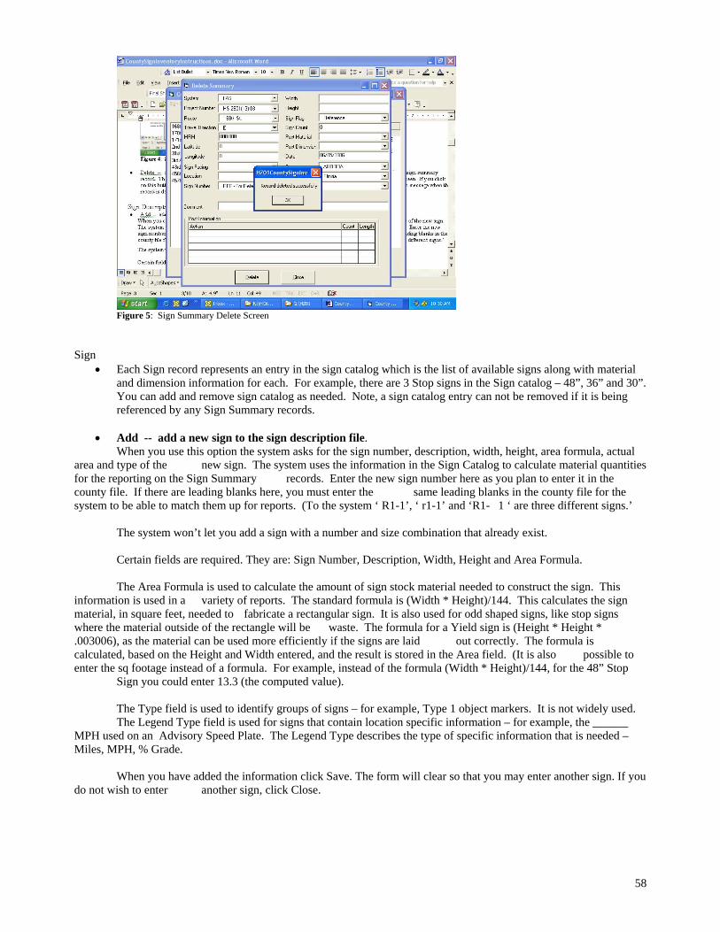
58
Figure 5: Sign Summary Delete Screen
Sign
Each Sign record represents an entry in the sign catalog which is the list of available signs along with material and dimension information for each. For example, there are 3 Stop signs in the Sign catalog – 48”, 36” and 30”. You can add and remove sign catalog as needed. Note, a sign catalog entry can not be removed if it is being referenced by any Sign Summary records.
Add -- add a new sign to the sign description file.
When you use this option the system asks for the sign number, description, width, height, area formula, actual area and type of the new sign. The system uses the information in the Sign Catalog to calculate material quantities for the reporting on the Sign Summary records. Enter the new sign number here as you plan to enter it in the county file. If there are leading blanks here, you must enter the same leading blanks in the county file for the system to be able to match them up for reports. (To the system ‘ R1-1’, ‘ r1-1’ and ‘R1- 1 ‘ are three different signs.’ The system won’t let you add a sign with a number and size combination that already exist. Certain fields are required. They are: Sign Number, Description, Width, Height and Area Formula. The Area Formula is used to calculate the amount of sign stock material needed to construct the sign. This information is used in a variety of reports. The standard formula is (Width * Height)/144. This calculates the sign material, in square feet, needed to fabricate a rectangular sign. It is also used for odd shaped signs, like stop signs where the material outside of the rectangle will be waste. The formula for a Yield sign is (Height * Height * .003006), as the material can be used more efficiently if the signs are laid out correctly. The formula is calculated, based on the Height and Width entered, and the result is stored in the Area field. (It is also possible to enter the sq footage instead of a formula. For example, instead of the formula (Width * Height)/144, for the 48” Stop Sign you could enter 13.3 (the computed value). The Type field is used to identify groups of signs – for example, Type 1 object markers. It is not widely used. The Legend Type field is used for signs that contain location specific information – for example, the ______ MPH used on an Advisory Speed Plate. The Legend Type describes the type of specific information that is needed – Miles, MPH, % Grade. When you have added the information click Save. The form will clear so that you may enter another sign. If you do not wish to enter another sign, click Close.

59
Figure 6 – Sign Catalog Add
Update -- update a sign that already exists in the sign description file.
When you choose this option, the system will pop up a Find screen, to let you enter criteria to find the signs that you want to update. The most commonly used is the sign number. You can also enter a partial number to see a larger set of results. See figure 7 for an example. (Note: at this time, the find only works with the Sign Number and Legend Type. If you try to search on any of the other fields the application will display an error message and shut down.)
Figure 7 – Sign Catalog Find Screen
When you click find, the system will search for all sign catalog entries that match the criteria you enter and display them in the list at the bottom of the screen. To update a particular sign in the catalog, double click on it in the list. An update screen will appear. This screen looks and works like the Add screen. See Figure 7.

60
Figure 8: Sign Catalog Update Screen
Delete -- delete a sign from the sign description file.
When you choose this option, the system will pop up a Find screen (the same as for the update), to let you enter criteria to find the signs that you want to delete. See Figure 6. When you click find, the system will search for all sign catalog entries that match the criteria you enter and display them in the list at the bottom of the screen. To delete a particular sign in the catalog, double click on it in the list. An delete screen will appear. This screen looks like the Add and Update screens, but includes a Delete button at the bottom. See Figure 9. If you click on this button, the system asks you to confirm that you really want to delete the record. It also pops up a confirmation message when the record is deleted.
Figure 9 – Sign Catalog Delete screen
Utilities
Find/Replace -- find and replace data in the sign summary file Note: This option has limited capabilities. It is intended to let you make bulk corrections. For example, if a project number was entered incorrectly, you would be able replace the incorrectly spelled project number in all sign summaries that have the incorrect data. However, it is only set up to handle a maximum of 20 corrections. If more rows are found, the application will generate and error message and shut down. If a project number is

61
wrong on an entire set of data (hundreds of records) it must be corrected one record at a time. (Or, corrected using Access 2002 to manipulate the database directly.)
Figure 10 – Find/Replace screen
Clear County -- Delete all sign summary information from the database
When you choose this option the all data in the sign summary file will be deleted. Only choose this option when you have made a copy of the database! There is way to recover the data once it’s been deleted. This option is intended to let you clear out the database in preparation for entering signs for a new project or county. Reports
All reports display in Print Preview mode initially. You can then review the report and choose to print all or part of it.
Sign/Posts description - This is an internal report intended is provided to help find records where the comment,
post material or post dimensions contains a certain word or phrase. For example, you can limit the report to only those entries that use U-Channel for posts.

62
Figure 11 – Sign/Posts By Description Criteria Screen
This report prints sign information in order by route, milepost, and sign number in condensed print with landscape paper orientation. It doesn’t provide any totals and isn’t meant to be included in any final reports or plans.
Figure 12 – Sign/Posts By Description
Sign summary by milepost – This report is intended to provide a set of guidelines for what posts and signs are in place and what actions need to be taken (Add, remove signs. Replace posts.) to bring the signing up to standards. This report is included along with plans used to solicit bids for off system signing projects. The report prints sign information in order by route, milepost, and sign number in condensed print with landscape paper orientation.
A criteria screen lets you indicate the information you want included in the report. See Figure 13. If no criteria is specified, all Sign Summary information is included.

63
The system asks for beginning and ending routes. The report contains sign information for all routes between the two specified. (The beginning and ending routes are included too - if you have a beginning route of ‘168th St’ and an ending route of ‘171st St’, ‘168th St’ is the first route on the report and ‘171st St’ is the last.) If you leave the beginning route blank the system starts at the top of the file. If you leave the ending route blank the system prints to the bottom of the file. (If you leave both blank the report includes all routes.) You can also limit the report to signs in a single system by specifying the system you want included. If you leave it blank, all systems are included in the report. The system tries to fit as many signs on each page as possible. A new page is started when the previous page is full, or the system or route changes. The system uses the sign number from each sign in the report to get the description of that sign from the description file. If no description is found, that area is left blank on the report. The direction code for each sign is translated from E, W, N, S to East, West, North, South
Figure 13: Sign Summary By Milepost Criteria Screen
This is the most heavily used report in the application. It provides a print out of the inventory of signs, along with instructions about what signs to add and remove, where to replace posts, etc.
Figure 14 – Sign Summary By Milepost

64
New sign summary by sign number – This report is intended to provide a list of the signs that need to be purchased and installed to bring the signing up to standard. The information is further broken down by System (Township, City/Town). The report prints new sign info in order by sign number, width, height, mph, and system.
This report uses the same criteria screen as the Sign Summary By Milepost report. See Figure 13. The report includes signs with a non-blank Sign Number, were the Sign Count is greater than zero and Sign Flag is “Install New Sign” or “Replace Sign”. For an example of this report, see Figure 15.
Figure 15 – New Sign Summary By Sign Number
New sign summary by route - This report is intended to provide a list, by route, of the signs that need to be purchased and installed to bring the signing up to standard. The information is further broken down by System (Township, City/Town). Prints new sign information in order by route, sign number, width, height, mph, and system.
This report uses the same criteria screen as the Sign Summary By Milepost report. See Figure 13. The report includes signs with a non-blank Sign Number, were the Sign Count is greater than zero and Sign Flag is “Install New Sign” or “Replace Sign”. For an example of this report, see Figure 16.
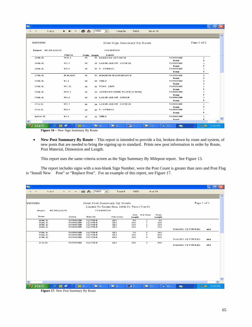
65
Figure 16 – New Sign Summary By Route
New Post Summary By Route – This report is intended to provide a list, broken down by route and system, of new posts that are needed to bring the signing up to standard. Prints new post information in order by Route, Post Material, Dimension and Length.
This report uses the same criteria screen as the Sign Summary By Milepost report. See Figure 13. The report includes signs with a non-blank Sign Number, were the Post Count is greater than zero and Post Flag is “Install New Post” or “Replace Post”. For an example of this report, see Figure 17.
Figure 17: New Post Summary By Route

66
Discarded sign summary by sign number – This report is intended to provide a list of the signs that are to be discarded (not left in place ore reused) to bring the signing up to standard. (It is very similar to the “New sign summary by sign number” report.) The information is further broken down by System (Township, City/Town). The report prints new sign info in order by sign number, width, height, mph, and system.
This report uses the same criteria screen as the Sign Summary By Milepost report. See Figure 13. The report includes signs with a non-blank Sign Number, were the Sign Count is greater than zero and Sign Flag is “Discard”. For an example of this report, see Figure 18.
Figure 18: Discarded Sign Summary By Sign Number
Discarded post summary – This report is intended to provide a list of the posts, broken down by system,
material, dimension and length, that are to be discarded (not left in place ore reused) to bring the signing up to standard. (It is very similar to the “New post summary” report.)
This report uses the same criteria screen as the Sign Summary By Milepost report. See Figure 13. The report includes signs with a non-blank Sign Number, were the Sign Count is greater than zero and Sign Flag is “Discard”. For an example of this report, see Figure 19.

67
Figure 19: Discarded Post Summary
Sign Material Summary By System – This report is intended to provide a summary of sign material (sheeting
and delineators) and posts, broken down by system. It is intended to provide information needed to bid a contract to bring the signs up to standard.
This report uses a criteria screen to allow the report to be limited to a subset of information. See Figure 20.
Figure 20: Sign Material Summary By System Criteria Screen
The report includes signs with a non-blank Sign Number, were the Sign Count is greater than zero and Sign Flag is “Install New Sign” or “Replace Sign”. It includes posts with a non-blank Post Number, were the Post Count is greater than zero and the Post Flag is “Install New Post” or “Replace Post”. For an example of this report, see Figure 21. The system calculates the square feet of aluminum, number of steel, wood and plastic posts, number of Type I Delineators, number of Type II Object Markers, and number of Type III Object markers needed in each system. The square feet of aluminum sign is computed as follows: If the width and height are both greater than zero, the width and height are divided by 12 to convert them from inches to feet. The results are multiplied and the resulting square footage is multiplied by the sign

68
count. If just the width is greater than zero, the sign number and width are used to find the sign in the description file and get the area from that.
Figure 21: New Sign Material By System
Post Material Summary By System – This report is intended to provide a list, broken down by route system
and material, of new posts that are needed to bring the signing up to standard. Prints new post information in order by System, Material, Dimension and Length and Length.
This report uses the same criteria screen as the Sign Summary By Milepost report. See Figure 13. The report includes posts with a non-blank Sign Number, were the Post Count is greater than zero and Post Flag is “Install New Post” or “Replace Post”. For an example of this report, see Figure 22.

69
Figure 22: New Post Material By System
List Sign Description File – This report lists the sign catalog, in order by Sign number. It is intended to
provide a reference for people adding sign summary information to the system. See Figure 23.
Figure 23: List Sign Description File

70
Data Dictionary Sign Summary Information Field Name Definition Required Comment System Indicates the type of roadway
system this sign is on. Examples are FAS (Federal Aid System), Township, City/Town. Choose from preset values or enter the value you want.
Yes Used in developing signing plans where different entities will be splitting the cost of bringing the signing up to standard. For example, one set of signing plans may include both Township and City roads where the Township and City are each going to pay for all or part of their signing upgrade.
Project Number Identifies the project that this entry pertains to. Enter the value you want. List of values is made up of all Project Numbers that currently exist on Sign Summary records.
Yes Generally only one project at a time is contained in the Sign Inventory database. If multiple projects are to be worked on, multiple copies of the database are created.
Route Description of the roadway that the sign is on. Examples are 170th St, 451 Ave. List of values is made up of all Routes that currently exist on Sign Summary records. To add a new route, simply type in the value when creating the sign summary record. Once that information is saved, the new route number will start showing up in the list of choices.
Yes Try for meaningful name. Sorting is alphabetical which can be confusing with routes that start with a number. For example, the routes listed below would sort in the order given. This is because the second character (a “1”) in 117th St comes alphabetically before the second character (a “7”) in 17th Ave. 117th St 17th Ave 1st St 2176 North Road 217th St
Travel Direction Direction a vehicle would be traveling to make use of a sign. For example, if a vehicle traveling North would come to and stop at a stop sign, enter North here. Limited to the choices North, South, East and West.
Yes Direction can be subjective in some areas. In the hills, it can be hard to determine direction and in some cases the most accurate description would be NorthEast. Do your best.
MRM Mileage Reference Marker. Represents the distance in miles between this location and the beginning of the route.
Yes The MRM is used to order the sign information in the order you would encounter the signs as you drive the route.
Latitude Latitude of this location No Not typically used. It is included to allow for possible GIS mapping in the future.
Longitude Longitude of this location No Not typically used. It is included to allow for possible GIS mapping in the future.
Sign Facing Direction the sign faces. Choices are North, South, North & South, East, West, East & West
Yes (nonRef)
Choices North & South, East & West are used for those signs, like object markers, that are mounted on both sides of the posts. Note: This field is not required if the Sign number is “REF – For Reference”
Location Side of the road the sign appears on. This is from the perspective of a motorist who would make use of the sign. Choices are Left, Right, X-Road
Yes (nonRef)
As you come up to the sign, is it on your left or right? X-Road is used for signs that face traffic coming in from a cross-road to the route, for example, stop signs that apply to traffic about to enter the roadway.

71
Note: This field is not required if the Sign number is “REF – For Reference”
Width Width of the sign, in inches. Yes (nonRef)
Used to calculate the material needed to fabricate the sign. Also indicates the size of the sign, for informational purposes. Note: This field is not required if the Sign number is “REF – For Reference”
Height Height of the sign, in inches. Yes (nonRef)
Used to calculate the material needed to fabricate the sign. Also indicates the size of the sign, for informational purposes. Note: This field is not required if the Sign number is “REF – For Reference”
Sign Flag Indicates action to be taken with this sign. Choices are Install New Sign, Discard Sign, Leave Existing Sign In Place, Replace Sign, Reference
Yes (nonRef)
Automatically set to “Reference” if the Sign Number is “REF – Reference”
Sign Count Indicates the number of signs represented by the information in this record.
Yes (nonRef)
Needs to be greater than zero if the Sign Flag is not “Reference”.
Date Date the sign information is added.
Yes If not filled in, currently date will be saved.
County County where the sign is located. Yes Choose from list of all counties in South Dakota or enter value that you want to use.
Township Township where the sign is located.
Yes Enter the value you want. List of values is made up of all Townships that currently exist on Sign Summary records.
Sign Number Identifies the sign (from the sign catalog) that this sign summary entry represents.
Yes Must choose from the list. To add new choices, or remove obsolete choices, update the sign catalog.
Comment Additional information describing this sign location.
No Limited to 60 characters. Information typed past the 60th character will be dropped without warning during the save.
Post Information Field Name Definition Required Comment Post Material Material the post is made from.
Choose from None, Plastic, Steel, Sq Tube, U-Channel, Wood
Yes (notRef)
None should be used with the sign represented by this entry is not mounted on a post. For example, a sign that is mounted on a light pole or a building. If None is used, the location of the sign should be noted in the Comment.
Post Dimension Size of the post. Enter the value you want. List of values is made up of all Post Dimensions that currently exist on Sign Summary records.
Yes (notRef)
Description of the post. May include 2X2, 5 Inch Round, 2.5 lb/ft
Action Indicates action to be taken with this post. Choices are Install New Post, Discard Post, Leave Existing Post In Place, Replace
Yes (notRef)

72
Post, Other (light pole, etc) Count Number of posts represented by
this entry Yes (notRef)
Length Length of the post(s) to be used, in feet
Note: Each Sign Summary record has room for a singe Post Material and Post Dimension value. Each Sign Summary record can have 2 or more combinations of Action/Count/Length. This application assumes that a sign assembly can use multiple supports. If so, it assumes that mixed materials will not be used – you would never have one square tubing support and one wood support. The multiple values for action, count and length allow you to specify a need to add 2 posts, 1 6 ft long and 1 9 ft long. Or to keep one 7 foot post, and replace one 9 foot post. Sign Catalog Information Field Name Definition Required Sign Number Code reference to the sign
represented by this entry. Examples are W1-1L, W10-1
Yes
Description Description of the sign. Examples are Turn Left, Railroad Advance
Yes
Width Width of the sign Yes Used to calculate the sign area Height Height of the sign Yes Used to calculate the sign area Area Formula Formula that can be used to
calculate the sign area. Must be a single numeric value, or a valid mathematical equation. When the equation is evaluated, the word “Width” is replaced with the width of the sign, and the work “Height” is replaced with the height of the sign.
Yes Standard formula for rectangular sign is (Width * Height)/144. Formula should be set up to yield a square foot value.
Area Result calculated by evaluating the Area Formula, using the specified Width and Height
Auth Calc
Type General grouping of types of signs
No Not widely used. Is used to group Type II Object markers
Legend Type Type of legend, if any, this particular sign uses. Must choose one of: Miles, County, Route, MPH, Distance, Tons, Feet, % Grade, % Grade & Miles, Feet & Inches
No Used to indicate signs where specific legend information must be supplied – for example, the speed on a Speed Limit sign. When a Legend Type is associated with a particular sign in the catalog, any Sign Summary records that reference this catalog entry will include fields to specify the legend information. This means that a Sign Summary record that references a Speed Limit sign in the catalog will include a field to specify the MPH. The % Grade & Miles legend and Feet & Inches legend require 2 values. Any Sign Summary records that reference them will include 2 fields to collect the required information.
Feel free to add signs as needed. Signs can be deleted from the catalog as long as they are not being referenced by the Sign Summary data.