signal processing for physical layer security with
TRANSCRIPT
PhD-FSTC-2016-14The Faculty of Sciences, Technology and Communication
DISSERTATION
Presented on 22/04/2016 in Luxembourg
to obtain the degree of
DOCTEUR DE L’UNIVERSITE DU LUXEMBOURGEN INFORMATIQUE
by
Ashkan KALANTARIBorn in Yazd, Iran
SIGNAL PROCESSING FOR PHYSICAL LAYER
SECURITY WITH APPLICATION IN SATELLITE
COMMUNICATIONS
Dissertation defense committee
Dr Bjorn Ottersten, dissertation supervisor
Professor and Director of SnT, University of Luxembourg
Dr Symeon Chatzinotas
Research Scientist, SnT, University of Luxembourg
Dr Francesco Viti, Chairman
Professor, University of Luxembourg
Dr Luc Vandendorpe
Professor, Universite Catholique de Louvain, Belgium
Dr Jens Krause
Senior Manager, Satellite Telecommunications Systems at SES, Luxembourg

Abstract
Wireless broadcast allows widespread and easy information transfer. However, it may
expose the information to unintended receivers, which could include eavesdroppers. As a
solution, cryptography at the higher network levels has been used to encrypt and protect
data. Cryptography relies on the fact that the computational power of the adversary
is not enough to break the encryption. However, due to increasing computing power,
the adversary power also increases. To further strengthen the security and complement
the encryption, the concept of physical layer security has been introduced and surged
an enormous amount of research. Widely speaking, the research in physical layer secu-
rity can be divided into two directions: the information-theoretic and signal processing
paradigms. This thesis starts with an overview of the physical layer security literature
and continues with the contributions which are divided into the two following parts.
In the first part, we investigate the information-theoretic secrecy rate. In the first
scenario, we study the confidentiality of a bidirectional satellite network consisting of
two mobile users who exchange two messages via a multibeam satellite using the XOR
network coding protocol. We maximize the sum secrecy rate by designing the optimal
beamforming vector along with optimizing the return and forward link time allocation.
In the second scenario, we study the effect of interference on the secrecy rate. We
investigate the secrecy rate in a two-user interference network where one of the users,
namely user 1, requires to establish a confidential connection. User 1 wants to prevent
an unintended user of the network to decode its transmission. User 1 has to adjust its
transmission power such that its secrecy rate is maximized while the quality of service at
the destination of the other user, user 2, is satisfied. We obtain closed-form solutions for
optimal joint power control. In the third scenario, we study secrecy rate over power ratio,
namely “secrecy energy efficiency”. We design the optimal beamformer for a multiple-
input single-output system with and without considering the minimum required secrecy
rate at the destination.
In the second part, we follow the signal processing paradigm to improve the security.
We employ the directional modulation concept to enhance the security of a multi-user
multiple-input multiple-output communication system in the presence of a multi-antenna
eavesdropper. Enhancing the security is accomplished by increasing the symbol error
rate at the eavesdropper without the eavesdropper’s CSI. We show that when the eaves-
dropper has less antennas than the users, regardless of the received signal SNR, it cannot
recover any useful information; in addition, it has to go through extra noise enhancing
processes to estimate the symbols when it has more antennas than the users. Finally, we
summarize the conclusions and discuss the promising research directions in the physical
layer security.

Acknowledgements
Above all, I am grateful to have family members who supported me morally and eco-
nomically during all of my studies and I would like to give them my sincerer thank for
their great support. I wish to be able to always live with them and wish a happy and
healthy life for them.
I would like to thank Professor Bjorn Ottersten, Dr Symeon Chatzinotas, Dr Sina Maleki,
and Dr Gan Zheng for their supervision during my PhD research in the Interdisciplinary
Centre for Security, Reliability and Trust (SnT) between the years 2012-2016. In addi-
tion, I would like to thank Professor Mojtaba Soltanalian, Professor Zhu Han, and Dr
Zhen Gao for their collaboration. I would like to also thank the “Fonds National de la
Recherche” of Luxembourg for fonding my PhD studies.
In addition, my special thanks go to my office mates, my colleagues, and the administra-
tive staff at the University of Luxembourg and SnT who provided a great and friendly
and cheerful environment for both enjoying life and carrying out research.
Ashkan Kalantari
Luxembourg, April 2016
iii


Contents
Abstract ii
Acknowledgements iii
Contents iv
List of Figures ix
List of Tables xi
Abbreviations xiii
Notations xv
1 Introduction 1
1.1 Motivation and Scope . . . . . . . . . . . . . . . . . . . . . . . . . . . . . 1
1.2 Thesis Organization . . . . . . . . . . . . . . . . . . . . . . . . . . . . . . 4
1.2.1 Chapter 2: Physical Layer Security . . . . . . . . . . . . . . . . . . 4
1.2.2 Chapter 3: Security in Bidirectional Multibeam Satellites . . . . . 4
1.2.2.1 Contributions . . . . . . . . . . . . . . . . . . . . . . . . 5
1.2.3 Chapter 4: Power Control in Wiretap Interference Channels . . . . 5
1.2.3.1 Contributions . . . . . . . . . . . . . . . . . . . . . . . . 6
1.2.4 Chapter 5: Secrecy Energy Efficiency Optimization for MISO andSISO Communication Networks . . . . . . . . . . . . . . . . . . . . 6
1.2.4.1 Contributions . . . . . . . . . . . . . . . . . . . . . . . . 7
1.2.5 Chapter 6: Security Enhancing Directional Modulation via Symbol-Level Precoding . . . . . . . . . . . . . . . . . . . . . . . . . . . . 7
1.2.5.1 Contributions . . . . . . . . . . . . . . . . . . . . . . . . 8
1.3 Publications . . . . . . . . . . . . . . . . . . . . . . . . . . . . . . . . . . . 9
1.3.1 Journals . . . . . . . . . . . . . . . . . . . . . . . . . . . . . . . . . 9
1.3.2 Conferences . . . . . . . . . . . . . . . . . . . . . . . . . . . . . . . 9
2 Physical Layer Security 11
2.1 Information-Theoretic Secrecy Rate Paradigm for Security . . . . . . . . . 11
2.1.1 Secrecy Rate in Non-cooperative Links . . . . . . . . . . . . . . . . 12
2.1.1.1 Secrecy in wiretap broadcast channels . . . . . . . . . . . 12
2.1.1.2 Secrecy in broadcast channels with confidential messages 17
v

Contents vi
2.1.1.3 Secrecy in wiretap multiple-access channels . . . . . . . . 18
2.1.1.4 Secrecy in wiretap interference channels . . . . . . . . . . 19
2.1.1.5 Secrecy rate and energy efficiency . . . . . . . . . . . . . 21
2.1.2 Cooperative Communication and Secrecy Rate . . . . . . . . . . . 21
2.1.2.1 Untrusted relay . . . . . . . . . . . . . . . . . . . . . . . 22
2.1.2.2 Cooperative communication with external eavesdropper . 23
2.2 Signal Processing Paradigm for Security . . . . . . . . . . . . . . . . . . . 25
2.2.1 Conventional precoding . . . . . . . . . . . . . . . . . . . . . . . . 26
2.2.2 Directional modulation via symbol-level precoding . . . . . . . . . 27
2.3 Conclusion . . . . . . . . . . . . . . . . . . . . . . . . . . . . . . . . . . . 29
3 Security in Bidirectional Multi-beam Satellites 31
3.1 Introduction . . . . . . . . . . . . . . . . . . . . . . . . . . . . . . . . . . . 31
3.1.1 Literature Review . . . . . . . . . . . . . . . . . . . . . . . . . . . 32
3.1.1.1 Network coding related works . . . . . . . . . . . . . . . 32
3.1.1.2 Physical layer security related works . . . . . . . . . . . . 33
3.1.2 Our Contribution . . . . . . . . . . . . . . . . . . . . . . . . . . . . 34
3.2 System Model . . . . . . . . . . . . . . . . . . . . . . . . . . . . . . . . . . 35
3.2.1 Network coding based bidirectional SATCOM . . . . . . . . . . . . 36
3.2.1.1 Signal model . . . . . . . . . . . . . . . . . . . . . . . . . 36
3.2.1.2 Users’ RL rates . . . . . . . . . . . . . . . . . . . . . . . 39
3.2.1.3 Users’ FL rates . . . . . . . . . . . . . . . . . . . . . . . . 40
3.2.1.4 Eavesdroppers’ channel capacities . . . . . . . . . . . . . 40
3.2.1.5 Secrecy rate definition . . . . . . . . . . . . . . . . . . . . 40
3.2.2 Conventional SATCOM . . . . . . . . . . . . . . . . . . . . . . . . 43
3.2.2.1 Signal model . . . . . . . . . . . . . . . . . . . . . . . . . 43
3.2.2.2 Users’ rates . . . . . . . . . . . . . . . . . . . . . . . . . . 44
3.2.2.3 Eavesdroppers’ channel capacities . . . . . . . . . . . . . 44
3.2.2.4 Secrecy rate definition . . . . . . . . . . . . . . . . . . . . 45
3.3 Problem Formulation and the Proposed Solution . . . . . . . . . . . . . . 45
3.3.1 Network coding for bidirectional SATCOM . . . . . . . . . . . . . 46
3.3.2 Conventional SATCOM . . . . . . . . . . . . . . . . . . . . . . . . 47
3.4 Simulation Results . . . . . . . . . . . . . . . . . . . . . . . . . . . . . . . 49
3.5 Conclusion . . . . . . . . . . . . . . . . . . . . . . . . . . . . . . . . . . . 55
4 Power Control in Wiretap Interference Channels 57
4.1 Introduction . . . . . . . . . . . . . . . . . . . . . . . . . . . . . . . . . . . 57
4.1.1 Contributions and main results . . . . . . . . . . . . . . . . . . . . 59
4.1.2 Related Work . . . . . . . . . . . . . . . . . . . . . . . . . . . . . . 60
4.2 System model . . . . . . . . . . . . . . . . . . . . . . . . . . . . . . . . . . 61
4.2.1 Signal Model . . . . . . . . . . . . . . . . . . . . . . . . . . . . . . 61
4.2.2 Secrecy rate of U1 . . . . . . . . . . . . . . . . . . . . . . . . . . . 63
4.3 Problem Formulation: Altruistic Scenario . . . . . . . . . . . . . . . . . . 65
4.3.1 Optimizing P1 for a Given P2 . . . . . . . . . . . . . . . . . . . . . 66
4.3.2 Optimizing P2 for a Given P1 . . . . . . . . . . . . . . . . . . . . . 68
4.4 Problem Formulation: Egoistic Scenario . . . . . . . . . . . . . . . . . . . 73
4.5 Secrecy Energy Efficiency . . . . . . . . . . . . . . . . . . . . . . . . . . . 78

Contents vii
4.6 Numerical Results . . . . . . . . . . . . . . . . . . . . . . . . . . . . . . . 79
4.7 Conclusion . . . . . . . . . . . . . . . . . . . . . . . . . . . . . . . . . . . 83
5 Secrecy Energy Efficiency in MISO and SISO Communication Net-works 85
5.1 Introduction . . . . . . . . . . . . . . . . . . . . . . . . . . . . . . . . . . . 85
5.2 Signal and System Model . . . . . . . . . . . . . . . . . . . . . . . . . . . 86
5.2.1 MISO System . . . . . . . . . . . . . . . . . . . . . . . . . . . . . . 87
5.2.2 SISO System . . . . . . . . . . . . . . . . . . . . . . . . . . . . . . 87
5.3 Problem Formulation: MISO System . . . . . . . . . . . . . . . . . . . . . 88
5.3.1 With QoS at the Receiver . . . . . . . . . . . . . . . . . . . . . . . 88
5.3.2 Without QoS at the Receiver . . . . . . . . . . . . . . . . . . . . . 90
5.4 Problem Formulation: SISO System . . . . . . . . . . . . . . . . . . . . . 91
5.5 Trade-off between ζ and η . . . . . . . . . . . . . . . . . . . . . . . . . . . 92
5.5.1 MISO System . . . . . . . . . . . . . . . . . . . . . . . . . . . . . . 93
5.5.2 SISO System . . . . . . . . . . . . . . . . . . . . . . . . . . . . . . 93
5.6 Simulation Results . . . . . . . . . . . . . . . . . . . . . . . . . . . . . . . 94
5.7 Conclusion . . . . . . . . . . . . . . . . . . . . . . . . . . . . . . . . . . . 96
6 Secure Directional Modulation via Symbol-Level Precoding 97
6.1 Introduction . . . . . . . . . . . . . . . . . . . . . . . . . . . . . . . . . . . 98
6.1.1 Motivation . . . . . . . . . . . . . . . . . . . . . . . . . . . . . . . 98
6.1.2 Contributions . . . . . . . . . . . . . . . . . . . . . . . . . . . . . . 99
6.1.3 Additional Related Works to Directional Modulation . . . . . . . . 100
6.2 Signal and System Model . . . . . . . . . . . . . . . . . . . . . . . . . . . 102
6.3 Security analysis of directional modulation . . . . . . . . . . . . . . . . . . 103
6.4 Optimal Precoder Design for Directional Modulation . . . . . . . . . . . . 104
6.4.1 The Case of Strong Transmitter (Ne < Nt) . . . . . . . . . . . . . 104
6.4.1.1 Iterative solution . . . . . . . . . . . . . . . . . . . . . . . 108
6.4.1.2 Non-negative least squares . . . . . . . . . . . . . . . . . 110
6.4.2 The Case of Strong Eavesdropper (Ne ≥ Nt) . . . . . . . . . . . . 111
6.4.2.1 Iterative solution . . . . . . . . . . . . . . . . . . . . . . . 112
6.4.2.2 Non-negative least squares . . . . . . . . . . . . . . . . . 112
6.5 Simulation Results . . . . . . . . . . . . . . . . . . . . . . . . . . . . . . . 113
6.6 Conclusions . . . . . . . . . . . . . . . . . . . . . . . . . . . . . . . . . . . 120
7 Conclusions and Future Work 123
7.1 Conclusion Summary . . . . . . . . . . . . . . . . . . . . . . . . . . . . . . 123
7.2 Future Work . . . . . . . . . . . . . . . . . . . . . . . . . . . . . . . . . . 125
A Proof of Theorem 3.3 127
B Proof of Theorem 4.1 129
C Proof of Theorem 4.4 131

Contents viii
Bibliography 135

List of Figures
2.1 Broadcast MIMO communications over wiretap fading channels. . . . . . 13
2.2 A MIMO multiple access channel over wiretap fading channels. . . . . . . 19
2.3 A cooperative relay link over wiretap fading channels in the presence ofa helper. . . . . . . . . . . . . . . . . . . . . . . . . . . . . . . . . . . . . . 22
3.1 Bidirectional satellite communication network. . . . . . . . . . . . . . . . 37
3.2 Average sum secrecy rate versus different number of feeds on the satellitefor the XOR network coding and conventional schemes. . . . . . . . . . . 51
3.3 Average sum secrecy rate versus the RL time allocation t1 in the XORnetwork coding scheme. . . . . . . . . . . . . . . . . . . . . . . . . . . . . 52
3.4 Average sum secrecy rate versus different RL, t1, and FL, t2 and t3 =1− t1 − t2, time allocation in the conventional scheme. . . . . . . . . . . . 52
3.5 Average sum secrecy rate versus the satellite’s forward link transmissionpower. . . . . . . . . . . . . . . . . . . . . . . . . . . . . . . . . . . . . . . 53
3.6 Average sum secrecy rate versus RL time allocation for different satellite’sforward link transmission powers. . . . . . . . . . . . . . . . . . . . . . . . 53
3.7 Average sum secrecy rate versus the distance between the user and theeavesdropper for XOR network coding and conventional schemes whileequal and optimal time allocation are employed. . . . . . . . . . . . . . . 54
3.8 Average sum secrecy rate versus different RL and FL time allocation inXOR network coding scheme for different distances between the user andeavesdropper. . . . . . . . . . . . . . . . . . . . . . . . . . . . . . . . . . . 54
4.1 Two-user wireless interference network. . . . . . . . . . . . . . . . . . . . . 63
4.2 Maximum achievable rate pairs of a two-user multiple-access fading channel. 64
4.3 Average secrecy rate versus the users’ maximum available powers in al-truistic and egoistic scenarios. . . . . . . . . . . . . . . . . . . . . . . . . . 80
4.4 Average optimal power consumed by the users versus their maximumavailable powers in altruistic scenario. . . . . . . . . . . . . . . . . . . . . 81
4.5 Average optimal power consumed by the users versus their maximumavailable powers in the egoistic scenario. . . . . . . . . . . . . . . . . . . . 81
4.6 Average excess QoS provided at D2 versus users’ maximum available pow-ers in the altruistic scenario. . . . . . . . . . . . . . . . . . . . . . . . . . . 82
4.7 Average secrecy rate versus U1’s maximum available power. . . . . . . . . 82
4.8 Average secrecy rate versus U2’s maximum available power. . . . . . . . . 83
4.9 Average secrecy energy efficiency versus U1’s maximum available power. . 83
5.1 Optimal ζ versus η0 and ζ versus η graphs. . . . . . . . . . . . . . . . . . 94
5.2 Average ζ versus η0 for different N and Pc. . . . . . . . . . . . . . . . . . 94
ix

List of Figures x
5.3 ζ and η relation for different antennas. . . . . . . . . . . . . . . . . . . . . 95
6.1 Generic architecture of a directional modulation transmitter, includingthe optimal security enhancing antenna weight generator using the pro-posed algorithms. . . . . . . . . . . . . . . . . . . . . . . . . . . . . . . . . 101
6.2 RF signal generation using actively driven elements, including high fre-quency power amplifiers and phase shifters. . . . . . . . . . . . . . . . . . 101
6.3 RF signal generation using power amplifiers and parasitic antennas. . . . 102
6.4 Average consumed power with respect to Nt for our designed precodersand the benchmark scheme when γ = 15.56 dB and β2 = 15.56 dB. . . . . 115
6.5 Average total SER at the users and average SER at E with respect toNt for our designed precoders and the benchmark scheme when NU = 10,γ = 15.56 dB, and β2 = 15.56 dB. . . . . . . . . . . . . . . . . . . . . . . 116
6.6 Average ‖HUw‖ for our designed precoders and the benchmark schemewhen γ = 15.56 dB, and β2 = 15.56 dB. . . . . . . . . . . . . . . . . . . . 116
6.7 Instantaneous symbol power to average noise power for power and signallevel minimization precoders when Nt = 10, Nrt = 10, Ne = 16 andγ = 15.56 dB. . . . . . . . . . . . . . . . . . . . . . . . . . . . . . . . . . . 117
6.8 Average consumed power with respect to NU for our designed precodersand the benchmark scheme when γ = 15.56 dB, and β2 = 15.56 dB. . . . 117
6.9 Average SER versus NU for our designed precoders and the benchmarkscheme when Nt = 16, γ = 15.56 dB, and β2 = 15.56 dB. . . . . . . . . . 118
6.10 Average consumed power with respect to required SNR for our designedprecoders and the benchmark scheme when NU = 19. . . . . . . . . . . . . 118
6.11 Average SER versus required SNR for our designed precoders and thebenchmark scheme when Nt = 20 and NU = 19. . . . . . . . . . . . . . . . 119
6.12 Average BER versus required SNR for our designed precoders and thebenchmark scheme when Nt = 6, NU = 6, and Ne = 7. . . . . . . . . . . . 119
6.13 Average consumed time with respect to number of transmit and receiveantennas to design the power minimization precoder using CVX package,iterative algorithm, and non-negative least squares formulation when γ =15.56 dB and ε = 10−3. . . . . . . . . . . . . . . . . . . . . . . . . . . . . 120
C.1 Different cases for the sign of the derivative in (C.61). . . . . . . . . . . . 132

List of Tables
2.1 Classification of physical layer security literature . . . . . . . . . . . . . . 12
3.1 Communication stages for the XOR network coding and the conventionalschemes. . . . . . . . . . . . . . . . . . . . . . . . . . . . . . . . . . . . . . 38
3.2 Link budget and parameters . . . . . . . . . . . . . . . . . . . . . . . . . . 51
xi


Abbreviations
ACM Adaptive Coding and Modulation
AES Advanced Encryption Standard
AF Amplify and Forward
AWGN Additive White Gaussian Noise
BER Bit Error Rate
CSI Channel State Information
DF Decode and Forward
ETA Equal Time Allocation
FL Forward Link
GW GateWay
ISM Industrial, Scientific and Medical
LDPC Low Density Parity Check
LoS Line of Sight
MAC Multiple Access Channel
MIMO Multiple-Input Multiple-Output
MIMOME Multiple-Input Multiple-Output Multiple-antenna Eavesdropper
MIMOSE Multiple-Input Multiple-Output Single-antenna Eavesdropper
MISO Multiple-Input Single-Output
MISOME Multiple-Input Single-Output Multiple-antenna Eavesdropper
MISOSE Multiple-Input Single-Output Single-antenna Eavesdropper
SIMOME Single-Input Multiple-Output Multiple-antenna Eavesdropper
M-PSK M-ary Phase Shift Keying
MSE Mean Square Error
OFDM Orthogonal Frequency Division Multiple Access
OTA Optimal Time Allocation
xiii

Abbreviations xiv
QoS Quality of Service
Q-PSK Quadrature Phase Shift Keying
RF Radio Frequency
RL Return Link
SDP Semidefinite Programming
SER Symbol Error Rate
SIC Successive Interference Cancellation
SIMO Single-Input Multi-Output
SINR Signal to Noise plus Interference Ratio
SISO Single-Input Single-Output
SNR Signal to Noise Ratio
SR Secrecy Rate
SATCOM Satellite Communications
SVD Singular Value Decomposition
ZF Zero Forcing

Notations
W, w Matrix, column vector
(·)T Transpose
(·)∗ Conjugate
(·)H Hermitian
(·)† Moore-Penrose pseudo inverse
‖ · ‖ Frobenius norm
| · | Absolute value
Re (·) Real part of a complex number
Im (·) Imaginary part of a complex number
arg (·) Angle of a complex number
IM×N An M by N identity matrix
A � 0 The Hermitian matrix A is positive semidefinite
a ◦ b Element-wise Hadamard product
diag(a) Diagonal matrix where the elements of vector a are its diagonal entries
a+ A vector where negative elements of the vector a are replaced by zero
λmax(·) Maximum eigenvalue
sup(·) Supremum
inf(·) Infimum
A(1)
≷(2)
0 A > 0 when the conditions of Case 1 hold and A < 0 when the conditions of
Case 2 hold
CN (m,K) Complex Gaussian distribution with mean vector m and covariance matrix K
λmax(A,B) Maximum eigenvalue of the matrix pencil (A,B)
xv


I would like to dedicate this thesis to my parents who have alwayssupport me in my life.
xvii


Chapter 1
Introduction
1.1 Motivation and Scope
Wireless communications allows information flow through broadcasting; however, unin-
tended receivers may also receive these information, with eavesdroppers amongst them.
One way to enhance the security is by applying encryption on the information before
transmission. Currently, security in communications is achieved at upper layers by
means of encryption such as the Advanced Encryption Standard (AES) [1, 2]. Nev-
ertheless, cryptography security is based on the assumption of limited computational
capability of the malicious nodes, and thus there exists the risk that a malicious node
can successfully break an encryption and get access to sensitive information [3]. As time
goes on, the increasing computational power of the computers increases the probability
of encryption interception.
In addition to the upper layer encryption techniques, recently, there has been significant
interest in securing wireless communications at the physical layer using an information-
theoretic approach. As a pioneer in information-theoretic physical layer security, Shan-
non mentioned that in order to have a perfectly secure communication, the length of
the key has to be at least equal to the length of the message [4]. Later, Wyner in-
troduced the concept of “secrecy rate” for discrete memoryless channels in his seminal
paper [5] which initiated a research direction for keyless secure communications. Wyner
noted that if the eavesdropper has a noisier channel than the legitimate receiver, we can
achieve a perfectly secure communication with encoding and decoding at the transmitter
and legitimate receiver, respectively. The main advantage of these approaches is that
the malicious nodes cannot get access to the protected information regardless of their
computational capabilities. The secrecy rate defines the bound for a perfectly secure
transmission and coding is being developed to achieve this bound. However, this area
1

Chapter 1. Introduction 2
is still in its infancy, and the research effort at the moment is inclined in implementing
practical codes [6–8]. Wyner’s idea was later extended to broadcast channels with con-
fidential messages [9], Gaussian [10], and fading channels [11–13]. We provide a detailed
overview of the information-theoretic research in Chapter 2.
The first part of this thesis focuses on the information-theoretic secrecy rate in both
satellite and terrestrial scenarios. In Chapter 3, we maximize the secrecy rate in a
bidirectional satellite communication network to facilitate fast and secure satellite com-
munications (SATCOM). SATCOM is becoming more and more integrated into com-
munication networks to complement the current terrestrial communication systems [14].
Satellite services have to support increasing demands for data transfer. Traditionally,
orthogonal resources either in frequency or time domain should be used to avoid inter-
ference between users. Bidirectional satellites where users exchange messages simulta-
neously can be one of the solutions to save the precious wireless resources. To realize
bidirectional satellite communications, we use network coding as an efficient protocol
to exchange information between two mobile satellite users. The basic principle is that
the received information from users are combined at the gateway (GW), and then the
mixed signal is simultaneously broadcast to the users using the same frequency. Be-
cause each user can subtract its own message, it can easily decode the message from
the other user. Network coding can greatly improve the system throughput. However,
the security it provides is largely unknown in SATCOM and is not yet compared with
the conventional scheme, which does not use network coding. Due to the broadcast
nature and immense area coverage, satellite communications systems, e.g., in military
and commercial applications, are vulnerable to security attacks such as eavesdropping.
We leverage the physical layer security approach to address the confidentiality issue in
bidirectional SATCOM using the principle of network coding.
In Chapter 4, the effect of interference on the secrecy rate was studied in wiretap in-
terference channels. Broadcasting information over the same frequency band in wireless
networks leads to interference among users. Even in the systems where the spatial
dimension is used to concentrate the signal towards the intended destination, the des-
tination may receive interfering signals from other transmitters operating in the same
frequency band. Also, due to the expansion and deployment of wireless services, the
spectrum is becoming scarce [15]. As one possible solution, devices can share the same
spectrum which results in interference and degradation of the signal quality. For in-
stance, IEEE standards such as WiFi, Zigbee and Bluetooth share the same frequency
band named the industrial, scientific and medical (ISM) band and they may interference
with each other [16]. Furthermore, the wireless medium leaves the information vulner-
able to unintended users who can potentially decode the message which was meant for
other users. By intelligently tuning the system parameters using physical layer security

Chapter 1. Introduction 3
techniques, we can prevent the wiretappers from getting access to the information. Con-
sequently, a specific rate can be perfectly secured for the users to transmit their data, so
that the wiretapper is not able to decode the message. Potentially, the interference can
improve the secrecy rate by introducing extra interference at the eavesdropper. To find
a relation between the secrecy rate and energy efficiency, we study the secrecy energy
efficiency in Chapter 5. Energy-efficiency, high data rates and secure communications
are essential requirements of the future wireless networks. We consider a multiple-input
single-output (MISO) and a single-input single-output (SISO) scenario while a single-
antenna unintended receiver, which is part of the network, is listening. The secrecy rate
over the power ratio, named “secrecy energy efficiency”, is maximized with and without
considering the minimum required secrecy spectral efficiency at the destination. For
comparison, we derive the optimal beamformer when the zero-forcing (ZF) technique
is used to null the signal at the eavesdropper with considering the minimum required
secrecy spectral efficiency. Furthermore, we study the trade-off between secrecy energy
efficiency and secrecy spectral efficiency.
The second part of this thesis focuses on enhancing the security through the signal pro-
cessing paradigm. In Chapter 6, we employ the directional modulation concept [17, 18]
to enhance the security for finite-alphabet signaling in a multi-user MIMO channel with-
out relaying on the information-theoretic secrecy rate. In the directional modulation,
the antenna weights are designed such that the desired data constellation is received only
in a specific direction, and is distorted in other directions. Although the Gaussian distri-
bution is optimal when the information-theoretic secrecy rate is the target, the Gaussian
distribution assumption for the signals is rarely satisfied in practical communication sys-
tems. There are digital communication systems which use finite-alphabet signals such
as M -PSK modulation which usually have a discrete uniform distribution [19]. Due to
the non-Gaussian distribution, finite-alphabet signals are not optimal in terms of the
developed secrecy rates in [5, 9–13]. Furthermore, although the physical layer security
concept introduced in [5] provides perfect secrecy with the proper coding scheme, it
also reduces the message transmission rate to the legitimate receiver. Primarily, the
secrecy rate requires perfect or statistical knowledge of the eavesdropper’s channel state
information (CSI) [5, 20–22], however, it may not be possible to acquire the perfect or
statistical CSI of a passive eavesdropper in practice. In addition, in the secrecy rate
approach, the transmission rate has to be lower than the achievable rate, which may
conflict with the increasing rate demands in wireless communications. In Chapter 6, we
study and design the optimal precoder for a directional modulation transmitter in order
to enhance the security in a quasi-static fading MIMO channel where a multi-antenna
eavesdropper is present. Here, enhancing the security means increasing the SER at the
eavesdropper. In directional modulation, users’ channels and symbols meant for the

Chapter 1. Introduction 4
users are used to design the precoder. The precoder is designed to induce the symbols
on the receiver antennas rather than generating the symbols at the transmitter and
sending them, which is the case in the conventional transmit precoding [23, 24].
1.2 Thesis Organization
We mention the system model details of each chapter in this section. These explanations
are followed by our contributions. Chapters 3, 4, and 5 span the first part of the thesis
which is focused on the information-theoretic secrecy rate. The second part of the thesis
focuses on enhancing the wireless security via signal processing paradigm. This approach
is described in Chapter 6. Finally, Chapter 7 summarizes the main results of the thesis
and proposes future possible research directions.
1.2.1 Chapter 2: Physical Layer Security
In this chapter, we mention the state of the art in physical layer security by dividing
them into two major groups. The first group consists of the works which study the
security based on the information-theoretic secrecy rate. We mention the information-
theoretic secrecy rate literature in detail and classify them into direct link and cooper-
ative communications subcategories. For the direct link communications, we divide the
works into broadcast wiretap channels, broadcast channels with confidential messages,
multiple-access channels, interference channels, and the works which jointly study the
secrecy rate and energy efficiency. The cooperative works are divided into works which
study the secrecy rate in networks with untrusted relays and the works which consider
external eavesdropper.
The second group includes the works which improve the security through the signal
processing paradigm by increasing the symbol/bit error rate or signal to noise ratio at
the eavesdropper. We divide the literature of this group into two categories. The first
category enhances the security using conventional precoding, which only uses the CSI of
the legitimate link in the precoder design. The second category uses both the legitimate
CSI and the symbols to design the precoder.
1.2.2 Chapter 3: Security in Bidirectional Multibeam Satellites
We study network coding based bidirectional SATCOM in this chapter. We consider
a scenario where two mobile users exchange data via a transparent multibeam satellite
in the presence of two eavesdroppers. There is an eavesdropper present for each user

Chapter 1. Introduction 5
who overhears the bidirectional communications. The users employ omnidirectional
antennas and the communication is prone to eavesdropping in both the return link1
(RL) and forward link2 (FL). In the RL, two users send signals using two orthogonal
frequency channels; the signals collected by the satellite are passed to the GW, where
they are decoded, XOR-ed and then the produced stream is re-encoded. This combined
stream is multiplied by the beamforming vector which contains the designed weight of
each feed. The beamforming weights are designed to maximize the users’ sum secrecy
rate. Consequently, each element of the resultant vector is transmitted to the satellite
using the feeder link. Each element which includes both the feed weight and the data
signal is applied to the corresponding feed to adjust the beams for broadcasting to both
users simultaneously in the FL. The content of this chapter is published in [22].
1.2.2.1 Contributions
The contributions of this chapter are as follows:
1. XOR network coding is introduced into SATCOM to enable both efficient and
secure bidirectional data exchange.
2. The end-to-end sum secrecy rate is first derived, and then maximized by designing
the optimal beamforming vector and the RL and FL time allocation. The opti-
mization problem regarding the beamforming vector is solved using semi-definite
programming (SDP) along with 1-D search.
3. Comprehensive simulation results are provided to demonstrate the advantage of
the bidirectional scheme over the conventional scheme using realistic SATCOM
parameters.
1.2.3 Chapter 4: Power Control in Wiretap Interference Channels
In this chapter, the secrecy rate is investigated in a two-user wireless interference net-
work. Apart from the two users, one of the idle users (unintended user) in this network
is a potential eavesdropper. Both nodes transmit in a way so that the secrecy rate is
maximized for the first user (user 1), and the second user (user 2) maintains the quality
of service (QoS) at its intended destination. Only user 1 needs to establish a secure
connection and to keep its data secure. For example, in a network with ISM band users,
user 1 and user 2 can be WiFi and ZigBee transmitters. The ZigBee can be used to send
1The return link denotes the data transmission from the user to the gateway via the satellite.2The forward link denotes the data transmission from the gateway to the user via the satellite.

Chapter 1. Introduction 6
measurement data, which is one of its applications, so its data may not be necessarily
important to the potential eavesdropper who is interested in WiFi messages. We study
the effect of interference from user 2 on the secrecy rate of user 1 in two scenarios,
namely altruistic and egoistic scenarios. In the altruistic scenario, we jointly optimize
the transmission powers of both users in order to maximize the secrecy rate of user 1,
while maintaining the QoS at user 2’s destination equal or above a specific threshold.
The incentives for user 2 to cooperate are twofold: 1) when positive secrecy rate cannot
be granted for user 1, it can enjoy an interference-free transmission, 2) user 1 adjusts
its transmission power to maintain the QoS of user 2’s destination equal or above the
threshold. In the egoistic scenario, the users’ powers are still jointly optimized. How-
ever, user 2 is selfish and only tries to maintain the minimum QoS at the corresponding
destination. The content of this chapter is published in [21].
1.2.3.1 Contributions
The contributions of this chapter are as follows:
1. It is shown that by appropriate control of user 1’s power, we can make sure that
the eavesdropper cannot decode the signal of user 2, and thus cannot employ
successive interference cancellation (SIC).
2. It is shown that the transmitted power from user 2 has a crucial role in achieving
a positive secrecy rate for user 1. According to the channel conditions, we define
the proper power transmission for user 2 to maintain a positive secrecy rate for
user 1
3. Closed-form expressions are developed to implement joint optimal power control
for both users in both altruistic and egoistic scenarios.
4. Finally, a new metric called “secrecy energy efficiency” is defined, which is the
secrecy rate over the consumed power ratio. Using the new metric, it is shown
that the interference channel can outperform the single-user channel for specific
values of QoS requirements.
1.2.4 Chapter 5: Secrecy Energy Efficiency Optimization for MISO
and SISO Communication Networks
In this chapter, we consider a multiple-input single-output (MISO) and a single-input
single-output (SISO) scenario while a single-antenna unintended receiver, which is part
of the network, is listening. The secrecy rate over the power ratio, named “secrecy energy

Chapter 1. Introduction 7
efficiency” and denoted by ζ, is maximized with and without considering the minimum
required secrecy spectral efficiency, denoted by η0, at the destination. For comparison,
we derive the optimal beamformer when zero-forcing (ZF) technique is used to null
the signal at the eavesdropper with considering the minimum required secrecy spectral
efficiency. Note that the ZF can only be used for the MISO scenario. Furthermore, the
trade-off between ζ and secrecy spectral efficiency, denoted by η, is studied. The content
of this chapter is published in [25].
1.2.4.1 Contributions
The contributions of this chapter are as follows:
1. A convex problem is formulated to derive the exact beamformer to maximize the
secrecy energy efficiency in a MISO wiretap channel.
2. An iterative algorithm is proposed for optimal power allocation in SISO wiretap
channel to maximize the secrecy energy efficiency.
3. The trade-off between the secrecy rate and energy efficiency is analyzed to figure
out the optimal operating point.
1.2.5 Chapter 6: Security Enhancing Directional Modulation via Symbol-
Level Precoding
In this chapter, the optimal precoder is designed for a directional modulation transmitter
to enhance the security in a quasi-static fading MIMO channel where a multi-antenna
eavesdropper is present. Here, enhancing the security means increasing the SER at
the eavesdropper. In directional modulation, users’ channels and symbols meant for the
users are used to design the precoder. The precoder is designed to induce the symbols on
the receiver antennas rather than generating the symbols at the transmitter and sending
them, which is the case in the conventional transmit precoding [23, 24]. In other words,
in the directional modulation, the modulation happens in the radio frequency (RF)
level while the arrays’ emitted signals pass through the wireless channel. This way,
we simultaneously communicate multiple interference-free symbols to multiple users.
Also, the precoder is designed such that the receivers antennas can directly recover the
symbols without CSI and equalization. Therefore, assuming the eavesdropper has a
different channel compared to the users, it receives scrambled symbols. In fact, the
channels between the transmitter and users act as secret keys [26] in the directional
modulation. Furthermore, since the precoder depends on the symbols, the eavesdropper

Chapter 1. Introduction 8
cannot calculate it. In contrast to the information theoretic secrecy rate paradigm, the
directional modulation enhances the security by considering more practical assumptions.
Particularly, directional modulation does not require the eavesdropper’s CSI to enhance
the security, furthermore, it does not reduce the transmission rate and signals are allowed
to follow a non-Gaussian distribution. A part of the content of this chapter is published
in [27], and all of the content is submitted to [28].
1.2.5.1 Contributions
The contributions of this chapter are as follows:
1. The optimal symbol-level precoder is designed for a security enhancing directional
modulation transmitter in a MIMO fading channel to communicate with arbitrary
number of users and symbol streams. In addition, we derive the necessary condition
for the existence of the precoder. The directional modulation literature mostly
includes LoS analysis with one or limited number of users, and multi-user works
do not perform security enhancing optimization.
2. It is shown that when the eavesdropper has less antennas than the transmitter,
regardless of the SNR level, it cannot extract useful information from the received
signal and when it has more antennas than the transmitter, it has to estimate the
symbols by extra processes which enhance the noise. We minimize the transmission
power for the former case and maximize the SER at the eavesdropper for the latter
case to prevent successful decoding at the eavesdropper. This is done while keeping
the SNR of users’ received signals above a predefined threshold and thus the users’
rate demands are satisfied. The directional modulation literature do not analyze
the abilities of a multi-antenna eavesdropper and rely on the fact that it receives
scrambled symbols
3. It is shown that in conventional precoding, the eavesdropper needs to have more
antennas than the receiver to estimate the symbols since the eavesdropper can
calculate the precoder. In our design, the eavesdropper has to have more antennas
than the transmitter since the precoder depends on both the channels and symbols.
The transmitter, e.g., a base station, probably has more antennas than the receiver,
hence, it is more likely to preserve the security in directional modulation, specially
in a massive MIMO system.
4. The power and SNR minimization precoder design problems are simplified into a
linearly-constrained quadratic programming problem. For faster design, we intro-
duce new auxiliary variable to transform the constraint into equality and propose

Chapter 1. Introduction 9
two different algorithms to solve the design problems. In the first algorithm, we
use a penalty method to get an unconstrained problem and solve it by proposing
using an iterative algorithm. Also, we prove that the algorithm converges to the
optimal point. In the second one, we use the constraint to get a non-negative least
squares design problem. For the latter, there are already fast techniques to solve
the problem.
1.3 Publications
The author has published his PhD research in the IEEE journals and international
conferences. The publications are listed below with the acronyms “J” and “C” defining
the journal and conference publications, respectively.
1.3.1 Journals
� J1: A. Kalantari, S. Maleki, G. Zheng, S. Chatzinotas, and B. Ottersten, “Joint
power control in wiretap interference channels”, IEEE Trans. Wireless Commun.,
vol. 14, no. 7, pp. 3810–3823, Jul. 2015.
� J2: A. Kalantari, G. Zheng, Z. Gao, Z. Han, and B. Ottersten, “Secrecy analysis
on network coding in bidirectional multibeam satellite communications”, IEEE
Trans. Inf. Forensics Security, vol. 10, no. 9, pp. 1862–1874, Sep. 2015.
� J3: A. Kalantari, M. Soltanalian, S. Maleki, S. Chatzinotas, and B. Ottersten, “Se-
curity enhancing directional modulation via symbol-level precoding”, submitted to
IEEE Journal of Selected Topics in Signal Processing.
1.3.2 Conferences
� C1: Sina Maleki, Ashkan Kalantari, Symeon Chatzinotas, Bjorn Ottersten, “Power
Allocation for Energy-Constrained Cognitive Radios in the Presence of an Eaves-
dropper,” IEEE International Conference on Acoustics, Speech, and Signal Pro-
cessing (ICASSP), Florence, Italy, May 2014.
� C2: A. Kalantari, S. Maleki, G. Zheng, S. Chatzinotas, and B. Ottersten, “Fea-
sibility of positive secrecy rate in wiretap interference channels”, in IEEE Global
Conf. on Signal and Inf. Proces. (GlobalSIP), Atlanta, GA, Dec. 2014, pp.
1190–1194.

Chapter 1. Introduction 10
� C3: A. Kalantari, S. Maleki, G. Zheng, S. Chatzinotas, and B. Ottersten, “Secrecy
energy efficiency optimization for MISO and SISO communication networks”, in
IEEE Int. Workshop on Signal Proces. Advances in Wireless Commun. (SPAWC),
Stockholm, Sweden, Jun. 2015, pp. 21–25.
� C4: A. Kalantari, M. Soltanalian, S. Maleki, S. Chatzinotas, and B. Ottersten,
“Secure M -PSK communication via directional modulation”, in IEEE Int. Conf.
on Acoustics, Speech and Signal Proces. (ICASSP), Shanghai, China, Mar. 2016
(to appear).
� C5: A. Kalantari, S. Maleki, S. Chatzinotas, and B. Ottersten, “Frequency of ar-
rival based interference localization using a single satellite”, submitted to 8th Ad-
vanced Satellite Multimedia Systems Conference, 14th Signal Processing for Space
Communications Workshop, Palma de Mollorca, Spain, Sep. 2016.
To keep the consistency of the thesis, the following publications are not included in the
thesis:
� Sina Maleki, Ashkan Kalantari, Symeon Chatzinotas, Bjorn Ottersten, “Power Al-
location for Energy-Constrained Cognitive Radios in the Presence of an Eavesdrop-
per,” IEEE International Conference on Acoustics, Speech, and Signal Processing
(ICASSP), Florence, Italy, May 2014.
� Ashkan Kalantari, Sina Maleki, Gan Zheng, Symeon Chatzinotas, Bjorn Ottersten,
“Feasibility of Positive Secrecy Rate in Wiretap Interference Channels,” IEEE
Global Conference on Signal and Information Processing (GlobalSIP), Atlanta,
GA, Dec. 2014.
� A. Kalantari, S. Maleki, S. Chatzinotas, and B. Ottersten, “Frequency of arrival
based interference localization using a single satellite”, submitted to 8th Advanced
Satellite Multimedia Systems Conference, 14th Signal Processing for Space Com-
munications Workshop, Palma de Mollorca, Spain, Sep. 2016.

Chapter 2
Physical Layer Security
In this chapter, we review the physical layer security literature which relates to this
thesis. Broadly speaking, we divide the related literature into two parts. For the first
part, we mention the works which use the information-theoretic secrecy rate as a metric
for establishing the security. In this part, we firstly elaborate on the secrecy rate concept
and then classify the related literature into direct link and cooperative wireless networks.
To go further into the literature depth, we discuss and classify each group into subgroups.
For the second part, we review the works which rely on the signal processing paradigm
to improve the security of wireless communication systems. A summary of the literature
review of this chapter is given in Table 2.1. For a detailed review of the physical layer
security state of the art, we refer the interested readers to [29]. Here, we use the word
“unintended receiver” to refer to the eavesdropper.
2.1 Information-Theoretic Secrecy Rate Paradigm for Se-
curity
In his fundamental work [4], Shannon mentions the conditions for having perfect secrecy
using a secret key. He shows that in order to have a perfectly secure transmission,
the length of the secret key needs to be at least equal to the length of the message.
Later, Wyner introduced the secrecy rate for the keyless secure transmission paradigm
in his seminal paper [5]. Wyner considered a discrete memoryless channels and showed
that it is possible to design a pair of encoder-decoder to establish a perfectly secure
transmission when the eavesdropper has noisier channel than the legitimate receiver.
The introduction of the keyless information-theoretic secrecy rate by Wyner opened up
many research areas. In the following, we overview the works built upon the information-
theoretic secrecy rate. Apart from the secrecy rate, another metric to measure the
11

Chapter 2. Physical Layer Security 12
Table 2.1: Classification of physical layer security literature
Category Related research
Secrecy in wiretap broadcast channels:single-antenna nodes
[5, 10–12, 30–34]
Secrecy in wiretap broadcast channels:multiple-antenna nodes
[35–68]
Secrecy in broadcast channels with confi-dential messages
[9, 69–87]
Secrecy in multiple-access channels [20, 70, 88–93]
Secrecy in interference channels [21, 94–112]
Energy efficiency and secrecy rate [25, 113–118]
Cooperative communication and secrecyrate: untrusted relay
[119–126]
Cooperative communication with externaleavesdropper
[22, 127–150, 150, 151]
Signal processing paradigm for security:conventional precoding
[152–157]
Signal processing paradigm for security:directional modulation via symbol-levelprecoding
[17, 18, 23, 27, 28, 158–176]
physical layer security is the secrecy outage probability, which measures the probability
that the secrecy rate goes below a predefined threshold rate.
2.1.1 Secrecy Rate in Non-cooperative Links
Since the introduction of the information-theoretic secrecy rate by Wyner for discrete
memoryless channels, this concept has been extended to different types of direct link
wireless networks. In this part, we categorize these works based on the wireless channel
type and mention the related literature.
2.1.1.1 Secrecy in wiretap broadcast channels
In wiretap broadcast channels, the aim is to keep the message secret from external
unintended receivers or eavesdroppers. A generalized wiretap broadcast channel is shown
in Fig. 2.1. Here, we categorize the literature into single-antenna and multiple-antenna
works.
� Wiretap broadcast channel with single-antenna nodes: Inspired by Wyner,
[30] shows that for a noiseless legitimate channel and a binary symmetric channel,
it is possible to establish a secure transmission at the rate of the legitimate link.
To further push the limits, [10] extends Wyner’s secrecy rate to Gaussian wiretap

Chapter 2. Physical Layer Security 13
Transm
itter
Receiver
Eavesdropper
. .
.
. .
.
. . .
Figure 2.1: Broadcast MIMO communications over wiretap fading channels.
channels. The authors of [31] extend [10] by considering a Gaussian interference
known at the encoder and propose the coding strategy to achieve the perfect se-
crecy rate. The authors of [12] analyze the secrecy rate when the main channel
is additive white Gaussian noise (AWGN) and the wiretap channel is Rayleigh
fading. They show that under artificial noise injection, positive secrecy rate is
achievable even when the average channel gain of the legitimate receiver is worse
than the eavesdropper. To analyze the secrecy rate in more general channels,
the authors of [32] derive a closed-form expression for the secrecy capacity and
an upper bound for the secrecy outage probability of α-µ fading wiretap chan-
nels. By taking into account more practical assumptions, the works in [11, 33]
study the secrecy rate by assuming the absence of the eavesdropper’s CSI. The
work of [11] studies strategies to achieve the secrecy rate over fading channels by
assuming both the availability and the absence of the eavesdropper’s CSI at the
transmitter. Assuming long coherence intervals for the eavesdropper’s channel, the
authors propose a on/off power allocation which gets close to optimal performance
for asymptotically infinity SNR. Compound1 wireless channels for the legitimate
receiver and the eavesdropper are studied in [33]. It is shown that without the
eavesdropper CSI knowledge at the transmitter and assuming limited states for it,
it is possible to guarantee perfect secrecy. The work of [34] determines the sensing
threshold, sensing time, and the transmission power to maximize the secrecy rate
of a cognitive radio using the statistical CSI of the eavesdropper.
� Wiretap broadcast channel with multiple-antenna nodes: The work of [35]
1The compound channel models transmission over a channel that may take a number of states andreliable communication needs to be guaranteed regardless of which state occurs.

Chapter 2. Physical Layer Security 14
initiated the extension of Wyner’s secrecy rate to multiple-antenna wiretap chan-
nel. In [35], space-time codes are used to initiate secure transmission in a multiple-
input multiple-output multiple-antenna eavesdropper (MIMOME) Rayleigh fading
channel. The secrecy rate for single-input multiple-output multiple-antenna eaves-
dropper (SIMOME) slow fading channel is derived in [36] and it is shown that
reception diversity improves the secrecy rate. The authors of [37] derive the opti-
mal transmit covariance matrix for a multiple-input single-output single-antenna
eavesdropper (MISOSE) channel where they consider AWGN legitimate channel
and Rayleigh fading and AWGN channels for the eavesdropper. The effect of
beamforming on the secrecy rate is investigated in [38]. The authors determine the
secrecy capacity of Gaussian MIMO wiretap channel with two antenna legitimate
nodes and a single-antenna eavesdropper and show that applying beamforming on
Gaussian signaling is the optimal strategy. The work of [39] derives the secrecy
rate in terms of generalized eigenvalues for a multiple-input multiple-output single-
antenna eavesdropper (MIMOSE) Rayleigh fading channels. The secrecy rate is
extended to multi-user scheduling scenario in [47]. The authors derive the achiev-
able secrecy sum-rate in a multi-user scenario where each user is wiretapped by
multiple eavesdroppers. In a new paradigm, [49] calculates the optimal jamming
covariance matrix for a full-duplex receiver in a SIMOME wiretap channel where
the receiver can both receive the signal and jamm the eavesdropper at the same
time. The advantage in [49] compared to cooperative jamming scenarios is the
“self-protection” ability at the receiver, which is that the destination can remove
the jamming from the received signal since it knowns the jamming pattern.
The secrecy rate of MIMOME network is studied in [40–42, 44, 45, 48]. To further
study the MIMOME channel, [41] derives the exact secrecy capacity of a MIMOME
AWGN wiretap channel. The analyzes of [39] are extended to include a multiple-
antenna eavesdropper in [40] and the authors derive the optimal covariance matrix
for Gaussian distributed inputs. The work of [42] characterizes the secrecy rate of
a MIMOME wiretap channel by considering a more general transmit covariance
matrix compared to [40, 41]. The achievable secrecy rate is studied while jointly
minimizing the power received by the eavesdropper and maximizing the power
received by the desired terminal. The precoding at the transmitter to maximize the
secrecy rate in a MIMOME channel is studied for space shift keying transmission
in [45]. Not all the research in the physical layer security is built from scratch,
the cognitive communications has shown to be useful in the information-theoretic
secrecy rate research. For example, a new relationship between the wiretap channel
and the cognitive radio channel is set up in [48]. The authors derive the optimal
covariance matrix of Gaussian input signal which maximizes the secrecy rate and

Chapter 2. Physical Layer Security 15
calculate the achievable rates in MIMOSE and MIMOME wiretap channels. The
work of [44] designs the transmit precoding in a MIMOME channel.
The works of [43, 46] study the secrecy outage probability. To perform secrecy
rate analysis on other channel types, [43] studies the secrecy outage probability
over MISOME generalized K-fading channels. The frequency domain analysis is
employed in [46] to derive a unified communication-theoretic approach in order to
analyze the probability of nonzero secrecy capacity, the secrecy outage probability,
and the secrecy capacity over MIMO fading channels.
The security of the systems with finite-alphabet inputs is considered in [50, 51].
The authors in [50] study the information-theoretic secrecy rate for a multiple-
antenna transmitter, receiver, and eavesdropper when finite-alphabet signal is
used. The authors assume that the eavesdropper CSI is available at the trans-
mitter. An external helper generating interference in the form of fine-alphabet
signal is considered in [51]. Information-theoretic secrecy rate expressions are de-
rived by approximating the beneficial interference distribution as sum of Gaussian
distributions and assuming the availability of the eavesdropper’s CSI.
As a way to exploit the diversity and reduce the amount of radio frequency
(RF) chains, antenna selection at the transmitter/receiver can be employed. The
physical layer security research also incorporates antenna selection to reduce the
transceiver complexity while improving the security. The work of [52] derives the
secrecy outage probability in a MISOME channel using transmitter antenna selec-
tion. As an extension of [52], the authors of [53] derive a closed-form expression
for the secrecy outage probability when transmit antenna selection is used in a MI-
MOME wiretap channel to maximize the SNR at the receiver. In [54], the authors
perform transmit antenna section to improve the secrecy outage probability in
MIMO wiretap channel with multiple multiple-antenna eavesdroppers. The work
of [55] considers optimal and suboptimal antenna selection at the transmitter in
a MIMOME wiretap channel. The authors maximize the secrecy rate and derive
the secrecy diversity order.
The usage of artificial noise to enhance the secrecy rate is studied in [56–62].
The work of [56] considers a MIMOME channel where it proposes using external
helpers to jamm the eavesdropper. This work derives the noise covariance matrix
to improve the secrecy rate. The authors of [57] calculate the optimum power
allocation strategy between the transmitted information and artificial noise to
guarantee a specific secrecy outage probability. The authors of [58] extend [57]
by defining a “Protected Zone” around the transmitter and study it by statistical
modeling. The work of [59] analyzes the secrecy rate in a slow flat fading MISO
wiretap channel where multiple eavesdroppers are present. The authors jointly
Chapter 2. Physical Layer Security 16
optimize the transmit and artificial noise covariance matrices. The work of [60]
considers a MISOSE wiretap channel in fast fading channels. The optimal transmit
and artificial noise matrices to maximize the secrecy rate are designed using perfect
CSI of the legitimate link and the statistics CSI of the eavesdropper. The power
splitting between the data and artificial noise transmission is proposed in [61]
to prevent the energy collector nodes to intercept the message. Secrecy rate is
extended to green wireless communications in [62], where the authors consider a
two-phase communication procedure. In the first phase, the source sends power
to the jammer through wireless channel. Then, the source communicates with
the destination in the second phase while the jammer creates interference at the
eavesdropper. The authors maximize the average rate and minimize the secrecy
outage probability.
To move toward practical scenarios and considering system errors, the physical
layer security research society has tried to study the effect of imperfect and partial
CSI on the secrecy rate. The authors of [63] minimize the secrecy outage proba-
bility in a MISOSE flat fading wiretap channel where perfect CSI of the legitimate
and partial CSI of the wiretap channel is considered. To further improve the se-
crecy, artificial noise is injected in the null direction of the legitimate receiver. The
authors of [64] follow a robust design approach along with Taylor series approxima-
tion to minimize the power and secrecy rate maximization over MIMOME wiretap
channel using imperfect global CSI. Robust design of transmit and receiver filters
over a MIMOME wiretap channel is studied in [65]. Considering the imperfect
CSIs of the legitimate link and the eavesdropper, the authors minimize the mean
square error (MSE) at the legitimate receiver, whereas keeping the MSE at the
eavesdropper above a threshold. The secrecy rate of a MISO transceiver in the
presence of multiple single-antenna eavesdroppers is studied in [66]. The secrecy
rate constrained to secrecy rate outage probability and power is maximized by
designing a robust beamformer using the imperfect CSI of the eavesdroppers. The
secrecy rate in a MIMOME channel is analyzed in [67] using the distribution of the
eavesdropper’s channel at the transmitter and the effect of the channel estimate
feedback. Stochastic geometry is used in [68] to minimize the secrecy outage prob-
ability in a MISO wiretap channel in the presence of multiple randomly located
single-antenna eavesdroppers. The authors maximize the throughput constrained
to outage of the legitimate link by designing the transmit beamformer with the
eavesdropper’s channel state distribution while the quantization error is consid-
ered.

Chapter 2. Physical Layer Security 17
2.1.1.2 Secrecy in broadcast channels with confidential messages
In broadcast channels with confidential messages, the goal is to keep the message of
each user secret from the other users, and a common message is usually transmitted to
the users. As a pioneer, the work of [9] considers a two-user network where a secret
message is transmitted to the first user and a common message to both of the users.
The secret and common messages are transmitted using different rates over discrete
memoryless channels. Works [69, 70] study a similar scenario as in [9] for Gaussian and
fading channels, respectively. The authors of [70] minimize the secrecy outage probabil-
ity using optimal power allocations and derive the secrecy capacity region. Broadcast
channels with one-sided interference are studied in [71, 72]. In [71], an easier way is
proposed to derive an outer bound for secrecy capacity region of a two-user one-sided
interference channel where the message of one user needs to be kept confidential while
message of other user is assumed to be alway transmitted securely. In [72], a two-user
network with one-sided interference where each destination is a potential eavesdropper
for the other one is studied. Using game theory, it is concluded that depending on the
objective of each pair, the equilibrium can include or exclude the self-jamming strat-
egy. The work of [69] characterizes the capacity region of the broadcast channel with
confidential messages by decomposing the legitimate receiver into two virtual receivers.
The authors of [73] derive the inner and outer bounds of the secrecy capacity region
for a memoryless interference MIMO broadcast channels where artificial noise is used to
enhance the secrecy of the private message. To further generalize the scenario, [74, 75]
consider transmitting two private messages to the users. The authors of [74] derive
the secrecy rate region for a two-user MIMO network where the transmitter wants to
transmit private message to each of the receivers. The work of [75] derives the secrecy
capacity for a two-user MIMO channel where each user should receive a private mes-
sage and both users need to receiver a common message. Later, [76] extended [73] to
the case where both users transmit artificial noise along with data. Outer bounds on
sum secrecy rate of a two-user Gaussian interference channel are studied in [77] where
message confidentiality is important for users. Secrecy capacity region for a two-user
MIMO Gaussian interference channel is investigated in [78] where each receiver is a po-
tential eavesdropper. The authors show that larger secrecy rate region can be achieved
when one or both destinations are considered as eavesdropper. The work in [177] an-
alyzes a two-user interference channel with one-sided noisy feedback where a common
message is sent to users and a confidential message to both users. The authors derive
the rate-equivocation region when the message of one user needs to be kept secret. As
a generalization, [79–81] consider sending a private message to each of the users in a
multi-user network. A multi-user interference channel where only one user as a potential
eavesdropper receives interference is considered in [81]. The sum secrecy rate is derived

Chapter 2. Physical Layer Security 18
using nested lattice codes. The work of [79] derives he optimal precoder to maximize
the sum secrecy rate in a large multi-user MIMO channel. The authors of [82] derive
closed-form optimal beamformers for two MIMO transmitters where each of them wants
to communicate a private message with its own receiver. The work of [83] studies the
secrecy rate competition. The authors study the rank of the optimal input covariance
matrix that achieves the secrecy capacity in a Gaussian interference channel with two
MISO links where each transmitter tries to maximize its own secrecy rate compared to
the secrecy rate of the other transmitter. The authors of [84] analyze a two-user MISO
Gaussian interference channel where each destination is a potential eavesdropper. Game
theory is used to tackle the scenario where each user tries to maximize the difference
between its secrecy rate and the secrecy rate of the other user. Beamformers under
full and limited channel CSI are designed at each transmitter to achieve this goal. A
two-user MISO interference channel is considered in [85] where each users may decode
the message of the other user. The beamforming is performed to jointly optimize the se-
crecy rates of the users. The broadcast channels with confidential messages is extended
to multi-user case in [86]. The authors consider a communication network comprised
of multiple-antenna base stations and single-antenna users. The total transmit power
is minimized while the signal-to-interference plus noise ratio and equivocation rate for
each user is satisfied. The extension of broadcast channel with confidential messages to
finite-alphabet input is considered in [87]. The authors maximize the secrecy rate in
a two-user channel where the transmitter sends a common message to both users and
private message to each of them.
2.1.1.3 Secrecy in wiretap multiple-access channels
As a natural extension, the Wyner wiretap channel was also extended to multiple access
(MAC) channel with external eavesdroppers, which can be seen in Fig. 2.2. As the first
work, [88] considers a MAC channel with an external eavesdropper where the authors
derive the outer bounds for the secrecy rate region and the power allocation to maximize
the secrecy sum rate. The upper bound for the secrecy sum rate of the MAC channel
is derived in [89]. In another scenario, [70] considers a two-user MAC channel where
each user is a potential eavesdropper for other users. The authors derive the rate-
equivocation pair for each user. The secrecy analysis of MAC channel is extended to
two-way communications in [20]. The authors consider two-way MAC channel where an
eavesdropper wiretaps the communication between two users. The work of [90] derives
the secrecy capacity region for a two-user MAC channel where both users transmit a
common message to the destination while one of them has a private message to transmit.
As a new approach, [91] uses uplink training to hide the CSI from eavesdroppers and

Chapter 2. Physical Layer Security 19
Transm
itter
Receiver
Eavesdropper
. .
.
. .
.
. . .
Transm
itter
. .
.
. .
. MAC channel
Wiretap channel
Figure 2.2: A MIMO multiple access channel over wiretap fading channels.
designs codes to create high decoding error at the eavesdropper. The security analysis
of a two-user MAC channel is extended to multiple-antenna nodes in [92] where an
external eavesdropper wiretaps the channel. The work of [93] characterizes the secrecy
rate region for discrete and Gaussian memoryless channels for a two-user MAC channel
in the presence of an external eavesdropper where individual secrecy rate constraints are
considered.
2.1.1.4 Secrecy in wiretap interference channels
Wireless transmission in the same frequency band causes interference at the receivers.
Physical layer security researchers have tried to study the interference effect on the se-
crecy rate and calculate the secrecy rate in the presence of interference. Secrecy rate
in a two-user interference channel is studied by [94–97]. The authors of [94] investigate
the secrecy rate in a two-user interference channel with an external eavesdropper. They
show that the structured transmission results in a better secrecy rate compared to ran-
domly generated Gaussian codebooks. The authors of [95] study the secrecy capacity
region for a two-user interference channel in the presence of an external eavesdropper.
The users jointly design randomized codebooks and inject noise along with data trans-
mission to improve the secrecy rate. The work of [96] considers a user who gets helping
interference in order to increase its confidentiality against an eavesdropper. The achiev-
able secrecy rate for both discrete memoryless and Gaussian channels is derived. The
possibility of secure transmission in a multi-user interference channel using interference
alignment and secrecy precoding is investigated in [98]. A two-user symmetric linear
deterministic interference channel is investigated in [99]. The achievable secrecy rate is

Chapter 2. Physical Layer Security 20
investigated when interference cancellation, cooperation, time sharing, and transmission
of random bits are used. It is shown that sharing random bits achieves a better secrecy
rate compared to sharing data bits. The authors in [100] consider a wireless network
comprised of users, eavesdroppers and interfering nodes. It is shown that interference
can improve secrecy rate. A transceiver pair is studied in [101] where they try to increase
the secrecy rate using an external interferer when a passive eavesdropper is present. The
authors of [102] consider a user and an eavesdropper where known interference which
only degrades the decoding ability at the eavesdropper is used to enhance the secrecy
capacity. The secrecy capacity and secrecy outage capacity when closest interfering node
and multiple interfering nodes are separately employed to prevent eavesdropping is stud-
ied in [103]. It is demonstrated that multiple interferes method is superior to the closet
interfering method. The exact secure degrees of freedom for different types of Gaussian
wiretap channels are discussed in [104] where cooperative jamming from helpers is used.
A scenario in [105] considers two sources where each of them communicates with its own
destination and each of them is wiretapped by a specific eavesdropper. The authors
investigate the effect of interference caused by sources transmission on the secrecy rate.
As an application of interference channels, the effect of interference on the secrecy rate
is also investigated in cognitive radio systems. In cognitive radios, secondary user trans-
mits in the primary user’s operating frequency band when it is not in use. Stochastic
geometry is used in [106] to analyze physical layer secrecy in a multiple node cognitive
radio network where an eavesdropper is present. The secrecy outage probability and the
secrecy rate of the primary user is derived while secondary user produces interference.
The equivocation-rate for a cognitive interference network is analyzed in [107] where
the primary receiver is a potential eavesdropper and should not decode the secondary
message. The authors of [108] maximize the secrecy rate for a multiple-antenna sec-
ondary user in the presence of an external eavesdropper while considering the QoS at
the primary receiver. In [109], a cognitive radio network with single-antenna nodes is
considered. The secondary user causes interference to both primary destination and
eavesdropper. The primary user is interested in maintaining secrecy rate while the sec-
ondary is aiming to increase its transmission rate. The achievable pair rate for both
users is derived and then the interaction is modeled as a game. Similar problems to
maximize the secrecy rate through beamforming design in cognitive radio are studied
in [110–112].
Our contributions in [21, 97] fall into the categories of secrecy in interference channel.
We consider a two-user interference channel with an external eavesdropper in [21] where
one user tries to maximize its secrecy rate while the other user is interested in keeping the
QoS at its destination. We derive closed-form expressions for the optimal power control
of the users to maximize the secrecy rate and preserving the QoS while preventing
Chapter 2. Physical Layer Security 21
the SIC at the eavesdropper. Depending on the channel conditions, bounds on the
transmission power of the interfering user are derived such that a positive secrecy rate
is sustained for the other user.
2.1.1.5 Secrecy rate and energy efficiency
While security is a concern, power consumption is also another important issue in wire-
less communications since some wireless devices rely on limited battery power. Recently,
researchers have shown interest to jointly optimize the secrecy rate and the power con-
sumption. In [113], sum secrecy outage probability over the consumed power is studied
where multiple layer optimization is used. The optimal power allocation is carried out
for each user on a specific subcarrier in a scalar manner in a MISO channel. The work
of [114] uses switched beamforming to maximize the secrecy outage probability over the
consumed power ratio, while delay and power constraints are considered. The optimal
beamformer a wiretap channel with multiple-antenna nodes is designed in [115] using
first-order Taylor series expansion and Hadamard inequality are used to maximize se-
crecy rate over power ratio. The work of [116] maximizes the secrecy energy efficiency
in a cooperative network with multiple decode-and-forward (DF) relays. The secrecy
energy efficiency is extended to cooperative networks in [117, 118]. Power consumption
for a fixed secrecy rate is minimized in [117] for an AF rely network. The work of [118]
maximizes the secrecy outage probability over the consumed power subject to power
limit for a large scale AF relay network.
Our contribution in [25] falls into the secrecy rate and energy efficiency category. The
work of [25] derives the exact solution for the optimal beamformer which maximizes the
secrecy rate over power, denoted by “secrecy energy efficiency”, for a MISO channel
wiretapped by a single-antenna eavesdropper. In addition, we propose an efficient itera-
tive algorithm to calculate the closed-form expression for maximizing the secrecy energy
efficiency in a SISO channel where a single-antenna eavesdropper is present.
2.1.2 Cooperative Communication and Secrecy Rate
Relay-aided cooperative communications helps improving the transmission coverage
without increasing the transmission power. Keeping a sufficiently low transmission power
prevents interference in other adjacent wireless networks. Furthermore, reducing the in-
terference improves the overall capacity [178]. While cooperative networks improve the
communications, similar to direct link communications, the security is sill an issue since
the information can be wiretapped by unintended receivers and the encryption can be
compromised. A typical wiretap relay channel in the presence of a helper is shown in
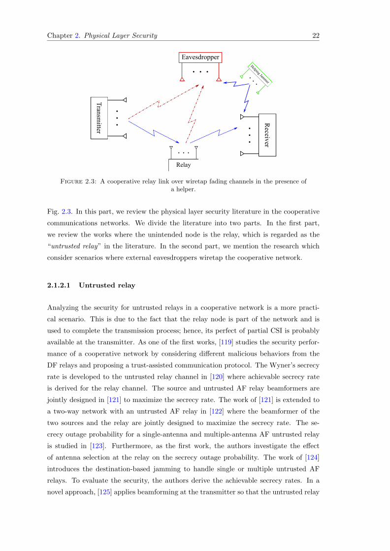
Chapter 2. Physical Layer Security 22
Eavesdropper
. . .
Relay
. . .
Helping Jammer. . .
Transm
itter
. .
.R
eceiver. .
.
Figure 2.3: A cooperative relay link over wiretap fading channels in the presence ofa helper.
Fig. 2.3. In this part, we review the physical layer security literature in the cooperative
communications networks. We divide the literature into two parts. In the first part,
we review the works where the unintended node is the relay, which is regarded as the
“untrusted relay” in the literature. In the second part, we mention the research which
consider scenarios where external eavesdroppers wiretap the cooperative network.
2.1.2.1 Untrusted relay
Analyzing the security for untrusted relays in a cooperative network is a more practi-
cal scenario. This is due to the fact that the relay node is part of the network and is
used to complete the transmission process; hence, its perfect of partial CSI is probably
available at the transmitter. As one of the first works, [119] studies the security perfor-
mance of a cooperative network by considering different malicious behaviors from the
DF relays and proposing a trust-assisted communication protocol. The Wyner’s secrecy
rate is developed to the untrusted relay channel in [120] where achievable secrecy rate
is derived for the relay channel. The source and untrusted AF relay beamformers are
jointly designed in [121] to maximize the secrecy rate. The work of [121] is extended to
a two-way network with an untrusted AF relay in [122] where the beamformer of the
two sources and the relay are jointly designed to maximize the secrecy rate. The se-
crecy outage probability for a single-antenna and multiple-antenna AF untrusted relay
is studied in [123]. Furthermore, as the first work, the authors investigate the effect
of antenna selection at the relay on the secrecy outage probability. The work of [124]
introduces the destination-based jamming to handle single or multiple untrusted AF
relays. To evaluate the security, the authors derive the achievable secrecy rates. In a
novel approach, [125] applies beamforming at the transmitter so that the untrusted relay

Chapter 2. Physical Layer Security 23
only receives the real valued part of the signal, whereas the receiver gets both the real
valued and imaginary valued parts of the signal. To perform a global optimization over
the cooperative network, [126] designs the precoder for the source, relay and destina-
tion. The authors consider a cooperative network with multiple-antenna nodes where
the relay is a potential eavesdropper. The precoding is applied at the source and relay
for message transmission and at the destination to jamm the relay such that the secrecy
rate is maximized.
2.1.2.2 Cooperative communication with external eavesdropper
As a extension to secrecy in broadcast wiretap channels, Wyner’s secrecy rate can be
analyzed in cooperative communications where the source/relay is being intercepted by
one or multiple eavesdroppers. Wyner’s secrecy rate concept was first extended to coop-
erative networks with external eavesdropper in [127]. The achievable rate-equivocation
region of the network is characterized when the relay transmits artificial noise. The
average secrecy outage probability is optimized in [128] for a cellular network with
multiple-antenna base station, relays, and eavesdropper where multiple single-antenna
users communicate with the base station. The work of [129] considers a cooperative
network consisting of multiple relays which are wiretapped by multiple eavesdroppers.
The relay weights are designed under total and individual power constraints to maxi-
mize the secrecy rate or null the information at the eavesdroppers. Upper and lower
bounds for the secrecy capacity of a diamond wiretap channel is derived in [130] where a
source communicates with a destination through two relays in the presence of an eaves-
dropper. As an application of full-duplex radios, [131] considers single-antenna source,
destinations, and eavesdroppers where they communicate through a multiple-antenna
full-duplex relay. The beamforming at the relay is designed to cancel self-interference
and satisfying different SINRs at the destination and eavesdroppers. Works [132, 133]
incorporate large arrays in cooperative networks and study the secrecy rate. A large
array MIMO relay is studied in [132] where it is powered by the signal from the source
and can freely change its location to improve the secrecy. The secrecy outage proba-
bility is derived for both AF and DF relaying protocols. A cooperative network with
single-antenna source and destination along with a large array relay is studied in [133].
The authors study the secrecy of AF and DF protocols at the relay in the presence of a
single-antenna eavesdropper. To move toward more practical scenarios, [134, 135] study
the robust design when the eavesdroppers’ imperfect CSI is available. The work of [134]
follows robust design to calculate the relay weights using the eavesdropper’s imperfect
CSI for a multiple relay cooperative network with single-antenna nodes in the presence
of a single-antenna eavesdropper. The work of [135] proposes a robust beamforming

Chapter 2. Physical Layer Security 24
design for a multiple-antenna relay using eavesdropper’s imperfect CSI to maximize the
secrecy rate. The secrecy analysis when the satellite works as a relay is studied in [22].
In this work, two users exchange messages using XOR network coding protocol while
each of them is being wiretapped by a specific eavesdropper. The authors derive the
satellite antenna weights to maximize the sun secrecy rate.
The effect of jamming and artificial noise in the secrecy of cooperative communications
is studied in [136–142]. The maximum number of eavesdropper for maintaining a secure
communication in a multiple relay cooperative network is studied in [136] where a set of
relay nodes are selected to transmit artificial noise in order to improve the secrecy rate.
The work of [137] studies the achievable secrecy rate in the cases where the relay performs
jamming or artificial noise generation from a known codebook to improve the secrecy
rate. A similar scenario as [127] is considered in [138] where the relay improves the
secrecy by jamming the eavesdropper. The authors derive the optimal power allocation
for the source and relay to maximize the secrecy rate. Cooperative jamming along with
interference aliment are used in [139] to improve the secrecy rate in a cooperative network
with multiple antenna nodes where the communication is wiretapped by a multiple-
antenna eavesdropper. Multiple scenarios where multiple relays perform AF, DF, or
jamming are considered in [179]. The authors derive the relay weights to maximize
the secrecy rate in the presence of one or more single-antenna eavesdroppers. The work
of [140] designs linear precoding and proposes using inactive DF relays of the cooperative
network as jammers to improve the secrecy where a multiple-antenna eavesdropper can
intercept the transmission in both hops. Similar as in [140], [141] considers cooperative
jamming by inactive nodes of a cooperative network consisting of multiple single-antenna
DF relays and single-antenna source and destination to counteract a single-antenna
eavesdropper. The authors propose optimal relay section and optimal power allocation
for signal transmission and jamming to improve the secrecy rate. As a usage of full-
duplex radios, a cooperative network including a full-duplex relay with the jamming
ability is considered in [142] to counteract a single-antenna eavesdropper.
As the relay selection can be used to improve the rate, it can be used to improve the
secrecy rate. Relay selection in cooperative networks to improve the secrecy is employed
in [143–148]. The authors of [143] propose relay selection and cooperative beamform-
ing to improve the secrecy. Optimal AF and DF relay selection is investigated in [144]
for a cooperative network with single-antenna nodes in the presence of single-antenna
eavesdropper. It is shown that the probability of interception for the proposed scheme
outperforms the conventional approach. Opportunistic relay selection in a cooperative
network with single-antenna nodes is employed in [145] to lower the probability of inter-
ception at the eavesdropper and outage probability at the destination. Relay selection

Chapter 2. Physical Layer Security 25
between multiple DF relays is carried out in [146] and the resulting secrecy rate is de-
rived. The authors in [147] consider a cooperative network consisting of multiple DF
relays and destinations. The relays perform collaborative beamforming to send the mes-
sage to the destination with the strongest link to the relays to maximize the secrecy
rate. The work of [148] considers a cooperative network with multiple AF relays and
users. The selected user jamms the transmission from source to relay and subtracts the
jamming after receiving the signal from the relay in order to improve the secrecy rate.
A part from two-hop cooperative networks, the secrecy rate in multi-hop networks is
studied in [149, 150, 150, 151]. A multi-hop cooperative network with full-duplex DF
relays is considered in [149] where a single-antenna eavesdropper wiretaps each hop. The
secrecy rate is evaluated when the relay receives the message and jamms the eavesdropper
at the same time. As another study in multi-hop relays, [150] performs security analysis
of a multi-hop DF relay network where the eavesdropper can wiretap all the hops.
The authors perform optimal power allocation/beamforming for single/multiple antenna
relay nodes to improve the secrecy rate. The work of [151] considers a cooperative
network with multiple AF relays with single-antennas nodes which is wiretapped by a
single-antenna eavesdropper. The authors derive the secrecy outage probability using
the CSI feedback.
Our contribution in [22] falls into the category of Cooperative communication with
external eavesdropper. The secrecy analysis when the satellite works as a relay is studied
in [22]. In this work, two users exchange messages using XOR network coding protocol
while each of them is being wiretapped by a specific eavesdropper. The authors derive
the satellite antenna weights to maximize the sun secrecy rate.
2.2 Signal Processing Paradigm for Security
In the information-theoretic secrecy rate, the perfect, imperfect, or statistical CSI knowl-
edge of the eavesdropper or specific assumptions on the eavesdropper’s CSI are required
at the transmitter. The transmitter uses these information to design the system pa-
rameters in order to maximize the secrecy rate. Moreover, when using the secrecy rate,
the secrecy rate is lower than the achievable rate of the channel. As an alternative, a
signal processing approach can be followed at the transmitter to improve the security.
Here, we divide these signal processing-based works into two groups. The first group
enhances the security by designing the precoding using the legitimate CSI. The second
group enhances the security by designing the precoding using both the legitimate CSI
and the symbols, which is referred to as “directional modulation”. In the following, we
mention these two groups.

Chapter 2. Physical Layer Security 26
2.2.1 Conventional precoding
As the first work, [152] mentions the concept of enhancing the security using artificial
noise, which deviates from the information-theoretic secrecy rate concept introduced by
Wyner [5]. This approach relys on the signal processing at the transmitter to design
the artificial noise in the null space of the legitimate receiver. One major advantage of
this technique is that the eavesdropper’s CSI is not required for the system design. In a
similar approach, the work of [153] designs a Robust beamformer in a MIMOME wiretap
channel. The beamformer is designed to maximize the jamming power, which is in the
null direction of the legitimate receiver, and sustains a predefined SINR at the legitimate
receiver without the eavesdropper’s CSI and imperfect CSI of the legitimate link. The
authors of [154] use the artificial noise in the null space of the legitimate channel to
prevent decoding at the eavesdropper over a MIMOME channel. The perfect secrecy is
achieved when the number of antennas of the legitimate receiver goes to infinity. Linear
precoding to transmit data and artificial noise is studied in [155] to improve the security
in a multi-cell environment without eavesdropper’s CSI where the number of antennas
and users increase asymptotically.
Although the Gaussian distribution is optimal when secrecy rate is the target, the Gaus-
sian distribution assumption for the signals cannot be always satisfied in practical com-
munication systems. There are digital communication systems which use finite-alphabet
signals such as M -PSK modulation which usually have a discrete uniform distribu-
tion [19]. Due to having a non-Gaussian distribution, finite-alphabet signals are not
optimal in terms of the developed secrecy rates in [5, 9–13]. Furthermore, although the
physical layer security concept introduced in [5] provides perfect secrecy, i.e., zero bit
leakage, it also reduces the message transmission rate to the legitimate receiver. There
have been research interests in investigating the security issues when finite-alphabet sig-
nal is used in a communication system [156, 157]. The authors in [156] devote some
of the available power in order to add a randomly scaled version of the finite-alphabet
data to itself to create induced fading without optimal beamforming and preserving the
phase of the symbol at the receiver. This way, the channel seen by the eavesdropper will
be different. If the added random part rotates the M -PSK constellation enough, the
eavesdropper decodes the wrong symbol. In [157], suboptimal random beamforming is
used to assure the security without requiring the eavesdropper channel state information
(CSI) when finite-alphabet signal is used.

Chapter 2. Physical Layer Security 27
2.2.2 Directional modulation via symbol-level precoding
Recently, there has been growing research interest on directional modulation technology
and its security enhancing ability for finite-alphabet input signals. As a pioneer, [17]
implements a directional modulation transmitter using a parasitic antenna. This system
creates the desired amplitude and phase in a specific direction by varying the length of
the reflector antennas for each symbol while scrambling the symbols in other directions.
The authors of [18] suggest using a phased array at the transmitter and employ a genetic
algorithm to derive the phase values of a phased array in order to create symbols in a
specific direction. The directional modulation concept is later extended to directionally
modulate symbols to more than one destination. In [158], the singular value decomposi-
tion (SVD) is used to directionally modulate symbols in a two user system. The authors
of [159] derive the array weights to create two orthogonal far field patterns to direction-
ally modulate two symbols to two different locations and [160] uses least-norm to derive
the array weights and directionally modulate symbols towards multiple destinations in
a multi-user multiple-input multiple-output (MIMO) system.
Array switching at the symbol rate is used in [161, 162, 176] to induce the desired symbols
without using actively driven elements, phase shifter and amplifier, in the RF chain. The
work of [161] uses an antenna array with a specific fixed delay in each RF chain to create
the desired symbols by properly switching the antennas. The authors in [162] use an
array where each element can switch to broadside pattern2, endfire pattern3, or off status
to create the desired symbols in a specific direction. Switched phased array to enhance
the security is proposed in [176].
In the second group, a parasitic antenna is used to create the desired amplitude and
phase in the far field by near field interactions between a driven antenna element and
multiple reflectors [17, 163, 164]. In [17, 163], transistor switches or varactor diodes are
used to change the reflector length or its capacitive load, respectively, when the channel
is line of sight (LoS). This approach creates a specific symbol in the far field of the an-
tenna towards the desired direction while randomizes the symbols in other directions due
to the antenna pattern change. In connection with [17], [164] studies the far field area
coverage of a parasitic antenna and shows that it is a convex region. The first group em-
ploys amplifiers and/or phases shifters to create an array with actively driven antennas
to directionally modulate the data [18, 27, 28, 158–160, 165–175], where [27, 158, 174]
consider fading channels. The authors of [18] use a genetic algorithm to derive the phase
values of a phased array and create symbols in a specific direction. The technique of [18]
is implemented in [165] using a four element microstrip patch array where symbols are
2Maximum radiation of an array directed normal to the axis of the array.3Additional maxima radiation directed along the axis.

Chapter 2. Physical Layer Security 28
directionally modulated for Q-PSK modulation. The authors of [166] propose an iter-
ative nonlinear optimization approach to design the array weights which minimizes the
distance between the desired and the directly modulated symbols in a specific direction.
In [167], baseband in-phase and quadrature-phase signals are separately used to excite
two different antennas so that symbols are correctly transmitted only in a specific di-
rection and scrambled in other directions. In another paradigm, [168] uses random and
optimized codebook selection, where the optimized selection suppresses large antenna
side lobes, in order to improve the security in a millimeter-wave large uniform linear an-
tenna array system. The authors of [169] derive optimal array weights to get a specific
bit error rate (BER) for Q-PSK modulation in the desired and undesired directions.
The work of [170] uses the Fourier transform to create the optimal constellation pattern
for Q-PSK directional modulation, while [171] uses the Fourier transforms along with
an iterative approach for Q-PSK directional modulation and constraining the far field
radiation patterns. The Fourier transform is used in [170, 171] to create the optimal
constellation pattern for Q-PSK directional modulation. In [158, 172–174] directional
modulation is employed along with noise injection. The authors of [172, 173] utilize an
orthogonal vector approach to derive the array weights in order to directly modulate
the data and inject the artificial noise in the direction of the eavesdropper. The work
of [172] is extended to retroactive arrays4 in [174] for a multi-path environment. An
algorithm including exhaustive search is used in [175] to adjust two-bit phase shifters
for directly modulating information. Since the location of the eavesdropper is unknown,
the transmitting angle of the interference is changed randomly. The directional mod-
ulation literature do not analyze the abilities of a multiple-antenna eavesdropper and
rely on the fact that it receives scrambled symbols. In addition, the works of [158, 173]
also transmit interference to degrade the signal quality at the eavesdropper. However,
depending on the eavesdropper’s number of antennas, it can remove the interference and
estimate the symbols. They show that compared to the conventional zero-forcing (ZF)
at the transmitter [23], directional modulation is more secure.
On top of the works in the directional modulation literature where antennas excita-
tion weight change on a symbol basis, the symbol-level precoding to create constructive
interference between the transmitted symbols has been developed in [180–183] by focus-
ing on the digital processing of the signal before being fed to the antenna array. The
main difference between directional modulation and the digital symbol-level precoding
for constructive interference is that the former focuses on applying array weights in
the analog domain such that the received signals on the receiving antennas have the
4A retroactive antenna can retransmit a reference signal back along the path which it was incidentdespite the presence of spatial and/or temporal variations in the propagation path.

Chapter 2. Physical Layer Security 29
desired amplitude and phase, whereas the latter uses symbol-level precoding for digi-
tal signal design at the transmitter to create constructive interference at the receiver.
Furthermore, directional modulation was originally motivated by physical layer security,
whereas symbol-level precoding by energy efficiency.
Our contributions in [27, 28] fall into the the category of directional modulation via
symbol-level precoding. In [27, 28], we design the array weights of a directional mod-
ulation transmitter in a single-user MIMO system to minimize the power consumption
while keeping the signal-to-noise ratio (SNR) of each received signal above a specific
level.
2.3 Conclusion
In this chapter, we reviewed the physical layer security literature by dividing it into
the works based on the keyless information-theoretic secrecy rate and signal processing
paradigms in Sections 2.1 and 2.2. The signal processing paradigm handles one of the
most important shortcomings of the keyless information-theoretic secrecy rate, which is
the requirement of the eavesdropper CSI at the transmitter, which may not be possible
to acquire in practice.
We divided the information-theoretic research into non-cooperative and cooperative cat-
egories in Sections 2.1.1 and 2.1.2. We further divided the secrecy rate analysis of the
non-cooperative category into: 1) wiretap broadcast channels, 2) broadcast with confi-
dential messages, 3) wiretap multiple access channels, and 4) secrecy rate and energy
efficiency. We divided the literature of the cooperative part into: 1) Untrusted relay, and
2) cooperative communication with external eavesdropper. The information-theoretic
secrecy rate literature considers the secrecy rate and the secrecy outage probability as
the security metric. These metrics along with the perfect, imperfect or partial CSI of
the legitimate and wiretap CSIs are used to design the transmitter, receiver, and/or the
relay, e.g., deriving the precoding at the transmitter.
The signal processing paradigm works were divided into two major categories: 1) con-
ventional precoding in Section 2.2.1, and 2) directional modulation via symbol-level
precoding in Section 2.2.2. In the conventional precoding literature, the transmitter is
designed only using the legitimate CSI knowledge. On the other hand, in the direc-
tional modulation via symbol-level precoding, the transmitter is designed using both
the symbols and the legitimate CSI. The directional modulation shows to outperform
the conventional precoding in terms of the imposed BER at the eavesdropper.


Chapter 3
Security in Bidirectional
Multi-beam Satellites
Network coding is an efficient means to improve the spectrum efficiency of satellite com-
munications. However, its resilience to eavesdropping attacks is not well understood.
This chapter studies the confidentiality issue in a bidirectional satellite network consist-
ing of two mobile users who want to exchange message via a multibeam satellite using
the XOR network coding protocol. We aim to maximize the sum secrecy rate by de-
signing the optimal beamforming vector along with optimizing the return and forward
link time allocation. The problem is non-convex, and we find its optimal solution using
semidefinite programming together with a 1-D search. For comparison, we also solve
the sum secrecy rate maximization problem for a conventional reference scheme without
using network coding. Simulation results using realistic system parameters demonstrate
that the bidirectional scheme using network coding provides considerably higher secrecy
rate compared to that of the conventional scheme. The contributions of this chapter are
published in [22].
3.1 Introduction
Satellite communications (SATCOM) is getting more and more integrated into communi-
cation networks to compliment the current terrestrial communication systems. Satellite
services have to support increasing demands for data transfer. To realize bidirectional
satellite communications, traditionally orthogonal resources either in frequency or time
domain should be used to avoid interference between users. To save the precious wireless
resources, network coding has been used in this work as an efficient protocol to exchange
information between two mobile satellite users. The basic principle is that the received
31

Chapter 3. Security in Bidirectional Multi-beam Satellites 32
information from users are combined on the satellite or gateway (GW), and then the
mixed signal is broadcast to users at the same time and using the same frequency. Be-
cause each user can subtract its own message, it can easily decode the message from the
other user.
However, due to the broadcast nature and immense area coverage, satellite commu-
nications systems, e.g., in military and commercial applications, are vulnerable to se-
curity attacks such as eavesdropping. Currently, security in SATCOM is achieved at
upper layers by means of encryption such as the Advanced Encryption Standard [1, 2].
Nevertheless, traditional security is based on the assumption of limited computational
capability of the malicious nodes, and thus there exists the risk that a malicious node
can successfully break an encryption, and get access to sensitive satellite data [3]. In
contrast to the upper layer encryption techniques, recently there has been significant
interest in securing wireless communications at the physical layer using an information-
theoretic approach named “secrecy rate” [5]. The main advantage of this approach is
that the malicious nodes cannot even get access to protected information regardless of
their computational capabilities.
While network coding can greatly improve the system throughput, whether it is more
secure than the conventional scheme, which does not use network coding, is largely
unknown in SATCOM. In this work, we will leverage the physical layer security approach
to address the confidentiality issue in bidirectional SATCOM using the principle of
network coding. Below, we provide an overview on the applications of network coding
to SATCOM and the related work in the physical layer security literature.
3.1.1 Literature Review
3.1.1.1 Network coding related works
Network coding technique, first introduced in [184], can considerably reduce delay, pro-
cessing complexity and power consumption, and can significantly increase the data rate
and robustness [185]. In the popular XOR network coding scheme, the received signals
at an intermediate node are first decoded into bit streams, and then XOR is applied on
the bit streams to combine them. The processed bits are re-encoded and then broadcast.
Utilization of network coding has been studied in both terrestrial and satellite networks.
The authors in [186] apply superposition coding and XOR network coding to a bidi-
rectional terrestrial relay network. A multi-group multi-way terrestrial relay network is
considered in [187] where superposition coding and XOR network coding are investigated
and compared to each other. Network coding can also considerably improve the spectral

Chapter 3. Security in Bidirectional Multi-beam Satellites 33
efficiency in bidirectional SATCOM in which two mobile users exchange information via
the satellite. The work in [188] compares the amplify-and-forward (AF) method with
the XOR network coding scheme in a satellite scenario. A joint delay and packet drop
rate control protocol without the knowledge of lost packets for mobile satellite using
network coding is studied in [189]. In [190], buffers are designed for satellites when the
network coding scheme is employed. Random linear network coding is used in [191] to
minimize the packet delivery time. Satellite beam switching for mobile users is tackled
in [192] where the network coding scheme increases the robustness in delivery of the
packets when mobile terminals move from beam to beam. The XOR network coding
protocol is demonstrated in a satellite test bed in [193].
3.1.1.2 Physical layer security related works
Wyner in [5] first showed that secure transmission is possible for the legitimate user given
the eavesdropper receives noisier data compared to the legitimate receiver. Inspired by
Wyner’s work, [10] extended the idea of physical layer secrecy rate from the discrete
memoryless wiretap channel to Gaussian wiretap channel. The Wyner’s wiretap channel
was generalized in [9] to the broadcast channel. After the seminal works done in [5, 9, 10],
there have been substantial amount of works in physical layer secrecy. Here, we only
review those most relevant to network coding and bidirectional communications. The
authors in [194] consider a relay utilizing the XOR network coding protocol where joint
relay and jammer selection is done to enhance the secrecy rate. A bidirectional AF relay
network with multiple-antenna nodes is considered in [195] where the relay beamforming
vector is designed by the waterfilling method to improve the secrecy rate. The authors
in [196] consider random relay selection in a bidirectional network in which the relay
performs both data transmission and jamming the eavesdropper at the same time to
increase the secrecy. The work in [139] performs selection over AF relays and jammers
in a bidirectional network for the single-antenna case, and precoding in the multiple-
antenna case to enhance the secrecy. To maximize the secrecy in a bidirectional network,
the authors in [197] consider the location and distribution of nodes while joint relay and
jammer selection is performed. Distributed beamforming along with artificial noise
and beamforming is studied in [198] for a bidirectional AF relay network. The work
in [199] designs the distributed beamforming weights for a bidirectional network where
one intermediate node acts as a jammer. In contrast to the terrestrial literature, there are
very few works in physical layer security for SATCOM. The problem of minimizing the
transmit power on a multibeam satellite while satisfying a minimum per user secrecy rate
is studied in [200]. Iterative algorithms are used to joint optimize the transmission power
and the beamforming vector by perfectly nulling the received signal at the eavesdropper.

Chapter 3. Security in Bidirectional Multi-beam Satellites 34
Both optimal and suboptimal solutions are developed in [201] where the use of artificial
noise is also studied.
Despite the physical layer security and network coding works in the terrestrial and
SATCOM scenarios, some unaddressed issue are left. In [186], only downlink bottlenecks
are considered when designing the beamforming weights for the XOR network coding
case. The uplink bottlenecks also need to be considered when optimizing the uplink-
downlink time allocation. In [187], the authors consider the decoding-re-encoding and
designing the beamforming vector separately. The works in [196, 197] consider single-
antenna relay where the AF protocol is used in a bidirectional network. The authors
in [195, 198, 199] use the analog network coding protocol in a two-way relay network to
facilitate secure information exchange between two users. Furthermore, the mentioned
terrestrial works in physical layer security for bidirectional communications assume one
eavesdropper in the environment. The works in [200, 201] design the beamforming
weights for unidirectional service for fixed users in the forward link (FL).
3.1.2 Our Contribution
In this work, we study the network coding based bidirectional SATCOM in which two
mobile users exchange data via a transparent multibeam satellite in the presence of
two eavesdroppers. There is an eavesdropper present for each user who overhears the
bidirectional communications. The users employ omnidirectional antennas and the com-
munication is prone to eavesdropping in both the return link (RL) and FL. In the RL,
two users send signals using two orthogonal frequency channels; the signals collected
by the satellite are passed to the GW, where they are decoded, XOR-ed and then the
produced stream is re-encoded. This combined stream is multiplied by the beamforming
vector which contains the designed weight of each feed. Consequently, each element of
the resultant vector is transmitted to the satellite using the feeder link. Each element
which includes both the feed weight and the data signal is applied to the corresponding
feed to adjust the beams for broadcasting to both users simultaneously in the FL. This
scheme is more power-efficient than the conventional method where network coding in
not utilized and the power is splitted into two data streams. This benefit is extremely
vital for SATCOM because of the limited on-board power.
Our main contributions in this work are summarized below to differentiate it from the
prior work:
1. XOR network coding is incorporated into SATCOM in to enable both efficient and
secure bidirectional data exchange.

Chapter 3. Security in Bidirectional Multi-beam Satellites 35
2. The end-to-end sum secrecy rate is first derived, and then maximized by designing
the optimal beamforming vector and the RL and FL time allocation. The opti-
mization problem regarding the beamforming vector is solved using semi-definite
programming (SDP) along with 1-D search.
3. Extensive simulation results are presented to demonstrate the advantage of the
bidirectional scheme over the conventional scheme using realistic SATCOM pa-
rameters.
3.2 System Model
Consider a satellite communication system comprised of two users denoted by U1 and
U2 who exchange information with each other, one multibeam transparent satellite de-
noted by S, one GW, two eavesdroppers denoted by E1 and E2 as depicted in Fig. 4.1.
Users are located in different beams of the satellite, and they transmit the RL signals
using different frequency channels simultaneously. We assume that each user and each
eavesdropper is equipped with a single omni-directional antenna. Because of the long
distance between the users, there is no direct link between them; furthermore, eaves-
droppers cannot cooperate and Ei can only overhear Ui for i = 1, 2. Contemporary
orbiting satellites such as ICO, SkyTerra, and Thuraya have limited power, here de-
fined as PS , and some of them do not have the on-board processing ability to decode
the received messages or perform on-board beamforming, so they have to forward the
received signal to the GW to get it processed [202–204]. Using the GW to process the
signal and designing the feed weights is referred to as the ground-based beamforming
technique. The ground-based beamforming technique is perceived as the most conve-
nient and economical approach [204]. In this chapter, we consider a commercial satellite
without digital processing ability and follow the ground-based beamforming paradigm.
In our satellite network model, we assume that the eavesdropper is a regular user which
is part of the network. However, it is considered as an unintended user, potential eaves-
dropper, which the information needs to be kept secret from it. Due to the fact that
the eavesdropper is part of the network, it is possible to estimate the channels to it.
Hence, similar to the works [20, 42, 179, 205, 206], we assume that the eavesdropper’s
channel state information (CSI) is known. Based on the mentioned assumption, we as-
sume that the users and eavesdropper know all the CSIs. Further, all communication
channels are known and fixed during the period of communication. It is worth men-
tioning that in the secrecy rate analysis of XOR network coding, only the CSI of the
eavesdroppers in the RL is required. Although we assume the availability of the eaves-
dropper’s CSI, there are methods such as null-space artificial noise transmission [207],

Chapter 3. Security in Bidirectional Multi-beam Satellites 36
random beamforming [51, 157, 208], or effective channel coding design to strengthen
the cryptography [209] in order to sustain secrecy without having the knowledge of the
eavesdropper’s CSI. Another alternative can be using the statistical knowledge of the
eavesdropper’s CSI in order to improve the secrecy [210–213]. Also, the interference
alignment technique can be used along with statistical knowledge of the eavesdropper’s
CSI to enhance the secrecy [95]. In the situations when the geographical area of the
eavesdropper is known, the worst-case scenario can be considered. In this scenario, the
best CSI from the user to the eavesdropper’s area is considered for the design. One pos-
sible example for the worst-case scenario can be when the occupied zone by the enemy
is known. This example can be one of the applications of this chapter.
To acquire the RL channel state information (CSI) at the GW, the users send the pilot
signals along with the data toward the satellite. For the FL CSI, the GW sends pilots
to the users. Afterwards, the estimated CSI by the users is sent back to the GW.
Therefore, getting the FL CSI takes more time compared to the RL CSI [214]. The
GWs are equipped with advanced transceivers and antennas and because of this reason,
the communication link between the GW and the satellite (feeder link) is modeled as
an ideal link. Hence, similar to the works [203, 215–218] which are carried out in the
satellite communications literature, we assume that the channel between the satellite
and the GW, which is referred to as the feeder link, is ideal with abundant bandwidth.
The complete communication phases of the network coding based scheme are summa-
rized in Table 3.1. The conventional scheme without using network coding is also in-
cluded for comparison and details are given in Section 3.2.2. The first two phases for the
RL are the same for both schemes while the main difference lies in the FL transmission.
In the conventional scheme, signals are sent in different time slots for each user in the
FL, so this scheme has less available transmission time for each user. In the bidirectional
scheme, signal streams are combined, and then sent in the FL using the XOR network
coding protocol, therefore, the spectral efficiency is significantly improved compared to
the conventional scheme.
3.2.1 Network coding based bidirectional SATCOM
3.2.1.1 Signal model
In this case, the whole communication takes place in four phases. In Phase I, both users
transmit signals using different frequencies simultaneously. The signals received at the
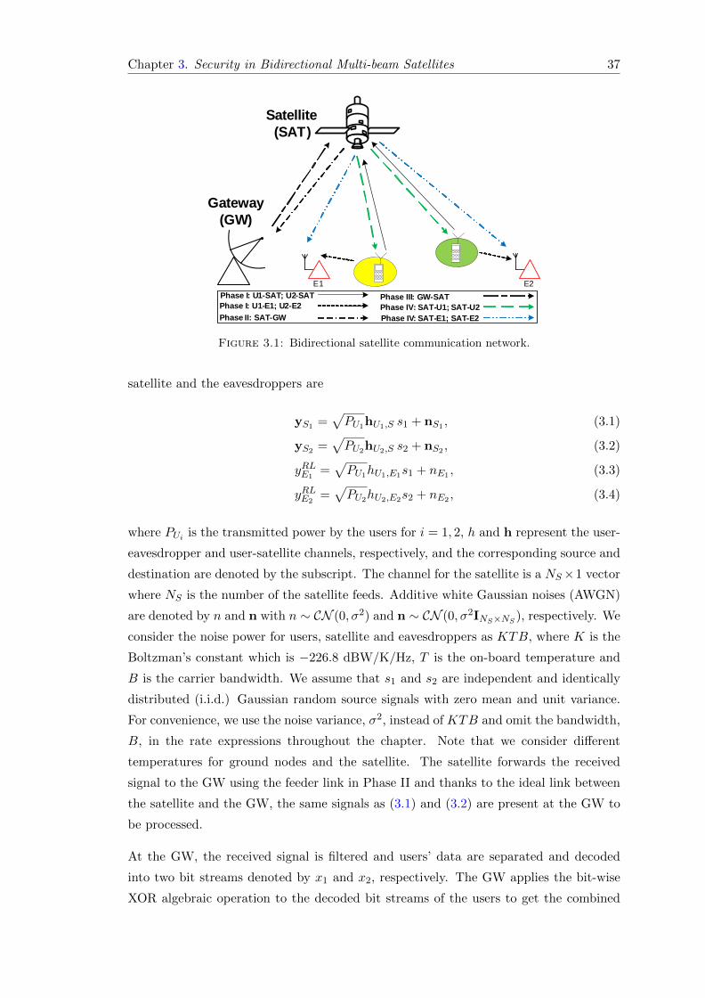
Chapter 3. Security in Bidirectional Multi-beam Satellites 37
Gateway(GW)
Satellite (SAT)
Phase I: U1-E1; U2-E2 Phase I: U1-SAT; U2-SAT
E1
Phase II: SAT-GW
Phase III: GW-SATPhase IV: SAT-U1; SAT-U2Phase IV: SAT-E1; SAT-E2
E2
Figure 3.1: Bidirectional satellite communication network.
satellite and the eavesdroppers are
yS1 =√PU1hU1,S s1 + nS1 , (3.1)
yS2 =√PU2hU2,S s2 + nS2 , (3.2)
yRLE1=√PU1hU1,E1s1 + nE1 , (3.3)
yRLE2=√PU2hU2,E2s2 + nE2 , (3.4)
where PUi is the transmitted power by the users for i = 1, 2, h and h represent the user-
eavesdropper and user-satellite channels, respectively, and the corresponding source and
destination are denoted by the subscript. The channel for the satellite is a NS×1 vector
where NS is the number of the satellite feeds. Additive white Gaussian noises (AWGN)
are denoted by n and n with n ∼ CN (0, σ2) and n ∼ CN (0, σ2INS×NS ), respectively. We
consider the noise power for users, satellite and eavesdroppers as KTB, where K is the
Boltzman’s constant which is −226.8 dBW/K/Hz, T is the on-board temperature and
B is the carrier bandwidth. We assume that s1 and s2 are independent and identically
distributed (i.i.d.) Gaussian random source signals with zero mean and unit variance.
For convenience, we use the noise variance, σ2, instead of KTB and omit the bandwidth,
B, in the rate expressions throughout the chapter. Note that we consider different
temperatures for ground nodes and the satellite. The satellite forwards the received
signal to the GW using the feeder link in Phase II and thanks to the ideal link between
the satellite and the GW, the same signals as (3.1) and (3.2) are present at the GW to
be processed.
At the GW, the received signal is filtered and users’ data are separated and decoded
into two bit streams denoted by x1 and x2, respectively. The GW applies the bit-wise
XOR algebraic operation to the decoded bit streams of the users to get the combined

Chapter 3. Security in Bidirectional Multi-beam Satellites 38
Table 3.1: Communication stages for the XOR network coding and the conventionalschemes.
Conventional referencescheme
XOR network codingscheme
Phase I: U1 and U2 simultaneously send their signals,s1 and s2, to the satellite while they are overheardby E1 and E2, respectively.
Phase II: The satellite passes the received signal tothe GW for processing. At the GW, the users’ signalsare separately decoded.
Phase III: The intendedsignal for U1, decodeds2, is re-encoded at theGW and the correspond-ing feed weights are de-signed. Then, the feedweights multiplied by thedata signal are sent to thesatellite.
Phase III: The GW ap-plies XOR operation onthe decoded streams froms1 and s2 to create amerged stream of bits andthe feed weights are de-signed. Then, the feedweights multiplied by thedata signal are sent to thesatellite.Phase IV: The satellite
passes the re-encoded sig-nal through the corre-sponding beam to U1
while E1 is listening to it.
Phase V: The intendedsignal for U2, decodeds1, is re-encoded at theGW and the correspond-ing feed weights are de-signed. Then, the feedweights multiplied by thedata signal are sent backto the satellite.
Phase IV: The satellitebroadcasts the mergedstream toward the usersthrough the correspond-ing beams which is wire-tapped by both E1 andE2.
Phase VI: The satellitepasses the re-encoded sig-nal through the corre-sponding beam to U2
while E2 is listening to it.
stream
xGW = x1 ⊕ x2. (3.5)
Note that before applying the XOR network coding, the GW uses zero-padding to add
zeros to the shorter bit stream in order to make equal length bit streams out of the
two different bit streams sent by the users [219, 220]. In Phase III, xGW is encoded
into sGW with unit power, and then multiplied by the beamforming vector, w. Using
the ideal feeder link, each element, wisGW (t), of the produced vector, wsGW , at the
GW which both includes the feed weight, wi, and the data signal, sGW , is transmitted
from the GW to the satellite. Since the codebook used at the GW to encode xGW can

Chapter 3. Security in Bidirectional Multi-beam Satellites 39
be different in the XOR network coding scheme, the RL and FL transmission times
are generally different for the XOR network coding. This enables optimum RL and
FL time allocation for the XOR network coding. The received signal by satellite is
denoted as sS = HGW,SwsGW . The model sS = HGW,SwsGW encapsulates the process
of transmitting each element of the vector wsGW from the GW to the satellite. Since
the feeder link is considered to be ideal, HGW,S is a NS ×NS identity matrix. Finally,
in Phase IV, each feed weight designed at the GW, which includes the data signal, is
applied to the corresponding feed at the satellite. Hence, the beams are adjusted and
the signal sS is broadcast through the antennas. The received signals at two users are,
respectively,
yFLXORU1= hTS,U1
sS + nU1 , (3.6)
yFLXORU2= hTS,U2
sS + nU2 . (3.7)
Similarly, the received signals at the eavesdroppers in Phase IV are, respectively,
yFLXORE1= hTS,E1
sS + nE1 , (3.8)
yFLXORE2= hTS,E2
sS + nE2 . (3.9)
In the following, we shall define the sum secrecy rate. We first introduce the users’ rates
and eavesdroppers’ channel capacities.
3.2.1.2 Users’ RL rates
Consider t1 and t2 for the RL (Phase I) and FL (Phase IV) transmission time, re-
spectively. In Phase I, we can characterize the RL rates (RRLU1, RRLU2
) by the following
equations [221, Chapter 5]:
RRLU1≤ IRLU1
= t1 log
(1 +
PU1
∥∥hU1,S
∥∥2
σ2S
)(3.10)
RRLU2≤ IRLU2
= t1 log
(1 +
PU2
∥∥hU2,S
∥∥2
σ2S
), (3.11)
where I denotes channel capacity or the maximum supported rate and R is the maximum
achievable rate.

Chapter 3. Security in Bidirectional Multi-beam Satellites 40
3.2.1.3 Users’ FL rates
After receiving the FL signal, users decode sS . As each user knows its own transmitted
bits, it can use the XOR operation to retrieve the intended bits. Subsequently, using (3.6)
and (3.7), the FL rates can be expressed as
RFLXOR = min{IFLXORU1
, IFLXORU2
}, (3.12)
IFLXORU1= t2 log
(1 +|hTS,U1
w|2
σ2U1
), (3.13)
IFLXORU2= t2 log
(1 +|hTS,U2
w|2
σ2U2
). (3.14)
Since the data for both users have gone through a bit-wise XOR operation at the GW
and a combined signal is broadcast, the GW has to adjust the combined signal’s data
rate to match both users’ channel capacities. This rate should be equal to the minimum
FL channel rate between the satellite and the users in Phase IV before sending sS to
the satellite.
3.2.1.4 Eavesdroppers’ channel capacities
Using (3.3) and (3.8), the channel capacity from U1 to E1, IRLE1, and from satellite to
E1, IFLXORE1, can be expressed, respectively, as
IRLE1= t1 log
(1 +
PU1 |hU1,E1 |2
σ2E1
), (3.15)
IFLXORE1= t2 log
(1 +|hTS,E1
w|2
σ2E1
). (3.16)
The channel capacities for E2 can be derived in a similar way.
3.2.1.5 Secrecy rate definition
First, we derive the secrecy rate for the RLs and FLs, and then the end-to-end secrecy
rate. In [13], the result of [5] is extended to fading channels with multiple-antenna
transmitter, receiver, and eavesdropper. Using the special case of the result in [13] for
single-antenna transmitter, multiple-antenna receiver, and single-antenna eavesdropper
along with employing (3.10) and (3.15), the secrecy rate for the RL of U1 is calculated

Chapter 3. Security in Bidirectional Multi-beam Satellites 41
as
SRRLU1= IRLU1
− IRLE1, (3.17)
where the notation “SR” means “secrecy rate”. To calculate the secrecy rate in the
FL, first, we derive the information that E1 can recover during the RL transmission in
Lemma 3.1.
Lemma 3.1. Independent of getting a positive or zero secrecy rate defined for the RL
of U1 in (3.17), E1 cannot recover any bits from U2 transmitted message using the FL
transmission.
Proof. To recover bits from U2, E1 has to apply XOR operation between the bits recov-
ered from U1 in the RL transmission and the bits derived from the satellite broadcast
in the FL transmission. Hence, the information detected by E1 in the FL depends on
the bits recovered from U1 in the RL transmission. The recovered bits from U1 in the
RL depend on the sign of the secrecy rate defined in (3.17). The sign of the RL secrecy
rate in (3.17) has the following possibilities:
1. If IRLU1− IRLE1
> 0, then U1 can establish a perfectly secured connection so that the
eavesdropper cannot get any bits from U1 in the RL [13]. Hence, E1 does not have
the bits transmitted by U1 in the RL and it cannot recover any bits from U2 using
the FL transmission.
2. If IRLU1− IRLE1
≤ 0, then the secrecy rate is zero. Therefore, U1 cannot establish a
secure connection in the RL. In this case, U1 remains silent during the correspond-
ing time slot. In this time slot, GW generates random bits instead of the bits from
U1 and applies XOR between them and the bits from U2. As a result, E1 cannot
recover any bits from U2 using the FL transmission.
Note that since the RL time, t1, is always positive and all the channels are known, the
sign of the expression IRLU1− IRLE1
is known prior to the beamformer design.
A similar argument as in Lemma 3.1 can be applied to E2. Consequently, using
Lemma 3.1, the secrecy rate for the FL is given in Lemma 3.2.
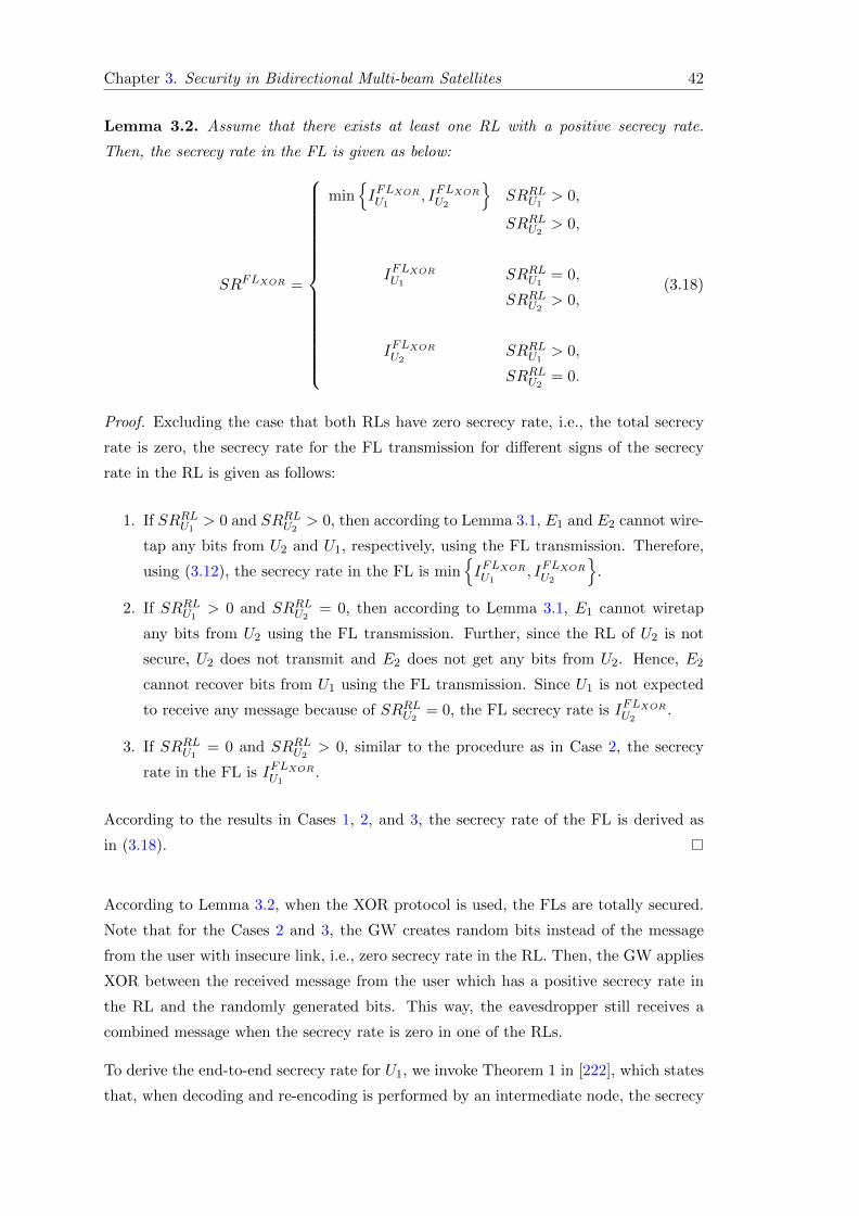
Chapter 3. Security in Bidirectional Multi-beam Satellites 42
Lemma 3.2. Assume that there exists at least one RL with a positive secrecy rate.
Then, the secrecy rate in the FL is given as below:
SRFLXOR =
min{IFLXORU1
, IFLXORU2
}SRRLU1
> 0,
SRRLU2> 0,
IFLXORU1SRRLU1
= 0,
SRRLU2> 0,
IFLXORU2SRRLU1
> 0,
SRRLU2= 0.
(3.18)
Proof. Excluding the case that both RLs have zero secrecy rate, i.e., the total secrecy
rate is zero, the secrecy rate for the FL transmission for different signs of the secrecy
rate in the RL is given as follows:
1. If SRRLU1> 0 and SRRLU2
> 0, then according to Lemma 3.1, E1 and E2 cannot wire-
tap any bits from U2 and U1, respectively, using the FL transmission. Therefore,
using (3.12), the secrecy rate in the FL is min{IFLXORU1
, IFLXORU2
}.
2. If SRRLU1> 0 and SRRLU2
= 0, then according to Lemma 3.1, E1 cannot wiretap
any bits from U2 using the FL transmission. Further, since the RL of U2 is not
secure, U2 does not transmit and E2 does not get any bits from U2. Hence, E2
cannot recover bits from U1 using the FL transmission. Since U1 is not expected
to receive any message because of SRRLU2= 0, the FL secrecy rate is IFLXORU2
.
3. If SRRLU1= 0 and SRRLU2
> 0, similar to the procedure as in Case 2, the secrecy
rate in the FL is IFLXORU1.
According to the results in Cases 1, 2, and 3, the secrecy rate of the FL is derived as
in (3.18).
According to Lemma 3.2, when the XOR protocol is used, the FLs are totally secured.
Note that for the Cases 2 and 3, the GW creates random bits instead of the message
from the user with insecure link, i.e., zero secrecy rate in the RL. Then, the GW applies
XOR between the received message from the user which has a positive secrecy rate in
the RL and the randomly generated bits. This way, the eavesdropper still receives a
combined message when the secrecy rate is zero in one of the RLs.
To derive the end-to-end secrecy rate for U1, we invoke Theorem 1 in [222], which states
that, when decoding and re-encoding is performed by an intermediate node, the secrecy

Chapter 3. Security in Bidirectional Multi-beam Satellites 43
rate of each hop needs to be taken into account as a bottleneck to derive the end-to-end
secrecy rate. Since decoding and re-encoding is performed at the GW, the result of
Theorem 1 in [222] can be applied. Consequently, using the mentioned theorem and
the secrecy rate derived in (3.17) and the result of Lemma 3.2 in (3.18), the end-to-end
secrecy rate for U1 is calculated by
SRXORU1= min
{SRRLU1
, SRFLXORU1
}. (3.19)
The end-to-end secrecy rate for U2 can be derived in a similar way. The sum end-to-end
secrecy rate is expressed as
SRXOR = SRXORU1+ SRXORU2
. (3.20)
3.2.2 Conventional SATCOM
A conventional scheme without using network coding is described here as a performance
benchmark.
3.2.2.1 Signal model
As shown in Table 3.1, the Phases I and II are the same for the conventional and the
XOR network coding schemes, which result in the same signal model for both schemes.
In Phases III and V, the GW sends back each element of the processed s2 and s1 to
the satellite, respectively, using the ideal feeder link where s1 and s2 are NS × 1 vectors
containing both the feed weights and the users’ data signals. s1 and s2 are defined as
s1 = w1s1 and s2 = w2s2, where s1 and s2 are the decoded and re-encoded versions of
the data signals received from U1 and U2 at the GW with unit power, and w1 and w2
are beamforming vectors to be designed at the GW. Note that since different Gaussian
codebooks are used at the GW to re-encode the signals for U1 and U2, the generated
signals at the GW are different from those received from the users. Therefore, generated
signals at the GW are shown by s1 and s2.
The satellite applies each component of the vector s2, containing the feed weight multi-
plied by the data signal, to the corresponding feed. Then, the beam is adjusted and s2
is sent toward U1 in Phase IV, and the received signals at U1 and E1 are, respectively,
yFLConU1= hTS,U1
s2 + nU1 , (3.21)
yFLConE1= hTS,E1
s2 + nE1 . (3.22)

Chapter 3. Security in Bidirectional Multi-beam Satellites 44
Similarly, at the end of Phase VI, the received signals at U2 and E2 are, respectively,
yFLConU2= hTS,U2
s1 + nU2 , (3.23)
yFLConE2= hTS,E2
s1 + nE2 . (3.24)
The beamformer weights in the conventional scheme are exclusively designed at the
GW for each user. Hence, when data is being transmitted for U1, the satellite’s main
lobe is focused toward U1. Since E2 is outside the beam directed toward U1 and the
beamformers are designed to maximize the signal strength toward U1, E2 receives the
signal from side lobes. As a result, the signal received by E2 is weak. Similar conditions
hold for E1 when transmitting to U2. To make the derivation tractable, we neglect these
weak signals received by E2 and E1 in Phases IV and VI, respectively. As a result, the
sum secrecy rate derived for the conventional scheme shall be an upper-bound.
3.2.2.2 Users’ rates
The RL rates for the conventional SATCOM are the same as the XOR network coding
scheme in (3.10) and (3.11). Using (3.21) and (3.23), the FL rates to U1 and U2 after
self-interference cancellation can be derived, respectively, as
IFLConU1= t2 log2
1 +
∣∣∣hTS,U1w2
∣∣∣2σ2U1
, (3.25)
IFLConU2= t3 log2
1 +
∣∣∣hTS,U2w1
∣∣∣2σ2U2
. (3.26)
In order to make the conventional method comparable to the bidirectional one, we
assume that the total available transmission time for both the network coding and the
conventional schemes are the same. In other words, the RL time for the users is t1 and
the FL for U1 and U2 are t2 and t3 = 1− t1 − t2, respectively.
3.2.2.3 Eavesdroppers’ channel capacities
The RL capacities for E1 and E2 in the conventional SATCOM are the same as the ones
derived for the XOR network coding scheme. Using (3.22) and (3.24), the FL capacity
from the satellite toward E1 and E2 to overhear the signals sent in Phases IV and VI,

Chapter 3. Security in Bidirectional Multi-beam Satellites 45
respectively, are
IFLConE1= t2 log2
1 +
∣∣∣hTS,E1w2
∣∣∣2σ2E1
, (3.27)
IFLConE2= t3 log2
1 +
∣∣∣hTS,E2w1
∣∣∣2σ2E2
. (3.28)
3.2.2.4 Secrecy rate definition
The RL secrecy rate for U1 and U2 are the same as the XOR network coding scheme
in Section 3.2.1.5. In the conventional scheme, the messages that E1 receives in the RL
and FL are different and can be decoded independently. Hence, the FL secrecy rate for
U1 can be defined using (3.25), (3.27) and the result from [13] as
SRFLConU1= IFLConU1
− IFLConE1. (3.29)
Utilizing (3.17), (3.29), and Theorem 1 in [222], the end-to-end secrecy rate for U1 is
derived as
SRConU1= min
{SRRLU1
, SRFLConU2
}. (3.30)
The end-to-end secrecy rate for U2 can be defined in a similar way. Like in Section 3.2.1.5,
the sum secrecy rate is
SRCon = SRConU1+ SRConU2
. (3.31)
3.3 Problem Formulation and the Proposed Solution
In this section, we study the problem of maximizing the sum secrecy rate by optimizing
the precoding vectors at the GW to shape the satellite beams along with the RL and
FL time allocation, given the maximum available power PS at the satellite. We consider
both the XOR network coding and the conventional schemes. For the XOR network
coding, we just solve the optimal beamformer design for the secrecy rate derived from
the first case of the FL secrecy rate in (3.18). The solutions for the optimal beamformer
design for the other two cases of (3.18) are similar to the first case of (3.18).

Chapter 3. Security in Bidirectional Multi-beam Satellites 46
3.3.1 Network coding for bidirectional SATCOM
Using the sum secrecy rate defined in (3.20), the optimization problem for the XOR
network coding scheme is defined as
maxw,t1,t2
min{IRLU1− IRLE1
,min{IFLXORU1
, IFLXORU2
}}+ min
{IRLU2− IRLE2
,min{IFLXORU1
, IFLXORU2
}}s.t. t1 + t2 = 1,
‖w‖2 ≤ PS . (3.32)
To transform (3.32) into a standard convex form, we apply the following procedures.
First, we assume that t1 and t2 are fixed and study the beamforming design. After
designing the optimal beamformer, the optimal time allocation is found by performing
1-D search of t1 over the range (0, 1). Second, after considering a fixed transmission
time for the RL and FL, the RL secrecy rate expressions in (3.32) are fixed and can be
dropped without loss of generality. Hence, (3.32) boils down into
maxw
min{IFLXORU1
, IFLXORU2
}s.t. ‖w‖2 ≤ PS . (3.33)
Next, we introduce the auxiliary variable u to remove the “min” operators. Then, (3.33)
yields
maxw,u>0
u
s.t. ‖w‖2 ≤ PS ,
σ2U1
(2ut2 − 1
)≤∣∣hTS,U1
w∣∣2,
σ2U2
(2ut2 − 1
)≤∣∣hTS,U2
w∣∣2. (3.34)
The last two constraints in (3.34) are not convex. By introducing W = wwH , we
rewrite (3.34) as
maxW�0,u>0
u
s.t. tr (W) ≤ PS ,
σ2U1
(2ut2 − 1
)≤ tr (WA) ,
σ2U2
(2ut2 − 1
)≤ tr (WB) , (3.35)

Chapter 3. Security in Bidirectional Multi-beam Satellites 47
where A = h∗S,U1hTS,U1
and B = h∗S,U2hTS,U2
. The rank constraint, rank (W) = 1,
in (3.35) is dropped. The optimal beamforming weight in (3.35) is designed for the FL
transmission. However, since the RL secrecy rates, which can be bottlenecks for the
total end-to-end secrecy rate, are not considered in (3.35), extra unnecessary power at
the satellite may be utilized. To fix this, one last constraint is added to (3.35) to get
maxW�0,u>0
u
s.t. tr (W) ≤ PS ,
σ2U1
(2ut2 − 1
)≤ tr (WA) ,
σ2U2
(2ut2 − 1
)≤ tr (WB) ,
u ≤ max{IRLU1− IRLE1
, IRLU2− IRLE2
}. (3.36)
Problem (3.36) is recognized as a SDP problem, thus convex and can be efficiently
solved. According to Theorem 2.2 in [223], when there are three constraints on the
matrix variable of a SDP problem such as (3.36), existence of a rank-1 optimal solution
for NS > 2 is guaranteed. Hence, if the solution to (3.36) happens not to be rank-
one, we can use Theorem 2.2 in [223] to recover the rank-one optimal solution out of a
non-rank-1 solution. According to [224], the complexity of problem (3.36) is
O
(3 +N2S
)(N2S
(N2S + 1
)2
)3 . (3.37)
Solving (3.36) is accompanied along with a 1-D exhaustive search over the time variable
t. We assume that the time variable is divided into m bins between 0 and 1. The overall
computational complexity for designing the beamformer for the XOR network coding
scheme is m times the complexity mentioned in (3.37). This is typically affordable since
the optimization is performed at the GW on the ground.
3.3.2 Conventional SATCOM
According to the secrecy rate defined in (3.31), the optimization problem for the con-
ventional scheme is
maxw1,w2,t1,t2
min{IRLU1− IRLE1
, IFLConU2− IFLConE2
}+ min
{IRLU2− IRLE2
, IFLConU1− IFLConE1
}s.t. ‖w1‖2 + ‖w2‖2 ≤ PS . (3.38)

Chapter 3. Security in Bidirectional Multi-beam Satellites 48
Assume that the power split between the beamforming vectors w1 and w2 is βPS and
(1− β)PS where β is a given parameter with 0 ≤ β ≤ 1. Using the parameter β, the
beamforming vectors w1 and w2 in the power constraint of (3.38) can be separated.
Hence, (3.38) can be rewritten as
maxw1,w2,t1,t2
min{IRLU1− IRLE1
, IFLConU2− IFLConE2
}+ min
{IRLU2− IRLE2
, IFLConU1− IFLConE1
}s.t. ‖w1‖2 ≤ βPS ,
‖w2‖2 ≤ (1− β)PS . (3.39)
The problem (3.39) can be expanded as
maxw1,w2,t1,t2
min
{SRRLU1
, t2 log
(σ2E2
σ2U2
σ2U2
+ |hTS,U2w1|2
σ2E2
+ |hTS,E2w1|2
)}
+ min
{SRRLU2
, t3 log
(σ2E1
σ2U1
σ2U1
+ |hTS,U1w2|2
σ2E1
+ |hTS,E1w2|2
)}s.t. ‖w1‖2 ≤ βPS ,
‖w2‖2 ≤ (1− β)PS . (3.40)
Before further simplifying (3.40), we first mention the following theorem.
Theorem 3.3. If the achievable secrecy rate is strictly greater than zero, the power
constraints in (3.40) are active at the optimal point w?1 and w?
2, i.e., ‖w1‖2 = βPS and
‖w2‖2 = (1− β)PS.
Proof. The proof is given in Appendix A.
Using Theorem 3.3, we can show that the constraints in (3.40) are active which enables
us to write (3.40) as
maxw1,w2,t1,t2
min
{IRLU1− IRLE1
, t2 log
(σ2E2
σ2U2
wH1 U2w1
wH1 E2w1
)}
+ min
{IRLU2− IRLE2
, t3 log
(σ2E1
σ2U1
wH2 U1w2
wH2 E1w2
)}s.t. ‖w1‖2 = βPS ,
‖w2‖2 = (1− β)PS , (3.41)
where U1 ,σ2U1
(1−β)PSI+h∗S,U1
hTS,U1,U2 ,
σ2U2βPS
I+h∗S,U2hTS,U2
,E1 ,σ2E1
(1−β)PSI+h∗S,E1
hTS,E1,E2 ,
σ2E2βPS
I + h∗S,E2hTS,E2
. The benefit of (3.41) is that given β, w1 and w2 can be optimized

Chapter 3. Security in Bidirectional Multi-beam Satellites 49
separately. To be specific, the optimal w1 and w2 corresponds to the eigenvectors asso-
ciated with the maximum eigenvalues of matrices C = L−11 U1L
−H1 and D = L−1
2 U2L−H2
where E1 = L1LH1 and E2 = L2L
H2 , respectively. As a result, (3.41) can be simplified
into
max0<t1<10<t2<1
min
{IRLU1− IRLE1
, t2 log
(σ2E2
σ2U2
λmax (C)
)}
+ min
{IRLU2− IRLE2
, t3 log
(σ2E1
σ2U1
λmax (D)
)}. (3.42)
Note that the constraints of (3.41) are dropped in (3.42) due to the homogeneity of the
objective function. To solve (3.42), we introduce auxiliary variables as u1 and u2 to
remove the “min” operators as
maxt1,t2,u1,u2
u1 + u2
s.t. u1 ≤ t1c, (3.43a)
u1 ≤ t2 log
(σ2E2
σ2U2
λmax (C)
), (3.43b)
u2 ≤ t1d, (3.43c)
u2 ≤ t3 log
(σ2E1
σ2U1
λmax (D)
), (3.43d)
u1, u2 ≥ 0, (3.43e)
0 < t1 < 1, 0 < t2 < 1, (3.43f)
where
c , log1 +
PU1‖hU1,S
‖2
σ2S(
1 +PU1 |hU1,E1 |
2
σ2E1
) , d , log1 +
PU2‖hU2,S
‖2
σ2S(
1 +PU2 |hU2,E2 |
2
σ2E2
) , (3.44)
and t3 = 1− t1 − t2. Clearly, it is a linear programming problem and can be optimally
solved. After that, we use 1-D search to find the optimal power allocation parameter
β?.
3.4 Simulation Results
In this section, we present numerical results to evaluate the secrecy rate of the XOR
network coding based SATCOM protocol and compare it with the conventional scheme.
We consider both i) equal RL and FL time allocation (ETA), and ii) optimized time

Chapter 3. Security in Bidirectional Multi-beam Satellites 50
allocation between the RL and the FL (OTA). We use labels “XOR-ETA” and “XOR-
OTA” to denote equal time allocation and optimal time allocation policies, respectively.
In our simulations, B denotes the carrier bandwidth, 41.67 kHz, for both RL and FL
transmissions. Since there is a main direct link from the satellite to the users as well as
some diffuse components, the channel from the satellite to the users can be modeled as
Rician [225]. The K-factor for the FL is determined by the multipath average scattered
power and random log-normal variable using the values provided by [225]. Due to the
“scintillation” effect [226], we have multipath in the RL. Moreover, there exists a direct
link like the FL case. Therefore, the RL can be considered to follow Rician distribution
with a higher K-factor which is assumed to be 15 dB. The rest of the link parameters
are summarized in Table 3.2 [227]. The satellite’s FL transmission power in Table 3.2
shows the carrier power used in the following transmissions: 1) the broadcast in Phase
IV of the XOR scheme or, 2) the transmissions in Phases IV and V of the conventional
reference scheme. If the satellite’s FL transmission power is not a variable in a simulation
scenario, its value provided by Table 3.2 is used.
The ground channels between the users and the eavesdroppers are assumed to follow a
Rayleigh distribution with the pathloss calculated by
L = 10 log
[(4π
λ
)2
dγ
], (3.45)
where γ is the pathloss exponent which we assume to be γ = 3.7. The maximum Doppler
shift is calculated using the following relation as
fDmax =v
λ=vfcc, (3.46)
where v is the user’s speed, fc is the maximum frequency used and c is the light speed.
Since the carrier bandwidth is 41.67 kHz, we assume that the RL operating bandwidth is
1616−1616.04167 MHz for U1, 1616.04367−1616.08534 MHz for U2 and the FL operating
bandwidth is 1616− 1616.04167 MHz which is common between the users. Each user is
supposed to move in a random direction with a 10 m/s speed. If not explicitly mentioned,
each eavesdropper’s distance to the user is randomly changed between 2 to 2.5 km.
We first show the average sum secrecy rate in Fig. 3.2 when the number of feeds used
on the satellite varies from 3 to 10. As we can see, the XOR network coding scheme
can achieve over 54% higher average sum secrecy rate than the conventional one. It can
be observed that optimizing the RL and FL communication times improves the average
sum secrecy rate for both schemes considerably, especially for the conventional scheme
in higher number of feeds. The effect of time allocation is further illustrated in

Chapter 3. Security in Bidirectional Multi-beam Satellites 51
Table 3.2: Link budget and parameters
Parameter Value
Satellite orbit type LEO
Operating band (1∼2 GHz) L-band
RL and FL frequency band, MHz 1616-1626.5
Beams on the Earth 48
Number of antenna arrays 318
Frequency reuse factor (FRF) 12
Number of carriers per beam 20
Carrier bandwidth, Bc, kHz 41.67
Guard bandwidth, kHz 2
Satellite’s antenna gain per beam, dBi 24.3
Total power at the satellite, dBW 31.46
Satellite noise temperature, K 290
Terminal noise temperature, K 321
Satellite’s FL transmission power, dBW 7.65
Mobile device radiation power, dBW 0
Mobile device antenna gain, dBi 3.5
Return and forward link pathloss, dB 151
Doppler shift due to satellite velocity, Hz 270
Envelope mean of the direct wave, ms 0.787
The variance of the direct wave, σ2s 0.0671
The power of the diffuse component 0.0456
Feeds of the satellite, NS
3 4 5 6 7 8 9 10
Av
era
ge
secr
ecy
ra
te (
bp
s)
×105
2.5
3
3.5
4
4.5
5
5.5
XOR-OTA
XOR-ETA
Con-OTA
Con-ETA
Figure 3.2: Average sum secrecy rate versus different number of feeds on the satellitefor the XOR network coding and conventional schemes.

Chapter 3. Security in Bidirectional Multi-beam Satellites 52
Return link transmission time, t1
0 0.2 0.4 0.6 0.8 1
Av
era
ge
secr
ecy
ra
te (
bp
s)
×105
0
1
2
3
4
5N
S=10
NS=8
NS=3
NS=5
0.5 0.55
×105
5
5.2
0.52 0.54 0.56
×105
4.6
4.8
Figure 3.3: Average sum secrecy rate versus the RL time allocation t1 in the XORnetwork coding scheme.
0.8
0.6
t1
0.4
0.20.8
0.6
0.4
t2
0.2
×105
0
1
2
3
Aver
gae
secr
ecy r
ate
(b
ps)
NS=5
Figure 3.4: Average sum secrecy rate versus different RL, t1, and FL, t2 and t3 =1− t1 − t2, time allocation in the conventional scheme.
Figs. 3.3 and 3.4 for the XOR network coding and the conventional schemes, respectively.
It is observed in Fig. 3.3 that for different number of feeds, the average sum secrecy rate
first increases, and then then decreases with the RL time allocation t1. Here, more
time is allocated to the RL transmission which means that the FL transmission rate is
a bottleneck for the end-to-end rate. The time split between the RL and FL depends
on the number of feeds at the satellite. As the number of feeds increases, the time
devoted to the FL transmission increases. This shows that the FL acts as a bottleneck
for the end-to-end communications. The change in the RL and FL time allocation
makes the channel secrecy rates closer to each other so that the overall average secrecy

Chapter 3. Security in Bidirectional Multi-beam Satellites 53
Satellite's forward link transmission power, PS (watt)
1 2 3 4 5 6 7 8
Av
era
ge
secr
ecy
ra
te (
bp
s)
×105
2.5
3
3.5
4
4.5
5
5.5
XOR-OTA
XOR-ETA
Con-OTA
Con-ETA
Figure 3.5: Average sum secrecy rate versus the satellite’s forward link transmissionpower.
Return link transmission time, t1
0 0.2 0.4 0.6 0.8 1
Av
era
ge
secr
ecy
ra
te (
bp
s)
×105
0
1
2
3
4
5P
S=10
PS=8
PS=4
PS=30.540.560.58
×105
4.8
5
0.52 0.54 0.56
×105
4.6
4.8
Figure 3.6: Average sum secrecy rate versus RL time allocation for different satellite’sforward link transmission powers.
rate increases. The optimal time allocation for one RL slot and two FL slots in the
conventional scheme can be seen in Fig. 3.4.
The effect of the satellite’s FL transmission power on the average secrecy rate is investi-
gated in Figs. 3.5 and 3.6. In Fig. 3.5, we see that the average secrecy rate for the equal
time allocation approach in both schemes starts to saturate as the available power for the
FL transmission increases. This can be explained by the fact that as the available power
increases, the RL becomes a bottleneck for the end-to-end secrecy rate and hinders the
overall improvement. On the other hand, while performing optimal time allocation over
RL and FL, the average secrecy rate keeps growing for both the conventional and the

Chapter 3. Security in Bidirectional Multi-beam Satellites 54
Distance from user to eavesdropper, d (m)
500 1000 1500 2000 2500 3000 3500 4000
Av
era
ge
secr
ecy
ra
te (
bp
s)
×105
0
1
2
3
4
5
6
XOR-OTA
XOR-ETA
Con-OTA
Con-ETA
Figure 3.7: Average sum secrecy rate versus the distance between the user and theeavesdropper for XOR network coding and conventional schemes while equal and opti-
mal time allocation are employed.
Return link transmission time, t1
0 0.2 0.4 0.6 0.8 1
Av
era
ge
secr
ecy
ra
te (
bp
s)
×105
0
1
2
3
4
5
6d=3Km
d=2Km
d=0.7Km
d=0.5Km
Figure 3.8: Average sum secrecy rate versus different RL and FL time allocation inXOR network coding scheme for different distances between the user and eavesdropper.
XOR network coding schemes. It is seen in Fig. 3.6 that by increasing the power at the
satellite, more time is allocated to the RL transmission in order to balance the RL and
FL secrecy rates and sustaining the secrecy rate growth. However, after increasing the
satellite’s power beyond a specific point, the effect of the optimal time allocation fades
out, and the average secrecy rate in the optimal time allocation scheme also saturates
due to RL being a bottleneck. This fact can be observed in Fig. 3.6. As the power of the
FL transmission increases, less time is exchanged between the RL and FL transmission
and the average secrecy rate saturates. The effect of the distance between each user
and the corresponding eavesdropper is investigated in Figs. 3.7 and 3.8. As is seen in

Chapter 3. Security in Bidirectional Multi-beam Satellites 55
Fig. 3.7, the average secrecy rate for equal time allocation in both schemes saturates as
the distance between the user and eavesdropper increases. This is because increasing
the distance to the eavesdropper improves the secrecy rate in the RL, leaving the FL
as a performance bottleneck. When the time allocation is optimized, the average se-
crecy rate shows notable gain in both schemes. However, after a specific distance, the
secrecy rate for the optimal power allocation also saturates. Increasing the distance to
the eavesdropper increases the secrecy rate for the RL, but this increment is going to
be quite small at some point and consequently vanishes. Consequently, as the distance
increases, less time exchange is required between the RL and FL transmission. This fact
can be seen in Fig. 3.8. Due to this limit in the RL secrecy rate, the secrecy rate can be
improved using optimal time allocation up to a limited distance. Furthermore, as it is
observed in Fig. 3.7, the average sum secrecy rate of the XOR network coding saturates
in a much longer distance compared to the conventional scheme. Interestingly, when the
user and the eavesdropper are close, the conventional scheme using the optimal time al-
location outperforms the XOR network coding scheme using equal time allocation. This
originates from the fact that there are more degrees of freedom in terms of optimal time
allocation in the conventional scheme compared to the XOR network coding scheme.
Hence, when it comes to picking up a secure protocol, distance plays an important role.
The results in Fig. 3.8 illustrate that as the distance between the user and the eaves-
dropper decreases, more time is allocated to the RL transmission of the XOR network
coding scheme in order to balance the secrecy rates in RL and FL. It is observed that
as the distance to the eavesdropper increases, less change is required in the RL and FL
times. This is due to the fact that as the distance increases, the improvement rate in
the secrecy rate of the RL is reduced and less regulation is required in the transmission
times.
3.5 Conclusion
In this chapter, we studied the sum secrecy rate of SATCOM network where XOR
network coding is used for bidirectional information transmission. We designed the
satellite’s antenna beamforming weights at the GW and transmit them to the satellite
via an ideal feeder link. The beamforming weights as well as the RL and FL time
allocations were designed to maximize the sum secrecy rate of the users. We also designed
the beamformer as well as the optimal time allocation for RL and FL to maximize the
sum secrecy rate for the one way conventional SATCOM scheme. Simulations showed
that the sum secrecy rate of the network coded SATCOM is considerably more than the
conventional SATCOM in most of the scenarios, especially when the legitimate users and

Chapter 3. Security in Bidirectional Multi-beam Satellites 56
the eavesdroppers are not close. We observed that increasing the satellite’s transmission
power will saturate the sum secrecy rate for equal RL and FL time allocation, whereas
it increases the sum secrecy rate of the optimal time allocation.

Chapter 4
Power Control in Wiretap
Interference Channels
Interference in wireless networks degrades the signal quality at the terminals. However,
it can potentially enhance the secrecy rate. This chapter investigates the secrecy rate
in a two-user interference network where one of the users, namely user 1, requires to
establish a confidential connection. User 1 wants to prevent an unintended user of the
network to decode its transmission. User 1 has to transmit such that its secrecy rate
is maximized while the quality of service at the destination of the other user, user 2, is
satisfied, and both user’s power limits are taken into account. We consider two scenarios:
1) user 2 changes its power in favor of user 1, an altruistic scenario, 2) user 2 is selfish
and only aims to maintain the minimum quality of service at its destination, an egoistic
scenario. It is shown that there is a threshold for user 2’s transmission power that only
below or above which, depending on the channel qualities, user 1 can achieve a positive
secrecy rate. Closed-form solutions are obtained in order to perform joint optimal power
control. Further, a new metric called secrecy energy efficiency is introduced. We show
that in general, the secrecy energy efficiency of user 1 in an interference channel scenario
is higher than that of an interference-free channel. The contributions of this chapter are
published in [21].
4.1 Introduction
Broadcasting information over the same frequency band in wireless networks leads to
interference among users. Even in the systems where the spatial dimension is used to
concentrate the signal towards the intended destination, the destination may receive in-
terfering signals from other transmitters operating in the same frequency band. Also, due
57

Chapter 4. Power Control in Wiretap Interference Channels 58
to the expansion and deployment of wireless services, the spectrum is getting scarce [15].
As one possible solution, devices can share the same spectrum which results in interfer-
ence and degradation of the signal quality. For instance, IEEE standards such as WiFi,
Zigbee and Bluetooth share the same frequency band named the industrial, scientific
and medical (ISM) band and they may interference with each other [16]. Furthermore,
the wireless medium leaves the information vulnerable to unintended users who can po-
tentially decode the message which was meant for other users. Throughout this chapter,
the words “wiretapper”, or “eavesdropper” refer to the unintended users. While there
are higher layer cryptography techniques to secure the data, it is yet possible that a
malicious agent breaks into the encryption and gets access to the data [3]. By intel-
ligently tuning the system parameters using physical layer security techniques, we can
prevent the wiretappers from getting access to the information and this way, and further
improve the system security along other techniques. Consequently, a specific rate can
be perfectly secured for the users to transmit their data, so that the wiretapper is not
able to decode the message. There are efficient coding schemes which can achieve this
rate. However, this area is still in its infancy, and the research effort at the moment is
inclined in implementing practical codes [6].
Potentially, the interference can improve the secrecy rate by introducing extra interfer-
ence at the eavesdropper. The possibility of secure transmission in a multi-user interfer-
ence channel using interference alignment and secrecy pre-coding is investigated in [98].
The authors of [94] investigate the secrecy rate in a two-user interference channel with
an external eavesdropper. They show structured transmission results in a better secrecy
rate compared to randomly generated Gaussian codebooks. The authors of [95] study
the secrecy capacity region for a two-user interference channel in the presence of an
external eavesdropper. The users jointly design randomized codebooks and inject noise
along with data transmission to improve the secrecy rate. The authors of [96] consider
a user who gets helping interference in order to increase its confidentiality against an
eavesdropper. The achievable secrecy rate for both discrete memoryless and Gaussian
channels is derived. A two-user interference network with an unintended user is consid-
ered in [97]. Depending on the channel conditions, bounds on the transmission power of
the interfering user is derived such that a positive secrecy rate is sustained for the other
user.
As an example of the interference channel, the effect of interference on the secrecy
rate is also investigated in cognitive radio systems. In cognitive radios, secondary user
transmits in the primary user’s operating frequency band when it is not in use. Stochastic
geometry is used in [106] to analyze physical layer secrecy in a multiple node cognitive
radio network where an eavesdropper is present. The secrecy outage probability and the
secrecy rate of the primary user is derived while secondary user produces interference.

Chapter 4. Power Control in Wiretap Interference Channels 59
The authors of [108] maximize the secrecy rate for a multiple-antenna secondary user
in the presence of an external eavesdropper while considering the quality of service
(QoS) at the primary receiver. Similar problems to maximize the secrecy rate through
beamforming design in cognitive radio are studied in [110–112].
4.1.1 Contributions and main results
In this work, we investigate the secrecy rate in a two-user wireless interference network.
Apart from the two users, one of the idle users (unintended user) in this network is
a potential eavesdropper. Both nodes transmit in a way so that the secrecy rate is
maximized for the first user (user 1), and the second user (user 2) maintains the QoS
at its intended destination. Only user 1 needs to establish a secure connection and to
keep its data secure. For example, in a network with ISM band users, user 1 and user
2 can be WiFi and ZigBee transmitters. The ZigBee can be used to send measurement
data, which is one of its applications, so its data may not be necessarily important to
the potential eavesdropper who is interested in WiFi messages.
The effect of interference from user 2 on the secrecy rate of user 1 is studied in two
scenarios, namely altruistic and egoistic scenarios. In the altruistic scenario, we jointly
optimize the transmission powers of both users in order to maximize the secrecy rate
of user 1, while maintaining the QoS at user 2’s destination equal or above a specific
threshold. The incentives for user 2 to cooperate are twofold: 1) when positive secrecy
rate cannot be granted for user 1, it can enjoy an interference-free transmission, 2) user
1 adjusts its transmission power to maintain the QoS of user 2’s destination equal or
above the threshold. In the egoistic scenario, the users’ powers are still jointly opti-
mized. However, user 2 is selfish and only tries to maintain the minimum QoS at the
corresponding destination. The contributions of our work are as follows. It is shown that
by appropriate control of user 1’s power, we can make sure that the eavesdropper cannot
decode the signal of user 2, and thus cannot employ successive interference cancellation
(SIC). Also, it is shown that the transmitted power from user 2 has a crucial role in
achieving a positive secrecy rate for user 1. According to the channel conditions, we
define the proper power transmission for user 2 to maintain a positive secrecy rate for
user 1. We develop closed-form expressions to implement joint optimal power control
for both users in both altruistic and egoistic scenarios. Finally, a new metric called
“secrecy energy efficiency” is defined, which is the secrecy rate over the consumed power
ratio. Using the new metric, it is shown that the interference channel can outperform
the single-user channel for specific values of QoS requirements.

Chapter 4. Power Control in Wiretap Interference Channels 60
4.1.2 Related Work
Inner and outer bounds for the secrecy capacity regions in a two-user interference chan-
nel with destinations as eavesdroppers are investigated in [73]. They showed that the
secrecy capacity can be enhanced when one user transmits signal with artificial noise.
Later, [73] was extended to the case when both users transmit artificial noise along with
data in [76]. As a result, they achieve a larger secrecy rate region when one or both
destinations are considered as eavesdropper. In [71], an outer bound for secrecy capac-
ity region is calculated for a two-user one-sided interference channel. Outer bounds on
sum rate of a two-user Gaussian interference channel are studied in [77] where message
confidentiality is important for users. Secrecy capacity region for a two-user MIMO
Gaussian interference channel is investigated in [78] where each receiver is a potential
eavesdropper. A two-user symmetric linear deterministic interference channel is investi-
gated in [99]. The achievable secrecy rate is investigated when interference cancelation,
cooperation, time sharing, and transmission of random bits are used. It is shown that
sharing random bits achieves a better secrecy rate compared to sharing data bits. A
two-user MISO interference channel is considered in [85] where beamforming is per-
formed to maintain fair secrecy rate. The work in [177] analyzes a two-user interference
channel with one-sided noisy feedback. Rate-equivocation region is derived when the
second user’s message needs to be kept secret. The secrecy rate constrained to secrecy
rate outage probability and power is maximized by designing robust beamformer in [66]
where a transceiver pair and multiple eavesdroppers constitute a network.
A multiple-user interference channel where only one user as a potential eavesdropper
receives interference is considered in [81]. The sum secrecy rate is derived using nested
lattice codes. The authors in [100] consider a wireless network comprised of users,
eavesdroppers and interfering nodes. It is shown that interference can improve secrecy
rate. A communication network comprised of multiple-antenna base stations and single-
antenna users is considered in [86]. The total transmit power is minimized while the
signal-to-interference plus noise ratio and equivocation rate for each user is satisfied.
In [72], a two-user network with one-sided-interference where each destination is a po-
tential eavesdropper for the other one is studied. Using game theory, it is concluded
that depending on the objective of each pair, the equilibrium can include or exclude the
self-jamming strategy. The authors of [84] analyze a two-user MISO Gaussian interfer-
ence channel where each destination is a potential eavesdropper. Game theory is used to
tackle the scenario where each user tries to maximize the difference between its secrecy
rate and the secrecy rate of the other user. Beamformers under full and limited channel
information are designed at each transmitter to achieve this goal.

Chapter 4. Power Control in Wiretap Interference Channels 61
A transceiver pair is studied in [101] where they try to increase the secrecy rate using an
external interferer when a passive eavesdropper is present. The authors of [102] consider
a user and an eavesdropper where known interference which only degrades the decoding
ability at the eavesdropper is used to enhance the secrecy capacity. The secrecy capacity
and secrecy outage capacity when closest interfering node and multiple interfering nodes
are separately employed to prevent eavesdropping is studied in [103]. It is demonstrated
that multiple interferes method is superior to the closet interfering method. The exact
secure degrees of freedom for different types of Gaussian wiretap channels are discussed
in [104] where cooperative jamming from helpers is used.
The equivocation-rate for a cognitive interference network is considered in [107] where
the primary receiver is a potential eavesdropper and should not decode the secondary
message. A MISO transceiver along with multiple single-antenna eavesdroppers are
considered in [48]. The relationship of the mentioned network with interference cognitive
radio network is used to design the transmit covariance matrix. In [109], the secondary
user causes interferes to both primary destination and eavesdropper. Primary user tries
to maintain its secrecy rate while the secondary aims to increase its rate. The achievable
pair rate for both users is derived.
4.2 System model
4.2.1 Signal Model
We consider a wireless interference network consisting of two users denoted by U1 and
U2, two destinations denoted by D1 and D2, and one user as the eavesdropper denoted
by E. E is assumed to be passive during U1 and U2 transmission and active outside
the mentioned period. All nodes employ one antenna for data communication. We
denote by x1 and x2, the messages which are sent over the same frequency band from
U1 and U2 to D1 and D2, respectively. Sharing the same frequency band by the users
leads to cross-interference. While the users send data, their signals are wiretapped by
the eavesdropper, E. The network setup is depicted in Fig. 4.1. Here, we consider a
scenario where E is only interested in the data sent by one of the users, namely U1. As
a result, x2 is considered as an interfering signal at both D1 and E.
There are two ways in order to carry out the joint power allocation: 1) users send
their channel information to a fusion center. At the fusion center, the optimal power
values are calculated and sent back to the users separately, 2) one of the users sends
its channel information to the other user who calculates the optimal power values and
sends the optimal power value to the corresponding user. It can be seen that the first

Chapter 4. Power Control in Wiretap Interference Channels 62
approach consumes more time and number of transmissions compared to the second
one. Since U1 is interested in sustaining a positive secrecy rate, it is fair if this user
pays the computational cost. Hence, we assume that U2 sends the channels data to U1
and then U1 calculates the optimal power values and sends back the related optimal
power value to U2. To perform channel estimation in the network, one approach is that
the destinations, including the unintended user, send pilots and the transmitters are
then able to estimate the required CSIs. After estimating the channels, U2 forwards the
required CSIs to U1. U1 is then responsible to perform the power control and inform U2
of the optimal power that it can transmit. Note that in practice, it is often optimistic to
have such a model, as the eavesdroppers are often totally passive. But here, we assume
that the eavesdropper is momentarily active, and thus its channel can be estimated and
remains unchanged for the optimal power control usage. One practical example of such a
scenario is when the eavesdropper is a known user in a network such that U1’s messages
should be kept confidential from it.
The received signals at D1 and D2 are as follows
yD1 =√P1hU1,D1x1 +
√P2hU2,D1x2 + nD1 , (4.1)
yD2 =√P2hU2,D2x2 +
√P1hU1,D2x1 + nD2 , (4.2)
where P1 and P2 are the power of the transmitted signals by U1 and U2, and hUi,Dj
is the channel gain from each user to the corresponding destination for i = 1, 2 and
j = 1, 2. The transmission signal from the i-th user, and the additive white Gaussian
noise at the i-th destination are shown by√Pixi and nDi for i = 1, 2, respectively.
The random variables xi and nDi are independent and identically distributed (i.i.d.)
with xi ∼ CN (0, 1) and nDi ∼ CN (0, σ2n), respectively, where CN denotes the complex
normal random variable. In practice, some signals follow Gaussian distribution such
as the amplitude of sample distributions of OFDM signal [228]. Using a Gaussian
distributed signal may not always be optimal, however, our focus is on maximizing the
secrecy rate by designing joint optimal power allocation in a specific system model. The
wiretapped signal at E is
yE =√P1hU1,Ex1 +
√P2hU2,Ex2 + nE , (4.3)
where hUi,E is the channel coefficient from the i-th user to the eavesdropper for i =
1, 2, and nE is the additive white Gaussian noise at the eavesdropper with the same
distribution as nDi . The additive white Gaussian noise at different receivers are assumed
to be mutually independent.

Chapter 4. Power Control in Wiretap Interference Channels 63
�����������
��
�����
��
������������ ����������
������������ ��������������
���������� ������������
�
�����������
��
�����
��
Figure 4.1: Two-user wireless interference network.
4.2.2 Secrecy rate of U1
In order to calculate the secrecy rate of U1, we need to first find the rate of U1 without
considering the secrecy, and then the rate in which the eavesdropper wiretaps U1. In this
chapter, we assume that U1 and U2 do not employ SIC. Therefore, using (4.1) and (4.2),
the rates for each user to the corresponding destination can be calculated as
IU1−D1 = log2
(1 +
P1|hU1,D1 |2
P2|hU2,D1 |2 + σ2
n
), (4.4)
IU2−D2 = log2
(1 +
P2|hU2,D2 |2
P1|hU1,D2 |2 + σ2
n
). (4.5)
The eavesdropper simultaneously receives signals from U1 and U2 which are transmitting
in the same frequency band. Hence, the channel from users towards the eavesdropper can
be modeled by a multiple-access channel. Assume that the transmission powers of U1 and
U2 in a specific time slot are P1 and P2. Then, considering that users employ Gaussian
codebooks and the eavesdropper tends to achieve the maximum wiretapping rate from
U1, the rate pairs achieved at the eavesdropper are shown in Fig. 4.2 [229] which lie on
the line from point “A” to point “D”. To wiretap U1 with the maximum achievable
rate, the eavesdropper can employ the SIC method [221]. Using SIC, the eavesdropper
first decodes the signal from U2 while considering U1’s signal as interference. Then,
considering the fact that the signal from U2 is decoded and known, eavesdropper deducts
U2’s signal from the received signal and gets an interference-free signal from U1. In
this approach, the rate pairs on the line “CD” are achieved at the eavesdropper if the
transmission rate of U2, defined by R2, is lower than the decode-able rate defined at
point “G”. To prevent the eavesdropper from achieving the maximal wiretapping rate,
U2’s transmission rate needs to be higher than the decode-able rate at point “G”. Since
users do not coordinate in order to implement time-sharing or rate-splitting, U1’s signal
cannot be decoded with the rates which are on the line “DE”, and thus it needs to

Chapter 4. Power Control in Wiretap Interference Channels 64
2R
1R
22 ,
2 2log 1
U E
n
P h
σ
+
2
1
2 ,
2 21 ,
log 1U E
U E n
P h
P h σ
+ +
1
2
1 ,
2 22 ,
log 1U E
U E n
P h
P h σ
+ +
11 ,
2 2log 1
U E
n
P h
σ
+
AB
C
DEF
G
Figure 4.2: Maximum achievable rate pairs of a two-user multiple-access fading chan-nel.
decode U1 considering U2 as the interference with a rate equal to the rate at point “E”.
Therefore, to disable the eavesdropper from performing SIC (i.e., achieving rate at point
“D”), the following condition needs to hold:
R2 =log2
(1 +
P2|hU2,D2 |2
P1|hU1,D2 |2 + σ2
n
)
> log2
(1 +
P2|hU2,E |2
P1|hU1,E |2 + σ2
n
). (4.6)
In (4.6), the left-hand side is the actual transmission rate of U2 which is equal to the
decode-able rate at its destination, D2 . If condition (4.6) is satisfied, the eavesdropper
has to decode U1’s signal by considering U2’s signal as interference. Interestingly, satis-
fying condition (4.2) just needs U1 to adjust its transmission power and is independent
from P2. The condition on P1 to satisfy (4.6) is derived as:
P1 >A′′
B′′if A′′ > 0, B′′ > 0, (4.7g)
P1 > 0 if A′′ < 0, B′′ > 0, (4.7h)
P1 <A′′
B′′if A′′ < 0, B′′ < 0, (4.7i)
P1 < 0 (not feasible) if A′′ > 0, B′′ < 0, (4.7j)
where A′′ = σ2n
(|hU2,E |
2 − |hU2,D2 |2)
and B′′ = |hU2,D2 |2|hU1,E |
2 − |hU1,D2 |2|hU2,E |
2.
As we can see, the channel conditions define whether U1 can block the eavesdropper
by adjusting its power. For the Cases 4.7g, 4.7h, and 4.7i, the instantaneous wiretap
rate from U1 toward E is obtained by IU1−E = log2
(1 +
P1|hU1,E|2
P2|hU2,E|2+σ2
n
), and thus the

Chapter 4. Power Control in Wiretap Interference Channels 65
secrecy rate of U1 in this case is as follows
CSU1=IU1−D1 − IU1−E = log2
(1 +
P1|hU1,D1 |2
P2|hU2,D1 |2 + σ2
n
)
− log2
(1 +
P1|hU1,E |2
P2|hU2,E |2 + σ2
n
). (4.8)
For Case 4.7j, no power from U1 is capable of preventing the eavesdropper from apply-
ing the SIC technique and deriving an interference-free version of U1’s signal and thus
IU1−E = log2
(1 +
P1|hU1,E|2
σ2n
). This results in the following secrecy rate
CSU1=IU1−D1 − IU1−E = log2
(1 +
P1|hU1,D1 |2
P2|hU2,D1 |2 + σ2
n
)
− log2
(1 +
P1|hU1,E |2
σ2n
). (4.9)
In the next two sections, we formulate and solve the underlying problems so as to find
the optimal P1 and P2.
4.3 Problem Formulation: Altruistic Scenario
In this section, we maximize the secrecy rate of U1 subject to the peak power limits of
the users as well as the quality of service (QoS) at D2. If one of the cases 4.7g, 4.7h,
or 4.7i holds, using (4.8), the following secrecy rate optimization is solved:
maxP1,P2
CSU1
s. t. P1 ≤ Pmax1 , P1
(4.7g)
≷(4.7i)
ω, P2 ≤ Pmax2 , IU2−D2 ≥ β, (4.10)
where β is the minimum required data rate for U2 and ω = A′′
B′′ . In Case 4.7h, any P1
ensures that the eavesdropper cannot employ SIC. Therefore, no additional constraint
over P1 is necessary. For Case 4.7j, using (4.9), the following secrecy rate optimization
problem should be solved
maxP1,P2
CSU2
s. t. P1 ≤ Pmax1 , P2 ≤ Pmax2 , IU2−D2 ≥ β. (4.11)

Chapter 4. Power Control in Wiretap Interference Channels 66
We first solve (4.10) and then (4.11). By inserting (4.8) into (4.10), we obtain
maxP1,P2
log2
1 +P1|hU1,D1 |
2
P2|hU2,D1 |2+σ2
n
1 +P1|hU1,E|
2
P2|hU2,E|2+σ2
n
s. t. P1 ≤ Pmax1 , P1
(4.7g)
≷(4.7i)
ω, P2 ≤ Pmax2 ,
P2|hU2,D2 |2
P1|hU1,D2 |2 + σ2
n
≥ γ, (4.12)
where γ is 2β − 1. Since log is a monotonic increasing function of its argument, we can
just maximize the argument and thus we rewrite (4.12) as
maxP1,P2
1 +P1|hU1,D1 |
2
P2|hU2,D1 |2+σ2
n
1 +P1|hU1,E|
2
P2|hU2,E|2+σ2
n
s. t. P1 ≤ Pmax1 , P1
(4.7g)
≷(4.7i)
ω, P2 ≤ Pmax2 ,
P2|hU2,D2 |2
P1|hU1,D2 |2 + σ2
n
≥ γ. (4.13)
Considering that the objective function is neither convex, nor concave, solving prob-
lem (4.13) is difficult. As a result, we shall adopt a two-step approach in order to
solve (4.13). First, we consider P2 to be fixed and derive the optimal value for P1, and
then we replace the obtained P1 in (4.13) and solve the optimization problem for P2.
4.3.1 Optimizing P1 for a Given P2
For this case, (4.13) is reduced to
maxP1
1 +P1|hU1,D1 |
2
P2|hU2,D1 |2+σ2
n
1 +P1|hU1,E|
2
P2|hU2,E|2+σ2
n
s. t. P1 ≤ Pmax1 , P1
(4.7g)
≷(4.7i)
ω, P1 ≤P2|hU2,D2 |
2 − γσ2n
γ|hU1,D2 |2 . (4.14)
In order to solve (4.14), first, we find the range of P2 for which the objective function
in (4.14) is always positive, i.e., a positive secrecy rate can be achieved. In the following
theorem, we outline the related bounds on P2 where the positive secrecy rate is obtained.

Chapter 4. Power Control in Wiretap Interference Channels 67
Theorem 4.1. Assume an interference network similar to the one mentioned in Fig. 4.1
along with the assumptions on power limits and the QoS. In order to achieve a positive
secrecy rate, P2 should satisfy the following bounds:
P2 >A
Bif A > 0, B > 0, (4.15k)
P2 > 0 if A < 0, B > 0, (4.15l)
P2 <A
Bif A < 0, B < 0, (4.15m)
where A = σ2n
(|hU1,E |
2 − |hU1,D1 |2)
and B = |hU1,D1 |2|hU2,E |
2 − |hU2,D1 |2|hU1,E |
2. Fur-
ther, for A > 0, B < 0, irrespective of the value of P2, no positive secrecy rate can be
obtained for U1.
Proof. The proof is given in Appendix B.
One immediate conclusion of Theorem 4.1 is given by the following corollary which can
be considered as the most important result of this chapter.
Corollary 4.2. In a wiretap interference channel as in Fig. 4.1, where the goal is to
obtain a positive secrecy rate for U1, the possibility of achieving a positive secrecy rate
is independent from the value of P1, and depends on the value of P2 and the conditions
of the channels.
Now that we have defined the required conditions for P2 to achieve a positive secrecy
rate, we investigate the optimal value of P1, denoted by P ?1 for a given P2. If we take the
derivative of the objective function in (4.14) with respect to P1, we see that the conditions
on P2 to have a monotonically increasing, referred to as Case 1, or decreasing, referred
to as Case 2, are the same as the conditions to have a positive or negative secrecy rate,
respectively. These conditions are summarized as follows
P2(1) >A
B, P2(2) <
A
Bif A > 0, B > 0,
P2(1) = ∅, P2(2) > 0 if A > 0, B < 0,
P2(1) > 0, P2(2) = ∅ if A < 0, B > 0,
P2(1) <A
B, P2(2) >
A
Bif A < 0, B < 0, (4.16)
where P2(1) refers to the required power in Case 1, P2(2) refers to the required power
in Case 2 and ∅ denotes the empty set. According to Theorem 4.1, and the conditions
in (4.16), the global optimal values for P1 in Cases 1 and 2 are defined as

Chapter 4. Power Control in Wiretap Interference Channels 68
1. If the objective function in (4.10) is monotonically increasing, then
P ?1 = min
{χ,P2|hU2,D2 |
2 − γσ2n
γ|hU1,D2 |2
}. (4.17)
where χ = Pmax1 for Cases 4.7g and 4.7h, χ = min {Pmax1 , ω} for Case 4.7i.
2. If the objective function in (4.10) is monotonically decreasing, then P ?1 = 0. This
could also be concluded from the fact that when a positive secrecy rate cannot be
granted, U1 should be turned off.
4.3.2 Optimizing P2 for a Given P1
We insert the P ?1 obtained in Subsection 4.3.1 into (4.14), and try to obtain the optimal
value for P2. First, we decompose the optimal answer of P1 in (4.17) into two different
answers as follows
P ?1 =
χ P2 ≥
γ(χ|hU1,D2 |
2+σ2
n
)|hU2,D2 |
2 ,
P2|hU2,D2 |2−γσ2
n
γ|hU1,D2 |2 P2 <
γ(χ|hU1,D2 |
2+σ2
n
)|hU2,D2 |
2 .
(4.18)
Using Theorem 4.1 and according to the two resulting cases in (5.24), we can break (4.13)
into two problems in order to optimize P2, respectively, as follows
maxP2
1 +Pmax1 |hU1,D1 |
2
P2|hU2,D1 |2+σ2
n
1 +Pmax1 |hU1,E|
2
P2|hU2,E|2+σ2
n
s. t. P2 ≤ Pmax2 , P2 ≥γ(χ|hU1,D2 |
2 + σ2n
)|hU2,D2 |
2 = λ1,
P2
(4.15k)
≷(4.15m)
σ2n
(|hU1,E |
2 − |hU1,D1 |2)
|hU1,D1 |2|hU2,E |
2 − |hU2,D1 |2|hU1,E |
2 = ϕ1, (4.19)
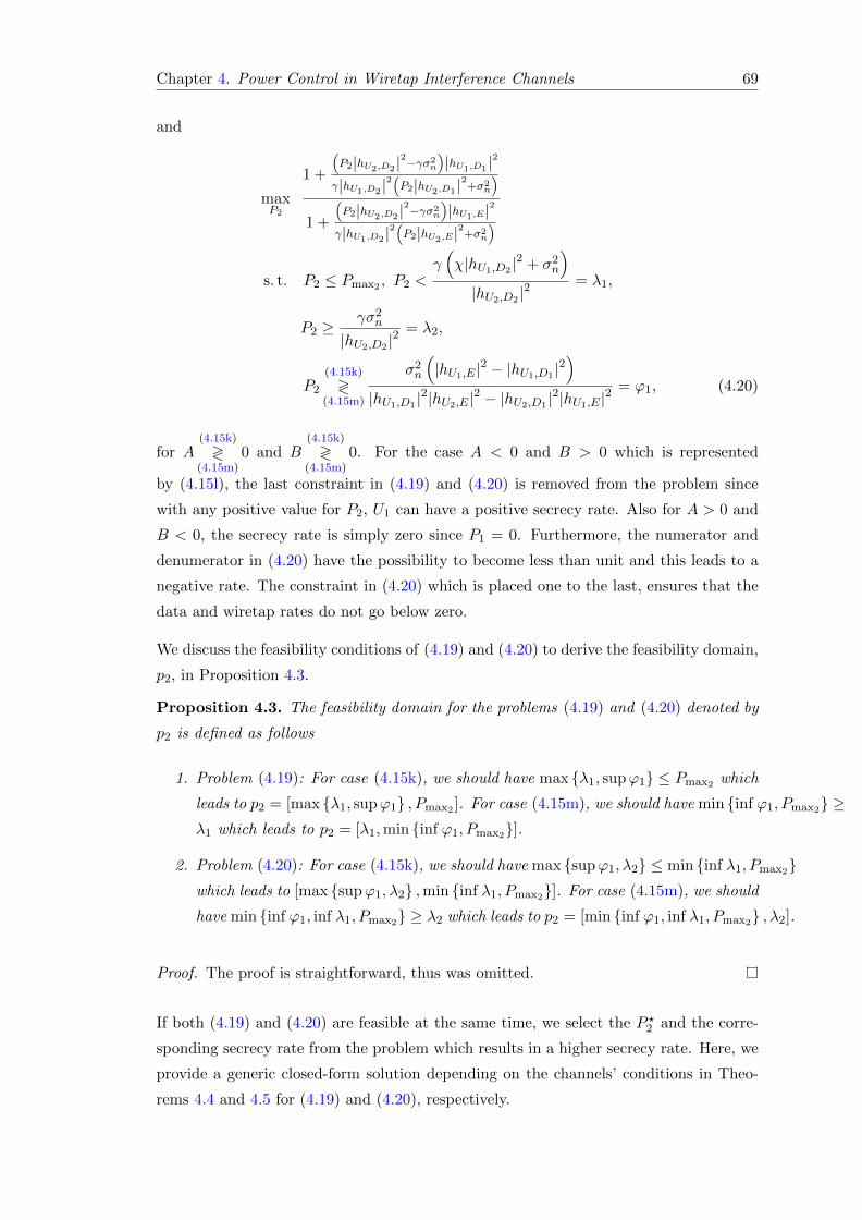
Chapter 4. Power Control in Wiretap Interference Channels 69
and
maxP2
1 +
(P2|hU2,D2 |
2−γσ2n
)|hU1,D1 |
2
γ|hU1,D2 |2(P2|hU2,D1 |
2+σ2
n
)1 +
(P2|hU2,D2 |
2−γσ2n
)|hU1,E|
2
γ|hU1,D2 |2(P2|hU2,E|
2+σ2
n
)
s. t. P2 ≤ Pmax2 , P2 <γ(χ|hU1,D2 |
2 + σ2n
)|hU2,D2 |
2 = λ1,
P2 ≥γσ2
n
|hU2,D2 |2 = λ2,
P2
(4.15k)
≷(4.15m)
σ2n
(|hU1,E |
2 − |hU1,D1 |2)
|hU1,D1 |2|hU2,E |
2 − |hU2,D1 |2|hU1,E |
2 = ϕ1, (4.20)
for A(4.15k)
≷(4.15m)
0 and B(4.15k)
≷(4.15m)
0. For the case A < 0 and B > 0 which is represented
by (4.15l), the last constraint in (4.19) and (4.20) is removed from the problem since
with any positive value for P2, U1 can have a positive secrecy rate. Also for A > 0 and
B < 0, the secrecy rate is simply zero since P1 = 0. Furthermore, the numerator and
denumerator in (4.20) have the possibility to become less than unit and this leads to a
negative rate. The constraint in (4.20) which is placed one to the last, ensures that the
data and wiretap rates do not go below zero.
We discuss the feasibility conditions of (4.19) and (4.20) to derive the feasibility domain,
p2, in Proposition 4.3.
Proposition 4.3. The feasibility domain for the problems (4.19) and (4.20) denoted by
p2 is defined as follows
1. Problem (4.19): For case (4.15k), we should have max {λ1, supϕ1} ≤ Pmax2 which
leads to p2 = [max {λ1, supϕ1} , Pmax2 ]. For case (4.15m), we should have min {inf ϕ1, Pmax2} ≥λ1 which leads to p2 = [λ1,min {inf ϕ1, Pmax2}].
2. Problem (4.20): For case (4.15k), we should have max {supϕ1, λ2} ≤ min {inf λ1, Pmax2}which leads to [max {supϕ1, λ2} ,min {inf λ1, Pmax2}]. For case (4.15m), we should
have min {inf ϕ1, inf λ1, Pmax2} ≥ λ2 which leads to p2 = [min {inf ϕ1, inf λ1, Pmax2} , λ2].
Proof. The proof is straightforward, thus was omitted.
If both (4.19) and (4.20) are feasible at the same time, we select the P ?2 and the corre-
sponding secrecy rate from the problem which results in a higher secrecy rate. Here, we
provide a generic closed-form solution depending on the channels’ conditions in Theo-
rems 4.4 and 4.5 for (4.19) and (4.20), respectively.

Chapter 4. Power Control in Wiretap Interference Channels 70
Theorem 4.4. Assume a = Pmax1 |hU1,D1 |2, b = |hU2,D1 |
2, c = Pmax1 |hU1,E |2, d =
|hU2,E |2, C = b − d, D = b
(c+ σ2
n
)− d
(a+ σ2
n
), E = −BPmax1 = bc− ad, F =
cdσ2n − a
(b(c+ σ2
n
)− cd
), G =
APmax1σ2n
= c − a, α = min (inf ϕ1, Pmax2), and β =
max {λ1, supϕ1}. Also, suppose that (4.19) is feasible. Then, (4.19) is solved as follows:
1. If CD < 0
(a) If A < 0 and E > 0
P ?2 = α (4.21)
(b) If E < 0
P ?2 =
β A > 0
λ1 A < 0(4.22)
2. If CD > 0
(a) If A < 0, E > 0 and F < 0
P ?2 = argP2
maxP2∈{λ1,α}
Cs (4.23)
(b) If E < 0 and F > 0
P ?2 =
P2C P2C ∈ p2
argP2
maxP2∈{β,Pmax2}
Cs A > 0, P2C /∈ p2
argP2
maxP2∈{λ1,Pmax2}
Cs A < 0, P2C /∈ p2
(4.24)
(c) If E > 0, F > 0 and G < 0
P ?2 =
argP2
maxP2∈{P2C ,λ1,α}
Cs P2C ∈ p2
argP2
maxP2∈{λ1,α}
Cs P2C /∈ p2
(4.25)
(d) If E < 0, F < 0 and G > 0
P ?2 =
argP2
maxP2∈{P2C ,β,Pmax2}
Cs P2C ∈ p2
argP2
maxP2∈{β,Pmax2}
Cs P2C /∈ p2
(4.26)

Chapter 4. Power Control in Wiretap Interference Channels 71
(e) If E < 0, F < 0 and G < 0
P ?2 = λ1 (4.27)
where Cs is the objective function in (4.19), P2C = −2bdGσ2n−√
∆2bdE , and ∆ = 4abcdCDσ2
n.
Proof. The proof is given in Appendix C.
Theorem 4.5. Assume e = |hU1,D1 |2, f = |hU2,D2 |
2, g = |hU1,D2 |2, h = |hU2,D1 |
2, i =
|hU1,E |2, j = |hU2,E |
2, H = h−j, δ = min (inf λ1, Pmax2), κ = min {inf λ1, inf ϕ1, Pmax2},µ = max {supϕ1, λ2}, I = −fi+ ghγ − (hi+ gj) γ + e (f + jγ),
J = −gh2iγ (f + jγ) + e(f2i (−h+ j) + fgj2γ + ghj2γ2
),
K = −gi (f + jγ) + e (fg + ghγ − hiγ + ijγ),
L = −ghi (f + jγ) + e (fhi+ fgj − fij + ghjγ).
Also, suppose that (4.20) is feasible. Then, (4.20) can be solved as follows
1. If HI < 0
(a) If J > 0
P ?2 =
δ A > 0, B > 0
δ A < 0, B > 0
κ A < 0, B < 0
(4.28)
(b) If J < 0
P ?2 =
µ A > 0, B > 0
λ2 A < 0, B > 0
λ2 A < 0, B < 0
(4.29)
2. If HI > 0
(a) If J > 0 and K < 0
P ?2 =
argP2
maxP2∈{µ,δ}
Cs A > 0, B > 0
argP2
maxP2∈{λ2,δ}
Cs A < 0, B > 0
argP2
maxP2∈{λ2,κ}
Cs A < 0, B < 0
(4.30)

Chapter 4. Power Control in Wiretap Interference Channels 72
(b) If J < 0 and K > 0
P ?2 =
P2C P2C ∈ p2
argP2
maxP2∈{µ,δ}
Cs A > 0, B > 0, P2C /∈ p2
argP2
maxP2∈{λ2,δ}
Cs A < 0, B > 0, P2C /∈ p2
argP2
maxP2∈{λ2,κ}
Cs A < 0, B < 0, P2C /∈ p2
(4.31)
(c) If J > 0, K > 0 and L < 0 or J < 0, K < 0 and L > 0
P ?2 =
argP2
maxP2∈{P2C ,µ,δ}
Cs A > 0, B > 0, P2C ∈ p2
argP2
maxP2∈{P2C ,λ2,δ}
Cs A < 0, B > 0, P2C ∈ p2
argP2
maxP2∈{P2C ,λ2,κ}
Cs A < 0, B < 0, P2C ∈ p2
argP2
maxP2∈{µ,δ}
Cs A > 0, B > 0, P2C /∈ p2
argP2
maxP2∈{λ2,δ}
Cs A < 0, B > 0, P2C /∈ p2
argP2
maxP2∈{λ2,κ}
Cs A < 0, B < 0, P2C /∈ p2
(4.32)
(d) If J > 0, K > 0 and L > 0
P ?2 =
δ A > 0, B > 0
δ A < 0, B > 0
κ A < 0, B < 0
(4.33)
(e) If J < 0, K < 0 and L < 0
P ?2 =
µ A > 0, B > 0
λ2 A < 0, B > 0
λ2 A < 0, B < 0
(4.34)
where Cs is the objective function in (4.20) and P2C = −2σ2nγL−
√∆
2J , and ∆ = 4egiHI(σ2n
)4γ (f + hγ) (f + jγ).
Proof. The proof can be obtained in the similar way to that of Theorem 4.4.
For problem (4.11), the optimal solution of P1 is as (4.17) when χ = Pmax1 . The closed-
form solution for the P2 is given in the following theorem.

Chapter 4. Power Control in Wiretap Interference Channels 73
Theorem 4.6. Assume a = |hU1,D1 |2, b = |hU2,D2 |
2, c = |hU1,D2 |2, d = |hU2,D1 |
2,
e = |hU1,E |2, A = b(a − e)σ + d(−eγσ + cγσ), B = 2bde(aγσ − cγσ), C = −bceγσ2 +
a(bcγσ2 + dγσ(−eγσ + cγσ)), ψ =σ2n
(|hU1,D1 |
2−|hU1,E|2)
|hU1,E|2|hU2,D1 |
2 , λ1 =γ(Pmax1 |hU1,D2 |
2+σ2
n
)|hU2,D2 |
2 ,
λ2 = γσ2n
|hU2,D2 |2 , and ς = min (Pmax2 , inf ψ, inf λ1). Then, optimal P2 is given as follows:
1. If A < 0
P ?2 = λ2 (4.35)
2. If A > 0
(a) If C > 0 or B > 0 and C < 0
P ?2 =
P2C P2C ∈ p2
argP2
maxP2∈{λ2,ψ}
Cs P2C /∈ p2
(4.36)
(b) If B < 0 and C < 0
P ?2 = argP2
maxP2∈{λ2,ψ}
Cs (4.37)
where Cs is the secrecy rate, P2C = −B−√
∆2D , ∆ = 4Aabcdeγ(dγσ + bσ), D = −bde(ab+
cdγ), and p2 is the feasibility domain of the problem.
Proof. The proof is similar to that of Theorem 4.4, thus was omitted.
4.4 Problem Formulation: Egoistic Scenario
In this section, we develop closed-form solutions for the case when U2 is selfish from the
view point of U1’s secrecy rate, and adjusts its transmission power just to meet its QoS,
i.e., SINR=γ. Later, we compare this case with respect to the altruistic scenario. If one
of the Cases 4.7g, 4.7h, or 4.7i holds and U2 is selfish, (4.14) can be written as
maxP1,P2
1 +P1|hU1,D1 |
2
P2|hU2,D1 |2+σ2
n
1 +P1|hU1,E|
2
P2|hU2,E|2+σ2
n
s. t. P1 ≤ Pmax1 , P1
(4.7g)
≷(4.7i)
ω, P2 ≤ Pmax2 ,P2|hU2,D2 |
2
P1|hU1,D2 |2 + σ2
n
= γ. (4.38)

Chapter 4. Power Control in Wiretap Interference Channels 74
In Case 4.7h, any P1 ensures that the eavesdropper cannot employ SIC, so no additional
constraint over P1 is necessary. For Case 4.7j, the problem is solved as follows
maxP1,P2
1 +P1|hU1,D1 |
2
P2|hU2,D1 |2+σ2
n
1 +P1|hU1,E|
2
σ2n
s. t. P1 ≤ Pmax1 , P2 ≤ Pmax2 ,P2|hU2,D2 |
2
P1|hU1,D2 |2 + σ2
n
= γ. (4.39)
We first solve (4.38) and then (4.39). Using the last constraint in (4.38), we can directly
derive the solution for P2 as P2 = γ
(P1|hU1,D2 |
2+σ2
n
)|hU2,D2 |
2 and replace it with the corresponding
value. Consequently, we can rewrite (4.38) as
maxP1
1 +P1|hU1,D1 |
2
γ
(P1|hU1,D2 |
2+σ2n
)|hU2,D2 |
2 |hU2,D1 |2+σ2
n
1 +P1|hU1,E|
2
γ
(P1|hU1,D2 |
2+σ2n
)|hU2,D2 |
2 |hU2,E|2+σ2
n
s. t. P1 ≤ Pmax1 , P1
(4.7g)
≷(4.7i)
ω, P1 ≤Pmax2 |hU2,D2 |
2 − γσ2n
γ|hU1,D2 |2 . (4.40)
Since the minimum value for the secrecy rate is zero, the objective function in (4.40)
should be greater or equal to one. Proposition 4.7 gives the required condition on P1
in order to have a positive secrecy rate. According to the channel conditions, these
constraints should be added to (4.40).
Proposition 4.7. In order for the objective function in (4.40) to result in a non-negative
secrecy rate, P1 should have the following bounds:
P1 >A′
B′if A′ > 0, B′ > 0, (4.41n)
P1 > 0 if A′ < 0, B′ > 0, (4.41o)
P1 <A′
B′if A′ < 0, B′ < 0, (4.41p)
where A′ = ((1 + c) d− b (1 + e))σ2n, B′ = a (be− cd). Also, for the case A′ > 0 and
B′ < 0, irrespective of the value for P2, no positive secrecy rate is possible for U1. The
values for b, c, d and e are defined in Theorem 4.8.
Proof. The proof is similar to that of Theorem 4.1, thus was omitted.

Chapter 4. Power Control in Wiretap Interference Channels 75
According to Proposition 4.7, we can rewrite (4.40) as
maxP1
1 +P1|hU1,D1 |
2
γ
(P1|hU1,D2 |
2+σ2n
)|hU2,D2 |
2 |hU2,D1 |2+σ2
n
1 +P1|hU1,E|
2
γ
(P1|hU1,D2 |
2+σ2n
)|hU2,D2 |
2 |hU2,E|2+σ2
n
s. t. P1 ≤ Pmax1 , P1
(4.7g)
≷(4.7i)
ω, P1
(4.41n)
R(4.41p)
A′
B′= ϕ3,
P1 ≤Pmax2 |hU2,D2 |
2 − γσ2n
γ|hU1,D2 |2 = λ3. (4.42)
Assuming that (4.42) is feasible, we give a closed-form solution for (4.42) in Theorem 4.8.
Theorem 4.8. Assuming a = |hU1,D2 |2, b = |hU1,D1 |
2, c = γ|hU2,D1 |
2
|hU2,D2 |2 , d = |hU1,E |
2,
e = γ|hU2,E|
2
|hU2,D2 |2 , Q = c − e, R = −(1 + c)d + a(c − e) + b(1 + e), S = −ac2d (1 + e) +
b(e (d+ ae) + c
(−d+ ae2
)), T = −A′
σ2n
= −(1 + c)d + b(1 + e), U = B′
a = be − cd, η =
min {Pmax1 , λ3}, η′ = min {η, ω}, θ = min {Pmax1 , λ3, ϕ3}, and θ′ = min {θ, ω} (4.40)
can be solved as follows
1. If QR < 0
(a) If S > 0, A′′ > 0, B′′ > 0, (or A′′ < 0, B′′ > 0)
P ?1 =
η Q > 0, R < 0
θ B′ < 0, Q < 0, R > 0
η B′ > 0, Q < 0, R > 0
(4.43)
(b) If S > 0, A′′ < 0, B′′ < 0
P ?1 =
η′ Q > 0, R < 0
θ′ B′ < 0, Q < 0, R > 0
η′ B′ > 0, Q < 0, R > 0
(4.44)
(c) If S < 0, A′′ > 0, B′′ > 0
P ?1 =
max {ϕ3, ω} B′ > 0, Q > 0, R < 0
ω Q < 0, R > 0(4.45)

Chapter 4. Power Control in Wiretap Interference Channels 76
(d) If S < 0, A′′ < 0, B′′ < 0 (or A′′ < 0, B′′ > 0)
P ?1 =
ϕ3 B′ > 0, Q > 0, R < 0
0 Q < 0, R > 0(4.46)
2. If QR > 0
(a) If S > 0, T < 0 and B′ > 0
P ?1 =
argP1
maxP1∈{max{ϕ3,ω},η}
Cs A′′ > 0, B′′ > 0
argP1
maxP1∈{ϕ3,η′}
Cs A′′ < 0, B′′ < 0
argP1
maxP1∈{ϕ3,η}
Cs A′′ < 0, B′′ > 0
(4.47)
(b) If S < 0, T > 0, A′′ > 0, B′′ > 0
P ?1 =
P1C P1C ∈ p1
argP1
maxP1∈{ω,η}
Cs P1C /∈ p1, B′ > 0
argP1
maxP1∈{ω,θ}
Cs P1C /∈ p1, B′ < 0
(4.48)
(c) If S < 0 and T > 0, A′′ < 0, B′′ < 0
P ?1 =
P1C P1C ∈ p1
argP1
maxP1∈{0,η′}
Cs P1C /∈ p1, B′ > 0
argP1
maxP1∈{0,θ′}
Cs P1C /∈ p1, B′ < 0
(4.49)
(d) If S < 0 and T > 0, A′′ < 0, B′′ > 0
P ?1 =
P1C P1C ∈ p1
argP1
maxP1∈{0,η}
Cs P1C /∈ p1, B′ > 0
argP1
maxP1∈{0,θ}
Cs P1C /∈ p1, B′ < 0
(4.50)
(e) If S > 0, T > 0, U < 0 and A′′ > 0, B′′ > 0
P ?1 =
argP1
maxP1∈{P1C ,ω,θ}
Cs P1C ∈ p1
argP1
maxP1∈{ω,θ}
Cs P1C /∈ p1
(4.51)
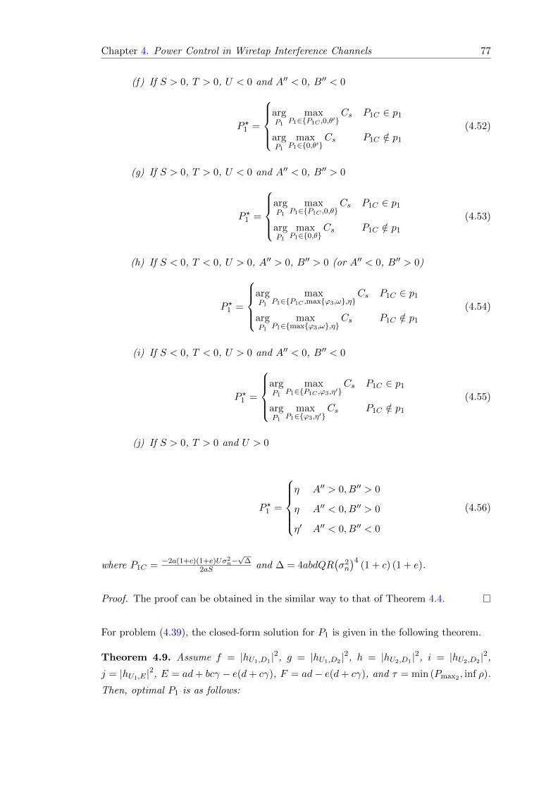
Chapter 4. Power Control in Wiretap Interference Channels 77
(f) If S > 0, T > 0, U < 0 and A′′ < 0, B′′ < 0
P ?1 =
argP1
maxP1∈{P1C ,0,θ′}
Cs P1C ∈ p1
argP1
maxP1∈{0,θ′}
Cs P1C /∈ p1
(4.52)
(g) If S > 0, T > 0, U < 0 and A′′ < 0, B′′ > 0
P ?1 =
argP1
maxP1∈{P1C ,0,θ}
Cs P1C ∈ p1
argP1
maxP1∈{0,θ}
Cs P1C /∈ p1
(4.53)
(h) If S < 0, T < 0, U > 0, A′′ > 0, B′′ > 0 (or A′′ < 0, B′′ > 0)
P ?1 =
argP1
maxP1∈{P1C ,max{ϕ3,ω},η}
Cs P1C ∈ p1
argP1
maxP1∈{max{ϕ3,ω},η}
Cs P1C /∈ p1
(4.54)
(i) If S < 0, T < 0, U > 0 and A′′ < 0, B′′ < 0
P ?1 =
argP1
maxP1∈{P1C ,ϕ3,η′}
Cs P1C ∈ p1
argP1
maxP1∈{ϕ3,η′}
Cs P1C /∈ p1
(4.55)
(j) If S > 0, T > 0 and U > 0
P ?1 =
η A′′ > 0, B′′ > 0
η A′′ < 0, B′′ > 0
η′ A′′ < 0, B′′ < 0
(4.56)
where P1C = −2a(1+c)(1+e)Uσ2n−√
∆2aS and ∆ = 4abdQR
(σ2n
)4(1 + c) (1 + e).
Proof. The proof can be obtained in the similar way to that of Theorem 4.4.
For problem (4.39), the closed-form solution for P1 is given in the following theorem.
Theorem 4.9. Assume f = |hU1,D1 |2, g = |hU1,D2 |
2, h = |hU2,D1 |2, i = |hU2,D2 |
2,
j = |hU1,E |2, E = ad+ bcγ − e(d+ cγ), F = ad− e(d+ cγ), and τ = min (Pmax2 , inf ρ).
Then, optimal P1 is as follows:

Chapter 4. Power Control in Wiretap Interference Channels 78
1. If E < 0
P ?2 = 0 (4.57)
2. If E > 0
(a) If F > 0
P ?2 =
P2C P2C ∈ p2
argP2
maxP2∈{0,τ}
Cs P2C /∈ p2
(4.58)
(b) If F < 0
P ?2 = argP2
maxP2∈{0,τ}
Cs (4.59)
where P2C = −G−√
∆2H , ∆ = 4Eabcdeγ(d+cγ)σ2, G = −2bceγ(d+cγ)σ, H = −bceγ(ad+
bcγ), ρ =σ2n
(|hU1,D1 |
2−|hU1,E|2)|hU2,D2 |
2
γ|hU1,E|2|hU2,D1 |
2|hU1,D2 |2 − σ2
n
|hU1,D2 |2 , and p2 is the feasibility domain of
the problem.
Proof. The proof can be obtained in the similar way to that of Theorem 4.4.
4.5 Secrecy Energy Efficiency
Before going to Section VI, we define a metric in order to investigate the energy effi-
ciency of the considered scenario. We define the secrecy energy efficiency, ηSEE , as the
maximum secrecy rate obtained from the objective of (9), namely Ψ, to the optimal
consumed power of U1, P ?1 , ratio as ηSEE =maxP1
Ψ
P ?1.
Similarly, in the case we have only one transceiver pair and an eavesdropper with no
interfering user, the secrecy energy efficiency metric, ηSEE , can be defined as ηSEEsu =log((σ2n+P ?|hU,D|2
)/(σ2n+P ?|hU,E|2
))P ? , where P is the transmission power, and P ? is the
optimal transmission power obtained from the optimization problem in the nominator.
When the condition |hU,D|2 > |hU,E |2 holds, the optimum consumed power in the single-
user case is Pmax. In contrast, as we shall see in Section VI, the optimal power consumed
by U1 in the interference channel is considerably lower than Pmax. Hence, as shall be
shown in Section VI, in a wide range of powers, the interference network outperforms
the single-user network in terms of secrecy energy efficiency.

Chapter 4. Power Control in Wiretap Interference Channels 79
4.6 Numerical Results
In this section, we present different scenarios as numerical examples to further clarify the
derived results. As a benchmark, we consider a single-user scenario where only one user is
present in the environment and there is no second user to produce interference [5]. Then,
we compare this benchmark with our system model. Here, we refer to the altruistic and
egoistic scenarios as interference channel modes. In all simulation scenarios, we assume
that the noise power is equal to one, i.e., σ2n = 1. All the channel coefficients are
modeled as i.i.d. complex normal random variables with real and imaginary parts being
as N (0, 1). The channel coefficients are normalized to have a unit variance as CN (0, 1).
For the first scenario, we consider the effect of the users’ power limits, Pmax1 and Pmax2 ,
on the average secrecy rate as shown in Fig. 4.3 for SINR = 1 at U2’s destination. By
observing the results in Fig. 4.3, we can draw the following conclusions for both altruistic
and egoistic scenarios:
1. Average secrecy rate of U1 increases as Pmax1 or Pmax2 increases.
2. Increasing Pmax1 is more effective on improving the average secrecy rate rather
than increasing Pmax2 . The reason is that increasing U2’s power creates more
interference to both U1 and E.
3. The average secrecy rate of U1 is lower in the egoistic scenario since U2 does not
change its transmitted power in favor of U1, and only adjusts it according to the
required QoS at D2. Also, by comparing Fig. 4.4 and Fig. 4.5, it can be seen
that U2 consumes less power in the egoistic scenario. When the Cases (4.15k)
and (4.15l) of Theorem 4.1 are true, U2 can improve the secrecy rate by providing
more power in the altruistic scenario.
The average optimal powers consumed by U1 and U2 are shown in Fig. 4.4 for the
altruistic scenario. Following points are implied by Fig. 4.4 as:
1. In contrast to the single-user case where the maximum power consumption is
optimum when the data link is stronger than the wiretap link, average optimal
powers expended by users in the interference channel modes are considerably less
than the available quantity. So, the optimum power control in the interference
channel leads to enormous power saving.
2. As Pmax1 increases, U2 consumes more power. A higher power transmission from
U1 produces more interference on D2. This makes U2 to choose higher transmission
power in order to maintain the QoS at D2.

Chapter 4. Power Control in Wiretap Interference Channels 80
Figure 4.3: Average secrecy rate versus the users’ maximum available powers inaltruistic and egoistic scenarios.
3. As Pmax2 increases, U1 utilizes more power. A higher available power for U2 enables
it to compensate a higher interference from U1, so U1 transmits with a higher power
to increase the secrecy rate.
4. Depending on the maximum available power to the users, the optimal consumed
power by one user can be higher or lower than the power consumed by the other
user.
Consumed powers by U1 and U2 for the egoistic scenario are illustrated in Fig. 4.5. As
we can see, the power consumption pattern is similar to the altruistic scenario as in
Fig. 4.4. By comparing Fig. 4.5 with Fig. 4.4, it is noticed that the power consumed by
the users in the altruistic scenario is higher than the egoistic scenario.
Average excess SINR provided by U2 at D2 in the altruistic scenario is shown in Fig. 4.6
for different values of the required QoS, γth. Following messages are conveyed by Fig. 4.6
as:
1. By increasing Pmax1 for a fixed Pmax2 , the excess SINR provided at D2 drops due
to increased interference from U1’s transmission.
2. Increasing Pmax2 for a fixed Pmax1 leads to a higher excess SINR at D2.
The average secrecy rate comparison among the single-user benchmark and the inter-
ference channel modes is presented in Fig. 4.7 with respect to the maximum available
power of U1. Following conclusions can be made according to Fig. 4.7:
1. Increasing Pmax2 also enhances the average secrecy rate but much less compared
to increasing the Pmax1 , because U2 induces interference on both D1 and E.
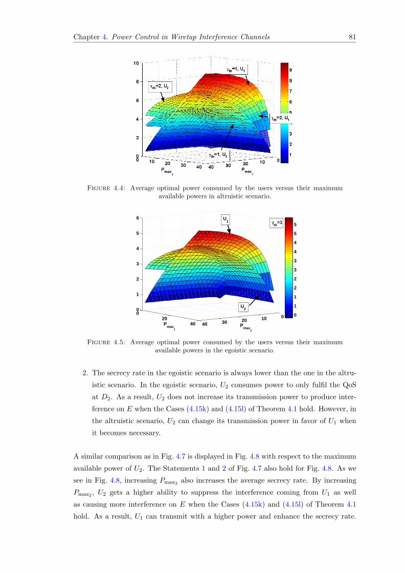
Chapter 4. Power Control in Wiretap Interference Channels 81
Figure 4.4: Average optimal power consumed by the users versus their maximumavailable powers in altruistic scenario.
010203040
020
40
0
1
2
3
4
5
6
Pmax
2
Pmax
1
0.5
1
1.5
2
2.5
3
3.5
4
4.5
5
5.5γth
=1
U2
U1
Figure 4.5: Average optimal power consumed by the users versus their maximumavailable powers in the egoistic scenario.
2. The secrecy rate in the egoistic scenario is always lower than the one in the altru-
istic scenario. In the egoistic scenario, U2 consumes power to only fulfil the QoS
at D2. As a result, U2 does not increase its transmission power to produce inter-
ference on E when the Cases (4.15k) and (4.15l) of Theorem 4.1 hold. However, in
the altruistic scenario, U2 can change its transmission power in favor of U1 when
it becomes necessary.
A similar comparison as in Fig. 4.7 is displayed in Fig. 4.8 with respect to the maximum
available power of U2. The Statements 1 and 2 of Fig. 4.7 also hold for Fig. 4.8. As we
see in Fig. 4.8, increasing Pmax2 also increases the average secrecy rate. By increasing
Pmax2 , U2 gets a higher ability to suppress the interference coming from U1 as well
as causing more interference on E when the Cases (4.15k) and (4.15l) of Theorem 4.1
hold. As a result, U1 can transmit with a higher power and enhance the secrecy rate.

Chapter 4. Power Control in Wiretap Interference Channels 82
Figure 4.6: Average excess QoS provided at D2 versus users’ maximum availablepowers in the altruistic scenario.
5 10 15 20 25 30 35 400.3
0.4
0.5
0.6
0.7
0.8
0.9
Pmax
1
Ave
rage
sec
recy
rat
e (b
/s/H
z)
Single−userγth
=0.05, Pmax
2
=20
γth
=0.3, Pmax
2
=20
γth
=0.3, Pmax
2
=30
γth
=0.3, Pmax
2
=10Altruistic
Egoistic
Figure 4.7: Average secrecy rate versus U1’s maximum available power.
As we can see from Fig. 4.7 and Fig. 4.8, the average secrecy rate in the interference
channel modes is lower than its value in the single-user case. However, we should note
that the power consumed in the interference channel modes is considerably lower than
the single-user case. To make a fair comparison, we use the “secrecy energy efficiency”
metric defined in Section 4.5 to compare the secrecy rates of the interference channel
modes and the single-user benchmark. This metric is derived for different values of γth
in Fig. 4.9. According to graphs in Fig. 4.9, we can make the following conclusions:
1. The secrecy energy efficiency is higher for the interference channel modes in a
considerable range of γth and Pmax1 . If we consider a specific available power for
U1, the acquired secrecy rate in the interference channel modes becomes higher
than the one achieved in the single-user case.

Chapter 4. Power Control in Wiretap Interference Channels 83
5 10 15 20 25 30 35 40
0.4
0.5
0.6
0.7
0.8
0.9
1
Pmax
2
Ave
rage
sec
recy
sat
e (b
/s/H
z)
SU, P
max1
=20
γth
=0.05, Pmax
1
=20
γth
=0.3, Pmax
1
=20
γth
=0.3, Pmax
1
=30
γth
=0.3, Pmax
1
=10
Egoistic
SU: Single−user
Altruistic
Figure 4.8: Average secrecy rate versus U2’s maximum available power.
5 10 15 20 25 30 35 400
0.05
0.1
0.15
0.2
0.25
0.3
0.35
0.4
Pmax
1
Ave
rage
sec
recy
rat
e to
pow
er r
atio
(bi
t/s/H
z/po
wer
uni
t)
Single−userγth
=1, Egoistic
γth
=1, Altruistic
γth
=15, Egoistic
γth
=15, Altruistic
Figure 4.9: Average secrecy energy efficiency versus U1’s maximum available power.
2. As the maximum available power to U1 increases, the secrecy energy efficiency falls
faster for the cases with lower γth.
4.7 Conclusion
We considered a two-user interference wireless channel in this chapter where the first
user, namely user 1, wants to sustain a positive secrecy rate while communicating with
its destination. The second user of the network, namely user 2, requires to preserve
a specific QoS at its destination. Both users create interference for their destinations
and another unintended user of the network, i.e., the eavesdropper, which is interested
in wiretapping user 2. We showed that by appropriate power control of user 1, the
eavesdropper cannot perform SIC. We studied the effect of interference from user 2
on the secrecy rate of user 1. Specifically, depending on the channel conditions, we

Chapter 4. Power Control in Wiretap Interference Channels 84
derived the conditions on user 2’s transmission power in which positive secrecy rate can
be provided. In addition, we jointly derived closed-form expressions for optimal power
transmission of user 1 and 2 to maximize the secrecy rate of user 1 and preserving the
QoS at the destination of user 2. We solve the joint power control problem for both
altruistic and egoistic scenarios. In the altruistic scenario, user 2 changes its power
to over satisfy the QoS at its destination if it improves the secrecy rate. However, it
preserves the minimum QoS at its destination in the egoistic scenario. The simulations
showed that decreasing the QoS at the destination of user 2 improves the secrecy rate
and the secrecy rate gets closer to the single-user case.
Moreover, the ratio of the secrecy rate over the optimal consumed power by user 1
was introduced as a new metric called “secrecy energy efficiency”, in order to take
into account both the secrecy rate and the consumed power. This was mainly done to
have a fair comparison with the benchmark scheme which is the single-user channel. It
was shown that in comparison with the single-user case, the secrecy energy efficiency
is considerably higher in the interference channel for a wide range of QoS at user 2’s
destination.

Chapter 5
Secrecy Energy Efficiency in
MISO and SISO Communication
Networks
Energy-efficiency, high data rates and secure communications are essential requirements
of the future wireless networks. In this chapter, optimizing the secrecy energy efficiency
is considered. The optimal beamformer is designed for a MISO system with and without
considering the minimum required secrecy rate. Further, the optimal power control in
a SISO system is carried out using an efficient iterative method, and this is followed by
analyzing the trade-off between the secrecy energy efficiency and the secrecy rate for
both MISO and SISO systems. The contribution of this chapter is published in [25].
5.1 Introduction
Due to the presence of several wireless devices in a specific environment, the trans-
mitted information may be exposed to unintended receivers. Using cryptography in
higher layers, a secure transmission can be initiated. Nevertheless, it is probable that
an unintended device, which maybe also be a part of the legitimate network, breaks
the encryption [3]. Fortunately, physical layer security techniques can further improve
the security by perfectly securing a transmission rate using the “secrecy rate” concept
introduced in [5]. While security is a concern, power consumption is also another impor-
tant issue in wireless communications since some wireless devices rely on limited battery
power.
85

Chapter 5. Secrecy Energy Efficiency in MISO and SISO Communication Networks 86
There are a wealth of research works in the literature which investigate the energy effi-
ciency in wireless networks such as [230, 231] and the references therein. Recently, some
research has been done to jointly optimize the secrecy rate and the power consumption.
Sum secrecy rate and power are jointly optimized in [113] to attain a minimum quality
of service (QoS). In [114], switched beamforming is used to maximize the secrecy out-
age probability over the consumed power ratio. Powers consumption for a fixed secrecy
rate is minimized in [117] for an amplify-and-forward (AF) relay network. The secrecy
outage probability over the consumed power is maximized subject to power limit for a
large scale AF relay network in [118]. The optimal beamformer for a wiretap channel
with multiple-antenna nodes is designed in [115] to maximize secrecy rate over power
ratio.
Here, we consider a multiple-input single-output (MISO) and a single-input single-output
(SISO) scenario while a single-antenna unintended receiver, which is part of the network,
is listening. The secrecy rate over the power ratio, named “secrecy energy efficiency”
and denoted by ζ, is maximized with and without considering the minimum required
secrecy spectral efficiency, denoted by η0, at the destination. For comparison, we derive
the optimal beamformer when zero-forcing (ZF) technique is used to null the signal
at the eavesdropper with considering the minimum required secrecy spectral efficiency.
Note that the ZF can only be used for the MISO scenario. Furthermore, the trade-off
between ζ and secrecy spectral efficiency, denoted by η, is studied.
The following issues distinct our work from the most related research. In [115], first-
order Taylor series expansion and Hadamard inequality are used to approximate the
optimal beamfromer for a MIMO system. However, the exact beamformer for the MISO
system is derived in this chapter. Furthermore, the innermost layer of algorithm in [115]
is based on the singular value decomposition, and is not applicable to SISO and MISO
systems. In this chapter, apart from the MISO system exact beamformer design, exact
optimal power allocation for the SISO system is also derived.
5.2 Signal and System Model
Consider a wireless communication network comprised of a transmitter denoted by T , a
receiver denoted by R, and an unintended user denoted by E. Note that to obtain the
secrecy rate, the legitimate user needs to be aware of the instantaneous channel to the
eavesdropper. This knowledge for the most general case with a passive eavesdropper is
not practical. In this work, the unintended user is assumed to be part of the network.
Therefore, the transmitter T is able to receive the training sequence from E, in order to

Chapter 5. Secrecy Energy Efficiency in MISO and SISO Communication Networks 87
estimate its channel. The signal model and the secrecy rates are derived in the following
parts.
5.2.1 MISO System
Here, we assume that the transmitter employs multiple antennas. The received signals
at R and E are then as follows
yR = hTT,Rwx+ nR, (5.1)
yE = hTT,Ewx+ nE , (5.2)
where x is the transmitted message, w is a vector containing beamforming gains, hT,R
and hT,E are the transmitter’s channel gains toward the receiver and eavesdropper,
respectively. The additive white Gaussian noise at the receiver and eavesdropper are
shown by nR and nE , respectively. The random variables x, nR, and nE are complex cir-
cularly symmetric (c.c.s.) and independent and identically Gaussian distributed (i.i.d.)
with x ∼ CN (0, 1), nR ∼ CN (0, σ2nR
), and nE ∼ CN (0, σ2nE
), respectively, where CNdenotes the complex normal random variable. The noise powers, σ2
nRand σ2
nE, are equal
to KTiB where K is the boltzman constant, Ti is the temperature at the corresponding
receiver with i ∈ {R,E}, and B is the transmission bandwidth. Using (5.1) and (5.2)
and the result in [13], the secrecy spectral efficiency (or rate in bps/Hz) denoted by η is
obtained by
ηMISO =
[log
(1 + a
1 + b
)]+
, (5.3)
where a =|hTT,Rw|
2
σ2nR
, b =|hTT,Ew|
2
σ2nE
, and [x]+ denotes max (x, 0). In this chapter, all the
logarithms are in base two. Further, the operator [·]+ is dropped throughout the chapter
for the sake of simplicity.
5.2.2 SISO System
When one antenna is employed at the transmitter, using the result in [232], the secrecy
spectral efficiency, η, is calculated as
ηSISO =
[log
(1 + a′
1 + b′
)]+
, (5.4)
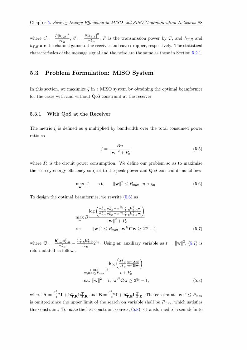
Chapter 5. Secrecy Energy Efficiency in MISO and SISO Communication Networks 88
where a′ =P |hT,R|2σ2nR
, b′ =P |hT,E|2σ2nE
, P is the transmission power by T , and hT,R and
hT,E are the channel gains to the receiver and eavesdropper, respectively. The statistical
characteristics of the message signal and the noise are the same as those in Section 5.2.1.
5.3 Problem Formulation: MISO System
In this section, we maximize ζ in a MISO system by obtaining the optimal beamformer
for the cases with and without QoS constraint at the receiver.
5.3.1 With QoS at the Receiver
The metric ζ is defined as η multiplied by bandwidth over the total consumed power
ratio as
ζ =Bη
‖w‖2 + Pc, (5.5)
where Pc is the circuit power consumption. We define our problem so as to maximize
the secrecy energy efficiency subject to the peak power and QoS constraints as follows
maxw
ζ s.t. ‖w‖2 ≤ Pmax, η > η0. (5.6)
To design the optimal beamformer, we rewrite (5.6) as
maxw
B
log
(σ2nEσ2nR
σ2nR
+wHh∗T,RhTT,Rw
σ2nE
+wHh∗T,EhTT,Ew
)‖w‖2 + Pc
s.t. ‖w‖2 ≤ Pmax, wHCw ≥ 2η0 − 1, (5.7)
where C =h∗T,Rh
TT,R
σ2nR
− h∗T,EhTT,E
σ2nE
2η0 . Using an auxiliary variable as t = ‖w‖2, (5.7) is
reformulated as follows
maxw,0<t≤Pmax
B
log
(σ2nEσ2nR
wHAwwHBw
)t+ Pc
s.t. ‖w‖2 = t, wHCw ≥ 2η0 − 1, (5.8)
where A =σ2nRt I + h∗T,RhT
T,R and B =σ2nEt I + h∗T,EhT
T,E. The constraint ‖w‖2 ≤ Pmax
is omitted since the upper limit of the search on variable shall be Pmax, which satisfies
this constraint. To make the last constraint convex, (5.8) is transformed to a semidefinite
Chapter 5. Secrecy Energy Efficiency in MISO and SISO Communication Networks 89
programming (SDP) optimization problem.
maxW,0<t≤Pmax
B
log
(σ2nEσ2nR
tr(WA)tr(WB)
)t+ Pc
s.t. tr (W) = t, tr (WC) ≥ 2η0 − 1, W � 0, (5.9)
where rank(W) = 1 constraint is dropped to have a set of convex constraints. Similar
to [233], matrix V and scalar s are defined such that V = sW and tr (sWB) = 1.
Accordingly, (5.9) is transformed into
maxV,0<t≤Pmax,s
B
t+ Pclog
(σ2nE
σ2nR
tr (VA)
)s.t. tr (V) = st, tr (VC) ≥ s (2η0 − 1) ,
tr (VB) = 1,V � 0, s ≥ 0. (5.10)
Finally, by considering the auxiliary variable t to be fixed and dropping the log due to
the monotonicity of logarithm function, (5.10) can be solved using SDP along with a
one-dimensional search over the variable t where t ∈ (0, Pmax]. Since the matrices A, B,
and C in (5.10) are Hermitian positive semidefinite, Theorem 2.3 in [223] can used to
derive an equivalent rank-one solution if the solution to (5.10) satisfies rank(W) ≥ 3.
In order to perform a comparison, we also design the optimal beamforming vector to
maximize the secrecy energy efficiency when zero-forcing (ZF) strategy is used to null
the received signal at the eavesdropper. Using (5.7), the ZF beamformer design problem
can be defined as follows
maxw
B
log
(σ2nR
+wHh∗T,RhTT,Rw
σ2nR
)‖w‖2 + Pc
s.t. ‖w‖2 ≤ Pmax, wHCw ≥ 2η0 − 1, hTT,Ew = 0. (5.11)
Using t = wHw, we get
maxw
B
t+ Pc
(log(wHAw
)− log σ2
nR
)s.t. ‖w‖2 = t, wHCw ≥ 2η0 − 1, hTT,Ew = 0, (5.12)
which can be simplified into
maxw
wHAw
s.t. ‖w‖2 = t, wHCw ≥ 2η0 − 1, hTT,Ew = 0. (5.13)

Chapter 5. Secrecy Energy Efficiency in MISO and SISO Communication Networks 90
To make the third constraint convex, similar to (5.8), (5.13) can be transformed into a
SDP optimization problem as
maxW
tr (WA)
s.t. tr (W) = t, tr (WC) ≥ 2η0 − 1,
tr (WD) = 0,W � 0, (5.14)
where D = h∗T,EhTT,E and the rank-one constraint on W is dropped to make the problem
convex. Since the matrices A, C, and D in (5.14) are Hermitian positive semidefinite,
Theorem 2.3 in [223] can used to derive an equivalent rank-one solution if the solution
to (5.14) satisfies rank(W) ≥ 3.
If the solution to (5.14) is not rank-one, Theorem 2.3 in [223] can be employed to derive
an equivalent rank-one solution. Problem (5.14) can be solved using SDP along with a
one-dimensional search over the variable t where t ∈ (0, Pmax].
5.3.2 Without QoS at the Receiver
Using (5.8), the optimal beamformer design problem without considering the QoS is
reduced to
maxw,0<t≤Pmax
B
log
(σ2nEσ2nR
wHAwwHBw
)t+ Pc
s.t. ‖w‖2 = t. (5.15)
For a fixed t, (5.15) can be written as
maxw
B
t+ Pc
σ2nE
σ2nR
wHAw
wHBw, (5.16)
where t ∈ (0, Pmax]. Due to the homogeneity of (5.15), the constraints on the bam-
forming vector can be satisfied and thus dropped. The optimal value and the optimal
beamforming vector in (5.16) are easily derived using Rayleigh-Ritz [234] when (5.16) is
in its standardized form as
maxv
B
t+ Pc
σ2nE
σ2nR
vHDv
vHv, (5.17)
where v = CHw, D = C−1AC−H, and matrix C is the Cholesky decomposition of
matrix B as B = CCH . The optimal beamforming vector is derived as w? = C−Hv?
where v? is the eigenvector corresponding to λmax
(C−1AC−H
). Finally, the optimal ζ

Chapter 5. Secrecy Energy Efficiency in MISO and SISO Communication Networks 91
is obtained in closed-form by
ζ? = B
log
(σ2nEσ2nR
λmax
(C−1AC−H
))t+ Pc
. (5.18)
Employing a one-dimensional search over t ∈ (0, Pmax] and using (5.18), the optimal
value of (5.17) is found.
5.4 Problem Formulation: SISO System
In the SISO case, the beamformer design is reduced to scalar power control. Similar
to (5.6), the optimization problem for SISO system is defined as
maxP
B
log
(σ2nEσ2nR
σ2nR
+P |hT,R|2
σ2nE
+P |hT,E|2)
Pc + Ps.t. Pmin ≤ P ≤ Pmax, (5.19)
where Pmin = 2η0−1α is obtained from the minimum QoS constraint, and it is assumed
that α =|hT,R|2σ2nR
− |hT,E|2
σ2nE
2η0 > 0. The numerator in the objective of (5.19) is concave
since the argument of the logarithm is concave for P ≥ 0 and|hT,R|2σ2nR
>|hT,E|2σ2nE
, which
are granted in our problem, and the denumerator is affine. Hence, (5.19) is categorized
as a family member of fractional programming problems known as “concave fractional
program” where a local optimum is a global one [235]. Here, we solve (5.19) using an
iterative (parametric) algorithm named Dinkelbach [236]. For the sake of simplicity, we
mention the values related to |hT,R|2 and |hT,E |2 by a and b, respectively. According
to [236], after dropping the constant B, (5.19) is written as
F (q) = maxP∈S
log
(σ2nE
σ2nR
σ2nR
+ Pa
σ2nE
+ Pb
)− q (Pc + P ) , (5.20)
q =f (P )
g (P ), (5.21)
where f(P ) and g(P ) are the numerator and denumerator of (5.19), respectively. Also,
S shows the feasible domain of P . To calculate the optimal P for (5.20), denoted by
P ?, the derivative of F (q) with respect to P is calculated as follows
∂F
∂P=− abqβP 2 + Pqβ
(−aσ2
nE− bσ2
nR
)+ aσ2
nE− qβσ2
nRσ2nE− bσ2
nR, (5.22)

Chapter 5. Secrecy Energy Efficiency in MISO and SISO Communication Networks 92
Algorithm 1 Iterative approach to solve (5.19)
1: Initialize n = 0;2: Pick any Pn ∈ S;3: Derive qn using (5.21);4: Derive P ?n using (5.24) and calculate F (qn) using (5.20);5: if F (qn) ≥ δ then6: n = n+ 1;7: Go to 3;8: end if
which is a quadratic equation with a closed-form solution as
P1,2 =q(aσ2
nE+ bσ2
nR
)±√
∆
−2abq, β = Ln2,
∆ = q2(aσ2
nE+ bσ2
nR
)2+ 4abq
(aσ2
nE− qσ2
nRσ2nE− bσ2
nR
). (5.23)
Since P1 in (5.23) is always negative, P ? is derived as
P ? =
P2 P2 ∈ S,argP
maxP∈{Pmin,Pmax}
F (q) P2 /∈ S,(5.24)
where P2 =q(aσ2
nE+bσ2
nR)−√
∆
−2abq . The procedure to solve (5.19) using Dinkelbach method
is summarized in Algorithm 1. Using the closed-form solution of (5.20) given in (5.24),
the following recursive relation is used to merge Steps 3 and 4 of Algorithm 1 as
Pn+1 =
f(Pn)g(Pn)
(aσ2
nE+ bσ2
nR
)−√
∆n
−2abf(Pn)g(Pn)
. (5.25)
It is proven in [236] that Algorithm 1 converges. In addition, since a local optimum for
a concave fractional program is the global optimum, and (5.19) falls into this category,
the solution found using Algorithm 1 is a global optimum.
5.5 Trade-off between ζ and η
In this section, we study the trade-off between secrecy energy efficiency and secrecy
spectral efficiency (i.e. ζ and η) for MISO and SISO systems.

Chapter 5. Secrecy Energy Efficiency in MISO and SISO Communication Networks 93
5.5.1 MISO System
To find the trade-off between ζ and η, we solve the optimal beamforming design problem
to maximize ζ and η separately for a specific power constraint, P . As a result, the pair
(ζ, η) is available for different values of P . For ζ, the optimization problem is as follows
maxw
B
log2
(σ2nEσ2nR
σ2nR
+wHh∗T,RhTT,Rw
σ2nE
+wHh∗T,EhTT,Ew
)P + Pc
s.t. ‖w‖2 = P. (5.26)
Using the constraint in (5.26), we conclude that wHwP = 1 which helps us homoge-
nize (5.26) as
maxw
B
log2
(σ2nEσ2nR
wHAwwHBw
)P + Pc
s.t. ‖w‖2 = P, (5.27)
where, A =σ2nRP I + h∗T,RhTT,R and B =
σ2nEP I + h∗T,EhTT,E . Similar to (5.15), the log
and the power constraint can be dropped. Similar to the solution to (5.17), the optimal
beamforming vector shall be w? = C−Hv? where v? is the eigenvector corresponding to
λmax
(C−1AC−H
). The final closed-form solution for ζ? is
ζ? = B
log
(σ2nEσ2nR
λmax
(C−1AC−H
))P + Pc
. (5.28)
The optimal beamforming vector for η? shall be the same as for ζ? and the optimal value
of η can be derived similar to the one for ζ. Hence, the pair (ζ?, η?) is available.
5.5.2 SISO System
By deriving P with respect to η using (5.4) as P =σ2nR
σ2nE
(2η−1)
σ2nE
a−σ2nR
b2η, the relation between
ζ and η is calculated using (5.5) as follows
ζ =Bη(σ2nEa− σ2
nRb2η)
σ2nRσ2nE
(2η − 1) + Pc(σ2nEa− σ2
nRb2η) . (5.29)
By solving dζdη = 0 using numerical methods, η corresponding to the optimal ζ can be
derived.

Chapter 5. Secrecy Energy Efficiency in MISO and SISO Communication Networks 94
Minimum required secrecy rate (b/s/Hz)0 1 2 3 4
Sec
recy
en
erg
y ef
fici
ency
(b
/s/W
att)
×106
0
0.5
1
1.5
2
2.5
3
3.5
4
Optimal ζ versus η0
ζ versus ηOptimal ζ versus η
0, ZF
Optimal ζ versus η0
ζ versus ηBorder line
N=3
N=1
Figure 5.1: Optimal ζ versus η0 and ζ versus η graphs.
Minimum required secrecy rate (b/s/Hz)0 1 2 3 4 5 6
Ave
rag
e se
crec
y en
erg
y ef
fici
ency
(b
/s/W
att)
×106
0
0.5
1
1.5
2
2.5
3
3.5
4
4.5N=4, P
C=3, Opt
N=4, PC
=3, ZF
N=4, PC
=5, Opt
N=4, PC
=5, ZF
N=2, PC
=3, Opt
N=2, PC
=3, ZF
N=2, PC
=5, Opt
N=2, PC
=5, ZF
N=1, PC
=3, Opt
N=1, PC
=5, Opt
Figure 5.2: Average ζ versus η0 for different N and Pc.
5.6 Simulation Results
In this section, we present numerical examples to investigate the secrecy energy effi-
ciency and its trade-off with the secrecy spectral efficiency. The simulations’ parameters
are as follows. Distance from the transmitter to receiver and eavesdropper, d, is con-
sidered to be 2 km, Quasi-static block fading channel model as CN (0, 1), path loss is
128.1 + 37.6 log10 d dB [237], bandwidth is 20 MHz, Pc = 5, Pmax = 50, receiver noise
temperature is 298 K, tolerance error for Dinkelbach algorithm is δ = 10−3, and N is
the number of antennas. If the secrecy rate is negative, it is considered to be zero.
For the figures presenting the average graphs, enough amount of channels are generated
and the average of the resultant metrics are considered. In the first simulation sce-
nario, the secrecy energy efficiency and secrecy spectral efficiency trade-off is studied.
Optimal ζ versus the minimum required η graphs as well as the graphs related to the

Chapter 5. Secrecy Energy Efficiency in MISO and SISO Communication Networks 95
Average secrecy spectral efficiency (b/s/Hz)0 1 2 3 4 5 6 7
Ave
rag
e se
crec
y en
erg
y ef
fici
ency
(b
/s/W
att) ×106
0
1
2
3
4
5
6Optimal ζN=11N=10N=9N=8N=7N=6N=5N=4N=3N=2
Figure 5.3: ζ and η relation for different antennas.
trade-off between ζ and η are presented in Fig. 5.1 using a single channel realization.
Two different regions are defined in Fig. 5.1 using a border line. The border line defines
the optimal operating point in terms of ζ. In the left-hand side region, increasing η
also increases ζ. Hence, to get a higher ζ, the secrecy rate can be increased, which is
desirable. However, the mechanism between ζ and η changes in the right-hand side of
Fig. 5.1. After the optimal point of ζ, increasing η demands more power which is higher
than the optimal power value for ζ. Therefore, as η increases, ζ falls below the optimal
value which is opposite to the procedure in the left-hand side, and the trade-off is clear.
Also, it is observed that ZF results in a lower secrecy energy efficiency. Nevertheless,
as the minimum required secrecy rate increases, the performance of the ZF approaches
the primary scheme, i.e., optimal beamformer design. For the second scenario, average
ζ versus the minimum required η is investigated for different numbers of antennas, and
circuit powers. The related graphs are depicted in Fig. 5.2. As it is shown, increasing
the number of antennas results in increasing the optimal value of ζ and makes it stable
for a longer range of η0. Further, we can see that decreasing Pc leads to higher secrecy
energy efficiency, and this is more significant for higher number of antennas. Similar to
the result in Fig. 5.1, ZF scheme shows a sub-optimal performance. ZF’s performance
gets closer to the optimal scheme as the circuit power, Pc, increases. Interestingly, for
fewer number of antennas, the gap between the performance of the ZF and the optimal
scheme even gets larger. This is due to less degrees of freedom for the ZF beamformer
design as the number of antennas decreases. To investigate the trade-off between ζ and
η, the average (ζ, η) pair for different number of antennas is presented in Fig. 5.3. It is
observed that the optimal ζ grows as number of antennas are increased.

Chapter 5. Secrecy Energy Efficiency in MISO and SISO Communication Networks 96
5.7 Conclusion
In this chapter, we studied the secrecy energy efficiency and its trade-off with the se-
crecy spectral efficiency in MISO and SISO wiretap channels. We designed the optimal
beamformer to maximize the secrecy energy efficiency with and without considering the
minimum required secrecy spectral efficiency at the receiver side. In addition, we de-
signed the beamformer to maximize the secrecy energy efficiency when the transmitter
applies zero forcing to null out the information signal in the direction of the eavesdrop-
per. The simulation results showed that the secrecy energy efficiency of the optimal
beamformer and the ZF beamformer designs gets closer as the minimum required se-
crecy spectral efficiency increases. In addition, we observed that the difference between
the secrecy energy efficiency of the optimal and ZF design decreases as the number of
transmission antennas increases. This is due to the fact that the ZF design by nature
limits the degrees of freedom in the beamformer design, while increasing the number of
antennas gives more degrees of freedom to the ZF design. Particularly, the numerical
results revealed that there is a specific point for the secrecy spectral efficiency where
the secrecy energy efficiency gets to its maximum point. Above this point, the secrecy
energy efficiency starts to fall below the optimal point. In addition, the simulations
showed that increasing the transmitter antennas improves the secrecy energy efficiency
considerably. Furthermore, increasing the transmitter antennas keeps the secrecy energy
efficiency in its maximum level for a longer range of minimum required secrecy spectral
efficiency.

Chapter 6
Secure Directional Modulation
via Symbol-Level Precoding
Wireless transmission provides wide coverage, yet it exposes information. As an information-
theoretic paradigm, secrecy rate derives bounds for secure transmission when the channel
to the eavesdropper is known, however, it restricts us in practice and proper codings
need to be developed to achieve these bounds. Here, we employ the concept of direc-
tional modulation and follow a signal processing approach to enhance the security of a
multi-user MIMO communication system in the presence of a multi-antenna eavesdrop-
per. Enhancing the security in this chapter means increasing the symbol error rate at
the eavesdropper. Unlike the information-theoretic secrecy rate paradigm, we assume
that the legitimate transmitter is not aware of its channel to the eavesdropper, which is
a more realistic assumption. We show that when the eavesdropper has lower antennas
than the users, regardless of the received signal SNR, it cannot recover any useful in-
formation, in addition, it has to go through extra noise enhancing processes to estimate
the symbols when it has more antennas than the users. Using the channel knowledge
and the intended symbols for the users, we design security enhancing symbol-level pre-
coders for different transmitter and eavesdropper antenna configurations. We transform
each design problem to a linearly constrained quadratic program and propose two algo-
rithms, namely iterative algorithm and non-negative least squares, at each scenario for
a computationally-efficient optimization design. Simulation results verify the analysis
and show that the designed precoders outperform the benchmark scheme in terms of
both power efficiency and security enhancement. The contribution of this chapter are
published in [27, 28].
97

Chapter 6. Secure Directional Modulation via Symbol-Level Precoding 98
6.1 Introduction
6.1.1 Motivation
Wireless communications allows information flow through broadcasting; however, it may
expose the information to unintended receivers, with eavesdroppers amongst them. To
derive a bound for secure transmission, Wyner proposed the secrecy rate concept in his
seminal paper [5] for discrete memoryless channels. The secrecy rate defines the bound
for secure transmission and proper coding is being developed to achieve this bound [8].
However, the secrecy rate can restrict the communication system in some aspects. Pri-
marily, the secrecy rate requires perfect or statistical knowledge of the eavesdropper’s
channel state information (CSI) [20–22, 179, 206], however, it may not be possible to
acquire the perfect or statistical CSI of a passive eavesdropper in practice. In addition,
in the secrecy rate approach, the transmission rate has to be lower than the achievable
rate, which may conflict with the increasing rate demands in wireless communications.
Furthermore, the transmit signal usually is required to follow a Gaussian distribution
which is not the case in current digital communication systems.
Recently, there has been growing research interest on directional modulation technology
and its security enhancing ability. As a pioneer, [17] implements a directional modulation
transmitter using parasitic antenna. This system creates the desired amplitude and
phase in a specific direction by varying the length of the reflector antennas for each
symbol while scrambling the symbols in other directions. The authors of [18] suggest
using a phased array at the transmitter and employ the genetic algorithm to derive the
phase values of a phased array in order to create symbols in a specific direction. The
directional modulation concept is later extended to directionally modulate symbols to
more than one destination. In [158], the singular value decomposition (SVD) is used to
directionally modulate symbols in a two user system. The authors of [159] derive the
array weights to create two orthogonal far field patterns to directionally modulate two
symbols to two different locations and [160] uses least-norm to derive the array weights
and directionally modulate symbols towards multiple destinations in a multi-user multi-
input multi-output (MIMO) system. The authors in [27] design the array weights of a
directional modulation transmitter in a single-user MIMO system to minimize the power
consumption while keeping the signal-to-noise ratio (SNR) of each received signal above a
specific level. The directional modulation literature focuses on practical implementation
and the security enhancing characteristics of this technology. On top of the works
in the directional modulation literature where antennas excitation weight change on
a symbol basis, the symbol-level precoding to create constructive interference between
the transmitted symbols has been developed in [180–183] by focusing on the digital

Chapter 6. Secure Directional Modulation via Symbol-Level Precoding 99
processing of the signal before being fed to the antenna array. The main difference
between directional modulation and the digital symbol-level precoding for constructive
interference is that the former focuses on applying array weights in the analog domain
such that the received signals on the receiving antennas have the desired amplitude and
phase, whereas the latter uses symbol-level precoding for digital signal design at the
transmitter to create constructive interference at the receiver. Furthermore, directional
modulation was originally motivated by physical layer security, whereas symbol-level
precoding by energy efficiency.
6.1.2 Contributions
In this chapter, we design the optimal precoder for a directional modulation transmitter
to enhance the security in a quasi-static fading MIMO channel where a multi-antenna
eavesdropper is present. Here, enhancing the security means increasing the SER at
the eavesdropper. In directional modulation, users’ channels and symbols meant for the
users are used to design the precoder. The precoder is designed to induce the symbols on
the receiver antennas rather than generating the symbols at the transmitter and sending
them, which is the case in the conventional transmit precoding [23, 24]. In other words,
in the directional modulation, the modulation happens in the radio frequency (RF)
level while the arrays’ emitted signals pass through the wireless channel. This way,
we simultaneously communicate multiple interference-free symbols to multiple users.
Also, the precoder is designed such that the receivers antennas can directly recover the
symbols without CSI and equalization. Therefore, assuming the eavesdropper has a
different channel compared to the users, it receives scrambled symbols. In fact, the
channels between the transmitter and users act as secret keys [26] in the directional
modulation. Furthermore, since the precoder depends on the symbols, the eavesdropper
cannot calculate it. In contrast to the information theoretic secrecy rate paradigm, the
directional modulation enhances the security by considering more practical assumptions.
Particularly, directional modulation does not require the eavesdropper’s CSI to enhance
the security, furthermore, it does not reduce the transmission rate and signals are allowed
to follow a non-Gaussian distribution. In light of the above, our contributions in this
chapter can be summarized as follows:
1. The optimal symbol-level precoder is designed for a security enhancing directional
modulation transmitter in a MIMO fading channel to communicate with arbitrary
number of users and symbol streams. In addition, we derive the necessary condition
for the existence of the precoder. The directional modulation literature mostly
includes LoS analysis with one or limited number of users, and multi-user works
do not perform security enhancing optimization.

Chapter 6. Secure Directional Modulation via Symbol-Level Precoding 100
2. It is shown that when the eavesdropper has less antennas than the transmitter,
regardless of the SNR level, it cannot extract useful information from the received
signal and when it has more antennas than the transmitter, it has to estimate the
symbols by extra processes which enhance the noise. We minimize the transmission
power for the former case and maximize the SER at the eavesdropper for the latter
case to prevent successful decoding at the eavesdropper. This is done while keeping
the SNR of users’ received signals above a predefined threshold and thus the users’
rate demands are satisfied. The directional modulation literature do not analyze
the abilities of a multi-antenna eavesdropper and rely on the fact that it receives
scrambled symbols
3. It is shown that in the conventional precoding, the eavesdropper needs to have
more antennas than the receiver to estimate the symbols since the eavesdropper
can calculate the precoder. In our design, the eavesdropper has to have more
antennas than the transmitter since the precoder depends on both the channels
and symbols. The transmitter, e.g., a base station, probably has more antennas
than the receiver, hence, it is more likely to preserve the security in directional
modulation, specially in a massive MIMO system.
4. The power and SNR minimization precoder design problems are simplified into a
linearly-constrained quadratic programming problem. For faster design, we intro-
duce new auxiliary variable to transform the constraint into equality and propose
two different algorithms to solve the design problems. In the first algorithm, we
use a penalty method to get an unconstrained problem and solve it by proposing
using an iterative algorithm. Also, we prove that the algorithm converges to the
optimal point. In the second one, we use the constraint to get a non-negative least
squares design problem. For the latter, there are already fast techniques to solve
the problem.
6.1.3 Additional Related Works to Directional Modulation
Array switching at the symbol rate is used in [161, 162] to induce the desired symbols.
In connection with [17], [164] studies the far field area coverage of a parasitic antenna
and shows that it is a convex region. The technique of [18] is implemented in [165] using
a four element microstrip patch array where symbols are directionally modulated for
Q-PSK modulation. The authors of [166] propose an iterative nonlinear optimization
approach to design the array weights which minimizes the distance between the desired
and the directly modulated symbols in a specific direction. The Fourier transform is
used in [170, 171] to create the optimal constellation pattern for Q-PSK directional

Chapter 6. Secure Directional Modulation via Symbol-Level Precoding 101
...EavesdropperE
... Use
r 1
1U
1N
... Use
r R
RU
RN
... Use
r r
rU
rN
...
...
1UH
rUH
RUH
EH
...
......
...
...
...e1s ens eNs
eN
1w
Join
topt
imal
wei
ghtg
ener
ator
for
ante
nna
elem
ents
Gen
erat
ing
the
phas
esof
the
inte
nded
sym
bols
Binary data
Opt
imiz
atio
n m
odul
e
Users' CSIs: , , ..., 1U
H2U
HRU
H
......
Tran
smit
ter
(T)
∠11s
∠RNs Nw
t
RF signal generator
Ind
uce
d s
ymb
ols
Scr
amb
led
ind
uce
d
sym
bol
s
11sγ
1nsγ
1Nsγ
r1sγ
rnsγ
rNsγR1sγ
Rnsγ
RNsγ
RF signal generator
Figure 6.1: Generic architecture of a directional modulation transmitter, includingthe optimal security enhancing antenna weight generator using the proposed algorithms.
L-way hybridpower divider
Narrowband Locked RF oscilator
...R
F s
ign
al g
ener
ator
1wPower amplifier gain
and phase shifer control ...
Nar
row
ban
d
Pow
er a
mp
lifi
er
Ph
ase
shif
ter
...tN
Nwt
Figure 6.2: RF signal generation using actively driven elements, including high fre-quency power amplifiers and phase shifters.
modulation. In [158, 172–174] directional modulation is employed along with noise
injection. The authors of [172, 173] utilize an orthogonal vector approach to derive the
array weights in order to directly modulate the data and inject the artificial noise in
the direction of the eavesdropper. The work of [172] is extended to retroactive arrays1
in [174] for a multi-path environment. An algorithm including exhaustive search is used
in [175] to adjust two-bit phase shifters for directly modulating information.

Chapter 6. Secure Directional Modulation via Symbol-Level Precoding 102
...L-way hybridpower divider
Parasitic antenna
Nar
row
ban
d
Pow
er a
mp
lifi
er
...
tN
1w
...Nwt
Control for power amplifier gain and switching reflector
antennas
RF
sig
nal
gen
erat
or Narrowband Locked RF oscilator
Figure 6.3: RF signal generation using power amplifiers and parasitic antennas.
6.2 Signal and System Model
We consider a communication network with a multi-antenna transmitter denoted by
T , R multi-antenna users denoted by Ur for r = 1, ..., R where the r-th user has Nr
antennas, and a multi-antenna eavesdropper2 denoted by E with Ne antennas, as shown
in Fig. 6.1. In addition, all the communication channels are considered to be quasi-
static block fading. We present two possible architectures for the RF signal generator
block of Fig. 6.1 in Figures. 6.2 and 6.3. In Fig. 6.2, power amplifiers and phase shifters
are used in each RF chain to adjust the gain and the phase of the transmitted signal
from each antenna. In Fig. 6.3, we adapt the technique of [17] to adjust the phase
using parasitic antennas in each RF chain. A parasitic antenna is comprised of a dipole
antenna and multiple reflector antennas. Near field interactions between the dipole and
reflector antennas creates the desired amplitude and phase in the far filed, which can be
adjusted by switching the proper MOSFETs. When using parasitic, the channel from
each parasitic antenna to the far field needs to be LoS, and we need to acquire the CSI of
the fading channel from the far field of each parasitic antenna to the receiving antennas.
For simplicity, we only consider the amplitude and phase of the received signals and
drop ej2πft, which is the carrier frequency part.
After applying the optimal coefficients to array elements, the received signals by Ur and
E are
yUr = HUrw + nUr , ∀ r (6.1)
yE = HEw + nE , ∀ r (6.2)
1A retroactive antenna can retransmit a reference signal back along the path which it was incidentdespite the presence of spatial and/or temporal variations in the propagation path.
2The same system model and solution holds for multiple colluding single-antenna eavesdroppers.

Chapter 6. Secure Directional Modulation via Symbol-Level Precoding 103
where the random variables nUr and nE denote the additive white Gaussian noise at
Ur and E, respectively. The Gaussian random variables nUr and nE are indepen-
dent and identically distributed (i.i.d.) with nUr ∼ CN (0, σ2nUr
INr×Nr), and nE ∼CN (0, σ2
nEINe×Ne), respectively, where CN denotes a complex and circularly symmetric
random variable. The signal yUr is an Nr×1 vector denoting the received signals by Ur,
yE is an Ne×1 vector denoting the received signals by E, HUr = [h1r , ...,hnr , ...,hNr ]T is
an Nr×Nt matrix denoting the channel from T to Ur, hnr is an Nt×1 vector containing
the channel coefficients from the transmitter antennas to the n-th antenna of the r-th
user, the channel for all users is HU = [HU1 , ...,HUr , ...,HUR ]T , HE is an Ne×Nt matrix
denoting the channel from T to E, and w is the transmit vector. In directional modu-
lation, the elements of HUrw =[√γs1r , ...,
√γsnr , ...,
√γsNr
]Tare the induced M -PSK
symbols on the antennas of the r-th user where snr is the induced M -PSK symbol on the
n-th antenna of the r-th user with instantaneous unit energy, i.e., |snr |2 = 1 and γ is the
SNR of the induced symbol. To detect the received symbols, Ur can apply conventional
detectors on each antenna.
To consider the worst case, throughout the chapter, we assume that T knows only HU
while E knows both HU and HE . In the following, we analyze the conditions under
which we can enhance the system security.
6.3 Security analysis of directional modulation
In this section, we discuss the conditions under which the directional modulation can
provide security benefits. We assume that E’s channel is independent from those of
the users, and to consider the worst case, we assume that HE is full rank. Hence, the
element numbers of HEw, i.e., received signals on E’s antennas, are different from those
of HUrw, i.e., received signals on receiver antennas, for r = 1, ..., R. Since w depends
on the symbols and E cannot calculate it, E has to remove HE to estimate w, and
then multiply the estimated w by HU to estimate the symbols. For Ne < Nt, E cannot
estimate HUw, however, when Ne ≥ Nt, E can estimate w as follows
w =(HHEHE
)−1HHEyE = w +
(HHEHE
)−1HHEnE , (6.3)
where w is the estimated w at E. Next, E can multiply w by HU to estimate the signals
at receiver antennas, HUw, as
HUw = HUw + HU
(HHEHE
)−1HHEnE . (6.4)

Chapter 6. Secure Directional Modulation via Symbol-Level Precoding 104
Through (6.3) to (6.4), E virtually puts itself in the location of the users, since we
assume that E knows the users’ channels HU , to estimate the received signal by them.
This way, E gets access to the secret key, which is observing the signals from users’ point
of view, however, the required process increases the noise at E.
Remark 6.1. Using a large scale array transmitter, it is more probable to satisfy the
condition Ne < Nt. Hence, the directional modulation technique seems to be a good
candidate to enhance the security when the transmitter is equipped with a large scale
array. �
Remark 6.2. Assuming that the legitimate channel is reciprocal, the users can transmit
pilots to T so it can estimate HU . This way, we avoid the additional downlink channel
estimation and the users do not have to send feedback bits to T , hence, E cannot
estimate HU . Assuming that E knows the channel from T to itself, i.e., HE , it can
estimate w for Ne ≥ Nt as in (6.3), but it cannot perform (6.4) to estimate the received
signals on the receiver antennas. �
In the next section, optimal symbol-level precoders for the directional modulation are
designed to enhance the security.
6.4 Optimal Precoder Design for Directional Modulation
In this section, we define the underlaying problems to design the security enhancing
symbol-level precoder for the directional modulation when Ne < Nt and Ne ≥ Nt,
respectively.
6.4.1 The Case of Strong Transmitter (Ne < Nt)
Since Ne < Nt, according to Section 6.3, E cannot estimate w and extract useful in-
formation from yE . In wireless transmission, adaptive coding and modulation (ACM)
is used to enhance the link performance and the channel capacity. In ACM, the trans-
mission power, coding rate, and the modulation order is set according to the channel
signal to noise ratio (SNR) [238]. Based on this, we preserve the SNR of the induced
symbol on the receiver antenna above or equal to a specific level to successfully decode
it. Here, we only focus on the SNR of an uncoded signal since considering SNR of a
coded transmission based on ACM is beyond the scope of this chapter.
To have a convex design problem and avoid an NP-hard problem [239], we separately
consider amplitudes of the in-phase and quadrature-phase parts of the induced M -PSK

Chapter 6. Secure Directional Modulation via Symbol-Level Precoding 105
symbol, snr , on the receiver antenna instead of the power of snr . Since the real and
imaginary valued parts of snr may differ in amplitude, and the angle of snr is fixed, we
need to increase the real and imaginary valued parts of snr in the same proportion, not
the same amount. If we show the real and imaginary valued parts of snr as Re (sk,r)
and Im (sk,r), the required in-phase and quadrature-phase thresholds are defined as
√γRe (snr) ,
√γIm (snr) . (6.5)
Since |snr |2 = 1, we can see that γ = γRe2 (snr) + γIm2 (snr).
We design the directional modulation precoder to minimize the total transmit power such
that 1) the signals received by the n-th antenna of the r-th user result in a phase equal
to that of snr , and 2) the signals received by the n-th antenna of the r-th user create
in-phase and quadrature-phase signal levels satisfying the thresholds defined in (6.5).
Accordingly, the precoder design problem is defined as
minw‖w‖2
s.t. arg(hTnrw
)= arg (snr) , (6.6a)
Re(hTnrw
)≥ √γRe (snr) , (6.6b)
Im(hTnrw
)≥ √γIm (snr) , (6.6c)
for r = 1, ..., R and n = 1, ..., N . Due to (6.6a), Re(hTnrw
)and Im
(hTnrw
)have the
same sign as Re (snr) and Im (snr), respectively. If both sides of (6.6b) or (6.6c) are
negative, the signal level constraints may not be satisfied. Since (6.6a) holds at the
optimal point, Re(hTnrw
)and Im
(hTnrw
)have the same sign as Re (snr) and Im (snr),
therefore, we can multiply both sides of the signal level constraints in (6.6b) and (6.6c)
by Re(snr) and Im(snr), respectively, to get
minw‖w‖2
s.t. arg(hTnrw
)= arg (snr) , (6.7a)
Re (snr) Re(hTnrw
)≥ √γRe2 (snr) , (6.7b)
Im (snr) Im(hTnrw
)≥ √γIm2 (snr) . (6.7c)
We can rewrite the phase constraint in (6.7a) as
Re(hTnrw
)αnr − Im
(hTnrw
)= 0, ∀n, ∀ r, (6.8)
where αnr = tan (snr). Since tan(·) repeats after a π radian period, symbols with
different phases can have the same tan value, e.g., tan(π4
)= tan
(3π4
). Therefore,

Chapter 6. Secure Directional Modulation via Symbol-Level Precoding 106
replacing (6.7a) with (6.8) creates ambiguity. To avoid this, we can add the constraints
Re (snr) Re(hTnrw
)≥ 0,
Im (snr) Im(hTnrw
)≥ 0, (6.9)
to the design problem (6.7) to avoid ambiguity. Interestingly, constraints (6.9) are
already present in (6.7b) and (6.7c). Note that (6.8) and (6.9) together are equivalent
to (6.6a), so the required condition to go from (6.6) to (6.7) still hold. Putting together
the constraints (6.8), (6.7b), and (6.7c) for all the users, (6.7) is written into the following
compact form
minw‖w‖2
s.t. ARe (HUw)− Im (HUw) = 0, (6.10a)
Re (S) Re (HUw) ≥ √γ sr, (6.10b)
Im (S) Im (HUw) ≥ √γ si, (6.10c)
where S = diag (s), s is an NU × 1 vector containing all the intended M -PSK symbols
for the users with NU =∑R
r=1Nr, sr = Re (s)◦Re (s), si = Im (s)◦Im (s), A = diag (α),
α = [α11 , ..., αnr , ..., αNR ]T .
To remove the real and imaginary valued parts from (6.10), we can use HU = Re (HU )+
iIm (HU ) and w = Re (w) + iIm (w) presentations to separate the real and imaginary
valued components of HUw as
HUw =Re (HU ) Re (w)− Im (HU ) Im (w)
+ i [Re (HU ) Im (w) + Im (HU ) Re (w)] , (6.11)
which leads into the following expressions
Re (HUw) = HU1w, Im (HUw) = HU2w, (6.12)
where w =[Re(wT), Im
(wT)]T
, HU1 = [Re (HU ) ,−Im (HU)], and HU2 = [Im (HU) ,Re (HU)].
Also, it is easy to see that ‖w‖2 = ‖w‖2.

Chapter 6. Secure Directional Modulation via Symbol-Level Precoding 107
Using the equivalents of Re (HUw) and Im (HUw) derived in (6.12), (6.10) transforms
into
minw‖w‖2
s.t. (AHU1 −HU2) w = 0, (6.13a)
Re (S) HU1w ≥√γ sr, (6.13b)
Im (S) HU2w ≥√γ si. (6.13c)
Proposition 6.3. A necessary condition for the existence of the optimal precoder for the
directional modulation is Nt >r′
2 where r′
is the rank of AHU1 −HU2. If AHU1 −HU2
is full rank, the necessary condition becomes Nt >NU2 , which means that the number of
transmit antennas needs to be more than half of the total number of receiver antennas.
Proof. Constraint (6.13a), shows that w should lie in the null space of the matrix
AHU1 −HU2 . If the SVD of AHU1 −HU2 is shown by UΣVH , the orthonormal ba-
sis for the null space of AHU1 −HU2 are the last 2Nt − r′
columns of the matrix V
with r′
being the rank of AHU1 −HU2 [240]. If AHU1 −HU2 is full rank, we have
r′
= NU . For (6.13) to be feasible, the mentioned null space should exist, meaning that
2Nt − r′> 0.
Provided that the necessary condition of Proposition 6.3 is met, a sufficient condition can
be proposed from a geometrical point of view; namely that the feasible set of (6.15) is
not empty. This holds if and only if the intersection of the linear spaces in the constraint
set constitutes a non-empty set.
According to Proposition 6.3, the null space of AHU1 −HU2 spans w as w = Eλ where
E =[vr′+1, ...,v2Nt
], λ =
[λ1, ..., λ2Nt−r′
]. (6.14)
By replacing w with Eλ, (6.13) boils down into
minλ‖λ‖2
s.t. Re (S) HU1Eλ ≥ √γ sr,
Im (S) HU2Eλ ≥ √γ si, (6.15)

Chapter 6. Secure Directional Modulation via Symbol-Level Precoding 108
which can be written into the following compact form3
minλ‖λ‖2
s.t. Bλ ≥ √γsT , (6.16)
where
B =
[Re (S) HU1E
Im (S) HU2E
], sT =
[sTr , s
Ti
]T. (6.17)
Problem (6.16) is a convex linearly constrained quadratic programming problem and
can be solved efficiently using standard convex optimization techniques. The design
problem (6.18) needs to be solved once for each set of the symbol, sT . Using optimization
packages such as CVX to solve (6.16) can be time consuming, hence, we propose two
other approaches to solve (6.16).
6.4.1.1 Iterative solution
In this part, we propose an iterative approach to solve (6.16). To do so, first, we define
an auxiliary real valued vector denoted by u to change the inequality constraint of (6.16)
into equality as
minλ,u
‖λ‖2
s.t. Bλ =√γsT + u, u ≥ 0. (6.18)
Using the penalty method [224], we can write (6.16) as an unconstrained optimization
problem
minλ,u≥0
‖λ‖2 + η‖Bλ− (√γsT + u)‖2, (6.19)
which is equivalent to (6.16) when η → ∞. We can solve (6.19) using an iterative
approach by first optimizing u and considering λ to be fixed, and then optimizing u and
considering λ to be fixed. In the following, we mention these two optimization problems
and their closed-form solutions.
When optimizing over u and keeping λ fixed, the optimization problem is
minu≥0
‖u− (Bλ−√γsT )‖2. (6.20)
3The design problem (6.16) can be extended to M-QAM modulation [182] by changing the constraintinto equality which is beyond the scope of this thesis.

Chapter 6. Secure Directional Modulation via Symbol-Level Precoding 109
The closed-form solution of (6.20) is given in Lemma 6.4.
Lemma 6.4. The closed-form solution of (6.20) is u? =(Bλ−√γsT
)+
.
Proof. To solve (6.20), we need to minimize the distance between the vectors u and(Bλ−√γsT
). Since λ is fixed, the elements of
(Bλ−√γsT
)are known. If an element
of Bλ−√γsT is nonnegative, we pick up the same value for the corresponding element
of u. If an element of Bλ−√γsT is negative, we pick up zero for the corresponding
element of u since u ≥ 0. This is equivalent to picking up u as
u? = (Bλ−√γsT )+. (6.21)
When optimizing over λ and keeping u fixed, the optimization problem is
minλ‖λ‖2 + η‖Bλ− (
√γsT + u)‖2. (6.22)
The closed-form solution of (6.22) is given in Lemma 6.5.
Lemma 6.5. The closed-form solution of (6.22) is λ? =(
Iη + BTB
)−1BT (a + u).
Proof. First, we expand (6.22) as
f (λ) =‖λ‖2 + η‖Bλ− (γsT + u)‖2
=λT(I + ηBTB
)λ− 2ηλT
(BTγsT + BTu
)+ η(√γsT + u)T (
√γsT + u) . (6.23)
Taking the derivative of f (λ) with respect to λ yields
λ? =
(I
η+ BTB
)−1
BT (a + u) . (6.24)
Since BTB is positive semidefinite, addition of Iη to BTB for η 6=∞ leads into diagonal
loading of BTB, which makes Iη + BTB invertible.
Using the closed-form solutions mentioned in Lemmas 6.4 and 6.5, we propose Algo-
rithm 2 to solve (6.19), where the matrix inversion in (6.24) needs to be calculated once
per symbol transmission.
Lemma 6.6. Algorithm 2 monotonically converges to the optimal point.

Chapter 6. Secure Directional Modulation via Symbol-Level Precoding 110
Algorithm 2 Iterative approach to solve (6.19)
1: Pick up λn ∈ IR2Nt and η ∈ (0,∞];2: Substitute λn in (6.21) to get un;3: Substitute un in (6.24) to get λn+1;4: if ‖λn − λn+1‖ ≥ ε then5: n = n+ 1;6: Go to 1;7: end if
Proof. Let’s denote the objective function in (6.19) by f (λ,u). Assume λ0 and u0
are initial values of f (λ,u). Using λ0 in Algorithm 2 gives us u? and λ? from (6.21)
and (6.24), respectively, which results in
f (λ?,u?) ≤ f (λ0,u?) ≤ f (λ0,u0) . (6.25)
Since fixing λ, (6.20), or u, (6.22), leads into a convex function, each iteration in Algo-
rithm 2 monotonically gets closer to the optimal point. This along with the fact that
f (λ,u) is lower bounded at zero, guarantees the convergence of Algorithm 2 to the
optimal point.
6.4.1.2 Non-negative least squares
We can derive λ using the constraint of (6.18) as
λ = B† (√γsT + u) . (6.26)
Replacing the λ derived in (6.26) back into the objective of (6.18) yields
minu
∥∥∥B†u +√γB†sT
∥∥∥2
s.t. u ≥ 0, (6.27)
which is a non-negative least squares optimization problem. Since B† and√γB†sT are
real valued, we can use the method of [241] or its fast version [242] to solve (6.27). Multi-
ple loops exist in algorithm used to solve non-negative least squares problem which their
iterations depend on the problem parameters, hence, the complexity of the algorithm
may not be derived analytically [241]. However, we present numerical results in Sec-
tion 6.5 to evaluate the computational time of this algorithm. Similar to Section 6.4.1.1,
B† needs to be calculated once per symbol transmission.

Chapter 6. Secure Directional Modulation via Symbol-Level Precoding 111
6.4.2 The Case of Strong Eavesdropper (Ne ≥ Nt)
In this case, as (6.4) shows, E can estimate the signals on receiver antennas, however,
this process enhances the noise at E. This capability of E comes from the fact that it
has more antennas than T and owns global CSI knowledge, which puts E in a superior
position compared to T from hardware and CSI knowledge point of view. Nevertheless,
there is still one possible way to enhance the security. Ignoring the noise, the estimated
symbols by E are equal to those induced on receiver antennas, therefore, we can design
the precoder such that the SNR of the induced snr becomes equal to the required level
for successful decoding, which is defined by ACM. However, due to enhanced noise at
E, the SNR level at E is lower than that of the users, which may prevent successful
decoding of the M -PSK symbol at E. Based on this, we can minimize the sum power of
the received signals at the users, ‖HUw‖2, which is the same as the sum power of the
estimated signals at E. Since the power of the received signal on each receiving antenna
is constrained, minimizing the sum power leads into minimizing the power of the signal
on each receiving antenna. This results in a sort of “security fairness” among the users.
Accordingly, the precoder design problem can be defined as
minw‖HUw‖2
s.t. arg(hTnrw
)= arg (snr) , (6.28a)
Re (snr) Re(hTnrw
)≥ √γRe2 (snr) , (6.28b)
Im (snr) Im(hTnrw
)≥ √γIm2 (snr) , (6.28c)
for r = 1, ..., R and n = 1, ..., N . Following a similar procedure as in Section 6.4.1, (6.28)
can be transformed to
minw‖HUw‖2
s.t. ARe (HUw)− Im (HUw) = 0,
Re (S) Re (HUw) ≥ √γ sr,
Im (S) Im (HUw) ≥ √γ si. (6.29)
Using (6.11) to (6.12), we expand ‖HUw‖2 as
‖HUw‖2 = wTHTU1
HU1w + wTHTU2
HU2w
= wT(HTU1
HU1 + HTU2
HU2
)w, (6.30)

Chapter 6. Secure Directional Modulation via Symbol-Level Precoding 112
which along with (6.12) helps us to convert (6.29) into
minw
wT(HTU1
HU1 + HTU2
HU2
)w
s.t. (AHU1 −HU2) w = 0,
Re (S) HU1w ≥√γ sr,
Im (S) HU2w ≥√γ si. (6.31)
For (6.31) to be feasible, w has to be in the null space of AHU1 −HU2 . Hence, we can
write w as a linear combination of the null space basis of AHU1 −HU2 which yields
w = Eλ, where E and λ are as in (6.14). This way, (6.31) boils down to4
minλ
λTET(HTU1
HU1 + HTU2
HU2
)Eλ
s.t. Bλ ≥ √γsT , (6.32)
where B and sT are as in (6.17). Similar as in Section 6.4.1, in the following, we propose
and iterative algorithm and non-negative least squares formulation to solve (6.32).
6.4.2.1 Iterative solution
By introducing the new variable u, we can rewrite (6.32) as
minλ,u
λTET(HTU1
HU1 + HTU2
HU2
)Eλ
s.t. Bλ =√γsT + u. (6.33)
We can adapt Algorithm 2 to solve (6.32) by replacing the solution to λ? as
λ? =
(ET(HTU1
HU1 + HTU2
HU2
)E
η+ BTB
)−1
BT (a + u) , (6.34)
which is derived using a similar procedure as in Section 6.4.1.1. Similar as in (6.24), the
matrix inversion in (6.34) needs to be calculated only once per symbol transmission.
6.4.2.2 Non-negative least squares
Assuming that HU1 and HU2 are non-singular, the matrix ET(HTU1
HU1 + HTU2
HU2
)E is
positive definite, hence, its Cholesky decomposition ET(HTU1
HU1 + HTU2
HU2
)E = LLT
4The design problem (6.32) can be extended to M-QAM modulation by changing the constraint intoequality which is beyond the scope of this thesis.

Chapter 6. Secure Directional Modulation via Symbol-Level Precoding 113
exists and can be used in order to rewrite (6.33) as
minλ,u
∥∥LTλ∥∥2
s.t. Bλ =√γsT + u. (6.35)
We can derive λ using the constraint of (6.35) as λ = B†(√γsT + u
)and replace it
back into the objective of (6.35) to get
minu
∥∥∥LTB†u + LTB†√γsT
∥∥∥2
s.t. u ≥ 0, (6.36)
which is a non-negative least squares optimization problem. Since LTB† and LTB†√γsT
are real valued, we can use [241, 242] to solve (6.36) in an efficient way.
6.5 Simulation Results
In this part, we present different simulation scenarios to analyze the security and the
performance of the directional modulation scheme for different precoding designs, and
compare them with a benchmark scheme. In all simulations, channels are considered to
be quasi static block Rayleigh which are generated using i.i.d. complex Gaussian random
variables with distribution∼ CN (0, 1) and remain fixed during the interval that the M -
PSK symbols are being induced at the receiver. Also, the noise is generated using i.i.d.
complex Gaussian random variables with distribution∼ CN (0, σ2), and the modulation
order used in all of the scenarios is uncoded 8-PSK modulation. Here, we simulate each
precoder for both strong transmitter, Ne < Nt, and strong eavesdropper, Ne ≥ Nt, cases.
This way, we show the benefit of the power minimizer precoder in the strong transmitter
case and the signal level minimizer precoder in the strong eavesdropper case. We use
the acronym “min” instead of minimization in the legend of the figures. We consider
the ZF at the transmitter [23] as the benchmark scheme since both our design and the
benchmark scheme use CSI knowledge at the transmitter to design the precoder.
In the benchmark scheme, ZF precoder is applied at the transmitter to remove the
interference among the symbol streams. The received signals at users and E in the
benchmark scheme are
yU = HUWsβ + nU, (6.37)
yE = HEWsβ + nE, (6.38)
Chapter 6. Secure Directional Modulation via Symbol-Level Precoding 114
where W = HHU
(HUHH
U
)−1is the precoding vector, s contains the symbols, and β
is the amplification factor for the symbols which acts similar as√γ in the directional
modulation scheme. For a fair comparison, we pick up the same values for√γ and β in
the simulations.
When using the benchmark, E has two ways to estimate the symbols. In the first way,
given that Ne ≥ Nt, E can follow a similar approach as in Section 6.3 to estimate W as
follows
W =[HHEHE
]−1HHEyE
= W +[HHEHE
]−1HHEnE , (6.39)
then, it can estimate the symbols by calculating HUW. In the second way, E can use
the knowledge of HU to calculate W and directly estimate sβ as
sβ =[(HEW)HHEW
]−1(HEW)HyE
= sβ +[(HEW)HHEW
]−1(HEW)HnE (6.40)
where sβ is the estimated sβ at E. Since HEW isNe×NU ,[(HEW)HHEW
]−1(HEW)HHEW =
I for Ne ≥ NU . Hence, in the benchmark scheme, E can derive the precoder and es-
timate the symbols when Ne ≥ NU . On the other hand, since our designed precoder
depends on both the channels and symbols, E cannot derive the precoder and estimate
the symbols when Ne ≥ NU . Broadly speaking, the base station has usually more anten-
nas than the users, hence, satisfying the condition Ne < Nt is more likely than Ne < NU ,
specially with a large scale array. Therefore, it is more probable to preserve the security
in our design compared to the benchmark scheme. Furthermore, by comparing (6.4)
and (6.40), we see that E has to multiply W by HU in our design whereas E does need
to do this in the benchmark scheme.
In the first scenario, the effect of number of transmitter antennas, Nt, on transmitter’s
consumed power and the SER at users and E is investigated for power and signal level
minimization precoders in (6.6) and (6.28), and the benchmark scheme. The average
consumed power, ‖w‖2, with respect to Nt is shown in Fig. 6.4 for NU = 8, 10. As
Nt increases, the power consumption of our design with power minimization precoder
converges to that of other two schemes. The power consumed by power minimization
precoder has the largest difference with other two schemes, almost 6 dB, for Nt = NU .
The signal level minimization precoder has almost the same power consumption as the
benchmark scheme. When the difference between Nt and NU increases, all three schemes
consume considerably less power.

Chapter 6. Secure Directional Modulation via Symbol-Level Precoding 115
10 11 12 13 14 15 16N
t
16
18
20
22
24
26
28
30
32
34
Ave
rag
e co
nsu
med
po
wer
(d
B)
Signal level minBenchmarkPower min
NrT
=8
NrT
=10
Figure 6.4: Average consumed power with respect to Nt for our designed precodersand the benchmark scheme when γ = 15.56 dB and β2 = 15.56 dB.
The average total SER at users and the average SER at E with respect to Nt are
presented in Fig. 6.5. Our designed precoders, power and signal level minimization, cause
considerably more SER at E compared to the benchmark scheme for a long range of Nt.
Furthermore, as Ne increases, there are cases, e.g., Nt = 16, that the error caused at E
by the benchmark scheme decreases while the error caused by our designed precoders
remains almost fixed. As Fig. 6.6 shows, our design with signal level minimization
precoder and the benchmark scheme keep users’ SER constant since they preserve a
constant SNR for the received signals on receiver antennas. As mentioned earlier, when
the SNR of the received signal is fixed, E may not successfully decode the symbols since
it suffers from enhanced noise and in contrast to the users, its SNR is probably lower
than the required level. Since the directional modulation with signal level minimization
imposes more error on E and consumes the same power as the benchmark scheme, it is
the preferable choice for secure communication when Ne ≥ Nt. Comparing Figures. 6.4
and 6.5 shows when the difference between Nt and NU goes above a specific amount,
the power and signal level minimization precoders converge in both power consumption
and the SER at E and users.
The instantaneous power of the induced symbols to average noise power in shown in
Fig. 6.7 for power and signal level minimizer precoders when Ne ≥ Nt. As we see, even
with E being able to estimate the symbols, the SNR at E is lower than the users since E
has to perform extra process to estimate the symbols which increases the noise. On the
other hand, when using the power minimizer precoder, the SNR at E may go over the
threshold value while for the signal level minimizer precoder, the SNR at E is always

Chapter 6. Secure Directional Modulation via Symbol-Level Precoding 116
10 11 12 13 14 15 16N
t
10-3
10-2
10-1
100
Ave
rag
e sy
mb
ol e
rro
r ra
te
E, signal level minE, power minE, benchmarkUsers, signal level minUsers, benchmarkUsers, power min
Ne=13
Ne=15
Figure 6.5: Average total SER at the users and average SER at E with respect to Nt
for our designed precoders and the benchmark scheme when NU = 10, γ = 15.56 dB,and β2 = 15.56 dB.
10 11 12 13 14 15 16N
t
16
18
20
22
24
26
28
30
Ave
rag
e ||
HU
w||
Power minBenchmarkSignal level min
NrT
=8
NrT
=10
Figure 6.6: Average ‖HUw‖ for our designed precoders and the benchmark schemewhen γ = 15.56 dB, and β2 = 15.56 dB.
kept at a fixed level below the required threshold, which imposes the maximum SER at
E.
In the second scenario, T ’s power consumption, total SER at the users, and SER at E
are plotted with respect to total receiving antennas, NU . Fig. 6.8 shows the average
consumed power with respect to NU . In contrast to Fig. 6.4, increasing NU decreases
the degrees of freedom and increases the power consumption. As NU approaches Nt,
the difference between the power consumed by the power minimization precoder and the
other two schemes increases.

Chapter 6. Secure Directional Modulation via Symbol-Level Precoding 117
0 2 4 6 8 10
Induced symbol index
0
5
10
15
20
25
Sig
nal
to
no
ise
rati
o (
dB
)Users, power minE, power minUsers, signal level minE, signal level minRequired SNR
Figure 6.7: Instantaneous symbol power to average noise power for power and signallevel minimization precoders when Nt = 10, Nrt = 10, Ne = 16 and γ = 15.56 dB.
10 11 12 13 14 15 16N
U
16
18
20
22
24
26
28
30
32
34
36
Ave
rag
e co
nsu
med
po
wer
(d
B) Signal level min
BenchmarkPower min
Nt=16
Nt=18
Figure 6.8: Average consumed power with respect to NU for our designed precodersand the benchmark scheme when γ = 15.56 dB, and β2 = 15.56 dB.
We investigate the effect of NU on average total SER at the users and the average SER
at E for all the schemes in Fig. 6.9. As NU increases, the SNR provided by the power
minimization precoder goes more above the threshold. This reduces the average SER
at both users and E. On the other hand, regardless of difference between Nt and NU ,
our design with signal level minimization precoder always preserves the SER at E in
the maximum value. When Nt > NrK , our design imposes more SER at E compared to
the benchmark scheme since Ne ≥ NU is required for E to estimate the symbols in the
benchmark scheme. As NU approaches Nt, the SER imposed on E by the signal level
minimization precoder and the benchmark scheme get closer.

Chapter 6. Secure Directional Modulation via Symbol-Level Precoding 118
10 11 12 13 14 15 16
NU
10-3
10-2
10-1
100
Ave
rag
e to
tal s
ymb
ol e
rro
r ra
te
E, signal level minE, power minE, benchmarkUser, signal level minUser, benchmarkUser, power min
Ne=16
Ne=18
Figure 6.9: Average SER versus NU for our designed precoders and the benchmarkscheme when Nt = 16, γ = 15.56 dB, and β2 = 15.56 dB.
0 2 4 6 8 10 12 14 16γ (dB)
5
10
15
20
25
30
35
Ave
rag
e co
nsu
med
po
wer
(d
B)
Signal level minBenchmarkPower min
Nt=22
Nt=20
Figure 6.10: Average consumed power with respect to required SNR for our designedprecoders and the benchmark scheme when NU = 19.
The next scenario inspects the effect of the required SNR for the received signals, γ, on
T ’s consumed power and the SER at users and E. The difference between the power
consumed by the power minimizer precoder and the other two schemes in low SNRs is
more than that of high SNRs. The average total SER at users and the average SER
at E with respect to γ is shown in Fig. 6.11. As SNR increases, the difference between
the SER imposed on E by our design and the benchmark scheme increases, where the
difference is the most for Ne = 20. The difference between the average total SER at
the users for power and signal level minimization precoders remains almost constant as
γ increases. The effect of low-density parity-check (LDPC) codes on the average total

Chapter 6. Secure Directional Modulation via Symbol-Level Precoding 119
0 2 4 6 8 10 12 14 16γ (dB)
10-4
10-3
10-2
10-1
100
Ave
rag
e to
tal s
ymb
ol e
rro
r ra
te
E, signal level minE, power minE, benchmarkUsers, signal level minUsers, benchmarkUsers, power min
Ne=20N
e=22
Ne=26
Figure 6.11: Average SER versus required SNR for our designed precoders and thebenchmark scheme when Nt = 20 and NU = 19.
0 2 4 6 8 10 12 14 16γ
10-3
10-2
10-1
Ave
rag
e b
it e
rro
r ra
te (
BE
R)
E, no LDPCE, LDPCUsers, no LDPCUsers, LDPC
Figure 6.12: Average BER versus required SNR for our designed precoders and thebenchmark scheme when Nt = 6, NU = 6, and Ne = 7.
bit error rate (BER) at the users and the average BER at E is shown in Fig. 6.12. For a
long range of SNRs, the usage of the LDPC at the users decreases the BER more than
that of E.
In the last scenario, we investigate the computational time of the proposed solutions for
the optimal directional modulation precoder design. Fig. 6.13 shows the average con-
sumed time with respect to system dimensions when designing the optimal precoders
using CVX package, iterative algorithm, and the non-negative least squares formulation
of Section 6.4.1.2. Both iterative algorithm and non-negative least squares consume

Chapter 6. Secure Directional Modulation via Symbol-Level Precoding 120
20 30 40 50 60 70 80N
t , N
U
10-3
10-2
10-1
100
Ave
rag
ee C
om
pu
tati
on
tim
e
CVX packageIterative algorithmNon-negative least squares
Figure 6.13: Average consumed time with respect to number of transmit and receiveantennas to design the power minimization precoder using CVX package, iterativealgorithm, and non-negative least squares formulation when γ = 15.56 dB and ε = 10−3.
considerably less time than CVX. Also, the average computation time of iterative al-
gorithm and non-negative least squares problem get closer as we move toward larger
system dimension.
6.6 Conclusions
We considered enhancing the security in a multi-user MIMO wireless network where a
multiple-antenna eavesdropper can potentially intercept the wireless transmission. We
used the directional modulation technique to follow a signal processing paradigm in
order to improve the security. The security is enhanced by increasing the SER at the
eavesdropper without using the eavesdropper’s CSI for M -PSK modulation, which is a
practical physical layer security scenario. In the directional modulation, the phase of
the received signal at the destination depends on both the channel and symbols; hence,
the receiver gets the phase of the intended M -PSK symbols while the eavesdropper gets
different phases. Our analysis showed that when the eavesdropper has less antennas than
the transmitter, the eavesdropper cannot get useful information from the received signal.
On the other hand, when the eavesdropper has more antennas than the transmitter, it
has to remove the effect of its own channel to estimate the precoding vector and then
multiply the estimated precoder by the users’ channel. This way, the eavesdropper
can estimate the received signal by the users; however, these operations enhance the
noise at the eavesdropper. This puts the users in a superior position compared to the
eavesdropper since the users can directly detect the symbols without requiring extra
Chapter 6. Secure Directional Modulation via Symbol-Level Precoding 121
processes as in the eavesdropper. We proposed the power minimization for the case that
the eavesdropper has less antennas than the transmitter and the SNR minimization
precoder for the case than the eavesdropper has more antennas than the transmitter.
More specifically, the SNR minimization precoder keeps the SNR at the eavesdropper
below the required level for successful decoding. We developed an iterative algorithm and
non-negative least squares formulation as fast ways to calculate the precoders. Further
analysis on the security of the conventional precodes revealed that the eavesdropper can
estimate the users’ signals in this type of precoding when it has more antennas than
the users. On the other hand, the eavesdropper has to have more antennas than the
transmitter to estimate the symbols in the directional modulation precoding. Generally,
the transmitter has more antennas than the users; as a result, it is more likely to enhance
the security using the directional modulation precoding. This benefit comes from that
fact that the precoder in the directional modulation depends on both the symbols and
the channels, consequently, the eavesdropper cannot calculated it. On the other hand,
the conventional precoder depends only on the channel CSI and can be calculated by
the eavesdropper.
The simulation results showed when the eavesdropper has less antennas than the trans-
mitter, the SNR minimization precoder causes more SER at the eavesdropper at the
expense of more power consumption. As the difference between the antennas of the
transmitter and users increases, the power and SNR minimization precoders consume
almost the same power. Furthermore, the simulations verified that the SNR minimiza-
tion precoder keeps the SNR level at the eavesdropper below the required threshold for
successful decoding. The results showed that compared to the conventional precoder,
the directional modulation precoders cause more SER at the eavesdropper and consume
less power in most of the cases. This is due to the fact that our precoders depend on
both the CSI knowledge and the symbols while the conventional precoder only depends
on the CSI knowledge and the eavesdropper can calculate it.


Chapter 7
Conclusions and Future Work
7.1 Conclusion Summary
Physical layer security has shown to be a promising technique to strengthen the security
of wireless networks and can complement the higher level network security approaches
such as cryptography. The concept of keyless information-theoretic physical layer se-
curity proposed by Wyner [5] has undergone an enormous amount of research and has
been extended to different types of direct link and cooperative wireless communica-
tion networks. In addition, the researchers have employed signal processing approaches
to enhance the security. We reviewed the literature of both information-theoretic and
signal processing paradigms in Chapter 2. This thesis has focused on both information-
theoretic and signal processing approaches to improve the security of wireless commu-
nication networks.
We considered maximizing the sum secrecy rate in a satellite communications network
in Chapter 3. The studied SATCOM network employs network coding to initiate the
bidirectional data exchange. Network coding principle has been known to increase the
throughput of bidirectional SATCOM. We studied the use of XOR network coding to
improve the sum secrecy rate of bidirectional SATCOM. We showed through the anal-
ysis that if the RL has positive secrecy rate, the XOR network coding can help having
a perfectly secure FL transmission for the corresponding message. The beamforming
vector as well as the optimal time allocation between the RL and the FL were optimized
to improve the secrecy rate in the considered SATCOM network. We compared the sum
secrecy rate of the XOR network coding with the conventional scheme, which operates
without network coding, using realistic system parameters. Our results demonstrated
that the network coding based scheme outperforms the conventional scheme substan-
tially, especially when the legitimate users and the eavesdroppers are not close.
123

Chapter 7. Conclusions and Future Work 124
Another focus of this thesis was studying the secrecy rate in wiretap interference channels
in Chapter 4 and investing the effect of interference on the secrecy rate. In this direction,
we studied the effect of interference on improving the secrecy rate in a two-user wireless
interference network where signals had a Gaussian distribution. We developed channel
dependent expressions for both altruistic and egoistic scenarios to define the proper
range of transmission power for the interfering user, namely user 2, in order to sustain
a positive secrecy rate for the other user, namely user 1. Closed-form solutions were
obtained in order to perform joint optimal power control for both users in the altruistic
and egoistic scenarios. It was shown that by decreasing the required QoS at user 2’s
destination, the secrecy rate in the interference channel improves and approaches to the
single-user case. Moreover, to fairly compare our scheme with the benchmark, the ratio
of the secrecy rate over the optimal consumed power by user 1 was introduced as a new
metric called “secrecy energy efficiency”, in order to take into account both the secrecy
rate and the consumed power. It was shown that in comparison with the single-user
case, the secrecy energy efficiency is considerably higher in the interference channel for
a wide range of QoS at user 2’s destination.
Since the energy efficiency is an important issue in wireless networks and is vital for
battery operated devices, we performed a joint study on secrecy rate and energy efficiency
in Chapter 5. In this chapter, we studied the secrecy energy efficiency and its trade-off
with the secrecy spectral efficiency in MISO and SISO wiretap channels. An optimal
beamformer was designed to maximize secrecy energy efficiency for the cases with and
without considering the minimum required secrecy spectral efficiency at the receiver
in a power limited system. We saw that as the minimum required secrecy spectral
efficiency increases, the performance of the optimal beamformer and the ZF beamformer,
the benchmark scheme, designs gets closer. Furthermore, as the number of antennas
decreases, the performance gap between the optimal and the ZF design increases. It
was observed that there is a specific amount of secrecy spectral efficiency below which
increasing secrecy spectral efficiency leads to higher secrecy energy efficiency, and above
which the opposite trend occurs. Depending on the power value corresponding to the
optimal secrecy energy efficiency, increasing secrecy spectral efficiency can increase or
decrease the secrecy energy efficiency. In addition, it was shown that adding more
antennas to the transmitter side increases secrecy energy efficiency considerably and
sustains the optimal secrecy energy efficiency for a longer range of minimum required
secrecy spectral efficiency.
Implementing the information-theoretic secrecy rate in real work communication net-
works has several challenges. One major drawback is that in order to design the system
parameters such as the optimal power or optimal beamformer, the perfect or partial
CSI of the eavesdropper is required. However, it may be impossible to get the CSI of

Chapter 7. Conclusions and Future Work 125
an eavesdropper in practice, especially, when the eavesdropper is passive. In addition,
implementing the secrecy rate requires transmitting lower than the achievable rate and
the data need to follow a Gaussian distribution. To handle these challenges, we focused
on using the signal processing paradigm to enhance the security in the second part of
this thesis. In Chapter 6, we used the directional modulation technology and followed
a signal processing approach to enhance the security over multiuser MIMO channels
in the presence of a multi-antenna eavesdropper. When using directional modulation,
we showed that the eavesdropper cannot estimate the symbols if it has fewer antennas
than the transmitter. On the other hand, when it has more antennas than the trans-
mitter, additional processing is required before estimating the symbols which enhances
the noise, whereas the users can directly apply conventional detectors. In addition, we
derived the necessary condition for the feasibility of the optimal precoder for the direc-
tional modulation. We proposed an iterative algorithm and non-negative least squares
formulation to reduce the design time of the optimal precoders. The results showed that
in most of the cases our designed directional modulation precoders impose a considerable
amount of symbol errors on the eavesdropper compared to the conventional precoding.
This is due to the fact that our precoders depend on both the CSI knowledge and the
symbols while the conventional precoder only depends on the CSI knowledge and the
eavesdropper can calculate it. The simulations showed that regardless of the number of
antennas, the signal level minimization precoder keeps the SER at the eavesdropper on
the maximum value, and it consumes the same power as the power minimization pre-
coder when the difference between the number of transmit and receive antennas is above
a specific value. Simulations showed that LDPC coding for the signal level minimization
precoder improves the BER more at the users than the eavesdropper for a long range
of SNRs. In addition, the numerical examples showed that both the power and signal
level minimization precoders outperform the benchmark scheme in terms of the power
consumption and/or the imposed error at the eavesdropper.
7.2 Future Work
In the directional of the information-theoretic secrecy rate, the contribution of Chap-
ter 3 can be extended to the case where users and/or the eavesdroppers have multiple
antennas. Furthermore, friendly external jammers can be considered to improve the
secrecy rate when the satellite broadcasts the XORed content.
The research direction in enhancing the wireless security using signal processing paradigm
seems to be a promising direction. In particular, the eavesdropper CSI is not required
in this scheme. Furthermore, in contrast to the information-theoretic secrecy rate, the

Chapter 7. Conclusions and Future Work 126
signal processing paradigm improves the security without reducing the achievable rate
and the data do not have to follow a Gaussian distribution. As an improvement, the
artificial noise can be incorporated into the directional modulation scheme to improve
the security when the transmitter has fewer number of antennas than the eavesdropper.
Appendix A
Proof of Theorem 3.3
Proof. In the objective function of problem (3.40), only the second argument of the
“min” operators, FL secrecy rates, include the beamforming vector. Hence, we focus on
these terms in our optimization. Using contradiction, we shall show that ‖w?1‖
2 = βPS
and ‖w?2‖
2 = (1− β)PS must hold for the optimal solutions w?1 and w?
2. Assume that
w?1 and w?
2 are the optimal solutions to (3.40) and satisfy ‖w1‖2 < βPS and ‖w2‖2 <(1− β)PS , then there exist constants α1 > 1 and α2 > 1 that satisfy ‖w?
1‖2 = βPS and
‖w?2‖
2 = (1− β)PS where w?1 = α1w
?1 and w?
2 = α2w?2. Replacing w?
1 by w?1 and w?
2
by w?2 in the FL secrecy rates of the objective in (3.40), we get
f1 (α1) = t2 log
(σ2E2
σ2U2
σ2U2
+ α21|hTS,U2
w?1|2
σ2E2
+ α21|hTS,E2
w?1|2
),
f2 (α2) = t3 log
(σ2E1
σ2U1
σ2U1
+ α22|hTS,U1
w?2|2
σ2E1
+ α22|hTS,E1
w?2|2
). (A.1)
Also, we assume that in the RL and FL of each user the secrecy rate is nonzero which
translates into
σ2E2
(σ2U2
+ |hTS,U2w1|2
)> σ2
U2
(σ2E2
+ |hTS,E2w1|2
), ∃w1, (A.2)
σ2E1
(σ2U1
+ |hTS,U1w2|2
)> σ2
U1
(σ2E1
+ |hTS,E1w2|2
), ∃w2. (A.3)
According to the conditions in (A.2) and (A.3), we can see that f1(α) and f2(α) are
monotonically increasing functions in the parameters α1 and α2. This contradicts that
w?1 and w?
2 are the optimal solutions. Since adjusting the RL and FLs transmission
time balances the RL and FL secrecy rates, the RL bottleneck does not limit the FL
secrecy rate increment. Hence, the power constraint should be active. This completes
the proof.
127


Appendix B
Proof of Theorem 4.1
For the objective function in (4.12) to be positive, the following condition must hold
log2
(1 +
P1|hU1,D1 |2
P2|hU2,D1 |2 + σ2
n
)
− log2
(1 +
P1|hU1,E |2
P2|hU2,E |2 + σ2
n
)> 0
⇒P1|hU1,D1 |
2
P2|hU2,D1 |2 + σ2
n
>P1|hU1,E |
2
P2|hU2,E |2 + σ2
n
⇒
P2 >σ2n
(|hU1,E|
2−|hU1,D1 |2)
B B > 0
P2 <σ2n
(|hU1,E|
2−|hU1,D1 |2)
B B < 0
(B.1)
where B = |hU1,D1 |2|hU2,E |
2 − |hU2,D1 |2|hU1,E |
2.
129


Appendix C
Proof of Theorem 4.4
In order to find the optimal P2 for (4.19), we analyze the derivative of the objective
function in (4.19). The derivative is defined at the top of next page in (C.61) where
a = Pmax1 |hU1,D1 |2, b = |hU2,D1 |
2, c = Pmax1 |hU1,E |2, and d = |hU2,E |
2. According to the
sign of the derivative, the optimal P2 can be found. The denumerator in (C.61) is already
positive, so the sign of (C.61) directly depends on the sign of the numerator. The numer-
ator is a quadratic equation. According to the sign of the discriminant of the quadratic
equation [243, Section 5.1], denoted by ∆ = 4abcdσ2n (b− d)
[−d(a+ σ2
n
)+ b
(c+ σ2
n
)],
the status of the roots can be defined. The sign of the discriminant can be defined as
1. If (b− d)[−d(a+ σ2
n
)+ b
(c+ σ2
n
)]< 0, ∆ < 0.
2. If (b− d)[−d(a+ σ2
n
)+ b
(c+ σ2
n
)]> 0, ∆ > 0.
Using the sign of ∆ as well as the sign of the P2’s coefficients in the quadratic equation
which we denote them from highest order to constant as a′, b′ and c′ in (C.61), the sign
of the derivative can be defined and consequently the optimal value for P2, P ?2 , can be
found as follows:
1. If ∆ < 0, no root exists for the numerator in (C.61) leading to the following cases:
∂OF
∂P2=bd (bc− ad)P 2
2 + 2b (−a+ c) dσ2nP2 + σ2
n
(cdσ2
n − a(−cd+ b
(c+ σ2
n
)))(σ2n + bP2)2(c+ σ2
n + dP2)2
(C.61)
131

Appendix X. Proof of Theorem 4.4 132
−5 −4 −3 −2 −1 0 1 2 3 4 5−15
−10
−5
0
5
10
15
P2
Der
ivat
ive
of th
e se
crec
y ra
te
(a) Strictly positive deriva-tive.
−5 −4 −3 −2 −1 0 1 2 3 4 5−15
−10
−5
0
5
10
15
P2
Der
ivat
ive
of th
e se
crec
y ra
te
(b) Strictly negative deriva-tive.
−5 −4 −3 −2 −1 0 1 2 3 4 5−15
−10
−5
0
5
10
15
P2
Der
ivat
ive
of th
e se
crec
y ra
te
(c) Negative and positivederivative.
−5 −4 −3 −2 −1 0 1 2 3 4 5−15
−10
−5
0
5
10
15
P2
Der
ivat
ive
of th
e se
crec
y ra
te
(d) Positive and negativederivative.
−5 −4 −3 −2 −1 0 1 2 3 4 5−15
−10
−5
0
5
10
15
P2
Der
ivat
ive
of th
e se
crec
y ra
te
(e) Positive, negative, posi-tive derivative.
−5 −4 −3 −2 −1 0 1 2 3 4 5−15
−10
−5
0
5
10
15
P2
Der
ivat
ive
of th
e se
crec
y ra
te
(f) Negative, positive, nega-tive derivative.
−5 −4 −3 −2 −1 0 1 2 3 4 5−15
−10
−5
0
5
10
15
P2
Der
ivat
ive
of th
e se
crec
y ra
te
(g) Negative, positive, nega-tive derivative.
−5 −4 −3 −2 −1 0 1 2 3 4 5−15
−10
−5
0
5
10
15
P2
Der
ivat
ive
of th
e se
crec
y ra
te
(h) Negative, positive, nega-tive derivative.
Figure C.1: Different cases for the sign of the derivative in (C.61).
(a) a′ > 0, then the derivative is strictly positive, as shown in Fig. C.1a, and is
monotonically increasing, so the highest value in the feasible set is the P ?2 .
(b) a′ < 0, then the derivative is strictly negative, as shown in Fig. C.1b, and
is monotonically decreasing, so the lowest possible value in the feasible set is
the P ?2 .
2. If ∆ > 0, there exist two roots (two critical points for the objective function
in (4.19)) for the derivative leading to the following cases:
(a) Only one of the roots is positive. This happens when the product of the
roots [243, Section 5.1], c′
a′ , is negative in the following cases:
i. a′ > 0 and c′ < 0, as shown in Fig. C.1c. In this case, the critical point
is a minimum, so one of the vertices of the feasible domain is the P ?2 .
ii. a′ < 0 and c′ > 0, as shown in Fig. C.1d. For this case, the critical point
is a maximum and if falls into the feasibility domain of P2, it is the P ?2 .
Otherwise, one of the vertices of the feasible domain is the P ?2 .
(b) Both of the roots are positive. This happens when both the product, c′
a′ , and
the sum [243, Section 5.1], − b′
a′ , of the roots are positive in two following
conditions:

Appendix X. Proof of Theorem 4.4 133
i. a′ > 0, c′ > 0 and b′ < 0, as shown in Fig. C.1e. For the first case, the
derivative is first positive, then negative and then positive, respectively,
meaning that the first root results in a maximum and the second root
results in a minimum. If the smaller root falls in the feasibility domain
of P2, then by comparing it with the vertices of the feasibility domain,
P ?2 is found. If the smaller root is not in the feasibility domain of P2, the
optimal value of P2 is at one of the vertices of the feasibility domain.
ii. a′ < 0, c′ < 0 and b′ > 0, as shown in Fig. C.1f. In this case, we
find out that the larger root is a maximum. If the larger root falls in
the feasibility domain of P2, then by comparing it to the vertices of the
feasibility domain of P2, we can find the P ?2 . If the larger root is not in
the feasibility domain of P2, we should find the optimal value of P2 in
the vertices of the feasibility domain.
(c) Both of the roots are negative. This happens when the product of the roots,c′
a′ , is positive and the sum of the roots, − b′
a′ , is negative in two following
conditions:
i. a′ > 0, c′ > 0 and b′ > 0, as shown in Fig. C.1g. Since the transmission
power is always positive, the critical points cannot be the answer to P ?2 .
For the first case, the derivative is first positive, then negative and then
positive, respectively. As a result, the secrecy rate will be increasing after
P2 > 0. So, P ?2 is the maximum possible value of P2 inside the feasibility
set.
ii. a′ < 0, c′ < 0 and b′ < 0, as shown in Fig. C.1h. As in Case 2(c)i,
the critical points cannot be the answer to P ?2 . For the first case, the
derivative is first negative, then positive and then negative, respectively.
So, the secrecy rate is decreasing after P2 > 0. Hence, P ?2 is the minimum
possible value of P2 inside the feasibility set.
In deriving the above closed-form optimal solutions, we have considered all the possible
cases of discriminant sign, ∆, and the coefficients of the quadratic equation, a′, b′, and
c′. In each case, we have calculated all the critical points and if applicable, these critical
points are compared with the vertices of the domain to make sure that the derived power
value is globally optimum. Hence, the optimal solutions presented in Appendix ?? are
global optimum.


Bibliography
[1] A. Roy-Chowdhury, J. Baras, M. Hadjitheodosiou, and S. Papademetriou, “Secu-
rity issues in hybrid networks with a satellite component,” IEEE Wireless Com-
mun. Mag., vol. 12, no. 6, pp. 50–61, Dec. 2005.
[2] H. Cruickshank, M. Howarth, S. Iyengar, Z. Sun, and L. Claverotte, “Securing
multicast in DVB-RCS satellite systems,” IEEE Wireless Commun. Mag., vol. 12,
no. 5, pp. 38–45, Oct. 2005.
[3] N. Sklavos and X. Zhang, Wireless Security and Cryptography: Specifications and
Implementations. Taylor & Francis, 2007.
[4] C. E. Shannon, “Communication theory of secrecy systems,” Bell Syst. Technical
Journal, vol. 28, pp. 656–715, July 1949.
[5] A. D. Wyner, “The wire-tap channel,” Bell Syst. Technical Journal, vol. 54, no. 8,
pp. 1355–1387, Jan. 1975.
[6] Physical layer wireless security. Seventh framework programme (FP7). [Online].
Available: http://www.phylaws-ict.org
[7] M. Bloch and J. Laneman, “Strong secrecy from channel resolvability,” IEEE
Trans. Inf. Theory, vol. 59, no. 12, pp. 8077–8098, Dec. 2013.
[8] M. Baldi, F. Chiaraluce, N. Laurenti, S. Tomasin, and F. Renna, “Secrecy trans-
mission on parallel channels: Theoretical limits and performance of practical
codes,” IEEE Trans. Inf. Forensics Security, vol. 9, no. 11, pp. 1765–1779, Nov.
2014.
[9] I. Csiszar and J. Korner, “Broadcast channels with confidential messages,” IEEE
Trans. Inf. Theory, vol. 24, no. 3, pp. 339–348, May 1978.
[10] S. Leung-Yan-Cheong and M. Hellman, “The Gaussian wire-tap channel,” IEEE
Trans. Inf. Theory, vol. 24, no. 4, pp. 451–456, Jul. 1978.
[11] P. K. Gopala, L. Lai, and H. El Gamal, “On the secrecy capacity of fading chan-
nels,” IEEE Trans. Inf. Theory, vol. 54, no. 10, pp. 4687–4698, Oct. 2008.
135
Bibliography 136
[12] Z. Li, W. Trappe, and R. Yates, “Secret communication via multi-antenna trans-
mission,” in Conference on Information Sciences and Systems (CISS), Baltimore,
MD, Mar. 2007, pp. 905–910.
[13] F. Oggier and B. Hassibi, “The MIMO wiretap channel,” in Int. Symp. on Com-
mun., Control and Signal Proces. (ISCCSP), St. Julians, Malta, Mar. 2008, pp.
213–218.
[14] B. Evans, M. Werner, E. Lutz, M. Bousquet, G. Corazza, and G. Maral, “Inte-
gration of satellite and terrestrial systems in future multimedia communications,”
IEEE Wireless Commun., vol. 12, no. 5, pp. 72–80, Oct. 2005.
[15] M. A. Olson, M. M. Bykowsky, and W. W. Sharkey, “Modeling the efficiency of
spectrum designated to licensed service and unlicensed operations,” FCC OSP
Working Paper Series, Feb. 2008.
[16] C. Chiasserini and R. Rao, “Coexistence mechanisms for interference mitigation
in the 2.4-GHz ISM band,” IEEE Trans. Wireless Commun., vol. 2, no. 5, pp.
964–975, Sep. 2003.
[17] A. Babakhani, D. Rutledge, and A. Hajimiri, “Transmitter architectures based
on near-field direct antenna modulation,” IEEE J. Solid-State Circuits, vol. 43,
no. 12, pp. 2674–2692, Dec. 2008.
[18] M. Daly and J. Bernhard, “Directional modulation technique for phased arrays,”
IEEE Trans. Antennas Propag., vol. 57, no. 9, pp. 2633–2640, Sep. 2009.
[19] M. Salehi and J. Proakis, Digital Communications, ser. McGraw-Hill higher edu-
cation. McGraw-Hill Education, 2007.
[20] E. Tekin and A. Yener, “The general Gaussian multiple-access and two-way wire-
tap channels: Achievable rates and cooperative jamming,” IEEE Trans. Inf. The-
ory, vol. 54, no. 6, pp. 2735–2751, Jun. 2008.
[21] A. Kalantari, S. Maleki, G. Zheng, S. Chatzinotas, and B. Ottersten, “Joint power
control in wiretap interference channels,” IEEE Trans. Wireless Commun., vol. 14,
no. 7, pp. 3810–3823, Jul. 2015.
[22] A. Kalantari, G. Zheng, Z. Gao, Z. Han, and B. Ottersten, “Secrecy analysis
on network coding in bidirectional multibeam satellite communications,” IEEE
Trans. Inf. Forensics Security, vol. 10, no. 9, pp. 1862–1874, Sep. 2015.
[23] L.-U. Choi and R. Murch, “A transmit preprocessing technique for multiuser
MIMO systems using a decomposition approach,” IEEE Trans. Wireless Com-
mun., vol. 3, no. 1, pp. 20–24, Jan. 2004.

Bibliography 137
[24] Q. Spencer, A. Swindlehurst, and M. Haardt, “Zero-forcing methods for downlink
spatial multiplexing in multiuser MIMO channels,” IEEE Trans. Signal Process.,
vol. 52, no. 2, pp. 461–471, Feb. 2004.
[25] A. Kalantari, S. Maleki, S. Chatzinotas, and B. Ottersten, “Secrecy energy effi-
ciency optimization for MISO and SISO communication networks,” in IEEE Int.
Workshop on Signal Proces. Advances in Wireless Commun. (SPAWC), Jun. 2015,
pp. 21–25.
[26] K. Ren, H. Su, and Q. Wang, “Secret key generation exploiting channel charac-
teristics in wireless communications,” IEEE Wireless Commun., vol. 18, no. 4, pp.
6–12, Aug. 2011.
[27] A. Kalantari, M. Soltanalian, S. Maleki, S. Chatzinotas, and B. Ottersten, “Se-
cure M -PSK communication via directional modulation,” in IEEE Int. Conf. on
Acoustics, Speech and Signal Proces. (ICASSP). Shanghai, China: to appear,
Mar. 2016.
[28] ——, “Security enhancing directional modulation via symbol-level precoding,”
IEEE Journal of Selected Topics in Signal Processing, (submitted).
[29] A. Mukherjee, S. Fakoorian, J. Huang, and A. Swindlehurst, “Principles of physical
layer security in multiuser wireless networks: A survey,” IEEECommun. Surveys
Tutorials, vol. 16, no. 3, pp. 1550–1573, Third 2014.
[30] A. Carleial and M. Hellman, “A note on Wyner’s wiretap channel,” IEEE Trans.
Inf. Theory, vol. 23, no. 3, pp. 387–390, May 1977.
[31] C. Mitrpant, A. Vinck, and Y. Luo, “An achievable region for the Gaussian wiretap
channel with side information,” IEEE Trans. Inf. Theory, vol. 52, no. 5, pp. 2181–
2190, May 2006.
[32] L. Kong, H. Tran, and G. Kaddoum, “Performance analysis of physical layer se-
curity over α-µ fading channel,” Electronics Letters, vol. 52, no. 1, pp. 45–47, Jan.
2016.
[33] Y. Liang, G. Kramer, H. V. Poor, and S. Shamai, “Compound wiretap channels,”
EURASIP J. Wirel. Commun. Netw., vol. 2009, pp. 5:1–5:12, Mar. 2009. [Online].
Available: http://dx.doi.org/10.1155/2009/142374
[34] S. Maleki, A. Kalantari, S. Chatzinotas, and B. Ottersten, “Power allocation for
energy-constrained cognitive radios in the presence of an eavesdropper,” in IEEE
Int. Conf. on Acoustics, Speech and Signal Proces. (ICASSP), Florence, Italy, May
2014, pp. 5695–5699.

Bibliography 138
[35] A. Hero, “Secure space-time communication,” IEEE Trans. Inf. Theory, vol. 49,
no. 12, pp. 3235–3249, Dec. 2003.
[36] P. Parada and R. Blahut, “Secrecy capacity of SIMO and slow fading channels,”
in IEEE Int. Symp. on Inf. Theory (ISIT), Sep. 2005, pp. 2152–2155.
[37] S. Shafiee and S. Ulukus, “Achievable rates in Gaussian MISO channels with
secrecy constraints,” in IEEE Int. Symp. on Inf. Theory (ISIT), Jun. 2007, pp.
2466–2470.
[38] S. Shafiee, N. Liu, and S. Ulukus, “Towards the secrecy capacity of the Gaussian
MIMO wire-tap channel: The 2-2-1 channel,” IEEE Trans. Inf. Theory, vol. 55,
no. 9, pp. 4033–4039, Sep. 2009.
[39] A. Khisti and G. W. Wornell, “Secure transmission with multiple antennas I: The
MISOME wiretap channel,” IEEE Trans. Inf. Theory, vol. 56, no. 7, pp. 3088–
3104, Jul. 2010.
[40] ——, “Secure transmission with multiple antennas–part II: The MIMOME wiretap
channel,” IEEE Trans. Inf. Theory, vol. 56, no. 11, pp. 5515–5532, Nov. 2010.
[41] F. Oggier and B. Hassibi, “The secrecy capacity of the MIMO wiretap channel,”
IEEE Trans. Inf. Theory, vol. 57, no. 8, pp. 4961–4972, Aug. 2011.
[42] T. Liu and S. Shamai, “A note on the secrecy capacity of the multiple-antenna
wiretap channel,” IEEE Trans. Inf. Theory, vol. 55, no. 6, pp. 2547–2553, Jun.
2009.
[43] H. Lei, C. Gao, I. Ansari, Y. Guo, G. Pan, and K. Qaraqe, “On physical layer
security over SIMO generalized-k fading channels,” IEEE Trans. Veh. Technol.,
vol. PP, no. 99, pp. 1–1, 2015.
[44] F. Wu, R. Zhang, L. Yang, and W. Wang, “Transmitter precoding-aided spatial
modulation for secrecy communications,” IEEE Trans. Veh. Technol., vol. 65,
no. 1, pp. 467–471, Jan. 2016.
[45] S. Rezaei Aghdam and T. Duman, “Physical layer security for space shift keying
transmission with precoding,” IEEE Wireless Commun. Lett., vol. PP, no. 99, pp.
1–1, 2016.
[46] K. Peppas, N. Sagias, and A. Maras, “Physical layer security for multiple-antenna
systems: A unified approach,” IEEE Trans. Commun., vol. 64, no. 1, pp. 314–328,
Jan. 2016.

Bibliography 139
[47] I. Krikidis and B. Ottersten, “Secrecy sum-rate for orthogonal random beamform-
ing with opportunistic scheduling,” IEEE Signal Process. Lett., vol. 20, no. 2, pp.
141–144, Feb. 2013.
[48] L. Zhang, R. Zhang, Y.-C. Liang, Y. Xin, and S. Cui, “On the relationship between
the multi-antenna secrecy communications and cognitive radio communications,”
IEEE Trans. Commun., vol. 58, no. 6, pp. 1877–1886, Jun. 2010.
[49] G. Zheng, I. Krikidis, J. Li, A. Petropulu, and B. Ottersten, “Improving physical
layer secrecy using full-duplex jamming receivers,” IEEE Trans. Signal Process.,
vol. 61, no. 20, pp. 4962–4974, Oct. 2013.
[50] S. Bashar, Z. Ding, and C. Xiao, “On secrecy rate analysis of MIMO wiretap
channels driven by finite-alphabet input,” IEEE Trans. Commun., vol. 60, no. 12,
pp. 3816–3825, Dec. 2012.
[51] A. Chorti, “Helping interferer physical layer security strategies for M-QAM and
M-PSK systems,” in Annual Conf. on Inf. Sciences and Syst. (CISS), Princeton,
NJ, Mar. 2012.
[52] H. Alves, R. Souza, M. Debbah, and M. Bennis, “Performance of transmit antenna
selection physical layer security schemes,” IEEE Signal Process. Lett., vol. 19,
no. 6, pp. 372–375, Jun. 2012.
[53] N. Yang, P. Yeoh, M. Elkashlan, R. Schober, and I. Collings, “Transmit antenna
selection for security enhancement in MIMO wiretap channels,” IEEE Trans. Com-
mun., vol. 61, no. 1, pp. 144–154, Jan. 2013.
[54] Y. Huang, F. Al-Qahtani, T. Duong, and J. Wang, “Secure transmission in MIMO
wiretap channels using general-order transmit antenna selection with outdated
CSI,” IEEE Trans. Commun., vol. 63, no. 8, pp. 2959–2971, Aug. 2015.
[55] J. Zhu, Y. Zou, G. Wang, Y.-D. Yao, and G. Karagiannidis, “On secrecy perfor-
mance of antenna-selection-aided MIMO systems against eavesdropping,” IEEE
Trans. Veh. Technol., vol. 65, no. 1, pp. 214–225, Jan. 2016.
[56] S. Fakoorian and A. Swindlehurst, “Solutions for the MIMO Gaussian wiretap
channel with a cooperative jammer,” IEEE Trans. Signal Process., vol. 59, no. 10,
pp. 5013–5022, Oct. 2011.
[57] N. Romero-Zurita, M. Ghogho, and D. McLernon, “Outage probability based
power distribution between data and artificial noise for physical layer security,”
IEEE Signal Process. Lett., vol. 19, no. 2, pp. 71–74, Feb. 2012.

Bibliography 140
[58] N. Romero-Zurita, D. McLernon, M. Ghogho, and A. Swami, “PHY layer security
based on protected zone and artificial noise,” IEEE Signal Process. Lett., vol. 20,
no. 5, pp. 487–490, May 2013.
[59] Q. Li and W.-K. Ma, “Spatially selective artificial-noise aided transmit optimiza-
tion for MISO multi-eves secrecy rate maximization,” IEEE Trans. Signal Process.,
vol. 61, no. 10, pp. 2704–2717, May 2013.
[60] P.-H. Lin, S.-H. Lai, S.-C. Lin, and H.-J. Su, “On secrecy rate of the generalized
artificial-noise assisted secure beamforming for wiretap channels,” IEEE J. Sel.
Areas Commun., vol. 31, no. 9, pp. 1728–1740, Sep. 2013.
[61] H. Xing, L. Liu, and R. Zhang, “Secrecy wireless information and power transfer
in fading wiretap channel,” IEEE Trans. Veh. Technol., vol. 65, no. 1, pp. 180–190,
Jan. 2016.
[62] W. Liu, X. Zhou, S. Durrani, and P. Popovski, “Secure communication with a
wireless-powered friendly jammer,” Wireless Communications, IEEE Transactions
on, vol. 15, no. 1, pp. 401–415, Jan. 2016.
[63] S. Gerbracht, C. Scheunert, and E. Jorswieck, “Secrecy outage in MISO systems
with partial channel information,” IEEE Trans. Inf. Forensics Security, vol. 7,
no. 2, pp. 704–716, April 2012.
[64] K. Cumanan, Z. Ding, B. Sharif, G. Y. Tian, and K. Leung, “Secrecy rate op-
timizations for a MIMO secrecy channel with a multiple-antenna eavesdropper,”
IEEE Trans. Veh. Technol., vol. 63, no. 4, pp. 1678–1690, May 2014.
[65] H. Reboredo, J. Xavier, and M. Rodrigues, “Filter design with secrecy constraints:
The MIMO Gaussian wiretap channel,” IEEE Trans. Signal Process., vol. 61,
no. 15, pp. 3799–3814, Aug. 2013.
[66] S. Ma, M. Hong, E. Song, X. Wang, and D. Sun, “Outage constrained robust
secure transmission for MISO wiretap channels,” IEEE Trans. Wireless Commun.,
vol. 13, no. 10, pp. 5558–5570, Oct. 2014.
[67] H.-M. Wang, C. Wang, and D. Ng, “Artificial noise assisted secure transmission
under training and feedback,” IEEE Trans. Signal Process., vol. 63, no. 23, pp.
6285–6298, Dec. 2015.
[68] T. Zheng, H. Wang, J. Yuan, D. Towsley, and M. Lee, “Multi-antenna transmission
with artificial noise against randomly distributed eavesdroppers,” IEEE Trans.
Commun., vol. 63, no. 11, pp. 4347–4362, Nov. 2015.

Bibliography 141
[69] H. Ly, T. Liu, and Y. Liang, “Multiple-input multiple-output Gaussian broad-
cast channels with common and confidential messages,” IEEE Trans. Inf. Theory,
vol. 56, no. 11, pp. 5477–5487, Nov 2010.
[70] Y. Liang and H. Poor, “Multiple-access channels with confidential messages,”
IEEE Trans. Inf. Theory, vol. 54, no. 3, pp. 976–1002, Mar. 2008.
[71] Z. Li, R. Yates, and W. Trappe, “Secrecy capacity region of a class of one-sided
interference channel,” in IEEE Int. Symp. on Inf. Theory (ISIT), Toronto, Canada,
Jul. 2008, pp. 379–383.
[72] J. Xie and S. Ulukus, “Secrecy games on the one-sided interference channel,” in
IEEE Int. Symp. on Inf. Theory (ISIT), St. Petersburg, Russia, Jul. 2011, pp.
1245–1249.
[73] R. Liu, I. Maric, P. Spasojevic, and R. Yates, “Discrete memoryless interference
and broadcast channels with confidential messages: Secrecy rate regions,” IEEE
Trans. Inf. Theory, vol. 54, no. 6, pp. 2493–2507, Jun. 2008.
[74] R. Liu and H. Poor, “Secrecy capacity region of a multiple-antenna Gaussian
broadcast channel with confidential messages,” IEEE Trans. Inf. Theory, vol. 55,
no. 3, pp. 1235–1249, Mar. 2009.
[75] R. Liu, T. Liu, H. Poor, and S. Shamai, “MIMO Gaussian broadcast channels with
confidential and common messages,” in IEEE Int. Symp. on Inf. Theory (ISIT),
Jun. 2010, pp. 2578–2582.
[76] J. Zhu, J. Mo, and M. Tao, “Cooperative secret communication with artificial
noise in symmetric interference channel,” IEEE Commun. Lett., vol. 14, no. 10,
pp. 885–887, Oct. 2010.
[77] X. He and A. Yener, “A new outer bound for the Gaussian interference channel
with confidential messages,” in Annual Conf. on Inf. Sciences and Syst. (CISS),
Baltimore, MD, Mar. 2009, pp. 318–323.
[78] S. Fakoorian and A. Swindlehurst, “MIMO interference channel with confiden-
tial messages: Achievable secrecy rates and precoder design,” IEEE Trans.Inf.
Forensics Security, vol. 6, no. 3, pp. 640–649, Sept. 2011.
[79] G. Geraci, R. Couillet, J. Yuan, M. Debbah, and I. Collings, “Large system analysis
of linear precoding in MISO broadcast channels with confidential messages,” IEEE
J. Sel. Areas Commun., vol. 31, no. 9, pp. 1660–1671, Sep. 2013.
[80] A. Khisti, A. Tchamkerten, and G. W. Wornell, “Secure broadcasting over fading
channels,” IEEE Trans. Inf. Theory, vol. 54, no. 6, pp. 2453–2469, Jun. 2008.

Bibliography 142
[81] X. He and A. Yener, “The Gaussian many-to-one interference channel with con-
fidential messages,” IEEE Trans. Inf. Theory, vol. 57, no. 5, pp. 2730–2745, May
2011.
[82] S. Fakoorian and A. Swindlehurst, “On the optimality of linear precoding for
secrecy in the MIMO broadcast channel,” IEEE J. Sel. Areas Commun., vol. 31,
no. 9, pp. 1701–1713, Sep. 2013.
[83] S. A. A. Fakoorian and A. L. Swindlehurst, “Competing for secrecy in the MISO
interference channel,” IEEE Trans. Signal Process., vol. 61, no. 1, pp. 170–181,
Jan. 2013.
[84] S. Fakoorian and A. Swindlehurst, “Full rank solutions for the MIMO Gaussian
wiretap channel with an average power constraint,” IEEE Trans. Signal Process.,
vol. 61, no. 10, pp. 2620–2631, May 2013.
[85] J. Ni, K.-K. Wong, Z. Fei, C. Xing, H. Chen, K.-F. Tong, and J. Kuang, “Secrecy-
rate balancing for two-user MISO interference channels,” IEEE Wireless Commun.
Lett., vol. 3, no. 1, pp. 6–9, Feb. 2014.
[86] Z. Fei, J. Ni, N. Wang, C. Xing, and J. Kuang, “A robust and distributed design
for coordinated downlink beamforming for secure MISO interference channels,”
Trans. Emerg. Telecommun. Technol., vol. 25, no. 10, pp. 1020–1027, Apr. 2014.
[87] Z. Mheich, F. Alberge, and P. Duhamel, “Achievable secrecy rates for the broad-
cast channel with confidential message and finite constellation inputs,” IEEE
Trans. Commun., vol. 63, no. 1, pp. 195–205, Jan. 2015.
[88] E. Tekin, S. Serbetli, and A. Yener, “On secure signaling for the Gaussian multi-
ple access wire-tap channel,” in Asilomar Conf. on Signals, Syst. and Computers
(ASILOMAR), Oct. 2005, pp. 1747–1751.
[89] E. Tekin and A. Yener, “The Gaussian multiple access wire-tap channel,” IEEE
Trans. Inf. Theory, vol. 54, no. 12, pp. 5747–5755, Dec. 2008.
[90] R. Liu, Y. Liang, and H. Poor, “Fading cognitive multiple-access channels with
confidential messages,” IEEE Trans. Inf. Theory, vol. 57, no. 8, pp. 4992–5005,
Aug. 2011.
[91] Z. Gao, Y.-H. Yang, and K. Liu, “Anti-eavesdropping space-time network coding
for cooperative communications,” IEEE Trans. Wireless Commun., vol. 10, no. 11,
pp. 3898–3908, November 2011.

Bibliography 143
[92] X. He, A. Khisti, and A. Yener, “MIMO multiple access channel with an arbitrarily
varying eavesdropper: Secrecy degrees of freedom,” IEEE Trans. Inf. Theory,
vol. 59, no. 8, pp. 4733–4745, Aug. 2013.
[93] A. Sonee and G. Hodtani, “On the secrecy rate region of multiple-access wiretap
channel with noncausal side information,” IEEE Trans. Inf. Forensics Security,
vol. 10, no. 6, pp. 1151–1166, Jun. 2015.
[94] S. Agrawal and S. Vishwanath, “On the secrecy rate of interference networks using
structured codes,” in IEEE Int. Symp. on Inf. Theory (ISIT), Seoul, Korea, Jun.
2009, pp. 2091–2095.
[95] O. Koyluoglu, H. El Gamal, L. Lai, and H. Poor, “Interference alignment for
secrecy,” IEEE Trans. Inf. Theory, vol. 57, no. 6, pp. 3323–3332, Jun. 2011.
[96] X. Tang, R. Liu, P. Spasojevic, and H. Poor, “Interference assisted secret commu-
nication,” IEEE Trans. Inf. Theory, vol. 57, no. 5, pp. 3153–3167, May 2011.
[97] A. Kalantari, S. Maleki, G. Zheng, S. Chatzinotas, and B. Ottersten, “Feasibility
of positive secrecy rate in wiretap interference channels,” in IEEE Global Conf.
on Signal and Inf. Proces. (GlobalSIP), Atlanta, GA, Dec. 2014, pp. 1190–1194.
[98] O. Koyluoglu, H. El-Gamal, L. Lai, and H. Poor, “On the secure degrees of freedom
in the K-user Gaussian interference channel,” in IEEE Int. Symp. on Inf. Theory
(ISIT), Toronto, Canada, Jul. 2008, pp. 384–388.
[99] P. Mohapatra and C. Murthy, “Secrecy in the 2-user symmetric deterministic
interference channel with transmitter cooperation,” in IEEE Workshop on Signal
Proces. Advances in Wireless Commun. (SPAWC), Darmstadt, Germany, Jun.
2013, pp. 270–274.
[100] A. Rabbachin, A. Conti, and M. Win, “The role of aggregate interference on in-
trinsic network secrecy,” in IEEE Int. Conf. on Commun. (ICC), Ottawa, Canada,
Jun. 2012, pp. 3548–3553.
[101] P. Xu, Z. Ding, X. Dai, and K. Leung, “A general framework of wiretap chan-
nel with helping interference and state information,” IEEE Trans. Inf. Forensics
Security, vol. 9, no. 2, pp. 182–195, Feb. 2014.
[102] M. El-Halabi and C. Georghiades, “On secure communication with known inter-
ference,” in Int. Symp. on Inf. Theory and its Applications (ISITA), Honolulu, HI,
Oct. 2012.

Bibliography 144
[103] A. Rabbachin, A. Conti, and M. Win, “Intentional network interference for de-
nial of wireless eavesdropping,” in IEEE Global Commun. Conf. (GLOBECOM),
Houston, TX, Dec. 2011.
[104] J. Xie and S. Ulukus, “Secure degrees of freedom of one-hop wireless networks,”
IEEE Trans. Inf. Theory, vol. 60, no. 6, pp. 3359–3378, Jun. 2014.
[105] L. Li, C. Huang, and Z. Chen, “Cooperative secrecy beamforming in wiretap
interference channels,” IEEE Signal Process. Lett., vol. 22, no. 12, pp. 2435–2439,
Dec. 2015.
[106] Z. Shu, Y. Yang, Y. Qian, and R. Hu, “Impact of interference on secrecy capacity
in a cognitive radio network,” in IEEE Global Commun. Conf. (GLOBECOM),
Houston, TX, Dec. 2011.
[107] Y. Liang, A. Somekh-Baruch, H. Poor, S. Shamai, and S. Verdu, “Capacity of cog-
nitive interference channels with and without secrecy,” IEEE Trans. Inf. Theory,
vol. 55, no. 2, pp. 604–619, Feb. 2009.
[108] Y. Pei, Y.-C. Liang, L. Zhang, K. Teh, and K. H. Li, “Secure communication over
MISO cognitive radio channels,” IEEE Trans. Wireless Commun., vol. 9, no. 4,
pp. 1494–1502, Apr. 2010.
[109] Y. Wu and K. Liu, “An information secrecy game in cognitive radio networks,”
IEEE Trans. Inf. Forensics Security, vol. 6, no. 3, pp. 831–842, Sep. 2011.
[110] S. Jeong, K. Lee, J. Kang, Y. Baek, and B. Koo, “Transmit beamforming with
imperfect CSIT in spectrum leasing for physical-layer security,” in IEEE Consumer
Commun. and Networking Conf. (CCNC), Las Vegas, NV, Jan. 2012, pp. 874–878.
[111] T. Kwon, V. Wong, and R. Schober, “Secure MISO cognitive radio system with
perfect and imperfect CSI,” in IEEE Global Commun. Conf. (GLOBECOM), Ana-
heim, CA, Dec. 2012, pp. 1236–1241.
[112] K. Lee, C.-B. Chae, and J. Kang, “Spectrum leasing via cooperation for enhanced
physical-layer secrecy,” IEEE Trans. Veh. Technol., vol. 62, no. 9, pp. 4672–4678,
Nov. 2013.
[113] D. Ng, E. Lo, and R. Schober, “Energy-efficient resource allocation for secure
OFDMA syststems,” IEEE Trans. Veh. Technol., vol. 61, no. 6, pp. 2572–2585,
Jul. 2012.
[114] X. Chen and L. Lei, “Energy-efficient optimization for physical layer security in
multi-antenna downlink networks with QoS guarantee,” IEEE Commun. Lett.,
vol. 17, no. 4, pp. 637–640, Apr. 2013.

Bibliography 145
[115] H. Zhang, Y. Huang, S. Li, and L. Yang, “Energy-efficient precoder design for
MIMO wiretap channels,” IEEE Commun. Lett., vol. 18, no. 9, pp. 1559–1562,
Sep. 2014.
[116] D. Wang, B. Bai, W. Chen, and Z. Han, “Energy efficient secure communication
over decode-and-forward relay channels,” IEEE Trans. Commun., vol. 63, no. 3,
pp. 892–905, Mar. 2015.
[117] H.-M. Wang, Q. Yin, W. Wang, and X.-G. Xia, “Joint null-space beamforming
and jamming to secure AF relay systems with individual power constraint,” in
IEEE Int. Conf. on Acoustics, Speech and Signal Proces. (ICASSP), May 2013,
pp. 2911–2914.
[118] J. Chen, X. Chen, T. Liu, and L. Lei, “Energy-efficient power allocation for secure
communications in large-scale MIMO relaying systems,” in IEEE/CIC Int. Conf.
on Commun. in China (ICCC), Shanghai, China, Oct. 2014, pp. 385–390.
[119] Z. Han and Y. Sun, “Securing cooperative transmission in wireless communica-
tions,” in Int. Conf. on Mobile and Ubiquitous Systems: Networking Services, NJ,
Piscataway, Aug. 2007.
[120] X. He and A. Yener, “Cooperation with an untrusted relay: A secrecy perspective,”
IEEE Trans. Inf. Theory, vol. 56, no. 8, pp. 3807–3827, Aug. 2010.
[121] C. Jeong, I.-M. Kim, and D. I. Kim, “Joint secure beamforming design at the
source and the relay for an amplify-and-forward MIMO untrusted relay system,”
IEEE Trans. Signal Process., vol. 60, no. 1, pp. 310–325, Jan. 2012.
[122] J. Mo, M. Tao, Y. Liu, and R. Wang, “Secure beamforming for MIMO two-way
communications with an untrusted relay,” IEEE Trans. Signal Process., vol. 62,
no. 9, pp. 2185–2199, May 2014.
[123] J. Huang, A. Mukherjee, and A. Swindlehurst, “Secure communication via an
untrusted non-regenerative relay in fading channels,” IEEE Trans. Signal Process.,
vol. 61, no. 10, pp. 2536–2550, May 2013.
[124] L. Sun, T. Zhang, Y. Li, and H. Niu, “Performance study of two-hop amplify-and-
forward systems with untrustworthy relay nodes,” IEEE Trans. Veh. Technol.,
vol. 61, no. 8, pp. 3801–3807, Oct. 2012.
[125] A. Mukherjee, “Imbalanced beamforming by a multi-antenna source for secure
utilization of an untrusted relay,” IEEE Commun. Lett., vol. 17, no. 7, pp. 1309–
1312, Jul. 2013.

Bibliography 146
[126] J. Xiong, L. Cheng, D. Ma, and J. Wei, “Destination aided cooperative jamming
for dual-hop amplify-and-forward MIMO untrusted relay systems,” IEEE Trans.
Veh. Technol., vol. PP, no. 99, pp. 1–1, 2015.
[127] L. Lai and H. El Gamal, “The relay-eavesdropper channel: Cooperation for se-
crecy,” IEEE Trans. Inf. Theory, vol. 54, no. 9, pp. 4005–4019, Sept. 2008.
[128] D. Ng, E. Lo, and R. Schober, “Secure resource allocation and scheduling for
OFDMA decode-and-forward relay networks,” IEEE Trans. Wireless Commun.,
vol. 10, no. 10, pp. 3528–3540, Oct. 2011.
[129] Y. Yang, Q. Li, W.-K. Ma, J. Ge, and P. Ching, “Cooperative secure beamforming
for AF relay networks with multiple eavesdroppers,” IEEE Signal Process. Lett.,
vol. 20, no. 1, pp. 35–38, Jan. 2013.
[130] S. Lee and A. Khisti, “Degraded Gaussian diamond–wiretap channel,” IEEE
Trans. Commun., vol. 63, no. 12, pp. 5027–5038, Dec. 2015.
[131] F. Zhu, F. Gao, T. Zhang, K. Sun, and M. Yao, “Physical-layer security for full
duplex communications with self-interference mitigation,” IEEE Trans. Wireless
Commun., vol. 15, no. 1, pp. 329–340, Jan. 2016.
[132] X. Chen, J. Chen, and T. Liu, “Secure transmission in wireless powered massive
MIMO relaying systems: Performance analysis and optimization,” IEEE Trans.
Veh. Technol., vol. PP, no. 99, pp. 1–1, 2015.
[133] X. Chen, L. Lei, H. Zhang, and C. Yuen, “Large-scale MIMO relaying techniques
for physical layer security: AF or DF?” IEEE Trans. Wireless Commun., vol. 14,
no. 9, pp. 5135–5146, Sep. 2015.
[134] X. Wang, K. Wang, and X.-D. Zhang, “Secure relay beamforming with imperfect
channel side information,” IEEE Trans. Veh. Technol., vol. 62, no. 5, pp. 2140–
2155, Jun. 2013.
[135] Q. Li, Y. Yang, W.-K. Ma, M. Lin, J. Ge, and J. Lin, “Robust cooperative beam-
forming and artificial noise design for physical-layer secrecy in af multi-antenna
multi-relay networks,” IEEE Trans. Signal Process., vol. 63, no. 1, pp. 206–220,
Jan. 2015.
[136] D. Goeckel, S. Vasudevan, D. Towsley, S. Adams, Z. Ding, and K. Leung, “Arti-
ficial noise generation from cooperative relays for everlasting secrecy in two-hop
wireless networks,” IEEE J. Sel. Areas Commun., vol. 29, no. 10, pp. 2067–2076,
Dec. 2011.

Bibliography 147
[137] R. Bassily and S. Ulukus, “Deaf cooperation for secrecy with multiple antennas
at the helper,” IEEE Trans. Inf. Forensics Security, vol. 7, no. 6, pp. 1855–1864,
Dec. 2012.
[138] ——, “Deaf cooperation and relay selection strategies for secure communication
in multiple relay networks,” IEEE Trans. Signal Process., vol. 61, no. 6, pp. 1544–
1554, Mar. 2013.
[139] Z. Ding, M. Peng, and H.-H. Chen, “A general relaying transmission protocol
for MIMO secrecy communications,” IEEE Trans. Commun., vol. 60, no. 11, pp.
3461–3471, Nov. 2012.
[140] J. Huang and A. Swindlehurst, “Cooperative jamming for secure communications
in MIMO relay networks,” IEEE Trans. Signal Process., vol. 59, no. 10, pp. 4871–
4884, Oct. 2011.
[141] Y. Liu, J. Li, and A. Petropulu, “Destination assisted cooperative jamming for
wireless physical-layer security,” IEEE Trans. Inf. Forensics Security, vol. 8, no. 4,
pp. 682–694, Apr. 2013.
[142] G. Chen, Y. Gong, P. Xiao, and J. Chambers, “Physical layer network security in
the full-duplex relay system,” IEEE Trans. Inf. Forensics Security, vol. 10, no. 3,
pp. 574–583, Mar. 2015.
[143] J. Kim, A. Ikhlef, and R. Schober, “Combined relay selection and cooperative
beamforming for physical layer security,” Journal of Commun. Netw., vol. 14,
no. 4, pp. 364–373, Aug. 2012.
[144] Y. Zou, X. Wang, and W. Shen, “Optimal relay selection for physical-layer security
in cooperative wireless networks,” IEEE J. Sel. Areas Commun., vol. 31, no. 10,
pp. 2099–2111, Oct. 2013.
[145] Y. Zou, X. Wang, W. Shen, and L. Hanzo, “Security versus reliability analysis of
opportunistic relaying,” IEEE Trans. Veh. Technol., vol. 63, no. 6, pp. 2653–2661,
Jul. 2014.
[146] F. Al-Qahtani, C. Zhong, and H. Alnuweiri, “Opportunistic relay selection for
secrecy enhancement in cooperative networks,” IEEE Trans. Commun., vol. 63,
no. 5, pp. 1756–1770, May 2015.
[147] T. Hoang, T. Duong, H. Suraweera, C. Tellambura, and H. Poor, “Cooperative
beamforming and user selection for improving the security of relay-aided systems,”
IEEE Trans. Commun., vol. 63, no. 12, pp. 5039–5051, Dec. 2015.

Bibliography 148
[148] S.-I. Kim, I.-M. Kim, and J. Heo, “Secure transmission for multiuser relay net-
works,” IEEE Trans. Wireless Commun., vol. 14, no. 7, pp. 3724–3737, Jul. 2015.
[149] J.-H. Lee, “Full-duplex relay for enhancing physical layer security in multi-hop
relaying systems,” IEEE Commun. Lett., vol. 19, no. 4, pp. 525–528, Apr. 2015.
[150] J. Lee, “Optimal power allocation for physical layer security in multi-hop DF relay
networks,” IEEE Trans. Wireless Commun., vol. 15, no. 1, pp. 28–38, Jan. 2016.
[151] L. Wang, Y. Cai, Y. Zou, W. Yang, and L. Hanzo, “Joint relay and jammer
selection improves the physical layer security in the face of CSI feedback delays,”
IEEE Trans. Veh. Technol., vol. PP, no. 99, pp. 1–1, 2015.
[152] R. Negi and S. Goel, “Secret communication using artificial noise,” in IEEE Veh.
Technology Conf. (VTC), vol. 3, Stockholm, Sweden, Sep. 2005, pp. 1906–1910.
[153] A. Mukherjee and A. Swindlehurst, “Robust beamforming for security in MIMO
wiretap channels with imperfect CSI,” IEEE Trans. Signal Process., vol. 59, no. 1,
pp. 351–361, Jan. 2011.
[154] S. Liu, Y. Hong, and E. Viterbo, “Practical secrecy using artificial noise,” IEEE
Commun. Lett., vol. 17, no. 7, pp. 1483–1486, Jul. 2013.
[155] J. Zhu, R. Schober, and V. Bhargava, “Linear precoding of data and artificial noise
in secure massive MIMO systems,” Wireless Communications, IEEE Transactions
on, vol. PP, no. 99, pp. 1–1, 2015.
[156] O. Bakr and R. Mudumbai, “A new jamming technique for secrecy in multi-
antenna wireless networks,” in IEEE Int. Symp. on Inf. Theory (ISIT), Austin,
TX, Jun. 2010, pp. 2513–2517.
[157] X. Li, J. Hwu, and E. P. Ratazzi, “Using antenna array redundancy and channel
diversity for secure wireless transmissions,” Journal of Commun., vol. 2, no. 3, pp.
24–32, May 2007.
[158] Y. Ding and V. Fusco, “MIMO inspired synthesis of directional modulation sys-
tems,” IEEE Antennas Wireless Propag. Lett., vol. PP, no. 99, 2015.
[159] ——, “Orthogonal vector approach for synthesis of multi-beam directional modula-
tion transmitters,” IEEE Antennas Wireless Propag. Lett., vol. 14, pp. 1330–1333,
Jun. 2015.
[160] M. Hafez and H. Arslan, “On directional modulation: An analysis of transmission
scheme with multiple directions,” in IEEE International Conference on Commu-
nication Workshop (ICCW), London, UK, Jun. 2015, pp. 459–463.

Bibliography 149
[161] E. J. Baghdady, “Directional signal modulation by means of switched spaced an-
tennas,” IEEE Trans. Commun., vol. 38, no. 4, pp. 399–403, Apr. 1990.
[162] M. Daly and J. Bernhard, “Beamsteering in pattern reconfigurable arrays using
directional modulation,” IEEE Trans. Antennas Propag., vol. 58, no. 7, pp. 2259–
2265, Jul. 2010.
[163] A. Chang, A. Babakhani, and A. Hajimiri, “Near-field direct antenna modulation
(NFDAM) transmitter at 2.4GHz,” in IEEE Antennas and Propagation Society
International Symposium (APSURSI), North Charleston, SC, Jun. 2009.
[164] J. Lavaei, A. Babakhani, A. Hajimiri, and J. Doyle, “A study of near-field direct
antenna modulation systems using convex optimization,” in American Control
Conference (ACC), Baltimore, MD, Jun. 2010, pp. 1065–1072.
[165] M. Daly, E. Daly, and J. Bernhard, “Demonstration of directional modulation
using a phased array,” IEEE Trans. Antennas Propag., vol. 58, no. 5, pp. 1545–
1550, May 2010.
[166] M. Daly and J. Bernhard, “Directional modulation and coding in arrays,” in IEEE
International Symposium on Antennas and Propagation (APSURSI), Spokane,
WA, Jul. 2011, pp. 1984–1987.
[167] T. Hong, M.-Z. Song, and Y. Liu, “Dual-beam directional modulation technique
for physical-layer secure communication,” IEEE Antennas Wireless Propag. Lett.,
vol. 10, pp. 1417–1420, Dec. 2011.
[168] N. Valliappan, A. Lozano, and R. Heath, “Antenna subset modulation for secure
millimeter-wave wireless communication,” IEEE Trans. Commun., vol. 61, no. 8,
pp. 3231–3245, Aug. 2013.
[169] Y. Ding and V. Fusco, “BER-driven synthesis for directional modulation secured
wireless communication,” International Journal of Microwave and Wireless Tech-
nologies, vol. 6, no. 2, pp. 139–149, Apr. 2014.
[170] ——, “Directional modulation transmitter radiation pattern considerations,” IET
Microwaves, Antennas & Propagation, vol. 7, no. 15, pp. 1201–1206, Dec. 2013.
[171] ——, “Constraining directional modulation transmitter radiation patterns,” IET
Microwaves, Antennas & Propagation, vol. 8, no. 15, pp. 1408–1415, Jul. 2014.
[172] ——, “A vector approach for the analysis and synthesis of directional modulation
transmitters,” IEEE Trans. Antennas Propag., vol. 62, no. 1, pp. 361–370, Jan.
2014.

Bibliography 150
[173] ——, “Directional modulation far-field pattern separation synthesis approach,”
IET Microwaves, Antennas & Propagation, vol. 9, no. 1, pp. 41–48, Aug. 2014.
[174] ——, “Directional modulation-enhanced retrodirective array,” Electronics Lett.,
vol. 51, no. 1, pp. 118–120, Jan. 2015.
[175] H. Shi and A. Tennant, “Simultaneous, multichannel, spatially directive data
transmission using direct antenna modulation,” IEEE Trans. Antennas Propag.,
vol. 62, no. 1, pp. 403–10, Jan. 2014.
[176] N. Alotaibi and K. Hamdi, “Switched phased-array transmission architecture for
secure millimeter-wave wireless communication,” IEEE Trans. Commun., vol. PP,
no. 99, pp. 1–1, 2016.
[177] S. Bross, Y. Steinberg, and S. Tinguely, “The discrete memoryless interference
channel with one-sided generalized feedback,” IEEE Trans. Inf. Theory, vol. 59,
no. 7, pp. 4171–4191, Jul. 2013.
[178] M. Dohler and Y. Li, Cooperative Communications: Hardware, Channel and
PHY. Wiley, 2010. [Online]. Available: https://books.google.lu/books?id=
YWj0PrnD78AC
[179] L. Dong, Z. Han, A. Petropulu, and H. Poor, “Improving wireless physical layer
security via cooperating relays,” IEEE Trans. Signal Process., vol. 58, no. 3, pp.
1875–1888, Mar. 2010.
[180] M. Alodeh, S. Chatzinotas, and B. Ottersten, “Constructive multiuser interference
in symbol level precoding for the MISO downlink channel,” IEEE Trans. Signal
Process., vol. 63, no. 9, pp. 2239–2252, May 2015.
[181] C. Masouros and G. Zheng, “Exploiting known interference as green signal power
for downlink beamforming optimization,” IEEE Trans. Signal Process., vol. 63,
no. 14, pp. 3628–3640, Jul. 2015.
[182] M. Alodeh, S. Chatzinotas, and B. Ottersten, “Constructive interference through
symbol level precoding for multi-level modulation,” in IEEE Global Commun.
Conf. (GLOBECOM), CA, San Diego, Dec. 2015.
[183] ——, “Symbol-level multiuser MISO precoding for multi-level adaptive
modulation: A multicast view,” 2016. [Online]. Available: http://arxiv.org/abs/
1601.02788
[184] R. Ahlswede, N. Cai, S.-Y. R. Li, and R. W. Yeung, “Network information flow,”
IEEE Trans. Inf. Theory, vol. 46, no. 4, pp. 1204–1216, Jul. 2000.

Bibliography 151
[185] R. Bassoli, H. Marques, J. Rodriguez, K. Shum, and R. Tafazolli, “Network coding
theory: A survey,” IEEE Commun. Surveys Tuts., vol. 15, no. 4, pp. 1–29, Fourth
quarter 2013.
[186] I. Hammerstrom, M. Kuhn, C. Esli, J. Zhao, A. Wittneben, and G. Bauch, “MIMO
two-way relaying with transmit CSI at the relay,” in IEEE Workshop on Signal
Proces. Advances in Wireless Commun. (SPAWC), Helsinki, Finland, Jun. 2007.
[187] A. Amah and A. Klein, “Regenerative multi-group multi-way relaying,” IEEE
Trans. Veh. Technol., vol. 60, no. 7, pp. 3017–3029, Sep. 2011.
[188] F. Rossetto, “A comparison of different physical layer network coding tech-
niques for the satellite environment,” in Advanced Satellite Multimedia Syst. Conf.
(ASMA) and the 11th Signal Proces. for Space Commun. Workshop (SPSC),
Cagliari, Italy, Sep. 2010, pp. 25–30.
[189] S. Sorour, S. Valaee, and N. Alagha, “Joint control of delay and packet drop rate
in satellite systems using network coding,” in Advanced Satellite Multimedia Syst.
Conf. (ASMA) and the 11th Signal Proces. for Space Commun. Workshop (SPSC),
Cagliari, Italy., Sep. 2010, pp. 46–53.
[190] F. Rossetto and D. Lucani, “Systematic design of network coding-aware buffering
strategies,” in Military Commun. Conf. (MILCOM), Baltimore, MD, Nov. 2011,
pp. 316–322.
[191] F. Vieira, D. Lucani, and N. Alagha, “Codes and balances: Multibeam satellite
load balancing with coded packets,” in IEEE Int. Conf. on Commun. (ICC), Ot-
tawa, Canada, Jun. 2012, pp. 3316–3321.
[192] ——, “Load-aware soft-handovers for multibeam satellites: A network coding per-
spective,” in Advanced Satellite Multimedia Syst. Conf. (ASMA) and the 11th
Signal Proces. for Space Commun. Workshop (SPSC), Baiona, Spain, Sep. 2012,
pp. 189–196.
[193] H. Bischl, H. Brandt, and F. Rossetto, “An experimental demonstration of network
coding for satellite networks,” CEAS Space Journal, vol. 2, no. 1-4, pp. 75–83, Jun.
2011.
[194] J. Chen, L. Song, Z. Han, and B. Jiao, “Joint relay and jammer selection for
secure decode-and-forward two-way relay commun.” in IEEE Global Commun.
Conf. (GLOBECOM), Houston, TX, Dec. 2011.
[195] A. Mukherjee and A. Swindlehurst, “Securing multi-antenna two-way relay chan-
nels with analog network coding against eavesdroppers,” in IEEE Int. Workshop

Bibliography 152
on Signal Proces. Advances in Wireless Commun. (SPAWC), Marrakech, Morocco,
Jun. 2010.
[196] Z. Ding, K. Leung, D. Goeckel, and D. Towsley, “Opportunistic relaying for secrecy
communications: Cooperative jamming vs. relay chatting,” IEEE Trans. Wireless
Commun., vol. 10, no. 6, pp. 1725–1729, June 2011.
[197] J. Chen, R. Zhang, L. Song, Z. Han, and B. Jiao, “Joint relay and jammer selection
for secure two-way relay networks,” IEEE Trans. Inf. Forensics Security, vol. 7,
no. 1, pp. 310–320, Feb. 2012.
[198] H.-M. Wang, Q. Yin, and X.-G. Xia, “Distributed beamforming for physical-layer
security of two-way relay networks,” IEEE Trans. Signal Process., vol. 60, no. 7,
pp. 3532–3545, July 2012.
[199] H.-M. Wang, M. Luo, Q. Yin, and X.-G. Xia, “Hybrid cooperative beamform-
ing and jamming for physical-layer security of two-way relay networks,” IEEE
Trans.Inf. Forensics Security, vol. 8, no. 12, pp. 2007–2020, Dec. 2013.
[200] L. Jiang, Z. Han, M. Vazquez-Castro, and A. Hjorungnes, “Secure satellite com-
munication systems design with individual secrecy rate constraintss,” IEEE Trans.
Inf. Forensics Security, vol. 6, no. 3, pp. 661–671, Sept. 2011.
[201] G. Zheng, P. Arapoglou, and B. Ottersten, “Physical layer security in multibeam
satellite systems,” IEEE Trans. Wireless Commun., vol. 11, no. 2, pp. 852–863,
Feb. 2012.
[202] D. Sunderland, G. Duncan, B. Rasmussen, H. Nichols, D. Kain, L. Lee, B. Clebow-
icz, I. Hollis, R.W., L. Wissel, and T. Wilder, “Megagate ASICs for the thuraya
satellite digital signal processor,” in Int. Symp. on Quality Electronic Design, San
Jose, CA, Mar. 2002, pp. 479–486.
[203] B. Devillers, A. Perez-Neira, and C. Mosquera, “Joint linear precoding and beam-
forming for the forward link of multi-beam broadband satellite systems,” in IEEE
Global Commun. Conf. (GLOBECOM), Houston, Texas, USA, Dec. 2011.
[204] A. Khan, M. Imran, and B. Evans, “Semi-adaptive beamforming for OFDM
based hybrid terrestrial-satellite mobile system,” IEEE Trans. Wireless Commun.,
vol. 11, no. 10, pp. 3424–3433, Oct. 2012.
[205] M. Yuksel, X. Liu, and E. Erkip, “A secure communication game with a relay
helping the eavesdropper,” IEEE Trans. Inf. Forensics Security, vol. 6, no. 3, pp.
818–830, Sep. 2011.

Bibliography 153
[206] H. Long, W. Xiang, Y. Zhang, Y. Liu, and W. Wang, “Secrecy capacity enhance-
ment with distributed precoding in multirelay wiretap systems,” IEEE Trans. Inf.
Forensics Security, vol. 8, no. 1, pp. 229–238, Jan. 2013.
[207] S. Goel and R. Negi, “Guaranteeing secrecy using artificial noise,” IEEE Trans.
Wireless Commun., vol. 7, no. 6, pp. 2180–2189, Jun. 2008.
[208] Q. Li, H. Song, and K. Huang, “Achieving secure transmission with equivalent
multiplicative noise in MISO wiretap channels,” IEEE Commun. Lett., vol. 17,
no. 5, pp. 892–895, May 2013.
[209] W. Harrison and S. McLaughlin, “Physical-layer security: Combining error con-
trol coding and cryptography,” in IEEE Int. Conf. on Commun. (ICC), Dresden,
Germany, Jun. 2009.
[210] J. Li and A. Petropulu, “Ergodic secrecy rate for multiple-antenna wiretap chan-
nels with Rician fading,” IEEE Trans. Inf. Forensics Security, vol. 6, no. 3, pp.
861–867, Sep. 2011.
[211] ——, “On ergodic secrecy rate for Gaussian MISO wiretap channels,” IEEE Trans.
Wireless Commun., vol. 10, no. 4, pp. 1176–1187, Apr. 2011.
[212] Z. Rezki, A. Khisti, and M.-S. Alouini, “Ergodic secret message capacity of
the wiretap channel with finite-rate feedback,” IEEE Trans. Wireless Commun.,
vol. 13, no. 6, pp. 3364–3379, Jun. 2014.
[213] M. Girnyk, M. Vehkapera, J. Yuan, and L. Rasmussen, “On the ergodic secrecy
capacity of MIMO wiretap channels with statistical CSI,” in Int. Symp. on Inf.
Theory and its Applications (ISITA), Melbourne, Australia, Oct. 2014, pp. 398–
402.
[214] B.-G. Kim, C.-S. Kim, and D.-S. Ahn, “Performance evaluation for a closed loop
power control using an efficient channel estimation in SAT-CDMA,” in IEEE Veh.
Technology Conf. (VTC), vol. 6, Melbourne, Australia, May 2006, pp. 2625–2629.
[215] L. Cottatellucci, M. Debbah, G. Gallinaro, R. Mueller, M. Neri, and R. Rinaldo,
“Interference mitigation techniques for broadband satellite systems,” in AIAA Int.
Commun. Satellite Syst. Conf. (ICSSC), San Diego, CA, Jun. 2006.
[216] D. Christopoulos, S. Chatzinotas, G. Zheng, J. Grotz, and B. Ottersten, “Linear
and nonlinear techniques for multibeam joint processing in satellite communica-
tions,” EURASIP Journal on Wireless Commun. and Networking, vol. 2012, pp.
1–13, May 2012.

Bibliography 154
[217] J. Arnau, B. Devillers, C. Mosquera, and A. Perez-Neira, “Performance study of
multiuser interference mitigation schemes for hybrid broadband multibeam satel-
lite architectures,” EURASIP Journal on Wireless Commun. and Networking, vol.
2012, pp. 1–19, Apr. 2012.
[218] V. Joroughi, B. Devillers, M. Vazquez, and A. Perez-Neira, “Design of an on-
board beam generation process for the forward link of a multi-beam broadband
satellite system,” in IEEE Global Commun. Conf. (GLOBECOM), Atlanta, GA,
Dec. 2013, pp. 2921–2926.
[219] S. Katti, H. Rahul, W. Hu, D. Katabi, M. Medard, and J. Crowcroft, “XORs in
the air: Practical wireless network coding,” IEEE/ACM Trans. Netw., vol. 16,
no. 3, pp. 497–510, Jun. 2008.
[220] X. Zhang, A. Ghrayeb, and M. Hasna, “On hierarchical network coding versus op-
portunistic user selection for two-way relay channels with asymmetric data rates,”
IEEE Trans. Commun., vol. 61, no. 7, pp. 2900–2910, Jul. 2013.
[221] D. Tse and P. Viswanath, Fundamentals of Wireless Communication. New York,
NY: Cambridge University Press, 2005.
[222] Z. Awan, A. Zaidi, and L. Vandendorpe, “Secure communication over parallel
relay channel,” IEEE Trans. Inf. Forensics Security, vol. 7, no. 2, pp. 359–371,
Apr. 2012.
[223] W. Ai, Y. Huang, and S. Zhang, “New results on hermitian matrix rank-one
decomposition,” Mathematical Programming, vol. 128, no. 1-2, pp. 253–283, Jun.
2011.
[224] S. Boyd and L. Vandenberghe, Convex Optimization. New York, NY: Cambridge
University Press, 2004.
[225] B. Vucetic and J. Du, “Channel modeling and simulation in satellite mobile com-
munication systems,” IEEE J. Sel. Areas Commun., vol. 10, no. 8, pp. 1209–1218,
Oct. 1992.
[226] Radio Sector, Propagation data and prediction methods required for the design
of Earth-space telecommunication systems, Int. Telecommunication Union (ITU)
Std., Oct. 2009.
[227] C. Fossa, R. Raines, G. Gunsch, and M. A. Temple, “An overview of the irid-
ium low earth orbit (LEO) satellite system,” in IEEE National Aerospace and
Electronics Conf., Dayton, OH, Jul. 1998, pp. 152–159.
Bibliography 155
[228] T. Chiueh and P. Tsai, OFDM Baseband Receiver Design for Wireless Communi-
cations. Wiley, 2008.
[229] D. Tse and S. Hanly, “Multiaccess fading channels. I. polymatroid structure, op-
timal resource allocation and throughput capacities,” IEEE Trans. Inf. Theory,
vol. 44, no. 7, pp. 2796–2815, Nov. 1998.
[230] S. Cui, A. Goldsmith, and A. Bahai, “Energy-efficiency of MIMO and cooperative
MIMO techniques in sensor networks,” IEEE J. Sel. Areas Commun., vol. 22,
no. 6, pp. 1089–1098, Aug. 2004.
[231] E.-V. Belmega and S. Lasaulce, “Energy-efficient precoding for multiple-antenna
terminals,” IEEE Trans. Signal Process., vol. 59, no. 1, pp. 329–340, Jan. 2011.
[232] J. Barros and M. Rodrigues, “Secrecy capacity of wireless channels,” in IEEE Int.
Symp. on Inf. Theory (ISIT), Seattle, WA, Jul. 2006, pp. 356–360.
[233] A. De Maio, Y. Huang, D. Palomar, S. Zhang, and A. Farina, “Fractional QCQP
with applications in ML steering direction estimation for radar detection,” IEEE
Trans. Signal Process., vol. 59, no. 1, pp. 172–185, Jan. 2011.
[234] R. Horn and C. Johnson, Matrix Analysis. Cambridge University Press, 1990.
[235] S. Schaible and T. Ibaraki, “Fractional programming,” European Journal of Op-
erational Research, vol. 12, no. 4, pp. 325–338, Apr. 1983.
[236] W. Dinkelbach, “On nonlinear fractional programming,” Management Science,
vol. 13, no. 7, pp. 492–498, Mar. 1967.
[237] 3GPP, “3rd generation partnership project, technical specification group radio
access network, coordinated multi-point operation for lte physical layer aspects,”
Technical report 36.819, 2011-2012. [Online]. Available: http://www.3gpp.org
[238] A. Goldsmith and S.-G. Chua, “Adaptive coded modulation for fading channels,”
IEEE Trans. Commun., vol. 46, no. 5, pp. 595–602, May 1998.
[239] N. Sidiropoulos, T. Davidson, and Z.-Q. Luo, “Transmit beamforming for physical-
layer multicasting,” IEEE Trans. Signal Process., vol. 54, no. 6, pp. 2239–2251,
Jun. 2006.
[240] G. Strang, Introduction to Linear Algebra, 4th ed. Wellesley-Cambridge Press
and SIAM, 2009.
[241] C. L. Lawson and R. J. Hanson, Solving least squares problems, ser. Classics in
applied mathematics. Philadelphia (Pa.): Society for Industrial and Applied
Mathematics (SIAM), 1995.

Bibliography 156
[242] R. Bro and S. De Jong, “A fast non-negativity-constrained least squares algo-
rithm,” Journal of Chemometrics, vol. 11, no. 5, pp. 393–401, Sep. 1997.
[243] M. Spiegel, S. Lipschutz, and J. Liu, Schaum’s Outline of Mathematical Handbook
of Formulas and Tables, 3rd ed., ser. McGraw Hill professional. Mcgraw-hill,
2008.