signs in thoracic imaging
DESCRIPTION
GoodTRANSCRIPT
Signs in Thoracic Imaging
Geoffrey B. Marshall, BSc, MD, Brenda A. Farnquist, BMLSc, MD, John H. MacGregor, MD,FRCP(C), and Paul W. Burrowes, MD, FRCP(C)
Abstract: Radiologic signs are recognizable, characteristic
patterns used to describe abnormalities visualized on imaging
modalities that ultimately aid in the diagnosis and subsequent
treatment of disease. This pictorial essay discusses 23 classic
roentgenographic signs used in thoracic imaging. Its purpose is
to be used as an educational review for residents, whether they
are beginning their training or preparing for certification exams,
and serve as a refresher and a reference to the practicing
radiologist.
Key Words: chest, pulmonary, sign, silhouette, radiograph,
computed tomography
(J Thorac Imaging 2006;21:76–90)
Radiologic signs are recognizable, characteristic pat-terns used to describe abnormalities visualized on
imaging modalities that ultimately aid in the diagnosisand subsequent treatment of disease. When the latepulmonary radiologist Benjamin Felson was asked abouthis propensity for naming signs he responded that ‘‘thename saves time, helps you remember the sign, andadvertises ity They say what I mean.’’1 This pictorialessay discusses 23 classic roentgenographic signs used inthoracic imaging and presents them in alphabetic order.Its purpose is to be used as an educational review forresidents, whether they are beginning their training orpreparing for certification exams, and serve as a refresherand a reference to the practicing radiologist.
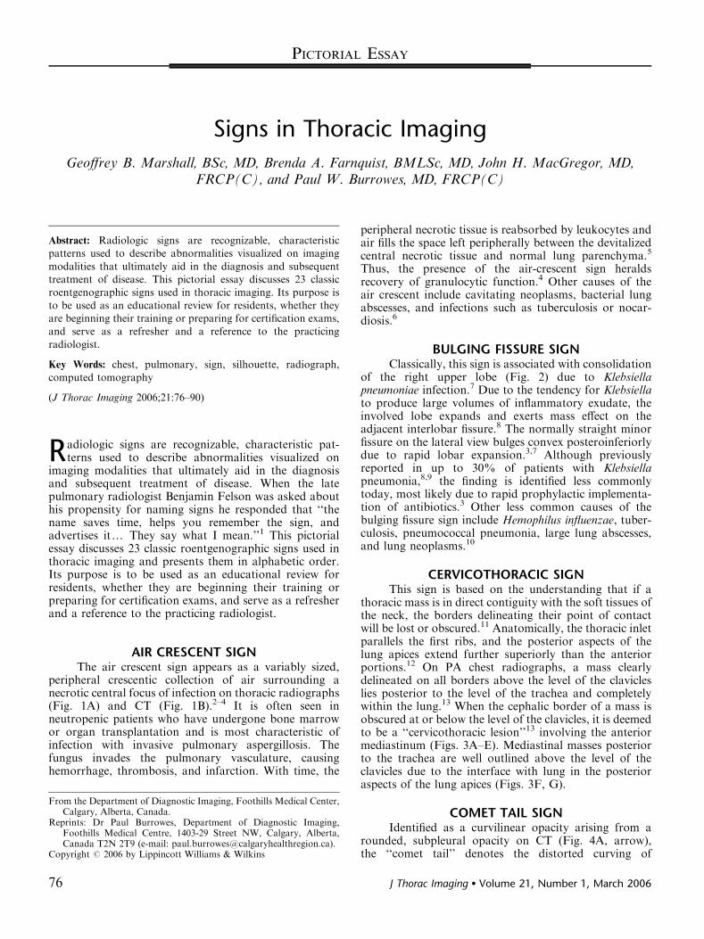
AIR CRESCENT SIGNThe air crescent sign appears as a variably sized,
peripheral crescentic collection of air surrounding anecrotic central focus of infection on thoracic radiographs(Fig. 1A) and CT (Fig. 1B).2–4 It is often seen inneutropenic patients who have undergone bone marrowor organ transplantation and is most characteristic ofinfection with invasive pulmonary aspergillosis. Thefungus invades the pulmonary vasculature, causinghemorrhage, thrombosis, and infarction. With time, the
peripheral necrotic tissue is reabsorbed by leukocytes andair fills the space left peripherally between the devitalizedcentral necrotic tissue and normal lung parenchyma.5
Thus, the presence of the air-crescent sign heraldsrecovery of granulocytic function.4 Other causes of theair crescent include cavitating neoplasms, bacterial lungabscesses, and infections such as tuberculosis or nocar-diosis.6
BULGING FISSURE SIGNClassically, this sign is associated with consolidation
of the right upper lobe (Fig. 2) due to Klebsiellapneumoniae infection.7 Due to the tendency for Klebsiellato produce large volumes of inflammatory exudate, theinvolved lobe expands and exerts mass effect on theadjacent interlobar fissure.8 The normally straight minorfissure on the lateral view bulges convex posteroinferiorlydue to rapid lobar expansion.3,7 Although previouslyreported in up to 30% of patients with Klebsiellapneumonia,8,9 the finding is identified less commonlytoday, most likely due to rapid prophylactic implementa-tion of antibiotics.3 Other less common causes of thebulging fissure sign include Hemophilus influenzae, tuber-culosis, pneumococcal pneumonia, large lung abscesses,and lung neoplasms.10
CERVICOTHORACIC SIGNThis sign is based on the understanding that if a
thoracic mass is in direct contiguity with the soft tissues ofthe neck, the borders delineating their point of contactwill be lost or obscured.11 Anatomically, the thoracic inletparallels the first ribs, and the posterior aspects of thelung apices extend further superiorly than the anteriorportions.12 On PA chest radiographs, a mass clearlydelineated on all borders above the level of the clavicleslies posterior to the level of the trachea and completelywithin the lung.13 When the cephalic border of a mass isobscured at or below the level of the clavicles, it is deemedto be a ‘‘cervicothoracic lesion’’13 involving the anteriormediastinum (Figs. 3A–E). Mediastinal masses posteriorto the trachea are well outlined above the level of theclavicles due to the interface with lung in the posterioraspects of the lung apices (Figs. 3F, G).
COMET TAIL SIGNIdentified as a curvilinear opacity arising from a
rounded, subpleural opacity on CT (Fig. 4A, arrow),the ‘‘comet tail’’ denotes the distorted curving ofCopyright r 2006 by Lippincott Williams & Wilkins
From the Department of Diagnostic Imaging, Foothills Medical Center,Calgary, Alberta, Canada.
Reprints: Dr Paul Burrowes, Department of Diagnostic Imaging,Foothills Medical Centre, 1403-29 Street NW, Calgary, Alberta,Canada T2N 2T9 (e-mail: [email protected]).
PICTORIAL ESSAY
76 J Thorac Imaging � Volume 21, Number 1, March 2006
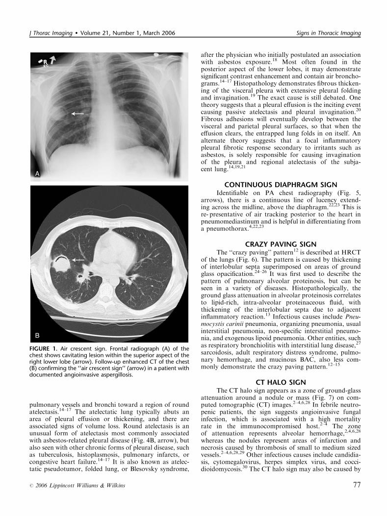
pulmonary vessels and bronchi toward a region of roundatelectasis.14–17 The atelectatic lung typically abuts anarea of pleural effusion or thickening, and there areassociated signs of volume loss. Round atelectasis is anunusual form of atelectasis most commonly associatedwith asbestos-related pleural disease (Fig. 4B, arrow), butalso seen with other chronic forms of pleural disease, suchas tuberculosis, histoplasmosis, pulmonary infarcts, orcongestive heart failure.14–17 It is also known as atelec-tatic pseudotumor, folded lung, or Blesovsky syndrome,
after the physician who initially postulated an associationwith asbestos exposure.18 Most often found in theposterior aspect of the lower lobes, it may demonstratesignificant contrast enhancement and contain air broncho-grams.14–17 Histopathology demonstrates fibrous thicken-ing of the visceral pleura with extensive pleural foldingand invagination.19 The exact cause is still debated. Onetheory suggests that a pleural effusion is the inciting eventcausing passive atelectasis and pleural invagination.20
Fibrous adhesions will eventually develop between thevisceral and parietal pleural surfaces, so that when theeffusion clears, the entrapped lung folds in on itself. Analternate theory suggests that a focal inflammatorypleural fibrotic response secondary to irritants such asasbestos, is solely responsible for causing invaginationof the pleura and regional atelectasis of the subja-cent lung.14,19,21
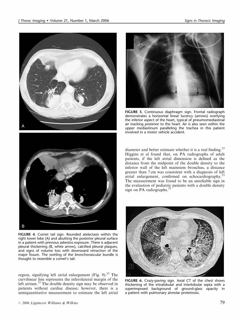
CONTINUOUS DIAPHRAGM SIGNIdentifiable on PA chest radiography (Fig. 5,
arrows), there is a continuous line of lucency extend-ing across the midline, above the diaphragm.22,23 This isre- presentative of air tracking posterior to the heart inpneumomediastinum and is helpful in differentiating froma pneumothorax.4,22,23
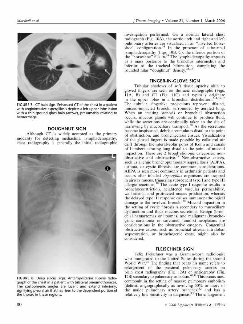
CRAZY PAVING SIGNThe ‘‘crazy paving’’ pattern12 is described at HRCT
of the lungs (Fig. 6). The pattern is caused by thickeningof interlobular septa superimposed on areas of groundglass opacification.24–26 It was first used to describe thepattern of pulmonary alveolar proteinosis, but can beseen in a variety of diseases. Histopathologically, theground glass attenuation in alveolar proteinosis correlatesto lipid-rich, intra-alveolar proteinaceous fluid, withthickening of the interlobular septa due to adjacentinflammatory reaction.13 Infectious causes include Pneu-mocystis carinii pneumonia, organizing pneumonia, usualinterstitial pneumonia, non-specific interstitial pneumo-nia, and exogenous lipoid pneumonia. Other entities, suchas respiratory bronchiolitis with interstitial lung disease,27
sarcoidosis, adult respiratory distress syndrome, pulmo-nary hemorrhage, and mucinous BAC, also less com-monly demonstrate the crazy paving pattern.12–15
CT HALO SIGNThe CT halo sign appears as a zone of ground-glass
attenuation around a nodule or mass (Fig. 7) on com-puted tomographic (CT) images.2–4,6,28 In febrile neutro-penic patients, the sign suggests angioinvasive fungalinfection, which is associated with a high mortalityrate in the immunocompromised host.2–4 The zoneof attenuation represents alveolar hemorrhage,2,4,6,28
whereas the nodules represent areas of infarction andnecrosis caused by thrombosis of small to medium sizedvessels.2–4,6,28,29 Other infectious causes include candidia-sis, cytomegalovirus, herpes simplex virus, and cocci-dioidomycosis.30 The CT halo sign may also be caused by
FIGURE 1. Air crescent sign. Frontal radiograph (A) of thechest shows cavitating lesion within the superior aspect of theright lower lobe (arrow). Follow-up enhanced CT of the chest(B) confirming the ‘‘air crescent sign’’ (arrow) in a patient withdocumented angioinvasive aspergillosis.
J Thorac Imaging � Volume 21, Number 1, March 2006 Signs in Thoracic Imaging
r 2006 Lippincott Williams & Wilkins 77

non-infectious causes, such as Wegener granulomatosis,metastatic angiosarcoma, Kaposi sarcoma, and brochio-loalveolar carcinoma (BAC).29,30 Due to the lepidicgrowth pattern of BAC, where the tumor cells spread alongthe alveolar walls, the typical ground glass halo visualizedwith the sign results.29
DEEP SULCUS SIGNThe presence of radiolucency in a deep costophrenic
sulcus on a supine thoracic radiograph (Fig. 8) ischaracteristic of a pneumothorax in a supine patient.31
Intrapleural air rises to the highest portion of thehemithorax leading to the presence of a lucency in theanteromedial, subpulmonic, and lateral basilar spaceadjacent to the diaphragm.3,4,31 It is useful in confirmingsuspected pneumothorax on AP supine radiography incompromised patients, such as those in the intensive caresetting.4
DOUBLE DENSITY SIGNOn frontal chest radiographs, this sign presents as a
curvilinear density projecting over the right retrocardiac
FIGURE 3. Cervicothoracic sign. Frontal radiograph of the chest with a coned view (A, B) demonstrates a mass projecting over theright superior mediastinum with indistinct borders along its superior margin. Follow-up enhanced CT of the chest (C, D) reveals amass extending from the cervical region into the anterior mediastinum representing a multinodular goiter. Conversely, in the caseof a posterior mediastinal mass, the supralateral margins project above the level of the clavicles and are clearly defined on thefrontal radiograph (E, F) in this patient (different patient from A, B) with a biopsy-proven ganglioneuroma (G, CT image).
FIGURE 2. Bulging fissure sign. PA (A)and lateral (B) radiographs of the chestshow dense consolidation of the rightmiddle lobe secondary to Klebsiellapneumoniae. Although classically thebulging fissure sign is demonstrated withright upper lobe consolidation andbowing of the minor fissure posteroin-feriorly, the consolidated segment in thiscase is causing upward bowing of theminor fissure (arrows).
Marshall et al J Thorac Imaging � Volume 21, Number 1, March 2006
78 r 2006 Lippincott Williams & Wilkins
region, signifying left atrial enlargement (Fig. 9).32 Thecurvilinear line represents the inferolateral margin of theleft atrium.33 The double density sign may be observed inpatients without cardiac disease; however, there is asemiquantitative measurement to estimate the left atrial
diameter and better estimate whether it is a real finding.33
Higgins et al found that, on PA radiographs of adultpatients, if the left atrial dimension is defined as thedistance from the midpoint of the double density to theinferior wall of the left mainstem bronchus, a distancegreater than 7 cm was consistent with a diagnosis of leftatrial enlargement, confirmed on echocardiography.33
The measurement was found to be an unreliable sign inthe evaluation of pediatric patients with a double densitysign on PA radiographs.33
FIGURE 4. Comet tail sign. Rounded atelectasis within theright lower lobe (A) and abutting the posterior pleural surfacein a patient with previous asbestos exposure. There is adjacentpleural thickening (B, white arrow), calcified pleural plaques,and signs of volume loss with downward retraction of themajor fissure. The swirling of the bronchovascular bundle isthought to resemble a comet’s tail.
FIGURE 5. Continuous diaphragm sign. Frontal radiographdemonstrates a horizontal linear lucency (arrows) overlyingthe inferior aspect of the heart, typical of pneumomediastinalair tracking posterior to the heart. Air is also seen within theupper mediastinum paralleling the trachea in this patientinvolved in a motor vehicle accident.
FIGURE 6. Crazy-paving sign. Axial CT of the chest showsthickening of the intralobular and interlobular septa with asuperimposed background of ground-glass opacity ina patient with pulmonary alveolar proteinosis.
J Thorac Imaging � Volume 21, Number 1, March 2006 Signs in Thoracic Imaging
r 2006 Lippincott Williams & Wilkins 79
DOUGHNUT SIGNAlthough CT is widely accepted as the primary
modality for detecting mediastinal lymphadenopathy,chest radiography is generally the initial radiographic
investigation performed. On a normal lateral chestradiograph (Fig. 10A), the aortic arch and right and leftpulmonary arteries are visualized in an ‘‘inverted horse-shoe’’ configuration.34 In the presence of subcarinallymphadenopathy (Figs. 10B, C), the inferior portion ofthe ‘‘horseshoe’’ fills in.34 The lymphadenopathy appearsas a mass posterior to the bronchus intermedius andinferior to the tracheal bifurcation, completing therounded hilar ‘‘doughnut’’ density.34,35
FINGER-IN-GLOVE SIGNTubular shadows of soft tissue opacity akin to
gloved fingers are seen on thoracic radiographs (Figs.11A, B) and CT (Fig. 11C) and typically originatein the upper lobes in a bronchial distribution.2–4,36,37
The tubular, fingerlike projections represent dilated,mucoid-impacted bronchi surrounded by aerated lung.When an inciting stenosis or bronchial obstructionoccurs, mucous glands will continue to produce fluid,while the secretions are continually taken to the site ofnarrowing by mucociliary transport.38 As the secretionsbecome inspissated, debris accumulates distal to the pointof obstruction, and bronchiectasis ensues. Visualizationof the gloved fingers is made possible by collateral airdrift through the interalveolar pores of Kohn and canalsof Lambert aerating lung distal to the point of mucoidimpaction. There are 2 broad etiologic categories: non-obstructive and obstructive.38 Non-obstructive causes,such as allergic bronchopulmonary aspergillosis (ABPA),asthma, or cystic fibrosis, are common considerations.ABPA is seen most commonly in asthmatic patients andoccurs after inhaled Aspergillus organisms are trappedin airway mucus, triggering subsequent type I and type IIIallergic reactions.38 The acute type I response results inbronchoconstriction, heightened vascular permeability,wall edema, and protracted mucus production, whereasthe delayed type III response causes immunopathologicaldamage to the involved bronchi.38 Mucoid impaction inthe setting of cystic fibrosis is secondary to mucociliarydysfunction and thick mucous secretions. Benign (bron-chial hamartomas or lipomas) and malignant (broncho-genic carcinoma or carcinoid tumors) neoplasms areconsiderations in the obstructive category. Congenitalobstructive causes, such as bronchial atresia, intralobarsequestration, or bronchogenic cysts, might also beconsidered.
FLEISCHNER SIGNFelix Fleischner was a German-born radiologist
who immigrated to the United States during the secondWorld War.39 The finding that bears his name refers toenlargement of the proximal pulmonary arteries onplain chest radiography (Fig. 12A) or angiography (Fig.12B) secondary to pulmonary embolism.40,41 This occurs mostcommonly in the setting of massive pulmonary embolism(defined angiographically as involving 50% or more ofthe major pulmonary artery branches)42 and has arelatively low sensitivity in diagnosis.43 The enlargement
FIGURE 7. CT halo sign. Enhanced CT of the chest in a patientwith angioinvasive aspergillosis depicts a left upper lobe lesionwith a thin ground glass halo (arrow), presumably relating tohemorrhage.
FIGURE 8. Deep sulcus sign. Anteroposterior supine radio-graph of the chest in a patient with bilateral pneumothoraces.The costophrenic angles are lucent and extend inferiorly,signifying pleural air that has risen to the dependent portion ofthe thorax in these regions.
Marshall et al J Thorac Imaging � Volume 21, Number 1, March 2006
80 r 2006 Lippincott Williams & Wilkins
can be caused by massive embolus enlarging the luminaldiameter of the proximal artery in the acute setting butcan also be seen in the subacute to chronic setting due toelevated pressures in the pulmonary arterial circulation.44
An important ancillary finding is the abrupt tapering ofthe occluded pulmonary artery distally, creating the‘‘knuckle sign.’’44
GOLDEN S SIGNDr Ross Golden was an American-born radiologist
who originally described this sign as a form of right upper
lobe collapse associated with a central mass.45 When theright upper lobe bronchus is obstructed by an endobron-chial lesion, there is elevation and medial displacement ofthe minor fissure with proximal convexity of the fissuredue to the mass (Fig. 13). This creates the ‘‘reverse S’’characteristic of central obstructing bronchogenic carci-nomas.3,4,45 Given the same presentation of a proximal,obstructing endobronchial lesion within the left upperlobe bronchus with associated left upper lobe collapse,the upwardly retracted major fissure will follow anS-shaped contour along its length. Although initiallyused to describe signs of right upper lobe collapse, the
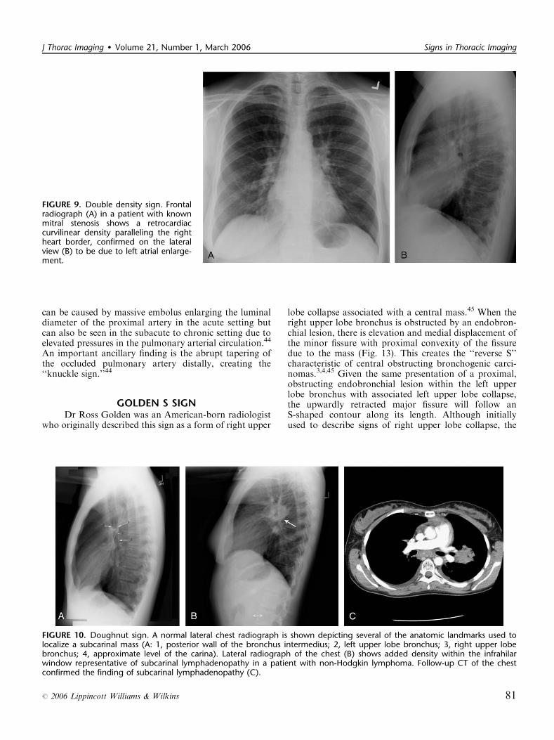
FIGURE 9. Double density sign. Frontalradiograph (A) in a patient with knownmitral stenosis shows a retrocardiaccurvilinear density paralleling the rightheart border, confirmed on the lateralview (B) to be due to left atrial enlarge-ment.
FIGURE 10. Doughnut sign. A normal lateral chest radiograph is shown depicting several of the anatomic landmarks used tolocalize a subcarinal mass (A: 1, posterior wall of the bronchus intermedius; 2, left upper lobe bronchus; 3, right upper lobebronchus; 4, approximate level of the carina). Lateral radiograph of the chest (B) shows added density within the infrahilarwindow representative of subcarinal lymphadenopathy in a patient with non-Hodgkin lymphoma. Follow-up CT of the chestconfirmed the finding of subcarinal lymphadenopathy (C).
J Thorac Imaging � Volume 21, Number 1, March 2006 Signs in Thoracic Imaging
r 2006 Lippincott Williams & Wilkins 81
Golden S sign can be applicable to atelectasis involvingany lobe.46
HAMPTON HUMPOn plain radiographs (Fig. 14A) and CT (Figs. 14B,
C), pulmonary infarcts are typically multifocal, peripheralin location, contiguous with one or more pleural surfaces,and more commonly confined to the lower lungs.3,47,48
The apex of these rounded or triangularly shapedopacities may point toward the hilum.3 The opacities re-solve slowly over a period of several months, akin to‘‘melting ice cubes,’’ and may leave a residual scar.3 Thefirst documentation of the finding was made by AubreyOtis Hampton, who was a practicing radiologist in themid 1920s. He and his co-author Castleman first reported
evidence of incomplete pulmonary infarction in the sett-ing of PE in the 1940s.47,48 Autopsy follow-up showedevidence of intra-alveolar hemorrhage without alveolarwall necrosis in the first 2 days of infarction. After 2 days,wall necrosis begins and eventually leads to pulmonaryinfarction and an organized scar.47,48 Hampton alsoobserved that there were differences in the healing ofthese incomplete infarcts depending on their premorbidcardiac history.47,48 In patients without heart disease,the incomplete infarcts would generally heal withoutscarring, whereas patients with congestive failure weremore likely to progress to infarction with a persis-ting pulmonary scar.47,48 When pulmonary embolismresults in infarction, airspace opacities typically developwithin 12 to 24 hours.3,48
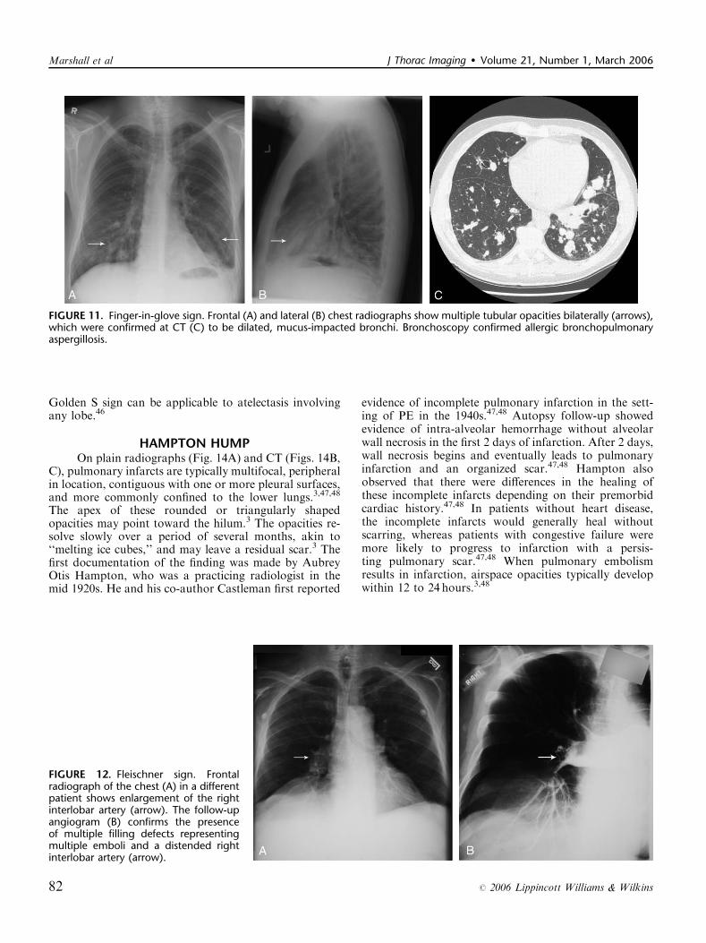
FIGURE 11. Finger-in-glove sign. Frontal (A) and lateral (B) chest radiographs show multiple tubular opacities bilaterally (arrows),which were confirmed at CT (C) to be dilated, mucus-impacted bronchi. Bronchoscopy confirmed allergic bronchopulmonaryaspergillosis.
FIGURE 12. Fleischner sign. Frontalradiograph of the chest (A) in a differentpatient shows enlargement of the rightinterlobar artery (arrow). The follow-upangiogram (B) confirms the presenceof multiple filling defects representingmultiple emboli and a distended rightinterlobar artery (arrow).
Marshall et al J Thorac Imaging � Volume 21, Number 1, March 2006
82 r 2006 Lippincott Williams & Wilkins
HILUM OVERLAY SIGNIn evaluating densities projecting over the hila on
PA chest radiographs, it is important to evaluate whetherthe opacity blends with the normal hilar shadow of theproximal pulmonary arteries and obscures clear visualiza-tion or if the mass and hilar structures are overlappingbut distinct from one another. If the hilar vessels aresharply delineated, then it can be assumed that theoverlying mass is anterior (Fig. 15) or posterior to the
centrally located vascular structures and the interveningaerated lung enables crisp visualization of the pulmonaryvessels.12,13 However, when the mass is inseparable fromthe proximal pulmonary arteries, it is assumed that thestructures are immediately adjacent to one another, withthe lack of interposing air obscuring the margins of thenormal hilar structures. This sign was originally describedby Benjamin Felson.12,13
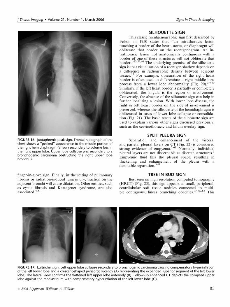
JUXTAPHRENIC PEAK SIGNThis sign, first documented by Kattan et al in
1980,49 is an ancillary sign of upper lobe collapse,depicted as a triangular opacity projecting superiorlyover the medial half of the diaphragm, at or near itshighest point (Fig. 16). It is most commonly relatedto the presence of an inferior accessory fissure.49,50
Although the mechanism is not certain, one theorysuggests it is due to the negative pressure of upper lobeatelectasis causing upward retraction of the visceralpleura and extrapleural fat protruding into the recess ofthe fissure.49 A recent retrospective analysis of patientswho have undergone upper lobectomies suggests that theprevalence of the sign increases in the ensuing weeks afterintervention and documents its utility in specificallyrecognizing the type of surgery.51
LUFTSICHEL SIGNThe word Luftsichel is German for ‘‘air crescent.’’
The finding is seen in the setting of left upper lobecollapse. Due to the absence of a minor fissure on the left,as the left upper lobe collapses, the major fissure assumesa vertical position roughly parallel to the anterior chestwall.4 As volume loss progresses, the fissure continues tomigrate more anteriorly and medially until the atelectaticlobe is contiguous with the left heart border, effectivelyobliterating its contour on the frontal radiograph(Figs. 17A–C). With movement of the apical upper lobesegment anteromedially, the superior segment of the leftlower lobe hyperinflates and fills the vacated apicalspace.4,52 Occasionally this segment will insinuate itselfbetween the aortic arch and the collapsed left upper lobecreating a sharp outline, or periaortic lucency, describedas the Luftsichel.3,4,52
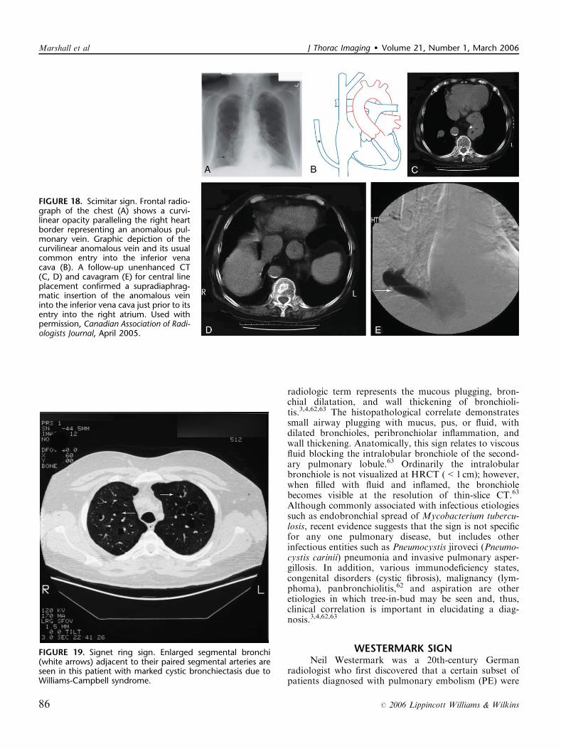
SCIMITAR SIGNOn PA chest radiography, a characteristic broad,
curved shadow extends inferiorly toward the diaphragmalong the right side of the heart (Figs. 18A, B).53 Itsappearance resembles a Turkish sword and signifies apartial anomalous pulmonary venous return, mostcommonly to the infradiaphragmatic inferior vena cava(Figs. 18C–E). It is part of the congenital hypogeneticlung (scimitar) syndrome.4,53
SIGNET RING SIGNDescribed on chest CT (Fig. 19, arrows) as a circle
of soft-tissue attenuation abutting a lucent ring, this signdepicts the pulmonary artery lying adjacent to a dilated
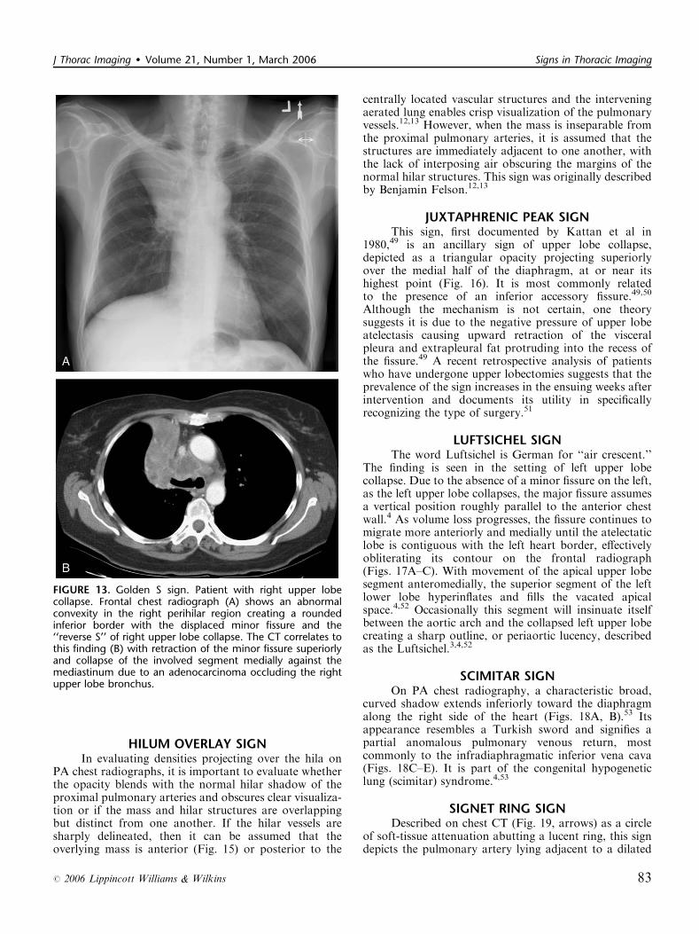
FIGURE 13. Golden S sign. Patient with right upper lobecollapse. Frontal chest radiograph (A) shows an abnormalconvexity in the right perihilar region creating a roundedinferior border with the displaced minor fissure and the‘‘reverse S’’ of right upper lobe collapse. The CT correlates tothis finding (B) with retraction of the minor fissure superiorlyand collapse of the involved segment medially against themediastinum due to an adenocarcinoma occluding the rightupper lobe bronchus.
J Thorac Imaging � Volume 21, Number 1, March 2006 Signs in Thoracic Imaging
r 2006 Lippincott Williams & Wilkins 83
bronchus in cross-section.54–57 The sign is found on CT inpatients with bronchiectasis, or irreversible, abnormalbronchial dilatation.56 Accompanying findings, such asperibronchial thickening, lack of bronchial tapering, andvisualization of bronchi within 1 cm of the pleura, are allcontributing findings confirming the diagnosis. In isola-tion, an enlarged bronchoarterial ratio may be a spuriousfinding, as bronchial diameter varies with parameters
such as altitude.58 Measurement of the bronchial luminaldiameter is made between the inner walls so as not tooverestimate in cases with associated peribronchialthickening. Bronchiectasis occurs due to bronchial wallinjury, most often due to necrotizing viral or bacterialbronchitis.4,57,58 It can also occur secondary to bronchialobstruction with subsequent mucus production dilatingthe involved airways, as mentioned previously with the
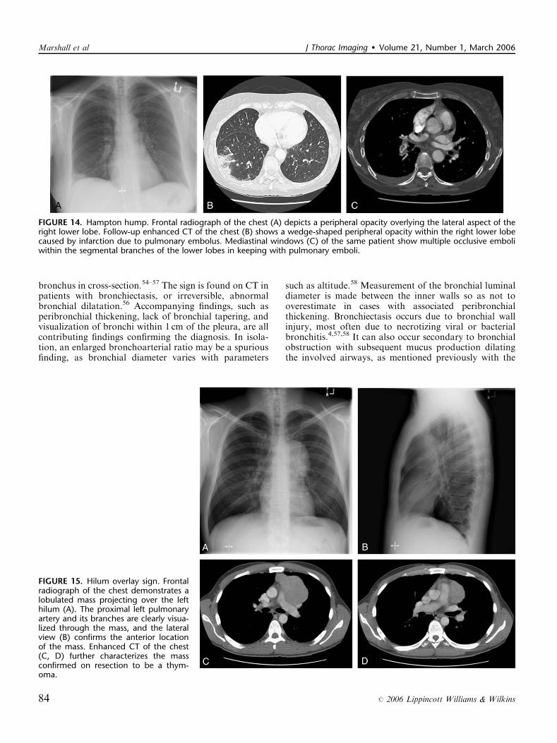
FIGURE 14. Hampton hump. Frontal radiograph of the chest (A) depicts a peripheral opacity overlying the lateral aspect of theright lower lobe. Follow-up enhanced CT of the chest (B) shows a wedge-shaped peripheral opacity within the right lower lobecaused by infarction due to pulmonary embolus. Mediastinal windows (C) of the same patient show multiple occlusive emboliwithin the segmental branches of the lower lobes in keeping with pulmonary emboli.
FIGURE 15. Hilum overlay sign. Frontalradiograph of the chest demonstrates alobulated mass projecting over the lefthilum (A). The proximal left pulmonaryartery and its branches are clearly visua-lized through the mass, and the lateralview (B) confirms the anterior locationof the mass. Enhanced CT of the chest(C, D) further characterizes the massconfirmed on resection to be a thym-oma.
Marshall et al J Thorac Imaging � Volume 21, Number 1, March 2006
84 r 2006 Lippincott Williams & Wilkins
finger-in-glove sign. Finally, in the setting of pulmonaryfibrosis or radiation-induced lung injury, traction on theadjacent bronchi will cause dilatation. Other entities, suchas cystic fibrosis and Kartagener syndrome, are alsoassociated.4,57
SILHOUETTE SIGNThis classic roentgenographic sign first described by
Felson in 1950 states that ‘‘an intrathoracic lesiontouching a border of the heart, aorta, or diaphragm willobliterate that border on the roentgenogram. An in-trathoracic lesion not anatomically contiguous with aborder of one of these structures will not obliterate thatborder.’’13,59,60 The underlying premise of the silhouettesign is that visualization of a roentgen shadow depends ona difference in radiographic density between adjacenttissues.13 For example, obscuration of the right heartborder is often used to differentiate a right middle lobeprocess from a lower lobe abnormality (Fig. 20).3,4,60
Similarly, if the left heart border is partially or completelyobliterated, the lingula is the region of involvement.Conversely, the absence of the silhouette sign can help infurther localizing a lesion. With lower lobe disease, theright or left heart border on the side of involvement ispreserved, whereas the silhouette of the hemidiaphragm isobliterated in cases of lower lobe collapse or consolida-tion (Fig. 21). The basic tenets of the silhouette sign areused to explain various other signs discussed previously,such as the cervicothoracic and hilum overlay sign.
SPLIT PLEURA SIGNSeparation and enhancement of the visceral
and parietal pleural layers on CT (Fig. 22) is consideredstrong evidence of empyema.3,61 Normally, individualpleural layers are not discernable as discrete structures.3
Empyemic fluid fills the pleural space, resulting inthickening and enhancement of the pleura with adenotable separation.3,61
TREE-IN-BUD SIGNBest seen on high resolution computed tomography
(HRCT) (Fig. 23), this sign appears as small, peripheral,centrilobular soft tissue nodules connected to multi-ple contiguous, linear branching opacities.3,4,62,63 This
FIGURE 16. Juxtaphrenic peak sign. Frontal radiograph of thechest shows a ‘‘peaked’’ appearance to the middle portion ofthe right hemidiaphragm (arrow) secondary to volume loss inthe right upper lobe. Upper lobe collapse was secondary to abronchogenic carcinoma obstructing the right upper lobebronchus.
FIGURE 17. Luftsichel sign. Left upper lobe collapse secondary to bronchogenic carcinoma causing compensatory hyperinflationof the left lower lobe and a crescent-shaped periaortic lucency (A) representing the expanded superior segment of the left lowerlobe. The lateral view confirms the flattened left upper lobe anteriorly (B). Follow-up enhanced CT depicts the collapsed upperlobe against the mediastinum with compensatory hyperinflation of the left lower lobe (C).
J Thorac Imaging � Volume 21, Number 1, March 2006 Signs in Thoracic Imaging
r 2006 Lippincott Williams & Wilkins 85
radiologic term represents the mucous plugging, bron-chial dilatation, and wall thickening of bronchioli-tis.3,4,62,63 The histopathological correlate demonstratessmall airway plugging with mucus, pus, or fluid, withdilated bronchioles, peribronchiolar inflammation, andwall thickening. Anatomically, this sign relates to viscousfluid blocking the intralobular bronchiole of the second-ary pulmonary lobule.63 Ordinarily the intralobularbronchiole is not visualized at HRCT (<1 cm); however,when filled with fluid and inflamed, the bronchiolebecomes visible at the resolution of thin-slice CT.63
Although commonly associated with infectious etiologiessuch as endobronchial spread of Mycobacterium tubercu-losis, recent evidence suggests that the sign is not specificfor any one pulmonary disease, but includes otherinfectious entities such as Pneumocystis jiroveci (Pneumo-cystis carinii) pneumonia and invasive pulmonary asper-gillosis. In addition, various immunodeficiency states,congenital disorders (cystic fibrosis), malignancy (lym-phoma), panbronchiolitis,62 and aspiration are otheretiologies in which tree-in-bud may be seen and, thus,clinical correlation is important in elucidating a diag-nosis.3,4,62,63
WESTERMARK SIGNNeil Westermark was a 20th-century German
radiologist who first discovered that a certain subset ofpatients diagnosed with pulmonary embolism (PE) were
FIGURE 18. Scimitar sign. Frontal radio-graph of the chest (A) shows a curvi-linear opacity paralleling the right heartborder representing an anomalous pul-monary vein. Graphic depiction of thecurvilinear anomalous vein and its usualcommon entry into the inferior venacava (B). A follow-up unenhanced CT(C, D) and cavagram (E) for central lineplacement confirmed a supradiaphrag-matic insertion of the anomalous veininto the inferior vena cava just prior to itsentry into the right atrium. Used withpermission, Canadian Association of Radi-ologists Journal, April 2005.
FIGURE 19. Signet ring sign. Enlarged segmental bronchi(white arrows) adjacent to their paired segmental arteries areseen in this patient with marked cystic bronchiectasis due toWilliams-Campbell syndrome.
Marshall et al J Thorac Imaging � Volume 21, Number 1, March 2006
86 r 2006 Lippincott Williams & Wilkins
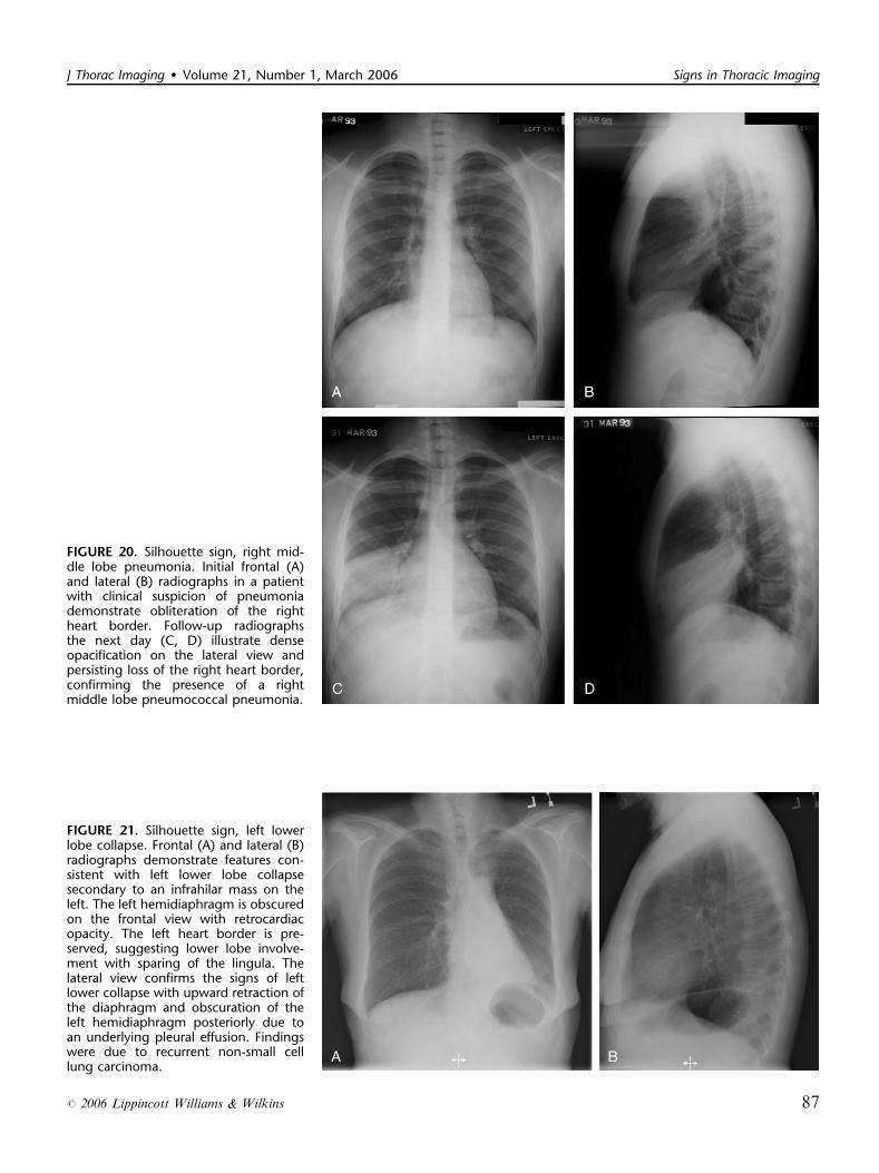
FIGURE 20. Silhouette sign, right mid-dle lobe pneumonia. Initial frontal (A)and lateral (B) radiographs in a patientwith clinical suspicion of pneumoniademonstrate obliteration of the rightheart border. Follow-up radiographsthe next day (C, D) illustrate denseopacification on the lateral view andpersisting loss of the right heart border,confirming the presence of a rightmiddle lobe pneumococcal pneumonia.
FIGURE 21. Silhouette sign, left lowerlobe collapse. Frontal (A) and lateral (B)radiographs demonstrate features con-sistent with left lower lobe collapsesecondary to an infrahilar mass on theleft. The left hemidiaphragm is obscuredon the frontal view with retrocardiacopacity. The left heart border is pre-served, suggesting lower lobe involve-ment with sparing of the lingula. Thelateral view confirms the signs of leftlower collapse with upward retraction ofthe diaphragm and obscuration of theleft hemidiaphragm posteriorly due toan underlying pleural effusion. Findingswere due to recurrent non-small celllung carcinoma.
J Thorac Imaging � Volume 21, Number 1, March 2006 Signs in Thoracic Imaging
r 2006 Lippincott Williams & Wilkins 87
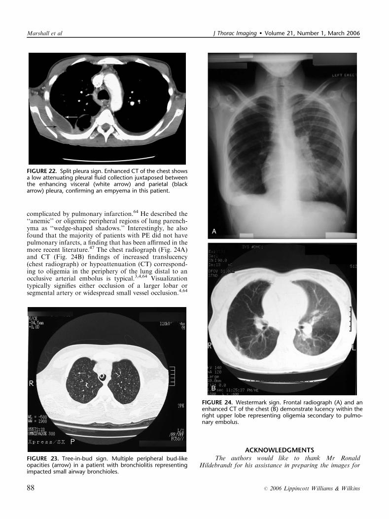
complicated by pulmonary infarction.64 He described the‘‘anemic’’ or oligemic peripheral regions of lung parench-yma as ‘‘wedge-shaped shadows.’’ Interestingly, he alsofound that the majority of patients with PE did not havepulmonary infarcts, a finding that has been affirmed in themore recent literature.47 The chest radiograph (Fig. 24A)and CT (Fig. 24B) findings of increased translucency(chest radiograph) or hypoattenuation (CT) correspond-ing to oligemia in the periphery of the lung distal to anocclusive arterial embolus is typical.3,4,64 Visualizationtypically signifies either occlusion of a larger lobar orsegmental artery or widespread small vessel occlusion.4,64
ACKNOWLEDGMENTSThe authors would like to thank Mr Ronald
Hildebrandt for his assistance in preparing the images for
FIGURE 22. Split pleura sign. Enhanced CT of the chest showsa low attenuating pleural fluid collection juxtaposed betweenthe enhancing visceral (white arrow) and parietal (blackarrow) pleura, confirming an empyema in this patient.
FIGURE 23. Tree-in-bud sign. Multiple peripheral bud-likeopacities (arrow) in a patient with bronchiolitis representingimpacted small airway bronchioles.
FIGURE 24. Westermark sign. Frontal radiograph (A) and anenhanced CT of the chest (B) demonstrate lucency within theright upper lobe representing oligemia secondary to pulmo-nary embolus.
Marshall et al J Thorac Imaging � Volume 21, Number 1, March 2006
88 r 2006 Lippincott Williams & Wilkins
the article. Special thanks to Heather Marshall fordesigning the schematic diagram of the scimitar vein.
REFERENCES1. Felson B. Letter from the editor. Sem Roentgenol. 1969;4:1.2. Franquet T, Muller NL, Gimenez A, et al. Spectrum of
pulmonary aspergillosis: histologic, clinical, and radiologic findings.Radiographics. 2001;21:825–837.
3. Collins J, Stern EJ. Signs in chest radiology. In: Collins J, Stern EJ,eds. Chest Radiology, The Essentials. Philadelphia: LippincottWilliams & Williams; 1999:18–27.
4. Muller NL, Fraser RS, Colman NC, et al. Radiologic Diagnosis ofDiseases of the Chest. Philadelphia: W.B. Saunders Company;2001.
5. Abramson S. Signs in imaging: the air-crescent sign. Radiology.2001;218:230–232.
6. Curtis AM, Smith GJ, Ravin CE. Air crescent sign of invasiveaspergillosis. Radiology. 1979;133:17–21.
7. Felson LB, Rosenberg LS, Hamburger M. Roentgen findings inacute Friedlander’s pneumonia. Radiology. 1949;53:559–565.
8. Barnes DJ, Naraqi S, Igo JD. The diagnostic and prognosticsignificance of bulging fissures in acute lobar pneumonia. Aust N Z JMed. 1988;18:130.
9. Moon WK, Im JG, Yeon KM, et al. Complications of Klebsiellapneumonia: CT evaluation. J Comput Assist Tomogr. 1995;19:176.
10. Francis JB, Francis PB. Bulging (sagging) fissure sign in Hemophilusinfluenzae lobar pneumonia. South Med J. 1978;71:1452–1453.
11. Felson B. More chest roentgen signs and how to teach them.Radiology. 1968;90:429.
12. Felson B. The mediastinum. Semin Roentgenol. 1969;4:41.13. Felson B. Localization of intrathoracic lesions. In: Felson B, ed.
Chest Roentgenology. Philadelphia: W.B. Saunders Company; 1973.14. Schneider HJ, Felson B, Gonzalez LL. Rounded atelectasis. AJR
Am J Roentgenol. 1980;134:225–232.15. Glass TA, Armstrong P, Minor GR, et al. Computed tomographic
features of round atelectasis. J Comput Tomogr. 1983;7:183–185.16. Doyle TC, Lawler GA. CT features of rounded atelectasis of the
lung. AJR Am J Roentgenol. 1984;143:225–228.17. Partap VA. The comet tail sign. Radiology. 1999;213:553–554.18. Blesovsky A. The folded lung. Br J Dis Chest. 1966;60:19–22.19. Menzies R, Fraser R. Round atelectasis: pathologic and pathogenic
features. Am J Surg Pathol. 1987;11:674–681.20. Hanke R, Kretzschmar R. Round atelectasis. Semin Roentgenol.
1980;15:174–182.21. Hillerdal G. Rounded atelectasis: clinical experience with 74
patients. Chest. 1989;95:836–841.22. Levin B. The continuous diaphragm sign. A newly recognized sign
of pneumomediastinum. Clin Radiol. 1973;24:337–338.23. Zylak CM, Standen JR, Barnes GR, et al. Pneumomediastinum
revisited. Radiographics. 2000;20:1043–1057.24. Franquet T, Gimenez A, Bordes R, et al. The crazy-paving pattern
in exogenous lipoid pneumonia: CT-pathologic correlation. AJRAm J Roentgenol. 1998;170:315–317.
25. Rossi SE, Erasmus JJ, Volpacchio M, et al. ‘‘Crazy-paving’’ patternat thin-section CT of the lungs: radiologic-pathologic overview.Radiographics. 2003;23:1509–1519.
26. Johkoh T, Itoh H, Muller NL, et al. Crazy-paving appearance atthin-section CT: spectrum of disease and pathologic findings.Radiology. 1999;211:155–160.
27. O’Donnell WJ, Kradin RL, Evins AE, et al. Case records ofthe Massachusetts General Hospital. Weekly clinicopathologicalexercises. Case 39-2004. A 52-year-old woman with recurrentepisodes of atypical pneumonia. N Engl J Med. 2004;351:2741–2749.
28. Kuhlman JE, Fishman EK, Siegelman SS. Invasive pulmonaryaspergillosis in acute leukemia: characteristic findings on CT, theCT halo sign, and the role of CT in early diagnosis. Radiology.1985;157:611–614.
29. Pinto P. Radiology. Signs in imaging: the CT halo sign. Radiology.2004;230:109–110.
30. Primack SL, Hartman TE, Lee KS, et al. Pulmonary nodules andthe CT halo sign. Radiology. 1994;190:513–515.
31. Gordon R. The deep sulcus sign. Radiology. 1980;136:25–27.32. Kaye J, Van Lingen B, Meyer MJ. The radiological diagnosis of
mitral valve disease. Br J Radiol. 1953;26:242–251.33. Higgins CB, Reinke RT, Jones NE, et al. Left atrial dimension
on the frontal thoracic radiograph: a method for assessingleft atrial enlargement. AJR Am J Roentgenol. 1978;130:251–255.
34. Andronikou S, Wieselthaler N. Modern imaging of tuberculosis inchildren: thoracic, central nervous system and abdominal tuber-culosis. Pediatr Radiol. 2004;34:861–875.
35. Roche CJ, O’Keeffe DP, Lee WK, et al. Selections from thebuffet of food signs in radiology. Radiographics. 2002;22:1369–1384.
36. Greer AE. Mucoid impaction of the bronchi. Ann Intern Med.1957;46:506–522.
37. Mintzer RA, Neiman HL, Reeder MM. Mucoid impaction of abronchus. JAMA. 1978;240:1397–1398.
38. Nguyen ET. Signs in imaging: the gloved finger sign. Radiology.2003;227:453–454.
39. Fraser RG, Mellins RB. The Fleischner Society: a 30th anniversaryretrospective. Radiology. 2000;214:631–632.
40. Fleischner FG. Roentgen diagnosis of pulmonary embolism. HeartBull. 1961;10:104–107.
41. Fleischner FG. Pulmonary embolism. Clin Radiol. 1962;13:169.
42. Kerr IH, Simon G, Sutton GC. The value of the plain radiographin acute massive pulmonary embolism. Br J Radiol. 1971;44:751.
43. Stein PD, Athanasoulis C, Greenspan RH, et al. Relation of plainchest radiographic findings to pulmonary arterial pressure andarterial blood oxygen levels in patients with acute pulmonaryembolism. Am J Cardiol. 1992;69:394.
44. Williams JR, Wilcox WC. Pulmonary embolism: roentgenographicand angiographic considerations. AJR Am J Roentgenol. 1963;89:333.
45. Golden R. The effect of bronchostenosis upon the roentgen-rayshadows in carcinoma of the bronchus. AJR Am J Roentgenol.1925;13:21–30.
46. Woodring JH, Reed JC. Radiographic manifestations of lobaratelectasis. J Thorac Imag. 1996;11:109–144.
47. Dalen JE. Pulmonary embolism: what have we learned sinceVirchow? Chest. 2002;122:1440–1456.
48. Hampton AO, Castleman B. Correlation of postmortem chestteleroentgenograms with autopsy findings with special reference topulmonary embolism and infarction. AJR Am J Roentgenol.1940;43:305–326.
49. Kattan KR, Eyler WR, Felson B. The juxtaphrenic peak in upperlobe collapse. Radiology. 1980;134:763–765.
50. Davis SD, Yankelevitz DF, Wand A, et al. Juxtaphrenic peak inupper and middle lobe volume loss: assessment with CT. Radiology.1996;198:143–149.
51. Konen E, Rozenman J, Simansky DA, et al. Prevalence of thejuxtaphrenic peak after upper lobectomy. AJR Am J Roentgenol.2001;177:869–873.
52. Webber M, Davies P. The Luftsichel: an old sign in upper lobecollapse. Clin Radiol. 1981;32:271–275.
53. Halasz NA, Halloran KH, Liebow AA. Bronchial and arterialanomalies with drainage of the right lung into the inferior vena cava.Circulation. 1956;14:826–846.
54. Naidich DP, McCauley DI, Khouri NF, et al. Computedtomography of bronchiectasis. J Comput Assist Tomogr. 1982;6:437–444.
55. McGuinness G, Naidich DT, Leitman BS, et al. Bronchiectasis: CTevaluation. AJR Am J Roentgenol. 1993;160:254–259.
56. Kang EY, Miller RR, Muller NL. Bronchiectasis: comparison ofpreoperative thin-section CT and pathologic findings in resectedspecimens. Radiology. 1994;195:649–654.
J Thorac Imaging � Volume 21, Number 1, March 2006 Signs in Thoracic Imaging
r 2006 Lippincott Williams & Wilkins 89

57. Ouellette H. Signs in imaging: the signet ring sign. Radiology.1999;212:67–68.
58. Kim JS. Bronchoarterial ratio on thin-section CT: comparisonbetween high altitude and sea level. J Comput Assist Tomogr.1997;21:306–311.
59. Felson B, Felson H. Localization of intrathoracic lesions bymeans of the postero-anterior roentgenogram; the silhouette sign.Radiology. 1950;55:363–374.
60. Longuet R, Phelan J, Tanous H, et al. Criteria of the silhouette sign.Radiology. 1977;122:581–585.
61. Stark DD, Federle MP, Goodman PC, et al. Differentiating lungabscess and empyema: radiography and computed tomography.AJR Am J Roentgenol. 1983;141:163–167.
62. Akira M, Kitatani F, Lee YS, et al. Diffuse panbronchiolitis:evaluation with high-resolution CT. Radiology. 1988;168:433–438.
63. Eisenhuber E. Signs in radiology: the tree-in-bud sign. Radiology.2002;222:771–772.
64. Westermark N. On the roentgen diagnosis of lung embolism. ActaRadiol. 1938;19:357–372.
Marshall et al J Thorac Imaging � Volume 21, Number 1, March 2006
90 r 2006 Lippincott Williams & Wilkins