simatic hmi hmi device pp 17-i profisafe in fail-safe operation - siemens … · 2015-01-20 · pp...
TRANSCRIPT
Preface
SIMATIC HMIHMI devicePP 17-I PROFIsafe in fail-safe operation
Operating Instructions (Compact)
Order no. 6AV6678-8LA00-0AB0
06/2006 A5E00457506-02
Overview 1
Planning Use
2
Mounting and Connection
3
Operator elements and displays
4
Configuring the HMI device
5
Fail-safe Mode
6
Appendix
A

Safety Guidelines This manual contains notices you have to observe in order to ensure your personal safety, as well as to prevent damage to property. The notices referring to your personal safety are highlighted in the manual by a safety alert symbol, notices referring only to property damage have no safety alert symbol. These notices shown below are graded according to the degree of danger.
Danger indicates that death or severe personal injury will result if proper precautions are not taken.
Warning indicates that death or severe personal injury may result if proper precautions are not taken.
Caution with a safety alert symbol, indicates that minor personal injury can result if proper precautions are not taken.
Caution without a safety alert symbol, indicates that property damage can result if proper precautions are not taken.
Notice indicates that an unintended result or situation can occur if the corresponding information is not taken into account.
If more than one degree of danger is present, the warning notice representing the highest degree of danger will be used. A notice warning of injury to persons with a safety alert symbol may also include a warning relating to property damage.
Qualified Personnel The device/system may only be set up and used in conjunction with this documentation. Commissioning and operation of a device/system may only be performed by qualified personnel. Within the context of the safety notes in this documentation qualified persons are defined as persons who are authorized to commission, ground and label devices, systems and circuits in accordance with established safety practices and standards.
Prescribed Usage Note the following:
Warning This device may only be used for the applications described in the catalog or the technical description and only in connection with devices or components from other manufacturers which have been approved or recommended by Siemens. Correct, reliable operation of the product requires proper transport, storage, positioning and assembly as well as careful operation and maintenance.
Trademarks All names identified by ® are registered trademarks of the Siemens AG. The remaining trademarks in this publication may be trademarks whose use by third parties for their own purposes could violate the rights of the owner.
Disclaimer of Liability We have reviewed the contents of this publication to ensure consistency with the hardware and software described. Since variance cannot be precluded entirely, we cannot guarantee full consistency. However, the information in this publication is reviewed regularly and any necessary corrections are included in subsequent editions.
이 기기는 업무용(A급) 전자파 적합기기로서 판매자 또는 사용자는 이 점을 주의하시기 바라며 가정 외의 지역에서 사용하는 것을 목적으로 합니다.

Siemens AG Automation and Drives Postfach 48 48 90437 NÜRNBERG GERMANY
Order no.: 6AV6678-8LA00-0ABEdition 06/2006
Copyright © Siemens AG 2006. Technical data subject to change
PP 17-I PROFIsafe in fail-safe operation Operating Instructions (Compact), 06/2006, 6AV6678-8LA00-0AB0 i
Preface Purpose of the Operating Instructions (compact)
This (compact) Operating Instructions is an extract from the PP 17-I PROFIsafe manual, edition 05/2006, and contains all information required for fail-safe operation of the HMI.
The full description of the HMI is found in the PP 17-I PROFIsafe operating instructions, edition 05/2006, which is certified by TÜV (Technical Inspection Authority) and always binding.
Documentation of fail-safe systems • System description "Safety engineering in SIMATIC S7"
– Provides an overview of the application, configuration, and function principle of S7 Distributed Safety and S7 F/FH fail-safe automation systems
– Contains a summary of detailed technical information on fail-safe engineering in S7-300 and S7-400 – Includes monitoring and reaction time calculation for S7 Distributed Safety and S7 F/FH fail-safe
systems • "S7 Distributed Safety Configuring and Programming" Manual / Online Help
Describes the configuration of the fail-safe CPU and fail-safe I/O, and the programming of the fail-safe CPU in F-FBD and F-LAD.
• "S7-400 Automation Systems, CPU data" Reference manual Describes the standard functions of the CPU 416F-2
Screens The HMI in this operating instruction, is partly displayed as photographs. Slight delivery status deviations of the HMI can occur in these photos.
Conventions Text is highlighted as follows to simplify reading the operating instructions:
Notation Scope
"Add screen" Terminology that appears in the user interface, e.g., dialog names, tabs, buttons, menu entries
Required parameters such as limit values, tag values
Path information
"File > Edit" Operation sequences such as menu commands, context menu commands
<F1>, <Alt+P> Keyboard operation
Please observe notes labeled as follows:
Note Notes contain important information concerning the product, its use or a specific section of the documentation to which you should pay particular attention.

Preface
PP 17-I PROFIsafe in fail-safe operation ii Operating Instructions (Compact), 06/2006, 6AV6678-8LA00-0AB0
Technical Support
You can contact Technical Support for all A&D projects
• Using the support request form on the web at: "http://www.siemens.de/automation/support-request"
• Telephone: + 49 180 5050 222 • Fax: + 49 180 5050 223 Further information about SIEMENS Technical Support is available on the Internet at "http://www.siemens.com/automation/service"
Service & Support on the Internet Service & Support offers online services for additional, comprehensive information on SIMATIC products at "http://www.siemens.com/automation/support":
• The newsletter offers you the latest information about to your products. • A large document base is available using our Service & Support search engine. • A world-wide forum where users and experts exchange their experience • Current product information, FAQs and downloads • Your local Automation & Drives representative • Information about on-site services, repairs, spare parts and lots more is available on our "Services"
pages.

PP 17-I PROFIsafe in fail-safe operation Operating Instructions (Compact), 06/2006, 6AV6678-8LA00-0AB0 iii
Table of contents 1 Overview 1-1
1.1 Functionality 1-1
1.2 Fail-safe Mode 1-1
1.3 Checklist for fail-safe operation 1-3
2 Planning Use 2-1
2.1 Prerequisites for fail-safe operation 2-1
3 Mounting and Connection 3-1
3.1 Mounting Standard Components 3-1
3.2 Wiring a Standard Component 3-3
3.3 Switching on and testing the HMI device 3-5
4 Operator elements and displays 4-1
4.1 Front-sided Control Elements and Displays 4-1
4.2 Backside HMI Components, LEDs and Ports 4-3
4.3 Labeling of Keys or Standard Components 4-6
5 Configuring the HMI device 5-1
5.1 Integrating the GSD File in STEP 7 5-1
5.2 Communication between the HMI Device and the PLC 5-1
5.3 Configuring the HMI device in STEP 7 5-6
5.4 Configure FB "F_PP17I_SIL3" 5-7
5.4.1 Overview 5-7
5.4.2 FB170 "F_PP17I_SIL3" 5-9
5.5 Configuring the PROFIBUS DP Interface 5-12
6 Fail-safe Mode 6-1
6.1 Overview 6-1
6.2 Query the State of the Emergency Stop Buttons 6-2
6.3 Passivation of the HMI device 6-3
6.4 Troubleshooting Check List 6-4
6.5 Error Diagnostics 6-6
6.6 Error Elimination and Reintegration 6-7

Table of contents
PP 17-I PROFIsafe in fail-safe operation iv Operating Instructions (Compact), 06/2006, 6AV6678-8LA00-0AB0
A Appendix A-1
A.1 System Alarms A-1
Index Index-1

PP 17-I PROFIsafe in fail-safe operation Operating Instructions (Compact), 06/2006, 6AV6678-8LA00-0AB0 1-1
Overview 1 1.1 Functionality
Performance Features Special performance features of the HMI for operation in fail-safe mode:
• Simultaneous operation in standard and fail-safe mode • Panel-mounting cut-outs optimized for the installation of emergency off switches with or without
protective collar. • In fail-safe mode, one to four emergency off buttons (dual-channel, with break contacts) can be
connected to the fail-safe channels. The design of the emergency off keys used must conform to the selected safety category.
• Three of the fail-safe channels can be used as standard digital inputs/outputs if not required for fail-safe operation.
• PROFIsafe communication allows fail-safe operation to SIL2/Cat. 3 and SIL3/Cat. 4.
Controllers The HMI has been released for the operation with a controller of the following type:
• SIMATIC CPU 416F-2 • SIMATIC CPU 315F-2 • SIMATIC CPU 317F-2
Differentiation of PP17-I and PP 17-I PROFIsafe Both HMIs feature the same front panel design.
Differences in the design features of the rear panel of the HMI for operation in fail-safe mode PP 17-I PROFIsafe compared to the standard HMI PP17-I:
• Printed type label "PP 17-I PROFIsafe" • Printed order number • Printed TÜV logo • White/yellow adhesive labels for the identification of digital IOs • Coded terminal blocks for the digital I/Os • Oval snap-out opening in the middle row • Message output on the configuration module of the PP 17-I PROFIsafe HMI after startup:
PP17 V2.xx
READY
1.2 Fail-safe Mode
Requirement For fail-safe operation of the HMI, the following software is required:
• SIMATIC S7 Distributed Safety as of V5.3

Overview 1.2 Fail-safe Mode
PP 17-I PROFIsafe in fail-safe operation 1-2 Operating Instructions (Compact), 06/2006, 6AV6678-8LA00-0AB0
Fail-safe automation system Fail-safe automation system (F systems) are used in plants requiring higher levels of safety.
F systems control processes in such a way that a safe state is achieved in every situation. An immediate shutdown therefore does not pose a danger to people or the environment.
Fail-safe Application of the HMI Device PP 17-I PROFIsafe is a DP-slave on PROFIBUS DP.
In fail-safe mode the HMI device registers the signal states of compatible emergency stop buttons and transmits corresponding safety frames to CPU. The CPU and HMI device communicate with each other via the fail-safe protocol, PROFIsafe.
SIL2/cat. 3 and SIL3/cat. 4 can be achieved with the HMI device by means of appropriate configuration of the safety functions in STEP 7 and the optional package "S7 Distributed Safety".
Fail-safe mode of the HMI differs from standard mode essentially in that for each fail-safe channel, two digital inputs and two digital outputs are used to relay the fail-safe input signals from the HMI to the CPU. The signals are monitored for errors during the communication. In the event of a fault, the HMI is placed into a safe state (1oo2 evaluation of the sensor).
The HMI device can be operated simultaneously in standard mode and fail-safe mode.
Diagnostic Function the HMI Device The fail-safe HMI device includes a non-configurable diagnostic function. The diagnostics are always activated and are automatically made available by the HMI in STEP 7 and passed on to the CPU in the event of a fault.
The diagnostic function passes the following diagnostics information to the CPU:
• Communication fault Communication between the HMI as DP-slave and the CPU as DP Master has been interrupted (e.g. due to wrong PROFIBUS address or PROFIsafe address).
• HW fault External wiring or internal hardware fault, data corruption or procedure error.
• Configuration error Error in the PROFIsafe configuration
Enable Input
Note Enable input does not affect the fail-safe channels The enable input of the HMI does not affect the digital inputs for the fail-safe channels. Fail-safe inputs are not locked when the HMI device is locked by an enable input. Emergency stop signals are always forwarded to the PLC.

Overview 1.3 Checklist for fail-safe operation
PP 17-I PROFIsafe in fail-safe operation Operating Instructions (Compact), 06/2006, 6AV6678-8LA00-0AB0 1-3
Example Configuration of an F System with a Fail-safe HMI Device
SIMATIC S7 416F-2 asDP Master (Class 1)
PROFIBUS Part 3 = PROFIBUS DP
F I/Oas
DP Slave
Standard I/Oas
DP Slave
Standard I/Oas
DP Slave
Operating and monitoring device asDP Master (Class 2) PP 17-I PROFIsafe
asDP Slave with F-I/O
Standard Host/SPSas
DP Master (Class 1)
Figure 1-1 Simultaneous operation of fail-safe and standard stations
In the depicted configuration, each DP-slave communicates with just one DP-master. The PP 17-I PROFIsafe communicates exclusively with the SIMATIC S7-416F-2 in this case.
1.3 Checklist for fail-safe operation
Introduction The checklist below can be used to verify that you have performed all necessary actions specifically required for fail-safe operation of the HMI. The steps in the HMI configuration are distinguished based on the safety class required.
Checklist for fail-safe operation Step Location Information Check
Phase 1: Planning Use
Determination of safety class (SIL2/cat. 3 or SIL3/cat. 4) that is to be achieved
- Chapter 2.1
Selection of sensors that fulfill the fail-safe mode requirements
- Chapter 2.1
Phase 2: Installing and connecting
Installing the emergency off buttons HMI device Chapter 3.1
Wiring the internal and external emergency off buttons Connecting strips, interfaces module on the rear panel of the HMI
Chapter 3.2
Overview 1.3 Checklist for fail-safe operation
PP 17-I PROFIsafe in fail-safe operation 1-4 Operating Instructions (Compact), 06/2006, 6AV6678-8LA00-0AB0
Step Location Information Check
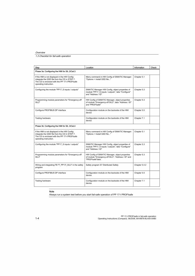
Phase 3a: Configuring the HMI for SIL 2/Cat.3
If the HMI is not displayed in the HW Config: integrate the GSD file from the CD in STEP 7. The CD is enclosed with the PP 17-I PROFIsafe operating instruction.
Menu command in HW Config of SIMATIC Manager: "Options > Install GSD file..."
Chapter 5.1
Configuring the module "PP17_S inputs / outputs" SIMATIC Manager HW Config, object properties of module "PP17_S inputs / outputs", tabs "Configure" and "Address / ID"
Chapter 5.3
Programming module parameters for "Emergency-off SIL2"
HW Config of SIMATIC Manager, object properties of module "Emergency-off SIL2", tabs "Address / ID" and "PROFIsafe"
Chapter 5.3
Configure PROFIBUS DP interface Configuration module on the backside of the HMI device
Chapter 5.5
Testing hardware Configuration module on the backside of the HMI device
Chapter 7.1
Phase 3b: Configuring the HMI for SIL 3/Cat.4
If the HMI is not displayed in the HW Config: integrate the GSD file from the CD in STEP 7. The CD is enclosed with the PP 17-I PROFIsafe operating instruction.
Menu command in HW Config of SIMATIC Manager: "Options > Install GSD file..."
Chapter 5.1
Configuring the module "PP17_S inputs / outputs" SIMATIC Manager HW Config, object properties of module "PP17_S inputs / outputs", tabs "Configure" and "Address / ID"
Chapter 5.3
Programming module parameters for "Emergency-off SIL3"
HW Config of SIMATIC Manager, object properties of module "Emergency-off SIL3", "Address / ID" and "PROFIsafe"tabs.
Chapter 5.3
Wiring and integrating FB "F_PP17I_SIL3" in the safety program
Safety program S7 Distributed Safety Chapter 5.4.2
Configure PROFIBUS DP interface Configuration module on the backside of the HMI device
Chapter 5.5
Testing hardware Configuration module on the backside of the HMI device
Chapter 7.1
Note Always run a system test before you start fail-safe operation of PP 17-I PROFIsafe

PP 17-I PROFIsafe in fail-safe operation Operating Instructions (Compact), 06/2006, 6AV6678-8LA00-0AB0 2-1
Planning Use 2 2.1 Prerequisites for fail-safe operation
Achievable Safety Classes (SIL) The following safety classes can be achieved with the HMI device:
• SIL2/Cat. 3 • SIL3/Cat. 4
Warning
Safety Class SIL3/Cat. 4 Safety class SIL3/cat. 4 can only be achieved with FB "F_PP17I_SIL3". This function block is provided on the CD which contains these operating instructions. To integrate FB "F_PP17I_SIL3":
• It must be ensured that the FB will be called in the control program.
• The FB parameters must be clearly assigned to the HMI with SIL3/cat. 4.
Caution Perform an acceptance procedure before putting the HMI device into operation.
Requirements for the sensors to be used (emergency stop buttons)
Warning General sensor requirements Our electronics are equipped with such safety engineering features as to leave 85% of the maximum permissible probability of hazardous faults for sensors and actuators up to you (this corresponds to the recommended load division in safety engineering between sensing devices, actuating devices, and electronic switching for input, processing, and output). Note, therefore, that instrumentation with sensors and actuators entails a considerable safety responsibility. Consider, too, that sensors and actuators do not generally withstand proof-test intervals of 10 years (the interval for an external function test according to IEC 61508) without considerable loss of safety. The probability of hazardous faults and the rate of occurrence of hazardous faults of a safety function must comply with an upper limit determined by a safety integrity level (SIL). You will find a listing of values achieved by the HMI device "Fail-Safe Performance Characteristics" in the specifications for the HMI device. To achieve SIL3 (AK6/Category 4), suitably qualified sensors are necessary. The sensors used must fulfill the standards IEC/EN 60947-5-1 and IEC/EN 60947-5-5 (VDE 0660, section 200).
Warning The HMI can only recognize two-channel equivalent sensor signals (break contacts, two-channel). Error can be detected using the following configurations:
• When connecting non-equivalent sensor signals. • With redundant connection of a single-channel sensor
Planning Use 2.1 Prerequisites for fail-safe operation
PP 17-I PROFIsafe in fail-safe operation 2-2 Operating Instructions (Compact), 06/2006, 6AV6678-8LA00-0AB0
Emergency stop is detected using the following configuration:
• With redundant connection of two single-channel sensors (normally open switches).
Warning
No redundant connection of two single-channel break contacts Ascertain that under no circumstances are two single-channel break contacts redundantly connected as sensor signals. If sensor signals are connected redundantly (break contacts), a fault will only be recognized if one of the sensors is triggered.
Caution All digital inputs and digital outputs that are not reserved with a fail-safe channel may not be connected as low-impedance.
Requirements for the duration of sensor signals
Warning Encoder signal requirements in terms of signal duration:
• In order to guarantee accurate detection of the sensor signal by the HMI, you must ensure that the sensor signals have a minimum duration of 50 ms. This is ensured by the usage of push-to-lock emergency stop buttons.
• In order for pulses to be detected with certainty, the time between two signal changes (pulse duration) must be greater than the PROFIsafe monitoring time.
Requirements for Cables The cables used must meet the following requirements:
• The unique assignment of terminals to sensors must be ensured. • Cables laid outside of the switching cabinet must be laid separately in accordance with the relevant
standards e.g. in stable pipes or cable ducts. This is intended to prevent short-circuits and cross-circuits.
• When wiring external emergency stop buttons with the fail-safe channels of the HMI, the following cable lengths must be maintained: – Unshielded cables: Max. 1 m – Shielded cables: Max. 10 m

PP 17-I PROFIsafe in fail-safe operation Operating Instructions (Compact), 06/2006, 6AV6678-8LA00-0AB0 3-1
Mounting and Connection 3 3.1 Mounting Standard Components
Introduction Where required, 22.5 mm diameter standard components e.g. key switches and emergency stop buttons can be built into the HMI. The installation in the lower section of the HMI device front is prepared by a pre-perforated cut-out with oblong holes.
Mount the standard components before mounting the HMI device itself in the switchgear cabinet.
Determine mounting position If you want to mount several standard components, first plan what component should be mounted in which position.
• Emergency stop button We recommend mounting a maximum of one emergency stop switch in the HMI. Mount any planned additional emergency stop buttons in the environment of the HMI in other positions on your system. In doing so, consider the maximum allowed cable length.
Use one of the oval shaped cut-out openings in the middle row for mounting the emergency stop button with or without protective collar. These cut-out openings are constructed so that you can position the emergency stop button further to the right or left dependent on which of the crescent-shaped die-cast pieces have been broken out.
When planning, please consider that an emergency stop button needs more space on the front side of the HMI than other standard components.
• Other standard components All of the other standard components can be mounted in any of the cut-out openings.

Mounting and Connection 3.1 Mounting Standard Components
PP 17-I PROFIsafe in fail-safe operation 3-2 Operating Instructions (Compact), 06/2006, 6AV6678-8LA00-0AB0
Example mounting position The following pictures show the recommended configuration of standard components and emergency stop buttons:
1 2
Figure 3-1 Rear view
12
Figure 3-2 Front view
① Emergency stop button
② Standard components
Mounting Standard Components Proceed as follows:
1 2 3
1
2
3
Figure 3-3 Knockout aperture for standard component
Mounting and Connection 3.2 Wiring a Standard Component
PP 17-I PROFIsafe in fail-safe operation Operating Instructions (Compact), 06/2006, 6AV6678-8LA00-0AB0 3-3
1. Use a sharp knife to cut a slit into the membrane on the front of the HMI device where you want the oblong hole ①.
2. Cut the membrane along the outer edge ② of the desired breakout aperture so that the cut-out membrane section only remains attached to the remaining membrane where it covers the three small webs ③.
Note The membrane on the front of the HMI device should only be cut for the knockout aperture in order to maintain an IP65 degree of protection for the front surface after the mounting of the standard component.
3. Place a screwdriver into the elongated slot ① of the cut-out opening and turn the screwdriver until the pre-stamped die-cast piece detaches.
4. Remove the detached piece.
5. Position the standard component into the empty cut-out opening.
6. Secure the standard component.
Result The required control elements are mounted and can be wired.
See also Front-sided Control Elements and Displays (Page 4-1)
3.2 Wiring a Standard Component
Introduction
FAILSAFEDI DO
141312111009
2.12.2
1.11.2
3.13.24.14.2
0807
141312111009
2.12.2
1.11.2
3.13.24.14.2
0807
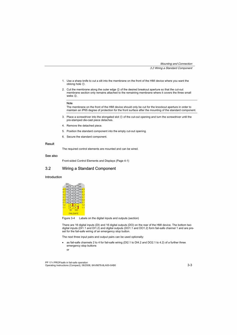
Figure 3-4 Labels on the digital inputs and outputs (section)
There are 16 digital inputs (DI) and 16 digital outputs (DO) on the rear of the HMI device. The bottom two digital inputs (DI1.1 and DI1.2) and digital outputs (DO1.1 and DO1.2) form fail-safe channel 1 and are pre-set for the fail-safe wiring of an emergency stop button.
The next three input pairs and output pairs can be used optionally:
• as fail-safe channels 2 to 4 for fail-safe wiring (DI2.1 to DI4.2 and DO2.1 to 4.2) of a further three emergency stop buttons or

Mounting and Connection 3.2 Wiring a Standard Component
PP 17-I PROFIsafe in fail-safe operation 3-4 Operating Instructions (Compact), 06/2006, 6AV6678-8LA00-0AB0
• for non-fail-safe wiring of six standard components (DI14 to DI09 and DO14 to DO09) The number of required emergency stop keys must match the number set in HW Config of the STEP 7 project ("Emergency Stop" parameter of the object properties of the slots hosting "PP17_S Inputs / Outputs"). The default value for this parameter is "4", i.e. four emergency stop keys are used and no non-fail-safe standard components.
The upper eight pairs of digital inputs (DI08 to DI01) and digital outputs (DO08 to DO01) are used for the wiring of standard components in standard mode.
Caution Fail-safe Mode The HMI device can only recognize two-channel equivalent sensor signals. The design of the emergency stop keys used must conform to the selected safety category.
Rules for Wiring
1
① Reverse polarity protection
• Only use the supplied coded terminal blocks to perform the wiring. • Wire the fail-safe channels gapless from bottom to top.
Example: Connecting two emergency stop buttons
– Connect emergency stop button 1 to the F channel 1 (DI1.1, DI1.2 and DO1.1, DO1.2) – Connect emergency stop button 2 to the F channel 2 (DI2.1, DI2.2 and DO2.1, DO2.2) – Wiring of an emergency stop button to the fail-safe channel 3 without assignment of fail-safe
channels 1 and 2 is not allowed.
Warning
All digital inputs and digital outputs that are not assigned to a fail-safe channel may not be connected with low-impedance (short-circuited).

Mounting and Connection 3.3 Switching on and testing the HMI device
PP 17-I PROFIsafe in fail-safe operation Operating Instructions (Compact), 06/2006, 6AV6678-8LA00-0AB0 3-5
Fail-safe Wiring of Emergency Stop Buttons Proceed as follows:
1. Connect emergency stop key 1 to the F channel 1 (digital inputs DI1.1 and DI1.2, digital outputs DO1.1 and DO1.2)
2. If you wish to use another emergency stop key, wire it to the F channel 2 (digital inputs DI2.1 and DI2.2, digital outputs DO2.1 and DO2.2)
3. Wire further emergency stop keys to the subsequent F channels gaplessly from bottom to top.
4. Perform a function test after wiring an emergency stop button.
See also Front-sided Control Elements and Displays (Page 4-1)
3.3 Switching on and testing the HMI device
Prerequisites for fail-safe operation
Caution Always check the following settings in HW Config of the SIMATIC Manager before commissioning, when using fail-safe mode:
• The number of connected emergency stop buttons must match the configuration of the HMI in HW Config.
• The modules "Emergency Stop SIL2" or "Emergency Stop SIL3" must be configured according to the required safety class.
Activate the host before switching on, otherwise a fault will occur in SIL3/cat. 4.

Mounting and Connection 3.3 Switching on and testing the HMI device
PP 17-I PROFIsafe in fail-safe operation 3-6 Operating Instructions (Compact), 06/2006, 6AV6678-8LA00-0AB0
Procedure Proceed as follows:
1. Connect the terminal block of the power supply to the HMI device.
2. Switch on the power supply. When the power is switched on, the "POWER" LED lights on the front of the HMI device.
The following message appears on the display of the configuration module during startup:
PP17 V2.xx
Startup
In this message "2.xx" stands for the fail-safe version of the HMI device.
If the HMI device does not start, it is possible the wires on the terminal block have been crossed. Check the connected wires and change the connections if necessary.
Mounting and Connection 3.3 Switching on and testing the HMI device
PP 17-I PROFIsafe in fail-safe operation Operating Instructions (Compact), 06/2006, 6AV6678-8LA00-0AB0 3-7
Ready for operation The following criteria indicates that the HMI device is ready for operation:
• The "POWER" LED on the front of the HMI device is lit, the "ERROR" LED is not. • The following message is shown on the display of the configuration module:
PP17 V2.xx
READY
Afterwards, perform a lamp test.
For detailed information on hardware and lamp tests, refer to the PP 17-I PROFIsafe operating instructions.
Switching off the HMI device Options for switching off the HMI device:
• Switch off the power supply. • Disconnect the terminal block from the HMI device. The system goes to a safe state in fail-safe mode.
Repairs Do not repair the device by yourself.
In case the HMI needs to be repaired, send it to the Retouren-Center in Fürth. The HMI device may only be repaired at the manufacturer's site.
The address is:
A&D Retouren-Center
Siemensstr. 2
D-90766 Fürth
If you use more than one HMI of the same type, we suggest the setup of a plant stop storage.
Note The HMI PP17 Standard replacement package is not allowed to be used for PP 17-I PROFIsafe.
See also Configuring the HMI device in STEP 7 (Page 5-6)
Front-sided Control Elements and Displays (Page 4-1)
Configuring the PROFIBUS DP Interface (Page 5-12)

Mounting and Connection 3.3 Switching on and testing the HMI device
PP 17-I PROFIsafe in fail-safe operation 3-8 Operating Instructions (Compact), 06/2006, 6AV6678-8LA00-0AB0

PP 17-I PROFIsafe in fail-safe operation Operating Instructions (Compact), 06/2006, 6AV6678-8LA00-0AB0 4-1
Operator elements and displays 4 4.1 Front-sided Control Elements and Displays
Front of the HMI device
1 2 3
① Keys with integrated LEDs
② Mounting position for standard components
③ "Power" LED and "Error" LED
Keys with integrated LEDs There are 16 short-stroke keys on the front of the HMI device. The individual keys can be configured as keys or switches.
• Button function: The corresponding bit in the PLC is set as long as the key is pressed. • Switch function: Pressing a key sets the corresponding bit in the PLC, a second press of the key sets it
back. Colored surface LEDs are integrated in each key. They can be used to indicate bit states of the connection PLC.
Red, green and yellow can be configured for the LEDs. The LEDs can flash and light continuously.

Operator elements and displays 4.1 Front-sided Control Elements and Displays
PP 17-I PROFIsafe in fail-safe operation 4-2 Operating Instructions (Compact), 06/2006, 6AV6678-8LA00-0AB0
The keys and LEDs are numbered as follows: 8
16
1
9 Figure 4-1 Numbering of the keys and LEDs
LED "POWER" The "POWER" LED lights as long as the HMI device is supplied with power.
"ERROR" LED The LED "ERROR" indicates if the HMI device is in test mode or if an error has occurred.
"ERROR" LED Displays Cause Remedy
LED flashes (normal mode) A PROFIsafe fault has occurred. Diagnose and rectify the fault.
LED lights (normal mode) A PROFIBUS fault has occurred. Diagnose and rectify the fault.
LED blinks (lamp test) A lamp test is currently being carried out.
End the lamp test by releasing the key assigned to the function or by resetting the two LED bits from the PLC.
LED lights (hardware test mode) A hardware test is being performed. Stop the hardware test using the menu of the configuration module or reboot the HMI device.
Additional Standard Components Knockout apertures are provided in the lower section of the HMI device for mounting additional standard components. A maximum of 12 additional components can be mounted and connected to the digital inputs outputs on the back of the HMI device.
A maximum of four emergency stop keys can be operated in fail-safe mode.
Labeling strips Labels can be applied to the keys and additionally mounted components.
See also Mounting Standard Components (Page 3-1)
Wiring a Standard Component (Page 3-3)
Labeling of Keys or Standard Components (Page 4-6)

Operator elements and displays 4.2 Backside HMI Components, LEDs and Ports
PP 17-I PROFIsafe in fail-safe operation Operating Instructions (Compact), 06/2006, 6AV6678-8LA00-0AB0 4-3
4.2 Backside HMI Components, LEDs and Ports
Back of the HMI Device
1 12 3
4
① Ports
② Configuration module
③ Knockout apertures for mounting standard components
④ Labeling strips
Operator elements and displays 4.2 Backside HMI Components, LEDs and Ports
PP 17-I PROFIsafe in fail-safe operation 4-4 Operating Instructions (Compact), 06/2006, 6AV6678-8LA00-0AB0
Configuration Module
1 2 3
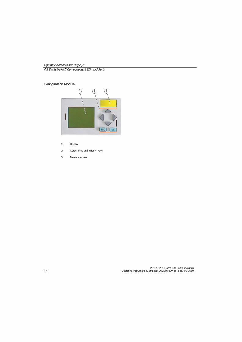
① Display
② Cursor keys and function keys
③ Memory module

Operator elements and displays 4.2 Backside HMI Components, LEDs and Ports
PP 17-I PROFIsafe in fail-safe operation Operating Instructions (Compact), 06/2006, 6AV6678-8LA00-0AB0 4-5
You can perform the following tasks with the configuration module:
• Configure the HMI-device interface to the PLC • Perform a hardware test A menu guides you through both tasks.
All parameters for the interface to the PLC are saved in the memory module of the HMI device. The memory module can be removed and used in another HMI device. Therefore it is not necessary to reconfigure the interface when exchanging the HMI electronics or the entire HMI device.
Note A memory module for a PP17-I standard device may not be used for a fail-safe PP 17-I PROFIsafe.
Digital Inputs and Outputs Additionally mounted standard components can be wired via the digital inputs and outputs. Unconnected digital inputs are automatically set to 0.
1
2
3
STANDARD
FAILSAFE
01DI DO
DI DO
02
141312111009
2.12.2
1.11.2
3.13.24.14.2
080706050403
0102
141312111009
2.12.2
1.11.2
3.13.24.14.2
080706050403
① Digital inputs DI01 to DI08, digital outputs DO01 to DO08
② Configurable:
• Standard digital inputs DI09 to DI14, standard digital outputs DO09 to DO14 or
• F channels 2 to 4: DI2.1 to DI4.2 and DO2.1 to DO4.2
③ F channel 1: DI1.1 and DI1.2, DO1.1 and DO1.2
Each F channel uses two digital inputs and two digital outputs. You set the number of F channels used in STEP 7.
The labels of the digital inputs and outputs are color-coded:
• Grey background: Assignment for standard mode • Yellow background: Assignment for fail-safe mode

Operator elements and displays 4.3 Labeling of Keys or Standard Components
PP 17-I PROFIsafe in fail-safe operation 4-6 Operating Instructions (Compact), 06/2006, 6AV6678-8LA00-0AB0
Power Supply and Enable Input On the left side of the HMI device's rear panel there are interfaces for connecting the power supply and enable input. Enable input makes it possible to disable the standard digital inputs of the HMI device.
Note Enable input does not affect the digital inputs of fail-safe channels The enable input does not affect the digital inputs assigned with fail-safe channels. Fail-safe inputs are not locked when the HMI device is locked by an enable input. Emergency stop signals are always forwarded to the PLC.
See also Configuring the HMI device in STEP 7 (Page 5-6)
Configuring the PROFIBUS DP Interface (Page 5-12)
Wiring a Standard Component (Page 3-3)
4.3 Labeling of Keys or Standard Components
Labeling of Keys or Standard Components You can label keys or standard components in relation to specific projects. Use labeling strips to do so.
The HMI comes with a sheet of removable labeling strips.
Additional sets of labeling strips can be ordered under order number 6AV3 671-8CB00.
1
① Labeling strips, example for the labeling of standard components
The labeling strips can be inserted before or after you install the HMI device.
Note Shorten or divide labeling strips if the standard components have been mounted in such a way as to prevent the lower part of a labeling strip from being pressed in.
Operator elements and displays 4.3 Labeling of Keys or Standard Components
PP 17-I PROFIsafe in fail-safe operation Operating Instructions (Compact), 06/2006, 6AV6678-8LA00-0AB0 4-7
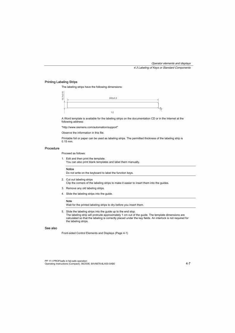
Printing Labeling Strips The labeling strips have the following dimensions:
A Word template is available for the labeling strips on the documentation CD or in the Internet at the following address:
"http://www.siemens.com/automation/support"
Observe the information in this file.
Printable foil or paper can be used as labeling strips. The permitted thickness of the labeling strip is 0.15 mm.
Procedure Proceed as follows:
1. Edit and then print the template. You can also print blank templates and label them manually.
Notice Do not write on the keyboard to label the function keys.
2. Cut out labeling strips Clip the corners of the labeling strips to make it easier to insert them into the guides.
3. Remove any old labeling strips.
4. Slide the labeling strips into the guide.
Note Wait for the printed labeling strips to dry before you insert them.
5. Slide the labeling strips into the guide up to the end stop. The labeling strip will protrude approximately 1 cm out of the guide. The template dimensions are calculated so that the labeling is correctly placed under the key fields. An interlock is not required for the labeling strips.
See also Front-sided Control Elements and Displays (Page 4-1)

Operator elements and displays 4.3 Labeling of Keys or Standard Components
PP 17-I PROFIsafe in fail-safe operation 4-8 Operating Instructions (Compact), 06/2006, 6AV6678-8LA00-0AB0

PP 17-I PROFIsafe in fail-safe operation Operating Instructions (Compact), 06/2006, 6AV6678-8LA00-0AB0 5-1
Configuring the HMI device 5 5.1 Integrating the GSD File in STEP 7
Principle If the HMI device is not listed in the hardware catalog of HW Config, you need to integrate the valid GSD (device database) files for the HMI device in the STEP 7 database. The GSD files are available on the documentation CD or in the Internet at the following address:
"http://www.siemens.com/automation/support"
Integrating a GSD File Proceed as follows:
1. Select the menu command "Options > Install GSD Files..." in the "HW Config" of the SIMATIC Manager.
2. Use the "Browse" function to open the drive where the GSD file is located (if you are using the CD, the CD drive of your PC). The GSD files in the selected folder are displayed.
3. Select the desired GSD file and click on "Install". The desired GSD file is then integrated into the STEP 7 database.
Result The HMI device is now shown in the hardware catalog of HW Config and can be inserted into a project.
See also Configuring the HMI device in STEP 7 (Page 5-6)
5.2 Communication between the HMI Device and the PLC
Introduction You configure the communication between the HMI device and PLC in the HW Config of the STEP 7 project.
You configure the parameters in the object properties of the following modules:
• "PP 17-I PROFIsafe inputs / outputs" • "Emergency Stop SIL2" or "Emergency Stop SIL3"
Configuring the HMI device 5.2 Communication between the HMI Device and the PLC
PP 17-I PROFIsafe in fail-safe operation 5-2 Operating Instructions (Compact), 06/2006, 6AV6678-8LA00-0AB0
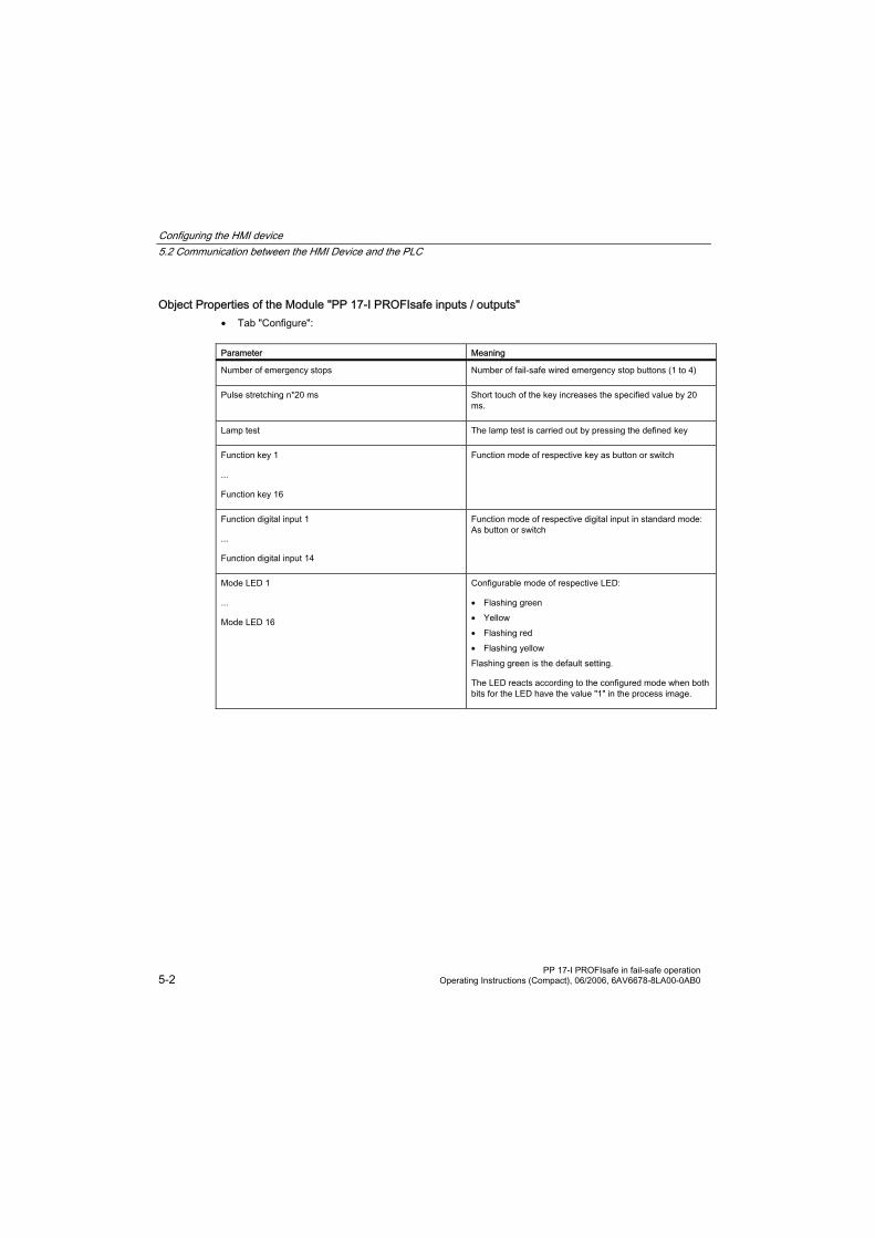
Object Properties of the Module "PP 17-I PROFIsafe inputs / outputs" • Tab "Configure":
Parameter Meaning
Number of emergency stops Number of fail-safe wired emergency stop buttons (1 to 4)
Pulse stretching n*20 ms Short touch of the key increases the specified value by 20 ms.
Lamp test The lamp test is carried out by pressing the defined key
Function key 1
...
Function key 16
Function mode of respective key as button or switch
Function digital input 1
...
Function digital input 14
Function mode of respective digital input in standard mode: As button or switch
Mode LED 1
...
Mode LED 16
Configurable mode of respective LED:
• Flashing green • Yellow • Flashing red • Flashing yellow Flashing green is the default setting.
The LED reacts according to the configured mode when both bits for the LED have the value "1" in the process image.

Configuring the HMI device 5.2 Communication between the HMI Device and the PLC
PP 17-I PROFIsafe in fail-safe operation Operating Instructions (Compact), 06/2006, 6AV6678-8LA00-0AB0 5-3
• Tab "Address / ID":
Parameter Meaning
Input > Address > Start of Address Area Start of address range in which the standard digital inputs of the HMI are mapped.
Predefined: 512
If you wish to call the signals of the standard digital inputs via a process image, enter an address range < 512.
Input > Process Image Process image to which the address range belongs
You can only select a process image if the address range is < 512.
Output > Address > Start of Address Area Start of address range in which the standard digital outputs of the HMI device are mapped.
Predefined: 512
If you wish to call the signals of the standard digital outputs via a process image, enter an address range < 512.
Output > Process Image Process image to which the address range belongs
You can only select a process image if the address range is < 512.
Configuring the HMI device 5.2 Communication between the HMI Device and the PLC
PP 17-I PROFIsafe in fail-safe operation 5-4 Operating Instructions (Compact), 06/2006, 6AV6678-8LA00-0AB0
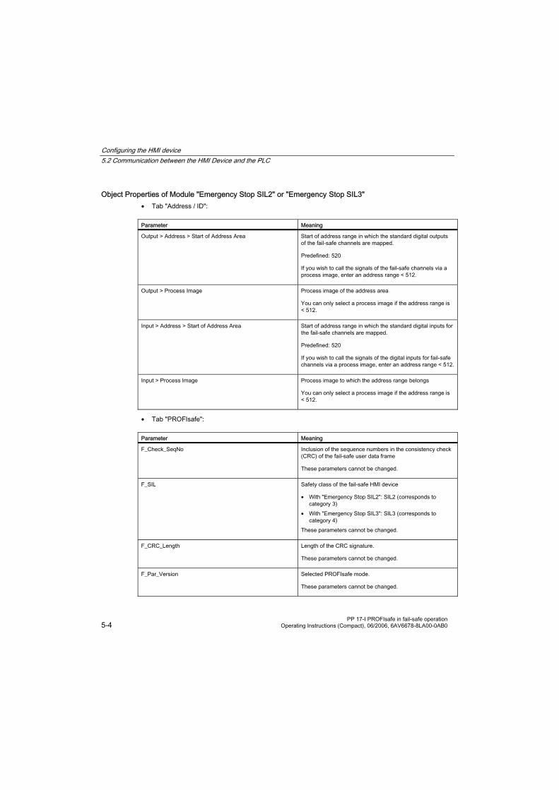
Object Properties of Module "Emergency Stop SIL2" or "Emergency Stop SIL3" • Tab "Address / ID":
Parameter Meaning
Output > Address > Start of Address Area Start of address range in which the standard digital outputs of the fail-safe channels are mapped.
Predefined: 520
If you wish to call the signals of the fail-safe channels via a process image, enter an address range < 512.
Output > Process Image Process image of the address area
You can only select a process image if the address range is < 512.
Input > Address > Start of Address Area Start of address range in which the standard digital inputs for the fail-safe channels are mapped.
Predefined: 520
If you wish to call the signals of the digital inputs for fail-safe channels via a process image, enter an address range < 512.
Input > Process Image Process image to which the address range belongs
You can only select a process image if the address range is < 512.
• Tab "PROFIsafe":
Parameter Meaning
F_Check_SeqNo Inclusion of the sequence numbers in the consistency check (CRC) of the fail-safe user data frame
These parameters cannot be changed.
F_SIL Safety class of the fail-safe HMI device
• With "Emergency Stop SIL2": SIL2 (corresponds to category 3)
• With "Emergency Stop SIL3": SIL3 (corresponds to category 4)
These parameters cannot be changed.
F_CRC_Length Length of the CRC signature.
These parameters cannot be changed.
F_Par_Version Selected PROFIsafe mode.
These parameters cannot be changed.

Configuring the HMI device 5.2 Communication between the HMI Device and the PLC
PP 17-I PROFIsafe in fail-safe operation Operating Instructions (Compact), 06/2006, 6AV6678-8LA00-0AB0 5-5
Parameter Meaning
F_Source_Add PROFIsafe address used to uniquely identify the source. The address is assigned automatically.
The "F_Source_Add" parameter can have a value between 1 and 65534.
F_Dest_Add PROFIsafe address used to uniquely identify the destination. The address is assigned automatically.
The "F_Dest_Add" parameter can have a value between 1 and 1022. You can change the value for "F_Dest_Add".
The value set for F_Dest_Add must be entered on the HMI device as a PROFIsafe address.
F_WD_Time Watchdog time in the fail-safe DP standard slave
A valid current safety message frame must come from the F CPU within the monitoring time period. Otherwise, the fail-safe DP standard slave goes to the safe state.
The "F_WD_Time" parameter can be set in 1 ms increments.. The monitoring time should be between 150 ms and 1000 ms.
Use the Excel table "s7cotia.xls" to calculate the monitoring time which corresponds to the availability of the system.
The Excel file "s7cotia.xls" is part of the optional package S7 Distributed Safety. You can find the current version of this table on the Internet at the following address:
"http://www.siemens.com/automation/support", article ID 19138505
You can find the parameters needed to calculate the monitoring time under "General Specifications".
Notice If an error occurs, the monitoring time is included in the ensured reaction time.
Further Information about Configuring F I/Os in STEP 7 You will find further information regarding the configuration of fail-safe I/Os in STEP 7 in the manual "S7 Distributed Safety Configuring and Programming" and in the system manual "Safety Engineering in SIMATIC S7".
See also Configuring the HMI device in STEP 7 (Page 5-6)
Configuring the PROFIBUS DP Interface (Page 5-12)

Configuring the HMI device 5.3 Configuring the HMI device in STEP 7
PP 17-I PROFIsafe in fail-safe operation 5-6 Operating Instructions (Compact), 06/2006, 6AV6678-8LA00-0AB0
5.3 Configuring the HMI device in STEP 7
Introduction To enable communication between the PLC and the HMI device, you need to configure the HMI device in "HW Config" of the SIMATIC Manager.
Requirement • The HMI device has been inserted into the STEP 7 project.
If the HMI device is not listed in the hardware catalog of HW Config, you need to integrate the valid GSD (device database) files for the HMI device in the STEP 7 database.
• The "Emergency Stop SIL2" or "Emergency Stop SIL3" module is inserted. • The "PP 17-I PROFIsafe in / outputs" module is inserted.
Note The HMI must always include module "PP 17-I PROFIsafe in / outputs" in HW Config.
Configure slot for "PP 17-I PROFIsafe inputs / outputs"
Caution Ensure that the number of connected emergency stop buttons matches the configuration of the HMI device in STEP 7.
1. In the context menu for "PP 17-I PROFISAFE inputs / outputs" select the "Object properties" entry. The "Properties DP Slave" dialog window opens.
2. In the "Configure" tab, open the folder "Station parameters > device specific parameters".
3. Enter the number of emergency stop buttons used.
4. Enter a value for the pulse stretching.
5. If necessary, select a different key for the lamp test.
6. Define the the individual keys and digital inputs for standard mode either as buttons or switches.
7. Set the mode for each LED.
8. Switch to the "Address / ID" tab. The start value for both address ranges are predefined with the value "512" for both the "Input" and "Output" groups. The signals for the standard digital inputs and outputs of the HMI device are mapped in the given address ranges.
9. Check the predefined start values of the address ranges.
10. If necessary, change the address range. If you wish to call the signals of the digital inputs or digital outputs via a process image, enter an address range < 512.
11. Only if the address range < 512: Select another process image for the start of the address range if necessary.
12. Save your settings with "OK".

Configuring the HMI device 5.4 Configure FB "F_PP17I_SIL3"
PP 17-I PROFIsafe in fail-safe operation Operating Instructions (Compact), 06/2006, 6AV6678-8LA00-0AB0 5-7
Configure PROFIsafe parameters for slot "Emergency Stop SIL2" or "Emergency Stop SIL3"
1. In the context menu for "Emergency Stop SIL2" or "Emergency Stop SIL3" select the "Object properties" entry. The "Properties DP Slave" dialog window opens.
In the "Address / ID" tab, the start address ranges for the "Inputs" and "Outputs" groups are both predefined with the value "520". The signals for the standard digital inputs and outputs of the fail-safe channels are mapped in the given address ranges.
2. Check the predefined start values of the address ranges.
3. If necessary, change the address range. If you wish to call the signals of the digital inputs or digital outputs via a process image, enter an address range < 512.
4. Switch to the "PROFIsafe" tab.
5. Check the parameters shown.
6. If you want to change a parameter, select it and click on the "Change Value" button. A selection dialog is displayed listing the possible parameter values.
7. Select the desired value and close the dialog with "OK".
8. Change other parameters if you wish and then save your settings with "OK".
Result The HMI device will now respond in operation according to the new configuration. The states of the digital inputs and outputs of the HMI device are stored in the specified address area of the PLC.
Further Information about Configuring F I/O in STEP 7 Further information about configuring F I/O in STEP 7 is available in the manual, "S7 Distributed Safety Configuring and Programming".
See also Integrating the GSD File in STEP 7 (Page 5-1)
Communication between the HMI Device and the PLC (Page 5-1)
Front-sided Control Elements and Displays (Page 4-1)
5.4 Configure FB "F_PP17I_SIL3"
5.4.1 Overview
SIL3/Cat. 4 Should safety class SIL3/cat. 4 be required, the FB "F_PP17I_SIL3" must be called in the safety program. This FB is supplied on a CD together with the documentation for the HMI device.
You can also find the FB on the Internet at the following address:
"http://www.siemens.com/automation/support"

Configuring the HMI device 5.4 Configure FB "F_PP17I_SIL3"
PP 17-I PROFIsafe in fail-safe operation 5-8 Operating Instructions (Compact), 06/2006, 6AV6678-8LA00-0AB0
Configuring in STEP 7
The following must be observed when integrating the FB "F_PP17I_SIL3" into the control program:
• The FB must be configured so that it is uniquely associated to the HMI device with SIL3/cat. 4. • The inputs and outputs of the FB are not automatically defined with valid values and must be manually
wired as part of the configuration. Please take special care that the values for the parameters "ADDR_INPUT" and "ADDR_OUTPUT" match the values that are configured in HW Confiig for the input and output ranges of the process image.
Note In SIL3/ Cat. 4 access to the start range of the process image is not allowed.
Detailed information about configuring the HMI device as a fail-safe DP standard slave is available in the manual, "Distributed Safety - Configuration and Programming".
Determining the Version of FB "F_PP17I_SIL3" in STEP 7 Proceed as follows:
1. Open the "LAD/STL/FBD" editor in STEP 7.
2. Navigate in the left pane to "Libraries > F_FB_PP17I_SIL3 > F_FB_PP17I".
3. In the shortcut menu for the "FB 170" entry, select the "Object Properties" command.
4. Select the "General Part 2" tab.
5. The version of the FB "F_PP17I_SIL3" is shown in the field "Version (Header)"

Configuring the HMI device 5.4 Configure FB "F_PP17I_SIL3"
PP 17-I PROFIsafe in fail-safe operation Operating Instructions (Compact), 06/2006, 6AV6678-8LA00-0AB0 5-9
5.4.2 FB170 "F_PP17I_SIL3"
Validity This description applies to version 2.3 of the FB "F_PP17I_SIL3".
Purpose The FB "F_PP17I_SIL3" is required in order to achieve safety class SIL3/cat. 4 with PP 17-I PROFIsafe.
The FB "F_PP17I_SIL3" fulfills the following tasks:
• You can use the FB SIL3/cat. 4 to determine which emergency stop button has been pressed. In order to do so, you query the state of outputs E_STOP1 to E_STOP4 of the FB.
• The FB produces a test pattern which assists in the investigation of errors during discrepancy evaluation. The test pattern is transferred to the HMI device from the FB via the configured output byte. The HMI device then returns this test pattern back to the FB's configured input byte. If the HMI device returns a faulty test pattern, discrepancy evaluation is started. After an assignable time interval (the so called discrepancy time) has elapsed, a check is performed to determine whether or not the discrepancy still exists. If so, then a discrepancy error exists. This will be reported to the ERROR output.
• After passivation of the HMI device, the FB executes the reintegration following user acknowledgement.
Fail-safe I/O DB An F-I/O DB is automatically generated for each F-I/O when the program is compiled by HW Config. The F-I/O DB contains variables that the user has to evaluate in the safety program.
Detailed information regarding the accessing F-I/Os and working with F-I/O DBs can be found in the "SIMATIC S7-Distributed Safety Configuration and Programming" manual in the "F-I/O access" chapter.
Mode of operation The FB "F_PP17I_SIL3" creates a test pattern. This test pattern is output to the PP 17-I PROFIsafe and then read back. If a faulty test pattern is read back, a discrepancy error is determined following the expiration of the discrepancy time.
If an emergency stop button is pressed, the following procedure is initiated:
• The fail-safe channels associated with the pressed emergency stop button are excluded from the test. • The associated output E_STOPn will be set to "0". • The remaining fail-safe channels will continue to be queried and tested. In case of error the following procedure is initiated:
• All emergency stop outputs E_STOP1 to E_STOP4 will be set to "0" (passivated). • The error output ERROR will be set to "1". • In the event of communications errors, the input data will be set to "0". • Errors will be stored so that an acknowledgement request can take place after the fault is eliminated.

Configuring the HMI device 5.4 Configure FB "F_PP17I_SIL3"
PP 17-I PROFIsafe in fail-safe operation 5-10 Operating Instructions (Compact), 06/2006, 6AV6678-8LA00-0AB0
Transient behavior
Notice The startup behavior of the FB "F_PP17I_SIL3" has changed as of version 2.3 and is not compatible with version 2.1. A user acknowledgement is no longer necessary following startup. Behavior at reintegration and startup is now identical. The FB "F_PP17I_SIL3" outputs all possible test patterns at startup (floating "0" at all bit positions).
The following options are available for evaluating the test pattern:
• If the test pattern is read back without errors, the outputs E_STOP1 to E_STOP4 are output. • If the test pattern is read back with errors, a startup error is recognized. The error output ERROR will
be set to "1". Cause for the startup error can be a PP 17-I PROFIsafe which is turned off, for example.
Malfunction In the following cases, the output ERROR will be set to "1":
• A value has been configured for input CH_CNT outside of the range 1 to 4. • A discrepancy error has occurred. • QBAD = 1 has been signalized from the F-I/O DB. • A startup error has occurred.
Note Set the watchdog interrupt to no longer than 200 ms. Otherwise, the FB will recognize a startup error.
Inputs
Parameters Data type Description
CH_CNT INT Number of emergency stop buttons used
Range: 1 to 4
If you configure a value outside of the range, the parameter ERROR will be set to "1".
You have to supply the parameter CH_CNT with a constant value. A change during operation or the use of a variable (bit memory, for example) is not permitted.
ADDR_INPUT WORD Start address of the inputs in process image
The value must match the value configured in HW Config.
In each case, only lower value byte of the given input word will be evaluated.
ACK_REI BOOL Acknowledge switch (input, memory bit, or higher-level user interface) for acknowledgement after passivation.
Configuring the HMI device 5.4 Configure FB "F_PP17I_SIL3"
PP 17-I PROFIsafe in fail-safe operation Operating Instructions (Compact), 06/2006, 6AV6678-8LA00-0AB0 5-11
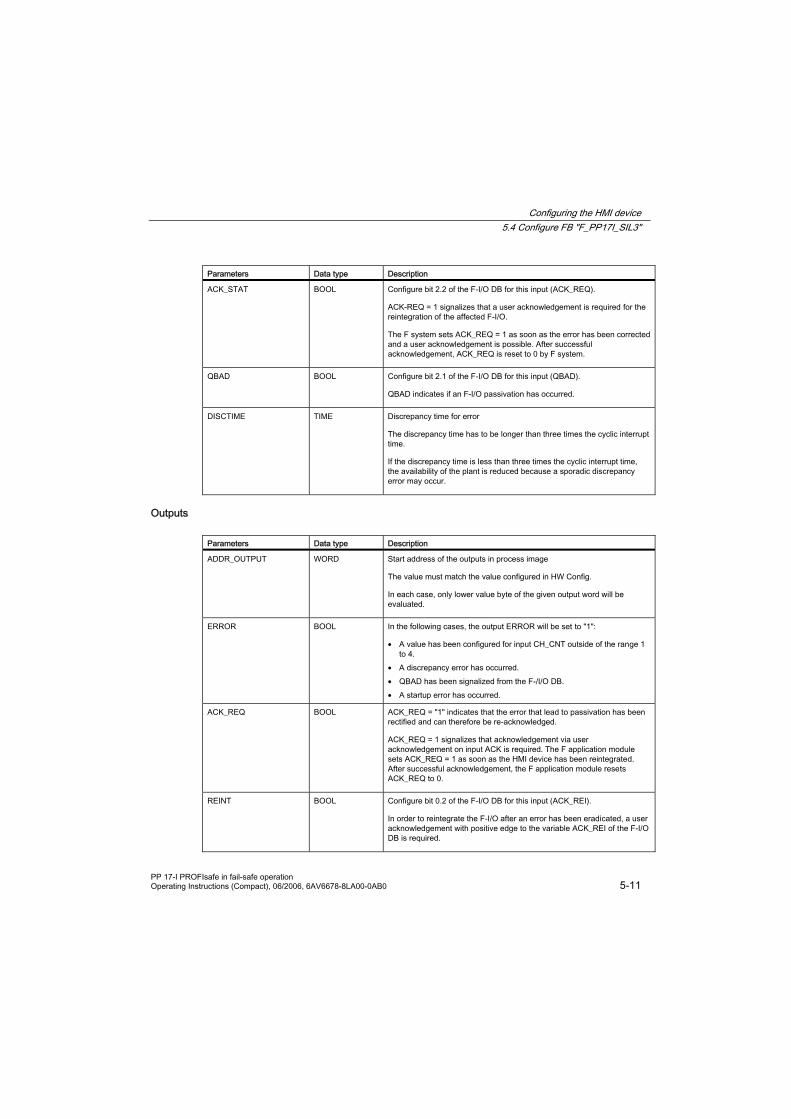
Parameters Data type Description
ACK_STAT BOOL Configure bit 2.2 of the F-I/O DB for this input (ACK_REQ).
ACK-REQ = 1 signalizes that a user acknowledgement is required for the reintegration of the affected F-I/O.
The F system sets ACK_REQ = 1 as soon as the error has been corrected and a user acknowledgement is possible. After successful acknowledgement, ACK_REQ is reset to 0 by F system.
QBAD BOOL Configure bit 2.1 of the F-I/O DB for this input (QBAD).
QBAD indicates if an F-I/O passivation has occurred.
DISCTIME TIME Discrepancy time for error
The discrepancy time has to be longer than three times the cyclic interrupt time.
If the discrepancy time is less than three times the cyclic interrupt time, the availability of the plant is reduced because a sporadic discrepancy error may occur.
Outputs
Parameters Data type Description
ADDR_OUTPUT WORD Start address of the outputs in process image
The value must match the value configured in HW Config.
In each case, only lower value byte of the given output word will be evaluated.
ERROR BOOL In the following cases, the output ERROR will be set to "1":
• A value has been configured for input CH_CNT outside of the range 1 to 4.
• A discrepancy error has occurred. • QBAD has been signalized from the F-/I/O DB. • A startup error has occurred.
ACK_REQ BOOL ACK_REQ = "1" indicates that the error that lead to passivation has been rectified and can therefore be re-acknowledged.
ACK_REQ = 1 signalizes that acknowledgement via user acknowledgement on input ACK is required. The F application module sets ACK_REQ = 1 as soon as the HMI device has been reintegrated. After successful acknowledgement, the F application module resets ACK_REQ to 0.
REINT BOOL Configure bit 0.2 of the F-I/O DB for this input (ACK_REI).
In order to reintegrate the F-I/O after an error has been eradicated, a user acknowledgement with positive edge to the variable ACK_REI of the F-I/O DB is required.
Configuring the HMI device 5.5 Configuring the PROFIBUS DP Interface
PP 17-I PROFIsafe in fail-safe operation 5-12 Operating Instructions (Compact), 06/2006, 6AV6678-8LA00-0AB0
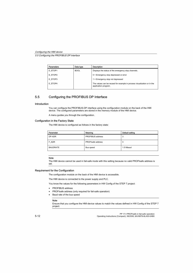
Parameters Data type Description
E_STOP1
E_STOP2
E_STOP3
E_STOP4
BOOL Displays the status of the emergency stop channels.
0 = Emergency stop depressed or error
1 = Emergency stop not depressed
The values can be reused for example in process visualization or in the application program.
5.5 Configuring the PROFIBUS DP Interface
Introduction You can configure the PROFIBUS-DP interface using the configuration module on the back of the HMI device. The configured parameters are stored in the memory module of the HMI device.
A menu guides you through the configuration.
Configuration in the Factory State The HMI device is configured as follows in the factory state:
Parameter Meaning Default setting
DP-ADR PROFIBUS address 3
F_ADR PROFIsafe address 0
BAUDRATE Bus speed 1.5 Mbaud
Note The HMI device cannot be used in fail-safe mode with this setting because no valid PROFIsafe address is set.
Requirement for the Configuration The configuration module on the back of the HMI device is accessible.
The HMI device is connected to the power supply and PLC.
You know the values for the following parameters in HW Config of the STEP 7 project:
• PROFIBUS address • PROFIsafe address (only required for fail-safe operation) • Baud rate of the bus speed
Note Ensure that you configure the HMI-device values to match the values defined in HW Config of the STEP 7 project.

Configuring the HMI device 5.5 Configuring the PROFIBUS DP Interface
PP 17-I PROFIsafe in fail-safe operation Operating Instructions (Compact), 06/2006, 6AV6678-8LA00-0AB0 5-13
Procedure - Setting Parameters
1. When the HMI device starts up, press the keys ESC + OK on the configuration module. The configuration mode is activated. The display shows the menu command "DEFAULT YES/NO".
2. Select "NO" with the and keys and confirm your selection with OK .
3. In menu "DP-ADR" use the and keys to set the same PROFIBUS address as is configured in HW Config of the STEP 7 project for the HMI device and confirm with OK . If you want to configure multidigit addresses, use the and keys to swap between the digits.
4. In menu "F-ADR" set the same PROFIsafe address as is configured for the "Emergency-Stop" slot in HW Config of the STEP 7 project.
5. In menu "BAUDRATE" set the same speed as is configured for PROFIBUS in HW Config of the STEP 7 project.
6. Exit configuration mode with ESC . The specified parameters are now saved. The HMI device resumes normal operation.
Procedure - Resetting to Factory State
1. When the HMI device starts up, press the keys ESC + OK on the configuration module. The configuration mode is activated. The display shows the menu command "DEFAULT YES/NO".
2. Select "YES" with the and keys and confirm your selection with OK .
3. Exit configuration mode with ESC . All parameters have now been reset to the factory state. The HMI device resumes normal operation.
Result The specified parameters are stored in the memory module of the configuration module.
See also Communication between the HMI Device and the PLC (Page 5-1)
Backside HMI Components, LEDs and Ports (Page 4-3)

Configuring the HMI device 5.5 Configuring the PROFIBUS DP Interface
PP 17-I PROFIsafe in fail-safe operation 5-14 Operating Instructions (Compact), 06/2006, 6AV6678-8LA00-0AB0

PP 17-I PROFIsafe in fail-safe operation Operating Instructions (Compact), 06/2006, 6AV6678-8LA00-0AB0 6-1
Fail-safe Mode 6 6.1 Overview
Fail-safe Mode You can use the HMI device in standard mode and fail-safe mode simultaneously.
In fail-safe mode the HMI device recognizes signal states from suitable emergency-stop buttons and sends corresponding safety telegrams to the F-CPU where the safety program runs. The F-CPU and HMI device communicate with each other via the safety oriented PROFIsafe protocol.
Note Activate the host before switching on, otherwise a fault will occur under SIL3/cat. 4.
Safety Functions During fail-safe operation, safety mechanisms are activated in both HMI device and F-CPU which recognize faults and react to them.
In the following cases, the safety mechanisms will cause the system to be placed in safe mode:
• An emergency stop button has been depressed • A fault has occurred
Reactions to Pressed Emergency Stop Buttons If an emergency stop button is pressed, the system will be placed in safe mode and stopped. In the control program, you can establish which emergency stop button was pressed. After the danger has been eliminated, the operator resets the emergency stop and the system restarts.
Responses to Faults in the System In the event of a fault, the system is placed in safe mode and the HMI device rendered passive. Substitution values will be set up on all fail-safe digital inputs instead of process values. Analyze and eliminate the current fault with the help of the various diagnostic tools. Afterwards, the HMI requires reintegrating. The process values are now restored to the digital inputs for F channels.
Reactions to Errors in the HMI Device If an internal fault in the HMI device is recognized (for example an internal overvoltage in SIL2/ cat. 3) the following reactions occur:
• All four emergency stop buttons will be activated. • The PROFIsafe CRC will be corrupted. • Communication will be broken. • The HMI device will be rendered passive.

Fail-safe Mode 6.2 Query the State of the Emergency Stop Buttons
PP 17-I PROFIsafe in fail-safe operation 6-2 Operating Instructions (Compact), 06/2006, 6AV6678-8LA00-0AB0
See also Prerequisites for fail-safe operation (Page 2-1)
Query the State of the Emergency Stop Buttons (Page 6-2)
Passivation of the HMI device (Page 6-3)
Troubleshooting Check List (Page 6-4)
Error Diagnostics (Page 6-6)
Error Elimination and Reintegration (Page 6-7)
6.2 Query the State of the Emergency Stop Buttons
Dependent on safety class The method for determining which emergency stop button has been pressed depends on the safety class (SIL2/cat. 3 or SIL3/cat. 4).
Safety class SIL2/cat. 3 If you want to determine which emergency stop button was pressed under safety class SIL2/cat. 3, address the first four bits in the process image given for the inputs of slot emergency-stop SIL2.
The following table shows the configuration of the bits to the emergency stop buttons.
Bit no. 3 2 1 0
Emergency stop button no.
4 3 2 1
Wired to DI4.1, DI4.2, DO4.1, DO4.2
DI3.1, DI3.2, DO3.1, DO3.2
DI2.1, DI2.2, DO2.1, DO2.2
DI1.1, DI1.2, DO1.1, DO1.2
Each bit can be assigned the following values:
0 = Emergency stop button pressed or fault
1 = Emergency stop not pressed
Example:
Binary pattern for "Emergency stop button 3 pressed": 1011
Alternatively you can read the binary pattern of the input range from FB 215 "F_ESTOP1". You will find further information regarding this FB in "S7 Distributed Safety Configuring and Programming".
Safety class SIL3/cat. 4 Should safety class SIL3/cat. 4 be required for the HMI device, the FB "F_PP17I_SIL3" must be called in the safety program.
If you want to determine which emergency stop button was pressed under safety class SIL3/cat. 4, query the state of the outputs "E_STOP1" to "E_STOP4" of the FB.
Fail-safe Mode 6.3 Passivation of the HMI device
PP 17-I PROFIsafe in fail-safe operation Operating Instructions (Compact), 06/2006, 6AV6678-8LA00-0AB0 6-3
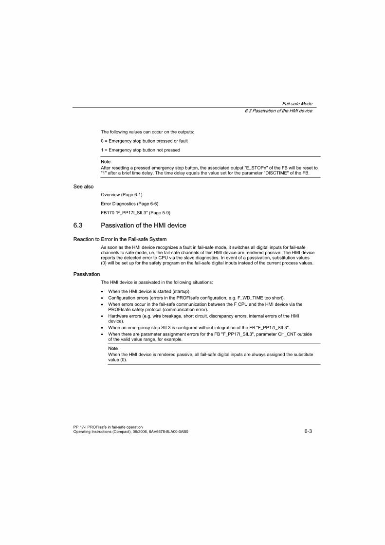
The following values can occur on the outputs:
0 = Emergency stop button pressed or fault
1 = Emergency stop button not pressed
Note After resetting a pressed emergency stop button, the associated output "E_STOPn" of the FB will be reset to "1" after a brief time delay. The time delay equals the value set for the parameter "DISCTIME" of the FB.
See also Overview (Page 6-1)
Error Diagnostics (Page 6-6)
FB170 "F_PP17I_SIL3" (Page 5-9)
6.3 Passivation of the HMI device
Reaction to Error in the Fail-safe System As soon as the HMI device recognizes a fault in fail-safe mode, it switches all digital inputs for fail-safe channels to safe mode, i.e. the fail-safe channels of this HMI device are rendered passive. The HMI device reports the detected error to CPU via the slave diagnostics. In event of a passivation, substitution values (0) will be set up for the safety program on the fail-safe digital inputs instead of the current process values.
Passivation The HMI device is passivated in the following situations:
• When the HMI device is started (startup). • Configuration errors (errors in the PROFIsafe configuration, e.g. F_WD_TIME too short). • When errors occur in the fail-safe communication between the F CPU and the HMI device via the
PROFIsafe safety protocol (communication error). • Hardware errors (e.g. wire breakage, short circuit, discrepancy errors, internal errors of the HMI
device). • When an emergency stop SIL3 is configured without integration of the FB "F_PP17I_SIL3". • When there are parameter assignment errors for the FB "F_PP17I_SIL3", parameter CH_CNT outside
of the valid value range, for example.
Note When the HMI device is rendered passive, all fail-safe digital inputs are always assigned the substitute value (0).

Fail-safe Mode 6.4 Troubleshooting Check List
PP 17-I PROFIsafe in fail-safe operation 6-4 Operating Instructions (Compact), 06/2006, 6AV6678-8LA00-0AB0
Determining Passivation If you want to determine if the HMI device is passive or not, address the "PASS_OUT" variable of the F I/O DB. The variable can be assigned the following values:
0 = HMI device not passive
1 = HMI device passive
Reintegration of a Fail-safe HMI Device After passivation of the HMI device, the fault must be diagnosed and rectified. Afterwards, the HMI device can be reintegrated.
Further Information on Passivation You will find further information regarding the passivation of F I/Os and F-I/O DBs in the "S7 Distributed Safety Configuring and Programming" manual.
See also Error Diagnostics (Page 6-6)
Troubleshooting Check List (Page 6-4)
6.4 Troubleshooting Check List
Narrowing down faults The following check list will support you in quickly narrowing down faults.
State of the Error LED
Further error patterns Possible cause Remedy
Operational phase: Start
Off HMI fails to integrate after startup.
A system message is displayed on the configuration module of the HMI device.
Dependant on system message, more detailed information under "System messages"
Carry out the remedies as described in System Messages.

Fail-safe Mode 6.4 Troubleshooting Check List
PP 17-I PROFIsafe in fail-safe operation Operating Instructions (Compact), 06/2006, 6AV6678-8LA00-0AB0 6-5
State of the Error LED
Further error patterns Possible cause Remedy
Operational phase: Fail-safe mode, lamp test not activated
- A PROFIsafe fault has occurred.
Interrogate the "DIAG" variable of the F-I/O DB.
Carry out the remedies as described in the "S7 Distributed Safety Configuring and Programming" manual.
Blinks
STEP 7 module diagnosis of numerous simultaneous "faults" with channel numbers of all channels with a configured emergency stop button.
SIL3 is set up and the HMI device receives an invalid test pattern (e.g. because the FB "F_PP17I_SIL3" is missing).
Numerous hardware errors have occurred.
Check that FB "F_PP17I_SIL3" is correctly integrated and configured in the safety program.
If there is no error in the configuration, check the wiring between the HMI device and all connected emergency stop buttons.
If the cause of the fault cannot be located, check the HMI device.
STEP 7 module diagnosis reports "communication error"
A PROFIBUS fault has occurred.
Parameters of the PROFIBUS DP interface do not match the parameters defined in HW Config.
A communication error that affects the HMI device alone suggests a fault in the HMI device. In this case, look for an error in the HMI device first.
Check the parameters defined in the configuration module.
STEP 7 module diagnosis reports "configuration error"
A PROFIBUS fault has occurred.
Incorrect settings for the PROFIsafe parameters in HW Config
Check that the PROFIsafe parameters are defined as follows:
F_Check_SeqNo = No check
F_CRC_Length = Byte CRC
F_Dest_Add = PROFIsafe address set on HMI device
F_WD_Time = Minimum 2 x cycle time of the monitoring program and > call time of the safety program in time interrupt
You will find details regarding the configuration settings under "Communication between the HMI and the PLC"
Lit
STEP 7 Module diagnosis reports "error" in channel no. 0 to 3
A PROFIBUS fault has occurred.
A hardware fault has occurred
Check the wiring between the HMI device and the emergency stop button on the displayed channel.
If the cause of the fault cannot be located, check the HMI device.
No defined state STEP 7 Module diagnosis reports "Module interrupted" or "Module missing"
The HMI device has failed due to a serious internal fault.
Exchange the HMI device.

Fail-safe Mode 6.5 Error Diagnostics
PP 17-I PROFIsafe in fail-safe operation 6-6 Operating Instructions (Compact), 06/2006, 6AV6678-8LA00-0AB0
6.5 Error Diagnostics
Definition Diagnostics enable you to determine if the signals are being correctly registered in the fail-safe HMI device.
Diagnostic functions Diagnostic functions (displays and messages) are not critical to safety and therefore are not designed to be safety-related functions. That is, they are not tested internally.
Diagnostic Options for the Fail-Safe HMI Device The following diagnostic options are available for fail-safe HMI device:
• LED "ERROR" on front side of the HMI device For correct evaluation of LED "ERROR" ensure that the lamp test is not active, as the LED "ERROR" also blinks during lamp testing.
State of the LED "ERROR" Type of error
Off No errors have occurred
Blinks PROFIsafe errors
Lit PROFIBUS errors
• Diagnostic Functions of the HMI Device Slave diagnosis according to PROFIBUS standard IEC 61784-1:2002 Ed1 CP 3/1.
• Error messages on the configuration module on the back of the HMI device. The error messages are described in detail in the appendix.
Diagnostic Function the HMI Device The fail-safe HMI device includes a non-configurable diagnostic function. The diagnostics are always activated and are automatically made available by the HMI in STEP 7 and passed on to the CPU in the event of a fault.
The diagnostic function passes the following diagnostics information to the CPU:
• Communication fault Communication between the HMI as DP-slave and the CPU as DP Master has been interrupted (e.g. due to wrong PROFIBUS address or PROFIsafe address).
• HW fault External wiring or internal hardware fault, data corruption or procedure error.
• Configuration error Error in the PROFIsafe configuration

Fail-safe Mode 6.6 Error Elimination and Reintegration
PP 17-I PROFIsafe in fail-safe operation Operating Instructions (Compact), 06/2006, 6AV6678-8LA00-0AB0 6-7
Reading Out Diagnostic Functions You can display the cause of the error in the module diagnostics in STEP 7 (see online help for STEP 7).
• Diagnostic information regarding communications errors and configuration errors are always assigned to channel "0".
• Diagnostic information regarding hardware errors are assigned to the fail-safe channels of the HMI device as follows:
Display in STEP 7 (Module diagnosis) Fail-safe channel on HMI device
Channel 0 fail-safe channel 1 (DI1.1, DI1.2, DO1.1, DO1.2)
Channel 1 fail-safe channel 2 (DI2.1, DI2.2, DO2.1, DO2.2)
Channel 2 Fail-safe channel 3 (DI3.1, DI3.2, DO3.1, DO3.2)
Channel 3 Fail-safe channel 4 (DI4.1, DI4.2, DO4.1, DO4.2)
You can read out diagnostic functions (slave diagnostics) by means of SFC 13 in the standard user program (see System and Standard Functions reference manual).
Diagnosis of PROFIsafe errors When diagnosing PROFIsafe errors, address the "DIAG" variable of the F-I/O DB. You will find further information regarding F-I/O DBs in "S7 Distributed Safety Configuring and Programming".
Behavior of the HMI device in the event of a serious internal fault The HMI device reacts as follows when a serious internal error in the HMI device causes the HMI device to fail:
• The connection to PROFIBUS DP will be interrupted and the fail-safe channels will be rendered passive.
• No diagnosis will be transmitted from the HMI device. In STEP 7 in module diagnosis, the standard diagnosis "Module interrupted" or "Module missing" will be reported.
See also Error Elimination and Reintegration (Page 6-7)
6.6 Error Elimination and Reintegration
End passivation When you have eliminated an error that lead to a passivation of the HMI device, you have to reintegrate the HMI device.
Fail-safe Mode 6.6 Error Elimination and Reintegration
PP 17-I PROFIsafe in fail-safe operation 6-8 Operating Instructions (Compact), 06/2006, 6AV6678-8LA00-0AB0
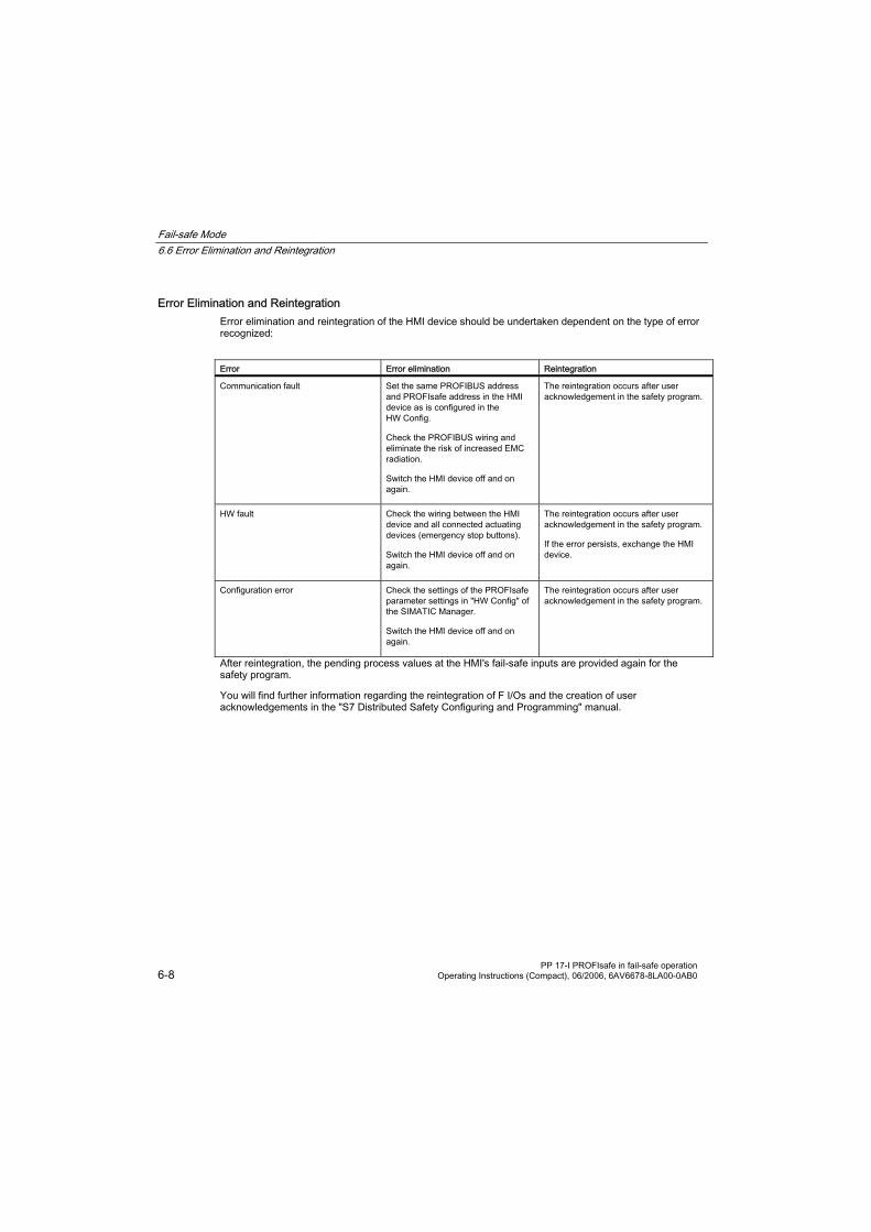
Error Elimination and Reintegration Error elimination and reintegration of the HMI device should be undertaken dependent on the type of error recognized:
Error Error elimination Reintegration
Communication fault Set the same PROFIBUS address and PROFIsafe address in the HMI device as is configured in the HW Config.
Check the PROFIBUS wiring and eliminate the risk of increased EMC radiation.
Switch the HMI device off and on again.
The reintegration occurs after user acknowledgement in the safety program.
HW fault Check the wiring between the HMI device and all connected actuating devices (emergency stop buttons).
Switch the HMI device off and on again.
The reintegration occurs after user acknowledgement in the safety program.
If the error persists, exchange the HMI device.
Configuration error Check the settings of the PROFIsafe parameter settings in "HW Config" of the SIMATIC Manager.
Switch the HMI device off and on again.
The reintegration occurs after user acknowledgement in the safety program.
After reintegration, the pending process values at the HMI's fail-safe inputs are provided again for the safety program.
You will find further information regarding the reintegration of F I/Os and the creation of user acknowledgements in the "S7 Distributed Safety Configuring and Programming" manual.
PP 17-I PROFIsafe in fail-safe operation Operating Instructions (Compact), 06/2006, 6AV6678-8LA00-0AB0 A-1
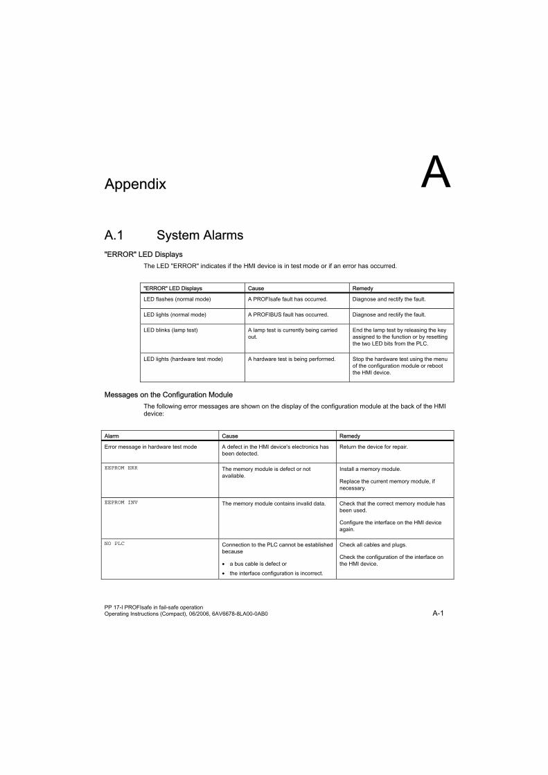
Appendix A A.1 System Alarms "ERROR" LED Displays
The LED "ERROR" indicates if the HMI device is in test mode or if an error has occurred.
"ERROR" LED Displays Cause Remedy
LED flashes (normal mode) A PROFIsafe fault has occurred. Diagnose and rectify the fault.
LED lights (normal mode) A PROFIBUS fault has occurred. Diagnose and rectify the fault.
LED blinks (lamp test) A lamp test is currently being carried out.
End the lamp test by releasing the key assigned to the function or by resetting the two LED bits from the PLC.
LED lights (hardware test mode) A hardware test is being performed. Stop the hardware test using the menu of the configuration module or reboot the HMI device.
Messages on the Configuration Module The following error messages are shown on the display of the configuration module at the back of the HMI device:
Alarm Cause Remedy
Error message in hardware test mode A defect in the HMI device's electronics has been detected.
Return the device for repair.
EEPROM ERR The memory module is defect or not available.
Install a memory module.
Replace the current memory module, if necessary.
EEPROM INV The memory module contains invalid data. Check that the correct memory module has been used.
Configure the interface on the HMI device again.
NO PLC Connection to the PLC cannot be established because
• a bus cable is defect or • the interface configuration is incorrect.
Check all cables and plugs.
Check the configuration of the interface on the HMI device.

Appendix A.1 System Alarms
PP 17-I PROFIsafe in fail-safe operation A-2 Operating Instructions (Compact), 06/2006, 6AV6678-8LA00-0AB0
Alarm Cause Remedy PP START There is a connection fault. Check the network configuration and the
configuration of the interface on the HMI device.
DIAG-ERROR There is a short circuit in one of the digital outputs.
Check the wiring of the digital outputs.

PP 17-I PROFIsafe in fail-safe operation Operating Instructions (Compact), 06/2006, 6AV6678-8LA00-0AB0 Index - 1
Index C Cable Lengths, 2-2 Check list
Application Planning, 1-3 Troubleshooting, 6-4
Communication fault, 6-6 Configuration error, 6-6 Connections
F_PP17I_SIL3, 5-10, 5-11
D Diagnostic functions, 6-6
Reading out, 6-7 Diagnostics, 6-6
Definition, 6-6
E Emergency stop button
Fail-safe wiring, 3-5 Emergency stop button
Mounting position, 3-2 Emergency stop button
Query state, 6-2 Emergency stop button
Pressed, 6-2 Error alarms, A-1 Error reaction
of the HMI device, 6-3
F F_PP17I_SIL3, 5-9 Fault, 6-6 FB 170, 5-9
H HMI device
Error reaction, 6-3 Switch off, 3-7 Switching on, 3-6 Testing, 3-6
HW fault, 6-6
I Inputs
F_PP17I_SIL3, 5-10
Internal error Reaction to, 6-7
K Keys
Labeling, 4-6
L Labeling
Keys or standard components, 4-6 Labeling strips, 4-7
M Malfunction
F_PP17I_SIL3, 5-10 Mode of operation
F_PP17I_SIL3, 5-9 Module diagnostics, 6-7 Mounting
Standard component, 3-2 Mounting position, 3-2
O Outputs
F_PP17I_SIL3, 5-11
P Passivation, 6-3
R Reading out
of the diagnostic functions, 6-7 Ready for operation, 3-7 Repairs, 3-7
S service
on the Internet, ii SFC 13, 6-7 Slave diagnostics
Reading out, 6-7 Standard component
Labeling, 4-6 Mounting, 3-2 Mounting position, 3-2
Starting

Index 6.6 Error Elimination and Reintegration
PP 17-I PROFIsafe in fail-safe operation Index - 2 Operating Instructions (Compact), 06/2006, 6AV6678-8LA00-0AB0
of the HMI device, 6-3 State
The emergency stop button, 6-2 support
on the Internet, ii Switch off
HMI device, 3-7 Switching on
HMI device, 3-6 System Alarms, A-1
T Testing
HMI device, 3-6 Transient behavior
F_PP17I_SIL3, 5-10 Troubleshooting
Check list, 6-4
W Wiring
Emergency stop button, 3-5