profisafe systembesch en 1.0safety functions to fail (safety integrity levels - sil). it is mainly...
TRANSCRIPT

IPROFIsafe System Description
Introduction
PROFIBUS and PROFINET are the only industrial communication systems providing comprehensive coverage including both factory and process automation. Both protocols are specified in the communication profile family 3 in the International Standards IEC 61158 and IEC 61784-1/-2.
One of the major events within the lifetime of the PROFIBUS and PROFINET International (PI) community was the first release of a specification for safety communication in 1999. It caused a quantum leap in possibilities in the world of auto-mation.
The name of this technology is PROFIsafe and its logo is shown below.
Since this event, PROFIsafe has evolved to be-come the leading and most comprehensive safety communication technology in the world. PROFI-safe is now progressing toward becoming an In-ternational Standard within IEC 61784-3-3.
It is the objective of this document to provide a thorough insight into the PROFIsafe technology and the related issues without becoming too en-
gulfed in specific details. It is not meant to replace standards or the official specifications and guide-lines mentioned below. Those are definitive and binding.
PROFIsafe is approved by both the IFA and TÜV.
Safety is a sensitive area of automation. Thus, the dissemination, implementation, and deployment of PROFIsafe technology must be treated seriously. The companies and institutions involved are obli-gated to conduct themselves according to the so-called “PROFIsafe Policy”.
This short description is to serve as a complement to and a modest summary of the official sources.
The abbreviation "F" in this document stands for "fail-safe", "functional safety", or just "safety re-lated".
II PROFIsafe System Description
Table of Contents
1. SAFETY IN AUTOMATION ...................... 1
1.1. TRENDS............................................. 1 1.2. PROFIBUS & PROFINET
INTERNATIONAL (PI) ACHIEVEMENTS ..... 1 1.3. INTERNATIONAL STANDARDS ................ 2
2. REQUIREMENTS FULLFILLED............... 3
3. “BLACK CHANNEL” CONSTRAINTS..... 5
3.1. BASIC FEATURES ................................ 5 3.2. NETWORK COMPONENTS ..................... 5 3.3. WIRELESS & SECURITY ....................... 5 3.4. DATA TYPES....................................... 5
4. PROFISAFE – THE SOLUTION ............... 5
4.1. SAFETY MEASURES ............................. 6 4.2. PROFISAFE FORMATS ........................ 6 4.3. PROFISAFE SERVICES........................ 7
5. HOW TO IMPLEMENT? ........................... 8
5.1. SAFETY CLASSES................................ 8 5.2. F-DEVICES......................................... 8 5.3. F-HOST ........................................... 10
6. CONFORMITY & CERTIFICATION ........ 10
6.1. THE PROFISAFE TESTS .................... 10 6.2. SAFETY ASSESSMENT........................ 11
7. PROFISAFE DEPLOYMENT .................. 11
7.1. ELECTRICAL SAFETY.......................... 11 7.2. POWER SUPPLIES ............................. 12 7.3. INCREASED IMMUNITY........................ 12 7.4. HIGH AVAILABILITY ............................ 12 7.5. INSTALLATION GUIDELINES ................. 12 7.6. WIRELESS TRANSMISSION.................. 13 7.7. SECURITY ........................................ 14
7.8. RESPONSE TIME ................................14
8. FOR INTEGRATORS ..............................15
8.1. DIRECTIVES & STANDARDS .................15 8.2. RISK REDUCTION STRATEGY ...............15 8.3. APPLICATION OF IEC 62061...............15 8.4. RISK EVALUATION ..............................16 8.5. SIL DETERMINATION ..........................16 8.6. SAFETY FUNCTION DESIGN..................16 8.7. ACHIEVED SIL...................................16 8.8. ELECTROMECHANICS .........................16 8.9. NON-ELECTRICAL PARTS ....................16 8.10. VALIDATION ......................................16
9. F-DEVICE FAMILIES...............................16
9.1. REMOTE I/O .....................................16 9.2. OPTICAL SENSORS.............................16 9.3. DRIVES.............................................16 9.4. ROBOTS ...........................................17 9.5. F-GATEWAYS....................................17 9.6. PA DEVICES .....................................17
10. USER BENEFITS....................................18
10.1. INTEGRATORS AND END USERS............18 10.2. DEVICE MANUFACTURERS...................18 10.3. FOR FUTURE INVESTMENTS.................18
11. PROFIBUS & PROFINET INTERNATIONAL (PI) .............................19
11.1. RESPONSIBILITIES OF PI.....................19 11.2. TECHNOLOGICAL DEVELOPMENT .........19 11.3. TECHNICAL SUPPORT .........................19 11.4. CERTIFICATION..................................19 11.5. TRAINING..........................................19 11.6. INTERNET .........................................19
1PROFIsafe System Description
1. Safety in automation
Any active industrial process is more or less as-sociated with the risk
of injuring or killing people, of destroying nature of damaging investments. With most processes it is quite easy to avoid risk without special requirements imposed on automa-tion systems. However, there are typical applica-tions associated with high risk, e.g. presses, saws, tooling machines, robots, conveying and packing systems, chemical processes, high pres-sure operations, off-shore technology, fire and gas sensing, burners, cable cars, etc. These applications need special care and technology.
Over time the market balances out the reliability and availability of standard automation technology to a certain economic cost level. That means the failure or error rate of standard automation tech-nology under normal circumstances is just acceptable for normal operations but not sufficient for the above-mentioned high-risk applications.
The situation may be compared with a public mail system. While normal letter delivery is expected to be as affordable as possible at a certain reliability level, everybody will use special mail for important messages.
1.1. Trends
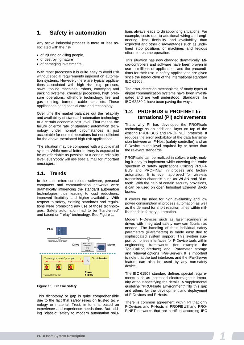
In the past, micro-controllers, software, personal computers and communication networks were dramatically influencing the standard automation technologies thus leading to cost reductions, improved flexibility and higher availability. With respect to safety, existing standards and regula-tions were prohibiting any use of those technolo-gies. Safety automation had to be "hard-wired" and based on "relay" technology. See Figure 1.
This dichotomy or gap is quite comprehensible due to the fact that safety relies on trusted tech-nology or material. Trust, in turn, is based on experience and experience needs time. But add-ing "classic" safety to modern automation solu-
tions always leads to disappointing situations. For example, costs due to additional wiring and engi-neering, less flexibility and availability than expected and other disadvantages such as unde-fined stop positions of machines and tedious efforts to resume operation.
This situation has now changed dramatically. Mi-cro-controllers and software have been proven in use in millions of applications and the precondi-tions for their use in safety applications are given since the introduction of the international standard IEC 61508.
The error detection mechanisms of many types of digital communication systems have been investi-gated and are well understood. Standards like IEC 62280-1 have been paving the ways.
1.2. PROFIBUS & PROFINET In-ternational (PI) achievements
That’s why PI has developed the PROFIsafe technology as an additional layer on top of the existing PROFIBUS and PROFINET protocols. It reduces the error probability of the data transmis-sion between an F-Host (safety controller) and an F-Device to the level required by or better than the relevant standards.
PROFIsafe can be realized in software only, mak-ing it easy to implement while covering the entire spectrum of safety applications utilizing PROFI-BUS and PROFINET in process and factory automation. It is even approved for wireless transmission channels such as WLAN and Blue-tooth. With the help of certain security provisions, it can be used on open Industrial Ethernet Back-bones.
It covers the need for high availability and low power consumption in process automation as well as the demand for short reaction times within mil-liseconds in factory automation.
Modern F-Devices such as laser scanners or drives with integrated safety now can flourish as needed. The handling of their individual safety parameters (iParameters) is made easy due to sophisticated system support. This system sup-port comprises interfaces for F-Device tools within engineering frameworks (for example the Tool Calling Interface) and iParameter storage and retrieval options (iPar-Server). It is important to note that the tool interfaces and the iPar-Server feature can also be used by any non-safety device.
The IEC 61508 standard defines special require-ments such as increased electromagnetic immu-nity without specifying the details. A supplemental guideline "PROFIsafe Environment" fills this gap and others for the development and deployment of F-Devices and F-Hosts.
There is common agreement within PI that only F-Devices and F-Hosts in PROFIBUS and PRO-FINET networks that are certified according IEC
Trusted technologyTrusted technology
Drive Frequencyconverter
andcontrol
Frequencyconverter
andcontrol
PowerSupply
Motor
PROFIBUS/PROFINET
PLC
Circuit breaker"Deenergize to trip" principle I
Figure 1: Classic Safety
2 PROFIsafe System Description
61508 are permitted. Conformity with the PROFIsafe protocol shall be tested by PI test laboratories and certified by PI office. A supple-mental "PROFIsafe Test Specification" document defines the roles and tasks of assessment bodies such as TÜV and the roles and tasks of PI test laboratories.
See www.profisafe.net for actual information about PROFIsafe and www.profibus.com for gen-eral PROFIBUS and PROFINET information.
1.3. International standards
In most countries, national laws regulate how people and the environment shall be protected. In Europe, the “Low Voltage Directive”, the “EMC Directive”, and the “Machinery Directive” are examples of such legislation. The laws in turn refer to International Standards.
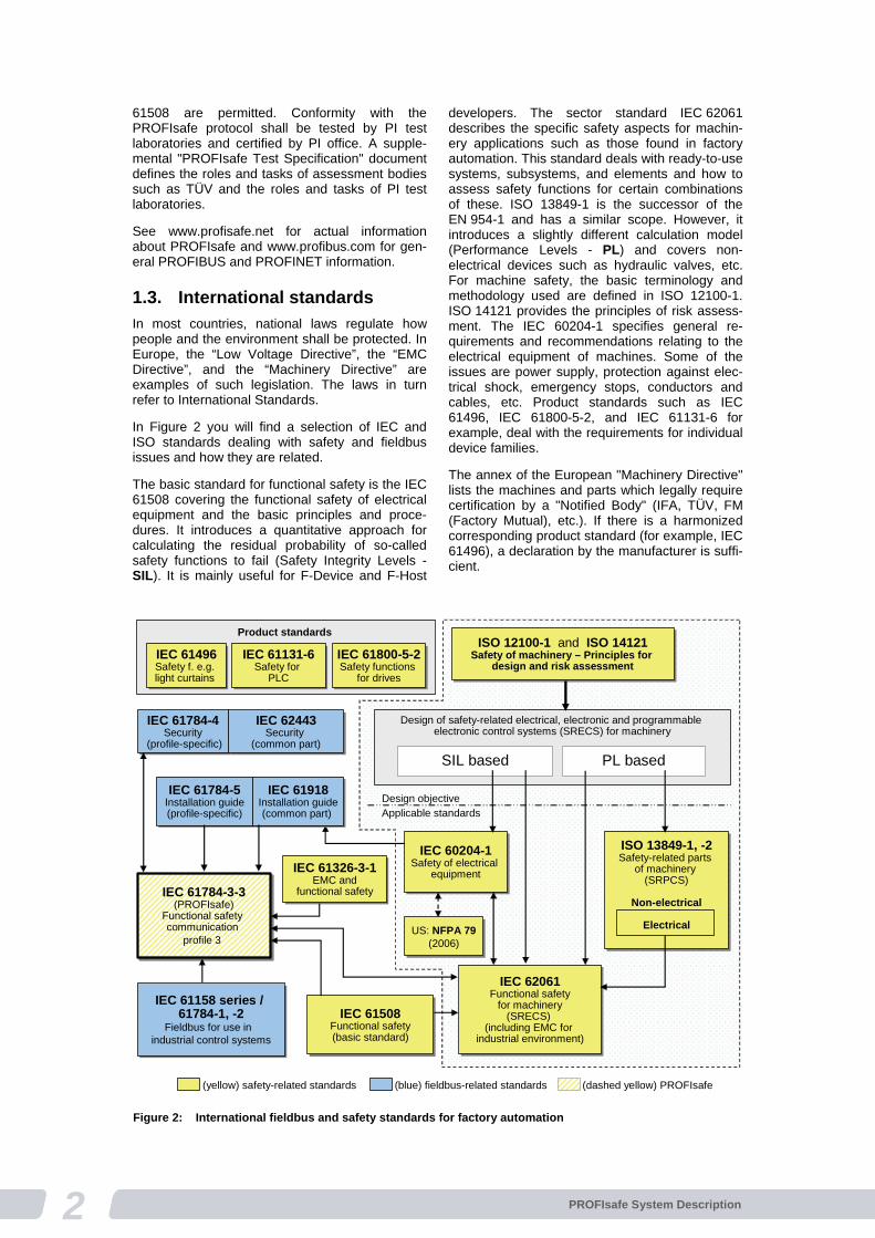
In Figure 2 you will find a selection of IEC and ISO standards dealing with safety and fieldbus issues and how they are related.
The basic standard for functional safety is the IEC 61508 covering the functional safety of electrical equipment and the basic principles and proce-dures. It introduces a quantitative approach for calculating the residual probability of so-called safety functions to fail (Safety Integrity Levels - SIL). It is mainly useful for F-Device and F-Host
developers. The sector standard IEC 62061 describes the specific safety aspects for machin-ery applications such as those found in factory automation. This standard deals with ready-to-use systems, subsystems, and elements and how to assess safety functions for certain combinations of these. ISO 13849-1 is the successor of the EN 954-1 and has a similar scope. However, it introduces a slightly different calculation model (Performance Levels - PL) and covers non-electrical devices such as hydraulic valves, etc. For machine safety, the basic terminology and methodology used are defined in ISO 12100-1. ISO 14121 provides the principles of risk assess-ment. The IEC 60204-1 specifies general re-quirements and recommendations relating to the electrical equipment of machines. Some of the issues are power supply, protection against elec-trical shock, emergency stops, conductors and cables, etc. Product standards such as IEC 61496, IEC 61800-5-2, and IEC 61131-6 for example, deal with the requirements for individual device families.
The annex of the European "Machinery Directive" lists the machines and parts which legally require certification by a "Notified Body" (IFA, TÜV, FM (Factory Mutual), etc.). If there is a harmonized corresponding product standard (for example, IEC 61496), a declaration by the manufacturer is suffi-cient.
Design of safety-related electrical, electronic and programmableelectronic control systems (SRECS) for machinery
ISO 12100-1 and ISO 14121Safety of machinery – Principles for
design and risk assessment
ISO 12100-1 and ISO 14121Safety of machinery – Principles for
design and risk assessment
SIL based PL based
Design objectiveApplicable standards
IEC 60204-1Safety of electrical
equipment
IEC 60204-1Safety of electrical
equipment
IEC 62061Functional safety
for machinery(SRECS)
(including EMC forindustrial environment)
IEC 62061Functional safety
for machinery(SRECS)
(including EMC forindustrial environment)
ISO 13849-1, -2Safety-related parts
of machinery(SRPCS)
Non-electrical
Electrical
ISO 13849-1, -2Safety-related parts
of machinery(SRPCS)
Non-electrical
Electrical
IEC 61508Functional safety(basic standard)
IEC 61508Functional safety(basic standard)
IEC 61158 series /61784-1, -2
Fieldbus for use in industrial control systems
IEC 61158 series /61784-1, -2
Fieldbus for use in industrial control systems
IEC 61784-3-3(PROFIsafe)
Functional safety communication
profile 3
IEC 61784-3-3(PROFIsafe)
Functional safety communication
profile 3
IEC 61784-4Security
(profile-specific)
IEC 61784-4Security
(profile-specific)
IEC 61784-5Installation guide(profile-specific)
IEC 61784-5Installation guide(profile-specific)
IEC 61918Installation guide(common part)
IEC 61918Installation guide(common part)
IEC 61326-3-1EMC and
functional safety
IEC 61326-3-1EMC and
functional safety
IEC 62443Security
(common part)
IEC 62443Security
(common part)
US: NFPA 79(2006)
US: NFPA 79(2006)
IEC 61496Safety f. e.g. light curtains
IEC 61496Safety f. e.g. light curtains
IEC 61800-5-2Safety functions
for drives
IEC 61800-5-2Safety functions
for drives
Product standards
IEC 61131-6Safety for
PLC
IEC 61131-6Safety for
PLC
(yellow) safety-related standards (blue) fieldbus-related standards (dashed yellow) PROFIsafe Figure 2: International fieldbus and safety standards for factory automation

3PROFIsafe System Description
The requirements for F-Devices and F-Hosts to provide increased electromagnetic immunity are defined in IEC 61326-3-1. Special functional safety (FS) performance criteria allow for incorrect functioning under increased electromagnetic inter-ference conditions above the normally required levels. However, in these cases the equipment under test (EUT) at least shall go into a safe state.
The fieldbus standards are specified in IEC 61158 and IEC 61784-1. Realtime Ethernet variants such as PROFINET IO are defined in IEC 61784-2. Common parts for installation guidelines are summed up in IEC 61918, whereas profile-specific parts are collected in IEC 61784-5. Com-mon parts for security guidelines are summed up in IEC 62443, whereas profile-specific parts are collected in IEC 61784-4.
In Figure 3 you will find a similar selection of IEC and ISO standards adapted to the requirements of process automation. Here, the sector standard IEC 61511 is considering the particular situation of long term experience ("proven-in-use") with very sensitive process instrumentation and a specified electromagnetic environment in this area. Thus, the IEC 61326-3-2 takes these EMC requirements into account.
2. Requirements fullfilled
From the very beginning, it was the intention of PROFIsafe to specify a comprehensive and effi-cient solution for both the safety device developer and the end user.
The PROFIsafe protocol is suitable for both PROFIBUS and PROFINET networks without impacts on these existing fieldbus standards. It is possible to transmit safety messages on the exist-ing standard bus cables in coexistence with the standard messages (Figure 4).
IEC 61511b)
Functional safety –Safety instrumented
systems for the process industry sector
IEC 61511b)
Functional safety –Safety instrumented
systems for the process industry sector
IEC 61508Functional safety(basic standard)
IEC 61508Functional safety(basic standard)
IEC 61158 series / 61784-1, -2
Fieldbus for use in industrial control systems
IEC 61158 series / 61784-1, -2
Fieldbus for use in industrial control systems
IEC 61784-3-3(PROFIsafe)
Functional safety communication
profile 3
IEC 61784-3-3(PROFIsafe)
Functional safety communication
profile 3
IEC 61784-4Security
(profile-specific)
IEC 61784-4Security
(profile-specific)
IEC 61784-5Installation guide(profile-specific)
IEC 61784-5Installation guide(profile-specific)
IEC 61918Installation guide(common part)
IEC 61918Installation guide(common part)
IEC 61326-3-2a)
EMC andfunctional safety
IEC 61326-3-2a)
EMC andfunctional safety
IEC 62443Security
(common part)
IEC 62443Security
(common part)
a) For specified electromagnetic environments; otherwise IEC 61326-3-1 b) EN ratified
IEC 61496Safety f. e.g. light curtains
IEC 61496Safety f. e.g. light curtains
IEC 61800-5-2Safety functions
for drives
IEC 61800-5-2Safety functions
for drives
Product standards
IEC 61131-6Safety for
PLC
IEC 61131-6Safety for
PLC
See safety standards for machinery(Figure 2)
Valid also in process industries,whenever applicable
US:ISA-84.00.01
(3 parts = modifiedIEC 61511)
US:ISA-84.00.01
(3 parts = modifiedIEC 61511)
DE: VDI 2180Part 1-4
DE: VDI 2180Part 1-4
(yellow) safety-related standards (blue) fieldbus-related standards (dashed yellow) PROFIsafe
IEC 61511b)
Functional safety –Safety instrumented
systems for the process industry sector
IEC 61511b)
Functional safety –Safety instrumented
systems for the process industry sector
IEC 61508Functional safety(basic standard)
IEC 61508Functional safety(basic standard)
IEC 61158 series / 61784-1, -2
Fieldbus for use in industrial control systems
IEC 61158 series / 61784-1, -2
Fieldbus for use in industrial control systems
IEC 61784-3-3(PROFIsafe)
Functional safety communication
profile 3
IEC 61784-3-3(PROFIsafe)
Functional safety communication
profile 3
IEC 61784-4Security
(profile-specific)
IEC 61784-4Security
(profile-specific)
IEC 61784-5Installation guide(profile-specific)
IEC 61784-5Installation guide(profile-specific)
IEC 61918Installation guide(common part)
IEC 61918Installation guide(common part)
IEC 61326-3-2a)
EMC andfunctional safety
IEC 61326-3-2a)
EMC andfunctional safety
IEC 62443Security
(common part)
IEC 62443Security
(common part)
a) For specified electromagnetic environments; otherwise IEC 61326-3-1 b) EN ratified
IEC 61496Safety f. e.g. light curtains
IEC 61496Safety f. e.g. light curtains
IEC 61800-5-2Safety functions
for drives
IEC 61800-5-2Safety functions
for drives
Product standards
IEC 61131-6Safety for
PLC
IEC 61131-6Safety for
PLC
See safety standards for machinery(Figure 2)
Valid also in process industries,whenever applicable
US:ISA-84.00.01
(3 parts = modifiedIEC 61511)
US:ISA-84.00.01
(3 parts = modifiedIEC 61511)
DE: VDI 2180Part 1-4
DE: VDI 2180Part 1-4
(yellow) safety-related standards (blue) fieldbus-related standards (dashed yellow) PROFIsafe
Figure 3: International fieldbus and safety standards for process automation
Combinationpossible
StandardCPU
Compactremote I/O
Limitswitch
Link
Coexistence of standard and safety communication
Conventional E-Stops
Safety-CPU(F-Host)
F-Modules in a remote I/O device
Laserscanner
Lightcurtains Robots Drives
Figure 4: The "Single Channel" approach
4 PROFIsafe System Description
This "Single Channel" approach also allows the use of standard PLCs with integrated but logically separated safety processing. This way media redundancy to achieve higher availability could be realized as an option. For those users who favor physical separation of the standard and safety communications, PROFIsafe is not a handicap. However, these users could still benefit from the common PROFIsafe technology on the separate communication networks.
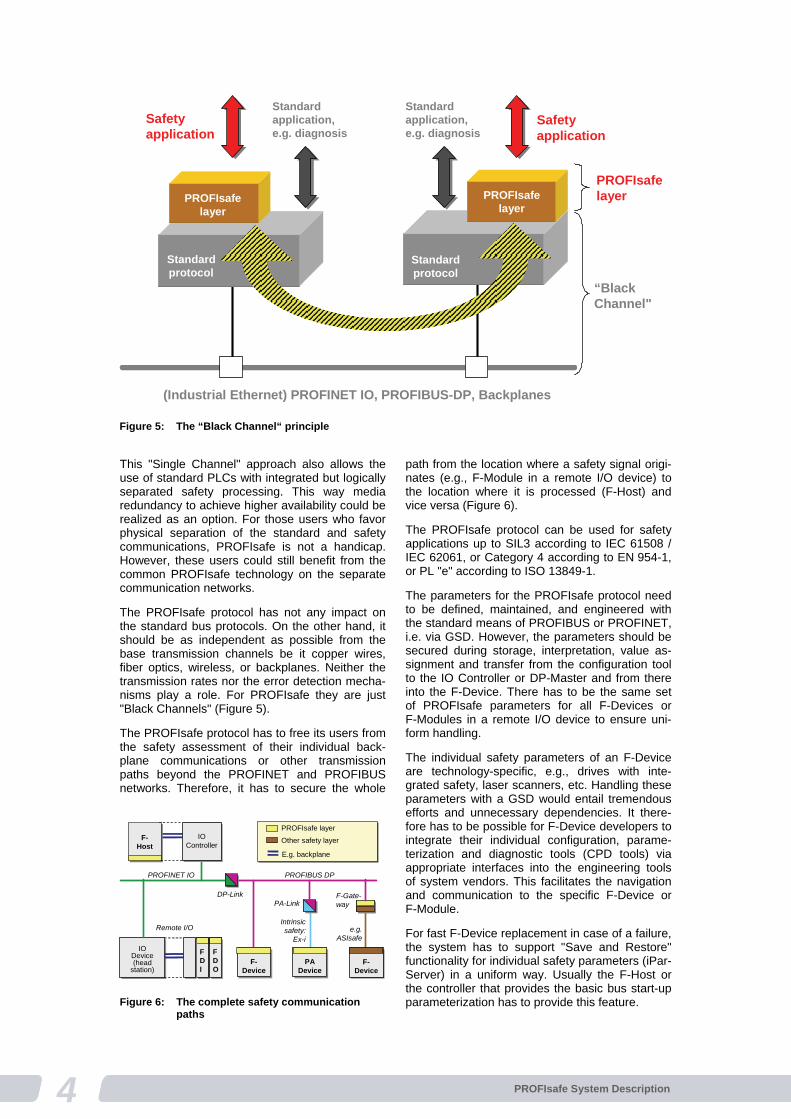
The PROFIsafe protocol has not any impact on the standard bus protocols. On the other hand, it should be as independent as possible from the base transmission channels be it copper wires, fiber optics, wireless, or backplanes. Neither the transmission rates nor the error detection mecha-nisms play a role. For PROFIsafe they are just "Black Channels" (Figure 5).
The PROFIsafe protocol has to free its users from the safety assessment of their individual back-plane communications or other transmission paths beyond the PROFINET and PROFIBUS networks. Therefore, it has to secure the whole
path from the location where a safety signal origi-nates (e.g., F-Module in a remote I/O device) to the location where it is processed (F-Host) and vice versa (Figure 6).
The PROFIsafe protocol can be used for safety applications up to SIL3 according to IEC 61508 / IEC 62061, or Category 4 according to EN 954-1, or PL "e" according to ISO 13849-1.
The parameters for the PROFIsafe protocol need to be defined, maintained, and engineered with the standard means of PROFIBUS or PROFINET, i.e. via GSD. However, the parameters should be secured during storage, interpretation, value as-signment and transfer from the configuration tool to the IO Controller or DP-Master and from there into the F-Device. There has to be the same set of PROFIsafe parameters for all F-Devices or F-Modules in a remote I/O device to ensure uni-form handling.
The individual safety parameters of an F-Device are technology-specific, e.g., drives with inte-grated safety, laser scanners, etc. Handling these parameters with a GSD would entail tremendous efforts and unnecessary dependencies. It there-fore has to be possible for F-Device developers to integrate their individual configuration, parame-terization and diagnostic tools (CPD tools) via appropriate interfaces into the engineering tools of system vendors. This facilitates the navigation and communication to the specific F-Device or F-Module.
For fast F-Device replacement in case of a failure, the system has to support "Save and Restore" functionality for individual safety parameters (iPar-Server) in a uniform way. Usually the F-Host or the controller that provides the basic bus start-up parameterization has to provide this feature.
Standardprotocol
Standardapplication,e.g. diagnosis
Safetyapplication
PROFIsafelayer
“Black Channel"
(Industrial Ethernet) PROFINET IO, PROFIBUS-DP, Backplanes
PROFIsafelayer
PROFIsafelayer
Standardprotocol
Standardapplication,e.g. diagnosis
Safetyapplication
Figure 5: The “Black Channel“ principle
IODevice(head
station)
IODevice(head
station)
FDI
FDI
FDO
FDO
Remote I/O
E.g. backplane
F-Host
F-Host
IOController
IOController
F-Device
F-Device
Intrinsicsafety:
Ex-i
PROFINET IO
e.g.ASIsafe
PROFIsafe layer
Other safety layer
PADevice
PADevice
PROFIBUS DP
F-Gate-way
F-Device
F-Device
DP-LinkPA-Link
Figure 6: The complete safety communication paths
5PROFIsafe System Description
Supplementary documentation define all aspects of deployment of PROFIsafe devices such as requirements for
Installation
Electrical safety
Power supplies
Electromagnetic compatibility
Data security Finally strong support for developers of PROFI-safe in F-Devices or F-Modules needs to be avail-able in the form of PROFIsafe development kits, competence centers and test centers.
In its current version, PROFIsafe meets all of these requirements. The final concept is still straightforward and easy to understand.
Before we learn more about PROFIsafe in detail let's take a look at some preconditions and con-straints.
3. “Black Channel” con-straints
Even though PROFIsafe uses the "Black Chan-nel" principle, there are some basic features of PROFIBUS and PROFINET that were considered for its design.
3.1. Basic features
One such feature is the cyclic communication between a bus controller and its associated field devices (send and receive response principle). This polling operation will immediately detect any failed device. PROFIsafe adopted this principle.
The other feature is the 1:1 communication rela-tionship between a bus controller and its associ-ated field devices. PROFIsafe also adopts this principle to ensure the authenticity of messages. However, this restricts an F-Module (Subslot) within a modular field device to be accessed by only one F-Host.
3.2. Network components
A "Black Channel" may comprise several types of transparent network components such as switches, routers, links, and wireless transmission channels. For PROFIsafe, minor constraints exist in order to meet the SIL3 requirements.
Any kind of switch is permitted but only 100 may be connected in a row. The F-Address space within a PROFIsafe island must be unique. Con-nected islands with the same F-Address space must be separated by multi-port routers. There are no known restrictions for links such as from PROFINET to PROFIBUS and from there to the intrinsic safety version MBP-IS (Figure 6).
3.3. Wireless & Security
Wireless transmission is permitted as long as sufficient availability (no nuisance trips) and secu-rity can be guaranteed.
PROFIsafe specifies certain security requirements for wireless transmission and for wired networks that are connected to industrial Ethernet back-bones or the Internet (open networks).
3.4. Data types
Fieldbus communication in general uses many different data types for information transfer (see literature box on page 9). In order to reduce com-plexity, PROFIsafe offers a reasonable subset.
4. PROFIsafe – the solution
It is the task of safety communication between two partners to deliver
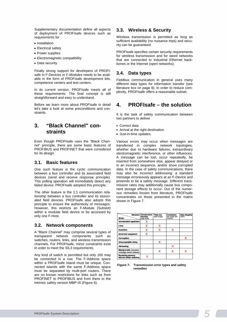
Correct data Arrival at the right destination Just-in-time updates. Various errors may occur when messages are transferred in complex network topologies, whether due to hardware failures, extraordinary electromagnetic interference, or other influences. A message can be lost, occur repeatedly, be inserted from somewhere else, appear delayed or in an incorrect sequence, and/or show corrupted data. In the case of safety communications, there may also be incorrect addressing: a standard message erroneously appears at an F-Device and pretends to be a safety message. Different trans-mission rates may additionally cause bus compo-nent storage effects to occur. Out of the numer-ous remedies known from literature, PROFIsafe concentrates on those presented in the matrix shown in Figure 7.
Error:
Measure: ConsecutiveNumber(sign of life)
Time-out(with receipt)
Codename(for sender and receiver)
Data integrity(CRC)
Unintended repetition
Loss
Insertion
Incorrect sequence
Corruption
Unacceptable delay
Adressing
XXXX
XX
X
XX X
Masquerade (standardmessage mimics failsafe) XRevolving memoryfailures within switches X
X X
Figure 7: Transmission error types and safety
remedies
6 PROFIsafe System Description
4.1. Safety measures
These safety measures include:
The consecutive numbering of the PROFIsafe messages ("sign-of-life")
A time expectation with acknowledgement ("watch-dog")
A codename between sender and receiver ("F-Address")
Data integrity checks (CRC = cyclic redundancy check)
Using the Consecutive Number, a receiver can see whether or not it received the messages completely and within the correct sequence. When it returns a message with the Consecutive Number only as an acknowledgement to the sender, the sender, too, will be assured. Basi-cally, a simple "toggle bit" would have proven sufficient. However, due to the storage buffers in some bus components, e.g. switches, a 24-bit counter was selected for PROFIsafe.
In safety technology, it not only matters that a message transfers the correct process signals or values, the updated actual values must arrive within a fault tolerance time, thus enabling the respective F-Device to automatically initiate any necessary safety reactions on site, e.g. stoppage of movement. For this purpose, the F-Devices utilize a watchdog timer that is restarted whenever a new PROFIsafe message with incremented Consecutive Number arrives.
The 1:1 relationship between the master and a slave facilitates the detection of misdirected mes-sage frames. Sender and receiver must simply have identification (codename) that is unique in the network, and can be used for verifying the authenticity of a PROFIsafe message. PROFIsafe uses an "F-Address" as the sender/receiver-codename.
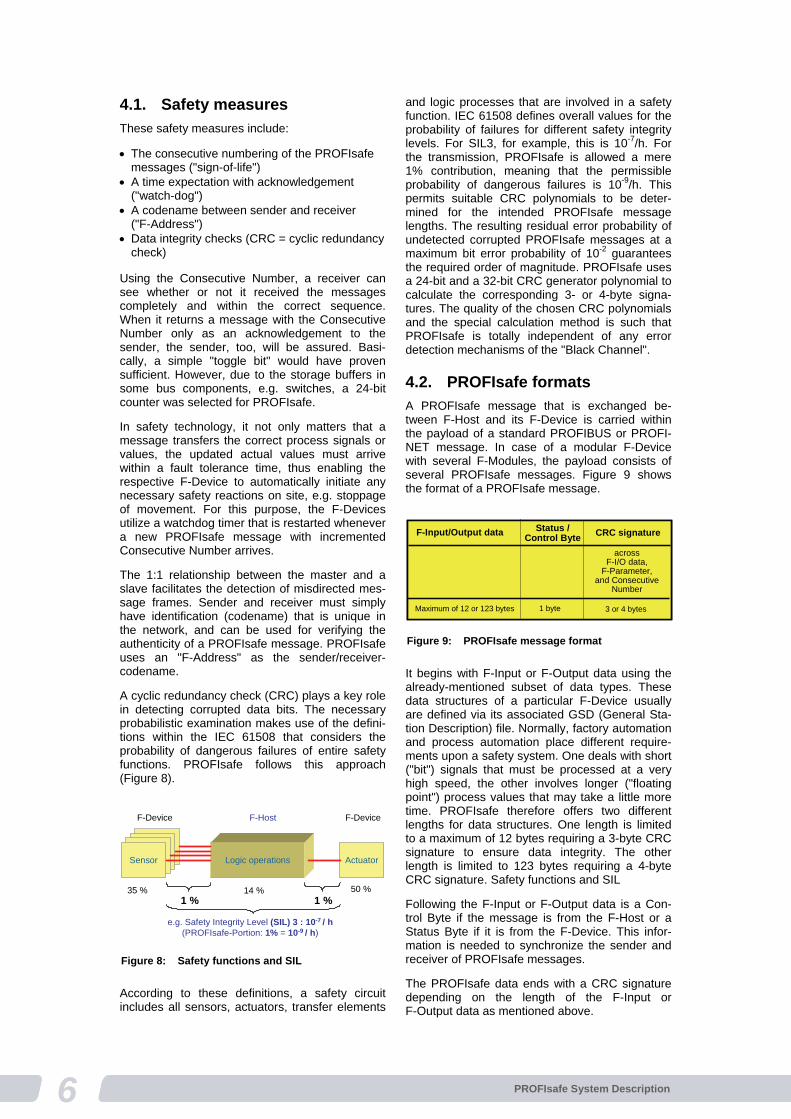
A cyclic redundancy check (CRC) plays a key role in detecting corrupted data bits. The necessary probabilistic examination makes use of the defini-tions within the IEC 61508 that considers the probability of dangerous failures of entire safety functions. PROFIsafe follows this approach (Figure 8).
According to these definitions, a safety circuit includes all sensors, actuators, transfer elements
and logic processes that are involved in a safety function. IEC 61508 defines overall values for the probability of failures for different safety integrity levels. For SIL3, for example, this is 10-7/h. For the transmission, PROFIsafe is allowed a mere 1% contribution, meaning that the permissible probability of dangerous failures is 10-9/h. This permits suitable CRC polynomials to be deter-mined for the intended PROFIsafe message lengths. The resulting residual error probability of undetected corrupted PROFIsafe messages at a maximum bit error probability of 10-2 guarantees the required order of magnitude. PROFIsafe uses a 24-bit and a 32-bit CRC generator polynomial to calculate the corresponding 3- or 4-byte signa-tures. The quality of the chosen CRC polynomials and the special calculation method is such that PROFIsafe is totally independent of any error detection mechanisms of the "Black Channel".
4.2. PROFIsafe formats
A PROFIsafe message that is exchanged be-tween F-Host and its F-Device is carried within the payload of a standard PROFIBUS or PROFI-NET message. In case of a modular F-Device with several F-Modules, the payload consists of several PROFIsafe messages. Figure 9 shows the format of a PROFIsafe message.
It begins with F-Input or F-Output data using the already-mentioned subset of data types. These data structures of a particular F-Device usually are defined via its associated GSD (General Sta-tion Description) file. Normally, factory automation and process automation place different require-ments upon a safety system. One deals with short ("bit") signals that must be processed at a very high speed, the other involves longer ("floating point") process values that may take a little more time. PROFIsafe therefore offers two different lengths for data structures. One length is limited to a maximum of 12 bytes requiring a 3-byte CRC signature to ensure data integrity. The other length is limited to 123 bytes requiring a 4-byte CRC signature. Safety functions and SIL
Following the F-Input or F-Output data is a Con-trol Byte if the message is from the F-Host or a Status Byte if it is from the F-Device. This infor-mation is needed to synchronize the sender and receiver of PROFIsafe messages.
The PROFIsafe data ends with a CRC signature depending on the length of the F-Input or F-Output data as mentioned above.
Logic operations ActuatorSensor
14 %1 % 1 %
e.g. Safety Integrity Level (SIL) 3 : 10-7 / h(PROFIsafe-Portion: 1% = 10-9 / h)
F-Host
50 %35 %
F-Device F-Device
Figure 8: Safety functions and SIL
F-Input/Output data Status /Control Byte
CRC signature
acrossF-I/O data,
F-Parameter,and Consecutive
Number
Maximum of 12 or 123 bytes 1 byte 3 or 4 bytes
F-Input/Output data Status /Control Byte
CRC signature
acrossF-I/O data,
F-Parameter,and Consecutive
Number
Maximum of 12 or 123 bytes 1 byte 3 or 4 bytes
Figure 9: PROFIsafe message format
7PROFIsafe System Description
The Consecutive Number is not transmitted within a PROFIsafe message. Both sender and receiver use their own counters that are synchronized via the Control Byte and Status Byte. Correct syn-chronization is monitored through the inclusion of the counter values into the CRC signature calcu-lation.
The "F-Address" is secured by inclusion in the CRC signature calculation as well.
4.3. PROFIsafe services
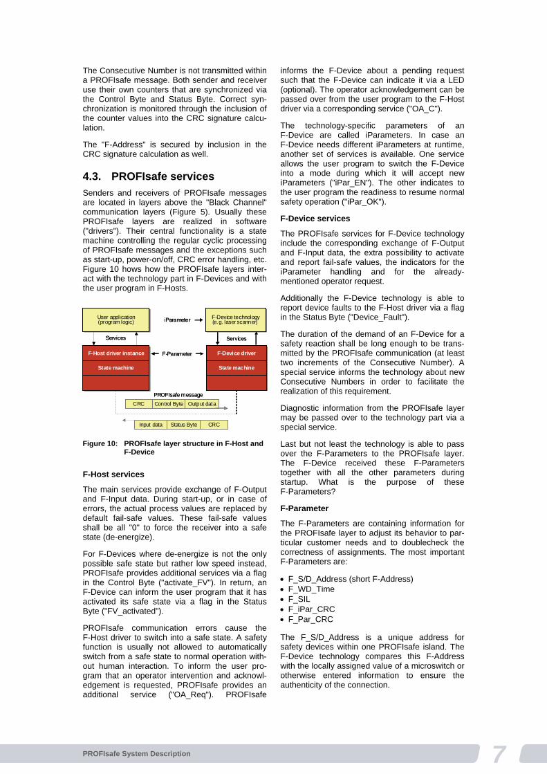
Senders and receivers of PROFIsafe messages are located in layers above the "Black Channel" communication layers (Figure 5). Usually these PROFIsafe layers are realized in software ("drivers"). Their central functionality is a state machine controlling the regular cyclic processing of PROFIsafe messages and the exceptions such as start-up, power-on/off, CRC error handling, etc. Figure 10 hows how the PROFIsafe layers inter-act with the technology part in F-Devices and with the user program in F-Hosts.
F-Host services
The main services provide exchange of F-Output and F-Input data. During start-up, or in case of errors, the actual process values are replaced by default fail-safe values. These fail-safe values shall be all "0" to force the receiver into a safe state (de-energize).
For F-Devices where de-energize is not the only possible safe state but rather low speed instead, PROFIsafe provides additional services via a flag in the Control Byte ("activate_FV"). In return, an F-Device can inform the user program that it has activated its safe state via a flag in the Status Byte ("FV_activated").
PROFIsafe communication errors cause the F-Host driver to switch into a safe state. A safety function is usually not allowed to automatically switch from a safe state to normal operation with-out human interaction. To inform the user pro-gram that an operator intervention and acknowl-edgement is requested, PROFIsafe provides an additional service ("OA_Req"). PROFIsafe
informs the F-Device about a pending request such that the F-Device can indicate it via a LED (optional). The operator acknowledgement can be passed over from the user program to the F-Host driver via a corresponding service ("OA_C").
The technology-specific parameters of an F-Device are called iParameters. In case an F-Device needs different iParameters at runtime, another set of services is available. One service allows the user program to switch the F-Device into a mode during which it will accept new iParameters ("iPar_EN"). The other indicates to the user program the readiness to resume normal safety operation ("iPar_OK").
F-Device services
The PROFIsafe services for F-Device technology include the corresponding exchange of F-Output and F-Input data, the extra possibility to activate and report fail-safe values, the indicators for the iParameter handling and for the already-mentioned operator request.
Additionally the F-Device technology is able to report device faults to the F-Host driver via a flag in the Status Byte ("Device_Fault").
The duration of the demand of an F-Device for a safety reaction shall be long enough to be trans-mitted by the PROFIsafe communication (at least two increments of the Consecutive Number). A special service informs the technology about new Consecutive Numbers in order to facilitate the realization of this requirement.
Diagnostic information from the PROFIsafe layer may be passed over to the technology part via a special service.
Last but not least the technology is able to pass over the F-Parameters to the PROFIsafe layer. The F-Device received these F-Parameters together with all the other parameters during startup. What is the purpose of these F-Parameters?
F-Parameter
The F-Parameters are containing information for the PROFIsafe layer to adjust its behavior to par-ticular customer needs and to doublecheck the correctness of assignments. The most important F-Parameters are:
F_S/D_Address (short F-Address) F_WD_Time F_SIL F_iPar_CRC F_Par_CRC The F_S/D_Address is a unique address for safety devices within one PROFIsafe island. The F-Device technology compares this F-Address with the locally assigned value of a microswitch or otherwise entered information to ensure the authenticity of the connection.
F-Host driver instanceF-Host driver instance
State machineState machine
F-Device driverF-Device driver
State machineState machine
Input data Status Byte CRC
Output dataControl ByteCRC
PROFIsafe message
Services Services
F-Device technology(e.g. laser scanner) F-Device technology(e.g. laser scanner)
User application(program logic)
User application(program logic)
F-Parameter
iParameter
Figure 10: PROFIsafe layer structure in F-Host and
F-Device
8 PROFIsafe System Description
The F_WD_Time specifies a number of milli-seconds for a watchdog timer. This timer monitors the reception of the next valid PROFIsafe mes-sage.
F_SIL indicates the SIL expected by the user for the particular F_Device. It is compared with the locally stored manufacturer information.
F_iPar_CRC is a signature across all the iPara-meters within the technology of the F-Device.
Finally, the F_Par_CRC is a signature across all the F-Parameters which is used to ensure correct delivery of the F-Parameters.
That's an overview of PROFIsafe and we will now get into the details. Are you ready? Let's see what else PI is offering.
5. How to implement?
First of all, it should be made sure, that all the necessary and helpful literature for the work that is available from PI has been obtained (see litera-ture box). Use the denoted or a later version. A previous version V1.30 of the PROFIsafe specifi-cation is available for information only and should not be used for new product developments.
Next it is recommended to study at least the basic safety standard IEC 61508 or get some consul-tancy on what needs to be established in your development processes and in your organization to achieve the necessary safety for your device. As a general rule, it is not possible to turn a stan-dard device into a safety device just by imple-menting the PROFIsafe protocol. The architecture of the safety technology together with the protocol and the manner in which both are implemented define the final SIL of the device.
5.1. Safety classes
Even though PROFIsafe is suitable for safety functions up to SIL3, it may not be necessary to design and develop the F-Device also for SIL3. The required safety class depends on the final customer application and on how the safety func-tions are defined. It may be possible through re-dundancy or other measures to achieve higher safety integrity levels with F-Devices of an even lower safety class.
5.2. F-Devices
You have two choices for the implementation of the PROFIsafe driver software. Either use the specification and do it from scratch or use a development kit available on the market. See the product guide on the PI website for further infor-mation. The advantage of using a development kit is obvious: precertified driver software, additional valuable information and tools, and technical sup-port.
For the PROFIBUS and PROFINET interface, you can use any of the available ASICs and layer stacks and adapt the PROFIsafe driver software.
Securing the GSD
For every device on PROFIBUS or PROFINET, a General Station Description (GSD file) is neces-sary. After defining the common part of the GSD for an F-Device, the coding of the F-Parameters is necessary. This section of the F-Parameters must be protected by a special CRC signature ("F_ParamDescCRC") against data corruption on storage media. A configuration tool can check the data integrity of the F-Parameter description section utilizing this special signature, which is also a part of the GSD file.
Securing configurations
The GSD file also contains descriptions for the F-Input and/or F-Output formats. In order to se-cure this part of the GSD file, another CRC signa-ture ("F_IO_StructureDescCRC") is used.
iParameter
According to the many different safety device technologies there is a huge variety of individual safety parameters (iParameter).
The amount of iParameters ranges from a few bytes for an F-Module up to several tens of kbytes for a laser scanner. For most of the safety devices, special parameterization and diagnostic software tools (CPD-Tool) already exist: therefore it did not make sense to handle iParameters via the GSD.
PROFIsafe therefore recommends using a new mechanism, the so-called Universal-Parameter Server (iPar-Server). It is the responsibility of F-Host manufacturers to provide this capability, whether it is realized within the non-safety part of an F-Host as the parameterization master or within a controlled subsystem such as a non-safety PLC or an industrial computer on the same network.
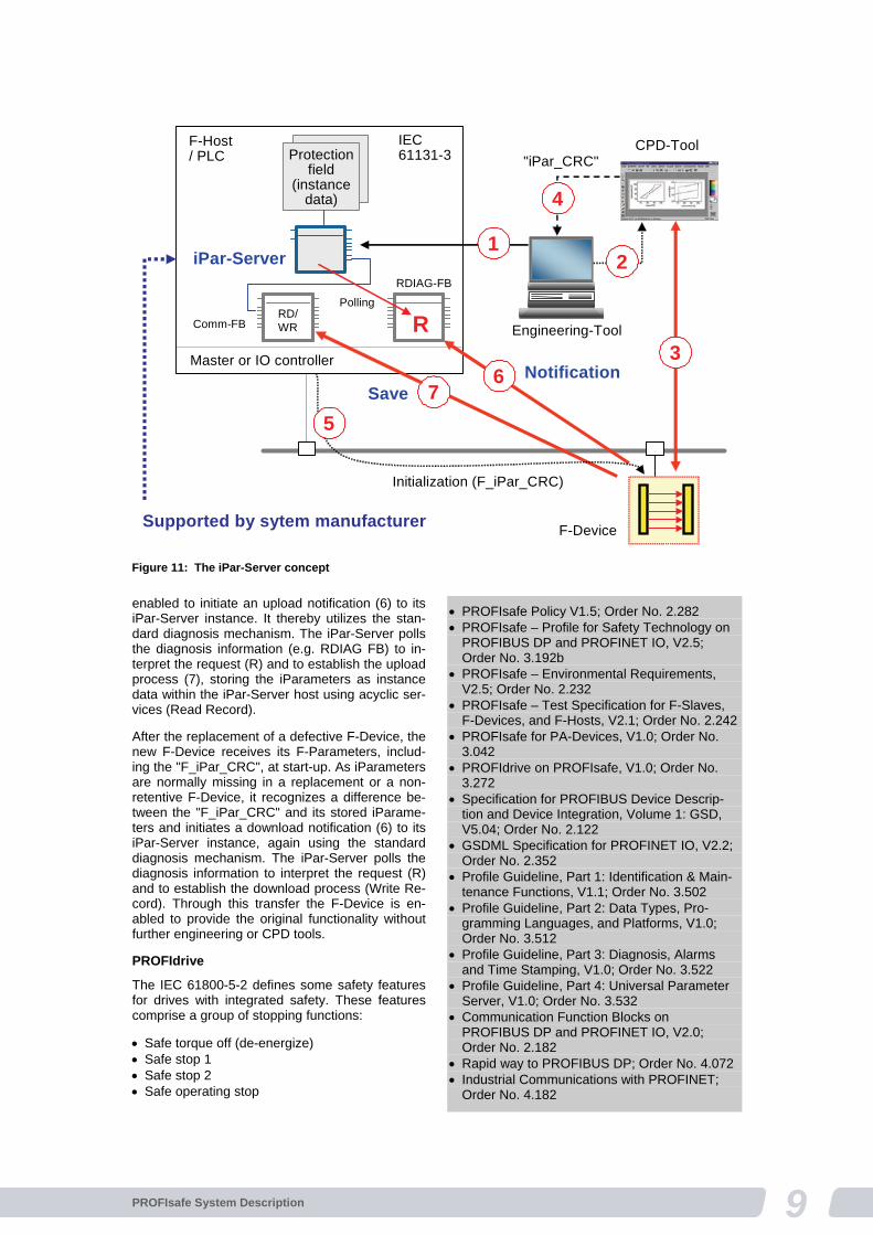
Figure 11 demonstrates the principle steps of the iPar-Server mechanism via an example. Together with the network configuration and F-Para-meterization of an F-Device, an associated iPar-Server function is instantiated (1). The F-Device is able to switch into the data exchange mode while using a safe state (FV). An associated CPD tool can be launched via an appropriate interface (2) such as TCI (Tool Calling Interface) or FDT (Field Device Tool) from the engineering tool, propagat-ing at least the node address of the configured device. Parameterization, commissioning, testing, etc., can be executed with the help of the CPD tool (3). After finalization, the iPar_CRC signature is calculated and displayed in hexadecimal form for (at least) copying and pasting of this value into the "F_iPar_CRC" entry field of the configuration part of the engineering tool (4). A restart of the F-Device is necessary to transfer the "F_iPar_CRC" parameter into the F-Device (5). After final verification and release, the F-Device is
9PROFIsafe System Description
enabled to initiate an upload notification (6) to its iPar-Server instance. It thereby utilizes the stan-dard diagnosis mechanism. The iPar-Server polls the diagnosis information (e.g. RDIAG FB) to in-terpret the request (R) and to establish the upload process (7), storing the iParameters as instance data within the iPar-Server host using acyclic ser-vices (Read Record).
After the replacement of a defective F-Device, the new F-Device receives its F-Parameters, includ-ing the "F_iPar_CRC", at start-up. As iParameters are normally missing in a replacement or a non-retentive F-Device, it recognizes a difference be-tween the "F_iPar_CRC" and its stored iParame-ters and initiates a download notification (6) to its iPar-Server instance, again using the standard diagnosis mechanism. The iPar-Server polls the diagnosis information to interpret the request (R) and to establish the download process (Write Re-cord). Through this transfer the F-Device is en-abled to provide the original functionality without further engineering or CPD tools.
PROFIdrive
The IEC 61800-5-2 defines some safety features for drives with integrated safety. These features comprise a group of stopping functions:
Safe torque off (de-energize) Safe stop 1 Safe stop 2 Safe operating stop
Engineering-Tool
Master or IO controller
F-Host / PLC Protection
field(instance
data)
CPD-Tool
Comm-FB
iPar-Server
IEC61131-3
7
F-Device
6 Notification
RPolling
RDIAG-FB
RD/WR
Save
1
3
2
"iPar_CRC"
4
Initialization (F_iPar_CRC)
5
Supported by sytem manufacturer
Figure 11: The iPar-Server concept
PROFIsafe Policy V1.5; Order No. 2.282 PROFIsafe – Profile for Safety Technology on
PROFIBUS DP and PROFINET IO, V2.5; Order No. 3.192b
PROFIsafe – Environmental Requirements, V2.5; Order No. 2.232
PROFIsafe – Test Specification for F-Slaves, F-Devices, and F-Hosts, V2.1; Order No. 2.242
PROFIsafe for PA-Devices, V1.0; Order No. 3.042
PROFIdrive on PROFIsafe, V1.0; Order No. 3.272
Specification for PROFIBUS Device Descrip-tion and Device Integration, Volume 1: GSD, V5.04; Order No. 2.122
GSDML Specification for PROFINET IO, V2.2; Order No. 2.352
Profile Guideline, Part 1: Identification & Main-tenance Functions, V1.1; Order No. 3.502
Profile Guideline, Part 2: Data Types, Pro-gramming Languages, and Platforms, V1.0; Order No. 3.512
Profile Guideline, Part 3: Diagnosis, Alarms and Time Stamping, V1.0; Order No. 3.522
Profile Guideline, Part 4: Universal Parameter Server, V1.0; Order No. 3.532
Communication Function Blocks on PROFIBUS DP and PROFINET IO, V2.0; Order No. 2.182
Rapid way to PROFIBUS DP; Order No. 4.072 Industrial Communications with PROFINET;
Order No. 4.182

10 PROFIsafe System Description
And a group of monitoring functions:
Safely limited acceleration Safely limited speed Safely limited torque / force Safely limited (absolute) position Safely limited increment Safe direction Safely limited motor temperature Figure 12 illustrates how electromechanics are replaced by electronic safety stops and monitor-ing functions. One major objective is to mainly monitor the operations of the drive control and to de-energize in case of failures only. The working group PROFIdrive within PI is specifying parts of these functions in a special amendment to their PROFIdrive specification (see literature box).
PA Devices
F-Devices for process automation follow the sec-tor standard IEC 61511, which takes into account the particular aspect of "proven-in-use". Under certain conditions a PA-Device may achieve a better SIL if it is proven-in-use. PA Devices usually follow the design models of IEC 61804. The Electronic Device Description (EDD) plays an important role here. Therefore, the PI Working Group "PA Devices" also specified, within a sepa-rate amendment to their PA Device specification, how to use the PROFIsafe platform for their devices and parameterization methodologies (see literature box).
I&M functions
Since 2005 the so-called I&M functions are man-datory for all PROFIBUS and PROFINET devices providing acyclic services. I&M stands for Identifi-cation and Maintenance and allows retrieving information about the device's manufacturer code, its catalog and serial number, and its hardware and software versions in a standardized manner. Via the manufacturer code and additional informa-tion on the PI website, the user can be directed to the most current product information on the manufacturer's website. See the Profile Guideline (literature box).
Diagnosis
One of the major advantages of PROFIBUS and PROFINET is the possibility for devices to report diagnosis information to the operator in excep-tional situations such as failures or errors. Good diagnosis information helps in reducing down times of facilities and thus costs. The concepts not only cover how to code the information but also how to provide foreign language support and how to provide HELP information on what to do in a particular situation. See the corresponding Pro-file Guideline (literature box).
5.3. F-Host
Depending on the strategy of system manufactur-ers, different kinds of architectures for F-Hosts with PROFIsafe communication are possible: stand-alone F-CPUs or integrated but logically separated safety processing within standard CPUs.
Possible structures
Safety processing also can be realized in many different ways: for example via hardware redun-dancy and discrepancy checking or via "software redundancy" or via "safeguarding" or by using already existing diverse hardware platforms. Due to the many different possibilities it did not make sense to create development kits, especially since the effort to implement the PROFIsafe driver is so minimal.
Conformance classes
In order to ensure that all F-Devices will be sup-ported by all the PROFIsafe F-Hosts on the mar-ket, PROFIsafe specifies conformance classes for F-Hosts. PROFIsafe F-Hosts shall meet the requirements of these conformance classes as a precondition for PI certification (Figure 13).
6. Conformity & certifica-tion
Several products of different types from various vendors communicate within a PROFIsafe island. The products must be implemented conform to the PROFIsafe specification to ensure that this communication works correctly. Usually the con-formance is documented through a certificate from the PI Certification Office based on the test report of one of the accredited PI test laborato-ries.
6.1. The PROFIsafe tests
The PROFIsafe protocol mechanisms are based on finite state machines. Thus it was possible via a validation tool for finite state machines to mathematically prove that PROFIsafe works correctly even in cases where more than two in-dependent errors or failures may occur. This sys-tematically was achieved by generating all possi-
DrivecontrolDrive
controlDrive
controlDrive
control
MotorMotor
Externalsafety
technology
Externalsafety
technology
SafetySTOP andmonitoringfunctions
SafetySTOP andmonitoringfunctions
MotorMotor
Externalsafety
technology
Externalsafety
technology
PROFIsafe onPROFINET IO /PROFIBUS DP
"De-energize"From to "Safe Operating STOP"
DrivecontrolDrive
controlDrive
controlDrive
control
MotorMotor
Externalsafety
technology
Externalsafety
technology
SafetySTOP andmonitoringfunctions
SafetySTOP andmonitoringfunctions
MotorMotor
Externalsafety
technology
Externalsafety
technology
PROFIsafe onPROFINET IO /PROFIBUS DP
"De-energize"From to "Safe Operating STOP" Figure 12: Drives with integrated safety STOP and
monitoring functions
11PROFIsafe System Description
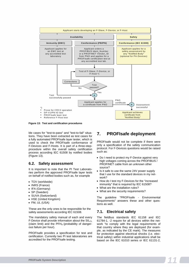
ble cases for "test-to-pass" and "test-to-fail" situa-tions. They have been extracted as test cases for a fully automated PROFIsafe layer tester, which is used to check the PROFIsafe conformance of F-Devices and F-Hosts. It is part of a three-step- procedure within the overall safety certification process according IEC 61508 by notified bodies (Figure 13).
6.2. Safety assessment
It is important to note that the PI Test Laborato-ries perform the approved PROFIsafe layer tests on behalf of notified bodies such as, for example
TÜV (worldwide) INRS (France) IFA (Germany) SP (Sweden) SUVA (Switzerland) HSE (United Kingdom) FM, UL (USA) These are the only ones to be responsible for the safety assessments according IEC 61508.
The mandatory safety manual of each and every F-Device shall provide information about the SILCL (claim limit) and the PFHd (probability of danger-ous failure per hour).
PROFIsafe provides a specification for test and certification. Currently two PI test laboratories are accredited for the PROFIsafe testing.
7. PROFIsafe deployment
PROFIsafe would not be complete if there were only a specification of the safety communication protocol. For F-Devices questions would be raised such as:
Do I need to protect my F-Device against very high voltages coming across the PROFIBUS / PROFINET cable from an unknown other source?
Is it safe to use the same 24V power supply that I use for the standard devices in my net-work?
How do I test my F-Devices for the "increased immunity" that is required by IEC 61508?
What are the installation rules? What are the security requirements? The guideline "PROFIsafe - Environmental Requirements" answers these and other ques-tions as well.
7.1. Electrical safety
The fieldbus standards IEC 61158 and IEC 61784-1, -2 require for all devices within the net-work "to comply with the legal requirements of that country where they are deployed (for exam-ple, as indicated by the CE mark). The measures for protection against electrical shocks (i.e. elec-trical safety) within industrial applications shall be based on the IEC 61010 series or IEC 61131-2,
Applicant starts developing an F-S lave, F-Device, or F-HostApplicant starts developing an F-S lave, F-Device, or F-Host
Applicant applies foran EM C test at
any accredited testlaboratory
Applicant applies foran EM C test at
any accredited testlaboratory
Applicant orders aPRO FIBUS Ident_Num beror a PRO FINET Vendor_IDfrom PNO and applies for a
PRO FIsafe certification test at any accredited test lab.
Applicant orders aPRO FIBUS Ident_Num beror a PRO FINET Vendor_IDfrom PNO and applies for a
PRO FIsafe certification test at any accredited test lab.
Applicant applies for a safety assessm ent by
any "Notified Body"(optional for PA-Devices)
Applicant applies for a safety assessm ent by
any "Notified Body"(optional for PA-Devices)
Test of F-S lave, F-Device, or F-Host *)
Test of F-S lave, F-Device, or F-Host *)
NoTest
passed?
Testpassed?
Applicant applies fora certificate from PNO
Applicant applies fora certificate from PNO
Applicant achievescertificate from"Notified Body"
Applicant achievescertificate from"Notified Body"
Test successfully passed
Assessm entsuccessful
PNOcertificate
Yes
*)• Prove for CRC2 operation• DP-V1/PN-IO test• PRO FIsafe layer test• Reference F-Host test
+
+
Im m unity (EM C)Im m unity (EM C) Conform ance (PB /PN)Conform ance (PB /PN) Conform ance (IEC 61508)Conform ance (IEC 61508)
AvailabilityAvailability SafetySafety
CorrectionsCorrections
Figure 13: Test and certification procedures
12 PROFIsafe System Description
clause 10 depending on device type specified therein". These measures are called PELV (Pro-tected Extra Low Voltage) and limit the permitted voltages in case of one failure to ranges that are not dangerous for humans.
Due to this normally legal requirement, it is possi-ble to limit the protection effort within an F-Device or an F-Host.
7.2. Power supplies
It is possible to use the same 24V power supplies for standard and F-Devices / F-Hosts. In both cases the power supplies shall provide PELV due to legal requirements.
7.3. Increased immunity
For each safety application, the corresponding SRS (Safety Requirements Specification) shall define electromagnetic immunity limits (see IEC 61000-1-1) which are required to achieve electromagnetic compatibility. These limits should be derived taking into account both the electro-magnetic phenomena (see IEC 61000-2-5) and the required safety integrity levels.
For general industrial applications the IEC 61326-3-1 defines immunity requirements for equipment performing or intended to perform safety related functions.
Product standards such as IEC 61496-1 (e.g. laser scanners) may define increased immunity requirements for some phenomena.
The environmental conditions within the process industries can be different from those of general industrial environments. Thus the specific requirements and performance criteria described in IEC 61326-3-2 can be used for PA Devices.
For PROFIsafe a particular EMC test bed is defined.
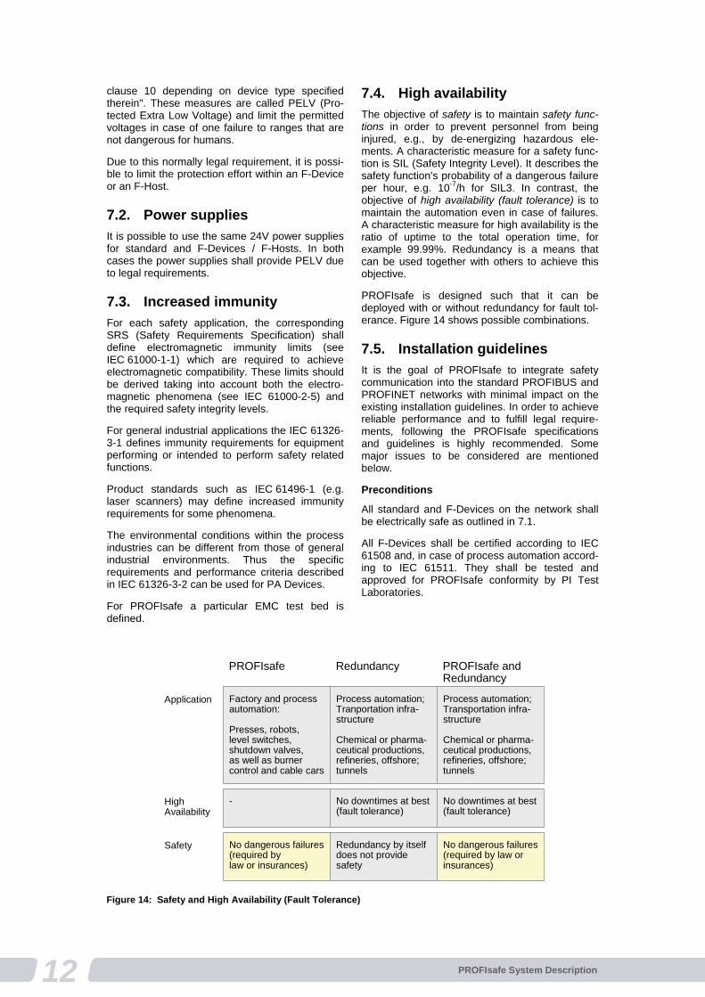
7.4. High availability
The objective of safety is to maintain safety func-tions in order to prevent personnel from being injured, e.g., by de-energizing hazardous ele-ments. A characteristic measure for a safety func-tion is SIL (Safety Integrity Level). It describes the safety function's probability of a dangerous failure per hour, e.g. 10-7/h for SIL3. In contrast, the objective of high availability (fault tolerance) is to maintain the automation even in case of failures. A characteristic measure for high availability is the ratio of uptime to the total operation time, for example 99.99%. Redundancy is a means that can be used together with others to achieve this objective.
PROFIsafe is designed such that it can be deployed with or without redundancy for fault tol-erance. Figure 14 shows possible combinations.
7.5. Installation guidelines
It is the goal of PROFIsafe to integrate safety communication into the standard PROFIBUS and PROFINET networks with minimal impact on the existing installation guidelines. In order to achieve reliable performance and to fulfill legal require-ments, following the PROFIsafe specifications and guidelines is highly recommended. Some major issues to be considered are mentioned below.
Preconditions
All standard and F-Devices on the network shall be electrically safe as outlined in 7.1.
All F-Devices shall be certified according to IEC 61508 and, in case of process automation accord-ing to IEC 61511. They shall be tested and approved for PROFIsafe conformity by PI Test Laboratories.
Factory and process automation:
Presses, robots, level switches, shutdown valves, as well as burnercontrol and cable cars
Process automation;Tranportation infra-structure
Chemical or pharma-ceutical productions,refineries, offshore;tunnels
Process automation;Transportation infra-structure
Chemical or pharma-ceutical productions,refineries, offshore;tunnels
Application
- No downtimes at best(fault tolerance)
No downtimes at best(fault tolerance)
HighAvailability
No dangerous failures(required by law or insurances)
Redundancy by itselfdoes not providesafety
No dangerous failures(required by law or insurances)
Safety
PROFIsafe Redundancy PROFIsafe andRedundancy
Figure 14: Safety and High Availability (Fault Tolerance)
13PROFIsafe System Description
All other standard devices within a PROFIsafe network shall prove conformity to PROFIBUS or PROFINET via a PI certificate or equivalent evi-dence.
Constraints
For PROFIBUS DP, no spurs or branch lines are permitted.
For PROFINET IO, the following rules apply
Less than 100 switches in a row Only one F-Host per submodule All network components must be suitable for an
industrial environment (e.g. IEC 61131-2) No single-port routers permitted to separate
PROFIsafe islands (characterized by unique F-Addresses)
Cabling
PROFIBUS and PROFINET both specify the use of shielded cables and double-sided connection of the shield with the connector housing for best electromagnetic immunity. As a consequence usually equipotential bonding is usually required. If this is not possible fiber optics may be used.
At their own risk, machine designers may use cables without shielding in case of specified elec-tromagnetic compatibility with minor burst and surge interferences.
Availability
Even with shielded cables unacceptable signal noise may be introduced onto the data lines of a device if, for example, the intermediate DC link of a frequency inverter is not filtering well enough. Other sources of unacceptable signal quality may be due to missing terminating resistors and the like. This is not a safety but an availability issue. Sufficient availability of the control functions is a precondition of safety. Safety functions on equip-
ment with insufficient availability may cause nui nuisance trips and as a consequence may tempt production managers to eventually remove these safety functions ("Bhopal effect").
PI companies provide many tools, procedures, and checklists to investigate the transmission quality of networks.
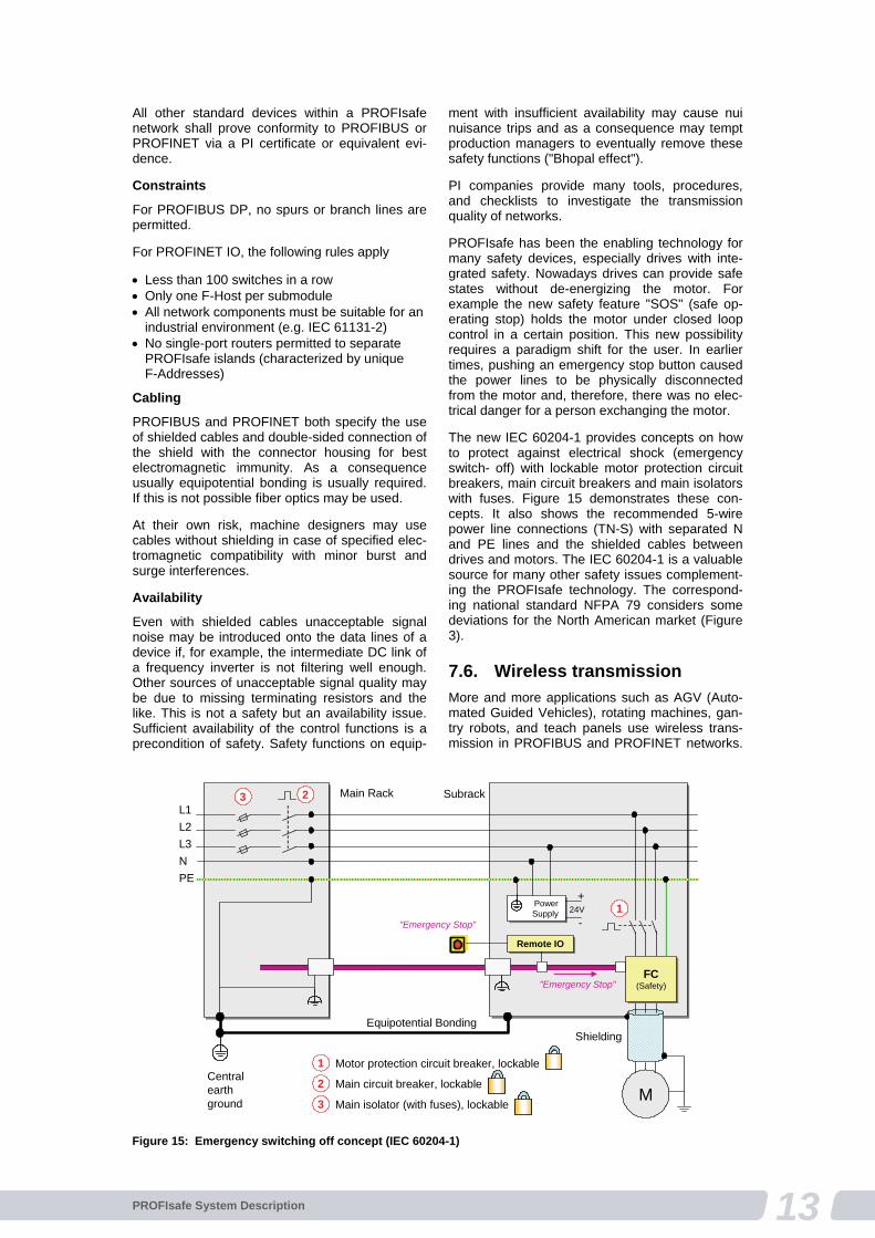
PROFIsafe has been the enabling technology for many safety devices, especially drives with inte-grated safety. Nowadays drives can provide safe states without de-energizing the motor. For example the new safety feature "SOS" (safe op-erating stop) holds the motor under closed loop control in a certain position. This new possibility requires a paradigm shift for the user. In earlier times, pushing an emergency stop button caused the power lines to be physically disconnected from the motor and, therefore, there was no elec-trical danger for a person exchanging the motor.
The new IEC 60204-1 provides concepts on how to protect against electrical shock (emergency switch- off) with lockable motor protection circuit breakers, main circuit breakers and main isolators with fuses. Figure 15 demonstrates these con-cepts. It also shows the recommended 5-wire power line connections (TN-S) with separated N and PE lines and the shielded cables between drives and motors. The IEC 60204-1 is a valuable source for many other safety issues complement-ing the PROFIsafe technology. The correspond-ing national standard NFPA 79 considers some deviations for the North American market (Figure 3).
7.6. Wireless transmission
More and more applications such as AGV (Auto-mated Guided Vehicles), rotating machines, gan-try robots, and teach panels use wireless trans-mission in PROFIBUS and PROFINET networks.
Main Rack Subrack
M
PowerSupply
PowerSupply 24V
+
-
Remote IORemote IO
Equipotential Bonding
Centralearthground
"Emergency Stop"
1
1 Motor protection circuit breaker, lockable
Main circuit breaker, lockable
Main isolator (with fuses), lockable
2
3
23L1
L2
L3
N
PE
"Emergency Stop"
FC(Safety)
FC(Safety)
Shielding
Figure 15: Emergency switching off concept (IEC 60204-1)
14 PROFIsafe System Description
PI will specify details for WLAN and Bluetooth as well. PROFIsafe, with its error detection mecha-nism for bit error probabilities up to 10-2 is approved for both "Black Channels". However, the security issues below must be considered in addi-tion.
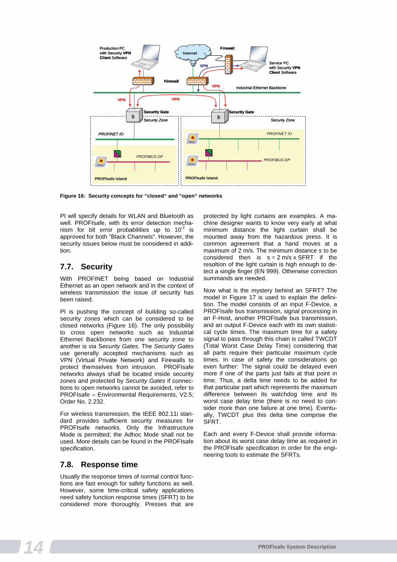
7.7. Security
With PROFINET being based on Industrial Ethernet as an open network and in the context of wireless transmission the issue of security has been raised.
PI is pushing the concept of building so-called security zones which can be considered to be closed networks (Figure 16). The only possibility to cross open networks such as Industrial Ethernet Backbones from one security zone to another is via Security Gates. The Security Gates use generally accepted mechanisms such as VPN (Virtual Private Network) and Firewalls to protect themselves from intrusion. PROFIsafe networks always shall be located inside security zones and protected by Security Gates if connec-tions to open networks cannot be avoided, refer to PROFIsafe – Environmental Requirements, V2.5; Order No. 2.232.
For wireless transmission, the IEEE 802.11i stan-dard provides sufficient security measures for PROFIsafe networks. Only the Infrastructure Mode is permitted; the Adhoc Mode shall not be used. More details can be found in the PROFIsafe specification.
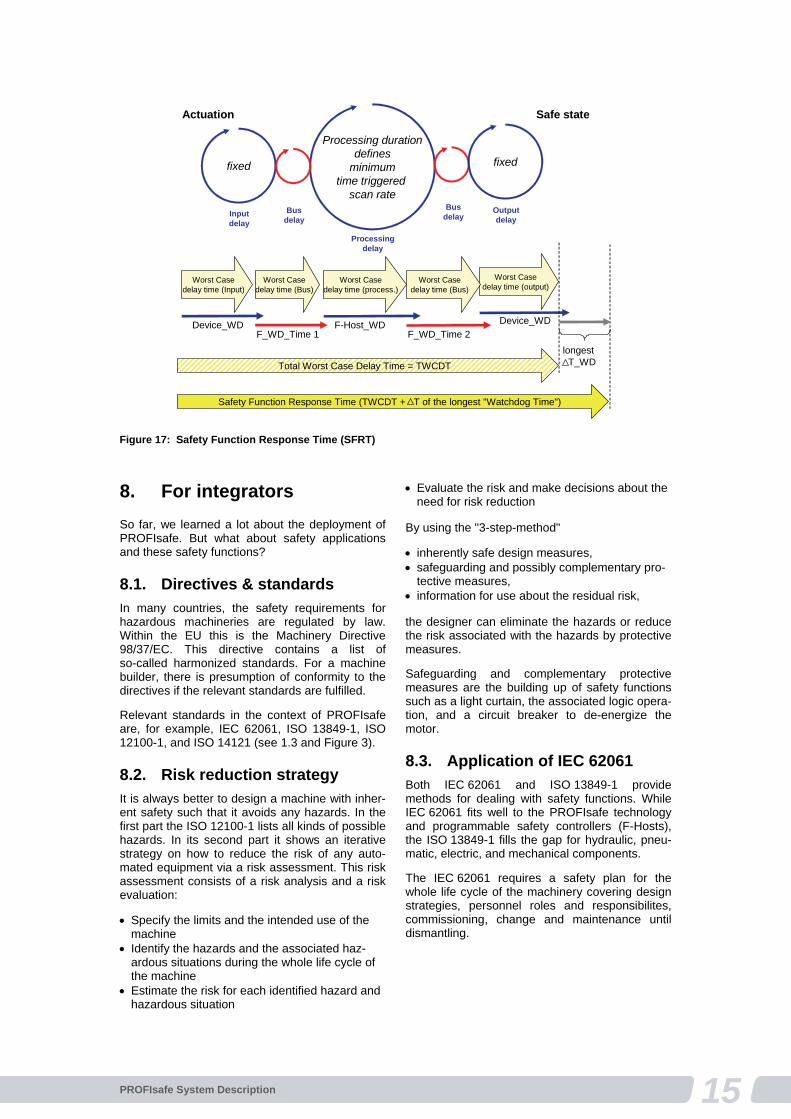
7.8. Response time
Usually the response times of normal control func-tions are fast enough for safety functions as well. However, some time-critical safety applications need safety function response times (SFRT) to be considered more thoroughly. Presses that are
protected by light curtains are examples. A ma-chine designer wants to know very early at what minimum distance the light curtain shall be mounted away from the hazardous press. It is common agreement that a hand moves at a maximum of 2 m/s. The minimum distance s to be considered then is s = 2 m/s x SFRT if the resoltion of the light curtain is high enough to de-tect a single finger (EN 999). Otherwise correction summands are needed.
Now what is the mystery behind an SFRT? The model in Figure 17 is used to explain the defini-tion. The model consists of an input F-Device, a PROFIsafe bus transmission, signal processing in an F-Host, another PROFIsafe bus transmission, and an output F-Device each with its own statisti-cal cycle times. The maximum time for a safety signal to pass through this chain is called TWCDT (Total Worst Case Delay Time) considering that all parts require their particular maximum cycle times. In case of safety the considerations go even further: The signal could be delayed even more if one of the parts just fails at that point in time. Thus, a delta time needs to be added for that particular part which represents the maximum difference between its watchdog time and its worst case delay time (there is no need to con-sider more than one failure at one time). Eventu-ally, TWCDT plus this delta time comprise the SFRT.
Each and every F-Device shall provide informa-tion about its worst case delay time as required in the PROFIsafe specification in order for the engi-neering tools to estimate the SFRTs.
Industrial Ethernet Backbone
PROFIBUS DP
Security Gate Security Gate
PROFINET IOPROFINET IO
Internet
Production PCwith Security VPNClient Software
Service PCwith Security VPNClient Software
Firewall
PROFIBUS DP
PROFIsafe Island PROFIsafe Island
Security Zone Security ZoneSSSS
Firewall
VPN
VPN
VPN
Internet
VPN
Figure 16: Security concepts for “closed“ and “open“ networks
15PROFIsafe System Description
8. For integrators
So far, we learned a lot about the deployment of PROFIsafe. But what about safety applications and these safety functions?
8.1. Directives & standards
In many countries, the safety requirements for hazardous machineries are regulated by law. Within the EU this is the Machinery Directive 98/37/EC. This directive contains a list of so-called harmonized standards. For a machine builder, there is presumption of conformity to the directives if the relevant standards are fulfilled.
Relevant standards in the context of PROFIsafe are, for example, IEC 62061, ISO 13849-1, ISO 12100-1, and ISO 14121 (see 1.3 and Figure 3).
8.2. Risk reduction strategy
It is always better to design a machine with inher-ent safety such that it avoids any hazards. In the first part the ISO 12100-1 lists all kinds of possible hazards. In its second part it shows an iterative strategy on how to reduce the risk of any auto-mated equipment via a risk assessment. This risk assessment consists of a risk analysis and a risk evaluation:
Specify the limits and the intended use of the machine
Identify the hazards and the associated haz-ardous situations during the whole life cycle of the machine
Estimate the risk for each identified hazard and hazardous situation
Evaluate the risk and make decisions about the need for risk reduction
By using the "3-step-method"
inherently safe design measures, safeguarding and possibly complementary pro-
tective measures, information for use about the residual risk, the designer can eliminate the hazards or reduce the risk associated with the hazards by protective measures.
Safeguarding and complementary protective measures are the building up of safety functions such as a light curtain, the associated logic opera-tion, and a circuit breaker to de-energize the motor.
8.3. Application of IEC 62061
Both IEC 62061 and ISO 13849-1 provide methods for dealing with safety functions. While IEC 62061 fits well to the PROFIsafe technology and programmable safety controllers (F-Hosts), the ISO 13849-1 fills the gap for hydraulic, pneu-matic, electric, and mechanical components.
The IEC 62061 requires a safety plan for the whole life cycle of the machinery covering design strategies, personnel roles and responsibilites, commissioning, change and maintenance until dismantling.
fixed
Processing durationdefines
minimumtime triggered
scan rate
fixed
Inputdelay
Busdelay
Processingdelay
Busdelay
Outputdelay
Worst Casedelay time (Bus)
Worst Casedelay time (output)
F_WD_Time 1 F_WD_Time 2
Total Worst Case Delay Time = TWCDT
Worst Casedelay time (process.)
Safety Function Response Time (TWCDT + T of the longest "Watchdog Time")
Worst Casedelay time (Input)
Worst Casedelay time (Bus)
Device_WD F-Host_WD Device_WD
longestT_WD
Actuation Safe state
Figure 17: Safety Function Response Time (SFRT)

16 PROFIsafe System Description
8.4. Risk evaluation
Both standards offer similar concepts for the risk evaluation of safety functions, based on ISO 14121:
Risk = severity of harm and probability of occur-rence of that harm
The probability of occurrence consists of the exposure of persons, the occurrence, and the possibility of avoidance.
8.5. SIL determination
Both standards provide calculated characteristics. One is the required SIL and the other the required PL (see 1.3). It is possible to transform one into the other. In the long run it can be expected that the difference will disappear for the user when the risk evaluation is performed in engineering tools via "questionnaires".
8.6. Safety function design
IEC 62061 defines so-called safety-related control systems (SRECS) for safety functions with sub-systems for sensing, processing, and actuation. Subsystems may contain elements (e.g. switches).
The easiest way to design a safety function is to use certified F-Devices (sensors, actuators) and a certified F-Host connected via PROFIsafe.
8.7. Achieved SIL
The F-Devices provide the necessary information in their safety manual to determine the achieved SIL of a particular safety function. In the first step, the least SILCL (claim limit) of all the safety devices (F-Devices, F-Host) is selected. This determines the maximum achievable SIL of the entire safety function. In some cases system manufacturers may offer system support to upgrade to a higher SIL via redundancy of F-Devices and corresponding system software.
In the second step, the PFHd values are added and the result is checked against the permitted value ranges for a particular SIL.
The least SIL value from these two steps deter-mines the achievable SIL.
In the following sections, you will see how you can combine F-Modules within remote I/O with classic electromechanical safety devices such as emergency stop buttons, door switches, etc. as shown in Figure 4.
8.8. Electromechanics
IEC 62061 provides four predetermined architec-tures A, B, C, and D for subsystems to connect classic safety devices. Formulas to calculate failure probabilities are provided for these circuits. With the help of B10 values for the switches, the
estimated number of switch cycles, the diagnostic coverage, and a common cause factor, the necessary probability of dangerous failures can be calculated with the formulas and added to determine the overall SIL.
8.9. Non-electrical parts
The ISO 13849-1 defines so-called SRP/CS (Safety-Related Parts of Control Systems) also for hydraulic, pneumatic, electric, and mechanic components. A PL and a PFHd value can be determined for such a component with the help of this standard and transformed into the SIL deter-mination for the safety function according to IEC 62061.
8.10. Validation
IEC 62061 requires a validation plan to be part of the overall safety plan. According to this plan the machinery shall be tested, checked, and docu-mented.
9. F-Device families
PROFIsafe as an enabling technology has been initiating new possibilities for standard and safety devices. This chapter is to provide a brief over-view of some important F-Devices and typical applications.
9.1. Remote I/O
Standard remote I/O now are able to incorporate safety modules without changing the head stations. F-Modules such as digital input/output, analog input/output, power modules, motor start-ers, and frequency converters with integrated safety are available. The F-Modules can be grouped together and allow shut-down in groups.
Emergency stop buttons need very costly yearly inspections as each and every button has to be tested. The new technology allows for easy col-lection of all actuations over the year. This way only the remaining unactuated buttons have to be tested, thus saving tremendous costs.
9.2. Optical sensors
Optical safety sensors such as light curtains and laser scanners are standardized within IEC 61496. Optical sensors are ideally suited to protect entry/exit portals in a flexible manner. The example in Figure 18 also shows how PROFIsafe complements the safety features of laser scan-ners and drives with integrated safety. See details below.
9.3. Drives
The safety features of drives are standardized in IEC 61800-5-2. These safety functions usually re require a safe position indicator. The value is
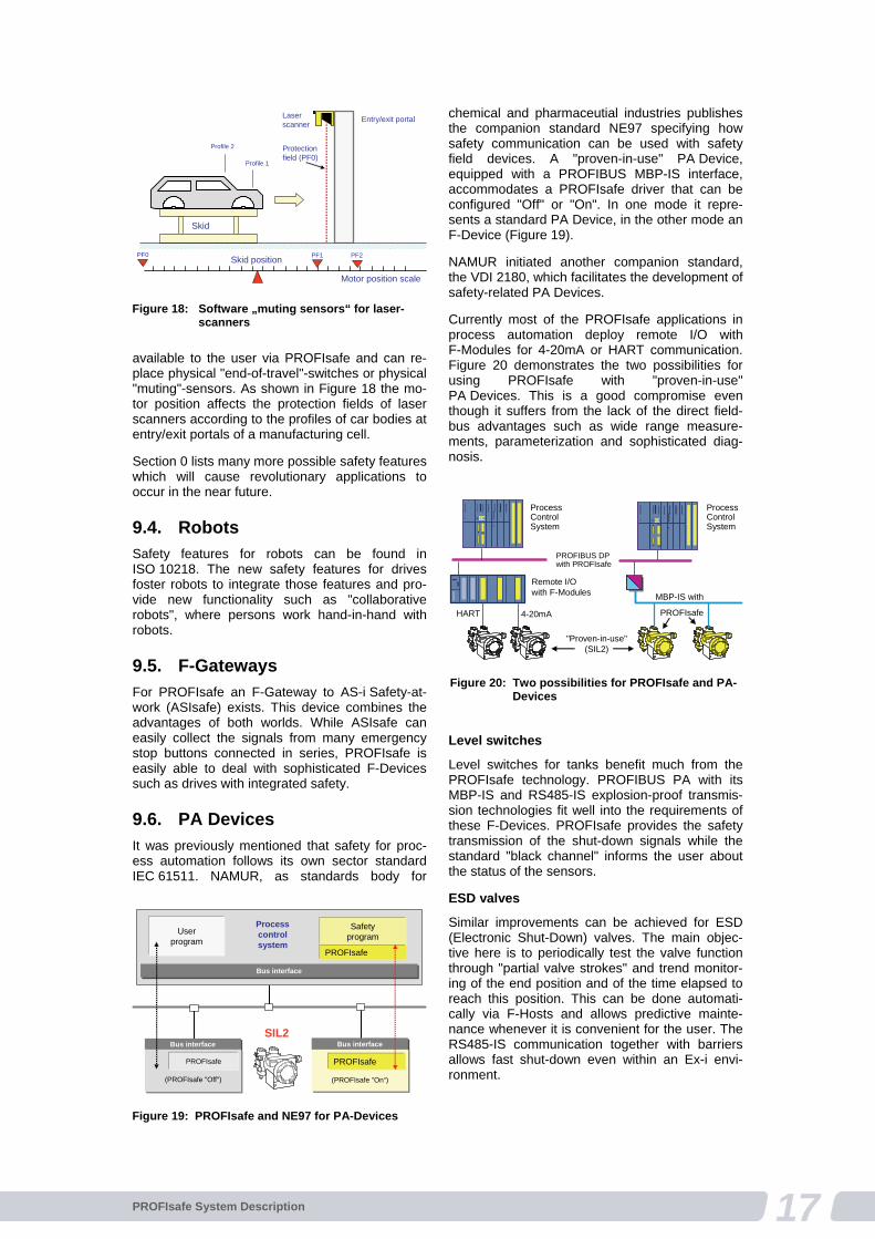
17PROFIsafe System Description
available to the user via PROFIsafe and can re-place physical "end-of-travel"-switches or physical "muting"-sensors. As shown in Figure 18 the mo-tor position affects the protection fields of laser scanners according to the profiles of car bodies at entry/exit portals of a manufacturing cell.
Section 0 lists many more possible safety features which will cause revolutionary applications to occur in the near future.
9.4. Robots
Safety features for robots can be found in ISO 10218. The new safety features for drives foster robots to integrate those features and pro-vide new functionality such as "collaborative robots", where persons work hand-in-hand with robots.
9.5. F-Gateways
For PROFIsafe an F-Gateway to AS-i Safety-at-work (ASIsafe) exists. This device combines the advantages of both worlds. While ASIsafe can easily collect the signals from many emergency stop buttons connected in series, PROFIsafe is easily able to deal with sophisticated F-Devices such as drives with integrated safety.
9.6. PA Devices
It was previously mentioned that safety for proc-ess automation follows its own sector standard IEC 61511. NAMUR, as standards body for
chemical and pharmaceutial industries publishes the companion standard NE97 specifying how safety communication can be used with safety field devices. A "proven-in-use" PA Device, equipped with a PROFIBUS MBP-IS interface, accommodates a PROFIsafe driver that can be configured "Off" or "On". In one mode it repre-sents a standard PA Device, in the other mode an F-Device (Figure 19).
NAMUR initiated another companion standard, the VDI 2180, which facilitates the development of safety-related PA Devices.
Currently most of the PROFIsafe applications in process automation deploy remote I/O with F-Modules for 4-20mA or HART communication. Figure 20 demonstrates the two possibilities for using PROFIsafe with "proven-in-use" PA Devices. This is a good compromise even though it suffers from the lack of the direct field-bus advantages such as wide range measure-ments, parameterization and sophisticated diag-nosis.
Level switches
Level switches for tanks benefit much from the PROFIsafe technology. PROFIBUS PA with its MBP-IS and RS485-IS explosion-proof transmis-sion technologies fit well into the requirements of these F-Devices. PROFIsafe provides the safety transmission of the shut-down signals while the standard "black channel" informs the user about the status of the sensors.
ESD valves
Similar improvements can be achieved for ESD (Electronic Shut-Down) valves. The main objec-tive here is to periodically test the valve function through "partial valve strokes" and trend monitor-ing of the end position and of the time elapsed to reach this position. This can be done automati-cally via F-Hosts and allows predictive mainte-nance whenever it is convenient for the user. The RS485-IS communication together with barriers allows fast shut-down even within an Ex-i envi-ronment.
Entry/exit portalLaser scanner
Skid
Skid position
Motor position scale
Protection field (PF0)
PF1 PF2
Profile 1
Profile 2
PF0
Figure 18: Software „muting sensors“ for laser-scanners
Bus interfaceBus interface
Process control system
Safetyprogram
Bus interfaceBus interface
PROFIsafe
PROFIsafe
(PROFIsafe "On“)
Userprogram
Bus interfaceBus interface
PROFIsafe
(PROFIsafe "Off")
SIL2
Figure 19: PROFIsafe and NE97 for PA-Devices
MBP-IS with
PROFIsafe
PROFIBUS DPwith PROFIsafe
ProcessControlSystem
HART 4-20mA
ProcessControlSystem
Remote I/Owith F-Modules
"Proven-in-use"(SIL2)
Figure 20: Two possibilities for PROFIsafe and PA-Devices

18 PROFIsafe System Description
Pressure transmitter
Safe pressure transmitters combine the function of measuring the tank filling and of protection against overflow ("level switch") via comparison with a setpoint value.
Gas and fire sensors
These sensors are in service on unmanned oil platforms for example. Additional position informa-tion makes it possible to automatically batten down the relevant hatches.
10. User benefits
More than 30 million PROFI-BUS devices have now been installed. Therefore, the top priority for development has always been and will continue to be ensuring that the system remains fully com-patible with the devices that are already in the field.
Thanks to the autonomous functional safety communication protocol of PROFIsafe and its "Black Channel" approach, it is even possible to cross-over from PROFINET to PROFIBUS without any major difficulties. The identical PROFIsafe driver software can be used in both PROFINET and PROFIBUS devices.
Introduction of PROFIsafe has been causing a three-step quantum leap:
From safety-related relay logic to safe programmable logic
From multi-wire to functional safe serial communication
From isolated to cooperating safety-related devices
The following statements perfectly sum up the benefits from several points of view.
10.1. Integrators and end users
Same cost savings as with the introduction of standard PROFI-BUS: reduced wiring, flexible configurations, parameterization, and diagnosis
Easy and cost-efficient system design with a broad product spectrum from all types of manu-facturers
In general no special installation restrictions
Highly innovative safety applications through easy communication between sophisticated F-Devices
High flexibility in the replacement of existing relay technology as well as expansion and retro-fit of existing installations
Integrated technology for both factory and process automation
Training, documentation, and maintenance required for only one bus technology
Programming of standard and safety-related applications with only one tool and certified function blocks
Easy documentation of safety-related configu-rations and logics
Cost saving system acceptance due to certified devices
International acceptance through IEC 61508-conforming technology.
Positive assessments by BGIA and TÜV
10.2. Device manufacturers
TÜV-certified software allows for easy imple-mentation and cost-efficient reproduction of a PROFIsafe solution
Different architectures of safety-related programmable controllers can adopt the PROFIsafe communication
Trailblazer for new innovative device functions
10.3. For future investments
Huge installed base of PROFIBUS and PROFI-NET devices
PROFIBUS/PROFINET organizations and sup-port centers are present worldwide
Use of all existing and future standards defined by PI also for safety-related applications
PROFIsafe is an international standard in IEC 61784-3-3
Future software to assist the life-cycle of safety applications from design through assessment, validation, and documentation, thus further r educing efforts
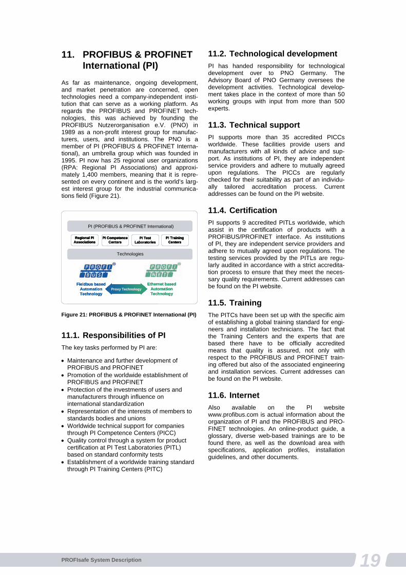
19PROFIsafe System Description
11. PROFIBUS & PROFINET International (PI)
As far as maintenance, ongoing development, and market penetration are concerned, open technologies need a company-independent insti-tution that can serve as a working platform. As regards the PROFIBUS and PROFINET tech-nologies, this was achieved by founding the PROFIBUS Nutzerorganisation e.V. (PNO) in 1989 as a non-profit interest group for manufac-turers, users, and institutions. The PNO is a member of PI (PROFIBUS & PROFINET Interna-tional), an umbrella group which was founded in 1995. PI now has 25 regional user organizations (RPA: Regional PI Associations) and approxi-mately 1,400 members, meaning that it is repre-sented on every continent and is the world’s larg-est interest group for the industrial communica-tions field (Figure 21).
11.1. Responsibilities of PI
The key tasks performed by PI are:
Maintenance and further development of PROFIBUS and PROFINET
Promotion of the worldwide establishment of PROFIBUS and PROFINET
Protection of the investments of users and manufacturers through influence on international standardization
Representation of the interests of members to standards bodies and unions
Worldwide technical support for companies through PI Competence Centers (PICC)
Quality control through a system for product certification at PI Test Laboratories (PITL) based on standard conformity tests
Establishment of a worldwide training standard through PI Training Centers (PITC)
11.2. Technological development
PI has handed responsibility for technological development over to PNO Germany. The Advisory Board of PNO Germany oversees the development activities. Technological develop-ment takes place in the context of more than 50 working groups with input from more than 500 experts.
11.3. Technical support
PI supports more than 35 accredited PICCs worldwide. These facilities provide users and manufacturers with all kinds of advice and sup-port. As institutions of PI, they are independent service providers and adhere to mutually agreed upon regulations. The PICCs are regularly checked for their suitability as part of an individu-ally tailored accreditation process. Current addresses can be found on the PI website.
11.4. Certification
PI supports 9 accredited PITLs worldwide, which assist in the certification of products with a PROFIBUS/PROFINET interface. As institutions of PI, they are independent service providers and adhere to mutually agreed upon regulations. The testing services provided by the PITLs are regu-larly audited in accordance with a strict accredita-tion process to ensure that they meet the neces-sary quality requirements. Current addresses can be found on the PI website.
11.5. Training
The PITCs have been set up with the specific aim of establishing a global training standard for engi-neers and installation technicians. The fact that the Training Centers and the experts that are based there have to be officially accredited means that quality is assured, not only with respect to the PROFIBUS and PROFINET train-ing offered but also of the associated engineering and installation services. Current addresses can be found on the PI website.
11.6. Internet
Also available on the PI website www.profibus.com is actual information about the organization of PI and the PROFIBUS and PRO-FINET technologies. An online-product guide, a glossary, diverse web-based trainings are to be found there, as well as the download area with specifications, application profiles, installation guidelines, and other documents.
Regional PI Associations
PI Competence Centers
PI Test Laboratories
PI Training Centers
PI (PROFIBUS & PROFINET International)
Technologies
Fieldbus based Automation Technology
Ethernet based Automation Technology
Proxy Technology
Regional PI Associations
PI Competence Centers
PI Test Laboratories
PI Training Centers
PI (PROFIBUS & PROFINET International)
Technologies
Fieldbus based Automation Technology
Ethernet based Automation Technology
Proxy Technology
Regional PI Associations
PI Competence Centers
PI Test Laboratories
PI Training Centers
PI (PROFIBUS & PROFINET International)
Technologies
Fieldbus based Automation Technology
Ethernet based Automation Technology
Proxy Technology
Figure 21: PROFIBUS & PROFINET International (PI)


PROFIsafe System Description – Safety Technology and Application
Version November 2010
Order Number 4.342
Publisher
PROFIBUS Nutzerorganisation e.V. (PNO) Haid und Neu-Str. 7 76313 Karlsruhe Germany Tel.: +49 (0)721 / 96 58 590 Fax: +49 (0)721 / 96 58 589
Liability Exclusion
PROFIBUS Nutzerorganisation has examined the contents of this brochure carefully. Nevertheless, errors can not be excluded. Liability of PROFIBUS Nutzerorganisation is excluded, regardless of the reason. The data in this brochure is checked periodically, however. Necessary corrections will be con-tained in subsequent versions. We gratefully accept suggestions for improvement.
Terms used in this brochure may be trade marks and their use by third parties for any purposes may violate the rights of the owner.
This brochure is not a substitute for the standard IEC 61784-3-3 and the associated specifications and guidelines of PROFIBUS & PROFINET International. In case of doubt, these documents take prece-dence.
© Copyright by PROFIBUS Nutzerorganisation e.V. 2010. All rights reserved.