simple and effective antennas for amateur radio...
TRANSCRIPT

1
Simple and Effective Antennas for Amateur Radio Operators
John Dawes, VK5BJE
This paper will cover the following points:
What is an antenna?
Resonant antennas
Non-resonant antennas
Balanced versus unbalanced antennas
Antenna Directivity
Antenna Couplers
Polarisation
Basic constructional Techniques
What is an antenna?
Antennas are radiators. Good ones radiate electromagnetic energy enabling
communications over varying distances. Here is a definition from the ARRL. ‘Antennas
belong to a class of devices called “transducers”. This term is derived from two Latin words,
meaning to “lead across” or “to transfer”. Thus, a transducer is a device that transfers, or
converts, energy from one form to another. The purpose of an antenna is to convert radio-
frequency electric current to electromagnetic waves, which are then radiated into space’
(The ARRL Antenna Book, 2000, p. 2.1).
Resonant Antennas
The most common and proven performer in basic antennas is the half wave dipole (λ/2).
Lambda, the 11th letter of the Greek alphabet is the symbol used for dipole, so λ/2 means a
half-wave dipole. We refer to our band from 7.000 MHz to 7.300 MHz as the 40 metre
amateur band. In US books the band is also referred to as the 40 metre amateur band, but
construction details for such an antenna are usually given in the Imperial measurement of
feet and inches. A 40 metre dipole, cut for, that is, resonant at 7.150 MHz will only be
resonant at one point.
If you decided to make such an antenna where would you make it resonant? I would choose
7.100 MHz approximately. I indicated earlier that this antenna is assumed to have a nominal
2
impedance of 50 ohms, so it can be fed with a light-weight coaxial feed-line with a
characteristic impedance of 50 ohms. If you expect to use a transceiver generating 100
watts in a suburban block I would use RG58 (the best quality I could afford – double
shielded is the best). I would also balance the antenna by adding a balun at the feed-point. I
will say more about this later. A half-wave dipole antenna is easy to construct as a single
band antenna.
A full-wave length antenna can be calculated in feet by the formula 984/F (MHz) and a λ/2 is
obtained by dividing the figure above the line by two (2). So a half-wave length antenna in
feet will be 492/F (MHz).
492/7.1 = 69.29 feet or 35 feet either side of the centre. If you want to compute the length
in metres it is done this way:
142.6464/7.1 = 20.09 metres.
However, if you get to work and construct the antenna to this formula it will be too long and
it will not work on 7.1 with a vswr of 2:1 or below. The formula only applies in space and
with perfect conditions. So you need to use a modified formula:
468/F (MHz) or 468/7.1 = 65.9155 or 65.92 feet or 66 feet will be fine. So if you cut your
antenna 66 feet long, that is, 33 feet each side of feed point or centre and located above
ground somewhere between seven and 10 metres, away from metal objects (cars, sheds,
clothes-lines etc.), it will work. Other relevant factors in determining where the resonant
point is, are: diameter of the wire, insulated or not, geometry of the antenna (horizontal or
inverted-vee or a combination of these two) and whether the antenna is balanced or not
and the nature of the ground. The rule of thumb is, cut your antenna to a length a few
centimetres (inches) longer and trim each leg equally in small lengths using your antenna
analyser to check the frequency as you go. Now I know we adopted decimal measurements
in the 1960’s and I use the metric measures of length most of the time, but for making
antennas I prefer to work in inches and feet. For me it is easier than metres, centimetres
and millimetres!
Non-Resonant Antennas
Universal Antenna
An old favourite and a very useful antenna is a centre-fed dipole fed with an open wire
feeder. This antenna is commonly referred to as a Universal Antenna (Orr & Cowan, 1972,
pp. 157 - 166). It is not a G5RV. One hundred feet across the top and a feeder of a quarter-
wave length long, or multiples of a quarter wavelength, will allow you to operate on all
bands from 3.5 to 28 MHz. You can use 300 ohm ribbon, commercially available 450 ohm
twin lead or home-brewed 450 ohm line using appropriate spreaders
(http://www.tetemtron.com.au), or wider still to make 600 ohm feeder. To operate this
antenna you need a balanced tuner or a standard tuner, e.g. a T-match and a 4:1 balun. A
better approach than bringing balanced feed-line into the shack is to use a standard tuner
and a 4:1 balun mounted under the eaves. The transition to coaxial line occurs here.

3
There are other practical issues to sort out if you choose this approach, e.g. keeping your
open wire feeder free of kinks, from twisting and flapping in the wind and away from metal
objects and avoiding sharp bends (ARRL, 1974, pp. 264 ff).
G5RV
Louis Varney, G5RV, died on June 28th 2000. He was 89 years of age.
(http://www.g0mwt.org.uk/society/g5rvfold/g5rv.htm)
He developed the popular non-resonant, multi-band antenna, now known by his call-sign
G5RV. This antenna is a dipole 102 feet long along the top fed by 29 feet six inches of 300
ohm ribbon (or 34 feet of open wire feeder) and then coaxial cable to the antenna coupler.
The theory of operation of this antenna is too complex and detailed to discuss here (see
Moxon, 1977, pp. 185 ff) for a detailed explanation band by band.
Random Wire
The Marconi or random wire can also work, satisfactorily, for a home station. I do not
recommend this antenna for portable use. It is just too difficult to obtain a satisfactory
ground without an extensive counterpoise, made even more difficult, if you are operating
over rock.
But at a home station a random wire can be useful. The challenge is defining the word
‘random’ (see Bertrand & Wait, 2005, p.82). If you make your random wire 33 feet long and
use a counterpoise 33 feet long, the same handbook defines it as ’30 Up and Out’ (p. 83),
but Kleinschmidt (1999- 2001, p. 4.12) describes it as 33 feet vertical turned on its side. But
because of the length, 33 feet, it is effectively a single band antenna (40m) and becomes a
half wave-length on 20 metres. Random means avoiding a length where the antenna
becomes a half-wave length long on any of your bands of interest. I have an Alinco EDX-2
automatic antenna tuner and I have included Alinco’s formula for calculating undesirable
antenna lengths for amateur bands. I did the arithmetic and settled on 43 feet as a useful
antenna length for a random wire. Some antenna manufacturers build vertical antennas to
this length.

4
Balanced versus Un-balanced Antennas
Kleinschmidt (1999 – 2001, p. 4.5 ff.) provided a simple explanation of why balanced
antennas perform better than unbalanced. Essentially it is to do with current flow. You want
your antenna to radiate effectively. I use un-balanced antennas when operating QRP in the
field. I only use five watts. Current flowing on the coax shield, interference to others and
skewed pattern are not really issues, but at home with 100 watt transceivers, I always use
balanced antennas. If you want both sides of your antenna to radiate equally and avoid
currents flowing on the outside of the coax (making if RF hot) use a balun.
Baluns with a 1:1 or 4:1 ratio can be purchased for as little as $50 from Australian suppliers.
These baluns are made by LDG and need water-proofing if you mount them outside. You
can make your own: I have two home-brewed models here today on display. You can also
purchase a balun kit from Tet-Emtron. If you decide to have a balun in place permanently on
your antenna you need to make it waterproof, which can be a difficult task. I used my
‘sewer pipe’ balun, which is a 4:1 balun, mounted under the eaves. I used this to feed a flat-
top dipole with 450 ohm open wire feeder.
Antenna Directivity
Nearly all antennas have some tendency to radiate better in some directions than in others.
Here is my definition. If an antenna is produces a radiated signal in one direction stronger
than another when compared with an antenna which radiates in all directions equally, such
an antenna is said to have gain (my emphasis). Gain is a quality usually attributed to beam
antennas and collinear vertical antennas. It is beyond the scope of the presentation to
discuss this any further today.
Antenna Couplers
‘(An) antenna tuner is a variable impedance transforming device that can transform the
impedance of an antenna system to that it appears to the transmitter as a 50 ohm load’
Hallas, 2010, 1.4). I thoroughly recommend Joel Hallas’s 2010 book if you are interested in
antenna couplers, to use a more precise term. He describes the various circuits used,
discusses the pros and cons or manual and auto tuners, reviews a number of recent
commercial products and describes home brewing techniques. He states that a home-made
tuner is within the capability of most amateurs and describes and gives circuit values for a T-
network, a Pi-network and a Low-pass L network (Hallas, 2010, p. 15.12). I have brought
along two on my home brew devices to show you how easy it to build attractive and useful
accessories for your shack. The first coupler on display is an L-Network for 160 metres and
above. This coupler enabled me to load my home brew 160 metre am/cw transmitter into a
quarter wave antenna cut for 160 metres and work cw on, say 1815 KHz and also the
ssb/(am 1843 KHz) portions of the band. It is capable of handling 100 watts pep. I used a
transmitter of 13 watts DC input to the final; almost QRP!

5
Photo 1
Photo 2
You will notice (photo 2) that the dual-gang capacitor is not directly bolted to the case. It sits
above RF ground and that is achieved by fixing the capacitor to a polycarbonate sheet and
then bolting that on spacers above the bottom of the case.
The circuit for this coupler came from Orr & Cowan (1972, p. 99). Photo 1 shows the front of
the coupler and photo 2 the interior and circuit components. The most difficult components
to find were the coils. They came from the AHARS buy and sell. The capacitor is a standard
broadcast type of about 425 pf. If more C is needed just add a high voltage good quality
fixed capacitor across the variable C and make it switchable. If you look at Orr & Cowan

6
(1972) you will see I took a very different approach to constructing my device, as I used a
closed box.
Another coupler I have used a great deal is a parallel tuned circuit. These have only
commonly become available very recently. Here is my very small SOTABEAMS Mountain
Tuner for 40 – 17 metre half wave length antennas (http://www.sotabeams.co.uk/antenna-
tuners/). Matching a half wave length antenna to a 50 ohm radio requires a parallel-tuned
circuit, that is, a coil and capacitor in parallel. But here are pictures of my home brew
parallel tuned coupler which does a great job, but a bit too heavy and large for mountain
topping!
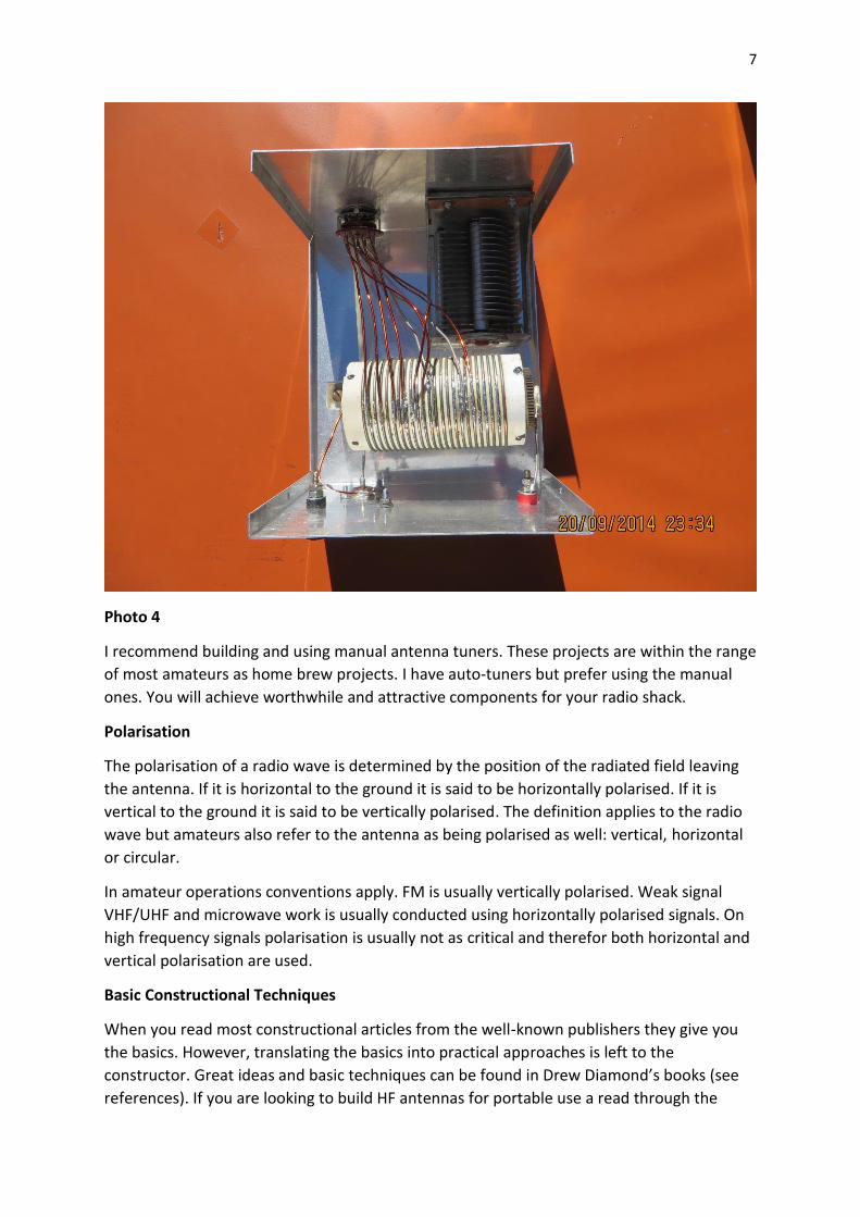
Photo 3 shows the front of the box.
Photo 3
Photo 4 shows the circuit components. Again I was fortunate in obtaining a coil and
capacitor at the AHARS buy and sell. Amateurs a generation or two before me knew where
these components came from, usually war service equipment that became available to
amateurs in the 1950’s. You will see I used good quality tinned copper wire for the links to
the switch. Heavy duty switches are hard to obtain. You should not hot-switch any tuner.
You will burn the contacts and destroy the switch if you do! This coupler enabled me to use
a quarter wave long wire, cut for 1843 KHz on the 80 metre band: a half wave length end-
fed antenna having a little more gain than a quarter wave length long-wire.
7
Photo 4
I recommend building and using manual antenna tuners. These projects are within the range
of most amateurs as home brew projects. I have auto-tuners but prefer using the manual
ones. You will achieve worthwhile and attractive components for your radio shack.
Polarisation
The polarisation of a radio wave is determined by the position of the radiated field leaving
the antenna. If it is horizontal to the ground it is said to be horizontally polarised. If it is
vertical to the ground it is said to be vertically polarised. The definition applies to the radio
wave but amateurs also refer to the antenna as being polarised as well: vertical, horizontal
or circular.
In amateur operations conventions apply. FM is usually vertically polarised. Weak signal
VHF/UHF and microwave work is usually conducted using horizontally polarised signals. On
high frequency signals polarisation is usually not as critical and therefor both horizontal and
vertical polarisation are used.
Basic Constructional Techniques
When you read most constructional articles from the well-known publishers they give you
the basics. However, translating the basics into practical approaches is left to the
constructor. Great ideas and basic techniques can be found in Drew Diamond’s books (see
references). If you are looking to build HF antennas for portable use a read through the
8
blogs of amateurs such as VK3ZPF, VK3PF, VK3YY and VK1NAM (just a few examples) will
reward you with practical approaches (http://www.parksnpeaks.org/). Here are just a few
ideas: soldering versus crimping when building antennas. There is a wealth of evidence that
crimping conductors onto antenna wire is a more satisfactory approach when building a
linked dipole than soldering. The proponents of crimping suggest that such joints are less
likely to fracture though many cycles of use and with wind loading, stretching and packing
up compared with soldered joints. I found it hard to give up soldering. It took quite a bit of
reading to convince me, but in the end I crimp Anderson Power Poles to make and break
linked dipoles. I usually just dab a bit of solder at the very tip of the cleared wire to hold the
strands together after I twist the wire and then I crimp using the Anderson PP crimping tool.
But any wire crimping tool will do a good job. If you look at some advertisements for
antennas in QST, for example, you will see uninsulated wire is used. Don’t use uninsulated
wire, especially if you live near the sea!
In ‘chassis-bashing’, for example, for many years I used a hand drill and a nibbler. The two
couplers on display were made this way. I have only owned a drill press for the last four or
five years.
Whenever you get a chance to see other people’s home brewed gear take a look. You will
always learn something: sometimes reinforcing your views about how things should be
done!
References
Alinco (n.d.) EDX-2 Automatic Antenna Tuner, Handbook of Instructions.
American Radio Relay League, 2000, The ARRL Antenna Book, ARRL, Newington, CT, USA.
Bertrand, R. & Wait, P., Your Entry Into Amateur Radio: The Foundation Licence Manual, 1st
Edition, The Wireless Institute of Australia, Caulfield North, Vic.
Diamond, D., 1995, Radio Projects For The Amateur, author published, Wonga Park, Vic.
__, 2001, Radio Projects For The Amateur, Vol. 2, author published, Wonga Park, Vic.
__, 2004, Radio Projects For The Amateur, Vol. 3, author published, Wonga Park, Vic.
__, 2008, Radio Projects For The Amateur, Vol. 4, author published, Wonga Park, Vic
Hallas, J., 2010, The ARRL Guide to Antenna Tuners, ARRL, Newington, CT, USA.
Kleinschmidt, K., 1999-2001, Stealth Amateur Radio: Operate from Anywhere, ARRL,
Newington, CT, USA.
Moxon, L., 1993, HF Antennas For All Locations, RSGB, Herts, UK.
Orr, W. & Cowan, S, 1972, Simple Low-cost Wire Antennas for Radio Amateurs, Radio
Publications, Wilton, CT, USA.
RSGB, 1977, Radio Communication Handbook, Fifth Edition, RSGB, London, UK.
Internet Resources
9
http://www.tetemtron.com.au (accessed on 21 Sept. 2014)
http://www.g0mwt.org.uk/society/g5rvfold/g5rv.htm (accessed on 21 Sept. 2014)
http://www.sotabeams.co.uk/antenna-tuners/ (accessed on 21 Sept. 2014)
http://www.parksnpeaks.org/ (accessed on 21 Sept. 2014
http://vk5bje.com
Books listed as references may be obtained from the Wireless Institute of Australia, Book
Shop. I suspect that Orr & Cowan may be out of print. While I am a member of the WIA and
ARRL, I have no financial interest in any of the publications or suppliers mentioned.
About the Author
John Dawes PhD has been a radio amateur since December 1976. He has explored many
facets of the hobby, including analogue ATV on 70 centimetres and, in addition to portable
and weak-signal communications on HF, VHF and UHF, he is active in digital modes, such as
JT65hf and Digital Voice (DStar). When he is in the shack he operates a DStar hot-spot on
438.925 MHz.
Please feel free to distribute this paper while observing proper attribution.