simple determination of the axial sti ness for
TRANSCRIPT
Loughborough UniversityInstitutional Repository
Simple determination of theaxial sti�ness for
largediameter independentwire rope core or �bre core
wire ropes
This item was submitted to Loughborough University's Institutional Repositoryby the/an author.
Citation: RAOOF, M. and DAVIES, T.J., 2003. Simple determination of theaxial sti�ness for largediameter independent wire rope core or �bre core wireropes. The Journal of Strain Analysis for Engineering Design, 38 (6), pp. 577-586
Additional Information:
• This is an article from the journal, The Journal of Strain Anal-ysis for Engineering Design [ c© IMechE]. It is also available at:http://journals.pepublishing.com/content/119785/?p=7e1a5d55a69443cd94dc741b58429f2e&pi=0
Metadata Record: https://dspace.lboro.ac.uk/2134/4753
Version: Published
Publisher: Professional Engineering Publishing / c© IMechE
Please cite the published version.

This item was submitted to Loughborough’s Institutional Repository (https://dspace.lboro.ac.uk/) by the author and is made available under the
following Creative Commons Licence conditions.
For the full text of this licence, please go to: http://creativecommons.org/licenses/by-nc-nd/2.5/

Simple determination of the axial stiffness for large-diameter independent wire rope core or ®bre core wireropes
M Raoof* and T J DaviesCivil and Building Engineering Department, Loughborough University, Loughborough, Leicestershire, UK
Abstract: Raoof and Kraincanic recently developed two somewhat different theoretical models foranalysing large-diameter wire ropes with either an independent wire rope core (IWRC) or a ®bre core.Most importantly, unlike all of the previously available theories (with their often very lengthymathematical formulations), very encouraging correlations have been found between Raoof andKraincanic’s theoretical predictions of wire rope axial stiffnesses and a fairly large body ofexperimental data from other sources, hence providing ample support for the reliability of boththeoretical models. Raoof and Kraincanic’s original models were, however, computer based andinvolved certain iterative procedures. This potential drawback for practical applications (in an areawhere, by tradition, the rule of thumb reigns supreme) is overcome in the present paper, which reportsdetails of some simpli®ed (but still accurate) procedures for predicting the no-slip and/or full-slip axialstiffnesses of wire ropes with either an independent wire rope core or a ®bre core, with the proposedformulations being amenable to simple hand calculations using a pocket calculator, which is of valueto busy practising engineers.
Keywords: wire ropes, friction, axial stiffness, bridges, offshore structures
NOTATION
ALi total cross-sectional area of the wires inlayer i of a strand
Aw cross-sectional area for an individualround wire
dw diameter of round wiresEfull-slip, Eno-slip
full-slip and no-slip axial stiffnessesrespectively of a wire rope based on theorthotropic sheet theory
Erope wire rope’s effective axial stiffness basedon Hruska’s approach
Esteel Young’s modulus for steelH Hruska’s parameter ˆ Erope=Esteel
M total number of strands in a wire ropen total number of layers of wires in a strand
including the king wire (layer number 1)nw number of wires in a layer of spiral strand
ai lay angle of layer i in a strand with theking wire being layer number 1
bj lay angle of a strand in layer j of the wirerope
1 INTRODUCTION
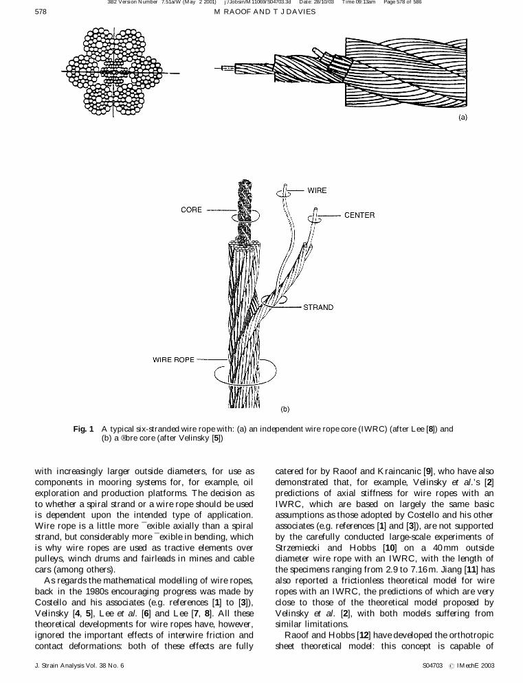
During the past two decades or so, considerable interesthas been shown in the mechanical characteristics ofhelically wound steel cables (spiral strands and/or wireropes) for use in both onshore and offshore applica-tions. At this point, it is probably worthwhile explainingthe main difference between a spiral strand and a wirerope. A spiral strand is a group of wires laid helically insuccessive layers over a central straight king wire (orequal lay core), while a wire rope consists of (typically)six strands laid helically over a central core which mayitself consist of a smaller independent wire rope (IWRC)or twisted ®bres (FC) (Fig. 1). Wire ropes and/or spiralstrands are used extensively in bridge design and astension members for suspended and stayed structuresgenerally. With reference to the offshore industry, therehas been a growing need for longer and stronger cables,
3B2 Version Number 7.51a/W (May 2 2001) j:/Jobsin/M11069/S04703.3d Date: 28/10/03 Time 09:12am Page 577 of 586
The MS was received on 3 June 2003 and was accepted after revision forpublication on 12 August 2003.* Corresponding author: Civil and Building Engineering Department,Loughborough University, Loughborough, Leicestershire LE11 3TU,UK.
577
S04703 # IMechE 2003 J. Strain Analysis Vol. 38 No. 6
with increasingly larger outside diameters, for use ascomponents in mooring systems for, for example, oilexploration and production platforms. The decision asto whether a spiral strand or a wire rope should be usedis dependent upon the intended type of application.Wire rope is a little more ¯exible axially than a spiralstrand, but considerably more ¯exible in bending, whichis why wire ropes are used as tractive elements overpulleys, winch drums and fairleads in mines and cablecars (among others).
As regards the mathematical modelling of wire ropes,back in the 1980s encouraging progress was made byCostello and his associates (e.g. references [1] to [3]),Velinsky [4, 5], Lee et al. [6] and Lee [7, 8]. All thesetheoretical developments for wire ropes have, however,ignored the important effects of interwire friction andcontact deformations: both of these effects are fully
catered for by Raoof and Kraincanic [9], who have alsodemonstrated that, for example, Velinsky et al.’s [2]predictions of axial stiffness for wire ropes with anIWRC, which are based on largely the same basicassumptions as those adopted by Costello and his otherassociates (e.g. references [1] and [3]), are not supportedby the carefully conducted large-scale experiments ofStrzemiecki and Hobbs [10] on a 40 mm outsidediameter wire rope with an IWRC, with the length ofthe specimens ranging from 2.9 to 7.16 m. Jiang [11] hasalso reported a frictionless theoretical model for wireropes with an IWRC, the predictions of which are veryclose to those of the theoretical model proposed byVelinsky et al. [2], with both models suffering fromsimilar limitations.
Raoof and Hobbs [12] have developed the orthotropicsheet theoretical model: this concept is capable of
3B2 Version Number 7.51a/W (May 2 2001) j:/Jobsin/M11069/S04703.3d Date: 28/10/03 Time 09:13am Page 578 of 586
Fig. 1 A typical six-stranded wire rope with: (a) an independent wire rope core (IWRC) (after Lee [8]) and(b) a ®bre core (after Velinsky [5])
M RAOOF AND T J DAVIES578
J. Strain Analysis Vol. 38 No. 6 S04703 # IMechE 2003

predicting, with a good degree of accuracy, themechanical characteristics of spiral strands under notjust static monotonic loading (which, incidentally, is thetype of loading the previously reported frictionlesstheoretical models have primarily been developed for)but also when the strands experience cyclic loading. Theresults from the orthotropic sheet concept were subse-quently used by Raoof and Kraincanic [9, 13] to developtwo somewhat different theoretical models for analysingthe various stiffness characteristics of wire ropes witheither a ®bre or an independent wire rope core.
As originally shown by Raoof and Hobbs [12], inrepeated (cyclic) loading regimes, due to the presence ofinterwire friction, the effective axial stiffness of axiallypreloaded spiral strands (with their ends ®xed againstrotation) varies (as a function of the externally appliedaxial load perturbations/mean axial load) between twolimits. The axial stiffnesses for small axial load changes(cf. the mean axial load) were shown to be signi®cantlylarger than for large axial load changes (associated withwhich gross slippage takes place between the wires in theline contact) because, for suf®ciently small external axialload disturbances and in the presence of interwirefriction, the helical wires stick together and the axiallypreloaded cable will effectively behave as a solid rod(with allowance being made for the presence of gapsbetween the individual wires). The upper and lowerbounds to the axial stiffnesses were, therefore, referredto as the no-slip and full-slip types respectively. Thesame terminology was also adopted by Raoof andKraincanic [9, 13] in their theoretical treatment of wireropes, which, as experimentally demonstrated by Strze-miecki and Hobbs [10], also exhibit the limiting no-slipand full-slip axial stiffness characteristics, when experi-encing cyclic axial load perturbations superimposed on amean axial preload.
In another publication, Raoof [14], based on theresults from an extensive series of theoretical parametricstudies using a wide range of large-diameter spiralstrand constructions, in conjunction with Hruska’s [15]simple formulations, presented straightforward routines,based on the orthotropic sheet model, for estimating theno-slip and full-slip axial moduli of axially preloadedspiral strands, with any construction details. Raoof [14]also showed that, primarily because of the inclusion ofthe strands’ diametral contractions in the orthotropicsheet theory, the estimates of full-slip axial stiffnessbased on this model are signi®cantly lower than thosebased on Hruska’s approach.
The original theoretical models of Raoof andKraincanic for wire ropes [9, 13], although being veryreliable, suffer from the potential drawback of beingmathematically rather complex. Developing simpleroutines, which are amenable to hand calculations usinga pocket calculator, similar to those for spiral strands, asalready reported by Raoof [14], is therefore highlydesirable and forms the purpose of the present paper. In
what follows, based on an extension of the work ofStrzemiecki and Hobbs [10], in conjunction withnumerical results based on Raoof and Kraincanic’smodels [9, 13], simple formulations will be developed forestimating the no-slip and full-slip axial stiffnesses ofwire ropes, with either a ®bre or an independent wirerope core, which should prove of value to busypractising engineers.
2 SIMPLIFIED METHODS
2.1 Hruska’s approach
The general form of Hruska’s equation, proposed byStrzemiecki and Hobbs [10], for the determination of theaxial stiffness of a wire rope, Erope, is (in the presentnotation)
H ˆ Erope
Esteel
ˆ
PM
jˆ1
Pn
iˆ1
ALicos3 ai
³ ´cos3 bj
PM
jˆ1
Pn
iˆ1
ALi= cos ai
³ ´= cos bj
…1†
where Esteel is the Young’s modulus of steel, M is thetotal number of strands in the rope, n is the total numberof layers of wires in each strand (including the kingwire), ALi
is the total cross-sectional area of the wires(which can have different diameters, even in a givenlayer) in layer i of a strand (with the king wire beinglayer number 1), ai is the lay angle of layer i in a strandand bj is the lay angle of a strand in layer j of the rope. Itshould be noted that the denominator in equation (1) isequal to the total net steel area in the wire rope’s normalcross-section, with the shapes of individual round wiresand spiral strands in the wire rope’s normal cross-section being elliptical [9, 13] and the central (king) wirein each spiral strand having a1 ˆ 0.
According to equation (1), the dominant parameterscontrolling the rope axial stiffness are the lay angles …bj†of the strands in the wire rope and also the lay angles…ai† of the steel wires forming the individual spiralstrands, with the parameter ALi
also playing a role.
2.2 Parameters used in the calculations
The numerical data relating to both the no-slip and full-slip axial stiffnesses, based on the work of Raoof andKraincanic [9, 13], on a number of wire ropes with ®breor independent wire rope cores, has been used in whatfollows. The ®bre core wire ropes had outside diametersof 9.53 and 40.5 mm and were analysed assuming both aregular lay (RL) and a Lang lay (LL) type ofconstruction. A Lang lay rope is the type in which the
3B2 Version Number 7.51a/W (May 2 2001) j:/Jobsin/M11069/S04703.3d Date: 28/10/03 Time 09:13am Page 579 of 586
SIMPLE DETERMINATION OF THE AXIAL STIFFNESS FOR LARGE-DIAMETER IWRC OR FIBRE CORE WIRE ROPES 579
S04703 # IMechE 2003 J. Strain Analysis Vol. 38 No. 6

directions of the lay of the individual wires in the outerstrands and that of the outer strands in the rope are thesame. If the lay directions of the wires and the strandsare the opposite of each other, then the rope is of aregular lay type. It should be noted that the `Hruska’stiffnesses, as calculated by equation (1), are the same,regardless of the type of lay. The wire ropes withindependent wire rope cores had outside diameters of33, 40, 55.6 and 76 mm. Two 76 mm outside diameterwire ropes were used in the analysis: a reasonablyfully bedded-in (comparator) wire rope and a new wirerope.
The results, after Raoof and Kraincanic [13], for the®bre core wire ropes have been obtained assuming twodifferent patterns (cases) of interstrand contacts: case 1,where the strands in the wire rope are assumed to be justtouching each other in line contact, in an unstressedcondition, so that the interstrand contacts in the hoopdirection (with a higher normal stiffness compared tothat in the radial direction) govern the diametralcontraction of the rope; and case 2, where the strandsin the wire rope are assumed to be resting on the ®brecore, in the presence of signi®cant gaps between theadjacent strands, so that the wire rope experiences radialdeformations due to ®bre core compliance.
The exact details of the theoretical model, relating toeach case of interstrand contacts in wire ropes with ®brecores, are reported by Raoof and Kraincanic [13].Moreover, the construction details of the wire ropesused in the present work, in conjunction with thecalculation details of the Hruska’s axial stiffnesses, aregiven elsewhere [16]. Alternatively, the full constructiondetails for the individual wire ropes may be found inreferences [2], [10] and [17] to [19].
2.3 Results
Table 1 presents a summary of the ®nal estimates of theaxial stiffnesses, based on Hruska’s approach, for eachof the seven different wire rope constructions, as well asthe numerical results for both the no-slip and full-slipaxial stiffnesses, as reported by Raoof and Kraincanic[9, 13] and later on by Kraincanic and Hobbs [17], basedon the considerably more complex (although moreaccurate) models of Raoof and Kraincanic [9, 13].Table 2, as a typical example, gives the full constructiondetails and calculation routines for Hruska’s axialstiffness prediction of the 76 mm (comparator) outsidediameter wire rope with an IWRC. The calculationroutines for Hruska’s axial stiffness, H, of wire ropeswith ®bre cores are exactly the same as those for wireropes with an IWRC, with the proviso that in the formerthe contribution of the ®bre core to axial stiffness, H, isassumed to be zero; i.e. only the contributions from theouter strands should be included. The predictions ofwire rope axial stiffness in Table 1 are all based on thetotal net steel area [9, 13], the values of which for theindividual wire ropes are also included in the lastcolumn of this table. Table 3, on the other hand,presents values of the corresponding experimentallydetermined axial stiffnesses, where available, as well asthe ratios of predicted/experimental results (for Eno-slip
and Efull-slip) with the predictions (as given in Table 1) ofEno-slip and Efull-slip based on Raoof and Kraincanic’smodels for wire ropes with an IWRC or ®bre core; thecorrelations between theory (which assumes a constantEsteel ˆ 200kN/mm2 for all the wire rope constructionsstudied) and experiments are very encouraging. Inparticular, it is important to note that for the two types
3B2 Version Number 7.51a/W (May 2 2001) j:/Jobsin/M11069/S04703.3d Date: 28/10/03 Time 09:13am Page 580 of 586
Table 1 Summary of the numerical results for the axial stiffnesses as calculated using Hruska’s simpleformula and the models proposed by Raoof and Kraincanic (Esteelˆ 200kN/mm2)
Raoof and Kraincanic
Type of coreconstruction*
Rope outsidediameter (mm)
HruskaErope=Esteel Eno-slip/Esteel Efull-slip/Esteel Eno-slip/Efull-slip
Total net steelarea (mm2)
IWRC 33 0.657 0.561 0.478 1.174 518.46IWRC 40 0.685 0.623 0.537 1.158 838.56IWRC 55.6 0.802 0.779 0.714 1.092 1633.91IWRC 76 0.754 0.708 0.646 1.096 3032.95IWRC 76 (comparator) 0.718 0.654 0.583 1.122 2881.90
Case 1FC (RL) 9.53 0.701 0.714 0.654 1.092 39.65FC (RL) 40.5 0.760 0.778 0.729 1.068 689.96FC (LL) 9.53 0.701 0.701 0.636 1.102 39.65FC (LL) 40.5 0.760 0.763 0.708 1.077 689.96
Case 2FC (RL) 9.53 0.701 0.658 0.608 1.081 39.65FC (RL) 40.5 0.760 0.732 0.689 1.063 689.96FC (LL) 9.53 0.701 0.652 0.600 1.086 39.65FC (LL) 40.5 0.760 0.722 0.675 1.069 689.96
* FC, ®bre core; LL, Lang’s lay; RL, regular lay.
M RAOOF AND T J DAVIES580
J. Strain Analysis Vol. 38 No. 6 S04703 # IMechE 2003

of wire ropes with an IWRC for which the measuredvalues of both the Eno-slip and Efull-slip are available, thecorrelations between the theory and test data (as regardsboth the upper and lower bounds to the wire rope axialstiffness) are, indeed, excellent, reinforcing the fact thatsuch remarkable correlations are not due to merecoincidence (i.e. by chance); in other words, thepresently assumed value of Esteel (ˆ 200kN/mm2) hasnot been used as a convenient ®ddle factor.
Similar to the ®ndings of Raoof [14] in the context ofspiral strands, in Raoof and Kraincanic’s models for wireropes [9, 13], unlike the no-slip axial stiffness which isslightly dependent on the value of mean axial load, thefull-slip axial stiffness is, in general, independent of themean axial load, with both of these limiting (i.e. upper andlower bounds) values of axial stiffness being independentof the magnitude of the interwire coef®cient of friction.
Furthermore, it is, perhaps, worth mentioning that thevalues of axial stiffness as traditionally quoted by themanufacturers, based on their shop measurements, areinvariably the full-slip ones (in the present terminology),because of the large axial load ranges involved.
Figures 2 and 3 show the relationship between thefull-slip axial stiffnesses as calculated using the simpleformula of Hruska and Raoof and Kraincanic’s [9, 13]models for all of the different wire rope constructions,relating to the results of cases 1 and 2 for the ropes with®bre cores respectively. Figure 4 shows similar correla-tions, but with the data relating to the ®bre core wireropes omitted.
Figures 5 and 6 present the relationships between theEfull-slip =Esteel and the Eno-slip=Efull-slip ratios, as calcu-lated using Raoof and Kraincanic’s [9, 13] models forwire ropes with ®bre cores (cases 1 and 2 respectively) or
3B2 Version Number 7.51a/W (May 2 2001) j:/Jobsin/M11069/S04703.3d Date: 28/10/03 Time 09:13am Page 581 of 586
Table 2 Construction details and calculation routines for Hruska’s axial stiffness of the 76 mm (comparator) outside diameter(IWRC) wire rope ‰…Erope=Esteel†full-slipˆ 2068:407=2881:899 ˆ 0:7177Š
1 2 3 4 5 6 7 8 9 10 11 12Layer inthe rope
Number ofstrands N
bj
(deg)Layer inthe strand nw wires
dw
(mm)Aw
(mm2)ai
(degrees) nwAw/cos ai nwAw6 cos3 ai
N 6P
(9)/cos bj
N 6P
(10) 6cos3bj
Core (1)King strand
1 0 Core (1) 1 3.9 11.946 0 11.946 11.9462 6 3.54 9.842 14.84 61.091 53.339
Totals 73.037 65.285 73.037 65.285IWRC strands(2)
6 18.11 Core (1) 1 3.34 8.762 0 8.762 8.7622 6 3.1 7.548 14.84 46.849 40.904
Totals 55.610 49.666 351.052 255.864
Outer strands(3)
6 18.24 Core (1) 1 5.8 26.421 0 26.421 26.4212 8 3.5 9.621 ¡9.53 78.046 73.8263 8 2.4 4.524 ¡13.91 37.285 33.100
8 3.2 8.042 ¡13.07 66.051 59.4684 16 3.7 10.752 ¡18.35 181.250 147.102
Totals 389.052 339.917 2457.810 1747.257Grand totals 2881.899 2068.407
Table 3 Summary of the experimentally determined results for the axial stiffnesses of the various wire rope constructions
Experimental results Predicted/experimental{
Type of coreconstruction
Rope diameter(mm)
Source of experimentalresults
Eno-slip¤/
Esteel
Efull-slip¤/
Esteel
Eno-slip/Efull-slip
ForEfull-slip
ForEno-slip
IWRC 33 Velinsky et al. [2] Ð 0.530 Ð 0.90 ÐIWRC 40 Strzemiecki and Hobbs [10] 0.625 0.545 1.146 0.99 0.997IWRC 76 Kraincanic and Hobbs [17] 0.685 0.653 1.049
0.722 0.678 1.0650.723 0.652 1.1090.819 0.663 1.235
Average 0.738 0.662 1.115 0.96 0.98IWRC 76 (comparator) Raoof and Kraincanic [18] Ð 0.566 Ð 1.03 Ð
Case 1FC (RL) 9.53 Velinsky [5] Ð 0.692 Ð 0.95 ÐFC (RL) 40.5 Cantin et al. [19] Ð Ð Ð Ð ÐFC (LL) 9.53 Velinsky [5] Ð Ð Ð Ð ÐFC (LL) 40.5 Cantin et al. [19] Ð 0.730±0.794 Ð 0.93 Ð
Case 2FC (RL) 9.53 Velinsky [5] Ð 0.692 Ð 0.88 ÐFC (RL) 40.5 Cantin et al. [19] Ð Ð Ð Ð ÐFC (LL) 9.53 Velinsky [5] Ð Ð Ð Ð ÐFC (LL) 40.5 Cantin et al. [19] Ð 0.730±0.794 Ð 0.88 Ð
*Assumed Esteel ˆ 200kN/mm2.{In connection with the experimental results with some reported scatter, the mean of the test results has been used.
SIMPLE DETERMINATION OF THE AXIAL STIFFNESS FOR LARGE-DIAMETER IWRC OR FIBRE CORE WIRE ROPES 581
S04703 # IMechE 2003 J. Strain Analysis Vol. 38 No. 6

an IWRC. Figure 7 presents similar correlations, butwith the data relating to the ®bre core wire ropesomitted.
2.4 Simple formulations
Using the results presented in the previous section, asimple method for determining the full-slip and no-slipaxial stiffnesses of wire ropes with either ®bre cores oran IWRC can be developed by ®tting various non-linear
curves (de®ned by second-order polynomials) throughthe data. In Figs 2, 3 and 4, Hruska’s simple parameterH is given by equation (1), as developed by Strzemieckiand Hobbs [10]. Once H is calculated, the full-slip axialstiffness, based on the more accurate models of Raoofand Kraincanic, may be found using a second-orderpolynomial of the general form
Efull-slip
Esteel
ˆ A…H2† ‡ B…H† ‡ C …2†
where the constant coef®cients A to C are given in
3B2 Version Number 7.51a/W (May 2 2001) j:/Jobsin/M11069/S04703.3d Date: 28/10/03 Time 09:13am Page 582 of 586
Fig. 2 Relationship between the full-slip E values for various wire rope constructions with either a ®bre core(case 1) or an IWRC as calculated using Raoof and Kraincanic’s models and Hruska’s formula
Fig. 3 Relationship between the full-slip E values for various wire rope constructions with either a ®bre core(case 2) or an IWRC as calculated using Raoof and Kraincanic’s models and Hruska’s formula
M RAOOF AND T J DAVIES582
J. Strain Analysis Vol. 38 No. 6 S04703 # IMechE 2003

Table 4 and correspond to the situation as to whetherthe ®bre core wire ropes are to be included (Figs 2 and 3)or not (Fig. 4), and, if included, which different patternof interstrand contacts for the ropes with ®bre cores(i.e. whether case 1 or 2, as de®ned previously) is to beconsidered.
Turning to the no-slip case, Figs 5, 6 and 7 show thetheoretical relationships between the no-slip and full-slip
3B2 Version Number 7.51a/W (May 2 2001) j:/Jobsin/M11069/S04703.3d Date: 28/10/03 Time 09:13am Page 583 of 586
Fig. 4 Relationship between the full-slip E values for the wire ropes with an IWRC as calculated using Raoofand Kraincanic’s model and Hruska’s formula
Fig. 5 Relationship between the full-slip and no-slip E values for various wire rope constructions with eithera ®bre core (case 1) or an IWRC as calculated using Raoof and Kraincanic’s models
Table 4 Values of the constant coef®cients A to C in equation(2) for all of the ®tted curves in Figs 2, 3 and 4, alongwith the correlation coef®cients, R
Reference A B C R
Fig. 2 ¡0.9099 2.9095 ¡1.00 0.870Fig. 3 ¡0.6275 2.4872 ¡0.86 0.957Fig. 4 ¡0.4913 2.3228 ¡0.83 0.998
SIMPLE DETERMINATION OF THE AXIAL STIFFNESS FOR LARGE-DIAMETER IWRC OR FIBRE CORE WIRE ROPES 583
S04703 # IMechE 2003 J. Strain Analysis Vol. 38 No. 6

moduli, with the individual numerical results havingbeen found to be very nearly independent of the level ofmean axial load on the cable (over the working loadranges). Denoting Efull-slip=Esteel ˆ k1, ®tted curvesde®ned by second-order polynomials of the general form
Eno-slip
Efull-slip
ˆ E…k21† ‡ Fk1 ‡ G …3†
provide a simple means of ®nding the no-slip axial
stiffness, once the corresponding full-slip axialstiffness has been found, depending upon whetherthe ®bre core wire ropes are to be included (Figs 5and 6) in the analysis or not (Fig. 7), and, ifincluded, whether case 1 or 2 is to be adopted forthe pattern of interstrand contacts in relation to thewire ropes with ®bre cores. The values of theconstant coef®cients E to G in equation (3) aregiven in Table 5, along with the correlationcoef®cients, R.
3B2 Version Number 7.51a/W (May 2 2001) j:/Jobsin/M11069/S04703.3d Date: 28/10/03 Time 09:14am Page 584 of 586
Fig. 6 Relationship between the full-slip and no-slip E values for various wire rope constructions with eithera ®bre core (case 2) or an IWRC as calculated using Raoof and Kraincanic’s models
Fig. 7 Relationship between the full-slip and no-slip E values for various wire rope constructions with IWRCas calculated using Raoof and Kraincanic’s model
M RAOOF AND T J DAVIES584
J. Strain Analysis Vol. 38 No. 6 S04703 # IMechE 2003

3 DISCUSSION
Similar to the results for spiral strands, based on theorthotropic sheet theory, the results for the axialstiffnesses of wire ropes with either ®bre cores or anIWRC, based on Raoof and Kraincanic’s models, werefound to give signi®cantly lower Efull-slip values thanthose based on Hruska’s simple approach, with the layangles playing a primary (controlling) role.
Comparing Figs 2 and 3, it is found that thetheoretical data are less scattered around the ®ttedcurve when the ®bre core wire ropes are analysedassuming that the strands in the wire rope are resting onthe ®bre core (case 2), in contrast to the situation whenthe strands in the wire rope are assumed to be justtouching each other in the line contact (case 1). On theother hand, the opposite is found when comparing Figs5 and 6, where the scatter of the data points about the®tted curves is less for case 1 (cf. case 2) of interstrandcontacts in wire ropes with a ®bre core.
With the data for the ®bre core wire ropes omittedfrom the plots, the degree of scatter around the ®ttedcurves is signi®cantly less (refer to Fig. 4 and Fig. 7) withthe ®tted mean curve(s) very nearly passing through allthe theoretical data points, which cover a rather wide
range of wire rope diameters and lay angles. This, then,suggests that the wire rope axial stiffness is determinedby the lay angles of the wires in the strands and of thestrands in the rope, with the other geometricalparameters having a second-order effect.
Table 6 presents a comparison between the predic-tions based on the quick calculation methods and theexperimental results that are available, where thecorrelations in the case of wire ropes with an IWRCare, indeed, very good. As regards the wire ropes with®bre cores, the correlations are reasonable. It should benoted that, strictly speaking, the theoretical models ofRaoof and Kraincanic have both been developed forlarge-diameter wire ropes: this is probably theunderlying reason for the relatively larger discrepancies(cf. other cases in Table 6) between theory and test datafor the smaller 9.53 mm diameter wire rope with a ®brecore.
Finally, the question may arise as to the accuracy thatis required in these stiffness calculations at the designstage when such large-diameter wire ropes are used inengineering applications. Because of the wide variety oftheir common types of application (each of whichimposes its own peculiar requirements), the requiredaccuracy very much depends on the intended type ofapplication. For the present purposes, it perhaps suf®cesto say that the very accurate estimates of axial stiffnessrequired for wire ropes with an IWRC in, for example,the ®eld of structural engineering may now be obtained,with minimal effort, by using the ®tted polynomials tothe data in Figs 4 and 7. As far as wire ropes with ®brecores are concerned, however, what is commonlyrequired in practice is a reasonable (as opposed tovery accurate) estimate of their axial stiffness, and inthis respect the accuracy of the presently proposedmethod(s) is certainly suf®cient to meet such practicalrequirements.
3B2 Version Number 7.51a/W (May 2 2001) j:/Jobsin/M11069/S04703.3d Date: 28/10/03 Time 09:14am Page 585 of 586
Table 5 Values of the constant coef®cients E to G in equation(3) for all of the ®tted curves in Figs 5, 6 and 7, alongwith the correlation coef®cients, R
Reference E F G R
Fig. 5 0.2855 ¡0.7563 1.471 0.9763Fig. 6 0.4043 ¡0.9180 1.514 0.8893Fig. 7 0.1656 ¡0.5759 1.410 0.9654
Table 6 Comparison between the predictions based on the quick calculation method(s) and theavailable experimental results
Experimental results Predicted values (using the appropriate polynomials)
Type of coreconstruction
Rope outsidediameter (mm)
Eno¡slip=Esteel
Efull¡slip=Esteel
Eno¡slip=Esteel
Efull¡slip=Esteel
…ˆ k1†Figure numbers for theappropriate polynomials
IWRC 33 Ð 0.530 0.566 0.484 7 and 4IWRC 40 0.625 0.545 0.611 0.531IWRC 76 0.738* 0.662* 0.712 0.642IWRC 76 (comparator) Ð 0.566 0.660 0.584
Case 1FC (RL) 9.53 Ð 0.692 0.665 0.592 5 and 2FC (LL) 40.5 Ð 0.730±0.794 0.745 0.685
Case 2FC (RL) 9.53 Ð 0.692 0.644 0.575 6 and 3FC (LL) 40.5 Ð 0.730±0.794 0.722 0.668
* The average of the corresponding experimental data as given in Table 3.
SIMPLE DETERMINATION OF THE AXIAL STIFFNESS FOR LARGE-DIAMETER IWRC OR FIBRE CORE WIRE ROPES 585
S04703 # IMechE 2003 J. Strain Analysis Vol. 38 No. 6

4 CONCLUSIONS
Numerical data, based on Raoof and Kraincanic’smodels, have been used to produce simple designprocedures in relation to the upper (no-slip) and lower(full-slip) bounds to the axial stiffness of wire ropes witheither ®bre or independent wire rope cores. Mostimportantly, unlike all of the previously availabletheories (with their often very lengthy mathematicalformulations), the available experimental data on a widerange of wire rope constructions have been found toprovide encouraging support for the present theoreticalpredictions which fully cater for the important effects(totally ignored in the previously available theories) ofinterwire friction and contact deformations.
The present work clearly demonstrates that, using thesimple formulation of Hruska, higher values of the full-slip axial stiffness are obtained when compared to themore re®ned models of Raoof and Kraincanic. With thisborne in mind, a simple method has been proposed bymeans of which the no-slip and full-slip axial stiffnessesof axially preloaded large-diameter wire ropes, witheither a ®bre core or an IWRC experiencing super-imposed cyclic axial load perturbations, may beestimated. The proposed method, which can also handlethe simpler case of static monotonic loading with itsassociated constant (full-slip) axial stiffness, is based onthe remarkable correlations found between the predic-tions of the axial stiffnesses as obtained from Hruska’sand Raoof and Kraincanic’s approaches, stronglysuggesting that the lay angles (both of the wires in thestrands and the strands in the rope) are the prime(controlling) parameters, with the cross-sectional areasof the individual wires also playing a role. The presentlyproposed method is amenable to simple hand calcula-tions, using a pocket calculator, and is hence of value tobusy practising engineers using the wire ropes in bothonshore and offshore applications, where (as far as wireropes are concerned) by tradition the rule of thumbreigns supreme.
REFERENCES
1 Costello, G. A. and Miller, R. E. Static response of reduced
rotation rope. J. Engng Mechanics Div., ASCE, 1980,
106(EM4), 623±631.2 Velinsky, S. A., Anderson, G. L. and Costello, G. A. Wire
rope with complex cross sections. J. Engng Mechanics,ASCE, March 1984, 110(3), 380±391.
3 Phillips, J. W. and Costello, G. A. Analysis of wire ropes
with internal-wire±rope cores. Trans. ASME, J. Appl.Mechanics, September 1985, 52, 510±516.
4 Velinsky, S. A. General non-linear theory for complex wire
rope. Int. J. Mech. Sci., 1985, 27(7/8), 497±507.5 Velinsky, S. A. Analysis of ®bre-core wire rope. Trans.
ASME, J. Energy Resources Technol., September 1985,
107, 388±393.6 Lee, W. K., Casey, N. F. and Grey, T. G. F. Helix geometry
in wire rope. Wire Industry, August 1987, 461±468.
7 Lee, W. K. The mechanics and mathematical modelling ofwire rope. PhD dissertation submitted to Strathclyde
University, 1989.
8 Lee, W. K. An insight into wire rope geometry. Int. J.Solids and Structs, 1991, 28(4), 471±490.
9 Raoof, M. and Kraincanic, I. Analysis of large diameter
steel ropes. J. Engng Mechanics, ASCE, June 1995, 121(6),667±675.
10 Strzemiecki, J. and Hobbs, R. E. Properties of wire rope
under various fatigue loadings. CESLIC Report SC6, CivilEngineering Department, Imperial College, London, 1988.
11 Jiang, W. A. A general formulation of the theory of wire
ropes. Trans. ASME, J. Appl. Mechanics, September 1995,62, 747±755.
12 Raoof, M. and Hobbs, R. E. Analysis of multi-layered
structural strands. J. Engng Mechanics, ASCE, July 1988,114(7), 1166±1182.
13 Raoof, M. and Kraincanic, I. Characteristics of ®bre-corewire rope. J. Strain Analysis, 1995, 30(3), 217±226.
14 Raoof, M. Simple formulae for spiral strands and multi-
strand ropes. Proc. Inst. Civ. Engrs, Part 2, December1990, 89, 527±542.
15 Hruska, F. H. Calculation of stresses in wire ropes. Wire
and Wire Products, September 1951, 26, 766±767 and 799±801.
16 Davies, T. J. Static, dynamic and fatigue characteristics of
helical cables. PhD thesis submitted to LoughboroughUniversity, December, 2000.
17 Kraincanic, I. and Hobbs, R. E. Axial stiffness and
torsional effects in a 76 mm wire rope: experimental dataand theoretical predictions. J. Strain Analysis, 1998, 34(1),
39±51.
18 Raoof, M. and Kraincanic, I. Behaviour of large diameterwire ropes. Int. J. Offshore and Polar Engng, September
1996, 6(3), 219±226.
19 Cantin, M. M., Cubat, D. and Nguyen Xuan, T. Experi-mental analysis and modelisation of the stiffness in torsion
of wire ropes. In Proceedings of the Organisation Pour
International l’Etude de l’Endurance des Cables (OIPEEC)Round Table Conference (Ed. L. Wiek), Delft University,
The Netherlands, 1993, pp. II67±II77.
3B2 Version Number 7.51a/W (May 2 2001) j:/Jobsin/M11069/S04703.3d Date: 28/10/03 Time 09:14am Page 586 of 586
M RAOOF AND T J DAVIES586
J. Strain Analysis Vol. 38 No. 6 S04703 # IMechE 2003