simplified addressing scheme for mixed...
TRANSCRIPT

SIMPLIFIED ADDRESSING SCHEME FOR MIXED RADIX FFT ALGORITHMS
Cuimei Ma1, Yizhuang Xie1, He Chen1, Yi Deng2, Wen Yan1
1Beijing Institute of Technology, Beijing, 100081, China;
2Virginia Polytechnic Institute and State University, Arlington, VA 22044 USA
ABSTRACT
A mixed radix algorithm for the in-place fast Fourier transform (FFT), which is broadly used in most embedded signal processing fields, can be explicitly expressed by an iterative equation based on the Cooley-Tukey algorithm. The expression can be applied to either decimation-in-time (DIT) or decimation-in-frequency (DIF) FFTs with ordered inputs. For many newly emerging low power portable computing applications, such as mobile high definition video compressing, mobile fast and accurate satellite location, etc., the existing methods perform either resource consuming or non-flexible. In this paper, we propose a new addressing scheme for efficiently implementing mixed radix FFTs. In this scheme, we elaborately design an accumulator that can generate accessing addresses for the operands, as well as the twiddle factors. The analytical results show that the proposed scheme reduces the algorithm complexity meanwhile helps the designer to efficiently choose an arbitrary FFT to design the in-place architecture.
Index Terms—Fast Fourier Transform, mixed radix, address generation, in place, arithmetical complexity.
1. INTRODUCTION Fast Fourier transform (FFT) algorithms play a key role in improving the feasibility of discrete Fourier transform (DFT), which is broadly used in most digital processing applications. For practical FFT uses, there are radix-2, radix-4 and split-radix [1] FFTs. Meanwhile, the research on radix-2k [2] FFT has resulted in the instantiation of such methods as radix-22 [3], radix-23 [4], and even radix-24 FFT [5]. Although the derivation and programming are intuitive for radix-2k FFT, the drawback is that the number of points has to be restricted to powers of two or four, which restricts its application in resource-limited portable computing scenarios.
Recently, an optimal choice for the FFT size is in demand and many non-power-of-two FFTs, such as 3! and 6!- point FFT, have been studied [6,7]. However, those methods are all in radix-q×2k FFTs [8], where q is prime,
such as 3, 5, and 7, et al. Because the mixed radix FFT can be used in general scenarios, it becomes practical and useful. Some mixed radix FFT algorithms are studied, such as radix-2/4 [9,10] and radix-2/2! FFTs. They are based on radix-2 FFT. However, if the padding-zero method is used to satisfy the radix-2!FFT, it will consume a larger amount of memory than the mixed radix FFT. Since the memory cost is a significant part of the FFT processor, minimizing the necessary size is an effective way for the area reduction. Therefore, arbitrary mixed radix FFTs problems are discussed in [11, 12].
Two methods, the pipelined and memory-based architectures [13, 14], have been proposed for different applications in various FFT processors. Although much higher throughput than memory based designs, the pipeline architectures have a larger area cost. Therefore, the in-place strategy [15] is taken and only one memory with N complex words is needed.
However, the in-place strategy has a complex design circuit, which has to generate addresses for both operands and twiddle factors. Demuth [11] proposed a nested loop index generation algorithm to index inputs and outputs of FFT stages and another way to index twiddle factor exponents. This method needs many parameters to get the address, which is difficult to implement using hardware. Hsiao [12] gave the index mapping method for the generalized mixed radix algorithm with some complex modulo operations. A bit-level representation of the accessing rule was mentioned by Sorokin [16], which is used in different processing stages for a radix-2/4 FFT. In this paper, we will extend it to an arbitrary mixed radix FFT.
An iterative expression that is applied to radix-r!/r! in-place architecture is derived. The N data are stored in RAM and the N twiddle factors are in ROM. An accumulator is set to make the accessing address map easily to the hardware circuits and there is no modulo operation. The illustrative example is based on radix-2/3 decimation-in- time (DIT) in-place 12-point FFT. By this method, an appropriate FFT size is chosen to minimize the memory size and a simplified address control is designed.
2. REVIEW OF MIXED-RADIX ALGORITHM
2014 IEEE International Conference on Acoustic, Speech and Signal Processing (ICASSP)
978-1-4799-2893-4/14/$31.00 ©2014 IEEE 8410

The N-point DFT of an N-point sequence )}({ nx , 1
0
0 1( ) ( ) ,N
knN
nX k x n W k N
−
=
= ≤ ≤ −∑ (1)
where 2exp( / )knNW j kn Nπ= − , and 1j = − .
Suppose that the FFT size satisfies 1 21 2s sN r r= × , where
1r and 2r are two radices, 1s and 2s are the corresponding integer powers, and a parameter s is 1 2s s s= + . We assume that the algorithm uses 1s radix- 1r stages followed by 2s radix- 2r stages. According to Cooley-Tukey algorithm, the time and frequency indices, i.e. n and k , are analyzed. The expressions for both n and k with s digits in terms of 1r , 2r , 1s and 2s are obtained as follows.
1 2 1 1
1 1
1
1
1 2 2 2
2 2
2
2
1 11 2 1 1 2 1 1
1 11 1 1 1 0
1 11 2 1 1 2 1 2
1 12 1 2 1 0
...
... ,
...
... ,
s s s ss s s
ss
s s s ss s s
ss
n r r n r r n r n
r n r n n
k r r k r r k r k
r k r k k
−− +
−−
−− +
−−
⎧ = × × + + × × + ×⋅⎪⎪ + × + + × +⎪⎨
= × × + + × × + ×⎪⎪
+ × + + × +⎪⎩
(2)
where if 10 1i s≤ ≤ − , 10 1[ , ]in r∈ − , else 20 1[ , ]in r∈ − ; if 20 1i s≤ ≤ − , 20 1[ , ]ik r∈ − , else 10 1[ , ]in r∈ − .
For brevity, assume that 1i
ic r= when 10 1, , ...,i s= , 1
1 1 2s i
s ic r r+ = × when 21 1, ...,i s= − . 2' iic r= when 20, ...,i s= ,
2
2 2 1' s is ic r r+ = × when 11 2 1, , ...,i s= − . Therefore, Eq.(2) is
rewritten as
1 1 2 2 1 1 0 0
1 1 2 2 1 1 0 0
... ,' ' ... ' ' .s s s s
s s s s
n c n c n c n c nk c k c k c k c k
− − − −
− − − −
= × + × + + × + ×⎧⎨
= × + × + + × + ×⎩
(3)
For notational convenience, Eq. (3) can be written as
1 2 2 1 0
1 2 3 2 1 0
( ... ) ,
( ... ) .
s s mixed radix
s s mixed radix
n n n n n n
k k k k k k
− −
− −
⎧ =⎪⎨
=⎪⎩
(4)
When Eq. (3) is substituted into Eq. (1), we decompose N-point DFT into s iterations and the mth (1≤m ≤ s ) iteration is as follows.
0 1 1 1 2 0
1
1 0 1 2 1 00
'( )
( ... ... )
( ... ... ) s m s m
s m
m m s m s m
rk c n
m m s m s m Nn
x k k k n n n
x k k k n n n W − −
−
− − − − −
−
− − − − −=
= ∑ (5)
where 1 2' ( , )r r r∈ . When m satisfies 21 m s≤ ≤ , 2'r r= ,
otherwise 1'r r= . From Eq. (5),
1 0 1 2 1 0( ... ... )m m s m s mx k k k n n n− − − − − denotes one
of 'r operands for radix- 'r butterfly in the mth stage and 0 1 1 1 0( ... ... )m m s mx k k k n n− − − represents the butterfly output.
Because the in-place algorithm is used, we can analyze 0 1 1 1 2 0 ( ) ( ... ... )m s m s m mixed radixAddr m k k k n n n− − − − −= to explore the
address generations in order to get the operands.
Table 1. Variable digit with cycles in each stage.
Stage Address representation Variable digit
1 m s≤ < radixmixedmsmsm nnnkkk )......( 021110 −−−−− 1mk −
s 0 1 2 1( ... )s mixed radixk k k k − 1sk −
Table 2. Different radix of iC in each stage.
Stage 0 1( ,..., )iC i s= − Radix
21 ( )m m s≤ ≤ 11 2, , ... sC C C 1r
1 10 1 2 1, , , ...,s s sC C C C+ + − 2r
2( )m s m s< ≤ 1 1 1 0, ..., ,sC C C− 1r
1 1 11 2 2 1, , , ..., ,s s s s sC C C C C+ + − − 2r Furthermore, ( )s m s mk c nW − −× is the corresponding twiddle
factor. We store the twiddle factors 2exp( / )iW j i Nπ= − in a lookup table sequentially, where i ranges from 0 to N-1. We can get them from the lookup table by analyzing the exponent part, i.e. ( )s m s mk c n− − .
The following section will present the addressing scheme by the iteration representation of n and k in the mth stage.
3. THE PROPOSED ADDRESSING SCHEME 3.1. Address generation for operands The 'r consecutive addresses for the 'r operands of radix-'r butterfly can be obtained in 'r clock cycles. For every
stage, we should find which digit is variable from 0 to 1'r −and the other digits are constant in
0 1 1 1 2 0( ... ... )m s m s m mixed radixk k k n n n− − − − − . The variable digit for every stage is listed in Table 1.
Assume an accumulator, which is represented by
1 2 3 2 1 0( ... )s s s mixed radixACC C C C C C C− − −= for mapping the data
addresses. iC is the ith digit, 1sC − is the most significant digit and 0C the least significant digit. Only 0C keeps varying with cycles, similar to 1mk − at the mth stage, just as shown in Table 1.
Because each digit in Addr is either 1r or 2r , iC in ACC is either 1r or 2r . Therefore, there list the value of
iC in Table 2. The relationship between Addr and ACC
8411
2−sC ...1−sC 0C... 1CmsC − 1−−msC 2−−msC 3−−msC
1k ...0k 1−mk ... 0n1−−msn 2−−msn 3−−msn 4−−msn
)(mACC
2−sC ...1−sC 0C ... 1CmsC − 1−−msC 2−−msC 3−−msC
)(mAddr
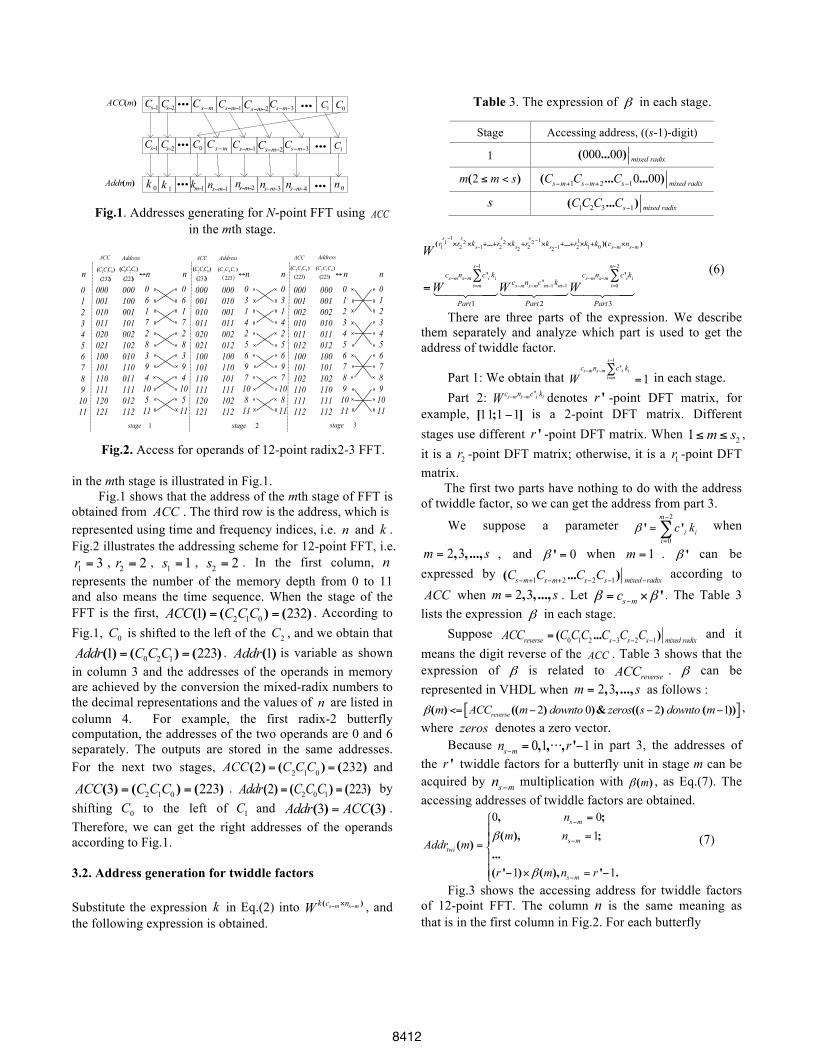
Fig.1. Addresses generating for N-point FFT using ACC in the
mth stage.
1stage
01234567891011
000001010011020021100101110111120121
n )()(
232012 CCC
000100001101002102010110011111012112
n↔
06172839410511
Address
)()(
223120 CCC
06172839410511
n
2stage
000001010011020021100101110111120121
000010001011002012100110101111102112
n↔
03142569710811
)(223102 )( CCC n)(
)(232
012 CCC
03142569710811
3stage
000001002010011012100101102110111112
000001002010011012100101102110111112
n↔
01234567891011
n)()(
223012 CCC
01234567891011
)()(
223012 CCC
Address AddressACC ACC ACC
Fig.2. Access for operands of 12-point radix2-3 FFT.
in the mth stage is illustrated in Fig.1. Fig.1 shows that the address of the mth stage of FFT is
obtained from ACC . The third row is the address, which is represented using time and frequency indices, i.e. n and k . Fig.2 illustrates the addressing scheme for 12-point FFT, i.e. 1 3r = , 2 2r = , 1 1s = , 2 2s = . In the first column, n
represents the number of the memory depth from 0 to 11 and also means the time sequence. When the stage of the FFT is the first, 2 1 01 232( ) ( ) ( )ACC C CC= = . According to Fig.1, 0C is shifted to the left of the 2C , and we obtain that
0 2 11 223( ) ( ) ( )Addr C C C= = . 1( )Addr is variable as shown in column 3 and the addresses of the operands in memory are achieved by the conversion the mixed-radix numbers to the decimal representations and the values of n are listed in column 4. For example, the first radix-2 butterfly computation, the addresses of the two operands are 0 and 6 separately. The outputs are stored in the same addresses. For the next two stages, ACC(2) = (C2C1C0 ) = (232) and
2 1 03 223( ) ( ) ( )ACC C CC= = . 2 0 12 223( ) ( ) ( )Addr C C C= = by shifting 0C to the left of 1C and 3 3( ) ( )Addr ACC= . Therefore, we can get the right addresses of the operands according to Fig.1. 3.2. Address generation for twiddle factors Substitute the expression k in Eq.(2) into ( )s m s mk c nW − −× , and the following expression is obtained.
Table 3. The expression of β in each stage.
Stage Accessing address, ((s-1)-digit)
1 000 00( ... ) mixed radix
2( )m m s≤ < 1 2 10 00( ... ... )s m s m s mixed radixC C C− + − + −
s 1 2 3 1( ... )s mixed radixCC C C −
W(r1s1−1×r2s2 ×ks−1+...+r2
s2 ×ks2+r2
s2 −1×ks2−1+...+r2
1×k1+k0 )(cs−m×ns−m )
=Wcs−mns−m c'i ki
i=m
s−1
∑
Part1! "# $##W
cs−mns−mc'm−1km−1
Part2! "## $##W
cs−mns−m c'ii=0
m−2
∑ ki
Part3! "# $##
(6)
There are three parts of the expression. We describe them separately and analyze which part is used to get the address of twiddle factor.
Part 1: We obtain that 1
1'
s
s m s m i ii m
c n c k
W
−
− −=∑
= in each stage. Part 2: 's m s m i ic n c kW − − denotes 'r -point DFT matrix, for example, 11 1 1[ ; ]− is a 2-point DFT matrix. Different stages use different 'r -point DFT matrix. When 21 m s≤ ≤ , it is a 2r -point DFT matrix; otherwise, it is a 1r -point DFT matrix. The first two parts have nothing to do with the address of twiddle factor, so we can get the address from part 3.
We suppose a parameter 2
0' '
m
i iic kβ
−
=
=∑ when
2 3, , ...,m s= , and 0'β = when 1m = . 'β can be expressed by 1 2 2 1( ... )s m s m s s mixed radixC C C C− + − + − − −
according to
ACC when 2 3, , ...,m s= . Let 's mcβ β−= × . The Table 3 lists the expression β in each stage.
Suppose 0 1 2 3 2 1 ( ... )reverse s s s mixed radixACC C CC C C C− − −= and it means the digit reverse of the ACC . Table 3 shows that the expression of β is related to reverseACC . β can be represented in VHDL when 2 3, , ...,m s= as follows :
[ ]2 0 2 1( ) (( ) )& (( ) ( ))reversem ACC m downto zeros s downto mβ <= − − − , where zeros denotes a zero vector.
Because 0 1 1, , , 's mn r− = ⋅⋅⋅ − in part 3, the addresses of the 'r twiddle factors for a butterfly unit in stage m can be acquired by s mn − multiplication with ( )mβ , as Eq.(7). The accessing addresses of twiddle factors are obtained.
0 01
1 1
, ;( ), ;
( )...( ' ) ( ), ' .
s m
s mtwi
s m
nm n
Addr m
r m n r
β
β
−
−
−
=⎧⎪ =⎪
= ⎨⎪⎪ − × = −⎩
(7)
Fig.3 shows the accessing address for twiddle factors of 12-point FFT. The column n is the same meaning as that is in the first column in Fig.2. For each butterfly
8412

2stage
000001010011020021100101110111120121
twiAddrβ
)()(
232012 CCC
3stage
000001002010011012100101102110111112
000024012036
)()(
223012 CCC
000000000000101010101010
000000030303
)( 02Cβ
000000101010010101111111
)( 21CCtwiAddr
01234567891011
n
1stage
twiAddrβ
000000000000000000000000
000000000000
ACC ACC
)(002n 1n 0n
010101010101
010101010101
012012012012
Fig.3. Accesses for twiddle factors of radix-2/3 FFT.
computation, the left addresses of it in Fig.2 are for the input operands the ones in Fig.3 are for the twiddle factors.
Therefore, we easily get the addresses of the operands and the twiddle factors using one accumulator for the mixed radix FFTs. The ACC satisfies the conditions listed in Table2. Figure 1 gives the relation between the addresses of operands and the accumulator. Table 3 lists the relation between the addresses of the twiddle factors and the same accumulator.
4. COMPARISONS
The architectures of the in-place algorithms are generally consistent. The key comparison part is the address generation. Meanwhile, because the twiddle factor is not considered in [12], only a comparison on the address generation for the operands between the method in [12] and the proposed scheme is given. The intermediate values in [11] are hard to be implemented in hardware, so there is no comparison with the scheme in [11].
For simplicity, a 12-point radix-2/3 FFT is taken as the illustrative example. Fig.4 (a) shows the proposed scheme and Fig.4 (b) shows the scheme in [12]. By comparison, the novel scheme has two characteristics:
(I) It keeps the architecture of FFT consistent for every stage. Thus, we only design one architecture to get the accessing address by the ACC . For the method in [12], the architecture of address generation for each stage is different. We have to design three different architectures to obtain the corresponding accessing addresses for the each stage. If the FFT point becomes larger, more resources are needed for the address generation.
(II)It requires no complex modulo operations. The larger the FFT size is, the more modulo operations are needed in [12].
Table 4 lists the number of mathematical operations for the 12-point FFT.
Therefore, the proposed scheme simplifies the complexity of generating addresses.
5. CONCLUSIONS AND DISCUSSION
2C0C 1C
Address
1Stage 2Stage 3Stage
6 3
0C 1C2C
Address
6 3
0C1C2C)(232=ACC 0C1C2C
0C1C2C
Address
6 3
0C1C2C)(223=ACC)(232=ACC
(a)
0C1C2C
1Stage 2Stage 3Stage
6 4 3
)(322=ACC 0C1C2C)(232=ACC
6mod
Address
6 3 4
0C1C2C)(223=ACC
6mod
62
Address
Address (b)
Fig.4. Address generation for 12-point radix-2/3 FFT by (a) the proposed method, and (b) the method in [12].
Table 4. Mathematical operations comparisons of Hsiao’s design and ours
Scheme Our Scheme Hsiao’s Design [12]
2-input addition 2 6
2-input multiplication 2 8
Modulo operation 0 2 An iterative approach can be applied to analyze the address generation for mixed-radix in-place FFT with ordered inputs. The accessing addresses for the operands and the twiddle factors can be achieved from one accumulator. It is easy to implement this accumulator in hardware circuits.
With respect to the tradeoff, mixed radix FFT costs more than one butterfly unit compared with fixed radix FFT. However, a unified architecture, just like that described in [17], can be achieved to compute arbitrary two butterflies. Therefore, the increased resources of the butterfly unit with unified architecture have small impact on the overall resources.
6. REFERENCES [1] T.Z. Sung, H.C. Hsin, et al, “Low-power and high-speed CORDIC-based split-radix FFT processor for OFDM systems,” Digit. Signal Prog, vol. 20, no. 2, pp. 511-527, 2010. [2] M. Garrido, J. Grajal, M.A. Sanchez, et al, “Pipelined radix-2k feedforward FFT architectures,” IEEE Trans. Very Large Scale Integr. (VLSI) Syst, vol. 21, no.1, pp. 23-32, 2013. [3] J. Li, F. Liu, T. Long, et al, “Research on Pipeline R22SDF FFT,” IET Int. Radar Conf,, Guilin, China, Apr. 20-22 2009, pp.1-5.
8413

[4] K. Maharatna, E. Grass, and U. Jagdhold, “A 64-Point Fourier Transform Chip for High-Speed Wireless LAN Application Using OFDM,” IEEE J. Solid-State Circuit, vol. 39 no.3, pp.484-493, 2004. [5] H. Liu and H. Lee, “A high performance four parallel 128/64- point radix-24 FFT/IFFT processor for MIMO-OFDM systems,” IEEE Asia Pacific Conf. Circuits Syst. (APCCSA), Macao, China, Nov. 30-Dec. 3 2008, pp.834-837. [6] E. Dubois and A. Venetsanopoulos, “A new algorithm for the radix-3 FFT,” IEEE Trans. Acoustics, Speech, Signal Prog, vol.29, no.4, pp. 939-941, 1982. [7] D. Takahash, “A new radix-6 FFT algorithm suitable for multiply-add instruction,” IEEE Int. Conf. Acoustics, Speech, Signal Prog., Istanbul, Turkey, Jun. 5-9 2000, vol.6, pp.3343-3346. [8] S.S. Deng, Y. Sun, L.S. Zhang, et al, “Design of High-Speed FFT Processor for Length N=q×2m,” J. Comput. Res. Dev., vol. 45, no. 8, pp. 1430-1438, 2008. [9] A.T. Jacobson, D.N. Truong, and B.M. Baas, “The design of a reconfigurable continuous-flow mixed-radix FFT Processor,” IEEE Int. Sym. Circuit Syst., Taipei, China, May 24-27 2009, pp.1133-1136. [10] H. Xiao, An Pan, Y. Chen, et al, “Low-cost reconfigurable VLSI architecture for fast Fourier transform,”IEEE Trans. Consum。Electron, vol. 54, no.4, pp.1617-1622, 2008.
[11] G.L.Demuth, “Algorithms for defining mixed radix FFT flow graphs,” IEEE trans. acoustics, speech, signal prog, vol. 37, no. 9, pp. 1349-1358, 1989. [12] C.F.Hsiao, Y.Chen, C.Y.Lee, “A generalized mixed-radix algorithm for memory-based FFT processors,” IEEE trans. circuit syst.-II, vol. 57, no. 1, pp.26-30, 2010. [13] C. Yu, M.H.Yen, P.A. Hsiung, et al, “A Low-Power 64-point Pipeline FFT/IFFT Processor for OFDM Applications,” IEEE Trans. Consum. Electron., vol. 57, no.1, pp.40-45, 2011. [14] C.L. Wey, S.Y. Lin, and W.C. Tang, “Efficient Memory-based FFT Processors for OFDM Applications,” IEEE Int. Conf. Electro/Information Technol, 2007, Chicago, US, May 17-20, pp. 345-350. [15] B.G. Jo and M.H. Sunwoo,“New Continuous-Flow Mixed-Radix (CFMR) FFT Processor Using Novel In-Place Strategy,” IEEE Trans. Circuit Syst.-I, vol. 52, no. 5, pp. 911-919, 2005. [16] H. Sorokin, J. Takala, “Conflict-free parallel access scheme for mixed-radix FFT supporting I/O permutations,” IEEE Conf. Aconstics, Speech, Signal Prog (ICASSP2011), Prague, C.Z., May 22-27 2011, pp. 2709-1712. [17] F. Qureshi, M. Garrido and O. Gustafsson, “Unified architecture for 2, 3, 4, 5, and 7-point DFTs based on Wingrad Fourier transform algorithm,” Electron. Lett., vol. 49, no.5, pp. 348-349, 2013.
8414