simulation, validation and economic analysis of …jocet.org/papers/170-e0025.pdfvarious pure...
TRANSCRIPT

Abstract—This paper presents the efficiencies such as exergy,
thermal, solar power cycle efficiency, along with solar heat input
and area of the solar collector for 4 selected working fluids.
Thermodynamic modeling was carried out using a commercial
scroll expander, two compact heat exchangers, a diaphragm
pump and a solar collector. The commercial software
Engineering Equation Solver (EES) was used for calculating the
parameters of various working fluids. The analyzed working
fluids have been recommended for solar ORC. Furthermore, the
economic analysis of solar powered ORC system has been
carried out with the solar collector cost and the overall ORC
cost of each working fluid in the system. Finally the payback
period has been calculated and was around 3.7 years.
Index Terms—Economic analysis, organic Rankine cycle,
solar collector, thermal efficiency.
I. INTRODUCTION
Organic Rankine cycle (ORC) has been the best proven
technology for energy conversion for harnessing energy from
low-temperature heat source. The ORC systems are exploited
in variety of energy resources such as solar, geothermal,
biomass and waste heat energy. The size of the ORC plant
ranges from few kilowatts to big size megawatts plants. These
days more researches have been carried out in focusing solar
energy conversion into electricity. Though there are few
drawbacks for solar powered ORC system such as high
investment costs, large area requirement for installation,
highly dependent on the weather conditions, less efficiency,
poor performance characteristics and un-matured technology
but still it is useful for reduction in consumption of fossil fuel
to reach the energy sustainability. However, small sizes ORCs
can be widely used in various applications such as electricity
generation in remotes houses, domestic CHP units or
thermally driven heat pumps. Currently, 1.6 billion people all
around the world still have no access to electricity. Huge
communities in underdeveloped countries do not have a
centralized grid connected to their main lines of electricity [1].
Therefore, conversion techniques from low heat source to
electricity in the underdeveloped countries, which require
rural electrification, are needed. In this context, the present
paper is divided into two parts. The first part deals with the
Manuscript received November 25, 2013; revised January 15, 2014. This
work was supported by the Energy Efficiency and Resources Core
Technology Program of the Korea Institute of Energy Technology
Evaluation and Planning (KETEP) granted financial resources from the
Ministry of Trade, Industry and Energy, Republic of Korea (No.
20112010100030).
Suresh Baral and K. C. Kim are with the School of Mechanical
Engineering, Pusan National University, Busan 609-735, Republic of Korea
(e-mail: [email protected], [email protected]).
working fluid selection, simulation and validation of the
results and final part discusses the economic analysis of solar
based ORC system for 1 kW electric power. The simulation
work presented in this paper was carried out with the
commercial software Engineering Equation Solver (EES).
The basic fundamental laws of thermodynamics have been
incorporated and the thermodynamic parameters were
calculated. The organic working fluids selection for solar
powered Rankine cycle plays important role in overall
efficiencies of the system. Various authors [2]-[5] screened
various pure organic compounds for using as working fluids
in ORC system and predicts the thermo-physical behavior of
working fluids depending on critical temperature, normal
boiling temperature and pressure. The solar ORC system can
work with saturated vapour or with a constant superheating of
a few degrees Celsius depending on the fluid properties. In
this study the introduction of the super heater is avoided for
minimizing the cost of the system. Furthermore the working
fluid compounds should also meet the Montreal Protocol and
Kyto Protocol agreement [6]-[8]. For the simulation model
only few pure working fluids compounds are selected for
solar ORC application which can be listed in Table I.
TABLE I: PROPERTIES OF WORKING FLUIDS [6]
Fluid
Crit
Temp
(°C)
Crit
Press ASHRAE
group
Atm. life
time(yr) ODP
GWP
(MPa) 100
yrs
R245fa 154.2 3.64 B1 8.8 0 820
R123 183.7 3.668 B1 1.3 0.02 77
R141b 204.2 4.25 n.a 9.3 0.12 725
Ethano
l 240.8 6.14 n.a n.a n.a n.a
II. SOLAR ORC SYSTEM MODELING
The present solar ORC system consisted of a working fluid
pump (diaphragm type), two compact heat exchangers and a
commercial scroll expander, as shown in Fig. 1. The working
principle is explained as the hot water obtained by the solar
collector is passed through the evaporator. The ORC working
fluid is pumped and passed through the evaporator, where it
changes its phase. The working fluid at the turbine outlet is
condensed in the condenser by cold water supplied from a tap
and flows back into the circulation pump to begin a repeated
cycle.
A simulation and thermodynamic modeling of the present
system was carried out to predict the performance
characteristics of the solar organic Rankine cycle under a
Simulation, Validation and Economic Analysis of Solar
Powered Organic Rankine Cycle for Electricity Generation
Suresh Baral and Kyung Chun Kim
Journal of Clean Energy Technologies, Vol. 3, No. 1, January 2015
62DOI: 10.7763/JOCET.2015.V3.170

range of conditions and parameters. The system equations
were derived easily from the energy and mass balance for a
control volume. The exergy of the ORC system was
calculated using the enthalpy and entropy of the evaporator
inlet and the dead state. The system equations obtained can be
expressed as follows:
Evaporator: 14 hhQin (1)
Condenser:23 hhQout (2)
Turbine:tst hhmW )( 21
.
(3)
Pump:psp hhmW /)( 43
.
(4)
Power output, Wout: .
4321
.
/)()( psts hhmhhm (5)
Thermal efficiency: in
outORC
Q
W (6)
Solar power cycle efficiency: cthSPC (7)
Exergy state point: .
.
oiooii ssThhmE (8)
Exergy efficiency:
..
/ inetexg EW (9)
Area of collector: Ac = )(/ netcin WIQ (10)
Fig. 1. Schematic diagram of solar ORC.
The present work also compared several ORC working
fluids for system efficiencies, appropriate area of the solar
collector for 1 kW power output.
For simplicity, several reasonable assumptions were
implemented by thermodynamic modeling. The assumptions
are listed as follows:
1) The electric power at the expander is fixed at 1 kW.
2) The evaporating temperature for solar ORC ranges from
100 °C to 150 °C.
3) The condensation temperature is fixed to 25°C.
4) The efficiency of the expander is set to be 70%.
5) The efficiency of the pump is assumed to be 70%.
6) The solar collector efficiency is presumed to be 70%.
7) The internal irreversibility is ignored.
8) The pressure drops in the components other than the
expander are ignored.
III. RESULTS AND DISCUSSIONS
In total, 4 pure organic working fluids were selected as
potential candidates as shown in Table I. The Table II lists the
system performance results for a design of 1 kW power
output.
TABLE II: SYSTEM PERFORMANCE FOR A 1 KW POWER OUTPUT ORC
Working
Fluid
Pmax ηexg ηth ηSPC .
V Ac Qin
(kPa) (%) (%) (%) (L/s) (m2) (kW)
R245fa 3379 46 14 10 0.08 12.21 6.84
R123 2104 55 17 12 0.15 10.28 5.75
R141b 1791 52 16 11 0.23 10.85 6.07
Ethanol 980 55 17 12 0.3 10.19 5.7
A. Efficiencies
The ORC efficiency is the most important index used to
evaluate the performance of the system. The exergy efficiency
is an indicator of how close the thermal efficiency is to the
highest value permissible depending on the temperature range
(Carnot efficiency). The system exergy efficiency ranged
from 46 % to 55% in this simulation model. The maximum
exergy efficiency was obtained using R123 and Ethanol as
shown in Table II. This is because these fluids rise at low
working pressures as the enthalpy difference in the expander
increases. Lower exergy efficiency means higher system
irreversibility. Normally, in an ORC system, the evaporator
makes the largest contribution to the overall irreversibility
followed by the expander. R245fa has the lowest exergy
efficiency fluid, requires the largest heat input due to the large
irreversibility in the evaporator.
The thermal efficiency and solar power cycle efficiency
ranged from 14 % to 17 % and 10 % to 12%, respectively.
From Fig. 2 the overall solar power efficiency of ORC
changes with increase in turbine inlet temperature. So it is
always necessary to run solar ORC in its full turbine inlet
temperature rating for getting the highest efficiency of the
system. The solar efficiency depends on the characteristics of
solar collector also. The solar collectors may be different
types such as flat plate, heat pipe vacuum type and parabolic
type of collectors.
100 110 120 130 140 1508
8.5
9
9.5
10
10.5
11
11.5
12
12.5
13
Turbine Inlet Temperature(°C)
So
lar
Po
we
r E
ffic
ien
cy(%
)
R245faR245fa R123R123 R141bR141b EthanolEthanol
Fig. 2. Variation in solar power efficiency with turbine inlet temperature.
B. Operating Pressure and Volume Flow Rates
To obtain the optimum efficiency of system there should be
certain range of operating pressure for various working fluids
with their thermal-physical behavior when subjected with
certain temperature. The operating pressure is determined
from the design conditions of ORC. The pressure needed for
operating ORC also determines the cost of the system. The
Journal of Clean Energy Technologies, Vol. 3, No. 1, January 2015
63

higher is the operating pressure, the larger is the need of heat
exchanger. From Table II, it can be been seen that R245fa has
the highest operating pressure needed followed by R123,
R141b and Ethanol. The high operating pressure needs robust
expander for withstanding its desired pressure. The other way
is by dividing the pressure by installing the expanders in
series or in parallel. This is advantageous because the system
power output is highest but on other hand the ORC system
will be quite expensive because of increased number of
expanders. The expander in the ORC system is one of the
expensive components. From Fig. 3, it is also revealed that
R245fa has wide range of operating pressure for 100 °C to
150 °C turbine inlet pressure. The pressure of 1260 kPa to
3380 kPa falls under the operating pressure of R245fa while
others have short operating range of pressure from 200 kPa to
2100 kPa. From the simulation procedure for working fluids
selection, the thermal efficiency should also be accounted
because it changes with the inlet turbine pressure.
From economical point of view, the turbine outlet volume
flow rate plays an important role because it determines the
size and cost. As shown in Table II, R245fa and R123 have
quiet low flow rates. These low volume flow rates are
preferable for decreasing the pump size and friction loss in a
pipe system. In general, the turbine outlet volume flow rate is
inversely proportional to the turbine inlet temperature, which
can be illustrated in Fig. 4. The proper introduction of a
working fluid mass flow rate is necessary for the expansion
process. The pump selection is also another fundamental
aspect for appropriate mass flow rate pumping. For the
economic condition ethanol is feasible for a large capacity
ORC system for electric power generation using solar energy.
Low volume flow rates are also important aspect for choice of
working fluid in the system in terms of monetary value.
Generally the R245fa is quite expensive as compared to other
working fluids.
450 900 1350 1800 2250 2700 3150
10.4
11.2
12
12.8
13.6
14.4
15.2
16
16.8
17.6
18.4
Operating Maximum Pressure (kPa)
Th
erm
al E
ffic
ien
cy (
%)
R245faR245fa
R123R123
R141bR141b
EthanolEthanol
Fig. 3. Variation in thermal power efficiency with turbine inlet pressure
ranges.
100 110 120 130 140 150
0.3
0.6
0.9
1.2
1.5
1.8
2.1
Turbine Inlet Temperature(°C)
Vo
lum
e f
low
ra
te (
L/s
)
R245faR245fa
R123R123
R141bR141b
EthanolEthanol
Fig. 4. Volume flow rate versus turbine inlet temperature.
C. Required Heat Input and Solar Collector Area
The heat input to the system is significant in a solar ORC
that determines the size of the collector and establishes a
major part of the system cost. Therefore, solar applications
will be more viable with fluids for which the amount of heat
required is small. From Table II, the heat required for a 1 kW
power output falls in the range between 5-7 kW when the inlet
turbine temperature is fixed at 150 °C. Fig. 5 shows the heat
input needed will be less if the inlet turbine temperature
changes from lower to highest.
100 110 120 130 140 1505
5.5
6
6.5
7
7.5
8
8.5
9
Turbine Inlet Temperature(°C)H
ea
t In
pu
t (k
W)
R245faR245fa
R123R123
R141bR141b
EthanolEthanol
Fig. 5. Variation in heat input with turbine inlet temperature.
The area of solar collector in ORC system is determined by
the heat input, net work done and solar insolation of the
location for installation. From Fig. 6 it can be seen that the
area of collector is fully depended on the solar insolation of
the location where the plant is installed. If the solar radiation
is too high in the particular location then the needed area is
too less and is far more cheap for installation and getting of
profit in very short period of establishment. From Table II, the
large area needed is for R245fa and the smallest is for Ethanol
whose areas are 12.21 m2 and 10.19 m
2 respectively. For a 1
kW power output, the required area of the collector is in the
range, 10-13 m2. The collector area also constitutes a major
part of the system cost.
600 650 700 750 800 850 900 950 10008
9
10
11
12
13
14
15
16
17
18
19
20
Solar Insolation (W/m^2)
Co
llecto
r S
ize
(m
^2)
R245faR245fa
R123R123
R141bR141b
EthanolEthanol
Fig. 6. Collector size versus solar insolation.
IV. VERIFICATION AND VALIDATION
For the verification and validation of simulation model the
results were compared with the experimented data. The
experimental data were obtained from a small scale ORC
system using a scroll expander developed in our laboratory
[9]. The ORC system used R245fa as the working fluid. The
experiment was carried out with the evaporating pressure of
2520 kPa and condensing temperature of 45°C. The
Journal of Clean Energy Technologies, Vol. 3, No. 1, January 2015
64
experiment was carried out with the setting mass flow at
different rates. The heat source was hot water generated by an
electric heater whose temperature was 130°C [9]. The
expander used in this experiment was locally manufactured.
The large size exchanger was used and condenser used chiller
for cooling of vapor after expansion. The 10 kW size of ORC
using hot water as heat source was used for generating of
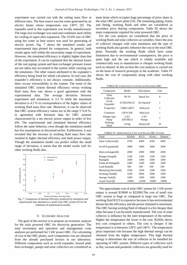
electric power. Fig. 7 shows the simulated results and
experimental data plotted for comparison. In general, both
results agree well within the uncertainty range of experiment.
However, the simulated efficiency is slightly higher than that
of the experiment. It can be explained that the internal losses
of the real piping system and heat exchanger pressure losses
are not taken into accounted in the system while carrying out
the simulation. The other reason attributed to the expander’s
efficiency being fixed for whole calculation. In real case, the
expander’s efficiency is not always constant. Additionally,
there occurs irreversibility in the system. The trend of the
simulated ORC system thermal efficiency versus working
fluid mass flow rate shows a good agreement with the
experimental data. The average deviation between
experiment and simulation is 3.5 % while the maximum
deviation is 4.5 % in correspondence of the higher values of
working fluid mass flow rate. Moreover, it can be observed
that ORC system efficiency values are in the range 5 %-8 %,
in agreement with literature data for ORC systems
characterized by a net electric power output in order of few
kW. The experimental and simulated thermal efficiency
follow the same behavior, even though the simulation model
has few assumptions as discussed earlier. Furthermore, it was
revealed that the increase in working fluid mass flow rate
resulted in higher thermal efficiency and shaft power output.
Though the simulation model can predict within the small
range of deviation, it seems that the model works well for
other working fluids also.
0.06 0.08 0.1 0.12 0.14 0.16 0.18
5.1
5.4
5.7
6
6.3
6.6
6.9
7.2
Working Fluid Mass Flow Rate [kg/s]
Th
erm
al E
ffic
ien
cy [
%]
Experiment [20]Experiment [20]
SimulationSimulation
Fig. 7. Comparison of thermal efficiency predicted by simulation and
experimental data obtained in a small scale ORC system [9] for the
validation of mathematical models.
V. ECONOMIC ANALYSIS
The goal of this section is to propose an economic analysis
for the solar powered ORC for electricity generation. The
total investment and operation and management costs
analyses are performed for 1 kW power ORC. For calculating
of cost of the ORC plants, each components cost are obtained
from the already purchased invoice in our laboratory.
Different components such as scroll expander, brazed plate
heat exchanger, pumps and solar collectors are considered as
main items which occupies huge percentage of price share in
the solar ORC power plant [10]. The remaining piping, frame
and fitting, working fluids and other are considered as
secondary price sharing components. Table III shows the
main components required for solar powered ORC.
For the cost analysis we considered that the price of
working fluids and solar collectors as variables. Since the area
of collector changes with solar insolation and the type of
working fluids also greatly influence the cost in the total ORC
plant. Normally the working fluids which have some
limitations due to environmental consequences, the price is
quite high and the one which is widely available and
commercially easy to manufacture is cheaper working fluids
such as ethanol. In this section the cost analysis is carried out
on the basis of research prototype in the academic. Table IV
shows the cost of components along with other working
fluids.
TABLE III: COMPONENTS FOR SOLAR-POWERED ORC
Component Model Description Unit
Solar
Collectors SP-10 Apack Inc. 8
Scroll
Expander E15H22N4.25 Air Squared 1
Evaporator CB60-14H-F AlfaLaval 1
Condenser CB76-50E AlfaLaval 1
Plunger type
Pump
CAT
2SF29ELS
CAT
Pumps 1
Working
Fluid 10 Kg Honeywell 10
TABLE IV: APPROXIMATE COST FOR SOLAR ORC SYSTEM
Fluid R245fa R123 R141a Ethanol
Solar Collectors($) 4700 4900 4500 4600
Scroll Expander($) 3900 3900 3900 3900
Heat exchangers($) 2000 2000 2000 2000
Plunger Pump($) 1500 1500 1500 1500
Piping($) 1000 1000 1000 1000
Frame & Fittings($) 1000 1000 1000 1000
Load Bank($) 500 500 500 500
Measuring Devices($) 2500 2500 2500 2500
Working Fluid($) 1500 4000 2000 1000
Storage Tank($) 1000 1000 1000 1000
Grand Total ($) 19600 22300 19900 19000
The approximate cost of solar ORC system for 1 kW power
output is around $19000 to $22000.The cost of small size
ORC system is huge as compared to large size ORC. The
working fluid R123 is expensive because it has environmental
threats but the efficiency and the power obtained is maximum.
The ORC having working fluid of ethanol is a bit cheaper than
other because it can be easily manufactured. The cost of solar
collector is influence by the inlet temperature of the turbine.
Higher the temperature the lower is the cost. R245fa shows
less cost compared to others. The cost is cheaper if the
temperature is in between 120°C and 140°C. The temperature
plays important role because the high thermal energy can be
obtained from the higher temperature. This high thermal
energy is determines the size of collector to be installed for
operating of ORC system. Different types of collectors such
as flat, vacuum and parabolic collectors are generally used for
Journal of Clean Energy Technologies, Vol. 3, No. 1, January 2015
65

getting the temperature within the desired need of ORC
performance and conditions. The Fig. 8 shows the variation in
the cost due to the variation on the temperature of inlet of
turbine. In other words the inlet turbine temperature can be
obtained from the different solar collector as highlighted
above. Another prospective for solar collector cost variation
is due to the meteorology conditions. The four seasons all
year shows different pattern but there is not too much
deviation in the price of solar collector cost. Fig. 9 shows the
cost of collector for each fluid when subjected to change in
solar insolation. The minimum solar insolation in this present
paper is assumed to be 600 W/m2 and the maximum is to be
1000 W/m2.
100 110 120 130 140 1503900
4200
4500
4800
5100
5400
5700
Turbine Inlet Temperature
So
lar
Co
llecto
r C
ost
($)
R245faR245fa
R123R123
R141bR141b
EthanolEthanol
Fig. 8. Collector cost variation with turbine inlet temperature.
600 650 700 750 800 850 900 950 1000
3200
4000
4800
5600
6400
7200
8000
Solar Insolation ( W/m^2)
Co
llecto
r C
ost
($)
R245faR245fa
R123R123
R141bR141b
EthanolEthanol
Fig. 9. Collector cost variation due to solar insolation.
A. Payback Period
The payback period of the solar ORC is determined by the
annual income generation from the power obtained through
the system. In other words, it is the time required to get back
the money spent in the solar ORC system.
Payback period = Total cost invested / Revenue generated
For simplicity the following are the assumptions for
calculating the payback period.
1) The sunshine during is assumed to be 5 hours only per
day.
2) The average solar insolation in the particular location is
assumed to be 800 W/m2.
3) The collector efficiency is presumed to be 70%. (Best
case scenario).
4) No any insurance, tax and subsidy are considered.
5) The cost of electricity (kWh) is assumed to be $0.39.
Table V shows the revenue generated during the year and
the payback period for each fluid. It can be seen that the solar
ORC capital cost will be recovered with the 3.7 years. The
most economical solar ORC are the working fluids with
R141b and R245fa. Since the payback period is almost same
for each working fluid but if more cost changing variables
such as size of heat exchanger, the size of expander and the
pump are taken into consideration then the period changes
automatically. In large scale of electrical generation, the
recommended working fluid is R245fa in solar ORC.
TABLE V: PAYBACK PERIOD FOR SOLAR ORC SYSTEM
Fluid Electricity Revenue
Payback
period
(kWh)/year ($) (year)
R245fa 13447 5244.33 3.74
R123 14747 5751.33 3.88
R141b 13699 5342.61 3.72
Ethanol 12662 4938.18 3.85
VI. CONCLUSION
A 1 kW solar organic Rankine cycle system was studied
and modeled thermodynamically with 4 selected organic
working fluids for temperature ranging from 100 °C to 150 °C.
The analysis involved comparing various parameters, such as
exergy, thermal, solar power cycle efficiencies in addition to
the heat input, turbine inlet volume flow rate, and the required
area of solar collector. For verification of the simulation
model, the experimental data were compared with the
simulated one. In the second part of the paper the economic
analysis was carried out. The analysis showed that the
payback period of the solar ORC system is around 3.7 years.
The total cost of research prototype testing facility of solar
based ORC system is not more than $ 20000. Finally from the
various range of parameters the working fluid R245fa is
considered the best candidate for using in solar powered ORC
in generating electric power.
REFERENCES
[1] S. Quoilin, M. Orosz, H. Hemond, and V. Lemort, “Performance and
design optimization of a low-cost solar organic Rankin cycle for
remote power generation,” Solar Energy, vol. 85, pp. 955-966, 2011.
[2] B. F. Tchanche, G. Lambrinos, A. Frangoudakis, and G. Papadakis,
“Low-grade heat conversion into power using organic Rankine
cycles–A review of various applications,” Renewable and Sustainable
Energy Reviews, vol. 15, no. 8, pp. 3963-3979, 2011.
[3] T. C. Hung, T. Y. Shai, and S. K. Wang, “A review of organic Rankine
cycles (ORCs) for the recovery of low-grade waste heat,” Energy, vol.
22, no. 7, pp. 661-667, 1997.
[4] H. J. Chen, D. Y. Goswami, and E. K. Stefanakos, “A review of
thermodynamic cycles and working fluids for the conversion of
low-grade heat,” Renewable and Sustainable Energy Reviews, vol. 14,
no. 9, pp. 3059-3067, 2010.
[5] U. Drescher, and D. Brüggemann, “Fluid selection for the Organic
Rankine Cycle (ORC) in biomass power and heat plants,” Applied
Thermal Engineering, vol. 27, no. 1, pp. 223-228, 2007.
[6] J. Li, P. Gang, and J. Jie, “Optimization of low temperature solar
thermal electric generation with organic Rankine cycle in different
areas,” Applied Energy, vol. 87, no. 11, pp. 3355-3365, 2010.
[7] D. H. Wei, X. S. Lu, L. Zhen, and J. M. Gu, “Performance analysis and
optimization of organic Rankine cycle (ORC) for waste heat recovery,”
Energy conversion and Management, vol. 48, no. 4, pp 1113-1119,
2007.
[8] A. M. Delgado-Torres and L. García-Rodríguez, “Analysis and
optimization of the low-temperature solar organic Rankine cycle
(ORC),” Energy Conversion and Management, vol. 51, no. 12, pp.
2846-2856, 2010.
[9] E. Yun, H. D. Kim, S. Y. Yoon, and K. C. Kim, “Development and
characterization of small-scale ORC system using scroll expander,”
Applied Mechanics and Materials, vol. 291-294, pp. 1627-1630,
2013.
Journal of Clean Energy Technologies, Vol. 3, No. 1, January 2015
66

[10] M. Q. Li, J. F. Wang, S. L. Li, X. R. Wang, W. F. He, and Y. P. Dai,
“Thermo-economic analysis and comparison of a CO2 transcritical
power cycle and an organic Rankine cycle,” Geothermics, vol. 50, pp.
101-111, 2014.
Suresh Baral is a PhD student in the School of
Mechanical Engineering, Pusan National University,
South Korea. His advisor is Prof. KC Kim. Mr. Baral
received his bachelor and master degree in mechanical
engineering from Institute of Engineering, Pulchowk
Campus and Kathmandu University, Nepal
respectively. He is a permanent faculty member in
Pokhara University, Nepal as a lecturer. His areas of
research interests are renewable energy and energy
conversion technology.
Kyung Chun Kim is a professor in the School of
Mechanical Engineering of Pusan National University
in Korea. He obtained the Ph.D. degree from the
Korea Advanced Institute of Science and Technology
(KAIST), Korea, in 1987. He was selected as a
member of the National Academy of Engineering of
Korea in 2004. His research interests include 3D3C
Micro-PIV, Bio-MEMS, turbulent flow
measurements based on PIV/LIF, biomedical
engineering, POCT development, wind turbines, and organic Rankine cycle
system.
Journal of Clean Energy Technologies, Vol. 3, No. 1, January 2015
67