sine wave plus dc conduit box long - energy alternatives owners gui… · sine wave plus dc conduit...
TRANSCRIPT

Sine Wave Plus DC Conduit Box Long
Owner’s Guide
DCCB-LDCCB-L-175DCCB-L-250


Sine Wave Plus Long DC Conduit Box
Owner’s Guide

About XantrexXantrex Technology Inc. is a world-leading supplier of advanced power electronics and controls with products from 50 watt mobile units to one MW utility-scale systems for wind, solar, batteries, fuel cells, microturbines, and backup power applications in both grid-connected and stand-alone systems. Xantrex products include inverters, battery chargers, programmable power supplies, and variable speed drives that convert, supply, control, clean, and distribute electrical power.
TrademarksSine Wave Plus Long DC Conduit Box is a trademark of Xantrex International. Xantrex is a registered trademark of Xantrex International.Other trademarks, registered trademarks, and product names are the property of their respective owners and are used herein for identification purposes only.
Notice of CopyrightSine Wave Plus Long DC Conduit Box (DCCB-L) Owner’s Guide © July 2004 Xantrex International. All rights reserved.
DisclaimerUNLESS SPECIFICALLY AGREED TO IN WRITING, XANTREX TECHNOLOGY INC. (“XANTREX”)(a) MAKES NO WARRANTY AS TO THE ACCURACY, SUFFICIENCY OR SUITABILITY OF ANY TECHNICAL OR OTHER INFORMATION PROVIDED IN ITS MANUALS OR OTHER DOCUMENTATION.(b) ASSUMES NO RESPONSIBILITY OR LIABILITY FOR LOSS OR DAMAGE, WHETHER DIRECT, INDIRECT, CONSEQUENTIAL OR INCIDENTAL, WHICH MIGHT ARISE OUT OF THE USE OF SUCH INFORMATION. THE USE OF ANY SUCH INFORMATION WILL BE ENTIRELY AT THE USER’S RISK.
Date and RevisionJuly 2004 Revision A
Part Number973-0032-01-01 Rev A
Contact InformationTelephone: 1 800 670 0707 (toll free North America)
1 360 925 5097 (direct)Fax: 1 800 994 7828 (toll free North America)
1 360 925 5143 (direct)Email: [email protected]: www.xantrex.com
973-0032-01-01 Rev A iii
About This Guide
PurposeThe purpose of this Owner’s Guide is to provide explanations and procedures for installing the Long DC Conduit Box (DCCB-L) on a Sine Wave Inverter/charger.
ScopeThe Owner’s Guide provides safety guidelines and procedures for installing the Long DC Conduit Box.
AudienceThe information in this Guide is intended for the experienced electrician who need to install the Long DC Conduit Box into a power system. Only skilled personnel, such as certified electricians and certified Renewable Energy technicians should attempt installation of this equipment. Skills required include the ability to read and understand how to follow single-line wiring diagrams.
OrganizationThis Guide consists of two chapters.Chapter 1, “Introduction” provides basic information about the design and purpose of the Sine Wave Plus Long DC Conduit Box.Chapter 2, “Installation” provides installation and wiring instructions for the Sine Wave Plus Long DC Conduit Box (DCCB-L).Warranty and Product Information is provided at the end of the manual.

About This Guide
iv 973-0032-01-01 Rev A
Conventions UsedThe following conventions are used in this guide.
Product Naming ConventionsDCCB-L refers to the Long DC Conduit Box without any factory installed wiring.DCCB-L-175/L-250 refers to the Long DC Conduit Box with either a GJ175F or a GJ250F Circuit Breaker installed. It includes some factory-installed wiring.DCCB-RE describes a field-installed, dual-conduit box installation intended for supporting multiple RE sources.Long DC Conduit Box refers to all products and is used in situations where all three products are treated the same.
WARNINGWarnings identify conditions that could result in personal injury or loss of life.
CAUTIONCautions identify conditions or practices that could result in damage to the unit or other equipment.
Important: These notes describe things which are important for you to know, but not as serious as a caution or warning.

About This Guide
973-0032-01-01 Rev A v
Abbreviations and Acronyms
Related InformationYou can find more information about Xantrex Technology Inc. as well as its products and services at www.xantrex.com.
AC Alternating Current
AHJ Authority Having JurisdictionASC Authorized Service CenterAWG American Wire GaugeBSM Battery Status MeterBTS Battery Temperature SensorCEC Canadian Electrical CodeCSA Canadian Standards AssociationDC Direct CurrentDCCB-L DC Conduit Box Long Version for the SW Plus Inverter/ChargerDCCB-L-175/L-250 A DCCB-L that includes factory-installed hardware.PVGFP PV Ground Fault ProtectionNEC National Electrical Code (US)RE Renewable EnergyRMA Return Material AuthorizationUL Underwriters Laboratory

vi

973-0032-01-01 Rev A vii
Important Safety Instructions
1. Installations of this equipment should only be performed by skilled personnel such as qualified electricians and certified Renewable Energy (RE) system installers to ensure adherence to the local and national electrical codes applicable in your installation. For a list of Xantrex Certified RE dealers, please visit our website at www.xantrexREdealers.com.
2. Before installing any components, read all instructions and cautionary markings on the Long DC Conduit Box, the batteries, and all appropriate sections of this guide.
3. The Long DC Conduit Box is designed to be permanently connected to your Sine Wave Plus inverter to prevent accidental exposure to shock hazards.
4. Do not expose the Long DC Conduit Box to rain, snow, or spray. To reduce risk of fire hazard, do not cover or obstruct the ventilation openings.
5. Do not install the Long DC Conduit Box in a zero-clearance compartment. The Sine Wave Plus inverter that is attached may overheat. Minimum clearance for ventilation around unit must be 12 inches (305 mm) at the end and the top.
6. To avoid a risk of fire and electric shock, make sure that existing wiring is in good condition and that wire is not undersized. Do not operate the inverter with damaged or substandard wiring.
7. To reduce the risk of electrical shock, disconnect both AC and DC power from the system before attempting any maintenance or cleaning or working on the Long DC Conduit Box.
8. The Long DC Conduit Box is provided with an equipment-grounding bar that must be connected to the inverter equipment ground and the system ground.
9. Do not store any flammable materials near the primary system panel.
WARNING
This chapter contains important safety and operating instructions for the Sine Wave Plus Long DC Conduit Box (all models). Read and keep this Installation Guide for future reference.

Safety
viii 973-0032-01-01 Rev A
Explosive gas precautions
1. Working in the vicinity of lead-acid batteries is dangerous. Batteries generate explosive gases during normal operation. Therefore you must read this guide and follow the instructions exactly before installing the DCCB-L.
2. To reduce the risk of battery explosion, follow these instructions and those published by the battery manufacturer and the manufacturer of the equipment in which the battery is installed.
Certifications
CSA certified to the following standards:• UL 1741-2001 First Edition, and• CSA C22.2 No. 107.1-01

973-0032-01-01 Rev A ix
Important Safety Instructions - - - - - - - - - - - - - - - - - - - - - - - - - - - - - - - - - - - - - - - - - - -vii
1 IntroductionIntroduction - - - - - - - - - - - - - - - - - - - - - - - - - - - - - - - - - - - - - - - - - - - - - - - - - - - - - - - - - - 1–2Specifications - - - - - - - - - - - - - - - - - - - - - - - - - - - - - - - - - - - - - - - - - - - - - - - - - - - - - - - - - 1–3Blockoff Plates - - - - - - - - - - - - - - - - - - - - - - - - - - - - - - - - - - - - - - - - - - - - - - - - - - - - - - - - 1–5Options/Accessories- - - - - - - - - - - - - - - - - - - - - - - - - - - - - - - - - - - - - - - - - - - - - - - - - - - - - 1–6
Charge Controllers or Diversion Load Controllers - - - - - - - - - - - - - - - - - - - - - - - - - - - - - - 1–6Charge Controller Installation Package - - - - - - - - - - - - - - - - - - - - - - - - - - - - - - - - - - - - - 1–7PV Ground Fault Protection (PVGFP-CF) - - - - - - - - - - - - - - - - - - - - - - - - - - - - - - - - - - - 1–8GJ175F and GJ250F Breakers and Flag Terminals - - - - - - - - - - - - - - - - - - - - - - - - - - - - - 1–8CF60 Circuit Breakers - - - - - - - - - - - - - - - - - - - - - - - - - - - - - - - - - - - - - - - - - - - - - - - 1–10CF-Series Breaker Mounting Plate - - - - - - - - - - - - - - - - - - - - - - - - - - - - - - - - - - - - - - - 1–10Power Distribution Blocks (PDB) - - - - - - - - - - - - - - - - - - - - - - - - - - - - - - - - - - - - - - - - 1–10Battery Status Monitor (BSM) - - - - - - - - - - - - - - - - - - - - - - - - - - - - - - - - - - - - - - - - - - 1–11Battery Temperature Sensors - - - - - - - - - - - - - - - - - - - - - - - - - - - - - - - - - - - - - - - - - - - 1–12Battery Cables - - - - - - - - - - - - - - - - - - - - - - - - - - - - - - - - - - - - - - - - - - - - - - - - - - - - - 1–12DC Negative Bus Bar - - - - - - - - - - - - - - - - - - - - - - - - - - - - - - - - - - - - - - - - - - - - - - - - 1–13
2 InstallationPreparing for the Installation - - - - - - - - - - - - - - - - - - - - - - - - - - - - - - - - - - - - - - - - - - - - - - - 2–2
Code Compliance - - - - - - - - - - - - - - - - - - - - - - - - - - - - - - - - - - - - - - - - - - - - - - - - - - - - 2–2Installation Tools and Materials - - - - - - - - - - - - - - - - - - - - - - - - - - - - - - - - - - - - - - - - - - 2–2
Pre-installation - - - - - - - - - - - - - - - - - - - - - - - - - - - - - - - - - - - - - - - - - - - - - - - - - - - - - - - - 2–3Location - - - - - - - - - - - - - - - - - - - - - - - - - - - - - - - - - - - - - - - - - - - - - - - - - - - - - - - - - - 2–3Service Planning - - - - - - - - - - - - - - - - - - - - - - - - - - - - - - - - - - - - - - - - - - - - - - - - - - - - 2–3Ventilation Requirements - - - - - - - - - - - - - - - - - - - - - - - - - - - - - - - - - - - - - - - - - - - - - - 2–4Removing and Replacing the Long DC Conduit Box Cover - - - - - - - - - - - - - - - - - - - - - - - 2–5Installing or Removing the Blockoff Plates - - - - - - - - - - - - - - - - - - - - - - - - - - - - - - - - - - 2–6Knockout Preparation - - - - - - - - - - - - - - - - - - - - - - - - - - - - - - - - - - - - - - - - - - - - - - - - - 2–7
Mounting - - - - - - - - - - - - - - - - - - - - - - - - - - - - - - - - - - - - - - - - - - - - - - - - - - - - - - - - - - - - 2–8Mounting the Long DC Conduit Box on the Xantrex Back Plate (XBP) - - - - - - - - - - - - - - - 2–8Mounting on Plywood - - - - - - - - - - - - - - - - - - - - - - - - - - - - - - - - - - - - - - - - - - - - - - - - 2–10
Installing Accessories- - - - - - - - - - - - - - - - - - - - - - - - - - - - - - - - - - - - - - - - - - - - - - - - - - - 2–11Dual DCCB-L Configurations (DCCB-L-RE) - - - - - - - - - - - - - - - - - - - - - - - - - - - - - - - - - - 2–13
Dual DCCB-Ls - - - - - - - - - - - - - - - - - - - - - - - - - - - - - - - - - - - - - - - - - - - - - - - - - - - - 2–13Dual DCCB-L-175s (or L-250s) - - - - - - - - - - - - - - - - - - - - - - - - - - - - - - - - - - - - - - - - - 2–14
Contents
Contents
x 973-0032-01-01 Rev A
Charge/Load Controllers - - - - - - - - - - - - - - - - - - - - - - - - - - - - - - - - - - - - - - - - - - - - - - - - -2–15Wiring - General - - - - - - - - - - - - - - - - - - - - - - - - - - - - - - - - - - - - - - - - - - - - - - - - - - - - - -2–16
Grounding the Long DC Conduit Box - - - - - - - - - - - - - - - - - - - - - - - - - - - - - - - - - - - - -2–16DC Equipment Grounding - - - - - - - - - - - - - - - - - - - - - - - - - - - - - - - - - - - - - - - - - -2–17Bonding DC Negative to Ground - - - - - - - - - - - - - - - - - - - - - - - - - - - - - - - - - - - - - -2–18Connecting to the Primary System Ground - - - - - - - - - - - - - - - - - - - - - - - - - - - - - - -2–18Connecting DC and AC Electrical System Grounds Together - - - - - - - - - - - - - - - - - - -2–19
Over-current Protection - - - - - - - - - - - - - - - - - - - - - - - - - - - - - - - - - - - - - - - - - - - - - - -2–22Master DC Disconnect - - - - - - - - - - - - - - - - - - - - - - - - - - - - - - - - - - - - - - - - - - - - - - - -2–23Additional Over-current Protection - - - - - - - - - - - - - - - - - - - - - - - - - - - - - - - - - - - - - - -2–24Battery Cable Connection - - - - - - - - - - - - - - - - - - - - - - - - - - - - - - - - - - - - - - - - - - - - - -2–25
Wiring - Specific - - - - - - - - - - - - - - - - - - - - - - - - - - - - - - - - - - - - - - - - - - - - - - - - - - - - - -2–27Single Inverter System - - - - - - - - - - - - - - - - - - - - - - - - - - - - - - - - - - - - - - - - - - - - - - - -2–27Single Inverter System with Renewable Energy - - - - - - - - - - - - - - - - - - - - - - - - - - - - - - -2–28Dual Inverter System with Renewable Energy - - - - - - - - - - - - - - - - - - - - - - - - - - - - - - - -2–29Dual Inverter System with Multiple Renewable Energy - - - - - - - - - - - - - - - - - - - - - - - - - -2–30Additional Accessory Wiring - - - - - - - - - - - - - - - - - - - - - - - - - - - - - - - - - - - - - - - - - - -2–31
Battery Status Monitor (BSM) (p/n TM500A or TM500A-NS) - - - - - - - - - - - - - - - - - -2–31Charge Controller Wiring using the C-Series Multifunction DC Controller
and the CC PCK - - - - - - - - - - - - - - - - - - - - - - - - - - - - - - - - - - - - - - - - - - - - - - -2–32Battery Temperature Sensor - - - - - - - - - - - - - - - - - - - - - - - - - - - - - - - - - - - - - - - - -2–33
Warranty and Return Information - - - - - - - - - - - - - - - - - - - - - - - - - - - - - - - - - - - WA–1
Index - - - - - - - - - - - - - - - - - - - - - - - - - - - - - - - - - - - - - - - - - - - - - - - - - - - - - - - - - - - - - - - IX–1

973-0032-01-01 Rev A xi
Figure 1-1 Sine Wave Plus Long DC Conduit Box - - - - - - - - - - - - - - - - - - - - - - - - - - - - - - - - - 1–2Figure 1-2 Long DC Conduit Box Dimensions (Not To Scale)- - - - - - - - - - - - - - - - - - - - - - - - - - 1–4Figure 1-3 The Blockoff Plates - - - - - - - - - - - - - - - - - - - - - - - - - - - - - - - - - - - - - - - - - - - - - - - 1–5Figure 1-4 The C-Series Multi-function DC Controller Family - - - - - - - - - - - - - - - - - - - - - - - - - 1–7Figure 1-5 Charge Controller Installation Package (CC PCK) - - - - - - - - - - - - - - - - - - - - - - - - - - 1–7Figure 1-6 PVGFP-CF Breakers (-1, -2, -3 and -4)- - - - - - - - - - - - - - - - - - - - - - - - - - - - - - - - - - 1–8Figure 1-7 GJ Breakers and Flag Terminals - - - - - - - - - - - - - - - - - - - - - - - - - - - - - - - - - - - - - - 1–9Figure 1-8 GJ 175F-PCK or the GJ250F-PCK- - - - - - - - - - - - - - - - - - - - - - - - - - - - - - - - - - - - - 1–9Figure 1-9 CF60 Circuit Breaker- - - - - - - - - - - - - - - - - - - - - - - - - - - - - - - - - - - - - - - - - - - - - 1–10Figure 1-10 CF-Series Mounting Plate (CFMP) - - - - - - - - - - - - - - - - - - - - - - - - - - - - - - - - - - - 1–10Figure 1-11 Power Distribution Blocks - - - - - - - - - - - - - - - - - - - - - - - - - - - - - - - - - - - - - - - - - 1–10Figure 1-12 Battery Status Monitor - - - - - - - - - - - - - - - - - - - - - - - - - - - - - - - - - - - - - - - - - - - - 1–11Figure 1-13 Battery Temperature Sensor - - - - - - - - - - - - - - - - - - - - - - - - - - - - - - - - - - - - - - - - 1–12Figure 1-14 Battery Cable Set (BC-L2-250 or BC-L2-175)- - - - - - - - - - - - - - - - - - - - - - - - - - - - 1–12Figure 1-15 DC Negative Bus Bar - - - - - - - - - - - - - - - - - - - - - - - - - - - - - - - - - - - - - - - - - - - - 1–13Figure 2-1 Warning Label - - - - - - - - - - - - - - - - - - - - - - - - - - - - - - - - - - - - - - - - - - - - - - - - - - 2–3Figure 2-2 Space and Clearance Requirements - - - - - - - - - - - - - - - - - - - - - - - - - - - - - - - - - - - - 2–4Figure 2-3 Removing and Replacing the Long DC Conduit Box Top Cover- - - - - - - - - - - - - - - - - 2–5Figure 2-4 The Blockoff Plates on the Long DC Conduit Box - - - - - - - - - - - - - - - - - - - - - - - - - - 2–6Figure 2-5 Knockout Locations on the Long DC Conduit Box - - - - - - - - - - - - - - - - - - - - - - - - - - 2–7Figure 2-6 The XBP Back Plate - - - - - - - - - - - - - - - - - - - - - - - - - - - - - - - - - - - - - - - - - - - - - - 2–8Figure 2-7 Mounting the Long DC Conduit Box and the SW Plus Inverter Charger on the XBP - - - 2–9Figure 2-8 Mounting the Long DC Conduit Box and the Sine Wave Plus Inverter Charger
on Plywood - - - - - - - - - - - - - - - - - - - - - - - - - - - - - - - - - - - - - - - - - - - - - - - - - - - 2–10Figure 2-9 Installing Circuit Breakers on the Long DC Conduit Box - - - - - - - - - - - - - - - - - - - - 2–12Figure 2-10 Optional Component Locations on the Long DC Conduit Box - - - - - - - - - - - - - - - - - 2–12Figure 2-11 Creating a DCCB-L-RE Configuration from Dual DCCB-Ls - - - - - - - - - - - - - - - - - - 2–13Figure 2-12 Creating a DCCB-L-RE Configuration from two DCCB-L-175 (or L-250)- - - - - - - - - 2–14Figure 2-13 Adding Charge or Diversion Load Controllers on the Long DC Conduit Box - - - - - - - 2–15Figure 2-14 Grounding Using PVGFP-CF - - - - - - - - - - - - - - - - - - - - - - - - - - - - - - - - - - - - - - - 2–20Figure 2-15 Grounding Without PVGFP-CF- - - - - - - - - - - - - - - - - - - - - - - - - - - - - - - - - - - - - - 2–21Figure 2-16 Battery Connections for a Single-inverter System- - - - - - - - - - - - - - - - - - - - - - - - - - 2–25Figure 2-17 Battery Connections for a Dual-inverter System- - - - - - - - - - - - - - - - - - - - - - - - - - - 2–26Figure 2-18 DC Wiring for a Single Inverter System - - - - - - - - - - - - - - - - - - - - - - - - - - - - - - - - 2–27Figure 2-19 DC Wiring for a Single Inverter System with Renewable Energy - - - - - - - - - - - - - - - 2–28Figure 2-20 DC Wiring for a Dual Inverter System with Renewable Energy - - - - - - - - - - - - - - - - 2–29
Figures

Figures
xii 973-0032-01-01 Rev A
Figure 2-21 DC Wiring for a Dual Inverters, Dual Long DC Conduit Box System with Multiple RE 2–30Figure 2-22 Installing the BSM on the Long DC Conduit Box - - - - - - - - - - - - - - - - - - - - - - - - - -2–31Figure 2-23 Wiring the C-Series Multifunction Charge Controllers to the Long DC Conduit Box
using the CC PCK - - - - - - - - - - - - - - - - - - - - - - - - - - - - - - - - - - - - - - - - - - - - - - -2–32Figure 2-24 BTS Port locations on the Sine Wave Plus Inverter - - - - - - - - - - - - - - - - - - - - - - - - -2–33Figure 2-25 BTS Port locations on the C-Series DC Controller- - - - - - - - - - - - - - - - - - - - - - - - - -2–33Figure 2-26 Installing the Battery Temperature Sensor - - - - - - - - - - - - - - - - - - - - - - - - - - - - - - -2–34

973-0032-01-01 Rev A xiii
Table 1-1 Operational and Environmental Specifications for the Long DC Conduit Box- - - - - - - - 1–3Table 2-1 Minimum Equipment Ground Wire and DC Disconnect Size Chart- - - - - - - - - - - - - - 2–17Table 2-2 Recommended Battery Cable Size Versus Length - - - - - - - - - - - - - - - - - - - - - - - - - 2–22Table 2-3 Battery Cable to Maximum Breaker/Fuse Size- - - - - - - - - - - - - - - - - - - - - - - - - - - - 2–22
Tables

xiv

1 Introduction
Chapter 1, “Introduction” provides basic information about the design and purpose of the Sine Wave Plus Long DC Conduit Box.
The following topics are covered in this chapter.
For this topic: See...
“Introduction” page 1–2“Specifications” page 1–3“Blockoff Plates” page 1–5“Options/Accessories” page 1–6

Introduction
1–2 973-0032-01-01 Rev A
IntroductionThe Sine Wave Plus Long DC Conduit Box (DCCB-L) connects to the DC side of the inverter and accepts DC conduit runs. The conduit box provides protection to the DC cables connected to the inverter and provides a centralized location for the DC circuit breakers and PV Ground Fault Protection (GFP) breakers. It is also designed to incorporate cabling from up to two Multi-function DC Charge Controllers, such as the Xantrex C-Series Charge Controllers, and cabling from a battery meter, such as the Xantrex Battery Status Meter.The Long DC Conduit Box is available in three different configurations. • The DCCB-L Basic provides an internal ground bar only and space to add
additional circuit breakers; three large and six small. • The DCCB-L-175 includes a 175 amp GJ, F-Type, circuit breaker, a DC
negative bus bar and 500A/50 mV shunt, battery cables (1 set) and a ground wire connected to the ground bar.
• The DCCB-L-250 includes a 250 amp GJ, F-type, circuit breaker a DC negative bus bar and 500A/50 mV shunt, battery cables (1 set) and a ground wire connected to the ground bar.
For expandability, the Long DC Conduit Box is designed so that a second DCCB-L (any model) can be added on for additional breaker spaces, wiring, room and controller mounting spaces. Dual configurations have been certified to meet UL1741-2001 (First Edition) standards when using the field-installable accessories as listed page 1–6.
Figure 1-1 Sine Wave Plus Long DC Conduit Box
Front Cover
DCCB-L-175 or DCCB-L-250 adds:❐ One GJ175F or GJ250F Circuit Breaker❐ DC Negative Bus Bar and Shunt❐ One Positive (+) Battery Cable❐ One Negative (–) Battery Cable❐ One length green GROUND wire
DCCB-L includes:❐ Front Cover❐ Blockoff Plates (top and bottom)❐ DC Ground Bar❐ 6CF/3GJ Mounting Plate❐ Battery Meter Mounting Box
ABCD
FGHIJ
Blockoff Plates
DCCB-L DCCB-L-175 or DCCB-L-250
AB
B
C
D
E
E
F
H
J
G
IUpper
Lower

Specifications
973-0032-01-01 Rev A 1–3
SpecificationsThe following table provides the operational and environmental specifications for the Long DC Conduit Box (all models).
Table 1-1 Operational and Environmental Specifications for the Long DC Conduit Box
DCCB-L Basic DCCB-L-175 DCCB-L-250
Dimensions 33" (H) x 13 1/2" (W) x 8 7/8" (D)(384 mm x 343 mm x 225 mm)
33" (H) x 13 1/2" (W) x 8 7/8" (D)(384 mm x 343 mm x 225 mm)
33" (H) x 13 1/2" (W) x 8 7/8" (D)(384 mm x 343 mm x 225 mm)
Weight 22 lbs (10 kg) 33 lbs (15 kg) 33 lbs (15 kg)
Shipping Weight
25 lbs (11.5 kg) 36 lbs (16.5 kg) 36 lbs (16.5 kg)
Factory-installed hardware
• DC Ground Bar (with 12 holes, accepts #2 - 14 AWG wires)
• 6CF/3GJ Mounting Plate• Mounting box for BSM (w cover)
• DC Ground Bar (with 12 holes, accepts #2 - 14 AWG wires)
• 6CF/3GJ Mounting Plate• Mounting box for BSM (w cover)• DC Negative Bus Bar• 500 A/50 mV Shunt• GJ175F Circuit Breaker
• DC Ground Bar (with 12 holes, accepts #2 - 14 AWG wires)
• 6CF/3GJ Mounting Plate• Mounting box for BSM (w cover)• DC Negative Bus Bar• 500 A/50 mV Shunt• GJ250F Circuit Breaker
Factory-installed wiring
None • One - Ground Wire (#4 AWG, 18", rated to 105 °C, stranded copper) (• One - Positive (+) Battery Cable (#2/0 AWG, 16" Cable)
• One - Negative (–) Battery Cable (#2/0 AWG, 30" Cable)
• One - Ground Wire (#4 AWG, 18", rated to 105 °C, stranded copper)• One - Positive (+) Battery Cable (#4/0 AWG, 16" Cable)
• One - Negative (–) Battery Cable (#4/0 AWG, 30" Cable)
Rated Temperature
0 to 25 °C (32 to 77 °F)
0 to 25 °C (32 to 77 °F)
0 to 25 °C (32 to 77 °F)
Storage Temperature
-55 to +100 °C (-67 to 212 °F)
-55 to +100 °C (-67 to 212 °F)
-55 to +100 °C (-67 to 212 °F)
Enclosure Indoor rated, Galveneel, White, Powdercoat Finish
Indoor rated, Galveneel, White, Powdercoat Finish
Indoor rated, Galveneel, White, Powdercoat Finish
Ratings • 160 Vdc maximum (Open Circuit)• 250 amps maximum each inverter• 250 amps max. renewable energy
• 160 Vdc maximum (Open Circuit)• 250 amps maximum each inverter• 250 amps max. renewable energy
• 160 Vdc maximum (Open Circuit)• 250 amps maximum each inverter• 250 amps max. renewable energy
Charge Controllers
Accommodates: 2 Charge Controllers, 60 amps max. each
Accommodates: 2 Charge Controllers, 60 amps max. each
Accommodates: 2 Charge Controllers, 60 amps max. each
Regulatory Certified by CSA to UL 1741-2001 (First Edition) and CSA C22.2 No. 107.1-01
Certified by CSA to UL 1741-2001 (First Edition) and CSA C22.2 No. 107.1-01
Certified by CSA to UL 1741-2001 (First Edition) and CSA C22.2 No. 107.1-01

Introduction
1–4 973-0032-01-01 Rev A
Optional hardwareavailable at Xantrex
• Charge Controllers (60 A max ea.)• Charge Controller Kit (CC PCK)• Power Distribution Blocks
(PDB-6 or PDB-12)• PVGFP-CF (-1, -2, -3, -4)• GJ175F or GJ250F Circuit
Breakers• GJ175F-PCK (includes wiring)• GJ250F-PCK (includes wiring)• Battery Status Meter (TM500A,
TM500A-NS, and TM48)• CF60 Circuit Breakers• CF Mounting Plate (CFMP)• DC Negative Bus Bar with shunt (DCBUSBAR)
• Battery Temperature Sensor (BTS)• BC-L2-175 (#2/0 AWG cable)• BC-L2-250 (#4/0 AWG cable)
• Charge Controllers (60 A max ea.)• Charge Controller Kit (CC PCK)• Power Distribution Blocks (PDB-6 or PDB-12)
• PVGFP-CF (-1, -2, -3, -4)• GJ175F or GJ250F Circuit
Breakers• GJ175F-PCK (includes wiring)• GJ250F-PCK (includes wiring)• Battery Status Meter (TM500A,
TM500A-NS, and TM48)• CF60 Circuit Breakers• CF Mounting Plate (CFMP)• DC Negative Bus Bar with shunt
(DCBUSBAR)• Battery Temperature Sensor (BTS)• BC-L2-175 (#2/0 AWG cable)• BC-L2-250 (#4/0 AWG cable)
• Charge Controllers (60 A max ea.)• Charge Controller Kit (CC PCK)• Power Distribution Blocks
(PDB-6 or PDB-12)• PVGFP-CF (-1, -2, -3, -4)• GJ175F or GJ250F Circuit
Breakers• GJ175F-PCK (includes wiring)• GJ250F-PCK (includes wiring)• Battery Status Meter (TM500A,
TM500A-NS, and TM48)• CF60 Circuit Breakers• CF Mounting Plate (CFMP)• DC Negative Bus Bar with shunt
(DCBUSBAR)• Battery Temperature Sensor (BTS)• BC-L2-175 (#2/0 AWG cable)• BC-L2-250 (#4/0 AWG cable)
Figure 1-2 Long DC Conduit Box Dimensions (Not To Scale)
Table 1-1 Operational and Environmental Specifications for the Long DC Conduit Box
DCCB-L Basic DCCB-L-175 DCCB-L-250
Inverter Side DCCB-L Base Outside
0.265 x 1” (Obround x4)
0.188” (fits up to #8
screw x2)

Blockoff Plates
973-0032-01-01 Rev A 1–5
Blockoff PlatesUpper and Lower Blockoff Plates are included to enclose the open portions of the Long DC Conduit Box chassis. In the event that an inverter is removed, the Blockoff Plates secure the enclosure to prevent accidental contact with any AC power within the Long DC Conduit Box. Remove the Blockoff Plate (upper or lower) from its position for the inverter used in your installation. The Blockoff Plates will not be needed at all in a dual SW Plus inverter installation. See “Installing or Removing the Blockoff Plates” on page 2–6 for additional information.
Important: The cable lengths provided in the DCCB-L-175/L-250 were designed for single-inverter systems to use the upper mounting location for the inverter. Mounting an inverter in the lower mounting position for a single-inverter system will required site-fabricated cables.
WARNING: Shock HazardBe sure to disconnect all DC and AC power before removing the inverter and installing the blockoff plate.
Figure 1-3 The Blockoff Plates
Upper Blockoff Plate
Lower Blockoff Plate
Knockout panel (if needed)

Introduction
1–6 973-0032-01-01 Rev A
Options/AccessoriesThe following CSA-approved accessories are available through Xantrex to expand or monitor the DC side of the system.• C-Series Multi-function DC Controllers (C35, C40, C60)• Charge Controller Installation Package (CC PCK)• PV Ground Fault Protection CF Breakers (PVGFP-CF-1, PVGFP-CF-2,
PVGFP-CF-3, PVGFP-CF-4)• GJ-F Series Flag Style Circuit Breakers 175A or 250A (without wiring)
(GJ175F, GJ250F)• GJ Series Flag Style Breakers 175A or 250A (with battery cables to connect
second inverter) (GJ175F-PCK, and GJ250F-PCK)• Dual-pole or Triple-pole GJ Flag Terminal Bus bars (GJ-FT2, GJ-FT3) • CF Breaker Mounting Plate (CFMP)• 60 Amp CF Series Circuit Breakers for loads (CF60)• Power Distribution Blocks 6:1 and 12:1 (PDB-6 or PDB-12) • Battery Status Meter (TM500A-NS without shunt) or (TM500A with shunt)• Battery Temperature Sensors (BTS)• Battery Cables for adding a second inverter (BC-L2-175 or BC-L2-250).
These battery cables are the same as those included with the appropriate breaker with the GJF175-PCK or GJF250-PCK.
• DC Negative Bus Bar (DCBUSBAR)
Charge Controllers or Diversion Load Controllers
If charge control or diversion control is required, spaces are provided for mounting up to two DC controllers on the top of the DCCB-L chassis. Xantrex offers the C-Series Multi-function DC Controller to provide either charge control or diversion control. Charge controllers not purchased from Xantrex may be used also, but might not fit the mounting holes on the top of DCCB-L. If this occurs, the non-Xantrex supplied charge controllers will need to be mounted somewhere off the DCCB-L chassis. Any charge controllers used on this component (Xantrex and Non-Xantrex) should not exceed 60 A each (120 A total).If more charge controllers are required, then it may be desirable to have two DCCB-Ls (any model combination) installed in a dual-configuration.
Important: The components shown in this section are to be used in a DCCB-L-RE configuration. Other components may be used, but may not allow continuous operation of the SW Plus Inverter and should be approved by the AHJ.

Options/Accessories
973-0032-01-01 Rev A 1–7
Charge Controller Installation Package
The following hardware can be purchased upon request for installing the C-Series Multi-function DC Controller to the Sine Wave Plus Long DC Conduit Box. The Charge Controller add-on package (CC PCK) includes the following:• one 48-inch white #6 AWG wire (temperature rated at 90° C),• one 96-inch red #6 AWG wire (temperature rated at 90° C),• one 48-inch green #10 AWG wire (temperature rated at 105° C), and • two conduit chase nipples, two lock nuts, and two plastic bushings for
1" knockouts.
See Figure 2-23 on page 2–32 for instructions on cutting and installing the CC PCK wiring.
Figure 1-4 The C-Series Multi-function DC Controller Family
CM/R Meter
Display
C35
C40 C60
CM FaceplateMeter Display
Figure 1-5 Charge Controller Installation Package (CC PCK)

Introduction
1–8 973-0032-01-01 Rev A
PV Ground Fault Protection (PVGFP-CF)
PV ground fault protection is available in up to four CF-Series breaker configurations. It’s designed to minimize the possibility of a fire resulting from ground faults in a PV array in accordance with the National Electric Code (NEC) for roof-mounting arrays on homes. Each switch is rated for 100 amps maximum per circuit and mounts directly to the breaker mounting plate. It is not designed or intended to prevent electrical shock or to be used for PV DC over-current protection. They can be used as an array disconnect.
Each charge controller that is connected to a roof mounted PV array on a home requires a “pole” on one of the four available PV-GFV-CF configurations. For example: If three controllers are used, one for a ground mounted PV array, one for a roof mounted PV array on a home, and one with a diversion load, only the one used for a roof-mounted array requires a ground fault pole.
GJ175F and GJ250F Breakers and Flag Terminals
GJ breakers are available in sizes 175A and 250A. The GJ175F and GJ250F breakers have single-pole “flag” terminals on them that are designed for use with lugged cables with ring terminals. These breakers can be used as a disconnect and/or an over-current device for the inverter(s) and PDBs.
Figure 1-6 PVGFP-CF Breakers (-1, -2, -3 and -4)
PVGFP-CF-4PVGFP-CF-1 PVGFP-CF-2 PVGFP-CF-3
Note: Wiring shown in this figure has been trimmed for visual purposes only and does not represent the actual length of wires that are attached to the breakers.
CAUTION: Equipment DamageNever install a PVGFP-CF between the diversion load and controller. Overcharging may occur during a “ground fault condition”.
Options/Accessories
973-0032-01-01 Rev A 1–9
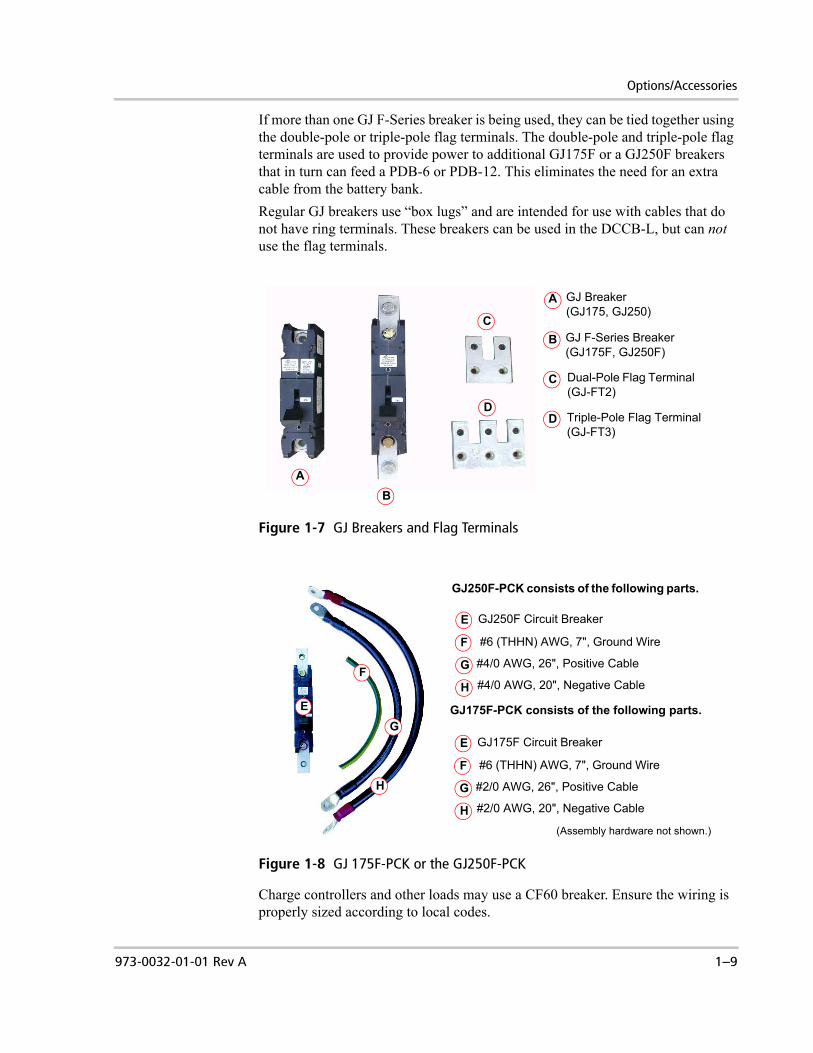
If more than one GJ F-Series breaker is being used, they can be tied together using the double-pole or triple-pole flag terminals. The double-pole and triple-pole flag terminals are used to provide power to additional GJ175F or a GJ250F breakers that in turn can feed a PDB-6 or PDB-12. This eliminates the need for an extra cable from the battery bank. Regular GJ breakers use “box lugs” and are intended for use with cables that do not have ring terminals. These breakers can be used in the DCCB-L, but can not use the flag terminals.
Charge controllers and other loads may use a CF60 breaker. Ensure the wiring is properly sized according to local codes.
Figure 1-7 GJ Breakers and Flag Terminals
Figure 1-8 GJ 175F-PCK or the GJ250F-PCK
GJ F-Series Breaker(GJ175F, GJ250F)
Dual-Pole Flag Terminal (GJ-FT2)
Triple-Pole Flag Terminal (GJ-FT3)
GJ Breaker(GJ175, GJ250)
A
B
C
D
AB
C
D
GJ250F Circuit Breaker
(Assembly hardware not shown.)
F
G
H
E
GJ175F-PCK consists of the following parts.
#4/0 AWG, 20", Negative Cable
#6 (THHN) AWG, 7", Ground Wire
#4/0 AWG, 26", Positive Cable
GJ250F-PCK consists of the following parts.
E
F
G
H
GJ175F Circuit Breaker
F
G
H
E
#2/0 AWG, 20", Negative Cable
#6 (THHN) AWG, 7", Ground Wire
#2/0 AWG, 26", Positive Cable

Introduction
1–10 973-0032-01-01 Rev A
CF60 Circuit Breakers
CF-Type (60 amp/160 Vdc Open Circuit) breakers are available at Xantrex for charge controllers and other DC loads. Smaller sizes can be used if properly sized for the load. Smaller breakers can be purchased at the local, electrical supply dealer. Ensure the wiring is properly sized for the breaker according to local code.
CF-Series Breaker Mounting Plate
The CF-Series Mounting Plate (CFMP) replaces the standard 3GJ/6CF Mounting Plate already in the DCCB-L and provides spaces for up to 10 CF-Series breakers.
Power Distribution Blocks (PDB)
Two Power Distribution Blocks are available for use as a DC positive bus.
Figure 1-9 CF60 Circuit Breaker
Figure 1-10 CF-Series Mounting Plate (CFMP)
Figure 1-11 Power Distribution Blocks
PDB-6 PDB-12
Options/Accessories
973-0032-01-01 Rev A 1–11
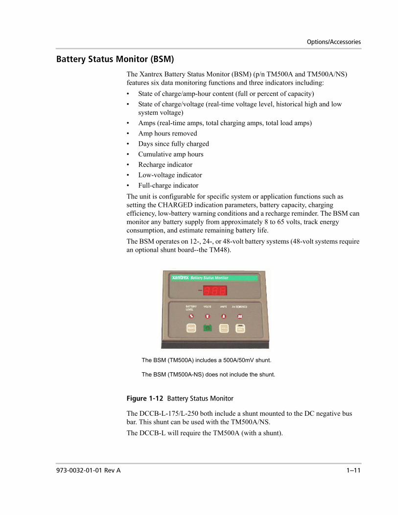
Battery Status Monitor (BSM)
The Xantrex Battery Status Monitor (BSM) (p/n TM500A and TM500A/NS) features six data monitoring functions and three indicators including:• State of charge/amp-hour content (full or percent of capacity)• State of charge/voltage (real-time voltage level, historical high and low
system voltage)• Amps (real-time amps, total charging amps, total load amps)• Amp hours removed• Days since fully charged• Cumulative amp hours• Recharge indicator • Low-voltage indicator• Full-charge indicatorThe unit is configurable for specific system or application functions such as setting the CHARGED indication parameters, battery capacity, charging efficiency, low-battery warning conditions and a recharge reminder. The BSM can monitor any battery supply from approximately 8 to 65 volts, track energy consumption, and estimate remaining battery life.The BSM operates on 12-, 24-, or 48-volt battery systems (48-volt systems require an optional shunt board--the TM48).
The DCCB-L-175/L-250 both include a shunt mounted to the DC negative bus bar. This shunt can be used with the TM500A/NS. The DCCB-L will require the TM500A (with a shunt).
Figure 1-12 Battery Status Monitor
The BSM (TM500A) includes a 500A/50mV shunt.
The BSM (TM500A-NS) does not include the shunt.
Introduction
1–12 973-0032-01-01 Rev A
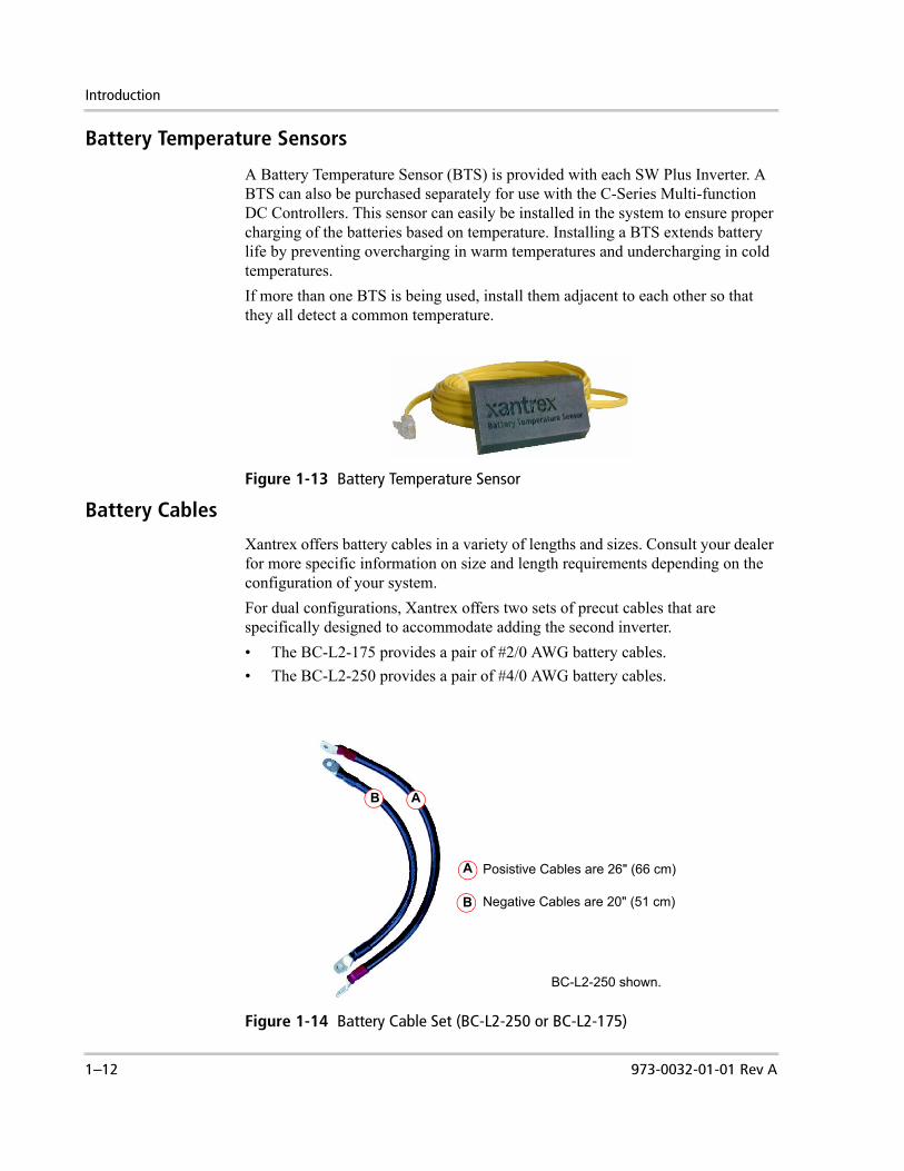
Battery Temperature Sensors
A Battery Temperature Sensor (BTS) is provided with each SW Plus Inverter. A BTS can also be purchased separately for use with the C-Series Multi-function DC Controllers. This sensor can easily be installed in the system to ensure proper charging of the batteries based on temperature. Installing a BTS extends battery life by preventing overcharging in warm temperatures and undercharging in cold temperatures.If more than one BTS is being used, install them adjacent to each other so that they all detect a common temperature.
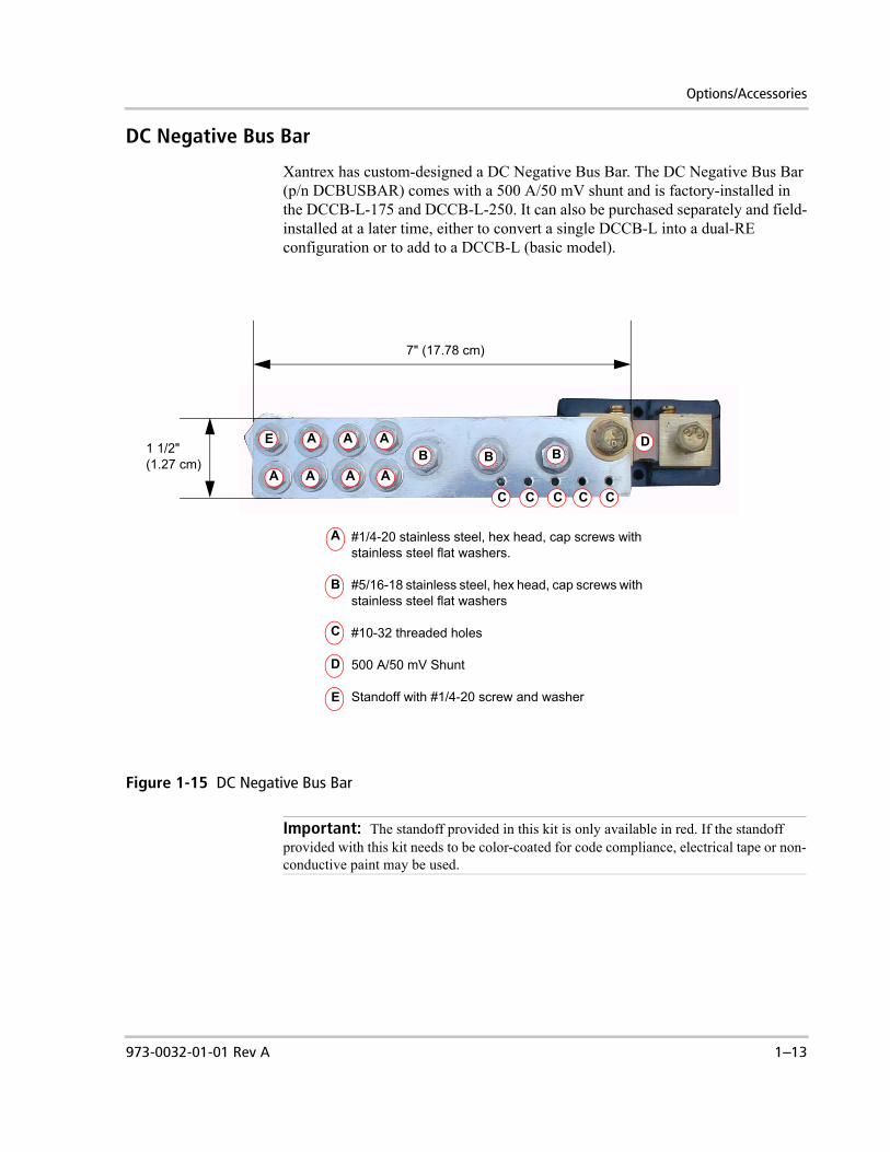
Battery Cables
Xantrex offers battery cables in a variety of lengths and sizes. Consult your dealer for more specific information on size and length requirements depending on the configuration of your system.For dual configurations, Xantrex offers two sets of precut cables that are specifically designed to accommodate adding the second inverter. • The BC-L2-175 provides a pair of #2/0 AWG battery cables. • The BC-L2-250 provides a pair of #4/0 AWG battery cables.
Figure 1-13 Battery Temperature Sensor
Figure 1-14 Battery Cable Set (BC-L2-250 or BC-L2-175)
BC-L2-250 shown.
Posistive Cables are 26" (66 cm)
Negative Cables are 20" (51 cm)
A
B
B A
Options/Accessories
973-0032-01-01 Rev A 1–13
DC Negative Bus Bar
Xantrex has custom-designed a DC Negative Bus Bar. The DC Negative Bus Bar (p/n DCBUSBAR) comes with a 500 A/50 mV shunt and is factory-installed in the DCCB-L-175 and DCCB-L-250. It can also be purchased separately and field-installed at a later time, either to convert a single DCCB-L into a dual-RE configuration or to add to a DCCB-L (basic model).
Figure 1-15 DC Negative Bus Bar
Important: The standoff provided in this kit is only available in red. If the standoff provided with this kit needs to be color-coated for code compliance, electrical tape or non-conductive paint may be used.
#1/4-20 stainless steel, hex head, cap screws with stainless steel flat washers.
#5/16-18 stainless steel, hex head, cap screws with stainless steel flat washers
#10-32 threaded holes
500 A/50 mV Shunt
Standoff with #1/4-20 screw and washer
A
B
C
A A A
AAAAB BB
C C C C C
7" (17.78 cm)
1 1/2" (1.27 cm)
D
D
E
E

1–14

2 Installation
Chapter 2, “Installation” provides installation and wiring instructions for the Sine Wave Plus Long DC Conduit Box (DCCB-L).
The following topics are covered in this chapter.
For this topic: See...
“Preparing for the Installation” page 2–2“Pre-installation” page 2–3“Mounting” page 2–8“Installing Accessories” page 2–11“Wiring - General” page 2–16“Wiring - Specific” page 2–27
“Single Inverter System” page 2–27“Single Inverter System with Renewable Energy” page 2–28“Dual Inverter System with Renewable Energy” page 2–29“Dual Inverter System with Multiple Renewable Energy”
page 2–30

Installation
2–2 973-0032-01-01 Rev A
Preparing for the Installation
Code Compliance
Governing installation codes vary depending on the location and type of installation. Installations of this equipment should only be performed by skilled personnel such as qualified electricians and Certified Renewable Energy (RE) System Installers to ensure adherence to the local and national electrical codes applicable in your application.
Installation Tools and Materials
Tools Required The following tools may be required for installing this equipment.❐ Wire strippers
❐ Assorted open-end wrenches or socket wrench and fittings
❐ Torque wrench
❐ Electrical tape
❐ Multimeter (AC/DC volts, frequency)
❐ Assorted Phillips screwdrivers
❐ Slotted screwdriver
❐ Level
❐ Utility knife
Hardware / Materials Required
The following materials may be required for completing this installation.❐ Conduits (flexible conduit recommended), bushings, and appropriate fittings
for wire runs. See “Service Planning” on page 2–3.
❐ DC fuses and/or DC disconnects
❐ Electrical wire of appropriate size and length and wire nuts
❐ Battery cables and battery cable lugs (depending on the type of battery cables used)
❐ Breaker panel(s)
❐ Power Distribution Block (optional)
❐ Ground busses, bars, and/or rods
❐ Six appropriately sized wood screws and/or lagbolts and washers (for plywood mounting)
Important: Be sure to obtain the appropriate permits, if necessary, prior to starting this installation.

Pre-installation
973-0032-01-01 Rev A 2–3
Pre-installation
Location
Be sure to allow sufficient space for the Long DC Conduit Box to be mounted directly adjacent to the inverter’s DC side. Be sure to leave room for expansion if necessary. Also consider the additional weight and ventilation space requirements of the Long DC Conduit Box and another components (such as the ACCB-L) that will be mounted with the SW Plus Inverter.
Service Planning
If for any reason the inverter may need service or needs to be removed from the position where it’s mounted, the following recommendations should be considered to make this task easier.To make servicing the inverter easier to accomplish:• Use flexible conduit.• When mounting the components such as the ACCB-L or DCCB-L next to the
inverter, bias the mounting screws away from the inverter. This will allow "sliding" room within the mounting holes, so that the ends can slide apart without being removed from their mounted position.
Figure 2-8, “Mounting the Long DC Conduit Box and the Sine Wave Plus Inverter Charger on Plywood” on page 2–10 for details.
WARNING: Shock HazardEnsure that no DC voltage is being supplied to the inverter and that no AC voltage is present on the AC wiring. Failure to do so could cause serious injury or death. A warning label is provided to inform all personnel that multiple sources of power are available inside. This label should be installed on the outside cover to be clearly visible. Ensure all sources are OFF or disconnected before servicing.
Figure 2-1 Warning Label
WARNINGELECTRICAL SHOCK
HAZARD
THIS ELECTRICAL SYSTEM IS EQUIPPED WITH ADC TO AC POWER INVERTE R. DISCONNECT THEDC AND AC SOURCES BEFORE SERVICING.
PN
3550

Installation
2–4 973-0032-01-01 Rev A
Ventilation Requirements
Minimum clearance for ventilation around Long DC Conduit Box must be at least 12 inches (305 mm) at the end and at the top. The minimum clearance is needed to prevent recirculating hot air from the inverter’s exhaust (DC side) from going back into the inverter’s intake (AC side).Please refer to the Sine Wave Plus Inverter/Charger Owner’s Guide for additional location considerations.
Figure 2-2 Space and Clearance Requirements
12” (305 mm)Minimum Required
12” (305 mm)Minimum Required
WARNINGELECTRICAL SHOCK
HAZARD
THIS ELECTRICAL SYSTEM IS EQUIPPED WITH ADC TO AC POWER INVERTE R. DISCONNECT THEDC AND AC SOURCES BEFORE SERVICING.
PN
3550
Shock Hazard Warning Label

Pre-installation
973-0032-01-01 Rev A 2–5
Removing and Replacing the Long DC Conduit Box Cover
Remove the top cover to install additional breakers and to connect the DC wiring of the inverter to the Long DC Conduit Box.
Figure 2-3 Removing and Replacing the Long DC Conduit Box Top Cover
Slide these 3 cover tabs into the cover slots on the SW Plus Inverter.
Slide these 3 cover tabs into the cover slots on the 2nd SW Plus Inverter (if used).
Remove these 3 #8 phillips screws from the top of the cover.
Remove these 3 #8 phillips screws from the bottom of the cover.
Remove these 8 #12 phillips screws from the front of the cover.
Replace these screws and torque to 26-28 in lbs.
Replace these screws and torque to 19-21 in lbs
Replace these screws and torque to 19-21 in lbs.
Only remove this screw if you are going to install a Battery Status Meter.
Installation
2–6 973-0032-01-01 Rev A
Installing or Removing the Blockoff Plates
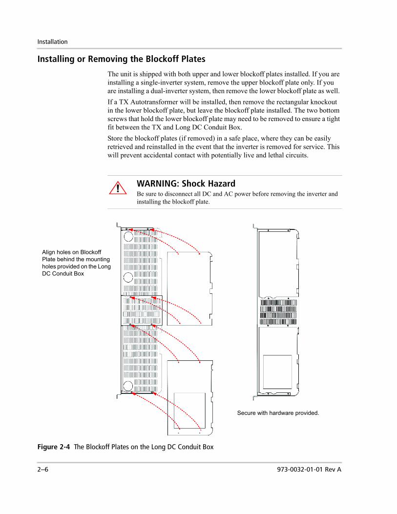
The unit is shipped with both upper and lower blockoff plates installed. If you are installing a single-inverter system, remove the upper blockoff plate only. If you are installing a dual-inverter system, then remove the lower blockoff plate as well. If a TX Autotransformer will be installed, then remove the rectangular knockout in the lower blockoff plate, but leave the blockoff plate installed. The two bottom screws that hold the lower blockoff plate may need to be removed to ensure a tight fit between the TX and Long DC Conduit Box.Store the blockoff plates (if removed) in a safe place, where they can be easily retrieved and reinstalled in the event that the inverter is removed for service. This will prevent accidental contact with potentially live and lethal circuits.
WARNING: Shock HazardBe sure to disconnect all DC and AC power before removing the inverter and installing the blockoff plate.
Figure 2-4 The Blockoff Plates on the Long DC Conduit Box
Align holes on Blockoff Plate behind the mounting holes provided on the Long DC Conduit Box
Secure with hardware provided.

Pre-installation
973-0032-01-01 Rev A 2–7
Knockout Preparation
Knockout preparation should be done before mounting either the inverter or the Long DC Conduit Box. To prepare the knockouts:1. Remove the appropriate knockouts from the Long DC Conduit Box for wire
runs from the battery bank, Renewable Energy sources and/or DC Generator, and Multi-function DC Charge Controllers (if used).
2. If additional CF- or GJ-type circuit breakers are to be added to the Long DC Conduit Box, remove one knockout on the circuit breaker mounting plate for each additional circuit breaker to be installed.
3. Ensure that there are no metal shavings in the Long DC Conduit Box or inverter before proceeding with the rest of the installation.
4. Install bushings in knockouts to protect the wires from damage.
Important: If larger knockouts are required, an electricians knockout punch may be used for larger size knockout holes if necessary.
Figure 2-5 Knockout Locations on the Long DC Conduit Box
Top
Outside Wall
Lower Blockoff Plate
½” Knockout (x3)
Base3/4 and 1” Dual Knockouts (x4)(two are not visible behind BSM mounting box in this illustration)
Knockout panel for CF- or GJ-type breakers
3/4 and 1” Dual Knockouts (x3)
3/4 and 1” Dual Knockouts (x13)
Bottom
2 and 2 ½” Dual Knockouts (x2)
2” Knockouts (x2)
2” Knockouts (x3)
One Rectangular Knockout only
3/4 and 1” Dual Knockouts (x5)2” Knockouts (x1)*
2 and 2 ½” Dual Knockouts (x2)**The 2” Knockouts on the outside wall are spaced 1 5/8” off the mounting surface (wall). This allows the use of 1 5/8” conduit mounting strut (aka Unistrut) to provide secure mounting for the large battery cable conduits. If using the XBP, a 1” spacer will be required.

Installation
2–8 973-0032-01-01 Rev A
MountingThe Long DC Conduit Box is designed to mount directly to the DC side of a SW Plus inverter. The SW Plus inverter can weigh up to 136 lbs (62 kg). The DCCB-L weighs up to 17 lbs (8 kg). Ensure the supporting surface is strong enough to hold twice the total weight being installed. Remember to include the weight of any other accessory, such as the AC conduit box and/or controllers, when considering the strength of the support surface.Xantrex provides a steel back plate (XBP) that provides the additional support. A sheet of 3/4" plywood could also provide adequate support.
Mounting the Long DC Conduit Box on the Xantrex Back Plate (XBP)
A two-piece steel, back plate is available for providing extra support to the mounting surface. The back plate comes with mounting hooks that can be attached to the panel to hang the components on as they’re installed. If two Long DC Conduit Boxs are to be installed, an additional back plate (XBP-DC) is available to provide the extra support required.
To mount the Long DC Conduit Box on the Back Plate (XBP):1. Install the mounting hook (if used) onto the back plate in the position
indicated in Figure 2-6.2. Mount the back plate according to the instructions provided with the XBP
Installation Instructions.
Figure 2-6 The XBP Back Plate
Mounting Hook for 2nd DCCB-L
Mounting Hook for 1st DCCB-L
Side View
35”(89 cm)
46”(117 cm)
XBP Left Side XBP Right Side
XBP-DC
Pass through holes for conduits running through the back of the back plate
Hand Holds for installing
Pass through holes for conduits running through the back of the back plate
13 1/2”(34 cm)

Mounting
973-0032-01-01 Rev A 2–9
3. Lift the inverter and place the mounting rail holes directly over the mounting hooks on the panel and lower into place.
4. Next, lift the Long DC Conduit Box and place it over the mounting hook for the DCCB-L and into the hole on the mounting rail.
5. Secure the inverter to the panel using the ten of the ¼-20 phillips screws provided with the back plate hardware kit. Torque to 76 in-lbs.
6. Push the Long DC Conduit Box as close to the inverter as it will possibly go and secure it to the panel using four of the ¼-20 phillips screws provided with the back plate hardware kit. Torque to 76 in-lbs.
Important: Ensure the mounting hooks are visible through the holes in the mounting rails. If you can not see the hooks, the unit is not installed properly and will not be secure to the wall.
Figure 2-7 Mounting the Long DC Conduit Box and the SW Plus Inverter Charger on the XBP
Be sure the mounting hooks are visible in the mounting rail holes
Mounting hook from backplate for Long DC Conduit Box
Secure the inverter and Long DC Conduit Box to the backplate with twelve ¼-20 phillips screws provided with the back plate.
IMPORTANT: Be sure to consult local electrical and building codes for additional mounting requirements.

Installation
2–10 973-0032-01-01 Rev A
Mounting on Plywood
To install the Long DC Conduit Box on plywood:1. Mount the inverter into place and secured with appropriate lag bolts. 2. Line up the Long DC Conduit Box at the DC end of the inverter, so that the
mounting rails are aligned together and the Long DC Conduit Box base is as close to the inverter as possible. The gap between the Long DC Conduit Box and the inverter should be no more than 1/16 inch.
3. Secure the Long DC Conduit Box in place with six #10 wood screws of an appropriate length (or lag bolts) in the six mounting and keyhole slots on the mounting rails of the Long DC Conduit Box. Bias the screws away from the inverter.
4. Leave the top cover off the Long DC Conduit Box to proceed with wire connections.
Figure 2-8 Mounting the Long DC Conduit Box and the Sine Wave Plus Inverter Charger on Plywood
Long DC Conduit Box Base with top cover removed
Mounting Rails
Mounting holes and keyhole slots for Long DC Conduit Box
Mounting holes and keyhole slots for Long DC Conduit Box
Bias the screws (top and bottom) away from the inverter for easier removal if necessary

Installing Accessories
973-0032-01-01 Rev A 2–11
Installing AccessoriesAdditional components may be required depending on the desired installation. Be sure to consult NEC/CEC regulations to ensure all installations meet code requirements.
GJ-Series Breakers Space is provided for up to three GJ-Series Breakers for over-current protection. Use either regular GJ-Series or GJ F-Series depending on the type of lugs used on the battery cables.
Flag Terminals If more than one GJ F-Type breaker is being used, they can be tied together using the dual-pole or triple-pole flag terminals. Regular GJ breakers can not use flag terminals.Both kinds of breakers can be used as a disconnect and/or an over-current device for the inverter(s) and the optional PDBs.
PVGFP-CF or CF60 Space is provided for up to six additional CF-Series Breakers for PV ground fault protection (PVGFP-CF) or load protection (CF60).To mount the GJ-Series or CF-Series Breakers:1. Place the circuit breaker behind the mounting plate in the position of the
knockout that was removed. 2. Align the hole of the circuit breaker with the hole in the mounting plate.3. Insert the mounting screw from the front of the mounting plate.
Tighten to the torque value indicated on the side of the breaker.
Power Distribution Blocks (PDB)
Install the PDB (if used) on the back wall of the Long DC Conduit Box chassis. Mounting holes are provided. PDBs are available in 6:1 and 12:1 sizes.
CF Mounting Plate (CFMP)
A separate mounting plate can be used if only CF breakers will be used. This mounting plate has 10 positions for CF-type Breakers. The CF Mounting replaces the existing mounting plate in the chassis.To install the CFMP:1. Remove the four nuts on the mounting screws holding the original mounting
plate in place. See Figure 2-10 on page 2–12.2. Slide the original mounting plate toward the back of the chassis away from
the screws and remove it.3. Slide the new CFMP into place and replace the nuts. 4. Tighten to 31 in-lbs.
Important: Ensure the position of the breaker lines up with the knockout removed in the Breaker Mounting plate.
CAUTION: Fire HazardEnsure the size of the breaker meets NEC/CEC requirements and is not oversized for the wire/cable used.

Installation
2–12 973-0032-01-01 Rev A
Figure 2-9 Installing Circuit Breakers on the Long DC Conduit Box
Figure 2-10 Optional Component Locations on the Long DC Conduit Box
DCCB-L
To install GJ or CF Circuit Breakers:1. Place the breaker behind the
mounting plate.2. Inserting mounting screws into
mounting holes from top, or front, of mounting plate.
3. Tighten to 20-25 in-lb.
Breaker Enlargement
Battery Status Meter
PVGFP-CF or CF-Type Breakers (PVGFP-CF -4 shown)
Triple Flag Terminal
GJ F-type Breakers
Power Distribution Block
To install the CFMP:1. Loosen the four nuts on the mounting
screws holding the original mounting plate in place (as shown above).
2. Slide the original mounting plate toward the back of the chassis away from the screws and remove it.
3. Slide the new CFMP into place and tighten the nuts.
4. Tighten to 31 in-lbs.
DC Negative Bus Bar and Shunt*
*Tighten the 10-32 phillips screws to 31 in-lbs when field-installing. Callout “C” in Figure 1-15 on page 1–13.
**Tighten the 1/4 x 20 phillips screws to 76 in-lbs when field-installing. Callout “A” in Figure 1-15 on page 1–13.
Dual DCCB-L Configurations (DCCB-L-RE)
973-0032-01-01 Rev A 2–13
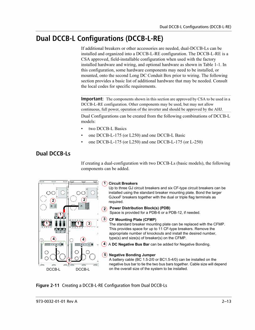
Dual DCCB-L Configurations (DCCB-L-RE)If additional breakers or other accessories are needed, dual-DCCB-Ls can be installed and organized into a DCCB-L-RE configuration. The DCCB-L-RE is a CSA approved, field-installable configuration when used with the factory installed hardware and wiring, and optional hardware as shown in Table 1-1. In this configuration, some hardware components may need to be installed, or mounted, onto the second Long DC Conduit Box prior to wiring. The following section provides a basic list of additional hardware that may be needed. Consult the local codes for specific requirements.
Dual Configurations can be created from the following combinations of DCCB-L models:• two DCCB-L Basics• one DCCB-L-175 (or L250) and one DCCB-L Basic• one DCCB-L-175 (or L250) and one DCCB-L-175 (or L-250)
Dual DCCB-Ls
If creating a dual-configuration with two DCCB-Ls (basic models), the following components can be added.
Important: The components shown in this section are approved by CSA to be used in a DCCB-L-RE configuration. Other components may be used, but may not allow continuous, full power, operation of the inverter and should be approved by the AHJ.
Figure 2-11 Creating a DCCB-L-RE Configuration from Dual DCCB-Ls
Circuit BreakersUp to three GJ circuit breakers and six CF-type circuit breakers can be installed using the standard breaker mounting plate. Bond the larger GJxxxF breakers together with the dual or triple flag terminals as required.
Power Distribution Block(s) (PDB)Space is provided for a PDB-6 or a PDB-12, if needed.
CF Mounting Plate (CFMP)The standard breaker mounting plate can be replaced with the CFMP. This provides space for up to 11 CF-type breakers. Remove the appropriate number of knockouts and install the desired number, type(s) and size(s) of breaker(s) on the CFMP.
Negative Bonding JumperA battery cable (BC 1.5-2/0 or BC1.5-4/0) can be installed on the negative bus bar to tie the two bus bars together. Cable size will depend on the overall size of the system to be installed.
A DC Negative Bus Bar can be added for Negative Bonding.
DCCB-LDCCB-L
1
2
3
4
5
1
2 2
3
4 4
5
1 1

Installation
2–14 973-0032-01-01 Rev A
Dual DCCB-L-175s (or L-250s)
It is also possible to add a second DCCB-L-175 or DCCB-L-250 to the end of an existing DCCB-L-175 or DCCB-L-250 to create the dual DC end shown in Figure 2-12. Minor reconfiguring of the factory installed 175A or 250A breaker and associated cables will be necessary. To prepare the second DCCB-L-175 (or DCCB-L-250) for use as the second DC end, the following steps will be necessary.
Figure 2-12 Creating a DCCB-L-RE Configuration from two DCCB-L-175 (or L-250)
2nd DCCB-L-175 (or L-250)
1st DCCB-L-175 (or L-250)
To convert a DCCB-L-175 or DCCB-L-250 to a Dual Configuration:1. Remove the DC breaker, positive cable, and
negative cable from the second DC end.2. If more than 6 CF breakers are needed in the
second DC end, remove the original GJ/CF breaker mounting plate in the second DC end and replace it with a CFMP.
3. Install the DC breaker (removed in step 1) in the first DC end adjacent to the inverter breakers. This new breaker will be used as the DC main bus overcurrent device/disconnect for charge controllers, other DC sources, and DC loads.
4. If needed, install a Power Distribution block (PDB-6 or PDB-12) in the second DC end.
5. Connect the DC positive cable (removed during step 1) to the DC main bus breaker (installed in step 3) and connect it to the PDB (Installed in step 4). Note: one end of the cable will need to be cut to length to fit into the PDB and a 2" chase bushing will be needed.
6. Use the negative cable (removed during step 1) as the negative bonding jumper between both DC negative bus bars in each DC end. Note: This cable can be used “as is” or cut to the required length if the appropriate crimper/lug is available or a Xantrex 18” cable may be purchased (p/n BC1.5B-2/0 or BC1.5B-4/0). A 2" chase bushing will also be needed.
7. Connect the #4 AWG ground wire from the second DC end equipment grounding bar to the first DC end equipment grounding bar.
1
2
3
4
5
6
7
2
3
445
6 6
7
Charge/Load Controllers
973-0032-01-01 Rev A 2–15
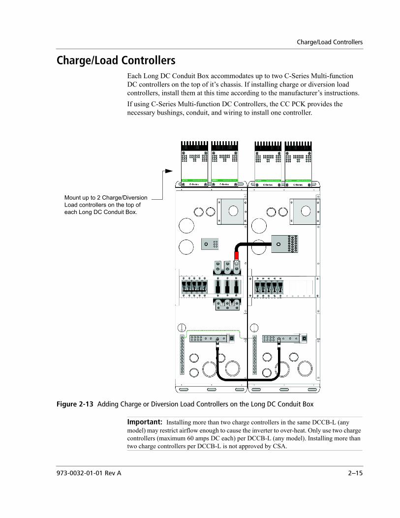
Charge/Load ControllersEach Long DC Conduit Box accommodates up to two C-Series Multi-function DC controllers on the top of it’s chassis. If installing charge or diversion load controllers, install them at this time according to the manufacturer’s instructions. If using C-Series Multi-function DC Controllers, the CC PCK provides the necessary bushings, conduit, and wiring to install one controller.
Figure 2-13 Adding Charge or Diversion Load Controllers on the Long DC Conduit Box
Important: Installing more than two charge controllers in the same DCCB-L (any model) may restrict airflow enough to cause the inverter to over-heat. Only use two charge controllers (maximum 60 amps DC each) per DCCB-L (any model). Installing more than two charge controllers per DCCB-L is not approved by CSA.
Mount up to 2 Charge/Diversion Load controllers on the top of each Long DC Conduit Box.

Installation
2–16 973-0032-01-01 Rev A
Wiring - General
Grounding the Long DC Conduit Box
The Long DC Conduit Box is used to ground the DC system. The purpose of grounding is to maintain all DC equipment at the same “ground” potential to avoid a shock hazard. It also provides a low impedance connection to shunt fault currents to earth. The following points should be taken into consideration when planning how to properly ground the DC system, whether or not you’re installing a new system or integrating new parts into an older system.• DC Equipment Grounding • Bonding DC Negative to Ground • Connecting to the Primary grounding system• Connecting DC and AC electrical system grounds together
WARNING: Shock HazardAlthough the DC electrical system may be “low voltage”, significant hazards may still be present, particularly from short-circuits of the battery system. Inverter systems, by their nature, involve power from multiple sources (e.g., inverter, generator, utility, batteries, and solar arrays) that add hazards and complexity that can be very challenging.
CAUTIONThe battery negative connection is only grounded at one point. This is usually the chassis bonding lug to the DC negative bus or bonded using the PVGFP-CF assembly.
CAUTION: Equipment DamageWhen making your DC connections, ensure there is nothing between the cable terminal/lug and the terminal surface (i.e., washers, anti-oxidant paste etc.). Overheating of the terminal may occur.
Important: The grounding requirements vary by county and by application. All installations must comply with national and local codes and ordinances. Consult local and/or national codes to ensure that proper grounding techniques are being employed and that the desired installation will meet all the code requirements when inspected. It is the responsibility of the installer to ensure the system meets all electrical codes for that jurisdiction. The following information is provided as a guide and is not intended to override applicable codes/requirements.

Wiring - General
973-0032-01-01 Rev A 2–17
DC Equipment Grounding
All DC components that have non-current carrying exposed metal parts require appropriate grounding. The Long DC Conduit Box provides the DC ground bar which will allow you to connect all the exposed metal chassis of the various DC components to the same point. The DC equipment will need to be connected to the DC ground bar using appropriately sized wires, referred to as equipment grounding conductors. Connecting these equipment grounding conductors to the DC ground bar will tie them together at the same voltage potential and provide a path to ground through the grounding electrode conductor. This reduces the possibility for electric shock and also provides a path for fault currents to flow through to blow fuses or trip circuit breakers. If two Long DC Conduit Boxes are used, ensure both DC ground bars are connected together using an appropriately sized equipment grounding conductor.
Equipment Grounding Conductor size
The equipment grounding conductor must have adequate ampacity and low enough impedance to cause the overcurrent device (fuse or circuit breaker) to open on the supply side in case an ungrounded conductor comes in contact with any exposed metal part of the DC system or equipment. In the United States, homes that have roof-mounted photovoltaic arrays are required to have ground-fault protection. In a DC system where there is ground-fault protection equipment, the size of the equipment grounding conductor should be coordinated with the size of the over-current devices for the DC equipment involved, as shown in Table 2-1. This table determines the minimum wire size of copper conductor you require, which is based on the size of the circuit breaker protecting the equipment that you are using in the DC system. This table also provides guidance on the torque requirements needed when attaching the corresponding wire to the ground bus bar.
In DC systems not required to use ground-fault protection equipment, the size of the equipment grounding conductor is required to be sized for 125 percent of the photovoltaic-originated short-circuit currents in that circuit. Consult PV array specifications and the NEC/CEC for proper wire sizes.
Important: The information in this section is based on a negative grounded DC system which is the normal configuration in most DC systems. If your system requires a positive ground, the information below will differ on what conductors are grounded and which are not. Consult the NEC/CEC regulations for positive grounding requirements.
Table 2-1 Minimum Equipment Ground Wire and DC Disconnect Size Chart
Battery DC Disconnect Size
Minimum Size of Copper Ground Wire
DCCB Ground Lug Wire Torque Spec
60 Amp #10 AWG 35 in-lb175 Amp #6 AWG 45 in-lb250 Amp #4 AWG 50 in-lb

Installation
2–18 973-0032-01-01 Rev A
Bonding DC Negative to Ground
The current carrying grounded conductors (DC negative) and the Equipment Grounding Conductors (green ground wires, equipment grounds) shall be tied or “bonded” together at a single point in the DC System. This connection is made with an appropriately sized wire as shown on Figure 2-15 on page 2–21, referred to as the Main Bonding Jumper. When an ungrounded conductor (DC positive) touches the grounding system, current will flow to the common grounding point (DC Ground Bar) through the Main Bonding Jumper to the grounded conductor (DC negative) and back to the source. This will cause the over-current protection device to open, which will stop the flow of current, protecting the system. In DC systems where there is a requirement to have a ground-fault protection device (PVGFP-CF) as shown on Figure 2-14 on page 2–20, it will effectively be the single point connection between the DC negative and the common grounding point (DC Ground Bar). In this application, if a DC ground-fault is detected, the ground-fault protection device will open and switch the grounding system from a low impedance, DC negative-to-ground bond to a high-impedance bond that will limit fault currents to a safe level.
Bonding location This single connection point or DC negative to ground “bond” is usually located in the over-current protection device enclosure (Long DC Conduit Box). The DC bond should not be done at the inverter. Codes do not generally allow this because the inverter is considered a “serviceable” item that may be removed from the system, in which case, the ground bond would be broken.
Size of the bonding jumper
For DC systems, the size of the bonding jumper that is used to bond the DC negative to the DC ground bar shall not be smaller than the size of the DC grounding electrode conductor used, which is the conductor that connects the DC ground bar to the primary system ground.
Connecting to the Primary System Ground
The common grounding point (DC Ground Bar) in the Long DC Conduit Box will need to be grounded to the Primary System Ground. The Primary System Ground is normally referred to as the grounding electrode or rod and usually is a copper-plated rod usually 5/8 inch round by 8 feet long and driven into the earth. It is also common to use copper wire placed in the concrete foundation of the building as a grounding system. Either method may be acceptable, but the local code will prevail. Connection to the Primary System Ground (ground rod/grounding electrode system) from the DC Ground Bar is done by the DC Grounding Electrode Conductor. The DC Grounding Electrode Conductor normally only carries current when there is a ground fault.
Important: Per the NEC, where ungrounded conductors (DC Positive) are increased in size (i.e. voltage drop, increased surge requirements), the DC Equipment Grounding Conductors shall be increased in size proportionately according to circular mil area of the ungrounded conductors.
Wiring - General
973-0032-01-01 Rev A 2–19
DC Grounding Electrode Conductor Size
The size for the DC Grounding Electrode Conductor when it is the DC systems sole connection to the Primary System Ground is not required to be larger than 6 AWG copper wire. It is recommended that the size of the DC Grounding Electrode Conductor should be larger than the NEC/CEC minimum requirements when installing power sources such as inverter/chargers, generators or for lightning protection.
Connecting DC and AC Electrical System Grounds Together
Inherently, Xantrex inverter systems have two separate electrical systems, a DC system and an AC system. This means the grounding consideration for both systems need to be accounted for and that the two electrical systems should be connected to a grounded, permanent wiring system with the AC and DC grounds common to each other. The NEC has provided two requirements, either using a single grounding electrode or using multiple grounding electrodes, when both DC and AC electrical systems are together:1. Single grounding electrode: The DC grounding electrode conductor and AC
grounding electrode conductor will be connected to a single grounding electrode. or,2. Multiple grounding electrodes: The DC grounding electrode conductor will be
connected between the DC grounding point to a separate DC grounding electrode. The DC grounding electrode will be connected to the AC grounding electrode to make a grounding electrode system. The conductor that connects the two ground electrodes will be no smaller than the largest grounding electrode conductor used – either AC or DC.
WARNING: Explosion HazardUnder no circumstance should a gas pipe or gas line be used for grounding purposes.

Installation
2–20 973-0032-01-01 Rev A
Figure 2-14 Grounding Using PVGFP-CF

Wiring - General
973-0032-01-01 Rev A 2–21
Figure 2-15 Grounding Without PVGFP-CF
Installation
2–22 973-0032-01-01 Rev A
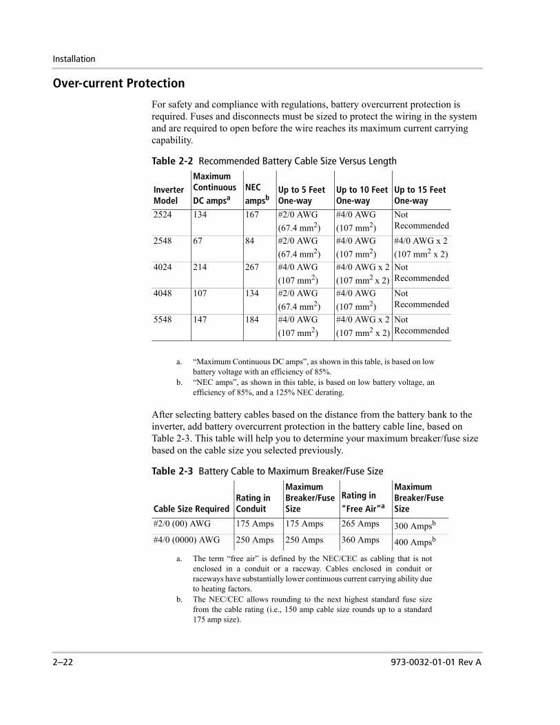
Over-current Protection
For safety and compliance with regulations, battery overcurrent protection is required. Fuses and disconnects must be sized to protect the wiring in the system and are required to open before the wire reaches its maximum current carrying capability.
After selecting battery cables based on the distance from the battery bank to the inverter, add battery overcurrent protection in the battery cable line, based on Table 2-3. This table will help you to determine your maximum breaker/fuse size based on the cable size you selected previously.
Table 2-2 Recommended Battery Cable Size Versus Length
InverterModel
Maximum ContinuousDC ampsa
a. “Maximum Continuous DC amps”, as shown in this table, is based on lowbattery voltage with an efficiency of 85%.
NEC ampsb
b. “NEC amps”, as shown in this table, is based on low battery voltage, anefficiency of 85%, and a 125% NEC derating.
Up to 5 Feet One-way
Up to 10 Feet One-way
Up to 15 Feet One-way
2524 134 167 #2/0 AWG(67.4 mm2)
#4/0 AWG(107 mm2)
Not Recommended
2548 67 84 #2/0 AWG(67.4 mm2)
#4/0 AWG(107 mm2)
#4/0 AWG x 2(107 mm2 x 2)
4024 214 267 #4/0 AWG(107 mm2)
#4/0 AWG x 2(107 mm2 x 2)
Not Recommended
4048 107 134 #2/0 AWG(67.4 mm2)
#4/0 AWG(107 mm2)
Not Recommended
5548 147 184 #4/0 AWG(107 mm2)
#4/0 AWG x 2(107 mm2 x 2)
Not Recommended
Table 2-3 Battery Cable to Maximum Breaker/Fuse Size
Cable Size RequiredRating in Conduit
Maximum Breaker/Fuse Size
Rating in “Free Air”a
a. The term “free air” is defined by the NEC/CEC as cabling that is notenclosed in a conduit or a raceway. Cables enclosed in conduit orraceways have substantially lower continuous current carrying ability dueto heating factors.
Maximum Breaker/Fuse Size
#2/0 (00) AWG 175 Amps 175 Amps 265 Amps 300 Ampsb
b. The NEC/CEC allows rounding to the next highest standard fuse sizefrom the cable rating (i.e., 150 amp cable size rounds up to a standard175 amp size).
#4/0 (0000) AWG 250 Amps 250 Amps 360 Amps 400 Ampsb

Wiring - General
973-0032-01-01 Rev A 2–23
Master DC Disconnect
The DCCB-L has been designed for the use of a DC main breaker as a master disconnect for charge controllers, DC loads, and other DC sources. The same disconnect(s) used for the inverter(s) should not be used as a controller and/or DC load disconnect. Instead, an independent disconnect for a DC bus is recommended to allow controllers and/or DC loads to operate when an inverter has been disconnected or vise versa (see Figure 2-21 on page 2–30). A CF60 may be used as a 60A DC bus disconnect using a 1" breaker slot and a GJ175F or GJ250F can be used as a 175A or 250A DC bus disconnect using a 1.5" breaker slot. The use of a main DC disconnect can help comply with the intent of the NEC’s "six hand throw requirement" to disable an electrical system within six motions of the hand.Some wind and water turbines, along with their controllers, may need to be wired directly to the battery bank or on a dedicated line to prevent from being inadvertently disconnected and causing a damaging, over-speed condition. Consult your turbine manufacturer's instructions for a wiring schematic and to determine if the turbine is fail-safe with loss of connection to the battery.
CAUTION: Equipment DamageDo not allow any device to be wired so that an inverter will be exposed to the open circuit voltage if any disconnects are opened. If the voltage is high enough it may damage the inverter and would not be covered under warranty.

Installation
2–24 973-0032-01-01 Rev A
Additional Over-current Protection
Depending on individual installation requirements, additional over-current devices (fuses or circuit breakers) may be desirable and/or required. The GJ F breakers used on DCCB-L models can be used both as a disconnect and an over-current device if inverter is overloaded or has an internal fault. However, additional over-current devices may be required.
Near battery bank The GJ F breakers will not provide over-current protection if there is a wiring fault between the battery bank and the breaker(s). It may be desirable to add an over-current device adjacent to the battery bank positive terminal particularly if metallic (conductive) conduits are used. Non-metallic (PVC etc.) conduits may negate this risk and need.
When using triple flag terminals
When using the triple flag terminals for the GJ F breakers, additional steps may be required to prevent over loading of the battery cables in the event of one cable is removed or becomes inadvertently disconnected. Use of the triple flag terminal on dual inverters will functionally "parallel" the battery cable conductors. This is permitted by the NEC 310.4 for cable 1/0 and larger. Specialized lugs are required to connect multiple parallel conductors into a common single conductor.
Large Loads or Diversion Loads
In addition, the dual-pole and triple-pole flag terminals when used on systems with large diversion loads and/or DC loads with inverters operating at full load could theoretically exceed the rated capacity of the conductors between the battery bank and the dual-pole or triple-pole flag terminal attached on the GJ F breakers thus requiring an additional over-current device. If the battery bank can not provide this level of current (+500 Adc for #4/0 AWG cable) for a theoretical continuous load (greater than 3 hours), then a over-current device sized specifically for the paralleled cable assembly may not be required.
Charge Controllers Charge controllers should be connected to a dedicated breaker that will allow them to function while the inverter breaker is in the off position. Connecting the "battery terminal" on charge controllers to the inverter side connection of a GJ F breaker will operate but is not recommended.

Wiring - General
973-0032-01-01 Rev A 2–25
Battery Cable Connection
Connect the battery cables for a single-inverter system as shown in Figure 2-16.
Important: NEC requires all grounded conductors larger than #6 AWG (such as battery cables) to be marked with white tape or heat shrink on their ends to visibly show correct polarity to prevent reverse polarity and shorting.
Figure 2-16 Battery Connections for a Single-inverter System

Installation
2–26 973-0032-01-01 Rev A
Connect the battery cables for a dual-inverter system as shown in Figure 2-17.
Important: NEC requires all grounded conductors larger than #6 AWG (such as battery cables) to be marked with white tape or heat shrink on their ends to visibly show correct polarity to prevent reverse polarity and shorting.
Figure 2-17 Battery Connections for a Dual-inverter System

Wiring - Specific
973-0032-01-01 Rev A 2–27
Wiring - SpecificThe following four diagrams illustrate how to make all the ground connections, battery connections, controller connections, and renewable energy connections for the basic configurations. They include:• Single inverter systems with no renewable energy• Single inverter systems with renewable energy• Dual inverters with renewable energy• Dual inverters with multiple renewable energy.These diagrams are basic examples only and may vary depending upon your specific installation. Ensure appropriate local electrical codes are followed at all times.
Single Inverter System
The following example diagram illustrates the proper DC wiring for a basic, single-inverter system.
Figure 2-18 DC Wiring for a Single Inverter System

Installation
2–28 973-0032-01-01 Rev A
Single Inverter System with Renewable Energy
The following example diagram illustrates the proper DC wiring for a single inverter system with renewable energy.
Figure 2-19 DC Wiring for a Single Inverter System with Renewable Energy

Wiring - Specific
973-0032-01-01 Rev A 2–29
Dual Inverter System with Renewable Energy
The following example diagram illustrates the proper DC wiring for a dual inverter system with renewable energy.
Figure 2-20 DC Wiring for a Dual Inverter System with Renewable Energy

Installation
2–30 973-0032-01-01 Rev A
Dual Inverter System with Multiple Renewable Energy
The following example diagram illustrates the proper DC wiring for a dual inverter system with dual DCCB-Ls and multiple renewable energy.
Figure 2-21 DC Wiring for a Dual Inverters, Dual Long DC Conduit Box System with Multiple RE

Wiring - Specific
973-0032-01-01 Rev A 2–31
Additional Accessory Wiring
Install additional accessories at this time, such as the Battery Status Monitor (BSM) (p/n TM500A and TM500A-NS) and Battery Temperature Sensors.
Battery Status Monitor (BSM) (p/n TM500A or TM500A-NS)
To install the BSM on the Long DC Conduit Box:1. Remove the cover plate from the BSM Mounting Box.2. Install the shunt board from the BSM to the shunt in the DCCB-L.3. Secure the BSM to the mounting box.4. Connect the BSM communications cable to the back of the BSM.5. Connect the other end of the BSM communications cable to the port on the
shunt.
See the Installation and Operator’s Guide for the BSM (TM500A) for additional information.
Figure 2-22 Installing the BSM on the Long DC Conduit Box
Remove the phillips screw to remove cover plate from the mounting box.
Install the shunt board from the BSM to the shunt in the DCCB-L.
Place the faceplate of the BSM over the mounting bracket and snap into place.
Connect the J1 communications cable to the back of the BSM and route it through the hole in the back of the mounting box.
Route the other end of the communi-cations cable to the current shunt board installed on the DC negative bus bar.
Place the mounting bracket over the mounting box and secure with the four plastic push rivets provided with the Long DC Conduit Box. The rivets will snap into place when pressed into the holes.
12
3
4
5
1
Install the 2 amp, 250 Vac, 3AG style in-line fuse that’s provided with the BSM.
2 3
4
6
7
Enlargement of Back of BSM
Install the bushing provided in the hole in the mounting box to protect the communications cable.
5
6
7
8
8
BSM Mounting Bracket
Plastic Push Rivets (4x)

Installation
2–32 973-0032-01-01 Rev A
Charge Controller Wiring using the C-Series Multifunction DC Controller and the CC PCK
The Charge Controller add-on package (CC PCK) includes the following hardware to facilitate wiring one C-Series Multifunction DC Controller to the Long DC Conduit Box: • two conduit chase nipples, two lock nuts, and two plastic bushings for
1" knockouts,• one 48-inch white #6 AWG wire (temperature rated at 90° C),• one 96-inch red #6 AWG wire (temperature rated at 90° C), and• one 48-inch green #10 AWG wire (temperature rated at 105° C).Follow the procedure below to prepare the units and install the wires.
Figure 2-23 Wiring the C-Series Multifunction Charge Controllers to the Long DC Conduit Box using the CC PCK
Remove two 1” knockouts in the bottom of the controller. (Step not shown in illustration).
Align the knockouts in the controller over the knockouts in the DCCB-L and install the conduit chase nipples, bushings, and lock nuts. (Step not shown in illustration).
Connect one end of the green ground wire (#10 AWG) to the chassis ground in the controller. Route the other end to the DC ground bar in the DCCB-L.
2
3
5
1
Remove two corresponding 1” knockout s in the top of the DCCB-L (Step not shown in illustration).
Connect one end of the white wire (#6 AWG) to one of the common negatives in the controller. Route the other end to the DC Negative Bus Bar.
Cut the 96-inch red #6 AWG wire into two pieces (length to depend on the placement of the circuit breakers). (Step not shown in illustration.)
6
4
To prepare the units for wiring:
To connect the wiring:
Connect one of the pieces of red #6 AWG wire to the Battery Positive terminal in the Controller and the other end to the top of the CF Circuit Breaker for the over-current protection.
Connect the other piece of red #6 AWG wire to the PV/Load Positive terminal in the Controller and the other end to the top of the CF Circuit Breaker for the PV or Load Disconnect. If PVGFP is required, then substitute the CF Circuit Breaker for the Load with a PVGFP-CF.
7
8
9 Repeat for each controller to be installed.
5 6
7
8
Over-current Protection
PV Array/Load Disconnect

Wiring - Specific
973-0032-01-01 Rev A 2–33
Battery Temperature Sensor
If you have a BTS connected to your battery, then you will need to pass its connecting wire through the Long DC Conduit Box to the DC side of the inverter (see Figure 2-24).If you have a BTS connected to your C-Series Multi-function DC controller, you can also run that wire through the Long DC Conduit Box.To run the BTS through the Long DC Conduit Box:1. Secure the BTS to a battery in the battery box. Connect multiple sensors to
one battery in a centralized location that will give the best representation of all the batteries temperatures.
2. Run the BTS cable(s) through the DC cable conduit.3. Connect the cable(s) to the inverter’s Battery Temperature Sensor Ports or the
C-Series Battery Temperature Ports.See your inverter manual and BTS manual for further information about the installation of this accessory.
Figure 2-24 BTS Port locations on the Sine Wave Plus Inverter
Figure 2-25 BTS Port locations on the C-Series DC Controller
Positive (+) Battery Cable Terminal
Negative (–) Battery Cable Terminal
Battery Temperature Sensor Port
Chassis Ground Lug
Battery Temperature Sensor Port

Installation
2–34 973-0032-01-01 Rev A
This completes the basic wiring for the Long DC Conduit Box. Once all wiring is complete, refer to the Sine Wave Plus Owner’s Manual for functional test, configuration, and operational instructions.
Figure 2-26 Installing the Battery Temperature Sensor
Battery Temperature Sensor Cable. Can also be routed to DC Controller.
973-0032-01-01 Rev A WA–1
Warranty and Return Information
WarrantyWhat does this warranty cover? This Limited Warranty is provided by Xantrex Technology, Inc. ("Xantrex") and covers defects in workmanship and materials in your Long DC Conduit Box. This warranty period lasts for two years from the date of purchase at the point of sale to you, the original end user customer. You require proof of purchase to make warranty claims.This Limited Warranty is transferable to subsequent owners but only for the unexpired portion of the Warranty Period. Subsequent owners also require proof of purchase.What will Xantrex do? Xantrex will, at its option, repair or replace the defective product free of charge, provided that you notify Xantrex of the product defect within the Warranty Period, and provided that Xantrex through inspection establishes the existence of such a defect and that it is covered by this Limited Warranty. Xantrex will, at its option, use new and/or reconditioned parts in performing warranty repair and building replacement products. Xantrex reserves the right to use parts or products of original or improved design in the repair or replacement. If Xantrex repairs or replaces a product, its warranty continues for the remaining portion of the original Warranty Period or 90 days from the date of the return shipment to the customer, whichever is greater. All replaced products and all parts removed from repaired products become the property of Xantrex.Xantrex covers both parts and labor necessary to repair the product, and return shipment to the customer via a Xantrex-selected non-expedited surface freight within the contiguous United States and Canada. Alaska and Hawaii are excluded. Contact Xantrex Customer Service for details on freight policy for return shipments outside of the contiguous United States and Canada.
How do you get service? If your product requires troubleshooting or warranty service, contact your merchant. If you are unable to contact your merchant, or the merchant is unable to provide service, contact Xantrex directly at:
Direct returns may be performed according to the Xantrex Return Material Authorization Policy described in your product manual. For some products, Xantrex maintains a network of regional Authorized Service Centers. Call Xantrex or check our website to see if your product can be repaired at one of these facilities.
What proof of purchase is required? In any warranty claim, dated proof of purchase must accompany the product and the product must not have been disassembled or modified without prior written authorization by Xantrex. Proof of purchase may be in any one of the following forms:• The dated purchase receipt from the original purchase of the product at point of sale to the end user, or• The dated dealer invoice or purchase receipt showing original equipment manufacturer (OEM) status, or• The dated invoice or purchase receipt showing the product exchanged under warranty
Telephone: 1 800 670 0707 (toll free North America)1 360 925 5097 (direct)
Fax: 1 800 994 7828 (toll free North America)1 360 925 5143 (direct)
Email: [email protected]

Warranty and Return
WA–2 973-0032-01-01 Rev A
What does this warranty not cover? This Limited Warranty does not cover normal wear and tear of the product or costs related to the removal, installation, or troubleshooting of the customer's electrical systems. This warranty does not apply to and Xantrex will not be responsible for any defect in or damage to:a) the product if it has been misused, neglected, improperly installed, physically damaged or altered, either inter-
nally or externally, or damaged from improper use or use in an unsuitable environment;b) the product if it has been subjected to fire, water, generalized corrosion, biological infestations, or input voltage
that creates operating conditions beyond the maximum or minimum limits listed in the Xantrex product specifi-cations including high input voltage from generators and lightning strikes;
c) the product if repairs have been done to it other than by Xantrex or its authorized service centers (hereafter "ASCs");
d) the product if it is used as a component part of a product expressly warranted by another manufacturer;e) the product if its original identification (trade-mark, serial number) markings have been defaced, altered, or
removed.
Disclaimer
ProductTHIS LIMITED WARRANTY IS THE SOLE AND EXCLUSIVE WARRANTY PROVIDED BY XANTREX IN CONNECTION WITH YOUR XANTREX PRODUCT AND IS, WHERE PERMITTED BY LAW, IN LIEU OF ALL OTHER WARRANTIES, CONDITIONS, GUARANTEES, REPRESENTATIONS, OBLIGATIONS AND LIABILITIES, EXPRESS OR IMPLIED, STATUTORY OR OTHERWISE IN CONNECTION WITH THE PRODUCT, HOWEVER ARISING (WHETHER BY CONTRACT, TORT, NEGLIGENCE, PRINCIPLES OF MANUFACTURER'S LIABILITY, OPERATION OF LAW, CONDUCT, STATEMENT OR OTHERWISE), INCLUDING WITHOUT RESTRICTION ANY IMPLIED WARRANTY OR CONDITION OF QUALITY, MERCHANTABILITY OR FITNESS FOR A PARTICULAR PURPOSE. ANY IMPLIED WARRANTY OF MERCHANTABILITY OR FITNESS FOR A PARTICULAR PURPOSE TO THE EXTENT REQUIRED UNDER APPLICABLE LAW TO APPLY TO THE PRODUCT SHALL BE LIMITED IN DURATION TO THE PERIOD STIPULATED UNDER THIS LIMITED WARRANTY.IN NO EVENT WILL XANTREX BE LIABLE FOR ANY SPECIAL, DIRECT, INDIRECT, INCIDENTAL OR CONSEQUENTIAL DAMAGES, LOSSES, COSTS OR EXPENSES HOWEVER ARISING WHETHER IN CONTRACT OR TORT INCLUDING WITHOUT RESTRICTION ANY ECONOMIC LOSSES OF ANY KIND, ANY LOSS OR DAMAGE TO PROPERTY, ANY PERSONAL INJURY, ANY DAMAGE OR INJURY ARISING FROM OR AS A RESULT OF MISUSE OR ABUSE, OR THE INCORRECT INSTALLATION, INTEGRATION OR OPERATION OF THE PRODUCT.
ExclusionsIf this product is a consumer product, federal law does not allow an exclusion of implied warranties. To the extent you are entitled to implied warranties under federal law, to the extent permitted by applicable law they are limited to the duration of this Limited Warranty. Some states and provinces do not allow limitations or exclusions on implied warranties or on the duration of an implied warranty or on the limitation or exclusion of incidental or consequential damages, so the above limitation(s) or exclusion(s) may not apply to you. This Limited Warranty gives you specific legal rights. You may have other rights which may vary from state to state or province to province.
Warning: Limitations On UsePlease refer to your product manual for limitations on uses of the product. SPECIFICALLY, PLEASE NOTE THAT THE SINE WAVE PLUS LONG DC CONDUIT BOX SHOULD NOT BE USED IN CONNECTION WITH LIFE SUPPORT SYSTEMS OR OTHER MEDICAL EQUIPMENT OR DEVICES. WITHOUT LIMITING THE GENERALITY OF THE FOREGOING, XANTREX MAKES NO REPRESENTATIONS OR WARRANTIES REGARDING THE USE OF THE XANTREX SINE WAVE PLUS LONG DC CONDUIT BOX IN CONNECTION WITH LIFE SUPPORT SYSTEMS OR OTHER MEDICAL EQUIPMENT OR DEVICES.
Please note that the Sine Wave Plus Long DC Conduit Box is not intended for use as an uninterruptible power supply and Xantrex makes no warranty or representation in connection with any use of the product for such purposes.

Warranty and Return
973-0032-01-01 Rev A WA–3
Return Material Authorization PolicyBefore returning a product directly to Xantrex you must obtain a Return Material Authorization (RMA) number and the correct factory "Ship To" address. Products must also be shipped prepaid. Product shipments will be refused and returned at your expense if they are unauthorized, returned without an RMA number clearly marked on the outside of the shipping box, if they are shipped collect, or if they are shipped to the wrong location.When you contact Xantrex to obtain service, please have your instruction manual ready for reference and be prepared to supply:• The serial number of your product• Information about the installation and use of the unit• Information about the failure and/or reason for the return• A copy of your dated proof of purchaseRecord these details in on page WA–4.
Return Procedure1. Package the unit safely, preferably using the original box and packing materials. Please ensure that your product
is shipped fully insured in the original packaging or equivalent. This warranty will not apply where the product is damaged due to improper packaging.
2. Include the following:• The RMA number supplied by Xantrex Technology, Inc. clearly marked on the outside of the box.• A return address where the unit can be shipped. Post office boxes are not acceptable.• A contact telephone number where you can be reached during work hours.• A brief description of the problem.
3. Ship the unit prepaid to the address provided by your Xantrex customer service representative.
If you are returning a product from outside of the USA or Canada In addition to the above, you MUST include return freight funds and are fully responsible for all documents, duties, tariffs, and deposits.
If you are returning a product to a Xantrex Authorized Service Center (ASC)A Xantrex return material authorization (RMA) number is not required. However, you must contact the ASC prior to returning the product or presenting the unit to verify any return procedures that may apply to that particular facility.
Out of Warranty ServiceIf the warranty period for your Sine Wave Plus Long DC Conduit Box has expired, if the unit was damaged by misuse or incorrect installation, if other conditions of the warranty have not been met, or if no dated proof of purchase is available, your inverter may be serviced or replaced for a flat fee.To return your Sine Wave Plus Long DC Conduit Box for out of warranty service, contact Xantrex Customer Service for a Return Material Authorization (RMA) number and follow the other steps outlined in “Return Procedure” on page WA–3. Payment options such as credit card or money order will be explained by the Customer Service Representative. In cases where the minimum flat fee does not apply, as with incomplete units or units with excessive damage, an additional fee will be charged. If applicable, you will be contacted by Customer Service once your unit has been received.

Warranty and Return
WA–4 973-0032-01-01 Rev A
Information About Your SystemAs soon as you open your Sine Wave Plus Long DC Conduit Box package, record the following information and be sure to keep your proof of purchase.
If you need to contact Customer Service, please record the following details before calling. This information will help our representatives give you better service.
❐ Serial Number _________________________________
❐ Purchased From _________________________________
❐ Purchase Date _________________________________
❐ Type of installation (e.g. RV, truck, residential) __________________________________
❐ Length of time inverter has been installed __________________________________
❐ Battery/battery bank size __________________________________
❐ Battery type (e.g. flooded, sealed gel cell, AGM) __________________________________
❐ DC wiring size and length __________________________________
❐ Alarm sounding? __________________________________
❐ Description of indicators on front panel __________________________________
❐ Appliances operating when problem occurred __________________________________
❐ Description of problem __________________________________
______________________________________________________________________________________
______________________________________________________________________________________

Aabbreviations and acronyms vAccessories 2–11Accessory Wiring 2–31additional accessory wiring 2–33
BBattery Status Monitor 2–31Battery Temperature Sensor 2–33Battery Temperature Sensor (BTS) 2–33Blockoff Plates 2–6Bonding DC Negative to Ground 2–18Bonding location 2–18
CCF Mounting Plate (CFMP) 2–11CF60 2–11Charge/Load Controllers 2–15Connecting DC and AC Electrical System Grounds
Together 2–19Customer Service
preparing to call WA–4
DDC conduit box
introduction 1–2DC Equipment Grounding 2–17DC Grounding Electrode Conductor Size 2–19DCCB-L-RE 2–13Dual DCCB-L Configurations 2–13
FFlag Terminals 2–11
GGJ-Series Breakers 2–11Grounding 2–16
IInformation about Your System form WA–4installation
codes 2–2knockout preparation 2–7materials 2–2tools 2–2
inverterpurchase date WA–4serial number WA–4
KKnockout Preparation 2–7knockouts
preparation 2–7
MMaster DC Disconnect 2–23materials required for installation 2–2Mounting 2–8
Oovercurrent protection, requirements 2–22
PPower Distribution Blocks (PDB) 2–11proof of purchase WA–4purchase date WA–4PV GFP 2–11
SSafety Instructions viiserial number WA–4Size of the bonding jumper 2–18
TTM500A 2–31TM500A-NS) 2–31tools required for installation 2–2
Index
IX-2
VVentilation Requirements 2–4
Wwarranty
out of warranty service WA–3terms and conditions WA–1
wiringadditional accessory 2–33
XXantrex
web site v

Xantrex Technology Inc.
1 800 670 0707 Tel. toll free NA1 360 925 5097 Tel. direct1 800 994 7828 Fax toll free NA1 360 925 5143 Fax [email protected]
973-0032-01-01 PC Printed in USA