single-axis linear motor stage ssa - hiwinmectrol.com
TRANSCRIPT
www.hiwinmikro.tw
User Manual
Single-Axis Linear Motor StageSSA

Contents CONTENTS 1
1. GENERAL INFORMATION 1
1.1 ABOUT THIS USER MANUAL ................................ 1 1.2 DEPICTIONS USED IN THIS USER MANUAL ........... 1
1.3 MANUFACTURER’S DETAILS ............................... 3
1.4 COPYRIGHT ..................................................... 3
1.5 PRODUCT MONITORING ..................................... 3
2. BASIC SAFETY NOTICES 4
2.1 INTENDED USE ................................................. 4
2.2 REASONABLY FORESEEABLE MISUSE ................. 4
2.3 CONVERSIONS AND MODIFICATIONS ................... 4
2.4 RESIDUAL RISKS ............................................... 5
2.5 PERSONNEL REQUIREMENTS ............................. 5
2.6 PROTECTIVE EQUIPMENT .................................. 5
2.7 LABELS ON LINEAR MOTOR SYSTEM ................... 6
3. DESCRIPTION OF THE LINEAR MOTOR SYSTEM 7
3.1 FIELD OF APPLICATION ...................................... 7
3.2 MAIN COMPONENTS OF THE LINEAR MOTOR SYSTEM .. 7
3.3 FUNCTIONAL DESCRIPTION ................................ 8
4. TRANSPORT AND INSTALLATION 10
4.1 DELIVERY ...................................................... 10
4.2 TRANSPORT TO THE INSTALLATION SITE ........... 10
4.3 REQUIREMENTS AT THE INSTALLATION SITE ...... 12
4.4 STORAGE....................................................... 12
4.5 UNPACKING AND INSTALLING ........................... 13
5. ASSEMBLY AND CONNECTION 14
5.1 ASSEMBLING THE LINEAR MOTOR SYSTEM ........ 15
5.2 ASSEMBLING THE MOVED LOAD ....................... 16
5.3 ELECTRICAL CONNECTION ............................... 16
6. COMMISSIONING 19
6.1 SWITCH ON THE LINEAR MOTOR SYSTEM .......... 19
6.2 PROGRAMMING .............................................. 20
7. MAINTENANCE AND CLEANING 21
7.1 LINEAR MOTOR ............................................... 23
7.2 POSITIONING MEASUREMENT SYSTEM .............. 23
7.3 ELECTROMECHANICAL COMPONENTS............... 23
7.4 LINEAR GUIDEWAYS ........................................ 23
8. TROUBLESHOOTING 25
9. DISPOSAL 26
10. DECLARATION OF INCORPORATION 27
1
MM06UE01-2002
1. General information 1.1 About this user manual 1.1.1 Version management
Table 1.1 Version management Version Date Comment 01-1 Dec 2019 Primary issue
1.1.2 Requirements
We assume that ● operating staff are trained in the safe operation practices for linear motor systems and have read and
understood this user manual in full; ● maintenance staff maintain and repair the linear motor systems in such a way that they pose no danger to
people, property or the environment. 1.1.3 Availability
This user manual must remain constantly available to all persons who work with or on the linear motor systems. 1.2 Depictions used in this user manual 1.2.1 Instructions
Instructions are indicated by triangular bullet points in the order in which they are to be carried out. Example: Position the linear motor system on the mounting holes. Place the mounting bolts into the mounting holes and tighten in a spiral pattern to a torque of 10 Nm. 1.2.2 Lists
Lists are indicated by bullet points. Example: The linear motor systems must not be operated: ● Outdoors ● In potentially explosive atmospheres 1.2.3 Information
Information is to describe general information and recommendations. Example:
Please contact HIWIN for special requests.
1.2.4 Depiction of safety notices
2
MM06UE01-2002
Safety notices are always indicated using a signal word and sometimes also a symbol for the specific risk (See section 1.2.4). The following signal words and risk levels are used:
DANGER! Imminent danger! Non-compliance with the safety notices will result in serious injury or death!
WARNING! Potentially dangerous situation! Non-compliance with the safety notices runs the risk of serious injury or death!
ATTENTION! Potentially dangerous situation! Non-compliance with the safety notices runs the risk of damage to property or environmental pollution!
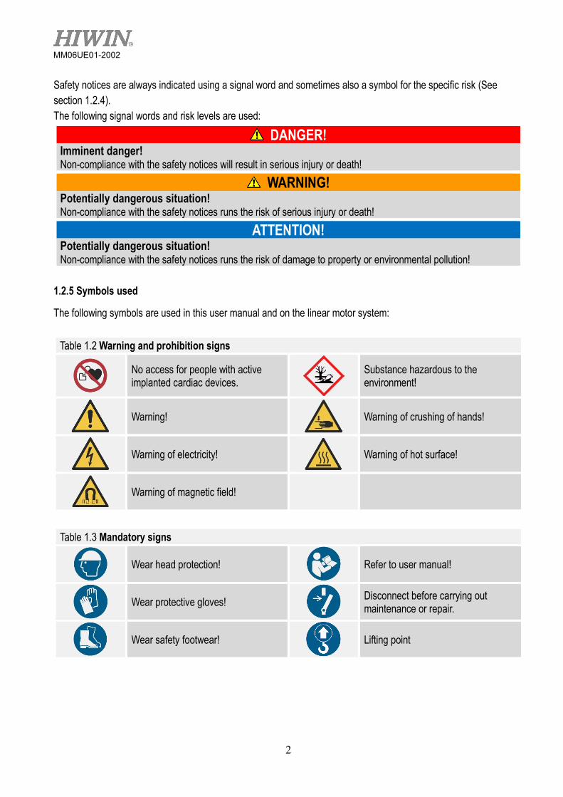
1.2.5 Symbols used
The following symbols are used in this user manual and on the linear motor system:
Table 1.2 Warning and prohibition signs
No access for people with active implanted cardiac devices.
Substance hazardous to the environment!
Warning!
Warning of crushing of hands!
Warning of electricity!
Warning of hot surface!
Warning of magnetic field!
Table 1.3 Mandatory signs
Wear head protection!
Refer to user manual!
Wear protective gloves!
Disconnect before carrying out maintenance or repair.
Wear safety footwear!
Lifting point
3
MM06UE01-2002
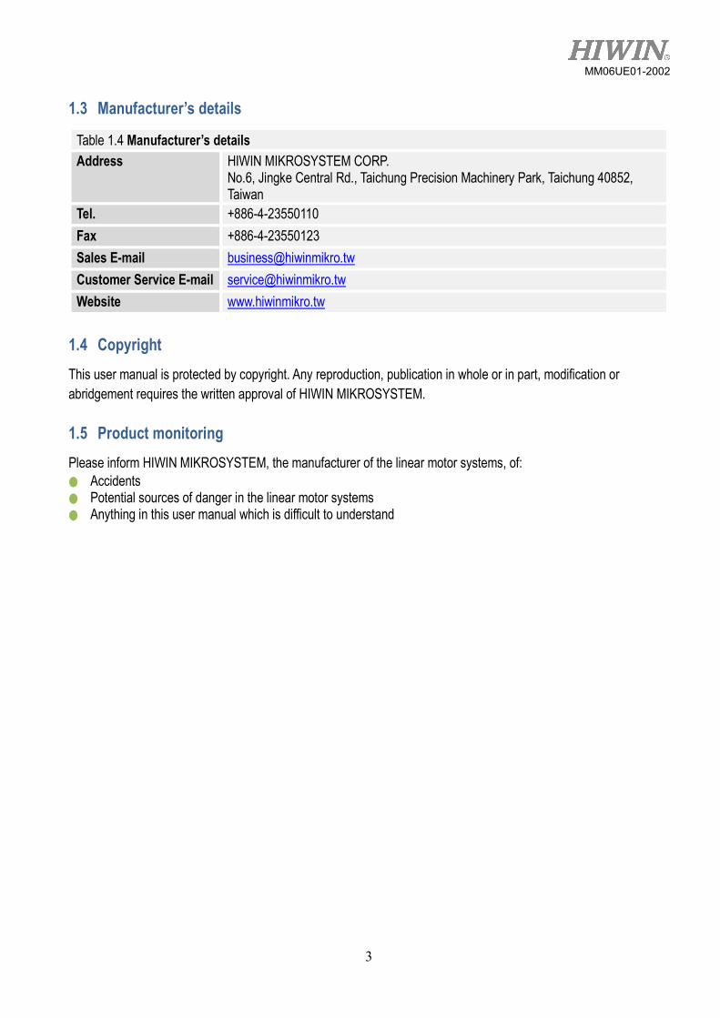
1.3 Manufacturer’s details
Table 1.4 Manufacturer’s details Address HIWIN MIKROSYSTEM CORP.
No.6, Jingke Central Rd., Taichung Precision Machinery Park, Taichung 40852, Taiwan
Tel. +886-4-23550110 Fax +886-4-23550123 Sales E-mail [email protected] Customer Service E-mail [email protected] Website www.hiwinmikro.tw
1.4 Copyright This user manual is protected by copyright. Any reproduction, publication in whole or in part, modification or abridgement requires the written approval of HIWIN MIKROSYSTEM. 1.5 Product monitoring Please inform HIWIN MIKROSYSTEM, the manufacturer of the linear motor systems, of: ● Accidents ● Potential sources of danger in the linear motor systems ● Anything in this user manual which is difficult to understand

4
MM06UE01-2002
2. Basic safety notices DANGER!
Danger from strong magnetic fields! Strong magnetic fields around linear motor systems pose a health risk to persons with implants (e.g. cardiac pacemakers) that are affected by magnetic fields. Persons with implants that are affected by magnetic fields should maintain a safe distance of at
least 1 m from linear motor systems.
ATTENTION!
Risk of physical damage to watches and magnetic storage media. Strong magnetic forces may destroy watches and magnetisable data storage media near to the linear motor system! Do not bring watches or magnetisable data storage media into the vicinity (<300 mm) of the
linear motor systems! 2.1 Intended use The linear motor system is a linear drive and guiding system for the precise positioning of fixed mounted loads, e.g. system components within an automated system, in terms of time and location. The LMX and LMAP linear motor systems are designed for installation and operation in horizontal positions and therefore do not feature parking brakes in their standard versions. In the case of vertical assembly, a parking brake, weight compensation device or both must be retrofitted. The loads to be moved must either be mounted on to the forcer or the base. The linear axes can be mounted on top of one another to create multi-axis systems. The specified linear motor systems may not be used outdoors or in hazardous areas where there is a risk of explosions. All linear motor systems may only be used for the stated intended purpose. ● The linear motor system must be operated within its specified performance limits (See Technical Information and
the Approval Drawing). ● Observation of the user manual and compliance with the maintenance and repair regulations are prerequisites
for the intended use of the linear motor systems. ● Any other use of the linear motor system shall be considered as contrary to the intended use. ● Use only genuine spare parts from HIWIN MIKROSYSTEM. 2.2 Reasonably foreseeable misuse The linear motor systems must not be operated: ● Outdoors ● In potentially explosive atmospheres 2.3 Conversions and modifications Modifications of the linear motor systems are not permitted! Please contact HIWIN MIKROSYSTEM for special request.
5
MM06UE01-2002
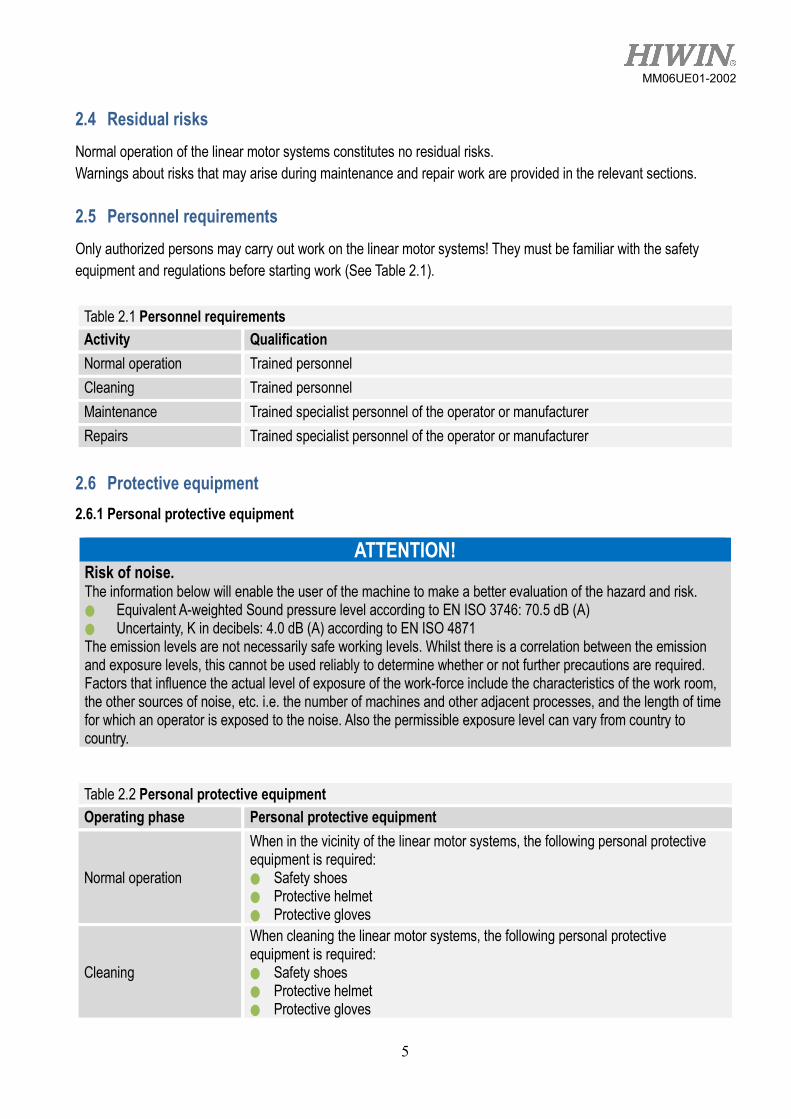
2.4 Residual risks Normal operation of the linear motor systems constitutes no residual risks. Warnings about risks that may arise during maintenance and repair work are provided in the relevant sections. 2.5 Personnel requirements Only authorized persons may carry out work on the linear motor systems! They must be familiar with the safety equipment and regulations before starting work (See Table 2.1).
Table 2.1 Personnel requirements Activity Qualification Normal operation Trained personnel Cleaning Trained personnel Maintenance Trained specialist personnel of the operator or manufacturer Repairs Trained specialist personnel of the operator or manufacturer
2.6 Protective equipment 2.6.1 Personal protective equipment
ATTENTION! Risk of noise. The information below will enable the user of the machine to make a better evaluation of the hazard and risk. ● Equivalent A-weighted Sound pressure level according to EN ISO 3746: 70.5 dB (A) ● Uncertainty, K in decibels: 4.0 dB (A) according to EN ISO 4871 The emission levels are not necessarily safe working levels. Whilst there is a correlation between the emission and exposure levels, this cannot be used reliably to determine whether or not further precautions are required. Factors that influence the actual level of exposure of the work-force include the characteristics of the work room, the other sources of noise, etc. i.e. the number of machines and other adjacent processes, and the length of time for which an operator is exposed to the noise. Also the permissible exposure level can vary from country to country.
Table 2.2 Personal protective equipment Operating phase Personal protective equipment
Normal operation
When in the vicinity of the linear motor systems, the following personal protective equipment is required: ● Safety shoes ● Protective helmet ● Protective gloves
Cleaning
When cleaning the linear motor systems, the following personal protective equipment is required: ● Safety shoes ● Protective helmet ● Protective gloves

6
MM06UE01-2002
Table 2.2 Personal protective equipment (continued) Operating phase Personal protective equipment
Maintenance and repairs
When carrying out maintenance and repairs, the following personal protective equipment is required: ● Safety shoes ● Protective helmet ● Protective gloves
2.6.2 Protective equipment on the linear motor system
Linear motor systems are fitted with position dampers. ● After every traverse, these position dampers must be tested at the end positions and, if necessary, replaced. ● The machine may not be operated without position dampers or when they are damaged! 2.7 Labels on linear motor system
Fig 2.1 Warning symbols and type plate – here for a LMSSA linear motor system
Table 2.3 Warning symbols
Pictogram Type and source of danger Protective measures
Danger from movements! Keep out of the machine’s area of movements! Prevent
unauthorized access to the danger area!
Danger from strong magnetic fields!
Persons whose health may be endangered by strong magnetic fields must keep a safe distance (1 m) from the linear motor system!
7
MM06UE01-2002
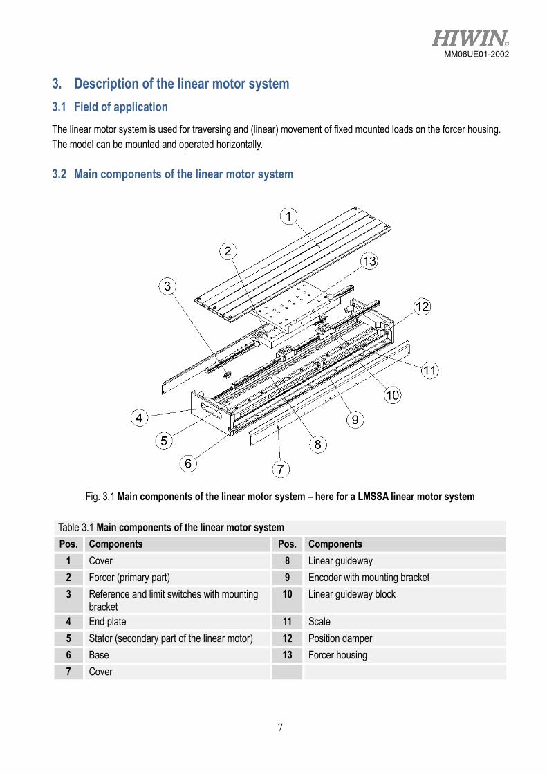
3. Description of the linear motor system 3.1 Field of application The linear motor system is used for traversing and (linear) movement of fixed mounted loads on the forcer housing. The model can be mounted and operated horizontally. 3.2 Main components of the linear motor system
Fig. 3.1 Main components of the linear motor system – here for a LMSSA linear motor system
Table 3.1 Main components of the linear motor system Pos. Components Pos. Components
1 Cover 8 Linear guideway 2 Forcer (primary part) 9 Encoder with mounting bracket 3 Reference and limit switches with mounting
bracket 10 Linear guideway block
4 End plate 11 Scale 5 Stator (secondary part of the linear motor) 12 Position damper 6 Base 13 Forcer housing 7 Cover
8
MM06UE01-2002
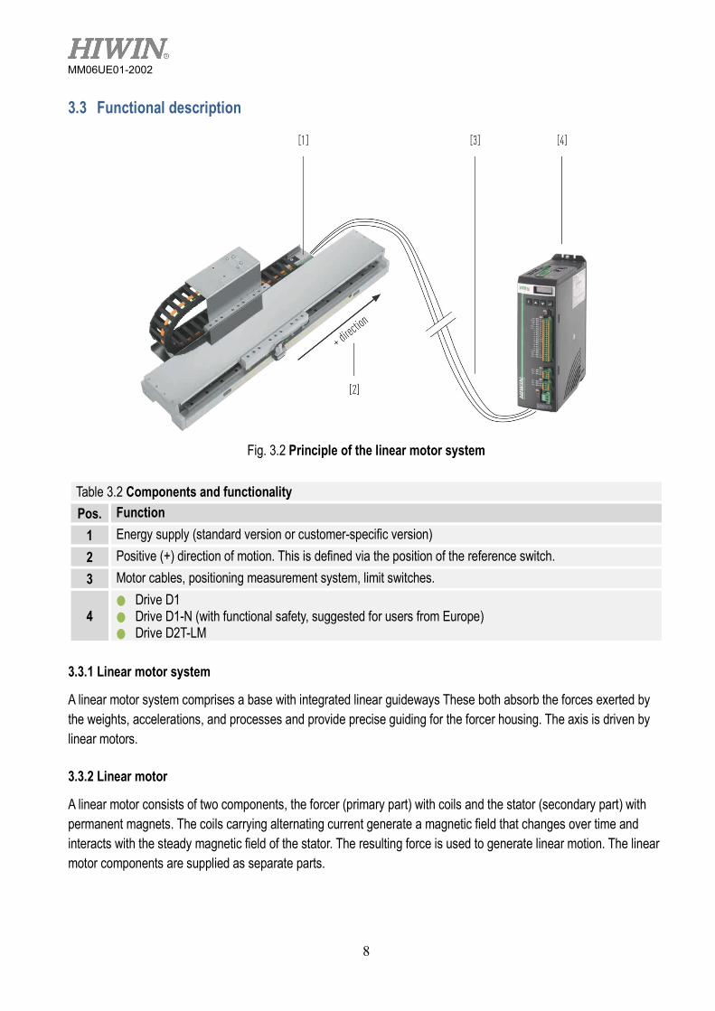
3.3 Functional description
Fig. 3.2 Principle of the linear motor system
Table 3.2 Components and functionality Pos. Function
1 Energy supply (standard version or customer-specific version) 2 Positive (+) direction of motion. This is defined via the position of the reference switch. 3 Motor cables, positioning measurement system, limit switches.
4 ● Drive D1 ● Drive D1-N (with functional safety, suggested for users from Europe) ● Drive D2T-LM
3.3.1 Linear motor system
A linear motor system comprises a base with integrated linear guideways These both absorb the forces exerted by the weights, accelerations, and processes and provide precise guiding for the forcer housing. The axis is driven by linear motors. 3.3.2 Linear motor
A linear motor consists of two components, the forcer (primary part) with coils and the stator (secondary part) with permanent magnets. The coils carrying alternating current generate a magnetic field that changes over time and interacts with the steady magnetic field of the stator. The resulting force is used to generate linear motion. The linear motor components are supplied as separate parts.

9
MM06UE01-2002
3.3.3 Positioning measurement system
ATTENTION! Damage caused by scratching! The measuring scale of the optical measuring system may be damaged by improper handling. Handle the measuring scale with care!
ATTENTION! Damage to the magnetic positioning measurement system! Strong magnetic fields and vibrations can damage the magnetic positioning measurement system. Protect the magnetic positioning measurement system against strong magnetic fields! Protect the magnetic positioning measurement system against strong vibrations!
The distance travelled is measured by a high-resolution positioning measurement system that is mounted on the base. Depending on its type, the linear motor system features an optical or a magnetic positioning measurement system. The installed positioning measurement system is fully cabled and is connected to the controller via a separate connector (See Technical Information and Approval Drawing).
Please note the documentation included with this product for positioning measurement system not described in these assembly instructions.
For assembly, disassembly, operation and cleaning, please consult the manufacturer’s separate operating instructions.
3.3.4 Limit switches (optional)
Depending on the type, a few optical or inductive switches generate a signal to the controller upon reaching the end of the travel distance. The limit switches are supplied pre-wired and operational (for pin assignment see Technical Information, Approval Drawing or Figure 3.3).
Figure 3.3 pin assignment (standard)
3.3.5 Cable chain (optional)
The motor, limit switch, and positioning measurement system cables are routed through the cable chain to the drive.
Please observe manufacturer’s instructions for retrofitting.

10
MM06UE01-2002
4. Transport and installation 4.1 Delivery 4.1.1 Delivery state
The linear motor systems are supplied fully assembled, function tested and ready for connection. To prevent damage arising during transport, the linear motor systems are provided with transportation safety devices and shipping devices. 4.1.2 Scope of delivery
For the scope of delivery, please see the contractual documentation. 4.2 Transport to the installation site
DANGER!
Danger from strong magnetic fields! Strong magnetic fields around linear motor system pose a health risk to persons with implants (e.g. cardiac pacemakers) that are affected by magnetic fields. Persons with implants that are affected by magnetic fields should maintain a safe distance of at
least 1 m from linear motor system
WARNING!
Risk of crushing from forcer housing! Danger of injury from crushing and damage to the linear motor system caused by movement of the forcer housing due to gravity, as it does not feature brakes in its standard version. Ensure that each transportation safety devices is well fixed before transportation. In most cases,
the devices are made in red.
WARNING!
Danger from heavy loads! Lifting heavy loads may damage your health. For system’s weight over 20 kg, use a hoist of an appropriate size when positioning heavy
loads! Observe applicable occupational health and safety regulations when handling suspended loads!
ATTENTION!
Risk of physical damage to watches and magnetic storage media. Strong magnetic forces may destroy watches and magnetisable data storage media near to the linear motor system! Do not bring watches or magnetisable data storage media into the vicinity (<300 mm) of the
linear motor system!
11
MM06UE01-2002
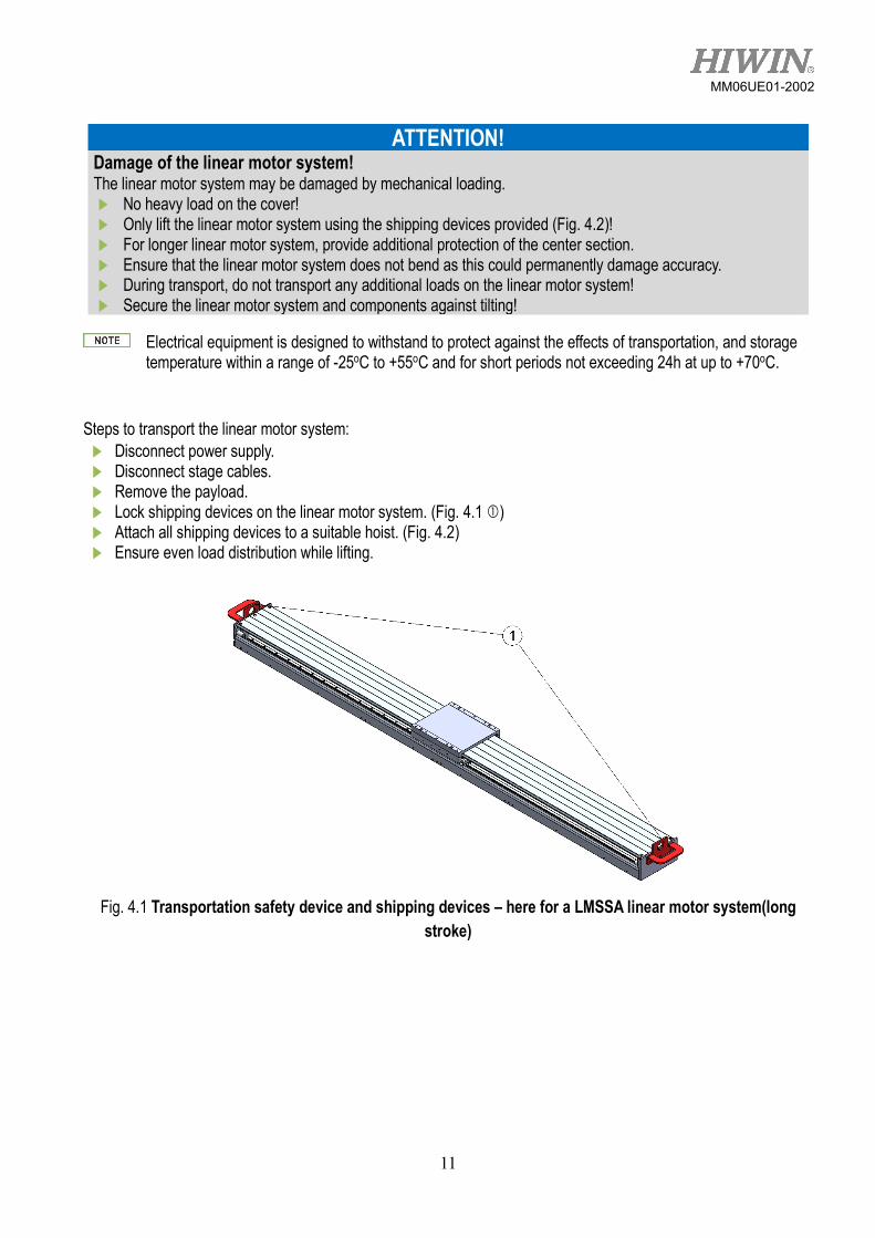
ATTENTION! Damage of the linear motor system! The linear motor system may be damaged by mechanical loading. No heavy load on the cover! Only lift the linear motor system using the shipping devices provided (Fig. 4.2)! For longer linear motor system, provide additional protection of the center section. Ensure that the linear motor system does not bend as this could permanently damage accuracy. During transport, do not transport any additional loads on the linear motor system! Secure the linear motor system and components against tilting!
Electrical equipment is designed to withstand to protect against the effects of transportation, and storage temperature within a range of -25oC to +55oC and for short periods not exceeding 24h at up to +70oC.
Steps to transport the linear motor system: Disconnect power supply. Disconnect stage cables. Remove the payload. Lock shipping devices on the linear motor system. (Fig. 4.1 ) Attach all shipping devices to a suitable hoist. (Fig. 4.2) Ensure even load distribution while lifting.
Fig. 4.1 Transportation safety device and shipping devices – here for a LMSSA linear motor system(long
stroke)
12
MM06UE01-2002
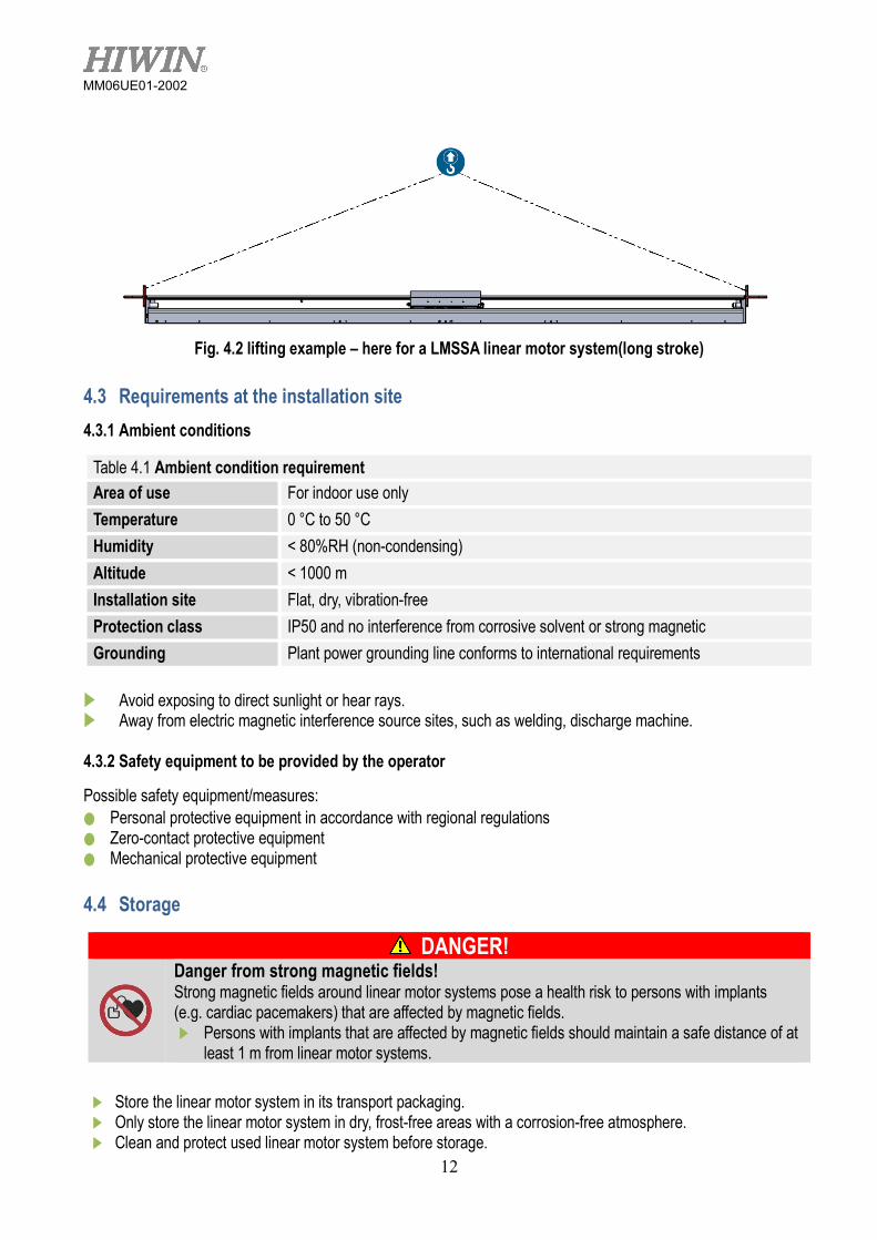
Fig. 4.2 lifting example – here for a LMSSA linear motor system(long stroke)
4.3 Requirements at the installation site 4.3.1 Ambient conditions
Table 4.1 Ambient condition requirement Area of use For indoor use only Temperature 0 °C to 50 °C Humidity < 80%RH (non-condensing) Altitude < 1000 m Installation site Flat, dry, vibration-free Protection class IP50 and no interference from corrosive solvent or strong magnetic Grounding Plant power grounding line conforms to international requirements
Avoid exposing to direct sunlight or hear rays. Away from electric magnetic interference source sites, such as welding, discharge machine. 4.3.2 Safety equipment to be provided by the operator
Possible safety equipment/measures: ● Personal protective equipment in accordance with regional regulations ● Zero-contact protective equipment ● Mechanical protective equipment 4.4 Storage
DANGER!
Danger from strong magnetic fields! Strong magnetic fields around linear motor systems pose a health risk to persons with implants (e.g. cardiac pacemakers) that are affected by magnetic fields. Persons with implants that are affected by magnetic fields should maintain a safe distance of at
least 1 m from linear motor systems. Store the linear motor system in its transport packaging. Only store the linear motor system in dry, frost-free areas with a corrosion-free atmosphere. Clean and protect used linear motor system before storage.
13
MM06UE01-2002
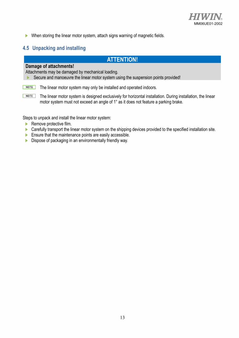
When storing the linear motor system, attach signs warning of magnetic fields. 4.5 Unpacking and installing
ATTENTION! Damage of attachments! Attachments may be damaged by mechanical loading. Secure and manoeuvre the linear motor system using the suspension points provided!
The linear motor system may only be installed and operated indoors.
The linear motor system is designed exclusively for horizontal installation. During installation, the linear motor system must not exceed an angle of 1° as it does not feature a parking brake.
Steps to unpack and install the linear motor system: Remove protective film. Carefully transport the linear motor system on the shipping devices provided to the specified installation site. Ensure that the maintenance points are easily accessible. Dispose of packaging in an environmentally friendly way.
14
MM06UE01-2002
5. Assembly and connection
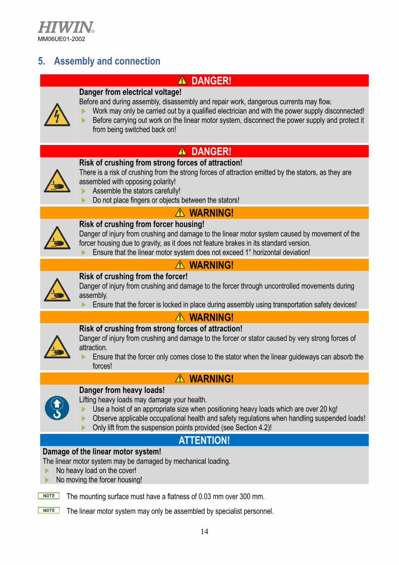
DANGER!
Danger from electrical voltage! Before and during assembly, disassembly and repair work, dangerous currents may flow. Work may only be carried out by a qualified electrician and with the power supply disconnected! Before carrying out work on the linear motor system, disconnect the power supply and protect it
from being switched back on!
DANGER!
Risk of crushing from strong forces of attraction! There is a risk of crushing from the strong forces of attraction emitted by the stators, as they are assembled with opposing polarity! Assemble the stators carefully! Do not place fingers or objects between the stators!
WARNING!
Risk of crushing from forcer housing! Danger of injury from crushing and damage to the linear motor system caused by movement of the forcer housing due to gravity, as it does not feature brakes in its standard version. Ensure that the linear motor system does not exceed 1° horizontal deviation!
WARNING!
Risk of crushing from the forcer! Danger of injury from crushing and damage to the forcer through uncontrolled movements during assembly. Ensure that the forcer is locked in place during assembly using transportation safety devices!
WARNING!
Risk of crushing from strong forces of attraction! Danger of injury from crushing and damage to the forcer or stator caused by very strong forces of attraction. Ensure that the forcer only comes close to the stator when the linear guideways can absorb the
forces!
WARNING!
Danger from heavy loads! Lifting heavy loads may damage your health. Use a hoist of an appropriate size when positioning heavy loads which are over 20 kg! Observe applicable occupational health and safety regulations when handling suspended loads! Only lift from the suspension points provided (see Section 4.2)!
ATTENTION! Damage of the linear motor system! The linear motor system may be damaged by mechanical loading. No heavy load on the cover! No moving the forcer housing!
The mounting surface must have a flatness of 0.03 mm over 300 mm.
The linear motor system may only be assembled by specialist personnel.

15
MM06UE01-2002
5.1 Assembling the linear motor system Secure the screws with retaining rings to prevent them from accidentally coming loose!
Steps to assemble the linear motor system: Remove the shipping devices. Remove the transportation safety device from the forcer housing. Remove the cover or bellows if the mounting holes are inaccessible. Drill mounting holes in the mounting surface in accordance with scale drawing (see Technical Information and
Approval Drawing). Clean mounting surface. Place the mounting bolts in the mounting holes and tighten them in a spiral motion from inside to outside with
applied torque (See Table 5.1). If the cover or bellows were removed, install them back.
Fig. 5.1 Assembling the linear motor system – here for an LMSSA linear motor system
Table 5.1 Mounting torque Screw Size Torque (kgf-cm) Screw Size Torque (kgf-cm)
M2 5 M6 120 M2.5 10 M8 310 M3 20 M10 690 M4 40 M12 1200 M5 90 M16 2000

16
MM06UE01-2002
5.2 Assembling the moved load Steps to assemble the moved load: Clean the mounting surface on the linear motor system that is to receive the load. Clean the mounting surface of the load. Position the load over the corresponding mounting holes on the mounting surface (see Technical Information
and Approval Drawing). Place the mounting bolts in the mounting holes and tighten them in a spiral motion from inside to outside with a
torque screws (See Table 5.1). Check the free movement of the load over the entire travel distance.
After assembling the moved load, please design another transportation safety device to lock the forcer housing in place during transport.
5.3 Electrical connection
DANGER!
Danger from electrical voltage! If linear motors are incorrectly earthed, there is a danger of electric shock. Before connecting the electrical power supply, ensure that the linear motor system is correctly
earthed.
DANGER!
Danger from electrical voltage! Electrical currents may flow even if the motor is not moving. Ensure that the linear motor system is disconnected from the power supply before the electrical
connections are detached from the motors. After disconnecting the drive amplifier from the power supply, wait at least 5 minutes before
touching live parts or breaking connections. For safety reasons, measure the voltage in the intermediate circuit and wait until it has fallen
below 40V.
Observe the separate assembly instructions of the drive!
The supply voltage is based on the drive. Please consult the manufacturer’s separate operating instructions for detailed information.
● Supplied with cabling ready for operation. ● All necessary connections via three connectors of each axis.

17
MM06UE01-2002
Fig. 5.2 Electrical connection for drive type of D1
Fig. 5.3 Electrical connection for drive type of D1-N
5.3.1 Connecting iron-core motors
The temperature sensor system cable is routed as standard through the motor’s extension cable. Both cables are therefore connected to the motor plug.
Observe the Technical Information and Approval Drawing for pin assignment!
5.3.2 Connecting the linear positioning measurement system
18
MM06UE01-2002
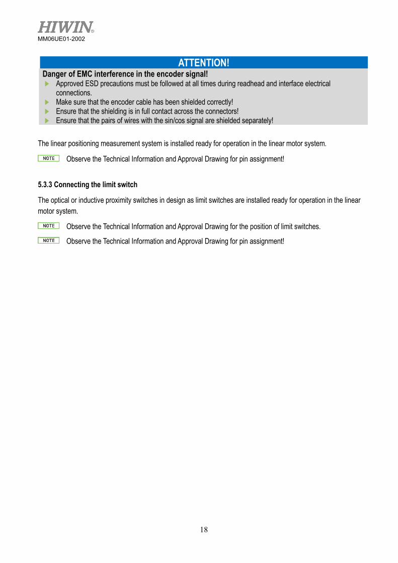
ATTENTION! Danger of EMC interference in the encoder signal! Approved ESD precautions must be followed at all times during readhead and interface electrical
connections. Make sure that the encoder cable has been shielded correctly! Ensure that the shielding is in full contact across the connectors! Ensure that the pairs of wires with the sin/cos signal are shielded separately!
The linear positioning measurement system is installed ready for operation in the linear motor system.
Observe the Technical Information and Approval Drawing for pin assignment!
5.3.3 Connecting the limit switch
The optical or inductive proximity switches in design as limit switches are installed ready for operation in the linear motor system.
Observe the Technical Information and Approval Drawing for the position of limit switches.
Observe the Technical Information and Approval Drawing for pin assignment!
19
MM06UE01-2002
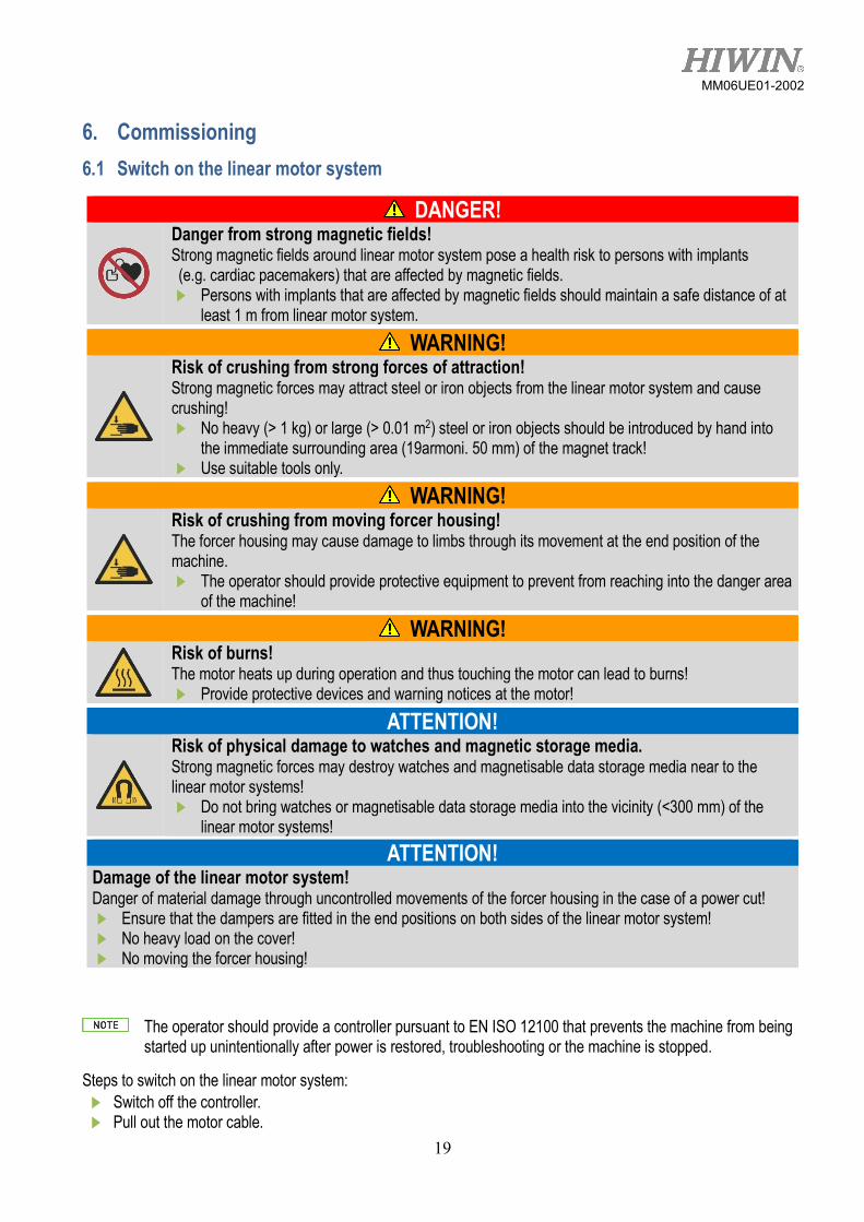
6. Commissioning 6.1 Switch on the linear motor system
DANGER!
Danger from strong magnetic fields! Strong magnetic fields around linear motor system pose a health risk to persons with implants (e.g. cardiac pacemakers) that are affected by magnetic fields. Persons with implants that are affected by magnetic fields should maintain a safe distance of at
least 1 m from linear motor system.
WARNING!
Risk of crushing from strong forces of attraction! Strong magnetic forces may attract steel or iron objects from the linear motor system and cause crushing! No heavy (> 1 kg) or large (> 0.01 m2) steel or iron objects should be introduced by hand into
the immediate surrounding area (19armoni. 50 mm) of the magnet track! Use suitable tools only.
WARNING!
Risk of crushing from moving forcer housing! The forcer housing may cause damage to limbs through its movement at the end position of the machine. The operator should provide protective equipment to prevent from reaching into the danger area
of the machine!
WARNING!
Risk of burns! The motor heats up during operation and thus touching the motor can lead to burns! Provide protective devices and warning notices at the motor!
ATTENTION!
Risk of physical damage to watches and magnetic storage media. Strong magnetic forces may destroy watches and magnetisable data storage media near to the linear motor systems! Do not bring watches or magnetisable data storage media into the vicinity (<300 mm) of the
linear motor systems! ATTENTION!
Damage of the linear motor system! Danger of material damage through uncontrolled movements of the forcer housing in the case of a power cut! Ensure that the dampers are fitted in the end positions on both sides of the linear motor system! No heavy load on the cover! No moving the forcer housing!
The operator should provide a controller pursuant to EN ISO 12100 that prevents the machine from being started up unintentionally after power is restored, troubleshooting or the machine is stopped.
Steps to switch on the linear motor system: Switch off the controller. Pull out the motor cable.

20
MM06UE01-2002
Connect positioning measurement system cable (see Section 5.3.2). Switch on the controller. Check the positioning measurement system (see separate assembly instructions for the drive and positioning
measurement system). Switch off the controller. Connect the motor cable (see Sections 5.3.1). Switch on the controller. Perform test run at slow speed. Perform test under usage conditions.
6.2 Programming
The programming of the linear motor system depends on the controller and drive used. Observe the user manual for the controller and drive!
21
MM06UE01-2002
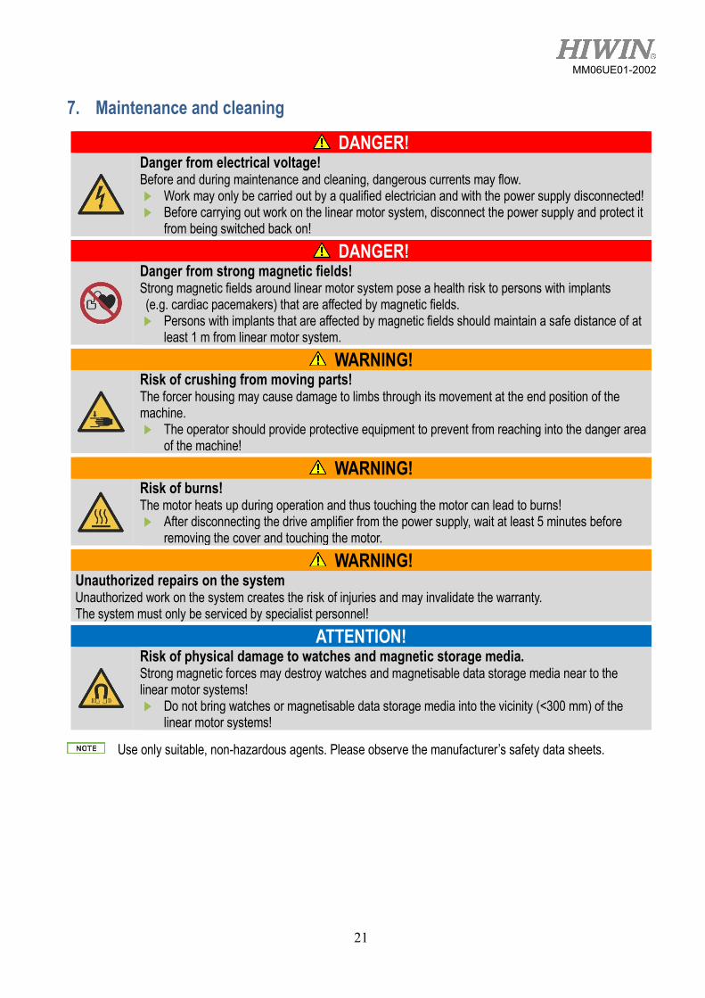
7. Maintenance and cleaning
DANGER!
Danger from electrical voltage! Before and during maintenance and cleaning, dangerous currents may flow. Work may only be carried out by a qualified electrician and with the power supply disconnected! Before carrying out work on the linear motor system, disconnect the power supply and protect it
from being switched back on!
DANGER!
Danger from strong magnetic fields! Strong magnetic fields around linear motor system pose a health risk to persons with implants (e.g. cardiac pacemakers) that are affected by magnetic fields. Persons with implants that are affected by magnetic fields should maintain a safe distance of at
least 1 m from linear motor system.
WARNING!
Risk of crushing from moving parts! The forcer housing may cause damage to limbs through its movement at the end position of the machine. The operator should provide protective equipment to prevent from reaching into the danger area
of the machine!
WARNING!
Risk of burns! The motor heats up during operation and thus touching the motor can lead to burns! After disconnecting the drive amplifier from the power supply, wait at least 5 minutes before
removing the cover and touching the motor.
WARNING! Unauthorized repairs on the system Unauthorized work on the system creates the risk of injuries and may invalidate the warranty. The system must only be serviced by specialist personnel!
ATTENTION!
Risk of physical damage to watches and magnetic storage media. Strong magnetic forces may destroy watches and magnetisable data storage media near to the linear motor systems! Do not bring watches or magnetisable data storage media into the vicinity (<300 mm) of the
linear motor systems!
Use only suitable, non-hazardous agents. Please observe the manufacturer’s safety data sheets.
22
MM06UE01-2002
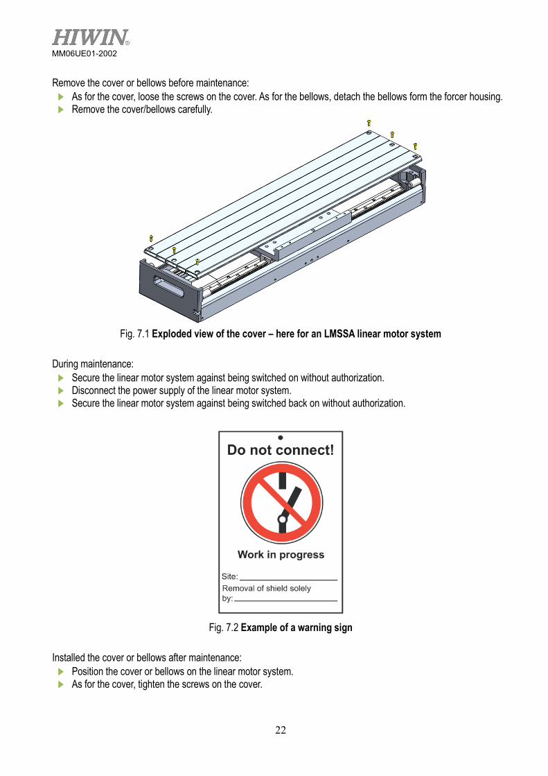
Remove the cover or bellows before maintenance: As for the cover, loose the screws on the cover. As for the bellows, detach the bellows form the forcer housing. Remove the cover/bellows carefully.
Fig. 7.1 Exploded view of the cover – here for an LMSSA linear motor system
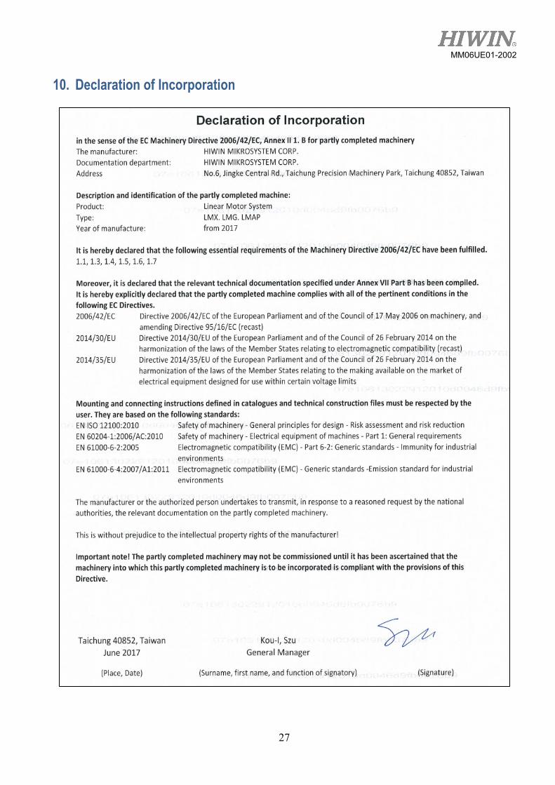
During maintenance: Secure the linear motor system against being switched on without authorization. Disconnect the power supply of the linear motor system. Secure the linear motor system against being switched back on without authorization.
Fig. 7.2 Example of a warning sign
Installed the cover or bellows after maintenance: Position the cover or bellows on the linear motor system. As for the cover, tighten the screws on the cover.

23
MM06UE01-2002
7.1 Linear motor Ensure that no parts are located between the forcer and the magnet track!
The linear motor operates maintenance-free. 7.2 Positioning measurement system 7.2.1 Magnetic positioning measurement system
Ensure that no dirt particles are located between the encoder and the measuring scale!
The magnetic positioning measurement system works on a non-contact basis and thus requires no maintenance. Check the magnetic positioning measurement system regularly for soiling, cleaning this when necessary. Otherwise, accumulating dirt particles will detach under the constant pressure of the cover plate. 7.2.2 Optical positioning measurement system
Ensure that no dirt particles are located between the encoder and the measuring scale! Only clean using a soft cloth in order to avoid scratching the measuring scale!
The optical positioning measurement system works on a non-contact basis and thus requires no maintenance. Regularly check the measuring scale for dirt and clean if necessary, as otherwise the surface of the measuring scale may become scratched and may no longer function correctly. 7.3 Electromechanical components The energy chain and the cable have a limited lifetime. For example, the energy chain is specified for 4 million cycles. However, the lifetime cannot be calculated exactly due to ambient conditions and drive performance. The following components should therefore be regularly checked for wear and correct position, and should be replaced if necessary (wearing parts are not covered by the warranty): ● Cable in the energy chain (e.g. signs of abrasion on the cable insulation) ● Cable plug connections ● Distance between the limit switch shelter and sensors (common cause of malfunction of the limit/reference
switch)
In critical production situations, make sure that there is a stock of wearing parts!
7.4 Linear guideways 7.4.1 Lubrication
As with rolling bearings, the rails of linear motor systems require a sufficient supply of lubricant. This lubrication reduces wear, protects against dirt and deposits, prevents corrosion and extends service life.
Observe the instructions of the lubricant manufacturer.
Check the miscibility of different lubricants. Lubricants of the same classification (e.g. CL) and similar viscosity (maximum difference of one class) are miscible. Greases are miscible when their base oil and thickening types are the same. The viscosity of the base oil must be similar and the NGLI class may be different by a maximum of one grade.

24
MM06UE01-2002
Ensure that old grease, dirt and chippings are removed from the profile rails before lubrication.
Only use lubricants that are in accordance with DIN 51825, KP2K of the consistency class NGLI2.
Ensure that only lubricants without solid lubricant particles (e.g. graphite or MoS2) are used!
Further information about lubrication and selection of approved lubricants can be found in the user manual for linear guideways at www.hiwin.tw.
Fig. 7.3 Grease nipples on linear guideways
● Relubricating interval every 200–600 operating hours or 1000 km. ● For nominal size 15, grease quantity 0.6 g. ● Relubrication as standard through grease nipple (See Fig. 7.3) with standard grease guns. 7.4.2 Cleaning
Dirt can settle and accumulate over time on unprotected profile rails. Profile rails must therefore be regularly checked for dirt and cleaned if necessary.

25
MM06UE01-2002
8. Troubleshooting Table 8.1 Fault table Fault Possible cause Remedy Motor does not start Supply lines disconnected Check connections, plug contacts may be
compressed, repair if necessary. The connectors have seals, which means that a certain screw connection resistance must be overcome.
Fuse has tripped via motor protection
Check motor protection for the right settings, remedy defects if necessary
Upon restart, the drive reports a fault during commutation
Motor phases connected incorrectly
Check rotational direction
Encoder counting direction incorrect
Change the sin and cos pair of wires in the encoder plug
forcer housing is too close to the limit switch/limit stop
Disconnect power supply to axis and move forcer housing manually into the center of the axis.
Additional drive resistance e.g. sealing lip, without parameter adjustment
Change parameters in the drive amplifier
Axis overspeeds upon restart
Commutation incorrect See fault during commutation Check commutation parameters in the drive, activate speed monitoring!
EMC interference with the encoder signal
Check the shielding of the connectors and cables
Axis overspeeds in positioning mode
Programming error in the position transfer, invalid acceleration ordered
Activate security settings in the drive amplifier, such as speed monitoring, permissible position errors etc.
Motor heats up too much (measure temperature)
Rated power exceeded as duty cycle is too long
Adapt load cycle to the rated power of the motor
Cooling insufficient Rectify cooling air supply or open cooling air passages, retrofit external fan if necessary
forcer housing is difficult to move Check lubrication of the guideways, foreign bodies in the traversing range?
Ambient temperature too high Observe permissible temperature range Load cycle has been modified Calculate load cycle and adapt accordingly Drive amplifier motor commutation does not function properly
Adapt commutation parameters of the drive amplifier
Operating noise from the forcer
Relubrication required otherwise risk of bearing damage
Lubrication or consultation with HIWIN MIKROSYSTEM
The axis generates cracking noises when it is subject to control
EMC interference in the encoder signal
Encoder cables must be used separately with shielded sin and cos signal pairs
Commutation incorrect Optimize commutation parameters.

26
MM06UE01-2002
Table 8.1 Fault table (continued) Fault Possible cause Remedy The forcer jerks while moving and generates operating noise that is not caused by the profile guideways
EMC interference in the encoder signal, encoder cable plug connection defective, pin bent in plug
Place motor cable and/or encoder cable shield in full contact with the earthing terminal of the amplifier, check pin in plug
Position discrepancies after several hours of operation
Use mains filter to stabilize voltage
9. Disposal
ATTENTION!
Danger caused by environmentally hazardous substances! The danger to the environment depends on the type of substance used. Clean contaminated parts thoroughly before disposal! Clarify the requirements for safe disposal with disposal companies and, where appropriate, with
the competent authorities!
Table 9.1 Disposal Fluids Lubricants dispose of as hazardous waste in an environmentally friendly way Soiled cleaning cloths dispose of as hazardous waste in an environmentally friendly way Linear motor system Cabling, electrical components dispose of as electrical waste PP components (e.g. cable chain) dispose of separately Steel components (e.g. guideways) dispose of separately Aluminum components (e.g. base) dispose of separately
27
MM06UE01-2002
10. Declaration of Incorporation