611axesintegres-isa-ispa-linear-axis iai...
TRANSCRIPT

LINEAR AXIS ISA/ISPA
w w w . i n t e l l i g e n t a c t u a t o r . d e
GB
Integrated System & Integrated System Precision

Y-Axis Z -Axis
Compact
Actuator
width
90mm
Medium
Actuator
width
120mm
Large
Actuator
width
150mm
SuperLarge
Actuator
width
198mm
X-AxisStandard Type Mid-Support Type
Single-Axis Robots
ISA-SXMISPA-SXM
P13
(Not available)
P16, P17
P23, P24 P27, P28
P25, P26
P33, P34 P35, P36
P29, P30 P31, P32
P18 P19, P20 P21, P22
P14 P15
ISA-MXMISPA-MXM
ISA-LXMISPA-LXM
ISA-WXMISPA-WXM
ISA-WXMXISPA-WXMX
ISA-LXMXISPA-LXMX
ISA-LXUWXISPA-LXUWX
ISA-LYMISPA-LYM
ISA-LZMISPA-LZM
ISA-MXMXISPA-MXMX
ISA-MYMISPA-MYM
ISA-MZMISPA-MZM
ISA-SYMISPA-SYM
ISA-SZMISPA-SZM
High-precision positioning systems with a linear positioning repeatability of 0.01 to 0.02 mm
V I S U A L I N D E X
(Not available) (Not available)
1 ISPA Catalog

ISPA Catalog 2
Application Examples of Combined Axes
Transfer/positioning systems combining single-axis actuators into a two to three orthogonal axes configuration.
For more informations see the enlarged catalogue “ISPA+ICSPA” with the additional cartesian robots, controllers and options.
RCS-C x 2
RCS-RA35
RCS-RA55
CD-Rom StockingIncremental
RC Line Controller
Positioning
X-SEL-K
X-SEL-K ICSA2 ICSA2
Cutting
IA Line
IA Line
Controller
Positioning
X-SEL-K
ICSA3
Circuit Board Inspection
IA Line Controller
Positioning
Pick & Place
IA Line Controller
Positioning
X-SEL-K
ISPA-WXM
ISA-LXM
1 2
PalletizingSynchronizing
IA Line Controller
Positioning
Parts Transfer
RC LineController
Positioning
X-SEL-K
ICSA3
IA Line Controller
Path Motion
Spraying/Coating
RCP2-C×2
RCS-C
RCP2-RMA×2
RCS-SM
1
2
RC- Line Controller
Unloading
X-SEL-K
ISPA-WXM × 2
ISA-LYM
1
2
IA Line Controller
Synchronizing
X-SEL-K
RCS-R20
ICSA3
RC Line Controller
ARC MotionPath Motion
DispensingBarcode Reading
X-SEL-K ICSA2
ISA-SYM
IA Line Controller
Positioning
Soldering
X-SEL-K
IA Line Controller
Positioning
Screwdriving
ICSA3 X-SEL-K
X-SEL-K
E-CON
IA Line
IA Line
ISA-LXM ISA-MXM RCS-RA55R
ICSA2
Positioning
Positioning
2
11
2
1
1

3 ISPA Catalog
ISA/ISPA Single-Axis Robots
Single-Axis Robot ISA/ISPA Series Features
Higher Maximum Acceleration/Deceleration of 1 G (9800 mm/sec2)
The ISA/ISPA is a high-precision positioning system comprised of a base, linear guides, ball screw and AC
servo motor. It achieves cost savings, because its design is more comprehensive and adjustment is much
easier than when individual components are purchased and assembled.
Both the ISA and ISPA achieve a maximum acceleration/
deceleration of 1 G, which was heretofore possible only with
the ISP Series.
• A dedicated cover prevents intrusion of small
parts and other foreign objects from above.
• To install the actuator, open the cover and
affix with bolts from above.
Y-Axis Type (SYM, MYM, LYM, etc.)
Z-Axis Type (SZM, MZM, LZM, etc.)
• A cover shape is adopted to prevent intrusion of
small parts and other foreign objects from
above when the actuator is installed on its side.
• The actuator comes standard with a slider anti-drop
brake by assuming use in a vertical application.
• The mounting holes provided in the back of the base
(actuator-mounting surface) are different from the
mounting holes of the X-axis type.
(A load can be attached easily to the base surface when the actuator is moved vertically.)
Z-Axis
Y-Axis
X-Axis
1
Achieving Higher Rigidity with Smaller Size via Base-Integrated Guide Structure
The thickness of the actuator has been reduced by
embedding the guide rails in the base. The base also
employs a hollow box structure for improved rigidity.
3
Dedicated X/Y/Z-Axes
Dedicated axes are available to choose from according to your specific need.2
* When accelerating to 2000 mm/sec, a robot operating at an acceleration of
1 G achieves the target speed approx. 0.5 second faster than a robot
operating at an acceleration of 0.3 G (as shown in the graph at right).
Acceleration/deceleration indicates the rate of change of speed. 1 G is equivalent to 9800
mm/sec2, or the ability to accelerate (or decelerate) 9800 mm/sec per second.
X-Axis Type (SXM, MXM, LXM, etc.)

MotorCoupling
Ball screw
ISPA Catalog 4
X-SEL S-SEL E-CON/S-CON
Program Operation Program/Positioner Operation Positioner/Pulse-train operation

5 ISPA Catalog
ISA/ISPA Single-Axis Robots
Single-Axis Robot Series Specification Table
3
6
14
3
6
14
6
14
5
9
19
6
9
19
-
-
5
9
19
6
9
19
9
19
19
P13
P14
P15
P16
P17
P18
P19
P20
P21
P22
P23
P24
P25
P26
P27
P28
P29
P30
P31
P32
P33
P34
P35
P36
Stroke (mm), maximum speed (mm/sec) (Note 1)Load capacity (Note 2) Motor
capacityLead
Model PageHorizontal
(kg) (W)
60
60
60
100
200
200
100
200
100
200
200
400
200
400
200
400
200
400
100
400
600
750
600
750
(mm)
Vertical
800
400
200
800
400
200
400
200
1000 1000 795 645 540
480 380 310 255
220 175 145 120
1500 1190 965 810
1000 795 645 540
480 380 310 255
500
250
1500
1000
500
1000 795 645 5401000
480 380 310 255500
220 175 145 120250
1500 1190 965 8101500
1000 795 645 5401000
480 380 310 255500
220 175 145 120250
480 380 310 255500
480 380 310 255500
1000 830 690 585 5001000
470 385 320 270 235500
1660 1380 1170 1000
830 690 585 500
1000 830 690 585 5001000
1000 830 690 585 5001000
470 385 320 270 235500
470 385 320 270 235500
470 385 320 270 235500
1670 1390 1170 1000 865
835 695 585 500 430
835 695 585 500 430
415 345 290 250 215
1670 1390 1170 1000 865
2000 1660 1380 1170 10002000
(Note 1) The figure in the elongated circle indicates the maximum speed for each stroke. (Note 2) The load capacity is based on actuator operation at the rated acceleration (refer to page 7).
ISA(ISPA)-SXM- -60-16-
ISA(ISPA)-SXM- -60-8-
ISA(ISPA)-SXM- -60-4-
ISA(ISPA)-SYM- -60-16-
ISA(ISPA)-SYM- -60-8-
ISA(ISPA)-SYM- -60-4-
ISA(ISPA)-SZM- -60-8- -B
ISA(ISPA)-SZM- -60-4- -B
ISA(ISPA)-MXM- -100-20-
ISA(ISPA)-MXM- -100-10-
ISA(ISPA)-MXM- -100-5-
ISA(ISPA)-MXM- -200-30-
ISA(ISPA)-MXM- -200-20-
ISA(ISPA)-MXM- -200-10-
ISA(ISPA)-MXMX- -200-30-
ISA(ISPA)-MXMX- -200-20-
ISA(ISPA)-MYM- -100-20-
ISA(ISPA)-MYM- -100-10-
ISA(ISPA)-MYM- -100-5-
ISA(ISPA)-MYM- -200-30-
ISA(ISPA)-MYM- -200-20-
ISA(ISPA)-MYM- -200-10-
ISA(ISPA)-MZM- -100-10- -B
ISA(ISPA)-MZM- -100-5- -B
ISA(ISPA)-MZM- -200-10- -B
12
25
50
12
25
50
-
-
20
40
80
25
40
80
25
40
20
40
80
25
40
80
-
-
-
16
8
4
16
8
4
8
4
20
10
5
30
20
10
30
20
20
10
5
30
20
10
10
5
10
1500
ISA(ISPA)-LXM- -200-20-
ISA(ISPA)-LXM- -200-10-
ISA(ISPA)-LXM- -400-40-
ISA(ISPA)-LXM- -400-20-
ISA(ISPA)-LXMX- -200-20-
ISA(ISPA)-LXMX- -400-40-
ISA(ISPA)-LXMX- -400-20-
ISA(ISPA)-LXUWX- -200-20-
ISA(ISPA)-LXUWX- -400-40-
ISA(ISPA)-LXUWX- -400-20-
ISA(ISPA)-LYM- -200-20-
ISA(ISPA)-LYM- -200-10-
ISA(ISPA)-LYM- -400-40-
ISA(ISPA)-LYM- -400-20-
ISA(ISPA)-LZM- -200-10- -B
ISA(ISPA)-LZM- -400-10-
ISA(ISPA)-WXM--600-40-
ISA(ISPA)-WXM--600-20-
ISA(ISPA)-WXM--600-10-
ISA(ISPA)-WXM--750-50-
ISA(ISPA)-WXM--750-25-
ISA(ISPA)-WXMX--600-40-
ISA(ISPA)-WXMX--600-20-
ISA(ISPA)-WXMX--750-50-
ISA(ISPA)-WXMX--750-25-
40
80
40
80
40
40
80
40
40
80
40
80
40
80
-
-
60
120
150
60
120
60
120
60
120
9
19
9
19
-
-
-
-
-
-
9
19
9
19
19
39
14
29
60
14
29
-
-
-
-
20
10
40
20
20
40
20
20
40
20
20
10
40
20
10
10
40
20
10
50
25
40
20
50
25
ISAISPA
(kg)
1425
1000 950
1200 1050 900 825 750
800 700 600 550 500
675
450
100 200 300 400 500 600 700 800 900 1000 1100 1200 1300 1400 1500 1600 1700 1800 1900 2000 2100 2200 2300 2400 2500
950 830 740 650 590 540 490 440 410 370 340
1480 1300 1180 1080 980 880 820 740 680
740 650 590 540 490 440 410 370 340
740 650 590 540 490 440 410 370 340
740 650 590 540 490 440 410 370 340
1480 1300 1180 1080 980 880 820 740 680
1000
1900 16602000
950 8301000
950 8301000
1900 16602000
950 8301000
17251965 1530 1365 1225 1110 1005 915 840 770 710 6552000
860980 765 680 610 555 500 455 420 385 355 325
720 660 605 555 515
1000
1250
2000
1000
1000
500
2000
2000
1000
1440 1320
1200 1075
12101930 1740 1580 1115 10352000
965 870 790
ISPA Catalog 6
ISA/ISPA Single-Axis Robots
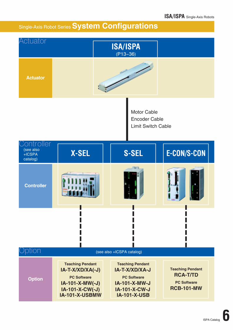
Single-Axis Robot Series System Configurations
Actuator
Actuator
Motor Cable
Encoder Cable
Limit Switch Cable
Option
Option
Teaching Pendant
IA-T-X/XD/XA(-J)
PC Software
IA-101-X-MW(-J)
IA-101-X-CW(-J)IA-101-X-USBMW
Teaching Pendant
IA-T-X/XD/XA-J
PC Software
IA-101-X-MW-J
IA-101-X-CW-JIA-101-X-USB
Teaching Pendant
RCA-T/TD
PC Software
RCB-101-MW
Controller
Controller
X-SEL S-SEL E-CON/S-CON(see also
+ICSPA
catalog)
(see also +ICSPA catalog)
ISA/ISPA(P13~36)

7 ISPA Catalog
ISA/ISPA Single-Axis Robots
Single-Axis Robot Series Points to Note
Speed "Speed" refers to the specified speed at which the actuator slider will move.
The slider accelerates from a stationary state, and once the specified speed is reached it will
maintain that speed until the specified position (immediately before the target position), where
it will begin decelerating to stop at the target position.
Notes on Catalog Specifications
< Caution >
The maximum speed of the ISA/ISPA Series will remain the same even when the load placed on the slider is changed.
The time needed to reach the specified speed will vary according to the acceleration (deceleration).
If the travel distance is short, the specified speed may not be reached.
With a long-stroke axis, the maximum speed will drop to avoid reaching a dangerous speed.
(If you are using a 600 or longer stroke, check the maximum speed for the applicable stroke in the corresponding dimensional drawing.)
When calculating the travel time, consider acceleration, deceleration and stabilization periods in addition to the travel time
at the specified speed. (Refer to pages 39 and 40 for the method to calculate travel time.)
Speed can be set in increments of 1 mm/sec in a program.
Acceleration/Deceleration
"Acceleration" refers to the rate of change of speed when the speed rises from zero (stationary
state) to the specified speed.
"Deceleration" refers to the rate of change of speed when the specified speed drops to zero
(stationary state).
PositioningRepeatability
"Positioning repeatability" refers to the positioning accuracy of repeated movements to a pre-
stored position.
This is not the same as "absolute positioning accuracy," so exercise caution.
Duty IAI recommends that our actuators be used at a duty of 50% or less as a guideline
in view of the relationship of service life and accuracy.
< Caution >
Increasing the acceleration (deceleration) will shorten the duration the actuator accelerates (decelerates) and decrease the
travel time. However, doing so will also cause rapid acceleration (deceleration), resulting in increased shock.
The rated acceleration is 0.3 G (or 0.15 G if the lead is 4 or 5 mm).
(The load capacity is set based on the rated acceleration.)
If the ISA/ISPA Series is operated at an acceleration (deceleration) exceeding the rated acceleration, the load capacity will drop.
(Refer to page 40 for details.)
Acceleration can be set in increments of 0.01 G in a program.
Positioning repeatability
Accuracy variation of the stop position
when positioning is performed
repeatedly to the same point.
Absolute positioning accuracy
Difference between the coordinate value
and the measured value when positioning
is performed to a given positioning point
specified by coordinates.
Duty (%) =Motion time
Motion time + Inactivityx 100

ISA/ISPA Single-Axis Robots
ISPA Catalog 8
Single-Axis Robot Series Points to Note
Notes on Catalog Specifications
Home The home is set on the motor side for the standard specification, or on the counter-motor side
for the reversed-home specification.
• The incremental actuator always requires homing every time the power is reconnected.
• During homing the slider will move to the mechanical end before reversing, so be careful to prevent contact
with surrounding parts.
• To change the home direction, the controller parameters must be changed.
Allowable Load
Moments
(Ma, Mb, Mc)
Each allowable load moment is calculated by assuming the service life of the guide as 10,000
km. Applying a moment exceeding the specified value will reduce the life of the guide, so
exercise caution.
Directions of load moment for slider type
Actuator Accuracy The accuracy of the ISA/ISPA-Series actuators is specified below.
The side and bottom faces of the actuator base provide reference surfaces for slider travel.
Use them to adjust parallelism when installing the actuator.
and load-mounting surface (top face)
±0.05 mm/m or less
Parallelism when mounted on frame (when the actuator
is mounted to a flat surface *1)
±0.05 mm/m or less
Condition: The above values are applicable at 20°C. *1 Flatness: 0.05 mm or less
Overhung LoadLength (L)
"Overhung load length" refers to a referenceoffset at which the actuator can operatesmoothly when a load, bracket, etc., is installedat a position offset from the actuator/slidercenter.When each model is used with an overhung loadexceeding the allowable length, vibration orstabilization delay may result. Therefore, besure to keep the overhung load length within theallowable value.

ISA/ISPA Single-Axis Robots
9 ISPA Catalog
Explanation of Model Specification Items
Applicablecontroller
AQ
B
C
CL
L
LL
LLM
LM
NM
RT
S
EU
T1
T2
N
S
M
X c c
Encoder type
48
16
ISA
ISPAA
I
48
51020
102030
510
10
2030
1020
2040
10
10
20
2040
102040
2550
2040
2550
100 ~
600
100 ~
1000
800 ~
2000
100 ~
1200
1000 ~
2500
100 ~
1300
900 ~
2500
900 ~
2500
SXMSYM
SZM
MXMMYM
MZM
MXMX
LXMLYM
LZM
LXMX
LXUWX
WXM
WXMX
2040
20
Series Motor output Lead Stroke Cable length Options
(7)(3)(1) (4) (5) (6) (8) (9)
60
_
_
100_
200_
100
200
200
200
400
200
400
200
400
600
750
600
750
400
200
_
_
_
_
_
_
_
_
_
_
_
_
_
_
_
_
_
_
_
_
_
_
_
_
_
_
_
_
_
_
_
_
_
_
_
_
_
_
_
_
_
_
_
_
_
_
_
_
_
_
_
_
_
_
_
_
_
_
_
_
_
_
_
_
_
_
_
_
_
_
_
_
_
_
_
_
_
_
_
_
_
_
_
_
_
_
_
_
_
_
_
_
_
_
_
_
_
_
_
_
_
_
_
_
_
_
_
_
_
_
Type
(2)
Refer to the right page for the explanation of each model specification item.
The selection range for each item will vary depending on the actuator type. For details, refer to the page corresponding to
each actuator type.

ISA/ISPA Single-Axis Robots
ISPA Catalog 10
(1) Series
Indicate the name of each series.
(3) Encoder type
Indicate whether the encoder installed in the actuator is an "absolute type" or "incremental type."
A: Absolute type Since the current slider position will be retained after the power is turned off, homing is not
required when the actuator is powered up.
I: Incremental type Since the slider position data are cleared when the power is turned off, homing must be
performed every time the actuator is powered up.
(4) Motor output
Indicate the output of the motor installed in the actuator
in watts.
(6) Stroke
Indicate the actuator stroke (range of operation) in millimeters.
(8) Cable length
Indicate the length of the motor/encoder cable connecting
the actuator and the controller.
N : No cable
S : 3m
M : 5m
X c c : Use this field when a length other than 3 m and 5 m is specified.
(Example X08 : 8m)
* The standard cable is a robot cable.
(9) Actuator Accuracy
Indicate a desired option(s) to be equipped on the actuator. Refer to pages 11 and 12 for the explanation of each option.
* When selecting multiple options, specify them in alphabetical order (e.g., AQ-B-L-NM).
AQ : [AQ seal] A unit that supplies lubricant to the sliding sections of the ball screw and guide.
B : [Brake] A brake for preventing the slider from falling in a vertical application when the power or servo is turned off.
C : [Creep sensor] A sensor for increasing the homing speed and thereby decreasing the homing time.
CL : [Creep sensor on opposite side] The creep sensor is normally installed on the right side as viewed from the motor.
Select this option if you want to install the sensor on the left side.
L : [Home limit switch] A limit switch for completing homing by reversing the slider using a sensor, not by the normal contact
method, during homing.
LL : [Home limit switch on opposite side] Similarly to the creep sensor on opposite side option, select this option if you want to
install the limit switch on the opposite side.
LM : [Master-axis designation] Specify this option for the axis to be used as the master in synchronized operation.
LLM : [M!
master axis used in synchronized operation.
NM : [Reverse-homing specification] Normally the home is set on the motor side. Select this option to specify the home on the
counter-motor side.
RT : [Guide with ball-retaining mechanism] A mechanism for reducing noise while extending the service life of the guide by
inserting a spacer (retention device) between guide balls.
EU : [Metal cablejoint connector] Select this option for a motor/encoder cable with metal cable plugs (see page 13).
Without this option plastic plugs are default. By this option cable lengths to 5 m are without surcharge, too.
S : !
required).
(5) Lead
Indicate the ball screw lead.
"Lead" refers to the distance the slider will move when the
ball screw rotates by one revolution.
The larger the lead, the faster the maximum speed
becomes.
(2) Type
Indicate the classification by size (S, M, L or W), shape (X,
Y or Z), etc.
(7) Applicable controller
Indicate the type of controller that can be used with the
actuator.
T1: X-SEL-KE/KT, E-CON
T2: X-SEL-P/Q, S-SEL, S-CON

ISA/ISPA Single-Axis Robots
11 ISPA Catalog
AQ: [AQ seal]
The AQ seal is a lubrication unit that utilizes lubrication
material made of resin-solidified lubricant.
The porous material impregnated with a large amount of
lubricant allows lubricant to ooze out onto its surface via the
capillary effect.
Lubricant is supplied when the AQ seal is pushed against the
guide or ball-screw surface (steel-ball rolling surface).
Combined use of the AQ seal and grease helps achieve
maintenance-free operation for a long period.
B: [Brake]
A retention mechanism that prevents the slider from falling and damaging the load when the power or servo is turned off in a vertical
actuator application.
The S, M and L-type Z-axis actuators of the ISA/ISPA Series (SZM, MZM and LZM) are designed for use in a vertical application and
therefore come standard with a brake.
If any axis other than the Z-axis is to be used vertically, install an optional brake.
For the S, M and L types, the brake is installed on the outside of the end cover on the counter-motor side (refer to the drawing of
each model). The brake is installed inside the actuator only for the W type.
C: [Creep sensor]
A sensor used for achieving high-speed homing.
Normally during homing, the slider is caused to contact the stopper at
the motor-side stroke end and then reverse, so the homing speed is
kept to between 10 and 20 mm/s.
For this reason, it takes time to complete homing when the stroke is long.
This proximity sensor reduces the homing time by allowing the slider
to return at high speed and then reducing the speed to the normal homing
speed just before homing is completed.
The standard installation position of this sensor is on the right side of the
actuator as viewed from the motor (option code: C) (refer to the limit
switch drawing on the right page).
A cover similar to that for the limit switch is provided on the outside of
the sensor.To install the sensor on the opposite side, select CL
(opposite side specification).
AQ: [AQ seal]
Guide rail Guide rail
AQ: [AQ seal]
Ball screw (screw)
(Sectional view of actuator)
Nut
(Side view of actuator)
Options
(S type) (M type) (L type)

ISPA Catalog12
LL: [Home limit switch on opposite side]
The normal homing operation of the ISA/ISPA Series
conforms to the "contact method," whereby the slider is
caused to contact the stopper and then reverse, after which
the Z phase will be detected and set as the home.
Option L (home limit switch) achieves this homing operation
by letting the slider reverse upon proximity sensor detection,
without contacting the stopper. When this option is specified,
three proximity sensors of HOME (for home detection), +OT
(counter-motor side overtravel) and -OT (motor-side
overtravel) will be installed. Use this option if you want to
fine-tune the reversing position.
The standard installation position of the home limit switch
and cover is on the right side of the actuator as viewed from
the motor (option code: L).
To install the switch on the opposite side, select LL (opposite
side specification).
LM: [Master-axis designation in synchronized operation]
"Synchronized operation function" is one of the functions provided by the X-SEL
controller.
It allows two actuator axes to operate simultaneously, with one axis acting as the
master (option code: M) and the other as the slave (option code: S). The slave follows
the master by super-high speed processing control to achieve simultaneous operation
of the two axes. The two actuator axes used in synchronized operation must have the
same specifications (type, lead motor output and stroke).When performing
synchronized operation, the master axis must be of the limit switch specification.
Therefore, specify LM (limit-switch master-axis designation) for the master axis and S
(slave-axis designation) for the slave axis.
NM: [Reverse homing specification]
With the ISA/ISPA Series, the standard home direction is the motor side. To change the home direction, the encoder must be
adjusted. If you prefer a reverse homing specification, specify it when placing an order.
RT: [Guide with ball-retaining mechanism]
A spacer (retainer) is inserted between guide balls (steel balls) to reduce noise while extending the service life of the guide.
The spacer eliminates annoying metal noise caused by colliding balls.
Since wear due to ball friction decreases, the service life of the guide will increase.
Elimination of ball contact will make the guide movement smoother, resulting in improved
slider operability.
S: [Slave-axis designation in synchronized operation]
Specify this option for the axis to be used as the slave in synchronized operation. Refer to the explanation of LM (master-axis
designation in synchronized operation) for details.
Options
* This option cannot be used
ISA/ISPA Single-Axis Robots

ISA/ISPA Single-Axis Robots
13 ISPA Catalog
* Note that changing the
home direction will
require the actuator to be
returned to IAI for
adjustment.
Applicable Controller Specifications
Models/Specifications
Options
Dimensions
Common Specifications * Refer to page 8 for the details of common specification items.
* Refer to page 9 for the details of model specification items.
Dimensions, Weight and Maximum Speed by Stroke
ISA-SXMISPA-SXM
Type Compact X-axis (90-mm wide) Stroke 100~600mm Load capacity 50kg (horizontal)/14kg (vertical)
Model specification items
Single-Axis Robot: Compact X-Axis Type, Actuator Width 90mm, 60W,Straight Shape
Single-Axis Robot: Compact X-Axis Type, Actuator Width 90mm, 60W, Straight Shape
High-Precision Specification
ISA[ISPA] – SXM – A – 60 – 16 – 600 – T1 – S – B
OptionsCable lengthApplicable controllerStrokeLeadMotor outputEncoder typeTypeSeries
Model Encoder type
Absolute
Incremental
Motor output
(W)
60
Lead(mm)
16
8
4
16
8
4
Stroke (mm)In increments of
50mm(Note 1)
Speed(mm/s)
100 ~ 600
1 ~ 800
1 ~ 400
1 ~ 200
1 ~ 800
1 ~ 400
1 ~ 200
Rated thrust(N)
63.7
127.4
254.8
63.7
127.4
254.8
* In the above model names, indicates the stroke, the cable length and £ the applicable options. *1.0G=9800mm/sec 2
Load capacity (Note 2)
Horizontal (kg)
Ratedacceleration
Maximumacceleration
12
25
50
12
25
50
3.5
12
30
3.5
12
30
Vertical (kg)
Ratedacceleration
Maximumacceleration
3
6
14
3
6
14
Acceleration (Note 2)
Horizontal (G)
Rated Maximum
0.3
0.3
0.15
0.3
0.3
0.15
1.0
0.6
0.5
1.0
0.6
0.5
Vertical (G)
Rated Maximum
0.3
0.3
0.15
0.3
0.3
0.15
0.7
0.5
0.3
0.7
0.5
0.3
2
5
12
2
5
12
Name
AQ seal
Brake
Creep sensor
Creep sensor on opposite side
Home limit switch
Home limit switch on opposite side
AQ
B
C
CL
L
LL
P11
P11
P11
P11
P12
P12
Code Page Name
Master-axis designation
Master-axis designation (sensor on opposite side)
Reverse homing specification
Guide with ball-retaining mechanism
Slave-axis designation
LM
LLM
NM
RT
S
P12
P12
P12
P12
P12
Code Page Positioning repeatability (Note 3)
Drive system (Note 4)
Backlash (Note 5)
Guide
Allowable load moment
Overhung load length
Base
Cable length (Note 6)
±0.02mm [±0.01mm]
Ball screw ø12mm, rolled C10 [equivalent to rolled C5]
0.05mm or less [0.02mm or less]
Integrated with base
Ma: 28.4N • m M b: 40.2N • m M c: 65.7N • m
Ma direction: 450mm or less, Mb/Mc directions: 450mm or less
Material: Aluminum with white alumite treatment
N: No cable, S: 3m, M: 5m, X££ : Length specification
Stroke 100 (150) 200
800
400
200
(250) 300
A
B
C
D
E
F
Weight (kg)
Lead 16
Lead 8
Lead 4
344.5
251
100
0
151
4
2.8
394.5
301
150
0
201
4
3.1
444.5
351
200
0
251
4
3.4
494.5
401
250
1
101
6
3.7
544.5
451
300
1
151
6
4.0
Maximumspeed
(mm/s)
(350) 400 (450) 500 (550) 600
594.5
501
350
1
201
6
4.3
644.5
551
400
1
251
6
4.6
694.5
601
450
2
101
8
4.9
744.5
651
500
2
151
8
5.2
794.5
701
550
2
201
8
5.5
844.5
751
600
2
251
8
5.8
* Refer to page 7 for other points to note.
(Note 1) The strokes that are set in increments of 50 mm are semi-standard settings.
(Note 2) Refer to page 38 for the relationship of acceleration and load capacity.
(Notes 3, 4, 5) The figures in brackets apply to the ISPA Series. Other specification values apply to both the ISA and ISPA Series.
(Note 6) The maximum cable length is 30 m. Specify the desired length in meters (e.g., X08 = 8 m).
Applicablecontroller
Maximum number
of controlled axes
Compatibleencoder type
Programoperation
Positioneroperation
Pulse-traincontrol
Supplyvoltage
X-SEL(-P/Q) 4(6) axes Absolute/incremental AC100/230V
AC100/230V
AC100/230V
ISA [ISPA] -SXM-A-60-16- -T1(2)- -£
ISA [ISPA] -SXM-A-60-8- -T1(2)- -£
ISA [ISPA] -SXM-A-60-4- -T1(2)- -£
ISA [ISPA] -SXM-I-60-16- -T1(2)- -£
ISA [ISPA] -SXM-I-60-8- -T1(2)- -£
ISA [ISPA] -SXM-I-60-4- -T1(2)- -£
Cable joint connector *1(plastic plugs are default)
Cable joint connectorof metal: option EU
Metal cable joint connector EU
S-/E-CON / - /
S-SEL
1 axis
2 axes
Absolute/incremental
Absolute/incremental

ISA/ISPA Single-Axis Robots
ISPA Catalog14
Models/Specifications
Options Common Specifications
Dimensions
* Note that changing the
home direction will
require the actuator to be
returned to IAI for
adjustment.
* Refer to page 8 for the details of common specification items.
ISA-SYMISPA-SYMType Compact Y-axis (90-mm wide) Stroke 100~600mm Load capacity 50kg (horizontal)/14kg (vertical)
* Refer to page 9 for the details of model specification items.
■ Dimensions, Weight and Maximum Speed by Stroke
High-Precision Specification
Single-Axis Robot: Compact Y-Axis Type, Actuator Width 90mm, 60W,Straight Shape
Single-Axis Robot: Compact Y-Axis Type, Actuator Width 90mm, 60W, Straight Shape
■ Model specification items
ISA[ISPA] - SYM - A - 60 - 16 - 600 - T1 - S - B
OptionsCable lengthApplicable controllerStrokeLeadMotor outputEncoder typeTypeSeries
Model Encoder type
Absolute
Incremental
Motoroutput
(W)
60
Lead(mm)
16
8
4
16
8
4
Stroke (mm)In increments of
50mm(Note 1)
Speed(mm/s)
100 ~ 600
1 ~ 800
1 ~ 400
1 ~ 200
1 ~ 800
1 ~ 400
1 ~ 200
Rated thrust(N)
63.7
127.4
254.8
63.7
127.4
254.8
* In the above model names, indicates the stroke, the cable length and the applicable options. *1.0G=9800mm/sec2
Load capacity (Note 2)
Horizontal (kg)
Ratedacceleration
Maximumacceleration
12
25
50
12
25
50
3.5
12
30
3.5
12
30
Vertical (kg)
Ratedacceleration
Maximumacceleration
3
6
14
3
6
14
Acceleration (Note 2)
Horizontal (G)
Rated Maximum
0.3
0.3
0.15
0.3
0.3
0.15
1.0
0.6
0.5
1.0
0.6
0.5
Vertical (G)
Rated Maximum
0.3
0.3
0.15
0.3
0.3
0.15
0.7
0.5
0.3
0.7
0.5
0.3
2
5
12
2
5
12
Name
AQ seal
Brake
Creep sensor
Creep sensor on opposite side
Home limit switch
Home limit switch on opposite side
AQ
B
C
CL
L
LL
➔ P11
➔ P11
➔ P11
➔ P11
➔ P12
➔ P12
Code Page Name
Master-axis designation
Master-axis designation (sensor on opposite side)
Reverse homing specification
Guide with ball-retaining mechanism
Slave-axis designation
LM
LLM
NM
RT
S
➔ P12
➔ P12
➔ P12
➔ P12
➔ P12
Code Page Positioning repeatability(Note 3)
Drive system (Note 4)
Backlash (Note 5)
Guide
Allowable load moment
Overhung load length
Base
Cable length (Note 6)
±0.02mm [±0.01mm]
Ball screw ø12mm, rolled C10 [equivalent to rolled C5]
0.05mm or less [0.02mm or less]
Integrated with base
Ma: 28.4Nm M b: 40.2Nm M c: 32.8Nm
Ma direction: 450mm or less, Mb/Mc directions: 450mm or less
Material: Aluminum with white alumite treatment
N: No cable, S: 3m, M: 5m, X : Length specification
Stroke 100 (150) 200
800
400
200
(250) 300
A
B
C
D
E
F
Weight (kg)
Lead 16
Lead 8
Lead 4
344.5
251
100
61
8
Ð
2.8
394.5
301
150
21
10
90
3.2
444.5
351
200
71
10
90
3.5
494.5
401
250
121
10
90
3.9
544.5
451
300
171
10
90
4.2
Maximumspeed(mm/s)
(350) 400 (450) 500 (550) 600
594.5
501
350
221
10
90
4.6
644.5
551
400
271
10
90
4.9
694.5
601
450
321
10
90
5.3
744.5
651
500
371
10
90
5.6
794.5
701
550
421
10
90
6.0
844.5
751
600
471
10
90
6.3
* Refer to page 7 for other points to note.
(Note 1) The strokes that are set in increments of 50 mm are semi-standard settings.(Note 2) Refer to page 38 for the relationship of acceleration and load capacity.(Notes 3, 4, 5) The figures in brackets apply to the ISPA Series. Other specification values apply to both the ISA and ISPA Series.(Note 6) The maximum cable length is 30 m. Specify the desired length in meters (e.g., X08 = 8 m).
Applicable Controller Specifications
Applicablecontroller
Maximum number
of controlled axes
Compatibleencoder type
Programoperation
Positioneroperation
Pulse-traincontrol
Supplyvoltage
X-SEL(-P/Q) 4(6) axes Absolute/incremental ▲ AC100/230V
AC100/230V
AC100/230V
ISA [ISPA] -SYM-A-60-16- -T1(2)--
ISA [ISPA] -SYM-I-60-4- -T1(2)--
ISA [ISPA] -SYM-A-60-8- -T1(2)--
ISA [ISPA] -SYM-A-60-4- -T1(2)--
ISA [ISPA] -SYM-I-60-16- -T1(2)--
ISA [ISPA] -SYM-I-60-8- -T1(2)--
Metal cable joint connector EU P13
S-/E-CON / - /
S-SEL
1 axis
2 axes
Absolute/incremental
Absolute/incremental

15 ISPA Catalog
ISA/ISPA Single-Axis Robots
Models/Specifications
Dimensions
* Note that changing the
home direction will
require the actuator to be
returned to IAI for
adjustment.
ISA-SZMISPA-SZM
Type Compact vertical axis (90-mm wide) Stroke 100~600mm Vertical application only (with standard brake) 14kg
* Refer to page 9 for the details of model specification items.
*The SZM type comes standard with a brake, so use a controller of brake specification.
Options Common Specifications
* The SZM type comes standard with a brake (B).
* Refer to page 8 for the details of common specification items.
Stroke 100 (150) 200
400
200
(250) 300
A
B
C
D
Weight (kg)
Lead 8
Lead 4
370
251
100
11
3.0
420
301
150
61
3.4
470
351
200
111
3.7
520
401
250
161
4.1
570
451
300
211
4.4Maximumspeed
(mm/s)
(350) 400 (450) 500 (550) 600
620
501
350
261
4.8
670
551
400
311
5.1
720
601
450
361
5.5
770
651
500
411
5.8
820
701
550
461
6.2
870
751
600
511
6.5
Dimensions, Weight and Maximum Speed by Stroke
Model Encoder type
Absolute
Incremental
Motor output
(W)
60
Lead(mm)
8
4
8
4
Stroke (mm)In increments of
50mm(Note 1)
Speed(mm/s)
100 ~ 600
1 ~ 400
1 ~ 200
1 ~ 400
1 ~ 200
Rated thrust(N)
127.4
254.8
127.4
254.8
* In the above model names, indicates the stroke, the cable length and the applicable options.
Load capacity (Note 2)
Ratedacceleration
Maximumacceleration
Ratedacceleration
Maximumacceleration
Horizontal (kg)
Vertical
application
only
Vertical (kg)
6
14
6
14
5
12
5
12
Acceleration (Note 2)
Rated Maximum Rated Maximum
Horizontal (G)
Vertical
application
only
Vertical (G)
0.3
0.15
0.3
0.15
0.5
0.3
0.5
0.3
*1.0G=9800mm/sec2
High-Precision Specification
Single-Axis Robot: Compact Vertical-Axis Type, Actuator Width 90mm, 60W,Straight Shape
Single-Axis Robot: Compact Vertical-AxisType, Actuator Width 90mm, 60W, Straight Shape
Model specification items
ISA[ISPA] - SZM - A - 60 - 16 - 600 - T1 - S - B - L
OptionsCable lengthApplicable controllerStrokeLeadMotor outputEncoder typeTypeSeries
Name
AQ seal
Brake
Creep sensor
Creep sensor on opposite side
Home limit switch
Home limit switch on opposite side
AQ
B
C
CL
L
LL
P11
P11
P11
P11
P12
P12
Code Page Name
Master-axis designation
Master-axis designation (sensor on opposite side)
Reverse homing specification
Guide with ball-retaining mechanism
Slave-axis designation
LM
LLM
NM
RT
S
P12
P12
P12
P12
P12
Code Page Positioning repeatability (Note 3)
Drive system (Note 4)
Backlash (Note 5)
Guide
Allowable load moment
Brake
Base
Cable length (Note 6)
±0.02mm [±0.01mm]
Ball screw ø12mm, rolled C10 [equivalent to rolled C5]
0.05mm or less [0.02mm or less]
Integrated with base
Ma: 28.4Nm M b: 40.2Nm M c: 33.3Nm
Comes standard with a dry, single-plate, non-excitation type electromagnetic brake.
Material: Aluminum with white alumite treatment
N: No cable, S: 3m, M: 5m, X : Length specification
Applicable Controller Specifications
Applicablecontroller
Maximum number
of controlled axes
Compatibleencoder type
Programoperation
Positioneroperation
Pulse-traincontrol
Supplyvoltage
X-SEL(-P/Q) 4(6) axes Absolute/incremental AC100/230V
AC100/230V
AC100/230V
* Refer to page 7 for other points to note.
(Note 1) The strokes that are set in increments of 50 mm are semi-standard settings.
(Note 2) Refer to page 38 for the relationship of acceleration and load capacity.
(Notes 3, 4, 5) The figures in brackets apply to the ISPA Series. Other specification values apply to both the ISA and ISPA Series.
(Note 6) The maximum cable length is 30 m. Specify the desired length in meters (e.g., X08 = 8 m).
ISA [ISPA] -SZM-A-60-8- -T1(2)--B-
ISA [ISPA] -SZM-I-60-4- -T1(2)--B-
ISA [ISPA] -SZM-A-60-4- -T1(2)--B-
ISA [ISPA] -SZM-I-60-8- -T1(2)--B-
Metal cable joint connector EU P13
S-/E-CON / - /
S-SEL
1 axis
2 axes
Absolute/incremental
Absolute/incremental

■ Model specification items
ISA[ISPA] - MXM - A - 100 - 20 - 1000 - T1 - S - B
OptionsCable lengthApplicable controllerStrokeLeadMotor outputEncoder typeTypeSeries
ISA-MXM-100 Single-Axis Robot: Medium X-Axis Long Slider Type, ActuatorWidth 120mm, 100W, Straight ShapeISPA-MXM-100
Type Stroke 100 ~ 1000mm Load capacity 80kg (horizontal)/19kg (vertical)
* Refer to page 9 for the details of model specification items.
Applicable Controller Specifications
Models/Specifications
Options Common Specifications
Dimensions
* Note that changing the
home direction will
require the actuator to be
returned to IAI for
adjustment.
* Refer to page 8 for the details of common specification items.
Positioning repeatability (Note 4)
Drive system (Note 5)
Backlash (Note 6)
Guide
Allowable load moment
Overhung load length
Base
Cable length (Note 7)
±0.02mm [±0.01mm]
Ball screw ø16mm, rolled C10 [equivalent to rolled C5]
0.05mm or less [0.02mm or less]
Integrated with base
Ma: 69.6Nm M b: 99.0Nm M c: 161.7Nm
Ma direction: 600mm or less, Mb/Mc directions: 600mm or less
Material: Aluminum with white alumite treatment
N: No cable, S: 3m, M: 5m, X : Length specification
ISA/ISPA Single-Axis Robots
ISPA Catalog16
Stroke 100 (150) 200 (250)
1000
500
250
300 (350)
A
B
C
D
E
F
Weight (kg)
Lead 20
Lead 10
Lead 5
393.5
304
100
0
204
4
6.2
443.5
354
150
0
254
4
6.7
493.5
404
200
1
104
6
7.2
543.5
454
250
1
154
6
7.7
593.5
504
300
1
204
6
8.3
643.5
554
350
1
254
6
8.8
Maximumspeed(mm/s)
400 (450) 500 (550)
693.5
604
400
2
104
8
9.3
743.5
654
450
2
154
8
9.8
793.5
704
500
2
204
8
10.4
843.5
754
550
2
254
8
10.9
600 (650) (750)700 800
893.5
804
600
3
104
10
11.4
943.5
854
650
3
154
10
11.9
1043.5
954
750
3
254
10
13.0
993.5
904
700
3
204
10
12.5
1093.5
1004
800
4
104
12
13.5
(850) 900 (950) 1000
1143.5
1054
850
4
154
12
14.0
1193.5
1104
900
4
204
12
14.6
1243.5
1154
950
4
254
12
15.1
1293.5
1204
1000
5
104
14
15.6
■ Dimensions, Weight and Maximum Speed by Stroke
540
255
120
645
310
145
795
380
175
1000
480
220
Model Encoder type
Absolute
Incremental
Motoroutput
(W)
100
Lead(mm)
20
10
5
20
10
5
Stroke (mm)In increments of
50mm(Note 1)
Speed(Note 2)(mm/s)
100 ~ 1000
1 ~ 1000
1 ~ 500
1 ~ 250
1 ~ 1000
1 ~ 500
1 ~ 250
Rated thrust(N)
84.3
169.5
340.1
84.3
169.5
340.1
Acceleration (Note 3)
Horizontal (G)
Rated Maximum Rated Maximum
0.3
0.3
0.15
0.3
0.3
0.15
1.0
0.6
0.5
1.0
0.6
0.5
0.3
0.3
0.15
0.3
0.3
0.15
0.8
0.5
0.3
0.8
0.5
0.3
Vertical (G)
Load capacity (Note 3)
Horizontal (kg)
Ratedacceleration
Maximumacceleration
Ratedacceleration
Maximumacceleration
20
40
80
20
40
80
6
20
45
6
20
45
3.5
9
19
3.5
9
19
2
7
15
2
7
15
Vertical (kg)
* In the above model names, indicates the stroke, the cable length and the applicable options. *1.0G=9800mm/sec2
High-Precision Specification
Medium X-axis (120-mm wide) long slider type
Single-Axis Robot: Medium X-Axis Long Slider Type, ActuatorWidth 120mm, 100W, Straight Shape
Name
AQ seal
Brake
Creep sensor
Creep sensor on opposite side
Home limit switch
Home limit switch on opposite side
AQ
B
C
CL
L
LL
➔ P11
➔ P11
➔ P11
➔ P11
➔ P12
➔ P12
Code Page Name
Master-axis designation
Master-axis designation (sensor on opposite side)
Reverse homing specification
Guide with ball-retaining mechanism
Slave-axis designation
LM
LLM
NM
RT
S
➔ P12
➔ P12
➔ P12
➔ P12
➔ P12
Code Page
Applicablecontroller
Maximum number
of controlled axes
Compatibleencoder type
Programoperation
Positioneroperation
Pulse-traincontrol
Supplyvoltage
X-SEL(-P/Q) 4(6) axes Absolute/incremental ▲ AC100/230V
AC100/230V
AC100/230V * Refer to page 7 for other points to note.
(Note 1) The strokes that are set in increments of 50 mm are semi-standard settings.(Note 2) A longer stroke will result in a lower maximum speed to prevent the ball screw from reaching a dangerous speed. (Refer to the above table for the maximum speed at a given stroke.)(Note 3) Refer to page 38 for the relationship of acceleration and load capacity.(Notes 4, 5, 6) The figures in brackets apply to the ISPA Series. Other specification values apply to both the ISA and ISPA Series.(Note 7) The maximum cable length is 30 m. Specify the desired length in meters (e.g., X08 = 8 m).
ISA [ISPA] -MXM-A-100-20- -T1(2)--
ISA [ISPA] -MXM-A-100-10- -T1(2)--
ISA [ISPA] -MXM-A-100-5- -T1(2)--
ISA [ISPA] -MXM-I-100-5- -T1(2)--
ISA [ISPA] -MXM-I-100-20- -T1(2)--
ISA [ISPA] -MXM-I-100-10- -T1(2)--
Metal cable joint connector EU P13
S-/E-CON / - /
S-SEL
1 axis
2 axes
Absolute/incremental
Absolute/incremental

17 ISPA Catalog
Model specification items
ISA[ISPA] - MXM - A - 200 - 30 - 1000 - T1 - S - B
OptionsCable lengthApplicable controllerStrokeLeadMotor outputEncoder typeTypeSeries
ISA/ISPA Single-Axis Robots
ISA-MXM-200 Single-Axis Robot: Medium X-Axis Long Slider Type, ActuatorWidth 120mm, 200W, Straight Shape
ISPA-MXM-200Type Stroke 100 ~ 1000mm Load capacity 80kg (horizontal)/19kg (vertical)
* Refer to page 9 for the details of model specification items.
Applicable Controller Specifications
Models/Specifications
Options
Dimensions
Common Specifications
* Note that changing the
home direction will
require the actuator to be
returned to IAI for
adjustment.
* Refer to page 8 for the details of common specification items.
Stroke 100 (150) 200 (250)
1500
1000
500
300 (350)
A
B
C
D
E
F
Weight (kg)
Lead 30
Lead 20
Lead 10
407.5
304
100
0
204
4
6.6
457.5
354
150
0
254
4
7.1
507.5
404
200
1
104
6
7.6
557.5
454
250
1
154
6
8.1
607.5
504
300
1
204
6
8.7
657.5
554
350
1
254
6
9.2
Maximumspeed
(mm/s)
400 (450) 500 (550)
707.5
604
400
2
104
8
9.7
757.5
654
450
2
154
8
10.2
807.5
704
500
2
204
8
10.8
857.5
754
550
2
254
8
11.3
600 (650) (750)700 800
907.5
804
600
3
104
10
11.8
957.5
854
650
3
154
10
12.3
1057.5
954
750
3
254
10
13.4
1007.5
904
700
3
204
10
12.9
1107.5
1004
800
4
104
12
13.9
(850) 900 (950) 1000
1157.5
1054
850
4
154
12
14.4
1207.5
1104
900
4
204
12
15.0
1257.5
1154
950
4
254
12
15.5
1307.5
1204
1000
5
104
14
16.0
Dimensions, Weight and Maximum Speed by Stroke
810
540
255
965
645
310
1190
795
380
1500
1000
480
Model Encoder type
Absolute
Incremental
Motor output
(W)
200
Lead(mm)
30
20
10
30
20
10
Stroke (mm)In increments of
50mm(Note 1)
Speed(Note 2)(mm/s)
100 ~ 1000
1 ~ 1500
1 ~ 1000
1 ~ 500
1 ~ 1500
1 ~ 1000
1 ~ 500
Rated thrust(N)
113
169.5
340.1
113
169.5
340.1
Acceleration (Note 3)
Horizontal (G)
Rated Maximum Rated Maximum
0.3
0.3
0.3
0.3
0.3
0.3
1.0
1.0
0.6
1.0
1.0
0.6
0.3
0.3
0.3
0.3
0.3
0.3
1.0
0.8
0.5
1.0
0.8
0.5
Vertical (G)
Load capacity (Note 3)
Horizontal (kg)
Ratedacceleration
Maximumacceleration
Ratedacceleration
Maximumacceleration
25
40
80
25
40
80
10
12
40
10
12
40
6
9
19
6
9
19
2
5
15
2
5
15
Vertical (kg)
* In the above model names, indicates the stroke, the cable length and the applicable options. *1.0G=9800mm/sec2
High-Precision Specification
Single-Axis Robot: Medium X-Axis Long Slider Type, ActuatorWidth 120mm, 200W, Straight Shape
Medium X-axis (120-mm wide) long slider type
Name
AQ seal
Brake
Creep sensor
Creep sensor on opposite side
Home limit switch
Home limit switch on opposite side
AQ
B
C
CL
L
LL
P11
P11
P11
P11
P12
P12
Code Page Name
Master-axis designation
Master-axis designation (sensor on opposite side)
Reverse homing specification
Guide with ball-retaining mechanism
Slave-axis designation
LM
LLM
NM
RT
S
P12
P12
P12
P12
P12
Code Page Positioning repeatability (Note 4)
Drive system (Note 5)
Backlash (Note 6)
Guide
Allowable load moment
Overhung load length
Base
Cable length (Note 7)
0.02mm [ 0.01mm]
Ball screw ø16mm, rolled C10 [equivalent to rolled C5]
0.05mm or less [0.02mm or less]
Integrated with base
Ma: 69.6Nm M b: 99.0Nm M c: 161.7Nm
Ma direction: 600mm or less, Mb/Mc directions: 600mm or less
Material: Aluminum with white alumite treatment
N: No cable, S: 3m, M: 5m, X : Length specification
Applicablecontroller
Maximum number
of controlled axes
Compatibleencoder type
Programoperation
Positioneroperation
Pulse-traincontrol
Supplyvoltage
X-SEL(-P/Q) 4(6) axes Absolute/incremental AC100/230V
AC100/230V
AC100/230V * Refer to page 7 for other points to note.
(Note 1) The strokes that are set in increments of 50 mm are semi-standard settings.(Note 2) A longer stroke will result in a lower maximum speed to prevent the ball
screw from reaching a dangerous speed. (Refer to the above table for the maximum speed at a given stroke.)
(Note 3) Refer to page 38 for the relationship of acceleration and load capacity.(Notes 4, 5, 6) The figures in brackets apply to the ISPA Series.
Other specification values apply to both the ISA and ISPA Series.(Note 7) The maximum cable length is 30 m. Specify the desired length in meters (e.g., X08 = 8 m).
ISA [ISPA] -MXM-A-200-30- -T1(2)--
ISA [ISPA] -MXM-A-200-20- -T1(2)--
ISA [ISPA] -MXM-I-200-10- -T1(2)--
ISA [ISPA] -MXM-I-200-30- -T1(2)--
ISA [ISPA] -MXM-A-200-10- -T1(2)--
ISA [ISPA] -MXM-I-200-20- -T1(2)--
Metal cable joint connector EU P13
S-/E-CON / - /
S-SEL
1 axis
2 axes
Absolute/incremental
Absolute/incremental

Model specification items
ISA[ISPA] - MXMX - A - 200 - 30 - 2000 - T1 - S - NM
OptionsCable lengthApplicable controllerStrokeLeadMotor outputEncoder typeTypeSeries
ISA/ISPA Single-Axis Robots
ISPA Catalog18
Dimensions
* Note that changing the
home direction will
require the actuator to be
returned to IAI for
adjustment.
* Due to its structure the
mid-support type cannot
be positioned horizontally
on its side or vertically.
Models/Specifications
ISA-MXMX Single-Axis Robot: Medium X-Axis Mid-Support Type, Actuator Width120mm, 200W, Straight Shape
ISPA-MXMXStroke 800 ~ 2000mm Load capacity 40kg (horizontal)
* Refer to page 9 for the details of model specification items.
Type
Stroke 800 900 1000 1100
1500
1000
1200 1300
A
B
C
D
E
F
G
H
Weight (kg)
Lead 30
Lead 20
1203.5
1100
800
0
0
200
0
10
15.0
1303.5
1200
900
0
0
200
0
10
16.1
1403.5
1300
1000
200
0
200
0
12
17.1
1503.5
1400
1100
250
0
250
0
12
18.2
1603.5
1500
1200
300
0
300
0
12
19.2
1703.5
1600
1300
350
0
350
0
12
20.3Maximumspeed
(mm/s)
1400 1500 1600 1700
1803.5
1700
1400
400
0
400
0
12
21.3
1425
950
1903.5
1800
1500
450
0
450
0
12
22.4
1200
800
2003.5
1900
1600
500
0
500
0
12
23.4
1050
700
2103.5
2000
1700
550
0
550
0
12
24.5
900
600
1800
2203.5
2100
1800
200
400
200
400
16
25.5
825
550
1900
2303.5
2200
1900
200
450
200
450
16
26.6
750
500
2000
2403.5
2300
2000
200
500
200
500
16
27.6
675
450
Dimensions, Weight and Maximum Speed by Stroke
Options Common Specifications * Refer to page 8 for the details of common specification items.
Model Encoder type
Absolute
Incremental
Motor output
(W)
200
Lead(mm)
30
20
30
20
Stroke (mm)In increments of
10mm
Speed(Note 1)(mm/s)
800 ~ 2000
1 ~ 1500
1 ~ 1000
1 ~ 1500
1 ~ 1000
Rated thrust(N)
113
169.5
113
169.5
* In the above model names, indicates the stroke, the cable length and the applicable options.
Acceleration (Note 2)
Horizontal (G)
0.3
0.3
0.3
0.3
Vertical (G)
Rated RatedMaximum Maximum
Horizontal
application
only
Load capacity (Note 2)
Horizontal (kg)
25
40
25
40
Vertical (kg)
Ratedacceleration
Ratedacceleration
Maximumacceleration
Maximumacceleration
Horizontal
application
only
*1.0G=9800mm/sec2
High-Precision Specification
Single-Axis Robot: Medium X-Axis Mid-Support Type, ActuatorWidth 120mm, 200W, Straight Shape
Medium X-axis (120-mm wide) mid-support type
Name
AQ seal
Brake
Creep sensor
Creep sensor on opposite side
Home limit switch
Home limit switch on opposite side
AQ
B
C
CL
L
LL
P11
P11
P11
P11
P12
P12
Code Page Name
Master-axis designation
Master-axis designation (sensor on opposite side)
Reverse homing specification
Guide with ball-retaining mechanism
Slave-axis designation
LM
LLM
NM
RT
S
P12
P12
P12
P12
P12
Code Page Positioning repeatability (Note 3)
Drive system (Note 4)
Backlash (Note 5)
Guide
Allowable load moment
Overhung load length
Base
Cable length (Note 6)
±0.02mm [±0.01mm]
Ball screw ø16mm, rolled C10 [equivalent to rolled C5]
0.05mm or less [0.02mm or less]
Integrated with base
Ma: 69.6Nm M b: 99.0Nm M c: 161.7Nm
Ma direction: 600mm or less, Mb/Mc directions: 600mm or less
Material: Aluminum with white alumite treatment
N: No cable, S: 3m, M: 5m, X : Length specification
Applicable Controller Specifications
Applicablecontroller
Maximum number
of controlled axes
Compatibleencoder type
Programoperation
Positioneroperation
Pulse-traincontrol
Supplyvoltage
X-SEL(-P/Q) 4(6) axes Absolute/incremental AC100/230V
AC100/230V
AC100/230V * Refer to page 7 for other points to note.
(Note 1) The strokes that are set in increments of 50 mm are semi-standard settings.
(Note 2) Refer to page 38 for the relationship of acceleration and load capacity.
(Notes 3, 4, 5) The figures in brackets apply to the ISPA Series. Other specification values apply to both the ISA and ISPA Series.
(Note 6) The maximum cable length is 30 m. Specify the desired length in meters (e.g., X08 = 8 m).
ISA [ISPA] -MXMX-A-200-30- -T1(2)--
ISA [ISPA] -MXMX-A-200-20- -T1(2)--
ISA [ISPA] -MXMX-I-200-20- -T1(2)--
ISA [ISPA] -MXMX-I-200-30- -T1(2)--
Metal cable joint connector EU P13
S-/E-CON / - /
S-SEL
1 axis
2 axes
Absolute/incremental
Absolute/incremental
19 ISPA Catalog
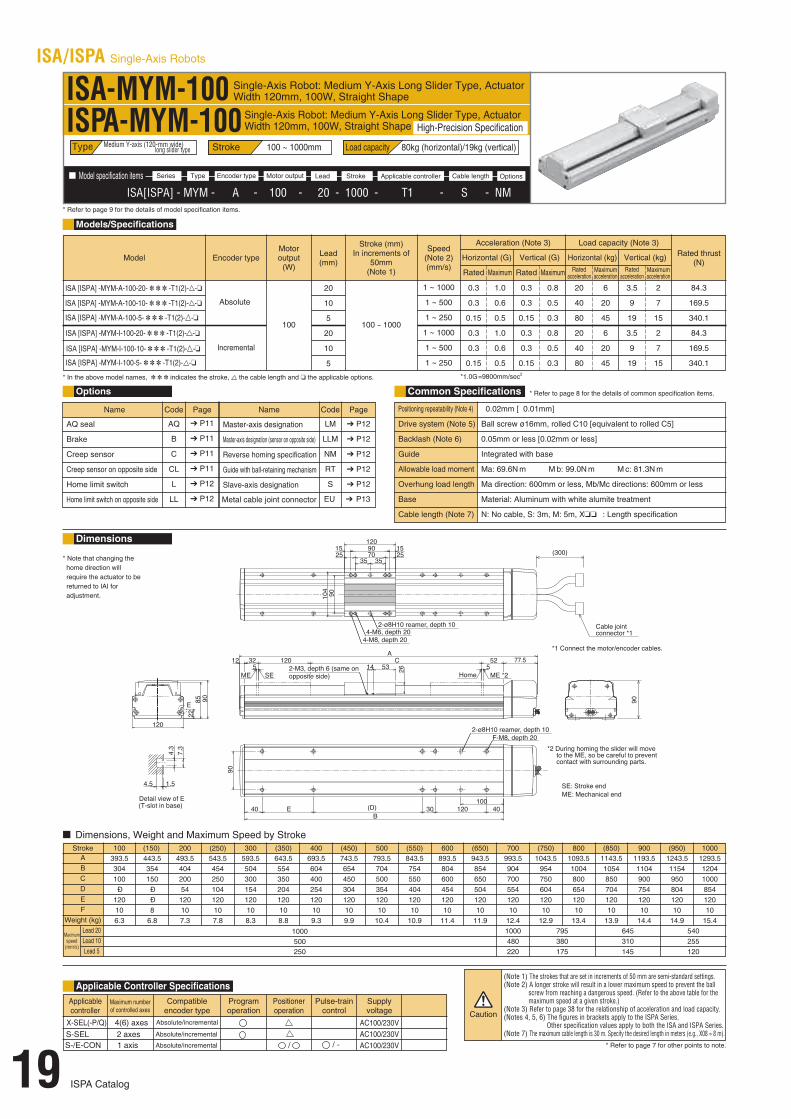
Model specification items
ISA[ISPA] - MYM - A - 100 - 20 - 1000 - T1 - S - NM
OptionsCable lengthApplicable controllerStrokeLeadMotor outputEncoder typeTypeSeries
ISA/ISPA Single-Axis Robots
Models/Specifications
Options
Dimensions
Common Specifications
* Note that changing the
home direction will
require the actuator to be
returned to IAI for
adjustment.
* Refer to page 8 for the details of common specification items.
ISA-MYM-100 Single-Axis Robot: Medium Y-Axis Long Slider Type, ActuatorWidth 120mm, 100W, Straight Shape
ISPA-MYM-100Type Stroke 100 ~ 1000mm Load capacity 80kg (horizontal)/19kg (vertical)
* Refer to page 9 for the details of model specification items.
Stroke 100 (150) 200 (250)
1000
500
250
300 (350)
A
B
C
D
E
F
Weight (kg)
Lead 20
Lead 10
Lead 5
393.5
304
100
Ð
120
10
6.3
443.5
354
150
Ð
Ð
8
6.8
493.5
404
200
54
120
10
7.3
543.5
454
250
104
120
10
7.8
593.5
504
300
154
120
10
8.3
643.5
554
350
204
120
10
8.8
Maximumspeed
(mm/s)
400 (450) 500 (550)
693.5
604
400
254
120
10
9.3
743.5
654
450
304
120
10
9.9
793.5
704
500
354
120
10
10.4
843.5
754
550
404
120
10
10.9
600 (650) (750)700 800
893.5
804
600
454
120
10
11.4
943.5
854
650
504
120
10
11.9
1043.5
954
750
604
120
10
12.9
993.5
904
700
554
120
10
12.4
1093.5
1004
800
654
120
10
13.4
(850) 900 (950) 1000
1143.5
1054
850
704
120
10
13.9
1193.5
1104
900
754
120
10
14.4
1243.5
1154
950
804
120
10
14.9
1293.5
1204
1000
854
120
10
15.4
Dimensions, Weight and Maximum Speed by Stroke
540
255
120
645
310
145
795
380
175
1000
480
220
Model Encoder type
Absolute
Incremental
Motor output
(W)
100
Lead(mm)
20
10
5
20
10
5
Stroke (mm)In increments of
50mm(Note 1)
Speed(Note 2)(mm/s)
100 ~ 1000
1 ~ 1000
1 ~ 500
1 ~ 250
1 ~ 1000
1 ~ 500
1 ~ 250
Rated thrust(N)
84.3
169.5
340.1
84.3
169.5
340.1
Acceleration (Note 3)
Horizontal (G)
0.3
0.3
0.15
0.3
0.3
0.15
1.0
0.6
0.5
1.0
0.6
0.5
Vertical (G)
0.3
0.3
0.15
0.3
0.3
0.15
0.8
0.5
0.3
0.8
0.5
0.3
Load capacity (Note 3)
Horizontal (kg)
20
40
80
20
40
80
6
20
45
6
20
45
Vertical (kg)
Rated Maximum Rated Maximum Ratedacceleration
Ratedacceleration
Maximumacceleration
Maximumacceleration
3.5
9
19
3.5
9
19
2
7
15
2
7
15
* In the above model names, indicates the stroke, the cable length and the applicable options. *1.0G=9800mm/sec2
High-Precision SpecificationSingle-Axis Robot: Medium Y-Axis Long Slider Type, ActuatorWidth 120mm, 100W, Straight Shape
Medium Y-axis (120-mm wide) long slider type
Name
AQ seal
Brake
Creep sensor
Creep sensor on opposite side
Home limit switch
Home limit switch on opposite side
AQ
B
C
CL
L
LL
P11
P11
P11
P11
P12
P12
Code Page Name
Master-axis designation
Master-axis designation (sensor on opposite side)
Reverse homing specification
Guide with ball-retaining mechanism
Slave-axis designation
LM
LLM
NM
RT
S
P12
P12
P12
P12
P12
Code Page Positioning repeatability (Note 4)
Drive system (Note 5)
Backlash (Note 6)
Guide
Allowable load moment
Overhung load length
Base
Cable length (Note 7)
0.02mm [ 0.01mm]
Ball screw ø16mm, rolled C10 [equivalent to rolled C5]
0.05mm or less [0.02mm or less]
Integrated with base
Ma: 69.6N m M b: 99.0N m M c: 81.3N m
Ma direction: 600mm or less, Mb/Mc directions: 600mm or less
Material: Aluminum with white alumite treatment
N: No cable, S: 3m, M: 5m, X : Length specification
Applicable Controller Specifications
Applicablecontroller
Maximum number
of controlled axes
Compatibleencoder type
Programoperation
Positioneroperation
Pulse-traincontrol
Supplyvoltage
X-SEL(-P/Q) 4(6) axes Absolute/incremental AC100/230V
AC100/230V
AC100/230V * Refer to page 7 for other points to note.
(Note 1) The strokes that are set in increments of 50 mm are semi-standard settings.(Note 2) A longer stroke will result in a lower maximum speed to prevent the ball
screw from reaching a dangerous speed. (Refer to the above table for the maximum speed at a given stroke.)
(Note 3) Refer to page 38 for the relationship of acceleration and load capacity.(Notes 4, 5, 6) The figures in brackets apply to the ISPA Series.
Other specification values apply to both the ISA and ISPA Series.(Note 7) The maximum cable length is 30 m. Specify the desired length in meters (e.g., X08 = 8 m).
ISA [ISPA] -MYM-A-100-20- -T1(2)--
ISA [ISPA] -MYM-I-100-5- -T1(2)--
ISA [ISPA] -MYM-A-100-10- -T1(2)--
ISA [ISPA] -MYM-A-100-5- -T1(2)--
ISA [ISPA] -MYM-I-100-20- -T1(2)--
ISA [ISPA] -MYM-I-100-10- -T1(2)--
Metal cable joint connector EU P13
S-/E-CON / - /
S-SEL
1 axis
2 axes
Absolute/incremental
Absolute/incremental

■ Model specification items
ISA[ISPA] - MYM - A - 200 - 30 - 1000 - T1 - S - NM
OptionsCable lengthApplicable controllerStrokeLeadMotor outputEncoder typeTypeSeries
ISA/ISPA Single-Axis Robots
ISPA Catalog 20
Models/Specifications
Options
Dimensions
Common Specifications
* Note that changing the
home direction will
require the actuator to be
returned to IAI for
adjustment.
* Refer to page 8 for the details of common specification items.
ISA-MYM-200 Single-Axis Robot: Medium Y-Axis Long Slider Type, ActuatorWidth 120mm, 200W, Straight ShapeISPA-MYM-200
Type Stroke 100 ~ 1000mm Load capacity 80kg (horizontal)/19kg (vertical)
* Refer to page 9 for the details of model specification items.
Stroke 100 (150) 200 (250)
1500
1000
500
300 (350)
A
B
C
D
E
F
Weight (kg)
Lead 30
Lead 20
Lead 10
407.5
304
100
Ð
120
10
6.8
457.5
354
150
Ð
Ð
8
7.3
507.5
404
200
54
120
10
7.8
557.5
454
250
104
120
10
8.3
607.5
504
300
154
120
10
8.8
657.5
554
350
204
120
10
9.3
Maximumspeed(mm/s)
400 (450) 500 (550)
707.5
604
400
254
120
10
9.8
757.5
654
450
304
120
10
10.4
807.5
704
500
354
120
10
10.9
857.5
754
550
404
120
10
11.4
600 (650) (750)700 800
907.5
804
600
454
120
10
11.9
957.5
854
650
504
120
10
12.4
1057.5
954
750
604
120
10
13.4
1007.5
904
700
554
120
10
12.9
1107.5
1004
800
654
120
10
13.9
(850) 900 (950) 1000
1157.5
1054
850
704
120
10
14.4
1207.5
1104
900
754
120
10
14.9
1257.5
1154
950
804
120
10
15.4
1307.5
1204
1000
854
120
10
15.9
■ Dimensions, Weight and Maximum Speed by Stroke
810
540
255
965
645
310
1190
795
380
1500
1000
480
Model Encoder type
Absolute
Incremental
Motoroutput
(W)
200
Lead(mm)
30
20
10
30
20
10
Stroke (mm)In increments of
50mm(Note 1)
Speed(Note 2)(mm/s)
100 ~ 1000
1 ~ 1500
1 ~ 1000
1 ~ 500
1 ~ 1500
1 ~ 1000
1 ~ 500
Rated thrust(N)
113
169.5
340.1
113
169.5
340.1
Acceleration (Note 3)
0.3
0.3
0.3
0.3
0.3
0.3
1.0
1.0
0.6
1.0
1.0
0.6
0.3
0.3
0.3
0.3
0.3
0.3
1.0
0.8
0.5
1.0
0.8
0.5
Load capacity (Note 3)
25
40
80
25
40
80
10
12
40
10
12
40
6
9
19
6
9
19
2
5
15
2
5
15
* In the above model names, indicates the stroke, the cable length and the applicable options. *1.0G=9800mm/sec2
Horizontal (G) Vertical (G) Horizontal (kg) Vertical (kg)
Rated Maximum Rated MaximumRated
accelerationRated
accelerationMaximumacceleration
Maximumacceleration
High-Precision Specification
Single-Axis Robot: Medium Y-Axis Long Slider Type, Actuator
Width 120mm, 200W, Straight Shape
Medium Y-axis (120-mm wide) long slider type
Name
AQ seal
Brake
Creep sensor
Creep sensor on opposite side
Home limit switch
Home limit switch on opposite side
AQ
B
C
CL
L
LL
➔ P11
➔ P11
➔ P11
➔ P11
➔ P12
➔ P12
Code Page Name
Master-axis designation
Master-axis designation (sensor on opposite side)
Reverse homing specification
Guide with ball-retaining mechanism
Slave-axis designation
LM
LLM
NM
RT
S
➔ P12
➔ P12
➔ P12
➔ P12
➔ P12
Code Page Positioning repeatability (Note 4)
Drive system (Note 5)
Backlash (Note 6)
Guide
Allowable load moment
Overhung load length
Base
Cable length (Note 7)
±0.02mm [±0.01mm]
Ball screw ø16mm, rolled C10 [equivalent to rolled C5]
0.05mm or less [0.02mm or less]
Integrated with base
Ma: 69.6Nm M b: 99.0Nm M c: 81.3Nm
Ma direction: 600mm or less, Mb/Mc directions: 600mm or less
Material: Aluminum with white alumite treatment
N: No cable, S: 3m, M: 5m, X : Length specification
Applicable Controller Specifications
Applicablecontroller
Maximum number
of controlled axes
Compatibleencoder type
Programoperation
Positioneroperation
Pulse-traincontrol
Supplyvoltage
X-SEL(-P/Q) 4(6) axes Absolute/incremental ▲ AC100/230V
AC100/230V
AC100/230V * Refer to page 7 for other points to note.
(Note 1) The strokes that are set in increments of 50 mm are semi-standard settings.(Note 2) A longer stroke will result in a lower maximum speed to prevent the ball screw from reaching a dangerous speed. (Refer to the above table for the maximum speed at a given stroke.)(Note 3) Refer to page 38 for the relationship of acceleration and load capacity.(Notes 4, 5, 6) The figures in brackets apply to the ISPA Series. Other specification values apply to both the ISA and ISPA Series.(Note 7) The maximum cable length is 30 m. Specify the desired length in meters (e.g., X08 = 8 m).
ISA [ISPA] -MYM-A- 200-30- -T1(2)--
ISA [ISPA] -MYM-A- 200-20- -T1(2)--
ISA [ISPA] -MYM-A- 200-10- -T1(2)--
ISA [ISPA] -MYM-I- 200-30- -T1(2)--
ISA [ISPA] -MYM-I- 200-20- -T1(2)--
ISA [ISPA] -MYM-I- 200-10- -T1(2)--
Metal cable joint connector EU P13
S-/E-CON / - /
S-SEL
1 axis
2 axes
Absolute/incremental
Absolute/incremental
21 ISPA Catalog
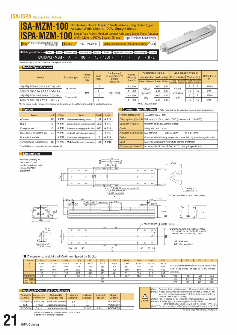
Model specification items
ISA[ISPA] - MZM - A - 100 - 10 - 1000 - T1 - S - B - L
OptionsCable lengthApplicable controllerStrokeLeadMotor outputEncoder typeTypeSeries
ISA/ISPA Single-Axis Robots
Options
Dimensions
* Note that changing the
home direction will
require the actuator to be
returned to IAI for
adjustment.
* The MZM type comes standard with a brake (B).
Vertical application only (with standard brake) 19kg
ISA-MZM-100 Single-Axis Robot: Medium Vertical-Axis Long Slider Type, Actuator Width 120mm, 100W, Straight Shape
ISPA-MZM-100Type Stroke 100 ~ 1000mm
* Refer to page 9 for the details of model specification items.
Models/Specifications
* The MZM type comes standard with a brake, so usea controller of brake specification.
Stroke 100 (150) 200 (250) 300
A
B
C
D
Weight (kg)
Lead 10
Lead 5
420.5
304
100
64
7.1
470.5
354
150
114
7.6
520.5
404
200
164
8.1
570.5
454
250
214
8.6
620.5
504
300
264
9.1
(350) 400 (450) 500
670.5
554
350
314
9.6
720.5
604
400
364
10.1
770.5
654
450
414
10.7
820.5
704
500
464
11.2
(550)
870.5
754
550
514
11.7
600
920.5
804
600
564
12.2
500
250
700 800
13.2
480
220
14.2
380
175
900
15.2
310
145
1000
16.2
255
120
Use the base of the MXM type for 700 and longer strokes.
Refer to the drawing on page 16 for the mounting
dimensions.
Dimensions, Weight and Maximum Speed by Stroke
Maximumspeed
(mm/s)
Model Encoder type
Absolute
Incremental
Motor output
(W)
100
Lead(mm)
10
5
10
5
Stroke (mm)In increments of
50mm(Note 1)
Speed(Note 2)(mm/s)
100 ~ 1000
1 ~ 500
1 ~ 250
1 ~ 500
1 ~ 250
Rated thrust(N)
169.5
340.1
169.5
340.1
* In the above model names, indicates the stroke, the cable length and the applicable options.
0.3
0.15
0.3
0.15
Acceleration (Note 3)
Horizontal (kg)
Vertical
application
only
Vertical (kg)
Rated RatedMaximum Maximum
0.5
0.3
0.5
0.3
9
19
9
19
Load capacity (Note 3)
Horizontal (kg)
Vertical
application
only
Vertical (kg)
Ratedacceleration
Ratedacceleration
Maximumacceleration
Maximumacceleration
7
15
7
15
*1.0G=9800mm/sec2
High-Precision Specification
Single-Axis Robot: Medium Vertical-Axis Long Slider Type, ActuatorWidth 120mm, 100W, Straight Shape
Medium vertical-axis (120-mm wide) long slider type
Name
AQ seal
Brake
Creep sensor
Creep sensor on opposite side
Home limit switch
Home limit switch on opposite side
AQ
B
C
CL
L
LL
P11
P11
P11
P11
P12
P12
Code Page Name
Master-axis designation
Master-axis designation (sensor on opposite side)
Reverse homing specification
Guide with ball-retaining mechanism
Slave-axis designation
LM
LLM
NM
RT
S
P12
P12
P12
P12
P12
Code Page
Common Specifications * Refer to page 8 for the details of common specification items.
Positioning repeatability (Note 4)
Drive system (Note 5)
Backlash (Note 6)
Guide
Allowable load moment
Brake
Base
Cable length (Note 7)
±0.02mm [±0.01mm]
Ball screw ø16mm, rolled C10 [equivalent to rolled C5]
0.05mm or less [0.02mm or less]
Integrated with base
Ma: 69.6Nm M b: 99.0Nm M c: 81.3Nm
Comes standard with a dry, single-plate, non-excitation type electromagnetic brake.
Material: Aluminum with white alumite treatment
N: No cable, S: 3m, M: 5m, X : Length specification
Applicable Controller Specifications
Applicablecontroller
Maximum number
of controlled axes
Compatibleencoder type
Programoperation
Positioneroperation
Pulse-traincontrol
Supplyvoltage
X-SEL(-P/Q) 4(6) axes Absolute/incremental AC100/230V
AC100/230V
AC100/230V* Refer to page 7 for other points to note.
(Note 1) The strokes that are set in increments of 50 mm are semi-standard settings.(Note 2) A longer stroke will result in a lower maximum speed to prevent the ball
screw from reaching a dangerous speed. (Refer to the above table for the maximum speed at a given stroke.)
(Note 3) Refer to page 38 for the relationship of acceleration and load capacity.(Notes 4, 5, 6) The figures in brackets apply to the ISPA Series.
Other specification values apply to both the ISA and ISPA Series.(Note 7) The maximum cable length is 30 m. Specify the desired length in meters (e.g., X08 = 8 m).
ISA [ISPA] -MZM-A-100-10- -T1(2)--B-
ISA [ISPA] -MZM-A-100-5- -T1(2)--B-
ISA [ISPA] -MZM-I-100-10- -T1(2)--B-
ISA [ISPA] -MZM-I-100-5- -T1(2)--B-
Metal cable joint connector EU P13
S-/E-CON / - /
S-SEL
1 axis
2 axes
Absolute/incremental
Absolute/incremental

Model specification items
ISA[ISPA] - MZM - A - 200 - 10 - 1000 - T1 - S - B - L
OptionsCable lengthApplicable controllerStrokeLeadMotor outputEncoder typeTypeSeries
ISA/ISPA Single-Axis Robots
ISPA Catalog 22
Dimensions
* Note that changing the
home direction will
require the actuator to be
returned to IAI for
adjustment.
Vertical application only (with standard brake) 19kg
ISA-MZM-200 Single-Axis Robot: Medium Vertical-Axis Long Slider Type,Actuator Width 120mm, 200W, Straight Shape
ISPA-MZM-200Type Stroke 100 ~ 1000mm
* Refer to page 9 for the details of model specification items.
Models/Specifications
* The MZM type comes standard with a brake, so usea controller of brake specification.
Options
* The MZM type comes standard with a brake (B).
Stroke 100 (150) 200 (250) 300
A
B
C
D
Weight (kg)
Maximum speed (mm/s)
434.5
304
100
64
7.1
484.5
354
150
114
7.6
534.5
404
200
164
8.1
584.5
454
250
214
8.6
634.5
504
300
264
9.1
(350) 400 (450) 500
684.5
554
350
314
9.6
734.5
604
400
364
10.1
784.5
654
450
414
10.7
834.5
704
500
464
11.2
(550)
884.5
754
550
514
11.7
600
934.5
804
600
564
12.2
500
700 800
13.2
480
14.2
380
900
15.2
310
1000
16.2
255
Use the base of the MXM type for 700 and longer strokes.
Refer to the drawing on page 17 for the mounting
dimensions.
Dimensions, Weight and Maximum Speed by Stroke
Model Encoder type
Absolute
Incremental
Motor output
(W)
200
Lead(mm)
10
Rated thrust(N)
340.1
340.1
Stroke (mm)In increments of
50mm(Note 1)
Speed(Note 2)(mm/s)
100 ~ 10001 ~ 500
1 ~ 500
* In the above model names, indicates the stroke, the cable length and the applicable options. *1.0G=9800mm/sec2
Acceleration (Note 3)
Horizontal (G)
Verticalapplication
only
Vertical (G)
Rated Rated
0.3
0.3
Maximum Maximum
0.5
0.5
Load capacity (Note 3)
Horizontal (kg)
Verticalapplication
only
Vertical (kg)
Ratedacceleration
Ratedacceleration
19
19
Maximumacceleration
Maximumacceleration
15
15
High-Precision Specification
Single-Axis Robot: Medium Vertical-Axis Long Slider Type, Actuator Width 120mm, 200W, Straight Shape
Medium vertical-axis (120-mm wide) long slider type
Name
AQ seal
Brake
Creep sensor
Creep sensor on opposite side
Home limit switch
Home limit switch on opposite side
AQ
B
C
CL
L
LL
P11
P11
P11
P11
P12
P12
Code Page Name
Master-axis designation
Master-axis designation (sensor on opposite side)
Reverse homing specification
Guide with ball-retaining mechanism
Slave-axis designation
LM
LLM
NM
RT
S
P12
P12
P12
P12
P12
Code Page
Common Specifications * Refer to page 8 for the details of common specification items.
Positioning repeatability (Note 4)
Drive system (Note 5)
Backlash (Note 6)
Guide
Allowable load moment
Brake
Base
Cable length (Note 7)
±0.02mm [±0.01mm]
Ball screw ø16mm, rolled C10 [equivalent to rolled C5]
0.05mm or less [0.02mm or less]
Integrated with base
Ma: 69.6Nm M b: 99.0Nm M c: 81.3Nm
Comes standard with a dry, single-plate, non-excitation type electromagnetic brake.
Material: Aluminum with white alumite treatment
N: No cable, S: 3m, M: 5m, X : Length specification
Applicable Controller Specifications
Applicablecontroller
Maximum number
of controlled axes
Compatibleencoder type
Programoperation
Positioneroperation
Pulse-traincontrol
Supplyvoltage
X-SEL(-P/Q) 4(6) axes Absolute/incremental AC100/230V
AC100/230V
AC100/230V* Refer to page 7 for other points to note.
(Note 1) The strokes that are set in increments of 50 mm are semi-standard settings.(Note 2) A longer stroke will result in a lower maximum speed to prevent the ball
screw from reaching a dangerous speed. (Refer to the above table for the maximum speed at a given stroke.)
(Note 3) Refer to page 38 for the relationship of acceleration and load capacity.(Notes 4, 5, 6) The figures in brackets apply to the ISPA Series.
Other specification values apply to both the ISA and ISPA Series.(Note 7) The maximum cable length is 30 m. Specify the desired length in meters (e.g., X08 = 8 m).
ISA [ISPA] -MZM-A-200-10- -T1(2)--B-
ISA [ISPA] -MZM-I-200-10- -T1(2)--B-
Metal cable joint connector EU P13
S-/E-CON / - /
S-SEL
1 axis
2 axes
Absolute/incremental
Absolute/incremental

23 ISPA Catalog
Model specification items
ISA[ISPA] - LXM - A - 200 - 10 - 1200 - T1 - S - B
OptionsCable lengthApplicable controllerStrokeLeadMotor outputEncoder typeTypeSeries
ISA/ISPA Single-Axis Robots
Options
Dimensions
* Note that changing the home direction
will require the actuator to be returned
to IAI for adjustment.
ISA-LXM-200 Single-Axis Robot: Large X-Axis Long Slider Type, ActuatorWidth 150mm, 200W, Straight Shape
ISPA-LXM-200Type Stroke 100 ~ 1200mm Load capacity 80kg (horizontal)/19kg (vertical)
* Refer to page 9 for the details of model specification items.
Models/Specifications
Stroke 100 (150) 200 (250) 300 (350)
A
B
C
D
E
F
Weight (kg)
Lead 20
Lead 10
453
338
100
0
238
4
11.0
503
388
150
0
288
4
11.8
553
438
200
1
138
6
12.5
603
488
250
1
188
6
13.3
653
538
300
1
238
6
14.0
703
588
350
1
288
6
14.8Maximumspeed
(mm/s)
400 (450) 500 (550)
753
638
400
2
138
8
15.5
803
688
450
2
188
8
16.3
853
738
500
2
238
8
17.0
903
788
550
2
288
8
17.8
600
953
838
600
3
138
10
18.5
(650)
1003
888
650
3
188
10
19.3
1000
500
700
1053
938
700
3
238
10
20.0
(750)
1103
988
750
3
288
10
20.8
800
1153
1038
800
4
138
12
21.5
(850)
1203
1088
850
4
188
12
22.3
900 (950) 1000 (1050) 1100 (1150)
1253
1138
900
4
238
12
23.0
1303
1188
950
4
288
12
23.8
1353
1238
1000
5
138
14
24.5
1403
1288
1050
5
188
14
25.3
1453
1338
1100
5
238
14
26.0
1503
1388
1150
5
288
14
26.8
1200
1553
1438
1200
6
138
16
27.5
Dimensions, Weight and Maximum Speed by Stroke
585
270
690
320
830
385
1000
470
500
235
Model Encoder type
Absolute
Incremental
Motor output
(W)
200
Lead(mm)
20
10
20
10
Stroke (mm)In increments of
50mm(Note 1)
Speed(Note 2)(mm/s)
100 ~ 1200
1 ~ 1000
1 ~ 500
1 ~ 1000
1 ~ 500
Rated thrust(N)
170.5
340.1
170.5
340.1
* In the above model names, indicates the stroke, the cable length and the applicable options.
Acceleration (Note 3)
Horizontal (G)
0.3
0.3
0.3
0.3
Vertical (G)
Rated Rated
0.3
0.3
0.3
0.3
1.0
0.6
1.0
0.6
Maximum Maximum
0.8
0.5
0.8
0.5
Load capacity (Note 3)
Horizontal (kg)
40
80
40
80
Vertical (kg)
Ratedacceleration
Ratedacceleration
9
19
9
19
12
40
12
40
Maximumacceleration
Maximumacceleration
4
14
4
14
*1.0G=9800mm/sec2
High-Precision SpecificationSingle-Axis Robot: Large X-Axis Long Slider Type, ActuatorWidth 150mm, 200W, Straight Shape
Large X-axis (150-mm wide) long slider type
Name
AQ seal
Brake
Creep sensor
Creep sensor on opposite side
Home limit switch
Home limit switch on opposite side
AQ
B
C
CL
L
LL
P11
P11
P11
P11
P12
P12
Code Page Name
Master-axis designation
Master-axis designation (sensor on opposite side)
Reverse homing specification
Guide with ball-retaining mechanism
Slave-axis designation
LM
LLM
NM
RT
S
P12
P12
P12
P12
P12
Code Page
Common Specifications * Refer to page 8 for the details of common specification items.
Positioning repeatability (Note 4)
Drive system (Note 5)
Backlash (Note 6)
Guide
Allowable load moment
Overhung load length
Base
Cable length (Note 7)
0.02mm [ 0.01mm]
Ball screw ø20mm, rolled C10 [equivalent to rolled C5]
0.05mm or less [0.02mm or less]
Integrated with base
Ma: 104.9Nm M b: 149.9Nm M c: 248.9Nm
Ma direction: 750mm or less, Mb/Mc directions: 750mm or less
Material: Aluminum with white alumite treatment
N: No cable, S: 3m, M: 5m, X : Length specification
Applicable Controller Specifications
Applicablecontroller
Maximum number
of controlled axes
Compatibleencoder type
Programoperation
Positioneroperation
Pulse-traincontrol
Supplyvoltage
X-SEL(-P/Q) 4(6) axes Absolute/incremental AC100/230V
AC100/230V
AC100/230V * Refer to page 7 for other points to note.
(Note 1) The strokes that are set in increments of 50 mm are semi-standard settings.(Note 2) A longer stroke will result in a lower maximum speed to prevent the ball
screw from reaching a dangerous speed. (Refer to the above table for the maximum speed at a given stroke.)
(Note 3) Refer to page 38 for the relationship of acceleration and load capacity.(Notes 4, 5, 6) The figures in brackets apply to the ISPA Series.
Other specification values apply to both the ISA and ISPA Series.(Note 7) The maximum cable length is 30 m. Specify the desired length in meters (e.g., X08 = 8 m).
ISA [ISPA] -LXM-A-200-20- -T1(2)--
ISA [ISPA] -LXM-A-200-10- -T1(2)--
ISA [ISPA] -LXM-I-200-10- -T1(2)--
ISA [ISPA] -LXM-I-200-20- -T1(2)--
Metal cable joint connector EU P13
S-/E-CON / - /
S-SEL
1 axis
2 axes
Absolute/incremental
Absolute/incremental

■ Model specification items
ISA[ISPA] - LXM - A - 400 - 40 - 1200 - T1 - S - B
OptionsCable lengthApplicable controllerStrokeLeadMotor outputEncoder typeTypeSeries
G
13
4
15
0
Dx200P
1501512015
EB
16
6
5533 C150
90
30 90 3045 45
81
.5
4.5 1.5
4.3
7.3
5050
55
12515
A
150
22
95
10
4.5
14
2868
104.5
SEME
ISA/ISPA Single-Axis Robots
ISPA Catalog 24
Models/Specifications
Dimensions
* Note that changing
the home direction
will require the
actuator to be
returned to IAI for
adjustment.
ISA-LXM-400 Single-Axis Robot: Large X-Axis Long Slider Type, ActuatorWidth 150mm, 400W, Straight ShapeISPA-LXM-400
Stroke 100 ~ 1200mm Load capacity 80kg (horizontal)/19kg (vertical)
* Refer to page 9 for the details of model specification items.
Type
Stroke 100 (150) 200 (250) 300 (350)
A
B
C
D
E
F
Weight (kg)
Lead 40
Lead 20
478
338
100
0
238
4
12.0
528
388
150
0
288
4
12.8
578
438
200
1
138
6
13.5
628
488
250
1
188
6
14.3
678
538
300
1
238
6
15.0
728
588
350
1
288
6
15.8
Maximumspeed(mm/s)
400 (450) 500 (550)
778
638
400
2
138
8
16.5
828
688
450
2
188
8
17.3
878
738
500
2
238
8
18.0
928
788
550
2
288
8
18.8
600
978
838
600
3
138
10
19.5
(650)
1028
888
650
3
188
10
20.3
2000
1000
700
1078
938
700
3
238
10
21.0
(750)
1128
988
750
3
288
10
21.8
800
1178
1038
800
4
138
12
22.5
(850)
1228
1088
850
4
188
12
23.3
900 (950) 1000 (1050) 1100 (1150)
1278
1138
900
4
238
12
24.0
1328
1188
950
4
288
12
24.8
1378
1238
1000
5
138
14
25.5
1428
1288
1050
5
188
14
26.3
1478
1338
1100
5
238
14
27.0
1528
1388
1150
5
288
14
27.8
1200
1578
1438
1200
6
138
16
28.5
■ Dimensions, Weight and Maximum Speed by Stroke
1660
830
1380
690
1170
585
1000
500
Model Encoder type
Absolute
Incremental
Motoroutput
(W)
400
Lead(mm)
40
20
40
20
Stroke (mm)In increments of
50mm(Note 1)
Speed(Note 2)(mm/s)
100 ~ 1200
1 ~ 2000
1 ~ 1000
1 ~ 2000
1 ~ 1000
Rated thrust(N)
170.0
340.1
170.0
340.1
* In the above model names, indicates the stroke, the cable length and the applicable options.
Acceleration (Note 3)
Horizontal (G)
0.3
0.3
0.3
0.3
Vertical (G)
Rated Rated
0.3
0.3
0.3
0.3
1.0
1.0
1.0
1.0
Maximum Maximum
1.0
0.8
1.0
0.8
Load capacity (Note 3)
Horizontal (kg)
40
80
40
80
Vertical (kg)
Ratedacceleration
Ratedacceleration
9
19
9
19
15
24
15
24
Maximumacceleration
Maximumacceleration
4
10
4
10
*1.0G=9800mm/sec2
High-Precision Specification
Single-Axis Robot: Large X-Axis Long Slider Type, ActuatorWidth 150mm, 400W, Straight Shape
Large X-axis (150-mm wide) long slider type
Options
Name
AQ seal
Brake
Creep sensor
Creep sensor on opposite side
Home limit switch
Home limit switch on opposite side
AQ
B
C
CL
L
LL
➔ P11
➔ P11
➔ P11
➔ P11
➔ P12
➔ P12
Code Page Name
Master-axis designation
Master-axis designation (sensor on opposite side)
Reverse homing specification
Guide with ball-retaining mechanism
Slave-axis designation
LM
LLM
NM
RT
S
➔ P12
➔ P12
➔ P12
➔ P12
➔ P12
Code Page
Common Specifications * Refer to page 8 for the details of common specification items.
Positioning repeatability (Note 4)
Drive system (Note 5)
Backlash (Note 6)
Guide
Allowable load moment
Overhung load length
Base
Cable length (Note 7)
±0.02mm [±0.01mm]
Ball screw ø20mm, rolled C10 [equivalent to rolled C5]
0.05mm or less [0.02mm or less]
Integrated with base
Ma: 104.7Nm M b: 149.9Nm M c: 248.9Nm
Ma direction: 750mm or less, Mb/Mc directions: 750mm or less
Material: Aluminum with white alumite treatment
N: No cable, S: 3m, M: 5m, X : Length specification
Applicable Controller Specifications
Applicablecontroller
Maximum number
of controlled axes
Compatibleencoder type
Programoperation
Positioneroperation
Pulse-traincontrol
Supplyvoltage
X-SEL(-P/Q) 4(6) axes Absolute/incremental ▲ AC100/230V
AC100/230V
AC100/230V * Refer to page 7 for other points to note.
(Note 1) The strokes that are set in increments of 50 mm are semi-standard settings.(Note 2) A longer stroke will result in a lower maximum speed to prevent the ball screw from reaching a dangerous speed. (Refer to the above table for the maximum speed at a given stroke.)(Note 3) Refer to page 38 for the relationship of acceleration and load capacity.(Notes 4, 5, 6) The figures in brackets apply to the ISPA Series. Other specification values apply to both the ISA and ISPA Series.(Note 7) The maximum cable length is 30 m. Specify the desired length in meters (e.g., X08 = 8 m).
ISA [ISPA] -LXM-A-400-40- -T1(2)--
ISA [ISPA] -LXM-I-400-20- -T1(2)--
ISA [ISPA] -LXM-A-400-20- -T1(2)--
ISA [ISPA] -LXM-I-400-40- -T1(2)--
Metal cable joint connector EU P13
S-/E-CON / - /
S-SEL
1 axis
2 axes
Absolute/incremental
Absolute/incremental

25 ISPA Catalog
Model specification items
ISA[ISPA] - LXMX - A - 200 - 20 - 2500 - T1 - S - NM
OptionsCable lengthApplicable controllerStrokeLeadMotor outputEncoder typeTypeSeries
ISA/ISPA Single-Axis Robots
ISA-LXMX-200 Single-Axis Robot: Large X-Axis Mid-Support Type, ActuatorWidth 150mm, 200W, Straight Shape
ISPA-LXMX-200
* Refer to page 9 for the details of model specification items.
Models/Specifications
Dimensions
* Note that changing the
home direction will
require the actuator to be
returned to IAI for
adjustment.
* Due to its structure the
mid-support type cannot
be positioned horizontally
on its side or vertically.
Stroke 1000 ~ 2500mm Load capacity 40kg (horizontal)Type
Stroke 1000 1100 1200 1300
1000
1400 1500
A
B
C
D
E
F
G
H
J
K
Weight (kg)
Maximum speed (mm/s)
1465
1350
1014
225
0
0
225
0
0
12
27.5
1565
1450
1114
275
0
0
275
0
0
12
29.0
1665
1550
1214
325
0
0
325
0
0
12
30.5
1765
1650
1314
375
0
0
375
0
0
12
32.0
1865
1750
1414
425
0
0
425
0
0
12
33.5
1965
1850
1514
475
0
0
475
0
0
12
35.0
950
1600 1700
2065
1950
1614
525
0
0
525
0
0
12
36.5
830
2165
2050
1714
575
0
0
575
0
0
12
38.0
740
1800 1900 2000 2100 2200 2300
2265
2150
1814
200
425
0
200
425
0
16
39.5
650
2365
2250
1914
200
475
0
200
475
0
16
41.0
590
2465
2350
2014
200
525
0
200
525
0
16
42.5
540
2565
2450
2114
200
575
0
200
575
0
16
44.0
490
2665
2550
2214
200
200
425
200
200
425
20
45.5
440
2765
2650
2314
200
200
475
200
200
475
20
47.0
410
2400 2500
2865
2750
2414
200
200
525
200
200
525
20
48.5
370
2965
2850
2514
200
200
575
200
200
575
20
50.0
340
Dimensions, Weight and Maximum Speed by Stroke
Model Encoder type
Absolute
Incremental
Motor output
(W)
200
Lead(mm)
20
20
Stroke (mm)In increments of
100mm
Speed(Note 1)(mm/s)
1000 ~ 25001 ~ 1000
1 ~ 1000
Rated thrust(N)
170.5
170.5
Acceleration (Note 2)
Horizontal (G)
0.3
0.3
Vertical (G)
Rated Rated
Horizontalapplication
only
Maximum Maximum
Load capacity (Note 2)
Horizontal (kg)
40
40
Vertical (kg)
Ratedacceleration
Ratedacceleration
Horizontalapplication
only
Maximumacceleration
Maximumacceleration
* In the above model names, indicates the stroke, the cable length and the applicable options. *1.0G=9800mm/sec2
High-Precision Specification
Single-Axis Robot: Large X-Axis Mid-Support Type, ActuatorWidth 150mm, 200W, Straight Shape
Large X-axis (150-mm wide) mid-support type
Options
Name
AQ seal
Brake
Creep sensor
Creep sensor on opposite side
Home limit switch
Home limit switch on opposite side
AQ
B
C
CL
L
LL
P11
P11
P11
P11
P12
P12
Code Page Name
Master-axis designation
Master-axis designation (sensor on opposite side)
Reverse homing specification
Guide with ball-retaining mechanism
Slave-axis designation
LM
LLM
NM
RT
S
P12
P12
P12
P12
P12
Code Page
Common Specifications * Refer to page 8 for the details of common specification items.
Positioning repeatability (Note 3)
Drive system (Note 4)
Backlash (Note 5)
Guide
Allowable load moment
Overhung load length
Base
Cable length (Note 6)
0.02mm [ 0.01mm]
Ball screw ø20mm, rolled C10 [equivalent to rolled C5]
0.05mm or less [0.02mm or less]
Integrated with base
Ma: 104.9Nm M b: 149.9Nm M c: 248.9Nm
Ma direction: 750mm or less, Mb/Mc directions: 750mm or less
Material: Aluminum with white alumite treatment
N: No cable, S: 3m, M: 5m, X : Length specification
Applicable Controller Specifications
Applicablecontroller
Maximum number
of controlled axes
Compatibleencoder type
Programoperation
Positioneroperation
Pulse-traincontrol
Supplyvoltage
X-SEL(-P/Q) 4(6) axes Absolute/incremental AC100/230V
AC100/230V
AC100/230V * Refer to page 7 for other points to note.
(Note 1) The strokes that are set in increments of 50 mm are semi-standard settings.
(Note 2) Refer to page 38 for the relationship of acceleration and load capacity.
(Notes 3, 4, 5) The figures in brackets apply to the ISPA Series. Other specification values apply to both the ISA and ISPA Series.
(Note 6) The maximum cable length is 30 m. Specify the desired length in meters (e.g., X08 = 8 m).
ISA [ISPA] -LXMX-A-200-20- -T1(2)--
ISA [ISPA] -LXMX-I-200-20- -T1(2)--
Metal cable joint connector EU P13
S-/E-CON / - /
S-SEL
1 axis
2 axes
Absolute/incremental
Absolute/incremental

■ Model specification items
ISA[ISPA] - LXMX - A - 400 - 40 - 2500 - T1 - S - NM
OptionsCable lengthApplicable controllerStrokeLeadMotor outputEncoder typeTypeSeries
ISA/ISPA Single-Axis Robots
ISPA Catalog 26
Models/Specifications
Dimensions
* Note that changing the
home direction will
require the actuator to be
returned to IAI for
adjustment.
* Due to its structure the
mid-support type cannot
be positioned horizontally
on its side or vertically.
ISA-LXMX-400 Single-Axis Robot: Large X-Axis Mid-Support Type, ActuatorWidth 150mm, 400W, Straight ShapeISPA-LXMX-400
Stroke 1000 ~ 2500mm Load capacity 80kg (horizontal)
* Refer to page 9 for the details of model specification items.
Type
Stroke 1000 1100 1200 1300
2000
1000
1400 1500
A
B
C
D
E
F
G
H
J
K
Weight (kg)
Lead 40
Lead 20
1490
1350
1014
225
0
0
225
0
0
12
28.5
1590
1450
1114
275
0
0
275
0
0
12
30.0
1690
1550
1214
325
0
0
325
0
0
12
31.5
1790
1650
1314
375
0
0
375
0
0
12
33.0
1890
1750
1414
425
0
0
425
0
0
12
34.5
1990
1850
1514
475
0
0
475
0
0
12
36.0
1900
950
1600 1700
2090
1950
1614
525
0
0
525
0
0
12
37.5
1660
830
2190
2050
1714
575
0
0
575
0
0
12
39.0
1480
740
1800 1900 2000 2100 2200 2300
2290
2150
1814
200
425
0
200
425
0
16
40.5
1300
650
2390
2250
1914
200
475
0
200
475
0
16
42.0
1180
590
2490
2350
2014
200
525
0
200
525
0
16
43.5
1080
540
2590
2450
2114
200
575
0
200
575
0
16
45.0
980
490
2690
2550
2214
200
200
425
200
200
425
20
46.5
880
440
2790
2650
2314
200
200
475
200
200
475
20
48.0
820
410
2400 2500
2890
2750
2414
200
200
525
200
200
525
20
49.5
740
370
2990
2850
2514
200
200
575
200
200
575
20
51.0
680
340
Maximumspeed(mm/s)
■ Dimensions, Weight and Maximum Speed by Stroke
Model Encoder type
Absolute
Incremental
Motoroutput
(W)
400
Lead(mm)
40
20
40
20
Stroke (mm)In increments of
100mm
Speed(Note 1)(mm/s)
1000 ~ 2500
1 ~ 2000
1 ~ 1000
1 ~ 2000
1 ~ 1000
Rated thrust(N)
170.0
340.1
170.0
340.1
* In the above model names, indicates the stroke, the cable length and the applicable options.
Acceleration (Note 2)
Horizontal (G)
0.3
0.3
0.3
0.3
Vertical (G)
Rated Rated
Horizontalapplication
only
Horizontalapplication
only
Maximum Maximum
*1.0G=9800mm/sec2
Load capacity (Note 2)
Horizontal (kg)
40
80
40
80
Vertical (kg)
Ratedacceleration
Ratedacceleration
Maximumacceleration
Maximumacceleration
High-Precision Specification
Single-Axis Robot: Large X-Axis Mid-Support Type, ActuatorWidth 150mm, 400W, Straight Shape
Large X-axis (150-mm wide) mid-support type
Options
Name
AQ seal
Brake
Creep sensor
Creep sensor on opposite side
Home limit switch
Home limit switch on opposite side
AQ
B
C
CL
L
LL
➔ P11
➔ P11
➔ P11
➔ P11
➔ P12
➔ P12
Code Page Name
Master-axis designation
Master-axis designation (sensor on opposite side)
Reverse homing specification
Guide with ball-retaining mechanism
Slave-axis designation
LM
LLM
NM
RT
S
➔ P12
➔ P12
➔ P12
➔ P12
➔ P12
Code Page
Common Specifications * Refer to page 8 for the details of common specification items.
Positioning repeatability (Note 3)
Drive system (Note 4)
Backlash (Note 5)
Guide
Allowable load moment
Overhung load length
Base
Cable length (Note 6)
±0.02mm [±0.01mm]
Ball screw ø20mm, rolled C10 [equivalent to rolled C5]
0.05mm or less [0.02mm or less]
Integrated with base
Ma: 104.9Nm M b: 149.9Nm M c: 248.9Nm
Ma direction: 750mm or less, Mb/Mc directions: 750mm or less
Material: Aluminum with white alumite treatment
N: No cable, S: 3m, M: 5m, X : Length specification
Applicable Controller Specifications
Applicablecontroller
Maximum number
of controlled axes
Compatibleencoder type
Programoperation
Positioneroperation
Pulse-traincontrol
Supplyvoltage
X-SEL(-P/Q)
E-Con
P-Driver
4(6) axes
1 axis
1 axis
Absolute/incremental
Absolute/incremental
Incremental
▲ AC100/230V
AC100/230V
AC100/230V * Refer to page 7 for other points to note.
(Note 1) The strokes that are set in increments of 50 mm are semi-standard settings.(Note 2) Refer to page 38 for the relationship of acceleration and load capacity.(Notes 3, 4, 5) The figures in brackets apply to the ISPA Series. Other specification values apply to both the ISA and ISPA Series.(Note 6) The maximum cable length is 30 m. Specify the desired length in meters (e.g., X08 = 8 m).
ISA [ISPA] -LXMX-A-400-40- -T1(2)--
ISA [ISPA] -LXMX-I-400-20- -T1(2)--
ISA [ISPA] -LXMX-A-400-20- -T1(2)--
ISA [ISPA] -LXMX-I-400-40- -T1(2)--

27 ISPA Catalog
Model specification items
ISA[ISPA] - LXUMX - A - 200 - 20 - 2500 - T1 - S - NM
OptionsCable lengthApplicable controllerStrokeLeadMotor outputEncoder typeTypeSeries
ISA/ISPA Single-Axis Robots
ISA-LXUWX-200ISPA-LXUWX-200
* Refer to page 9 for the details of model specification items.
Models/Specifications
Dimensions
* Note that changing the home direction will
require the actuator to bereturned to IAI
for adjustment.
Stroke 1000 ~ 2500mm Load capacity 40kg (horizontal)Type
Stroke 1000 1100 1200 1300
1000
1400 1500
A
B
C
D
E
F
G
H
J
K
Weight (kg)
Maximum speed (mm/s)
1565
1450
1014
275
0
0
275
0
0
12
29.0
1665
1550
1114
325
0
0
325
0
0
12
30.5
1765
1650
1214
375
0
0
375
0
0
12
32.0
1865
1750
1314
425
0
0
425
0
0
12
33.5
1965
1850
1414
475
0
0
475
0
0
12
35.0
2065
1950
1514
525
0
0
525
0
0
12
36.5
950
1600 1700
2165
2050
1614
575
0
0
575
0
0
12
38.0
830
2265
2150
1714
200
425
0
200
425
0
16
39.5
740
1800 1900 2000 2100 2200 2300
2365
2250
1814
200
475
0
200
475
0
16
41.0
650
2465
2350
1914
200
525
0
200
525
0
16
42.5
590
2565
2450
2014
200
575
0
200
575
0
16
44.0
540
2665
2550
2114
200
200
425
200
200
425
20
45.5
490
2765
2650
2214
200
200
475
200
200
475
20
47.0
440
2865
2750
2314
200
200
525
200
200
525
20
48.5
410
2400 2500
2965
2850
2414
200
200
575
200
200
575
20
50.0
370
3065
2950
2514
200
200
625
200
200
625
20
51.5
340
Dimensions, Weight and Maximum Speed by Stroke
Model Encoder type
Absolute
Incremental
Motor output
(W)
200
Lead(mm)
20
20
Stroke (mm)In increments of
100mm
Speed(Note 1)(mm/s)
1000 ~ 25001 ~ 1000
1 ~ 1000
Rated thrust(N)
170.5
170.5
Acceleration (Note 2)
Horizontal (G)
0.3
0.3
Vertical (G)
Rated Rated
Horizontalapplication
only
Maximum Maximum
Load capacity (Note 2)
Horizontal (kg)
40
40
Vertical (kg)
Ratedacceleration
Ratedacceleration
Horizontalapplication
only
Maximumacceleration
Maximumacceleration
* In the above model names, indicates the stroke, the cable length and the applicable options. *1.0G=9800mm/sec2
High-Precision Specification
Single-Axis Robot: Large X-Axis Mid-Support, Double SliderType, Actuator Width 150mm, 200W, Straight Shape
Single-Axis Robot: Large X-Axis Mid-Support, Double Slider Type, ActuatorWidth 150mm, 200W, Straight Shape
Large X-axis (150-mm wide)mid-support, double slider type
Options
Name
AQ seal
Brake
Creep sensor
Creep sensor on opposite side
Home limit switch
Home limit switch on opposite side
AQ
B
C
CL
L
LL
P11
P11
P11
P11
P12
P12
Code Page Name
Master-axis designation
Master-axis designation (sensor on opposite side)
Reverse homing specification
Guide with ball-retaining mechanism
Slave-axis designation
LM
LLM
NM
RT
S
P12
P12
P12
P12
P12
Code Page
Common Specifications * Refer to page 8 for the details of common specification items.
Positioning repeatability (Note 3)
Drive system (Note 4)
Backlash (Note 5)
Guide
Allowable load moment
Overhung load length
Base
Cable length (Note 6)
0.02mm [ 0.01mm]
Ball screw ø20mm, rolled C10 [equivalent to rolled C5]
0.05mm or less [0.02mm or less]
Integrated with base
Ma: 179.3N m M b: 254.8N m M c: 247.0N m
Ma direction: 1250mm or less, Mb/Mc directions: 1250mm or less
Material: Aluminum with white alumite treatment
N: No cable, S: 3m, M: 5m, X : Length specification
Applicable Controller Specifications
Applicablecontroller
Maximum number
of controlled axes
Compatibleencoder type
Programoperation
Positioneroperation
Pulse-traincontrol
Supplyvoltage
X-SEL(-P/Q) 4(6) axes Absolute/incremental AC100/230V
AC100/230V
AC100/230V * Refer to page 7 for other points to note.
(Note 1) The strokes that are set in increments of 50 mm are semi-standard settings.
(Note 2) Refer to page 38 for the relationship of acceleration and load capacity.
(Notes 3, 4, 5) The figures in brackets apply to the ISPA Series. Other specification values apply to both the ISA and ISPA Series.
(Note 6) The maximum cable length is 30 m. Specify the desired length in meters (e.g., X08 = 8 m).
* Due to its structure the
mid-support type cannot
be positioned horizontally
on its side or vertically.
ISA [ISPA] -LXUWX-A-200-20- -T1(2)--
ISA [ISPA] -LXUWX-I-200-20- -T1(2)--
Metal cable joint connector EU P13
S-/E-CON / - /
S-SEL
1 axis
2 axes
Absolute/incremental
Absolute/incremental

■ Model specification items
ISA[ISPA] - LXUWX - A - 400 - 40 - 2500 - T1 S - NM
OptionsCable lengthApplicable controllerStrokeLeadMotor outputEncoder typeTypeSeries
ISA/ISPA Single-Axis Robots
ISPA Catalog 28
Models/Specifications
Dimensions
* Note that changing the home direction will require the actuator to bereturned to IAI for adjustment.
ISA-LXUWX-400 Single-Axis Robot: Large X-Axis Mid-Support, DoubleSlider Type, Actuator Width 150mm, 400W, Straight ShapeISPA-LXUWX-400
Stroke 1000 ~ 2500mm Load capacity 80kg (horizontal)
* Refer to page 9 for the details of model specification items.
Type
Stroke 1000 1100 1200 1300
2000
1000
1400 1500
A
B
C
D
E
F
G
H
J
K
Weight (kg)
Lead 40
Lead 20
1590
1450
1014
275
0
0
275
0
0
12
30.0
1690
1550
1114
325
0
0
325
0
0
12
31.5
1790
1650
1214
375
0
0
375
0
0
12
33.0
1890
1750
1314
425
0
0
425
0
0
12
34.5
1990
1850
1414
475
0
0
475
0
0
12
36.0
2090
1950
1514
525
0
0
525
0
0
12
37.5
1900
950
1600 1700
2190
2050
1614
575
0
0
575
0
0
12
39.0
1660
830
2290
2150
1714
200
425
0
200
425
0
16
40.5
1480
740
1800 1900 2000 2100 2200 2300
2390
2250
1814
200
475
0
200
475
0
16
42.0
1300
650
2490
2350
1914
200
525
0
200
525
0
16
43.5
1180
590
2590
2450
2014
200
575
0
200
575
0
16
45.0
1080
540
2690
2550
2114
200
200
425
200
200
425
20
46.5
980
490
2790
2650
2214
200
200
475
200
200
475
20
48.0
880
440
2890
2750
2314
200
200
525
200
200
525
20
49.5
820
410
2400 2500
2990
2850
2414
200
200
575
200
200
575
20
51.0
740
370
3090
2950
2514
200
200
625
200
200
625
20
52.5
680
340
Maximumspeed(mm/s)
■ Dimensions, Weight and Maximum Speed by Stroke
Model Encoder type
Absolute
Incremental
Motoroutput
(W)
400
Lead(mm)
40
20
40
20
Stroke (mm)In increments of
100mm
Speed(Note 1)(mm/s)
1000 ~ 2500
1 ~ 2000
1 ~ 1000
1 ~ 2000
1 ~ 1000
Rated thrust(N)
170.0
340.1
170.0
340.1
* In the above model names, indicates the stroke, the cable length and the applicable options.
Acceleration (Note 2)
Horizontal (G)
0.3
0.3
0.3
0.3
Vertical (G)
Rated Rated
Horizontalapplication
only
Maximum Maximum
Load capacity (Note 2)
Horizontal (kg)
40
80
40
80
Vertical (kg)
Ratedacceleration
Ratedacceleration
Horizontalapplication
only
Maximumacceleration
Maximumacceleration
*1.0G=9800mm/sec2
High-Precision Specification
Single-Axis Robot: Large X-Axis Mid-Support, Double Slider Type, ActuatorWidth 150mm, 400W, Straight Shape
Large X-axis (150-mm wide) mid-support, double slider type
Options
Name
AQ seal
Brake
Creep sensor
Creep sensor on opposite side
Home limit switch
Home limit switch on opposite side
AQ
B
C
CL
L
LL
➔ P11
➔ P11
➔ P11
➔ P11
➔ P12
➔ P12
Code Page Name
Master-axis designation
Master-axis designation (sensor on opposite side)
Reverse homing specification
Guide with ball-retaining mechanism
Slave-axis designation
LM
LLM
NM
RT
S
➔ P12
➔ P12
➔ P12
➔ P12
➔ P12
Code Page
Common Specifications * Refer to page 8 for the details of common specification items.
Positioning repeatability (Note 3)
Drive system (Note 4)
Backlash (Note 5)
Guide
Allowable load moment
Overhung load length
Base
Cable length (Note 6)
±0.02mm [±0.01mm]
Ball screw ø20mm, rolled C10 [equivalent to rolled C5]
0.05mm or less [0.02mm or less]
Integrated with base
Ma: 179.3Nm M b: 254.8Nm M c: 247.0Nm
Ma direction: 1250mm or less, Mb/Mc directions: 1250mm or less
Material: Aluminum with white alumite treatment
N: No cable, S: 3m, M: 5m, X : Length specification
Applicable Controller Specifications
Applicablecontroller
Maximum number
of controlled axes
Compatibleencoder type
Programoperation
Positioneroperation
Pulse-traincontrol
Supplyvoltage
X-SEL(-P/Q) 4(6) axes Absolute/incremental ▲ AC100/230V
AC100/230V
AC100/230V * Refer to page 7 for other points to note.
(Note 1) The strokes that are set in increments of 50 mm are semi-standard settings.(Note 2) Refer to page 38 for the relationship of acceleration and load capacity.(Notes 3, 4, 5) The figures in brackets apply to the ISPA Series. Other specification values apply to both the ISA and ISPA Series.(Note 6) The maximum cable length is 30 m. Specify the desired length in meters (e.g., X08 = 8 m).
* Due to its structure the
mid-support type cannot
be positioned horizontally
on its side or vertically.
ISA [ISPA] -LXUWX-A-400-40- -T1(2)--
ISA [ISPA] -LXUWX-I-400-20- -T1(2)--
ISA [ISPA] -LXUWX-A-400-20- -T1(2)--
ISA [ISPA] -LXUWX-I-400-40- -T1(2)--
Metal cable joint connector EU P13
S-/E-CON / - /
S-SEL
1 axis
2 axes
Absolute/incremental
Absolute/incremental

29 ISPA Catalog
Model specification items
ISA[ISPA] - LYM - A - 200 - 20 - 1200 Ð T1 - S - NM
OptionsCable lengthApplicable controllerStrokeLeadMotor outputEncoder typeTypeSeries
ISA/ISPA Single-Axis Robots
Models/Specifications
Dimensions
* Note that changing the
home direction will
require the actuator to be
returned to IAI for
adjustment.
ISA-LYM-200 Single-Axis Robot: Large Y-Axis Long Slider Type, ActuatorWidth 150mm, 200W, Straight Shape
ISPA-LYM-200Stroke 100 ~ 1200mm Load capacity 80kg (horizontal)/19kg (vertical)
* Refer to page 9 for the details of model specification items.
Type
Stroke 100 (150) 200 (250) 300 (350)
A
B
C
D
Weight (kg)
Lead 20
Lead 10
453
338
100
0
11.0
503
388
150
0
11.8
553
438
200
1
12.5
603
488
250
1
12.3
653
538
300
1
14.1
703
588
350
1
14.9Maximumspeed
(mm/s)
400 (450) 500 (550)
753
638
400
2
15.7
803
688
450
2
16.5
853
738
500
2
17.3
903
788
550
2
18.1
600
953
838
600
3
18.8
(650)
1003
888
650
3
19.6
1000
500
700
1053
938
700
3
20.4
(750)
1103
988
750
3
21.2
800
1153
1038
800
4
22.0
1000
470
(850)
1203
1088
850
4
22.8
900 (950) 1000 (1050) 1100 (1150)
1253
1138
900
4
23.5
1303
1188
950
4
24.3
1353
1238
1000
5
25.1
1403
1288
1050
5
25.9
1453
1338
1100
5
26.7
1503
1388
1150
5
27.5
1200
1553
1438
1200
6
28.2
Dimensions, Weight and Maximum Speed by Stroke
830
385
690
320
585
270
500
235
Model Encoder type
Absolute
Incremental
Motor output
(W)
200
Lead(mm)
20
10
20
10
Stroke (mm)In increments of
50mm(Note 1)
Speed(Note 2)(mm/s)
100 ~ 1200
1 ~ 1000
1 ~ 500
1 ~ 1000
1 ~ 500
Rated thrust(N)
170.5
340.1
170.5
340.1
* In the above model names, indicates the stroke, the cable length and the applicable options.
Acceleration (Note 3)
Horizontal (G)
0.3
0.3
0.3
0.3
1.0
0.6
1.0
0.6
0.3
0.3
0.3
0.3
0.8
0.5
0.8
0.5
Vertical (G)
Rated RatedMaximum Maximum
Load capacity (Note 3)
Horizontal (kg)
40
80
40
80
12
40
12
40
9
19
9
19
4
14
4
14
Vertical (kg)
Ratedacceleration
Ratedacceleration
Maximumacceleration
Maximumacceleration
* 1.0G=9800mm/sec2
High-Precision Specification
Single-Axis Robot: Large Y-Axis Long Slider Type, ActuatorWidth 150mm, 200W, Straight Shape
Large Y-axis (150-mm wide) long slider type
Options
Name
AQ seal
Brake
Creep sensor
Creep sensor on opposite side
Home limit switch
Home limit switch on opposite side
AQ
B
C
CL
L
LL
P11
P11
P11
P11
P12
P12
Code Page Name
Master-axis designation
Master-axis designation (sensor on opposite side)
Reverse homing specification
Guide with ball-retaining mechanism
Slave-axis designation
LM
LLM
NM
RT
S
P12
P12
P12
P12
P12
Code Page
Common Specifications * Refer to page 8 for the details of common specification items.
Positioning repeatability (Note 4)
Drive system (Note 5)
Backlash (Note 6)
Guide
Allowable load moment
Overhung load length
Base
Cable length (Note 7)
0.02mm [ 0.01mm]
Ball screw ø20mm, rolled C10 [equivalent to rolled C5]
0.05mm or less [0.02mm or less]
Integrated with base
Ma: 104.9Nm M b: 149.9Nm M c: 124.5Nm
Ma direction: 750mm or less, Mb/Mc directions: 750mm or less
Material: Aluminum with white alumite treatment
N: No cable, S: 3m, M: 5m, X : Length specification
Applicable Controller Specifications
Applicablecontroller
Maximum number
of controlled axes
Compatibleencoder type
Programoperation
Positioneroperation
Pulse-traincontrol
Supplyvoltage
X-SEL(-P/Q) 4(6) axes Absolute/incremental AC100/230V
AC100/230V
AC100/230V * Refer to page 7 for other points to note.
(Note 1) The strokes that are set in increments of 50 mm are semi-standard settings.(Note 2) A longer stroke will result in a lower maximum speed to prevent the ball
screw from reaching a dangerous speed. (Refer to the above table for the maximum speed at a given stroke.)
(Note 3) Refer to page 38 for the relationship of acceleration and load capacity.(Notes 4, 5, 6) The figures in brackets apply to the ISPA Series.
Other specification values apply to both the ISA and ISPA Series.(Note 7) The maximum cable length is 30 m. Specify the desired length in meters (e.g., X08 = 8 m).
ISA [ISPA] -LYM-A-200-20- -T1(2)--
ISA [ISPA] -LYM-I-200-20- -T1(2)--
ISA [ISPA] -LYM-A-200-10- -T1(2)--
ISA [ISPA] -LYM-I-200-10- -T1(2)--
Metal cable joint connector EU P13
S-/E-CON / - /
S-SEL
1 axis
2 axes
Absolute/incremental
Absolute/incremental

■ Model specification items
ISA[ISPA] - LYM - A - 400 - 40 - 1200 - T1 - S - NM
OptionsCable lengthApplicable controllerStrokeLeadMotor outputEncoder typeTypeSeries
ISA/ISPA Single-Axis Robots
ISPA Catalog 30
ISA-LYM-400 Single-Axis Robot: Large Y-Axis Long Slider Type, ActuatorWidth 150mm, 400W, Straight ShapeISPA-LYM-400
* Refer to page 9 for the details of model specification items.
Models/Specifications
Dimensions
* Note that changing the
home direction will
require the actuator to be
returned to IAI for
adjustment.
Stroke 100 ~ 1200mm Load capacity 80kg (horizontal)/19kg (vertical)Type
Stroke 100 (150) 200 (250) 300 (350)
A
B
C
D
Weight (kg)
Lead 40
Lead 20
478
338
100
0
12.0
528
388
150
0
12.8
578
438
200
1
13.5
628
488
250
1
14.3
678
538
300
1
15.1
728
588
350
1
15.9Maximumspeed(mm/s)
400 (450) 500 (550)
778
638
400
2
16.7
828
688
450
2
17.5
878
738
500
2
18.3
928
788
550
2
19.1
600
978
838
600
3
19.8
(650)
1028
888
650
3
20.6
2000
1000
700
1078
938
700
3
21.4
(750)
1128
988
750
3
22.2
800
1178
1038
800
4
23.0
(850)
1228
1088
850
4
23.8
900 (950) 1000 (1050) 1100 (1150)
1278
1138
900
4
24.5
1660
830
1328
1188
950
4
23.3
1378
1238
1000
5
26.1
1428
1288
1050
5
26.9
1478
1338
1100
5
27.7
1528
1388
1150
5
28.5
1200
1578
1438
1200
6
29.2
■ Dimensions, Weight and Maximum Speed by Stroke
1380
690
1170
585
1000
500
Model Encoder type
Absolute
Incremental
Motoroutput
(W)
400
Lead(mm)
40
20
40
20
Stroke (mm)In increments of
50mm(Note 1)
Speed(Note 2)(mm/s)
100 ~ 1200
1 ~ 2000
1 ~ 1000
1 ~ 2000
1 ~ 1000
Rated thrust(N)
170.0
340.1
170.0
340.1
* In the above model names, indicates the stroke, the cable length and the applicable options.
Acceleration (Note 3)
Horizontal (G)
0.3
0.3
0.3
0.3
Vertical (G)
Rated Rated
0.3
0.3
0.3
0.3
1.0
1.0
1.0
1.0
Maximum Maximum
1.0
0.8
1.0
0.8
Load capacity (Note 3)
Horizontal (kg)
40
80
40
80
Vertical (kg)
Ratedacceleration
Ratedacceleration
9
19
9
19
15
24
15
24
Maximumacceleration
Maximumacceleration
4
10
4
10
*1.0 G=9800mm/sec2
High-Precision Specification
Single-Axis Robot: Large Y-Axis Long Slider Type, ActuatorWidth 150mm, 400W, Straight Shape
Large Y-axis (150-mm wide) long slider type
Options
Name
AQ seal
Brake
Creep sensor
Creep sensor on opposite side
Home limit switch
Home limit switch on opposite side
AQ
B
C
CL
L
LL
➔ P11
➔ P11
➔ P11
➔ P11
➔ P12
➔ P12
Code Page Name
Master-axis designation
Master-axis designation (sensor on opposite side)
Reverse homing specification
Guide with ball-retaining mechanism
Slave-axis designation
LM
LLM
NM
RT
S
➔ P12
➔ P12
➔ P12
➔ P12
➔ P12
Code Page
Common Specifications * Refer to page 8 for the details of common specification items.
Positioning repeatability (Note 4)
Drive system (Note 5)
Backlash (Note 6)
Guide
Allowable load moment
Overhung load length
Base
Cable length (Note 7)
±0.02mm [±0.01mm]
Ball screw ø20mm, rolled C10 [equivalent to rolled C5]
0.05mm or less [0.02mm or less]
Integrated with base
Ma: 104.9Nm M b: 149.9Nm M c: 124.5Nm
Ma direction: 750mm or less, Mb/Mc directions: 750mm or less
Material: Aluminum with white alumite treatment
N: No cable, S: 3m, M: 5m, X : Length specification
Applicable Controller Specifications
Applicablecontroller
Maximum number
of controlled axes
Compatibleencoder type
Programoperation
Positioneroperation
Pulse-traincontrol
Supplyvoltage
X-SEL(-P/Q) 4(6) axes Absolute/incremental ▲ AC100/230V
AC100/230V
AC100/230V * Refer to page 7 for other points to note.
(Note 1) The strokes that are set in increments of 50 mm are semi-standard settings.(Note 2) A longer stroke will result in a lower maximum speed to prevent the ball screw from reaching a dangerous speed. (Refer to the above table for the maximum speed at a given stroke.)(Note 3) Refer to page 38 for the relationship of acceleration and load capacity.(Notes 4, 5, 6) The figures in brackets apply to the ISPA Series. Other specification values apply to both the ISA and ISPA Series.(Note 7) The maximum cable length is 30 m. Specify the desired length in meters (e.g., X08 = 8 m).
ISA [ISPA] -LYM-A-400-40- -T1(2)--
ISA [ISPA] -LYM-I-400-20- -T1(2)--
ISA [ISPA] -LYM-A-400-20- -T1(2)--
ISA [ISPA] -LYM-I-400-40- -T1(2)--
Metal cable joint connector EU P13
S-/E-CON / - /
S-SEL
1 axis
2 axes
Absolute/incremental
Absolute/incremental

31 ISPA Catalog
Model specification items
ISA[ISPA] - LZM - I - 200 - 10 - 1200 - T1 - S - B - L
OptionsCable lengthApplicable controllerStrokeLeadMotor outputEncoder typeTypeSeries
ISA/ISPA Single-Axis Robots
ISA-LZM-200 Single-Axis Robot: Large Vertical-Axis Long Slider Type,Actuator Width 150mm, 200W, Straight Shape
ISPA-LZM-200
* Refer to page 9 for the details of model specification items.
Models/Specifications
Dimensions
* Note that changing the
home direction will
require the actuator to be
returned to IAI for
adjustment.
Options
Stroke 100 ~ 1200mmType Vertical application only (with standard brake) 19kg
Stroke (150) 200
500
(250) 300
A
B
C
D
Weight (kg)
Maximum speed (mm/s)
530
388
150
148
13.2
580
438
200
198
13.9
630
488
250
248
14.7
680
538
300
298
15.5
100
480
338
100
98
12.4
(350) 400 (450) 500
730
588
350
348
16.3
780
638
400
398
17.1
830
688
450
448
17.9
880
738
500
498
18.7
(550)
930
788
550
548
19.5
600
980
838
600
598
20.2
700
21.8
500
Use the base of the LXM type for 700 and longer strokes.
Refer to the drawing on page 23 for the mounting dimensions.
800
23.4
470
24.9
385
900
26.5
320
1000
28.1
270
1100 1200
29.6
235
Dimensions, Weight and Maximum Speed by Stroke
Model Encoder type
Absolute
Incremental
Motor output
(W)
200
Lead(mm)
10
10
Stroke (mm)In increments of
50mm(Note 1)
Speed(Note 2)(mm/s)
100 ~ 12001 ~ 500
1 ~ 500
Rated thrust(N)
340.1
340.1
Acceleration (Note 3)
Horizontal (G)
0.3
0.3
0.5
0.5
Vertical (G)
Rated Rated
Verticalapplication
only
Maximum Maximum
Load capacity (Note 3)
Horizontal (kg)
19
19
14
14
Vertical (kg)
Ratedacceleration
Ratedacceleration
Verticalapplication
only
Maximumacceleration
Maximumacceleration
* In the above model names, indicates the stroke, the cable length and the applicable options. *1.0G=9800mm/sec2
High-Precision Specification
Single-Axis Robot: Large Vertical-Axis Long Slider Type, ActuatorWidth 150mm, 200W, Straight Shape
Large vertical-axis (150-mm wide)long slider type
* The MZM type comes standard with a brake (B).
Name
AQ seal
Brake
Creep sensor
Creep sensor on opposite side
Home limit switch
Home limit switch on opposite side
AQ
B
C
CL
L
LL
P11
P11
P11
P11
P12
P12
Code Page Name
Master-axis designation
Master-axis designation (sensor on opposite side)
Reverse homing specification
Guide with ball-retaining mechanism
Slave-axis designation
LM
LLM
NM
RT
S
P12
P12
P12
P12
P12
Code Page
Common Specifications * Refer to page 8 for the details of common specification items.
Positioning repeatability (Note 4)
Drive system (Note 5)
Backlash (Note 6)
Guide
Allowable load moment
Brake
Base
Cable length (Note 7)
±0.02mm [±0.01mm]
Ball screw ø16mm, rolled C10 [equivalent to rolled C5]
0.05mm or less [0.02mm or less]
Integrated with base
Ma: 104.9Nm M b: 149.9Nm M c: 124.5Nm
Comes standard with a dry, single-plate, non-excitation type electromagnetic brake.
Material: Aluminum with white alumite treatment
N: No cable, S: 3m, M: 5m, X : Length specification
* The LZM type comes standard with a brake, so usea controller of brake specification.
Applicable Controller Specifications
Applicablecontroller
Maximum number
of controlled axes
Compatibleencoder type
Programoperation
Positioneroperation
Pulse-traincontrol
Supplyvoltage
X-SEL(-P/Q) 4(6) axes Absolute/incremental AC100/230V
AC100/230V
AC100/230V * Refer to page 7 for other points to note.
(Note 1) The strokes that are set in increments of 50 mm are semi-standard settings.(Note 2) A longer stroke will result in a lower maximum speed to prevent the ball
screw from reaching a dangerous speed. (Refer to the above table for the maximum speed at a given stroke.)
(Note 3) Refer to page 38 for the relationship of acceleration and load capacity.(Notes 4, 5, 6) The figures in brackets apply to the ISPA Series.
Other specification values apply to both the ISA and ISPA Series.(Note 7) The maximum cable length is 30 m. Specify the desired length in meters (e.g., X08 = 8 m).
ISA [ISPA] -LZM-A-200-10- -T1(2)--B-
ISA [ISPA] -LZM-I-200-10- -T1(2)--B-
Metal cable joint connector EU P13
S-/E-CON / - /
S-SEL
1 axis
2 axes
Absolute/incremental
Absolute/incremental

Model specification items
ISA[ISPA] - LZM - I - 400 - 10 - 1200 - T1 - S - B - L
OptionsCable lengthApplicable controllerStrokeLeadMotor outputEncoder typeTypeSeries
ISA/ISPA Single-Axis Robots
ISPA Catalog 32
ISA-LZM-400 Single-Axis Robot: Large Vertical-Axis Long Slider Type, Actuator Width 150mm, 400W, Straight Shape
ISPA-LZM-400
* Refer to page 9 for the details of model specification items.
Models/Specifications
Dimensions
* Note that changing the
home direction will
require the actuator to be
returned to IAI for
adjustment.
Stroke 100 ~ 1200mmType Vertical application only (with standard brake) 39kg
Stroke (150) 200
500
(250) 300
A
B
C
D
Weight (kg)
Maximum speed (mm/s)
555
388
150
148
13.2
605
438
200
198
13.9
655
488
250
248
14.7
705
538
300
298
15.5
100
505
338
100
98
12.4
(350) 400 (450) 500
755
588
350
348
16.3
805
638
400
398
17.1
855
688
450
448
17.9
905
738
500
498
18.7
(550)
955
788
550
548
19.5
600
1005
838
600
598
20.2
700
21.8
500
Use the base of the LXM type for 700 and longer strokes.
Refer to the drawing on page 24 for the mounting dimensions.
800
23.4
470
24.9
385
900
26.5
320
1000
28.1
270
1100 1200
29.6
235
Dimensions, Weight and Maximum Speed by Stroke
Model Encoder type
Absolute
Incremental
Motor output
(W)
400
Lead(mm)
10
10
Stroke (mm)In increments of
50mm(Note 1)
Speed(Note 2)(mm/s)
100 ~ 12001 ~ 500
1 ~ 500
Rated thrust(N)
680.2
680.2
Acceleration (Note 3)
Horizontal (G)
0.3
0.3
0.5
0.5
Vertical (G)
Rated Rated
Verticalapplication
only
Maximum Maximum
Load capacity (Note 3)
Horizontal (kg)
39
39
28
28
Vertical (kg)
Ratedacceleration
Ratedacceleration
Verticalapplication
only
Maximumacceleration
Maximumacceleration
* In the above model names, indicates the stroke, the cable length and the applicable options. *1.0G=9800mm/sec2
High-Precision Specification
Single-Axis Robot: Large Vertical-Axis Long Slider Type, ActuatorWidth 150mm, 400W, Straight Shape
Large vertical-axis (150-mm wide)long slider type
Options
* The MZM type comes standard with a brake (B).
Name
AQ seal
Brake
Creep sensor
Creep sensor on opposite side
Home limit switch
Home limit switch on opposite side
AQ
B
C
CL
L
LL
P11
P11
P11
P11
P12
P12
Code Page Name
Master-axis designation
Master-axis designation (sensor on opposite side)
Reverse homing specification
Guide with ball-retaining mechanism
Slave-axis designation
LM
LLM
NM
RT
S
P12
P12
P12
P12
P12
Code Page
Common Specifications * Refer to page 8 for the details of common specification items.
Positioning repeatability (Note 4)
Drive system (Note 5)
Backlash (Note 6)
Guide
Allowable load moment
Brake
Base
Cable length (Note 7)
±0.02mm [±0.01mm]
Ball screw ø20mm, rolled C10 [equivalent to rolled C5]
0.05mm or less [0.02mm or less]
Integrated with base
Ma: 104.9Nm M b: 149.9Nm M c: 124.5Nm
Comes standard with a dry, single-plate, non-excitation type electromagnetic brake.
Material: Aluminum with white alumite treatment
N: No cable, S: 3m, M: 5m, X : Length specification
* The LZM type comes standard with a brake, so usea controller of brake specification.
Applicable Controller Specifications
Applicablecontroller
Maximum number
of controlled axes
Compatibleencoder type
Programoperation
Positioneroperation
Pulse-traincontrol
Supplyvoltage
X-SEL(-P/Q) 4(6) axes Absolute/incremental AC100/230V
AC100/230V
AC100/230V * Refer to page 7 for other points to note.
(Note 1) The strokes that are set in increments of 50 mm are semi-standard settings.(Note 2) A longer stroke will result in a lower maximum speed to prevent the ball
screw from reaching a dangerous speed. (Refer to the above table for the maximum speed at a given stroke.)
(Note 3) Refer to page 38 for the relationship of acceleration and load capacity.(Notes 4, 5, 6) The figures in brackets apply to the ISPA Series.
Other specification values apply to both the ISA and ISPA Series.(Note 7) The maximum cable length is 30 m. Specify the desired length in meters (e.g., X08 = 8 m).
ISA [ISPA] -LZM-A-400-10- -T1(2)--B-
ISA [ISPA] -LZM-I-400-10- -T1(2)--B-
Metal cable joint connector EU P13
S-/E-CON / - /
S-SEL
1 axis
2 axes
Absolute/incremental
Absolute/incremental

ISA/ISPA Single-Axis Robots
33 ISPA Catalog
Caution
ISA-WXM-600ISPA-WXM-600
Single-Axis Robot: Super Large X-Axis Long Slider Type,
Actuator Width 198mm, 600W, Straight Shape
Single-Axis Robot: Super Large X-Axis Long Slider Type,
Actuator Width 198mm, 600W, Straight Shape, High-Precision Specification
TypeSuper large X-axis (198-mm wide)
Long slider type Stroke 100~1300mm Load capacity 150kg (horizontal)/60kg (vertical)
WXM I 600 40 1300 T1 S C(Example) ISA
Model specification items Cable length OptionsApplicable controllerStrokeLeadMotor outputEncoder typeTypeSeries
- - - - - - - - L-
(Note 1) When the stroke increases, the maximum speed drops in order to
prevent the ball screw from reaching a dangerous speed. (Refer to
the above table for the maximum speed at each stroke.)
(Note 2) Refer to page 38 for the relationship of acceleration and load
capacity.
(Note 3) The maximum cable length is 30 m. Specify a desired length in
meters. (Example: X08 = 8 m)
Models/Specifications
Options
Dimensions
Common Specifications
Applicable Controller Specifications
Model Encoder TypeLead(mm)
Motor output(W)
Stroke100mm increments
(mm)
Speed(Note 1)(mm/s)
Load capacity (Note2)
Horizontal (kg) Vertical (kg) Rated thrust(N)
Absolute
Incremental
255
510
1020
ISA [ISPA]-WXM- -600-40- - - -L-
ISA [ISPA]-WXM- -600-20- - - -L-
ISA [ISPA]-WXM- -600-10- - - -L-
*In the above model names, indicates the encoder type, the stroke, the applicable controller, the cable length, and the applicable options.
* The WXM type comes standard with home limit switch (code: L).
* The specifications of the ISPA are shown in [ ].
* 1.0G=9800mm/sec2
* Refer to page 9 for the details of model specification items.
600
40
20
10
100 ~ 1300
1 ~ 2000
1 ~ 1000
1 ~ 500
60
120
150
18
36
75
14
29
60
5
Maximumacceleration
Maximumacceleration
Ratedacceleration
Ratedacceleration
15
40
Acceleration (Note 2)
Horizontal (G) Vertical (G)
0.3
0.3
0.3
1.0
1.0
0.6
0.2
0.2
0.2
1.0
Maximum MaximumRated Rated
0.8
0.5
AQ
B
C
L
AQ seal
Brake
Creep sensor
Home limit switch
P11
P11
P11
P12
Page
Ball screw ø20mm, equivalent to rolled C10 [equivalent to C5]
0.05mm or less [0.02mm or less]
Integrated with base
Ma/Mb/Mc directions: 900mm or less
T1: XSEL-KE/KT, E-Con, P-Driver, T2: XSEL-P/Q
Material: Aluminum with white alumite treatment
N: No cable, S: 3m, M: 5m, X : Length specification
0~40°C, 85% RH (non-condensing)
Drive system
Positioning repeatability
Backlash
Guide
Allowable load moment
Overhang load length
Base
Applicable controller
Cable length (Note 3)
Ambient operating temperature/humidity
Applicablecontroller
Maximumnumber of
controlled axes
Compatibleencoder type
Operatingmethod
Supplyvoltage
X-SEL(-P/Q)
S-SEL
S-/E-CON
* The WXM type comes standard with home limit switch, so use it with a controller of the limit switch specification.
4(6) axes
2 axes
1 axis
Absolute/incremental
Program
or
Positioner
Positioner(S-CON: also pulse train)
AC100/230V
AC230V
AC230V
CodeName
LM
NM
S
Master-axis designation
Reversed home specification
Slave-axis designation
P12
P12
P12
PageCodeName 0.02mm [0.01mm]
Ma: 139.2Nm, Mb: 199.9Nm, Mc: 391Nm2
0.0
–0
81
310135
160 II
(7)SEME
(7)
03
1
2-M5, depth 10
Same on the opposite side
m-ø9K
2-ø8H7 reamer2-ø8H7 reamer
41
2-ø8H7 reamer, depth 108-M8, depth 30
ME * 2Home
Ensure 100 or more
164196
9090
NX200
L(Stroke+440)
30 120 3010 160 10
60 235
335
41 Stroke
50 65 02
5 .8
11
08
1
180 219–2 (300)
198A
050
21
PP
(ø9)
¿18
8
Detail of base mounting hole
Detail view of A
10
4R2
7H
8
4R
Detail view of P
71
51
3.4
6
3.7
1.5 4.5
6Reference
surfaceCable joint connector*1
*1 Connect the motor cable and
encoder cable here.
SE: Stroke end
ME: Mechanical end
*2 During home return, the slider
will move to the ME, so be careful
to prevent contact with
surrounding parts.
*3 The cable outlet direction can
be changed to right or left at the
customer s site.
* 3
* 3
* Those equipped with an optional brake have the
same external dimensions, but the weight increases by 0.5 kg.
Stroke 100 200 300 400 500 600 700 800 900 1000
L
I
K
N
m
Weight (kg)
Lead 40
Lead 20
Lead 10
540
70
245
-
4
18.1
2000
1000
500
640
170
145
1
6
20.1
740
270
245
1
6
22.1
840
370
145
2
8
24.1
940
470
245
2
8
26.1
1040
570
145
3
10
28.0
1140
670
245
3
10
30.0
1240
770
145
4
12
32.0
1340
870
245
4
12
34.0
1670
835
415
1440
970
145
5
14
35.9
1390
695
345
1100
1540
1070
245
5
14
37.9
1170
585
290
1200
1640
1170
145
6
16
39.9
1000
500
250
1300
1740
1270
245
6
16
41.9
865
430
215
Dimensions, Weight and Maximum Speed by Stroke
* To change the home direction,
the actuator must be returned to
IAI for adjustment.
Maximum speed
(mm/s)
* Varies depending
on the stroke.
Metal cable joint connector EU P13

ISA/ISPA Single-Axis Robots
ISPA Catalog 34
Caution
Single-Axis Robot: Super Large X-Axis Long Slider Type,
Actuator Width 198mm, 750W, Straight Shape
Single-Axis Robot: Super Large X-Axis Long Slider Type,
Actuator Width 198mm, 750W, Straight Shape, High-Precision Specification
TypeSuper large X-axis (198-mm wide)
Long slider type Stroke 100~1300mm Load capacity 120kg (horizontal)/29kg (vertical)
WXM I 750 50 1300 T1 S C(Example) ISA
Model specification items Cable length OptionsApplicable controllerStrokeLeadMotor outputEncoder typeTypeSeries
- - - - - - - - L-
(Note 1) When the stroke increases, the maximum speed drops in order to
prevent the ball screw from reaching a dangerous speed. (Refer to
the above table for the maximum speed at each stroke.)
(Note 2) Refer to page 38 for the relationship of acceleration and load
capacity.
(Note 3) The maximum cable length is 30 m. Specify a desired length in
meters. (Example: X08 = 8 m)
Models/Specifications
Options
Dimensions
Common Specifications
Applicable Controller Specifications
Model Encoder TypeLead(mm)
Motor output(W)
Stroke100mm increments
(mm)
Speed(Note 1)(mm/s)
Load capacity (Note2)
Horizontal (kg) Vertical (kg) Rated thrust(N)
Absolute
Incremental
255
510
ISA [ISPA]-WXM- -750-50- - - -L-
ISA [ISPA]-WXM- -750-25- - - -L-
*In the above model names, indicates the encoder type, the stroke, the applicable controller, the cable length, and the applicable options.
* The WXM type comes standard with home limit switch (code: L).
* The specifications of the ISPA are shown in [ ].
* 1.0G=9800mm/sec2
* Refer to page 9 for the details of model specification items.
75050
25100 ~ 1300
1 ~ 2000
1 ~ 1250
60
120
18
36
14
29
5
Maximumacceleration
Maximumacceleration
Ratedacceleration
Ratedacceleration
15
Acceleration (Note 2)
Horizontal (G) Vertical (G)
0.3
0.3
1.0
1.0
0.2
0.2
1.0
Maximum MaximumRated Rated
0.8
AQ
B
C
L
AQ seal
Brake
Creep sensor
Home limit switch
P11
P11
P11
P11
Page
Ball screw ø20mm, equivalent to rolled C10 [equivalent to C5]
0.05mm or less [0.02mm or less]
Integrated with base
Ma/Mb/Mc directions: 900mm or less
T1: XSEL-KE/KT, E-Con, P-Driver, T2: XSEL-P/Q
Material: Aluminum with white alumite treatment
N: No cable, S: 3m, M: 5m, X : Length specification
0~40°C, 85% RH (non-condensing)
Drive system
Positioning repeatability
Backlash
Guide
Allowable load moment
Overhang load length
Base
Applicable controller
Cable length (Note 3)
Ambient operating temperature/humidity
Applicablecontroller
Maximumnumber of
controlled axes
Compatibleencoder type
Operatingmethod
Supplyvoltage
X-SEL(-P/Q)
* The WXM type comes standard with home limit switch, so use it with a controller of the limit switch specification.
4(6) axes
AC230V
AC230V
CodeName
LM
NM
S
Master-axis designation
Reversed home specification
Slave-axis designation
P12
P12
P12
PageCodeName
ISA-WXM-750ISPA-WXM-750
±0.02mm [±0.01mm]
Ma: 139.2N • m, Mb: 199.9N • m, Mc: 391N • m
Detail of base mounting hole
Detail view of A
Detail view of P
Referencesurface
Cable joint connector*1
*1 Connect the motor cable and
encoder cable here.
SE: Stroke end
ME: Mechanical end
*2 During home return, the slider
will move to the ME, so be careful
to prevent contact with
surrounding parts.
*3 The cable outlet direction can
be changed to right or left at the
customer’s site.
* Those equipped with an optional brake have the
same external dimensions, but the weight increases by 0.5 kg.
Dimensions, Weight and Maximum Speed by Stroke
* To change the home direction,
the actuator must be returned to
IAI for adjustment.
08
1±
20 .
0
330135
160 II
(7)SEME
(7)
03
1
2-M5, depth 10
Same on the opposite side
m-ø9K
2-ø8H7 reamer2-ø8H7 reamer
41
2-ø8H7 reamer, depth 10 8-M8, depth 30ME* 2Home
Ensure 100 or more
164196
9090
NX200
L(Stroke+460)
30 120 3010 160 10
60 255
355
41 Stroke
50 65
02
5.8
11
08
1
180 239±2 (300)
198
050
21
PP
(ø9)
ø18
8
10
4R2
7H
8
4R
71
51
3.4
6
3.7
1.5 4.5
6
A
* 3
* 3
Stroke 100 200 300 400 500 600 700 800 900 1000
L
I
K
N
m
Weight (kg)
Lead 40
Lead 25
560
70
245
-
4
20.9
2000
1250
660
170
145
1
6
22.9
760
270
245
1
6
24.9
860
370
145
2
8
26.9
960
470
245
2
8
28.9
1060
570
145
3
10
30.8
1160
670
245
3
10
32.8
1260
770
145
4
12
34.8
1360
870
245
4
12
36.8
1460
970
145
5
14
38.7
2000
1090
1100
1560
1070
245
5
14
40.7
1840
920
1200
1660
1170
145
6
16
42.7
1570
785
1300
1760
1270
245
6
16
44.7
1360
680
Maximum speed (mm/s)
* Varies depending
on the stroke.
S-SEL
S-/E-CON
2 axes
1 axis
Absolute/incremental
Program
or
Positioner
Positioner(S-CON: also pulse train)
AC100/230V
Metal cable joint connector EU P13
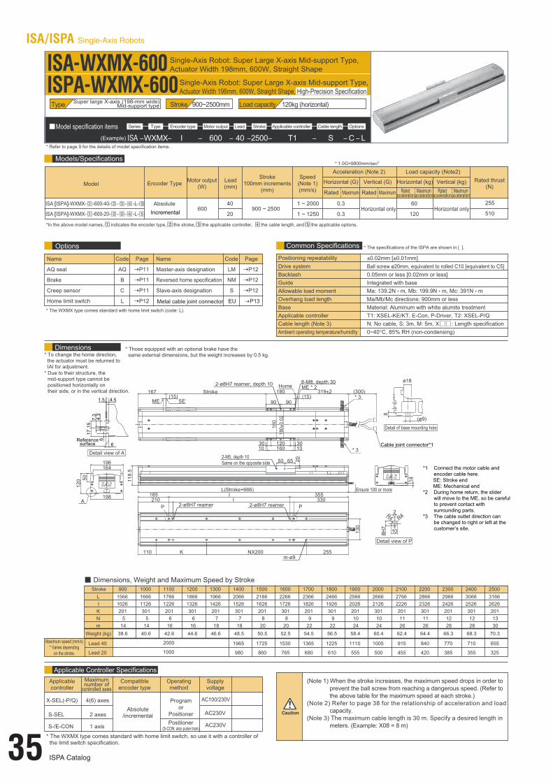
ISA/ISPA Single-Axis Robots
35 ISPA Catalog
Caution
ISA-WXMX-600ISPA-WXMX-600
Single-Axis Robot: Super Large X-axis Mid-support Type,
Actuator Width 198mm, 600W, Straight Shape
Single-Axis Robot: Super Large X-axis Mid-support Type,
Actuator Width 198mm, 600W, Straight Shape, High-Precision Specification
TypeSuper large X-axis (198-mm wide)
Mid-support type Stroke 900~2500mm Load capacity 120kg (horizontal)
WXMX I 600 40 2500 T1 S C(Example) ISA
Model specification items Cable length OptionsApplicable controllerStrokeLeadMotor outputEncoder typeTypeSeries
- - - - - - - - L-
(Note 1) When the stroke increases, the maximum speed drops in order to
prevent the ball screw from reaching a dangerous speed. (Refer to
the above table for the maximum speed at each stroke.)
(Note 2) Refer to page 38 for the relationship of acceleration and load
capacity.
(Note 3) The maximum cable length is 30 m. Specify a desired length in
meters. (Example: X08 = 8 m)
Models/Specifications
Options
Dimensions
Common Specifications
Applicable Controller Specifications
Model Encoder TypeLead(mm)
Motor output(W)
Stroke100mm increments
(mm)
Speed(Note 1)(mm/s)
Load capacity (Note2)
Horizontal (kg) Vertical (kg) Rated thrust(N)
Absolute
Incremental
255
510
ISA [ISPA]-WXMX- -600-40- - - -L-
ISA [ISPA]-WXMX- -600-20- - - -L-
*In the above model names, indicates the encoder type, the stroke, the applicable controller, the cable length, and the applicable options.
* The WXMX type comes standard with home limit switch (code: L).
* The specifications of the ISPA are shown in [ ].
* 1.0G=9800mm/sec2
* Refer to page 9 for the details of model specification items.
60040
20900 ~ 2500
1 ~ 2000
1 ~ 1250
60
120
Maximumacceleration
Maximumacceleration
Ratedacceleration
Ratedacceleration
Acceleration (Note 2)
Horizontal (G) Vertical (G)
0.3
0.3Horizontal only Horizontal only
Maximum MaximumRated Rated
AQ
B
C
L
AQ seal
Brake
Creep sensor
Home limit switch
P11
P11
P11
P12
Page
Ball screw ø20mm, equivalent to rolled C10 [equivalent to C5]
0.05mm or less [0.02mm or less]
Integrated with base
Ma/Mb/Mc directions: 900mm or less
T1: XSEL-KE/KT, E-Con, P-Driver, T2: XSEL-P/Q
Material: Aluminum with white alumite treatment
N: No cable, S: 3m, M: 5m, X : Length specification
0~40°C, 85% RH (non-condensing)
Drive system
Positioning repeatability
Backlash
Guide
Allowable load moment
Overhang load length
Base
Applicable controller
Cable length (Note 3)
Ambient operating temperature/humidity
Applicablecontroller
Maximumnumber of
controlled axes
Compatibleencoder type
Operatingmethod
Supplyvoltage
X-SEL(-P/Q)
* The WXMX type comes standard with home limit switch, so use it with a controller of the limit switch specification.
4(6) axes
AC230V
AC230V
CodeName
LM
NM
S
Master-axis designation
Reversed home specification
Slave-axis designation
P12
P12
P12
PageCodeName ±0.02mm [±0.01mm]
Ma: 139.2N • m, Mb: 199.9N • m, Mc: 391N • m
Detail of base mounting hole
Detail view of A
Detail view of P
Cable joint connector*1
*1 Connect the motor cable and
encoder cable here.
SE: Stroke end
ME: Mechanical end
*2 During home return, the slider
will move to the ME, so be careful
to prevent contact with
surrounding parts.
*3 The cable outlet direction can
be changed to right or left at the
customer’s site.
* Those equipped with an optional brake have the
same external dimensions, but the weight increases by 0.5 kg.
Dimensions, Weight and Maximum Speed by Stroke
* To change the home direction,
the actuator must be returned to
IAI for adjustment.
* Due to their structure, the
mid-support type cannot be
positioned horizontally on
their side, or in the vertical direction.
08
1±
20 .
0
330I185 I
2-ø8H7 reamer2-ø8H7 reamer210
(15) (15)
03
1
2-M5, depth 10
Same on the opposite side
m-ø9K
2-ø8H7 reamer, depth 10 8-M8, depth 30
Ensure 100 or more
164196
9090
NX200
L(Stroke+666)
30 120 3010 160 10
110 255
355
167 Stroke
50 65
02
5.8
11
08
1
180 319±2 (300)
198
050
21
PP
(ø9)
ø188
41
SEME
ME * 2Home
10
4R2
7H
8
4R
A
71
51
3.4
6
3.7
1.5 4.5
6
* 3
* 3
2166
1626
201
8
20
50.5
1725
860
2266
1726
301
8
20
52.5
1530
765
2366
1826
201
9
22
54.5
1365
680
2466
1926
301
9
22
56.5
1225
610
2566
2026
201
10
24
58.4
1110
555
2666
2126
301
10
24
60.4
1005
500
2766
2226
201
11
26
62.4
915
455
2866
2326
301
11
26
64.4
840
420
2966
2426
201
12
28
66.3
770
385
3066
2526
301
12
28
68.3
710
355
3166
2626
201
13
30
70.3
655
325
Stroke 900
L
I
K
N
m
1566
1026
201
5
14
38.6
1000
1666
1126
301
5
14
40.6
1100
1766
1226
201
6
16
42.6
1200
1866
1326
301
6
16
44.6
1300
1966
1426
201
7
18
46.6
1400
2066
1526
301
7
18
48.5
1965
980
1500 1600 1700 1800 1900 2000 2100 2200 2300 2400 2500
2000
1000
Weight (kg)
Lead 40
Lead 20
Maximum speed (mm/s)
* Varies depending
on the stroke.
Referencesurface
S-SEL
S-/E-CON
2 axes
1 axis
Absolute/incremental
Program
or
Positioner
Positioner(S-CON: also pulse train)
AC100/230V
Metal cable joint connector EU P13

ISA/ISPA Single-Axis Robots
ISPA Catalog 36
Caution
60
120
0.3
0.3Horizontal only Horizontal only
ISA-WXMX-750ISPA-WXMX-750
Single-Axis Robot: Super Large X-axis Mid-support Type,
Actuator Width 198mm, 750W, Straight Shape
Single-Axis Robot: Super Large X-axis Mid-support Type,
Actuator Width 198mm, 750W, Straight Shape, High-Precision Specification
TypeSuper large X-axis (198-mm wide)
Mid-support type Stroke 900~2500mm Load capacity 120kg (horizontal)
WXMX I 750 50 2500 T1 S C(Example) ISA
Model specification items Cable length OptionsApplicable controllerStrokeLeadMotor outputEncoder typeTypeSeries
- - - - - - - - L-
(Note 1) When the stroke increases, the maximum speed drops in order to
prevent the ball screw from reaching a dangerous speed. (Refer to
the above table for the maximum speed at each stroke.)
(Note 2) Refer to page 38 for the relationship of acceleration and load
capacity.
(Note 3) The maximum cable length is 30 m. Specify a desired length in
meters. (Example: X08 = 8 m)
Models/Specifications
Options
Dimensions
Common Specifications
Applicable Controller Specifications
Model Encoder TypeLead(mm)
Motor output(W)
Stroke100mm increments
(mm)
Speed(Note 1)(mm/s)
Load capacity (Note2)
Horizontal (kg) Vertical (kg) Rated thrust(N)
Absolute
Incremental
255
510
ISA [ISPA]-WXMX- -750-50- - - -L-
ISA [ISPA]-WXMX- -750-25- - - -L-
*In the above model names, indicates the encoder type, the stroke, the applicable controller, the cable length, and the applicable options.
* The WXMX type comes standard with home limit switch (code: L).
* The specifications of the ISPA are shown in [ ].
* 1.0G=9800mm/sec2
* Refer to page 9 for the details of model specification items.
75050
25900 ~ 2000
1 ~ 2000
1 ~ 1250
Maximumacceleration
Maximumacceleration
Ratedacceleration
Ratedacceleration
Acceleration (Note 2)
Horizontal (G) Vertical (G)
Maximum MaximumRated Rated
AQ
B
C
L
AQ seal
Brake
Creep sensor
Home limit switch
P11
P11
P11
P11
Page
Ball screw ø20mm, equivalent to rolled C10 [equivalent to C5]
0.05mm or less [0.02mm or less]
Integrated with base
Ma/Mb/Mc directions: 900mm or less
T1: XSEL-KE/KT, E-Con, P-Driver, T2: XSEL-P/Q
Material: Aluminum with white alumite treatment
N: No cable, S: 3m, M: 5m, X : Length specification
0~40°C, 85% RH (non-condensing)
Drive system
Positioning repeatability
Backlash
Guide
Allowable load moment
Overhang load length
Base
Applicable controller
Cable length (Note 3)
Ambient operating temperature/humidity
Applicablecontroller
Maximumnumber of
controlled axes
Compatibleencoder type
Operatingmethod
Supplyvoltage
X-SEL(-P/Q)
* The WXMX type comes standard with home limit switch, so use it with a controller of the limit switch specification.
4(6) axes
AC230V
AC230V
CodeName
LM
NM
S
Master-axis designation
Reversed home specification
Slave-axis designation
P12
P12
P12
PageCodeName ±0.02mm [±0.01mm]
Ma: 139.2N • m, Mb: 199.9N • m, Mc: 391N • m
08
1±
20.
0
330I185 I
2-ø8H7 reamer2-ø8H7 reamer210
(15) (15)
03
1
2-M5, depth 10
Same on the opposite side
m-ø9K
2-ø8H7 reamer, depth 10 8-M8, depth 30
Ensure 100 or more
164196
9090
NX200
L(Stroke+666)
30 120 3010 160 10
110 255
355
167 Stroke
50 65
02
5.8
11
08
1
180 319±2 (300)
198
050
21
PP
(ø9)
ø188
41
SEME
ME * 2Home
10
4R2
7H
8
4R
A
71
51
3.4
6
3.7
1.5 4.5
6
* 3
* 3
2166
1626
201
8
20
53.3
2266
1726
301
8
20
55.3
1200
2366
1826
201
9
22
57.3
1075
2466
1926
301
9
22
59.3
1930
965
2566
2026
201
10
24
61.2
1740
870
2666
2126
301
10
24
63.2
1580
790
2766
2226
201
11
26
65.2
1440
720
2866
2326
301
11
26
67.2
1320
660
2966
2426
201
12
28
69.1
1210
605
3066
2526
301
12
28
71.1
1115
555
3166
2626
201
13
30
73.1
1035
515
Stroke 900
L
I
K
N
m
1566
1026
201
5
14
41.4
1000
1666
1126
301
5
14
43.4
1100
1766
1226
201
6
16
45.4
1200
1866
1326
301
6
16
47.4
1300
1966
1426
201
7
18
49.4
1400
2066
1526
301
7
18
51.3
1500 1600 1700 1800 1900 2000 2100 2200 2300 2400 2500
1250
2000
Weight (kg)
Lead 50
Lead 25
Maximum speed (mm/s)
* Varies depending
on the stroke.
Dimensions, Weight and Maximum Speed by Stroke
Detail of base mounting hole
Detail view of A
Detail view of P
Cable joint connector*1
*1 Connect the motor cable and
encoder cable here.
SE: Stroke end
ME: Mechanical end
*2 During home return, the slider
will move to the ME, so be careful
to prevent contact with
surrounding parts.
*3 The cable outlet direction can
be changed to right or left at the
customer’s site.
* Those equipped with an optional brake have the
same external dimensions, but the weight increases by 0.5 kg.* To change the home direction,
the actuator must be returned to
IAI for adjustment.* Due to their structure, the
mid-support type cannot be
positioned horizontally on
their side, or in the vertical direction.
Referencesurface
S-SEL
S-/E-CON
2 axes
1 axis
Absolute/incremental
Program
or
Positioner
Positioner(S-CON: also pulse train)
AC100/230V
Metal cable joint connector EU P13

Reference
37 ISPA Catalog

Reference
ISPA Catalog 38

IAI Industrieroboter GmbH
Ober der Röth 4
D-65824 Schwalbach / Frankfurt
Germany
Tel.:+49-6196-8895-0
Fax:+49-6196-8895-24
E-Mail: [email protected]
Internet: http://www.eu.IAI-GmbH.de
IAI America Inc.2690 W. 237th Street, Torrance, CA 90505, U.S.A
Tel.: +1-310-891-6015 Fax: +1-310-891-0815
IAI CORPORATION645-1 Shimizu Hirose, Shizuoka 424-0102, Japan
Tel.: +81-543-64-5105 Fax: +81-543-64-5182
ISA Series
Catalogue No. 0406-E
IAI, the IAI-logo, RoboCylinder™, the RoboCylinder™-logo, IntelligentActuator™ and the IntelligentActuator™-logo are trademarks or productnames of IAI Corporation or of the subsidiaries in USA or Germany
The information contained in this catalog issubject to change without notice for the pupose
of product inprovement
Providing quality products
since 1986