single-cycle plain-woven objects
TRANSCRIPT

Single-Cycle Plain-Woven Objects
Qing Xing1, Ergun Akleman2, Jianer Chen3, Jonathan L. Gross41Architecture Department, Texas A&M University2Visualization Department, Texas A&M University
3Computer Science Department, Texas A&M University4Computer Science Department, Columbia University
Abstract—It has recently been shown that if we twistan arbitrary subset of edges of a mesh on an orientablesurface, the resulting extended graph rotation system(EGRS) can be used to induce a cyclic weaving on thesurface. In extended graph rotation systems, an edge isviewed as a paper strip that can be twisted. The sidesof the paper strips provide “two strands” to constructweaving structures. Either these strands are “parallel” tothe mesh edge for an “untwisted edge”, or they both crossover the edge and over each other for a “twisted edge”. Ifan arbitrary subset of edges of a mesh on an orientablesurface is twisted in the same helical sense, then theEGRS induces a cyclic plain-weaving on the surface, whichconsists of cycles that cross other cycles (or themselves) byalternatingly going over and under.
In this paper, we show that it is always possible to createa single-cycle plain-weaving starting from a mesh on anarbitrary surface, by selecting an appropriate subset ofedges to be twisted. We also demonstrate how, startingfrom a mesh, to construct a large number of single-cycleplain-woven objects. Interestingly, the single-cycle solutionswith a minimal number of edge twists correspond to plain-woven objects that are visually similar to Celtic knots.
For converting plain-weaving cycles to 3D thread struc-tures, we extend the original projection method, whichpreviously worked only when all mesh edges are twisted.With the extension described here, our projection methodcan also be used to handle untwisted edges. We havedeveloped a system that converts any manifold mesh intosingle-cycle plain-woven objects, by interactively control-ling the proportion of edges that are twisted. The systemalso allows us to change the shapes of the threads with a setof parameters, interactively in real-time. We demonstratehere that by using this system, we can create a wide varietyof single-cycle plain-woven objects.
1. INTRODUCTION
A plain-woven object consists of threads that are
interlaced so that a traversal of each thread alternatingly
goes over and under the other threads (or itself) as it
crosses them. It has recently been shown how to create
plain-woven objects from any given manifold mesh
surface, by constructing an alternating projection of a
link on the surface. It has also been shown how to create
such plain-woven objects from any given manifold mesh
by twisting some of the edges of a related orientable
manifold mesh [1], [2]. Akleman et al. showed that
twisting all the edges of a manifold mesh is a useful
approach for creating objects that visually resemble
plain-weaving. Nonetheless, there are two problems with
twisting all the edges: (1) it does not control the number
of cycles that will be created, and (2) the visual results
are too uniform. On the other hand, if we randomly twist
some of the edges, we can get interesting results, as
shown in Figure 2. However, random twisting does not
control the number of cycles. In this paper, we develop
a method that allows us to control the number of cycles
in a plain-weaving, which, in particular, enables us to
construct single-cycle plain-weavings on an arbitrary
surface. We also show that there exist a large number
of single-cycle plain-weaving structures and that some
of the single-cycle plain-weaving structures visually
resemble Celtic knots (See Figure 1).
Twisting all the edges of a manifold mesh is theo-
retically related to drawing Celtic knots in 2D using
planar graphs [3], [4]. Twisting all edges makes the
resulting weaving visually look like physical weaving.
However, we have noticed that to visually achieve the
look of Celtic knots in 3D, we need to leave many edges
untwisted. One problem with leaving many edges un-
twisted is that the resulting weaving can be a separable
link, which means that a sphere can be inserted into
3D-space that does not intersect the link, such that part
of the link lies on one side of the separation and part
on the other (See Figure 2). A separable link will fall
apart if it is physically realized. By reducing the number
of components of the link to one, we guarantee that
physical structure will not fall apart.
The mathematical links without solid shape need to
be converted to 3D thread structures, such as extruded
lines (ribbons) or extruded surfaces (yarns). The pro-
jection (PR) method introduced in [1] for converting
mathematical links to 3D thread structures is provided
only for twisted edges. Since we use untwisted edges
in this paper, there is a need to extend the projection
method to handle untwisted edges.
As a practical implementation, we have developed a
system that converts any manifold mesh into a single-
cycle plain-woven object. Our system converts the math-
ematical knots and links to 3D thread structures, such
that the shapes of the threads can be interactively
2010 Shape Modeling International Conference
978-0-7695-4072-6/10 $26.00 © 2010 IEEE
DOI 10.1109/SMI.2010.13
90

54.99% twisted 65.61% twisted 75.02% twisted 99.83% twisted
Fig. 1. Rainbow colored single-cycle plain-woven bunnies. Each bottom image magni es the detail of the single-cycle plain-woven bunnyimmediately above. The number below each bottom image indicates the percentage of edges that are twisted. These details illustrate how thepercentage of twisted edges impacts the visual results. We painted the single thread with rainbow colors to better illustrate its structure.
20% twisted 40% twisted 60% twisted 80% twisted 98% twisted
3138 cycles 1351 cycles 346 cycles 35 cycles 3 cycles
Fig. 2. Random twisting with no cycle control. Each bottom image is magni ed detail from the plain-woven Rockarm object immediatelyabove. The number below a bottom image indicates the percentage of edges that are twisted and the number of cycles. These details illustratehow the percentage of twisted edges impacts the visual results.
controlled with a set of parameters. The 3D structure
of the single thread can cover the original orientable
manifold mesh, without leaving large gaps. In Section 3,
we provide examples of some single-cycle plain-woven
objects. In addition, we show in Section 4 that the
number of single-cycle solutions are statistically high.
Section 5 gives our conclusions and describes possibil-
ities for future work.
2. THEORY FOR SINGLE-CYCLE WEAVING
As introduced formally in [1], a cyclic plain-weavingon an orientable surface So is a projection of a link
L on So, such that (1) there are no triple intersections
at any single point of So, and (2) a traversal of the
image on So of each component of L goes over and
under alternatingly as it crosses the images of other
components or of itself.
Graph Rotation Systems have been a powerful model
in the study of topological graph theory [5], [6], [7], [8].
A rotation at a vertex of a graph is a cyclic ordering of
91
the set of the edge-ends that are incident at that vertex. It
is well-known (see Theorem 3.2.2 of [5]) that a rotation
system specifies a graph embedding and that every graph
embedding can be specified by a rotation system.
Akleman et al. introduced extended graph rotation
systems [2] to facilitate a representation of cyclic weav-
ing in which edge twists are used to create crossings in a
weaving. In extended graph rotation systems, an edge is
viewed as a paper strip that can be twisted clockwise
or counter-clockwise in helical sense (see Figure 3).
The sides of the paper strips provides “two strands” in
the generated weaving pattern. These strands are either
“parallel” to the mesh edge for an “untwisted edge”, or
they both cross over the edge and over each other for
a “twisted edge”. The type of the crossover depends on
helical twist type (i.e. clockwise or counter-clockwise).
If an arbitrary subset of edges of a mesh on an orientable
surface So is twisted in the same helical sense, then the
GRS induces a cyclic plain-weaving on So [2].
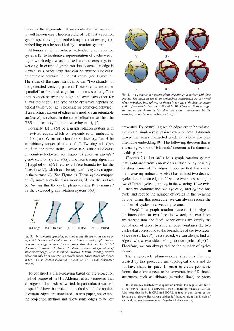
Formally, let ρo(G) be a graph rotation system with
no twisted edges, which corresponds to an embedding
of the graph G on an orientable surface So. Let A be
an arbitrary subset of edges of G. Twisting all edges
in A in the same helical sense (i.e. either clockwise
or counter-clockwise; see Figure 3) gives an extendedgraph rotation system ρ(G). The face tracing algorithm
[1] applied on ρ(G) returns all face boundaries for the
faces in ρ(G), which can be regarded as cycles mapped
to the surface So (See Figure 4). These cycles mapped
on So make a cyclic plain-weaving W on the surface
So. We say that the cyclic plain-weaving W is inducedby the extended graph rotation system ρ(G).
(a) Edge (b) 0 Twisted (c) +1 Twisted (d) -1 Twisted
Fig. 3. In computer graphics, an edge is usually drawn as shown in(a) and it is not considered to be twisted. In extended graph rotationsystems, an edge is viewed as a paper strip that can be twistedclockwise or counter-clockwise. (b) shows a visual interpretation ofan untwisted edge, which is called 0-twisted. In plain-weaving, twistededges can only be in one of two possible states. These states are shownin (c) +1 (i.e. counter-clockwise) twisted or (d) −1 (i.e. clockwise)twisted.
To construct a plain-weaving based on the projection
method proposed in [1], Akleman et al. suggested that
all edges of the mesh be twisted. In particular, it was left
unspecified how the projection method should be applied
if certain edges are untwisted. In this paper, we extend
the projection method and allow some edges to be left
(a) (b) (c)
(d) (e) (f)
Fig. 4. An example of creating plain-weaving on a surface with facetracing. The mesh in (a) is an octahedron constructed by untwistededges embedded in a sphere. As shown in (c), the eight face-boundarywalks of the octahedron are unlinked in 3D. However, if some edgesare twisted as shown in (d), then the cycles represented by theboundary walks become linked, as in (f).
untwisted. By controlling which edges are to be twisted,
we create single-cycle plain-woven objects. Edmonds
proved that every connected graph has a one-face non-
orientable embedding [9]. The following theorem that is
a weaving version of Edmonds’ theorem is fundamental
to this paper.
Theorem 2.1: Let ρ(G) be a graph rotation system
that is obtained from a mesh on a surface So by possibly
twisting some of its edges. Suppose that the cyclic
plain-weaving induced by ρ(G) has at least two distinct
cycles. Let e be an edge in G whose two sides belong to
two different cycles c1 and c2 in the weaving. If we twiste , then we combine the two cycles c1 and c2 into one
cycle and reduce the number of cycles in the weaving
by one. Using this procedure, we can always reduce the
number of cycles in a weaving to one.
Proof: In a graph rotation system, if an edge at
the intersection of two faces is twisted, the two faces
are merged into one face1. Since cycles are simply the
boundaries of faces, twisting an edge combines the two
cycles that correspond to the boundaries of the two faces.
Since the surface So is connected, we can always find an
edge e whose two sides belong to two cycles of ρ(G).Therefore, we can always reduce the number of cycles
to one.
The single-cycle plain-weaving structures that are
created by this procedure are topological knots and do
not have shape in space. In order to create geometric
forms, these knots need to be converted into 3D thread
structures, such as ribbons (extruded lines) or yarns
1If e is already twisted, twist operation untwist the edge e. Similarly,
if the original edge e is untwisted, twist operation makes e twisted.
Also note that in both GRS and EGRS, a face is considered as the
domain that always lies on one (either left-hand or right-hand) side of
a thread, as one traverses one of cycles of the weaving.
92

(extruded polygons). The resulting 3D thread structures
must look smooth and must not self-intersect. For con-
version of topological links into geometric forms, we
need to extend the projection method introduced in [1],
so that it will work well for untwisted edges.
3. EXTENDING THE PROJECTION METHOD TO
UNTWISTED EDGES
For a rotation system ρ0(G), we consider only the
polygonal mesh surfaces, where every vertex has valence
at least 3, every face has at least three sides (i.e.
triangles), every edge has positive length, and every
vertex has position information. Whereas Akleman et
al. gave a detailed explanation of the projection method
for twisted edges, here we explain how to handle both
twisted and untwisted edges. Moreover, in addition to
explaining the method in 3D, we provide explanation
for a mesh in the plane, which can provide a better
understanding of the process.
(a) Top (b) Bottom (c) Together
Fig. 6. Strip construction with c and w control for twisted case.
(a) One Side (b) Other side (c) Together
Fig. 7. Strip construction with c and w control for untwisted case.
Figure 5 shows the steps of the extended projection
method for a mesh in the plane with one untwisted edge.
The procedure consists of five steps as follows:
1) Project the initial mesh to a local plane. The
result will locally be a planar tiling as shown in
Figure 5(a).
2) Connect the center of each face to the vertices
of that face, thereby forming a quadrilateral for
each edge. Graph theorists call this construction
the radial graph of the embedding. In Figure 5(b)
small black dots identify the centers of the faces
(called “face-points” of the radial graph) and the
vertex positions (called “vertex-points”). Figure
5(c) and (d) show the 24 quadrilaterals constructed
by joining the face-points and the vertex points for
every edge. These quadrilaterals are called edge-regions.
3) a) For every twisted edge, project the corre-
sponding edge-region to two small planar
regions, one slightly above and the other
slightly below the original plane shown in
Figure 6(a) and (b).
b) For every untwisted edge, create two side-
by-side quadrilaterals in the original plane.
These are triangular-looking shapes that are
shown in Figure 7(a) and (b). Each quadri-
lateral consists of the original edge and two
vertices that are co-located in the center of
its corresponding face. Since two vertices
are co-located in the center of the face, the
procedure yields a quadrilateral instead of a
triangle. Figure 5(e) shows projected edge
regions for one untwisted edge and for the
other edges twisted.
4) Using the projected edge regions (i.e. quadrilater-
als) as control shapes, we form strips by using a
simple bilinear equation. Figures 6 and 7 show
how the strips are formed for the twisted and
untwisted cases.
a) For twisted edges, the procedure shown in
Figure 6(a) and (b) creates two strips that are
on top of each other, forming an “ ” shape
as shown in Figure 6(c). We calculate the 4corners of the yellow quadrilateral regions,
in barycentric coordinates inside two grey
quadrilaterals slightly above and below the
original plane. The positions of these corner
points is parameterized by two parameters
w and c. The value of w controls the width
of the yellow quadrilateral region, and the
value of c controls the length of the yellow
quadrilateral region. Note that to compute the
upper and lower yellow quadrilateral regions,
we switch c and w values, which gives us
“ ” shape shown in Figure 6(c).
b) For untwisted edges, the procedure shown in
Figure 7(a) and (b) creates two strips that
are side-by-side as shown in Figure 7(c).
Figure 5(f) shows all strips: “ ” shapes for
twisted edges and two parallel strips for the
untwisted edges. We again calculate the 4corners of the yellow quadrilateral regions,
in barycentric coordinates inside the grey
triangle-looking quadrilaterals. The value of
w again controls the width of the yellow
quadrilateral region, and the value of c con-
trols the length of the yellow quadrilateral re-
gion. On the other hand, to compute the two
93
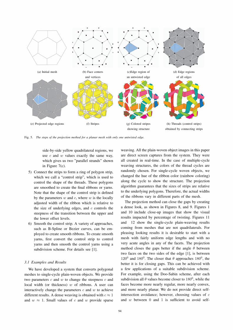
(a) Initial mesh (b) Face centers (c)Edge region of (d) Edge regions
and vertices an untwisted edge of all edges
(e) Projected edge regions (f) Stripes (g) Colored stripes (h) Threads (control strips)
showing structure obtained by connecting strips
Fig. 5. The steps of the projection method for a planar mesh with only one untwisted edge.
side-by-side yellow quadrilateral regions, we
use c and w values exactly the same way,
which gives us two ”parallel strands” shown
in Figure 7(c).
5) Connect the strips to form a ring of polygon strip,
which we call a “control strip”, which is used to
control the shape of the threads. These polygons
are smoothed to create the final ribbons or yarns.
Note that the shape of the control strip is defined
by the parameters w and c, where w is the locally
adjusted width of the ribbon which is relative to
the size of underlying edges, and c controls the
steepness of the transition between the upper and
the lower offset levels.
6) Smooth the control strip. A variety of approaches,
such as B-Spline or Bezier curves, can be em-
ployed to create smooth ribbons. To create smooth
yarns, first convert the control strip to control
yarns and then smooth the control yarns using a
subdivision scheme. For details see [1].
3.1 Examples and Results
We have developed a system that converts polygonal
meshes to single-cycle plain-woven objects. We provide
two parameters c and w to change the steepness c and
local width (or thickness) w of ribbons. A user can
interactively change the parameters c and w to achieve
different results. A dense weaving is obtained with c ≈ 1and w ≈ 1. Small values of c and w provide sparse
weaving. All the plain-woven object images in this paper
are direct screen captures from the system. They were
all created in real-time. In the case of multiple-cycle
weaving structures, the colors of the thread cycles are
randomly chosen. For single-cycle woven objects, we
changed the hue of the ribbon color (rainbow coloring)
along the cycle to show the structure. The projection
algorithm guarantees that the sizes of strips are relative
to the underlying polygons. Therefore, the actual widths
of the ribbons vary in different parts of the mesh.
The projection method can close the gaps by creating
a dense look, as shown in Figures 8, and 9. Figures 1
and 10 include close-up images that show the visual
results impacted by percentage of twisting. Figures 11
and 12 show the single-cycle plain-weaving results
coming from meshes that are not quadrilaterals. For
pleasing looking results it is desirable to start with a
mesh with fairly uniform edge lengths and with no
very acute angles in any of the facets. The projection
method closes the gaps better if the angle θ between
two faces on the two sides of the edge [1], is between
1200 and 1800. The closer that θ approaches 1800, the
better it is for closing gaps. This can be achieved with
a few applications of a suitable subdivision scheme.
For example, using the Doo-Sabin scheme, after each
subdivision all θ values become closer to 1800, while the
faces become more nearly regular, more nearly convex,
and more nearly planar. We do not provide direct self-
intersection avoidance; however, choosing values of c
and w between 0 and 1 is sufficient to avoid self-
94

54.52% Dense 54.52% Sparse 97.99% Dense 97.99% Sparse
57.27% Dense 57.27% Sparse 69.89% Sparse 99.95% Dense
Fig. 8. Single-cycle plain-woven Venus objects. Top images are uniform colored and bottom images are rainbow colored.
intersection.
4. AN ANALYSIS OF SINGLE-CYCLE
PLAIN-WEAVING
One might correctly expect that single-cycle graph
rotation systems are sparsely distributed. An edge can
be in either of two states: twisted or untwisted. If the
number of edges is E, then, the total number of subsets
of edges that could be selected for twisting is 2E . Even
if the proportion of single-cycle selections is very low,
the absolute number of single-cycle selections can still
be very high, as we shall see now.
4.1 Lower Bound from Spanning Trees of the Dual
A large set of single-cycle solutions on a mesh M
with the smallest number of twisted edges can be
obtained from the dual mesh M of the original mesh
M . Note that each dual edge e between two vertices v1
and v2 in the dual mesh M corresponds to a primal edge
e (i.e., an edge in the original mesh) M that is on the
boundary of the two faces f1 and f2 in M . These two
primal faces correspond to, respectively, the two dual
vertices v1 and v2. Therefore, if we twist the primal edge
e, then the two primal faces f1 and f2 are merged into a
single face (Theorem 2.1). Correspondingly, the number
of cycles in the corresponding weaving is reduced by
one. Accordingly, if we construct a spanning tree T in
the dual mesh M , then twisting all the primal edges in
M would merge all the faces in the original mesh M
into a single face. This induces a single-cycle weaving.
It is also easy to see that this is the minimum number
of edges in M that must be twisted in order to obtain a
single-cycle plain-weaving.
Let μ denote the average number of sides in a primal
face (in the original mesh M ) and let F denote the
number of faces of M . Then it can be inferred from
the dual of Euler’s theorem (often called the edge-face
equation) that the sum of the degrees of the vertices is
twice the number of edges in a graph that μF = 2E.
Therefore, the minimum number of edges that need to
be twisted in order to obtain a single-cycle solution is
95
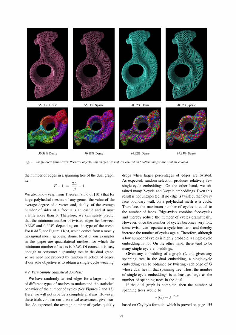
55.11% Dense 55.11% Sparse 98.02% Dense 98.02% Sparse
50.39% Dense 70.18% Dense 84.92% Dense 99.95% Dense
Fig. 9. Single-cycle plain-woven Rockarm objects. Top images are uniform colored and bottom images are rainbow colored.
the number of edges in a spanning tree of the dual graph,
i.e.
F − 1 =2E
μ− 1.
We also know (e.g. from Theorem 8.5.6 of [10]) that for
large polyhedral meshes of any genus, the value of the
average degree of a vertex and, dually, of the average
number of sides of a face μ is at least 3 and at most
a little more than 6. Therefore, we can safely predict
that the minimum number of twisted edges lies between
0.33E and 0.66E, depending on the type of the mesh.
For 0.33E, see Figure 11(b), which comes from a mostly
hexagonal mesh, geodesic dome. Most of our examples
in this paper are quadrilateral meshes, for which the
minimum number of twists is 0.5E. Of course, it is easy
enough to construct a spanning tree in the dual graph,
so we need not proceed by random selection of edges,
if our sole objective is to obtain a single-cycle weaving.
4.2 Very Simple Statistical Analysis
We have randomly twisted edges for a large number
of different types of meshes to understand the statistical
behavior of the number of cycles (See Figures 2 and 13).
Here, we will not provide a complete analysis. However,
these trials confirm our theoretical assessment given ear-
lier. As expected, the average number of cycles quickly
drops when larger percentages of edges are twisted.
As expected, random selection produces relatively few
single-cycle embeddings. On the other hand, we ob-
tained many 2-cycle and 3-cycle embeddings. Even this
result is not unexpected. If no edge is twisted, then every
face boundary walk on a polyhedral mesh is a cycle.
Therefore, the maximum number of cycles is equal to
the number of faces. Edge-twists combine face-cycles
and thereby reduce the number of cycles dramatically.
However, once the number of cycles becomes very low,
some twists can separate a cycle into two, and thereby
increase the number of cycles again. Therefore, although
a low number of cycles is highly probable, a single-cycle
embedding is not. On the other hand, there tend to be
many single-cycle embeddings.
Given any embedding of a graph G, and given any
spanning tree in the dual embedding, a single-cycle
embedding can be obtained by twisting each edge of G
whose dual lies in that spanning tree. Thus, the number
of single-cycle embeddings is at least as large as the
number of spanning trees in the dual.
If the dual graph is complete, then the number of
spanning trees would be
τ(G) = F F−2
based on Cayley’s formula, which is proved on page 155
96
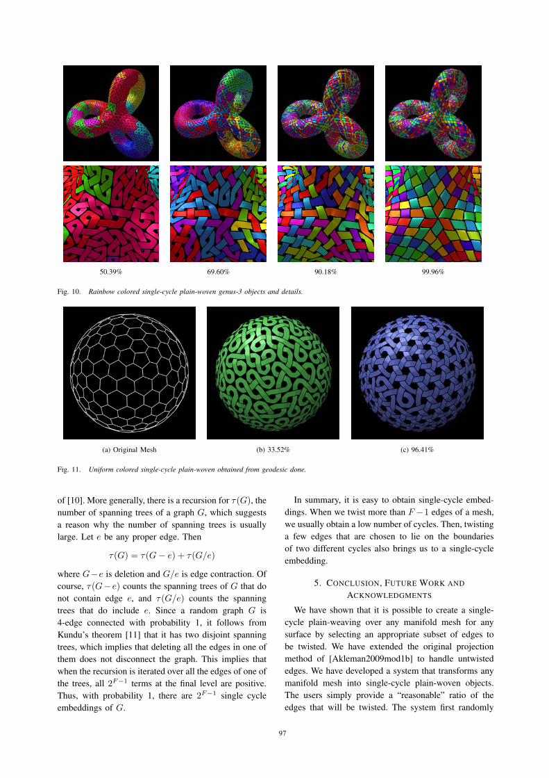
50.39% 69.60% 90.18% 99.96%
Fig. 10. Rainbow colored single-cycle plain-woven genus-3 objects and details.
(a) Original Mesh (b) 33.52% (c) 96.41%
Fig. 11. Uniform colored single-cycle plain-woven obtained from geodesic done.
of [10]. More generally, there is a recursion for τ(G), the
number of spanning trees of a graph G, which suggests
a reason why the number of spanning trees is usually
large. Let e be any proper edge. Then
τ(G) = τ(G − e) + τ(G/e)
where G−e is deletion and G/e is edge contraction. Of
course, τ(G− e) counts the spanning trees of G that do
not contain edge e, and τ(G/e) counts the spanning
trees that do include e. Since a random graph G is
4-edge connected with probability 1, it follows from
Kundu’s theorem [11] that it has two disjoint spanning
trees, which implies that deleting all the edges in one of
them does not disconnect the graph. This implies that
when the recursion is iterated over all the edges of one of
the trees, all 2F−1 terms at the final level are positive.
Thus, with probability 1, there are 2F−1 single cycle
embeddings of G.
In summary, it is easy to obtain single-cycle embed-
dings. When we twist more than F −1 edges of a mesh,
we usually obtain a low number of cycles. Then, twisting
a few edges that are chosen to lie on the boundaries
of two different cycles also brings us to a single-cycle
embedding.
5. CONCLUSION, FUTURE WORK AND
ACKNOWLEDGMENTS
We have shown that it is possible to create a single-
cycle plain-weaving over any manifold mesh for any
surface by selecting an appropriate subset of edges to
be twisted. We have extended the original projection
method of [Akleman2009mod1b] to handle untwisted
edges. We have developed a system that transforms any
manifold mesh into single-cycle plain-woven objects.
The users simply provide a “reasonable” ratio of the
edges that will be twisted. The system first randomly
97
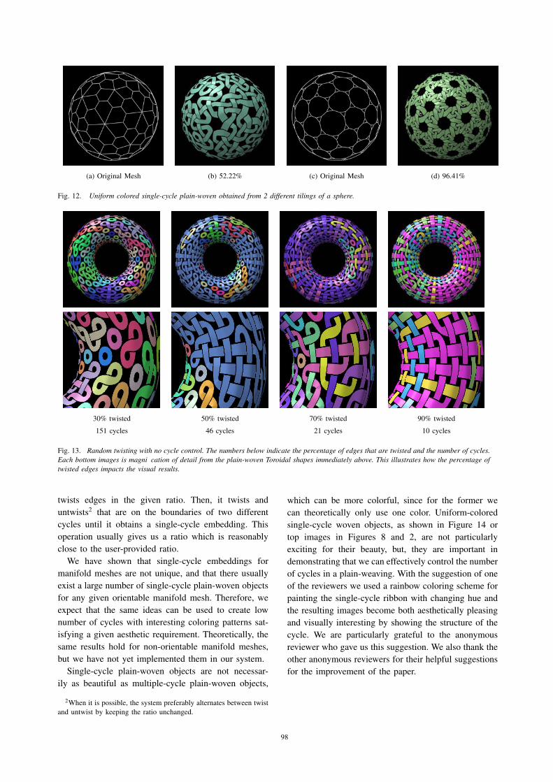
(a) Original Mesh (b) 52.22% (c) Original Mesh (d) 96.41%
Fig. 12. Uniform colored single-cycle plain-woven obtained from 2 different tilings of a sphere.
30% twisted 50% twisted 70% twisted 90% twisted
151 cycles 46 cycles 21 cycles 10 cycles
Fig. 13. Random twisting with no cycle control. The numbers below indicate the percentage of edges that are twisted and the number of cycles.Each bottom images is magni cation of detail from the plain-woven Toroidal shapes immediately above. This illustrates how the percentage oftwisted edges impacts the visual results.
twists edges in the given ratio. Then, it twists and
untwists2 that are on the boundaries of two different
cycles until it obtains a single-cycle embedding. This
operation usually gives us a ratio which is reasonably
close to the user-provided ratio.
We have shown that single-cycle embeddings for
manifold meshes are not unique, and that there usually
exist a large number of single-cycle plain-woven objects
for any given orientable manifold mesh. Therefore, we
expect that the same ideas can be used to create low
number of cycles with interesting coloring patterns sat-
isfying a given aesthetic requirement. Theoretically, the
same results hold for non-orientable manifold meshes,
but we have not yet implemented them in our system.
Single-cycle plain-woven objects are not necessar-
ily as beautiful as multiple-cycle plain-woven objects,
2When it is possible, the system preferably alternates between twist
and untwist by keeping the ratio unchanged.
which can be more colorful, since for the former we
can theoretically only use one color. Uniform-colored
single-cycle woven objects, as shown in Figure 14 or
top images in Figures 8 and 2, are not particularly
exciting for their beauty, but, they are important in
demonstrating that we can effectively control the number
of cycles in a plain-weaving. With the suggestion of one
of the reviewers we used a rainbow coloring scheme for
painting the single-cycle ribbon with changing hue and
the resulting images become both aesthetically pleasing
and visually interesting by showing the structure of the
cycle. We are particularly grateful to the anonymous
reviewer who gave us this suggestion. We also thank the
other anonymous reviewers for their helpful suggestions
for the improvement of the paper.
98

50.38% twisted 55.60% twisted 69.39% twisted 90.66% twisted
Fig. 14. Uniform colored single-cycle plain-woven bunnies. Each bottom image magni es the detail of the single-cycle plain-woven bunnyimmediately above. The number below each bottom image indicates the percentage of edges that are twisted. These details illustrate how thepercentage of twisted edges impacts the visual results.
REFERENCES
[1] E. Akleman, J. Chen, Q. Xing, and J. Gross, “Cyclic
plain-weaving on polygonal meshes with graph rotation sys-
tems,” ACM Transactions on Graphics; Proceedings of SIG-GRAPH 2009, pp. 78.1–78.8, 2009.
[2] E. Akleman, J. Chen, J. Gross, and Q. Xing, “Extended graph
rotation systems as a model for cyclic weaving on orientable
surfaces,” Technical Report - Computer Science Department,
Texas A&M University - TR09-203, 2009.
[3] C. Mercat, “Les entrelacs des enluminure celtes,” Dossier PourLa Science, vol. 15, January 2001.
[4] M. Kaplan and E. Cohen, “Computer generated celtic design,”
in Proc. of 14th Eurographics Workshop on Rendering, 2003,
pp. 9–16.
[5] J. L. Gross and T. W. Tucker, Topological Graph Theory. Wiley
Interscience, New York, 1987.
[6] A. T. White, Graphs of Groups on Surfaces, Volume 188:Interactions and Models. North-Holland Mathematics Studies,
2001.
[7] C. P. Bonnington and C. H. C. Little, The Foundations ofTopological Graph Theory. Springer, New York, 1995.
[8] J. Chen, J. L. Gross, and R. G. Rieper, “Overlap matrices and
total imbedding distributions,” Discrete Mathematics, no. 128,
pp. 73–94, 1994.
[9] J. R. Edmonds, “On the surface duality of linear graphs,” JournalRes. Nat. Bur. Standards Sect. B, pp. 121–123, 1965.
[10] J. L. Gross and J. Yellen, Graph Theory and Its Applications.
2nd Edition, CRC Press, 2006.
[11] S. Kundu, “Bounds on the number of disjoint spanning trees,”
J. Combin. Theory Ser. B, vol. 17, pp. 199–203, 1974.
99