single duct air terminal - energy...
TRANSCRIPT

SD–2 Metal Industries, Inc. ■ For complete product specifications and submittal data, visit us at www.metalaire.com
SINGLE DUCT AIR TERMINAL UNITS
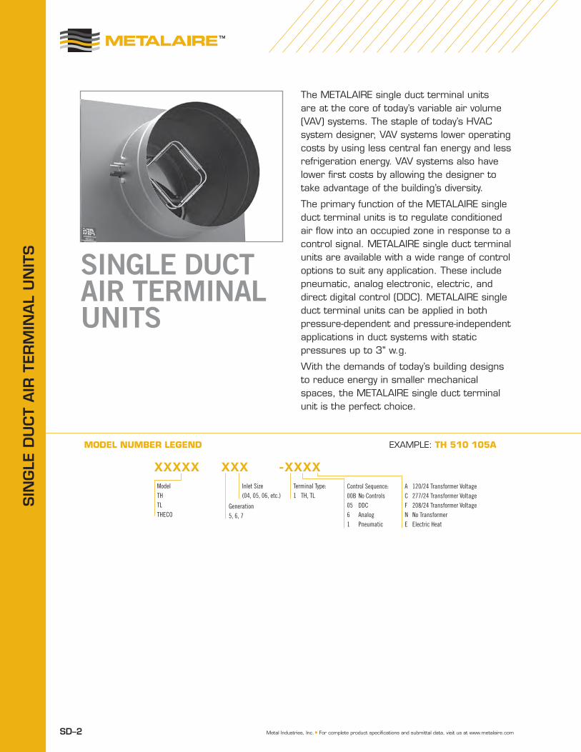
The METALAIRE single duct terminal units are at the core of today’s variable air volume (VAV) systems. The staple of today’s HVAC system designer, VAV systems lower operating costs by using less central fan energy and less refrigeration energy. VAV systems also have lower first costs by allowing the designer to take advantage of the building’s diversity.
The primary function of the METALAIRE single duct terminal units is to regulate conditioned air flow into an occupied zone in response to a control signal. METALAIRE single duct terminal units are available with a wide range of control options to suit any application. These include pneumatic, analog electronic, electric, and direct digital control (DDC). METALAIRE single duct terminal units can be applied in both pressure-dependent and pressure-independent applications in duct systems with static pressures up to 3" w.g.
With the demands of today’s building designs to reduce energy in smaller mechanical spaces, the METALAIRE single duct terminal unit is the perfect choice.
MODEL NUMBER LEGEND
XXXXX XXX -XXXXModelTHTLTHECO
Generation5, 6, 7
Inlet Size(04, 05, 06, etc.)
Terminal Type:1 TH, TL
Control Sequence:00B No Controls05 DDC6 Analog1 Pneumatic
A 120/24 Transformer VoltageC 277/24 Transformer VoltageF 208/24 Transformer VoltageN No TransformerE Electric Heat
ExAMPLE: TH 510 105A
SIN
GLE
DU
CT
AIR
TER
mIN
AL
UN
ITS
TH-5
00
SIN
GLE
DU
CT
SIN
GLE D
UCT
SD–3© 2012 Metal Industries, Inc.
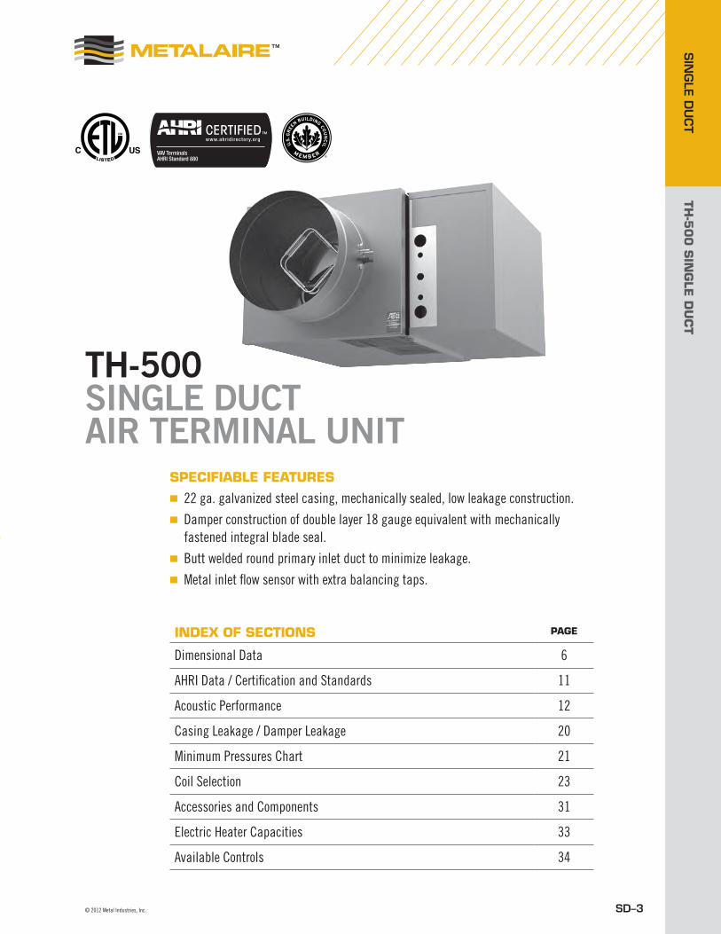
TH-500 SINGLE DUCT AIR TERMINAL UNIT
spEcifiABLE fEATUREs
■ 22 ga. galvanized steel casing, mechanically sealed, low leakage construction.■ Damper construction of double layer 18 gauge equivalent with mechanically
fastened integral blade seal.■ Butt welded round primary inlet duct to minimize leakage.■ Metal inlet flow sensor with extra balancing taps.
iNDEX Of sEcTiONs pAGE
Dimensional Data 6
AHRI Data / Certification and Standards 11
Acoustic Performance 12
Casing Leakage / Damper Leakage 20
Minimum Pressures Chart 21
Coil Selection 23
Accessories and Components 31
Electric Heater Capacities 33
Available Controls 34

TH-5
00
SIN
GLE
DU
CT
SIN
GLE
DU
CT
SD–4 Metal Industries, Inc. ■ For complete product specifications and submittal data, visit us at www.metalaire.com
TH-500 SINGLE DUCT AIR TERMINAL UNITThe METALAIRE TH-500 is the simplest and most widely used VAV terminal unit. Its basic components are an insulated sheet metal box, round inlet damper, flow measuring device and rectangular outlet. The unit is served by a central air handler and modulates the amount of ‘primary’ cooling air to the space between a minimum set point and the design airflow.
When necessary, the METALAIRE TH-500 can be provided with a heating coil on the discharge of the unit to provide for reheat.
sTANDARD fEATUREs
■ TH-500 available in 10 unit sizes and TH-ECO-500 available in 8 sizes to handle 80-8000 CFM.
■ Variable or constant volume applications.■ 22 ga. galvanized steel casing, mechanically
sealed for low leakage.■ Damper construction of double layer, 18 gauge
equivalent, galvanized steel with sandwiched flexible gasket, mechanically fastened to provide tight seal (<1% at 3.0" wg static pressure)
■ Optional factory calibrated controls to meet all control strategies.
■ Multi-quadrant, averaging flow sensor for highly accurate (+/-5%) flow readings with varying inlet duct configurations after certified balancer has balanced terminal.
■ Externally accessible steel balancing taps.■ External control cabinet with offset mounting
plate is standard.■ 3-beaded inlet connection tube for added rigidity
and secure flex duct connections.■ 1/2" thick, dual density (1.5lb/ft3 min.) fiberglass
insulation with edges coated. Meets NFPA 90A and UL 181.
■ Rectangular discharge with slip and drive cleat duct connection.
■ Independently tested and certified laboratory performance data.
■ Full range of options and accessories available (heating coils, disconnects, attenuators, etc.).
■ Full range of liners/insulation available.

TH-5
00
SIN
GLE
DU
CT
SIN
GLE D
UCT
SD–5© 2012 Metal Industries, Inc.
TH-500 SINGLE DUCT AIR TERMINAL UNIT
fEATUREs AND BENEfiTs
1 Damper rotates in a self-lubricating, long life, low friction thermoplastic bearing.
2 Continuous welded primary inlet duct to minimize leakage with three stiffening beads for added rigidity.
3 Damper construction of double layer 18 gauge equivalent with mechanically fastened integral blade seal.
4 All metal constructed inlet flow sensor with extra balancing taps.
5 Galvanized steel casing, mechanically sealed for low leakage construction.
6 NEMA 1 rated control enclosure with stand-off to prevent penetration of casing standard on all terminal units.
7 All TH-500 terminal units are AHRI certified and shipped with the AHRI seal.
7
1 2 3 4 5 6
TH-5
00
SIN
GLE
DU
CT
SIN
GLE
DU
CT
SD–6 Metal Industries, Inc. ■ For complete product specifications and submittal data, visit us at www.metalaire.com
Model Number
Inlet Size A Width Height Unit wt.
in. mm. in. mm. in. mm. in. mm. lb. kg.
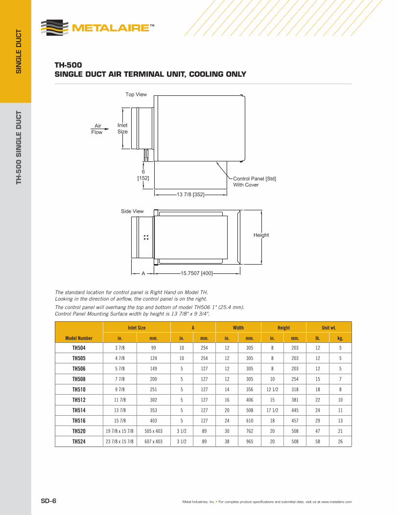
TH504 3 7/8 99 10 254 12 305 8 203 12 5
TH505 4 7/8 124 10 254 12 305 8 203 12 5
TH506 5 7/8 149 5 127 12 305 8 203 12 5
TH508 7 7/8 200 5 127 12 305 10 254 15 7
TH510 9 7/8 251 5 127 14 356 12 1/2 318 18 8
TH512 11 7/8 302 5 127 16 406 15 381 22 10
TH514 13 7/8 353 5 127 20 508 17 1/2 445 24 11
TH516 15 7/8 403 5 127 24 610 18 457 29 13
TH520 19 7/8 x 15 7/8 505 x 403 3 1/2 89 30 762 20 508 47 21
TH524 23 7/8 x 15 7/8 607 x 403 3 1/2 89 38 965 20 508 58 26
TH-500 siNGLE DUcT AiR TERMiNAL UNiT, cOOLiNG ONLy
The standard location for control panel is Right Hand on Model TH. Looking in the direction of airflow, the control panel is on the right.
The control panel will overhang the top and bottom of model TH506 1" (25.4 mm). Control Panel Mounting Surface width by height is 13 7/8" x 9 3/4". dth ght U it
n 305 8 5 5 5 4 2 8 5 0 /2 4 x 0

TH-5
00
SIN
GLE
DU
CT
SIN
GLE D
UCT
SD–7© 2012 Metal Industries, Inc.
TH-500 siNGLE DUcT AiR TERMiNAL UNiT wiTH HOT wATER cOiL
Model Number
Inlet Size A Width Height Unit wt.
in. mm. in mm. in. mm. in. mm.
1 Row 2 Row 3 Row 4 Row
lb kg lb kg. lb. kg. lb. kg.
TH504 3 7/8 99 10 254 12 305 8 203 17 7.7 18 8 21 9.5 23 10.4
TH505 4 7/8 124 10 254 12 305 8 203 17 7.7 18 8 21 9.5 23 10.4
TH506 5 7/8 149 5 127 12 305 8 203 17 7.7 18 8 21 9.5 23 10.4
TH508 7 7/8 200 5 127 12 305 10 254 20 9 22 10 26 11.8 28 13
TH510 9 7/8 251 5 127 14 356 12 1/2 318 24 11 27 12 32 14.5 38 17
TH512 11 7/8 302 5 127 16 406 15 381 31 14 34 15.4 40 18 43 19.5
TH514 13 7/8 353 5 127 20 508 17 1/2 445 34 15.4 39 17.7 48 21.8 53 24
TH516 15 7/8 403 5 127 24 610 18 457 42 19 48 21.8 54 24.5 59 26.8
TH520 19 7/8 x 15 7/8 505 x 403 5 127 30 762 20 508 64 29 72 32.7 78 35 86 39
TH524 23 7/8 x 15 7/8 607 x 403 5 127 38 965 20 508 79 36 89 40 99 45 109 49
The standard location for control panel is Right Hand on Model TH. Looking in the direction of airflow, the control panel is on the right.
The control panel will overhang the top and bottom of model TH506 1" (25.4 mm) Control Panel Mounting Surface width by height is 13 7/8" x 9 3/4".
minal Size A thgieH htdiW 1 ow
g9 1 5 1 3 5 7 21
124 10 254 05 8 20 7 37
5 4 2 22 2 7
40 9
7 61 18 45 2 1 11 59 30x
x 7 1 9 21 1
TH-5
00
SIN
GLE
DU
CT
SIN
GLE
DU
CT
SD–8 Metal Industries, Inc. ■ For complete product specifications and submittal data, visit us at www.metalaire.com
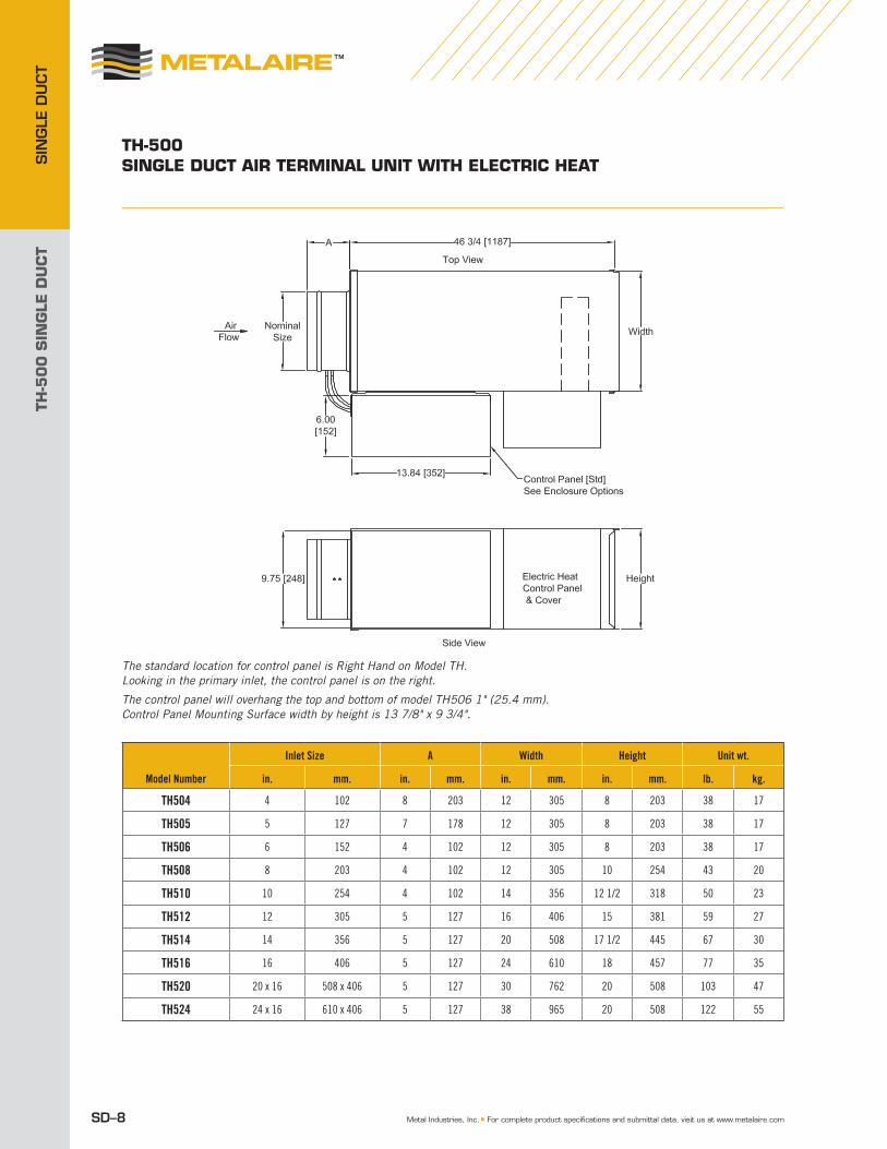
TH-500 siNGLE DUcT AiR TERMiNAL UNiT wiTH ELEcTRic HEAT
Model Number
Inlet Size A Width Height Unit wt.
in. mm. in. mm. in. mm. in. mm. lb. kg.
TH504 4 102 8 203 12 305 8 203 38 17
TH505 5 127 7 178 12 305 8 203 38 17
TH506 6 152 4 102 12 305 8 203 38 17
TH508 8 203 4 102 12 305 10 254 43 20
TH510 10 254 4 102 14 356 12 1/2 318 50 23
TH512 12 305 5 127 16 406 15 381 59 27
TH514 14 356 5 127 20 508 17 1/2 445 67 30
TH516 16 406 5 127 24 610 18 457 77 35
TH520 20 x 16 508 x 406 5 127 30 762 20 508 103 47
TH524 24 x 16 610 x 406 5 127 38 965 20 508 122 55
The standard location for control panel is Right Hand on Model TH. Looking in the primary inlet, the control panel is on the right.
The control panel will overhang the top and bottom of model TH506 1" (25.4 mm). Control Panel Mounting Surface width by height is 13 7/8" x 9 3/4".
Size mm10

TH-5
00
SIN
GLE
DU
CT
SIN
GLE D
UCT
SD–9© 2012 Metal Industries, Inc.
TH-500 siNGLE DUcT AiR TERMiNAL UNiT wiTH iNTEGRAL ATTENUATOR
Model Number
Inlet Size A Width Height Unit wt.
in. mm. in. mm. in. mm. in. mm. lb. kg.
TH504 3 7/8 99 8 203 12 305 8 203 12 5
TH505 4 7/8 124 7 178 12 305 8 203 12 5
TH506 5 7/8 149 4 102 12 305 8 203 12 5
TH508 7 7/8 200 4 102 12 305 10 254 15 7
TH510 9 7/8 251 4 102 14 356 12 1/2 318 18 8
TH512 11 7/8 302 5 127 16 406 15 381 22 10
TH514 13 7/8 353 5 127 20 508 17 1/2 445 24 11
TH516 15 7/8 403 5 127 24 610 18 457 29 13
TH520 19 7/8 x 15 7/8 505 x 403 5 127 30 762 20 508 47 21
TH524 23 7/8 x 15 7/8 607 x 403 5 127 38 965 20 508 58 26
5 5
T 4 23 7 08 6 3
The standard location for control panel is Right Hand on Model TH. Looking in the direction of airflow, the control panel is on the right.
The control panel will overhang the top and bottom of model TH506 1" (25.4 mm). Control Panel Mounting Surface width by height is 13 7/8" x 9 3/4".

TH-5
00
SIN
GLE
DU
CT
SIN
GLE
DU
CT
SD–10 Metal Industries, Inc. ■ For complete product specifications and submittal data, visit us at www.metalaire.com
TH-500 siNGLE DUcT AiR TERMiNAL UNiT wiTH iNTEGRAL ATTENUATOR AND HOT wATER cOiL
Model Number
Inlet Size A Width Height Unit wt.
in. mm. in. mm. in. mm. in. mm. lb. kg.
TH504 3 7/8 99 8 203 12 305 8 203 12 5
TH505 4 7/8 124 7 178 12 305 8 203 12 5
TH506 5 7/8 149 4 102 12 305 8 203 12 5
TH508 7 7/8 200 4 102 12 305 10 254 15 7
TH510 9 7/8 251 4 102 14 356 12 1/2 318 18 8
TH512 11 7/8 302 5 127 16 406 15 381 22 10
TH514 13 7/8 353 5 127 20 508 17 1/2 445 24 11
TH516 15 7/8 403 5 127 24 610 18 457 29 13
TH520 19 7/8 x 15 7/8 505 x 403 5 127 30 762 20 508 47 21
TH524 23 7/8 x 15 7/8 607 x 403 5 127 38 965 20 508 58 26
5 27
H524 23 7/8 x 38
The standard location for control panel is Right Hand on Model TH. Looking in the direction of airflow, the control panel is on the right.
The control panel will overhang the top and bottom of model TH506 1" (25.4 mm). Control Panel Mounting Surface width by height is 13 7/8" x 9 3/4".
TH-5
00
SIN
GLE
DU
CT
SIN
GLE D
UCT
SD–11© 2012 Metal Industries, Inc.
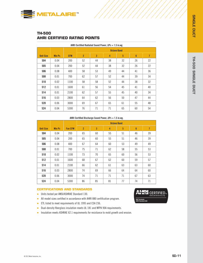
TH-500 AHRi cERTifiED RATiNG pOiNTs
AHRI Certified Radiated Sound Power, ΔPs = 1.5 in.wg
Unit Size Min Ps CFM
Octave Band
2 3 4 5 6 7
504 0.04 200 52 44 38 32 26 22
505 0.04 200 52 44 38 32 26 22
506 0.08 400 58 53 49 44 41 36
508 0.01 700 62 57 52 44 39 34
510 0.02 1100 58 58 52 44 38 32
512 0.01 1600 61 56 54 45 41 40
514 0.01 2100 62 57 55 45 40 34
516 0.03 2800 64 62 56 50 47 44
520 0.06 3000 69 67 65 61 55 48
524 0.04 5300 76 71 71 65 60 54
AHRI Certified Discharge Sound Power, ΔPs = 1.5 in.wg.
Unit Size Min Ps Fan CFM
Octave Band
2 3 4 5 6 7
504 0.04 200 65 60 55 51 46 39
505 0.04 200 65 60 55 51 46 39
506 0.08 400 67 64 60 53 49 49
508 0.01 700 75 71 62 58 55 53
510 0.02 1100 73 70 65 60 56 53
512 0.01 1600 68 67 62 60 59 57
514 0.01 2100 66 62 61 63 63 60
516 0.03 2800 74 69 66 64 64 60
520 0.06 3000 74 71 71 71 67 63
524 0.04 5300 86 85 81 77 74 71
cERTificATiONs AND sTANDARDs■ Units tested per ANSI/ASHRAE Standard 130.■ All model sizes certified in accordance with AHRI 880 certification program.■ ETL listed to meet requirements of UL 1995 and CSA 236.■ Dual-density fiberglass insulation meets UL 181 and NFPA 90A requirements.■ Insulation meets ASHRAE 62.1 requirements for resistance to mold growth and erosion.
TH-5
00
SIN
GLE
DU
CT
SIN
GLE
DU
CT
SD–12 Metal Industries, Inc. ■ For complete product specifications and submittal data, visit us at www.metalaire.com
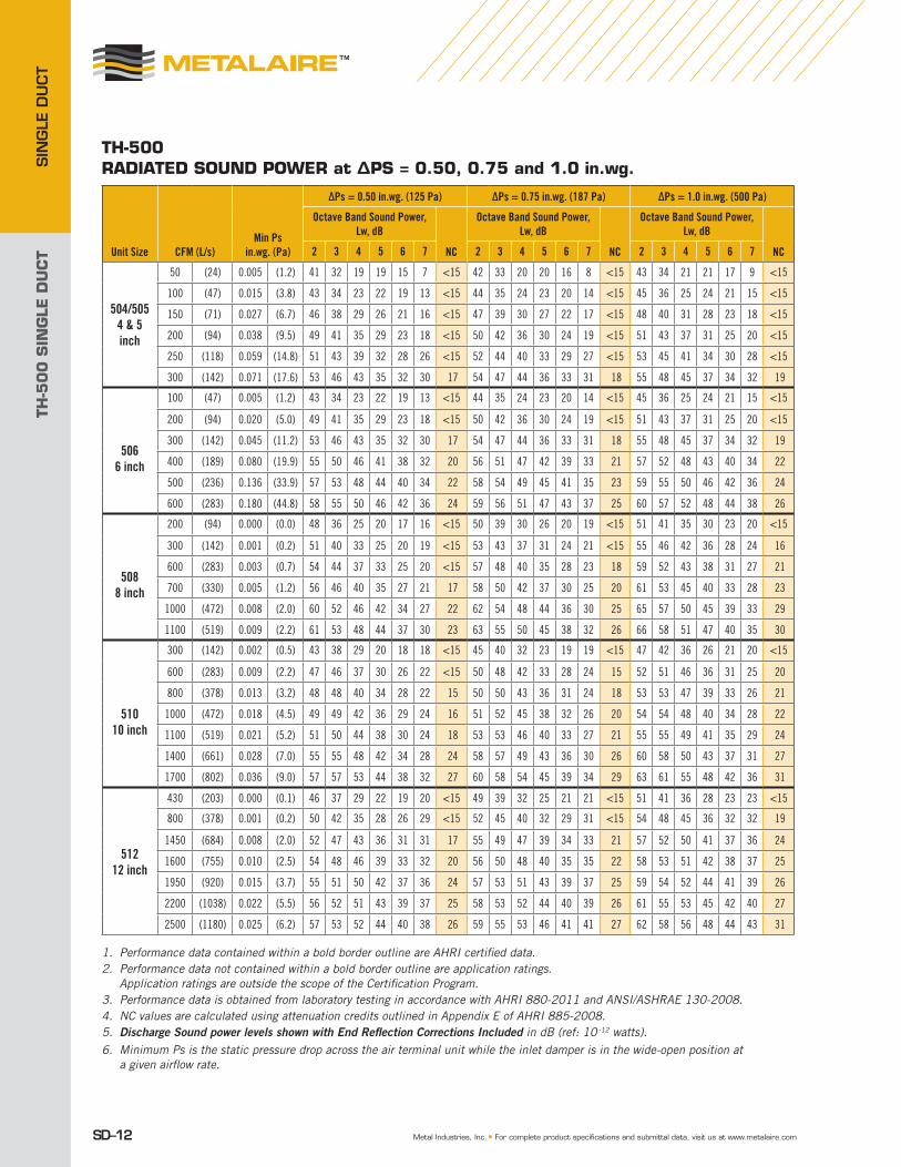
TH-500 RADiATED sOUND pOwER at Δps = 0.50, 0.75 and 1.0 in.wg.
1. Performance data contained within a bold border outline are AHRI certified data.2. Performance data not contained within a bold border outline are application ratings.
Application ratings are outside the scope of the Certification Program.3. Performance data is obtained from laboratory testing in accordance with AHRI 880-2011 and ANSI/ASHRAE 130-2008.4. NC values are calculated using attenuation credits outlined in Appendix E of AHRI 885-2008. 5. Discharge Sound power levels shown with End Reflection Corrections Included in dB (ref: 10 -12 watts). 6. Minimum Ps is the static pressure drop across the air terminal unit while the inlet damper is in the wide-open position at
a given airflow rate.
Unit Size CFM (L/s)Min Ps
in.wg. (Pa)
ΔPs = 0.50 in.wg. (125 Pa) ΔPs = 0.75 in.wg. (187 Pa) ΔPs = 1.0 in.wg. (500 Pa)
Octave Band Sound Power, Lw, dB
NC
Octave Band Sound Power, Lw, dB
NC
Octave Band Sound Power, Lw, dB
NC2 3 4 5 6 7 2 3 4 5 6 7 2 3 4 5 6 7
504/5054 & 5inch
50 (24) 0.005 (1.2) 41 32 19 19 15 7 <15 42 33 20 20 16 8 <15 43 34 21 21 17 9 <15
100 (47) 0.015 (3.8) 43 34 23 22 19 13 <15 44 35 24 23 20 14 <15 45 36 25 24 21 15 <15
150 (71) 0.027 (6.7) 46 38 29 26 21 16 <15 47 39 30 27 22 17 <15 48 40 31 28 23 18 <15
200 (94) 0.038 (9.5) 49 41 35 29 23 18 <15 50 42 36 30 24 19 <15 51 43 37 31 25 20 <15
250 (118) 0.059 (14.8) 51 43 39 32 28 26 <15 52 44 40 33 29 27 <15 53 45 41 34 30 28 <15
300 (142) 0.071 (17.6) 53 46 43 35 32 30 17 54 47 44 36 33 31 18 55 48 45 37 34 32 19
506
6 inch
100 (47) 0.005 (1.2) 43 34 23 22 19 13 <15 44 35 24 23 20 14 <15 45 36 25 24 21 15 <15
200 (94) 0.020 (5.0) 49 41 35 29 23 18 <15 50 42 36 30 24 19 <15 51 43 37 31 25 20 <15
300 (142) 0.045 (11.2) 53 46 43 35 32 30 17 54 47 44 36 33 31 18 55 48 45 37 34 32 19
400 (189) 0.080 (19.9) 55 50 46 41 38 32 20 56 51 47 42 39 33 21 57 52 48 43 40 34 22
500 (236) 0.136 (33.9) 57 53 48 44 40 34 22 58 54 49 45 41 35 23 59 55 50 46 42 36 24
600 (283) 0.180 (44.8) 58 55 50 46 42 36 24 59 56 51 47 43 37 25 60 57 52 48 44 38 26
508
8 inch
200 (94) 0.000 (0.0) 48 36 25 20 17 16 <15 50 39 30 26 20 19 <15 51 41 35 30 23 20 <15
300 (142) 0.001 (0.2) 51 40 33 25 20 19 <15 53 43 37 31 24 21 <15 55 46 42 36 28 24 16
600 (283) 0.003 (0.7) 54 44 37 33 25 20 <15 57 48 40 35 28 23 18 59 52 43 38 31 27 21
700 (330) 0.005 (1.2) 56 46 40 35 27 21 17 58 50 42 37 30 25 20 61 53 45 40 33 28 23
1000 (472) 0.008 (2.0) 60 52 46 42 34 27 22 62 54 48 44 36 30 25 65 57 50 45 39 33 29
1100 (519) 0.009 (2.2) 61 53 48 44 37 30 23 63 55 50 45 38 32 26 66 58 51 47 40 35 30
510
10 inch
300 (142) 0.002 (0.5) 43 38 29 20 18 18 <15 45 40 32 23 19 19 <15 47 42 36 26 21 20 <15
600 (283) 0.009 (2.2) 47 46 37 30 26 22 <15 50 48 42 33 28 24 15 52 51 46 36 31 25 20
800 (378) 0.013 (3.2) 48 48 40 34 28 22 15 50 50 43 36 31 24 18 53 53 47 39 33 26 21
1000 (472) 0.018 (4.5) 49 49 42 36 29 24 16 51 52 45 38 32 26 20 54 54 48 40 34 28 22
1100 (519) 0.021 (5.2) 51 50 44 38 30 24 18 53 53 46 40 33 27 21 55 55 49 41 35 29 24
1400 (661) 0.028 (7.0) 55 55 48 42 34 28 24 58 57 49 43 36 30 26 60 58 50 43 37 31 27
1700 (802) 0.036 (9.0) 57 57 53 44 38 32 27 60 58 54 45 39 34 29 63 61 55 48 42 36 31
51212 inch
430 (203) 0.000 (0.1) 46 37 29 22 19 20 <15 49 39 32 25 21 21 <15 51 41 36 28 23 23 <15
800 (378) 0.001 (0.2) 50 42 35 28 26 29 <15 52 45 40 32 29 31 <15 54 48 45 36 32 32 19
1450 (684) 0.008 (2.0) 52 47 43 36 31 31 17 55 49 47 39 34 33 21 57 52 50 41 37 36 24
1600 (755) 0.010 (2.5) 54 48 46 39 33 32 20 56 50 48 40 35 35 22 58 53 51 42 38 37 25
1950 (920) 0.015 (3.7) 55 51 50 42 37 36 24 57 53 51 43 39 37 25 59 54 52 44 41 39 26
2200 (1038) 0.022 (5.5) 56 52 51 43 39 37 25 58 53 52 44 40 39 26 61 55 53 45 42 40 27
2500 (1180) 0.025 (6.2) 57 53 52 44 40 38 26 59 55 53 46 41 41 27 62 58 56 48 44 43 31

TH-5
00
SIN
GLE
DU
CT
SIN
GLE D
UCT
SD–13© 2012 Metal Industries, Inc.
Unit Size CFM (L/s)Min Ps
in.wg. (Pa)
ΔPs = 0.50 in.wg. (125 Pa) ΔPs = 0.75 in.wg. (187 Pa) ΔPs = 1.0 in.wg. (500 Pa)
Octave Band Sound Power, Lw, dB
NC
Octave Band Sound Power, Lw, dB
NC
Octave Band Sound Power, Lw, dB
NC2 3 4 5 6 7 2 3 4 5 6 7 2 3 4 5 6 7
514
14 inch
550 (260) 0.000 (0.0) 52 38 36 28 25 20 <15 53 39 37 29 26 21 <15 54 40 38 30 27 22 <15
925 (437) 0.001 (0.2) 53 41 39 31 27 22 <15 54 42 40 32 28 23 <15 55 43 41 33 29 24 16
1600 (755) 0.003 (0.7) 56 46 44 35 31 26 18 57 47 45 36 32 27 19 58 48 46 37 33 28 20
1900 (897) 0.004 (1.0) 57 50 49 39 33 28 23 58 51 50 40 34 29 24 59 52 51 41 35 30 25
2100 (991) 0.005 (1.2) 59 54 51 42 36 31 25 60 55 52 43 37 32 26 61 56 53 44 38 33 27
2600 (1227) 0.006 (1.5) 62 56 54 43 40 36 29 63 57 55 44 41 37 30 64 58 56 45 42 38 31
3250 (1534) 0.007 (1.7) 64 60 57 46 44 40 32 65 61 58 47 45 41 33 66 62 59 48 46 42 34
516
16 inch
750 (354) 0.001 (0.4) 54 39 30 24 19 17 <15 54 41 33 28 21 19 <15 55 43 35 30 24 20 16
1100 (519) 0.006 (1.5) 56 45 36 29 24 20 17 56 47 39 32 26 22 17 57 49 41 34 29 24 18
1500 (708) 0.010 (2.6) 58 51 41 35 31 26 20 58 53 44 38 33 28 21 59 55 46 40 36 30 24
2400 (1133) 0.023 (5.7) 60 53 44 40 37 33 22 60 55 47 42 38 34 24 60 57 49 43 40 35 26
2800 (1321) 0.030 (7.5) 61 54 47 42 39 35 23 61 56 49 44 40 36 25 62 58 51 45 42 37 27
3600 (1699) 0.045 (11.1) 62 57 52 46 42 39 26 63 59 53 48 43 40 28 64 60 55 49 44 41 30
4400 (2076) 0.060 (15.0) 65 61 57 50 46 43 32 66 62 58 51 47 44 33 67 63 58 52 48 45 33
52020 x 16
1100 (519) 0.008 (2.0) 51 45 33 29 27 23 <15 53 47 35 31 29 25 <15 55 49 37 33 31 27 16
1600 (755) 0.024 (6.0) 53 51 43 39 32 29 19 55 53 45 41 34 31 21 57 55 47 43 36 33 24
2500 (1180) 0.055 (13.7) 59 58 56 52 44 39 31 61 60 58 54 46 41 33 63 62 60 56 48 43 35
3000 (1416) 0.060 (14.9) 64 62 60 56 50 43 35 66 64 62 58 52 45 37 68 66 64 60 54 47 39
4600 (2171) 0.140 (34.8) 70 67 65 62 52 47 41 72 69 67 64 54 49 43 74 71 69 66 56 51 45
5300 (2501) 0.167 (41.6) 71 69 67 64 54 48 43 73 71 69 66 56 50 45 75 73 71 68 58 52 47
6200 (2926) 0.202 (50.3) 74 71 69 66 56 49 45 76 73 71 68 58 51 47 78 75 73 70 60 53 49
52424 x 16
1250 (590) 0.010 (2.5) 54 45 35 32 30 23 <15 55 46 37 34 31 25 16 55 47 39 35 32 26 16
2000 (944) 0.015 (3.7) 58 51 44 41 36 31 20 59 52 45 42 37 32 21 59 52 46 42 38 32 21
3000 (1416) 0.020 (5.0) 63 56 50 47 42 37 26 64 57 51 48 43 38 27 64 57 52 48 44 38 27
4000 (1888) 0.025 (6.2) 66 61 58 53 49 42 33 67 62 59 54 50 43 34 68 62 59 55 50 44 34
5300 (2501) 0.040 (10.0) 70 66 63 59 55 49 38 72 67 64 61 56 50 39 73 68 64 62 57 51 39
6000 (2831) 0.050 (12.4) 73 68 66 61 57 51 42 75 69 67 63 58 52 43 76 70 68 64 59 53 44
7200 (3398) 0.070 (17.4) 76 72 68 66 60 54 44 77 73 70 68 61 55 46 78 74 71 69 62 56 47
1. Performance data contained within a bold border outline are AHRI certified data.2. Performance data not contained within a bold border outline are application ratings.
Application ratings are outside the scope of the Certification Program.3. Performance data is obtained from laboratory testing in accordance with AHRI 880-2011 and ANSI/ASHRAE 130-2008.4. NC values are calculated using attenuation credits outlined in Appendix E of AHRI 885-2008. 5. Discharge Sound power levels shown with End Reflection Corrections Included in dB (ref: 10 -12 watts). 6. Minimum Ps is the static pressure drop across the air terminal unit while the inlet damper is in the wide-open position at
a given airflow rate.
TH-500 RADiATED sOUND pOwER at Δps = 0.50, 0.75 and 1.0 in.wg. continued

TH-5
00
SIN
GLE
DU
CT
SIN
GLE
DU
CT
SD–14 Metal Industries, Inc. ■ For complete product specifications and submittal data, visit us at www.metalaire.com
TH-500 RADiATED sOUND pOwER at Δps = 1.50, 2.0 and 3.0 in.wg.
1. Performance data contained within a bold border outline are AHRI certified data.2. Performance data not contained within a bold border outline are application ratings.
Application ratings are outside the scope of the Certification Program.3. Performance data is obtained from laboratory testing in accordance with AHRI 880-2011 and ANSI/ASHRAE 130-2008.4. NC values are calculated using attenuation credits outlined in Appendix E of AHRI 885-2008. 5. Discharge Sound power levels shown with End Reflection Corrections Included in dB (ref: 10 -12 watts). 6. Minimum Ps is the static pressure drop across the air terminal unit while the inlet damper is in the wide-open position at
a given airflow rate.
Unit Size CFM (L/s)Min Ps
in.wg. (Pa)
ΔPs = 1.5 in.wg. (375 Pa) ΔPs = 2.0 in.wg. (500 Pa) ΔPs = 3.0 in.wg. (750 Pa)
Octave Band Sound Power, Lw, dB
NC
Octave Band Sound Power, Lw, dB
NC
Octave Band Sound Power, Lw, dB
NC2 3 4 5 6 7 2 3 4 5 6 7 2 3 4 5 6 7
504/5054 & 5inch
50 (24) 0.005 (1.2) 44 35 22 22 18 11 <15 44 36 23 22 19 13 <15 45 38 25 24 23 18 <15
100 (47) 0.015 (3.8) 46 37 26 25 22 17 <15 46 38 27 25 23 19 <15 47 40 29 27 27 24 <15
150 (71) 0.027 (6.7) 49 41 32 29 24 20 <15 49 42 33 29 25 22 <15 50 44 35 31 29 27 <15
200 (94) 0.038 (9.5) 52 44 38 32 26 22 <15 52 45 39 32 27 24 <15 53 47 41 34 31 29 <15
250 (118) 0.059 (14.8) 54 46 42 35 31 30 15 54 47 43 35 32 32 17 55 49 45 37 36 37 19
300 (142) 0.071 (17.6) 56 49 46 38 35 34 20 56 50 47 38 36 36 21 57 52 49 40 40 41 23
506
6 inch
100 (47) 0.005 (1.2) 46 37 26 25 22 17 <15 46 38 27 25 23 19 <15 47 40 29 27 27 24 <15
200 (94) 0.020 (5.0) 52 44 38 32 26 22 <15 52 45 39 32 27 24 <15 53 47 41 34 31 29 <15
300 (142) 0.045 (11.2) 56 49 46 38 35 34 20 56 50 47 38 36 36 21 57 52 49 40 40 41 23
400 (189) 0.080 (19.9) 58 53 49 44 41 36 23 58 54 50 44 42 38 24 59 56 52 46 46 43 26
500 (236) 0.136 (33.9) 60 56 51 47 43 38 25 61 57 52 47 44 40 26 61 59 54 49 48 45 29
600 (283) 0.180 (44.8) 61 58 53 49 45 40 27 62 59 54 49 46 42 29 62 61 56 51 50 47 31
508
8 inch
200 (94) 0.000 (0.0) 52 42 37 33 26 22 <15 52 43 38 35 29 23 <15 53 45 39 36 32 27 <15
300 (142) 0.001 (0.2) 55 46 43 38 32 29 17 55 46 43 40 35 33 17 56 47 45 42 40 38 19
600 (283) 0.003 (0.7) 60 55 47 42 36 32 24 61 57 51 45 39 36 26 61 59 54 49 43 41 29
700 (330) 0.005 (1.2) 62 57 52 44 39 34 26 63 60 53 47 40 37 29 64 61 56 51 44 41 31
1000 (472) 0.008 (2.0) 67 60 53 48 42 36 31 68 63 56 50 44 39 33 70 66 60 54 47 42 37
1100 (519) 0.009 (2.2) 68 61 54 50 43 38 32 69 64 57 52 45 40 34 71 67 61 56 49 44 38
510
10 inch
300 (142) 0.002 (0.5) 50 46 40 30 25 24 <15 54 47 40 32 26 25 <15 56 47 42 35 29 26 17
600 (283) 0.009 (2.2) 55 55 50 40 35 29 24 59 55 51 43 39 35 25 60 56 51 45 42 40 25
800 (378) 0.013 (3.2) 56 57 51 43 37 30 26 61 60 53 46 42 38 29 63 62 56 49 45 42 32
1000 (472) 0.018 (4.5) 57 58 52 44 38 32 27 62 63 56 49 44 40 33 64 67 60 52 47 45 38
1100 (519) 0.021 (5.2) 58 58 52 44 38 32 27 63 64 57 50 45 41 34 65 68 61 53 48 47 39
1400 (661) 0.028 (7.0) 63 62 54 47 41 35 32 70 66 58 52 47 44 37 71 70 63 56 50 49 41
1700 (802) 0.036 (9.0) 66 65 59 54 46 40 35 72 67 60 55 50 48 38 73 72 64 58 53 51 44
51212 inch
430 (203) 0.000 (0.1) 54 45 40 31 26 26 <15 55 47 41 34 29 28 16 56 47 44 38 34 33 18
800 (378) 0.001 (0.2) 57 51 49 40 35 35 23 58 54 53 45 40 41 27 58 56 56 50 44 42 31
1450 (684) 0.008 (2.0) 60 55 53 44 40 39 27 62 60 58 49 44 43 33 63 64 63 55 48 45 38
1600 (755) 0.010 (2.5) 61 56 54 45 41 40 29 63 60 58 49 44 44 33 65 65 63 55 48 46 38
1950 (920) 0.015 (3.7) 62 58 56 47 44 42 31 64 62 60 51 47 47 35 66 66 65 56 50 49 41
2200 (1038) 0.022 (5.5) 64 59 57 49 45 44 32 66 62 60 52 48 47 35 68 67 65 56 51 50 41
2500 (1180) 0.025 (6.2) 65 61 59 51 48 46 34 67 65 63 55 51 49 38 69 68 67 60 52 51 43

TH-5
00
SIN
GLE
DU
CT
SIN
GLE D
UCT
SD–15© 2012 Metal Industries, Inc.
Unit Size CFM (L/s)Min Ps
in.wg. (Pa)
ΔPs = 1.5 in.wg. (375 Pa) ΔPs = 2.0 in.wg. (500 Pa) ΔPs = 3.0 in.wg. (750 Pa)
Octave Band Sound Power, Lw, dB
NC
Octave Band Sound Power, Lw, dB
NC
Octave Band Sound Power, Lw, dB
NC2 3 4 5 6 7 2 3 4 5 6 7 2 3 4 5 6 7
514
14 inch
550 (260) 0.000 (0.0) 55 41 39 31 28 23 16 55 41 39 31 28 23 16 56 42 40 32 29 24 17
925 (437) 0.001 (0.2) 56 43 41 33 30 24 17 56 44 42 34 30 25 17 57 45 43 35 31 26 18
1600 (755) 0.003 (0.7) 58 49 46 38 33 28 20 59 49 47 38 34 29 21 60 50 48 39 35 30 22
1900 (897) 0.004 (1.0) 60 53 52 41 36 31 26 60 53 52 42 36 31 26 61 54 53 43 37 32 27
2100 (991) 0.005 (1.2) 62 57 55 45 40 34 30 62 57 54 45 40 34 29 63 58 55 46 40 35 30
2600 (1227) 0.006 (1.5) 65 59 57 46 43 39 32 65 59 57 46 43 39 32 66 60 58 47 44 40 33
3250 (1534) 0.007 (1.7) 67 63 60 49 47 43 35 67 63 60 49 47 43 35 68 64 61 50 48 44 36
516
16 inch
750 (354) 0.001 (0.4) 56 45 39 33 28 23 17 57 47 42 36 31 26 18 59 51 47 40 36 30 21
1100 (519) 0.006 (1.5) 58 51 45 39 34 28 20 59 53 49 44 38 32 23 61 56 51 49 40 35 25
1500 (708) 0.010 (2.6) 60 57 51 45 41 36 26 61 59 55 50 45 42 30 63 61 57 53 49 47 32
2400 (1133) 0.023 (5.7) 63 61 55 49 46 42 31 65 65 60 54 51 48 35 68 67 64 60 58 56 39
2800 (1321) 0.030 (7.5) 64 62 56 50 47 44 32 67 66 61 56 53 50 37 69 69 65 62 61 59 41
3600 (1699) 0.045 (11.1) 67 64 59 54 50 47 34 69 67 63 58 56 53 38 71 70 67 64 63 62 43
4400 (2076) 0.060 (15.0) 69 66 62 56 54 51 37 71 69 65 60 59 56 41 73 72 69 66 65 64 45
52020 x 16
1100 (519) 0.008 (2.0) 56 50 38 34 32 28 18 57 51 39 35 33 29 19 59 53 41 37 35 31 21
1600 (755) 0.024 (6.0) 58 56 48 44 37 34 25 59 57 49 45 38 35 26 61 59 51 47 40 37 28
2500 (1180) 0.055 (13.7) 64 63 61 57 49 44 36 65 64 62 58 50 45 37 67 66 64 60 52 47 39
3000 (1416) 0.060 (14.9) 69 67 65 61 55 48 41 70 68 66 62 56 49 42 72 70 68 64 58 51 44
4600 (2171) 0.140 (34.8) 75 72 70 67 57 52 46 76 73 71 68 58 53 47 78 75 73 70 60 55 49
5300 (2501) 0.167 (41.6) 76 74 72 69 59 53 48 77 75 73 70 60 54 49 79 77 75 72 62 56 51
6200 (2926) 0.202 (50.3) 79 76 74 71 61 54 50 80 77 75 72 62 55 51 82 79 77 74 64 57 54
52424 x 16
1250 (590) 0.010 (2.5) 58 50 42 38 35 29 20 58 52 44 39 37 32 20 59 55 49 42 39 35 24
2000 (944) 0.015 (3.7) 62 55 49 45 41 35 25 62 59 53 49 45 39 28 63 63 57 53 49 43 33
3000 (1416) 0.020 (5.0) 67 60 55 51 47 41 31 67 64 59 55 51 45 34 69 69 64 58 55 48 40
4000 (1888) 0.025 (6.2) 71 65 62 58 53 47 37 72 70 68 63 57 52 44 74 72 70 66 60 55 46
5300 (2501) 0.040 (10.0) 76 71 71 65 60 54 47 78 73 71 68 62 55 47 80 76 75 70 64 58 51
6000 (2831) 0.050 (12.4) 77 72 70 66 61 55 46 81 75 73 69 63 57 49 83 77 76 72 65 59 53
7200 (3398) 0.070 (17.4) 81 76 74 72 65 59 50 83 79 76 74 67 60 53 85 81 79 76 69 62 56
TH-500 RADiATED sOUND pOwER at Δps = 1.50, 2.0 and 3.0 in.wg. continued
1. Performance data contained within a bold border outline are AHRI certified data.2. Performance data not contained within a bold border outline are application ratings.
Application ratings are outside the scope of the Certification Program.3. Performance data is obtained from laboratory testing in accordance with AHRI 880-2011 and ANSI/ASHRAE 130-2008.4. NC values are calculated using attenuation credits outlined in Appendix E of AHRI 885-2008. 5. Discharge Sound power levels shown with End Reflection Corrections Included in dB (ref: 10 -12 watts). 6. Minimum Ps is the static pressure drop across the air terminal unit while the inlet damper is in the wide-open position at
a given airflow rate.
TH-5
00
SIN
GLE
DU
CT
SIN
GLE
DU
CT
SD–16 Metal Industries, Inc. ■ For complete product specifications and submittal data, visit us at www.metalaire.com
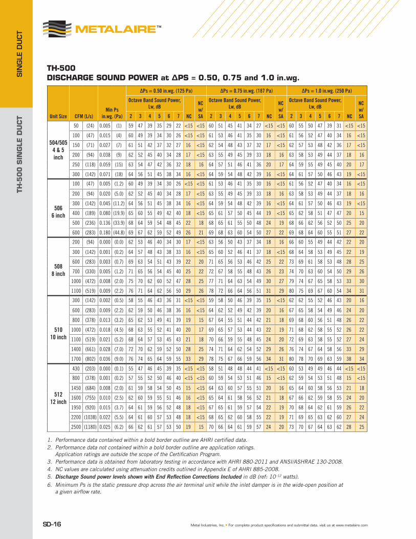
TH-500 DiscHARGE sOUND pOwER at Δps = 0.50, 0.75 and 1.0 in.wg.
1. Performance data contained within a bold border outline are AHRI certified data.2. Performance data not contained within a bold border outline are application ratings.
Application ratings are outside the scope of the Certification Program.3. Performance data is obtained from laboratory testing in accordance with AHRI 880-2011 and ANSI/ASHRAE 130-2008.4. NC values are calculated using attenuation credits outlined in Appendix E of AHRI 885-2008. 5. Discharge Sound power levels shown with End Reflection Corrections Included in dB (ref: 10 -12 watts). 6. Minimum Ps is the static pressure drop across the air terminal unit while the inlet damper is in the wide-open position at
a given airflow rate.
Unit Size CFM (L/s)Min Ps
in.wg. (Pa)
ΔPs = 0.50 in.wg. (125 Pa) ΔPs = 0.75 in.wg. (187 Pa) ΔPs = 1.0 in.wg. (250 Pa)
Octave Band Sound Power, Lw, dB
NC
NC w/ SA
Octave Band Sound Power, Lw, dB
NC
NC w/ SA
Octave Band Sound Power, Lw, dB
NC
NC w/ SA2 3 4 5 6 7 2 3 4 5 6 7 2 3 4 5 6 7
504/5054 & 5inch
50 (24) 0.005 (1) 59 47 39 35 29 22 <15 <15 60 51 45 41 34 27 <15 <15 60 55 50 47 39 31 <15 <15
100 (47) 0.015 (4) 60 49 39 34 30 26 <15 <15 61 53 46 41 35 30 16 <15 61 56 52 47 40 34 16 <15
150 (71) 0.027 (7) 61 51 42 37 32 27 16 <15 62 54 48 43 37 32 17 <15 62 57 53 48 42 36 17 <15
200 (94) 0.038 (9) 62 52 45 40 34 28 17 <15 63 55 49 45 39 33 18 16 63 58 53 49 44 37 18 16
250 (118) 0.059 (15) 63 54 47 42 36 32 18 16 64 57 51 46 41 36 20 17 64 59 55 49 45 40 20 17
300 (142) 0.071 (18) 64 56 51 45 38 34 16 <15 64 59 54 48 42 39 16 <15 64 61 57 50 46 43 19 <15
506
6 inch
100 (47) 0.005 (1.2) 60 49 39 34 30 26 <15 <15 61 53 46 41 35 30 16 <15 61 56 52 47 40 34 16 <15
200 (94) 0.020 (5.0) 62 52 45 40 34 28 17 <15 63 55 49 45 39 33 18 16 63 58 53 49 44 37 18 16
300 (142) 0.045 (11.2) 64 56 51 45 38 34 16 <15 64 59 54 48 42 39 16 <15 64 61 57 50 46 43 19 <15
400 (189) 0.080 (19.9) 65 60 55 49 42 40 18 <15 65 61 57 50 45 44 19 <15 65 62 58 51 47 47 20 15
500 (236) 0.136 (33.9) 68 64 59 54 48 45 22 18 68 65 61 55 50 48 24 19 68 66 62 56 52 50 25 20
600 (283) 0.180 (44.8) 69 67 62 59 52 49 26 21 69 68 63 60 54 50 27 22 69 68 64 60 55 51 27 22
508
8 inch
200 (94) 0.000 (0.0) 62 53 46 40 34 30 17 <15 63 56 50 43 37 34 18 16 66 60 55 49 44 42 22 20
300 (142) 0.001 (0.2) 64 57 48 43 38 33 16 <15 65 60 52 46 41 37 18 <15 68 64 58 53 49 45 22 19
600 (283) 0.003 (0.7) 69 63 54 51 43 39 22 20 71 65 56 53 46 42 25 22 73 69 61 58 53 48 28 25
700 (330) 0.005 (1.2) 71 65 56 54 45 40 25 22 72 67 58 55 48 43 26 23 74 70 63 60 54 50 29 26
1000 (472) 0.008 (2.0) 75 70 62 60 52 47 28 25 77 71 64 63 54 49 30 27 79 74 67 65 58 53 33 30
1100 (519) 0.009 (2.2) 76 71 64 62 56 50 29 26 78 72 66 64 56 51 31 29 80 75 69 67 60 54 34 31
510
10 inch
300 (142) 0.002 (0.5) 58 55 46 43 36 31 <15 <15 59 58 50 46 39 35 15 <15 62 62 55 52 46 43 20 16
600 (283) 0.009 (2.2) 62 59 50 46 38 36 16 <15 64 62 52 49 42 39 20 16 67 65 58 54 49 46 24 20
800 (378) 0.013 (3.2) 65 62 53 49 41 39 19 15 67 64 55 51 44 42 21 18 69 68 60 56 51 48 26 22
1000 (472) 0.018 (4.5) 68 63 55 52 41 40 20 17 69 65 57 53 44 43 22 19 71 68 62 58 55 52 26 22
1100 (519) 0.021 (5.2) 68 64 57 53 45 43 21 18 70 66 59 55 48 45 24 20 72 69 63 58 55 52 27 24
1400 (661) 0.028 (7.0) 72 70 62 59 52 50 28 25 74 71 64 62 54 52 29 26 76 74 67 64 58 56 33 29
1700 (802) 0.036 (9.0) 76 74 65 64 59 55 33 29 78 75 67 66 59 56 34 31 80 78 70 69 63 59 38 34
51212 inch
430 (203) 0.000 (0.1) 55 47 46 45 39 35 <15 <15 58 51 48 48 44 41 <15 <15 60 53 49 49 46 44 <15 <15
800 (378) 0.001 (0.2) 57 55 52 50 46 40 <15 <15 60 59 54 53 51 46 15 <15 62 59 54 53 51 48 15 <15
1450 (684) 0.008 (2.0) 61 59 58 54 50 45 15 <15 64 63 60 57 55 51 20 16 65 64 60 58 56 53 21 18
1600 (755) 0.010 (2.5) 62 60 59 55 51 46 16 <15 65 64 61 58 56 52 21 18 67 66 62 59 58 55 24 20
1950 (920) 0.015 (3.7) 64 61 59 56 52 48 18 <15 67 65 61 59 57 54 22 19 70 68 64 62 61 59 26 22
2200 (1038) 0.022 (5.5) 64 61 60 57 53 48 18 <15 68 65 62 60 58 55 22 19 71 69 65 63 62 60 27 24
2500 (1180) 0.025 (6.2) 66 62 61 57 53 50 19 15 70 66 64 61 59 57 24 20 73 70 67 64 63 62 28 25
TH-5
00
SIN
GLE
DU
CT
SIN
GLE D
UCT
SD–17© 2012 Metal Industries, Inc.
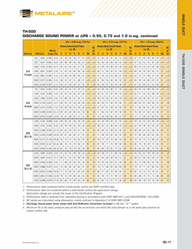
Unit Size CFM (L/s)Min Ps
in.wg. (Pa)
ΔPs = 0.50 in.wg. (125 Pa) ΔPs = 0.75 in.wg. (187 Pa) ΔPs = 1.0 in.wg. (250 Pa)
Octave Band Sound Power, Lw, dB
NC
NC w/ SA
Octave Band Sound Power, Lw, dB
NC
NC w/ SA
Octave Band Sound Power, Lw, dB
NC
NC w/ SA2 3 4 5 6 7 2 3 4 5 6 7 2 3 4 5 6 7
514
14 inch
550 (260) 0.000 (0.0) 46 38 36 34 27 22 <15 <15 51 45 43 41 36 31 <15 <15 57 51 49 49 44 39 <15 <15
925 (437) 0.001 (0.2) 46 38 38 36 30 23 <15 <15 52 45 45 44 39 32 <15 <15 57 52 51 51 47 42 <15 <15
1600 (755) 0.003 (0.7) 49 43 43 42 37 32 <15 <15 55 49 49 48 44 40 <15 <15 60 55 54 55 52 48 <15 <15
1900 (897) 0.004 (1.0) 51 45 45 44 40 36 <15 <15 56 51 50 50 47 44 <15 <15 60 56 55 56 54 51 15 <15
2100 (991) 0.005 (1.2) 53 48 49 48 44 41 <15 <15 57 53 53 53 50 47 <15 <15 62 57 57 58 57 54 18 <15
2600 (1227) 0.006 (1.5) 58 52 52 51 48 47 <15 <15 61 56 55 56 54 52 16 <15 65 59 59 60 59 57 21 <15
3250 (1534) 0.007 (1.7) 64 57 54 54 52 55 19 <15 66 60 57 58 56 58 22 <15 67 62 60 61 61 60 24 16
516
16 inch
750 (354) 0.001 (0.4) 48 43 41 33 29 25 <15 <15 54 49 45 40 37 34 <15 <15 60 55 53 48 46 43 <15 <15
1100 (519) 0.006 (1.5) 50 45 43 36 32 26 <15 <15 56 51 47 43 40 35 <15 <15 62 57 53 50 48 44 <15 <15
1500 (708) 0.010 (2.6) 53 48 45 41 36 31 <15 <15 58 53 50 47 43 39 <15 <15 64 59 56 53 51 47 15 <15
2400 (1133) 0.023 (5.7) 60 55 53 50 44 40 <15 <15 64 59 57 54 50 46 15 <15 68 63 61 58 56 52 20 18
2800 (1321) 0.030 (7.5) 64 58 58 55 49 44 <15 <15 67 62 61 58 54 49 19 16 71 66 64 61 59 55 24 21
3600 (1699) 0.045 (11.1) 69 63 64 60 55 50 20 18 71 66 65 62 59 54 24 21 74 69 67 64 63 58 27 25
4400 (2076) 0.060 (15.0) 74 67 68 65 57 53 26 25 75 69 68 66 60 57 27 26 77 71 69 67 64 61 30 29
52020 x 16
1100 (519) 0.008 (2.0) 49 43 42 36 34 34 <15 <15 54 50 49 43 42 42 <15 <15 59 56 55 50 49 49 <15 <15
1600 (755) 0.024 (6.0) 54 50 48 42 39 36 <15 <15 58 55 53 48 46 43 <15 <15 62 59 58 54 52 50 15 <15
2500 (1180) 0.055 (13.7) 64 62 59 54 51 44 19 16 66 64 61 58 55 50 21 19 68 66 63 61 58 55 24 21
3000 (1416) 0.060 (14.9) 69 67 64 60 57 52 25 22 71 68 65 62 60 55 26 24 72 69 66 64 62 58 27 25
4600 (2171) 0.140 (34.8) 76 73 72 70 63 55 32 29 78 75 74 73 66 59 34 32 79 76 75 75 68 62 35 33
5300 (2501) 0.167 (41.6) 80 76 75 74 66 57 35 33 82 78 77 76 69 60 38 35 83 79 78 78 71 63 39 37
6200 (2926) 0.202 (50.3) 83 79 78 79 69 58 39 37 85 80 79 81 72 62 40 39 86 81 81 83 74 65 41 40
52424 x 16
1250 (590) 0.010 (2.5) 47 52 45 44 38 35 <15 <15 60 58 53 51 48 45 <15 <15 65 63 61 58 58 54 20 18
2000 (944) 0.015 (3.7) 60 61 55 52 48 46 18 15 65 64 60 58 54 51 21 19 68 67 64 63 59 57 25 22
3000 (1416) 0.020 (5.0) 71 68 63 60 59 56 26 24 74 70 66 63 61 58 28 26 76 72 68 66 62 60 31 28
4000 (1888) 0.025 (6.2) 73 69 64 62 62 57 27 25 76 71 68 65 64 60 29 27 79 74 71 67 66 62 33 31
5300 (2501) 0.040 (10.0) 77 75 66 67 65 64 34 32 80 77 69 70 68 66 37 34 82 79 72 72 70 67 39 37
6000 (2831) 0.050 (12.4) 79 76 69 68 66 65 35 33 82 78 72 71 69 67 38 35 84 80 75 73 71 68 40 38
7200 (3398) 0.070 (17.4) 82 80 72 69 69 66 40 38 85 82 75 72 72 68 42 40 87 84 78 74 74 69 45 42
TH-500 DiscHARGE sOUND pOwER at Δps = 0.50, 0.75 and 1.0 in.wg. continued
1. Performance data contained within a bold border outline are AHRI certified data.2. Performance data not contained within a bold border outline are application ratings.
Application ratings are outside the scope of the Certification Program.3. Performance data is obtained from laboratory testing in accordance with AHRI 880-2011 and ANSI/ASHRAE 130-2008.4. NC values are calculated using attenuation credits outlined in Appendix E of AHRI 885-2008. 5. Discharge Sound power levels shown with End Reflection Corrections Included in dB (ref: 10 -12 watts). 6. Minimum Ps is the static pressure drop across the air terminal unit while the inlet damper is in the wide-open position at
a given airflow rate.

TH-5
00
SIN
GLE
DU
CT
SIN
GLE
DU
CT
SD–18 Metal Industries, Inc. ■ For complete product specifications and submittal data, visit us at www.metalaire.com
TH-500 DiscHARGE sOUND pOwER at Δps = 1.50, 2.0 and 3.0 in.wg.
1. Performance data contained within a bold border outline are AHRI certified data.2. Performance data not contained within a bold border outline are application ratings.
Application ratings are outside the scope of the Certification Program.3. Performance data is obtained from laboratory testing in accordance with AHRI 880-2011 and ANSI/ASHRAE 130-2008.4. NC values are calculated using attenuation credits outlined in Appendix E of AHRI 885-2008. 5. Discharge Sound power levels shown with End Reflection Corrections Included in dB (ref: 10 -12 watts). 6. Minimum Ps is the static pressure drop across the air terminal unit while the inlet damper is in the wide-open position at
a given airflow rate.
Unit Size CFM (L/s)Min Ps
in.wg. (Pa)
ΔPs = 1.5 in.wg. (375 Pa) ΔPs = 2.0 in.wg. (500 Pa) ΔPs = 3.0 in.wg. (750 Pa)
Octave Band Sound Power, Lw, dB
NC
NC w/ SA
Octave Band Sound Power, Lw, dB
NC
NC w/ SA
Octave Band Sound Power, Lw, dB
NC
NC w/ SA2 3 4 5 6 7 2 3 4 5 6 7 2 3 4 5 6 7
504/5054 & 5inch
50 (24) 0.005 (1) 62 57 52 49 41 33 17 <15 62 57 52 49 41 33 17 <15 64 59 52 51 43 35 20 17
100 (47) 0.015 (4) 63 58 54 49 42 36 18 16 63 58 54 49 42 36 18 16 65 60 54 51 44 38 21 18
150 (71) 0.027 (7) 64 59 55 50 44 38 20 17 64 59 55 50 44 38 20 17 66 61 55 52 46 40 22 20
200 (94) 0.038 (9) 65 60 55 51 46 39 21 18 65 60 55 51 46 39 21 18 67 62 55 53 48 41 23 21
250 (118) 0.059 (15) 66 61 57 51 47 42 22 20 66 61 57 51 47 42 22 20 68 63 59 53 49 44 25 22
300 (142) 0.071 (18) 66 63 59 52 48 45 21 16 66 63 59 52 48 45 21 16 68 65 61 54 50 47 24 19
506
6 inch
100 (47) 0.005 (1.2) 63 58 54 49 42 36 18 16 63 58 54 49 42 36 18 16 65 60 54 51 44 38 21 18
200 (94) 0.020 (5.0) 65 60 55 51 46 39 21 18 65 60 55 51 46 39 21 18 67 62 55 53 48 41 23 21
300 (142) 0.045 (11.2) 66 63 59 52 48 45 21 16 66 63 59 52 48 45 21 16 68 65 61 54 50 47 24 19
400 (189) 0.080 (19.9) 67 64 60 53 49 49 22 18 67 64 60 53 49 49 22 18 69 67 62 55 51 51 26 21
500 (236) 0.136 (33.9) 70 68 64 58 54 52 27 22 70 68 64 58 54 52 27 22 72 70 66 60 56 54 29 25
600 (283) 0.180 (44.8) 71 70 66 62 57 53 29 25 71 70 66 62 57 53 29 25 73 72 68 64 59 55 32 27
508
8 inch
200 (94) 0.000 (0.0) 66 60 54 50 46 44 22 0 67 61 55 52 48 46 23 21 68 62 56 54 50 48 25 22
300 (142) 0.001 (0.2) 68 64 56 53 49 48 22 0 69 65 57 55 51 50 24 20 70 66 58 57 53 52 25 21
600 (283) 0.003 (0.7) 73 68 59 56 53 52 27 22 74 69 60 58 55 54 29 26 75 70 61 60 57 56 30 27
700 (330) 0.005 (1.2) 75 71 62 58 55 53 31 25 76 72 63 60 57 55 32 29 77 73 64 62 59 57 33 30
1000 (472) 0.008 (2.0) 80 75 67 66 61 58 34 33 81 76 68 68 63 60 35 32 82 77 69 70 65 62 37 34
1100 (519) 0.009 (2.2) 81 76 69 68 62 60 35 36 82 77 70 70 64 62 37 34 83 78 71 72 66 64 38 35
510
10 inch
300 (142) 0.002 (0.5) 62 62 56 53 48 45 20 15 62 62 56 53 48 45 20 16 64 64 57 55 50 48 22 19
600 (283) 0.009 (2.2) 68 66 61 57 52 49 25 20 68 66 61 57 52 49 25 21 70 68 63 59 55 53 27 24
800 (378) 0.013 (3.2) 70 68 63 58 54 51 26 21 70 68 63 58 54 51 26 22 72 70 65 61 57 53 28 25
1000 (472) 0.018 (4.5) 72 69 64 59 55 52 27 22 72 69 64 59 55 52 27 24 74 71 66 61 57 54 29 26
1100 (519) 0.021 (5.2) 73 70 65 60 56 53 28 24 73 70 65 60 56 53 28 25 74 72 68 62 59 55 31 27
1400 (661) 0.028 (7.0) 77 75 69 65 60 57 34 29 77 75 69 65 60 57 34 31 79 76 71 66 63 60 35 32
1700 (802) 0.036 (9.0) 81 79 72 70 64 60 39 34 81 79 72 70 64 60 39 35 83 81 74 71 66 64 41 38
51212 inch
430 (203) 0.000 (0.1) 61 55 49 50 47 46 <15 <15 62 56 50 51 48 47 <15 <15 64 58 52 53 50 49 16 <15
800 (378) 0.001 (0.2) 63 58 52 53 50 49 <15 <15 64 59 53 54 51 50 15 <15 66 61 55 56 53 52 18 <15
1450 (684) 0.008 (2.0) 66 64 59 58 56 54 21 16 67 65 60 59 57 55 22 19 69 67 62 61 59 57 25 21
1600 (755) 0.010 (2.5) 68 67 62 60 59 57 25 20 69 68 63 61 60 58 26 22 71 70 65 63 62 60 28 25
1950 (920) 0.015 (3.7) 73 71 66 65 64 63 29 25 74 72 67 66 65 64 31 27 76 74 69 68 67 66 33 29
2200 (1038) 0.022 (5.5) 74 72 67 66 66 64 31 26 75 73 68 67 67 65 32 28 77 75 70 69 69 67 34 31
2500 (1180) 0.025 (6.2) 76 73 69 67 67 66 32 27 77 74 70 68 68 67 33 29 79 76 72 70 70 69 35 32

TH-5
00
SIN
GLE
DU
CT
SIN
GLE D
UCT
SD–19© 2012 Metal Industries, Inc.
Unit Size CFM (L/s)Min Ps
in.wg. (Pa)
ΔPs = 1.5 in.wg. (375 Pa) ΔPs = 2.0 in.wg. (500 Pa) ΔPs = 3.0 in.wg. (750 Pa)
Octave Band Sound Power, Lw, dB
NC
NC w/ SA
Octave Band Sound Power, Lw, dB
NC
NC w/ SA
Octave Band Sound Power, Lw, dB
NC
NC w/ SA2 3 4 5 6 7 2 3 4 5 6 7 2 3 4 5 6 7
514
14 inch
550 (260) 0.000 (0.0) 62 58 56 56 53 48 15 <15 64 60 58 58 55 50 18 15 67 63 61 61 58 53 21 19
925 (437) 0.001 (0.2) 63 59 57 58 55 51 15 <15 65 61 59 60 57 53 18 15 68 64 62 63 60 56 21 19
1600 (755) 0.003 (0.7) 65 61 60 61 59 56 20 <15 67 63 62 63 61 58 22 18 70 66 65 66 64 61 25 21
1900 (897) 0.004 (1.0) 65 61 60 62 61 58 22 <15 67 63 62 64 63 60 24 18 70 66 65 67 66 63 27 21
2100 (991) 0.005 (1.2) 66 62 61 63 63 60 24 <15 68 64 63 65 65 62 26 19 71 67 66 68 68 65 29 22
2600 (1227) 0.006 (1.5) 68 63 62 64 64 62 26 16 70 65 64 66 66 64 28 20 73 68 67 69 69 67 31 24
3250 (1534) 0.007 (1.7) 69 64 63 65 65 63 27 17 71 66 65 67 67 65 29 21 74 69 68 70 70 68 32 25
516
16 inch
750 (354) 0.001 (0.4) 66 61 57 55 54 52 18 <15 67 62 58 57 56 54 19 16 69 64 60 59 58 56 21 19
1100 (519) 0.006 (1.5) 67 62 59 57 56 53 19 <15 68 63 60 59 58 55 20 18 70 65 62 61 60 57 22 20
1500 (708) 0.010 (2.6) 69 64 61 59 58 55 21 17 70 65 62 61 60 57 22 20 72 67 64 63 62 59 25 22
2400 (1133) 0.023 (5.7) 72 67 64 62 62 58 25 21 73 68 65 64 64 60 26 24 75 70 67 66 66 62 28 26
2800 (1321) 0.030 (7.5) 74 69 66 64 64 60 27 23 75 70 67 66 66 62 28 26 77 72 69 68 68 64 31 29
3600 (1699) 0.045 (11.1) 76 71 68 66 66 62 29 26 77 72 69 68 68 64 31 29 79 74 71 70 70 66 33 31
4400 (2076) 0.060 (15.0) 78 72 69 68 67 64 31 29 79 73 70 70 69 66 32 31 81 75 72 72 71 68 35 34
52020 x 16
1100 (519) 0.008 (2.0) 66 64 63 60 59 59 23 16 67 65 64 61 60 60 24 20 68 66 65 62 61 61 25 21
1600 (755) 0.024 (6.0) 68 66 64 62 60 59 24 19 69 67 65 63 61 60 25 22 70 68 66 64 62 61 26 24
2500 (1180) 0.055 (13.7) 72 70 68 66 64 62 28 24 73 71 69 67 65 63 29 27 74 72 70 68 66 64 31 28
3000 (1416) 0.060 (14.9) 74 71 71 71 67 63 29 25 76 73 71 71 67 64 32 29 77 74 72 71 68 65 33 31
4600 (2171) 0.140 (34.8) 83 79 78 79 72 67 39 35 84 80 79 80 73 68 40 38 85 81 80 81 74 69 41 39
5300 (2501) 0.167 (41.6) 86 82 81 83 75 68 42 39 87 83 82 84 76 69 44 41 88 84 83 85 77 70 45 43
6200 (2926) 0.202 (50.3) 89 84 84 88 78 70 45 43 90 85 85 89 79 71 46 45 91 86 86 90 80 72 48 46
52424 x 16
1250 (590) 0.010 (2.5) 66 65 62 60 59 58 22 18 67 66 63 61 60 59 24 21 68 67 64 62 61 60 25 22
2000 (944) 0.015 (3.7) 70 68 66 64 61 59 26 21 71 69 67 65 62 60 27 25 72 70 68 66 63 61 28 26
3000 (1416) 0.020 (5.0) 77 73 69 67 64 62 32 27 78 74 70 68 65 63 33 31 79 75 71 69 66 64 34 32
4000 (1888) 0.025 (6.2) 80 76 72 70 67 64 35 31 81 77 73 71 68 65 37 34 82 78 74 72 69 66 38 35
5300 (2501) 0.040 (10.0) 86 85 81 77 74 71 46 41 87 86 82 78 75 72 47 45 88 87 83 79 76 73 48 46
6000 (2831) 0.050 (12.4) 89 88 84 80 77 74 50 45 90 89 85 81 78 75 51 48 91 90 86 82 79 76 52 50
7200 (3398) 0.070 (17.4) 91 90 86 82 79 76 52 47 92 91 87 83 80 77 53 51 93 92 88 84 81 78 54 52
TH-500 DiscHARGE sOUND pOwER at Δps = 1.50, 2.0 and 3.0 in.wg. continued
1. Performance data contained within a bold border outline are AHRI certified data.2. Performance data not contained within a bold border outline are application ratings.
Application ratings are outside the scope of the Certification Program.3. Performance data is obtained from laboratory testing in accordance with AHRI 880-2011 and ANSI/ASHRAE 130-2008.4. NC values are calculated using attenuation credits outlined in Appendix E of AHRI 885-2008. 5. Discharge Sound power levels shown with End Reflection Corrections Included in dB (ref: 10 -12 watts). 6. Minimum Ps is the static pressure drop across the air terminal unit while the inlet damper is in the wide-open position at
a given airflow rate.
TH-5
00
SIN
GLE
DU
CT
SIN
GLE
DU
CT
SD–20 Metal Industries, Inc. ■ For complete product specifications and submittal data, visit us at www.metalaire.com
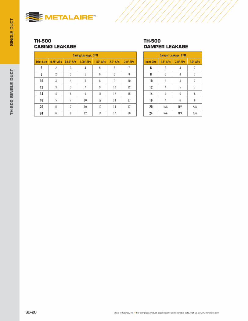
TH-500 cAsiNG LEAKAGE
Casing Leakage, CFM
Inlet Size 0.25" ΔPs 0.50" ΔPs 1.00" ΔPs 1.50" ΔPs 2.0" ΔPs 3.0" ΔPs
6 2 3 4 5 6 7
8 2 3 5 6 6 8
10 3 4 6 8 9 10
12 3 5 7 9 10 12
14 4 6 9 11 12 15
16 5 7 10 12 14 17
20 5 7 10 12 14 17
24 6 8 12 14 17 20
TH-500 DAMpER LEAKAGE
Damper Leakage, CFM
Inlet Size 1.5" ΔPs 3.0" ΔPs 6.0" ΔPs
6 3 4 7
8 3 4 7
10 4 5 7
12 4 5 7
14 4 6 8
16 4 6 8
20 N/A N/A N/A
24 N/A N/A N/A

TH-5
00
SIN
GLE
DU
CT
SIN
GLE D
UCT
© 2012 Metal Industries, Inc. SD–21
TH-500 MiniMuM Pressures
Unit Size CFMUnit ΔPs (in. wg)
Unit ΔPt (in. wg)
Unit + 1R Coil, ΔPs (in. wg)
Unit + 1R Coil, ΔPt (in. wg)
Unit + 2R Coil, ΔPs (in. wg)
Unit + 2R Coil, ΔPt (in. wg)
Unit + 3R Coil, ΔPs (in. wg)
Unit + 3R Coil, ΔPt (in. wg)
Unit + 4R Coil, ΔPs (in. wg)
Unit + 4R Coil, ΔPt (in. wg)
504 / 5054-inch5-inch
5066-inch
100 0.005 0.020 0.02 0.03 0.04 0.05 0.05 0.06 0.05 0.06
200 0.020 0.079 0.06 0.12 0.10 0.16 0.14 0.20 0.18 0.24
300 0.045 0.178 0.12 0.25 0.21 0.34 0.29 0.42 0.37 0.50
400 0.080 0.316 0.20 0.44 0.34 0.58 0.47 0.71 0.60 0.84
500 0.125 0.494 0.31 0.67 0.51 0.87 0.69 1.05 0.88 1.24
600 0.180 0.712 0.39 0.92 0.69 1.22 — — — —
5088-inch
300 0.001 0.039 0.05 0.09 0.10 0.14 0.16 0.20 0.20 0.24
400 0.001 0.069 0.08 0.15 0.16 0.23 0.24 0.31 0.32 0.39
500 0.002 0.108 0.11 0.22 0.23 0.34 0.35 0.46 0.46 0.57
600 0.003 0.155 0.15 0.30 0.32 0.47 0.47 0.62 0.63 0.78
700 0.004 0.211 0.19 0.40 0.41 0.62 0.61 0.82 0.82 1.03
800 0.005 0.275 0.25 0.52 0.52 0.79 0.78 1.05 — —
900 0.007 0.348 0.31 0.65 0.63 0.97 — — — —
1000 0.008 0.430 0.37 0.79 0.75 1.17 — — — —
51010-inch
400 0.004 0.030 0.04 0.07 0.09 0.12 0.13 0.16 0.17 0.20
600 0.009 0.068 0.09 0.15 0.18 0.24 0.25 0.31 0.35 0.41
800 0.016 0.121 0.15 0.25 0.29 0.39 0.37 0.47 0.56 0.66
1000 0.025 0.189 0.21 0.38 0.41 0.58 0.49 0.66 0.81 0.98
1200 0.036 0.272 0.29 0.52 0.58 0.81 0.65 0.88 — —
1400 0.049 0.370 0.38 0.70 0.78 1.10 — — — —
1600 0.063 0.483 0.48 0.90 — — — — — —
51212-inch
800 0.020 0.070 0.09 0.14 0.19 0.24 0.26 0.31 0.34 0.39
1000 0.031 0.110 0.14 0.22 0.27 0.35 0.38 0.46 0.49 0.57
1200 0.045 0.158 0.20 0.31 0.38 0.49 0.52 0.63 0.68 0.79
1400 0.061 0.215 0.25 0.41 0.49 0.65 0.67 0.83 0.88 1.04
1600 0.080 0.281 0.32 0.52 0.59 0.79 0.85 1.05 — —
1800 0.101 0.356 0.40 0.66 0.72 0.98 — — — —
2000 0.125 0.439 0.49 0.80 0.87 1.18 — — — —
2200 0.151 0.532 0.57 0.95 — — — — — —
1. ΔPs = static pressure drop; ΔPt = total pressure drop.2. Calculations of ΔPs and ΔPt were performed using standard air with a density of 0.075 lbm / cu.ft.3. Data based on testing standard METALAIRE hot water coils per AHRI Standard 410.4. Unit ΔPs and Unit ΔPt are pressure drops across the air terminal unit while the inlet damper is in the wide-open position.5. Data applies to air terminal units with hot water coil mounted on the discharge side.6. “ —” is shown when the static pressure drop exceeds 0.50 in. wg.
1-Single Duct ATU_TH-500_v10_82312.indd 21 8/31/12 12:04 AM

TH-5
00
SIN
GLE
DU
CT
SIN
GLE
DU
CT
SD–22 Metal Industries, Inc. ■ For complete product specifications and submittal data, visit us at www.metalaire.com
Unit Size CFMUnit ΔPs (in.wg.)
Unit ΔPt (in.wg.)
Unit + 1R Coil, ΔPs (in.wg.)
Unit + 1R Coil, ΔPt (in.wg.)
Unit + 2R Coil, ΔPs (in.wg.)
Unit + 2R Coil, ΔPt (in.wg.)
Unit + 3R Coil, ΔPs (in.wg.)
Unit + 3R Coil, ΔPt (in.wg.)
Unit + 4R Coil, ΔPs (in.wg.)
Unit + 4R Coil, ΔPt (in.wg.)
51414-inch
1000 0.000 0.044 0.06 0.10 0.12 0.16 0.19 0.23 0.25 0.29
1300 0.000 0.075 0.09 0.16 0.19 0.26 0.29 0.36 0.38 0.45
1600 0.001 0.113 0.13 0.24 0.27 0.38 0.41 0.52 0.54 0.65
2000 0.001 0.177 0.18 0.36 0.39 0.57 0.59 0.77 0.79 0.97
2300 0.001 0.234 0.24 0.47 0.50 0.73 0.75 0.98 -- --
2600 0.002 0.299 0.29 0.59 0.61 0.91 -- -- -- --
3000 0.002 0.398 0.37 0.77 0.78 1.18 -- -- -- --
3300 0.003 0.482 0.44 0.92 -- -- -- -- -- --
51616-inch
1600 0.030 0.094 0.12 0.18 0.23 0.29 0.33 0.39 0.45 0.51
2000 0.044 0.144 0.18 0.28 0.33 0.43 0.48 0.58 0.62 0.72
2300 0.052 0.185 0.22 0.35 0.42 0.55 0.60 0.73 0.78 0.91
2600 0.070 0.239 0.28 0.45 0.52 0.69 0.75 0.92 -- --
3000 0.085 0.310 0.36 0.58 0.66 0.88 0.95 1.17 -- --
3300 0.100 0.373 0.42 0.69 0.77 1.04 -- -- -- --
3600 0.113 0.438 0.48 0.81 0.89 1.22 -- -- -- --
4000 0.131 0.532 0.58 0.98 -- -- -- -- -- --
52020 x 16
1500 0.008 0.028 0.05 0.07 0.11 0.13 0.16 0.18 0.21 0.23
2000 0.013 0.049 0.08 0.12 0.17 0.21 0.25 0.29 0.33 0.37
2500 0.021 0.077 0.13 0.19 0.25 0.31 0.37 0.43 0.48 0.54
3000 0.030 0.111 0.18 0.26 0.35 0.43 0.50 0.58 0.66 0.74
3500 0.041 0.151 0.23 0.34 0.45 0.56 0.65 0.76 0.86 0.97
4000 0.053 0.198 0.29 0.44 0.56 0.71 0.82 0.97 -- --
5000 0.083 0.309 0.44 0.67 0.82 1.05 -- -- -- --
6000 0.120 0.445 0.61 0.94 -- -- -- -- -- --
52424 x 16
2000 0.014 0.040 0.06 0.09 0.12 0.15 0.17 0.20 0.23 0.26
3000 0.031 0.090 0.13 0.19 0.24 0.30 0.35 0.41 0.45 0.51
4000 0.056 0.160 0.22 0.32 0.40 0.50 0.58 0.68 0.75 0.85
5000 0.087 0.250 0.33 0.49 0.59 0.75 0.84 1.00 -- --
6000 0.125 0.360 0.45 0.68 0.81 1.04 -- -- -- --
6500 0.152 0.428 0.52 0.80 -- -- -- -- -- --
7000 0.173 0.493 0.59 0.91 -- -- -- -- -- --
TH-500 MiNiMUM pREssUREs continued
1. ΔPs = static pressure drop; ΔPt = total pressure drop.2. Calculations of ΔPs and ΔPt were performed using standard air with a density of 0.075 lbm/cu.ft.3. Data based on testing standard METALAIRE hot water coils per AHRI Standard 410.4. Unit ΔPs and Unit ΔPt are pressure drops across the air terminal unit while the inlet damper is in the wide-open position.5. Data applies to air terminal units with hot water coil mounted on the discharge side.6. “ --” is shown when the static pressure drop exceeds 0.50 in.wg.
TH-5
00
SIN
GLE
DU
CT
SIN
GLE D
UCT
SD–23© 2012 Metal Industries, Inc.
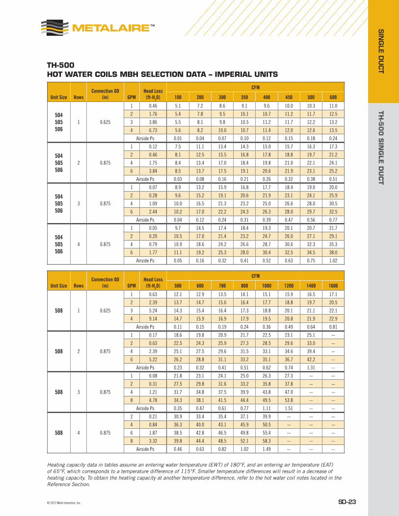
TH-500 HOT wATER cOiLs MBH sELEcTiON DATA – iMpERiAL UNiTs
Unit Size RowsConnection OD
(in) GPMHead Loss
(ft-H2O)
CFM
100 200 300 350 400 450 500 600
504 505 506
1 0.625
1 0.46 5.1 7.2 8.6 9.1 9.6 10.0 10.3 11.0
2 1.76 5.4 7.8 9.5 10.1 10.7 11.2 11.7 12.5
3 3.86 5.5 8.1 9.8 10.5 11.2 11.7 12.2 13.2
4 6.73 5.6 8.2 10.0 10.7 11.4 12.0 12.6 13.5
Airside Ps 0.01 0.04 0.07 0.10 0.12 0.15 0.18 0.24
504 505 506
2 0.875
1 0.12 7.5 11.1 13.4 14.3 15.0 15.7 16.3 17.3
2 0.46 8.1 12.5 15.5 16.8 17.8 18.8 19.7 21.2
4 1.75 8.4 13.4 17.0 18.4 19.8 21.0 22.1 24.1
6 3.84 8.5 13.7 17.5 19.1 20.6 21.9 23.1 25.2
Airside Ps 0.03 0.08 0.16 0.21 0.26 0.32 0.38 0.51
504 505 506
3 0.875
1 0.07 8.9 13.2 15.9 16.8 17.7 18.4 19.0 20.0
2 0.28 9.6 15.2 19.1 20.6 21.9 23.1 24.1 25.9
4 1.09 10.0 16.5 21.3 23.2 25.0 26.6 28.0 30.5
6 2.44 10.2 17.0 22.2 24.3 26.3 28.0 29.7 32.5
Airside Ps 0.04 0.12 0.24 0.31 0.39 0.47 0.56 0.77
504 505 506
4 0.875
1 0.05 9.7 14.5 17.4 18.4 19.3 20.1 20.7 21.7
2 0.20 10.5 17.0 21.4 23.2 24.7 26.0 27.1 29.1
4 0.79 10.9 18.6 24.2 26.6 28.7 30.6 32.3 35.3
6 1.77 11.1 19.2 25.3 28.0 30.4 32.5 34.5 38.0
Airside Ps 0.05 0.16 0.32 0.41 0.52 0.63 0.75 1.02
Unit Size RowsConnection OD
(in) GPMHead Loss
(ft-H2O)
CFM
500 600 700 800 1000 1200 1400 1600
508 1 0.625
1 0.63 12.1 12.9 13.5 14.1 15.1 15.9 16.5 17.1
2 2.39 13.7 14.7 15.6 16.4 17.7 18.8 19.7 20.5
3 5.24 14.3 15.4 16.4 17.3 18.8 20.1 21.1 22.1
4 9.14 14.7 15.9 16.9 17.9 19.5 20.8 21.9 22.9
Airside Ps 0.11 0.15 0.19 0.24 0.36 0.49 0.64 0.81
508 2 0.875
1 0.17 18.6 19.8 20.9 21.7 22.5 23.1 25.1 --
2 0.63 22.5 24.3 25.9 27.3 28.5 29.6 33.0 --
4 2.39 25.1 27.5 29.6 31.5 33.1 34.6 39.4 --
6 5.22 26.2 28.8 31.1 33.2 35.1 36.7 42.2 --
Airside Ps 0.23 0.32 0.41 0.51 0.62 0.74 1.31 --
508 3 0.875
1 0.08 21.8 23.1 24.1 25.0 26.3 27.3 -- --
2 0.31 27.5 29.8 31.6 33.2 35.8 37.8 -- --
4 1.21 31.7 34.8 37.5 39.9 43.8 47.0 -- --
8 4.78 34.3 38.1 41.5 44.4 49.5 53.8 -- --
Airside Ps 0.35 0.47 0.61 0.77 1.11 1.51 -- --
508 4 0.875
2 0.21 30.9 33.4 35.4 37.1 39.9 -- -- --
4 0.84 36.3 40.0 43.1 45.9 50.5 -- -- --
6 1.87 38.5 42.8 46.5 49.8 55.4 -- -- --
8 3.32 39.8 44.4 48.5 52.1 58.3 -- -- --
Airside Ps 0.46 0.63 0.82 1.02 1.49 -- -- --
Heating capacity data in tables assume an entering water temperature (EWT) of 180°F, and an entering air temperature (EAT) of 65°F, which corresponds to a temperature difference of 115°F. Smaller temperature differences will result in a decrease of heating capacity. To obtain the heating capacity at another temperature difference, refer to the hot water coil notes located in the Reference Section.
TH-5
00
SIN
GLE
DU
CT
SIN
GLE
DU
CT
SD–24 Metal Industries, Inc. ■ For complete product specifications and submittal data, visit us at www.metalaire.com
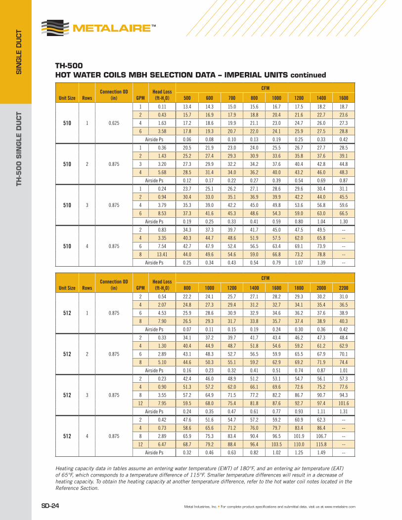
TH-500 HOT wATER cOiLs MBH sELEcTiON DATA – iMpERiAL UNiTs continued
Unit Size RowsConnection OD
(in) GPMHead Loss
(ft-H2O)
CFM
500 600 700 800 1000 1200 1400 1600
510 1 0.625
1 0.11 13.4 14.3 15.0 15.6 16.7 17.5 18.2 18.7
2 0.43 15.7 16.9 17.9 18.8 20.4 21.6 22.7 23.6
4 1.63 17.2 18.6 19.9 21.1 23.0 24.7 26.0 27.3
6 3.58 17.8 19.3 20.7 22.0 24.1 25.9 27.5 28.8
Airside Ps 0.06 0.08 0.10 0.13 0.19 0.25 0.33 0.42
510 2 0.875
1 0.36 20.5 21.9 23.0 24.0 25.5 26.7 27.7 28.5
2 1.43 25.2 27.4 29.3 30.9 33.6 35.8 37.6 39.1
3 3.20 27.3 29.9 32.2 34.2 37.6 40.4 42.8 44.8
4 5.68 28.5 31.4 34.0 36.2 40.0 43.2 46.0 48.3
Airside Ps 0.12 0.17 0.22 0.27 0.39 0.54 0.69 0.87
510 3 0.875
1 0.24 23.7 25.1 26.2 27.1 28.6 29.6 30.4 31.1
2 0.94 30.4 33.0 35.1 36.9 39.9 42.2 44.0 45.5
4 3.79 35.3 39.0 42.2 45.0 49.8 53.6 56.8 59.6
6 8.53 37.3 41.6 45.3 48.6 54.3 59.0 63.0 66.5
Airside Ps 0.19 0.25 0.33 0.41 0.59 0.80 1.04 1.30
510 4 0.875
2 0.83 34.3 37.3 39.7 41.7 45.0 47.5 49.5 --
4 3.35 40.3 44.7 48.6 51.9 57.5 62.0 65.8 --
6 7.54 42.7 47.9 52.4 56.5 63.4 69.1 73.9 --
8 13.41 44.0 49.6 54.6 59.0 66.8 73.2 78.8 --
Airside Ps 0.25 0.34 0.43 0.54 0.79 1.07 1.39 --
Unit Size RowsConnection OD
(in) GPMHead Loss
(ft-H2O)
CFM
800 1000 1200 1400 1600 1800 2000 2200
512 1 0.875
2 0.54 22.2 24.1 25.7 27.1 28.2 29.3 30.2 31.0
4 2.07 24.8 27.3 29.4 31.2 32.7 34.1 35.4 36.5
6 4.53 25.9 28.6 30.9 32.9 34.6 36.2 37.6 38.9
8 7.90 26.5 29.3 31.7 33.8 35.7 37.4 38.9 40.3
Airside Ps 0.07 0.11 0.15 0.19 0.24 0.30 0.36 0.42
512 2 0.875
2 0.33 34.1 37.2 39.7 41.7 43.4 46.2 47.3 48.4
4 1.30 40.4 44.9 48.7 51.8 54.6 59.2 61.2 62.9
6 2.89 43.1 48.3 52.7 56.5 59.9 65.5 67.9 70.1
8 5.10 44.6 50.3 55.1 59.2 62.9 69.2 71.9 74.4
Airside Ps 0.16 0.23 0.32 0.41 0.51 0.74 0.87 1.01
512 3 0.875
2 0.23 42.4 46.0 48.9 51.2 53.1 54.7 56.1 57.3
4 0.90 51.3 57.2 62.0 66.1 69.6 72.6 75.2 77.6
8 3.55 57.2 64.9 71.5 77.2 82.2 86.7 90.7 94.3
12 7.95 59.5 68.0 75.4 81.8 87.6 92.7 97.4 101.6
Airside Ps 0.24 0.35 0.47 0.61 0.77 0.93 1.11 1.31
512 4 0.875
2 0.42 47.6 51.6 54.7 57.2 59.2 60.9 62.3 --
4 0.73 58.6 65.6 71.2 76.0 79.7 83.4 86.4 --
8 2.89 65.9 75.3 83.4 90.4 96.5 101.9 106.7 --
12 6.47 68.7 79.2 88.4 96.4 103.5 110.0 115.8 --
Airside Ps 0.32 0.46 0.63 0.82 1.02 1.25 1.49 --
Heating capacity data in tables assume an entering water temperature (EWT) of 180°F, and an entering air temperature (EAT) of 65°F, which corresponds to a temperature difference of 115°F. Smaller temperature differences will result in a decrease of heating capacity. To obtain the heating capacity at another temperature difference, refer to the hot water coil notes located in the Reference Section.

TH-5
00
SIN
GLE
DU
CT
SIN
GLE D
UCT
SD–25© 2012 Metal Industries, Inc.
TH-500 HOT wATER cOiLs MBH sELEcTiON DATA – iMpERiAL UNiTs continued
Unit Size RowsConnection OD
(in) GPMHead Loss
(ft-H2O)
CFM
600 700 800 1000 1500 2000 2500 3000
514 1 0.625
1 0.20 19.8 21.9 22.7 23.5 26.3 28.2 29.5 30.6
2 0.74 23.4 26.6 27.9 29.1 33.6 36.9 39.3 41.3
3 3.36 25.9 29.8 31.4 33.0 37.1 41.1 44.2 46.8
4 6.17 26.8 31.1 32.9 34.6 39.1 43.6 47.1 50.1
Airside Ps 0.02 0.04 0.05 0.06 0.11 0.19 0.27 0.37
514 2 0.875
2 0.39 34.4 39.4 41.4 43.3 50.1 54.7 58.0 60.6
4 1.52 39.7 46.6 49.6 52.3 63.0 70.7 76.6 81.4
6 3.36 41.8 49.7 53.1 56.2 68.9 78.4 85.8 91.9
8 5.84 43.0 47.4 51.3 58.4 72.3 82.9 91.3 98.2
Airside Ps 0.05 0.09 0.10 0.12 0.24 0.39 0.57 0.78
514 3 0.875
2 0.25 42.8 46.1 48.9 53.5 61.2 66.0 69.4 71.8
6 2.20 52.1 57.6 62.7 71.5 88.5 100.8 110.3 117.9
8 3.89 53.4 59.4 64.8 74.5 93.4 107.6 118.7 127.8
10 6.05 54.3 60.5 66.2 76.3 96.6 112.1 124.4 134.5
Airside Ps 0.08 0.10 0.13 0.19 0.37 0.59 0.86 1.17
514 4 0.875
4 0.78 55.4 61.2 66.3 75.0 90.9 101.7 109.5 115.5
6 1.26 58.3 64.9 71.0 81.6 101.9 116.5 127.5 136.3
8 3.08 59.8 66.9 73.5 85.2 108.2 125.3 138.6 149.4
12 6.89 61.3 69.0 76.1 89.0 115.1 135.3 151.6 165.0
Airside Ps 0.11 0.14 0.17 0.25 0.49 0.79 1.15 1.56
Unit Size RowsConnection OD
(in) GPMHead Loss
(ft-H2O)
CFM
1000 1500 2000 2500 3000 3500 4000 4200
516 1 0.625
1 0.23 25.4 28.5 30.5 32.0 33.2 34.1 34.8 35.1
2 0.86 31.6 36.7 40.3 43.1 45.3 47.1 48.7 49.2
4 3.25 35.9 42.8 47.9 51.9 55.3 58.1 60.5 61.4
6 7.12 37.6 45.3 51.1 55.8 59.7 63.0 65.9 66.9
Airside Ps 0.04 0.08 0.14 0.20 0.27 0.36 0.45 0.49
516 2 0.875
2 0.41 46.2 53.7 58.8 62.4 65.2 67.5 69.3 69.9
4 1.59 55.8 67.8 76.4 83.0 88.4 92.7 96.5 97.8
6 2.52 60.0 74.2 84.8 93.1 100.0 105.8 110.8 112.6
8 6.21 62.3 77.9 89.7 99.2 107.1 113.8 119.6 121.7
Airside Ps 0.09 0.18 0.29 0.42 0.57 0.74 0.93 1.01
516 3 0.875
2 0.26 57.1 65.5 70.8 74.4 77.0 79.1 80.7 81.3
4 1.03 70.4 85.7 96.3 104.2 110.3 115.3 119.4 120.8
8 4.06 78.9 100.0 115.9 128.5 138.8 147.4 141.1 157.5
10 6.31 80.8 103.4 120.7 134.6 146.1 155.9 154.8 167.4
Airside Ps 0.14 0.27 0.44 0.63 0.86 1.11 1.40 1.51
516 4 0.875
2 0.20 63.2 72.1 77.5 81.0 83.5 85.5 -- --
4 0.80 79.5 97.1 109.1 117.8 124.4 129.7 -- --
8 1.80 86.1 115.1 134.3 149.3 161.4 171.5 -- --
10 4.95 91.8 119.3 140.4 157.3 171.2 182.8 -- --
Airside Ps 0.18 0.36 0.58 0.84 1.15 1.49 -- --
Heating capacity data in tables assume an entering water temperature (EWT) of 180°F, and an entering air temperature (EAT) of 65°F, which corresponds to a temperature difference of 115°F. Smaller temperature differences will result in a decrease of heating capacity. To obtain the heating capacity at another temperature difference, refer to the hot water coil notes located in the Reference Section.
TH-5
00
SIN
GLE
DU
CT
SIN
GLE
DU
CT
SD–26 Metal Industries, Inc. ■ For complete product specifications and submittal data, visit us at www.metalaire.com
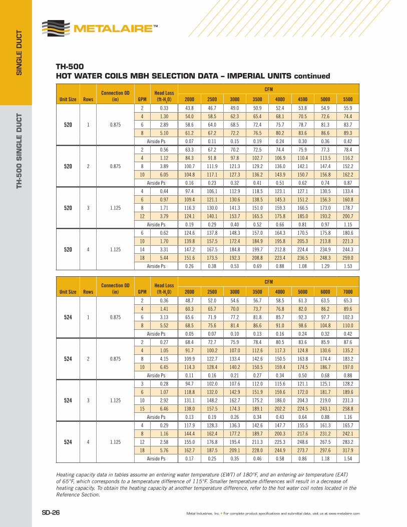
TH-500 HOT wATER cOiLs MBH sELEcTiON DATA – iMpERiAL UNiTs continued
Unit Size RowsConnection OD
(in) GPMHead Loss
(ft-H2O)
CFM
2000 2500 3000 3500 4000 4500 5000 5500
520 1 0.875
2 0.33 43.8 46.7 49.0 50.9 52.4 53.8 54.9 55.9
4 1.30 54.0 58.5 62.3 65.4 68.1 70.5 72.6 74.4
6 2.89 58.6 64.0 68.5 72.4 75.7 78.7 81.3 83.7
8 5.10 61.2 67.2 72.2 76.5 80.2 83.6 86.6 89.3
Airside Ps 0.07 0.11 0.15 0.19 0.24 0.30 0.36 0.42
520 2 0.875
2 0.56 63.3 67.2 70.2 72.5 74.4 75.9 77.3 78.4
4 1.12 84.3 91.8 97.8 102.7 106.9 110.4 113.5 116.2
8 3.89 100.7 111.9 121.3 129.2 136.0 142.1 147.4 152.2
10 6.05 104.8 117.1 127.3 136.2 143.9 150.7 156.8 162.2
Airside Ps 0.16 0.23 0.32 0.41 0.51 0.62 0.74 0.87
520 3 1.125
4 0.44 97.4 106.1 112.9 118.5 123.1 127.1 130.5 133.4
6 0.97 109.4 121.1 130.6 138.5 145.3 151.2 156.3 160.8
8 1.71 116.3 130.0 141.3 151.0 159.3 166.5 173.0 178.7
12 3.79 124.1 140.1 153.7 165.5 175.8 185.0 193.2 200.7
Airside Ps 0.19 0.29 0.40 0.52 0.66 0.81 0.97 1.15
520 4 1.125
6 0.62 124.6 137.8 148.3 157.0 164.3 170.5 175.8 180.6
10 1.70 139.8 157.5 172.4 184.9 195.8 205.3 213.8 221.3
14 3.31 147.2 167.5 184.8 199.7 212.8 224.4 234.9 244.3
18 5.44 151.6 173.5 192.3 208.8 223.4 236.5 248.3 259.0
Airside Ps 0.26 0.38 0.53 0.69 0.88 1.08 1.29 1.53
Unit Size RowsConnection OD
(in) GPMHead Loss
(ft-H2O)
CFM
2000 2500 3000 3500 4000 5000 6000 7000
524 1 0.875
2 0.36 48.7 52.0 54.6 56.7 58.5 61.3 63.5 65.3
4 1.41 60.3 65.7 70.0 73.7 76.8 82.0 86.2 89.6
6 3.13 65.6 71.9 77.2 81.8 85.7 92.3 97.7 102.3
8 5.52 68.5 75.6 81.4 86.6 91.0 98.6 104.8 110.0
Airside Ps 0.05 0.07 0.10 0.13 0.16 0.24 0.32 0.42
524 2 0.875
2 0.27 68.4 72.7 75.9 78.4 80.5 83.6 85.9 87.6
4 1.05 91.7 100.2 107.0 112.6 117.3 124.8 130.6 135.2
8 4.15 109.9 122.7 133.4 142.6 150.5 163.8 174.4 183.2
10 6.45 114.3 128.4 140.2 150.5 159.4 174.5 186.7 197.0
Airside Ps 0.11 0.16 0.21 0.27 0.34 0.50 0.68 0.88
524 3 1.125
3 0.28 94.7 102.0 107.6 112.0 115.6 121.1 125.1 128.2
6 1.07 118.8 132.0 142.9 151.9 159.6 172.0 181.7 189.6
10 2.92 131.1 148.2 162.7 175.2 186.0 204.3 219.0 231.3
15 6.46 138.0 157.5 174.3 189.1 202.2 224.5 243.1 258.8
Airside Ps 0.13 0.19 0.26 0.34 0.43 0.64 0.88 1.16
524 4 1.125
4 0.29 117.9 128.3 136.3 142.6 147.7 155.5 161.3 165.7
8 1.16 144.4 162.4 177.2 189.7 200.3 217.6 231.2 242.1
12 2.58 155.0 176.8 195.4 211.3 225.3 248.6 267.5 283.2
18 5.76 162.7 187.5 209.1 228.0 244.9 273.7 297.6 317.9
Airside Ps 0.17 0.25 0.35 0.46 0.58 0.86 1.18 1.54
Heating capacity data in tables assume an entering water temperature (EWT) of 180°F, and an entering air temperature (EAT) of 65°F, which corresponds to a temperature difference of 115°F. Smaller temperature differences will result in a decrease of heating capacity. To obtain the heating capacity at another temperature difference, refer to the hot water coil notes located in the Reference Section.

TH-5
00
SIN
GLE
DU
CT
SIN
GLE D
UCT
SD–27© 2012 Metal Industries, Inc.
TH-500 HOT wATER cOiLs kw sELEcTiON DATA – METRic UNiTs
Heating capacity data in tables assume an entering water temperature (EWT) of 82°C, and an entering air temperature (EAT) of 18°C, which corresponds to a temperature difference of 64°C. Smaller temperature differences will result in a decrease of heating capacity. To obtain the heating capacity at another temperature difference, refer to the hot water coil notes located in the Reference Section.
Unit Size RowsConnection OD
(mm)Water Flow
(L/s)Head Loss
(kPa)
Airflow (L/s)
47 94 142 165 189 212 236 283
504 505 506
1 15.9
0.06 1.37 1.5 2.1 2.5 2.7 2.8 2.9 3.0 3.2
0.13 5.26 1.6 2.3 2.8 3.0 3.1 3.3 3.4 3.7
0.19 11.54 1.6 2.4 2.9 3.1 3.3 3.4 3.6 3.9
0.25 20.12 1.6 2.4 2.9 3.1 3.3 3.5 3.7 4.0
Airside Ps (kPa) 0.00 0.01 0.02 0.02 0.03 0.04 0.04 0.06
504 505 506
2 22.2
0.06 0.36 2.2 3.3 3.9 4.2 4.4 4.6 4.8 5.1
0.13 1.37 2.4 3.7 4.5 4.9 5.2 5.5 5.8 6.2
0.25 5.23 2.5 3.9 5.0 5.4 5.8 6.1 6.5 7.1
0.38 11.48 2.5 4.0 5.1 5.6 6.0 6.4 6.8 7.4
Airside Ps (kPa) 0.01 0.02 0.04 0.05 0.06 0.08 0.09 0.13
504 505 506
3 22.2
0.06 0.21 2.6 3.9 4.7 4.9 5.2 5.4 5.6 5.9
0.13 0.84 2.8 4.5 5.6 6.0 6.4 6.8 7.1 7.6
0.25 3.26 2.9 4.8 6.2 6.8 7.3 7.8 8.2 8.9
0.38 7.29 3.0 5.0 6.5 7.1 7.7 8.2 8.7 9.5
Airside Ps (kPa) 0.01 0.03 0.06 0.08 0.10 0.12 0.14 0.19
504 505 506
4 22.2
0.06 0.15 2.8 4.2 5.1 5.4 5.7 5.9 6.1 6.4
0.13 0.60 3.1 5.0 6.3 6.8 7.2 7.6 7.9 8.5
0.25 2.36 3.2 5.4 7.1 7.8 8.4 9.0 9.5 10.3
0.38 5.29 3.3 5.6 7.4 8.2 8.9 9.5 10.1 11.1
Airside Ps (kPa) 0.01 0.04 0.08 0.10 0.13 0.16 0.19 0.25
Unit Size RowsConnection OD
(mm)Water Flow
(L/s)Head Loss
(kPa)
Airflow (L/s)
236 283 330 378 472 566 661 755
508 1 15.9
0.06 1.88 3.5 3.8 4.0 4.1 4.4 4.7 4.8 5.0
0.13 7.14 4.0 4.3 4.6 4.8 5.2 5.5 5.8 6.0
0.19 15.66 4.2 4.5 4.8 5.1 5.5 5.9 6.2 6.5
0.25 27.32 4.3 4.7 4.9 5.2 5.7 6.1 6.4 6.7
Airside Ps (kPa) 0.03 0.04 0.05 0.06 0.09 0.12 0.16 0.20
508 2 22.2
0.06 0.51 5.4 5.8 6.1 6.4 6.6 6.8 7.3 --
0.13 1.88 6.6 7.1 7.6 8.0 8.3 8.7 9.7 --
0.25 7.14 7.3 8.1 8.7 9.2 9.7 10.1 11.5 --
0.38 15.60 7.7 8.4 9.1 9.7 10.3 10.7 12.4 --
Airside Ps (kPa) 0.06 0.08 0.10 0.13 0.15 0.18 0.33 --
508 3 22.2
0.06 0.24 6.4 6.8 7.1 7.3 7.7 8.0 -- --
0.13 0.93 8.1 8.7 9.3 9.7 10.5 11.1 -- --
0.25 3.62 9.3 10.2 11.0 11.7 12.8 13.8 -- --
0.50 14.29 10.0 11.2 12.2 13.0 14.5 15.8 -- --
Airside Ps (kPa) 0.09 0.12 0.15 0.19 0.28 0.38 -- --
508 4 22.2
0.13 0.63 9.0 9.8 10.4 10.9 11.7 -- -- --
0.25 2.51 10.6 11.7 12.6 13.4 14.8 -- -- --
0.38 5.59 11.3 12.5 13.6 14.6 16.2 -- -- --
0.50 9.92 11.7 13.0 14.2 15.3 17.1 -- -- --
Airside Ps (kPa) 0.11 0.16 0.20 0.25 0.37 -- -- --
TH-5
00
SIN
GLE
DU
CT
SIN
GLE
DU
CT
SD–28 Metal Industries, Inc. ■ For complete product specifications and submittal data, visit us at www.metalaire.com
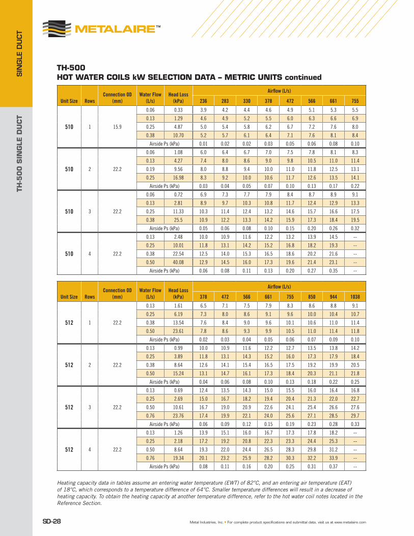
TH-500 HOT wATER cOiLs kw sELEcTiON DATA – METRic UNiTs continued
Heating capacity data in tables assume an entering water temperature (EWT) of 82°C, and an entering air temperature (EAT) of 18°C, which corresponds to a temperature difference of 64°C. Smaller temperature differences will result in a decrease of heating capacity. To obtain the heating capacity at another temperature difference, refer to the hot water coil notes located in the Reference Section.
Unit Size RowsConnection OD
(mm)Water Flow
(L/s)Head Loss
(kPa)
Airflow (L/s)
236 283 330 378 472 566 661 755
510 1 15.9
0.06 0.33 3.9 4.2 4.4 4.6 4.9 5.1 5.3 5.5
0.13 1.29 4.6 4.9 5.2 5.5 6.0 6.3 6.6 6.9
0.25 4.87 5.0 5.4 5.8 6.2 6.7 7.2 7.6 8.0
0.38 10.70 5.2 5.7 6.1 6.4 7.1 7.6 8.1 8.4
Airside Ps (kPa) 0.01 0.02 0.02 0.03 0.05 0.06 0.08 0.10
510 2 22.2
0.06 1.08 6.0 6.4 6.7 7.0 7.5 7.8 8.1 8.3
0.13 4.27 7.4 8.0 8.6 9.0 9.8 10.5 11.0 11.4
0.19 9.56 8.0 8.8 9.4 10.0 11.0 11.8 12.5 13.1
0.25 16.98 8.3 9.2 10.0 10.6 11.7 12.6 13.5 14.1
Airside Ps (kPa) 0.03 0.04 0.05 0.07 0.10 0.13 0.17 0.22
510 3 22.2
0.06 0.72 6.9 7.3 7.7 7.9 8.4 8.7 8.9 9.1
0.13 2.81 8.9 9.7 10.3 10.8 11.7 12.4 12.9 13.3
0.25 11.33 10.3 11.4 12.4 13.2 14.6 15.7 16.6 17.5
0.38 25.5 10.9 12.2 13.3 14.2 15.9 17.3 18.4 19.5
Airside Ps (kPa) 0.05 0.06 0.08 0.10 0.15 0.20 0.26 0.32
510 4 22.2
0.13 2.48 10.0 10.9 11.6 12.2 13.2 13.9 14.5 --
0.25 10.01 11.8 13.1 14.2 15.2 16.8 18.2 19.3 --
0.38 22.54 12.5 14.0 15.3 16.5 18.6 20.2 21.6 --
0.50 40.08 12.9 14.5 16.0 17.3 19.6 21.4 23.1 --
Airside Ps (kPa) 0.06 0.08 0.11 0.13 0.20 0.27 0.35 --
Unit Size RowsConnection OD
(mm)Water Flow
(L/s)Head Loss
(kPa)
Airflow (L/s)
378 472 566 661 755 850 944 1038
512 1 22.2
0.13 1.61 6.5 7.1 7.5 7.9 8.3 8.6 8.8 9.1
0.25 6.19 7.3 8.0 8.6 9.1 9.6 10.0 10.4 10.7
0.38 13.54 7.6 8.4 9.0 9.6 10.1 10.6 11.0 11.4
0.50 23.61 7.8 8.6 9.3 9.9 10.5 11.0 11.4 11.8
Airside Ps (kPa) 0.02 0.03 0.04 0.05 0.06 0.07 0.09 0.10
512 2 22.2
0.13 0.99 10.0 10.9 11.6 12.2 12.7 13.5 13.8 14.2
0.25 3.89 11.8 13.1 14.3 15.2 16.0 17.3 17.9 18.4
0.38 8.64 12.6 14.1 15.4 16.5 17.5 19.2 19.9 20.5
0.50 15.24 13.1 14.7 16.1 17.3 18.4 20.3 21.1 21.8
Airside Ps (kPa) 0.04 0.06 0.08 0.10 0.13 0.18 0.22 0.25
512 3 22.2
0.13 0.69 12.4 13.5 14.3 15.0 15.5 16.0 16.4 16.8
0.25 2.69 15.0 16.7 18.2 19.4 20.4 21.3 22.0 22.7
0.50 10.61 16.7 19.0 20.9 22.6 24.1 25.4 26.6 27.6
0.76 23.76 17.4 19.9 22.1 24.0 25.6 27.1 28.5 29.7
Airside Ps (kPa) 0.06 0.09 0.12 0.15 0.19 0.23 0.28 0.33
512 4 22.2
0.13 1.26 13.9 15.1 16.0 16.7 17.3 17.8 18.2 --
0.25 2.18 17.2 19.2 20.8 22.3 23.3 24.4 25.3 --
0.50 8.64 19.3 22.0 24.4 26.5 28.3 29.8 31.2 --
0.76 19.34 20.1 23.2 25.9 28.2 30.3 32.2 33.9 --
Airside Ps (kPa) 0.08 0.11 0.16 0.20 0.25 0.31 0.37 --
TH-5
00
SIN
GLE
DU
CT
SIN
GLE D
UCT
SD–29© 2012 Metal Industries, Inc.
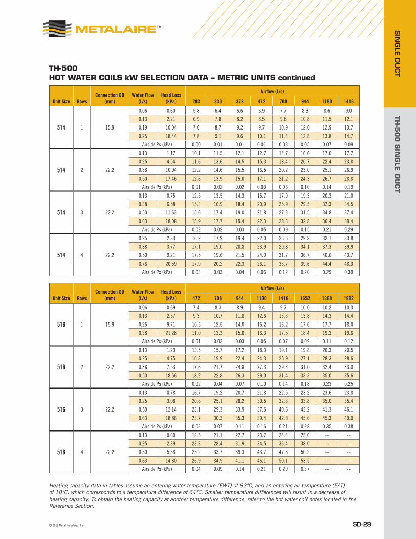
TH-500 HOT wATER cOiLs kw sELEcTiON DATA – METRic UNiTs continued
Heating capacity data in tables assume an entering water temperature (EWT) of 82°C, and an entering air temperature (EAT) of 18°C, which corresponds to a temperature difference of 64°C. Smaller temperature differences will result in a decrease of heating capacity. To obtain the heating capacity at another temperature difference, refer to the hot water coil notes located in the Reference Section.
Unit Size RowsConnection OD
(mm)Water Flow
(L/s)Head Loss
(kPa)
Airflow (L/s)
283 330 378 472 708 944 1180 1416
514 1 15.9
0.06 0.60 5.8 6.4 6.6 6.9 7.7 8.3 8.6 9.0
0.13 2.21 6.9 7.8 8.2 8.5 9.8 10.8 11.5 12.1
0.19 10.04 7.6 8.7 9.2 9.7 10.9 12.0 12.9 13.7
0.25 18.44 7.8 9.1 9.6 10.1 11.4 12.8 13.8 14.7
Airside Ps (kPa) 0.00 0.01 0.01 0.01 0.03 0.05 0.07 0.09
514 2 22.2
0.13 1.17 10.1 11.5 12.1 12.7 14.7 16.0 17.0 17.7
0.25 4.54 11.6 13.6 14.5 15.3 18.4 20.7 22.4 23.8
0.38 10.04 12.2 14.6 15.5 16.5 20.2 23.0 25.1 26.9
0.50 17.46 12.6 13.9 15.0 17.1 21.2 24.3 26.7 28.8
Airside Ps (kPa) 0.01 0.02 0.02 0.03 0.06 0.10 0.14 0.19
514 3 22.2
0.13 0.75 12.5 13.5 14.3 15.7 17.9 19.3 20.3 21.0
0.38 6.58 15.3 16.9 18.4 20.9 25.9 29.5 32.3 34.5
0.50 11.63 15.6 17.4 19.0 21.8 27.3 31.5 34.8 37.4
0.63 18.08 15.9 17.7 19.4 22.3 28.3 32.8 36.4 39.4
Airside Ps (kPa) 0.02 0.02 0.03 0.05 0.09 0.15 0.21 0.29
514 4 22.2
0.25 2.33 16.2 17.9 19.4 22.0 26.6 29.8 32.1 33.8
0.38 3.77 17.1 19.0 20.8 23.9 29.8 34.1 37.3 39.9
0.50 9.21 17.5 19.6 21.5 24.9 31.7 36.7 40.6 43.7
0.76 20.59 17.9 20.2 22.3 26.1 33.7 39.6 44.4 48.3
Airside Ps (kPa) 0.03 0.03 0.04 0.06 0.12 0.20 0.29 0.39
Unit Size RowsConnection OD
(mm)Water Flow
(L/s)Head Loss
(kPa)
Airflow (L/s)
472 708 944 1180 1416 1652 1888 1982
516 1 15.9
0.06 0.69 7.4 8.3 8.9 9.4 9.7 10.0 10.2 10.3
0.13 2.57 9.3 10.7 11.8 12.6 13.3 13.8 14.3 14.4
0.25 9.71 10.5 12.5 14.0 15.2 16.2 17.0 17.7 18.0
0.38 21.28 11.0 13.3 15.0 16.3 17.5 18.4 19.3 19.6
Airside Ps (kPa) 0.01 0.02 0.03 0.05 0.07 0.09 0.11 0.12
516 2 22.2
0.13 1.23 13.5 15.7 17.2 18.3 19.1 19.8 20.3 20.5
0.25 4.75 16.3 19.9 22.4 24.3 25.9 27.1 28.3 28.6
0.38 7.53 17.6 21.7 24.8 27.3 29.3 31.0 32.4 33.0
0.50 18.56 18.2 22.8 26.3 29.0 31.4 33.3 35.0 35.6
Airside Ps (kPa) 0.02 0.04 0.07 0.10 0.14 0.18 0.23 0.25
516 3 22.2
0.13 0.78 16.7 19.2 20.7 21.8 22.5 23.2 23.6 23.8
0.25 3.08 20.6 25.1 28.2 30.5 32.3 33.8 35.0 35.4
0.50 12.14 23.1 29.3 33.9 37.6 40.6 43.2 41.3 46.1
0.63 18.86 23.7 30.3 35.3 39.4 42.8 45.6 45.3 49.0
Airside Ps (kPa) 0.03 0.07 0.11 0.16 0.21 0.28 0.35 0.38
516 4 22.2
0.13 0.60 18.5 21.1 22.7 23.7 24.4 25.0 -- --
0.25 2.39 23.3 28.4 31.9 34.5 36.4 38.0 -- --
0.50 5.38 25.2 33.7 39.3 43.7 47.3 50.2 -- --
0.63 14.80 26.9 34.9 41.1 46.1 50.1 53.5 -- --
Airside Ps (kPa) 0.04 0.09 0.14 0.21 0.29 0.37 -- --

TH-5
00
SIN
GLE
DU
CT
SIN
GLE
DU
CT
SD–30 Metal Industries, Inc. ■ For complete product specifications and submittal data, visit us at www.metalaire.com
TH-500 HOT wATER cOiLs kw sELEcTiON DATA – METRic UNiTs continued
Heating capacity data in tables assume an entering water temperature (EWT) of 82°C, and an entering air temperature (EAT) of 18°C, which corresponds to a temperature difference of 64°C. Smaller temperature differences will result in a decrease of heating capacity. To obtain the heating capacity at another temperature difference, refer to the hot water coil notes located in the Reference Section.
Unit Size RowsConnection OD
(mm)Water Flow
(L/s)Head Loss
(kPa)
Airflow (L/s)
944 1180 1416 1652 1888 2124 2360 2596
520 1 22.2
0.13 0.99 12.8 13.7 14.3 14.9 15.3 15.8 16.1 16.4
0.25 3.89 15.8 17.1 18.2 19.1 19.9 20.6 21.3 21.8
0.38 8.64 17.2 18.7 20.1 21.2 22.2 23.0 23.8 24.5
0.50 15.24 17.9 19.7 21.1 22.4 23.5 24.5 25.4 26.1
Airside Ps (kPa) 0.02 0.03 0.04 0.05 0.06 0.07 0.09 0.10
520 2 22.2
0.13 1.67 18.5 19.7 20.6 21.2 21.8 22.2 22.6 23.0
0.25 3.35 24.7 26.9 28.6 30.1 31.3 32.3 33.2 34.0
0.50 11.63 29.5 32.8 35.5 37.8 39.8 41.6 43.2 44.6
0.63 18.08 30.7 34.3 37.3 39.9 42.1 44.1 45.9 47.5
Airside Ps (kPa) 0.04 0.06 0.08 0.10 0.13 0.15 0.18 0.22
520 3 28.6
0.25 1.32 28.5 31.1 33.1 34.7 36.0 37.2 38.2 39.1
0.38 2.90 32.0 35.5 38.2 40.6 42.5 44.3 45.8 47.1
0.50 5.11 34.1 38.1 41.4 44.2 46.6 48.8 50.7 52.3
0.76 11.33 36.3 41.0 45.0 48.5 51.5 54.2 56.6 58.8
Airside Ps (kPa) 0.05 0.07 0.10 0.13 0.16 0.20 0.24 0.29
520 4 28.6
0.38 1.85 36.5 40.3 43.4 46.0 48.1 49.9 51.5 52.9
0.63 5.08 40.9 46.1 50.5 54.1 57.3 60.1 62.6 64.8
0.88 9.89 43.1 49.0 54.1 58.5 62.3 65.7 68.8 71.5
1.14 16.26 44.4 50.8 56.3 61.1 65.4 69.2 72.7 75.8
Airside Ps (kPa) 0.06 0.09 0.13 0.17 0.22 0.27 0.32 0.38
Unit Size RowsConnection OD
(mm)Water Flow
(L/s)Head Loss
(kPa)
Airflow (L/s)
944 1180 1416 1652 1888 2360 2832 3304
524 1 22.2
0.13 1.08 14.3 15.2 16.0 16.6 17.1 17.9 18.6 19.1
0.25 4.21 17.7 19.2 20.5 21.6 22.5 24.0 25.2 26.2
0.38 9.36 19.2 21.1 22.6 24.0 25.1 27.0 28.6 30.0
0.50 16.50 20.1 22.1 23.8 25.4 26.6 28.9 30.7 32.2
Airside Ps (kPa) 0.01 0.02 0.02 0.03 0.04 0.06 0.08 0.10
524 2 22.2
0.13 0.81 20.0 21.3 22.2 23.0 23.6 24.5 25.2 25.6
0.25 3.14 26.8 29.3 31.3 33.0 34.3 36.5 38.2 39.6
0.50 12.40 32.2 35.9 39.1 41.8 44.1 48.0 51.1 53.6
0.63 19.28 33.5 37.6 41.1 44.1 46.7 51.1 54.7 57.7
Airside Ps (kPa) 0.03 0.04 0.05 0.07 0.08 0.12 0.17 0.22
524 3 28.6
0.19 0.84 27.7 29.9 31.5 32.8 33.8 35.5 36.6 37.5
0.38 3.20 34.8 38.6 41.8 44.5 46.7 50.4 53.2 55.5
0.63 8.73 38.4 43.4 47.6 51.3 54.5 59.8 64.1 67.7
0.95 19.31 40.4 46.1 51.0 55.4 59.2 65.7 71.2 75.8
Airside Ps (kPa) 0.03 0.05 0.06 0.08 0.11 0.16 0.22 0.29
524 4 28.6
0.25 0.87 34.5 37.6 39.9 41.8 43.2 45.5 47.2 48.5
0.50 3.47 42.3 47.6 51.9 55.5 58.6 63.7 67.7 70.9
0.76 7.71 45.4 51.8 57.2 61.9 66.0 72.8 78.3 82.9
1.14 17.22 47.6 54.9 61.2 66.8 71.7 80.1 87.1 93.1
Airside Ps (kPa) 0.04 0.06 0.09 0.11 0.14 0.21 0.29 0.38

TH-5
00
SIN
GLE
DU
CT
SIN
GLE D
UCT
SD–31© 2012 Metal Industries, Inc.
TH-500AccEssORiEs AND cOMpONENTsHOT wATER cOiLsWhen ordered with the air terminal, the hot water coil is shipped attached to the discharge of the terminal casing via slip and drive connections. The discharge end of the casing has slip and drive connections for easy connection to downstream ductwork. The hot water coil is constructed of aluminum fin and copper serpentine-type tubes with male sweat connections tested at 300 psig.
Coil selection may be made using METALAIRE Terminal Selection Software. Contact your METALAIRE representative for a copy. In the interest of energy conservation and due to the possibility of condensation, all hot water coils are marked, “Coil must be externally insulated after installation in the field.” Hot water coils are tested in accordance to AHRI. Options, at an additional charge on hot water coils, include access doors for inspection and cleaning, and inlet/outlet on opposite sides of coils.
HOT wATER cOiL cONsTRUcTiON DETAiLs■ Hot water coils are factory mounted on the discharge of the terminal and are
available with an optional integral coil access door.■ Coils are enclosed in 20 gauge coated steel casing with slip and drive connection.■ Fins are rippled and sine wave type constructed from heavy gauge aluminum,
mechanically bonded to the tubes.■ Tubes are copper with a minimum wall thickness of 0.016" with male solder
header connections.■ Coils are leak tested to 300 psig with minimum burst of 2000 psig at
ambient temperature.■ Coil performance data is based on tests run in accordance with AHRI standard 410;
coils are AHRI certified and include AHRI label.
Coil Connection Size, Inches (mm)
TH Size 1 Row 2 Row 3 Row 4 Row
504 / 505 / 506 5/8" (15.8) 7/8" (22.2) 7/8" (22.2) 7/8" (22.2)
508 5/8" (15.8) 7/8" (22.2) 7/8" (22.2) 7/8" (22.2)
510 5/8" (15.8) 7/8" (22.2) 7/8" (22.2) 7/8" (22.2)
512 7/8" (22.2) 7/8" (22.2) 7/8" (22.2) 7/8" (22.2)
514 5/8" (15.8) 7/8" (22.2) 7/8" (22.2) 7/8" (22.2)
516 5/8" (15.8) 7/8" (22.2) 7/8" (22.2) 7/8" (22.2)
520 7/8" (22.2) 7/8" (22.2) 1 1/8" (28.6) 1 1/8" (28.6)
524 7/8" (22.2) 7/8" (22.2) 1 1/8" (28.6) 1 1/8" (28.6)
All coils have 10 fins/inch with the exception of 3&4 row coils on 20 & 24 boxes which are 8 FPI
All accessories which can be attached to the Single Duct Boxes are not a part of the AHRI certification program
but ratings can be affected by their use.
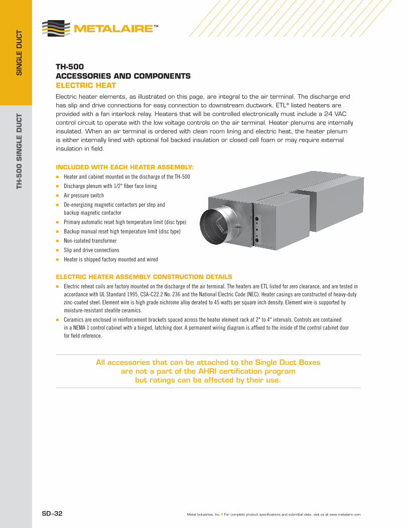
TH-5
00
SIN
GLE
DU
CT
SIN
GLE
DU
CT
Metal Industries, Inc. ■ For complete product specifications and submittal data, visit us at www.metalaire.comSD–32
TH-500Accessories And componenTseLecTric HeATElectric heater elements, as illustrated on this page, are integral to the air terminal. The discharge end has slip and drive connections for easy connection to downstream ductwork. ETL® listed heaters are provided with a fan interlock relay. Heaters that will be controlled electronically must include a 24 VAC control circuit to operate with the low voltage controls on the air terminal. Heater plenums are internally insulated. When an air terminal is ordered with clean room lining and electric heat, the heater plenum is either internally lined with optional foil backed insulation or closed cell foam or may require external insulation in field.
incLuded WiTH eAcH HeATer AssembLy:■ Heater and cabinet mounted on the discharge of the TH-500■ Discharge plenum with 1/2" fiber face lining■ Air pressure switch■ De-energizing magnetic contactors per step and
backup magnetic contactor■ Primary automatic reset high temperature limit (disc type)■ Backup manual reset high temperature limit (disc type)■ Non-isolated transformer■ Slip and drive connections■ Heater is shipped factory mounted and wired
eLecTric HeATer AssembLy consTrucTion deTAiLs■ Electric reheat coils are factory mounted on the discharge of the air terminal. The heaters are ETL listed for zero clearance, and are tested in
accordance with UL Standard 1995, CSA-C22.2 No. 236 and the National Electric Code (NEC). Heater casings are constructed of heavy-duty zinc-coated steel. Element wire is high grade nichrome alloy derated to 45 watts per square inch density. Element wire is supported by moisture-resistant steatite ceramics.
■ Ceramics are enclosed in reinforcement brackets spaced across the heater element rack at 2" to 4" intervals. Controls are contained in a NEMA 1 control cabinet with a hinged, latching door. A permanent wiring diagram is affixed to the inside of the control cabinet door for field reference.
All accessories that can be attached to the Single Duct Boxes are not a part of the AHRI certification program
but ratings can be affected by their use.
1-Single Duct ATU_TH-500_v10_82312.indd 32 8/31/12 12:07 AM
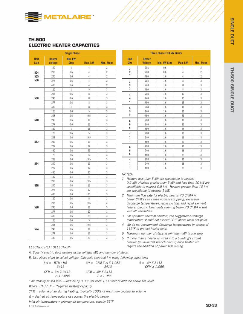
TH-5
00
SIN
GLE
DU
CT
SIN
GLE D
UCT
SD–33© 2012 Metal Industries, Inc.
TH-500ELEcTRic HEATER cApAciTiEs
Single Phase Three Phase FCQ kW Limits
Unit Size
Heater Voltage
Min. kW Step Max. kW Max. Steps
Unit Size
Heater Voltage Min. kW Step Max. kW Max. Steps
504505506
120 1 4 2 222
208 0.6 4 2
208 0.6 4 2 240 0.6 4 2
240 0.6 4 2 480 1.6 4 2
277 0.6 4 2 333
208 1.6 8 3
480 1.6 4 2 240 1.6 8 3
508
120 1 5 3 480 1.6 8 3
208 0.6 8 3 444
208 1.6 13 3
240 0.6 8 3 240 1.6 13 3
277 0.6 8 3 480 1.6 15 3
480 1 8 3 555
208 1.6 16 3
510
120 0.6 5 3 240 1.6 16 3
208 0.6 9.5 3 480 1.6 23 3
240 0.6 11 3 666
208 1.6 16 3
277 0.6 12 3 240 1.6 16 3
480 1 15 3 480 1.6 24 3
512
120 0.6 5 3 777
208 1.6 16 3
208 0.6 9.5 3 240 1.6 16 3
240 0.6 11 3 480 1.6 39 3
277 0.6 12 3 666
208 1.6 16 3
480 0.6 23 3 240 1.6 16 3
514
120 0.6 5 3 480 1.6 39 3
208 0.6 9.5 3 777
208 1.6 16 3
240 0.6 11 3 240 1.6 16 3
277 0.6 12 3 480 1.6 39 3
480 0.6 23 3
516
120 1.4 5 3
208 0.6 9.5 3
240 0.6 11 3
277 0.6 12 3
480 0.6 23 3
520
120 0.6 5 3
208 0.6 9.5 3
240 0.6 11 3
277 0.6 12 3
480 0.6 23 3
524
120 0.6 5 3
208 0.6 9.5 3
240 0.6 11 3
277 0.6 12 3
480 0.6 23 3
NOTES:1. Heaters less than 5 kW are specifiable to nearest
0.2 kW. Heaters greater than 5 kW and less than 10 kW are specifiable to nearest 0.5 kW. Heaters greater than 10 kW are specifiable to nearest 1 kW.
2. Minimum flow rate for electric heat is 70 CFM/kW. Lower CFM’s can cause nuisance tripping, excessive discharge temperatures, rapid cycling, and rapid element failure. Electric Heat units running below 70 CFM/kW will void all warranties.
3. For optimum thermal comfort, the suggested discharge temperature should not exceed 20°F above room set point.
4. We do not recommend discharge temperatures in excess of 115°F to protect heater coils.
5. Maximum number of steps at minimum kW is one step.6. If more than 1 heater is wired into a building’s circuit
breaker (multi-outlet branch circuit) each heater will require the addition of power side fusing.ELECTRIC HEAT SELECTION:
A. Specify electric duct heaters using voltage, kW, and number of steps.
B. Use above chart to select voltage. Calculate required kW using following equations:
kW = BTU / HR kW = CFM X ∆ X 1.085 ∆ = kW X 3413 3413 3413 CFM X 1.085
CFM = kW X 3413 CFM = kW X 3413 ∆ x 1.085 ∆ x 1.085
* air density at sea level — reduce by 0.036 for each 1000 feet of altitude above sea level
Where: BTU / Hr = Required heating capacity
CFM = volume of air during heating. Typically 100% of maximum cooling air volume
∆ = desired air temperature rise across the electric heater
Inlet air temperature = primary air temperature, usually 55°F
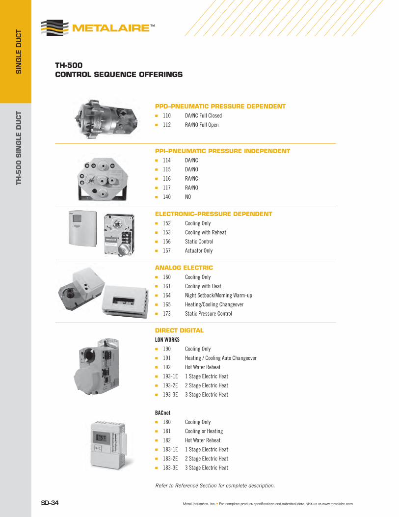
TH-5
00
SIN
GLE
DU
CT
SIN
GLE
DU
CT
SD–34 Metal Industries, Inc. ■ For complete product specifications and submittal data, visit us at www.metalaire.com
ppD–pNEUMATic pREssURE DEpENDENT■ 110 DA/NC Full Closed■ 112 RA/NO Full Open
ppi–pNEUMATic pREssURE iNDEpENDENT■ 114 DA/NC■ 115 DA/NO■ 116 RA/NC■ 117 RA/NO■ 140 NO
ELEcTRONic–pREssURE DEpENDENT■ 152 Cooling Only■ 153 Cooling with Reheat■ 156 Static Control■ 157 Actuator Only
ANALOG ELEcTRic■ 160 Cooling Only■ 161 Cooling with Heat■ 164 Night Setback/Morning Warm-up■ 165 Heating/Cooling Changeover■ 173 Static Pressure Control
DiREcT DiGiTAL
LON WORKS■ 190 Cooling Only■ 191 Heating / Cooling Auto Changeover■ 192 Hot Water Reheat■ 193-1E 1 Stage Electric Heat■ 193-2E 2 Stage Electric Heat■ 193-3E 3 Stage Electric Heat
BACnet■ 180 Cooling Only■ 181 Cooling or Heating■ 182 Hot Water Reheat■ 183-1E 1 Stage Electric Heat■ 183-2E 2 Stage Electric Heat■ 183-3E 3 Stage Electric Heat
Refer to Reference Section for complete description.
TH-500cONTROL sEqUENcE OffERiNGs