single duct terminal units • 3000 series - nailor...variable air volume (vav) single duct...
TRANSCRIPT
A5
SING
LE DU
CT TER
MIN
AL U
NITS
A
SINGLE DUCT TERMINAL UNITS • 3000 SERIES
3000 SERIES • VARIABLE OR CONSTANT VOLUME
PRODUCT OVERVIEW
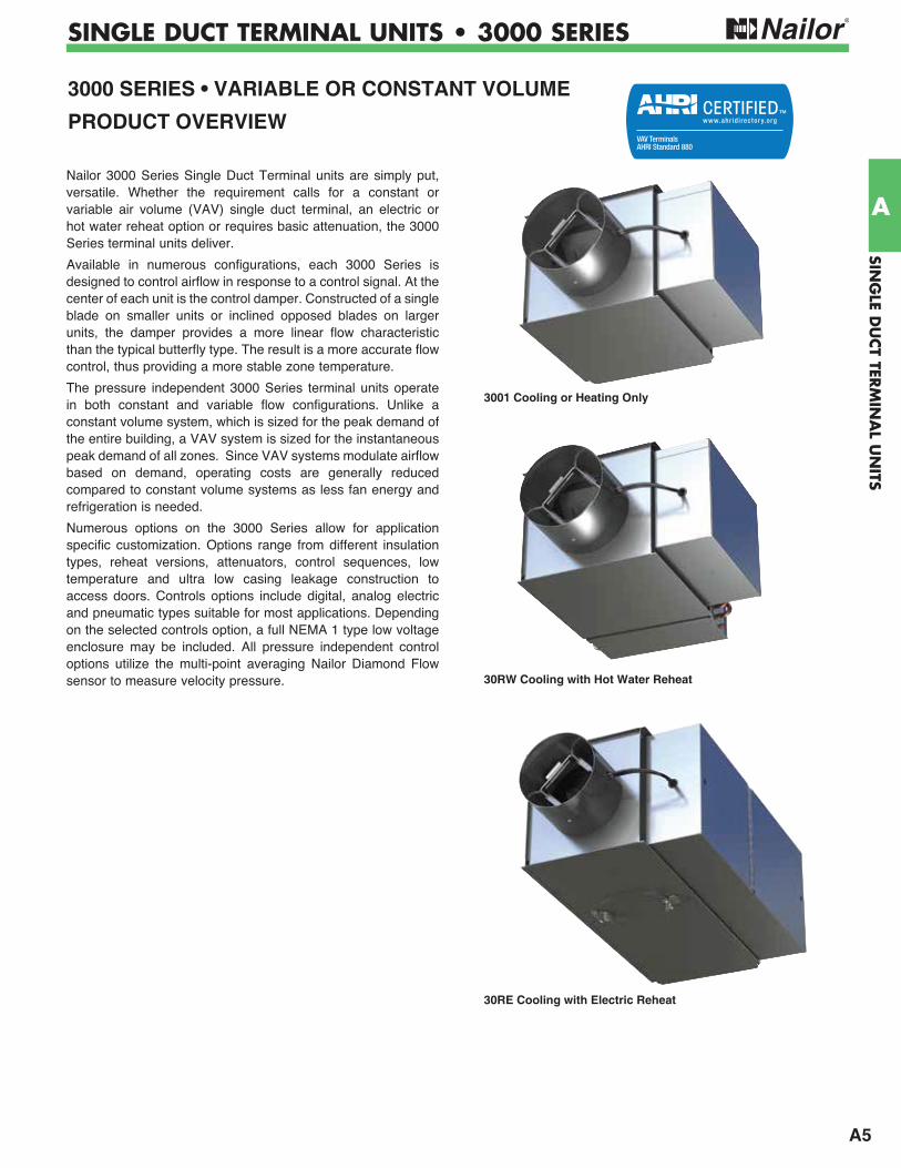
Nailor 3000 Series Single Duct Terminal units are simply put, versatile. Whether the requirement calls for a constant or variable air volume (VAV) single duct terminal, an electric or hot water reheat option or requires basic attenuation, the 3000 Series terminal units deliver.
Available in numerous configurations, each 3000 Series is designed to control airflow in response to a control signal. At the center of each unit is the control damper. Constructed of a single blade on smaller units or inclined opposed blades on larger units, the damper provides a more linear flow characteristic than the typical butterfly type. The result is a more accurate flow control, thus providing a more stable zone temperature.
The pressure independent 3000 Series terminal units operate in both constant and variable flow configurations. Unlike a constant volume system, which is sized for the peak demand of the entire building, a VAV system is sized for the instantaneous peak demand of all zones. Since VAV systems modulate airflow based on demand, operating costs are generally reduced compared to constant volume systems as less fan energy and refrigeration is needed.
Numerous options on the 3000 Series allow for application specific customization. Options range from different insulation types, reheat versions, attenuators, control sequences, low temperature and ultra low casing leakage construction to access doors. Controls options include digital, analog electric and pneumatic types suitable for most applications. Depending on the selected controls option, a full NEMA 1 type low voltage enclosure may be included. All pressure independent control options utilize the multi-point averaging Nailor Diamond Flow sensor to measure velocity pressure.
3001 Cooling or Heating Only
30RW Cooling with Hot Water Reheat
30RE Cooling with Electric Reheat
A6
SIN
GLE
DU
CT
TERM
INA
L U
NIT
S
A
SINGLE DUCT TERMINAL UNITS • 3000 SERIES
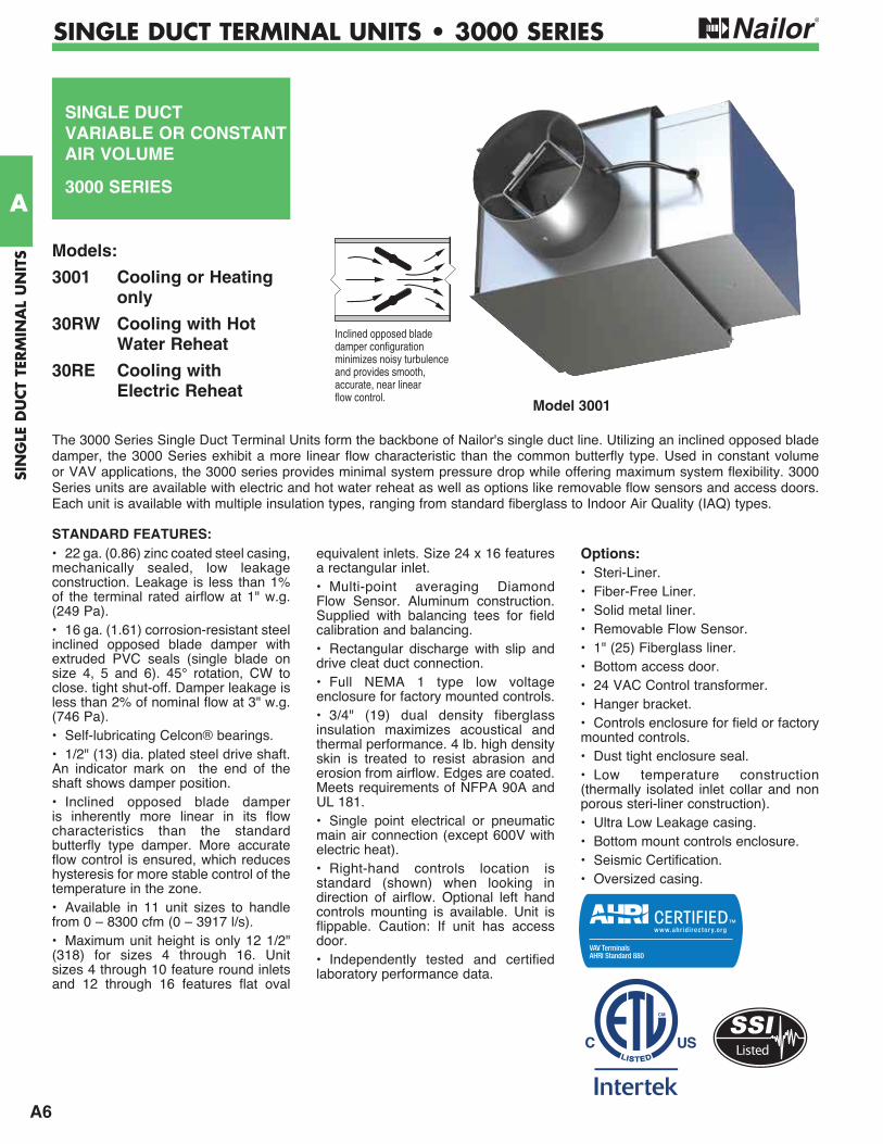
• 22 ga. (0.86) zinc coated steel casing, mechanically sealed, low leakage construction. Leakage is less than 1% of the terminal rated airflow at 1" w.g. (249 Pa).• 16 ga. (1.61) corrosion-resistant steel inclined opposed blade damper with extruded PVC seals (single blade on size 4, 5 and 6). 45° rotation, CW to close. tight shut-off. Damper leakage is less than 2% of nominal flow at 3" w.g. (746 Pa).• Self-lubricating Celcon® bearings.• 1/2" (13) dia. plated steel drive shaft. An indicator mark on the end of the shaft shows damper position.• Inclined opposed blade damper is inherently more linear in its flow characteristics than the standard butterfly type damper. More accurate flow control is ensured, which reduces hysteresis for more stable control of the temperature in the zone.• Available in 11 unit sizes to handle from 0 – 8300 cfm (0 – 3917 l/s).• Maximum unit height is only 12 1/2" (318) for sizes 4 through 16. Unit sizes 4 through 10 feature round inlets and 12 through 16 features flat oval
equivalent inlets. Size 24 x 16 features a rectangular inlet.• Multi-point averaging Diamond Flow Sensor. Aluminum construction. Supplied with balancing tees for field calibration and balancing.• Rectangular discharge with slip and drive cleat duct connection.• Full NEMA 1 type low voltage enclosure for factory mounted controls. • 3/4" (19) dual density fiberglass insulation maximizes acoustical and thermal performance. 4 lb. high density skin is treated to resist abrasion and erosion from airflow. Edges are coated. Meets requirements of NFPA 90A and UL 181.• Single point electrical or pneumatic main air connection (except 600V with electric heat).• Right-hand controls location is standard (shown) when looking in direction of airflow. Optional left hand controls mounting is available. Unit is flippable. Caution: If unit has access door.• Independently tested and certified laboratory performance data.
Options:• Steri-Liner.• Fiber-Free Liner.• Solid metal liner.• Removable Flow Sensor.• 1" (25) Fiberglass liner.• Bottom access door.• 24 VAC Control transformer.• Hanger bracket.• Controls enclosure for field or factory mounted controls.• Dust tight enclosure seal.• Low temperature construction (thermally isolated inlet collar and non porous steri-liner construction). • Ultra Low Leakage casing.• Bottom mount controls enclosure.• Seismic Certification.• Oversized casing.
Model 3001
Inclined opposed bladedamper configurationminimizes noisy turbulenceand provides smooth,accurate, near linearflow control.
SINGLE DUCTVARIABLE OR CONSTANT AIR VOLUME
3000 SERIES
The 3000 Series Single Duct Terminal Units form the backbone of Nailor's single duct line. Utilizing an inclined opposed blade damper, the 3000 Series exhibit a more linear flow characteristic than the common butterfly type. Used in constant volume or VAV applications, the 3000 series provides minimal system pressure drop while offering maximum system flexibility. 3000 Series units are available with electric and hot water reheat as well as options like removable flow sensors and access doors. Each unit is available with multiple insulation types, ranging from standard fiberglass to Indoor Air Quality (IAQ) types.
Models:
3001 Cooling or Heating only
30RW Cooling with Hot Water Reheat
30RE Cooling with Electric Reheat
STANDARD FEATURES:
Listed

A7
SING
LE DU
CT TER
MIN
AL U
NITS
A
SINGLE DUCT TERMINAL UNITS • 3000 SERIES
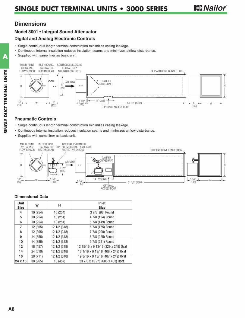
Dimensions Model 3001 • Basic Unit
Digital and Analog Electronic Controls• A full NEMA 1 controls enclosure is provided for factory mounted controls. Optional for field mounted controls.
Digital and Analog Electronic Controls with Bottom Mount Control Enclosure
Pneumatic Controls• Universal pneumatic control mounting panel features double wall stand-off construction for strength and rigidity. Controls mounting
screws do not penetrate terminal casing.
W 15 1/2" (394)
SLIP AND DRIVE CONNECTION
14 1/2" (368)5 3/4"(146)
5 1/2"(140)
1/2"(13)
AIRFLOW
UNIVERSAL PNEUMATIC CONTROL MOUNTING PANEL AND
PROTECTIVE SHROUD
INLET: ROUND,FLAT OVAL OR RECTANGULAR
MULTI-POINTAVERAGING
FLOW SENSOR
DAMPER DRIVESHAFT
H H
W5 3/4"(146)
1/2"(13)
OPTIONALACCESS DOOR
6 1/2"(165)
W15 1/2" (394)
14" (356)6"(152)
11"(279)
5 1/2"(140)
1/2"(13)
H
CONTROLS ENCLOSURE FOR FACTORY
MOUNTED CONTROLS
INLET: ROUND,FLAT OVAL ORRECTANGULAR
MULTI-POINTAVERAGING
FLOW SENSOR
DAMPER DRIVESHAFT
W6"(152)
1/2"(13)
H
SLIP AND DRIVE CONNECTION
OPTIONALACCESS DOOR
14" (356)
6"(152)
1/2"(13)
H
15 1/2" (394)5 1/2"(140)
CONTROLS ENCLOSURE FOR FACTORY
MOUNTED CONTROLS
INLET: ROUND,FLAT OVAL ORRECTANGULAR
MULTI-POINTAVERAGING
FLOW SENSOR
OPTIONALACCESS DOOR
11" (279)
W
SLIP AND DRIVECONNECTION
DAMPER DRIVESHAFT 6"
(152)
1/2"(13)
H
11" (279)
W
SLIP AND DRIVE CONNECTION
AIRFLOW
AIRFLOW
A8
SIN
GLE
DU
CT
TERM
INA
L U
NIT
S
A
SINGLE DUCT TERMINAL UNITS • 3000 SERIES
W51 1/2" (1308)
14 1/2" (368)5 3/4"(146) 5 1/2"
(140)
1/2"(13)
UNIVERSAL PNEUMATIC CONTROL MOUNTING PANEL AND
PROTECTIVE SHROUD
DAMPER DRIVESHAFT
H H
W5 3/4"(146)
OPTIONALACCESS DOOR
6 1/2"(165)
INLET: ROUND,FLAT OVAL ORRECTANGULAR
MULTI-POINTAVERAGING
FLOW SENSOR SLIP AND DRIVE CONNECTION
AIRFLOW
Dimensions Model 3001 • Integral Sound Attenuator
Digital and Analog Electronic Controls
Pneumatic Controls
5 1/2"(140) 51 1/2" (1308) W
SLIP AND DRIVE CONNECTION
H
DAMPER DRIVESHAFT
OPTIONAL ACCESS DOOR
14" (356)6"
(152)W 6"
(152)
11"(279)
1/2"(13)
H
CONTROLS ENCLOSURE FOR FACTORY
MOUNTED CONTROLS
INLET: ROUND,FLAT OVAL ORRECTANGULAR
MULTI-POINTAVERAGING
FLOW SENSOR
AIRFLOW
• Single continuous length terminal construction minimizes casing leakage.
• Continuous internal insulation reduces insulation seams and minimizes airflow disturbance.
• Supplied with same liner as basic unit.
• Single continuous length terminal construction minimizes casing leakage.• Continuous internal insulation reduces insulation seams and minimizes airflow disturbance.• Supplied with same liner as basic unit.
Dimensional Data
Unit Size
W HInletSize
4 10 (254) 10 (254) 3 7/8 (98) Round5 10 (254) 10 (254) 4 7/8 (124) Round6 10 (254) 10 (254) 5 7/8 (149) Round7 12 (305) 12 1/2 (318) 6 7/8 (175) Round8 12 (305) 12 1/2 (318) 7 7/8 (200) Round9 14 (356) 12 1/2 (318) 8 7/8 (225) Round
10 14 (356) 12 1/2 (318) 9 7/8 (251) Round12 18 (457) 12 1/2 (318) 12 15/16 x 9 13/16 (329 x 249) Oval14 24 (610) 12 1/2 (318) 16 1/16 x 9 13/16 (408 x 249) Oval16 28 (711) 12 1/2 (318) 19 3/16 x 9 13/16 (487 x 249) Oval
24 x 16 38 (965) 18 (457) 23 7/8 x 15 7/8 (606 x 403) Rect.
A9
SING
LE DU
CT TER
MIN
AL U
NITS
A
SINGLE DUCT TERMINAL UNITS • 3000 SERIES
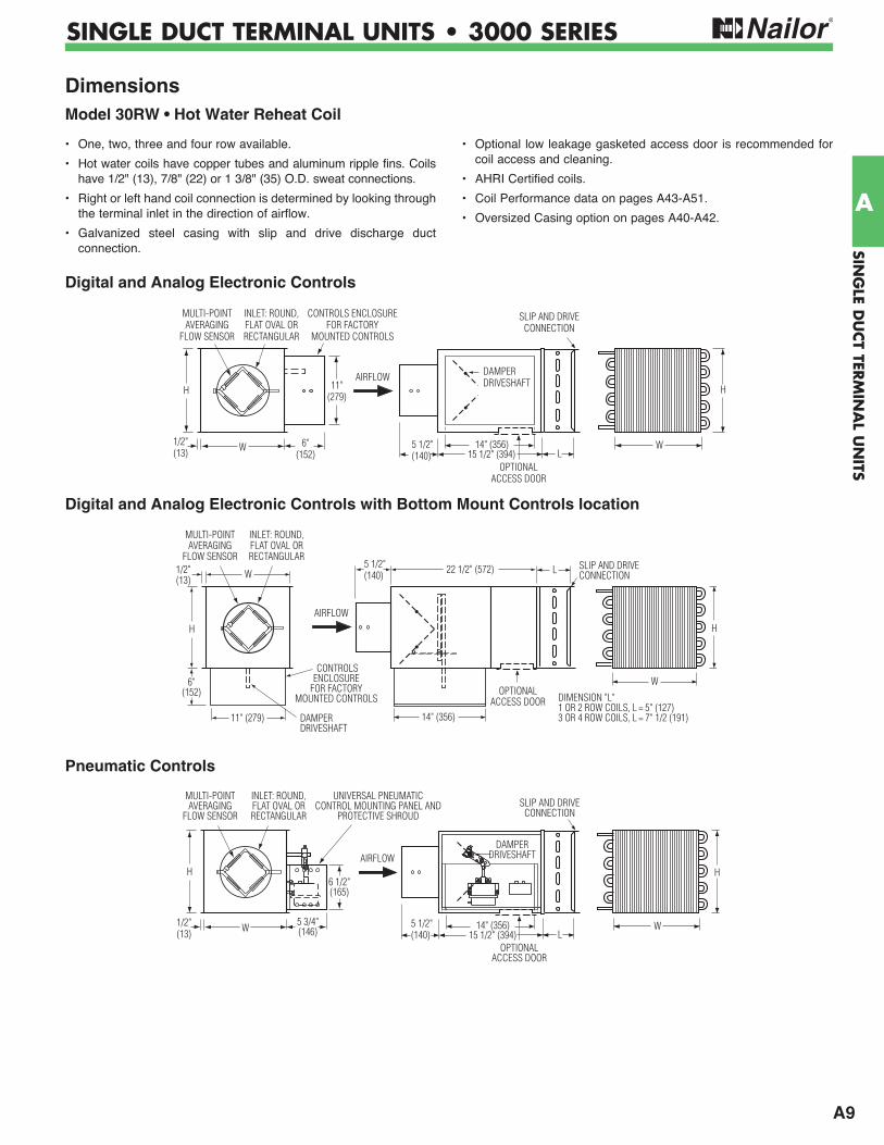
Dimensions Model 30RW • Hot Water Reheat Coil
Digital and Analog Electronic Controls
OPTIONALACCESS DOOR
LW
SLIP AND DRIVECONNECTION
H
15 1/2" (394)14" (356)5 1/2"
(140)W1/2"
(13)
H
INLET: ROUND,FLAT OVAL ORRECTANGULAR
MULTI-POINTAVERAGING
FLOW SENSOR
5 3/4"(146)
UNIVERSAL PNEUMATIC CONTROL MOUNTING PANEL AND
PROTECTIVE SHROUD
DAMPER DRIVESHAFT
6 1/2"(165)
AIRFLOW
Digital and Analog Electronic Controls with Bottom Mount Controls location
OPTIONALACCESS DOOR
LW
SLIP AND DRIVECONNECTION
H
15 1/2" (394)14" (356)5 1/2"
(140)
DAMPERDRIVESHAFT AIRFLOW
W 6"(152)
11"(279)
1/2"(13)
H
CONTROLS ENCLOSURE FOR FACTORY
MOUNTED CONTROLS
INLET: ROUND,FLAT OVAL ORRECTANGULAR
MULTI-POINTAVERAGING
FLOW SENSOR
OPTIONALACCESS DOOR
SLIP AND DRIVECONNECTION
14" (356)
5 1/2"(140)
6"(152)
1/2"(13)
INLET: ROUND,FLAT OVAL ORRECTANGULAR
MULTI-POINTAVERAGING
FLOW SENSOR
11" (279)
22 1/2" (572)W
H
DAMPERDRIVESHAFT
L
W
H
DIMENSION "L"1 OR 2 ROW COILS, L = 5" (127)3 OR 4 ROW COILS, L = 7" 1/2 (191)
CONTROLSENCLOSURE
FOR FACTORY MOUNTED CONTROLS
AIRFLOW
Pneumatic Controls
• One, two, three and four row available.
• Hot water coils have copper tubes and aluminum ripple fins. Coils have 1/2" (13), 7/8" (22) or 1 3/8" (35) O.D. sweat connections.
• Right or left hand coil connection is determined by looking through the terminal inlet in the direction of airflow.
• Galvanized steel casing with slip and drive discharge duct connection.
• Optional low leakage gasketed access door is recommended for coil access and cleaning.
• AHRI Certified coils.
• Coil Performance data on pages A43-A51.
• Oversized Casing option on pages A40-A42.
A10
SIN
GLE
DU
CT
TERM
INA
L U
NIT
S
A
SINGLE DUCT TERMINAL UNITS • 3000 SERIES
Dimensional Data
5 1/2"(140)
51 1/2" (1308)OPTIONAL ACCESS DOOR
SLIP AND DRIVE CONNECTION
H
L W
DAMPERDRIVESHAFT
14" (356)W 6"
(152)
11"(279)
1/2"(13)
H
CONTROLS ENCLOSURE FOR FACTORY
MOUNTED CONTROLS
INLET: ROUND,FLAT OVAL ORRECTANGULAR
MULTI-POINTAVERAGING
FLOW SENSOR
AIRFLOW
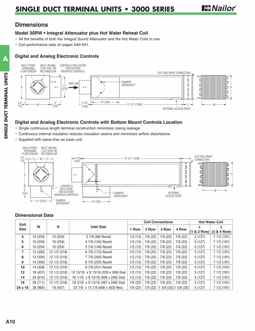
Dimensions Model 30RW • Integral Attenuator plus Hot Water Reheat Coil• All the benefits of both the Integral Sound Attenuator and the Hot Water Coils in one.
• Coil performance data on pages A43-A51.
Digital and Analog Electronic Controls with Bottom Mount Controls Location• Single continuous length terminal construction minimizes casing leakage.
• Continuous internal insulation reduces insulation seams and minimizes airflow disturbance.
• Supplied with same liner as basic unit.
Digital and Analog Electronic Controls
5 1/2"(140)
51 1/2" (1308)SLIP AND DRIVECONNECTION
DAMPERDRIVESHAFT
H
OPTIONALACCESS DOOR
W
L
14" (356)
6"(152)
1/2"(13)
INLET: ROUND,FLAT OVAL ORRECTANGULAR
MULTI-POINTAVERAGING
FLOW SENSOR
11" (279)
W
H
DAMPERDRIVESHAFT
CONTROLSENCLOSURE
FOR FACTORY MOUNTED CONTROLS
Unit Size
W H Inlet SizeCoil Connections Hot Water Coil
1 Row 2 Row 3 Row 4 RowL
(1 & 2 Row)L
(3 & 4 Row)4 10 (254) 10 (254) 3 7/8 (98) Round 1/2 (13) 7/8 (22) 7/8 (22) 7/8 (22) 5 (127) 7 1/2 (191)5 10 (254) 10 (254) 4 7/8 (124) Round 1/2 (13) 7/8 (22) 7/8 (22) 7/8 (22) 5 (127) 7 1/2 (191)6 10 (254) 10 (254) 5 7/8 (149) Round 1/2 (13) 7/8 (22) 7/8 (22) 7/8 (22) 5 (127) 7 1/2 (191)7 12 (305) 12 1/2 (318) 6 7/8 (175) Round 1/2 (13) 7/8 (22) 7/8 (22) 7/8 (22) 5 (127) 7 1/2 (191)8 12 (305) 12 1/2 (318) 7 7/8 (200) Round 1/2 (13) 7/8 (22) 7/8 (22) 7/8 (22) 5 (127) 7 1/2 (191)9 14 (356) 12 1/2 (318) 8 7/8 (225) Round 1/2 (13) 7/8 (22) 7/8 (22) 7/8 (22) 5 (127) 7 1/2 (191)
10 14 (356) 12 1/2 (318) 9 7/8 (251) Round 1/2 (13) 7/8 (22) 7/8 (22) 7/8 (22) 5 (127) 7 1/2 (191)12 18 (457) 12 1/2 (318) 12 15/16 x 9 13/16 (329 x 249) Oval 1/2 (13) 7/8 (22) 7/8 (22) 7/8 (22) 5 (127) 7 1/2 (191)14 24 (610) 12 1/2 (318) 16 1/16 x 9 13/16 (408 x 249) Oval 1/2 (13) 7/8 (22) 7/8 (22) 7/8 (22) 5 (127) 7 1/2 (191)16 28 (711) 12 1/2 (318) 19 3/16 x 9 13/16 (487 x 249) Oval 7/8 (22) 7/8 (22) 7/8 (22) 7/8 (22) 5 (127) 7 1/2 (191)
24 x 16 38 (965) 18 (457) 23 7/8 x 15 7/8 (606 x 403) Rect. 7/8 (22) 7/8 (22) 1 3/8 (35) 1 3/8 (35) 5 (127) 7 1/2 (191)
A11
SING
LE DU
CT TER
MIN
AL U
NITS
A
SINGLE DUCT TERMINAL UNITS • 3000 SERIES
AIRFLOW
5 1/2"(140)
29" (737)31" (787)
W6"(152)
H
1/2" (13)
OPTIONAL ACCESS DOOR
W 6"(152)
11"(279)
1/2"(13)
H
CONTROLS ENCLOSURE FOR FACTORY
MOUNTED CONTROLS
INLET: ROUND,FLAT OVAL ORRECTANGULAR
MULTI-POINTAVERAGING
FLOW SENSOR
PRIMARYAIR
VALVECONTROLSENCLOSURE
SLIP AND DRIVECONNECTION
ELECTRIC COILCONTROLS
ENCLOSURE(HINGED ACCESS
DOOR)
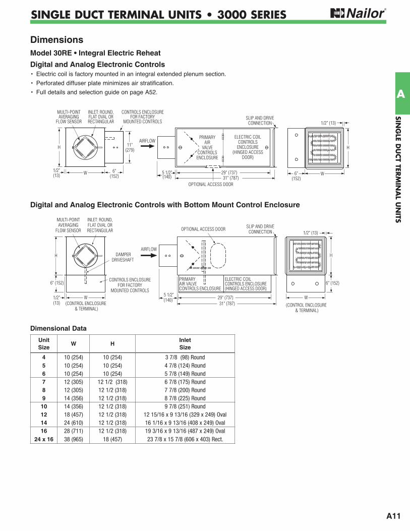
Dimensions Model 30RE • Integral Electric Reheat
Digital and Analog Electronic Controls• Electric coil is factory mounted in an integral extended plenum section.
• Perforated diffuser plate minimizes air stratification.
• Full details and selection guide on page A52.
SLIP AND DRIVECONNECTIONOPTIONAL ACCESS DOOR
AIRFLOW
1/2"(13)
CONTROLS ENCLOSURE FOR FACTORY
MOUNTED CONTROLS
INLET: ROUND,FLAT OVAL ORRECTANGULAR
MULTI-POINTAVERAGING
FLOW SENSOR
5 1/2"(140) 29" (737)
31" (787)
H
1/2" (13)
W(CONTROL ENCLOSURE
& TERMINAL)(CONTROL ENCLOSURE
& TERMINAL)
6" (152)
H
W
6" (152)
DAMPERDRIVESHAFT
PRIMARYAIR VALVECONTROLS ENCLOSURE
ELECTRIC COILCONTROLS ENCLOSURE(HINGED ACCESS DOOR)
Digital and Analog Electronic Controls with Bottom Mount Control Enclosure
Dimensional Data
Unit Size
W HInlet Size
4 10 (254) 10 (254) 3 7/8 (98) Round 5 10 (254) 10 (254) 4 7/8 (124) Round6 10 (254) 10 (254) 5 7/8 (149) Round7 12 (305) 12 1/2 (318) 6 7/8 (175) Round8 12 (305) 12 1/2 (318) 7 7/8 (200) Round9 14 (356) 12 1/2 (318) 8 7/8 (225) Round
10 14 (356) 12 1/2 (318) 9 7/8 (251) Round12 18 (457) 12 1/2 (318) 12 15/16 x 9 13/16 (329 x 249) Oval14 24 (610) 12 1/2 (318) 16 1/16 x 9 13/16 (408 x 249) Oval16 28 (711) 12 1/2 (318) 19 3/16 x 9 13/16 (487 x 249) Oval
24 x 16 38 (965) 18 (457) 23 7/8 x 15 7/8 (606 x 403) Rect.
A12
SIN
GLE
DU
CT
TERM
INA
L U
NIT
S
A
SINGLE DUCT TERMINAL UNITS • 3000 SERIES
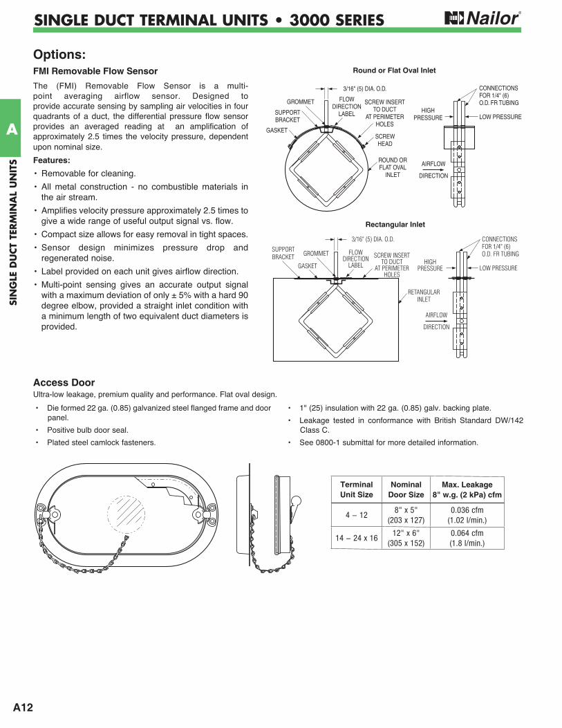
Access DoorUltra-low leakage, premium quality and performance. Flat oval design.
• Die formed 22 ga. (0.85) galvanized steel flanged frame and door panel.
• Positive bulb door seal.
• Plated steel camlock fasteners.
• 1" (25) insulation with 22 ga. (0.85) galv. backing plate.
• Leakage tested in conformance with British Standard DW/142 Class C.
• See 0800-1 submittal for more detailed information.
Terminal Unit Size
Nominal Door Size
Max. Leakage8" w.g. (2 kPa) cfm
8" x 5" (203 x 127)
0.036 cfm (1.02 l/min.)
12" x 6" (305 x 152)
0.064 cfm (1.8 l/min.)
FMI Removable Flow Sensor
The (FMI) Removable Flow Sensor is a multi-point averaging airflow sensor. Designed to provide accurate sensing by sampling air velocities in four quadrants of a duct, the differential pressure flow sensor provides an averaged reading at an amplification of approximately 2.5 times the velocity pressure, dependent upon nominal size.
Features:
• Removable for cleaning.
• All metal construction - no combustible materials in the air stream.
• Amplifies velocity pressure approximately 2.5 times to give a wide range of useful output signal vs. flow.
• Compact size allows for easy removal in tight spaces.
• Sensor design minimizes pressure drop and regenerated noise.
• Label provided on each unit gives airflow direction.
• Multi-point sensing gives an accurate output signal with a maximum deviation of only ± 5% with a hard 90 degree elbow, provided a straight inlet condition with a minimum length of two equivalent duct diameters is provided.
SCREW INSERTTO DUCT
AT PERIMETERHOLES
FLOWDIRECTION
LABELSUPPORTBRACKET
GASKET
ROUND ORFLAT OVAL
INLET
3/16" (5) DIA. O.D.
GROMMET
SCREWHEAD
AIRFLOW
LOW PRESSURE
CONNECTIONSFOR 1/4" (6)O.D. FR TUBING
HIGHPRESSURE
DIRECTION
Options:
SCREW INSERTTO DUCT
AT PERIMETERHOLES
FLOWDIRECTION
LABEL
3/16" (5) DIA. O.D.
SUPPORTBRACKET
GASKET
RETANGULAR INLET
GROMMET
AIRFLOW
LOW PRESSURE
CONNECTIONSFOR 1/4" (6)O.D. FR TUBING
HIGHPRESSURE
DIRECTION
Round or Flat Oval Inlet
Rectangular Inlet
A13
SING
LE DU
CT TER
MIN
AL U
NITS
A
SINGLE DUCT TERMINAL UNITS • 3000 SERIES
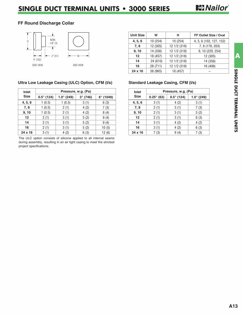
Standard Leakage Casing, CFM (l/s)
Inlet Size
Pressure, w.g. (Pa)
0.25" (62) 0.5" (124) 1.0" (249)
4, 5, 6 3 (1) 4 (2) 3 (1)7, 8 2 (1) 3 (1) 7 (3)
9, 10 2 (1) 3 (1) 5 (2)12 2 (1) 3 (1) 6 (3)14 3 (1) 4 (2) 4 (2)16 3 (1) 4 (2) 6 (3)
24 x 16 7 (3) 9 (4) 7 (3)
Ultra Low Leakage Casing (ULC) Option, CFM (l/s)
Inlet Size
Pressure, w.g. (Pa)
0.5" (124) 1.0" (249) 3" (746) 6" (1049)
4, 5, 6 1 (0.5) 1 (0.5) 3 (1) 6 (3)7, 8 1 (0.5) 2 (1) 4 (2) 7 (3)
9, 10 1 (0.5) 2 (1) 4 (2) 8 (4)12 2 (1) 3 (1) 5 (2) 9 (4)14 2 (1) 3 (1) 5 (2) 9 (4)16 2 (1) 3 (1) 5 (2) 10 (5)
24 x 16 3 (1) 4 (2) 6 (3) 12 (6)
The ULC option consists of silicone applied to all internal seams during assembly, resulting in an air tight casing to meet the strictest project specifications.
FF Round Discharge Collar
4" (102)
H
END VIEW
NOM.- 1/8" (3)
2" (51) W
SIDE VIEW
Unit Size W H FF Outlet Size / Oval
4, 5, 6 10 (254) 10 (254) 4, 5, 6 (102, 127, 152)7, 8 12 (305) 12 1/2 (318) 7, 8 (178, 203)
9, 10 14 (356) 12 1/2 (318) 9, 10 (229, 254)12 18 (457) 12 1/2 (318) 12 (305)14 24 (610) 12 1/2 (318) 14 (356)16 28 (711) 12 1/2 (318) 16 (406)
24 x 16 38 (965) 18 (457) –
A14
SIN
GLE
DU
CT
TERM
INA
L U
NIT
S
A
SINGLE DUCT TERMINAL UNITS • 3000 SERIES
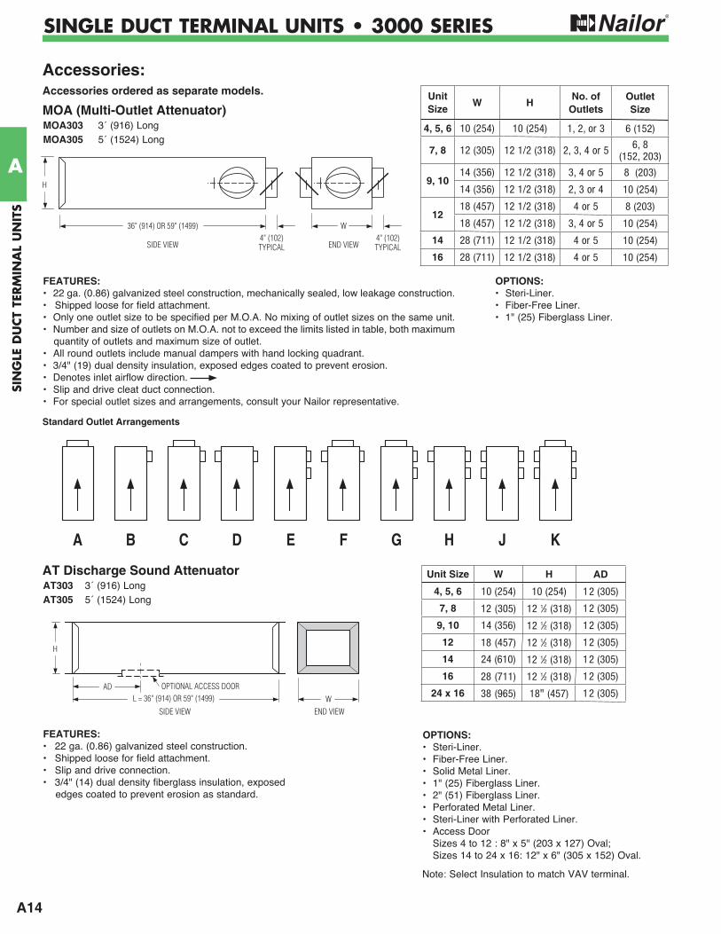
AT Discharge Sound AttenuatorAT303 3´ (916) LongAT305 5´ (1524) Long
H
L = 36" (914) OR 59" (1499)AD
WSIDE VIEW END VIEW
OPTIONAL ACCESS DOOR
FEATURES:• 22 ga. (0.86) galvanized steel construction.• Shipped loose for field attachment.• Slip and drive connection.• 3/4" (14) dual density fiberglass insulation, exposed
edges coated to prevent erosion as standard.
Unit Size W H AD
4, 5, 6 10 (254) 10 (254) 12 (305)
7, 8 12 (305) 12 12 (318) 12 (305)
9, 10 14 (356) 12 12 (318) 12 (305)
12 18 (457) 12 12 (318) 12 (305)
14 24 (610) 12 12 (318) 12 (305)
16 28 (711) 12 12 (318) 12 (305)
24 x 16 38 (965) 18" (457) 12 (305)
Standard Outlet Arrangements
H
36" (914) OR 59" (1499)
SIDE VIEW4" (102)TYPICAL
4" (102)TYPICAL
W
END VIEW
A B C D E F G H J K
FEATURES:• 22 ga. (0.86) galvanized steel construction, mechanically sealed, low leakage construction.• Shipped loose for field attachment.• Only one outlet size to be specified per M.O.A. No mixing of outlet sizes on the same unit.• Number and size of outlets on M.O.A. not to exceed the limits listed in table, both maximum
quantity of outlets and maximum size of outlet.• All round outlets include manual dampers with hand locking quadrant.• 3/4" (19) dual density insulation, exposed edges coated to prevent erosion.• Denotes inlet airflow direction.• Slip and drive cleat duct connection.• For special outlet sizes and arrangements, consult your Nailor representative.
Accessories:Accessories ordered as separate models.
MOA (Multi-Outlet Attenuator)MOA303 3´ (916) LongMOA305 5´ (1524) Long
UnitSize
W HNo. of
OutletsOutletSize
4, 5, 6 10 (254) 10 (254) 1, 2, or 3 6 (152)
7, 8 12 (305) 12 1/2 (318) 2, 3, 4 or 5 6, 8 (152, 203)
9, 1014 (356) 12 1/2 (318) 3, 4 or 5 8 (203)
14 (356) 12 1/2 (318) 2, 3 or 4 10 (254)
1218 (457) 12 1/2 (318) 4 or 5 8 (203)
18 (457) 12 1/2 (318) 3, 4 or 5 10 (254)
14 28 (711) 12 1/2 (318) 4 or 5 10 (254)
16 28 (711) 12 1/2 (318) 4 or 5 10 (254)
OPTIONS:• Steri-Liner.• Fiber-Free Liner.• 1" (25) Fiberglass Liner.
OPTIONS:• Steri-Liner.• Fiber-Free Liner.• Solid Metal Liner.• 1" (25) Fiberglass Liner.• 2" (51) Fiberglass Liner.• Perforated Metal Liner.• Steri-Liner with Perforated Liner.• Access Door Sizes 4 to 12 : 8" x 5" (203 x 127) Oval; Sizes 14 to 24 x 16: 12" x 6" (305 x 152) Oval.
Note: Select Insulation to match VAV terminal.
A15
SING
LE DU
CT TER
MIN
AL U
NITS
A
SINGLE DUCT TERMINAL UNITS • 3000 SERIES
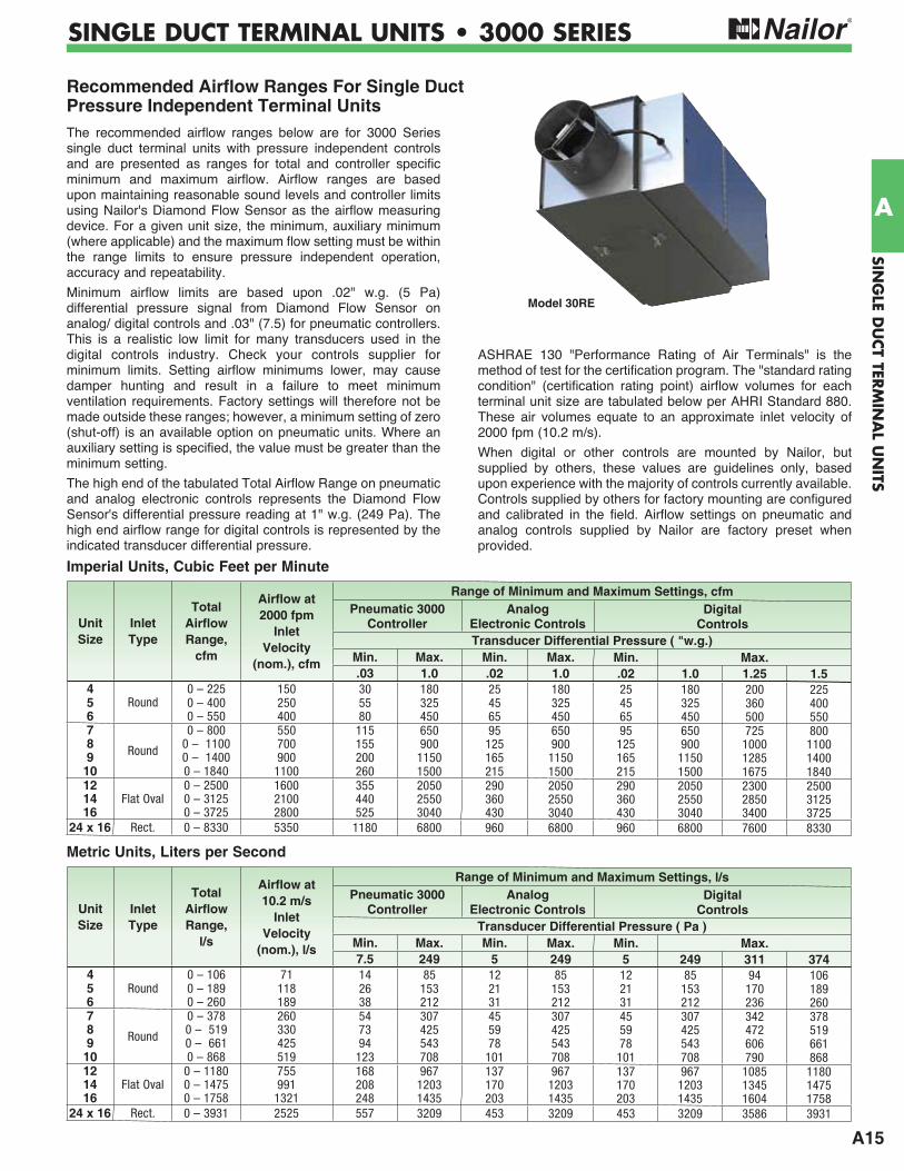
Recommended Airflow Ranges For Single Duct Pressure Independent Terminal UnitsThe recommended airflow ranges below are for 3000 Series single duct terminal units with pressure independent controls and are presented as ranges for total and controller specific minimum and maximum airflow. Airflow ranges are based upon maintaining reasonable sound levels and controller limits using Nailor's Diamond Flow Sensor as the airflow measuring device. For a given unit size, the minimum, auxiliary minimum (where applicable) and the maximum flow setting must be within the range limits to ensure pressure independent operation, accuracy and repeatability.
Minimum airflow limits are based upon .02" w.g. (5 Pa) differential pressure signal from Diamond Flow Sensor on analog/ digital controls and .03" (7.5) for pneumatic controllers. This is a realistic low limit for many transducers used in the digital controls industry. Check your controls supplier for minimum limits. Setting airflow minimums lower, may cause damper hunting and result in a failure to meet minimum ventilation requirements. Factory settings will therefore not be made outside these ranges; however, a minimum setting of zero (shut-off) is an available option on pneumatic units. Where an auxiliary setting is specified, the value must be greater than the minimum setting.
The high end of the tabulated Total Airflow Range on pneumatic and analog electronic controls represents the Diamond Flow Sensor's differential pressure reading at 1" w.g. (249 Pa). The high end airflow range for digital controls is represented by the indicated transducer differential pressure.
ASHRAE 130 "Performance Rating of Air Terminals" is the method of test for the certification program. The "standard rating condition" (certification rating point) airflow volumes for each terminal unit size are tabulated below per AHRI Standard 880. These air volumes equate to an approximate inlet velocity of 2000 fpm (10.2 m/s).
When digital or other controls are mounted by Nailor, but supplied by others, these values are guidelines only, based upon experience with the majority of controls currently available. Controls supplied by others for factory mounting are configured and calibrated in the field. Airflow settings on pneumatic and analog controls supplied by Nailor are factory preset when provided.
Model 30RE
Imperial Units, Cubic Feet per Minute
Metric Units, Liters per Second
Unit Size
InletType
Total Airflow Range,
cfm
Airflow at 2000 fpm
InletVelocity
(nom.), cfm
Range of Minimum and Maximum Settings, cfmPneumatic 3000
ControllerAnalog
Electronic ControlsDigital
ControlsTransducer Differential Pressure ( "w.g.)
Min. Max. Min. Max. Min. Max..03 1.0 .02 1.0 .02 1.0 1.25 1.5
4Round
0 – 225 150 30 180 25 180 25 180 200 2255 0 – 400 250 55 325 45 325 45 325 360 4006 0 – 550 400 80 450 65 450 65 450 500 5507
Round
0 – 800 550 115 650 95 650 95 650 725 8008 0 – 1100 700 155 900 125 900 125 900 1000 11009 0 – 1400 900 200 1150 165 1150 165 1150 1285 1400
10 0 – 1840 1100 260 1500 215 1500 215 1500 1675 184012
Flat Oval0 – 2500 1600 355 2050 290 2050 290 2050 2300 2500
14 0 – 3125 2100 440 2550 360 2550 360 2550 2850 312516 0 – 3725 2800 525 3040 430 3040 430 3040 3400 3725
24 x 16 Rect. 0 – 8330 5350 1180 6800 960 6800 960 6800 7600 8330
Unit Size
InletType
Total Airflow Range,
l/s
Airflow at 10.2 m/s
InletVelocity
(nom.), l/s
Range of Minimum and Maximum Settings, l/sPneumatic 3000
ControllerAnalog
Electronic ControlsDigital
ControlsTransducer Differential Pressure ( Pa )
Min. Max. Min. Max. Min. Max.7.5 249 5 249 5 249 311 374
4 0 – 106 71 14 85 12 85 12 85 94 1065 Round 0 – 189 118 26 153 21 153 21 153 170 1896 0 – 260 189 38 212 31 212 31 212 236 2607
Round
0 – 378 260 54 307 45 307 45 307 342 3788 0 – 519 330 73 425 59 425 59 425 472 5199 0 – 661 425 94 543 78 543 78 543 606 661
10 0 – 868 519 123 708 101 708 101 708 790 86812 0 – 1180 755 168 967 137 967 137 967 1085 118014 Flat Oval 0 – 1475 991 208 1203 170 1203 170 1203 1345 147516 0 – 1758 1321 248 1435 203 1435 203 1435 1604 1758
24 x 16 Rect. 0 – 3931 2525 557 3209 453 3209 453 3209 3586 3931
A16
SIN
GLE
DU
CT
TERM
INA
L U
NIT
S
A
SINGLE DUCT TERMINAL UNITS • 3000 SERIES
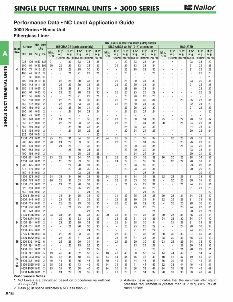
Performance Data • NC Level Application Guide3000 Series • Basic UnitFiberglass Liner
Inlet Size
Airflow Min. inletNC Levels @ Inlet Pressure ( Ps) shown
PsDISCHARGE (basic assembly) DISCHARGE w/ 36" (914) attenuator RADIATED
cfm l/s "w.g. Pa Min. Ps
0.5" w.g.
(125 Pa)
1.0" w.g.
(250 Pa)
1.5" w.g.
(375 Pa)
2.0" w.g.
(500 Pa)
3.0" w.g.
(750 Pa)
Min. Ps
0.5" w.g.
(125 Pa)
1.0" w.g.
(250 Pa)
1.5" w.g.
(375 Pa)
2.0" w.g.
(500 Pa)
3.0" w.g.
(750 Pa)
Min. Ps
0.5" w.g.
(125 Pa)
1.0" w.g.
(250 Pa)
1.5" w.g.
(375 Pa)
2.0" w.g.
(500 Pa)
3.0" w.g.
(750 Pa)
4
225 106 0.53 133 21 - 30 33 34 36 - - 29 33 33 34 - * - 23 25 29200 94 0.43 106 20 25 29 33 34 35 - 25 29 33 33 34 - - - 21 24 28150 71 0.10 25 - 21 26 29 30 30 - - 26 28 29 30 - - - 21 22 22100 47 0.11 28 - - 21 21 21 21 - - 20 - - 20 - - - - 20 2375 35 0.06 16 - - - - - - - - - - - - - - - - - 20
5
400 189 0.19 48 - 23 28 30 33 35 - 20 26 30 31 33 - - - 23 26 31300 142 0.11 28 - 23 29 30 33 35 - 23 29 30 33 34 - - - 21 23 28250 118 0.05 12 - 23 28 31 33 34 - - 28 30 33 34 - - - - 22 25200 94 0.05 13 - 21 25 28 29 30 - 20 25 25 28 29 - - - - 20 22125 59 0.02 5 - - 20 21 21 21 - - 20 20 20 20 - - - - - -
6
550 260 0.01 2 - 25 29 33 36 38 - 20 25 30 33 34 - - 20 25 28 31450 212 0.01 2 - 23 28 33 35 36 - 20 25 30 31 33 - - - 22 24 29400 189 0.01 2 - 20 25 30 31 33 - - 23 26 29 30 - - - 21 25 29200 94 0.01 2 - - 21 24 24 24 - - 21 23 24 24 - - - - - 20100 47 0.01 2 - - - - - - - - - - - - - - - - - -
7
800 378 0.01 2 - 24 28 31 35 38 - 23 26 30 34 36 25 - 22 28 33 37650 307 0.01 2 - 23 28 33 37 37 - 23 26 31 34 36 20 - 21 24 29 34550 260 0.01 2 - - 24 30 31 34 - - 24 28 30 33 - - - 24 28 32335 158 0.01 2 - - 21 25 25 26 - - 20 24 24 25 - - - 20 22 24225 106 0.01 2 - - - - - 20 - - - - - - - - - - - -
8
1100 519 0.01 2 25 28 31 34 37 40 24 26 29 31 36 39 - 20 25 29 31 35900 425 0.01 2 20 24 29 33 36 38 - 23 26 31 34 37 - - 23 26 29 33700 330 0.01 2 - 21 26 31 35 38 - - 25 30 33 35 - - 21 24 26 31600 283 0.01 2 - - 25 30 34 36 - - 23 29 30 31 - - - 23 25 31400 189 0.01 2 - - - 25 26 28 - - - 24 24 24 - - - 20 21 25
9
1400 661 0.01 2 23 28 31 34 37 39 21 28 30 33 36 39 20 20 23 28 34 381250 590 0.01 2 - 25 29 33 35 38 - 24 29 31 35 37 - 20 22 26 33 36900 425 0.01 2 - - 24 28 31 35 - - 23 28 30 33 - - - 23 28 31675 319 0.01 2 - - 23 28 30 33 - - 23 28 30 31 - - - 20 25 26450 212 0.01 2 - - - 23 24 25 - - - 21 23 24 - - - - 20 22
10
1850 873 0.01 2 24 31 34 36 38 39 24 30 31 34 36 38 22 22 26 31 33 371650 779 0.01 2 20 28 31 35 37 39 - 28 31 33 35 37 - 20 25 30 31 361100 519 0.01 2 - 21 25 28 31 35 - - 21 25 29 31 - - 21 24 25 31825 389 0.01 2 - - 20 25 29 31 - - - 21 25 29 - - - 21 23 28550 260 0.01 2 - - - 21 24 26 - - - - 21 23 - - - - - 22
12
2500 1180 0.01 2 - 31 34 35 38 40 - 31 33 35 36 38 29 28 31 34 35 402000 944 0.01 2 - 28 30 31 35 37 - 26 28 30 31 34 22 25 29 31 33 371600 755 0.01 2 - 23 26 29 33 35 - 20 23 26 29 33 - 20 25 28 30 351200 566 0.01 2 - - 21 25 29 33 - - - 23 25 29 - - 20 24 28 31800 378 0.01 2 - - - - 21 24 - - - - - 21 - - - 20 21 24
14
3125 1475 0.01 2 23 31 34 35 38 39 20 31 33 34 36 38 29 28 31 36 39 432700 1274 0.01 2 - 29 30 33 35 37 - 28 29 31 34 36 24 25 30 34 37 402100 991 0.01 2 - 21 25 29 33 36 - 21 24 28 30 34 - 21 26 31 34 371550 731 0.01 2 - - 21 26 30 33 - - 20 25 26 29 - - 24 28 30 341050 495 0.01 2 - - - 21 24 26 - - - 21 23 24 - - - 24 26 28
16
3725 1758 0.03 8 - 29 31 33 35 38 - 28 30 31 35 38 30 30 33 37 40 443500 1652 0.03 8 - 26 29 31 34 36 - 24 28 31 34 35 28 30 33 36 39 432800 1321 0.02 6 - 23 26 29 31 34 - 21 25 29 30 33 23 24 29 34 36 402100 991 0.02 4 - - 20 25 26 30 - - - 23 25 28 - - 26 30 34 361400 661 0.01 3 - - - - 21 24 - - - - - 23 - - 21 26 29 31
24 x
16
8330 3931 0.02 5 49 49 49 52 53 53 48 48 48 50 52 52 44 44 49 51 54 577000 3303 0.02 4 45 45 45 48 49 50 44 44 44 46 48 49 40 41 47 49 51 556000 2831 0.01 2 40 41 43 45 46 48 39 40 41 44 45 46 36 39 45 47 49 535350 2525 0.01 2 35 38 40 43 45 46 34 36 39 41 44 45 32 38 44 46 48 514000 1888 0.01 2 25 31 35 38 40 43 24 30 34 36 39 41 24 35 39 43 45 473000 1416 0.01 2 - 24 29 33 35 38 - 23 28 31 34 37 20 31 36 38 40 44
1. NC Levels are calculated based on procedures as outlined on page A75.
2. Dash (-) in space indicates a NC less than 20.
3. Asterisk (*) in space indicates that the minimum inlet static pressure requirement is greater than 0.5" w.g. (125 Pa) at rated airflow.
Performance Notes:
A17
SING
LE DU
CT TER
MIN
AL U
NITS
A
SINGLE DUCT TERMINAL UNITS • 3000 SERIES
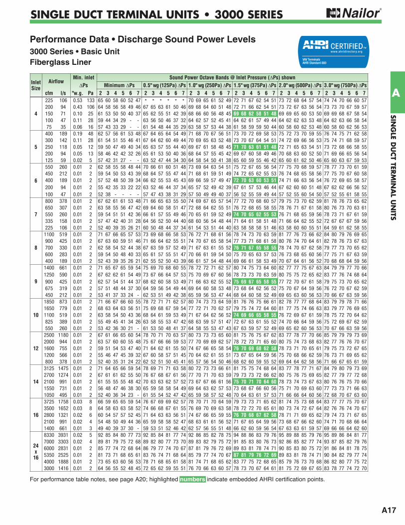
Performance Data • Discharge Sound Power Levels3000 Series • Basic UnitFiberglass Liner
For performance table notes, see page A20; highlighted numbers indicate embedded AHRI certification points.
Inlet Size
AirflowMin. inlet Sound Power Octave Bands @ Inlet Pressure ( Ps) shown
Ps Minimum Ps 0.5" wg (125Pa) Ps 1.0" wg (250Pa) Ps 1.5" wg (375Pa) Ps 2.0" wg (500Pa) Ps 3.0" wg (750Pa) Pscfm l/s "w.g. Pa 2 3 4 5 6 7 2 3 4 5 6 7 2 3 4 5 6 7 2 3 4 5 6 7 2 3 4 5 6 7 2 3 4 5 6 7
4
225 106 0.53 133 65 60 58 60 52 47 * * * * * * 70 69 65 61 52 49 72 71 67 62 54 51 73 72 68 64 57 54 74 74 70 66 60 57200 94 0.43 106 64 58 56 58 49 46 67 65 63 61 50 46 69 68 64 60 51 48 72 71 66 62 54 51 73 72 67 63 56 54 73 73 70 67 59 57150 71 0.10 25 61 53 50 50 40 37 65 62 55 51 42 39 68 66 60 56 48 45 69 68 62 58 51 48 69 69 65 60 53 50 69 69 68 67 58 54100 47 0.11 28 59 44 34 29 - - 63 56 50 46 37 32 64 62 57 52 45 41 64 62 61 57 49 44 64 62 62 63 53 48 64 62 63 66 58 5475 35 0.06 16 57 43 33 29 - - 61 54 48 44 35 29 63 58 57 53 44 38 61 58 59 59 50 44 60 58 60 62 53 48 60 58 60 62 56 53
5
400 189 0.19 48 62 57 56 61 53 48 67 64 65 64 54 49 71 68 70 67 56 51 73 70 72 69 58 53 75 72 73 70 59 55 76 74 75 71 62 58300 142 0.11 28 61 54 51 55 46 41 67 64 62 60 49 44 70 69 65 63 52 48 73 70 67 64 54 51 74 72 69 66 56 53 75 74 71 68 59 57250 118 0.05 12 59 50 47 49 40 34 65 63 57 55 44 40 69 67 61 58 48 45 71 70 63 61 51 48 72 71 65 63 54 51 73 72 68 66 58 55200 94 0.05 13 58 46 42 42 32 26 65 61 53 50 40 36 68 64 57 55 45 42 69 67 60 58 49 46 70 68 63 60 52 50 71 69 66 65 56 54125 59 0.02 5 57 42 31 27 - - 63 52 47 44 34 30 64 58 54 50 41 38 65 60 59 55 46 42 65 60 61 62 50 46 65 60 63 67 59 53
6
550 260 0.01 2 62 58 55 58 48 44 70 66 61 60 51 48 73 69 64 63 54 51 75 72 67 65 56 54 77 75 70 68 59 57 78 77 73 70 61 59450 212 0.01 2 59 54 50 53 43 39 68 64 57 55 47 44 71 68 61 59 51 49 74 72 65 62 55 53 76 74 68 65 58 56 77 75 70 67 60 58400 189 0.01 2 57 52 48 50 39 34 66 62 55 53 45 43 69 66 59 57 49 47 72 70 63 60 53 51 74 71 66 63 56 54 76 72 69 65 58 57200 94 0.01 2 55 42 35 33 22 22 63 52 46 44 37 34 65 57 52 49 42 39 67 61 57 53 46 44 67 62 60 60 51 48 67 62 62 66 56 52100 47 0.01 2 52 38 - - - - 57 47 43 38 31 29 57 50 49 49 40 37 56 52 55 59 49 44 57 52 55 60 54 50 57 52 55 61 58 55
7
800 378 0.01 2 67 62 61 61 53 48 71 66 65 63 55 50 74 69 67 65 57 54 77 72 70 68 60 57 79 75 73 70 62 59 81 78 76 73 65 62650 307 0.01 2 63 58 55 56 47 42 69 64 60 58 51 47 72 68 64 62 55 51 76 72 68 65 58 55 78 76 71 67 61 58 80 76 73 70 63 61550 260 0.01 2 59 54 51 51 42 36 66 61 57 55 49 46 70 65 61 59 52 49 74 70 65 62 55 53 76 71 68 65 59 56 78 73 71 67 61 59335 158 0.01 2 57 47 42 40 31 28 64 56 52 50 44 40 68 60 56 54 48 44 71 64 61 58 51 48 71 66 64 62 55 52 72 67 67 67 59 56225 106 0.01 2 52 40 39 35 26 21 60 50 48 44 37 34 61 54 53 51 44 40 63 58 58 58 51 46 63 58 60 60 55 51 64 59 61 62 58 55
8
1100 519 0.01 2 71 67 66 65 57 53 73 69 68 66 58 53 76 72 71 68 61 56 78 74 73 70 63 59 81 77 76 73 66 62 84 80 79 76 69 65900 425 0.01 2 67 63 60 59 51 46 71 66 64 62 55 51 74 70 67 65 58 54 77 73 71 68 61 58 80 76 74 70 64 61 82 78 76 73 67 63700 330 0.01 2 62 58 54 52 44 38 67 63 59 57 52 49 71 67 63 61 55 52 76 71 67 65 58 55 78 74 70 67 62 58 79 77 73 70 65 62600 283 0.01 2 59 54 50 48 40 33 65 61 57 55 51 47 70 66 61 59 54 50 75 70 65 63 57 53 76 73 68 65 60 56 77 75 71 67 63 59400 189 0.01 2 52 43 39 35 26 21 62 55 52 50 43 39 66 61 57 54 48 44 69 66 61 58 53 49 70 67 64 61 56 52 70 68 68 64 59 56
9
1400 661 0.01 2 71 65 67 65 59 54 75 69 70 68 60 55 78 72 72 71 62 57 80 74 75 73 64 60 82 77 77 75 67 63 84 79 79 77 70 661250 590 0.01 2 67 62 62 61 54 49 73 67 66 64 57 53 75 70 69 67 60 56 78 73 73 70 63 59 80 75 75 72 65 62 83 77 76 74 68 64900 425 0.01 2 62 57 54 51 44 37 68 62 60 58 53 49 71 66 63 62 55 52 75 69 67 65 58 55 77 72 70 67 61 58 79 75 73 70 65 62675 319 0.01 2 57 51 48 44 37 30 64 59 56 54 49 44 69 64 60 58 53 48 73 68 64 62 56 52 75 70 67 64 59 56 76 72 70 67 62 59450 212 0.01 2 53 41 37 33 24 - 62 53 51 49 42 38 65 59 56 53 47 44 68 64 60 58 52 49 69 65 63 60 56 53 70 66 67 63 59 56
10
1850 873 0.01 2 71 66 67 66 60 55 78 72 71 71 62 57 80 74 73 73 64 59 81 76 76 75 66 61 82 78 77 77 68 64 83 79 79 78 71 661650 779 0.01 2 68 63 64 63 56 51 75 69 68 67 59 54 77 72 71 70 62 57 79 75 74 72 64 60 81 77 75 74 66 63 83 79 77 76 69 651100 519 0.01 2 63 58 54 50 43 36 68 64 61 59 53 49 71 67 64 62 56 52 74 69 66 65 58 55 76 72 69 67 61 59 78 75 72 70 64 62825 389 0.01 2 55 49 45 41 34 26 63 58 55 53 47 42 68 63 59 57 51 47 72 67 63 61 55 52 74 70 66 64 59 56 75 72 69 67 62 59550 260 0.01 2 53 42 36 30 21 - 61 53 50 48 41 37 64 58 55 53 47 43 67 63 59 57 52 49 69 65 62 60 56 53 70 67 66 63 59 56
12
2500 1180 0.01 2 67 61 66 65 60 54 78 70 71 70 63 57 80 73 73 73 65 60 81 75 76 75 67 62 83 77 78 77 70 66 85 79 79 79 73 692000 944 0.01 2 63 57 60 60 55 48 75 67 66 66 59 53 77 70 69 69 62 57 78 72 73 71 65 60 80 75 74 73 68 63 82 77 76 76 70 671600 755 0.01 2 59 51 54 53 47 40 71 64 62 61 55 50 74 67 66 65 58 54 76 70 69 68 62 58 78 73 71 70 65 61 79 75 73 72 67 651200 566 0.01 2 55 46 47 45 39 32 67 60 58 57 51 45 70 64 62 61 55 51 73 67 65 64 59 56 75 70 68 66 62 59 76 73 71 69 65 62800 378 0.01 2 52 40 35 31 24 22 62 52 51 50 45 41 65 57 56 54 50 46 68 62 60 59 55 52 69 64 64 62 58 56 71 66 67 65 61 59
14
3125 1475 0.01 2 71 64 65 66 59 54 78 69 71 71 63 58 80 72 73 73 66 61 81 75 75 74 68 64 83 77 78 77 71 67 84 79 80 79 73 692700 1274 0.01 2 67 61 61 62 55 50 76 67 68 67 61 56 77 70 71 70 63 59 79 73 73 72 66 62 80 75 76 75 69 65 82 77 79 77 72 682100 991 0.01 2 61 55 55 55 48 42 70 63 63 62 57 52 73 67 67 66 61 56 75 70 71 70 64 60 78 73 74 73 67 63 80 76 76 75 70 661550 731 0.01 2 56 48 47 46 38 30 65 59 58 58 54 49 69 64 63 62 57 53 73 68 67 66 60 56 75 71 70 69 63 60 77 73 73 71 66 631050 495 0.01 2 52 40 36 34 23 - 61 55 54 52 47 42 65 59 58 57 52 48 70 64 63 61 57 53 71 66 66 64 60 56 72 68 70 67 63 60
16
3725 1758 0.03 8 66 59 65 65 59 54 76 67 69 69 62 57 78 70 71 70 64 59 79 73 73 71 65 62 81 74 75 73 68 64 83 77 77 75 70 673500 1652 0.03 8 64 58 63 63 58 52 74 66 68 67 61 55 76 69 70 69 63 58 78 72 72 70 65 61 80 73 74 72 67 64 82 76 76 74 70 672800 1321 0.02 6 60 54 57 57 52 45 71 64 63 63 56 51 74 67 66 65 59 55 76 70 68 67 62 58 78 71 71 69 65 62 79 74 73 71 67 652100 991 0.02 4 54 48 50 49 44 36 65 59 58 58 52 47 68 63 61 61 56 52 71 67 65 64 59 56 73 68 67 66 62 60 74 71 70 68 66 641400 661 0.01 3 49 40 39 37 30 - 59 53 51 52 46 42 62 57 56 55 51 48 66 62 60 59 56 54 67 63 63 61 59 57 69 66 66 64 62 60
24 x
16
8330 3931 0.02 5 92 85 84 80 77 73 92 85 84 81 77 74 92 86 85 82 78 75 94 88 86 83 79 76 95 89 88 85 79 76 95 89 86 84 81 777000 3303 0.02 4 89 81 79 75 72 68 89 82 80 77 73 70 89 83 82 79 75 72 91 85 83 80 76 73 92 86 85 82 77 74 93 87 85 82 79 766000 2831 0.01 2 85 77 74 72 68 64 86 79 77 74 70 67 87 81 79 76 72 69 89 83 81 78 74 71 90 85 83 80 75 72 91 86 84 81 78 755350 2525 0.01 2 81 73 71 68 65 61 83 76 74 71 68 64 85 79 77 74 70 67 87 81 79 76 72 69 89 83 81 78 74 71 90 84 82 79 77 744000 1888 0.01 2 73 65 63 60 56 53 78 71 68 65 61 58 81 74 71 68 65 62 83 77 75 72 68 65 85 79 76 73 70 68 86 82 80 77 75 723000 1416 0.01 2 64 56 55 52 48 45 72 65 62 59 55 51 76 70 66 63 60 57 78 73 70 67 64 61 81 75 72 69 67 65 83 78 77 74 72 70
A18
SIN
GLE
DU
CT
TERM
INA
L U
NIT
S
A
SINGLE DUCT TERMINAL UNITS • 3000 SERIES
For full performance table notes, see page A20.
Performance Data • Discharge Sound Power Levels3000 Series • With 3 ft. (914) Integral AttenuatorFiberglass Liner
Inlet Size
AirflowMin. inlet Sound Power Octave Bands @ Inlet Pressure ( Ps) shown
Ps Minimum Ps 0.5" wg (125Pa) Ps 1.0" wg (250Pa) Ps 1.5" wg (375Pa) Ps 2.0" wg (500Pa) Ps 3.0" wg (750Pa) Pscfm l/s "w.g. Pa 2 3 4 5 6 7 2 3 4 5 6 7 2 3 4 5 6 7 2 3 4 5 6 7 2 3 4 5 6 7 2 3 4 5 6 7
4
225 106 0.53 133 62 55 49 44 30 27 * * * * * * 67 68 61 53 31 30 69 71 64 55 33 32 70 71 64 57 36 35 71 72 65 58 39 38200 94 0.43 106 62 53 47 42 27 27 64 65 58 53 31 28 66 68 59 52 32 31 69 71 62 55 35 35 70 71 63 56 35 36 70 72 66 59 37 37150 71 0.10 25 60 48 41 34 21 23 63 59 51 43 23 20 66 66 56 48 27 27 67 67 58 51 29 31 66 68 60 53 31 32 66 69 63 59 36 35100 47 0.11 28 58 41 26 - - - 62 56 47 39 21 - 64 61 53 44 27 26 63 60 56 47 29 27 63 60 57 51 31 30 64 61 58 53 34 3475 35 0.06 16 56 40 - - - - 60 53 43 36 - 20 63 57 52 42 30 24 60 57 54 46 27 25 59 55 57 51 33 30 59 58 58 53 38 35
5
400 189 0.19 48 59 52 47 45 31 28 64 62 60 55 34 30 68 67 66 59 36 32 70 70 69 62 37 34 72 71 69 62 38 36 73 72 70 63 41 39300 142 0.11 28 59 49 42 39 24 22 64 64 57 52 30 26 67 69 61 55 33 31 70 70 63 57 35 35 71 72 65 58 36 35 72 73 67 60 37 37250 118 0.05 12 58 45 38 33 21 20 63 60 53 47 25 21 67 67 57 51 28 27 69 69 59 54 29 31 70 71 61 55 32 33 70 72 63 58 36 36200 94 0.05 13 57 43 34 - - 24 64 61 50 43 24 23 68 63 53 47 27 27 68 65 55 48 29 29 70 67 58 48 30 31 71 68 61 52 32 34125 59 0.02 5 56 39 - - - - 62 51 42 36 - 21 64 57 49 40 27 24 64 59 54 42 23 23 64 57 58 52 30 28 64 57 61 59 41 35
6
550 260 0.01 2 59 51 46 42 26 24 67 62 56 51 31 29 70 66 60 55 33 32 72 70 64 58 35 35 74 72 66 60 38 38 75 73 68 62 40 40450 212 0.01 2 57 47 41 37 21 20 65 62 52 47 28 26 68 66 57 51 32 32 71 70 61 55 36 37 73 71 64 57 37 38 74 72 66 59 38 38400 189 0.01 2 56 45 39 34 20 20 64 61 51 45 26 24 67 64 55 49 29 29 70 67 59 53 31 34 72 69 62 55 34 36 73 70 64 57 36 38200 94 0.01 2 54 37 27 - - 20 62 50 43 37 21 21 65 54 48 40 24 24 66 57 52 43 26 27 67 58 55 48 29 30 67 59 57 53 32 32100 47 0.01 2 51 37 - - - - 56 44 38 30 - 20 57 47 44 38 26 23 55 49 50 46 26 25 56 51 52 50 33 31 56 52 53 53 40 37
7
800 378 0.01 2 66 58 55 51 35 31 71 65 61 57 38 32 74 68 64 60 40 35 76 71 67 62 41 38 78 74 69 64 44 40 80 76 72 67 46 43650 307 0.01 2 62 54 49 46 29 25 69 64 57 52 34 29 72 67 60 56 37 33 75 71 64 59 40 38 77 73 67 62 42 40 79 75 70 64 44 41550 260 0.01 2 58 51 45 41 25 22 65 61 54 49 30 26 69 65 58 53 33 31 73 68 62 57 36 35 75 70 65 59 39 38 77 72 68 61 42 40335 158 0.01 2 56 45 37 35 26 20 63 55 48 43 26 23 67 59 53 47 30 27 70 63 57 50 33 31 70 64 60 54 36 34 71 65 63 58 39 37225 106 0.01 2 51 37 38 33 - - 59 49 43 37 27 21 60 53 49 43 29 25 62 57 55 50 31 29 62 58 57 53 36 33 63 59 58 57 41 37
8
1100 519 0.01 2 70 66 63 61 43 37 72 68 65 63 44 35 75 70 68 65 46 38 77 72 70 67 48 40 80 76 72 69 50 43 83 79 75 71 53 46900 425 0.01 2 66 61 58 55 37 31 70 65 61 58 40 32 73 68 64 61 42 35 76 72 67 64 45 38 79 74 70 66 47 42 81 77 73 68 50 45700 330 0.01 2 61 57 52 48 31 23 66 61 56 52 35 28 70 66 60 56 38 32 75 70 64 60 42 36 77 72 68 63 45 39 78 74 71 65 48 43600 283 0.01 2 58 53 47 43 26 - 64 59 53 50 31 25 69 64 58 54 36 30 74 68 62 58 40 36 75 70 65 60 43 39 76 71 69 63 46 42400 189 0.01 2 51 40 38 33 - - 61 55 48 44 27 22 65 60 54 49 32 27 68 65 59 53 37 32 69 65 62 57 40 35 69 65 64 61 43 38
9
1400 661 0.01 2 70 62 63 58 43 40 74 69 66 63 45 39 77 71 68 65 47 41 79 73 70 67 49 44 81 76 72 69 51 46 84 78 75 71 53 491250 590 0.01 2 66 59 59 55 39 36 72 64 63 59 42 37 74 70 66 62 44 39 77 72 69 64 46 42 79 75 71 66 48 45 82 77 73 68 51 47900 425 0.01 2 61 55 49 45 28 23 67 61 56 51 35 30 70 65 59 55 38 34 74 69 63 58 41 38 76 71 66 60 44 41 78 73 69 63 47 44675 319 0.01 2 56 49 43 38 23 20 64 58 52 47 30 25 69 62 56 51 35 31 73 66 60 55 39 36 75 68 63 57 42 39 75 71 67 60 45 43450 212 0.01 2 52 41 34 28 - - 61 53 47 42 25 22 64 58 52 46 30 27 67 63 57 51 35 33 68 64 60 54 38 36 69 65 63 57 41 38
10
1850 873 0.01 2 71 66 62 56 43 43 77 71 66 63 46 43 78 72 69 65 48 45 80 74 71 67 49 47 81 76 73 68 51 49 83 77 74 70 53 511650 779 0.01 2 67 60 60 54 40 41 75 66 65 60 43 41 77 72 67 63 45 43 78 73 70 65 48 45 81 75 71 67 49 48 82 77 73 68 51 501100 519 0.01 2 61 53 46 41 26 23 66 61 56 50 35 32 69 64 59 53 38 36 72 67 62 56 40 39 74 70 64 58 43 42 76 72 67 60 46 45825 389 0.01 2 54 46 39 33 20 20 61 56 50 44 29 26 65 60 54 48 33 31 69 64 58 52 37 36 71 67 61 54 40 39 72 70 65 57 43 43550 260 0.01 2 50 38 30 - - - 58 51 45 39 24 22 62 56 50 43 29 28 65 61 55 48 34 33 66 63 58 51 37 36 67 64 61 54 40 39
12
2500 1180 0.01 2 65 59 59 55 41 41 78 69 66 63 46 44 79 71 69 64 48 46 81 73 72 66 50 49 82 75 73 68 53 52 83 76 75 70 56 552000 944 0.01 2 62 56 53 49 35 35 74 66 62 57 41 39 75 68 65 60 44 43 77 70 68 63 48 47 78 72 70 65 50 50 80 74 72 66 53 531600 755 0.01 2 59 51 47 43 29 27 69 63 58 52 37 36 71 65 61 56 41 40 74 67 64 59 44 44 75 70 67 61 47 47 77 73 69 63 50 501200 566 0.01 2 52 45 41 35 22 22 64 58 54 48 33 31 68 61 57 51 37 36 71 65 60 55 41 42 73 67 63 57 44 45 74 70 66 59 48 48800 378 0.01 2 50 37 29 21 - - 59 49 46 40 27 26 62 55 51 44 32 32 66 60 55 48 37 38 67 62 59 51 40 41 68 64 62 54 43 45
14
3125 1475 0.01 2 69 62 58 55 44 43 78 68 66 63 48 46 79 71 69 65 50 48 80 73 71 67 53 50 82 75 74 69 56 53 83 77 76 71 58 552700 1274 0.01 2 66 59 55 52 40 38 75 66 63 59 45 43 76 69 66 62 48 45 78 71 69 64 51 48 80 73 72 67 54 51 81 76 75 70 57 542100 991 0.01 2 60 53 49 45 33 30 70 62 59 54 41 38 72 65 63 58 44 42 75 68 67 61 48 46 77 71 69 64 51 49 80 74 72 67 54 521550 731 0.01 2 55 47 42 36 25 21 65 57 54 48 36 32 69 62 59 53 40 38 73 66 63 58 45 43 74 68 66 60 48 47 76 70 69 62 51 501050 495 0.01 2 51 39 32 25 - - 61 54 50 44 31 29 65 58 54 48 36 35 70 62 59 53 41 41 71 64 62 56 44 44 71 66 65 58 47 48
16
3725 1758 0.03 8 66 59 57 55 46 43 75 66 64 62 48 44 77 69 67 63 50 47 78 72 69 65 52 49 81 74 71 66 54 52 83 75 73 67 56 543500 1652 0.03 8 62 57 56 55 43 40 72 65 63 60 46 42 75 67 65 61 48 45 78 70 68 62 50 48 80 72 70 64 52 51 81 74 72 66 54 542800 1321 0.02 6 59 53 52 51 40 37 70 62 60 55 43 40 73 65 62 57 45 42 76 68 65 59 47 45 77 70 67 61 50 49 79 72 70 63 53 532100 991 0.02 4 54 47 45 43 30 25 64 58 54 49 37 34 67 61 57 52 41 39 71 64 61 55 44 43 72 67 64 58 47 46 73 69 67 60 50 501400 661 0.01 3 48 39 34 32 - - 57 52 47 42 31 28 62 56 52 46 36 34 66 60 57 50 40 41 67 62 60 53 43 44 68 65 63 56 46 48
24 x
16
8330 3931 0.02 5 91 84 81 72 71 68 91 84 81 73 71 69 91 85 82 74 72 70 93 87 83 75 73 71 94 88 85 77 73 71 94 88 83 76 75 727000 3303 0.02 4 88 80 76 67 66 63 88 81 77 69 67 65 88 82 79 71 69 67 90 84 80 72 70 68 91 85 82 74 71 69 92 86 82 74 73 716000 2831 0.01 2 84 76 71 64 62 59 85 78 74 66 64 62 86 80 76 68 66 64 88 82 78 70 68 66 89 84 80 72 69 67 90 85 81 73 72 705350 2525 0.01 2 80 72 68 60 59 56 82 75 71 63 62 59 84 78 74 66 64 62 86 80 76 68 66 64 88 82 78 70 68 66 89 83 79 71 71 694000 1888 0.01 2 72 64 60 52 50 48 77 70 65 57 55 53 80 73 68 60 59 57 82 76 72 64 62 60 84 78 73 65 64 63 85 81 77 69 69 673000 1416 0.01 2 63 55 52 44 42 40 71 64 59 51 49 46 75 69 63 55 54 52 77 72 67 59 58 56 80 74 69 61 61 60 82 77 74 66 66 65
A19
SING
LE DU
CT TER
MIN
AL U
NITS
A
SINGLE DUCT TERMINAL UNITS • 3000 SERIES
Performance Data • Radiated Sound Power Levels3000 Series • Basic UnitFiberglass Liner
For performance table notes, see page A20; highlighted numbers indicate embedded AHRI certification points.
Inlet Size
AirflowMin. inlet Sound Power Octave Bands @ Inlet Pressure ( Ps) shown
Ps Minimum Ps 0.5" wg (125Pa) Ps 1.0" wg (250Pa) Ps 1.5" wg (375Pa) Ps 2.0" wg (500Pa) Ps 3.0" wg (750Pa) Pscfm l/s "w.g. Pa 2 3 4 5 6 7 2 3 4 5 6 7 2 3 4 5 6 7 2 3 4 5 6 7 2 3 4 5 6 7 2 3 4 5 6 7
4
225 106 0.53 133 - 37 33 33 - - * * * * * * 51 48 45 38 32 30 55 54 49 42 33 32 55 55 51 44 35 33 56 57 54 48 39 38200 94 0.43 106 - 36 33 32 - - - 39 37 38 29 29 49 46 43 37 30 29 53 52 47 40 32 31 53 53 50 42 33 33 54 55 53 47 37 37150 71 0.10 25 - 35 29 31 - - - 40 36 30 25 23 47 46 40 34 28 26 49 50 47 39 31 30 47 48 48 43 34 32 48 48 48 50 40 37100 47 0.11 28 - - - - - - - 37 32 27 - - - 43 42 34 27 23 - 44 45 41 32 29 - 43 46 46 36 32 - 42 44 51 43 3875 35 0.06 16 - - - - - - - 37 31 26 - - - 41 43 37 29 24 - 42 45 42 32 29 - 38 42 45 40 33 - 36 41 48 44 40
5
400 189 0.19 48 49 41 34 36 34 27 52 45 40 40 39 36 56 48 45 38 37 34 60 52 49 40 39 34 63 56 51 42 40 36 63 59 56 45 44 40300 142 0.11 28 47 38 32 32 30 27 50 43 37 35 33 31 54 46 44 37 35 31 57 49 47 39 38 33 59 52 49 40 39 35 59 55 53 43 43 39250 118 0.05 12 - 35 31 25 23 - 50 40 36 32 30 25 54 45 42 33 32 28 55 48 45 35 35 30 56 51 48 37 37 32 57 53 51 42 41 35200 94 0.05 13 - - - - - - 50 38 34 27 25 - 52 43 39 31 30 25 52 45 43 32 32 28 53 48 46 36 36 30 53 48 48 44 41 34125 59 0.02 5 - - - - - - - 33 29 21 - - 48 40 38 28 27 - 48 42 42 34 33 27 49 42 44 39 38 29 49 42 44 47 46 37
6
550 260 0.01 2 48 47 41 39 31 29 49 48 42 41 35 31 57 52 46 41 35 32 62 55 49 45 36 34 64 58 51 45 40 38 67 61 56 48 44 43450 212 0.01 2 48 44 37 35 30 28 48 47 40 38 32 29 56 50 45 40 34 31 59 53 48 44 36 33 61 55 50 43 39 37 64 58 54 46 42 41400 189 0.01 2 - 42 33 33 28 26 49 46 39 35 30 28 56 49 44 38 32 29 59 52 47 40 36 33 62 54 49 42 39 36 64 58 54 45 42 41200 94 0.01 2 - - - - - - 47 36 30 24 - - 53 43 38 30 29 28 53 45 43 32 31 30 53 47 44 36 32 32 55 49 46 43 37 37100 47 0.01 2 - - - - - - - 34 27 - - - - 35 38 33 29 24 45 39 40 37 31 28 47 39 40 42 37 32 46 40 40 46 44 38
7
800 378 0.01 2 50 47 51 37 36 36 50 48 45 37 33 33 57 52 48 40 34 32 63 58 53 46 38 35 68 62 56 49 40 38 70 66 61 54 45 42650 307 0.01 2 49 45 46 38 31 30 49 48 45 37 31 29 54 50 47 40 34 32 60 54 50 44 37 35 64 58 54 48 40 38 67 63 58 51 44 43550 260 0.01 2 48 43 41 33 27 25 48 44 40 32 28 26 55 49 45 38 32 30 61 54 49 43 36 33 64 58 52 45 38 36 65 61 57 50 42 40335 158 0.01 2 - - 28 33 - - - 40 35 29 24 - 52 48 42 36 30 28 57 51 46 40 32 30 57 52 48 42 34 32 57 53 50 47 39 38225 106 0.01 2 - - - - - - - 39 33 28 - - 50 45 40 34 28 25 52 47 43 38 31 29 51 47 43 41 33 31 52 48 45 42 35 36
8
1100 519 0.01 2 52 50 45 37 34 33 57 51 46 37 35 32 60 54 51 40 38 33 65 57 53 43 42 36 67 60 56 45 44 39 70 63 60 49 48 42900 425 0.01 2 51 47 40 34 31 29 56 50 45 37 34 31 58 53 49 39 37 33 63 56 51 42 42 36 65 58 54 44 44 39 68 60 56 47 48 42700 330 0.01 2 50 43 37 31 29 25 51 47 42 33 31 28 57 51 47 37 36 32 61 53 50 40 39 35 63 55 51 42 41 37 64 59 56 45 44 40600 283 0.01 2 - 39 33 29 26 - 50 45 40 31 30 26 57 49 45 35 34 31 60 53 49 38 38 33 61 55 51 40 40 36 63 59 56 44 43 40400 189 0.01 2 - 35 26 - - - 49 41 36 28 27 24 54 47 41 32 31 30 57 52 46 35 34 32 57 52 47 37 36 34 59 54 51 41 40 39
9
1400 661 0.01 2 51 46 46 44 37 35 52 47 46 41 38 35 57 53 49 42 37 35 64 58 53 47 41 37 66 63 57 50 43 40 69 67 61 54 47 441250 590 0.01 2 51 46 45 42 35 35 51 46 46 41 37 34 56 52 48 42 36 34 63 57 52 46 40 37 65 62 56 50 43 40 68 65 60 53 46 44900 425 0.01 2 48 40 39 36 30 29 50 45 42 37 32 30 56 50 45 40 35 33 60 54 49 44 39 36 63 58 52 47 41 38 64 61 56 50 44 42675 319 0.01 2 47 37 31 29 22 - 49 41 36 31 28 25 55 48 42 37 32 30 58 52 46 41 35 33 60 56 50 44 38 36 60 57 52 47 41 39450 212 0.01 2 - - 24 - - - 48 40 33 30 26 24 53 46 39 34 30 29 54 49 43 38 33 31 55 50 46 41 35 34 56 52 48 45 39 38
10
1850 873 0.01 2 57 47 48 40 36 27 58 49 48 40 37 31 60 55 52 45 39 35 64 59 56 50 43 39 65 62 57 52 46 42 68 66 61 56 49 461650 779 0.01 2 55 45 45 40 35 26 57 49 46 39 36 30 59 54 51 44 38 34 63 58 55 49 42 38 64 60 56 51 45 41 67 65 60 55 48 451100 519 0.01 2 51 37 35 30 25 - 53 46 42 35 31 27 55 50 47 41 35 31 60 54 50 45 39 36 61 56 51 47 42 39 64 61 55 51 45 43825 389 0.01 2 - 33 29 25 - - 50 43 38 32 29 25 55 48 43 38 33 30 58 52 47 42 37 34 59 54 49 44 39 37 61 57 53 49 43 41550 260 0.01 2 - - - - - - - 38 33 29 25 - 51 44 38 34 30 28 53 47 42 38 34 32 56 50 45 41 36 35 57 52 48 45 40 38
12
2500 1180 0.01 2 57 55 54 50 42 36 60 57 53 46 41 38 63 61 54 50 42 39 66 63 57 53 45 41 67 64 59 55 48 44 70 69 63 59 52 502000 944 0.01 2 54 50 48 44 37 33 58 55 51 46 39 35 61 59 53 49 42 37 64 61 56 52 45 41 65 62 58 55 48 44 68 66 61 58 51 491600 755 0.01 2 52 45 41 36 30 27 56 52 45 40 34 30 59 56 49 46 38 35 61 58 53 49 42 39 62 60 55 51 44 42 65 64 58 55 48 461200 566 0.01 2 47 39 33 29 24 - 52 48 40 36 30 27 55 52 45 41 34 32 58 55 49 45 38 36 60 58 51 48 41 39 61 61 55 52 45 44800 378 0.01 2 - - - - - - 50 41 34 30 26 - 52 48 41 37 31 30 53 52 45 42 35 33 54 53 47 44 37 36 56 55 50 48 42 42
14
3125 1475 0.01 2 61 57 54 50 45 38 62 58 53 49 45 38 64 61 55 50 47 40 67 65 59 52 49 46 67 68 61 54 52 49 71 71 65 58 54 522700 1274 0.01 2 57 53 50 46 42 35 58 56 49 44 40 35 62 60 53 48 45 39 64 63 56 50 47 44 65 66 59 52 49 47 69 69 63 57 52 502100 991 0.01 2 54 48 44 39 35 30 56 53 46 41 37 31 60 57 50 44 41 38 63 61 55 48 44 43 64 63 57 50 46 45 66 66 60 55 50 481550 731 0.01 2 46 40 35 30 26 - 51 48 42 35 31 27 57 55 48 40 36 35 60 58 52 45 40 39 60 60 53 47 43 41 62 63 57 52 47 451050 495 0.01 2 - 32 24 - - - 49 46 38 31 28 24 52 51 43 37 33 31 54 55 47 41 37 35 55 57 50 45 40 38 56 58 52 48 43 42
16
3725 1758 0.03 8 58 58 55 51 45 38 61 60 55 51 46 39 64 62 57 53 48 39 67 66 60 56 50 45 69 69 62 57 51 49 71 72 65 59 53 493500 1652 0.03 8 57 57 53 49 43 36 60 60 55 50 45 38 63 62 57 52 46 37 66 65 59 54 48 43 68 68 61 56 50 48 71 71 64 59 53 482800 1321 0.02 6 54 51 49 43 37 32 59 55 50 44 38 32 62 59 53 47 41 35 65 63 57 50 44 39 66 65 59 52 46 41 68 69 62 56 50 462100 991 0.02 4 49 44 41 34 28 - 54 50 44 37 34 28 59 57 50 42 37 32 61 60 53 45 40 36 63 63 56 49 43 39 64 65 58 53 47 441400 661 0.01 3 - 34 31 - - - 50 47 39 32 29 26 54 53 46 38 35 31 56 57 49 42 38 34 57 59 51 45 40 38 58 61 54 49 44 42
24 x
16
8330 3931 0.02 5 70 67 68 61 60 55 74 71 68 62 61 55 78 75 73 67 64 58 80 77 75 70 66 60 82 78 77 72 67 61 84 81 80 75 70 637000 3303 0.02 4 67 64 65 59 57 53 71 68 66 60 58 53 75 72 71 65 62 56 77 74 73 68 64 58 79 76 75 70 65 59 81 78 78 73 68 616000 2831 0.01 2 64 60 61 55 53 51 69 66 64 58 56 51 72 70 69 63 60 54 74 72 71 66 62 56 76 73 73 69 63 57 78 76 76 72 66 595350 2525 0.01 2 63 57 57 52 52 47 67 64 63 57 54 49 70 68 68 62 58 53 72 70 70 65 60 55 74 72 72 68 62 56 76 74 75 71 64 584000 1888 0.01 2 61 52 50 46 43 40 62 60 60 54 50 45 66 64 64 59 54 49 68 66 67 62 56 51 69 68 69 64 58 52 72 70 71 67 60 543000 1416 0.01 2 56 48 46 43 39 37 57 56 56 51 46 42 61 60 61 56 50 45 63 62 63 59 52 47 65 64 65 61 54 48 67 66 68 64 56 50
A20
SIN
GLE
DU
CT
TERM
INA
L U
NIT
S
A
SINGLE DUCT TERMINAL UNITS • 3000 SERIES
Ratings are certified in accordance with AHRI Standards.
InletSize
AirflowMin. Inlet Discharge Sound Power Levels
@ 1.5" w.g. (375 Pa) PsRadiated Sound Power Levels
@ 1.5" w.g. (375 Pa) PsPs Octave Band Octave Band
cfm I/s "w.g. Pa 2 3 4 5 6 7 2 3 4 5 6 74 150 71 0.10 25 69 68 62 58 51 48 49 50 47 39 31 305 250 118 0.05 12 71 70 63 61 51 48 55 48 45 35 35 306 400 189 0.01 2 72 70 63 60 53 51 59 52 47 40 36 337 550 260 0.01 2 74 70 65 62 55 53 61 54 49 43 36 338 700 330 0.01 2 76 71 67 65 58 55 61 53 50 40 39 359 900 425 0.01 2 75 69 67 65 58 55 60 54 49 44 39 3610 1100 519 0.01 2 74 69 66 65 58 55 60 54 50 45 39 3612 1600 755 0.01 2 76 70 69 68 62 58 61 58 53 49 42 3914 2100 991 0.01 2 75 70 71 70 64 60 63 61 55 48 44 4316 2800 1321 0.02 5 76 70 68 67 62 58 65 63 57 50 44 39
24 x 16 5350 2525 0.01 2 87 81 79 76 72 69 72 70 70 65 60 55
Performance Notes for Sound Power Levels:1. Discharge sound power is the noise emitted from the unit
discharge into the downstream duct. Discharge Sound Power Levels (SWL) now include duct end reflection energy as part of the standard rating. Including the duct end correction provides sound power levels that would normally be transmitted into an acoustically, non-reflective duct. The effect of including the energy correction to the discharge SWL, is higher sound power levels when compared to previous AHRI certified data. For more information on duct end reflection calculations see AHRI Standard 880.
2. Radiated sound power is the breakout noise transmitted through the unit casing walls.
3. Sound power levels are in decibels, dB re 10-12 watts.
4. All sound data listed by octave bands is raw data without any corrections for room absorption or duct attenuation. Dash (-) in space indicates sound power level is less than 20 dB or equal to background.
5. Minimum inlet Ps is the minimum operating pressure requirement of the unit (damper full open) and the difference in static pressure from inlet to discharge of the unit.
6. Asterisk (*) in space indicates that the minimum inlet static pressure requirement is greater than 0.5" w.g. (125 Pa) at rated airflow.
7. Data derived from independent tests conducted in accordance with ANSI/ASHRAE Standard 130 and AHRI Standard 880.
Performance Data • AHRI Certification and Performance Notes3000 Series • Basic Unit • AHRI Certification Rating PointsFiberglass Liner
A21
SING
LE DU
CT TER
MIN
AL U
NITS
A
SINGLE DUCT TERMINAL UNITS • 3000Q SERIES
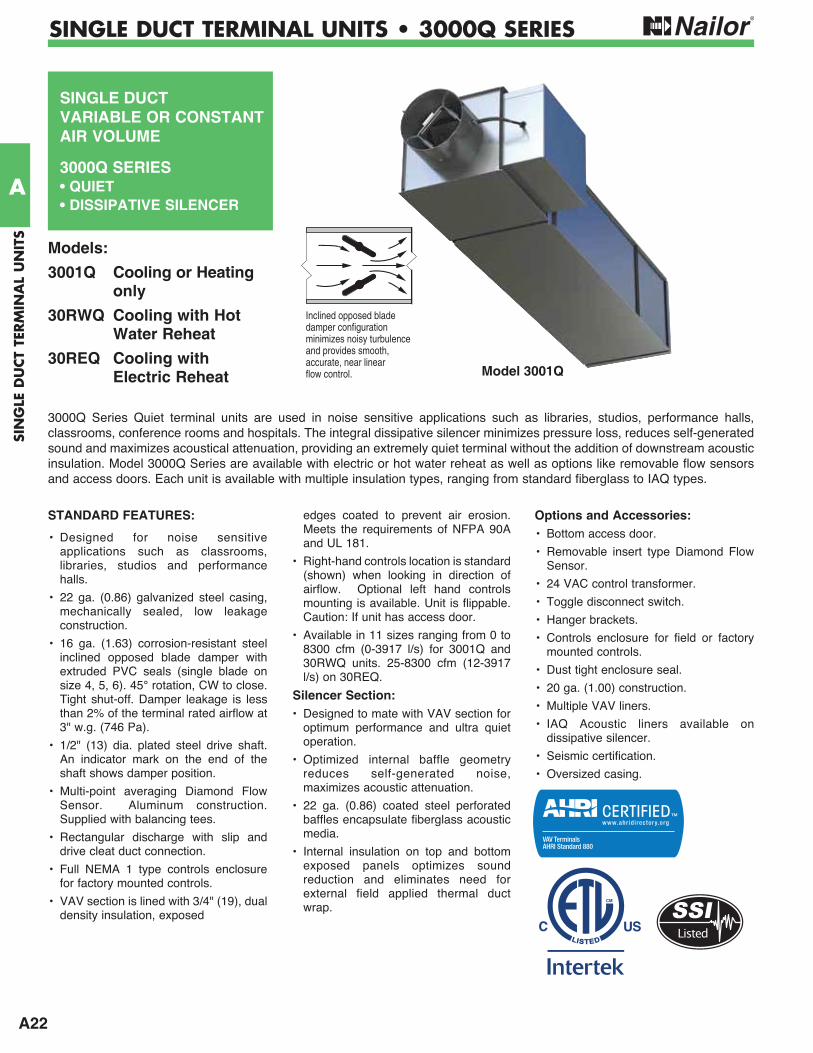
Nailor 3000Q Series Quiet Terminal units control the flow of conditioned primary air into a constant or variable air volume (VAV) HVAC system at exceptionally quiet levels. There are three versions of the 3000Q series: the standard cooling unit (3001Q), a cooling with water reheat unit (30RWQ) and a cooling unit with electric reheat (30REQ). Each unit includes a VAV terminal and factory installed dissipative silencer providing an assembly ideal for use in sound sensitive environments like libraries, performance halls, classrooms, conference rooms, studios and hospitals.
The 3000Q Series shares design features with the 3000 Series terminal units like the opposed blade damper (OBD), rectangular discharge, multi-point averaging Diamond Flow Sensor and various control options. The VAV and silencer assembly is designed to provide minimal impact on system pressure drop while concurrently delivering superior sound attenuation.
Each dissipative silencer is constructed with internal baffle (an acoustic absorption media) and is internally insulated. The baffles are made of perforated steel and are designed with elliptical nose pieces to transition air into and out of the silencer. Arranged inside the silencer as side pods, the baffles act to attenuate discharge sound using an acoustical media placed between the silencer casing and the baffle. Internal (top and bottom) panels exposed to the airstream are insulated with fiberglass and as a result, field installed externally wrapped insulation is not needed.
Of the three available types of media, the standard is a simple fiberglass fill which provides exceptional attenuation. When IAQ is a concern, the fiberglass can be wrapped in a woven fiberglass cloth to prevent erosion and entrainment of fibers into the airstream. Since the fiberglass cloth is porous moisture can penetrate the underlying fiberglass. There is also an option that wraps the fiberglass with Mylar, designed primarily for environments where fiberglass isolation is paramount.
In the past, selecting a silencer to mate with a VAV terminal involved multiple calculations, guesswork and an intimate knowledge of silencer performance. The engineer or contractor had to contend with pressure classes, sizes and free area to balance the associated pressure drop, attenuation and self generated noise against the VAV terminal performance. Even after careful selection, the result was still a guess due to the unknown system effect created by the close coupled terminal/silencer assembly. Since each 3000Q Series unit is designed, manufactured and tested as a complete assembly, the guesswork is eliminated.
3001Q Cooling or Heating only
30RWQ Cooling with Hot Water Reheat
30REQ Cooling with Electric Reheat
3000Q SERIES • QUIET TYPE WITH DISSIPATIVE SILENCERPRODUCT OVERVIEW
A22
SIN
GLE
DU
CT
TERM
INA
L U
NIT
S
A
SINGLE DUCT TERMINAL UNITS • 3000Q SERIES
SINGLE DUCTVARIABLE OR CONSTANT AIR VOLUME
3000Q SERIES• QUIET• DISSIPATIVE SILENCER
STANDARD FEATURES:
• Designed for noise sensitive applications such as classrooms, libraries, studios and performance halls.
• 22 ga. (0.86) galvanized steel casing, mechanically sealed, low leakage construction.
• 16 ga. (1.63) corrosion-resistant steel inclined opposed blade damper with extruded PVC seals (single blade on size 4, 5, 6). 45° rotation, CW to close. Tight shut-off. Damper leakage is less than 2% of the terminal rated airflow at 3" w.g. (746 Pa).
• 1/2" (13) dia. plated steel drive shaft. An indicator mark on the end of the shaft shows damper position.
• Multi-point averaging Diamond Flow Sensor. Aluminum construction. Supplied with balancing tees.
• Rectangular discharge with slip and drive cleat duct connection.
• Full NEMA 1 type controls enclosure for factory mounted controls.
• VAV section is lined with 3/4" (19), dual density insulation, exposed
edges coated to prevent air erosion. Meets the requirements of NFPA 90A and UL 181.
• Right-hand controls location is standard (shown) when looking in direction of airflow. Optional left hand controls mounting is available. Unit is flippable. Caution: If unit has access door.
• Available in 11 sizes ranging from 0 to 8300 cfm (0-3917 l/s) for 3001Q and 30RWQ units. 25-8300 cfm (12-3917 l/s) on 30REQ.
Silencer Section:• Designed to mate with VAV section for
optimum performance and ultra quiet operation.
• Optimized internal baffle geometry reduces self-generated noise, maximizes acoustic attenuation.
• 22 ga. (0.86) coated steel perforated baffles encapsulate fiberglass acoustic media.
• Internal insulation on top and bottom exposed panels optimizes sound reduction and eliminates need for external field applied thermal duct wrap.
Options and Accessories:• Bottom access door.
• Removable insert type Diamond Flow Sensor.
• 24 VAC control transformer.
• Toggle disconnect switch.
• Hanger brackets.
• Controls enclosure for field or factory mounted controls.
• Dust tight enclosure seal.
• 20 ga. (1.00) construction.
• Multiple VAV liners.
• IAQ Acoustic liners available on dissipative silencer.
• Seismic certification.
• Oversized casing.
3000Q Series Quiet terminal units are used in noise sensitive applications such as libraries, studios, performance halls, classrooms, conference rooms and hospitals. The integral dissipative silencer minimizes pressure loss, reduces self-generated sound and maximizes acoustical attenuation, providing an extremely quiet terminal without the addition of downstream acoustic insulation. Model 3000Q Series are available with electric or hot water reheat as well as options like removable flow sensors and access doors. Each unit is available with multiple insulation types, ranging from standard fiberglass to IAQ types.
Models:
3001Q Cooling or Heating only
30RWQ Cooling with Hot Water Reheat
30REQ Cooling with Electric Reheat Model 3001Q
Inclined opposed bladedamper configurationminimizes noisy turbulenceand provides smooth,accurate, near linearflow control.
Listed
A23
SING
LE DU
CT TER
MIN
AL U
NITS
A
SINGLE DUCT TERMINAL UNITS • 3000Q SERIES
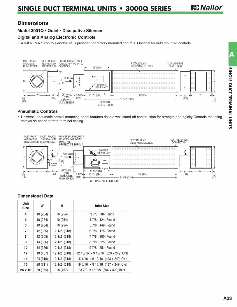
Dimensions Model 3001Q • Quiet • Dissipative Silencer
Digital and Analog Electronic Controls • A full NEMA 1 controls enclosure is provided for factory mounted controls. Optional for field mounted controls.
Pneumatic Controls• Universal pneumatic control mounting panel features double wall stand-off construction for strength and rigidity Controls mounting
screws do not penetrate terminal casing.
5 1/2"(140)
W
1/2"(13)
SLIP AND DRIVECONNECTION
H
W 6"(152)1/2"
(13)
H
15 1/2" (394)51 1/2" (1308)
14 1/2" (368)36" (914)
AIRFLOW
6"(152)
OPTIONAL(FMI)
REMOVABLEFLOW SENSOR
INLET: ROUND,FLAT OVAL ORRECTANGULAR
MULTI-POINTAVERAGING
FLOW SENSOR
6 1/2"(165)
UNIVERSAL PNEUMATIC CONTROL MOUNTINGPANEL AND PROTECTIVE SHROUD
DAMPER DRIVESHAFT
OPTIONAL ACCESS DOOR
RECTANGULARDISSIPATIVE SILENCER
5 1/2"(140)
W
1/2"(13)
H
6"(152)1/2"
(13)51 1/2" (1308)
14" (356)
36" (914)
RECTANGULARDISSIPATIVE SILENCER
SLIP AND DRIVECONNECTION
AIRFLOW
6"(152)
DAMPERDRIVESHAFT
OPTIONAL(FMI)
REMOVABLEFLOW SENSOR
CONTROLS ENCLOSUREFOR FACTORY MOUNTEDCONTROLS
INLET: ROUND,FLAT OVAL ORRECTANGULAR
MULTI-POINTAVERAGINGFLOW SENSOR
11"(279)
OPTIONALACCESS DOOR
15 1/2" (394)
H
W
Dimensional Data
Unit Size
W H Inlet Size
4 10 (254) 10 (254) 3 7/8 (98) Round
5 10 (254) 10 (254) 4 7/8 (124) Round
6 10 (254) 10 (254) 5 7/8 (149) Round
7 12 (305) 12 1/2 (318) 6 7/8 (175) Round
8 12 (305) 12 1/2 (318) 7 7/8 (200) Round
9 14 (356) 12 1/2 (318) 8 7/8 (225) Round
10 14 (356) 12 1/2 (318) 9 7/8 (251) Round
12 18 (457) 12 1/2 (318) 12 15/16 x 9 13/16 (329 x 249) Oval
14 24 (610) 12 1/2 (318) 16 1/16 x 9 13/16 (408 x 249) Oval
16 28 (711) 12 1/2 (318) 19 3/16 x 9 13/16 (487 x 249) Oval
24 x 16 38 (965) 18 (457) 23 7/8 x 15 7/8 (606 x 403) Rect.
A24
SIN
GLE
DU
CT
TERM
INA
L U
NIT
S
A
SINGLE DUCT TERMINAL UNITS • 3000Q SERIES
5 1/2"(140)
29" (737)
31" (787)W1/2"(13)
H
OPTIONALACCESS DOOR
W
H
48" (1219)79" (2007)
6"(152)
11 3/4"(298)
1/2"(13)
6"(152)
CONTROLS ENCLOSUREFOR FACTORYMOUNTED CONTROLS
OPTIONAL(FMI)
REMOVABLEFLOW SENSOR
RECTANGULARDISSIPATIVE SILENCER
SLIP AND DRIVECONNECTION
AIRFLOW
INLET: ROUND,FLAT OVAL ORRECTANGULAR
PRIMARYAIR
VALVECONTROLS
ENCLOSURE
ELECTRIC COILCONTROLSENCLOSURE(HINGEDACCESS DOOR)
MULTI-POINTAVERAGING
FLOW SENSOR
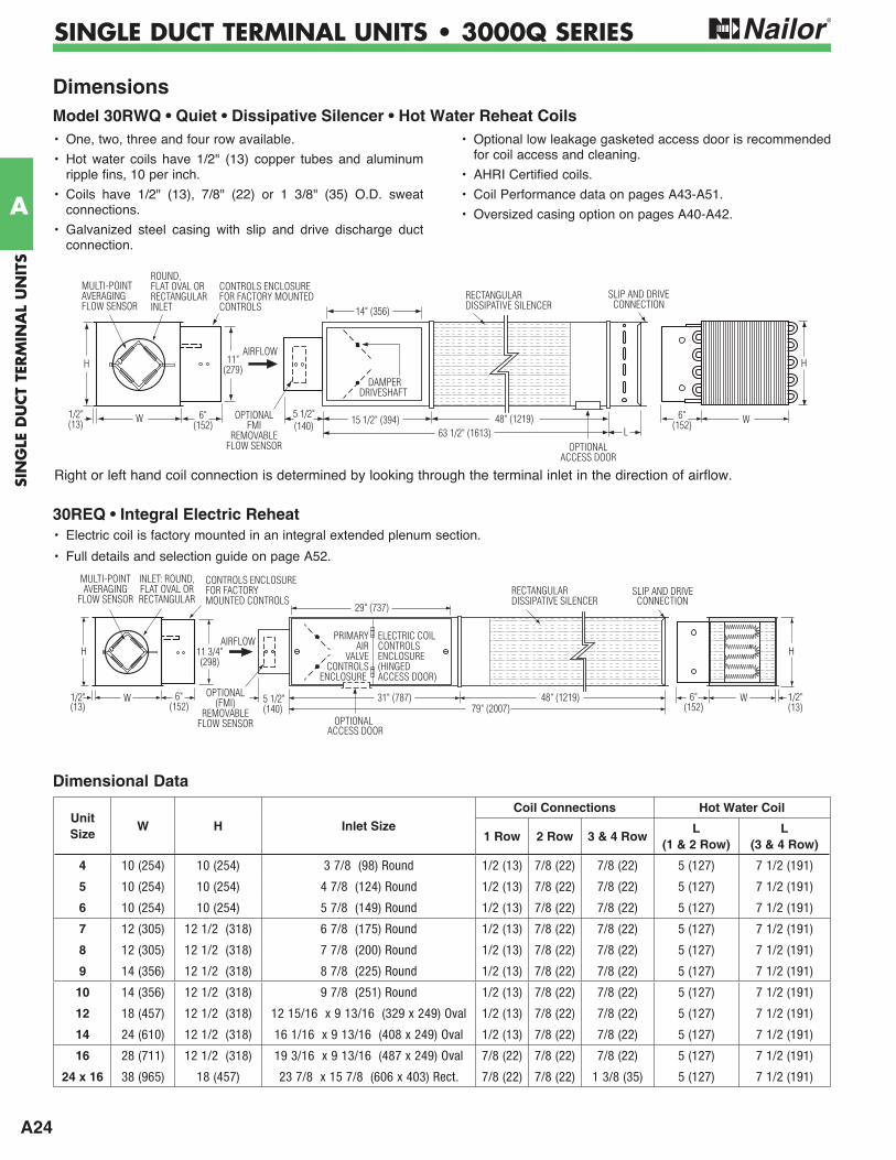
30REQ • Integral Electric Reheat• Electric coil is factory mounted in an integral extended plenum section.
• Full details and selection guide on page A52.
Dimensions Model 30RWQ • Quiet • Dissipative Silencer • Hot Water Reheat Coils
5 1/2"(140)
DAMPERDRIVESHAFT
L
SLIP AND DRIVECONNECTION
W 6"(152)
1/2"(13)
11"(279)H
15 1/2" (394)63 1/2" (1613)
14" (356)
48" (1219)OPTIONALFMI
REMOVABLEFLOW SENSOR
RECTANGULARDISSIPATIVE SILENCER
CONTROLS ENCLOSUREFOR FACTORY MOUNTEDCONTROLS
ROUND,FLAT OVAL ORRECTANGULARINLET
MULTI-POINTAVERAGINGFLOW SENSOR
OPTIONALACCESS DOOR
6"(152)
AIRFLOWH
W
• One, two, three and four row available.
• Hot water coils have 1/2" (13) copper tubes and aluminum ripple fins, 10 per inch.
• Coils have 1/2" (13), 7/8" (22) or 1 3/8" (35) O.D. sweat connections.
• Galvanized steel casing with slip and drive discharge duct connection.
• Optional low leakage gasketed access door is recommended for coil access and cleaning.
• AHRI Certified coils.
• Coil Performance data on pages A43-A51.
• Oversized casing option on pages A40-A42.
Right or left hand coil connection is determined by looking through the terminal inlet in the direction of airflow.
Dimensional Data
Unit Size
W H Inlet SizeCoil Connections Hot Water Coil
1 Row 2 Row 3 & 4 RowL
(1 & 2 Row)L
(3 & 4 Row)
4 10 (254) 10 (254) 3 7/8 (98) Round 1/2 (13) 7/8 (22) 7/8 (22) 5 (127) 7 1/2 (191)
5 10 (254) 10 (254) 4 7/8 (124) Round 1/2 (13) 7/8 (22) 7/8 (22) 5 (127) 7 1/2 (191)
6 10 (254) 10 (254) 5 7/8 (149) Round 1/2 (13) 7/8 (22) 7/8 (22) 5 (127) 7 1/2 (191)
7 12 (305) 12 1/2 (318) 6 7/8 (175) Round 1/2 (13) 7/8 (22) 7/8 (22) 5 (127) 7 1/2 (191)
8 12 (305) 12 1/2 (318) 7 7/8 (200) Round 1/2 (13) 7/8 (22) 7/8 (22) 5 (127) 7 1/2 (191)
9 14 (356) 12 1/2 (318) 8 7/8 (225) Round 1/2 (13) 7/8 (22) 7/8 (22) 5 (127) 7 1/2 (191)
10 14 (356) 12 1/2 (318) 9 7/8 (251) Round 1/2 (13) 7/8 (22) 7/8 (22) 5 (127) 7 1/2 (191)
12 18 (457) 12 1/2 (318) 12 15/16 x 9 13/16 (329 x 249) Oval 1/2 (13) 7/8 (22) 7/8 (22) 5 (127) 7 1/2 (191)
14 24 (610) 12 1/2 (318) 16 1/16 x 9 13/16 (408 x 249) Oval 1/2 (13) 7/8 (22) 7/8 (22) 5 (127) 7 1/2 (191)
16 28 (711) 12 1/2 (318) 19 3/16 x 9 13/16 (487 x 249) Oval 7/8 (22) 7/8 (22) 7/8 (22) 5 (127) 7 1/2 (191)
24 x 16 38 (965) 18 (457) 23 7/8 x 15 7/8 (606 x 403) Rect. 7/8 (22) 7/8 (22) 1 3/8 (35) 5 (127) 7 1/2 (191)

A25
SING
LE DU
CT TER
MIN
AL U
NITS
A
SINGLE DUCT TERMINAL UNITS • 3000Q SERIES
FMI Removable Flow Sensor
The (FMI) Removable Flow Sensor is a multi-point averaging airflow sensor. Designed to provide accurate sensing by sampling air velocities in four quadrants of a duct, the differential pressure flow sensor provides an averaged reading at an amplification of approximately 2.5 times the velocity pressure, dependent upon nominal size.
Features:
• Removable for cleaning.
• All metal construction - no combustible materials in the air stream.
• Amplifies velocity pressure approximately 2.5 times to give a wide range of useful output signal vs. flow.
• Compact size allows for easy removal in tight spaces.
• Sensor design minimizes pressure drop and regenerated noise.
• Label provided on each unit gives airflow direction.
• Multi-point sensing gives an accurate output signal with a maximum deviation of only ± 5% with a hard 90 degree elbow, provided a straight inlet condition with a minimum length of two equivalent duct diameters is provided.
SCREW INSERTTO DUCT
AT PERIMETERHOLES
FLOWDIRECTION
LABELSUPPORTBRACKET
GASKET
ROUND ORFLAT OVAL
INLET
3/16" (5) DIA. O.D.
GROMMET
SCREWHEAD
AIRFLOW
LOW PRESSURE
CONNECTIONSFOR 1/4" (6)O.D. FR TUBING
HIGHPRESSURE
DIRECTION
Options:
SCREW INSERTTO DUCT
AT PERIMETERHOLES
FLOWDIRECTION
LABEL
3/16" (5) DIA. O.D.
SUPPORTBRACKET
GASKET
RETANGULAR INLET
GROMMET
AIRFLOW
LOW PRESSURE
CONNECTIONSFOR 1/4" (6)O.D. FR TUBING
HIGHPRESSURE
DIRECTION
Round or Flat Oval Inlet
Rectangular Inlet
Access DoorUltra-low leakage, premium quality and performance. Flat oval design.
• Die formed 22 ga. (0.86) galvanized steel flanged and door panel.
• Positive bulb door seal.
• Plated steel camlock fasteners.
• 1" (25) insulation with 22 ga. (0.86) galvanized backing plate.
• Leakage tested in conformance with British Standard DW/142 Class C.
• See 0800-1 submittal for more detailed information.
Terminal Unit Size
Nominal Door Size
Max. Leakage8" w.g. (2 kPa) cfm
8" x 5" (203 x 127)
0.036 cfm (1.02 l/min.)
12" x 6" (305 x 152)
0.064 cfm (1.8 l/min.)
A26
SIN
GLE
DU
CT
TERM
INA
L U
NIT
S
A
SINGLE DUCT TERMINAL UNITS • 3000Q SERIES
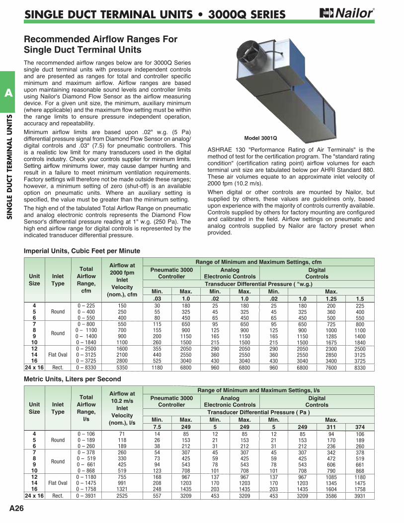
Recommended Airflow Ranges For Single Duct Terminal UnitsThe recommended airflow ranges below are for 3000Q Series single duct terminal units with pressure independent controls and are presented as ranges for total and controller specific minimum and maximum airflow. Airflow ranges are based upon maintaining reasonable sound levels and controller limits using Nailor's Diamond Flow Sensor as the airflow measuring device. For a given unit size, the minimum, auxiliary minimum (where applicable) and the maximum flow setting must be within the range limits to ensure pressure independent operation, accuracy and repeatability.
Minimum airflow limits are based upon .02" w.g. (5 Pa) differential pressure signal from Diamond Flow Sensor on analog/ digital controls and .03" (7.5) for pneumatic controllers. This is a realistic low limit for many transducers used in the digital controls industry. Check your controls supplier for minimum limits. Setting airflow minimums lower, may cause damper hunting and result in a failure to meet minimum ventilation requirements. Factory settings will therefore not be made outside these ranges; however, a minimum setting of zero (shut-off) is an available option on pneumatic units. Where an auxiliary setting is specified, the value must be greater than the minimum setting.
The high end of the tabulated Total Airflow Range on pneumatic and analog electronic controls represents the Diamond Flow Sensor's differential pressure reading at 1" w.g. (250 Pa). The high end airflow range for digital controls is represented by the indicated transducer differential pressure.
ASHRAE 130 "Performance Rating of Air Terminals" is the method of test for the certification program. The "standard rating condition" (certification rating point) airflow volumes for each terminal unit size are tabulated below per AHRI Standard 880. These air volumes equate to an approximate inlet velocity of 2000 fpm (10.2 m/s).
When digital or other controls are mounted by Nailor, but supplied by others, these values are guidelines only, based upon experience with the majority of controls currently available. Controls supplied by others for factory mounting are configured and calibrated in the field. Airflow settings on pneumatic and analog controls supplied by Nailor are factory preset when provided.
Model 3001Q
Imperial Units, Cubic Feet per Minute
Metric Units, Liters per Second
Unit Size
InletType
Total Airflow Range,
cfm
Airflow at 2000 fpm
InletVelocity
(nom.), cfm
Range of Minimum and Maximum Settings, cfmPneumatic 3000
ControllerAnalog
Electronic ControlsDigital
ControlsTransducer Differential Pressure ( "w.g.)
Min. Max. Min. Max. Min. Max..03 1.0 .02 1.0 .02 1.0 1.25 1.5
4Round
0 – 225 150 30 180 25 180 25 180 200 2255 0 – 400 250 55 325 45 325 45 325 360 4006 0 – 550 400 80 450 65 450 65 450 500 5507
Round
0 – 800 550 115 650 95 650 95 650 725 8008 0 – 1100 700 155 900 125 900 125 900 1000 11009 0 – 1400 900 200 1150 165 1150 165 1150 1285 1400
10 0 – 1840 1100 260 1500 215 1500 215 1500 1675 184012
Flat Oval0 – 2500 1600 355 2050 290 2050 290 2050 2300 2500
14 0 – 3125 2100 440 2550 360 2550 360 2550 2850 312516 0 – 3725 2800 525 3040 430 3040 430 3040 3400 3725
24 x 16 Rect. 0 – 8330 5350 1180 6800 960 6800 960 6800 7600 8330
Unit Size
InletType
Total Airflow Range,
l/s
Airflow at 10.2 m/s
InletVelocity
(nom.), l/s
Range of Minimum and Maximum Settings, l/sPneumatic 3000
ControllerAnalog
Electronic ControlsDigital
ControlsTransducer Differential Pressure ( Pa )
Min. Max. Min. Max. Min. Max.7.5 249 5 249 5 249 311 374
4 0 – 106 71 14 85 12 85 12 85 94 1065 Round 0 – 189 118 26 153 21 153 21 153 170 1896 0 – 260 189 38 212 31 212 31 212 236 2607
Round
0 – 378 260 54 307 45 307 45 307 342 3788 0 – 519 330 73 425 59 425 59 425 472 5199 0 – 661 425 94 543 78 543 78 543 606 661
10 0 – 868 519 123 708 101 708 101 708 790 86812 0 – 1180 755 168 967 137 967 137 967 1085 118014 Flat Oval 0 – 1475 991 208 1203 170 1203 170 1203 1345 147516 0 – 1758 1321 248 1435 203 1435 203 1435 1604 1758
24 x 16 Rect. 0 – 3931 2525 557 3209 453 3209 453 3209 3586 3931
A27
SING
LE DU
CT TER
MIN
AL U
NITS
A
SINGLE DUCT TERMINAL UNITS • 3000Q SERIES
Performance Data • NC Level Application Guide3000Q Series • Quiet • Dissipative SilencerFiberglass Acoustic Media (FAM)
1. NC Levels are calculated based on procedures as outlined on page A75.
2. Dash (-) in space indicates a NC less than 20.
3. Asterisk (*) in space indicates that the minimum inlet static pressure requirement is greater than 0.5" w.g. (125 Pa) at rated airflow.
Inlet Size
Airflow Min. inletNC Levels @ Inlet Pressure ( Ps) shown
PsDISCHARGE RADIATED
cfm l/s "w.g. PaMin.
Ps0.5" w.g.
(125 Pa)
1.0" w.g.
(250 Pa)
1.5" w.g.
(375 Pa)
2.0" w.g.
(500 Pa)
3.0" w.g.
(750 Pa)
Min. Ps
0.5" w.g.
(125 Pa)
1.0" w.g.
(250 Pa)
1.5" w.g.
(375 Pa)
2.0" w.g.
(500 Pa)
3.0" w.g.
(750 Pa)
4
200 94 0.38 94 - - - 21 20 21 - - - 21 24 28150 71 0.23 57 - - - - - - - - - 21 22 22100 47 0.11 28 - - - - - - - - - - 20 2350 24 0.04 11 - - - - - - - - - - - -
5
350 165 0.17 41 - - 20 24 24 28 - - - 23 25 30250 118 0.08 20 - - 23 25 25 26 - - - - 22 25150 71 0.03 7 - - - - - - - - - - - 20100 47 0.02 5 - - - - - - - - - - - -
6
500 236 0.05 13 - - - 21 21 26 - - 20 23 26 30400 189 0.04 10 - - - 20 20 23 - - - 21 25 29300 142 0.03 6 - - - - - - - - - 20 21 25200 94 0.01 3 - - - - - - - - - - - 20
7
700 330 0.03 7 - - 23 26 29 31 22 - 21 26 30 35550 260 0.01 2 - - - 23 26 28 - - - 24 28 32400 189 0.01 2 - - - 23 23 24 - - - 20 23 26250 118 0.01 2 - - - - - - - - - - - 20
8
1100 519 0.02 4 - 20 25 28 33 36 - 20 25 29 31 35900 425 0.01 3 - - 23 26 30 34 - - 23 26 29 33700 330 0.01 2 - - 23 25 30 33 - - 21 24 26 31500 236 0.01 2 - - - 23 24 28 - - - 21 23 26
9
1400 661 0.01 2 - 21 25 28 33 36 20 20 23 28 34 381150 543 0.01 2 - - 20 26 29 31 - - 21 25 31 35900 425 0.01 2 - - - 24 26 29 - - - 23 28 31650 307 0.01 2 - - - 23 23 25 - - - 20 23 26
10
1500 708 0.02 5 - 20 23 28 30 34 - 20 24 28 30 351100 519 0.02 4 - - - 21 24 28 - - 21 24 25 31700 330 0.01 2 - - - - - 21 - - - 21 23 28215 101 0.01 1 - - - - - - - - - - - -
12
2500 1180 0.04 10 - 25 29 33 34 35 29 28 31 34 35 402050 967 0.03 7 - 21 25 28 30 33 22 25 29 31 33 381600 755 0.02 6 - 20 24 24 28 29 - 20 25 28 30 351150 543 0.02 4 - - - 20 21 26 - - 20 24 26 30
14
2650 1251 0.02 5 - 21 23 26 29 30 24 25 30 34 37 402100 991 0.02 4 - - - 24 26 30 - 21 26 31 34 371550 731 0.01 2 - - - - 21 25 - - 24 28 30 341000 472 0.01 2 - - - - - - - - - 21 25 26
16
3725 1758 0.14 36 23 25 29 28 33 38 30 * 33 37 40 442800 1321 0.12 30 - - - 24 24 28 23 24 29 34 36 401800 849 0.05 12 - - - - - 21 - - 24 29 31 35800 378 0.01 2 - - - - - - - - 26 30 34 36
24 x
16
8330 3931 0.05 12 30 31 39 48 49 56 44 44 49 51 54 577000 3303 0.04 10 27 29 36 43 46 49 43 43 48 50 53 565350 2525 0.01 2 - 26 34 41 44 46 40 41 47 49 51 553800 1793 0.01 2 - - 24 28 29 32 32 38 44 46 48 51
Performance Notes:
A28
SIN
GLE
DU
CT
TERM
INA
L U
NIT
S
A
SINGLE DUCT TERMINAL UNITS • 3000Q SERIES
Performance Data • Discharge Sound Power Levels3000Q Series • Quiet • Dissipative SilencerFiberglass Acoustic Media (FAM)
For performance table notes, see page A30; highlighted numbers indicate embedded AHRI certification points.
Inlet Size
AirflowMin. inlet Sound Power Octave Bands @ Inlet Pressure ( Ps) shown
Ps Minimum Ps 0.5" w.g. (125Pa) Ps 1.0" w.g. (250Pa) Ps 1.5" w.g. (375Pa) Ps 2.0" w.g. (500Pa) Ps 3.0" w.g. (750Pa) Pscfm l/s "w.g. Pa 2 3 4 5 6 7 2 3 4 5 6 7 2 3 4 5 6 7 2 3 4 5 6 7 2 3 4 5 6 7 2 3 4 5 6 7
4
200 94 0.38 94 58 47 35 25 24 30 60 55 41 29 26 31 62 55 42 29 28 35 65 58 44 32 31 38 64 58 46 33 32 40 65 60 49 37 36 44150 71 0.21 52 56 44 30 - - 24 59 50 35 - 21 25 61 53 38 24 24 31 60 55 41 27 28 36 60 55 42 29 30 39 60 55 43 35 35 44100 47 0.11 28 51 39 - - - - 54 44 29 - - 21 54 46 35 - 22 30 55 47 37 27 27 35 56 47 38 30 30 38 56 47 38 31 35 4350 24 0.04 11 50 37 - - - - 51 38 26 - - - 52 39 29 - - 28 53 41 32 - 26 35 54 41 32 - 24 36 55 42 32 - 30 38
5
350 165 0.17 41 59 50 37 30 27 31 64 56 45 36 32 33 67 60 49 38 34 37 70 61 51 39 37 40 70 63 51 40 38 42 73 65 53 42 41 45250 118 0.10 25 56 45 30 - - 22 61 55 39 29 23 27 66 58 41 32 27 32 68 60 44 34 31 37 68 61 46 35 32 39 69 62 49 37 35 42150 71 0.03 7 54 41 - - - - 59 47 30 - - 21 60 51 35 23 20 27 62 53 40 26 24 32 62 53 42 29 27 35 62 54 43 35 33 41100 47 0.02 5 53 41 - - - - 56 44 30 - - - 57 46 34 23 24 28 59 48 37 25 25 34 59 48 37 26 28 36 59 49 39 31 33 40
6
500 236 0.05 13 53 44 32 35 28 27 59 53 40 41 37 36 63 56 43 41 38 39 68 62 46 42 39 42 68 62 48 44 41 44 72 64 52 45 43 47400 189 0.05 12 52 39 29 28 21 22 59 51 36 37 32 31 62 54 39 38 34 35 67 60 42 38 36 39 67 59 46 40 39 43 69 61 49 41 41 47300 142 0.03 6 54 37 21 - - - 60 46 33 31 27 30 62 49 36 33 30 33 65 54 39 34 33 39 65 54 42 37 37 42 66 56 45 38 40 45200 94 0.01 3 52 36 - - - - 56 40 27 - - 29 57 45 31 24 - 31 59 49 35 26 32 35 59 49 38 33 37 40 60 49 41 39 43 44
7
700 330 0.03 7 58 49 37 33 34 34 66 57 45 44 43 41 69 60 47 44 46 45 72 64 51 45 49 49 74 67 53 47 50 51 76 69 55 48 51 53550 260 0.04 10 56 46 32 28 26 26 62 54 40 38 38 37 66 57 43 39 42 42 69 62 46 40 45 45 72 64 49 43 46 48 73 66 51 44 48 51400 189 0.01 2 57 41 28 22 23 - 60 52 36 32 35 35 65 55 39 34 37 39 69 59 43 37 41 43 69 60 45 39 42 45 70 61 48 40 44 48250 118 0.01 2 54 32 - - - - 54 43 25 - 24 26 56 45 29 22 26 30 60 49 32 25 31 35 59 49 34 31 33 39 60 48 36 31 35 43
8
1100 519 0.02 4 66 60 50 44 42 42 69 63 54 47 47 47 73 67 56 48 48 49 75 69 58 49 49 53 78 73 61 51 50 54 79 76 63 52 51 56900 425 0.01 3 63 56 44 38 34 35 68 60 49 43 42 42 71 65 52 45 44 46 74 67 55 46 45 49 76 71 58 48 46 51 78 74 60 49 48 53700 330 0.01 2 59 51 37 32 25 27 64 57 44 39 37 39 69 61 48 40 39 42 71 64 51 42 41 45 75 69 54 43 42 48 75 72 57 45 44 51500 236 0.01 2 57 45 29 22 - - 61 54 40 32 29 32 64 59 43 33 33 37 69 64 47 36 35 41 69 65 51 38 37 44 70 68 54 41 39 48
9
1400 661 0.01 2 67 62 52 49 50 49 69 64 53 48 51 51 72 67 56 52 52 53 75 69 59 53 53 56 78 73 62 55 55 58 80 76 64 56 55 601150 543 0.01 2 59 56 46 43 42 39 65 59 48 45 44 44 69 62 52 47 46 47 74 65 55 49 48 51 76 69 57 50 49 52 78 71 59 50 50 54900 425 0.01 2 55 52 41 39 34 30 64 56 45 43 41 41 68 60 48 44 43 44 72 64 51 45 44 48 74 67 53 46 46 50 75 70 56 47 48 53650 307 0.01 2 53 45 35 31 28 24 62 52 41 37 34 35 65 57 43 38 38 39 69 62 46 39 40 44 69 64 49 41 41 47 70 66 53 42 43 50
10
1500 708 0.02 5 67 55 45 45 45 43 69 62 52 47 51 51 71 65 54 48 52 54 75 68 56 50 53 57 77 71 59 51 54 58 80 74 60 52 55 601100 519 0.02 4 63 49 37 36 30 26 61 56 45 42 42 40 66 59 47 43 44 45 70 62 50 45 46 50 72 65 53 45 47 51 74 69 55 47 49 53700 330 0.01 2 56 40 28 22 - - 56 49 37 34 31 31 60 54 41 35 35 38 65 58 44 36 39 43 66 61 47 38 41 46 66 63 50 39 44 49215 101 0.01 1 42 - - - - - 38 29 - - - - 46 37 22 - - - 49 45 26 - - 21 49 45 30 - 22 27 48 47 34 20 26 32
12
2500 1180 0.04 10 64 55 49 49 53 50 73 65 57 54 59 59 76 68 59 55 59 61 79 70 62 56 60 64 80 72 63 58 62 65 81 74 65 60 63 672050 967 0.03 7 63 51 44 45 48 43 70 61 52 50 55 53 73 65 55 52 57 57 75 67 58 53 58 59 77 69 59 54 59 61 79 72 62 57 61 631600 755 0.02 6 61 48 39 42 40 35 69 58 49 47 52 49 72 62 50 48 53 51 72 64 54 49 55 54 75 67 55 50 55 55 75 70 58 52 57 581150 543 0.02 4 54 44 34 35 29 25 60 54 43 43 45 40 65 58 46 44 47 44 69 62 49 46 50 49 70 64 51 47 52 52 73 68 55 49 54 55
14
2650 1251 0.02 5 62 52 47 50 51 48 68 60 53 53 57 57 71 62 57 55 58 59 74 65 59 57 60 62 76 67 62 60 62 63 77 69 65 62 64 662100 991 0.02 4 59 47 42 45 44 40 62 56 50 50 53 51 66 58 53 52 55 54 72 62 56 54 57 57 74 65 60 57 59 60 77 67 63 60 61 621550 731 0.01 2 58 42 36 37 32 28 58 51 45 45 46 43 64 54 49 48 49 47 68 59 53 51 53 52 70 61 56 53 55 54 73 64 59 55 57 571000 472 0.01 2 52 38 27 22 - - 56 45 40 39 37 35 60 49 44 42 42 40 64 53 48 46 47 46 66 56 52 49 50 50 67 58 55 51 53 53
16
3725 1758 0.14 36 62 52 52 58 63 59 70 63 59 62 63 61 76 67 64 57 62 61 75 69 62 59 63 63 79 72 66 60 65 63 83 73 67 61 65 662800 1321 0.12 30 53 48 44 47 47 43 62 57 51 50 52 50 68 60 55 52 54 53 72 63 58 54 56 57 72 66 60 55 57 59 75 68 62 57 60 611800 849 0.05 12 49 40 35 36 31 27 58 51 45 43 43 40 62 55 48 46 47 46 66 58 51 48 50 50 68 60 54 50 52 53 70 63 57 53 55 56800 378 0.01 2 45 37 29 - - - 51 43 35 33 32 30 54 45 40 38 39 38 55 48 44 42 44 45 56 50 46 44 48 49 57 52 49 47 51 54
24 x
16
8330 3931 0.05 12 75 66 68 66 68 67 78 63 67 65 67 64 84 74 71 72 74 70 91 79 80 77 80 75 92 82 80 76 80 80 97 85 87 85 86 827000 3303 0.04 10 72 64 65 62 65 63 76 62 66 64 66 63 82 73 70 70 72 69 87 78 77 73 75 75 90 81 79 75 78 78 92 83 82 78 82 815350 2525 0.01 2 68 58 59 56 57 55 74 67 65 63 65 62 80 72 69 68 70 68 86 78 76 72 73 73 88 80 78 74 76 76 90 82 81 77 80 803800 1793 0.01 2 61 51 52 48 48 46 68 59 57 54 55 52 72 64 61 58 59 58 75 67 65 61 62 62 76 69 67 63 64 64 78 71 70 66 68 69
A29
SING
LE DU
CT TER
MIN
AL U
NITS
A
SINGLE DUCT TERMINAL UNITS • 3000Q SERIES
Performance Data • Radiated Sound Power Levels3000Q Series • Quiet • Dissipative SilencerFiberglass Acoustic Media (FAM)
For performance table notes, see page A30; highlighted numbers indicate embedded AHRI certification points.
Inlet Size
AirflowMin. inlet Sound Power Octave Bands @ Inlet Pressure ( Ps) shown
Ps Minimum Ps 0.5" w.g. (125Pa) Ps 1.0" w.g. (250Pa) Ps 1.5" w.g. (375Pa) Ps 2.0" w.g. (500Pa) Ps 3.0" w.g. (750Pa) Pscfm l/s "w.g. Pa 2 3 4 5 6 7 2 3 4 5 6 7 2 3 4 5 6 7 2 3 4 5 6 7 2 3 4 5 6 7 2 3 4 5 6 7
4
200 94 0.38 94 - 36 33 32 - - - 39 37 38 29 29 49 46 43 37 30 29 53 52 47 40 32 31 53 53 50 42 33 33 54 55 53 47 37 37150 71 0.23 57 - 35 29 31 - - - 40 36 30 25 23 47 46 40 34 28 26 49 50 47 39 31 30 47 48 48 43 34 32 48 48 48 50 40 37100 47 0.11 28 - - - - - - - 37 32 27 - - - 43 42 34 27 23 - 44 45 41 32 29 - 43 46 46 36 32 - 42 44 51 43 3850 24 0.04 11 - - - - - - - 37 38 30 - - - 36 41 40 32 27 - 35 40 43 38 31 - 35 40 43 38 31 - 32 36 37 35 37
5
350 165 0.17 41 48 39 33 32 30 27 52 45 39 38 37 32 55 48 45 38 36 32 59 51 49 40 39 34 61 54 51 42 40 36 61 57 55 45 44 40250 118 0.08 20 - 35 31 25 23 - 50 40 36 32 30 25 54 45 42 33 32 28 55 48 45 35 35 30 56 51 48 37 37 32 57 53 51 42 41 35150 71 0.03 7 - - - - - - 49 35 31 23 20 - 50 41 39 30 29 21 50 43 43 34 33 27 48 45 45 40 39 31 51 45 46 46 44 37100 47 0.02 5 - - - - - - - 33 29 - - - - 39 38 28 26 - - 40 42 36 34 26 46 40 43 43 41 31 47 41 43 47 46 37
6
500 236 0.05 13 48 44 38 36 30 28 49 48 42 40 33 30 57 52 46 41 35 32 60 54 49 45 36 34 62 57 51 45 40 38 65 59 55 47 43 42400 189 0.04 10 - 42 33 33 28 26 49 46 39 35 30 28 56 49 44 38 32 29 59 52 47 40 36 33 62 54 49 42 39 36 64 58 54 45 42 41300 142 0.03 6 - 34 27 26 - - 47 42 35 29 25 - 55 46 40 33 30 28 58 49 44 36 33 32 59 51 47 38 36 34 60 55 51 43 39 39200 94 0.01 3 - - - - - - 47 36 30 24 - - 53 43 38 30 29 28 53 45 43 32 31 30 53 47 44 36 32 32 55 49 46 43 37 37
7
700 330 0.03 7 49 46 48 37 33 32 49 48 45 37 31 30 56 51 47 40 34 31 62 57 52 45 37 34 66 60 55 48 40 37 68 64 60 52 44 42550 260 0.01 2 48 43 41 33 27 25 48 44 40 32 28 26 55 49 45 38 32 30 61 54 49 43 36 33 64 58 52 45 38 36 65 61 57 50 42 40400 189 0.01 2 46 39 33 33 - - 46 43 38 30 26 20 53 48 43 37 31 29 57 51 46 41 34 32 59 53 49 44 36 34 60 56 52 47 40 40250 118 0.01 2 - - 20 31 - - - 39 34 28 21 - 51 46 41 35 29 27 54 47 43 38 31 30 53 48 44 40 33 32 53 49 46 43 37 38
8
1100 519 0.02 4 52 50 45 37 34 33 57 51 46 37 35 32 60 54 51 40 38 33 65 57 53 43 42 36 67 60 56 45 44 39 70 63 60 49 48 42900 425 0.01 3 51 47 40 34 31 29 56 50 45 37 34 31 58 53 49 39 37 33 63 56 51 42 42 36 65 58 54 44 44 39 68 60 56 47 48 42700 330 0.01 2 50 43 37 31 29 25 51 47 42 33 31 28 57 51 47 37 36 32 61 53 50 40 39 35 63 55 51 42 41 37 64 59 56 45 44 40500 236 0.01 2 - 38 30 27 24 - 50 44 39 31 29 25 55 48 44 35 34 31 58 51 47 37 37 33 59 53 49 39 39 36 61 55 52 43 43 40
9
1400 661 0.01 2 51 46 46 44 37 35 52 47 46 41 38 35 57 53 49 42 37 35 64 58 53 47 41 37 66 63 57 50 43 40 69 67 61 54 47 441150 543 0.01 2 50 45 44 41 34 34 51 46 45 40 36 33 56 52 47 41 36 34 62 56 51 45 39 37 64 61 55 49 42 39 67 64 59 52 46 43900 425 0.01 2 48 40 39 36 30 29 50 45 42 37 32 30 56 50 45 40 35 33 60 54 49 44 39 36 63 58 52 47 41 38 64 61 56 50 44 42650 307 0.01 2 47 36 31 28 21 - 49 41 36 31 28 25 54 48 42 37 32 30 57 51 46 41 35 33 59 54 49 44 38 36 60 57 52 47 41 39
10
1500 708 0.02 5 54 43 43 38 34 26 56 48 46 39 35 30 58 53 50 44 38 34 62 57 53 48 42 38 64 59 55 50 45 41 66 64 59 54 48 451100 519 0.02 4 51 37 35 30 25 - 53 46 42 35 31 27 55 50 47 41 35 31 60 54 50 45 39 36 61 56 51 47 42 39 64 61 55 51 45 43700 330 0.01 2 - 33 29 25 - - 50 43 38 32 29 25 55 48 43 38 33 30 58 52 47 42 37 34 59 54 49 44 39 37 61 57 53 49 43 41215 101 0.01 1 - - - - - - 41 36 30 27 25 - 51 41 35 32 29 28 53 43 39 36 32 30 56 45 40 38 34 33 57 47 44 42 38 37
12
2500 1180 0.04 10 57 55 54 50 42 36 60 57 53 46 41 38 63 61 54 50 42 39 66 63 57 53 45 41 67 64 59 55 48 44 70 69 63 59 52 502050 967 0.03 7 55 50 48 44 37 33 58 55 51 46 39 35 61 59 53 49 42 37 64 61 56 52 45 41 65 62 58 55 48 44 68 67 61 58 51 491600 755 0.02 6 52 45 41 36 30 27 56 52 45 40 34 30 59 56 49 46 38 35 61 58 53 49 42 39 62 60 55 51 44 42 65 64 58 55 48 461150 543 0.02 4 47 38 31 27 23 - 52 48 40 36 30 26 55 52 45 41 34 32 58 55 49 45 38 36 59 57 51 48 41 39 61 60 55 52 45 44
14
2650 1251 0.02 5 57 53 50 46 42 35 58 56 49 44 40 35 62 60 53 48 45 39 64 63 56 50 47 44 65 66 59 52 49 47 69 69 63 57 52 502100 991 0.02 4 54 48 44 39 35 30 56 53 46 41 37 31 60 57 50 44 41 38 63 61 55 48 44 43 64 63 57 50 46 45 66 66 60 55 50 481550 731 0.01 2 46 40 35 30 26 - 51 48 42 35 31 27 57 55 48 40 36 35 60 58 52 45 40 39 60 60 53 47 43 41 62 63 57 52 47 451000 472 0.01 2 - - - - - - 48 45 37 31 28 24 52 51 43 37 33 31 54 53 46 41 37 35 55 56 49 44 40 38 56 57 52 48 43 42
16
3725 1758 0.14 36 58 58 55 51 45 38 * * * * * * 64 62 57 53 48 39 67 66 60 56 50 45 69 69 62 57 51 49 71 72 65 59 53 492800 1321 0.12 30 54 51 49 43 37 32 59 55 50 44 38 32 62 59 53 47 41 35 65 63 57 50 44 39 66 65 59 52 46 41 68 69 62 56 50 461800 849 0.05 12 47 40 37 30 24 - 52 49 42 36 32 27 57 55 49 41 36 32 59 59 52 44 39 35 61 61 54 48 42 38 62 64 57 52 46 43800 991 0.01 2 49 44 41 34 28 - 54 50 44 37 34 28 59 57 50 42 37 32 61 60 53 45 40 36 63 63 56 49 43 39 64 65 58 53 47 44
24 x
16
8330 3931 0.05 12 70 67 68 61 60 55 74 71 68 62 61 55 78 75 73 67 64 58 80 77 75 70 66 60 82 78 77 72 67 61 84 81 80 75 70 637000 3303 0.04 10 67 64 65 59 57 53 71 68 66 60 58 53 75 72 71 65 62 56 77 74 73 68 64 58 79 76 75 70 65 59 81 78 78 73 68 615350 2525 0.01 2 63 57 57 52 52 47 67 64 63 57 54 49 70 68 68 62 58 53 72 70 70 65 60 55 74 72 72 68 62 56 76 74 75 71 64 583800 1425 0.01 2 61 52 50 46 43 40 62 60 60 54 50 45 66 64 64 59 54 49 68 66 67 62 56 51 69 68 69 64 58 52 72 70 71 67 60 54

A30
SIN
GLE
DU
CT
TERM
INA
L U
NIT
S
A
SINGLE DUCT TERMINAL UNITS • 3000Q SERIES
Performance Data • AHRI Certification and Performance Notes3000Q Series • Quiet • Dissipative Silencer • AHRI Certification Rating PointsFiberglass Acoustic Media (FAM)
Ratings are certified in accordance with AHRI Standards.
Performance Notes for Sound Power Levels:1. Discharge sound power is the noise emitted from the unit
discharge into the downstream duct. Discharge Sound Power Levels (SWL) now include duct end reflection energy as part of the standard rating. Including the duct end correction provides sound power levels that would normally be transmitted into an acoustically, non-reflective duct. The effect of including the energy correction to the discharge SWL, is higher sound power levels when compared to previous AHRI certified data. For more information on duct end reflection calculations see AHRI Standard 880.
2. Radiated sound power is the breakout noise transmitted through the unit casing walls.
3. Sound power levels are in decibels, dB re 10-12 watts.
4. All sound data listed by octave bands is raw data without any corrections for room absorption or duct attenuation. Dash (-) in space indicates sound power level is less than 20 dB or equal to background.
5. Minimum inlet Ps is the minimum operating pressure requirement of the unit (damper full open) and the difference in static pressure from inlet to discharge of the unit.
6. Asterisk (*) in space indicates that the minimum inlet static pressure requirement is greater than 0.5" w.g. (125 Pa) at rated airflow.
7. Data derived from independent tests conducted in accordance with ANSI/ASHRAE Standard 130 and AHRI Standard 880.
InletSize
AirflowMin. Inlet Discharge Sound Power Levels
@ 1.5" w.g. (375 Pa) PsRadiated Sound Power Levels
@ 1.5" w.g. (375 Pa) PsPs Octave Band Octave Band
cfm I/s "w.g. Pa 2 3 4 5 6 7 2 3 4 5 6 74 150 71 0.21 52 62 58 55 48 29 37 49 50 47 39 31 305 250 118 0.10 25 66 62 53 49 30 38 55 48 45 35 35 306 400 189 0.05 12 66 61 54 52 39 41 59 52 47 40 36 337 550 260 0.04 10 68 63 56 51 38 43 61 54 49 43 36 338 700 330 0.01 2 72 67 59 51 37 46 61 53 50 40 39 359 900 425 0.01 2 71 65 57 49 41 48 60 54 49 44 39 3610 1100 519 0.02 5 71 65 56 49 46 51 60 54 50 45 39 3612 1600 755 0.02 5 73 66 57 51 54 55 61 58 53 49 42 3914 2100 991 0.02 5 72 66 61 56 57 57 63 61 55 48 44 4316 2800 1321 0.12 30 73 67 61 55 57 59 65 63 57 50 44 39
24 x 16 5350 2525 0.01 2 87 80 77 72 74 75 72 70 70 65 60 55
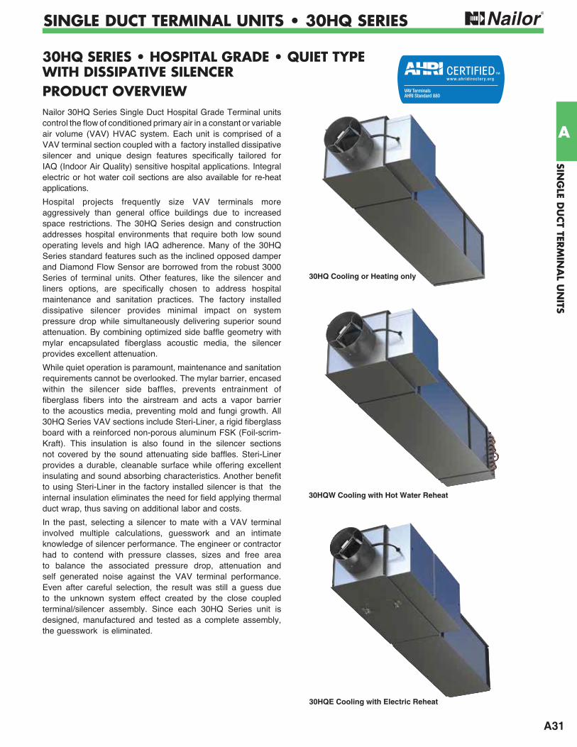
A31
SING
LE DU
CT TER
MIN
AL U
NITS
A
SINGLE DUCT TERMINAL UNITS • 30HQ SERIES
30HQ SERIES • HOSPITAL GRADE • QUIET TYPE WITH DISSIPATIVE SILENCERPRODUCT OVERVIEWNailor 30HQ Series Single Duct Hospital Grade Terminal units control the flow of conditioned primary air in a constant or variable air volume (VAV) HVAC system. Each unit is comprised of a VAV terminal section coupled with a factory installed dissipative silencer and unique design features specifically tailored for IAQ (Indoor Air Quality) sensitive hospital applications. Integral electric or hot water coil sections are also available for re-heat applications.
Hospital projects frequently size VAV terminals more aggressively than general office buildings due to increased space restrictions. The 30HQ Series design and construction addresses hospital environments that require both low sound operating levels and high IAQ adherence. Many of the 30HQ Series standard features such as the inclined opposed damper and Diamond Flow Sensor are borrowed from the robust 3000 Series of terminal units. Other features, like the silencer and liners options, are specifically chosen to address hospital maintenance and sanitation practices. The factory installed dissipative silencer provides minimal impact on system pressure drop while simultaneously delivering superior sound attenuation. By combining optimized side baffle geometry with mylar encapsulated fiberglass acoustic media, the silencer provides excellent attenuation.
While quiet operation is paramount, maintenance and sanitation requirements cannot be overlooked. The mylar barrier, encased within the silencer side baffles, prevents entrainment of fiberglass fibers into the airstream and acts a vapor barrier to the acoustics media, preventing mold and fungi growth. All 30HQ Series VAV sections include Steri-Liner, a rigid fiberglass board with a reinforced non-porous aluminum FSK (Foil-scrim-Kraft). This insulation is also found in the silencer sections not covered by the sound attenuating side baffles. Steri-Liner provides a durable, cleanable surface while offering excellent insulating and sound absorbing characteristics. Another benefit to using Steri-Liner in the factory installed silencer is that the internal insulation eliminates the need for field applying thermal duct wrap, thus saving on additional labor and costs.
In the past, selecting a silencer to mate with a VAV terminal involved multiple calculations, guesswork and an intimate knowledge of silencer performance. The engineer or contractor had to contend with pressure classes, sizes and free area to balance the associated pressure drop, attenuation and self generated noise against the VAV terminal performance. Even after careful selection, the result was still a guess due to the unknown system effect created by the close coupled terminal/silencer assembly. Since each 30HQ Series unit is designed, manufactured and tested as a complete assembly, the guesswork is eliminated.
30HQ Cooling or Heating only
30HQW Cooling with Hot Water Reheat
30HQE Cooling with Electric Reheat
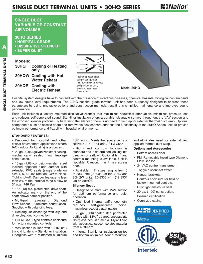
A32
SIN
GLE
DU
CT
TERM
INA
L U
NIT
S
A
SINGLE DUCT TERMINAL UNITS • 30HQ SERIES
SINGLE DUCTVARIABLE OR CONSTANT AIR VOLUME
30HQ SERIES• HOSPITAL GRADE• DISSIPATIVE SILENCER• SUPER QUIET
• Designed for hospital and other critical environment applications where IAQ (Indoor Air Quality) is a concern.• 22 ga. (0.86) galvanized steel casing, mechanically sealed, low leakage construction.• 16 ga. (1.63) corrosion-resistant steel inclined opposed blade damper with extruded PVC seals (single blade on size 4, 5, 6). 45° rotation, CW to close. Tight shut-off. Damper leakage is less than 2% of the terminal rated airflow at 3" w.g. (746 Pa)• 1/2" (13) dia. plated steel drive shaft. An indicator mark on the end of the shaft shows damper position.• Multi-point averaging Diamond Flow Sensor. Aluminum construction. Supplied with balancing tees.• Rectangular discharge with slip and drive cleat duct connection.• Full NEMA 1 type controls enclosure for factory mounted controls.• VAV section is lined with 13/16" (21) thick, 4 lb. density Steri-Liner insulation. Fiberglass with a reinforced aluminum
FSK facing. Meets the requirements of NFPA 90A, UL 181 and ASTM C655.• Right-hand controls location is standard and is determined looking into direction of airflow. Optional left hand controls mounting is available. Unit is flippable. Caution: If unit has access door. • Available in 11 sizes ranging from 0 to 8330 cfm (0-3931 l/s) for 30HQ and 30HQW units. 25-8330 cfm (12-3931 l/s) on 30HQE.
Silencer Section:• Designed to mate with VAV section for optimum performance and quiet operation.• Optimized internal baffle geometry reduces self-generated noise, maximizes acoustic attenuation.• 22 ga. (0.86) coated steel perforated baffles with 13% free area encapsulate fiberglass acoustic media. Mylar lining with acoustical spacer isolates material from airstream.• Internal Steri-Liner insulation on top and bottom optimizes sound reduction
and eliminates need for external field applied thermal duct wrap.
Options and Accessories:• Bottom access door.• FMI Removable insert type Diamond
Flow Sensor.• 24 VAC control transformer.• Toggle disconnect switch.• Hanger brackets.• Controls enclosure for field or
factory mounted controls.• Dust tight enclosure seal.• 20 ga. (1.00) construction. • Seismic certification.• Oversized casing.
Hospital system designs have to contend with the presence of infectious diseases, chemical hazards, biological contaminants and low sound level requirements. The 30HQ hospital grade terminal unit has been purposely designed to address these parameters by using innovative options and construction methods, resulting in simplified maintenance and improved sound performance.
Each unit includes a factory mounted dissipative silencer that maximizes acoustical attenuation, minimizes pressure loss and reduces self-generated sound. Steri-liner insulation offers a durable, cleanable surface throughout the VAV section and the exposed silencer portions. By fully lining the silencer, there is no need to field apply external thermal duct wrap. Optional components such as access doors and removable flow sensors enhance the functionality of the 30HQ Series units to provide optimum performance and flexibility in hospital environments.
Models:30HQ Cooling or Heating only30HQW Cooling with Hot Water Reheat30HQE Cooling with Electric Reheat
Model 30HQ
STANDARD FEATURES:
Inclined opposed bladedamper configurationminimizes noisy turbulenceand provides smooth,accurate, near linearflow control.
Listed
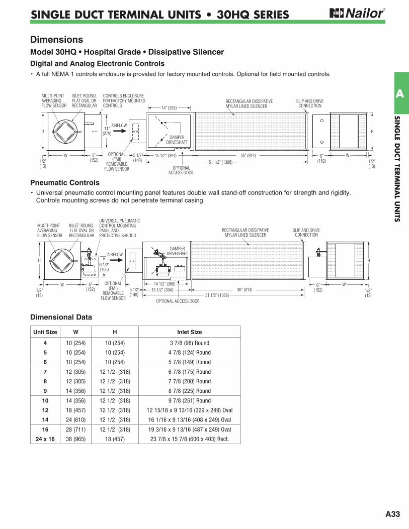
A33
SING
LE DU
CT TER
MIN
AL U
NITS
A
SINGLE DUCT TERMINAL UNITS • 30HQ SERIES
Dimensions Model 30HQ • Hospital Grade • Dissipative SilencerDigital and Analog Electronic Controls• A full NEMA 1 controls enclosure is provided for factory mounted controls. Optional for field mounted controls.
Pneumatic Controls• Universal pneumatic control mounting panel features double wall stand-off construction for strength and rigidity.
Controls mounting screws do not penetrate terminal casing.
5 1/2"(140)
W1/2"(13)
SLIP AND DRIVECONNECTION
H
W 6"(152)1/2"
(13)
H
15 1/2" (394)51 1/2" (1308)
14 1/2" (368)36" (914)
AIRFLOW
6"(152)
OPTIONAL(FMI)
REMOVABLEFLOW SENSOR
INLET: ROUND,FLAT OVAL ORRECTANGULAR
MULTI-POINTAVERAGINGFLOW SENSOR
6 1/2"(165)
UNIVERSAL PNEUMATIC CONTROL MOUNTINGPANEL AND PROTECTIVE SHROUD
DAMPER DRIVESHAFT
OPTIONAL ACCESS DOOR
RECTANGULAR DISSIPATIVEMYLAR LINED SILENCER
5 1/2"(140)
W1/2"(13)
SLIP AND DRIVECONNECTION
H
W 6"(152)1/2"
(13)
H
15 1/2" (394)51 1/2" (1308)
14" (356)
36" (914)
RECTANGULAR DISSIPATIVEMYLAR LINED SILENCER
AIRFLOW
6"(152)
OPTIONALACCESS DOOR
DAMPERDRIVESHAFT
OPTIONAL(FMI)
REMOVABLEFLOW SENSOR
CONTROLS ENCLOSUREFOR FACTORY MOUNTEDCONTROLS
INLET: ROUND,FLAT OVAL ORRECTANGULAR
MULTI-POINTAVERAGINGFLOW SENSOR
11"(279)
Dimensional Data
Unit Size W H Inlet Size
4 10 (254) 10 (254) 3 7/8 (98) Round
5 10 (254) 10 (254) 4 7/8 (124) Round
6 10 (254) 10 (254) 5 7/8 (149) Round
7 12 (305) 12 1/2 (318) 6 7/8 (175) Round
8 12 (305) 12 1/2 (318) 7 7/8 (200) Round
9 14 (356) 12 1/2 (318) 8 7/8 (225) Round
10 14 (356) 12 1/2 (318) 9 7/8 (251) Round
12 18 (457) 12 1/2 (318) 12 15/16 x 9 13/16 (329 x 249) Oval
14 24 (610) 12 1/2 (318) 16 1/16 x 9 13/16 (408 x 249) Oval
16 28 (711) 12 1/2 (318) 19 3/16 x 9 13/16 (487 x 249) Oval
24 x 16 38 (965) 18 (457) 23 7/8 x 15 7/8 (606 x 403) Rect.
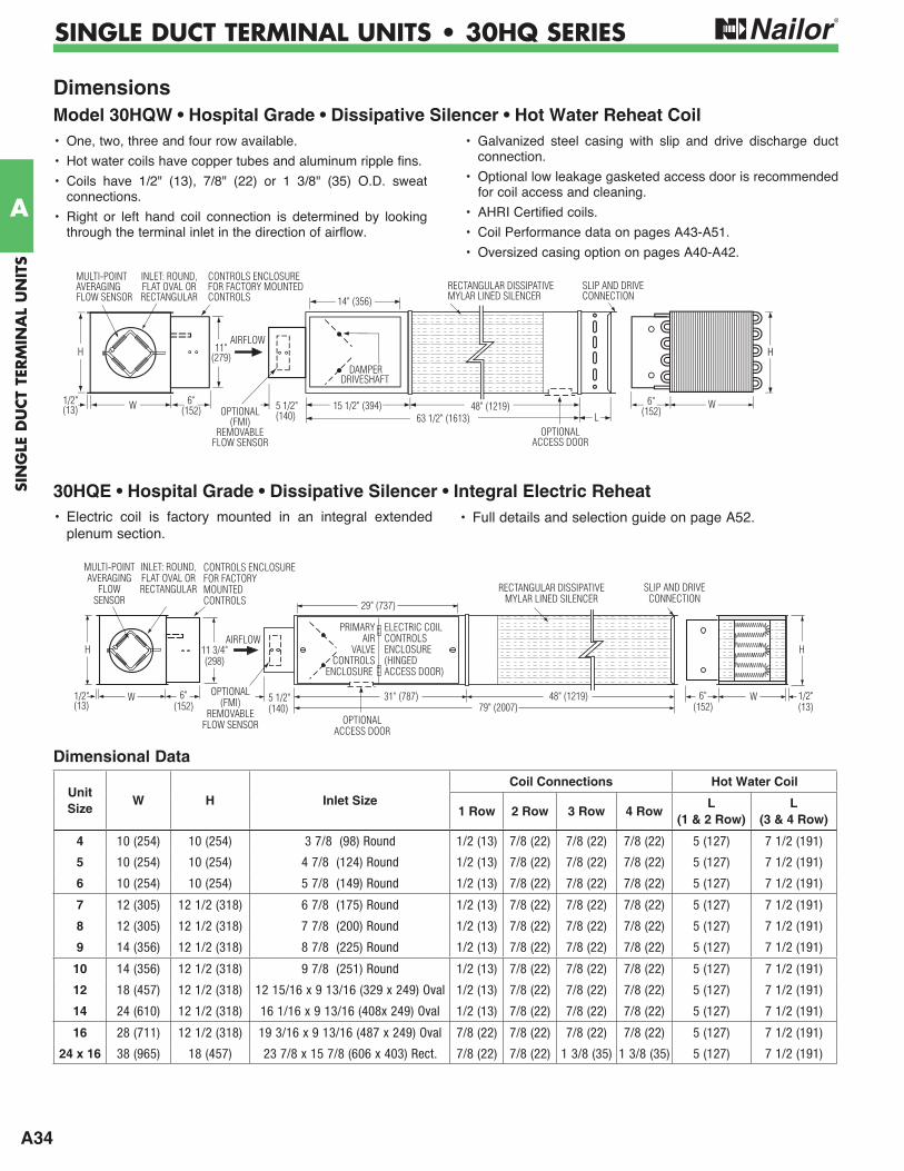
A34
SIN
GLE
DU
CT
TERM
INA
L U
NIT
S
A
SINGLE DUCT TERMINAL UNITS • 30HQ SERIES
5 1/2"(140)
29" (737)
31" (787)W1/2"(13)
H
OPTIONALACCESS DOOR
W
H
48" (1219)79" (2007)
6"(152)
11 3/4"(298)
1/2"(13)
6"(152)
CONTROLS ENCLOSUREFOR FACTORYMOUNTEDCONTROLS
OPTIONAL(FMI)
REMOVABLEFLOW SENSOR
RECTANGULAR DISSIPATIVEMYLAR LINED SILENCER
SLIP AND DRIVECONNECTION
AIRFLOW
INLET: ROUND,FLAT OVAL ORRECTANGULAR
PRIMARYAIR
VALVECONTROLS
ENCLOSURE
ELECTRIC COILCONTROLSENCLOSURE(HINGEDACCESS DOOR)
MULTI-POINTAVERAGING
FLOWSENSOR
30HQE • Hospital Grade • Dissipative Silencer • Integral Electric Reheat• Electric coil is factory mounted in an integral extended
plenum section.• Full details and selection guide on page A52.
Dimensions Model 30HQW • Hospital Grade • Dissipative Silencer • Hot Water Reheat Coil
5 1/2"(140)
OPTIONALACCESS DOOR
HH
DAMPERDRIVESHAFT
LW
SLIP AND DRIVECONNECTION
W 6"(152)
1/2"(13)
11"(279)H
15 1/2" (394)63 1/2" (1613)
14" (356)
48" (1219)
AIRFLOW
OPTIONAL(FMI)
REMOVABLEFLOW SENSOR
CONTROLS ENCLOSUREFOR FACTORY MOUNTEDCONTROLS
INLET: ROUND,FLAT OVAL ORRECTANGULAR
MULTI-POINTAVERAGINGFLOW SENSOR
6"(152)
RECTANGULAR DISSIPATIVEMYLAR LINED SILENCER
• One, two, three and four row available.
• Hot water coils have copper tubes and aluminum ripple fins.
• Coils have 1/2" (13), 7/8" (22) or 1 3/8" (35) O.D. sweat connections.
• Right or left hand coil connection is determined by looking through the terminal inlet in the direction of airflow.
• Galvanized steel casing with slip and drive discharge duct connection.
• Optional low leakage gasketed access door is recommended for coil access and cleaning.
• AHRI Certified coils.
• Coil Performance data on pages A43-A51.
• Oversized casing option on pages A40-A42.
Dimensional Data
Unit Size
W H Inlet Size
Coil Connections Hot Water Coil
1 Row 2 Row 3 Row 4 RowL
(1 & 2 Row)L
(3 & 4 Row)
4 10 (254) 10 (254) 3 7/8 (98) Round 1/2 (13) 7/8 (22) 7/8 (22) 7/8 (22) 5 (127) 7 1/2 (191)
5 10 (254) 10 (254) 4 7/8 (124) Round 1/2 (13) 7/8 (22) 7/8 (22) 7/8 (22) 5 (127) 7 1/2 (191)
6 10 (254) 10 (254) 5 7/8 (149) Round 1/2 (13) 7/8 (22) 7/8 (22) 7/8 (22) 5 (127) 7 1/2 (191)
7 12 (305) 12 1/2 (318) 6 7/8 (175) Round 1/2 (13) 7/8 (22) 7/8 (22) 7/8 (22) 5 (127) 7 1/2 (191)
8 12 (305) 12 1/2 (318) 7 7/8 (200) Round 1/2 (13) 7/8 (22) 7/8 (22) 7/8 (22) 5 (127) 7 1/2 (191)
9 14 (356) 12 1/2 (318) 8 7/8 (225) Round 1/2 (13) 7/8 (22) 7/8 (22) 7/8 (22) 5 (127) 7 1/2 (191)
10 14 (356) 12 1/2 (318) 9 7/8 (251) Round 1/2 (13) 7/8 (22) 7/8 (22) 7/8 (22) 5 (127) 7 1/2 (191)
12 18 (457) 12 1/2 (318) 12 15/16 x 9 13/16 (329 x 249) Oval 1/2 (13) 7/8 (22) 7/8 (22) 7/8 (22) 5 (127) 7 1/2 (191)
14 24 (610) 12 1/2 (318) 16 1/16 x 9 13/16 (408x 249) Oval 1/2 (13) 7/8 (22) 7/8 (22) 7/8 (22) 5 (127) 7 1/2 (191)
16 28 (711) 12 1/2 (318) 19 3/16 x 9 13/16 (487 x 249) Oval 7/8 (22) 7/8 (22) 7/8 (22) 7/8 (22) 5 (127) 7 1/2 (191)
24 x 16 38 (965) 18 (457) 23 7/8 x 15 7/8 (606 x 403) Rect. 7/8 (22) 7/8 (22) 1 3/8 (35) 1 3/8 (35) 5 (127) 7 1/2 (191)
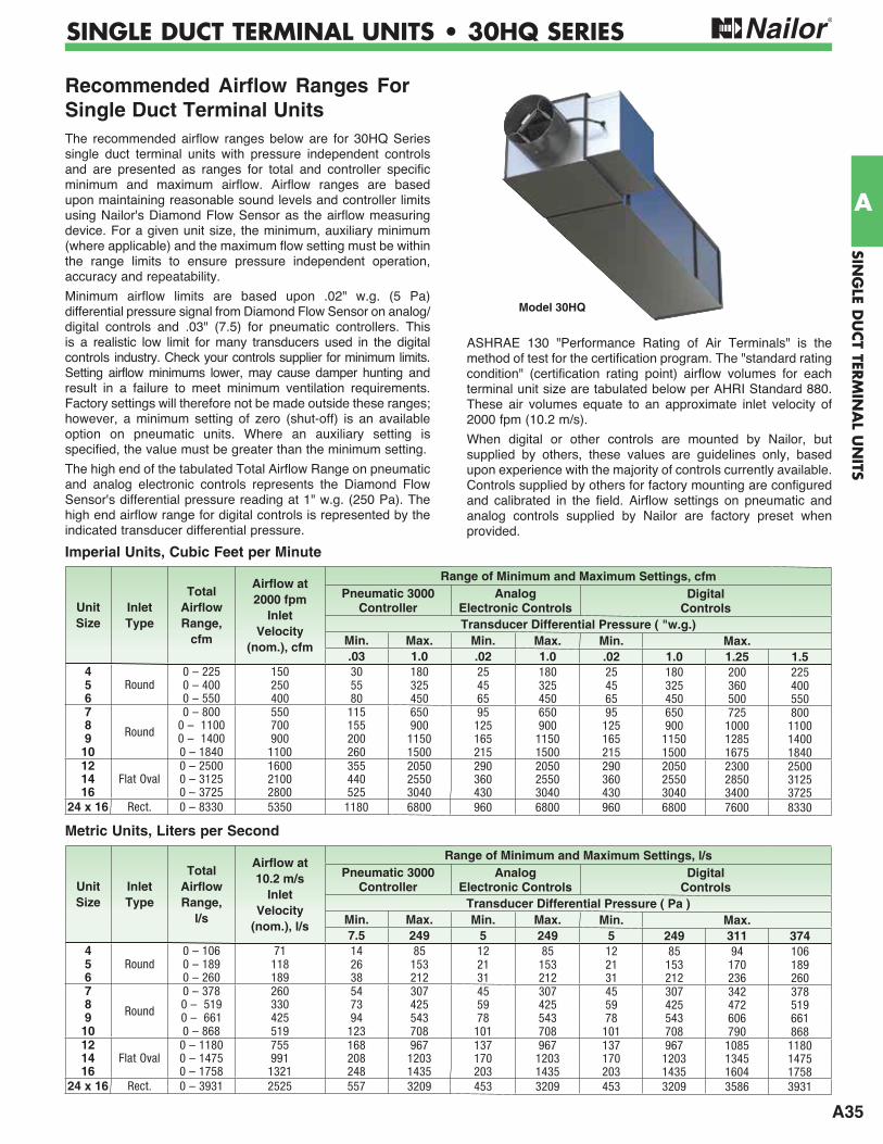
A35
SING
LE DU
CT TER
MIN
AL U
NITS
A
SINGLE DUCT TERMINAL UNITS • 30HQ SERIES
Recommended Airflow Ranges For Single Duct Terminal UnitsThe recommended airflow ranges below are for 30HQ Series single duct terminal units with pressure independent controls and are presented as ranges for total and controller specific minimum and maximum airflow. Airflow ranges are based upon maintaining reasonable sound levels and controller limits using Nailor's Diamond Flow Sensor as the airflow measuring device. For a given unit size, the minimum, auxiliary minimum (where applicable) and the maximum flow setting must be within the range limits to ensure pressure independent operation, accuracy and repeatability.
Minimum airflow limits are based upon .02" w.g. (5 Pa) differential pressure signal from Diamond Flow Sensor on analog/ digital controls and .03" (7.5) for pneumatic controllers. This is a realistic low limit for many transducers used in the digital controls industry. Check your controls supplier for minimum limits. Setting airflow minimums lower, may cause damper hunting and result in a failure to meet minimum ventilation requirements. Factory settings will therefore not be made outside these ranges; however, a minimum setting of zero (shut-off) is an available option on pneumatic units. Where an auxiliary setting is specified, the value must be greater than the minimum setting.
The high end of the tabulated Total Airflow Range on pneumatic and analog electronic controls represents the Diamond Flow Sensor's differential pressure reading at 1" w.g. (250 Pa). The high end airflow range for digital controls is represented by the indicated transducer differential pressure.
ASHRAE 130 "Performance Rating of Air Terminals" is the method of test for the certification program. The "standard rating condition" (certification rating point) airflow volumes for each terminal unit size are tabulated below per AHRI Standard 880. These air volumes equate to an approximate inlet velocity of 2000 fpm (10.2 m/s).
When digital or other controls are mounted by Nailor, but supplied by others, these values are guidelines only, based upon experience with the majority of controls currently available. Controls supplied by others for factory mounting are configured and calibrated in the field. Airflow settings on pneumatic and analog controls supplied by Nailor are factory preset when provided.
Model 30HQ
Imperial Units, Cubic Feet per Minute
Metric Units, Liters per Second
Unit Size
InletType
Total Airflow Range,
cfm
Airflow at 2000 fpm
InletVelocity
(nom.), cfm
Range of Minimum and Maximum Settings, cfmPneumatic 3000
ControllerAnalog
Electronic ControlsDigital
ControlsTransducer Differential Pressure ( "w.g.)
Min. Max. Min. Max. Min. Max..03 1.0 .02 1.0 .02 1.0 1.25 1.5
4Round
0 – 225 150 30 180 25 180 25 180 200 2255 0 – 400 250 55 325 45 325 45 325 360 4006 0 – 550 400 80 450 65 450 65 450 500 5507
Round
0 – 800 550 115 650 95 650 95 650 725 8008 0 – 1100 700 155 900 125 900 125 900 1000 11009 0 – 1400 900 200 1150 165 1150 165 1150 1285 1400
10 0 – 1840 1100 260 1500 215 1500 215 1500 1675 184012
Flat Oval0 – 2500 1600 355 2050 290 2050 290 2050 2300 2500
14 0 – 3125 2100 440 2550 360 2550 360 2550 2850 312516 0 – 3725 2800 525 3040 430 3040 430 3040 3400 3725
24 x 16 Rect. 0 – 8330 5350 1180 6800 960 6800 960 6800 7600 8330
Unit Size
InletType
Total Airflow Range,
l/s
Airflow at 10.2 m/s
InletVelocity
(nom.), l/s
Range of Minimum and Maximum Settings, l/sPneumatic 3000
ControllerAnalog
Electronic ControlsDigital
ControlsTransducer Differential Pressure ( Pa )
Min. Max. Min. Max. Min. Max.7.5 249 5 249 5 249 311 374
4 0 – 106 71 14 85 12 85 12 85 94 1065 Round 0 – 189 118 26 153 21 153 21 153 170 1896 0 – 260 189 38 212 31 212 31 212 236 2607
Round
0 – 378 260 54 307 45 307 45 307 342 3788 0 – 519 330 73 425 59 425 59 425 472 5199 0 – 661 425 94 543 78 543 78 543 606 661
10 0 – 868 519 123 708 101 708 101 708 790 86812 0 – 1180 755 168 967 137 967 137 967 1085 118014 Flat Oval 0 – 1475 991 208 1203 170 1203 170 1203 1345 147516 0 – 1758 1321 248 1435 203 1435 203 1435 1604 1758
24 x 16 Rect. 0 – 3931 2525 557 3209 453 3209 453 3209 3586 3931
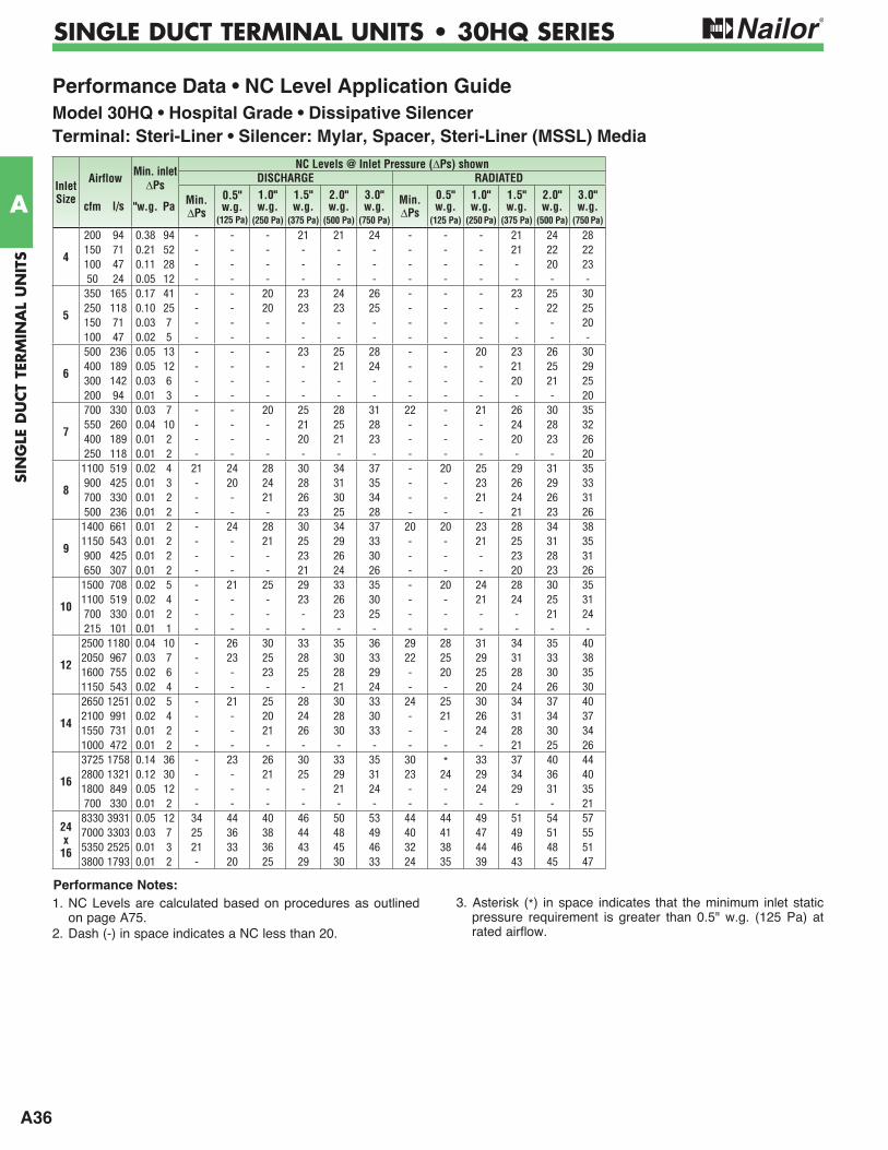
A36
SIN
GLE
DU
CT
TERM
INA
L U
NIT
S
A
SINGLE DUCT TERMINAL UNITS • 30HQ SERIES
Performance Data • NC Level Application GuideModel 30HQ • Hospital Grade • Dissipative SilencerTerminal: Steri-Liner • Silencer: Mylar, Spacer, Steri-Liner (MSSL) Media
1. NC Levels are calculated based on procedures as outlined on page A75.
2. Dash (-) in space indicates a NC less than 20.
3. Asterisk (*) in space indicates that the minimum inlet static pressure requirement is greater than 0.5" w.g. (125 Pa) at rated airflow.
Inlet Size
Airflow Min. inletNC Levels @ Inlet Pressure ( Ps) shown
PsDISCHARGE RADIATED
cfm l/s "w.g. Pa Min. Ps
0.5" w.g.
(125 Pa)
1.0" w.g.
(250 Pa)
1.5" w.g.
(375 Pa)
2.0" w.g.
(500 Pa)
3.0" w.g.
(750 Pa)
Min. Ps
0.5" w.g.
(125 Pa)
1.0" w.g.
(250 Pa)
1.5" w.g.
(375 Pa)
2.0" w.g.
(500 Pa)
3.0" w.g.
(750 Pa)
4
200 94 0.38 94 - - - 21 21 24 - - - 21 24 28150 71 0.21 52 - - - - - - - - - 21 22 22100 47 0.11 28 - - - - - - - - - - 20 2350 24 0.05 12 - - - - - - - - - - - -
5
350 165 0.17 41 - - 20 23 24 26 - - - 23 25 30250 118 0.10 25 - - 20 23 23 25 - - - - 22 25150 71 0.03 7 - - - - - - - - - - - 20100 47 0.02 5 - - - - - - - - - - - -
6
500 236 0.05 13 - - - 23 25 28 - - 20 23 26 30400 189 0.05 12 - - - - 21 24 - - - 21 25 29300 142 0.03 6 - - - - - - - - - 20 21 25200 94 0.01 3 - - - - - - - - - - - 20
7
700 330 0.03 7 - - 20 25 28 31 22 - 21 26 30 35550 260 0.04 10 - - - 21 25 28 - - - 24 28 32400 189 0.01 2 - - - 20 21 23 - - - 20 23 26250 118 0.01 2 - - - - - - - - - - - 20
8
1100 519 0.02 4 21 24 28 30 34 37 - 20 25 29 31 35900 425 0.01 3 - 20 24 28 31 35 - - 23 26 29 33700 330 0.01 2 - - 21 26 30 34 - - 21 24 26 31500 236 0.01 2 - - - 23 25 28 - - - 21 23 26
9
1400 661 0.01 2 - 24 28 30 34 37 20 20 23 28 34 381150 543 0.01 2 - - 21 25 29 33 - - 21 25 31 35900 425 0.01 2 - - - 23 26 30 - - - 23 28 31650 307 0.01 2 - - - 21 24 26 - - - 20 23 26
10
1500 708 0.02 5 - 21 25 29 33 35 - 20 24 28 30 351100 519 0.02 4 - - - 23 26 30 - - 21 24 25 31700 330 0.01 2 - - - - 23 25 - - - - 21 24215 101 0.01 1 - - - - - - - - - - - -
12
2500 1180 0.04 10 - 26 30 33 35 36 29 28 31 34 35 402050 967 0.03 7 - 23 25 28 30 33 22 25 29 31 33 381600 755 0.02 6 - - 23 25 28 29 - 20 25 28 30 351150 543 0.02 4 - - - - 21 24 - - 20 24 26 30
14
2650 1251 0.02 5 - 21 25 28 30 33 24 25 30 34 37 402100 991 0.02 4 - - 20 24 28 30 - 21 26 31 34 371550 731 0.01 2 - - 21 26 30 33 - - 24 28 30 341000 472 0.01 2 - - - - - - - - - 21 25 26
16
3725 1758 0.14 36 - 23 26 30 33 35 30 * 33 37 40 442800 1321 0.12 30 - - 21 25 29 31 23 24 29 34 36 401800 849 0.05 12 - - - - 21 24 - - 24 29 31 35700 330 0.01 2 - - - - - - - - - - - 21
24 x
16
8330 3931 0.05 12 34 44 40 46 50 53 44 44 49 51 54 577000 3303 0.03 7 25 36 38 44 48 49 40 41 47 49 51 555350 2525 0.01 3 21 33 36 43 45 46 32 38 44 46 48 513800 1793 0.01 2 - 20 25 29 30 33 24 35 39 43 45 47
Performance Notes:
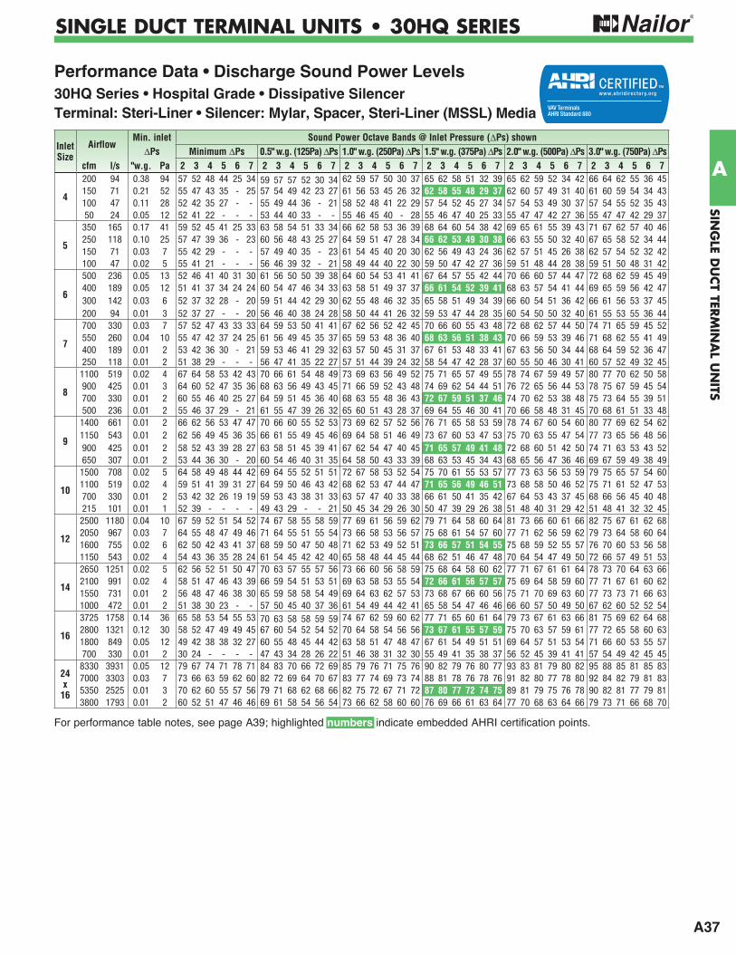
A37
SING
LE DU
CT TER
MIN
AL U
NITS
A
SINGLE DUCT TERMINAL UNITS • 30HQ SERIES
Performance Data • Discharge Sound Power Levels30HQ Series • Hospital Grade • Dissipative SilencerTerminal: Steri-Liner • Silencer: Mylar, Spacer, Steri-Liner (MSSL) Media
For performance table notes, see page A39; highlighted numbers indicate embedded AHRI certification points.
Inlet Size
AirflowMin. inlet Sound Power Octave Bands @ Inlet Pressure ( Ps) shown
Ps Minimum Ps 0.5" w.g. (125Pa) Ps 1.0" w.g. (250Pa) Ps 1.5" w.g. (375Pa) Ps 2.0" w.g. (500Pa) Ps 3.0" w.g. (750Pa) Pscfm l/s "w.g. Pa 2 3 4 5 6 7 2 3 4 5 6 7 2 3 4 5 6 7 2 3 4 5 6 7 2 3 4 5 6 7 2 3 4 5 6 7
4
200 94 0.38 94 57 52 48 44 25 34 59 57 57 52 30 34 62 59 57 50 30 37 65 62 58 51 32 39 65 62 59 52 34 42 66 64 62 55 36 45150 71 0.21 52 55 47 43 35 - 25 57 54 49 42 23 27 61 56 53 45 26 32 62 58 55 48 29 37 62 60 57 49 31 40 61 60 59 54 34 43100 47 0.11 28 52 42 35 27 - - 55 49 44 36 - 21 58 52 48 41 22 29 57 54 52 45 27 34 57 54 53 49 30 37 57 54 55 52 35 4350 24 0.05 12 52 41 22 - - - 53 44 40 33 - - 55 46 45 40 - 28 55 46 47 40 25 33 55 47 47 42 27 36 55 47 47 42 29 37
5
350 165 0.17 41 59 52 45 41 25 33 63 58 54 51 33 34 66 62 58 53 36 39 68 64 60 54 38 42 69 65 61 55 39 43 71 67 62 57 40 46250 118 0.10 25 57 47 39 36 - 23 60 56 48 43 25 27 64 59 51 47 28 34 66 62 53 49 30 38 66 63 55 50 32 40 67 65 58 52 34 44150 71 0.03 7 55 42 29 - - - 57 49 40 35 - 23 61 54 45 40 20 30 62 56 49 43 24 36 62 57 51 45 26 38 62 57 54 52 32 42100 47 0.02 5 55 41 21 - - - 56 46 39 32 - 21 58 49 44 40 22 30 59 50 47 42 27 36 59 51 48 44 28 38 59 51 50 48 31 42
6
500 236 0.05 13 52 46 41 40 31 30 61 56 50 50 39 38 64 60 54 53 41 41 67 64 57 55 42 44 70 66 60 57 44 47 72 68 62 59 45 49400 189 0.05 12 51 41 37 34 24 24 60 54 47 46 34 33 63 58 51 49 37 37 66 61 54 52 39 41 68 63 57 54 41 44 69 65 59 56 42 47300 142 0.03 6 52 37 32 28 - 20 59 51 44 42 29 30 62 55 48 46 32 35 65 58 51 49 34 39 66 60 54 51 36 42 66 61 56 53 37 45200 94 0.01 3 52 37 27 - - 20 56 46 40 38 24 28 58 50 44 41 26 32 59 53 47 44 28 35 60 54 50 50 32 40 61 55 53 55 36 44
7
700 330 0.03 7 57 52 47 43 33 33 64 59 53 50 41 41 67 62 56 52 42 45 70 66 60 55 43 48 72 68 62 57 44 50 74 71 65 59 45 52550 260 0.04 10 55 47 42 37 24 25 61 56 49 45 35 37 65 59 53 48 36 40 68 63 56 51 38 43 70 66 59 53 39 46 71 68 62 55 41 49400 189 0.01 2 53 42 36 30 - 21 59 53 46 41 29 32 63 57 50 45 31 37 67 61 53 48 33 41 67 63 56 50 34 44 68 64 59 52 36 47250 118 0.01 2 51 38 29 - - - 56 47 41 35 22 27 57 51 44 39 24 32 58 54 47 42 28 37 60 55 50 46 30 41 60 57 52 49 32 45
8
1100 519 0.02 4 67 64 58 53 42 43 70 66 61 54 48 49 73 69 63 56 49 52 75 71 65 57 49 55 78 74 67 59 49 57 80 77 70 62 50 58900 425 0.01 3 64 60 52 47 35 36 68 63 56 49 43 45 71 66 59 52 43 48 74 69 62 54 44 51 76 72 65 56 44 53 78 75 67 59 45 54700 330 0.01 2 60 55 46 40 25 27 64 59 51 45 36 40 68 63 55 48 36 43 72 67 59 51 37 46 74 70 62 53 38 48 75 73 64 55 39 51500 236 0.01 2 55 46 37 29 - 21 61 55 47 39 26 32 65 60 51 43 28 37 69 64 55 46 30 41 70 66 58 48 31 45 70 68 61 51 33 48
9
1400 661 0.01 2 66 62 56 53 47 47 70 66 60 55 52 53 73 69 62 57 52 56 76 71 65 58 53 59 78 74 67 60 54 60 80 77 69 62 54 621150 543 0.01 2 62 56 49 45 36 35 66 61 55 49 45 46 69 64 58 51 46 49 73 67 60 53 47 53 75 70 63 55 47 54 77 73 65 56 48 56900 425 0.01 2 58 52 43 39 28 27 63 58 51 45 39 41 67 62 54 47 40 45 71 65 57 49 41 48 72 68 60 51 42 50 74 71 63 53 43 52650 307 0.01 2 53 44 36 30 - 20 60 54 46 40 31 35 64 58 50 43 33 39 68 63 53 45 34 43 68 65 56 47 36 46 69 67 59 49 38 49
10
1500 708 0.02 5 64 58 49 48 44 42 69 64 55 52 51 51 72 67 58 53 52 54 75 70 61 55 53 57 77 73 63 56 53 59 79 75 65 57 54 601100 519 0.02 4 59 51 41 39 31 27 64 59 50 46 43 42 68 62 53 47 44 47 71 65 56 49 46 51 73 68 58 50 46 52 75 71 61 52 47 53700 330 0.01 2 53 42 32 26 19 19 59 53 43 38 31 33 63 57 47 40 33 38 66 61 50 41 35 42 67 64 53 43 37 45 68 66 56 45 40 48215 101 0.01 1 52 39 - - - - 49 43 29 - - 21 50 45 34 29 26 30 50 47 39 29 26 38 51 48 40 31 29 42 51 48 41 32 32 45
12
2500 1180 0.04 10 67 59 52 51 54 52 74 67 58 55 58 59 77 69 61 56 59 62 79 71 64 58 60 64 81 73 66 60 61 66 82 75 67 61 62 682050 967 0.03 7 64 55 48 47 49 46 71 64 55 51 55 54 73 66 58 53 56 57 75 68 61 54 57 60 77 71 62 56 59 62 79 73 64 58 60 641600 755 0.02 6 62 50 42 43 41 37 68 59 50 47 50 48 71 62 53 49 52 51 73 66 57 51 54 55 75 68 59 52 55 57 76 70 60 53 56 581150 543 0.02 4 54 43 36 35 28 24 61 54 45 42 42 40 65 58 48 44 45 44 68 62 51 46 47 48 70 64 54 47 49 50 72 66 57 49 51 53
14
2650 1251 0.02 5 62 56 52 51 50 47 70 63 57 55 57 56 73 66 60 56 58 59 75 68 64 58 60 62 77 71 67 61 61 64 78 73 70 64 63 662100 991 0.02 4 58 51 47 46 43 39 66 59 54 51 53 51 69 63 58 53 55 54 72 66 61 56 57 57 75 69 64 58 59 60 77 71 67 61 60 621550 731 0.01 2 56 48 47 46 38 30 65 59 58 58 54 49 69 64 63 62 57 53 73 68 67 66 60 56 75 71 70 69 63 60 77 73 73 71 66 631000 472 0.01 2 51 38 30 23 - - 57 50 45 40 37 36 61 54 49 44 42 41 65 58 54 47 46 46 66 60 57 50 49 50 67 62 60 52 52 54
16
3725 1758 0.14 36 65 58 53 54 55 53 70 63 58 58 59 59 74 67 62 59 60 62 77 71 65 60 61 64 79 73 67 61 63 66 81 75 69 62 64 682800 1321 0.12 30 58 52 47 49 49 45 67 60 54 52 54 52 70 64 58 54 56 56 73 67 61 55 57 59 75 70 63 57 59 61 77 72 65 58 60 631800 849 0.05 12 49 42 38 38 32 27 60 55 48 45 44 42 63 58 51 47 48 47 67 61 54 49 51 51 69 64 57 51 53 54 71 66 60 53 55 57700 330 0.01 2 30 24 - - - - 47 43 34 28 26 22 51 46 38 31 32 30 55 49 41 35 38 37 56 52 45 39 41 41 57 54 49 42 45 45
24 x
16
8330 3931 0.05 12 79 67 74 71 78 71 84 83 70 66 72 69 85 79 76 71 75 76 90 82 79 76 80 77 93 83 81 79 80 82 95 88 85 81 85 837000 3303 0.03 7 73 66 63 59 62 60 82 72 69 64 70 67 83 77 74 69 73 74 88 81 78 76 78 76 91 82 80 77 78 80 92 84 82 79 81 835350 2525 0.01 3 70 62 60 55 57 56 79 71 68 62 68 66 82 75 72 67 71 72 87 80 77 72 74 75 89 81 79 75 76 78 90 82 81 77 79 813800 1793 0.01 2 60 52 51 47 46 46 69 61 58 54 56 54 73 66 62 58 60 60 76 69 66 61 63 64 77 70 68 63 64 66 79 73 71 66 68 70
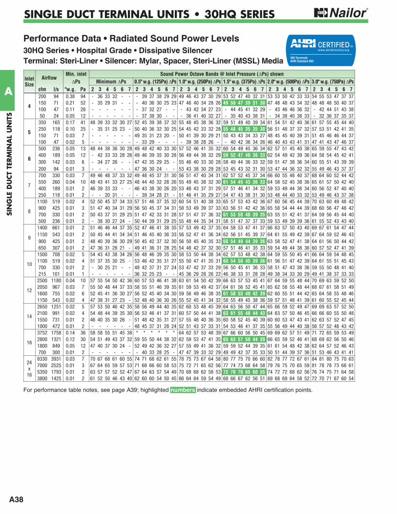
A38
SIN
GLE
DU
CT
TERM
INA
L U
NIT
S
A
SINGLE DUCT TERMINAL UNITS • 30HQ SERIES
Performance Data • Radiated Sound Power Levels30HQ Series • Hospital Grade • Dissipative SilencerTerminal: Steri-Liner • Silencer: Mylar, Spacer, Steri-Liner (MSSL) Media
For performance table notes, see page A39; highlighted numbers indicate embedded AHRI certification points.
Inlet Size
AirflowMin. inlet Sound Power Octave Bands @ Inlet Pressure ( Ps) shown
Ps Minimum Ps 0.5" w.g. (125Pa) Ps 1.0" w.g. (250Pa) Ps 1.5" w.g. (375Pa) Ps 2.0" w.g. (500Pa) Ps 3.0" w.g. (750Pa) Pscfm l/s "w.g. Pa 2 3 4 5 6 7 2 3 4 5 6 7 2 3 4 5 6 7 2 3 4 5 6 7 2 3 4 5 6 7 2 3 4 5 6 7
4
200 94 0.38 94 - 36 33 32 - - - 39 37 38 29 29 49 46 43 37 30 29 53 52 47 40 32 31 53 53 50 42 33 33 54 55 53 47 37 37150 71 0.21 52 - 35 29 31 - - - 40 36 30 25 23 47 46 40 34 28 26 49 50 47 39 31 30 47 48 48 43 34 32 48 48 48 50 40 37100 47 0.11 28 - - - - - - - 37 32 27 - - - 43 42 34 27 23 - 44 45 41 32 29 - 43 46 46 36 32 - 42 44 51 43 3850 24 0.05 12 - - - - - - - 37 38 30 - - - 36 41 40 32 27 - 35 40 43 38 31 - 34 38 40 38 33 - 32 36 37 35 37
5
350 165 0.17 41 48 39 33 32 30 27 52 45 39 38 37 32 55 48 45 38 36 32 59 51 49 40 39 34 61 54 51 42 40 36 61 57 55 45 44 40250 118 0.10 25 - 35 31 25 23 - 50 40 36 32 30 25 54 45 42 33 32 28 55 48 45 35 35 30 56 51 48 37 37 32 57 53 51 42 41 35150 71 0.03 7 - - - - - - 49 35 31 23 20 - 50 41 39 30 29 21 50 43 43 34 33 27 48 45 45 40 39 31 51 45 46 46 44 37100 47 0.02 5 - - - - - - - 33 29 - - - - 39 38 28 26 - - 40 42 36 34 26 46 40 43 43 41 31 47 41 43 47 46 37
6
500 236 0.05 13 48 44 38 36 30 28 49 48 42 40 33 30 57 52 46 41 35 32 60 54 49 45 36 34 62 57 51 45 40 38 65 59 55 47 43 42400 189 0.05 12 - 42 33 33 28 26 49 46 39 35 30 28 56 49 44 38 32 29 59 52 47 40 36 33 62 54 49 42 39 36 64 58 54 45 42 41300 142 0.03 6 - 34 27 26 - - 47 42 35 29 25 - 55 46 40 33 30 28 58 49 44 36 33 32 59 51 47 38 36 34 60 55 51 43 39 39200 94 0.01 3 - - - - - - 47 36 30 24 - - 53 43 38 30 29 28 53 45 43 32 31 30 53 47 44 36 32 32 55 49 46 43 37 37
7
700 330 0.03 7 49 46 48 37 33 32 49 48 45 37 31 30 56 51 47 40 34 31 62 57 52 45 37 34 66 60 55 48 40 37 68 64 60 52 44 42550 260 0.04 10 48 43 41 33 27 25 48 44 40 32 28 26 55 49 45 38 32 30 61 54 49 43 36 33 64 58 52 45 38 36 65 61 57 50 42 40400 189 0.01 2 46 39 33 33 - - 46 43 38 30 26 20 53 48 43 37 31 29 57 51 46 41 34 32 59 53 49 44 36 34 60 56 52 47 40 40250 118 0.01 2 - - 20 31 - - - 39 34 28 21 - 51 46 41 35 29 27 54 47 43 38 31 30 53 48 44 40 33 32 53 49 46 43 37 38
8
1100 519 0.02 4 52 50 45 37 34 33 57 51 46 37 35 32 60 54 51 40 38 33 65 57 53 43 42 36 67 60 56 45 44 39 70 63 60 49 48 42900 425 0.01 3 51 47 40 34 31 29 56 50 45 37 34 31 58 53 49 39 37 33 63 56 51 42 42 36 65 58 54 44 44 39 68 60 56 47 48 42700 330 0.01 2 50 43 37 31 29 25 51 47 42 33 31 28 57 51 47 37 36 32 61 53 50 40 39 35 63 55 51 42 41 37 64 59 56 45 44 40500 236 0.01 2 - 38 30 27 24 - 50 44 39 31 29 25 55 48 44 35 34 31 58 51 47 37 37 33 59 53 49 39 39 36 61 55 52 43 43 40
9
1400 661 0.01 2 51 46 46 44 37 35 52 47 46 41 38 35 57 53 49 42 37 35 64 58 53 47 41 37 66 63 57 50 43 40 69 67 61 54 47 441150 543 0.01 2 50 45 44 41 34 34 51 46 45 40 36 33 56 52 47 41 36 34 62 56 51 45 39 37 64 61 55 49 42 39 67 64 59 52 46 43900 425 0.01 2 48 40 39 36 30 29 50 45 42 37 32 30 56 50 45 40 35 33 60 54 49 44 39 36 63 58 52 47 41 38 64 61 56 50 44 42650 307 0.01 2 47 36 31 28 21 - 49 41 36 31 28 25 54 48 42 37 32 30 57 51 46 41 35 33 59 54 49 44 38 36 60 57 52 47 41 39
10
1500 708 0.02 5 54 43 43 38 34 26 56 48 46 39 35 30 58 53 50 44 38 34 62 57 53 48 42 38 64 59 55 50 45 41 66 64 59 54 48 451100 519 0.02 4 51 37 35 30 25 - 53 46 42 35 31 27 55 50 47 41 35 31 60 54 50 45 39 36 61 56 51 47 42 39 64 61 55 51 45 43700 330 0.01 2 - 30 25 21 - - 48 42 37 31 27 24 53 47 42 37 33 29 56 50 45 41 36 33 58 51 47 43 38 36 59 55 50 48 41 40215 101 0.01 1 - - - - - - 36 32 25 23 - - 45 36 29 28 26 22 46 38 33 31 28 28 49 38 34 33 30 29 49 41 38 37 33 33
12
2500 1180 0.04 10 57 55 54 50 42 36 60 57 53 46 41 38 63 61 54 50 42 39 66 63 57 53 45 41 67 64 59 55 48 44 70 69 63 59 52 502050 967 0.03 7 55 50 48 44 37 33 58 55 51 46 39 35 61 59 53 49 42 37 64 61 56 52 45 41 65 62 58 55 48 44 68 67 61 58 51 491600 755 0.02 6 52 45 41 36 30 27 56 52 45 40 34 30 59 56 49 46 38 35 61 58 53 49 42 39 62 60 55 51 44 42 65 64 58 55 48 461150 543 0.02 4 47 38 31 27 23 - 52 48 40 36 30 26 55 52 45 41 34 32 58 55 49 45 38 36 59 57 51 48 41 39 61 60 55 52 45 44
14
2650 1251 0.02 5 57 53 50 46 42 35 58 56 49 44 40 35 62 60 53 48 45 39 64 63 56 50 47 44 65 66 59 52 49 47 69 69 63 57 52 502100 991 0.02 4 54 48 44 39 35 30 56 53 46 41 37 31 60 57 50 44 41 38 63 61 55 48 44 43 64 63 57 50 46 45 66 66 60 55 50 481550 731 0.01 2 46 40 35 30 26 - 51 48 42 35 31 27 57 55 48 40 36 35 60 58 52 45 40 39 60 60 53 47 43 41 62 63 57 52 47 451000 472 0.01 2 - - - - - - 48 45 37 31 28 24 52 51 43 37 33 31 54 53 46 41 37 35 55 56 49 44 40 38 56 57 52 48 43 42
16
3752 1758 0.14 36 58 58 55 51 45 38 * * * * * * 64 62 57 53 48 39 67 66 60 56 50 45 69 69 62 57 51 49 71 72 65 59 53 492800 1321 0.12 30 54 51 49 43 37 32 59 55 50 44 38 32 62 59 53 47 41 35 65 63 57 50 44 39 66 65 59 52 46 41 68 69 62 56 50 461800 849 0.05 12 47 40 37 30 24 - 52 49 42 36 32 27 57 55 49 41 36 32 59 59 52 44 39 35 61 61 54 48 42 38 62 64 57 52 46 43700 300 0.01 2 - - - - - - - 40 33 28 25 - 47 47 39 33 32 29 49 49 42 37 35 33 50 51 44 39 37 36 51 53 46 43 41 41
24 x
16
8330 3931 0.03 7 70 67 68 61 60 55 74 71 68 62 61 55 78 75 73 67 64 58 80 77 75 70 66 60 82 78 77 72 67 61 84 81 80 75 70 637000 2525 0.01 3 67 64 65 59 57 53 71 68 66 60 58 53 75 72 71 65 62 56 77 74 73 68 64 58 79 76 75 70 65 59 81 78 78 73 68 615350 1793 0.01 2 63 57 57 52 52 47 67 64 63 57 54 49 70 68 68 62 58 53 72 70 70 65 60 55 74 72 72 68 62 56 76 74 75 71 64 583800 1425 0.01 2 61 52 50 46 43 40 62 60 60 54 50 45 66 64 64 59 54 49 68 66 67 62 56 51 69 68 69 64 58 52 72 70 71 67 60 54

A39
SING
LE DU
CT TER
MIN
AL U
NITS
A
SINGLE DUCT TERMINAL UNITS • 30HQ SERIES
Performance Data • AHRI Certification and Performance Notes30HQ Series • Hospital Grade • Dissipative Silencer • AHRI Certification PointsTerminal: Steri-Liner • Silencer: Mylar, Spacer, Steri-Liner (MSSL) Media
Ratings are certified in accordance with AHRI Standards.
Performance Notes for Sound Power Levels:1. Discharge sound power is the noise emitted from the unit
discharge into the downstream duct. Discharge Sound Power Levels (SWL) now include duct end reflection energy as part of the standard rating. Including the duct end correction provides sound power levels that would normally be transmitted into an acoustically, non-reflective duct. The effect of including the energy correction to the discharge SWL, is higher sound power levels when compared to previous AHRI certified data. For more information on duct end reflection calculations see AHRI Standard 880.
2. Radiated sound power is the breakout noise transmitted through the unit casing walls.
3. Sound power levels are in decibels, dB re 10-12 watts.
4. All sound data listed by octave bands is raw data without any corrections for room absorption or duct attenuation. Dash (-) in space indicates sound power level is less than 20 dB or equal to background.
requirement of the unit (damper full open) and the difference in static pressure from inlet to discharge of the unit.
6. Asterisk (*) in space indicates that the minimum inlet static pressure requirement is greater than 0.5" w.g. (125 Pa) at rated airflow.
7. Data derived from independent tests conducted in accordance with ANSI/ASHRAE Standard 130 and AHRI Standard 880.
InletSize
AirflowMin. Inlet Discharge Sound Power Levels
@ 1.5" w.g. (375 Pa) PsRadiated Sound Power Levels
@ 1.5" w.g. (375 Pa) PsPs Octave Band Octave Band
cfm l/s "w.g. Pa 2 3 4 5 6 7 2 3 4 5 6 74 150 71 0.24 60 65 60 55 48 29 37 49 50 47 39 31 305 250 118 0.08 20 67 62 53 49 30 38 55 48 45 35 35 306 400 189 0.06 15 71 67 58 51 37 41 59 52 47 40 36 337 550 260 0.06 16 74 67 59 48 36 45 61 54 49 43 36 338 700 330 0.08 21 77 67 58 48 39 47 61 53 50 40 39 359 900 425 0.07 17 75 65 57 48 44 48 60 54 49 44 39 3610 1100 519 0.14 34 77 65 57 50 49 50 60 54 50 45 39 3612 1600 755 0.19 48 76 64 58 52 54 55 61 58 53 49 42 3914 2100 991 0.19 46 75 68 64 57 57 55 63 61 55 48 44 4316 2800 1321 0.30 75 77 68 63 55 58 58 65 63 57 50 44 39
24 x 16 5350 2525 0.01 2 87 80 77 72 74 75 72 70 70 65 60 55
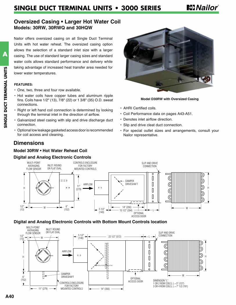
A40
SIN
GLE
DU
CT
TERM
INA
L U
NIT
S
A
OPTIONALACCESS DOOR
SLIP AND DRIVECONNECTION
14" (356)
5 1/2"(140)
6"(152)
1/2"(13)
INLET: ROUNDOR FLAT OVAL
MULTI-POINTAVERAGING
FLOW SENSOR
11" (279)
22 1/2" (572)W
H
DAMPERDRIVESHAFT
L
W
H
DIMENSION "L"1 OR 2 ROW COILS, L = 5" (127)3 OR 4 ROW COILS, L = 7" 1/2 (191)
CONTROLS ENCLOSURE FOR FACTORY
MOUNTED CONTROLS
AIRFLOW
SINGLE DUCT TERMINAL UNITS • 3000 SERIES
Nailor offers oversized casing on all Single Duct Terminal
Units with hot water reheat. The oversized casing option
allows the selection of a standard inlet size with a larger
casing. The use of standard larger casing sizes and standard
water coils allows standard performance and delivery while
taking advantage of increased heat transfer area needed for
lower water temperatures.
Model D30RW with Oversized Casing
Digital and Analog Electronic Controls with Bottom Mount Controls location
Dimensions Model 30RW • Hot Water Reheat Coil
Digital and Analog Electronic Controls
OPTIONALACCESS DOOR
LW
SLIP AND DRIVECONNECTION
H
15 1/2" (394)14" (356)
5 1/2"(140)
DAMPERDRIVESHAFT
W 6"(152)
11"(279)
1/2"(13)
H
CONTROLS ENCLOSURE FOR FACTORY
MOUNTED CONTROLS INLET: ROUNDOR FLAT OVAL
MULTI-POINTAVERAGING
FLOW SENSOR
AIRFLOW
Oversized Casing • Larger Hot Water CoilModels: 30RW, 30RWQ and 30HQW
FEATURES:
• One, two, three and four row available.
• Hot water coils have copper tubes and aluminum ripple fins. Coils have 1/2" (13), 7/8" (22) or 1 3/8" (35) O.D. sweat connections.
• Right or left hand coil connection is determined by looking through the terminal inlet in the direction of airflow.
• Galvanized steel casing with slip and drive discharge duct connection.
• Optional low leakage gasketed access door is recommended for coil access and cleaning.
• AHRI Certified coils.
• Coil Performance data on pages A43-A51.
• Denotes inlet airflow direction.
• Slip and drive cleat duct connection.
• For special outlet sizes and arrangements, consult your Nailor representative.
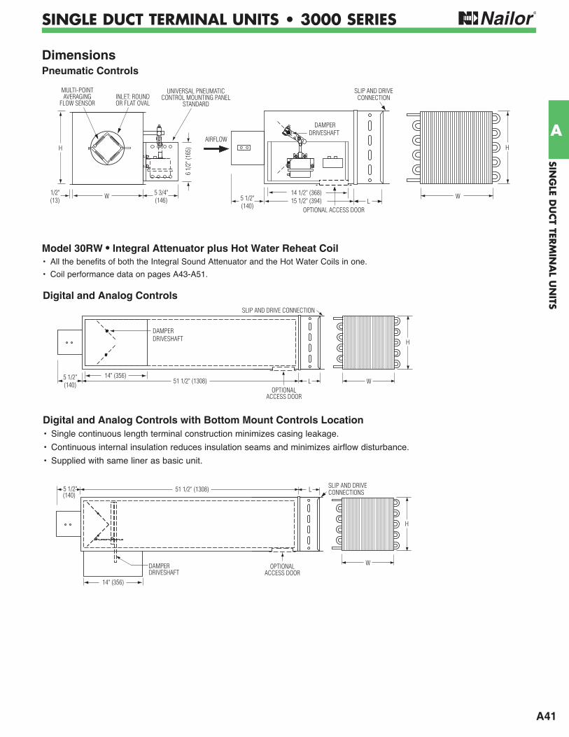
A41
SING
LE DU
CT TER
MIN
AL U
NITS
A
SINGLE DUCT TERMINAL UNITS • 3000 SERIES
Pneumatic Controls
W15 1/2" (394)14 1/2" (368)5 3/4"
(146) 5 1/2"(140)
1/2"(13)
6 1/
2" (1
65)H
DAMPER DRIVESHAFT
LW
SLIP AND DRIVECONNECTION
H
OPTIONAL ACCESS DOOR
INLET: ROUNDOR FLAT OVAL
MULTI-POINTAVERAGING
FLOW SENSOR
UNIVERSAL PNEUMATICCONTROL MOUNTING PANEL
STANDARD
AIRFLOW
Model 30RW • Integral Attenuator plus Hot Water Reheat Coil• All the benefits of both the Integral Sound Attenuator and the Hot Water Coils in one.
• Coil performance data on pages A43-A51.
Digital and Analog Controls with Bottom Mount Controls Location
Digital and Analog Controls
• Single continuous length terminal construction minimizes casing leakage.
• Continuous internal insulation reduces insulation seams and minimizes airflow disturbance.
• Supplied with same liner as basic unit.
OPTIONALACCESS DOOR
H
W
14" (356)
5 1/2"(140)
51 1/2" (1308) SLIP AND DRIVECONNECTIONSL
DAMPERDRIVESHAFT
5 1/2"(140)
51 1/2" (1308)
SLIP AND DRIVE CONNECTION
H
L W
DAMPERDRIVESHAFT
14" (356)
OPTIONALACCESS DOOR
Dimensions
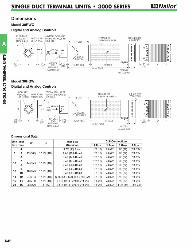
A42
SIN
GLE
DU
CT
TERM
INA
L U
NIT
S
A
SINGLE DUCT TERMINAL UNITS • 3000 SERIES
Dimensions Model 30RWQ
Digital and Analog Controls
Model 30HQW
Digital and Analog Controls
Unit Size
Inlet Size
W HInlet Size (Nominal)
Coil Connections1 Row 2 Row 3 Row 4 Row
4 3 7/8 (98) Round 1/2 (13) 7/8 (22) 7/8 (22) 7/8 (22)8 5 12 (305) 12 1/2 (318) 4 7/8 (124) Round 1/2 (13) 7/8 (22) 7/8 (22) 7/8 (22)
6 5 7/8 (149) Round 1/2 (13) 7/8 (22) 7/8 (22) 7/8 (22)
107
14 (356) 12 1/2 (318)6 7/8 (175) Round 1/2 (13) 7/8 (22) 7/8 (22) 7/8 (22)
8 7 7/8 (200) Round 1/2 (13) 7/8 (22) 7/8 (22) 7/8 (22)
129
18 (457) 12 1/2 (318)8 7/8 (225) Round 1/2 (13) 7/8 (22) 7/8 (22) 7/8 (22)
10 9 7/8 (251) Round 1/2 (13) 7/8 (22) 7/8 (22) 7/8 (22)14 12 24 (610) 12 1/2 (318) 12 15/16 x 9 13/16 (329 x 249) Oval 1/2 (13) 7/8 (22) 7/8 (22) 7/8 (22)16 14 28 (711) 12 1/2 (318) 16 1/16 x 9 13/16 (408 x 249) Oval 7/8 (22) 7/8 (22) 7/8 (22) 7/8 (22)24 16 38 (965) 18 (457) 19 3/16 x 9 13/16 (487 x 249) Oval 7/8 (22) 7/8 (22) 1 3/8 (35) 1 3/8 (35)
Dimensional Data
5 1/2"(140)
H
DAMPERDRIVESHAFT
L
SLIP AND DRIVECONNECTION
W 6"(152)
1/2"(13)
11"(279)H
15 1/2" (394)63 1/2" (1613)
14" (356)
48" (1219)OPTIONAL
(FMI)REMOVABLE
FLOW SENSOR
RECTANGULARDISSIPATIVE SILENCER
CONTROLS ENCLOSUREFOR FACTORY MOUNTEDCONTROLS
INLET: ROUNDOR FLAT OVAL
MULTI-POINTAVERAGINGFLOW SENSOR
OPTIONALACCESS DOOR
6"(152)
AIRFLOW
W
5 1/2"(140)
DAMPERDRIVESHAFT
L
SLIP AND DRIVECONNECTION
W 6"(152)
1/2"(13)
11"(279)H
15 1/2" (394)63 1/2" (1613)
14" (356)
48" (1219)OPTIONAL
(FMI)REMOVABLE
FLOW SENSOR
RECTANGULARDISSIPATIVE SILENCER
CONTROLS ENCLOSUREFOR FACTORY MOUNTEDCONTROLS
INLET: ROUNDOR FLAT OVAL
MULTI-POINTAVERAGINGFLOW SENSOR
OPTIONALACCESS DOOR
6"(152)
AIRFLOW
W
H
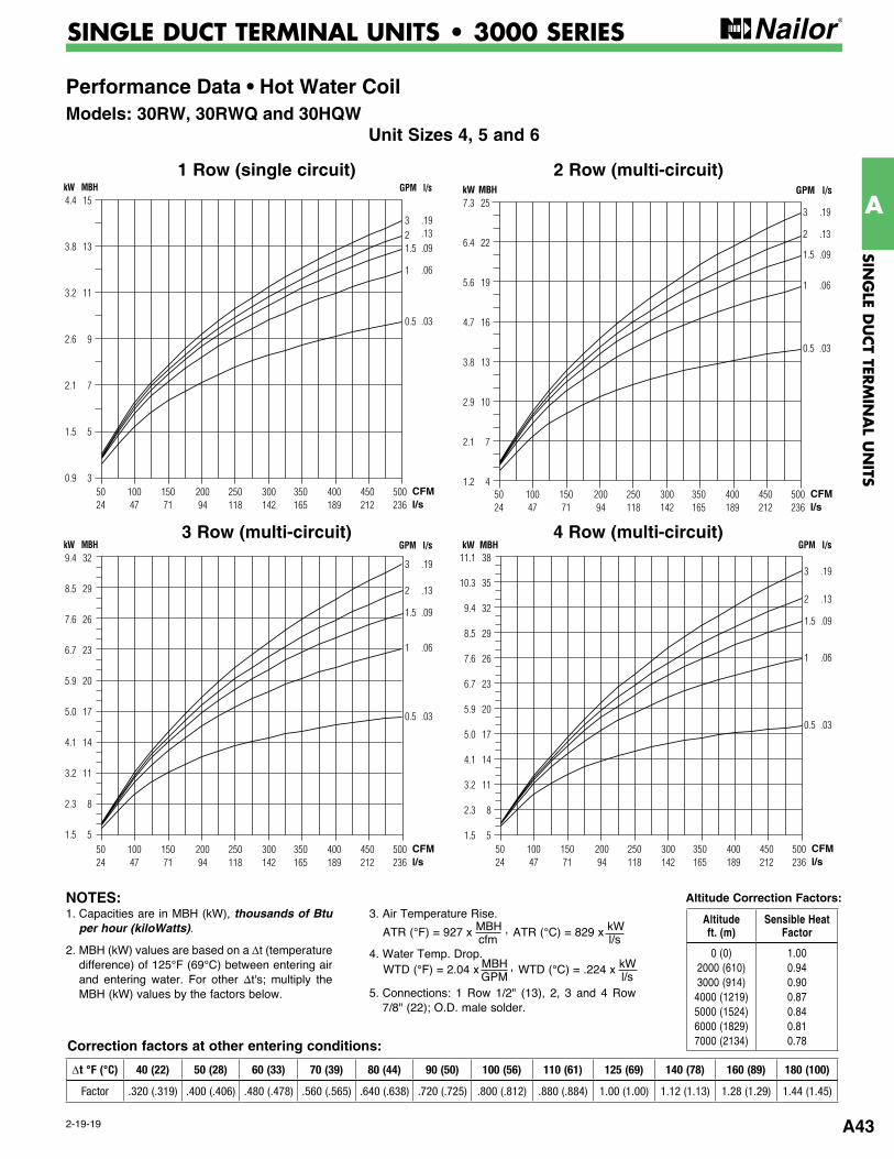
A43
SING
LE DU
CT TER
MIN
AL U
NITS
A
2-19-19
SINGLE DUCT TERMINAL UNITS • 3000 SERIES
Performance Data • Hot Water CoilModels: 30RW, 30RWQ and 30HQW
Unit Sizes 4, 5 and 6
2 Row (multi-circuit)
CFMl/s
50 100 150 200 250 300 350 400 450 500 24 47 71 94 118 142 165 189 212 236
15
13
11
9
7
5
3
4.4
3.8
3.2
2.6
2.1
1.5
0.9
kW MBH GPM l/s
321.5
1
0.5
.19
.13
.09
.06
.03
1 Row (single circuit)
3 Row (multi-circuit) 4 Row (multi-circuit)
CFMl/s
50 100 150 200 250 300 350 400 450 500 24 47 71 94 118 142 165 189 212 236
25
22
19
16
13
10
7
4
7.3
6.4
5.6
4.7
3.8
2.9
2.1
1.2
kW MBH GPM l/s
3
2
1.5
1
0.5
.19
.13
.09
.06
.03
CFMl/s
50 100 150 200 250 300 350 400 450 500 24 47 71 94 118 142 165 189 212 236
32
29
26
23
20
17
14
11
8
5
9.4
8.5
7.6
6.7
5.9
5.0
4.1
3.2
2.3
1.5
kW MBH GPM l/s
3
2
1.5
1
0.5
.19
.13
.09
.06
.03
CFMl/s
50 100 150 200 250 300 350 400 450 500 24 47 71 94 118 142 165 189 212 236
38
35
32
29
26
23
20
17
14
11
8
5
11.1
10.3
9.4
8.5
7.6
6.7
5.9
5.0
4.1
3.2
2.3
1.5
kW MBH GPM l/s
3
2
1.5
1
0.5
.19
.13
.09
.06
.03
Altitude Correction Factors:
Correction factors at other entering conditions:
1. Capacities are in MBH (kW), thousands of Btu per hour (kiloWatts).
2. MBH (kW) values are based on a ∆t (temperature difference) of 125°F (69°C) between entering air and entering water. For other ∆t's; multiply the MBH (kW) values by the factors below.
3. Air Temperature Rise.
4. Water Temp. Drop.
5. Connections: 1 Row 1/2" (13), 2, 3 and 4 Row 7/8" (22); O.D. male solder.
ATR (°C) = 829 x kW l/s
ATR (°F) = 927 x MBH , cfm
WTD (°C) = .224 x kW l/s
WTD (°F) = 2.04 x MBH , GPM
NOTES:Altitude ft. (m)
Sensible Heat Factor
0 (0)2000 (610) 3000 (914)
4000 (1219) 5000 (1524) 6000 (1829) 7000 (2134)
1.00 0.94 0.90 0.87 0.84 0.81 0.78
∆t °F (°C) 40 (22) 50 (28) 60 (33) 70 (39) 80 (44) 90 (50) 100 (56) 110 (61) 125 (69) 140 (78) 160 (89) 180 (100)
Factor .320 (.319) .400 (.406) .480 (.478) .560 (.565) .640 (.638) .720 (.725) .800 (.812) .880 (.884) 1.00 (1.00) 1.12 (1.13) 1.28 (1.29) 1.44 (1.45)
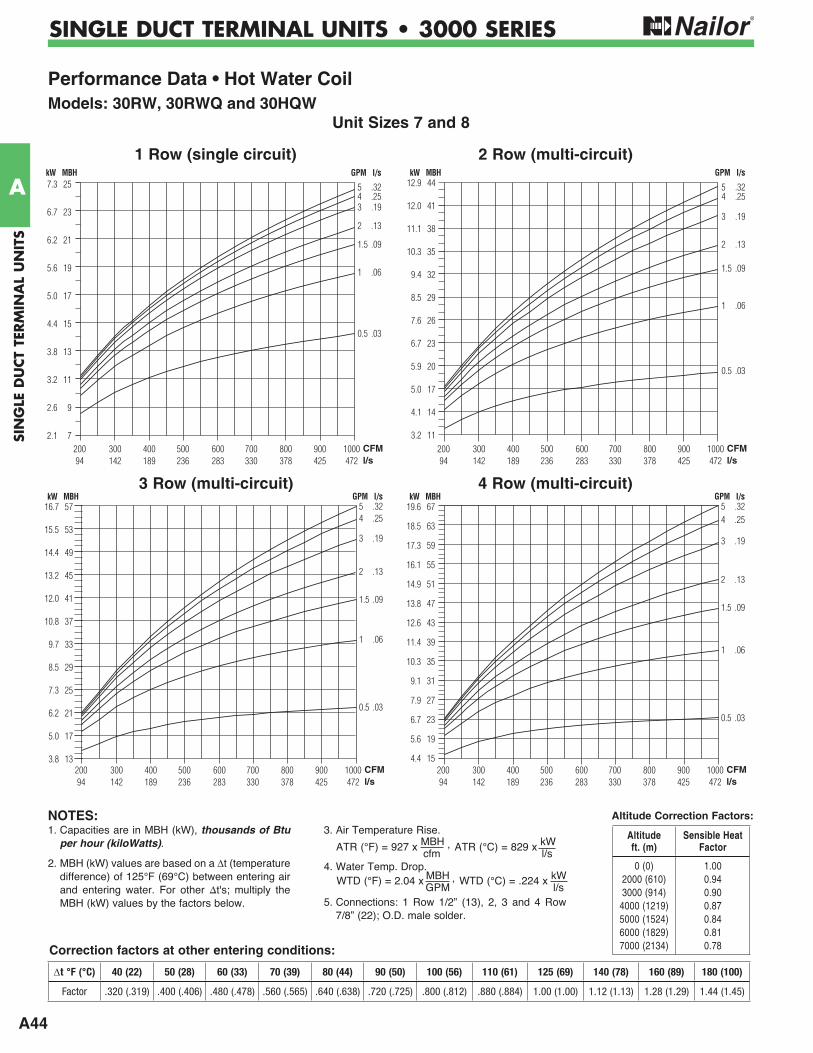
A44
SIN
GLE
DU
CT
TERM
INA
L U
NIT
S
A
SINGLE DUCT TERMINAL UNITS • 3000 SERIES
Performance Data • Hot Water Coil Models: 30RW, 30RWQ and 30HQW
Unit Sizes 7 and 8
2 Row (multi-circuit)
543
2
1.5
1
0.5
CFMl/s
200 300 400 500 600 700 800 900 1000 94 142 189 236 283 330 378 425 472
25
23
21
19
17
15
13
11
9
7
7.3
6.7
6.2
5.6
5.0
4.4
3.8
3.2
2.6
2.1
kW MBH GPM l/s
.32
.25
.19
.13
.09
.06
.03
1 Row (single circuit)
3 Row (multi-circuit) 4 Row (multi-circuit)
54
3
2
1.5
1
0.5
CFMl/s
200 300 400 500 600 700 800 900 1000 94 142 189 236 283 330 378 425 472
44
41
38
35
32
29
26
23
20
17
14
11
12.9
12.0
11.1
10.3
9.4
8.5
7.6
6.7
5.9
5.0
4.1
3.2
kW MBH GPM l/s
.32
.25
.19
.13
.09
.06
.03
54
3
2
1.5
1
0.5
CFMl/s
200 300 400 500 600 700 800 900 1000 94 142 189 236 283 330 378 425 472
57
53
49
45
41
37
33
29
25
21
17
13
16.7
15.5
14.4
13.2
12.0
10.8
9.7
8.5
7.3
6.2
5.0
3.8
kW MBH GPM l/s.32.25
.19
.13
.09
.06
.03
54
3
2
1.5
1
0.5
CFMl/s
200 300 400 500 600 700 800 900 1000 94 142 189 236 283 330 378 425 472
67
63
59
55
51
47
43
39
35
31
27
23
19
15
19.6
18.5
17.3
16.1
14.9
13.8
12.6
11.4
10.3
9.1
7.9
6.7
5.6
4.4
kW MBH GPM l/s.32.25
.19
.13
.09
.06
.03
Altitude Correction Factors:
Correction factors at other entering conditions:
1. Capacities are in MBH (kW), thousands of Btu per hour (kiloWatts).
2. MBH (kW) values are based on a t (temperature difference) of 125°F (69°C) between entering air and entering water. For other t's; multiply the MBH (kW) values by the factors below.
3. Air Temperature Rise.
4. Water Temp. Drop.
5. Connections: 1 Row 1/2” (13), 2, 3 and 4 Row 7/8” (22); O.D. male solder.
ATR (°C) = 829 x kW l/s
ATR (°F) = 927 x MBH , cfm
WTD (°C) = .224 x kW l/s
WTD (°F) = 2.04 x MBH , GPM
NOTES:Altitude ft. (m)
Sensible Heat Factor
0 (0)2000 (610) 3000 (914)
4000 (1219) 5000 (1524) 6000 (1829) 7000 (2134)
1.00 0.94 0.90 0.87 0.84 0.81 0.78
t °F (°C) 40 (22) 50 (28) 60 (33) 70 (39) 80 (44) 90 (50) 100 (56) 110 (61) 125 (69) 140 (78) 160 (89) 180 (100)
Factor .320 (.319) .400 (.406) .480 (.478) .560 (.565) .640 (.638) .720 (.725) .800 (.812) .880 (.884) 1.00 (1.00) 1.12 (1.13) 1.28 (1.29) 1.44 (1.45)
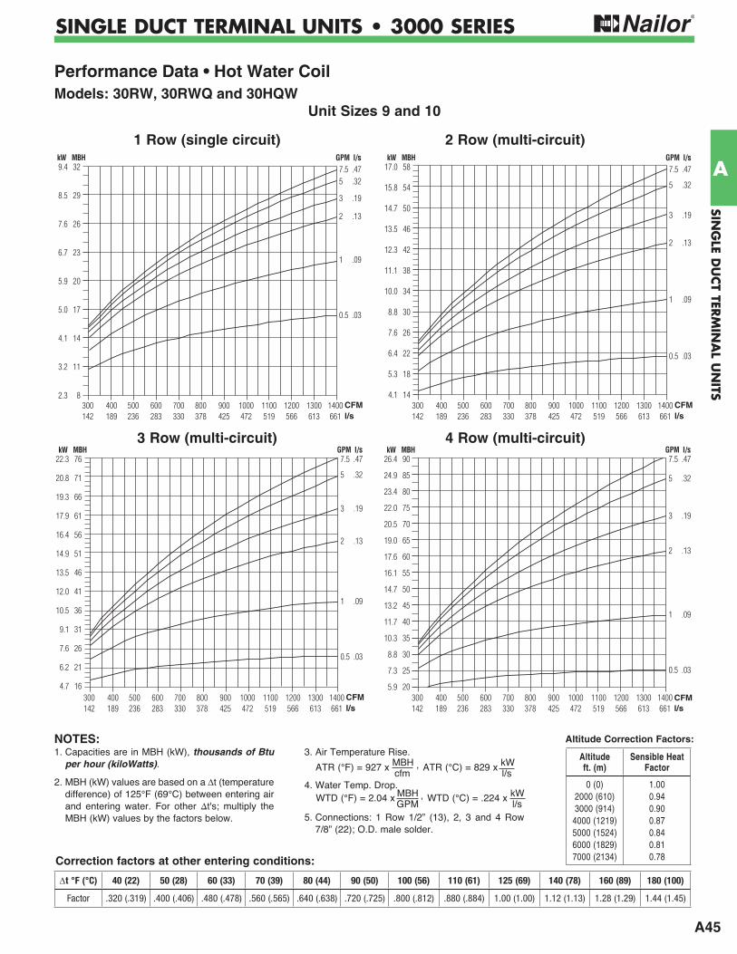
A45
SING
LE DU
CT TER
MIN
AL U
NITS
A
SINGLE DUCT TERMINAL UNITS • 3000 SERIES
Performance Data • Hot Water CoilModels: 30RW, 30RWQ and 30HQW
Unit Sizes 9 and 10
2 Row (multi-circuit)
7.55
3
2
1
0.5
CFMl/s
300 400 500 600 700 800 900 1000 1100 1200 1300 1400 142 189 236 283 330 378 425 472 519 566 613 661
32
29
26
23
20
17
14
11
8
9.4
8.5
7.6
6.7
5.9
5.0
4.1
3.2
2.3
kW MBH GPM l/s.47.32
.19
.13
.09
.03
1 Row (single circuit)
3 Row (multi-circuit) 4 Row (multi-circuit)
7.5
5
3
2
1
0.5
CFMl/s
300 400 500 600 700 800 900 1000 1100 1200 1300 1400 142 189 236 283 330 378 425 472 519 566 613 661
58
54
50
46
42
38
34
30
26
22
18
14
17.0
15.8
14.7
13.5
12.3
11.1
10.0
8.8
7.6
6.4
5.3
4.1
kW MBH GPM l/s.47
.32
.19
.13
.09
.03
7.5
5
3
2
1
0.5
CFMl/s
300 400 500 600 700 800 900 1000 1100 1200 1300 1400 142 189 236 283 330 378 425 472 519 566 613 661
76
71
66
61
56
51
46
41
36
31
26
21
16
22.3
20.8
19.3
17.9
16.4
14.9
13.5
12.0
10.5
9.1
7.6
6.2
4.7
kW MBH GPM l/s.47
.32
.19
.13
.09
.03
7.5
5
3
2
1
0.5
CFMl/s
300 400 500 600 700 800 900 1000 1100 1200 1300 1400 142 189 236 283 330 378 425 472 519 566 613 661
90
85
80
75
70
65
60
55
50
45
40
35
30
25
20
26.4
24.9
23.4
22.0
20.5
19.0
17.6
16.1
14.7
13.2
11.7
10.3
8.8
7.3
5.9
kW MBH GPM l/s.47
.32
.19
.13
.09
.03
Altitude Correction Factors:
Correction factors at other entering conditions:
1. Capacities are in MBH (kW), thousands of Btu per hour (kiloWatts).
2. MBH (kW) values are based on a t (temperature difference) of 125°F (69°C) between entering air and entering water. For other t's; multiply the MBH (kW) values by the factors below.
3. Air Temperature Rise.
4. Water Temp. Drop.
5. Connections: 1 Row 1/2” (13), 2, 3 and 4 Row 7/8” (22); O.D. male solder.
ATR (°C) = 829 x kW l/s
ATR (°F) = 927 x MBH , cfm
WTD (°C) = .224 x kW l/s
WTD (°F) = 2.04 x MBH , GPM
NOTES:Altitude ft. (m)
Sensible Heat Factor
0 (0)2000 (610) 3000 (914)
4000 (1219) 5000 (1524) 6000 (1829) 7000 (2134)
1.00 0.94 0.90 0.87 0.84 0.81 0.78
t °F (°C) 40 (22) 50 (28) 60 (33) 70 (39) 80 (44) 90 (50) 100 (56) 110 (61) 125 (69) 140 (78) 160 (89) 180 (100)
Factor .320 (.319) .400 (.406) .480 (.478) .560 (.565) .640 (.638) .720 (.725) .800 (.812) .880 (.884) 1.00 (1.00) 1.12 (1.13) 1.28 (1.29) 1.44 (1.45)
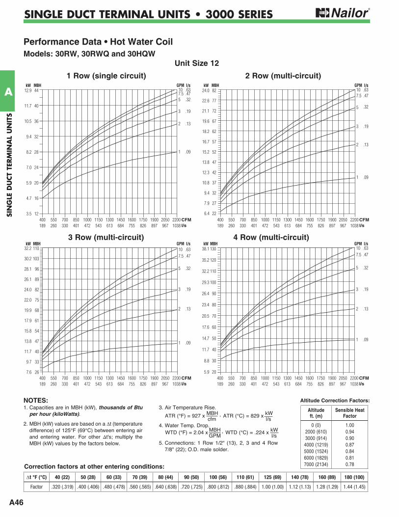
A46
SIN
GLE
DU
CT
TERM
INA
L U
NIT
S
A
SINGLE DUCT TERMINAL UNITS • 3000 SERIES
Performance Data • Hot Water CoilModels: 30RW, 30RWQ and 30HQW
Unit Size 12
2 Row (multi-circuit)
107.55
3
2
1
CFMl/s
400 550 700 850 1000 1150 1300 1450 1600 1750 1900 2050 2200 189 260 330 401 472 543 613 684 755 826 897 967 1038
44
40
36
32
28
24
20
16
12
12.9
11.7
10.5
9.4
8.2
7.0
5.9
4.7
3.5
kW MBH GPM l/s.63.47.32
.19
.13
.09
1 Row (single circuit)
3 Row (multi-circuit) 4 Row (multi-circuit)
107.5
5
3
2
1
CFMl/s
400 550 700 850 1000 1150 1300 1450 1600 1750 1900 2050 2200 189 260 330 401 472 543 613 684 755 826 897 967 1038
82
77
72
67
62
57
52
47
42
37
32
27
22
24.0
22.6
21.1
19.6
18.2
16.7
15.2
13.8
12.3
10.8
9.4
7.9
6.4
kW MBH GPM l/s.63.47
.32
.19
.13
.09
107.5
5
3
2
1
CFMl/s
400 550 700 850 1000 1150 1300 1450 1600 1750 1900 2050 2200 189 260 330 401 472 543 613 684 755 826 897 967 1038
110
103
96
89
82
75
68
61
54
47
40
33
26
32.2
30.2
28.1
26.1
24.0
22.0
19.9
17.9
15.8
13.8
11.7
9.7
7.6
kW MBH GPM l/s.63.47
.32
.19
.13
.09
107.5
5
3
2
1
CFMl/s
400 550 700 850 1000 1150 1300 1450 1600 1750 1900 2050 2200 189 260 330 401 472 543 613 684 755 826 897 967 1038
130
120
110
100
90
80
70
60
50
40
30
20
38.1
35.2
32.2
29.3
26.4
23.4
20.5
17.6
14.7
11.7
8.8
5.9
kW MBH GPM l/s.63.47
.32
.19
.13
.09
Altitude Correction Factors:
Correction factors at other entering conditions:
1. Capacities are in MBH (kW), thousands of Btu per hour (kiloWatts).
2. MBH (kW) values are based on a t (temperature difference) of 125°F (69°C) between entering air and entering water. For other t's; multiply the MBH (kW) values by the factors below.
3. Air Temperature Rise.
4. Water Temp. Drop.
5. Connections: 1 Row 1/2" (13), 2, 3 and 4 Row 7/8" (22); O.D. male solder.
ATR (°C) = 829 x kW l/s
ATR (°F) = 927 x MBH , cfm
WTD (°C) = .224 x kW l/s
WTD (°F) = 2.04 x MBH , GPM
NOTES:Altitude ft. (m)
Sensible Heat Factor
0 (0)2000 (610) 3000 (914)
4000 (1219) 5000 (1524) 6000 (1829) 7000 (2134)
1.00 0.94 0.90 0.87 0.84 0.81 0.78
t °F (°C) 40 (22) 50 (28) 60 (33) 70 (39) 80 (44) 90 (50) 100 (56) 110 (61) 125 (69) 140 (78) 160 (89) 180 (100)
Factor .320 (.319) .400 (.406) .480 (.478) .560 (.565) .640 (.638) .720 (.725) .800 (.812) .880 (.884) 1.00 (1.00) 1.12 (1.13) 1.28 (1.29) 1.44 (1.45)
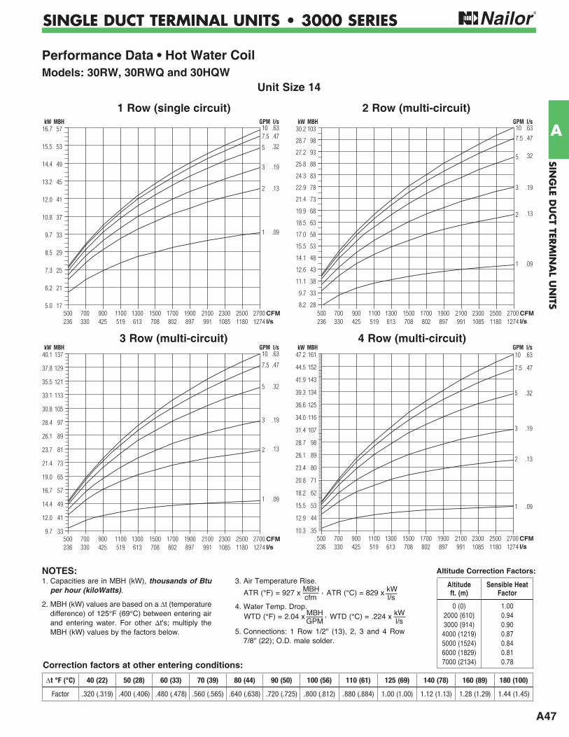
A47
SING
LE DU
CT TER
MIN
AL U
NITS
A
SINGLE DUCT TERMINAL UNITS • 3000 SERIES
Performance Data • Hot Water CoilModels: 30RW, 30RWQ and 30HQW
Unit Size 14
2 Row (multi-circuit)
107.5
5
3
2
1
CFMl/s
500 700 900 1100 1300 1500 1700 1900 2100 2300 2500 2700 236 330 425 519 613 708 802 897 991 1085 1180 1274
57
53
49
45
41
37
33
29
25
21
17
16.7
15.5
14.4
13.2
12.0
10.8
9.7
8.5
7.3
6.2
5.0
kW MBH GPM l/s.63.47
.32
.19
.13
.09
1 Row (single circuit)
3 Row (multi-circuit) 4 Row (multi-circuit)
10
7.5
5
3
2
1
CFMl/s
500 700 900 1100 1300 1500 1700 1900 2100 2300 2500 2700 236 330 425 519 613 708 802 897 991 1085 1180 1274
103
98
93
88
83
78
73
68
63
58
53
48
43
38
33
28
30.2
28.7
27.2
25.8
24.3
22.9
21.4
19.9
18.5
17.0
15.5
14.1
12.6
11.1
9.7
8.2
kW MBH GPM l/s.63
.47
.32
.19
.13
.09
10
7.5
5
3
2
1
CFMl/s
500 700 900 1100 1300 1500 1700 1900 2100 2300 2500 2700 236 330 425 519 613 708 802 897 991 1085 1180 1274
137
129
121
113
105
97
89
81
73
65
57
49
41
33
40.1
37.8
35.5
33.1
30.8
28.4
26.1
23.7
21.4
19.0
16.7
14.4
12.0
9.7
kW MBH GPM l/s.63
.47
.32
.19
.13
.09
10
7.5
5
3
2
1
CFMl/s
500 700 900 1100 1300 1500 1700 1900 2100 2300 2500 2700 236 330 425 519 613 708 802 897 991 1085 1180 1274
161
152
143
134
125
116
107
98
89
80
71
62
53
44
35
47.2
44.5
41.9
39.3
36.6
34.0
31.4
28.7
26.1
23.4
20.8
18.2
15.5
12.9
10.3
kW MBH GPM l/s.63
.47
.32
.19
.13
.09
Altitude Correction Factors:
Correction factors at other entering conditions:
1. Capacities are in MBH (kW), thousands of Btu per hour (kiloWatts).
2. MBH (kW) values are based on a t (temperature difference) of 125°F (69°C) between entering air and entering water. For other t's; multiply the MBH (kW) values by the factors below.
3. Air Temperature Rise.
4. Water Temp. Drop.
5. Connections: 1 Row 1/2" (13), 2, 3 and 4 Row 7/8" (22); O.D. male solder.
ATR (°C) = 829 x kW l/s
ATR (°F) = 927 x MBH , cfm
WTD (°C) = .224 x kW l/s
WTD (°F) = 2.04 x MBH , GPM
NOTES:Altitude ft. (m)
Sensible Heat Factor
0 (0)2000 (610) 3000 (914)
4000 (1219) 5000 (1524) 6000 (1829) 7000 (2134)
1.00 0.94 0.90 0.87 0.84 0.81 0.78
t °F (°C) 40 (22) 50 (28) 60 (33) 70 (39) 80 (44) 90 (50) 100 (56) 110 (61) 125 (69) 140 (78) 160 (89) 180 (100)
Factor .320 (.319) .400 (.406) .480 (.478) .560 (.565) .640 (.638) .720 (.725) .800 (.812) .880 (.884) 1.00 (1.00) 1.12 (1.13) 1.28 (1.29) 1.44 (1.45)
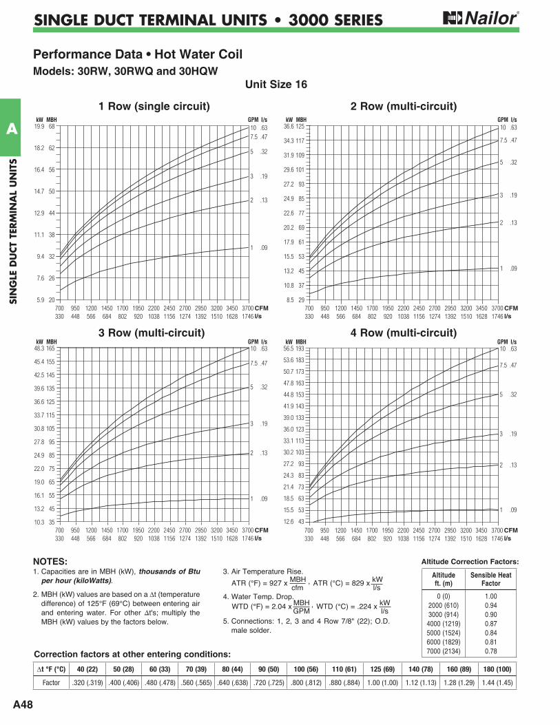
A48
SIN
GLE
DU
CT
TERM
INA
L U
NIT
S
A
SINGLE DUCT TERMINAL UNITS • 3000 SERIES
Performance Data • Hot Water CoilModels: 30RW, 30RWQ and 30HQW
Unit Size 16
2 Row (multi-circuit)
107.5
5
3
2
1
CFMl/s
700 950 1200 1450 1700 1950 2200 2450 2700 2950 3200 3450 3700 330 448 566 684 802 920 1038 1156 1274 1392 1510 1628 1746
68
62
56
50
44
38
32
26
20
19.9
18.2
16.4
14.7
12.9
11.1
9.4
7.6
5.9
kW MBH GPM l/s.63.47
.32
.19
.13
.09
1 Row (single circuit)
3 Row (multi-circuit) 4 Row (multi-circuit)
10
7.5
5
3
2
1
CFMl/s
700 950 1200 1450 1700 1950 2200 2450 2700 2950 3200 3450 3700 330 448 566 684 802 920 1038 1156 1274 1392 1510 1628 1746
125
117
109
101
93
85
77
69
61
53
45
37
29
36.6
34.3
31.9
29.6
27.2
24.9
22.6
20.2
17.9
15.5
13.2
10.8
8.5
kW MBH GPM l/s.63
.47
.32
.19
.13
.09
10
7.5
5
3
2
1
CFMl/s
700 950 1200 1450 1700 1950 2200 2450 2700 2950 3200 3450 3700 330 448 566 684 802 920 1038 1156 1274 1392 1510 1628 1746
165
155
145
135
125
115
105
95
85
75
65
55
45
35
48.3
45.4
42.5
39.6
36.6
33.7
30.8
27.8
24.9
22.0
19.0
16.1
13.2
10.3
kW MBH GPM l/s.63
.47
.32
.19
.13
.09
10
7.5
5
3
2
1
CFMl/s
700 950 1200 1450 1700 1950 2200 2450 2700 2950 3200 3450 3700 330 448 566 684 802 920 1038 1156 1274 1392 1510 1628 1746
193
183
173
163
153
143
133
123
113
103
93
83
73
63
53
43
56.5
53.6
50.7
47.8
44.8
41.9
39.0
36.0
33.1
30.2
27.2
24.3
21.4
18.5
15.5
12.6
kW MBH GPM l/s.63
.47
.32
.19
.13
.09
Altitude Correction Factors:
Correction factors at other entering conditions:
1. Capacities are in MBH (kW), thousands of Btu per hour (kiloWatts).
2. MBH (kW) values are based on a t (temperature difference) of 125°F (69°C) between entering air and entering water. For other t's; multiply the MBH (kW) values by the factors below.
3. Air Temperature Rise.
4. Water Temp. Drop.
5. Connections: 1, 2, 3 and 4 Row 7/8" (22); O.D. male solder.
ATR (°C) = 829 x kW l/s
ATR (°F) = 927 x MBH , cfm
WTD (°C) = .224 x kW l/s
WTD (°F) = 2.04 x MBH , GPM
NOTES:Altitude ft. (m)
Sensible Heat Factor
0 (0)2000 (610) 3000 (914)
4000 (1219) 5000 (1524) 6000 (1829) 7000 (2134)
1.00 0.94 0.90 0.87 0.84 0.81 0.78
t °F (°C) 40 (22) 50 (28) 60 (33) 70 (39) 80 (44) 90 (50) 100 (56) 110 (61) 125 (69) 140 (78) 160 (89) 180 (100)
Factor .320 (.319) .400 (.406) .480 (.478) .560 (.565) .640 (.638) .720 (.725) .800 (.812) .880 (.884) 1.00 (1.00) 1.12 (1.13) 1.28 (1.29) 1.44 (1.45)
A49
SING
LE DU
CT TER
MIN
AL U
NITS
A
SINGLE DUCT TERMINAL UNITS • 3000 SERIES
Performance Data • Hot Water CoilModels: 30RW, 30RWQ and 30HQW
Unit Size 24 x 16
2 Row (multi-circuit)
15
10
7.5
5
3
1
CFMl/s
1000 1700 2400 3100 3800 4500 5200 5900 6600 7300 8000 472 802 1133 1463 1793 2124 2454 2784 3115 3445 3775
135
125
115
105
95
85
75
65
55
45
35
39.6
36.6
33.7
30.8
27.8
24.9
22.0
19.0
16.1
13.2
10.3
kW MBH GPM l/s.95
.63
.47
.32
.19
.09
1 Row (single circuit)
3 Row (multi-circuit) 4 Row (multi-circuit)
15
10
7.5
5
3
1
CFMl/s
1000 1700 2400 3100 3800 4500 5200 5900 6600 7300 8000 472 802 1133 1463 1793 2124 2454 2784 3115 3445 3775
240230220210200190180170160150140130120110100
908070605040
113109104
999490858076716661575247423833282119
kW MBH GPM l/s.95
.63
.47
.32
.19
.09
15
10
7.5
5
3
1
CFMl/s
1000 1700 2400 3100 3800 4500 5200 5900 6600 7300 8000 472 802 1133 1463 1793 2124 2454 2784 3115 3445 3775
320
300
280
260
240
220
200
180
160
140
120
100
80
60
40
93.8
87.9
82.0
76.2
70.3
64.5
58.6
52.7
46.9
41.0
35.2
29.3
23.4
17.6
11.7
kW MBH GPM l/s.95
.63
.47
.32
.19
.09
15
10
7.5
5
3
1
CFMl/s
1000 1700 2400 3100 3800 4500 5200 5900 6600 7300 8000 472 802 1133 1463 1793 2124 2454 2784 3115 3445 3775
370
350
330
310
290
270
250
230
210
190
170
150
130
110
90
70
50
108.4
102.6
96.7
90.8
85.0
79.1
73.3
67.4
61.5
55.7
49.8
44.0
38.1
32.2
26.4
20.5
14.7
kW MBH GPM l/s.95
.63
.47
.32
.19
.09
Altitude Correction Factors:
Correction factors at other entering conditions:
1. Capacities are in MBH (kW), thousands of Btu per hour (kiloWatts).
2. MBH (kW) values are based on a t (temperature difference) of 125°F (69°C) between entering air and entering water. For other t's; multiply the MBH (kW) values by the factors below.
3. Air Temperature Rise.
4. Water Temp. Drop.
5. Connections: 1 and 2 Row 7/8" (22). 3 and 4 Row 1 3/8" (35); O.D. male solder.
ATR (°C) = 829 x kW l/s
ATR (°F) = 927 x MBH , cfm
WTD (°C) = .224 x kW l/s
WTD (°F) = 2.04 x MBH , GPM
NOTES:Altitude ft. (m)
Sensible Heat Factor
0 (0)2000 (610) 3000 (914)
4000 (1219) 5000 (1524) 6000 (1829) 7000 (2134)
1.00 0.94 0.90 0.87 0.84 0.81 0.78
t °F (°C) 40 (22) 50 (28) 60 (33) 70 (39) 80 (44) 90 (50) 100 (56) 110 (61) 125 (69) 140 (78) 160 (89) 180 (100)
Factor .320 (.319) .400 (.406) .480 (.478) .560 (.565) .640 (.638) .720 (.725) .800 (.812) .880 (.884) 1.00 (1.00) 1.12 (1.13) 1.28 (1.29) 1.44 (1.45)
A50
SIN
GLE
DU
CT
TERM
INA
L U
NIT
S
A
SINGLE DUCT TERMINAL UNITS • 3000 SERIES
Performance Data • Hot Water Coil • Pressure DropModels: 30RW, 30RWQ and 30HQW
Unit Sizes 4, 5 & 6 Unit Sizes 7 & 8
Air Pressure DropPa in. w.g.
1 ROW
2 ROW
3 ROW2 ROW
3 ROW
4 ROW
4 ROW 1 ROW
2 ROW
3 ROW
2 ROW
3 ROW
Air Pressure DropPa in. w.g.
4 ROW
4 ROW
Water Pressure Drop
WATER FLOW
HE
AD
LO
SS
(W
AT
ER
PR
ES
SU
RE
DR
OP
)
1 2 4 6 8 10 GPM .06 .13 .25 .38 .50 .63 l/s
10.08.0
6.0
4.0
2.0
1.0
0.8
0.6
0.4
0.2
0.1
kPa ft. H2O29.823.9
17.9
11.9
6.0
3.0
2.4
1.8
1.2
0.6
0.3
AIRFLOW
100 200 300 500 CFM 47 94 142 236 l/s
AIR
PR
ES
SU
RE
DR
OP
1.000.80
0.60
0.40
0.20
0.10
0.08
0.06
0.04
0.02
0.01
249199
149
100
50
25
20
15
10
5
2
1 ROW 1 ROW
Water Pressure Drop
WATER FLOW
HE
AD
LO
SS
(W
AT
ER
PR
ES
SU
RE
DR
OP
)
1 2 4 6 8 10 GPM .06 .13 .25 .38 .50 .63 l/s
10.08.0
6.0
4.0
2.0
1.0
0.8
0.6
0.4
0.2
0.1
kPa ft. H2O29.823.9
17.9
11.9
6.0
3.0
2.4
1.8
1.2
0.6
0.3
AIRFLOW
100 200 400 600 1000 CFM 47 94 189 283 472 l/s
AIR
PR
ES
SU
RE
DR
OP
1.000.80
0.60
0.40
0.20
0.10
0.08
0.06
0.04
0.02
0.01
249199
149
100
50
25
20
15
10
5
2
Unit Sizes 9 & 10 Unit Size 12
1 ROW
2 ROW
3 ROW
1 ROW
2 ROW
3 ROW
Water Pressure Drop
WATER FLOW
HE
AD
LO
SS
(W
AT
ER
PR
ES
SU
RE
DR
OP
)
1 2 4 6 8 10 GPM .06 .13 .25 .38 .50 .63 l/s
10.08.0
6.0
4.0
2.0
1.00.8
0.6
0.4
0.2
0.1
kPa ft. H2O29.823.9
17.9
11.9
6.0
3.02.4
1.8
1.2
0.6
0.3
AIR
PR
ES
SU
RE
DR
OP
Air Pressure Drop
AIRFLOW
100 200 400 600 1000 2000 CFM 47 94 189 283 472 944 l/s
10.08.06.0
4.0
2.0
1.00.80.6
0.4
0.2
0.10.080.06
0.04
0.02
0.01
Pa in. w.g.248619891492
994
497
249199149
99
50
252015
10
5
2
4 ROW 4 ROW
1 ROW
2 ROW
3 ROW
1 ROW
2 ROW
3 ROW
Water Pressure Drop
WATER FLOW
HE
AD
LO
SS
(W
AT
ER
PR
ES
SU
RE
DR
OP
)
1 2 4 6 8 10 GPM .06 .13 .25 .38 .50 .63 l/s
10.08.0
6.0
4.0
2.0
1.0
0.8
0.6
0.4
0.2
0.1
kPa ft. H2O29.823.9
17.9
11.9
6.0
3.0
2.4
1.8
1.2
0.6
0.3
Air Pressure Drop
AIRFLOW
100 200 400 600 1000 3000 CFM 47 94 189 283 472 1416 l/s
AIR
PR
ES
SU
RE
DR
OP
10.08.06.0
4.0
2.0
1.00.80.6
0.4
0.2
0.10.080.06
0.04
0.02
0.01
Pa in. w.g.248619891492
994
497
249199149
99
50
252015
10
5
2
4 ROW4 ROW
1. Capacities are in MBH (kW), thousands of Btu per hour (kiloWatts).
2. MBH (kW) values are based on a t (temperature difference) of 125°F (69°C) between entering air and entering water. For other t's; multiply the MBH (kW) values by the factors below.
3. Air Temperature Rise.
4. Water Temp. Drop.
5. Connections: 1 Row 1/2" (13), 2, 3 and 4 Row 7/8" (22); O.D. male solder.
ATR (°C) = 829 x kW l/s
ATR (°F) = 927 x MBH , cfm
WTD (°C) = .224 x kW l/s
WTD (°F) = 2.04 x MBH , GPM
NOTES:
A51
SING
LE DU
CT TER
MIN
AL U
NITS
A
SINGLE DUCT TERMINAL UNITS • 3000 SERIES
Unit Size 14 Unit Size 16
Performance Data • Hot Water Coil • Pressure DropModels: 30RW, 30RWQ and 30HQW
1 ROW
2 ROW
3 ROW
Water Pressure Drop
WATER FLOW
HE
AD
LO
SS
(W
AT
ER
PR
ES
SU
RE
DR
OP
)
1 2 4 6 8 10 GPM .06 .13 .25 .38 .50 .63 l/s
10.08.0
6.0
4.0
2.0
1.0
0.8
0.6
0.4
0.2
0.1
kPa ft. H2O29.823.9
17.9
11.9
6.0
3.0
2.4
1.8
1.2
0.6
0.3
Air Pressure Drop
AIR
PR
ES
SU
RE
DR
OP
4 ROW
1 ROW
2 ROW
3 ROW
AIRFLOW
100 200 400 600 1000 3000 CFM 47 94 189 283 472 1416 l/s
10.08.06.0
4.0
2.0
1.00.80.6
0.4
0.2
0.10.080.06
0.04
0.02
0.01
Pa in. w.g.248619891492
994
497
249199149
99
50
252015
10
5
2
4 ROW
1 ROW
2 ROW
3 ROW
1 ROW
2 ROW
3 ROW
Water Pressure Drop
WATER FLOW
HE
AD
LO
SS
(W
AT
ER
PR
ES
SU
RE
DR
OP
)
1 2 4 6 8 10 GPM .06 .13 .25 .38 .50 .63 l/s
10.08.0
6.0
4.0
2.0
1.00.8
0.6
0.4
0.2
0.1
kPa ft. H2O29.823.9
17.9
11.9
6.0
3.02.4
1.8
1.2
0.6
0.3
Air Pressure Drop
AIRFLOW
100 200 400 600 1000 2000 4000 CFM 47 94 189 283 472 944 1888 l/s
AIR
PR
ES
SU
RE
DR
OP
10.08.06.0
4.0
2.0
1.00.80.6
0.4
0.2
0.10.080.06
0.04
0.02
0.01
Pa in. w.g.248619891492
994
497
249199149
99
50
252015
10
5
2
4 ROW
4 ROW
Unit Size 24 x 16
1 ROW
2 ROW
3 ROW
Water Pressure Drop
WATER FLOW
HE
AD
LO
SS
(W
AT
ER
PR
ES
SU
RE
DR
OP
)
1 2 4 6 8 10 20 GPM .06 .13 .25 .38 .50 .63 1.26 l/s
10.08.0
6.0
4.0
2.0
1.00.8
0.6
0.4
0.2
0.1
kPa ft. H2O29.823.9
17.9
11.9
6.0
3.02.4
1.8
1.2
0.6
0.3
AIR
PR
ES
SU
RE
DR
OP
Air Pressure Drop
AIRFLOW
100 200 400 600 1000 2000 4000 8000 CFM 47 94 189 283 472 944 1888 3775 l/s
10.08.06.0
4.0
2.0
1.00.80.6
0.4
0.2
0.10.080.06
0.04
0.02
0.01
Pa in. w.g.248619891492
994
497
249199149
99
50
252015
10
5
2
4 ROW
4 ROW
1 ROW
2 ROW
3 ROW
1. Capacities are in MBH (kW), thousands of Btu per hour (kiloWatts).
2. MBH (kW) values are based on a t (temperature difference) of 125°F (69°C) between entering air and entering water. For other t's; multiply the MBH (kW) values by the factors below.
3. Air Temperature Rise.
4. Water Temp. Drop.
5. Connections: 1 Row 1/2" (13), 2, 3 and 4 Row 7/8" (22); O.D. male solder.
ATR (°C) = 829 x kW l/s
ATR (°F) = 927 x MBH , cfm
WTD (°C) = .224 x kW l/s
WTD (°F) = 2.04 x MBH , GPM
NOTES:
A52
SIN
GLE
DU
CT
TERM
INA
L U
NIT
S
A
SINGLE DUCT TERMINAL UNITS • 3000 SERIES
Electric Heating Coils Selection, Capacities and FeaturesModels: 30RE, 30REQ and 30HQENailor manufactures its own electric heating coils. They have been specifically designed and tested for use with variable air volume single duct terminal units.
All terminals with electric heat have been tested and ETL listed as an assembly, eliminating the need to mount coils a minimum of 36" (914) downstream or having to ship a bulky length of ductwork when coils are to be supplied mounted on the terminal.
Nailor electric coils are factory mounted as an integral part of the terminal unit in an insulated extended plenum section. Total length of the casing including heater terminal is only 31" (787), providing a compact, easy to handle unit. The unique inclined opposed blade damper design provides improved and more even airflow over the coil elements compared with round butterfly damper designs, which helps to minimize air stratification, avoid nuisance tripping of the thermal cut-outs and maximize heat transfer.
Selection Guidelines:The table below provides a general guideline as to the voltages and maximum kiloWatts available for each terminal unit size. Up to three stages of heat are available. A minimum of 0.5 kW/stage is required.
For optimum diffuser performance and maximum thermal comfort, ASHRAE recommends that discharge temperatures do not exceed 15°F (8°C) above room set point, as stratification and short circuiting may occur. ASHRAE Standard 62.1 limits discharge temperatures to 90°F (32°C) or increasing the
ventilation rate when heating from the ceiling. Never select kW to exceed a discharge temperatures of 115°F (46°C).
T (Air Temp. Rise, °F) = kW x 3160
cfm
The coil ranges listed are restricted to a maximum of 48 amps and do not require circuit fusing to meet NEC code requirements. Total pressure at the airflow switch should be at least 0.07" w.g. (17 Pa) to ensure correct coil operation and avoid possible nuisance tripping of the thermal cutouts due to insufficient airflow over the coil elements.
Model 30RE
Electric Coil Limitations
* Minimum required airflow must be the greater of the air volume listed or 70 cfm per kilowatt (33 L/s/kW)
Unit Size
Heating Range* cfm (l/s)
Maximum kWSingle Phase Three Phase
120V 208V 220V 240V 277V 347V 208V 380V 480V 600V
4 5 6
25 – 225 (12 – 106) 45 – 400 (21 – 189) 65 – 550 (31 – 260)
3.0 5.0 5.5
3.0 5.0 7.5
3.0 5.0 7.5
3.0 5.0 7.5
3.0 5.0 7.5
3.0 5.0 7.5
3.0 5.0 7.5
3.0 5.0 7.5
3.0 5.0 7.5
3.0 5.0 7.5
7 8 9
95 – 800 (45 – 378) 125 – 1100 (59 – 519) 165 – 1400 (78 – 661)
5.5 5.5 5.5
9.5 9.5 9.5
9.5 10.5 10.5
9.5 11.0 11.0
9.5 13.0 13.0
9.5 13.0 16.0
9.5 13.0 16.0
9.5 13.0 16.0
9.5 13.0 16.0
9.5 13.0 16.0
10 12 14
215 – 1840 (101 – 868) 290 – 2500 (137 – 1180) 360 – 3125 (170 – 1475)
5.5 5.5 5.5
9.5 9.5 9.5
10.5 10.510.5
11.0 11.0 11.0
13.0 13.0 13.0
16.5 16.5 16.5
17.0 17.0 17.0
16.5 16.5 16.5
21.0 30.0 31.0
21.0 30.0 38.5
16 24 x 16
430 – 3725 (203 – 1758) 960 – 8330 (453 – 3931)
5.5 5.5
9.5 9.5
10.510.5
11.0 11.0
13.0 13.0
16.5 16.5
17.0 17.0
16.5 16.5
31.0 31.0
38.5 38.5
• Primary auto-reset high limit thermal cut-out.• Secondary manual reset high limit thermal cut-outs (one per
element).• Positive pressure airflow switch.• Derated high quality nickel-chrome alloy heating elements.• Magnetic or safety contactors and/or PE switches as required.• Control transformer. Class II, 24 Vac for digital and analog
controls.• Line terminal block.• ETL Listed as an assembly.• Hinged door control enclosure.• High performance arrowhead insulators.
• Slip and drive discharge connection.• Class A 80/20 Ni/Cr wire.
Options:• Quiet contactors.• Mercury contactors.• Toggle type disconnect switch.• Door interlock disconnect switch.• Power circuit fusing.• Dust tight construction.• SCR control.
Tested and approved to the following
standards:
ANSI/UL1996, 4th ed.
CSA C22.2No. 155-M1986.
Standard Features:
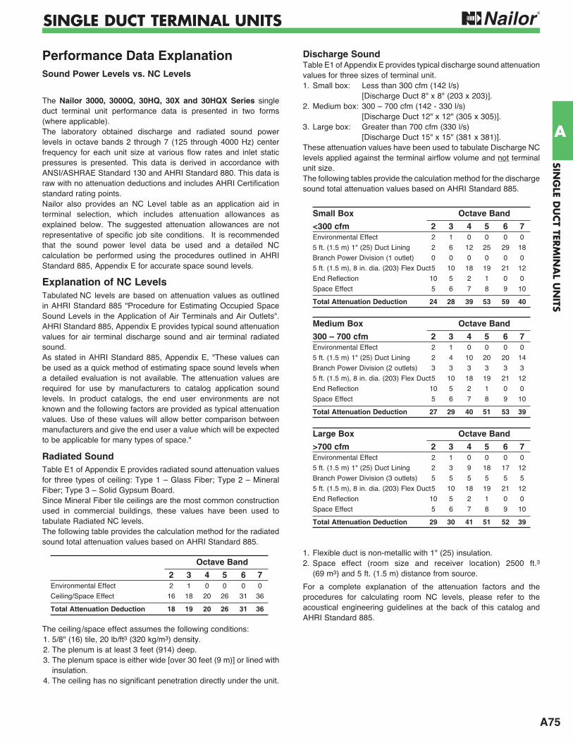
A75
SING
LE DU
CT TER
MIN
AL U
NITS
A
SINGLE DUCT TERMINAL UNITS
Performance Data ExplanationSound Power Levels vs. NC Levels
The Nailor 3000, 3000Q, 30HQ, 30X and 30HQX Series single duct terminal unit performance data is presented in two forms (where applicable). The laboratory obtained discharge and radiated sound power levels in octave bands 2 through 7 (125 through 4000 Hz) center frequency for each unit size at various flow rates and inlet static pressures is presented. This data is derived in accordance with ANSI/ASHRAE Standard 130 and AHRI Standard 880. This data is raw with no attenuation deductions and includes AHRI Certification standard rating points. Nailor also provides an NC Level table as an application aid in terminal selection, which includes attenuation allowances as explained below. The suggested attenuation allowances are not representative of specific job site conditions. It is recommended that the sound power level data be used and a detailed NC calculation be performed using the procedures outlined in AHRI Standard 885, Appendix E for accurate space sound levels.
Explanation of NC LevelsTabulated NC levels are based on attenuation values as outlined in AHRI Standard 885 "Procedure for Estimating Occupied Space Sound Levels in the Application of Air Terminals and Air Outlets". AHRI Standard 885, Appendix E provides typical sound attenuation values for air terminal discharge sound and air terminal radiated sound. As stated in AHRI Standard 885, Appendix E, "These values can be used as a quick method of estimating space sound levels when a detailed evaluation is not available. The attenuation values are required for use by manufacturers to catalog application sound levels. In product catalogs, the end user environments are not known and the following factors are provided as typical attenuation values. Use of these values will allow better comparison between manufacturers and give the end user a value which will be expected to be applicable for many types of space."
Radiated SoundTable E1 of Appendix E provides radiated sound attenuation values for three types of ceiling: Type 1 – Glass Fiber; Type 2 – Mineral Fiber; Type 3 – Solid Gypsum Board.Since Mineral Fiber tile ceilings are the most common construction used in commercial buildings, these values have been used to tabulate Radiated NC levels.The following table provides the calculation method for the radiated sound total attenuation values based on AHRI Standard 885.
The ceiling/space effect assumes the following conditions:1. 5/8" (16) tile, 20 lb/ft3 (320 kg/m3) density.2. The plenum is at least 3 feet (914) deep.3. The plenum space is either wide [over 30 feet (9 m)] or lined with
insulation.4. The ceiling has no significant penetration directly under the unit.
Discharge SoundTable E1 of Appendix E provides typical discharge sound attenuation values for three sizes of terminal unit.1. Small box: Less than 300 cfm (142 l/s) [Discharge Duct 8" x 8" (203 x 203)].2. Medium box: 300 – 700 cfm (142 - 330 l/s) [Discharge Duct 12" x 12" (305 x 305)].3. Large box: Greater than 700 cfm (330 l/s) [Discharge Duct 15" x 15" (381 x 381)].These attenuation values have been used to tabulate Discharge NC levels applied against the terminal airflow volume and not terminal unit size.The following tables provide the calculation method for the discharge sound total attenuation values based on AHRI Standard 885.
1. Flexible duct is non-metallic with 1" (25) insulation.2. Space effect (room size and receiver location) 2500 ft.3 (69 m3) and 5 ft. (1.5 m) distance from source.
For a complete explanation of the attenuation factors and the procedures for calculating room NC levels, please refer to the acoustical engineering guidelines at the back of this catalog and AHRI Standard 885.
Octave Band
2 3 4 5 6 7 Environmental Effect 2 1 0 0 0 0
Ceiling/Space Effect 16 18 20 26 31 36
Total Attenuation Deduction 18 19 20 26 31 36
Small Box Octave Band
<300 cfm 2 3 4 5 6 7 Environmental Effect 2 1 0 0 0 0
5 ft. (1.5 m) 1" (25) Duct Lining 2 6 12 25 29 18
Branch Power Division (1 outlet) 0 0 0 0 0 0
5 ft. (1.5 m), 8 in. dia. (203) Flex Duct 5 10 18 19 21 12
End Reflection 10 5 2 1 0 0
Space Effect 5 6 7 8 9 10
Total Attenuation Deduction 24 28 39 53 59 40
Medium Box Octave Band
300 – 700 cfm 2 3 4 5 6 7 Environmental Effect 2 1 0 0 0 0
5 ft. (1.5 m) 1" (25) Duct Lining 2 4 10 20 20 14
Branch Power Division (2 outlets) 3 3 3 3 3 3
5 ft. (1.5 m), 8 in. dia. (203) Flex Duct 5 10 18 19 21 12
End Reflection 10 5 2 1 0 0
Space Effect 5 6 7 8 9 10
Total Attenuation Deduction 27 29 40 51 53 39
Large Box Octave Band
>700 cfm 2 3 4 5 6 7 Environmental Effect 2 1 0 0 0 0
5 ft. (1.5 m) 1" (25) Duct Lining 2 3 9 18 17 12
Branch Power Division (3 outlets) 5 5 5 5 5 5
5 ft. (1.5 m), 8 in. dia. (203) Flex Duct 5 10 18 19 21 12
End Reflection 10 5 2 1 0 0
Space Effect 5 6 7 8 9 10
Total Attenuation Deduction 29 30 41 51 52 39
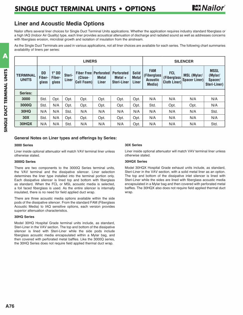
A76
SIN
GLE
DU
CT
TERM
INA
L U
NIT
S
A
SINGLE DUCT TERMINAL UNITS • OPTIONS
LINERS SILENCER
TERMINALUNITS
DDFiber- glass
1" DD Fiber-glass
Steri-Liner
Fiber Free(Close-
Cell Foam)
Perforated MetalLiner
Perforated Metal +
Steri-Liner
Solid Metal Liner
FAM (Fiberglass
Acoustic Media)
FCL(Fiberglass Cloth Liner)
MSL (Mylar/Spacer Liner)
MSSL (Mylar/Spacer/
Steri-Liner)
Series:
3000 Std. Opt. Opt. Opt. Opt. Opt. Opt. N/A N/A N/A N/A
3000Q Std. N/A Opt. Opt. Opt. Opt. Opt. Std. Opt. Opt. N/A
30HQ N/A N/A Std. N/A N/A N/A N/A N/A N/A N/A Std.
30X Std. N/A Opt. Opt. Opt. Opt. Opt. N/A N/A N/A N/A
30HQX N/A N/A Std. N/A N/A N/A Opt. N/A N/A N/A Std.
Liner and Acoustic Media OptionsNailor offers several liner choices for Single Duct Terminal Units applications. Whether the application requires industry standard fiberglass or a high IAQ (Indoor Air Quality) type, each liner provides acoustical attenuation of discharge and radiated sound as well as addresses concerns with fiberglass erosion, microbial growth and isolation of insulation from the airstream.
As the Single Duct Terminals are used in various applications, not all liner choices are available for each series. The following chart summaries availability of liners per series:
3000 Series
Liner inside optional attenuator will match VAV terminal liner unless otherwise stated.
3000Q Series
There are two components to the 3000Q Series terminal units, the VAV terminal and the dissipative silencer. Liner selection determines the liner type installed into the terminal portion only. Each dissipative silencer is lined top and bottom with fiberglass as standard. When the FCL or MSL acoustic media is selected, a foil faced fiberglass is used. As the entire silencer is internally insulated, there is no need for field applied duct wrap.
There are three acoustic media options available within the side pods of the dissipative silencer. From the standard FAM (Fiberglass Acoustic Media) to IAQ sensitive options, each version provides superior attenuation characteristics.
30HQ Series
Model 30HQ Hospital Grade terminal units include, as standard, Steri-Liner in the VAV section. The top and bottom of the dissipative silencer is lined with Steri-Liner while the side pods include fiberglass acoustic media encapsulated within a Mylar bag, and then covered with perforated metal baffles. Like the 3000Q series, the 30HQ Series does not require field applied thermal duct wrap.
30X Series
Liner inside optional attenuator will match VAV terminal liner unless otherwise stated.
30HQX Series
Model 30HQX Hospital Grade exhaust units include, as standard, Steri-Liner in the VAV section, with a solid metal liner as an option. The top and bottom of the dissipative inlet silencer is lined with Steri-Liner while the sides are lined with fiberglass acoustic media encapsulated in a Mylar bag and then covered with perforated metal baffles. The 30HQX also does not require field applied thermal duct wrap.
General Notes on Liner types and offerings by Series:
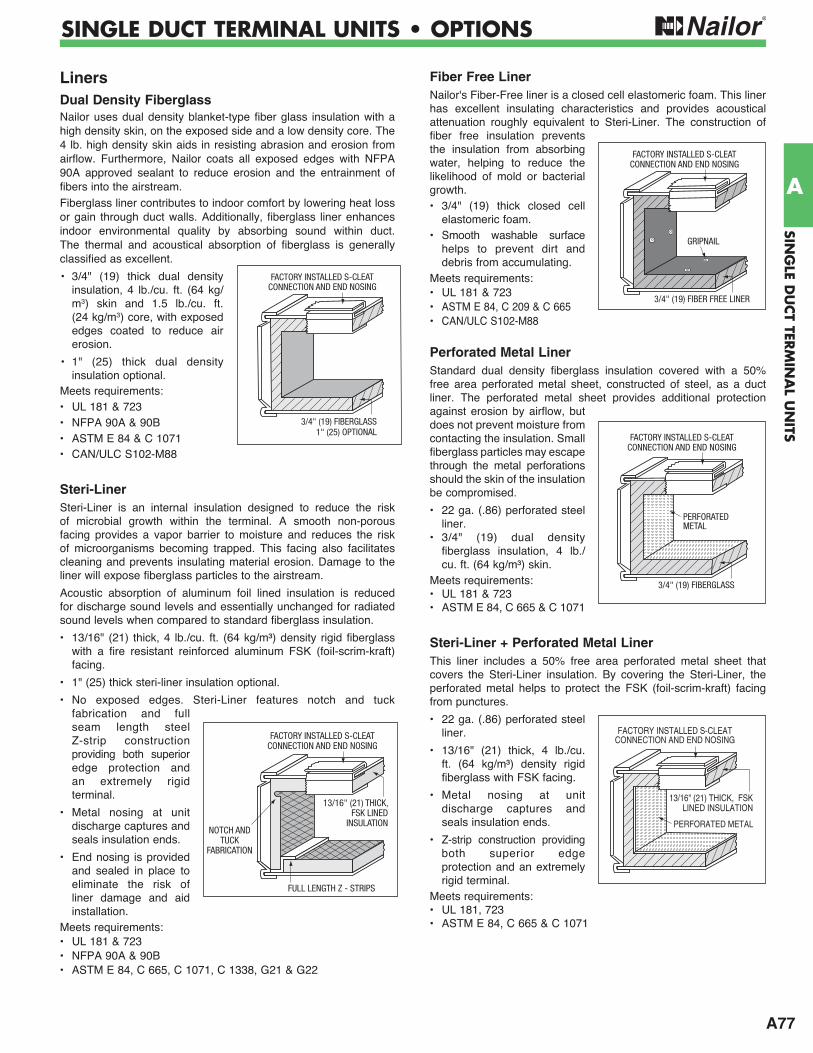
A77
SING
LE DU
CT TER
MIN
AL U
NITS
A
SINGLE DUCT TERMINAL UNITS • OPTIONS
LinersDual Density FiberglassNailor uses dual density blanket-type fiber glass insulation with a high density skin, on the exposed side and a low density core. The 4 lb. high density skin aids in resisting abrasion and erosion from airflow. Furthermore, Nailor coats all exposed edges with NFPA 90A approved sealant to reduce erosion and the entrainment of fibers into the airstream.Fiberglass liner contributes to indoor comfort by lowering heat loss or gain through duct walls. Additionally, fiberglass liner enhances indoor environmental quality by absorbing sound within duct. The thermal and acoustical absorption of fiberglass is generally classified as excellent.
• 3/4" (19) thick dual density insulation, 4 lb./cu. ft. (64 kg/m3) skin and 1.5 lb./cu. ft. (24 kg/m3) core, with exposed edges coated to reduce air erosion.
• 1" (25) thick dual density insulation optional.
Meets requirements:• UL 181 & 723• NFPA 90A & 90B• ASTM E 84 & C 1071• CAN/ULC S102-M88
Steri-LinerSteri-Liner is an internal insulation designed to reduce the risk of microbial growth within the terminal. A smooth non-porous facing provides a vapor barrier to moisture and reduces the risk of microorganisms becoming trapped. This facing also facilitates cleaning and prevents insulating material erosion. Damage to the liner will expose fiberglass particles to the airstream.
Acoustic absorption of aluminum foil lined insulation is reduced for discharge sound levels and essentially unchanged for radiated sound levels when compared to standard fiberglass insulation.
• 13/16" (21) thick, 4 lb./cu. ft. (64 kg/m³) density rigid fiberglass with a fire resistant reinforced aluminum FSK (foil-scrim-kraft) facing.
• 1" (25) thick steri-liner insulation optional.
• No exposed edges. Steri-Liner features notch and tuck fabrication and full seam length steel Z-strip construction providing both superior edge protection and an extremely rigid terminal.
• Metal nosing at unit discharge captures and seals insulation ends.
• End nosing is provided and sealed in place to eliminate the risk of liner damage and aid installation.
Meets requirements:• UL 181 & 723• NFPA 90A & 90B• ASTM E 84, C 665, C 1071, C 1338, G21 & G22
Fiber Free LinerNailor's Fiber-Free liner is a closed cell elastomeric foam. This liner has excellent insulating characteristics and provides acoustical attenuation roughly equivalent to Steri-Liner. The construction of fiber free insulation prevents the in sulation from absorbing water, helping to reduce the likelihood of mold or bacterial growth.• 3/4" (19) thick closed cell
elastomeric foam.• Smooth washable surface
helps to prevent dirt and debris from accumulating.
Meets requirements:• UL 181 & 723• ASTM E 84, C 209 & C 665• CAN/ULC S102-M88
Perforated Metal LinerStandard dual density fiberglass insulation covered with a 50% free area perforated metal sheet, constructed of steel, as a duct liner. The perforated metal sheet provides additional protection against erosion by airflow, but does not prevent moisture from contacting the insulation. Small fiberglass particles may escape through the metal perforations should the skin of the insulation be compromised.
• 22 ga. (.86) perforated steel liner.
• 3/4" (19) dual density fiberglass insulation, 4 lb./ cu. ft. (64 kg/m³) skin.
Meets requirements:• UL 181 & 723• ASTM E 84, C 665 & C 1071
Steri-Liner + Perforated Metal LinerThis liner includes a 50% free area perforated metal sheet that covers the Steri-Liner insulation. By covering the Steri-Liner, the perforated metal helps to protect the FSK (foil-scrim-kraft) facing from punctures.
• 22 ga. (.86) perforated steel liner.
• 13/16" (21) thick, 4 lb./cu. ft. (64 kg/m³) density rigid fiberglass with FSK facing.
• Metal nosing at unit discharge captures and seals insulation ends.
• Z-strip construction providing both superior edge protection and an extremely rigid terminal.
Meets requirements:• UL 181, 723• ASTM E 84, C 665 & C 1071
NOTCH ANDTUCK
FABRICATION
FULL LENGTH Z - STRIPS
13/16" (21) THICK, FSK LINED
INSULATION
FACTORY INSTALLED S-CLEATCONNECTION AND END NOSING
3/4" (19) FIBERGLASS1" (25) OPTIONAL
FACTORY INSTALLED S-CLEATCONNECTION AND END NOSING
3/4" (19) FIBER FREE LINER
GRIPNAIL
FACTORY INSTALLED S-CLEATCONNECTION AND END NOSING
PERFORATED METAL
13/16" (21) THICK, FSKLINED INSULATION
FACTORY INSTALLED S-CLEATCONNECTION AND END NOSING
3/4" (19) FIBERGLASS
PERFORATEDMETAL
FACTORY INSTALLED S-CLEATCONNECTION AND END NOSING
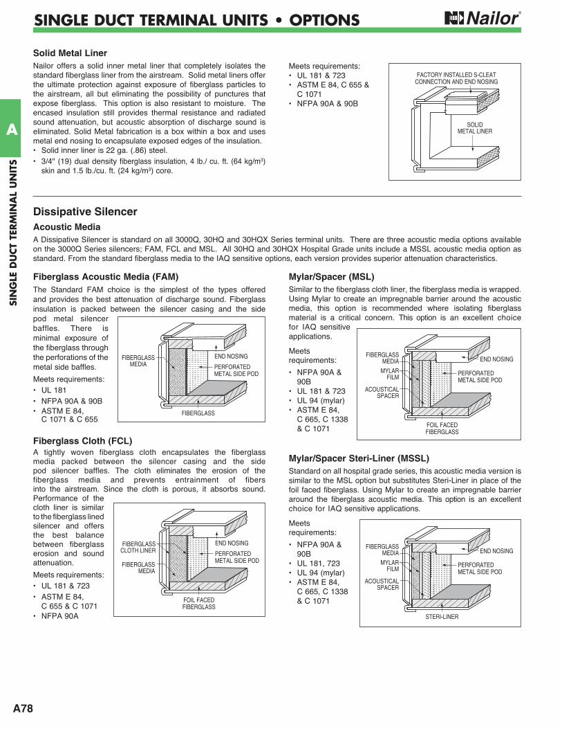
A78
SIN
GLE
DU
CT
TERM
INA
L U
NIT
S
A
SINGLE DUCT TERMINAL UNITS • OPTIONS
Solid Metal LinerNailor offers a solid inner metal liner that completely isolates the standard fiberglass liner from the airstream. Solid metal liners offer the ultimate protection against exposure of fiberglass particles to the airstream, all but eliminating the possibility of punctures that expose fiberglass. This option is also resistant to moisture. The encased insulation still provides thermal resistance and radiated sound attenuation, but acoustic absorption of discharge sound is eliminated. Solid Metal fabrication is a box within a box and uses metal end nosing to encapsulate exposed edges of the insulation. • Solid inner liner is 22 ga. (.86) steel.• 3/4" (19) dual density fiberglass insulation, 4 lb./ cu. ft. (64 kg/m3)
skin and 1.5 lb./cu. ft. (24 kg/m3) core.
Meets requirements:• UL 181 & 723• ASTM E 84, C 655 & C 1071• NFPA 90A & 90B
SOLIDMETAL LINER
FACTORY INSTALLED S-CLEATCONNECTION AND END NOSING
Fiberglass Acoustic Media (FAM)The Standard FAM choice is the simplest of the types offered and provides the best attenuation of discharge sound. Fiberglass insulation is packed between the silencer casing and the side pod metal silencer baffles. There is minimal exposure of the fiberglass through the perforations of the metal side baffles.
Meets requirements:• UL 181• NFPA 90A & 90B• ASTM E 84,
C 1071 & C 655
Fiberglass Cloth (FCL)A tightly woven fiberglass cloth encapsulates the fiberglass media packed between the silencer casing and the side pod silencer baffles. The cloth eliminates the erosion of the fiberglass media and prevents entrainment of fibers into the airstream. Since the cloth is porous, it absorbs sound. Performance of the cloth liner is similar to the fiberglass lined silencer and offers the best balance between fiberglass erosion and sound attenuation.
Meets requirements:• UL 181 & 723• ASTM E 84, C 655 & C 1071• NFPA 90A
Mylar/Spacer (MSL)Similar to the fiberglass cloth liner, the fiberglass media is wrapped. Using Mylar to create an impregnable barrier around the acoustic media, this option is recommended where isolating fiberglass material is a critical concern. This option is an excellent choice for IAQ sensitive applications.
Meets requirements:
• NFPA 90A & 90B
• UL 181 & 723• UL 94 (mylar)• ASTM E 84,
C 665, C 1338 & C 1071
Mylar/Spacer Steri-Liner (MSSL)Standard on all hospital grade series, this acoustic media version is similar to the MSL option but substitutes Steri-Liner in place of the foil faced fiberglass. Using Mylar to create an impregnable barrier around the fiberglass acoustic media. This option is an excellent choice for IAQ sensitive applications.
Meets requirements:
• NFPA 90A & 90B
• UL 181, 723• UL 94 (mylar)• ASTM E 84,
C 665, C 1338 & C 1071
END NOSINGFIBERGLASS
MEDIA
FOIL FACEDFIBERGLASS
MYLARFILM
ACOUSTICALSPACER
PERFORATEDMETAL SIDE POD
Dissipative Silencer
Acoustic MediaA Dissipative Silencer is standard on all 3000Q, 30HQ and 30HQX Series terminal units. There are three acoustic media options available on the 3000Q Series silencers; FAM, FCL and MSL. All 30HQ and 30HQX Hospital Grade units include a MSSL acoustic media option as standard. From the standard fiberglass media to the IAQ sensitive options, each version provides superior attenuation characteristics.
END NOSINGFIBERGLASSMEDIA
FIBERGLASS
PERFORATEDMETAL SIDE POD
END NOSING
FIBERGLASSMEDIA
FOIL FACEDFIBERGLASS
PERFORATEDMETAL SIDE POD
FIBERGLASSCLOTH LINER END NOSING
FIBERGLASSMEDIA
STERI-LINER
MYLARFILM
ACOUSTICALSPACER
PERFORATEDMETAL SIDE POD
G3
SUG
GESTED
SPEC
IFICA
TION
S
G
SUGGESTED SPECIFICATIONS
Model 3001 • Basic Unit
1. Furnish and install Nailor 3000 Series Single Duct Variable Volume Terminal Units of the sizes and capabilities as indicated on the drawings. Units shall be pressure independent with (DDC, analog electronic, pneumatic) controls. Units shall reset to any flow between minimum and the maximum cataloged airflow as allowed by the specific controller.
2. The entire terminal unit shall be designed and built as a single unit. The unit shall be provided with a primary variable air volume damper that controls the air quantity in response to a (DDC, analog electronic, pneumatic electric) thermostat. The unit shall also include all options such as electric or hot water heating coils, attenuators and access doors. The space limitations shall be reviewed carefully to insure that all units will fit into the space allowed.
3. Unit casing shall be 22 ga. (.86) galvanized steel with round, flat oval or rectangular inlets with 5 1
2" (140) deep inlet duct collar for field connection. Outlets shall be rectangular and configured for slip and drive connections. Casing leakage downstream of the damper shall not exceed 1% @ 1" w.g. (249 Pa). High side casing leakage shall not exceed 2% @ 3" w.g. (746 Pa).
4. Damper assemblies of 16 ga. (1.63) galvanized steel shall be multiple opposed blade construction arranged to close at 45 degrees from full open to minimize air turbulence and provide near linear operation. Damper blades shall be fitted with flexible seals for tight closure and minimized sound generation. Damper blades shall be screwed through the shaft to insure that no slippage occurs. Blade shafts shall pivot on corrosion free Celcon® bearings. In the fully closed position, air leakage past the closed damper shall not exceed 2% of the nominal catalog rating at 3" w.g. (746 Pa) inlet static pressure as rated by ASHRAE Standard 130.
5. The terminal units shall be capable of operation as described herein with a minimum inlet static pressure that shall not exceed .18" w.g. (45 Pa) @ 2000 fpm (10.2 m/s) inlet velocity. (The sequence of operations should be described here, if not part of the temperature controls specifications.) Each unit shall be complete with factory mounted (DDC, electric, analog electronic or pneumatic) controls. Gauge tap ports shall be supplied in the piping between the flow pick up and the controller.
6. Each unit shall be constructed with single point electrical or pneumatic connection. All electrical components shall be ETL or UL listed or recognized and installed in accordance with the National Electrical Code. All electrical components shall be installed in a control box. The entire assembly shall be ETL listed and so labeled.
7. Each unit shall be internally lined with 34" (19) dual density
fiberglass insulation. Edges shall be sealed against airflow erosion. Units shall meet NFPA 90A and UL 181 standards.
8. All sound data shall be compiled in an independent laboratory and in accordance with the latest version of AHRI Standard 880 and ANSI/ASHRAE Standard 130. All units shall be AHRI certified and bear the AHRI certification label.
OPTIONS
Electric Heat:Model: 30REStaged(Substitute the following paragraphs:)
1. Furnish and install Nailor Model 30RE Single Duct Variable Volume Terminal Units of the sizes and capabilities as indicated on the drawings. Units shall be pressure independent with (DDC, analog electronic, pneumatic) controls. Units shall reset to any flow between minimum and the maximum cataloged airflow as allowed by the specific controller.9. Single Duct Terminal Unit Staged Electric Heating Coils: a. Electric heating coils shall consist of open coils of high grade nickel and chromium resistance wire or nichrome elements and insulated with ceramic insulators in galvanized steel brackets, supported in heavy gauge galvanized steel frames. Each unit employing an electric heating coil shall be constructed and installed in accordance with the requirements of the local authorities and shall be UL or ETL listed specifically with the heater as a component of the terminal unit device.
b. Coils shall have the capacities indicated in Contract Documents. Coils rated up through 16.5 kW shall be single phase, 347 volt, 60 hertz and coils larger than 16.5 kW shall be three phase, four wire, 208, 480 or 600 volt, 60 hertz. Coils shall be available in one, two or three stages.
c. Terminal bolts, nuts and washers shall be of corrosion resistant materials. Coils shall be constructed so the installation may be accomplished in accordance with the provisions of the National Electrical Code, for zero clearance. Coils shall be given a 2000 volt dielectric test at the factory.
d. Automatic reset thermal cutouts shall be furnished for primary protection with manually resettable limit switches in power circuits for secondary protection. Both devices shall be serviceable through terminal box without removing heating element from the terminal device. The air pressure safety cutout pickup probe shall be remotely mounted near the volume control damper for maximum fidelity.
e. Heating coils shall have a terminal box and cover, with quiet type built-in magnetic step controlled contactors for each circuit, branch circuit fusing for each branch circuit on heaters over 48 amps per the NEC and an air flow safety interlock switch for installation in the heater control enclosure. Provide a 120 or 24 VAC control power transformer with an integral or separately mounted primary and/or secondary overcurrent protection device in accordance with NEC requirements.
f. All wiring of built-in devices shall be brought to clearly marked terminal strips. A complete wiring diagram shall be permanently attached to the heating coil panel cover.
g. Electric heating coils shall be designed for operation with the DDC controller and control system.
h. Electric heating coils and the associated control panels shall be constructed as a component of the entire terminal unit and mounted in the discharge attenuator downstream of the terminal unit. The resulting unit, including the heater and the VAV damper, shall be no longer than 37" (940) in length.
i. The manufacturer shall prove adequate even airflow over the electric heating coil under the full range of airflow scheduled (minimum to maximum) to prevent uneven heating of the electric coils. The terminal device shall be listed in accordance with UL 1995 as a composite assembly consisting of the VAV terminal device and the electric heating device.
j. Shop Drawings shall be submitted for review. Shop Drawings shall indicate specifically the exact construction, materials, internal wiring, NEC working clearances, etc., of the terminal units and electric heating coils to be furnished under these Specifications.
Single Duct Terminal Units • 3000 Series
G4
G
SUG
GES
TED
SPEC
IFIC
ATI
ON
SSUGGESTED SPECIFICATIONS
Model 3001 • Basic UnitOPTIONS (continued)
Proportional Heat (SCR):(Substitute the following paragraphs:)
1. Furnish and install Nailor Model 30RE Single Duct Variable Volume Terminal Units of the sizes and capabilities as indicated on the drawings. Units shall be pressure independent with (DDC, analog electronic, pneumatic) controls. Units shall reset to any flow between minimum and the maximum cataloged airflow as allowed by the specific controller.9. Single Duct Terminal Unit Proportional Electric Heating Coils:a. Electric heating coils shall consist of open coils of high grade nickel and chromium resistance wire or nichrome elements and insulated with ceramic insulators in galvanized steel brackets, supported in heavy gauge galvanized steel frames. Each unit employing an electric heating coil shall be constructed and installed in accordance with the requirements of the local authorities and shall be UL or ETL listed specifically with the heater as a component of the terminal unit device.
b. Coils shall have the capacities indicated in Contract Documents. Coils rated up through 15.5 kW shall be single phase, 347 volt, 60 hertz and coils larger than 15.5 kW shall be three phase, four wire, 208, 480 or 600 volt, 60 hertz.
c. Terminal bolts, nuts and washers shall be of corrosion resistant materials. Coils shall be constructed so the installation may be accomplished in accordance with the provisions of the National Electrical Code, for zero clearance. Coils shall be given a 2000 volt dielectric test at the factory.
d. Automatic reset thermal cutouts shall be furnished for primary protection with manually resettable limit switches in power circuits for secondary protection. Both devices shall be serviceable through terminal box without removing heating element from the terminal device. The air pressure safety cutout pickup probe shall be remotely mounted near the volume control damper for maximum fidelity.
e. Heating coils shall have a terminal box and cover, with proportional heat control for the single circuit, branch circuit fusing on heaters over 45 amps per the NEC and an air flow safety interlock switch for installation in the heater control enclosure. Provide a 120 or 24 VAC control power transformer with an integral or separately mounted primary and/or secondary overcurrent protection device in accordance with NEC requirements
f. An electric heater shall be factory mounted and pre-wired as an integral package with single duct variable volume terminal unit. Heaters shall be sized as shown on the drawings. The entire assembly including the electric heater shall be ETL listed for zero clearance and so labeled and shall meet all requirements of the latest National Electrical Code, (CSA C22.2 No.236). The unit shall have a single point electrical and/or pneumatic connection (dual point electrical on 600V). Heater casing and panel shall be a minimum of 20 ga. (1.00) galvanized steel. Each heater shall be complete with automatic reset high limit thermal cut-outs, control voltage transformer as required, ground terminal and high grade nickel chrome alloy wire.Element wires shall be supported by ceramic isolators. Each heater shall be supplied with factory supplied and pre-wired branch circuit fusing as required by NEC and UL. Circuiting and fusing shall also be in accordance with the circuiting requirements as shown on the plans.Additional accessories shall include (control transformer, circuit fusing, disconnect switch, pneumatic electric switches) for heater control.Heater shall be capable of providing proportional control of heater capacity from an input signal of 4 – 20 mA, 2 – 10 VDC or 0 – 10 VDC. The SCR controller shall provide a 1 – 24 VDC pulsed output to SSR(s) [solid state relay(s)] in proportion to zone heating demand. The SSR's shall switch with zero cross over to reduce system noise and thermal shock on heater coils.
g. All wiring of built-in devices shall be brought to clearly marked terminal strips. A complete wiring diagram shall be permanently attached to the heating coil panel cover.
h. Electric heating coils shall be designed for operation with the DDC controller and control system.
i. Electric heating coils and the associated control panels shall be constructed as a component of the entire terminal unit and mounted in the discharge attenuator downstream of the terminal unit. The resulting unit, including the heater and the VAV damper, shall be no longer than 37" (940) in length.
j. The manufacturer shall prove adequate even airflow over the electric heating coil under the full range of airflow scheduled (minimum to maximum) to prevent uneven heating of the electric coils. The terminal device shall be listed in accordance with UL 1995 as a composite assembly consisting of the VAV terminal device and the electric heating device.
k. Shop Drawings shall be submitted for review. Shop Drawings shall indicate specifically the exact construction, materials, internal wiring, NEC working clearances, etc., of the terminal units and electric heating coils to be furnished under these Specifications.
Proportional Heat with Discharge Temperature Control (DTC):(Substitute the following paragraphs:)
1. Furnish and install Nailor Model 30RE Single Duct Variable Volume Terminal Units of the sizes and capabilities as indicated on the drawings. Units shall be pressure independent with (DDC, analog electronic, pneumatic) controls. Units shall reset to any flow between minimum and the maximum cataloged airflow as allowed by the specific controller.9. Single Duct Terminal Unit Proportional Electric Heating Coils:a. Electric heating coils shall consist of open coils of high grade nickel and chromium resistance wire or nichrome elements and insulated with ceramic insulators in galvanized steel brackets, supported in heavy gauge galvanized steel frames. Each unit employing an electric heating coil shall be constructed and installed in accordance with the requirements of the local authorities and shall be UL or ETL listed specifically with the heater as a component of the terminal unit device.
b. Coils shall have the capacities indicated in Contract Documents. Coils rated up through 15.5 kW shall be single phase, 347 volt, 60 hertz and coils larger than 15.5 kW shall be three phase, four wire, 208, 480 or 600 volt, 60 hertz.
c. Terminal bolts, nuts and washers shall be of corrosion resistant materials. Coils shall be constructed so the installation may be accomplished in accordance with the provisions of the National Electrical Code, for zero clearance. Coils shall be given a 2000 volt dielectric test at the factory.
d. Automatic reset thermal cutouts shall be furnished for primary protection with manually resettable limit switches in power circuits for secondary protection. Both devices shall be serviceable through terminal box without removing heating element from the terminal device. The air pressure safety cutout pickup probe shall be remotely mounted near the volume control damper for maximum fidelity.
e. Heating coils shall have a terminal box and cover, with proportional heat control for the single circuit, branch circuit fusing on heaters over 45 amps per the NEC and an air flow safety interlock switch for installation in the heater control enclosure. Provide a 120 or 24 VAC control power transformer with an integral or separately mounted primary and/or secondary overcurrent protection device in accordance with NEC requirements.
Single Duct Terminal Units • 3000 Series
SUGGESTED SPECIFICATIONS
G5
SUG
GESTED
SPEC
IFICA
TION
S
G
Single Duct Terminal Units • 3000 Series
Model 3001 • Basic UnitOPTIONS (continued)
f. An electric heater shall be factory mounted and pre-wired as an integral package with the single duct variable volume terminal unit. Heaters shall be sized as shown on the drawings. The entire assembly including the electric heater shall be ETL listed for zero clearance and so labeled and shall meet all requirements of the latest National Electrical Code, (CSA C22.2 No.236). The unit shall have a single point electrical and/or pneumatic connection (dual point electrical on 600V). Heater casing and panel shall be a minimum of 20 ga. (1.00) galvanized steel. Each heater shall be complete with automatic reset high limit thermal cut-outs, control voltage transformer as required, ground terminal and high grade nickel chrome alloy wire.Element wires shall be supported by ceramic isolators. Each heater shall be supplied with factory supplied and pre-wired branch circuit fusing as required by NEC and UL. Circuiting and fusing shall also be in accordance with the circuiting requirements as shown on the plans.Additional accessories shall include (control transformer, circuit fusing, disconnect switch, pneumatic electric switches) for heater control.Heater shall be capable of providing proportional control of heater capacity from an input signal of 4 – 20 mA, 2 – 10 VDC or 0 – 10 VDC. The SCR controller shall provide a 1 – 24 VDC pulsed output to SSR(s) [solid state relay(s)] in proportion to zone heating demand. The SSR's shall switch with zero cross over to reduce system noise and thermal shock on heater coils.The SCR controller shall contain a discharge temperature sensor capable of limiting leaving air temperature to a user defined setpoint. The SCR controller shall pulse the coil to maintain zone demand while providing the set maximum discharge air temperature. Upon measuring a discharge air temperature above the user defined setpoint, the controller shall reduce heater capacity to maintain maximum allowable discharge air temperature. The discharge air temperature setpoint shall be adjustable from 80 – 120°F (27 – 49°C) by use of a controller mounted potentiometer.
g. All wiring of built-in devices shall be brought to clearly marked terminal strips. A complete wiring diagram shall be permanently attached to the heating coil panel cover.
h. Electric heating coils shall be designed for operation with the DDC controller and control system.
i. Electric heating coils and the associated control panels shall be constructed as a component of the entire terminal unit and mounted in the discharge attenuator downstream of the terminal unit. The resulting unit, including the heater and the VAV damper, shall be no longer than 37" (940) in length.
j. The manufacturer shall prove adequate even airflow over the electric heating coil under the full range of airflow scheduled (minimum to maximum) to prevent uneven heating of the electric coils. The terminal device shall be listed in accordance with UL 1995 as a composite assembly consisting of the VAV terminal device and the electric heating device.
k. Shop Drawings shall be submitted for review. Shop Drawings shall indicate specifically the exact construction, materials, internal wiring, NEC working clearances, etc., of the terminal units and electric heating coils to be furnished under these Specifications.
Hot Water Heating Coils:Model: 30RW(Substitute the following paragraphs:)
1. Furnish and install Nailor Model 30RW Single Duct Variable Volume Terminal Units of the sizes and capabilities as indicated on the drawings. Units shall be pressure independent with (DDC, analog electronic, pneumatic) controls. Units shall reset to any flow between minimum and the maximum cataloged airflow as allowed by the specific controller.
9. Single Duct Terminal Device Hot Water Heating Coils
a. Terminal unit hot water heating coils shall be mounted on the discharge of the unit with slip and drive connections. Provide an access door or panel on the bottom of the attenuator section of the terminal unit for servicing and cleaning the unit.
b. Hot water heating coils shall be constructed with copper tubes and aluminum plate fins. Coils shall have a maximum of 10 fins per inch. Supply and return connections shall be on the same end of the coil. Fins shall be bonded to the tubes by means of mechanical expansion of the tubes. Fins shall be at least .0045" (.11) thick.
c. Coils shall have galvanized steel casings on all sides no lighter than 20 ga. (1.00).
d. Tubes shall be 12" (13) O.D. and shall be spaced approximately 1
14" (32) apart and shall have a minimum wall thickness of 0.016" (.41).
Hot water shall be equally distributed through all tubes by the use of orifices or header design. Water velocity in the tubes shall not exceed five feet per second. The water pressure drop through the coil shall not exceed 10 feet. Heating coil face velocities shall not exceed the maximum face velocity indicated in the schedules on the Contract Documents.
e. Coils shall be tested by air pressure under water. Coils shall be tested at 350 psi (2,413 kPa) air static pressure.
f. Coil ratings, calculations and selection data shall be in accordance with the applicable AHRI Standards and shall be submitted with the Shop Drawings.
Liner: Steri-Liner(Substitute the following paragraph:)7. Each unit shall be fully lined with non-porous, sealed liner which complies with NFPA 90A & 90B, ASTM E84, UL 723, UL 181 and ASTM G21 & G22. Installation shall be 1/2" (13) minimum thickness, 4 lb./cu. ft. (64 kg/m3) density with reinforced aluminum foil-scrim-kraft (FSK) facing. All cut edges shall be secured with steel angles or end caps to encapsulate edges and prevent erosion. Insulation shall be Nailor Steri-Liner or equal.
Fiber-Free Liner(Substitute the following paragraph:)7. Each unit shall be fully lined with a non-porous closed cell elastomeric foam liner which complies with NFPA 90A & 90B, ASTM E84, UL 723 and UL 181. Installation shall be 3/8" (10) minimum thickness and secured to the interior of the terminal with mechanical fasteners. No fiberglass is permitted. Insulation shall be Nailor Fiber-Free Liner or equal.
SUGGESTED SPECIFICATIONS
G6
G
SUG
GES
TED
SPEC
IFIC
ATI
ON
S
Single Duct Terminal Units • 3000 Series
Model 3001 • Basic UnitOPTIONS (continued)
EZvav Digital Controls1.1 ASC VAV BACnet CONTROLLERS
A. Digital VAV Controllers shall be responsible for monitoring and controlling directly connected VAV Terminals as required. Controllers shall include fully adjustable analog outputs and digital outputs as required utilizing a proportional plus integral control loop to control damper, electric heat and hot water coils for the purpose of maintaining
B. The VAV controller shall be available with integrated applications (based on model) for Single Duct, Dual Duct, and Fan Powered terminal units, including any of the following as required by the control sequence. For Single/Dual Duct terminals: Cooling Only, Cooling/Heating with Changeover and Morning Warm up. For Fan Powered terminals: Cooling with Reheat/Supplementary Heat, Heating coil
Sensor, including communication parameters (instance, MAC, baud)
based software. VAV controllers shall not require the use of a personal computer and PC based software and/or any interface modules.
D. The VAV controller shall be capable of being balanced from the
E. The controller shall have integrated MS/TP communications. The communication port shall have network protection bulbs and integrated end-of-line (EOL) terminations.
F. The controller shall have an integrated actuator rated at 40 in-lbs. Connection to the damper shall be with a v-bolt clamp, accepting 3/8" to 5/8" damper shaft sizes. The actuator shall travel 0 to 95 degrees with adjustable end stops at 45 and 60 degrees of rotation. The actuator shall have an integrated gear disengagement mechanism.
G. The controller shall have an integrated transducer pressure sensor
consuming and accurate to 4.5% of reading or 0.0008"wc, whichever is greater.
H. The controller shall have a Dedicated Room Sensor port for direct interface to a Digital Display Room Sensor or Discrete Room Sensor. The controller shall have the ability of detecting if a sensor has been connected to the port and identify its type, either digital display or discrete. Sensors shall be hot-swappable without powering down the controller. Sensor information via the ports shall not consume any of the devices terminated input capacity.
I. The controller shall have screw terminal blocks that can accommodate wire sizes 14-22 AWG. Terminals shall be color coded: black terminals for power, green terminals for input and outputs, and grey terminals for twisted-shielded-pair communication.
J. The power supply for the controller shall be 24 volts AC (-15%, +20%) power. Voltage below the operating range of the system shall be considered an outage.
1.2 DIGITAL ROOM SENSOR
A. The Digital Display Room Sensor (thermostat) shall provide space condition measurements and indications, including temperature and local motion/occupancy (optional), and user setpoint adjustments.
B. The Digital Room Sensor shall connect directly to the controller and shall not utilize any of the hardware I/O points of the controller. The Digital Display Room Sensor shall be able to be located up to 75' from the controller.
C. The Digital Display Room Sensor shall provide a Temporary
for connection to the BACnet MS/TP communication trunk to which the devices connected. The Digital Display Room Sensor, the connected controller, and all other devices on the BACnet network shall be accessible through the temporary communication jack. Microprocessor based sensors whose port only allows communication with the controller to which it is connected shall not be acceptable.
D. The Digital Display Room Sensor shall have an integrated sensor for temperature measurement as standard and a second integrated sensor for motion/occupancy (optional).
E. User/Occupant setpoints may be adjusted via the Digital Display Room Sensor.
for all control sequences allowing access to communication and application parameters.
G. The Digital Display Room Sensor shall have two levels of password protection: One level to protect user setpoint adjustment, and one level
4 digits in length.
Model 3001Q • Quiet Unit1. Furnish and install Nailor 3000Q Series Single Duct Variable Volume Quiet Terminal Units of the sizes and capabilities as indicated on the drawings. Unit shall be pressure independent with (DDC, analog electronic, pneumatic) controls. Unit shall reset to any flow between minimum and the maximum cataloged airflow as allowed by the specific controller.
2. The entire quiet terminal unit shall be designed and built as a single unit. The unit shall be provided with a primary variable air volume damper that controls the air quantity in response to a (DDC, electric, analog electronic or pneumatic) thermostat. The unit shall have a factory installed dissipative silencer and include all options such as electric or hot water heating coils and access doors. The space limitations shall be reviewed carefully to insure that all units will fit into the space allowed.
3. Unit casing shall be 22 ga. (.86) galvanized steel with round, flat oval or rectangular inlets with 5 1
2" (140) deep inlet duct collar for field connection. Outlets shall be rectangular and configured for slip and drive connections. Casing leakage downstream of the damper shall not exceed 1% @ 1" w.g. (250 Pa). High side casing leakage shall not exceed 2% @ 3" w.g. (746 Pa).
4. Damper assemblies of 16 ga. (1.63) galvanized steel shall be multiple opposed blade construction arranged to close at 45 degrees from full open to minimize air turbulence and provide near linear operation. Damper blades shall be fitted with flexible seals for tight closure and minimized sound generation. Damper blades shall be screwed through the shaft to insure that no slippage occurs. Blade shafts shall pivot in corrosion free self-lubricating bronze oilite bearings. In the fully closed position, air leakage past the closed damper shall not exceed 2% of the nominal catalog rating at 3" w.g. (746 Pa) inlet static pressure as rated by ASHRAE Standard 130.
5. The terminal units shall be capable of operation as described herein with a minimum inlet static pressure that shall not exceed 0.30" w.g. (75 Pa) @ 2000 fpm (10.2 m/s) inlet velocity. (The sequence of operations should be described here, if not part of the temperature controls specifications.) Each unit shall be complete with factory mounted (DDC, electric, analog electronic or pneumatic) controls. Gauge tap ports shall be supplied in the piping between the flow pick up and the controller.
6. Each unit shall be constructed with single point electrical (and pneumatic) connections. All electrical components shall be ETL or UL listed or recognized and installed in accordance with the National Electrical Code. All electrical components shall be installed in a control box. The entire assembly shall be ETL listed and so labeled.
SUGGESTED SPECIFICATIONS
G7
SUG
GESTED
SPEC
IFICA
TION
S
G
Single Duct Terminal Units • 3000Q Series
7. Each VAV section unit shall be internally lined with 34" (19) dual
density fiberglass insulation. Edges shall be sealed against airflow erosion. Units shall meet NFPA 90A and UL 181 standards.
8. All sound data shall be compiled in an independent laboratory and in accordance with the latest version of AHRI Standard 880 and ANSI/ASHRAE Standard 130.
9. Dissipative silencers shall contain a unit casing constructed of 22 ga. (.86) galvanized steel. Inlet and discharge shall be rectangular and configured for slip and drive connections. Each silencer shall be lined with fiberglass insulation, placed inside the top and bottom sides of the silencer, thereby eliminating the requirement for field wrapping with thermal insulation. The silencer baffles shall be filled with fiberglass absorption media and encapsulated by 22 ga. (.86) perforated coated steel baffles. The perforated metal baffles shall be rigidly fastened to the casing of the silencer. Units shall meet NFPA 90A and UL 181 standards.
OPTIONSElectric Heat:Model: 30REQStaged(Substitute the following paragraphs:)1. Furnish and install Nailor Model 30REQ Single Duct Variable Volume Quiet Terminal Units of the sizes and capabilities as indicated on the drawings. Unit shall be pressure independent with (DDC, analog electronic, pneumatic) controls. Unit shall reset to any flow between minimum and the maximum cataloged airflow as allowed
by the specific controller.10. Single Duct Quiet Terminal Unit Staged Electric Heating Coils:
a. Electric heating coils shall consist of open coils of high grade nickel and chromium resistance wire or nichrome elements and insulated with ceramic insulators in galvanized steel brackets, supported in heavy gauge galvanized steel frames. Each unit employing an electric heating coil shall be constructed and installed in accordance with the requirements of the local authorities and shall be UL or ETL listed specifically with the heater as a component of the terminal unit device.
b. Coils shall have the capacities indicated in Contract Documents. Coils rated up through 16.5 kW shall be single phase, 347 volt, 60 hertz and coils larger than 16.5 kW shall be three phase, four wire, 208, 480 or 600 volt, 60 hertz. Coils shall be available in one, two or three stages.
c. Terminal bolts, nuts and washers shall be of corrosion resistant materials. Coils shall be constructed so the installation may be accomplished in accordance with the provisions of the National Electrical Code, for zero clearance. Coils shall be given a 2000 volt dielectric test at the factory.
d. Automatic reset thermal cutouts shall be furnished for primary protection with manually resettable limit switches in power circuits for secondary protection. Both devices shall be serviceable through terminal box without removing heating element from the terminal device. The air pressure safety cutout pickup probe shall be remotely mounted near the volume control damper for maximum fidelity.
e. Heating coils shall have a terminal box and cover, with quiet type built-in magnetic step controlled contactors for each circuit, branch circuit fusing for each branch circuit on heaters over 48 amps per the NEC and an air flow safety interlock switch for installation in the heater control enclosure. Provide a 120 or 24 VAC control power transformer with an integral or separately mounted primary and/or secondary overcurrent protection device in accordance with NEC requirements.
f. All wiring of built-in devices shall be brought to clearly marked terminal strips. A complete wiring diagram shall be permanently attached to the heating coil panel cover.
g. Electric heating coils shall be designed for operation with the DDC controller and control system.
h. Electric heating coils and the associated control panels shall be constructed as a component of the entire terminal unit and mounted in the discharge attenuator downstream of the terminal unit. The resulting unit, including the heater, the VAV damper and the dissipative silencer shall be no longer than 79" (2007) in length.
i. The manufacturer shall prove adequate even airflow over the electric heating coil under the full range of airflow scheduled (minimum to maximum) to prevent uneven heating of the electric coils. The terminal device shall be listed in accordance with UL 1995 as a composite assembly consisting of the VAV terminal device and the electric heating device.
j. Shop Drawings shall be submitted for review. Shop Drawings shall indicate specifically the exact construction, materials, internal wiring, NEC working clearances, etc., of the terminal units and electric heating coils to be furnished under these Specifications.
Proportional Heat (SCR):(Substitute the following paragraphs:)1. Furnish and install Nailor Model 30REQ Single Duct Variable Volume Quiet Terminal Units of the sizes and capabilities as indicated on the drawings. Unit shall be pressure independent with (DDC, analog electronic, pneumatic) controls. Unit shall reset to any flow between minimum and the maximum cataloged airflow as allowed by the specific controller.
b. Coils shall have the capacities indicated in Contract Documents. Coils rated up through 15.5 kW shall be single phase, 347 volt, 60 hertz and coils larger than 15.5 kW shall be three phase, four wire, 208, 480 or 600 volt, 60 hertz.
c. Terminal bolts, nuts and washers shall be of corrosion resistant materials. Coils shall be constructed so the installation may be accomplished in accordance with the provisions of the National Electrical Code, for zero clearance. Coils shall be given a 2000 volt dielectric test at the factory.
d. Automatic reset thermal cutouts shall be furnished for primary protection with manually resettable limit switches in power circuits for secondary protection. Both devices shall be serviceable through terminal box without removing heating element from the terminal device. The air pressure safety cutout pickup probe shall be remotely mounted near the volume control damper for maximum fidelity.
e. Heating coils shall have a terminal box and cover, with quiet type built-in magnetic step controlled contactors for each circuit, branch circuit fusing for each branch circuit on heaters over 45 amps per the NEC and an air flow safety interlock switch for installation in the heater control enclosure. Provide a 120 or 24 VAC control power transformer with an integral or separately mounted primary and/or secondary overcurrent protection device in accordance with NEC requirements.10. Single Duct VAV Quiet Terminal Unit Staged Electric Heating Coils:
a. Electric heating coils shall consist of open coils of high grade nickel and chromium resistance wire or nichrome elements and insulated with ceramic insulators in galvanized steel brackets, supported in heavy gauge galvanized steel frames. Each unit employing an electric heating coil shall be constructed and installed in accordance with the requirements of the local authorities and shall be UL or ETL listed specifically with the heater as a component of the terminal unit device.
f. An electric heater shall be factory mounted and pre-wired as an integral package with the fan powered terminal unit. Heaters shall be sized as shown on the drawings. The entire assembly including the electric heater shall be ETL listed for zero clearance and so labeled and shall meet all requirements of the latest National Electrical Code, (CSA C22.2 No.236). The unit shall have a single point electrical and/ or pneumatic connection (dual point electrical on 600V). Heater casing
SUGGESTED SPECIFICATIONS
G8
G
SUG
GES
TED
SPEC
IFIC
ATI
ON
S
Model 3001Q • Quiet UnitOPTIONS (continued)
and panel shall be a minimum of 20 ga. (1.00) galvanized steel. Each heater shall be complete with automatic reset high limit thermal cut-outs, control voltage transformer as required, ground terminal, fan relay for interlocking the heater and fan and high grade nickel chrome alloy wire.Element wires shall be supported by ceramic isolators. Each heater shall be supplied with factory supplied and pre-wired branch circuit fusing as required by NEC and UL. Circuiting and fusing shall also be in accordance with the circuiting requirements as shown on the plans.Additional accessories shall include (control transformer, circuit fusing, disconnect switch, pneumatic electric switches) for heater control.Heater shall be capable of providing proportional control of heater capacity from an input signal of 4 – 20 mA, 2 – 10 VDC or 0 – 10 VDC. The SCR controller shall provide a 1 – 24 VDC pulsed output to SSR(s) [solid state relay(s)] in proportion to zone heating demand. The SSR's shall switch with zero cross over to reduce system noise and thermal shock on heater coils.
g. Electric heating coils shall be designed for operation with the DDC controller and control system.
h. Electric heating coils and the associated control panels shall be constructed as a component of the entire terminal unit and mounted in the discharge attenuator downstream of the terminal unit. The resulting unit, including the heater, the VAV damper and the dissipative silencer shall be no longer than 79" (2007) in length.
i. The manufacturer shall prove adequate even airflow over the electric heating coil under the full range of airflow scheduled (minimum to maximum) to prevent uneven heating of the electric coils. The terminal device shall be listed in accordance with UL 1995 as a composite assembly consisting of the VAV terminal device and the electric heating device.
j. Shop Drawings shall be submitted for review. Shop Drawings shall indicate specifically the exact construction, materials, internal wiring, NEC working clearances, etc., of the terminal units and electric heating coils to be furnished under these Specifications.
Proportional Heat with Discharge Temperature Control (DTC):(Substitute the following paragraphs:)1. Furnish and install Nailor Model 30REQ Single Duct Variable Volume Quiet Terminal Units of the sizes and capabilities as indicated on the drawings. Unit shall be pressure independent with (DDC, analog electronic, pneumatic) controls. Unit shall reset to any flow between minimum and the maximum cataloged airflow as allowed by the specific controller.10. Single Duct Quiet Terminal Unit Staged Electric Heating Coils:
a. Electric heating coils shall consist of open coils of high grade nickel and chromium resistance wire or nichrome elements and insulated with ceramic insulators in galvanized steel brackets, supported in heavy gauge galvanized steel frames. Each unit employing an electric heating coil shall be constructed and installed in accordance with the requirements of the local authorities and shall be UL or ETL listed specifically with the heater as a component of the terminal unit device.
b. Coils shall have the capacities indicated in Contract Documents. Coils rated up through 15.5 kW shall be single phase, 347 volt, 60 hertz and coils larger than 15.5 kW shall be three phase, four wire, 208, 480 or 600 volt, 60 hertz.
c. Terminal bolts, nuts and washers shall be of corrosion resistant materials. Coils shall be constructed so the installation may be accomplished in accordance with the provisions of the National Electrical Code, for zero clearance. Coils shall be given a 2000 volt dielectric test at the factory.
d. Automatic reset thermal cutouts shall be furnished for primary protection with manually resettable limit switches in power circuits for secondary protection. Both devices shall be serviceable through terminal box without removing heating element from the terminal device. The air pressure safety cutout pickup probe shall be remotely mounted near the volume control damper for maximum fidelity.
e. Heating coils shall have a terminal box and cover, with quiet type built-in magnetic step controlled contactors for each circuit, branch circuit fusing for each branch circuit on heaters over 45 amps per the NEC and an air flow safety interlock switch for installation in the heater control enclosure. Provide a 120 or 24 VAC control power transformer with an integral or separately mounted primary and/or secondary overcurrent protection device in accordance with NEC requirements.
f. All wiring of built-in devices shall be brought to clearly marked terminal strips. A complete wiring diagram shall be permanently attached to the heating coil panel cover.The SCR controller shall contain a discharge temperature sensor capable of limiting leaving air temperature to a user defined setpoint. The SCR controller shall pulse the coil to maintain zone demand while providing the set maximum discharge air temperature. Upon measuring a discharge air temperature above the user defined setpoint, the controller shall reduce heater capacity to maintain maximum allowable discharge air temperature. The discharge air temperature setpoint shall be adjustable from 80–100°F (27–149°C) by use of a controller mounted potentiometer.
g. Electric heating coils shall be designed for operation with the DDC controller and control system.
h. Electric heating coils and the associated control panels shall be constructed as a component of the entire terminal unit and mounted in the discharge attenuator downstream of the terminal unit. The resulting unit, including the heater, the VAV damper and the dissipative silencer shall be no longer than 79" (2007) in length.
i. The manufacturer shall prove adequate even airflow over the electric heating coil under the full range of airflow scheduled (minimum to maximum) to prevent uneven heating of the electric coils. The terminal device shall be listed in accordance with UL 1995 as a composite assembly consisting of the VAV terminal device and the electric heating device.
j. Shop Drawings shall be submitted for review. Shop Drawings shall indicate specifically the exact construction, materials, internal wiring, NEC working clearances, etc., of the terminal units and electric heating coils to be furnished under these Specifications.
Hot Water Heating Coils:Model: 30RWQ(Substitute the following paragraphs:)10. Single Duct Quiet Terminal Device Hot Water Heating Coils
a. Terminal unit hot water heating coils shall be mounted on the discharge of the unit with slip and drive connections. Provide an access door or panel on the bottom of the silencer section of the terminal unit for servicing and cleaning the unit.
b. Hot water heating coils shall be constructed with copper tubes and aluminum plate fins. Coils shall have a maximum of 10 fins per inch. Supply and return connections shall be on the same end of the coil. Fins shall be bonded to the tubes by means of mechanical expansion of the tubes. Fins shall be at least .0045" (.11) thick.
c. Coils shall have galvanized steel casings on all sides no lighter than 20 ga. (1.00).
d. Tubes shall be 12" (13) O.D. and shall be spaced approximately 1
14" (32) apart and shall have a minimum wall thickness of 0.016" (.41).
Hot water shall be equally distributed through all tubes by the use of header. Water velocity in the tubes shall not exceed five feet per second. The water pressure drop through the coil shall not exceed 10 feet. Heating coil face velocities shall not exceed the maximum face velocity indicated in the schedules on the Contract Documents.
Single Duct Terminal Units • 3000Q Series
SUGGESTED SPECIFICATIONS
G9
SUG
GESTED
SPEC
IFICA
TION
S
G
Single Duct Terminal Units • 3000Q Series
Model 3001Q • Quiet UnitOPTIONS (continued)
e. Coils shall be tested by air pressure under water. Coils shall be tested at 350 psi (2,413 kPa) air static pressure.
f. Control valves automatic vents and drains, if needed, shall be supplied and field installed by others.
g. Coil ratings, calculations and selection data shall be in accordance with the applicable AHRI Standards and shall be submitted with the Shop Drawings.
Liner: Steri-Liner(Substitute the following paragraph:)3. Unit casings shall be 20 ga. (1.00) galvanized steel. Unit shall be fully lined with non-porous, sealed liner which complies with NFPA 90A & 90B, ASTM E84, UL 723, UL 181 and ASTM G21 & G22. Installation shall be 1/2" (13) minimum thickness, 4 lb./cu. ft. (64 kg/m3) density with reinforced aluminum foil-scrim-kraft (FSK) facing. All cut edges shall be secured with steel angles or end caps to encapsulate edges and prevent erosion. Insulation shall be Nailor Steri-Liner or equal.
Fiber-Free Liner(Substitute the following paragraph:)3. Unit casings shall be 20 ga. (1.00) galvanized steel. Unit shall be fully lined with a non-porous closed cell elastomeric foam liner which complies with NFPA 90A & 90B, ASTM E84, UL 723 & UL 181. Installation shall be 3/8" (10) minimum thickness and secured to the interior of the terminal with mechanical fasteners. No fiberglass is permitted. Insulation shall be Nailor Fiber-Free Liner or equal.
EZvav Digital Controls1.1 ASC VAV BACnet CONTROLLERS
A. Digital VAV Controllers shall be responsible for monitoring and controlling directly connected VAV Terminals as required. Controllers shall include fully adjustable analog outputs and digital outputs as required utilizing a proportional plus integral control loop to control damper, electric heat and hot water coils for the purpose of maintaining
B. The VAV controller shall be available with integrated applications (based on model) for Single Duct, Dual Duct, and Fan Powered terminal units, including any of the following as required by the control sequence. For Single/Dual Duct terminals: Cooling Only, Cooling/Heating with Changeover and Morning Warm up. For Fan Powered terminals: Cooling with Reheat/Supplementary Heat, Heating coil
Sensor, including communication parameters (instance, MAC, baud)
based software. VAV controllers shall not require the use of a personal computer and PC based software and/or any interface modules.
D. The VAV controller shall be capable of being balanced from the
E. The controller shall have integrated MS/TP communications. The communication port shall have network protection bulbs and integrated end-of-line (EOL) terminations.
F. The controller shall have an integrated actuator rated at 40 in-lbs. Connection to the damper shall be with a v-bolt clamp, accepting 3/8(B-ASC)" to 5/8(B-ASC)" damper shaft sizes. The actuator shall travel 0 to 95 degrees with adjustable end stops at 45 and 60 degrees of rotation. The actuator shall have an integrated gear disengagement mechanism.
G. The controller shall have an integrated transducer pressure
or 0-2(B-ASC)"wc, consuming and accurate to 4.5% of reading or 0.0008(B-ASC)"wc, whichever is greater.
H. The controller shall have a Dedicated Room Sensor port for direct interface to a Digital Display Room Sensor or Discrete Room Sensor. The controller shall have the ability of detecting if a sensor has been connected to the port and identify its type, either digital display or discrete. Sensors shall be hot-swappable without powering down the controller. Sensor information via the ports shall not consume any of the devices terminated input capacity.
I.The controller shall have screw terminal blocks that can accommodate wire sizes 14-22 AWG. Terminals shall be color coded: black terminals for power, green terminals for input and outputs, and grey terminals for twisted-shielded-pair communication.
J. The power supply for the controller shall be 24 volts AC (-15%, +20%) power. Voltage below the operating range of the system shall be considered an outage.
1.2 DIGITAL ROOM SENSOR
A. The Digital Display Room Sensor (thermostat) shall provide space condition measurements and indications, including temperature and local motion/occupancy (optional), and user setpoint adjustments.
B. The Digital Room Sensor shall connect directly to the controller and shall not utilize any of the hardware I/O points of the controller. The Digital Display Room Sensor shall be able to be located up to 75’ from the controller.
C. The Digital Display Room Sensor shall provide a Temporary
for connection to the BACnet MS/TP communication trunk to which the devices connected. The Digital Display Room Sensor, the connected controller, and all other devices on the BACnet network shall be accessible through the temporary communication jack. Microprocessor based sensors whose port only allows communication with the controller to which it is connected shall not be acceptable.
D. The Digital Display Room Sensor shall have an integrated sensor for temperature measurement as standard and a second integrated sensor for motion/occupancy (optional).
E. User/Occupant setpoints may be adjusted via the Digital Display Room Sensor.
for all control sequences allowing access to communication and application parameters.
G. The Digital Display Room Sensor shall have two levels of password protection: One level to protect user setpoint adjustment, and one level
4 digits in length.

SUGGESTED SPECIFICATIONS
G10
G
SUG
GES
TED
SPEC
IFIC
ATI
ON
S
Model 30HQ • Hospital Grade Unit
1. Furnish and install Nailor 30HQ Series Single Duct Variable Volume Hospital Grade Terminal Units of the sizes and capabilities as indicated on the drawings. Units shall be pressure independent with (DDC, analog electronic, pneumatic) controls. Units shall reset to any flow between minimum and the maximum cataloged airflow as allowed by the specific controller.
2. The entire hospital grade terminal unit shall be designed and built as a single unit. The unit shall be provided with a primary variable air volume damper that controls the air quantity in response to a (DDC, electric, analog electronic or pneumatic) thermostat. The unit shall include a factory installed dissipative silencer and include all options such as electric or hot water heating coils and access doors. The space limitations shall be reviewed carefully to insure that all units will fit into the space allowed.
3. Unit casing shall be 22 ga. (0.86) galvanized steel with round or flat oval inlets with 5 1
2" (140) deep inlet duct collar for field connection. Outlets shall be rectangular and configured for slip and drive connections. Casing leakage downstream of the damper shall not exceed 1% @ 1" w.g. (250 Pa). High side casing leakage shall not exceed 2% @ 3" w.g. (746 Pa).
4. Damper assemblies of 16 ga. (1.63) galvanized steel shall be multiple opposed blade construction arranged to close at 45 degrees from full open to minimize air turbulence and provide near linear operation. Damper blades shall be fitted with flexible seals for tight closure and minimized sound generation. Damper blades shall be screwed through the shaft to insure that no slippage occurs. Blade shafts shall pivot in corrosion free self-lubricating bronze oilite bearings. In the fully closed position, air leakage past the closed damper shall not exceed 2% of the nominal catalog rating at 3" w.g. (746 Pa) inlet static pressure as rated by ASHRAE Standard 130.
5. The terminal units shall be capable of operation as described herein with a minimum inlet static pressure that shall not exceed 0.28" w.g. (70 Pa) @ 2000 fpm (10.2 m/s) inlet velocity. (The sequence of operations should be described here, if not part of the temperature controls specifications.) Each unit shall be complete with factory mounted (DDC, electric, analog electronic or pneumatic) controls. Gauge tap ports shall be supplied in the piping between the flow pick up and the controller.
6. Each unit shall be constructed with single point electrical (and pneumatic) connections. All electrical components shall be ETL or UL listed or recognized and installed in accordance with the National Electrical Code. All electrical components shall be installed in a control box. The entire assembly shall be ETL listed and so labeled.
7. Each VAV section shall be internally lined with 13/16" (21) thick, 4 lb. /cu. ft. (64 Kg/m3) density fiberglass insulation with a reinforced aluminum FSK facing. Units shall meet NFPA 90A and UL 181 standards.
8. All sound data shall be compiled in an independent laboratory and in accordance with the latest version of AHRI Standard 880 and ANSI/ASHRAE Standard 130. All units shall be AHRI certified and bear the AHRI certification label.
9. Dissipative silencer sections shall contain a unit casing constructed of 22 ga. (.86) galvanized steel. Inlet and discharge shall be rectangular and configured for slip and drive connections. Each silencer shall be internally lined with 13/16" (21) thick, 4 lb. density fiberglass insulation with a reinforced aluminum FSK facing, placed inside the top and bottom sides of the silencer, thereby eliminating the requirement for field wrapping with thermal insulation. The silencer baffles shall be filled with fiberglass acoustical absorption media and encapsulated by 22 ga. (.86) perforated coated steel baffles. A mylar liner shall separate the fiberglass from the perforated metal baffle, with an acoustical spacer and isolate the fiberglass from the airstream. The perforated metal baffles shall be rigidly fastened to the casing of the silencer. Units shall meet NFPA 90A and UL 181 standards.
OPTIONS
Electric Heat:Model: 30HQEStaged(Substitute the following paragraphs:)
1. Furnish and install Nailor Model 30HQE Single Duct Variable Volume Hospital Grade Terminal Units of the sizes and capabilities as indicated on the drawings. Unit shall be pressure independent with (DDC, analog electronic, pneumatic) controls. Unit shall reset to any flow between minimum and the maximum cataloged airflow as allowed by the specific controller.
10. Single Duct Hospital Grade Terminal Unit Staged Electric Heating Coils:
a. Electric heating coils shall consist of open coils of high grade nickel and chromium resistance wire or nichrome elements and insulated with ceramic insulators in galvanized steel brackets, supported in heavy gauge galvanized steel frames. Each unit employing an electric heating coil shall be constructed and installed in accordance with the requirements of the local authorities and shall be UL or ETL listed specifically with the heater as a component of the terminal unit device.
b. Coils shall have the capacities indicated in Contract Documents. Coils rated up through 16.5 kW shall be single phase, 347 volt, 60 hertz and coils larger than 16.5 kW shall be three phase, four wire, 208, 480 or 600 volt, 60 hertz. Coil shall be available in one, two or three stages.
c. Terminal bolts, nuts and washers shall be of corrosion resistant materials. Coils shall be constructed so the installation may be accomplished in accordance with the provisions of the National Electrical Code, for zero clearance. Coils shall be given a 2000 volt dielectric test at the factory.
d. Automatic reset thermal cutouts shall be furnished for primary protection with manually resettable limit switches in power circuits for secondary protection. Both devices shall be serviceable through terminal box without removing heating element from the terminal device. The air pressure safety cutout pickup probe shall be remotely mounted near the volume control damper for maximum fidelity.
e. Heating coils shall have a terminal box and cover, with quiet type built-in magnetic step controlled contactors for each circuit, branch circuit fusing for each branch circuit on heaters over 48 amps per the NEC and an air flow safety interlock switch for installation in the heater control enclosure. Provide a 120 or 24 VAC control power transformer with an integral or separately mounted primary and/or secondary overcurrent protection device in accordance with NEC requirements.
f. All wiring of built-in devices shall be brought to clearly marked terminal strips. A complete wiring diagram shall be permanently attached to the heating coil panel cover.
g. Electric heating coils shall be designed for operation with the DDC
controller and control system.
h. Electric heating coils and the associated control panels shall be constructed as a component of the entire terminal unit and mounted in the discharge attenuator downstream of the terminal unit. The resulting unit, including the heater, the VAV damper and the dissipative silencer shall be no longer than 79" (2007) in length.
i. The manufacturer shall prove adequate even airflow over the electric heating coil under the full range of airflow scheduled (minimum to maximum) to prevent uneven heating of the electric coils. The terminal device shall be listed in accordance with UL 1995 as a composite assembly consisting of the VAV terminal device and the electric heating device.
j. Shop Drawings shall be submitted for review. Drawings shall indicate specifically the exact construction, materials, internal wiring, NEC working clearances, etc., of the terminal units and electric heating coils to be furnished under these Specifications.
Single Duct Terminal Units • 30HQ Series
SUGGESTED SPECIFICATIONS
G11
SUG
GESTED
SPEC
IFICA
TION
S
G
Single Duct Terminal Units • 30HQ Series
Model 30HQ • Hospital Grade UnitOPTIONS (continued)
Proportional Heat (SCR)(Substitute the following paragraphs:)
1. Furnish and install Nailor Model 30HQE Single Duct Variable Volume Hospital Grade Terminal Units of the sizes and capabilities as indicated on the drawings. Unit shall be pressure independent with (DDC, analog electronic, pneumatic) controls. Unit shall reset to any flow between minimum and the maximum cataloged airflow as allowed by the specific controller.
10. Single Duct Hospital Grade Terminal Unit Staged Electric Heating Coils:
a. Electric heating coils shall consist of open coils of high grade nickel and chromium resistance wire or nichrome elements and insulated with ceramic insulators in galvanized steel brackets, supported in heavy gauge galvanized steel frames. Each unit employing an electric heating coil shall be constructed and installed in accordance with the requirements of the local authorities and shall be UL or ETL listed specifically with the heater as a component of the terminal unit device.
b. Coils shall have the capacities indicated in Contract Documents. Coils rated up through 15.5 kW shall be single phase, 347 volt, 60 hertz and coils larger than 15.5 kW shall be three phase, four wire, 207, 480 or 600 volt, 60 hertz.
c. Terminal bolts, nuts and washers shall be of corrosion resistant materials. Coils shall be constructed so the installation may be accomplished in accordance with the provisions of the National Electrical Code, for zero clearance. Coils shall be given a 2000 volt dielectric test at the factory.
d. Automatic reset thermal cutouts shall be furnished for primary protection with manually resettable limit switches in power circuits for secondary protection. Both devices shall be serviceable through terminal box without removing heating element from the terminal device. The air pressure safety cutout pickup probe shall be remotely mounted near the volume control damper for maximum fidelity.
e. Heating coils shall have a terminal box and cover, with quiet type built-in magnetic step controlled contactors for each circuit, branch circuit fusing for each branch circuit on heaters over 45 amps per the NEC and an air flow safety interlock switch for installation in the heater control enclosure. Provide a 120 or 24 VAC control power transformer with an integral or separately mounted primary and/or secondary overcurrent protection device in accordance with NEC requirements.
f. All wiring of built-in devices shall be brought to clearly marked terminal strips. A complete wiring diagram shall be permanently attached to the heating coil panel cover.
g. Electric heating coils shall be designed for operation with the DDC controller and control system.
f. An electric heater shall be factory mounted and pre-wired as an integral package with the fan powered terminal unit. Heaters shall be sized as shown on the drawings. The entire assembly including the electric heater shall be ETL listed for zero clearance and so labeled and shall meet all requirements of the latest National Electrical Code, (CSA C22.2 No.236). The unit shall have a single point electrical and/or pneumatic connection (dual point electrical on 600V). Heater casing and panel shall be a minimum of 20 ga. (1.00) galvanized steel. Each heater shall be complete with automatic reset high limit thermal cut-outs, control voltage transformer as required, ground terminal, fan relay for interlocking the heater and fan and high grade nickel chrome alloy wire.Element wires shall be supported by ceramic isolators. Each heater shall be supplied with factory supplied and pre-wired branch circuit fusing as required by NEC and UL. Circuiting and fusing shall also be in accordance with the circuiting requirements as shown on the plans.Additional accessories shall include (control transformer, circuit fusing,
disconnect switch, pneumatic electric switches) for heater control. Heater shall be capable of providing proportional control of heater capacity from an input signal of 4 – 20 mA, 2 – 10 VDC or 0 – 10 VDC. The SCR controller shall provide a 1 – 24 VDC pulsed output to SSR(s) [solid state relay(s)] in proportion to zone heating demand. The SSR's shall switch with zero cross over to reduce system noise and thermal shock on heater coils.
h. Electric heating coils and the associated control panels shall be constructed as a component of the entire terminal unit and mounted in the discharge attenuator downstream of the terminal unit. The resulting unit, including the heater, the VAV damper and the dissipative silencer shall be no longer than 79" (2007) in length.
i. The manufacturer shall prove adequate even airflow over the electric heating coil under the full range of airflow scheduled (minimum to maximum) to prevent uneven heating of the electric coils. The terminal device shall be listed in accordance with UL 1995 as a composite assembly consisting of the VAV terminal device and the electric heating device.
j. Shop Drawings shall be submitted for review. Drawings shall indicate specifically the exact construction, materials, internal wiring, NEC working clearances, etc., of the terminal units and electric heating coils to be furnished under these Specifications.
Proportional Heat with Discharge Temperature Control (DTC)(Substitute the following paragraphs:)
1. Furnish and install Nailor Model 30HQE Single Duct Variable Volume Hospital Grade Terminal Units of the sizes and capabilities as indicated on the drawings. Unit shall be pressure independent with (DDC, analog electronic, pneumatic) controls. Unit shall reset to any flow between minimum and the maximum cataloged airflow as allowed by the specific controller.
10. Single Duct Hospital Grade Terminal Unit Staged Electric Heating Coils:
a. Electric heating coils shall consist of open coils of high grade nickel and chromium resistance wire or nichrome elements and insulated
with ceramic insulators in galvanized steel brackets, supported in heavy gauge galvanized steel frames. Each unit employing an electric heating coil shall be constructed and installed in accordance with the requirements of the local authorities and shall be UL or ETL listed specifically with the heater as a component of the terminal unit device.
b. Coils shall have the capacities indicated in Contract Documents. Coils rated up through 15.5 kW shall be single phase, 347 volt, 60 hertz and coils larger than 15.5 kW shall be three phase, four wire, 207, 480 or 600 volt, 60 hertz.
c. Terminal bolts, nuts and washers shall be of corrosion resistant materials. Coils shall be constructed so the installation may be accomplished in accordance with the provisions of the National Electrical Code, for zero clearance. Coils shall be given a 2000 volt dielectric test at the factory.
d. Automatic reset thermal cutouts shall be furnished for primary protection with manually resettable limit switches in power circuits for secondary protection. Both devices shall be serviceable through terminal box without removing heating element from the terminal device. The air pressure safety cutout pickup probe shall be remotely mounted near the volume control damper for maximum fidelity.
e. Heating coils shall have a terminal box and cover, with quiet type built-in magnetic step controlled contactors for each circuit, branch circuit fusing for each branch circuit on heaters over 45 amps per the NEC and an air flow safety interlock switch for installation in the heater control enclosure. Provide a 120 or 24 VAC control power transformer with an integral or separately mounted primary and/or secondary overcurrent protection device in accordance with NEC requirements.
SUGGESTED SPECIFICATIONS
G12
G
SUG
GES
TED
SPEC
IFIC
ATI
ON
S
Single Duct Terminal Units • 30HQ Series
Model 30HQ • Hospital Grade UnitOPTIONS (continued)
f. All wiring of built-in devices shall be brought to clearly marked terminal strips. A complete wiring diagram shall be permanently attached to the heating coil panel cover.An electric heater shall be factory mounted and pre-wired as an integral package with the fan powered terminal unit. Heaters shall be sized as shown on the drawings. The entire assembly including the electric heater shall be ETL listed for zero clearance and so labeled and shall meet all requirements of the latest National Electrical Code, (CSA C22.2 No.236). The unit shall have a single point electrical and/or pneumatic connection (dual point electrical on 600V). Heater casing and panel shall be a minimum of 20 ga. (1.00) galvanized steel. Each heater shall be complete with automatic reset high limit thermal cut-outs, control voltage transformer as required, ground terminal, fan relay for interlocking the heater and fan and high grade nickel chrome alloy wire.Element wires shall be supported by ceramic isolators. Each heater shall be supplied with factory supplied and pre-wired branch circuit fusing as required by NEC and UL. Circuiting and fusing shall also be in accordance with the circuiting requirements as shown on the plans.Additional accessories shall include (control transformer, circuit fusing, disconnect switch, pneumatic electric switches) for heater control.The SCR controller shall contain a discharge temperature sensor capable of limiting leaving air temperature to a user defined setpoint. The SCR controller shall pulse the coil to maintain zone demand while providing the set maximum discharge air temperature. Upon measuring a discharge air temperature above the user defined setpoint, the controller shall reduce heater capacity to maintain maximum allowable discharge air temperature. The discharge air temperature setpoint shall be adjustable from 80 – 100°F (27 – 149°C) by use of a controller mounted potentiometer.
g. Electric heating coils shall be designed for operation with the DDC controller and control system.
h. Electric heating coils and the associated control panels shall be constructed as a component of the entire terminal unit and mounted in the discharge attenuator downstream of the terminal unit. The resulting unit, including the heater, the VAV damper and the dissipative silencer shall be no longer than 79" (2007) in length.
i. The manufacturer shall prove adequate even airflow over the electric heating coil under the full range of airflow scheduled (minimum to maximum) to prevent uneven heating of the electric coils. The terminal device shall be listed in accordance with UL 1995 as a composite assembly consisting of the VAV terminal device and the electric heating device.
j. Shop Drawings shall be submitted for review. Drawings shall indicate specifically the exact construction, materials, internal wiring, NEC working clearances, etc., of the terminal units and electric heating coils to be furnished under these Specifications.
Hot Water Heating Coils:Model: 30HQW(Substitute the following paragraphs:)
30HQW1. Furnish and install Nailor 30HQW Single Duct Variable Volume Hospital Grade Terminal Units of the sizes and capabilities as indicated on the drawings. Units shall be pressure independent with (DDC, analog electronic, pneumatic) controls. Units shall reset to any flow between minimum and the maximum cataloged airflow as allowed by the specific controller.
10. Single Duct Hospital Grade Terminal Device Hot Water Heating Coils
a. Terminal unit hot water heating coils shall be mounted on the
discharge of the unit with slip and drive connections. Provide an access door or panel on the bottom of the attenuator section of the terminal unit for servicing and cleaning the unit.
b. Hot water heating coils shall be constructed with copper tubes and aluminum plate fins. Coils shall have a maximum of 10 fins per inch. Supply and return connections shall be on the same end of the coil. Fins shall be bonded to the tubes by means of mechanical expansion of the tubes. Fins shall be at least .0045" (.11) thick.
c. Coils shall have galvanized steel casings on all sides no lighter than 22 ga. (1.00).
d. Tubes shall be 12" (13) O.D. and shall be spaced approximately 1
14" (32) apart and shall have a minimum wall thickness of 0.016" (.41).
Hot water shall be equally distributed through all tubes by the use of orifices or header design. Water velocity in the tubes shall not exceed five feet per second. The water pressure drop through the coil shall not exceed 10 feet. Heating coil face velocities shall not exceed the maximum face velocity indicated in the schedules on the Contract Documents.
e. Coils shall be tested by air pressure under water. Coils shall be tested at 350 psi (2,413 kPa) air static pressure.
f. Coil ratings, calculations and selection data shall be in accordance with the applicable AHRI Standards and shall be submitted with the Shop Drawings.
EZvav Digital Controls1.1 ASC VAV BACnet CONTROLLERS
A. Digital VAV Controllers shall be responsible for monitoring and controlling directly connected VAV Terminals as required. Controllers shall include fully adjustable analog outputs and digital outputs as required utilizing a proportional plus integral control loop to control damper, electric heat and hot water coils for the purpose of maintaining
B. The VAV controller shall be available with integrated applications (based on model) for Single Duct, Dual Duct, and Fan Powered terminal units, including any of the following as required by the control sequence. For Single/Dual Duct terminals: Cooling Only, Cooling/Heating with Changeover and Morning Warm up. For Fan Powered terminals: Cooling with Reheat/Supplementary Heat, Heating coil
Sensor, including communication parameters (instance, MAC, baud)
based software. VAV controllers shall not require the use of a personal computer and PC based software and/or any interface modules.
D. The VAV controller shall be capable of being balanced from the
E. The controller shall have integrated MS/TP communications. The communication port shall have network protection bulbs and integrated end-of-line (EOL) terminations.
F. The controller shall have an integrated actuator rated at 40 in-lbs. Connection to the damper shall be with a v-bolt clamp, accepting 3/8(B-ASC)" to 5/8(B-ASC)" damper shaft sizes. The actuator shall travel 0 to 95 degrees with adjustable end stops at 45 and 60 degrees of rotation. The actuator shall have an integrated gear disengagement mechanism.
G. The controller shall have an integrated transducer pressure
or 0-2(B-ASC)"wc, consuming and accurate to 4.5% of reading or 0.0008(B-ASC)"wc, whichever is greater.
SUGGESTED SPECIFICATIONS
G13
SUG
GESTED
SPEC
IFICA
TION
S
G
Model 30HQ • Hospital Grade UnitOPTIONS (continued)
H. The controller shall have a Dedicated Room Sensor port for direct interface to a Digital Display Room Sensor or Discrete Room Sensor. The controller shall have the ability of detecting if a sensor has been connected to the port and identify its type, either digital display or discrete. Sensors shall be hot-swappable without powering down the controller. Sensor information via the ports shall not consume any of the devices terminated input capacity.
I. The controller shall have screw terminal blocks that can accommodate wire sizes 14-22 AWG. Terminals shall be color coded: black terminals for power, green terminals for input and outputs, and grey terminals for twisted-shielded-pair communication.
J. The power supply for the controller shall be 24 volts AC (-15%, +20%) power. Voltage below the operating range of the system shall be considered an outage.
1.2 DIGITAL ROOM SENSOR
A. The Digital Display Room Sensor (thermostat) shall provide space condition measurements and indications, including temperature and local motion/occupancy (optional), and user setpoint adjustments.
B. The Digital Room Sensor shall connect directly to the controller and shall not utilize any of the hardware I/O points of the controller. The Digital Display Room Sensor shall be able to be located up to 75’ from the controller.
C. The Digital Display Room Sensor shall provide a Temporary
for connection to the BACnet MS/TP communication trunk to which the devices connected. The Digital Display Room Sensor, the connected controller, and all other devices on the BACnet network shall be accessible through the temporary communication jack. Microprocessor based sensors whose port only allows communication with the controller to which it is connected shall not be acceptable.
D. The Digital Display Room Sensor shall have an integrated sensor for temperature measurement as standard and a second integrated sensor for motion/occupancy (optional).
E. User/Occupant setpoints may be adjusted via the Digital Display Room Sensor.
for all control sequences allowing access to communication and application parameters.
G. The Digital Display Room Sensor shall have two levels of password protection: One level to protect user setpoint adjustment, and one level
4 digits in length.
Model 30X • Exhaust • Basic Unit1. Furnish and install Nailor 30X Series Single Duct Variable Volume Exhaust Terminal Units of the sizes and capabilities as indicated on the drawings. Units shall be pressure independent with DDC, analog electronic or pneumatic or controls. Units shall reset to any flow between minimum and the maximum cataloged airflow as allowed by the specific controller.
2. The entire exhaust terminal unit shall be designed and built as a single unit. The units shall be provided with a variable air volume damper that controls the air quantity in response to a control signal. The units shall also include all options such as attenuators and access doors. Exhaust units shall feature a venturi valve inlet with integrated flow sensor for optimized airflow performance and reduced pressure drop. The space limitations shall be reviewed carefully to insure that all units will fit into the space allowed.
3. Unit casing shall be 22 ga. (.86) galvanized steel with rectangular inlet and outlet connections, configured for slip and drive connections. Basic valve assembly shall not exceed 30" (762) in length. Casing leakage downstream of the damper shall not exceed 1% @ 1" w.g. (250 Pa). High side leakage shall not exceed 2% @ 3" w.g. (746 Pa).
4. Damper assemblies of 16 ga. (1.6) galvanized steel shall be multiple opposed blade construction arranged to close at 45 degrees from full open to minimize air turbulence and provide near linear operation. Damper blades shall be fitted with flexible seals for tight closure and minimized sound generation. Damper blades shall be screwed through the shaft to insure that no slippage occurs. Blade shafts shall pivot on corrosion free Celcon® bearings. In the fully closed position, air leakage past the closed damper shall not exceed 2% of the nominal catalog rating at 3" w.g. (746 Pa) inlet static pressure as rated by ASHRAE Standard 130.
5. The terminal unit shall be capable of operation as described herein with a minimum inlet static pressure that shall not exceed 0.37" w.g. (92 Pa) at 2000 fpm (10.2 m/s) inlet velocity for unit sizes 4 through 16. (The sequence of operations should be described here, if not part of the temperature controls specifications.) Gauge tap ports shall be supplied in the piping between the flow pick up and the controller.
6. Each unit shall be constructed with single point electrical connections. All electrical components shall be ETL or UL listed or recognized and installed in accordance with the National Electrical Code. All electrical components shall be installed in a control box. The entire assembly shall be ETL listed and so labeled.
7. Each unit shall be internally lined with ¾" (19) dual density fiberglass insulation. Edges shall be sealed against airflow erosion. Units shall meet NFPA 90A and UL 181 standards.
8. All sound data shall be compiled in an independent laboratory and in accordance with the latest version of AHRI Standard 880 and ANSI/ASHRAE Standard 130. All units shall be AHRI certified and bear the AHRI certification label.
9. The unit shall be capable of being changed from Right Hand to Left Hand configuration by flipping the unit over. No controls, field adjustments, nor field re-assembly shall be required to accomplish this. The unit shall be listed by UL or ETL under UL 1995 to operate in either orientation.
OPTIONSAttenuator:(Add the following paragraph to 30X Series:)
10. Attenuator section shall be 36" (914) long and constructed of 22 ga. (.86) galvanized steel. Inlet and discharge shall be rectangular and configured for slip and drive connections. Each attenuator section shall be internally lined with ¾" (19) dual density fiberglass insulation. Edges shall be sealed against airflow erosion. Units shall meet NFPA 90A and UL 181 standards.
Single Duct Terminal Units
SUGGESTED SPECIFICATIONS
G14
G
SUG
GES
TED
SPEC
IFIC
ATI
ON
S
Single Duct Terminal Units
Model 30HQX • Hospital Grade • Dissipative Silencer
1. Furnish and install Nailor Model 30HQX Single Duct Variable Volume Exhaust Terminal Units of the sizes and capabilities as indicated on the drawings. Units shall be pressure independent with DDC controls. Units shall reset to any flow between minimum and the maximum cataloged airflow as allowed by the specific controller.
2. The entire terminal unit shall be designed and built as a single unit. The units shall be provided with a variable air volume damper that controls the air quantity in response to a control signal. The units shall also include dissipative silencers and access doors. Exhaust units shall feature a venturi valve inlet with integrated flow sensor for optimized airflow performance and reduced pressure drop. The space limitations shall be reviewed carefully to insure that all units will fit into the space allowed.
3. Unit casing shall be 22 ga. (0.86) galvanized steel with rectangular inlet and outlet connections, configured for slip and drive connections. Casing leakage downstream of the damper shall not exceed 1% @ 1" w.g. (250 Pa). High side leakage shall not exceed 2% @ 3" w.g. (746 Pa).
4. Damper assemblies of 16 ga. (1.61) galvanized steel shall be multiple opposed blade construction arranged to close at 45 degrees from full open to minimize air turbulence and provide near linear operation. Damper blades shall be fitted with flexible seals for tight closure and minimized sound generation. Damper blades shall be screwed through the shaft to insure that no slippage occurs. Blade shafts shall pivot on corrosion free Celcon® bearings. In the fully closed position, air leakage past the closed damper shall not exceed 2% of the nominal catalog rating at 3" w.g. (746 Pa) inlet static pressure as rated by ASHRAE Standard 130.
5. The terminal unit shall be capable of operation as described herein with a minimum inlet static pressure that shall not exceed 0.40" w.g. (100 Pa) at 2000 fpm (10.2 m/s) inlet velocity for unit sizes 4 through 16. (The sequence of operations should be described here, if not part of the temperature controls specifications.) Gauge tap ports shall be supplied in the piping between the flow pick up and the controller.
6. Each unit shall be constructed with single point electrical connections. All electrical components shall be ETL or UL listed or recognized and installed in accordance with the National Electrical Code. All electrical components shall be installed in a control box. The entire assembly shall be ETL listed and so labeled.
7. Each section shall be internally lined with 13/16" (21) thick, 4 lb. density fiberglass insulation with a reinforced aluminum FSK facing. Units shall meet NFPA 90A and UL 181 standards.
8. All sound data shall be compiled in an independent laboratory and in accordance with the latest version of AHRI Standard 880 and ANSI/ASHRAE Standard 130. All units shall be AHRI certified and bear the AHRI certification label.
9. The unit shall be capable of being changed from Right Hand to Left Hand configuration by flipping the unit over. No controls, field adjustments, nor field re-assembly shall be required to accomplish this. The unit shall be listed by UL or ETL under UL 1995 to operate in either orientation.
10. Silencer sections shall contain a unit casing constructed of 22 ga. (.86) galvanized steel. Inlet and discharge shall be rectangular and configured for slip and drive connections. Each silencer section shall be internally lined with 13/16" (21) thick, 4 lb./cu. ft. (64 kg/m³) density fiberglass insulation with a reinforced aluminum FSK facing, placed inside the top and bottom sides of the silencer, thereby eliminating the requirement for field wrapping with thermal insulation. The silencer baffles shall be filled with fiberglass absorption media and encapsulated by 22 ga. (.86) perforated coated steel baffles. A mylar liner shall separate the fiberglass from the perforated baffle with an acoustical spacer and isolate the fiberglass from the airstream. The perforated metal baffles shall be rigidly fastened to the casing of the silencer. Units shall meet NFPA 90A and UL 181 standards.
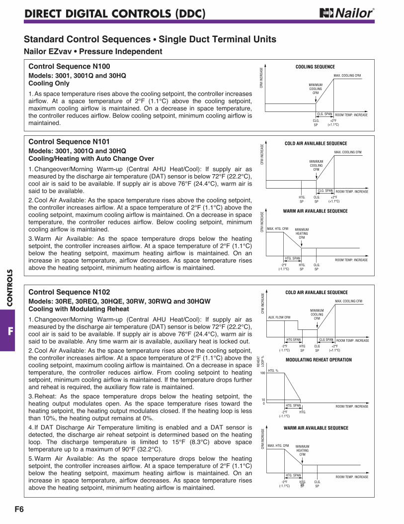
DIRECT DIGITAL CONTROLS (DDC)
F6
CO
NTR
OLS
F
Standard Control Sequences • Single Duct Terminal Units Nailor EZvav • Pressure Independent
Control Sequence N100Models: 3001, 3001Q and 30HQCooling Only
1. As space temperature rises above the cooling setpoint, the controller increases airflow. At a space temperature of 2°F (1.1°C) above the cooling setpoint, maximum cooling airflow is maintained. On a decrease in space temperature, the controller reduces airflow. Below cooling setpoint, minimum cooling airflow is maintained.
Control Sequence N101Models: 3001, 3001Q and 30HQCooling/Heating with Auto Change Over
1. Changeover/Morning Warm-up (Central AHU Heat/Cool): If supply air as measured by the discharge air temperature (DAT) sensor is below 72°F (22.2°C), cool air is said to be available. If supply air is above 76°F (24.4°C), warm air is said to be available.
2. Cool Air Available: As the space temperature rises above the cooling setpoint, the controller increases airflow. At a space temperature of 2°F (1.1°C) above the cooling setpoint, maximum cooling airflow is maintained. On a decrease in space temperature, the controller reduces airflow. Below cooling setpoint, minimum cooling airflow is maintained.
3. Warm Air Available: As the space temperature drops below the heating setpoint, the controller increases airflow. At a space temperature of 2°F (1.1°C) below the heating setpoint, maximum heating airflow is maintained. On an increase in space temperature, airflow decreases. As space temperature rises above the heating setpoint, minimum heating airflow is maintained.
Control Sequence N102Models: 30RE, 30REQ, 30HQE, 30RW, 30RWQ and 30HQWCooling with Modulating Reheat
1. Changeover/Morning Warm-up (Central AHU Heat/Cool): If supply air as measured by the discharge air temperature (DAT) sensor is below 72°F (22.2°C), cool air is said to be available. If supply air is above 76°F (24.4°C), warm air is said to be available. Any time warm air is available, auxiliary heat is locked out.
2. Cool Air Available: As the space temperature rises above the cooling setpoint, the controller increases airflow. At a space temperature of 2°F (1.1°C) above the cooling setpoint, maximum cooling airflow is maintained. On a decrease in space temperature, the controller reduces airflow. From cooling setpoint to heating setpoint, minimum cooling airflow is maintained. If the temperature drops further and reheat is required, the auxiliary flow rate is maintained.
3. Reheat: As the space temperature drops below the heating setpoint, the heating output modulates open. As the space temperature rises toward the heating setpoint, the heating output modulates closed. If the heating loop is less than 10%, the heating output remains at 0%.
4. If DAT Discharge Air Temperature limiting is enabled and a DAT sensor is detected, the discharge air reheat setpoint is determined based on the heating loop. The discharge temperature is limited to 15°F (8.3°C) above space temperature up to a maximum of 90°F (32.2°C).
5. Warm Air Available: As the space temperature drops below the heating setpoint, the controller increases airflow. At a space temperature of 2°F (1.1°C) below the heating setpoint, maximum heating airflow is maintained. On an increase in space temperature, airflow decreases. As space temperature rises above the heating setpoint, minimum heating airflow is maintained.
CLG.SP
CLG. SPAN ROOM TEMP. INCREASE
MAX. COOLING CFM
CFM
INCR
EASE
COOLING SEQUENCE
MINIMUMCOOLING
CFM
+2°F(+1.1°C)
MINIMUMHEATING
CFM
HTG.SP
CLG.SP
ROOM TEMP. INCREASECF
M IN
CREA
SE
MAX. HTG. CFM
WARM AIR AVAILABLE SEQUENCE
HTG. SPAN
HTG.SP
CLG.SP
CLG. SPAN ROOM TEMP. INCREASE
MAX. COOLING CFM
CFM
INCR
EASE
COLD AIR AVAILABLE SEQUENCE
MINIMUMCOOLING
CFM
+2°F(+1.1°C)
-2°F(-1.1°C)
HTGSP
CLGSP
CLG SPAN ROOM TEMP. INCREASE
MAX. COOLING CFM
CFM
INCR
EASE
AUX. FLOW CFM
COLD AIR AVAILABLE SEQUENCE
HTG SPAN
MINIMUMCOOLING
CFM
-2°F(-1.1°C)
+2°F(+1.1°C)
MINIMUMHEATING
CFM
HTG.SP
CLG.SP
ROOM TEMP. INCREASE
CFM
INCR
EASE
MAX. HTG. CFM
WARM AIR AVAILABLE SEQUENCE
HTG. SPAN
-2°F(-1.1°C) SP
MODULATING REHEAT OPERATION
ROOM TEMP. INCREASE
HTG.
HTG. SPAN
-2°F(-1.1°C)
LOOP
%
0
100
10
HTG. %
REHE
AT
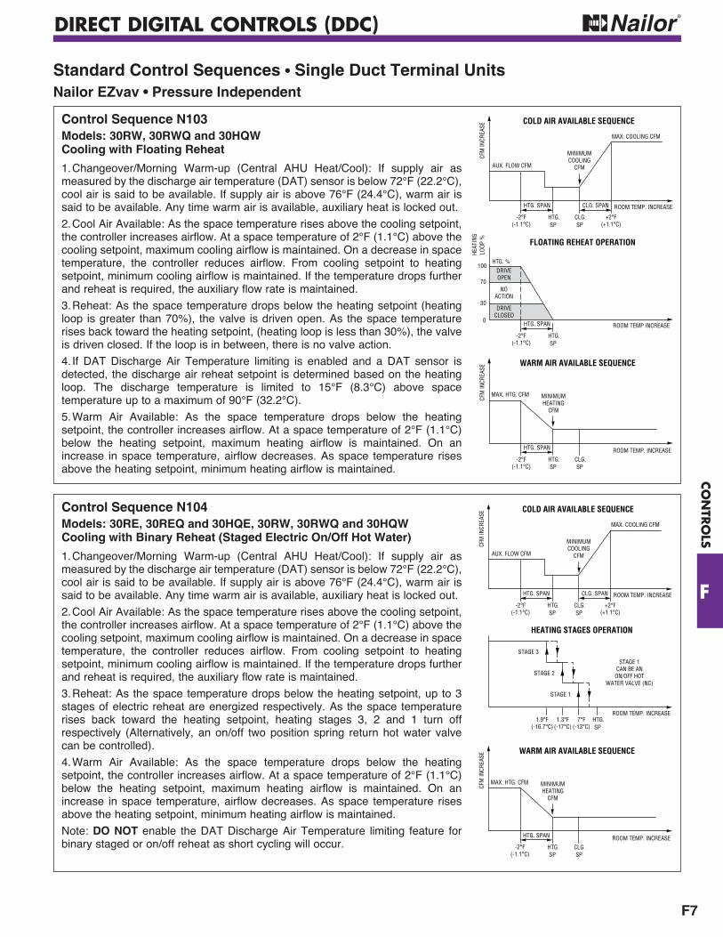
DIRECT DIGITAL CONTROLS (DDC)
F7
CO
NTR
OLS
F
Control Sequence N103Models: 30RW, 30RWQ and 30HQWCooling with Floating Reheat
1. Changeover/Morning Warm-up (Central AHU Heat/Cool): If supply air as measured by the discharge air temperature (DAT) sensor is below 72°F (22.2°C), cool air is said to be available. If supply air is above 76°F (24.4°C), warm air is said to be available. Any time warm air is available, auxiliary heat is locked out.
2. Cool Air Available: As the space temperature rises above the cooling setpoint, the controller increases airflow. At a space temperature of 2°F (1.1°C) above the cooling setpoint, maximum cooling airflow is maintained. On a decrease in space temperature, the controller reduces airflow. From cooling setpoint to heating setpoint, minimum cooling airflow is maintained. If the temperature drops further and reheat is required, the auxiliary flow rate is maintained.
3. Reheat: As the space temperature drops below the heating setpoint (heating loop is greater than 70%), the valve is driven open. As the space temperature rises back toward the heating setpoint, (heating loop is less than 30%), the valve is driven closed. If the loop is in between, there is no valve action.
4. If DAT Discharge Air Temperature limiting is enabled and a DAT sensor is detected, the discharge air reheat setpoint is determined based on the heating loop. The discharge temperature is limited to 15°F (8.3°C) above space temperature up to a maximum of 90°F (32.2°C).
5. Warm Air Available: As the space temperature drops below the heating setpoint, the controller increases airflow. At a space temperature of 2°F (1.1°C) below the heating setpoint, maximum heating airflow is maintained. On an increase in space temperature, airflow decreases. As space temperature rises above the heating setpoint, minimum heating airflow is maintained.
Standard Control Sequences • Single Duct Terminal Units Nailor EZvav • Pressure Independent
HTG.SP
CLG.SP
CLG. SPAN ROOM TEMP. INCREASE
MAX. COOLING CFM
CFM
INCR
EASE
AUX. FLOW CFM
COLD AIR AVAILABLE SEQUENCE
HTG. SPAN
MINIMUMCOOLING
CFM
-2°F(-1.1°C)
+2°F(+1.1°C)
MINIMUMHEATING
CFM
HTG.SP
CLG.SP
ROOM TEMP. INCREASE
CFM
INCR
EASE
MAX. HTG. CFM
WARM AIR AVAILABLE SEQUENCE
HTG. SPAN
-2°F(-1.1°C)
FLOATING REHEAT OPERATION
ROOM TEMP INCREASE
HTG.SP
HTG. SPAN
-2°F(-1.1°C)
LOOP
%
0
100
30
HTG. %
NOACTION
DRIVEOPEN
DRIVECLOSED
HEAT
ING
70
Control Sequence N104Models: 30RE, 30REQ and 30HQE, 30RW, 30RWQ and 30HQWCooling with Binary Reheat (Staged Electric On/Off Hot Water)
1. Changeover/Morning Warm-up (Central AHU Heat/Cool): If supply air as measured by the discharge air temperature (DAT) sensor is below 72°F (22.2°C), cool air is said to be available. If supply air is above 76°F (24.4°C), warm air is said to be available. Any time warm air is available, auxiliary heat is locked out.
2. Cool Air Available: As the space temperature rises above the cooling setpoint, the controller increases airflow. At a space temperature of 2°F (1.1°C) above the cooling setpoint, maximum cooling airflow is maintained. On a decrease in space temperature, the controller reduces airflow. From cooling setpoint to heating setpoint, minimum cooling airflow is maintained. If the temperature drops further and reheat is required, the auxiliary flow rate is maintained.
3. Reheat: As the space temperature drops below the heating setpoint, up to 3 stages of electric reheat are energized respectively. As the space temperature rises back toward the heating setpoint, heating stages 3, 2 and 1 turn off respectively (Alternatively, an on/off two position spring return hot water valve can be controlled).
4. Warm Air Available: As the space temperature drops below the heating setpoint, the controller increases airflow. At a space temperature of 2°F (1.1°C) below the heating setpoint, maximum heating airflow is maintained. On an increase in space temperature, airflow decreases. As space temperature rises above the heating setpoint, minimum heating airflow is maintained.
Note: DO NOT enable the DAT Discharge Air Temperature limiting feature for binary staged or on/off reheat as short cycling will occur. -2°F
(-1.1°C)
MINIMUMHEATING
CFM
HTG.SP
CLG.SP
ROOM TEMP. INCREASE
CFM
INCR
EASE
MAX. HTG. CFM
WARM AIR AVAILABLE SEQUENCE
HTG. SPAN
HTG.SP
CLG.SP
CLG. SPAN ROOM TEMP. INCREASE
MAX. COOLING CFM
CFM
INCR
EASE
AUX. FLOW CFM
COLD AIR AVAILABLE SEQUENCE
HTG. SPAN
MINIMUMCOOLING
CFM
-2°F(-1.1°C)
+2°F(+1.1°C)
HEATING STAGES OPERATION
ROOM TEMP. INCREASEHTG.SP
1.9°F(-16.7°C)
1.3°F(-17°C)
7°F(-13°C)
STAGE 3
STAGE 2
STAGE 1
STAGE 1CAN BE AN
ON/OFF HOTWATER VALVE (NC)
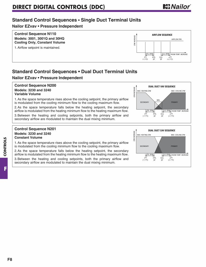
DIRECT DIGITAL CONTROLS (DDC)
F8
CO
NTR
OLS
F
Standard Control Sequences • Single Duct Terminal UnitsNailor EZvav • Pressure Independent
Control Sequence N110Models: 3001, 3001Q and 30HQCooling Only, Constant Volume
1. Airflow setpoint is maintained.
-2°F(-1.1°C)
CLG.SP
CLG. SPAN ROOM TEMP. INCREASE
AIRFLOW CFM
CFM
INCR
EASE
AIRFLOW SEQUENCE
+2°F(+1.1°C)
HTG. SPAN
HTG.SP
Control Sequence N200Models: 3230 and 3240Variable Volume
1. As the space temperature rises above the cooling setpoint, the primary airflow is modulated from the cooling minimum flow to the cooling maximum flow.2. As the space temperature falls below the heating setpoint, the secondary airflow is modulated from the heating minimum flow to the heating maximum flow.3. Between the heating and cooling setpoints, both the primary airflow and secondary airflow are modulated to maintain the dual mixing minimum.
HTG.SP
CLG.SP
CLG. SPAN ROOM TEMP. INCREASE
MAX. COOLING CFMMAX. HEATING CFM
CFM
INCR
EASE
SECONDARY PRIMARY
DUAL DUCT VAV SEQUENCE
HTG. SPAN
-2°F(-1.1°C)
+2°F(+1.1°C)
MIN.
Control Sequence N201Models: 3230 and 3240Constant Volume
1. As the space temperature rises above the cooling setpoint, the primary airflow is modulated from the cooling minimum flow to the cooling maximum flow.2. As the space temperature falls below the heating setpoint, the secondary airflow is modulated from the heating minimum flow to the heating maximum flow.3. Between the heating and cooling setpoints, both the primary airflow and secondary airflow are modulated to maintain the dual mixing minimum.
HTG.SP
CLG.SP
CLG. SPAN ROOM TEMP. INCREASE
MAX. COOLING CFMMAX. HEATING CFMCF
M IN
CREA
SE
SECONDARY PRIMARY
DUAL DUCT CAV SEQUENCE
HTG. SPAN
-2°F(-1.1°C)
+2°F(+1.1°C)
Standard Control Sequences • Dual Duct Terminal UnitsNailor EZvav • Pressure Independent
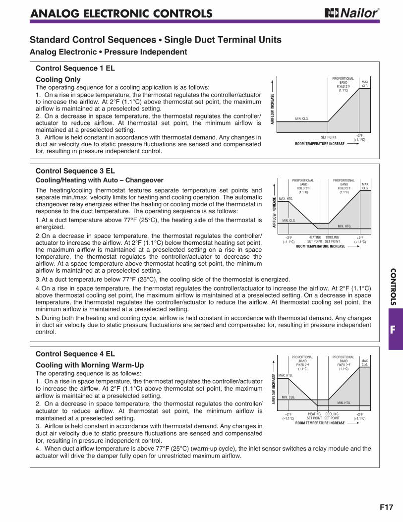
ANALOG ELECTRONIC CONTROLS
F17
CO
NTR
OLS
F
ROOM TEMPERATURE INCREASE
SET POINT +2°F(+1.1°C)
MIN. CLG.
MAX.CLG.
PROPORTIONAL BAND
FIXED 2°F(1.1°C)
AIRF
LOW
INCR
EASE
Control Sequence 1 EL
Cooling OnlyThe operating sequence for a cooling application is as follows:1. On a rise in space temperature, the thermostat regulates the controller/actuator to increase the airflow. At 2°F (1.1°C) above thermostat set point, the maximum airflow is maintained at a preselected setting.2. On a decrease in space temperature, the thermostat regulates the controller/actuator to reduce airflow. At thermostat set point, the minimum airflow is maintained at a preselected setting.3. Airflow is held constant in accordance with thermostat demand. Any changes in duct air velocity due to static pressure fluctuations are sensed and compensated for, resulting in pressure independent control.
Control Sequence 3 EL Cooling/Heating with Auto – Changeover
The heating/cooling thermostat features separate temperature set points and separate min./max. velocity limits for heating and cooling operation. The automatic changeover relay energizes either the heating or cooling mode of the thermostat in response to the duct temperature. The operating sequence is as follows:1. At a duct temperature above 77°F (25°C), the heating side of the thermostat is energized.2. On a decrease in space temperature, the thermostat regulates the controller/actuator to increase the airflow. At 2°F (1.1°C) below thermostat heating set point, the maximum airflow is maintained at a preselected setting on a rise in space temperature, the thermostat regulates the controller/actuator to decrease the airflow. At a space temperature above thermostat heating set point, the minimum airflow is maintained at a preselected setting.3. At a duct temperature below 77°F (25°C), the cooling side of the thermostat is energized. 4. On a rise in space temperature, the thermostat regulates the controller/actuator to increase the airflow. At 2°F (1.1°C) above thermostat cooling set point, the maximum airflow is maintained at a preselected setting. On a decrease in space temperature, the thermostat regulates the controller/actuator to reduce the airflow. At thermostat cooling set point, the minimum airflow is maintained at a preselected setting.5. During both the heating and cooling cycle, airflow is held constant in accordance with thermostat demand. Any changes in duct air velocity due to static pressure fluctuations are sensed and compensated for, resulting in pressure independent control.
ROOM TEMPERATURE INCREASE
COOLINGSET POINT
HEATINGSET POINT
MIN. CLG.
PROPORTIONAL BAND
FIXED 2°F(1.1°C)
PROPORTIONAL BAND
FIXED 2°F(1.1°C)
MAX.CLG.
MAX. HTG.
MIN. HTG.
+2°F(+1.1°C)
–2°F(–1.1°C)
AIRF
LOW
INCR
EASE
Standard Control Sequences • Single Duct Terminal UnitsAnalog Electronic • Pressure Independent
Control Sequence 4 EL
Cooling with Morning Warm-UpThe operating sequence is as follows:1. On a rise in space temperature, the thermostat regulates the controller/actuator to increase the airflow. At 2°F (1.1°C) above thermostat set point, the maximum airflow is maintained at a preselected setting.2. On a decrease in space temperature, the thermostat regulates the controller/actuator to reduce airflow. At thermostat set point, the minimum airflow is maintained at a preselected setting.3. Airflow is held constant in accordance with thermostat demand. Any changes in duct air velocity due to static pressure fluctuations are sensed and compensated for, resulting in pressure independent control.4. When duct airflow temperature is above 77°F (25°C) (warm-up cycle), the inlet sensor switches a relay module and the actuator will drive the damper fully open for unrestricted maximum airflow.
ROOM TEMPERATURE INCREASE
COOLINGSET POINT
HEATINGSET POINT
MIN. CLG.
PROPORTIONAL BAND
FIXED 2°F(1.1°C)
PROPORTIONAL BAND
FIXED 2°F(1.1°C)
MAX.CLG.
MAX. HTG.
MIN. HTG.
+2°F(+1.1°C)
–2°F(–1.1°C)
AIRF
LOW
INCR
EASE
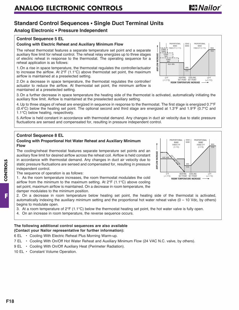
ANALOG ELECTRONIC CONTROLS
F18
CO
NTR
OLS
F
Standard Control Sequences • Single Duct Terminal UnitsAnalog Electronic • Pressure Independent
Control Sequence 5 EL Cooling with Electric Reheat and Auxiliary Minimum Flow
The reheat thermostat features a separate temperature set point and a separate auxiliary flow limit for reheat control. The reheat relay energizes up to three stages of electric reheat in response to the thermostat. The operating sequence for a reheat application is as follows:1. On a rise in space temperature, the thermostat regulates the controller/actuator to increase the airflow. At 2°F (1.1°C) above thermostat set point, the maximum airflow is maintained at a preselected setting.2. On a decrease in space temperature, the thermostat regulates the controller/actuator to reduce the airflow. At thermostat set point, the minimum airflow is maintained at a preselected setting.3. On a further decrease in space temperature the heating side of the thermostat is activated, automatically initiating the auxiliary flow limit. Airflow is maintained at the preselected auxiliary setting.4. Up to three stages of reheat are energized in sequence in response to the thermostat. The first stage is energized 0.7°F (0.4°C) below the heating set point. The optional second and third stage are energized at 1.3°F and 1.9°F (0.7°C and 1.1°C) below heating, respectively.5. Airflow is held constant in accordance with thermostat demand. Any changes in duct air velocity due to static pressure fluctuations are sensed and compensated for, resulting in pressure independent control.
Control Sequence 8 ELCooling with Proportional Hot Water Reheat and Auxiliary Minimum FlowThe cooling/reheat thermostat features separate temperature set points and an auxiliary flow limit for desired airflow across the reheat coil. Airflow is held constant in accordance with thermostat demand. Any changes in duct air velocity due to static pressure fluctuations are sensed and compensated for, resulting in pressure independent control. The sequence of operation is as follows:1. As the room temperature increases, the room thermostat modulates the cold airflow from the minimum to the maximum setting. At 2°F (1.1°C) above cooling set point, maximum airflow is maintained. On a decrease in room temperature, the damper modulates to the minimum position.2. On a decrease in room temperature below heating set point, the heating side of the thermostat is activated, automatically indexing the auxiliary minimum setting and the proportional hot water reheat valve (0 – 10 Vdc, by others) begins to modulate open. 3. At a room temperature of 2°F (1.1°C) below the thermostat heating set point, the hot water valve is fully open. 4. On an increase in room temperature, the reverse sequence occurs.
ROOM TEMPERATURE INCREASE
COOLINGSET POINT
HEATINGSET POINT
MIN.
CLG.
MAX.
CLG.
DEADBAND
PROPORTIONALBAND
FIXED 2°F (1.1°C)
PROPORTIONALBAND
FIXED 2°F (1.1°C)
AUX. MIN.
STAGEONE
STAGETWO
STAGETHREE
+2°F(+1.1°C)
–2°F(–1.1°C)
AIRF
LOW
INCR
EASE
ROOM TEMPERATURE INCREASE
COOLINGSET POINT
HEATINGSET POINT
–2°F(–1.1°C)
+2°F(+1.1°C)
MIN.
CLG.
MAX.
CLG.
DEADBAND
AUX. MIN.
HOT WATER FLOW
AIRF
LOW
INCR
EASE
PROPORTIONAL BAND
FIXED 2°F(1.1°C)
PROPORTIONAL BAND
FIXED 2°F(1.1°C)
The following additional control sequences are also available(Contact your Nailor representative for further information):6 EL • Cooling With Electric Reheat Plus Morning Warm-up. 7 EL • Cooling With On/Off Hot Water Reheat and Auxiliary Minimum Flow (24 VAC N.C. valve, by others).9 EL • Cooling With On/Off Auxiliary Heat (Perimeter Radiation).10 EL • Constant Volume Operation.
PNEUMATIC CONTROLS
F29
CO
NTR
OLS
F
Standard Control Sequences • Single Duct Terminal UnitsPneumatic • Pressure Independent • Nailor 3000 ControllerThe sequences illustrated feature the Nailor 3000 controller and a constant 5 psi reset span which does not vary with minimum and maximum settings. For a more detailed explanation of control options and terminology, refer to the engineering section in the back of this catalog.
TEMPERATURE INCREASERESET SPAN 8 – 13 PSI
VAV COOLINGDIRECT ACTING THERMOSTAT, NORMALLY CLOSED DAMPER
MIN.
80
60
40
20
0
CLG.
100
THERMOSTAT OUTPUT, PSI
AIRF
LOW
, % O
F TO
TAL
CAPA
CITY
MAX.
3 8 13 150
80
60
40
20
0
CLG.
100
THERMOSTAT OUTPUT, PSI
AIRF
LOW
, % O
F TO
TAL
CAPA
CITY
MAX.
3 8 13 150
TEMPERATURE DECREASERESET SPAN 3 – 8 PSI
VAV COOLINGREVERSE ACTING THERMOSTAT, NORMALLY OPEN DAMPER
MOR
NING
WAR
M U
P
MIN.
80
60
40
20
0
100
THERMOSTAT OUTPUT, PSI
AIRF
LOW
, % O
F TO
TAL
CAPA
CITY
MAX.
3 8 13 150
TEMPERATURE INCREASERESET SPAN 8 – 13 PSI
VAV COOLINGDIRECT ACTING THERMOSTAT, NORMALLY OPEN DAMPER
MOR
NING
WAR
M U
P
MIN.
CLG.
Control Sequence 1P3Direct Acting, Normally Open • When main control air is off, damper is fully open. Morning warm-up setting (if required) with warm air from system supplied at full flow rate.• Main control air on – controller is activated. Begins modulating cold airflow on thermostat demand.• Increase in room temperature increases thermostat output pressure (thus increasing airflow).• Minimum airflow is maintained between 0 and 8 psi thermostat signal.• Further increase in room temperature will increase thermostat signal from 8 to 13 psi which will increase airflow. At 13 psi and above, preset maximum airflow is maintained.• If main control air fails, damper fails open.
Control Sequence 2P3Reverse Acting, Normally Open • When main control air is off, damper is fully open. Morning warm-up setting available if required.• Main control air on – controller is activated. Begins modulating cold airflow according to thermostat output.• Decrease in room temperature increases thermostat output pressure (thus decreasing airflow).• Maximum airflow is maintained between 0 and 3 psi thermostat signal.• Further decrease in room temperature will increase thermostat signal from 3 to 8 psi which will decrease airflow to room. At 8 psi and above, minimum airflow is maintained.• If main control air fails, damper fails open.
Control Sequence 3P3Direct Acting, Normally Closed • When main control air is off, damper is closed.• Main control air on – controller is activated. Begins modulating cold airflow according to thermostat demand.• Increase in room temperature increases thermostat output pressure (thus increasing airflow).• Minimum airflow is maintained between 0 and 8 psi thermostat signal.• Further increase in room temperature will increase thermostat signal from 8 to 13 psi which in turn increases airflow to room. At 13 psi and above, preset maximum airflow is maintained.• If main control air fails, damper fails closed.
TEMPERATURE DECREASERESET SPAN 3 – 8 PSI
VAV COOLINGREVERSE ACTING THERMOSTAT, NORMALLY CLOSED DAMPER
MIN.
80
60
40
20
0
CLG.
100
THERMOSTAT OUTPUT, PSI
AIRF
LOW
, % O
F TO
TAL
CAPA
CITY
MAX.
3 8 13 150
Control Sequence 4P3Reverse Acting, Normally Closed • When main control air is off, damper is closed.• Main control air on – controller is activated. Begins modulating cold airflow according to thermostat demand.• Decrease in room temperature increases thermostat output pressure (thus decreasing airflow).• Maximum airflow is maintained between 0 and 3 psi thermostat signal.• Further decrease in room temperature will increase thermostat output pressure from 3 to 8 psi which will decrease airflow to room. At 8 psi and above, minimum airflow is maintained.• If main control air fails, damper fails closed.
PNEUMATIC CONTROLS
F30
CO
NTR
OLS
F
Standard Control Sequences • Single Duct Terminal UnitsPneumatic • Pressure Independent • Nailor 3000 Controller
80
60
40
20
0
100
THERMOSTAT OUTPUT, PSI
AIRF
LOW
, % O
F TO
TAL
CAPA
CITY
MAX.
3 8 13 150
TEMPERATURE INCREASERESET SPAN 8 – 13 PSI
VAV COOLING, HOT WATER REHEATDIRECT ACTING THERMOSTAT, NORMALLY OPEN DAMPER
HOT WATER FLOWMIN.
80
60
40
20
0
100
THERMOSTAT OUTPUT, PSI
AIRF
LOW
, % O
F TO
TAL
CAPA
CITY
MAX.
3 8 13 150
TEMPERATURE INCREASERESET SPAN 8 – 13 PSI
VAV COOLING, ELECTRIC REHEATDIRECT ACTING THERMOSTAT, NORMALLY OPEN DAMPER
MIN.
STEP 2
STEP 1
80
60
40
20
0
100
MAIN CONTROL AIR
AIRF
LOW
, % O
F TO
TAL
CAPA
CITY CONSTANT AIRFLOW
CONSTANT VOLUME
80
60
40
20
0
100
MAIN CONTROL AIR
AIRF
LOW
, % O
F TO
TAL
CAPA
CITY CONSTANT AIRFLOW
CONSTANT VOLUME, HOT WATER REHEAT
HOT WATER FLOW
Control Sequence 8P3C.V. - Hot Water Reheat N.O.
• When main air is off, damper is open.• Main control air is on – controller maintains preset constant airflow regardless of duct pressure or room temperature.• As room temperature increases, a room thermostat modulates the hot water valve towards the closed position, or opens it on temperature drop.• If main control air fails, damper fails open and hot water valve fails open.
Control Sequence 7P3 C.V.N.C.
• When main control air is off, damper is closed.• Main control air on – controller maintains preset constant airflow regardless of duct pressure or room temperature.• A room thermostat is not used.• If main control air fails, damper fails closed.• A normally open damper assembly is optional.
Control Sequence 1P3
D.A.N.O. - Hot Water Reheat N.O.• When main control air is off, damper is fully open. • Main control air on – controller is activated and begins modulating on thermostat demand.• Increase in room temperature modulates hot water valve towards closed position (at 8 psi). Minimum airflow is maintained between 0 and 8 psi thermostat signal.• Further increase in room temperature will increase thermostat signal from 8 to 13 psi which will increase airflow to maximum cooling. • If main control air fails, damper fails open and hot water valve fails open.
Hot water reheat coils may also be sequenced with 2P3, 3P3 and 4P3.
Control Sequence 1P3 D.A.N.O. - Electric Reheat N.C.
• When main control air is off, damper is fully open.
• Main control air on – controller is activated and begins modulating on thermostat demand.
• Increase in room temperature de-energizes the electric reheat coil one step at a time. Minimum airflow is maintained between 0 and 8 psi thermostat signal. At 8 psi, electric reheat is off.
• Further increase in room temperature will increase thermostat output signal from 8 to 13 psi which will increase airflow to maximum cooling.
• If main control air fails, damper fails open and P.E. switch for electric heater is closed (energized).
Electric reheat coils may also be sequenced with 2P3, 3P3 and 4P3.