sinumerik live: multi-face machining milling (3+2 axes) · sinumerik live: multi-face machining...
TRANSCRIPT
SINUMERIK live: Multi-face machining milling (3+2 axes)
Principles, handling and use cases with SINUMERIK Operate
siemens.com/cnc4you Unrestricted © Siemens AG 2017
Unrestricted © Siemens AG 2017
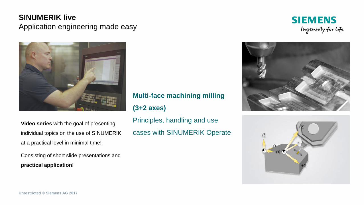
SINUMERIK live Application engineering made easy
Video series with the goal of presenting
individual topics on the use of SINUMERIK
at a practical level in minimal time!
Consisting of short slide presentations and
practical application!
Multi-face machining milling
(3+2 axes)
Principles, handling and use
cases with SINUMERIK Operate
Unrestricted © Siemens AG 2017
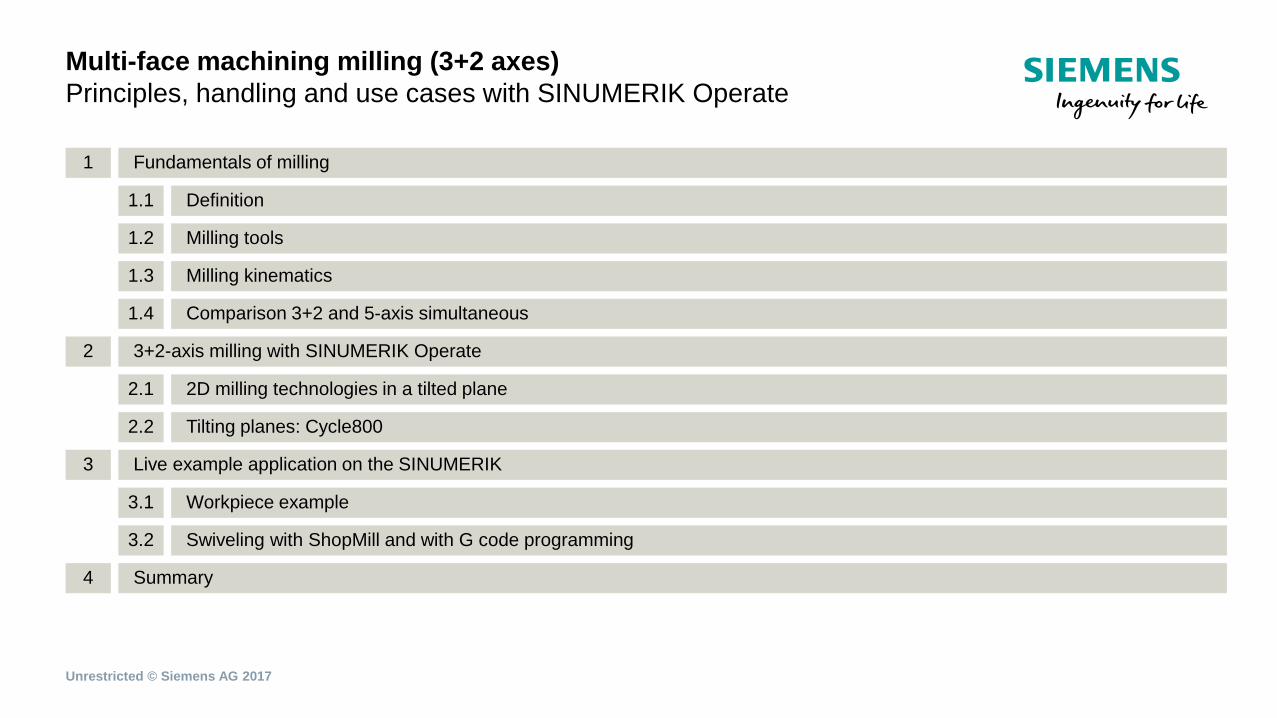
Multi-face machining milling (3+2 axes) Principles, handling and use cases with SINUMERIK Operate
Fundamentals of milling 1
Definition 1.1
Milling tools 1.2
Milling kinematics 1.3
Comparison 3+2 and 5-axis simultaneous 1.4
3+2-axis milling with SINUMERIK Operate 2
2D milling technologies in a tilted plane 2.1
Tilting planes: Cycle800 2.2
Live example application on the SINUMERIK 3
Workpiece example 3.1
Swiveling with ShopMill and with G code programming 3.2
Summary 4
Unrestricted © Siemens AG 2017
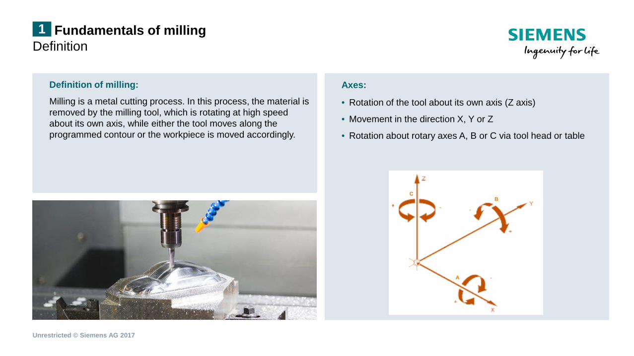
Axes:
• Rotation of the tool about its own axis (Z axis)
• Movement in the direction X, Y or Z
• Rotation about rotary axes A, B or C via tool head or table
Fundamentals of milling Definition
Definition of milling:
Milling is a metal cutting process. In this process, the material is removed by the milling tool, which is rotating at high speed about its own axis, while either the tool moves along the programmed contour or the workpiece is moved accordingly.
1
A
B C
Unrestricted © Siemens AG 2017
Fundamentals of milling Milling tools 1
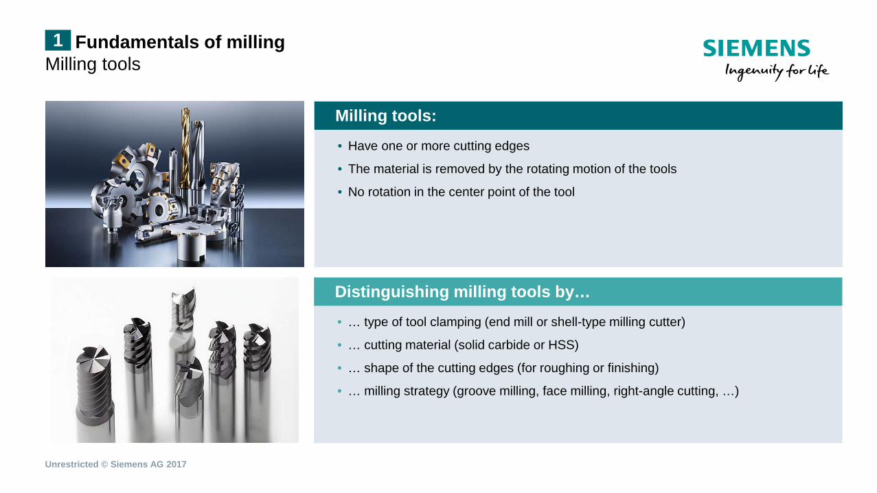
Milling tools:
• Have one or more cutting edges
• The material is removed by the rotating motion of the tools
• No rotation in the center point of the tool
Distinguishing milling tools by…
• … type of tool clamping (end mill or shell-type milling cutter)
• … cutting material (solid carbide or HSS)
• … shape of the cutting edges (for roughing or finishing)
• … milling strategy (groove milling, face milling, right-angle cutting, …)
Unrestricted © Siemens AG 2017
Fundamentals of milling Milling kinematics 1
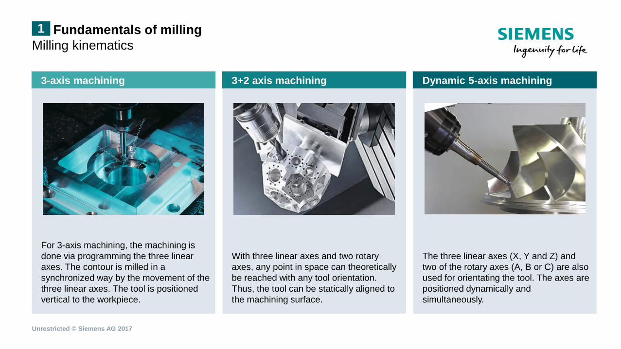
3-axis machining 3+2 axis machining Dynamic 5-axis machining
For 3-axis machining, the machining is done via programming the three linear axes. The contour is milled in a synchronized way by the movement of the three linear axes. The tool is positioned vertical to the workpiece.
With three linear axes and two rotary axes, any point in space can theoretically be reached with any tool orientation. Thus, the tool can be statically aligned to the machining surface.
The three linear axes (X, Y and Z) and two of the rotary axes (A, B or C) are also used for orientating the tool. The axes are positioned dynamically and simultaneously.
Unrestricted © Siemens AG 2017
Fundamentals of milling Milling kinematics 1
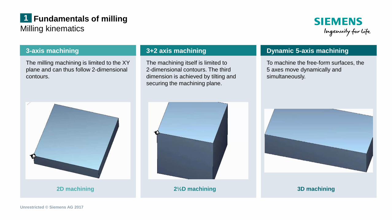
3-axis machining 3+2 axis machining Dynamic 5-axis machining
The milling machining is limited to the XY plane and can thus follow 2-dimensional contours.
The machining itself is limited to 2-dimensional contours. The third dimension is achieved by tilting and securing the machining plane.
To machine the free-form surfaces, the 5 axes move dynamically and simultaneously.
2D machining 2½D machining 3D machining
Unrestricted © Siemens AG 2017
Fundamentals of milling Milling kinematics 1
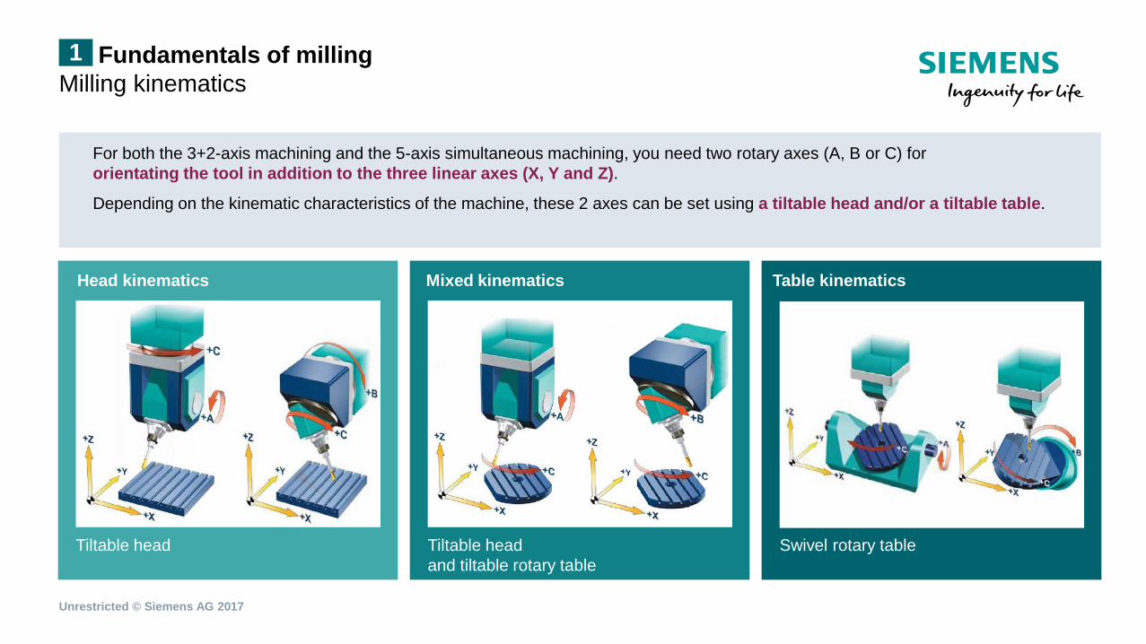
Tiltable head
Head kinematics
Tiltable head and tiltable rotary table
Mixed kinematics
Swivel rotary table
Table kinematics
For both the 3+2-axis machining and the 5-axis simultaneous machining, you need two rotary axes (A, B or C) for orientating the tool in addition to the three linear axes (X, Y and Z).
Depending on the kinematic characteristics of the machine, these 2 axes can be set using a tiltable head and/or a tiltable table.
Unrestricted © Siemens AG 2017
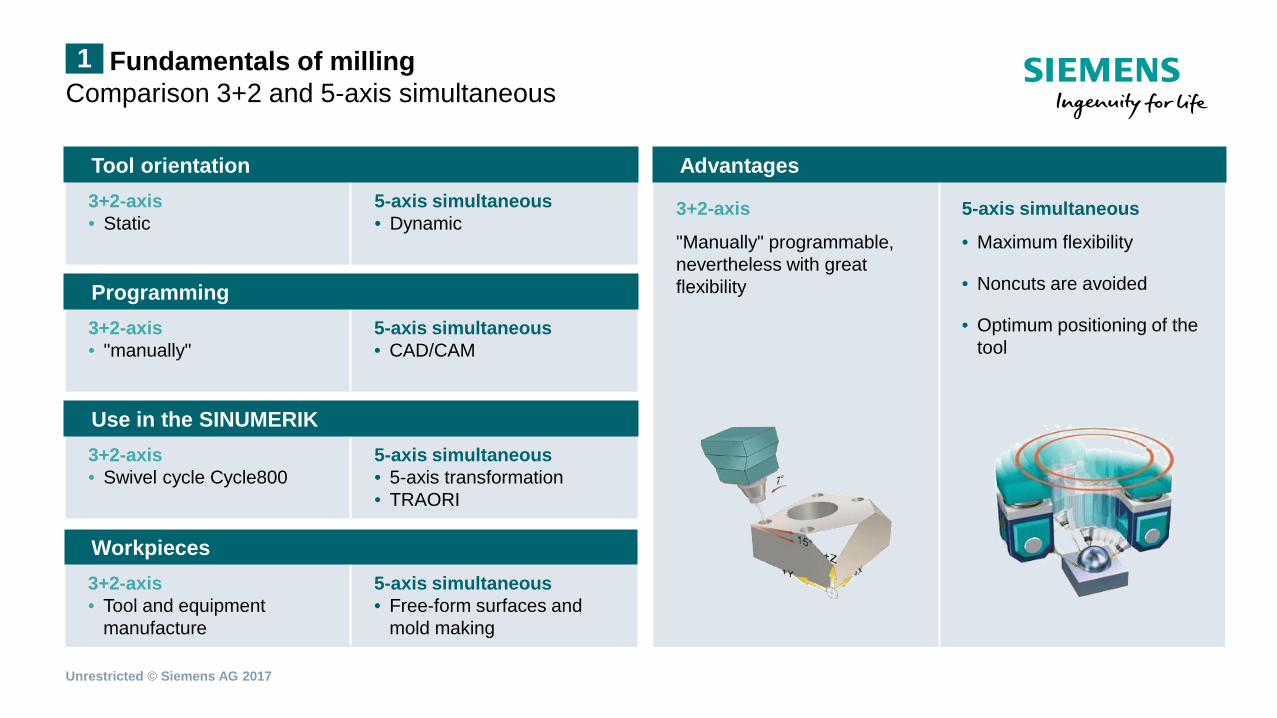
Fundamentals of milling Comparison 3+2 and 5-axis simultaneous 1
5-axis simultaneous • Dynamic
5-axis simultaneous • CAD/CAM
5-axis simultaneous • 5-axis transformation • TRAORI
5-axis simultaneous • Free-form surfaces and
mold making
5-axis simultaneous
• Maximum flexibility
• Noncuts are avoided
• Optimum positioning of the tool
3+2-axis • Static
3+2-axis • "manually"
3+2-axis • Swivel cycle Cycle800
3+2-axis • Tool and equipment
manufacture
3+2-axis
"Manually" programmable, nevertheless with great flexibility
Tool orientation
Programming
Use in the SINUMERIK
Workpieces
Advantages
Unrestricted © Siemens AG 2017
3+2-axis with SINUMERIK Operate 2D milling technologies in a tilted plane 2
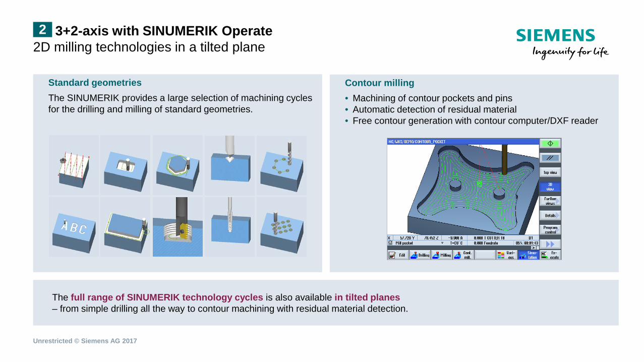
Contour milling • Machining of contour pockets and pins • Automatic detection of residual material • Free contour generation with contour computer/DXF reader
The full range of SINUMERIK technology cycles is also available in tilted planes – from simple drilling all the way to contour machining with residual material detection.
Standard geometries The SINUMERIK provides a large selection of machining cycles for the drilling and milling of standard geometries.
Unrestricted © Siemens AG 2017
3+2-axis with SINUMERIK Operate Tilting planes: Cycle800 2
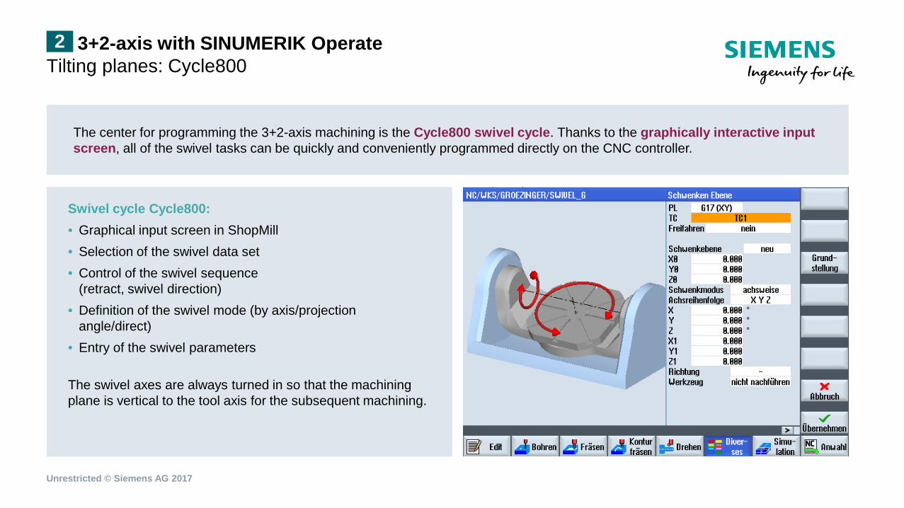
The center for programming the 3+2-axis machining is the Cycle800 swivel cycle. Thanks to the graphically interactive input screen, all of the swivel tasks can be quickly and conveniently programmed directly on the CNC controller.
Swivel cycle Cycle800: • Graphical input screen in ShopMill • Selection of the swivel data set • Control of the swivel sequence
(retract, swivel direction) • Definition of the swivel mode (by axis/projection
angle/direct) • Entry of the swivel parameters The swivel axes are always turned in so that the machining plane is vertical to the tool axis for the subsequent machining.
Unrestricted © Siemens AG 2017
Live example application on the SINUMERIK Example workpiece with ShopMill 3
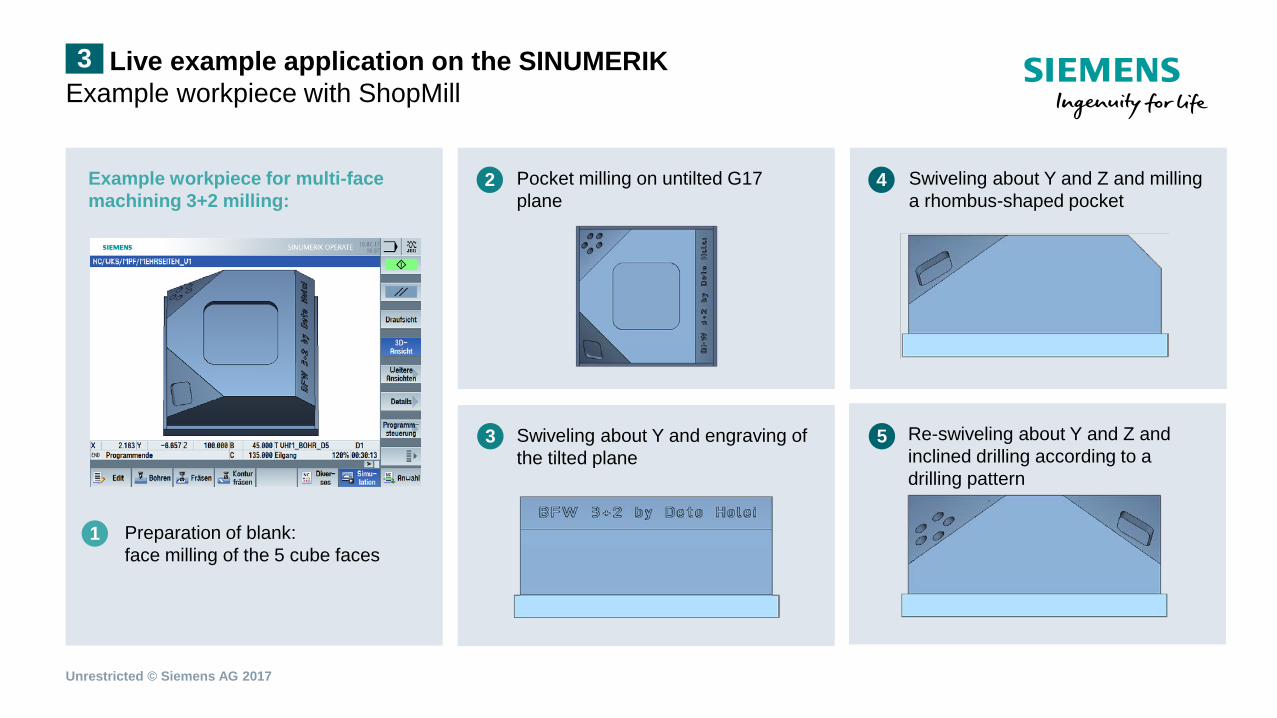
1) Swiveling about Y and Z and milling a rhombus-shaped pocket
1) Pocket milling on untilted G17 plane
1) Swiveling about Y and engraving of the tilted plane
1) Re-swiveling about Y and Z and inclined drilling according to a drilling pattern
Example workpiece for multi-face machining 3+2 milling:
1) Preparation of blank: face milling of the 5 cube faces
1
2
3
4
5
Unrestricted © Siemens AG 2017
Live example application on the SINUMERIK Example workpiece with ShopMill 3
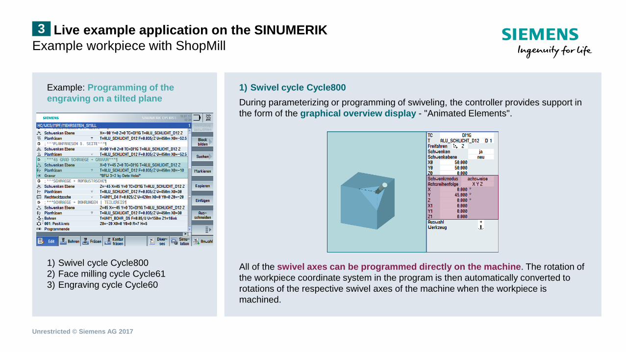
Example: Programming of the engraving on a tilted plane 1) Swivel cycle Cycle800 2) Face milling cycle Cycle61 3) Engraving cycle Cycle60
1) Swivel cycle Cycle800 During parameterizing or programming of swiveling, the controller provides support in the form of the graphical overview display - "Animated Elements". All of the swivel axes can be programmed directly on the machine. The rotation of the workpiece coordinate system in the program is then automatically converted to rotations of the respective swivel axes of the machine when the workpiece is machined.
Unrestricted © Siemens AG 2017
Live example application on the SINUMERIK Example workpiece with ShopMill 3
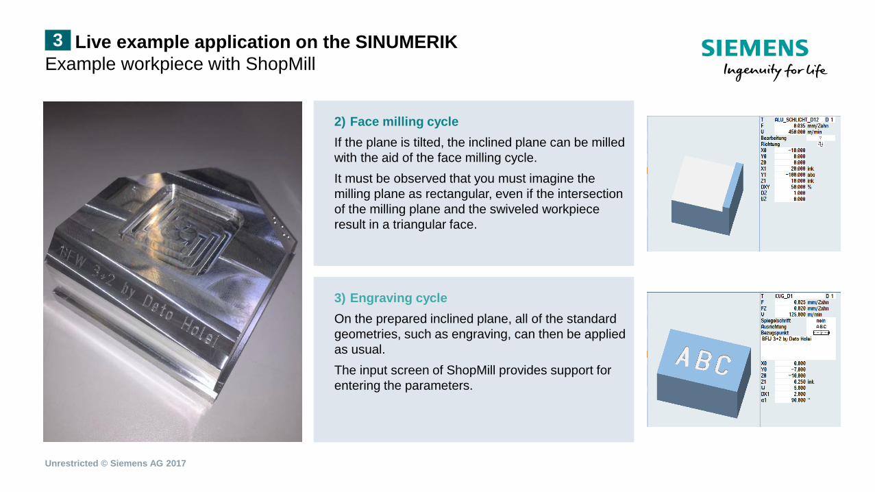
3) Engraving cycle On the prepared inclined plane, all of the standard geometries, such as engraving, can then be applied as usual. The input screen of ShopMill provides support for entering the parameters.
2) Face milling cycle If the plane is tilted, the inclined plane can be milled with the aid of the face milling cycle. It must be observed that you must imagine the milling plane as rectangular, even if the intersection of the milling plane and the swiveled workpiece result in a triangular face.
Unrestricted © Siemens AG 2017
Summary 4
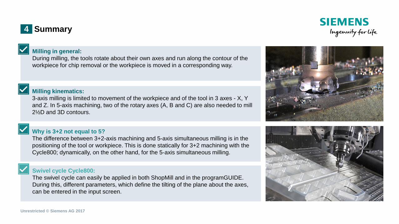
Milling in general: During milling, the tools rotate about their own axes and run along the contour of the workpiece for chip removal or the workpiece is moved in a corresponding way.
Why is 3+2 not equal to 5? The difference between 3+2-axis machining and 5-axis simultaneous milling is in the positioning of the tool or workpiece. This is done statically for 3+2 machining with the Cycle800; dynamically, on the other hand, for the 5-axis simultaneous milling.
Swivel cycle Cycle800: The swivel cycle can easily be applied in both ShopMill and in the programGUIDE. During this, different parameters, which define the tilting of the plane about the axes, can be entered in the input screen.
Milling kinematics: 3-axis milling is limited to movement of the workpiece and of the tool in 3 axes - X, Y and Z. In 5-axis machining, two of the rotary axes (A, B and C) are also needed to mill 2½D and 3D contours.
Unrestricted © Siemens AG 2017
Thank you for your attention!
Technology and Application Center Erlangen
siemens.com/cnc4you