siprom dr24 - siemens · 2005-01-06 · functions of siprom dr24 21 ... siprom dr24 9 1.3...
TRANSCRIPT
s
SIPROM DR24
Graphical Configuration of the multifunction unit SIPART DR24
Manual Release 10/2003
Introduction
1
Functions of SIPROM DR24
2
Graphical Layout
3
Tabular Layout
4
Edit parameters
5
Documentation
6
Short-cut keys
7
Error messages
8
References
9
Edit function blocs
10
Display process variables
11
12
13
14
15
s Introduction MS-DOS is a trade mark of Microsoft MS-WINDOWS is a trade mark of Microsoft SIPART is a trade mark of Siemens AG SIMATIC is a trade mark of Siemens AG All other product and system names are ( registered ) trade marks of the respective owner and must be handled accordingly. Edited by Automation an Drives Division, Business range Process Instrumentation (A&D PI1) Oestliche Rheinbrueckenstrasse 50 D-76187 Karlsruhe Distribution and duplication of this document, as well as utilization and publication of its contents require explicit authorization. Offenders are liable to the payment of damages. All rights reserved, especially in case of the grant of a patent or utility model registration. © Siemens AG 2000 All Rights Reserved
The contents of this document were checked for conformity with the described software. However, deviations can not be completely excluded and we are not liable for total conformity. The information in this document is regularly reviewed and the required corrections included in the following issues.
We are open to any remarks and suggestions. Subject to modification
Release: 10 / 2003 (english) Pages incl. cover: 72 Printed in the Federal Republic of Germany

s Introduction
SIPROM DR24 3
SIPROM DR24
Operating Instructions 10.2003 Page
1 Introduction 9
1.1 Components and Delivery 10
1.2 Hardware and Software Requirements 11
1.3 Connecting SIPART DR24 to the PC 12
1.3.1 END-END data link (RS 232) 13
1.3.2 PROFIBUS DP data link 14
1.4 Default Settings of SIPART DR24 17
1.5 Installing the software from CD-ROM to Hard Disk 18
1.6 Programstart under MS-WINDOWS XP (or NT, 2000) 19
2. Functions of SIPROM DR24 21
2.1 Functions of operator interface 21
2.1.1 File, New ... 22
2.1.2 File, Open ... 24
2.1.3 Controller, Load from controller ... 25
2.1.4 Change controller type 25
2.1.5 Options, Program ... 26
2.1.6 Options, Communication ... 26
2.1.7 Options, Passwort ... 27
2.1.8 Options, Language ... 27
2.1.9 Help 27
2.2 Functions of the working mask 28

Introduction s
SIPROM DR24 4
Page
2.2.1 File, Print ... 29
2.2.2 File, Compare 30
2.2.3 Controller, Load from controller ... 31
2.2.4 Controller, Change keyword ... 32
3 Graphical Circuit Design 35
3.1 Select pages 35
3.2 Page overview 36
3.3 Partial Circuits 38
3.4 Example Circuit 39
3.5 Graphical properties 41
4 Tabular Circuit Design 43
5 Edit Parameters 47
5.1 On-Line-Parameters 48
5.2 Off-Line-Parameters 49
5.3 Clock-Parameters 50
5.4 Define Hardware 51
5.5 Uni – Modul Parameters 52

s Introduction
SIPROM DR24 5
Page
6 Documentation 53
7 Shortcut Keys 59
8 Error Messages 61
9 References 65
10 Function Block EDITOR 67
10.1 Example Subtractor 68
10.2 Example Binary Integrator 69
10.3 Example Analog Input 70
11 Display Process variables 71
11.1 Process values 71
11.2 Status bits 72
Introduction s
SIPROM DR24 6
1. Introduction SIPROM DR24 is a MS-WINDOWS application (32-Bit) for comfortable configuration of multifunction units SIPART DR24. It's possible to configure the old controllers DR24 (6DR2400-..) as well as the actual controllers (6DR2410-..). The software includes a function library for the multifunction unit, which allows to define all function blocks on a maximum of 100 pages ( FDEF ). After defining and placing the blocks, they are connected from data sources to data sinks ( FCON ). Analog and binary signals are distinguished by colors. The position of the function blocks, i.e. their process sequence, is defined automatically. The configuration entered via PC is saved on hard disk or diskette, output on a printer, or, if a SIPART DR24 is connected, transmitted to the controller via serial interface ( RS 232C or Profibus DP). For modification, storage, or tabular print-out, programs of the SIPART DR24 can be transferred to the PC as a tabular device data plan.

s Introduction
SIPROM DR24 7
1.1 Components and Delivery The software SIPROM DR24 is delivered on CD-ROM. The manual is on CD-ROM in the format MS-WINWORD. A SETUP routine copies all files from the CD-ROM to a hard disk. The compressed files are decompressed during the copy procedure. Contents of CD-ROM:
Introduction s
SIPROM DR24 8
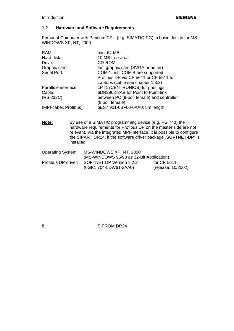
1.2 Hardware and Software Requirements Personal-Computer with Pentium CPU (e.g. SIMATIC-PG) in basic design for MS-WINDOWS XP, NT, 2000 RAM: min. 64 MB Hard disk: 10 MB free area Drive: CD-ROM Graphic card: fast graphic card (SVGA or better) Serial Port: COM 1 until COM 4 are supported
Profibus DP via CP 5611 or CP 5511 for Laptops (cable see chapter 1.3.3)
Parallele interface: LPT1 (CENTRONICS) for printings Cable: 6DR2902-8AB for Point to Point-link (RS 232C) between PC (9-pol. female) and controller (9 pol. female) (MPI-cabel, Profibus) 6ES7 901-0BF00-0AA0; 5m length Note: By use of a SIMATIC programming device (e.g. PG 740) the
hardware requirements for Profibus DP on the master side are not relevant. Via the integrated MPI-interface, it is possible to configure the SIPART DR24, if the software driver package „SOFTNET-DP“ is installed.
Operating System: MS-WINDOWS XP, NT, 2000 (MS-WINDOWS 95/98 as 32-Bit Application) Profibus DP driver: SOFTNET DP Version ≥ 2.2 for CP 5611
(6GK1 704-5DW61-3AA0) (release: 10/2002)

s Introduction
SIPROM DR24 9
1.3 Connecting SIPART DR24 to the PC The following links between SIPART controllers and higher-level systems can be realized with the interface module 6DR2803-8C or -8A: END-END connection ( V.24/V.28 or RS 232C )
RS
485
RS
485
EN
D /
EN
DR
S 2
32
+ 15
0 R
SIP
AR
T-B
US
RS
485
RS
485
EN
D /
EN
DR
S 2
32
+ 15
0 R
SIP
AR
T-B
US
Figure 1.3.1 Setting RS 232C END-END with 6DR2803-8C
X3X2 X1
END
-EN
D
BUS
Figure 1.3.2 Setting RS 232C END-END
with 6DR2803-8A

Introduction s
SIPROM DR24 10
1.3.1 END-END data link ( V.24/V.28 or RS 232C ) Generally, either shielded or unshielded round cable ( e.g. LiYCY 4x0.14 mm2 ) should be used for END-END data links. The maximum lengths are 10 m ( shielded ) and 30 m ( unshielded ). PC - AT COM 1 ... 4
SIPART DR SES6DR2803-8C / -8A
25 - pol. male
Jumper to END-END
25 - pol. female C74451-A347-D38
9 - pol. female C73451-A347-D39
TxD PIN 2 PIN 3 RxD
RxD PIN 3 PIN 2 TxD
GND PIN 7 PIN 7 and 8 GND
PC - AT COM 1 ... 4
SIPART DR SES6DR2803-8C / -8A
Jumper to END-END
9 - pol. female C74451-A347-D39
9 - pol. female C73451-A347-D39
RxD PIN 2 PIN 2 TxD
TxD PIN 3 PIN 3 RxD
GND PIN 5 PIN 7 and 8 GND
Table 1: END-END link ( V.24 / V.28 / RS 232C )
s Introduction
SIPROM DR24 11
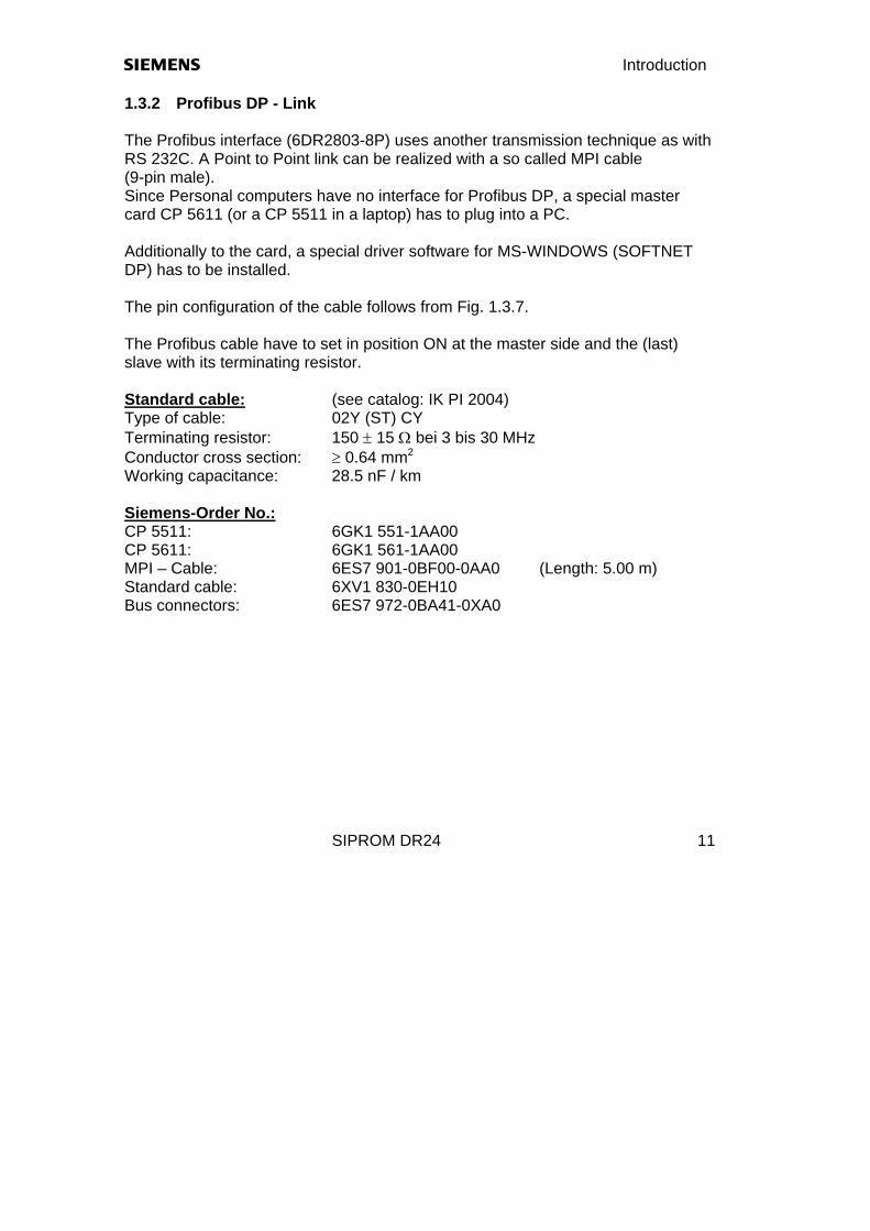
1.3.2 Profibus DP - Link The Profibus interface (6DR2803-8P) uses another transmission technique as with RS 232C. A Point to Point link can be realized with a so called MPI cable (9-pin male). Since Personal computers have no interface for Profibus DP, a special master card CP 5611 (or a CP 5511 in a laptop) has to plug into a PC. Additionally to the card, a special driver software for MS-WINDOWS (SOFTNET DP) has to be installed. The pin configuration of the cable follows from Fig. 1.3.7. The Profibus cable have to set in position ON at the master side and the (last) slave with its terminating resistor. Standard cable: (see catalog: IK PI 2004) Type of cable: 02Y (ST) CY Terminating resistor: 150 ± 15 Ω bei 3 bis 30 MHz Conductor cross section: ≥ 0.64 mm2
Working capacitance: 28.5 nF / km Siemens-Order No.: CP 5511: 6GK1 551-1AA00 CP 5611: 6GK1 561-1AA00 MPI – Cable: 6ES7 901-0BF00-0AA0 (Length: 5.00 m) Standard cable: 6XV1 830-0EH10 Bus connectors: 6ES7 972-0BA41-0XA0

Introduction s
SIPROM DR24 12
RxD/TxD-A RxD/TxD-B
Screen
Controller 1
ONOFFA B
ONOFFA B
CP 5611
Controller 2
ONOFFA B
Controller xx
ONOFFA B
Fig. 1.3.3 Profibus DP – Master – Slave link
s Introduction
SIPROM DR24 13
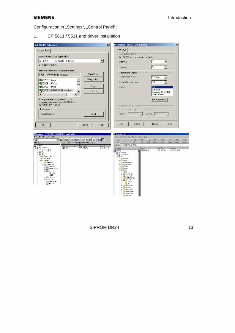
Configuration in „Settings“, „Control Panel“: 1. CP 5611 / 5511 and driver installation

Introduction s
SIPROM DR24 14
2. MPI interface in a SIMATIC PG (PG 740,..)
On a Profibus DP with more than one master (PC/PG and SIMATIC S5/S7) there is a marking „PG/PC is the onely master on the bus“ necessary in the settings according to point 1 or 2!. 1.4 Default settings in a SIPART DR24 For a communication with a PC, the SIPART DR24 must be prepared with default settings. If necessary, the factory settings are set with the function „All Preset“ (Apst). In the level "Structure" ( STRU ) - "Off-Line-Parameters" (OFPA), the slave adress of the SIPART DR24 must be programmed accordingly:
s Introduction
SIPROM DR24 15
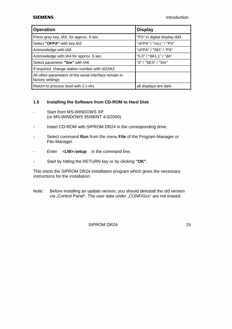
Operation Display Press gray key, tA5, for approx. 6 sec "PS" in digital display dd3 Select "OFPA" with key tA2 "oFPA" / "roLL" / "PS" Acknowledge with tA6 "oFPA" / "SEt" / "PS" Acknowledge with tA4 for approx. 6 sec "0.0" / "dA1.1" / "dA" Select parameter "Snr" with tA6 "0" / "SES" / "Snr" If required, change station number with tA2/tA3 All other parameters of the serial interface remain in factory settings
Return to process level with 2 x tA1 all displays are dark 1.5 Installing the Software from CD-ROM to Hard Disk - Start from MS-WINDOWS XP (or MS-WINDOWS 95/98/NT 4.0/2000) - Insert CD-ROM with SIPROM DR24 in the corresponding drive. - Select command Run from the menu File of the Program-Manager or File-Manager. - Enter <LW>:setup in the command line. - Start by hitting the RETURN key or by clicking "OK". This starts the SIPROM DR24 installation program which gives the necessary instructions for the installation: Note: Before installing an update version, you should deinstall the old version
via „Control Panel“. The user data under „CONFIGxx“ are not erased.
Introduction s
SIPROM DR24 16
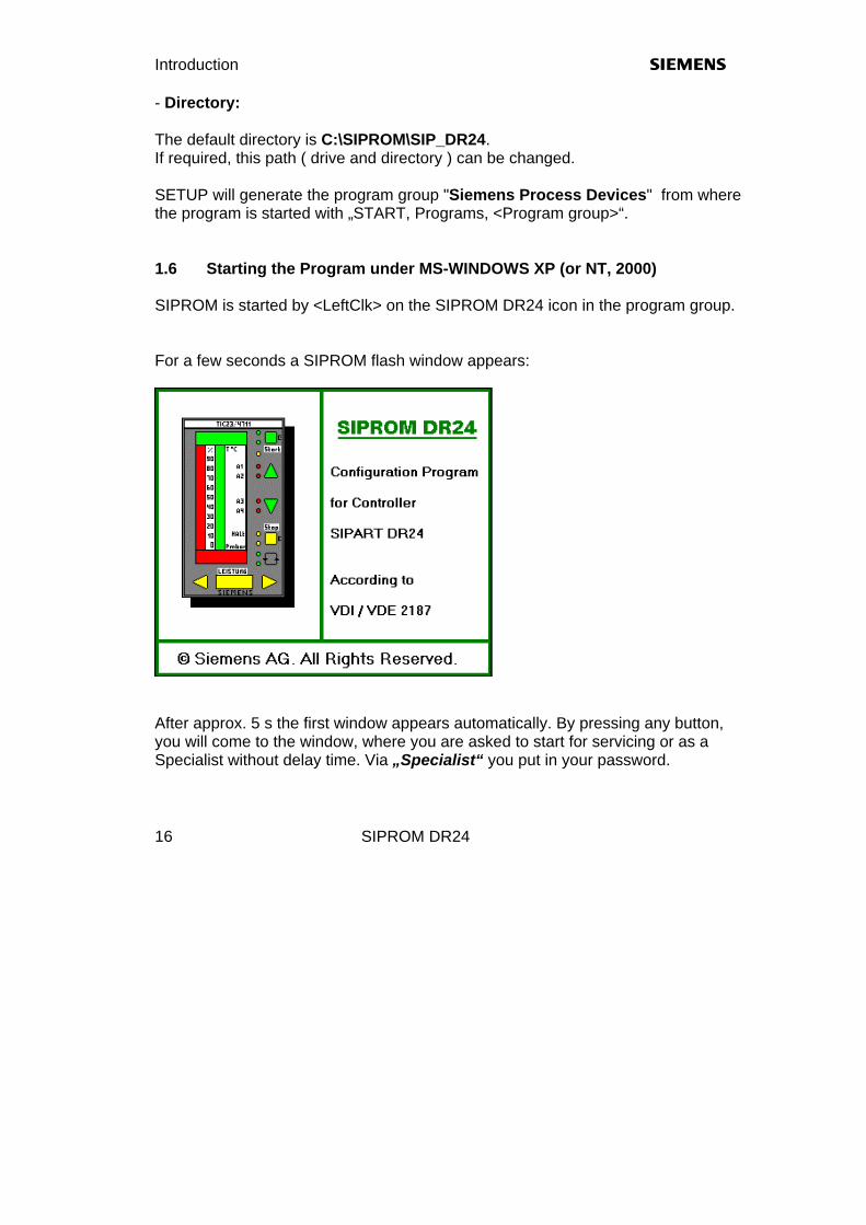
- Directory: The default directory is C:\SIPROM\SIP_DR24. If required, this path ( drive and directory ) can be changed. SETUP will generate the program group "Siemens Process Devices" from where the program is started with „START, Programs, <Program group>“. 1.6 Starting the Program under MS-WINDOWS XP (or NT, 2000) SIPROM is started by <LeftClk> on the SIPROM DR24 icon in the program group. For a few seconds a SIPROM flash window appears:
After approx. 5 s the first window appears automatically. By pressing any button, you will come to the window, where you are asked to start for servicing or as a Specialist without delay time. Via „Specialist“ you put in your password.
s Introduction
SIPROM DR24 17
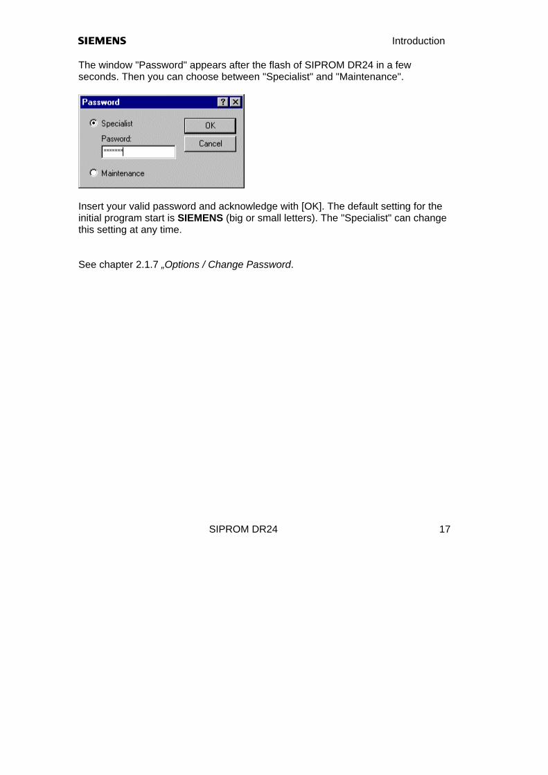
The window "Password" appears after the flash of SIPROM DR24 in a few seconds. Then you can choose between "Specialist" and "Maintenance".
Insert your valid password and acknowledge with [OK]. The default setting for the initial program start is SIEMENS (big or small letters). The "Specialist" can change this setting at any time. See chapter 2.1.7 „Options / Change Password.

s Functions
SIPROM DR24 18
2. Functions of SIPROM DR24 Generally, the former functionality of SIPROM DR24 under MS-WINDOWS 3.1 or MS-WIN95 has been maintained. In some points, however, the program has been extended. The following extensions with regard to elder versions have been implemented: 1. New install procedure (InstallShield); Deinstallation is included 2. New filenames according to other SIPROM programs 3. Select language in install procedure: GERMAN/ENGLISH 4. New print functions 5. More document functions; Front- / Rear side and block diagram more Edit-functions 6. Zoom-function in EDIT window 7. Integration of all new functions of SIPART DR24 (6DR2410-..) 8. Now: 32-Bit-application for MS-WINDOWS XP (NT, 2000, 95, 98) 9. Communication via Profibus DP (CP 5611, 5511) 10. Protection of user program with keyword 11. Conversion of old DR24 data and continuation with modifications 12. Display program for process values and status information 2.1 Functions of the working window

s Functions
SIPROM DR24 19
2.1.1 File, New ...
By selecting “Graphic Layout”, an empty schematic is opened in the working area for graphic layout. By selecting “Tabular Layout”, you reach the working area for Tabular Layout. In both cases the factory settings are loaded. The graphic and tabular layouts are not linked within the software, that means that a DR24 cannot be read out in graphical mode.

Functions s
SIPROM DR24 20
After selecting a new graphical layout, an empty schematic appears with a function block library on the left side. The empty schematic has the format "Landscape".

s Functions
SIPROM DR24 21
2.1.2 File, Open ...
If you select one of the existing files with the extension *.g24, *.t24 and *.pic the conversion is done automatically. Afterwards this file can be modified for a new DR24 (6DR2410-) by quitting with “No”. All Input- and Output-functions stay in the 2-level-format, when it was an old file, by quitting with “Yes”. The 4-channel-format can be created with a new schematic or after converting with “No” to DR2410. Regarding the kind of the loaded file, SIPROM DR24 switches to the actual device type:

Functions s
SIPROM DR24 22
Selecting the extension *.pic loads a circuit design created under GEM/3 from a disk or hard-disk and converts it for further processing. PIC-files, which only include tabular device data are automatically loaded to the tabular layout. Important! A new device ist better set to factory settings with the function „ALL PRESET“ in order that the extended RAM area is erased. 2.1.3 Controller, Load from controller ...
That function reads out a SIPART DR24 in tabular layout. On the PC interface -COMx or PROFIBUS-DP- is connected a DR24 with the specified station number (example: 24). 2.1.4 Select controller type Bevor you work with a graphic- or tabular layout you can select an old DR24 (6DR2400-) or a new one (6DR2410-).
s Functions
SIPROM DR24 23
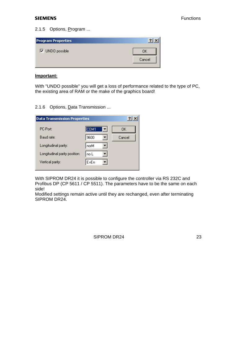
2.1.5 Options, Program ...
Important: With "UNDO possible" you will get a loss of performance related to the type of PC, the existing area of RAM or the make of the graphics board! 2.1.6 Options, Data Transmission ...
With SIPROM DR24 it is possible to configure the controller via RS 232C and Profibus DP (CP 5611 / CP 5511). The parameters have to be the same on each side! Modified settings remain active until they are rechanged, even after terminating SIPROM DR24.

Functions s
SIPROM DR24 24
2.1.7 Options, Change Password ...
The default setting of the password for a specialist "SIEMENS" can be changed with that function. 2.1.8 Options, Language ... That function selects GERMAN or ENGLISH. 2.1.9 Help, Contents ... The menu item "Help" includes all the different help functions of SIPROM DR24. "About SIPROM DR24" displays the current release of the program.

s Functions
SIPROM DR24 25
2.2 Functions in the working area
This window provides functions for creating a graphical data set for the SIPART DR24. Available data are read either from hard disk / diskette or from the connected controller for tabular layout. The following menues are inserted to the working window: Graphical layout: Edit, Insert, Page, Window Tabular layout: Edit, Window

Functions s
SIPROM DR24 26
2.2.1 File, Print ...
The function "File, Print" can print a graphical or tabular data set and/or the documentation of the device. All parts of the device data (ONPA, OFPA, ... ec.) and even the complete connections on the rear side and front functions can be selected. When no data are selected, only the documentation header is printed out. Another printer is selected via the function Printer Setup, in which other formats as "Portrait" or "Landscape" can be adapted. The button Print Preview shows you the print in advance on the screen. This function shows the graphical and tabular device data on one or two pages at the same moment, which could be zoomed in two stages.

s Functions
SIPROM DR24 27
2.2.2 File, Compare ... The function "File, Compare" compares an actual data set in the RAM area with a file or with device data from a DR24. The differences in the different levels (Parameters, Hdef, Fdef, Fcon and Fpos) can be monitored via buttons and be printed out if required.

Functions s
SIPROM DR24 28
2.2.3 Controller, Load from Controller ...
After selecting [OK] the communication is started. The status display is monitored in the following window>
After [Close] the DR24 data can be monitored and changed in tabular layout format. The function "Controller, Save to Controller ..." follows the same way.

s Functions
SIPROM DR24 29
2.2.4 Controller, Change Keyword ...
That function will protect a user program in the referenced controller. Activate Keyword: - Select "New keyword" and "Confirm keyword" - Edit keyword between "0 ... 65534" - The protection is activated at once; only the On-Line-parameters can be
changed now, all other levels are blocked; in the display "BLS" is monitored. Change Keyword: - Switch all edit fields to "activ" - Edit "Old keyword" - Edit "New keyword" and "Confirm keyword"

Functions s
SIPROM DR24 30
Deactivate Keyword: - With the keyword "65535" (FFFFHex) the protection is canceled permanent. - If there is a wrong trial, the next trial can be started after a certain time:
1. Trial: ca. 1 min. 2. Trial: ca. 5 min. 3. Trial: ca. 10 min. each following trial: ca. 1.5 hours
Starting with software release: C5 the keyword protection of OFPA, CLPA, CAE4/5, HdEF, FdEF, FCON and FPOS in the SIPART DR24 (6DR2410- ) can be realized. Caution: By loss of the actual keyword, the controller have to be send back to
the manufacturer!

s Functions
SIPROM DR24 31
(blank page)
s Graphical Layout
SIPROM DR24 32
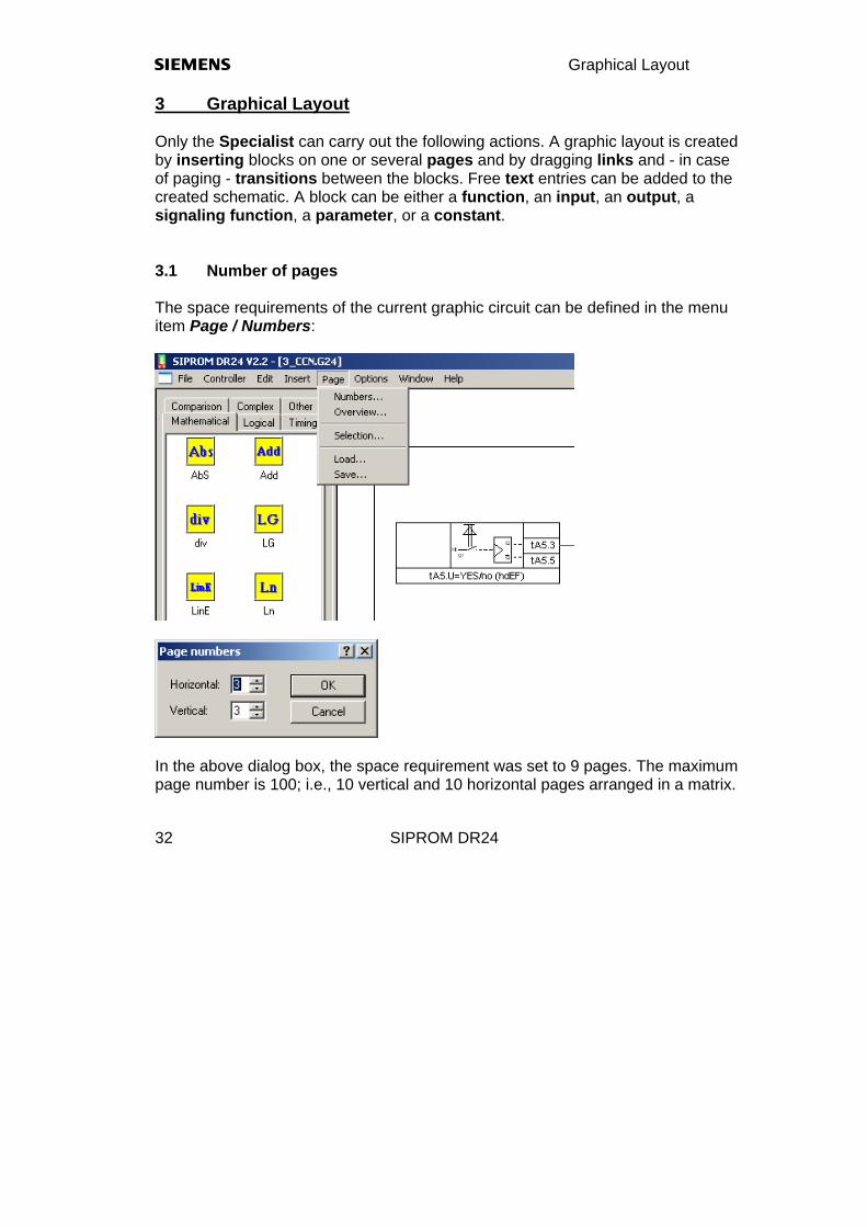
3 Graphical Layout Only the Specialist can carry out the following actions. A graphic layout is created by inserting blocks on one or several pages and by dragging links and - in case of paging - transitions between the blocks. Free text entries can be added to the created schematic. A block can be either a function, an input, an output, a signaling function, a parameter, or a constant. 3.1 Number of pages The space requirements of the current graphic circuit can be defined in the menu item Page / Numbers:
In the above dialog box, the space requirement was set to 9 pages. The maximum page number is 100; i.e., 10 vertical and 10 horizontal pages arranged in a matrix.

s Graphic circuit design
SIPROM DR24 33
3.2 Page Overview The function "Page, Overview" prepositions a maximum of 10 visable function blocks on the selected pages. It is possible to select more than 10 blocks, so far there is enough place on a selected page.
Processing continues with the function Page / Selection... if another page than 1/1 is required.

Graphic Layout s
SIPROM DR24 34
With the menu "Insert", all the required blocks are selected, placed on the pages, and connected. Often used blocks are drawn from the left library window with the mouse to the actual page (FDEF).
s Graphic circuit design
SIPROM DR24 35
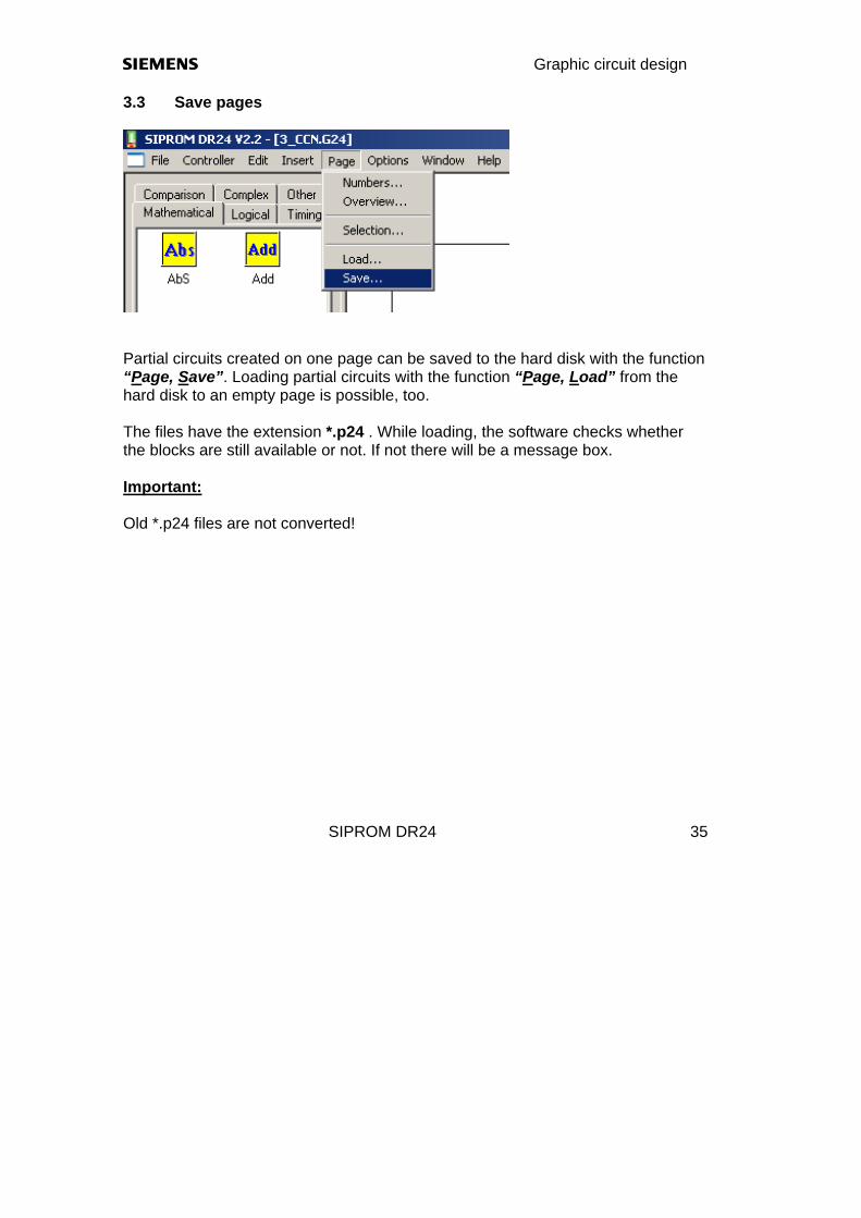
3.3 Save pages
Partial circuits created on one page can be saved to the hard disk with the function “Page, Save”. Loading partial circuits with the function “Page, Load” from the hard disk to an empty page is possible, too. The files have the extension *.p24 . While loading, the software checks whether the blocks are still available or not. If not there will be a message box. Important: Old *.p24 files are not converted!
Graphic Layout s
SIPROM DR24 36
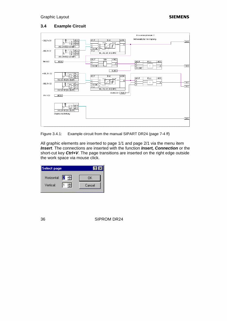
3.4 Example Circuit
Figure 3.4.1: Example circuit from the manual SIPART DR24 (page 7-4 ff) All graphic elements are inserted to page 1/1 and page 2/1 via the menu item Insert. The connections are inserted with the function Insert, Connection or the short-cut key Ctrl+V. The page transitions are inserted on the right edge outside the work space via mouse click.
s Graphic circuit design
SIPROM DR24 37
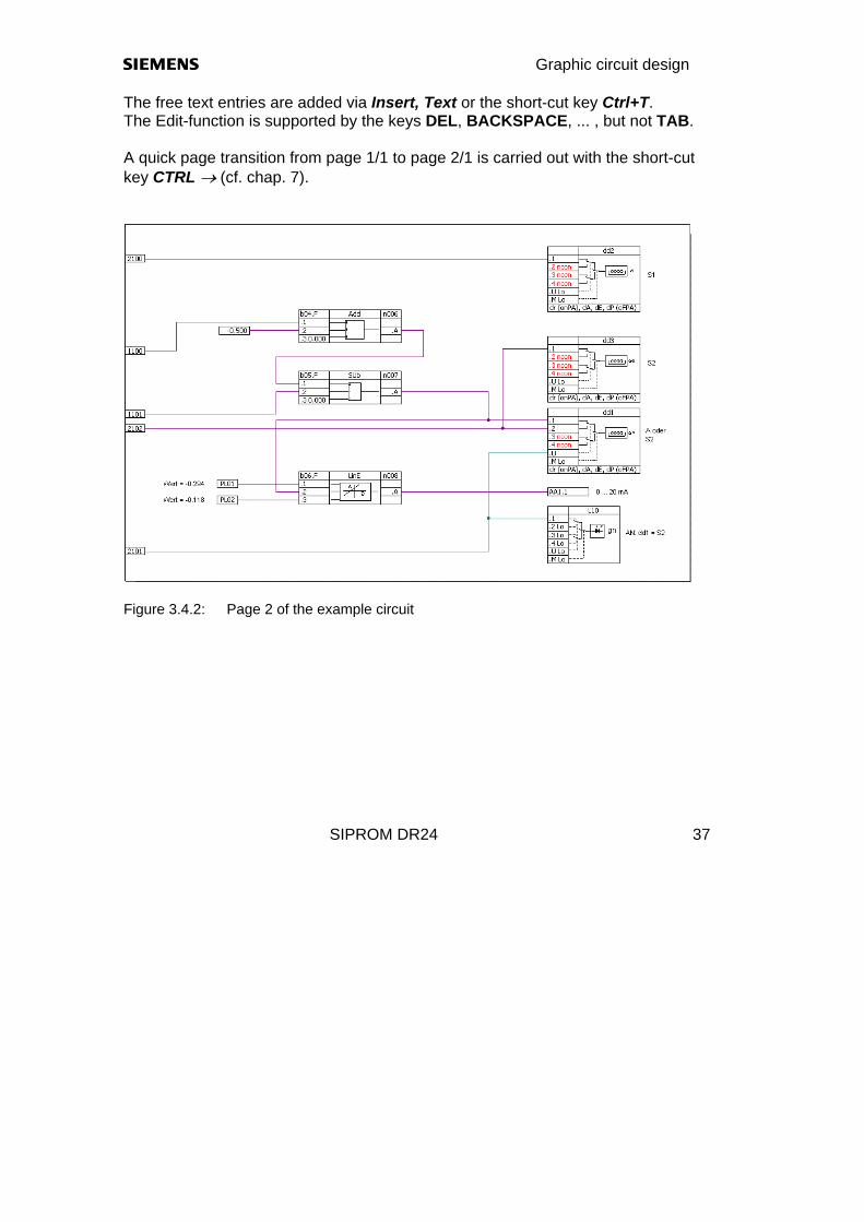
The free text entries are added via Insert, Text or the short-cut key Ctrl+T. The Edit-function is supported by the keys DEL, BACKSPACE, ... , but not TAB. A quick page transition from page 1/1 to page 2/1 is carried out with the short-cut key CTRL → (cf. chap. 7).
Figure 3.4.2: Page 2 of the example circuit

Graphic Layout s
SIPROM DR24 38
3.5 Graphic properties Starting from „Factory settings“ its possible to change the graphical properties of the function blocks, the page transitions, the connection dots and text strings. The function will be select via „Options / Graphic...“

s Graphic circuit design
SIPROM DR24 39
(blank page)

s Tabular Layout
SIPROM DR24 40
4 Tabular Layout The tabular layout is opened with the menue File, New .... Then, the pull down menu Edit displays the different configuration levels Parameters, Define Hardware (Hdef), Define Functions (Fdef), Connect Functions (Fcon), Position Functions (Fpos) and Documentation. Like for graphic circuit design, the different parameters are selected in pull down menus. The parameters of the Clock function block and the option “UNI-module” are only released, when the function "Cloc" was defined in FDEF or “Uni_..” in HDEF for AE4/5 was defined.
s Tabular circiut design
SIPROM DR24 41
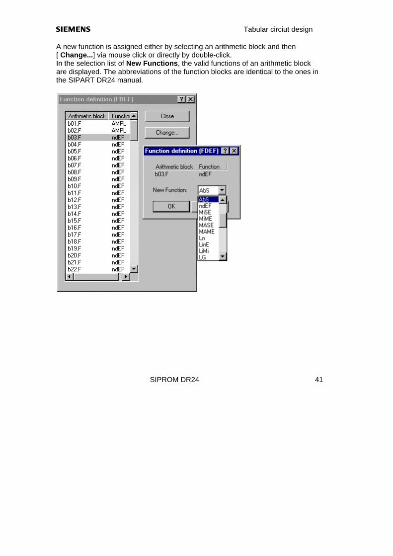
A new function is assigned either by selecting an arithmetic block and then [ Change...] via mouse click or directly by double-click. In the selection list of New Functions, the valid functions of an arithmetic block are displayed. The abbreviations of the function blocks are identical to the ones in the SIPART DR24 manual.

Tabular Layout s
SIPROM DR24 42
Via mouse click and [ Change...] or double mouse click on a Data Sink, a new data source can be assigned. In the selection list New Data Source, the available data sources are displayed.
s Tabular circiut design
SIPROM DR24 43
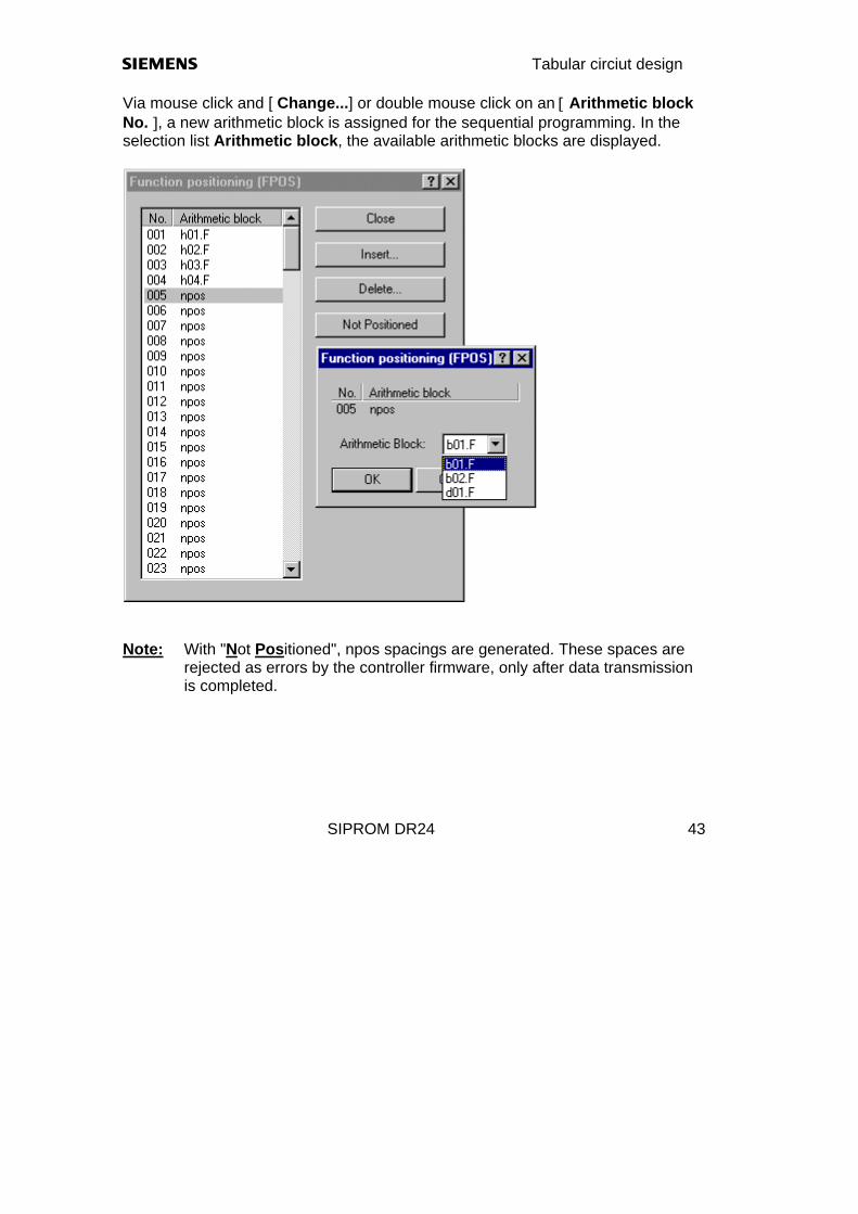
Via mouse click and [ Change...] or double mouse click on an [ Arithmetic block No. ], a new arithmetic block is assigned for the sequential programming. In the selection list Arithmetic block, the available arithmetic blocks are displayed.
Note: With "Not Positioned", npos spacings are generated. These spaces are
rejected as errors by the controller firmware, only after data transmission is completed.
s Parameters
SIPROM DR24 44
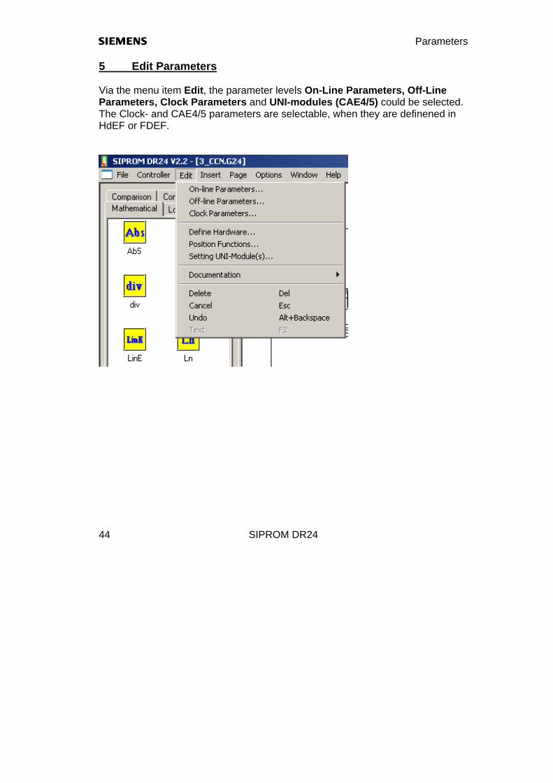
5 Edit Parameters Via the menu item Edit, the parameter levels On-Line Parameters, Off-Line Parameters, Clock Parameters and UNI-modules (CAE4/5) could be selected. The Clock- and CAE4/5 parameters are selectable, when they are definened in HdEF or FDEF.

s Parameters
SIPROM DR24 45
5.1 On-Line-Parameters
New Values within the Setting Range can be entered in this box. Values outside the setting range are rejected. The new value is adopted by clicking [OK], clicking [Cancel] leads back to the On-Line Parameters dialog.

Parameters s
SIPROM DR24 46
5.2 Off-Line-Parameters
New Values within the Setting Range can be entered in this box. Values outside the setting range are rejected. The new value is adopted by clicking [OK], clicking [Cancel] leads back to the Off-Line Parameters dialog. The parameters of the serial interface (Baudrate,, ... etc.) are not displayed. The printout of OFPA shows the controller adress always as "zero".

s Parameters
SIPROM DR24 47
5.3 Clock Parameters Clock Parameters can be selected only, when the Clock function has been defined as type d01.F, d02.F, or d03.F in the Define Function level (FDEF).
The change dialog for the required parameter is opened via mouse click and [Change...] or directly by double-click. New Values within the Setting Range can be entered in this box. Values outside the setting range are rejected. The new value is adopted by clicking [OK], clicking [Cancel] leads back to the Clock Parameters dialog.
Parameters s
SIPROM DR24 48
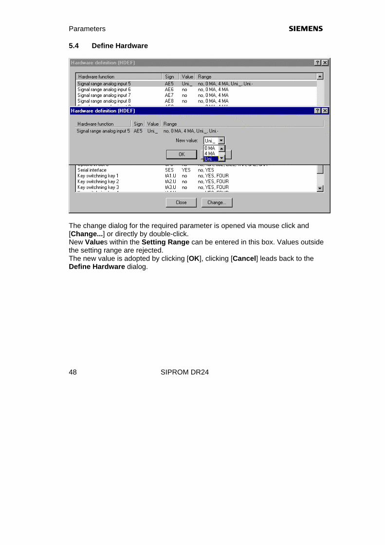
5.4 Define Hardware
The change dialog for the required parameter is opened via mouse click and [Change...] or directly by double-click. New Values within the Setting Range can be entered in this box. Values outside the setting range are rejected. The new value is adopted by clicking [OK], clicking [Cancel] leads back to the Define Hardware dialog.
s Parameters
SIPROM DR24 49
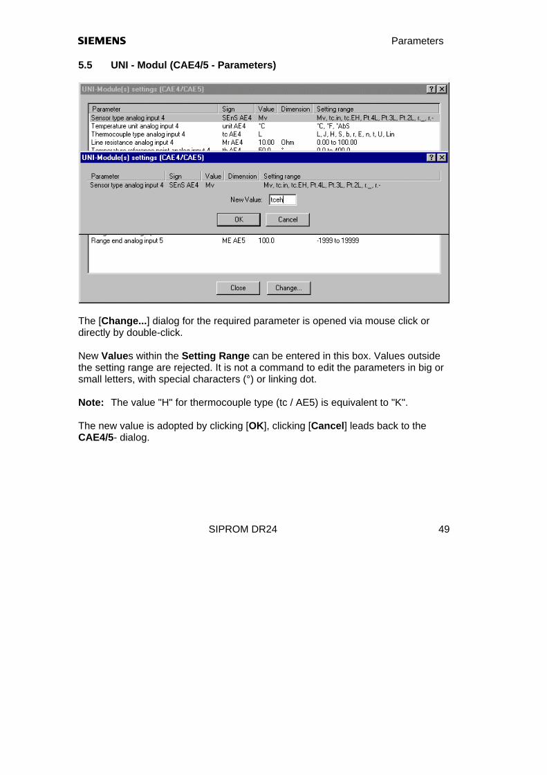
5.5 UNI - Modul (CAE4/5 - Parameters)
The [Change...] dialog for the required parameter is opened via mouse click or directly by double-click. New Values within the Setting Range can be entered in this box. Values outside the setting range are rejected. It is not a command to edit the parameters in big or small letters, with special characters (°) or linking dot. Note: The value "H" for thermocouple type (tc / AE5) is equivalent to "K". The new value is adopted by clicking [OK], clicking [Cancel] leads back to the CAE4/5- dialog.

s Documentation
SIPROM DR24 50
6 Documentation Assignment and identification data of the controller setup are entered in these dialog boxes. The data appear in the printed controller documentation. You can use 20 characters with size 11 / Arial for landscape format and 13 characters with size 11 / Arial for portrait format The header data are entered in the first dialog for the documentation cover and frame:

s Documentation
SIPROM DR24 51
The inputs of the SIPART DR24 are described by max. 110 characters / Arial/11 for the format DIN A4 / landscape.
In order to change text strings, you can use the standard edit keys, such as BACKSPACE, TAB, arrows, Del, ....
Documentation s
SIPROM DR24 52
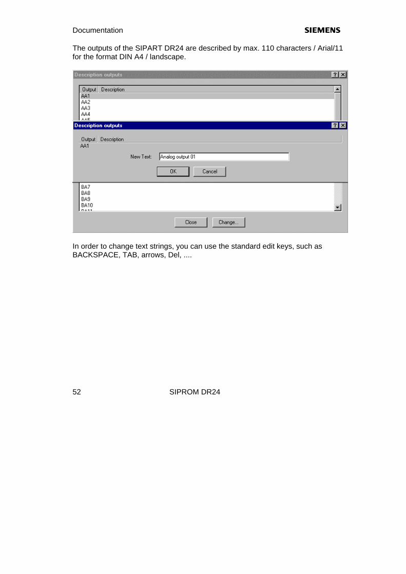
The outputs of the SIPART DR24 are described by max. 110 characters / Arial/11 for the format DIN A4 / landscape.
In order to change text strings, you can use the standard edit keys, such as BACKSPACE, TAB, arrows, Del, ....

s Documentation
SIPROM DR24 53
Front display with examples for the different levels.

Documentation s
SIPROM DR24 54
Rear side display of the different PIN connections.

s Documentation
SIPROM DR24 55
(blank page)

s Short-cut keys
SIPROM DR24 56
7 Short-cut Keys 1. Del delete arithmetic block or link 2. Esc cancel action 3. ← scroll left 4. → scroll right 5. ↑ scroll up 6. ↓ scroll down 7. Shift + ← scroll one line to the left 8. Shift + → scroll one line to the right 9. Shift + ↑ scroll one line up 10. Shift + ↓ scroll one line down 11. Ctrl + ← scroll one page to the left 12. Ctrl + → scroll one page to the right 13. Ctrl + ↑ scroll one page up 14. Ctrl + ↓ scroll one page down 15. Ctrl + P print 16. Ctrl + O load circuit design (Open file) 17. Ctrl + N new circuit design (New file) 18. Ctrl + S save circuit design (Save file) 19. Ctrl + T insert text 20. Ctrl + V insert link 21. Alt + Backspace undo last action 22. TAB-key Tabulator ahead 23. Shift + TAB-key Tabulator back 24. Backspace Backspace

s Shortcut keys
SIPROM DR24 57
(blank page)
s Error messages
SIPROM DR24 58
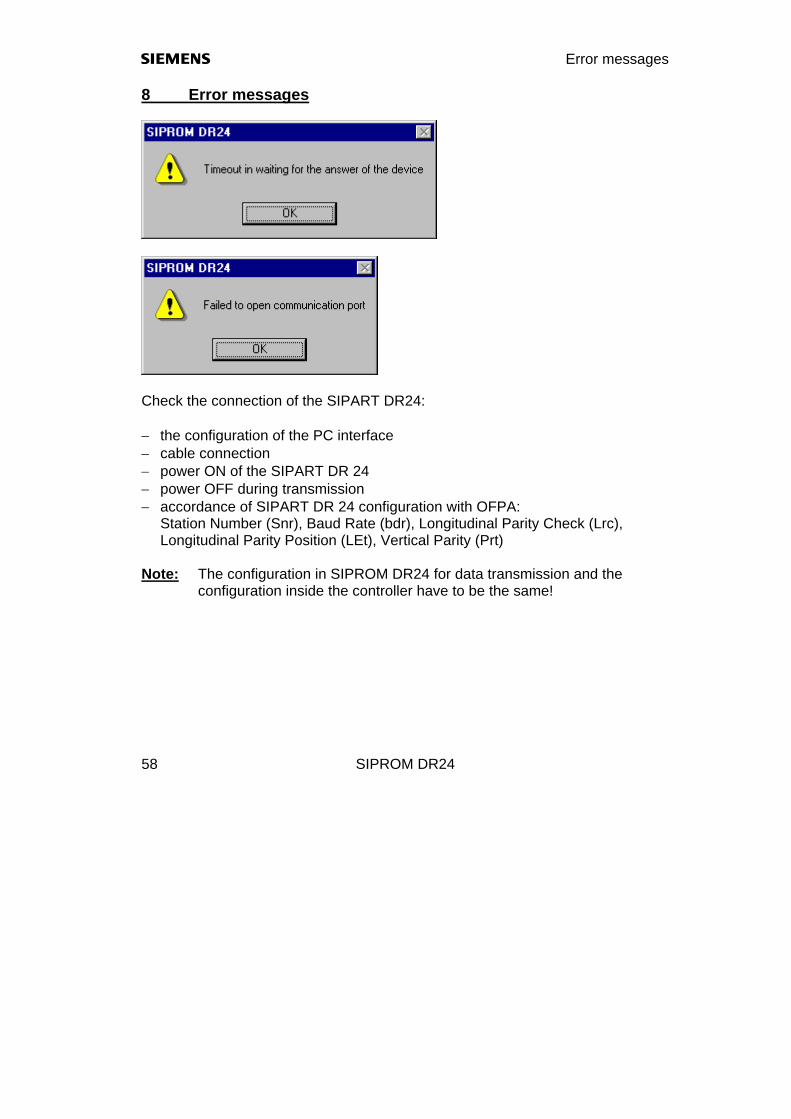
8 Error messages
Check the connection of the SIPART DR24: − the configuration of the PC interface − cable connection − power ON of the SIPART DR 24 − power OFF during transmission − accordance of SIPART DR 24 configuration with OFPA:
Station Number (Snr), Baud Rate (bdr), Longitudinal Parity Check (Lrc), Longitudinal Parity Position (LEt), Vertical Parity (Prt)
Note: The configuration in SIPROM DR24 for data transmission and the
configuration inside the controller have to be the same!

s Error messages
SIPROM DR24 59
One of the parameters entered is outside the valid range.
Wrong input for number of pages (horizontal/vertical).
It is not enough place for a new function block.
Collision between two different data sets!
Error messages s
SIPROM DR24 60
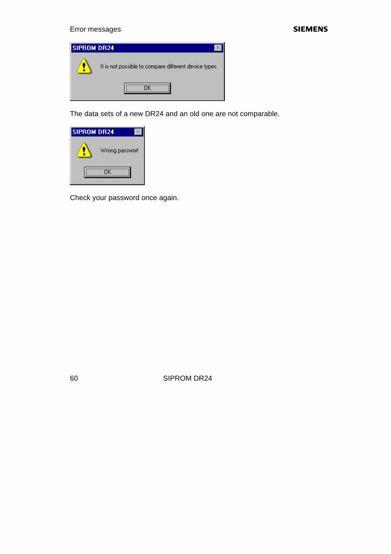
The data sets of a new DR24 and an old one are not comparable.
Check your password once again.

s Error messages
SIPROM DR24 61
(blank page)
s References
SIPROM DR24 62
9 References /1/ Operating Instructions SIPART DR24, Serial SIPART DR24 V.28-Bus Interface Order number: C73000-B7476-C135 /2/ Multifunction Unit Manual SIPART DR24, 6DR 2410 Order number: C79000-G7476-C153 /3/ User's Guide Microsoft® Windows™, Operating System NT Version 4.0 SP6 or greater Operating System XP Version 5.1 SP1 or greater /4/ The Windows™ Interface An Application Design Guide

s References
SIPROM DR24 63
(blank page)

s Editor
SIPROM DR24 64
10 Function Block EDITOR With the editor "SIPROM DR24 Editor", the contours of the graphic blocks are changed on a default factory settings basis. The editor is located in the path "C:\SIPROM\SIP_DR24\“ and is started from the File-Manager. However, the file "DR24CFG.INI" in the path „C:\SIPROM\SIP_DR24\“ should be copied to a custom user path as backup, e.g. "C:\MYPATH\SIPROM\...", prior to starting.
After clicking [OK], the modified coordinates are written to the respective positions of the file "DR24CFG.INI". The font size in the function blocks is adjusted to the block size via "File / Font".

s Editor
SIPROM DR24 65
10.1 Example Subtractor (SUb) Default factory settings for the coordinates of a subtractor:

Editor s
SIPROM DR24 66
10.2 Example Binary Integrator (bin) Default factory settings for the coordinates of a binary integrator:

s Editor
SIPROM DR24 67
10.3 Example Analog Input (AE1) Default factory settings for the coordinates of an analog input:

s Display
SIPROM DR24 68
11 Display of Process values The program "SIPROM DR24 Display" shows all process variables and status bits, which could be found in the status registers STxx. The different variables can be selected from "View/Show process values" or "View/Show status register". The program is installed in "C:/SIPROM/SIP_DR24" and is started via "START, Programs ...".
s Editor
SIPROM DR24 69
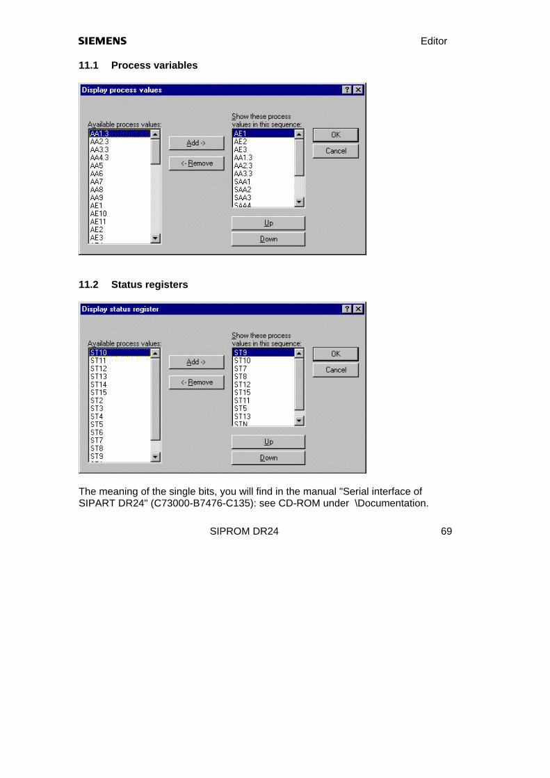
11.1 Process variables
11.2 Status registers
The meaning of the single bits, you will find in the manual "Serial interface of SIPART DR24" (C73000-B7476-C135): see CD-ROM under \Documentation.