siso system design
TRANSCRIPT

EE392m - Winter 2003 Control Engineering 7-1
Lecture 7 - SISO Loop Design
• Design approaches, given specs• Loopshaping: in-band and out-of-band specs• Design example• Fundamental design limitations for the loop
– Frequency domain limitations– Structural design limitations– Engineering design limitations

EE392m - Winter 2003 Control Engineering 7-2
Modern control design• Observable and controllable system
– Can put poles anywhere– Can drive state anywhere– Can design ‘optimal control’
• Issues– Large control– Error peaking in the transient– Noise amplification– Poor robustness, margins– Engineering trade off vs. a single optimality index

EE392m - Winter 2003 Control Engineering 7-3
Feedback controller design
• Conflicting requirements• Engineers look for a
reasonable trade-off– Educated guess, trial and
error controller parameterchoice
– Optimization, if theperformance is reallyimportant
• optimality parameters areused as tuning handles
Analysis and simulation
eskk
ssku I
PD
D
++
+−=
1τ
Plant model
Design process
D
I
P
kkk
Stability Performance Robustness
IndexesConstraintsSpecs
EE392m - Winter 2003 Control Engineering 7-4
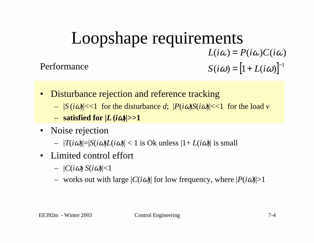
Loopshape requirementsPerformance
• Disturbance rejection and reference tracking– |S (iω)|<<1 for the disturbance d; |P(iω)S(iω)|<<1 for the load v– satisfied for |L (iωωωω)|>>1
• Noise rejection– |T(iω)|=|S(iω)L(iω)| < 1 is Ok unless |1+ L(iω)| is small
• Limited control effort– |C(iω) S(iω)|<1– works out with large |C(iω)| for low frequency, where |P(iω)|>1
[ ] 1)(1)(
)()()(−+=
=
ωωωωω
iLiS
iCiPiL
EE392m - Winter 2003 Control Engineering 7-5
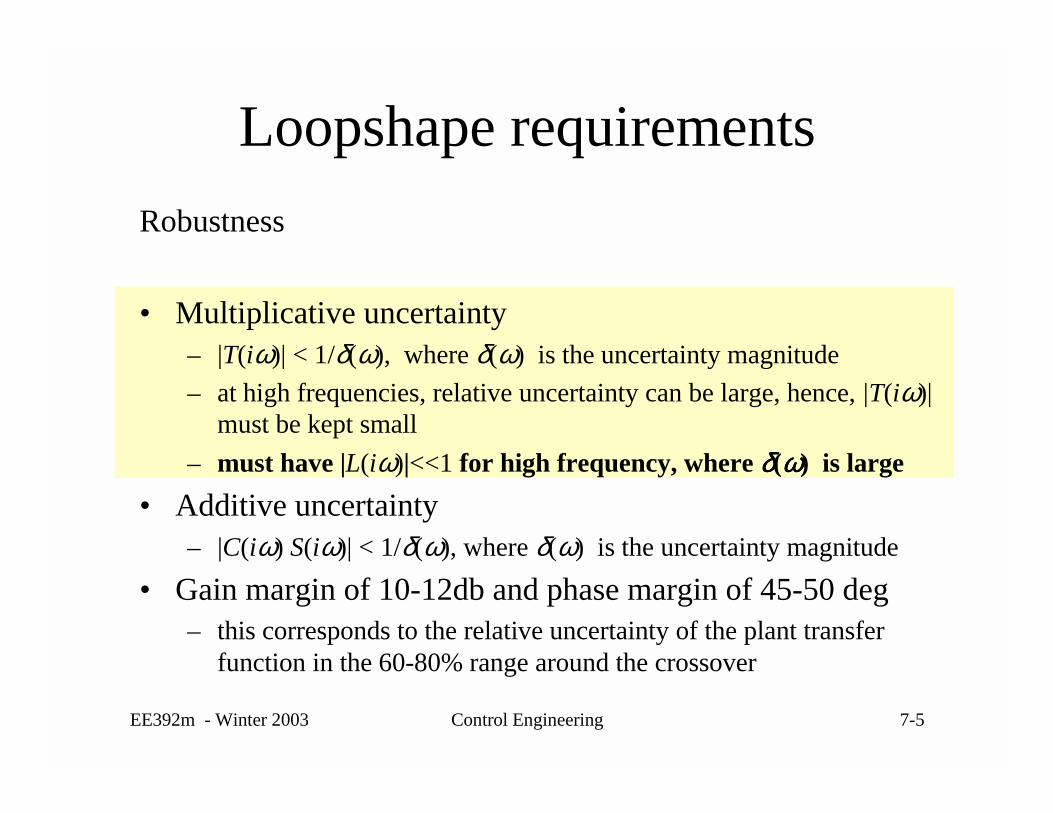
Loopshape requirementsRobustness
• Multiplicative uncertainty– |T(iω)| < 1/δ(ω), where δ(ω) is the uncertainty magnitude– at high frequencies, relative uncertainty can be large, hence, |T(iω)|
must be kept small– must have |L(iω)|<<1 for high frequency, where δδδδ(ωωωω) is large
• Additive uncertainty– |C(iω) S(iω)| < 1/δ(ω), where δ(ω) is the uncertainty magnitude
• Gain margin of 10-12db and phase margin of 45-50 deg– this corresponds to the relative uncertainty of the plant transfer
function in the 60-80% range around the crossover

EE392m - Winter 2003 Control Engineering 7-6
Gain and phase margins
• Are less informativethan the noisesensitivity
Im L(s)
Re L(s)
1/gm
ϕm
-1[ ] 1)()(1)()( −+= sCsPsCsSu
Additive uncertainty|∆(iω)| radius
sensitivitypeak margin
• Can use uncertaintycharacterization andthe sensitivity instead
• Margins are useful fordeciding upon the loopshape modifications

EE392m - Winter 2003 Control Engineering 7-7
Loop Shape Requirements• Low frequency:
– high gain L= small S
• High frequency:– small gain L
= small T · large δ• Bandwidth
– performance can beonly achieved in alimited frequencyband: ω ≤ ωB
– ωB is the bandwidth
Fundamental tradeoff: performance vs. robustness
0 dB
ωgc
|L(iω)|
ωB
Performance
RobustnessBandwidth
slope

EE392m - Winter 2003 Control Engineering 7-8
Loopshaping design
• Loop design– Use P,I, and D feedback to shape the loop gain
• Loop modification and bandwidth– Low-pass filter - get rid of high-frequency stuff - robustness– Notch filter - get rid of oscillatory stuff - robustness– Lead-lag to improve phase around the crossover - bandwidth
• P+D in the PID together have a lead-lag effect
• Need to maintain stability while shaping the magnitude ofthe loop gain
• Formal design tools H2, H∞, LMI, H∞ loopshaping– cannot go past the fundamental limitations

EE392m - Winter 2003 Control Engineering 7-9
Example - disk drive servo• The problem from HW Assignment 2
– data in diskPID.m, diskdata.mat
• Design model: is an uncertainty
• Analysis model: description for• Design approach: PID control based on
the simplified model
)()( 20 sP
sgsP ∆+=
1)(
+++=
ssk
skksC
DD
IP τ
Disk servo control
EDISTURBANCVCM TTJ +=ϕ&&
VoiceCoilMotor
)(sP∆
)(sP∆

EE392m - Winter 2003 Control Engineering 7-10
Disk drive servo controller• Start from designing a PD controller
– poles, characteristic equation
( )
0
010)()(1
002
20
=++
=+⋅+⇒=+
PD
DP
kgksgssgskksPsC
02
000 /;/2 gwkgwk PD ==• Critically damped system
where frequency w0 is the closed-loop bandwidth
• In the derivative term make dynamics fasterthan w0. Select 0/25.0 wD =τ 1+s
skD
D τ

EE392m - Winter 2003 Control Engineering 7-11
Disk drive servo• Step up from PD to PID control
0
011
00023
20
=+++
=⋅
+++
IPD
IDP
kgksgkgsssgk
sskk
0030000
20 //;/;/ wcgbwkgawkgwk DIDP ==== τ
• Keep the system close to the critically damped, add integratorterm to correct the steady state error, keep the scaling
where a, b, and c are the tuning parameters
• Initial guess: w0 =2000; a=2; b=0.1; c =0.25• Tune a, b, c and w0 by watching performance and robustness

EE392m - Winter 2003 Control Engineering 7-12
Disk drive - controller tuning
• Tune a, b, w0 , and τD by trial and error• Find a trade off taking into the account
– Closed loop step response– Loop gain - performance– Robustness - sensitivity– Gain and phase margins
• Try to match the characteristics of C2 controller (demo)
• The final tuned values:w0 =1700; a=1.5; b=0.5; c=0.2

EE392m - Winter 2003 Control Engineering 7-13
Disk servo - controller comparison• PID is compared
against a referencedesign
• Reference design: 4-thorder controller: lead-lag + notch filter– Matlab diskdemo– Data in diskPID.m,diskdata.mat
4th-order compe nsa tor C2 (blue, das hed), PID (red)
Time (sec)
Ampl
itude
0 0.005 0.01 0.015-0.05
0
0.05
0.1
0.15
0.2
0.25
0.3
EE392m - Winter 2003 Control Engineering 7-14
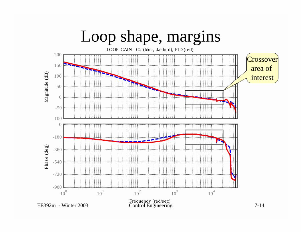
Loop shape, marginsLOOP GAIN - C2 (blue, dashe d), PID (red)
Frequency (rad/sec)
Phas
e (d
eg)
Mag
nitu
de (d
B)
-100
-50
0
50
100
150
200
100 101 102 103 104-900
-720
-540
-360
-180
0
Crossoverarea of interest

EE392m - Winter 2003 Control Engineering 7-15
Disk drive servo - robustness
104
-30
-25
-20
-15ROBUS TNESS TO PLANT UNCERTAINTY (dB) - C2 (blue , da s he d), PID (re d)10
4
-50
-40
-30
-20
-10
TRANSFER FUNCTION AND ACCEP TABLE UNCERTAINTY - C2 (blue , da s he d), PID (re d, dotte d)
[m2,ph2]=bode(feedback(C2,Gd),w))
[mP,phP]=bode(feedback(PIDd,Gd),w))
Full model
Simple model
Robust stability bounds
PID
C2 - Matlab demo
plot(w,1./mP,w,1/m2)
1/|Su(iω)|

EE392m - Winter 2003 Control Engineering 7-16
Fundamental design limitations
• If we do not have a reference design - how do we know ifwe are doing well. May be there is a much bettercontroller?
• Cannot get around the fundamental design limitations– frequency domain limitations on the loop shape– system structure limitations– engineering design limitations

EE392m - Winter 2003 Control Engineering 7-17
Frequency domain limitationS(iω) + T(iω) = 1
• Bode’s integral constraint - waterbed effect
Robustness: |T(iω)|<<1 Performance: |S(iω)|<<1
-6
-4
-2
0
log |S(iω)|
0)(log0
=∫∞
ωω diS (for most real-life stable system, or worse for the rest)

EE392m - Winter 2003 Control Engineering 7-18
Structural design limitations
• Delays and non-minimum phase (r.h.s. zeros)– cannot make the response faster than delay, set bandwidth smaller
• Unstable dynamics– makes Bode’s integral constraint worse– re-design system to make it stable or use advanced control design
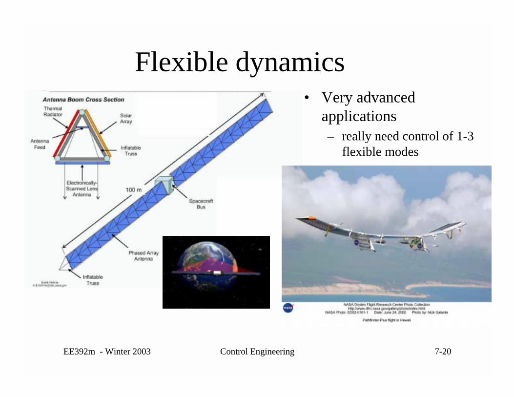
• Flexible dynamics– cannot go faster than the oscillation frequency– practical approach:
• filter out and use low-bandwidth control (wait till it settles)• use input shaping feedforward

EE392m - Winter 2003 Control Engineering 7-19
Unstable dynamics• Very advanced applications
– need advanced feedback control design
EE392m - Winter 2003 Control Engineering 7-20
Flexible dynamics• Very advanced
applications– really need control of 1-3
flexible modes

EE392m - Winter 2003 Control Engineering 7-21
Engineering design limitations• Sensors
– noise - have to reduce |T(iω)| - reduced performance– quantization - same effect as noise– bandwidth (estimators) - cannot make the loop faster
• Actuators– range/saturation - limit the load sensitivity |C(iω) S(iω)|– actuator bandwidth - cannot make the loop faster– actuation increment - sticktion, quantization - effect of a load variation– other control handles
• Modeling errors– have to increase robustness, decrease performance
• Computing, sampling time– Nyquist sampling frequency limits the bandwidth