sitc box al exposion proof - axel larsson
TRANSCRIPT

5.725B_UK - 1
Ref. 5.725B_UK - 2015-02-16. www.axel-larsson.se
MANUALSwitch box AL 77-1990 Explosion proof
Commissioning Ensure that the switch box correspond to the ordered part speci-fications. If needed contact Axel Larsson. The electrical connection between the RC1990 switch box and the control system is to be established according to the standards for installation. The installer must also refer to the label on the switch box and the EC-type exa-mination certificate (available on request) to ensure that the elec-trical and environmental parameters correspond to the installation requirements. Fit suitable Explosion-proof cable gland, EEx d approved for EEx d switch box and EEx e approved for EEx i switch box. Extra cable entries with EX glands may be required if solenoid valves are to be connected.
Note: Cable entries in Explosion-proof design suitable for the cable type and ambient condition and/or a plug are demanded for approved application.
Maintenance1. Check that the threaded gaps between the cover and the housing (7) do not have any damage, due to mechanical or corrosion affection. 2. If needed touch up the painting.
3. Check the condition of the cable glands and that they are correctly mounted.
4. If necessary protect the gaps and threads against corrosion with nonhardening grease. KlübercIsoflex Topas NCA 52 or identical. The gaps and threads must not be painted or treated with silicone oil based grease.
5. Check that O-rings for cover (2) and shaft (8) are intact. Damaged O-rings must be replaced with genuine spare parts only.
6. Check that all screws and the cover are correctly tightened. Secure the cover (2) with the locking screw (1).
Mounting1. Operate the actuator to the ”closed valve position”.
2. Fasten the Namur console (10) to the switch box (7) with 4 pcs M6 screws according to drawing 003146.
3. Dismantle the cover (2) on the switch box. Loosen the locking screw (1), unscrew the cover and lift it straight up.
4. Mount the RC1990 switch box shaft (8) through the hole in the
box. The shaft journal must go through the brass bearing bush (9). Turn the shaft so that it aligns with the groove in the actuator stem (13).
5. Mount the RC1990 box and console with the shaft in the groove on the top side of the actuator stem (13).
6. Fasten the console with 4 pcs screws (12) to the upper side of the actuator and centre the units with each other before tighte ning the screws.
7. Slide the two cams (5) over the shaft (8). The cams should be turned according to drawing 003146.
8. Adjustment of the lower switch for ”closed valve position” indica tion: Turn the lower cam (5) clockwise until the switch is actuated. When a click is heard (only mechanical switches), the cam must be locked with the grub screw (3).
- 2 -
Rotork Sweden AB Tel +46 (0)23 587 00Fax +46 (0)23 587 [email protected]
www.remotecontrol.se
Montering
1. Ställ manöverdonet i ”stängt ventilläge”. 2. Skruva fast Namur konsolen (10) på RC1990 boxen (7) med 4 st M6 skruvar enligt ritning 003146.
3. Demontera locket (2). Lossa stoppskruven (1), skruva loss locket och lyft av det rakt upp.
4. Montera axeln (8) genom mässingsbussningen (9) i botten på RC1990 boxen. Vrid axeln så att den står längs med spåret i donaxeln.
5. Montera RC1990 box och konsol med axeln i spåret på ovansidan av manöverdonets spindel (13).
6.Skruva fast konsolen med 4 st skruvar (12) på donets ovansida och centrera enheterna med varandra före åtdragning av skruvarna.
7.Träd de två kammarna (5) över axeln (8). Kammarna vänds enligt ritning 003146.
8.Justering av undre brytare, som indikerar ”stängt ventilläge”: Vrid undre kammen (5) medurs så att brytaren påverkas. När klickljud hörs (endast me- kaniska brytare) låses kammen med insexskruven (3).
9.Ställ manöverdonet i öppet läge.
10. Justering av övre brytare, som indikerar ”öppet ventilläge”: Nu skall axeltappens nyckel- grepp (13) stå i donets längsriktning. Vrid den övre kammen moturs så att brytaren påverkas. När klickljud hörs (endast mekaniska brytare) låses kammen med insexskruven.
11. Montera kabelförskruvning/ar och om det behövs även blindplugg. Anslut inkommande kabel enligt elschemat som är fäst på RC1990 lockets insida. Spänningen måste vara frånslagen.
12. Skruva tillbaka locket (2) på RC1990 boxen och säkra med låsskruv (1).
Demontering
1.Bryt spänningen till RC1990 boxen och avlufta manöverdonet.
2.Demontera locket (2). Lossa stoppskruv (1). Skruva loss locket och lyft av det rakt upp.
3.Ta loss kablarna från kopplingsplinten och jordningen. Öppna kabelförskruvningen och dra ur kablarna.
4.Lossa de fyra skruvarna (12) som håller Namur konsolen (10). Lyft bort konsolen och RC1990 boxen från donet. Skruva tillbaka locket (2) och lås med stoppskruv (1). Plugga ingångarna på RC1990 boxen för skydd mot damm och smuts.
Ritning nr. 003146
Directive conformity: 94/9/EC Standard conformity: CENELEC EN 50014:1997+A1:1999+A2:1999 CENELEC EN 50018:2000, EN 50020:2002 CENELEC EN 50281-1-1:1998 Certificate: EC Nemko: Nemko 03ATEX1435, Nemko 04ATEX1030 RosTechNadzor: RTN Explosion Proof Centre CTB: GOST R Group and category: CE 0470 II 2 G D EEx d IIC T4, T5, T6 CE 0470 II 2 G D EEx ib IIC T5, T6
5.725B_UK - 2
Ref. 5.725B_UK - 2015-02-16. www.axel-larsson.se
MANUALSwitch box AL 77-1990 Explosion proof
- 3 -
Rotork Sweden AB Tel +46 (0)23 587 00Fax +46 (0)23 587 [email protected]
www.remotecontrol.se
Beskrivning Typ Tmin Max T6/T5 (°C) Ui (VDC) Ii (mA) Pi (mW) Ci (nF) Li (µH)Transmitter 4-20mA 3W2 kod:708-xxx -40°C T6+60/T5+75 30 160 1000 10 0Mekaniskt gränslägeguldpläterat V5J012BB1xx -55°C* T6+65/T5+80 30 100 750 - -
Induktiv givare NJ2-V3-N -25°C T6+65/T5+80 16 25 64 40 50Induktiv givare NS5002 -20°C T6+70/T5+80 15 50 120 80 110Induktiv givare NS5009 -20°C T6+70/T5+70 15 50 120 80 110Induktiv givare NJ5-18GK-SN -40°C T6+65/T5+80 16 25 64 120 200Induktiv givare NCB2-V3-N0 -25°C T6+65/T5+80 16 25 64 100 100Induktiv givare SJ3,5-SN -50°C T6+65/T5+80 16 25 64 30 100Induktiv givare NJ2-11-SN-G -40°C T6+65/T5+80 16 25 64 50 150
R/I-omvandlare IPAQ-HX -40°C T6+50/T5+65 Ui/Uo: 30 Ii 100/Io 25
Pi 900/Po 188
Ci 0/Co 66
Li 0/Lo 50
Tabell för EEx ib
Skylten för 1990 i EEx ib ser ut som ovan och fylls i enligt beskrivning och tabell. Gränser för omgiv-ningstemperatur (T.amb) fylls i enligt data för ingående komponenter. Min-värde tas från komponenten med högst min-värde och MaxT5/T6-värden från komponenten med lägst max-värde. Maxvärden förUi, Ii, Pi, Ci och Li är också angivna i tabellen. Värdena är även tryckta på elschemat på insidan av locket.
* -55 °C endast vid användande av lågtemp-o-ring till locket.
Dismounting1. Switch off the power to the switch box and vent the actuator.
2. Dismantle the cover (2) on the switch box. Loosen the locking screw (1), unscrew the cover and lift it straight up.
3. Disconnect the wires from the terminal strip and open the cable gland/s. Remove the cables.
4. Loosen the mounting bracket by the screws (12) to the upper side of the actuator. Remove the switch box. Put the cover back on the switch box. Lock with screw (1).
EEX ibDescription Type Tmin Max T6/T5
(°C)Ui
(VDC)Li
(mA)Pi
(mW)Ci
(nF)Li
(µH)Transmitter 4-20mA 3W2 code:708-xxx -40°C T6+60/T5+75 30 160 1000 10 0
Micro switch Gold plated V5J012BB1xx -55°C * T6+65/T5+80 30 100 750 - -Inductive sensor NJ2-V3-N -25°C T6+65/T5+80 16 25 64 40 50Inductive sensor NS5002 -20°C T6+70/T5+80 15 50 120 80 110Inductive sensor NS5009 -20°C T6+70/T5+70 15 50 120 80 110Inductive sensor NJ5-18GK-SN -40°C T6+65/T5+80 16 25 64 120 200Inductive sensor NCB2-V3-N0 -25°C T6+65/T5+80 16 25 64 100 100Inductive sensor SJ3,5-SN -50°C T6+65/T5+80 16 25 64 30 100
Inductive sensor NJ2-11-SN-G -40°C T6+65/T5+80 16 25 64 50 150Inhead transmitter IPAQ-HX -40°C T6+50/T5+65 Ui/Uo: 30 Ii 100/ Io 25 Pi 900/Po 188 Ci 0/ Co 66 Li 0/Lo 50
* -55°C only with low temp o-ring for the lid.
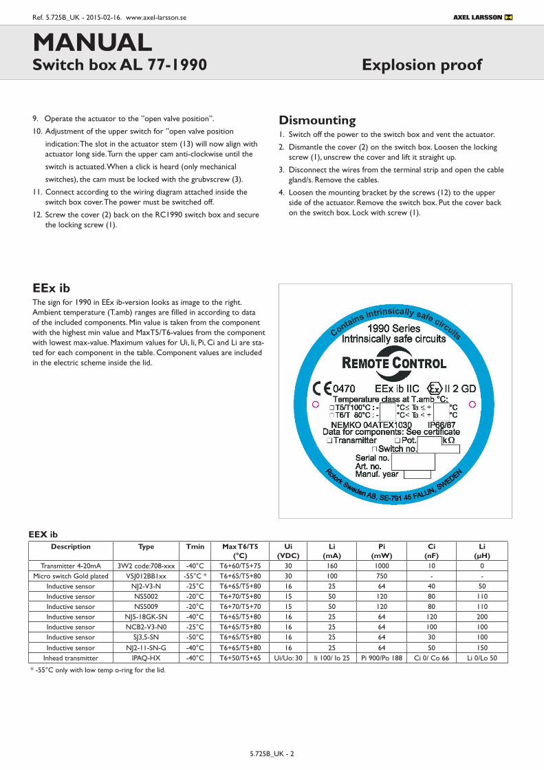
EEx ibThe sign for 1990 in EEx ib-version looks as image to the right. Ambient temperature (T.amb) ranges are filled in according to data of the included components. Min value is taken from the component with the highest min value and MaxT5/T6-values from the component with lowest max-value. Maximum values for Ui, Ii, Pi, Ci and Li are sta-ted for each component in the table. Component values are included in the electric scheme inside the lid.
9. Operate the actuator to the ”open valve position”.
10. Adjustment of the upper switch for ”open valve position
indication: The slot in the actuator stem (13) will now align with actuator long side. Turn the upper cam anti-clockwise until the
switch is actuated. When a click is heard (only mechanical
switches), the cam must be locked with the grubvscrew (3).
11. Connect according to the wiring diagram attached inside the switch box cover. The power must be switched off.
12. Screw the cover (2) back on the RC1990 switch box and secure the locking screw (1).

5.725B_UK - 3
Ref. 5.725B_UK - 2015-02-16. www.axel-larsson.se
MANUALSwitch box AL 77-1990 Explosion proof
- 4 -
www.remotecontrol.se
Rotork Sweden ABBox 80
Kontrollvägen 15SE-791 22 Falun
SwedenTel +46 (0)23 587 00Fax +46 (0)23 587 [email protected]
Ref
No
399A
/ A
rt N
o 98
0399
Rätt till ändring utanföregående meddelande
Skylten för 1990 i EEx d-version ser ut som ovan och fylls i enligt beskrivning och tabell. Gränser för omgivningstemperatur (T.amb) fylls i enligt data för ingående komponenter. Min-värde tas från komponenten med högst min-värde och MaxT4/T5/T6-värden från komponenten med lägst max-värde. På skylten anges nominell spänning och max ström. Värdena är även tryckta på elschemat på insidan av locket.
Beskrivning Typ Tmin Max T6/T5/T4 (°C) U (VDC) I (mA)Transmitter 4-20mA 3W2 kod:708-124D1ADH -40°C T6+60/T5+70 33 20Transmitter 4-20mA EEx ia 3W2 kod:708-226D1AD -40°C T6+60/T5+75 30 20Potentiometer 1k Ohm FCP22AC -50°C T6+60/T5+75/T4+100 (1k Ohm, 1W)Induktiv givare IS5001 -25°C T6+60/T5+75 36 200Induktiv givare IS5026 -25°C T6+60/T5+75 36 200Induktiv givare NJ2-V3-N -25°C T6+60/T5+75 8Induktiv givare NBB2-V3-E2 -25°C T6+60/T5+75 30 100Induktiv givare NBB3-V3-Z4 -25°C T6+60/T5+75 60 100Induktiv givare NJ5-18GK-SN -40°C T6+60/T5+75 25Induktiv givare SJ3,5-SN -40°C T6+60/T5+75 25Mekaniskt gränslägeguldpläterat V5J012BB1C -50°C T6+60 30 100
Mekaniskt gränsläge V5B210CB1C -50°C T6+60/T5+75/T4+110 250VAC 6AR/I-omvandlare IPAQ-H -40°C T6+50/T5+65/T4+85 36 20R/I-omvandlare IPAQ-HX -40°C T6+60/T5+75/T4+85 30 20R/I-omvandlare MESO-H -40°C T6+60/T5+75/T4+85 42 20
Tabell för EEx d
EEX dDescription Type Tmin Max T6/T5/T4
(°C)U
(VDC)I
(mA)Transmitter 4-20mA 3W2 code:708-124D1ADH -40°C T6+60/T5+70 33 20
Transmitter 4-20mA EEx ia 3W2 code:708-226D1AD -40°C T6+60/T5+75 30 20Potentiometer 1k Ohm FCP22AC -50°C T6+60/T5+75/T4+100 (1k Ohm, 1W) -
Inductive sensor IS5001 -25°C T6+60/T5+75 36 200Inductive sensor IS5026 -25°C T6+60/T5+75 36 200Inductive sensor NJ2-V3-N -25°C T6+60/T5+75 8 -Inductive sensor NBB2-V3-E2 -25°C T6+60/T5+75 30 100Inductive sensor NBB3-V3-Z4 -25°C T6+60/T5+75 60 100Inductive sensor NJ5-18GK-SN -40°C T6+60/T5+75 25 -Inductive sensor SJ3,5-SN -40°C T6+60/T5+75 25 -
Micro switch Gold plated V5J012BB1C -50°C T6+60 30 100Micro switch V5B210CB1C -50°C T6+60/T5+75/T4+110 250 VAC 6A
Inhead transmitter IPAQ-H -40°C T6+50/T5+65/T4+85 36 20Inhead transmitter IPAQ-HX -40°C T6+60/T5+75/T4+85 30 20Inhead transmitter MESO-H -40°C T6+60/T5+75/T4+85 42 20
EEx dThe sign for 1990 in EEx d-version looks as image to the right. Ambient temperature (T.amb) ranges are filled in according to data of the included components. Min value is taken from the component with the highest min value and MaxT4/T5/T6-values from the compo-nent with lowest max-value. Nom. Volts and Max current are filled in. Component values are included in the electric scheme inside the lid.
Telephone +46 10 455 97 00 • [email protected] • www.axel-larsson.seSTOCKHOLM GÖTEBORG MOTALA KARLSTAD FALUN SKELLEFTEÅ
Des
ign
and
spec
i�ca
tions
sub
ject
to c
hang
e w
ithou
t prio
r not
ice.
Head Of�ce: Truckvägen 12, P.O. Box 805, SE-194 28 Upplands Väsby (Stockholm), Sweden.