size reduction equipment - bitmesra.ac.in · constant for a given reduction ratio irrespective of...
TRANSCRIPT


SIZE REDUCTION

APPLICATIONS
• To obtain workable size
• To obtain powders
• Obtain specific shape and size
• Increase reactivity
• Permit separation of unwanted ingredient
• Mineral, Metallurgical Industries, Pharmaceutical Industry, Food Industry, Nanotechnology,

MECHANISM OF SIZE REDUCTION
• COMPRESSION
• IMPACT
• ATTRITION
• SHEAR
• Non-mechanical introduction of energy (Thermal shock, explosive shattering, electrohydraulic)
• (a) Between two solid - crushing or attrition;
• (b)shearing;
• (c) Compression crushing in a particle bed
• (d)Impact at one solid surface
• (e) Impact between particles
• (f) Shear action of the surrounding medium
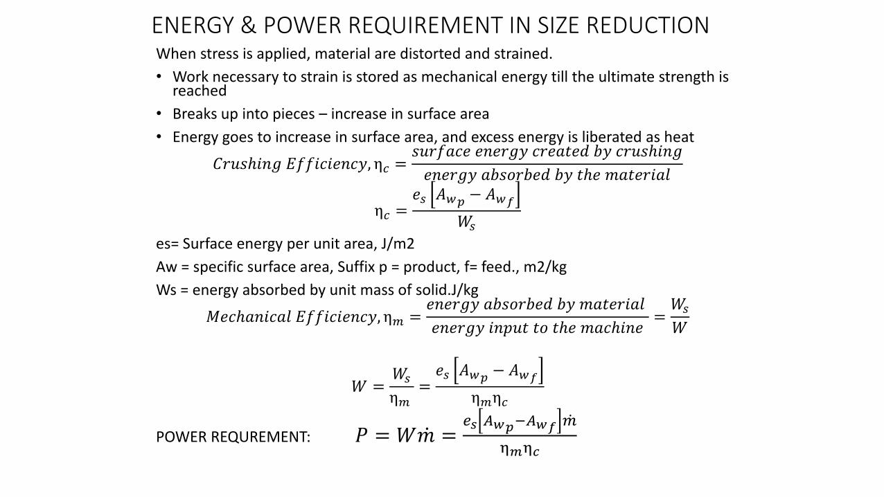
ENERGY & POWER REQUIREMENT IN SIZE REDUCTIONWhen stress is applied, material are distorted and strained.
• Work necessary to strain is stored as mechanical energy till the ultimate strength is reached
• Breaks up into pieces – increase in surface area
• Energy goes to increase in surface area, and excess energy is liberated as heat
𝐶𝑟𝑢𝑠ℎ𝑖𝑛𝑔 𝐸𝑓𝑓𝑖𝑐𝑖𝑒𝑛𝑐𝑦, η𝑐 =𝑠𝑢𝑟𝑓𝑎𝑐𝑒 𝑒𝑛𝑒𝑟𝑔𝑦 𝑐𝑟𝑒𝑎𝑡𝑒𝑑 𝑏𝑦 𝑐𝑟𝑢𝑠ℎ𝑖𝑛𝑔
𝑒𝑛𝑒𝑟𝑔𝑦 𝑎𝑏𝑠𝑜𝑟𝑏𝑒𝑑 𝑏𝑦 𝑡ℎ𝑒 𝑚𝑎𝑡𝑒𝑟𝑖𝑎𝑙
η𝑐 =𝑒𝑠 𝐴𝑤𝑝 − 𝐴𝑤𝑓
𝑊𝑠
es= Surface energy per unit area, J/m2
Aw = specific surface area, Suffix p = product, f= feed., m2/kg
Ws = energy absorbed by unit mass of solid.J/kg
𝑀𝑒𝑐ℎ𝑎𝑛𝑖𝑐𝑎𝑙 𝐸𝑓𝑓𝑖𝑐𝑖𝑒𝑛𝑐𝑦, η𝑚 =𝑒𝑛𝑒𝑟𝑔𝑦 𝑎𝑏𝑠𝑜𝑟𝑏𝑒𝑑 𝑏𝑦 𝑚𝑎𝑡𝑒𝑟𝑖𝑎𝑙
𝑒𝑛𝑒𝑟𝑔𝑦 𝑖𝑛𝑝𝑢𝑡 𝑡𝑜 𝑡ℎ𝑒 𝑚𝑎𝑐ℎ𝑖𝑛𝑒=𝑊𝑠
𝑊
𝑊 =𝑊𝑠
η𝑚=𝑒𝑠 𝐴𝑤𝑝 − 𝐴𝑤𝑓
η𝑚η𝑐
POWER REQUREMENT: 𝑃 = 𝑊 𝑚 =𝑒𝑠 𝐴𝑤𝑝−𝐴𝑤𝑓 𝑚
η𝑚η𝑐

POWER REQUIREMENT IN SIZE REDUCTION
𝑃 = 𝑊 𝑚 =𝑒𝑠 𝐴𝑤𝑝 − 𝐴𝑤𝑓 𝑚
η𝑚η𝑐
𝐷𝑠 =6
𝜑𝑠𝜌𝑝𝐴𝑤or𝐴𝑤 =
6
𝜑𝑠𝜌𝑝𝐷𝑠
𝑃 =6𝑒𝑠 𝑚
η𝑚η𝑐𝜌𝑝
1
𝜑𝑠𝑝𝐷𝑠𝑝−
1
𝜑𝑠𝑓𝐷𝑠𝑓

RITTINGERS LAW [1867]• The work required for size reduction is proportional to the
new surface area created:
𝑊𝑅 =𝑃
𝑚∝ 𝐴𝑤𝑝 − 𝐴𝑤𝑓
𝑊𝑅 =𝑃
𝑚∝
1
𝜑𝑠𝑝𝜌𝑝𝑝𝐷𝑠𝑝−
1
𝜑𝑠𝜌𝑝𝑓𝐷𝑠𝑓
𝑊𝑅 =𝑃
𝑚∝
1
𝜑𝑠𝜌𝑝
1
𝐷𝑠𝑝−
1
𝐷𝑠𝑓
𝑊𝑅 =𝑃
𝑚= 𝐾𝑅
1
𝐷𝑠𝑝−
1
𝐷𝑠𝑓• Where KR is called the Rittinger’s Constant.• Application of the law
• Where surface area created is significant – fine grinding• Particle size less than 0.05mm• Energy in put is not very high
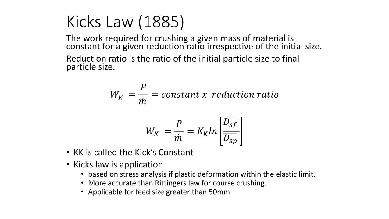
Kicks Law (1885)The work required for crushing a given mass of material is constant for a given reduction ratio irrespective of the initial size.
Reduction ratio is the ratio of the initial particle size to final particle size.
𝑊𝐾 =𝑃
𝑚= 𝑐𝑜𝑛𝑠𝑡𝑎𝑛𝑡 𝑥 𝑟𝑒𝑑𝑢𝑐𝑡𝑖𝑜𝑛 𝑟𝑎𝑡𝑖𝑜
𝑊𝐾 =𝑃
𝑚= 𝐾𝐾𝑙𝑛
𝐷𝑠𝑓
𝐷𝑠𝑝
• KK is called the Kick’s Constant
• Kicks law is application• based on stress analysis if plastic deformation within the elastic limit.• More accurate than Rittingers law for course crushing.• Applicable for feed size greater than 50mm

Bond’s Law (1952)The work required to form particles of size Dp p from a very large particle size is proportional to the square root of the surface to volume ratio ( 𝑠𝑝 𝑣𝑝) of the product.
𝜑𝑠 =6
𝑠𝑝𝜑𝐷𝑝, 𝑂𝑅
𝑠𝑝
𝑣𝑝=
6
𝜑𝐷𝑝
𝑊𝐵 =𝑃
𝑚∝
𝑠𝑝
𝑣𝑝 𝑝
𝑊𝐵 =𝑃
𝑚= 𝐾
6
𝜑𝐷𝑝𝑝= 𝐾𝐵
1
𝐷𝑝𝑝
• Where , 𝐾𝐵 = Bonds constant
Energy required to reduce from Dpf to Dpp
𝑊𝐵 =𝑃
𝑚= 𝐾𝐵
1
𝐷𝑝𝑝−
1
𝐷𝑝𝑓
• If feed is very large, 𝑊𝐵 =𝑃
𝑚= 𝐾𝐵
1
𝐷𝑝𝑝

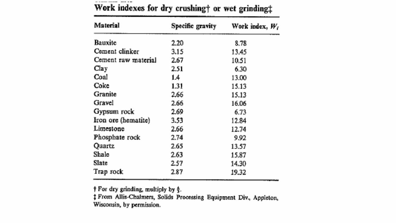
WORK INDEX• Work Index, Wi, is the gross energy requirement in kilowatt
hour per ton of feed (kWh/ton of feed) to reduce a very large particle to such a size that 80% of the product will pass through a 10micrometer, or 0.1 mm screen.
• If Dp is in mm, 𝑊𝑖 = 𝐾𝐵1
𝐷𝑝𝑝
𝐾𝐵 = 0.1𝑊𝑖 = 0.3162𝑊𝑖
𝑃
𝑚= 0.3162𝑊𝑖
1
𝐷𝑝𝑝−
1
𝐷𝑝𝑓
• Values of WI for wet Grinding:
Property Soft Medium Hard Very hard
Work Index,𝑊𝑖, KWh/ton 7-9 9-14 14-20 >20
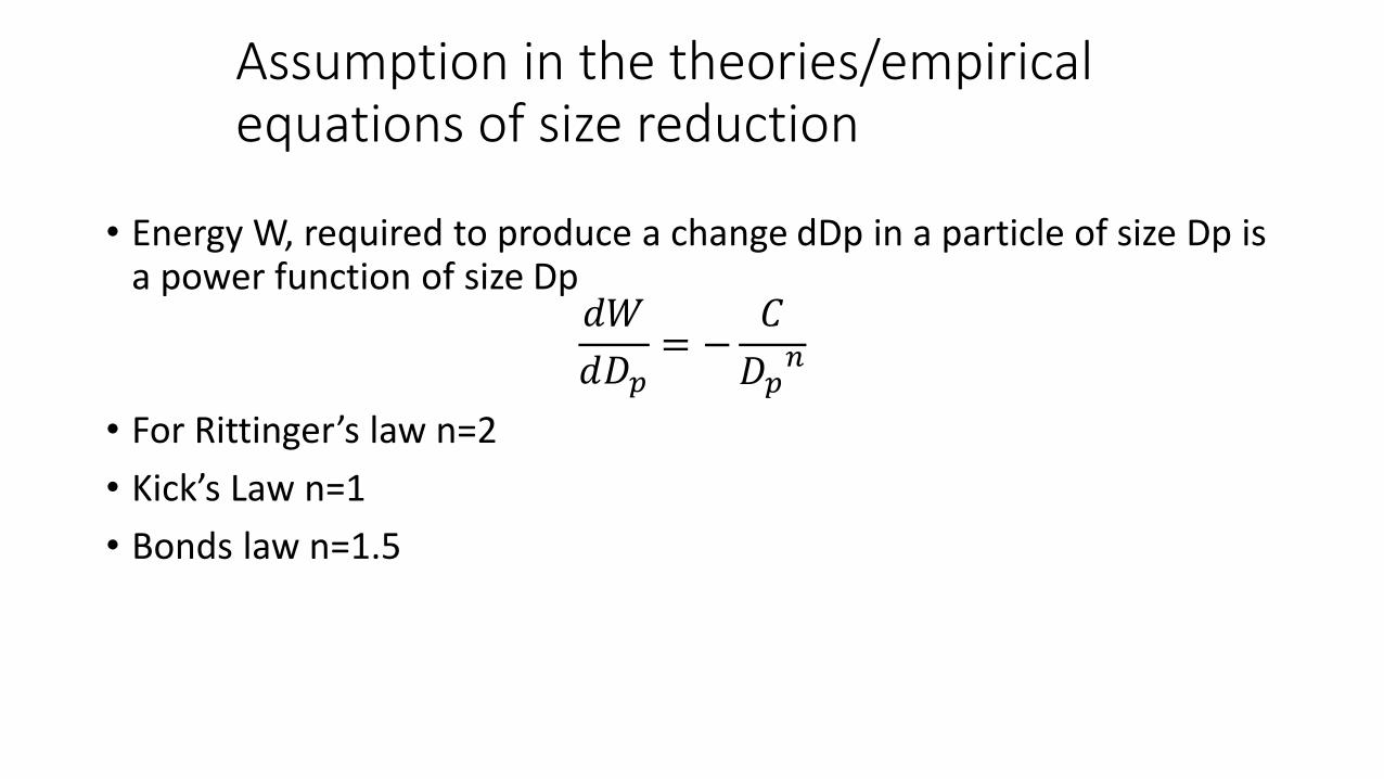
Assumption in the theories/empirical equations of size reduction
• Energy W, required to produce a change dDp in a particle of size Dp is a power function of size Dp
𝑑𝑊
𝑑𝐷𝑝= −
𝐶
𝐷𝑝𝑛
• For Rittinger’s law n=2
• Kick’s Law n=1
• Bonds law n=1.5

• Particles of average feed size 50 x 10(-4) m are crushed to an average product size of 10 x 10 (-4) m at the rate of 20 tonnes per hour. At this rate, the crusher consumes 40 kW of power of which 5 kW are required for running the mill empty. Calculate the power consumption if 12 tonnes/h of this product is further crushed to 5 x 10 (-4) m size in the same mill? Assume that Rittinger’s law is applicable.
• It is desired to crush 10 ton/hr of iron ore hematite. The size of the feed is such that 80% passes a 72.6 mm screen, and 80% of product a 3.175mm screen. Calculate the gross power requirement for wet grinding and dry grinding. Work index of Hematite is 12.68 [Ans 17.96kW]
Size Reduction Equipment
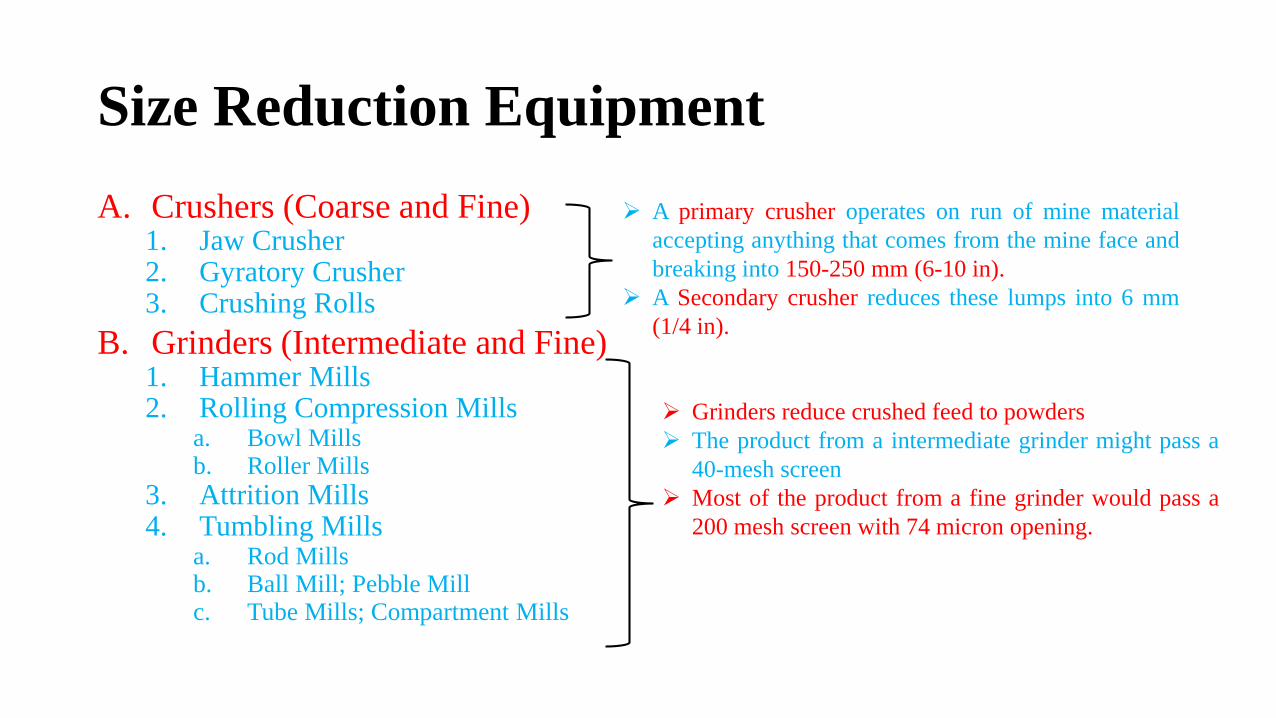
A. Crushers (Coarse and Fine)1. Jaw Crusher2. Gyratory Crusher3. Crushing Rolls
B. Grinders (Intermediate and Fine)1. Hammer Mills2. Rolling Compression Mills
a. Bowl Millsb. Roller Mills
3. Attrition Mills4. Tumbling Mills
a. Rod Millsb. Ball Mill; Pebble Millc. Tube Mills; Compartment Mills
A primary crusher operates on run of mine material
accepting anything that comes from the mine face and
breaking into 150-250 mm (6-10 in).
A Secondary crusher reduces these lumps into 6 mm
(1/4 in).
Grinders reduce crushed feed to powders
The product from a intermediate grinder might pass a
40-mesh screen
Most of the product from a fine grinder would pass a
200 mesh screen with 74 micron opening.

Size Reduction Equipment
C. Ultrafine Grinders
1. Hammer Mills with internal classification
2. Fluid Energy Mills
3. Agitated Mills
D. Cutting Machines
1. Knife Cutters; dicers; millers.
Feed Size is less than 6mm.
Product size is 1-50 microns
Definite size and shape
Product size will be 2-10 mm
in length.

Breaking Pattern
• There are different mechanisms by which size reduction may beachieved.
• Impact: Particle breaks by a single rigid force
• Compression: Particle disintegration by two rigid forces
• Shear: Produced when the particle is compressed between 2edges of the hard surfaces
• Attrition: Arising form particles scrapping between 2 surfaces.

Crushers: Blake Jaw Crusher
‘V’ Opening at the top
Reciprocating in a horizontal Plane
Angle 20-30°

• Eccentric Motion
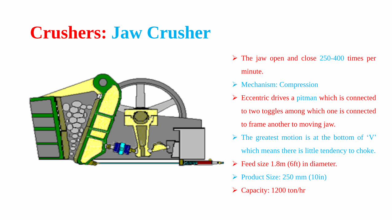
Crushers: Jaw Crusher
Crushers: Jaw Crusher
The jaw open and close 250-400 times per
minute.
Mechanism: Compression
Eccentric drives a pitman which is connected
to two toggles among which one is connected
to frame another to moving jaw.
The greatest motion is at the bottom of ‘V’
which means there is little tendency to choke.
Feed size 1.8m (6ft) in diameter.
Product Size: 250 mm (10in)
Capacity: 1200 ton/hr
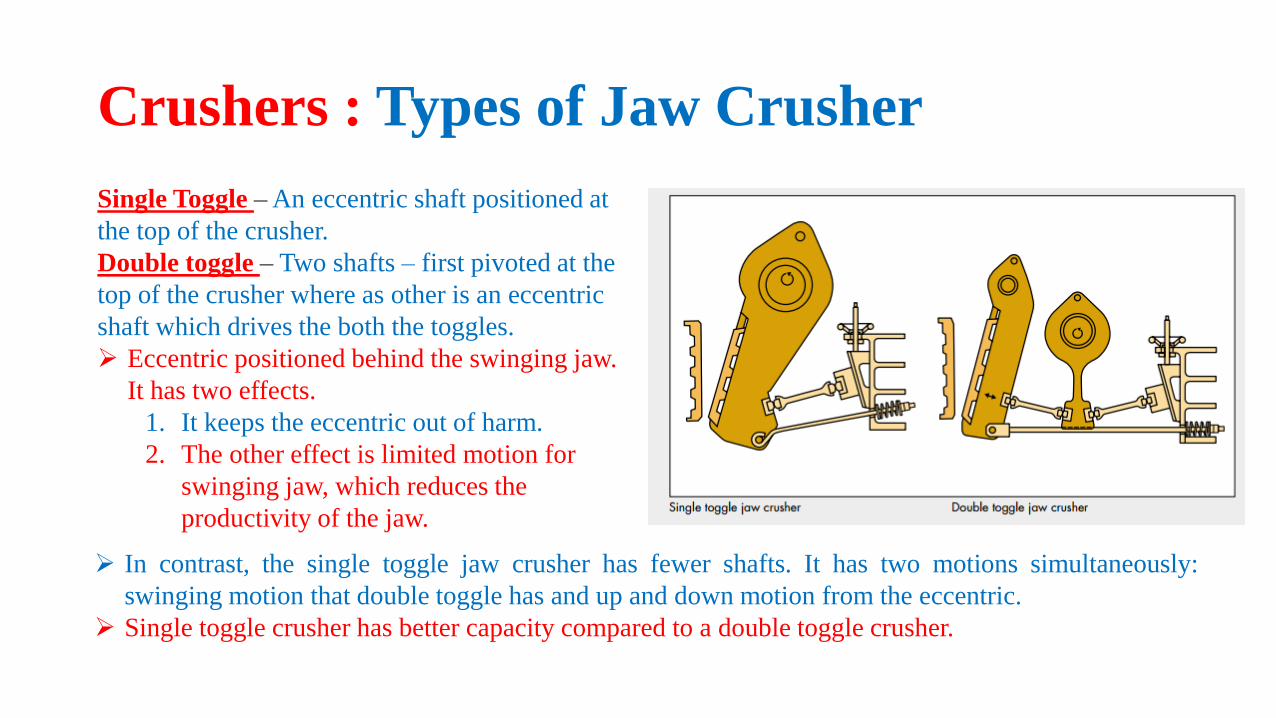
Crushers : Types of Jaw Crusher
Single Toggle –An eccentric shaft positioned at
the top of the crusher.
Double toggle – Two shafts – first pivoted at the
top of the crusher where as other is an eccentric
shaft which drives the both the toggles.
Eccentric positioned behind the swinging jaw.
It has two effects.
1. It keeps the eccentric out of harm.
2. The other effect is limited motion for
swinging jaw, which reduces the
productivity of the jaw.
In contrast, the single toggle jaw crusher has fewer shafts. It has two motions simultaneously:
swinging motion that double toggle has and up and down motion from the eccentric.
Single toggle crusher has better capacity compared to a double toggle crusher.
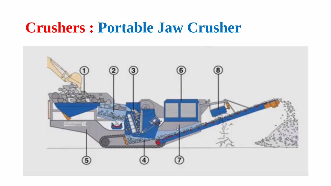
Crushers : Portable Jaw Crusher


Crushers : Gyratory Crusher
Mechanism : Compression
A gyratory crusher may be looked up on as a jaw
crusher with circular jaws, between which material
is being crushed at some point all the time.
A conical crushing head gyrates inside a funnel
shaped casing open at the top.
A crushing head is pivoted at the top.
An eccentric drives the bottom end of the shaft.
The bottom of the crushing head move towards and
away from the wall.
Solid caught in the V-shaped space between the
head and casing are broken and re-broken until they
pass out the bottom.

Crushers : Gyratory Crusher
Speed of gyratory is 125-425 gyratory per minute.
Because some part of the working head is working all the
time the discharge from the gyratory is continuous instead
of intermittent as jaw crusher.
Less maintenance and power requirement is small
compared with jaw crusher.
And the capacity is more than jaw crusher 4500 ton/hr.
The capacity varies with
1. Jaw setting
2. The impact strength of the feed.
3. Speed of the gyratory machine.

Crushers : Gyratory Crusher

Crushers : Smooth Roll Crushers
Heavy smooth faced metal rolls turning on
parallel horizontal are working elements of
smooth roll crusher.
Particles of feed caught between the rolls are
broken in compression and drop out below.
The rolls turn towards each other at the same
speed.
They have relatively narrow faces (300-917mm)
and large diameter (600-1200mm) so that they
can ‘nip’ the large lumps.
Rolls speed 50-300 rpm.
These are consider as secondary crushers with
feeds 12-75 mm in size and the product is 12-1
mm.
The product size can be estimated as
Dp = 0.04R+d
Where R = Radius of the roll
d = half the width of the gap between the rolls.

Crushers : Smooth Roll Crushers
The maximum size of the product is 2d.
These operates most effectively when set to give a reduction
ratio of 3 or 4 or 1.
That is the max diameter of the particle is 1/3rd or 1/4th of
that feed.
The forces exerted by these rolls are very great from 8700 –
70000 N/cm.
To allow unbreakable material to pass through without
damaging the machine, at least one roll must be spring
mounted.
Crushers : Smooth Roll Crushers

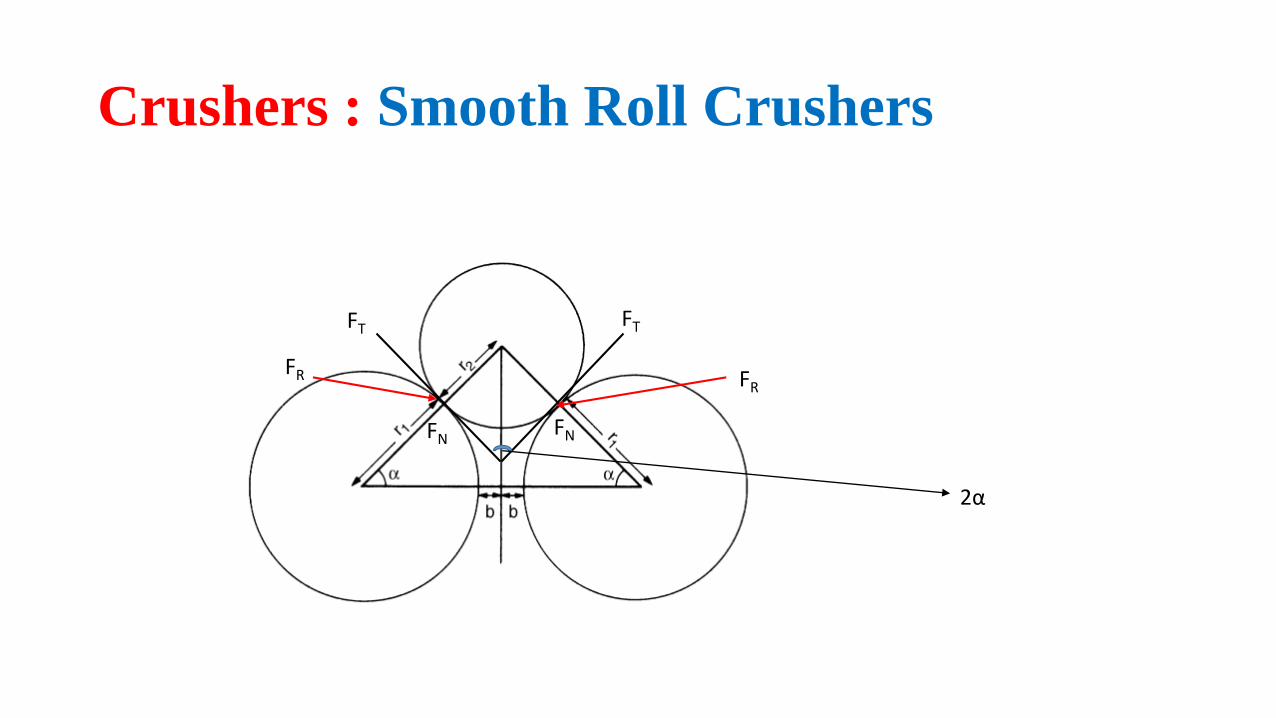
Crushers : Smooth Roll Crushers
2α
FT
FNFN
FRFR
FT

Crushers : Toothed Roll Crushers
Roll faces carry corrugations, breaker bars, or teeth.
Contains 2 rolls as in smooth roll crusher or one roll
acting against stationary curved breaker plate.
Machine shown in a figure is single roll toothed crusher.
Machines known as disintegrators contain two corrugated
rolls turning at two different speeds which tear the feed
apart.
Pyramid Tooth
Single Tooth Crusher
Double Tooth Crusher

• Toothed roll crushers are much more versatile then smooth rollcrusher, within the limitation that they cannot handle very hard solids.
• Operated by compression, impact and shear.
• The particle size feed to these machines may be given as great as 500mm and the capacity is 500tons/hr.
Crushers : Toothed Roll Crushers
Crushers : Toothed Roll Crushers

Breaking Pattern of the Crushers
Crusher Compression Impact Attrition Shear
Jaw Crusher Y
Gyratory Crusher Y
Smooth Roll Crusher Y
Tooth Roll Crusher Y Y Y
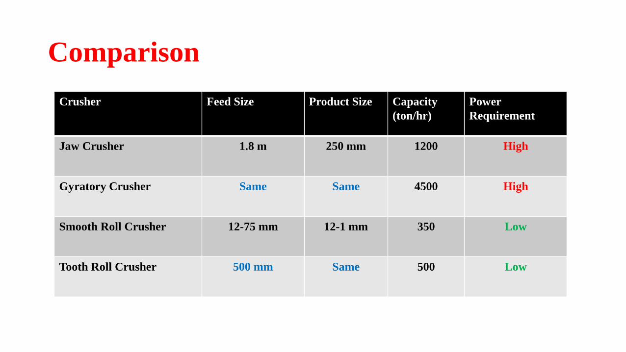
Comparison
Crusher Feed Size Product Size Capacity
(ton/hr)
Power
Requirement
Jaw Crusher 1.8 m 250 mm 1200 High
Gyratory Crusher Same Same 4500 High
Smooth Roll Crusher 12-75 mm 12-1 mm 350 Low
Tooth Roll Crusher 500 mm Same 500 Low
Grinders
The product from a crusher is often fed to grinder in which it is reduced topowder.
Grinders (Intermediate and Fine)1. Hammer Mills
2. Rolling Compression Millsa. Bowl Mills
b. Roller Mills
3. Attrition Mills
4. Tumbling Millsa. Rod Mills
b. Ball Mill; Pebble Mill
c. Tube Mills; Compartment Mills

Grinders: Hammer Mill
Contains high speed rotor.
Feed dropped into the top of casing is broken and fall
out through the bottom opening.
Particles are broken by sets of swing hammer pinned to
a rotor disk.
Particle enter into the casing can not escape being
struck by the hammers.
It shatters into pieces, which fly against stationary anvil
plate and break into small pieces.
These in turn rubbed into powder by hammers and
pushed through the grate or screen that covers the
discharge opening.
Feed
Introducing
Product
Discharge
Grinders: Hammer Mill
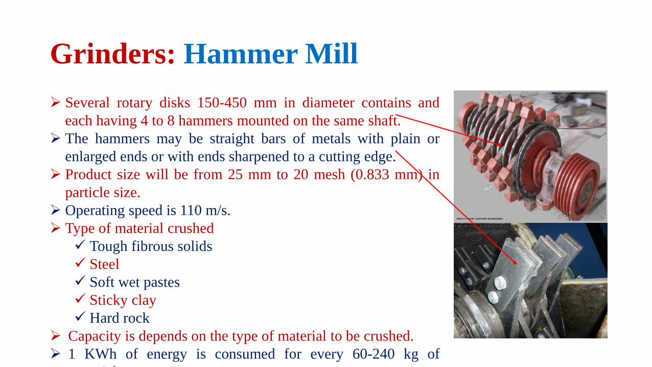
Several rotary disks 150-450 mm in diameter contains and
each having 4 to 8 hammers mounted on the same shaft.
The hammers may be straight bars of metals with plain or
enlarged ends or with ends sharpened to a cutting edge.
Product size will be from 25 mm to 20 mesh (0.833 mm) in
particle size.
Operating speed is 110 m/s.
Type of material crushed
Tough fibrous solids
Steel
Soft wet pastes
Sticky clay
Hard rock
Capacity is depends on the type of material to be crushed.
1 KWh of energy is consumed for every 60-240 kg of
material.

Grinders: Impactor
An impact or illustrated in figure resembles
the duty of heavy hammer mill except that it
contains no grate or screen.
Rotor will be same as in hammer mill.
Particles are broken by impact alone
without rubbing action as in hammer mills.
Consider as a primary crusher for rock and
ore, processing up to 600 ton/hr.
Give equidimensional particles (mostly
cubical) than slab shaped particles which
are given by from jaw or gyratory crusher

Grinders: Rolling-Compression Machines
In this kind of mill the solid particles are caught and
crushed between a rolling member and face of the
ring or casing.
The most common types are
Rolling ring pulverisers
Bowl mills
And the roller mills.
One of the roller miller is showing in the figure.
Vertical cylindrical rollers press outward with great
force against a stationary anvil ring or bull ring.
Plows lift the solid lumps from the floor and direct
them between roll and ring.

Grinders: Rolling-Compression Machines
Product is swept out of the mille by stream of
air to a classifier separator from which over
size particles return to the mill for further
reduction.
The rollers rotate on the stationary axes which
may be vertical or horizontal.
These are used to grind the
Lime stone
Cement clinker
Coal
Capacity is 500 ton/hr
Product size may be as fine as 99% pass
through a 200 mesh screen (i.e 74 micron).

Grinders: Attrition Mills
Particles of soft solids are rubbed between the grooved
flat faces of rotating circular disks.
The axis of the disk usually horizontal, some times
vertical.
Grinders: Attrition Mills
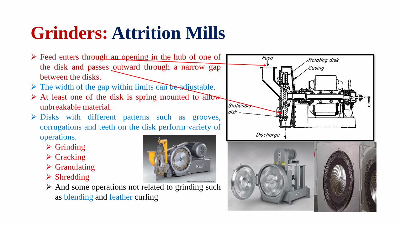
Feed enters through an opening in the hub of one of
the disk and passes outward through a narrow gap
between the disks.
The width of the gap within limits can be adjustable.
At least one of the disk is spring mounted to allow
unbreakable material.
Disks with different patterns such as grooves,
corrugations and teeth on the disk perform variety of
operations.
Grinding
Cracking
Granulating
Shredding
And some operations not related to grinding such
as blending and feather curling

Grinders: Attrition Mills
A single runner attrition mill contains disks of rockemery for reducing solids like clay and talc.
And metal disks for crushing wood, starch, insecticidepowders and wax.
Metal disks are usually made up of white iron, and insome cases stainless steel for corrosive materials.
Double runner mills give fine products but processsoft solids only.
Air is drawn through the disk to remove the productand prevent choking.
More heat is generated which can be removed by spraying water or refrigerator brine. Removal of heat is essential in case of sensitive materials like rubber.

Parameter Single disk runner Double disk runner
Disk Diameter 250-1400 mm 250-1400 mm
Speed 350-700 rpm 1200-7000 rpm
Capacity 0.5- 8 ton/hr 0.5-8 ton/hr
Product size Passed through 200 mesh
i.e 0.074mm
Passed through 200 mesh
i.e 0.074mm
Power consumption 8-80 kWh per ton of
product
8-80 kWh per ton of
product
Grinders: Attrition Mills

Grinders: Tumbling Mill
A typical tumbling mill is shown in figure
A cylindrical shell slowly turning about its
horizontal axis and filled about half of its
volume with grinding medium.
The shell is usually steel line with carbon
steel plate, porcelain, silica rock or rubber.
The grinding medium
Is metal rods in rod mill.
Lengths of chain or balls of metal,
rubber or wood in ball mill.
Flint pebbles or porcelain or zircon
spheres in a pebble mill.

Grinders: Tumbling Mill
Motion in rod mill
Motion in ball mill

Grinders: Tumbling Mill
Continuous and
Batch tumbling mills

Grinders: Tumbling Mill
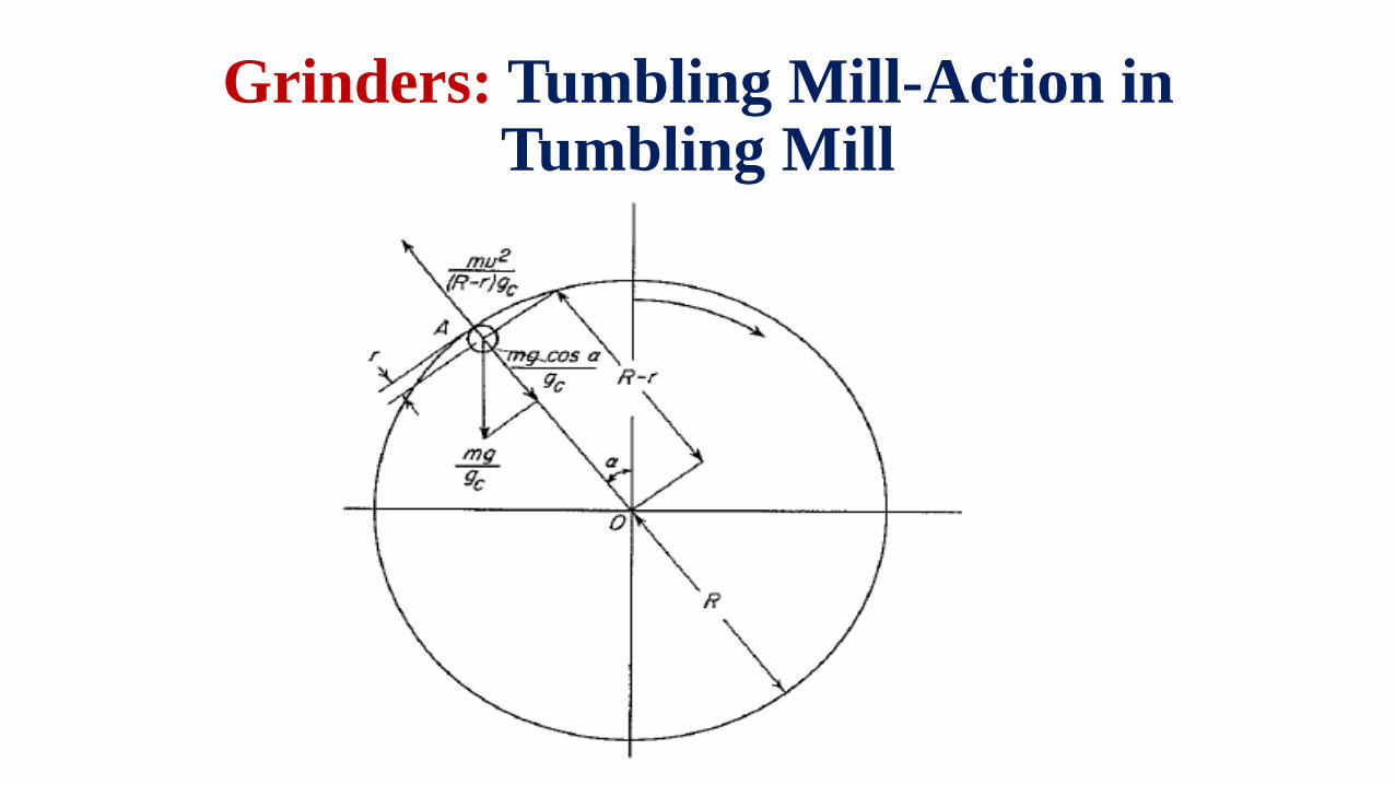
In all tumbling mills the grinding elements carried up the
side of the shell from there they fall on the particles
underneath.
The energy expanded in lifting the grinding elements is
utilised in reducing particle size.
Therefore the breaking pattern in ball mill is impact
alone.
Where as in other tumbling mills such as rod mill
particles are reduced from the rolling compressing and
attrition.
The grinding rods are usually steel, 25-125 mm in size
and extended the full length of the shell.
Rod mills are intermediate grinders reducing 20 mm feed
size to 0.833 mm (i.e 10 mesh screen).

Grinders: Tumbling Mill – Ball Mill
25-125 mm50-175 mm
Industrial ball mills

Grinders: Tumbling Mill – Compartment Ball Mill

Grinders: Tumbling Mill – Compartment Ball Mill (Conical)
Segregation of grinding units in a single chamber
is a characteristic of conical ball mill shown in the
figure.
Feed enters from left through a 60° cone into the
primary grinding zone where the diameter of the
balls are large.
And leaves through the 30° cone to the right
where the dia of the balls are less.
Large balls becomes small as mill is operated and
migrates towards the discharge.
New large balls are added periodically.
Initial breaking of large particles occurs by large
balls and small particle by small balls.
This kind of mills increase the efficiency.

Grinders: Tumbling Mill-Action in Tumbling Mill
Grinders: Tumbling Mill-Action in Tumbling Mill
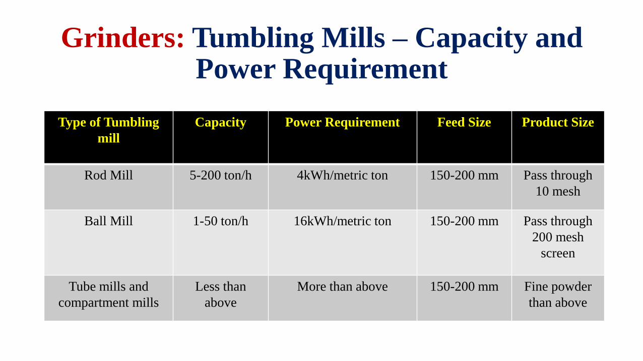
Grinders: Tumbling Mills – Capacity and Power Requirement
Type of Tumbling
mill
Capacity Power Requirement Feed Size Product Size
Rod Mill 5-200 ton/h 4kWh/metric ton 150-200 mm Pass through
10 mesh
Ball Mill 1-50 ton/h 16kWh/metric ton 150-200 mm Pass through
200 mesh
screen
Tube mills and
compartment mills
Less than
above
More than above 150-200 mm Fine powder
than above

• Many commercial powders must contain particles averaging 1 to 20microns in size.
• Mills that reduces solids to such fine powders are called ultrafinegrinders.
• Ultrafine grinding can be done based on dry and wet basis
• Dry Basis
• High speed hammer mills with internal and external classification.
• Wet basis
• Fluid energy or jet mills.
Ultrafine Grinders

Ultrafine Grinders: Classifying Hammer Mills
Hammer mill with internal classification is the Mikro
Automizer illustrated in figure.
A set of hammers held between rotor and wall such as in
conventional hammer mill.
In addition to the hammers the rotor shaft carries 2 fans which
draw air through the mill.
On the rotor disk a short radial vanes are placed to separate the
oversized particles from the acceptable size.
Principle:
In the grinding zone solid particles are given a high rotational
velocity.
Coarser particles are contracted along the wall due to the
centrifugal force acting on them.
The air stream carries the fine particles from the grinding zone
in the direction of AB.
The over sized particles thrown outward by the vanes in the
direction of BA

Ultrafine Grinders: Classifying Hammer Mills
The passage of particles through the vanes is
depends on the two predominant forces.
1. Centrifugal Force by vanes.
2. Drag force by air stream.
Coarse particle are thrown back into the
grinding zone by the vanes.
And fine particles are carried by the air stream.
Capacity – 1 to 2 ton/h
Average product size will be from 1- 20
microns.
Power requirement 40 kWh/metric ton.

Ultrafine Grinders: Classifying Hammer Mills
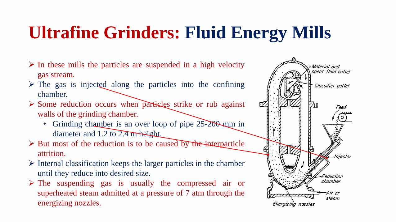
Ultrafine Grinders: Fluid Energy Mills
In these mills the particles are suspended in a high velocity
gas stream.
The gas is injected along the particles into the confining
chamber.
Some reduction occurs when particles strike or rub against
walls of the grinding chamber.
• Grinding chamber is an over loop of pipe 25-200 mm in
diameter and 1.2 to 2.4 m height.
But most of the reduction is to be caused by the interparticle
attrition.
Internal classification keeps the larger particles in the chamber
until they reduce into desired size.
The suspending gas is usually the compressed air or
superheated steam admitted at a pressure of 7 atm through the
energizing nozzles.

Classification of ground particles takes place at the upper
bend of the chamber.
As the gas flows with high speed around this bend, the
coarser particles thrown outward to outer wall of the
chamber and the fine particles congregate inner wall of the
chamber.
A discharge opening at inner wall is connected to a cyclone
separator or bag filters for the product.
Feed size is 12 mm but it is more effective when the feed
particles are less than 100 mesh screen.
Product size is 500 nm to 10 microns
And the amount of steam is used 1-4 kg/kg of product
Compressed air is 6-9 kg of air /kg of product is used.
Capacity is up to 6000 kg/h
Ultrafine Grinders: Fluid Energy Mills

Ultrafine Grinders: Agitated Mills
For some ultra fine grinders small batch non-rotary
mills containing solid grinding medium are available.
The grinding medium consists of hard solid such as
Balls
Pellets
Or sand grains
These mills are vertical vessels 4 to 1200L in capacity,
filled with liquid in which the grinding medium is
suspended.
Fluid and grinding medium mixed with multiarmed
impellers.
A concentrated slurry is admitted at the top and
product can be discharged from the bottom.
These mills are useful to produce 1 micron or less size
of particle.

Ultrafine Grinders: Colloid Mills
The feed liquid with particles suspended in it is pumped to
closely spaced surfaces.
Among which one is stationary and other one is moving
relative to other with a speed of 50 m/s or more.
The principal action is disruption of lightly bonded clusters
or agglomerates.
The final size of the particle is less than 5 microns.
And the space between the surfaces can be adjustable to 25
microns.
Syrups, milk, ointments, paints etc. are processed in this
way.
The capacities of colloid mills are relatively low ranging
from 2-3 L/min to 440 L/min

• In some size reduction problems the feedstock is to tenacious or too resilient tobroken by compression, impact, or attrition.
• In other problems feed must be reduced to particles of fixed dimensions.
• These requirements are met by the devices that cut, chop or tear the material intodesired characteristics.
• Rotary knife cutters and granulators are considered as the cutting machines.
• These are used in the manufacture of rubber, plastics and recycling of paper andpulp.
Cutting Machines:

Cutting Machines: Rotary Knife Cutters
A rotary knife cutter shown in figure contains horizontal rotor
turning at 200 to 900 r/min inside a cylindrical chamber.
On the rotary 2-12 flying knives with the edges of tampered
steel or stellite pass with close clearance over 1-7 stationary
bed knives.
Feed particles entering the chamber from above are cut
several times per minute.
And emerged at the bottom through a screen with 5-8 mm
opening.
Rotary knife cutters and granulators are similar in design.
A granulator yields more or less irregular pieces.
But a cutter yield cube, thin squares and some times diamond
shapes.
