skf flex coupling installation instructions flex spacer coupling installation instructions 1....
TRANSCRIPT
SKF Flex Coupling Installation Instructions
The performance of the coupling depends largely upon how you install and maintain. 1. Thoroughly clean all components, paying particular attention to the removal of the
protective coating in the bore of flanges. 2. Fit flanges to the shafts after placing the external clamp rings on the shafts.(Where
Taper Lock flanges are used, see separate fitting instructions supplied with the Taper Lock Bushes).Locate flanges so that dimension M is obtained (see paragraph 3). Flanges with internal clamping rings should then have the clamping rings fitted, engaging only two or three of the threads of the screw at this time.
3. Bring shafts into line until dimension M is obtained (table 2). If shaft end float is to
occur, locate the shafts at mid-position of end float when checking dimension M. Note that shaft ends may project beyond the faces of the flanges if required. In this event, allow sufficient space between shaft ends for end float and misalignment.
4. Check parallel alignment by laying a straight edge across the flanges at several
positions around the circumference. Check angular alignment by measuring gap between flanges at several positions around the circumference. It is desirable to align the coupling as accurately as possible, particularly on high-speed applications
5. Open out type and fit over coupling flanges ensuring that the tyre beads seat
properly on the flanges and/or clamping rings. To ensure proper seating, it may be necessary to strike the outside diameter of the tyre with a small mallet. When seated there should be a gap between the ends of the tyre as shown in table 1.
Table 1
Coupling Size F40 to F60 F70 to F120 F140 and F160 F180 to F250
Tyre Gap (mm) 2 3 5 6
1/4

6. Tighten clamping ring screws alternately and evenly (half turn at a time) working round each flange until the required screw torque is achieved (table 2).
Table 2
*Hexagon Socket Caphead Clamping Screws on these sizes.
Coupling Size M size Screw size Clamping screw
Torque(Nm) F40* 22 M6 15
F50* 25 M6 15
F60* 33 M6 15
F70 23 M8 24
F80 25 M8 24
F90 27 M10 40
F100 27 M10 40
F110 25 M10 40
F120 29 M12 50
F140 32 M12 55
F160 30 M16 80
F180 46 M16 105
F200 48 M16 120
F220 55 M20 165
F250 59 M20 165
Note: Satisfactory performance depends on correct installation and maintenance.
2/4

SKF Flex Spacer Coupling Installation Instructions 1. Thoroughly clean all components paying particular attention to the removal of the
protective coating in flange bores and on bushes.
2. Place each cleaned Taper Lock Bush in its respective flange and slide the flange onto its shaft. If keys are required, side fitting keys with top clearance should be used.
3. Using a straight edge line up the faces indicated with the shaft ends. Using a dial gauge check the runout of the spacer flange.
4. Position SKFFlex flange on spacer shaft to dimension “Y” shown in table 3 and secure with Taper Lock Bush. This ensures that the distance between the flanges ‘M’ is maintained on assembly
3/4
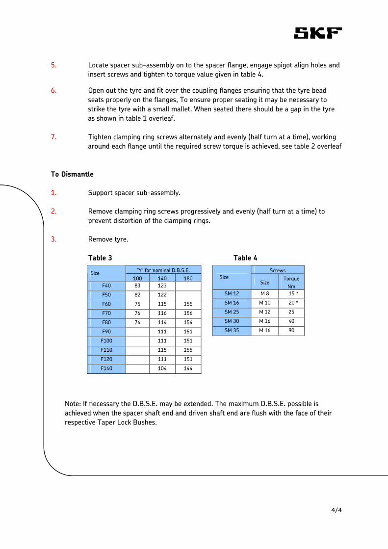
5. Locate spacer sub-assembly on to the spacer flange, engage spigot align holes and insert screws and tighten to torque value given in table 4.
6. Open out the tyre and fit over the coupling flanges ensuring that the tyre bead seats properly on the flanges, To ensure proper seating it may be necessary to strike the tyre with a small mallet. When seated there should be a gap in the tyre as shown in table 1 overleaf.
7. Tighten clamping ring screws alternately and evenly (half turn at a time), working
around each flange until the required screw torque is achieved, see table 2 overleaf To Dismantle 1. Support spacer sub-assembly. 2. Remove clamping ring screws progressively and evenly (half turn at a time) to
prevent distortion of the clamping rings.
3. Remove tyre. Table 3 Table 4
Screws Size
Size Torque
Nm SM 12 M 8 15 *
SM 16 M 10 20 *
SM 25 M 12 25
SM 30 M 16 40
SM 35 M 16 90
"Y" for nominal D.B.S.E. Size 100 140 180
F40 83 123
F50 82 122
F60 75 115 155
F70 76 116 156
F80 74 114 154
F90 111 151
F100 111 151
F110 115 155
F120 111 151
F140 104 144
Note: If necessary the D.B.S.E. may be extended. The maximum D.B.S.E. possible is achieved when the spacer shaft end and driven shaft end are flush with the face of their respective Taper Lock Bushes.
4/4
FRC and Jaw Coupling Installation Instructions 1. These couplings permit quick easy installation by means of a taper bush and
offer quick alignment. 2. Check the angular misalignment by checking the assembled length in four
positions at 90º around the coupling and check parallel misalignment using a straight edge across the coupling flange covers.
3. Allowable angular misalignment for all FRC couplings is 1º. 4. Allowable parallel misalignment for FRC couplings depends on size as
follows; Coupling Size FRC70 to 110 FRC130 to 180 FRC230 to 280
p (mm) 0.3 0.3 0.4 For most consistent results, check across the shrouds at least 3 of the 6 points where the rubber element petals are visible between the flange drive dogs.
1/1
1/2
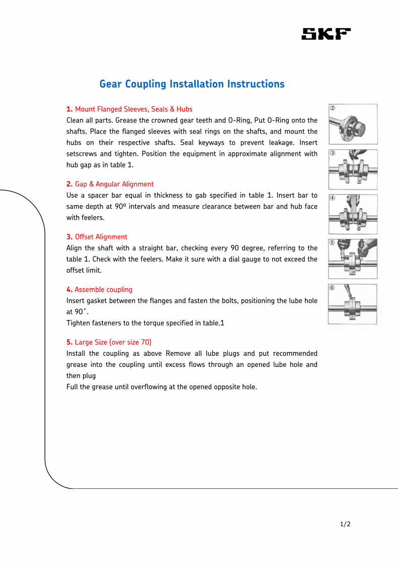
Gear Coupling Installation Instructions 1. Mount Flanged Sleeves, Seals & Hubs Clean all parts. Grease the crowned gear teeth and O-Ring, Put O-Ring onto the shafts. Place the flanged sleeves with seal rings on the shafts, and mount the hubs on their respective shafts. Seal keyways to prevent leakage. Insert setscrews and tighten. Position the equipment in approximate alignment with hub gap as in table 1.
2. Gap & Angular Alignment Use a spacer bar equal in thickness to gab specified in table 1. Insert bar to same depth at 90º intervals and measure clearance between bar and hub face with feelers.
3. Offset Alignment Align the shaft with a straight bar, checking every 90 degree, referring to the table 1. Check with the feelers. Make it sure with a dial gauge to not exceed the offset limit.
4. Assemble coupling Insert gasket between the flanges and fasten the bolts, positioning the lube hole at 90˚. Tighten fasteners to the torque specified in table.1
5. Large Size (over size 70) Install the coupling as above Remove all lube plugs and put recommended grease into the coupling until excess flows through an opened lube hole and then plug Full the grease until overflowing at the opened opposite hole.
2/2
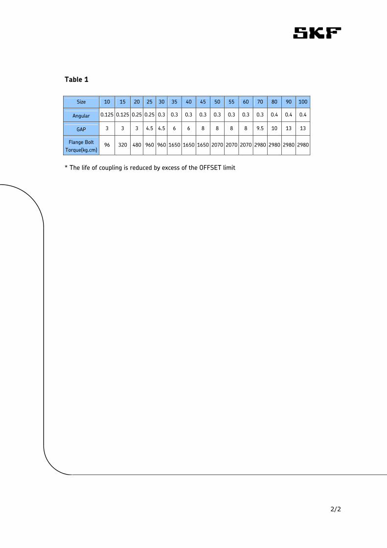
Table 1
Size 10 15 20 25 30 35 40 45 50 55 60 70 80 90 100
Angular 0.125 0.125 0.25 0.25 0.3 0.3 0.3 0.3 0.3 0.3 0.3 0.3 0.4 0.4 0.4
GAP 3 3 3 4.5 4.5 6 6 8 8 8 8 9.5 10 13 13
Flange Bolt Torque(kg.cm)
96 320 480 960 960 1650 1650 1650 2070 2070 2070 2980 2980 2980 2980
* The life of coupling is reduced by excess of the OFFSET limit
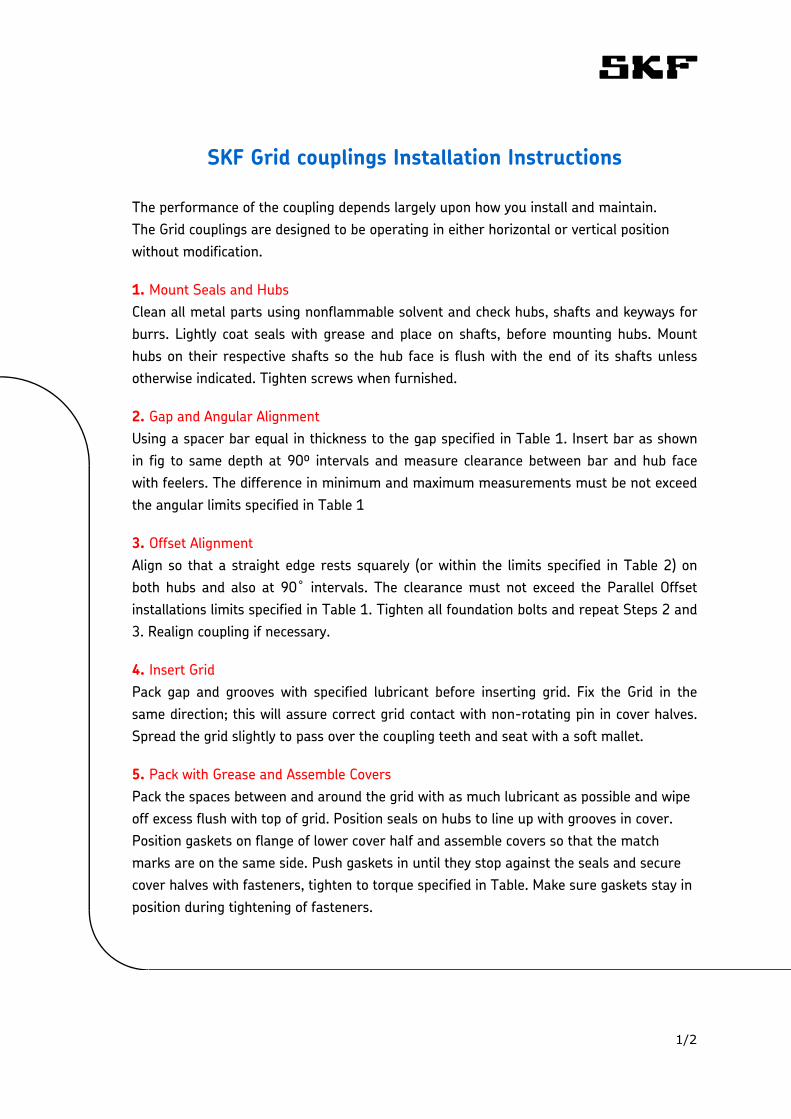
SKF Grid couplings Installation Instructions
The performance of the coupling depends largely upon how you install and maintain. The Grid couplings are designed to be operating in either horizontal or vertical position without modification.
1. Mount Seals and Hubs Clean all metal parts using nonflammable solvent and check hubs, shafts and keyways for burrs. Lightly coat seals with grease and place on shafts, before mounting hubs. Mount hubs on their respective shafts so the hub face is flush with the end of its shafts unless otherwise indicated. Tighten screws when furnished.
2. Gap and Angular Alignment Using a spacer bar equal in thickness to the gap specified in Table 1. Insert bar as shown in fig to same depth at 90º intervals and measure clearance between bar and hub face with feelers. The difference in minimum and maximum measurements must be not exceed the angular limits specified in Table 1
3. Offset Alignment Align so that a straight edge rests squarely (or within the limits specified in Table 2) on both hubs and also at 90˚ intervals. The clearance must not exceed the Parallel Offset installations limits specified in Table 1. Tighten all foundation bolts and repeat Steps 2 and 3. Realign coupling if necessary.
4. Insert Grid Pack gap and grooves with specified lubricant before inserting grid. Fix the Grid in the same direction; this will assure correct grid contact with non-rotating pin in cover halves. Spread the grid slightly to pass over the coupling teeth and seat with a soft mallet.
5. Pack with Grease and Assemble Covers
1/2
Pack the spaces between and around the grid with as much lubricant as possible and wipe off excess flush with top of grid. Position seals on hubs to line up with grooves in cover. Position gaskets on flange of lower cover half and assemble covers so that the match marks are on the same side. Push gaskets in until they stop against the seals and secure cover halves with fasteners, tighten to torque specified in Table. Make sure gaskets stay in position during tightening of fasteners.
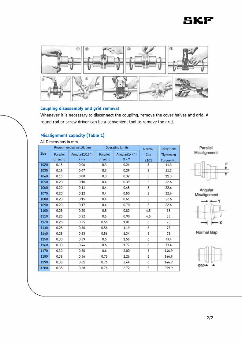
Coupling disassembly and grid removal Whenever it is necessary to disconnect the coupling, remove the cover halves and grid. A round rod or screw driver can be a convenient tool to remove the grid. Misalignment capacity (Table 1) All Dimensions in mm
Recommended installation Operating Limits
Size Parallel Offset p
Angular(1/16˚) X - Y
Parallel Offset p
Angular(1/ 4˚) X - Y
Normal
Gap
±10%
Cover Bolts
Tightening
Torque Nm 1020 0.15 0.06 0.3 0.24 3 11.3
1030 0.15 0.07 0.3 0.29 3 11.3
1040 0.15 0.08 0.3 0.32 3 11.3
1050 0.20 0.10 0.4 0.39 3 22.6
1060 0.20 0.11 0.4 0.45 3 22.6
1070 0.20 0.12 0.4 0.50 3 22.6
1080 0.20 0.15 0.4 0.61 3 22.6
1090 0.20 0.17 0.4 0.70 3 22.6
1100 0.25 0.20 0.5 0.82 4.5 35
1110 0.25 0.22 0.5 0.90 4.5 35
1120 0.28 0.25 0.56 1.01 6 73
1130 0.28 0.30 0.56 1.19 6 73
1140 0.28 0.33 0.56 1.34 6 73
1150 0.30 0.39 0.6 1.56 6 73.4
1160 0.30 0.44 0.6 1.77 6 73.4
1170 0.30 0.50 0.6 2.00 6 146.9
1180 0.38 0.56 0.76 2.26 6 146.9
1190 0.38 0.61 0.76 2.44 6 146.9
1200 0.38 0.68 0.76 2.72 6 259.9
2/2
Chain Coupling Installation Instructions 1. Remove dirt and grease from coupling bore, shaft and bushing and make sure
there are no burrs on the shaft, bore, key, or keyway. Place the oil seals for the cover on the sprocket halves.
2. Bring the sprocket faces close together and correct the angular and offset
misalignment. The allowable angular and offset misalignment is 1 deg and 2% of the chain pitch and if the sprocket speed is 1/3 or more of the speed then it will be 0.5 deg & 1%.
3. Maintain the gap between sprocket faces and firmly fasten the set bolt. 4. Lubricate the chain with grease, then wrap the chain around both sprockets and fix
with connecting pin. 5. Fill the required quantity of grease into both sides of case and fasten them firmly.
Use gaskets with out fail.
1/1