skfcanadalimited montreal¥textile dryers ¥film stretching tenders ¥electricmotors running...
TRANSCRIPT

Heavy
Duty
PillowBlocks
Heavy
Duty
PillowBlocks
SKFCanada
Limited
® SKF is a registered trademark of SKF Canada Limited.The contents of this publication are the copyright of thepublisher and may not be reproduced (even extracts)unless permission is granted. Every care has been taken toensure the accuracy of the information contained in thispublication but no liability can be accepted for any loss ordamage whether direct, indirect or consequential arisingout of use of the information contained herein. The servicesand associated benefits described within this brochure areonly intended for use by authorized SKF Canada Limiteddistributors and their customers.
© 2008 SKF Canada Limited.
Printed in CanadaCatalogue CDN 994 / April 2008
SKF Canada Limited40 Executive CourtScarborough, OntarioM1S 4N4
Montreal101 Ave. LindsayDorval, QuebecH9P 2S6
Edmonton5220 75th StreetEdmonton, AlbertaT6E 5S4
Vancouver1480 Kootenay StreetVancouver, B.C.V5K 4R1
$50.00
Customer ServiceTelephone: 1-866-TEAMSKFFax: [email protected]
Cent
reFo
ld
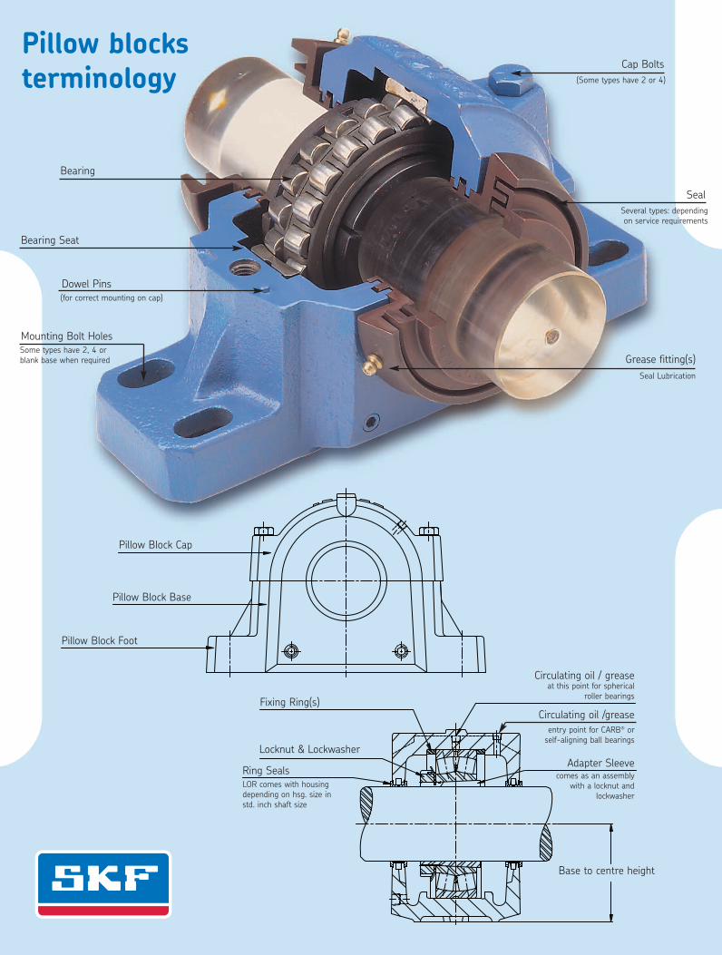
Cap Bolts(Some types have 2 or 4)
Grease fitting(s)Seal Lubrication
SealSeveral types: dependingon service requirements
Bearing
Pillow Block Cap
Pillow Block Base
Pillow Block Foot
Fixing Ring(s)
Locknut & Lockwasher
Ring SealsLOR comes with housingdepending on hsg. size instd. inch shaft size
Base to centre height
Adapter Sleevecomes as an assembly
with a locknut andlockwasher
Circulating oil / grease
Lithium soap/mineral oil 1100° F-18° C
266 °F130 °C (*9)
L
Lithium soap/mineral oil 110L 0° F-18° C
266 °F130 °C
( Lithium soap/mineral oil 1100° F-18° C
266 °F130 °C
L
• Agricultural equipment• Automotive wheel bearings• Conveyors• Small electric motors• Indusrial fans
• Agricultural equipment• Automotive wheel bearings• Conveyors• Small electric motors• Indusrial fans
• Agricultural equipment• Automotive wheel bearings• Conveyors• Small electric motors• Indusrial fans
M Lithium soap/mineral oil 120-22° F-30° C
250 °F120 °C
• Bearings >100 mm (3.9 in) shaft size• Outer bearing ring rotation• Vertical shaft appications• Continuous high ambient temperatures >35˚C (95˚F)
• Propeller shafts• Agricultural equipment• Car, truck and trailer wheel bearings• Large electric motors
M Complex calcium sulphonate/mineral oil 400-20° C -4° F
150 °C302 °F
• Steel on steel plain bearings• Pulp and paper making machines• Asphalt vibrating screens• Continous casting machines• Work roll bearings in steel industry
• Sealed spherical roller bearings operating up to 150˚C (302˚F)• Withstands peak temperatures of 200˚C (392˚F)
185M Lithium complex soap/mineral oil-30˚ C-22° F
140 °C284 °F
• Wheel bearings in cars, trailers and trucks• Washing machines• Electric motors
M Di-urea/mineral oil 96-40° C-40° F
150 °C302 °F
• Verical shafts• Severe vibrations• Low noise• Rust inhibiting properties
V PTFE/synthetic (fluorinated polyether) 400-40° C-40° F
260 °C500 °F
• Bakery equipment (ovens)• Kiln truck wheels• Load rollers in copying machines• Wafer baking machines• Textile dryers
• Film stretching tenders• Electric motors running at extreme temperatures• Emergency / hot fans• Vacuum pumps
L Lithium soap/mineral oil 200-30° C-22° F
110 °C230 °F
• Windmills• Screw conveyors• Centralized lubrication systems• Spherical roller thrust bearing applications
Lithium-calcium soap/synthetic ester oil 110-40° C-40° F
90 °C (*3)194 °F
• Agricultural and foresty equipment• Locks, dams, bridges• Mining and conveying equipment• Water treatment & irrigation• Linkages, rod ends
• Construction and earth moving equipment• Other applications where contamination of the environment is a concern
Lithium soap/PAO oil 18-50° C-58° F
110 °C230 °F
• Textile spinning spindles• Machine tool spindles• Instruments and control equipment• Small electic motors used in medical and dental equipment
• In-line skates• Printing cyclinders• Robots
M Lithium-calcium soap/mineral oil 1 020-10° C-14° F
120 °C250 °F
• Trunnion bearings on rotating drums• Support and thrust rollers on rotary kilns and dryers• Bucket wheel excavators
• Slewing ring bearings• High pressure roller mills• Crushers
M Lithium complex/mineral oil 500-20° C-4° F
120 °C250 °F
• Rolling element bearings running at low speed and very high loads• Jaw crushers• Track laying machines
• Lift mast wheels• Building machines such as mechancial rams, crane arms and crane hooks
=
Lithium complex/mineral oil 210-5° F-21° C
290 °F143 °C
• Pulp and paper making machines• Traction motors for rail vehicles• Work roll bearings in steel industry• Heavy machinery, vibrating screens
• Jaw crushers• Dam gates• Crane wheels, sheaves
M 68Aluminum complex/white mineral oil
-5˚ F-21° C
250 °F121°C
• Bakery equipment• Food processing equipment• Multi-pack cassette bearings• Wrapping machines
• Conveyor bearings• Bottling machines
Aluminum complex/white mineral oil 68-5° F
-21° C250 °F121°C
• Bakery equipment• Food processing equipment• Multi-pack cassette bearings• Wrapping machines
• Conveyor bearings• Bottling machines
68Aluminum complex/white mineral oil
-5° F-21° C
250 °F121°C
• Bakery equipment• Food processing equipment• Multi-pack cassette bearings• Wrapping machines
• Conveyor bearings• Bottling machines
68Aluminum complex/white mineral oil
-5° F-21° C
250 °F121°C
• Bakery equipment• Food processing equipment• Multi-pack cassette bearings• Wrapping machines
• Conveyor bearings• Bottling machines
Typical Applications Temperaturerange (*1)
Thickener / base oil Base oilviscosity (*2)
LTL HTPL
Pillow blocksterminology
Bearing Seat
Dowel Pins(for correct mounting on cap)
Mounting Bolt HolesSome types have 2, 4 orblank base when required
EH = Extremely highVH = Very HighH = High
M = MediumL = LowVL = Very Low
For more information on bearing operatingparameters, please refer to page 317.
Abbreviations
Circulating oil /greaseentry point for CARB® orself-aligning ball bearings
at this point for sphericalroller bearings


Introduction
From the company that invented the self-aligning ball bearing 100 years ago, SKF has evolved into a knowledge engineeringcompany that is able to draw on five platforms to create unique solutions for its customers. These platforms include bearings,bearing units and seals, of course, but extend to other areas including: lubricants and lubrication systems, critical for long bearinglife in many applications; mechatronics that combine mechanical and electronics knowledge into systems for more effective linearmotion and sensorized solutions; and a full range of services, from design and logistics support to condition monitoring andreliability systems.
Though the scope has broadened, SKF continues to maintain the world’s leadership in design, manufacture and marketing ofrolling bearings, as well as complementary products such as radial seals. SKF also holds an increasingly important position inthe market for linear motion products, high-precision aerospace bearings, machine tool spindles and plant maintenance services.
The SKF Group has global ISO 14001 environmental certification, individual divisions have been approved for quality certificationin accordance with either ISO 9000 or QS 9000.
With some 100 manufacturing sites worldwide and sales companies in 70 countries, SKF is a truly international corporation.In addition, our distributors and dealers in some 15 000 locations around the world, an e-business marketplace and a globaldistribution system put SKF close to customers for the supply of both products and services. In essence, SKF solutions areavailable wherever and whenever customers need them. Overall, the SKF brand and the corporation are stronger than ever.As the knowledge engineering company, we stand ready to serve you with world-class product competencies, intellectualresources and the vision to help you succeed.
Made by SKF stands for excellence. It symbolizes our consistent endeavor to achieve total quality in everything we do.For those who use our product, “Made by SKF” implies three main benefits:
Reliability – thanks to modern, efficient products, based on our worldwide application know-how, optimized materials,forward-looking designs and the most advanced production techniques.
Cost effectiveness – resulting in the favourable ratio between our product quality plus services facilities and the purchaseprice of the product.
Market leadership – which you can achieve by taking advantage of our products and services Increased operating time andreduced down-time, as well as improved output and product quality are the key to a successful partnership.
ABOUT THE CATALOGUE
The following tables include complete assembly, housing, bearing, adapter and seal numbers, important dimensions andload ratings and are arranged for maximum convenience.
Dimensions, weights and loads are shown in both metric and imperial values.
The publication is designed to enable you to understand how best to select the pillow blocks and bearings that will becompatible with your requirements.
Load, Speed, Ambient Conditions, Lubrication, Life and Dimensions
Installation procedures, lubrication and maintenance recommendations are explained in easy-to-follow steps.
For more detailed information on products, applications, maintenance or monitoring please contact the SKF Engineeringdepartment or you nearest SKF District Office. (See the back cover for local branch information)
Copyright SKF Canada Limited 2008The contents of this publication are the copyright of the publisher and may not be reproduced (even extracts) unlesspermission is granted. Every care has been taken to ensure the accuracy of the information contained in this publicationbut no liability can be accepted for any errors or omissions.
Publication CDN 994Printed in Canada

SNL
Introductio
nSAFD
SAF
SDCD
AdditionalBlocks
Accessories
Bearings
Table of Contents
3
General Information 4
Final Selection of Bearing and Pillow Block 5
Seal Information 6
Location of Bearings in Pillow Blocks 15
Basic Mounting Procedures 16
Lubrication 30
Shaft Tolerances for Adapter Mounting 38
Cap Bolt Tightening Torque Valves 39
Radial Internal Clearance of Spherical Roller Bearings 40
Mounting of Spherical Roller Bearings with Tapered Bore 42
Split Pillow Block Housing Safe Loads 44
Shaft Length in Housings with One End Closed 52
Axial Displacement of CARB® Toroidal Roller Bearings 54
SNL Adapter Mount Assemblies 56
Cylindrical Mount Assemblies 90
Large Bore Assemblies 106
SAFD Adapter Mount of Imperial Assemblies 120
Adapter Mount of Metric Assemblies 136
Cylindrical Mount Assemblies 142
SAF Adapter Mount Assemblies 148
Cylindrical Mount Assemblies 168
SDCD Adapter Mount Assemblies 182
Cylindrical Mount Assemblies 202
Take-UP TY Design 220
TU Design 228
Solid Steel Blocks 230
Flanged Units (F) Square design 234
(FC) Round design 236
Accessories Locknuts, Washers, Adapter and Withdrawal sleeves 240
Bearings 295
Conversion Charts Metric/Imperial, Celsius/Fahrenheit 311

SNL
IntroductionSAFD
SAFSDCD
AdditionalBlocksAccessories
Bearings
4
General information
Some Words About SKF Pillow Blocks (split housing)
SKF's complete line of ball and roller bearings and pillow block housings is adaptable to every industrial purpose and offersthese outstanding performance advantages:
Low Friction CharacteristicsInherent Self-AlignmentEase of AssemblyNo AdjustmentInfrequent LubricationPrevents Drips and LeaksNo Intrusion of Abrasive and Corrosive MatterEconomical, Trouble-Free Operation
SKF bearing housings are made of grey cast iron, ductile iron or cast steel. The bearing seating of the housing is machined totolerances such that a loose fit of the bearing outer ring is assured and in most cases the seating width is such that the bearinghas axial freedom. Dimensional inaccuracies, slight positioning errors in mounting and thermal elongation of the shaft can beaccommodated in the pillow block housing itself.
Axial location of the bearings is achieved by inserting the fixing rings specified in the housing tables. If only one ring is to be usedwith the bearing having an adapter sleeve, the fixing ring should be positioned on the same side of the bearing as the locknut.The bearing is then displaced from its centre position in the housing by the distance equal to half the fixing ring width.
Pillow block housings shown in the housing tables are horizontally split and are designated for use with self-aligning ball bearings,spherical roller or CARB with either a tapered bore for mounting on a sleeve or with a cylindrical bore. The elongated(slotted) bolt holes in the housing base permit slight adjustments to be made to position the pillow block. The housings are fittedwith dowel pins, or the mating surfaces may be stepped to ensure correct location of the associated caps and bases, which areNOT interchangeable. Most housings are now stamped with serial numbers on the cap and base to assist.
Pillow block housing material
SKF pillow blocks are usually made of cast iron and are mainly intended for grease lubricated ball or roller bearings.For extra heavy-duty applications, ductile iron or cast steel pillow blocks are available.
The methods of bearing and housing selection we recommend must only be used for general or standard applications. Where conditionssuch as high thrust loads, shock loads, extreme temperatures and speeds prevail consult SKF for detailed recommendations.
Material Specification
Cast Iron ASTM A48 Grade 35GG20 ISO/DIS185 Grade 200
Cast Steel ASTM A27 Grade 65-35
Ductile Iron ASTM A536 Grade 65-45-12
psi MPa35000 240
65000 450
65000 450
Ultimatetensile strength
psi MPa- -
35000 240
45000 310
YieldStrength
%-
24
12
MinimumElongation

SNL
Introductio
nSAFD
SAF
SDCD
AdditionalBlocks
Accessories
Bearings
5
Final selection of bearing and pillow block
Contributing factors:
1. Bearing radial loads or combined loads (radial and thrust) follow recommendations shown in theSKF General Catalogue 6000 for the calculation of bearing equivalent loads.
2. Speed (rpm) at which the bearing will operate.
3. Required minimum life for the bearing from the table below:
Guide to values of requisite basic rating life L10h for different classes of machines
Class of Machine L10h operating hours
Household machines, agricultural machines, instruments, technical apparatus for medical use 300… 3 000
Machines used for short periods or intermittently: Electric hand tools, lifting tackle in 3 000… 8 000workshops, construction machines
Machines to work with high operational reliability during short periods or intermittently: 8 000… 12 000Elevators, cranes for packaged goods, slings or drums, bales, etc.
Machines used for 8 hours a day but not always: Gear drives for general purposes, 10 000… 25 000electric motors for industrial use, rotary crushers
Machines used for 8 hours a day and fully utilized: Machine tools, woodworking machines, 20 000… 30 000machines for the engineering industry, cranes for bulk materials, ventilator fans, conveyorbelts, printing equipment, separators and centrifuges
Machines for continuous use 24 hours per day: Rolling mill gear units, medium sized 40 000… 50 000electrical machinery, compressors, mine hoists, pumps and textile machinery
Wind energy machinery, including main shaft, yaw, pitching gear box & generator bearings 30000… 100 000
Water works machinery, rotary furnaces, cable stranding machines, propulsion machinery 60 000… 100 000for marine vessels
Large electrical machinery, power generation plant, mine pumps and mine ventilators fans, >100 000tunnel shaft bearing for marine vessels
4. Based on the answers to #'s 1, 2 & 3 above, select the most suitable bearing from life,load and speed tables on pages 294 through 309. Be sure to check that the bearing andseal selected will operate at the required speeds shown on pages 8 and 9.

SNL
IntroductionSAFD
SAFSDCD
AdditionalBlocksAccessories
Bearings
6
General information on seals
Sealselection
G - SealTSN .. G
L - SealTSN .. LMetric only
V-Ring SealTSN .. A
Felt SealTSN .. C
LabyrinthTSN .. S
TaconiteTSN .. ND
TripleRing SealLER/LOR (P)
SuitableProperties
Temperature -40°C/ -40°F+100°C/212°F
-40°C/ -40° F+100°C/212°F
-40°C/ -40°F+100°C/212°F
-40°C/ -40°F+100°C/212°F
-50°C / -58°F+200°C / 392°F
-40°C / -40°F+100°C / 212°F
LOR 120°C / 248°FLER/LORP 200°C
PeripheralSpeed
8m/sec1600 ft/min
13m/sec.2600 f/min
12m/s / 2400 ft/min1)
7m/s / 1400 ft/min4m/s800 ft/min
Same asBearing
12m/s2400ft/min
Same asBearing
MisalignmentDegrees
0.5-1° <100mm 1°>100mm 0.5°
1-1.5° 0.5° 0.3° 0.5° 0.3°
GreaseRelubrication
4 m/s 3)
800ft/min4 m/s 3)
800ft/min2)
OilLubrication
LowFriction
Non-locatingBearing
VerticalArrangement
4)
Serviceability
Dust, FineParticulatecontaminants
CoarseParticulateContaminants
AbrasiveContaminants
Liquids whenSprayed
DirectSunlight
Sealing AbilityAgainst
There are many different types of seal designs for use in SKF Pillow Blocks. Many alternative choices are availableto the user to ensure that the correct or most suitable solution will be found to meet thecondition surrounding a particular application.
If a contact (rubbing) seal is selected, care must be taken with regard to the surface finish of the shaft.It is recommended that the shaft surface roughness does not exceed 125 RMS (Ra: 3.2µm ISO N8)
1.) When V-ring axially supported2.) If appropriate components are used: ASNA .. V3.) When using housing with grease escape hole (suffix V)4.) When the V-ring of the lower seal is mounted inboard
Less Suitable
Not Suitable
Very Good
Normal

SNL
Introductio
nSAFD
SAF
SDCD
AdditionalBlocks
Accessories
Bearings
7
General information on seals
LOR (P) c/w contactelement B-10785*or B-10724*
Triple RingSealTS
TaconiteSealTER-C
TaconiteSealTER-CV
LabyrinthSealTSNC-E
LabyrinthSealTSDC-E
LabyrinthSealTSNC-D
LabyrinthSealTSDC-D
-40°C/-40°F+100°C/+212°F
-40°C/-40°F+100°C /212°F
-40°C/-40° F+100°C/212°F
-40°C/-40°F+100°C/212°F
-40°C/-40°F+100°C/212°F
-40°C/-40°F+100°C/212°F
-40°C /-40°F+100°C/212°F
-40°C /-40°F+100°C/212°F
See Footnote Same asbearing
Same asbearing
12m/s2400 ft/min
Same asbearing
Same asbearing
12m/s2400ft/min
12m/s2400ft/min
0.3°0.3°
0.3°
*B-10724 is polyurethane and is rated for 120°C maximum and speeds must be reduced to those on the following pages.B-10785 is made of 10% graphite filled PTFE and can run at the speed of the bearing. With the LORP seal it can accomodatetemperatures of 200ºC.
Consult SKF Engineeing

SNL
IntroductionSAFD
SAFSDCD
AdditionalBlocksAccessories
Bearings
8
Speed limits for pillow block seals (rpm)
ShaftDia.
in/mm
LORc/wB-10724
TER-CVTSNC-DTSDC-D
TERTER-V
TSN-G TSN-L TSN-A TSN-C TSN-ND
3/42015/16251
-----
-----
-----
78407640642061106020
-12 400-9930-
68606680562053505270
39203820321030603010
-11465-9172-
301 3/161 1/4351 7/16
-----
----6280
--2250-2175
50905070481043604190
8270--7085-
44604440421038203660
25502540241021802090
7643--6551-
1 1/2401 11/161 3/445
-----
6018-53505159-
2175-18001800-
40103820357034403390
-6200--5500
35103340312030102970
20101910178017201700
-5732--5096
1 7/81 15/165022 1/16
-----
48154659--4377
15751575---
32103100306030302920
--4975--
28102720267026502550
16001550153015201460
--4586--
552 3/162 1/4602 7/16
-2 600--2350
-41274012-3704
-14001400-1250
27802750267025502470
4520--4145-
24302410234022302160
13901380134012701240
4169--3822-
2 1/2652 11/162 3/470
2350-21502150-
3611-3359--
-1250-11501150
24102350224021902180
-3820--3540
21102060196019201910
12001180112011001090
-3528--3276
2 15/16753803 3/16
1950-1950-1800
3073---2832
1050-850-950
20502040201019101890
-3315-3100-
18001780176016701650
103010201000960940
-3057-2866-
3 1/4853 7/163 1/290
1800-16501650-
2778-26262579-
-925-900900
18501800175017001700
-2925--2760
16201570153015001490
920900880860850
-2698--2548
3 11/1695
1650-
2448-
--
16301610
-2615
14301410
820800
-2414
Non Contact Seals Contact Seals
LER, LOR, TS, TER-CTSNC-E, TSDC-E
LOR or LORP c/w B-10785r/min.
Sealspeedlimitisthesameasspeedratingofbearing

ShaftDia.
in/mm
LORc/wB-10724
TER-CVTSNC-DTSDC-D
TERTER-V
TSN-G TSN-L TSN-A TSN-C TSN-ND
1003 15/1644 3/164 1/4
-1450145013501350
-2293-21562124
-775---
15301530150014401420
2485----
13401340132012601240
760760750720710
2293----
1104 7/164 1/2115120
-13001300--
-20342006--
-700675--
13901360134013301270
2260--21602065
12201190117011601110
690680670660640
2085--19941911
1254 15/1651305 3/16
-11501150-1075
-1828--1740
----590
12201220120011801160
1980--1920-
10701070105010301010
610610600590580
1834--1764-
5 1/41355 7/165 1/2140
1075-10501050-
1720-16601641-
--560--
11501130110010901090
-1835--1770
1000990970960960
570570550540550
-1699--1638
1451505 15/166155
--950950-
--15201505-
--515--
1050102010151000990
17051660--1610
920890885875860
530510508500490
15811529--1479
1606 7/161656 1/2170
-875-875-
-1402-1389-
-475---
960940930930900
1560-1510-1460
840820810810790
480465460460450
1433-1390-1349
6 3/46 15/1671807 3/16
825825825-800
13371301--1256
-440435-425
890870---
-----
785760---
445435---
---1274-
2007 15/168 7/168 1/2220
-725680680640
-113710701062-
-385360355-
-----
-----
-----
-----
1146---1042
SNL
Introductio
nSAFD
SAF
SDCD
AdditionalBlocks
Accessories
Bearings
9
Speed limits for pillow block seals (rpm)
Sealspeedlimitisthesameasspeedratingofbearing
LER, LOR, TS, TER-CTSNC-E, TSDC-E
LOR or LORP c/w B-10785r/min.
Non Contact Seals Contact Seals

SNL
IntroductionSAFD
SAFSDCD
AdditionalBlocksAccessories
Bearings
10
Standard seals
Double-lip seal, Type G
Double-lip G seals are made of polyurethane, a wear-resistantmaterial which has good elastic properties. The seals are intendedfor grease lubrication and can be used at peripheral speeds of up to8m/s (1600 ft/min). The permissible angular misalignment isapproximately 1° for shaft diameters up to approximately 100 mm(3 15/16”) and 0.5° for larger sizes. The seal counterface on the shaftshould be ground and the surface roughness Ra should not exceed3.2µm/125 RMS. The axial movement of the shaft relative to thehousing is not limited when double-lip seals are used. Double-lip Gseals are always supplied in packs of two. When a housing is usedfor a shaft end, i.e. with one end cover, one of the seals will be leftover and can be kept as a spare. The double-lip G seals areidentified by the designation prefix TSN followed by the sizeidentification and the suffix G, e.g. TSN 511 GA.
Double-lip seal, Type L
Double-lip L seals are made of thermo plastic elastomer (TPE) andcan be used for peripheral speeds of up to 13 m/s (2600 ft/min). Inall other aspects they are the same as the G seal. However they areonly available for metric shafts in housing sizes 507 - 522, as ofMarch 2007. The double-lip L seals are identified by the designationprefix TSN, followed by the size identification and the suffix L, e.g.TSN 511 L.
V-ring seals, Type A
The V-ring seal consists of a V-ring and a sheet steel sealing washerwith vulcanized rubber lip which fits into the sealing groove in thehousing. The washer is protected against corrosion. The V-rings aremade of nitrile rubber (NRB) and have a sealing lip which sealsaxially against the sealing washer. The V-ring "body", which sitstightly on the shaft and rotates with it, also serves as a flinger. V-ring seals provide efficient sealing even under difficult operatingconditions such as high speeds and roughly finished shafts. They canbe operated at peripheral speeds in excess of 7 m/s (1400 ft/min)provided that the V ring is prevented from moving or lifting from theshaft by a support ring. Consult SKF for recommended supportrings. The permissible angular misalignment for V-ring seals isapproximately 1.5° for a 50 mm shaft, decreasing to approximately1° for a shaft diameter of 150 mm and above. The axial movementof the shaft relative to the housing is limited to ±1 mm, for shaftdiameters up to 65 mm, and to approximately ±1.2 mm for largershaft diameters. V-ring seals are always supplied in packs of two.When a housing with one end closed is used, one of the seals will beleft over and can be kept as a spare. The V-ring seals are identifiedby the designation prefix TSN followed by the size identification andthe suffix A, e.g. TSN 511 A.

SNL
Introductio
nSAFD
SAF
SDCD
AdditionalBlocks
Accessories
Bearings
11
Standard Seals
Felt ring seals Type C
Felt ring seals are simple but efficient seals for use with greaselubrication. They can be operated at peripheral speeds of up to 4 m/s(800 ft/min). The seals can be used at higher speeds, but a smallgap will form between the felt and the shaft, and as a result theseals become non-rubbing gap-type seals.
For pillow block housings with bearings on adapter sleeves andshafts not exceeding a surface roughness of Ra 3.2µm, the felt ringseals are split, meaning that oil-impregnated felt is inserted into lightalloy half-rings. The seals should be inserted into the grooves of thehousing. The rubber O-section cords should be put into the groovesfirst as they prevent the seal rings from turning.
SNL pillow block housings for bearings mounted on the cylindricalseatings of stepped shafts, sizes 205 to 218 inclusive, can also besupplied with felt seals. In this case the seals consist of loose feltstrips which can be inserted into the sealing grooves. Beforemounting the FS felt strips they should be left to soak for a fewminutes in hot oil. The permissible angular misalignment for feltseals is approximately 0.5°. The seal counterface on the shaft shouldbe ground and the surface roughness should not exceed Ra 3.2µm(125 RMS). The axial movement on the shaft relative to the housingis not limited when felt seals are used. The ready-to-mount felt ringseals (in light alloy half-rings) are always supplied in packs of two.When a housing is used at a shaft end, i.e. with one end cover, oneof the seals will be left over and can be kept as a spare. The felt ringseals are identified by the designation prefix TSN followed by the sizeidentification and the suffix C, e.g. TSN 511 C.
For applications with spherical roller or CARB bearings that are tooperate at continuously high temperatures of up to approximately+200°C (392°F), SKF graphited FSB sealing strips made ofaluminum boron silicate can be used. With these, the rubberO-section cords are replaced by fluoro rubber O-section cords.These seals are identified by the suffix CB, e.g. TSN 511 CB.
Felt Strips

SNL
IntroductionSAFD
SAFSDCD
AdditionalBlocksAccessories
Bearings
12
Labyrinth Seal (Taconite Service Seal)
Taconite Service SealsTypes: TER, TER-V, TER-C and TER-CV
These purgeable seals were designed for use in very dirtyenvironments. The TER..C and the TER..CV seals consist of twopieces: one that fits into the standard seal groove of the housing andanother that is attached to the shaft. The single-piece TER andTER..V seals simply fit into the standard seal groove of the housing.The additional contact elements are as follows:
TER..C - no contact elementTER..CV - a V-ring sealTER - a felt strip and rubber contact sealTER..V - a felt strip and V-ring seal
Consult SKF for availability.
TER 5xx -C TER 5xx -CV
TER xxx -VTER xxx

A labyrinth created between the rotating seal ring and its matchinghub grooves results in an efficient seal, particularly if the labyrinthis filled with grease. The sliding fit of the rotating seal ring on theshaft ensures that it will automatically find its own proper locationrelative to the stationary hub grooves. For larger shaft diametersan O-sectioned cord is inserted between the seal ring and the shaftto ensure ring rotation and to avoid possible lubricant leakage.
The maximum permissible misalignment between the shaft andhousing must be restricted to 0.25°.
To compliment the LOR and LORP units and improve sealing,SKF has introduced contact elements that fit into the truncatedmiddle ring on the O.D. of the seal. The B-10724-xxx is madeof polyurethane for temperatures of up to 120ºC, while theB-10785-xxx is made of 10% graphite-filled PTFE for temperaturesof up to 200ºC and for speed limits equal to that of the bearing.
LOR + B-10724-xxx = improved sealingLOR + B-10785-xxx = improved sealing and speedLORP + the B-10785-xxx = improved sealing,speed and higher temperatures
SNL
Introductio
nSAFD
SAF
SDCD
AdditionalBlocks
Accessories
Bearings
13
Triple Ring Seals Types LER, LOR, LORP, TS, S(Including LOR & LORP with contact elements)
LERER
TS S
LOR (P) LOR (P) + CONTACT ELEMENT

SNL
IntroductionSAFD
SAFSDCD
AdditionalBlocksAccessories
Bearings
14
Labyrinth Seals Type D and E
Extreme service seals of types D and E were initially developed forthe mining industry, where fine abrasive dust was prevalent (e.g.taconite). They have since found usage in the forest, pulp and paper,and other industries where water and water-laden debris prevail.They are most commonly used in the, SDCD and SNL series ofhousings, which have additional grease fittings to allow the seals tobe periodically purged. Their design offers the distinct advantage thathousing caps may be removed for maintenance inspection of thebearings with the seals remaining undisturbed.
NOTE: SNL and SSNLD housings must be modified to suffixMC106 when using TSNC-D, TSNC-E or MC17 seals.
SAFD and FSAFD must be modified to MC14 when using TSNC-Dand TSNC-E. These seals are available on special order only.

SNL
Introductio
nSAFD
SAF
SDCD
AdditionalBlocks
Accessories
Bearings
15
Location of Bearings in Pillow Blocks
If the bearing is to be held (located), fixing rings are insertedbetween the side faces of the outer ring and the housing shoulders.If an adapter sleeve is used to secure the bearing to the shaft andonly one fixing ring is required, it should be placed on the same sideof the bearing as the locknut. The bearing is then displaced from itscentral position in the housing by a distance equal to half the fixingring width.
# of Rings Location of Rings1 on the same side as the sleeve nut2 one on each side of the bearing3 two on the same side as the sleeve nut4 two on each side of the bearing
NOTE:As opposed to a held bearing, a free bearing will be mountedwithout fixing rings. The bearing, positioned in the centre ofthe bearing seat in the pillow block housing, will ensure properlubrication as well as enough room for shaft expansion andcontraction.
SAF blocks shown in the tables with one fixing only are nowalso being offered with two fixing rings to centre the bearing.The suffix reads "HH".
FRB 16.5/150
Fixing ring witha width of16.5mm
Fixing ring for ahousing bore of150mm
1 RING
2 RINGS
3 RINGS
4 RINGS
SNL
IntroductionSAFD
SAFSDCD
AdditionalBlocksAccessories
Bearings
16
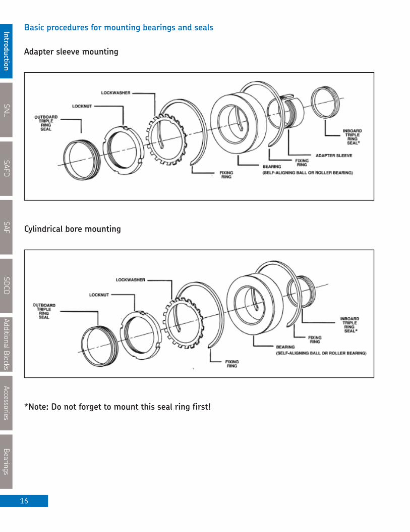
Basic procedures for mounting bearings and seals
Adapter sleeve mounting
Cylindrical bore mounting
*Note: Do not forget to mount this seal ring first!

SNL
Introductio
nSAFD
SAF
SDCD
AdditionalBlocks
Accessories
Bearings
17
Basic Procedures for Mounting Bearing and Seals
Preparation before Mounting
• Do not unwrap the bearing until ready for mounting. Do notremove the protective coating from the bearing. It will mixwith any petroleum-based grease or oil that is to be used asthe lubricant.
• Clean the shaft and housing. Remove all burrs and sharp edges.• Check that the shaft diameter is to the recommended tolerance.• Read and become familiar with the bearing mounting procedureand the installation instructions to be used for this assembly.
NOTE: Caps and bases of housings are not interchangeable.Most SNL and SAF blocks are now marked with capand base serial numbers to assist.
Adapter Sleeve Mounting – Spherical roller andCARB® Bearings
All spherical roller and CARB bearings with tapered bores formounting on adapter sleeves have to be driven up the tapersufficiently to achieve the proper reduction of internal clearance.
The unmounted clearance of each bearing must be measuredand recorded. To do this, stand the bearing on the bench andinsert progressively thicker feeler gauges the full length of theroller between the unloaded roller and the outer ring at the toplocation. Never roll the rollers over the gauges, as the wrongvalues will be obtained.
For an unmounted bearing, measure radial clearance at the top.For a mounted bearing, measure radial clearance at the bottom.
Position the adapter sleeve (less the locknut and lockwasher) onthe shaft in the correct position for the proposed bearing mountedcentre line. A light smear of clean spindle oil applied to the sleeveoutside diameter results in easier mounting and removal of thebearing.
Mount the bearing on the adapter with the large bore side ofthe inner ring matching the large side of the taper on the adaptersleeve. With the bearing finger-tight on the adapter, locate thebearing and adapter to the proper axial location on the shaft.Do not apply the lockwasher, as the drive-up procedure coulddamage it. To avoid damage to the bearing, it is most importantthat during this and subsequent operations the shaft be“blocked up” such that the bearing is unloaded.
Lubricate the chamfered face and the threads of the locknut(use Molykote for larger sizes), then apply the locknut with thechamfered face toward the bearing and tighten the nut until thesleeve is snug on the shaft. Wrenches are available for bearingdrive-up (page 249). For larger bearings, hydraulic mountingnuts are recommended to obtain the required internal clearancereduction. Refer to pages 256-257.
Never tighten the locknut with a hammer and drift. The locknut canbe damaged and chips can enter the bearing. Continue tighteningthe locknut and measuring the internal clearance with feeler gaugesuntil the reduction in internal clearance is the amount shown in thetable on pages 44 and 45. Remove the locknut or hydraulic nut.Mount the lockwasher with its inner prong located in the slot ofthe adapter sleeve and with its outer tabs leaning away from thebearing. Re-apply the locknut and tighten until it is firmly seatedagainst the lockwasher. Find the lockwasher tab that is nearestto one of the slots in the locknut. If the tab is past the slot, do notloosen but tighten the nut until the tab can be bent into a slot.
For large size adapter sleeves (size 44 and up) the use of the oilinjection method is standard practice. For these adapter sleeves,the lockwasher is replaced with a lockplate. In these cases, after thelocknut is tightened to achieve the proper reduction of the internalclearance in the bearing, take the lock-plate and place its prong inthe slot of the adapter sleeve. Note how much the locknut will haveto be tightened for the holes in the locknut to align with the holes inthe lockplate. Reverse the lockplate and observe again how muchthe locknut will have to be tightened for the holes in the locknut toalign with the holes in the lockplate. The lockplate is to be placed inthe position requiring the least tightening to align the two sets ofholes. When the locknut has been tightened to achieve this, theninsert and tighten the cap screws. Lock the cap screws with lockwirethrough the holes in the heads. Do a final check on the mountedinternal clearance of the bearing.
SNL
IntroductionSAFD
SAFSDCD
AdditionalBlocksAccessories
Bearings
18
Basic Procedures for Mounting Bearings and Seals
Adapter Sleeve Mounting – Self-Aligning BallBearings
Position the adapter sleeve (less the locknut and lockwasher) onthe shaft in the correct position for the proposed bearing mountedcentre line. A light smear of clean spindle oil applied to the sleeveoutside diameter results in easier mounting and removal of thebearing.
Mount the bearing on the adapter sleeve with the large bore sideof the inner ring matching the large side of the taper on the adaptersleeve. With the bearing finger-tight on the adapter, if necessary,relocate the bearing and adapter sleeve to the proper axial locationon the shaft. Do not apply the lockwasher as the drive-up procedurecould damage it. To avoid damage to the bearing it is most importantthat during the subsequent operations the shaft is “blocked up” suchthat the bearing is unloaded. Lubricate the chamfered face andthreads of the locknut (Molykote on larger sizes) then apply thelocknut with the chamfered face toward the bearing. Just tighten thenut with an appropriate wrench until the sleeve does not move onthe shaft and the bearing does not rotate on the shaft. Finally rotatethe locknut through the “turning angle” shown below.
CAUTION: A loose adapter sleeve can lead to the inner ringturning on the adapter sleeve and/or the adaptersleeve turning on the shaft. But to ensure thatthe nut is not excessively tight, make certain theouter ring of the bearing rotates freely.
When mounting a normal clearance bearing, swiveling the outerring will result in a slight drag. If the bearing has a C3 clearance,the outer ring will swivel freely. Remove the locknut and mountthe lockwasher with the inner prong located in the slot of theadapter sleeve and the tabs leaning toward the locknut. Re-applythe locknut and tighten until firmly seated against the lockwasher.Find the lockwasher tab that is nearest to one of the slots in thelocknut. If the slot is past the tab do not loosen but tighten the nutuntil a tab can be bent into a slot.
The SKF drive-up method is a distinct advantage when mountingself alingning and CARB bearings on adapter sleeves.
Cylindrical Bore Mounting – Self-aligning Ball orSpherical Roller Bearings
Small bearings – Bore size 50mm and smaller
Apply a coat of light oil to the shaft and bearing bore. Fit a cleantube with one end squared and bore slightly larger than the bearingbore against the bearing inner ring. With the bearing square on theshaft, apply pressure to the tube using a press. The bearing mustbe seated firmly against the shaft shoulder. The SKF TMFT 36mounting tool is ideal for smaller bearings.
Mount the lockwasher with the inner tab located in the shaftkeyway and with the outer tabs leaning away from the bearing,apply the locknut with the chamfered face lubricated and facingthe bearing. Tighten with an appropriate wrench until allcomponents are locked up solidly to the shaft shoulder. It maybe necessary to further tighten the nut to engage a washertab with a slot in the locknut. A very small movement of thenut will usually align a tab with a slot.
Large Bearings – Bore Size 50 mm and larger
These bearings are not easily pressed onto the shaft and shouldtherefore be heated using a temperature controlled oven, hotplateor electric induction heater which is environmentally friendly.In cases where the bearings are too large for the above, an oilbath with a mixture of 10% to 15% soluble oil in water, heated toapproximately 100ºC may be used. The bearing must be supportedto isolate it from direct contact with the bottom of the tank toavoid localized heating and damage to the bearing. After heating,mount the bearing on the shaft firmly against the shaft shoulder.Immediately apply the locknut and tighten to prevent the bearingfrom shrinking away from its proper position against the shaftshoulder. When the bearing has cooled, remove the locknut. Mountthe lockwasher with its inner prong located in the shaft keyway andwith its outer tabs leaning away from the bearing. Apply the locknutwith the face lubricated and tighten with the appropriate wrenchuntil all components are locked up solidly to the shaft shoulder.It may be necessary to further tighten the nut to engage a washertab with a slot in the nut. A very small movement of the nut willusually align a tab with a slot.
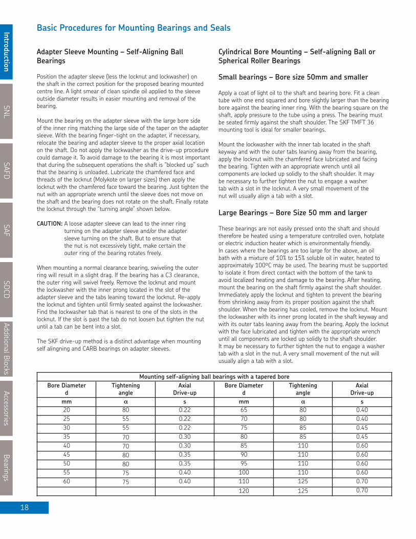
Bore Diameterd
Tighteningangle
AxialDrive-up
Bore Diameterd
Tighteningangle
AxialDrive-up
mm αα s mm αα s20 80 0.22 65 80 0.4025 55 0.22 70 80 0.4030 55 0.22 75 85 0.4535 70 0.30 80 85 0.4540 70 0.30 85 110 0.6045 80 0.35 90 110 0.6050 80 0.35 95 110 0.6055 75 0.40 100 110 0.6060 75 0.40 110 125 0.70
120 125 0.70
Mounting self-aligning ball bearings with a tapered bore

SNL
Introductio
nSAFD
SAF
SDCD
Additional Blocks
Accessories
Bearings
19
SDCD housings and SNL housings over size 32 use end coversmade of cast iron or machined steel discs, which fit into the sealgroove of the housing.
For housings mounted at the ends of shafts, the opening must befitted with an end cover to prevent the entry of contaminants intothe bearing.
SNL housings size 32 and under, are equipped with end coversmade of plastic and are suitable for operating temperatures in the range of –40º to +110ºC (-40º to +230ºF). For highertemperatures, sheet steel end covers should be used. An end cover suffix of VZ 137 is used to indicate the steel design.
SAFD, SAF and SAFS housings use steel disc end plugs with amoulded neoprene rubber tire on the O.D. This rubber tire providesa positive seal in the groove of the housing.
End Covers
EPR style
ASNH style
ETS style ASDC style

SNL
IntroductionSAFD
SAFSDCD
Additional BlocksAccessories
Bearings
20
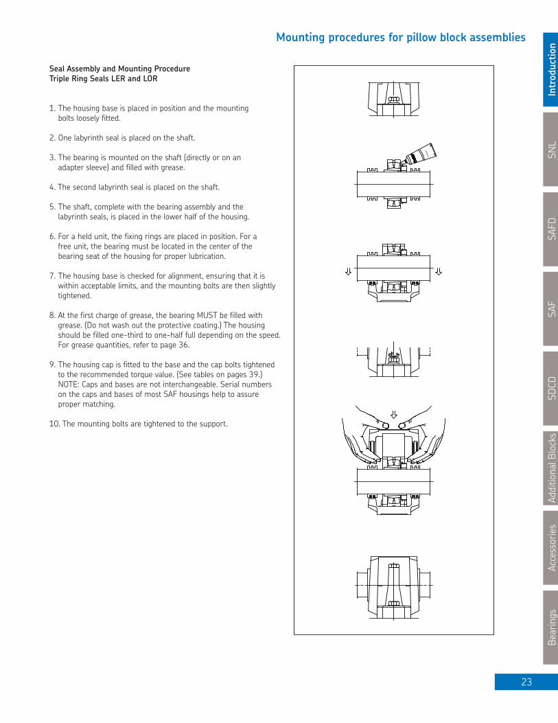
Mounting procedures for pillow block assemblies
Seal Assembly and Mounting Procedure
G-Type Seal (and L design for metric sizes in SNL 507-522 blocks)
1. The housing base is placed in position and the mounting boltsloosely fitted.
2. The halves of the seals are inserted in the housing grooves and the space between the lips of the seals is filled with grease.
3. The bearing is mounted on the shaft (directly or on an adaptersleeve) and filled with grease.
4. The shaft, complete with bearing assembly, is placed in the lower half of the housing.
5. For a held unit, the fixing rings are placed in position. For a freeunit, the bearing must be located in the center of the bearing seat of the housing for proper lubrication.
6. The housing base is checked for alignment, ensuring that it iswithin the acceptable limits, and the mounting bolts are thenslightly tightened.
7. The other halves of the seals are inserted into the cap and thespace between the lips of the seals is filled with grease. For sizes528-532 and 616-620 the seal halves must be turned so thatthe spigots fit in the holes of the connecting seal halves.
8. At the first charge of grease, the bearing MUST be filled withgrease. (Do not wash out the protective coating.) The housingshould be filled one-third to one-half full, depending on thespeed. For grease quantities, refer to page 36.
9. The housing cap is fitted to the base and the cap bolts tightened to the recommended torque. (See tables on page 39.) NOTE: Caps and bases are not interchangeable. Serial numberson the caps and bases of all SNL housings help to assure proper matching.
10. Finally the housing mounting bolts are tightened to the support.
Gre
ase

SNL
Introductio
nSAFD
SAF
SDCD
Additional Blocks
Accessories
Bearings
21
Mounting procedures for pillow block assemblies
Seal Assembly and Mounting ProcedureV-Ring Seal Type “A”
1. The housing base is placed in position and the mounting boltsloosely fitted.
2. One V-ring and one sheet metal washer are placed on the shaft.Care should be taken to position these correctly in relation to thehousing. Do not allow the V-ring seal lip to pass through the sheetmetal washer.
3. The bearing is mounted on the shaft (directly or on an adaptersleeve) and filled with grease.
4. The second V-ring and sealing washer are placed on the shaft.
5. The shaft, complete with the bearing assembly and the sealingcomponents, is placed in the lower half of the housing.
6. For a held unit, the fixing rings are placed in position. For a freeunit, the bearing must be located in the center of the bearing seatof the housing for proper lubrication.
7. The housing base is checked for alignment, ensuring that it iswithin acceptable limits, and the mounting bolts are then slightlytightened.
8. At the first charge of grease, the bearing MUST be filled withgrease. (Do not wash out the protective coating.) The housingshould be filled one-third to one-half full, depending on thespeed. For grease quantities, refer to page 36.
9. The housing cap is fitted to the base and the cap bolts tightened to the recommended torque. (See tables on page 39.) NOTE: Caps and bases are not interchangeable. Serial numbers on the caps and bases of all SNL housings help to assure proper matching.
10. The outer surfaces of the sealing washers are smeared withgrease and the V-rings are pushed axially along the shaft until their sealing lips are aligned and in the correct workingpositions relative to the sealing washers. The simplest way tomove the V-rings is to use a screwdriver blade while rotating the shaft by hand.
NOTE: V-ring seals may be used for oil lubrication. The assemblyshown to the right is for grease. When V-rings are used for oil, a V-ring is used on both the inside and the outside of the sealingwasher. Consult SKF Engineering for details.
Gre
ase
Gre
ase

SNL
IntroductionSAFD
SAFSDCD
Additional BlocksAccessories
Bearings
22
Mounting procedures for pillow block assemblies
Seal Assembly and Mounting ProcedureFelt Seal Type “C”
1. The housing base is placed in position and the attachment bolts loosely fitted.
2. The rubber O-section cords are placed in the grooves in thehousing base.
3. The halves of the alloy ring with felt seals are mounted on the O-section cords in the grooves of the housing base.
4. The bearing is mounted on the shaft (directly or on an adapter sleeve) and filled with grease.
5. The shaft, complete with the bearing assembly, is placed in the lower half of the housing.
6. For a held unit, the fixing rings are placed in position. For a free unit, the bearing must be located in the center of the bearing seat of the housing for proper lubrication.
7. The housing base is checked for alignment, ensuring that thehousing is within acceptable limits, and the mounting bolts arethen slightly tightened.
8. The rubber O-section cords are placed in the grooves in thehousing cap.
9. The felt seals with the light alloy rings are mounted on the O-section cords in the grooves of the housing cap.
10. At the first charge of grease, the bearing MUST be filled withgrease. (Do not wash out the protective coating.) The housingshould be filled one-third to one-half full depending on thespeed. For grease quantities, refer to page 36.
11. The housing cap is fitted to the base and the cap bolts tightenedto the recommended torque value. (See tables on pages 39.)NOTE: Caps and bases are not interchangeable. Serial numberson the caps and bases of all SNL housings help to assure propermatching.
12. Finally, the mounting bolts are tightened to the support.
Gre
ase
SNL
Introductio
nSAFD
SAF
SDCD
Additional Blocks
Accessories
Bearings
23
Mounting procedures for pillow block assemblies
Seal Assembly and Mounting ProcedureTriple Ring Seals LER and LOR
1. The housing base is placed in position and the mounting bolts loosely fitted.
2. One labyrinth seal is placed on the shaft.
3. The bearing is mounted on the shaft (directly or on an adapter sleeve) and filled with grease.
4. The second labyrinth seal is placed on the shaft.
5. The shaft, complete with the bearing assembly and the labyrinth seals, is placed in the lower half of the housing.
6. For a held unit, the fixing rings are placed in position. For a free unit, the bearing must be located in the center of the bearing seat of the housing for proper lubrication.
7. The housing base is checked for alignment, ensuring that it iswithin acceptable limits, and the mounting bolts are then slightlytightened.
8. At the first charge of grease, the bearing MUST be filled withgrease. (Do not wash out the protective coating.) The housingshould be filled one-third to one-half full depending on the speed.For grease quantities, refer to page 36.
9. The housing cap is fitted to the base and the cap bolts tightenedto the recommended torque value. (See tables on pages 39.)NOTE: Caps and bases are not interchangeable. Serial numberson the caps and bases of most SAF housings help to assureproper matching.
10. The mounting bolts are tightened to the support.G
reas
e

SNL
IntroductionSAFD
SAFSDCD
Additional BlocksAccessories
Bearings
24
Mounting procedures for pillow block assemblies
Seal Assembly and Mounting Procedure Labyrinth SealType “S” and “TS”
1. The housing base is placed in position and the mounting bolts loosely fitted.
2. One labyrinth seal is placed on the shaft.
3. The bearing is mounted on the shaft (directly or on an adapter sleeve) and filled with grease.
4. The second labyrinth seal is placed on the shaft.
5. The shaft, complete with the bearing assembly and the labyrinth seals, is placed in the lower half of the housing.
6. For a held unit, the fixing rings are placed in position. For a free unit, the bearing must be located in the center of the bearing seat of the housing for proper lubrication.
7. The housing base is checked for alignment, ensuring that it is within acceptable limits and the mounting bolts are then slightly tightened.
8. At the first charge of grease, the bearing MUST be filled with grease. (Do not wash out the protective coating.) The housing should be filled one-third to one-half full depending on the speed. For grease quantities, refer to page 36.
9. The housing cap is fitted to the base and the cap bolts tightened to the recommended torque value. (See tables on page 39.) NOTE: Caps and bases are not interchangeable. Serial numbers on the caps and bases of all SNL housings help to assure proper matching.
10. The mounting bolts are tightened to the support.
11. Finally the silicon O-section cords are placed in the grooves ofthe labyrinth seals. The simplest way to mount the cords is touse a screwdriver blade while rotating the shaft by hand.
NOTE: Type S is used with SNL and SSNLD.Type TS is used with SNL sizes over 32 and with SDCD.
Gre
ase

SNL
Introductio
nSAFD
SAF
SDCD
Additional Blocks
Accessories
Bearings
25
Mounting procedures for pillow block assemblies
Seal Assembly and Mounting Procedure Triple Ring Seals "LOR, LORP" (with optional contact elements B-10724-XX or B-10785-XX)
1. The housing base is placed in position and the mounting bolts loosely fitted.
NOTE: Where contact elements are added in steps 2 and 4, theradial lip seal must be mounted on the centre ring of the triple ringseal. The radial lip seal may point in either direction, depending onthe requirement: retention of grease or exclusion of contaminants.
2. One labyrinth seal is placed on the shaft, paying attention not todamage the O-ring.
3. The bearing is mounted on the shaft (directly or on an adaptersleeve) and filled with grease.
4. The second labyrinth seal is placed on the shaft, paying attentionnot to damage the O-ring.
5. The shaft, complete with the bearing assembly and the labyrinthseals, is placed in the lower half of the housing. In the case of anadditional contact element, seat the O.D. of the radial lip contactelement in the centre groove of housing hub.
6. For a held unit, the fixing rings are placed in position. For a free unit, the bearing must be located in the center of the bearing seat for proper lubrication.
7. The housing base is checked for alignment, ensuring that it is within acceptable limits, and the mounting bolts are thenslightly tightened.
8. At the first charge of grease, the bearing MUST be filled withgrease. (Do not wash out the protective coating.) The housingshould be filled one-third to one-half full depending on the speed.For grease quantities refer to page 36.)
9. The housing cap is fitted to the base and the cap bolts tightenedto the recommended torque. (See table on page 39.) NOTE: Capsand bases are not interchangeable. Serial numbers on the capsand bases of most SAF housings help to assure proper matching.
10. The mounting bolts are tightened to the support.
Gre
ase

SNL
IntroductionSAFD
SAFSDCD
Additional BlocksAccessories
Bearings
26
Mounting procedures for pillow block assemblies
Seal Assembly and Mounting ProcedureLabyrinth SealsType “TER-C”
1. The housing base is placed in position and the mounting bolts loosely fitted.
2. Slide one labyrinth flinger, with the prongs pointed toward thebearing location onto the shaft. Then slide the labyrinth insert,with the O-ring installed on its O.D., on the shaft.
3. The bearing is mounted on the shaft (directly or on an adapter)and filled with grease.
4. The second labyrinth seal is placed on the shaft following the instructions as described above under step 2 except in reverse sequence.
5. The shaft, complete with the bearing assembly and the labyrinthseal assemblies, is placed in the lower half of the housing.
6. For a held unit, the fixing rings are placed in position. For a freeunit, the bearing must be located in the center of the bearing seatof the housing for proper lubrication.
7. The housing base is checked for alignment, ensuring that it is within acceptable limits, and the mounting bolts are thenslightly tightened.
8. At the first charge of grease, the bearing MUST be filled withgrease. (Do not wash out the protective coating.) The housingshould be filled one-third to one-half full depending on the speed.For grease quantities, refer to page 36.
9. The housing cap is fitted to the base, being careful not to damagethe O-rings on the O.D. of the seal rings, and the cap bolts aretightened to the recommended torque. (See tables on page 39.)NOTE: Caps and bases are not interchangeable. Serial numberson the caps and bases of most SAF housings help to assureproper matching.
10. The mounting bolts are tightened to the support.
11. Fill the seal labyrinth on the insert and the flinger with grease.
12. To adjust the labyrinth seal flingers, move the flingers axiallytoward the housing till they contact the insert. Back the flingeroff 1/16” (1.6 mm) on the “HELD” assembly. For a “FREE”assembly, back off the amount of the expected shaft expansion plus 1/32” (0.8 mm). Tighten the set screws.
Gre
ase
SNL
Introductio
nSAFD
SAF
SDCD
Additional Blocks
Accessories
Bearings
27
Mounting procedures for pillow block assemblies
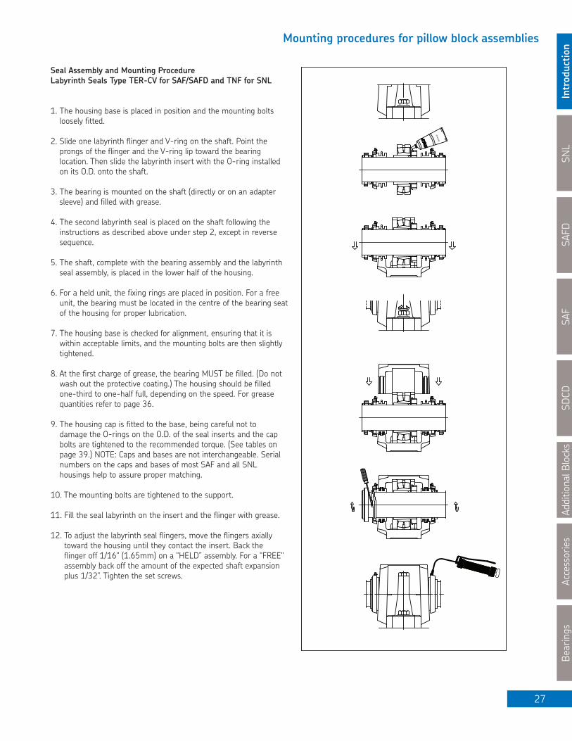
Seal Assembly and Mounting ProcedureLabyrinth Seals Type TER-CV for SAF/SAFD and TNF for SNL
1. The housing base is placed in position and the mounting boltsloosely fitted.
2. Slide one labyrinth flinger and V-ring on the shaft. Point theprongs of the flinger and the V-ring lip toward the bearinglocation. Then slide the labyrinth insert with the O-ring installedon its O.D. onto the shaft.
3. The bearing is mounted on the shaft (directly or on an adaptersleeve) and filled with grease.
4. The second labyrinth seal is placed on the shaft following theinstructions as described above under step 2, except in reversesequence.
5. The shaft, complete with the bearing assembly and the labyrinthseal assembly, is placed in the lower half of the housing.
6. For a held unit, the fixing rings are placed in position. For a freeunit, the bearing must be located in the centre of the bearing seatof the housing for proper lubrication.
7. The housing base is checked for alignment, ensuring that it iswithin acceptable limits, and the mounting bolts are then slightlytightened.
8. At the first charge of grease, the bearing MUST be filled. (Do notwash out the protective coating.) The housing should be filledone-third to one-half full, depending on the speed. For greasequantities refer to page 36.
9. The housing cap is fitted to the base, being careful not to damage the O-rings on the O.D. of the seal inserts and the capbolts are tightened to the recommended torque. (See tables onpage 39.) NOTE: Caps and bases are not interchangeable. Serialnumbers on the caps and bases of most SAF and all SNLhousings help to assure proper matching.
10. The mounting bolts are tightened to the support.
11. Fill the seal labyrinth on the insert and the flinger with grease.
12. To adjust the labyrinth seal flingers, move the flingers axiallytoward the housing until they contact the insert. Back the flinger off 1/16" (1.65mm) on a “HELD” assembly. For a "FREE"assembly back off the amount of the expected shaft expansionplus 1/32”. Tighten the set screws.
Gre
ase

SNL
IntroductionSAFD
SAFSDCD
Additional BlocksAccessories
Bearings
28
Mounting procedures for pillow block assemblies
Seal Assembly and Mounting ProcedureLabyrinth Seals TSNC, TSDC "D" Type
1. The housing base is placed in position and the mounting bolts loosely fitted.
2. Slide one labyrinth flinger and V-ring onto the shaft. Point theprongs of the flinger and the V-ring lip toward the bearinglocation. Then slide the labyrinth insert with the O-ring installedon its O.D. onto the shaft.
3. The bearing is mounted on the shaft (directly or on an adaptersleeve) and filled with grease.
4. The second labyrinth seal is placed on the shaft following theinstructions as described above under step 2, except in reversesequence.
5. The shaft, complete with the bearing assembly and the labyrinthseal assemblies, is placed in the lower half of the housing.
6. For a held unit, the fixing rings are placed in position. For a freeunit, the bearing must be located in the center of the bearing seat of the housing for proper lubrication.
7. The housing base is checked for alignment, ensuring that is within acceptable limits, and the mounting bolts are then slightly tightened.
8. At the first charge of grease, the bearing MUST be filled (do notwash out the protective coating) and the housing should be filledone-third to one-half full depending on the speed. For greasequantities refer to page 36.
9. The housing cap is fitted to the base, being careful not to damagethe O-rings on the O.D. of the seal inserts, and the cap bolts aretightened to the recommended torque. (See tables on page 39.)NOTE: Caps and bases are not interchangeable. Serial numberson the caps and bases of all SNL housings help to assure propermatching. SAFD and SDCD are not serialized.
10. The mounting bolts are tightened to the support.
11. To adjust the labyrinth seal flingers, move the flingers axiallytoward the housing till they contact the insert. Back the flingeroff 1/16” on a “HELD” assembly. For a “FREE” assembly back off the amount of the expected shaft expansion plus 1/32”.Tighten the set screws which secure the flingers on the shaft. To complete the assembly in the case of SDCD housings withthese labyrinth seal assemblies, take one half of the 4 mmrubber cord supplied and insert it into the counter bore of each flinger bore adjacent to the outer face.
12. At the initial start up, with the shaft rotating, lubricate the sealsthrough the grease fitting until a bead of grease appears aroundthe periphery of the flingers. NOTE: Use the same grease as forthe lubrication of the bearing.
Gre
ase

SNL
Introductio
nSAFD
SAF
SDCD
Additional Blocks
Accessories
Bearings
29
Mounting procedures for pillow block assemblies
Seal Assembly and Mounting ProcedureLabyrinth Seals TSNC, TSDC “E” Type
1. The housing base is placed in position and the mounting boltsloosely fitted.
2. Slide one labyrinth flinger onto the shaft, with the prongs pointedtoward the bearing location. Then slide the labyrinth insert ontothe shaft, with the O-ring installed on its O.D.
3. The bearing is mounted on the shaft (directly or on an adapter)and filled with grease.
4. The second labyrinth seal is placed on the shaft following theinstructions as described above under step 2, except in reversesequence.
5. The shaft, complete with the bearing assembly and the labyrinthseal assemblies, is placed in the lower half of the housing.
6. For a held unit, the fixing rings are placed in position. For a freeunit, the bearing must be located in the center of the bearing seatof the housing for proper lubrication.
7. The housing base is checked for alignment, ensuring that it iswithin acceptable limits, and the mounting bolts are then slightlytightened.
8. At the first charge of grease, the bearing MUST be filled withgrease. (Do not wash out the protective coating.) The housingshould be filled one-third to one-half full, depending on thespeed. For quantities refer to page 36.
9. The housing cap is fitted to the base and the cap bolts tightenedto the recommended torque value. (See tables on page 39.)NOTE: Caps and bases are not interchangeable. Serial numberson the caps and bases of all SNL housings help to assure propermatching. SAFD and SDCD are not serialized.
10. The mounting bolts are tightened to the support.
11. To adjust the labyrinth seal flingers, move the flinger axiallytoward the housing until they contact the insert. Back the flingeroff 1/16” on "HELD" assemblies. For "FREE" assemblies, back offthe amount of the expected shaft expansion plus 1/32”. Tightenthe set screws which secure the flingers to the shaft. A final stepwith TSCD seals requires the 4 mm rubber cord supplied to beinserted into the counterbore of each flinger.
12. At the initial startup, with shaft rotating, lubricate the sealsthrough the grease fitting until a bead of grease appears aroundthe periphery of the flingers. NOTE: Use the same grease as forthe lubrication of the bearing.
Gre
ase

SNL
IntroductionSAFD
SAFSDCD
Additional BlocksAccessories
Bearings
30
Lubrication
General
It is necessary to lubricate rolling bearings to prevent metalliccontact between the rolling elements, the raceways and the cage.The most favourable running (operating) condition for a rollingbearing is obtained when the minimum quantity of lubricantnecessary to ensure reliable operation is used. However, the quantity used also depends on additional functions required of the lubricant, i.e. sealing and cooling.
Lubricating properties deteriorate as a result of aging andmechanical churning. When using labyrinth and taconite seals in severely contaminated environments, it is suggested to shorten the relubrication interval. Certain operating conditions, i.e. high speeds, high temperatures or heavy loads, require morefrequent relubrication.
The choice of lubricant depends primarily on the temperature range, operating speed and magnitude of the load. Either oil orgrease of proper quality can be considered for lubricating bearings.At low and medium speeds, grease usually permits a simplermethod of obtaining reliable and durable lubrication. It requires a simpler sealing system and has an additional advantage ofaffording excellent protection to bearings against rust and intrusionof contaminants. With high speeds, it becomes necessary to add fresh grease and remove old grease more frequently to obtain safe operation. When this becomes impractical, due to speed andtemperature, oil should be used instead of grease.
When oil is used, it is advisable to employ an oil reservoir or anadequate supply of oil and effective housing seals to avoid leakage.The level of oil should be about the centre of the lowest ball or roller when the bearing is stationary.
Too high an oil level or too large a quantity of grease usually resultsin higher operating temperatures due to churning of the lubricant.
Grease Lubrication
SKF pillow block housings are primarily intended for greaselubrication. In the majority of cases it is sufficient to charge thehousings with grease on mounting and to replace this greaseperiodically, either at specified time intervals or when performinginspections.
Pillow block housing caps can be equipped with grease fittings. For spherical roller bearings with W33 or E suffix (groove in outerring and three lubricating holes spaced at 120°) the centerlubricating fitting should be used. For bearings without the W33 or E feature, either of the two side lubrication fittings can be used to supply grease. Generally the fitting on the side opposite thelocknut is used, unless one end is closed.
At installation, the grease must be worked in between the rollingelements. The housing should be packed one-third to one-half full.Never mix greases with unlike base oils or incompatible thickeners. Itshould also be noted that bearings are generally lubricated aftermounting. This ensures an accurate clearance measurement, avoidsthe mess in trying to handle a greasy bearing, and decreases thepossibility of additional contamination being introduced into thebearing. Only when, after mounting, an even distribution of thegrease in the bearing is not possible should one consider greasingprior to mounting.
Lubrication through centerfitting for W33
Lubrication through theside fitting for bearingswithout W33

SNL
Introductio
nSAFD
SAF
SDCD
Additional Blocks
Accessories
Bearings
31
Lubrication
Procedure for applying lubricant to bearings and pillow blocks:
a) Mount the bearing onto the shaft.
b) Pack each bearing as completely full of the specified grease aspossible by swiveling the outer ring open, rotating it as necessaryto inject the grease, then swiveling the outer ring closed. Becareful not to use force in the event that a roller end catches thecorner of the outer sphere.
c) When assembling the flinger (where applicable), pack both theinboard and outboard flingers full of the same lubricant used inthe bearing.
d) Before assembling the pillow block cap to the base, and aftercompleting the bearing and base assembly, fill the pillow blockone-third to one-half full, depending on the speed, with the same lubricant that was used to pack the bearing.
e) Before applying the cap to the base, spray or otherwise coat theinterior of the cap with a rust preventative.
f) Smear a liberal amount of grease on the V-ring (where applicable),contacting surfaces of the seal, hub on the shaft, plate and hub.
If long term storage and/or shipping considerations have to be takeninto account, then, dependent on the circumstances, additionallubrication precautions have to be considered.
Lubrication procedure to be used after start-up
Many applications require relubrication between inspections. As aresult, drilled and tapped holes are included in the centre of theblock for W33 or E type bearings and offset holes for self-aligningand CARB® bearings. There are also dimples over the hubs toaccommodate holes for lubricating the seals. Grease nipples areincluded in SNL blocks.
When housings need such grease fittings and the bearings are notlubricated via the W33 feature in the center of the bearing, then anextra V-Ring seal is supplied. This extra seal is mounted inside of thegrease input side of the pillow block. The grease will then be forcedthrough the bearing and any surplus grease will escape from theside of the housing opposite this extra V-Ring seal.
Except for the V-Ring seal set described above, very few seal designswill allow for an excess grease charge to escape from the housingand therefore present possible overheating conditions. If bearingtemperatures are monitored, it will be noted that the temperaturewill rise immediately after a grease charge enters a bearing. Undernormal conditions such increased heating will last only as long as ittakes a bearing to clear the excess grease away.
In applications where the operating conditions demand frequentrelubrication, it is important to ensure that an excess of grease doesnot build up within the housing. This can lead to bearing failurethrough churning of the grease, subsequent overheating andeventual bearing burnout.
G and C design seals are examples, which do not allow grease topurge through the seals. If frequent relubrication is required, it isadvisable to provide the housing with a grease escape hole throughwhich excess grease can escape. SNL housings can be supplied withgrease purge holes in the base. This housing design is identified bythe suffix VU, e.g. SNL 511-609 VU. Consult SKF for details.

SNL
IntroductionSAFD
SAFSDCD
Additional BlocksAccessories
Bearings
32
Housing with grease escape hole
LER/LOR seals in SAF/SAFD units won't allow for grease purging.Pressure may be relieved if the drain plug is removed whileregreasing and with the bearing running. When bearingtemperatures return to normal, the drain plug is replaced.
Oil is generally used for rolling bearing lubrication when high speeds or operating temperatures are beyond the capabilities of the lubricating grease. In these cases the frictional (internal) or applied (external) heat has to be removed from the bearing.
The simplest method of oil lubrication is the "Oil Bath". Thelubricating oil, which is picked up by the rotating components of the bearing, is distributed within the bearing and then flows back to the oil sump. The oil level should be such that it reaches the center of the lowest rolling element when the bearing isstationary. The oil level height is shown in this catalogue asdimension H3. The mounting of an oil sight gauge on the side of the pillow block is useful to ensure an adequate oil level is maintained.
Operating at higher speeds will cause the bearing operatingtemperature to increase and will accelerate aging of the oil. Toremove the heat, oil circulating systems or cooling coils in the oilsump are available (consult SKF). Cooling of the oil enables theoperating temperature of the bearing to be kept at a lower level.
Pillow blocks with triple ring seals (LER, LOR, LORP, S, TS) and V-ring seals are also suitable for oil lubrication providing certaincriteria are observed. The SNL housings can also be used for oillubrication at relatively high speeds, however, the specially developedUL-design seals are recommended. In order for these seals to be used the SNL housing must be modified and the housing withseals ordered as a unit. Consult SKF for details.
Pillow blocks of series SAF, SAFD and SDCD designs are equippedwith oil sumps that permit oil bath or circulating oil lubrication. The oil supply hole in the pillow block cap must be positionedopposite to the exit hole in the base of the pillow block to ensurethat the oil passes through the bearing. Holes for oil indicators (sightglass) can be drilled in the bases.
NOTE: If for any reason an application is considered to be differentfrom standard, or on the borderline between grease and oil,please contact SKF.
SNL
Introductio
nSAFD
SAF
SDCD
Additional Blocks
Accessories
Bearings
33
Oil lubrication
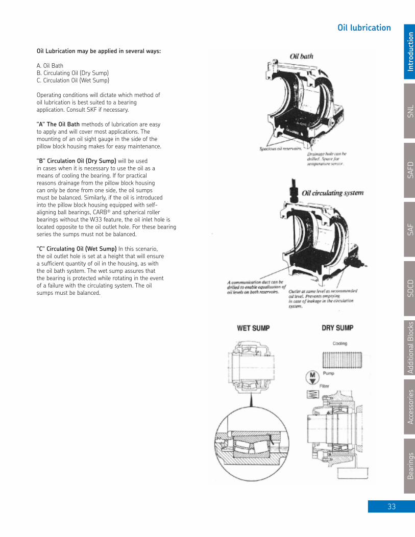
Oil Lubrication may be applied in several ways:
A. Oil BathB. Circulating Oil (Dry Sump)C. Circulation Oil (Wet Sump)
Operating conditions will dictate which method of oil lubrication is best suited to a bearingapplication. Consult SKF if necessary.
"A" The Oil Bath methods of lubrication are easyto apply and will cover most applications. Themounting of an oil sight gauge in the side of thepillow block housing makes for easy maintenance.
"B" Circulation Oil (Dry Sump) will be usedin cases when it is necessary to use the oil as ameans of cooling the bearing. If for practicalreasons drainage from the pillow block housingcan only be done from one side, the oil sumpsmust be balanced. Similarly, if the oil is introducedinto the pillow block housing equipped with self-aligning ball bearings, CARB® and spherical roller bearings without the W33 feature, the oil inlet hole islocated opposite to the oil outlet hole. For these bearingseries the sumps must not be balanced.
"C" Circulating Oil (Wet Sump) In this scenario,the oil outlet hole is set at a height that will ensurea sufficient quantity of oil in the housing, as with the oil bath system. The wet sump assures that the bearing is protected while rotating in the eventof a failure with the circulating system. The oilsumps must be balanced.

SNL
IntroductionSAFD
SAFSDCD
Additional BlocksAccessories
Bearings
34
Relubrication and Relubrication Intervals
Relubrication Intervals
The period during which a grease lubricated bearing will functionsatisfactorily without relubrication is dependant on the bearing type,size, and operating conditions such as load, speed, temperature,environment and grease used.
Contaminated grease results in failures such as premature fatigue,polishing wear, etc. Where there is a risk of the grease becomingcontaminated, the relubrication intervals should be reduced. Thisreduction also applies to applications where the grease is required to seal against moisture (e.g. bearings in paper making machines,where water runs over the bearing housings); relubrication shouldbe done once a week.
Quality age resistant greases are usually good for temperatures up to +70ºC. At temperatures above 70ºC, the lubrication intervalsshould be halved for each increment of 15ºC but the maximumpermissible operating temperature for the grease should not beexceeded. Conversely, if operating temperatures are lower than50ºC, the intervals can be lengthened to about twice the 70ºC value. It should be noted however, that relubrication intervals might vary significantly even where apparently similar grease are used.
SKF offers the Dial Set software package, which calculates theappropriate relubrication intervals and volume required. It can be requested from your local SKF office or found online atwww.mapro.skf.com.
The amount of grease needed for relubrication can be estimatedusing the follow formulae:
G = 0.002 D B if lubrication is through the central W33 groove and holes.G = 0.005 D B if lubrication is from the side as with self-aligningand CARB® bearings.
Where:
G = the grease quantity in grams (for ozs. X 0.0353)D = the bearing outside diameter in mmB = the total bearing width in mm
If the relubrication interval is not specified we suggest that lubricantis removed and replaced at regular plant maintenance shutdowns.The cap of a split housing and the cover of a one-piece housing canusually be taken off to expose the bearing. After removing the usedgrease, fresh grease should be packed between the rolling elements.
If frequent relubrication is required, a grease nipple should be fittedto the housing. A grease gun can then be used to ensure that freshgrease actually reaches the bearing and replaces the old grease.After a number of such re-lubrications, the housing should beopened and the used grease removed before fresh grease is added.
SNL
Introductio
nSAFD
SAF
SDCD
Additional Blocks
Accessories
Bearings
35
Notes

SNL
IntroductionSAFD
SAFSDCD
Additional BlocksAccessories
Bearings
36
The approximate intial grease charge (mass) for split pillow blocks is given in these tables. The recommended intial grease charge is one-third to one-half the volume of the free space in the pillow block, (40% fill shown) and the empty space between rolling elements and cage of the bearing. This recommendation is for moderate speeds and normal or light bearing loads (C/P>8.3).
Initial Grease Charges for Split Pillow Blocks
Size Grease qty. Size Greaseqty. Size Grease qty. Size Grease qty.g. oz. g. oz. g. oz. kg lb
505, 205 25 0,9 507 70 2,5 308 127 4,5 34 1,1 2,4506-605, 206 40 1,4 509 85 3,0 609, 309 142 5,0 36 1,4 3,1507-606, 207 50 1,8 510 113 4,0 610, 310 184 6,5 38 1,8 4,0508-607, 208 60 2,1 511 142 5,0 611, 311 227 8,0 40 2,3 5,1509 65 2,3 513 213 7,5 312 283 10,0 44 2,7 6,0510-608, 210 75 2,6 515 255 9,0 613, 313 369 13,0 48 3,4 7,5511-609, 211 100 3,5 516, 216 369 13,0 314 397 14,0 52 4,3 9,5512-610, 212 150 5,3 517, 217 369 13,0 615, 315 397 14,0 56 4,4 9,7513-611, 213 180 6,4 518, 218 397 14,0 616, 316 453 16,0 60 6,2 13,7515-612, 215 230 8,1 520, 220 595 21,0 617, 317 567 20,0 64 7,7 17,0516-613, 216 280 9,9 522, 222 794 28,0 618, 318 624 22,0 68 9,4 20,7517, 217 330 11,6 524, 224 1134 40,0 620, 320 1134 40,0 72 9,7 21,4518-605, 218 430 15,2 526, 226 1475 52,1 622, 322 1475 52,1 76 9,6 21,2519-616 480 16,9 528, 228 1475 52,1 624, 324 1700 60,0 80 12,2 26,9520-617 630 22,2 530, 230 1700 60,0 626, 326 1930 68,1 84 14,9 32,8522-619 850 30,0 532, 232 1930 68,1 628, 328 2381 84,0 88 16,2 35,7524-620 1000 35,3 534, 234 2381 84,0 630, 330 2722 96,1 92 18,8 41,4526 1100 38,8 536, 236 2722 96,1 632, 332 3290 116,1 96 18,5 40,8528 1400 49,4 538, 238 3290 116,1 634, 334 3860 136,3530 1700 60,0 540, 240 3860 136,3 638, 338 5200 183,6532 2000 70,6 544, 244 5200 183,6
g. oz. g. oz. kg lb kg lb
520 571 20,2 024 KA 595 21,0 36 1,2 2,6 34 1,86 4,1522 771 27,2 026 KA 794 28,0 38 1,5 3,3 36 1,89 4,2524 914 32,3 028 KA 1134 40,0 40 1,9 4,2 38 2,15 4,7526 1257 44,4 030 KA 1475 52,1 44 2,4 5,3 40 2,48 5,5530 1371 48,4 032 KA 1475 52,1 48 2,8 6,2 44 3,03 6,7532 1714 60,5 034 KA 1475 52,1 52 3,6 7,9 48 3,80 8,4534 2171 76,6 036 KA 1930 68,1 56 4,5 9,9 52 5,63 12,4536 2514 88,7 038 KA 1930 68,1 60 4,6 10,1 56 5,64 12,4538 2971 104,9 040 KA 2381 84,0 64 6,5 14,3 60 6,93 15,3540 3657 129,1 044 KA 3290 116,1 68 8,1 17,9 64 8,61 19,0544 4800 169,4 048 KA 3860 136,3 72 8,1 17,9 68 8,35 18,4
052 KA 5200 183,6 76 11,0 24,3 72 10,69 23,6056 KA 7000 247,1 80 11,7 25,8 76 12,29 27,1
84 11,8 26,0 80 14,62 32,288 14,4 31,7 84 15,25 33,6
88 15,07 33,2
SNL, SSN
LDSD
AF
SAF, SAFS, SAFD
SAF-K
SAF
SNL 30, S
DCD
30
SNL 31, S
DCD
31
SNL 32, S
DCD
32
* If grease-filled seals are used i.e. TER, TSNC, TNF or ND, grease quantities listed do not include the grease charge of the seals.
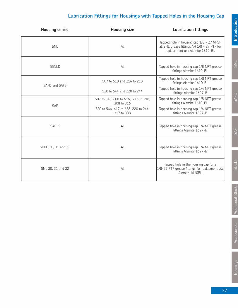
SNL
Introductio
nSAFD
SAF
SDCD
Additional Blocks
Accessories
Bearings
37
Lubrication Fittings for Housings with Tapped Holes in the Housing Cap
SNL AllTapped hole in housing cap 1/8 - 27 NPSF all SNL grease fittings AH 1/8 - 27 PTF for
replacement use Alemite 1610-BL
SSNLD All Tapped hole in housing cap 1/8 NPT greasefittings Alemite 1610-BL
SAFD and SAFS
SAF
SAF-K All Tapped hole in housing cap 1/4 NPT greasefittings Alemite 1627-B
SDCD 30, 31 and 32 All Tapped hole in housing cap 1/4 NPT greasefittings Alemite 1627-B
SNL 30, 31 and 32 AllTapped hole in the housing cap for a
1/8-27 PTF grease fittings for replacment useAlemite 1610BL
Housing series Housing size
520 to 544 and 220 to 244Tapped hole in housing cap 1/4 NPT grease
fittings Alemite 1627-B
507 to 518 and 216 to 218
520 to 544, 617 to 638, 220 to 244, 317 to 338
507 to 518, 608 to 616, 216 to 218, 308 to 316
Tapped hole in housing cap 1/4 NPT greasefittings Alemite 1627-B
Tapped hole in housing cap 1/8 NPT greasefittings Alemite 1610-BL
Tapped hole in housing cap 1/8 NPT greasefittings Alemite 1610-BL
Lubrication fittings
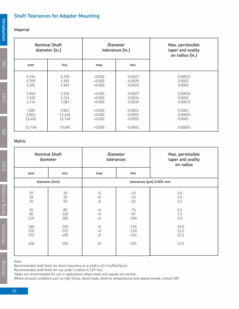
SNL
IntroductionSAFD
SAFSDCD
Additional BlocksAccessories
Bearings
38
Shaft Tolerances for Adapter Mounting
Note:Recommended shaft finish for direct mounting on a shaft is 63 rms/Ra32(µm).Recommended shaft finish for use under a sleeve is 125 rms.Tables are recommended for use in applications where loads and speeds are normal. Where unusual conditions such as high thrust, shock loads, extreme temperatures and speeds prevail, consult SKF.
Imperial
Nominal Shaftdiameter
Diametertolerances
Max. permissibletaper and ovality
on radius
over incl. max min
101830
5080120
180250315
400
183050
80120180
250315400
500
+0+0+0
+0+0+0
+0+0+0
+0
-43-52-62
-74-87-100
-115-130-140
-155
4,04,55,5
6,57,59,0
10,011,512,5
13,5
Metric
diameter (mm) tolerances (µm) 0.001 mm
Nominal Shaftdiameter (in.)
Diametertolerances (in.)
Max. permissibletaper and ovalityon radius (in.)
over incl. max min
0.3940.7091,181
1,9693.1504,724
7,0879,84312,402
15,748
0.7091,1811,969
3.1504,7247,087
9,84312,40215,748
19,685
+0.000+0.000+0.000
+0.000+0.000+0.000
+0.000+0.000+0.000
+0.000
-0.0017-0.0020-0.0024
-0.0029-0.0034-0.0039
-0.0045-0.0051-0.0055
-0.0061
0.000150.00020.0002
0.000250.00030.00035
0.00040.000450.0005
0.00055

SNL
Introductio
nSAFD
SAF
SDCD
Additional Blocks
Accessories
Bearings
39
Cap Bolt Tightening Torque Values
Proper assembly of pillow block housings requires that adequate torque be applied to the housing cap and base bolts during installation. This produces a preload to avoid elastic separation of the mating parts under load and to resist gradual loosening over time. For assemblies that will be subject to cyclic loading and dynamic imbalance, following these torque values is of increased importance.
The torque values below are based on the bolt material; yield strength and material interface between the bolt and housing. These values are for unlubricated threads. For situations where lubrication is used, additional factors must be considered.
Bolt Grade Cap Bolt Size Yield Strength
75% 90%
SAE Grade 8 7⁄16 - 14 - 66 791⁄2 - 13 (MPa) 103 124
SAF 024-052K 5⁄8 - 11 634 206 248SAF 300 series 3⁄4 - 10 369 443SAF 530 - 544 7⁄8 - 9 599 718SAF 600 series 1 - 8 PSI 898 1077
11⁄4 - 7 91, 900 1809 2171
11⁄2 - 6 3155 3787
13⁄4 - 5 4969 5963
SAF, SAFD and SDCD
Bolt Grade Cap Bolt Size Yield Strength
75% 90%7⁄16 - 14 (MPa) 63 75
ISO Grade 8.8 1⁄2 - 13 640 97 1175⁄8 - 11 195 2343⁄4 - 10 PSI 348 4187⁄8 - 9 92, 800 565 6781 - 8 847 1016
(MPa) 248PSI 35, 950
1⁄2 - 13 (MPa) 97 1165⁄8 - 11 634 193 2323⁄4 - 10 345 4157⁄8 - 9 PSI 560 6721 - 8 91,900 840 1008
SAF
11⁄2 - 6 1153 1384
Torque (Nm)
Torque (Nm)
SAE Grade 2 (SAF 056)
ASTM 449(all other)
(SAF 213 to 228, SAF 507 to 528)
Bolt Grade Cap Bolt Size Yield Strength
75% 90%
M10 x 1.5 (MPa) 49 58M12 x 1.75 660 85 102M16 x 2 213 255M20 x 2.5 PSI 427 513M24 x 3 95, 700 731 878
SNL / FSNLDTorque (Nm)
ISO Grade 8.8

SNL
IntroductionSAFD
SAFSDCD
Additional BlocksAccessories
Bearings
40
Radial Internal Clearance of Spherical Roller Bearings
Spherical roller bearings are manufactured with a variety of radial internal clearances. The most common radial internal clearance is normal without a suffix marked on the bearing. For applications which require different internal clearances SKF can supply bearings with smaller (C2) or greater (C3, C4 and C5) clearances. Values listed in these tables are measured at normal ambient temperatures and zero measuring load before mounting.
from incl. min max min max min max min max min max
18 24 10 20 20 35 35 45 45 60 60 75
25 30 15 25 25 40 40 55 55 75 75 95
31 40 15 30 30 45 45 60 60 80 80 100
41 50 20 35 35 55 55 75 75 100 100 125
51 65 20 40 40 65 65 90 90 120 120 150
66 80 30 50 50 80 80 110 110 145 145 180
81 100 35 60 60 100 100 135 135 180 180 225
101 120 40 75 75 120 120 160 160 210 210 260
121 140 50 95 95 145 145 190 190 240 240 300
141 160 60 110 110 170 170 220 220 280 280 350
161 180 65 120 120 180 180 240 240 310 310 390
181 200 70 130 130 200 200 260 260 340 340 430
201 225 80 140 140 220 220 290 290 380 380 470
226 250 90 150 150 240 240 320 320 420 420 520
215 280 100 170 170 260 260 350 350 460 460 570
281 315 110 190 190 280 280 370 370 500 500 630
316 355 120 200 200 310 310 410 410 550 550 690
356 400 130 220 220 340 340 450 450 600 600 750
401 450 140 240 240 370 370 500 500 660 660 820
451 500 140 260 260 410 410 550 550 720 720 900
501 560 150 280 280 440 440 600 600 780 780 1000
561 630 170 310 310 480 480 650 650 850 850 1100
631 710 190 350 350 530 530 700 700 920 920 1190
711 800 210 390 390 580 580 770 770 1010 1010 1300
801 900 230 430 430 650 650 860 860 1120 1120 1440
901 1000 260 480 480 710 710 930 930 1220 1220 1570
1001 1120 290 530 530 780 780 1020 1020 1330 1330 1720
1121 1250 320 580 580 860 860 1120 1120 1460 1460 1870
1251 1400 350 640 640 950 950 1240 1240 1620 1620 2060
1401 1600 400 720 720 1060 1060 1380 1380 1800 1800 2300
1601 1800 450 810 810 1180 1180 1550 1550 2000 2000 2550
d (mm) C2 Normal C3 C4 C5
Bore Diameter Radial Internal Clearance (µm)
For Cylindrical Bore

SNL
Introductio
nSAFD
SAF
SDCD
Additional Blocks
Accessories
Bearings
41
Radial Internal Clearance of Spherical Roller Bearings
from incl. min max min max min max min max min max
24 30 20 30 30 40 40 55 55 75 - -
31 40 25 35 35 50 50 65 65 85 85 105
41 50 30 45 45 60 60 80 80 100 100 130
51 65 40 55 55 75 75 95 95 120 120 160
66 80 50 70 70 95 95 120 120 150 150 200
81 100 55 80 80 110 110 140 140 180 180 230
101 120 65 100 100 135 135 170 170 220 220 280
121 140 80 120 120 160 160 200 200 260 260 330
141 160 90 130 130 180 180 230 230 300 300 380
161 180 100 140 140 200 200 260 260 340 340 430
181 200 110 160 160 220 220 290 290 370 370 470
201 225 120 180 180 250 250 320 320 410 410 520
226 250 140 200 200 270 270 350 350 450 450 570
251 280 150 220 220 300 300 390 390 490 490 620
281 315 170 240 240 330 330 430 430 540 540 680
316 355 190 270 270 360 360 470 470 590 590 740
356 400 210 300 300 400 400 520 520 650 650 820
401 450 230 330 330 440 440 570 570 720 720 910
451 500 260 370 370 490 490 630 630 790 790 1000
501 560 290 410 410 540 540 680 680 870 870 1100
561 630 320 460 460 600 600 760 760 980 980 1230
631 710 350 510 510 670 670 850 850 1090 1090 1360
711 800 390 570 570 750 750 960 960 1220 1220 1500
801 900 440 640 640 840 840 1070 1070 1370 1370 1690
901 1000 490 710 710 930 930 1190 1190 1520 1520 1860
1001 1120 530 770 770 1030 1030 1300 1300 1670 1670 2050
1121 1250 570 830 830 1120 1120 1420 1420 1830 1830 2250
1251 1400 620 910 910 1230 1230 1560 1560 2000 2000 2450
1401 1600 680 1000 1000 1350 1350 1720 1720 2200 2200 2700
1601 1800 750 1110 1110 1500 1500 1920 1920 2400 2400 2950
d (mm) C2 Normal C3 C4 C5
Bore Diameter Radial Internal Clearance (µm)
For Tapered Bore
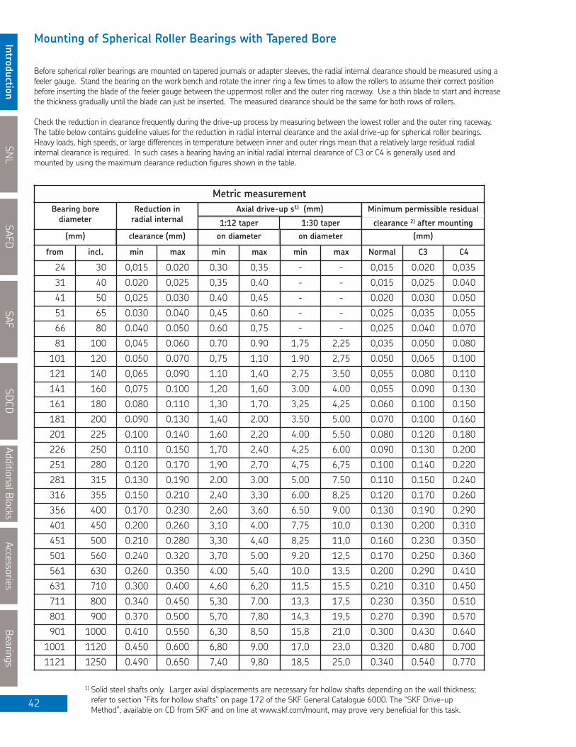
SNL
IntroductionSAFD
SAFSDCD
Additional BlocksAccessories
Bearings
42
Mounting of Spherical Roller Bearings with Tapered Bore
Before spherical roller bearings are mounted on tapered journals or adapter sleeves, the radial internal clearance should be measured using a feeler gauge. Stand the bearing on the work bench and rotate the inner ring a few times to allow the rollers to assume their correct position before inserting the blade of the feeler gauge between the uppermost roller and the outer ring raceway. Use a thin blade to start and increase the thickness gradually until the blade can just be inserted. The measured clearance should be the same for both rows of rollers.
Check the reduction in clearance frequently during the drive-up process by measuring between the lowest roller and the outer ring raceway. The table below contains guideline values for the reduction in radial internal clearance and the axial drive-up for spherical roller bearings. Heavy loads, high speeds, or large differences in temperature between inner and outer rings mean that a relatively large residual radial internal clearance is required. In such cases a bearing having an initial radial internal clearance of C3 or C4 is generally used and mounted by using the maximum clearance reduction figures shown in the table.
from incl. min max min max min max Normal C3 C4
24 30 0,015 0.020 0.30 0,35 - - 0,015 0.020 0,035
31 40 0.020 0,025 0,35 0.40 - - 0,015 0,025 0.040
41 50 0,025 0.030 0.40 0,45 - - 0.020 0.030 0.050
51 65 0.030 0.040 0,45 0.60 - - 0,025 0,035 0,055
66 80 0.040 0.050 0.60 0,75 - - 0,025 0.040 0.070
81 100 0,045 0.060 0.70 0.90 1,75 2,25 0,035 0.050 0.080
101 120 0.050 0.070 0,75 1,10 1.90 2,75 0.050 0,065 0.100
121 140 0,065 0.090 1.10 1,40 2,75 3.50 0,055 0.080 0.110
141 160 0,075 0.100 1,20 1,60 3.00 4.00 0,055 0.090 0.130
161 180 0.080 0.110 1,30 1,70 3,25 4,25 0.060 0.100 0.150
181 200 0.090 0.130 1,40 2.00 3.50 5.00 0.070 0.100 0.160
201 225 0.100 0.140 1,60 2,20 4.00 5.50 0.080 0.120 0.180
226 250 0.110 0.150 1,70 2,40 4,25 6.00 0.090 0.130 0.200
251 280 0.120 0.170 1,90 2,70 4,75 6,75 0.100 0.140 0.220
281 315 0.130 0.190 2.00 3.00 5.00 7.50 0.110 0.150 0.240
316 355 0.150 0.210 2,40 3,30 6.00 8,25 0.120 0.170 0.260
356 400 0.170 0.230 2,60 3,60 6.50 9.00 0.130 0.190 0.290
401 450 0.200 0.260 3,10 4.00 7,75 10,0 0.130 0.200 0.310
451 500 0.210 0.280 3,30 4,40 8,25 11,0 0.160 0.230 0.350
501 560 0.240 0.320 3,70 5.00 9.20 12,5 0.170 0.250 0.360
561 630 0.260 0.350 4.00 5,40 10.0 13,5 0.200 0.290 0.410
631 710 0.300 0.400 4,60 6,20 11,5 15,5 0.210 0.310 0.450
711 800 0.340 0.450 5,30 7.00 13,3 17,5 0.230 0.350 0.510
801 900 0.370 0.500 5,70 7,80 14,3 19,5 0.270 0.390 0.570
901 1000 0.410 0.550 6,30 8,50 15,8 21,0 0.300 0.430 0.640
1001 1120 0.450 0.600 6,80 9.00 17,0 23,0 0.320 0.480 0.700
1121 1250 0.490 0.650 7,40 9,80 18,5 25,0 0.340 0.540 0.770
Bearing borediameter
Reduction inradial internal 1:12 taper
Axial drive-up s1) (mm)
1:30 taper clearance 2) after mounting
Minimum permissible residual
(mm) clearance (mm) on diameter on diameter (mm)
1) Solid steel shafts only. Larger axial displacements are necessary for hollow shafts depending on the wall thickness;refer to section "Fits for hollow shafts" on page 172 of the SKF General Catalogue 6000. The "SKF Drive-upMethod", available on CD from SKF and on line at www.skf.com/mount, may prove very beneficial for this task.
Metric measurement
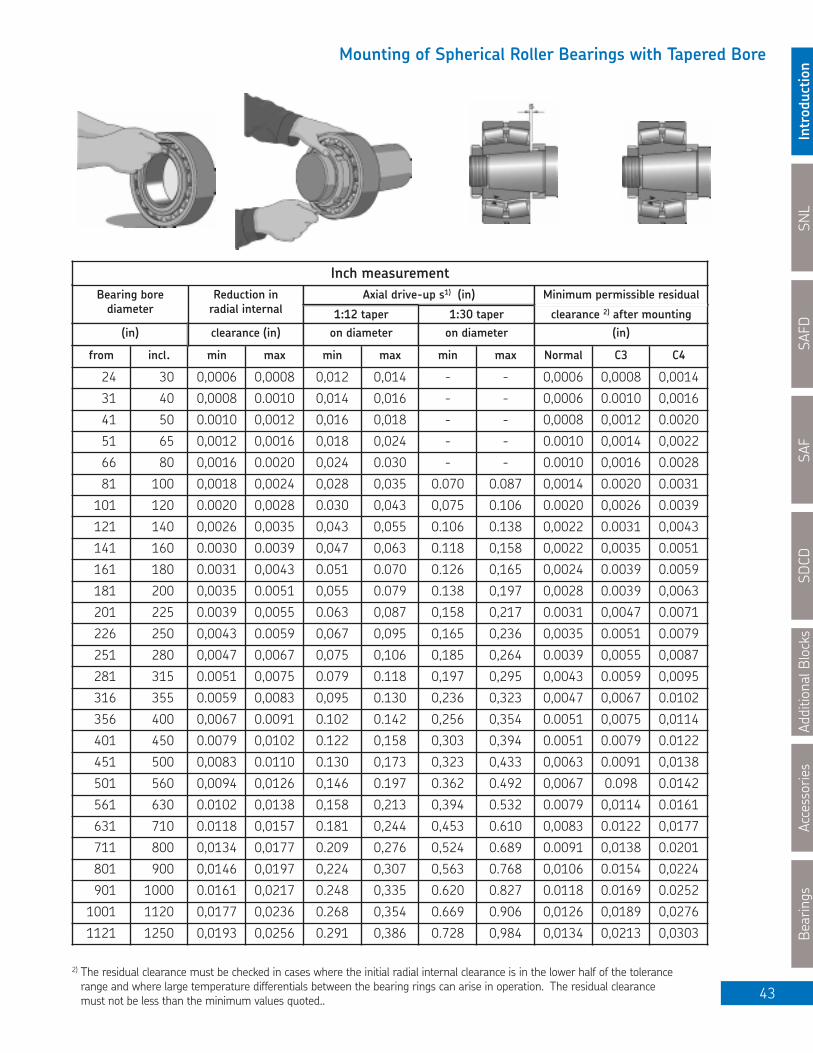
SNL
Introductio
nSAFD
SAF
SDCD
Additional Blocks
Accessories
Bearings
43
Mounting of Spherical Roller Bearings with Tapered Bore
from incl. min max min max min max Normal C3 C4
24 30 0,0006 0,0008 0,012 0,014 - - 0,0006 0,0008 0,0014
31 40 0,0008 0.0010 0,014 0,016 - - 0,0006 0.0010 0,0016
41 50 0.0010 0,0012 0,016 0,018 - - 0,0008 0,0012 0.0020
51 65 0,0012 0,0016 0,018 0,024 - - 0.0010 0,0014 0,0022
66 80 0,0016 0.0020 0,024 0.030 - - 0.0010 0,0016 0.0028
81 100 0,0018 0,0024 0,028 0,035 0.070 0.087 0,0014 0.0020 0.0031
101 120 0.0020 0,0028 0.030 0,043 0,075 0.106 0.0020 0,0026 0.0039
121 140 0,0026 0,0035 0,043 0,055 0.106 0.138 0,0022 0.0031 0,0043
141 160 0.0030 0.0039 0,047 0,063 0.118 0,158 0,0022 0,0035 0.0051
161 180 0.0031 0,0043 0.051 0.070 0.126 0,165 0,0024 0.0039 0.0059
181 200 0,0035 0.0051 0,055 0.079 0.138 0,197 0,0028 0.0039 0,0063
201 225 0.0039 0,0055 0.063 0,087 0,158 0,217 0.0031 0,0047 0.0071
226 250 0,0043 0.0059 0,067 0,095 0,165 0,236 0,0035 0.0051 0.0079
251 280 0,0047 0,0067 0,075 0,106 0,185 0,264 0.0039 0,0055 0,0087
281 315 0.0051 0,0075 0.079 0.118 0,197 0,295 0,0043 0.0059 0,0095
316 355 0.0059 0,0083 0,095 0.130 0,236 0,323 0,0047 0,0067 0.0102
356 400 0,0067 0.0091 0.102 0.142 0,256 0,354 0.0051 0,0075 0,0114
401 450 0.0079 0,0102 0.122 0,158 0,303 0,394 0.0051 0.0079 0.0122
451 500 0,0083 0.0110 0.130 0,173 0,323 0,433 0,0063 0.0091 0,0138
501 560 0,0094 0,0126 0,146 0.197 0.362 0.492 0,0067 0.098 0.0142
561 630 0.0102 0,0138 0,158 0,213 0,394 0.532 0.0079 0,0114 0.0161
631 710 0.0118 0,0157 0.181 0,244 0,453 0.610 0,0083 0.0122 0,0177
711 800 0,0134 0,0177 0.209 0,276 0,524 0.689 0.0091 0,0138 0.0201
801 900 0,0146 0,0197 0,224 0,307 0,563 0.768 0,0106 0.0154 0,0224
901 1000 0.0161 0,0217 0.248 0,335 0.620 0.827 0.0118 0.0169 0.0252
1001 1120 0,0177 0,0236 0.268 0,354 0.669 0.906 0,0126 0,0189 0,0276
1121 1250 0,0193 0,0256 0.291 0,386 0.728 0,984 0,0134 0,0213 0,0303
Bearing borediameter
Reduction inradial internal 1:12 taper
Axial drive-up s1) (in)
1:30 taper clearance 2) after mounting
Minimum permissible residual
(in) clearance (in) on diameter on diameter (in)
2) The residual clearance must be checked in cases where the initial radial internal clearance is in the lower half of the tolerancerange and where large temperature differentials between the bearing rings can arise in operation. The residual clearance must not be less than the minimum values quoted..
Inch measurement

SNL
IntroductionSAFD
SAFSDCD
Additional BlocksAccessories
Bearings
44
Split Pillow Block Housing Safe Loads
The selection of a rolling bearing pillow block depends not only on determining adequate service life of the bearing for the operating conditions of the application but also on the adequacy of the housing to safely accommodate the magnitude and characteristics of all applied loads.
Split pillow blocks are designed for predominantly vertical loads directly through the base. If the load direction is not perpendicular to the base, care should be taken to see that the selected housings have sufficient strength and an adequate factor of safety against fracture when properlyassembled to carry the loads involved.
Proper assembly techniques dictate that the housing cap and base bolts be torqued to achieve preload during installation to avoid elastic separation of the mating parts under load and to resist gradual loosening over time. To obtain full fatigue resistance of the bolts, care in following the recommended torque requirements is of particular importance when the assembly is subjected to the action of cyclic loading and dynamic imbalance.
The tabulations on the following pages show the approximate safe loads for different directions of load. These guideline limits have been established using accepted engineering practices with consideration given to safety, ultimate tensile strength of the materials used and workingstresses to reflect a safety factor of 5 against fracture.
For purely axial force under static or dynamic conditions, the permissible load is approximately 65% of the P180 value shown in the tables. When applied axial loads are of any substantial magnitude, it is preferable to support the base against a shoulder rather than relying solely on the base bolt tightening to prevent slippage between the base and the mounting surface.
The axial load rating for adapter sleeve mounted pillow blocks depends also on the shaft/ adapter sleeve fitting. If spherical roller, CARB or self-aligning ball bearings with adapter sleeves are mounted on smooth shafts with no fixed abutment, the friction between the shaft and adapter sleeve determines the magnitude of the axial load that can be supported. Provided the bearings are correctly mounted, the permissible axial load can be calculated from:
F ap = 3 B d
whereF ap = maximum permissible axial load, NB = bearing width, mmd = bearing bore diameter, mm
When an application is subjected to dynamic unbalance loading or shock, SKF Engineering should be contacted.

SNL
Introductio
nSAFD
SAF
SDCD
Additional Blocks
Accessories
Bearings
45
Pillow Block Housing Safe LoadsSeries: SNL 200-300, SNL 500-600
Size P 55° P 90° P 120° P 150° P 180° P 55° P 90° P 120° P 150° P 180° Cap Bolt
505, 205 25800 15800 11700 10000 13300 - - - - - M10
506-605, 206-305 28300 16700 13300 10800 14200 - - - - - M10
507-606, 207 31700 19200 14200 13300 15800 - - - - - M10
508-607, 208-307 35800 21700 15800 14200 18300 63300 38300 28300 25000 33300 M10
509, 209 38300 23000 16600 15000 19200 68300 41700 30000 26700 35000 M10
510-608, 210 44200 25800 20000 18300 21600 78300 46600 35800 33300 38500 M12
511-609, 211 45800 28300 20800 19200 23300 81700 50000 37500 35000 41700 M12
512-610, 212 50000 30000 21700 20000 25000 90000 53300 38300 35800 45000 M12
513-611, 213 56700 34200 25000 21700 28300 101700 61700 41700 38300 50000 M12
515-612, 215 68300 41700 30800 26700 34200 123300 75000 55000 48300 61700 M12
516-613, 216 71700 43300 31700 29200 35800 128300 78300 56700 51700 65000 M12
517, 217 80000 48300 34200 31700 40000 143300 86700 61700 56700 71700 M12
518-615, 218 91700 56700 41700 35800 45800 165000 101700 75000 61700 81700 M16
519-616 96700 58300 43300 38300 48300 175000 105000 78300 68300 86700 M16
520-617 103300 61700 46700 41700 51700 183300 111700 83300 75000 93300 M20
522-619 113300 68300 51700 45800 56700 200000 123300 93300 81700 101700 M20
524-620 131600 78300 58300 53300 66700 233300 141700 105000 95000 120000 M20
526 150000 90000 68300 60000 75000 250000 146700 110000 98300 123300 M24
528 175000 105000 78500 71700 88300 283300 166700 128300 116700 143300 M24
530 200000 121700 93300 80000 100000 333300 200000 148300 131700 165000 M24
532 241700 143300 106700 95000 120000 391700 233300 166700 151700 191700 M24
Recommended Safe Load (N)
NOTE: For torque values refer to page 39.
SNL/FSNL SSNLD

SNL
IntroductionSAFD
SAFSDCD
Additional BlocksAccessories
Bearings
46
Pillow Block Housing Safe LoadsSeries: SAFD 200, SAFD 500
Size P 90° P 120° P 150° P 180° P 90° P 120° P 150° P 180° Cap Bolt
509, 209 32500 19600 18000 21200 - - - - 7⁄16 - 14
510, 210 40000 26000 23600 28500 - - - - 7⁄16 - 14
511, 211 44000 27500 25000 30500 - - - - 1⁄2 - 13
513, 213 44000 26000 23200 27500 - - - - 1⁄2 - 13
515, 215 61000 36500 33500 40000 45500 28500 25500 31000 1⁄2 - 13
516, 216 83000 51000 45000 53000 83000 50000 45000 53000 5⁄8 - 11
517, 217 47500 29000 26500 32000 50000 31500 28500 34000 5⁄8 - 11
518, 218 85000 54000 48000 60000 95000 61000 55000 65500 5⁄8 - 11
520, 220 85000 53000 48000 58500 106000 65500 60000 71000 5⁄8 - 11
522, 222 108000 67000 61000 72000 - - - - 5⁄8 - 11
524, 224 150000 95000 88000 108000 - - - - 5⁄8 - 11
526, 226 186000 125000 118000 153000 - - - - 3⁄4 - 10
528, 228 183000 116000 106000 127000 - - - - 7⁄8 - 9
530, 230 236000 150000 134000 166000 - - - - 7⁄8 - 9
532, 232 208000 132000 120000 146000 - - - - 7⁄8 - 9
534, 234 208000 127000 114000 132000 - - - - 7⁄8 - 9
536, 236 320000 196000 176000 204000 - - - - 7⁄8 - 9
538, 238 250000 153000 134000 250000 - - - - 1 - 8
540, 240 335000 208000 186000 224000 - - - - 1 - 8
544, 244 415000 260000 236000 285000 - - - - 1 - 8
SAFD FSAFD
Recommended Safe Load (N)
NOTE: For torque values refer to page 39.

SNL
Introductio
nSAFD
SAF
SDCD
Additional Blocks
Accessories
Bearings
47
Pillow Block Housing Safe LoadsSeries: (F)SAF 200, (F)SAF 500, (F)SAF 0
Size P 90° P 120° P 150° P 180° P 90° P 120° P 150° P 180° Cap Bolt
509 12700 7650 6800 8150 - - - - 7⁄16 - 14
510 17600 11200 10200 12500 - - - - 7⁄16 - 14
511 27133 17347 15790 19126 - - - - 1⁄2 - 13
513 30500 18000 16300 19000 - - - - 1⁄2 - 13
515 45500 28000 25500 30500 32500 20400 18600 22400 1⁄2 - 13
516, 216 50000 30500 26500 31500 36500 22000 19600 23200 5⁄8 - 11
517, 217 51000 31500 28500 34500 37000 23200 21200 25500 5⁄8 - 11
518, 218 22502 38500 34694 49817 60938 38475 34694 42246 5⁄8 - 11
520, 220, 024 81398 50707 46259 55600 71168 44480 40032 48928 3⁄4 - 10
522, 222, 026 88960 55600 50707 60937 - - - - 3⁄4 - 10
524, 224, 028 111200 72502 66720 81398 - - - - 1 - 8
526, 226, 030, 032 113424 73837 68054 84512 - - - - 1 - 8
528, 228, 034 149008 94297 85846 103194 - - - - 1 - 8
530, 230 137000 88000 80000 96500 - - - - 3⁄4 - 10
532, 232, 036, 038 135664 85846 78285 94298 - - - - 3⁄4 - 10
534, 234, 040 140112 85846 76950 92518 - - - - 3⁄4 - 10
536, 236 140112 85846 75616 88960 - - - - 3⁄4 - 10
538, 238, 044 193472 106752 94298 113424 - - - - 7⁄8 - 9
540, 240, 048 217952 135664 120096 144560 - - - - 7⁄8 - 9
544, 244, 052 253536 160128 144560 173472 - - - - 1 - 8
056 271328 169024 151232 184592 - - - - 11⁄2 - 6
SAF FSAF
Recommended Safe Load (N)
NOTE: For torque values refer to page 39.

SNL
IntroductionSAFD
SAFSDCD
Additional BlocksAccessories
Bearings
48
Pillow Block Housing Safe LoadsSeries: (F)SAF 300, (F)SAF 600
Size P 90° P 120° P 150° P 180° P 90° P 120° P 150° P 180° Cap Bolt
308 19600 12500 .11400 14000 - - - - 1⁄2 - 13
609, 309 21200 13200 12200 15000 - - - - 1⁄2 - 13
610, 310 23600 14456 12900 16000 - - - - 1⁄2 - 13
611, 311 26000 16235 15000 17792 21350 13344 12200 14456 1⁄2 - 13
312 29801 18459 16680 20238 25354 15790 14000 16902 1⁄2 - 13
613, 313 49818 30246 26688 31581 36250 21800 19570 23130 5⁄8 - 11
314 55600 34694 30914 37808 55600 34700 30900 37800 5⁄8 - 11
615, 315 72502 45370 40700 49818 60938 38475 34694 42256 5⁄8 - 11
616, 316 51597 32025 29134 34694 55600 34027 30914 36918 3⁄4 - 10
617, 317 56490 35584 32026 38475 62272 39142 35584 42923 3⁄4 - 10
618, 318 76950 48928 44480 54266 - - - - 3⁄4 - 10
620, 320 111200 72502 66720 81398 - - - - 1 - 8
622, 322 113424 73837 68054 84512 - - - - 1 - 8
624, 324 137880 87180 80064 96077 - - - - 3⁄4 - 10
626, 326 135664 85846 78285 94298 - - - - 3⁄4 - 10
628, 328 140112 85846 76950 92518 - - - - 3⁄4 - 10
630, 330 140112 84512 75616 88960 - - - - 3⁄4 - 10
632, 332 173472 106752 94298 113424 - - - - 7⁄8 - 9
634, 334 217952 135664 120096 144560 - - - - 7⁄8 - 9
638, 338 253536 160128 151232 184592 - - - - 1 - 8
SAF FSAF
Recommended Safe Load (N)
NOTE: For torque values refer to page 39.

SNL
Introductio
nSAFD
SAF
SDCD
Additional Blocks
Accessories
Bearings
49
Pillow Block Housing Safe LoadsSeries: SAFS 200, SAFS 500, SAFS 0, SAFS 200-11, SAFS 500-11, SAFS 0-11
Size P 90° P 120° P 150° P 180° P 90° P 120° P 150° P 180° Cap Bolt
515 59603 36918 33360 40032 45370 28467 25353 30914 1⁄2 - 13
516, 216 82733 49818 44480 52486 82733 49818 44818 52486 5⁄8 - 11
517, 217 47149 29134 26688 32026 49818 31581 28467 34027 5⁄8 - 11
518, 218 84512 53376 48038 58714 94297 59603 54265 64941 1⁄2 - 13
520, 220, 024 84512 52486 48038 57379 104973 64941 58713 71168 5⁄8 - 11
522, 222, 026 106752 66720 59603 72502 - - - - 5⁄8 - 11
524, 224, 028 149008 94298 87181 106752 - - - - 5⁄8 - 11
526, 226, 030, 032 184592 124544 117872 151232 - - - - 3⁄4 - 10
528, 228, 034 180144 115648 104973 126768 - - - - 7⁄8 - 9
530, 230 235744 149008 135664 162352 - - - - 7⁄8 - 9
532, 232, 036, 038 206832 133440 120096 144560 - - - - 7⁄8 - 9
534, 234, 040 206832 126768 113424 133440 - - - - 1 - 8
536, 236 320256 195712 173472 202384 - - - - 13⁄8 - 6
538, 238, 044 249088 151232 135664 160128 - - - - 11⁄8 - 7
540, 240, 048 333600 206832 184592 222400 - - - - 11⁄4 - 7
544, 244, 052 413664 260208 235744 284672 - - - - 13⁄8 - 6
SAFS SAFS-11
Recommended Safe Load (N)
NOTE: For torque values refer to page 39.

SNL
IntroductionSAFD
SAFSDCD
Additional BlocksAccessories
Bearings
50
Pillow Block Housing Safe LoadsSeries: SDCD 30, SDCD 30/MC14, SDCD 0, SDCD 0/MC14, SDCD 31, SDCD 31/MC14,SDCD 1, SDCD 1/MC14, SDCD 32, SDCD 32/MC14, SDCD 2, SDCD 2/MC14
P 55° P 90° P 120° P 150° P 180° Pa Cap Bolt3000
Cap Bolt3100
Cap Bolt3200
(3)034, (3)134, (3)234 630000 300000 228000 204000 255000 165000 7⁄8 - 9 7⁄8 - 9 1 - 8
(3)036, (3)136, (3)236 720000 345000 255000 228000 285000 186000 7⁄8 - 9 7⁄8 - 9 1 - 8
(3)038, (3)138, (3)238 810000 390000 300000 264000 330000 213000 7⁄8 - 9 1 - 8 1 - 8
(3)040, (3)140, (3)240 960000 480000 330000 300000 390000 252000 1 - 8 1 - 8 11⁄4 - 7
(3)044, (3)144, (3)244 1200000 570000 420000 390000 480000 300000 1 - 8 1 - 8 11⁄4 - 7
(3)048, (3)148, (3)248 1260000 600000 450000 420000 510000 330000 1 - 8 11⁄4 - 7 11⁄4 - 7
(3)052, (3)152, (3)252 1410000 690000 510000 450000 570000 360000 11⁄4 - 7 11⁄4 - 7 11⁄4 - 7
(3)056, (3)156, (3)256 1500000 720000 540000 480000 600000 390000 11⁄4 - 7 11⁄4 - 7 11⁄4 - 7
(3)060, (3)160, (3)260 1800000 870000 660000 570000 720000 450000 11⁄4 - 7 11⁄4 - 7 11⁄4 - 7
(3)064, (3)164, (3)264 2106000 1021000 750000 660000 840000 540000 11⁄4 - 7 11⁄4 - 7 11⁄2 - 6
(3)068, (3)168, (3)268 2646000 1260000 961000 840000 1051000 1051000 11⁄4 - 7 11⁄2 - 6 13⁄4 - 5
(3)072, (3)172, (3)272 2761000 1321000 990000 900000 1111000 1111000 11⁄4 - 7 11⁄2 - 6 13⁄4 - 5
(3)076, (3)176, (3)276 2761000 1321000 990000 900000 1111000 1111000 11⁄4 - 7 13⁄4 - 5 13⁄4 - 5
(3)080, (3)180, (3)280 3060000 1400000 1111000 990000 1231000 1231000 11⁄2 - 6 13⁄4 - 5 13⁄4 - 5
(3)084, (3)184 3456000 1650000 1260000 1111000 1381000 1381000 13⁄4 - 5 13⁄4 - 5 -
(3)088, (3)188 3834000 1836000 1381000 1231000 1530000 1530000 13⁄4 - 5 13⁄4 - 5 -
Recommended Safe Load (N)SDCDSize
NOTE: For torque values refer to page 39.
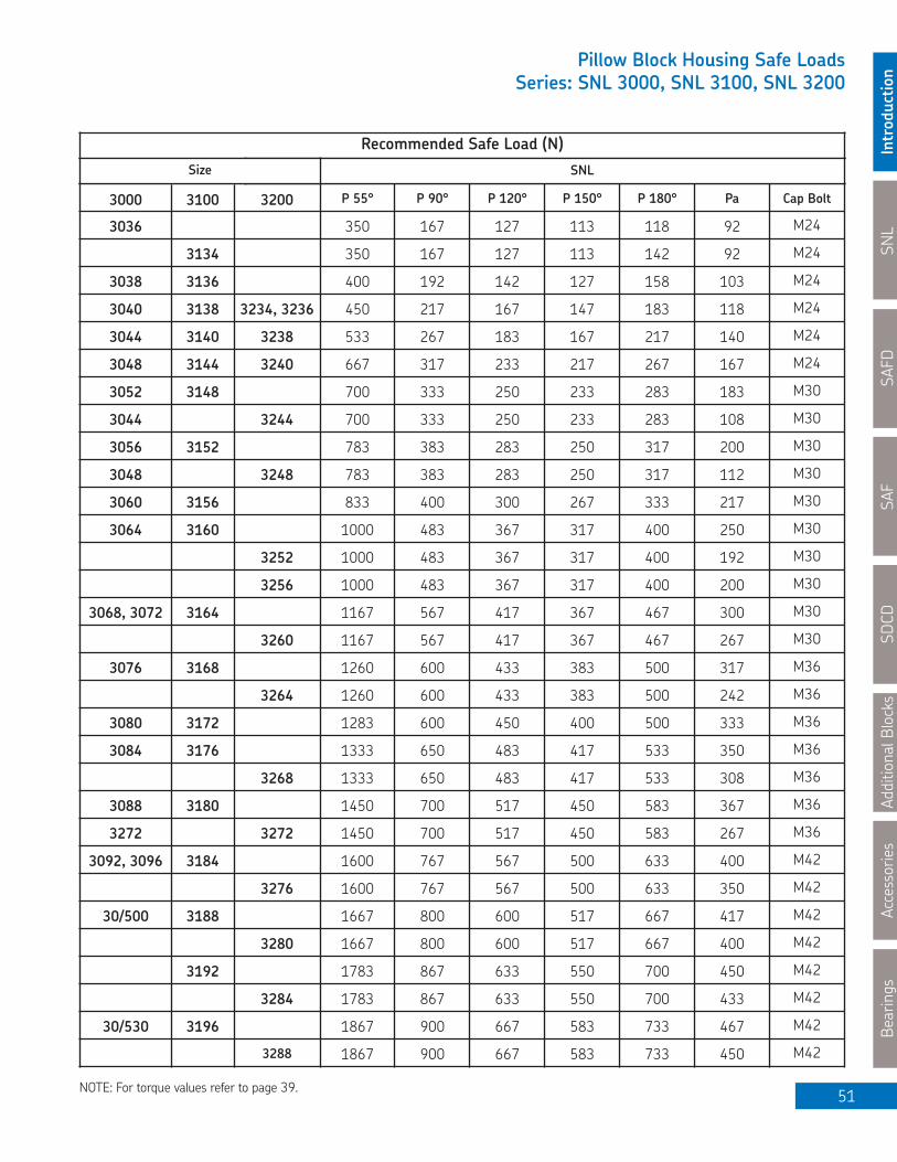
SNL
Introductio
nSAFD
SAF
SDCD
Additional Blocks
Accessories
Bearings
51
Pillow Block Housing Safe LoadsSeries: SNL 3000, SNL 3100, SNL 3200
3000 3100 3200 P 55° P 90° P 120° P 150° P 180° Pa Cap Bolt
3036 350 167 127 113 118 92 M24
3134 350 167 127 113 142 92 M24
3038 3136 400 192 142 127 158 103 M24
3040 3138 3234, 3236 450 217 167 147 183 118 M24
3044 3140 3238 533 267 183 167 217 140 M24
3048 3144 3240 667 317 233 217 267 167 M24
3052 3148 700 333 250 233 283 183 M30
3044 3244 700 333 250 233 283 108 M30
3056 3152 783 383 283 250 317 200 M30
3048 3248 783 383 283 250 317 112 M30
3060 3156 833 400 300 267 333 217 M30
3064 3160 1000 483 367 317 400 250 M30
3252 1000 483 367 317 400 192 M30
3256 1000 483 367 317 400 200 M30
3068, 3072 3164 1167 567 417 367 467 300 M30
3260 1167 567 417 367 467 267 M30
3076 3168 1260 600 433 383 500 317 M36
3264 1260 600 433 383 500 242 M36
3080 3172 1283 600 450 400 500 333 M36
3084 3176 1333 650 483 417 533 350 M36
3268 1333 650 483 417 533 308 M36
3088 3180 1450 700 517 450 583 367 M36
3272 3272 1450 700 517 450 583 267 M36
3092, 3096 3184 1600 767 567 500 633 400 M42
3276 1600 767 567 500 633 350 M42
30/500 3188 1667 800 600 517 667 417 M42
3280 1667 800 600 517 667 400 M42
3192 1783 867 633 550 700 450 M42
3284 1783 867 633 550 700 433 M42
30/530 3196 1867 900 667 583 733 467 M42
3288 1867 900 667 583 733 450 M42
Recommended Safe Load (N)SNLSize
NOTE: For torque values refer to page 39.

SNL
IntroductionSAFD
SAFSDCD
Additional BlocksAccessories
Bearings
52
Shaft Length from Centre Line of Bearing to End of Shaft for Pillow Block Closed on One SideRecommended shaft length from centre line of the bearingwhen one end of the pillow block housing is closed on the locknut side for shaft mounted cylindrical bore, or adapter sleeve mounted bearings.
mm. in. mm. in.
1205 E 18,5 23⁄32 2209 E 22209 E 25,5 11206 E 19 3⁄4 2210 E 22210 E 26,5 1 1⁄161207 E 20,5 13⁄16 2211 E 22211 E 27,5 1 3⁄321208 E 22 7⁄8 2212 E 22212 E 30 1 3⁄161209 E 23,5 15⁄16 2213 E 22213 E 32,5 1 9⁄321210 E 25 1 2215 E 22215 E 34,5 1 3⁄81211 E 25,5 1 2216 E 22216 E 36,5 1 7⁄161212 E 27 1 1⁄16 2217 22217 E 39 1 17⁄321213 E 28,5 1 1⁄8 2218 22218 E 43 1 11⁄161215 30,5 1 7⁄32 2219 22219 E 47 1 7⁄81216 33 1 5⁄16 2220 22220 E 51 21217 35 1 3⁄8 2222 22222 E 52,5 2 1⁄161218 38 1 1⁄2 22224 E 56 2 7⁄321219 40 1 19⁄32 22226 E 60 2 3⁄81220 42 1 21⁄32 22228 CC 63 2 1⁄21222 45 1 3⁄4 22230 CC 69 2 23⁄32
22232 CC 74,5 2 15⁄161305 E 21305 CC 19,5 3⁄4 22234 CC 78,5 3 3⁄321306 E 21306 CC 20,5 13⁄16 22236 CC 79,5 3 1⁄81307 E 21307 CC 23,5 15⁄16 22238 CC 83,5 3 9⁄321308 E 21308 EW 24,5 31⁄32 22240 CC 87,5 3 7⁄161309 E 21309 E 26,5 1 1⁄16 22244 CC 97 3 13⁄161310 E 21310 E 28,5 1 1⁄8 2305 23 29⁄321311 E 21311 E 29,5 1 5⁄32 2306 24,5 31⁄321312 E 21312 E 31,5 1 1⁄4 2307 E 27,5 1 3⁄321313 E 21313 E 33,5 1 5⁄16 2308 E 22308 E 29,5 1 5⁄321315 21315 E 36,5 1 7⁄16 2309 E 22309 E 32 1 1⁄41316 21316 E 39,5 1 9⁄16 2310 22310 E 35 1 3⁄81317 21317 E 41,5 1 5⁄8 2311 22311 E 36,5 1 7⁄161318 21318 E 42,5 1 11⁄16 2312 22312 E 39 1 17⁄321320 21320 E 48,5 1 29⁄32 2313 22313 E 41 1 5⁄81322 51 2 22314 E 42,5 1 11⁄16
2315 22315 E 45,5 1 13⁄162205 E 22205 E 20 25⁄32 2316 22316 E 49 1 15⁄162206 E 22206 E 21 13⁄16 2317 22317 E 51 22207 E 22207 E 24,5 31⁄32 22318 E 55 2 5⁄322208 E 22208 E 24,5 31⁄32 22319 E 57,5 2 1⁄4
Recommended ShaftLength "S"
Recommended ShaftLength "S"
Basic BearingNumber
Basic BearingNumber
S

SNL
Introductio
nSAFD
SAF
SDCD
Additional Blocks
Accessories
Bearings
53
Shaft Length from Centre Line of Bearing to End of Shaft for Pillow Block Closed on One Side
Recommended shaft length from centre line of the bearing when one end of the pillow block housing is closed
on the locknut side for shaft mounted cylindrical bore,or adapter sleeve mounted bearings.
mm. in. mm. in.
22320 E 61.5 2 7⁄16 23140 CC 94.5 3 23⁄3222322 E 66 2 19⁄32 23144 CC 103 4 1⁄1622324 CC 70 2 3⁄4 23148 CC 109 4 9⁄3222326 CC 74.5 2 15⁄16 23152 CC 124 4 7⁄822328 CC 80 3 5⁄32 23156 CC 127 522330 CC 86.5 3 13⁄32 23160 CC 128 5 1⁄1622332 CC 91.5 3 19⁄32 23164 CC 138 5 7⁄1622334 CC 95.5 3 3⁄4 23168 CC 158 6 7⁄3222336 CC 99.5 3 29⁄32 23172 CC 164 6 15⁄3222338 CC 103,5 4 1⁄16 23176 CA 165 6 1⁄222340 CC 107,5 4 7⁄32 23180 CA 170 6 11⁄16
23184 CJ 190 7 1⁄223024 CC 50 1 31⁄32 23188 CA 191 7 17⁄3223026 CC 54 2 1⁄823028 CC 55.5 2 3⁄16 23218 CC 49.5 1 15⁄1623030 CC 60.5 2 3⁄8 23220 CC 55.5 2 3⁄1623032 CC 64 2 1⁄2 23222 CC 61 2 15⁄3223034 CC 68.5 2 11⁄16 23224 CC 65 2 9⁄1623036 CC 73 2 7⁄8 23226 CC 68 2 11⁄1623038 CC 74.5 2 15⁄16 23228 CC 73 2 7⁄823040 CC 79 3 1⁄8 23230 CC 80.5 3 3⁄1623044 CC 83 3 9⁄32 23232 CC 86.5 3 13⁄3223048 CC 88 3 15⁄32 23234 CC 90.5 3 9⁄1623052 CC 94 3 11⁄16 23236 CC 92.5 3 21⁄3223056 CC 99 3 29⁄32 23238 CC 97.5 3 27⁄3223060 CC 109 4 9⁄32 23240 CC 102,5 4 1⁄3223064 CC 110,5 4 11⁄32 23244 CC 115 4 17⁄3223068 CC 119,5 4 23⁄32 23248 CC 125 4 15⁄1623072 CC 120 4 23⁄32 23252 CC 134 5 9⁄3223076 CC 123,5 4 7⁄8 23256 CC 136 5 3⁄823080 CAC 134 5 9⁄32 23260 CC 144 5 11⁄1623084 CA 135 5 5⁄16 23264 CC 154 6 1⁄1623088 CA 157 6 3⁄16 23268 CA 175 6 7⁄823134 CC 79.5 3 5⁄32 23272 CA 182 7 3⁄1623136 CC 84.5 3 11⁄32 23276 CA 188 7 13⁄3223138 CC 89.5 3 17⁄32 23280 CA 198 7 13⁄16
Basic BearingNumber
Recommended ShaftLength "S"
Basic BearingNumber
Recommended ShaftLength "S"
S

SNL
IntroductionSAFD
SAFSDCD
Additional BlocksAccessories
Bearings
54
Axial displacement using CARB® bearings in SNL housings
The permissible axial displacement in a CARB bearing is dependent on the clearance remaining in the bearing after mounting: the larger the residual radial internal clearance, the larger the permissible axial displacement of one ring in relation to the other. This axial displacement reduces the clearance in the bearing until at a given displacement, the clearance disappears altogether or the rollers may start to be exposed at one side of the bearing.
The table opposite shows the maximum permissible axial displacement for each CARB bearing when mounted normally and having initial normal radial internal clearance. It is assumed that there is little difference in temperature between the inner and outer ring.
When the rings are displaced a certain distance, the roller and cage assembly will move through the bearing, or alternately, if the outer ring moves out from the bearing the roller and cage assembly could contact the locknut or locking washer.
For bearings of series C22 K up to and including size 22, KMFE locknuts are utilized. These have an extension on the face of the nut, which has a smaller diameter than the O.D of the inner ring, which prevents contact from occurring. Adapter sleeves with this nut are identified by the suffix E.
The C23 K series uses standard locknuts.
For bearings of series C22 K and C 32 K, for sizes 24 and above, the adapter sleeves are supplied together with a KML locknut and MBL lockwasher, indicated by the suffix L in the adapter sleeve designation. (L = low section height)
On some larger sizes adapter sleeves suffix HTL indicates that a different adapter sleeve is used.
It should be observed that the possible axial displacement of the shaft relative to the housing might be limited by the type of the seal used.
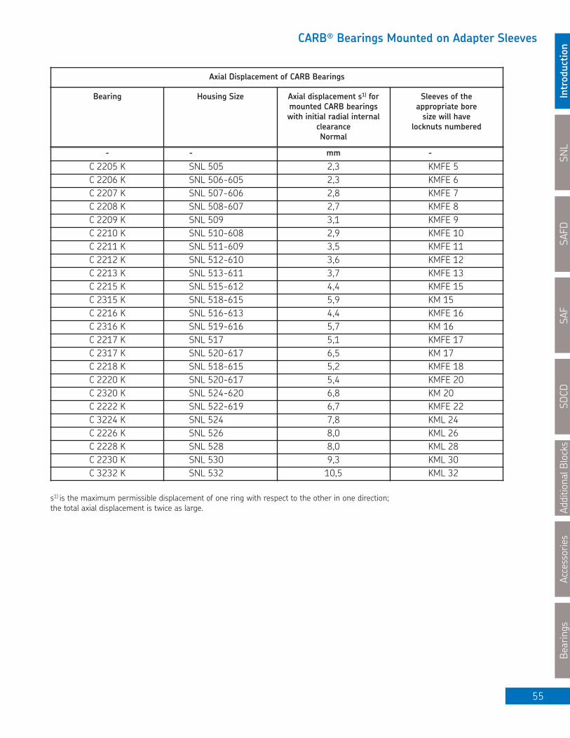
SNL
Introductio
nSAFD
SAF
SDCD
Additional Blocks
Accessories
Bearings
55
CARB® Bearings Mounted on Adapter Sleeves
- - mm -
C 2205 K SNL 505 2,3 KMFE 5C 2206 K SNL 506-605 2,3 KMFE 6C 2207 K SNL 507-606 2,8 KMFE 7C 2208 K SNL 508-607 2,7 KMFE 8C 2209 K SNL 509 3,1 KMFE 9C 2210 K SNL 510-608 2,9 KMFE 10C 2211 K SNL 511-609 3,5 KMFE 11C 2212 K SNL 512-610 3,6 KMFE 12C 2213 K SNL 513-611 3,7 KMFE 13C 2215 K SNL 515-612 4,4 KMFE 15C 2315 K SNL 518-615 5,9 KM 15C 2216 K SNL 516-613 4,4 KMFE 16C 2316 K SNL 519-616 5,7 KM 16C 2217 K SNL 517 5,1 KMFE 17C 2317 K SNL 520-617 6,5 KM 17C 2218 K SNL 518-615 5,2 KMFE 18C 2220 K SNL 520-617 5,4 KMFE 20C 2320 K SNL 524-620 6,8 KM 20C 2222 K SNL 522-619 6,7 KMFE 22C 3224 K SNL 524 7,8 KML 24C 2226 K SNL 526 8,0 KML 26C 2228 K SNL 528 8,0 KML 28C 2230 K SNL 530 9,3 KML 30C 3232 K SNL 532 10,5 KML 32
Bearing Housing Size Axial displacement s1) formounted CARB bearings with initial radial internal
clearance Normal
Sleeves of theappropriate boresize will have
locknuts numbered
Axial Displacement of CARB Bearings
s1) is the maximum permissible displacement of one ring with respect to the other in one direction; the total axial displacement is twice as large.
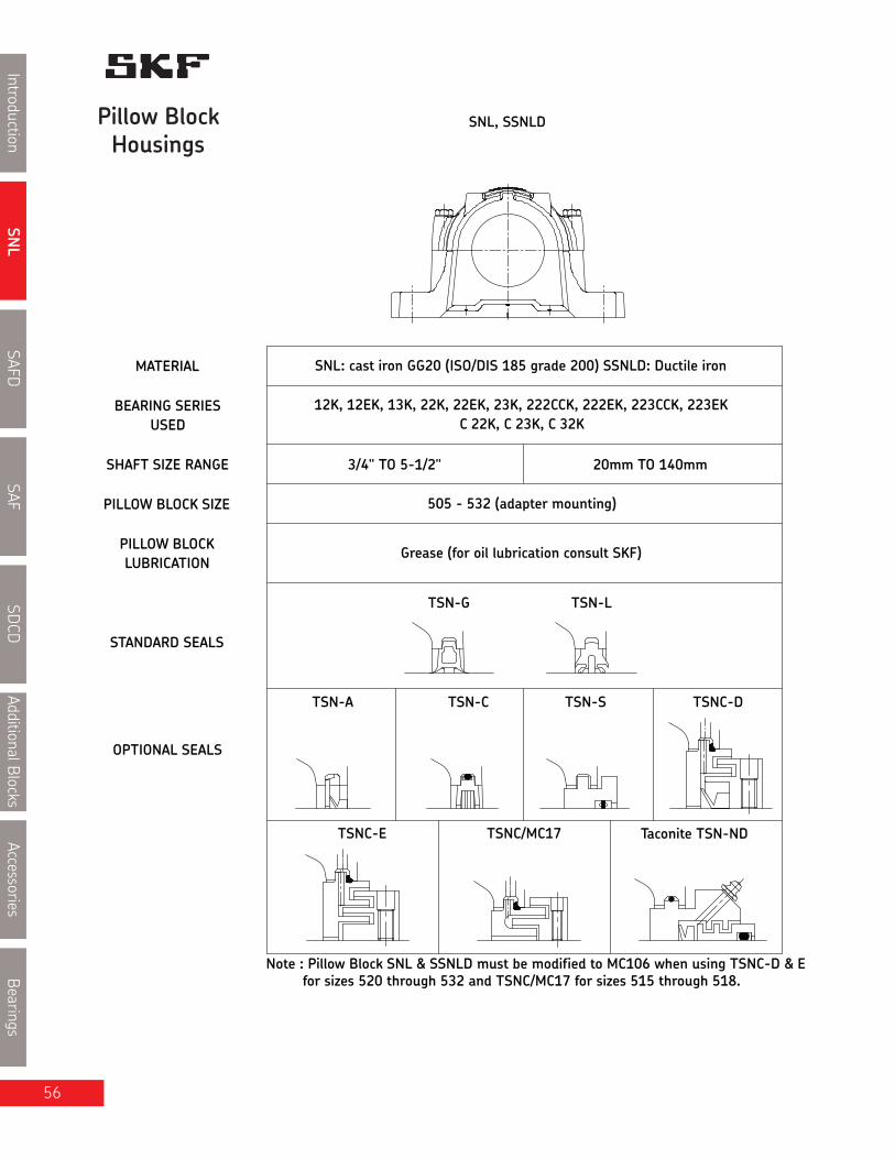
SNL
IntroductionSAFD
SAFSD
CDAdditionalBlocks
AccessoriesBearings
56
Note : Pillow Block SNL & SSNLD must be modified to MC106 when using TSNC-D & Efor sizes 520 through 532 and TSNC/MC17 for sizes 515 through 518.
SNL: cast iron GG20 (ISO/DIS 185 grade 200) SSNLD: Ductile iron
12K, 12EK, 13K, 22K, 22EK, 23K, 222CCK, 222EK, 223CCK, 223EK
MATERIAL
BEARING SERIESUSED
STANDARD SEALS
OPTIONAL SEALS
LUBRICATIONPILLOW BLOCK
SHAFT SIZE RANGE
PILLOW BLOCK SIZE 505 - 532 (adapter mounting)
3/4" TO 5-1/2" 20mm TO 140mm
Grease (for oil lubrication consult SKF)
C 22K, C 23K, C 32K
SNL, SSNLD
TSN-S
TSNC/MC17TSNC-E
TSNC-DTSN-A
TSN-L
TSN-C
Taconite TSN-ND
TSN-G
Pillow BlockHousings

SNL
Introduction
SAFD
SAF
SDCD
AdditionalB
locks
Accessories
Bearings
SNL Split Pillow Blocks Nomenclature Adapter Mount
SNLF 22520/37⁄16 TGA
BaseOFS
Basic Design
MaterialOD
Size
SuffixesDEHK7NMTATCTGTLTNDTSVVUY
Two bolt (standard)Four boltBlank (dimples only)*
Cast ironDuctile iron
Bearing bore: 20 = 100mmShaft size: 37⁄16”
Purgeable labyrinth seal (TSNC-D c/w V ring) (1/pkg)Purgeable labyrinth seal (TSNC-E, without V ring) (1/pkg)Held unit, 2 fixing rings includedTighter housing fit that can be used with CARB bearings for high speeds or vibrationSuffix required on sizes SNL 524-620 to SNL 532 indicating central relubrication hole for W33 bearingsV ring "A" seal (2/pkg)Felt "C" seal (2/pkg)Double lip "G" seal (2/pkg)Double lip "L" seal for metric sizes; Only TSN 507 toTSN 522 are available as of March 2007 (2/pkg)Taconite seal (1/pkg)Standard labyrinth "S" seal (1/pkg)Open grease escape hole in baseTwo grease escape holes diagonally opposed on the side facesOne end closed with end cover or end plug
How to order SNL: (Example)
When you order one SNL 22520-3 7⁄16 TGA you will receive a package containing the following:
1 - Pillow block housing SNL 520-617: Cap drilled, tapped, and one grease fitting AH 1⁄8 - 27 PTF included1 - Bearing SKF 22220 EK1 - Adapter sleeve HA 320, complete with locknut KM20 and lockwasher MB201 - Seal kit TSN 520 GA, containing 2 double lip seals to "G" design
If a "HELD" or "FIXED" unit is required, add the suffix "H" and two FRB 12/180 fixing rings will be included.Only one bearing per shaft should be held. CARB® bearings displace internally and are therefore always "FREE".However they must always be located in the housing with fixing rings, as does a true "FIXED" bearing.If a unit with one end closed is required, add the suffix "Y" and one ASNH 520-617 end cover will be included.
* CAUTION: If replacing a drilled blank base unit with a 4 hole base unit, the holes are NOT in the same position.
57

Shaft Housing Complete Replacement V-ring only Felt Double Lip Labyrinth EndDia. V-ring Current Former Seal seal Seal Coverda seal nr pt. nr. pt. nr. C G or L S
SNL Inch Size Seals + V ringNumbers for Replacement in Vring Seals
The catalogue references G or L*design seals only, if a different sealis desired, the suffixes may change.The following shows the appropriatenumber for the optional seals.SN
LIntroduction
SAFDSAF
SDCD
AdditionalBlocksAccessories
Bearings
58
3⁄4 SNL 505 TSN 505A 400200 V20A TSN 505C TSN 505GE TSN 505SE ASNH505SNL 506-605 TSN 605A 400200 V20A TSN 605C TSN 605GE TSN 605SE ASNH 506-605a a a a a a a a
15⁄16 SNL 506-605 TSN 506A 400250 V25A TSN 506C TSN 506GA TSN 506SA ASNH 506-605SNL 507-606 TSN 606A 400250 V25A TSN 606C TSN 606GA TSN 606SA ASNH 507-606
a a a a a a a a a
1 SNL 506-605 TSN 506A 400250 V25A TSN 506C TSN 506L TSN 506SE ASNH 506-605SNL 507-606 TSN 606A 400250 V25A TSN 506C TSN 606GA TSN 606SE ASNH 507-606
a a a a a a a a a
1 3⁄16 SNL 507-606 TSN 507A 400300 V30A TSN 507C TSN 507L TSN 507SA ASNH 507-606. SNL 508-607 TSN 607A 400300 V30A TSN 607C TSN 607G TSN 607SA ASNH 508-607a a a a a a a a a
1 1⁄4 SNL 508-607 TSN 508AE 400320 V32A TSN 508CE TSN 508GE TSN 508SE ASNH 508-607. SNL 510-608 TSN 608AE 400320 V32A TSN 608CE TSN 608GE TSN 608SE ASNH 510-608a a a a a a a a a
1 7⁄16 SNL 509 TSN 509AE 400380 V38A TSN 509CE TSN 509GA TSN 509SA ASNH 509. SNL 511-609 TSN 609AE 400380 V38A TSN 609CE TSN 609GA TSN 609SA ASNH 511-609a a a a a a a a a
.1 1⁄2 SNL 509 TSN 509AE 400380 V38A TSN 509CE TSN 509GE TSN 509SE ASNH 509
. SNL 511-609 TSN 609AE 400380 V38A TSN 609CE TSN 609GE TSN 609SE ASNH 511-609a a a a a a a a a
.1 11⁄16 SNL 510-608 TSN 510A 400450 V45A TSN 510C TSN 510GA TSN 510SA ASNH 510-608
. SNL 512-610 TSN 610A 400450 V45A TSN 610C TSN 610GA TSN 610SA ASNH 512-610a a a a a a a a a
.1 3⁄4 SNL 510-608 TSN 510A 400450 V45A TSN 510C TSN 510L TSN 510SE ASNH 510-608
. SNL 512-610 TSN 610A 400450 V45A TSN 610C TSN 610G TSN 610SE ASNH 512-610a a a a a a a a a
.1 15⁄16 SNL 511-609 TSN 511A 400500 V50A TSN 511C TSN 511L TSN 511SA ASNH 511-609
. SNL 513-611 TSN 611A 400500 V50A TSN 611C TSN 611G TSN 611GA ASNH 513-611a a a a a a a a a
.2 SNL 511-609 TSN 511A 400500 V50A TSN 511C TSN 511L TSN 511SE ASNH 511-609
. SNL 513-611 TSN 611A 400500 V50A TSN 611C TSN 611G TSN 611SE ASNH 513-611a a a a a a a a a
.2 1⁄8 SNL 512-610 TSN 512A 400550 V55A TSN 512C TSN 512GS TSN 512SS ASNH 512-610
. SNL 515-612 TSN 612A 400550 V55A TSN 612C TSN 612GS TSN 612SS ASNH 515-612a a a a a a a a a
.2 3⁄16 SNL 513-611 TSN 513AE 400550 V55A TSN 513CE TSN 513GA TSN 513SA ASNH 513-611
. SNL 516-613 TSN 613AE 400550 V55A TSN 613CE TSN 613GA TSN 613SA ASNH 516-613a a a a a a a a a
.2 1⁄4 SNL 513-611 TSN 513A 400600 V60A TSN 513CE TSN 513GE TSN 513SE ASNH 513-611
. SNL 516-613 TSN 613A 400600 V60A TSN 613CE TSN 613GE TSN 613SE ASNH 516-613a a a a a a a a a
.2 7⁄16 SNL 515-612 TSN 515AE 400600 V60A TSN 515CE TSN 515GA TSN 515SA ASNH 515-612
. SNL 518-615 TSN 615AE 400600 V60A TSN 615CE TSN 615GA TSN 615SA ASNH 518-615a a a a a a a a a
2 1⁄2 SNL 515-612 TSN 515A 400650 V65A TSN 515C TSN 515GE TSN 515SE ASNH 515-612
. SNL 518-615 TSN 615A 400650 V65A TSN 615C TSN 615GE TSN 615SE ASNH 518-615a a a a a a a a a
2/pkg 2/pkg 2/pkg 2/pkg 2/pkg 1/pkg 1/pkg

SNL
Introduction
SAFD
SAF
SDCD
AdditionalB
locks
Accessories
Bearings
SNL Inch Size Seals + V ringNumbers for Replacement
in V ring Seals
The catalogue references G or L*design seals only, if a different sealis desired, the suffixes may change.The following shows the appropriate
number for the optional seals.
59* New double lip “L” design seals are available in metric dimensions from TSN 507 to TSN 522 only, as of March 2007
Shaft Housing Complete Replacement V-ring only Felt Double Lip Labyrinth EndDia. V-ring Current Former Seal seal Seal Coverda seal nr pt. nr. pt. nr. C G or L S
2/pkg 2/pkg 2/pkg 2/pkg 2/pkg 1/pkg 1/pkg
.2 11⁄16 SNL 516-613 TSN 516A 400700 V70A TSN 516C TSN 516GA TSN 516SA ASNH 516-613
. SNL 519-616 TSN 616A 400700 V70A TSN 616C TSN 616GA TSN 616SA ASNH 519-616a a a a a a a a
2 3⁄4 SNL 516-613 TSN 516A 400700 V70A TSN 516C TSN 516L TSN 516SE ASNH 516-613SNL 519-616 TSN 616A 400700 V70A TSN 616C TSN 616G TSN 616SE ASNH 519-616a a a a a a a a
2 15⁄16 SNL 517 TSN 517A 400750 V75A TSN 517C TSN 517L TSN 517SA ASHN 517SNL 520-617 TSN 617A 400750 V75A TSN 617C TSN 617G TSN 617SA ASNH 520-617a a a a a a a a
3 SNL 517 TSN 517A 400750 V75A TSN 517C TSN 517L TSN 517SE ASNH 517. SNL 520-617 TSN 617A 400750 V75A TSN 617C TSN 617G TSN 617SE ASNH 510-617
a a a a a a a a
3 3⁄16 SNL 518-615 TSN 518A 400800 V80A TSN 518CE TSN 518L TSN 518SA ASNH 518-615a a a a a a a a
3 1⁄4 SNL 518-615 TSN 518A 400800 V80A TSN 518CE TSN 518GE TSN 518SE ASNH 518-615. SNL 522-619 TSN 619A 400850 V85A TSN 619C TSN 619GE TSN 619SE ASNH 522-619
a a a a a a a a
.3 7⁄16 SNL 520-617 TSN 520A 400900 V90A TSN 520C TSN 520GA TSN 520SA ASNH 520-617
. SNL 524-620 TSN 620A 400900 V90A TSN 620C TSN 620GA TSN 620SA ASNH 524-620a a a a a a a a
3 1⁄2 SNL 520-617 TSN 520A 400900 V90A TSN 520C TSN 520GE TSN 520SE ASNH 520-617. SNL 524-620 TSN 620A 400900 V90A TSN 620C TSN 620GE TSN 620SE ASNH 524-620
a a a a a a a a
3 15⁄16 SNL 522-619 TSN 522A 401000 V100A TSN 522C TSN 522L TSN 522SA ASNH 522-619a a a a a a a a
.4 SNL 522-619 TSN 522A 401000 V100A TSN 522C TSN 522L TSN 522SE ASNH 522-619a a a a a a a a
.4 3⁄16 SNL 524-620 TSN 524A 401100 V11OA TSN 524CE TSN 524GA TSN 524SA ASNH 524-620a a a a a a a a
.4 1⁄4 SNL 524-620 TSN 524A 401100 V11OA TSN 524C TSN 524GE TSN 524SE ASNH 524-620a a a a a a a a
.4 7⁄16 SNL 526 TSN 526A 401100 V11OA TSN 526C TSN 526GA TSN 526SA ASNH 526a a a a a a a a
.4 1⁄2 SNL 526 TSN 526A 401100 V110A TSN 526C TSN 526G TSN 526SE ASNH 526a a a a a a a a
4 15⁄16 SNL 528 TSN 528A 401300 V130A TSN 528C TSN 528G TSN 528SA ASNH 528a a a a a a a a
5 SNL 528 TSN 528A 401300 V130A TSN 528C TSN 528 GE TSN 528SE ASNH 528a a a a a a a a
.5 3⁄16 SNL 530 TSN 530A 401300 V130A TSN 530C TSN 530GA TSN 520SA ASNH 530a a a a a a a a
5 1⁄4 SNL 530 TSN 530A 401300 V130A TSN 530C TSN 530GE TSN 530SE ASNH 530a a a a a a a a
5 7⁄16 SNL 532 TSN 532A 401400 V140A TSN 532C TSN 532GA TSN 532SA ASNH 532a a a a a a a a
5 1⁄2 SNL 532 TSN 532A 401400 V140A TSN532C TSN 532G TSN 532SE ASNH 532

mm in lb. kg.
Shaft Complete Pillow Housing Standard Bearing Adapter Fixing Mass EndDia. Block Assembly Seal Sleeve Rings Complete Coverda Package Qty.
SNL
IntroductionSAFD
SAFSD
CDAdditionalBlocks
AccessoriesBearings
60
Series SNL 500 and SNL 600Pillow Blocks of cast iron forbearing with adapter sleeve,grease or oil lubricationda 3⁄4 - 15⁄16 in (20 - 25 mm)
3⁄4 SNL 1505/ 3⁄4 TGE SNL 505 TSN 505GE 1205 EK HE 205 FRB 5/52 2 3.66 1.66 ASNH 505
SNL 1605/ 3⁄4 TGE SNL 506-605 TSN 605GE 1305 EK HE 305 FRB 7.5/62 2 5.14 2.33 ASNH 506-605
SNL 2505/ 3⁄4 TGE SNL 505 TSN 505GE 2205 EK HE 305 FRB 3.5/52 2 3.70 1.68 ASNH 505
SNL 2605/ 3⁄4 TGE SNL 506-605 TSN 605GE 2305 EK HE 2305 FRB 4/62 2 5.31 2.41 ASNH 506-605
SNL 22505/ 3⁄4 TGE SNL 505 TSN 505GE 22205 EK HE 305 FRB 3.5/52 2 3.75 1.70 ASNH 505
SNL C2505/ 3⁄4 TGE SNL 505 TSN 505GE C2205 K* HE 305E FRB 3.5/52 2 3.75 1.70 ASNH 505
20 SNL 1505/20 TL SNL 505 TSN 505L 1205 EK H 205 FRB 5/52 2 3.66 1.66 ASNH 505
SNL 1605/20 TG SNL 506-605 TSN 605G 1305 EK H 305 FRB 7.5/62 2 5.14 2.33 ASNH 506-605
SNL 2505/20 TL SNL 505 TSN 505L 2205 EK H 305 FRB 3.5/52 2 3.70 1.68 ASNH 505
SNL 2605/20 TG SNL 506-605 TSN 605G 2305 EK H 2305 FRB 7.5/62 2 5.31 2.41 ASNH 506-605
SNL 22505/20 TL SNL 505 TSN 505L 22205 EK H 305 FRB 3.5/52 2 3.75 1.70 ASNH 505
SNL C2505/20 TL SNL 505 TSN 505L C2205 K* H 305E FRB 3.5/52 2 3.75 1.70 ASNH 505
15⁄16 SNL 1506/ 15⁄16TGA SNL 506-605 TSN 506GA 1206 EK HA 206 FRB 8/62 2 5.11 2.32 ASNH 506-605
SNL 1606/ 15⁄16TGA SNL 507-606 TSN 606GA 1306 EK HA 306 FRB 7.5/72 2 5.80 2.63 ASNH 507-606
SNL 2506/ 15⁄16TGA SNL 506-605 TSN 506GA 2206 EK HA 306 FRB 6/62 2 5.20 2.36 ASNH 506-605
SNL 2606/ 15⁄16TGA SNL 507-606 TSN 606GA 2306 EK HA 2306 FRB 3.5/72 2 6.04 2.74 ASNH 507-606
SNL 22506/ 15⁄16 TGA SNL 506-605 TSN 506GA 22206 EK HA 306 FRB 6/62 2 5.25 2.38 ASNH 506-605
SNL C2506/ 15⁄16TGA SNL 506-605 TSN 506GA C2206 K* HA 306E FRB 6/62 2 5.25 2.38 ASNH 506-605
25 SNL 1506/25 TL SNL 506-605 TSN 506L 1206 EK H 206 FRB 8/62 2 5.11 2.32 ASNH 506-605
SNL 1606/25 TG SNL 507-606 TSN 606G 1306 EK H 306 FRB 7.5/72 2 5.80 2.63 ASNH 507-606
SNL 2506/25 TL SNL 506-605 TSN 506L 2206 EK H 306 FRB 6/62 2 5.20 2.36 ASNH 506-605
SNL 2606/25 TG SNL 507-606 TSN 606G 2306 EK H 2306 FRB 3.5/72 2 6.28 2.82 ASNH 507-606
SNL 22506/25 TL SNL 506-605 TSN 506L 22206 EK H 306 FRB 6/62 2 5.25 2.38 ASNH 506-605
SNL C2506/25 TL SNL 506-605 TSN 506L C2206 K* H 306E FRB 6/62 2 5.25 2.38 ASNH 506-605
* Must always be located.
daS
A 2A 3A
Double-lip sealsG & L design
Labyrinth sealsS design
Taconite sealsND design

SNL
Introduction
SAFD
SAF
SDCD
AdditionalB
locks
Accessories
Bearings
61
Pillow block housing series SNL
Housing No. Dimensions Bolts
A A1 A2 A3 H H1 H2 Jmax Jmin J L N N1 G S*
in/mm
*NOTE: Dimension "S" indicates the shaft length from the centre of the bearing to the end of the shaft for housingswith one end closed. For tabulation of the dimension "S", see the bearing tables on pages 52 and 53.
(2 req'd)
SNL 505 2 5⁄8 1 13⁄16 3 3⁄16 5 1⁄8 2 15⁄16 1.575 3⁄4 5 3⁄8 4 7⁄8 5 1⁄8 6 1⁄2 3⁄4 5⁄8 1⁄2 *
67 46 80 130 74 40 19 137 123 130 165 20 15 12 *
SNL 506-605 3 1⁄16 2 1⁄16 3 1⁄2 5 5⁄16 3 1⁄2 1.969 7⁄8 6 1⁄8 5 11⁄16 5 15⁄16 7 5⁄16 3⁄4 5⁄8 1⁄2 *
77 52 89 135 89 50 22 157 143 150 185 20 15 12 *
SNL 507-606 3 1⁄4 2 1⁄16 3 3⁄4 5 1⁄2 3 5⁄8 1.969 7⁄8 6 1⁄8 5 11⁄16 5 15⁄16 7 5⁄16 3⁄4 5⁄8 1⁄2 *
82 52 94 140 93 50 22 157 143 150 185 20 15 12 *
For an example on how to order, please see page 57
H
H 2
L
J
G
1H
A1
N
N 1

SNL
IntroductionSAFD
SAFSD
CDAdditionalBlocks
AccessoriesBearings
Series SNL 500 and SNL 600Pillow blocks of cast iron forbearing with adapter sleeve,grease or oil lubricationda 1 - 1 1⁄4 in (30 mm) da
S
A 2A 3A
Double-lip sealsG & L design
Labyrinth sealsS design
Taconite sealsND design
Shaft Complete Pillow Housing Standard Bearing Adapter Fixing Mass EndDia. Block Assembly Seal Sleeve Rings Complete Coverda Package Qty.
mm in lb. kg.
1 SNL 1506/1 TG SNL 506-605 TSN 506G 1206 EK HE 206 FRB 8/62 2 5.11 2.32 ASNH 506-605
SNL 1606/1 TG SNL 507-606 TSN 606G 1306 EK HE 306 FRB 7.5/72 2 5.80 2.63 ASNH 507-606
SNL 2506/1 TG SNL 506-605 TSN 506G 2206 EK HE 306 FRB 6/62 2 5.20 2.36 ASNH 506-605
SNL 2606/1 TG SNL 507-606 TSN 606G 2306 K HE 2306 FRB 3.5/72 2 6.28 2.82 ASNH 507-606
SNL 22506/1 TG SNL 506-605 TSN 506G 22206 EK HE 306 FRB 6/62 2 5.25 2.38 ASNH 506-605
SNL C2506/1 TG SNL 506-605 TSN 506G C2206 K* HE 306E FRB 6/62 2 5.25 2.38 ASNH 506-605
30 SNL 1507/30 TL SNL 507-606 TSN 507L 1207 EK H 207 FRB 8.5/72 2 5.84 2.65 ASNH 507-606
SNL 1607/30 TG SNL 508-607 TSN 607G 1307 EK H 307 FRB 9/80 2 7.80 3.54 ASNH 508-607
SNL 2507/30 TL SNL 507-606 TSN 507L 2207 EK H 307 FRB 5.5/72 2 6.02 2.73 ASNH 507-606
SNL 2607/30 TG SNL 508-607 TSN 607G 2307 EK H 2307 FRB 4/80 2 8.22 3.73 ASNH 507-606
SNL 22507/30 TL SNL 507-606 TSN 507L 22207 EK H 307 FRB 5.5/72 2 6.06 2.75 ASNH 507-606
SNL C2507/30 TL SNL 507-606 TSN 507L C2207 K* H 307E FRB 5.5/72 2 6.06 2.75 ASNH 507-606
1 3⁄16 SNL 1507/1 3⁄16TG SNL 507-606 TSN 507G 1207 EK HA 207 FRB 8.5/72 2 5.84 2.65 ASNH 507-606
SNL 1607/1 3⁄16 TG SNL 508-607 TSN 607G 1307 EK HA 307 FRB 9/80 2 7.80 3.54 ASNH 508-607
SNL 2507/1 3⁄16 TG SNL 507-606 TSN 507G 2207 EK HA 307 FRB 5.5/72 2 6.02 2.73 ASNH 507-606
SNL 2607/1 3⁄16 TG SNL 508-607 TSN 607G 2307 EK HA 2307 FRB 4/80 2 8.22 3.73 ASNH 507-606
SNL 22507/1 3⁄16 TG SNL 507-606 TSN 507G 22207 EK HA 307 FRB 5.5/72 2 6.06 2.75 ASNH 507-606
SNL C2507/1 3⁄16 TG SNL 507-606 TSN 507G C2207 K* HA 307E FRB 5.5/72 2 6.06 2.75 ASNH 507-606
1 1⁄4 SNL 1508/1 1⁄4 TGE SNL 508-607 TSN 508GE 1208 EK HE 208 FRB 10.5/80 2 7.67 3.48 ASNH 508-607
SNL 1608/1 1⁄4 TGE SNL 510-608 TSN 608GE 1308 EK HE 308 FRB 9/90 2 9.02 4.09 ASNH 510-608
SNL 2508/1 1⁄4 TGE SNL 508-607 TSN 508GE 2208 EK HE 208 FRB 8/80 2 9.26 4.20 ASNH 508-607
SNL 2608/1 1⁄4 TGE SNL 510-608 TSN 608GE 2308 EK HE 2308 FRB 4/90 2 9.55 4.33 ASNH 510-608
SNL 21608/1 1⁄4 TGE SNL 510-608 TSN 608GE 21308 EK HE 308 FRB 9/90 2 9.02 4.09 ASNH 510-608
SNL 22508/1 1⁄4 TGE SNL 508-607 TSN 508GE 22208 EK HE 308 FRB 8/80 2 8.16 3.70 ASNH 508-607
SNL 22608/1 1⁄4 TGE SNL 510-608 TSN 608GE 22308 EK HE 2308 FRB 4/90 2 9.52 4.32 ASNH 510-608
SNL C2508/1 1⁄4 TGE SNL 508-607 TSN 508GE C2208 K* HE 308E FRB 8/80 2 8.16 3.70 ASNH 508-607
* Must always be located.
62

SNL
Introduction
SAFD
SAF
SDCD
AdditionalB
locks
Accessories
Bearings
63
Pillow block housing series SNL
H
H 2
L
J
G
1H
A1
N
N 1
Housing No. Dimensions Bolts
A A1 A2 A3 H H1 H2 Jmax Jmin J L N N1 G S*
in/mm
*NOTE: Dimension "S" indicates the shaft length from the centre of the bearing to the end of the shaft for housings with oneend closed. For tabulation of the dimension "S", see the bearing tables on pages 52 and 53.
For an example on how to order, please see page 57.
SNL 507-606 3 1⁄4 2 1⁄16 3 3⁄4 5 1⁄2 3 5⁄8 1.969 7⁄8 6 1⁄8 5 11⁄16 5 15⁄16 7 5⁄16 3⁄4 5⁄8 1⁄2 *
82 52 94 140 93 50 22 157 143 150 185 20 15 12 *
SNL 508-607 3 3⁄8 2 3⁄8 3 13⁄16 5 3⁄4 4 1⁄4 2.362 1 6 7⁄8 6 1⁄2 6 11⁄16 8 1⁄8 3⁄4 5⁄8 1⁄2 *
85 60 97 145 108 60 25 175 165 170 205 20 15 12 *
SNL 506-605 3 1⁄16 2 1⁄16 3 1⁄2 5 5⁄16 3 1⁄2 1.969 7⁄8 6 1⁄8 5 11⁄16 5 15⁄16 7 5⁄16 3⁄4 5⁄8 1⁄2 *
77 52 89 135 89 50 22 157 143 150 185 20 15 12 *
SNL 510-608 3 9⁄16 2 3⁄8 4 5 15⁄16 4 1⁄2 2.362 1 6 7⁄8 6 1⁄2 6 11⁄16 8 1⁄8 3⁄4 5⁄8 1⁄2 *
90 60 102 150 113 60 25 175 165 170 205 20 15 12 *
(2 req'd)

SNL
IntroductionSAFD
SAFSD
CDAdditionalBlocks
AccessoriesBearings
64
Series SNL 500 and SNL 600Pillow blocks of cast iron forbearing with adapter sleeve,grease or oil lubricationda 1 7⁄16 - 1 1⁄2 in (35 mm) da
S
A 2A 3A
Double-lip sealsG & L design
Labyrinth sealsS design
Taconite sealsND design
Shaft Complete Pillow Housing Standard Bearing Adapter Fixing Mass EndDia. Block Assembly Seal Sleeve Rings Complete Coverda Package Qty.
mm in lb. kg.
35 SNL 1508/35 TL SNL 508-607 TSN 508L 1208 EK H 208 FRB 10.5/80 2 7.89 3.58 ASNH 508-607
SNL 1608/35 TG SNL 510-608 TSN 608G 1308 EK H 308 FRB 9/90 2 9.02 4.09 ASNH 510-608
SNL 2508/35 TL SNL 508-607 TSN 508L 2208 EK H 308 FRB 8/80 2 8.14 3.69 ASNH 508-607
SNL 2608/35 TG SNL 510-608 TSN 608G 2308 EK H 2308 FRB 4/90 2 9.48 4.32 ASNH 510-608
SNL 21608/35 TG SNL 510-608 TSN 608G 21308 EK H 308 FRB 9/90 2 9.02 4.09 ASNH 510-608
SNL 22508/35 TL SNL 508-607 TSN 508L 22208 EK H 308 FRB 8/80 2 8.16 3.70 ASNH 508-607
SNL 22608/35 TG SNL 510-608 TSN 608G 22308 EK H 2308 FRB 4/90 2 9.52 4.32 ASNH 510-608
SNL C2508/35 TL SNL 508-607 TSN 508L C2208 K* H 308E FRB 8/80 2 8.16 3.70 ASNH 508-607
1 7⁄16 SNL 1509/1 7⁄16TGA SNL 509 TSN 509GA 1209 EK HA 209 FRB 5.5/85 2 7.91 3.59 ASNH 509
SNL 1609/1 7⁄16TGA SNL 511-609 TSN 609GA 1309 EK HA 309 FRB 9.5/100 2 12.3 5.59 ASNH 511-609
SNL 2509/1 7⁄16TGA SNL 509 TSN 509GA 2209 EK HA 309 FRB 3.5/85 2 8.18 3.71 ASNH 509
SNL 2609/1 7⁄16TGA SNL 511-609 TSN 609GA 2309 EK HA 2309 FRB 4/100 2 13.0 5.88 ASNH 511-609
SNL 21609/1 7⁄16TGA SNL 511-609 TSN 609GA 21309 EK HA 309 FRB 9.5/100 2 12.3 5.59 ASNH 511-609
SNL 22509/1 7⁄16TGA SNL 509 TSN 509GA 22209 EK HA 309 FRB 3.5/85 2 8.16 3.70 ASNH 509
SNL 22609/1 7⁄16TGA SNL 511-609 TSN 609GA 22309 EK HA 2309 FRB 4/100 2 13.3 6.03 ASNH 511-609SNL C2509/1 7⁄16TGA SNL 509 TSN 509GA C2209 K* HA 309E FRB 3.5/85 2 8.16 3.70 ASNH 509
1 1⁄2 SNL 1509/1 1⁄2 TGE SNL 509 TSN 509GE 1209 EK HE 209 FRB 5.5/85 2 7.91 3.59 ASNH 509
SNL 1609/1 1⁄2 TGE SNL 511-609 TSN 609GE 1309 EK HE 309 FRB 9.5/100 2 12.3 5.59 ASNH 511-609
SNL 2509/1 1⁄2 TGE SNL 509 TSN 509GE 2209 EK HE 309 FRB 3.5/85 2 8.18 3.71 ASNH 509
SNL 2609/1 1⁄2 TGE SNL 511-609 TSN 609GE 2309 EK HE 309 FRB 4/100 2 13.0 5.88 ASNH 511-609
SNL 21609/1 1⁄2 TGE SNL 511-609 TSN 609GE 21309 EK HE 309 FRB 9.5/100 2 12.3 5.59 ASNH 511-609
SNL 22509/1 1⁄2 TGE SNL 509 TSN 509GE 22209 EK HE 309 FRB 3.5/85 2 8.16 3.70 ASNH 509
SNL 22609/1 1⁄2 TGE SNL 511-609 TSN 609GE 22309 EK HE 2309 FRB 4/100 2 13.3 6.03 ASNH 511-609SNL C2509/1 1⁄2 TGE SNL 509 TSN 509GE C2209 K* HE 309E FRB 3.5/85 2 8.16 3.70 ASNH 509
* Must always be located.

SNL
Introduction
SAFD
SAF
SDCD
AdditionalB
locks
Accessories
Bearings
65
Pillow block housing series SNL
H
H 2
L
J
G
1H
A1
N
N 1
Housing No. Dimensions Bolts
A A1 A2 A3 H H1 H2 Jmax Jmin J L N N1 G S*
in/mm
*NOTE: Dimension "S" indicates the shaft length from the centre of the bearing to the end of the shaft for housings with oneend closed. For tabulation of the dimension "S", see the bearing tables on pages 52 and 53.
For an example on how to order, please see page 57.
(2 req'd)
SNL 508-607 3 3⁄8 2 3⁄8 3 13⁄16 5 3⁄4 4 1⁄4 2.362 1 6 7⁄8 6 1⁄2 6 11⁄16 8 1⁄8 3⁄4 5⁄8 1⁄2 *
85 60 97 145 108 60 25 175 165 170 205 20 15 12 *
SNL 509 3 3⁄8 2 3⁄8 3 13⁄16 5 15⁄16 4 5⁄16 2.362 1 6 7⁄8 6 1⁄2 6 11⁄16 8 1⁄8 3⁄4 5⁄8 1⁄2 *
85 60 97 150 109 60 25 175 165 170 205 20 15 12 *
SNL 510-608 3 9⁄16 2 3⁄8 4 5 15⁄16 4 1⁄2 2.362 1 6 7⁄8 6 1⁄2 6 11⁄16 8 1⁄8 3⁄4 5⁄8 1⁄2 *
90 60 102 150 113 60 25 175 165 170 205 20 15 12 *
SNL 511-609 3 3⁄4 2 3⁄4 4 1⁄4 6 1⁄8 5 2.756 1 1⁄8 8 7⁄16 8 1⁄16 8 5⁄16 10 1⁄16 1 3⁄4 5⁄8 *
95 70 107 155 128 70 28 215 205 210 255 24 18 16 *

SNL
IntroductionSAFD
SAFSD
CDAdditionalBlocks
AccessoriesBearings
66
Series SNL 500 and SNL 600Pillow blocks of cast iron forbearing with adapter sleeve,grease or oil lubricationda 1 11⁄16 - 1 3⁄4 in (40 mm) da
S
A 2A 3A
Double-lip sealsG & L design
Labyrinth sealsS design
Taconite sealsND design
Shaft Complete Pillow Housing Standard Bearing Adapter Fixing Mass EndDia. Block Assembly Seal Sleeve Rings Complete Coverda Package Qty.
mm in lb. kg.
40 SNL 1509/40 TL SNL 509 TSN 509L 1209 EK H 209 FRB 5.5/85 2 7.91 3.59 ASNH 509
SNL 1609/40 TG SNL 511-609 TSN 609G 1309 EK H 309 FRB 9.5/100 2 12.3 5.59 ASNH 511-609
SNL 2509/40 TL SNL 509 TSN 509L 2209 EK H 309 FRB 3.5/85 2 8.18 3.71 ASNH 509
SNL 2609/40 TG SNL 511-609 TSN 609G 2309 EK H 309 FRB 4/100 2 13.0 5.88 ASNH 511-609
SNL 21609/40 TG SNL 511-609 TSN 609G 21309 EK H 309 FRB 9.5/100 2 12.3 5.59 ASNH 511-609
SNL 22509/40 TL SNL 509 TSN 509L 22209 EK H 309 FRB 3.5/85 2 8.16 3.70 ASNH 509
SNL 22609/40 TG SNL 511-609 TSN 609G 22309 EK H 2309 FRB 4/100 2 13.3 6.03 ASNH 511-609
SNL C2509/40 TL SNL 509 TSN 509L C2209 K* H 309E FRB 3.5/85 2 8.16 3.70 ASNH 509
1 11⁄16 SNL 1510/1 11⁄16 TGA SNL 510-608 TSN 510GA 1210 EK HA 210 FRB 10.5/90 2 8.80 3.99 ASNH 510-608
SNL 1610/1 11⁄16 TGA SNL 512-610 TSN 610GA 1310 EK HA 310 FRB 10.5/110 2 14.6 6.60 ASNH 512-610
SNL 2510/1 11⁄16 TGA SNL 510-608 TSN 510GA 2210 EK HA 310 FRB 9/90 2 8.95 3.71 ASNH 510-608
SNL 2610/1 11⁄16 TGA SNL 512-610 TSN 610GA 2310 K HA 2310 FRB 4/110 2 15.6 7.06 ASNH 512-610
SNL 21610/1 11⁄16 TGA SNL 512-610 TSN 610GA 21310 EK HA 310 FRB 10.5/110 2 14.6 6.60 ASNH 512-610
SNL 22510/1 11⁄16 TGA SNL 510-608 TSN 510GA 22210 EK HA 310 FRB 9/90 2 9.02 4.09 ASNH 510-608
SNL 22610/1 11⁄16 TGA SNL 512-610 TSN 610GA 22310 EK HA 2310 FRB 4/110 2 16.0 7.26 ASNH 512-610
SNL C2510/1 11⁄16 TGA SNL 510-608 TSN 510GA C2210 K* HA 310E FRB 9/90 2 9.02 4.09 ASNH 510-608
1 3⁄4 SNL 1510/1 3⁄4 TG SNL 510-608 TSN 510G 1210 EK HE 210 FRB 10.5/90 2 8.80 3.99 ASNH 510-608
SNL 1610/1 3⁄4 TG SNL 512-610 TSN 610G 1310 EK HE 310 FRB 10.5/110 2 14.6 6.60 ASNH 512-610
SNL 2510/1 3⁄4 TG SNL 510-608 TSN 510G 2210 EK HE 310 FRB 9/90 2 8.95 3.71 ASNH 510-608
SNL 2610/1 3⁄4 TG SNL 512-610 TSN 610G 2310 K HE 2310 FRB 4/110 2 15.6 7.06 ASNH 512-610
SNL 21610/1 3⁄4 TG SNL 512-610 TSN 610G 21310 EK HE 310 FRB 10.5/110 2 14.6 6.60 ASNH 512-610
SNL 22510/1 3⁄4 TG SNL 510-608 TSN 510G 22210 EK HE 310 FRB 9/90 2 9.02 4.09 ASNH 510-608
SNL 22610/1 3⁄4 TG SNL 512-610 TSN 610G 22310 EK HE 2310 FRB 4/110 2 16.0 7.26 ASNH 512-610
SNL C2510/1 3⁄4 TG SNL 510-608 TSN 510G C2210 K* HE 310E FRB 9/90 2 9.02 4.09 ASNH 510-608
* Must always be located.
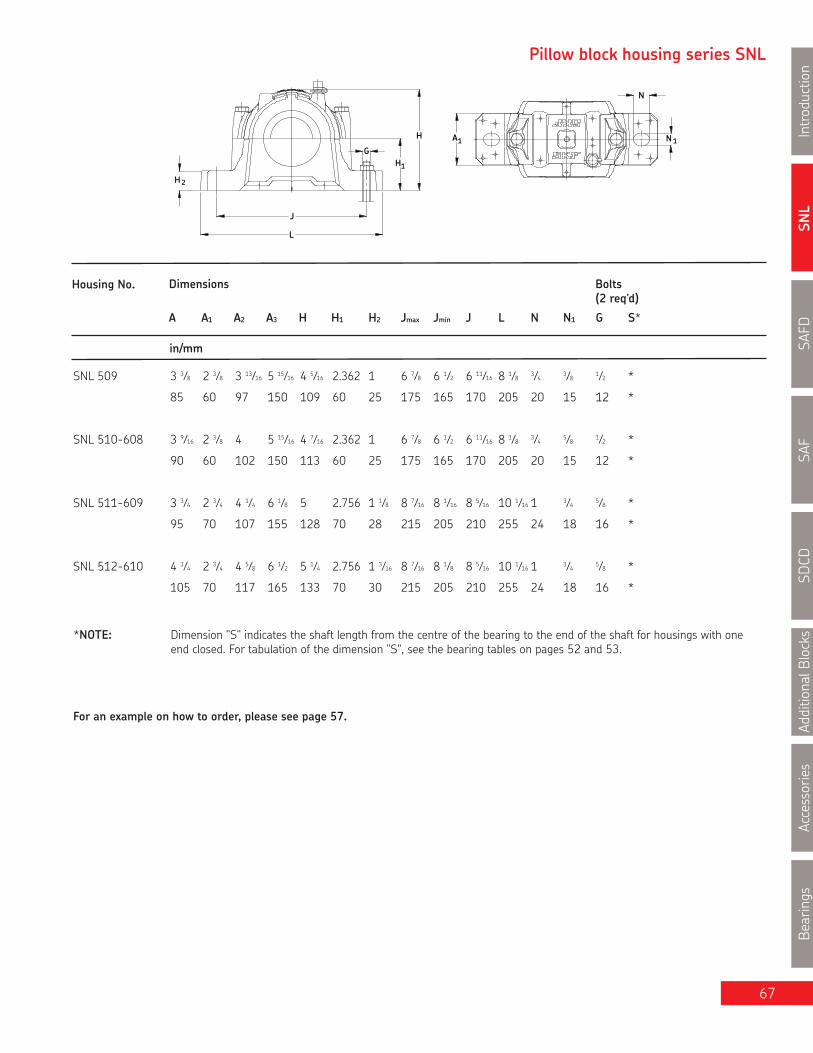
SNL
Introduction
SAFD
SAF
SDCD
AdditionalB
locks
Accessories
Bearings
67
Pillow block housing series SNL
H
H 2
L
J
G
1H
A1
N
N 1
Housing No. Dimensions Bolts
A A1 A2 A3 H H1 H2 Jmax Jmin J L N N1 G S*
in/mm
*NOTE: Dimension "S" indicates the shaft length from the centre of the bearing to the end of the shaft for housings with oneend closed. For tabulation of the dimension "S", see the bearing tables on pages 52 and 53.
For an example on how to order, please see page 57.
(2 req'd)
SNL 509 3 3⁄8 2 3⁄8 3 13⁄16 5 15⁄16 4 5⁄16 2.362 1 6 7⁄8 6 1⁄2 6 11⁄16 8 1⁄8 3⁄4 3⁄8 1⁄2 *
85 60 97 150 109 60 25 175 165 170 205 20 15 12 *
SNL 510-608 3 9⁄16 2 3⁄8 4 5 15⁄16 4 7⁄16 2.362 1 6 7⁄8 6 1⁄2 6 11⁄16 8 1⁄8 3⁄4 5⁄8 1⁄2 *
90 60 102 150 113 60 25 175 165 170 205 20 15 12 *
SNL 511-609 3 3⁄4 2 3⁄4 4 1⁄4 6 1⁄8 5 2.756 1 1⁄8 8 7⁄16 8 1⁄16 8 5⁄16 10 1⁄16 1 3⁄4 5⁄8 *
95 70 107 155 128 70 28 215 205 210 255 24 18 16 *
SNL 512-610 4 1⁄4 2 3⁄4 4 5⁄8 6 1⁄2 5 1⁄4 2.756 1 3⁄16 8 7⁄16 8 1⁄8 8 5⁄16 10 1⁄16 1 3⁄4 5⁄8 *
105 70 117 165 133 70 30 215 205 210 255 24 18 16 *

SNL
IntroductionSAFD
SAFSD
CDAdditionalBlocks
AccessoriesBearings
68
Series SNL 500 and SNL 600Pillow blocks of cast iron forbearing with adapter sleeve,grease or oil lubricationda 1 15⁄16 (45 - 50 mm) da
S
A 2A 3A
Double-lip sealsG & L design
Labyrinth sealsS design
Taconite sealsND design
Shaft Complete Pillow Housing Standard Bearing Adapter Fixing Mass EndDia. Block Assembly Seal Sleeve Rings Complete Coverda Package Qty.
mm in lb. kg.
45 SNL 1510/45 TL SNL 510-608 TSN 510L 1210 EK H 210 FRB 10.5/90 2 8.80 3.99 ASNH 510-608SNL 1610/45 TG SNL 512-610 TSN 610G 1310 EK H 310 FRB 10.5/110 2 14.6 6.60 ASNH 512-610
SNL 2510/45 TL SNL 510-608 TSN 510L 2210 EK H 310 FRB 9/90 2 8.95 3.71 ASNH 510-608
SNL 2610/45 TG SNL 512-610 TSN 610G 2310 K H 2310 FRB 4/110 2 15.6 7.06 ASNH 512-610
SNL 21610/45 TG SNL 512-610 TSN 610G 21310 EK H 310 FRB 10.5/110 2 14.6 6.60 ASNH 512-610
SNL 22510/45 TL SNL 510-608 TSN 510L 22210 EK H 310 FRB 9/90 2 9.02 4.09 ASNH 510-608
SNL 22610/45 TG SNL 512-610 TSN 610G 22310 EK H 2310 FRB 4/110 2 16.0 7.26 ASNH 512-610
SNL C2510/45 TL SNL 510-608 TSN 510L C2210 K* H 310E FRB 9/90 2 9.02 4.09 ASNH 510-608
1 15⁄16 SNL 1511/1 15⁄16 TG SNL 511-609 TSN 511G 1211 EK HA 211 FRB 11.5/100 2 11.9 5.40 ASNH 511-609
SNL 1611/1 15⁄16 TG SNL 513-611 TSN 611G 1311 EK HA 311 FRB 11/120 2 18.6 8.44 ASNH 513-611
SNL 2511/1 15⁄16 TG SNL 511-609 TSN 511G 2211 EK HA 311 FRB 9.5/100 2 12.2 5.50 ASNH 511-609
SNL 2611/1 15⁄16 TG SNL 513-611 TSN 611G 2311 K HA 2311 FRB 4/120 2 19.8 8.97 ASNH 513-611
SNL 21611/1 15⁄16 TG SNL 513-611 TSN 611G 21311 EK HA 311 FRB 11/120 2 18.7 8.49 ASNH 513-611
SNL 22511/1 15⁄16 TG SNL 511-609 TSN 511G 22211 EK HA 311 FRB 9.5/100 2 12.3 5.59 ASNH 511-609
SNL 22611/1 15⁄16 TG SNL 513-611 TSN 611G 22311 EK HA 2311 FRB 4/120 2 20.3 9.22 ASNH 513-611
SNL C2511/1 15⁄16 TG SNL 511-609 TSN 511G C2211 K* HA 311E FRB 9.5/100 2 12.3 5.59 ASNH 511-609
50 SNL 1511/50 TL SNL 511-609 TSN 511L 1211 EK H 211 FRB 11.5/100 2 11.9 5.40 ASNH 511-609
SNL 1611/50 TG SNL 513-611 TSN 611G 1311 EK H 311 FRB 11/120 2 18.6 8.44 ASNH 513-611
SNL 2511/50 TL SNL 511-609 TSN 511L 2211 EK H 311 FRB 9.5/100 2 12.2 5.50 ASNH 511-609
SNL 2611/50 TG SNL 513-611 TSN 611G 2311 K H 2311 FRB 4/120 2 19.8 8.97 ASNH 513-611
SNL 21611/50 TG SNL 513-611 TSN 611G 21311 EK H 311 FRB 11/120 2 18.7 8.49 ASNH 513-611
SNL 22511/50 TL SNL 511-609 TSN 511L 22211 EK H 311 FRB 9.5/100 2 12.3 5.59 ASNH 511-609
SNL 22611/50 TG SNL 513-611 TSN 611G 22311 EK H 2311 FRB 4/120 2 20.3 9.22 ASNH 513-611
SNL C2511/50 TL SNL 511-609 TSN 511L C2211 K* H 311E FRB 9.5/100 2 12.3 5.59 ASNH 511-609
* Must always be located.

SNL
Introduction
SAFD
SAF
SDCD
AdditionalB
locks
Accessories
Bearings
69
Pillow block housing series SNL
H
H 2
L
J
G
1H
A1
N
N 1
Housing No. Dimensions Bolts
A A1 A2 A3 H H1 H2 Jmax Jmin J L N N1 G S*
in/mm
*NOTE: Dimension "S" indicates the shaft length from the centre of the bearing to the end of the shaft for housings with oneend closed. For tabulation of the dimension "S", see the bearing tables on pages 52 and 53.
For an example on how to order, please see page 57.
(2 req'd)
SNL 510-608 3 9⁄16 2 3⁄8 4 5 15⁄16 4 7⁄16 2.362 1 6 7⁄8 6 1⁄2 6 11⁄16 8 1⁄8 3⁄4 5⁄8 1⁄2 *
90 60 102 150 113 60 25 175 165 170 205 20 15 12 *
SNL 511-609 3 3⁄4 2 3⁄4 4 1⁄4 6 1⁄8 5 2.756 1 1⁄8 8 7⁄16 8 1⁄8 8 5⁄16 10 1⁄16 1 3⁄4 5⁄8 *
95 70 107 155 128 70 28 215 205 210 255 24 18 16 *
SNL 512-610 4 1⁄4 2 3⁄4 4 5⁄8 6 1⁄2 5 1⁄4 2.756 1 3⁄16 8 7⁄16 8 1⁄8 8 5⁄16 10 1⁄16 1 3⁄4 5⁄8 *
105 70 117 165 133 70 30 215 205 210 255 24 18 16 *
SNL 513-611 4 3⁄8 3 1⁄8 4 13⁄16 6 11⁄16 5 7⁄8 3.150 1 3⁄16 9 1⁄4 8 7⁄8 9 1⁄8 10 13⁄16 1 3⁄4 5⁄8 *
110 80 122 170 148 80 30 236 224 230 275 24 18 16 *
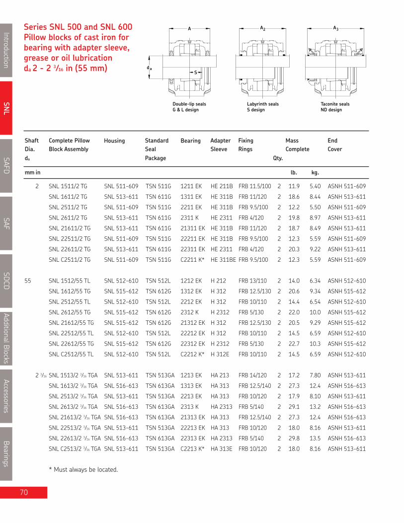
SNL
IntroductionSAFD
SAFSD
CDAdditionalBlocks
AccessoriesBearings
70
Series SNL 500 and SNL 600Pillow blocks of cast iron forbearing with adapter sleeve,grease or oil lubricationda 2 - 2 3⁄16 in (55 mm) da
S
A 2A 3A
Double-lip sealsG & L design
Labyrinth sealsS design
Taconite sealsND design
Shaft Complete Pillow Housing Standard Bearing Adapter Fixing Mass EndDia. Block Assembly Seal Sleeve Rings Complete Coverda Package Qty.
mm in lb. kg.
2 SNL 1511/2 TG SNL 511-609 TSN 511G 1211 EK HE 211B FRB 11.5/100 2 11.9 5.40 ASNH 511-609
SNL 1611/2 TG SNL 513-611 TSN 611G 1311 EK HE 311B FRB 11/120 2 18.6 8.44 ASNH 513-611
SNL 2511/2 TG SNL 511-609 TSN 511G 2211 EK HE 311B FRB 9.5/100 2 12.2 5.50 ASNH 511-609
SNL 2611/2 TG SNL 513-611 TSN 611G 2311 K HE 2311 FRB 4/120 2 19.8 8.97 ASNH 513-611
SNL 21611/2 TG SNL 513-611 TSN 611G 21311 EK HE 311B FRB 11/120 2 18.7 8.49 ASNH 513-611
SNL 22511/2 TG SNL 511-609 TSN 511G 22211 EK HE 311B FRB 9.5/100 2 12.3 5.59 ASNH 511-609
SNL 22611/2 TG SNL 513-611 TSN 611G 22311 EK HE 2311 FRB 4/120 2 20.3 9.22 ASNH 513-611
SNL C2511/2 TG SNL 511-609 TSN 511G C2211 K* HE 311BE FRB 9.5/100 2 12.3 5.59 ASNH 511-609
55 SNL 1512/55 TL SNL 512-610 TSN 512L 1212 EK H 212 FRB 13/110 2 14.0 6.34 ASNH 512-610
SNL 1612/55 TG SNL 515-612 TSN 612G 1312 EK H 312 FRB 12.5/130 2 20.6 9.34 ASNH 515-612
SNL 2512/55 TL SNL 512-610 TSN 512L 2212 EK H 312 FRB 10/110 2 14.4 6.54 ASNH 512-610
SNL 2612/55 TG SNL 515-612 TSN 612G 2312 K H 2312 FRB 5/130 2 22.0 10.0 ASNH 515-612
SNL 21612/55 TG SNL 515-612 TSN 612G 21312 EK H 312 FRB 12.5/130 2 20.5 9.29 ASNH 515-612
SNL 22512/55 TL SNL 512-610 TSN 512L 22212 EK H 312 FRB 10/110 2 14.5 6.59 ASNH 512-610
SNL 22612/55 TG SNL 515-612 TSN 612G 22312 EK H 2312 FRB 5/130 2 22.7 10.3 ASNH 515-612
SNL C2512/55 TL SNL 512-610 TSN 512L C2212 K* H 312E FRB 10/110 2 14.5 6.59 ASNH 512-610
2 3⁄16 SNL 1513/2 3⁄16 TGA SNL 513-611 TSN 513GA 1213 EK HA 213 FRB 14/120 2 17.2 7.80 ASNH 513-611
SNL 1613/2 3⁄16 TGA SNL 516-613 TSN 613GA 1313 EK HA 313 FRB 12.5/140 2 27.3 12.4 ASNH 516-613
SNL 2513/2 3⁄16 TGA SNL 513-611 TSN 513GA 2213 EK HA 313 FRB 10/120 2 17.9 8.10 ASNH 513-611
SNL 2613/2 3⁄16 TGA SNL 516-613 TSN 613GA 2313 K HA 2313 FRB 5/140 2 29.1 13.2 ASNH 516-613
SNL 21613/2 3⁄16 TGA SNL 516-613 TSN 613GA 21313 EK HA 313 FRB 12.5/140 2 27.3 12.4 ASNH 516-613
SNL 22513/2 3⁄16 TGA SNL 513-611 TSN 513GA 22213 EK HA 313 FRB 10/120 2 18.0 8.16 ASNH 513-611
SNL 22613/2 3⁄16 TGA SNL 516-613 TSN 613GA 22313 EK HA 2313 FRB 5/140 2 29.8 13.5 ASNH 516-613
SNL C2513/2 3⁄16 TGA SNL 513-611 TSN 513GA C2213 K* HA 313E FRB 10/120 2 18.0 8.16 ASNH 513-611
* Must always be located.

SNL
Introduction
SAFD
SAF
SDCD
Accessories
Bearings
71
Pillow block housing series SNL
H
H 2
L
J
G
1H
A1
N
N 1
Housing No. Dimensions Bolts
A A1 A2 A3 H H1 H2 Jmax Jmin J L N N1 G S*
in/mm
*NOTE: Dimension "S" indicates the shaft length from the centre of the bearing to the end of the shaft for housings with oneend closed. For tabulation of the dimension "S", see the bearing tables on pages 52 and 53.
For an example on how to order, please see page 57.
(2 req'd)
SNL 511-609 253 3⁄4 2 3⁄4 4 1⁄4 6 1⁄8 5 2.756 1 1⁄8 8 7⁄16 8 1⁄8 8 5⁄16 10 1⁄16 1 3⁄4 5⁄8 *
95 70 107 155 128 70 28 215 205 210 255 24 18 16 *
SNL 512-610 4 1⁄4 2 3⁄4 4 5⁄8 6 1⁄2 5 1⁄4 2.756 1 3⁄16 8 7⁄16 8 1⁄8 8 5⁄16 10 1⁄16 1 3⁄4 5⁄8 *
105 70 117 165 133 70 30 215 205 210 255 24 18 16 *
SNL 513-611 4 3⁄8 3 1⁄8 4 13⁄16 6 11⁄16 5 7⁄8 3.150 1 3⁄16 9 1⁄4 8 7⁄8 9 1⁄8 10 13⁄16 1 3⁄4 5⁄8 *
110 80 122 170 148 80 30 236 224 230 275 24 18 16 *
SNL 515-612 4 5⁄8 3 1⁄8 5 6 7⁄8 6 1⁄8 3.150 1 3⁄16 9 3⁄8 8 3⁄4 9 1⁄8 11 1 3⁄4 5⁄8 *
115 80 127 175 154 80 30 238 222 230 280 24 18 16 *
SNL 516-613 4 3⁄4 3 5⁄8 5 7⁄16 7 1⁄8 6 15⁄16 3.740 1 1⁄4 10 1⁄2 9 15⁄16 10 1⁄4 12 7⁄16 1 1⁄8 7⁄8 3⁄4 *
120 90 138 180 175 95 32 268 252 260 315 28 22 20 *
AdditionalB
locks

SNL
IntroductionSAFD
SAFSD
CDAdditionalBlocks
AccessoriesBearings
72
Series SNL 500 and SNL 600Pillow blocks of cast iron forbearing with adapter sleeve,grease or oil lubricationda 2 1⁄4 - 2 7⁄16 in (60 mm) da
S
A 2A 3A
Double-lip sealsG & L design
Labyrinth sealsS design
Taconite sealsND design
Shaft Complete Pillow Housing Standard Bearing Adapter Fixing Mass EndDia. Block Assembly Seal Sleeve Rings Complete Coverda Package Qty.
mm in lb. kg.
2 1⁄4 SNL 1513/2 1⁄4 TGE SNL 513-611 TSN 513GE 1213 EK HE 213 FRB 14/120 2 17.7 8.05 ASNH 513-611
SNL 1613/2 1⁄4 TGE SNL 516-613 TSN 613GE 1313 EK HE 313 FRB 12.5/140 2 27.3 12.4 ASNH 516-613
SNL 2513/2 1⁄4 TGE SNL 513-611 TSN 513GE 2213 EK HE 313 FRB 10/120 2 18.4 8.35 ASNH 513-611
SNL 2613/2 1⁄4 TGE SNL 516-613 TSN 613GE 2313 K HE 2313 FRB 5/140 2 29.1 13.2 ASNH 516-613
SNL 21613/2 1⁄4 TGE SNL 516-613 TSN 613GE 21313 EK HE 313 FRB 12.5/140 2 27.3 12.4 ASNH 516-613
SNL 22513/2 1⁄4 TGE SNL 513-611 TSN 513GE 22213 EK HE 313 FRB 10/120 2 18.5 8.41 ASNH 513-611
SNL 22613/2 1⁄4 TGE SNL 516-613 TSN 613GE 22313 EK HE 2313 FRB 5/140 2 29.7 13.5 ASNH 516-613
SNL C2513/2 1⁄4 TGE SNL 513-611 TSN 513GE C2213 K* HE 313E FRB 10/120 2 18.5 8.41 ASNH 513-611
60 SNL 1513/60 TL SNL 513-611 TSN 513L 1213 EK H 213 FRB 14/120 2 17.7 8.05 ASNH 513-611
SNL 1613/60 TG SNL 516-613 TSN 613G 1313 EK H 313 FRB 12.5/140 2 27.3 12.4 ASNH 516-613
SNL 2513/60 TL SNL 513-611 TSN 513L 2213 EK H 313 FRB 10/120 2 18.4 8.35 ASNH 513-611
SNL 2613/60 TG SNL 516-613 TSN 613G 2313 K H 2313 FRB 5/140 2 29.1 13.2 ASNH 516-613
SNL 21613/60 TG SNL 516-613 TSN 613G 21313 EK H 313 FRB 12.5/140 2 27.3 12.4 ASNH 516-613
SNL 22513/60 TL SNL 513-611 TSN 513L 22213 EK H 313 FRB 10/120 2 18.5 8.41 ASNH 513-611
SNL 22613/60 TG SNL 516-613 TSN 613G 22313 EK H 2313 FRB 5/140 2 29.7 13.5 ASNH 516-613
SNL C2513/60 TL SNL 513-611 TSN 513L C2213 K* H 313E FRB 10/120 2 18.5 8.41 ASNH 513-611
2 7⁄16 SNL 1515/2 7⁄16 TGA SNL 515-612 TSN 515GA 1215 K HA 215 FRB 15.5/130 2 20.0 9.06 ASNH 515-612
SNL 1615/2 7⁄16 TGA SNL 518-615 TSN 615GA 1315 K HA 315 FRB 14/160 2 37.1 16.8 ASNH 518-615
SNL 2515/2 7⁄16 TGA SNL 515-612 TSN 515GA 2215 EK HA 315 FRB 12.5/130 2 20.5 9.31 ASNH 515-612
SNL 2615/2 7⁄16 TGA SNL 518-615 TSN 615GA 2315 K HA 2315 FRB 5/160 2 40.0 18.2 ASNH 518-615
SNL 21615/2 7⁄16 TGA SNL 518-615 TSN 615GA 21315 EK HA 315 FRB 14/160 2 37.1 16.8 ASNH 518-615
SNL 22515/2 7⁄16 TGA SNL 515-612 TSN 515GA 22215 EK HA 315 FRB 12.5/130 2 20.8 9.43 ASNH 515-612
SNL 22615/2 7⁄16 TGA SNL 518-615 TSN 615GA 22315 EK HA 2315 FRB 5/160 2 41.2 18.7 ASNH 518-615
SNL C2515/2 7⁄16 TGA SNL 515-612 TSN 515GA C2215 K* HA 315E FRB 12.5/130 2 20.8 9.43 ASNH 515-612
SNL C2615/2 7⁄16 TGA SNL 518-615 TSN 615GA C2315 K* HA 2315 FRB 5/160 2 41.2 18.7 ASNH 518-615
* Must always be located.

SNL
Introduction
SAFD
SAF
SDCD
AdditionalB
locks
Accessories
Bearings
73
Pillow block housing series SNL
H
H 2
L
J
G
1H
A1
N
N 1
Housing No. Dimensions Bolts
A A1 A2 A3 H H1 H2 Jmax Jmin J L N N1 G S*
in/mm
*NOTE: Dimension "S" indicates the shaft length from the centre of the bearing to the end of the shaft for housings with oneend closed. For tabulation of the dimension "S", see the bearing tables on pages 52 and 53.
For an example on how to order, please see page 57.
(2 req'd)
SNL 513-611 4 3⁄8 3 1⁄8 4 13⁄16 6 11⁄16 5 7⁄8 3.150 1 3⁄16 9 1⁄4 8 7⁄8 9 1⁄8 10 13⁄16 1 3⁄4 5⁄8 *
110 80 122 170 148 80 30 236 224 230 275 24 18 16 *
SNL 515-612 4 5⁄8 3 1⁄8 5 6 7⁄8 6 1⁄8 3.150 1 3⁄16 9 3⁄8 8 3⁄4 9 1⁄8 11 1 3⁄4 5⁄8 *
115 80 127 175 154 80 30 238 222 230 280 24 18 16 *
SNL 516-613 4 3⁄4 3 5⁄8 5 7⁄16 7 1⁄8 6 15⁄16 3.740 1 1⁄4 10 1⁄2 9 15⁄16 10 1⁄4 12 7⁄16 1 1⁄8 7⁄8 3⁄4 *
120 90 138 180 175 95 32 268 252 260 315 28 22 20 *
SNL 518-615 5 1⁄2 3 15⁄16 6 1⁄4 8 7⁄8 7 5⁄8 3.937 1 3⁄8 11 5⁄8 11 1⁄4 11 7⁄16 13 5⁄8 1 1⁄8 7⁄8 3⁄4 *
140 100 158 225 193 100 35 295 285 290 345 28 22 20 *

SNL
IntroductionSAFD
SAFSD
CDAdditionalBlocks
AccessoriesBearings
Series SNL 500 and SNL 600Pillow blocks of cast iron forbearing with adapter sleeve,grease or oil lubricationda 2 1⁄2 - 2 11⁄16 in (65 mm) da
S
A 2A 3A
Double-lip sealsG & L design
Labyrinth sealsS design
Taconite sealsND design
Shaft Complete Pillow Housing Standard Bearing Adapter Fixing Mass EndDia. Block Assembly Seal Sleeve Rings Complete Coverda Package Qty.
mm in lb. kg.
2 1⁄2 SNL 1515/2 1⁄2 TGE SNL 515-612 TSN 515GE 1215 K HE 215 FRB 15.5/130 2 20.0 9.06 ASNH 515-612
SNL 1615/2 1⁄2 TGE SNL 518-615 TSN 615GE 1315 K HE 315 FRB 14/160 2 37.1 16.8 ASNH 518-615
SNL 2515/2 1⁄2 TGE SNL 515-612 TSN 515GE 2215 EK HE 315 FRB 12.5/130 2 20.5 9.31 ASNH 515-612
SNL 2615/2 1⁄2 TGE SNL 518-615 TSN 615GE 2315 K HE 2315 FRB 5/160 2 40.0 18.2 ASNH 518-615
SNL 21615/2 1⁄2 TGE SNL 518-615 TSN 615GE 21315 EK HE 315 FRB 14/160 2 37.1 16.8 ASNH 518-615
SNL 22515/2 1⁄2 TGE SNL 515-612 TSN 515GE 22215 EK HE 315 FRB 12.5/130 2 20.8 9.43 ASNH 515-612
SNL 22615/2 1⁄2 TGE SNL 518-615 TSN 615GE 22315 EK HE 2315 FRB 5/160 2 41.2 18.7 ASNH 518-615
SNL C2515/2 1⁄2 TGE SNL 515-612 TSN 515GE C2215 K* HE 315E FRB 12.5/130 2 20.8 9.43 ASNH 515-612
SNL C2615/2 1⁄2 TGE SNL 518-615 TSN 615GE C2315 K* HE 2315 FRB 5/160 2 41.2 18.7 ASNH 518-615
65 SNL 1515/65 TL SNL 515-612 TSN 515L 1215 K H 215 FRB 15.5/130 2 20.0 9.06 ASNH 515-612
SNL 1615/65 TG SNL 518-615 TSN 615G 1315 K H 315 FRB 14/160 2 37.1 16.8 ASNH 518-615
SNL 2515/65 TL SNL 515-612 TSN 515L 2215 EK H 315 FRB 12.5/130 2 20.5 9.31 ASNH 515-612
SNL 2615/65 TG SNL 518-615 TSN 615G 2315 K H 2315 FRB 5/160 2 40.0 18.2 ASNH 518-615
SNL 21615/65 TG SNL 518-615 TSN 615G 21315 EK H 315 FRB 14/160 2 37.1 16.8 ASNH 518-615
SNL 22515/65 TL SNL 515-612 TSN 515L 22215 EK H 315 FRB 12.5/130 2 20.8 9.43 ASNH 515-612
SNL 22615/65 G SNL 518-615 TSN 615G 22315 EK H 2315 FRB 5/160 2 41.2 18.7 ASNH 518-615
SNL C2515/65 TL SNL 515-612 TSN 515L C2215 K* H 315E FRB 12.5/130 2 20.8 9.43 ASNH 515-612
SNL C2615/65 TG SNL 518-615 TSN 615G C2315 K* H 2315 FRB 5/160 2 41.2 18.7 ASNH 518-615
2 11⁄16 SNL 1516/2 11⁄16 TGA SNL 516-613 TSN 516GA 1216 K HA 216 FRB 16/140 2 26.5 12.0 ASNH 516-613
SNL 1616/2 11⁄16 TGA SNL 519-616 TSN 616GA 1316 K HA 316 FRB 14.5/170 2 41.4 18.8 ASNH 519-616
SNL 2516/2 11⁄16 TGA SNL 516-613 TSN 516GA 2216 EK HA 316 FRB 12.5/140 2 27.3 12.4 ASNH 516-613
SNL 2616/2 11⁄16 TGA SNL 519-616 TSN 616GA 2316 K HA 2316 FRB 5/170 2 46.3 21.0 ASNH 519-616
SNL 21616/2 11⁄16 TGA SNL 519-616 TSN 616GA 21316 EK HA 316 FRB 14.5/170 2 41.7 18.9 ASNH 519-616
SNL 22516/2 11⁄16 TGA SNL 516-613 TSN 516GA 22216 EK HA 316 FRB 12.5/140 2 27.5 12.5 ASNH 516-613
SNL 22616/2 11⁄16 TGA SNL 519-616 TSN 616GA 22316 EK HA 2316 FRB 5/170 2 46.5 21.1 ASNH 519-616
SNL C2516/2 11⁄16 TGA SNL 516-613 TSN 516GA C2216 K* HA 316E FRB 12.5/140 2 27.5 12.5 ASNH 516-613
SNL C2616/2 11⁄16 TGA SNL 519-616 TSN 616GA C2316 K* HA 2316 FRB 5/170 2 46.5 21.1 ASNH 519-616
* Must always be located.
74

SNL
Introduction
SAFD
SAF
SDCD
AdditionalB
locks
Accessories
Bearings
75
Pillow block housing series SNL
H
H 2
L
J
G
1H
A1
N
N 1
Housing No. Dimensions Bolts
A A1 A2 A3 H H1 H2 Jmax Jmin J L N N1 G S*
in/mm
*NOTE: Dimension "S" indicates the shaft length from the centre of the bearing to the end of the shaft for housings with oneend closed. For tabulation of the dimension "S", see the bearing tables on pages 52 and 53.
For an example on how to order, please see page 57.
(2 req'd)
SNL 515-612 4 5⁄8 3 1⁄8 5 6 7⁄8 6 1⁄8 3.150 1 3⁄16 9 3⁄8 8 3⁄4 9 1⁄8 11 1 3⁄4 5⁄8 *
115 80 127 175 154 80 30 238 222 230 280 24 18 16 *
SNL 516-613 4 3⁄4 3 5⁄8 5 7⁄16 7 1⁄8 6 15⁄16 3.740 1 1⁄4 10 1⁄2 9 15⁄16 10 1⁄4 12 7⁄16 1 1⁄8 7⁄8 3⁄4 *
120 90 138 180 175 95 32 268 252 260 315 28 22 20 *
SNL 518-615 5 1⁄2 3 15⁄16 6 1⁄4 8 7⁄8 7 5⁄8 3.937 1 3⁄8 11 5⁄8 11 1⁄4 11 7⁄16 13 5⁄8 1 1⁄8 7⁄8 3⁄4 *
140 100 158 225 193 100 35 295 285 290 345 28 22 20 *
SNL 519-616 5 3⁄4 3 15⁄16 6 7⁄16 8 11⁄16 8 5⁄16 4.409 1 3⁄8 11 5⁄8 11 1⁄4 11 7⁄16 13 5⁄8 1 1⁄8 7⁄8 3⁄4 *
145 100 163 220 210 112 35 295 285 290 345 28 22 20 *

SNL
IntroductionSAFD
SAFSD
CDAdditionalBlocks
AccessoriesBearings
Series SNL 500 and SNL 600Pillow blocks of cast iron forbearing with adapter sleeve,grease or oil lubricationda 2 3⁄4 - 2 15⁄16 in (70 mm) da
S
A 2A 3A
Double-lip sealsG & L design
Labyrinth sealsS design
Taconite sealsND design
Shaft Complete Pillow Housing Standard Bearing Adapter Fixing Mass EndDia. Block Assembly Seal Sleeve Rings Complete Coverda Package Qty.
mm in lb. kg.
2 3⁄4 SNL 1516/2 3⁄4 TG SNL 516-613 TSN 516G 1216 K HE 216 FRB 16/140 2 26.5 12.0 ASNH 516-613
SNL 1616/2 3⁄4 TG SNL 519-616 TSN 616G 1316 K HE 316 FRB 14.5/170 2 41.4 18.8 ASNH 519-616
SNL 2516/2 3⁄4 TG SNL 516-613 TSN 516G 2216 EK HE 316 FRB 12.5/140 2 27.2 12.4 ASNH 516-613
SNL 2616/2 3⁄4 TG SNL 519-616 TSN 616G 2316 K HE 2316 FRB 5/170 2 46.3 21.0 ASNH 519-616
SNL 21616/2 3⁄4 TG SNL 519-616 TSN 616G 21316 EK HE 316 FRB 14.5/170 2 41.7 18.9 ASNH 519-616
SNL 22516/2 3⁄4 TG SNL 516-613 TSN 516G 22216 EK HE 316 FRB 12.5/140 2 27.6 12.5 ASNH 516-613
SNL 22616/2 3⁄4 TG SNL 519-616 TSN 616G 22316 EK HE 2316 FRB 5/170 2 46.5 21.1 ASNH 519-616
SNL C2516/2 3⁄4 TG SNL 516-613 TSN 516G C2216 K* HE 316E FRB 12.5/140 2 27.6 12.5 ASNH 516-613
SNL C2616/2 3⁄4 TG SNL 519-616 TSN 616G C2316 K* HE 2316 FRB 5/170 2 46.5 21.1 ASNH 519-616
70 SNL 1516/70 TL SNL 516-613 TSN 516L 1216 K H 216 FRB 16/140 2 26.5 12.0 ASNH 516-613
SNL 1616/70 TG SNL 519-616 TSN 616G 1316 K H 316 FRB 14.5/170 2 41.4 18.8 ASNH 519-616
SNL 2516/70 TL SNL 516-613 TSN 516L 2216 EK H 316 FRB 12.5/140 2 27.2 12.4 ASNH 516-613
SNL 2616/70 TG SNL 519-616 TSN 616G 2316 K H 2316 FRB 5/170 2 46.3 21.0 ASNH 519-616
SNL 21616/70 TG SNL 519-616 TSN 616G 21316 EK H 316 FRB 14.5/170 2 41.7 18.9 ASNH 519-616
SNL 22516/70 TL SNL 516-613 TSN 516L 22216 EK H 316 FRB 12.5/140 2 27.5 12.5 ASNH 516-613
SNL 22616/70 TG SNL 519-616 TSN 616G 22316 EK H 2316 FRB 5/170 2 46.5 21.1 ASNH 519-616
SNL C2516/70 TL SNL 516-613 TSN 516L C2216 K* H 316E FRB 12.5/140 2 27.5 12.5 ASNH 516-613
SNL C2616/70 TG SNL 519-616 TSN 616G C2316 K* H 2316 FRB 5/170 2 46.5 21.1 ASNH 519-616
2 15⁄16 SNL 1517/2 15⁄16 TG SNL 517 TSN 517G 1217 K HA 217 FRB 16.5/150 2 28.9 13.1 ASNH 517
SNL 1617/2 15⁄16 TG SNL 520-617 TSN 617G 1317 K HA 317 FRB 14.5/180 2 51.8 23.5 ASNH 520-617
SNL 2517/2 15⁄16 TG SNL 517 TSN 517G 2217 K HA 317 FRB 12.5/150 2 29.9 13.6 ASNH 517
SNL 2617/2 15⁄16 TG SNL 520-617 TSN 617G 2317 K HA 2317 FRB 5/180 2 56.9 25.8 ASNH 520-617
SNL 21617/2 15⁄16 TG SNL 520-617 TSN 617G 21317 EK HA 317 FRB 14.5/180 2 51.8 23.5 ASNH 520-617
SNL 22517/2 15⁄16 TG SNL 517 TSN 517G 22217 EK HA 317 FRB 12.5/150 2 30.4 13.8 ASNH 517
SNL 22617/2 15⁄16 TG SNL 520-617 TSN 617G 22317 EK HA 2317 FRB 5/180 2 57.3 26.0 ASNH 520-617
SNL C2517/2 15⁄16 TG SNL 517 TSN 517G C2217 K* HA 317E FRB 12.5/150 2 30.4 13.8 ASNH 517
SNL C2617/2 15⁄16 TG SNL 520-617 TSN 617G C2317 K* HA 2317 FRB 5/180 2 57.3 26.0 ASNH 520-617
* Must always be located.
76

SNL
Introduction
SAFD
SAF
SDCD
AdditionalB
locks
Accessories
Bearings
77
Pillow block housing series SNL
H
H 2
L
J
G
1H
A1
N
N 1
Housing No. Dimensions Bolts
A A1 A2 A3 H H1 H2 Jmax Jmin J L N N1 G S*
in/mm
*NOTE: Dimension "S" indicates the shaft length from the centre of the bearing to the end of the shaft for housings with oneend closed. For tabulation of the dimension "S", see the bearing tables on pages 52 and 53.
For an example on how to order, please see page 57.
(2 req'd)
SNL 516-613 4 3⁄4 3 5⁄8 5 7⁄16 7 1⁄8 6 15⁄16 3.740 1 1⁄4 10 1⁄2 9 15⁄16 10 1⁄4 12 7⁄16 1 1⁄8 7⁄8 3⁄4 *
120 90 138 180 175 95 32 268 252 260 315 28 22 20 *
SNL 517 4 15⁄16 3 5⁄8 5 5⁄8 8 5⁄16 7 1⁄4 3.740 1 1⁄4 10 1⁄2 9 15⁄16 10 1⁄4 12 5⁄8 1 1⁄8 7⁄8 3⁄4 *
125 90 143 210 183 95 32 268 252 260 320 28 22 20 *
SNL 519-616 5 3⁄4 3 15⁄16 6 7⁄16 8 11⁄16 8 5⁄16 4.409 1 3⁄8 11 5⁄8 11 1⁄4 11 7⁄16 13 5⁄8 1 1⁄8 7⁄8 3⁄4 *
145 100 163 220 210 112 35 295 285 290 345 28 22 20 *
SNL 520-617 6 5⁄16 4 5⁄16 7 9 1⁄4 8 9⁄16 4.409 1 9⁄16 12 13⁄16 12 3⁄8 12 5⁄8 15 1 1⁄4 1 7⁄8 *
160 110 178 235 218 112 40 326 314 320 380 32 26 24 *

SNL
IntroductionSAFD
SAFSD
CDAdditionalBlocks
AccessoriesBearings
78
Series SNL 500 and SNL 600Pillow blocks of cast iron forbearing with adapter sleeve,grease or oil lubricationda 3 in (75 - 80 mm) da
S
A 2A 3A
Double-lip sealsG & L design
Labyrinth sealsS design
Taconite sealsND design
Shaft Complete Pillow Housing Standard Bearing Adapter Fixing Mass EndDia. Block Assembly Seal Sleeve Rings Complete Coverda Package Qty.
mm in lb. kg.
75 SNL 1517/75 TL SNL 517 TSN 517L 1217 K H 217 FRB 16.5/150 2 28.9 13.1 ASNH 517
SNL 1617/75 TG SNL 520-617 TSN 617G 1317 K H 317 FRB 14.5/180 2 51.8 23.5 ASNH 520-617
SNL 2517/75 TL SNL 517 TSN 517L 2217 K H 317 FRB 12.5/150 2 29.9 13.6 ASNH 517
SNL 2617/75 TG SNL 520-617 TSN 617G 2317 K H 2317 FRB 5/180 2 56.9 25.8 ASNH 520-617
SNL 21617/75 TG SNL 520-617 TSN 617G 21317 EK H 317 FRB 14.5/180 2 51.8 23.5 ASNH 520-617
SNL 22517/75 TL SNL 517 TSN 517L 22217 EK H 317 FRB 12.5/150 2 30.4 13.8 ASNH 517
SNL 22617/75 TG SNL 520-617 TSN 617G 22317 EK H 2317 FRB 5/180 2 57.3 26.0 ASNH 520-617
SNL C2517/75 TL SNL 517 TSN 517L C2217 K* H 317E FRB 12.5/150 2 30.4 13.8 ASNH 517
SNL C2617/75 TG SNL 520-617 TSN 617G C2317 K* H 2317 FRB 5/180 2 57.3 26.0 ASNH 520-617
3 SNL 1517/3 TG SNL 517 TSN 517G 1217 K HE 217 FRB 16.5/150 2 28.9 13.1 ASNH 517
SNL 1617/3 TG SNL 520-617 TSN 617G 1317 K HE 317 FRB 14.5/180 2 51.8 23.5 ASNH 520-617
SNL 2517/3 TG SNL 517 TSN 517G 2217 K HE 317 FRB 12.5/150 2 29.9 13.6 ASNH 517
SNL 2617/3 TG SNL 520-617 TSN 617G 2317 K HE 2317 FRB 5/180 2 56.9 25.8 ASNH 520-617
SNL 21617/3 TG SNL 520-617 TSN 617G 21317 EK HE 317 FRB 14.5/180 2 51.8 23.5 ASNH 520-617
SNL 22517/3 TG SNL 517 TSN 517G 22217 EK HE 317 FRB 12.5/150 2 30.4 13.8 ASNH 517
SNL 22617/3 TG SNL 520-617 TSN 617G 22317 EK HE 2317 FRB 5/180 2 57.3 26.0 ASNH 520-617
SNL C2517/3 TG SNL 517 TSN 517G C2217 K* HE 317E FRB 12.5/150 2 30.4 13.8 ASNH 517
SNL C2617/3 TG SNL 520-617 TSN 617G C2317 K* HE 2317 FRB 5/180 2 57.3 26.0 ASNH 520-617
80 SNL 1518/80 TL SNL 518-615 TSN 518L 1218 K H 218 FRB 17.5/160 2 35.7 16.2 ASNH 518-615
SNL 2518/80 TL SNL 518-615 TSN 518L 2218 K H 318 FRB 12.5/160 2 36.2 16.4 ASNH 518-615
SNL 22518/80 TL SNL 518-615 TSN 518L 22218 EK H 318 FRB 12.5/160 2 37.6 17.1 ASNH 518-615
SNL 23518/80 TL SNL 518-615 TSN 518L 23218CCK/W33 H 2318 FRB 6.25/160 2 41.0 18.6 ASNH 518-615
SNL C2518/80 TL SNL 518-615 TSN 518L C2218 K * H 318E FRB 12.5/160 2 37.6 17.1 ASNH 518-615
* Must always be located.

SNL
Introduction
SAFD
SAF
SDCD
AdditionalB
locks
Accessories
Bearings
79
Pillow block housing series SNL
H
H 2
L
J
G
1H
A1
N
N 1
Housing No. Dimensions Bolts
A A1 A2 A3 H H1 H2 Jmax Jmin J L N N1 G S*
in/mm
*NOTE: Dimension "S" indicates the shaft length from the centre of the bearing to the end of the shaft for housings with oneend closed. For tabulation of the dimension "S", see the bearing tables on pages 52 and 53.
For an example on how to order, please see page 57.
(2 req'd)
SNL 517 4 15⁄16 3 5⁄8 5 5⁄8 8 5⁄16 7 1⁄4 3.740 1 1⁄4 10 1⁄2 9 15⁄16 10 1⁄4 12 5⁄8 1 1⁄8 7⁄8 3⁄4 *
125 90 143 210 183 95 32 268 252 260 320 28 22 20 *
SNL 518-615 5 1⁄2 3 15⁄16 6 1⁄4 8 7⁄8 7 5⁄8 3.937 1 3⁄8 11 5⁄8 11 1⁄4 11 7⁄16 13 5⁄8 1 1⁄8 7⁄8 3⁄4 *
140 100 158 225 193 100 35 295 285 290 345 28 22 20 *
SNL 520-617 6 5⁄16 4 15⁄16 7 9 1⁄4 8 9⁄16 4.409 1 9⁄16 12 13⁄16 12 3⁄8 12 5⁄8 15 1 1⁄4 1 7⁄8 *
160 110 178 235 218 112 40 326 314 320 380 32 26 24 *

SNL
IntroductionSAFD
SAFSD
CDAdditionalBlocks
AccessoriesBearings
Series SNL 500 and SNL 600Pillow blocks of cast iron forbearing with adapter sleeve,grease or oil lubricationda 3 3⁄16 - 3 7⁄16 in (85 mm) da
S
A 2A 3A
Double-lip sealsG & L design
Labyrinth sealsS design
Taconite sealsND design
Shaft Complete Pillow Housing Standard Bearing Adapter Fixing Mass EndDia. Block Assembly Seal Sleeve Rings Complete Coverda Package Qty.
mm in lb. kg.
3 3⁄16 SNL 1518/3 3⁄16 TG SNL 518-615 TSN 518G 1218 K HA 218 FRB 17.5/160 2 35.7 16.2 ASNH 518-615
SNL 2518/3 3⁄16 TG SNL 518-615 TSN 518G 2218 K HA 318 FRB 12.5/160 2 36.2 16.4 ASNH 518-615
SNL 22518/3 3⁄16 TG SNL 518-615 TSN 518G 22218 EK HA 318 FRB 12.5/160 2 37.6 17.1 ASNH 518-615
SNL 23518/3 3⁄16 TG SNL 518-615 TSN 518G 23218CCK/W33 HA 2318 FRB 6.25/160 2 41.0 18.6 ASNH 518-615
SNL C2518/3 3⁄16 TG SNL 518-615 TSN 518G C2218 K * HA 318E FRB 12.5/160 2 37.6 17.1 ASNH 518-615
3 1⁄4 SNL 1518/3 1⁄4 TGE SNL 518-615 TSN 518GE 1218 K HE 218 FRB 17.5/160 2 35.7 16.2 ASNH 518-615
SNL 2518/3 1⁄4 TGE SNL 518-615 TSN 518GE 2218 K HE 318 FRB 12.5/160 2 36.2 16.4 ASNH 518-615
SNL 22518/3 1⁄4 TGE SNL 518-615 TSN 518GE 22218 EK HE 318 FRB 12.5/160 2 37.6 17.1 ASNH 518-615
SNL 23518/3 1⁄4 TGE SNL 518-615 TSN 518GE 23218CCK/W33 HE 2318 FRB 6.25/160 2 41.0 18.6 ASNH 518-615
SNL C2518/3 1⁄4 TGE SNL 518-615 TSN 518GE C2218 K * HE 318E FRB 12.5/160 2 37.6 17.1 ASNH 518-615
85 SNL 1519/85 TL SNL 519-616 TSN 519L 1219 K H 219 FRB 18/170 2 39.9 18.1 ASNH 519-616
SNL 1619/85 TG SNL 522-619 TSN 619G 1319 K H 319 FRB 17.5/200 2 70.0 32.0 ASNH 522-619
SNL 2519/85 TL SNL 519-616 TSN 519L 2219 K H 319 FRB 12.5/170 2 42.1 19.1 ASNH 519-616
SNL 2619/85 TG SNL 522-619 TSN 619G 2319 K H 2319 FRB 6.5/200 2 73.7 33.5 ASNH 522-619
SNL 21619/85 TG SNL 522-619 TSN 619G 21319 EK H 2319 FRB 17.5/200 2 71.6 32.5 ASNH 522-619
SNL 22519/85 TL SNL 519-616 TSN 519L 22219 EK H 319 FRB 12.5/170 2 42.1 19.1 ASNH 519-616
SNL 22619/85 TG SNL 522-619 TSN 619G 22319 EK H 2319 FRB 6.5/200 2 74.3 33.7 ASNH 522-619
3 7⁄16 SNL 1520/3 7⁄16 TGA SNL 520-617 TSN 520GA 1220 K HA 220 FRB 18/180 2 49.8 22.6 ASNH 520-617
SNL 1620/3 7⁄16 TGA SNL 524-620 TSN 620GA 1320 K HA 320 FRB 19.5/215 2 79.6 36.1 ASNH 524-620
SNL 2520/3 7⁄16 TGA SNL 520-617 TSN 520GA 2220 K HA 320 FRB 12/180 2 52.5 23.8 ASNH 520-617
SNL 2620/3 7⁄16 TGA SNL 524-620 TSN 620GA 2320 K HA 2320 FRB 6.5/215 2 89.0 40.4 ASNH 524-620
SNL 21620/3 7⁄16 TGA SNL 524-620 TSN 620GA 21320 EK HA 320 FRB 19.5/215 2 80.7 36.6 ASNH 524-620
SNL 22520/3 7⁄16 TGA SNL 520-617 TSN 520GA 22220 EK HA 320 FRB 12/180 2 52.7 23.9 ASNH 520-617
SNL 22620/3 7⁄16 TGA SNL 524-620 TSN 620GA 22320 EK HA 2320 FRB 6.5/215 2 90.2 40.9 ASNH 524-620
SNL 23520/3 7⁄16 TGA SNL 520-617 TSN 520GA 23220CCK/W33 HA 2320 FRB 4.85/180 2 57.3 26.0 ASNH 520-617
SNL C2520/3 7⁄16 TGA SNL 520-617 TSN 520GA C2220 K* HA 320E FRB 12/180 2 52.7 23.9 ASNH 520-617
SNL C2620/3 7⁄16 TGA SNL 524-620 TSN 620GA C2320 K* HA 2320 FRB 6.5/215 2 90.2 40.9 ASNH 524-620
* Must always be located.
80
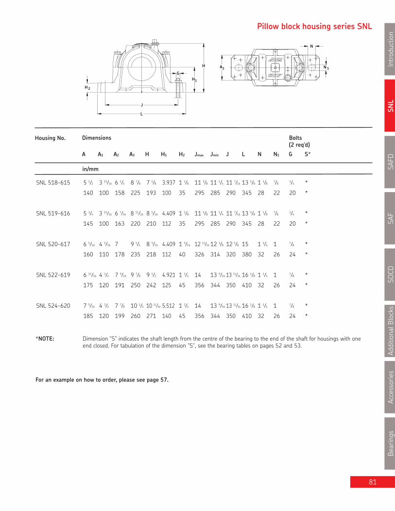
SNL
Introduction
SAFD
SAF
SDCD
AdditionalB
locks
Accessories
Bearings
81
Pillow block housing series SNL
H
H 2
L
J
G
1H
A1
N
N 1
Housing No. Dimensions Bolts
A A1 A2 A3 H H1 H2 Jmax Jmin J L N N1 G S*
in/mm
*NOTE: Dimension "S" indicates the shaft length from the centre of the bearing to the end of the shaft for housings with oneend closed. For tabulation of the dimension "S", see the bearing tables on pages 52 and 53.
For an example on how to order, please see page 57.
SNL 518-615 5 1⁄2 3 15⁄16 6 1⁄4 8 7⁄8 7 5⁄8 3.937 1 3⁄8 11 5⁄8 11 1⁄4 11 7⁄16 13 5⁄8 1 1⁄8 7⁄8 3⁄4 *
140 100 158 225 193 100 35 295 285 290 345 28 22 20 *
SNL 519-616 5 3⁄4 3 15⁄16 6 7⁄16 8 11⁄16 8 5⁄16 4.409 1 3⁄8 11 5⁄8 11 1⁄4 11 7⁄16 13 5⁄8 1 1⁄8 7⁄8 3⁄4 *
145 100 163 220 210 112 35 295 285 290 345 28 22 20 *
SNL 520-617 6 5⁄16 4 5⁄16 7 9 1⁄4 8 9⁄16 4.409 1 9⁄16 12 13⁄16 12 3⁄8 12 5⁄8 15 1 1⁄4 1 7⁄8 *
160 110 178 235 218 112 40 326 314 320 380 32 26 24 *
SNL 522-619 6 15⁄16 4 3⁄4 7 9⁄16 9 7⁄8 9 1⁄2 4.921 1 3⁄4 14 13 9⁄16 13 11⁄16 16 1⁄8 1 1⁄4 1 7⁄8 *
175 120 191 250 242 125 45 356 344 350 410 32 26 24 *
SNL 524-620 7 5⁄16 4 3⁄4 7 7⁄8 10 1⁄4 10 11⁄16 5.512 1 3⁄4 14 13 9⁄16 13 11⁄16 16 1⁄8 1 1⁄4 1 7⁄8 *
185 120 199 260 271 140 45 356 344 350 410 32 26 24 *
(2 req'd)

SNL
IntroductionSAFD
SAFSD
CDAdditionalBlocks
AccessoriesBearings
82
Series SNL 500 and SNL 600Pillow blocks of cast iron forbearing with adapter sleeve,grease or oil lubricationda 3 1⁄2 in (90 - 100 mm) da
S
A 2A 3A
Double-lip sealsG & L design
Labyrinth sealsS design
Taconite sealsND design
Shaft Complete Pillow Housing Standard Bearing Adapter Fixing Mass EndDia. Block Assembly Seal Sleeve Rings Complete Coverda Package Qty.
mm in lb. kg.
3 1⁄2 SNL 1520/3 1⁄2 TGE SNL 520-617 TSN 520GE 1220 K HE 220 FRB 18/180 2 49.8 22.6 ASNH 520-617
SNL 1620/3 1⁄2 TGE SNL 524-620 TSN 620GE 1320 K HE 320 FRB 19.5/215 2 79.6 36.1 ASNH 524-620
SNL 2520/3 1⁄2 TGE SNL 520-617 TSN 520GE 2220 K HE 320 FRB 12/180 2 52.5 23.8 ASNH 520-617
SNL 2620/3 1⁄2 TGE SNL 524-620 TSN 620GE 2320 K HE 2320 FRB 6.5/215 2 89.0 40.4 ASNH 524-620
SNL 21620/3 1⁄2 TGE SNL 524-620 TSN 620GE 21320 EK HE 320 FRB 19.5/215 2 80.7 36.6 ASNH 524-620
SNL 22520/3 1⁄2 TGE SNL 520-617 TSN 520GE 22220 EK HE 320 FRB 12/180 2 52.7 23.9 ASNH 520-617
SNL 22620/3 1⁄2 TGE SNL 524-620 TSN 620GE 22320 EK HE 2320 FRB 6.5/215 2 90.2 40.9 ASNH 524-620
SNL 23520/3 1⁄2 TGE SNL 520-617 TSN 520GE 23220CCK/W33 HE 2320 FRB 4.85/180 2 57.3 26.0 ASNH 520-617
SNL C2520/3 1⁄2 TGE SNL 520-617 TSN 520GE C2220 K* HE 320E FRB 12/180 2 52.7 23.9 ASNH 520-617
SNL C2620/3 1⁄2 TGE SNL 524-620 TSN 620GE C2320 K* HE 2320 FRB 6.5/215 2 90.2 40.9 ASNH 524-620
90 SNL 1520/90 TL SNL 520-617 TSN 520L 1220 K H 220 FRB 18/180 2 49.8 22.6 ASNH 520-617
SNL 1620/90 TG SNL 524-620 TSN 620G 1320 K H 320 FRB 19.5/215 2 79.6 36.1 ASNH 524-620
SNL 2520/90 TL SNL 520-617 TSN 520L 2220 K H 320 FRB 12/180 2 52.5 23.8 ASNH 520-617
SNL 2620/90 TG SNL 524-620 TSN 620G 2320 K H 2320 FRB 6.5/215 2 89.0 40.4 ASNH 524-620
SNL 21620/90 TG SNL 524-620 TSN 620G 21320 EK H 320 FRB 19.5/215 2 80.7 36.6 ASNH 524-620
SNL 22520/90 TL SNL 520-617 TSN 520L 22220 EK H 320 FRB 12/180 2 52.7 23.9 ASNH 520-617
SNL 22620/90 TG SNL 524-620 TSN 620G 22320 EK H 2320 FRB 6.5/215 2 90.2 40.9 ASNH 524-620
SNL 23520/90 TL SNL 520-617 TSN 520L 23220CCK/W33 H 2320 FRB 4.85/180 2 57.3 26.0 ASNH 520-617
SNL C2520/90 TL SNL 520-617 TSN 520L C2220 K* H 320E FRB 12/180 2 52.7 23.9 ASNH 520-617
SNL C2620/90 TG SNL 524-620 TSN 620G C2320 K* H 2320 FRB 6.5/215 2 90.2 40.9 ASNH 524-620
100 SNL 1522/100 TL SNL 522-619 TSN 522L 1222K H 222 FRB 21/200 2 64.0 29.0 ASNH 522-619
SNL 2522/100 TL SNL 522-619 TSN 522L 2222 K H 322 FRB 13.5/200 2 64.6 29.3 ASNH 522-619
SNL 22522/100 TL SNL 522-619 TSN 522L 22222 K H 322 FRB 13.5/200 2 68.3 31.0 ASNH 522-619
SNL 23522/100 TL SNL 522-619 TSN 522L 23222CCK/W33 H 2322 FRB 5.1/200 2 75.4 34.2 ASNH 522-619
SNL C2522/100 TL SNL 522-619 TSN 522L C2222 K* H 322E FRB 13.5/200 2 68.3 31.0 ASNH 522-619
* Must always be located.

SNL
Introduction
SAFD
SAF
SDCD
AdditionalB
locks
Accessories
Bearings
83
Pillow block housing series SNL
H
H 2
L
J
G
1H
A1
N
N 1
Housing No. Dimensions Bolts
A A1 A2 A3 H H1 H2 Jmax Jmin J L N N1 G S*
in/mm
*NOTE: Dimension "S" indicates the shaft length from the centre of the bearing to the end of the shaft for housings with oneend closed. For tabulation of the dimension "S", see the bearing tables on pages 52 and 53.
For an example on how to order, please see page 57.
(2 req'd)
SNL 520-617 6 5⁄16 4 5⁄16 7 9 1⁄4 8 9⁄16 4.409 1 9⁄16 12 13⁄16 12 3⁄8 12 5⁄8 15 1 1⁄4 1 7⁄8 *
160 110 178 235 218 112 40 326 314 320 380 32 26 24 *
SNL 522-619 6 15⁄16 4 3⁄4 7 9⁄16 9 7⁄8 9 1⁄2 4.921 1 3⁄4 14 13 9⁄16 13 11⁄16 16 1⁄8 1 1⁄4 1 7⁄8 *
175 120 191 250 242 125 45 356 344 350 410 32 26 24 *
SNL 524-620 7 5⁄16 4 3⁄4 7 7⁄8 10 1⁄4 10 11⁄16 5.512 1 3⁄4 14 13 9⁄16 13 11⁄16 16 1⁄8 1 1⁄4 1 7⁄8 *
185 120 199 260 271 140 45 356 344 350 410 32 26 24 *
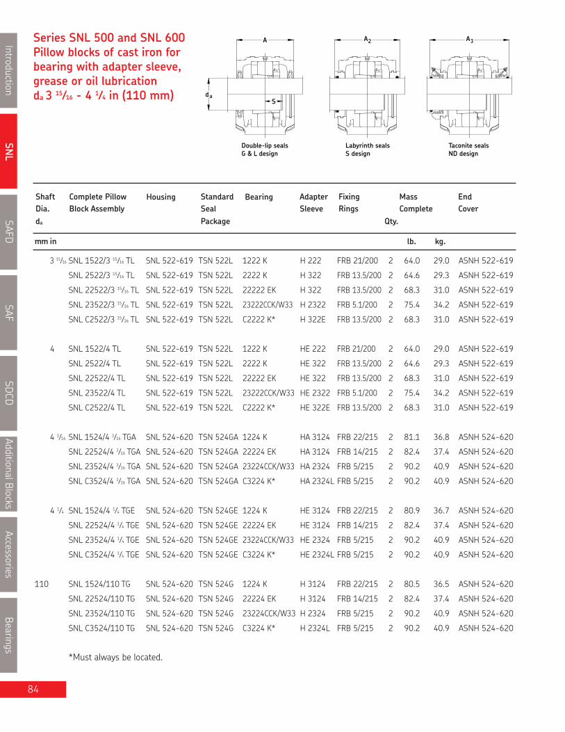
SNL
IntroductionSAFD
SAFSD
CDAdditionalBlocks
AccessoriesBearings
84
Series SNL 500 and SNL 600Pillow blocks of cast iron forbearing with adapter sleeve,grease or oil lubricationda 3 15⁄16 - 4 1⁄4 in (110 mm) da
S
A 2A 3A
Double-lip sealsG & L design
Labyrinth sealsS design
Taconite sealsND design
Shaft Complete Pillow Housing Standard Bearing Adapter Fixing Mass EndDia. Block Assembly Seal Sleeve Rings Complete Coverda Package Qty.
mm in lb. kg.
3 15⁄16 SNL 1522/3 15⁄16 TL SNL 522-619 TSN 522L 1222 K H 222 FRB 21/200 2 64.0 29.0 ASNH 522-619
SNL 2522/3 15⁄16 TL SNL 522-619 TSN 522L 2222 K H 322 FRB 13.5/200 2 64.6 29.3 ASNH 522-619
SNL 22522/3 15⁄16 TL SNL 522-619 TSN 522L 22222 EK H 322 FRB 13.5/200 2 68.3 31.0 ASNH 522-619
SNL 23522/3 15⁄16 TL SNL 522-619 TSN 522L 23222CCK/W33 H 2322 FRB 5.1/200 2 75.4 34.2 ASNH 522-619
SNL C2522/3 15⁄16 TL SNL 522-619 TSN 522L C2222 K* H 322E FRB 13.5/200 2 68.3 31.0 ASNH 522-619
4 SNL 1522/4 TL SNL 522-619 TSN 522L 1222 K HE 222 FRB 21/200 2 64.0 29.0 ASNH 522-619
SNL 2522/4 TL SNL 522-619 TSN 522L 2222 K HE 322 FRB 13.5/200 2 64.6 29.3 ASNH 522-619
SNL 22522/4 TL SNL 522-619 TSN 522L 22222 EK HE 322 FRB 13.5/200 2 68.3 31.0 ASNH 522-619
SNL 23522/4 TL SNL 522-619 TSN 522L 23222CCK/W33 HE 2322 FRB 5.1/200 2 75.4 34.2 ASNH 522-619
SNL C2522/4 TL SNL 522-619 TSN 522L C2222 K* HE 322E FRB 13.5/200 2 68.3 31.0 ASNH 522-619
4 3⁄16 SNL 1524/4 3⁄16 TGA SNL 524-620 TSN 524GA 1224 K HA 3124 FRB 22/215 2 81.1 36.8 ASNH 524-620
SNL 22524/4 3⁄16 TGA SNL 524-620 TSN 524GA 22224 EK HA 3124 FRB 14/215 2 82.4 37.4 ASNH 524-620
SNL 23524/4 3⁄16 TGA SNL 524-620 TSN 524GA 23224CCK/W33 HA 2324 FRB 5/215 2 90.2 40.9 ASNH 524-620
SNL C3524/4 3⁄16 TGA SNL 524-620 TSN 524GA C3224 K* HA 2324L FRB 5/215 2 90.2 40.9 ASNH 524-620
4 1⁄4 SNL 1524/4 1⁄4 TGE SNL 524-620 TSN 524GE 1224 K HE 3124 FRB 22/215 2 80.9 36.7 ASNH 524-620
SNL 22524/4 1⁄4 TGE SNL 524-620 TSN 524GE 22224 EK HE 3124 FRB 14/215 2 82.4 37.4 ASNH 524-620
SNL 23524/4 1⁄4 TGE SNL 524-620 TSN 524GE 23224CCK/W33 HE 2324 FRB 5/215 2 90.2 40.9 ASNH 524-620
SNL C3524/4 1⁄4 TGE SNL 524-620 TSN 524GE C3224 K* HE 2324L FRB 5/215 2 90.2 40.9 ASNH 524-620
110 SNL 1524/110 TG SNL 524-620 TSN 524G 1224 K H 3124 FRB 22/215 2 80.5 36.5 ASNH 524-620
SNL 22524/110 TG SNL 524-620 TSN 524G 22224 EK H 3124 FRB 14/215 2 82.4 37.4 ASNH 524-620
SNL 23524/110 TG SNL 524-620 TSN 524G 23224CCK/W33 H 2324 FRB 5/215 2 90.2 40.9 ASNH 524-620
SNL C3524/110 TG SNL 524-620 TSN 524G C3224 K* H 2324L FRB 5/215 2 90.2 40.9 ASNH 524-620
*Must always be located.

SNL
Introduction
SAFD
SAF
SDCD
AdditionalB
locks
Accessories
Bearings
85
Pillow block housing series SNL
H
H 2
L
J
G
1H
A1
N
N 1
Housing No. Dimensions Bolts
A A1 A2 A3 H H1 H2 Jmax Jmin J L N N1 G S*
in/mm
*NOTE: Dimension "S" indicates the shaft length from the centre of the bearing to the end of the shaft for housings with oneend closed. For tabulation of the dimension "S", see the bearing tables on pages 52 and 53.
For an example on how to order, please see page 57.
(2 req'd)
SNL 522-619 6 15⁄16 4 3⁄4 7 9⁄16 9 7⁄8 9 1⁄2 4.921 1 3⁄4 14 13 9⁄16 13 11⁄16 16 1⁄8 1 1⁄4 1 7⁄8 *
175 120 191 250 242 125 45 356 344 350 410 32 26 24 *
SNL 524-620 7 5⁄16 4 3⁄4 7 7⁄8 10 1⁄4 10 11⁄16 5.512 1 3⁄4 14 13 9⁄16 13 11⁄16 16 1⁄8 1 1⁄4 1 7⁄8 *
185 120 199 260 271 140 45 356 344 350 410 32 26 24 *

SNL
IntroductionSAFD
SAFSD
CDAdditionalBlocks
AccessoriesBearings
86
Series SNL 500 and SNL 600Pillow blocks of cast iron forbearing with adapter sleeve,grease or oil lubricationda 4 7⁄16 - 5 in (115 - 125 mm) da
S
A 2A 3A
Double-lip sealsG & L design
Labyrinth sealsS design
Taconite sealsND design
Shaft Complete Pillow Housing Standard Bearing Adapter Fixing Mass EndDia. Block Assembly Seal Sleeve Rings Complete Coverda Package Qty.
mm in lb. kg.
4 7⁄16 SNL 22526/4 7⁄16 TGA SNL 526 TSN 526GA 22226 EK HA 3126 FRB 13/230 2 104 47.2 ASNH 526
SNL 23526/4 7⁄16 TGA SNL 526 TSN 526GA 23226CCK/W33 HA 2326 FRB 5/230 2 113 51.1 ASNH 526
SNL C2526/4 7⁄16 TGA SNL 526 TSN 526GA C2226 K* HA 3126L FRB 13/230 2 104 42.2 ASNH 526
4 1⁄2 SNL 22526/ 4 1⁄2 TG SNL 526 TSN 526G 22226 EK HE 3126 FRB 13/230 2 104 47.2 ASNH 526
SNL 23526/ 4 1⁄2 TG SNL 526 TSN 526G 23226CCK/W33 HE 2326 FRB 5/230 2 113 51.1 ASNH 526
SNL C2526/ 4 1⁄2 TG SNL 526 TSN 526G C2226 K* HE 3126L FRB 13/230 2 104 42.2 ASNH 526
115 SNL 22526/115 TG SNL 526 TSN 526G 22226 EK H 3126 FRB 13/230 2 104 47.2 ASNH 526
SNL 23526/115 TG SNL 526 TSN 526G 23226CCK/W33 H 2326 FRB 5/230 2 113 51.1 ASNH 526
SNL C2526/115 TG SNL 526 TSN 526G C2226 K* H 3126L FRB 13/230 2 104 42.2 ASNH 526
125 SNL 22528/125 TG SNL 528 TSN 528G 22228CCK/W33 H 3128 FRB 15/250 2 128 57.9 ASNH 528
SNL 23528/125 TG SNL 528 TSN 528G 23228CCK/W33 H 2328 FRB 5/250 2 140 63.6 ASNH 528
SNL C2528/125 TG SNL 528 TSN 528G C2228 K* H 3128L FRB 15/250 2 128 57.9 ASNH 528
4 15⁄16 SNL 22528/4 15⁄16 TG SNL 528 TSN 528G 22228CCK/W33 HA 3128 FRB 15/250 2 128 57.9 ASNH 528
SNL 23528/4 15⁄16 TG SNL 528 TSN 528G 23228CCK/W33 HA 2328 FRB 5/250 2 140 63.6 ASNH 528
SNL C2528/4 15⁄16 TG SNL 528 TSN 528G C2228 K * HA 3128L FRB 15/250 2 128 57.9 ASNH 528
5 SNL 22528/5 TGE SNL 528 TSN 528GE 22228CCK/W33 HE 3128 FRB 15/250 2 128 57.9 ASNH 528
SNL 23528/5 TGE SNL 528 TSN 528GE 23228CCK/W33 HE 2328 FRB 5/250 2 140 63.6 ASNH 528
SNL C2528/5 TGE SNL 528 TSN 528GE C2228 K* HE 3128L FRB 15/250 2 128 57.9 ASNH 528
* Must always be located.

SNL
Introduction
SAFD
SAF
SDCD
AdditionalB
locks
Accessories
Bearings
87
Pillow block housing series SNL
H
H 2
L
J
G
1H
A1
N
N 1
Housing No. Dimensions Bolts
A A1 A2 A3 H H1 H2 Jmax Jmin J L N N1 G S*
in/mm
*NOTE: Dimension "S" indicates the shaft length from the centre of the bearing to the end of the shaft for housings with oneend closed. For tabulation of the dimension "S", see the bearing tables on pages 52 and 53.
For an example on how to order, please see page 57.
(2 req'd)
SNL 526 7 1⁄2 5 1⁄8 8 3⁄16 10 7⁄16 11 7⁄16 5.906 2 15 1⁄4 14 11⁄16 15 17 9⁄16 1 3⁄8 1 1⁄8 1 *
190 130 208 265 290 150 50 387 373 380 445 35 28 24 *
SNL 528 8 1⁄8 5 15⁄16 8 13⁄16 11 1⁄4 11 15⁄16 5.906 2 16 3⁄4 16 15⁄16 16 9⁄16 19 11⁄16 1 11⁄16 1 3⁄8 1 1⁄4 *
205 150 223 285 302 150 50 427 413 420 500 42 35 30 *

SNL
IntroductionSAFD
SAFSD
CDAdditionalBlocks
AccessoriesBearings
88
Series SNL 500 and SNL 600Pillow blocks of cast iron forbearing with adapter sleeve,grease or oil lubricationda 5 3⁄16 - 5 1⁄2 in(135 - 140 mm)
daS
A 2A 3A
Double-lip sealsG & L design
Labyrinth sealsS design
Taconite sealsND design
Shaft Complete Pillow Housing Standard Bearing Adapter Fixing Mass EndDia. Block Assembly Seal Sleeve Rings Complete Coverda Package Qty.
mm in lb. kg.
5 3⁄16 SNL 22530/5 3⁄16 TGA SNL 530 TSN 530GA 22230CCK/W33 HA 3130 FRB 16.5/270 2 159 72.0 ASNH 530
SNL 23530/5 3⁄16 TGA SNL 530 TSN 530GA 23230CCK/W33 HA 2330 FRB 5/270 2 174 79.1 ASNH 530
SNL C2530/5 3⁄16 TGA SNL 530 TSN 530GA C2230 K* HA 3130L FRB 16.5/270 2 159 72.0 ASNH 530
5 1⁄4 SNL 22530/5 1⁄4 TGE SNL 530 TSN 530GE 22230CCK/W33 HE 3130 FRB 16.5/270 2 159 72.0 ASNH 530
SNL 23530/5 1⁄4 TGE SNL 530 TSN 530GE 23230CCK/W33 HE 2330 FRB 5/270 2 174 79.1 ASNH 530
SNL C2530/5 1⁄4 TGE SNL 530 TSN 530GE C2230 K* HE 3130L FRB 16.5/270 2 159 72.0 ASNH 530
135 SNL 22530/135 TG SNL 530 TSN 530G 22230CCK/W33 H 3130 FRB 16.5/270 2 159 72.0 ASNH 530
SNL 23530/135 TG SNL 530 TSN 530G 23230CCK/W33 H 2330 FRB 5/270 2 174 79.1 ASNH 530
SNL C2530/135 TG SNL 530 TSN 530G C2230 K* H 3130L FRB 16.5/270 2 159 72.0 ASNH 530
5 7⁄16 SNL 22532/5 7⁄16 TGA SNL 532 TSN 532GA 22232CCK/W33 HA 3132 FRB 17/290 2 187 84.7 ASNH 532
SNL 23532/5 7⁄16 TGA SNL 532 TSN 532GA 23232CCK/W33 HA 2332 FRB 5/290 2 205 93.2 ASNH 532
SNL C3532/5 7⁄16 TGA SNL 532 TSN 532GA C3232 K* HA 2332L FRB 5/290 2 205 93.2 ASNH 532
5 1⁄2 SNL 22532/5 1⁄2 TG SNL 532 TSN 532G 22232CCK/W33 HE 3132 FRB 17/290 2 187 84.7 ASNH 532
SNL 23532/5 1⁄2 TG SNL 532 TSN 532G 23232CCK/W33 HE 2332 FRB 5/290 2 205 93.2 ASNH 532
SNL C3532/5 1⁄2 TG SNL 532 TSN 532G C3232 K* HE 2332L FRB 5/290 2 205 93.2 ASNH 532
140 SNL 22532/140 TG SNL 532 TSN 532G 22232CCK/W33 H 3132 FRB 17/290 2 187 84.7 ASNH 532
SNL 23532/140 TG SNL 532 TSN 532G 23232CCK/W33 H 2332 FRB 5/290 2 205 93.2 ASNH 532
SNL C3532/140 TG SNL 532 TSN 532G C3232 K* H 2332L FRB 5/290 2 205 93.2 ASNH 532
* Must always be located.

SNL
Introduction
SAFD
SAF
SDCD
AdditionalB
locks
Accessories
Bearings
89
Pillow block housing series SNL
H
H 2
L
J
G
1H
A1
N
N 1
Housing No. Dimensions Bolts
A A1 A2 A3 H H1 H2 Jmax Jmin J L N N1 G S*
in/mm
*NOTE: Dimension "S" indicates the shaft length from the centre of the bearing to the end of the shaft for housings with oneend closed. For tabulation of the dimension "S", see the bearing tables on pages 52 and 53.
For an example on how to order, please see page 57.
(2 req'd)
SNL 530 8 11⁄16 6 5⁄16 9 1⁄2 11 5⁄8 12 3⁄4 6.299 2 3⁄8 17 15⁄16 17 1⁄2 17 3⁄4 20 7⁄8 1 11⁄16 1 3⁄8 1 1⁄4 *
220 160 241 295 323 160 60 457 443 450 530 42 35 30 *
SNL 532 9 1⁄4 6 5⁄16 10 12 7⁄16 13 9⁄16 6.693 2 3⁄8 18 3⁄4 18 1⁄4 18 1⁄2 21 11⁄16 1 11⁄16 1 3⁄8 1 1⁄4 *
235 160 254 315 344 170 60 477 463 470 550 42 35 30 *

SNL: cast iron GG20 (ISO/DIS 185 grade 200) SSNLD: Ductile iron
12, 12E, 13, 22, 22E, 23, 222CC, 222E, 223CC, 223E
MATERIAL
BEARING SERIESUSED
STANDARD SEALS
OPTIONAL SEALS
LUBRICATIONPILLOW BLOCK
SHAFT SIZE RANGE
PILLOW BLOCK SIZE205 - 232 (cylindrical bore mounting)
3/4" TO 5-1/2" 25mm TO 160mm
Grease (for oil lubrication consult SKF)
305 - 320 (cylindrical bore mounting)
C 22, C 23, C32
SNL, SSNLD
TSN-STSN-A TSN-C Loose felt strips2 x FS
Taconite TSN-ND
TSN-G TSN-L
Pillow BlockHousings
SNL
IntroductionSAFD
SAFSD
CDAdditionalBlocks
AccessoriesBearings
90
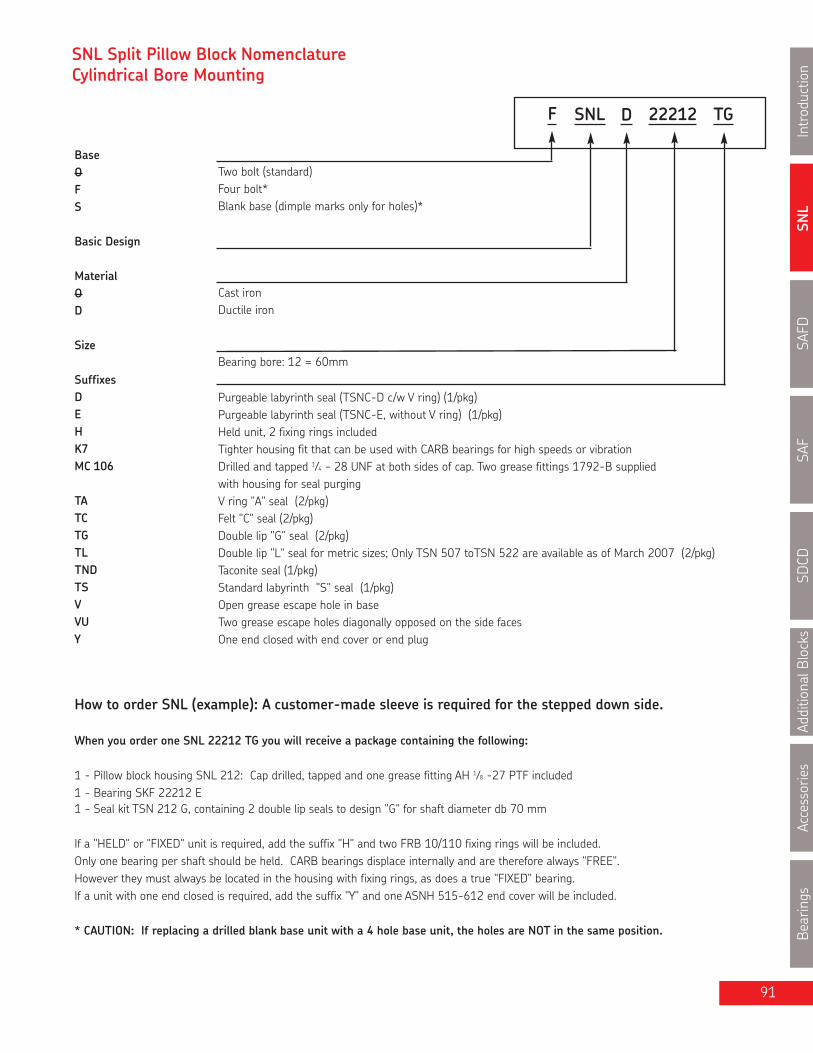
SNL
Introduction
SAFD
SAF
SDCD
AdditionalB
locks
Accessories
Bearings
91
SNL Split Pillow Block NomenclatureCylindrical Bore Mounting
BaseOFS
Basic Design
MaterialOD
Size
SuffixesDEHK7MC 106
TATCTGTLTNDTSVVUY
Two bolt (standard)Four bolt*Blank base (dimple marks only for holes)*
Cast ironDuctile iron
Bearing bore: 12 = 60mm
Purgeable labyrinth seal (TSNC-D c/w V ring) (1/pkg)Purgeable labyrinth seal (TSNC-E, without V ring) (1/pkg)Held unit, 2 fixing rings includedTighter housing fit that can be used with CARB bearings for high speeds or vibrationDrilled and tapped 1⁄4 - 28 UNF at both sides of cap. Two grease fittings 1792-B suppliedwith housing for seal purgingV ring "A" seal (2/pkg)Felt "C" seal (2/pkg)Double lip "G" seal (2/pkg)Double lip "L" seal for metric sizes; Only TSN 507 toTSN 522 are available as of March 2007 (2/pkg)Taconite seal (1/pkg)Standard labyrinth "S" seal (1/pkg)Open grease escape hole in baseTwo grease escape holes diagonally opposed on the side facesOne end closed with end cover or end plug
How to order SNL (example): A customer-made sleeve is required for the stepped down side.
When you order one SNL 22212 TG you will receive a package containing the following:
1 - Pillow block housing SNL 212: Cap drilled, tapped and one grease fitting AH 1⁄8 -27 PTF included1 - Bearing SKF 22212 E1 - Seal kit TSN 212 G, containing 2 double lip seals to design "G" for shaft diameter db 70 mm
If a "HELD" or "FIXED" unit is required, add the suffix "H" and two FRB 10/110 fixing rings will be included.Only one bearing per shaft should be held. CARB bearings displace internally and are therefore always "FREE".However they must always be located in the housing with fixing rings, as does a true "FIXED" bearing.If a unit with one end closed is required, add the suffix "Y" and one ASNH 515-612 end cover will be included.
* CAUTION: If replacing a drilled blank base unit with a 4 hole base unit, the holes are NOT in the same position.
SNLF 22212 TGD

SNL
IntroductionSAFD
SAFSD
CDAdditionalBlocks
AccessoriesBearings
SNL - Cylindrical Bore MountingSeries SNL 200 and SNL 300Pillow blocks of cast iron forbearings with cylindrical boremounting, grease or oil lubricationda 25 - 40 mmdb 30 - 50 mm
db da
A 2A 3A
Labyrinth sealsS design
Taconite sealsND designG & L design
Double-lip seals
Shaft Complete Pillow Housing Standard Bearing Fixing Mass EndDia. Block Assembly Seal Rings Complete Coverda/db Package Qty.
mm lb. kg.
25 30 SNL 1205 TG SNL 205 TSN 205G 1205 E FRB 5/52 2 3.44 1.56 ASNH 506-605
SNL 1305 TG SNL 206-305 TSN 305G 1305 E FRB 7.5/62 2 4.85 2.20 ASNH 507-605
SNL 2205 TG SNL 205 TSN 205G 2205 E FRB 3.5/52 2 4.10 1.86 ASNH 506-605
SNL 2305 TG SNL 206-305 TSN 305G 2305 FRB 4/62 2 4.98 2.26 ASNH 507-605
SNL 21305 TG SNL 206-305 TSN 305G 21305 CC FRB 7.5/62 2 4.83 2.19 ASNH 507-605
SNL 22205 TG SNL 205 TSN 205G 22205 E FRB 3.5/52 2 3.53 1.60 ASNH 506-605
SNL C2205 TG SNL 205 TSN 205G C2205* FRB 3.5/52 2 4.10 1.86 ASNH 506-605
30 35 SNL 1206 TG SNL 206-305 TSN 206G 1206 E FRB 8/62 2 4.76 2.16 ASNH 507-606
SNL 1306 TG SNL 507-606 TSN 306G 1306 E FRB 7.5/72 2 5.82 2.64 ASNH 507-606
SNL 2206 TG SNL 206-305 TSN 206G 2206 E FRB 6/62 2 4.83 2.19 ASNH 507-606
SNL 2306 TG SNL 507-606 TSN 306G 2306 FRB 3.5/72 2 6.22 2.82 ASNH 507-606
SNL 21306 TG SNL 507-606 TSN 306G 21306 CC FRB 7.5/72 2 5.80 2.63 ASNH 507-606
SNL 22206 TG SNL 206-305 TSN 206G 22206 E FRB 6/62 2 4.87 2.21 ASNH 507-606
SNL C2206 TG SNL 206-305 TSN 206G C2206* FRB 6/62 2 4.83 2.19 ASNH 507-606
35 45 SNL 1207 TG SNL 207 TSN 207G 1207 E FRB 8.5/72 2 5.47 2.48 ASNH 509
SNL 1307 TG SNL 208-307 TSN 307G 1307 E FRB 9/80 2 7.67 3.48 ASNH 510-608
SNL 2207 TG SNL 207 TSN 207G 2207 E FRB 5.5/72 2 5.60 2.54 ASNH 509
SNL 2307 TG SNL 208-307 TSN 307G 2307 E FRB 4/80 2 7.96 3.61 ASNH 510-608
SNL 21307 TG SNL 208-307 TSN 307G 21307 CC FRB 9/80 2 7.67 3.48 ASNH 510-608
SNL 22207 TG SNL 207 TSN 207G 22207 E FRB 5.5/72 2 5.67 2.57 ASNH 509
SNL C2207 TG SNL 207 TSN 207G C2207* FRB 5.5/72 2 5.67 2.57 ASNH 509
40 50 SNL 1208 TG SNL 208-307 TSN 208G 1208 E FRB 10.5/80 2 7.17 3.25 ASNH 510-608
SNL 1308 TG SNL 510-608 TSN 308G 1308 E FRB 9/90 2 8.82 4.00 ASNH 510-608
SNL 2208 TG SNL 208-307 TSN 208G 2208 E FRB 8/80 2 8.55 3.88 ASNH 510-608
SNL 2308 TG SNL 510-608 TSN 308G 2308 E FRB 4/90 2 9.19 4.17 ASNH 510-608
SNL 21308 TG SNL 510-608 TSN 308G 21308 E FRB 9/90 2 8.80 3.99 ASNH 510-608
SNL 22208 TG SNL 208-307 TSN 208G 22208 E FRB 8/80 2 7.28 3.30 ASNH 510-608
SNL 22308 TG SNL 510-608 TSN 308G 22308 E FRB 4/90 2 10.3 4.67 ASNH 510-608
* Must always be located.
92

SNL
Introduction
SAFD
SAF
SDCD
AdditionalB
locks
Accessories
Bearings
93
Pillow block housing series SNL
H
J
L
2
GH1
H1A
N
1N
Housing No. Dimensions Bolts
A A1 A2 A3 H H1 H2 Jmax Jmin J L N N1 G
in/mm
For an example on how to order, please see page 91.
(2 req'd)
SNL 205 2 5⁄8 1 13⁄16 3 9⁄16 5 1⁄2 2 15⁄16 1.575 3⁄4 5 3⁄8 4 7⁄8 5 1⁄8 6 1⁄2 3⁄4 5⁄8 1⁄2
67 46 90 140 74 40 19 137 123 130 165 20 15 12
SNL 206-305 3 1⁄16 2 1⁄16 3 3⁄8 5 15⁄16 3 3⁄8 1.969 7⁄8 6 1⁄8 5 11⁄16 5 15⁄16 7 5⁄16 3⁄4 5⁄8 1⁄2
77 52 89 150 89 50 22 157 143 150 185 20 15 12
SNL 507-606 3 1⁄4 2 1⁄16 3 3⁄4 6 1⁄8 3 5⁄8 1.969 7⁄8 6 1⁄8 5 11⁄16 5 15⁄16 7 5⁄16 3⁄4 5/8 1⁄2
82 52 94 155 93 50 22 157 143 150 185 20 15 12
SNL 207 3 1⁄4 2 1⁄16 3 3⁄4 6 1⁄8 3 5⁄8 1.969 7⁄8 6 1⁄8 5 11⁄16 5 15⁄16 7 5⁄16 3⁄4 5⁄8 1⁄2
82 52 96 155 93 50 22 157 143 150 185 20 15 12
SNL 208-307 3 3⁄8 2 3⁄8 3 15⁄16 6 15⁄16 4 1⁄4 2.362 1 6 7⁄8 6 1⁄2 6 11⁄16 8 1⁄8 3⁄4 5⁄8 1⁄2
85 60 99 160 108 60 25 175 165 170 205 20 15 12
SNL 510-608 3 9⁄16 2 3⁄8 4 6 9⁄16 4 1⁄2 2.362 1 6 7⁄8 6 1⁄2 6 11⁄16 8 1⁄8 3⁄4 5⁄8 1⁄2
90 60 102 167 113 60 25 175 165 170 205 20 15 12

SNL
IntroductionSAFD
SAFSD
CDAdditionalBlocks
AccessoriesBearings
94
SNL - Cylindrical Bore MountingSeries SNL 200 and SNL 300Pillow blocks of cast iron forbearings with cylindrical boremounting, grease or oil lubricationda 45 - 55 mmdb 55 - 65 mm
db da
A 2A 3A
Labyrinth sealsS design
Taconite sealsND designG & L design
Double-lip seals
Shaft Complete Pillow Housing Standard Bearing Fixing Mass EndDia. Block Assembly Seal Rings Complete Coverda/db Package Qty.
mm lb. kg.
45 55 SNL 1209 TG SNL 209 TSN 209G 1209 E FRB 5.5/85 2 7.21 3.27 ASNH 511-609
SNL 1309 TG SNL 511-609 TSN 309G 1309 E FRB 9.5/100 2 12.0 5.45 ASNH 511-609
SNL 2209 TG SNL 209 TSN 209G 2209 E FRB 3.5/85 2 7.34 3.33 ASNH 511-609
SNL 2309 TG SNL 511-609 TSN 309G 2309 E FRB 4/100 2 12.5 5.69 ASNH 511-609
SNL 21309 TG SNL 511-609 TSN 309G 21309 E FRB 9.5/100 2 12.0 5.44 ASNH 511-609
SNL 22209 TG SNL 209 TSN 209G 22209 E FRB 3.5/85 2 7.36 3.34 ASNH 511-609
SNL 22309 TG SNL 511-609 TSN 309G 22309 E FRB 4/100 2 12.8 5.79 ASNH 511-609
SNL C2209 TG SNL 209 TSN 209G C2209* FRB 3.5/85 2 12.8 5.79 ASNH 511-609
50 60 SNL 1210 TG SNL 210 TSN 210G 1210 E FRB 10.5/90 2 7.98 3.62 ASNH 512-610
SNL 1310 TG SNL 512-610 TSN 310G 1310 E FRB 10.5/110 2 14.2 6.43 ASNH 512-610
SNL 2210 TG SNL 210 TSN 210G 2210 E FRB 9/90 2 8.11 3.68 ASNH 512-610
SNL 2310 TG SNL 512-610 TSN 310G 2310 FRB 4/110 2 15.0 6.80 ASNH 512-610
SNL 21310 TG SNL 512-610 TSN 310G 21310 E FRB 10.5/110 2 14.2 6.43 ASNH 512-610
SNL 22210 TG SNL 210 TSN 210G 22210 E FRB 9/90 2 8.11 3.68 ASNH 512-610
SNL 22310 TG SNL 512-610 TSN 310G 22310 E FRB 4/110 2 15.4 7.00 ASNH 512-610
SNL C2210 TG SNL 210 TSN 210G C2210* FRB 9/90 2 15.3 6.94 ASNH 512-610
55 65 SNL 1211 TG SNL 211 TSN 211G 1211 E FRB 11.5/100 2 11.1 5.02 ASNH 513-611
SNL 1311 TG SNL 513-611 TSN 311G 1311 E FRB 11/120 2 18.2 8.25 ASNH 513-611
SNL 2211 TG SNL 211 TSN 211G 2211 E FRB 9.5/100 2 11.2 5.10 ASNH 513-611
SNL 2311 TG SNL 513-611 TSN 311G 2311 FRB 4/120 2 19.1 8.65 ASNH 513-611
SNL 21311 TG SNL 513-611 TSN 311G 21311 E FRB 11/120 2 18.2 8.25 ASNH 513-611
SNL 22211 TG SNL 211 TSN 211G 22211 E FRB 9.5/100 2 11.3 5.11 ASNH 513-611
SNL 22311 TG SNL 513-611 TSN 311G 22311 E FRB 4/120 2 19.6 8.90 ASNH 513-611
SNL C2211 TG SNL 211 TSN 211G C2211* FRB 9.5/100 2 11.3 5.11 ASNH 513-611
* Must always be located.

SNL
Introduction
SAFD
SAF
SDCD
AdditionalB
locks
Accessories
Bearings
95
Pillow block housing series SNL
H
J
L
2
GH1
H1A
N
1N
Housing No. Dimensions Bolts
A A1 A2 A3 H H1 H2 Jmax Jmin J L N N1 G
in/mm
For an example on how to order, please see page 91.
(2 req'd)
SNL 209 3 3⁄8 2 3⁄8 3 13⁄16 6 5⁄16 4 1⁄4 2.362 1 6 7⁄8 6 1⁄2 6 11⁄16 8 1⁄8 3⁄4 5⁄8 1⁄2
85 60 97 160 109 60 25 175 165 170 205 20 15 12
SNL 210 3 9⁄16 2 3⁄8 4 6 1⁄2 4 1⁄2 2.362 1 6 7⁄8 6 1⁄2 6 11⁄16 8 1⁄8 3⁄4 5⁄8 1⁄2
90 60 102 165 113 60 25 175 165 170 205 20 15 12
SNL 511-609 3 3⁄4 2 3⁄4 4 1⁄4 6 11⁄16 5 2.756 1 1⁄8 8 7⁄16 8 1⁄8 8 5⁄16 10 1⁄16 1 3⁄4 5⁄8
95 70 107 172 128 70 28 215 205 210 255 24 18 16
SNL 211 3 3⁄4 2 3⁄4 4 1⁄4 6 11⁄16 5 2.756 1 1⁄8 8 7⁄16 8 1⁄8 8 5⁄16 10 1⁄16 1 3⁄4 5⁄8
95 70 107 170 128 70 28 215 205 210 255 24 18 16
SNL 512-610 4 1⁄4 2 3⁄4 4 5⁄8 7 1⁄8 5 1⁄4 2.756 1 3⁄16 8 7⁄16 8 1⁄8 8 5⁄16 10 1⁄16 1 3⁄4 5⁄8
105 70 117 187 134 70 30 215 205 210 255 24 18 16
SNL 513-611 4 3⁄8 3 1⁄8 5 7 1⁄2 5 7⁄8 3.150 1 3⁄16 9 3⁄8 9 3⁄4 9 1⁄8 10 13⁄16 1 3⁄4 5⁄8
110 80 128 192 149 80 30 238 222 230 275 24 18 16
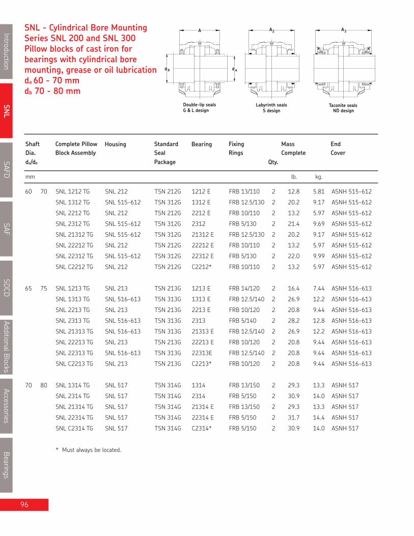
SNL
IntroductionSAFD
SAFSD
CDAdditionalBlocks
AccessoriesBearings
96
SNL - Cylindrical Bore MountingSeries SNL 200 and SNL 300Pillow blocks of cast iron forbearings with cylindrical boremounting, grease or oil lubricationda 60 - 70 mmdb 70 - 80 mm
db da
A 2A 3A
Labyrinth sealsS design
Taconite sealsND designG & L design
Double-lip seals
Shaft Complete Pillow Housing Standard Bearing Fixing Mass EndDia. Block Assembly Seal Rings Complete Coverda/db Package Qty.
mm lb. kg.
60 70 SNL 1212 TG SNL 212 TSN 212G 1212 E FRB 13/110 2 12.8 5.81 ASNH 515-612
SNL 1312 TG SNL 515-612 TSN 312G 1312 E FRB 12.5/130 2 20.2 9.17 ASNH 515-612
SNL 2212 TG SNL 212 TSN 212G 2212 E FRB 10/110 2 13.2 5.97 ASNH 515-612
SNL 2312 TG SNL 515-612 TSN 312G 2312 FRB 5/130 2 21.4 9.69 ASNH 515-612
SNL 21312 TG SNL 515-612 TSN 312G 21312 E FRB 12.5/130 2 20.2 9.17 ASNH 515-612
SNL 22212 TG SNL 212 TSN 212G 22212 E FRB 10/110 2 13.2 5.97 ASNH 515-612
SNL 22312 TG SNL 515-612 TSN 312G 22312 E FRB 5/130 2 22.0 9.99 ASNH 515-612
SNL C2212 TG SNL 212 TSN 212G C2212* FRB 10/110 2 13.2 5.97 ASNH 515-612
65 75 SNL 1213 TG SNL 213 TSN 213G 1213 E FRB 14/120 2 16.4 7.44 ASNH 516-613
SNL 1313 TG SNL 516-613 TSN 313G 1313 E FRB 12.5/140 2 26.9 12.2 ASNH 516-613
SNL 2213 TG SNL 213 TSN 213G 2213 E FRB 10/120 2 20.8 9.44 ASNH 516-613
SNL 2313 TG SNL 516-613 TSN 313G 2313 FRB 5/140 2 28.2 12.8 ASNH 516-613
SNL 21313 TG SNL 516-613 TSN 313G 21313 E FRB 12.5/140 2 26.9 12.2 ASNH 516-613
SNL 22213 TG SNL 213 TSN 213G 22213 E FRB 10/120 2 20.8 9.44 ASNH 516-613
SNL 22313 TG SNL 516-613 TSN 313G 22313E FRB 12.5/140 2 20.8 9.44 ASNH 516-613
SNL C2213 TG SNL 213 TSN 213G C2213* FRB 10/120 2 20.8 9.44 ASNH 516-613
70 80 SNL 1314 TG SNL 517 TSN 314G 1314 FRB 13/150 2 29.3 13.3 ASNH 517
SNL 2314 TG SNL 517 TSN 314G 2314 FRB 5/150 2 30.9 14.0 ASNH 517
SNL 21314 TG SNL 517 TSN 314G 21314 E FRB 13/150 2 29.3 13.3 ASNH 517
SNL 22314 TG SNL 517 TSN 314G 22314 E FRB 5/150 2 31.7 14.4 ASNH 517
SNL C2314 TG SNL 517 TSN 314G C2314* FRB 5/150 2 30.9 14.0 ASNH 517
* Must always be located.

SNL
Introduction
SAFD
SAF
SDCD
AdditionalB
locks
Accessories
Bearings
97
Pillow block housing series SNL
H
J
L
2
GH1
H1A
N
1N
Housing No. Dimensions Bolts
A A1 A2 A3 H H1 H2 Jmax Jmin J L N N1 G
in/mm
For an example on how to order, please see page 91.
(2 req'd)
SNL 212 4 1⁄4 2 3⁄4 4 5⁄8 7 1⁄8 5 1⁄4 2.756 1 3⁄16 8 7⁄16 8 1⁄8 8 5⁄16 10 1⁄16 1 3⁄4 5⁄8
105 70 117 180 134 70 30 215 205 210 255 24 18 16
SNL 213 4 3⁄8 3 1⁄8 5 7 9⁄16 5 7⁄8 3.150 1 3⁄16 9 3⁄8 8 3⁄4 9 1⁄8 10 13⁄16 1 3⁄4 5⁄8
110 80 128 190 149 80 30 238 222 230 275 24 18 16
SNL 515-612 4 5⁄8 3 1⁄8 5 6 7⁄8 6 1⁄8 3.150 1 3⁄16 9 3⁄8 8 3⁄4 9 1⁄8 11 1 3⁄4 5⁄8
115 80 127 175 154 80 30 238 222 230 280 24 18 16
SNL 516-613 4 3⁄4 3 5⁄8 5 7⁄16 7 7⁄8 7 3.740 1 1⁄4 10 1⁄2 9 15⁄16 10 1⁄4 12 7⁄16 1 1⁄8 7⁄8 3⁄4
120 90 138 200 177 95 32 268 252 260 315 28 22 20
SNL 517 4 15⁄16 3 5⁄8 5 5⁄8 8 7 1⁄4 3.740 1 1⁄4 10 1⁄2 9 15⁄16 10 1⁄4 12 7⁄16 1 1⁄8 7⁄8 3⁄4
125 90 143 205 183 95 32 268 252 260 320 28 22 20
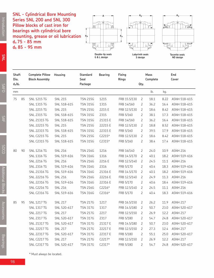
SNL
IntroductionSAFD
SAFSD
CDAdditionalBlocks
AccessoriesBearings
SNL - Cylindrical Bore MountingSeries SNL 200 and SNL 300Pillow blocks of cast iron forbearings with cylindrical boremounting, grease or oil lubricationda 75 - 85 mmdb 85 - 95 mm
db da
A 2A 3A
Labyrinth sealsS design
Taconite sealsND designG & L design
Double-lip seals
Shaft Complete Pillow Housing Standard Bearing Fixing Mass EndDia. Block Assembly Seal Rings Complete Coverda/db Package Qty.
mm lb. kg.
75 85 SNL 1215 TG SNL 215 TSN 215G 1215 FRB 15.5/130 2 18.1 8.22 ASNH 518-615
SNL 1315 TG SNL 518-615 TSN 315G 1315 FRB 14/160 2 36.2 16.4 ASNH 518-615
SNL 2215 TG SNL 215 TSN 215G 2215 E FRB 12.5/130 2 18.6 8.42 ASNH 518-615
SNL 2315 TG SNL 518-615 TSN 315G 2315 FRB 5/160 2 38.1 17.3 ASNH 518-615
SNL 21315 TG SNL 518-615 TSN 315G 21315 E FRB 14/160 2 36.2 16.4 ASNH 518-615
SNL 22215 TG SNL 215 TSN 215G 22215 E FRB 12.5/130 2 18.8 8.52 ASNH 518-615
SNL 22315 TG SNL 518-615 TSN 315G 22315 E FRB 5/160 2 39.5 17.9 ASNH 518-615
SNL C2215 TG SNL 215 TSN 215G C2215* FRB 12.5/130 2 18.6 8.42 ASNH 518-615
SNL C2315 TG SNL 518-615 TSN 315G C2315* FRB 5/160 2 38.4 17.4 ASNH 518-615
80 90 SNL 1216 TG SNL 216 TSN 216G 1216 FRB 16/140 2 24.0 10.9 ASNH 216
SNL 1316 TG SNL 519-616 TSN 316G 1316 FRB 14.5/170 2 40.1 18.2 ASNH 519-616
SNL 2216 TG SNL 216 TSN 216G 2216 E FRB 12.5/140 2 24.5 11.1 ASNH 216
SNL 2316 TG SNL 519-616 TSN 316G 2316 FRB 5/170 2 40.4 18.3 ASNH 519-616
SNL 21316 TG SNL 519-616 TSN 316G 21316 E FRB 14.5/170 2 40.1 18.2 ASNH 519-616
SNL 22216 TG SNL 216 TSN 216G 22216 E FRB 12.5/140 2 24.9 11.3 ASNH 216
SNL 22316 TG SNL 519-616 TSN 316G 22316 E FRB 5/170 2 40.6 18.4 ASNH 519-616
SNL C2216 TG SNL 216 TSN 216G C2216* FRB 12.5/140 2 24.5 11.1 ASNH 216
SNL C2316 TG SNL 519-616 TSN 316G C2316* FRB 5/170 2 40.4 18.3 ASNH 519-616
85 95 SNL 1217 TG SNL 217 TSN 217G 1217 FRB 16.5/150 2 26.2 11.9 ASNH 217
SNL 1317 TG SNL 520-617 TSN 317G 1317 FRB 14.5/180 2 50.7 23.0 ASNH 520-617
SNL 2217 TG SNL 217 TSN 217G 2217 FRB 12.5/150 2 26.9 12.2 ASNH 217
SNL 2317 TG SNL 520-617 TSN 317G 2317 FRB 5/180 2 54.7 24.8 ASNH 520-617
SNL 21317 TG SNL 520-617 TSN 317G 21317 E FRB 14.5/180 2 50.7 23.0 ASNH 520-617
SNL 22217 TG SNL 217 TSN 217G 22217 E FRB 12.5/150 2 27.3 12.4 ASNH 217
SNL 22317 TG SNL 520-617 TSN 317G 22317 E FRB 5/180 2 55.1 25.0 ASNH 520-617
SNL C2217 TG SNL 217 TSN 217G C2217* FRB 12.5/150 2 26.9 12.2 ASNH 217
SNL C2317 TG SNL 520-617 TSN 317G C2317* FRB 5/180 2 54.7 24.8 ASNH 520-617
* Must always be located.
98

SNL
Introduction
SAFD
SAF
SDCD
AdditionalB
locks
Accessories
Bearings
99
Pillow block housing series SNL
H
J
L
2
GH1
H1A
N
1N
Housing No. Dimensions Bolts
A A1 A2 A3 H H1 H2 Jmax Jmin J L N N1 G
in/mm
For an example on how to order, please see page 91.
(2 req'd)
SNL 215 4 5⁄8 3 1⁄8 5 1⁄4 7 11⁄16 6 1⁄8 3.150 1 3⁄16 9 3⁄8 8 3⁄4 9 1⁄8 10 13⁄16 1 3⁄4 5⁄8
115 80 133 195 155 80 30 238 222 230 280 24 18 16
SNL 216 4 3⁄4 3 5⁄8 5 7⁄16 7 7⁄8 7 3.740 1 1⁄4 10 1⁄2 9 15⁄16 10 1⁄4 12 7⁄16 1 1⁄8 7⁄8 3⁄4
120 90 138 200 177 95 32 268 252 260 315 28 22 20
SNL 217 4 15⁄16 3 5⁄8 5 5⁄8 8 7 1⁄4 3.740 1 1⁄4 10 1⁄2 9 15⁄16 10 1⁄4 12 7⁄16 1 1⁄8 7⁄8 3⁄4
125 90 143 205 183 95 32 268 252 260 320 28 22 20
SNL 518-615 5 1⁄2 3 15⁄16 6 1⁄4 8 11⁄16 7 5⁄8 3.937 1 3⁄8 11 5⁄8 11 1⁄4 11 7⁄16 13 5⁄8 1 1⁄8 7⁄8 3⁄4
140 100 158 220 194 100 35 295 285 290 345 28 22 20
SNL 519-616 5 3⁄4 3 15⁄16 6 7⁄16 8 1⁄16 8 3⁄8 4.409 1 3⁄8 11 5⁄8 11 1⁄4 11 7⁄16 13 5⁄8 1 1⁄8 7⁄8 3⁄4
145 100 163 205 212 112 35 295 285 290 345 28 22 20
SNL 520-617 6 5⁄16 4 5⁄16 7 8 11⁄16 8 9⁄16 4.409 1 9⁄16 12 3⁄16 12 3⁄8 12 5⁄8 15 1 1⁄4 1 1⁄32 1
160 110 178 220 218 112 40 326 314 320 380 32 26 24

SNL
IntroductionSAFD
SAFSD
CDAdditionalBlocks
AccessoriesBearings
100
SNL - Cylindrical Bore MountingSeries SNL 200 and SNL 300Pillow blocks of cast iron forbearings with cylindrical boremounting, grease or oil lubricationda 90 - 110 mmdb 100 - 125 mm
db da
A 2A 3A
Labyrinth sealsS design
Taconite sealsND designG & L design
Double-lip seals
Shaft Complete Pillow Housing Standard Bearing Fixing Mass EndDia. Block Assembly Seal Rings Complete Coverda/db Package Qty.
mm lb. kg.
90 100 SNL 1218 TG SNL 218 TSN 218G 1218 FRB 17.5/160 2 32.4 14.7 ASNH 218
SNL 2218 TG SNL 218 TSN 218G 2218 FRB 12.5/160 2 34.8 15.8 ASNH 218
SNL 22218 TG SNL 218 TSN 218G 22218 E FRB 12.5/160 2 34.2 15.5 ASNH 218
SNL 23218 TG SNL 218 TSN 218G 23218CC/W33 FRB 6.25/160 2 36.4 16.5 ASNH 218
SNL C2218 TG SNL 218 TSN 218G C2218* FRB 12.5/160 2 34.8 15.8 ASNH 218
95 110 SNL 1319 TA SNL 522-619 TSN 319A 1319 FRB 17.5/200 2 64.6 29.3 ASNH 522-619
SNL 2319 TA SNL 522-619 TSN 319A 2319 FRB 6.5/200 2 70.6 32.0 ASNH 522-619
SNL 21319 TA SNL 522-619 TSN 319A 21319 E FRB 17.5/200 2 65.5 29.7 ASNH 522-619
SNL 22319 TA SNL 522-619 TSN 319A 22319 E FRB 6.5/200 2 71.0 32.2 ASNH 522-619
100 115 SNL 1220 TG SNL 520-617 TSN 220G 1220 FRB 18/180 2 48.1 21.8 ASNH 520-617
SNL 1320 TA SNL 524-620 TSN 320A 1320 FRB 19.5/215 2 77.6 35.2 ASNH 524-620
SNL 2220 TG SNL 520-617 TSN 220G 2220 FRB 12/180 2 50.0 22.7 ASNH 520-617
SNL 2320 TA SNL 524-620 TSN 320A 2320 FRB 6.5/215 2 85.6 38.8 ASNH 524-620
SNL 21320 TA SNL 524-620 TSN 320A 21320 E FRB 19.5/215 2 78.7 35.7 ASNH 524-620
SNL 22220 TG SNL 520-617 TSN 220G 22220 E FRB 12/180 2 53.8 24.4 ASNH 520-617
SNL 22320 TA SNL 524-620 TSN 320A 22320 E FRB 6.5/215 2 86.7 39.3 ASNH 524-620
SNL 23220 TG SNL 520-617 TSN 220G 23220CC/W33 FRB 4.85/180 2 52.5 23.8 ASNH 520-617
SNL C2220 TG SNL 520-617 TSN 220G C2220* FRB 12/180 2 50.0 22.7 ASNH 520-617
SNL C2320 TA SNL 524-620 TSN 320A C2320* FRB 6.5/215 2 85.6 38.8 ASNH 524-620
110 125 SNL 1222 TG SNL 522-619 TSN 222G 1222 FRB 21/200 2 61.3 27.8 ASNH 522-619
SNL 2222 TG SNL 522-619 TSN 222G 2222 FRB 13.5/200 2 65.0 29.5 ASNH 522-619
SNL 22222 TG SNL 522-619 TSN 222G 22222 E FRB 13.5/200 2 64.8 29.4 ASNH 522-619
SNL 23222 TG SNL 522-619 TSN 222G 23222CC/W33 FRB 5.1/200 2 70.3 31.9 ASNH 522-619
SNL C2222 TG SNL 522-619 TSN 222G C2222* FRB 13.5/200 2 65.0 29.5 ASNH 522-619
* Must always be located.

SNL
Introduction
SAFD
SAF
SDCD
AdditionalB
locks
Accessories
Bearings
101
Pillow block housing series SNL
H
J
L
2
GH1
H1A
N
1N
Housing No. Dimensions Bolts
A A1 A2 A3 H H1 H2 Jmax Jmin J L N N1 G
in/mm
For an example on how to order, please see page 91.
(2 req'd)
SNL 218 5 1⁄2 3 15⁄16 6 1⁄4 8 11⁄16 7 5⁄8 3.937 1 3⁄8 11 5⁄8 11 1⁄4 11 7⁄16 13 5⁄8 1 1⁄8 7⁄8 3⁄4
140 100 158 220 194 100 35 295 285 290 345 28 22 20
SNL 520-617 6 5⁄16 4 5⁄16 7 8 11⁄16 8 9⁄16 4.409 1 9⁄16 12 13⁄16 12 3⁄8 12 5⁄8 15 1 1⁄4 1 1⁄32 1
160 110 178 220 218 112 40 326 314 320 380 32 26 24
SNL 522-619 6 15⁄16 4 3⁄4 7 9⁄16 10 9 1⁄2 4.921 1 3⁄4 14 13 9⁄16 13 11⁄16 16 1⁄8 1 1⁄4 1 1⁄32 1
175 120 191 255 242 125 45 356 344 350 410 32 26 24
SNL 524-620 7 5⁄16 4 3⁄4 7 7⁄8 10 1⁄4 10 11⁄16 5.512 1 3⁄4 14 13 9⁄16 13 11⁄16 16 1⁄8 1 1⁄4 1 1⁄32 1
185 120 199 260 271 140 45 356 344 350 410 32 26 24

SNL
IntroductionSAFD
SAFSD
CDAdditionalBlocks
AccessoriesBearings
102
SNL - Cylindrical Bore MountingSeries SNL 200 and SNL 300Pillow blocks of cast iron forbearings with cylindrical boremounting, grease or oil lubricationda 120 - 160 mmdb 135 - 175 mm
db da
A 2A 3A
Labyrinth sealsS design
Taconite sealsND designG & L design
Double-lip seals
Shaft Complete Pillow Housing Standard Bearing Fixing Mass EndDia. Block Assembly Seal Rings Complete Coverda/db Package Qty.
mm lb. kg.
120 135 SNL 1224 TG SNL 524-620 TSN 224G 1224 FRB 22/215 2 74.3 33.7 ASNH 524-620
SNL 22224 TG SNL 524-620 TSN 224G 22224 E FRB 14/215 2 78.3 35.5 ASNH 524-620
SNL 23224 TG SNL 524-620 TSN 224G 23224CC/W33 FRB 5/215 2 84.7 38.4 ASNH 524-620
SNL C3224 TG SNL 524-620 TSN 224G C3224* FRB 5/215 2 84.7 38.4 ASNH 524-620
130 145 SNL 1226 TG SNL 526 TSN 226G 1226 FRB 22/230 2 93.0 42.2 ASNH 526
SNL 22226 TG SNL 526 TSN 226G 22226 E FRB 13/230 2 99.0 44.9 ASNH 526
SNL 23226 TG SNL 526 TSN 226G 23226CC/W33 FRB 5/230 2 104 47.2 ASNH 526
SNL C2226 TG SNL 526 TSN 226G C2226* FRB 13/230 2 100 45.4 ASNH 526
140 155 SNL 22228 TG SNL 528 TSN 228G 22228CC/W33 FRB 15/250 2 121 54.7 ASNH 528
SNL 23228 TG SNL 528 TSN 228G 23228CC/W33 FRB 5/250 2 129 58.7 ASNH 528
SNL C2228 TG SNL 528 TSN 228G C2228* FRB 15/250 2 129 58.7 ASNH 528
150 165 SNL 22230 TG SNL 530 TSN 230G 22230CC/W33 FRB 16.5/270 2 149 67.8 ASNH 530
SNL 23230 TG SNL 530 TSN 230G 23230CC/W33 FRB 5/270 2 161 73.2 ASNH 530
SNL C2230 TG SNL 530 TSN 230G C2230* FRB 16.5/270 2 161 73.2 ASNH 530
160 175 SNL 22232 TG SNL 532 TSN 232G 22232CC/W33 FRB 17/290 2 173 78.4 ASNH 532
SNL 23232 TG SNL 532 TSN 232G 23232CC/W33 FRB 5/290 2 188 85.3 ASNH 532
SNL C3232 TG SNL 532 TSN 232G C3232* FRB 5/290 2 188 85.3 ASNH 532
* Must always be located.

SNL
Introduction
SAFD
SAF
SDCD
AdditionalB
locks
Accessories
Bearings
103
Pillow block housing series SNL
H
J
L
2
GH1
H1A
N
1N
Housing No. Dimensions Bolts
A A1 A2 A3 H H1 H2 Jmax Jmin J L N N1 G
in/mm
For an example on how to order, please see page 91.
(2 req'd)
SNL 524-620 7 5⁄16 4 3⁄4 7 7⁄8 10 1⁄4 10 11⁄16 5.512 1 3⁄4 14 13 9⁄16 13 11⁄16 16 1⁄8 1 1⁄4 1 1
185 120 199 260 271 140 45 356 344 350 410 32 26 24
SNL 526 7 1⁄2 5 1⁄8 8 3⁄16 10 7⁄16 11 7⁄16 5.906 2 15 1⁄4 14 11⁄16 15 17 9⁄16 1 3⁄8 1 1⁄8 1
190 130 208 265 290 150 50 387 373 380 445 35 28 24
SNL 528 8 1⁄8 5 15⁄16 8 13⁄16 11 7⁄16 11 15⁄16 5.906 2 16 3⁄4 16 15⁄16 16 9⁄16 19 11⁄16 1 11⁄16 1 3⁄8 1 1⁄4
205 150 223 290 302 150 50 427 413 420 500 42 35 30
SNL 530 8 11⁄16 6 5⁄16 9 1⁄2 12 12 3⁄4 6.299 2 3⁄8 17 15⁄16 17 1⁄2 17 3⁄4 20 7⁄8 1 11⁄16 1 3⁄8 1 1⁄4
220 160 241 305 323 160 60 457 443 450 530 42 35 30
SNL 532 9 1⁄4 6 5⁄16 10 12 5⁄8 13 9⁄16 6.693 2 3⁄8 18 3⁄4 18 1⁄4 18 1⁄2 21 11⁄16 1 11⁄16 1 3⁄8 1 1⁄4
235 160 254 320 344 170 60 477 463 470 550 42 35 30

SNL
IntroductionSAFD
SAFSD
CDAdditionalBlocks
AccessoriesBearings
104
FSNL 511-609 NM 20 15 210 35 234FSNL 513-611 NM 20 15 230 40 252FSNL 515-612 NM 20 15 230 40 257
FSNL 516-613 NM 24 18 260 50 288FSNL 517 NM 24 18 260 50 292FSNL 518-615 NM 24 18 290 50 317
FSNL 520-617 NM 24 18 320 60 348FSNL 522-619 NM 24 18 350 70 378FSNL 524-620 NM 24 18 350 70 378
FSNL 526 NM 28 22 380 70 414FSNL 528 NM 32 26 420 80 458FSNL 530 NM 32 26 450 90 486
FSNL 532 NM 32 26 470 90 506
Some housings which are already prepared for four-bolt mounting having 4 cast holes in the base can be supplied.These housings are also prepared for relubrication of the bearing via the outer ring (suffix NM) as standard. Thehousings are designated FSNL .. NM e.g. FSNL 511-609 NM.
Housings forfour-bolt mounting
Housing DimensionsSize N N1 J1 J2 J6
-
mm
Hole for grease nipple (standard) Hole for grease nipple (NM design)
Dimple indicatingwhere to drill holefor dowel pinJ1
J6
J2
N1
N

SNL
Introduction
SAFD
SAF
SDCD
AdditionalB
locks
Accessories
Bearings
105
Notes
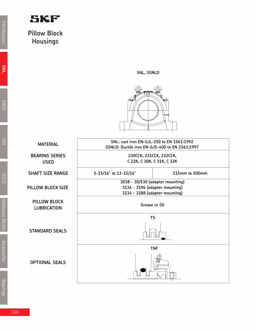
SNL
IntroductionSAFD
SAFSD
CDAdditionalBlocks
AccessoriesBearings
Pillow BlockHousings
SNL, SSNLD
PILLOW BLOCKLUBRICATION
OPTIONAL SEALS
STANDARD SEALS
PILLOW BLOCK SIZE
SHAFT SIZE RANGE
USEDBEARING SERIES
MATERIAL
Grease or Oil
3234 - 3288 (adapter mounting)3134 - 3196 (adapter mounting)
115mm to 500mm
3038 - 30/530 (adapter mounting)
5-15/16" to 13-15/16"
SNL: cast iron EN-GJL-250 to EN 1561:1992
C 22K, C 30K, C 31K, C 32K230CCK, 231CCK, 232CCK,
SSNLD: Ductile iron EN-GJS-400 to EN 1563:1997
TS
TNF
106

SNL
Introduction
SAFD
SAF
SDCD
AdditionalB
locks
Accessories
Bearings
107
SNL 3000, 3100 and 3200 Split Pillow Blocks Nomenclature Adapter Mounting
Base Design
Material0D
Size
Adapter mount
SuffixesOHT
TD
TNFTSSNTURTTURAY
Standard with a four bolt base
Cast iron (standard)Ductile iron
Bearing bore: 34 = 170 mm
Shaft size: 5 15⁄16”
Standard TS triple ring sealHeld or fixed unit c/w fixing ringsDrilled and tapped with one 1⁄8-27" NPSF hole at the locknut side of the cap to take the includedAH 1/8-27" PTF grease fittingDrilled and tapped with one 1⁄8-27" NPSF hole on each side of the cap to take the included AH 1⁄8-27" PTFgrease fittingsHousing with taconite seal ( 1/pkg)Housing with labyrinth seal (1/pkg)Housing drilled and tapped for a sensor (hole size and thread configuration to be specified by the customer)Modified housing, including oil seals for use with a spherical roller bearingModified housing, including oil seals for use with a CARBHousing with an end cover ("A" suffix used in European catalogues)
How to order SNL (example):
When you order a SNL 23134K/5 15⁄16” you will receive a package containing the following:
1 - Pillow block housing SNL 31341 - Triple ring seals TS 34/5 15⁄16”1 - Bearing SKF 23134CCK/W331 - Adapter sleeve HA 3134 for shaft diameter 5 15⁄16"
If a "HELD" or "FIXED" unit is required, add the suffix "H" and two FRB 10/280 fixing rings will be included. Only one bearing pershaft should be held. CARB displace internally and are therefore always "FREE", however, they must always be located in thehousing with fixing rings, as does a true "FIXED" bearing.If a unit with one end closed is required, add the suffix "Y" and one ETS 34 end cover will be included.
SNL K 5 15⁄1623134 TSSND

SNL
IntroductionSAFD
SAFSD
CDAdditionalBlocks
AccessoriesBearings
108
Series SNL 3000, 3100 and 3200Pillow blocks for bearings onadapter sleeves, grease oroil lubricationda 5 15⁄16 - 6 1⁄2 in (150 - 160 mm)
Shaft Complete Pillow Housing Seal Bearing Adapter Fixing Mass Complete EndDia. Block Assembly Sleeve Rings Qty. Cover
mm in lb. kg.
150 SNL 23134K/150 SNL3134 TS34 23134CCK/W33 H 3134 FRB 10/280 2 212 96.1 ETS34SNL C3134K/150 SNL3134 TS34 C3134K * H 3134L FRB 10/280 2 210 95.1 ETS34SNL 23234K/150 SNL3234 TS40/150 23234CCK/W33 H 2334 FRB 6/310 2 329 149 ETS40
5 15⁄16 SNL 23134K/5 15⁄16 SNL3134 TS34/5 15⁄16 23134CCK/W33 HA 3134 FRB 10/280 2 207 94 ETS34SNLC3134K/5 15⁄16 SNL3134 TS34/5 15⁄16 C3134K* HA 3134L FRB 10/280 2 207 94 ETS34SNL 23234K/5 15⁄16 SNL3234 TS40/5 15⁄16 23234CCK/W33 HA 2334 FRB 6/310 2 329 149 ETS40
6 SNL 23134K/6 SNL3134 TS34/6 23134CCK/W33 HE 3134 FRB 10/280 2 207 94 ETS34
160 SNL 23036K/160 SNL3036 TS36 23036CCK/W33 H 3036 FRB 17/280 2 214 97 ETS36SNL C3036K/160 SNL3036 TS36 C3036K* H 3036 FRB 17/280 2 214 97 ETS36SNL 23136K/160 SNL3136 TS36 23136CCK/W33 H 3136 FRB 10/300 2 245 111 ETS36SNL C3136K/160 SNL3136 TS36 C3136K* H 3136L FRB 10/300 2 240 109 ETS36SNL 23236K/160 SNL3236 TS38/160 23236CCK/W33 H 2336 FRB 6/320 2 335 152 ETS38
6 7⁄16 SNL 23036K/6 7⁄16 SNL3036 TS36/6 7⁄16 23036CCK/W33 HA 3036 FRB 17/280 2 214 97 ETS36SNL C3036K/6 7⁄16 SNL3036 TS36/6 7⁄16 C3036K* HA 3036 FRB 17/280 2 214 97 ETS36SNL 23136K/6 7⁄16 SNL3136 TS36/6 7⁄16 23136CCK/W33 HA 3136 FRB 10/300 2 245 111 ETS36SNL C3136K/6 7⁄16 SNL3136 TS36/6 7⁄16 C3136K* HA 3136L FRB 10/300 2 240 109 ETS36SNL 23236K/6 7⁄16 SNL3236 TS38/6 7⁄16 23236CCK/W33 HA 2336 FRB 6/320 2 335 152 ETS38
6 1⁄2 SNL 23036K/6 1⁄2 SNL3036 TS36/6 1⁄2 23036CCK/W33 HE 3036 FRB 17/280 2 214 97 ETS36SNL C3036K/6 1⁄2 SNL3036 TS36/6 1⁄2 C3036K* HE 3036 FRB 17/280 2 214 97 ETS36SNL 23136K/6 1⁄2 SNL3136 TS36/6 1⁄2 23136CCK/W33 HE 3136 FRB 10/300 2 245 111 ETS36SNL C3136K/6 1⁄2 SNL3136 TS36/6 1⁄2 C3136K* HE 3136L FRB 10/300 2 240 109 ETS36
* Must always be located.
da
A
A2
A1
AX
3
S
Labyrinth sealsTS design
Taconite sealsTNF design

SNL
Introduction
SAFD
SAF
SDCD
AdditionalB
locks
Accessories
Bearings
109
Large SNL Pillow Blocks of the 3000, 3100 and 3200 series
H
H2
L
J
G
1H
1J
SNL 3140
1N
N
Housing No. Dimensions Bolts(2 req'd)
A A1 A2 A3 X H H1 H2 L J J1 S* G
in/mm
For an example on how to order, please see page 107.
SNL 3134 9.06 7.09 9.45 11.81 0.55 13.11 6.693 2.76 20.08 16.93 3.94 3.54 1230 180 240 300 14 333 170 70 510 430 100 90 24
SNL 3234 10.24 8.27 10.63 13.19 0.39 14.76 7.48 3.15 22.05 18.90 4.72 3.74 1260 210 270 335 10 375 190 80 560 480 120 95 24
SNL 3036 9.06 7.09 9.45 12.20 0.55 13.11 6.69 2.76 20.08 16.93 3.94 3.43 1230 180 240 310 14 333 170 70 510 430 100 87 24
SNL 3136 9.45 7.48 9.84 12.40 0.59 14 7.087 3 20.87 17.72 4.33 3.74 1240 190 250 315 15 353 180 75 530 450 110 95 24
SNL 3236 10.24 8.27 10.63 13.19 0.39 14.76 7.48 3.15 22.05 18.90 4.72 5.87 1260 210 270 335 10 375 190 80 560 480 120 149 24
*NOTE: Dimension "S" indicates the shaft length from the centre of the bearing to the end of the shaft for housingswith one end closed.

SNL
IntroductionSAFD
SAFSD
CDAdditionalBlocks
AccessoriesBearings
110
Series SNL 3000, 3100 and 3200Pillow blocks for bearings onadapter sleeves, grease oroil lubricationda 6 15⁄16 - 7 3⁄16 in (170 - 180 mm)
Shaft Complete Pillow Housing Seal Bearing Adapter Fixing Mass Complete EndDia. Block Assembly Sleeve Rings Qty. Cover
mm in lb. kg.
da
A
A2
A1
AX
3
S
Labyrinth sealsTS design
Taconite sealsTNF design
170 SNL 23038K/170 SNL3038 TS38 23038CCK/W33 H 3038 FRB 10/290 4 236 107 ETS38SNL C3038K/170 SNL3038 TS38 C3038K* H 3038 FRB 10/290 4 236 107 ETS38SNL 23138K/170 SNL3138 TS38 23138CCK/W33 H 3138 FRB 10/320 2 304 138 ETS38SNL C3138K/170 SNL3138 TS38 C3138K* H 3138L FRB 10/320 2 301 136.5 ETS38SNL 23238K/170 SNL3238 TS40/170 23238CCK/W33 H 2338 FRB 6/340 2 412 187 ETS40
6 15⁄16 SNL 23038K/6 15⁄16 SNL3038 TS38/6 15⁄16 23038CCK/W33 HA 3038 FRB 10/290 4 236 107 ETS38SNL C3038K/6 15⁄16 SNL3038 TS38/6 15⁄16 C3038K* HA 3038 FRB 10/290 4 236 107 ETS38SNL 23138K/6 15⁄16 SNL3138 TS38/6 15⁄16 23138CCK/W33 HA 3138 FRB 10/320 2 304 138 ETS38SNL C3138K/6 15⁄16 SNL3138 TS38/6 15⁄16 C3138K* HA 3138L FRB 10/320 2 300 136 ETS38SNL 23238K/6 15⁄16 SNL3238 TS40/6 15⁄16 23238CCK/W33 HA 2338 FRB 6/340 2 412 187 ETS40
180 SNL 23040K/180 SNL3040 TS40 23040CCK/W33 H 3040 FRB 10/310 4 295 134 ETS40SNL C3040K/180 SNL3040 TS40 C3040K* H 3040 FRB 10/310 4 295 134 ETS40SNL 23140K/180 SNL3140 TS40 23140CCK/W33 H 3140 FRB 10/340 2 379 172 ETS40SNL C3140K/180 SNL3140 TS40 C3140K* H 3140 FRB 10/340 2 373 169 ETS40SNL 23240K/180 SNL3240 TS48/180 23240CCK/W33 H 2340 FRB 6/360 2 474 215 ETS48
7 3⁄16 SNL 23040K/7 3⁄16 SNL3040 TS40/7 3⁄16 23040CCK/W33 HA 3040 FRB 10/310 4 295 134 ETS40SNL C3040K/7 3⁄16 SNL3040 TS40/7 3⁄16 C3040K* HA 3040 FRB 10/310 4 295 134 ETS40SNL 23140K/7 3⁄16 SNL3140 TS40/7 3⁄16 23140CCK/W33 HA 3140 FRB 10/340 2 379 172 ETS40SNL C3140K/7 3⁄16 SNL3140 TS40/7 3⁄16 C3140K* HA 3140 FRB 10/340 2 373 169 ETS40SNL 23240K/7 3⁄16 SNL 3240 TS 48/7 3⁄16 23240CCK/W33 HA 2340 FRB 6/360 2 474 215 ETS48
* Must always be located.

SNL
Introduction
SAFD
SAF
SDCD
AdditionalB
locks
Accessories
Bearings
111
Large SNL Pillow Blocks of the 3000, 3100 and 3200 series
H
H2
L
J
G
1H
1J
SNL 3140
1N
N
Housing No. Dimensions Bolts(2 req'd)
A A1 A2 A3 X H H1 H2 L J J1 S* G
in/mm
For an example on how to order, please see page 107.
SNL 3038 9.45 7.48 9.84 12.40 0.59 13.90 7.09 2.95 20.87 17.72 4.33 5.00 1240 190 250 315 15 353 180 75 530 450 110 127 24
SNL 3138 10.24 8.27 10.63 13.19 0.39 14.76 7.480 3.15 22.05 18.90 4.72 3.94 1260 210 270 335 10 375 190 80 560 480 120 100 24
SNL 3238 11.02 9.06 11.42 13.98 0.39 16.18 8.27 3.35 24.02 20.08 5.12 4.29 1 1⁄4280 230 290 355 10 411 210 85 610 510 130 109 30
SNL 3040 10.24 8.27 10.63 13.19 0.39 14.76 7.48 3.15 22.05 18.90 4.72 3.74 1260 210 270 335 10 375 190 80 560 480 120 95 24
SNL 3140 11 9.06 11.42 13.98 0.39 16.18 8.268 3.35 24 20.08 5.12 4.25 1 1⁄4280 230 290 355 10 411 210 85 610 510 130 108 30
SNL 3240 11.42 9.45 11.81 14.96 0.47 17.09 8.66 3.54 25.20 21.26 5.51 4.53 1 1⁄4290 240 300 380 12 434 220 90 640 540 140 115 30
*NOTE: Dimension "S" indicates the shaft length from the centre of the bearing to the end of the shaft for housingswith one end closed.

SNL
IntroductionSAFD
SAFSD
CDAdditionalBlocks
AccessoriesBearings
112
Series SNL 3000, 3100 and 3200Pillow blocks for bearings onadapter sleeves, grease oroil lubricationda 9 7⁄16 in (200 - 240 mm)
Shaft Complete Pillow Housing Seal Bearing Adapter Fixing Mass Complete EndDia. Block Assembly Sleeve Rings Qty. Cover
mm in lb. kg.
da
A
A2
A1
AX
3
S
Labyrinth sealsTS design
Taconite sealsTNF design
200 SNL 23044K/200 SNL3044 TS44 23044CCK/W33 OH 3044H FRB 10/340 4 370 168 ETS44SNL C3044K/200 SNL3044 TS44 C3044K* OH 3044H FRB 10/340 4 370 168 ETS44SNL 23144K/200 SNL3144 TS44 23144CCK/W33 OH 3144H FRB 10/370 2 450 204 ETS44SNL C3144K/200 SNL3144 TS44 C3144K* OH 3144HTL FRB 10/370 2 201 21 ETS44SNL 23244K/200 SNL3244 TS48/200 23244CCK/W33 OH 2344H FRB 10/400 2 637 289 ETS48
220 SNL 23048K/220 SNL3048 TS48 23048CCK/W33 OH 3048H FRB 12/360 4 417 189 ETS48SNL C3048K/220 SNL3048 TS48 C3048K* OH 3048H FRB 12/360 4 417 189 ETS48SNL 23148K/220 SNL3148 TS48 23148CCK/W33 OH 3148H FRB 10/400 2 576 261 ETS48SNL C3148K/220 SNL3148 TS48 C3148K* OH 3148HTL FRB 10/400 2 568 257.5 ETS48SNL 23248K/220 SNL3248 TS52/220 23248CCK/W33 OH 2348H FRB 10/440 2 778 353 ETS52
9 7⁄16 SNL23052K/9 7⁄16 SNL3052 TS52/9 7⁄16 23052CCK/W33 SNP 3052x9 7⁄16 FRB 22/400 2 560 254 ETS52
240 SNL 23052K/240 SNL3052 TS52 23052CCK/W33 OH 3052H FRB 22/400 2 560 254 ETS52SNL C3052K/240 SNL3052 TS52 C3052K* OH 3052H FRB 22/400 2 560 254 ETS52SNL 23152K/240 SNL3152 TS52 23152CCK/W33 OH 3152H FRB 10/440 2 717 325 ETS52SNL C3152K/240 SNL3152 TS52 C3152K* OH 3152HTL FRB 10/440 2 711 322.5 ETS52SNL 23252K/240 SNL3252 TS64/240 23252CCK/W33 OH 2352H FRB 10/480 2 1034 469 ETS64
* Must always be located.

SNL
Introduction
SAFD
SAF
SDCD
AdditionalB
locks
Accessories
Bearings
113
Large SNL Pillow Blocks of the 3000, 3100 and 3200 series
H
H2
L
J
G
1H
1J
SNL 3140
1N
N
Housing No. Dimensions Bolts(2 req'd)
A A1 A2 A3 X H H1 H2 L J J1 S* G
in/mm
For an example on how to order, please see page 107.
SNL 3044 11.02 9.06 11.42 14.17 0.39 16.18 8.27 3.35 24.02 20.08 5.12 4.21 1 1⁄4280 230 290 360 10 411 210 85 610 510 130 107 30
SNL 3144 11.42 9.45 11.81 14.37 0.47 17.09 8.661 3.54 25.20 21.26 5.51 4.49 1 1⁄4290 240 300 365 12 434 220 90 640 540 140 114 30
SNL 3244 12.20 10.24 12.40 15.75 0.47 18.66 9.45 3.74 27.56 23.62 5.91 4.89 1 1⁄4310 260 315 400 12 474 240 95 700 600 150 124 30
SNL 3048 11.42 9.45 11.81 14.96 0.47 17.09 8.66 3.54 25.20 21.26 5.51 4.45 1 1⁄4290 240 300 380 12 434 220 90 640 540 140 113 30
SNL 3148 12.20 10.24 12.40 15.75 0.47 10.24 9.449 3.74 27.56 23.62 5.91 4.76 1 1⁄4310 260 315 400 12 474 240 95 700 600 150 121 30
SNL 3248 12.60 11.02 12.99 16.34 0.51 20.31 10.24 3.94 30.31 25.59 6.30 5.28 1 1⁄2320 280 330 415 13 516 260 100 770 650 160 134 36
SNL 3052 12.20 10.24 12.40 15.75 27/64 18.66 9.45 3.74 27.56 23.62 5.91 4.72 1 1⁄4310 260 315 400 12 474 240 95 700 600 150 120 30
SNL 3152 12.60 11.02 12.99 16.34 0.51 20.31 10.24 3.94 30.31 25.59 6.30 5.16 1 1⁄2320 280 330 415 13 516 260 100 770 650 160 131 36
SNL 3252 13.78 12.20 14.17 17.52 0.87 23.27 11.81 4.33 32.68 27.95 7.48 5.94 1 1⁄2350 310 360 445 22 591 300 110 830 710 190 151 36
*NOTE: Dimension "S" indicates the shaft length from the centre of the bearing to the end of the shaft for housingswith one end closed.

SNL
IntroductionSAFD
SAFSD
CDAdditionalBlocks
AccessoriesBearings
114
Series SNL 3000, 3100 and 3200Pillow blocks for bearings onadapter sleeves, grease oroil lubricationda 260 - 320 mm
Shaft Complete Pillow Housing Seal Bearing Adapter Fixing Mass Complete EndDia. Block Assembly Sleeve Rings Qty. Cover
mm lb. kg.
da
A
A2
A1
AX
3
S
Labyrinth sealsTS design
Taconite sealsTNF design
260 SNL 23056K/260 SNL3056 TS56 23056CCK/W33 OH 3056H FRB 10/420 6 650 295 ETS56SNL C3056K/260 SNL3056 TS56 C3056K* OH3056H FRB 10/420 6 650 295 ETS56SNL 23156K/260 SNL3156 TS56 23156CCK/W33 OH3156H FRB 10/460 2 820 372 ETS56SNL C3156K/260 SNL3156 TS56 C3156K* OH3156HTL FRB 10/460 2 811 368 ETS56SNL 23256K/260 SNL3256 TS60/260 23256CCK/W33 OH2356H FRB 10/500 2 1045 474 ETS60
280 SNL 23060K/280 SNL3060 TS60 23060CCK/W33 OH3060H FRB25/460 2 772 350 ETS60SNL C3060K/280 SNL3060 TS60 C3060KM* OH3060H FRB25/460 2 772 350 ETS60SNL 23160K/280 SNL3160 TS60 23160CCK/W33 OH3160H FRB 10/500 2 1001 454 ETS60SNL C3160K/280 SNL3160 TS60 C3160K* OH3160H FRB 10/500 2 990 449 ETS60SNL 23260K/280 SNL3260 TS64/280 23260CCK/W33 OH3260H FRB 10/540 2 1228 557 ETS64
300 SNL 23064K/300 SNL3064 TS64 23064CCK/W33 OH 3064H FRB 10/480 6 895 406 ETS64SNL C3064K/300 SNL3064 TS64 C3064KM* OH 3064H FRB 10/480 6 895 406 ETS64SNL 23164K/300 SNL3164 TS64 23164CCK/W33 OH 3164H FRB 10/540 2 1175 533 ETS64SNL C3164K/300 SNL3164 TS64 C3164K* OH 3164H FRB 10/540 2 1164 528 ETS64SNL 23264K/300F SNL3264F TS68/300 23264CCK/W33 OH 3264H FIXED HSG** - 1541 699 ETS68SNL 23264K/300L SNL 3264L TS68/300 23264CCK/W33 OH 3264H FREE HSG - 1535 696 ETS68
320 SNL 23068K/320 SNL3068 TS68 23068CCK/W33 OH3068H FRB16/520 4 1054 478 ETS68SNL C3068K/320 SNL3068 TS68 C3068KM* OH3068H FRB16/520 4 1054 478 ETS68SNL 23168K/320F SNL 3168F TS68 23168CCK/W33 OH3168H FIXED HSG** - 1520 689 ETS68SNL 23168K/320L SNL 3168L TS68 23168CCK/W33 OH3168H FREE HSG - 1520 689 ETS68SNL C3168K/320F SNL 3168F TS68 C3168KM* OH3168H FIXED HSG** - 1520 689 ETS68SNL C3168K/320L SNL 3168L TS68 C3168KM* OH3168H FREE HSG - 1520 689 ETS68SNL 23268K/320F SNL 3268F TS76/320 23268CAK/W33 OH3268H FIXED HSG** - 1807 819 ETS76SNL 23268K/320L SNL 3268L TS76/320 23268CAK/W33 OH3268H FREE HSG - 1800 816 ETS76
* Must always be located.
** These blocks are manufactured as fixed units, no fixing rings are required.
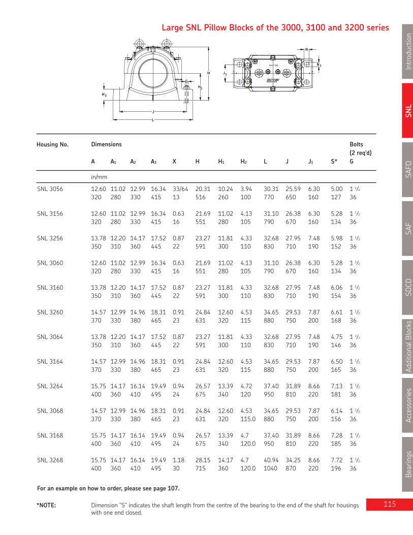
SNL
Introduction
SAFD
SAF
SDCD
AdditionalB
locks
Accessories
Bearings
115
Large SNL Pillow Blocks of the 3000, 3100 and 3200 series
H
H2
L
J
G
1H
1J
SNL 3140
1N
N
Housing No. Dimensions Bolts(2 req'd)
A A1 A2 A3 X H H1 H2 L J J1 S* G
in/mm
For an example on how to order, please see page 107.
SNL 3056 12.60 11.02 12.99 16.34 33/64 20.31 10.24 3.94 30.31 25.59 6.30 5.00 1 1⁄2320 280 330 415 13 516 260 100 770 650 160 127 36
SNL 3156 12.60 11.02 12.99 16.34 0.63 21.69 11.02 4.13 31.10 26.38 6.30 5.28 1 1⁄2320 280 330 415 16 551 280 105 790 670 160 134 36
SNL 3256 13.78 12.20 14.17 17.52 0.87 23.27 11.81 4.33 32.68 27.95 7.48 5.98 1 1⁄2350 310 360 445 22 591 300 110 830 710 190 152 36
SNL 3060 12.60 11.02 12.99 16.34 0.63 21.69 11.02 4.13 31.10 26.38 6.30 5.28 1 1⁄2320 280 330 415 16 551 280 105 790 670 160 134 36
SNL 3160 13.78 12.20 14.17 17.52 0.87 23.27 11.81 4.33 32.68 27.95 7.48 6.06 1 1⁄2350 310 360 445 22 591 300 110 830 710 190 154 36
SNL 3260 14.57 12.99 14.96 18.31 0.91 24.84 12.60 4.53 34.65 29.53 7.87 6.61 1 1⁄2370 330 380 465 23 631 320 115 880 750 200 168 36
SNL 3064 13.78 12.20 14.17 17.52 0.87 23.27 11.81 4.33 32.68 27.95 7.48 4.75 1 1⁄2350 310 360 445 22 591 300 110 830 710 190 146 36
SNL 3164 14.57 12.99 14.96 18.31 0.91 24.84 12.60 4.53 34.65 29.53 7.87 6.50 1 1⁄2370 330 380 465 23 631 320 115 880 750 200 165 36
SNL 3264 15.75 14.17 16.14 19.49 0.94 26.57 13.39 4.72 37.40 31.89 8.66 7.13 1 1⁄2400 360 410 495 24 675 340 120 950 810 220 181 36
SNL 3068 14.57 12.99 14.96 18.31 0.91 24.84 12.60 4.53 34.65 29.53 7.87 6.14 1 1⁄2370 330 380 465 23 631 320 115.0 880 750 200 156 36
SNL 3168 15.75 14.17 16.14 19.49 0.94 26.57 13.39 4.7 37.40 31.89 8.66 7.28 1 1⁄2400 360 410 495 24 675 340 120.0 950 810 220 185 36
SNL 3268 15.75 14.17 16.14 19.49 1.18 28.15 14.17 4.7 40.94 34.25 8.66 7.72 1 1⁄2400 360 410 495 30 715 360 120.0 1040 870 220 196 36
*NOTE: Dimension "S" indicates the shaft length from the centre of the bearing to the end of the shaft for housingswith one end closed.

SNL
IntroductionSAFD
SAFSD
CDAdditionalBlocks
AccessoriesBearings
116
Series SNL 3000, 3100 and 3200Pillow blocks for bearings onadapter sleeves, grease oroil lubricationda 340 - 380 mm
Shaft Complete Pillow Housing Seal Bearing Adapter Fixing Mass Complete EndDia. Block Assembly Sleeve Rings Qty. Cover
mm lb. kg.
da
A
A2
A1
AX
3
S
Labyrinth sealsTS design
Taconite sealsTNF design
340 SNL 23072K/340 SNL 3072 TS72 23072CCK/W33 OH3072H FRB 16/540 4 1068 484 ETS72SNL C3072K/340 SNL 3072 TS72 C3072KM* OH3072H FRB 16/540 4 1068 484 ETS72SNL 23172K/340F SNL 3172F TS72 23172CCK/W33 OH3172H FIXED HSG** - 1601 726 ETS72SNL 23172K/340L SNL 3172L TS72 23172CCK/W33 OH3172H FREE HSG - 1601 726 ETS72SNL C3172K/340F SNL 3172F TS72 C3172KM* OH3172H FIXED HSG** - 1601 726 ETS72SNL 23272K/340F SNL 3272F TS80/340 23272CAK/W33 OH3272H FIXED HSG** - 2171 984 ETS80SNL 23272K/340L SNL 3272L TS80/340 23272CAK/W33 OH3272H FREE HSG - 2164 981 ETS80
360 SNL 23076K/360F SNL 3076F TS76 23076CCK/W33 OH3076H FIXED HSG** - 1299 589 ETS76SNL 23076K/360L SNL 3076L TS76 23076CCK/W33 OH3076H FREE HSG - 1293 586 ETS76SNL C3076K/360F SNL 3076F TS76 C3076KM* OH3076H FIXED HSG** - 1293 586 ETS76SNL 23176K/360F SNL 3176F TS76 23176CAK/W33 OH3176H FIXED HSG** - 1681 762 ETS76SNL 23176K/360L SNL 3176L TS76 23176CAK/W33 OH3176H FREE HSG - 1674 759 ETS76SNL C3176K/360F SNL 3176F TS76 C3176KMB* OH3176HE FIXED HSG** - 1674 759 ETS76SNL 23276K/360F SNL 3276F TS92/360 23276CAK/W33 OH3276H FIXED HSG** - 2534 1149 ETS92SNL 23276K/360L SNL 3276L TS92/360 23276CAK/W33 OH3276H FREE HSG - 2515 1140 ETS92
380 SNL 23080K/380F SNL 3080F TS80 23080CCK/W33 OH3080H FIXED HSG** - 1432 649 ETS80SNL 23080K/380L SNL 3080L TS80 23080CCK/W33 OH3080H FREE HSG - 1425 646 ETS80SNL C3080K/380F SNL 3080F TS80 C3080KM* OH3080H FIXED HSG** - 1432 649 ETS80SNL 23180K/380F SNL 3180F TS80 23180CAK/W33 OH3180H FIXED HSG** - 2054 931 ETS80SNL 23180K/380L SNL 3180L TS80 23180CAK/W33 OH3180H FREE HSG - 2047 928 ETS80SNL C3180K/380F SNL 3180F TS80 C3180KMB* OH3180HE FIXED HSG** - 2054 931 ETS80SNL 23280K/380F SNL 3280F TS84/380 23280CAK/W33 OH3280H FIXED HSG** - 2718 1232 ETS84SNL 23280K/380L SNL 3280L TS84/380 23280CAK/W33 OH3280H FREE HSG - 2702 1225 ETS84
* Must always be located.** These blocks are manufactured as fixed units, no fixing rings are required.

SNL
Introduction
SAFD
SAF
SDCD
AdditionalB
locks
Accessories
Bearings
117
Large SNL Pillow Blocks of the 3000, 3100 and 3200 series
H
H2
L
J
G
1H
1J
SNL 3140
1N
N
Housing No. Dimensions Bolts(2 req'd)
A A1 A2 A3 X H H1 H2 L J J1 S* G
in/mm
For an example on how to order, please see page 107.
SNL 3072 14.57 12.99 14.96 18.31 0.91 24.84 12.60 4.5 34.65 29.53 7.87 6.14 1 1⁄2370 330 380 465 23 631 320 115.0 880 750 200 156 36
SNL 3172 15.75 14.17 16.14 19.49 1.18 27.36 13.78 4.7 39.37 33.07 8.66 7.48 1 1⁄2400 360 410 495 30 695 350 120.0 1000 840 220 190 36
SNL 3272 16.93 15.35 17.32 20.47 1.18 30.51 14.96 4.9 44.09 37.40 9.45 8.15 -430 390 440 520 30 775 380 125.0 1120 950 240 207 42
SNL 3076 15.75 14.17 16.14 19.49 0.94 26.57 13.39 4.7 37.40 31.89 8.66 6.46 1 1⁄2400 360 410 495 24 675 340 120.0 950 810 220 164 36
SNL 3176 15.75 14.17 16.14 19.49 1.18 28.15 14.17 4.7 40.94 34.25 8.66 7.52 1 1⁄2400 360 410 495 30 715 360 120.0 1040 870 220 191 36
SNL 3276 18.11 16.54 18.50 21.85 1.38 31.89 16.14 5.1 46.06 39.37 10.24 8.66 -460 420 470 555 35 810 410 130.0 1170 1000 260 220 42
SNL 3080 15.75 14.17 16.14 19.49 1.18 27.36 13.78 4.7 39.37 33.07 8.66 6.85 1 1⁄2400 360 410 495 30 695 350 120.0 1000 840 220 174 36
SNL 3180 16.93 15.35 17.32 20.67 1.18 30.51 14.96 4.9 44.09 37.40 9.45 7.99 -430 390 440 525 30 775 380 125.0 1120 950 240 203 42
SNL 3280 18.11 16.54 18.50 21.85 1.38 31.89 16.14 5.1 46.06 39.37 10.24 8.94 -460 420 470 555 35 810 410 130.0 1170 1000 260 227 42
*NOTE: Dimension "S" indicates the shaft length from the centre of the bearing to the end of the shaft for housingswith one end closed.
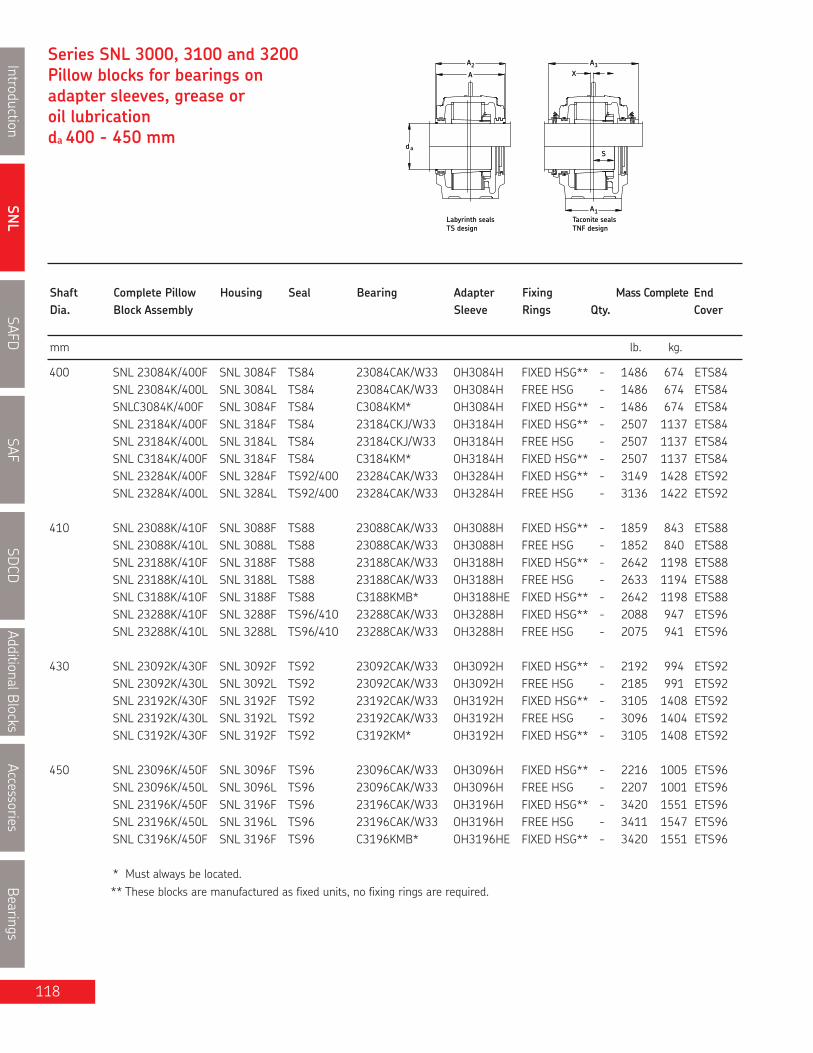
SNL
IntroductionSAFD
SAFSD
CDAdditionalBlocks
AccessoriesBearings
118
Series SNL 3000, 3100 and 3200Pillow blocks for bearings onadapter sleeves, grease oroil lubricationda 400 - 450 mm
da
A
A2
A1
AX
3
S
Labyrinth sealsTS design
Taconite sealsTNF design
Shaft Complete Pillow Housing Seal Bearing Adapter Fixing Mass Complete EndDia. Block Assembly Sleeve Rings Qty. Cover
mm lb. kg.
400 SNL 23084K/400F SNL 3084F TS84 23084CAK/W33 OH3084H FIXED HSG** - 1486 674 ETS84SNL 23084K/400L SNL 3084L TS84 23084CAK/W33 OH3084H FREE HSG - 1486 674 ETS84SNLC3084K/400F SNL 3084F TS84 C3084KM* OH3084H FIXED HSG** - 1486 674 ETS84SNL 23184K/400F SNL 3184F TS84 23184CKJ/W33 OH3184H FIXED HSG** - 2507 1137 ETS84SNL 23184K/400L SNL 3184L TS84 23184CKJ/W33 OH3184H FREE HSG - 2507 1137 ETS84SNL C3184K/400F SNL 3184F TS84 C3184KM* OH3184H FIXED HSG** - 2507 1137 ETS84SNL 23284K/400F SNL 3284F TS92/400 23284CAK/W33 OH3284H FIXED HSG** - 3149 1428 ETS92SNL 23284K/400L SNL 3284L TS92/400 23284CAK/W33 OH3284H FREE HSG - 3136 1422 ETS92
410 SNL 23088K/410F SNL 3088F TS88 23088CAK/W33 OH3088H FIXED HSG** - 1859 843 ETS88SNL 23088K/410L SNL 3088L TS88 23088CAK/W33 OH3088H FREE HSG - 1852 840 ETS88SNL 23188K/410F SNL 3188F TS88 23188CAK/W33 OH3188H FIXED HSG** - 2642 1198 ETS88SNL 23188K/410L SNL 3188L TS88 23188CAK/W33 OH3188H FREE HSG - 2633 1194 ETS88SNL C3188K/410F SNL 3188F TS88 C3188KMB* OH3188HE FIXED HSG** - 2642 1198 ETS88SNL 23288K/410F SNL 3288F TS96/410 23288CAK/W33 OH3288H FIXED HSG** - 2088 947 ETS96SNL 23288K/410L SNL 3288L TS96/410 23288CAK/W33 OH3288H FREE HSG - 2075 941 ETS96
430 SNL 23092K/430F SNL 3092F TS92 23092CAK/W33 OH3092H FIXED HSG** - 2192 994 ETS92SNL 23092K/430L SNL 3092L TS92 23092CAK/W33 OH3092H FREE HSG - 2185 991 ETS92SNL 23192K/430F SNL 3192F TS92 23192CAK/W33 OH3192H FIXED HSG** - 3105 1408 ETS92SNL 23192K/430L SNL 3192L TS92 23192CAK/W33 OH3192H FREE HSG - 3096 1404 ETS92SNL C3192K/430F SNL 3192F TS92 C3192KM* OH3192H FIXED HSG** - 3105 1408 ETS92
450 SNL 23096K/450F SNL 3096F TS96 23096CAK/W33 OH3096H FIXED HSG** - 2216 1005 ETS96SNL 23096K/450L SNL 3096L TS96 23096CAK/W33 OH3096H FREE HSG - 2207 1001 ETS96SNL 23196K/450F SNL 3196F TS96 23196CAK/W33 OH3196H FIXED HSG** - 3420 1551 ETS96SNL 23196K/450L SNL 3196L TS96 23196CAK/W33 OH3196H FREE HSG - 3411 1547 ETS96SNL C3196K/450F SNL 3196F TS96 C3196KMB* OH3196HE FIXED HSG** - 3420 1551 ETS96
* Must always be located.** These blocks are manufactured as fixed units, no fixing rings are required.

SNL
Introduction
SAFD
SAF
SDCD
AdditionalB
locks
Accessories
Bearings
119
Large SNL Pillow Blocks of the 3000, 3100 and 3200 series
H
H2
L
J
G
1H
1J
SNL 3140
1N
N
Housing No. Dimensions Bolts(2 req'd)
A A1 A2 A3 X H H1 H2 L J J1 S* G
in/mm
For an example on how to order, please see page 107.
SNL 3084 15.75 14.17 16.14 19.49 1.18 28.15 14.17 4.72 40.94 34.25 8.66 6.89 1 1⁄2400 360 410 495 30 715 360 120 1040 870 220 175 36
SNL 3184 18.11 16.54 18.50 21.85 1.38 31.89 16.14 5.12 46.06 39.37 10.24 8.78 -460 420 470 555 35 810 410 130 1170 1000 260 223 42
SNL 3284 18.50 17.32 18.90 22.24 1.38 34.65 17.32 5.71 50.39 42.13 10.24 9.33 -470 440 480 565 35 880 440 145 1280 1070 260 237 42
SNL 3088 16.93 15.35 17.32 20.67 1.18 30.51 14.96 4.92 44.09 37.40 9.45 7.48 -430 390 440 525 30 775 380 125 1120 950 240 190 42
SNL 3188 18.11 16.93 18.50 21.85 1.38 32.87 16.54 5.31 48.03 40.55 10.24 8.79 -460 430 470 555 35 835 420 135 1220 1030 260 223 42
SNL 3288 18.50 17.32 18.90 22.24 1.38 36.22 18.11 6.10 52.36 43.70 10.24 9.41 -470 440 480 565 35 920 460 155 1330 1110 260 239 48
SNL 3092 18.11 16.54 18.50 21.85 1.38 31.89 16.14 5.12 46.06 39.37 10.24 7.91 -460 420 470 555 35 810 410 130 1170 1000 260 201 42
SNL 3192 18.50 17.32 18.90 22.24 1.38 34.65 17.32 5.71 50.39 42.13 10.24 9.13 -470 440 480 565 35 880 440 145 1280 1070 260 232 42
SNL 3096 18.11 16.54 18.50 21.85 1.38 31.89 16.14 5.12 46.06 39.37 10.24 7.91 -460 420 470 555 35 810 410 130 1170 1000 260 201 42
SNL 3196 18.50 17.32 18.90 22.24 1.38 36.22 18.11 6.10 52.36 43.70 10.24 9.21 -470 440 480 565 35 920 460 155 1330 1110 260 234 48
*NOTE: Dimension "S" indicates the shaft length from the centre of the bearing to the end of the shaft for housingswith one end closed.

SNL
IntroductionSAFD
SAFSDCD
AdditionalBlocksAccessories
Bearings
120
type seals for sizes 520 through 532, and TSAF-D & E for sizes 515-518. For smaller sizes, TSNC-D & E and TSAF-D & E are not available.Consult SKF for availability of metric LOR & LORC type seals.
Note : SAFD & FSAFD pillow blocks must be modified to MC14 when using TSNC-D & E
+ Contact elementB-10724-xxx orB-10785-xxx
Ductile Iron ASTM A536 grade 65-45-12
12K, 12EK, 22K, 22EK, 222CCK, 222EK, 232CCK
MATERIAL
BEARING SERIESUSED
STANDARD SEALS
OPTIONAL SEALS
LUBRICATIONPILLOW BLOCK
SHAFT SIZE RANGE
PILLOW BLOCK SIZE 509 - 544 (adapter mounting)
1-7/16" to 8" 50mm to 200mm
Grease or Oil
SAFD, FSAFD
TSNC-D & TSAF -DTSNC-E & TSAF-E
TER-CVTER-C
LER LOR & LORP
LOR
Pillow BlockHousings

SNL
Introduction
SAFD
SAF
SDCD
AdditionalBlocks
Accessories
Bearings
121
SAFD Split Pillow Blocks Nomenclature Adapter Mounting
SAFDF 22520/37⁄16 CV
BaseOF**
Basic Design
MaterialD
Size
SuffixesOCCVDEHK7MTLCTLPY
Note:
Two boltFour bolt
Ductile iron
Bearing size: 20 = 100mmShaft size: 3 7⁄16”
Standard triple LER/LOR triple ring seals (included)*Taconite service seal TER..C of Canadian design (1/pkg)Taconite service seal TER..CV of Canadian design c/w V ring (1/pkg)Purgeable labyrinth seal TSNC..D c/w V ring (1/pkg)Purgeable labyrinth seal TSNC..E without V ring (1/pkg)Held bearing c/w fixing ringsTighter housing fit, can be used with CARB® bearings for high speeds or vibrationMetric (used as housing suffix where a modification is required)Combination of LOR and B-10724-xxx contact element (max temp. 120ºC)LORP c/w B-10785-xxx contact element for higher temperatures and speeds. (max temp. 200ºC)One end closed with end cover or end plug
* SAFD blocks include the seals for standard shaft sizes (shown as highlighted in the tables)If non-standard shaft sizes are requested those seals must be ordered separately** Sizes 618, 522 and above are standard with 4 bolt bases. Prefix "F" is not required
How to order SAFD: (Example)
When you order one SAFD 22520-37⁄16 you will receive the following:
1 - Pillow block housing SAFD 520: Cap drilled and tapped with two 1⁄4" NPT holes (for Alemite 1627-B grease fittings, which arenot included.) Base drilled, tapped and plugged with two diagonally opposed 1⁄2" NPT holes.
2 - Triple ring seals LOR 102 installed in housing hubs.1 - Bearing SKF 22220 EK1 - Adapter sleeve HA 320 for shaft dia. 37⁄16
If a "HELD or FIXED" unit is required, add the suffix "H" and 2 fixing rings (locating or stabilizing) FRB 12/180 will be included.Only one bearing per shaft should be held. CARB bearings displace internally and are therefore always "FREE".However, they must always be located in the housing with fixing rings as does a true "FIXED" bearing.If one end closed is required please add the letter "Y" to the assembly number and one EPR 12 will be included.

Shaft Complete Pillow Housing Triple Taconite Bearing Adapter Fixing MassDia. Block Assembly Ring Service Sleeve Rings Completeda Seal Seal (2 req’d)
in lb. kg.
SNL
IntroductionSAFD
SAFSDCD
AdditionalBlocksAccessories
Bearings
122
Series SAFD 500Pillow blocks of ductile iron forbearings with adapter sleeve,grease or oil lubricationda 1 7⁄16 - 2 in
S
1A
3H 3H
3
da
A
A
daS
1A
A2A
1 7⁄16 1) SAFD 1509/ 1 7⁄16 SAFD 509 LER 17 TER 17 1209 EK HA 209 FRB 5.5/85 11.5 5.2
SAFD 2509/ 1 7⁄16 SAFD 509 LER 17 TER 17 2209 EK HA 309 FRB 3.5/85 11.7 5.3
SAFD 22509/ 1 7⁄16 SAFD 509 LER 17 TER 17 22209 EK HA 309 FRB 3.5/85 11.7 5.3
SAFD C2509/ 1 7⁄16 SAFD 509 LER 17 TER 17 C2209 K* HA 309E FRB 3.5/85 12.0 5.5
1 1⁄2 SAFD 1509/ 1 1⁄2 SAFD 509 LER 18 - 1209 EK HE 209 FRB 5.5/85 11.5 5.2
SAFD 2509/ 1 1⁄2 SAFD 509 LER 18 - 2209 EK HE 309 FRB 3.5/85 11.7 5.3
SAFD 22509/ 1 1⁄2 SAFD 509 LER 18 - 22209 EK HE 309 FRB 3.5/85 11.7 5.3
SAFD C2509/ 1 1⁄2 SAFD 509 LER 18 - C2209 K* HE 309E FRB 3.5/85 12.0 5.5
1 11⁄16 1) SAFD 1510/ 1 11⁄16 SAFD 510 LER 20 TER 510/ 1 11⁄16 1210 EK HA 210 FRB 6.5/90 12.7 5.8SAFD 2510/ 1 11⁄16 SAFD 510 LER 20 TER 510/ 1 11⁄16 2210 K HA 310 FRB 5/90 12.9 5.9SAFD 22510/ 1 11⁄16 SAFD 510 LER 20 TER 510/ 1 11⁄16 22210 EK HA 310 FRB 5/90 12.9 5.9SAFD C2510/ 1 11⁄16 SAFD 510 LER 20 TER 510/ 1 11⁄16 C2210 K* HA 310E FRB 5/90 12.9 5.9
1 3⁄4 SAFD 1510/ 1 3⁄4 SAFD 510 LER 21 TER 510/ 1 3⁄4 1210 EK HE 210 FRB 6.5/90 12.7 5.8SAFD 2510/ 1 3⁄4 SAFD 510 LER 21 TER 510/ 1 3⁄4 2210 K HE 310 FRB 5/90 12.9 5.9SAFD 22510/ 1 3⁄4 SAFD 510 LER 21 TER 510/ 1 3⁄4 22210 EK HE 310 FRB 5/90 12.9 5.9SAFD C2510/ 1 3⁄4 SAFD 510 LER 21 TER 510/ 1 3⁄4 C2210 K* HE 310E FRB 5/90 12.9 5.9
1 15⁄16 1) SAFD 1511/ 1 15⁄16 SAFD 511 LER 24 TER 511/ 1 15⁄16 1211 EK HA 211 FRB 6/100 16.5 7.5SAFD 2511/ 1 15⁄16 SAFD 511 LER 24 TER 511/ 1 15⁄16 2211 EK HA 311 FRB 4/100 16.8 7.6SAFD 22511/ 1 15⁄16 SAFD 511 LER 24 TER 511/ 1 15⁄16 22211 EK HA 311 FRB 4/100 16.8 7.6SAFD C2511/ 1 15⁄16 SAFD 511 LER 24 TER 511/ 1 15⁄16 C2211 K* HA 311BE FRB 4/100 16.0 7.3
2 SAFD 1511/2 SAFD 511 LER 25 TER 511/2 1211 EK HE 211B FRB 6/100 16.5 7.5SAFD 2511/2 SAFD 511 LER 25 TER 511/2 2211 EK HE 311B FRB 4/100 16.8 7.6SAFD 22511/2 SAFD 511 LER 25 TER 511/2 22211 EK HE 311B FRB 4/100 16.8 7.6SAFD C2511/ 2 SAFD 511 LER 25 TER 511/2 C2211 K* HE 311BE FRB 4/100 16.0 7.3
1) The highlighted sizes contain seals, which are included in that housing, optional shaft sizes require additional seals.* Must always be located.

SNL
Introduction
SAFD
SAF
SDCD
AdditionalBlocks
Accessories
Bearings
123
Pillow block housing series SAFD
MADE IN CANADA
G
2H
LJ
1H
1J
H
Housing No. Dimensions Static Bolts EndOil Level (req’d) Plug
A A1 A2 A3 H H1 H2 H3 L Jmax Jmin J1 G S
in/mm
NOTE: Dimension "S" indicates the shaft length from the centre of the bearing to the end of the shaft for housings with oneend closed. For tabulation of the dimension "S", see the bearing tables on pages 52 and 53.When oil lubrication is used static oil level H3 must be maintained.
For an example on how to order please see page 121.
SAFD 509 3 7⁄16 2 3⁄8 3 5⁄8 - 4 3⁄8 2 1⁄4 13⁄16 31⁄32 8 1⁄4 7 6 1⁄4 - (2) 1⁄2 * EPR 3
87 60 92 - 111 57.15 21 25 210 178 159 - (2) 12
SAFD 510 3 7⁄16 2 3⁄8 3 5⁄8 6 3⁄4 4 5⁄8 2 1⁄2 15⁄16 15⁄32 8 1⁄4 7 6 1⁄2 - (2) 1⁄2 * EPR 4
87 60 92 171 117 63.50 24 28 210 178 165 - (2) 12
SAFD 511 3 3⁄4 2 3⁄4 3 7⁄8 7 5 1⁄4 2 3⁄4 15⁄16 15⁄16 9 5⁄8 7 7⁄8 7 3⁄8 - (2) 5⁄8 * EPR 5
95 70 98 178 133 69.85 24 30 245 200 187 - (2) 16

SNL
IntroductionSAFD
SAFSDCD
AdditionalBlocksAccessories
Bearings
Series SAFD 500Pillow blocks of ductile iron,for bearings with adaptersleeve, grease or oil lubricationda 2 3⁄16 - 2 3⁄4 in
S
1A
3H 3H
3
da
A
A
daS
1A
A2A
Shaft Complete Pillow Housing Triple Taconite Bearing Adapter Fixing MassDia. Block Assembly** Ring Service Sleeve Rings Completeda Seal Seal (2 req’d)
in lb. kg.
2 3⁄16 1) SAFD 1513/ 2 3⁄16 SAFD 513 LER 29 TER 513/ 2 3⁄16 1213 EK HA 213 FRB 8/120 22.3 10.0
SAFD 2513/ 2 3⁄16 SAFD 513 LER 29 TER 513/ 2 3⁄16 2213 EK HA 313 FRB 4/120 23.1 10.5
SAFD 22513/ 2 3⁄16 SAFD 513 LER 29 TER 513/ 2 3⁄16 22213EK HA 313 FRB 4/120 23.1 10.5SAFD C2513/ 2 3⁄16 SAFD 513 LER 29 TER 513/ 2 3⁄16 C2213 K* HA 313E FRB 4/120 22.0 10.0
2 1⁄4 SAFD 1513/ 2 1⁄4 SAFD 513 LER 30 TER 513/ 2 1⁄4 1213 EK HE 213 FRB 8/120 22.3 10.0
SAFD 2513/ 2 1⁄4 SAFD 513 LER 30 TER 513/ 2 1⁄4 2213 EK HE 313 FRB 4/120 23.1 10.5
SAFD 22513/ 2 1⁄4 SAFD 513 LER 30 TER 513/ 2 1⁄4 22213EK HE 313 FRB 4/120 23.1 10.5
SAFD C2513/ 2 1⁄4 SAFD 513 LER 30 TER 513/ 2 1⁄4 C2213 K* HE 313E FRB 4/120 22.0 10.0
2 7⁄16 1) (F)SAFD 1515/ 2 7⁄16 (F)SAFD 515 LOR 37 TER 515/ 2 7⁄16 1215 K HA 215 FRB 8/130 27.4 12.5
(F)SAFD 2515/ 2 7⁄16 (F)SAFD 515 LOR 37 TER 515/ 2 7⁄16 2215 K HA 315 FRB 5/130 28.2 12.8(F)SAFD 22515/ 2 7⁄16 (F)SAFD 515 LOR 37 TER 515/ 2 7⁄16 22215 EK HA 315 FRB 5/130 28.4 12.9
(F)SAFD C2515/ 2 7⁄16 (F)SAFD 515 LOR 37 TER 515/ 2 7⁄16 C2215 K* HA 315E FRB 5/130 28.4 12.9
2 1⁄2 (F)SAFD 1515/ 2 1⁄2 (F)SAFD 515 LOR 38 TER 515/ 2 7⁄16 1215 K HE 215 FRB 8/130 27.4 12.5
(F)SAFD 2515/ 2 1⁄2 (F)SAFD 515 LOR 38 TER 515/ 2 7⁄16 2215 K HE 315 FRB 5/130 28.2 12.8
(F)SAFD 22515/ 2 1⁄2 (F)SAFD 515 LOR 38 TER 515/ 2 7⁄16 22215 EK HE 315 FRB 5/130 28.4 12.9
(F)SAFD C2515/ 2 1⁄2 (F)SAFD 515 LOR 38 TER 515/ 2 7⁄16 C2215 K* HE 315E FRB 5/130 28.4 12.9
2 11⁄1 6 1) (F)SAFD 1516/ 2 11⁄16 (F)SAFD 516 LOR 44 TER 516/ 2 11⁄16 1216 K HA 216 FRB 8.5/140 32.4 14.7
(F)SAFD 2516/ 2 11⁄16 (F)SAFD 516 LOR 44 TER 516/ 2 11⁄16 2216 K HA 316 FRB 5/140 33.5 15.2
(F)SAFD 22516/ 2 11⁄16 (F)SAFD 516 LOR 44 TER 516/ 2 11⁄16 22216 EK HA 316 FRB 5/140 33.6 15.2
(F)SAFD C2516/ 2 11⁄16 (F)SAFD 516 LOR 44 TER 516/ 2 11⁄16 C2216 K* HA 316E FRB 5/140 38.0 17.3
2 3⁄4 (F)SAFD 1516/ 2 3⁄4 (F)SAFD 516 LOR 45 TER 516/ 2 3⁄4 1216 K HE 216 FRB 8.5/140 32.4 14.7
(F)SAFD 2516/ 2 3⁄4 (F)SAFD 516 LOR 45 TER 516/ 2 3⁄4 2216 EK HE 316 FRB 5/140 33.5 15.2
(F)SAFD 22516/ 2 3⁄4 (F)SAFD 516 LOR 45 TER 516/ 2 3⁄4 22216 EK HE 316 FRB 5/140 33.6 15.3
1) The highlighted sizes contain seals, which are included in that housing, optional shaft sizes require additional seals.* Must always be located.** (F)SAFD = 2 or 4 bolt base. Sizes 522 and above are standard with 4 bolt base. The prefix (F) is not required
124

SNL
Introduction
SAFD
SAF
SDCD
AdditionalBlocks
Accessories
Bearings
125
Pillow block housing series SAFD
MADE IN CANADA
G
2H
LJ
1H
1J
H
Housing No. Dimensions Static Bolts EndOil Level (req’d) Plug
A A1 A2 A3 H H1 H2 H3 L Jmax Jmin J1 G S
in/mm
NOTE: Dimension "S" indicates the shaft length from the centre of the bearing to the end of the shaft for housings with oneend closed. For tabulation of the dimension "S", see the bearing tables on pages 52 and 53.
For an example on how to order please see page 121.
SAFD 513 4 1⁄4 3 1⁄8 4 1⁄2 7 3⁄8 5 15⁄16 3 1 1 3⁄32 11 9 1⁄2 8 1⁄8 - (2) 5⁄8 * EPR 6
108 79 114 188 151 76.2 25 28 279 241 206 - (2) 16
SAFD 515 4 5⁄8 3 1⁄8 4 3⁄4 7 3⁄4 6 3⁄8 3 1⁄4 1 1⁄8 1 1⁄8 11 1⁄4 9 5⁄8 8 5⁄8 - (2) 5⁄8 * EPR 7
117 79 121 197 162 82.55 29 29 286 244 219 - (2) 16
FSAFD 515 4 5⁄8 3 1⁄8 4 3⁄4 7 3⁄4 6 3⁄8 3 1⁄4 1 1⁄8 1 1⁄8 11 1⁄4 9 5⁄8 8 5⁄8 1 7⁄8 (4) 1⁄2 * EPR 7
117 79 121 197 162 82.55 29 29 286 244 219 47.6 (4) 12
SAFD 516 4 3⁄4 3 1⁄2 4 7⁄8 7 15⁄16 6 7⁄8 3 1⁄2 1 1⁄4 1 1⁄4 13 11 9 5⁄8 - (2) 3⁄4 * EPR 8
121 89 124 202 175 88.9 32 32 330 279 244 - (2) 20
FSAFD 516 4 3⁄4 3 1⁄2 4 7⁄8 7 15⁄16 6 7⁄8 3 1⁄2 1 1⁄4 1 1⁄4 13 11 9 5⁄8 2 1⁄8 (4) 5⁄8 * EPR 8
121 89 124 202 175 88.9 32 32 330 279 244 54 (4) 16

SNL
IntroductionSAFD
SAFSDCD
AdditionalBlocksAccessories
Bearings
Series SAFD 500Pillow blocks of ductile iron,for bearings with adaptersleeve, grease or oil lubricationda 2 15⁄16 - 3 7⁄16 in
S
1A
3H 3H
3
da
A
A
daS
1A
A2A
Shaft Complete Pillow Housing Triple Taconite Bearing Adapter Fixing MassDia. Block Assembly** Ring Service Sleeve Rings Completeda Seal Seal (2 req’d)
in lb. kg.
2 15⁄16 1) (F)SAFD 1517/ 2 15⁄16 (F)SAFD 517 LOR 53 TER 517/ 2 15⁄16 1217 K HA 217 FRB 9/150 39.7 18.0
(F)SAFD 2517/ 2 15⁄16 (F)SAFD 517 LOR 53 TER 517/ 2 15⁄16 2217 K HA 317 FRB 5/150 41.0 18.6
(F)SAFD 22517/ 2 15⁄16 (F)SAFD 517 LOR 53 TER 517/ 2 15⁄16 22217 EK HA 317 FRB 5/150 41.2 18.7
(F)SAFD C2517/ 2 15⁄16 (F)SAFD 517 LOR 53 TER 517/ 2 15⁄16 C2217 K* HA 317E FRB 5/150 38.0 17.3
3 (F)SAFD 1517/ 3 (F)SAFD 517 LOR 54 TER 517/ 3 1217 K HE 217 FRB 9/150 39.7 18.0
(F)SAFD 2517/ 3 (F)SAFD 517 LOR 54 TER 517/ 3 2217 K HE 317 FRB 5/150 41.0 18.6
(F)SAFD 22517/ 3 (F)SAFD 517 LOR 54 TER 517/ 3 22217 EK HE 317 FRB 5/150 41.2 18.7
(F)SAFD C2517/ 3 (F)SAFD 517 LOR 54 TER 517/ 3 C2217 K* HE 317E FRB 5/150 38.0 17.3
3 3⁄16 1) (F)SAFD 1518/ 3 3⁄16 (F)SAFD 518 LOR 188 TER 518/ 3 3⁄16 1218 K HA 218 FRB 16.2/160 48.5 22.0
(F)SAFD 2518/ 3 3⁄16 (F)SAFD 518 LOR 188 TER 518/ 3 3⁄16 2218 K HA 318 FRB 11.2/160 51.0 23.0
(F)SAFD 22518/ 3 3⁄16 (F)SAFD 518 LOR 188 TER 518/ 3 3⁄16 22218 EK HA 318 FRB 11.2/160 51.0 23.0
(F)SAFD 23518/ 3 3⁄16 (F)SAFD 518 LOR 188 TER 518/ 3 3⁄16 23218CCK/W33 HA 2318 FRB 5/160 54.0 24.4
(F)SAFD C2518/ 3 3⁄16 (F)SAFD 518 LOR 188 TER 518/ 3 3⁄16 C2218 K* HA 318E FRB 11.2/160 51.0 23.0
3 1⁄4 (F)SAFD 1518/ 3 1⁄4 (F)SAFD 518 LOR 189 TER 518/ 3 1⁄4 1218 K HE 218 FRB 16.2/160 48.5 22.0
(F)SAFD 2518/ 3 1⁄4 (F)SAFD 518 LOR 189 TER 518/ 3 1⁄4 2218 K HE 318 FRB 11.2/160 51.0 23.1
(F)SAFD 22518/ 3 1⁄4 (F)SAFD 518 LOR 189 TER 518/ 3 1⁄4 22218 EK HE 318 FRB 11.2/160 51.0 23.1
(F)SAFD 23518/ 3 1⁄4 (F)SAFD 518 LOR 189 TER 518/ 3 1⁄4 23218CCK/W33 HE 2318 FRB 5/160 54.0 24.4
(F)SAFD C2518/ 3 1⁄4 (F)SAFD 518 LOR 189 TER 518/ 3 1⁄4 C2218 K* HE 318E FRB 11.2/160 47.0 21.364
3 7⁄16 1) (F)SAFD 1520/ 3 7⁄16 (F)SAFD 520 LOR 102 TER 520/ 3 7⁄16 1220 K HA 220 FRB 18/180 61.3 27.8
(F)SAFD 2520/ 3 7⁄16 (F)SAFD 520 LOR 102 TER 520/ 3 7⁄16 2220 K HA 320 FRB 12/180 64.6 29.3
(F)SAFD 22520/ 3 7⁄16 (F)SAFD 520 LOR 102 TER 520/ 3 7⁄16 22220 EK HA 320 FRB 12/180 64.2 29.1
(F)SAFD 23520/ 3 7⁄16 (F)SAFD 520 LOR 102 TER 520/ 3 7⁄16 23220CCK/W33 HA 2320 FRB 4.85/180 68.6 31.1
(F)SAFD C2520/ 3 7⁄16 (F)SAFD 520 LOR 102 TER 520/ 3 7⁄16 C2220 K* HA 320E FRB 12/180 62.0 28.2
1) The highlighted sizes contain seals, which are included in that housing, optional shaft sizes require additional seals.* Must always be located.** (F)SAFD = 2 or 4 bolt base. Sizes 522 and above are standard with 4 bolt base. The prefix (F) is not required.
126

SNL
Introduction
SAFD
SAF
SDCD
AdditionalBlocks
Accessories
Bearings
127
Pillow block housing series SAFD
MADE IN CANADA
G
2H
LJ
1H
1J
H
Housing No. Dimensions Static Bolts EndOil Level (req’d) Plug
A A1 A2 A3 H H1 H2 H3 L Jmax Jmin J1 G S
in/mm
NOTE: Dimension "S" indicates the shaft length from the centre of the bearing to the end of the shaft for housings with oneend closed. For tabulation of the dimension "S", see the bearing tables on pages 52 and 53.
For an example on how to order please see page 121.
SAFD 517 4 13⁄16 3 1⁄2 5 8 7 5⁄16 3 3⁄4 1 1⁄4 1 3⁄8 13 11 9 7⁄8 - (2) 3⁄4 * EPR 9
122 89 127 203 186 95.25 32 35 330 279 251 - (2) 20
FSAFD 517 4 13⁄16 3 1⁄2 5 8 7 5⁄16 3 3⁄4 1 1⁄4 1 3⁄8 13 11 9 7⁄8 2 1⁄8 (4) 5⁄8 * EPR 9
122 89 127 203 186 95.25 32 35 330 279 251 54 (4) 16
SAFD 518 5 1⁄2 3 7⁄8 5 3⁄4 8 11⁄16 7 3⁄4 4 1 5⁄8 1 1⁄2 13 3⁄4 11 5⁄8 10 3⁄8 - (2) 3⁄4 * EPR 11
140 98 146 221 197 101.60 41 38 349 295 264 - (2) 20
FSAFD 518 5 1⁄2 3 7⁄8 5 3⁄4 8 11⁄16 7 3⁄4 4 1 5⁄8 1 1⁄2 13 3⁄4 11 5⁄8 10 3⁄8 2 1⁄8 (4) 5⁄8 * EPR 11
140 98 146 221 197 101.60 41 38 349 295 264 54 (4) 16
SAFD 520 6 4 3⁄8 6 1⁄8 9 8 3⁄4 4 1⁄2 1 3⁄4 1 21⁄32 15 1⁄4 13 1⁄8 11 5⁄8 - (2) 7⁄8 * EPR 12
152 111 156 230 222 114.30 44 42 387 333 295 - (2) 24
FSAFD 520 6 4 3⁄8 6 1⁄8 9 8 3⁄4 4 1⁄2 1 3⁄4 1 21⁄32 15 1⁄4 13 1⁄8 11 5⁄8 2 3⁄8 (4) 3⁄4 * EPR 12
152 111 156 230 222 114.30 44 42 387 333 295 60 (4) 20

SNL
IntroductionSAFD
SAFSDCD
AdditionalBlocksAccessories
Bearings
Series SAFD 500Pillow blocks of ductile iron,for bearings with adaptersleeve, grease or oil lubricationda 3 1⁄2 - 4 1⁄4 in
S
1A
3H 3H
3
da
A
A
daS
1A
A2A
Shaft Complete Pillow Housing Triple Taconite Bearing Adapter Fixing MassDia. Block Assembly** Ring Service Sleeve Rings Completeda Seal Seal (2 req’d)
in lb. kg.
3 15⁄16 1) SAFD 1522/ 3 15⁄16 SAFD 522 LOR 109 TER 522/ 3 15⁄16 1222 K H 222 FRB 21/200 88.0 40.0
SAFD 2522/ 3 15⁄16 SAFD 522 LOR 109 TER 522/ 3 15⁄16 2222 K H 322 FRB 13.5/200 93.0 42.1
SAFD 22522/ 3 15⁄16 SAFD 522 LOR 109 TER 522/ 3 15⁄16 22222 EK H 322 FRB 13.5/200 92.4 41.9
SAFD 23522/ 3 15⁄16 SAFD 522 LOR 109 TER 522/ 3 15⁄16 23222CCK/W33 H 2322 FRB 5.1/200 100 45.1
SAFD C2522/ 3 15⁄16 SAFD 522 LOR 109 TER 522/ 3 15⁄16 C2222 K* H 322E FRB 13.5/200 73.0 33.2
4 SAFD 1522/4 SAFD 522 LOR 110 TER 522/4 1222 K HE 222 FRB 21/200 88.0 40.0
SAFD 2522/4 SAFD 522 LOR 110 TER 522/4 2222 K HE 322 FRB 13.5/200 93.0 42.2
SAFD 22522/4 SAFD 522 LOR 110 TER 522/4 22222 EK HE 322 FRB 13.5/200 92.4 41.9
SAFD 23522/4 SAFD 522 LOR 110 TER 522/4 23222CCK/W33 HE 2322 FRB 5.1/200 100 45.1
SAFD C2522/4 SAFD 522 LOR 110 TER 522/4 C2222 K* HE 322E FRB 13.5/200 73.0 33.2
4 3⁄16 1) SAFD 22524/4 3⁄16 SAFD 524 LOR 113 TER 524/4 3⁄16 22224 EK HA 3124 FRB 14/215 106 48.0
SAFD 23524/4 3⁄16 SAFD 524 LOR 113 TER 524/4 3⁄16 23224CCK/W33 HA 2324 FRB 5/215 114 52.0
SAFD C2524/4 3⁄16 SAFD 524 LOR 113 TER 524/4 3⁄16 C2224 K* HA 3124L FRB 14/215 106 48.0
SAFD C3524/4 3⁄16 SAFD 524 LOR 113 TER 524/4 3⁄16 C3224 K* HA 2324L FRB 5/215 114 52.0
4 1⁄4 SAFD 22524/4 1⁄4 SAFD 524 LOR 114 TER 524/4 1⁄4 22224 EK HE 3124 FRB 14/215 106 48.0
SAFD 23524/4 1⁄4 SAFD 524 LOR 114 TER 524/4 1⁄4 23224CCK/W33 HE 2324 FRB 5/215 114 52.0
SAFD C2524/4 1⁄4 SAFD 524 LOR 114 TER 524/4 1⁄4 C2224 K* HE 3124L FRB 14/215 106 48.0
SAFD C3524/4 1⁄4 SAFD 524 LOR 114 TER 524/4 1⁄4 C3224 K* HE 2324L FRB 5/215 114 52.0
1) The highlighted sizes contain seals, which are included in that housing, optional shaft sizes require additional seals.* Must always be located.** (F)SAFD = 2 or 4 bolt base. Sizes 522 and above are standard with 4 bolt base. The prefix (F) is not required.
128
3 1⁄2 (F)SAFD 1520/ 3 1⁄2 FSAFD 520 LOR 103 TER 520/ 3 1⁄2 1220 K HE 220 FRB 18/180 61.3 27.8
(F)SAFD 2520/ 3 1⁄2 FSAFD 520 LOR 103 TER 520/ 3 1⁄2 2220 K HE 320 FRB 12/180 64.4 29.3
(F)SAFD 22520/ 3 1⁄2 FSAFD 520 LOR 103 TER 520/ 3 1⁄2 22220 EK HE 320 FRB 12/180 64.2 29.1
(F)SAFD 23520/ 3 1⁄2 FSAFD 520 LOR 103 TER 520/ 3 1⁄2 23220CCK/W33 HE 2320 FRB 4.85/180 68.6 31.1
(F)SAFD C2520/ 3 1⁄2 FSAFD 520 LOR 103 TER 520/ 3 1⁄2 C2220 K* HE 320E FRB 12/180 62.0 28.2

SNL
Introduction
SAFD
SAF
SDCD
AdditionalBlocks
Accessories
Bearings
129
Pillow block housing series SAFD
MADE IN CANADA
G
2H
LJ
1H
1J
H
Housing No. Dimensions Static Bolts EndOil Level (req’d) Plug
A A1 A2 A3 H H1 H2 H3 L Jmax Jmin J1 G S
in/mm
NOTE: Dimension "S" indicates the shaft length from the centre of the bearing to the end of the shaft for housings with oneend closed. For tabulation of the dimension "S", see the bearing tables on pages 52 and 53.
For an example on how to order please see page 121.
SAFD 522 6 7⁄16 4 3⁄4 6 1⁄2 9 1⁄2 9 5⁄8 4 15⁄16 2 1 25⁄32 16 1⁄2 14 1⁄2 12 5⁄8 2 3⁄4 (4) 3⁄4 * EPR 13
164 121 165 242 244 125.41 51 45 419 368 321 70 (4) 20
SAFD 524 7 1⁄8 4 3⁄4 7 3⁄8 10 5⁄16 10 1⁄4 5 1⁄4 2 1⁄8 1 27⁄32 16 1⁄2 14 1⁄2 13 1⁄4 2 3⁄4 (4) 3⁄4 * EPR 14
181 121 187 262 260 133.35 54 47 419 368 337 70 (4) 20
SAFD 520 6 4 3⁄8 6 1⁄8 9 8 3⁄4 4 1⁄2 1 3⁄4 1 21⁄32 15 1⁄4 13 1⁄8 11 5⁄8 - (2) 7⁄8 * EPR 12
152 111 156 230 222 114.30 44 42 387 333 295 - (2) 24
FSAFD 520 6 4 3⁄8 6 1⁄8 9 8 3⁄4 4 1⁄2 1 3⁄4 1 21⁄32 15 1⁄4 13 1⁄8 11 5⁄8 2 3⁄8 (4) 3⁄4 * EPR 12
152 111 156 230 222 114.30 44 42 387 333 295 60 (4) 20

SNL
IntroductionSAFD
SAFSDCD
AdditionalBlocksAccessories
Bearings
130
Series SAFD 500Pillow blocks of ductile iron,for bearings with adaptersleeve, grease or oil lubricationda 4 7⁄16 - 5 7⁄16 in
3H
ad
3
1A
A
A
S S
H 3
da
A1
A 2
A
Shaft Complete Pillow Housing Triple Taconite Bearing Adapter Fixing MassDia. Block Assembly Ring Service Sleeve Rings Completeda Seal Seal (2 req’d)
in lb. kg.
4 15⁄16 SAFD 22528/4 15⁄16 SAFD 528 LOR 122 TER 528/4 15⁄16 22228CCK/W33 HA 3128 FRB 15/250 175 80.0
SAFD 23528/4 15⁄16 SAFD 528 LOR 122 TER 528/4 15⁄16 23228CCK/W33 HA 2328 FRB 5/250 188 86.0
SAFD C2528/4 15⁄16 SAFD 528 LOR 122 TER 528/4 15⁄16 C2228 K* HA 3128L FRB 15/250 153 69.6
5 SAFD 22528/5 SAFD 528 LOR 123 TER 528/5 22228CCK/W33 HE 3128 FRB 15/250 175 80.0
SAFD 23528/5 SAFD 528 LOR 123 TER 528/5 23228CCK/W33 HE 2328 FRB 5/250 188 86.0
SAFDC2528/5 SAFD 528 LOR 123 TER 528/5 C2228 K* HE 3128L FRB 15/250 153 69.6
5 3⁄16 1) SAFD 22530/5 3⁄16 SAFD 530 LOR 125 TER 530/5 3⁄16 22230CCK/W33 HA 3130 FRB 16.5/270 209 95.0
SAFD 23530/5 3⁄16 SAFD 530 LOR 125 TER 530/5 3⁄16 23230CCK/W33 HA 2330 FRB 5/270 225 102
SAFD C2530/5 3⁄16 SAFD 530 LOR 125 TER 530/5 3⁄16 C2230 K* HA 3130L FRB 16.5/270 199 90.5
5 1⁄4 SAFD 22530/5 1⁄4 SAFD 530 LOR 126 TER 530/5 1⁄4 22230CCK/W33 HE 3130 FRB 16.5/270 209 95.0
SAFD 23530/5 1⁄4 SAFD 530 LOR 126 TER 530/5 1⁄4 23230CCK/W33 HE 2330 FRB 5/270 225 102
SAFD C2530/5 1⁄4 SAFD 530 LOR 126 TER 530/5 1⁄4 C2230 K* HE 3130L FRB 16.5/270 199 90.5
5 7⁄16 1) SAFD 22532/5 7⁄16 SAFD 532 LOR 130 TER 532/5 7⁄16 22232CCK/W33 HA 3132 FRB 17/290 240 110
SAFD 23532/5 7⁄16 SAFD 532 LOR 130 TER 532/5 7⁄16 23232CCK/W33 HA 2332 FRB 5/290 260 120
SAFD C3532/5 7⁄16 SAFD 532 LOR 130 TER 532/5 7⁄16 C3232 K* HA 2332L FRB 5/290 260 120
1) The highlighted sizes contain seals, which are included in that housing, optional shaft sizes require additional seals.* Must always be located.
4 7⁄16 1) SAFD 22526/4 7⁄16 SAFD 526 LOR 117 TER 526/4 7⁄16 22226 EK HA 3126 FRB 13/230 156 71.0
SAFD 23526/4 7⁄16 SAFD 526 LOR 117 TER 526/4 7⁄16 23226CCK/W33 HA 2326 FRB 5/230 165 75.0
SAFD C2526/4 7⁄16 SAFD 526 LOR 117 TER 526/4 7⁄16 C2226 K* HA 3126L FRB 13/230 144 65.5
4 1⁄2 SAFD 22526/4 1⁄2 SAFD 526 LOR 118 TER 526/4 1⁄2 22226 EK HE 3126 FRB 13/230 156 71.0
SAFD 23526/4 1⁄2 SAFD 526 LOR 118 TER 526/4 1⁄2 23226CCK/W33 HE 2326 FRB 5/230 165 75.0
SAFD C2526/4 1⁄2 SAFD 526 LOR 118 TER 526/4 1⁄2 C2226 K* HE 3126L FRB 13/230 144 65.5

SNL
Introduction
SAFD
SAF
SDCD
AdditionalBlocks
Accessories
Bearings
131
Pillow block housing series SAFD
H 2
LJ
GH1
H
1J
SAFD 540
in/mm
Housing No. Dimensions Static Bolts EndOil Level (req’d) Plug
A A1 A2 A3 H H1 H2 H3 L Jmax Jmin J1 G S
NOTE: Dimension "S" indicates the shaft length from the centre of the bearing to the end of the shaft for housings with oneend closed. For tabulation of the dimension "S", see the bearing tables on pages 52 and 53.
For an example on how to order please see page 121.
SAFD 528 7 3⁄8 5 7⁄8 7 5⁄8 10 1⁄2 12 6 2 3⁄8 2 1⁄32 20 1⁄8 17 1⁄8 16 3 3⁄8 (4) 1 * EPR 27
187 149 194 267 305 152.40 60 52 511 435 406 86 (4) 24
SAFD 530 8 1⁄8 6 1⁄4 8 3⁄8 11 3⁄8 12 1⁄2 6 5⁄16 2 1⁄2 2 21 1⁄4 18 1⁄4 17 3 3⁄4 (4) 1 * EPR 16
206 159 213 289 318 160.34 64 51 540 464 432 95 (4) 24
SAFD 532 8 1⁄2 6 1⁄4 8 3⁄4 11 3⁄4 13 5⁄16 6 11⁄16 2 5⁄8 2 1⁄16 22 19 1⁄4 17 3⁄8 3 3⁄4 (4) 1 * EPR 16
216 159 222 299 338 169.86 67 52 559 489 441 95 (4) 24
SAFD 526 7 3⁄4 5 1⁄8 8 11 11 3⁄4 6 2 3⁄8 2 11⁄32 18 3⁄8 16 14 5⁄8 3 1⁄4 (4) 7⁄8 * EPR 15
197 130 203 280 298 152.40 60 59 467 406 371 83 (4) 24
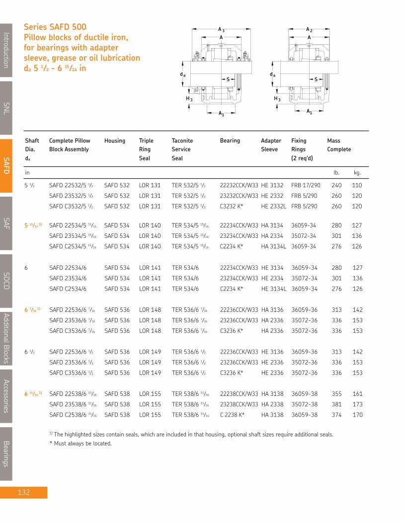
SNL
IntroductionSAFD
SAFSDCD
AdditionalBlocksAccessories
Bearings
Series SAFD 500Pillow blocks of ductile iron,for bearings with adaptersleeve, grease or oil lubricationda 5 1⁄2 - 6 15⁄16 in
3H
ad
3
1A
A
A
S S
H 3
da
A1
A 2
A
Shaft Complete Pillow Housing Triple Taconite Bearing Adapter Fixing MassDia. Block Assembly Ring Service Sleeve Rings Completeda Seal Seal (2 req’d)
in lb. kg.
6 SAFD 22534/6 SAFD 534 LOR 141 TER 534/6 22234CCK/W33 HE 3134 36059-34 280 127
SAFD 23534/6 SAFD 534 LOR 141 TER 534/6 23234CCK/W33 HE 2334 35072-34 301 136
SAFD C2534/6 SAFD 534 LOR 141 TER 534/6 C2234 K* HE 3134L 36059-34 276 126
6 7⁄16 1) SAFD 22536/6 7⁄16 SAFD 536 LOR 148 TER 536/6 7⁄16 22236CCK/W33 HA 3136 36059-36 313 142
SAFD 23536/6 7⁄16 SAFD 536 LOR 148 TER 536/6 7⁄16 23236CCK/W33 HA 2336 35072-36 336 153
SAFD C3536/6 7⁄16 SAFD 536 LOR 148 TER 536/6 7⁄16 C3236 K* HA 2336 35072-36 336 153
6 1⁄2 SAFD 22536/6 1⁄2 SAFD 536 LOR 149 TER 536/6 1⁄2 22236CCK/W33 HE 3136 36059-36 313 142
SAFD 23536/6 1⁄2 SAFD 536 LOR 149 TER 536/6 1⁄2 23236CCK/W33 HE 2336 35072-36 336 153
SAFD C3536/6 1⁄2 SAFD 536 LOR 149 TER 536/6 1⁄2 C3236 K* HE 2336 35072-36 336 153
6 15⁄16 1) SAFD 22538/6 15⁄16 SAFD 538 LOR 155 TER 538/6 15⁄16 22238CCK/W33 HA 3138 36059-38 355 161
SAFD 23538/6 15⁄16 SAFD 538 LOR 155 TER 538/6 15⁄16 23238CCK/W33 HA 2338 35072-38 381 173
SAFD C2538/6 15⁄16 SAFD 538 LOR 155 TER 538/6 15⁄16 C 2238 K* HA 3138 36059-38 374 170
1) The highlighted sizes contain seals, which are included in that housing, optional shaft sizes require additional seals.* Must always be located.
132
5 1⁄2 SAFD 22532/5 1⁄2 SAFD 532 LOR 131 TER 532/5 1⁄2 22232CCK/W33 HE 3132 FRB 17/290 240 110
SAFD 23532/5 1⁄2 SAFD 532 LOR 131 TER 532/5 1⁄2 23232CCK/W33 HE 2332 FRB 5/290 260 120
SAFD C3532/5 1⁄2 SAFD 532 LOR 131 TER 532/5 1⁄2 C3232 K* HE 2332L FRB 5/290 260 120
5 15⁄16 1) SAFD 22534/5 15⁄16 SAFD 534 LOR 140 TER 534/5 15⁄16 22234CCK/W33 HA 3134 36059-34 280 127
SAFD 23534/5 15⁄16 SAFD 534 LOR 140 TER 534/5 15⁄16 23234CCK/W33 HA 2334 35072-34 301 136
SAFD C2534/5 15⁄16 SAFD 534 LOR 140 TER 534/5 15⁄16 C2234 K* HA 3134L 36059-34 276 126

SNL
Introduction
SAFD
SAF
SDCD
AdditionalBlocks
Accessories
Bearings
133
Pillow block housing series SAFD
H 2
LJ
GH1
H
1J
SAFD 540
in/mm
Housing No. Dimensions Static Bolts EndOil Level (req’d) Plug
A A1 A2 A3 H H1 H2 H3 L Jmax Jmin J1 G S
NOTE: Dimension "S" indicates the shaft length from the centre of the bearing to the end of the shaft for housings with oneend closed. For tabulation of the dimension "S", see the bearing tables on pages 52 and 53.
For an example on how to order please see page 121.
SAFD 536 9 5⁄8 7 1⁄8 10 13 14 7⁄8 7 1⁄2 3 2 3⁄8 26 3⁄4 23 5⁄8 20 7⁄8 4 5⁄8 (4) 1 * EPR 19
244 181 254 330 378 190.50 76 60 679 600 530 117 (4) 24
SAFD 538 10 1⁄2 7 1⁄2 10 3⁄4 13 3⁄4 15 13⁄16 7 7⁄8 3 1⁄8 2 7⁄16 28 24 3⁄8 21 5⁄8 4 1⁄2 (4) 1 1⁄4 * EPR 20
267 191 273 349 398 200.03 79 62 711 619 549 114 (4) 30
SAFD 532 8 1⁄2 6 1⁄4 8 3⁄4 11 3⁄4 13 5⁄16 6 11⁄16 2 5⁄8 2 1⁄16 22 19 1⁄4 17 3⁄8 3 3⁄4 (4) 1 * EPR 16
216 159 222 299 338 169.86 67 52 559 489 441 95 (4) 24
SAFD 534 9 1⁄4 6 3⁄4 9 5⁄8 12 1⁄2 14 3⁄16 7 1⁄16 2 3⁄4 2 5⁄32 24 3⁄4 21 5⁄8 19 3⁄8 4 1⁄4 (4) 1 * EPR 18
235 171 244 318 360 179.39 70 55 629 549 492 108 (4) 24

SNL
IntroductionSAFD
SAFSDCD
AdditionalBlocksAccessories
Bearings
134
Series SAFD 500Pillow blocks of ductile iron,for bearings with adaptersleeve, grease or oil lubricationda 7 - 8 in
3H
ad
3
1A
A
A
S S
H 3
da
A1
A 2
A
Shaft Complete Pillow Housing Triple Taconite Bearing Adapter Fixing MassDia. Block Assembly Ring Service Sleeve Rings Completeda Seal Seal (2 req’d)
in lb. kg.
7 SAFD 22538/7 SAFD 538 LOR 156 TER 538/7 22238CCK/W33 H 3138/7 36059-38 355 161
SAFD 23538/7 SAFD 538 LOR 156 TER 538/7 23238CCK/W33 H 2338/7 35072-38 381 173
SAFD C2538/7 SAFD 538 LOR 156 TER 538/7 C 2238 K* H 3138/7 36059-38 374 170
7 3⁄16 1) SAFD 22540/7 3⁄16 SAFD 540 LOR 159 TER 540/7 3⁄16 22240CCK/W33 HA 3140 36059-40 442 200
SAFD 23540/7 3⁄16 SAFD 540 LOR 159 TER 540/7 3⁄16 23240CCK/W33 HA 2340 35072-40 473 214
7 1⁄4 SAFD 22540/7 1⁄4 SAFD 540 LOR 160 TER 540/7 1⁄4 22240CCK/W33 H 3140/7 1⁄4 36059-40 442 200
SAFD 23540/7 1⁄4 SAFD 540 LOR 160 TER 540/7 1⁄4 23240CCK/W33 H 2340/7 1⁄4 35072-40 473 214
7 15⁄16 1) SAFD 22544/7 15⁄16 SAFD 544 LOR 167 TER 544/7 15⁄16 22244CCK/W33 SNW 44x7 15⁄16 36059-44 582 264
SAFD 23544/7 15⁄16 SAFD 544 LOR 167 TER 544/7 15⁄16 23244CCK/W33 SNW 144x7 15⁄16 35072-44 627 285
SAFD C2544/7 15⁄16 SAFD 544 LOR 167 TER 544/7 15⁄16 C2244 K* H 3144/7 15⁄16 36059-44 576 262
8 SAFD 22544/8 SAFD 544 LOR 168 TER 544/8 22244CCK/W33 H 3144/8 36059-44 582 264
SAFD 23544/8 SAFD 544 LOR 168 TER 544/8 23244CCK/W33 H 2344/8 35072-44 627 285
SAFD C2544/8 SAFD 544 LOR 168 TER 544/8 C2244 K* H 3144/8 36059-44 576 262
1) The highlighted sizes contain seals, which are included in that housing, optional shaft sizes require additional seals.* Must always be located.

SNL
Introduction
SAFD
SAF
SDCD
AdditionalBlocks
Accessories
Bearings
135
H 2
LJ
GH1
H
1J
SAFD 540
in/mm
Housing No. Dimensions Static Bolts EndOil Level (req’d) Plug
A A1 A2 A3 H H1 H2 H3 L Jmax Jmin J1 G S
NOTE: Dimension "S" indicates the shaft length from the centre of the bearing to the end of the shaft for housings with oneend closed. For tabulation of the dimension "S", see the bearing tables on pages 52 and 53.
For an example on how to order please see page 121.
Pillow block housing series SAFD
SAFD 538 10 1⁄2 7 1⁄2 10 3⁄4 13 3⁄4 15 13⁄16 7 7⁄8 3 1⁄8 2 7⁄16 28 24 3⁄8 21 5⁄8 4 1⁄2 (4) 1 1⁄4 * EPR 20
267 191 273 349 402 200.03 79 62 711 619 549 114 (4) 30
SAFD 540 11 8 11 1⁄4 14 1⁄4 16 1⁄2 8 1⁄4 3 3⁄8 2 15⁄32 29 1⁄2 25 22 1⁄2 5 (4) 1 1⁄4 * EPR 21
279 203 286 362 419 209.55 86 63 749 635 572 127 (4)30
SAFD 544 11 3⁄4 8 3⁄4 12 15 18 3⁄4 9 1⁄2 3 3⁄4 3 1⁄8 32 3⁄4 27 7⁄8 24 3⁄4 5 1⁄4 (4) 1 1⁄2 * EPR 23
298 222 305 381 476 241.30 95 79 832 708 629 133 (4) 36
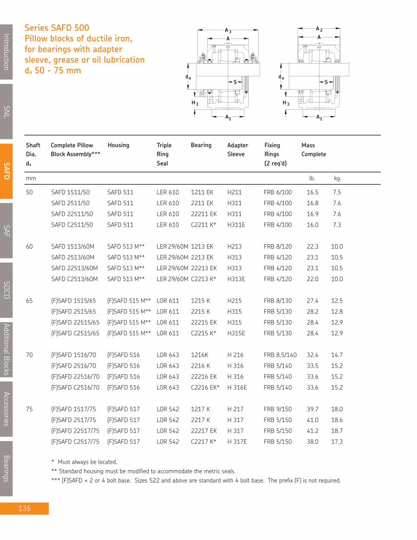
SNL
IntroductionSAFD
SAFSDCD
AdditionalBlocksAccessories
Bearings
136
Series SAFD 500Pillow blocks of ductile iron,for bearings with adaptersleeve, grease or oil lubricationda 50 - 75 mm
1A
3H 3H
A 3
da
A
Sda
1A
2A
S
A
Shaft Complete Pillow Housing Triple Bearing Adapter Fixing MassDia. Block Assembly*** Ring Sleeve Rings Completeda Seal (2 req’d)
mm lb. kg.
50 SAFD 1511/50 SAFD 511 LER 610 1211 EK H211 FRB 6/100 16.5 7.5
SAFD 2511/50 SAFD 511 LER 610 2211 EK H311 FRB 4/100 16.8 7.6
SAFD 22511/50 SAFD 511 LER 610 22211 EK H311 FRB 4/100 16.9 7.6
SAFD C2511/50 SAFD 511 LER 610 C2211 K* H311E FRB 4/100 16.0 7.3
60 SAFD 1513/60M SAFD 513 M** LER 29/60M 1213 EK H213 FRB 8/120 22.3 10.0
SAFD 2513/60M SAFD 513 M** LER 29/60M 2213 EK H313 FRB 4/120 23.1 10.5
SAFD 22513/60M SAFD 513 M** LER 29/60M 22213 EK H313 FRB 4/120 23.1 10.5
SAFD C2513/60M SAFD 513 M** LER 29/60M C2213 K* H313E FRB 4/120 22.0 10.0
65 (F)SAFD 1515/65 (F)SAFD 515 M** LOR 611 1215 K H215 FRB 8/130 27.4 12.5
(F)SAFD 2515/65 (F)SAFD 515 M** LOR 611 2215 K H315 FRB 5/130 28.2 12.8
(F)SAFD 22515/65 (F)SAFD 515 M** LOR 611 22215 EK H315 FRB 5/130 28.4 12.9
(F)SAFD C2515/65 (F)SAFD 515 M** LOR 611 C2215 K* H315E FRB 5/130 28.4 12.9
70 (F)SAFD 1516/70 (F)SAFD 516 LOR 643 1216K H 216 FRB 8.5/140 32.4 14.7
(F)SAFD 2516/70 (F)SAFD 516 LOR 643 2216 K H 316 FRB 5/140 33.5 15.2
(F)SAFD 22516/70 (F)SAFD 516 LOR 643 22216 EK H 316 FRB 5/140 33.6 15.2
(F)SAFD C2516/70 (F)SAFD 516 LOR 643 C2216 EK* H 316E FRB 5/140 33.6 15.2
75 (F)SAFD 1517/75 (F)SAFD 517 LOR 542 1217 K H 217 FRB 9/150 39.7 18.0
(F)SAFD 2517/75 (F)SAFD 517 LOR 542 2217 K H 317 FRB 5/150 41.0 18.6
(F)SAFD 22517/75 (F)SAFD 517 LOR 542 22217 EK H 317 FRB 5/150 41.2 18.7
(F)SAFD C2517/75 (F)SAFD 517 LOR 542 C2217 K* H 317E FRB 5/150 38.0 17.3
* Must always be located.** Standard housing must be modified to accommodate the metric seals.*** (F)SAFD = 2 or 4 bolt base. Sizes 522 and above are standard with 4 bolt base. The prefix (F) is not required.
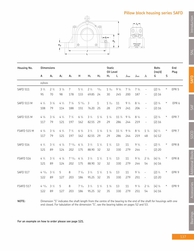
SNL
Introduction
SAFD
SAF
SDCD
AdditionalBlocks
Accessories
Bearings
137
MADE IN CANADA
H 2
JL
1H
HG
1J
in/mm
Housing No. Dimensions Static Bolts EndOil Level (req’d) Plug
A A1 A2 A3 H H1 H2 H3 L Jmax Jmin J1 G S
NOTE: Dimension "S" indicates the shaft length from the centre of the bearing to the end of the shaft for housings with oneend closed. For tabulation of the dimension "S", see the bearing tables on pages 52 and 53.
For an example on how to order please see page 121.
Pillow block housing series SAFD
SAFD 511 3 3⁄4 2 3⁄4 3 7⁄8 7 5 1⁄4 2 3⁄4 15⁄16 1 3⁄16 9 5⁄8 7 7⁄8 7 3⁄8 - (2) 5⁄8 * EPR 5
95 70 98 178 133 69.85 24 30 245 200 187 - (2) 16
SAFD 513 M 4 1⁄4 3 1⁄8 4 1⁄2 7 3⁄8 5 15⁄16 3 1 1 3⁄32 11 9 1⁄2 8 1⁄8 - (2) 5⁄8 * EPR 6
108 79 114 188 151 76.20 25 28 279 241 206 - (2) 16
SAFD 515 M 4 5⁄8 3 1⁄8 4 3⁄4 7 3⁄4 6 3⁄8 3 1⁄4 1 1⁄8 1 1⁄8 11 1⁄4 9 5⁄8 8 5⁄8 - (2) 5⁄8 * EPR 7
117 79 121 197 162 82.55 29 29 286 244 219 - (2) 16
FSAFD 515 M 4 5⁄8 3 1⁄8 4 3⁄4 7 3⁄4 6 3⁄8 3 1⁄4 1 1⁄8 1 1⁄8 11 1⁄4 9 5⁄8 8 5⁄8 1 7⁄8 (4) 1⁄2 * EPR 7
117 79 121 197 162 82.55 29 29 286 244 219 48 (4) 12
SAFD 516 4 3⁄4 3 1⁄2 4 7⁄8 7 15⁄16 6 7⁄8 3 1⁄2 1 1⁄4 1 1⁄4 13 11 9 5⁄8 - (2) 3⁄4 * EPR 8
121 89 124 202 175 88.90 32 32 330 279 244 - (2) 20
FSAFD 516 4 3⁄4 3 1⁄2 4 7⁄8 7 15⁄16 6 7⁄8 3 1⁄2 1 1⁄4 1 1⁄4 13 11 9 5⁄8 2 1⁄8 (4) 5⁄8 * EPR 8
121 89 124 202 175 88.90 32 32 330 279 244 54 (4) 16
SAFD 517 4 13⁄16 3 1⁄2 5 8 7 5⁄16 3 3⁄4 1 1⁄4 1 3⁄8 13 11 9 7⁄8 - (2) 3⁄4 * EPR 9
122 89 127 203 186 95.25 32 35 330 279 251 - (2) 20
FSAFD 517 4 13⁄16 3 1⁄2 5 8 7 5⁄16 3 3⁄4 1 1⁄4 1 3⁄8 13 11 9 7⁄8 2 1⁄8 (4) 5⁄8 * EPR 9
122 89 127 203 186 95.25 32 35 330 279 251 54 (4) 16

SNL
IntroductionSAFD
SAFSDCD
AdditionalBlocksAccessories
Bearings
138
Series SAFD 500Pillow blocks of ductile iron,for bearings with adaptersleeve, grease or oil lubricationda 80 - 115 mm
1A
3H 3H
A 3
da
A
Sda
1A
2A
S
A
Shaft Complete Pillow Housing Triple Bearing Adapter Fixing MassDia. Block Assembly*** Ring Sleeve Rings Completeda Seal (2 req’d)
mm lb. kg.
80 (F)SAFD 1518/80 (F)SAFD 518 LOR 639 1218 K H 218 FRB 16.2/160 48.5 22.0
(F)SAFD 2518/80 (F)SAFD 518 LOR 639 2218 K H 318 FRB 11.2/160 51.0 23.0
(F)SAFD 22518/80 (F)SAFD 518 LOR 639 22218 EK H 318 FRB 11.2/160 51.0 23.0
(F)SAFD C2518/80 (F)SAFD 518 LOR 639 C2218 K* H 318E FRB 11.2/160 47.0 21.4
90 (F)SAFD 1520/90M (F)SAFD 520 M** LOR 640 1220 K H 220 FRB 18/180 61.3 27.8
(F)SAFD 2520/90M (F)SAFD 520 M** LOR 640 2220 K H 320 FRB 12/180 64.6 29.3
(F)SAFD 22520/90M (F)SAFD 520 M** LOR 640 22220 EK H 320 FRB 12/180 64.2 29.1
(F)SAFD 23520/90M (F)SAFD 520 M** LOR 640 23220CCK/W33 H 2320 FRB 4.85/180 68.6 31.1
(F)SAFD C2520/90M (F)SAFD 520 M** LOR 640 C2220 K* H 320E FRB 12/180 62.0 28.2
100 SAFD 1522/100 SAFD 522 LOR 109 1222 K H 222 FRB 21/200 88.0 40.0
SAFD 2522/100 SAFD 522 LOR 109 2222 K H 322 FRB 13.5/200 93.0 42.1
SAFD 22522/100 SAFD 522 LOR 109 22222 EK H 322 FRB 13.5/200 92.4 41.9
SAFD 23522/100 SAFD 522 LOR 109 23222CCK/W33 H 2322 FRB 5.1/200 100 45.1
SAFD C2522/100 SAFD 522 LOR 109 C2222 K* H 322E FRB 13.5/200 73.0 41.9
110 SAFD 22524/110 SAFD 524 M** LOR 655 22224 EK H 3124 FRB 14/215 106 48.0
SAFD 23524/110 SAFD 524 M** LOR 655 23224CCK/W33 H 2324 FRB 5/215 114 52.0
SAFD C3524/110 SAFD 524 M** LOR 655 C3224 K* H 2324L FRB 5/215 114 52.0
115 SAFD 22526/115 SAFD 526 LOR 600 22226 EK H 3126 FRB 13/230 156 71.0
SAFD 23526/115 SAFD 526 LOR 600 23226CCK/W33 H 2326 FRB 5/230 165 75.0
SAFD C2526/115 SAFD 526 LOR 600 C2226 K * H 3126L FRB 13/230 144 65.5
* Must always be located.** Standard housing must be modified to accommodate the metric seals.
*** (F)SAFD = 2 or 4 bolt base. Sizes 522 and above are standard with 4 bolt base. The prefix (F) is not required.

SNL
Introduction
SAFD
SAF
SDCD
AdditionalBlocks
Accessories
Bearings
139
MADE IN CANADA
H 2
JL
1H
HG
1J
in/mm
Housing No. Dimensions Static Bolts EndOil Level (req’d) Plug
A A1 A2 A3 H H1 H2 H3 L Jmax Jmin J1 G S
NOTE: Dimension "S" indicates the shaft length from the centre of the bearing to the end of the shaft for housings with oneend closed. For tabulation of the dimension "S", see the bearing tables on pages 52 and 53.
For an example on how to order please see page 121.
Pillow block housing series SAFD
SAFD 518 5 1⁄2 3 7⁄8 5 3⁄4 8 11⁄16 7 3⁄4 4 1 5⁄8 1 1⁄2 13 3⁄4 11 5⁄8 10 3⁄8 - (2) 3⁄4 * EPR 11
140 98 146 221 197 101.60 41 38 349 295 264 - (2) 20
FSAFD 518 5 1⁄2 3 7⁄8 5 3⁄4 8 11⁄16 7 3⁄4 4 1 5⁄8 1 1⁄2 13 3⁄4 11 5⁄8 10 3⁄8 2 1⁄8 (4) 5⁄8 * EPR 11
140 98 146 221 197 101.60 41 38 349 295 264 54 (4) 16
SAFD 520 M 6 4 3⁄8 6 1⁄8 9 8 3⁄4 4 1⁄2 1 3⁄4 1 21⁄32 15 1⁄4 13 1⁄8 11 5⁄8 - (2) 7⁄8 * EPR 12
152 111 156 230 222 114.30 44 42 387 333 295 - (2) 24
FSAFD 520 M 6 4 3⁄8 6 1⁄8 9 8 3⁄4 4 1⁄2 1 3⁄4 1 21⁄32 15 1⁄4 13 1⁄8 11 5⁄8 2 3⁄8 (4) 3⁄4 * EPR 12
152 111 156 230 222 114.30 44 42 387 333 295 60 (4) 20
SAFD 522 6 7⁄16 4 3⁄4 6 1⁄2 9 1⁄2 9 5⁄8 4 15⁄16 2 1 25⁄32 16 1⁄2 14 1⁄2 12 5⁄8 2 3⁄4 (4) 3⁄4 * EPR 13
164 121 165 242 244 125.41 51 45 419 368 321 70 (4) 20
SAFD 524 M 7 1⁄8 4 3⁄4 7 3⁄8 10 5⁄16 10 1⁄4 5 1⁄4 2 1⁄8 1 27⁄32 16 1⁄2 14 1⁄2 13 1⁄4 2 3⁄4 (4) 3⁄4 * EPR 14
181 121 187 262 260 133.35 54 47 419 368 337 70 (4) 20
SAFD 526 7 3⁄4 5 1⁄8 8 11 11 3⁄4 6 2 3⁄8 2 11⁄32 18 3⁄8 16 14 5⁄8 3 1⁄4 (4) 7⁄8 * EPR 15
197 130 203 280 298 152.40 60 59 467 406 371 83 (4) 24
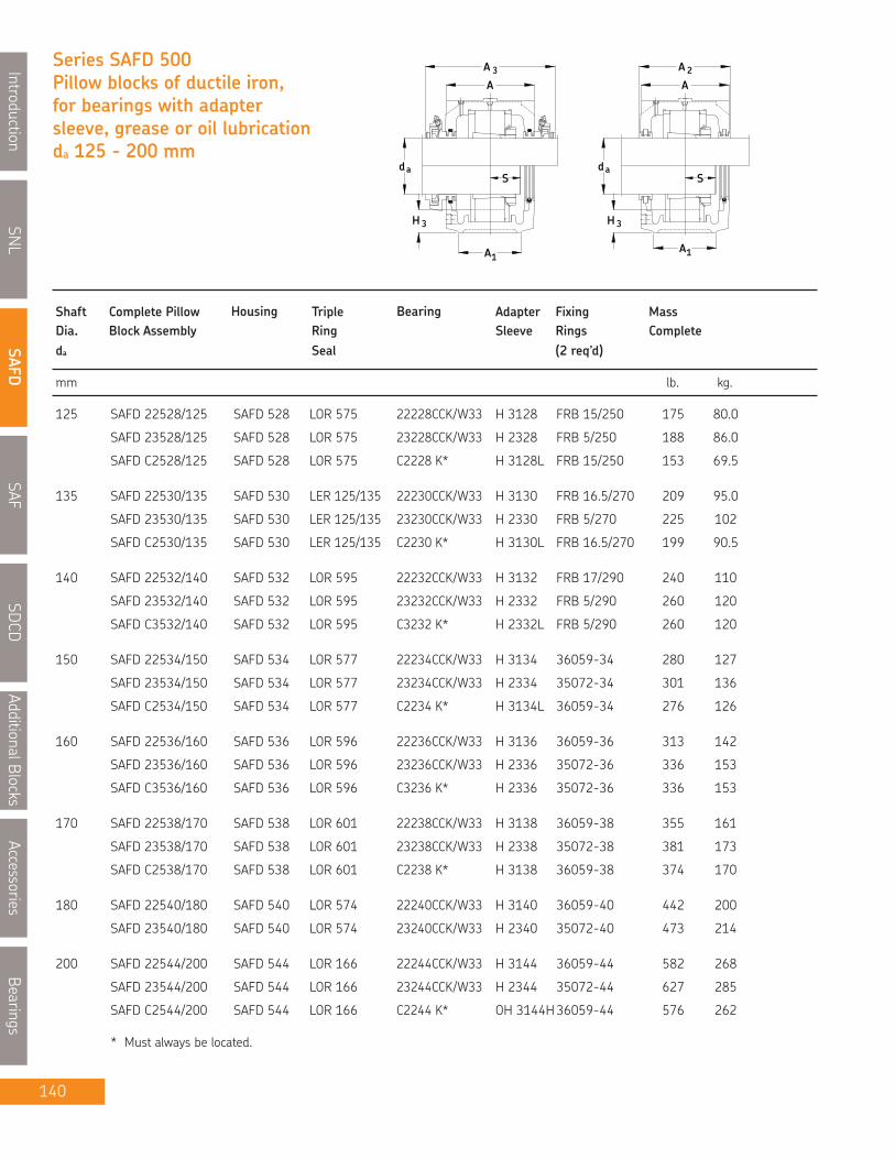
SNL
IntroductionSAFD
SAFSDCD
AdditionalBlocksAccessories
Bearings
140
Series SAFD 500Pillow blocks of ductile iron,for bearings with adaptersleeve, grease or oil lubricationda 125 - 200 mm
3H
ad
3
1A
A
A
S S
H 3
da
A1
A
A2
Shaft Complete Pillow Housing Triple Bearing Adapter Fixing MassDia. Block Assembly Ring Sleeve Rings Completeda Seal (2 req’d)
mm lb. kg.
125 SAFD 22528/125 SAFD 528 LOR 575 22228CCK/W33 H 3128 FRB 15/250 175 80.0
SAFD 23528/125 SAFD 528 LOR 575 23228CCK/W33 H 2328 FRB 5/250 188 86.0
SAFD C2528/125 SAFD 528 LOR 575 C2228 K* H 3128L FRB 15/250 153 69.5
135 SAFD 22530/135 SAFD 530 LER 125/135 22230CCK/W33 H 3130 FRB 16.5/270 209 95.0
SAFD 23530/135 SAFD 530 LER 125/135 23230CCK/W33 H 2330 FRB 5/270 225 102
SAFD C2530/135 SAFD 530 LER 125/135 C2230 K* H 3130L FRB 16.5/270 199 90.5
140 SAFD 22532/140 SAFD 532 LOR 595 22232CCK/W33 H 3132 FRB 17/290 240 110
SAFD 23532/140 SAFD 532 LOR 595 23232CCK/W33 H 2332 FRB 5/290 260 120
SAFD C3532/140 SAFD 532 LOR 595 C3232 K* H 2332L FRB 5/290 260 120
150 SAFD 22534/150 SAFD 534 LOR 577 22234CCK/W33 H 3134 36059-34 280 127
SAFD 23534/150 SAFD 534 LOR 577 23234CCK/W33 H 2334 35072-34 301 136
SAFD C2534/150 SAFD 534 LOR 577 C2234 K* H 3134L 36059-34 276 126
160 SAFD 22536/160 SAFD 536 LOR 596 22236CCK/W33 H 3136 36059-36 313 142
SAFD 23536/160 SAFD 536 LOR 596 23236CCK/W33 H 2336 35072-36 336 153
SAFD C3536/160 SAFD 536 LOR 596 C3236 K* H 2336 35072-36 336 153
170 SAFD 22538/170 SAFD 538 LOR 601 22238CCK/W33 H 3138 36059-38 355 161
SAFD 23538/170 SAFD 538 LOR 601 23238CCK/W33 H 2338 35072-38 381 173
SAFD C2538/170 SAFD 538 LOR 601 C2238 K* H 3138 36059-38 374 170
180 SAFD 22540/180 SAFD 540 LOR 574 22240CCK/W33 H 3140 36059-40 442 200
SAFD 23540/180 SAFD 540 LOR 574 23240CCK/W33 H 2340 35072-40 473 214
200 SAFD 22544/200 SAFD 544 LOR 166 22244CCK/W33 H 3144 36059-44 582 268
SAFD 23544/200 SAFD 544 LOR 166 23244CCK/W33 H 2344 35072-44 627 285
SAFD C2544/200 SAFD 544 LOR 166 C2244 K* OH 3144H36059-44 576 262
* Must always be located.

SNL
Introduction
SAFD
SAF
SDCD
AdditionalBlocks
Accessories
Bearings
141
Pillow block housing series SAFD
2H
JL
GH1
H
1J
SAFD 540
in/mm
Housing No. Dimensions Static Bolts EndOil Level (req’d) Plug
A A1 A2 A3 H H1 H2 H3 L Jmax Jmin J1 G S
NOTE: Dimension "S" indicates the shaft length from the centre of the bearing to the end of the shaft for housings with oneend closed. For tabulation of the dimension "S", see the bearing tables on pages 52 and 53.
For an example on how to order please see page 121.
SAFD 528 7 3⁄8 5 7⁄8 7 5⁄8 10 1⁄2 12 6 2 3⁄8 2 1⁄32 20 1⁄8 17 1⁄8 16 3 3⁄8 (4) 1 * EPR 27
187 149 194 267 305 152.40 60 52 511 435 406 86 (4) 24
SAFD 530 8 1⁄8 6 1⁄4 8 3⁄8 11 3⁄8 12 1⁄2 6 5⁄16 2 1⁄2 2 21 1⁄4 18 1⁄4 17 3 3⁄4 (4) 1 * EPR 16
206 159 213 289 318 160.34 64 51 540 464 432 95 (4) 24
SAFD 532 8 1⁄2 6 1⁄4 8 3⁄4 11 3⁄4 13 5⁄16 6 11⁄16 2 5⁄8 2 1⁄16 22 19 1⁄4 17 3⁄8 3 3⁄4 (4) 1 * EPR 16
216 159 222 299 338 169.86 67 52 559 489 441 95 (4) 24
SAFD 534 9 1⁄4 6 3⁄4 9 5⁄8 12 1⁄2 14 3⁄16 7 1⁄16 2 3⁄4 2 5⁄32 24 3⁄4 21 5⁄8 19 3⁄8 4 1⁄4 (4) 1 * EPR 18
235 171 244 318 360 179.39 70 55 629 549 492 108 (4) 24
SAFD 536 9 5⁄8 7 1⁄8 10 13 14 7⁄8 7 1⁄2 3 2 3⁄8 26 3⁄4 23 5⁄8 20 7⁄8 4 5⁄8 (4) 1 * EPR 19244 181 254 330 378 190.50 76 60 679 600 530 117 (4) 24
SAFD 538 10 1⁄2 7 1⁄2 10 3⁄4 13 3⁄4 15 13⁄16 7 7⁄8 3 1⁄8 2 7⁄16 28 24 3⁄8 21 5⁄8 4 1⁄2 (4) 1 1⁄4 * EPR 20
267 191 273 349 402 200.03 79 62 711 619 549 114 (4) 30
SAFD 540 11 8 11 1⁄4 14 1⁄4 16 1⁄2 8 1⁄4 3 3⁄8 2 15⁄32 29 1⁄2 25 22 1⁄2 5 (4) 1 1⁄4 * EPR 21
279 203 286 362 419 209.55 86 63 749 635 572 127 (4)30
SAFD 544 11 3⁄4 8 3⁄4 12 15 18 3⁄4 9 1⁄2 3 3⁄4 3 1⁄8 32 3⁄4 27 7⁄8 24 3⁄4 5 1⁄4 (4) 1 1⁄2 * EPR 23
298 222 305 381 476 241.30 95 79 832 708 629 133 (4) 36

SNL
IntroductionSAFD
SAFSDCD
AdditionalBlocksAccessories
BearingsNote : Consult SKF for availability of Metric LOR seals.
B-10785-xxxB-10724-xxx or+ Contact element
Ductile Iron ASTM A536 grade 65-45-12
12, 12E, 22, 22E, 222CC, 222E, 232CC
MATERIAL
BEARING SERIESUSED
STANDARD SEALS
OPTIONAL SEALS
LUBRICATIONPILLOW BLOCK
SHAFT SIZE RANGE
PILLOW BLOCK SIZE 213 - 244 (cylindrical bore mounting)
2-13/16" to 9-9/16" 72mm to 243mm
Grease or Oil
SAFD, FSAFD
TER-C TER-CV
LER LOR & LORP
LOR
142
Pillow BlockHousings

SNL
Introduction
SAFD
SAF
SDCD
AdditionalBlocks
Accessories
Bearings
143
SAFD Split Pillow Block NomenclatureCylindrical Bore Mounting
SAFD 22232 H
BaseOF**
Basic Design
Size
SuffixesOCCVDEHTLCTLPY
Note:
Two boltFour bolt
Bearing size: 22 = 110mm bore
Standard LER/LOR triple ring seals (included)*Taconite service seal TER..C of Canadian design (1/pkg)Taconite service seal TER..CV of Canadian design c/w V ring (1/pkg)Purgeable labyrinth seal TSNC..D c/w V ring (1/pkg)Purgeable labyrinth seal TSNC..E without V ring (1/pkg)Held bearing c/w fixing ringsCombination of LOR and B-10724-xxx contact element (max temp. 120C)LORP with B-10785-xxx contact element for higher temperatures and speeds. (max. temp. 200C)One end closed with end cover or end plug
How to order: (Example)
When you order one SAFD 23222 you will receive a package containing the following:
1 - Pillow block housing SAFD 222. Cap drilled, tapped and plugged with two holes 1⁄4" NPT for anAlemite 1627-B grease fittings, which is not included.Base, drilled, tapped and plugged with two diagonally opposed holes 1⁄2" NPT.
2 - Triple ring seals: LOR 121 for shaft diameter da (47⁄8")
LOR 113 for shaft diameter db (43⁄16”)
1 - Bearing SKF 23222 CC/W331 - Locknut AN 221 - Lockwasher W22
If a "HELD or FIXED" unit is required, add the suffix "H" and 2 fixing rings (locating or stabilizing) FRB 5.1/200 will be included.Only one bearing per shaft should be held. CARB bearings displace internally and are therefore always "FREE".However, they must always be located in the housing with fixing rings as does a true "FIXED" bearing.If one end is closed, add "Y" to the assembly number and one EPR 14 end plug will be included.
* SAFD blocks include the seals for standard shaft sizes (highlighted print.) If non-standard shaft sizesare requested, those seals must be ordered separately.
** Sizes 222, 318 and above come as standard with 4 bolt bases, Prefix "F" not required.
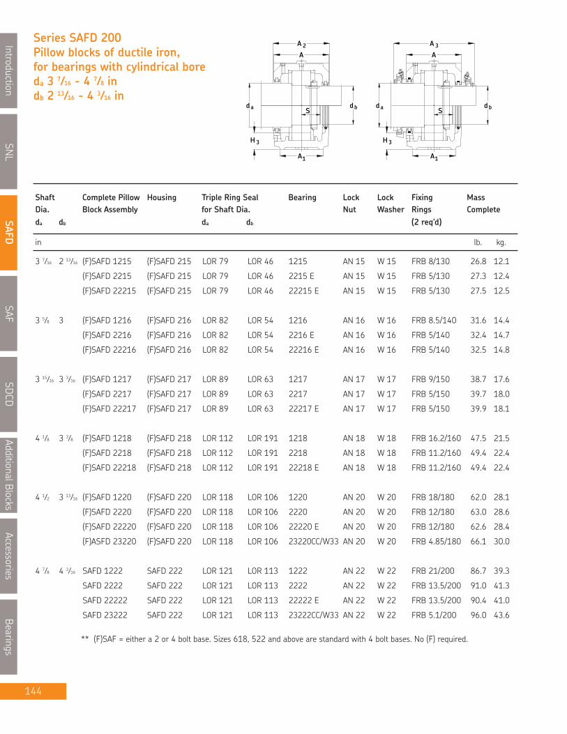
SNL
IntroductionSAFD
SAFSDCD
AdditionalBlocksAccessories
Bearings
144
Series SAFD 200Pillow blocks of ductile iron,for bearings with cylindrical boreda 3 7⁄16 - 4 7⁄8 indb 2 13⁄16 - 4 3⁄16 in
b
H 3
ad
A1
A
S
2
A
d d
3H
a
1A
3A
A
Sdb
Shaft Complete Pillow Housing Triple Ring Seal Bearing Lock Lock Fixing MassDia. Block Assembly for Shaft Dia. Nut Washer Rings Completeda db da db (2 req’d)
in lb. kg.
3 7⁄16 2 13⁄16 (F)SAFD 1215 (F)SAFD 215 LOR 79 LOR 46 1215 AN 15 W 15 FRB 8/130 26.8 12.1
(F)SAFD 2215 (F)SAFD 215 LOR 79 LOR 46 2215 E AN 15 W 15 FRB 5/130 27.3 12.4
(F)SAFD 22215 (F)SAFD 215 LOR 79 LOR 46 22215 E AN 15 W 15 FRB 5/130 27.5 12.5
3 5⁄8 3 (F)SAFD 1216 (F)SAFD 216 LOR 82 LOR 54 1216 AN 16 W 16 FRB 8.5/140 31.6 14.4
(F)SAFD 2216 (F)SAFD 216 LOR 82 LOR 54 2216 E AN 16 W 16 FRB 5/140 32.4 14.7
(F)SAFD 22216 (F)SAFD 216 LOR 82 LOR 54 22216 E AN 16 W 16 FRB 5/140 32.5 14.8
3 15⁄16 3 3⁄16 (F)SAFD 1217 (F)SAFD 217 LOR 89 LOR 63 1217 AN 17 W 17 FRB 9/150 38.7 17.6
(F)SAFD 2217 (F)SAFD 217 LOR 89 LOR 63 2217 AN 17 W 17 FRB 5/150 39.7 18.0
(F)SAFD 22217 (F)SAFD 217 LOR 89 LOR 63 22217 E AN 17 W 17 FRB 5/150 39.9 18.1
4 1⁄8 3 3⁄8 (F)SAFD 1218 (F)SAFD 218 LOR 112 LOR 191 1218 AN 18 W 18 FRB 16.2/160 47.5 21.5
(F)SAFD 2218 (F)SAFD 218 LOR 112 LOR 191 2218 AN 18 W 18 FRB 11.2/160 49.4 22.4
(F)SAFD 22218 (F)SAFD 218 LOR 112 LOR 191 22218 E AN 18 W 18 FRB 11.2/160 49.4 22.4
4 1⁄2 3 13⁄16 (F)SAFD 1220 (F)SAFD 220 LOR 118 LOR 106 1220 AN 20 W 20 FRB 18/180 62.0 28.1
(F)SAFD 2220 (F)SAFD 220 LOR 118 LOR 106 2220 AN 20 W 20 FRB 12/180 63.0 28.6
(F)SAFD 22220 (F)SAFD 220 LOR 118 LOR 106 22220 E AN 20 W 20 FRB 12/180 62.6 28.4
(F)ASFD 23220 (F)SAFD 220 LOR 118 LOR 106 23220CC/W33 AN 20 W 20 FRB 4.85/180 66.1 30.0
4 7⁄8 4 3⁄16 SAFD 1222 SAFD 222 LOR 121 LOR 113 1222 AN 22 W 22 FRB 21/200 86.7 39.3
SAFD 2222 SAFD 222 LOR 121 LOR 113 2222 AN 22 W 22 FRB 13.5/200 91.0 41.3
SAFD 22222 SAFD 222 LOR 121 LOR 113 22222 E AN 22 W 22 FRB 13.5/200 90.4 41.0
SAFD 23222 SAFD 222 LOR 121 LOR 113 23222CC/W33 AN 22 W 22 FRB 5.1/200 96.0 43.6
** (F)SAF = either a 2 or 4 bolt base. Sizes 618, 522 and above are standard with 4 bolt bases. No (F) required.

SNL
Introduction
SAFD
SAF
SDCD
AdditionalBlocks
Accessories
Bearings
145
Pillow block housing series SAFD
MADE IN CANADA
H2
JL
GH
H1
J1
in/mm
Housing No. Dimensions Static Bolts EndOil Level (req’d) Plug
A A1 A2 A3 H H1 H2 H3 L Jmax Jmin J1 G S
NOTE: Dimension "S" indicates the shaft length from the centre of the bearing to the end of the shaft for housings with oneend closed. For tabulation of the dimension "S", see the bearing tables on pages 52 and 53.
For an example on how to order please see page 143.
SAFD 215 4 5⁄8 3 1⁄8 4 3⁄4 7 3⁄4 6 3⁄8 3 1⁄4 1 1⁄8 1 1.⁄8 11 1⁄4 9 5⁄8 8 5⁄8 - (2) 5⁄8 * EPR 8
117 79 121 197 162 82.55 29 29 286 244 219 - (2) 16
FSAFD 215 4 5⁄8 3 1⁄8 4 3⁄4 7 3⁄4 6 3⁄8 3 1⁄4 1 1⁄8 1 1⁄8 11 1⁄4 9 5⁄8 8 5⁄8 1 7⁄8 (4) 1⁄2 * EPR 8
117 79 121 197 162 82.55 29 29 286 244 219 48 (4) 12
SAFD 216 4 3⁄4 3 1⁄2 4 7⁄8 7 15⁄16 6 7⁄8 3 1⁄2 1 3⁄16 1 1⁄4 13 11 9 5⁄8 - (2) 3⁄4 * EPR 9
121 89 124 202 175 88.90 30 32 330 279 244 - (2) 20
FSAFD 216 4 3⁄4 3 1⁄2 4 7⁄8 7 15⁄16 6 7⁄8 3 1⁄2 1 3⁄16 1 1⁄4 13 11 9 5⁄8 2 1⁄8 (4) 5⁄8 * EPR 9
121 89 124 202 175 88.90 30 32 330 279 244 54 (4) 16
SAFD 217 4 13⁄16 3 1⁄2 5 8 7 5⁄16 3 3⁄4 1 1⁄4 1 3⁄8 13 11 9 7⁄8 - (2) 3⁄4 * EPR 9
122 89 127 203 186 95.25 32 35 330 279 251 - (2) 20
FSAFD 217 4 13⁄16 3 1⁄2 5 8 7 5⁄16 3 3⁄4 1 1⁄4 1 3⁄8 13 11 9 7⁄8 2 1⁄8 (4) 5⁄8 * EPR 9
122 89 127 203 186 95.25 32 35 330 279 251 54 (4) 16
SAFD 218 5 1⁄2 3 7⁄8 5 3⁄4 8 11⁄16 7 3⁄4 4 1 5⁄16 1 1⁄2 13 3⁄4 11 5⁄8 10 3⁄8 - (2) 3⁄4 * EPR 11
140 98 146 221 197 101.6 33 38 349 295 264 - (2) 20
FSAFD 218 5 1⁄2 3 7⁄8 5 3⁄4 8 11⁄16 7 3⁄4 4 1 5⁄16 1 1⁄2 13 3⁄4 11 5⁄8 10 3⁄8 2 1⁄8 (4) 5⁄8 * EPR 11
140 98 146 221 197 101.6 33 38 349 295 264 54 (4) 16
SAFD 220 6 4 3⁄8 6 1⁄8 9 8 3⁄4 4 1⁄2 1 3⁄4 1 21⁄32 15 1⁄4 13 1⁄8 11 5⁄8 - (2) 7⁄8 * EPR 12
152 111 156 230 222 114.30 44 42 387 333 295 - (2) 22
FSAFD 220 6 4 3⁄8 6 1⁄8 9 8 3⁄4 4 1⁄2 1 3⁄4 1 21⁄32 15 1⁄4 13 1⁄8 11 5⁄8 2 3⁄8 (4) 3⁄4 * EPR 12
152 111 156 230 222 114.30 44 42 387 333 295 60 (4) 20
SAFD 222 6 7⁄16 4 3⁄4 6 1⁄2 9 1⁄2 9 5⁄8 4 15⁄16 2 1 25⁄32 16 1⁄2 14 1⁄2 12 5⁄8 2 3⁄4 (4) 3⁄4 * EPR 14
164 121 165 242 244 125.41 51 45 419 368 321 70 (4) 20

SNL
IntroductionSAFD
SAFSDCD
AdditionalBlocksAccessories
Bearings
146
Series SAFD 200Pillow blocks of ductile iron,for bearings with cylindrical boreda 5 5⁄16 - 9 9⁄16 indb 4 9⁄16 - 8 5⁄16 in
b
H 3
ad
A1
A
S
2
A
d d
3H
a
1A
3A
A
Sdb
in lb. kg.
5 5⁄16 4 9⁄16 SAFD 22224 SAFD 224 LOR 127 LOR 119 22224 E AN 24 W 24 FRB 14/215 103 47.0
SAFD 23224 SAFD 224 LOR 127 LOR 119 23224CC/W33 AN 24 W 24 FRB 5/215 110 50.0
5 7⁄8 4 15⁄16 SAFD 22226 SAFD 226 LOR 136 LOR 122 22226 E AN 26 W 26 FRB 13/230 153 69.0
SAFD 23226 SAFD 226 LOR 136 LOR 122 23226CC/W33 AN 26 W 26 FRB 5/230 160 72.0
6 1⁄4 5 5⁄16 SAFD 22228 SAFD 228 LOR 144 LOR 127 22228CC/W33 AN 28 W 28 FRB 15/250 171 77.0
SAFD 23228 SAFD 228 LOR 144 LOR 127 23228CC/W33 AN 28 W 28 FRB 5/250 180 82.0
6 5⁄8 5 3⁄4 SAFD 22230 SAFD 230 LOR 151 LOR 134 22230CC/W33 AN 30 W 30 FRB 16.5/270 202 92.0
SAFD 23230 SAFD 230 LOR 151 LOR 134 23230CC/W33 AN 30 W 30 FRB 5/270 216 98.0
7 6 1⁄16 SAFD 22232 SAFD 232 LOR 156 LOR 142 22232CC/W33 AN 32 W 32 FRB 17/290 230 104
SAFD 23232 SAFD 232 LOR 156 LOR 142 23232CC/W33 AN 32 W 32 FRB 5/290 244 111
7 7⁄16 6 7⁄16 SAFD 22234 SAFD 234 LOR 161 LOR 148 22234CC/W33 AN 34 W 34 36059-34 240 110
SAFD 23234 SAFD 234 LOR 161 LOR 148 23234CC/W33 AN 34 W 34 35072-34 260 120
7 13⁄16 6 7⁄8 SAFD 22236 SAFD 236 LOR 165 LOR 154 22236CC/W33 AN 36 W 36 36059-36 313 142
SAFD 23236 SAFD 236 LOR 165 LOR 154 23236CC/W33 AN 36 W 36 35072-36 336 153
8 3⁄8 7 1⁄4 SAFD 22238 SAFD 238 LOR 171 LOR 160 22238CC/W33 AN 38 W 38 36059-38 355 161
SAFD 23238 SAFD 238 LOR 171 LOR 160 23238CC/W33 AN 38 W 38 35072-38 381 173
8 3⁄4 7 5⁄8 SAFD 22240 SAFD 240 LOR 175 LOR 164 22240CC/W33 AN 40 W 40 36059-40 442 200
SAFD 23240 SAFD 240 LOR 175 LOR 164 23240CC/W33 AN 40 W 40 35072-40 473 214
9 9⁄16 8 5⁄16 SAFD 22244 SAFD 244 LOR 179 LOR 170 22244CC/W33 N 44 W 44 36059-44 582 264
SAFD 23244 SAFD 244 LOR 179 LOR 170 23244CC/W33 N 44 W 44 35072-44 627 285
Shaft Complete Pillow Housing Triple Ring Seal Bearing Lock Lock Fixing MassDia. Block Assembly for Shaft Dia. Nut Washer Rings Completeda db da db (2 req’d)

SNL
Introduction
SAFD
SAF
SDCD
AdditionalBlocks
Accessories
Bearings
147
Pillow block housing series SAFD
MADE IN CANADA
H2
JL
GH
H1
J1
in/mm
Housing No. Dimensions Static Bolts EndOil Level (req’d) Plug
A A1 A2 A3 H H1 H2 H3 L Jmax Jmin J1 G S
NOTE: Dimension "S" indicates the shaft length from the centre of the bearing to the end of the shaft for housings with oneend closed. For tabulation of the dimension "S", see the bearing tables on pages 52 and 53.
For an example on how to order please see page 143.
SAFD 224 7 1⁄8 4 3⁄4 7 3⁄8 10 5⁄16 10 1⁄4 5 1⁄4 2 1⁄8 1 27⁄32 16 1⁄2 14 1⁄2 13 1⁄4 2 3⁄4 (4) 3⁄4 * EPR 15
181 121 187 262 260 133.35 54 47 419 368 337 70 (4) 20
SAFD 226 7 3⁄4 5 1⁄8 8 11 11 3⁄4 6 2 3⁄8 2 11⁄32 18 3⁄8 16 14 5⁄8 3 1⁄4 (4) 7⁄8 * EPR 27
197 130 203 280 298 152.40 60 59 467 406 371 83 (4) 22
SAFD 228 7 3⁄8 5 7⁄8 7 5⁄8 11 11 3⁄4 6 2 3⁄8 2 1⁄32 20 1⁄8 17 1⁄8 16 3 3⁄8 (4) 1 * EPR 16
187 149 194 280 298 152.40 60 52 511 435 406 86 (4) 24
SAFD 230 8 1⁄8 6 1⁄4 8 3⁄8 11 3⁄8 12 1⁄2 6 5⁄16 2 1⁄2 2 21 1⁄4 18 1⁄4 17 3 3⁄4 (4) 1 * EPR 17
206 159 213 289 318 160.34 64 51 540 464 432 95 (4) 24
SAFD 232 8 1⁄2 6 1⁄4 8 3⁄4 11 3⁄4 13 5⁄16 6 11⁄16 2 5⁄8 2 1⁄16 22 19 1⁄4 17 3⁄8 3 3⁄4 (4) 1 * EPR 18
216 159 222 299 338 169.86 67 52 559 489 441 95 (4) 24
SAFD 234 9 1⁄4 6 3⁄4 9 5⁄8 12 1⁄2 14 3⁄16 7 1⁄16 2 3⁄4 2 5⁄32 24 3⁄4 21 5⁄8 19 3⁄8 4 1⁄4 (4) 1 * EPR 19
235 171 244 318 360 179.39 70 55 629 549 492 108 (4) 24
SAFD 236 9 5⁄8 7 1⁄8 10 13 14 7⁄8 7 1⁄2 3 2 3⁄8 26 3⁄4 23 5⁄8 20 7⁄8 4 5⁄8 (4) 1 * EPR 20
244 181 254 330 378 190.50 76 60 679 600 530 117 (4) 24
SAFD 238 10 1⁄2 7 1⁄2 10 3⁄4 13 3⁄4 15 13⁄16 7 7⁄8 3 1⁄8 2 7⁄16 28 24 3⁄8 21 5⁄8 4 1⁄2 (4) 1 1⁄4 * EPR 21
267 191 273 349 402 200.03 79 62 711 619 549 114 (4) 30
SAFD 240 11 8 11 1⁄4 14 1⁄4 16 1⁄2 8 1⁄4 3 3⁄8 2 15⁄32 29 1⁄2 25 22 1⁄2 5 (4) 1 1⁄4 * EPR 22
279 203 286 362 419 209.55 86 63 749 635 572 127 (4)30
SAFD 244 11 3⁄4 8 3⁄4 12 15 18 3⁄4 9 1⁄2 3 3⁄4 3 1⁄8 32 3⁄4 27 7⁄8 24 3⁄4 5 1⁄4 (4) 1 1⁄2 * EPR 24298 222 305 381 476 241 95 79 832 708 629 133 (4) 36

SNL
IntroductionSAFD
SAFSDCD
AdditionalBlocksAccessories
Bearings
148
Note : Consult SKF for availability of Metric LOR seals.
B-10785-xxxB-10724-xxx or+ Contact element
12K, 12EK, 13K, 13EK, 222CCK, 222EK, 223CCK, 230CCK, 230CACK,
MATERIAL
BEARING SERIESUSED
STANDARD SEALS
OPTIONAL SEALS
LUBRICATIONPILLOW BLOCK
SHAFT SIZE RANGE
PILLOW BLOCK SIZE
1-3/8" to 10-1/2"
Grease or Oil
SAF, FSAF, SAFS, FSAFS
609 - 640 (adapter mounting)507 - 544 (adapter mounting)024 - 056 (adapter mounting)
SAF cast iron ASTM A48 grade 35SAFS cast steel ASTM A27 grade 65-35
C 22K, C 23K
TER TER-VLOR
TER-C TER-CV
LOR & LORPLER
Pillow BlockHousings

SNL
Introduction
SAFD
SAF
SDCD
AdditionalBlocks
Accessories
Bearings
149
SAF Split Pillow Blocks Nomenclature Adapter Mounting
SAFF 22520/37⁄16 YH
Base0F**
Basic Design
Material0S
Size
SuffixesO-11CCVHHHK7TTLCTLPTVY
Note:
Two boltFour bolt (for cast iron)
Cast iron (standard)Cast steel
Bearing bore 20 = 100mmShaft diameter 3 7⁄16
Standard triple ring seals (included)*4 bolt base for cast steel blocks, i.e. SAFS 22520/3 7⁄16 - 11Taconite service seal TER..C of Canadian design (1/pkg)Taconite service seal TER..CV of Canadian design c/w V ring (1/pkg)Held bearing c/w fixing rings (included)*Option for a held bearing with 2 fixing rings where normally one is used (centres bearing)Tighter housing fit, can be used with CARB® bearings for high speeds or vibrationTaconite seal TER of American designCombination of LOR and B-10724-xxx contact element (max temp. 120ºC)LORP with B-10785-xxx contact element for higher temperatures and speeds. (max. temp. 200ºC)Taconite service seal TER..V of American design c/w V ringOne end closed with end cover or end plug
* SAF housings include the seals, fixing rings and a grease nipple for the 222 series bearings on standardshaft sizes (shown as highlighted in the tables). If non-standard shaft sizes or bearings other than the 222series are required, seals and/or fixing rings must be ordered separately** Sizes 618, 522 and above are standard with 4 bolt bases. Prefix "F" not required
How to order SAF: (Example)
When you order one SAF 22520-37⁄16 you will receive the following:
1 - Pillow block housing SAF 520: Cap drilled and tapped with two holes 1⁄4" NPT, with grease fitting includedBase drilled, tapped and plugged with two diagonally opposed 1⁄2" NPT holes.
2 - Triple ring seals LOR 1021 - Bearing SKF 22220 EK1 - Adapter sleeve HA 320 for shaft dia. 37⁄16”
If a "HELD or FIXED" unit is required, add the suffix "H" and 1 fixing ring (locating or stabilizing) SR 20-17 will be included.Only one bearing per shaft should be held. CARB bearings displace internally and are therefore always "FREE".However, they must always be located in the housing with fixing rings as does a true "FIXED" bearing.If one end is closed add letter "Y" and an EPR 12 end cover will also be included.

in lb. kg.
Shaft Complete Pillow Triple Ring Taconite Adapter Fixing Mass EndDia. Block Assembly Housing Seal*** Seal Bearing Sleeve Rings Qty. Complete Coverda
SNL
IntroductionSAFD
SAFSDCD
AdditionalBlocksAccessories
Bearings
150
Series SAFPillow block of cast iron forbearings with adapter sleeves,grease or oil lubricationda 1 3⁄16 - 1 3⁄4 in
1A
H 3 3H
adS
ad
AA 3
X
A1
S
X
2AA
1 3⁄16 1) SAF 1507/ 1 3⁄16 SAF 507 LER 14 TER 14 1207 EK HA 207 SR 7-6 1 7.00 3.2 EPR 2
SAF 22507/1 3⁄16 SAF 507 LER 14 TER 14 22207 EK HA 307 36053-6 1 8.00 3.6 EPR 2
SAF C2507/1 3⁄16 SAF 507 LER 14 TER 14 C2207 EK* HA 307E 36053-6 1 8.00 3.6 EPR 2
1 7⁄16 1) SAF 1509/ 1 7⁄16 SAF 509 LER 17 TER 17 1209 EK HA 209 SR 9-0 1 12.0 5.4 EPR 3
SAF 1609/ 1 7⁄16 SAF 609 LER 17 TER 17 1309 EK HA 309 SR 1609 2 19.0 8.6 EPR 3
SAF 22509/ 1 7⁄16 SAF 509 LER 17 TER 17 22209 EK HA 309 SR 9-9 1 12.0 5.4 EPR 3
SAF C2509/ 1 7⁄16 SAF 509 LER 17 TER 17 C2209 EK* HA 309E SR 9-9 1 12.0 5.4 EPR 3
SAF 22609/ 1 7⁄16 SAF 609 LER 17 TER 17 22309 EK HA 2309 SR 11-9 1 20.0 9.1 EPR 3
1 1⁄2 SAF 1509/ 1 1⁄2 SAF 509 LER 18 TER 18 1209 EK HE 209 SR 9-0 1 11.0 5.0 EPR 3
SAF 1609/ 1 1⁄2 SAF 609 LER 18 TER 18 1309 EK HE 309 SR 1609 2 18.0 8.2 EPR 3
SAF 22509/ 1 1⁄2 SAF 509 LER 18 TER 18 22209 EK HE 309 SR 9-9 1 12.0 5.4 EPR 3
SAF C2509/ 1 1⁄2 SAF 509 LER 18 TER 18 C2209 EK* HE 309E SR 9-9 1 12.0 5.4 EPR 3
SAF 22609/ 1 1⁄2 SAF 609 LER 18 TER 18 22309 EK HE 2309 SR 11-9 1 20.0 9.1 EPR 3
1 11⁄16 1) SAF 1510/ 1 11⁄16 SAF 510 LER 20 TER 20 1210 EK HA 210 SR 10-8 1 11.0 5.0 EPR 4
SAF 1610/ 1 11⁄16 SAF 610 LER 20 TER 20 1310 EK HA 310 SR 1610 2 21.0 9.5 EPR 4
SAF 22510/ 1 11⁄16 SAF 510 LER 20 TER 20 22210 EK HA 310 SR 10-0 1 11.5 5.2 EPR 4
SAFC2510/ 1 11⁄16 SAF 510 LER 20 TER 20 C2210 EK* HA 310E SR 10-0 1 11.5 5.2 EPR 4
SAF 22610/ 1 11⁄16 SAF 610 LER 20 TER 20 22310 EK HA 2310 SR 0-10 1 22.0 10.0 EPR 4
1 3⁄4 SAF 1510/ 1 3⁄4 SAF 510 LER 21 TER 21 1210 EK HE 210 SR 10-8 1 11.0 5.0 EPR 4
SAF 1610/ 1 3⁄4 SAF 610 LER 21 TER 21 1310 EK HE 310 SR 1610 2 21.0 9.5 EPR 4
SAF 22510/ 1 3⁄4 SAF 510 LER 21 TER 21 22210 EK HE 310 SR 10-0 1 11.5 5.2 EPR 4
SAF C2510/ 1 3⁄4 SAF 510 LER 21 TER 21 C2210 EK* HE 310E SR 10-0 1 11.5 5.2 EPR 4
SAF 22610/ 1 3⁄4 SAF 610 LER 21 TER 21 22310 EK HE 2310 SR 0-10 1 22.0 10.0 EPR 4
1) The highlighted sizes contain seals, which are included in that housing, optional shaft sizes require additional seals.* Must always be located.*** If seals for metric shafting are required, please check SKF for availability.

SNL
Introduction
SAFD
SAF
SDCD
AdditionalBlocks
Accessories
Bearings
151
Pillow block housing series SAF
H 2
JL
H1
GH
1J
F AS F FS A
Dimensions Static Oil Level H3 BoltsHousing No. Roller Ball (req’d)
A1 A2 A3 H H1 H2 Bearing Bearing Jmax Jmin J1 L X S G
in/mm
For an example on how to order, please see page 149.
SAF 507 2 3 1⁄4 - 3 53⁄64 2 13⁄16 7⁄8 7⁄8 6 1⁄8 5 5⁄8 - 7 1⁄2 5⁄64 * (2) 3⁄8
50.8 82.6 - 98.8 50.80 20.6 22 22 155.6 142.9 - 190.5 1.8 * (2) 10
SAF 509 2 3⁄8 3 5⁄8 6 1⁄16 4 7⁄16 2 1⁄4 13⁄16 31⁄32 1 7 6 1⁄4 - 8 1⁄4 7⁄64 * (2) 1⁄2
60.3 92.1 154 112.7 57.15 20.6 24.6 25.4 177.8 158.8 - 209.6 2.8 * (2) 12
SAF 609 2 3⁄4 4 1⁄4 6 3⁄4 5 5⁄16 2 3⁄4 1 1 9⁄32 1 5⁄16 7 7⁄8 7 3⁄8 - 9 5⁄8 3⁄16 * (2) 5⁄8
69.8 108.0 171.5 134.9 69.85 25.4 32.5 33.3 200.0 187.3 - 244.5 4.76 * (2) 16
SAF 510 2 3⁄8 3 5⁄8 6 1⁄2 413⁄16 2 1⁄2 15⁄16 1 3⁄32 1 1⁄8 7 6 1⁄2 - 8 1⁄4 3⁄16 * (2) 1⁄2
60.3 92.1 165.1 122 63.50 23.8 27.8 28.6 177.8 165.1 - 209.6 4.76 * (2) 12
SAF 610 2 3⁄4 4 5⁄8 7 1⁄2 5 13⁄16 3 1 1⁄8 1 3⁄8 1 7⁄16 9 7 3⁄4 - 10 5⁄8 3⁄16 * (2) 5⁄8
69.8 117.5 190.5 147.6 76.20 28.6 34.9 36.5 228.6 196.8 - 269.9 4.76 * (2) 16
NOTE: Dimension "S" indicates the shaft length from centre of bearing to end of shaft for housings with one end closed.For tabulation of dimension "S" See bearing tables on pages 52 and 53.
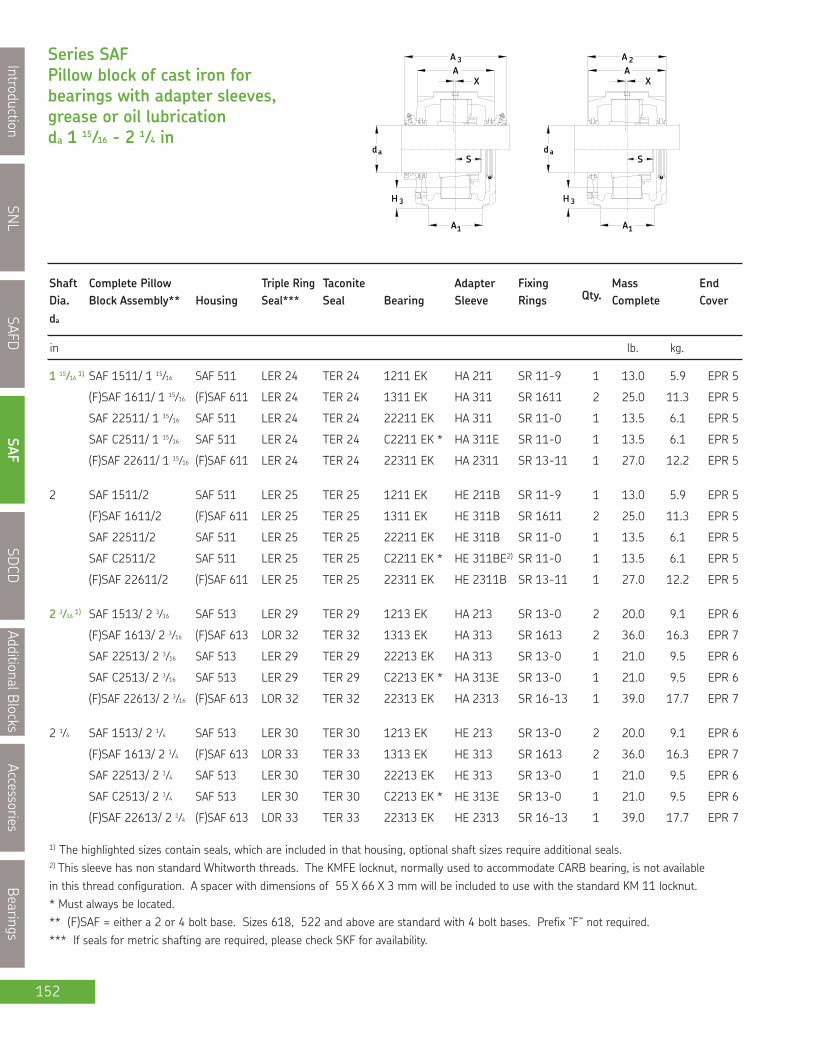
SNL
IntroductionSAFD
SAFSDCD
AdditionalBlocksAccessories
Bearings
152
Series SAFPillow block of cast iron forbearings with adapter sleeves,grease or oil lubricationda 1 15⁄16 - 2 1⁄4 in
1A
H 3 3H
adS
ad
AA 3
X
A1
S
X
2AA
in lb. kg.
Shaft Complete Pillow Triple Ring Taconite Adapter Fixing Mass EndDia. Block Assembly** Housing Seal*** Seal Bearing Sleeve Rings Qty. Complete Coverda
1 15⁄16 1) SAF 1511/ 1 15⁄16 SAF 511 LER 24 TER 24 1211 EK HA 211 SR 11-9 1 13.0 5.9 EPR 5
(F)SAF 1611/ 1 15⁄16 (F)SAF 611 LER 24 TER 24 1311 EK HA 311 SR 1611 2 25.0 11.3 EPR 5
SAF 22511/ 1 15⁄16 SAF 511 LER 24 TER 24 22211 EK HA 311 SR 11-0 1 13.5 6.1 EPR 5
SAF C2511/ 1 15⁄16 SAF 511 LER 24 TER 24 C2211 EK * HA 311E SR 11-0 1 13.5 6.1 EPR 5
(F)SAF 22611/ 1 15⁄16 (F)SAF 611 LER 24 TER 24 22311 EK HA 2311 SR 13-11 1 27.0 12.2 EPR 5
2 SAF 1511/2 SAF 511 LER 25 TER 25 1211 EK HE 211B SR 11-9 1 13.0 5.9 EPR 5
(F)SAF 1611/2 (F)SAF 611 LER 25 TER 25 1311 EK HE 311B SR 1611 2 25.0 11.3 EPR 5
SAF 22511/2 SAF 511 LER 25 TER 25 22211 EK HE 311B SR 11-0 1 13.5 6.1 EPR 5
SAF C2511/2 SAF 511 LER 25 TER 25 C2211 EK * HE 311BE2) SR 11-0 1 13.5 6.1 EPR 5
(F)SAF 22611/2 (F)SAF 611 LER 25 TER 25 22311 EK HE 2311B SR 13-11 1 27.0 12.2 EPR 5
2 3⁄16 1) SAF 1513/ 2 3⁄16 SAF 513 LER 29 TER 29 1213 EK HA 213 SR 13-0 2 20.0 9.1 EPR 6
(F)SAF 1613/ 2 3⁄16 (F)SAF 613 LOR 32 TER 32 1313 EK HA 313 SR 1613 2 36.0 16.3 EPR 7
SAF 22513/ 2 3⁄16 SAF 513 LER 29 TER 29 22213 EK HA 313 SR 13-0 1 21.0 9.5 EPR 6
SAF C2513/ 2 3⁄16 SAF 513 LER 29 TER 29 C2213 EK * HA 313E SR 13-0 1 21.0 9.5 EPR 6
(F)SAF 22613/ 2 3⁄16 (F)SAF 613 LOR 32 TER 32 22313 EK HA 2313 SR 16-13 1 39.0 17.7 EPR 7
2 1⁄4 SAF 1513/ 2 1⁄4 SAF 513 LER 30 TER 30 1213 EK HE 213 SR 13-0 2 20.0 9.1 EPR 6
(F)SAF 1613/ 2 1⁄4 (F)SAF 613 LOR 33 TER 33 1313 EK HE 313 SR 1613 2 36.0 16.3 EPR 7
SAF 22513/ 2 1⁄4 SAF 513 LER 30 TER 30 22213 EK HE 313 SR 13-0 1 21.0 9.5 EPR 6
SAF C2513/ 2 1⁄4 SAF 513 LER 30 TER 30 C2213 EK * HE 313E SR 13-0 1 21.0 9.5 EPR 6
(F)SAF 22613/ 2 1⁄4 (F)SAF 613 LOR 33 TER 33 22313 EK HE 2313 SR 16-13 1 39.0 17.7 EPR 7
1) The highlighted sizes contain seals, which are included in that housing, optional shaft sizes require additional seals.2) This sleeve has non standard Whitworth threads. The KMFE locknut, normally used to accommodate CARB bearing, is not availablein this thread configuration. A spacer with dimensions of 55 X 66 X 3 mm will be included to use with the standard KM 11 locknut.* Must always be located.** (F)SAF = either a 2 or 4 bolt base. Sizes 618, 522 and above are standard with 4 bolt bases. Prefix “F” not required.*** If seals for metric shafting are required, please check SKF for availability.
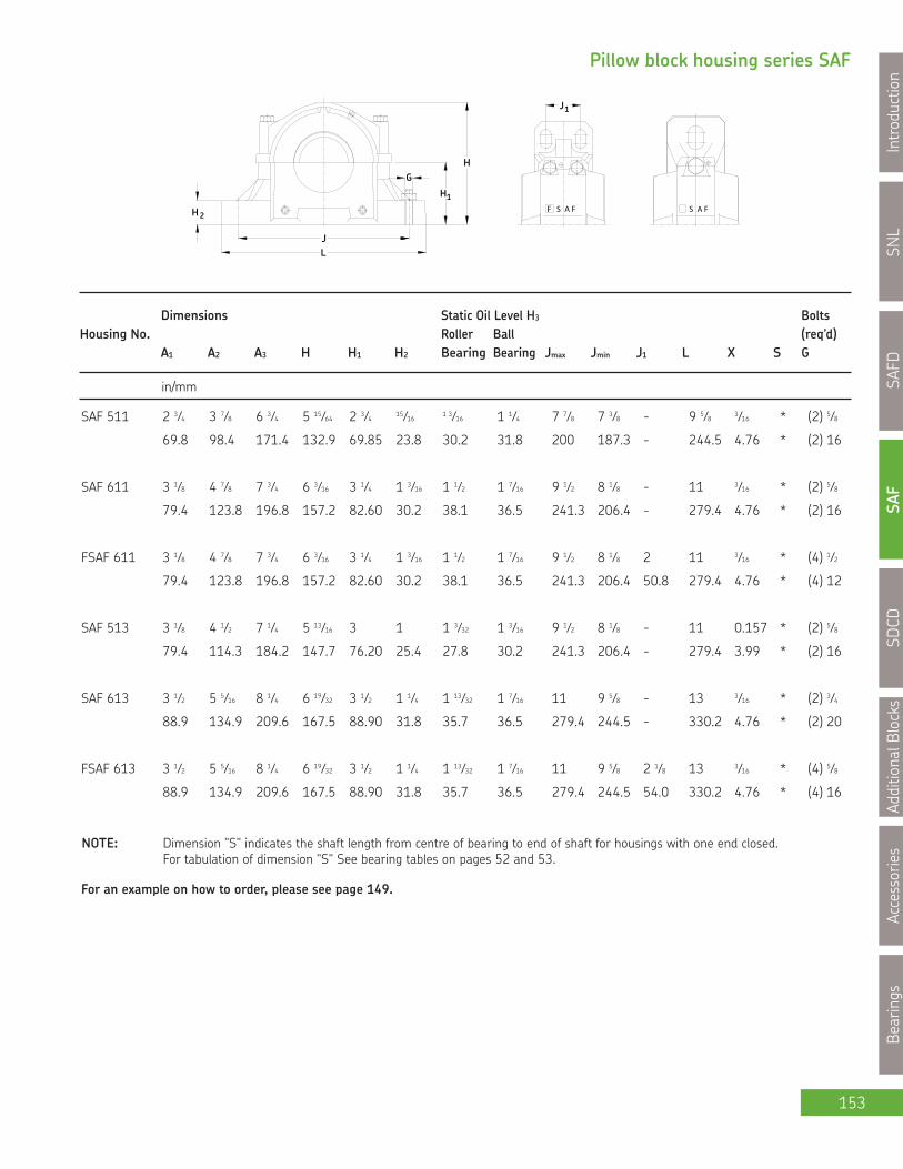
SNL
Introduction
SAFD
SAF
SDCD
AdditionalBlocks
Accessories
Bearings
153
Pillow block housing series SAF
H 2
JL
H1
GH
1J
F AS F FS A
Dimensions Static Oil Level H3 BoltsHousing No. Roller Ball (req’d)
A1 A2 A3 H H1 H2 Bearing Bearing Jmax Jmin J1 L X S G
in/mm
NOTE: Dimension "S" indicates the shaft length from centre of bearing to end of shaft for housings with one end closed.For tabulation of dimension "S" See bearing tables on pages 52 and 53.
For an example on how to order, please see page 149.
SAF 511 2 3⁄4 3 7⁄8 6 3⁄4 5 15⁄64 2 3⁄4 15⁄16 1 3⁄16 1 1⁄4 7 7⁄8 7 3⁄8 - 9 5⁄8 3⁄16 * (2) 5⁄8
69.8 98.4 171.4 132.9 69.85 23.8 30.2 31.8 200 187.3 - 244.5 4.76 * (2) 16
SAF 611 3 1⁄8 4 7⁄8 7 3⁄4 6 3⁄16 3 1⁄4 1 3⁄16 1 1⁄2 1 7⁄16 9 1⁄2 8 1⁄8 - 11 3⁄16 * (2) 5⁄8
79.4 123.8 196.8 157.2 82.60 30.2 38.1 36.5 241.3 206.4 - 279.4 4.76 * (2) 16
FSAF 611 3 1⁄8 4 7⁄8 7 3⁄4 6 3⁄16 3 1⁄4 1 3⁄16 1 1⁄2 1 7⁄16 9 1⁄2 8 1⁄8 2 11 3⁄16 * (4) 1⁄2
79.4 123.8 196.8 157.2 82.60 30.2 38.1 36.5 241.3 206.4 50.8 279.4 4.76 * (4) 12
SAF 513 3 1⁄8 4 1⁄2 7 1⁄4 5 13⁄16 3 1 1 3⁄32 1 3⁄16 9 1⁄2 8 1⁄8 - 11 0.157 * (2) 5⁄8
79.4 114.3 184.2 147.7 76.20 25.4 27.8 30.2 241.3 206.4 - 279.4 3.99 * (2) 16
SAF 613 3 1⁄2 5 5⁄16 8 1⁄4 6 19⁄32 3 1⁄2 1 1⁄4 1 13⁄32 1 7⁄16 11 9 5⁄8 - 13 3⁄16 * (2) 3⁄4
88.9 134.9 209.6 167.5 88.90 31.8 35.7 36.5 279.4 244.5 - 330.2 4.76 * (2) 20
FSAF 613 3 1⁄2 5 5⁄16 8 1⁄4 6 19⁄32 3 1⁄2 1 1⁄4 1 13⁄32 1 7⁄16 11 9 5⁄8 2 1⁄8 13 3⁄16 * (4) 5⁄8
88.9 134.9 209.6 167.5 88.90 31.8 35.7 36.5 279.4 244.5 54.0 330.2 4.76 * (4) 16

SNL
IntroductionSAFD
SAFSDCD
AdditionalBlocksAccessories
Bearings
154
Series SAFPillow block of cast iron forbearings with adapter sleeves,grease or oil lubricationda 2 7⁄16 - 2 11⁄16 in
1A
H 3 3H
adS
ad
AA 3
X
A1
S
X
2AA
in lb. kg.
Shaft Complete Pillow Triple Ring Taconite Adapter Fixing Mass EndDia. Block Assembly** Housing Seal*** Seal Bearing Sleeve Rings Qty. Complete Coverda
2 7⁄16 1) (F)SAF 1515/ 2 7⁄16 (F)SAF 515 LOR 37 TER 37 1215 K HA 215 SR 15-0 2 24.0 10.9 EPR 7
(F)SAF 1615/ 2 7⁄16 (F)SAF 615 LOR 37 TER 37 1315 K HA 315 SR 1615 2 51.0 23.1 EPR 7
(F)SAF 22515/ 2 7⁄16 (F)SAF 515 LOR 37 TER 37 22215 EK HA 315 SR 15-0 1 24.0 10.9 EPR 7
(F)SAF C2515/ 2 7⁄16 (F)SAF 515 LOR 37 TER 37 C2215 EK* HA 315E SR 15-0 1 24.0 10.9 EPR 7
(F)SAF 22615/ 2 7⁄16 (F)SAF 615 LOR 37 TER 37 22315 EK HA 2315 SR 18-15 1 55.0 24.9 EPR 7
(F)SAF C2615/ 2 7⁄16 (F)SAF 615 LOR 37 TER 37 C2315 EK* HA 2315 SR 18-15 1 55.0 24.9 EPR 7
2 1⁄2 (F)SAF 1515/ 2 1⁄2 (F)SAF 515 LOR 38 TER 38 1215 K HE 215 SR 15-0 2 24.0 10.9 EPR 7
(F)SAF 1615/ 2 1⁄2 (F)SAF 615 LOR 38 TER 38 1315 K HE 315 SR 1615 2 51.0 23.1 EPR 7
(F)SAF 22515/ 2 1⁄2 (F)SAF 515 LOR 38 TER 38 22215 EK HE 315 SR 15-0 1 24.0 10.9 EPR 7
(F)SAF C2515/ 2 1⁄2 (F)SAF 515 LOR 38 TER 38 C2215 EK* HE 315E SR 15-0 1 24.0 10.9 EPR 7
(F)SAF 22615/ 2 1⁄2 (F)SAF 615 LOR 38 TER 38 22315 EK HE 2315 SR 18-15 1 55.0 24.9 EPR 7
(F)SAF C2615/ 2 1⁄2 (F)SAF 615 LOR 38 TER 38 C2315 EK * HE 2315 SR 18-15 1 55.0 24.9 EPR 7
2 11⁄16 1) (F)SAF 1516/ 2 11⁄16 (F)SAF 516 LOR 44 TER 44 1216 K HA 216 SR 1516 2 31.0 14.1 EPR 8
(F)SAF 1616/ 2 11⁄16 (F)SAF 616 LOR 44 TER 44 1316 K HA 316 SR 1616 2 60.0 27.2 EPR 8
(F)SAF 22516/ 2 11⁄16 (F)SAF 516 LOR 44 TER 44 22216 EK HA 316 SR 16-13 1 32.0 14.5 EPR 8
(F)SAF C2516/ 2 11⁄16 (F)SAF 516 LOR 44 TER 44 C2216 EK * HA 316E SR 16-13 1 32.0 14.5 EPR 8
(F)SAF 22616/ 2 11⁄16 (F)SAF 616 LOR 44 TER 44 22316 EK HA 2316 SR 19-16 1 66.0 29.9 EPR 8
(F)SAF C2616/ 2 11⁄16 (F)SAF 616 LOR 44 TER 44 C2316 EK * HA 2316 SR 19-16 1 66.0 29.9 EPR 8
1) The highlighted sizes contain seals, which are included in that housing, optional shaft sizes require additional seals.* Must always be located.** (F)SAF = either a 2 or 4 bolt base. Sizes 618, 522 and above are standard with 4 bolt bases. Prefix “F” not required.*** If seals for metric shafting are required, please check SKF for availability.

SNL
Introduction
SAFD
SAF
SDCD
AdditionalBlocks
Accessories
Bearings
155
Pillow block housing series SAF
H 2
JL
H1
GH
1J
F AS F FS A
Dimensions Static Oil Level H3 BoltsHousing No. Roller Ball (req’d)
A1 A2 A3 H H1 H2 Bearing Bearing Jmax Jmin J1 L X S G
in/mm
NOTE: Dimension "S" indicates the shaft length from centre of bearing to end of shaft for housings with one end closed.For tabulation of dimension "S" See bearing tables on pages 52 and 53.
For an example on how to order, please see page 149.
SAF 515 3 1⁄8 4 11⁄16 7 5⁄8 6 13⁄64 3 1⁄4 1 1⁄8 1 1⁄8 1 1⁄4 9 5⁄8 8 5⁄8 - 11 1⁄4 0.118 * (2) 5⁄8
79.4 119.1 193.7 157.6 82.55 28.6 28.6 31.8 244.5 219.1 - 285.8 3.00 * (2) 16
FSAF 515 3 1⁄8 4 11⁄16 7 5⁄8 6 13⁄64 3 1⁄4 1 1⁄8 1 1⁄8 1 1⁄4 9 5⁄8 8 5⁄8 1 7⁄8 11 1⁄4 0.118 * (2) 5⁄8
79.4 119.1 193.7 157.6 82.55 28.6 28.6 31.8 244.5 219.1 47.6 285.8 3.00 * (2) 16
SAF 615 3 7⁄8 5 7⁄8 8 11⁄16 7 9⁄16 4 1 5⁄8 1 19⁄32 1 11⁄16 11 5⁄8 10 3⁄8 - 13 3⁄4 3⁄16 * (2) 3⁄4
98.4 149.2 220.6 192.1 101.60 41.3 40.5 42.9 295.3 263.5 - 349.2 4.76 * (2) 20
FSAF 615 3 7⁄8 5 5⁄8 8 11⁄16 7 9⁄16 4 1 5⁄8 1 19⁄32 1 11⁄16 11 5⁄8 10 3⁄8 2 1⁄8 13 3⁄4 3⁄16 * (4) 5⁄8
98.4 149.2 220.6 192.1 101.60 41.3 40.5 42.9 295.3 263.5 54.0 349.2 4.76 * (4) 16
SAF 516 3 1⁄2 5 5⁄16 8 1⁄4 6 11⁄16 3 1⁄2 1 1⁄4 1 1⁄4 1 5⁄16 11 9 5⁄8 - 13 3⁄16 * (2) 3⁄4
88.9 134.9 209.6 169.8 88.90 31.8 31.8 33.3 279.4 244.5 - 330.2 4.76 * (2) 20
FSAF 516 3 1⁄2 5 5⁄16 8 1⁄4 6 11⁄16 3 1⁄2 1 1⁄4 1 1⁄4 1 5⁄16 11 9 5⁄8 2 1⁄8 13 3⁄16 * (4) 5⁄8
88.9 134.9 209.6 169.8 88.90 31.8 31.8 33.3 279.4 244.5 54.0 330.2 4.76 * (4) 16
SAF 616 3 7⁄8 6 1⁄2 9 3⁄16 8 1⁄4 4 1⁄4 1 3⁄4 1 11⁄16 1 13⁄16 12 5⁄8 10 5⁄8 - 14 1⁄4 3⁄16 * (2) 3⁄4
98.4 165.1 233.4 209.6 108.00 44.4 42.9 46.0 320.7 269.9 - 362.0 4.76 * (2) 20
FSAF 616 3 7⁄8 6 1⁄2 9 3⁄16 8 1⁄4 4 1⁄4 1 3⁄4 1 11⁄16 1 13⁄16 12 5⁄8 10 5⁄8 2 1⁄8 14 1⁄4 3⁄16 * (4) 5⁄8
98.4 165.1 233.4 209.6 108.00 44.4 42.9 46.0 320.7 269.9 54.0 362.0 4.76 * (4) 16
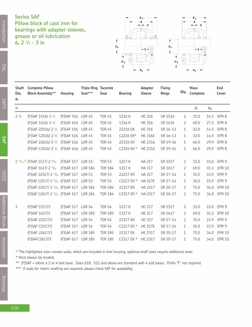
SNL
IntroductionSAFD
SAFSDCD
AdditionalBlocksAccessories
Bearings
156
Series SAFPillow block of cast iron forbearings with adapter sleeves,grease or oil lubricationda 2 3⁄4 - 3 in
1A
H 3 3H
adS
ad
AA 3
X
A1
S
X
2AA
in lb. kg.
Shaft Complete Pillow Triple Ring Taconite Adapter Fixing Mass EndDia. Block Assembly** Housing Seal*** Seal Bearing Sleeve Rings Qty. Complete Coverda
1) The highlighted sizes contain seals, which are included in that housing, optional shaft sizes require additional seals.* Must always be located.** (F)SAF = either a 2 or 4 bolt base. Sizes 618, 522 and above are standard with 4 bolt bases. Prefix “F” not required.*** If seals for metric shafting are required, please check SKF for availability.
2 3⁄4 (F)SAF 1516/ 2 3⁄4 (F)SAF 516 LOR 45 TER 45 1216 K HE 216 SR 1516 2 31.0 14.1 EPR 8
(F)SAF 1616/ 2 3⁄4 (F)SAF 616 LOR 45 TER 45 1316 K HE 316 SR 1616 2 60.0 27.2 EPR 8
(F)SAF 22516/ 2 3⁄4 (F)SAF 516 LOR 45 TER 45 22216 EK HE 316 SR 16-13 1 32.0 14.5 EPR 8
(F)SAF C2516/ 2 3⁄4 (F)SAF 516 LOR 45 TER 45 C2216 EK* HE 316E SR 16-13 1 32.0 14.5 EPR 8
(F)SAF 22616/ 2 3⁄4 (F)SAF 616 LOR 45 TER 45 22316 EK HE 2316 SR 19-16 1 66.0 29.9 EPR 8
(F)SAF C2616/ 2 3⁄4 (F)SAF 616 LOR 45 TER 45 C2316 EK * HE 2316 SR 19-16 1 66.0 29.9 EPR 8
2 15⁄16 1) (F)SAF 1517/ 2 15⁄16 (F)SAF 517 LOR 53 TER 53 1217 K HA 217 SR 1517 2 33.0 15.0 EPR 9
(F)SAF 1617/ 2 15⁄16 (F)SAF 617 LOR 184 TER 184 1317 K HA 317 SR 1617 2 69.0 31.3 EPR 10
(F)SAF 22517/ 2 15⁄16 (F)SAF 517 LOR 53 TER 53 22217 EK HA 317 SR 17-14 1 35.0 15.9 EPR 9
(F)SAF C2517/ 2 15⁄16 (F)SAF 517 LOR 53 TER 53 C2217 EK * HA 317E SR 17-14 1 35.0 15.9 EPR 9
(F)SAF 22617/ 2 15⁄16 (F)SAF 617 LOR 184 TER 184 22317 EK HA 2317 SR 20-17 1 75.0 34.0 EPR 10
(F)SAF C2617/ 2 15⁄16 (F)SAF 617 LOR 184 TER 184 C2317 EK * HA 2317 SR 20-17 1 75.0 34.0 EPR 10
3 (F)SAF 1517/3 (F)SAF 517 LOR 54 TER 54 1217 K HE 217 SR 1517 2 33.0 15.0 EPR 9
(F)SAF 1617/3 (F)SAF 617 LOR 185 TER 185 1317 K HE 317 SR 1617 2 69.0 31.3 EPR 10
(F)SAF 22517/3 (F)SAF 517 LOR 54 TER 54 22217 EK HE 317 SR 17-14 1 35.0 15.9 EPR 9
(F)SAF C2517/3 (F)SAF 517 LOR 54 TER 54 C2217 EK * HE 317E SR 17-14 1 35.0 15.9 EPR 9
(F)SAF 22617/3 (F)SAF 617 LOR 185 TER 185 22317 EK HE 2317 SR 20-17 1 75.0 34.0 EPR 10
(F)SAFC2617/3 (F)SAF 617 LOR 185 TER 185 C2317 EK * HE 2317 SR 20-17 1 75.0 34.0 EPR 10
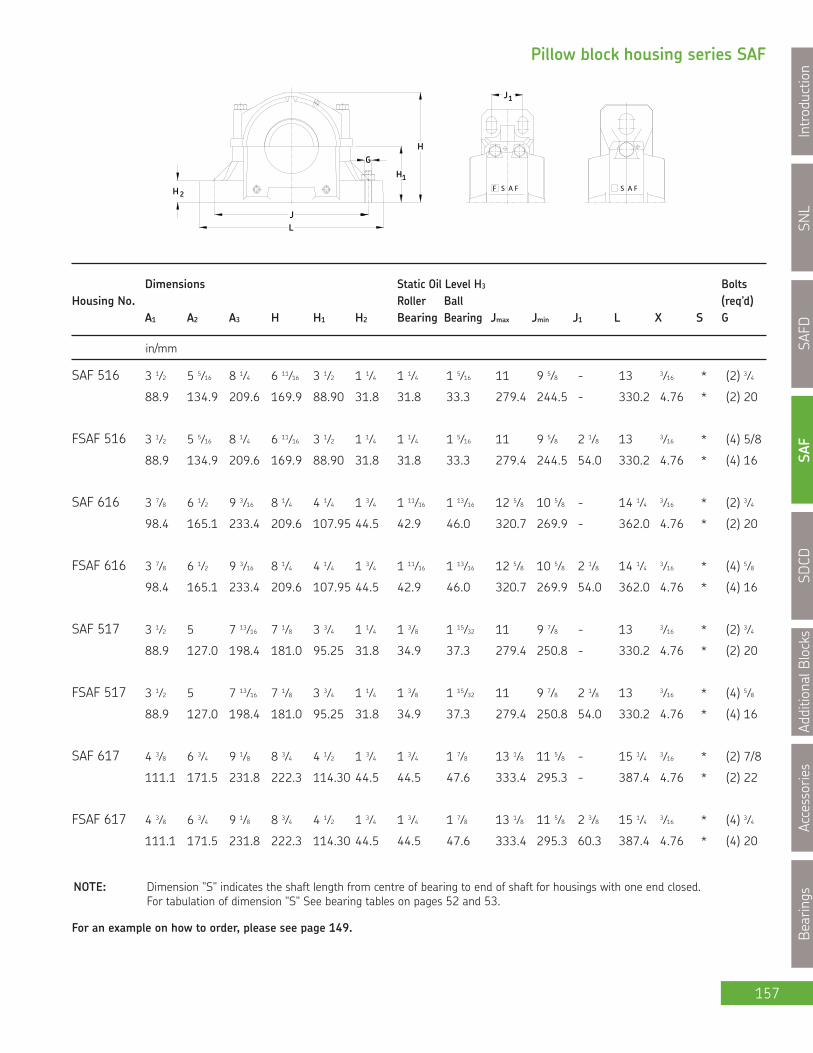
SNL
Introduction
SAFD
SAF
SDCD
AdditionalBlocks
Accessories
Bearings
157
Pillow block housing series SAF
H 2
JL
H1
GH
1J
F AS F FS A
Dimensions Static Oil Level H3 BoltsHousing No. Roller Ball (req’d)
A1 A2 A3 H H1 H2 Bearing Bearing Jmax Jmin J1 L X S G
in/mm
NOTE: Dimension "S" indicates the shaft length from centre of bearing to end of shaft for housings with one end closed.For tabulation of dimension "S" See bearing tables on pages 52 and 53.
For an example on how to order, please see page 149.
SAF 516 3 1⁄2 5 5⁄16 8 1⁄4 6 11⁄16 3 1⁄2 1 1⁄4 1 1⁄4 1 5⁄16 11 9 5⁄8 - 13 3⁄16 * (2) 3⁄4
88.9 134.9 209.6 169.9 88.90 31.8 31.8 33.3 279.4 244.5 - 330.2 4.76 * (2) 20
FSAF 516 3 1⁄2 5 5⁄16 8 1⁄4 6 11⁄16 3 1⁄2 1 1⁄4 1 1⁄4 1 5⁄16 11 9 5⁄8 2 1⁄8 13 3⁄16 * (4) 5/8
88.9 134.9 209.6 169.9 88.90 31.8 31.8 33.3 279.4 244.5 54.0 330.2 4.76 * (4) 16
SAF 616 3 7⁄8 6 1⁄2 9 3⁄16 8 1⁄4 4 1⁄4 1 3⁄4 1 11⁄16 1 13⁄16 12 5⁄8 10 5⁄8 - 14 1⁄4 3⁄16 * (2) 3⁄4
98.4 165.1 233.4 209.6 107.95 44.5 42.9 46.0 320.7 269.9 - 362.0 4.76 * (2) 20
FSAF 616 3 7⁄8 6 1⁄2 9 3⁄16 8 1⁄4 4 1⁄4 1 3⁄4 1 11⁄16 1 13⁄16 12 5⁄8 10 5⁄8 2 1⁄8 14 1⁄4 3⁄16 * (4) 5⁄8
98.4 165.1 233.4 209.6 107.95 44.5 42.9 46.0 320.7 269.9 54.0 362.0 4.76 * (4) 16
SAF 517 3 1⁄2 5 7 13⁄16 7 1⁄8 3 3⁄4 1 1⁄4 1 3⁄8 1 15⁄32 11 9 7⁄8 - 13 3⁄16 * (2) 3⁄4
88.9 127.0 198.4 181.0 95.25 31.8 34.9 37.3 279.4 250.8 - 330.2 4.76 * (2) 20
FSAF 517 3 1⁄2 5 7 13⁄16 7 1⁄8 3 3⁄4 1 1⁄4 1 3⁄8 1 15⁄32 11 9 7⁄8 2 1⁄8 13 3⁄16 * (4) 5⁄8
88.9 127.0 198.4 181.0 95.25 31.8 34.9 37.3 279.4 250.8 54.0 330.2 4.76 * (4) 16
SAF 617 4 3⁄8 6 3⁄4 9 1⁄8 8 3⁄4 4 1⁄2 1 3⁄4 1 3⁄4 1 7⁄8 13 1⁄8 11 5⁄8 - 15 1⁄4 3⁄16 * (2) 7/8
111.1 171.5 231.8 222.3 114.30 44.5 44.5 47.6 333.4 295.3 - 387.4 4.76 * (2) 22
FSAF 617 4 3⁄8 6 3⁄4 9 1⁄8 8 3⁄4 4 1⁄2 1 3⁄4 1 3⁄4 1 7⁄8 13 1⁄8 11 5⁄8 2 3⁄8 15 1⁄4 3⁄16 * (4) 3⁄4
111.1 171.5 231.8 222.3 114.30 44.5 44.5 47.6 333.4 295.3 60.3 387.4 4.76 * (4) 20

SNL
IntroductionSAFD
SAFSDCD
AdditionalBlocksAccessories
Bearings
158
Series SAFPillow block of cast iron forbearings with adapter sleeves,grease or oil lubricationda 3 3⁄16 - 3 1⁄2 in
1A
H 3 3H
adS
ad
AA 3
X
A1
S
X
2AA
in lb. kg.
Shaft Complete Pillow Triple Ring Taconite Adapter Fixing Mass EndDia. Block Assembly** Housing Seal*** Seal Bearing Sleeve Rings Qty. Complete Coverda
1) The highlighted sizes contain seals, which are included in that housing, optional shaft sizes require additional seals.* Must always be located.** (F)SAF = either a 2 or 4 bolt base. Sizes 618, 522 and above are standard with 4 bolt bases. Prefix “F” not required.*** If seals for metric shafting are required, please check SKF for availability.
3 3⁄16 1) (F)SAF1518/ 3 3⁄16 (F)SAF 518 LOR 188 TER 188 1218 K HA 218 SR 1518 2 44.0 20.0 EPR 11
SAF 1618/ 3 3⁄16 SAF 618 LOR 188 TER 188 1318 K HA 318 SR 1618 2 92.0 41.7 EPR 11
(F)SAF 22518 3 3⁄16 (F)SAF 518 LOR 188 TER 188 22218 EK HA 318 SR 18-15 1 44.0 20.0 EPR 11
(F)SAF C2518/ 3 3⁄16 (F)SAF 518 LOR 188 TER 188 C2218 EK* HA 318E SR 18-15 1 44.0 20.0 EPR 11
SAF 22618/ 3 3⁄16 SAF 618 LOR 188 TER 188 22318 EK HA 2318 SR 21-18 1 97.0 44.0 EPR 11
SAF C2618/ 3 3⁄16 SAF 618 LOR 188 TER 188 C2318 EK * HA 2318 SR 21-18 1 97.0 44.0 EPR 11
3 1⁄4 (F)SAF 1518/ 3 1⁄4 (F)SAF 518 LOR 189 TER 189 1218 K HE 218 SR 1518 2 44.0 20.0 EPR 11
SAF 1618/ 3 1⁄4 SAF 618 LOR 189 TER 189 1318 K HE 318 SR 1618 2 92.0 41.7 EPR 11
(F)SAF 22518/ 3 1⁄4 (F)SAF 518 LOR 189 TER 189 22218 EK HE 318 SR 18-15 1 44.0 20.0 EPR 11
(F)SAF C2518/ 3 1⁄4 (F)SAF 518 LOR 189 TER 189 C2218 EK* HE 318E SR 18-15 1 44.0 20.0 EPR 11
SAF 22618/ 3 1⁄4 SAF 618 LOR 189 TER 189 22318 EK HE 2318 SR 21-18 1 97.0 44.0 EPR 11
SAF C2618/ 3 1⁄4 SAF 618 LOR 189 TER 189 C2318 EK* HE 2318 SR 21-18 1 97.0 44.0 EPR 11
3 7⁄16 1) (F)SAF 1520/ 3 7⁄16 (F)SAF 520 LOR 102 TER 102 1220 K HA 220 SR 1520 2 62.0 28.1 EPR 12
SAF 1620/ 3 7⁄16 SAF 620 LOR 102 TER 102 1320 K HA 320 SR 1620 2 101.0 45.8 EPR 12
(F)SAF 22520/ 3 7⁄16 (F)SAF 520 LOR 102 TER 102 22220 EK HA 320 SR 20-17 1 74.0 33.6 EPR 12
(F)SAF C2520/ 3 7⁄16 (F)SAF 520 LOR 102 TER 102 C2220 EK* HA 320E SR 20-17 1 74.0 33.6 EPR 12
SAF 22620/ 3 7⁄16 SAF 620 LOR 102 TER 102 22320 EK HA 2320 SR 24-20 1 125.0 56.7 EPR 12
SAF C2620/ 3 7⁄16 SAF 620 LOR 102 TER 102 C2320 EK* HA 2320 SR 24-20 1 125.0 56.7 EPR 12
3 1⁄2 (F)SAF 1520/ 3 1⁄2 (F)SAF 520 LOR 103 TER 103 1220 K HE 220 SR 1520 2 62.0 28.1 EPR 12
SAF 1620/ 3 1⁄2 SAF 620 LOR 103 TER 103 1320 K HE 320 SR 1620 2 101.0 45.8 EPR 12
(F)SAF 22520/ 3 1⁄2 (F)SAF 520 LOR 103 TER 103 22220 EK HE 320 SR 20-17 1 74.0 33.6 EPR 12
(F)SAF C2520/ 3 1⁄2 (F)SAF 520 LOR 103 TER 103 C2220 EK* HE 320E SR 20-17 1 74.0 33.6 EPR 12
SAF 22620/ 3 1⁄2 SAF 620 LOR 103 TER 103 22320 EK HE 2320 SR 24-20 1 125.0 56.7 EPR 12
SAF C2620/ 3 1⁄2 SAF 620 LOR 103 TER 103 C2320 EK* HE 2320 SR 24-20 1 125.0 56.7 EPR 12

SNL
Introduction
SAFD
SAF
SDCD
AdditionalBlocks
Accessories
Bearings
159
Pillow block housing series SAF
H 2
JL
H1
GH
1J
F AS F FS A
Dimensions Static Oil Level H3 BoltsHousing No. Roller Ball (req’d)
A1 A2 A3 H H1 H2 Bearing Bearing Jmax Jmin J1 L X S G
in/mm
NOTE: Dimension "S" indicates the shaft length from centre of bearing to end of shaft for housings with one end closed.For tabulation of dimension "S" See bearing tables on pages 52 and 53.
For an example on how to order, please see page 149.
SAF 518 3 7⁄8 5 7⁄8 8 1⁄8 7 23⁄32 4 1 5⁄8 1 1⁄2 1 1⁄2 11 3⁄4 10 1⁄4 - 13 3⁄4 3⁄16 * (2) 3⁄4
98.4 149.2 206.4 196.1 101.60 41.3 38.1 38.1 298.5 260.4 - 349.3 4.76 * (2) 20
FSAF 518 3 7⁄8 5 7⁄8 8 1⁄8 7 23⁄32 4 1 5⁄8 1 1⁄2 1 1⁄2 11 3⁄4 10 1⁄4 2 1⁄8 13 3⁄4 3⁄16 * (4) 5⁄8
98.4 149.2 206.4 196.1 101.60 41.3 38.1 38.1 298.5 260.4 54.0 349.3 4.76 * (4) 16
SAF 618 4 3⁄8 6 7⁄8 9 1⁄8 9 1⁄4 4 3⁄4 2 1 7⁄8 2 13 1⁄2 12 2 1⁄4 15 1⁄2 3⁄16 * (4) 3⁄4
111.1 174.6 231.8 235.0 120.65 50.8 47.6 50.8 342.9 304.8 57.2 393.7 4.76 * (4) 20
SAF 520 4 3⁄8 6 1⁄8 8 3⁄4 8 9⁄16 4 1⁄2 1 3⁄4 1 21⁄32 1 21⁄32 13 1⁄8 11 5⁄8 - 15 1⁄4 3⁄16 * (2) 7⁄8
111.1 155.6 222.3 217.5 114.30 44.5 42.1 42.1 333.4 295.3 - 387.4 4.76 * (2) 22
FSAF 520 4 3⁄8 6 1⁄8 8 3⁄4 8 9⁄16 4 1⁄2 1 3⁄4 1 21⁄32 1 21⁄32 13 1⁄8 11 5⁄8 2 3⁄8 15 1⁄4 3⁄16 * (4) 3⁄4
111.1 155.6 222.3 217.5 114.30 44.5 42.1 42.1 333.4 295.3 60.3 387.4 4.76 * (4) 20
SAF 620 4 3⁄4 7 3⁄8 10 10 3⁄16 5 1⁄4 2 1⁄8 2 1⁄32 2 3⁄16 14 1⁄2 13 1⁄4 2 3⁄4 16 1⁄2 3⁄16 * (4) 3⁄4
120.7 187.3 254.0 258.8 133.35 54.0 51.6 55.6 368.3 336.6 69.9 419.1 4.76 * (4) 20

SNL
IntroductionSAFD
SAFSDCD
AdditionalBlocksAccessories
Bearings
160
Series SAFPillow block of cast iron forbearings with adapter sleeves,grease or oil lubricationda 4 15⁄16 - 4 1⁄2 in
a
A1
H 3 3H
A1
daS
ddaS
A
XA
3 A
XA
2
A1
3H
S
AA
2
SAF-KA series
in lb. kg.
Shaft Complete Pillow Triple Ring Taconite Adapter Fixing Mass EndDia. Block Assembly** Housing Seal*** Seal Bearing Sleeve Rings Qty. Complete Coverda
1) The highlighted sizes contain seals, which are included in that housing, optional shaft sizes require additional seals.* Must always be located.** (F)SAF = either a 2 or 4 bolt base. Sizes 618, 522 and above are standard with 4 bolt bases. Prefix “F” not required.*** If seals for metric shafting are required, please check SKF for availability.
4 SAF 1522/4 SAF 522 LOR 110 TER 110 1222 K HE 222 SR 1522 2 69.0 31.3 EPR 13
SAF 1622/4 SAF 622 LOR 110 TER 110 1322 K HE 322 SR 1622 2 138.0 62.6 EPR 13
SAF 22522/4 SAF 522 LOR 110 TER 110 22222 EK HE 322 SR 22-19 1 73.0 33.1 EPR 13
SAF C2522/4 SAF 522 LOR 110 TER 110 C2222 EK* HE 322E SR 22-19 1 73.0 33.1 EPR 13
SAF 22622/4 SAF 622 LOR 110 TER 110 22322 EK HE 2322 SR 0-22 1 165.0 74.8 EPR 13
4 3⁄16 1) SAF 22524/4 3⁄16 SAF 524 LOR 113 TER 113 22224 EK HA 3124 SR 24-20 1 120.0 54.4 EPR 14
SAF 22624/4 3⁄16 SAF 624 LOR 113 TER 113 22324CCK/W33 HA 2324 SR 0-24 1 225.0 102.0 EPR 14
(F)SAF 23024KA/4 3⁄16 (F)SAF 024KA LOR 113 TER 113 23024CCK/W33 SNW3024x4 3⁄16 38151-24 2 73.0 33.1 EPR 14
4 1⁄4 SAF 22524/4 1⁄4 SAF 524 LOR 114 TER 114 22224 EK HE 3124 SR 24-20 1 120.0 54.4 EPR 14
SAF 22624/4 1⁄4 SAF 624 LOR 114 TER 114 22324CCK/W33 HE 2324 SR 0-24 1 225.0 102.0 EPR 14
(F)SAF 23024KA 4 1⁄4 (F)SAF 024KA LOR 114 TER 114 23024CCK/W33 SNW3024x4 1⁄4 38151-24 2 73.0 33.1 EPR 14
4 7⁄16 1) SAF 22526/4 7⁄16 SAF 526 LOR 117 TER 117 22226 EK HA 3126 SR 26-0 1 160.0 72.6 EPR 15
SAF C2526/4 7⁄16 SAF 526 LOR 117 TER 117 C2226 EK* HA 3126 L SR 26-0 1 160.0 72.6 EPR 15
SAF 22626/4 7⁄16 SAF 626 LOR 117 TER 117 22326CCK/W33 HA 2326 SR 0-26 1 233.0 105.7 EPR 15
SAF 23026KA/4 7⁄16 SAF 026KA LOR 117 TER 117 23026CCK/W33 SNW3026x4 7⁄16 38151-26 2 95.0 43.1 EPR 15
4 1⁄2 SAF 22526/4 1⁄2 SAF 526 LOR 118 TER 118 22226 EK HE 3126 SR 26-0 1 160.0 72.6 EPR 15
SAF C2526/4 1⁄2 SAF 526 LOR 118 TER 118 C2226 EK* HE 3126 L SR 26-0 1 160.0 72.6 EPR 15
SAF 22626/4 1⁄2 SAF 626 LOR 118 TER 118 22326CCK/W33 HE 2326 SR 0-26 1 233.0 105.7 EPR 15
SAF 23026KA/4 1⁄2 SAF 026KA LOR 118 TER 118 23026CCK/W33 SNW3026x4 1⁄2 38151-26 2 95.0 43.1 EPR 15
3 15⁄16 1) SAF 1522/ 3 15⁄16 SAF 522 LOR 109 TER 109 1222 K H 222 SR 1522 2 69.0 31.3 EPR 13
SAF 1622/ 3 15⁄16 SAF 622 LOR 109 TER 109 1322 K H 322 SR 1622 2 138.0 62.6 EPR 13
SAF 22522/ 3 15⁄16 SAF 522 LOR 109 TER 109 22222 EK H 322 SR 22-19 1 73.0 33.1 EPR 13
SAF C2522/ 3 15⁄16 SAF 522 LOR 109 TER 109 C2222 EK* H 322E SR 22-19 1 73.0 33.1 EPR 13
SAF 22622/ 3 15⁄16 SAF 622 LOR 109 TER 109 22322 EK H 2322 SR 0-22 1 165.0 74.8 EPR 13

SNL
Introduction
SAFD
SAF
SDCD
AdditionalBlocks
Accessories
Bearings
161
Pillow block housing series SAF
J1
1
2H
LJ
G
H
H
FSF A S FA
Dimensions Static Oil BoltsHousing No. Level (req’d)
A1 A2 A3 H H1 H2 H3 Jmax Jmin J1 L X S G
in/mm
NOTE: Dimension "S" indicates the shaft length from centre of bearing to end of shaft for housings with one end closed.For tabulation of dimension "S" See bearing tables on pages 52 and 53.
For an example on how to order, please see page 149.
SAF 522 4 3⁄4 6 1⁄2 9 1⁄8 9 27⁄64 4 15⁄16 2 1 25⁄32 1 25⁄32 14 1⁄2 12 5⁄8 2 3⁄4 16 1⁄2 3⁄16 (4) 3⁄4
120.7 165.1 231.8 239.3 125.41 50.8 45.2 45.2 368.3 320.7 69.9 419.1 4.76 (4) 20
SAF 622 5 1⁄4 8 1⁄8 10 3⁄4 11 5⁄16 6 2 3⁄8 2 13⁄32 2 1⁄2 16 14 5⁄8 3 1⁄4 18 3⁄8 3⁄16 (4) 7⁄8
133.4 206.4 273.1 287.3 152.40 60.3 61.1 63.5 406.4 371.5 82.6 466.7 4.76 (4) 22
SAF 524 4 3⁄4 7 3⁄8 10 10 1⁄8 5 1⁄4 2 1⁄8 1 27⁄32 14 1⁄2 13 1⁄4 2 3⁄4 16 1⁄2 3⁄16 * (4) 3⁄4
120.7 187.3 254.0 257.2 133.35 54.0 46.8 368.3 336.6 69.9 419.1 4.76 * (4) 20
SAF 624 6 1⁄4 8 3⁄8 11 12 1⁄2 6 5⁄16 2 1⁄2 2 3⁄8 18 1⁄4 17 3 3⁄4 21 1⁄4 3⁄16 * (4) 1
158.8 212.7 279.4 317.5 160.34 63.5 60.3 463.6 431.8 95.3 539.8 4.76 * (4) 24
SAF 024KA 4 3⁄8 6 9 8 3⁄4 4 1⁄2 1 3⁄4 1 9⁄16 13 1⁄8 11 5⁄8 - 15 1⁄4 - * (2) 7⁄8
111.1 152.4 228.6 222.3 114.30 44.5 39.7 333.4 295.3 - 387.4 - * (2) 22
FSAF 024KA 4 3⁄8 6 9 8 3⁄4 4 1⁄2 1 3⁄4 1 9⁄16 13 1⁄8 11 5⁄8 2 3⁄8 15 1⁄4 - * (4) 3⁄4
111.1 152.4 228.6 222.3 114.30 44.5 39.7 333.4 295.3 60.3 387.4 - * (4) 20
SAF 526 5 1⁄4 7 5⁄8 10 5⁄8 11 5⁄8 6 2 3⁄8 2 3⁄8 16 14 5⁄8 3 1⁄4 18 3⁄8 3⁄16 * (4) 7⁄8
133.4 193.7 269.9 295.3 152.40 60.3 60.3 406.4 371.5 82.6 466.7 4.76 * (4) 22
SAF 626 6 1⁄4 8 3⁄4 11 3⁄8 13 5⁄16 6 11⁄16 2 5⁄8 2 7⁄16 19 1⁄4 17 3⁄8 3 3⁄4 22 3⁄16 * (4) 1
158.8 222.3 288.9 338.1 169.86 66.7 61.9 489.0 441.3 95.3 558.8 4.76 * (4) 24
SAF 026KA 4 3⁄4 6 1⁄2 9 1⁄4 9 5⁄8 4 15⁄16 2 1 11⁄16 14 1⁄2 12 5⁄8 2 3⁄4 16 1⁄2 - * (4) 3⁄4
120.7 165.1 235.0 244.5 125.41 50.8 42.9 368.3 320.7 69.9 419.1 - * (4) 20

SNL
IntroductionSAFD
SAFSDCD
AdditionalBlocksAccessories
Bearings
162
Series SAFPillow block of cast iron forbearings with adapter sleeves,grease or oil lubricationda 4 15⁄16 - 5 1⁄2 in
a
A1
H 3 3H
A1
daS
ddaS
A
XA
3 A
XA
2
A1
3H
S
AA
2
SAF-KA series
in lb. kg.
Shaft Complete Pillow Triple Ring Taconite Adapter Fixing Mass EndDia. Block Assembly Housing Seal*** Seal Bearing Sleeve Rings Qty. Complete Coverda
1) The highlighted sizes contain seals, which are included in that housing, optional shaft sizes require additional seals.* Must always be located.*** If seals for metric shafting are required, please check SKF for availability.
4 15⁄16 1) SAF 22528/4 15⁄16 SAF 528 LOR 122 TER 122 22228CCK/W33 HA 3128 SR 28-0 1 175 79.4 EPR 27
SAF C2528/4 15⁄16 SAF 528 LOR 122 TER 122 C2228K* HA 3128 L SR 28-0 1 175 79.4 EPR 27
SAF 22628/4 15⁄16 SAF 628 LOR 122 TER 122 22328CCK/W33 HA 2328 SR 0-28 1 330 149.7 EPR 27
SAF 23028KA/4 15⁄16 SAF 028KA LOR 122 TER 122 23028CCK/W33 SNW3028x4 15⁄16 36053-50 2 115 52.2 EPR 27
5 SAF 22528/5 SAF 528 LOR 123 TER 123 22228CCK/W33 HE 3128 SR 28-0 1 175 79.4 EPR 27
SAF C2528/5 SAF 528 LOR 123 TER 123 C2228K* HE 3128 L SR 28-0 1 175 79.4 EPR 27
SAF 22628/5 SAF 628 LOR 123 TER 123 22328CCK/W33 HE 2328 SR 0-28 1 330 149.7 EPR 27
SAF 23028KA/5 SAF 028KA LOR 123 TER 123 23028CCK/W33 SNW3028x5 36053-50 2 115 52.2 EPR 27
5 3⁄16 1) SAF 22530/5 3⁄16 SAF 530 LOR 125 TER 125 22230CCK/W33 HA 3130 SR 30-0 1 220 99.8 EPR 16
SAF C2530/5 3⁄16 SAF 530 LOR 125 TER 125 C2230K* HA 3130 L SR 30-0 1 220 99.8 EPR 16
SAF 22630/5 3⁄16 SAF 630 LOR 125 TER 125 22330CCK/W33 HA 2330 SR 36-30 1 375 170.1 EPR 16
SAF 23030KA/5 3⁄16 SAF 030KA LOR 125 TER 125 23030CCK/W33 SNW3030x5 3⁄16 SR 0-21 2 155 70.3 EPR 16
5 1⁄4 SAF 22530/5 1⁄4 SAF 530 LOR 126 TER 126 22230CCK/W33 HE 3130 SR 30-0 1 220 99.8 EPR 16
SAF C2530/5 1⁄4 SAF 530 LOR 126 TER 126 C2230K* HE 3130 L SR 30-0 1 220 99.8 EPR 16
SAF 22630/5 1⁄4 SAF 630 LOR 126 TER 126 22330CCK/W33 HE 2330 SR 36-30 1 375 170.1 EPR 16
SAF 23030KA/5 1⁄4 SAF 030KA LOR 126 TER 126 23030CCK/W33 SNW3030x5 1⁄4 SR 0-21 2 155 70.3 EPR 16
5 7⁄16 1) SAF 22532/5 7⁄16 SAF 532 LOR 130 TER 130 22232CCK/W33 HA 3132 SR 32-0 1 245 111.1 EPR 16
SAF 22632/5 7⁄16 SAF 632 LOR 130 TER 130 22332CCK/W33 HA 2332 SR 38-32 1 430 195.0 EPR 16
SAF 23032KA/5 7⁄16 SAF 032KA LOR 130 TER 130 23032CCK/W33 SNW3032x5 7⁄16 38151-32 2 140 63.5 EPR 16
5 1⁄2 SAF 22532/5 1⁄2 SAF 532 LOR 131 TER 131 22232CCK/W33 HE 3132 SR 32-0 1 245 111.1 EPR 16
SAF 22632/5 1⁄2 SAF 632 LOR 131 TER 131 22332CCK/W33 HE 2332 SR 38-32 1 430 195.0 EPR 16
SAF 23032KA/5 1⁄2 SAF 032KA LOR 131 TER 131 23032CCK/W33 SNW3032x5 1⁄2 38151-32 2 140 63.5 EPR 16

SNL
Introduction
SAFD
SAF
SDCD
AdditionalBlocks
Accessories
Bearings
163
Pillow block housing series SAF
J1
1
2H
LJ
G
H
H
FSF A S FA
Dimensions Static Oil BoltsHousing No. Level (req’d)
A1 A2 A3 H H1 H2 H3 Jmax Jmin J1 L X S G
in/mm
NOTE: Dimension "S" indicates the shaft length from centre of bearing to end of shaft for housings with one end closed.For tabulation of dimension "S" See bearing tables on pages 52 and 53.
For an example on how to order, please see page 149.
SAF 528 5 7⁄8 7 5⁄8 10 1⁄4 12 1⁄32 6 2 3⁄8 2 1⁄32 17 3⁄8 15 5⁄8 3 3⁄8 20 1⁄8 3⁄16 * (4) 1
149.2 193.7 260.4 305.6 152.40 60.3 51.6 441.3 396.9 85.7 511.2 4.76 * (4) 24
SAF 628 6 3⁄4 9 5⁄8 12 1⁄8 14 3⁄16 7 1⁄16 2 3⁄4 2 9⁄16 21 5⁄8 19 3⁄8 4 1⁄4 24 3⁄4 3⁄16 * (4) 1
171.5 244.5 308.0 360.4 179.39 69.9 65.1 549.3 492.1 108.0 628.7 4.76 * (4) 24
SAF 028KA 4 3⁄4 7 3⁄8 10 1⁄16 10 1⁄4 5 1⁄4 2 1⁄8 1 13⁄16 14 1⁄2 13 1⁄4 2 3⁄4 16 1⁄2 - * (4) 3⁄4
120.7 187.3 255.6 260.4 133.35 54.0 46.0 368.3 336.6 69.9 419.1 - * (4) 20
SAF 530 6 1⁄4 8 3⁄8 11 12 1⁄2 6 5⁄16 2 1⁄2 2 18 1⁄4 17 3 3⁄4 21 1⁄4 3⁄16 * (4) 1
158.8 212.7 279.4 317.5 160.34 63.5 50.8 463.6 431.8 95.3 539.8 4.76 * (4) 24
SAF 630 7 1⁄8 9 3⁄4 12 1⁄2 14 7⁄8 7 1⁄2 3 2 5⁄8 23 5⁄8 20 7⁄8 4 5⁄8 26 3⁄4 3⁄16 * (4) 1
181.0 247.7 317.5 377.8 190.50 76.2 66.7 600.1 530.2 117.5 679.5 4.76 * (4) 24
SAF 030KA 5 1⁄4 8 1⁄8 10 13⁄16 11 5⁄16 6 2 3⁄8 2 7⁄32 16 14 5⁄8 3 1⁄4 18 3⁄8 - * (4) 7⁄8
133.4 206.4 274.6 287.3 152.40 60.3 56.4 406.4 371.5 82.6 466.7 - * (4) 22
SAF 532 6 1⁄4 8 3⁄4 11 3⁄8 13 5⁄16 6 11⁄16 2 5⁄8 2 1⁄16 19 1⁄4 17 3⁄8 3 3⁄4 22 3⁄16 * (4) 1
158.8 222.3 288.9 338.1 169.86 66.7 52.4 489.0 441.3 95.3 558.8 4.76 * (4) 24
SAF 632 7 1⁄2 10 3⁄4 13 3⁄8 15 11⁄16 7 7⁄8 3 1⁄8 2 11⁄16 24 3⁄8 21 5⁄8 4 1⁄2 28 3⁄16 * (4) 1 1⁄4
190.5 273.1 339.7 398.5 200.03 79.4 68.3 619.1 549.3 114.3 711.2 4.76 * (4) 30
SAF 032KA 5 1⁄4 8 1⁄8 10 13⁄16 11 5⁄16 6 2 3⁄8 2 1⁄32 16 14 5⁄8 3 1⁄4 18 3⁄8 - * (4) 7⁄8
133.4 206.4 274.6 287.3 152.40 60.3 51.6 406.4 371.5 82.6 466.7 - * (4) 22

SNL
IntroductionSAFD
SAFSDCD
AdditionalBlocksAccessories
Bearings
164
Series SAFPillow block of cast iron forbearings with adapter sleeves,grease or oil lubricationda 5 15⁄16 - 7 3⁄16 in
a
A1
H 3 3H
A1
daS
ddaS
A
XA
3 A
XA
2
A1
3H
S
AA
2
SAF-KA series
in lb. kg.
Shaft Complete Pillow Triple Ring Taconite Adapter Fixing Mass EndDia. Block Assembly Housing Seal*** Seal Bearing Sleeve Rings Qty. Complete Coverda
1) The highlighted sizes contain seals, which are included in that housing, optional shaft sizes require additional seals.* Must always be located.*** If seals for metric shafting are required, please check SKF for availability.
5 15⁄16 1) SAF 22534/5 15⁄16 SAF 534 LOR 140 TER 140 22234CCK/W33 HA 3134 SR 34-0 1 310 140.6 EPR 18
SAF C2534/5 15⁄16 SAF 534 LOR 140 TER 140 C2234K* HA 3134 L SR 34-0 1 310 140.6 EPR 18
SAF 22634/5 15⁄16 SAF 634 LOR 140 TER 140 22334CCK/W33 HA 2334 SR 40-34 1 515 233.6 EPR 18
SAF 23034KA/5 15⁄16 SAF 034KA LOR 140 TER 140 23034CCK/W33 SNW3034x5 15⁄16 SR 0-24 2 170 77.1 EPR 18
6 SAF 22534/6 SAF 534 LOR 141 TER 141 22234CCK/W33 HE 3134 SR 34-0 1 310 140.6 EPR 18
SAF C2534/6 SAF 534 LOR 141 TER 141 C2234K* HE 3134 L SR 34-0 1 310 140.6 EPR 18
SAF 22634/6 SAF 634 LOR 141 TER 141 22334CCK/W33 HE 2334 SR 40-34 1 515 233.6 EPR 18
SAF 23034KA/6 SAF 034KA LOR 141 TER 141 23034CCK/W33 SNW3034x6 SR 0-24 2 170 77.1 EPR 18
6 7⁄16 1) SAF 22536/6 7⁄16 SAF 536 LOR 148 TER 148 22236CCK/W33 HA 3136 SR 36-30 1 345 156.5 EPR 19
SAF 23036KA/6 7⁄16 SAF 036KA LOR 148 TER 148 23036CCK/W33 SNW3036x6 7⁄16 38151-36 2 225 102.0 EPR 19
6 1⁄2 SAF 22536/ 6 1⁄2 SAF 536 LOR 149 TER 149 22236CCK/W33 HE 3136 SR 36-30 1 345 156.5 EPR 19
SAF 23036KA/ 6 1⁄2 SAF 036KA LOR 149 TER 149 23036CCK/W33 SNW3036x6 1⁄2 38151-36 2 225 102.0 EPR 19
6 15⁄16 1) SAF 22538/ 6 15⁄16 SAF 538 LOR 155 TER 155 22238CCK/W33 HA 3138 SR 38-32 1 400 181.4 EPR 20
SAF C2538/ 6 15⁄16 SAF 538 LOR 155 TER 155 C2238K* HA 3138 L SR 38-32 1 400 181.4 EPR 20
SAF 22638/ 6 15⁄16 SAF 638 LOR 155 TER 155 22338CCK/W33 HA 2338 SR 44-38 1 700 317.5 EPR 20
SAF 23038KA/ 15⁄16 SAF 038KA LOR 155 TER 155 23038CCK/W33 SNW3038x6 15⁄16 38151-38 2 235 106.6 EPR 20
7 3⁄16 1) SAF 22540/ 7 3⁄16 SAF 540 LOR 159 TER 159 22240CCK/W33 HA 3140 SR 40-34 1 490 222.2 EPR 21
SAF 23040KA/ 7 3⁄16 SAF 040KA LOR 159 TER 159 23040CCK/W33 SNW3040x7 3⁄16 38151-40 2 300 136.1 EPR 21

SNL
Introduction
SAFD
SAF
SDCD
AdditionalBlocks
Accessories
Bearings
165
Pillow block housing series SAF
J1
1
2H
LJ
G
H
H
FSF A S FA
Dimensions Static Oil BoltsHousing No. Level (req’d)
A1 A2 A3 H H1 H2 H3 Jmax Jmin J1 L X S G
in/mm
NOTE: Dimension "S" indicates the shaft length from centre of bearing to end of shaft for housings with one end closed.For tabulation of dimension "S" See bearing tables on pages 52 and 53.
For an example on how to order, please see page 149.
SAF 534 6 3⁄4 9 5⁄8 12 1⁄8 14 3⁄16 7 1⁄16 2 3⁄4 2 5⁄32 21 5⁄8 19 3⁄8 4 1⁄4 24 3⁄4 3⁄16 * (4) 1
171.5 244.5 308.0 360.4 179.39 69.9 54.8 549.3 492.1 108.0 628.7 4.76 * (4) 24
SAF 634 8 11 1⁄4 13 7⁄8 16 1⁄2 8 1⁄4 3 3⁄8 2 3⁄4 25 22 1⁄2 5 29 1⁄2 3⁄16 * (4) 1 1⁄4
203.2 285.8 352.4 419.1 209.55 85.7 69.9 635.0 571.5 127.0 749.3 4.76 * (4) 30
SAF 034KA 5 7⁄8 7 5⁄8 10 5⁄16 11 3⁄4 6 2 3⁄8 1 23⁄32 17 1⁄8 16 3 3⁄8 20 1⁄8 - * (4) 1
149.2 193.7 261.9 298.5 152.40 60.3 43.7 435.0 406.4 85.7 511.2 - * (4) 24
SAF 536 7 1⁄8 10 12 1⁄2 14 7⁄8 7 1⁄2 3 2 3⁄8 23 5⁄8 20 7⁄8 4 5⁄8 26 3⁄4 3⁄16 * (4) 1
181.0 254.0 317.5 377.8 190.50 76.2 60.3 600.1 530.2 117.5 679.5 4.76 * (4) 24
SAF 036KA 6 1⁄4 8 3⁄4 11 7⁄16 13 5⁄16 6 11⁄16 2 5⁄8 2 1⁄16 19 1⁄4 17 3⁄8 3 3⁄4 22 - * (4) 1
158.8 222.3 290.5 338.1 169.86 66.7 52.4 489.0 441.3 95.3 558.8 - * (4) 24
SAF 538 7 1⁄2 10 3⁄4 13 3⁄8 15 11⁄16 7 7⁄8 3 1⁄8 2 7⁄16 24 3⁄8 21 5⁄8 4 1⁄2 28 3⁄16 * (4) 1 1⁄4
190.5 273.1 339.7 398.5 200.03 79.4 61.9 619.1 549.3 114.3 711.2 4.76 * (4) 30
SAF 638 8 3⁄4 12 14 5⁄8 18 5⁄8 9 1⁄2 3 3⁄4 3 3⁄8 27 7⁄8 24 3⁄4 5 1⁄4 32 3⁄4 3⁄16 * (4) 1 1⁄2
222.3 304.8 371.5 473.1 241.30 95.3 85.7 708.0 628.7 133.4 831.9 4.76 * (4) 36
SAF 038KA 6 1⁄4 8 3⁄4 14 5⁄8 13 5⁄16 6 11⁄16 2 5⁄8 1 7⁄8 19 1⁄4 17 3⁄8 3 3⁄4 22 - * (4) 1
158.8 222.3 371.5 338.1 169.86 66.7 47.6 489.0 441.3 95.3 558.8 - * (4) 24
SAF 540 8 11 1⁄4 14 1⁄8 16 1⁄2 8 1⁄4 3 3⁄8 2 15⁄32 25 22 1⁄2 5 29 1⁄2 3/16 * (4) 1 1⁄4
203.2 285.8 358.8 419.1 209.55 85.7 62.7 635.0 571.5 127.0 749.3 4.76 * (4) 30
SAF 040KA 6 3⁄4 9 5⁄8 12 9⁄16 14 3⁄16 7 1⁄16 2 3⁄4 1 15⁄16 21 5⁄8 19 3⁄8 4 1⁄4 24 3⁄4 - * (4) 1
171.5 244.5 319.1 360.4 179.39 69.9 49.2 549.3 492.1 108.0 628.7 - * (4) 24

SNL
IntroductionSAFD
SAFSDCD
AdditionalBlocksAccessories
Bearings
166
Series SAFPillow block of cast iron forbearings with adapter sleeves,grease or oil lubricationda 7 7⁄8 - 10 1⁄2 in
1
3H
A
adS
AA 3
1
3H
A
adS
AA 2
in lb. kg.
Shaft Complete Pillow Triple Ring Taconite Adapter Fixing Mass EndDia. Block Assembly Housing Shaft*** Seal for Bearing Sleeve Rings Qty. Complete Cover
1) The highlighted sizes contain seals, which are included in that housing, optional shaft sizes require additional seals.* Must always be located.*** If seals for metric shafting are required, please check SKF for availability.
7 7⁄8 SAF 22544/ 7 7⁄8 SAF 544 LOR 166 TER 166 22244CCK/W33 H 3144 SR 44-38 1 672 305 EPR 23
SAF 23044KA/ 7 7⁄8 SAF 044KA LOR 166 TER 166 23044CCK/W33 SNW3044x7 7⁄8 36053-140 2 385 175 EPR 23
7 15⁄16 1) SAF 22544/ 7 15⁄16 SAF 544 LOR 167 TER 167 22244CCK/W33 SNW44x7 15⁄16 SR 44-38 1 673 305 EPR 23
SAF C2544/7 15⁄16 SAF 544 LOR 167 TER 167 C2244K* HA 3144 L SR 44-38 1 673 305 EPR 23
SAF 23044KA/7 15⁄16 SAF 044KA LOR 167 TER 167 23044CCK/W33 SNW3044x7 15⁄16 36053-140 2 385 175 EPR 23
8 7⁄16 SAF 23048KA/8 7⁄16 SAF 048KA LOR 550 TER 550 23048CCK/W33 SNP3048x8 7⁄16 A-8897 2 480 218 X-5217-4
8 1⁄2 SAF 23048KA/8 1⁄2 SAF 048KA LOR 551 TER 551 23048CCK/W33 SNP3048x8 1⁄2 A-8897 2 480 218 X-5217-4
8 15⁄16 1) SAF 23048KA/8 15⁄16 SAF 048KA LOR 552 TER 552 23048CCK/W33 SNP3048x8 15⁄16 A-8897 2 470 213 X-5217-4
9 SAF 23048KA/9 SAF 048KA LOR 513 TER 513 23048CCK/W33 SNP3048x9 A-8897 2 470 213 X-5217-4
9 7⁄16 1) SAF 23052KA/9 7⁄16 SAF 052KA LOR 553 TER 553 23052CCK/W33 SNP3052x9 7⁄16 A-8898 2 650 295 X-5217-2
9 1⁄2 SAF 23052KA/9 1⁄2 SAF 052KA LOR 178 TER 178 23052CCK/W33 SNP3052x9 1⁄2 A-8898 2 650 295 X-5217-2
9 15⁄16 SAF 23056KA/9 15⁄16 SAF 056KA LOR 607 TER 607 23056CCK/W33 SNP3056x9 15⁄16 A-8819 2 650 295 X-5217-2
10 SAF 23056KA/10 SAF 056KA LOR 568 TER 568 23056CCK/W33 SNP3056x10 A-8819 2 650 295 X-5217-2
10 7⁄16 1) SAF 23056KA/10 7⁄16 SAF 056KA LOR 606 TER 606 23056CCK/W33 SNP3056x10 7⁄16 A-8819 2 640 290 X-5217-1
10 1⁄2 SAF 23056KA/10 1⁄2 SAF 056KA LOR 519 TER 519 23056CCK/W33 SNP3056x10 1⁄2 A-8819 2 640 290 X-5217-1

SNL
Introduction
SAFD
SAF
SDCD
AdditionalBlocks
Accessories
Bearings
167
Pillow block housing series SAF
J
L
2H
J
H1
1
GH
F AS F
Dimensions Static Oil BoltHousing No. Level (req’d)
A1 A2 A3 H H1 H2 H3 Jmax Jmin J1 L X S G
in/mm
NOTE: Dimension "S" indicates the shaft length from centre of bearing to end of shaft for housings with one end closed.For tabulation of dimension "S" See bearing tables on pages 52 and 53.
For an example on how to order, please see page 149.
SAF 544 8 3⁄4 12 14 1⁄2 18 5⁄8 9 1⁄2 3 3⁄4 3 1⁄8 27 7⁄8 24 3⁄4 5 1⁄4 32 3⁄4 3⁄16 * (4) 1 1⁄2
222.3 304.8 368.3 473.1 241.30 95.3 79.4 708.0 628.7 133.4 831.9 4.76 * (4) 36
SAF 044KA 7 1⁄2 10 3⁄4 13 7⁄16 15 11⁄16 7 7⁄8 3 1⁄8 2 1⁄4 24 3⁄8 21 5⁄8 4 1⁄2 28 - * (4) 1 1⁄4
190.5 273.1 341.3 398.5 200.03 79.4 57.2 619.1 549.3 114.3 711.2 - * (4) 30
SAF 048KA 8 11 1⁄4 15 3⁄8 16 1⁄2 8 1⁄4 3 3⁄8 2 7⁄32 25 22 1⁄2 5 29 1⁄2 - * (4) 1 1⁄4
203.2 285.8 390.5 419.1 209.55 85.7 56.4 635.0 571.5 127.0 749.3 - * (4) 30
SAF 052KA 8 3⁄4 12 16 1⁄8 18 5⁄8 9 1⁄2 3 3⁄4 2 3⁄4 27 7⁄8 24 3⁄4 5 1⁄4 32 3⁄4 - * (4) 1 1⁄2
222.3 304.8 409.6 473.1 241.30 95.3 69.9 708.0 628.7 133.4 831.9 - * (4) 36
SAF 056KA 9 12 1⁄4 16 1⁄2 19 1⁄2 9 7⁄8 4 2 7⁄8 29 1⁄2 26 1⁄4 5 1⁄2 34 1⁄4 - * (4) 1 1⁄2
228.6 311.2 419.1 495.3 250.83 101.6 73.0 749.3 666.8 139.7 870.0 - * (4) 36

SNL
IntroductionSAFD
SAFSDCD
AdditionalBlocksAccessories
Bearings
Note : Consult SKF for availability of Metric LOR seals.
+ Contact elementB-10724-xxx orB-10785-xxx
13, 13E, 222CC, 223CC
MATERIAL
BEARING SERIESUSED
STANDARD SEALS
OPTIONAL SEALS
LUBRICATIONPILLOW BLOCK
SHAFT SIZE RANGE
PILLOW BLOCK SIZE
1-7/16" to 9-9/16"
Grease or Oil
SAF, FSAF, SAFS, FSAFS
308 - 340 (cylindrical bore mounting)213 - 244 (cylindrical bore mounting)
SAF cast iron ASTM A48 grade 35SAFS cast steel ASTM A27 grade 65-35
LOR & LORP
TER-C
LER
LOR TER
TER-CV
TER-V
168
Pillow BlockHousings

SNL
Introduction
SAFD
SAF
SDCD
AdditionalBlocks
Accessories
Bearings
169
Cylinderical Bore Mounting Split Pillow Blocks Nomenclature
SAFF 22234 T
Base0F**
Basic Design
Material0S
Size
SuffixesO-11210CCVHHHTTLCTLPTVY
Note:
Two boltFour bolt (for cast iron)
Cast iron (standard)Cast steel
Bearing bore: 34 = 170 mm
Standard triple ring seals (included)*4 bolt base for cast steel blocks i.e. SAFS 22220-11Contact seal (Now generally replaced by the LOR design)Taconite service seal TER..C of Canadian design (1/pkg))Taconite service seal of Canadian design c/w V ring (1/pkg)Held bearing, fixing rings for the 222 series bearings are included as standard.Option for a held bearing with 2 fixing rings where normally one is used (centres bearing)Taconite service seal TER of American designStandard LOR seal with additional B-10724-xxx contact element (max. temp.120ºC)LORP with B-10785-xxx contact element for higher temperatures and speeds. (max. temp. 200ºC)Taconite service TER..V seal of American design c/w V ringOne end closed with end cover or end plug.
* SAF housings include the seals, fixing rings and a grease nipple for the 222 series bearings with standardshaft sizes (highlighted in tables). If non-standard shaft sizes or bearings other than the 222 seriesare required. Seals and/or fixing rings must be ordered separately.** Sizes 222, 318 and above have four bolt bases as standard. Prefix "F" not required.
How to order SAF: (Example)
When you order one SAF 22234 you will receive a package containing the following:
1 - Pillow block housing SAF 234, Cap drilled, tapped and plugged with 2 holes 1⁄4" NPT with grease fitting includedBase drilled, tapped and plugged with two diagonally opossed 1⁄2" NPT holes.
2 - Triple ring seals for shaft diameters: da LOR 161 (77⁄16") and db LOR 148 (6
7⁄16")1 - Bearing SKF 22234 CC/W331 - Locknut AN 34 (If the shaft has been threaded to metric dimensions a KM 34 locknut may be required).1 - Lockwasher W34 (If the KM 34 version is used a MB34 washer will be required).
If a "HELD or FIXED" unit is required, add the suffix "H" and 1 fixing ring (locating or stabilizing) SR 34-0 will be included.Only one bearing per shaft should be held. CARB bearings displace internally and are therefore always "FREE".However, they must always be located in the housing with fixing rings as does a true "FIXED" bearing.If one end is closed add letter "Y" and an EPR 19 end cover will also be included .
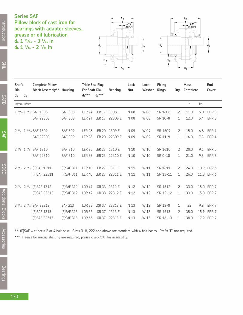
SNL
IntroductionSAFD
SAFSDCD
AdditionalBlocksAccessories
Bearings
170
Series SAFPillow block of cast iron forbearings with adapter sleeves,grease or oil lubricationda 1 15⁄16 - 3 1⁄16 indb 1 7⁄16 - 2 7⁄16 in
3H
1A
H 3
1A
adS
db
(.1875")4.76
A2A
adS
(.1875")
AA
4.76
3
bd
in/mm in/mm lb. kg.
Shaft Complete Pillow Triple Seal Ring Lock Lock Fixing Mass EndDia. Block Assembly** Housing For Shaft Dia. Bearing Nut Washer Rings Qty. Complete Coverda db da*** da***
** (F)SAF = either a 2 or 4 bolt base. Sizes 318, 222 and above are standard with 4 bolt bases. Prefix “F” not required.
*** If seals for metric shafting are required, please check SKF for availability.
1 15⁄16 1 7⁄16 SAF 1308 SAF 308 LER 24 LER 17 1308 E N 08 W 08 SR 1608 2 11.0 5.0 EPR 3
SAF 22308 SAF 308 LER 24 LER 17 22308 E N 08 W 08 SR 10-8 1 12.0 5.4 EPR 3
2 1⁄8 1 11⁄16 SAF 1309 SAF 309 LER 28 LER 20 1309 E N 09 W 09 SR 1609 2 15.0 6.8 EPR 4
SAF 22309 SAF 309 LER 28 LER 20 22309 E N 09 W 09 SR 11-9 1 16.0 7.3 EPR 4
2 3⁄8 1 7⁄8 SAF 1310 SAF 310 LER 35 LER 23 1310 E N 10 W 10 SR 1610 2 20.0 9.1 EPR 5
SAF 22310 SAF 310 LER 35 LER 23 22310 E N 10 W 10 SR 0-10 1 21.0 9.5 EPR 5
2 9⁄16 2 1⁄16 (F)SAF 1311 (F)SAF 311 LER 40 LER 27 1311 E N 11 W 11 SR 1611 2 24.0 10.9 EPR 6
(F)SAF 22311 (F)SAF 311 LER 40 LER 27 22311 E N 11 W 11 SR 13-11 1 26.0 11.8 EPR 6
2 7⁄8 2 1⁄4 (F)SAF 1312 (F)SAF 312 LOR 47 LOR 33 1312 E N 12 W 12 SR 1612 2 33.0 15.0 EPR 7
(F)SAF 22312 (F)SAF 312 LOR 47 LOR 33 22312 E N 12 W 12 SR 15-12 1 33.0 15.0 EPR 7
3 1⁄16 2 7⁄16 SAF 22213 SAF 213 LOR 55 LOR 37 22213 E N 13 W 13 SR 13-0 1 22 9.8 EPR 7
(F)SAF 1313 (F)SAF 313 LOR 55 LOR 37 1313 E N 13 W 13 SR 1613 2 35.0 15.9 EPR 7
(F)SAF 22313 (F)SAF 313 LOR 55 LOR 37 22313 E N 13 W 13 SR 16-13 1 38.0 17.2 EPR 7

SNL
Introduction
SAFD
SAF
SDCD
AdditionalBlocks
Accessories
Bearings
171
Pillow block housing series SAF
2H
JL
HG
1H
1J
FSF A S FA
Dimensions Static Oil Level H3 BoltHousing No. Roller Ball (req’d)
A1 A2 A3 H H1 H2 Bearing Bearing Jmax Jmin J1 L S G
in/mm
NOTE: Dimension "S" indicates the shaft length from centre of bearing to end of shaft for housings with one end closed.For tabulation of dimension "S" See bearing tables on pages 52 and 53.
For an example on how to order, please see page 169.
SAF 308 2 3⁄8 4 6 25⁄32 4 13⁄16 2 1⁄2 1 1 3⁄16 1 7⁄32 7 6 1⁄2 - 8 1⁄4 * (2) 1⁄2
60.3 101.6 172.2 122.2 63.50 25.4 30.2 31.0 177.8 165.1 - 209.6 * (2) 12
SAF 309 2 3⁄4 4 1⁄4 7 1⁄8 5 5⁄16 2 3⁄4 1 1 9⁄32 1 5⁄16 7 7⁄8 7 3⁄8 - 9 5⁄8 * (2) 5⁄8
69.8 108.0 181.0 134.9 69.80 25.4 32.5 33.3 200.0 187.3 - 244.5 * (2) 16
SAF 310 2 3⁄4 4 5⁄8 7 1⁄2 5 13⁄16 3 1 1⁄8 1 3⁄8 1 7⁄16 9 7 3⁄4 - 10 5⁄8 * (2) 5⁄8
69.8 117.5 190.5 147.6 76.20 28.6 34.9 36.5 228.6 196.8 - 269.9 * (2) 16
SAF 311 3 1⁄8 5 7 3⁄4 6 3⁄16 3 1⁄4 1 3⁄16 1 7⁄16 1 1⁄2 9 1⁄2 8 1⁄8 - 11 * (2) 5⁄8
79.4 127.0 196.9 157.2 82.60 30.2 36.5 38.1 241.3 206.4 - 279.4 * (2) 16
FSAF 311 3 1⁄8 5 7 3⁄4 6 3⁄16 3 1⁄4 1 3⁄16 1 7⁄16 1 1⁄2 9 1⁄2 8 1⁄8 2 11 * (4) 1⁄2
79.4 127.0 196.9 157.2 82.60 30.2 36.5 38.1 241.3 206.4 50.8 279.4 * (4) 12
SAF 312 3 1⁄8 5 1⁄4 8 1⁄8 6 3⁄8 3 1⁄4 1 3⁄16 1 5⁄16 1 3⁄8 9 5⁄8 8 5⁄8 - 11 1⁄4 * (2) 5⁄8
79.4 133.4 206.4 161.9 82.60 30.2 33.3 34.9 244.5 219.1 - 285.6 * (2) 16
FSAF 312 3 1⁄8 5 1⁄4 8 1⁄8 6 3⁄8 3 1⁄4 1 3⁄16 1 5⁄16 1 3⁄8 9 5⁄8 8 5⁄8 1 7⁄8 11 1⁄4 * (4) 1⁄2
79.4 133.4 206.4 161.9 82.60 30.2 33.3 34.9 244.5 219.1 47.6 285.6 * (4) 12
SAF 213 3 1⁄8 4 1⁄2 7 1⁄2 5 21⁄32 3 1 - 1 3⁄16 9 1⁄2 8 1⁄8 - 11 * (2) 5⁄8
79.4 114.3 190.5 143.67 76.2 25.4 - 30.2 241.3 206.38 - 279.4 * (2) 5⁄8
SAF 313 3 1⁄2 5 5⁄16 8 1⁄4 6 19⁄32 3 1⁄2 1 1⁄4 1 13⁄32 1 7⁄16 11 9 5⁄8 - 13 * (2) 3⁄4
88.9 134.9 209.6 167.5 88.90 31.8 35.7 36.5 279.4 244.5 - 330.2 * (2) 20
FSAF 313 3 1⁄2 5 5⁄16 8 1⁄4 6 19⁄32 3 1⁄2 1 1⁄4 1 13⁄32 1 7⁄16 11 9 5⁄8 2 1⁄8 13 * (4) 5⁄8
88.9 134.9 209.6 167.5 88.90 31.8 35.7 36.5 279.4 244.5 54 330.0 * (4) 16

SNL
IntroductionSAFD
SAFSDCD
AdditionalBlocksAccessories
Bearings
172
Series SAFPillow block of cast iron forbearings with adapter sleeves,grease or oil lubricationda 3 1⁄4 - 3 5⁄8 indb 2 5⁄8 - 3 in
3H
1A
H 3
1A
adS
db
(.1875")4.76
A2A
adS
(.1875")
AA
4.76
3
bd
in/mm in/mm lb. kg.
Shaft Complete Pillow Triple Seal Ring Lock Lock Fixing Mass EndDia. Block Assembly** Housing For Shaft Dia. Bearing Nut Washer Rings Qty. Complete Coverda db da*** da***
** (F)SAF = either a 2 or 4 bolt base. Sizes 318, 222 and above are standard with 4 bolt bases. Prefix “F” not required.
*** If seals for metric shafting are required, please check SKF for availability.
3 1⁄4 2 5⁄8 (F)SAF 1314 (F)SAF 314 LOR 64 LOR 43 1314 N 14 W 14 SR 1614 2 39.0 17.7 EPR 8
(F)SAF 22314 (F)SAF 314 LOR 64 LOR 43 22314 E N 14 W 14 SR 17-14 1 42.0 19.0 EPR 8
3 7⁄16 2 13⁄16 (F)SAF 22215 (F)SAF 215 LOR 79 LOR 46 22215 E AN 15 W 15 SR 15-0 1 27 12.2 EPR 8
(F)SAF 1315 (F)SAF 315 LOR 79 LOR 46 1315 AN 15 W 15 SR 1615 2 49.0 22.2 EPR 8
(F)SAF 22315 (F)SAF 315 LOR 79 LOR 46 22315 E AN 15 W 15 SR 18-15 1 53.0 24.0 EPR 8
3 5⁄8 3 (F)SAF 1316 (F)SAF 316 LOR 84 LOR 60 1316 AN 16 W 16 SR 1616 2 58.0 26.3 EPR 10
(F)SAF 22216 (F)SAF 216 LOR 82 LOR 54 22216 E AN 16 W 16 SR 16-13 1 35.0 15.9 EPR 9
SAFS 22216 SAFS 216 LOR 82 LOR 54 22216 E AN 16 W 16 SR 16-13 1 37.5 17.0 EPR 9
SAFS 22216-11 SAFS 216-11 LOR 82 LOR 54 22216 E AN 16 W 16 SR 16-13 1 37.5 17.0 EPR 9
(F)SAF 22316 (F)SAF 316 LOR 84 LOR 60 22316 E AN 16 W 16 SR 19-16 1 63.0 28.6 EPR 10

SNL
Introduction
SAFD
SAF
SDCD
AdditionalBlocks
Accessories
Bearings
173
Pillow block housing series SAF
2H
JL
HG
1H
1J
FSF A S FA
Dimensions Static Oil Level H3 BoltHousing No. Roller Ball (req’d)
A1 A2 A3 H H1 H2 Bearing Bearing Jmax Jmin J1 L S G
in/mm
NOTE: Dimension "S" indicates the shaft length from centre of bearing to end of shaft for housings with one end closed.For tabulation of dimension "S" See bearing tables on pages 52 and 53.
For an example on how to order, please see page 169.
SAF 314 3 1⁄2 5 3⁄8 8 9⁄32 7 3⁄8 3 3⁄4 1 1⁄4 1 15⁄32 1 9⁄16 11 9 7⁄8 - 13 * (2) 3⁄4
88.9 136.5 210.3 187.3 95.25 31.8 37.3 39.7 279.4 250.8 - 330.2 * (2) 20
FSAF 314 3 1⁄2 5 3⁄8 8 9⁄32 7 3⁄8 3 3⁄4 1 1⁄4 1 15⁄32 1 9⁄16 11 9 7⁄8 2 1⁄8 13 * (4) 5⁄8
88.9 136.5 210.3 187.3 95.25 31.8 37.3 39.7 279.4 250.8 54.0 330.2 * (4) 16
SAF 215 3 1⁄8 4 11⁄16 7 3⁄4 6 1⁄8 3 1⁄4 1 1⁄8 - 1 1⁄4 9 5⁄8 8 5⁄8 - 11 1⁄4 * (2) 5⁄8
79.4 119.1 196.9 155.6 82.55 28.6 - 31.8 244.5 219.1 - 285.8 * (2) 16
FSAF 215 3 1⁄8 4 11⁄16 7 3⁄4 6 1⁄8 3 1⁄4 1 1⁄8 - 1 1⁄4 9 5⁄8 8 5⁄8 1 7⁄8 11 1⁄4 * (4) 1⁄2
79.4 119.1 196.9 155.6 82.55 28.6 - 31.8 244.5 219.1 47.6 285.8 * (4) 12
SAF 315 3 7⁄8 5 7⁄8 9 7 9⁄16 4 1 5⁄8 1 19⁄32 1 11⁄16 11 5⁄8 10 3⁄8 - 13 3⁄4 * (2) 3⁄4
98.4 149.2 228.6 192.1 101.60 41.3 40.5 42.9 295.3 263.5 - 349.3 * (2) 20
FSAF 315 3 7⁄8 5 7⁄8 9 7 9⁄16 4 1 5⁄8 1 19⁄32 1 11⁄16 11 5⁄8 10 3⁄8 2 1⁄8 13 3⁄4 * (4) 5⁄8
98.4 149.2 228.6 192.1 101.60 41.3 40.5 42.9 295.3 263.5 54.0 349.3 * (4) 16
SAF 216 3 1⁄2 5 5⁄16 8 7⁄32 6 19⁄32 3 1⁄2 1 1⁄4 1 1⁄4 1 5⁄16 11 9 5⁄8 - 13 * (2) 3⁄4
88.9 134.9 208.8 167.5 88.90 31.8 31.8 33.3 279.4 244.5 - 330.2 * (2) 20
FSAF 216 3 1⁄2 5 5⁄16 8 7⁄32 6 19⁄32 3 1⁄2 1 1⁄4 1 1⁄4 1 5⁄16 11 9 5⁄8 2 1⁄8 13 * (4) 5⁄8
88.9 134.9 208.8 167.5 88.90 31.8 31.8 33.3 279.4 244.5 54.0 330.2 * (4) 16
SAFS 216 3 1⁄2 5 5⁄16 8 7⁄32 6 19⁄32 3 1⁄2 1 1⁄4 1 1⁄4 1 5⁄16 11 9 5⁄8 - 13 * (2) 3⁄4
88.9 134.9 208.8 167.5 88.90 31.8 31.8 33.3 279.4 244.5 - 330.2 * (2) 20
SAFS 216-11 3 1⁄2 5 5⁄16 8 7⁄32 6 19⁄32 3 1⁄2 1 1⁄4 1 1⁄4 1 5⁄16 11 9 5⁄8 2 1⁄8 13 * (4) 5⁄8
88.9 134.9 208.8 167.5 88.90 31.8 31.8 33.3 279.4 244.5 54.0 330.2 * (4) 16
SAF 316 3 7⁄8 6 1⁄2 9 3⁄16 8 1⁄4 4 1⁄4 1 5⁄16 1 11⁄16 1 13⁄16 12 5⁄8 10 5⁄8 - 14 1⁄4 * (2) 3⁄4
98.4 165.1 233.4 209.6 107.95 33.3 42.9 46.0 320.7 269.9 - 362.0 * (2) 20
FSAF 316 3 7⁄8 6 1⁄2 9 3/16 8 1⁄4 4 1⁄4 1 5⁄16 1 11⁄16 1 13⁄16 12 5⁄8 10 5⁄8 2 1⁄8 14 1⁄4 * (4) 5⁄8
98.4 165.1 233.4 209.6 107.95 33.3 42.9 46.0 320.7 269.9 54.0 362.0 * (4) 16

SNL
IntroductionSAFD
SAFSDCD
AdditionalBlocksAccessories
Bearings
174
Series SAFPillow block of cast iron forbearings with adapter sleeves,grease or oil lubricationda 3 15⁄16 - 4 1⁄8 indb 3 3⁄16 - 3 3⁄8 in
3H
1A
H 3
1A
adS
db
(.1875")4.76
A2A
adS
(.1875")
AA
4.76
3
bd
in/mm in/mm lb. kg.
Shaft Complete Pillow Triple Seal Ring Lock Lock Fixing Mass EndDia. Block Assembly** Housing For Shaft Dia. Bearing Nut Washer Rings Qty. Complete Coverda db da*** da***
** (F)SAF = either a 2 or 4 bolt base. Sizes 318, 222 and above are standard with 4 bolt bases. Prefix “F” not required.
*** If seals for metric shafting are required, please check SKF for availability.
3 15⁄16 3 3⁄16 (F)SAF 1317 (F)SAF 317 LOR 109 LOR 188 1317 AN 17 W 17 SR 1617 2 68.0 30.8 EPR 11
(F)SAF 22217 (F)SAF 217 LOR 89 LOR 63 22217 E AN 17 W 17 SR 17-14 1 38.0 17.2 EPR 9
SAFS 22217 SAFS 217 LOR 89 LOR 63 22217 E AN 17 W 17 SR 17-14 1 42.8 19.4 EPR 9
SAFS 22217-11 SAFS 217-11 LOR 89 LOR 63 22217 E AN 17 W 17 SR 17-14 1 42.8 19.4 EPR 9
(F)SAF 22317 (F)SAF 317 LOR 109 LOR 188 22317 E AN 17 W 17 SR 20-17 1 81.0 36.7 EPR 11
4 1⁄8 3 3⁄8 SAF 1318 SAF 318 LOR 112 LOR 191 1318 AN 18 W 18 SR 1618 2 75.0 34.0 EPR 11
(F)SAF 22218 (F)SAF 218 LOR 112 LOR 191 22218 E AN 18 W 18 SR 18-15 1 45.0 20.4 EPR 11
SAFS 22218 SAFS 218 LOR 112 LOR 191 22218 E AN 18 W 18 SR 18-15 1 48.0 21.8 EPR 11
SAFS 22218-11 SAFS 218-11 LOR 112 LOR 191 22218 E AN 18 W 18 SR 18-15 1 48.0 21.8 EPR 11
SAF 22318 SAF 318 LOR 112 LOR 191 22318 E AN 18 W 18 SR 21-18 1 94.0 42.6 EPR 11

SNL
Introduction
SAFD
SAF
SDCD
AdditionalBlocks
Accessories
Bearings
175
Pillow block housing series SAF
2H
JL
HG
1H
1J
FSF A S FA
Dimensions Static Oil Level H3 BoltHousing No. Roller Ball (req’d)
A1 A2 A3 H H1 H2 Bearing Bearing Jmax Jmin J1 L S G
in/mm
NOTE: Dimension "S" indicates the shaft length from centre of bearing to end of shaft for housings with one end closed.For tabulation of dimension "S" See bearing tables on pages 52 and 53.
For an example on how to order, please see page 169.
SAF 217 3 1⁄2 5 7 13⁄16 7 1⁄8 3 3⁄4 1 1⁄4 1 3⁄8 1 7⁄16 11 9 7⁄8 - 13 * (2) 3⁄4
88.9 127.0 198.4 181.0 95.25 31.8 34.9 36.5 279.4 250.8 - 330.2 * (2) 20
FSAF 217 3 1⁄2 5 7 13⁄16 7 1⁄8 3 3⁄4 1 1⁄4 1 3⁄8 1 7⁄16 11 9 7⁄8 2 1⁄8 13 * (4) 5⁄8
88.9 127.0 198.4 181.0 95.25 31.8 34.9 36.5 279.4 250.8 54.0 330.2 * (4) 16
SAFS 217 3 1⁄2 5 7 13⁄16 7 1⁄8 3 3⁄4 1 1⁄4 1 3⁄8 1 7⁄16 11 9 7⁄8 - 13 * (2) 3⁄4
88.9 127.0 198.4 181.0 95.25 31.8 34.9 36.5 279.4 250.8 - 330.2 * (2) 20
SAFS 217-11 3 1⁄2 5 7 13⁄16 7 1⁄8 3 3⁄4 1 1⁄4 1 3⁄8 1 7⁄16 11 9 7⁄8 2 1⁄8 13 * (4) 5⁄8
88.9 127.0 198.4 181.0 95.25 31.8 34.9 36.5 279.4 250.8 54.0 330.2 * (4) 16
SAF 317 4 3⁄8 6 3⁄4 9 9⁄32 8 3⁄4 4 1⁄2 1 3⁄4 1 3⁄4 1 7⁄8 13 1⁄8 11 5⁄8 - 15 1⁄4 * (2) 7⁄8
111.1 171.5 235.7 222.3 114.30 44.5 44.5 47.63 333.4 295.3 - 387.4 * (2) 22
FSAF 317 4 3⁄8 6 3⁄4 9 9⁄32 8 3⁄4 4 1⁄2 1 3⁄4 1 3⁄4 1 7⁄8 13 1⁄8 11 5⁄8 2 3⁄8 15 1⁄4 * (4) 3⁄4
111.1 171.5 235.7 222.3 114.30 44.5 44.5 47.63 333.4 295.3 60.3 387.4 * (4) 20
SAF 218 3 7⁄8 5 7⁄8 8 3⁄8 7 9⁄16 4 1 5⁄8 1 1⁄2 1 1⁄2 11 3⁄4 10 1⁄4 - 13 3⁄4 * (2) 3⁄4
98.4 149.2 212.7 192.1 101.60 41.3 38.1 38.1 298.5 260.4 - 349.3 * (2) 20
FSAF 218 3 7⁄8 5 3⁄4 8 3⁄8 7 9⁄16 4 1 5⁄8 1 1⁄2 1 1⁄2 11 3⁄4 10 1⁄4 2 1⁄8 13 3⁄4 * (4) 5⁄8
98.4 146.1 212.7 192.1 101.60 41.3 38.1 38.1 298.5 260.4 54.0 349.3 * (4) 16
SAFS 218 3 7⁄8 5 7⁄8 8 3⁄8 7 9⁄16 4 1 5⁄8 1 1⁄2 1 1⁄2 11 3⁄4 10 1⁄4 - 13 3⁄4 * (2) 3⁄4
98.4 149.2 212.7 192.1 101.60 41.3 38.1 38.1 298.5 260.4 - 349.3 * (2) 20
SAFS 218-11 3 7⁄8 5 3⁄4 8 3⁄8 7 9⁄16 4 1 5⁄8 1 1⁄2 1 1⁄2 11 3⁄4 10 1⁄4 2 1⁄8 13 3⁄4 * (4) 5⁄8
98.4 146.1 212.7 192.1 101.60 41.3 38.1 38.1 298.5 260.4 54.0 349.3 * (4) 16
SAF 318 4 3⁄8 6 7⁄8 9 1⁄2 9 3⁄16 4 3⁄4 2 1 7⁄8 2 13 1⁄2 12 2 1⁄4 15 1⁄2 * (4) 3⁄4
111.1 174.6 241.3 233.4 120.65 50.8 47.6 50.80 342.9 304.8 57.2 393.7 * (4) 20

SNL
IntroductionSAFD
SAFSDCD
AdditionalBlocksAccessories
Bearings
176
Series SAFPillow block of cast iron forbearings with adapter sleeves,grease or oil lubricationda 4 1⁄2 - 5 5⁄16 indb 3 13⁄16 - 4 9⁄16 in
3H
1A
H 3
1A
adS
db
(.1875")4.76
A2A
adS
(.1875")
AA
4.76
3
bd
in/mm in/mm lb. kg.
Shaft Complete Pillow Triple Seal Ring Lock Lock Fixing Mass EndDia. Block Assembly** Housing For Shaft Dia. Bearing Nut Washer Rings Qty. Complete Coverda db da*** da***
** (F)SAF = either a 2 or 4 bolt base. Sizes 318, 222 and above are standard with 4 bolt bases. Prefix “F” not required.
*** If seals for metric shafting are required, please check SKF for availability.
4 1⁄2 3 13⁄16 SAF 1320 SAF 320 LOR 118 LOR 106 1320 AN 20 W 20 SR 1620 2 93.0 42.2 EPR 12
(F)SAF 22220 (F)SAF 220 LOR 118 LOR 106 22220 E AN 20 W 20 SR 20-17 1 71.0 32.2 EPR 12
SAFS 22220 SAFS 220 LOR 118 LOR 106 22220 E AN 20 W 20 SR 20-17 1 75.9 34.4 EPR 12
SAFS 22220-11 SAFS 220-11 LOR 118 LOR 106 22220 E AN 20 W 20 SR 20-17 1 75.9 34.4 EPR 12
SAF 22320 SAF 320 LOR 118 LOR 106 22320 E AN 20 W 20 SR 24-20 1 120 54.4 EPR 12
4 7⁄8 4 3⁄16 SAF 1322 SAF 322 LOR 121 LOR 113 1322 AN 22 W 22 SR 1622 2 125 56.7 EPR 14
SAF 22222 SAF 222 LOR 121 LOR 113 22222 E AN 22 W 22 SR 22-19 1 94.0 42.6 EPR 14
SAFS 22222 SAFS 222 LOR 121 LOR 113 22222 E AN 22 W 22 SR 22-19 1 100 45.6 EPR 14
SAF 22322 SAF 322 LOR 121 LOR 113 22322 E AN 22 W 22 SR 0-22 1 160 72.6 EPR 14
5 5⁄16 4 9⁄16 SAF 22224 SAF 224 LOR 127 LOR 119 22224 E AN 24 W 24 SR 24-20 1 110 49.9 EPR 15
SAFS 22224 SAFS 224 LOR 127 LOR 119 22224 E AN 24 W 24 SR 24-20 1 118 53.4 EPR 15
SAF 22324 SAF 324 LOR 127 LOR 119 22324CC/W33 AN 24 W 24 SR 0-24 1 215 97.5 EPR 15

SNL
Introduction
SAFD
SAF
SDCD
AdditionalBlocks
Accessories
Bearings
177
Pillow block housing series SAF
2H
JL
HG
1H
1J
FSF A S FA
Dimensions Static Oil BoltHousing No. Level (req’d)
A1 A2 A3 H H1 H2 H3 Jmax Jmin J1 L S G
in/mm
NOTE: Dimension "S" indicates the shaft length from centre of bearing to end of shaft for housings with one end closed.For tabulation of dimension "S" See bearing tables on pages 52 and 53.
For an example on how to order, please see page 169.
SAF 220 4 3⁄8 6 1⁄8 8 5⁄8 8 15⁄32 4 1⁄2 1 3⁄4 1 21⁄32 13 1⁄8 11 5⁄8 - 15 1⁄4 * (2) 7⁄8
111.1 155.6 219.1 215.1 114.30 44.5 42.1 333.4 295.3 - 387.4 * (2) 22
FSAF 220 4 3⁄8 6 1⁄8 8 5⁄8 8 15⁄32 4 1⁄2 1 3⁄4 1 21⁄32 13 1⁄8 11 5⁄8 2 3⁄8 15 1⁄4 * (4) 3⁄4
111.1 155.6 219.1 215.1 114.30 44.5 42.1 333.4 295.3 60.3 387.4 * (4) 20
SAFS 220 4 3⁄8 6 1⁄8 8 5⁄8 8 15⁄32 4 1⁄2 1 3⁄4 1 21⁄32 13 1⁄8 11 5⁄8 2 3⁄8 15 1⁄4 * (2) 7⁄8
111.1 155.6 219.1 215.1 114.30 44.5 42.1 333.4 295.3 60.3 387.4 * (2) 22
SAFS 220-11 4 3⁄8 6 1⁄8 8 5⁄8 8 15⁄32 4 1⁄2 1 3⁄4 1 21⁄32 13 1⁄8 11 5⁄8 2 3⁄8 15 1⁄4 * (4) 3⁄4
111.1 155.6 219.1 215.1 114.30 44.5 42.1 333.4 295.3 60.3 387.4 * (4) 20
SAF 320 4 3⁄4 7 3⁄8 10 10 3⁄16 5 1⁄4 2 1⁄8 2 1⁄32 14 1⁄2 13 1⁄4 2 3⁄4 16 1⁄2 * (4) 3⁄4
120.7 187.3 254.0 258.8 133.35 54.0 51.6 368.3 336.6 69.9 419.1 * (4) 20
SAF 222 4 3⁄4 6 1⁄2 9 1⁄8 9 27⁄32 4 15⁄16 2 1 25⁄32 14 1⁄2 12 5⁄8 2 3⁄4 16 1⁄2 * (4) 3⁄4
120.7 165.1 231.8 250.0 125.41 50.8 45.2 368.3 320.7 69.9 419.1 * (4) 20
SAFS 222 4 3⁄4 6 1⁄2 9 1⁄8 9 27⁄32 4 15⁄16 2 1 25⁄32 14 1⁄2 12 5⁄8 2 3⁄4 16 1⁄2 * (4) 3⁄4
120.65 165.10 231.78 250.03 125.41 50.80 45.24 368.30 320.68 69.9 419.10 * (4) 20
SAF 322 5 1⁄4 8 1⁄8 10 3⁄4 11 5⁄16 6 2 3⁄8 2 13⁄32 16 14 5⁄8 3 1⁄4 18 3⁄8 * (4) 7⁄8
133.4 206.4 273.1 287.3 152.40 60.3 61.1 406.4 371.5 82.6 466.7 * (4) 22
SAF 224 4 3⁄4 7 3⁄8 10 10 1⁄8 5 1⁄4 2 1⁄8 1 27⁄32 14 1⁄2 13 1⁄4 2 3⁄4 16 1⁄2 * (4) 3⁄4
120.7 187.3 254.0 257.2 133.35 54.0 46.8 368.3 336.6 69.9 419.1 * (4) 20
SAFS 224 4 3⁄4 7 3⁄8 10 10 1⁄8 5 1⁄4 2 1⁄8 1 27⁄32 14 1⁄2 13 1⁄4 2 3⁄4 16 1⁄2 * (4) 3⁄4
120.7 187.3 254.0 257.2 133.35 54.0 46.8 368.3 336.6 69.9 419.1 * (4) 20
SAF 324 6 1⁄4 8 3⁄8 11 12 1⁄2 6 5⁄16 2 1⁄2 2 3⁄8 18 1⁄4 17 3 3⁄4 21 1⁄4 * (4) 1
158.75 212.7 279.4 317.5 160.34 63.5 60.325 463.55 431.8 95.3 539.75 * (4) 24
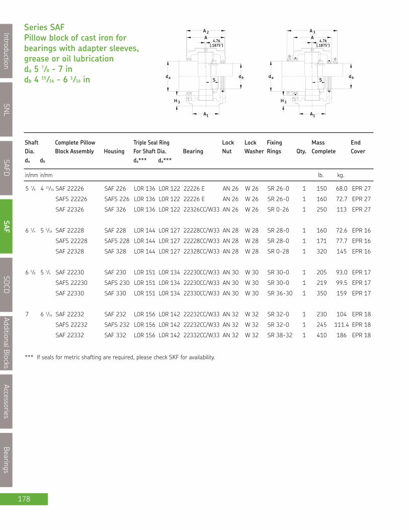
SNL
IntroductionSAFD
SAFSDCD
AdditionalBlocksAccessories
Bearings
178
Series SAFPillow block of cast iron forbearings with adapter sleeves,grease or oil lubricationda 5 7⁄8 - 7 indb 4 15⁄16 - 6 1⁄16 in
3H
1A
H 3
1A
adS
db
(.1875")4.76
A2A
adS
(.1875")
AA
4.76
3
bd
in/mm in/mm lb. kg.
Shaft Complete Pillow Triple Seal Ring Lock Lock Fixing Mass EndDia. Block Assembly Housing For Shaft Dia. Bearing Nut Washer Rings Qty. Complete Coverda db da*** da***
*** If seals for metric shafting are required, please check SKF for availability.
5 7⁄8 4 15⁄16 SAF 22226 SAF 226 LOR 136 LOR 122 22226 E AN 26 W 26 SR 26-0 1 150 68.0 EPR 27
SAFS 22226 SAFS 226 LOR 136 LOR 122 22226 E AN 26 W 26 SR 26-0 1 160 72.7 EPR 27
SAF 22326 SAF 326 LOR 136 LOR 122 22326CC/W33 AN 26 W 26 SR 0-26 1 250 113 EPR 27
6 1⁄4 5 5⁄16 SAF 22228 SAF 228 LOR 144 LOR 127 22228CC/W33 AN 28 W 28 SR 28-0 1 160 72.6 EPR 16
SAFS 22228 SAFS 228 LOR 144 LOR 127 22228CC/W33 AN 28 W 28 SR 28-0 1 171 77.7 EPR 16
SAF 22328 SAF 328 LOR 144 LOR 127 22328CC/W33 AN 28 W 28 SR 0-28 1 320 145 EPR 16
6 5⁄8 5 3⁄4 SAF 22230 SAF 230 LOR 151 LOR 134 22230CC/W33 AN 30 W 30 SR 30-0 1 205 93.0 EPR 17
SAFS 22230 SAFS 230 LOR 151 LOR 134 22230CC/W33 AN 30 W 30 SR 30-0 1 219 99.5 EPR 17
SAF 22330 SAF 330 LOR 151 LOR 134 22330CC/W33 AN 30 W 30 SR 36-30 1 350 159 EPR 17
7 6 1⁄16 SAF 22232 SAF 232 LOR 156 LOR 142 22232CC/W33 AN 32 W 32 SR 32-0 1 230 104 EPR 18
SAFS 22232 SAFS 232 LOR 156 LOR 142 22232CC/W33 AN 32 W 32 SR 32-0 1 245 111.4 EPR 18
SAF 22332 SAF 332 LOR 156 LOR 142 22332CC/W33 AN 32 W 32 SR 38-32 1 410 186 EPR 18

SNL
Introduction
SAFD
SAF
SDCD
AdditionalBlocks
Accessories
Bearings
Pillow block housing series SAF
2H
JL
HG
1H
1J
FSF A S FA
Dimensions Static Oil BoltHousing No. Level (req’d)
A1 A2 A3 H H1 H2 H3 Jmax Jmin J1 L S G
in/mm
NOTE: Dimension "S" indicates the shaft length from centre of bearing to end of shaft for housings with one end closed.For tabulation of dimension "S" See bearing tables on pages 52 and 53.
For an example on how to order, please see page 169.179
SAF 226 5 1⁄4 7 5⁄8 10 5⁄8 11 5⁄16 6 2 3⁄8 2 3⁄8 16 14 5⁄8 3 1⁄4 18 3⁄8 * (4) 7⁄8
133.4 193.7 269.9 287.3 152.40 60.3 60.3 406.4 371.5 82.6 466.7 * (4) 22
SAFS 226 5 1⁄4 7 5⁄8 10 5⁄8 11 5⁄16 6 2 3⁄8 2 3⁄8 16 14 5⁄8 3 1⁄4 18 3⁄8 * (4) 7⁄8
133.4 193.7 269.9 287.3 152.40 60.3 60.3 406.4 371.5 82.6 466.7 * (4) 22
SAF 326 6 1⁄4 8 3⁄4 11 3⁄8 13 5⁄16 6 11⁄16 2 5⁄8 2 7⁄16 19 1⁄4 17 3⁄8 3 3⁄4 22 * (4) 1
158.8 222.3 288.9 338.1 169.86 66.7 61.9 489.0 441.3 95.3 558.8 * (4) 24
SAF 228 5 7⁄8 7 5⁄8 10 1⁄4 12 1⁄32 6 2 3⁄8 2 1⁄32 17 3⁄8 15 5⁄8 3 3⁄8 20 1⁄8 * (4) 1
149.2 193.7 260.4 305.6 152.40 60.3 51.6 441.3 396.9 85.7 511.2 * (4) 24
SAFS 228 5 7⁄8 7 5⁄8 10 1⁄4 12 1⁄32 6 2 3⁄8 2 1⁄32 17 3⁄8 15 5⁄8 3 3⁄8 20 1⁄8 * (4) 1
149.2 193.7 260.4 305.6 152.40 60.3 51.6 441.3 396.9 85.7 511.2 * (4) 24
SAF 328 6 3⁄4 9 3⁄8 12 1⁄8 14 3⁄16 7 1⁄16 2 3⁄4 2 9⁄16 21 5⁄8 19 3⁄8 4 1⁄4 24 3⁄4 * (4) 1
171.5 238.1 308.0 360.4 179.39 69.9 65.1 549.3 492.1 108.0 628.7 * (4) 24
SAF 230 6 1⁄4 8 3⁄8 11 12 1⁄2 6 5⁄16 2 1⁄2 2 18 1⁄4 17 3 3⁄4 21 1⁄4 * (4) 1
158.8 212.7 279.4 317.5 160.34 63.5 50.8 463.6 431.8 95.3 539.8 * (4) 24
SAFS 230 6 1⁄4 8 3⁄8 11 12 1⁄2 6 5⁄16 2 1⁄2 2 18 1⁄4 17 3 3⁄4 21 1⁄4 * (4) 1
158.8 212.7 279.4 317.5 160.34 63.5 50.8 463.6 431.8 95.3 539.8 * (4) 24
SAF 330 7 1⁄8 9 3⁄4 12 1⁄2 14 7⁄8 7 1⁄2 3 2 5⁄8 23 5⁄8 20 7⁄8 4 5⁄8 26 3⁄4 * (4) 1
181.0 247.7 317.5 377.8 190.50 76.2 66.7 600.1 530.2 117.5 679.5 * (4) 24
SAF 232 6 1⁄4 8 3⁄4 11 3⁄8 13 5⁄16 6 11⁄16 2 5⁄8 2 1⁄16 19 1⁄4 17 3⁄8 3 3⁄4 22 * (4) 1
158.8 222.3 288.9 338.1 169.86 66.7 52.4 489.0 441.3 95.3 558.8 * (4) 24
SAFS 232 6 1⁄4 8 3⁄4 11 3⁄8 13 5⁄16 6 11⁄16 2 5⁄8 2 1⁄16 19 1⁄4 17 3⁄8 3 3⁄4 22 * (4) 1
158.8 222.3 288.9 338.1 169.86 66.7 52.4 489.0 441.3 95.3 558.8 * (4) 24
SAF 332 7 1⁄2 10 3⁄4 13 3⁄8 15 11⁄16 7 7⁄8 3 1⁄8 2 11⁄16 24 3⁄8 21 5⁄8 4 1⁄2 28 * (4) 1 1⁄4
190.5 273.1 339.7 398.5 200.03 79.4 68.3 619.1 549.3 114.3 711.2 * (4) 30
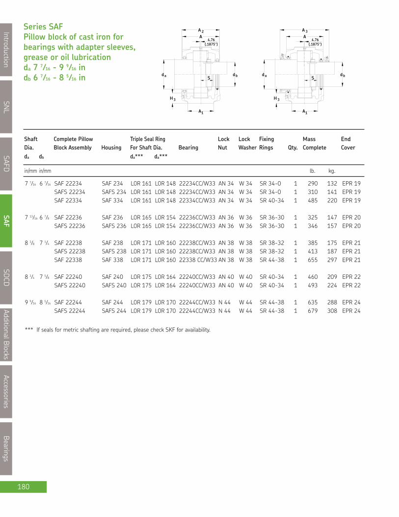
SNL
IntroductionSAFD
SAFSDCD
AdditionalBlocksAccessories
Bearings
180
Series SAFPillow block of cast iron forbearings with adapter sleeves,grease or oil lubricationda 7 7⁄16 - 9 9⁄16 indb 6 7⁄16 - 8 5⁄16 in
3H
1A
H 3
1A
adS
db
(.1875")4.76
A2A
adS
(.1875")
AA
4.76
3
bd
in/mm in/mm lb. kg.
Shaft Complete Pillow Triple Seal Ring Lock Lock Fixing Mass EndDia. Block Assembly Housing For Shaft Dia. Bearing Nut Washer Rings Qty. Complete Coverda db da*** da***
*** If seals for metric shafting are required, please check SKF for availability.
7 7⁄16 6 7⁄16 SAF 22234 SAF 234 LOR 161 LOR 148 22234CC/W33 AN 34 W 34 SR 34-0 1 290 132 EPR 19SAFS 22234 SAFS 234 LOR 161 LOR 148 22234CC/W33 AN 34 W 34 SR 34-0 1 310 141 EPR 19SAF 22334 SAF 334 LOR 161 LOR 148 22334CC/W33 AN 34 W 34 SR 40-34 1 485 220 EPR 19
7 13⁄16 6 7⁄8 SAF 22236 SAF 236 LOR 165 LOR 154 22236CC/W33 AN 36 W 36 SR 36-30 1 325 147 EPR 20SAFS 22236 SAFS 236 LOR 165 LOR 154 22236CC/W33 AN 36 W 36 SR 36-30 1 346 157 EPR 20
8 3⁄8 7 1⁄4 SAF 22238 SAF 238 LOR 171 LOR 160 22238CC/W33 AN 38 W 38 SR 38-32 1 385 175 EPR 21SAFS 22238 SAFS 238 LOR 171 LOR 160 22238CC/W33 AN 38 W 38 SR 38-32 1 413 187 EPR 21SAF 22338 SAF 338 LOR 171 LOR 160 22338 CC/W33 AN 38 W 38 SR 44-38 1 655 297 EPR 21
8 3⁄4 7 5⁄8 SAF 22240 SAF 240 LOR 175 LOR 164 22240CC/W33 AN 40 W 40 SR 40-34 1 460 209 EPR 22SAFS 22240 SAFS 240 LOR 175 LOR 164 22240CC/W33 AN 40 W 40 SR 40-34 1 493 224 EPR 22
9 9⁄16 8 5⁄16 SAF 22244 SAF 244 LOR 179 LOR 170 22244CC/W33 N 44 W 44 SR 44-38 1 635 288 EPR 24SAFS 22244 SAFS 244 LOR 179 LOR 170 22244CC/W33 N 44 W 44 SR 44-38 1 679 308 EPR 24

SNL
Introduction
SAFD
SAF
SDCD
AdditionalBlocks
Accessories
Bearings
181
Pillow block housing series SAF
2H
JL
HG
1H
1J
FSF A S FA
Dimensions Static Oil BoltHousing No. Level (req’d)
A1 A2 A3 H H1 H2 H3 Jmax Jmin J1 L S G
in/mm
NOTE: Dimension "S" indicates the shaft length from centre of bearing to end of shaft for housings with one end closed.For tabulation of dimension "S" See bearing tables on pages 52 and 53.
For an example on how to order, please see page 169.
SAF 234 6 3⁄4 9 5⁄8 12 3⁄8 14 3⁄16 7 1⁄16 2 3⁄4 2 5⁄32 21 5⁄8 19 3⁄8 4 1⁄4 24 3⁄4 * (4) 1171.45 244.48 314.33 360.36 179.39 69.85 54.77 549.28 492.13 107.95 628.65 * (4) 24
SAFS 234 6 3⁄4 9 5⁄8 12 3⁄8 14 3⁄16 7 1⁄16 2 3⁄4 2 5⁄32 21 5⁄8 19 3⁄8 4 1⁄4 24 3⁄4 * (4) 1171.45 244.48 314.33 360.36 179.39 69.85 54.77 549.28 492.13 107.95 628.65 * (4) 24
SAF 334 8 11 1⁄4 14 1⁄8 16 1⁄2 8 1⁄4 3 3⁄8 2 3⁄4 25 22 1⁄2 5 29 1⁄2 * (4) 1 1⁄4203.20 285.75 358.78 419.10 209.55 85.73 69.85 635.00 571.50 127.00 749.30 * (4) 30
SAF 236 7 1⁄8 10 12 1⁄2 14 7⁄8 7 1⁄2 3 2 3⁄8 23 5⁄8 20 7⁄8 4 5⁄8 26 3⁄4 * (4) 1180.98 254.00 317.50 377.83 190.50 76.20 60.33 600.08 530.23 117.48 679.45 * (4) 24
SAFS 236 7 1⁄8 10 12 1⁄2 14 7⁄8 7 1⁄2 3 2 3⁄8 23 5⁄8 20 7⁄8 4 5⁄8 26 3⁄4 * (4) 1180.98 254.00 317.50 377.83 190.50 76.20 60.33 600.08 530.23 117.48 679.45 * (4) 24
SAF 238 7 1⁄2 10 3⁄4 14 7⁄8 15 11⁄16 7 7⁄8 3 1⁄8 2 7⁄16 24 3⁄8 21 5⁄8 4 1⁄2 28 * (4) 1 1⁄4190.50 273.05 377.83 398.46 200.03 79.38 61.91 619.13 549.28 114.30 711.20 * (4) 30
SAFS 238 7 1⁄2 10 3⁄4 14 7⁄8 15 11⁄16 7 7⁄8 3 1⁄8 2 7⁄16 24 3⁄8 21 5⁄8 4 1⁄2 28 * (4) 1 1⁄4190.50 273.05 377.83 398.46 200.03 79.38 61.91 619.13 549.28 114.30 711.20 * (4) 30
SAF 338 8 3⁄4 12 16 1⁄8 18 5⁄8 9 1⁄2 3 3⁄4 3 3⁄8 27 7⁄8 24 3⁄4 5 1⁄4 32 3⁄4 * (4) 1 1⁄2222.25 304.80 409.58 473.08 241.30 95.25 85.73 708.03 628.65 133.35 831.85 * (4) 36
SAF 240 8 11 1⁄4 15 3⁄8 16 1⁄2 8 1⁄4 3 3⁄8 2 15⁄32 25 22 1⁄2 5 29 1⁄2 * (4) 1 1⁄4203.20 285.75 390.53 419.10 209.55 85.73 62.71 635.00 571.50 127.00 749.30 * (4) 30
SAFS 240 8 11 1⁄4 15 3⁄8 16 1⁄2 8 1⁄4 3 3⁄8 2 15⁄32 25 22 1⁄2 5 29 1⁄2 * (4) 1 1⁄4203.20 285.75 390.53 419.10 209.55 85.73 62.71 635.00 571.50 127.00 749.30 * (4) 30
SAF 244 8 3⁄4 12 16 1⁄8 18 5⁄8 9 1⁄2 3 3⁄4 3 1⁄8 27 7⁄8 24 3⁄4 5 1⁄4 32 3⁄4 * (4) 1 1⁄2222.25 304.80 409.58 473.08 241.30 95.25 79.38 708.03 628.65 133.35 831.85 * (4) 36
SAFS 244 8 3⁄4 12 16 1⁄8 18 5⁄8 9 1⁄2 3 3⁄4 3 1⁄8 27 7⁄8 24 3⁄4 5 1⁄4 32 3⁄4 * (4) 1 1⁄2222.25 304.80 409.58 473.08 241.30 95.25 79.38 708.03 628.65 133.35 831.85 * (4) 36

SNL
IntroductionSAFD
SAFSDCD
AdditionalBlocksAccessories
Bearings
182
Note : Pillow Block SDCD must be modified to MC14 when using TSDC-D & E type seals.
Ductile Iron ASTM A536 grade 65-45-12
230CCK, 231CCK, 232CCK
MATERIAL
BEARING SERIESUSED
STANDARD SEALS
OPTIONAL SEALS
LUBRICATIONPILLOW BLOCK
SHAFT SIZE RANGE
PILLOW BLOCK SIZE3036 - 3088 (adapter mounting)
5-15/16" to 16.142" 150mm to 410mm
Grease or Oil
SDCD, SDCD/MC14
3134 - 3188 (adapter mounting)3234 - 3280 (adapter mounting)
TSDC-D TSDC-E
TS
Pillow BlockHousings

SNL
Introduction
SAFD
SAF
SDCD
AdditionalB
locks
Accessories
Bearings
183
SDCD Adapter Mounting
KD MC14/67⁄16
Base
MaterialDT
Size
Adapter mount
Modification
Shaft size
Suffixes0DEHY
Four bolt base is standard
Ductile iron (standard)Cast steel
Bearing bore 36 = 180mm
(For tactonite seals)
6 7⁄16”
Standard "TS" triple ring sealTaconite service seal of TSDC design, c/w V ringTaconite service seal of TSDC design, no V ringHeld unit, c/w fixing ringsOne end closed with end cover or end plug
How to order: (Example)
When you order one SDCD 23236KMC 14/ 6 7⁄16 D you will receive a package containing the following:
1 - Pillow block housing SDCD 3236/MC14: Cap drilled, tapped and plugged with three holes, (1) 1⁄4" NPT at the centreand two 1⁄8" NPT holes for the seals. Button head grease nipples are included.
2 - Taconite service seals TSDC 36/ 6 7⁄16 D.1 - Bearing SKF 23236 CCK/W33.1 - Adapter sleeve HA 2336 for shaft diameter 6 7⁄16".
If a "HELD or FIXED" unit is required, add the suffix "H" and 2 fixing rings (locating or stabilizing) FRB 10/320 will be included.Only one bearing per shaft should be held. CARB® bearings displace internally and are therefore always "FREE".However, they must always be located in the housing with fixing rings as does a true "FIXED" bearing.If a unit with one end closed is required, add the suffix "Y" and one ASDC 36 end cover will be included.
SDC D23236
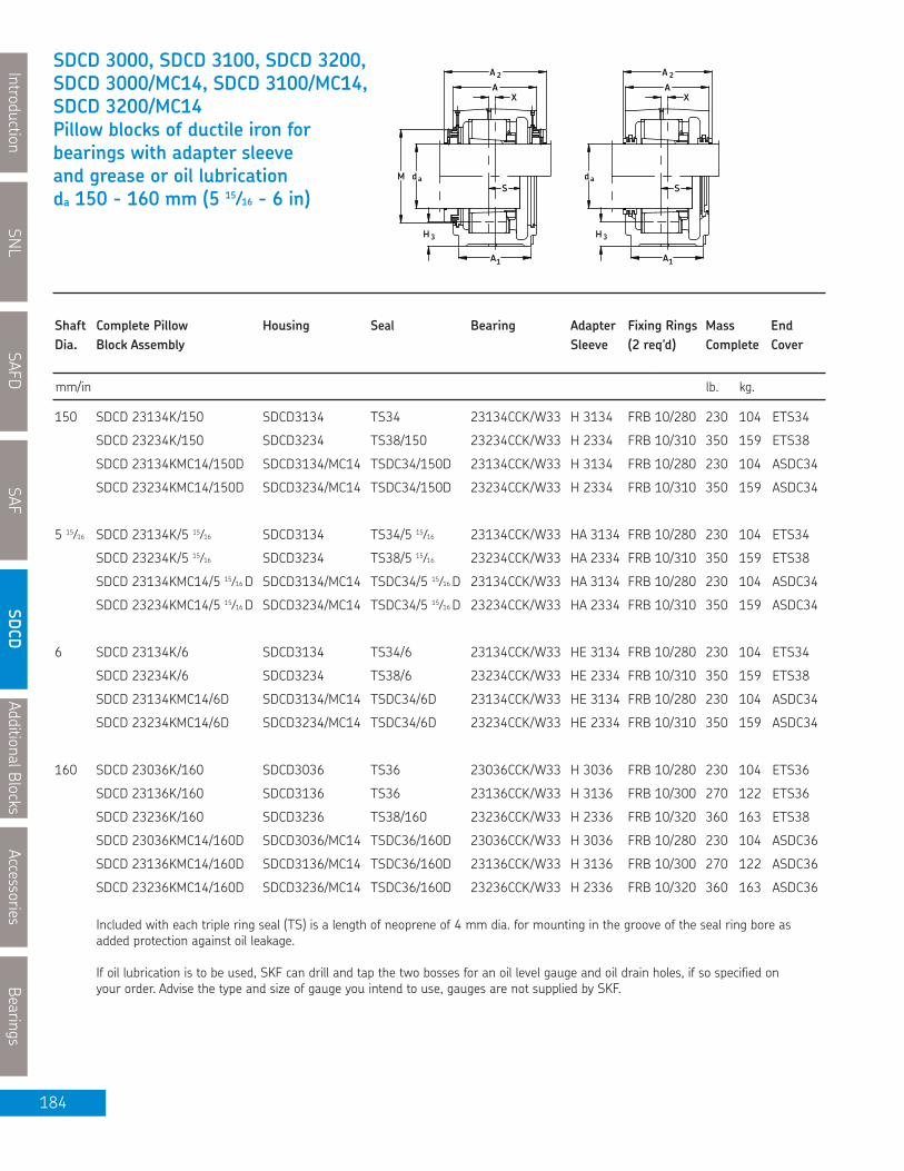
SNL
IntroductionSAFD
SAFSDCD
AdditionalBlocksAccessories
Bearings
184
3H
A1
3H
A1
daMS
A
A 2
daS
X XA
A 2
mm/in lb. kg.
Shaft Complete Pillow Housing Seal Bearing Adapter Fixing Rings Mass EndDia. Block Assembly Sleeve (2 req’d) Complete Coverda Shaft Dia da Shaft Dia da Design.
150 SDCD 23134K/150 SDCD3134 TS34 23134CCK/W33 H 3134 FRB 10/280 230 104 ETS34
SDCD 23234K/150 SDCD3234 TS38/150 23234CCK/W33 H 2334 FRB 10/310 350 159 ETS38
SDCD 23134KMC14/150D SDCD3134/MC14 TSDC34/150D 23134CCK/W33 H 3134 FRB 10/280 230 104 ASDC34
SDCD 23234KMC14/150D SDCD3234/MC14 TSDC34/150D 23234CCK/W33 H 2334 FRB 10/310 350 159 ASDC34
5 15⁄16 SDCD 23134K/5 15⁄16 SDCD3134 TS34/5 15⁄16 23134CCK/W33 HA 3134 FRB 10/280 230 104 ETS34
SDCD 23234K/5 15⁄16 SDCD3234 TS38/5 15⁄16 23234CCK/W33 HA 2334 FRB 10/310 350 159 ETS38
SDCD 23134KMC14/5 15⁄16 D SDCD3134/MC14 TSDC34/5 15⁄16 D 23134CCK/W33 HA 3134 FRB 10/280 230 104 ASDC34
SDCD 23234KMC14/5 15⁄16 D SDCD3234/MC14 TSDC34/5 15⁄16 D 23234CCK/W33 HA 2334 FRB 10/310 350 159 ASDC34
6 SDCD 23134K/6 SDCD3134 TS34/6 23134CCK/W33 HE 3134 FRB 10/280 230 104 ETS34
SDCD 23234K/6 SDCD3234 TS38/6 23234CCK/W33 HE 2334 FRB 10/310 350 159 ETS38
SDCD 23134KMC14/6D SDCD3134/MC14 TSDC34/6D 23134CCK/W33 HE 3134 FRB 10/280 230 104 ASDC34
SDCD 23234KMC14/6D SDCD3234/MC14 TSDC34/6D 23234CCK/W33 HE 2334 FRB 10/310 350 159 ASDC34
Included with each triple ring seal (TS) is a length of neoprene of 4 mm dia. for mounting in the groove of the seal ring bore asadded protection against oil leakage.
If oil lubrication is to be used, SKF can drill and tap the two bosses for an oil level gauge and oil drain holes, if so specified onyour order. Advise the type and size of gauge you intend to use, gauges are not supplied by SKF.
160 SDCD 23036K/160 SDCD3036 TS36 23036CCK/W33 H 3036 FRB 10/280 230 104 ETS36
SDCD 23136K/160 SDCD3136 TS36 23136CCK/W33 H 3136 FRB 10/300 270 122 ETS36
SDCD 23236K/160 SDCD3236 TS38/160 23236CCK/W33 H 2336 FRB 10/320 360 163 ETS38
SDCD 23036KMC14/160D SDCD3036/MC14 TSDC36/160D 23036CCK/W33 H 3036 FRB 10/280 230 104 ASDC36
SDCD 23136KMC14/160D SDCD3136/MC14 TSDC36/160D 23136CCK/W33 H 3136 FRB 10/300 270 122 ASDC36
SDCD 23236KMC14/160D SDCD3236/MC14 TSDC36/160D 23236CCK/W33 H 2336 FRB 10/320 360 163 ASDC36
SDCD 3000, SDCD 3100, SDCD 3200,SDCD 3000/MC14, SDCD 3100/MC14,SDCD 3200/MC14Pillow blocks of ductile iron forbearings with adapter sleeveand grease or oil lubricationda 150 - 160 mm (5 15⁄16 - 6 in)

AdditionalB
locks
Accessories
Bearings
185
Pillow block housing series SDCD, SDCD/MC14
H 3
L
H
1A
2
J
1HG
daS
H
2AA
J1
MADEIN CANADA
Housing No. Dimensions Static Oil Level Bolts(4 req’d)
A A1 A2 X* H H1 H2 H3max H3min L Jmax Jmin J1 M S** G
in/mm
NOTE: * Dimension "X" indicates the centreline of the bearing seat in the housing is offset this distance in relation to thecentreline of the housing, away from the oil sump. When oil lubrication is used the static oil level H3 must be maintained.
** Dimension "S" indicates the shaft length from the bearing centre to the end of the shaft on the locknut side, whichallows adequate clearance between the shaft end and the end cover. Normally the shaft need not be any longer thanrequired for the adapter sleeve.
SDCD 3134 9 1⁄16 7 1⁄8 9 5⁄8 9⁄16 13 3⁄16 6.693 2 3⁄4 2 1⁄4 2 3⁄32 20 1⁄16 17 1⁄8 16 11⁄16 3 15⁄16 - 3 5⁄32 1
230 180 246 14 335 170 70 57 53 510 436 424 100 - 79.5 24
SDCD 3234 10 1⁄4 8 1⁄4 10 5⁄8 13⁄32 14 3⁄4 7.480 3 3⁄16 2 23⁄32 2 1⁄2 22 1⁄16 19 1⁄8 18 5⁄8 4 3⁄4 - 3 9⁄16 1
260 210 270 10 375 190 80 69 64 560 486 474 120 - 90.5 24
SDCD 3134/MC14 9 1⁄16 7 1⁄8 10 13⁄16 9⁄16 13 3⁄16 6.693 2 3⁄4 - - 20 1⁄16 17 1⁄8 16 11⁄16 3 15⁄16 8 5⁄8 3 5⁄32 1
230 180 275 14 335 170 70 - - 510 436 424 100 219 79.5 24
SDCD 3234/MC14 10 1⁄4 8 1⁄4 12 13⁄32 14 3⁄4 7.480 3 3⁄16 - - 22 1⁄16 19 1⁄8 18 5⁄8 4 3⁄4 8 5⁄8 3 9⁄16 1
260 210 305 10 375 190 80 - - 560 486 474 120 219 90.5 24
SNL
Introduction
SAFD
SAF
SDCD
For an example on how to order please see page 183.
SDCD 3036 9 1⁄16 7 1⁄8 9 7⁄16 - 13 3⁄16 6.693 2 3⁄4 2 1⁄8 2 20 1⁄16 17 3⁄16 16 11⁄16 3 15⁄16 - 2 7⁄8 1
230 180 240 - 335 170 70 54 51 510 436 424 100 - 73 24
SDCD 3136 9 7⁄16 7 1⁄2 9 7⁄8 19⁄32 14 7.087 3 2 5⁄16 2 3⁄16 20 7⁄8 17 15⁄16 17 1⁄2 4 3⁄8 - 3 11⁄32 1
240 190 250 15 355 180 75 59 55 530 456 444 110 - 84.5 24
SDCD 3236 10 1⁄4 8 1⁄4 10 5⁄8 9⁄16 14 3⁄4 7.480 3 3⁄16 2 1⁄2 2 5⁄16 22 1⁄16 19 1⁄8 18 5⁄8 4 3⁄4 - 3 21⁄32 1
260 210 270 14 375 190 80 64 59 560 486 474 120 - 92.5 24
SDCD 3036/MC14 9 1⁄16 7 1⁄8 10 13⁄16 - 13 3⁄16 6.693 2 3⁄4 - - 20 1⁄16 17 3⁄16 16 11⁄16 3 15⁄16 9 1⁄16 2 7⁄8 1
230 180 275 - 335 170 70 - - 510 436 424 100 230 73 24
SDCD 3136/MC14 9 7⁄16 7 1⁄2 11 3⁄16 19⁄32 14 7.087 3 - - 20 7⁄8 17 15⁄16 17 1⁄2 4 3⁄8 9 1⁄16 3 11⁄32 1
240 190 284 15 355 180 75 - - 530 456 444 110 230 84.5 24
SDCD 3236/MC14 10 1⁄4 8 1⁄4 12 9⁄16 14 3⁄4 7.480 3 3⁄16 - - 22 1⁄16 19 1⁄8 18 5⁄8 4 3⁄4 9 1⁄16 3 21⁄32 1
260 210 305 10 375 190 80 - - 560 486 474 120 230 92.5 24

SNL
IntroductionSAFD
SAFSDCD
AdditionalBlocksAccessories
Bearings
186
3H
A1
3H
A1
daMS
A
A 2
daS
X XA
A 2
mm/in lb. kg.
Shaft Complete Pillow Housing Seal Bearing Adapter Fixing Rings Mass EndDia. Block Assembly Sleeve (2 req’d) Complete Coverda Shaft Dia da Shaft Dia da Design.
SDCD 3000, SDCD 3100, SDCD 3200,SDCD 3000/MC14, SDCD 3100/MC14,SDCD 3200/MC14Pillow blocks of ductile iron forbearings with adapter sleeveand grease or oil lubricationda 170 mm (6 7⁄16 - 6 3⁄4 in)
6 7⁄16 SDCD 23036K/6 7⁄16 SDCD3036 TS36/6 7⁄16 23036CCK/W33 HA 3036 FRB 10/280 230 104 ETS36
SDCD 23136K/6 7⁄16 SDCD3136 TS36/6 7⁄16 23136CCK/W33 HA 3136 FRB 10/300 270 122 ETS36
SDCD 23236K/6 7⁄16 SDCD3236 TS38/6 7⁄16 23236CCK/W33 HA 2336 FRB 10/320 360 163 ETS38
SDCD 23036KMC14/6 7⁄16D SDCD3036/MC14 TSDC36/6 7⁄16D 23036CCK/W33 HA 3036 FRB 10/280 230 104 ASDC36
SDCD 23136KMC14/6 7⁄16D SDCD3136/MC14 TSDC36/6 7⁄16D 23136CCK/W33 HA 3136 FRB 10/300 270 122 ASDC36
SDCD 23236KMC14/6 7⁄16D SDCD3236/MC14 TSDC36/6 7⁄16D 23236CCK/W33 HA 2336 FRB 10/320 360 163 ASDC36
6 1⁄2 SDCD 23036K/6 1⁄2 SDCD3036 TS36/6 1⁄2 23036CCK/W33 HE 3036 FRB 10/280 230 104 ETS 36
SDCD 23136K/6 1⁄2 SDCD3136 TS36/6 1⁄2 23136CCK/W33 HE 3136 FRB 10/300 270 122 ETS 36
SDCD 23236K/6 1⁄2 SDCD3236 TS38/6 1⁄2 23236CCK/W33 HE 2336 FRB 10/320 360 163 ETS 38
SDCD 23036KMC14/6 1⁄2D SDCD3036/MC14 TSDC36/6 1⁄2D 23036CCK/W33 HE 3036 FRB 10/280 230 104 ASDC36
SDCD 23136KMC14/6 1⁄2D SDCD3136/MC14 TSDC36/6 1⁄2D 23136CCK/W33 HE 3136 FRB 10/300 270 122 ASDC36
SDCD 23236KMC14/6 1⁄2D SDCD3236/MC14 TSDC36/6 1⁄2D 23236CCK/W33 HE 2336 FRB 10/320 360 163 ASDC36
170 SDCD 23038K/170 SDCD3038 TS38 23038CCK/W33 H 3038 FRB 10/290 270 122 ETS38
SDCD 23138K/170 SDCD3138 TS38 23138CCK/W33 H 3138 FRB 10/320 340 154 ETS38
SDCD 23238K/170 SDCD3238 TS40/170 23238CCK/W33 H 2338 FRB 10/340 440 200 ETS40
SDCD 23038KMC14/170D SDCD3038/MC14 TSDC38/170D 23038CCK/W33 H 3038 FRB 10/290 270 122 ASDC38
SDCD 23138KMC14/170D SDCD3138/MC14 TSDC38/170D 23138CCK/W33 H 3138 FRB 10/320 340 154 ASDC38
SDCD 23238KMC14/170D SDCD3238/MC14 TSDC38/170D 23238CCK/W33 H 2338 FRB 10/340 440 200 ASDC38
6 3⁄4 SDCD 23038K/6 3⁄4 SDCD3038 TS38/6 3⁄4 23038CCK/W33 HE 3038 FRB 10/290 270 122 ETS38
SDCD 23138K/6 3⁄4 SDCD3138 TS38/6 3⁄4 23138CCK/W33 HE 3138 FRB 10/320 340 154 ETS38
SDCD 23238K/6 3⁄4 SDCD3238 TS40/6 3⁄4 23238CCK/W33 HE 2338 FRB 10/340 440 200 ETS40
SDCD 23038KMC14/6 3⁄4D SDCD3038/MC14 TSDC38/6 3⁄4D 23038CCK/W33 HE 3038 FRB 10/290 270 122 ASDC38
SDCD 23138KMC14/6 3⁄4D SDCD3138/MC14 TSDC38/6 3⁄4D 23138CCK/W33 HE 3138 FRB 10/320 340 154 ASDC38
SDCD 23238KMC14/6 3⁄4D SDCD3238/MC14 TSDC38/6 3⁄4D 23238CCK/W33 HE 2338 FRB 10/340 440 200 ASDC38
Included with each triple ring seal (TS) is a length of neoprene of 4 mm dia. for mounting in the groove of the seal ring bore asadded protection against oil leakage.
If oil lubrication is to be used, SKF can drill and tap the two bosses for an oil level gauge and oil drain holes, if so specified onyour order. Advise the type and size of gauge you intend to use, gauges are not supplied by SKF.

AdditionalB
locks
Accessories
Bearings
187
Pillow block housing series SDCD, SDCD/MC14
H 3
L
H
1A
2
J
1HG
daS
H
2AA
J1
MADEIN CANADA
Housing No. Dimensions Static Oil Level Bolts(4 req’d)
A A1 A2 X* H H1 H2 H3max H3min L Jmax Jmin J1 M S** G
in/mm
NOTE: * Dimension "X" indicates the centreline of the bearing seat in the housing is offset this distance in relation to thecentreline of the housing, away from the oil sump. When oil lubrication is used the static oil level H3 must be maintained.
** Dimension "S" indicates the shaft length from the bearing centre to the end of the shaft on the locknut side, whichallows adequate clearance between the shaft end and the end cover. Normally the shaft need not be any longer thanrequired for the adapter sleeve.
SNL
Introduction
SAFD
SAF
SDCD
For an example on how to order please see page 183.
SDCD 3036 9 1⁄16 7 1⁄8 9 7⁄16 - 13 3⁄16 6.693 2 3⁄4 2 1⁄8 2 20 1⁄16 17 3⁄16 16 11⁄16 3 15⁄16 - 2 7⁄8 1
230 180 240 - 335 170 70 54 51 510 436 424 100 - 73 24
SDCD 3136 9 7⁄16 7 1⁄2 9 7⁄8 19⁄32 14 7.087 3 2 5⁄16 2 3⁄16 20 7⁄8 17 15⁄16 17 1⁄2 4 3⁄8 - 3 11⁄32 1
240 190 250 15 355 180 75 59 55 530 456 444 110 - 84.5 24
SDCD 3236 10 1⁄4 8 1⁄4 10 5⁄8 9⁄16 14 3⁄4 7.480 3 3⁄16 2 1⁄2 2 5⁄16 22 1⁄16 19 1⁄8 18 5⁄8 4 3⁄4 - 3 21⁄32 1
260 210 270 14 375 190 80 64 59 560 486 474 120 - 92.5 24
SDCD 3036/MC14 9 1⁄16 7 1⁄8 10 13⁄16 - 13 3⁄16 6.693 2 3⁄4 - - 20 1⁄16 17 3⁄16 16 11⁄16 3 15⁄16 9 1⁄16 2 7⁄8 1
230 180 275 - 335 170 70 - - 510 436 424 100 230 73 24
SDCD 3136/MC14 9 7⁄16 7 1⁄2 1 13⁄16 19⁄32 14 7.087 3 - - 20 7⁄8 17 15⁄16 17 1⁄2 4 3⁄8 9 1⁄16 3 11⁄32 1
240 190 284 15 355 180 75 - - 530 456 444 110 230 84.5 24
SDCD 3236/MC14 10 1⁄4 8 1⁄4 12 9⁄16 14 3⁄4 7.480 3 3⁄16 - - 22 1⁄16 19 1⁄8 18 5⁄8 4 3⁄4 9 1⁄16 3 21⁄32 1
260 210 305 10 375 190 80 - - 560 486 474 120 230 92.5 24
SDCD 3038 9 7⁄16 7 1⁄2 9 7⁄8 - 14 7.087 3 2 9⁄32 2 3⁄16 20 7⁄8 18 17 1⁄2 4 3⁄8 - 2 15⁄16 1
240 190 250 - 355 180 75 58 55 530 456 444 110 - 74.5 24
SDCD 3138 10 1⁄4 8 1⁄4 10 5⁄8 13⁄32 14 3⁄4 7.480 3 3⁄16 2 13⁄32 2 1⁄4 22 1⁄16 19 1⁄8 18 11⁄16 4 3⁄4 - 3 17⁄32 1
260 210 270 10 375 190 80 61 57 560 486 474 120 - 89.5 24
SDCD 3238 11 9 1⁄16 11 7⁄16 15⁄32 16 3⁄16 8.268 3 3⁄8 3 2 13⁄16 24 20 5⁄16 19 13⁄16 5 1⁄8 - 3 27⁄32 1 1⁄4
280 230 290 12 410 210 85 76 71 610 517 503 130 - 97.5 30
SDCD 3038/MC14 9 7⁄16 7 1⁄2 11 3⁄16 - 14 7.087 3 - - 22 1⁄16 19 1⁄8 18 5⁄8 4 3⁄4 10 3 1⁄8 1
240 190 284 - 355 180 76 - - 560 486 474 120 254 79 24
SDCD 3138/MC14 10 1⁄4 8 1⁄4 12 13⁄32 14 3⁄4 7.480 3 3⁄16 - - 22 1⁄16 19 1⁄8 18 11⁄16 4 3⁄4 9 5⁄8 3 17⁄32 1
260 210 305 10 375 190 80 - - 560 486 474 120 244 89.5 24
SDCD 3238/MC14 11 9 1⁄16 12 25⁄32 15⁄32 16 3⁄16 8.268 3 3⁄8 - - 24 20 5⁄16 19 13⁄16 5 1⁄8 9 5⁄8 3 27⁄32 1 1⁄4
280 230 325 12 410 210 85 - - 610 517 503 130 244 97.5 30

SNL
IntroductionSAFD
SAFSDCD
AdditionalBlocksAccessories
Bearings
188
3H
A1
3H
A1
daMS
A
A 2
daS
X XA
A 2
mm/in lb. kg.
Shaft Complete Pillow Housing Seal Bearing Adapter Fixing Rings Mass EndDia. Block Assembly Sleeve (2 req’d) Complete Coverda Shaft Dia da Shaft Dia da Design.
SDCD 3000, SDCD 3100, SDCD 3200,SDCD 3000/MC14, SDCD 3100/MC14,SDCD 3200/MC14Pillow blocks of ductile iron forbearings with adapter sleeveand grease or oil lubricationda 180 mm (6 15⁄16 - 7 3⁄16 in)
6 15⁄16 SDCD 23038K/6 15⁄16 SDCD3038 TS38/6 15⁄16 23038CCK/W33 HA 3038 FRB 10/290 270 122 ETS38
SDCD 23138K/6 15⁄16 SDCD3138 TS38/6 15⁄16 23138CCK/W33 HA 3138 FRB 10/320 340 154 ETS38
SDCD 23238K/6 15⁄16 SDCD3238 TS40/6 15⁄16 23238CCK/W33 HA 2338 FRB 10/340 440 200 ETS40
SDCD 23038KMC14/6 15⁄16D SDCD3038/MC14 TSDC38/6 15⁄16D 23038CCK/W33 HA 3038 FRB 10/290 270 122 ASDC38
SDCD 23138KMC14/6 15⁄16D SDCD3138/MC14 TSDC38/6 15⁄16D 23138CCK/W33 HA 3138 FRB 10/320 340 154 ASDC38
SDCD 23238KMC14/6 15⁄16D SDCD3238/MC14 TSDC38/6 15⁄16D 23238CCK/W33 HA 2338 FRB 10/340 440 200 ASDC38
7 SDCD 23040K/7 SDCD3040 TS40/7 23040CCK/W33 HE 3040 FRB 10/310 340 154 ETS40
SDCD 23140K/7 SDCD3140 TS40/7 23140CCK/W33 HE 3140 FRB 10/340 420 190 ETS40
SDCD 23240K/7 SDCD3240 TS44/7 23240CCK/W33 HE 2340 FRB 10/360 520 236 ETS44
SDCD 23040KMC14/7D SDCD3040/MC14 TSDC40/7D 23040CCK/W33 HE 3040 FRB 10/310 340 154 ASDC40
SDCD 23140KMC14/7D SDCD3140/MC14 TSDC40/7D 23140CCK/W33 HE 3140 FRB 10/340 420 190 ASDC40
SDCD 23240KMC14/7D SDCD3240/MC14 TSDC40/7D 23240CCK/W33 HE 2340 FRB 10/360 520 236 ASDC40
180 SDCD 23040K/180 SDCD3040 TS40 23040CCK/W33 H 3040 FRB 10/310 340 154 ETS40
SDCD 23140K/180 SDCD3140 TS40 23140CCK/W33 H 3140 FRB 10/340 420 190 ETS40
SDCD 23240K/180 SDCD3240 TS44/180 23240CCK/W33 H 2340 FRB 10/360 520 236 ETS44
SDCD 23040KMC14/180D SDCD3040/MC14 TSDC40/180D 23040CCK/W33 H 3040 FRB 10/310 340 154 ASDC40
SDCD 23140KMC14/180D SDCD3140/MC14 TSDC40/180D 23140CCK/W33 H 3140 FRB 10/340 420 190 ASDC40
SDCD 23240KMC14/180D SDCD3240/MC14 TSDC40/180D 23240CCK/W33 H 2340 FRB 10/360 520 236 ASDC40
7 3⁄16 SDCD 23040K/7 3⁄16 SDCD3040 TS40/7 3⁄16 23040CCK/W33 HA 3040 FRB 10/310 340 154 ETS40
SDCD 23140K/7 3⁄16 SDCD3140 TS40/7 3⁄16 23140CCK/W33 HA 3140 FRB 10/340 420 190 ETS40
SDCD 23240K/7 3⁄16 SDCD3240 TS44/7 3⁄16 23240CCK/W33 HA 2340 FRB 10/360 520 236 ETS44
SDCD 23040KMC14/7 3⁄16D SDCD3040/MC14 TSDC40/7 3⁄16D 23040CCK/W33 HA 3040 FRB 10/310 340 154 ASDC40
SDCD 23140KMC14/7 3⁄16D SDCD3140/MC14 TSDC40/7 3⁄16D 23140CCK/W33 HA 3140 FRB 10/340 420 190 ASDC40
SDCD 23240KMC14/7 3⁄16D SDCD3240/MC14 TSDC40/7 3⁄16D 23240CCK/W33 HA 2340 FRB 10/360 520 236 ASDC40
Included with each triple ring seal (TS) is a length of neoprene of 4 mm dia. for mounting in the groove of the seal ring bore asadded protection against oil leakage.
If oil lubrication is to be used, SKF can drill and tap the two bosses for an oil level gauge and oil drain holes, if so specified onyour order. Advise the type and size of gauge you intend to use, gauges are not supplied by SKF.

AdditionalB
locks
Accessories
Bearings
189
Pillow block housing series SDCD, SDCD/MC14
H 3
L
H
1A
2
J
1HG
daS
H
2AA
J1
MADEIN CANADA
Housing No. Dimensions Static Oil Level Bolts(4 req’d)
A A1 A2 X* H H1 H2 H3max H3min L Jmax Jmin J1 M S** G
in/mm
NOTE: * Dimension "X" indicates the centreline of the bearing seat in the housing is offset this distance in relation to thecentreline of the housing, away from the oil sump. When oil lubrication is used the static oil level H3 must be maintained.
** Dimension "S" indicates the shaft length from the bearing centre to the end of the shaft on the locknut side, whichallows adequate clearance between the shaft end and the end cover. Normally the shaft need not be any longer thanrequired for the adapter sleeve.
SNL
Introduction
SAFD
SAF
SDCD
For an example on how to order please see page 183.
SDCD 3038 9 7⁄16 7 1⁄2 9 7⁄8 - 14 7.087 3 2 9⁄32 2 3⁄16 20 7⁄8 18 17 1⁄2 4 3⁄8 - 2 15⁄16 1
240 190 250 - 355 180 75 58 55 530 456 444 110 - 74.5 24
SDCD 3138 10 1⁄4 8 1⁄4 10 5⁄8 13⁄32 14 3⁄4 7.480 3 3⁄16 2 13⁄32 2 1⁄4 22 1⁄16 19 1⁄8 18 11⁄16 4 3⁄4 - 3 17⁄32 1
260 210 270 10 375 190 80 61 57 560 486 474 120 - 89.5 24
SDCD 3238 11 9 1⁄16 11 7⁄16 15⁄32 16 3⁄16 8.268 3 3⁄8 3 2 13⁄16 24 20 5⁄16 19 13⁄16 5 1⁄8 - 3 27⁄32 1 1⁄4
280 230 290 12 410 210 85 76 71 610 517 503 130 - 97.5 30
SDCD 3038/MC14 9 7⁄16 7 1⁄2 11 3⁄16 - 14 7.087 3 - - 22 1⁄16 19 1⁄8 18 5⁄8 4 3⁄4 10 3 1⁄8 1
240 190 284 - 355 180 76 - - 560 486 474 120 254 79 24
SDCD 3138/MC14 10 1⁄4 8 1⁄4 12 13⁄32 14 3⁄4 7.480 3 3⁄16 - - 22 1⁄16 19 1⁄8 18 11⁄16 4 3⁄4 9 5⁄8 3 17⁄32 1
260 210 305 10 375 190 80 - - 560 486 474 120 244 89.5 24
SDCD 3238/MC14 11 9 1⁄16 12 25⁄32 15⁄32 16 3⁄16 8.268 3 3⁄8 - - 24 20 5⁄16 19 13⁄16 5 1⁄8 9 5⁄8 3 27⁄32 1 1⁄4
280 230 325 12 410 210 85 - - 610 517 503 130 244 97.5 30
SDCD 3040 10 1⁄4 8 1⁄4 10 5⁄8 - 14 3⁄4 7.480 3 3⁄16 2 13⁄32 2 7⁄32 22 1⁄16 19 1⁄8 18 5⁄8 4 3⁄4 - 3 1⁄8 1
260 210 270 - 375 190 80 61 56 560 486 474 120 - 79 24
SDCD 3140 11 9 1⁄16 11 7⁄16 13⁄32 16 3⁄16 8.268 3 3⁄8 2 29⁄32 2 11⁄16 24 20 5⁄16 19 13⁄16 5 1⁄8 - 3 23⁄32 1 1⁄4
280 230 290 10 410 210 85 74 68 610 517 503 130 - 94.5 30
SDCD 3240 11 7⁄16 9 7⁄16 11 13⁄16 7⁄16 17 1⁄8 8.661 3 9⁄16 3 1⁄8 2 7⁄8 25 3⁄16 21 1⁄2 21 5 1⁄2 - 4 1⁄32 1 1⁄4
290 240 300 11 435 220 90 79 73 640 547 533 140 - 102.5 30
SDCD 3040/MC14 10 1⁄4 8 1⁄4 12 - 14 3⁄4 7.480 3 3⁄16 - - 22 1⁄16 19 1⁄8 18 5⁄8 4 3⁄4 10 3 1⁄8 1
260 210 305 - 375 190 80 - - 560 486 474 120 254 79 24
SDCD 3140/MC14 11 9 1⁄16 12 25⁄32 13⁄32 16 3⁄16 8.268 3 3⁄8 - - 24 20 5⁄16 19 13⁄16 5 1⁄8 10 3 23⁄32 1 1⁄4
280 230 325 10 410 210 85 - - 610 517 503 130 254 94.5 30
SDCD 3240/MC14 11 7⁄16 9 7⁄16 13 3⁄16 7⁄16 17 1⁄8 8.661 3 9⁄16 - - 25 3⁄16 21 1⁄2 21 5 1⁄2 10 4 1⁄32 1 1⁄4
290 240 335 11 435 220 90 - - 640 547 533 140 254 102.5 30

SNL
IntroductionSAFD
SAFSDCD
AdditionalBlocksAccessories
Bearings
190
3H
A1
3H
A1
daMS
A
A 2
daS
X XA
A 2
mm lb. kg.
Shaft Complete Pillow Housing Seal Bearing Adapter Fixing Rings Mass EndDia. Block Assembly Sleeve (2 req’d) Complete Coverda Shaft Dia da Shaft Dia da Design.
SDCD 3000, SDCD 3100, SDCD 3200,SDCD 3000/MC14, SDCD 3100/MC14,SDCD 3200/MC14Pillow blocks of ductile iron forbearings with adapter sleeveand grease or oil lubricationda 200 - 220 mm
200 SDCD 23044K/200 SDCD3044 TS44 23044CCK/W33 H 3044 FRB 10/340 420 190 ETS44
SDCD 23144K/200 SDCD3144 TS44 23144CCK/W33 H 3144 FRB 10/370 495 224 ETS44
SDCD 23244K/200 SDCD3244 TS48/200 23244CCK/W33 H 2344 FRB 10/400 680 309 ETS48
SDCD 23044KMC14/200D SDCD3044/MC14 TSDC44/200D 23044CCK/W33 H 3044 FRB 10/340 420 190 ASDC44
SDCD 23144KMC14/200D SDCD3144/MC14 TSDC44/200D 23144CCK/W33 H 3144 FRB 10/370 495 224 ASDC44
SDCD 23244KMC14/200D SDCD3244/MC14 TSDC44/200D 23244CCK/W33 H 2344 FRB 10/400 680 309 ASDC44
220 SDCD 23048K/220 SDCD3048 TS48 23048CCK/W33 H 3048 FRB 10/360 495 224 ETS48
SDCD 23148K/220 SDCD3148 TS48 23148CCK/W33 H 3148 FRB 10/400 635 288 ETS48
SDCD 23248K/220 SDCD3248 TS52/220 23248CCK/W33 H 2348 FRB 10/440 840 381 ETS52
SDCD 23048KMC14/220D SDCD3048/MC14 TSDC48/220D 23048CCK/W33 H 3048 FRB 10/360 495 224 ASDC48
SDCD 23148KMC14/220D SDCD3148/MC14 TSDC48/220D 23148CCK/W33 H 3148 FRB 10/400 635 288 ASDC48
SDCD 23248KMC14/220D SDCD3248/MC14 TSDC48/220D 23248CCK/W33 H 2348 FRB 10/440 840 381 ASDC48
Included with each triple ring seal (TS) is a length of neoprene of 4 mm dia. for mounting in the groove of the seal ring bore asadded protection against oil leakage.
If oil lubrication is to be used, SKF can drill and tap the two bosses for an oil level gauge and oil drain holes, if so specified onyour order. Advise the type and size of gauge you intend to use, gauges are not supplied by SKF.
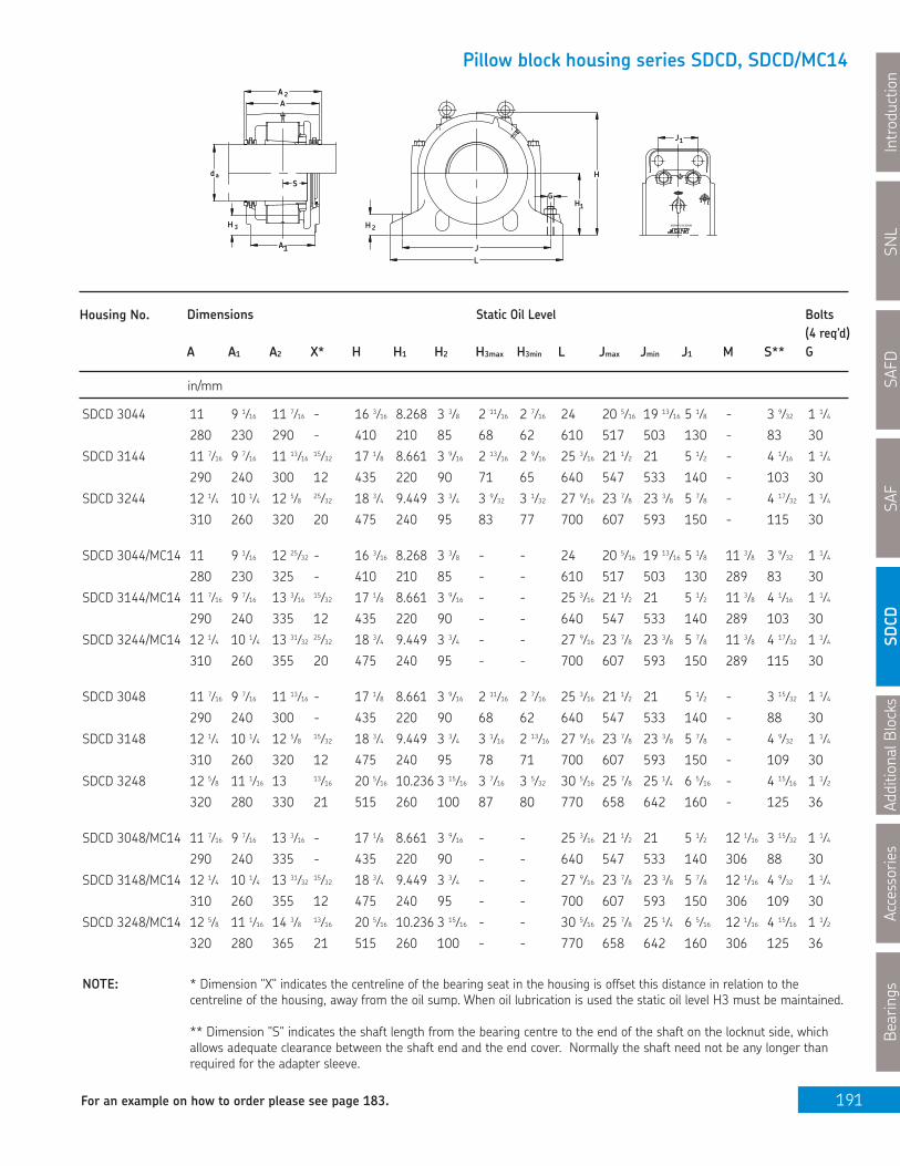
AdditionalB
locks
Accessories
Bearings
191
Pillow block housing series SDCD, SDCD/MC14
H 3
L
H
1A
2
J
1HG
daS
H
2AA
J1
MADEIN CANADA
Housing No. Dimensions Static Oil Level Bolts(4 req’d)
A A1 A2 X* H H1 H2 H3max H3min L Jmax Jmin J1 M S** G
in/mm
NOTE: * Dimension "X" indicates the centreline of the bearing seat in the housing is offset this distance in relation to thecentreline of the housing, away from the oil sump. When oil lubrication is used the static oil level H3 must be maintained.
** Dimension "S" indicates the shaft length from the bearing centre to the end of the shaft on the locknut side, whichallows adequate clearance between the shaft end and the end cover. Normally the shaft need not be any longer thanrequired for the adapter sleeve.
SNL
Introduction
SAFD
SAF
SDCD
For an example on how to order please see page 183.
SDCD 3044 11 9 1⁄16 11 7⁄16 - 16 3⁄16 8.268 3 3⁄8 2 11⁄16 2 7⁄16 24 20 5⁄16 19 13⁄16 5 1⁄8 - 3 9⁄32 1 1⁄4
280 230 290 - 410 210 85 68 62 610 517 503 130 - 83 30
SDCD 3144 11 7⁄16 9 7⁄16 11 13⁄16 15⁄32 17 1⁄8 8.661 3 9⁄16 2 13⁄16 2 9⁄16 25 3⁄16 21 1⁄2 21 5 1⁄2 - 4 1⁄16 1 1⁄4
290 240 300 12 435 220 90 71 65 640 547 533 140 - 103 30
SDCD 3244 12 1⁄4 10 1⁄4 12 5⁄8 25⁄32 18 3⁄4 9.449 3 3⁄4 3 9⁄32 3 1⁄32 27 9⁄16 23 7⁄8 23 3⁄8 5 7⁄8 - 4 17⁄32 1 1⁄4
310 260 320 20 475 240 95 83 77 700 607 593 150 - 115 30
SDCD 3044/MC14 11 9 1⁄16 12 25⁄32 - 16 3⁄16 8.268 3 3⁄8 - - 24 20 5⁄16 19 13⁄16 5 1⁄8 11 3⁄8 3 9⁄32 1 1⁄4
280 230 325 - 410 210 85 - - 610 517 503 130 289 83 30
SDCD 3144/MC14 11 7⁄16 9 7⁄16 13 3⁄16 15⁄32 17 1⁄8 8.661 3 9⁄16 - - 25 3⁄16 21 1⁄2 21 5 1⁄2 11 3⁄8 4 1⁄16 1 1⁄4
290 240 335 12 435 220 90 - - 640 547 533 140 289 103 30
SDCD 3244/MC14 12 1⁄4 10 1⁄4 13 31⁄32 25⁄32 18 3⁄4 9.449 3 3⁄4 - - 27 9⁄16 23 7⁄8 23 3⁄8 5 7⁄8 11 3⁄8 4 17⁄32 1 1⁄4
310 260 355 20 475 240 95 - - 700 607 593 150 289 115 30
SDCD 3048 11 7⁄16 9 7⁄16 11 13⁄16 - 17 1⁄8 8.661 3 9⁄16 2 11⁄16 2 7⁄16 25 3⁄16 21 1⁄2 21 5 1⁄2 - 3 15⁄32 1 1⁄4
290 240 300 - 435 220 90 68 62 640 547 533 140 - 88 30
SDCD 3148 12 1⁄4 10 1⁄4 12 5⁄8 15⁄32 18 3⁄4 9.449 3 3⁄4 3 1⁄16 2 13⁄16 27 9⁄16 23 7⁄8 23 3⁄8 5 7⁄8 - 4 9⁄32 1 1⁄4
310 260 320 12 475 240 95 78 71 700 607 593 150 - 109 30
SDCD 3248 12 5⁄8 11 1⁄16 13 13⁄16 20 5⁄16 10.236 3 15⁄16 3 7⁄16 3 5⁄32 30 5⁄16 25 7⁄8 25 1⁄4 6 5⁄16 - 4 15⁄16 1 1⁄2
320 280 330 21 515 260 100 87 80 770 658 642 160 - 125 36
SDCD 3048/MC14 11 7⁄16 9 7⁄16 13 3⁄16 - 17 1⁄8 8.661 3 9⁄16 - - 25 3⁄16 21 1⁄2 21 5 1⁄2 12 1⁄16 3 15⁄32 1 1⁄4
290 240 335 - 435 220 90 - - 640 547 533 140 306 88 30
SDCD 3148/MC14 12 1⁄4 10 1⁄4 13 31⁄32 15⁄32 18 3⁄4 9.449 3 3⁄4 - - 27 9⁄16 23 7⁄8 23 3⁄8 5 7⁄8 12 1⁄16 4 9⁄32 1 1⁄4
310 260 355 12 475 240 95 - - 700 607 593 150 306 109 30
SDCD 3248/MC14 12 5⁄8 11 1⁄16 14 3⁄8 13⁄16 20 5⁄16 10.236 3 15⁄16 - - 30 5⁄16 25 7⁄8 25 1⁄4 6 5⁄16 12 1⁄16 4 15⁄16 1 1⁄2
320 280 365 21 515 260 100 - - 770 658 642 160 306 125 36
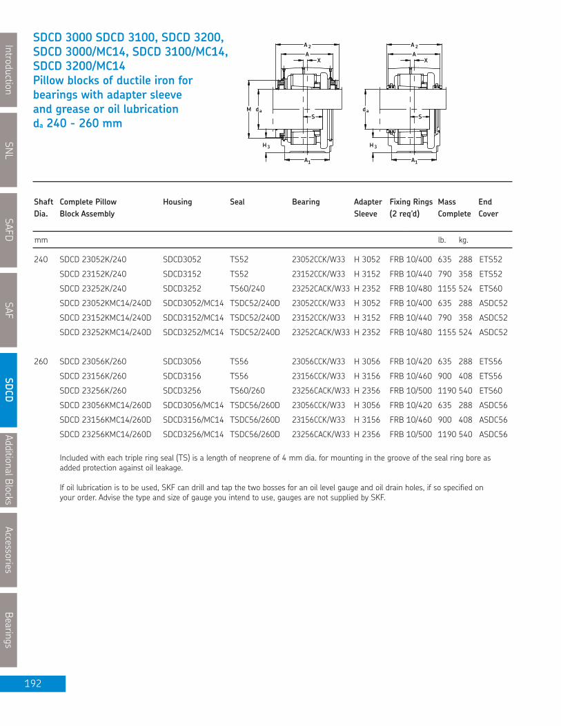
SNL
IntroductionSAFD
SAFSDCD
AdditionalBlocksAccessories
Bearings
192
3H
A1
3H
A1
daMS
A
A 2
daS
X XA
A 2
mm lb. kg.
Shaft Complete Pillow Housing Seal Bearing Adapter Fixing Rings Mass EndDia. Block Assembly Sleeve (2 req’d) Complete Coverda Shaft Dia da Shaft Dia da Design.
SDCD 3000 SDCD 3100, SDCD 3200,SDCD 3000/MC14, SDCD 3100/MC14,SDCD 3200/MC14Pillow blocks of ductile iron forbearings with adapter sleeveand grease or oil lubricationda 240 - 260 mm
240 SDCD 23052K/240 SDCD3052 TS52 23052CCK/W33 H 3052 FRB 10/400 635 288 ETS52
SDCD 23152K/240 SDCD3152 TS52 23152CCK/W33 H 3152 FRB 10/440 790 358 ETS52
SDCD 23252K/240 SDCD3252 TS60/240 23252CACK/W33 H 2352 FRB 10/480 1155 524 ETS60
SDCD 23052KMC14/240D SDCD3052/MC14 TSDC52/240D 23052CCK/W33 H 3052 FRB 10/400 635 288 ASDC52
SDCD 23152KMC14/240D SDCD3152/MC14 TSDC52/240D 23152CCK/W33 H 3152 FRB 10/440 790 358 ASDC52
SDCD 23252KMC14/240D SDCD3252/MC14 TSDC52/240D 23252CACK/W33 H 2352 FRB 10/480 1155 524 ASDC52
260 SDCD 23056K/260 SDCD3056 TS56 23056CCK/W33 H 3056 FRB 10/420 635 288 ETS56
SDCD 23156K/260 SDCD3156 TS56 23156CCK/W33 H 3156 FRB 10/460 900 408 ETS56
SDCD 23256K/260 SDCD3256 TS60/260 23256CACK/W33 H 2356 FRB 10/500 1190 540 ETS60
SDCD 23056KMC14/260D SDCD3056/MC14 TSDC56/260D 23056CCK/W33 H 3056 FRB 10/420 635 288 ASDC56
SDCD 23156KMC14/260D SDCD3156/MC14 TSDC56/260D 23156CCK/W33 H 3156 FRB 10/460 900 408 ASDC56
SDCD 23256KMC14/260D SDCD3256/MC14 TSDC56/260D 23256CACK/W33 H 2356 FRB 10/500 1190 540 ASDC56
Included with each triple ring seal (TS) is a length of neoprene of 4 mm dia. for mounting in the groove of the seal ring bore asadded protection against oil leakage.
If oil lubrication is to be used, SKF can drill and tap the two bosses for an oil level gauge and oil drain holes, if so specified onyour order. Advise the type and size of gauge you intend to use, gauges are not supplied by SKF.

AdditionalB
locks
Accessories
Bearings
193
Pillow block housing series SDCD, SDCD/MC14
H 3
L
H
1A
2
J
1HG
daS
H
2AA
J1
MADEIN CANADA
Housing No. Dimensions Static Oil Level Bolts(4 req’d)
A A1 A2 X* H H1 H2 H3max H3min L Jmax Jmin J1 M S** G
in/mm
NOTE: * Dimension "X" indicates the centreline of the bearing seat in the housing is offset this distance in relation to thecentreline of the housing, away from the oil sump. When oil lubrication is used the static oil level H3 must be maintained.
** Dimension "S" indicates the shaft length from the bearing centre to the end of the shaft on the locknut side, whichallows adequate clearance between the shaft end and the end cover. Normally the shaft need not be any longer thanrequired for the adapter sleeve.
SNL
Introduction
SAFD
SAF
SDCD
For an example on how to order please see page 183.
SDCD 3052 12 1⁄4 10 1⁄4 12 5⁄8 - 18 3⁄4 9.449 3 3⁄4 2 7⁄8 2 9⁄16 27 9⁄16 23 7⁄8 23 5⁄16 5 7⁄8 - 3 11⁄16 1 1⁄4
310 260 320 - 475 240 95 73 65 700 607 593 150 - 94 30
SDCD 3152 12 5⁄8 11 13 1⁄2 20 5⁄16 10.236 3 15⁄16 3 1⁄4 3 30 5⁄16 25 7⁄8 25 1⁄4 6 5⁄16 - 4 7⁄8 1 1⁄2
320 280 330 13 515 260 100 83 76 770 658 642 160 - 124 36
SDCD 3252 13 13⁄16 12 1⁄4 14 3⁄16 1 1⁄32 23 1⁄4 11.811 4 3⁄8 4 13⁄32 4 1⁄32 32 11⁄16 28 1⁄4 27 5⁄8 7 1⁄2 - 5 9⁄32 1 1⁄2
350 310 360 26 590 300 110 112 102 830 718 702 190 - 134 36
SDCD 3052/MC14 12 1⁄4 10 1⁄4 13 31⁄32 - 18 3⁄4 9.449 3 3⁄4 - - 27 9⁄16 23 7⁄8 23 5⁄16 5 7⁄8 12 7⁄8 3 11⁄16 1 1⁄4
310 260 355 - 475 240 95 - - 700 607 593 150 327 94 30
SDCD 3152/MC14 12 5⁄8 11 14 3⁄8 1⁄2 20 5⁄16 10.236 3 15⁄16 - - 30 5⁄16 25 7⁄8 25 1⁄4 6 5⁄16 12 7⁄8 4 7⁄8 1 1⁄2
320 280 365 13 515 260 100 - - 770 658 642 160 327 124 36
SDCD 3252/MC14 13 13⁄16 12 1⁄4 15 17⁄32 1 1⁄32 23 1⁄4 11.811 4 3⁄8 - - 32 11⁄16 28 1⁄4 27 5⁄8 7 1⁄2 12 7⁄8 5 9⁄32 1 1⁄2
350 310 394 26 590 300 110 - - 830 718 702 190 327 134 36
SDCD 3056 12 1⁄4 10 1⁄4 12 5⁄8 - 18 3⁄4 9.449 3 3⁄4 2 1⁄2 2 3⁄16 27 9⁄16 23 7⁄8 23 5⁄16 5 7⁄8 - 3 29⁄32 1 1⁄4
310 260 320 - 475 240 95 63 55 700 607 593 150 - 99 30
SDCD 3156 12 5⁄8 11 13 5⁄8 21 5⁄8 11.024 4 1⁄8 3 5⁄8 3 3⁄8 31 1⁄8 26 11⁄16 26 1⁄16 6 5⁄16 - 5 1 1⁄2
320 280 350 16 550 280 105 93 86 790 678 662 160 - 127 36
SDCD 3256 13 13⁄16 12 1⁄4 14 3⁄16 1 1⁄32 23 1⁄4 11.811 4 3⁄8 4 3 5⁄8 32 11⁄16 28 1⁄4 27 5⁄8 7 1⁄2 - 5 3⁄8 1 1⁄2
350 310 360 26 590 300 110 101 92 830 718 702 190 - 136 36
SDCD 3056/MC14 12 1⁄4 10 1⁄4 13 31⁄32 - 18 3⁄4 9.449 3 3⁄4 - - 27 9⁄16 23 7⁄8 23 5⁄16 5 7⁄8 13 5⁄8 3 29⁄32 1 1⁄4
310 260 355 - 475 240 95 - - 700 607 593 150 346 99 30
SDCD 3156/MC14 12 5⁄8 11 14 3⁄8 5⁄8 21 5⁄8 11.024 4 1⁄8 - - 31 1⁄8 26 11⁄16 26 1⁄16 6 5⁄16 13 5⁄8 5 1 1⁄2
320 280 365 16 550 280 105 - - 790 678 662 160 346 127 36
SDCD 3256/MC14 13 13⁄16 12 1⁄4 15 17⁄32 1 1⁄32 23 1⁄4 11.811 4 3⁄8 - - 32 11⁄16 28 1⁄4 27 5⁄8 7 1⁄2 13 5⁄8 5 3⁄8 1 1⁄2
350 310 394 26 590 300 110 - - 830 718 702 190 346 136 36

SNL
IntroductionSAFD
SAFSDCD
AdditionalBlocksAccessories
Bearings
194
3H
A1
3H
A1
daMS
A
A 2
daS
X XA
A 2
mm lb. kg.
Shaft Complete Pillow Housing Seal Bearing Adapter Fixing Rings Mass EndDia. Block Assembly Sleeve (2 req’d) Complete Coverda Shaft Dia da Shaft Dia da Design.
SDCD 3000, SDCD 3100, SDCD 3200,SDCD 3000/MC14, SDCD 3100/MC14,SDCD 3200/MC14Pillow blocks of ductile iron forbearings with adapter sleeveand grease or oil lubricationda 280 - 300 mm
280 SDCD 23060K/280 SDCD3060 TS60 23060CCK/W33 H 3060 FRB 10/460 900 408 ETS60
SDCD 23160K/280 SDCD3160 TS60 23160CCK/W33 H 3160 FRB 10/500 1100 500 ETS60
SDCD 23260K/280 SDCD3260 TS64/ 280 23260CACK/W33 H 3260 FRB 10/540 1365 620 ETS64
SDCD 23060KMC14/280D SDCD3060/MC14 TSDC60/280D 23060CCK/W33 H 3060 FRB 10/460 900 408 ASDC60
SDCD 23160KMC14/280D SDCD3160/MC14 TSDC60/280D 23160CCK/W33 H 3160 FRB 10/500 1100 500 ASDC60
SDCD 23260KMC14/280D SDCD3260/MC14 TSDC60/280D 23260CACK/W33 H 3260 FRB 10/540 1365 620 ASDC60
300 SDCD 23064K/300 SDCD3064 TS64 23064CCK/W33 H 3064 FRB 10/480 900 408 ETS64
SDCD 23164K/300 SDCD3164 TS64 23164CCK/W33 H 3164 FRB 10/540 1295 587 ETS64
SDCD 23264K/300 SDCD3264 TS64 23264CACK/W33 H 3264 FRB 10/580 1925 875 ETS64
SDCD 23064KMC14/300D SDCD3064/MC14 TSDC64/300D 23064CCK/W33 H 3064 FRB 10/480 900 408 ASDC64
SDCD 23164KMC14/300D SDCD3164/MC14 TSDC64/300D 23164CCK/W33 H 3164 FRB 10/540 1295 587 ASDC64
SDCD 23264KMC14/300D SDCD3264/MC14 TSDC64/300D 23264CACK/W33 H 3264 FRB 10/580 1925 875 ASDC64
Included with each triple ring seal (TS) is a length of neoprene of 4 mm dia. for mounting in the groove of the seal ring bore asadded protection against oil leakage.
If oil lubrication is to be used, SKF can drill and tap the two bosses for an oil level gauge and oil drain holes, if so specified onyour order. Advise the type and size of gauge you intend to use, gauges are not supplied by SKF.

AdditionalB
locks
Accessories
Bearings
195
Pillow block housing series SDCD, SDCD/MC14
H 3
L
H
1A
2
J
1HG
daS
H
2AA
J1
MADEIN CANADA
Housing No. Dimensions Static Oil Level Bolts(4 req’d)
A A1 A2 X* H H1 H2 H3max H3min L Jmax Jmin J1 M S** G
in/mm
NOTE: * Dimension "X" indicates the centreline of the bearing seat in the housing is offset this distance in relation to thecentreline of the housing, away from the oil sump. When oil lubrication is used the static oil level H3 must be maintained.
** Dimension "S" indicates the shaft length from the bearing centre to the end of the shaft on the locknut side, whichallows adequate clearance between the shaft end and the end cover. Normally the shaft need not be any longer thanrequired for the adapter sleeve.
SNL
Introduction
SAFD
SAF
SDCD
For an example on how to order please see page 183.
SDCD 3060 12 5⁄8 11 1⁄16 13 - 21 5⁄8 11.024 4 1⁄8 3 7⁄16 3 1⁄16 31 1⁄8 26 11⁄16 26 1⁄16 6 5⁄16 - 4 9⁄32 1 1⁄2
320 280 330 - 550 280 105 87 78 790 678 662 160 - 109 36
SDCD 3160 13 3⁄4 12 1⁄4 14 3⁄16 7⁄8 23 1⁄4 11.811 4 3⁄8 3 13⁄16 3 1⁄2 32 11⁄16 28 1⁄4 27 5⁄8 7 1⁄2 - 5 1⁄16 1 1⁄2
350 310 360 22 590 300 110 97 89 830 718 702 190 - 128 36
SDCD 3260 14 9⁄16 13 15 1 5⁄32 24 13⁄16 12.598 4 9⁄16 4 3⁄16 3 25⁄32 34 5⁄8 29 13⁄16 29 3⁄16 7 7⁄8 - 5 11⁄16 1 1⁄2
370 330 380 29 630 320 115 106 96 880 758 742 200 - 144 36
SDCD 3060/MC14 12 5⁄8 11 1⁄16 14 3⁄8 - 21 5⁄8 11.024 4 1⁄8 - - 31 1⁄8 26 11⁄16 26 1⁄16 6 5⁄16 14 7⁄16 4 9⁄32 1 1⁄2
320 280 365 - 550 280 105 - - 790 678 662 160 367 109 36
SDCD 3160/MC14 13 3⁄4 12 1⁄4 15 17⁄32 7⁄8 23 1⁄4 11.811 4 3⁄8 - - 32 11⁄16 28 1⁄4 27 5⁄8 7 1⁄2 14 7⁄16 5 1⁄16 1 1⁄2
350 310 394 22 590 300 110 - - 830 718 702 190 367 128 36
SDCD 3260/MC14 14 9⁄16 13 16 5⁄16 1 5⁄32 24 13⁄16 12.598 4 9⁄16 - - 34 5⁄8 29 13⁄16 29 3⁄16 7 7⁄8 14 7⁄16 5 11⁄16 1 1⁄2
370 330 414 29 630 320 115 - - 880 758 742 200 367 144 36
SDCD 3064 12 5⁄8 11 1⁄16 13 - 21 5⁄8 11.024 4 1⁄8 3 1⁄32 2 11⁄16 31 1⁄8 26 11⁄16 26 1⁄16 6 5⁄16 - 4 11⁄32 1 1⁄2
320 280 330 - 550 280 105 77 68 790 678 662 160 - 110.5 36
SDCD 3164 14 9⁄16 13 15 29⁄32 24 13⁄16 12.598 4 1⁄2 4 1⁄16 3 5⁄8 34 5⁄8 29 13⁄16 29 1⁄4 7 7⁄8 - 5 7⁄16 1 1⁄2
370 330 380 23 630 320 115 103 93 880 758 742 200 - 138 36
SDCD 3264 16 1⁄8 14 9⁄16 16 1⁄2 1 7⁄32 27 3⁄4 14.173 4 3⁄4 5 5⁄32 4 23⁄32 39 3⁄8 34 5⁄16 33 3⁄8 9 1⁄16 - 6 1⁄16 1 3⁄4
410 370 420 31 705 360 120 131 120 1000 872 848 230 - 154 45
SDCD 3064/MC14 12 5⁄8 11 1⁄16 14 3⁄8 - 21 5⁄8 11.024 4 1⁄8 - - 31 1⁄8 26 11⁄16 26 1⁄16 6 5⁄16 15 19⁄32 4 11⁄32 1 1⁄2
320 280 365 - 550 280 105 - - 790 678 662 160 396 110.5 36
SDCD 3164/MC14 14 9⁄16 13 16 5⁄16 29⁄32 24 13⁄16 12.598 4 1⁄2 - - 34 5⁄8 29 13⁄16 29 1⁄4 7 7⁄8 15 19⁄32 5 7⁄16 1 1⁄2
370 330 414 23 630 320 115 - - 880 758 742 200 396 138 36
SDCD 3264/MC14 16 1⁄8 14 9⁄16 17 29⁄32 1 7⁄32 27 3⁄4 14.173 4 3⁄4 - - 39 3⁄8 34 5⁄16 33 3⁄8 9 1⁄16 15 19⁄32 6 1⁄16 1 3⁄4
410 370 455 31 705 360 120 - - 1000 872 848 230 396 154 45

SNL
IntroductionSAFD
SAFSDCD
AdditionalBlocksAccessories
Bearings
196
3H
A1
3H
A1
daMS
A
A 2
daS
X XA
A 2
mm lb. kg.
Shaft Complete Pillow Housing Seal Bearing Adapter Fixing Rings Mass EndDia. Block Assembly Sleeve (2 req’d) Complete Coverda Shaft Dia da Shaft Dia da Design.
SDCD 3000, SDCD 3100, SDCD 3200,SDCD 3000/MC14, SDCD 3100/MC14,SDCD 3200/MC14Pillow blocks of ductile iron forbearings with adapter sleeveand grease or oil lubricationda 320 - 340 mm
320 SDCD 23068K/320 SDCD3068 TS68 23068CCK/W33 H 3068 FRB 10/520 1100 500 ETS68
SDCD 23168K/320 SDCD3168 TS68 23168CCK/W33 H 3168 FRB 10/580 1850 839 ETS68
SDCD 23268K/320 SDCD3268 TS68 23268CACK/W33 H 3268 FRB 10/620 2465 1119 ETS68
SDCD 23068KMC14/320D SDCD3068/MC14 TSDC68/320D 23068CCK/W33 H 3068 FRB 10/520 1100 500 ASDC68
SDCD 23168KMC14/320D SDCD3168/MC14 TSDC68/320D 23168CCK/W33 H 3168 FRB 10/580 1850 839 ASDC68
SDCD 23268KMC14/320D SDCD3268/MC14 TSDC68/320D 23268CACK/W33 H 3268 FRB 10/620 2465 1119 ASDC68
340 SDCD 23072K/340 SDCD3072 TS72 23072CCK/W33 H 3072 FRB 10/540 1295 587 ETS72
SDCD 23172K/340 SDCD3172 TS72 23172CACK/W33 H 3172 FRB 10/600 1890 857 ETS72
SDCD 23272K/340 SDCD3272 TS72 23272CAK/W33 H 3272 FRB 10/650 2550 1158 ETS72
SDCD 23072KMC14/340D SDCD3072/MC14 TSDC72/340D 23072CCK/W33 H 3072 FRB 10/540 1295 587 ASDC72
SDCD 23172KMC14/340D SDCD3172/MC14 TSDC72/340D 23172CACK/W33 H 3172 FRB 10/600 1890 857 ASDC72
SDCD 23272KMC14/340D SDCD3272/MC14 TSDC72/340D 23272CAK/W33 H 3272 FRB 10/650 2550 1158 ASDC72
Included with each triple ring seal (TS) is a length of neoprene of 4 mm dia. for mounting in the groove of the seal ring bore asadded protection against oil leakage.
If oil lubrication is to be used, SKF can drill and tap the two bosses for an oil level gauge and oil drain holes, if so specified onyour order. Advise the type and size of gauge you intend to use, gauges are not supplied by SKF.

AdditionalB
locks
Accessories
Bearings
197
Pillow block housing series SDCD, SDCD/MC14
H 3
L
H
1A
2
J
1HG
daS
H
2AA
J1
MADEIN CANADA
Housing No. Dimensions Static Oil Level Bolts(4 req’d)
A A1 A2 X* H H1 H2 H3max H3min L Jmax Jmin J1 M S** G
in/mm
NOTE: * Dimension "X" indicates the centreline of the bearing seat in the housing is offset this distance in relation to thecentreline of the housing, away from the oil sump. When oil lubrication is used the static oil level H3 must be maintained.
** Dimension "S" indicates the shaft length from the bearing centre to the end of the shaft on the locknut side, whichallows adequate clearance between the shaft end and the end cover. Normally the shaft need not be any longer thanrequired for the adapter sleeve.
SNL
Introduction
SAFD
SAF
SDCD
For an example on how to order please see page 183.
SDCD 3068 13 13⁄16 12 1⁄4 14 3⁄16 - 23 1⁄4 11.811 4 3⁄8 3 1⁄4 2 13⁄16 32 11⁄16 28 1⁄4 27 5⁄8 7 1⁄2 - 4 23⁄32 1 1⁄2
350 310 360 - 590 300 110 82 71 830 718 702 190 - 119.5 36
SDCD 3168 16 1⁄8 14 9⁄16 16 1⁄2 1 7⁄32 27 3⁄4 14.173 4 3⁄4 5 1⁄32 4 9⁄16 39 3⁄8 34 5⁄16 33 3⁄8 9 1⁄16 - 6 7⁄32 1 3⁄4
410 370 420 31 705 360 120 128 116 1000 872 848 230 - 158 45
SDCD 3268 17 1⁄8 15 1⁄2 17 1⁄2 1 7⁄32 30 1⁄8 15.354 5 5 23⁄32 5 7⁄32 44 38 1⁄2 37 1⁄2 9 1⁄4 - 6 7⁄8 2
435 394 445 31 765 390 127 145 132 1118 977 953 235 - 175 50
SDCD 3068/MC14 13 13⁄16 12 1⁄4 15 17⁄32 - 23 1⁄4 11.811 4 3⁄8 - - 32 11⁄16 28 1⁄4 27 5⁄8 7 1⁄2 16 13⁄32 4 23⁄32 1 1⁄2
350 310 394 - 590 300 110 - - 830 718 702 190 417 119.5 36
SDCD 3168/MC14 16 1⁄8 14 9⁄16 17 29⁄32 1 7⁄32 27 3⁄4 14.173 4 3⁄4 - - 39 3⁄8 34 5⁄16 33 3⁄8 9 1⁄16 16 13⁄32 6 7⁄32 1 3⁄4
410 370 455 31 705 360 120 - - 1000 872 848 230 417 158 45
SDCD 3268/MC14 17 1⁄8 15 1⁄2 18 7⁄8 1 7⁄32 30 1⁄8 15.354 5 - - 44 38 1⁄2 37 1⁄2 9 1⁄4 16 13⁄32 6 7⁄8 2
435 394 479 31 765 390 127 - - 1118 977 953 235 417 175 50
SDCD 3072 14 9⁄16 13 15 - 24 13⁄16 12.598 4 1⁄2 3 23⁄32 3 11⁄32 34 11⁄16 29 13⁄16 29 1⁄4 7 7⁄8 - 4 23⁄32 1 1⁄2
370 330 380 - 630 320 115 94 85 880 758 742 200 - 120 36
SDCD 3172 16 1⁄8 14 9⁄16 16 1⁄2 1 7⁄32 27 3⁄4 14.173 4 3⁄4 4 9⁄16 4 1⁄8 39 3⁄8 34 3⁄8 33 3⁄8 9 1⁄16 - 6 15⁄32 1 3⁄4
410 370 420 31 705 360 120 116 104 1000 872 848 230 - 164 45
SDCD 3272 17 1⁄8 15 1⁄2 17 1⁄2 1 7⁄32 30 1⁄8 15.354 5 5 9⁄32 4 23⁄32 44 38 1⁄2 37 1⁄2 9 1⁄4 - 7 3⁄16 2
435 394 445 31 765 390 127 134 120 1118 977 953 235 - 182 50
SDCD 3072/MC14 14 9⁄16 13 16 5⁄16 - 24 13⁄16 12.598 4 1⁄2 - - 34 11⁄16 29 13⁄16 29 1⁄4 7 7⁄8 17 5⁄32 4 23⁄32 1 1⁄2
370 330 389 - 630 320 115 - - 880 758 742 200 436 120 36
SDCD 3172/MC14 16 1⁄8 14 9⁄16 17 29⁄32 1 7⁄32 27 3⁄4 14.173 4 3⁄4 - - 39 3⁄8 34 3⁄8 33 3⁄8 9 1⁄16 17 5⁄32 6 15⁄32 1 3⁄4
410 370 455 31 705 360 120 - - 1000 872 848 230 436 164 45
SDCD 3272/MC14 17 1⁄8 15 1⁄2 18 7⁄8 1 7⁄32 30 1⁄8 15.354 5 - - 44 38 1⁄2 37 1⁄2 9 1⁄4 17 5⁄32 7 3⁄16 2
435 394 479 31 765 390 127 - - 1118 977 953 235 436 182 50

SNL
IntroductionSAFD
SAFSDCD
AdditionalBlocksAccessories
Bearings
198
3H
A1
3H
A1
daMS
A
A 2
daS
X XA
A 2
mm lb. kg.
Shaft Complete Pillow Housing Seal Bearing Adapter Fixing Rings Mass EndDia. Block Assembly Sleeve (2 req’d) Complete Coverda Shaft Dia da Shaft Dia da Design.
SDCD 3000, SDCD 3100, SDCD 3200,SDCD 3000/MC14, SDCD 3100/MC14,SDCD 3200/MC14Pillow blocks of ductile iron forbearings with adapter sleeveand grease or oil lubricationda 360 - 380 mm
360 SDCD 23076K/360 SDCD3076 TS76 23076CCK/W33 H 3076 FRB 10/560 1295 587 ETS76
SDCD 23176K/360 SDCD3176 TS76 23176CAK/W33 H 3176 FRB 10/620 2300 1043 ETS76
SDCD 23276K/360 SDCD3276 TS76 23276CAK/W33 H 3276 FRB 10/680 3080 1398 ETS76
SDCD 23076KMC14/360D SDCD3076/MC14 TSDC76/360D 23076CCK/W33 H 3076 FRB 10/560 1295 587 ASDC76
SDCD 23176KMC14/360D SDCD3176/MC14 TSDC76/360D 23176 CAK/W33 H 3176 FRB 10/620 2300 1043 ASDC76
SDCD 23276KMC14/360D SDCD3276/MC14 TSDC76/360D 23276 CAK/W33 H 3276 FRB 10/680 3080 1398 ASDC76
380 SDCD 23080K/380 SDCD3080 TS80 23080CACK/W33 H 3080 FRB 10/600 1890 857 ETS80
SDCD 23180K/380 SDCD3180 TS80 23180CAK/W33 H 3180 FRB 10/650 2390 1084 ETS80
SDCD 23280K/380 SDCD3280 TS80 23280CAK/W33 H 3280 FRB 10/720 3300 1498 ETS80
SDCD 23080KMC14/380D SDCD3080/MC14 TSDC80/380D 23080CACK/W33 H 3080 FRB 10/600 1890 857 ASDC80
SDCD 23180KMC14/380D SDCD3180/MC14 TSDC80/380D 23180CAK/W33 H 3180 FRB 10/650 2390 1084 ASDC80
SDCD 23280KMC14/380D SDCD3280/MC14 TSDC80/380D 23280CAK/W33 H 3280 FRB 10/720 3300 1498 ASDC80
Included with each triple ring seal (TS) is a length of neoprene of 4 mm dia. for mounting in the groove of the seal ring bore asadded protection against oil leakage.
If oil lubrication is to be used, SKF can drill and tap the two bosses for an oil level gauge and oil drain holes, if so specified onyour order. Advise the type and size of gauge you intend to use, gauges are not supplied by SKF.

AdditionalB
locks
Accessories
Bearings
199
Pillow block housing series SDCD, SDCD/MC14
H 3
L
H
1A
2
J
1HG
daS
H
2AA
J1
MADEIN CANADA
Housing No. Dimensions Static Oil Level Bolts(4 req’d)
A A1 A2 X* H H1 H2 H3max H3min L Jmax Jmin J1 M S** G
in/mm
NOTE: * Dimension "X" indicates the centreline of the bearing seat in the housing is offset this distance in relation to thecentreline of the housing, away from the oil sump. When oil lubrication is used the static oil level H3 must be maintained.
** Dimension "S" indicates the shaft length from the bearing centre to the end of the shaft on the locknut side, whichallows adequate clearance between the shaft end and the end cover. Normally the shaft need not be any longer thanrequired for the adapter sleeve.
SNL
Introduction
SAFD
SAF
SDCD
For an example on how to order please see page 183.
SDCD 3076 14 9⁄16 13 15 - 24 13⁄16 12.598 4 1⁄2 3 1⁄4 2 27⁄32 34 11⁄16 29 13⁄16 29 1⁄4 7 7⁄8 - 4 7⁄8 1 1⁄2
370 330 380 - 630 320 115 83 72 880 758 742 200 - 123.5 36
SDCD 3176 17 1⁄8 15 1⁄2 17 1⁄2 1 7⁄32 30 1⁄8 15.354 5 5 7⁄16 5 44 38 1⁄2 37 1⁄2 9 1⁄4 - 6 1⁄2 2
435 394 445 31 765 390 127 138 127 1118 978 953 235 - 165 50
SDCD 3276 18 1⁄8 16 1⁄2 18 1⁄2 1 7⁄32 33 1⁄8 16.737 5 6 1⁄8 5 9⁄16 47 1⁄4 41 3⁄16 40 1⁄4 9 7⁄8 - 7 13⁄32 2
460 419 470 31 841 425 127 155 141 1200 1047 1022 251 - 188 50
SDCD 3076/MC14 14 9⁄16 13 16 5⁄16 - 24 13⁄16 12.598 4 1⁄2 - - 34 11⁄16 29 13⁄16 29 1⁄4 7 7⁄8 17 29⁄32 4 7⁄8 1 1⁄2
370 330 389 - 630 320 115 - - 880 758 742 200 455 123.5 36
SDCD 3176/MC14 17 1⁄8 15 1⁄2 18 7⁄8 1 7⁄32 30 1⁄8 15.354 5 - - 44 38 1⁄2 37 1⁄2 9 1⁄4 17 29⁄32 6 1⁄2 2
435 394 479 31 765 390 127 - - 1118 978 953 235 455 165 50
SDCD 3276/MC14 18 1⁄8 16 1⁄2 19 7⁄8 1 7⁄32 33 1⁄8 16.737 5 - - 47 1⁄4 41 3⁄16 40 1⁄4 9 7⁄8 17 29⁄32 7 13⁄32 2
460 419 505 31 841 425 127 - - 1200 1047 1022 251 455 188 50
SDCD 3080 16 1⁄8 14 9⁄16 16 1⁄2 - 27 3⁄4 14.173 4 3⁄4 4 3⁄16 3 3⁄4 39 3⁄8 34 5⁄16 33 3⁄8 9 1⁄16 - 5 9⁄32 1 3⁄4
410 370 420 - 705 360 120 106 94 1000 872 848 230 - 134 45
SDCD 3180 17 1⁄8 15 1⁄2 17 1⁄2 1 7⁄32 30 1⁄8 15.354 5 4 31⁄32 4 1⁄2 44 38 1⁄2 37 1⁄2 9 1⁄4 - 6 11⁄16 2
435 394 445 31 765 390 127 126 113 1118 978 953 235 - 170 50
SDCD 3280 18 1⁄8 16 1⁄2 18 1⁄2 1 7⁄32 33 1⁄8 16.732 5 5 1⁄2 4 7⁄8 47 1⁄4 41 3⁄16 40 1⁄4 9 7⁄8 - 7 13⁄16 2
460 419 470 31 841 425 127 140 124 1200 1047 1022 251 - 198 50
SDCD 3080/MC14 16 1⁄8 14 9⁄16 17 29⁄32 - 27 3⁄4 14.173 4 3⁄4 - - 39 3⁄8 34 5⁄16 33 3⁄8 9 1⁄16 18 21⁄32 5 9⁄32 1 3⁄4
410 370 455 - 705 360 120 - - 1000 872 848 230 474 134 45
SDCD 3180/MC14 17 1⁄8 15 1⁄2 18 7⁄8 1 7⁄32 30 1⁄8 15.354 5 - - 44 38 1⁄2 37 1⁄2 9 1⁄4 18 21⁄32 6 11⁄16 2
435 394 479 31 765 390 127 - - 1118 978 953 235 474 170 50
SDCD 3280/MC14 18 1⁄8 16 1⁄2 19 7⁄8 1 7⁄32 33 1⁄8 16.732 5 - - 47 1⁄4 41 3⁄16 40 1⁄4 9 7⁄8 18 21⁄32 7 13⁄16 2
460 419 505 31 841 425 127 - - 1200 1047 1022 251 474 198 50

SNL
IntroductionSAFD
SAFSDCD
AdditionalBlocksAccessories
Bearings
200
3H
A1
3H
A1
daMS
A
A 2
daS
X XA
A 2
mm lb. kg.
Shaft Complete Pillow Housing Seal Bearing Adapter Fixing Rings Mass EndDia. Block Assembly Sleeve (2 req’d) Complete Coverda Shaft Dia da Shaft Dia da Design.
SDCD 3000, SDCD 3100, SDCD 3200,SDCD 3000/MC14, SDCD 3100/MC14,SDCD 3200/MC14Pillow blocks of ductile iron forbearings with adapter sleeveand grease or oil lubricationda 400 - 410 mm
400 SDCD 23084K/400 SDCD3084 TS84 23084CAK/W33 H 3084 FRB 10/620 2300 1043 ETS84
SDCD 23184K/400 SDCD3184 TS84 23184CK/W33 H 3184 FRB 10/700 3050 1383 ETS84
SDCD 23084KMC14/400D SDCD3084/MC14 TSDC84/400D 23084CAK/W33 H 3084 FRB 10/620 2300 1043 ASDC84
SDCD 23184KMC14/400D SDCD3184/MC14 TSDC84/400D 23184CKJ/W33 H 3184 FRB 10/700 3050 1383 ASDC84
410 SDCD 23088K/410 SDCD3088 TS88 23088CAK/W33 H 3088 FRB 10/650 2300 1043 ETS88
SDCD 23188K/410 SDCD3188 TS88 23188CAK/W33 H 3188 FRB 10/720 3150 1428 ETS88
SDCD 23088KMC14/410D SDCD3088/MC14 TSDC88/410D 23088CAK/W33 H 3088 FRB 10/650 2300 1043 ASDC88
SDCD 23188KMC14/410D SDCD3188/MC14 TSDC88/410D 23188CAK/W33 H 3188 FRB 10/720 3150 1428 ASDC88
Included with each triple ring seal (TS) is a length of neoprene of 4 mm dia. for mounting in the groove of the seal ring bore asadded protection against oil leakage.
If oil lubrication is to be used, SKF can drill and tap the two bosses for an oil level gauge and oil drain holes, if so specified onyour order. Advise the type and size of gauge you intend to use, gauges are not supplied by SKF.

AdditionalB
locks
Accessories
Bearings
201
Pillow block housing series SDCD, SDCD/MC14
H 3
L
H
1A
2
J
1HG
daS
H
2AA
J1
MADEIN CANADA
Housing No. Dimensions Static Oil Level Bolts(4 req’d)
A A1 A2 X* H H1 H2 H3max H3min L Jmax Jmin J1 M S** G
in/mm
NOTE: * Dimension "X" indicates the centreline of the bearing seat in the housing is offset this distance in relation to thecentreline of the housing, away from the oil sump. When oil lubrication is used the static oil level H3 must be maintained.
** Dimension "S" indicates the shaft length from the bearing centre to the end of the shaft on the locknut side, whichallows adequate clearance between the shaft end and the end cover. Normally the shaft need not be any longer thanrequired for the adapter sleeve.
SNL
Introduction
SAFD
SAF
SDCD
For an example on how to order please see page 183.
SDCD 3084 17 1⁄8 15 1⁄2 17 1⁄2 - 30 1⁄8 15.354 5 5 4 9⁄16 44 38 1⁄2 37 1⁄2 9 1⁄4 - 5 5⁄16 2
435 394 445 - 765 390 127 127 115 1118 978 952 235 - 135 50
SDCD 3184 18 1⁄8 16 1⁄2 18 1⁄2 1 7⁄32 33 1⁄8 16.732 5 5 5⁄8 5 1⁄32 47 1⁄4 41 3⁄16 40 5⁄16 9 7⁄8 - 7 1⁄2 2
460 419 470 31 841 425 127 143 128 1200 1046 1024 251 - 190 50
SDCD 3084/MC14 17 1⁄8 15 1⁄2 18 7⁄8 - 30 1⁄8 15.354 5 - - 44 38 1⁄2 37 1⁄2 9 1⁄4 19 1⁄2 5 5⁄16 2
435 394 479 - 765 390 127 - - 1118 978 952 235 495 135 50
SDCD 3184/MC14 18 1⁄8 16 1⁄2 19 7⁄8 1 7⁄32 33 1⁄8 16.737 5 - - 47 1⁄4 41 3⁄16 40 5⁄16 9 7⁄8 19 1⁄2 7 1⁄2 2
460 419 505 31 841 425 127 - - 1200 1046 1024 251 495 190 50
SDCD 3088 17 1⁄8 15 1⁄2 17 1⁄2 - 30 1⁄8 15.354 5 4 1⁄2 4 44 38 1⁄2 37 1⁄2 9 1⁄4 - 6 3⁄16 2
435 394 445 - 765 390 127 114 102 1118 978 952 235 - 157 50
SDCD 3188 18 1⁄8 16 1⁄2 18 1⁄2 1 7⁄32 33 1⁄8 16.732 5 5 1⁄8 4 9⁄16 47 1⁄4 41 3⁄16 40 5⁄16 9 7⁄8 - 7 17⁄32 2
460 419 470 31 841 425 127 130 115 1200 1046 1024 251 - 191 50
SDCD 3088/MC14 17 1⁄8 15 1⁄2 18 7⁄8 - 30 1⁄8 15.354 5 - - 44 38 1⁄2 37 1⁄2 9 1⁄4 20 13⁄32 6 3⁄16 2
435 394 479 - 765 390 127 - - 1118 978 952 235 518 157 50
SDCD 3188/MC14 18 1⁄8 16 1⁄2 19 7⁄8 1 7⁄32 33 1⁄8 16.732 5 - - 47 1⁄4 41 3⁄16 40 5⁄16 9 7⁄8 20 13⁄32 7 17⁄32 2
460 419 505 31 841 425 127 - - 1200 1046 1024 251 518 191 50

SNL
IntroductionSAFD
SAFSDCD
AdditionalBlocksAccessories
Bearings
Note : Pillow Block SDCD must be modified to MC14 when using TSDC-D & E type seals.
Ductile Iron ASTM A536 grade 65-45-12
230CC, 231CC, 232CC
MATERIAL
BEARING SERIESUSED
STANDARD SEALS
OPTIONAL SEALS
LUBRICATIONPILLOW BLOCK
SHAFT SIZE RANGE
PILLOW BLOCK SIZE036 - 088 (cylindrical bore mounting)
6-7/8" to 19" 174.63mm to 482.60mm
Grease or Oil
SDCD, SDCD/MC14
134 - 188 (cylindrical bore mounting)234 - 280 (cylindrical bore mounting)
TSDC-D TSDC-E
TS
202
Pillow BlockHousings

SNL
Introduction
SAFD
SAF
SDCD
AdditionalB
locks
Accessories
Bearings
203
Cylindrical Bore Mounting
D MC14 D
Basic design
MaterialDT
Bearing bore
HubOMC14
SuffixesDEHY
Ductile ironCast steel
Bore: 44 = 220mm
Standard hub configuration for TS labyrinth sealsModified to accommodate Taconite seals
Taconite service seal TSDC design c/w V ringTaconite service seal TSDC design no V ringHeld unit, complete with fixing ringsOne end closed
How to order: (Example)
When you order one SDCD 23244/MC14 D you will receive a package containing the following:
1 - Pillow block housing SDCD 244/MC14, cap drilled, tapped and plugged with three holes (1) 1⁄4" NPTat the centre (2) 1⁄8" NPT for seals (D or E)
2 - Labyrinth seals for shaft diametersda TSDC 52/9 9⁄16 D anddb TSDC 44/8 5⁄16 D
1 - Bearing SKF 23244CC/W331 - Locknut N0441 - Lockwasher W044
If a "HELD or FIXED" unit is required, add the suffix “H” and two fixing rings (locating or stabalizing) will be included.Not more than one bearing on each shaft should be "HELD".If you require one end closed add "Y" to complete assembly number i.e. SDCD 23244/MC14D Yand you will receive one Taconite seal shaft diameter da TSDC 52/9 9⁄16 and one end plug ASDC 48.
SDC 23244/

SNL
IntroductionSAFD
SAFSDCD
AdditionalBlocksAccessories
Bearings
204
S S
H
A1
3 H 3
1A
dM a
2AA
X
Md db 1 a db
A 2
XA
If oil lubrication is to be used, SKF can drill and tap the two bosses for the oil level gauge and oil drain holes, if so specified on yourorder. Advise the type and size of the gauge you intend to use, gauges are not supplied by SKF.
Shaft Complete Pillow Housing Seal Assemblies Bearing Lock Lock End Fixing Mass
Dia. Block Assembly For Shaft Dia Nut Washer Cover RingComp
da/db da db (2 req'd)
in kg
Series SDCD 000, SDCD 100,SDCD 200, SDCD 000/MC14,SDCD 100/MC14, SDCD 200/MC14Pillow blocks of ductile ironfor bearings with cylindricalbore mounting and greaseor oil lubricationda 7 7⁄16 - 7 13⁄16 indb 6 7⁄16 - 6 7⁄8 in
da 7 7⁄16
db 6 7⁄16
SDCD 23134 SDCD134 TS40/7 7⁄16 TS34/6 7⁄16 23134CC/W33 N 034 W 034 ETS34 FRB 10/280 95
SDCD 23234 SDCD234 TS40/7 7⁄16 TS38/6 7⁄16 23234CC/W33 AN 34 W 34 ETS38 FRB 10/310 145
SDCD 23134/MC14D SDCD134/MC14 TSDC38/7 7⁄16D TSDC34/6 7⁄16D 23134CC/W33 N 034 W 034 ASDC34 FRB 10/280 95
SDCD 23234/MC14D SDCD234/MC14 TSDC38/7 7⁄16D TSDC34/6 7⁄16D 23234CC/W33 N 034 W 034 ASDC34 FRB 10/310 145
da 7 13⁄16
db 6 7⁄8
SDCD 23036 SDCD036 TS44/7 13⁄16 TS36/6 7⁄8 23036CC/W33 N 036 W 036 ETS36 FRB 10/280 95
SDCD 23136 SDCD136 TS44/7 13⁄16 TS36/6 7⁄8 23136CC/W33 N 036 W 036 ETS36 FRB 10/300 113
SDCD 23236 SDCD236 TS44/7 13⁄16 TS38/6 7⁄8 23236CC/W33 AN 36 W 36 ETS38 FRB 10/320 150
SDCD 23036/MC14D SDCD036/MC14 TSDC40/7 13⁄16D TSDC36/6 7⁄8D 23036CC/W33 N 036 W 036 ASDC36 FRB 10/280 95
SDCD 23136/MC14D SDCD136/MC14 TSDC40/7 13⁄16D TSDC36/6 7⁄8D 23136CC/W33 N 036 W 036 ASDC36 FRB 10/300 113
SDCD 23236/MC14D SDCD236/MC14 TSDC40/7 13⁄16D TSDC36/6 7⁄8D 23236CC/W33 N 036 W 036 ASDC36 FRB 10/320 150

AdditionalB
locks
Accessories
Bearings
205
Pillow block housing series SDCD, SDCD/MC14
S
H 3
JL
1A
2H
H1G
da db H
2A
A
J1
MADE IN CANADA
Housing No. Dimensions Static BoltsOil Level (4 req’d)
A A1 A2 X* H H1 H2 H3max H3min L Jmax Jmin J1 M M1 S** G
in/mm
NOTE: * Dimension "X" indicates the centreline of the bearing seat in the housing is offset this distance in relation to thecentreline of the housing, away from the oil sump. When oil lubrication is used the static oil level H3 must be maintained.
** Dimension "S" indicates the shaft length from the bearing centre to the end of the shaft on the locknut side, whichallows adequate clearance between the shaft end and the end cover. Normally the shaft need not be any longer thanrequired for the adapter sleeve.
SNL
Introduction
SAFD
SAF
SDCD
For an example on how to order please see page 203.
SDCD 134 9 1⁄16 7 1⁄8 9 7⁄16 9⁄16 13 3⁄16 6.693 2 3⁄4 2 1⁄4 2 3⁄32 20 1⁄16 17 1⁄8 16 11⁄16 3 15⁄16 - - 5 1⁄16 1
230 180 240 14 335 170 70 57 53 510 436 424 100 - - 128 24
SDCD 234 10 1⁄4 8 1⁄4 10 5⁄8 13⁄32 14 3⁄4 7.480 3 3⁄16 2 23⁄32 2 1⁄2 22 1⁄16 19 1⁄8 18 5⁄8 4 3⁄4 - - 5 7⁄8 1
260 210 270 10 375 190 80 69 64 560 486 474 120 - - 149 24
SDCD 134/MC14 9 1⁄16 7 1⁄8 10 13⁄16 9⁄16 13 3⁄16 6.693 2 3⁄4 - - 20 1⁄16 17 1⁄8 16 11⁄16 3 15⁄16 9 5⁄8 8 5⁄8 5 1⁄16 1
230 180 275 14 335 170 70 - - 510 436 424 100 244 219 128 24
SDCD 234/MC14 10 1⁄4 8 1⁄4 12 13⁄32 14 3⁄4 7.480 3 3⁄16 - - 22 1⁄16 19 1⁄8 18 5⁄8 4 3⁄4 9 5⁄8 8 5⁄8 5 7⁄8 1
260 210 305 10 375 190 80 - - 560 486 474 120 244 219 149 24
SDCD 036 9 1⁄16 7 1⁄8 9 7⁄16 - 13 3⁄16 6.693 2 3⁄4 2 1⁄8 2 20 1⁄16 17 3⁄16 16 11⁄16 3 15⁄16 - - 4 3⁄16 1
230 180 240 - 335 170 70 54 51 510 436 424 100 - - 107 24
SDCD 136 9 7⁄16 7 1⁄2 9 7⁄8 19⁄32 14 7.087 3 2 5⁄16 2 3⁄16 20 7⁄8 17 15⁄16 17 1⁄2 4 3⁄8 - - 5 7⁄16 1
240 190 250 15 355 180 76 59 55 530 456 444 110 - - 138 24
SDCD 236 10 1⁄4 8 1⁄4 10 5⁄8 9⁄16 14 3⁄4 7.480 3 3⁄16 2 1⁄2 2 5⁄16 22 1⁄16 19 1⁄8 18 5⁄8 4 3⁄4 - - 5 7⁄8 1
260 210 270 14 375 190 80 64 59 560 486 474 120 - - 149 24
SDCD 036/MC14 9 1⁄16 7 1⁄8 10 13⁄16 - 13 3⁄16 6.693 2 3⁄4 - - 20 1⁄16 17 3⁄16 16 11⁄16 3 15⁄16 10 9 1⁄16 4 3⁄16 1
230 180 275 - 335 170 70 - - 510 436 424 100 254 230 107 24
SDCD 136/MC14 9 1⁄4 7 1⁄2 11 3⁄16 19⁄32 14 7.087 3 - - 20 7⁄8 17 15⁄16 17 1⁄2 4 3⁄8 10 9 1⁄16 5 7⁄16 1
240 190 284 15 355 180 76 - - 530 456 444 110 254 230 138 24
SDCD 236/MC14 10 1⁄4 8 1⁄4 12 9⁄16 14 3⁄4 7.480 3 3⁄16 - - 22 1⁄16 19 1⁄8 18 5⁄8 4 3⁄4 10 9 1⁄16 5 7⁄8 1
260 210 305 14 375 190 80 - - 560 486 474 120 254 230 149 24

SNL
IntroductionSAFD
SAFSDCD
AdditionalBlocksAccessories
Bearings
206
S S
H
A1
3 H 3
1A
dM a
2AA
X
Md db 1 a db
A 2
XA
Shaft Complete Pillow Housing Seal Assemblies Bearing Lock Lock End Fixing Mass
Dia. Block Assembly For Shaft Dia Nut Washer Cover RingComp
da/db da db (2 req'd)
in kg
Series SDCD 000, SDCD 100,SDCD 200, SDCD 000/MC14,SDCD 100/MC14, SDCD 200/MC14Pillow blocks of ductile ironfor bearings with cylindricalbore mounting and greaseor oil lubricationda 8 3⁄8 - 8 3⁄4 indb 7 1⁄4 - 7 5⁄8 in
da 8 3⁄8
db 7 1⁄4
SDCD 23038 SDCD038 TS44/8 3⁄8 TS38/7 1⁄4 23038CC/W33 N 038 W 038 ETS38 FRB 10/290 113
SDCD 23138 SDCD138 TS44/8 3⁄8 TS38/7 1⁄4 23138CC/W33 N 038 W 038 ETS38 FRB 10/320 140
SDCD 23238 SDCD238 TS44/8 3⁄8 TS40/7 1⁄4 23238CC/W33 AN 38 W 38 ETS40 FRB 10/340 181
SDCD 23038/MC14D SDCD038/MC14 TSDC44/8 3⁄8D TSDC38/7 1⁄4D 23038CC/W33 N 038 W 038 ASDC38 FRB 10/290 113
SDCD 23138/MC14D SDCD138/MC14 TSDC44/8 3⁄8D TSDC38/7 1⁄4D 23138CC/W33 N 038 W 038 ASDC38 FRB 10/320 140
SDCD 23238/MC14D SDCD238/MC14 TSDC44/8 3⁄8D TSDC38/7 1⁄4D 23238CC/W33 N 038 W 038 ASDC38 FRB 10/340 181
da 8 3⁄4
db 7 5⁄8
SDCD 23040 SDCD040 TS48/8 3⁄4 TS40/7 5⁄8 23040CC/W33 N 040 W 040 ETS40 FRB 10/310 140
SDCD 23140 SDCD140 TS48/8 3⁄4 TS40/7 5⁄8 23140CC/W33 N 040 W 040 ETS40 FRB 10/340 176
SDCD 23240 SDCD240 TS48/8 3⁄4 TS44/7 5⁄8 23240CC/W33 AN 40 W 40 ETS44 FRB 10/360 220
SDCD 23040/MC14D SDCD040/MC14 TSDC48/8 3⁄4D TSDC40/7 5⁄8D 23040CC/W33 N 040 W 040 ASDC40 FRB 10/310 140
SDCD 23140/MC14D SDCD140/MC14 TSDC48/8 3⁄4D TSDC40/7 5⁄8D 23140CC/W33 N 040 W 040 ASDC40 FRB 10/340 176
SDCD 23240/MC14D SDCD240/MC14 TSDC48/8 3⁄4D TSDC40/7 5⁄8D 23240CC/W33 N 040 W 040 ASDC40 FRB 10/360 220
If oil lubrication is to be used, SKF can drill and tap the two bosses for the oil level gauge and oil drain holes, if so specified on yourorder. Advise the type and size of the gauge you intend to use, gauges are not supplied by SKF.

AdditionalB
locks
Accessories
Bearings
207
Pillow block housing series SDCD, SDCD/MC14
S
H 3
JL
1A
2H
H1G
da db H
2A
A
J1
MADE IN CANADA
Housing No. Dimensions Static BoltsOil Level (4 req’d)
A A1 A2 X* H H1 H2 H3max H3min L Jmax Jmin J1 M M1 S** G
in/mm
NOTE: * Dimension "X" indicates the centreline of the bearing seat in the housing is offset this distance in relation to thecentreline of the housing, away from the oil sump. When oil lubrication is used the static oil level H3 must be maintained.
** Dimension "S" indicates the shaft length from the bearing centre to the end of the shaft on the locknut side, whichallows adequate clearance between the shaft end and the end cover. Normally the shaft need not be any longer thanrequired for the adapter sleeve.
SNL
Introduction
SAFD
SAF
SDCD
For an example on how to order please see page 203.
SDCD 038 9 7⁄16 7 1⁄2 9 7⁄8 - 14 7.087 3 2 9⁄32 2 3⁄16 20 7⁄8 18 17 1⁄2 4 3⁄8 - - 4 1⁄2 1
240 190 250 - 355 180 76 58 55 530 456 444 111 - - 112 24
SDCD 138 10 1⁄4 8 1⁄4 10 5⁄8 13⁄32 14 3⁄4 7.480 3 3⁄16 2 13⁄32 2 1⁄4 22 1⁄16 19 1⁄8 18 11⁄16 4 3⁄4 - - 5 3⁄4 1
260 210 270 10 375 190 80 61 57 560 486 474 120 - - 146 24
SDCD 238 11 9 1⁄16 11 7⁄16 15⁄32 16 3⁄16 8.268 3 3⁄8 3 2 13⁄16 24 20 5⁄16 19 13⁄16 5 1⁄8 - - 6 3⁄8 1 1⁄4
280 230 290 12 410 210 85 76 71 610 517 503 130 - - 163 30
SDCD 038/MC14 9 7⁄16 7 1⁄2 11 3⁄16 - 14 7.087 3 - - 20 7⁄8 18 17 1⁄2 4 3⁄8 11 3⁄8 9 5⁄8 4 1⁄2 1
240 190 284 - 355 180 76 - - 530 456 444 111 289 244 112 24
SDCD 138/MC14 10 1⁄4 8 1⁄4 12 13⁄32 14 3⁄4 7.480 3 3⁄16 - - 22 1⁄16 19 1⁄8 18 11⁄16 4 3⁄4 11 3⁄8 9 5⁄8 5 3⁄4 1
260 210 305 10 375 190 80 - - 560 486 474 120 289 244 146 24
SDCD 238/MC14 11 9 1⁄16 12 25⁄32 15⁄32 16 3⁄16 8.268 3 3⁄8 - - 24 20 5⁄16 19 13⁄16 5 1⁄8 11 3⁄8 9 5⁄8 6 3⁄8 1 1⁄4
280 230 325 12 410 210 85 - - 610 517 503 130 289 244 163 30
SDCD 040 10 1⁄4 8 1⁄4 10 5⁄8 - 14 3⁄4 7.480 3 3⁄16 2 13⁄32 2 7⁄32 22 1⁄16 19 1⁄8 18 5⁄8 4 3⁄4 - - 4 15⁄16 1
260 210 270 - 375 190 80 61 56 560 486 474 120 - - 125 24
SDCD 140 11 9 1⁄16 11 7⁄16 13⁄32 16 3⁄16 8.268 3 3⁄8 2 29⁄32 2 11⁄16 24 20 5⁄16 19 13⁄16 5 1⁄8 - - 6 5⁄16 1 1⁄4
280 230 290 10 410 210 85 74 68 610 517 503 130 - - 160 30
SDCD 240 11 7⁄16 9 7⁄16 11 13⁄16 7⁄16 17 1⁄8 8.661 3 9⁄16 3 1⁄8 2 7⁄8 25 3⁄16 21 1⁄2 21 5 1⁄2 - - 6 13⁄16 1 1⁄4
290 240 300 11 435 220 90 79 73 640 547 533 140 - - 174 30
SDCD 040/MC14 10 1⁄4 8 1⁄4 12 - 14 3⁄4 7.480 3 3⁄16 - - 22 1⁄16 19 1⁄8 18 5⁄8 4 3⁄4 12 1⁄16 10 4 15⁄16 1
260 210 305 - 375 190 80 - - 560 486 474 120 306 254 125 24
SDCD 140/MC14 11 9 1⁄16 12 25⁄32 13⁄32 16 3⁄16 8.268 3 3⁄8 - - 24 20 5⁄16 19 13⁄16 5 1⁄8 12 1⁄16 10 6 5⁄16 1 1⁄4
280 230 325 10 410 210 85 - - 610 517 503 130 306 254 160 30
SDCD 240/MC14 11 7⁄16 9 7⁄16 13 3⁄16 7⁄16 17 1⁄8 8.661 3 9⁄16 - - 25 3⁄16 21 1⁄2 21 5 1⁄2 12 1⁄16 10 6 13⁄16 1 1⁄4
290 240 335 11 435 220 90 - - 640 547 533 140 306 254 174 30

SNL
IntroductionSAFD
SAFSDCD
AdditionalBlocksAccessories
Bearings
208
S S
H
A1
3 H 3
1A
dM a
2AA
X
Md db 1 a db
A 2
XA
Shaft Complete Pillow Housing Seal Assemblies Bearing Lock Lock End Fixing Mass
Dia. Block Assembly For Shaft Dia Nut Washer Cover RingComp
da/db da db (2 req'd)
in kg
Series SDCD 000, SDCD 100,SDCD 200, SDCD 000/MC14,SDCD 100/MC14, SDCD 200/MC14Pillow blocks of ductile ironfor bearings with cylindricalbore mounting and greaseor oil lubricationda 9 9⁄16 - 10 1⁄2 indb 8 5⁄16 - 9 1⁄16 in
da 9 9⁄16
db 8 5⁄16
SDCD 23044 SDCD044 TS52/9 9⁄16 TS44/8 5⁄16 23044CC/W33 N 044 W 044 ETS44 FRB 10/340 177
SDCD 23144 SDCD144 TS52/9 9⁄16 TS44/8 5⁄16 23144CC/W33 N 044 W 044 ETS44 FRB 10/370 209
SDCD 23244 SDCD244 TS52/9 9⁄16 TS44/8 5⁄16 23244CC/W33 N 044 W 044 ETS48 FRB 10/400 288
SDCD 23044/MC14D SDCD044/MC14 TSDC48-909spec. TSDC44/8 5⁄16D 23044CC/W33 N 044 W 044 ASDC44 FRB 10/340 177
SDCD 23144/MC14D SDCD144/MC14 TSDC52/9 9⁄16D TSDC44/8 5⁄16D 23144CC/W33 N 044 W 044 ASDC44 FRB 10/370 209
SDCD 23244/MC14D SDCD244/MC14 TSDC52/9 9⁄16D TSDC44/8 5⁄16D 23244CC/W33 N 044 W 044 ASDC44 FRB 10/400 288
da 10 1⁄2
db 9 1⁄16
SDCD 23048 SDCD048 TS56/10 1⁄2 TS48/9 1⁄16 23048CC/W33 N 048 P 48 ETS48 FRB 10/360 209
SDCD 23148 SDCD148 TS56/10 1⁄2 TS48/9 1⁄16 23148CC/W33 N 048 P 48 ETS48 FRB 10/400 270
SDCD 23248 SDCD248 TS56/10 1⁄2 TS52/9 1⁄16 23248CC/W33 N 048 P 48 ETS52 FRB 10/440 358
SDCD 23048/MC14D SDCD048/MC14 TSDC56/10 1⁄2D TSDC48/9 1⁄16D 23048CC/W33 N 048 P 48 ASDC48 FRB 10/360 209
SDCD 23148/MC14D SDCD148/MC14 TSDC56/10 1⁄2D TSDC48/9 1⁄16D 23148CC/W33 N 048 P 48 ASDC48 FRB 10/400 270
SDCD 23248/MC14D SDCD248/MC14 TSDC56/10 1⁄2D TSDC48/9 1⁄16D 23248CC/W33 N 048 P 48 ASDC48 FRB 10/440 358
If oil lubrication is to be used, SKF can drill and tap the two bosses for the oil level gauge and oil drain holes, if so specified on yourorder. Advise the type and size of the gauge you intend to use, gauges are not supplied by SKF.

AdditionalB
locks
Accessories
Bearings
209
Pillow block housing series SDCD, SDCD/MC14
S
H 3
JL
1A
2H
H1G
da db H
2A
A
J1
MADE IN CANADA
Housing No. Dimensions Static BoltsOil Level (4 req’d)
A A1 A2 X* H H1 H2 H3max H3min L Jmax Jmin J1 M M1 S** G
in/mm
NOTE: * Dimension "X" indicates the centreline of the bearing seat in the housing is offset this distance in relation to thecentreline of the housing, away from the oil sump. When oil lubrication is used the static oil level H3 must be maintained.
** Dimension "S" indicates the shaft length from the bearing centre to the end of the shaft on the locknut side, whichallows adequate clearance between the shaft end and the end cover. Normally the shaft need not be any longer thanrequired for the adapter sleeve.
SNL
Introduction
SAFD
SAF
SDCD
For an example on how to order please see page 203.
SDCD 044 11 9 1⁄16 11 7⁄16 - 16 3⁄16 8.268 3 3⁄8 2 11⁄16 2 7⁄16 24 20 5⁄16 19 13⁄165 1⁄8 - - 5 7⁄16 1 1⁄4
280 230 290 - 410 210 85 68 62 610 517 503 130 - - 139 30
SDCD 144 11 7⁄16 9 7⁄16 11 13⁄16 15⁄32 17 1⁄8 8.661 3 9⁄16 2 13⁄16 2 9⁄16 25 3⁄16 21 1⁄2 21 5 1⁄2 - - 6 11⁄16 1 1⁄4
290 240 300 12 435 220 90 71 65 640 547 533 140 - - 170 30
SDCD 244 12 1⁄4 10 1⁄4 12 5⁄8 25⁄32 18 3⁄4 9.449 3 3⁄4 3 9⁄32 3 1⁄32 27 9⁄16 23 7⁄8 23 3⁄8 5 7⁄8 - - 7 1⁄2 1 1⁄4
310 260 320 20 475 240 95 83 77 700 607 593 150 - - 190 30
SDCD 044/MC14 11 9 1⁄16 12 25⁄32- 16 3⁄16 8.268 3 3⁄8 - - 24 20 5⁄16 19 13⁄165 1⁄8 12 7⁄8 11 3⁄8 5 7⁄16 1 1⁄4
280 230 325 - 410 210 85 - - 610 517 503 130 327 289 139 30
SDCD 144/MC14 11 7⁄16 9 7⁄16 13 3⁄16 15⁄32 17 1⁄8 8.661 3 9⁄16 - - 25 3⁄16 21 1⁄2 21 5 1⁄2 12 7⁄8 11 3⁄8 6 11⁄16 1 1⁄4
290 240 335 12 435 220 90 - - 640 547 533 140 327 289 170 30
SDCD 244/MC14 12 1⁄4 10 1⁄4 13 31⁄32 25⁄32 18 3⁄4 9.449 3 3⁄4 - - 27 9⁄16 23 7⁄8 23 3⁄8 5 7⁄8 12 7⁄8 11 3⁄8 7 1⁄2 1 1⁄4
310 260 355 20 475 240 95 - - 700 607 593 150 327 289 190 30
SDCD 048 11 7⁄16 9 7⁄16 11 13⁄16- 17 1⁄8 8.661 3 9⁄16 2 11⁄16 2 7⁄16 25 3⁄16 21 1⁄2 21 5 1⁄2 - - 5 11⁄16 1 1⁄4
290 240 300 - 435 220 90 68 62 640 547 533 140 - - 144 30
SDCD 148 12 1⁄4 10 1⁄4 12 5⁄8 15⁄32 18 3⁄4 9.449 3 3⁄4 3 1⁄16 2 13⁄16 27 9⁄16 23 7⁄8 23 3⁄8 5 7⁄8 - - 7 3⁄16 1 1⁄4
310 260 320 12 475 240 95 78 71 700 607 593 150 - - 182 30
SDCD 248 12 5⁄8 11 1⁄16 13 13⁄16 20 5⁄16 10.236 3 15⁄16 3 7⁄16 3 5⁄32 30 5⁄16 25 7⁄8 25 1⁄4 6 5⁄16 - - 8 3⁄16 1 1⁄2
320 280 330 21 515 260 100 87 80 770 658 642 160 - - 208 36
SDCD 048/MC14 11 7⁄16 9 7⁄16 13 3⁄16 - 17 1⁄8 8.661 3 9⁄16 - - 25 3⁄16 21 1⁄2 21 5 1⁄2 13 5⁄8 12 1⁄16 5 11⁄16 1 1⁄4
290 240 335 - 435 220 90 - - 640 547 533 140 346 306 144 30
SDCD 148/MC14 12 1⁄4 10 1⁄4 13 31⁄32 15⁄32 18 3⁄4 9.449 3 3⁄4 - - 27 9⁄16 23 7⁄8 23 3⁄8 5 7⁄8 13 5⁄8 12 1⁄16 7 3⁄16 1 1⁄4
310 260 355 12 475 240 95 - - 700 607 593 150 346 306 182 30
SDCD 248/MC14 12 5⁄8 11 1⁄16 14 3⁄8 13⁄16 20 5⁄16 10.236 3 15⁄16 - - 30 5⁄16 25 7⁄8 25 1⁄4 6 5⁄16 13 5⁄8 12 1⁄16 8 3⁄16 1 1⁄2
320 280 365 21 515 260 100 - - 770 658 642 160 346 306 208 36

SNL
IntroductionSAFD
SAFSDCD
AdditionalBlocksAccessories
Bearings
210
S S
H
A1
3 H 3
1A
dM a
2AA
X
Md db 1 a db
A 2
XA
Shaft Complete Pillow Housing Seal Assemblies Bearing Lock Lock End Fixing Mass
Dia. Block Assembly For Shaft Dia Nut Washer Cover RingComp
da/db da db (2 req'd)
in kg
Series SDCD 000, SDCD 100,SDCD 200, SDCD 000/MC14,SDCD 100/MC14, SDCD 200/MC14Pillow blocks of ductile ironfor bearings with cylindricalbore mounting and greaseor oil lubricationda 11 1⁄4 - 12 1⁄8 indb 9 7⁄8 - 10 5⁄8 in
da 11 1⁄4
db 9 7⁄8
SDCD 23052 SDCD052 TS60/11 1⁄4 TS52/9 7⁄8 23052CC/W33 N 052 P 52 ETS52 FRB 10/400 270
SDCD 23152 SDCD152 TS60/11 1⁄4 TS52/9 7⁄8 23152CC/W33 N 052 P 52 ETS52 FRB 10/440 336
SDCD 23252 SDCD252 TS60/11 1⁄4 TS60/9 7⁄8 23252CAC/W33 N 052 P 52 ETS60 FRB 10/480 490
SDCD 23052/MC14D SDCD052/MC14 TSDC60/11 1⁄4D TSDC52/9 7⁄8D 23052CC/W33 N 052 P 52 ASDC52 FRB 10/400 270
SDCD 23152/MC14D SDCD152/MC14 TSDC60/11 1⁄4D TSDC52/9 7⁄8D 23152CC/W33 N 052 P 52 ASDC52 FRB 10/440 336
SDCD 23252/MC14D SDCD252/MC14 TSDC60/11 1⁄4D TSDC52/9 7⁄8D 23252CAC/W33 N 052 P 52 ASDC52 FRB 10/480 490
da 12 1⁄8
db 10 5⁄8
SDCD 23056 SDCD056 TS64/12 1⁄8 TS56/10 5⁄8 23056CC/W33 N 056 P 56 ETS56 FRB 10/420 270
SDCD 23156 SDCD156 TS64/12 1⁄8 TS56/10 5⁄8 23156CC/W33 N 056 P 56 ETS56 FRB 10/460 381
SDCD 23256 SDCD256 TS64/12 1⁄8 TS60/10 5⁄8 23256CAC/W33 N 056 P 56 ETS60 FRB 10/500 503
SDCD 23056/MC14D SDCD056/MC14 TSDC64/12 1⁄8D TSDC56/10 5⁄8D 23056CC/W33 N 056 P 56 ASDC56 FRB 10/420 270
SDCD 23156/MC14D SDCD156/MC14 TSDC64/12 1⁄8D TSDC56/10 5⁄8D 23156CC/W33 N 056 P 56 ASDC56 FRB 10/460 381
SDCD 23256/MC14D SDCD256/MC14 TSDC64/12 1⁄8D TSDC56/10 5⁄8D 23256CAC/W33 N 056 P 56 ASDC56 FRB 10/500 503
If oil lubrication is to be used, SKF can drill and tap the two bosses for the oil level gauge and oil drain holes, if so specified on yourorder. Advise the type and size of the gauge you intend to use, gauges are not supplied by SKF.

AdditionalB
locks
Accessories
Bearings
211
Pillow block housing series SDCD, SDCD/MC14
S
H 3
JL
1A
2H
H1G
da db H
2A
A
J1
MADE IN CANADA
Housing No. Dimensions Static BoltsOil Level (4 req’d)
A A1 A2 X* H H1 H2 H3max H3min L Jmax Jmin J1 M M1 S** G
in/mm
NOTE:* Dimension "X" indicates the centreline of the bearing seat in the housing is offset this distance in relation to thecentreline of the housing, away from the oil sump. When oil lubrication is used the static oil level H3 must be maintained.
** Dimension "S" indicates the shaft length from the bearing centre to the end of the shaft on the locknut side, whichallows adequate clearance between the shaft end and the end cover. Normally the shaft need not be any longer thanrequired for the adapter sleeve.
SNL
Introduction
SAFD
SAF
SDCD
For an example on how to order please see page 203.
SDCD 052 12 1⁄4 10 1⁄4 12 5⁄8 - 18 3⁄4 9.449 3 3⁄4 2 7⁄8 2 9⁄16 27 9⁄16 23 7⁄8 23 5⁄16 5 7⁄8 - - 6 3⁄16 1 1⁄4
310 260 320 - 475 240 95 73 65 700 607 593 150 - - 158 30
SDCD 152 12 5⁄8 11 13 1⁄2 20 5⁄16 10.236 3 15⁄16 3 1⁄4 3 30 5⁄16 25 7⁄8 25 1⁄4 6 5⁄16 - - 7 7⁄8 1 1⁄2
320 280 330 13 515 260 100 83 76 770 658 642 160 - - 200 36
SDCD 252 13 13⁄16 12 1⁄4 14 3⁄16 1 1⁄32 23 1⁄4 11.811 4 3⁄8 4 13⁄32 4 1⁄32 32 11⁄16 28 1⁄4 27 5⁄8 7 1⁄2 - - 9 3⁄8 1 1⁄2
350 310 360 26 590 300 110 112 102 830 718 702 190 - - 239 36
SDCD 052/MC14 12 1⁄4 10 1⁄4 13 31⁄32 - 18 3⁄4 9.449 3 3⁄4 - - 27 9⁄16 23 7⁄8 23 5⁄16 5 7⁄8 14 7⁄16 12 7⁄8 6 3⁄16 1 1⁄4
310 260 355 - 475 240 95 - - 700 607 593 150 367 327 158 30
SDCD 152/MC14 12 5⁄8 11 14 3⁄8 1⁄2 20 5⁄16 10.236 3 15⁄16 - - 30 5⁄16 25 7⁄8 25 1⁄4 6 5⁄16 14 7⁄16 12 7⁄8 7 7⁄8 1 1⁄2
320 280 365 13 515 260 100 - - 770 658 642 160 367 327 200 36
SDCD 252/MC14 13 13⁄16 12 1⁄4 15 17⁄32 1 1⁄32 23 1⁄4 11.811 4 3⁄8 - - 32 11⁄16 28 1⁄4 27 5⁄8 7 1⁄2 14 7⁄16 12 7⁄8 9 3⁄8 1 1⁄2
350 310 394 26 590 300 110 - - 830 718 702 190 367 327 239 36
SDCD 056 12 1⁄4 10 1⁄4 12 5⁄8 - 18 3⁄4 9.449 3 3⁄4 2 1⁄2 2 3⁄16 27 9⁄16 23 7⁄8 23 5⁄16 5 7⁄8 - - 6 1⁄4 1 1⁄4
310 260 320 - 475 240 95 63 55 700 607 593 150 - - 159 30
SDCD 156 12 5⁄8 11 13 5⁄8 21 5⁄8 11.024 4 1⁄8 3 5⁄8 3 3⁄8 31 1⁄8 26 11⁄16 26 1⁄16 6 5⁄16 - - 8 1 1⁄2
320 280 350 16 550 280 105 93 86 790 678 662 160 - - 204 36
SDCD 256 13 13⁄16 12 1⁄4 14 3⁄16 1 23 1⁄4 11.811 4 3⁄8 4 3 5⁄8 32 11⁄16 28 1⁄4 27 5⁄8 7 1⁄2 - - 9 7⁄16 1 1⁄2
350 310 360 25 590 300 110 101 92 830 718 702 190 - - 240 36
SDCD 056/MC14 12 1⁄4 10 1⁄4 13 31⁄32 - 18 3⁄4 9.449 3 3⁄4 - - 27 9⁄16 23 7⁄8 23 5⁄16 5 7⁄8 15 19⁄32 13 5⁄8 6 1⁄4 1 1⁄4
310 260 355 - 475 240 95 - - 700 607 593 150 396 346 159 30
SDCD 156/MC14 12 5⁄8 11 14 3⁄8 5⁄8 21 5⁄8 11.024 4 1⁄8 - - 31 1⁄8 26 11⁄16 26 1⁄16 6 5⁄16 15 19⁄32 13 5⁄8 8 1 1⁄2
320 280 365 16 550 280 105 - - 790 678 662 160 396 346 204 36
SDCD 256/MC14 13 13⁄16 12 1⁄4 15 17⁄32 1 1⁄32 23 1⁄4 11.811 4 3⁄8 - - 32 11⁄16 28 1⁄4 27 5⁄8 7 1⁄2 15 19⁄32 13 5⁄8 9 7⁄16 1 1⁄2
350 310 394 26 590 300 110 - - 830 718 702 190 396 346 240 36

SNL
IntroductionSAFD
SAFSDCD
AdditionalBlocksAccessories
Bearings
212
S S
H
A1
3 H 3
1A
dM a
2AA
X
Md db 1 a db
A 2
XA
Shaft Complete Pillow Housing Seal Assemblies Bearing Lock Lock End Fixing Mass
Dia. Block Assembly For Shaft Dia Nut Washer Cover RingComp
da/db da db (2 req'd)
in kg
Series SDCD 000, SDCD 100,SDCD 200, SDCD 000/MC14,SDCD 100/MC14, SDCD 200/MC14Pillow blocks of ductile ironfor bearings with cylindricalbore mounting and greaseor oil lubricationda 13 - 13 3⁄4 indb 11 7⁄16 - 12 3⁄16 in
da 13
db 11 7⁄16
SDCD 23060 SDCD060 TS68/13 TS60/ 11 7⁄16 23060CC/W33 N 060 P 60 ETS60 FRB 10/460 381
SDCD 23160 SDCD160 TS68/13 TS60/ 11 7⁄16 23160CC/W33 N 060 P 60 ETS60 FRB 10/500 474
SDCD 23260 SDCD260 TS68/13 TS64/ 11 7⁄16 23260CAC/W33 N 060 P 60 ETS64 FRB 10/540 585
SDCD 23060/MC14D SDCD060/MC14 TSDC68/13D TSDC60/ 11 7⁄16D 23060CC/W33 N 060 P 60 ASDC60 FRB 10/460 381
SDCD 23160/MC14D SDCD160/MC14 TSDC68/13D TSDC60/ 11 7⁄16D 23160CC/W33 N 060 P 60 ASDC60 FRB 10/500 474
SDCD 23260/MC14D SDCD260/MC14 TSDC68/13D TSDC60/ 11 7⁄16D 23260CAC/W33 N 060 P 60 ASDC60 FRB 10/540 585
da 13 3⁄4
db 12 3⁄16
SDCD 23064 SDCD064 TS72/13 3⁄4 TS64/12 3⁄16 23064CC/W33 N 064 P 64 ETS64 FRB 10/480 381
SDCD 23164 SDCD164 TS72/13 3⁄4 TS64/12 3⁄16 23164CC/W33 N 064 P 64 ETS64 FRB 10/540 558
SDCD 23264 SDCD264 TS72/13 3⁄4 TS64/12 3⁄16 23264CAC/W33 N 064 P 64 ETS64 FRB 10/580 834
SDCD 23064/MC14D SDCD064/MC14 TSDC72/13 3⁄4D TSDC64/12 3⁄16D 23064CC/W33 N 064 P 64 ASDC64 FRB 10/480 381
SDCD 23164/MC14D SDCD164/MC14 TSDC72/13 3⁄4D TSDC64/12 3⁄16D 23164CC/W33 N 064 P 64 ASDC64 FRB 10/540 558
SDCD 23264/MC14D SDCD264/MC14 TSDC72/13 3⁄4D TSDC64/12 3⁄16D 23264CAC/W33 N 064 P 64 ASDC64 FRB 10/580 834
If oil lubrication is to be used, SKF can drill and tap the two bosses for the oil level gauge and oil drain holes, if so specified on yourorder. Advise the type and size of the gauge you intend to use, gauges are not supplied by SKF.
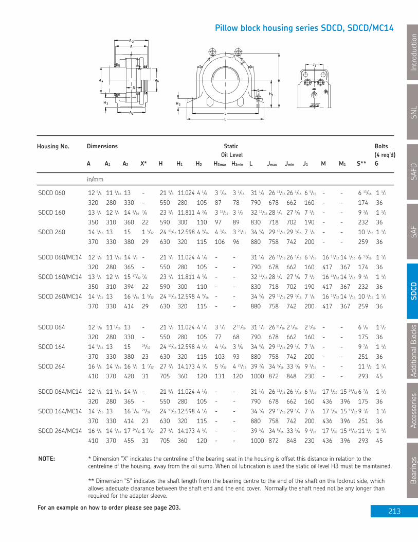
AdditionalB
locks
Accessories
Bearings
213
Pillow block housing series SDCD, SDCD/MC14
S
H 3
JL
1A
2H
H1G
da db H
2A
A
J1
MADE IN CANADA
Housing No. Dimensions Static BoltsOil Level (4 req’d)
A A1 A2 X* H H1 H2 H3max H3min L Jmax Jmin J1 M M1 S** G
in/mm
NOTE: * Dimension "X" indicates the centreline of the bearing seat in the housing is offset this distance in relation to thecentreline of the housing, away from the oil sump. When oil lubrication is used the static oil level H3 must be maintained.
** Dimension "S" indicates the shaft length from the bearing centre to the end of the shaft on the locknut side, whichallows adequate clearance between the shaft end and the end cover. Normally the shaft need not be any longer thanrequired for the adapter sleeve.
SNL
Introduction
SAFD
SAF
SDCD
For an example on how to order please see page 203.
SDCD 060 12 5⁄8 11 1⁄16 13 - 21 5⁄8 11.024 4 1⁄8 3 7⁄16 3 1⁄16 31 1⁄8 26 11⁄16 26 1⁄16 6 5⁄16 - - 6 13⁄16 1 1⁄2
320 280 330 - 550 280 105 87 78 790 678 662 160 - - 174 36
SDCD 160 13 3⁄4 12 1⁄4 14 3⁄16 7⁄8 23 1⁄4 11.811 4 3⁄8 3 13⁄16 3 1⁄2 32 11⁄16 28 1⁄4 27 5⁄8 7 1⁄2 - - 9 1⁄8 1 1⁄2
350 310 360 22 590 300 110 97 89 830 718 702 190 - - 232 36
SDCD 260 14 9⁄16 13 15 1 5⁄32 24 13⁄16 12.598 4 9⁄16 4 3⁄16 3 25⁄32 34 5⁄8 29 13⁄16 29 3⁄16 7 7⁄8 - - 10 3⁄16 1 1⁄2
370 330 380 29 630 320 115 106 96 880 758 742 200 - - 259 36
SDCD 060/MC14 12 5⁄8 11 1⁄16 14 3⁄8 - 21 5⁄8 11.024 4 1⁄8 - - 31 1⁄8 26 11⁄16 26 1⁄16 6 5⁄16 16 13⁄32 14 7⁄16 6 13⁄16 1 1⁄2
320 280 365 - 550 280 105 - - 790 678 662 160 417 367 174 36
SDCD 160/MC14 13 3⁄4 12 1⁄4 15 17⁄32 7⁄8 23 1⁄4 11.811 4 3⁄8 - - 32 11⁄16 28 1⁄4 27 5⁄8 7 1⁄2 16 13⁄32 14 7⁄16 9 1⁄8 1 1⁄2
350 310 394 22 590 300 110 - - 830 718 702 190 417 367 232 36
SDCD 260/MC14 14 9⁄16 13 16 5⁄16 1 5⁄32 24 13⁄16 12.598 4 9⁄16 - - 34 5⁄8 29 13⁄16 29 3⁄16 7 7⁄8 16 13⁄32 14 7⁄16 10 3⁄16 1 1⁄2
370 330 414 29 630 320 115 - - 880 758 742 200 417 367 259 36
SDCD 064 12 5⁄8 11 1⁄16 13 - 21 5⁄8 11.024 4 1⁄8 3 1⁄2 2 11⁄16 31 1⁄8 26 11⁄16 2 1⁄16 2 5⁄16 - - 6 7⁄8 1 1⁄2
320 280 330 - 550 280 105 77 68 790 678 662 160 - - 175 36
SDCD 164 14 9⁄16 13 15 29⁄32 24 13⁄16 12.598 4 1⁄2 4 1⁄16 3 5⁄8 34 5⁄8 29 13⁄16 29 1⁄4 7 7⁄8 - - 9 7⁄8 1 1⁄2
370 330 380 23 630 320 115 103 93 880 758 742 200 - - 251 36
SDCD 264 16 1⁄8 14 9⁄16 16 1⁄2 1 7⁄32 27 3⁄4 14.173 4 3⁄4 5 5⁄32 4 23⁄32 39 3⁄8 34 5⁄16 33 3⁄8 9 1⁄16 - - 11 1⁄2 1 3⁄4
410 370 420 31 705 360 120 131 120 1000 872 848 230 - - 293 45
SDCD 064/MC14 12 5⁄8 11 1⁄16 14 3⁄8 - 21 5⁄8 11.024 4 1⁄8 - - 31 1⁄8 26 11⁄16 26 1⁄16 6 5⁄16 17 5⁄32 15 19⁄32 6 7⁄8 1 1⁄2
320 280 365 - 550 280 105 - - 790 678 662 160 436 396 175 36
SDCD 164/MC14 14 9⁄16 13 16 5⁄16 29⁄32 24 13⁄16 12.598 4 1⁄2 - - 34 5⁄8 29 13⁄16 29 1⁄4 7 7⁄8 17 5⁄32 15 19⁄32 9 7⁄8 1 1⁄2
370 330 414 23 630 320 115 - - 880 758 742 200 436 396 251 36
SDCD 264/MC14 16 1⁄8 14 9⁄16 17 29⁄32 1 7⁄32 27 3⁄4 14.173 4 3⁄4 - - 39 3⁄8 34 5⁄16 33 3⁄8 9 1⁄16 17 5⁄32 15 19⁄32 11 1⁄2 1 3⁄4
410 370 455 31 705 360 120 - - 1000 872 848 230 436 396 293 45

SNL
IntroductionSAFD
SAFSDCD
AdditionalBlocksAccessories
Bearings
214
S S
H
A1
3 H 3
1A
dM a
2AA
X
Md db 1 a db
A 2
XA
Shaft Complete Pillow Housing Seal Assemblies Bearing Lock Lock End Fixing Mass
Dia. Block Assembly For Shaft Dia Nut Washer Cover RingComp
da/db da db (2 req'd)
in kg
Series SDCD 000, SDCD 100,SDCD 200, SDCD 000/MC14,SDCD 100/MC14, SDCD 200/MC14Pillow blocks of ductile ironfor bearings with cylindricalbore mounting and greaseor oil lubricationda 14 1⁄2 - 15 1⁄4 indb 13 - 13 3⁄4 in
da 14 1⁄2
db 13
SDCD 23068 SDCD068 TS80/14 1⁄2 TS68/13 23068CC/W33 N 068 P 68 ETS68 FRB 10/520 475
SDCD 23168 SDCD168 TS80/14 1⁄2 TS68/13 23168CC/W33 N 068 P 68 ETS68 FRB 10/580 789
SDCD 23268 SDCD268 TS80/14 1⁄2 TS68/13 23268CA/W33 N 068 P 68 ETS68 FRB 10/620 1063
SDCD 23068/MC14D SDCD068/MC14 TSDC76/14 1⁄2D TSDC68/13D 23068CC/W33 N 068 P 68 ASDC68 FRB 10/520 474
SDCD 23168/MC14D SDCD168/MC14 TSDC76/14 1⁄2D TSDC68/13D 23168CC/W33 N 068 P 68 ASDC68 FRB 10/580 789
SDCD 23268/MC14D SDCD268/MC14 TSDC76/14 1⁄2D TSDC68/13D 23268CA/W33 N 068 P 68 ASDC68 FRB 10/620 1063
da 15 1⁄4
db 13 3⁄4
SDCD 23072 SDCD072 TS84/15 1⁄4 TS72/13 3⁄4 23072CC/W33 N 072 P 72 ETS72 FRB 10/540 558
SDCD 23172 SDCD172 TS84/15 1⁄4 TS72/13 3⁄4 23172CAC/W33 N 072 P 72 ETS72 FRB 10/600 814
SDCD 23272 SDCD272 TS84/15 1⁄4 TS72/13 3⁄4 23272CA/W33 N 072 P 72 ETS72 FRB 10/650 1107
SDCD 23072/MC14D SDCD072/MC14 TSDC80/15 1⁄4D TSDC72/13 3⁄4D 23072CC/W33 N 072 P 72 ASDC72 FRB 10/540 558
SDCD 23172/MC14D SDCD172/MC14 TSDC80/15 1⁄4D TSDC72/13 3⁄4D 23172CAC/W33 N 072 P 72 ASDC72 FRB 10/600 814
SDCD 23272/MC14D SDCD272/MC14 TSDC80/15 1⁄4D TSDC72/13 3⁄4D 23272CA/W33 N 072 P 72 ASDC72 FRB 10/650 1107
If oil lubrication is to be used, SKF can drill and tap the two bosses for the oil level gauge and oil drain holes, if so specified on yourorder. Advise the type and size of the gauge you intend to use, gauges are not supplied by SKF.

AdditionalB
locks
Accessories
Bearings
215
Pillow block housing series SDCD, SDCD/MC14
S
H 3
JL
1A
2H
H1G
da db H
2A
A
J1
MADE IN CANADA
Housing No. Dimensions Static BoltsOil Level (4 req’d)
A A1 A2 X* H H1 H2 H3max H3min L Jmax Jmin J1 M M1 S** G
in/mm
NOTE: * Dimension "X" indicates the centreline of the bearing seat in the housing is offset this distance in relation to thecentreline of the housing, away from the oil sump. When oil lubrication is used the static oil level H3 must be maintained.
** Dimension "S" indicates the shaft length from the bearing centre to the end of the shaft on the locknut side, whichallows adequate clearance between the shaft end and the end cover. Normally the shaft need not be any longer thanrequired for the adapter sleeve.
SNL
Introduction
SAFD
SAF
SDCD
For an example on how to order please see page 203.
SDCD 068 13 13⁄16 12 1⁄4 14 3⁄16 - 23 1⁄4 11.811 4 3⁄8 3 1⁄4 2 13⁄16 32 11⁄16 28 1⁄4 27 5⁄8 7 1⁄2 - - 7 11⁄16 1 1⁄2
350 310 360 - 590 300 110 82 71 830 718 702 190 - - 196 36
SDCD 168 16 1⁄8 14 9⁄16 16 1⁄2 1 7⁄32 27 3⁄4 14.173 4 3⁄4 5 1⁄32 4 9⁄16 39 3⁄8 34 5⁄16 33 3⁄8 9 1⁄16 - - 11 3⁄16 1 3⁄4
410 370 420 31 705 360 120 128 116 1000 872 848 230 - - 284 45
SDCD 268 17 1⁄8 15 1⁄2 17 1⁄2 1 7⁄32 30 1⁄8 15.354 5 5 23⁄32 5 7⁄32 44 38 1⁄2 37 1⁄2 9 1⁄4 - - 12 1⁄4 2
435 394 445 31 765 390 127 145 132 1118 977 953 235 - - 312 50
SDCD 068/MC14 13 13⁄16 12 1⁄4 15 17⁄32 - 23 1⁄4 11.811 4 3⁄8 - - 32 11⁄16 28 1⁄4 27 5⁄8 7 1⁄2 17 29⁄32 16 13⁄32 7 11⁄16 1 1⁄2
350 310 394 - 590 300 110 - - 830 718 702 190 455 417 196 36
SDCD 168/MC14 16 1⁄8 14 9⁄16 17 29⁄32 1 7⁄32 27 3⁄4 14.173 4 3⁄4 - - 39 3⁄8 34 5⁄16 33 3⁄8 9 1⁄16 17 29⁄32 16 13⁄32 11 3⁄16 1 3⁄4
410 370 455 31 705 360 120 - - 1000 872 848 230 455 417 284 45
SDCD 268/MC14 17 1⁄8 15 1⁄2 18 7⁄8 1 7⁄32 30 1⁄8 15.354 5 - - 44 38 1⁄2 37 1⁄2 9 1⁄4 17 29⁄32 16 13⁄32 12 1⁄4 2
435 394 479 31 765 390 127 - - 1118 977 953 235 455 417 312 50
SDCD 072 14 9⁄16 13 15 - 24 13⁄16 12.598 4 1⁄2 3 23⁄32 3 11⁄32 34 11⁄16 29 13⁄16 29 1⁄4 7 7⁄8 - - 8 1⁄8 1 1⁄2
370 330 380 - 630 320 115 94 85 880 758 742 200 - - 207 36
SDCD 172 16 1⁄8 14 9⁄16 16 1⁄2 1 7⁄32 27 3⁄4 14.173 4 3⁄4 4 9⁄16 4 1⁄8 39 3⁄8 34 3⁄8 33 3⁄8 9 1⁄16 - - 11 3⁄16 1 3⁄4
410 370 420 31 705 360 120 116 104 1000 872 848 230 - - 284 45
SDCD 272 17 1⁄8 15 1⁄2 17 1⁄2 1 7⁄32 30 1⁄8 15.354 5 5 9⁄32 4 23⁄32 44 38 1⁄2 37 1⁄2 9 1⁄4 - - 12 7⁄16 2
435 394 445 31 765 390 127 134 120 1118 977 953 235 - - 316 50
SDCD 072/MC14 14 9⁄16 13 16 5⁄16 - 24 13⁄16 12.598 4 1⁄2 - - 34 11⁄16 29 13⁄16 29 1⁄4 7 7⁄8 18 21⁄32 17 5⁄32 8 1⁄8 1 1⁄2
370 330 389 - 630 320 115 - - 880 758 742 200 474 436 207 36
SDCD 172/MC14 16 1⁄8 14 9⁄16 17 29⁄32 1 7⁄32 27 3⁄4 14.173 3⁄4 - - 39 3⁄8 34 3⁄8 33 3⁄8 9 1⁄16 18 21⁄32 17 5⁄32 11 3⁄16 1 3⁄4
410 370 455 31 705 360 120 - - 1000 872 848 230 474 436 284 45
SDCD 272/MC14 17 1⁄8 15 1⁄2 18 7⁄8 1 7⁄32 30 1⁄8 15.354 5 - - 44 38 1⁄2 37 1⁄2 9 1⁄4 18 21⁄32 17 5⁄32 12 7⁄16 2
435 394 479 31 765 390 127 - - 1118 977 953 235 474 436 316 50
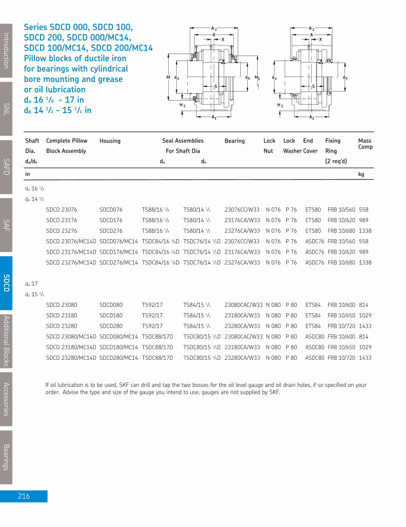
SNL
IntroductionSAFD
SAFSDCD
AdditionalBlocksAccessories
Bearings
216
S S
H
A1
3 H 3
1A
dM a
2AA
X
Md db 1 a db
A 2
XA
Shaft Complete Pillow Housing Seal Assemblies Bearing Lock Lock End Fixing Mass
Dia. Block Assembly For Shaft Dia Nut Washer Cover RingComp
da/db da db (2 req'd)
in kg
Series SDCD 000, SDCD 100,SDCD 200, SDCD 000/MC14,SDCD 100/MC14, SDCD 200/MC14Pillow blocks of ductile ironfor bearings with cylindricalbore mounting and greaseor oil lubricationda 16 1⁄8 - 17 indb 14 1⁄2 - 15 1⁄4 in
da 16 1⁄8
db 14 1⁄2
SDCD 23076 SDCD076 TS88/16 1⁄8 TS80/14 1⁄2 23076CC/W33 N 076 P 76 ETS80 FRB 10/560 558
SDCD 23176 SDCD176 TS88/16 1⁄8 TS80/14 1⁄2 23176CA/W33 N 076 P 76 ETS80 FRB 10/620 989
SDCD 23276 SDCD276 TS88/16 1⁄8 TS80/14 1⁄2 23276CA/W33 N 076 P 76 ETS80 FRB 10/680 1338
SDCD 23076/MC14D SDCD076/MC14 TSDC84/16 1⁄8D TSDC76/14 1⁄2D 23076CC/W33 N 076 P 76 ASDC76 FRB 10/560 558
SDCD 23176/MC14D SDCD176/MC14 TSDC84/16 1⁄8D TSDC76/14 1⁄2D 23176CA/W33 N 076 P 76 ASDC76 FRB 10/620 989
SDCD 23276/MC14D SDCD276/MC14 TSDC84/16 1⁄8D TSDC76/14 1⁄2D 23276CA/W33 N 076 P 76 ASDC76 FRB 10/680 1338
da 17
db 15 1⁄4
SDCD 23080 SDCD080 TS92/17 TS84/15 1⁄4 23080CAC/W33 N 080 P 80 ETS84 FRB 10/600 814
SDCD 23180 SDCD180 TS92/17 TS84/15 1⁄4 23180CA/W33 N 080 P 80 ETS84 FRB 10/650 1029
SDCD 23280 SDCD280 TS92/17 TS84/15 1⁄4 23280CA/W33 N 080 P 80 ETS84 FRB 10/720 1433
SDCD 23080/MC14D SDCD080/MC14 TSDC88/17D TSDC80/15 1⁄4D 23080CAC/W33 N 080 P 80 ASDC80 FRB 10/600 814
SDCD 23180/MC14D SDCD180/MC14 TSDC88/17D TSDC80/15 1⁄4D 23180CA/W33 N 080 P 80 ASDC80 FRB 10/650 1029
SDCD 23280/MC14D SDCD280/MC14 TSDC88/17D TSDC80/15 1⁄4D 23280CA/W33 N 080 P 80 ASDC80 FRB 10/720 1433
If oil lubrication is to be used, SKF can drill and tap the two bosses for the oil level gauge and oil drain holes, if so specified on yourorder. Advise the type and size of the gauge you intend to use, gauges are not supplied by SKF.

AdditionalB
locks
Accessories
Bearings
217
Pillow block housing series SDCD, SDCD/MC14
S
H 3
JL
1A
2H
H1G
da db H
2A
A
J1
MADE IN CANADA
Housing No. Dimensions Static BoltsOil Level (4 req’d)
A A1 A2 X* H H1 H2 H3max H3min L Jmax Jmin J1 M M1 S** G
in/mm
NOTE: * Dimension "X" indicates the centreline of the bearing seat in the housing is offset this distance in relation to thecentreline of the housing, away from the oil sump. When oil lubrication is used the static oil level H3 must be maintained.
** Dimension "S" indicates the shaft length from the bearing centre to the end of the shaft on the locknut side, whichallows adequate clearance between the shaft end and the end cover. Normally the shaft need not be any longer thanrequired for the adapter sleeve.
SNL
Introduction
SAFD
SAF
SDCD
For an example on how to order please see page 203.
SDCD 076 14 9⁄16 13 15 - 24 13⁄16 12.598 4 1⁄2 3 1⁄4 2 27⁄32 34 11⁄16 29 13⁄16 29 1⁄4 7 7⁄8 - - 8 1⁄8 1 1⁄2
370 330 380 - 630 320 115 83 72 880 758 742 200 - - 207 36
SDCD 176 17 1⁄8 15 1⁄2 17 1⁄2 1 7⁄32 30 1⁄8 15.354 5 5 7⁄16 5 44 38 1⁄2 37 1⁄2 9 1⁄4 - - 11 11⁄16 2
435 394 445 31 765 390 127 138 127 1118 978 953 235 - - 297 50
SDCD 276 18 1⁄8 16 1⁄2 18 1⁄2 1 7⁄32 33 1⁄8 16.737 5 6 1⁄8 5 9⁄16 47 1⁄4 41 3⁄16 40 1⁄4 9 7⁄8 - - 13 1⁄8 2
460 419 470 31 841 425 127 155 141 1200 1047 1022 251 - - 333 50
SDCD 076/MC14 14 9⁄16 13 16 5⁄16 - 24 13⁄16 12.598 4 1⁄2 - - 34 11⁄16 29 13⁄16 29 1⁄4 7 7⁄8 19 1⁄2 17 29⁄32 8 1⁄8 1 1⁄2
370 330 389 - 630 320 115 - - 880 758 742 200 495 455 207 36
SDCD 176/MC14 17 1⁄8 15 1⁄2 18 7⁄8 1 7⁄32 30 1⁄8 15.354 5 - - 44 38 1⁄2 37 1⁄2 9 1⁄4 19 1⁄2 17 29⁄32 11 11⁄16 2
435 394 479 31 765 390 127 - - 1118 978 953 235 495 455 297 50
SDCD 276/MC14 18 1⁄8 16 1⁄2 19 7⁄8 1 7⁄32 33 1⁄8 16.737 5 - - 47 1⁄4 4 13⁄16 40 1⁄4 9 7⁄8 19 1⁄2 17 29⁄32 13 1⁄8 2
460 419 505 31 841 425 127 - - 1200 1047 1022 251 495 455 333 50
SDCD 080 16 1⁄8 14 9⁄16 16 1⁄2 - 27 3⁄4 14.173 4 3⁄4 4 3⁄16 3 3⁄4 39 3⁄8 34 5⁄16 33 3⁄8 9 1⁄16 - - 9 1⁄8 1 3⁄4
410 370 420 - 705 360 120 106 94 1000 872 848 230 - - 232 45
SDCD 180 17 1⁄8 15 1⁄2 17 1⁄2 1 7⁄32 30 1⁄8 15.354 5 4 31⁄32 4 1⁄2 44 38 1⁄2 37 1⁄2 9 1⁄4 - - 11 13⁄16 2
435 394 445 31 765 390 127 126 113 1118 978 953 235 - - 300 50
SDCD 280 18 1⁄8 16 1⁄2 18 1⁄2 1 7⁄32 33 1⁄8 16.732 5 5 1⁄2 4 7⁄8 47 1⁄4 41 3⁄16 40 1⁄4 9 7⁄8 - - 13 7⁄16 2
460 419 470 31 841 425 127 140 124 1200 1047 1022 251 - - 341 50
SDCD 080/MC14 16 1⁄8 14 9⁄16 17 29⁄32 - 27 3⁄4 14.173 4 3⁄4 - - 39 3⁄8 34 5⁄16 33 3⁄8 9 1⁄16 20 13⁄32 18 21⁄32 9 1⁄8 1 3⁄4
410 370 455 - 705 360 120 - - 1000 872 848 230 518 474 232 45
SDCD 180/MC14 17 1⁄8 15 1⁄2 18 7⁄8 1 7⁄32 30 1⁄8 15.354 5 - - 44 38 1⁄2 37 1⁄2 9 1⁄4 20 13⁄32 18 21⁄32 11 13⁄16 2
435 394 479 31 765 390 127 - - 1118 978 953 235 518 474 300 50
SDCD 280/MC14 18 1⁄8 16 1⁄2 19 7⁄8 1 7⁄32 33 1⁄8 16.737 5 - - 47 1⁄4 41 3⁄16 40 1⁄4 9 7⁄8 20 13⁄32 18 21⁄32 13 7⁄16 2
460 419 505 31 841 425 127 - - 1200 1047 1022 251 518 474 341 50

SNL
IntroductionSAFD
SAFSDCD
AdditionalBlocksAccessories
Bearings
218
S S
H
A1
3 H 3
1A
dM a
2AA
X
Md db 1 a db
A 2
XA
Shaft Complete Pillow Housing Seal Assemblies Bearing Lock Lock End Fixing Mass
Dia. Block Assembly For Shaft Dia Nut Washer Cover RingComp
da/db da db (2 req'd)
in kg
Series SDCD 000, SDCD 100,SDCD 200, SDCD 000/MC14,SDCD 100/MC14, SDCD 200/MC14Pillow blocks of ductile ironfor bearings with cylindricalbore mounting and greaseor oil lubricationda 18 - 19 indb 16 1⁄8 - 17 in
da 18
db 16 1⁄8
SDCD 23084 SDCD084 TS96/18 TS88/16 1⁄8 23084CA/W33 N 084 P 84 ETS88 FRB 10/620 989
SDCD 23184 SDCD184 TS96/18 TS88/16 1⁄8 23184C/W33 N 084 P 84 ETS88 FRB 10/700 1313
SDCD 23084/MC14D SDCD084/MC14 TSDC92/18D TSDC84/16 1⁄8 D 23084CA/W33 N 084 P 84 ASDC84 FRB 10/620 989
SDCD 23184/MC14D SDCD184/MC14 TSDC92/18D TSDC84/16 1⁄8 D 23184CJ/W33 N 084 P 84 ASDC84 FRB 10/700 1313
da 19
db 17 SDCD 23088 SDCD088 TS500/19 TS92/17 23088CA/W33 N 088 P 88 ETS92 FRB 10/650 989
SDCD 23188 SDCD188 TS500/19 TS92/17 23188CA/W33 N 088 P 88 ETS92 FRB 10/720 1347
SDCD 23088/MC14D SDCD088/MC14 TSDC96/19D TSDC88/17D 23088CA/W33 N 088 P 88 ASDC88 FRB 10/650 989
SDCD 23188/MC14D SDCD188/MC14 TSDC96/19D TSDC88/17D 23188CA/W33 N 088 P 88 ASDC88 FRB 10/720 1347
If oil lubrication is to be used, SKF can drill and tap the two bosses for the oil level gauge and oil drain holes, if so specified on yourorder. Advise the type and size of the gauge you intend to use, gauges are not supplied by SKF.

AdditionalB
locks
Accessories
Bearings
219
Pillow block housing series SDCD, SDCD/MC14
S
H 3
JL
1A
2H
H1G
da db H
2A
A
J1
MADE IN CANADA
Housing No. Dimensions Static BoltsOil Level (4 req’d)
A A1 A2 X* H H1 H2 H3max H3min L Jmax Jmin J1 M M1 S** G
in/mm
NOTE: * Dimension "X" indicates the centreline of the bearing seat in the housing is offset this distance in relation to thecentreline of the housing, away from the oil sump. When oil lubrication is used the static oil level H3 must be maintained.
** Dimension "S" indicates the shaft length from the bearing centre to the end of the shaft on the locknut side, whichallows adequate clearance between the shaft end and the end cover. Normally the shaft need not be any longer thanrequired for the adapter sleeve.
SNL
Introduction
SAFD
SAF
SDCD
For an example on how to order please see page 203.
SDCD 084 17 1⁄8 15 1⁄2 17 1⁄2 - 30 1⁄8 15.354 5 5 4 9⁄16 44 38 1⁄2 37 1⁄2 9 1⁄4 - - 9 5⁄8 2
435 394 445 - 765 390 127 127 115 1118 978 952 235 - - 244 50
SDCD 184 18 1⁄8 16 1⁄2 18 1⁄2 1 7⁄32 33 1⁄8 16.732 5 5 5⁄8 5 1⁄32 47 1⁄4 41 3⁄16 40 5⁄16 9 7⁄8 - - 12 13⁄16 2
460 419 470 31 841 425 127 143 128 1200 1046 1024 251 - - 325 50
SDCD 084/MC14 17 1⁄8 15 1⁄2 18 7⁄8 - 30 1⁄8 15.354 5 - - 44 38 1⁄2 1⁄2 9 1⁄4 21 13⁄32 19 1⁄2 9 5⁄8 2
435 394 479 - 765 390 127 - - 1118 978 952 235 544 495 244 50
SDCD 184/MC14 18 1⁄8 16 1⁄2 19 7⁄8 1 7⁄32 33 1⁄8 16.732 5 - - 47 1⁄4 41 3⁄16 40 5⁄16 9 7⁄8 21 13⁄32 19 1⁄2 12 13⁄16 2
460 419 505 31 841 425 127 - - 1200 1046 1024 251 544 495 325 50
SDCD 088 17 1⁄8 15 1⁄2 17 1⁄2 - 30 1⁄8 15.354 5 4 1⁄2 4 44 38 1⁄2 37 1⁄2 9 1⁄4 - - 9 3⁄4 2
435 394 445 - 765 390 127 114 102 1118 978 952 235 - - 248 50
SDCD 188 18 1⁄8 16 1⁄2 18 1⁄2 1 7⁄32 33 1⁄8 16.732 5 5 1⁄8 4 9⁄16 47 1⁄4 41 3⁄16 40 5⁄16 9 7⁄8 - - 12 13⁄16 2
460 419 470 31 841 425 127 130 115 1200 1046 1024 251 - - 325 50
SDCD 088/MC14 17 1⁄8 15 1⁄2 18 7⁄8 - 30 1⁄8 15.354 5 - - 44 38 1⁄2 37 1⁄2 9 1⁄4 22 13⁄32 20 13⁄32 9 3⁄4 2
435 394 479 - 765 390 127 - - 1118 978 952 235 569 518 248 50
SDCD 188/MC14 18 1⁄8 16 1⁄2 19 7⁄8 1 7⁄32 33 1⁄8 16.737 5 - - 47 1⁄4 3⁄16 40 5⁄16 9 7⁄8 22 13⁄32 20 13⁄32 12 13⁄16 2
460 419 505 31 841 425 127 - - 1200 1046 1024 251 569 518 325 50

SNL
IntroductionSAFD
SAFSD
CDAdditionalB
locksAccessories
Bearings
220
Series TY-RPATake-up units with topangle protected screwda 1 7⁄16 - 2 3⁄16 in(36.51 - 55.56 mm)Travel 12 - 36 in(304.8 - 914.4 mm)
Shaft Designation Housing Frame Travel Bearing Adapter Fixing
Dia. Unit Code Sleeve Ring
da Complete (2 req'd) A B C D E
in/mm in/mm in/mm
1 7⁄16 TY 107 RPA-12 TY 107 R PA 12-1 12 22209 EK HA 309 SR 9-9 3 15⁄16 28 1⁄2 3 5⁄8 3⁄8 26 1⁄2
36.51 304.8 100.0 723.9 92.1 9.5 673.1
1 7⁄16 TY 107 RPA-18 TY 107 R PA 18-1 18 22209 EK HA 309 SR 9-9 3 15⁄16 34 1⁄2 3 5⁄8 3⁄8 32 1⁄2
36.51 457.2 100.0 876.3 92.1 9.5 825.5
1 7⁄16 TY 107 RPA-24 TY 107 R PA 24-1 24 22209 EK HA 309 SR 9-9 3 15⁄16 40 1⁄2 3 5⁄8 3⁄8 38 1⁄2
36.51 609.6 100.0 1028.7 92.1 9.5 977.9
1 15⁄16 TY 115 RPA-12 TY 115 R PA 12-2 12 22211 EK HA 311 SR 11-0 4 3⁄16 29 1⁄2 3 5⁄8 3⁄8 27 1⁄2
49.21 304.8 106.4 749.3 92.1 9.5 698.5
1 15⁄16 TY 115 RPA-18 TY 115 R PA 18-2 18 22211 EK HA 311 SR 11-0 4 3⁄16 35 1⁄2 3 5⁄8 3⁄8 33 1⁄2
49.21 457.2 106.4 901.7 92.1 9.5 850.9
1 15⁄16 TY 115 RPA-24 TY 115 R PA 24-2 24 22211 EK HA 311 SR 11-0 4 3⁄16 41 1⁄2 3 5⁄8 3⁄8 39 1⁄2
49.21 609.6 106.4 1054.1 92.1 9.5 1003.3
2 3⁄16 TY 203 RPA-12 TY 203 R PA 12-4 12 22213 EK HA 313 SR 13-0 5 1⁄8 32 1⁄2 4 5⁄8 1⁄2 30 1⁄2
55.56 304.8 130.2 825.5 117.5 12.7 774.7
2 3⁄16 TY 203 RPA-18 TY 203 R PA 18-4 18 22213 EK HA 313 SR 13-0 5 1⁄8 38 1⁄2 4 5⁄8 1⁄2 36 1⁄2
55.56 457.2 130.2 977.9 117.5 12.7 927.1
2 3⁄16 TY 203 RPA-24 TY 203 R PA 24-4 24 22213 EK HA 313 SR 13-0 5 1⁄8 44 1⁄2 4 5⁄8 1⁄2 42 1⁄2
55.56 609.6 130.2 1130.3 117.5 12.7 1079.5
2 3⁄16 TY 203 RPA-30 TY 203 R PA 30-4 30 22213 EK HA 313 SR 13-0 5 1⁄8 50 1⁄2 4 5⁄8 1⁄2 54 1⁄2
55.56 762.0 130.2 1282.7 117.5 12.7 1384.3
2 3⁄16 TY 203 RPA-36 TY 203 R PA 36-4 36 22213 EK HA 313 SR 13-0 5 1⁄8 56 1⁄2 4 5⁄8 1⁄2 5 1/2
55.56 914.4 130.2 1435.1 117.5 12.7 139.7
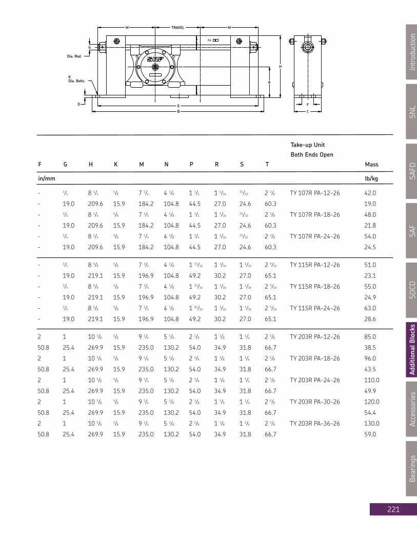
SNL
Introduction
SAFD
SAF
SDCD
AdditionalBlocks
Accessories
Bearings
221
Take-up Unit
Both Ends Open
F G H K M N P R S T Mass
in/mm lb/kg
- 3⁄4 8 1⁄4 5⁄8 7 1⁄4 4 1⁄8 1 3⁄4 1 1⁄16 31⁄32 2 3⁄8 TY 107R PA-12-26 42.0
- 19.0 209.6 15.9 184.2 104.8 44.5 27.0 24.6 60.3 19.0
- 3⁄4 8 1⁄4 5⁄8 7 1⁄4 4 1⁄8 1 3⁄4 1 1⁄16 31⁄32 2 3⁄8 TY 107R PA-18-26 48.0
- 19.0 209.6 15.9 184.2 104.8 44.5 27.0 24.6 60.3 21.8
- 3⁄4 8 1⁄4 5⁄8 7 1⁄4 4 1⁄8 1 3⁄4 1 1⁄16 31⁄32 2 3⁄8 TY 107R PA-24-26 54.0
- 19.0 209.6 15.9 184.2 104.8 44.5 27.0 24.6 60.3 24.5
- 3⁄4 8 5⁄8 5⁄8 7 3⁄4 4 1⁄8 1 15⁄16 1 3⁄16 1 1⁄16 2 9⁄16 TY 115R PA-12-26 51.0
- 19.0 219.1 15.9 196.9 104.8 49.2 30.2 27.0 65.1 23.1
- 3⁄4 8 5⁄8 5⁄8 7 3⁄4 4 1⁄8 1 15⁄16 1 3⁄16 1 1⁄16 2 9⁄16 TY 115R PA-18-26 55.0
- 19.0 219.1 15.9 196.9 104.8 49.2 30.2 27.0 65.1 24.9
- 3⁄4 8 5⁄8 5⁄8 7 3⁄4 4 1⁄8 1 15⁄16 1 3⁄16 1 1⁄16 2 9⁄16 TY 115R PA-24-26 63.0
- 19.0 219.1 15.9 196.9 104.8 49.2 30.2 27.0 65.1 28.6
2 1 10 5⁄8 5⁄8 9 1⁄4 5 1⁄8 2 1⁄8 1 3⁄8 1 1⁄4 2 5⁄8 TY 203R PA-12-26 85.0
50.8 25.4 269.9 15.9 235.0 130.2 54.0 34.9 31.8 66.7 38.5
2 1 10 5⁄8 5⁄8 9 1⁄4 5 1⁄8 2 1⁄8 1 3⁄8 1 1⁄4 2 5⁄8 TY 203R PA-18-26 96.0
50.8 25.4 269.9 15.9 235.0 130.2 54.0 34.9 31.8 66.7 43.5
2 1 10 5⁄8 5⁄8 9 1⁄4 5 1⁄8 2 1⁄8 1 3⁄8 1 1⁄4 2 5⁄8 TY 203R PA-24-26 110.0
50.8 25.4 269.9 15.9 235.0 130.2 54.0 34.9 31.8 66.7 49.9
2 1 10 5⁄8 5⁄8 9 1⁄4 5 1⁄8 2 1⁄8 1 3⁄8 1 1⁄4 2 5⁄8 TY 203R PA-30-26 120.0
50.8 25.4 269.9 15.9 235.0 130.2 54.0 34.9 31.8 66.7 54.4
2 1 10 5⁄8 5⁄8 9 1⁄4 5 1⁄8 2 1⁄8 1 3⁄8 1 1⁄4 2 5⁄8 TY 203R PA-36-26 130.0
50.8 25.4 269.9 15.9 235.0 130.2 54.0 34.9 31.8 66.7 59.0

SNL
IntroductionSAFD
SAFSD
CDAdditionalB
locksAccessories
Bearings
222
Series TY-RPATake-up units with topangle protected screwda 2 7⁄16 - 3 7⁄16 in(61.91 - 87.31 mm)Travel 12 - 36 in(304.8 - 914.4 mm)
Shaft Designation Housing Frame Travel Bearing Adapter Fixing
Dia. Unit Code Sleeve Ring
da Complete (2 req'd) A B C D E
in/mm in/mm in/mm
2 7⁄16 TY 207 RPA-12 TY 207 R PA 12-4 12 22215 EK HA 315 SR 15-0 5 1⁄8 32 1⁄2 4 5⁄8 1⁄2 30 1⁄2
61.91 304.8 130.2 825.5 117.5 12.7 774.7
2 7⁄16 TY 207 RPA-18 TY 207 R PA 18-4 18 22215 EK HA 315 SR 15-0 5 1⁄8 38 1⁄2 4 5⁄8 1⁄2 36 1⁄2
61.91 457.2 130.2 977.9 117.5 12.7 927.1
2 7⁄16 TY 207 RPA-24 TY 207 R PA 24-4 24 22215 EK HA 315 SR 15-0 5 1⁄8 44 1⁄2 4 5⁄8 1⁄2 42 1⁄2
61.91 609.6 130.2 1130.3 117.5 12.7 1079.5
2 7⁄16 TY 207 RPA-30 TY 207 R PA 30-4 30 22215 EK HA 315 SR 15-0 5 1⁄8 50 1⁄2 4 5⁄8 1⁄2 48 1⁄2
61.91 762.0 130.2 1282.7 117.5 12.7 1231.9
2 7⁄16 TY 207 RPA-36 TY 207 R PA 36-4 36 22215 EK HA 315 SR 15-0 5 1⁄8 56 1⁄2 4 5⁄8 1⁄2 54 1⁄2
61.91 914.4 130.2 1435.1 117.5 12.7 1384.3
2 15⁄16 TY 215 RPA-12 TY 215 R PA 12-5 12 22217 EK HA 317 SR 17-14 5 5⁄8 34 1⁄2 4 5⁄8 1⁄2 32.0
74.61 304.8 142.9 876.3 117.5 12.7 812.8
2 15⁄16 TY 215 RPA-18 TY 215 R PA 18-5 18 22217 EK HA 317 SR 17-14 5 5⁄8 40 1⁄2 4 5⁄8 1⁄2 38.0
74.61 457.2 142.9 1028.7 117.5 12.7 965.2
2 15⁄16 TY 215 RPA-24 TY 215 R PA 24-5 24 22217 EK HA 317 SR 17-14 5 5⁄8 46 1⁄2 4 5⁄8 1⁄2 44.0
74.61 609.6 142.9 1181.1 117.5 12.7 1117.6
2 15⁄16 TY 215 RPA-30 TY 215 R PA 30-5 30 22217 EK HA 317 SR 17-14 5 5⁄8 52 1⁄2 4 5⁄8 1⁄2 50.0
74.61 762.0 142.9 1333.5 117.5 12.7 1270.0
2 15⁄16 TY 215 RPA-36 TY 215 R PA 36-5 36 22217 EK HA 317 SR 17-14 5 5⁄8 58 1⁄2 4 5⁄8 1⁄2 56.0
74.61 914.4 142.9 1485.9 117.5 12.7 1422.4
3 7⁄16 TY 307 RPA-12 TY 307 R PA 12-6 12 22220 EK HA 320 SR 20-17 7 38 1⁄2 5 3⁄4 1⁄2 36.0
87.31 304.8 177.8 977.9 146.1 12.7 914.4
3 7⁄16 TY 307 RPA-18 TY 307 R PA 18-6 18 22220 EK HA 320 SR 20-17 7 44 1⁄2 5 3⁄4 1⁄2 42.0
87.31 457.2 177.8 1130.3 146.1 12.7 1066.8
3 7⁄16 TY 307 RPA-24 TY 307 R PA 24-6 24 22220 EK HA 320 SR 20-17 7 50 1⁄2 5 3⁄4 1⁄2 48.0
87.31 609.6 177.8 1282.7 146.1 12.7 1219.2
3 7⁄16 TY 307 RPA-30 TY 307 R PA 30-6 30 22220 EK HA 320 SR 20-17 7 56 1⁄2 5 3⁄4 1⁄2 54.0
87.31 762.0 177.8 1435.1 146.1 12.7 1371.6
3 7⁄16 TY 307 RPA-36 TY 307 R PA 36-6 36 22220 EK HA 320 SR 20-17 7 62 1⁄2 5 3⁄4 1⁄2 60.0
87.31 914.4 177.8 1587.5 146.1 12.7 1524.0

SNL
Introduction
SAFD
SAF
SDCD
AdditionalBlocks
Accessories
Bearings
223
Take-up Unit
Both Ends Open
F G H K M N P R S T Mass
in/mm lb/kg
2 1 10 5⁄8 5⁄8 9 1⁄4 5 1⁄8 2 1⁄8 1 7⁄16 1 9⁄32 2 5⁄8 TY 207R PA-12-33 92.0
50.8 25.4 269.9 15.9 235.0 130.2 54.0 36.5 32.5 66.7 41.7
2 1 10 5⁄8 5⁄8 9 1⁄4 5 1⁄8 2 1⁄8 1 7⁄16 1 9⁄32 2 5⁄8 TY 207R PA-18-33 105.0
50.8 25.4 269.9 15.9 235.0 130.2 54.0 36.5 32.5 66.7 47.6
2 1 10 5⁄8 5⁄8 9 1⁄4 5 1⁄8 2 1⁄8 1 7⁄16 1 9⁄32 2 5⁄8 TY 207R PA-24-33 110.0
50.8 25.4 269.9 15.9 235.0 130.2 54.0 36.5 32.5 66.7 49.9
2 1 10 5⁄8 5⁄8 9 1⁄4 5 1⁄8 2 1⁄8 1 7⁄16 1 9⁄32 2 5⁄8 TY 207R PA-30-33 120.0
50.8 25.4 269.9 15.9 235.0 130.2 54.0 36.5 32.5 66.7 54.4
2 1 10 5⁄8 5⁄8 9 1⁄4 5 1⁄8 2 1⁄8 1 7⁄16 1 9⁄32 2 5⁄8 TY 207R PA-36-33 130.0
50.8 25.4 269.9 15.9 235.0 130.2 54.0 36.5 32.5 66.7 59.0
2 1 1⁄8 11 3⁄4 3⁄4 10 5 5⁄8 2 1⁄2 1 9⁄16 1 13⁄32 2 15⁄16 TY 215R PA-12-33 100
50.8 28.6 298.5 19.0 254.0 142.9 63.5 39.7 35.7 74.6 45.4
2 1 1⁄8 11 3⁄4 3⁄4 10 5 5⁄8 2 1⁄2 1 9⁄16 1 13⁄32 2 15⁄16 TY 215R PA-18-33 115
50.8 28.6 298.5 19.0 254.0 142.9 63.5 39.7 35.7 74.6 52.2
2 1 1⁄8 11 3⁄4 3⁄4 10 5 5⁄8 2 1⁄2 1 9⁄16 1 13⁄32 2 15⁄16 TY 215R PA-24-33 130
50.8 28.6 298.5 19.0 254.0 142.9 63.5 39.7 35.7 74.6 59.0
2 1 1⁄8 11 3⁄4 3⁄4 10 5 5⁄8 2 1⁄2 1 9⁄16 1 13⁄32 2 15⁄16 TY 215R PA-30-33 140
50.8 28.6 298.5 19.0 254.0 142.9 63.5 39.7 35.7 74.6 63.5
2 1 1⁄8 11 3⁄4 3⁄4 10 5 5⁄8 2 1⁄2 1 9⁄16 1 13⁄32 2 15⁄16 TY 215R PA-36-33 155
50.8 28.6 298.5 19.0 254.0 142.9 63.5 39.7 35.7 74.6 70.3
2 1⁄2 1 1⁄4 14 1⁄2 3⁄4 12 6 7⁄8 2 1⁄2 1 15⁄16 1 3⁄4 3 7⁄16 TY 307R PA-12-33 155
63.5 31.8 368.3 19.0 304.8 174.6 63.5 49.2 44.5 87.3 70.3
2 1⁄2 1 1⁄4 14 1⁄2 3⁄4 12 6 7⁄8 2 1⁄2 1 15⁄16 1 3⁄4 3 7⁄16 TY 307R PA-18-33 175
63.5 31.8 368.3 19.0 304.8 174.6 63.5 49.2 44.5 87.3 79.4
2 1⁄2 1 1⁄4 14 1⁄2 3⁄4 12 6 7⁄8 2 1⁄2 1 15⁄16 1 3⁄4 3 7⁄16 TY 307R PA-24-33 190
63.5 31.8 368.3 19.0 304.8 174.6 63.5 49.2 44.5 87.3 86.2
2 1⁄2 1 1⁄4 14 1⁄2 3⁄4 12 6 7⁄8 2 1⁄2 1 15⁄16 1 3⁄4 3 7⁄16 TY 307R PA-30-33 205
63.5 31.8 368.3 19.0 304.8 174.6 63.5 49.2 44.5 87.3 93.0
2 1⁄2 1 1⁄4 14 1⁄2 3⁄4 12 6 7⁄8 2 1⁄2 1 15⁄16 1 3⁄4 3 7⁄16 TY 307R PA-36-33 220
63.5 31.8 368.3 19.0 304.8 174.6 63.5 49.2 44.5 87.3 99.8

SNL
IntroductionSAFD
SAFSD
CDAdditionalB
locksAccessories
Bearings
224
Series TY-RPATake-up units with topangle protected screwda 3 15⁄16 - 4 15⁄16 in(100.01 - 125.41 mm)Travel 12 - 36 in(304.8 - 914.4 mm)
Shaft Designation Housing Frame Travel Bearing Adapter Fixing
Dia. Unit Code Sleeve Ring
da Complete (2 req'd) A B C D E
in/mm in/mm in/mm
3 15⁄16 TY 315 RPA-12 TY 315 R PA 12-6 12 22222 EK H 322 SR 22-19 7 38 1⁄2 5 3⁄4 1⁄2 36.0
100.01 304.8 177.8 977.9 146.1 12.7 914.4
3 15⁄16 TY 315 RPA-18 TY 315 R PA 18-6 18 22222 EK H 322 SR 22-19 7 44 1⁄2 5 3⁄4 1⁄2 42.0
100.01 457.2 177.8 1130.3 146.1 12.7 1066.8
3 15⁄16 TY 315 RPA-24 TY 315 R PA 24-6 24 22222 EK H 322 SR 22-19 7 50 1⁄2 5 3⁄4 1⁄2 48.0
100.01 609.6 177.8 1282.7 146.1 12.7 1219.2
3 15⁄16 TY 315 RPA-30 TY 315 R PA 30-6 30 22222 EK H 322 SR 22-19 7 56 1⁄2 5 3⁄4 1⁄2 54.0
100.01 762.0 177.8 1435.1 146.1 12.7 1371.6
4 7⁄16 TY 407 RPA-12 TY 407 R PA 12-7 12 22226 EK HA 3126 SR 26-0 8 38 1⁄2 5 3⁄4 1⁄2 36.0
112.71 304.8 203.2 977.9 146.1 12.7 914.4
4 7⁄16 TY 407 RPA-18 TY 407 R PA 18-7 18 22226 EK HA 3126 SR 26-0 8 44 1⁄2 5 3⁄4 1⁄2 42.0
112.71 457.2 203.2 1130.3 146.1 12.7 1066.8
4 7⁄16 TY 407 RPA-24 TY 407 R PA 24-7 24 22226 EK HA 3126 SR 26-0 8 50 1⁄2 5 3⁄4 1⁄2 48.0
112.71 609.6 203.2 1282.7 146.1 12.7 1,219.2
4 7⁄16 TY 407 RPA-30 TY 407 R PA 30-7 30 22226 EK HA 3126 SR 26-0 8 56 1⁄2 5 3⁄4 1⁄2 54.0
112.71 762.0 203.2 1435.1 146.1 12.7 1,371.6
4 15⁄16 TY 415 RPA-12 TY 415 R PA 12-8 12 22228CCK/W33 HA 3128 35072-288 1/2 48 1⁄2 6 7⁄8 5⁄8 44 1⁄2
125.41 304.8 215.9 1231.9 174.6 15.9 1,130.3
4 15⁄16 TY 415 RPA-18 TY 415 R PA 18-8 18 22228CCK/W33 HA 3128 35072-288 1/2 54 1⁄2 6 7⁄8 5⁄8 50 1⁄2
125.41 457.2 215.9 1384.3 174.6 15.9 1,282.7
4 15⁄16 TY 415 RPA-24 TY 415 R PA 24-8 24 22228CCK/W33 HA 3128 35072-288 1/2 60 1⁄2 6 7⁄8 5⁄8 56 1⁄2
125.41 609.6 215.9 1536.7 174.6 15.9 1,435.1
4 15⁄16 TY 415 RPA-30 TY 415 R PA 30-8 30 22228CCK/W33 HA 3128 35072-288 1/2 66 1⁄2 6 7⁄8 5⁄8 62 1⁄2
125.41 762.0 215.9 1689.1 174.6 15.9 1,587.5

SNL
Introduction
SAFD
SAF
SDCD
AdditionalBlocks
Accessories
Bearings
225
Take-up Unit
Both Ends Open
F G H K M N P R S T Mass
in/mm lb/kg
2 1⁄2 1 1⁄4 14 1⁄2 3⁄4 12 6 7⁄8 2 7⁄8 2 1⁄8 1 31⁄32 3 13⁄16 TY 315R PA-12-39 155
63.5 31.8 368.3 19.0 304.8 174.6 73.0 54.0 50.0 96.8 70.3
2 1⁄2 1 1⁄4 14 1⁄2 3⁄4 12 6 7⁄8 2 7⁄8 2 1⁄8 1 31⁄32 3 13⁄16 TY 315R PA-18-39 170
63.5 31.8 368.3 19.0 304.8 174.6 73.0 54.0 50.0 96.8 77.1
2 1⁄2 1 1⁄4 14 1⁄2 3⁄4 12 6 7⁄8 2 7⁄8 2 1⁄8 1 31⁄32 3 13⁄16 TY 315R PA-24-39 190
63.5 31.8 368.3 19.0 304.8 174.6 73.0 54.0 50.0 96.8 86.2
2 1⁄2 1 1⁄4 14 1⁄2 3⁄4 12 6 7⁄8 2 7⁄8 2 1⁄8 1 31⁄32 3 13⁄16 TY 315R PA-30-39 205
63.5 31.8 368.3 19.0 304.8 174.6 73.0 54.0 50.0 96.8 93.0
2 1⁄2 1 3⁄8 16 3⁄4 3⁄4 12 7 3 1⁄16 2 1⁄2 2 9⁄32 4 1⁄4 TY 407R PA-12-32 270
63.5 34.9 425.5 19.0 304.8 177.8 77.8 63.5 57.9 108.0 122.4
2 1⁄2 1 3⁄8 16 3⁄4 3⁄4 12 7 3 1⁄16 2 1⁄2 2 9⁄32 4 1⁄4 TY 407R PA-18-32 280
63.5 34.9 425.5 19.0 304.8 177.8 77.8 63.5 57.9 108.0 127.0
2 1/2 1 3⁄8 16 3⁄4 3⁄4 12 7 3 1⁄16 2 1⁄2 2 9⁄32 4 1⁄4 TY 407 RPA-24-32 290
63.5 34.9 425.5 19.0 304.8 177.8 77.8 63.5 57.9 108.0 132
2 1⁄2 1 3⁄8 16 3⁄4 3⁄4 12 7 3 1⁄16 2 1⁄2 2 9⁄32 4 1⁄4 TY 407 RPA-30-32 300
63.5 34.9 425.5 19.0 304.8 177.8 77.8 63.5 57.9 108.0 136
3 3⁄8 1 3⁄4 19 1⁄8 1 16 1⁄4 7 1⁄8 3 5⁄8 2 5⁄8 2 13⁄32 4 1⁄8 TY 415 RPA-12-32 450
85.7 44.5 485.8 25.4 412.8 181.0 92.1 66.7 61.1 104.8 204
3 3⁄8 1 3⁄4 19 1⁄8 1 16 1⁄4 7 1⁄8 3 5⁄8 2 5⁄8 2 13⁄32 4 1⁄8 TY 415 RPA-18-32 470
85.7 44.5 485.8 25.4 412.8 181.0 92.1 66.7 61.1 104.8 213
3 3⁄8 1 3⁄4 19 1⁄8 1 16 1⁄4 7 1⁄8 3 5⁄8 2 5⁄8 2 13⁄32 4 1⁄8 TY 415 RPA-24-32 490
85.7 44.5 485.8 25.4 412.8 181.0 92.1 66.7 61.1 104.8 222
3 3⁄8 1 3⁄4 19 1⁄8 1 16 1⁄4 7 1⁄8 3 5⁄8 2 5⁄8 2 13⁄32 4 1⁄8 TY 415 RPA-30-32 510
85.7 44.5 485.8 25.4 412.8 181.0 92.1 66.7 61.1 104.8 231

SNL
IntroductionSAFD
SAFSD
CDAdditionalB
locksAccessories
Bearings
226
Series TY-RPATake-up units with topangle protected screwda 5 7⁄16 - 5 15⁄16 in(138.11 - 150.81 mm)Travel 12 - 30 in(304.8 - 762.0 mm)
Shaft Designation Housing Frame Travel Bearing Adapter Fixing
Dia. Unit Code Sleeve Ring
da Complete (2 req'd) A B C D E
in/mm in/mm in/mm
5 7⁄16 TY 507 RPA-12 TY 507 R PA 12-9 12 22232CCK/W33 HA 3132 35072-32 9 1⁄2 52 1⁄2 8 3⁄4 3⁄4 48 1⁄2
138.11 304.8 241.3 1333.5 222.3 19.0 1,231.9
5 7⁄16 TY 507 RPA-18 TY 507 R PA 18-9 18 22232CCK/W33 HA 3132 35072-32 9 1⁄2 58 1⁄2 8 3⁄4 3⁄4 54 1⁄2
138.11 457.2 241.3 1485.9 222.3 19.0 1,384.3
5 7⁄16 TY 507 RPA-24 TY 507 R PA 24-9 24 22232CCK/W33 HA 3132 35072-32 9 1⁄2 64 1⁄2 8 3⁄4 3⁄4 60 1⁄2
138.11 609.6 241.3 1638.3 222.3 19.0 1,536.7
5 7⁄16 TY 507 RPA-30 TY 507 R PA 30-9 30 22232CCK/W33 HA 3132 35072-32 9 1⁄2 70 1⁄2 8 3⁄4 3⁄4 66 1⁄2
138.11 762.0 241.3 1790.7 222.3 19.0 1,689.1
5 15⁄16 TY 515 RPA-12 TY 515 R PA 12-10 12 22234CCK/W33 HA 3134 35072-34 10 1⁄2 57 1⁄2 9 1⁄8 5⁄8 54.0
150.81 304.8 266.7 1460.5 231.8 15.9 1,371.6
5 15⁄16 TY 515 RPA-18 TY 515 R PA 18-10 18 22234CCK/W33 HA 3134 35072-34 10 1⁄2 63 1⁄2 9 1⁄8 5⁄8 60.0
150.81 457.2 266.7 1612.9 231.8 15.9 1,524.0
5 15⁄16 TY 515 RPA-24 TY 515 R PA 24-10 24 22234CCK/W33 HA 3134 35072-34 10 1⁄2 69 1⁄2 9 1⁄8 5⁄8 66.0
150.81 609.6 266.7 1765.3 231.8 15.9 1,676.4
5 15⁄16 TY 515 RPA-30 TY 515 R PA 30-10 30.0 22234CCK/W33 HA 3134 35072-34 10 1⁄2 75 1⁄2 9 1⁄8 5⁄8 72.0
150.81 762.0 266.7 1917.7 231.8 15.9 1,828.8

SNL
Introduction
SAFD
SAF
SDCD
AdditionalBlocks
Accessories
Bearings
227
Take-up Unit
Both Ends Open
F G H K M N P R S T Mass
in/mm lb/kg
5 1⁄2 2 21 7⁄8 1 1⁄8 18 1⁄4 10 1⁄8 3 15⁄16 3 2 25⁄32 3 15⁄16 TY 507 RPA-12-29 615
139.7 50.8 555.6 28.6 463.6 257.2 100.0 76.2 70.6 100.0 279
5 1⁄2 2 21 7⁄8 1 1⁄8 18 1⁄4 10 1⁄8 3 15⁄16 3 2 25⁄32 3 15⁄16 TY 507 RPA-18-29 640
139.7 50.8 555.6 28.6 463.6 257.2 100.0 76.2 70.6 100.0 290
5 1⁄2 2 21 7⁄8 1 1⁄8 18 1⁄4 10 1⁄8 3 15⁄16 3 2 25⁄32 3 15⁄16 TY 507 RPA-24-29 132
139.7 50.8 555.6 28.6 463.6 257.2 100.0 76.2 70.6 100.0 60
5 1⁄2 2 21 7⁄8 1 1⁄8 18 1⁄4 10 1⁄8 3 15⁄16 3 2 25⁄32 3 15⁄16 TY 507 RPA-30-29 690
139.7 50.8 555.6 28.6 463.6 257.2 100.0 76.2 70.6 100.0 313
6 2 23 3⁄16 1 1⁄4 21 10 1⁄8 4 3⁄16 3 1⁄8 2 15⁄16 4 13⁄16 TY 515 RPA-12-33 850
152.4 50.8 589.0 31.8 533.4 257.2 106.4 79.4 74.6 122.2 385
6 2 23 3⁄16 1 1⁄4 21 10 1⁄8 4 3⁄16 3 1⁄8 2 15⁄16 4 13⁄16 TY 515 RPA-18-33 890
152.4 50.8 589.0 31.8 533.4 257.2 106.4 79.4 74.6 122.2 404
6 2 23 3⁄16 1 1⁄4 21 10 1⁄8 4 3⁄16 3 1⁄8 2 15⁄16 4 13⁄16 TY 515 RPA-24-33 930
152.4 50.8 589.0 31.8 533.4 257.2 106.4 79.4 74.6 122.2 422
6 2 23 3⁄16 1 1⁄4 21 10 1⁄8 4 3⁄16 3 1⁄8 2 15⁄16 4 13⁄16 TY 515 RPA-30-33 970
152.4 50.8 589.0 31.8 533.4 257.2 106.4 79.4 74.6 122.2 440
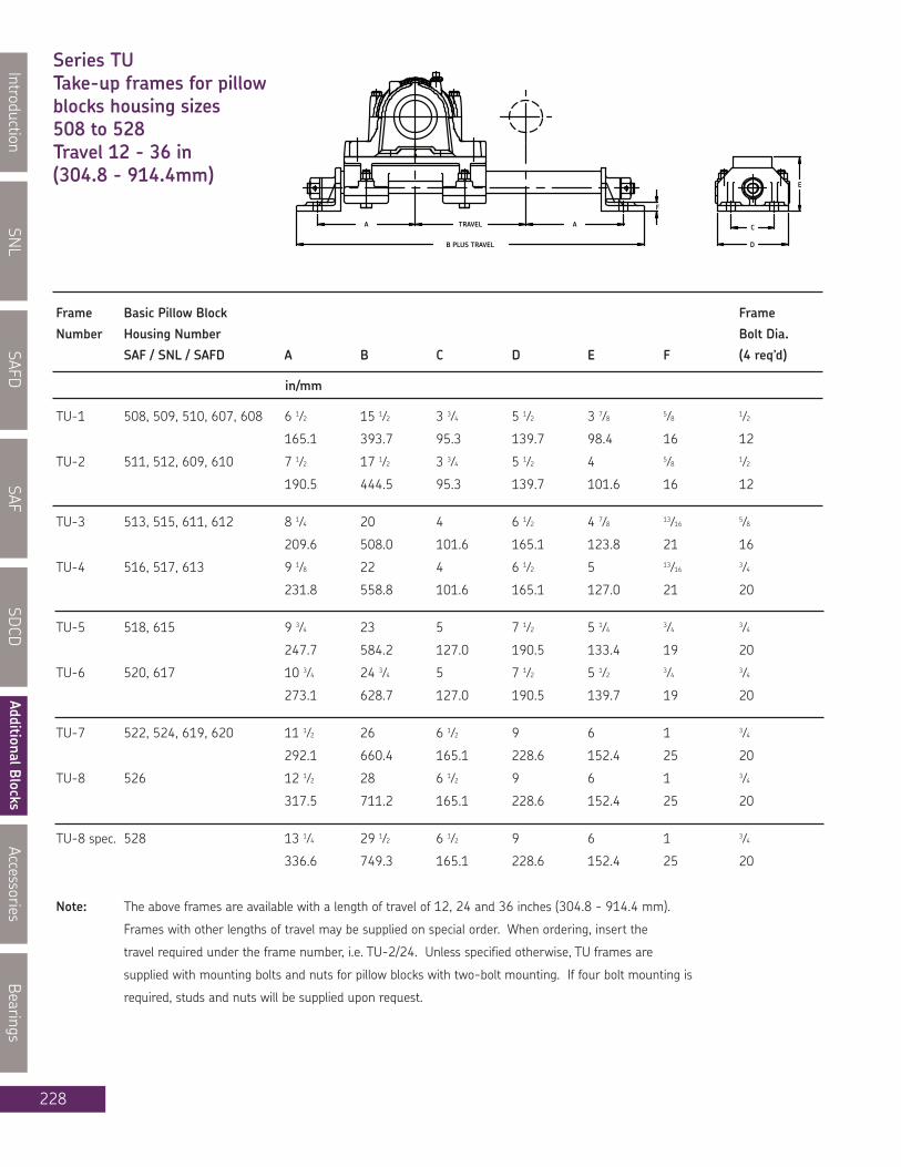
SNL
IntroductionSAFD
SAFSD
CDAdditionalB
locksAccessories
Bearings
228
Series TUTake-up frames for pillowblocks housing sizes508 to 528Travel 12 - 36 in(304.8 - 914.4mm)
Frame Basic Pillow Block Frame
Number Housing Number Bolt Dia.
SAF / SNL / SAFD A B C D E F (4 req’d)
in/mm
TU-1 508, 509, 510, 607, 608 6 1⁄2 15 1⁄2 3 3⁄4 5 1⁄2 3 7⁄8 5⁄8 1⁄2
165.1 393.7 95.3 139.7 98.4 16 12
TU-2 511, 512, 609, 610 7 1⁄2 17 1⁄2 3 3⁄4 5 1⁄2 4 5⁄8 1⁄2
190.5 444.5 95.3 139.7 101.6 16 12
TU-3 513, 515, 611, 612 8 1⁄4 20 4 6 1⁄2 4 7⁄8 13⁄16 5⁄8
209.6 508.0 101.6 165.1 123.8 21 16
TU-4 516, 517, 613 9 1⁄8 22 4 6 1⁄2 5 13⁄16 3⁄4
231.8 558.8 101.6 165.1 127.0 21 20
TU-5 518, 615 9 3⁄4 23 5 7 1⁄2 5 1⁄4 3⁄4 3⁄4
247.7 584.2 127.0 190.5 133.4 19 20
TU-6 520, 617 10 3⁄4 24 3⁄4 5 7 1⁄2 5 1⁄2 3⁄4 3⁄4
273.1 628.7 127.0 190.5 139.7 19 20
TU-7 522, 524, 619, 620 11 1⁄2 26 6 1⁄2 9 6 1 3⁄4
292.1 660.4 165.1 228.6 152.4 25 20
TU-8 526 12 1⁄2 28 6 1⁄2 9 6 1 3⁄4
317.5 711.2 165.1 228.6 152.4 25 20
TU-8 spec. 528 13 1⁄4 29 1⁄2 6 1⁄2 9 6 1 3⁄4
336.6 749.3 165.1 228.6 152.4 25 20
Note: The above frames are available with a length of travel of 12, 24 and 36 inches (304.8 - 914.4 mm).
Frames with other lengths of travel may be supplied on special order. When ordering, insert the
travel required under the frame number, i.e. TU-2/24. Unless specified otherwise, TU frames are
supplied with mounting bolts and nuts for pillow blocks with two-bolt mounting. If four bolt mounting is
required, studs and nuts will be supplied upon request.

SNL
Introduction
SAFD
SAF
SDCD
AdditionalBlocks
Accessories
Bearings
229
Notes

SNL
IntroductionSAFD
SAFSD
CDAdditionalB
locksAccessories
Bearings
230
Solid Type Steel Pillow Blocksda 1 15⁄16 - 3 7⁄16 in
How to order:When you order one 200-22522 you will receive a package containing the following:1 - 200-520 solid steel housing2 - V-ring CR 4010002 - open end covers1 - bearing SKF 22222 EK1 - adapter sleeve H 322If your order specifies "HELD" or "FIXED" bearing you will receive 2 fixing (locating or stabilizing) ringsFRB 13.5/200. Not more than one bearing on each shaft should be "HELD".If your order specifies "ONE END CLOSED" you will receive one blind end cover in place of the openend cover and v-ring 401000.
Shaft Complete Pillow Housing V-Ring Bearing Adapter Fixing Mass
Dia. Block Assembly Seal Sleeve Rings Qty. Complete
da Designation
in lb kg
1 15⁄16 120-22611 120-611 400500 22311 EK HA 2311 FRB 4/120 2 24 10.9
2 3⁄16 120-22513 120-513 400500 22213EK HA 313 FRB 10/120 2 30 13.6
2 7⁄16 130-22515 130-515 400600 22215 EK HA 315 FRB 8/130 2 39 17.7
2 7⁄16 160-22615 160-615 400600 22315 EK HA 2315 FRB 5/160 2 77 34.9
2 15⁄16 150-22517 150-517 400750 22217 EK HA 317 FRB 9/150 2 52 23.6
2 15⁄16 180-22617 180-617 400750 22317 EK HA 2317 FRB 5/180 2 100 45.4
3 3⁄16 160-22518 160-518 400800 22218 EK HA 318 FRB 10/160 2 70 31.7
3 3⁄16 160-23518 160-518 400800 23218CCK/W33 HA 2318 FRB 5/160 2 74 33.6
3 7⁄16 180-22520 180-520 400900 22220EK HA 320 FRB 10/180 2 95 43.1
3 7⁄16 180-23520 180-520 400900 23220CCK/W33 HA 2320 FRB 5/180 2 99 44.9

SNL
Introduction
SAFD
SAF
SDCD
AdditionalBlocks
Accessories
Bearings
231
Housing No. Bolt dia.
(4 req'd)
A A1 H H1 H2 J J1 L G
in/mm
120-611 4 7⁄16 3 1⁄8 6 1⁄2 3.000 1 8 13⁄16 2 11 1⁄2
112.7 79.4 165.1 76.2 25.4 223.8 50.8 279.4 12
120-513 4 7⁄16 3 1⁄8 6 1⁄2 3.000 1 8 13⁄16 2 11 1⁄2
112.7 79.4 165.1 76.2 25.4 223.8 50.8 279.4 12
130-515 4 3⁄4 3 1⁄8 7 1⁄4 3.250 1 9 1⁄8 2 11 1⁄4 5⁄8
120.7 79.4 184.2 82.6 25.4 231.8 50.8 285.8 16
160-615 5 7⁄8 4 8 3⁄4 4.000 1 1⁄4 11 2 1⁄4 13 3⁄4 5⁄8
149.2 101.6 222.3 101.6 31.8 279.4 57.2 349.3 16
150-517 5 4 8 3.750 1 10 2 1⁄8 12 1⁄2 5⁄8
127.0 101.6 203.2 95.3 25.4 254.0 54.0 317.5 16
180-617 6 4 3⁄8 10 1⁄4 4.500 1 1⁄2 12 3⁄8 2 3⁄8 15 1⁄4 3⁄4
152.4 111.1 260.4 114.3 38.1 314.3 60.3 387.4 20
160-518 5 7⁄8 4 8 3⁄4 4.000 1 1⁄4 11 2 1⁄4 13 3⁄4 5⁄8
149.2 101.6 222.3 101.6 31.8 279.4 57.2 349.3 16
180-520 6 4 3⁄8 10 1⁄4 4.500 1 1⁄2 12 3⁄8 2 3⁄8 15 1⁄4 3⁄4
152.4 111.1 260.4 114.3 38.1 314.3 60.3 387.4 20

SNL
IntroductionSAFD
SAFSD
CDAdditionalB
locksAccessories
Bearings
232
Solid Type Steel Pillow Blocksda 3 15⁄16 - 6 15⁄16 in
Shaft Complete Pillow Housing V-Ring Bearing Adapter Fixing Mass
Dia. Block Assembly Seal Sleeve Rings Qty. Complete
da Designation
in lb kg
3 15⁄16 200-22522 200-522 401000 22222 EK H 322 FRB 13.5/200 2 110 49.9
3 15⁄16 200-23522 200-522 401000 23222CCK/W33 H 2322 FRB 5.1/200 2 112 50.8
4 3⁄16 215-22524 215-524 401100 22224 EK HA 3124 FRB 14/215 2 136 61.7
4 7⁄16 230-22526 230-526 401100 22226 EK HA 3126 FRB 13/230 2 178 80.7
4 7⁄16 230-23526 230-526 401100 23226CCK/W33 HA 2326 FRB 5/230 2 188 85.3
4 15⁄16 250-22528 250-528 401300 22228CCK/W33 HA 3128 FRB 15/250 2 202 91.6
4 15⁄16 250-23528 250-528 401300 23228CCK/W33 HA 2328 FRB 5/250 2 215 97.5
5 7⁄16 290-22532 290-532 401400 22232CCK/W33 HA 3132 FRB 17/290 2 285 129.2
5 7⁄16 290-23532 290-532 401400 23232CCK/W33 HA 2332 FRB 5/290 2 305 138.3
5 15⁄16 280-23134 280-3134 401500 23134CCK/W33 HA 3134 FRB 10/280 2 300 136
6 7⁄16 300-23136 300-3136 401600 23136CCK/W33 HA 3136 FRB 10/300 2 340 154
6 15⁄16 320-23138 320-3138 401800 23138CCK/W33 HA 3138 FRB 10/320 2 410 186
For how to order, please refer to page 230.

SNL
Introduction
SAFD
SAF
SDCD
AdditionalBlocks
Accessories
Bearings
233
Housing No. Bolt dia.
(4 req'd)
A A1 H H1 H2 J J1 L G
in/mm
200-522 6 3⁄8 5 10 9⁄16 4.938 1 5⁄8 13 1⁄2 2 3⁄4 16 1⁄2 3⁄4
161.9 127.0 268.3 125.4 41.3 342.9 69.9 419.1 19
215-524 7 1⁄4 5 11 1⁄2 5.250 1 3⁄4 13 3⁄4 2 3⁄4 16 1⁄2 3⁄4
184.2 127.0 292.1 133.4 44.5 349.3 69.9 419.1 19
230-526 8 5 1⁄8 13 6.000 1 7⁄8 15 3⁄8 3 1⁄4 18 3⁄8 7⁄8
203.2 130.2 330.2 152.4 47.6 390.5 82.6 466.7 22
250-528 8 5 7⁄8 13 3⁄4 6.000 2 16 1⁄2 3 3⁄8 20 1⁄8 1
203.2 149.2 349.3 152.4 50.8 419.1 85.7 511.2 24
290-532 8 3⁄4 6 1⁄4 15 6.688 2 18 1⁄4 3 3⁄4 22 1
222.3 158.8 381.0 169.9 50.8 463.6 95.3 558.8 24
280-3134 8 3⁄4 6 1⁄4 15 6.688 2 18 1⁄4 3 3⁄4 22 1
222.3 158.8 381 169.87 50.8 463.6 95.3 558.8 24
300-3136 9 1⁄2 6 3⁄4 16 1⁄4 7.063 2 1⁄8 20 5⁄8 4 1⁄4 24 3⁄4 1
241.3 171.5 412.8 179.40 54 523.9 108 628.7 24
320-3138 9 7⁄8 7 1⁄8 16 1⁄2 7.500 2 1⁄8 22 1⁄4 4 5⁄8 26 3⁄4 1
250.8 181 419.1 190.50 54 565.2 117.5 679.5 24

SNL
IntroductionSAFD
SAFSD
CDAdditionalB
locksAccessories
Bearings
234
Series: Flanged Housingsda 1 11⁄16 - 4 15⁄16 in
E
FREE BRG.
HELD BRG.
DIA.F
G
S
BOLT DIA.
CTRS. SQUAREC
D
SQUARE
BA
ad
How to order:When you order on F-200-22222 K you will receive a package containing the following:1 - F-200 flanged housing1 - V-ring 4010001 - V-ring 4013001 - Open end cover1 - Spacer for locating the bearing1 - Bearing SKF 22222EK1 - Adapter sleeve H322If your order specifies "HELD" or "FIXED" you will receive 2 fixing (locating or stabilizing) rings FRB 5.1/200.Not more than one bearing on each shaft should be "HELD".If you order specifies "ONE END CLOSED" you will receive one blind end cover in place of the open end coverand V-ring 401000.
Shaft Complete Pillow Housing V-Ring Bearing Adapter Fixing
Dia. Block Assembly Seal Sleeve Rings Qty.
da Designation
in
1 11⁄16 F-90-22210 K F-90 400400 400550 22210EK HA 310 FRB 5/90 2
1 15⁄16 F-100-22211 K F-100 400500 400650 22211 EK HA 311 FRB 4/100 2
2 3⁄16 F-120-22213 K F-120 400550 400800 22213EK HA 313 FRB 4/120 2
2 7⁄16 F-130-22215 K F-130 400600 400900 22215 EK HA 315 FRB 5/130 2
2 11⁄16 F-140-22216 K F-140 400650 400950 22216 EK HA 316 FRB 5/140 2
2 15⁄16 F-150-22217 K F-150 400750 401000 22217 EK HA 317 FRB 5/150 2
3 7⁄16 F-180-22220 K F-180 400850 401200 22220 EK HA 320 FRB 5/180 2
3 15⁄16 F-200-22222 K F-200 401000 401300 22222 EK H 322 FRB 5.1/200 2
4 3⁄16 F-215-22224 K F-215 401100 401400 22224 EK HA 3124 FRB 5/215 2
4 7⁄16 F-230-22226 K F-230 401100 401500 22226 EK HA 3126 FRB 5/230 2
4 15⁄16 F-250-22228 K F-250 401300 401700 22228CCK/W33 HA 3128 FRB 5/250 2
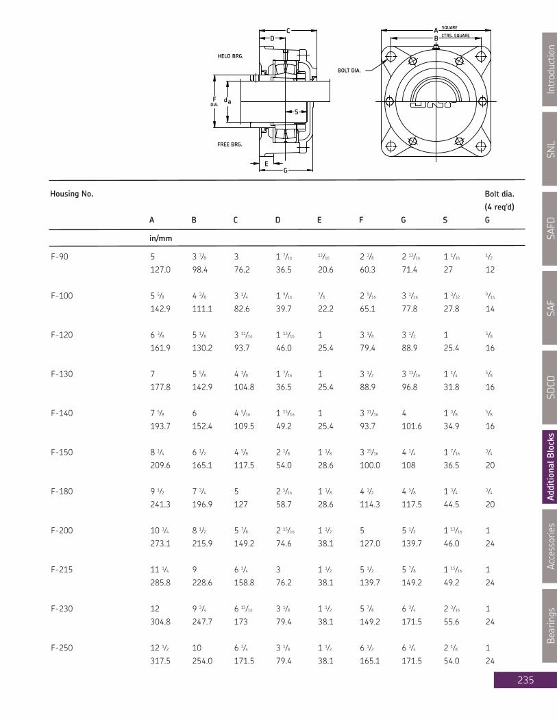
SNL
Introduction
SAFD
SAF
SDCD
AdditionalBlocks
Accessories
Bearings
235
Housing No. Bolt dia.
(4 req'd)
A B C D E F G S G
in/mm
E
FREE BRG.
HELD BRG.
DIA.F
G
S
BOLT DIA.
CTRS. SQUAREC
D
SQUARE
BA
ad
F-90 5 3 7⁄8 3 1 7⁄16 13⁄16 2 3⁄8 2 13⁄16 1 1⁄16 1⁄2
127.0 98.4 76.2 36.5 20.6 60.3 71.4 27 12
F-100 5 5⁄8 4 3⁄8 3 1⁄4 1 9⁄16 7⁄8 2 9⁄16 3 1⁄16 1 3⁄32 9⁄16
142.9 111.1 82.6 39.7 22.2 65.1 77.8 27.8 14
F-120 6 3⁄8 5 1⁄8 3 11⁄16 1 13⁄16 1 3 1⁄8 3 1⁄2 1 5⁄8
161.9 130.2 93.7 46.0 25.4 79.4 88.9 25.4 16
F-130 7 5 5⁄8 4 1⁄8 1 7⁄16 1 3 1⁄2 3 13⁄16 1 1⁄4 5⁄8
177.8 142.9 104.8 36.5 25.4 88.9 96.8 31.8 16
F-140 7 5⁄8 6 4 5⁄16 1 15⁄16 1 3 11⁄16 4 1 3⁄8 5⁄8
193.7 152.4 109.5 49.2 25.4 93.7 101.6 34.9 16
F-150 8 1⁄4 6 1⁄2 4 5⁄8 2 1⁄8 1 1⁄8 3 15⁄16 4 1⁄4 1 7⁄16 3⁄4
209.6 165.1 117.5 54.0 28.6 100.0 108 36.5 20
F-180 9 1⁄2 7 3⁄4 5 2 5⁄16 1 1⁄8 4 1⁄2 4 5⁄8 1 3⁄4 3⁄4
241.3 196.9 127 58.7 28.6 114.3 117.5 44.5 20
F-200 10 3⁄4 8 1⁄2 5 7⁄8 2 15⁄16 1 1⁄2 5 5 1⁄2 1 13⁄16 1
273.1 215.9 149.2 74.6 38.1 127.0 139.7 46.0 24
F-215 11 1⁄4 9 6 1⁄4 3 1 1⁄2 5 1⁄2 5 7⁄8 1 15⁄16 1
285.8 228.6 158.8 76.2 38.1 139.7 149.2 49.2 24
F-230 12 9 3⁄4 6 13⁄16 3 1⁄8 1 1⁄2 5 7⁄8 6 3⁄4 2 3⁄16 1
304.8 247.7 173 79.4 38.1 149.2 171.5 55.6 24
F-250 12 1⁄2 10 6 3⁄4 3 1⁄8 1 1⁄2 6 1⁄2 6 3⁄4 2 1⁄8 1
317.5 254.0 171.5 79.4 38.1 165.1 171.5 54.0 24

SNL
IntroductionSAFD
SAFSD
CDAdditionalB
locksAccessories
Bearings
236
Series: Flanged Unit FCda 2 3⁄16 - 4 3⁄16 in
How to order:When you order on FC-200-22222 K you will receive a package containing the following:1 - FC-200 flanged housing1 - V-ring 4010001 - V-ring 4013001 - Open end cover1 - Spacer for locating the bearing1 - Bearing SKF 22222EK1 - Adapter sleeve H322If your order specifies "HELD" or "FIXED" you will receive 2 fixing (locating or stabilizing) rings FRB 5.1/200.Not more than one bearing on each shaft should be "HELD".If you order specifies "ONE END CLOSED" you will receive one blind end cover in place of the open end coverand V-ring 401000.
Shaft Complete Pillow Housing V-Ring Bearing Adapter Fixing
Dia. Block Assembly Seal Sleeve Rings Qty.
da Designation
in
2 3⁄16 FC-120-22213 K FC-120 400550 400800 22213EK HA 313 FRB 4/120 2
2 7⁄16 FC-130-22215 K FC-130 400600 400900 22215 EK HA 315 FRB 5/130 2
2 11⁄16 FC-140-22216 K FC-140 400650 400950 22216 EK HA 316 FRB 5/140 2
2 15⁄16 FC-150-22217 K FC-150 400750 401000 22217 EK HA 317 FRB 5/150 2
3 3⁄16 FC-160-22218 K FC-160 400800 401100 22218 EK HA 318 FRB 5/160 2
3 7⁄16 FC-180-22220 K FC-180 400850 401200 22220 EK HA 320 FRB 5/180 2
3 15⁄16 FC-200-22222 K FC-200 401000 401300 22222 EK H 322 FRB 5.1/200 2
4 3⁄16 FC-215-22224 K FC-215 401100 401400 22224 EK HA 3124 FRB 5/215 2

SNL
Introduction
SAFD
SAF
SDCD
AdditionalBlocks
Accessories
Bearings
237
Housing No. Bolt dia.
No. req'd
A B C D E F G J M N S G
in/mm
FC-120 8 1⁄4 7 1⁄4 3 5⁄8 1 7⁄8 2 15⁄16 3⁄4 7⁄8 6.000 1 5⁄8 3.125 1 1⁄2
209.6 184.2 92.1 47.6 74.6 19.1 22.2 152.40 41.3 82.55 25.4 12
FC-130 8 1⁄2 7 1⁄2 3 7⁄8 2 1⁄8 2 1⁄2 3⁄4 7⁄8 6.250 1 3⁄4 3.500 1 1⁄4 1⁄2
215.9 190.5 98.4 54.0 63.5 19.1 22.2 158.75 44.5 88.90 31.8 12
FC-140 8 1⁄2 7 1⁄2 3 7⁄8 2 1⁄8 2 1⁄2 3⁄4 7⁄8 6.375 1 3⁄4 3.688 1 3⁄8 1⁄2
215.9 190.5 98.4 54.0 63.5 19.1 22.2 161.93 44.5 93.68 34.9 12
FC-150 10 1⁄4 9 4 3⁄16 2 1⁄4 2 13⁄16 3⁄4 1 7.250 2 3.938 1 7⁄16 5⁄8
260.4 228.6 106.4 57.2 71.4 19.1 25.4 184.15 50.8 100.03 36.5 16
FC-160 10 1⁄2 9 1⁄4 4 3⁄4 2 3⁄4 2 1⁄8 1 1 8.000 2 1⁄2 4.188 1 3⁄4 5⁄8
266.7 235 120.7 69.9 54 25.4 25.4 203.20 63.5 106.38 44.5 16
FC-180 11 3⁄4 10 3⁄8 4 3⁄4 2 3⁄4 3 1 1 8.375 2 3⁄8 4.500 1 13⁄16 5⁄8
298.5 263.5 120.7 69.9 76.2 25.4 25.4 212.73 60.3 114.30 46.0 16
FC-200 12 3⁄4 11 3⁄8 5 3⁄8 3 3 3⁄8 1 1 1⁄4 9.500 2 5⁄8 5.000 1 15⁄16 3⁄4
323.9 288.9 136.5 76.2 85.7 25.4 31.8 241.30 66.7 127.00 49.2 20
FC-215 14 3⁄4 12 3⁄4 6 1⁄4 3 3⁄8 3 3⁄4 1 1⁄4 1 1⁄8 10.750 2 7⁄8 5.500 2 3⁄16 7⁄8
374.7 323.9 158.8 85.7 95.2 31.8 28.6 273.05 73 139.70 55.6 22

SNL
IntroductionSAFD
SAFSD
CDAdditionalB
locksAccessories
Bearings
238
Series: Flanged Unit FCda 4 7⁄16 - 7 3⁄16 in
How to order:When you order on FC-200-22222 K you will receive a package containing the following:1 - FC-200 flanged housing1 - V-ring 4010001 - V-ring 4013001 - Open end cover1 - Spacer for locating the bearing1 - Bearing SKF 22222EK1 - Adapter sleeve H322If your order specifies "HELD" or "FIXED" you will receive 2 fixing (locating or stabilizing) rings FRB 5.1/200.Not more than one bearing on each shaft should be "HELD".If you order specifies "ONE END CLOSED" you will receive one blind end cover in place of the open end coverand V-ring 401000.
Shaft Complete Pillow Housing V-Ring Bearing Adapter Fixing
Dia. Block Assembly Seal Sleeve Rings Qty.
da Designation
in
4 7⁄16 FC-230-22226 K FC-230 401100 401500 22226 EK HA 3126 FRB 5/230 2
4 15⁄16 FC-250-22228 K FC-250 401300 401700 22228CCK/W33 HA 3128 FRB 5/250 2
5 7⁄16 FC-290-22232 K FC-290 401400 401900 22232CCK/W33 HA 3132 FRB 5/290 2
5 15⁄16 FC-260-23034 K FC-260 401500 401900 23034CCK/W33 HA 3034 FRB 10/260 2
6 7⁄16 FC-300-23136 K FC-300 401600 401990 23136CCK/W33 HA 3136 FRB 10/300 2
7 3⁄16 FC-360-22240 K FC-360 401800 402500 22240CCK/W33 HA 3140 FRB 10/360 2

SNL
Introduction
SAFD
SAF
SDCD
AdditionalBlocks
Accessories
Bearings
239
Housing No. Bolt dia.
No. req'd
A B C D E F G J M N S G
in/mm
FC-230 15 1⁄4 13 3⁄8 6 3⁄4 3 1⁄2 3 1⁄2 1 1⁄8 1 1⁄8 11.250 3 5.875 2 1⁄8 (4) 7⁄8
387.4 339.7 171.5 88.9 88.9 28.6 28.6 285.8 76.2 149.2 54.0 (4) 22
FC-250 16 14 6 11⁄16 3 1/2 3 5⁄8 1 1⁄4 1 1⁄4 12.000 3 1⁄2 6.500 2 1⁄4 (4) 1
406.4 355.6 169.9 88.9 92.1 31.8 31.8 304.8 88.9 165.1 57.2 (4) 24
FC-260 16 14 6 11⁄16 3 1⁄2 3 5⁄8 1 1⁄4 1 1⁄4 12.000 3 1⁄2 7.500 2 1⁄4 (4) 1
406.4 355.6 169.9 88.9 92.1 31.8 31.8 304.8 88.9 190.5 57.2 (4) 24
FC-290 18 1⁄2 16 1⁄2 8 3 6 1⁄2 1 1⁄4 2 14.500 2 3⁄4 7.500 1 1⁄2 (6) 1
469.9 419.1 203.2 76.2 165.1 31.8 50.8 368.3 69.9 190.5 38.1 (6) 24
FC-300 18 1⁄2 16 1⁄2 8 3 6 1⁄2 1 1⁄4 2 14.500 2 3⁄4 8.000 1 1⁄2 (6) 1
469.9 419.1 203.2 76.2 165.1 31.8 50.8 368.3 69.9 203.2 38.1 (6) 24
FC-360 22 1⁄2 20 9 3 7 1⁄2 1 1⁄2 3 17.250 2 3⁄4 9.250 1 1⁄2 (6) 1 1⁄8
571.5 508.0 228.6 76.2 190.5 38.1 76.2 438.2 69.9 235.0 38.1 (6) 27
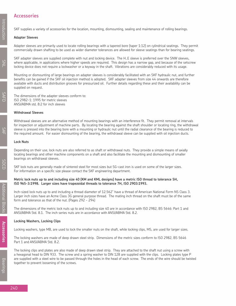
SNL
IntroductionSAFD
SAFSD
CDAdditionalBlocks
AccessoriesBearings
240
Accessories
SKF supplies a variety of accessories for the location, mounting, dismounting, sealing and maintenance of rolling bearings.
Adapter Sleeves
Adapter sleeves are primarily used to locate rolling bearings with a tapered bore (taper 1:12) on cylindrical seatings. They permitcommercially drawn shafting to be used as wider diameter tolerances are allowed for sleeve seatings than for bearing seatings.
SKF adapter sleeves are supplied complete with nut and locking device. The H..E sleeve is preferred over the SNW sleeves,where applicable, in applications where higher speeds are required. This design has a narrow gap, and because of the setscrewlocking device does not require a lockwasher or a keyway in the shaft. Vibrations are considerably reduced with its usage.
Mounting or dismounting of large bearings on adapter sleeves is considerably facilitated with an SKF hydraulic nut, and furtherbenefits can be gained if the SKF oil injection method is adopted. SKF adapter sleeves from size 44 onwards are thereforeavailable with ducts and distribution grooves for pressurized oil. Further details regarding these and their availability can besupplied on request.
The dimensions of the adapter sleeves conform to:ISO 2982-1: 1995 for metric sleevesANSI/ABMA std. 8:2 for inch sleeves
Withdrawal Sleeves
Withdrawal sleeves are an alternative method of mounting bearings with an interference fit. They permit removal at intervalsfor inspection or adjustment of machine parts. By locating the bearing against the shaft shoulder or locating ring, the withdrawalsleeve is pressed into the bearing bore with a mounting or hydraulic nut until the radial clearance of the bearing is reduced tothe required amount. For easier dismounting of the bearing, the withdrawal sleeve can be supplied with oil injection ducts.
Lock Nuts
Depending on their use, lock nuts are also referred to as shaft or withdrawal nuts. They provide a simple means of axiallylocating bearings and other machine components on a shaft and also facilitate the mounting and dismounting of smallerbearings on withdrawal sleeves.
SKF lock nuts are generally made of sintered steel for most sizes but SG-cast iron is used on some of the larger sizes.For information on a specific size please contact the SKF engineering department.
Metric lock nuts up to and including size 40 (KM and KML designs) have a metric ISO thread to tolerance 5H,ISO 965-3:1998. Larger sizes have trapezoidal threads to tolerance 7H, ISO 2903:1993.
Inch-sized lock nuts up to and including a thread diameter of 12.562” have a thread of American National Form NS Class 3.Larger inch sizes have an Acme Class 3G general purpose thread. The mating inch thread on the shaft must be of the sameform and tolerance as that of the nut. (Pages 292 - 294)
The dimensions of the metric lock nuts up to and including size 40 are in accordance with ISO 2982, BS 5646: Part 1 andANSI/ABMA Std. 8.1. The inch series nuts are in accordance with ANSI/ABMA Std. 8.2.
Locking Washers, Locking Clips
Locking washers, type MB, are used to lock the smaller nuts on the shaft, while locking clips, MS, are used for larger sizes.
The locking washers are made of deep drawn steel strip. Dimensions of the metric sizes conform to ISO 2982, BS 5646Part 1 and ANSI/ABMA Std. 8.2.
The locking clips and plates are also made of deep drawn steel strip. They are attached to the shaft nut using a screw witha hexagonal head to DIN 933. The screw and a spring washer to DIN 128 are supplied with the clips. Locking plates type Pare supplied with a steel wire to be passed through the holes in the head of each screw. The ends of the wire should be twistedtogether to prevent loosening of the screws.

SNL
Introduction
SAFD
SAF
SDCD
AdditionalB
locks
Accessories
Bearings
241
Accessories cont...
Wrenches
SKF wrenches are designed especially for use with shaft and withdrawal nuts for the drive-up of small bearings on a tapered shaftseating or adapter sleeve. They are also used on withdrawal nuts for the dismounting of small bearings from withdrawal sleeves.
The wrenches are made of construction steel; the jaws are machined and hardened. They are for use with nuts having the samedesignation number but in some cases are used for two or three sizes. See page 249 for a listing of the wrenches and the lock-nuts they can accommodate.
The impact wrenches are made of spherodial graphite cast iron and have a special impact face positioned to permit maximumtransmission of the impact energy to the nuts. The impact wrenches are designed so that each may be used for a number ofnut sizes.
Hydraulic Nuts
SKF hydraulic nuts considerably facilitate the mounting of rolling bearings with a tapered bore and dismounting bearings from bothadapter and withdrawal sleeves. They comprise an internally threaded steel ring with a groove in one face into which an annularpiston is fitted. This piston is activated when pressurized oil is injected. Up to size 40, the hydraulic nuts have metric fine threadswith an ISO profile of medium quality. Sizes 41 and above incorporate metric ISO trapezoidal threads. Hydraulic nuts with inchthreads or nuts without threads can also be supplied. All designs are made of high-strength steel and are designed to withstandthe pressures generally encountered when mounting and dismounting rolling bearings. The oil pumps required in conjunction withthe hydraulic nuts are available in a number of designs from SKF. Normal machine oil having a viscosity of approximately 300 cStat 20ºC is suitable as a pressure medium during mounting. For dismounting, oil with a viscosity of 900 cSt is preferred. Furtherinformation on hydraulic nuts, pumps or adapters is available from the SKF engineering department. (Pages 254 -257)
Other Accessories
In addition to the selection of accessories shown on the following pages, SKF can also supply a wide variety of other aids formounting, dismounting, monitoring and lubrication of rolling bearings. For complete details on the numerous items availableplease consult the SKF Maintenance Catalogue MP 3000, available from your local SKF office or online at www.mapro.skf.com.

SNL
IntroductionSAFD
SAFSD
CDAdditionalBlocks
AccessoriesBearings
242
Dimensions Mass Designation
Locking Wrench
G d1 d3 B b h Device
mm in/mm kg/lb
M 10x0.75 13.5 18 4 3 2 0.006 KM 0 MB 0 HN 0
0.531 0.709 0.157 0.118 0.079 0.013
M 12x1 17 22 4 3 2 0.008 KM 1 MB 1 HN 1
0.669 0.866 0.157 0.118 0.079 0.018
M 15x1 21 25 5 4 2 0.012 KM 2 MB 2 HN 2 - 3
0.827 0.984 0.197 0.157 0.079 0.026
M 17x1 24 28 5 4 2 0.012 KM 3 MB 3 HN 2 - 3
0.945 1.102 0.197 0.157 0.079 0.026
M 20x1 26 32 6 4 2 0.020 KM 4 MB 4 HN 4
1.024 1.260 0.236 0.157 0.079 0.044
M 25x1.5 32 38 7 5 2 0.028 KM 5 MB 5 HN 5-6
1.260 1.496 0.276 0.197 0.079 0.062
M 30x1.5 38 45 7 5 2 0.038 KM 6 MB 6 HN 5-6
1.496 1.772 0.276 0.197 0.079 0.084
M 35x1.5 44 52 8 5 2 0.058 KM 7 MB 7 HN 7
1.732 2.047 0.315 0.197 0.079 0.128
M 40x1.5 50 58 9 6 2.5 0.078 KM 8 MB 8 HN 8-9
1.969 2.283 0.354 0.236 0.098 0.172
M 45x1.5 56 65 10 6 2.5 0.11 KM 9 MB 9 HN 8-9
2.205 2.559 0.394 0.236 0.098 0.24
M 50x1.5 61 70 11 6 2.5 0.14 KM 10 MB 10 HN 10-11
2.402 2.756 0.433 0.236 0.098 0.31
M 55x2 67 75 11 7 3 0.15 KM 11 MB 11 HN 10-11
2.638 2.953 0.433 0.276 0.118 0.33
M 60x2 73 80 11 7 3 0.16 KM 12 MB 12 HN 12-13
2.874 3.150 0.433 0.276 0.118 0.35
M 65x2 79 85 12 7 3 0.19 KM 13 MB 13 HN 12-13
3.110 3.346 0.472 0.276 0.118 0.42
M 70x2 85 92 12 8 3.5 0.22 KM 14 MB 14 HN 14
3.346 3.622 0.472 0.315 0.138 0.48
M 75x2 90 98 13 8 3.5 0.27 KM 15 MB 15 HN 15
3.543 3.858 0.512 0.315 0.138 0.59
M 80x2 95 105 15 8 3.5 0.36 KM 16 MB 16 HN 16
3.740 4.134 0.591 0.315 0.138 0.79
Lock NutsMetricM 10 x 0.75 - M 80 x 2
KM 0 - KM 16
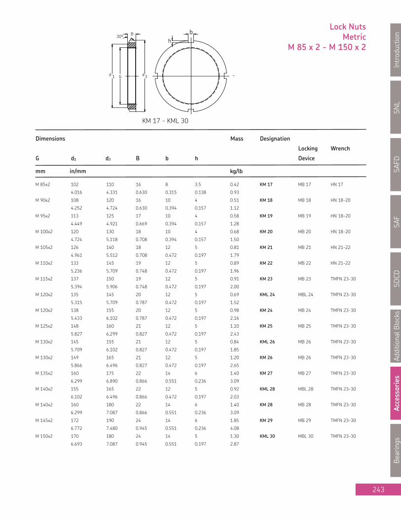
SNL
Introduction
SAFD
SAF
SDCD
AdditionalB
locks
Accessories
Bearings
243
Lock NutsMetric
M 85 x 2 - M 150 x 2
Dimensions Mass Designation
Locking Wrench
G d1 d3 B b h Device
mm in/mm kg/lb
M 85x2 102 110 16 8 3.5 0.42 KM 17 MB 17 HN 17
4.016 4.331 0.630 0.315 0.138 0.93
M 90x2 108 120 16 10 4 0.51 KM 18 MB 18 HN 18-20
4.252 4.724 0.630 0.394 0.157 1.12
M 95x2 113 125 17 10 4 0.58 KM 19 MB 19 HN 18-20
4.449 4.921 0.669 0.394 0.157 1.28
M 100x2 120 130 18 10 4 0.68 KM 20 MB 20 HN 18-20
4.724 5.118 0.708 0.394 0.157 1.50
M 105x2 126 140 18 12 5 0.81 KM 21 MB 21 HN 21-22
4.961 5.512 0.708 0.472 0.197 1.79
M 110x2 133 145 19 12 5 0.89 KM 22 MB 22 HN 21-22
5.236 5.709 0.748 0.472 0.197 1.96
M 115x2 137 150 19 12 5 0.91 KM 23 MB 23 TMFN 23-30
5.394 5.906 0.748 0.472 0.197 2.00
M 120x2 135 145 20 12 5 0.69 KML 24 MBL 24 TMFN 23-30
5.315 5.709 0.787 0.472 0.197 1.52
M 120x2 138 155 20 12 5 0.98 KM 24 MB 24 TMFN 23-30
5.433 6.102 0.787 0.472 0.197 2.16
M 125x2 148 160 21 12 5 1.10 KM 25 MB 25 TMFN 23-30
5.827 6.299 0.827 0.472 0.197 2.43
M 130x2 145 155 21 12 5 0.84 KML 26 MB 26 TMFN 23-30
5.709 6.102 0.827 0.472 0.197 1.85
M 130x2 149 165 21 12 5 1.20 KM 26 MB 26 TMFN 23-30
5.866 6.496 0.827 0.472 0.197 2.65
M 135x2 160 175 22 14 6 1.40 KM 27 MB 27 TMFN 23-30
6.299 6.890 0.866 0.551 0.236 3.09
M 140x2 155 165 22 12 5 0.92 KML 28 MBL 28 TMFN 23-30
6.102 6.496 0.866 0.472 0.197 2.03
M 140x2 160 180 22 14 6 1.40 KM 28 MB 28 TMFN 23-30
6.299 7.087 0.866 0.551 0.236 3.09
M 145x2 172 190 24 14 6 1.85 KM 29 MB 29 TMFN 23-30
6.772 7.480 0.945 0.551 0.236 4.08
M 150x2 170 180 24 14 5 1.30 KML 30 MBL 30 TMFN 23-30
6.693 7.087 0.945 0.551 0.197 2.87
KM 17 - KML 30
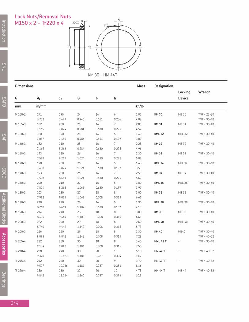
SNL
IntroductionSAFD
SAFSD
CDAdditionalBlocks
AccessoriesBearings
244
Dimensions Mass Designation
Locking Wrench
G d1 d3 B b h Device
mm in/mm kg/lb
M 150x2 171 195 24 14 6 1.85 KM 30 MB 30 TMFN 23-30
6.732 7.677 0.945 0.551 0.236 4.08 TMFN 30-40
M 155x3 182 200 25 16 7 2.05 KM 31 MB 31 TMFN 30-40
7.165 7.874 0.984 0.630 0.275 4.52
M 160x3 180 190 25 14 5 1.40 KML 32 MBL 32 TMFN 30-40
7.087 7.480 0.984 0.551 0.197 3.09
M 160x3 182 210 25 16 7 2.25 KM 32 MB 32 TMFN 30-40
7.165 8.268 0.984 0.630 0.275 4.96
M 165x3 193 210 26 16 7 2.30 KM 33 MB 33 TMFN 30-40
7.598 8.268 1.024 0.630 0.275 5.07
M 170x3 190 200 26 16 5 1.60 KML 34 MBL 34 TMFN 30-40
7.480 7.874 1.024 0.630 0.197 3.53
M 170x3 193 220 26 16 7 2.55 KM 34 MB 34 TMFN 30-40
7.598 8.661 1.024 0.630 0.275 5.62
M 180x3 200 210 27 16 5 1.80 KML 36 MBL 36 TMFN 30-40
7.874 8.268 1.063 0.630 0.197 3.97
M 180x3 203 230 27 18 8 3.00 KM 36 MB 36 TMFN 30-40
7.992 9.055 1.063 0.708 0.315 6.61
M 190x3 210 220 28 16 5 1.90 KML 38 MBL 38 TMFN 30-40
8.268 8.661 1.102 0.630 0.197 4.19
M 190x3 214 240 28 18 8 3.00 KM 38 MB 38 TMFN 30-40
8.425 9.449 1.102 0.708 0.315 6.61
M 200x3 222 240 29 18 8 2.60 KML 40 MBL 40 TMFN 30-40
8.740 9.449 1.142 0.708 0.315 5.73
M 200x3 226 250 29 18 8 3.30 KM 40 MB40 TMFN 30-40
8.898 9.842 1.142 0.708 0.315 7.28 TMFN 40-52
Tr 205x4 232 250 30 18 8 3.40 HML 41 T - TMFN 30-40
9.134 9.842 1.181 0.708 0.315 7.50
Tr 210x4 238 270 30 20 10 5.10 HM 42 T - TMFN 40-52
9.370 10.623 1.181 0.787 0.394 11.2
Tr 215x4 242 260 30 20 9 3.70 HM 43 T - TMFN 40-52
9.527 10.236 1.181 0.787 0.354 8.16
Tr 220x4 250 280 32 20 10 4.75 HM 44 T MB 44 TMFN 40-52
9.842 11.024 1.260 0.787 0.394 10.5
Lock Nuts/Removal NutsM150 x 2 - Tr220 x 4
KM 30 - HM 44T

SNL
Introduction
SAFD
SAF
SDCD
AdditionalB
locks
Accessories
Bearings
245
Lock Nuts/Removal NutsTr230 x 4 - Tr370 x 5
Dimensions Mass Designation
Locking Wrench
G d1 d3 B b h Device
mm in/mm kg/lb
Tr 230x4 260 290 34 20 10 5.60 HM 46 T - TMFN 40-52
10.236 11.417 1.338 0.787 0.394 12.4
Tr 235x4 262 280 34 20 9 4.60 HML 47 T - TMFN 40-52
10.315 11.024 1.338 0.787 0.354 10.1
Tr 240x4 270 300 34 20 10 5.60 HM 48 T MB 48 TMFN 40-52
10.630 11.811 1.338 0.787 .394 12.4
Tr 250x4 290 320 36 20 10 7.45 HM 50 T - TMFN 40-52
11.417 12.598 1.417 0.787 0.394 16.4
Tr 260x4 300 330 36 24 12 7.55 HM 52 T MB 52 TMFN 52-64
11.811 12.992 1.417 0.945 0.472 16.6
Tr 270x4 310 340 38 24 12 9.20 HM 54 T - TMFN 52-64
12.205 13.386 1.496 0.945 0.472 20.3
Tr 280x4 320 350 38 24 12 8.65 HM 56 T MB 56 TMFN 52-64
12.598 13.779 1.496 0.945 0.472 19.0
Tr 290x4 330 370 40 24 12 12.0 HM 58 T - TMFN 52-64
12.922 14.567 1.575 0.945 0.472 26.5
Tr 310x5 350 390 42 24 12 13.5 HM 62 T - TMFN 52-64
13.779 15.354 1.653 0.945 0.472 29.8
Tr 330x5 380 420 52 28 15 20.5 HM 66 T - TMFN 64-80
14.960 16.535 2.047 1.102 0.590 45.2
Tr 350x5 410 450 55 28 15 25.0 HM 70 T - TMFN 64-80
16.142 17.716 2.165 1.102 0.590 55.0
Tr 370x5 430 470 58 28 15 28.0 HM 74 T - TMFN 64-80
16.929 18.504 2.283 1.102 0.590 61.7
HM 46T - HM 74T

SNL
IntroductionSAFD
SAFSD
CDAdditionalBlocks
AccessoriesBearings
246
Lock Nuts U.S.Thread Form0.391 - 3.137 in
Dimensions T.P.I. Mass Designation
G Lock Nut Locking Wrench
Major Dia. d1 d3 B b h Device
in in/mm g/oz
0.391 32 0.625 0.755 0.229 0.120 0.073 4 N-00 W 00 HN 0
15.88 19.18 5.82 3.05 1.85 0.14
0.469 32 0.719 0.880 0.323 0.120 0.073 7 N-01 W 01 HN 1
18.26 22.35 8.20 3.05 1.85 0.25
0.586 32 0.813 1.005 0.323 0.120 0.104 10 N-02 W 02 HN 2-3
20.65 25.53 8.20 3.05 2.64 0.35
0.664 32 0.938 1.130 0.354 0.120 0.104 13 N-03 W 03 HN 2-3
23.82 28.70 8.99 3.05 2.64 0.46
0.781 32 1.126 1.380 0.385 0.178 0.104 19 N-04 W 04 HN 4
28.58 35.05 9.78 4.52 2.64 0.67
0.989 32 1.281 1.568 0.416 0.178 0.104 25 N-05 W 05 HN 5-6
32.54 39.83 10.57 4.52 2.64 0.88
1.173 18 1.500 1.755 0.416 0.178 0.104 43 N-06 W 06 HN 5-6
38.10 44.58 10.57 4.52 2.64 1.52
1.376 18 1.813 2.068 0.448 0.178 0.104 53 N-07 W 07 HN 7
46.05 52.53 11.38 4.52 2.64 1.87
1.563 18 2.000 2.255 0.448 0.240 0.104 85 N-08 W 08 HN 8-9
50.80 57.28 11.38 6.10 2.64 3.00
1.767 18 2.281 2.536 0.448 0.240 0.104 120 N-09 W 09 HN 8-9
57.94 64.41 11.38 6.10 2.64 4.23
1.967 18 2.438 2.693 0.510 0.240 0.104 150 N-10 W 10 HN 10-11
61.92 68.40 12.95 6.10 2.64 5.29
2.157 18 2.656 2.974 0.510 0.240 0.135 160 N-11 W 11 HN 10-11
67.46 75.54 12.95 6.10 3.43 5.64
2.360 18 2.844 3.161 0.541 0.240 0.135 220 N-12 W 12 HN 12-13
72.24 80.29 13.74 6.10 3.43 7.76
2.548 18 3.063 3.380 0.573 0.240 0.135 200 N-13 W 13 HN 12-13
77.80 85.85 14.55 6.10 3.43 7.05
2.751 18 3.313 3.630 0.573 0.240 0.135 240 N-14 W 14 HN 14
84.15 92.20 14.55 6.10 3.43 8.46
2.933 12 3.563 3.880 0.604 0.360 0.135 290 AN-15 W 15 HN 15
90.50 98.55 15.34 9.14 3.43 10.2
3.137 12 3.844 4.161 0.604 0.360 0.135 400 AN-16 W 16 HN 16
97.64 105.69 15.34 9.14 3.43 14.1
N-00 - AN-16
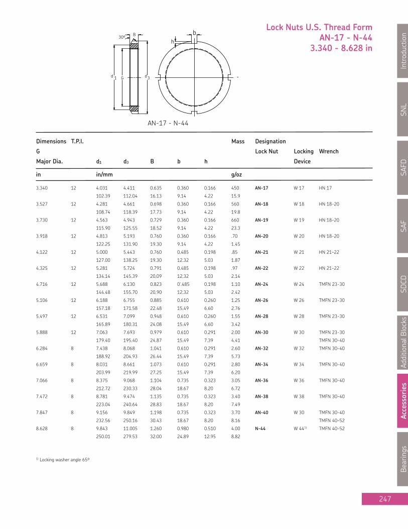
SNL
Introduction
SAFD
SAF
SDCD
AdditionalB
locks
Accessories
Bearings
247
Lock Nuts U.S. Thread FormAN-17 - N-44
3.340 - 8.628 in
Dimensions T.P.I. Mass Designation
G Lock Nut Locking Wrench
Major Dia. d1 d3 B b h Device
in in/mm g/oz
3.340 12 4.031 4.411 0.635 0.360 0.166 450 AN-17 W 17 HN 17
102.39 112.04 16.13 9.14 4.22 15.9
3.527 12 4.281 4.661 0.698 0.360 0.166 560 AN-18 W 18 HN 18-20
108.74 118.39 17.73 9.14 4.22 19.8
3.730 12 4.563 4.943 0.729 0.360 0.166 660 AN-19 W 19 HN 18-20
115.90 125.55 18.52 9.14 4.22 23.3
3.918 12 4.813 5.193 0.760 0.360 0.166 .70 AN-20 W 20 HN 18-20
122.25 131.90 19.30 9.14 4.22 1.45
4.122 12 5.000 5.443 0.760 0.485 0.198 .85 AN-21 W 21 HN 21-22
127.00 138.25 19.30 12.32 5.03 1.87
4.325 12 5.281 5.724 0.791 0.485 0.198 .97 AN-22 W 22 HN 21-22
134.14 145.39 20.09 12.32 5.03 2.14
4.716 12 5.688 6.130 0.823 0'.485 0.198 1.10 AN-24 W 24 TMFN 23-30
144.48 155.70 20.90 12.32 5.03 2.42
5.106 12 6.188 6.755 0.885 0.610 0.260 1.25 AN-26 W 26 TMFN 23-30
157.18 171.58 22.48 15.49 6.60 2.76
5.497 12 6.531 7.099 0.948 0.610 0.260 1.55 AN-28 W 28 TMFN 23-30
165.89 180.31 24.08 15.49 6.60 3.42
5.888 12 7.063 7.693 0.979 0.610 0.291 2.00 AN-30 W 30 TMFN 23-30
179.40 195.40 24.87 15.49 7.39 4.41 TMFN 30-40
6.284 8 7.438 8.068 1.041 0.610 0.291 2.60 AN-32 W 32 TMFN 30-40
188.92 204.93 26.44 15.49 7.39 5.73
6.659 8 8.031 8.661 1.073 0.610 0.291 2.80 AN-34 W 34 TMFN 30-40
203.99 219.99 27.25 15.49 7.39 6.20
7.066 8 8.375 9.068 1.104 0.735 0.323 3.05 AN-36 W 36 TMFN 30-40
212.72 230.33 28.04 18.67 8.20 6.72
7.472 8 8.781 9.474 1.135 0.735 0.323 3.40 AN-38 W 38 TMFN 30-40
223.04 240.64 28.83 18.67 8.20 7.49
7.847 8 9.156 9.849 1.198 0.735 0.323 3.70 AN-40 W 30 TMFN 30-40
232.56 250.16 30.43 18.67 8.20 8.16 TMFN 40-52
8.628 8 9.843 11.005 1.260 0.980 0.510 4.00 N-44 W 441) TMFN 40-52
250.01 279.53 32.00 24.89 12.95 8.82
1) Locking washer angle 65º
AN-17 - N-44

SNL
IntroductionSAFD
SAFSD
CDAdditionalBlocks
AccessoriesBearings
248
Dimensions T.P.I. Mass Designation Hex. Head
G Lock Nut Locking Wrench Retaining
Major Dia. d1 d2 d3 B B1 b h Device Screw
in in/mm kg/lb
4.325 12 4.901 - 5.318 0.791 - 0.485 0.198 0.63 N 022 W 022 HN 21-22 -
124.48 - 135.06 20.09 - 12.32 5.03 1.39
4.716 12 5.313 - 5.693 0.823 - 0.485 0.198 0.71 N 024 W 024 TMFN 23-30 -
134.95 - 144.60 20.90 - 12.32 5.03 1.56
5.106 12 5.703 - 6.130 0.885 - 0.485 0.198 0.86 N 026 W 026 TMFN 23-30 -
144.86 - 155.70 22.48 - 12.32 5.03 1.89
5.497 12 6.109 - 6.505 0.948 - 0.485 0.266 0.98 N 028 W 028 TMFN 23-30 -
155.17 - 165.23 24.08 - 12.32 5.73 2.16
5.888 12 6.688 - 7.130 0.979 - 0.610 0.229 1.35 N 030 W 030 TMFN 23-30 -
169.88 - 181.10 24.87 - 15.49 5.82 2.98
6.284 8 7.094 - 7.505 1.041 - .610 0.229 1.50 N 032 W 032 TMFN 23-30 -
180.19 - 190.63 26.44 - 15.49 5.82 3.31
6.659 8 7.484 - 7.880 1.073 - 0.610 0.229 1.65 N 034 W 034 TMFN 30-40 -
190.09 - 200.15 27.25 - 15.49 5.82 3.64
7.065 8 7.875 - 8.255 1.104 - 0.610 0.229 1.75 N 036 W 036 TMFN 30-40 -
200.02 - 209.68 28.04 - 15.49 5.82 3.86
7.472 8 8.266 - 8.693 1.135 - 0.610 0.229 1.95 N 038 W 038 TMFN 30-40 -
209.96 - 220.80 28.83 - 15.49 5.82 4.30
7.847 8 8.750 - 9.443 1.198 - 0.735 0.323 2.75 N 040 W 040 TMFN 30-40 -
222.25 - 239.85 30.43 - 18.67 8.20 6.06
8.628 8 9.531 - 10.255 1.260 - 0.860 0.385 3.20 N 044 W 044 TMFN 40-52 -
242.09 - 206.48 32.00 - 21.84 9.78 7.06
9.442 6 10.625 10.423 11.443 1.354 1.687 0.860 0.385 4.50 N 048 P 48 TMFN 40-525⁄16-18x
5⁄8
269.88 264.74 290.65 34.39 42.85 21.84 9.78 9.92
Lock Nuts, Lock Washers And Lock Plates: Light Section
N 022 - N 048 W 022 - W 044 P 48

SNL
Introduction
SAFD
SAF
SDCD
AdditionalB
locks
Accessories
Bearings
249
Dimensions T.P.I. Mass Designation Hex. Head
G Lock Nut Locking Wrench Retaining
Major Dia. T.P.I. d1 d2 d3 B B1 b h Device Screw
in in/mm kg/lb
10.192 6 11.406 11.298 12.193 1.416 1.750 0.860 0.385 5.10 N 052 P 52 L/P TMFN 40-52 5/16-18x5/8
289.71 286.97 309.70 35.97 44.45 21.84 9.78 11.2
11.004 6 12.219 12.110 13.005 1.510 1.844 0.980 0.385 5.80 N 056 P 56 TMFN 52-64 5/16-18x5/8
310.36 307.59 330.33 38.35 46.84 24.89 9.78 12.8
11.785 6 13.219 13.110 14.193 1.573 1.937 0.980 0.510 7.80 N 060 P 60 TMFN 52-64 3/8-16x3/4
335.76 332.99 360.50 39.95 49.20 24.89 12.95 17.2
12.562 6 14.031 13.860 15.005 1.666 2.031 0.980 0.510 9.00 N 064 P 64 TMFN 52-64 3/8-16x3/4
356.39 352.04 381.13 42.32 51.59 24.89 12.95 19.8
13.339 5 14.813 14.735 15.755 1.791 2.156 0.980 0.510 10.7 N 068 P 68 TMFN 52-64 3/8-16x3/4
376.25 374.27 400.18 45.49 54.76 24.89 12.95 23.6 TMFN 64-80
14.170 5 15.500 15.485 16.505 1.791 2.156 1.230 0.510 10.8 N 072 P 72 L/P TMFN 64-80 3/8-16x3/4
393.70 393.32 419.23 45.49 54.76 31.24 12.95 23.8
14.957 5 16.625 16.485 17.755 1.916 2.344 1.230 0.604 14.6 N 076 P 76 TMFN 64-80 1/2-13x7/8
422.28 418.72 450.98 48.67 59.54 31.24 15.34 32.2
15.745 5 17.438 17.235 18.505 2.073 2.500 1.230 0.604 16.5 N 080 P 80 TMFN 64-80 1/2-13x7/8
442.93 437.77 470.03 52.65 63.50 31.24 15.34 36.4
16.532 5 18.188 18.110 19.318 2.073 2.500 1.355 0.604 17.3 N 084 P 84 TMFN 64-80 1/2-13x7/8
461.98 459.99 490.66 52.65 63.50 34.42 15.34 38.1
17.319 5 19.250 19.110 20.505 2.385 2.906 1.355 0.607 24.1 N 088 P 88 TMFN 64-80 5/8-11x1
488.95 485.39 520.83 60.58 73.81 34.42 15.43 53.1 TMFN 80-500
18.107 5 20.688 19.985 21.255 2.385 2.906 1.355 0.607 25.5 N 092 P 92 TMFN 80-500 5/8-11x1
525.48 507.62 539.88 60.58 73.81 34.42 15.43 56.2
18.894 5 20.750 20.673 22.068 2.385 2.937 1.480 0.607 25.9 N 096 P 96 TMFN 80-500 5/8-11x11/4
527.05 525.09 560.53 60.58 74.60 37.59 15.43 57.1
N 052 - N 096 P 52 L/P - P 96
Lock Nuts, Lock Washers And Lock Plates: Light Section

SNL
IntroductionSAFD
SAFSD
CDAdditionalBlocks
AccessoriesBearings
250
Dimensions Axial Loosening Mass Designation Grub Recomm.
Static Torque Lock nut Spanner Screw Tightening
G d1 d3 B B1 b h Capacity Wrench Size Torque
mm kN Nm kg Nm
M 20x1 26 32 9.5 8.5 4 2 24 28 0.031 KMFE 4 HN 4 M5 4
M 25x1.5 31 38 10.5 8.5 5 2 31.5 35 0.042 KMFE 5 HN 5 - 6 M5 4
M 30x1.5 36 45 10.5 8.5 5 2 36.5 42 0.058 KMFE 6 HN 5 - 6 M5 4
M 35x1.5 42.5 52 11.5 8.5 5 2 50 49 0.08 KMFE 7 HN 7 M5 4
M 40x1.5 47 58 13 10 6 2.5 62 80 0.11 KMFE 8 HN 8 - 9 M6 8
M 45x1.5 53 65 13 10 6 2.5 78 94 0.14 KMFE 9 HN 8 - 9 M6 8
M 50x1.5 57.5 70 14 11 6 2.5 91.5 100 0.16 KMFE 10 HN 10 - 11 M6 8
M 55x2 64 75 14 11 7 3 91.5 110 0.18 KMFE 11 HN 10 - 11 M6 8
M 60x2 69 80 14 11 7 3 95 120 0.19 KMFE 12 HN 12 - 13 M6 8
M 65x2 76 85 15 12 7 3 108 130 0.23 KMFE 13 HN 12 - 13 M6 8
M 70x2 79 92 15 12 8 3.5 118 140 0.26 KMFE 14 HN 14 M6 8
M 75x2 85 98 16 13 8 3.5 134 150 0.32 KMFE 15 HN 15 M6 8
M 80x2 91.5 105 18 15 8 3.5 173 300 0.42 KMFE 16 HN 16 M8 18
M 85x2 98 110 19 15 8 3.5 190 315 0.46 KMFE 17 HN 17 M8 18
M 90x2 102 120 19 15 10 4 216 335 0.58 KMFE 18 HN 18 - 20 M8 18
M 95x2 110 125 20 16 10 4 236 355 0.66 KMFE 19 HN 18 - 20 M8 18
M 100x2 112 130 21 17 10 4 255 370 0.71 KMFE 20 HN 18 - 20 M8 18
M 105x2 112 140 21 17 12 5 290 390 0.85 KMFE 21 HN 21 - 22 M8 18
M 110x2 122 145 21.5 17.5 12 5 310 410 0.93 KMFE 22 HN 21 - 22 M8 18
M 115x2 126 150 25 20 12 5 315 645 1.11 KMFE 23 TMFN 23-30 M10 35
M 120x2 130 155 26 20 12 5 340 675 1.16 KMFE 24 TMFN 23-30 M10 35
M 125x2 136 160 27 21 12 5 360 700 1.26 KMFE 25 TMFN 23-30 M10 35
M 130x2 141 165 28 21 12 5 365 730 1.33 KMFE 26 TMFN 23-30 M10 35
d3Gd1
BB1
KMFE Locknuts with Locking ScrewM 20 x 1 - M130 x 2
b
h
KMFE 4 - KMFE 26

SNL
Introduction
SAFD
SAF
SDCD
AdditionalB
locks
Accessories
Bearings
251
Wrenches series’ HN and TMFN
Designation
Suitable for nut series:
KM N AN KMK KMFE KMT
HN 0 0 0 0
HN 1 1 1 1
HN 2-3 2, 3 2, 3 2, 3 0
HN 4 4 4 4 4 1, 2
HN 5-6 5, 6 5, 6 5, 6 5, 6 3, 4, 5
HN 7 7 7 7 7 6,7
HN 8-9 8, 9 8, 9 8, 9 8, 9 8
HN 10-11 10, 11 10, 11 10, 11 10, 11 9, 10
HN 12-13 12, 13 12, 13 12, 13 12, 13 11, 12
HN 14 14 14 14 14
HN 15 15 15 15 15 13, 14
HN 16 16 16 16 16 15
HN 17 17 17 17 17 16
HN 18-20 18, 19, 20 18, 19, 20 18, 19, 20 18, 19, 20 17, 18, 19
HN 21-22 21, 22 21, 22 21, 22 20, 22
Designation Suitable for nut series:
H23, H31,
H32 H30, H39 KM KML KMFE HM..T HML..T HM30 HM31 AN N
TMFN 23-30 24 - 30 26 - 32 23 - 30 26 - 32 23 - 26 24 - 30 026 - 032
TMFN 30-40 30 - 40 34 - 40 30 - 40 34 - 40 41 - 42 30 - 40 034 - 040
TMFN 40-52 40 - 48 44 - 52 40 - 52 41 - 50 41 - 54 44 - 52 40 - 44 044 - 052
TMFN 52-64 52 - 64 56 - 68 50 - 64 54 - 68 56 - 68 60 - 64 056 - 068
TMFN 64-80 64 - 80 68 - 88 64 - 80 68 - 90 68 - 88 64 - 80 068 - 088
TMFN 80 - 500 80 - 500 88 - 530 80 - 100 88 - 108 88 - 530 80 - 500 088 - 530
TMFN 500-600 500 - 600 530 - 630 100 - 120 106-126 530 - 630 500-600 530 - 630
TMFN 600-750 600 - 750 670 - 800 670 - 800 600-750 670 - 800
Additional wrenches available upon request:
TMHN 7 sets for smaller self-aligning ball bearings, spherical roller or CARB bearings. Sizes 5-11 depending on seriesHNA adjustable spanners - can accommodate more sizes per wrench. HNA 1 - 4, 5 - 8, 14 - 24.
HN..SNL specially designed for use with SNL blocks. All sizes from 5 to 32.TMFS axial lock nut socket sets (Metric dimensions only) sizes 0 to 20.
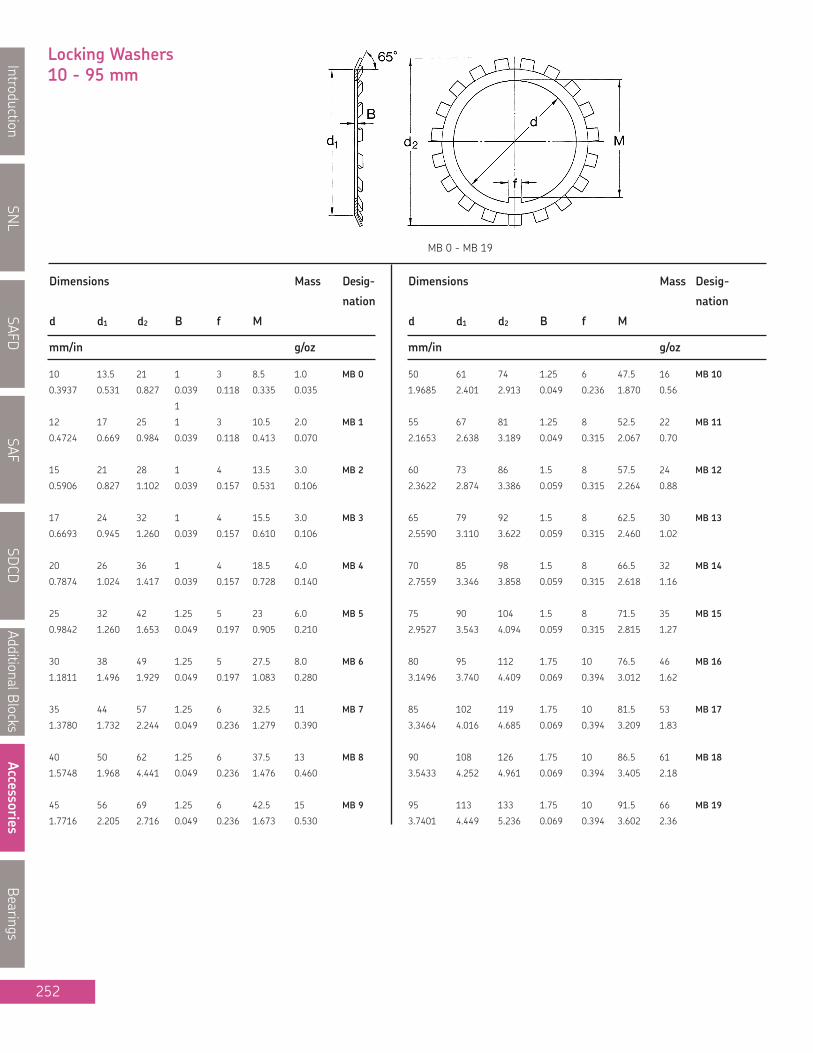
SNL
IntroductionSAFD
SAFSD
CDAdditionalBlocks
AccessoriesBearings
252
Locking Washers10 - 95 mm
Dimensions Mass Desig- Dimensions Mass Desig-
nation nation
d d1 d2 B f M d d1 d2 B f M
mm/in g/oz mm/in g/oz
10 13.5 21 1 3 8.5 1.0 MB 0 50 61 74 1.25 6 47.5 16 MB 10
0.3937 0.531 0.827 0.039 0.118 0.335 0.035 1.9685 2.401 2.913 0.049 0.236 1.870 0.56
1
12 17 25 1 3 10.5 2.0 MB 1 55 67 81 1.25 8 52.5 22 MB 11
0.4724 0.669 0.984 0.039 0.118 0.413 0.070 2.1653 2.638 3.189 0.049 0.315 2.067 0.70
15 21 28 1 4 13.5 3.0 MB 2 60 73 86 1.5 8 57.5 24 MB 12
0.5906 0.827 1.102 0.039 0.157 0.531 0.106 2.3622 2.874 3.386 0.059 0.315 2.264 0.88
17 24 32 1 4 15.5 3.0 MB 3 65 79 92 1.5 8 62.5 30 MB 13
0.6693 0.945 1.260 0.039 0.157 0.610 0.106 2.5590 3.110 3.622 0.059 0.315 2.460 1.02
20 26 36 1 4 18.5 4.0 MB 4 70 85 98 1.5 8 66.5 32 MB 14
0.7874 1.024 1.417 0.039 0.157 0.728 0.140 2.7559 3.346 3.858 0.059 0.315 2.618 1.16
25 32 42 1.25 5 23 6.0 MB 5 75 90 104 1.5 8 71.5 35 MB 15
0.9842 1.260 1.653 0.049 0.197 0.905 0.210 2.9527 3.543 4.094 0.059 0.315 2.815 1.27
30 38 49 1.25 5 27.5 8.0 MB 6 80 95 112 1.75 10 76.5 46 MB 16
1.1811 1.496 1.929 0.049 0.197 1.083 0.280 3.1496 3.740 4.409 0.069 0.394 3.012 1.62
35 44 57 1.25 6 32.5 11 MB 7 85 102 119 1.75 10 81.5 53 MB 17
1.3780 1.732 2.244 0.049 0.236 1.279 0.390 3.3464 4.016 4.685 0.069 0.394 3.209 1.83
40 50 62 1.25 6 37.5 13 MB 8 90 108 126 1.75 10 86.5 61 MB 18
1.5748 1.968 4.441 0.049 0.236 1.476 0.460 3.5433 4.252 4.961 0.069 0.394 3.405 2.18
45 56 69 1.25 6 42.5 15 MB 9 95 113 133 1.75 10 91.5 66 MB 19
1.7716 2.205 2.716 0.049 0.236 1.673 0.530 3.7401 4.449 5.236 0.069 0.394 3.602 2.36
MB 0 - MB 19

SNL
Introduction
SAFD
SAF
SDCD
AdditionalB
locks
Accessories
Bearings
253
Locking Washers100 - 280 mm
Dimensions Mass Desig- Dimensions Mass Desig-
nation nation
d d1 d2 B f M d d1 d2 B f M
mm/in g/oz mm/in g/oz
100 120 142 1.75 12 96.5 77 MB 20 155 182 212 2.5 16 147.5 200 MB 31
3.9370 4.724 5.590 0.069 0.472 3.799 2.72 6.1024 7.165 8.346 0.098 0.630 5.807 7.06
105 126 145 1.75 12 100.5 83 MB 21 160 182 217 2.5 18 154 215 MB 32
4.1338 4.961 5.709 0.069 0.472 3.957 2.93 6.2992 7.165 8.543 0.098 0.709 6.063 7.59
110 133 154 1.75 12 105.5 91 MB 22 165 193 222 2.5 18 157.5 240 MB 33
4.3307 5.236 6.063 0.069 0.472 4.153 3.21 6.4960 7.598 8.740 0.098 0.709 6.201 8.46
115 137 159 2 12 110.5 107 MB 23 170 193 232 2.5 18 164 240 MB 34
4.5275 5.394 6.260 0.079 0.472 4.350 3.78 6.6929 7.598 9.134 0.098 0.709 6.457 8.46
120 138 164 2 14 115 108 MB 24 180 203 242 2.5 20 174 260 MB 36
4.7244 5.433 6.457 0.079 0.551 4.527 3.81 7.0866 7.992 9.527 0.098 0.787 6.850 9.18
125 148 170 2 14 120 115 MB 25 190 214 252 2.5 20 184 260 MB 38
4.9212 5.827 6.693 0.079 0.551 4.724 4.06 7.4803 8.425 9.921 0.098 0.787 7.244 9.18
130 149 175 2 14 125 115 MB 26 200 226 262 2.5 20 194 280 MB 40
5.1181 5.866 6.890 0.079 0.551 4.921 4.06 7.8740 8.898 10.315 0.098 0.787 7.638 9.88
135 160 185 2 14 130 140 MB 27 220 250 292 3 24 213 350 MB 44
5.3150 6.299 7.283 0.079 0.551 5.118 4.94 8.6614 9.842 11.496 0.118 0.945 8.386 12.36
140 160 192 2 16 135 135 MB 28 240 270 312 3 24 233 450 MB 48
5.5118 6.299 7.559 0.079 0.630 5.315 4.77 9.4488 10.630 12.283 0.118 0.945 9.173 15.89
145 172 202 2 16 140 165 MB 29 260 300 342 3 28 253 650 MB 52
5.7087 6.772 7.953 0.079 0.630 5.512 5.82 10.2362 11.811 13.464 0.118 1.102 9.961 22.95
150 171 205 2 16 145 180 MB 30 280 320 362 3 28 273 1050 MB 56
5.9055 6.7323 8.071 0.079 0.630 5.709 6.35 11.0236 12.598 14.252 0.118 1.102 10.748 37.07
MB 20 - MB 56

SNL
IntroductionSAFD
SAFSD
CDAdditionalBlocks
AccessoriesBearings
254
Locking Washers0.406 - 4.192 in
Dimensions Mass Desig- Dimensions Mass Desig-
nation nation
d d1 d2 B f M V d d1 d2 B f M V
mm/in g/oz mm/in g/oz
0.406 0.625 0.875 0.032 0.120 0.334 0.062 2 W 00 2.182 2.656 3.109 0.053 0.290 2.069 0.125 22 W 1110.31 15.88 22.22 0.81 3.05 8.48 1.57 0.07 55.42 67.46 78.96 1.35 7.37 52.55 3.18 0.77
0.484 0.719 1.016 0.032 0.120 0.412 0.062 2 W 01 2.400 2.844 3.344 0.053 0.290 2.267 0.125 25 W 1212.29 18.26 25.81 0.81 3.05 10.46 1.57 0.07 60.96 72.24 84.94 1.35 7.37 57.58 3.18 0.88
0.601 0.813 1.156 0.032 0.120 0.529 0.062 3 W 02 2.588 3.063 3.578 0.053 0.290 2.455 0.125 27 W 1315.27 20.65 29.36 0.81 3.05 13.44 1.57 0.10 65.74 77.80 90.88 1.35 7.37 62.36 3.18 0.95
0.679 0.938 1.328 0.032 0.120 0.607 0.062 5 W 03 2.791 3.313 3.828 0.053 0.290 2.658 0.188 32 W 1417.25 23.83 33.73 0.81 3.05 15.42 1.57 0.17 70.89 84.15 97.23 1.35 7.37 67.51 4.77 1.13
0.801 1.125 1.531 0.032 0.176 0.729 0.062 7 W 04 2.973 3.563 4.109 0.062 0.290 2.831 0.188 48 W 1520.34 28.58 38.89 0.81 4.47 18.52 1.57 0.25 75.51 90.50 104.37 1.57 7.37 71.91 4.77 1.69
0.989 1.281 1.719 0.040 0.176 0.909 0.094 8 W 05 3.177 3.844 4.375 0.062 0.353 3.035 0.188 53 W 1625.12 32.54 43.66 1.02 4.47 23.09 2.39 0.28 80.70 97.64 111.12 1.57 8.97 77.09 4.77 1.87
1.193 1.500 1.922 0.040 0.176 1.093 0.094 8 W 06 3.395 4.031 4.625 0.062 0.353 3.253 0.188 57 W 1730.30 38.10 48.82 1.02 4.47 27.76 2.39 0.28 86.23 102.39 117.48 1.57 8.97 82.63 4.77 2.01
1.396 1.813 2.250 0.040 0.176 1.296 0.094 14 W 07 3.582 4.281 4.938 0.084 0.353 3.418 0.188 70 W 1835.46 46.05 57.15 1.02 4.47 32.92 2.39 0.49 90.98 108.74 125.42 2.13 8.97 86.82 4.77 2.47
1.583 2.000 2.469 0.048 0.290 1.475 0.094 19 W 08 3.800 4.563 5.219 0.084 0.353 3.636 0.188 82 W 1940.21 50.80 62.71 1.22 7.37 37.46 2.39 0.67 96.52 115.90 132.56 2.13 8.97 92.35 4.77 2.89
1.792 2.281 2.734 0.048 0.290 1.684 0.125 21 W 09 3.988 4.813 5.500 0.084 0.353 3.809 0.250 94 W 2045.52 57.94 69.44 1.22 7.37 42.77 3.18 0.74 101.30 122.25 139.70 2.13 8.97 96.75 6.35 3.31
1.992 2.438 2.922 0.048 0.290 1.884 0.125 20 W 10 4.192 5.000 5.703 0.084 0.353 4.013 0.250 100 W 2150.60 61.92 74.22 1.22 7.37 47.85 3.18 0.70 106.48 127.00 144.86 2.13 8.97 101.93 6.35 3.53
W 00 - W 21
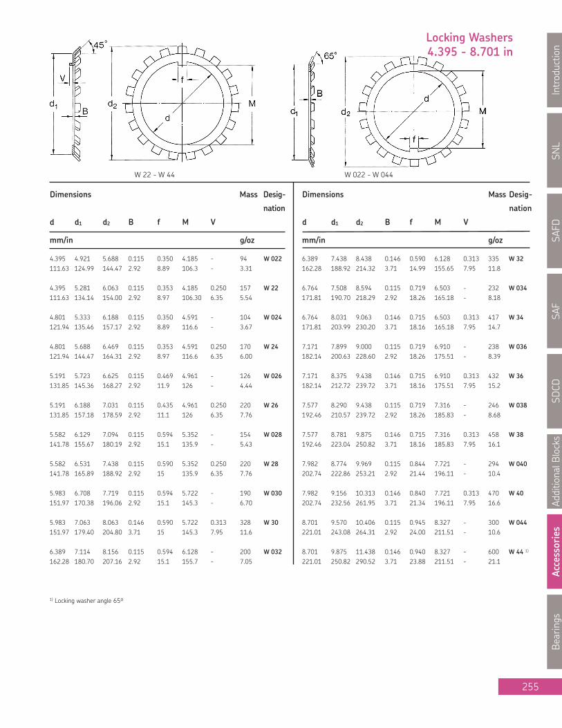
SNL
Introduction
SAFD
SAF
SDCD
AdditionalB
locks
Accessories
Bearings
255
Dimensions Mass Desig- Dimensions Mass Desig-
nation nation
d d1 d2 B f M V d d1 d2 B f M V
mm/in g/oz mm/in g/oz
4.395 4.921 5.688 0.115 0.350 4.185 - 94 W 022 6.389 7.438 8.438 0.146 0.590 6.128 0.313 335 W 32111.63 124.99 144.47 2.92 8.89 106.3 - 3.31 162.28 188.92 214.32 3.71 14.99 155.65 7.95 11.8
4.395 5.281 6.063 0.115 0.353 4.185 0.250 157 W 22 6.764 7.508 8.594 0.115 0.719 6.503 - 232 W 034111.63 134.14 154.00 2.92 8.97 106.30 6.35 5.54 171.81 190.70 218.29 2.92 18.26 165.18 - 8.18
4.801 5.333 6.188 0.115 0.350 4.591 - 104 W 024 6.764 8.031 9.063 0.146 0.715 6.503 0.313 417 W 34121.94 135.46 157.17 2.92 8.89 116.6 - 3.67 171.81 203.99 230.20 3.71 18.16 165.18 7.95 14.7
4.801 5.688 6.469 0.115 0.353 4.591 0.250 170 W 24 7.171 7.899 9.000 0.115 0.719 6.910 - 238 W 036121.94 144.47 164.31 2.92 8.97 116.6 6.35 6.00 182.14 200.63 228.60 2.92 18.26 175.51 - 8.39
5.191 5.723 6.625 0.115 0.469 4.961 - 126 W 026 7.171 8.375 9.438 0.146 0.715 6.910 0.313 432 W 36131.85 145.36 168.27 2.92 11.9 126 - 4.44 182.14 212.72 239.72 3.71 18.16 175.51 7.95 15.2
5.191 6.188 7.031 0.115 0.435 4.961 0.250 220 W 26 7.577 8.290 9.438 0.115 0.719 7.316 - 246 W 038131.85 157.18 178.59 2.92 11.1 126 6.35 7.76 192.46 210.57 239.72 2.92 18.26 185.83 - 8.68
5.582 6.129 7.094 0.115 0.594 5.352 - 154 W 028 7.577 8.781 9.875 0.146 0.715 7.316 0.313 458 W 38141.78 155.67 180.19 2.92 15.1 135.9 - 5.43 192.46 223.04 250.82 3.71 18.16 185.83 7.95 16.1
5.582 6.531 7.438 0.115 0.590 5.352 0.250 220 W 28 7.982 8.774 9.969 0.115 0.844 7.721 - 294 W 040141.78 165.89 188.92 2.92 15 135.9 6.35 7.76 202.74 222.86 253.21 2.92 21.44 196.11 - 10.4
5.983 6.708 7.719 0.115 0.594 5.722 - 190 W 030 7.982 9.156 10.313 0.146 0.840 7.721 0.313 470 W 40151.97 170.38 196.06 2.92 15.1 145.3 - 6.70 202.74 232.56 261.95 3.71 21.34 196.11 7.95 16.6
5.983 7.063 8.063 0.146 0.590 5.722 0.313 328 W 30 8.701 9.570 10.406 0.115 0.945 8.327 - 300 W 044151.97 179.40 204.80 3.71 15 145.3 7.95 11.6 221.01 243.08 264.31 2.92 24.00 211.51 - 10.6
6.389 7.114 8.156 0.115 0.594 6.128 - 200 W 032 8.701 9.875 11.438 0.146 0.940 8.327 - 600 W 44 1)
162.28 180.70 207.16 2.92 15.1 155.7 - 7.05 221.01 250.82 290.52 3.71 23.88 211.51 - 21.1
1) Locking washer angle 65º
W 22 - W 44 W 022 - W 044
Locking Washers4.395 - 8.701 in

SNL
IntroductionSAFD
SAFSD
CDAdditionalBlocks
AccessoriesBearings
256
Hydraulic Nuts - HMV Series(Metric Thread)HMV 10E - HMV 27EAll HMV nuts are manufactured withBSP 1/4" connection thread and aresupplied with quick connectionnipple 729832A and nipple 729106(Male BSP 1/4" and Female NPT 3/8")
Dimensions Axial Piston Mass Designation
Displacement Area
G d1 d2 d3 B B1 Max.
mm mm/in mm2/in2 kg/lb
M 50x1.5 50.5 104 114 38 4 5 2 900 2.70 HMV 10E
1.988 4.094 4.488 1.496 0.157 0.197 4.5 5.95
M 60x2 60.5 115 125 38 5 5 3 300 2.80 HMV 12E
2.382 4.527 4.921 1.496 0.197 0.197 5.1 6.17
M 65x2 65.5 121 130 38 5 5 3 600 3.00 HMV 13E
2.578 4.764 5.118 1.496 0.197 0.197 5.6 6.61
M 70x2 70.5 127 135 38 5 5 3 800 3.20 HMV 14E
2.775 5.000 5.315 1.496 0.197 0.197 5.9 7.05
M 75x2 75.5 132 140 38 5 5 4 000 3.40 HMV 15E
2.972 5.197 5.512 1.496 0.197 0.197 6.2 7.49
M 80x2 80.5 137 146 38 5 5 4 200 3.70 HMV 16E
3.169 5.394 5.748 1.496 0.197 0.197 6.5 8.16
M 85x2 85.5 142 150 38 5 5 4 400 3.75 HMV 17E
3.366 5.590 5.906 1.496 0.197 0.197 6.8 8.27
M 90x2 90.5 147 156 38 5 5 4 700 4.00 HMV 18E
3.563 5.787 6.142 1.496 0.197 0.197 7.3 8.82
M 95x2 95.5 153 162 38 5 5 4 900 4.30 HMV 19E
3.760 6.024 6.378 1.496 0.197 0.197 7.6 9.48
M 100x2 100.5 158 166 38 6 5 5 100 4.40 HMV 20E
3.957 6.220 6.535 1.496 0.236 0.197 7.9 9.70
M 105x2 105.5 163 172 38 6 5 5 300 4.65 HMV 21E
4.153 6.417 6.772 1.496 0.236 0.197 8.2 10.25
M 110x2 110.5 169 178 38 6 5 5 600 4.95 HMV 22E
4.350 6.654 7.008 1.496 0.236 0.197 8.7 10.91
M 115x2 115.5 174 182 38 6 5 5 800 5.00 HMV 23E
4.547 6.850 7.165 1.496 0.236 0.197 9.0 11.02
M 120x2 120.5 179 188 38 6 5 6 000 5.25 HMV 24E
4.744 7.047 7.401 1.496 0.236 0.197 9.3 11.57
M 125x2 125.5 184 192 38 6 5 6 200 5.35 HMV 25E
4.941 7.244 7.560 1.496 0.236 0.197 9.6 11.79
M 130x2 130.5 190 198 38 6 5 6 400 5.65 HMV 26E
5.138 6.693 7.795 1.496 0.236 0.197 9.9 12.46
M 135x2 135.5 195 204 38 6 5 6 600 5.90 HMV 27E
5.335 6.677 8.031 1.496 0.236 0.197 10.2 13.00

SNL
Introduction
SAFD
SAF
SDCD
AdditionalB
locks
Accessories
Bearings
257
Dimensions Axial Piston Mass Designation
Displacement Area
G d1 d2 d3 B B1 Max.
mm mm/in mm2/in2 kg/lb
M 140x2 140.5 200 208 38 7 5 6 800 6.00 HMV 28E
5.531 7.874 8.189 1.496 0.276 0.197 10.5 13.22
M 145x2 145.5 206 214 39 7 5 7 300 6.50 HMV 29E
5.728 8.110 8.425 1.535 0.276 0.197 11.3 14.33
M 150x2 150.5 211 220 39 7 5 7 500 6.60 HMV 30E
5.925 8.307 8.661 1.535 0.276 0.197 11.6 14.55
M 155x3 155.5 218 226 39 7 5 8 100 6.95 HMV 31E
6.122 8.583 8.898 1.535 0.276 0.197 12.6 15.32
M 160x3 160.5 224 232 40 7 6 8 600 7.60 HMV 32E
6.319 8.819 9.134 1.575 0.276 0.236 13.3 16.75
M 165x3 165.5 229 238 40 7 6 8 900 7.90 HMV 33E
6.516 9.016 9.370 1.575 0.276 0.236 13.8 17.42
M 170x3 170.5 235 244 41 7 6 9 400 8.40 HMV 34E
6.712 9.252 9.606 1.614 0.276 0.236 14.6 18.52
M 180x3 180.5 247 256 41 7 6 10 300 9.15 HMV 36E
7.106 9.724 10.079 1.614 0.276 0.236 16.0 20.17
M 190x3 191 259 270 42 8 7 11 500 10.5 HMV 38E
7.519 10.200 10.630 1.653 0.315 0.276 17.8 23.15
M 200x3 201 271 282 43 8 8 12 500 11.5 HMV 40E
7.913 10.669 11.102 1.693 0.315 0.315 19.4 25.35
Tr 205x4 207 276 288 43 8 8 12 800 12.0 HMV 41E
8.150 10.866 11.338 1.693 0.315 0.315 19.8 26.45
Tr 210x4 212 282 294 44 8 9 13 400 12.5 HMV 42E
8.346 11.102 11.575 1.732 0.315 0.354 20.8 27.60
Tr 215x4 217 287 300 44 8 9 13 700 13.0 HMV 43E
8.543 11.300 11.811 1.732 0.315 0.354 21.2 28.66
Tr 220x4 222 293 306 44 8 9 14 400 13.5 HMV 44E
8.740 11.535 12.047 1.732 0.315 0.354 22.3 29.76
Tr 225x4 227 300 312 45 8 9 15 200 14.5 HMV 45E
8.937 11.811 12.283 1.772 0.315 0.354 23.6 32.0
Tr 230x4 232 305 318 45 8 9 15 500 14.5 HMV 46E
9.134 12.010 12.520 1.772 0.315 0.354 24.0 32.0
Tr 235x4 237 311 326 46 8 10 16 200 16.0 HMV 47E
9.330 12.244 12.835 1.811 0.315 0.394 25.1 35.3
Hydraulic Nuts - HMV Series (Metric Thread)HMV 28E - HMV 47E
All HMV nuts are manufactured withBSP 1/4" connection thread and are
supplied with quick connectionnipple 729832A and nipple 729106
(Male BSP 1/4" and Female NPT 3/8")

SNL
IntroductionSAFD
SAFSD
CDAdditionalBlocks
AccessoriesBearings
258
Hydraulic Nuts - HMV Series(Metric Thread)HMV 48E - HMV 76EAll HMV nuts are manufactured withBSP 1/4" connection thread and aresupplied with quick connectionnipple 729832A and nipple 729106(Male BSP 1/4" and Female NPT 3/8")
Dimensions Axial Piston Mass Designation
Displacement Area
G d1 d2 d3 B B1 Max.
mm mm/in mm2/in2 kg/lb
Tr 240x4 242 316 330 46 9 10 16 500 16.0 HMV 48E
9.527 12.441 12.992 1.811 0.354 0.394 25.6 35.3
Tr 250x4 252 329 342 46 9 10 17 600 17.5 HMV 50E
9.921 12.953 13.464 1.811 0.354 0.394 27.3 38.6
Tr 260x4 262 341 356 47 9 11 18 800 19.0 HMV 52E
10.315 13.425 14.016 1.850 0.354 0.433 29.1 41.9
Tr 270x4 272 352 368 48 9 12 19 800 20.5 HMV 54E
10.709 13.858 14.488 1.890 0.354 0.472 30.7 45.2
Tr 280x4 282 363 380 49 9 12 21 100 22.0 HMV 56E
11.102 14.291 14.960 1.929 0.354 0.472 32.7 48.5
Tr 290x4 292 375 390 49 9 13 22 400 22.5 HMV 58E
11.469 14.764 15.354 1.929 0.354 0.512 34.7 49.6
Tr 300x4 302 386 404 51 9 14 23 600 25.5 HMV 60E
11.889 15.197 15.905 2.008 0.394 0.551 36.6 56.2
Tr 310x5 312 397 416 52 10 14 24 900 27.0 HMV 62E
12.283 15.630 16.378 2.047 0.394 0.551 38.6 59.5
Tr 320x5 322 409 428 53 10 14 26 300 29.5 HMV 64E
12.677 16.102 16.850 2.087 0.394 0.551 40.8 65.0
Tr 330x5 332 419 438 53 10 14 27 000 30.0 HMV 66E
13.071 16.496 17.244 2.087 0.394 0.551 41.8 66.1
Tr 340x5 342 430 450 54 10 14 28 400 31.5 HMV 68E
13.464 16.929 17.716 2.126 0.394 0.551 44.0 69.4
Tr 345x5 347 436 456 54 10 14 29 400 32.5 HMV 69E
13.661 17.165 17.952 2.126 0.394 0.551 45.6 71.65
Tr 350x5 352 442 464 56 10 14 29 900 35.0 HMV 70E
13.858 17.402 18.268 2.205 0.394 0.551 46.3 77.1
Tr 360x5 362 455 472 56 10 15 31 300 35.5 HMV 72E
14.252 17.913 18.583 2.205 0.394 0.590 48.5 78.3
Tr 365x5 367 460 482 57 11 15 31 700 38.5 HMV 73E
14.449 18.110 18.976 2.244 0.433 0.590 49.1 84.9
Tr 370x5 372 466 486 57 11 16 32 800 39.0 HMV 74E
14.646 18.346 19.134 2.244 0.433 0.630 50.8 86.0
Tr 380x5 382 476 498 58 11 16 33 500 40.5 HMV 76E
15.040 18.740 19.606 2.283 0.433 0.630 51.9 89.3

SNL
Introduction
SAFD
SAF
SDCD
AdditionalB
locks
Accessories
Bearings
259
Dimensions Axial Piston Mass Designation
Displacement Area
G d1 d2 d3 B B1 Max.
mm mm/in mm2/in2 kg/lb
Tr 385x5 387 483 504 58 11 16 34 700 41.0 HMV 77E
15.236 19.016 19.842 2.283 0.433 0.630 53.8 90.4
Tr 400x5 402 499 522 60 11 17 36 700 45.5 HMV 80E
15.827 19.646 20.551 2.362 0.433 0.669 56.9 100
Tr 410x5 412 510 534 61 11 17 38 300 48.0 HMV 82E
16.220 20.079 21.024 2.401 0.433 0.669 59.4 106
Tr 420x5 422 522 546 61 11 17 40 000 50.0 HMV 84E
16.614 20.551 21.497 2.401 0.433 0.669 62.0 110
Tr 430x5 432 532 556 62 11 17 40 800 52.5 HMV 86E
17.008 20.945 21.890 2.441 0.433 0.669 63.2 116
Tr 440x5 442 543 566 62 12 17 42 500 54.0 HMV 88E
17.401 21.378 22.283 2.441 0.472 0.669 65.9 119
Tr 450x5 452 554 580 64 12 17 44 100 57.5 HMV 90E
17.795 21.811 22.835 2.520 0.472 0.669 68.4 127
Tr 460x5 462 565 590 64 12 17 45 100 60.0 HMV 92E
18.189 22.244 23.228 2.520 0.472 0.669 69.9 132
Tr 470x5 472 576 602 65 12 18 46 900 62.0 HMV 94E
18.583 22.677 23.700 2.559 0.472 0.709 72.7 137
Tr 480x5 482 587 612 65 12 19 48 600 63.0 HMV 96E
18.976 23.11 24.094 2.559 0.472 0.748 75.3 139
Tr 490x5 492 597 624 66 12 19 49 500 66.0 HMV 98E
19.370 23.504 24.567 2.598 0.472 0.748 76.7 145
Tr 500x5 502 609 636 67 12 19 51 500 70.0 HMV 100E
19.764 23.976 25.039 2.638 0.472 0.748 79.8 754
Tr 510x6 512 624 648 68 12 20 53 300 74.0 HMV 102E
20.157 24.567 25.512 2.677 0.472 0.787 82.6 163
Tr 520x6 522 634 658 68 13 20 54 300 75.0 HMV 104E
20.551 24.961 25.905 2.677 0.512 0.787 84.2 165
Tr 530x6 532 645 670 69 13 21 56 200 79.0 HMV 106E
20.945 25.394 26.378 2.716 0.512 0.827 87.1 174
Tr 540x6 542 657 682 69 13 21 58 200 81.0 HMV 108E
21.388 25.866 26.850 2.716 0.512 0.827 90.2 179
Tr 550x6 552 667 693 70 13 21 59 200 84.0 HMV 110E
21.732 26.26 27.283 2.756 0.512 0.827 91.8 185
Hydraulic Nuts - HMV Series (Metric Thread)HMV 77E - HMV 110E
All HMV nuts are manufactured withBSP 1/4" connection thread and are
supplied with quick connectionnipple 729832A and nipple 729106
(Male BSP 1/4" and Female NPT 3/8")
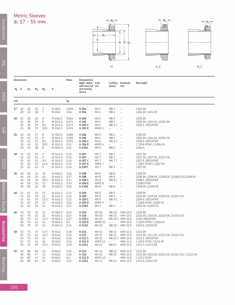
SNL
IntroductionSAFD
SAFSD
CDAdditionalBlocks
AccessoriesBearings
260
Metric Sleevesd1 17 - 55 mm B2
B1
d1 G dd
3
B2 B2
Dimensions Mass DesignationsAdptr. sleeve Lock Locking Hydraulic Bearing(s)with lock nut nut device nut
d1 d d3 B1 B2 G and lockingdevice
mm kg
17 20 32 24 7 M 20x1 0.036 H 204 KM 4 MB 4 – 1204 EK20 32 28 7 M 20x1 0.04 H 304 KM 4 MB 4 – 2204 EK, 1304 EK
20 25 38 26 8 M 25x1.5 0.064 H 205 KM 5 MB 5 – 1205 EK25 38 29 8 M 25x1.5 0.071 H 305 KM 5 MB 5 – 2205 EK, 1305 EK, 22205 EK25 38 29 8.5 M 25x1.5 0.071 H 305 C KM 5 MB 5 C – 2205 E-2RS1KTN925 38 29 10.5 M 25x1.5 0.076 H 305 E KMFE 5 – –
25 30 45 27 8 M 30x1.5 0.086 H 206 KM 6 MB 6 – 1206 EK30 45 31 8 M 30x1.5 0.095 H 306 KM 6 MB 6 – 2206 EK, 1306 EK, 22206 EK30 45 31 8.5 M 30x1.5 0.095 H 306 C KM 6 MB 6 C – 2206 E-2RS1KTN930 45 31 10.5 M 30x1.5 0.11 H 306 E KMFE 6 – – C 2206 KTN9, C 2206 KV30 45 38 8 M 30x1.5 0.11 H 2306 KM 6 MB 6 – 2306 K
30 35 52 29 9 M 35x1.5 0.12 H 207 KM 7 MB 7 – 1207 EK35 52 35 9 M 35x1.5 0.14 H 307 KM 7 MB 7 – 2207 EK, 1307 EK, 22207 EK35 52 35 9.5 M 35x1.5 0.14 H 307 C KM 7 MB 7 C – 2207 E-2RS1KTN935 52 35 11.5 M 35x1.5 0.15 H 307 E KMFE 7 – – C 2207 KTN9, C 2207 KV35 52 43 9 M 35x1.5 0.16 H 2307 KM 7 MB 7 – 2307 EK
35 40 58 31 10 M 40x1.5 0.16 H 208 KM 8 MB 8 – 1208 EK40 58 36 10 M 40x1.5 0.17 H 308 KM 8 MB 8 – 2208 EK, 1308 EK, 22208 EK, 21308 CCK,C2208 KV40 58 36 10.5 M 40x1.5 0.17 H 308 C KM 8 MB 8 C – 2208 E-2RS1KTN940 58 36 13 M 40x1.5 0.19 H 308 E KMFE 8 – – C2208 KTN940 58 46 10 M 40x1.5 0.22 H 2308 KM 8 MB 8 – 2308 EK, 22308 EK
40 45 65 33 11 M 45x1.5 0.21 H 209 KM 9 MB 9 – 1209 EK45 65 39 11 M 45x1.5 0.23 H 309 KM 9 MB 9 – 2209 EK, 1309 EK, 22209 EK, 21309 CCK45 65 39 11.5 M 45x1.5 0.23 H 309 C KM 9 MB 9 C – 2209 E-2RS1KTN945 65 39 13 M 45x1.5 0.24 H 309 E KMFE 9 – – C 2209 KTN9, C2209 KV45 65 50 11 M 45x1.5 0.27 H 2309 KM 9 MB 9 – 2309 EK, 22309 EK
45 50 70 35 12 M 50x1.5 0.24 H 210 KM 10 MB 10 HMV 10 E 1210 EK50 70 42 12 M 50x1.5 0.27 H 310 KM 10 MB 10 HMV 10 E 2210 EK, 1310 EK, 22210 EK, 21310 CCK50 70 42 12.5 M 50x1.5 0.27 H 310 C KM 10 MB 10 C HMV 10 E 2210-2RS1KTN950 70 42 14 M 50x1.5 0.3 H 310 E KMFE 10 – HMV 10 E C 2210 KTN9, C 2210 KV50 70 55 12 M 50x1.5 0.34 H 2310 KM 10 MB 10 HMV 10 E 2310 K, 22310 EK
50 55 75 37 12.5 M 55x2 0.28 H 211 KM 11 MB 11 HMV 11 E 1211 EK55 75 45 12.5 M 55x2 0.32 H 311 KM 11 MB 11 HMV 11 E 2211 EK, 1311 EK, 22211 EK, 21311 CCK55 75 45 13 M 55x2 0.32 H 311 C KM 11 MB 11 C HMV 11 E 2211 E-2RS1KTN955 75 45 14 M 55x2 0.34 H 311 E KMFE 11 – HMV 11 E C 2211 KTN9, C2211 KV55 75 59 12.5 M 55x2 0.39 H 2311 KM 11 MB 11 HMV 11 E 2311 K, 22311 EK
55 60 80 38 13 M 60x2 0.31 H 212 KM 12 MB 12 HMV 12 E 1212 EK60 80 47 13 M 60x2 0.36 H 312 KM 12 MB 12 HMV 12 E 2212 EK, 1312 EK, 22212 EK, 21312 CCK, C 2212 KV60 80 47 14 M 60x2 0.4 H 312 E KMFE 12 – HMV 12 E C 2212 KTN960 80 62 13 M 60x2 0.45 H 2312 KM 12 MB 12 HMV 12 E 2312 K, 22312 EK
H H..E H..C

SNL
Introduction
SAFD
SAF
SDCD
AdditionalB
locks
Accessories
Bearings
261
Metric Sleevesd1 60 - 110 mmB2
B1
d1 G dd
3
B2 B2
Dimensions Mass DesignationsAdptr. sleeve Lock Locking Hydraulic Bearing(s)with lock nut nut device nut
d1 d d3 B1 B2 G and lockingdevice
mm kg
60 65 85 40 14 M 65x2 0.36 H 213 KM 13 MB 13 HMV 13 E 1213 EK65 85 50 14 M 65x2 0.42 H 313 KM 13 MB 13 HMV 13 E 2213 EK, 1313 EK, 22213 EK, 21213 CCK, C 2213 KV65 85 50 15 M 65x2 0.42 H 313 C KM 13 MB 13 C HMV 13 E 22213 E-2RS1KTN965 85 50 15 M 65x2 0.43 H 313 E KMFE 13 – HMV 13 E C 2213 KTN965 85 65 14 M 65x2 0.52 H 2313 KM 13 MB 13 HMV 13 E 2313 K, 22313 EK
70 92 52 14 M 70x2 0.67 H 314 KM 14 MB 14 HMV 14 E 22214EK, 21314 CCK,C 2214 KV70 92 52 15 M 70x2 0.67 H 314 E KMFE 14 – HMV 14 E C 2214 KTN970 92 68 14 M 70x2 0.88 H 2314 KM 14 MB 14 HMV 14 E 22314 EK, C 2314 K
65 75 98 43 15 M 75x2 0.66 H 215 KM 15 MB 15 HMV 15 E 1215 K75 98 55 15 M 75x2 0.78 H 315 KM 15 MB 15 HMV 15 E 2215 K, 1315 K, 22215 EK, 21315 CCK, C 2215 KV75 98 55 16 M 75x2 0.8 H 315 E KMFE 15 – HMV 15 E C 2215 K75 98 73 15 M 75x2 1.1 H 2315 KM 15 MB 15 HMV 15 E 2315 K, 22315 EK, C 2315 K
70 80 105 46 17 M 80x2 0.81 H 216 KM 16 MB 16 HMV 16 E 1216 K80 105 59 17 M 80x2 0.95 H 316 KM 16 MB 16 HMV 16 E 2216 EK, 1316 K, 22216 EK, 21316 CCK. C 2216 KV80 105 59 18 M 80x2 1.01 H 316 E KMFE 16 – HMV 16 E C 2216 K80 105 78 17 M 80x2 1.2 H 2316 KM 16 MB 16 HMV 16 E 2316 K, 22316 EK, C 2316 K
75 85 110 50 18 M 85x2 0.94 H 217 KM 17 MB 17 HMV 17 E 1217 K85 110 63 18 M 85x2 1.1 H 317 KM 17 MB 17 HMV 17 E 2217 K, 1317 K, 22217 EK, 21317 CCK, C 2217 KV85 110 63 19 M 85x2 1.17 H 317 E KMFE 17 – HMV 17 E C 2217 K85 110 82 18 M 85x2 1.35 H 2317 KM 17 MB 17 HMV 17 E 2317 K, 22317 EK, C 2317 K
80 90 120 52 18 M 90x2 1.1 H 218 KM 18 MB 18 HMV 18 E 1218 K90 120 65 18 M 90x2 1.3 H 318 KM 18 MB 18 HMV 18 E 2218 K, 1318 K, 22218 EK, 21318 CCK, C2218 KV90 120 65 19 M 90x2 1.43 H 318 E KMFE 18 – HMV 18 E C 2218 K90 120 86 18 M 90x2 1.6 H 2318 KM 18 MB 18 HMV 18 E 2318 K, 23218 CCK/W33, 22318 EK, C2318 K
85 95 125 55 19 M 95x2 1.25 H 219 KM 19 MB 19 HMV 19 E 1219 K95 125 68 19 M 95x2 1.4 H 319 KM 19 MB 19 HMV 19 E 2219 K, 1319K, 22219 EK, 21319 CCK95 125 68 20 M 95x2 1.41 H 319 E KMFE 19 – HMV 19 E C 2219 K95 125 90 19 M 95x2 1.8 H 2319 KM 19 MB 19 HMV 19 E 2319 K, 22319 EK, C 2319 K
90 100 130 58 20 M 100x2 1.4 H 220 KM 20 MB 20 HMV 20 E 1220 K100 130 71 20 M 100x2 1.6 H 320 KM 20 MB 20 HMV 20 E 2220 K, 1320 K, 22220 EK, 21320 CCK,100 130 71 21 M 100x2 1.72 H 320 E KMFE 20 – HMV 20 E C 2220 K100 130 76 20 M 100x2 1.8 H 3120 KM 20 MB 20 HMV 20 E 23120 CCK/W33, C 3120 K, C3120 KV100 130 97 20 M 100x2 2 H 2320 KM 20 MB 20 HMV 20 E 2320 K, 23220 CCK/W33, 22320 EK, C2320 K
100 110 145 63 21 M 110x2 1.8 H 222 KM 22 MB 22 HMV 22 E 1222 K110 145 77 21 M 110x2 2.04 H 322 KM 22 MB 22 HMV 22 E 2222 K, 1322 K, 23022 CCK, 22222 EK, 21322 CCK110 145 77 21.5 M 110x2 2.11 H 322 E KMFE 22 – HMV 22 E C 3022 K, C 2222 K110 145 81 21 M 110x2 2.1 H 3122 KM 22 MB 22 HMV 22 E 23122 CCK/W33110 145 105 21 M 110x2 2.75 H 2322 KM 22 MB 22 HMV 22 E 2322 K, 23222 CCK/W33, 22322 EK
110 120 145 72 22 M 120x2 1.8 H 3024 KML 24 MBL 24 HMV 24 E 1224 K, 23024 CCK/W33, C3024 K120 155 72 26 M 120x2 1.87 H 3024 E KMFE 24 – HMV 24 E C 3024 K120 155 88 22 M 120x2 2.5 H 3124 KM 24 MB 24 HMV 24 E 23124 CCCK/W33, 22224 EK120 145 88 22 M 120x2 2.5 H 3124 L KML 24 MBL 24 HMV 24 E C 2224 K120 155 112 22 M 120x2 3 H 2324 KM 24 MB 24 HMV 24 E 23224 CCK/W33, 22324 CCK/W33120 145 112 22 M 120x2 3.12 H 2324 L KML 24 MBL 24 HMV 24 E C 3224 K
H, H..L H..E H..C

SNL
IntroductionSAFD
SAFSD
CDAdditionalBlocks
AccessoriesBearings
262
Metric Sleevesd1 115 - 180 mm
B2
B1
d1 G dd
3
Dimensions Mass DesignationsAdptr. sleeve Lock Locking Hydraulic Bearing(s)with lock nut nut device nut
d1 d d3 B1 B2 G and lockingdevice
mm kg
115 130 155 80 23 M 130x2 2.8 H 3026 KML 26 MBL 26 HMV 26 E 23026 CCK/W33, C3026 K130 165 92 23 M 130x2 3.45 H 3126 KM 26 MB 26 HMV 26 E 23126 CCK/W33, 22226 EK130 155 92 23 M 130x2 3.65 H 3126 L KML 26 MBL 26 HMV 26 E C 2226 K130 165 121 23 M 130x2 4.45 H 2326 KM 26 MB 26 HMV 26 E 23226 CCK/W33, 22326 CCK/W33
125 140 165 82 24 M 140x2 3.05 H 3028 KML 28 MBL 28 HMV 28 E 23028 CCK/W33, C 3028 K140 180 97 24 M 140x2 4.1 H 3128 KM 28 MB 28 HMV 28 E 23128 CCK/W33, 22228 CCK/W33140 165 97 24 M 140x2 3.62 H 3128 L KML 28 MBL 28 HMV 28 E C 2228 K140 180 131 24 M 140x2 5.4 H 2328 KM 28 MB 28 HMV 28 E 23228 CCK/W33, 22328 CCK/W33
135 150 180 87 26 M 150x2 3.75 H 3030 KML 30 MBL 30 HMV 30 E 23030 CCK/W33150 195 111 26 M 150x2 5.25 H 3130 KM 30 MB 30 HMV 30 E 23130 CCK/W33, 22230 CCK/W33150 180 111 26 M 150x2 4.7 H 3130 L KML 30 MBL 30 HMV 30 E C 3130 K, 2230 K, C3130 K, C2230 K150 195 139 26 M 150x2 6.4 H 2330 KM 30 MB 30 HMV 30 E 23230 CCK/W33, 22330 CCK/W33
140 160 190 93 27.5 M 160x3 5.1 H 3032 KML 32 MBL 32 HMV 32 E 23032 CCK/W33, C3032 K160 210 119 27.5 M 160x3 7.25 H 3132 KM 32 MB 32 HMV 32 E 23132 CCK/W33, 22232 CCK/W33160 190 119 27.5 M 160x3 6.4 H 3132 L KML 32 MBL 32 HMV 32 E C 3132 K160 210 147 27.5 M 160x3 8.8 H 2332 KM 32 MB 32 HMV 32 E 23232 CCK/W33, 22332 CCK/W33160 190 147 27.5 M 160x3 7.95 H 2332 L KML 32 MBL 32 HMV 32 E C 3232 K
150 170 200 101 28.5 M 170x3 5.8 H 3034 KML 34 MBL 34 HMV 34 E 23034 CCK/W33, C 3034 K170 220 122 28.5 M 170x3 8.1 H 3134 KM 34 MB 34 HMV 34 E 23134 CCK/W33, 22234 CCK/W33170 200 122 28.5 M 170x3 7.15 H 3134 L KML 34 MBL 34 HMV 34 E C 3134 K, C2334 K170 220 154 28.5 M 170x3 9.9 H 2334 KM 34 MB 34 HMV 34 E 23234 CCK/W33, 22334 CCK/W33
160 180 210 87 29.5 M 180x3 5.7 H 3936 KML 36 MBL 36 HMV 36 E 23936 CCK/W33180 210 109 29.5 M 180x3 6.7 H 3036 KML 36 MBL 36 HMV 36 E 23036 CCK/W33, C3036 K180 230 131 29.5 M 180x3 9.15 H 3136 KM 36 MB 36 HMV 36 E 23136 CCK/W33, 22236 CCK/W33180 210 131 29.5 M 180x3 8.15 H 3136 L KML 36 MBL 36 HMV 36 E C 3136 K180 230 161 30 M 180x3 11 H 2336 KM 36 MB 36 HMV 36 E 23236 CCK/W33, 22336 CCK/W33, C3236 K
170 190 220 89 30.5 M 190x3 6.2 H 3938 KML 38 MBL 38 HMV 38 E 23938 CCK/W33190 220 112 30.5 M 190x3 7.25 H 3038 KML 38 MBL 38 HMV 38 E 23038 CCK/W33, C 3038 K190 240 141 30.5 M 190x3 10.5 H 3138 KM 38 MB 38 HMV 38 E 23138 CCK/W33, 22238 CCK/W33190 240 169 30.5 M 190x3 12 H 2338 KM 38 MB 38 HMV 38 E 23238 CCK/W33, 22338 CCK/W33
180 200 240 98 31.5 M 200x3 7.9 H 3940 KML 40 MBL 40 HMV 40 E 23940 CCK/W33200 240 120 31.5 M 200x3 8.9 H 3040 KML 40 MBL 40 HMV 40 E 23040 CCK/W33, C 3040 K200 250 150 31.5 M 200x3 12 H 3140 KM 40 MB 40 HMV 40 E 23140 CCK/W33, 22240 CCK/W33, C3140 K200 250 176 31.5 M 200x3 13.5 H 2340 KM 40 MB 40 HMV 40 E 23240 CCK/W33, 22340 CCK/W33
H, H..L

SNL
Introduction
SAFD
SAF
SDCD
AdditionalB
locks
Accessories
Bearings
263
Metric Sleevesd1 200 - 400 mmB2
B3
d1 G d3
dB1
G1A
Dimensions Mass DesignationsAdptr. sleeve Lock Locking Hydraulic Bearing(s)with lock nut nut device nut
d1 d d3 B1 B2 B3 G G1 A and lockingdevice
mm kg
200 220 260 96 30 41 Tr 220x4 M 6 4.2 7.95 OH 3944 H HM 3044 MS 3044 HMV 44 E 23944 CCK/W33220 260 126 30 41 Tr 220x4 M 6 4.2 9.9 OH 3044 H HM 3044 MS 3044 HMV 44 E C 3044 K220 280 161 35 – Tr 220x4 M 6 4.2 15 OH 3144 H HM 44 T MB 44 HMV 44 E 23144 CCK/W33, 22244 CCK/W33,
C 2244 K220 260 161 30 41 Tr 220x4 M 6 4.2 14.3 OH 3144 HTL HM 3044 MS 3044 HMV 44 E C 3144 K220 280 186 35 – Tr 220x4 M 6 4.2 17 OH 2344 H HM 44 T MB 44 HMV 44 E 23244 CCK/W33, 22344 CCK/W33
220 240 290 101 34 46 Tr 240x4 M 6 4.2 11 OH 3948 H HM 3048 MS 3052-48 HMV 48 E 23948 CCK/W33240 290 133 34 46 Tr 240x4 M 6 4.2 12 OH 3048 H HM 3048 MS 3052-48 HMV 48 E 23048 CCK/W33, C 3048 K240 300 172 37 – Tr 240x4 M 6 4.2 16.5 OH 3148 H HM 48 T MB 48 HMV 48 E 23148 CCK/W33, 22248 CCK/W33240 290 172 34 46 Tr 240x4 M 6 4.2 15.1 OH 3148 HTL HM 3048 MS 3052-48 HMV 48 E C 3148 K240 300 199 37 – Tr 240x4 M 6 4.2 19 OH 2348 H HM 48 T MB 48 HMV 48 E 23248 CCK/W33, 22348 CCK/W33
240 260 310 116 34 46 Tr 260x4 M 6 4.2 11.7 OH 3952 H HM 3052 MS 3052-48 HMV 52 E 23952 CCK/W33260 310 145 34 46 Tr 260x4 M 6 4.2 13.5 OH 3052 H HM 3052 MS 3052-48 HMV 52 E 23052 CCK/W33,260 330 190 39 – Tr 260x4 M 6 4.2 21 OH 3152 H HM 52 T MB 52 HMV 52 E 23152 CCK/W33, 22252 CACK/W33260 310 190 34 46 Tr 260x4 M 6 4.2 17.7 OH 3152 HTL HM 3052 MS 3052-48 HMV 52 E C 3152 K260 330 211 39 – Tr 260x4 M 6 4.2 23 OH 2352 H HM 52 T MB 52 HMV 52 E 23252 CCK/W33, 22352 CACK/W33
260 280 330 121 38 50 Tr 280x4 M 6 4.2 15.3 OH 3956 H HM 3056 MS 3056 HMV 56 E 23956 CCK/W33280 330 152 38 50 Tr 280x4 M 6 4.2 16 OH 3056 H HM 3056 MS 3056 HMV 56 E 23056 CCK/W33, C 3056 K280 350 195 41 – Tr 280x4 M 6 4.2 23 OH 3156 H HM 56 T MB 56 HMV 56 E 23156 CCK/W33, 22256 CACK/W33280 330 195 38 50 Tr 280x4 M 6 4.2 19.3 OH 3156 HTL HM 3056 MS 3056 HMV 56 E C 3156 K280 350 224 41 – Tr 280x4 M 6 4.2 27 OH 2356 H HM 56 T MB 56 HMV 56 E 23256 CACK/W33, 22356 CCK/W33
280 300 360 140 42 54 Tr 300x4 M 6 4.2 20 OH 3960 H HM 3060 MS 3060 HMV 60 E 23960 CCK/W33300 360 168 42 54 Tr 300x4 M 6 4.2 20.5 OH 3060 H HM 3060 MS 3060 HMV 60 E 23060 CCK/W33, C 3060 K300 380 208 40 53 Tr 300x4 M 6 4.2 29 OH 3160 H HM 3160 MS 3160 HMV 60 E 23160 CCK/W33, 22260 CACK/W33,
C 3160 K300 380 240 40 53 Tr 300x4 M 6 4.2 32 OH 3260 H HM 3160 MS 3160 HMV 60 E 23260 CACK/W33
300 320 380 140 42 55 Tr 320x5 M 6 4 21.5 OH 3964 H HM 3064 MS 3068-64 HMV 64 E 23964 CACK/W33320 380 171 42 55 Tr 320x5 M 6 4 22 OH 3064 H HM 3064 MS 3068-64 HMV 64 E 23064 CCK/W33, C 3064 KM320 400 226 42 56 Tr 320x5 M 6 4 32 OH 3164 H HM 3164 MS 3164 HMV 64 E 23164 CCK/W33, 22264
CACK/W33, C 3164 KM320 400 258 42 56 Tr 320x5 M 6 4 35 OH 3264 H HM 3164 MS 3164 HMV 64 E 23264 CACK/W33
320 340 400 144 45 58 Tr 340x5 M 6 4 24.5 OH 3968 H HM 3068 MS 3068-64 HMV 68 E 23968 CCK/W33340 400 187 45 58 Tr 340x5 M 6 4 27 OH 3068 H HM 3068 MS 3068-64 HMV 68 E 23068 CCK/W33, C3068 KM340 440 254 55 72 Tr 340x5 M 6 4 50 OH 3168 H HM 3168 MS 3172-68 HMV 68 E 23168 CCK/W33, C 3168 KM340 440 288 55 72 Tr 340x5 M 6 4 51.5 OH 3268 H HM 3168 MS 3172-68 HMV 68 E 23268 CAK/W33
340 360 420 144 45 58 Tr 360x5 M 6 4 25.2 OH 3972 H HM 3072 MS 3072 HMV 72 E 23972 CACK/W33360 420 144 45 58 Tr 360x5 M 6 4 25.2 OH 3972 HE HME 3072 MS 3072 HMV 72 E C 3972 KM360 420 188 45 58 Tr 360x5 M 6 4 29 OH 3072 H HM 3072 MS 3072 HMV 72 E 23072 CCK/W33, C3072 KM360 460 259 58 75 Tr 360x5 M 6 4 56 OH 3172 H HM 3172 MS 3172-68 HMV 72 E 23172 CACK/W33, C 3172 KM360 460 299 58 75 Tr 360x5 M 6 4 60.5 OH 3272 H HM 3172 MS 3172-68 HMV 72 E 23272 CAK/W33
360 380 450 164 48 62 Tr 380x5 M 6 4 31.5 OH 3976 H HM 3076 MS 3080-76 HMV 76 E 23976 CCK/W33, C3976 KMB380 450 193 48 62 Tr 380x5 M 6 4 35.5 OH 3076 H HM 3076 MS 3080-76 HMV 76 E 23076 CCK/W33, C 3076 KM380 490 264 60 77 Tr 380x5 M 6 4 61.5 OH 3176 H HM 3176 MS 3176 HMV 76 E 23176 CAK/W33380 490 310 60 77 Tr 380x5 M 6 4 69.5 OH 3276 H HM 3176 MS 3176 HMV 76 E 23276 CAK/W33
380 400 470 168 52 66 Tr 400x5 M 6 4 35 OH 3980 H HM 3080 MS 3080-76 HMV 80 E 23980 CACK/W33400 470 210 52 66 Tr 400x5 M 6 4 40 OH 3080 H HM 3080 MS 3080-76 HMV 80 E 23080 CACK/W33, C 3080 KM400 520 272 62 82 Tr 400x5 M 6 4 73 OH 3180 H HM 3180 MS 3184-80 HMV 80 E 23180 CAK/W33400 520 328 62 82 Tr 400x5 M 6 4 87 OH 3280 H HM 3180 MS 3184-80 HMV 80 E 23820 CAK/W33
400 420 490 168 52 66 Tr 420x5 M 6 4 36 OH 3984 H HM 3084 MS 3084 HMV 84 E 23984 CACK/W33420 490 168 52 66 Tr 420x5 M 6 4 36 OH 3984 HE HME 3084 MS 3084 HMV 84 E C 3984 KM420 490 212 52 66 Tr 420x5 M 6 4 47 OH 3084 H HM 3084 MS 3084 HMV 84 E 23084 CAK/W33, C 3084 KM420 540 304 70 90 Tr 420x5 M 6 4 80 OH 3184 H HM 3184 MS 3184-80 HMV 84 E 23184 CK/W33, C 3184 KM420 540 352 70 90 Tr 420x5 M 6 4 96 OH 3284 H HM 3184 MS 3184-80 HMV 84 E 23284 CAK/W33
OH .. H, OH .. HTL OH .. HE
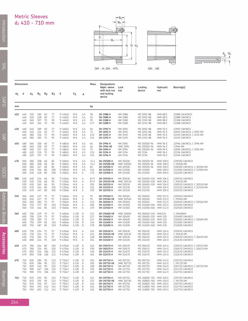
SNL
IntroductionSAFD
SAFSD
CDAdditionalBlocks
AccessoriesBearings
264
Metric Sleevesd1 410 - 710 mm B2
B3
d1 G d3
dB1
G1A
Dimensions Mass DesignationsAdptr. sleeve Lock Locking Hydraulic Bearing(s)with lock nut nut device nut
d1 d d3 B1 B2 B3 G G1 A and lockingdevice
mm kg
410 440 520 189 60 77 Tr 440x5 M 8 6.5 58 OH 3988 H HM 3088 MS 3092-88 HMV 88 E 23988 CACK/W33440 520 228 60 77 Tr 440x5 M 8 6.5 65 OH 3088 H HM 3088 MS 3092-88 HMV 88 E 23088 CAK/W33440 560 307 70 90 Tr 440x5 M 8 6.5 95 OH 3188 H HM 3188 MS 3192-88 HMV 88 E 23188 CAK/W33440 560 361 70 90 Tr 440x5 M 8 6.5 117 OH 3288 H HM 3188 MS 3192-88 HMV 88 E 23288 CAK/W33
430 460 540 189 60 77 Tr 460x5 M 8 6.5 60 OH 3992 H HM 3092 MS 3092-88 HMV 92 E 23992 CAK/W33460 540 234 60 77 Tr 460x5 M 8 6.5 71 OH 3092 H HM 3092 MS 3092-88 HMV 92 E 23092 CAK/W33, C 3092 KM460 580 326 75 95 Tr 460x5 M 8 6.5 119 OH 3192 H HM 3192 MS 3192-88 HMV 92 E 23192 CAK/W33, C 3192 KM460 580 382 75 95 Tr 460x5 M 8 6.5 134 OH 3292 H HM 3192 MS 3192-88 HMV 92 E 23292 CAK/W33
450 480 560 200 60 77 Tr 480x5 M 8 6.5 66 OH 3996 H HM 3096 MS 30/500-96 HMV 96 E 23996 CAK/W33, C 3996 KM480 560 200 60 77 Tr 480x5 M 8 6.5 66 OH 3996 HE HME 3096 MS 30/500-96 HMV 96 E C3996 KM480 560 237 60 77 Tr 480x5 M 8 6.5 75 OH 3096 H HM 3096 MS 30/500-96 HMV 96 E 23096 CAK/W33, C 3096 KM480 620 335 75 95 Tr 480x5 M 8 6.5 135 OH 3196 H HM 3196 MS 3196 HMV 96 E 23196 CAK/W33480 620 397 75 95 Tr 480x5 M 8 6.5 153 OH 3296 H HM 3196 MS 3196 HMV 96 E 23296 CAK/W33
470 500 580 208 68 85 Tr 500x5 M 8 6.5 74.3 OH 39/500 H HM 30/500 MS 30/500-96 HMV 100 E 239/500 CAK/W33500 580 208 68 85 Tr 500x5 M 8 6.5 74.3 OH 39/500 HE HME 30/500 MS 30/500-96 HMV 100 E C 39/500 KM500 580 247 68 85 Tr 500x5 M 8 6.5 82 OH 30/500 H HM 30/500 MS 30/500-96 HMV 100 E 230/500 CAK/W33, C 30/500 KM500 630 356 80 100 Tr 500x5 M 8 6.5 145 OH 31/500 H HM 31/500 MS 31/500 HMV 100 E 231/500 CAK/W33, C 31/500 KM500 630 428 80 100 Tr 500x5 M 8 6 170 OH 32/500 H HM 31/500 MS 31/500 HMV 100 E 232/500 CAK/W33
500 530 630 216 68 90 Tr 530x6 M 8 6 87.9 OH 39/530 H HM 30/530 MS 30/600-530 HMV 106 E 239/530 CAK/W33530 630 216 68 90 Tr 530x6 M 8 6 87.9 OH 39/530 HE HME 30/530 MS 30/600-530 HMV 106 E C 39/530 KM530 630 265 68 90 Tr 530x6 M 8 6 105 OH 30/530 H HM 30/530 MS 30/600-530 HMV 106 E 230/530 CAK/W33, C 30/530 KM530 670 364 80 105 Tr 530x6 M 8 6 161 OH 31/530 H HM 31/530 MS 31/530 HMV 106 E 231/530 CAK/W33, C 31/530 KM530 670 447 80 105 Tr 530x6 M 8 6 192 OH 32/530 H HM 31/530 MS 31/530 HMV 106 E 232/530 CAK/W33
530 560 650 227 75 97 Tr 560x6 M 8 6 95 OH 39/560 H HM 30/560 MS 30/560 HMV 112 E 239/560 CAK/W33560 650 227 75 97 Tr 560x6 M 8 6 95 OH 39/560 HE HME 30/560 MS 30/560 HMV 112 E C 39/560 KM560 650 282 75 97 Tr 560x6 M 8 6 112 OH 30/560 H HM 30/560 MS 30/560 HMV 112 E 230/560 CAK/W33, C 30/560 KM560 710 377 85 110 Tr 560x6 M 8 6 185 OH 31/560 H HM 31/560 MS 31/600–560 HMV 112 E 231/560 CAK/W33560 710 462 85 110 Tr 560x6 M 8 6 219 OH 32/560 H HM 31/560 MS 31/600–560 HMV 112 E 232/560 CAK/W33
560 600 700 239 75 97 Tr 600x6 G 1/8 8 127 OH 39/600 HE HME 30/600 MS 30/600-530 HMV120 C 39/600KM600 700 239 75 97 Tr 600x6 G 1/8 8 127 OH 39/600 H HM 30/600 MS 30/600-530 HMV 120 239/600 CAK/W33600 700 289 75 97 Tr 600x6 G 1/8 8 147 OH 30/600 H HM 30/600 MS 30/600-530 HMV 120 230/600 CAK/W33, C 30/600 KM600 750 399 85 110 Tr 600x6 G 1/8 8 234 OH 31/600 H HM 31/600 MS 31/600-560 HMV 120 231/600 CAK/W33600 750 487 85 110 Tr 600x6 G 1/8 8 278 OH 32/600 H HM 31/600 MS 31/600-560 HMV 120 232/600 CAK/W33
600 630 730 254 75 97 Tr 630x6 M 8 6 124 OH 39/630 H HM 30/630 MS 30/630 HMV 126 E 239/630 CAK/W33630 730 254 75 97 Tr 630x6 M 8 6 124 OH 39/630 HE HME 30/630 MS 30/630 HMV 126 E C 39/630 KM630 730 301 75 97 Tr 630x6 M 8 6 138 OH 30/630 H HM 30/630 MS 30/630 HMV 126 E 230/630 CAK/W33, C 30/630 KM630 800 424 95 120 Tr 630x6 M 8 6 254 OH 31/630 H HM 31/630 MS 31/630 HMV 126 E 231/630 CAK/W33
630 670 780 264 80 102 Tr 670x6 G 1/8 8 162 OH 39/670 H HM 30/670 MS 30/670 HMV 134 E 239/670 CAK/W33, C 39/670 KM670 780 324 80 102 Tr 670x6 G 1/8 8 190 OH 30/670 H HM 30/670 MS 30/670 HMV 134 E 230/670 CAK/W33, C 30/670 KM670 850 456 106 131 Tr 670x6 G 1/8 8 340 OH 31/670 H HM 31/670 MS 31/670 HMV 134 E 231/670 CAK/W33670 850 558 106 131 Tr 670x6 G 1/8 8 401 OH 32/670 H HM 31/670 MS 31/670 HMV 134 E 232/670 CAK/W33
670 710 830 286 90 112 Tr 710x7 G 1/8 8 183 OH 39/710 H HM 30/710 MS 30/710 HMV 142 E 239/710 CAK/W33710 830 286 90 112 Tr 710x7 G 1/8 8 183 OH 39/710 HE HME 30/710 MS 30/710 HMV 142 E C 39/710 KM710 830 342 90 112 Tr 710x7 G 1/8 8 228 OH 30/710 H HM 30/710 MS 30/710 HMV 142 E 230/710 CAK/W33, C 30/710 KM710 900 467 106 135 Tr 710x7 G 1/8 8 392 OH 31/710 H HM 31/710 MS 31/710 HMV 142 E 231/710 CAK/W33710 900 572 106 135 Tr 710x7 G 1/8 8 459 OH 32/710 H HM 31/710 MS 31/710 HMV 142 E 232/710 CAK/W33
710 750 870 291 90 112 Tr 750x7 G 1/8 8 211 OH 39/750 H HM 30/750 MS 30/800-750 HMV 150 E 239/750 CAK/W33750 870 291 90 112 Tr 750x7 G 1/8 8 211 OH 39/750 HE HME 30/750 MS 30/800-750 HMV 150 E C 39/750 KM750 870 356 90 112 Tr 750x7 G 1/8 8 246 OH 30/750 H HM 30/750 MS 30/800-750 HMV 150 E 230/750 CAK/W33750 950 493 112 141 Tr 750x7 G 1/8 8 451 OH 31/750 H HM 31/750 MS 31/800-750 HMV 150 E 231/750 CAK/W33750 950 603 112 141 Tr 750x7 G 1/8 8 526 OH 32/750 H HM 31/750 MS 31/800-750 HMV 150 E 232/750 CAK/W33
OH .. H, OH .. HTL OH .. HE

SNL
Introduction
SAFD
SAF
SDCD
AdditionalB
locks
Accessories
Bearings
265
Metric Sleevesd1 750 - 1 000 mmB2
B3
d1 G d3
dB1
G1A
Dimensions Mass DesignationsAdptr. sleeve Lock Locking Hydraulic Bearing(s)with lock nut nut device nut
d1 d d3 B1 B2 B3 G G1 A and lockingdevice
mm kg
750 800 920 303 90 112 Tr 800x7 G 1/8 10 259 OH 39/800 H HM 30/800 MS 30/800-750 HMV 160 E 239/800 CAK/W33800 920 303 90 112 Tr 800x7 G 1/8 10 259 OH 39/800 HE HME 30/800 MS 30/800-750 HMV 160 E C 39/800 KM800 920 366 90 112 Tr 800x7 G 1/8 10 302 OH 30/800 H HM 30/800 MS 30/800-750 HMV 160 E 230/800 CAK/W33800 1 000 505 112 141 Tr 800x7 G 1/8 10 535 OH 31/800 H HM 31/800 MS 31/800-750 HMV 160 E 231/800 CAK/W33
800 850 980 308 90 115 Tr 850x7 G 1/8 10 288 OH 39/850 H HM 30/850 MS 30/900-850 HMV 170 E 239/850 CAK/W33850 980 308 90 115 Tr 850x7 G 1/8 10 288 OH 39/850 HE HME 30/850 MS 30/900-850 HMV 170 E C 39/850 KM850 980 380 90 115 Tr 850x7 G 1/8 10 341 OH 30/850 H HM 30/850 MS 30/900-850 HMV 170 E 230/850 CAK/W33850 1 060 536 118 147 Tr 850x7 G 1/8 10 616 OH 31/850 H HM 31/850 MS 31/850 HMV 170 E 231/850 CAK/W33
850 900 1 030 326 100 125 Tr 900x7 G 1/8 10 330 OH 39/900 H HM 30/900 MS 30/900-850 HMV 180 E 239/900 CAK/W33900 1 030 326 100 125 Tr 900x7 G 1/8 10 330 OH 39/900 HE HME 30/900 MS 30/900-850 HMV 180 E C 39/900 KMB900 1 030 400 100 125 Tr 900x7 G 1/8 10 387 OH 30/900 H HM 30/900 MS 30/900-850 HMV 180 E 230/900 CAK/W33900 1 120 557 125 154 Tr 900x7 G 1/8 10 677 OH 31/900 H HM 31/900 MS 31/900 HMV 180 E 231/900 CAK/W33
900 950 1 080 344 100 125 Tr 950x8 G 1/8 10 363 OH 39/950 H HM 30/950 MS 30/950 HMV 190 E 239/950 CAK/W33950 1 080 420 100 125 Tr 950x8 G 1/8 10 424 OH 30/950 H HM 30/950 MS 30/950 HMV 190 E 230/950 CAK/W33950 1 170 583 125 154 Tr 950x8 G 1/8 10 738 OH 31/950 H HM 31/950 MS 31/950 HMV 190 E 231/950 CAK/W33
950 1 000 1 140 358 100 125 Tr 1000x8 G 1/8 10 407 OH 39/1000 H HM 30/1000 MS 30/1000 HMV 200 E 239/1000 CAK/W331 000 1 140 430 100 125 Tr 1000x8 G 1/8 10 470 OH 30/1000 H HM 30/1000 MS 30/1000 HMV 200 E 230/1000 CAK/W331 000 1 240 609 100 154 Tr 1000x8 G 1/8 10 842 OH 31/1000 H HM 31/1000 MS 31/1000 HMV 200 E 231/1000 CAK/W33
1 000 1 060 1 200 372 100 125 Tr 1060x8 G 1/8 12 490 OH 39/1060 H HM 30/1060 MS 30/1000 HMV 212 E 239/1060 CAK/W331 060 1 200 447 100 125 Tr 1060x8 G 1/8 12 571 OH 30/1060 H HM 30/1060 MS 30/1000 HMV 212 E 230/1060 CAK/W331 060 1 300 622 125 154 Tr 1060x8 G 1/8 12 984 OH 31/1060 H HM 31/1060 MS 31/1000 HMV 212 E 231/1060 CAK/W33
OH .. H, OH .. HTL OH .. HE

SNL
IntroductionSAFD
SAFSD
CDAdditionalBlocks
AccessoriesBearings
266
Inch Sleevesd1 3/4 - 17/16 in B2
B1
d1 G dd
3
B2
Dimensions Mass DesignationsAdptr. sleeve Lock Locking Hydraulic Bearing(s)with lock nut nut device nut
d1 d d3 B1 B2 G and lockingdevice
in mm kg
3/4 25 38 26 8 M 25x1.5 0.07 HE 205 KM 5 MB 5 - 1205 EK25 38 29 8 M 25x1.5 0.08 HE 305 KM 5 MB 5 - 2205 EK, 1305 EK25 38 29 10.5 M 25x1.5 0.088 HE 305 E KMFE 5 – - C2205 K25 38 35 8 M 25x1.5 0.09 HE 2305 KM 5 MB 5 - 2305 K
7/8 30 45 27 8 M 30x1.5 0.11 HS 206 KM 6 MB 6 - 1206 EK30 45 31 8 M 30x1.5 0.12 HS 306 KM 6 MB 6 - 2206 EK, 1306 EK
15/16 30 45 27 8 M 30x1.5 0.1 HA 206 KM 6 MB 6 - 1206 EK30 45 31 8 M 30x1.5 0.12 HA 306 KM 6 MB 6 - 2206 EK30 45 31 10.5 M 30x1.5 0.13 HA 306 E KMFE 6 – - C 2206 K30 45 38 8 M 30x1.5 0.13 HA 2306 KM 6 MB 6 - 2306 K
1 30 45 27 8 M 30x1.5 0.08 HE 206 KM 6 MB 6 - 1206 EK30 45 31 8 M 30x1.5 0.1 HE 306 KM 6 MB 6 - 2206 EK, 1306 EK30 45 31 10.5 M 30x1.5 0.11 HE 306 E KMFE 6 – - C 2206 K30 45 38 8 M 30x1.5 0.11 HE 2306 KM 6 MB 6 - 2306 K
11/8 35 52 29 9 M 35x1.5 0.14 HS 207 KM 7 MB 7 - 1207 EK35 52 35 9 M 35x1.5 0.16 HS 307 KM 7 MB 7 - 2207 EK, 1307 EK,
22207 EK35 52 35 11.5 M 35x1.5 0.17 HS 307 E KMFE 7 – - C 2207 K
13/16 35 52 29 9 M 35x1.5 0.12 HA 207 KM 7 MB 7 - 1207 EK35 52 35 9 M 35x1.5 0.14 HA 307 KM 7 MB 7 - 2207 EK, 1307 EK,
22207 EK35 52 35 11.5 M 35x1.5 0.15 HA 307 E KMFE 7 – - C 2207 K35 52 43 9 M 35x1.5 0.16 HA 2307 KM 7 MB 7 - 2307 EK
11/4 40 58 31 10 M 40x1.5 0.19 HE 208 KM 8 MB 8 - 1208 EK40 58 36 10 M 40x1.5 0.22 HE 308 KM 8 MB 8 - 2208 EK, 1308 EK,
22208 EK, 21308 CCK40 58 36 13 M 40x1.5 0.19 HE 308 E KMFE 8 – - C 2208 K40 58 46 10 M 40x1.5 0.28 HE 2308 KM 8 MB 8 - 2308 EK, 22308 EK
13/8 40 58 31 10 M 40x1.5 0.16 HS 208 KM 8 MB 8 - 1208 EK40 58 36 10 M 40x1.5 0.17 HS 308 KM 8 MB 8 - 2208 EK, 1308 EK,
22208 EK, 21308 CCK
17/16 45 65 33 11 M 45x1.5 0.26 HA 209 KM 9 MB 9 - 1209 EK45 65 39 11 M 45x1.5 0.29 HA 309 KM 9 MB 9 - 2209 EK, 1309 EK,
22209 EK, 21309 CCK45 65 39 13 M 45x1.5 0.31 HA 309 E KMFE 9 – - C 2209 K45 65 50 11 M 45x1.5 0.35 HA 2309 KM 9 MB 9 - 2309 EK, 22309 EK
HA, HE, HS HA .. E, HE .. E, HS .. E

SNL
Introduction
SAFD
SAF
SDCD
AdditionalB
locks
Accessories
Bearings
267
Inch Sleevesd1 11/2 - 21/8 inB2
B1
d1 G dd
3
B2 B2
Dimensions Mass DesignationsAdptr. sleeve Lock Locking Hydraulic Bearing(s)with lock nut nut device nut
d1 d d3 B1 B2 G and lockingdevice
in mm kg
11/2 45 65 33 11 M 45x1.5 0.2 HE 209 KM 9 MB 9 – 1209 EK45 65 39 11 M 45x1.5 0.24 HE 309 KM 9 MB 9 – 2209 EK, 1309 EK,
22209 EK, 21309 CCK45 65 39 13 M 45x1.5 0.26 HE 309 E KMFE 9 – – C 2209 K45 65 50 11 M 45x1.5 0.31 HE 2309 KM 9 MB 9 – 2309 EK, 22309 EK
15/8 50 70 35 12 M 50x1.5 0.31 HS 210 KM 10 MB 10 HMV 10 E 1210 EK50 70 42 12 M 50x1.5 0.36 HS 310 KM 10 MB 10 HMV 10 E 2210 EK, 1310 EK,
22210 EK, 21310 CCK50 70 55 12 M 50x1.5 0.4 HS 2310 KM 10 MB 10 HMV 10 E 2310 EK, 22310 EK
111/1650 70 35 12 M 50x1.5 0.28 HA 210 KM 10 MB 10 HMV 10 E 1210 EK50 70 42 12 M 50x1.5 0.32 HA 310 KM 10 MB 10 HMV 10 E 2210 EK, 1310 EK,
22210 EK, 21310 CCK50 70 42 14 M 50x1.5 0.32 HA 310 E KMFE 10 – HMV 10 E C 2210 K50 70 55 12 M 50x1.5 0.4 HA 2310 KM 10 MB 10 HMV 10 E 2310 EK, 22310 EK
13/4 50 70 35 12 M 50x1.5 0.26 HE 210 KM 10 MB 10 HMV 10 E 1210 EK50 70 42 12 M 50x1.5 0.29 HE 310 KM 10 MB 10 HMV 10 E 2210 EK, 1310 EK,
22210 EK, 21310 CCK50 70 42 14 M 50x1.5 0.29 HE 310 E KMFE 10 – HMV 10 E C 2210 K50 70 55 12 M 50x1.5 0.36 HE 2310 KM 10 MB 10 HMV 10 E 2310 EK, 22310 EK
17/8 55 75 37 12.5 M 55x2 0.33 HS 211 KM 11 MB 11 HMV 11 E 1211 EK55 75 45 12.5 M 55x2 0.38 HS 311 KM 11 MB 11 HMV 11 E 2211 EK, 1311 EK,
22211 EK, 21311 CCK
115/1655 75 37 12.5 M 55x2 0.3 HA 211 KM 11 MB 11 HMV 11 E 1211 EK55 75 45 12.5 M 55x2 0.34 HA 311 KM 11 MB 11 HMV 11 E 2211 EK, 1311 EK,
22211 EK, 21311 CCK55 75 45 14 M 55x2 0.35 HA 311 E KMFE 11 – HMV 11 E C 2211 K55 75 59 12.5 M 55x2 0.42 HA 2311 KM 11 MB 11 HMV 11 E 2311 K, 22311 EK
2 55 75 37 12.5 W 55x1/19 0.26 HE 211 B HM 11 MB 11 – 1211 EK55 75 45 12.5 W 55x1/19 0.29 HE 311 B HM 11 MB 11 – 2211 EK. 1311 EK.
22211 EK. 21311 CCK55 75 45 14 W 55x1/19 0.3 HE 311 BE KMFE 11 B – – C 2211 K55 75 59 12.5 W 55x1/19 0.36 HE 2311 B HM 11 MB 11 – 2311 K, 22311 EK
21/8 60 80 38 13 M 60x2 0.35 HS 212 KM 12 MB 12 HMV 12 E 1212 EK60 80 47 13 M 60x2 0.4 HS 312 KM 12 MB 12 HMV 12 E 2212 EK, 1312 EK,
22212 EK, 21312 CCK60 80 47 14 M 60x2 0.41 HS 312 E KMFE 12 – HMV 12 E C 2212 K60 80 62 13 M 60x2 0.49 HS 2312 KM 12 MB 12 HMV 12 E 2312 K, 22312 EK

SNL
IntroductionSAFD
SAFSD
CDAdditionalBlocks
AccessoriesBearings
268
Inch Sleevesd1 23/16 - 211/16 in B2
B1
d1 G dd
3
B2
Dimensions Mass DesignationsAdptr. sleeve Lock Locking Hydraulic Bearing(s)with lock nut nut device nut
d1 d d3 B1 B2 G and lockingdevice
in mm kg
23/16 65 85 40 14 M 65x2 0.49 HA 213 KM 13 MB 13 HMV 13 E 1213 K65 85 50 14 M 65x2 0.58 HA 313 KM 13 MB 13 HMV 13 E 2213 EK, 1313 EK,
22213 EK, 21313 CCK65 85 50 15 M 65x2 0.59 HA 313 E KMFE 13 – HMV 13 E C 2213 K65 85 65 14 M 65x2 0.75 HA 2313 KM 13 MB 13 HMV 13 E 2313 K, 22313 EK
21/4 65 85 40 14 M 65x2 0.44 HE 213 KM 13 MB 13 HMV 13 E 1213 EK65 85 50 14 M 65x2 0.52 HE 313 KM 13 MB 13 HMV 13 E 2213 EK, 1313 EK,
22213 EK, 21313 CCK65 85 50 15 M 65x2 0.53 HE 313 E KMFE 13 – HMV 13 E C 2213 E65 85 65 14 M 65x2 0.65 HE 2313 KM 13 MB 13 HMV 13 E 2313 K, 22313 EK
23/8 65 85 40 14 M 65x2 0.44 HS 213 KM 13 MB 13 HMV 13 E 1213 EK65 85 50 14 M 65x2 0.71 HS 313 KM 13 MB 13 HMV 13 E 2213 EK, 1313 EK,
22213 EK, 21313 CCK65 85 65 14 M 65x2 0.8 HS 2313 KM 13 MB 13 HMV 13 E 2313 K, 22313 EK
27/16 75 98 43 15 M 75x2 0.75 HA 215 KM 15 MB 15 HMV 15 E 1215 K75 98 55 15 M 75x2 0.91 HA 315 KM 15 MB 15 HMV 15 E 2215 EK, 1315 EK,
22215 EK, 21315 CCK75 98 55 16 M 75x2 0.93 HA 315 E KMFE 15 – HMV 15 E C 2215 K75 98 73 15 M 75x2 1.15 HA 2315 KM 15 MB 15 HMV 15 E 2315 K, 22315 EK,
C 2315 K
21/2 75 98 43 15 M 75x2 0.7 HE 215 KM 15 MB 15 HMV 15 E 1215 K75 98 55 15 M 75x2 0.85 HE 315 KM 15 MB 15 HMV 15 E 2215 K, 1315 K,
22215 EK, 21315 CCK75 98 55 16 M 75x2 0.87 HE 315 E KMFE 15 – HMV 15 E C 2215 K75 98 73 15 M 75x2 1.09 HE 2315 KM 15 MB 15 HMV 15 E 2315 K, 22315 EK,
C 2315 K, C 2315 K
25/8 75 98 43 15 M 75x2 0.7 HS 215 KM 15 MB 15 HMV 15 E 1215 K75 98 55 15 M 75x2 0.71 HS 315 KM 15 MB 15 HMV 15 E 2215 EK, 1315 EK,
22215 EK, 21315 CCK75 98 73 15 M 75x2 0.9 HS 2315 KM 15 MB 15 HMV 15 E 2315 K, 22315 EK,
C 2315 K
211/16 80 105 46 17 M 80x2 0.87 HA 216 KM 16 MB 16 HMV 16 E 1216 K80 105 59 17 M 80x2 1.05 HA 316 KM 16 MB 16 HMV 16 E 2216 EK, 1316 EK,
22216 EK, 21316 CCK80 105 59 18 M 80x2 1.06 HA 316 E KMFE 16 – HMV 16 E C 2216 K80 105 78 17 M 80x2 1.3 HA 2316 KM 16 MB 16 HMV 16 E 2316 K, 22316 K,
C 2316 K
HA, HE, HS HA .. E, HE .. E

SNL
Introduction
SAFD
SAF
SDCD
AdditionalB
locks
Accessories
Bearings
269
Inch Sleevesd1 23/4 - 31/4 in
Dimensions Mass DesignationsAdptr. sleeve Lock Locking Hydraulic Bearing(s)with lock nut nut device nut
d1 d d3 B1 B2 G and lockingdevice
in mm kg
23/4 80 105 46 17 M 80x2 0.81 HE 216 KM 16 MB 16 HMV 16 E 1216 K80 105 59 17 M 80x2 0.97 HE 316 KM 16 MB 16 HMV 16 E 2216 EK, 1316 K,
22216 EK, 21316 CCK80 105 59 18 M 80x2 0.98 HE 316 E KMFE 16 – HMV 16 E C 2216 K80 105 78 17 M 80x2 1.2 HE 2316 KM 16 MB 16 HMV 16 E 2316 K, 22316 EK,
C 2316 K
215/16 85 110 50 18 M 85x2 0.94 HA 217 KM 17 MB 17 HMV 17 E 1217 K85 110 63 18 M 85x2 1.1 HA 317 KM 17 MB 17 HMV 17 E 2217 EK, 1317 K,
22217 EK, 21317 CCK85 110 63 19 M 85x2 1.19 HA 317 E KMFE 17 – HMV 17 E C 2217 E85 110 82 18 M 85x2 1.4 HA 2317 KM 17 MB 17 HMV 17 E 2317 K, 22317 EK,
C 2317 K
3 85 110 50 18 M 85x2 0.87 HE 217 KM 17 MB 17 HMV 17 E 1217 K85 110 63 18 M 85x2 1 HE 317 KM 17 MB 17 HMV 17 E 2217 K, 1317 K,
22217 EK, 21317 CCK85 110 63 19 M 85x2 0.99 HE 317 E KMFE 17 – HMV 17 E C 2217 K85 110 82 18 M 85x2 1.3 HE 2317 KM 17 MB 17 HMV 17 E 2317 K, 22317 EK,
C 2317 K
33/16 90 120 52 18 M 90x2 1.05 HA 218 KM 18 MB 18 HMV 18 E 1218 K90 120 65 18 M 90x2 1.25 HA 318 KM 18 MB 18 HMV 18 E 2218 K, 1318 K,
22218 EK, 21318 CCK90 120 65 19 M 90x2 1.26 HA 318 E KMFE 18 – HMV 18 E C 2218 K90 120 86 18 M 90x2 1.5 HA 2318 KM 18 MB 18 HMV 18 E 2318 K, 23218-
CCK/W33, 22318 EK,C 2318 K
31/4 90 120 52 18 M 90x2 0.97 HE 218 KM 18 MB 18 HMV 18 E 1218 K90 120 65 18 M 90x2 1.1 HE 318 KM 18 MB 18 HMV 18 E 2218 K, 1318 K,
22218 EK, 21318 CCK90 120 65 19 M 90x2 1.11 HE 318 E KMFE 18 – HMV 18 E C 2218 K90 120 86 18 M 90x2 1.4 HE 2318 KM 18 MB 18 HMV 18 E 2318 K, 23218-
CCK/W33, 22318 EK,C2318 K
95 125 55 19 M 95x2 1.35 HE 219 KM 19 MB 19 HMV 19 E 1219 K95 125 68 19 M 95x2 1.6 HE 319 KM 19 MB 19 HMV 19 E 2219 K, 1319 K,
22219 EK, 21319 CCK95 125 68 20 M 95x2 1.61 HE 319 E KMFE 19 – HMV 19 E C 2219 K95 125 90 19 M 95x2 2 HE 2319 KM 19 MB 19 HMV 19 E 2319 K, 22319 EK,
C 2319 K
B2
B1
d1 G dd
3
B2
HA, HE, HS HA .. E, HE .. E

SNL
IntroductionSAFD
SAFSD
CDAdditionalBlocks
AccessoriesBearings
270
Inch Sleevesd1 37/16 - 41/4 in B2
B1
d1 G dd
3
B2
Dimensions Mass DesignationsAdptr. sleeve Lock Locking Hydraulic Bearing(s)with lock nut nut device nut
d1 d d3 B1 B2 G and lockingdevice
in mm kg
37/16 100 130 58 20 M 100x2 1.55 HA 220 KM 20 MB 20 HMV 20 E 1220 K100 130 71 20 M 100x2 1.8 HA 320 KM 20 MB 20 HMV 20 E 2220 K, 1320 K,
22220 EK, 21320 CCK100 130 71 21 M 100x2 1.75 HA 320 E KMFE 20 – HMV 20 E C 2220 K100 130 97 20 M 100x2 2.35 HA 2320 KM 20 MB 20 HMV 20 E 2320 K, 23220-
CCK/W33, 22320 EK,C2320 K
31/2 100 130 58 20 M 100x2 1.45 HE 220 KM 20 MB 20 HMV 20 E 1220 K100 130 71 20 M 100x2 1.75 HE 320 KM 20 MB 20 HMV 20 E 2220 K, 1320 K,
22220 EK, 21320 CCK100 130 71 21 M 100x2 1.7 HE 320 E KMFE 20 – HMV 20 E C 2220 K100 130 76 20 M 100x2 1.8 HE 3120 KM 20 MB 20 HMV 20 E 23120 CCK/W33100 130 97 20 M 100x2 2.2 HE 2320 KM 20 MB 20 HMV 20 E 2320 K, 23220-
CCK/W33, 22320 EK,C2320 K
315/16 See metric sleeves for d1 = 100mm
4 110 145 63 21 M 110x2 1.65 HE 222 KM 22 MB 22 HMV 22 E 1222 K110 145 77 21 M 110x2 1.9 HE 322 KM 22 MB 22 HMV 22 E 2222 K, 1322 K,
23022 CCK, 22222 EK,21322 CCK
110 145 77 21.5 M 110x2 1.85 HE 322 E KMFE 22 – HMV 22 E C 2222 K110 145 81 21 M 110x2 2.25 HE 3122 KM 22 MB 22 HMV 22 E 23122 CCK/W33110 145 105 21 M 110x2 2.4 HE 2322 KM 22 MB 22 HMV 22 E 2322 K, 23222-
CCK/W33, 22322 EK
43/16 120 145 72 22 M 120x2 2.25 HA 3024 KML 24 MBL 24 HMV 24 E 1224 K, 23024-CCK/W33
120 155 72 26 M 120x2 2.32 HA 3024 E KMFE 24 – HMV 24 E C 3024 K120 155 88 22 M 120x2 2.9 HA 3124 KM 24 MB 24 HMV 24 E 2224 K, 23124-
CCK/W33120 145 88 22 M 120x2 2.6 HA 3124 L KML 24 MBL 24 HMV 24 E C 2224 K120 155 112 22 M 120x2 3.6 HA 2324 KM 24 MB 24 HMV 24 E 23224 CCK/W33,
22324 CCK/W33120 145 112 22 M 120x2 3.3 HA 2324 L KML 24 MBL 24 HMV 24 E C 3224 K
41/4 120 145 72 22 M 120x2 2 HE 3024 KML 24 MBL 24 HMV 24 E 1224 K, 23024-CCK/W33, C 3024 KV
120 155 72 26 M 120x2 2.7 HE 3024 E KMFE 24 – HMV 24 E C 3024 K120 155 88 22 M 120x2 2.8 HE 3124 KM 24 MB 24 HMV 24 E 23124 CCK/W33.
22224 EK120 155 112 22 M 120x2 3.35 HE 2324 KM 24 MB 24 HMV 24 E 23224 CCK/W33,
22324 CCK/W33120 145 112 22 M 120x2 3.05 HE 2324 L KML 24 MBL 24 HMV 24 E C 3224 K
HA, HA .. L, HE, HE ..L HA .. E, HE .. E

SNL
Introduction
SAFD
SAF
SDCD
AdditionalB
locks
Accessories
Bearings
271
Inch Sleevesd1 47/16 - 51/4 in
Dimensions Mass DesignationsAdptr. sleeve Lock Locking Hydraulic Bearing(s)with lock nut nut device nut
d1 d d3 B1 B2 G and lockingdevice
in mm kg
47/16 130 155 80 23 M 130x2 3.05 HA 3026 KML 26 MBL 26 HMV 26 E 23026 CCK/W33130 165 92 23 M 130x2 3.75 HA 3126 KM 26 MB 26 HMV 26 E 23126 CCK/W33,
22226 EK130 155 92 23 M 130x2 3.55 HA 3126 L KML 26 MBL 26 HMV 26 E C 2226 K130 165 92 28 M 130x2 3.77 HA 3126 E KMFE 26 – HMV 26 E C 2226 K130 165 121 23 M 130x2 4.74 HA 2326 KM 26 MB 26 HMV 26 E 23226 CCK/W33,
22326 CCK/W33,C 2326 K
41/2 130 155 80 23 M 130x2 2.9 HE 3026 KML 26 MBL 26 HMV 26 E 23026 CCK/W33,C 3026 K
130 165 92 23 M 130x2 3.6 HE 3126 KM 26 MB 26 HMV 26 E 23126 CCK/W33,22226 EK
130 155 92 23 M 130x2 3.4 HE 3126 L KML 26 MBL 26 HMV 26 E C 2226 K130 165 121 23 M 130x2 4.55 HE 2326 KM 26 MB 26 HMV 26 E 23226 CCK/W33,
22326 CCK/W33,C2326 K
415/16 140 165 82 24 M 140x2 3 HA 3028 KML 28 MBL 28 HMV 28 E 23028 CCK/W33140 180 97 24 M 140x2 4.1 HA 3128 KM 28 MB 28 HMV 28 E 23128 CCK/W33,
22228 CCK/W33140 165 97 24 M 140x2 4.6 HA 3128 L KML 28 MBL 28 HMV 28 E C 2228 K140 180 131 24 M 140x2 5.3 HA 2328 KM 28 MB 28 HMV 28 E 23228 CCK/W33,
22328 CCK/W33
5 140 165 82 24 M 140x2 2.8 HE 3028 KML 28 MBL 28 HMV 28 E 23028 CCK/W33140 180 97 24 M 140x2 3.8 HE 3128 KM 28 MB 28 HMV 28 E 23128 CCK/W33,
22228 CCK/W33140 165 97 24 M 140x2 3.3 HE 3128 L KML 28 MBL 28 HMV 28 E C 2228 K140 180 131 24 M 140x2 5 HE 2328 KM 28 MB 28 HMV 28 E 23228 CCK/W33,
22328 CCK/W33
53/16 150 180 87 26 M 150x2 4.2 HA 3030 KML 30 MBL 30 HMV 30 E 23030 CCK/W33150 195 111 26 M 150x2 5.8 HA 3130 KM 30 MB 30 HMV 30 E 23130 CCK/W33,
22230 CCK/W33150 180 111 26 M 150x2 5.3 HA 3130 L KML 30 MBL 30 HMV 30 E C 2230 K150 195 139 26 M 150x2 7.1 HA 2330 KM 30 MB 30 HMV 30 E 23230 CCK/W33,
22330 CCK/W33
51/4 150 180 87 26 M 150x2 4 HE 3030 KML 30 MBL 30 HMV 30 E 23030 CCK/W33150 195 111 26 M 150x2 5.5 HE 3130 KM 30 MB 30 HMV 30 E 23130 CCK/W33,
22230 CCK/W33150 180 111 26 M 150x2 5 HE 3130 L KML 30 MBL 30 HMV 30 E C 2230 K150 195 139 26 M 150x2 6.8 HE 2330 KM 30 MB 30 HMV 30 E 23230 CCK/W33,
22330 CCK/W33
B2
B1
d1 G dd
3
B2
HA, HA .. L, HE, HE ..L HA .. E, HE .. E

SNL
IntroductionSAFD
SAFSD
CDAdditionalBlocks
AccessoriesBearings
272
Inch Sleevesd1 57/16 - 61/2 in B2
B1
d1 G dd
3
B2
Dimensions Mass DesignationsAdptr. sleeve Lock Locking Hydraulic Bearing(s)with lock nut nut device nut
d1 d d3 B1 B2 G and lockingdevice
in mm kg
57/16 160 190 93 27.5 M 160x3 5.4 HA 3032 KML 32 MBL 32 HMV 32 E 23032 CCK/W33160 210 119 27.5 M 160x3 7.55 HA 3132 KM 32 MB 32 HMV 32 E 23132 CCK/W33,
22232 CCK/W33160 210 147 27.5 M 160x3 9.4 HA 2332 KM 32 MB 32 HMV 32 E 23232 CCK/W33,
22332 CCK/W33160 190 147 27.5 M 160x3 8.55 HA 2332 L KML 32 MBL 32 HMV 32 E C 3232 K
51/2 160 190 93 27.5 M 160x3 5.1 HE 3032 KML 32 MBL 32 HMV 32 E 23032 CCK/W33160 210 119 27.5 M 160x3 7.3 HE 3132 KM 32 MB 32 HMV 32 E 23132 CCK/W33,
22232 CCK/W33160 190 119 27.5 M 160x3 6.45 HE 3132 L KML 32 MBL 32 HMV 32 E C 3132 K160 210 147 27.5 M 160x3 8.8 HE 2332 KM 32 MB 32 HMV 32 E 23232 CCK/W33,
22332 CCK/W33160 190 147 27.5 M 160x3 7.95 HE 2332 L KML 32 MBL 32 HMV 32 E C 3232 K
515/16 170 200 101 28.5 M 170x3 5.7 HA 3034 KML 34 MBL 34 HMV 34 E 23034 CCK/W33,C 3034 K
170 220 122 28.5 M 170x3 7.8 HA 3134 KM 34 MB 34 HMV 34 E 23134 CCK/W33,22234 CCK/W33
170 200 122 28.5 M 170x3 6.8 HA 3134 L KML 34 MBL 34 HMV 34 E C 2234 K170 220 154 28.5 M 170x3 9.6 HA 2334 KM 34 MB 34 HMV 34 E 23234 CCK/W33,
22334 CCK/W33
6 170 200 101 28.5 M 170x3 5.4 HE 3034 KML 34 MBL 34 HMV 34 E 23034 CCK/W33,C 3034 K
170 220 122 28.5 M 170x3 7.55 HE 3134 KM 34 MB 34 HMV 34 E 23134 CCK/W33,22234 CCK/W33
170 200 122 28.5 M 170x3 6.6 HE 3134 L KML 34 MBL 34 HMV 34 E C 2234 K170 220 154 28.5 M 170x3 9.2 HE 2334 KM 34 MB 34 HMV 34 E 23234 CCK/W33,
22334 CCK/W33
67/16 180 210 109 29.5 M 180x3 6 HA 3036 KML 36 MBL 36 HMV 36 E 23036 CCK/W33,C 3036 K
180 230 131 29.5 M 180x3 8.15 HA 3136 KM 36 MB 36 HMV 36 E 23136 CCK/W33,22236 CCK/W33
180 210 131 29.5 M 180x3 7.2 HA 3136 L KML 36 MBL 36 HMV 36 E C 3136 K180 230 161 29.5 M 180x3 9.9 HA 2336 KM 36 MB 36 HMV 36 E 23236 CCK/W33,
22336 CCK/W33,C 3236 K
61/2 180 210 109 29.5 M 180x3 5.55 HE 3036 KML 36 MBL 36 HMV 36 E 23036 CCK/W33,C 3036 K
180 230 131 29.5 M 180x3 7.8 HE 3136 KM 36 MB 36 HMV 36 E 23136 CCK/W33,22236 CCK/W33
180 210 131 29.5 M 180x3 6.85 HE 3136 L KML 36 MBL 36 HMV 36 E C 3136 K180 230 161 29.5 M 180x3 9.35 HE 2336 KM 36 MB 36 HMV 36 E 23236 CCK/W33,
22336 CCK/W33,C 3236 K
HA, HA .. L, HE, HE ..L HA .. E, HE .. E

SNL
Introduction
SAFD
SAF
SDCD
AdditionalB
locks
Accessories
Bearings
273
Inch Sleevesd1 63/4 - 73/16 in
Dimensions Mass DesignationsAdptr. sleeve Lock Locking Hydraulic Bearing(s)with lock nut nut device nut
d1 d d3 B1 B2 G and lockingdevice
in mm kg
63/4 190 220 112 30.5 M 190x3 7.2 HE 3038 KML 38 MBL 38 HMV 38 E 23038 CCK/W33,C3038 K
190 240 141 30.5 M 190x3 10.2 HE 3138 KM 38 MB 38 HMV 38 E 23138 CCK/W33,22238 CCK/W33
190 240 169 30.5 M 190x3 11.7 HE 2338 KM 38 MB 38 HMV 38 E 23238 CCK/W33,22338 CCK/W33
615/16 190 220 112 30.5 M 190x3 5.8 HA 3038 KML 38 MBL 38 HMV 38 E 23038 CCK/W33,C 3038 K
190 240 141 30.5 M 190x3 8.5 HA 3138 KM 38 MB 38 HMV 38 E 23138 CCK/W33,22238 CCK/W33
190 240 169 30.5 M 190x3 10 HA 2338 KM 38 MB 38 HMV 38 E 23238 CCK/W33,22338 CCK/W33
7 200 240 120 31.5 M 200x3 9.35 HE 3040 KML 40 MBL 40 HMV 40 E 23040 CCK/W33,C 3040 K
200 250 150 31.5 M 200x3 12.3 HE 3140 KM 40 MB 40 HMV 40 E 23140 CCK/W33,22240 CCK/W33,C 3140 K
200 250 176 31.5 M 200x3 14.2 HE 2340 KM 40 MB 40 HMV 40 E 23240 CCK/W33,22340 CCK/W33
73/16 200 240 120 31.5 M 200x3 8.25 HA 3040 KML 40 MBL 40 HMV 40 E 23040 CCK/W33,C 3040 K
200 250 150 31.5 M 200x3 11.2 HA 3140 KM 40 MB 40 HMV 40 E 23140 CCK/W33,22240 CCK/W33,C 3140 K
B2
B1
d1 G dd
3
B2
HA, HA .. L, HE, HE ..L HA .. E, HE .. E

Dimensions Mass Designation Lock nut Locking Bearing(s)device
d1 d d3 B1 B2 G nom. T.P.I.
in mm in kg
SNL
IntroductionSAFD
SAFSD
CDAdditionalBlocks
AccessoriesBearings
274
B2
B1
d1 G dd
3
3/4 25 19/16 1.269 0.456 0.969 32 0.10 SNW 5 x 3/4 N05 W05 1205 EK
15/16 30 13/4 1.353 0.456 1.173 18 0.10 SNW 6 x 15/16 N06 W06 1206 EK, 1306 EK
1 30 13/4 1.353 0.456 1.173 18 0.10 SNW 6 x 1 N06 W06 1206 EK, 1306 EK
11/8 35 21/16 1.459 0.487 1.376 18 0.16 SNW 7 x 11/8 N07 W 07 1207 EK, 1307 EK, 22207 EK
13/16 35 21/16 1.459 0.487 1.376 18 0.16 SNW 7 x 13/16 N07 W07 1207 EK, 1307 EK, 22207 EK
11/4 35 21/16 1.459 0.487 1.376 18 0.16 SNW 7 x 11/4 N07 W07 1207 EK, 1307 EK, 22207 EK40 21/4 1.504 0.495 1.563 18 0.19 SNW 8 x 11/4 N08 W08 1208 EK, 1308 EK, 22208 EK
13/8 40 21/4 1.504 0.495 1.563 18 0.19 SNW 8 x 13/8 N08 W08 1208 EK, 1308 EK, 22208 EK45 217/32 1.584 0.495 1.767 18 0.28 SNW 9 x 13/8 N09 W09 1209 EK, 1309 EK, 22209 EK, 21309 EK
15/16 40 21/4 1.504 0.495 1.563 18 0.19 SNW 8 x 15/16 N08 W08 1208 EK, 1308 EK, 22208 EK45 217/32 1.584 0.495 1.767 18 0.28 SNW 9 x 15/16 N09 W09 1209 EK, 1309 EK, 22209 EK, 21309 EK
17/16 45 217/32 1.584 0.495 1.767 18 0.28 SNW 9 x 17/16 N09 W09 1209 EK, 1309 EK, 22209 EK, 21309 EK45 217/32 2.133 0.495 1.767 18 0.32 SNW 109 x 17/16 N09 W09 2309 EK, 22309 EK
11/2 45 217/32 2.133 0.495 1.767 18 0.32 SNW 109 x 11/2 N09 W09 2309 EK, 22309 EK
15/8 50 211/16 1.765 0.558 1.967 18 0.33 SNW 10 x 15/8 N10 W10 1210 EK, 1310 EK, 22210 EK, 21310 CCK
111/16 50 211/16 1.765 0.558 1.967 18 0.33 SNW 10 x 111/16 N10 W10 1210 EK, 1310 EK, 22210 EK, 21310 CCK50 211/16 2.394 0.558 1.967 18 0.39 SNW 110 x 111/16 N10 W10 2310 EK, 22310 EK
13/4 50 211/16 1.765 0.558 1.967 18 0.33 SNW 10 x 13/4 N10 W10 1210 EK, 1310 EK, 22210 EK, 21310 CCK55 231/32 1.845 0.563 2.157 18 0.36 SNW 11 x 13/4 N11 W11 1211 EK, 1311 EK, 22211 EK, 21311 EK
113/16 55 231/32 1.845 0.563 2.157 18 0.36 SNW 11 x 113/16 N11 W11 1211 EK, 1311 EK, 22211 EK, 21311 EK
17/8 55 231/32 1.845 0.563 2.157 18 0.36 SNW 11 x 17/8 N11 W11 1211 EK, 1311 EK, 22211 EK, 21311 EK
115/16 55 231/32 1.845 0.563 2.157 18 0.36 SNW 11 x 115/16 N11 W11 1211 EK, 1311 EK, 22211 EK, 21311 EK55 231/32 2.516 0.563 2.157 18 0.43 SNW 111 x 115/16 N11 W11 2311 K, 22311 EK
2 55 231/32 1.845 0.563 2.157 18 0.36 SNW 11 x 2 N11 W11 1211 EK, 1311 EK, 22211 EK, 21311 EK55 231/32 2.516 0.563 2.157 18 0.43 SNW 111 x 2 N11 W11 2311 K, 22311 EK65 33/8 2.100 0.625 2.548 18 0.64 SNW 13 x 2 N13 W13 1213 EK, 1313 EK, 22213 EK
21/16 60 35/32 2.659 0.594 2.360 18 0.73 SNW 112 x 21/16 N12 W12 2312 K, 22312 EK
Wide SlotAdapter Sleeves with Inch Dimensionsd1 3/4 - 21/16 in

SNL
Introduction
SAFD
SAF
SDCD
AdditionalB
locks
Accessories
Bearings
275
Dimensions Mass Designation Lock nut Locking Hydraulic Bearing(s)device nut
d1 d d3 B1 B2 G nom. T.P.I.
in mm in kg
23/16 65 33/8 2.100 0.625 2.548 18 0.64 SNW 13 x 23/16 N13 W13 - 1213 EK, 1313EK, 22213 EK,65 33/8 2.771 0.625 2.548 18 0.79 SNW 113 x 23/16 N13 W13 - 2313 K, 22313 EK
21/4 65 33/8 2.100 0.625 2.548 18 0.64 SNW 13 x 21/4 N13 W13 - 1213 EK,1313 EK,22213 EK65 33/8 2.771 0.625 2.548 18 0.79 SNW 113 x 21/4 N13 W13 - 2313 K, 22313 EK
25/16 65 33/8 2.100 0.625 2.548 18 0.64 SNW 13 x 25/16 N13 W13 - 1213 EK, 1313EK, 22213 EK,
23/8 75 37/8 2.296 0.665 2.933 12 1.00 SNW 15 x 23/8 AN15 W15 - 1215 K, 1315 K, 22215 EK
27/16 75 37/8 2.296 0.665 2.933 12 1.00 SNW 15 x 27/16 AN15 W15 - 1215 K, 1315 K, 22215 EK75 37/8 3.084 0.665 2.933 12 1.35 SNW 115 x 27/16 AN15 W15 - 2315 K, 22315 EK
211/16 80 45/32 2.376 0.665 3.137 12 1.10 SNW 16 x 211/16 AN16 W16 - 1216 K, 1316 K, 22216 EK80 45/32 3.204 0.665 3.137 12 1.45 SNW 116 x 211/16 AN16 W16 - 2316 K, 22316 EK
23/4 80 45/32 2.376 0.665 3.137 12 1.10 SNW 16 x 23/4 AN16 W16 - 1216 K, 1316 K, 22216 EK
215/16 85 413/32 2.486 0.697 3.340 12 1.30 SNW 17 x 215/16 AN17 W17 - 1217 K, 1317 K, 22217 EK85 413/32 3.312 0.697 3.340 12 1.55 SNW 117 x 215/16 AN17 W17 - 2317 K, 22317 EK
3 85 413/32 2.486 0.697 3.340 12 1.30 SNW 17 x 3 AN17 W17 - 1217 K, 1317 K, 22217 EK85 413/32 3.312 0.697 3.340 12 1.55 SNW 117 x 3 AN17 W17 - 2317 K, 22317 EK
33/16 90 421/32 2.646 0.782 3.527 12 1.40 SNW 18 x 33/16 AN18 W18 HMVC 18 1218 K, 1318 K, 22218 EK90 421/32 3.553 0.782 3.527 12 1.80 SNW 118 x 33/16 AN18 W18 HMVC 18 2318 K, 23218 CCK/W33, 22318 EK
31/4 90 421/32 2.646 0.782 3.527 12 1.40 SNW 18 x 31/4 AN18 W18 HMVC 18 1218 K, 1318 K, 22218 EK
35/16 95 415/16 2.760 0.813 3.730 12 1.85 SNW 19 x 35/16 AN19 W19 HMVC19 1219 K, 1319 K, 22219 EK95 415/16 3.702 0.813 3.730 12 2.20 SNW 119 x 35/16 AN19 W19 HMVC19 23219 CCK/W33, 22319 EK
37/16 100 53/16 2.869 0.844 3.918 12 2.00 SNW 20 x 37/16 AN20 W20 HMVC20 1220 K, 1320 K, 22220 EK100 53/16 3.971 0.844 3.918 12 2.85 SNW 120 x 37/16 AN20 W20 HMVC20 23220 CCK/W33, 22320EK
31/2 100 53/16 2.869 0.844 3.918 12 2.00 SNW 20 x 31/2 AN20 W20 HMVC20 1220 K, 1320 K, 22220 EK100 53/16 3.971 0.844 3.918 12 2.85 SNW 120 x 31/2 AN20 W20 HMVC20 23220 CCK/W33, 22320EK
311/16 105 57/16 2.987 0.844 4.122 12 2.05 SNW 21 x 311/16 AN21 W21 1321 K110 523/32 3.206 0.906 4.325 12 2.25 SNW 22 x 311/16 AN22 W22 HMVC22 1222 K, 1322 K, 22222 EK
315/16 110 523/32 3.206 0.906 4.325 12 2.25 SNW 22 x 315/16 AN22 W22 HMVC22 1222 K, 1322 K, 22222 EK110 523/32 4.348 0.906 4.325 12 2.95 SNW 122 x 315/16 AN22 W22 HMVC22 23222 CCK/W33, 22322 EK
B2
B1
d1 G dd
3
Wide SlotAdapter Sleeves with Inch Dimensions
d1 23/16 - 315/16 in

Dimensions Mass Designation Lock nut Locking Hydraulic Bearing(s)device nut
d1 d d3 B1 B2 G nom. T.P.I.
in mm in kg
SNL
IntroductionSAFD
SAFSD
CDAdditionalBlocks
AccessoriesBearings
276
B2
B1
d1 G dd
3
4 110 523/32 3.206 0.906 4.325 12 2.25 SNW 22 x 4 AN22 W22 HMVC 22 1222K, 1322K, 22222EK
43/16 120 511/16 2.947 0.938 4.716 12 2.80 SNW 3024 x 43/16 N024 W024 HMVC 24 23024 CCK/W33511/16 3.466 0.938 4.716 12 2.65 SNW 3124 x 43/16 NO24 W024 HMVC 24 23124 CCK/W3361/8 3.466 0.938 4.716 12 3.00 SNW 24 x 43/16 AN24 W24 HMVC 24 22224 EK61/8 4.648 0.938 4.716 12 3.55 SNW 124 x 43/16 AN24 W24 HMVC 24 23224 CCK/W33,
22324 CCK/W33
41/4 120 511/16 3.466 0.938 4.716 12 2.65 SNW 3124 x 41/4 N024 W024 HMVC 24 23124 CCK/W3361/8 3.466 0.938 4.716 12 3.00 SNW 24 x 41/4 AN24 W24 HMVC 24 22224 EK
47/16 130 61/8 3.237 1.00 5.106 12 3.40 SNW 3026 x 47/16 N026 W026 HMVC 26 23026 CCK/W3361/8 3.762 1.00 5.106 12 3.80 SNW 3126 x 47/16 N026 W026 HMVC 26 23126 CCK/W3363/4 3.762 1.00 5.106 12 4.40 SNW 26 x 47/16 AN26 W26 HMVC 26 22226 EK63/4 4.982 1.00 5.106 12 5.65 SNW 126 x 47/16 AN26 W26 HMVC 26 23226 CCK/W33,
22326 CCK/W33
41/2 130 61/8 3.237 1.00 5.106 12 3.40 SNW 3026 x 41/2 N026 W026 HMVC 26 23026 CCK/W3361/8 3.762 1.00 5.106 12 3.80 SNW 3126 x 41/2 N026 W026 HMVC 26 23126CCK/W3363/4 3.762 1.00 5.106 12 4.40 SNW 26 x 41/2 AN26 W26 HMVC 26 22226 EK
415/16 140 61/2 3.340 1.063 5.497 12 3.80 SNW 3028 x 415/16 N028 W028 HMVC 28 23028 CCK/W3361/2 3.981 1.063 5.497 12 4.00 SNW 3128 x 415/16 N028 W028 HMVC 28 23128 CCK/W3373/32 3.981 1.063 5.497 12 4.75 SNW 28 x 415/16 AN28 W28 HMVC 28 22228 CCK/W3373/32 5.323 1.063 5.497 12 5.90 SNW 128 x 415/16 AN28 W28 HMVC 28 23228 CCK/W33,
22328 CCK/W33
5 140 61/2 3.340 1.063 5.497 12 3.85 SNW 3028 x 5 N028 W028 HMVC 28 23028 CCK/W3361/2 3.981 1.063 5.497 12 4.00 SNW 3128 x 5 N028 W028 HMVC 28 23128 CCK/W3373/32 3.981 1.063 5.497 12 4.75 SNW 28 x 5 AN28 W28 HMVC 28 22228CCK/W33
53/16 150 71/8 3.492 1.094 5.888 12 4.45 SNW 3030 x 53/16 N030 W030 HMVC 30 23030 CCK/W3371/8 4.241 1.094 5.888 12 6.20 SNW 3130 x 53/16 N030 W030 HMVC 30 23130 CCK/W33711/16 4.241 1.125 5.888 12 7.25 SNW 30 x 53/16 AN30 W30 HMVC 30 22230 CCK/W33711/16 5.621 1.125 5.888 12 8.15 SNW 130 x 53/16 AN30 W30 HMVC 30 23230 CCK/W33
22330 CCK/W33
51/4 150 711/16 4.241 1.125 5.888 12 7.25 SNW 30 x 51/4 AN30 W30 HMVC 30 22230 CCK/W33
57/16 160 71/2 3.711 1.156 6.284 8 5.45 SNW 3032 x 57/16 N032 W032 HMVC 32 23032 CCK/W3371/2 4.578 1.156 6.284 8 6.10 SNW 3132 x 57/16 N032 W032 HMVC 32 23132 CCK/W3381/16 4.578 1.187 6.284 8 7.05 SNW 32 x 57/16 AN32 W32 HMVC 32 22232 CCK/W3381/16 5.920 1.187 6.284 8 8.15 SNW 132 x 57/16 AN32 W32 HMVC 32 23232 CCK/W33,
22332CCK/W33
53/4 160 81/16 4.578 1.187 6.284 8 7.05 SNW 32 x 53/4 AN32 W32 HMVC 32 22232 CCK/W33
Wide SlotAdapter Sleeves with Inch Dimensionsd1 4 - 53/4 in

SNL
Introduction
SAFD
SAF
SDCD
AdditionalB
locks
Accessories
Bearings
277
Dimensions Mass Designation Lock nut Locking Hydraulic Bearing(s)device nut
d1 d d3 B1 B2 G nom. T.P.I.
in mm in kg
515/16 170 77/8 4.019 1.188 6.659 8 6.10 SNW 3034 x 515/16 N034 W034 HMVC 34 23034 CCK/W3377/8 4.847 1.188 6.659 8 7.30 SNW 3134 x 515/16 N034 W034 HMVC 34 23134CCK/W33821/32 4.847 1.219 6.659 8 8.85 SNW 34 x 515/16 AN34 W34 HMVC 34 22234 CCK/W33821/32 6.188 1.219 6.659 8 9.55 SNW 134 x 515/16 AN34 W34 HMVC 34 23234 CCK/W33,
22334CCK/W33
6 170 77/8 4.019 1.188 6.659 8 6.10 SNW 3034 x 6 N034 W034 HMVC 34 23034 CCK/W3377/8 4.847 1.188 6.659 8 7.30 SNW 3134 x 6 N034 W034 HMVC 34 23134 CCK/W33821/32 4.847 1.219 6.659 8 8.85 SNW 34 x 6 AN34 W34 HMVC 34 22234 CCK/W33821/32 6.188 1.219 6.659 8 9.55 SNW 134 x 6 AN34 W34 HMVC 34 23234 CCK/W33,
22334 CCK/W33
67/16 180 81/4 4.337 1.219 7.066 8 6.80 SNW 3036 x 67/16 N036 W036 HMVC 36 23036 CCK/W3381/4 5.038 1.219 7.066 8 7.75 SNW 3136 x 67/16 N036 W036 HMVC 36 23136 CCK/W3391/16 5.038 1.250 7.066 8 9.30 SNW 36 x 67/16 AN36 W36 HMVC 36 22236 CCK/W3391/16 6.456 1.250 7.066 8 10.0 SNW 136 x 67/16 AN36 W36 HMVC 36 23236 CCK/W33,
22336 CCK/W33
61/2 180 81/4 5.038 1.219 7.066 8 7.75 SNW 3136 x 61/2 N036 W036 HMVC 36 23136 CCK/W3391/16 5.038 1.250 7.066 8 9.30 SNW 36 x 61/2 AN36 W36 HMVC 36 22236 CCK/W33
615/16 190 811/16 4.412 1.250 7.472 8 7.50 SNW 3038 x 615/16 N038 W038 HMVC 38 23038 CCK/W33811/16 5.261 1.250 7.472 8 8.95 SNW 3138 x 615/16 N038 W038 HMVC 38 23138 CCK/W33915/32 5.261 1.281 7.472 8 10.5 SNW 38 x 615/16 AN38 W38 HMVC 38 22238 CCK/W33915/32 6.758 1.281 7.472 8 12.5 SNW 138 x 615/16 AN38 W38 HMVC 38 23238 CCK/W33,
22338 CCK/W33
7 190 811/16 4.412 1.250 7.472 8 7.50 SNW 3038 x 7 N038 W038 HMVC 38 23038 CCK/W33811/16 5.261 1.250 7.472 8 8.95 SNW 3138 x 7 N038 W038 HMVC 38 23138 CCK/W33915/32 5.261 1.281 7.472 8 10.5 SNW 38 x 7 AN38 W38 HMVC 38 22238 CCK/W33915/32 6.758 1.281 7.472 8 12.5 SNW 138 x 7 AN38 W38 HMVC 38 23238 CCK/W33,
22338 CCK/W33
73/16 200 97/16 4.750 1.313 7.847 8 8.85 SNW 3040 x 73/16 N040 W040 HMVC 40 23040 CCK/W3397/16 5.484 1.313 7.847 8 12.9 SNW 3140 x 73/16 N040 W040 HMVC 40 23140 CCK/W33927/32 5.484 1.344 7.847 8 14.0 SNW 40 x 73/16 AN40 W40 HMVC 40 22240 CCK/W33927/32 7.095 1.344 7.847 8 16.0 SNW 140 x 73/16 AN40 W40 HMVC 40 23240 CCK/W33,
22340 CCK/W33
715/16 220 101/4 5.130 1.375 8.628 8 11.0 SNW 3044 x 715/16 N044 W044 HMVC 44 23044 CCK/W33101/4 5.901 1.375 8.628 8 12.8 SNW 3144 x 715/16 N044 W044 HMVC 44 23144 CCK/W3311 5.901 1.406 8.628 8 14.5 SNW 44 x 715/16 N44 W44 HMVC 44 22244 CCK/W3311 7.287 1.406 8.628 8 21.0 SNW 144 x 715/16 N44 W44 HMVC 44 23244CCK/W33,
22344 CCK/W33
8 220 101/4 5.130 1.375 8.628 8 11.0 SNW 3044 x 8 N044 W044 HMVC 44 23044 CCK/W33101/4 5.901 1.375 8.628 8 12.8 SNW 3144 x 8 N044 W044 HMVC 44 23144 CCK/W3311 5.901 1.406 8.628 8 14.5 SNW 44 x 8 N44 W44 HMVC 44 22244 CCK/W33
B2
B1
d1 G dd
3
Wide SlotAdapter Sleeves with Inch Dimensions
d1 515/16 - 8 in

Dimensions Mass DesignationsAdapter Sleeve Lock Locking Bearing(s)
d1 d d3 B1 B2 B3 c/w Lock Nut and Nut DeviceLocking Device
in/mm kg/lb
SNL
IntroductionSAFD
SAFSD
CDAdditionalBlocks
AccessoriesBearings
278
220 240 290 133 34 46 12.00 H 3048 HM 3048 MS 3052-48 23048 CCK
9.4488 11.417 5.236 1.338 1.811 26.50
240 300 172 37 - 16.00 H 3148 HM 48 T MB 48 23148 CCK
9.4488 11.811 6.772 1.457 - 35.30 22248 CCK
240 300 199 37 - 19.00 H 2348 HM 48 T MB 48 23248 CCK
9.4488 11.811 7.835 1.457 - 41.90 22348 CCK
8 15/16 240 290.65 137.97 34.39 43.13 14.50 SNP 3048 x 8 15/161) N 048 P 48 23048 CCK
9.4488 11.443 5.432 1.354 1.698 32.00
240 290.65 168.60 34.39 43.13 17.00 SNP 3148 x 8 15/161) N 048 P 48 23148 CCK
9.4488 11.443 6.638 1.354 1.698 37.50
240 260 310 145 34 46 13.50 H 3052 HM 3052 MS 3052-48 23052 CCK
10.2362 12.204 5.709 1.338 1.811 29.80
260 330 190 39 - 21.00 H 3152 HM 52 T MB 52 23152 CCK
10.2362 12.992 7.480 1.535 - 46.30 22252 CACK
260 330 211 39 - 23.00 H 2352 HM 52 T MB 52 23252 CCK
10.2362 12.992 8.307 1.535 - 50.70 22352 CCK
9 7/16 260 309.70 152.88 35.97 44.70 18.60 SNP 3052 x 9 7/161) N 052 P 52 L/P 23052 CCK
10.2362 12.193 6.019 1.416 1.760 41.00
260 309.70 192.86 35.97 44.70 20.00 SNP 3152 x 9 7/161) N 052 P 52 L/P 23152 CACK
10.2362 12.193 7.593 1.416 1.760 44.00
9 1/2 260 309.70 152.88 35.97 44.70 18,6 SNP 3052 x 9 1/21) N 052 P 52 L/P 23052 CCK
10.236 12.193 6.019 1.416 1.760 41.0
260 309.70 192.86 35.97 44.70 20.0 SNP 3152 x 9 1/21) N 052 P 52 L/P 23152 CCK
10.236 12.193 7.593 1.416 1.760 44.0
9 15/16 280 330.33 157.25 38.35 47.09 20.6 SNP 3056 x 9 15/161) N 056 P 56 23056 CCK
11.0236 13.005 6.191 1.510 1.854 45.5
1) Wide Slot
Adapter Sleeves - large sizesd1 815/16 - 915/16 in220 - 240 mm
B2
B3
d1 G d3
dB1

SNL
Introduction
SAFD
SAF
SDCD
AdditionalB
locks
Accessories
Bearings
279
Dimensions Mass DesignationsAdapter Sleeve Lock Locking Bearing(s)
d1 d d3 B1 B2 B3 c/w Lock Nut and Nut DeviceLocking Device
in/mm kg/lb
10 280 330.33 157.25 38.35 47.09 20.6 SNP 3056 x 101) N 056 P 56 23056 CCK
11.0236 13.005 6.191 1.510 1.854 45.5
280 330.33 197.26 38.35 47.09 21.0 SNP 3156 x 101) N 056 P 56 23156 CCK
11.0236 13.005 7.766 1.510 1.854 46.5
260 280 330 152 38 50 16.0 H 3056 HM 3056 MS 3056 23056 CCK
11.0236 12.992 5.984 1.496 1.968 35.3
280 350 195 41 - 23.0 H 3156 HM 56T MB 56 23156 CCK
11.0236 13.780 7.677 1.614 - 50.7 22256 CACK
280 350 224 41 - 27.0 H 2356 HM 56T MB 56 23256 CACK
11.0236 13.780 8.819 1.614 - 59.5 22356 CCK
107/16 280 330.33 157.25 38.35 47.09 20.6 SNP 3056 x 10 7/161) N 056 P 56 23056 CCK
11.0236 13.005 6.191 1.510 1.854 45.5
280 330.33 227.25 38.35 47.09 26.8 SNP 3256 x 10 7/161) N 056 P 56 23256 CACK
11.0236 13.005 8.947 1.510 1.854 59.0
101/2 280 330.33 157.25 38.35 47.09 20.6 SNP 3056 x 10 1/21) N 056 P 56 23056 CCK
11.0236 13.005 6.191 1.510 1.854 45.5
280 300 360 168 42 54 20.5 H 3060 HM 3060 MS 3060 23060 CCK
11.8110 14.173 6.614 1.654 2.126 45.2
300 380 208 40 53 29.0 H 3160 HM 3160 MS 3160 23160 CCK
11.8110 14.96 8.189 1.575 2.087 63.9 22260 CACK
300 380 240 40 53 32.0 H 3260 HM 3160 MS 3160 23260 CACK
11.8110 14.96 9.449 1.575 2.087 70.6
1015/16 300 360.50 170.87 40 49.48 27.0 SNP 3060 x 10 15/161) N 060 P 60 23060 CCK
11.8110 14.193 6.727 1.575 1.948 59.0
300 360.50 244.86 40 49.48 31.0 SNP 3260 x 10 15/161) N 060 P 60 23260 CACK
11.8110 14.193 9.640 1.575 1.948 68.5
11.0236 13.005 6.191 1.510 1.854 45.5
1) Wide Slot
B2
B1
d1 G dd
3
Adapter Sleeves - large sizesd1 10 - 1015/16 in260 - 280 mm

Dimensions Mass DesignationsAdapter Sleeve Lock Locking Bearing(s)
d1 d d3 B1 B2 B3 c/w Lock Nut and Nut DeviceLocking Device
in/mm kg/lb
SNL
IntroductionSAFD
SAFSD
CDAdditionalBlocks
AccessoriesBearings
280
B2
B1
d1 G dd
3
11 300 360.50 170.87 40 49.48 27.0 SNP 3060 x 111) N 060 P 60 23060 CCK
11.8110 14.193 6.727 1.575 1.948 59.0
300 360.50 244.86 40 49.48 31.0 SNP 3260 x 111) N 060 P 60 23260 CACK
11.8110 14.193 9.640 1.575 1.948 68.5
11 1/2 320 381.13 176.43 42.32 51.84 29.5 SNP 3064 x 11 1/21) N 064 P 64 23064 CCK
12.5984 15.005 6.946 1.666 2.041 65.0
300 320 380 171 42 55 22.0 H 3064 HM 3064 MS 3068-64 23064 CCK
12.5984 14.960 6.732 1.653 2.165 48.5
320 400 226 42 56 32.0 H 3164 HM 3164 MS 3164 23164 CCK
12.5984 15.748 8.898 1.653 2.205 70.6 22264 CACK
320 400 258 42 56 35.0 H 3264 HM 3164 MS 3164 23264 CACK
12.5984 15.748 10.157 1.653 2.205 77.2
1115/16 320 381.13 176.43 42.32 51.84 29.5 SNP 3064 x 11 15/161) N 064 P 64 23064 CCK
12.5984 15.005 6.946 1.666 2.041 65.0
320 381.13 263.42 42.32 51.84 44.5 SNP 3264 x 11 15/161) N 064 P 64 23264 CACK
12.5984 15.005 10.371 1.666 2.041 98.0
12 7/16 340 400.18 192.09 45.49 55.02 35.3 SNP 3068 x 12 7/161) N 068 P 68 23068 CCK
13.3858 15.755 7.562 1.791 2.166 77.8
320 340 400 187 45 58 27.0 H 3068 HM 3068 MS 3068-64 23068 CCK
13.3858 15.748 7.362 1.772 2.283 59.5
340 360 420 188 45 58 29.0 H 3072 HM 3072 MS 3072 23072 CCK
14.1732 16.535 7.401 1.772 2.283 63.9
137/16 360 419.23 192.51 45.49 55.02 39.0 SNP 3072 N 072 P 72 L/P 23072 CCK
14.1732 16.505 7.579 1.791 2.166 86.0
1) Wide Slot
Adapter Sleeves - large sizesd1 11 - 137/16 in300 - 340 mm

SNL
Introduction
SAFD
SAF
SDCD
AdditionalB
locks
Accessories
Bearings
281
Dimensions Mass DesignationsAdapter Sleeve Lock Locking Bearing(s)
d1 d d3 B1 B2 B3 c/w Lock Nut and Nut DeviceLocking Device
in/mm kg/lb
1315/16 380 450.98 196.67 48.67 59.77 43.0 SNP 30761) N 076 P 76 23076 CCK
14.9606 17.755 7.743 1.916 2.353 94.5
360 380 450 193 48 62 35.5 H 3076 HM 3076 MS 3080-76 23076 CCK
14.9606 17.716 7.598 1.890 2.441 78.1
380 400 470 210 52 66 40.0 H 3080 HM 3080 MS 3080-76 23080 CACK
15.7480 18.504 8.268 2.047 2.598 88.2
400 420 490 212 52 66 47.0 H 3084 HM 3084 MS 3084 23084 CAK
16.5354 19.291 8.346 2.047 2.598 104
450 480 560 237 60 77 75.0 H 3096 HM 3096 MS 30/500-96 23096 CAK
18.8976 22.047 9.330 2.362 3.031 165
1) Wide Slot
B2
B1
d1 G dd
3
Adapter Sleeves - large sizesd1 1315/16 in
360 - 450 mm
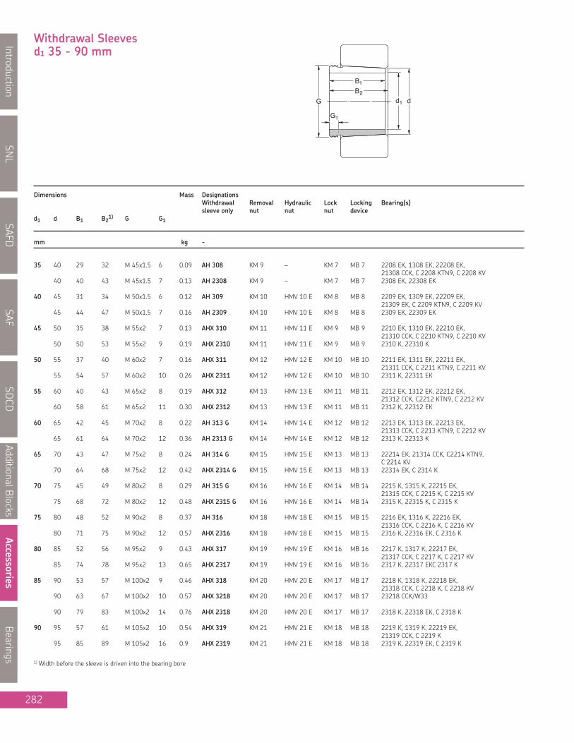
Dimensions Mass DesignationsWithdrawal Removal Hydraulic Lock Locking Bearing(s)sleeve only nut nut nut device
d1 d B1 B21) G G1
mm kg -
SNL
IntroductionSAFD
SAFSD
CDAdditionalBlocks
AccessoriesBearings
282
B1
G d1 dB2
G1
35 40 29 32 M 45x1.5 6 0.09 AH 308 KM 9 – KM 7 MB 7 2208 EK, 1308 EK, 22208 EK,21308 CCK, C 2208 KTN9, C 2208 KV
40 40 43 M 45x1.5 7 0.13 AH 2308 KM 9 – KM 7 MB 7 2308 EK, 22308 EK
40 45 31 34 M 50x1.5 6 0.12 AH 309 KM 10 HMV 10 E KM 8 MB 8 2209 EK, 1309 EK, 22209 EK,21309 EK, C 2209 KTN9, C 2209 KV
45 44 47 M 50x1.5 7 0.16 AH 2309 KM 10 HMV 10 E KM 8 MB 8 2309 EK, 22309 EK
45 50 35 38 M 55x2 7 0.13 AHX 310 KM 11 HMV 11 E KM 9 MB 9 2210 EK, 1310 EK, 22210 EK,21310 CCK, C 2210 KTN9, C 2210 KV
50 50 53 M 55x2 9 0.19 AHX 2310 KM 11 HMV 11 E KM 9 MB 9 2310 K, 22310 K
50 55 37 40 M 60x2 7 0.16 AHX 311 KM 12 HMV 12 E KM 10 MB 10 2211 EK, 1311 EK, 22211 EK,21311 CCK, C 2211 KTN9, C 2211 KV
55 54 57 M 60x2 10 0.26 AHX 2311 KM 12 HMV 12 E KM 10 MB 10 2311 K, 22311 EK
55 60 40 43 M 65x2 8 0.19 AHX 312 KM 13 HMV 13 E KM 11 MB 11 2212 EK, 1312 EK, 22212 EK,21312 CCK, C2212 KTN9, C 2212 KV
60 58 61 M 65x2 11 0.30 AHX 2312 KM 13 HMV 13 E KM 11 MB 11 2312 K, 22312 EK
60 65 42 45 M 70x2 8 0.22 AH 313 G KM 14 HMV 14 E KM 12 MB 12 2213 EK, 1313 EK, 22213 EK,21313 CCK, C 2213 KTN9, C 2212 KV
65 61 64 M 70x2 12 0.36 AH 2313 G KM 14 HMV 14 E KM 12 MB 12 2313 K, 22313 K
65 70 43 47 M 75x2 8 0.24 AH 314 G KM 15 HMV 15 E KM 13 MB 13 22214 EK, 21314 CCK, C2214 KTN9,C 2214 KV
70 64 68 M 75x2 12 0.42 AHX 2314 G KM 15 HMV 15 E KM 13 MB 13 22314 EK, C 2314 K
70 75 45 49 M 80x2 8 0.29 AH 315 G KM 16 HMV 16 E KM 14 MB 14 2215 K, 1315 K, 22215 EK,21315 CCK, C 2215 K, C 2215 KV
75 68 72 M 80x2 12 0.48 AHX 2315 G KM 16 HMV 16 E KM 14 MB 14 2315 K, 22315 K, C 2315 K
75 80 48 52 M 90x2 8 0.37 AH 316 KM 18 HMV 18 E KM 15 MB 15 2216 EK, 1316 K, 22216 EK,21316 CCK, C 2216 K, C 2216 KV
80 71 75 M 90x2 12 0.57 AHX 2316 KM 18 HMV 18 E KM 15 MB 15 2316 K, 22316 EK, C 2316 K
80 85 52 56 M 95x2 9 0.43 AHX 317 KM 19 HMV 19 E KM 16 MB 16 2217 K, 1317 K, 22217 EK,21317 CCK, C 2217 K, C 2217 KV
85 74 78 M 95x2 13 0.65 AHX 2317 KM 19 HMV 19 E KM 16 MB 16 2317 K, 22317 EKC 2317 K
85 90 53 57 M 100x2 9 0.46 AHX 318 KM 20 HMV 20 E KM 17 MB 17 2218 K, 1318 K, 22218 EK,21318 CCK, C 2218 K, C 2218 KV
90 63 67 M 100x2 10 0.57 AHX 3218 KM 20 HMV 20 E KM 17 MB 17 23218 CCK/W33
90 79 83 M 100x2 14 0.76 AHX 2318 KM 20 HMV 20 E KM 17 MB 17 2318 K, 22318 EK, C 2318 K
90 95 57 61 M 105x2 10 0.54 AHX 319 KM 21 HMV 21 E KM 18 MB 18 2219 K, 1319 K, 22219 EK,21319 CCK, C 2219 K
95 85 89 M 105x2 16 0.9 AHX 2319 KM 21 HMV 21 E KM 18 MB 18 2319 K, 22319 EK, C 2319 K
1) Width before the sleeve is driven into the bearing bore
Withdrawal Sleevesd1 35 - 90 mm

SNL
Introduction
SAFD
SAF
SDCD
AdditionalB
locks
Accessories
Bearings
283
Dimensions Mass DesignationsWithdrawal Removal Hydraulic Lock Locking Bearing(s)sleeve only nut nut nut device
d1 d B1 B21) G G1 G2 A
mm kg –
95 100 59 63 M 110x2 10 0.58 AHX 320 KM 22 HMV 22 E KM 19 MB 19 2220 K, 1320 K, 22220 EK,21320 CCK, C 2220 K
100 64 68 M 110x2 11 0.66 AHX 3120 KM 22 HMV 22 E KM 19 MB 19 23120 CCK/W33, C 2320 K, C 3120 K,C 3120 KV
100 73 77 M 110x2 11 0.76 AHX 3220 KM 22 HMV 22 E KM 19 MB 19 23220 CCK/W33
100 90 94 M 110x2 16 1.00 AHX 2320 KM 22 HMV 22 E KM 19 MB 19 2320 K, 22320 EK, C 2320 K
105 110 63 67 M 120x2 12 0.77 AHX 322 KM 24 HMV 24 E KM 21 MB 21 1322 K110 68 72 M 120x2 11 0.76 AHX 3122 KM 24 HMV 24 E KM 21 MB 21 2222 K, 23122 CCK/W33, 22222 EK,
C 3022 K, C 2222 K110 82 86 M 120x2 11 1.00 AHX 3222 G KM 24 HMV 24 E KM 21 MB 21 23222 CCK/W33
110 98 102 M 120x2 16 1.30 AHX 2322 G KM 24 HMV 24 E KM 21 MB 21 2322 K, 22322 EK110 82 91 M 115x2 13 0.71 AH 24122 KM 23 HMV 23 E KM 21 MB 21 24122 CCK30/W33, C 4122 K30V
115 120 60 64 M 130x2 13 0.73 AHX 3024 KM 26 HMV 26 E KM 22 MB 22 23024 CCK/W33, C 3024 K,C 3024 KV
120 75 79 M 130x2 12 0.94 AHX 3124 KM 26 HMV 26 E KM 22 MB 22 23124 CCK/W33, 22224 EK, C 2224 K120 90 94 M 130x2 13 1.30 AHX 3224 G KM 26 HMV 26 E KM 22 MB 22 23224 CCK/W33, C 3224K120 105 109 M 130x2 17 1.55 AHX 2324 G KM 26 HMV 26 E KM 22 MB 22 22324 CCK/W33
120 73 82 M 125x2 13 0.7 AH 24024 KM 25 HMV 25 E KM 22 MB 22 24024 CCK30/W33, C 4024 K30V120 93 102 M 130x2 13 1.00 AH 24124 KM 26 HMV 26 E KM 22 MB 22 24124 CCK30/W33, C 4124 K30V
125 130 67 71 M 140x2 14 0.91 AHX 3026 KM 28 HMV 28 E KM 24 MB 24 23026 CCK/W33, C 3026 K130 78 82 M 140x2 12 1.10 AHX 3126 KM 28 HMV 28 E KM 24 MB 24 23126 CCK/W33, 22226 EK, C 2226 K130 98 102 M 140x2 15 1.50 AHX 3226 G KM 28 HMV 28 E KM 24 MB 24 23226 CCK/W33130 115 119 M 140x2 19 1.85 AHX 2326 G KM 28 HMV 28 E KM 24 MB 24 22326 CCK/W33
130 83 93 M 135x2 14 0.90 AH 24026 KM 27 HMV 27 E KM 24 MB 24 24026 CCK30/W33, C 4026 K30,C 4026 K30V
130 94 104 M 140x2 14 1.15 AH 24126 KM 28 HMV 28 E KM 24 MB 24 24126 CCK30/W33,C4126 K30V/VE240
135 140 68 73 M 150x2 14 1.00 AHX 3028 KM 30 HMV 30 E KM 26 MB 26 23028 CCK/W33, C 3028 K,C4026 K30V
140 83 88 M 150x2 14 1.30 AHX 3128 KM 30 HMV 30 E KM 26 MB 26 23128 CCK/W33, 22228 EK, C 2228 K140 104 109 M 150x2 15 1.75 AHX 3228 G KM 30 HMV 30 E KM 26 MB 26 23228 CCK/W33140 125 130 M 150x2 20 2.25 AHX 2328 G KM 30 HMV 30 E KM 26 MB 26 22328 CCK/W33
140 83 93 M 145x2 14 0.95 AH 24028 KM 29 HMV 29 E KM 26 MB 26 24028 CCK30/W33, C 4028 K30V140 99 109 M 150x2 14 1.30 AH 24128 KM 30 HMV 30 E KM 26 MB 26 24128 CCK30/W33, C 4128 K30V
145 150 72 77 M 160x3 15 1.15 AHX 3030 KM 32 HMV 32 E KM 28 MB 28 23030 CCK/W33, C 3030 KMB150 96 101 M 160x3 15 1.70 AHX 3130 G KM 32 HMV 32 E KM 28 MB 28 23130 CCK/W33, 22230 CCK/W33,
C 3130 K, C 2230 K150 114 119 M 160x3 17 2.10 AHX 3230 G KM 32 HMV 32 E KM 28 MB 28 23230 CCK/W33150 135 140 M 160x3 24 2.75 AHX 2330 G KM 32 HMV 32 E KM 28 MB 28 22330 CCK/W33
150 90 101 M 155x3 15 1.05 AH 24030 KM 31 HMV 31 E KM 28 MB 28 24030 CCK30/W33, C 4030 K30V150 115 126 M 160x3 15 1.55 AH 24130 KM 32 HMV 32 E KM 28 MB 28 24130 CCK30/W33, C 4130 K30V
1) Width before the sleeve is driven into the bearing bore
B1
G d1 dB2
G1
Withdrawal Sleevesd1 95 - 145 mm
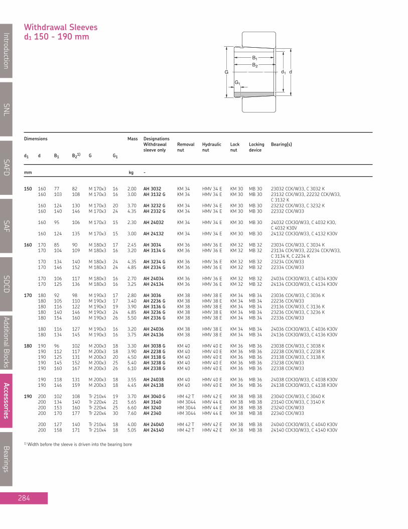
Dimensions Mass DesignationsWithdrawal Removal Hydraulic Lock Locking Bearing(s)sleeve only nut nut nut device
d1 d B1 B21) G G1
mm kg -
SNL
IntroductionSAFD
SAFSD
CDAdditionalBlocks
AccessoriesBearings
284
B1
G d1 dB2
G1
150 160 77 82 M 170x3 16 2.00 AH 3032 KM 34 HMV 34 E KM 30 MB 30 23032 CCK/W33, C 3032 K160 103 108 M 170x3 16 3.00 AH 3132 G KM 34 HMV 34 E KM 30 MB 30 23132 CCK/W33, 22232 CCK/W33,
C 3132 K160 124 130 M 170x3 20 3.70 AH 3232 G KM 34 HMV 34 E KM 30 MB 30 23232 CCK/W33, C 3232 K160 140 146 M 170x3 24 4.35 AH 2332 G KM 34 HMV 34 E KM 30 MB 30 22332 CCK/W33
160 95 106 M 170x3 15 2.30 AH 24032 KM 34 HMV 34 E KM 30 MB 30 24032 CCK30/W33, C 4032 K30,C 4032 K30V
160 124 135 M 170x3 15 3.00 AH 24132 KM 34 HMV 34 E KM 30 MB 30 24132 CCK30/W33, C 4132 K30V
160 170 85 90 M 180x3 17 2.45 AH 3034 KM 36 HMV 36 E KM 32 MB 32 23034 CCK/W33, C 3034 K170 104 109 M 180x3 16 3.20 AH 3134 G KM 36 HMV 36 E KM 32 MB 32 23134 CCK/W33, 22234 CCK/W33,
C 3134 K, C 2234 K170 134 140 M 180x3 24 4.35 AH 3234 G KM 36 HMV 36 E KM 32 MB 32 23234 CCK/W33170 146 152 M 180x3 24 4.85 AH 2334 G KM 36 HMV 36 E KM 32 MB 32 22334 CCK/W33
170 106 117 M 180x3 16 2.70 AH 24034 KM 36 HMV 36 E KM 32 MB 32 24034 CCK30/W33, C 4034 K30V170 125 136 M 180x3 16 3.25 AH 24134 KM 36 HMV 36 E KM 32 MB 32 24134 CCK30/W33, C 4134 K30V
170 180 92 98 M 190x3 17 2.80 AH 3036 KM 38 HMV 38 E KM 34 MB 34 23036 CCK/W33, C 3036 K180 105 110 M 190x3 17 3.40 AH 2236 G KM 38 HMV 38 E KM 34 MB 34 22236 CCK/W33180 116 122 M 190x3 19 3.90 AH 3136 G KM 38 HMV 38 E KM 34 MB 34 23136 CCK/W33, C 3136 K180 140 146 M 190x3 24 4.85 AH 3236 G KM 38 HMV 38 E KM 34 MB 34 23236 CCK/W33, C 3236 K180 154 160 M 190x3 26 5.50 AH 2336 G KM 38 HMV 38 E KM 34 MB 34 22336 CCK/W33
180 116 127 M 190x3 16 3.20 AH 24036 KM 38 HMV 38 E KM 34 MB 34 24036 CCK30/W33, C 4036 K30V180 134 145 M 190x3 16 3.75 AH 24136 KM 38 HMV 38 E KM 34 MB 34 24136 CCK30/W33, C 4136 K30V
180 190 96 102 M 200x3 18 3.30 AH 3038 G KM 40 HMV 40 E KM 36 MB 36 23038 CCK/W33, C 3038 K190 112 117 M 200x3 18 3.90 AH 2238 G KM 40 HMV 40 E KM 36 MB 36 22238 CCK/W33, C 2238 K190 125 131 M 200x3 20 4.50 AH 3138 G KM 40 HMV 40 E KM 36 MB 36 23138 CCK/W33, C 3138 K190 145 152 M 200x3 25 5.40 AH 3238 G KM 40 HMV 40 E KM 36 MB 36 23238 CCK/W33190 160 167 M 200x3 26 6.10 AH 2338 G KM 40 HMV 40 E KM 36 MB 36 22338 CCK/W33
190 118 131 M 200x3 18 3.55 AH 24038 KM 40 HMV 40 E KM 36 MB 36 24038 CCK30/W33, C 4038 K30V190 146 159 M 200x3 18 4.45 AH 24138 KM 40 HMV 40 E KM 36 MB 36 24138 CCK30/W33, C 4138 K30V
190 200 102 108 Tr 210x4 19 3.70 AH 3040 G HM 42 T HMV 42 E KM 38 MB 38 23040 CCK/W33, C 3040 K200 134 140 Tr 220x4 21 5.65 AH 3140 HM 3044 HMV 44 E KM 38 MB 38 23140 CCK/W33, C 3140 K200 153 160 Tr 220x4 25 6.60 AH 3240 HM 3044 HMV 44 E KM 38 MB 38 23240 CCK/W33200 170 177 Tr 220x4 30 7.60 AH 2340 HM 3044 HMV 44 E KM 38 MB 38 22340 CCK/W33
200 127 140 Tr 210x4 18 4.00 AH 24040 HM 42 T HMV 42 E KM 38 MB 38 24040 CCK30/W33, C 4040 K30V200 158 171 Tr 210x4 18 5.05 AH 24140 HM 42 T HMV 42 E KM 38 MB 38 24140 CCK30/W33, C 4140 K30V
1) Width before the sleeve is driven into the bearing bore
Withdrawal Sleevesd1 150 - 190 mm

SNL
Introduction
SAFD
SAF
SDCD
AdditionalB
locks
Accessories
Bearings
285
Dimensions Mass DesignationsWithdrawal Removal Hydraulic Lock Locking Bearing(s)sleeve only nut nut nut device
d1 d B1 B21) G G1 G2 A
mm kg –
200 220 111 117 Tr 230x4 20 G 1/8 6.5 7.3 AOH 3044 G HM 46 T HMV 46 E KM 40 MB 40 23044 CCK/W33, C 3044 K220 145 151 Tr 240x4 23 G 1/4 9 9.3 AOH 3144 HM 3048 HMV 48 E KM 40 MB 40 23144 CCK/W33, C 3144 K220 181 189 Tr 240x4 30 G 1/4 9 13.5 AOH 2344 HM 3048 HMV 48 E KM 40 MB 40 23244 CCK/W33,
22344 CCK/W33220 130 136 Tr 240x4 20 G 1/4 9 9.40 AOH 2244 HM 3048 HMV 48 E KM 40 MB 40 22244 CCK/W33, C 2244K
220 138 152 Tr 230x4 20 G 1/8 6.5 8.2 AOH 24044 HM 46 T HMV 46 E KM 40 MB 40 24044 CCK30/W33,C 4044 K30V
220 170 184 Tr 230x4 20 G 1/8 6.5 10 AOH 24144 HM 46 T HMV 46 E KM 40 MB 40 24144 CCK30/W33
220 240 116 123 Tr 260x4 21 G 1/4 9 7.95 AOH 3048 HM 3052 HMV 52 E HM 44 T MB 44 23048 CCK/W33, C 3048 K240 154 161 Tr 260x4 25 G 1/4 9 12 AOH 3148 HM 3052 HMV 52 E HM 44 T MB 44 23148 CCK/W33, C 3148 K240 189 197 Tr 260x4 30 G 1/4 9 14 AOH 2348 HM 3052 HMV 52 E HM 44 T MB 44 23248 CCK/W33,
22348 CCK/W33
240 138 153 Tr 250x4 20 G 1/8 6.5 8.05 AOH 24048 HM 50 T HMV 50 E HM 48 T MB 44 24048 CCK30/W33240 180 195 Tr 260x4 20 G 1/4 9 11.5 AOH 24148 HM 3052 HMV 52 E HM 48 T MB 44 24148 CCK30/W33
240 260 128 135 Tr 280x4 23 G 1/4 9 9.6 AOH 3052 HM 3056 HMV 56 E HM 48 T MB 48 23052 CCK/W33, C 3052 K260 155 161 Tr 280x4 23 G 1/4 9 13.5 AOH 2252 G HM 3056 HMV 56 E HM 48 T MB 48 22252 CCK/W33260 172 179 Tr 280x4 26 G 1/4 9 15.5 AOH 3152 G HM 3056 HMV 56 E HM 48 T MB 48 23152 CCK/W33, C 3152 K260 205 213 Tr 280x4 30 G 1/4 9 19 AOH 2352 G HM 3056 HMV 56 E HM 48 T MB 48 23252 CCK/W33,
22352 CCK/W33
260 162 178 Tr 280x4 22 G 1/8 6.5 12.5 AOH 24052 G HM 3056 HMV 56 E HM 48 T MB 48 24052 CCK30/W33260 202 218 Tr 280x4 22 G 1/4 9 14 AOH 24152 HM 3056 HMV 56 E HM 48 T MB 48 24152 CCK30/W33
260 280 131 139 Tr 300x4 24 G 1/4 9 11 AOH 3056 HM 3060 HMV 60 E HM 52 T MB 52 23056 CCK/W33, C 3056 K280 155 163 Tr 300x4 24 G 1/4 9 15 AOH 2256 G HM 3160 HMV 60 E HM 52 T MB 52 22256 CCK/W33280 175 183 Tr 300x4 28 G 1/4 9 17 AOH 3156 G HM 3160 HMV 60 E HM 52 T MB 52 23156 CCK/W33, C 3156 K280 212 220 Tr 300x4 30 G 1/4 9 21.5 AOH 2356 G HM 3160 HMV 60 E HM 52 T MB 52 23256 CCK/W33,
22356 CCK/W33
280 162 179 Tr 300x4 22 G 1/8 6.5 13.5 AOH 24056 G HM 3160 HMV 60 E HM 52 T MB 52 24056 CCK30/W33280 202 219 Tr 300x4 22 G 1/4 9 15 AOH 24156 HM 3160 HMV 60 E HM 52 T MB 52 24156 CCK30/W33
280 300 145 153 Tr 320x5 26 G 1/4 9 13 AOH 3060 HM 3064 HMV 64 E HM 56 T MB 56 23060 CCK/W33, C 3060 KM300 170 178 Tr 320x5 26 G 1/4 9 18 AOH 2260 G HM 3164 HMV 64 E HM 56 T MB 56 22260 CCK/W33300 192 200 Tr 320x5 30 G 1/4 9 20.5 AOH 3160 G HM 3164 HMV 64 E HM 56 T MB 56 23160 CCK/W33, C 3160 K300 228 236 Tr 320x5 34 G 1/4 9 23.5 AOH 3260 G HM 3164 HMV 64 E HM 56 T MB 56 23260 CCK/W33
300 184 202 Tr 320x5 24 G 1/8 6.5 17 AOH 24060 G HM 3164 HMV 64 E HM 56 T MB 56 24060 CCK30/W33,C 4060 K30M
300 224 242 Tr 320x5 24 G 1/4 9 18.5 AOH 24160 HM 3164 HMV 64 E HM 56 T MB 56 24160 CCK30/W33
1) Width before the sleeve is driven into the bearing bore
G2
A
G1
G
B1B2
d1 d
Withdrawal Sleevesd1 200 - 280 mm

Dimensions Mass DesignationsWithdrawal Removal Hydraulic Lock Locking Bearing(s)sleeve only nut nut nut device
d1 d B1 B21) G G1 G2 A
mm kg –
SNL
IntroductionSAFD
SAFSD
CDAdditionalBlocks
AccessoriesBearings
286
G2
A
G1
G
B1B2
d1 d
300 320 149 157 Tr 340x5 27 G 1/4 9 16.5 AOH 3064 G HM 3068 HMV 68 E HM 3060 MS 3060 23064 CCK/W33,C 3064 KM
320 180 190 Tr 340x5 27 G 1/4 9 20 AOH 2264 G HM 3168 HMV 68 E HM 3060 MS 3060 22264 CCK/W33320 209 217 Tr 340x5 31 G 1/4 9 24.5 AOH 3164 G HM 3168 HMV 68 E HM 3060 MS 3060 23164 CCK/W33. C 3164 KM320 246 254 Tr 340x5 36 G 1/4 9 27.5 AOH 3264 G HM 3168 HMV 68 E HM 3060 MS 3060 23264 CCK/W33
320 184 202 Tr 340x5 24 G 1/8 6.5 18 AOH 24064 G HM 3168 HMV 68 E HM 3060 MS 3060 24064 CCK30/W33320 242 260 Tr 340x5 24 G 1/4 9 20.5 AOH 24164 HM 3168 HMV 68 E HM 3060 MS 3060 24164 CCK30/W33
320 340 162 171 Tr 360x5 28 G 1/4 9 19 AOH 3068 G HM 3072 HMV 72 E HM 3064 MS 3068-64 23068 CCK/W33 C 3068 KM340 225 234 Tr 360x5 33 G 1/4 9 28.5 AOH 3168 G HM 3172 HMV 72 E HM 3064 MS 3068-64 23168 CCK/W33, C 3168 KM340 264 273 Tr 360x5 38 G 1/4 9 32 AOH 3268 G HM 3172 HMV 72 E HM 3064 MS 3068-64 23268 CAK/W33
340 206 225 Tr 360x5 26 G 1/4 9 18 AOH 24068 HM 3172 HMV 72 E HM 3064 MS 3068-64 24068 CCK30/W33340 269 288 Tr 360x5 26 G 1/4 9 25.5 AOH 24168 HM 3172 HMV 72 E HM 3064 MS 3068-64 24168 ECCK30/W33
340 360 167 176 Tr 380x5 30 G 1/4 9 21.0 AOH 3072 G HM 3076 HMV 76 E HM 3068 MS 3068-64 23072 CCK/W33,C 3072 KM
360 229 238 Tr 380x5 35 G 1/4 9 30.5 AOH 3172 G HM 3176 HMV 76 E HM 3068 MS 3068-64 23172 CCK/W33,C 3172 KM
360 274 283 Tr 380x5 40 G 1/4 9 35.5 AOH 3272 G HM 3176 HMV 76 E HM 3068 MS 3068-64 23272 CAK/W33
360 206 226 Tr 380x5 26 G 1/4 9 20.0 AOH 24072 HM 3176 HMV 76 E HM 3068 MS 3068-64 24072 CCK30/W33360 269 289 Tr 380x5 26 G 1/4 9 26.0 AOH 24172 HM 3176 HMV 76 E HM 3068 MS 3068-64 24172 ECCK30/W33
360 380 170 180 Tr 400x5 31 G 1/4 9 22.5 AOH 3076 G HM 3080 HMV 80 E HM 3072 MS 3072 23076 CCK/W33.C 3076 KM
380 232 242 Tr 400x5 36 G 1/4 9 33.0 AOH 3176 G HM 3180 HMV 80 E HM 3072 MS 3072 23176 CAK/W33,C 3176 KMB
380 284 294 Tr 400x5 42 G 1/4 9 42.0 AOH 3276 G HM 3180 HMV 80 E HM 3072 MS 3072 23276 CAK/W33
380 208 228 Tr 400x5 28 G 1/4 9 23.5 AOH 24076 HM 3180 HMV 80 E HM 3072 MS 3072 24076 CCK30/W33380 271 291 Tr 400x5 28 G 1/4 9 31.0 AOH 24176 HM 3180 HMV 80 E HM 3072 MS 3072 24176 ECAK30/W33
380 400 183 193 Tr 420x5 33 G 1/4 9 26.0 AOH 3080 G HM 3080 HMV 84 E HM 3076 MS 3080-76 23080 CCK/W33,C 3080 KM
400 240 250 Tr 420x5 38 G 1/4 9 36.0 AOH 3180 G HM 3184 HMV 84 E HM 3076 MS 3080-76 23180 CAK/W33,C 3180 KMB
400 302 312 Tr 420x5 44 G 1/4 9 48.0 AOH 3280 G HM 3184 HMV 84 E HM 3076 MS 3080-76 23280 CAK/W33
400 228 248 Tr 420x5 28 G 1/4 9 27.0 AOH 24080 HM 3184 HMV 84 E HM 3076 MS 3080-76 24080 CACK30/W33
400 278 298 Tr 420x5 28 G 1/4 9 35.0 AOH 24180 HM 3184 HMV 84 E HM 3076 MS 3080-76 24180 ECCK30/W33
1) Width before the sleeve is driven into the bearing bore
Withdrawal Sleevesd1 300 - 380 mm

SNL
Introduction
SAFD
SAF
SDCD
AdditionalB
locks
Accessories
Bearings
287
Dimensions Mass DesignationsWithdrawal Removal Hydraulic Lock Locking Bearing(s)sleeve only nut nut nut device
d1 d B1 B21) G G1 G2 A
mm kg –
400 420 186 196 Tr 440x5 34 G 1/4 9 28.0 AOH 3084 G HM 3088 HMV 88 E HM 3080 MS 3080-76 23084 CAK/W33,C 3084 KM
420 266 276 Tr 440x5 40 G 1/4 9 43.0 AOH 3184 G HM 3188 HMV 88 E HM 3080 MS 3080-76 23184 CK/W33, C 3184 KM420 321 331 Tr 440x5 46 G 1/4 9 54.5 AOH 3284 G HM 3188 HMV 88 E HM 3080 MS 3080-76 23284 CAK/W33
420 230 252 Tr 440x5 30 G 1/4 9 29.0 AOH 24084 HM 3188 HMV 88 E HM 3080 MS 3080-76 24084 ECAK30/W33420 310 332 Tr 440x5 30 G 1/4 9 39.0 AOH 24184 HM 3188 HMV 88 E HM 3080 MS 3080-76 24184 ECAK30/W33
420 440 194 205 Tr 460x5 35 G 1/4 9 31.0 AOHX 3088 G HM 3092 HMV 92 E HM 3084 MS 3084 23088 CAK/W33,C 3088 KMB
440 270 281 Tr 460x5 42 G 1/4 9 46.0 AOHX 3188 G HM 3192 HMV 92 E HM 3084 MS 3084 23188 CAK/W33,C 3188 KMB
440 330 341 Tr 460x5 48 G 1/4 9 64.5 AOHX 3288 G HM 3192 HMV 92 E HM 3084 MS 3084 23288 CAK/W33
440 242 264 Tr 460x5 30 G 1/4 9 32.0 AOH 24088 HM 3192 HMV 92 E HM 3084 MS 3084 24088 ECAK30/W33440 310 332 Tr 460x5 30 G 1/4 9 45.5 AOH 24188 HM 3192 HMV 92 E HM 3084 MS 3084 24188 ECAK30/W33
440 460 202 213 Tr 480x5 37 G 1/4 9 34.0 AOHX 3092 G HM 3096 HMV 96 E HM 3088 MS 3092-88 23092 CAK/W33,C 3092 KM
460 285 296 Tr 480x5 43 G 1/4 9 51.5 AOHX 3192 G HM 3196 HMV 96 E HM 3088 MS 3092-88 23192 CAK/W33,C 3192 KM
460 349 360 Tr 480x5 50 G 1/4 9 80.0 AOHX 3292 G HM 3196 HMV 96 E HM 3088 MS 3092-88 23292 CAK/W33
460 250 273 Tr 480x5 32 G 1/4 9 34.5 AOH 24092 HM 3196 HMV 96 E HM 3088 MS 3092-88 24092 ECAK30/W33460 332 355 Tr 480x5 32 G 1/4 9 50.0 AOH 24192 HM 3196 HMV 96 E HM 3088 MS 3092-88 24192 ECAK30/W33
460 480 205 217 Tr 500x5 38 G 1/4 9 34.0 AOHX 3096 G HM 30/500 HMV 100 E HM 3092 MS 3092-88 23096 CAK/W33,C 3096 KM
480 295 307 Tr 500x5 45 G 1/4 9 63.0 AOHX 3196 G HM 31/500 HMV 100 E HM 3092 MS 3092-88 23196 CAK/W33,C 3196 KMB
480 364 376 Tr 500x5 52 G 1/4 9 81.0 AOHX 3296 G HM 31/500 HMV 100 E HM 3092 MS 3092-88 23296 CAK/W33
480 250 273 Tr 500x5 32 G 1/4 9 36.5 AOH 24096 HM 31/500 HMV 100 E HM 3092 MS 3092-88 24096 ECAK30/W33480 340 363 Tr 500x5 32 G 1/4 9 51.5 AOH 24196 HM 31/500 HMV 100 E HM 3092 MS 3092-88 24196 ECAK30/W33
480 500 209 221 Tr 530x6 40 G 1/4 9 41.0 AOHX 30/500 G HM 30/530 HMV 106 E HM 3096 MS 30/500-96 230/500 CAK/W33,C 30/500 KM
500 313 325 Tr 530x6 47 G 1/4 9 66.5 AOHX 31/500 G HM 31/530 HMV 106 E HM 3096 MS 30/500-96 231/500 CAK/W33,C 31/500 KM
500 393 405 Tr 530x6 54 G 1/4 9 89.5 AOHX 32/500 G HM 31/530 HMV 106 E HM 3096 MS 30/500-96 232/500 CAK/W33
500 253 276 Tr 530x6 35 G 1/4 9 43.0 AOH 240/500 HM 31/530 HMV 106 E HM 3096 MS 30/500-96 240/500 ECAK30/W33500 360 383 Tr 530x6 35 G 1/4 9 63.0 AOH 241/500 HM 31/530 HMV 106 E HM 3096 MS 30/500-96 241/500 ECAK30/W33,
C 41/500 K30MB500 530 230 242 Tr 560x6 45 G 1/4 10 63.5 AOH 30/530 HM 30/560 HMV 112 E HM 30/500 MS 30/500-96 230/530 CAK/W33,
C 30/530 KM530 325 337 Tr 560x6 53 G 1/4 10 93.5 AOH 31/530 HM 31/560 HMV 112 E HM 30/500 MS 30/500-96 231/530 CAK/W33,
C 31/530 KM530 412 424 Tr 560x6 57 G 1/4 10 142 AOH 32/530 G HM 31/560 HMV 112 E HM 30/500 MS 30/500-96 232/530 CAK/W33
530 285 309 Tr 560x6 35 G 1/4 9 64.5 AOH 240/530 G HM 31/560 HMV 112 E HM 30/500 MS 30/500-96 240/530 ECAK30/W33
530 370 394 Tr 560x6 35 G 1/4 9 92.0 AOH 241/530 G HM 31/560 HMV 112 E HM 30/500 MS 30/500-96 241/530 ECAK30/W33
1) Width before the sleeve is driven into the bearing bore
G2
A
G1
G
B1B2
d1 d
Withdrawal Sleevesd1 400 - 500 mm

Dimensions Mass DesignationsWithdrawal Removal Hydraulic Lock Locking Bearing(s)sleeve only nut nut nut device
d1 d B1 B21) G G1 G2 A
mm kg –
SNL
IntroductionSAFD
SAFSD
CDAdditionalBlocks
AccessoriesBearings
288
G2
A
G1
G
B1B2
d1 d
530 560 240 252 Tr 600x6 45 G 1/4 11 73.5 AOHX 30/560 HM 30/600 HMV 120 E HM 30/530 MS 30/600-530 230/560 CAK/W33,C 30/560 KM
560 335 347 Tr 600x6 55 G 1/4 11 107 AOH 31/560 HM 31/600 HMV 120 E HM 30/530 MS 30/600-530 231/560 CAK/W33,C 31/560 KMB
560 422 434 Tr 600x6 57 G 1/4 11 143 AOHX 32/560 HM 31/600 HMV 120 E HM 30/530 MS 30/600-530 232/560 CAK/W33
560 296 320 Tr 600x6 38 G 1/4 9 71.0 AOH 240/560 G HM 31/600 HMV 120 E HM 30/530 MS 30/600-530 240/560 ECAK30/W33560 393 417 Tr 600x6 38 G 1/4 9 107 AOH 241/560 G HM 31/600 HMV 120 E HM 30/530 MS 30/600-530 241/560 ECAK30/W33
570 600 245 259 Tr 630x6 45 G 1/4 11 77.0 AOHX 30/600 HM 30/630 HMV 126 E HM 30/560 MS 30/560 230/600 CAK/W33,C 30/600 KM
600 355 369 Tr 630x6 55 G 1/4 11 120 AOHX 31/600 HM 31/630 HMV 126 E HM 30/560 MS 30/560 231/600 CAK/W33,C 31/600 KMB
600 445 459 Tr 630x6 57 G 1/4 11 159 AOHX 32/600 G HM 31/630 HMV 126 E HM 30/560 MS 30/560 232/600 CAK/W33
600 310 336 Tr 630x6 38 G 1/4 9 108 AOHX 240/600 HM 31/630 HMV 126 E HM 30/560 MS 30/560 240/600 ECAK30/W33600 413 439 Tr 630x6 38 G 1/4 9 120 AOHX 241/600 HM 31/630 HMV 126 E HM 30/560 MS 30/560 241/600 ECAK30/W33
600 630 258 272 Tr 670x6 46 G 1/4 11 88.5 AOH 30/630 HM 30/670 HMV 134 E HM 30/600 MS 30/600-530 230/630 CAK/W33,C 30/630 KM
630 375 389 Tr 670x6 60 G 1/4 11 139 AOH 31/630 HM 31/670 HMV 134 E HM 30/600 MS 30/600-530 231/630 CAK/W33,C 31/630 KMB
630 475 489 Tr 670x6 63 G 1/4 11 188 AOH 32/630 G HM 31/670 HMV 134 E HM 30/600 MS 30/600-530 232/630 CAK/W33
630 330 356 Tr 670x6 40 G 1/4 9 101 AOH 240/630 G HM 31/670 HMV 134 E HM 30/600 MS 30/600-530 240/630 ECAK30/W33630 440 466 Tr 670x6 40 G 1/4 9 139 AOH 241/630 G HM 31/670 HMV 134 E HM 30/600 MS 30/600-530 241/630 ECAK30/W33
630 670 280 294 Tr 710x7 50 G 1/4 12 125 AOH 30/670 HM 30/710 HMV 142 E HM 30/630 MS 30/630 230/670 CAK/W33,C 30/670 KM
670 395 409 Tr 710x7 59 G 1/4 12 189 AOHX 31/670 HM 31/710 HMV 142 E HM 30/630 MS 30/630 231/670 CAK/W33,C 31/670 KMB
670 500 514 Tr 710x7 62 G 1/4 12 252 AOH 32/670 G HM 31/710 HMV 142 E HM 30/630 MS 30/630 232/670 CAK/W33
670 348 374 Tr 710x7 40 G 1/4 12 140 AOH 240/670 G HM 31/710 HMV 142 E HM 30/630 MS 30/630 240/670 ECAK30/W33670 452 478 Tr 710x7 40 G 1/4 12 180 AOH 241/670 HM 31/710 HMV 142 E HM 30/630 MS 30/630 241/670 ECAK30/W33
670 710 286 302 Tr 750x7 50 G 1/4 15 138 AOHX 30/710 HM 30/750 HMV 150 E HM 30/670 MS 30/670 230/710 CAK/W33,C 30/710 KM
710 405 421 Tr 750x7 60 G 1/4 15 207 AOHX 31/710 HM 31/750 HMV 150 E HM 30/670 MS 30/670 231/710 CAK/W33,C 31/710 KMB
710 515 531 Tr 750x7 65 G 1/4 15 278 AOH 32/710 G HM 31/750 HMV 150 E HM 30/670 MS 30/670 232/710 CAK/W33
710 360 386 Tr 750x7 45 G 1/4 12 155 AOH 240/710 G HM 31/750 HMV 150 E HM 30/670 MS 30/670 240/710 ECAK30/W33,C 40/710 K30M
710 483 509 Tr 750x7 45 G 1/4 12 205 AOH 241/710 HM 31/750 HMV 150 E HM 30/670 MS 30/670 241/710 ECAK30/W33
1) Width before the sleeve is driven into the bearing bore
Withdrawal Sleevesd1 530 - 670 mm

SNL
Introduction
SAFD
SAF
SDCD
AdditionalB
locks
Accessories
Bearings
289
Dimensions Mass DesignationsWithdrawal Removal Hydraulic Lock Locking Bearing(s)sleeve only nut nut nut device
d1 d B1 B21) G G1 G2 A
mm kg –
710 750 300 316 Tr 800x7 50 G 1/4 15 145 AOH 30/750 HM 30/800 HMV 160 E HM 30/710 MS 30/710 230/750 CAK/W33,C 30/750 KMB
750 425 441 Tr 800x7 60 G 1/4 15 238 AOH 31/750 HM 31/800 HMV 160 E HM 30/710 MS 30/710 231/750 CAK/W33,C 31/750 KMB
750 540 556 Tr 800x7 65 G 1/4 15 320 AOH 32/750 HM 31/800 HMV 160 E HM 30/710 MS 30/710 232/750 CAK/W33
750 380 408 Tr 800x7 45 G 1/4 12 178 AOH 240/750 G HM 31/800 HMV 160 E HM 30/710 MS 30/710 240/750 ECAK30/W33750 520 548 Tr 800x7 45 G 1/4 12 240 AOH 241/750 G HM 31/800 HMV 160 E HM 30/710 MS 30/710 241/750 ECAK30/W33
750 800 308 326 Tr 850x7 50 G 1/4 15 204 AOH 30/800 HM 30/850 HMV 170 E HM 30/750 MS 30/800-750 230/800 CAK/W33,C 30/800 KMB
800 438 456 Tr 850x7 63 G 1/4 15 305 AOH 31/800 HM 31/850 HMV 170 E HM 30/750 MS 30/800-750 231/800 CAK/W33,C 31/800 KMB
800 550 568 Tr 850x7 67 G 1/4 15 401 AOH 32/800 HM 31/850 HMV 170 E HM 30/750 MS 30/800-750 232/800 CAK/W33
800 395 423 Tr 850x7 50 G 1/4 15 237 AOH 240/800 G HM 31/850 HMV 170 E HM 30/750 MS 30/800-750 240/800 ECAK30/W33800 525 553 Tr 850x7 50 G 1/4 15 318 AOH 241/800 G HM 31/850 HMV 170 E HM 30/750 MS 30/800-750 241/800 ECAK30/W33
800 850 325 343 Tr 900x7 53 G 1/4 15 230 AOH 30/850 HM 30/900 HMV 180 E HM 30/800 MS 30/800-750 230/850 CAK/W33,C 30/850 KMB
850 462 480 Tr 900x7 62 G 1/4 15 345 AOH 31/850 HM 31/900 HMV 180 E HM 30/800 MS 30/800-750 231/850 CAK/W33,C 31/850 KMB
850 585 603 Tr 900x7 70 G 1/4 15 461 AOH 32/850 HM 31/900 HMV 180 E HM 30/800 MS 30/800-750 232/850 CAK/W33
850 415 445 Tr 900x7 50 G 1/4 15 265 AOH 240/850 G HM 31/900 HMV 180 E HM 30/800 MS 30/800-750 240/850 ECAK30/W33850 560 600 Tr 900x7 60 G 1/4 15 368 AOH 241/850 HM 31/900 HMV 180 E HM 30/800 MS 30/800-750 241/850 ECAK30/W33
850 900 335 355 Tr 950x8 55 G 1/4 15 250 AOH 30/900 HM 30/950 HMV 190 E HM 30/850 MS 30/900-850 230/900 CAK/W33, C 30/900 KM900 475 495 Tr 950x8 63 G 1/4 15 379 AOH 31/900 HM 31/950 HMV 190 E HM 30/850 MS 30/900-850 231/900 CAK/W33900 585 605 Tr 950x8 70 G 1/4 15 489 AOH 32/900 HM 31/950 HMV 190 E HM 30/850 MS 30/900-850 232/900 CAK/W33
900 430 475 Tr 950x8 55 G 1/4 15 296 AOH 240/900 HM 31/950 HMV 190 E HM 30/850 MS 30/900-850 240/900 ECAK30/W33900 575 620 Tr 950x8 60 G 1/4 15 402 AOH 241/900 HM 31/950 HMV 190 E HM 30/850 MS 30/900-850 241/900 ECAK30/W33
900 950 355 375 Tr 1000x8 55 G 1/4 15 285 AOH 30/950 HM 30/1000 HMV 200 E HM 30/900 MS 30/900-850 230/950 CAK/W33,C 30/950 KMB
950 500 520 Tr 1000x8 62 G 1/4 15 426 AOH 31/950 HM 31/1000 HMV 200 E HM 30/900 MS 30/900-850 231/950 CAK/W33950 600 620 Tr 1000x8 70 G 1/4 15 533 AOH 32/950 HM 31/1000 HMV 200 E HM 30/900 MS 30/900-850 232/950 CAK/W33
950 467 512 Tr 1000x8 55 G 1/4 15 340 AOH 240/950 HM 31/1000 HMV 200 E HM 30/900 MS 30/900-850 240/950 CAK30/W33950 605 650 Tr 1000x8 60 G 1/4 15 449 AOH 241/950 HM 31/1000 HMV 200 E HM 30/900 MS 30/900-850 241/950 CAK30/W33
950 1 000 365 387 Tr 1060x8 57 G 1/4 15 318 AOH 30/1000 HM 30/1060 HMV 212 E HM 30/950 MS 30/950 230/1000 CAKF/W33,C 30/1000 KM
1 000 525 547 Tr 1060x8 63 G 1/4 15 485 AOH 31/1000 HM 31/1060 HMV 212 E HM 30/950 MS 30/950 231/1000 CAKF/W33,C 31/1000 KMB
1 000 630 652 Tr 1060x8 70 G 1/4 15 608 AOH 32/1000 HM 31/1060 HMV 212 E HM 30/950 MS 30/950 232/1000 CAK/W33
1 000 469 519 Tr 1060x8 57 G 1/4 15 369 AOH 240/1000 HM 31/1060 HMV 212 E HM 30/950 MS 30/950 240/1000 CAK30F/W331 000 645 695 Tr 1060x8 65 G 1/4 15 519 AOH 241/1000 HM 31/1060 HMV 212 E HM 30/950 MS 30/950 241/1000 ECAK30/W33
1000 1 060 385 407 Tr 1120x8 60 G 1/4 15 406 AOH 30/1060 HM 30/1120 HMV 224 E HM 30/1000 MS 30/1000 230/1060 CAKF/W331 060 540 562 Tr 1120x8 65 G 1/4 15 599 AOH 31/1060 HM 30/1120 HMV 224 E HM 30/1000 MS 30/1000 231/1060 CAK/W33
1 060 498 548 Tr 1120x8 60 G 1/4 15 479 AOH 240/1060 HM 30/1120 HMV 224 E HM 30/1000 MS 30/1000 240/1060 CAK30F/W331 060 665 715 Tr 1120x8 65 G 1/4 15 652 AOH 241/1060 HM 30/1120 HMV 224 E HM 30/1000 MS 30/1000 241/1060 CAK30/W33
1) Width before the sleeve is driven into the bearing bore
G2
A
G1
G
B1B2
d1 d
Withdrawal Sleevesd1 710 - 1000 mm
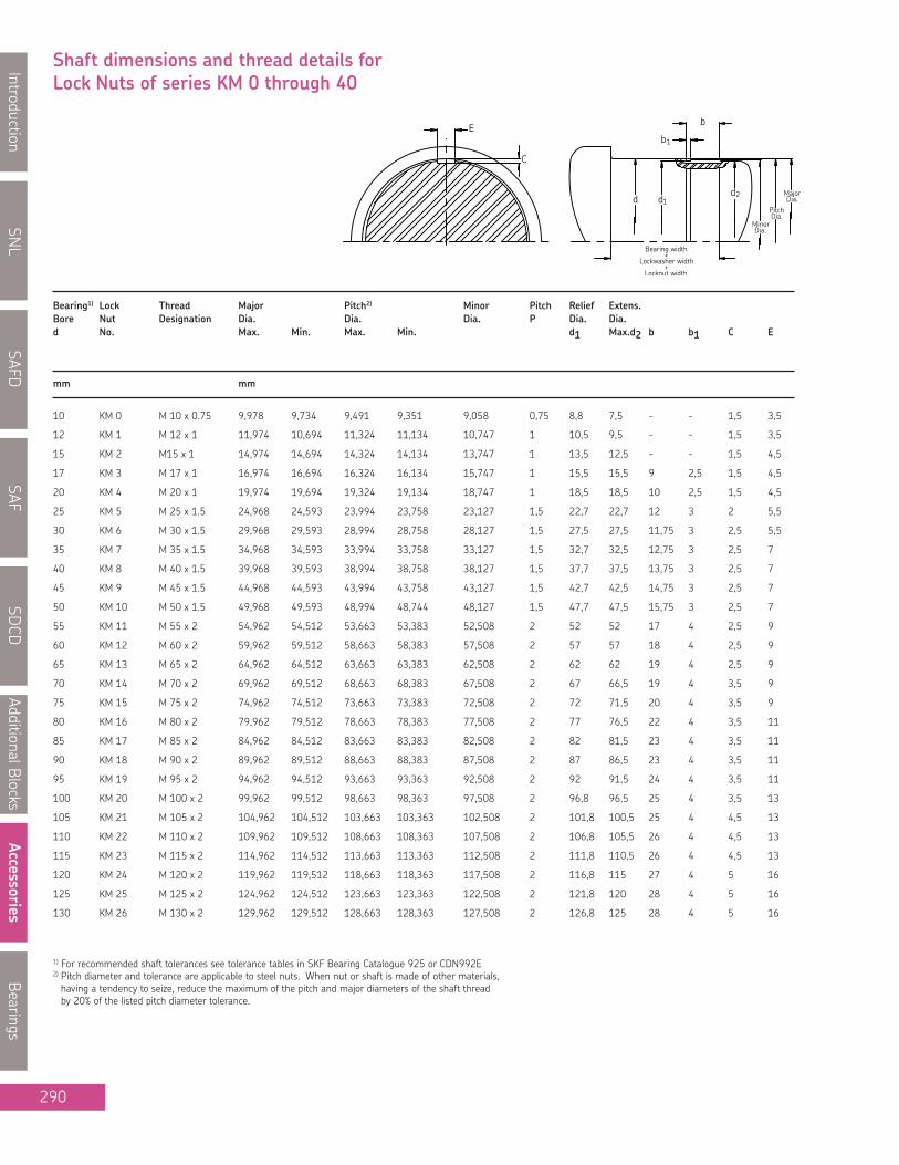
SNL
IntroductionSAFD
SAFSD
CDAdditionalBlocks
AccessoriesBearings
290
Bearing1) Lock Thread Major Pitch2) Minor Pitch Relief Extens.Bore Nut Designation Dia. Dia. Dia. P Dia. Dia.d No. Max. Min. Max. Min. d1 Max.d2 b b1 C E
mm mm
10 KM 0 M 10 x 0.75 9,978 9,734 9,491 9,351 9,058 0,75 8,8 7,5 - - 1,5 3,5
12 KM 1 M 12 x 1 11,974 10,694 11,324 11,134 10,747 1 10,5 9,5 - - 1,5 3,5
15 KM 2 M15 x 1 14,974 14,694 14,324 14,134 13,747 1 13,5 12,5 - - 1,5 4,5
17 KM 3 M 17 x 1 16,974 16,694 16,324 16,134 15,747 1 15,5 15,5 9 2,5 1,5 4,5
20 KM 4 M 20 x 1 19,974 19,694 19,324 19,134 18,747 1 18,5 18,5 10 2,5 1,5 4,5
25 KM 5 M 25 x 1.5 24,968 24,593 23,994 23,758 23,127 1,5 22,7 22,7 12 3 2 5,5
30 KM 6 M 30 x 1.5 29,968 29,593 28,994 28,758 28,127 1,5 27,5 27,5 11,75 3 2,5 5,5
35 KM 7 M 35 x 1.5 34,968 34,593 33,994 33,758 33,127 1,5 32,7 32,5 12,75 3 2,5 7
40 KM 8 M 40 x 1.5 39,968 39,593 38,994 38,758 38,127 1,5 37,7 37,5 13,75 3 2,5 7
45 KM 9 M 45 x 1.5 44,968 44,593 43,994 43,758 43,127 1,5 42,7 42,5 14,75 3 2,5 7
50 KM 10 M 50 x 1.5 49,968 49,593 48,994 48,744 48,127 1,5 47,7 47,5 15,75 3 2,5 7
55 KM 11 M 55 x 2 54,962 54,512 53,663 53,383 52,508 2 52 52 17 4 2,5 9
60 KM 12 M 60 x 2 59,962 59,512 58,663 58,383 57,508 2 57 57 18 4 2,5 9
65 KM 13 M 65 x 2 64,962 64,512 63,663 63,383 62,508 2 62 62 19 4 2,5 9
70 KM 14 M 70 x 2 69,962 69,512 68,663 68,383 67,508 2 67 66,5 19 4 3,5 9
75 KM 15 M 75 x 2 74,962 74,512 73,663 73,383 72,508 2 72 71,5 20 4 3,5 9
80 KM 16 M 80 x 2 79,962 79,512 78,663 78,383 77,508 2 77 76,5 22 4 3,5 11
85 KM 17 M 85 x 2 84,962 84,512 83,663 83,383 82,508 2 82 81,5 23 4 3,5 11
90 KM 18 M 90 x 2 89,962 89,512 88,663 88,383 87,508 2 87 86,5 23 4 3,5 11
95 KM 19 M 95 x 2 94,962 94,512 93,663 93,363 92,508 2 92 91,5 24 4 3,5 11
100 KM 20 M 100 x 2 99,962 99,512 98,663 98,363 97,508 2 96,8 96,5 25 4 3,5 13
105 KM 21 M 105 x 2 104,962 104,512 103,663 103,363 102,508 2 101,8 100,5 25 4 4,5 13
110 KM 22 M 110 x 2 109,962 109,512 108,663 108,363 107,508 2 106,8 105,5 26 4 4,5 13
115 KM 23 M 115 x 2 114,962 114,512 113,663 113,363 112,508 2 111,8 110,5 26 4 4,5 13
120 KM 24 M 120 x 2 119,962 119,512 118,663 118,363 117,508 2 116,8 115 27 4 5 16
125 KM 25 M 125 x 2 124,962 124,512 123,663 123,363 122,508 2 121,8 120 28 4 5 16
130 KM 26 M 130 x 2 129,962 129,512 128,663 128,363 127,508 2 126,8 125 28 4 5 16
1) For recommended shaft tolerances see tolerance tables in SKF Bearing Catalogue 925 or CDN992E2) Pitch diameter and tolerance are applicable to steel nuts. When nut or shaft is made of other materials,having a tendency to seize, reduce the maximum of the pitch and major diameters of the shaft threadby 20% of the listed pitch diameter tolerance.
Shaft dimensions and thread details forLock Nuts of series KM 0 through 40

SNL
Introduction
SAFD
SAF
SDCD
AdditionalB
locks
Accessories
Bearings
291
Bearing1) Lock Thread Major Pitch2) Minor Pitch Relief Extens.Bore Nut Designation Dia. Dia. Dia. P Dia. Dia.d No. Max. Min. Max. Min. d1 Max.d2 b b1 C E
mm mm
135 KM 27 M 135 x 2 134,962 134,512 133,663 133,363 132,508 2 131,8 130 29 4 5 16
140 KM 28 M 140 x 2 139,962 139,512 138,663 138,363 137,508 2 136,8 135 29 4 5 18
145 KM 29 M 145 x 2 144,962 144,512 143,663 143,363 142,508 2 - - - - -
150 KM 30 M 150 x 2 149,962 149,512 148,663 148,363 147,508 2 146,8 145 31 4 5 18
155 KM 31 M 155 x 3 154,952 154,352 153,003 152,648 151,271 3 - - - - -
160 KM 32 M 160 x 3 159,952 159,352 158,003 157,648 156,271 3 155,5 154 35 6 6 20
165 KM 33 M 165 x 3 164,952 164,352 163,003 162,648 161,271 3 - - - - -
170 KM 34 M 170 x 3 169,952 169,352 168,003 167,648 166,271 3 165,5 164 36 6 6 20
- - M 175 x 3 174,952 174,352 173,003 172,648 171,271 3 - - - - -
180 KM 36 M 180 x 3 179,952 179,352 178,003 177,648 176,271 3 175,5 174 37,5 6 6 22
- - M 185 x 3 184,952 184,352 183,003 182,648 181,271 3 - - - - -
190 KM 38 M 190 x 3 189,952 189,352 188,003 187,648 186,271 3 185,5 184 38,5 6 6 22
- - M 195 x 3 194,952 194,352 193,003 192,648 191,271 3 - - - - -
200 KM 40 M 200 x 3 199,952 199,352 198,003 197,648 196,271 3 195,5 194 39,5 6 6 22
1) For recommended shaft tolerances see tolerance tables in SKF Bearing Catalogue 925 or CDN992E2) Pitch diameter and tolerance are applicable to steel nuts. When nut or shaft is made of other materials,having a tendency to seize, reduce the maximum of the pitch and major diameters of the shaft threadby 20% of the listed pitch diameter tolerance.
Shaft dimensions and thread details forLock Nuts of series KM 0 through 40
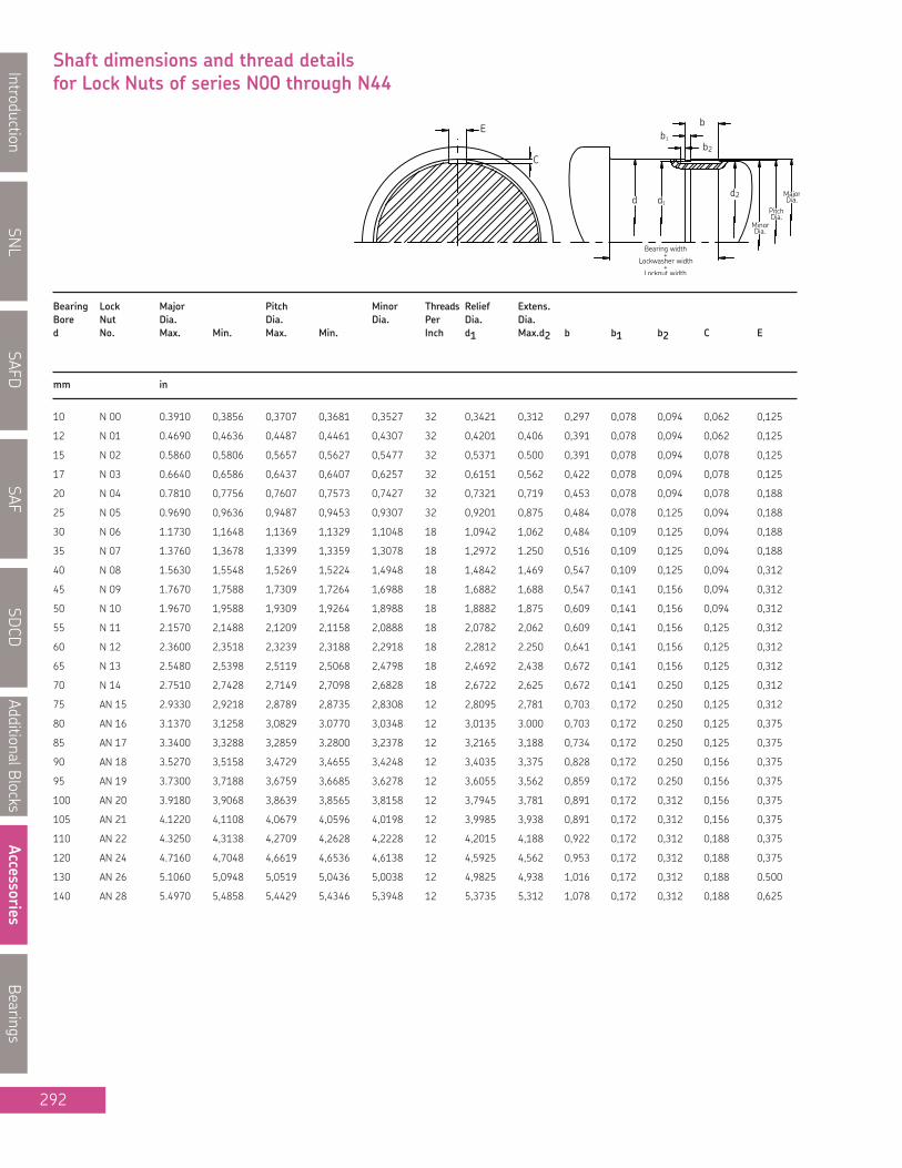
SNL
IntroductionSAFD
SAFSD
CDAdditionalBlocks
AccessoriesBearings
292
Bearing Lock Major Pitch Minor Threads Relief Extens.Bore Nut Dia. Dia. Dia. Per Dia. Dia.d No. Max. Min. Max. Min. Inch d1 Max.d2 b b1 b2 C E
mm in
10 N 00 0.3910 0,3856 0,3707 0,3681 0,3527 32 0,3421 0,312 0,297 0,078 0,094 0,062 0,125
12 N 01 0.4690 0,4636 0,4487 0,4461 0,4307 32 0,4201 0,406 0,391 0,078 0,094 0,062 0,125
15 N 02 0.5860 0,5806 0,5657 0,5627 0,5477 32 0,5371 0.500 0,391 0,078 0,094 0,078 0,125
17 N 03 0.6640 0,6586 0,6437 0,6407 0,6257 32 0,6151 0,562 0,422 0,078 0,094 0,078 0,125
20 N 04 0.7810 0,7756 0,7607 0,7573 0,7427 32 0,7321 0,719 0,453 0,078 0,094 0,078 0,188
25 N 05 0.9690 0,9636 0,9487 0,9453 0,9307 32 0,9201 0,875 0,484 0,078 0,125 0,094 0,188
30 N 06 1.1730 1,1648 1,1369 1,1329 1,1048 18 1,0942 1,062 0,484 0,109 0,125 0,094 0,188
35 N 07 1.3760 1,3678 1,3399 1,3359 1,3078 18 1,2972 1.250 0,516 0,109 0,125 0,094 0,188
40 N 08 1.5630 1,5548 1,5269 1,5224 1,4948 18 1,4842 1,469 0,547 0,109 0,125 0,094 0,312
45 N 09 1.7670 1,7588 1,7309 1,7264 1,6988 18 1,6882 1,688 0,547 0,141 0,156 0,094 0,312
50 N 10 1.9670 1,9588 1,9309 1,9264 1,8988 18 1,8882 1,875 0,609 0,141 0,156 0,094 0,312
55 N 11 2.1570 2,1488 2,1209 2,1158 2,0888 18 2,0782 2,062 0,609 0,141 0,156 0,125 0,312
60 N 12 2.3600 2,3518 2,3239 2,3188 2,2918 18 2,2812 2.250 0,641 0,141 0,156 0,125 0,312
65 N 13 2.5480 2,5398 2,5119 2,5068 2,4798 18 2,4692 2,438 0,672 0,141 0,156 0,125 0,312
70 N 14 2.7510 2,7428 2,7149 2,7098 2,6828 18 2,6722 2,625 0,672 0,141 0.250 0,125 0,312
75 AN 15 2.9330 2,9218 2,8789 2,8735 2,8308 12 2,8095 2,781 0,703 0,172 0.250 0,125 0,312
80 AN 16 3.1370 3,1258 3,0829 3.0770 3,0348 12 3,0135 3.000 0,703 0,172 0.250 0,125 0,375
85 AN 17 3.3400 3,3288 3,2859 3.2800 3,2378 12 3,2165 3,188 0,734 0,172 0.250 0,125 0,375
90 AN 18 3.5270 3,5158 3,4729 3,4655 3,4248 12 3,4035 3,375 0,828 0,172 0.250 0,156 0,375
95 AN 19 3.7300 3,7188 3,6759 3,6685 3,6278 12 3,6055 3,562 0,859 0,172 0.250 0,156 0,375
100 AN 20 3.9180 3,9068 3,8639 3,8565 3,8158 12 3,7945 3,781 0,891 0,172 0,312 0,156 0,375
105 AN 21 4.1220 4,1108 4,0679 4,0596 4,0198 12 3,9985 3,938 0,891 0,172 0,312 0,156 0,375
110 AN 22 4.3250 4,3138 4,2709 4,2628 4,2228 12 4,2015 4,188 0,922 0,172 0,312 0,188 0,375
120 AN 24 4.7160 4,7048 4,6619 4,6536 4,6138 12 4,5925 4,562 0,953 0,172 0,312 0,188 0,375
130 AN 26 5.1060 5,0948 5,0519 5,0436 5,0038 12 4,9825 4,938 1,016 0,172 0,312 0,188 0.500
140 AN 28 5.4970 5,4858 5,4429 5,4346 5,3948 12 5,3735 5,312 1,078 0,172 0,312 0,188 0,625
Shaft dimensions and thread detailsfor Lock Nuts of series N00 through N44

SNL
Introduction
SAFD
SAF
SDCD
AdditionalB
locks
Accessories
Bearings
293
Bearing Lock Major Pitch Minor Threads Relief Extens.Bore Nut Dia. Dia. Dia. Per Dia. Dia.d No. Max. Min. Max. Min. Inch d1 Max.d2 b b1 b2 C E
mm in
150 AN 30 5.8880 5,8768 5,8339 5,8256 5,7858 12 5,7645 5,719 1,141 0,172 0,375 0,219 0,625
160 AN 32 6.2840 6,2728 6,2028 6,1937 6,1306 8 6,1093 6,125 1,203 0,266 0,375 0,234 0,625
170 AN 34 6.6590 6,6478 6,5778 6,5687 6,5056 8 6,4843 6.500 1,234 0,266 0,375 0,234 0.750
180 AN 36 7.0660 7,0548 6,9848 6,9757 6,9126 8 6,8913 6,906 1,266 0,266 0,375 0,234 0.750
190 AN 38 7.4720 7,4608 7,3908 7,3817 7,3186 8 7,2973 7,312 1,297 0,266 0,375 0,234 0.750
200 AN 40 7.8470 7,8358 7,7658 7,7544 7,6936 8 7,6723 7,688 1,359 0,266 0,375 0,234 0,875
220 N 44 8.6280 8,6168 8,5468 8,5347 8,4746 8 8,4533 8,312 1,391 0,266 0,188 0,375 1,062
Shaft dimensions and thread detailsfor Lock Nuts of series N00 through N44

SNL
IntroductionSAFD
SAFSD
CDAdditionalBlocks
AccessoriesBearings
294
Bearing Lock Major Pitch Minor Threads Relief Extens.Bore Nut Dia. Dia. Dia. Per Dia. Dia.d No. Max. Min. Max. Min. Inch d1 Max.d2 b b1 b2 C E
mm in
110 N 022 4.3250 4,3138 4,2709 4,2626 4,2228 12 4,2015 4,188 0,922 0,172 0,312 0,188 0,375
120 N 024 4.7160 4,7048 4,6619 4,6536 4,6138 12 4,5925 4,562 0,953 0,172 0,312 0,188 0,375
130 N 026 5.1060 5,0948 5,0519 5,0436 5,0038 12 4,9825 4,938 1,016 0,172 0,312 0,188 0.500
140 N 028 5.4970 5,5006 5,4429 5,4346 5,3948 12 5,3735 5,312 1,078 0,172 0,312 0,188 0,625
150 N 030 5.8880 5,8768 5,8339 5,8256 5,7858 12 5,7645 5,719 1,141 0,172 0,375 0,219 0,625
160 N 032 6.2840 6,2688 6,2028 6,1937 6,1306 8 6,1093 6,125 1,203 0,266 0,375 0,234 0,625
170 N 034 6.6590 6,6438 6,5778 6,5687 6,5056 8 6,4843 6.500 1,234 0,266 0,375 0,234 0.750
180 N036 7.0660 7,0508 6,9848 6,9757 6,9126 8 6,8913 6,906 1,266 0,266 0,375 0,234 0.750
190 N 038 7.4720 7,4568 7,3908 7,3817 7,3186 8 7,2973 7,312 1,297 0,266 0,375 0,234 0.750
200 N 040 7.8470 7,8318 7,7658 7,7544 7,6936 8 7,6723 7,688 1,359 0,266 0,375 0,234 0,875
220 N 044 8.6280 8,6128 8,5468 8,5347 8,4746 8 8,4533 8,312 1,391 0,266 0,188 0,375 1,062
240 N 048 9.4420 9,4218 9,3337 9,3213 9,2374 6 9,2005 9,188 1,734 0,266 - 0,438 1,125
260 N 052 10.1920 10,1718 10,0837 10,0707 9,9874 6 9,9505 9,938 1,797 0,266 - 0,438 1,188
280 N 056 11.0040 10,9838 10,8957 10,8827 10,7994 6 10,7625 10.750 1,891 0,266 - 0,438 1.250
300 N 060 11.7850 11,7648 11,6767 11,6637 11,5804 6 11,5435 11.500 1,953 0,266 - 0,438 1,375
320 N 064 12.5620 12,5418 12,4537 12,4402 12,3574 6 12,3205 12,312 2,047 0,266 - 0,438 1,438
340 N 068 13.3030 13.2870 13.2030 13.1870 13.0830 5 13.0460 13,062 2,172 0,266 - 0,438 1.500
360 N 072 14.1340 14.1180 14.0340 14.0180 13.9140 5 13.8770 13,812 2,172 0,266 - 0.500 1.500
380 N 076 14.9210 14.9050 14.8210 14.8050 14.7010 5 14.6640 14,625 2,297 0,266 - 0.500 1.500
400 N 080 15.7090 15.6930 15.6090 15.5930 15.4890 5 15.4520 15,375 2,453 0,266 - 0.500 1,625
420 N 084 16.4960 16.4800 16.3960 16.3800 16.2760 5 16.2390 16,188 2,453 0,266 - 0.500 1,625
440 N 088 17.2830 17.2670 17.1830 17.1670 17.0630 5 17.0260 17.000 2,766 0,266 - 0.500 1,812
460 N 092 18.0710 18.0550 17.9710 17.9550 17.8510 5 17.8140 17.750 2,766 0,266 - 0.500 1,812
480 N 096 18.8580 18.8420 18.7580 18.7420 18.6380 5 18.6010 18.500 2,766 0,266 - 0.500 1,812
Shaft dimensions and thread detailsfor Lock Nuts Light section of series N022 through N096

D
B
d
Bearing Designation Dimensions Basic Load Ratings Speed Limit Mass
Dynamic Static
Cylindrical Bore Tapered Bore d D B C Cº Ref. Limit
mm/in kN/lb r/min kg/lb
1205E 1205EK 25 52 15 14.3 4.0 28 000 18 000 0.14
0.9843 2.0472 0.5906 3 215 899 0.31
1206E 1206EK 30 62 16 15.6 4.65 24 000 15 000 0.22
1.1811 2.4409 0.6299 3 507 1 045 0.49
1207E 1207EK 35 72 17 19.0 6.0 20 000 13 000 0.32
1.3780 2.8346 0.6693 4 271 1 349 0.71
1208E 1208EK 40 80 18 19.9 6.95 18 000 11 000 0.42
1.5748 3.1496 0.7087 4 474 1 562 0.93
1209E 1209EK 45 85 19 22.9 7.8 17 000 11 000 0.47
1.7717 3.3465 0.7480 5 148 1 753 1.04
1210E 1210EK 50 90 20 26.5 9.15 16 000 10 000 0.53
1.9685 3.5433 0.7874 5 957 2 057 1.17
1211E 1211EK 55 100 21 27.6 10.6 14 000 9 000 0.71
2.1654 3.9370 0.8268 6 204 2 383 1.57
1212E 1212EK 60 110 22 31.2 12.2 12 000 8 500 0.90
2.3622 4.3307 0.8661 7 014 2 743 1.98
1213E 1213EK 65 120 23 35.1 14.0 11 000 7 000 1.15
2.5591 4.7244 0.9055 7 890 3 147 2.54
1215 1215K 75 130 25 39.0 15.6 10 000 6 700 1.35
2.9528 5.1181 0.9843 8 767 3 507 2.98
1216 1216K 80 140 26 39.7 17.0 9 500 6 000 1.65
3.1496 5.5118 1.0236 8 925 3 822 3.64
1217 1217K 85 150 28 48.8 20.8 9 000 5 600 2.05
3.3465 5.9055 1.1024 10 970 4 676 4.52
1218 1218K 90 160 30 57.2 23.6 8 500 5 300 2.50
3.5433 6.2992 1.1811 12 859 5 305 5.51
1219 1219K 95 170 32 63.7 27.0 8 000 5 000 3.10
3.7402 6.6929 1.2598 14 320 6 070 6.84
1220 1220K 100 180 34 68.9 30.0 7 500 4 800 3.70
3.9370 7.0866 1.3386 15 489 6 744 8.16
1222 1222K 110 200 38 88.4 39.0 6 700 4 300 5.15
4.3307 7.8740 1.4961 19 872 8 767 11.36
SNL
Introduction
SAFD
SAF
SDCD
AdditionalBlocks
Accessories
Bearings
295
Self-Aligning Ball BearingsSeries 12

SNL
IntroductionSAFD
SAFSDCD
AdditionalBlocksAccessories
Bearings
296
Bearing Designation Dimensions Basic Load Ratings Speed Limit Mass
Dynamic Static
Cylindrical Bore Tapered Bore d D B C Cº Ref. Limit
D
B
d
1305 E 1305 EK 25 62 17 19.0 5.4 22 000 15 000 0.26
0.9843 2.4409 0.6693 4 271 1 214 0.57
1306 E 1306 EK 30 72 19 22.5 6.8 19 000 13 000 0.39
1.1811 2.8346 0.7480 5 058 1 529 0.86
1307 E 1307 EK 35 80 21 26.5 8.5 16 000 11 000 0.51
1.3780 3.1496 0.8268 5 957 1 911 1.12
1308 E 1308 EK 40 90 23 33.8 11.2 14 000 9 500 0.72
1.5748 3.5433 0.9055 7 598 2 518 1.59
1309 E 1309 EK 45 100 25 39.0 13.4 12 000 8 500 0.96
1.7717 3.9370 0.9843 8 767 3 012 2.12
1310 E 1310 EK 50 110 27 43.6 14.0 12 000 8 000 1.20
1.9685 4.3307 1.0630 9 801 3 147 2.65
1311 E 1311 EK 55 120 29 50.7 18.0 11 000 7 500 1.60
2.1654 4.7244 1.1417 11 397 4 046 3.53
1312 E 1312 EK 60 130 31 58.5 22.0 9 000 6 300 1.95
2.3622 5.1181 1.2205 13 151 4 946 4.30
1313 E 1313 EK 65 140 33 65.0 25.5 8 500 6 000 2.45
2.5591 5.5118 1.2992 14 612 5 732 5.40
1314 - 70 150 35 74.1 27.5 8 500 6 000 3.00
2.7559 5.9055 1.3780 16 658 6 182 6.62
1315 1315 EK 75 160 37 79.3 30.0 8 000 5 600 3.55
2.9528 6.2992 1.4567 17 827 6 744 7.83
1316 1316 K 80 170 39 88.4 33.5 7 500 5 300 4.20
3.1496 6.6929 1.5354 19 872 7 531 9.26
1317 1317 K 85 180 41 97.5 38.0 7 000 4 800 5.00
3.3465 7.0866 1.6142 21 918 8 542 11.03
1318 1318 K 90 190 43 117.0 44.0 6 700 4 500 5.80
3.5433 7.4803 1.6929 26 302 9 891 12.79
1320 1320 K 100 215 47 143.0 57.0 6 000 4 000 8.30
3.9370 8.4646 1.8504 32 146 12 814 18.30
1322 1322 K 110 240 50 163.0 72.0 5 300 3 600 12.0
4.3307 9.4488 1.9685 36 642 16 186 26.46
Self-Aligning Ball BearingsSeries 13
mm/in kN/lb r/min kg/lb

D
B
d
SNL
Introduction
SAFD
SAF
SDCD
AdditionalBlocks
Accessories
Bearings
297
Self-Aligning Ball BearingsSeries 22
Bearing Designation Dimensions Basic Load Ratings Speed Limit Mass
Dynamic Static
Cylindrical Bore Tapered Bore d D B C Cº Ref. Limit
mm/in kN/lb r/min kg/lb
2205 E 2205 EK 25 52 18 16.8 4.4 26 000 18 000 0.16
0.9843 2.0472 0.7087 3 777 989 0.35
2206 E 2206 EK 30 62 20 23.8 6.7 22 000 15 000 0.26
1.1811 2.4409 0.7874 5 350 1 506 0.57
2207 E 2207 EK 35 72 23 30.7 8.8 18 000 12 000 0.40
1.3780 2.8346 0.9055 6 901 1 978 0.88
2208 E 2208 EK 40 80 23 31.9 10.0 16 000 11 000 0.51
1.5748 3.1496 0.9055 7 171 2 248 1.12
2209 E 2209 EK 45 85 23 32.5 10.6 15 000 10 000 0.55
1.7717 3.3465 0.9055 7 306 2 383 1.21
2210 E 2210 EK 50 90 23 33.8 11.2 14 000 9 500 0.60
1.9685 3.5433 0.9055 7 598 2 518 1.32
2211 E 2211 EK 55 100 25 39.0 13.4 12 000 8 500 0.81
2.1654 3.9370 0.9843 8 767 3 012 1.79
2212 E 2212 EK 60 110 28 48.8 17.0 11 000 8 000 1.10
2.3622 4.3307 1.1024 10 970 3 822 2.43
2213 E 2213 EK 65 120 31 57.2 20.0 10 000 7 000 1.45
2.5591 4.7244 1.2205 12 859 4 496 3.20
2215 E 2215 EK 75 130 31 58.5 22.0 9 000 6 300 1.60
2.9528 5.1181 1.2205 13 151 4.946 3.53
2216 E 2216 EK 80 140 33 65.0 25.5 8 500 6 000 2.00
3.1496 5.5118 1.2992 14 612 5 732 4.41
2217 2217 K 85 150 36 58.5 23.6 8 000 5 600 2.50
3.3465 5.9055 1.4173 13 151 5 305 5.51
2218 2218 K 90 160 40 70.2 28.5 7 500 5 300 3.40
3.5433 6.2992 1.5748 15 782 6 407 7.50
2219 2219 K 95 170 43 83.2 34.5 7 000 5 000 4.10
3.7402 6.6929 1.6929 18 703 7 756 9.04
2220 2220 K 100 180 46 97.5 40.5 6 700 4 800 5.00
3.9370 7.0866 1.8110 21 918 9 104 11.03
2222 2222 K 110 200 53 124.0 52.0 6 000 4 300 7.10
4.3307 7.8740 2.0866 27 875 11 690 15.66

SNL
IntroductionSAFD
SAFSDCD
AdditionalBlocksAccessories
Bearings
D
B
d
Self-Aligning Ball BearingsSeries 23
Bearing Designation Dimensions Basic Load Ratings Speed Limit Mass
Dynamic Static
Cylindrical Bore Tapered Bore d D B C Cº Ref. Limit
mm/in kN/lb r/min kg/lb
2306 2306 K 30 72 27 31,2 8.80 18 000 13 000 0.50
1.1811 2.8346 1.0630 7 014 1 978 1.10
2307 E 2307 EK 35 80 31 39.7 11.20 16 000 12 000 0.68
1.3780 3.1496 1.2205 8 925 2 518 1.50
2308 E 2308 EK 40 90 33 54.0 16.0 14 000 10 000 0.93
1.5748 3.5433 1.2992 12 139 3 597 2.05
2309 E 2309 EK 45 100 36 64.0 19.3 13 000 9 000 1.25
1.7717 3.9370 1.4173 14 387 4 339 2.76
2310 2310 K 50 110 40 63.7 20.0 14 000 9 500 1.65
1.9685 4.3307 1.5748 14 320 4 496 3.64
2311 2311 K 55 120 43 76.1 24.0 11 000 7 500 2.10
2.1654 4.7244 1.6929 17 107 5 395 4.63
2312 2312 K 60 130 46 87.1 28.5 9 500 7 000 2.60
2.3622 5.1181 1.8110 19 580 6 407 5.73
2313 2313 K 65 140 48 95.6 32.5 9 000 6 300 3.25
2.5591 5.5118 1.8898 21 491 7 306 7.17
2315 2315 K 75 160 55 124.0 43.0 7 500 5 600 4.70
2.9528 6.2992 2.1654 27 875 9 666 10.36
2316 2316 K 80 170 58 135.0 49.0 7 000 5 300 6.10
3.1496 6.6929 2.2835 30 348 11 015 13.45
2317 2317 K 85 180 60 140.0 51.0 6 700 4 800 7.05
3.3465 7.0866 2.3622 31 472 11 465 15.55
2320 2320 K 100 215 73 190.0 80.0 5 600 4 000 12.5
3.9370 8.4646 2.8740 42 712 17 984 27.56
298

SNL
Introduction
SAFD
SAF
SDCD
AdditionalBlocks
Accessories
Bearings
D
B
d d
21308 E 21308 EK 40 90 23 5.5 104 108 7 000 9 500 0.75
1.5748 3.5433 0.9055 0.22 23 379 24 278 1.65
21309 E 21309 EK 45 100 25 5.5 125 127 6 300 8 500 0.99
1.7717 3.9370 0.9843 0.22 28 100 28 550 2.18
21310 E 21310 EK 50 110 27 5.5 156 166 5 600 7 500 1.35
1.9685 4.3307 1.0630 0.22 35 069 37 317 2.98
21311 E 21311 EK 55 120 29 5.5 156 166 5 600 7 500 1.70
2.1654 4.7244 1.1417 0.22 35 069 37 317 3.75
21312 E 21312 EK 60 130 31 5.5 212 240 4 800 6 300 2.10
2.3622 5.1181 1.2205 0.22 47 658 53 952 4.63
21313 E 21313 EK 65 140 33 5.5 236 270 4 300 6 000 2.55
2.5591 5.5118 1.2992 0.22 53 053 60 696 5.62
21315 E 21315 EK 75 160 37 5.5 285 325 4 000 5 600 3.75
2.9528 6.2992 1.4567 0.22 64 068 73 060 8.27
21316 E 21316 EK 80 170 39 5.5 325 375 3 800 5 300 4.45
3.1496 6.6929 1.5354 0.22 73 060 84 300 9.81
21317 E 21317 EK 85 180 41 5.5 325 375 3 800 5 300 5.20
3.3465 7.0866 1.6142 0.22 73 060 84 300 11.47
21320 E 21320 EK 100 215 47 8.3 425 490 3 400 4 500 8.60
3.9370 8.4646 1.8504 0.33 95 540 110 152 18.96
Bearing Designation Dimensions W33 Basic Load Ratings Speed Limit MassGrooveWidth Dynamic Static
Cylindical Bore Tapered Bore d D B b C Cº Ref. Limit
mm/in kN/lb r/min kg/lb
299
Spherical Roller BearingsSeries 213

Spherical Roller BearingsSeries 222
22207 E 22207 EK 35 72 23 3.70 86.5 85 9 000 12 000 0.451.3780 2.8346 0.91 0.15 19 445 19 108 0.99
22208 E 22208 EK 40 80 23 5.50 96.5 90 8 000 11 000 0.531.5748 3.1496 0.9055 0.22 21 693 20 232 1.17
22209 E 22209 EK 45 85 23 5.50 102 98 7 500 10 000 0.581.7717 3.3465 0.9055 0.22 22 930 22 030 1.28
22210 E 22210 EK 50 90 23 5.50 104 108 7 000 9 500 0.631.9685 3.5433 0.9055 0.22 23 379 24 278 1.39
22211 E 22211 EK 55 100 25 5.50 125 127 6 300 8 500 0.842.1654 3.9370 0.9843 0.22 28 100 28 550 1.85
22212 E 22212 EK 60 110 28 5.50 156 166 5 600 7 500 1.152.3622 4.3307 1.1024 0.22 35 069 37 317 2.54
22213 E 22213 EK 65 120 31 5.50 193 216 5 000 7 000 1.552.5591 4.7244 1.2205 0.22 43 386 48 557 3.42
22215 E 22215 EK 75 130 31 5.50 212 240 4 800 6 300 1.702.9528 5.1181 1.2205 0.22 47 658 53 952 3.75
22216 E 22216 EK 80 140 33 5.50 236 270 4 300 6 000 2.103.1496 5.5118 1.2992 0.22 53 053 60 696 4.63
22217 E 22217 EK 85 150 36 5.50 285 325 4 000 5 600 2.653.3465 5.9055 1.4173 0.22 64 068 73 060 5.84
22218 E 22218 EK 90 160 40 5.50 325 375 3 800 5 300 3.403.5433 6.2992 1.5748 0.22 73 060 84 300 7.50
22220 E 22220 EK 100 180 46 8.30 425 490 3 400 4 500 4.903.9370 7.0866 1.8110 0.33 95 540 110 152 10.80
22222 E 22222 EK 110 200 53 8.30 560 640 3 000 4 000 7.004.3307 7.8740 2.0866 0.33 125 888 143 872 15.44
22224 E 22224 EK 120 215 58 11.1 630 765 2 800 3 800 8.704.7244 8.4646 2.2835 0.44 141 624 171 972 19.18
22226 E 22226 EK 130 230 64 11.1 735 930 2 600 3 600 11.005.1181 9.0551 2.5197 0.44 165 228 209 064 24.26
22228CC/W33 22228CCK/W33 140 250 68 11.1 710 900 2 400 3200 14.005.5118 9.8425 2.6772 0.44 159 608 202 320 30.87
Bearing Designation Dimensions W33 Basic Load Ratings Speed Limit MassGrooveWidth Dynamic Static
Cylindical Bore Tapered Bore d D B b C Cº Ref. Limit
mm/in kN/lb r/min kg/lb
D
B
d d
SNL
IntroductionSAFD
SAFSDCD
AdditionalBlocksAccessories
Bearings
300

SNL
Introduction
SAFD
SAF
SDCD
AdditionalBlocks
Accessories
Bearings
Spherical Roller BearingsSeries 222
D
B
d d
Bearing Designation Dimensions W33 Basic Load Ratings Speed Limit MassGrooveWidth Dynamic Static
Cylindical Bore Tapered Bore d D B b C Cº Ref. Limit
mm/in kN/lb r/min kg/lb
301
22230CC/W33 22230CCK/W33 150 270 73 13.9 850 1 080 2 200 3 000 18.0
5.9055 10.6299 2.87 0.55 191 080 242 784 39.7
22232CC/W33 22232CCK/W33 160 290 80 13.9 1 000 1 290 2 000 2 800 22.5
6.2992 11.4173 3.1496 0.55 224 800 289 992 49.6
22234CC/W33 22234CCK/W33 170 310 86 16.7 1 120 1 460 1 900 2 600 28.5
6.6929 12.2047 3.3858 0.66 251 776 328 208 62.8
22236CC/W33 22236CCK/W33 180 320 86 16.7 1 180 1 560 1 800 2 600 29.5
7.0866 12.5984 3.3858 0.66 265 264 350 688 65.0
22238CC/W33 22238CCK/W33 190 340 92 16.7 1 270 1 700 1 700 2 400 36.5
7.4803 13.3858 3.6220 0.66 285 496 382 160 80.5
22240CC/W33 22240CCK/W33 200 360 98 16.7 1 460 1 930 1 600 2 200 43.5
7.8740 14.1732 3.8583 0.66 328 208 433 864 95.9
22244CC/W33 22244CCK/W33 220 400 108 16.7 1 760 2 360 1 500 2 000 60.5
8.6614 15.7480 4.2520 0.66 395 648 530 528 133.4

Introduction
Spherical Roller BearingsSeries 223
D
B
d d
22308 E 22308 EK 40 90 33 5.5 150 140 6 000 8 000 1.05
1.5748 3.5433 1.2992 0.22 33 720 31 472 2.32
22309 E 22309 EK 45 100 36 5.5 183 183 5 300 7 000 1.40
1.7717 3.937 1.4173 0.22 41 138 41 138 3.09
22310 E 22310 EK 50 110 40 5.5 220 224 4 800 6 300 1.90
1.9685 4.3307 1.5748 0.22 49 456 50 355 4.19
22311 E 22311 EK 55 120 43 5.5 270 280 4 300 5 600 2.45
2.1654 4.7244 1.6929 0.22 60 696 62 944 5.40
22312 E 22312 EK 60 130 46 8.3 310 335 4 000 5 300 3.10
2.3622 5.1181 1.811 0.33 69 688 75 308 6.84
22313 E 22313 EK 65 140 48 8.3 340 360 3 800 5 000 3.75
2.5591 5.5118 1.8898 0.33 76 432 80 928 8.27
22314 E 22314 EK 70 150 51 8.3 400 430 3 400 4 500 4.55
2.7559 5.9055 2.0079 0.33 89 920 96 664 10.03
22315 E 22315 EK 75 160 55 8.3 440 475 3 200 4 300 5.55
2.9528 6.2992 2.1654 0.33 98 912 106 780 12.24
22316 E 22316 EK 80 170 58 8.3 490 540 3 000 4 000 6.60
3.1496 6.6929 2.2835 0.33 110 152 121 392 14.55
22317 E 22317 EK 85 180 60 8.3 550 620 2 800 3 800 7.65
3.3465 7.0866 2.3622 0.33 123 640 139 376 16.87
22318 E 22318 EK 90 190 64 11.1 610 695 2 600 3 600 9.05
3.5433 7.4803 2.5197 0.44 137 128 156 236 19.96
22319 E 22319 EK 95 200 67 11.1 670 765 2 600 3 400 10.50
3.7402 7.874 2.6378 0.44 150 616 171 972 23.15
22320 E 22320 EK 100 215 73 11.1 815 950 2 400 3 000 13.50
3.937 8.4646 2.874 0.44 183 212 213 560 29.77
22322 E 22322 EK 110 240 80 13.9 950 1 120 2 000 2 800 18.40
4.3307 9.4488 3.1496 0.55 213 560 251 776 40.57
Bearing Designation Dimensions W33 Basic Load Ratings Speed Limit MassGrooveWidth Dynamic Static
Cylindical Bore Tapered Bore d D B b C Cº Ref. Limit
mm/in kN/lb r/min kg/lb
SNL
SAFDSAF
SDCD
AdditionalBlocksAccessories
Bearings
302

SNL
Introduction
SAFD
SAF
SDCD
AdditionalBlocks
Accessories
Bearings
Spherical Roller BearingsSeries 223
D
B
d d
22324CC/W33 22324CCK/W33 120 260 86 13,9 965 1 120 2 000 2 600 23.00
4.7244 10.236 3.3858 0.55 216 932 251 776 50.72
22326CC/W33 22326CCK/W33 130 280 93 16.7 1 120 1 320 1 800 2 400 29.00
5.1181 11.024 3.6614 0.66 251 776 296 736 63.95
22328CC/W33 22328CCK/W33 140 300 102 16.7 1 290 1 560 1 700 2 200 36.50
5.5118 11.811 4.0157 0.66 289 992 350 688 80.50
22330CC/W33 22330CCK/W33 150 320 108 16.7 1 460 1 760 1 600 2 000 43.50
5.9055 12.5984 4.252 0.66 328 208 395 648 95.90
22332CC/W33 22332CCK/W33 160 340 114 16.7 1 600 1 960 1 500 1 900 52.00
6.2992 13.3858 4.4882 0.66 359 680 440 608 115.00
22334CC/W33 22334CCK/W33 170 360 120 16.7 1 760 2 160 1 400 1 800 61.00
6.6929 14.1732 4.7244 0.66 395 648 485 568 135.00
22336CC/W33 22336CCK/W33 180 380 126 22.3 2 000 2 450 1 300 1 700 71.50
7.0866 14.9606 4.9606 0.88 449 600 550 760 158.00
22338CC/W33 22338CCK/W33 190 400 132 22.3 2 120 2 650 1 200 1 600 82.50
7.4803 15.748 5.1969 0.88 476 576 595 720 182.00
22340CC/W33 22340CCK/W33 200 420 138 22.3 2 320 2 900 1 200 1 500 95.00
7.874 16.5354 5.4331 0.88 521 536 651 920 210.00
Bearing Designation Dimensions W33 Basic Load Ratings Speed Limit MassGrooveWidth Dynamic Static
Cylindical Bore Tapered Bore d D B b C Cº Ref. Limit
mm/in kN/lb r/min kg/lb
303

AdditionalBlocks
Spherical Roller BearingsSeries 230
D
B
d d
23024CC/W33 23024CCK/W33 120 180 46 5.50 355 510 3 200 4 000 4.204.7244 7.0866 1.8110 0.22 79 804 114 648 9.30
23026CC/W33 23026CCK/W33 130 200 52 8.30 430 610 2 800 3 600 6.005.1181 7.8740 2.0472 0.33 96 664 137 128 13.20
23028CC/W33 23028CCK/W33 140 210 53 8.30 465 680 2 600 3 400 6.555.5118 8.2677 2.0866 0.33 104 532 152 864 14.40
23030CC/W33 23030CCK/W33 150 225 56 8.30 510 750 2 400 3 200 7.955.9055 8.8583 2.2047 0.33 114 648 168 600 17.50
23032CC/W33 23032CCK/W33 160 240 60 11.1 585 880 2 400 3 000 9.706.2992 9.4488 2.3622 0.44 131 508 197 824 21.40
23034CC/W33 23034CCK/W33 170 260 67 11.1 710 1 060 2 200 2 800 13.006.6929 10.2362 2.6378 0.44 159 608 238 288 28.70
23036CC/W33 23036CCK/W33 180 280 74 13.9 830 1 250 2 000 2 600 17.007.0866 11.0236 2.9134 0.55 186 584 281 000 37.50
23038CC/W33 23038CCK/W33 190 290 75 13.9 865 1340 1 900 2 400 18.007.4803 11.4173 2.9528 0.55 194 452 301 232 39.70
23040CC/W33 23040CCK/W33 200 310 82 13.9 1 000 1 530 1 800 2 200 23.307.8740 12.2047 3.2283 0.55 224 800 343 944 51.40
23044CC/W33 23044CCK/W33 220 340 90 13.9 1 220 1 860 1 600 2 000 30.508.6614 13.3858 3.5433 0.55 274 256 418 128 67.30
23048CC/W33 23048CCK/W33 240 360 92 13.9 1 290 2 080 1 500 1 900 33.509.4488 14.1732 3.6220 0.55 289 992 467 584 73.90
23052CC/W33 23052CCK/W33 260 400 104 16.7 1 600 2 550 1 300 1 700 48.5010.2362 15.7480 4.0945 0.66 359 680 573 240 106.90
23056CC/W33 23056CCK/W33 280 420 106 16.7 1 730 2 850 1 300 1 600 52.5011.0236 16.5354 4.1732 0.66 388 904 640 680 115.80
23060CC/W33 23060CCK/W33 300 460 118 16.7 2 120 3 450 1 200 1 500 71.5011.8110 18.1102 4.6457 0.66 476 576 775 560 157.70
23064CC/W33 23064CCK/W33 320 480 121 16.7 2 240 3 800 1 100 1 400 78.0012.5984 18.8976 4.7638 0.66 503 552 854 240 172.00
23068CC/W33 23068CCK/W33 340 520 133 22.3 2 700 4 550 1 000 1 300 105.0013.3858 20.4724 5.2362 0.88 606 960 1 022 840 231.50
Bearing Designation Dimensions W33 Basic Load Ratings Speed Limit MassGrooveWidth Dynamic Static
Cylindical Bore Tapered Bore d D B b C Cº Ref. Limit
mm/in kN/lb r/min kg/lb
SNL
IntroductionSAFD
SAFSDCD
AccessoriesBearings
304
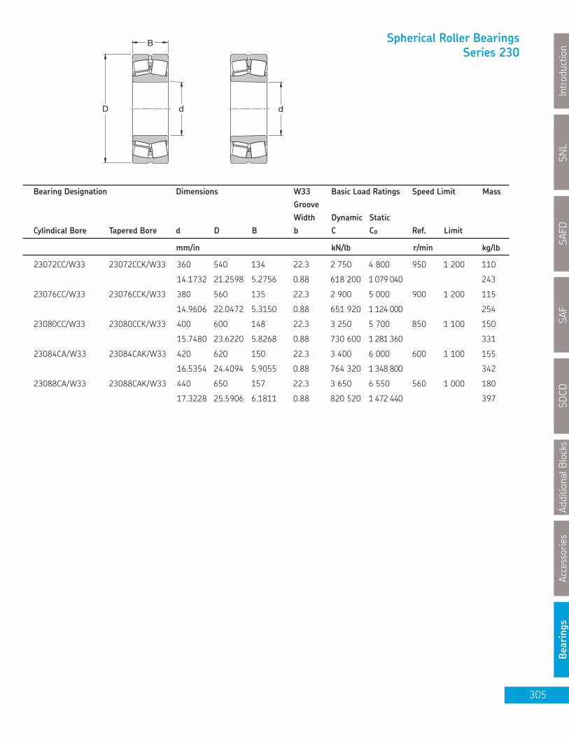
Spherical Roller BearingsSeries 230
D
B
d d
23072CC/W33 23072CCK/W33 360 540 134 22.3 2 750 4 800 950 1 200 110
14.1732 21.2598 5.2756 0.88 618 200 1 079 040 243
23076CC/W33 23076CCK/W33 380 560 135 22.3 2 900 5 000 900 1 200 115
14.9606 22.0472 5.3150 0.88 651 920 1 124 000 254
23080CC/W33 23080CCK/W33 400 600 148 22.3 3 250 5 700 850 1 100 150
15.7480 23.6220 5.8268 0.88 730 600 1 281 360 331
23084CA/W33 23084CAK/W33 420 620 150 22.3 3 400 6 000 600 1 100 155
16.5354 24.4094 5.9055 0.88 764 320 1 348 800 342
23088CA/W33 23088CAK/W33 440 650 157 22.3 3 650 6 550 560 1 000 180
17.3228 25.5906 6.1811 0.88 820 520 1 472 440 397
Bearing Designation Dimensions W33 Basic Load Ratings Speed Limit MassGrooveWidth Dynamic Static
Cylindical Bore Tapered Bore d D B b C Cº Ref. Limit
mm/in kN/lb r/min kg/lb
SNL
Introduction
SAFD
SAF
SDCD
AdditionalBlocks
Accessories
Bearings
305

SAFSDCD
AdditionalBlocksAccessories
Bearings
Spherical Roller BearingsSeries 231
D
B
d d
23134CC/W33 23134CCK/W33 170 280 88 13.9 1 040 1 500 1 800 2 400 22.006.6929 11.0236 3.4646 0.50 233 792 337 200 48.50
23136CC/W33 23136CCK/W33 180 300 96 13.9 1 200 1 760 1 700 2 200 28.007.0866 11.8110 3.7795 0.50 269 760 395 648 61.70
23138CC/W33 23138CCK/W33 190 320 104 13.9 1 370 2 080 1 500 2 000 35.007.4803 12.5984 4.0945 0.50 307 976 467 584 77.20
23140CC/W33 23140CCK/W33 200 340 112 16.7 1 600 2 360 1 500 1 900 43.007.8740 13.3858 4.4094 0.70 359 680 530 528 94.80
23144CC/W33 23144CCK/W33 220 370 120 16.7 1 800 2 750 1 300 1 700 53.508.6614 14.5669 4.7244 0.70 404 640 618 200 118.50
23148CC/W33 23148CCK/W33 240 400 128 16.7 2 080 3 200 1 200 1 600 66.509.4488 15.7480 5.0394 0.70 467 584 719 360 146.60
23152CC/W33 23152CCK/W33 260 440 144 16.7 2 550 3 900 1 100 1 400 90.5010.2362 17.3228 5.6693 0.70 573 240 876 720 199.60
23156CC/W33 23156CCK/W33 280 460 146 16.7 2 650 4 250 1 000 1 300 97.0011.0236 18.1102 5.7480 0.70 595 720 955 400 214.00
23160CC/W33 23160CCK/W33 300 500 160 16.7 3 200 5 100 950 1 200 125.0011.8110 19.6850 6.2992 0.70 719 360 1 146 480 275.60
23164CC/W33 23164CCK/W33 320 540 176 22.3 3 750 6 000 850 1 100 165.0012.5984 21.2598 6.9291 0.90 843 000 1 348 800 363.80
23168CC/W33 23168CCK/W33 340 580 190 22.3 4 250 6 800 800 1 000 210.0013.3858 22.8346 7.4803 0.90 955 400 1 528 640 463.10
23172CC/W33 23172CCK/W33 360 600 192 22.3 4 300 6 950 750 1 000 220.0014.1732 23.6220 7.5591 0.90 966 640 1 562 360 485.10
23176CA/W33 23176CAK/W33 380 620 194 22,3 4 400 7 100 560 1 000 230.0014.9606 24.4094 7.6378 0.90 989 120 1 596 080 507.20
23180CA/W33 23180CAK/W33 400 650 200 22.3 4 650 7 650 530 950 265.0015.7480 25.5906 7.8740 0.90 1 045 320 1 719 720 584.30
23184CJ/W33 23184CKJ/W33 420 700 224 22.3 5 600 9 300 480 900 350.0016.5354 27.5591 8.8189 0.90 1 258 880 2 090 640 771.80
23188CA/W33 23188CAK/W33 440 720 226 22.3 6 000 10 000 450 850 360.0017.3228 28.3465 8.8976 0.90 1 348 800 2 248 000 793.80
Bearing Designation Dimensions W33 Basic Load Ratings Speed Limit MassGrooveWidth Dynamic Static
Cylindical Bore Tapered Bore d D B b C Cº Ref. Limit
mm/in kN/lb r/min kg/lb
306
SNL
IntroductionSAFD
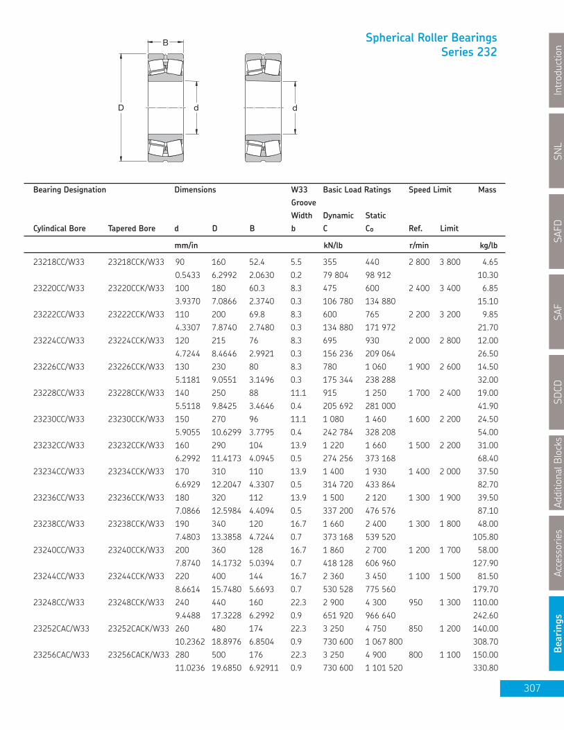
SAF
SDCD
AdditionalBlocks
Accessories
Bearings
Spherical Roller BearingsSeries 232
D
B
d d
23218CC/W33 23218CCK/W33 90 160 52.4 5.5 355 440 2 800 3 800 4.650.5433 6.2992 2.0630 0.2 79 804 98 912 10.30
23220CC/W33 23220CCK/W33 100 180 60.3 8.3 475 600 2 400 3 400 6.853.9370 7.0866 2.3740 0.3 106 780 134 880 15.10
23222CC/W33 23222CCK/W33 110 200 69.8 8.3 600 765 2 200 3 200 9.854.3307 7.8740 2.7480 0.3 134 880 171 972 21.70
23224CC/W33 23224CCK/W33 120 215 76 8.3 695 930 2 000 2 800 12.004.7244 8.4646 2.9921 0.3 156 236 209 064 26.50
23226CC/W33 23226CCK/W33 130 230 80 8.3 780 1 060 1 900 2 600 14.505.1181 9.0551 3.1496 0.3 175 344 238 288 32.00
23228CC/W33 23228CCK/W33 140 250 88 11.1 915 1 250 1 700 2 400 19.005.5118 9.8425 3.4646 0.4 205 692 281 000 41.90
23230CC/W33 23230CCK/W33 150 270 96 11.1 1 080 1 460 1 600 2 200 24.505.9055 10.6299 3.7795 0.4 242 784 328 208 54.00
23232CC/W33 23232CCK/W33 160 290 104 13.9 1 220 1 660 1 500 2 200 31.006.2992 11.4173 4.0945 0.5 274 256 373 168 68.40
23234CC/W33 23234CCK/W33 170 310 110 13.9 1 400 1 930 1 400 2 000 37.506.6929 12.2047 4.3307 0.5 314 720 433 864 82.70
23236CC/W33 23236CCK/W33 180 320 112 13.9 1 500 2 120 1 300 1 900 39.507.0866 12.5984 4.4094 0.5 337 200 476 576 87.10
23238CC/W33 23238CCK/W33 190 340 120 16.7 1 660 2 400 1 300 1 800 48.007.4803 13.3858 4.7244 0.7 373 168 539 520 105.80
23240CC/W33 23240CCK/W33 200 360 128 16.7 1 860 2 700 1 200 1 700 58.007.8740 14.1732 5.0394 0.7 418 128 606 960 127.90
23244CC/W33 23244CCK/W33 220 400 144 16.7 2 360 3 450 1 100 1 500 81.508.6614 15.7480 5.6693 0.7 530 528 775 560 179.70
23248CC/W33 23248CCK/W33 240 440 160 22.3 2 900 4 300 950 1 300 110.009.4488 17.3228 6.2992 0.9 651 920 966 640 242.60
23252CAC/W33 23252CACK/W33 260 480 174 22.3 3 250 4 750 850 1 200 140.0010.2362 18.8976 6.8504 0.9 730 600 1 067 800 308.70
23256CAC/W33 23256CACK/W33 280 500 176 22.3 3 250 4 900 800 1 100 150.0011.0236 19.6850 6.92911 0.9 730 600 1 101 520 330.80
Bearing Designation Dimensions W33 Basic Load Ratings Speed Limit MassGrooveWidth Dynamic Static
Cylindical Bore Tapered Bore d D B b C Cº Ref. Limit
mm/in kN/lb r/min kg/lb
307
SNL
Introduction
SAFD

SNL
IntroductionSAFD
SAFSDCD
AdditionalBlocksAccessories
Bearings
Spherical Roller BearingsSeries 232
D
B
d d
23260CAC/W33 23260CACK/W33 300 540 192 22.3 3 900 5 850 750 1 000 190
11.8110 21.2598 7.5591 0.9 876 720 1 315 080 419
23264CAC/W33 23264CACK/W33 320 580 208 22.3 4 400 6 700 700 950 240
12.5984 22.8346 8.1890 0.9 989 120 1 506 160 529
23268CA/W33 23268CAK/W33 340 620 224 22.3 5 100 7 800 560 800 295
13.3858 24.4094 8.8189 0.9 1 146 480 1 753 440 650
23272CA/W33 23272CA/W33 360 650 232 22.3 5 400 8 300 530 750 335
14.1732 25.5906 9.1339 0.9 1 213 920 1 865 840 739
23276CA/W33 23276CA/W33 380 680 240 22.3 5 850 9 150 500 750 375
14.9606 26.7717 9.4488 0.9 1 315 080 2 056 920 827
23280CA/W33 23280CA/W33 400 720 256 22.3 6 550 10 400 480 670 450
15.7480 28.3465 10.0787 0.9 1 472 440 2 337 920 992
Bearing Designation Dimensions W33 Basic Load Ratings Speed Limit MassGrooveWidth Dynamic Static
Cylindical Bore Tapered Bore d D B b C Cº Ref. Limit
mm/in kN/lb r/min kg/lb
308

SNL
Introduction
SAFD
SAF
SDCD
AdditionalBlocks
Accessories
Bearings
Series: CARB®
D
B
d
Bearing Designation Dimensions Basic Load Ratings Speed Limit Mass
Dynamic Static
Cylindrical Bore Tapered Bore d D B C Cº Ref. Limit
mm/in kN/lb r/min kg/lb
C2205/TN9 C2205K/TN9 25 52 18 44 40 13 000 18 000 0.17
0.9843 2.072 0.7086 9 891 8 992 0.37
C2206/TN9 C2206K/TN9 30 62 20 69.5 62 11 000 15 000 0.27
1.1811 2.4409 0.7874 15 624 13 938 0.60
C2207/TN9 C2207K/TN9 35 72 23 83 80 9 500 13 000 0.43
1.3780 2.8346 0.9055 18 658 17 984 0.95
C2208/TN9 C2208K/TN9 40 80 23 90 86,5 8 000 11 000 0.50
1.5748 3.1496 0.9055 20 232 19 445 1.10
C2209/TN9 C2209K/TN9 45 85 23 93 93 8 000 11 000 0.55
1.7717 3.3465 0.9055 20 906 20 906 1.21
C2210/TN9 C2210K/TN9 50 90 23 98 100 7 000 9 500 0.59
1.9685 3.5433 0.9055 22 030 22 480 1.30
C2211/TN9 C2211K/TN9 55 100 25 116 114 6 700 9 000 0.79
2.1654 3.9370 0.9843 26 077 25 627 1.74
C2212/TN9 C2212K/TN9 60 110 28 143 156 5 600 7 500 1.10
2.3622 4.3307 1.1024 32 146 35 069 2.43
C2213/TN9 C2213K/TN9 65 120 31 180 180 5 300 7 500 1.40
2.5591 4.7244 1.2205 40 464 40 464 3.09
C2214/TN9 C2214K/TN9 70 125 31 186 196 5 000 7 000 1.45
2.7559 4.9213 1.2205 41 813 44 061 3.20
C2314 C2314K 70 150 51 405 430 3 800 5 000 4.25
2.7559 5.9055 2.0079 91 044 96 664 9.37
C2215 C2215K 75 130 31 196 208 4 800 6 700 1.60
2.9528 5.1181 1.2205 44 061 46 758 3.53
C2315 C2315K 75 160 55 425 465 3 600 4 800 5.20
2.9528 6.2992 2.1654 95 540 104 532 11.47
C2216 C2216K 80 140 33 220 250 4 500 6 000 2.00
3.1496 5.5118 1.2992 49 456 56 200 4.41
C2316 C2316K 80 170 58 510 550 3 400 4 500 6.20
3.1496 6.6929 2.2835 114 648 123 640 13.67
309

SNL
IntroductionSAFD
SAFSDCD
AdditionalBlocksAccessories
Bearings
D
B
d
Series: CARB®
Bearing Designation Dimensions Basic Load Ratings Speed Limit Mass
Dynamic Static
Cylindrical Bore Tapered Bore d D B C Cº Ref. Limit
mm/in kN/lb r/min kg/lb
C2217 C2217K 85 150 36 275 320 4 300 5 600 2.60
3.3465 5.9055 1.4173 61 820 71 936 5.70
C2317 C2317K 85 180 60 540 600 3 200 4 300 7.30
3.3465 7.0866 2.3622 121 392 134 880 16.1
C2218 C2218K 90 160 40 325 380 3 800 5 300 3.30
3.5433 6.2992 1.5748 73 060 85 424 7.30
C2220 C2220K 100 180 46 415 465 3 600 4 800 4.90
3.9370 7.0866 1.8110 93 292 104 532 10.70
C2320 C2320K 100 215 73 800 880 2 600 3 600 12.50
3.9370 8.4646 2.8740 179 840 197 824 27.60
C2222 C2222K 110 200 53 530 620 3 200 4 300 6.90
4.3307 7.8740 2.0866 119 144 139 376 15.20
C3224 C3224K 120 215 76 750 980 2 400 3 200 11.50
4.7244 8.4646 2.9921 168 600 220 304 25.40
C2226 C2226K 130 230 64 735 930 2 800 3 800 11.00
5.1181 9.0551 2.5197 165 228 209 064 24.30
C2228 C2228K 140 250 68 830 1 060 2 400 3 400 13.80
5.5118 9.8425 2.6772 186 584 238 288 30.40
C2230 C2230K 150 270 73 980 1 220 2 400 3 200 17.50
5.9055 10.6299 2.8740 220 304 274 256 38.60
C3232 C3232K 160 290 104 1 370 1 830 1 700 2 400 28.50
6.2992 11.4173 4.0945 307 976 411 384 62.80
310

SNL
Introduction
SAFD
SAF
SDCD
AdditionalBlocks
Accessories
Bearings
Decimals of a millimeter into decimals of an inch0 0.01 0.02 0.03 0.04 0.05 0.06 0.07 0.08 0.09
milli- Milli-meter in. in. in. in. in. in. in. in. in. in. meter
0 …… 0.00039 0.00079 0.00118 0.00157 0.00197 0.00236 0.00276 0.00315 0.00354 0
0.001 0.00004 0.00043 0.00083 0.00122 0.00161 0.00201 0.00240 0.00280 0.00319 0.00358 0.001
0.002 0.00008 0.00047 0.00087 0.00126 0.00165 0.00205 0.00244 0.00283 0.00323 0.00362 0.002
0.003 0.00012 0.00051 0.00091 0.00130 0.00169 0.00209 0.00248 0.00287 0.00327 0.00366 0.003
0.004 0.00016 0.00055 0.00094 0.00134 0.00173 0.00213 0.00252 0.00291 0.00331 0.00370 0.004
0.005 0.00020 0.00059 0.00098 0.00138 0.00177 0.00217 0.00256 0.00295 0.00335 0.00374 0.005
0.006 0.00024 0.00063 0.00102 0.00142 0.00181 0.00220 0.00260 0.00299 0.00339 0.00378 0.006
0.007 0.00028 0.00067 0.00106 0.00146 0.00185 0.00224 0.00264 0.00303 0.00343 0.00382 0.007
0.008 0.00031 0.00071 0.00110 0.00150 0.00189 0.00228 0.00268 0.00307 0.00346 0.00386 0.008
0.009 0.00035 0.00075 0.00114 0.00154 0.00195 0.00232 0.00272 0.00311 0.00350 0.00390 0.009
00 0.1 0.2 0.3 0.4 0.5 0.6 0.7 0.8 0.9
Milli- Milli-
meter in. in. in. in. in. in. in. in. in. in. meter
0 …… 0.00394 0.0787 0.01181 0.01575 0.01969 0.02362 0.02756 0.03150 0.03543 0
0.01 0.00039 0.00433 0.00827 0.01220 0.01614 0.02008 0.02402 0.02795 0.03189 0.03583 0.01
0.02 0.00079 0.00472 0.00866 0.01260 0.01654 0.02047 0.02441 0.02835 0.03228 0.03622 0.02
0.03 0.00118 0.00512 0.00906 0.01299 0.01693 0.02087 0.02480 0.02874 0.03268 0.03661 0.03
0.04 0.00157 0.00551 0.00945 0.01339 0.01732 0.02126 0.02520 0.02913 0.03307 0.03701 0.04
0.05 0.00197 0.00591 0.00984 0.01378 0.01772 0.02165 0.02559 0.02953 0.03346 0.03740 0.05
0.06 0.00236 0.00630 0.01024 0.01417 0.01811 0.02205 0.02598 0.02992 0.03386 0.03780 0.06
0.07 0.00276 0.00669 0.01063 0.01457 0.01850 0.02244 0.02638 0.03031 0.03425 0.03819 0.07
0.08 0.00315 0.00709 0.01102 0.01496 0.01890 0.02283 0.02677 0.03071 0.03465 0.03858 0.08
0.09 0.00354 0.00748 0.01142 0.01535 0.01929 0.02323 0.02717 0.03110 0.03504 0.03898 0.09
00 1 2 3 4 5 6 7 8 9
Milli- Milli-
meter in. in. in. in. in. in. in. in. in. in. meter
0 …… 0.03937 0.07874 0.11811 0.15748 0.19685 0.23622 0.27559 0.31496 0.35433 0
0.1 0.00394 0.04331 0.08268 0.12205 0.16142 0.20079 0.24016 0.27953 0.31890 0.35827 0.1
0.2 0.00787 0.04724 0.08661 0.12598 0.16535 0.20472 0.24409 0.28346 0.32283 0.36220 0.2
0.3 0.01181 0.05118 0.09055 0.12992 0.16929 0.20866 0.24803 0.28740 0.32677 0.36614 0.3
0.4 0.01575 0.05512 0.09449 0.13386 0.17323 0.21260 0.25197 0.29134 0.33071 0.37008 0.4
0.5 0.01969 0.05906 0.09843 0.13780 0.17717 0.21654 0.25591 0.29528 0.33465 0.37402 0.5
0.6 0.02362 0.06299 0.10236 0.14173 0.18110 0.22047 0.25984 0.29921 0.33858 0.37795 0.6
0.7 0.02756 0.06693 0.10630 0.14567 0.18504 0.22441 0.26378 0.30315 0.34252 0.38189 0.7
0.8 0.03150 0.07087 0.11024 0.14961 0.18898 0.22835 0.26772 0.30709 0.34646 0.38583 0.8
0.9 0.03543 0.07480 0.11417 0.15354 0.19291 0.23228 0.27165 0.31102 0.35039 0.38976 0.9
0 10 20 30 40 50 60 70 80 90
Milli- Milli-
meter in. in. in. in. in. in. in. in. in. in. metre
0 …… 0.39370 0.78740 1.18110 1.57480 1.96850 2.36220 2.75591 3.14961 3.54331 0
1 0.03937 0.43307 0.82677 1.22047 1.61417 2.00787 2.40157 2.79528 3.18898 3.58268 1
2 0.07874 0.47224 0.86614 1.25984 1.65354 2.04724 2.44094 2.83465 3.22835 3.62205 2
3 0.11811 0.51181 0.90551 1.29921 1.69291 2.08661 4.48031 2.87402 3.26772 3.66142 3
4 0.15748 0.55118 0.94488 1.33858 1.73228 2.12598 2.51969 2.91339 3.30709 3.70079 4
5 0.19685 0.59055 0.98425 1.37795 1.77165 2.16535 2.55906 2.95276 3.34646 3.74016 5
6 0.23622 0.62992 1.02362 1.41732 1.81102 2.20472 2.59843 2.99213 3.38583 3.77953 6
7 0.27559 0.66929 1.06299 1.45669 1.85039 2.24409 2.63780 3.03150 3.42520 3.81890 7
8 0.31496 0.70866 1.10236 1.49606 1.88976 2.28346 2.67717 3.07087 3.46457 3.85827 8
9 0.35433 0.74803 1.14173 1.53543 1.92913 2.32283 2.71654 3.11024 3.50394 3.89764 9
311
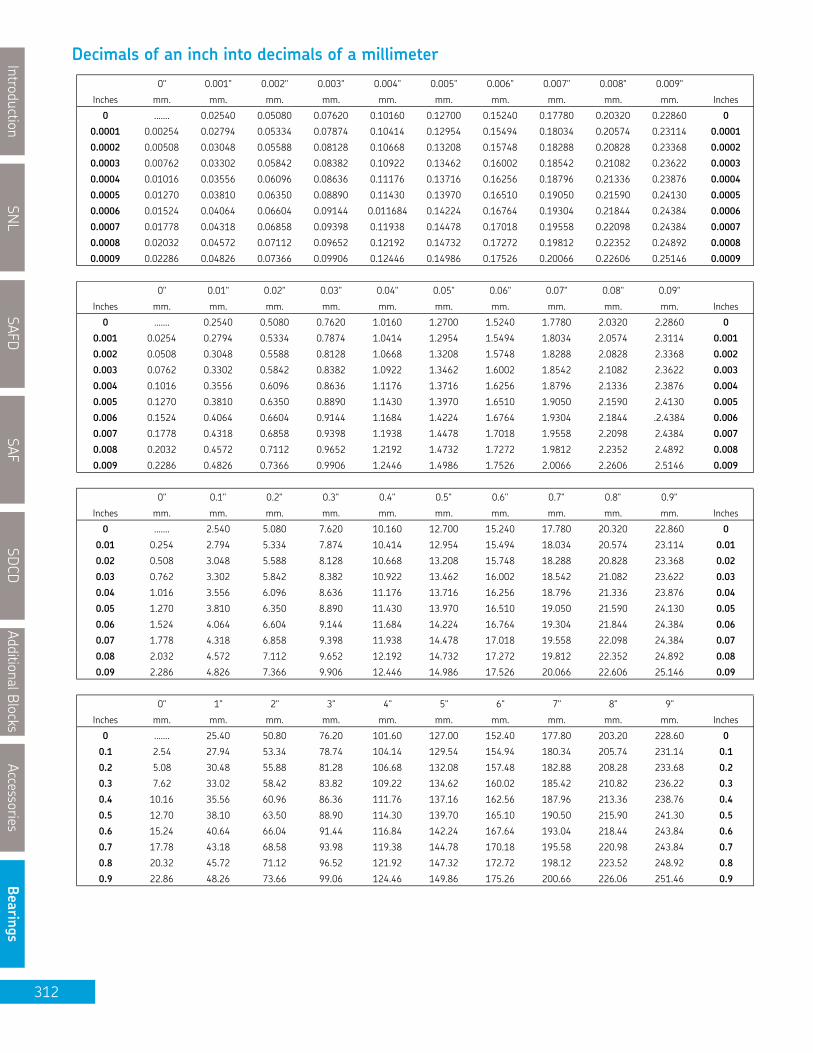
SNL
IntroductionSAFD
SAFSDCD
AdditionalBlocksAccessories
Bearings
0" 0.001" 0.002" 0.003" 0.004" 0.005" 0.006" 0.007" 0.008" 0.009"
Inches mm. mm. mm. mm. mm. mm. mm. mm. mm. mm. Inches
0 ……. 0.02540 0.05080 0.07620 0.10160 0.12700 0.15240 0.17780 0.20320 0.22860 0
0.0001 0.00254 0.02794 0.05334 0.07874 0.10414 0.12954 0.15494 0.18034 0.20574 0.23114 0.0001
0.0002 0.00508 0.03048 0.05588 0.08128 0.10668 0.13208 0.15748 0.18288 0.20828 0.23368 0.0002
0.0003 0.00762 0.03302 0.05842 0.08382 0.10922 0.13462 0.16002 0.18542 0.21082 0.23622 0.0003
0.0004 0.01016 0.03556 0.06096 0.08636 0.11176 0.13716 0.16256 0.18796 0.21336 0.23876 0.0004
0.0005 0.01270 0.03810 0.06350 0.08890 0.11430 0.13970 0.16510 0.19050 0.21590 0.24130 0.0005
0.0006 0.01524 0.04064 0.06604 0.09144 0.011684 0.14224 0.16764 0.19304 0.21844 0.24384 0.0006
0.0007 0.01778 0.04318 0.06858 0.09398 0.11938 0.14478 0.17018 0.19558 0.22098 0.24384 0.0007
0.0008 0.02032 0.04572 0.07112 0.09652 0.12192 0.14732 0.17272 0.19812 0.22352 0.24892 0.0008
0.0009 0.02286 0.04826 0.07366 0.09906 0.12446 0.14986 0.17526 0.20066 0.22606 0.25146 0.0009
0" 0.01" 0.02" 0.03" 0.04" 0.05" 0.06" 0.07" 0.08" 0.09"
Inches mm. mm. mm. mm. mm. mm. mm. mm. mm. mm. Inches
0 ……. 0.2540 0.5080 0.7620 1.0160 1.2700 1.5240 1.7780 2.0320 2.2860 0
0.001 0.0254 0.2794 0.5334 0.7874 1.0414 1.2954 1.5494 1.8034 2.0574 2.3114 0.001
0.002 0.0508 0.3048 0.5588 0.8128 1.0668 1.3208 1.5748 1.8288 2.0828 2.3368 0.002
0.003 0.0762 0.3302 0.5842 0.8382 1.0922 1.3462 1.6002 1.8542 2.1082 2.3622 0.003
0.004 0.1016 0.3556 0.6096 0.8636 1.1176 1.3716 1.6256 1.8796 2.1336 2.3876 0.004
0.005 0.1270 0.3810 0.6350 0.8890 1.1430 1.3970 1.6510 1.9050 2.1590 2.4130 0.005
0.006 0.1524 0.4064 0.6604 0.9144 1.1684 1.4224 1.6764 1.9304 2.1844 .2.4384 0.006
0.007 0.1778 0.4318 0.6858 0.9398 1.1938 1.4478 1.7018 1.9558 2.2098 2.4384 0.007
0.008 0.2032 0.4572 0.7112 0.9652 1.2192 1.4732 1.7272 1.9812 2.2352 2.4892 0.008
0.009 0.2286 0.4826 0.7366 0.9906 1.2446 1.4986 1.7526 2.0066 2.2606 2.5146 0.009
0" 0.1" 0.2" 0.3" 0.4" 0.5" 0.6" 0.7" 0.8" 0.9"
Inches mm. mm. mm. mm. mm. mm. mm. mm. mm. mm. Inches
0 ……. 2.540 5.080 7.620 10.160 12.700 15.240 17.780 20.320 22.860 0
0.01 0.254 2.794 5.334 7.874 10.414 12.954 15.494 18.034 20.574 23.114 0.01
0.02 0.508 3.048 5.588 8.128 10.668 13.208 15.748 18.288 20.828 23.368 0.02
0.03 0.762 3.302 5.842 8.382 10.922 13.462 16.002 18.542 21.082 23.622 0.03
0.04 1.016 3.556 6.096 8.636 11.176 13.716 16.256 18.796 21.336 23.876 0.04
0.05 1.270 3.810 6.350 8.890 11.430 13.970 16.510 19.050 21.590 24.130 0.05
0.06 1.524 4.064 6.604 9.144 11.684 14.224 16.764 19.304 21.844 24.384 0.06
0.07 1.778 4.318 6.858 9.398 11.938 14.478 17.018 19.558 22.098 24.384 0.07
0.08 2.032 4.572 7.112 9.652 12.192 14.732 17.272 19.812 22.352 24.892 0.08
0.09 2.286 4.826 7.366 9.906 12.446 14.986 17.526 20.066 22.606 25.146 0.09
0" 1" 2" 3" 4" 5" 6" 7" 8" 9"
Inches mm. mm. mm. mm. mm. mm. mm. mm. mm. mm. Inches
0 ……. 25.40 50.80 76.20 101.60 127.00 152.40 177.80 203.20 228.60 0
0.1 2.54 27.94 53.34 78.74 104.14 129.54 154.94 180.34 205.74 231.14 0.1
0.2 5.08 30.48 55.88 81.28 106.68 132.08 157.48 182.88 208.28 233.68 0.2
0.3 7.62 33.02 58.42 83.82 109.22 134.62 160.02 185.42 210.82 236.22 0.3
0.4 10.16 35.56 60.96 86.36 111.76 137.16 162.56 187.96 213.36 238.76 0.4
0.5 12.70 38.10 63.50 88.90 114.30 139.70 165.10 190.50 215.90 241.30 0.5
0.6 15.24 40.64 66.04 91.44 116.84 142.24 167.64 193.04 218.44 243.84 0.6
0.7 17.78 43.18 68.58 93.98 119.38 144.78 170.18 195.58 220.98 243.84 0.7
0.8 20.32 45.72 71.12 96.52 121.92 147.32 172.72 198.12 223.52 248.92 0.8
0.9 22.86 48.26 73.66 99.06 124.46 149.86 175.26 200.66 226.06 251.46 0.9
Decimals of an inch into decimals of a millimeter
312

SNL
Introduction
SAFD
SAF
SDCD
AdditionalBlocks
Accessories
Bearings
0" 1" 2" 3" 4" 5" 6" 7" 8" 9"
Inches mm. mm. mm. mm. mm. mm. mm. mm. mm. mm. Inches
0 …. 25.400 50.800 76.200 101.600 127.000 152.400 177.800 203.200 228.600 01/64 0.397 25.797 51.197 76.597 101.997 127.397 152.797 178.197 203.597 228.997 1/64
1/32 0.794 26.194 51.594 76.994 102.394 127.794 153.194 178.594 203.994 229.394 1/32
3/64 1.191 26.591 51.991 77.391 102.791 128.191 153.591 178.991 204.391 229.791 3/64
1/16 1.588 26.988 52.388 77.788 103.188 128.588 153.988 179.388 204.788 230.188 1/16
5/64 1.984 27.384 52.784 78.184 103.584 128.984 154.384 179.784 205.184 230.584 5/64
3/32 2.381 27.381 53.181 78.581 103.981 129.381 154.781 180.181 205.581 230.981 3/32
7/64 2.778 28.178 53.578 78.978 104.378 129.778 155.178 180.578 205.978 231.378 7/64
1/8 3.175 28.575 53.975 79.375 104.775 130.175 155.575 180.975 206.375 231.775 1/8
9/64 3.572 28.972 54.372 79.772 105.172 130.572 155.972 181.372 206.772 232.172 9/64
5/32 3.969 29.369 54.769 80.169 105.569 130.969 156.369 181.769 207.169 232.569 5/32
11/64 4.366 29.766 55.166 80.566 105.966 131.366 156.766 182.166 207.566 232.966 11/64
3/16 4.763 30.163 55.563 80.963 106.363 131.763 157.163 182.563 207.963 233.363 3/16
13/64 5.159 30.559 55.959 81.359 106.759 132.159 157.559 182.959 208.359 233.759 13/64
7/32 5.556 30.956 56.356 81.756 107.156 132.556 157.956 183.356 208.756 234.156 7/32
15/64 5.953 31.353 56.753 82.153 107.553 132.953 158.353 183.753 209.153 234.553 15/64
1/4 6.350 31.750 57.150 82.550 107.950 133.350 158.750 184.150 209.550 234.950 1/4
17/64 6.747 32.147 57.547 82.947 108.347 133.747 159.147 184.547 209.947 235.347 17/64
9/32 7.144 32.544 57.944 83.344 108.744 134.144 159.544 184.944 210.344 235.744 9/32
19/64 7.541 32.941 58.341 83.741 109.141 134.541 159.941 185.341 210.741 236.141 19/64
5/16 7.938 33.338 58.738 84.138 109.538 134.938 160.338 185.738 211.138 236.538 5/16
21/64 8.334 33.734 59.134 84.534 109.934 135.334 160.734 186.134 211.534 236.934 21/64
11/32 8.731 34.131 59.531 84.931 110.331 135.731 161.131 186.531 211.931 237.331 11/32
23/64 9.128 34.528 59.928 85.328 110.728 136.128 161.528 186.928 212.328 237.728 23/64
3/8 9.525 34.925 60.325 85.725 111.125 136.525 161.925 187.325 212.725 238.125 3/8
25/64 9.922 35.322 60.722 86.122 111.522 136.922 162.322 187.722 213.122 238.522 25/64
13/32 10.319 35.719 61.119 86.519 111.919 137.319 162.719 188.119 213.519 238.919 13/32
27/64 10.716 36.116 61.516 86.916 112.316 137.716 163.116 188.516 213.916 239.316 27/64
7/16 11.113 36.513 61.913 87.313 112.713 138.113 163.513 188.913 214.313 239.713 7/16
29/64 11.509 36.909 62.309 87.709 113.109 138.509 163.909 189.309 214.709 240.109 29/64
15/32 11.906 37.306 62.706 88.106 113.509 138.906 164.306 189.706 215.106 240.506 15/32
31/64 12.303 37.703 63.103 88.503 113.903 139.303 164.703 190.103 215.503 240.903 31/64
1/2 12.700 38.100 63.500 88.900 114.300 139.700 165.100 190.500 215.900 241.300 1/2
33/64 13.097 38.497 63.897 89.297 114.697 140.097 165.497 190.897 216.297 241.697 23/64
17/32 13.494 38.894 64.294 89.694 115.094 140.494 165.894 191.294 216.694 242.094 17/32
35/64 13.891 39.291 64.691 90.091 115.491 140.891 166.291 191.691 217.091 242.491 35/64
9/16 14.288 39.688 65.088 90.488 115.888 141.288 166.688 192.088 217.488 242.888 9/16
37/64 14.684 40.084 65.484 90.884 116.284 141.684 167.084 192.484 217.884 243.284 37/64
19/32 15.081 40.481 65.881 91.281 116.681 142.081 167.481 192.881 218.281 243.681 18/32
39/64 15.478 40.878 66.287 91.678 117.078 142.478 167.878 193.278 218.678 244.078 39/64
5/8 15.875 41.275 66.675 92.075 117.475 142.875 168.275 193.675 219.075 244.475 5/8
41/64 16.272 41.672 67.072 92.472 117.872 143.272 168.672 194.072 219.472 244.872 41/64
21/32 16.699 42.069 64.469 92.869 118.269 143.669 169.069 194.469 219.869 245.269 21/32
46/64 17.066 42.466 67.866 93.266 118.666 144.066 169.466 194.866 220.266 245.666 46/64
11/16 17.463 42.863 68.263 93.663 119.063 144.463 169.863 195.263 220.663 246.063 11/16
45/64 17.859 43.529 68.659 94.059 119.459 144.859 170.259 195.659 221.059 246.459 45/64
23/32 18.256 43.656 69.056 94.456 119.856 145.256 170.656 196.056 221.456 246.856 23/32
47/64 18.653 44.053 69.453 94.853 120.253 145.653 171.053 196.453 221.853 247.253 47/64
3/4 19.050 44.450 69.850 95.250 120.650 146.050 171.450 196.850 222.250 247.650 3/4
49/64 19.447 44.847 70.247 95.647 121.047 146.477 171.847 197.247 222.647 248.047 49/64
25/32 19.844 45.244 70.644 96.044 121.444 146.844 172.244 197.644 223.044 248.444 25/32
51/64 20.241 45.641 71.041 96.441 121.841 147.241 172.641 198.041 223.441 248.841 51/64
13/16 20.638 46.038 71.438 96.838 122.238 147.638 173.038 198.438 223.838 249.238 13/16
5
Fractional inches into millimeters
313

SNL
IntroductionSAFD
SAFSDCD
AdditionalBlocksAccessories
Bearings
Fractional inches into millimeters
0" 1" 2" 3" 4" 5" 6" 7" 8" 9"
Inches mm. mm. mm. mm. mm. mm. mm. mm. mm. mm. Inches
053/64 21.034 46.434 71.834 97.234 122.634 148.034 173.434 198.834 224.234 249.634 53/64
27/32 21.431 46.831 72.231 97.631 123.031 148.431 173.831 199.231 224.631 250.031 27/32
55/64 21.828 47.228 72.628 98.028 123.428 148.828 174.228 199.628 225.028 250.428 55/64
7/8 22.225 47.625 73.025 98.425 123.825 149.225 174.625 200.025 225.425 250.825 7/8
57/64 22.622 48.022 73.422 98.822 124.222 149.622 175.022 200.422 225.822 251.222 57/64
29/32 23.019 48.419 73.819 99.219 124.619 150.019 175.419 200.819 226.219 251.619 29/32
59/64 23.416 48.816 72.216 99.616 125.016 150.416 175.816 201.216 226.616 252.016 59/64
15/16 23.813 49.213 74.613 100.013 125.413 150.813 176.213 201.613 227.013 252.413 15/16
61/64 24.209 49.609 75.009 100.409 125.809 151.209 176.609 202.009 227.409 252.809 61/64
31/32 24.606 50.006 75.406 100.806 126.206 151.606 177.006 202.406 227.806 253.206 31/32
63/64 25.003 50.403 75.803 101.203 126.603 152.003 177.403 202.803 228.203 253.603 63/64
314

SNL
Introduction
SAFD
SAF
SDCD
AdditionalBlocks
Accessories
Bearings
-459.4 to 0 0 to 100 100 to 1000
C F C F C F C F C F
-273 -459.4 ….. -17.8 0 32 10.0 50 122.0 38 100 212 260 500 932
-268 -450 ….. -17.2 1 33.8 10.6 51 123.8 43 110 230 266 510 950
-262 -440 ….. -16.7 2 35.6 11.1 52 125.6 49 120 248 271 520 968
-257 -430 ….. -16.1 3 37.4 11.7 53 127.4 54 130 266 277 530 986
-251 -420 ….. -15.6 4 39.2 12.2 54 129.2 60 140 284 282 540 1004
-246 -410 ….. -15.0 5 41.0 12.8 55 131.0 66 150 302 288 550 1022
-240 -400 ….. -14.4 6 42.8 13.3 56 132.8 71 160 320 293 560 1040
-234 -390 ….. -13.9 7 44.6 13.9 57 134.6 77 170 338 299 570 1058
-229 -380 ….. -13.3 8 46.4 14.4 58 136.4 82 180 356 304 580 1076
-223 -370 ….. -12.8 9 48.2 15.0 59 138.2 88 190 374 310 590 1094
-218 -360 ….. -12.2 10 50.0 15.6 60 140.0 93 200 392 316 600 1112
-212 -350 ….. -11.7 11 51.8 16.1 61 141.8 99 210 410 321 610 1130
-207 -340 ….. -11.1 12 53.6 16.7 62 143.6 100 212 413.6 327 620 1148
-201 -330 ….. -10.6 13 55.4 17.2 63 145.4 104 220 428 332 630 1166
-196 -320 ….. -10.0 14 57.2 17.8 64 147.2 110 230 436 338 640 1184
-190 -310 ….. -9.4 15 59.0 18.3 65 149.0 116 240 464 343 650 1202
-184 -300 ….. -8.9 16 60.8 18.9 66 150.8 121 250 482 349 660 1220
-179 -290 ….. -8.3 17 62.6 19.4 67 152.6 127 260 500 354 670 1238
-173 -280 ….. -7.8 18 64.4 20.0 68 154.4 132 270 518 360 580 1256
-169 -273 -459.4 -7.2 19 66.2 20.6 69 156.2 138 280 536 366 690 1274
-168 -270 -454 -6.7 20 68.0 21.1 70 158.0 143 290 554 371 700 1292
-162 -260 -436 -6.1 21 69.8 21.7 71 159.8 149 300 572 377 710 1310
-157 -250 -418 -5.6 22 71.6 22.2 72 161.6 154 310 590 382 720 1328
-151 -240 -400 -5.0 23 73.4 22.8 73 163.4 160 320 608 388 730 1346
-146 -230 -382 -4.4 24 75.2 23.3 74 165.2 166 330 626 393 740 1364
-140 -220 -364 -3.9 25 77.0 23.9 75 167.0 171 340 644 399 750 1382
-134 -210 -346 -3.3 26 78.8 24.4 76 168.8 177 350 662 404 760 1400
-129 -200 -328 -2.8 27 80.6 25.0 77 170.6 182 360 680 410 770 1418
-123 -190 -310 -2.2 28 82.4 25.6 78 172.4 188 370 698 416 780 1436
-118 -180 -292 -1.7 29 84.2 26.1 79 174.2 193 380 716 421 790 1454
-112 -170 -274 -1.1 30 86.0 26.7 80 176.0 199 390 734 427 800 1472
-107 -160 -256 -.6 31 87.9 27.2 81 177.8 204 400 752 432 810 1490
-101 -150 -238 0. 32 89.6 27.8 82 179.6 210 410 770 438 820 1508
-96 -140 -220 .6 33 91.4 28.3 83 181.4 216 420 788 443 830 1526
-90 -130 -202 1.1 34 93.2 28.9 84 183.2 221 430 806 449 840 1544
-84 -120 -184 1.7 35 95.0 29.4 85 185.0 227 440 824 454 850 1562
-79 -110 -166 2.2 36 96.8 30.0 86 186.8 232 450 842 460 860 1580
-73 -100 -148 2.8 37 98.6 30.6 87 188.6 238 460 860 466 870 1598
-68 -90 -130 3.3 38 100.4 31.1 88 190.4 243 470 878 471 880 1616
-62 -80 -112 3.9 39 102.2 31.7 89 192.2 249 480 896 477 890 1634
-57 -70 -94 4.4 40 104.0 32.2 90 194.0 254 490 914 482 900 1652
-51 -60 -76 5.0 41 105.8 32.8 91 195.8 …. …. …. 488 910 1670
-46 -50 -58 5.6 42 107.6 33.3 92 197.6 …. …. …. 493 920 1688
-40 -40 -40 6.1 43 109.4 33.9 93 199.4 …. …. …. 499 930 1706
-34 -30 -22 6.7 44 111.2 34.4 94 201.2 …. …. …. 504 940 1724
-29 -20 -4 7.2 45 113.0 35.0 95 203.0 …. …. …. 510 950 1742
-23 -10 14 7.8 46 114.8 35.6 96 204.8 …. …. …. 516 960 1760
-17.8 0 32 8.3 47 116.6 36.1 97 206.6 …. …. …. 522 970 1778
….. ….. ….. 8.9 48 118.4 36.7 98 208.4 …. …. …. 527 980 1796
….. ….. ….. 9.4 49 120.2 37.2 99 210.2 …. …. …. 532 990 1814
….. ….. ….. ….. ….. ….. 37.8 100 212.0 …. …. …. 538 1000 1832
Temperature Conversion Tables (F° and C°)Example: Centre column "0" degrees, if Celsius it would be 32 degrees F, if it was Fahrenheit it would be -17.8 degrees C.
315

SNL
IntroductionSAFD
SAFSDCD
AdditionalBlocksAccessories
Bearings
Subject PageAdapter Sleeves
Metric 260
Inch 266
BearingsCARB 309
Self-Aligning Ball Bearings 295
Spherical Roller Bearings 299
Clearance Tables 40
Clearance reduction for Spherical Roller Bearings 42
Tightening angle for Self-Aligning Bearings 18
Hydraulic Nuts 256
Metric thread
Inch sizes (please see Bearing catalogue 925)
Locking DevicesMetric Showing locking device and wrench 242
Imperial Showing locking device and wrench 246
KMFE design for CARB or high speed applications 250
Shaft dimensions and thread details 290
Locking Washers or PlatesMetric (MB). 252
Imperial (W, W0). 254
LubricationGeneral 30
Application in Pillow Blocks 31
Oil Lubrication 33
Relubrication Intervals 34
Initial Grease Charge in Split Blocks 36
Lubrication Fittings 37
Grease Chart (Inside back cover)
Mounting of bearingsBasic procedures 16
With seals 16
On Sleeves 17
Subject Index
316

SNL
Introduction
SAFD
SAF
SDCD
AdditionalBlocks
Accessories
Bearings
Subject Index
Subject PageMounting of bearings with:
G seals (double lip) 20
A seals (V ring) 21
C seals (Felt) 22
LER/LOR Labyrinth seals 23
S/TS Labyrinth seals 24
LOR/LORP c/w Contact Elements 25
TER-C seals 26
TER-CV 27
TNF 27
TSNC/TSDC “D” design 28
TSNC/TSDC “E” design 29
SealsSelection chart 6
Speed Limits 8
Standard designs 10
End covers 19
Shaft dimensions and thread detailsMetric Locknuts 290
Imperial Locknuts 292
Shaft, end of shaft lengths“S” dimension 52
Shaft Tolerances and FitsAdapter mounts 38
Permissible taper and ovality 38
317
L = LowM = MediumH = HighEH = Extremely High
Bearing operating parameters
Temperature Speed for roller bearings SRB/TRB/CARB® CRB
Speed for ball bearings
< 50° C/ 122°F50 to 100° C/ 122 to 230°F> 100 ° C/ 212°F> 150 °C /132 °F
EH = Exremely HighVH = Very HighH = HighM = MediumL = Low
n.dm over 700,000n.dm up to 700,000n.dm up to 500,000n.dm up to 300,000n.dm below 100,000
H = HighM = MediumL = LowVL = Very Low
n.dm over 210,000n.dm up to 210,000n.dm up to 75,000n.dm up to 30,000
n.dm over 270,000n.dm up to 270,000n.dm up to 75,000n.dm up to 30,000
Load
VH = Very highH = HighM = MediumL = Low
C/P <2C/P ~4C/P ~8C/P ≥15
n: Speed, rpmc: Dynamic load ratingp: Equivalent bearing loaddm: D + d
2
Terminology for Parameters

SKF Canada Limited - Head Office40 Executive CourtScarborough, OntarioM1S 4N4Tel: +1 416 299 12208:00a.m. - 8:00p.m. EST Monday to Friday
SKF Canada Limited - Montreal101 Avenue LindsayDorval, QuebecH9P 2S6Tel: (514) 636-52307:00a.m. - 5:00p.m. EST Monday to Friday
SKF Canada Limited - Vancouver1480 Kootenay StreetVancouver, BCV5K 4R1Tel: (604) 291-09927:30a.m. - 5:00p.m. PT Monday to Friday
SKF Canada Customer Service & SupportTel: 1 (866) TEAM SKF or (1-866-832-6753)Fax: +1 416 292 0399E-mail: [email protected] Page: www.skf.ca8:00a.m. - 8:00p.m. EST Monday to Friday
SKF Canada Limited - Edmonton4125 84 AvenueEdmonton, ABT6B 3H3Tel: (780) 466-52198:00a.m. - 5:00p.m. MT Monday to Friday
After Hours Emergency Rush Shipments:Montreal: 1-514-891-1184Scarborough: 1-866-238-4687Vancouver: 1-866-238-4687Edmonton: 1-866-238-4687
Technical Support Hotline:Montreal: 1-514-636-5230Scarborough: 416-299-2810Vancouver: 1-604-291-0992(Ext. 227 or 228)
GET CONNECTED - CONTACT SKF CANADA
HOW TO ORDER - to order your catalogues online please visit ourwebsite at www.skf.ca or email us at [email protected]
(#457-010)
318
To obtain a copy of SKF’s925 Bearing Catalogue,please [email protected] or visitwww.skf.ca/catalogues
To obtain a copy of SKF’sLinear Motion Catalogue,please [email protected] or visitwww.skf.ca/catalogues
To obtain a copy of SKF’sLubrication ProductsCatalogue, please [email protected] or visitwww.skf.ca/catalouges
To obtain a copy of SKF’sSeal Handbook Catalogue,please [email protected] or visitwww.skf.ca/catalogues
To obtain a copy of SKF’sMaintenance and LubricationCatalogue, please [email protected] or visitwww.skf.ca/catalogues
(#LUB3000)(#4664/5)(#CDN925) (#MP3000)
To order online, please go to www.skf.ca/catalogues to order any one of the catalouges listed above orcontact [email protected] to find out more.
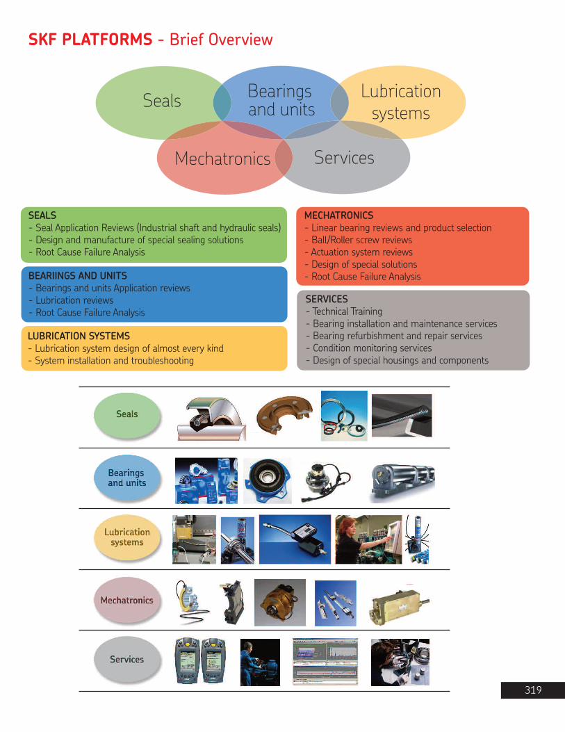
SKF PLATFORMS - Brief Overview
319
Seals Bearings and units
Lubricationsystems
Mechatronics Services
SEALS- Seal Application Reviews (Industrial shaft and hydraulic seals)- Design and manufacture of special sealing solutions- Root Cause Failure Analysis
BEARIINGS AND UNITS- Bearings and units Application reviews- Lubrication reviews- Root Cause Failure Analysis
LUBRICATION SYSTEMS- Lubrication system design of almost every kind- System installation and troubleshooting
SERVICES- Technical Training- Bearing installation and maintenance services- Bearing refurbishment and repair services- Condition monitoring services- Design of special housings and components
MECHATRONICS- Linear bearing reviews and product selection- Ball/Roller screw reviews- Actuation system reviews- Design of special solutions- Root Cause Failure Analysis

M L L to M General purpose Lithium soap/mineral oil 1100° F-18° C
266 °F130 °C (*9)
LGAP 2
LGEL 2
LGFA 00
LGFA 0
LGFA 1
LGFA 2
LGEM 2
LGEV 2
LGLT 2
LGGB 2
LGWM 1
LGWA 2
LGHB 2
LGHP 2
LGET 2
M NS (*7) L to M General purpose Lithium soap/mineral oil 110LGAP 0 0° F-18° C
266 °F130 °C
(*10)
LGAP 1
M M L to M General purpose Lithium soap/mineral oil 1100° F-18° C
266 °F130 °C
LGMT 3
• Agricultural equipment• Automotive wheel bearings• Conveyors• Small electric motors• Indusrial fans
• Agricultural equipment• Automotive wheel bearings• Conveyors• Small electric motors• Indusrial fans
• Agricultural equipment• Automotive wheel bearings• Conveyors• Small electric motors• Indusrial fans
M M L to M General purpose Lithium soap/mineral oil 120-22° F-30° C
250 °F120 °C
• Bearings >100 mm (3.9 in) shaft size• Outer bearing ring rotation• Vertical shaft appications• Continuous high ambient temperatures >35˚C (95˚F)
• Propeller shafts• Agricultural equipment• Car, truck and trailer wheel bearings• Large electric motors
M to H VL to M H to VH EP high viscosity, high temperature (*5) Complex calcium sulphonate/mineral oil 400-20° C
-4° F150 °C302 °F
• Steel on steel plain bearings• Pulp and paper making machines• Asphalt vibrating screens• Continous casting machines• Work roll bearings in steel industry
• Sealed spherical roller bearings operating up to 150˚C (302˚F)• Withstands peak temperatures of 200˚C (392˚F)
185M to H L to M H Wide temperature (*4) extreme pressu9e Lithium complex soap/mineral oil-30˚ C
-22° F140 °C284 °F
• Wheel bearings in cars, trailers and trucks• Washing machines• Electric motors
M to H M to H L to MHigh performance polyurea grease Di-urea/mineral oil 96-40° C
-40° F150 °C302 °F
• Verical shafts• Severe vibrations• Low noise• Rust inhibiting properties
VH L to M H to VH Extreme temperature PTFE/synthetic (fluorinated polyether) 400-40° C-40° F
260 °C500 °F
• Bakery equipment (ovens)• Kiln truck wheels• Load rollers in copying machines• Wafer baking machines• Textile dryers
• Film stretching tenders• Electric motors running at extreme temperatures• Emergency / hot fans• Vacuum pumps
L to M L to M HExtreme pressure, low pressure Lithium soap/mineral oil 200-30° C
-22° F110 °C230 °F
• Windmills• Screw conveyors• Centralized lubrication systems• Spherical roller thrust bearing applications
L to M L to M M to H Green biodegradable, low toxicity Lithium-calcium soap/synthetic ester oil 110-40° C
-40° F90 °C (*3)194 °F
• Agricultural and foresty equipment• Locks, dams, bridges• Mining and conveying equipment• Water treatment & irrigation• Linkages, rod ends
• Construction and earth moving equipment• Other applications where contamination of the environment is a concern
L to M M to EH L Low temperature, extremely high speed Lithium soap/PAO oil 18-50° C
-58° F110 °C230 °F
• Textile spinning spindles• Machine tool spindles• Instruments and control equipment• Small electic motors used in medical and dental equipment
• In-line skates• Printing cyclinders• Robots
M VL H to VH Extremely high viscosity with solid lubricants Lithium-calcium soap/mineral oil 1 020-10° C
-14° F120 °C250 °F
• Trunnion bearings on rotating drums• Support and thrust rollers on rotary kilns and dryers• Bucket wheel excavators
• Slewing ring bearings• High pressure roller mills• Crushers
M VL H to VH High viscosity plus solid lubricants
Lithium complex/mineral oil 500-20° C-4° F
120 °C250 °F
• Rolling element bearings running at low speed and very high loads• Jaw crushers• Track laying machines
• Lift mast wheels• Building machines such as mechancial rams, crane arms and crane hooks
= Recommended = Suitable
= Not suitable
(*8)
(*7)
(*6)
(*8)
(*8)
(*7)
(*6) (*10)
M L to M H Extremepressure
Lithium complex/mineral oil 210-5° F-21° C
290 °F143 °C
• Pulp and paper making machines• Traction motors for rail vehicles• Work roll bearings in steel industry• Heavy machinery, vibrating screens
• Jaw crushers• Dam gates• Crane wheels, sheaves
M NS (*7) L to M Food compatible 68Aluminum complex/white mineral oil
-5˚ F-21° C
250 °F121°C
• Bakery equipment• Food processing equipment• Multi-pack cassette bearings• Wrapping machines
• Conveyor bearings• Bottling machines
M NS (*7) L to M Food compatible Aluminum complex/white mineral oil 68-5° F
-21° C250 °F121°C
• Bakery equipment• Food processing equipment• Multi-pack cassette bearings• Wrapping machines
• Conveyor bearings• Bottling machines
M L L to M Food compatible 68Aluminum complex/white mineral oil
-5° F-21° C
250 °F121°C
• Bakery equipment• Food processing equipment• Multi-pack cassette bearings• Wrapping machines
• Conveyor bearings• Bottling machines
M M L to M Food compatible 68Aluminum complex/white mineral oil
-5° F-21° C
250 °F121°C
• Bakery equipment• Food processing equipment• Multi-pack cassette bearings• Wrapping machines
• Conveyor bearings• Bottling machines
SKF bearing greases overview chartBearing workingconditions
Temp Speed Load Verticalshaft
Fast outerring
rotation
Oscillatingmovements
Severevibrations
Shock load or
frequent start-ups
Pump-ability
Rustinhibitingproperties
Description Typical Applications Temperaturerange (*1)
Thickener / base oil Base oilviscosity (*2)
LTL HTPL
NS = Not specified
Heavy
Duty
PillowBlocks
Heavy
Duty
PillowBlocks
SKFCanada
Limited
® SKF is a registered trademark of SKF Canada Limited.The contents of this publication are the copyright of thepublisher and may not be reproduced (even extracts)unless permission is granted. Every care has been taken toensure the accuracy of the information contained in thispublication but no liability can be accepted for any loss ordamage whether direct, indirect or consequential arisingout of use of the information contained herein. The servicesand associated benefits described within this brochure areonly intended for use by authorized SKF Canada Limiteddistributors and their customers.
© 2008 SKF Canada Limited.
Printed in CanadaCatalogue CDN 994 / April 2008
SKF Canada Limited40 Executive CourtScarborough, OntarioM1S 4N4
Montreal101 Ave. LindsayDorval, QuebecH9P 2S6
Edmonton5220 75th StreetEdmonton, AlbertaT6E 5S4
Vancouver1480 Kootenay StreetVancouver, B.C.V5K 4R1
$50.00
Customer ServiceTelephone: 1-866-TEAMSKFFax: [email protected]