skin effect modifications of the resistive wall mode dynamics in tokamaks
TRANSCRIPT

Physics Letters A 377 (2013) 2780–2784
Contents lists available at ScienceDirect
Physics Letters A
www.elsevier.com/locate/pla
Skin effect modifications of the Resistive Wall Mode dynamicsin tokamaks
Fabio Villone a,∗, Vladimir D. Pustovitov b
a Ass. Euratom/ENEA/CREATE, DIEI, Università di Cassino e del Lazio Meridionale, Via Di Biasio 43, 03043 Cassino, FR, Italyb Institute of Tokamak Physics, National Research Centre ‘Kurchatov Institute’, Pl. Kurchatova 1, Moscow 123182, Russia
a r t i c l e i n f o a b s t r a c t
Article history:Received 8 January 2013Received in revised form 27 June 2013Accepted 11 August 2013Available online 26 August 2013Communicated by F. Porcelli
We present the first evidence of the skin-effect modification of the Resistive Wall Mode (RWM) dynamicsin a tokamak. The computations are performed with the CarMa code, using its unique ability of treatingvolumetric 3D conducting structures. The results prove that conventional thin-wall models and codes,assuming the thin equivalent wall located on the inner side of a real (thick) wall, may fail to get accurateestimates of RWM growth rates, since the inclusion of the skin effect makes the growth rates alwayslarger than otherwise. The difference is noticeable even for the conventional slow RWMs and becomessubstantial for faster modes. Some possible equivalent thin-wall modeling approaches are also discussed.
© 2013 Elsevier B.V. All rights reserved.
1. Introduction
The fusion plasma in toroidal devices is subject to various in-stabilities, with the most deleterious developing on the very fastAlfvenic time scale (typically microseconds). These put rather se-vere limitations on the achievable parameters and require carefuloptimization of the operation scenarios. Even well done, this stillleaves a danger of undesirable slower instabilities. Such are, forexample, so-called resistive wall modes (RWMs) [1–3]. The steady-state advanced scenario in ITER aims at high plasma pressure ex-ceeding the RWM stability limit [2,3]. This requires suppression ofthe RWM instability, which can be performed with an active mag-netic feedback system, as in the DIII-D tokamak [1–3]. Efficiencyof such suppression depends on the quality of theoretical modelsbehind the feedback algorithms.
RWMs are usually treated as slow modes [1–3] perfectly pen-etrating the vacuum vessel wall, so that the normal componentof magnetic perturbations is assumed constant across the wall.In the theory of RWMs, this constitutes the widely used “thinwall” approximation [2,3]. The advanced tokamak scenarios requireoperation quite above the stability limit [1–3], hence the modegrowth rate can be so high (though still far below the Alfveniclevel) that the standard RWM theory reviewed in [2,3] may notbe valid because of the skin effect [4,5]. The mode can be hencecalled “fast” RWM and, formally, placed between the usual “slow”RWM and much faster ideal MHD modes on Alfvenic time scale.
* Corresponding author. Tel.: +39 0776 2993674; fax: +39 0776 2993707.E-mail address: [email protected] (F. Villone).
0375-9601/$ – see front matter © 2013 Elsevier B.V. All rights reserved.http://dx.doi.org/10.1016/j.physleta.2013.08.021
In this range, the plasma inertia can be neglected and the wall re-sistivity still plays an important role in the mode dynamics, butthe theory must be revised. In particular, in [4,5] it is analyticallyshown that the thin-wall approximation can yield a substantial un-derestimation of the growth rate of RWM, when the wall widthand the penetration depth become comparable. Similar effect hasbeen noticed earlier in [6] and confirmed in [7], though withoutmuch discussion of the underlying physics and separation of tworegimes, slow and fast RWMs. In [4,5] the issue was clarified andthe importance of thick-wall effect in present and planned toka-mak experiments was strongly emphasized. In particular, the skineffect makes the current density to penetrate only partially in thewall, with a number of consequences that will be discussed in thefollowing.
Here, we discuss the nonrotating (locked) modes with a realgrowth rate, using the CarMa computational tool [8,9], which hasbeen recently developed for the analysis of RWM in presenceof three-dimensional conducting structures. It has been success-fully experimentally validated on the RFX-mod device [9–11] andextensively applied to ITER [12,13]. Contrary to other availablethree-dimensional RWM codes, like VALEN [14] or STARWALL [15],CarMa has the unique feature to combine the MHD models forthe plasma with a rigorous volumetric treatment of the surround-ing conductors, without resorting to the usual thin-wall approxi-mation. This ability of CarMa allows us to present in this Letterthe first numerical confirmation, with a three-dimensional RWMcode, of the thick-wall effect predicted analytically in the cylindri-cal limit [4,5]. The calculations are performed in realistic toroidalgeometry, and the results also give some indications about equiva-lent simplified thin-wall modeling of thick structures.

F. Villone, V.D. Pustovitov / Physics Letters A 377 (2013) 2780–2784 2781
2. Formulations
In the traditional thin-wall models, the normal component ofthe magnetic field is assumed the same at the both sides of thewall. In the cylindrical approximation, calling τw = μ0rwdw/η thewall time constant (rw , dw , η are the inner radius of the wall (wallradius in the following), thickness and resistivity, respectively), thedispersion relation for the RWM growth rate γ is:
γ τw = Γm, (1)
where Γm = −2m(1− Bplm/Bm) describes the plasma response (m is
the poloidal wave number of the magnetic perturbation, Bm is itsamplitude at the inner side of the wall, and Bpl
m is the contribu-tion to Bm due to the plasma). The thin-wall limit corresponds todw/δ � 1, where δ = √
η/(μ0γ ) is the skin depth. In terms of γ ,this means γ τw � rw/dw . This covers only a narrow range of in-stabilities observed in experiments. The gap between such slowRWMs and the ideal MHD modes on Alfvenic time scales is typ-ically 3–4 orders of magnitude, which gives a vast room to themodes with larger γ . When the skin depth is only a small part ofthe wall thickness (γ τw � rw/dw ), the dispersion relation for theRWMs becomes [4,5]:
γ τw = Γmdw/δ. (2)
This takes into account both the reduction of the volume wherethe main part of the energy is dissipated and the related suppres-sion of the field penetration through the wall. Compared to (1),this gives larger growth rates as we could expect for a thinner wall.Also, since δ is a function of γ , this means a different dependenceof γ on Γm:
γ τw = Γ 2mdw/rw . (3)
Larger growth rate and its stronger dependence on Γm than ex-pected from (1) indicates that the accuracy of the standard thin-wall approaches can be insufficient, when the skin depth becomescomparable with the wall thickness. Effective feedback controllersneed to be designed on accurate models. Hence, reliable compu-tational tools, able both to provide the correct growth rate scalingand to treat realistic geometries, are required.
The CarMa code answers this need. A coupling surface S isintroduced between the plasma and the conducting structures.Solving the linearized single-fluid MHD equations neglecting theplasma mass, the (instantaneous) plasma response matrix to mag-netic field perturbations on S is computed and is coupled to a3D volumetric integral formulation of the eddy currents problem,which describes the conducting structures by means of a three-dimensional finite elements mesh – no thin-wall approximation ismade. The final form of the model [8] is:
L∗ dI
dt+ R I = 0, (4)
where I is a vector of 3D discrete currents in the finite ele-ments mesh, the fully populated inductance matrix L∗ includesthe plasma response, and the sparse matrix R describes the resis-tance of the 3D structures. The RWM growth rate γ is computedas the unstable eigenvalue of the dynamical matrix −(L∗)−1 R ofsystem (4) (the meaning of multiple unstable eigenvalues is dis-cussed in [9]). Using the same approach without plasma, onlystable eigenvalues are found, the slowest of which is inversely pro-portional to the wall time constant τw . This quantity will be usedfor growth rate normalization, in order to compare cases referringto different conducting structures.
Table 1Sensitivity of growth rate to mesh size.
nt np nw γ τw
50 30 4 5.9050 30 8 5.9250 30 2 5.84
100 30 2 5.8350 60 2 5.90
3. The thick-wall effect
We refer to the plasma configuration described in [8], havinga circular cross section with a major radius R0 = 2 m and a mi-nor radius a = 0.4 m, for which the n = 1 external kink modeis unstable (n is the toroidal mode number). With this plasma,several different circular resistive walls are considered, with thesame major radius R0 and minor radii from rw = 1.3a to rw =1.5a (the latter denotes the inner side of the wall). We assumedw = rw/10; hence, the walls are geometrically thin. For each wall,we give a 3D finite elements discretization with np = 30 elementsin the poloidal direction, nt = 50 elements in the toroidal direc-tion and nw = 4 elements in the wall width. The adequacy ofthis choice is confirmed by the mesh sensitivity analysis of Ta-ble 1.
The CarMa code can only treat thick walls; in order to re-produce the thin-wall approximation, we consider walls withrw/dw � 1, representing them with only one radial finite ele-ment in the wall width. Fig. 1 shows the calculated behavior ofthe quantity Γm = γ τw as a function of rw/dw , for the consideredplasma and a wall with rw = 1.3a. In the explored range, a varia-tion of Γm is only around 3%. In the following, we use the resultfor rw/dw = 500 as the thin-wall estimate.
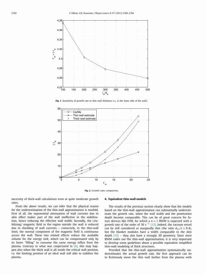
Fig. 2 shows the growth rates for various wall configurations,both in the thin-wall approximation and using the full capacitiesof the CarMa code; also the thick-wall estimate (3), derived as theasymptote at γ τw � rw/dw = 10, is reported. First of all, we noticethat the thin-wall approximation fails to give a good estimate ofthe growth rate, except for γ τw � 10.
Secondly, the CarMa result is clearly capable of reproducing theexpected quadratic behavior in terms of Γm , predicted by the thick-wall estimate (3). In any case, the CarMa result is always above thethin- and thick-wall estimates, as expected in cylindrical geome-try [7].
To highlight the features of the thick-wall solutions, in Fig. 3we show the current density pattern corresponding to the unstableeigenvector and the radial behavior of the toroidal component Jφin the wall, for a case with Γm = 23.6. The current density hasa dominant n = 1, low-m structure. A substantial attenuation ofJφ across the wall is precisely the effect completely neglected inthe thin-wall approximation. The radial decay of the poloidal andmuch smaller radial component is similar.
This thick-wall effect is expected to become significant whenthe skin depth δ is comparable to the wall width [4,5]. To quantifythis expectation, we computed the quantity γ τw/Γm as a func-tion of the ratio dw/δ (Fig. 4). We refer here to the configurationwith rw = 1.5a, considering various walls of increasing thickness.When the penetration depth δ is much greater than the wall widthdw , we recover the thin-wall approximation, so that γ τw → Γm .Conversely, when dw � δ, any increase of the wall thickness doesnot appreciably modify the growth rate γ , since the skin effectreduces the induced currents in the additional layers of the con-ducting material. Consequently, in this limit the quantity γ τw in-creases with dw as τw . When dw � δ (a situation in-between thevalidity range of the existing analytical models [4,5]) the errorof the thin-wall approximation can exceed 50%. This proves the
2782 F. Villone, V.D. Pustovitov / Physics Letters A 377 (2013) 2780–2784
Fig. 1. Sensitivity of growth rate to thin wall thickness (rw is the inner side of the wall).
Fig. 2. Growth rates comparison.
necessity of thick-wall calculations even at quite moderate growthrates.
From the above results, we can infer that the physical reasonfor the underestimation of the thin-wall approximation is twofold.First of all, the exponential attenuation of wall currents due toskin effect makes part of the wall ineffective in the stabiliza-tion, hence reducing the effective wall width. Secondly, the (sta-bilizing) magnetic field in the region outside the wall is reduceddue to shielding of wall currents – conversely, in the thin-walllimit, the normal component of the magnetic field is continuousacross the wall. These two related effects reduce the availablevolume for the energy sink, which can be compensated only byits faster “filling” to consume the same energy influx from theplasma. Contrary to what was conjectured in [6], this may hap-pen also when the thick wall is all inside the critical wall position,i.e. the limiting position of an ideal wall still able to stabilize theplasma.
4. Equivalent thin-wall models
The results of the previous section clearly show that the modelsbased on the thin-wall approximation can substantially underesti-mate the growth rate, when the wall width and the penetrationdepth become comparable. This can be of great concern for fu-ture devices like ITER, for which a n = 1 RWM is expected with agrowth rate of the order of 30 s−1 [12]. Indeed, the vacuum vesselcan be still considered as marginally thin (the ratio dw/δ � 0.4),but the blanket modules have a width comparable to the skindepth [12] – they also have a strongly 3D geometry. Since mostRWM codes use the thin-wall approximation, it is very importantto develop some guidelines about a possible equivalent simplifiedthin-wall modeling of thick structures.
Provided that the thin-wall approximation systematically un-derestimates the actual growth rate, the first approach can beto fictitiously move the thin wall farther from the plasma with

F. Villone, V.D. Pustovitov / Physics Letters A 377 (2013) 2780–2784 2783
Fig. 3. Current density in the wall.
Fig. 4. Scan of wall width.

2784 F. Villone, V.D. Pustovitov / Physics Letters A 377 (2013) 2780–2784
Fig. 5. Growth rates with various wall models (rw is the inner side of the wall).
respect to its actual position – e.g. to rw + dw/2, the geometricalbarycenter of the wall, rather than on the inner side rw . This cangive rise to a reasonable reproduction of the expected thick-wallbehavior, like for instance it has been shown in [12], where the ef-fect of the thick blanket modules has been represented by a thinwall located behind the actual plasma facing surfaces of the blan-ket modules. However, this procedure can be carried out only on atrial-and-error basis, since it has no physical grounds. Indeed, thecurrent in the wall is not concentrated at the barycenter, but ratheron the inner side as shown in Fig. 3; so, from a physical point ofview, the equivalent thin wall should be in fact positioned at theinner side of the thick wall. Fig. 5 reports the results obtained lo-cating a thin wall at the geometrical barycenter of the thick wall,showing a substantial overestimation of the growth rate with re-spect to the reference computations.
The second approach that we propose here is more physicallysound. The idea is to mimic the thick-wall behavior with multi-ple thin walls. For the simple case under consideration, since theradial component of the current density in the thick wall is negli-gible, we replace the true exponential current density behavior inFig. 3 with a “staircase” distribution with multiple current sheetslocated at thin wall positions. Fig. 5 shows that, indeed, by usingfour nested thin walls we can substantially improve the agreementwith the accurate computation (thick wall including skin effect),as compared to the thin-wall approximation. The first comment isthat, adding multiple thin walls, we obtain a more unstable so-lution than with one single thin wall (not in absolute terms, butnormalizing the growth rate to the wall time). This rather coun-terintuitive result can be explained only in the frame of the thick-wall approach. Secondly, it should be noted that, in more complexvolumetric geometries (e.g. with cuts, holes, voids etc., like ITERblankets), it may be rather complicated to work out the correctgeometry of the multiple nested thin walls, since the radial cur-rent density may become more significant.
5. Conclusions
We have presented the first numerical confirmation, with a 3DRWM code, of the thick-wall effect recently predicted in cylindrical
geometry [4,5,16]. The unique ability of the CarMa code of treatingvolumetric conductors has been exploited to highlight the limitsof the usual thin-wall approximation, which is shown (see Fig. 2)to systematically underestimate the growth rate of RWM instabil-ity. The actual error becomes significant when the wall width andthe penetration depth are comparable, which can occur in existingtokamaks for modes faster than conventional “slow” RWMs. Thismust be taken into account in developing the control strategy inITER.
Acknowledgements
The authors are grateful to the experts of the ITPA TopicalGroup on MHD Stability for fruitful discussions, to Yu.V. Gribov,S.V. Konovalov and N.V. Ivanov for the support. One of the au-thors (F.V.) would like to thank Y.Q. Liu (CCFE) for providing theplasma response matrices. This work was supported in part byItalian MIUR under PRIN grant 2010SPS9B3 and Rosatom State Cor-poration.
References
[1] E.J. Strait, et al., Nucl. Fusion 43 (2003) 430.[2] T.C. Hender, et al., Nucl. Fusion 47 (2007) S128.[3] M.S. Chu, M. Okabayashi, Plasma Phys. Controlled Fusion 52 (2010) 123001.[4] V.D. Pustovitov, Phys. Lett. A 376 (2012) 2001.[5] V.D. Pustovitov, Plasma Phys. Rep. 38 (2012) 697.[6] L.-J. Zheng, M.T. Kotschenreuther, Phys. Plasmas 12 (2005) 072504.[7] V.D. Pustovitov, V.V. Yanovskiy, in: Proc. 34th EPS Conference on Plasma
Physics, in: Europhysics Conference Abstracts, vol. 31F, 2007, p. 4.115.[8] A. Portone, F. Villone, Y.Q. Liu, R. Albanese, G. Rubinacci, Plasma Phys. Con-
trolled Fusion 50 (2008) 085004.[9] F. Villone, et al., Phys. Rev. Lett. 100 (2008) 255005.
[10] G. Marchiori, et al., Nucl. Fusion 52 (2012) 023020.[11] M. Baruzzo, et al., Nucl. Fusion 51 (2011) 083037.[12] F. Villone, et al., Nucl. Fusion 50 (2010) 125011.[13] F. Villone, et al., Plasma Phys. Controlled Fusion 54 (2012) 085003.[14] J. Bialek, et al., Phys. Plasmas 8 (2001) 2170.[15] E. Strumberger, et al., Phys. Plasmas 15 (2008) 056110.[16] V.D. Pustovitov, V.V. Yanovskiy, Plasma Phys. Rep. 39 (2013) 345.