sks rifle - cia
TRANSCRIPT
TC 9-56
DEPARTMENT OF THE ARMY TRAINING CIRCULAR
SKS RIFLE SIMONOV TYPE 56
iEADQUARTERS, DEPARTMENT OF THE ARMY
OCTOBER 1969
THE 7.62~MM SIMONOV SEMIAUTOMATIC
CARBINE (SKS)
General
The Soviet-designed Simonov semiautomatic carbine (fig1 ), a
gas-operated, integral box magazine-fed weapon equipped with a
folding blade bayonet, is now obsolete in the Soviet Army, but is
used by most of the other Eurasian Communist countries. This
weapon has been manufactured in East Germany as the
Karabiner-S (fig 2 ), in the People’s Republic of China as the Type
56 semiautomatic carbine, in North Korea as the Type 63 carbine,
and in Yugoslavia as the M59/66 rifle. The country of origin can
be determined by the markings. The Soviet and East German
weapons usually carry the year of manufacture and the serial
number on the front left of the receiver; the PRC weapons have
the symbol XhA (Type 56) located there, and the late
PRC Type 56 has a spike bayonet. The North Korean weapons
have “63” stamped into the receiver cover. The East German
version has a hole through the stock for attaching the lower end of
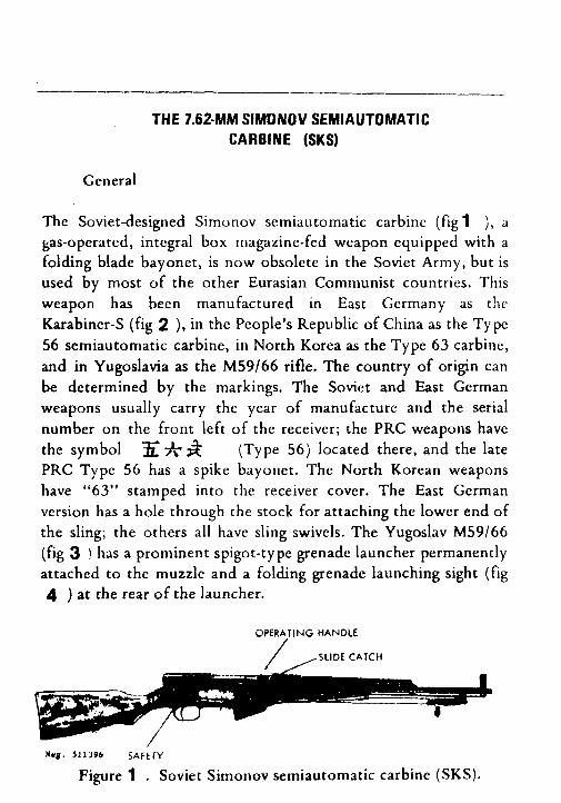
the sling; the others all have sling swivels. The Yugoslav M59/66
(fig 3 ! has a prominent spigot-type grenade launcher permanently
attached to the muzzle and a folding grenade launching sight (fig
4 ) at the rear of the launcher.
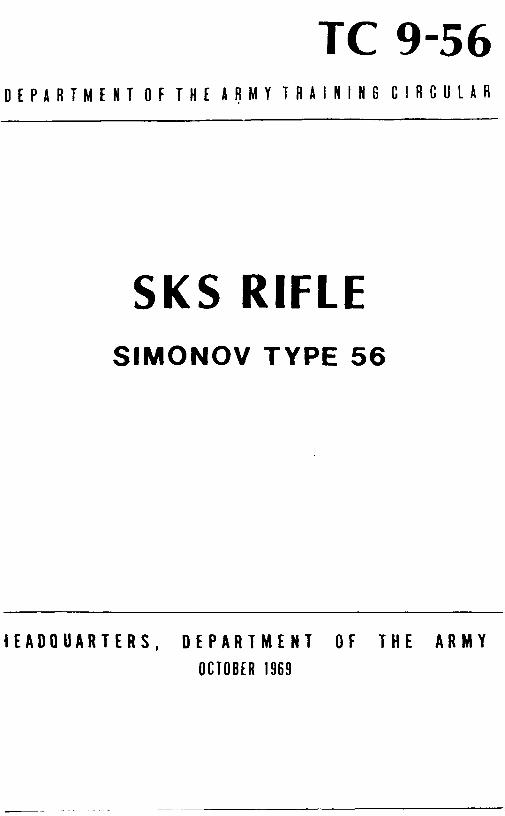
OPERATING HANDLE I
Wu.9. 511396 SAFtlY
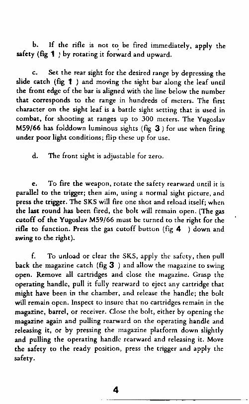
Figure 1 . Soviet Simonov semiautomatic carbine (SKS).
1
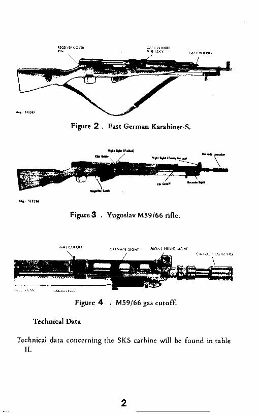
Figure 2 . East German Karabiner-S.
Figure3 . Yugoslav M59/66 rifle.
Figure 4 . M59/66 gas cutoff.
Technical Data
Technical data concerning the SKS carbine will be found in table
II.
Operation
a. Grasp the operating handle (fig 1 ), pull it fully to the
rear, and release it. If the magazine is empty, the bolt will remain
open. Insert a stripper clip into the clip guides at the top front of
the bolt carrier, and with the thumb as close as possible to the
base of the top cartridge, press the cartridges off the clip and into
the magazine (fig 5 ). Remove the empty clip. If clipped
Figure 5 . Loading the SKS.
ammunition is not available, individual cartridges can be placed on
top of the magazine follower and pressed down into the magazine
until it is full. Pull operating handle rearward and release it; the
bolt will run forward and chamber a cartridge.
CAUTION: The rifle is now ready to fire!
3
b. If the rifle is not to be fired immediately, apply the
safety (fig 1 ) by rotating it forward and upward.
C. Set the rear sight for the desired range by depressing the
slide catch (fq 1 ) and moving the sight bar along the leaf until
the front edge of the bar is aligned with the line below the number
that corresponds to the range in hundreds of meters. The first
character on the sight leaf is a battle sight setting that is used in
combat, for shooting at ranges up to 300 meters. The Yugoslav
M59/66 has folddown luminous sights (fii 3 ) for use when firing
under poor light conditions; flip these up for use.
d. The front sight is adjustable for zero.
e. To fire the weapon, rotate the safety rearward until it is
parallel to the trigger; then aim, using a normal sight picture, and
press the trigger. The SKS will fire one shot and reload itself; when
the last round has been fued, the bolt will remain open. (The gas
cutoff of the Yugoslav M59/66 must be turned to the right for the *
rifle to function. Press the gas cutoff button (fig 4 ) down and
swing to the right).
f. To unload or clear the SKS, apply the safety, then pull
back the magazine catch (fig 3 ) and allow the magazine to swing
open. Remove all cartridges and close the magazine. Grasp the
operating handle, pull it fully rearward to eject any cartridge that
might have been in the chamber, and release the handle; the bolt
will remain open. Inspect to insure that no cartridges remain in the
magazine, barrel, or receiver. Close the bolt, either by opening the
magazine again and pulling rearward on the operating handle and
releasing it, or by pressing the magazine platform down slightly
and pulling the operating handle rearward and releasing it. Move
the safety to the ready position, press the trigger and apply the
safety.
4
g- The SKS bayonet is affixed by forcing the hilt to the
rear (against spring pressure) ‘and swinging the bayonet forward
until it locks to the muzzle. This action is reversed to fold the bayonet in its stowed position.
.h. The Yugoslav M49/56 can launch rifle grenades. The
grenades must have tail booms of 22-mm inside diameter and if at
all possible, only Yugoslav-made grenades should be launched.
Prior to firing grenades, clear the rifle and cut off the
gas mechanism by pressing in the lock (fig 4 ) and rotating it to
the top of the gas cylinder. Lift the grenade sight to its vertical
position. Pull the operating handle rearward until it is caught open
and insert a grenade launching cartridge into the chamber.
(Note: These cartridges are packed in the tail booms of the
Yugoslav grenades.) Under no circumstances can a bulleted
cartridge be used; to do so will cause the grenade to explode on
the launcher. Depress the follower and while holding it down pull
the operating handle rearward then ease it forward. Tap the
operating handle forward to insure that the bolt locked. Slide the
appropriate type grenade fully onto the launcher. To launch the
grenade, move the safety to the fire position, align the appropriate
range arc (fig6 ) with the ogive (largest diameter) of the grenade
and then align the sight and grenade on the target. Press the
trigger.
1. Prior to firing successive rounds, the operating handle
must be smartly drawn rearward to eject the fired cartridge case.
Prior to firing bulleted rounds, fold the grenade sight rearward,
press in the lock (fig 6 ) and rotate it to the right as far as
possible.
Disassembly and Assembly
a. To disassemble the SKS carbine:
5
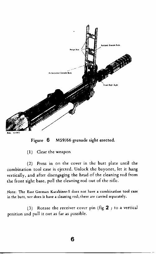
Figure 6 M59/66 grenade sight erected.
(1) Clear the weapon
(2) Press in on the cover in the butt plate until the
combination tool case is ejected. Unlock the bayonet, let it hang
vertically, and after disengaging the head of the cleaning rod from
the front sight base, pull the cleaning rod out of the rifle.
Note: The East German Karabiner-S does not have a combination tool case
in the butt, nor does it have a cleaning rod; these are carried separately.
(3) Rotate the receiver cover pin (fig 2 J to a vertical
position and pull it out as far as possible.
6
Note: It may be necessary to pry the receiver cover pin handle away 1;onl
the receiver before it can be rotated.
Remove the rcceivcr cover to the rear and pull the driving spring
assembly out of the bolt carrier.
(4) Open the magazine by pulling the magazine catch
(fig 3 ) to the rear. Pull the operating handle fully rearward, and
lift the bolt carrier and bolt out of the receiver. Separate the bolt
from the bolt carrier.
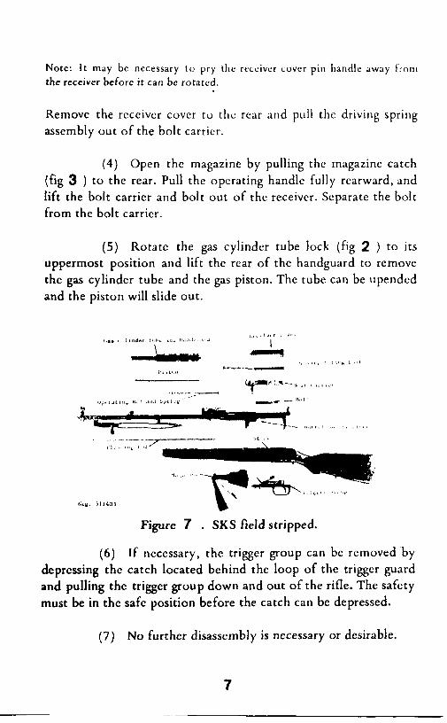
(5) Rotate the gas cylinder tube lock (fig 2 ) to its
uppermost position and lift the rear of the handguard to remove
the gas cylinder tube and the gas piston. The tube can be upended
and the piston will slide out.
Figure 7 . SKS field stripped.
(6) If necessary, the trigger group can be removed by
dcprcssing the catch located behind the loop of the trigger guard
and pulling the trigger group down and out of the rifle. The safety
must be in the safe position before the catch can be depressed.
(7) No further disassembly is necessary or desirable.
7
b. To rcasscmblc the wc;~pon, follow the proccdurc listed
below:
(1) Invert the rifle and engage the pins at the front of
the trigger group with the notches behind the magazine box.
Swing the trigger group into position in the stock and seat it by a
blow of the hand on the loop of the trigger guard. Move the safety
to the fire position to insure that the catch is fully engaged.
(2) Slide the gas piston, small end first, into the gas
cylinder tube; fit the large end of the tube over the gas cylinder
(fig 2 ). Swing the rear end of the gas cylinder tube into the rear
sight base and turn the gas cylinder lock downward.
(3) Place the bolt into the receiver, with the extractor
to the right front, and position the rear of the bolt about
three-eights of an inch from the inner rear wall of the receiver. Lay
the bolt carrier on the bolt and while pressing down on the carrier,
move it slightly back and forth until it mates with the bolt. Slide
the bolt and bolt carrier fully forward in the receiver. Insert the 1
driving spring assembly, stepped end first, into the bolt carrier.
(4) Insure that the receiver cover pin is pulled fully out
to the right, then slide the receiver cover into place from the rear.
Secure it with the receiver cover pin and rotate the pin down to
the locked position. Close the magazine, and replace the cleaning
rod and the combination tool case.
Functioning
a. The SKS semiautomatic carbine is gas operated (fq
8 ). After the SKS has been loaded, pressure on the trigger
releases the hammer, which impacts against the firing pin, firing
the rifle. The propellant gases drive the bullet through the barrel,
8
and after the bullet passes the gas port, some of the gases are
tapped off and directed against t’he piston head.
b. The propellant gases drive the piston and operating rod
rearward against the bolt carrier. This forces the carrier and the
hammer rearward and compresses the driving and hammer springs.
After the bolt carrier moves rearward about one-fourth inch, a
cam on the inner top of the bolt carrier (6, fig 8 ) contacts a
projection on the top rear of the bolt and lifts the rear of the bolt
up and out of its seat in the receiver. The disconnector, which has
been held down by the bolt, now rises. The bolt and bolt carrier
now travel rearward as a unit, while the piston is returned forward
by the spring. The extractor withdraws the fired cartridge case
from the chamber and holds it to the bolt until the case strikes the
fixed ejector and is expelled. The rear end of the bolt carrier
strikes the inner wall of the receiver, and all rearward movement
then terminates.
C. The driving spring expands and forces the bolt and bolt
carrier forward; the bolt drives the top round out of the magazine
and into the chamber. When the cartridge is fully seated in the
chamber, the extractor snaps into the groove of the cartridge, and
forward movement of the bolt ceases. The bolt carrier still has a
short distance to travel, and as it does, cams the rear of the bolt
down into its seat in the receiver; the bolt, as it scats, forces the
disconnector down. All forward movement terminates when the
bolt carrier strikes the receiver.
d. The SKS has a complicated trigger mechanism (fig 9 ).
The hammer is cocked by the recoiling bolt and is held cocked by
a sliding sear. The sear is disengaged from the hammer by a
spring-loaded trigger bar pivoted to the top of the trigger. The
vertical alignment of the trigger bar is controlled by the
disconnector; this, when depressed by the locking of the bolt,
9
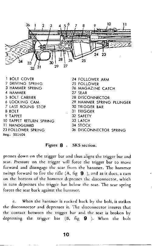
1 BOLT COVER 24 2 DRIVING SPRING 25 3 HAMMER SPRING 26 4 HAMMER 27
5 BOLT CARRIER 28
6 LOCKING CAM 29
7 LAST ROUND STOP 30
8 BOLT 31
9 TAPPET 32
10 TAPPET RETURN SPRING 33
11 HANDGUARD 34
23 FOLLOWER SPRING Neg. 511404
36
FOLLOWER ARM FOLLOWER MAGAZINE CATCH SEAR DISCONNECTOR HAMMER SPRING PLUNGER TRIGGER BAR TRIGGER SAFETY LATCH
STOCK DISCONNECTOR SPRING
Figure 8 . SKS section.
presses down on the trigger bar and thus aligns the trigger bar and
scar. Prcssurc on the trigger will force the trigger bar to move
forward and disengage the scar from the hammer. The hammer
swings forward to fire the rifle (A, f’ig 9 ), and as it does, a cam
on the bottom of the hammer dcprcsscs the disconnector, which
in turn dcprcsses the trigger bar below the scar. The scar spring
forces the sear back against the harnnrer.
C. When the hammer is rocked back by the bolt, it strikes
the disconnector and depresses it. The disconnector insures that
the contact bctwecn the trigger bar and the sear is broken by
depressing the trigger bar (B, fig 9 ). When the bolt
10
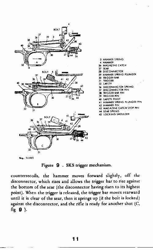
3 HAMMER SPRING
4 HAMMER 26 MAGAZINE CATCH
27 SEAR 28 DISCONNECTOR
29 HAMMER SPRING PLUNGER
30 TRIGGER BAR
31 TRIGGER 32 SAFETY
36 DISCONNECTOR SPRING
37 DISCONNECTOR PIN 38 TRIGGER 8M PIN
39 TRIGGER PIN
40 SAfEW PIVOT 4, HAMMER SPRING PLUNGER PIN
42 HAMMER PIN _ 43 MAGAZINE CATCH STOP PIN
U SEARSPRING 45 LOCKING SHOULDER
Figure 9 . SKS trigger mechanism.
counterrecoils, the hammer moves forward slightly, off the
disconnector, which rises and allows the trigger bar to rise against
the bottom of the sear (the disconnector having risen to its highest
point). When the trigger is released, the trigger bar moves rearward
until it is clear of the sear, then it springs up (if the bolt is locked)
against the disconnector, and the rifle is ready for another shot (C,
fig 9 1.
11
f. The disconnector (B, fig 9 ) prevents the rifle from
firing if the bolt is not fully lockcc!. It does this in two ways: by
its control of the position of the trigger bar; and by a notch in the
disconnector, which intercepts the scar notch of the hammer if the
disconnector is not fully dcprcsscd, such as when the bolt is not
fully lock&
6. The safety, when rotated up to the safe position, places
a block behind the trigger and prevents the trigger from being
pressed.
h. The bolt catch is normally held depressed by a light
spring. When the last round is fed from the magazine, a nib on the
magazine platform contacts the catch and forces it upward. As the
recoiling bolt passes the catch, the catch protrudes into the bolt
path and holds the bolt open.
Accessories
a. The following accessories arc available for use with the
SKS semiautomatic carbine:
(1) Combination tool kit.
(2) Sling.
(3) Charger clips. ‘..,
(4) Standard Soviet pattern two-compar;;n’&t oil and
cleaning solvent container, or Yugoslav one-compartment oiler.
b. The combination tool kit, except for its cap, is similar in
appearance and use to the kit for the AK-47 assault rifle. When
12
used as a cleaning rod guide, the cap is twisted into engagement
with the front sight base.
C. The stripper clips are used to charge the rifle’s magazine.
Each holds 10 cartridges.
Condition
Fails to fire (no cart ridge in
Feile to extract
Defective cartridlc BolL not fully locked
Short recoil
Fouled weepon
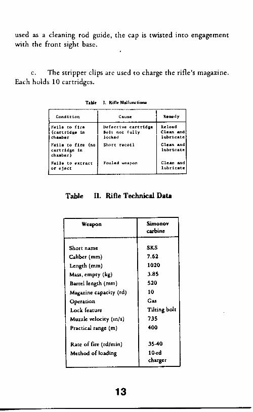
Table II. Rifle Technical Data
Weapon Simonov carbine
Short name
Caliber (mm)
Length (mm)
~w, empty (kg) Barrel length (mm)
Magazine capacity (rd)
Operation
Lock feature
Muzzle velocity (m/s)
I Practical range (m)
Rate of fire (rdlmin)
Method of loading
SKS
7.62
1020
3.85
520
10
Gas
Tilting bolt
735
400
35-40
lo-rd charger
13
I. FURFQSEANDSCOPE
This manual will provide information to the user which will allow proficiency training in the use and care of the Simonov Type 45, or the PRC Type 56 rifles. The information contained within this report will apply to either type rifle and where differences occur you will find notation to that effect.
II. CONDITIONS OF PERFOF!M?WCE
You will be given a Simonov type rifle, ten rounds of 7.62X39MM ammunition, an inert round, a striper clip, and a combination tool kit.
Within the limitations given in performance standards below, adjust, load, fire, reduce a stoppage, unload, and clear the weapon.
IV. PB
A. Adjust, load and fire the weapon. (See fig. 1.) ____________________-____--------___--____---______----------_-
FIGURE 1
-----------------------====------==============================
1. Adjust:
a. Adjust rear sight: (See fig. 2.)
1. Depress slide catch.
2. Slide sight carrier along the leaf until front edge of bar aligns with line below the number that corresponds to specified range in hundreds of meters (100-10000.
14
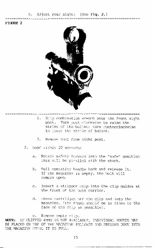
Is. Adjust rear sight: (See fig. 2.)
FIGURE 2
1. Slip combination wrench over the front sight post. Turn ,post clockwise to raise the strike of the bullet; turn conterclockwise to lower the strike of bullet.
2. Remove tool from sight post.
2. Loac' within 20 seconds:
a. Rotate safety for$?ard this will be p'arallcl
b. Pull operatin:! handle
into the "safe" position with the stock.
back and release it. If the magazine is empty, the bolt will remain open.
C. Insert a stripper clip into the clip guides at the front of the bolt carrier.
d. Press cartridges off the clip and into the magazine, (the thumb should be as close to the face of the clip as possible).
e. Remove empty clip. NOTE: IF CLIPPED AM!40 IS YoT AVAILABLE, INDIVIDUAL ROUNDS XAY BE PLACED ON TOP OF THE XAGAZTPJE FOLLOWER AND PRESSED DoW?'J INTO THE YAGAZILJE UNTIL IT IS FUJA.
15
f. Pull operating handle back and release it. (Dolt will go forward and chamber a round).
3. Fire within 5 seconds: ,
a. Rotate the safety selector to the rear until it is pointed full down and is against the rear of the trigger guard. ("FIRE" position).
b. Aim and fire. The bolt will remain closed between rounds and open after the last round.
4. IMMEDIATE ACTION TO: Reduce stoppage.
a. When rifle fails to fire, pull the operating handle back to eject bad round, watch for ejection, release handle to chamber new round.
b. Aim and atempt to fire.
C. If immediate action fails to reduce stoppage, unload, clear, disassemble, and inspect. Repair or replace defect and reasemble.
5. UNLOAD AND CLEAR WEAPON:
a.
b.
C.
d.
e.
f.
g.
h.
Place weapon on "SAFE".
Pull back magazine catch and allow magazine to swing open.
Remove all cartridges
Close the magazine.
Pull operating handle remaining rounds.
to the rear to eject any
Release the handle (bolt will remain open).
Inspect to insure no cartridges remain in the magazine, chamber, or receiver.
Close bolt:
1. Open magazine again and pull operating handle to rear and release.
2. Pull operating handle to the rear, press down on the magazine follower slightly, then ease bolt carrier forward.
16
' 1. Move safety td "FIRE" position.
j. Press trigger.
k. Place weapon on "SAFE". -~------~~---~~~-----~~---~-~~------_----~~---~~~-----~----~--- ____----------------------------------------------------------- ---__-----_-----___---~------~__---___----_---_~~---~~~-----~~- --~__--------~--__---~~----__-------------_---~_~--____~---_~~-
17
You will learn disassembly, cleaning, reassembly of the weapon within 35 minutes. You will also learn ammunition maintainence and to perform a function check.
VI. CONDITION OF PERFORTUNCJZ
You will be given an SKS rifle, a cleaning rod and combination tool kit, 10 rounds of 7.62 X 3MM ammunition, a wire bore brush, chamber brush, and toothbrush, rifle bore cleaner, lube oil, solvent, cleaning patches, and clean rags.
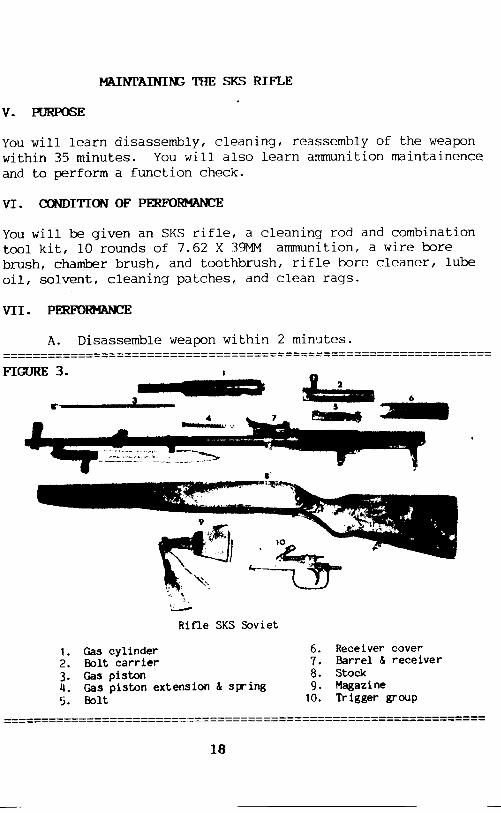
VII. PERFOEMANCE
A. Disassemble weapon within 2 minutes. ---------_------------__-___----____---------~~~~~~~~~-_____-~~~ ____-________________------__-------_--____--
1. 2.
Z: 5.
-., 1 I I
\-
Rifle SKS Soviet
Gas cylinder Bolt carrier Gas piston Gas piston extension & sp-ing Bolt
Receiver cover ;: Barrel & receiver 8. stock 9. Magazine
10. Trigger group ----___-------_______------~ ===================================___--------_-_-------- __----
18
1. Insure weapon is clear and on "SAFE".
2. Remove recoil spring assembly:
a. Rotate the receiver cover retaining pin to the vertical position and pull to the right.
b. Remove the receiver cover by sliding it to the rear and lifting off.
c. Pull the recoil spring assembly from the bolt carrier.
3. Remove the bolt and carrier.
a. Pull operating handle to the rear.
b. Lift the bolt and bolt carrier out of the receiver.
4. Separate the bolt from the carrier.
5. Remove the gas cylinder and piston:
a. Rotate the gas cylinder tube lock until the handle is at a 45 degree angle to the rear.
b. Lift the rear of the handguard to remove the gas cylinder tube and gas piston.
c. Lower front end of tube and allow piston to slide out.
6. Remove gas piston extension and spring:
a. Place thumb in front of rear sight base.
b. Rotate gas cylinder tube lock slowly forward.
C. Remove and separate piston extension and spring.
7. Remove trigger group:
a. Insure weapon is on "SAFE".
b. Push in on trigger group retaining lock.
c. Pull trigger group up and out.
19 ~_ ~__ ~ -
a. Remove magazine by pulling up and out.
e. Unlock bayonet and separate barrel from the stock.
B. Identify weapon parts. (See fig 2).
C. Cleaning and maintainance. (See page 22).
D. Reassemble weapon within 4 minutes:
1. Attach barrel to stock, and into closed position.
lock bayonet
2. Replace magazine into stock open.
3. Replace trigger group:
a. Invert rifle and engage
leaving it
pins at the front of the trigger group (notches must be behind the magazine box).
b. Swing trigger group into position in the stock (seat it by a hand blow on the loop of the trigger guard).
c. Move safety to "FIRE" position to insure catch is fully engaged.
4. Replace gas piston extension and spring:
a. Place gas piston extension and spring:
b. Hold gas tube lock in vertical position.
C. Insert gas piston extension with spring back into it's recess in front of the rear sight.
d. Push back into recess until it can be locked into place.
e. Dock by rotating gas tube lock 45 degree angle to the rear.
5. Replace gas cylinder tubs and piston:
a. Slide gas piston, small end first, into the front of the gas tube.
20
b. Fit large end of gas tube over the gas cylinder block on barrel.
C. Swing rear end of gas cylinder tube into rear sight base.
d. Turn gas cylinder lock down into the detent.
6. Replace bolt and carrier:
a. Connect bolt and carrier together and place bolt and carrier into the receiver.
b. Push down and forward all the way to seat.
7. Replace recoil spring assembly:
a. Insert recoil spring assembly, curled end first, into bolt carrier.
b. Pull receiver cover pin fully to the right.
C. Slide receiver cover into place from the rear.
d. Secure cover with receiver cover pin.
e. Rotate pin down to locked position.
8. Close magazine.
VII. P-~IONCHlXKWI'lWIN20SECONDS.
1. Pull operating handle to the rear and hold it.
2. Press down on magazine follower.
3. Allow bolt to go forward.
4. Place safety lever on "SAFE".
5. Press trigger (harmwar should not go forward).
6. Place safety lever on "FIRE".
7. Press trigger (hamner should go forward).
21
Ix. CL-THE-.
1. Use rifle bore cleaner (RRC) to clean the face of the slide.
2. Clean the bore and chamber by:
a. Wetting a patch with Rl3C and running it back and forth through the bore several times.
b. Attach a bore brush to the cleaning rod and run several
it through the bore and chamber times.
c. Run dry patches through the bore and chamber until they come out clean.
d. Inspect bore for fouling and residue. If it is not clean, repeat the above cleaning process.
3. Clean the other parts with RBC or a cleaning solvent to remove all grease, dirt, or powder fouling. Soak small parts in cleaning solution.
4. Dry the parts using clean, dry rags.
5. Cover all parts with a light coat of oil.
22