sl20 22m gb - bradley scott windows · 2018. 2. 9. · sl1042 slat spacer 12.5 mm sl1148 cord...
TRANSCRIPT
Pelli
niS.
p.A
.vi
a Fu
sari
, 19
• 26
845
Co
do
gn
o (
LO)
ITA
LIA
T. +
39
0377
466
411
• F.
+ 3
9 03
77 4
3763
5 •
info
@p
ellin
i.net
SL20
M
SL22
MM
TL01
4GB
Edit
ion
05.
07
www.pellini.net
visu
al d
esig
n: s
tefa
no
sib
on
i.it
Tech
nic
al C
atal
og
ue
engl
ish
SL20MVENETIAN BLIND
double-glazed unit 20 mm • 22 mm
Scre
enLin
e
SL22M
ScreenLine®
copertina SL20-22M_GB 20-04-2007 9:47 Pagina 1
ScreenLine2
tech
nic
al s
pec
ific
atio
nSL
20M
S
L22M
Syst
em M M
SL20MVENETIAN BLIND
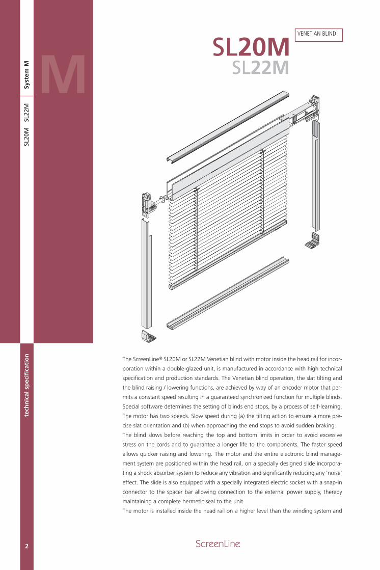
The ScreenLine® SL20M or SL22M Venetian blind with motor inside the head rail for incor-
poration within a double-glazed unit, is manufactured in accordance with high technical
specification and production standards. The Venetian blind operation, the slat tilting and
the blind raising / lowering functions, are achieved by way of an encoder motor that per-
mits a constant speed resulting in a guaranteed synchronized function for multiple blinds.
Special software determines the setting of blinds end stops, by a process of self-learning.
The motor has two speeds. Slow speed during (a) the tilting action to ensure a more pre-
cise slat orientation and (b) when approaching the end stops to avoid sudden braking.
The blind slows before reaching the top and bottom limits in order to avoid excessive
stress on the cords and to guarantee a longer life to the components. The faster speed
allows quicker raising and lowering. The motor and the entire electronic blind manage-
ment system are positioned within the head rail, on a specially designed slide incorpora-
ting a shock absorber system to reduce any vibration and significantly reducing any ‘noise’
effect. The slide is also equipped with a specially integrated electric socket with a snap-in
connector to the spacer bar allowing connection to the external power supply, thereby
maintaining a complete hermetic seal to the unit.
The motor is installed inside the head rail on a higher level than the winding system and
SL22M
SL20 22M_GB 15-05-2007 9:39 Pagina 2
technical features
3
1.
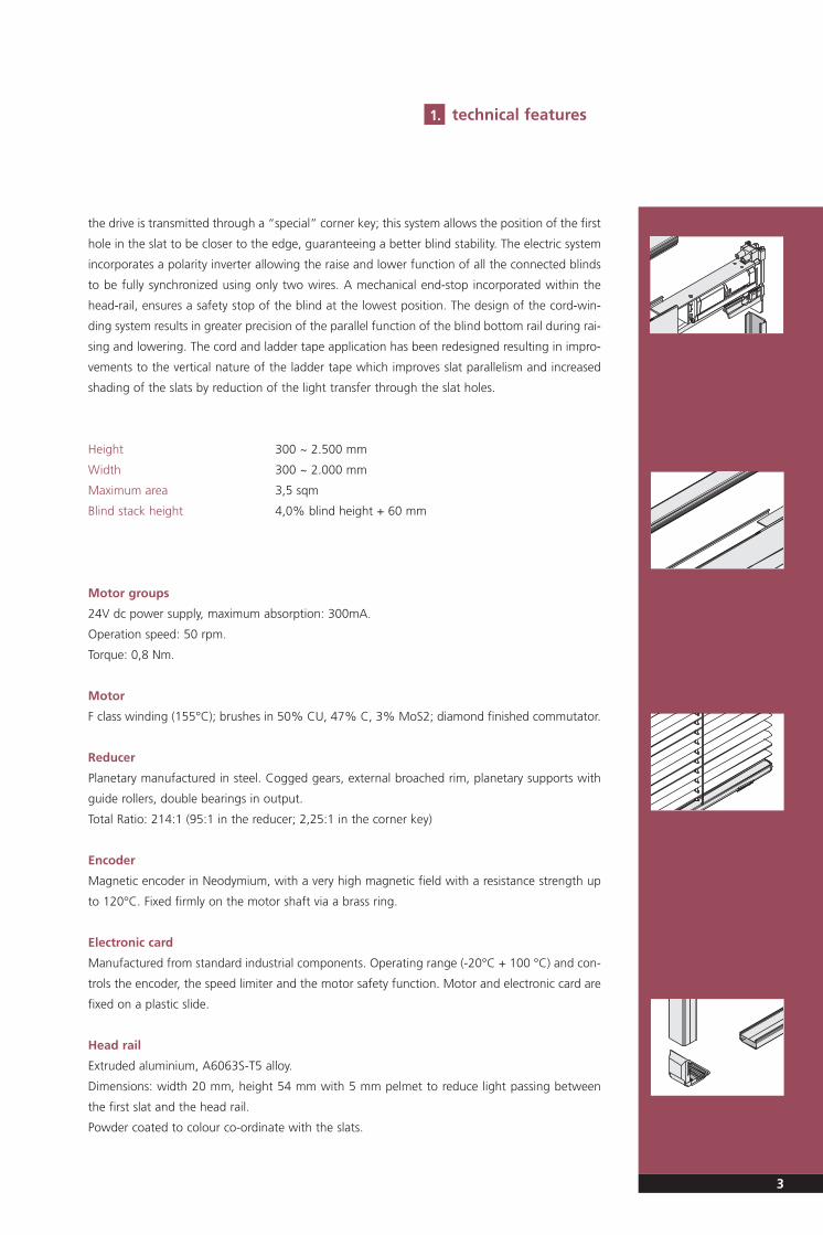
the drive is transmitted through a “special” corner key; this system allows the position of the first
hole in the slat to be closer to the edge, guaranteeing a better blind stability. The electric system
incorporates a polarity inverter allowing the raise and lower function of all the connected blinds
to be fully synchronized using only two wires. A mechanical end-stop incorporated within the
head-rail, ensures a safety stop of the blind at the lowest position. The design of the cord-win-
ding system results in greater precision of the parallel function of the blind bottom rail during rai-
sing and lowering. The cord and ladder tape application has been redesigned resulting in impro-
vements to the vertical nature of the ladder tape which improves slat parallelism and increased
shading of the slats by reduction of the light transfer through the slat holes.
Height 300 ~ 2.500 mm
Width 300 ~ 2.000 mm
Maximum area 3,5 sqm
Blind stack height 4,0% blind height + 60 mm
Motor groups
24V dc power supply, maximum absorption: 300mA.
Operation speed: 50 rpm.
Torque: 0,8 Nm.
Motor
F class winding (155°C); brushes in 50% CU, 47% C, 3% MoS2; diamond finished commutator.
Reducer
Planetary manufactured in steel. Cogged gears, external broached rim, planetary supports with
guide rollers, double bearings in output.
Total Ratio: 214:1 (95:1 in the reducer; 2,25:1 in the corner key)
Encoder
Magnetic encoder in Neodymium, with a very high magnetic field with a resistance strength up
to 120°C. Fixed firmly on the motor shaft via a brass ring.
Electronic card
Manufactured from standard industrial components. Operating range (-20°C + 100 °C) and con-
trols the encoder, the speed limiter and the motor safety function. Motor and electronic card are
fixed on a plastic slide.
Head rail
Extruded aluminium, A6063S-T5 alloy.
Dimensions: width 20 mm, height 54 mm with 5 mm pelmet to reduce light passing between
the first slat and the head rail.
Powder coated to colour co-ordinate with the slats.
SL20 22M_GB 15-05-2007 9:39 Pagina 3
ScreenLine4
VENETIAN BLINDte
chn
ical
sp
ecif
icat
ion
SL20
M
SL2
2M Slat
Aluminium, AA 6010-T8 alloy. Dimensions: width 12,5 mm, thickness 0.2 mm.
High-resistance polyester paint. Available colours: nine.
The slat have a special treatment designed to eliminate possible emissions of chemical products
inside the double-glazed unit, when exposed to ultraviolet and heat radiation i.e. non-fogging.
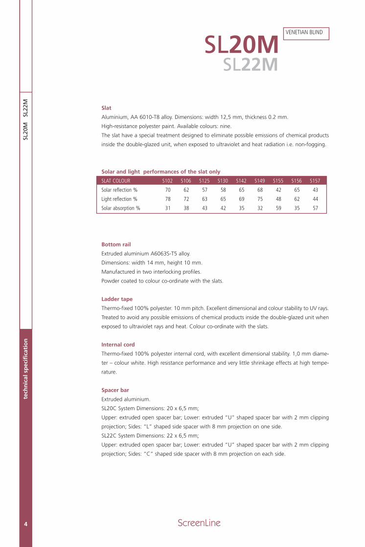
Solar and light performances of the slat only
SLAT COLOUR S102 S106 S125 S130 S142 S149 S155 S156 S157
Solar reflection % 70 62 57 58 65 68 42 65 43
Light reflection % 78 72 63 65 69 75 48 62 44
Solar absorption % 31 38 43 42 35 32 59 35 57
Bottom rail
Extruded aluminium A6063S-T5 alloy.
Dimensions: width 14 mm, height 10 mm.
Manufactured in two interlocking profiles.
Powder coated to colour co-ordinate with the slats.
Ladder tape
Thermo-fixed 100% polyester. 10 mm pitch. Excellent dimensional and colour stability to UV rays.
Treated to avoid any possible emissions of chemical products inside the double-glazed unit when
exposed to ultraviolet rays and heat. Colour co-ordinate with the slats.
Internal cord
Thermo-fixed 100% polyester internal cord, with excellent dimensional stability. 1,0 mm diame-
ter – colour white. High resistance performance and very little shrinkage effects at high tempe-
rature.
Spacer bar
Extruded aluminium.
SL20C System Dimensions: 20 x 6,5 mm;
Upper: extruded open spacer bar; Lower: extruded “U” shaped spacer bar with 2 mm clipping
projection; Sides: “L” shaped side spacer with 8 mm projection on one side.
SL22C System Dimensions: 22 x 6,5 mm;
Upper: extruded open spacer bar; Lower: extruded “U” shaped spacer bar with 2 mm clipping
projection; Sides: “C” shaped side spacer with 8 mm projection on each side.
SL20MSL22M
SL20 22M_GB 15-05-2007 9:39 Pagina 4
ScreenLine 5
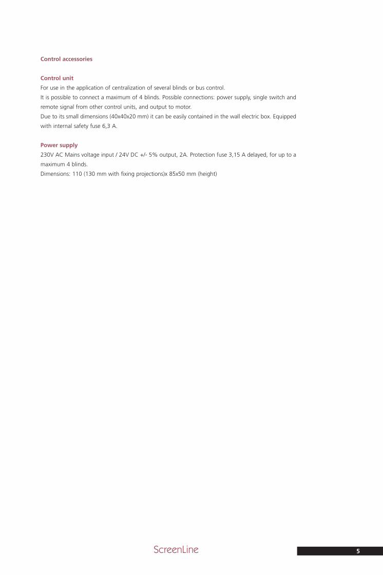
Control accessories
Control unit
For use in the application of centralization of several blinds or bus control.
It is possible to connect a maximum of 4 blinds. Possible connections: power supply, single switch and
remote signal from other control units, and output to motor.
Due to its small dimensions (40x40x20 mm) it can be easily contained in the wall electric box. Equipped
with internal safety fuse 6,3 A.
Power supply
230V AC Mains voltage input / 24V DC +/- 5% output, 2A. Protection fuse 3,15 A delayed, for up to a
maximum 4 blinds.
Dimensions: 110 (130 mm with fixing projections)x 85x50 mm (height)
SL20 22M_GB 15-05-2007 9:39 Pagina 5

SL20
M
6 ScreenLine
SL20M
SL1818Extruded open spacer bar20x6,5 mm
SL1850Tube support SL20-22M
SL1848 - SL1849End stop RHEnd stop LH
SL1149Ladder tape fixing ring
SL1042Slat spacer 12.5 mm
SL1148Cord fixing ring
SL1052Calibrated tube
SL1817Head rail (painted)
SL1145Sliding tube cap
SL1844Internal motor with encoder
SL1740Extruded "L" shaped spacer bar20x6,5 mm
SL11651 mm internal cord
SL105720 mmplastic corner key
SL1199Ladder tape 12,5 mm
SL1217ScreenLineplastic label
SL1542Extruded "U" shaped spacer bar20x6,5 mm
SL125212,5 mmnon-fogging slat
SL1196Bottom rail(painted)
SL1627Bottom railweight 15 gr
SL1197Bottom rail cover
SL1154Ladder tape fixing plug
SL1155Bottom rail end cap
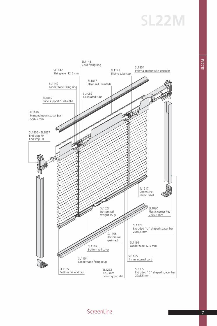
2. technical drawings
comprehensive drawing with component codes
SL20 22M_GB 15-05-2007 9:39 Pagina 6
ScreenLine 7
SL22
M
SL22M
SL1819Extruded open spacer bar22x6,5 mm
SL1850Tube support SL20-22M
SL1856 - SL1857End stop RHEnd stop LH
SL1149Ladder tape fixing ring
SL1042Slat spacer 12.5 mm
SL1148Cord fixing ring
SL1052Calibrated tube
SL1817Head rail (painted)
SL1145Sliding tube cap
SL1854Internal motor with encoder
SL1772Extruded "C" shaped spacer bar22x6,5 mm
SL11651 mm internal cord
SL1820Plastic corner key22x6,5 mm
SL1199Ladder tape 12,5 mm
SL1217ScreenLineplastic label
SL1773Extruded "U" shaped spacer bar22x6,5 mm
SL125212,5 mmnon-fogging slat
SL1196Bottom rail(painted)
SL1627Bottom railweight 15 gr
SL1197Bottom rail cover
SL1154Ladder tape fixing plug
SL1155Bottom rail end cap
SL20 22M_GB 15-05-2007 9:39 Pagina 7
SL20
M
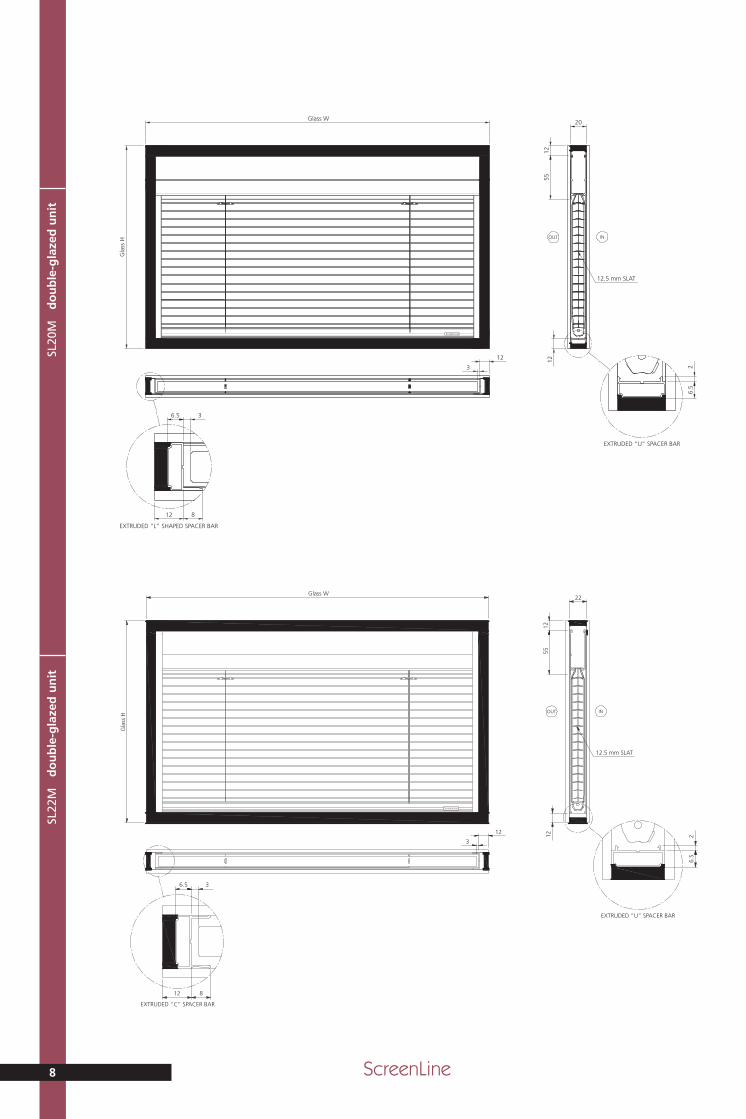
do
ub
le-g
laze
d u
nit
8 ScreenLine
ScreenLine
Glass WG
lass
H
12.5 mm SLAT
INOUT
20
5512
6.5
2
EXTRUDED “U” SPACER BAR
12
3
36.5
12
EXTRUDED “L” SHAPED SPACER BAR
8
12
SL22
M
do
ub
le-g
laze
d u
nit
ScreenLine
Glass W
Gla
ss H
36.5
12
EXTRUDED “C” SPACER BAR
8
12
3
6.5
2
EXTRUDED “U” SPACER BAR
12
12.5 mm SLAT
INOUT
22
5512
SL20 22M_GB 15-05-2007 9:39 Pagina 8
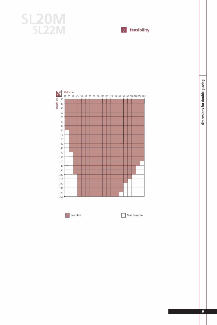
Feasible Not feasible
feasibility3.
9
SL20M
dim
ensi
ons
for
doub
le g
lazi
ng
30
40
50
60
70
80
90
100
110
120
130
140
150
160
170
180
190
200
210
220
230
240
250
30 35 40 45 50 60 70 80 90 100 110 120 130 140 150 160 170 180 190 200
Width cm
Hei
ght
cm
WH
SL22M
SL20 22M_GB 15-05-2007 9:39 Pagina 9
SL20
M
SL2
2M
co
ntr
ol u
nit
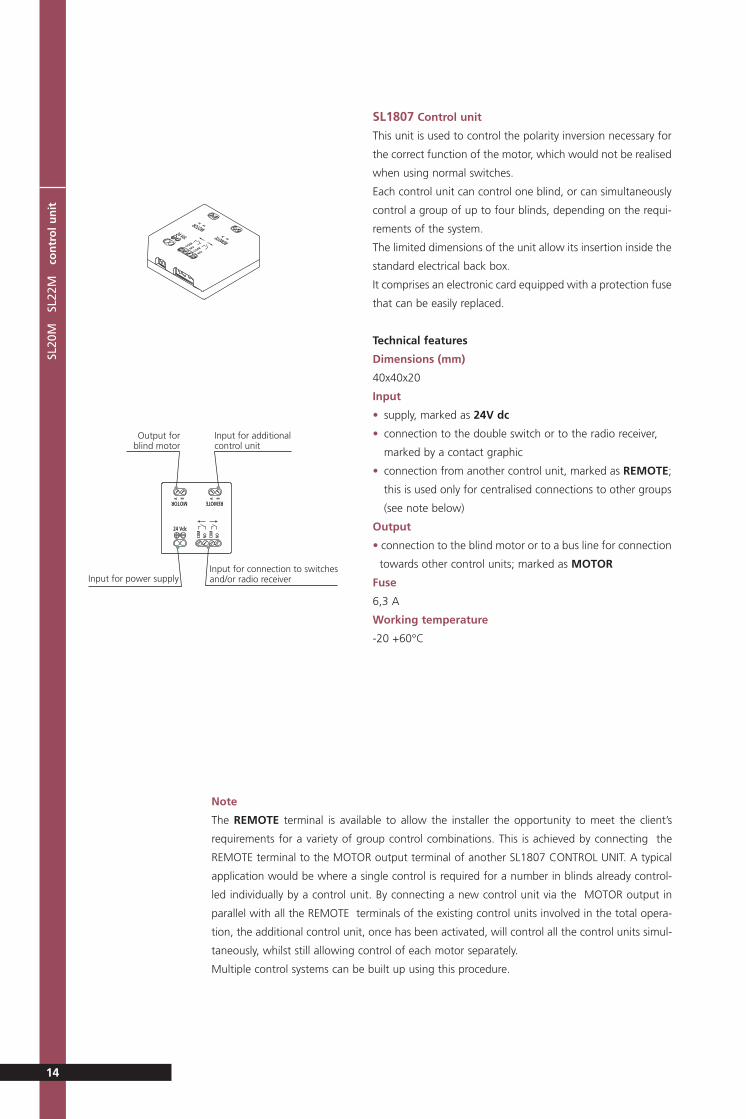
SL1807 Control unit
This unit is used to control the polarity inversion necessary for
the correct function of the motor, which would not be realised
when using normal switches.
Each control unit can control one blind, or can simultaneously
control a group of up to four blinds, depending on the requi-
rements of the system.
The limited dimensions of the unit allow its insertion inside the
standard electrical back box.
It comprises an electronic card equipped with a protection fuse
that can be easily replaced.
Technical features
Dimensions (mm)
40x40x20
Input
• supply, marked as 24V dc
• connection to the double switch or to the radio receiver,
marked by a contact graphic
• connection from another control unit, marked as REMOTE;
this is used only for centralised connections to other groups
(see note below)
Output
• connection to the blind motor or to a bus line for connection
towards other control units; marked as MOTOR
Fuse
6,3 A
Working temperature
-20 +60°C
14
Note
The REMOTE terminal is available to allow the installer the opportunity to meet the client’s
requirements for a variety of group control combinations. This is achieved by connecting the
REMOTE terminal to the MOTOR output terminal of another SL1807 CONTROL UNIT. A typical
application would be where a single control is required for a number in blinds already control-
led individually by a control unit. By connecting a new control unit via the MOTOR output in
parallel with all the REMOTE terminals of the existing control units involved in the total opera-
tion, the additional control unit, once has been activated, will control all the control units simul-
taneously, whilst still allowing control of each motor separately.
Multiple control systems can be built up using this procedure.
MOTOR
REMOTE24 Vdc
COMNO
COMNO
AB
AB
MOTOR REMOTE
24 Vdc
COM
NO COM
NO
A B A B
Output forblind motor
Input for additionalcontrol unit
Input for power supplyInput for connection to switchesand/or radio receiver
SL20 22M_GB 15-05-2007 9:39 Pagina 14
SL20
M
SL2
2M
po
wer
su
pp
ly
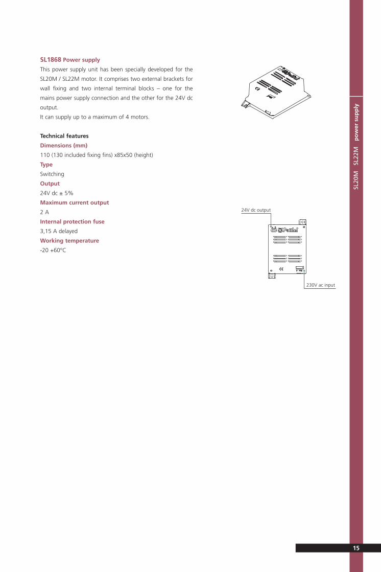
SL1868 Power supply
This power supply unit has been specially developed for the
SL20M / SL22M motor. It comprises two external brackets for
wall fixing and two internal terminal blocks – one for the
mains power supply connection and the other for the 24V dc
output.
It can supply up to a maximum of 4 motors.
Technical features
Dimensions (mm)
110 (130 included fixing fins) x85x50 (height)
Type
Switching
Output
24V dc ± 5%
Maximum current output
2 A
Internal protection fuse
3,15 A delayed
Working temperature
-20 +60°C
15
24V dc output
230V ac input
SL20 22M_GB 15-05-2007 9:39 Pagina 15

SL20
M
SL2
2M
tra
nsm
itte
rSL
20M
S
L22M
r
ecei
ver
Remote control
The remote control for the SL20M system is by radio control,
FM, comprising a transmitter and a receiver.
SL1821 Transmitter
Can control a single group of blinds or two groups of blinds.
It has 4 channels linked to switches and a L.E.D. display.
Technical features
Dimensions (mm)
67x34x8 (height)
Battery
CR2032
Frequency
433.920 MHz
Number of possible combination
266
Channel
No. 4
SL1822 Receiver
It has only two channels (UP/DOWN) and therefore it is able to
control only one control unit.
Its terminal board allows connection to the 24V dc low tension
power supply and to the contact out- put terminals. It incor-
porates two switches and two L.E.D. signals for the transmit-
ter program function.
Technical features
Dimensions (mm)
79x48x21 (height)
Power supply
24Vac/dc
Stand-by consumption
40mA
Working temperature
-20 +60°C
Code memorisation ability
500
Channel
No. 2
16
L.E.D.
Button
Cord loop
P1 button P2 button
L.E.D. L.E.D.
Contacts output
Power supply inputRadio aerial
SL20 22M_GB 15-05-2007 9:39 Pagina 16

Remote control programming
The receiver of the remote control must be programmed during installation in order to be con-
nected to the signals from the transmitter.
The receiver is equipped with a programming procedure to automatically recognise the trans-
mitter (self learning); this is simply achieved by pressing the button on the receiver.
Receiver programming procedure
Press the ‘P1’ button located on the receiver and the respective L.E.D. will flash 5 times.
During this flashing period, press one of the transmitter buttons to memorise the position. The
L.E.D. on the receiver will now continuously flash for 3 seconds to confirm positive record of
setting.
To set channel ‘P2’, on the receiver repeat the above operation, using the other button loca-
ted on the transmitter.
Electric connection to the blind
Connect the two-core cable with the attached ring connectors to the terminals located in the
top right corner key (top left on request), using the 2 No. screws provided. For this procedu-
re, please see the picture sequence present on the assembly instructions (H1 & H2).
During this operation please ensure that the screws are fully tightened to avoid bad connec-
tion and subsequent malfunction.
Cover the area around the connection with more secondary sealant to ensure no possibility
of water penetration creating a short circuit after glazing.
Ensure that there is no possibility of the wires being damage by the framing system causing
a short circuit.
Function of the blind
The system SL20M – SL22M must be connected to a power supply sufficient to ensure a con-
stant 24V dc supply to all the connected motors.
The electronic card, contained inside the blind, controls the several functions, one of which
controls the stop position corresponding to the end stop of the top and bottom positions.
The dedicated software provides two speeds. Slow speed to optimise the tilting function of
the slats and to stop the motor slowly as the blind approaches the end stops, and a higher
speed for the raising and lowering function.
The blind function (Up / Down) is activated by switching the power supply (inversion).
It is possible to control the up / down inversion using a rocker switch (two way retractable –
centre off), or by a double commutator switch, or alternatively by remote radio control.
• Using a double commutator switch (i.e. Vimar – Idea serie – code 16145), it is possible to
connect all the blinds to be controlled simultaneously with only two wires.
• A standard rocker type switch should be used in conjunction with a dedicated ‘control unit’.
This system will allow any group of up to 4 blinds to be controlled together using only two
wires.
diagrams electric
17
SL20 22M_GB 15-05-2007 9:39 Pagina 17

• Remote radio control should also be used in conjunction with a dedicated ‘control unit’.
The following selection of wiring diagrams indicates the wide variety of possible combina-
tions.
To tilt the slats of the blind, keep pressing the respective up or down switch till the desi-
red inclination is achieved. The slow speed at the start of the process allows accurate slat
inclination. By using a double commutator switch, the slat position is adjusted by quickly
pressing and releasing the up or down buttons.
To raise/lower the blind, by pressing the switch continuously, the speed will change from
the slow speed for tilting to fast speed for raise / lower. Once the fast speed is reached, the
button can be released and the blind will automatically continue to its stop position.(top
or bottom). This procedure increase the ‘life’ of the system, since it avoids any excessive
stop / starts. When using a commutator switch, the button will need to be depressed until
the blind reaches the desired position.
To stop the stroke of the blind, press the UP or Down button or move towards the cen-
tre the double commutator switch.
Setting of the blind end stops
The setting of the blind end stops is carried out in the Company during manufacture.
The motor has a self-learning process: the blind, during the raise and lower operation is
able to recognise the extreme positions and to memorise them. Once these limits are
memorised, the blind will move between these two positions, and when nearing the limit
the blind will slowly come to rest and so avoid sudden stops which results in less stress on
the components.
When the motor experiences a sudden increase in the energy absorption or a remarkable
reduction of the motor speed, as a possible result of glass deflection (e.g. reduced cavity),
the blind will stop. When this occurs all previous limits are over-ridden and the blind will
wait till new one’s are self-learned. When this unexpected stop occurs, and the cause of
the blind to stop is resolved, the original end stop will be automatically reset and the blind
will function normally.
Where it is deemed a faster recognition of the end stop by the motor is required, the fol-
lowing procedure must be followed (at least two times). Raise the blind by pressing the UP
button; the blind raises and forms a stack at the top limit and then goes down a few mil-
limetres, signalling that the end stop has been memorised. Then press the down button
and wait till the blind reaches the lower limit and stops.
Where the blind stops before reaching the lower position, to reset the original end stop
press the down button again until the blind goes down further and then comes to a sud-
den stop. The motor then memorises this lower position and will approach the limit more
slowly when nearing this limit in future movements.
diagrams electric
18
SL20 22M_GB 15-05-2007 9:39 Pagina 18
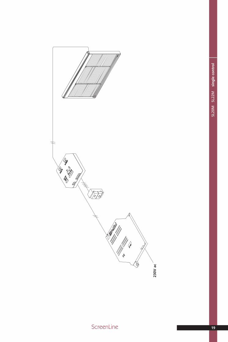
ScreenLine 19
SL20
M
SL2
2M
si
ng
le c
on
tro
l
230V
ac
SL20 22M_GB 15-05-2007 9:39 Pagina 19
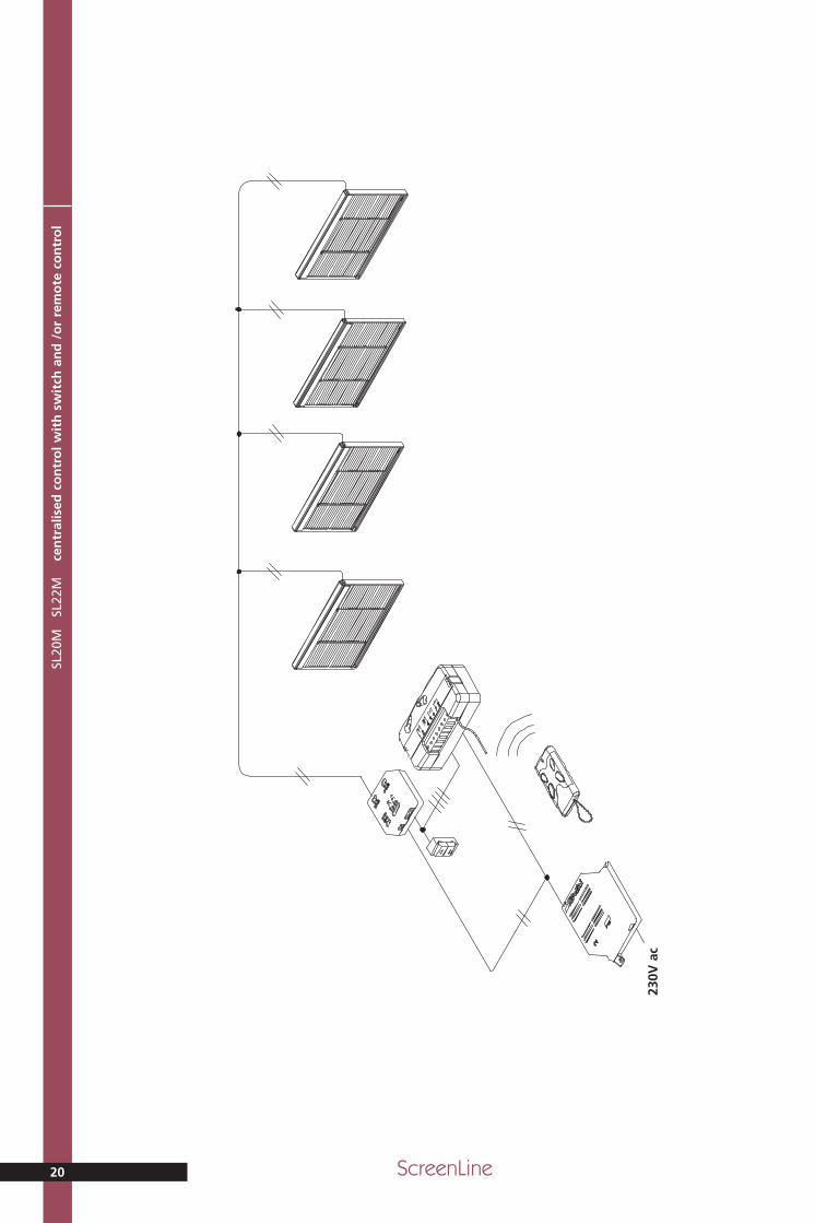
SL20
M
SL2
2M
ce
ntr
alis
ed c
on
tro
l wit
h s
wit
ch a
nd
/o
r re
mo
te c
on
tro
l
20 ScreenLine
230V
ac
SL20 22M_GB 15-05-2007 9:39 Pagina 20
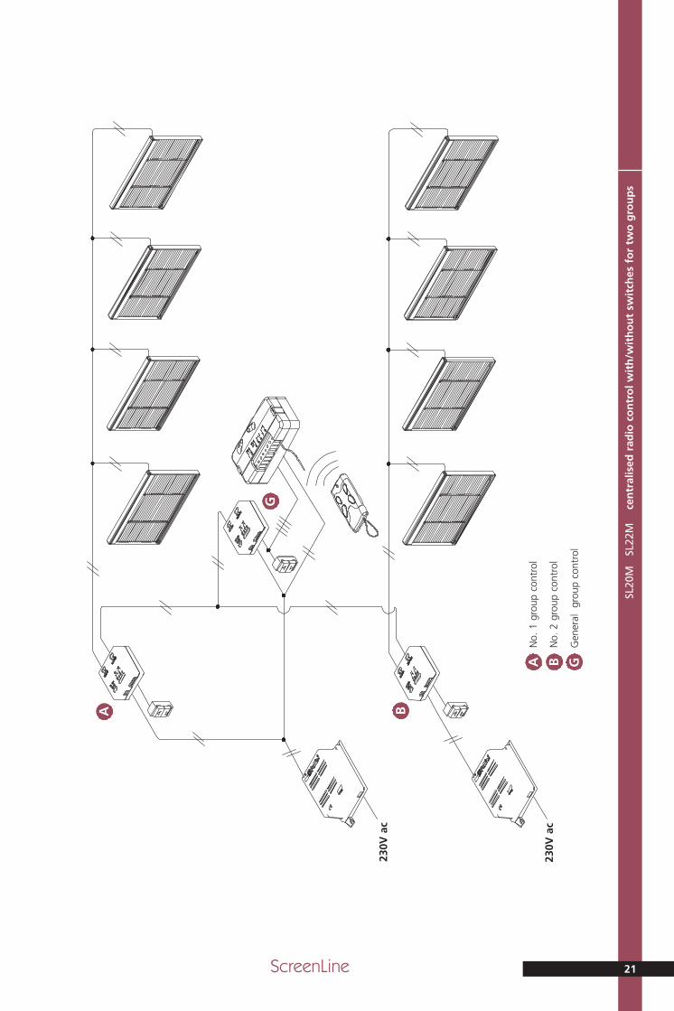
ScreenLine 21
SL20
M
SL2
2M
ce
ntr
alis
ed r
adio
co
ntr
ol w
ith
/wit
ho
ut
swit
ches
fo
r tw
o g
rou
ps
230V
ac
230V
ac
A B
G
A B G
No.
1 g
roup
con
trol
No.
2 g
roup
con
trol
Gen
eral
gr
oup
cont
rol
SL20 22M_GB 15-05-2007 9:39 Pagina 21
SL20
M
SL2
2M
ce
ntr
alis
ed c
on
tro
l an
d s
ing
le c
on
tro
l fo
r tw
o g
rou
ps
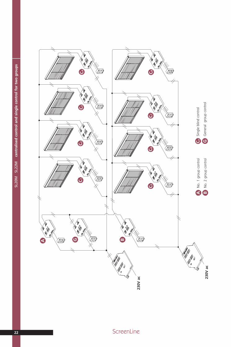
22 ScreenLine
230V
ac 23
0V a
c
BA GC
1C
2C
3C
4
C5
C6
C7
C8
A B
No.
1 g
roup
con
trol
No.
2 g
roup
con
trol
Cx G
Sing
le b
lind
cont
rol
Gen
eral
gr
oup
cont
rol
SL20 22M_GB 15-05-2007 9:39 Pagina 22

ScreenLine 23
SL20
M
SL2
2M
ce
ntr
alis
ed c
on
tro
l wit
h s
wit
ch a
nd
/ o
r re
mo
te c
on
tro
l an
d s
ing
le s
wit
ch
230V
ac 23
0V a
c
G
C1
C2
C3
C4
C5
C6
C7
C8
Cx G
Sing
le b
lind
cont
rol
Gen
eral
gr
oup
cont
rol
SL20 22M_GB 15-05-2007 9:39 Pagina 23
Pelli
niS.
p.A
.vi
a Fu
sari
, 19
• 26
845
Co
do
gn
o (
LO)
ITA
LIA
T. +
39
0377
466
411
• F.
+ 3
9 03
77 4
3763
5 •
info
@p
ellin
i.net
SL20
M
SL22
MM
TL01
4GB
Edit
ion
05.
07
www.pellini.net
visu
al d
esig
n: s
tefa
no
sib
on
i.it
Tech
nic
al C
atal
og
ue
engl
ish
SL20MVENETIAN BLIND
double-glazed unit 20 mm • 22 mm
Scre
enLin
e
SL22M
ScreenLine®
copertina SL20-22M_GB 20-04-2007 9:47 Pagina 1