slope stability analysis of a jamuna river embankment · sirajganj near the bank of jamuna river....
TRANSCRIPT
Journal of Civil Engineering (IEB), 42 (1) (2014) 119-136
Slope stability analysis of a Jamuna riverembankment
Nuzhath Fatema and Mehedi Ahmed Ansary
Department of Civil Engineering,Bangladesh University of Engineering and Technology, Dhaka 1000, Bangladesh
Received 11 March 2013
Abstract
A study on Slope Stability Analysis of an embankment has been carried out considering differentslopes at different conditions. For this purpose embankment soil has been collected from Basuria inSirajganj near the bank of Jamuna River. Also field bore logs has been done up to a depth of 30 m.Grain size analysis of the sample reveals that it contains 63% sand, 35% silt and 2% clay, which meansthe sample, is not pure sandy soil. According to Unified Soil Classification System (USCS) the soilsample is SW – SM. To obtain the shear strength parameters of the collected disturbed sample of theembankment, a remolded sample has been made in the laboratory. For that purpose StandardCompaction Test has been carried out. Consolidated Undrained Shear test has been performed to obtainthe shear strength parameters. The cohesion and angle of internal friction are found to be 7 kPa and 21°respectively from shear test. For the parametric study, shear strength parameters have been modified tobe 10 kPa; 14° and 20 kPa; 12°. The shear strength parameters of the underlying soils have beenobtained using the existing correlation with SPT-N value shown in the bore logs. Based on the resultsof soil investigations, stability analysis using STB2010 at some conditions (dry, high flood level, lowflood level and rapid drawdown with slope 1:1, 1:1.5 and 1:2) of the embankment has been performed.It has been found that the safety factor decreases with steep slope while increasing with flatter one. Asthe recommended minimum safety factor is 1.2, the strength of soil mostly depends on the factorwhether it’s protected or not. From the analysis it has been found that except the soil at high flood levelwith 1:1 slope and rapid drawdown condition with all three slopes, rest of the soils with givencondition have satisfied the factor. The maximum safety factor has been found 2.255 for soil at drycondition with a slope 1:2 while the minimum factor is 0.66 at rapid drawdown condition with 1:1slope. Hence we can realize that the soil having the minimum factor possesses very bad conditionwhich needs to be protected with a conventional design solution. Among all other designs we havechosen Revetment Design as the most appreciable and easily accessible solution for river embankmentprotection. According to Revetment Design geotextile layer and concrete block layers are placed overthe slope to protect failure. It causes a huge cost to place concrete block layer overall the embankmentuniformly. Four layers of concrete block have been placed at the bottom through toe up to the middleof the slope while one or two layers are placed from middle up to the top of the embankment for highflood level condition. For rapid drawdown condition, number of layers has been extended to 7 withslope 1:1 but the number has been reduced with flatter slope due to make the design economical. Fromthe design, the soil at critical condition has satisfied the factor of safety.
© 2014 Institution of Engineers, Bangladesh. All rights reserved.
Keywords: Sands, embankment, shear strength, Slope Stability

Fatema and Ansary / Journal of Civil Engineering (IEB), 42 (1) (2014) 119-136120
1. Introduction
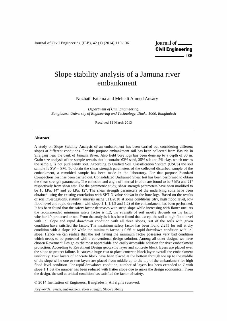
Earthen embankments in Bangladesh are beset with multi-facetted problems. Devastatingflood and excessive rainfall are accelerating the failure process which results immensedamage to agriculture and infrastructures every year. Over the last few decades, nearly 13000km of flood and river embankments have been repaired in Bangladesh (Hossain, M.Z. andSakai, T., 2011). But, earthen embankments in Bangladesh are facing problems like erosion,breaching in every year. The major causes of failure identified were breach of theembankment cutting by the public, overflow, erosion, seepage and sliding. Furthermore,insufficient supervision during construction results in poor-quality earthworks with the use ofinappropriate soil materials, insufficient or no clod breaking, inadequate compaction and orinsufficient laying of topsoil layers, the use of inferior materials, inadequate maintenance,river migration and cutting by the public (Hoque and Siddique, 1995). Among many reasons,the improper design methodology and construction procedure is prime and one of the mostimportant causes of embankment failure. The stability of earthen embankments is influencedby seepage occurred during the increase and decrease of the adjacent water level in the riveror reservoir (Morii and Kunio, 1993). In Bangladesh, nearly 4,600 km of embankments alongthe bank of big rivers are flowing across the country. JAMUNA, one of the big rivers isflowing alongside of Sirajganj district of Bangladesh (Figure 1). At 41 locations of its bank,the length of failure occurring is about 160.62km. This is because of the fluctuation of waterlevels, siltation and scouring and severe wave actions of the river. In addition, devastatingflood in almost every year and excessive rainfall are stepping up the early failure ofembankments which results immense damage to agriculture and infrastructures. To minimizethe impact of natural disasters as well as to achieve the goal of agricultural production,sustainable and cost-effective protection measures of those river embankments are nowcrucial for Bangladesh. Some of the major causes of these embankment failures are due to theuse of geotechnically unstable materials, improper method of construction and insufficientpost operative maintenance. So, prior to construction of a stable embankment it is importantto evaluate the inherent properties of the construction materials for its safe design as well asto select appropriate protection system.
The concept of stability is one of the most important issues in Civil Engineering field.Stability concept comprises some of the important factors in Civil Engineering namely: force,moment and equilibrium. These factors and concepts form the basis of all Civil Engineeringstructural analysis and construction work. Overstressing a soil material of an earth slopeusually may bring about a sudden rupture with a rapid displacement or sliding of the rupturedsoil mass or granular shear strain causing distress to earth structures. Natural slopes, whichhave been stable for many years, may suddenly fail due one or more of the following causes:External disturbance in the form of cutting or filling of parts of a slope; external disturbancein the form of seismic activity; increase in pore water pressures within a slope; progressivedecrease in shear strength of slope materials and weathering can also contribute to failure ofslopes. Manmade slope can be categorized into three types, such as, cut slopes, embankmentincluding earth dams and spoil or waste heaps. The factors contributing to the slope stabilityinclude: the type of soil, geometry of the cross-section of the slope, weight, loads and loaddistribution, gravity, increase in moisture content of the soil material, decrease in shearstrength of soil, vibrations and earthquakes, due to human action like excavation, undercuttingand overloading.
Revetment Design is the most conventional and gratifying solution for river bank protection.Revetments are used to protect banks and shorelines from erosion caused by waves andcurrents. It is assumed to be easily accessible for Bangladesh. It is composed of a layer oferosion resistant material that covers the erodible material of the river bank and sometimes
Fatema and Ansary / Journal of Civil Engineering (IEB), 42 (1) (2014) 119-136 121
also the bed of the river. Various materials may be used for this purpose, including grouts andgeotextiles. The choice of the most suitable material should be made at an early stage in theproject. Armor stone can be directly placed onto the bed or bed to be protected. Howevergenerally good practice to place it on an under layer that provides a transition between thecoarse armor stone of the cover layer and the fine erodible material of the foundation. Theunder layer may be made of crushed block or gravel that prevents sub soils from being erodedthrough the voids of the protection. Geotextiles may be used as a part of the filtering system,either with or instead of the granular filter. The under layer reduces both the risk offoundation material being washed through the armor layer and of the cover layer punchinginto the subsoil. The level of the revetment toe is determined in relation to the maximumscour expected after completion of the works.
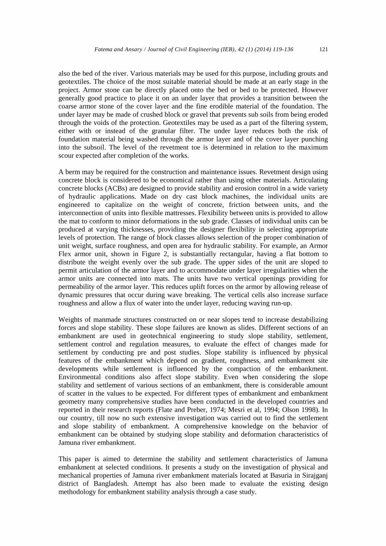
A berm may be required for the construction and maintenance issues. Revetment design usingconcrete block is considered to be economical rather than using other materials. Articulatingconcrete blocks (ACBs) are designed to provide stability and erosion control in a wide varietyof hydraulic applications. Made on dry cast block machines, the individual units areengineered to capitalize on the weight of concrete, friction between units, and theinterconnection of units into flexible mattresses. Flexibility between units is provided to allowthe mat to conform to minor deformations in the sub grade. Classes of individual units can beproduced at varying thicknesses, providing the designer flexibility in selecting appropriatelevels of protection. The range of block classes allows selection of the proper combination ofunit weight, surface roughness, and open area for hydraulic stability. For example, an ArmorFlex armor unit, shown in Figure 2, is substantially rectangular, having a flat bottom todistribute the weight evenly over the sub grade. The upper sides of the unit are sloped topermit articulation of the armor layer and to accommodate under layer irregularities when thearmor units are connected into mats. The units have two vertical openings providing forpermeability of the armor layer. This reduces uplift forces on the armor by allowing release ofdynamic pressures that occur during wave breaking. The vertical cells also increase surfaceroughness and allow a flux of water into the under layer, reducing waving run-up.
Weights of manmade structures constructed on or near slopes tend to increase destabilizingforces and slope stability. These slope failures are known as slides. Different sections of anembankment are used in geotechnical engineering to study slope stability, settlement,settlement control and regulation measures, to evaluate the effect of changes made forsettlement by conducting pre and post studies. Slope stability is influenced by physicalfeatures of the embankment which depend on gradient, roughness, and embankment sitedevelopments while settlement is influenced by the compaction of the embankment.Environmental conditions also affect slope stability. Even when considering the slopestability and settlement of various sections of an embankment, there is considerable amountof scatter in the values to be expected. For different types of embankment and embankmentgeometry many comprehensive studies have been conducted in the developed countries andreported in their research reports (Flate and Preber, 1974; Mesri et al, 1994; Olson 1998). Inour country, till now no such extensive investigation was carried out to find the settlementand slope stability of embankment. A comprehensive knowledge on the behavior ofembankment can be obtained by studying slope stability and deformation characteristics ofJamuna river embankment.
This paper is aimed to determine the stability and settlement characteristics of Jamunaembankment at selected conditions. It presents a study on the investigation of physical andmechanical properties of Jamuna river embankment materials located at Basuria in Sirajganjdistrict of Bangladesh. Attempt has also been made to evaluate the existing designmethodology for embankment stability analysis through a case study.
Fatema and Ansary / Journal of Civil Engineering (IEB), 42 (1) (2014) 119-136122
Fig. 1. Location map of the study area
Fig. 2. Components of typical armor stone revetment
2. Geology of The Study Area
The study Jamuna River in 1787 a tectonic movement followed by an abnormal flood ledchanges in the course of the Brahmaputra and started its flow through a new course known asthe Jamuna (Bhuiyan, M.A.H., Rakib, M.A., Takashi, Rahman, M.J.J. and Suzuki, Shigeyuki,2010). It is the main channel of the Brahmaputra River when it flows out of India intoBangladesh. Jamuna enters in Bangladesh from the North West side of Kurigram district and
Fatema and Ansary / Journal of Civil Engineering (IEB), 42 (1) (2014) 119-136 123
flows to south, ending its independent existence as it joins the Padma River near GoalundoGhat. Bounding coordinates of the river area is W: 89.532, E: 89.871, N: 25.228, S: 23.869.The climate of the study area is tropical monsoon. Jamuna Bridge site is located betweenTangail and Sirajganj town. It lies within latitude 24022′50″–24026′30″N and longitude89055′30″–89058′45″E. The river reach is characterized by well defined braiding nature,meta-stable islands, nodes, sandbars, shifting ana-branches and rigorous bank erosion.Geomorphologically, the eastern bank is bounded with the lateral extension of MadhupurTract and the west bank is the Barind Tract, which is composed of silty clay. Duringmonsoon, the average annual discharge of Jamuna River (JR) at Ba-hadurabad point is about50000 m3/s. However, the discharge increased to 100000 m3/s during the 1988 and 1998flood events. The average water surface slope is approximately 6.5 cm/km for the lowerreach. The soil deposits mainly consist of the following types of soils (after Geological Mapof Bangladesh, GSB, 1990): ASL – Alluvial Silt – Light to medium – grey, fine sandy toclayey silt. Commonly poorly stratified; average grain size decreases away from mainchannels. Chiefly deposited in flood basins and inter stream areas. Unit includes small backswamp deposits and varying amounts of thin, inter stratified sand, deposited during episodicor unusually large floods. Illite is the most abundant clay minerals. Most areas are floodedannually. Included in this unit are thin veneers of sand spread by episodic large floods overflood – plain silts. Historic pottery, artifacts and charcoal (radiocarbon dated 500 – 6000 yearsB.P.) found in upper 4m.
3. Sample Collection and Laboratory Tests
The soil samples were collected directly from the broken part of the right bank embankmentof Jamuna River at Basuria in Sirajganj district. The field investigations consisted of drillingof boreholes, identification of subsoil layer, assessment of density and consistency of subsoillayers by carrying out Standard Penetration Test, collection of disturbed and undisturbed tubesamples. One borehole was drilled at Basuria site on the bank of Jamuna River. Geologicprofile of the subsoil is made from the bore log data at Basuria site. The soil overall the wholedepth possess non – plastic behavior. Silt with little clay, brown in color, having very loosedensity exists near the top of the ground surface extending to about 8 feet depth. The SPT – Nvalue of this type of soil at the given depth is 1. Very fine sand with little silt trace mica isencountered just below the top clay layer having grey in color and non-plasticity behavior. Itextends up to the final depth of boring 102 feet (30m) and possibly beyond. The densityvaries with depth such as loose density up to 28 feet depth, medium density up to 63 feetdepth and dense density for the rest. At the layer up to 28 feet depth, the average SPT – Nvalue is 3 while the range of SPT – N value is 15 – 25 up to 63 feet depth. Again SPT – Nvalue up to 73 feet depth is 26 and up to 102 feet the range is 28 – 32 feet. Before analysis,duration of storage of samples is likely to affect some determinations more than others.Certain constituents are subjected to loss by adsorption on the sides of the glass containerwalls. So polythene bags have been used for the storage of sample for laboratory tests. Thelaboratory tests have been conducted in the Laboratory of Bangladesh University ofEngineering And Technology. The testing procedures are in accordance with AmericanSociety for Testing and Materials (ASTM). The tests include particle size analysis,compaction characteristics and consolidated undrained direct shear test. Consolidatedundrained direct shear test was done with samples having different water content.
The following tests were conducted in the laboratory in order to access the collected sample:(i) Grain size analysis(ii) Compaction test(iii) Consolidated – Undrained Direct Shear test (CU test)
Fatema and Ansary / Journal of Civil Engineering (IEB), 42 (1) (2014) 119-136124
Grain size analysis is performed to determine the percentage of different grain sizes containedwithin a soil. Basically two well known laboratory tests for Grain size distribution analysis,they are: Sieve analysis and Hydrometer analysis. The mechanical or sieve analysis isperformed to determine the distribution of coarser, larger sized particles and the hydrometeranalysis is conducted to determine the distribution of finer particles. The distribution ofdifferent grain sizes affects the engineering properties of soil. Grain size analysis provides thegrain size distribution and it is required in classifying the soil.
Compaction, basically, is the densification of soil by removal of air, which requiresmechanical energy. Simplistically, compaction may be defined as the process in which soilparticles are enforced to remain closer together with the resultant reduction in air voids.Compaction, measured in terms of dry unit weight, increases the strength characteristics ofsoils, thereby increasing the bearing capacity of “foundations” constructed over them.Maximum dry density refers to the density at which the volume of air at a specific energyapplications kept to a minimum, implying the soil particles are rearranged to give a minimumvolume of air at the compaction energy. Soil compaction results in higher strength, reducedsettlement and reduced permeability. A remolded sample is developed by compaction testwith the corresponding water content of 95% peak value of the dry density at wet side. Thisremolded sample is used in consolidated undrained direct shear test. From shear test we canconceive the strength of soil which determines the susceptibility to failure.
In all soil stability problems, such as design of foundations, retaining walls and embankments,knowledge of the strength of soil involved is required. The determination of the properstrength to use in a stability problem can be the most difficult question arises in the soilengineering. Hence the test of Strength test enables us to specify the characteristics of soilproperly.
4. Laboratory Test Results and Discussion
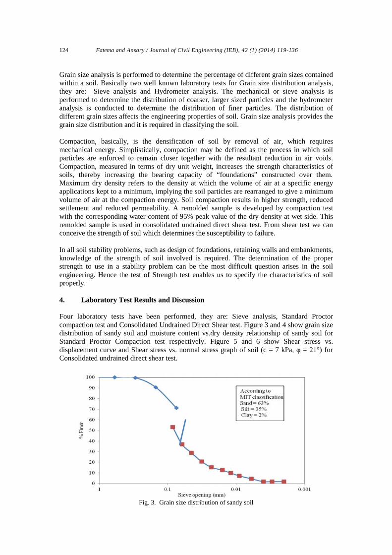
Four laboratory tests have been performed, they are: Sieve analysis, Standard Proctorcompaction test and Consolidated Undrained Direct Shear test. Figure 3 and 4 show grain sizedistribution of sandy soil and moisture content vs.dry density relationship of sandy soil forStandard Proctor Compaction test respectively. Figure 5 and 6 show Shear stress vs.displacement curve and Shear stress vs. normal stress graph of soil (c = 7 kPa, φ = 21°) forConsolidated undrained direct shear test.
Fig. 3. Grain size distribution of sandy soil
Fatema and Ansary / Journal of Civil Engineering (IEB), 42 (1) (2014) 119-136 125
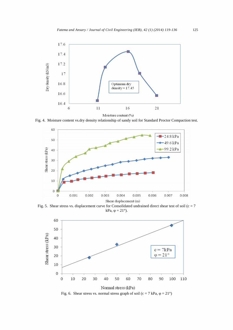
Fig. 4. Moisture content vs.dry density relationship of sandy soil for Standard Proctor Compaction test.
Fig. 5. Shear stress vs. displacement curve for Consolidated undrained direct shear test of soil (c = 7kPa, φ = 21°).
Fig. 6. Shear stress vs. normal stress graph of soil (c = 7 kPa, φ = 21°)
Fatema and Ansary / Journal of Civil Engineering (IEB), 42 (1) (2014) 119-136126
According to MIT classification the percentage of sand, silt and clay at our soil sample havebeen found 63%, 35% and 2% respectively. Hence it can realize that the sample is not thepure sand. According To Unified Soil Classification system (USCS) the soil sample is SW-SM. It has a portion of silt and clay. The amount of silt portion is quite appreciable while theportion of clay might be negligible. This sandy soil has been used for the compaction testwhich is necessary to perform consolidated undrained direct shear test further. The motto ofthe compaction test is to develop a remolded sample for shear test with the correspondingwater content of 95% peak value of dry density at wet side. From the shear test the values ofcohesion and angle of internal friction have been obtained for sand. For further parametricstudy, shear strength parameters have been modified. Table 1 shows the values of cohesionand angle of internal friction of three types of soil obtained from Consolidated Undraineddirect Shear Test.
Table 1Results from Consolidated Undrained direct Shear Test
Soil sample Cohesion, c (kN/m2) Angle of internal friction, φ(degree)Type 1 7 21
Type 2 10 14
Type 3 20 12
From the table 1 we can analyze that cohesion is increasing with the increase of clay whileangle of internal friction is decreasing along with it. The more the cohesion the more wouldbe the presence of clay while the reverse case happens for angle of internal friction. Thevalues of cohesion and angle of internal friction have been used in the stability analysis. Theshear strength parameters of the underlying soils have been obtained using the existingcorrelation with SPT-N value shown in the bore logs.
5. Slope Stability Analysis
Civil engineers are often expected to make calculations to check the safety of natural slopes,slopes of excavations, and compacted embankments. This check involves determining theshear stress developed along the most likely rupture surface and comparing it with shearstrength of the soil. This process is called slope stability analysis. The most likely rupturesurface is the critical surface that has the minimum factor of safety.
The Program STB2010This is a program for the analysis of the stability of slope (Verruijt, A., Delft University,2010). The program uses Bishop’s simplified method with some modifications introduced atGeoDelft and the Delft University for the calculation of the facto of safety of circular slipsurface, with Koppejan’s correction for very deep circles, and a modification to account forthe strength reduction of a double sliding model. The program also allows for a possiblehorizontal body force, to simulate the effect of an earthquake. The soil properties used in theprogram are:
- Wd: Dry unit weight (kN/m3).- Ws: Saturated unit weight (kN/m3).- Ko: Coefficient of neutral horizontal stress (-).- c: Cohesion (kN/m2).- phi: Angle of internal friction (degrees).- P/F: Switch for the groundwater condition (-).- p = 0: Zero level of the pore water pressure (m).- cap: Thickness of capillary zone, above groundwater table (m).- The unit weight of water is 10 kN/m3.

Fatema and Ansary / Journal of Civil Engineering (IEB), 42 (1) (2014) 119-136 127
6. Results of Stability Analysis Using STB2010
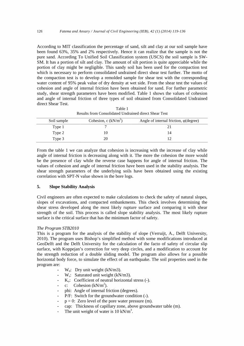
STB2010 is used for the analysis of stability of slope, using Bishop’s method with someconditions. Graphs and other graphics are created here. When the software is started the firstform appeared in General, Soil Properties and Nodes chart where all general and samplingrelated information is given. Figure 7 – 10 show the results of Stability Analysis of soil (c = 7kPa, φ = 21°) at four conditions (dry, low flood level, high flood level and rapid drawdownrespectively) with three slopes (1:1, 1:1.5 and 1:2).
Fig. 7. Result of stability analysis of soil (c = 7 kPa, φ = 21°) at dry condition for slope 1:1.5
Fig. 8. Result of stability analysis of soil (c = 7 kPa, φ = 21°) at low flood level condition for slope1:1.5
The results obtained from the analysis using STB2010 are shown in Table 2 to 4. Thefluctuation of the safety factor along with four conditions and three slopes for the soils havingdifferent parametric characteristics has been shown in Figure 11 to 13. From the figures forall kinds of soil, it has been realized that the safety factor increases with the increase of water
Fatema and Ansary / Journal of Civil Engineering (IEB), 42 (1) (2014) 119-136128
Fig. 9. Result of stability analysis of soil (c = 7 kPa, φ = 21°) at high flood level condition for slope1:1.5
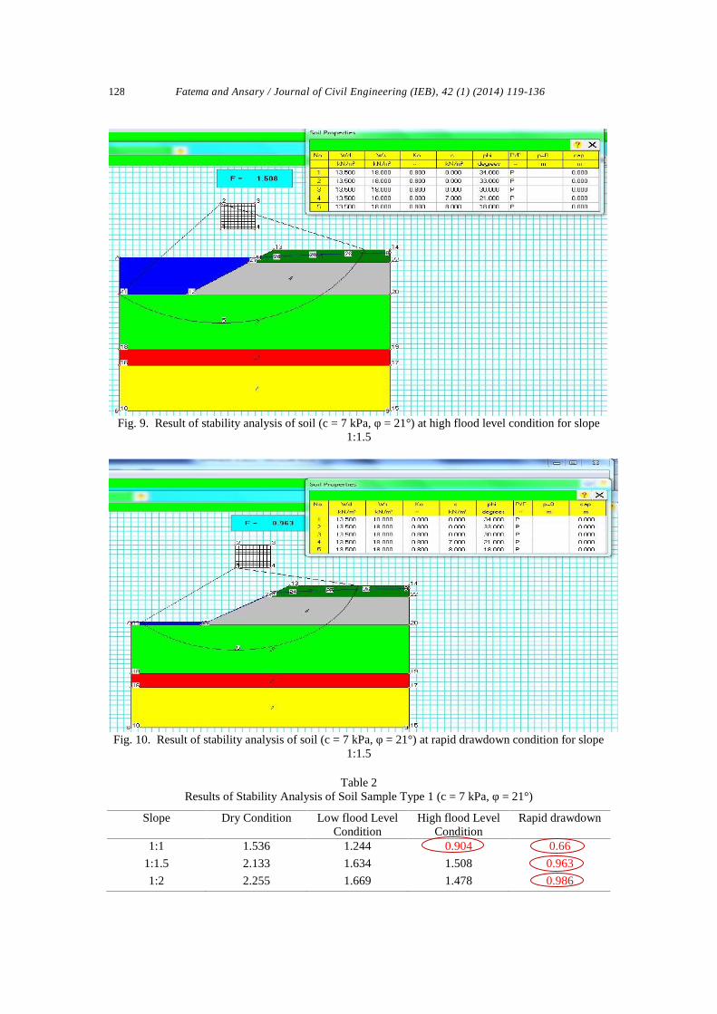
Fig. 10. Result of stability analysis of soil (c = 7 kPa, φ = 21°) at rapid drawdown condition for slope1:1.5
Table 2Results of Stability Analysis of Soil Sample Type 1 (c = 7 kPa, φ = 21°)
Slope Dry Condition Low flood LevelCondition
High flood LevelCondition
Rapid drawdown
1:1 1.536 1.244 0.904 0.66
1:1.5 2.133 1.634 1.508 0.963
1:2 2.255 1.669 1.478 0.986
Fatema and Ansary / Journal of Civil Engineering (IEB), 42 (1) (2014) 119-136 129
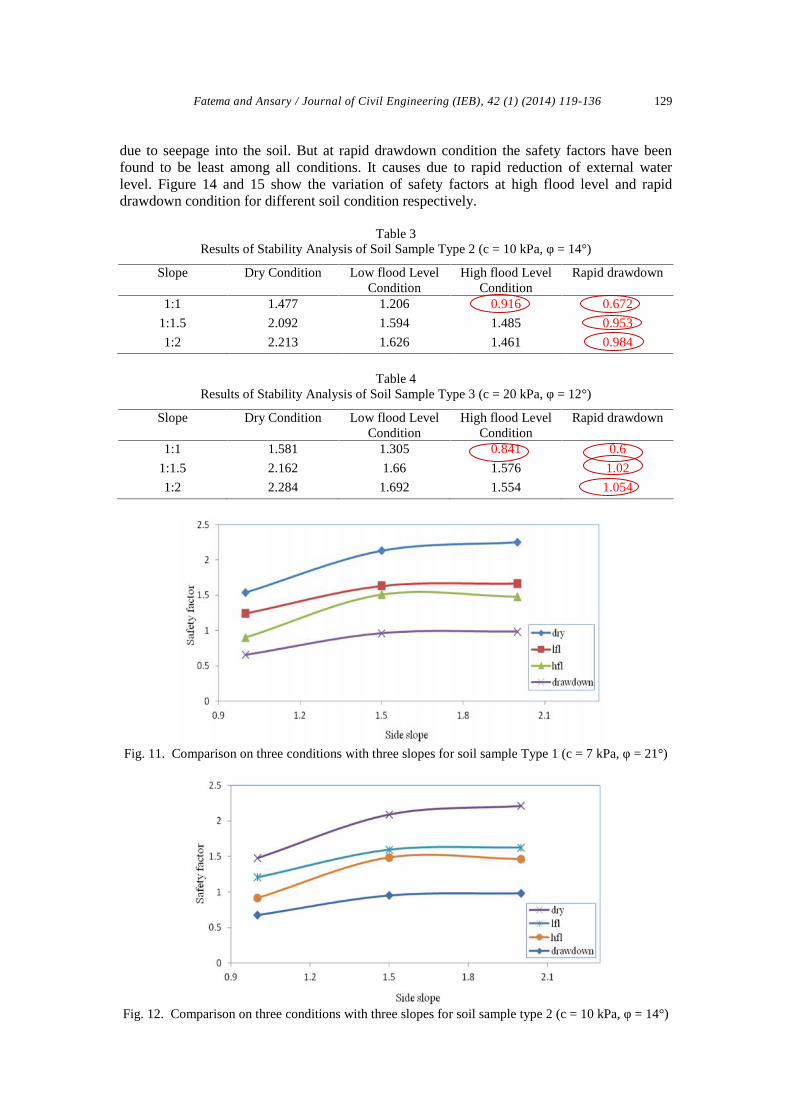
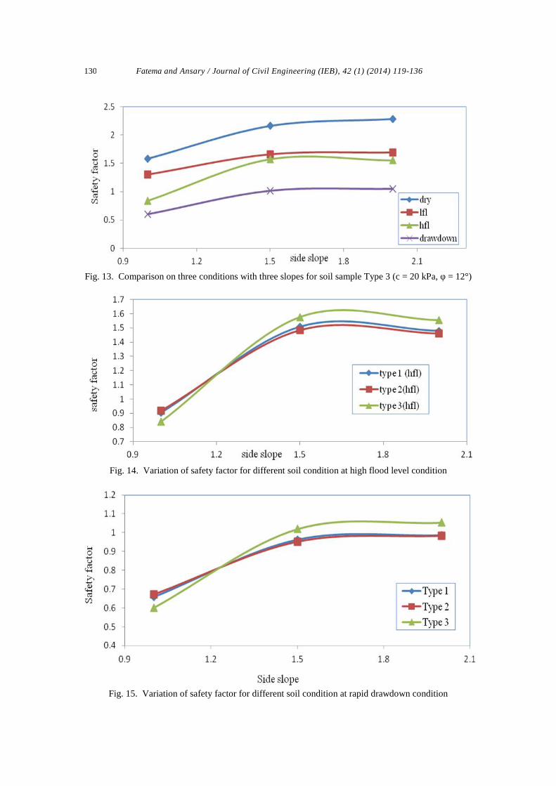
due to seepage into the soil. But at rapid drawdown condition the safety factors have beenfound to be least among all conditions. It causes due to rapid reduction of external waterlevel. Figure 14 and 15 show the variation of safety factors at high flood level and rapiddrawdown condition for different soil condition respectively.
Table 3Results of Stability Analysis of Soil Sample Type 2 (c = 10 kPa, φ = 14°)
Slope Dry Condition Low flood LevelCondition
High flood LevelCondition
Rapid drawdown
1:1 1.477 1.206 0.916 0.672
1:1.5 2.092 1.594 1.485 0.953
1:2 2.213 1.626 1.461 0.984
Table 4Results of Stability Analysis of Soil Sample Type 3 (c = 20 kPa, φ = 12°)
Slope Dry Condition Low flood LevelCondition
High flood LevelCondition
Rapid drawdown
1:1 1.581 1.305 0.841 0.6
1:1.5 2.162 1.66 1.576 1.02
1:2 2.284 1.692 1.554 1.054
Fig. 11. Comparison on three conditions with three slopes for soil sample Type 1 (c = 7 kPa, φ = 21°)
Fig. 12. Comparison on three conditions with three slopes for soil sample type 2 (c = 10 kPa, φ = 14°)
Fatema and Ansary / Journal of Civil Engineering (IEB), 42 (1) (2014) 119-136130
Fig. 13. Comparison on three conditions with three slopes for soil sample Type 3 (c = 20 kPa, φ = 12°)
Fig. 14. Variation of safety factor for different soil condition at high flood level condition
Fig. 15. Variation of safety factor for different soil condition at rapid drawdown condition
Fatema and Ansary / Journal of Civil Engineering (IEB), 42 (1) (2014) 119-136 131
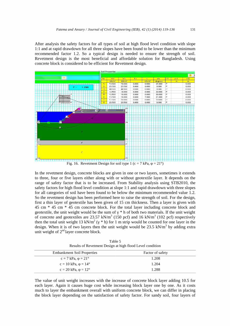
After analysis the safety factors for all types of soil at high flood level condition with slope1:1 and at rapid drawdown for all three slopes have been found to be lower than the minimumrecommended factor 1.2. So a typical design is needed to ensure the strength of soil.Revetment design is the most beneficial and affordable solution for Bangladesh. Usingconcrete block is considered to be efficient for Revetment design.
Fig. 16. Revetment Design for soil type 1 (c = 7 kPa, φ = 21°)
In the revetment design, concrete blocks are given in one or two layers, sometimes it extendsto three, four or five layers either along with or without geotextile layer. It depends on therange of safety factor that is to be increased. From Stability analysis using STB2010, thesafety factors for high flood level condition at slope 1:1 and rapid drawdown with three slopesfor all categories of soil have been found to be below the minimum recommended value 1.2.So the revetment design has been performed here to raise the strength of soil. For the design,first a thin layer of geotextile has been given of 15 cm thickness. Then a layer is given with45 cm * 45 cm * 45 cm concrete block. For the total layer including concrete block andgeotextile, the unit weight would be the sum of γ * h of both two materials. If the unit weightof concrete and geotextiles are 23.57 kN/m3 (150 pcf) and 16 kN/m3 (102 pcf) respectivelythen the total unit weight 13 kN/m2 (γ * h) for 1 m strip would be counted for one layer in thedesign. When it is of two layers then the unit weight would be 23.5 kN/m3 by adding extraunit weight of 2nd layer concrete block.
Table 5Results of Revetment Design at high flood Level condition
Embankment Soil Properties Factor of safety
c = 7 kPa, φ = 21° 1.208
c = 10 kPa, φ = 14° 1.204
c = 20 kPa, φ = 12° 1.288
The value of unit weight increases with the increase of concrete block layer adding 10.5 foreach layer. Again it causes huge cost while increasing block layer one by one. As it costsmuch to layer the embankment overall with uniform concrete block, we can differ in placingthe block layer depending on the satisfaction of safety factor. For sandy soil, four layers of

Fatema and Ansary / Journal of Civil Engineering (IEB), 42 (1) (2014) 119-136132
concrete block have been placed at the bottom through toe up to the middle of the slope whiletwo layers have been placed from middle up to the top of the embankment due to make thedesign economical. Figure 16 shows the result with necessary diagram of stability analysis.
Fig. 17. Slope of an embankment
Table 5 shows the safety factor for different soil conditions at high flood level. For type 1 (c =7 kPa, φ = 21°), four layers for high flood level condition have been placed at the bottomthrough toe up to the middle of the slope while two layers have been placed from middle upto the top of the embankment. For type 2 (c = 10 kPa, φ = 14°) four layers have been placeduniformly across the embankment for high flood level condition. For type 3 (c = 20 kPa, φ =12°), four layers have been placed at the bottom through toe up to the middle of the slopewhile one layer has been placed from middle up to the top of the embankment for high floodlevel condition. Again for rapid drawdown condition, the distribution of block layers alongwith obtained safety factors have been given in table 6. The distribution of block layers is onthe basis of making the design economical.
Table 6Results of Revetment Design at Rapid drawdown condition
slope c = 7 kPa, φ = 21° c = 10 kPa, φ = 14° c = 20 kPa, φ = 12°1:1 1.201 (7b+1top) 1.200(7b+2top) 1.213 (6b+1top)
1:1.5 1.214 (3b+1top) 1.208 (3b+1top) 1.273(3b+1top)
1:2 1.276 (3b+1top) 1.268 (3b+1top) 1.213(1b+1top)
Table 7Variation of safety factor of Type1 (c = 7 kPa, φ = 21°) soil
Layer 1 Safety factor Layer 2 Safety factor Layer 3 Safety factor Layer 4 Safety factor
1b + 1t 0.968 2b + 1t 1.043 3b + 1t 1.12 4b + 1t 1.198
1b + 2t 0.981 2b + 2t 1.055 3b + 2t 1.131 4b + 2t 1.208
1b + 3t 0.994 2b + 3t 1.067 3b + 3t 1.141 4b + 3t 1.218
1b + 4t 1.006 2b + 4t 1.078 3b + 4t 1.151 4b + 4t 1.227
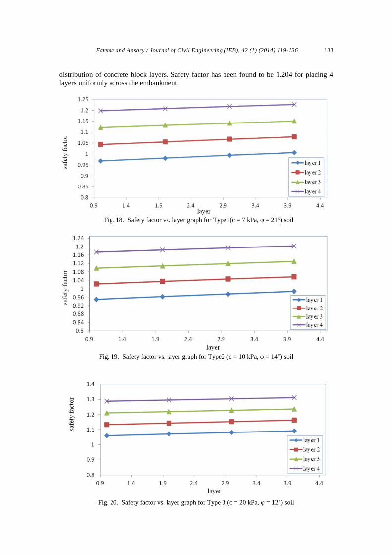
Figure 17 shows the slope of an embankment indicating bottom and top. Table 7 shows thevariation of safety factor for Type 1(c = 7 kPa, φ = 21°) depending on the distribution ofconcrete block layers. Safety factor has been found to be 1.198 for placing 4 layers at thebottom through toe up to the middle of the slope and 1 layer from the middle up to the top ofthe embankment. But it doesn’t satisfy the condition. So 2 layers have been placed instead of1 layer from the middle up to the top and the safety factor has been found to be 1.208. Table 8shows the variation of safety factor for Type 2(c = 10 kPa, φ = 14°) depending on the
Fatema and Ansary / Journal of Civil Engineering (IEB), 42 (1) (2014) 119-136 133
distribution of concrete block layers. Safety factor has been found to be 1.204 for placing 4layers uniformly across the embankment.
Fig. 18. Safety factor vs. layer graph for Type1(c = 7 kPa, φ = 21°) soil
Fig. 19. Safety factor vs. layer graph for Type2 (c = 10 kPa, φ = 14°) soil
Fig. 20. Safety factor vs. layer graph for Type 3 (c = 20 kPa, φ = 12°) soil

Fatema and Ansary / Journal of Civil Engineering (IEB), 42 (1) (2014) 119-136134
Table 8Variation of safety factor of Type2(c = 10 kPa, φ = 14°) soil
Layer 1 Safety factor Layer 2 Safety factor Layer 3 Safety factor Layer 4 Safety factor
1b + 1t 0.951 2b + 1t 1.024 3b + 1t 1.098 4b + 1t 1.175
1b + 2t 0.964 2b + 2t 1.036 3b + 2t 1.109 4b + 2t 1.185
1b + 3t 0.976 2b + 3t 1.0477 3b + 3t 1.12 4b + 3t 1.195
1b + 4t 0.988 2b + 4t 1.058 3b + 4t 1.131 4b + 4t 1.204
Table 9Variation of safety factor of Type3(c = 20 kPa, φ = 12°) soil
.
Layer 1 Safety factor Layer 2 Safety factor Layer 3 Safety factor Layer 4 Safety factor
1b + 1t 1.059 2b + 1t 1.134 3b + 1t 1.21 4b + 1t 1.288
1b + 2t 1.071 2b + 2t 1.144 3b + 2t 1.219 4b + 2t 1.296
1b + 3t 1.082 2b + 3t 1.154 3b + 3t 1.228 4b + 3t 1.304
1b + 4t 1.092 2b + 4t 1.164 3b + 4t 1.237 4b + 4t 1.312
Table 9 shows the variation of safety factor for Type 3(c = 20 kPa, φ = 12°) depending on thedistribution of concrete block layers. Safety factor has been found to be 1.288 for placing 4layers at the bottom through toe up to the middle of the slope and 1 layer from the middle upto the top of the embankment which satisfies the condition. The variation of safety factor fordifferent parametric soil at high flood level condition has been shown in figure 18 to 20.
After Revetment Design the conditions are satisfied for the soil samples at high flood leveland rapid drawdown conditions. For all cases, the safety factors are above the recommendedvalue. These values have ensured the shear strength of soil along with the protection of riverembankment. The soil having better safety factors are assumed to be more protective fromerosion. After the design, the number of layers at rapid drawdown has been found to begreater in quantity than high flood level condition. But in practice, rarely rapid drawdowncondition is considered, so the number of layers used is minimum.
7. Conclusion
Riverbank erosion is often initiated by failure of a riverbank causing high sediment loads orheavy rainfall. This generates high volume and velocity run-off which will concentrate in thelower drainages within the river’s catchments area. When the stress applied by these riverflows exceeds the resistance of the riverbank material, erosion will occur. As the sedimentload increases, fast-flowing rivers will erode their banks downstream. Eventually, the riverbecomes overloaded or velocity is reduced, leading to the deposition of sediment to furtherdownstream or in dams and reservoirs. The deposition may eventually lead to the riverdeveloping a new channel. While all rivers change in the long-term, short-term rates ofchange vary significantly. With growing demand for protecting people’s health and homes,agriculture and city dwellers; the issue of river embankments and flood control embankmentsin Bangladesh is getting much attention lately. This is because of the construction of riverembankments in Bangladesh is the cheapest form to protect flood water in rainy season andstore necessary water in the dry season. This research has been carried out to investigate thegeotechnical characteristics of the embankment and presented results of more recent soilinvestigation along the embankment alignment. For this purpose embankment soil has beencollected from Basuria in Sirajganj near the bank of Jamuna River. Also field bore logs hasbeen done up to a depth of 30 m. Direct from the broken part of the embankment, the soilsamples are collected by which the following laboratory tests: Grain Size Analysis,

Fatema and Ansary / Journal of Civil Engineering (IEB), 42 (1) (2014) 119-136 135
Compaction Test, Shear Test have been performed. The collected sample contains 63% sand,35 % silt and 2% clay. According to the Unified Soil Classification System (USCS), the soilsample is SW – SM. With a view to making a remolded sample to obtain the shear strengthparameters of the collected disturbed sample of the embankment, a Standard ProctorCompaction test has been conducted in the laboratory. The remolded sample has been madewith the corresponding water content of 95% peak value of the dry density at wet side. Theoptimum dry density has been found to be 17.45 kN/m3. Due to obtain the shear strengthparameters, Consolidated Undrained Shear test has been performed in the laboratory. Thecohesion and angle of internal friction has been found to be 7 kPa and 21° respectively. Forfurther parametric study, Shear strength parameters has been modified to be 10 kPa; 14° and20 kPa; 12°. The parameters of the soil sample of the embankment have been found directlyfrom the laboratory tests, while for the underlying soils the shear strength parameters havebeen obtained from the correlation with SPT – N value shown in the bore logs.
Based on the data of the present investigation, stability analysis of some critical sections ofthe embankment has been carried out. The stability analysis has been conducted usingSTB2010. The analysis depends on the soil parameters obtained during the construction ofembankment. The analysis has been performed for soils at three conditions; dry, low floodlevel, high flood level and rapid drawdown with three different slopes; 1:1, 1:1.5 and 1:2. Thevalues of cohesion and angle of internal friction obtained from the shear test have been usedin STB2010. The maximum safety factor has been obtained 2.255 for soil at dry conditionwith a slope 1:2 while the minimum factor is 0.66 at rapid drawdown condition with 1:1slope. As long as water increases, the soil becomes weakened for steepening slope. But atrapid drawdown condition safety factor has been found to be the least because of rapidreduction of external water level. So the soil would fail at any time as having lower shearstrength to protest against erosion. It has been realized that, soil at dry condition has betterstrength to protect embankment from failure. Again the strength increases with flatter sloperather than steep slope. The main reason of the failure at high water level is considered to bewater seepage into the soil while the reason is rapid reduction of external water level for rapiddrawdown condition. For this type of soil, a design named Revetment Design with a thingeotextile layer and concrete block layer has been conducted to protect river embankment.This design is affordable and suitable for Bangladesh. To make the design more economical,four layers of concrete block have been placed at the bottom through toe up to the middle ofthe slope while one or two layers are placed from middle up to the top of the embankment forhigh flood level but at drawdown condition, number of layers have been increased due tosatisfy the recommended value. After Revetment Design a reasonable safety factor has beenachieved for the soils at critical condition which ensures the protective strength of soil againstfailure.
ReferencesAlam, M.K., Hasan, A.K.M.S., Khan, M.R. “Geological Map of Bangladesh: Geological survey of
Bangladesh”, Whitney, John W., 1990, United States Geological Survey.Bhuiyan, M.A.H., Rakib, M.A., Takashi, Rahman, M.J.J. and Suzuki, Shigeyuki “Regulation of
Brahmaputra-Jamuna River around Jamuna Bridge Site, Bangladesh: GeoenvironmentalImpacts”. J. Water Resource and Protection, 2010, 2, 123-130 Doi:10.4236/jwarp.2010.22014Published Online February 2010 (http://www.SciRP.org/journal/jwarp/).
Das, B.M. (Fifth Edition). “Principles of Geotechnical Engineering”Flaate, K. and Preber, T. (1974). “Stability of Road Embankments”, Canadian Geotechnical Journal,
Vol. 11, No. 1, pp. 72 – 78.Hoque, M.M. and M.A.B Siddique, 1995. Flood control projects in Bangladesh: Reasons for failure
and Recommendations for improvement. Disasters, 19: 260-263. DOI: 10.1111/j.1467-7717.1995.tb00344.x

Fatema and Ansary / Journal of Civil Engineering (IEB), 42 (1) (2014) 119-136136
Hossain, M.Z. and Sakai, T. “River Embankment and Bank Failure: A Study on GeotechnicalCharacteristics and Stability Analysis”, American Journal of Environmental Sciences 7 (2):102-107, 2011
http://www.kennisbank-waterbouw.nl/DesignCodes/rockmanual/chapter%208.pdfMorii, T. and H. Kunio, 1993. Finite element analysis of stress and stability of earth dams during
reservoir filling. J. Fac. Agric., Tottori Univ., 29: 45-53.M. Z. Hossain and T. Sakai. “Severity of Flood Embankments in Bangladesh and Its Remedial
Approach”. Agricultural Engineering International: the CIGR Ejournal. Manuscript LW 08004. Vol. X. May, 2008.
Thornton, Christopher I. and Kane, Richard (October 2007). “Revetment Design Considerations inSheltered Water Wave Conditions”. Professional Development Series.
Verruijt, A., Delft University, 2010, [email protected]