slot-die coating of perovskite solar cells: an overview
TRANSCRIPT

Slot-Die Coating of Perovskite Solar Cells: An Overview
Rahul Patidar, Daniel Burkitt, Katherine Hooper, David Richards, Trystan Watson
SPECIFIC, Baglan Bay Innovation Centre, Central Avenue, Baglan, Port Talbot, SA12 7AX.
Abstract
To make perovskite solar cells an industrially relevant technology large area deposition techniques are needed and one of the mostpromising is slot-die coating. This review article details the progress reported in the literature where slot-die coating has been usedfor the deposition of both the perovskite layer and other layers in the perovskite solar cell device stack. An overview of the methodsused to adapt the coating process, materials and drying conditions in order to create high quality layers and devices is given and anoutlook on future research directions in this field is made.
Keywords: Slot-die Coating, Perovskite Solar Cell, Manufacturing, Photovoltaics, Roll-to-Roll
1. Introduction1
The remarkable opto-electronic properties of lead halide per-2
ovskites coupled with the advancements in thin film photo-3
voltaic device fabrication generated from organic photovoltaic4
(OPV) and dye sensitised solar cell (DSSC) research has pro-5
pelled perovskite solar cells (PSC) to astonishing power con-6
version efficiencies (PCEs) and the forefront of next generation7
photovoltaics research. In under a decade PCEs rose from 3.8%8
in 2009 to certified 24.2% as of July 2019, outperforming well9
established technologies like multicrystalline silicon and cop-10
per indium gallium selenide solar cells (CIGS) [1, 2, 3, 4, 5].11
PSCs show great potential in becoming a disruptive technol-12
ogy in the photovoltaics industry, however, there are many chal-13
lenges yet to overcome to bring this technology to the market.14
For instance, bridging the ‘scaling gap’ and transitioning PSCs15
from a lab scale to an industrial scale is a serious challenge [6].16
Compatibility with flexible substrates and devices and the po-17
tential for high throughput roll-to-roll (R2R) manufacture that18
this offers is one of the key features that makes the case for us-19
ing PSCs compelling. R2R fabrication not only offers the possi-20
bility of manufacturing at far higher speeds than those possible21
for conventional silicon photovoltaics but also offers the oppor-22
tunity to deploy modules at unprecedented rates and in novel23
formats, as demonstrated for structurally similar organic photo-24
voltaics [7, 8].25
Efforts are being made to upscale the technology with a va-26
riety of techniques having been employed for the fabrication of27
large area PSCs, utilising both solution based and vacuum de-28
position methods. The most common are spin coating, blade29
coating [9], screen printing [10], spray coating [11, 12], slot-30
die coating, gravure printing [13] and vacuum deposition [14].31
It could be argued that, to date, the most successful of these32
is blade coating where it has been used for the deposition of33
the perovskite layer in modules with PCEs of over 15% and34
an aperture area of 30cm2 [15]. Blade coating of perovskites35
has only been reported for small scale bench-top sheet-to-sheet36
(S2S) fabrication and not for R2R processes. Only gravure [13]37
and slot-die coating [16, 17, 18, 19, 20, 21] have been reported38
for use in R2R deposition processes for the perovskite layer39
of the device stack, with slot-die coating resulting in devices40
achieving both high PCEs and line speeds on flexible glass [20]41
and plastic substrates [19].42
Slot-die coating is well suited for the deposition of perovskite43
inks, as well as other layers in the device stack. As a pre-44
metered coating method, it is highly efficient in terms of mate-45
rials usage and results in very low wastage levels of inks com-46
pared to other deposition methods such as spin coating or spray47
and screen printing. For a typical slot-die coating process a48
coating head is positioned close to and across a substrate or49
web, ink is then pumped into the head, using a syringe pump,50
with the ink forced out of a narrow slit along the length of the51
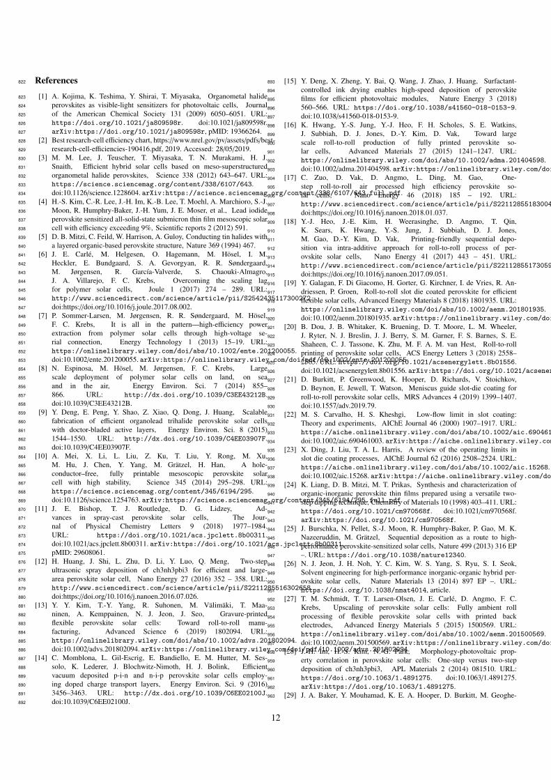
coating head (Figure 1).52
Figure 1: Schematic of a slot-die coating process, showing the delivery of inkto the head from a syringe pump and formation of an ink wet film between thecoating head lips and the substrate.
The ink forms a liquid bridge between the coating head and53
the substrate whereby when the substrate is moved past the54
head, the deposition of a wet film is achieved. Over a given55
coating width the thickness of the dry film deposited is con-56
trolled by adjusting the flow of ink to the coating head and the57
Preprint submitted to Applied Materials Today November 27, 2019

speed at which the substrate moves past the head. This directly58
translates to changes in the wet film thickness and subsequently59
after drying the dry film thickness. This allows for very fine60
control of the dry film thickness, to within a few nm, as well as61
the ability to deposit very thin dry films, of tens of nm, up to62
much thicker films of tens of microns simply by adjusting the63
ink flow rate or substrate speed.64
There are a number of common failure mechanisms for slot-65
die coatings including (i) the ‘low-flow’ limit [22], where the66
breakup of the downstream meniscus causes discontinuity in67
the wet film (ii) discontinuous film defects such as rivulets,68
where the coating breaks into multiple smaller stripes with gaps69
(iii) completely discontinuous films where the coating stops and70
starts along the length of the substrate (iv) air-entrainment de-71
fects, associated with the breakup of the upstream meniscus72
leading to ‘bubbles’ within the wet film and areas of uncoated73
substrate and (v) ’flooding’ or ‘dripping’ where the flow of ink74
to the head is too great compared to the coating speed and re-75
sults in the gradual build-up of ink at the coating head and loss76
of pre-metering and the expected film thickness. One of the77
most important operating limits is the low-flow limit, which78
causes break-up of the down stream meniscus and discontinous79
film formation. The capillary number is given by 1 and the low-80
flow limit can be given in terms of a critical capillary number81
(Calow− f low) as in 2, above which, for a particular gap height and82
wet film thickness, the coating is unstable, the low-flow limit is83
generally applicable for capillary numbers less than one but de-84
viations can occur for higher capillary numbers. Here µ is the85
viscosity of the ink, σ is surface tension, V is the web speed86
or coating speed, H is the gap between substrate and die head87
and t is the wet film thickness. Therefore, for the set operating88
parameters H and V, the ink rheology (surface tension and vis-89
cosity) must be adjusted (or vice-versa) to remain below critical90
capillary number ensuring defect free films with right wet film91
thickness. For a more complete explanation of slot-die coating92
and common defects the reader is directed to the review article93
by Harris et al. [23].94
Ca =µVσ
(1)95
Calow− f low =µVσ≤ 0.65
2Ht − 1
32
(2)96
Table 1 summarises the device stacks and current density -97
voltage (JV) scan photovoltaic performance parameters for per-98
ovskite solar cells with a slot-die coated perovskite layer re-99
ported in the literature so far.100
In this review, the summary of various approaches developed101
to slot-die coat perovskite and other layers of the device stack102
will be presented. The effects of different coating procedures,103
additives and drying conditions will be discussed, along with104
discussion on the fundamental understanding of nucleation and105
crystallization of slot-die coated perovskite films. A compre-106
hensive review of the development in the performance of slot-107
die coated perovskite solar cells will be given.108
2. Perovskite Film Formation109
The perovskite layer is the most important layer in the per-110
ovskite solar cell device stack, to this end it is vital to have111
defect free films with large grain size, crystal phase purity and112
good film coverage that can deliver higher photovoltaic perfor-113
mance and stability. The following sections will discuss the114
various procedures developed to improve the quality of slot-die115
coated perovskite layers, all of which are effectively based on116
controlling the crystallization dynamics of the perovskite mate-117
rial.118
2.1. Two-Step119
The two-step or sequential deposition process for the fabrica-120
tion of organic-inorganic perovskite layers was first introduced121
by Mitzi et al. [24] and later further developed for deposition of122
the active layer in PSCs by Burschka et al. [25]. In this process123
a pre-deposited lead halide film is exposed to a cation and halide124
source e.g. methylammonium iodide (MAI) or caesium iodide,125
that then react together to form the final perovskite. Most typ-126
ically this is achieved by spin coating a lead iodide (PbI2) film127
that is then dried and exposed to a solution of MAI either by128
spin coating the solution on top of the PbI2 film or dipping the129
PbI2 film into a solution of MAI. When this is applied to slot-130
die coating, the principal of the process is the same, with a PbI2131
layer first slot-die coated onto the substrate and the film dried,132
followed by either slot-die coating of a MAI solution onto the133
PbI2 layer or dip coating of the PbI2 layer in a MAI solution.134
Compared to depositing the perovskite precursors from a135
single ink in one coating stage, termed a ‘one-step’ or ‘sin-136
gle step’ process, the two-step process allows the separation137
of film formation into distinct parts that might be beneficial to138
the overall film formation. When considering the formation of139
the perovskite film, the nucleation and crystal growth of the140
perovskite from the wet film of the precursor solution is criti-141
cal to achieving good dry film formation with good overall film142
coverage. This is particularly challenging when using many143
of the strongly polar aprotic solvents commonly used for per-144
ovskite precursor inks. These inks, which poorly wet on many145
of the common interlayers, can lead to de-wetting of the sub-146
strate as well as the growth of large crystals with large voids,147
that when fabricated into devices lead to shunt leakages and148
shorts that are detrimental to performance. This was overcome149
in spin coated layers by depositing the lead iodide first, sepa-150
rately to the other precursors, which resulted in films with high151
surface coverage that could then be converted to perovskite to152
a high degree. Later this was somewhat superseded by the de-153
velopment of the ‘anti-solvent’ or ‘solvent quenching’ method154
[26], where the precursor film is rapidly exposed to a solvent155
which poorly solvates the precursors and leads to the rapid nu-156
cleation of perovskite and almost complete surface coverage.157
This method can produce excellent film qualities but integrat-158
ing this into a standard slot-die coating process is difficult. For159
these reasons many of the first reports of slot-die coated per-160
ovskite layers made use of the two-step method, as it can result161
in high surface coverage.162
2

Schmidt et al. compared the effects of the two-step deposi-163
tion with that of one-step on slot-die coated films [27]. The164
outcome of both approaches was found to be dependent on165
the device stack and interlayers the precursor solutions were166
deposited onto, the one-step deposition performed better with167
ITO/PEDOT: PSS (P-I-N ‘inverted’ architecture stack) geome-168
try while perovskite would did not form on a ITO/ZnO/PCBM169
(N-I-P ‘standard’ architecture stack) geometry. The lower per-170
formance with one-step deposition in an N-I-P stack is linked to171
poor film coverage of the perovskite on top of the electron trans-172
port layer (ETL), leading to lower photocurrent [28]. Whereas173
for two-step deposition perovskite formation was achieved in174
both device stacks, however the performance of the P-I-N stack175
devices was very poor. This demonstrates the importance and176
interplay of the deposition process (one or two-step), the prop-177
erties of the substrate layer the formulation is being deposited178
onto. The nucleation and crystallisation of the different precur-179
sor solutions in dependent on the substrate surface.180
In the two-step deposition process it is important to have181
highly uniform PbI2 films with high surface coverage, but also182
films that can be converted to perovskite readily. Contrary to183
spin coating, the slow drying of the slot-die coated films gives184
enough time for mass transfer and solvent flow to cause non-185
uniformity in the films[29]. Hwang K et al. reported the im-186
pact of slow drying on slot-die coated PbI2 films in an effort to187
deposit the perovskite layer sequentially [16], the formation of188
highly non-uniform films upon slow drying was noticed, to mit-189
igate the unwanted flow of the ink a process to mimic the spin190
coating drying mechanism by externally quenching the films191
by a gas jet was employed. A second slot-die coating head was192
connected beside the first head and compressed nitrogen gas193
was flowed on to the just deposited wet film, to speed drying,194
the ‘gas quenched’ PbI2 films formed were found to be dense195
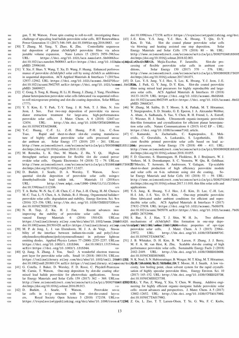
and with uniform film coverage. Figure 2 shows the difference196
in the PbI2 film morphology with gas quenching to that of films197
allowed to dry under ambient conditions. The dense lead io-198
dide films formed using this process were found to poorly con-199
vert to perovskite when exposed to MAI. To increase the re-200
activity of the PbI2 films to MAI and obtain full conversion to201
perovskite, a solvent vapour soaking technique was employed.202
After drying the gas quenched PbI2 films were stored in an en-203
closed chamber, this resulted in a more porous film that allowed204
complete penetration of MAI and a high degree of conversion205
to perovskite, as well as achieving good film coverage with few206
pin hole formations. As the perovskite layer, the ECL and hole207
transport layers (HTL) were deposited using slot-die coating,208
resulting in a hero cell performance for the complete slot-die209
coated device of 11.96% PCE. However, storing the film for210
long periods to make it more reactive is not an ideal method,211
especially for a scaled-up manufacturing process where reduc-212
ing the production time and maximising throughput are critical,213
the process also limits the transition to continuous roll to roll214
fabrication.215
In order to develop a more scalable method to produce highly216
reactive PbI2 films the same group reported using a method,217
previously demonstrated for spin coated devices [30, 31], in-218
volving an unstable perovskite intermediate [18]. A non-219
Figure 2: Optical microscopy and SEM images of the slot-die coated PbI2 filmsby (a) ambient drying (b) gas-quenching and air storage (c) by gas quenchingand enclosed space storage. Reproduced with permission from ref [16]. Copy-right 2015, Wiley.
stochiometric amount of MAI (referred as intra-addive ap-220
proach) was added to the PbI2 formulation to slow down the221
PbI2 crystallization in the first deposition step making it highly222
reactive at the second step, this subsequently gives greater con-223
version to the final perovskite. Figure 3 shows the schematic224
representation of the process. A PCE of 5.8% was achieved225
with a R2R processed device on a flexible substrate with evapo-226
rated top contacts. To push the PCE further, CH3NH2PbI3 was227
replaced with the double cation perovskite (FA0.4MA0.6PbI3)228
whereby 40mol% FAI was used as an additive in the first step229
along with PbI2 followed by MAI deposition. This increased230
the PCE to 7.3% in the same device stack on a flexible substrate231
and led to a PCE of 11.0% when the P3HT hole transport layer232
(HTL) was changed to PEDOT:PSS, (see Figure 3). The similar233
approach was further used by Gong et al. to deposit triple cation234
perovksite [32]. The active layer was partially printed by micro-235
gravure printing. For the printing of active layer, PbI2/CsI films236
with samll amount of MAI/FAI (as an intra additive) was first237
printed using microgravure method on top of gravure printed238
SnO2. This was followed by slot die coating of FAI/MAI mix-239
ture for the complete conversion to perovskite. In additon, gas240
blowing was used to reduce the roughness of the perovksite film241
resulting in improved performance of the stack . Intra additive242
approach combined with gas blowing resulted in hero PCE of243
10.57%.244
Another method, ‘mediator extraction treatment’ (MET) for245
the preparation of PbI2 films that result in high quality per-246
ovskite layers was reported by Kim et al. [33]. A PbI2247
ink formulation of lead iodide in Dimthylformamide (DMF)248
with 10%vol/vol Dimethyl sulfoxide (DMSO) was first slot-die249
coated, and then exposed to a gas flow from an air knife. This250
resulted in a PbI2-DMSO complex, which was then dipped in251
an antisolvent bath to extract DMSO. In the following conver-252
sion step, the resulting PbI2 films were dipped in a MAI bath253
(mixed with 25 wt% mehylammonium chloride), which once254
dried, converted to the final perovskite phase. The MET pro-255
3

Figure 3: (a) Schematic illustration of the coating procedure (b) JV curve ofthe R2R coated devices. Reproduced with permission from ref [18]. CopyrightElsevier, 2017 (c) A schematic illustration showcasing the different PbI2 crys-tal orientation made by MET and heat treatment and subsequent CH3NH3PbI3films. Reproduced with permission from ref [33]. Copyright 2018, Royal Soci-ety of Chemistry.
duced porous PbI2 films with relatively randomized crystal ori-256
entation, giving a highly reactive PbI2 film, a schematic repre-257
sentation of the crystal orientation is shown in Figure 3. The258
random orientation of crystal increased the MAI penetration259
rate within the PbI2 films and subsequently led to conversion260
to perovskite within 100 seconds, this method produced a max-261
imum PCE of 18.3% which was comparable to a spin coated262
active layer.263
Yu-Ching Huang et al. reported the use of near infrared264
(NIR) heating for the drying of two-step perovskite films, for265
both the PbI2 layer and the perovskite film when used in a P-I-N266
device structure with ITO coated glass substrate, PEDOT:PSS267
HTL and PCBM/PEI ETL and silver top electrode. This was268
combined with depositing the PbI2 ink onto a heated substrate269
to improve the lead iodide film formation, The drying times of270
the perovskite layer was reduced from 1500 to 30s with the use271
of NIR heating [34].272
As much as good stability and efficiency are priorities in a273
scaled-up photovoltaic manufacturing process, the safety of the274
process is equally important. In PSCs, the solvent and Pb are275
the main source of toxicity and significant efforts have been put276
towards low toxicity and green solvents for perovskite precur-277
sors. The sequential deposition route has also attracted interest278
due to the ability to use relatively non-toxic solvent systems,279
compared to the commonly used DMF solvent system. Re-280
meika et al. demonstrated to use of low toxicity DMSO as a281
solvent for lead iodide formulations used for slot-die coating,282
although the layer was not optimised for performance and re-283
sulted in low PCEs [35]. Burkitt et al. developed an improved284
deposition method, again using DMSO as solvent for lead io-285
dide, that resulted in improved film formation and device per-286
formance compared to those using DMF as solvent [36]. By287
also heating the m-TiO2 coated substrate, to 100◦C, then di-288
rectly coating on to this, the PbI2 films were made more reactive289
to MAI and to give greater levels of conversion to perovskite.290
The choice of solvent for the MAI ink was also optimised for291
slot-die coating and ethanol found to be the best of those as-292
sessed, this resulted in devices produced with slot-die coated293
PbI2 and MAI with average PCEs of 11% and a hero PCE of294
13.2%. In another work, the use of these solvent systems was295
further demonstrated in a R2R process, using a P-I-N device296
stack with ITO coated PET substrate, PEDOT:PSS HTL and297
PCBM/BCP ECL and silver top electrode, but the low volatil-298
ity of the DMSO solvent led to reticulation of the PbI2 film on299
drying in the R2R ovens. By increasing the drying temperature300
the film formation was improved, but this resulted in damage to301
the temperature sensitive substrate and a wide spread in device302
performance [21].303
Two-step deposition has been shown to produce high effi-304
ciency small area devices, with PCEs up to 18.3% and been305
shown to work in R2R processes. Key to these results has been306
speeding the drying of the PbI2 films to improve film uniformity307
and also using methods that result in films that react readily308
to form perovskite, either through enclosed chamber storage,309
mediator extraction treatment, solvent choice or intra-additive310
approaches. Of these the intra-additive approach has shown311
great potential for R2R processing and combined with the de-312
velopments of MET and safer solvents along with rapid heat-313
ing methods could deliver a viable R2R process for the slot-die314
coating of perovskite films.315
2.2. One-Step316
Due to the increased complexity, coating time and potentially317
lower yield, two-step deposition is not the ideal method for a318
scaled-up manufacturing process and a one-step process would319
be preferred. PSCs stacks can be broadly divided into two cate-320
gories, N-I-P (standard) and P-I-N (inverted). Most of the work321
to date has reported one-step slot-die coated perovskite in the P-322
I-N geometry due to improved perovskite film coverage on top323
of an organic layer e.g. PEDOT:PSS. However, the stability of324
the P-I-N stack is a concern to commercial development [37].325
PEDOT:PSS, the most commonly used HTL in an P-I-N geom-326
etry is vulnerable to water. The instability of the ITO/organic327
interface, the acidic nature of PEDOT and diffusion of PSS are328
additional reasons that makes this stack prone to faster degra-329
dation [38, 39]. But, unlike the N-I-P stack which normally330
requires high temperature sintering for the metal oxide layer,331
the P-I-N stack consists of organic layers which are processed332
at low temperatures and are therefore compatible with plastic333
substrates, hence are more easily R2R compatible. However,334
recent developments [40] in low temperature processed metal335
oxide electron transport layers like tin oxide (SnO2) have cre-336
ated a route for N-I-P stacks to be compatible with plastic sub-337
strates, as discussed in more detail in Section 4.338
2.2.1. Controlling Film Formation Through Drying Conditions339
For one-step perovskite formulations the device stack of340
choice was initially the P-I-N, due to the improved film quality,341
4

Figure 4: (a) Illustration of layer differences with varying conditions (b) 1.Use of air knife following initial nucleation growth. 2. Convective motionsand reduced viscosity boost the crystal growth at the interface with the sub-strate 3. Crystals approach the cooler region reducing the vertical growth ratein favour of lateral growth across the warm substrate. 4. Reduced thickness isachieved. Reproduced with permission from ref [41]. Copyright 2016, Else-vier. (c) Schematic representation of the perovskite film formation via slot-diecoating under the gas-blowing process combined with substrate heating. Re-produced with permission from ref [43]. Copyright 2018, Elsevier.
but many works developed novel strategies to improve the one-342
step film formation in the N-I-P stack. Cotella et al. demon-343
strated one-step deposition of CH3NH3PbI3−xClx perovskite in344
DMF solvent system on a mesoporous titanium dioxide (m-345
TiO2) metal oxide scaffold through a heating process and exter-346
nally quenching the perovskite film, with an air-knife, to mimic347
the self-quenching step similar to spin coating. [41] By de-348
veloping a temperature gradient, formed by heating the sub-349
strate, between the top and bottom of the wet film the suppres-350
sion of the vertical growth of perovskite crystals was shown,351
Figure 4. This inherently forces horizontal perovskite crystal352
growth, thereby reducing the roughness of the film. Further-353
more, adding the air knife treatment increases the temperature354
gradient by removing a greater proportion of energy from the355
top of the film and hence suppressing vertical crystal growth,356
leading to flattening of the films with relatively lower rough-357
ness, Figure 4. With the growth of a highly uniform film with358
high surface coverage, a PCE of 9.2% was recorded.359
Following this work, the same group reported the deposition360
of four layers of the same device stack via slot-die coating, in-361
cluding the compact TiO2 (titanium dioxide) metal oxide layer,362
the m-TiO2 layer, the perovskite layer and the Spiro-OMeTAD363
HTL, further demonstrating the potential of slot-die coating for364
this device stack[42]365
Following the work by Cotella et al., a similar approach was366
taken by Kim et al. to produce high quality CH3NH3PbI3 per-367
ovskite films from a DMF solvent system in a one step depo-368
sition on planar N-I-P PSCs with a ZnO ETL. By combining369
blowing and heating of the film to speed nucleation and evap-370
oration of solvent, the formation of large perovskite crystals371
with voids between was avoided and surface coverage and uni-372
formity improved, resulting in a PCE of 12.7% [43]. Ciro et al.373
demonstrated flexible planar P-I-N stack PSCs using an ITO374
coated PET substrate, PEDOT:PSS HTL, CH3NH3PbI3−xClx375
perovskite from DMF solvent system and PCBM ETL [44]. To376
improve the morphology of the perovskite film the solids con-377
tent of the formulation was optimised along with heating of the378
substrate (to an optimal temperature of 80◦C, which resulted in379
both improved surface coverage and lower surface roughness.380
Although the absolute PCEs were low, this nonetheless demon-381
strated substrate heating and drying conditions as an effective382
way to control perovskite film morphology.383
Attempts to control perovskite film formation using drying384
methods have shown that increasing the nucleation rate of the385
perovskite film is important for achieving films with high sur-386
face coverage and that rapid drying of the solvent can help to387
avoid the formation of large crystallites and voids within the388
film.389
2.2.2. Controlling Film Formation Through Precursor Choice390
Rapid crystallization was also implemented by Lee et al.,391
in a P-I-N stack with PEDOT:PSS HTL and C60/PCBM ETL,392
using mixed lead precursors in a DMF solvent system, the393
use of mixed lead acetate and lead chloride precursors in the394
perovskite ink was demonstrated[45]. Lead acetate induces395
fast crystallization by forming an unstable organic by-product396
(methylammonium acetate) [46]. The use of lead acetate as the397
only Pb source combined with gas blowing however, caused the398
rapid crystallization on the surface of the film. This then en-399
trapped the remaining solvent and by-product within the film,400
causing the formation of voids in the active layer. To avoid401
this, lead chloride was added alongside lead acetate to retard402
the rapid crystallization on the surface, avoiding any formation403
of voids, Figure 5. Using two different lead anion precursors404
combined with gas blowing improved the grain size, morphol-405
ogy and film coverage and resulted in a PCE of 13.3% over a406
small area of 0.1 cm2 and 8.3% PCE over a 10cm2 module.407
Similar use of lead acetate was made by Kamaraki et al. on408
flexible ITO coated PET substrates, with slot-die coated PE-409
DOT:PSS HTL and PCBM ETL layers also, using a solely lead410
acetate precursor in DMF solvent system [47]. The deposition411
temperature of the perovskite ink was optimised and similar to412
the work of Ciro et al. [44] resulted in changes in surface rough-413
ness. Optimised coating conditions for all three layers resulted414
in average PCEs of 5% and a maximum of 6.5%. Notably, Gia-415
como et al. also used a mixed lead chloride and lead acetate pre-416
cursor solution in DMF for large area high performance module417
fabrication in a nitrogen atmosphere glove-box system [48].418
Judicious selection of perovskite precursors is another419
method to control the nucleation and crystallization rate of per-420
ovskite films and so improve surface coverage and morphology.421
When this is combined with methods to control the drying of422
the films it can result in high performance cells and modules.423
2.2.3. Controlling Film Formation Through Solvent Choice424
Jung et al. demonstrated the use of solvent additives for re-425
fining the morphology of one-step slot-die coated CH3NH3PbI3426
perovskite films in a P-I-N device stack with PEDOT:PSS HTL427
and PCBM ETL [49]. 5vol% of N-cyclohexyl-2-pyrrolidone428
(CHP) along with 6vol% of dimethyl sulfoxide (DMSO) was429
mixed in with the 0.75M perovskite DMF solvent system pre-430
cursor ink. Fourier-transform infrared spectroscopy (FTIR) re-431
sults showed adduct formation between PbI2 and DMSO and432
that this was dominant over that with DMF and CHP. The high433
polarity and high basicity of DMSO compared to that of DMF434
5

Figure 5: (a) Schematic representation of the crystallization of perovskite films.(b) SEM images showcasing the voids formed by rapid crystallization of per-ovskite and the same being mitigated by addition of PbCl2. Adapted with per-mission from ref [45]. Copyright 2018, American Chemical Society.
and CHP were found to be the reason for this behavior. The435
adduct formation with DMSO mainly retarded the crystalliza-436
tion rate of perovskite films. Interestingly CHP having the high437
boiling point and low vapour pressure likely remained in the438
solidifying film and assisted in uniform nucleation growth. To-439
gether the combined effects of these result in uniform and ho-440
mogenous perovskite films that consequently resulted in better441
performance. Moreover the binary additive was found to play a442
role in preferentially oriented crystal growth of perovskite films443
which again helped in better charge transport [50].444
PCEs of around 18% with slot die coating have been445
achieved by making use of DMF and N-Methyl-2-Pyrrolidone446
(NMP) [33, 51].However, the high toxicity of DMF and NMP447
limits its usage in manufacturing process. A safer alternative448
was developed by Noel et al. wherein the composite of ace-449
tonitrile (ACN) with methylamine gas was developed to dis-450
solve MAI and PbI2 [52]. Due to the low boiling point and high451
volatility of ACN, 98% of crystallization was noted (after ˜110452
sec) at room temperature. The rapid crystallization of the ACN453
based formulation and lower toxicity, relative to DMF, fit well454
into the criteria for its use in large area fabrication and the low455
viscosity potentially means high slot-die coating speeds can be456
attained. Dou et al. implemented this formulation for slot-die457
coating, in a R2R fabrication process using a flexible indium458
zinc oxide coated glass substrate and a N-I-P device stack, with459
slot-die coated tin oxide ETL [20]. The optimized R2R process460
led to the formation of uniaxially oriented crystalline smooth461
perovskite films. A hero PCE of 14.12% was reported for R2R462
and 17.31% for S2S slot-die coated films, Figure 6. While the463
ACN formulation is suitable for large area deposition, it could464
be argued that high flammability and still considerable toxicity465
of this solvent system might hinder its commercial use.466
Alternatively, DMSO is another less toxic solvent for use in467
large area manufacturing of PSCs. The solvent itself is con-468
sidered low toxicity but it is able to easily penetrate the skin469
along with any solute dissolved in it. However, with proper470
safety precautions it is an attractive option. Unfortunately, the471
poor wetting of DMSO on most substrates makes it quite dif-472
ficult to print with good film coverage. Galagan et al. demon-473
strated the addition of 10%vol/vol 2-Butoxyethanol in DMSO474
to lower the surface tension of the solvent mixture. This im-475
proved wetting and achieved improved film coverage [19]. In476
Figure 6: (a–c) Schematic illustration of slot-die coating process on rigid sub-strate (a) XRD (b) JV data (c). (d) Schematic illustration of slot-die coatingprocess on flexible glass substrate with R2R process. (e) Images showing R2Rcoating (f) JV curve of the best performing R2R-coated device. Adapted withpermission from ref [20]. Copyright 2018, American Chemical Society.
a R2R process, using a flexible ITO coated PET substrate and477
N-I-P device stack, using a slot-die coated tin oxide layer and478
a slot-die coated Cs0.15FA0.85PbI2.85Br0.15 perovskite layer the479
best performing device demonstrated a PCE of 15.2% over an480
active area of 0.09cm2 and a stabilised PCE of 13.5%.481
Modification of solvent systems offers a powerful tool to con-482
trol the perovskite film morphology and has resulted in high483
performance R2R devices, but careful consideration needs to484
be given to the suitability of such systems for industrial manu-485
facture.486
2.2.4. Controlling Film Formation Through Additives and Sur-487
face Modification488
Additives have played a large role in improving the stabil-489
ity and efficiency of PSCs by influencing crystal growth and490
the morphology of perovskite films [53]. Zuo et al. used491
a NH4Cl additive to improve the perovskite film quality in a492
CH3NH3PbI3 perovskite formulation in DMF with small ad-493
ditions of NH4Cl using a P-I-N device stack with PEDOT:PSS494
HTL and PCBM ETL [17]. Absorption spectroscopy confirmed495
the higher absorption of light by the active layer in the pres-496
ence of NH4Cl. Additionally higher photoluminescence inten-497
sity was observed in the films with NH4Cl, confirming mitiga-498
tion in non-radiative recombination and film defects. For slot-499
die coated devices the use of a NH4Cl additive was combined500
with heating of the substrate and gas blowing, yielding high-501
quality perovskite films for both S2S glass substrate devices502
and R2R devices on flexible PET substrate. Notably the fabri-503
cation was carried out at 45% relative humidity demonstrating504
a hero cell performance of 15.57% PCE for S2S coated devices505
and 11.16% PCE with R2R coated devices.506
A different approach to improve perovskite film morphology507
and reduce defects is by surface treating interlayers. In one such508
work, by Gu et al., 3-aminopropanoic acid as an ambipolar self-509
assembled monolayer (C3-SAM) was introduced for the modi-510
fication of PEDOT:PSS [54]. Using a P-I-N device stack with511
CH3NH3PbI3−xClx perovskite formulation, PEDOT:PSS HTL512
and PCBM/ZnO ETL, C3-SAM was applied to the PEDOT:PSS513
film. The modified PEDOT:PSS helped in better perovskite film514
6

Figure 7: SEM (a–c) and AFM (d–f) images of CH3NH3PbI3−xClx films onthe as-prepared PEDOT:PSS (a and d), methanol washed PEDOT:PSS (b ande) and C3-SAM modified PEDOT:PSS (c and f). (g) The ultraviolet photoelec-tron spectroscopy (UPS) spectra of the as-prepared PEDOT:PSS (black line),methanol washed PEDOT:PSS (red line) and C3-SAM modified PEDOT:PSS(blue line). (h) The energy band alignment of PSCs. Reproduced with permis-sion from ref [54] Copyright 2015, Royal Society of Chemistry.
growth but also had a positive effect on the energy band align-515
ment by inducing an extra permanent dipole. It was further con-516
firmed by UV photoelectron spectroscopy, that the treatment of517
C3-SAM lowered the work function of PEDOT:PSS by 0.2eV,518
Figure 7, the improvement in charge transport and film mor-519
phology led to the hero PCE of 5.1% on flexible S2S roll coated520
PSCs.521
Recently, Kim et al. introduced polyethylene ox-522
ide (PEO) as an additive in slot-die coated perovskite523
films, using a P-I-N stack with modified PEDOT:PSS524
HTL, (CH3NH3)0.6(HC(NH2)2)0.38Cs0.2PbI2.975Br0.025 and525
PCBM/PEIE ETL and evaporated Ag top electrode [55]. This526
was used in conjunction with using PbCl2 as the source of527
chloride as an additive and with deposition of the perovskite528
ink onto a heated substrate. The polymer additive was found529
to improve the tolerance of perovskite to deposition in high530
humidity (approx. 55% RH) conditions and resulted in clear531
changes to performance, Figure 8. This novel method for the532
fabrication of PSCs in ambient conditions has the potential of533
driving manufacturing cost further down, an important step534
towards commercialization. Notably it’s the only fully R2R535
(except top contact) processed PSC reported so far, showing an536
impressive efficiency of 11.7%.537
3. 2D Perovskite Layers538
Recently, 2D perovskites have gained interest due to im-539
proved lifetime compared to 3D perovskites [56]. 2D per-540
ovskites are typically prepared by introducing a large organic541
molecule (for example butylammonium) in between the layers542
of 3D perovskite. Previously the performance of the PSCs with543
2D perovskite have been quite low compared to 3D perovskite,544
however they have significantly improved in the past few years545
and have recently achieved 14.1% PCE [57]. Excellent lifetime546
and improvement in the performance of 2D perovskite based547
PSCs has encouraged their use with large area printing and548
Figure 8: Comparison of device performance and surface morphology withand without PEO at in a low (30±5% RH) and high (55±5% RH) humiditycoating environment. JV curves of the slot-die coated devices in (a) low and (b)high humidity, SEM images of perovskite films on glass/ITO/m-PEDOT:PSSsubstrates w/o PEO deposited in (c) low and (d) high humidity, and with PEOdeposited at (e) low and (f) high humidity. Reproduced with permission fromref [55]. Copyright 2019, Wiley.
coating techniques. Fu et al. first demonstrated R2R printed549
2D perovskite reporting an impressive PCE of 8% on plastic550
substrate and 12.5% by batch coating on glass substrate [58].551
Loss in performance in the R2R printed device compared to552
spin coated device (14.9% PCE) was attributed to mediocre553
film quality by R2R slot-die deposition due to less hydrophilic554
surface of ITO/PET. However, it is an encouraging report with555
the first ever R2R coated 2D perovskite and shows progress for556
large area 2D perovskite PSCs.557
4. Interlayers558
Although it is important to perfect the deposition of the per-559
ovskite layer, it is also vital to achieve the same with charge560
transport layers. Defects in the coatings can be detrimental to561
device performance through various processes; voids and pin-562
holes can cause shunt leakages and lead to shorts, poor charge563
blocking capabilities can lead to increases in recombination564
of charge carriers. In addition to this, temperature limitations565
must be overcome for coating onto temperature sensitive sub-566
strates such as PET, where a maximum processing temperature567
of 140◦C is required. This significantly hinders the deposition568
of the more common solution processed ETLs such as; tin oxide569
(SnO2) from tin chloride (SnCl4.2H2O) [59], NiOx from nickel570
(II) acetate tetrahydrate, and TiO2 from titanium diisopropoxide571
bis (acetylacetonate) [60], which require much higher anneal-572
ing temperatures of 300◦C and above.573
7

4.1. Tin Oxide Electron Transport Layer574
Tin oxide (SnO2) has gained significant usage as an ETL in575
perovskite devices, due to its high electron mobility, better band576
alignment with perovskite when compared to TiO2 and unlike577
TiO2 it doesn’t induce serious UV degradation [40]. Therefore,578
SnO2 is a strong candidate for an ETL in devices in terms of579
both performance and stability. The use of SnO2 is well estab-580
lished in small area devices, with the majority of reports em-581
ploying a tin (IV) chloride precursor [40, 59]. Although this582
precursor requires a relatively low temperature anneal at 180◦C,583
it is still too high to be compatible with common flexible sub-584
strates e.g. PET, in addition a long annealing time of around585
one hour is required.586
Recently the use of SnO2 formulations for low-temperature587
R2R depositions with excellent device performance have been588
reported. Galagan et al. [19] and Bu et al. [61] used a col-589
loidal suspension of tin (IV) oxide 15% wt./vol in H2O (Alfa590
Aesar), which can be dried at 140 - 150◦C in a shorter period591
of time. Galagan et al. employed this SnO2 solution into a R2R592
N-I-P stack, in which the solution was diluted with 10vol%593
1-butanol to aid wetting and slot-die coated at 5m/min, with594
subsequent drying at 140◦C in a 20m length oven at the same595
speed. Perovskite was also R2R coated, with the subsequent596
spiro-OMeTAD and gold contacts deposited offline, achieving597
a hero cell reverse scan PCE of 15.2% and a stabilised PCE of598
13.5%. Bu et al. also used this SnO2 solution for use in bench-599
top S2S slot-die coating for devices and modules on ITO coated600
PET substrate. The colloidal suspension was diluted with IPA601
in a 1:1 ratio to aid in the wetting of the ink on the substrate.602
Three slot-die coatings of the ink were made to build up the film603
thickness and improve uniformity, followed by drying at 140◦C604
for 60 minutes. Such a long drying time is unattractive for high605
throughput R2R coating, however, Galagan et al. showed that606
this drying time can be reduced to a few minutes. Bu et al.607
highlighted the fact that the KOH stabilizing agent in the SnO2608
solution also passivates the perovskite/SnO2 interface leading609
to enhanced efficiency and stability. The rest of the device stack610
in this case was spin-coated but does however prove the com-611
patibility of this SnO2 solution with a slot-die coating process612
capable of producing high efficiency devices and modules with613
PCEs of 17.18% for small area devices and an impressive 15%614
for a 5 x 6 cm2 flexible module.615
4.2. Zinc Oxide Electron Trasport Layer616
Slot-die coated Zinc Oxide (ZnO) layers have been widely617
used in organic photovoltaic devices [62]. Hwang K et al. used618
this knowledge and made a fully R2R coated perovskite device,619
apart from evaporated contacts, using a ZnO nanoparticle solu-620
tion made in house [16]. No difference was noted when com-621
paring the slot-die coated zinc oxide to the spin coated equiva-622
lent. Slot-die coated zinc oxide layers required a relatively short623
drying time of 10 minutes at 120◦C, demonstrating compatibil-624
ity with a R2R processes on temperature sensitive substrates.625
However, zinc oxide has been reported on numerous occasions626
to cause stability problems with perovskite devices and induce627
rapid degradation of the perovskite layer. It is well reported that628
thermal annealing of perovskite on top of ZnO causes the per-629
ovskite to decompose and is due to the basic properties of the630
ZnO, causing deprotonation of the methyl ammonium cations.631
Krebs et al. also used low-temperature (110◦C) dried, slot-632
die coated ZnO on flexible ITO coated PET substrates with N-633
I-P device stack, with a PCBM interlayer between the ZnO and634
perovskite [27]. Krebs et al. also found that annealing the per-635
ovskite precursor on top of the ZnO caused issues with per-636
ovskite formation, and overcame this by using a two-step per-637
ovskite deposition, which gave a champion efficiency of 2.6%.638
Although the device performance is relatively low due to the639
use of a printed top electrode, it does demonstrate the compati-640
bility of ZnO in a R2R compatible process.641
The instability of ZnO based devices can, to an extent, be642
reduced by depositing the ZnO on top of the perovskite, usually643
using a nanoparticle formulation, firstly by negating the need644
for thermal annealing of the perovskite on the ZnO surface, and645
secondly as ZnO has a strong resistance to oxygen and humidity646
[63].647
4.3. Titanium Dioxide Electron Transport Layer648
Slot-die coating of the TiO2 blocking layer has been achieved649
by Burkitt et al., but required sintering at 550◦C for an extended650
period, which is not low-temperature substrate compatible. In651
order to achieve an adequate blocking layer the solvent sys-652
tem for the titanium diisopropoxide bis (acetylacetonate) pre-653
cursor was optimised and two coatings of the layer made, one654
on top of the other in an attempt to fill pin-holes and coat-655
ing defects [42]. More recently Hossain et al. have reported656
the use of TiO2 nanoparticles for a low-temperature coatable657
blocking layer processed at 100◦C. As the nanoparticles are pre-658
synthesised in the anatase phase, high temperature annealing is659
avoided. Using these nanoparticles Hossain et al. achieved a660
stabilised efficiency of 15.7% using slot-die coating or alterna-661
tively the same efficiency was achieved using inkjet printing of662
the layer, demonstrating the potential for low temperature TiO2663
slot-die coating formulations [64].664
4.4. Hole Transport Layers665
Slot-die coating of HTLs in PSCs has been reported for666
both P-I-N and N-I-P device stacks. For the P-I-N stack the667
most common of these is PEDOT:PSS, the slot-die coating of668
which has been well developed for organic photovoltaics; mod-669
ified PEDOT:PSS layers for slot-die coating have been reported670
[17, 65] to improve the energy level alignment with perovskite,671
but nonetheless PEDOT:PSS is still seen as an unattractive HTL672
due to stability issues. Zuo et al. reported on slot-die coating of673
reduced graphene oxide as a replacement for PEDOT:PSS that674
resulted in improved performance and could be a potentially at-675
tractive HTL for large area PSCs [17, 66]. Metal oxide HTLs,676
such as nickel oxide (NiOx) are seen as potentially more stable677
alternatives to PEDOT:PSS and in a conference proceeding re-678
port from Giacomo et al. slot-die coating of NiOx was reported,679
but a comprehensive explanation of the processing conditions680
has not yet been given [67].681
For the N-I-P device stack slot-die coating of spiro-MeOTAD682
was reported by Burkitt et al. [42] where the use of a highly683
8

toxic chlorobenzene solvent system was avoided by replacing684
this with less toxic toluene, but the stability issues of spiro-685
OMeTAD are still unattractive for the use of this HTL in large686
area depositions. Qin et al. reported the replacement of spiro-687
MeOTAD with bifluo-OMeTAD, that forms amorphous films688
and avoids the formation of large crystallites that worsen the689
performance of spiro-OMeTAD films, this resulted in a high690
performance of 14.7% PCE for devices with slot-die coated691
ETL, perovskite and HTL.692
The use of P3HT as a slot-die coated HTL has also been re-693
ported for both S2S and R2R devices, but has generally resulted694
in lower performance or been used in conjunction with another695
evaporated HTL [16, 18].696
Slot-die coating of HTLs is a relatively understudied area of697
research and in particular the reports on the deposition of more698
stable materials and metal oxides is scarce.699
5. Contacts700
In PSCs transparent conductive oxides (TCO) have been the701
preferred choice for transparent electrode (hereafter referred as702
bottom electrode) mainly because of its good electrical con-703
ductivity and high transparency. TCOs are widely used across704
several industries for various applications like smart windows,705
touchscreens, organic light emitting diodes, liquid crystal dis-706
plays and antistatic coatings. Given their commercial use, they707
have been well optimized for large scale production. However,708
they still contribute to over 70% of the total cost of PSCs. Look-709
ing at alternatives, Sears et al demonstrated TCO free slot die710
printed transparent electrode for PSCs by replacing tin doped711
indium oxide by Ag/PEDOT:PSS achieving PCE of 11%.[68].712
For top contact, high vacuum thermal evaporation is typically713
used for lab scale fabrication which basically is a bottle neck714
for cost effective high through put manufacturing. Printing the715
solution processed top electrode is not trivial for number of rea-716
sons. Ideal top electrode would have high conductivity which717
can be processed at low temperature and the processing solu-718
tion must be orthogonal to all the layers underneath. To realize719
complete solution processed PSCs, solutions like fully printed720
mesoscopic PSCs[10] and printable top electrodes have been721
proposed.[69]. However, till date to the best of our knowledge722
no reports are available showcasing the slot die printing of top723
electrode in PSCs. Other techniques like ink-jet [70] and spray724
coating[69] have been implemented to print silver nanowire as725
top electrode.726
6. Module Representation727
Good performance has been reported so far on slot-die coated728
PSCs, however, this has been demonstrated mostly for small729
area devices with small aperture masks used for testing. It is730
equally important to showcase the performance of large area731
printed PSCs to assess its potential for manufacture and actual732
power generation. The first slot-die coated perovskite module733
was reported by Hwang K et al. with 40cm2 active area but734
the performance was poor and not reported fully [16]. Later in735
Figure 9: (a) – 6 in. by 6 in. perovskite module; (b) – IV curve and power curveof the 6 in. by 6 in. module, with the actual module dimension of 168.75 cm2,containing 25 interconnected cells. Reproduced with permission from ref [48].Copyright 2017, Elsevier.
2018, Lee et al. reported the use of mixed Pb precursors, Sec-736
tion 2.2.2, for the fabrication of large area PSCs. This strategy737
was successfully implemented for module fabrication attaining738
8.3% PCE on 10cm2 area [45], it is to be noted that only per-739
ovskite was printed via slot-die coating in this report. Following740
this, Giacomo et al. demonstrated a module, Figure 9, with PCE741
of 10% on a 6-inch substrate with an active area of 168.75cm2,742
notably the one-step perovskite and HTL were both printed by743
slot-die coating while the ETL was deposited by electron beam744
deposition [48].745
7. Outlook and Perspectives746
Slot-die coating has proven to be a powerful tool for the de-747
position of perovskite films for both high performance small748
area devices and large area modules, it is also one of the only749
techniques to have been used for the demonstration of R2R fab-750
rication of perovskite solar cells. A great deal of effort has been751
directed at developing strategies for controlling the formation752
of the perovskite layer, both in terms of achieving a high rate753
of nucleation to facilitate the formation of films with high sur-754
face coverage and in controlling the crystallisation and crystal755
growth of the perovskite to achieve large grain sizes with good756
interconnection and orientation. These have been achieved us-757
ing a variety of methods including drying regimes, precursors758
and additives, surface modifications and solvent systems, as759
well as by separating the perovskite deposition process out into760
multiple steps. In most cases combinations of these methods761
have been combined and adapted to the particular set of pro-762
cessing conditions used.763
To date the two most promising slot-die perovskite methods764
reported are the R2R demonstrations from Dou et al. [20] and765
Galagan et al. [19]. The use of the ACN:MA solvent system766
in the work of Dou et al. demonstrates the great potential of767
this system for the easy deposition of high quality perovskite768
films that dry rapidly and are deposited from a low viscosity769
solvent system. But, along with the toxicity of ACN the other770
downside to this system is that it has been reported that caesium771
ions show poor solubility in this system and Cs containing per-772
ovskites have been reported as some of the most stable and high773
performing perovskites. The work of Galagan et al. demon-774
strates the potential for the deposition of mixed cation and an-775
ion perovskites, in particular containing caesium and the use776
9

of lower toxicity solvent systems based on DMSO, but DMSO777
is relatively low volatility and achieving good film formation778
and rapid drying is not trivial. Both works show great promise779
for the development of slot-die coating fabrication methods and780
finding ways to achieve the best of both in one system seems a781
highly desirable target. In particular, achieving a rapid drying782
low viscosity solvent system that is also able to deliver Cs ions783
but avoids the use of toxic ACN would overcome some of the784
hurdles to demonstrating a reliable industrially relevant R2R785
coating process.786
Both of these works have also shown the use of SnO2 ETLs,787
deposited by slot-die coating, the work of Dou et al. using788
a higher temperature process and the work of Galagan et al.789
demonstrating the use of a lower temperature process. SnO2790
appears to be a clear leader for the development of slot-die coat-791
able ETL formulations, using low cost precursors that require792
low deposition temperatures and result in high performance and793
stable devices. Further developing SnO2 formulations to im-794
prove both the coating properties and electronic properties of795
the films is a sound progression for ETL development. De-796
position of HTLs using slot-die coating is an under explored797
area and worthy of further study, the coating method seems798
well adapted to this and is likely to be the method of choice799
for R2R compatible coatings of these materials seen in the fu-800
ture. Slot-die coating has potential for deposition of other lay-801
ers in the device stack, such as transparent conductive films and802
electrodes, but the lack of full 2D patterning might limit this to803
certain device stacks. As well as photovoltaics there are other804
technologies where slot-die coating of perovskites has been re-805
ported, including photodetectors [71] and PeLEDs [72] and de-806
velopments in these areas are likely to also be relevant to pho-807
tovoltaics.808
8. Acknowledgements809
This work was supported by the Engineering and Phys-810
ical Sciences Research Council (EPSRC) through SPE-811
CIFIC Innovation and Knowledge Centre (EP/N020863/1 and812
EP/P030831/1). This project has received funding from the813
European Union’s Horizon 2020 research and innovation pro-814
gramme under the Marie Sklodowska-Curie grant agreement815
No 764787. The authors would like to acknowledge the finan-816
cial support provided by the M2A that has been made possible817
through funding from the European Social Fund via the Welsh818
Government, the Engineering and Physical Sciences Research819
Council (EP/L015099/1) and Tata Steel Europe that has made820
this research possible.821
10

No. Type Device Stack Key Concept ScanDirection
Active Area Voc Jsc FF PCE Stabilised PCE Hero PCE Reference
(cm2) (V) (mAcm−2) (%) (%) (%) (%)1. S2S PET/ITO/ZnO/PCBM/CH3NH3PbI3/P3HT/PEDOT:PSS/Ag Comparison of one
and two-step methodsNS 0.2-0.5 0.69 4.6 47 1.6 NS 2.6 [27]
PET/ITO/PEDOT:PSS/CH3NH3PbI3−xClx/PCBM/ZnO/Ag NS 0.2-0.5 0.88 7.9 49 3.4 NS 4.92. S2S Glass/ITO/ZnO/CH3NH3PbI3/P3HT/Ag Lead iodide film for-
mationNS 0.1 0.95 19.9 54 10.1 NS 11.96 [16]
3. S2S PET/ITO/PEDOT:PSS/CH3NH3PbI3−xClx/PCBM/Au Substrate Heating Reverse 0.12 0.68 9.6 33 2.4 NS 2.91 [44]4. S2S Glass/FTO/c-TiO2/m-TiO2/CH3NH3PbI3−xClx/Spiro-OMeTAD/Au Heated substrate and
air-knifeReverse 0.062 0.78 14.9 66 7.0 8.1 9.2 [41]
5. S2S Glass/ITO/PEDOT:PSS/CH3NH3PbI3/PCBM/BCP/Ag Solvent additives NS 0.1 0.87 14.3 77 9.57 NS 9.57 [49]Glass/ITO/FrGo/CH3NH3PbI3/PCBM/BCP/Ag NS 0.1 1.0 16.3 76 12.52 NS 12.52
6. R2R PET/ITO/ZnO/CH3NH3PbI3/P3HT/MoO3/Ag Intra-additive sequen-tial deposition
NS 0.1 0.93 12.3 51 5.80 NS 5.80 [18]
R2R PET/ITO/ZnO/(CH3NH3)0.6(HC(NH2)2)0.4PbI3/P3HT/MoO3/Ag Mixed cations NS 0.1 0.93 14.4 54 7.25 NS 7.25R2R PET/ITO/ZnO/(CH3NH3)0.6(HC(NH2)2)0.4PbI3/PEDOT:PSS/MoO3/Ag NS 0.1 1.04 19.6 54 11.0 NS 11.0
7. S2S Glass/FTO/SnO2/CH3NH3PbI3/Spiro-OMeTAD/Au Mediator ExtractionTreatment
Reverse 0.096 1.11 21.9 76 17.3 NS 18.3 [33]
8. S2S Glass/ITO/SnO2/CH3NH3PbI3−xClx/Spiro-OMeTAD/Au Solvent and precursoradditives
Reverse 0.06 1.1 21.5 76 18.0 15.6 18.0 [51]
9. S2S PET/ITO/ZnO/CH3NH3PbI3/P3HT/Au Surface treatments Reverse 1.0 NS NS NS 1.6 NS 3.6 [35]10. S2S PET/ITO/modified-PEDOT:PSS/CH3NH3PbI3−xClx/PCBM/Ca/Al Use of NH4Cl addi-
tiveReverse 0.1 1.02 19.8 77 15.57 15.17 15.57 [17]
R2R PET/ITO/modified-PEDOT:PSS/CH3NH3PbI3−xClx/PCBM/Ca/Al Reverse 0.1 0.98 17.4 65 11.16 NS 11.1611. S2S Glass/ITO/PEDOT:PSS/CH3NH3PbI3−xClx/PCBM/BCP/Ag Mixed lead precursors NS 0.1 0.88 16.6 78 11.4 NS 13.3 [45]
4 cell module with same structure 10.0 3.8 4.1 52 8.3 NS 8.312. S2S Glass/FTO/c-TiO2/m-TiO2/CH3NH3PbI3−xClx/Spiro-OMeTAD/Au Four layers in N-I-P
stack slot-die coated.Reverse 0.09 0.8 15.8 46 5.73 7 11.9 [42]
13. S2S Glass/ITO/ZnO/CH3NH3PbI3/Bifluo-OMeTAD/Ag Blowing and heatingof perovskite film
Reverse 0.1 1.10 17.21 67.25 11.10 NS 12.73 [43]
14. S2S Glass/ITO/TiO2/CH3NH3PbI3−xClx/Spiro-OMeTAD/Au Large area module NS 0.09 1.03 22.1 74 16.8 14 16.8 [48]25 cell module with same structure. NS 151.87* 21.2 17.3 68 11.1 NS 11.1
15. S2S Flexible Glass/IZO/SnO2/CH3NH3PbI3/Spiro-OMeTAD/Au ACN:MA solvent Reverse 0.15 1.11 22.4 70 17.31 15.6 17.31 [20]R2R Flexible Glass/IZO/SnO2/CH3NH3PbI3/Spiro-OMeTAD/Au Reverse 0.15 1.08 21.2 62 14.12 NS 14.12
16. S2S Glass/FTO/c-TiO2/m-TiO2/CH3NH3PbI3/Spiro-OMeTAD/Au PbI2 in DMSO Reverse 0.09 0.96 16.7 67 11.0 NS 13.2 [36]Forward 0.09 0.95 15.2 59 8.7 NS 10.6
17. R2R PET/ITO/SnO2/Cs0.15(HC(NH2)2)0.85PbI2.85Br0.15/Spiro-OMeTAD/Au Mixed cation andDMSO with 2-butoxyethanol
Reverse 0.09 1.03 20.7 72 15.2 13.5 15.2 [19]
Forward 0.09 0.97 20.0 61 11.9 13.5 11.918. S2S Glass/ITO/PEDOT:PSS/CH3NH3PbI3/PCBM/PEI/Ag NIR heating NS 0.3 0.98 18.4 67 12.0 NS 12.3 [34]19. R2R PET/ITO/m-PEDOT:PSS/(CH3NH3)0.6(HC(NH2)2)0.38Cs0.2PbI2.975Br0.025/PCBM/PEIE/Ag PEO additive Reverse 0.1 0.93 20.3 45 8.62 NS 11.67 [55]20. S2S PET/ITO/PEDOT:PSS/CH3NH3PbI3/PCBM/Ag Pb precursor Forward 0.1 0.96 15.9 35 5 NS 6.5 [47]21. S2S PET/ITO/PEDOT:PSS/C3-SAM/CH3NH3PbI3−xClx/PCBM/ZnO/Ag Surface modification Forward 0.05 0.98 13.7 38 5.1 NS 5.1 [54]22. S2S Glass/ITO/PEDOT:PSS/(CH3(CH2)3NH3)2(CH3NH3)3Pb4I13/PCBM/PEIE/Ag 2D Perovskite Forward 0.1 1.06 16.6 71 12.5 NS 12.5 [58]
R2R PET/ITO/PEDOT:PSS/(CH3(CH2)3NH3)2(CH3NH3)3Pb4I13/PCBM/PEIE/Ag Forward 0.1 1.02 13.6 58 8.0 NS 8.023. R2R PEN/ITO/SnO2/PbI2-CsI/HC(NH2)2I-CH3NH3I/Spiro-OMeTAD/Ag Two step mixed cation NS 0.07 0.98 16.82 64 9.97 9.8 10.57 [32]
Table 1: Device stacks and JV scan photovoltaic parameters of slot-die coated perovskite devices reported in the literature so far.Note:1. Bold font indicates slot-die coated layer in the device stack.2. The performance parameters (Voc, Jsc, FF and PCE) are the average values. Italic font is used if the mean values were not available and represents the parameters of hero cell and not mean values.3. * The active area was calculated by multiplying the geometric fill fcator with that of substrate area.4. R2R is a process involving transfer of substrates between two moving rolls. Therefore reports using just rollers, essentially roll coating are also termed as S2S.
11
References822
[1] A. Kojima, K. Teshima, Y. Shirai, T. Miyasaka, Organometal halide823
perovskites as visible-light sensitizers for photovoltaic cells, Journal824
of the American Chemical Society 131 (2009) 6050–6051. URL:825
https://doi.org/10.1021/ja809598r. doi:10.1021/ja809598r.826
arXiv:https://doi.org/10.1021/ja809598r, pMID: 19366264.827
[2] Best research-cell efficiency chart, https://www.nrel.gov/pv/assets/pdfs/best-828
research-cell-efficiencies-190416.pdf, 2019. Accessed: 28/05/2019.829
[3] M. M. Lee, J. Teuscher, T. Miyasaka, T. N. Murakami, H. J.830
Snaith, Efficient hybrid solar cells based on meso-superstructured831
organometal halide perovskites, Science 338 (2012) 643–647. URL:832
https://science.sciencemag.org/content/338/6107/643.833
doi:10.1126/science.1228604. arXiv:https://science.sciencemag.org/content/338/6107/643.full.pdf.834
[4] H.-S. Kim, C.-R. Lee, J.-H. Im, K.-B. Lee, T. Moehl, A. Marchioro, S.-J.835
Moon, R. Humphry-Baker, J.-H. Yum, J. E. Moser, et al., Lead iodide836
perovskite sensitized all-solid-state submicron thin film mesoscopic solar837
cell with efficiency exceeding 9%, Scientific reports 2 (2012) 591.838
[5] D. B. Mitzi, C. Feild, W. Harrison, A. Guloy, Conducting tin halides with839
a layered organic-based perovskite structure, Nature 369 (1994) 467.840
[6] J. E. Carle, M. Helgesen, O. Hagemann, M. Hosel, I. M.841
Heckler, E. Bundgaard, S. A. Gevorgyan, R. R. Søndergaard,842
M. Jørgensen, R. Garcıa-Valverde, S. Chaouki-Almagro,843
J. A. Villarejo, F. C. Krebs, Overcoming the scaling lag844
for polymer solar cells, Joule 1 (2017) 274 – 289. URL:845
http://www.sciencedirect.com/science/article/pii/S2542435117300272.846
doi:https://doi.org/10.1016/j.joule.2017.08.002.847
[7] P. Sommer-Larsen, M. Jørgensen, R. R. Søndergaard, M. Hosel,848
F. C. Krebs, It is all in the pattern—high-efficiency power849
extraction from polymer solar cells through high-voltage se-850
rial connection, Energy Technology 1 (2013) 15–19. URL:851
https://onlinelibrary.wiley.com/doi/abs/10.1002/ente.201200055.852
doi:10.1002/ente.201200055. arXiv:https://onlinelibrary.wiley.com/doi/pdf/10.1002/ente.201200055.853
[8] N. Espinosa, M. Hosel, M. Jørgensen, F. C. Krebs, Large854
scale deployment of polymer solar cells on land, on sea855
and in the air, Energy Environ. Sci. 7 (2014) 855–856
866. URL: http://dx.doi.org/10.1039/C3EE43212B.857
doi:10.1039/C3EE43212B.858
[9] Y. Deng, E. Peng, Y. Shao, Z. Xiao, Q. Dong, J. Huang, Scalable859
fabrication of efficient organolead trihalide perovskite solar cells860
with doctor-bladed active layers, Energy Environ. Sci. 8 (2015)861
1544–1550. URL: http://dx.doi.org/10.1039/C4EE03907F.862
doi:10.1039/C4EE03907F.863
[10] A. Mei, X. Li, L. Liu, Z. Ku, T. Liu, Y. Rong, M. Xu,864
M. Hu, J. Chen, Y. Yang, M. Gratzel, H. Han, A hole-865
conductor–free, fully printable mesoscopic perovskite solar866
cell with high stability, Science 345 (2014) 295–298. URL:867
https://science.sciencemag.org/content/345/6194/295.868
doi:10.1126/science.1254763. arXiv:https://science.sciencemag.org/content/345/6194/295.full.pdf.869
[11] J. E. Bishop, T. J. Routledge, D. G. Lidzey, Ad-870
vances in spray-cast perovskite solar cells, The Jour-871
nal of Physical Chemistry Letters 9 (2018) 1977–1984.872
URL: https://doi.org/10.1021/acs.jpclett.8b00311.873
doi:10.1021/acs.jpclett.8b00311. arXiv:https://doi.org/10.1021/acs.jpclett.8b00311,874
pMID: 29608061.875
[12] H. Huang, J. Shi, L. Zhu, D. Li, Y. Luo, Q. Meng, Two-step876
ultrasonic spray deposition of ch3nh3pbi3 for efficient and large-877
area perovskite solar cell, Nano Energy 27 (2016) 352 – 358. URL:878
http://www.sciencedirect.com/science/article/pii/S2211285516302658.879
doi:https://doi.org/10.1016/j.nanoen.2016.07.026.880
[13] Y. Y. Kim, T.-Y. Yang, R. Suhonen, M. Valimaki, T. Maa-881
ninen, A. Kemppainen, N. J. Jeon, J. Seo, Gravure-printed882
flexible perovskite solar cells: Toward roll-to-roll manu-883
facturing, Advanced Science 6 (2019) 1802094. URL:884
https://onlinelibrary.wiley.com/doi/abs/10.1002/advs.201802094.885
doi:10.1002/advs.201802094. arXiv:https://onlinelibrary.wiley.com/doi/pdf/10.1002/advs.201802094.886
[14] C. Momblona, L. Gil-Escrig, E. Bandiello, E. M. Hutter, M. Ses-887
solo, K. Lederer, J. Blochwitz-Nimoth, H. J. Bolink, Efficient888
vacuum deposited p-i-n and n-i-p perovskite solar cells employ-889
ing doped charge transport layers, Energy Environ. Sci. 9 (2016)890
3456–3463. URL: http://dx.doi.org/10.1039/C6EE02100J.891
doi:10.1039/C6EE02100J.892
[15] Y. Deng, X. Zheng, Y. Bai, Q. Wang, J. Zhao, J. Huang, Surfactant-893
controlled ink drying enables high-speed deposition of perovskite894
films for efficient photovoltaic modules, Nature Energy 3 (2018)895
560–566. URL: https://doi.org/10.1038/s41560-018-0153-9.896
doi:10.1038/s41560-018-0153-9.897
[16] K. Hwang, Y.-S. Jung, Y.-J. Heo, F. H. Scholes, S. E. Watkins,898
J. Subbiah, D. J. Jones, D.-Y. Kim, D. Vak, Toward large899
scale roll-to-roll production of fully printed perovskite so-900
lar cells, Advanced Materials 27 (2015) 1241–1247. URL:901
https://onlinelibrary.wiley.com/doi/abs/10.1002/adma.201404598.902
doi:10.1002/adma.201404598. arXiv:https://onlinelibrary.wiley.com/doi/pdf/10.1002/adma.201404598.903
[17] C. Zuo, D. Vak, D. Angmo, L. Ding, M. Gao, One-904
step roll-to-roll air processed high efficiency perovskite so-905
lar cells, Nano Energy 46 (2018) 185 – 192. URL:906
http://www.sciencedirect.com/science/article/pii/S2211285518300454.907
doi:https://doi.org/10.1016/j.nanoen.2018.01.037.908
[18] Y.-J. Heo, J.-E. Kim, H. Weerasinghe, D. Angmo, T. Qin,909
K. Sears, K. Hwang, Y.-S. Jung, J. Subbiah, D. J. Jones,910
M. Gao, D.-Y. Kim, D. Vak, Printing-friendly sequential depo-911
sition via intra-additive approach for roll-to-roll process of per-912
ovskite solar cells, Nano Energy 41 (2017) 443 – 451. URL:913
http://www.sciencedirect.com/science/article/pii/S2211285517305979.914
doi:https://doi.org/10.1016/j.nanoen.2017.09.051.915
[19] Y. Galagan, F. Di Giacomo, H. Gorter, G. Kirchner, I. de Vries, R. An-916
driessen, P. Groen, Roll-to-roll slot die coated perovskite for efficient917
flexible solar cells, Advanced Energy Materials 8 (2018) 1801935. URL:918
https://onlinelibrary.wiley.com/doi/abs/10.1002/aenm.201801935.919
doi:10.1002/aenm.201801935. arXiv:https://onlinelibrary.wiley.com/doi/pdf/10.1002/aenm.201801935.920
[20] B. Dou, J. B. Whitaker, K. Bruening, D. T. Moore, L. M. Wheeler,921
J. Ryter, N. J. Breslin, J. J. Berry, S. M. Garner, F. S. Barnes, S. E.922
Shaheen, C. J. Tassone, K. Zhu, M. F. A. M. van Hest, Roll-to-roll923
printing of perovskite solar cells, ACS Energy Letters 3 (2018) 2558–924
2565. URL: https://doi.org/10.1021/acsenergylett.8b01556.925
doi:10.1021/acsenergylett.8b01556. arXiv:https://doi.org/10.1021/acsenergylett.8b01556.926
[21] D. Burkitt, P. Greenwood, K. Hooper, D. Richards, V. Stoichkov,927
D. Beynon, E. Jewell, T. Watson, Meniscus guide slot-die coating for928
roll-to-roll perovskite solar cells, MRS Advances 4 (2019) 1399–1407.929
doi:10.1557/adv.2019.79.930
[22] M. S. Carvalho, H. S. Kheshgi, Low-flow limit in slot coating:931
Theory and experiments, AIChE Journal 46 (2000) 1907–1917. URL:932
https://aiche.onlinelibrary.wiley.com/doi/abs/10.1002/aic.690461003.933
doi:10.1002/aic.690461003. arXiv:https://aiche.onlinelibrary.wiley.com/doi/pdf/10.1002/aic.690461003.934
[23] X. Ding, J. Liu, T. A. L. Harris, A review of the operating limits in935
slot die coating processes, AIChE Journal 62 (2016) 2508–2524. URL:936
https://aiche.onlinelibrary.wiley.com/doi/abs/10.1002/aic.15268.937
doi:10.1002/aic.15268. arXiv:https://aiche.onlinelibrary.wiley.com/doi/pdf/10.1002/aic.15268.938
[24] K. Liang, D. B. Mitzi, M. T. Prikas, Synthesis and characterization of939
organic-inorganic perovskite thin films prepared using a versatile two-940
step dipping technique, Chemistry of Materials 10 (1998) 403–411. URL:941
https://doi.org/10.1021/cm970568f. doi:10.1021/cm970568f.942
arXiv:https://doi.org/10.1021/cm970568f.943
[25] J. Burschka, N. Pellet, S.-J. Moon, R. Humphry-Baker, P. Gao, M. K.944
Nazeeruddin, M. Gratzel, Sequential deposition as a route to high-945
performance perovskite-sensitized solar cells, Nature 499 (2013) 316 EP946
–. URL: https://doi.org/10.1038/nature12340.947
[26] N. J. Jeon, J. H. Noh, Y. C. Kim, W. S. Yang, S. Ryu, S. I. Seok,948
Solvent engineering for high-performance inorganic-organic hybrid per-949
ovskite solar cells, Nature Materials 13 (2014) 897 EP –. URL:950
https://doi.org/10.1038/nmat4014, article.951
[27] T. M. Schmidt, T. T. Larsen-Olsen, J. E. Carle, D. Angmo, F. C.952
Krebs, Upscaling of perovskite solar cells: Fully ambient roll953
processing of flexible perovskite solar cells with printed back954
electrodes, Advanced Energy Materials 5 (2015) 1500569. URL:955
https://onlinelibrary.wiley.com/doi/abs/10.1002/aenm.201500569.956
doi:10.1002/aenm.201500569. arXiv:https://onlinelibrary.wiley.com/doi/pdf/10.1002/aenm.201500569.957
[28] J.-H. Im, H.-S. Kim, N.-G. Park, Morphology-photovoltaic prop-958
erty correlation in perovskite solar cells: One-step versus two-step959
deposition of ch3nh3pbi3, APL Materials 2 (2014) 081510. URL:960
https://doi.org/10.1063/1.4891275. doi:10.1063/1.4891275.961
arXiv:https://doi.org/10.1063/1.4891275.962
[29] J. A. Baker, Y. Mouhamad, K. E. A. Hooper, D. Burkitt, M. Geoghe-963
12
gan, T. M. Watson, From spin coating to roll-to-roll: investigating the964
challenge of upscaling lead halide perovskite solar cells, IET Renewable965
Power Generation 11 (2017) 546–549. doi:10.1049/iet-rpg.2016.0683.966
[30] T. Zhang, M. Yang, Y. Zhao, K. Zhu, Controllable sequen-967
tial deposition of planar ch3nh3pbi3 perovskite films via ad-968
justable volume expansion, Nano Letters 15 (2015) 3959–3963.969
URL: https://doi.org/10.1021/acs.nanolett.5b00843.970
doi:10.1021/acs.nanolett.5b00843. arXiv:https://doi.org/10.1021/acs.nanolett.5b00843,971
pMID: 25996160.972
[31] Y. Xie, F. Shao, Y. Wang, T. Xu, D. Wang, F. Huang, Enhanced perfor-973
mance of perovskite ch3nh3pbi3 solar cell by using ch3nh3i as additive974
in sequential deposition, ACS Applied Materials & Interfaces 7 (2015)975
12937–12942. URL: https://doi.org/10.1021/acsami.5b02705.976
doi:10.1021/acsami.5b02705. arXiv:https://doi.org/10.1021/acsami.5b02705,977
pMID: 26009927.978
[32] C. Gong, S. Tong, K. Huang, H. Li, H. Huang, J. Zhang, J. Yang, Flexible979
planar heterojunction perovskite solar cells fabricated via sequential roll-980
to-roll microgravure printing and slot-die coating deposition, Solar RRL981
(????).982
[33] Y. Y. Kim, E. Y. Park, T.-Y. Yang, J. H. Noh, T. J. Shin, N. J.983
Jeon, J. Seo, Fast two-step deposition of perovskite via me-984
diator extraction treatment for large-area, high-performance985
perovskite solar cells, J. Mater. Chem. A 6 (2018) 12447–986
12454. URL: http://dx.doi.org/10.1039/C8TA02868K.987
doi:10.1039/C8TA02868K.988
[34] Y.-C. Huang, C.-F. Li, Z.-H. Huang, P.-H. Liu, C.-S.989
Tsao, Rapid and sheet-to-sheet slot-die coating manufac-990
ture of highly efficient perovskite solar cells processed un-991
der ambient air, Solar Energy 177 (2019) 255 – 261. URL:992
http://www.sciencedirect.com/science/article/pii/S0038092X18311204.993
doi:https://doi.org/10.1016/j.solener.2018.11.020.994
[35] M. Remeika, L. K. Ono, M. Maeda, Z. Hu, Y. Qi, High-995
throughput surface preparation for flexible slot die coated per-996
ovskite solar cells, Organic Electronics 54 (2018) 72 – 79. URL:997
http://www.sciencedirect.com/science/article/pii/S1566119917306237.998
doi:https://doi.org/10.1016/j.orgel.2017.12.027.999
[36] D. Burkitt, J. Searle, D. A. Worsley, T. Watson, Se-1000
quential slot-die deposition of perovskite solar cells using1001
dimethylsulfoxide lead iodide ink, Materials 11 (2018).1002
URL: http://www.mdpi.com/1996-1944/11/11/2106.1003
doi:10.3390/ma11112106.1004
[37] T. A. Berhe, W.-N. Su, C.-H. Chen, C.-J. Pan, J.-H. Cheng, H.-M. Chen,1005
M.-C. Tsai, L.-Y. Chen, A. A. Dubale, B.-J. Hwang, Organometal halide1006
perovskite solar cells: degradation and stability, Energy Environ. Sci. 91007
(2016) 323–356. URL: http://dx.doi.org/10.1039/C5EE02733K.1008
doi:10.1039/C5EE02733K.1009
[38] N. H. Tiep, Z. Ku, H. J. Fan, Recent advances in1010
improving the stability of perovskite solar cells, Ad-1011
vanced Energy Materials 6 (2016) 1501420. URL:1012
https://onlinelibrary.wiley.com/doi/abs/10.1002/aenm.201501420.1013
doi:10.1002/aenm.201501420. arXiv:https://onlinelibrary.wiley.com/doi/pdf/10.1002/aenm.201501420.1014
[39] M. P. de Jong, L. J. van IJzendoorn, M. J. A. de Voigt, Sta-1015
bility of the interface between indium-tin-oxide and poly(3,4-1016
ethylenedioxythiophene)/poly(styrenesulfonate) in polymer light-1017
emitting diodes, Applied Physics Letters 77 (2000) 2255–2257. URL:1018
https://doi.org/10.1063/1.1315344. doi:10.1063/1.1315344.1019
arXiv:https://doi.org/10.1063/1.1315344.1020
[40] Q. Jiang, X. Zhang, J. You, Sno2: A wonderful electron trans-1021
port layer for perovskite solar cells, Small 14 (2018) 1801154. URL:1022
https://onlinelibrary.wiley.com/doi/abs/10.1002/smll.201801154.1023
doi:10.1002/smll.201801154. arXiv:https://onlinelibrary.wiley.com/doi/pdf/10.1002/smll.201801154.1024
[41] G. Cotella, J. Baker, D. Worsley, F. D. Rossi, C. Pleydell-Pearce,1025
M. Carnie, T. Watson, One-step deposition by slot-die coating of1026
mixed lead halide perovskite for photovoltaic applications, So-1027
lar Energy Materials and Solar Cells 159 (2017) 362 – 369. URL:1028
http://www.sciencedirect.com/science/article/pii/S0927024816303518.1029
doi:https://doi.org/10.1016/j.solmat.2016.09.013.1030
[42] D. Burkitt, J. Searle, T. Watson, Perovskite so-1031
lar cells in n-i-p structure with four slot-die-coated lay-1032
ers, Royal Society Open Science 5 (2018) 172158. URL:1033
https://royalsocietypublishing.org/doi/abs/10.1098/rsos.172158.1034
doi:10.1098/rsos.172158. arXiv:https://royalsocietypublishing.org/doi/pdf/10.1098/rsos.172158.1035
[43] J.-E. Kim, Y.-S. Jung, Y.-J. Heo, K. Hwang, T. Qin, D.-Y.1036
Kim, D. Vak, Slot die coated planar perovskite solar cells1037
via blowing and heating assisted one step deposition, Solar1038
Energy Materials and Solar Cells 179 (2018) 80 – 86. URL:1039
http://www.sciencedirect.com/science/article/pii/S0927024818300540.1040
doi:https://doi.org/10.1016/j.solmat.2018.02.003.1041
[44] J. Ciro, M. A. Mejıa-Escobar, F. Jaramillo, Slot-die pro-1042
cessing of flexible perovskite solar cells in ambient con-1043
ditions, Solar Energy 150 (2017) 570 – 576. URL:1044
http://www.sciencedirect.com/science/article/pii/S0038092X17303766.1045
doi:https://doi.org/10.1016/j.solener.2017.04.071.1046
[45] D. Lee, Y.-S. Jung, Y.-J. Heo, S. Lee, K. Hwang, Y.-J. Jeon, J.-E.1047
Kim, J. Park, G. Y. Jung, D.-Y. Kim, Slot-die coated perovskite1048
films using mixed lead precursors for highly reproducible and large-1049
area solar cells, ACS Applied Materials & Interfaces 10 (2018)1050
16133–16139. URL: https://doi.org/10.1021/acsami.8b02549.1051
doi:10.1021/acsami.8b02549. arXiv:https://doi.org/10.1021/acsami.8b02549,1052
pMID: 29668247.1053
[46] W. Zhang, M. Saliba, D. T. Moore, S. K. Pathak, M. T. Horantner,1054
T. Stergiopoulos, S. D. Stranks, G. E. Eperon, J. A. Alexander-Webber,1055
A. Abate, A. Sadhanala, S. Yao, Y. Chen, R. H. Friend, L. A. Estroff,1056
U. Wiesner, H. J. Snaith, Ultrasmooth organic-inorganic perovskite1057
thin-film formation and crystallization for efficient planar heterojunc-1058
tion solar cells, Nature Communications 6 (2015) 6142 EP –. URL:1059
https://doi.org/10.1038/ncomms7142, article.1060
[47] C. Kamaraki, A. Zachariadis, C. Kapnopoulos, E. Mek-1061
eridis, C. Gravalidis, A. Laskarakis, S. Logothetidis, Effi-1062
cient flexible printed perovskite solar cells based on lead ac-1063
etate precursor, Solar Energy 176 (2018) 406 – 411. URL:1064
http://www.sciencedirect.com/science/article/pii/S0038092X1831034X.1065
doi:https://doi.org/10.1016/j.solener.2018.10.055.1066
[48] F. D. Giacomo, S. Shanmugam, H. Fledderus, B. J. Bruijnaers, W. J.1067
Verhees, M. S. Dorenkamper, S. C. Veenstra, W. Qiu, R. Gehlhaar,1068
T. Merckx, T. Aernouts, R. Andriessen, Y. Galagan, Up-scalable1069
sheet-to-sheet production of high efficiency perovskite module1070
and solar cells on 6-in. substrate using slot die coating, So-1071
lar Energy Materials and Solar Cells 181 (2018) 53 – 59. URL:1072
http://www.sciencedirect.com/science/article/pii/S0927024817306190.1073
doi:https://doi.org/10.1016/j.solmat.2017.11.010, thin film solar cells and1074
applications.1075
[49] Y.-S. Jung, K. Hwang, Y.-J. Heo, J.-E. Kim, D. Lee, C.-H. Lee,1076
H.-I. Joh, J.-S. Yeo, D.-Y. Kim, One-step printable perovskite1077
films fabricated under ambient conditions for efficient and repro-1078
ducible solar cells, ACS Applied Materials & Interfaces 9 (2017)1079
27832–27838. URL: https://doi.org/10.1021/acsami.7b05078.1080
doi:10.1021/acsami.7b05078. arXiv:https://doi.org/10.1021/acsami.7b05078,1081
pMID: 28752996.1082
[50] S. Bae, S. J. Han, T. J. Shin, W. H. Jo, Two different1083
mechanisms of ch3nh3pbi3 film formation in one-step depo-1084
sition and its effect on photovoltaic properties of opv-type1085
perovskite solar cells, J. Mater. Chem. A 3 (2015) 23964–1086
23972. URL: http://dx.doi.org/10.1039/C5TA06870C.1087
doi:10.1039/C5TA06870C.1088
[51] J. B. Whitaker, D. H. Kim, B. W. Larson, F. Zhang, J. J. Berry,1089
M. F. A. M. van Hest, K. Zhu, Scalable slot-die coating of high1090
performance perovskite solar cells, Sustainable Energy Fuels 2 (2018)1091
2442–2449. URL: http://dx.doi.org/10.1039/C8SE00368H.1092
doi:10.1039/C8SE00368H.1093
[52] N. K. Noel, S. N. Habisreutinger, B. Wenger, M. T. Klug, M. T. Horantner,1094
M. B. Johnston, R. J. Nicholas, D. T. Moore, H. J. Snaith, A low vis-1095
cosity, low boiling point, clean solvent system for the rapid crystalli-1096
sation of highly specular perovskite films, Energy Environ. Sci. 101097
(2017) 145–152. URL: http://dx.doi.org/10.1039/C6EE02373H.1098
doi:10.1039/C6EE02373H.1099
[53] T. Li, Y. Pan, Z. Wang, Y. Xia, Y. Chen, W. Huang, Additive engi-1100
neering for highly efficient organic–inorganic halide perovskite solar1101
cells: recent advances and perspectives, J. Mater. Chem. A 5 (2017)1102
12602–12652. URL: http://dx.doi.org/10.1039/C7TA01798G.1103
doi:10.1039/C7TA01798G.1104
[54] Z. Gu, L. Zuo, T. T. Larsen-Olsen, T. Ye, G. Wu, F. C. Krebs,1105
13

H. Chen, Interfacial engineering of self-assembled monolayer1106
modified semi-roll-to-roll planar heterojunction perovskite so-1107
lar cells on flexible substrates, J. Mater. Chem. A 3 (2015)1108
24254–24260. URL: http://dx.doi.org/10.1039/C5TA07008B.1109
doi:10.1039/C5TA07008B.1110
[55] J.-E. Kim, S.-S. Kim, C. Zuo, M. Gao, D. Vak, D.-Y. Kim,1111
Humidity-tolerant roll-to-roll fabrication of perovskite so-1112
lar cells via polymer-additive-assisted hot slot die deposi-1113
tion, Advanced Functional Materials 0 (????) 1809194. URL:1114
https://onlinelibrary.wiley.com/doi/abs/10.1002/adfm.201809194.1115
doi:10.1002/adfm.201809194. arXiv:https://onlinelibrary.wiley.com/doi/pdf/10.1002/adfm.201809194.1116
[56] J. Yan, W. Qiu, G. Wu, P. Heremans, H. Chen, Re-1117
cent progress in 2d/quasi-2d layered metal halide perovskites1118
for solar cells, J. Mater. Chem. A 6 (2018) 11063–1119
11077. URL: http://dx.doi.org/10.1039/C8TA02288G.1120
doi:10.1039/C8TA02288G.1121
[57] W. Fu, J. Wang, L. Zuo, K. Gao, F. Liu, D. S. Ginger,1122
A. K.-Y. Jen, Two-dimensional perovskite solar cells with1123
14.1% power conversion efficiency and 0.68% external radia-1124
tive efficiency, ACS Energy Letters 3 (2018) 2086–2093.1125
URL: https://doi.org/10.1021/acsenergylett.8b01181.1126
doi:10.1021/acsenergylett.8b01181. arXiv:https://doi.org/10.1021/acsenergylett.8b01181.1127
[58] C. Zuo, A. D. Scully, D. Vak, W. Tan, X. Jiao, C. R. McNeill, D. Angmo,1128
L. Ding, M. Gao, Self-assembled 2d perovskite layers for efficient print-1129
able solar cells, Advanced Energy Materials 9 (2019) 1803258. URL:1130
https://onlinelibrary.wiley.com/doi/abs/10.1002/aenm.201803258.1131
doi:10.1002/aenm.201803258. arXiv:https://onlinelibrary.wiley.com/doi/pdf/10.1002/aenm.201803258.1132
[59] G. Murugadoss, H. Kanda, S. Tanaka, H. Nishino, S. Ito,1133
H. Imahori, T. Umeyama, An efficient electron transport1134
material of tin oxide for planar structure perovskite solar1135
cells, Journal of Power Sources 307 (2016) 891 – 897. URL:1136
http://www.sciencedirect.com/science/article/pii/S0378775316300441.1137
doi:https://doi.org/10.1016/j.jpowsour.2016.01.044.1138
[60] T. Supasai, N. Henjongchom, I.-M. Tang, F. Deng, N. Ru-1139
jisamphan, Compact nanostructured tio2 deposited by aerosol1140
spray pyrolysis for the hole-blocking layer in a ch3nh3pbi3 per-1141
ovskite solar cell, Solar Energy 136 (2016) 515 – 524. URL:1142
http://www.sciencedirect.com/science/article/pii/S0038092X16302936.1143
doi:https://doi.org/10.1016/j.solener.2016.07.035.1144
[61] T. Bu, J. Li, F. Zheng, W. Chen, X. Wen, Z. Ku, Y. Peng,1145
J. Zhong, Y.-B. Cheng, F. Huang, Universal passivation strat-1146
egy to slot-die printed sno2 for hysteresis-free efficient flexi-1147
ble perovskite solar module, Nature Communications 9 (2018)1148
4609. URL: https://doi.org/10.1038/s41467-018-07099-9.1149
doi:10.1038/s41467-018-07099-9.1150
[62] R. R. Søndergaard, M. Hosel, F. C. Krebs, Roll-to-roll fabrica-1151
tion of large area functional organic materials, Journal of Poly-1152
mer Science Part B: Polymer Physics 51 (2013) 16–34. URL:1153
https://onlinelibrary.wiley.com/doi/abs/10.1002/polb.23192.1154
doi:10.1002/polb.23192. arXiv:https://onlinelibrary.wiley.com/doi/pdf/10.1002/polb.23192.1155
[63] P. Zhang, J. Wu, T. Zhang, Y. Wang, D. Liu, H. Chen, L. Ji, C. Liu,1156
W. Ahmad, Z. D. Chen, S. Li, Perovskite solar cells with zno electron-1157
transporting materials, Advanced Materials 30 (2018) 1703737. URL:1158
https://onlinelibrary.wiley.com/doi/abs/10.1002/adma.201703737.1159
doi:10.1002/adma.201703737. arXiv:https://onlinelibrary.wiley.com/doi/pdf/10.1002/adma.201703737.1160
[64] I. M. Hossain, D. Hudry, F. Mathies, T. Abzieher, S. Moghadamzadeh,1161
D. Rueda-Delgado, F. Schackmar, M. Bruns, R. Andriessen, T. Aernouts,1162
F. Di Giacomo, U. Lemmer, B. S. Richards, U. W. Paetzold, A. Hadipour,1163
Scalable processing of low-temperature tio2 nanoparticles for high-1164
efficiency perovskite solar cells, ACS Applied Energy Materials 21165
(2019) 47–58. URL: https://doi.org/10.1021/acsaem.8b01567.1166
doi:10.1021/acsaem.8b01567. arXiv:https://doi.org/10.1021/acsaem.8b01567.1167
[65] C. Zuo, L. Ding, Modified pedot layer makes a1168
1.52 v voc for perovskite/pcbm solar cells, Ad-1169
vanced Energy Materials 7 (2017) 1601193. URL:1170
https://onlinelibrary.wiley.com/doi/abs/10.1002/aenm.201601193.1171
doi:10.1002/aenm.201601193. arXiv:https://onlinelibrary.wiley.com/doi/pdf/10.1002/aenm.201601193.1172
[66] J.-S. Yeo, C.-H. Lee, D. Jang, S. Lee, S. M. Jo, H.-I. Joh, D.-Y.1173
Kim, Reduced graphene oxide-assisted crystallization of per-1174
ovskite via solution-process for efficient and stable planar solar1175
cells with module-scales, Nano Energy 30 (2016) 667 – 676. URL:1176
http://www.sciencedirect.com/science/article/pii/S2211285516304839.1177
doi:https://doi.org/10.1016/j.nanoen.2016.10.065.1178
[67] F. D. Giacomo, H. Fledderus, H. Gorter, G. Kirchner, I. d. Vries,1179
I. Dogan, W. Verhees, V. Zardetto, M. Najafi, D. Zhang, H. Lifka,1180
Y. Galagan, T. Aernouts, S. Veenstra, P. Groen, R. Andriesse, Large1181
area ¿140cm2 perovskite solar modules made by sheet to sheet1182
and roll to roll fabrication with 14.5% efficiency (2018) 2795–2798.1183
doi:10.1109/PVSC.2018.8548157.1184
[68] K. K. Sears, M. Fievez, M. Gao, H. C. Weerasinghe, C. D. Easton, D. Vak,1185
Ito-free flexible perovskite solar cells based on roll-to-roll, slot-die1186
coated silver nanowire electrodes, Solar RRL 1 (2017) 1700059. URL:1187
https://onlinelibrary.wiley.com/doi/abs/10.1002/solr.201700059.1188
doi:10.1002/solr.201700059. arXiv:https://onlinelibrary.wiley.com/doi/pdf/10.1002/solr.201700059.1189
[69] F. Guo, H. Azimi, Y. Hou, T. Przybilla, M. Hu, C. Bronnbauer,1190
S. Langner, E. Spiecker, K. Forberich, C. J. Brabec, High-1191
performance semitransparent perovskite solar cells with solution-1192
processed silver nanowires as top electrodes, Nanoscale 7 (2015)1193
1642–1649. URL: http://dx.doi.org/10.1039/C4NR06033D.1194
doi:10.1039/C4NR06033D.1195
[70] M. Xie, H. Lu, L. Zhang, J. Wang, Q. Luo, J. Lin, L. Ba,1196
H. Liu, W. Shen, L. Shi, C.-Q. Ma, Fully solution-processed1197
semi-transparent perovskite solar cells with ink-jet printed sil-1198
ver nanowires top electrode, Solar RRL 2 (2018) 1700184. URL:1199
https://onlinelibrary.wiley.com/doi/abs/10.1002/solr.201700184.1200
doi:10.1002/solr.201700184. arXiv:https://onlinelibrary.wiley.com/doi/pdf/10.1002/solr.201700184.1201
[71] S. Tong, C. Gong, C. Zhang, G. Liu, D. Zhang, C. Zhou,1202
J. Sun, S. Xiao, J. He, Y. Gao, J. Yang, Fully-printed,1203
flexible cesium-doped triple cation perovskite photodetec-1204
tor, Applied Materials Today 15 (2019) 389 – 397. URL:1205
http://www.sciencedirect.com/science/article/pii/S2352940718307613.1206
doi:https://doi.org/10.1016/j.apmt.2019.03.001.1207
[72] V. Prakasam, D. Tordera, F. Di Giacomo, R. Abbel, A. Langen,1208
G. Gelinck, H. J. Bolink, Large area perovskite light-emitting1209
diodes by gas-assisted crystallization, J. Mater. Chem. C 7 (2019)1210
3795–3801. URL: http://dx.doi.org/10.1039/C8TC06482B.1211
doi:10.1039/C8TC06482B.1212
14