sm5000 v2 manual
DESCRIPTION
Siemens XJ Elevator Board Commissioning Instruction ManualTRANSCRIPT

Table of Contents Contents 1 Chapter I SM5000 serial control system functions 4 1.1 Basic functions list 4 1.2 Special Functions List 6 1.3 security features list 8 1.4 Optional Feature List 8 Chapter II SM5000 serial control system board Product Number 9 2.1 Product type designation 9 2.2. SM5000 serial system board Product Number List 9 Chapter III SM5000 serial control system structure and components introduced 10 3.1 System block diagram 10 3.2 The system main components of performance indicators 10
3.2.1 Features 11 3.2.2 Scope 11 3.2.3 Reference standards 11 3.2.4 Power Specifications 11 3.2.5 Operating Temperature 11 3.2.6 Detection Indicator 11
3.3 Introduction Classification system main components 12 3.3.1 Main computer board SM5000-V2 12 3.3.2 Car computer board SM5000-02A 15 3.3.3 Expansion car computer board SM5000-02B 18 3.3.4 Outer Zhao and display PC board SM5000-04A 19
Chapter IV SM5000 serial control system installation 22 4.1 Important 22 4.2 Delivery Inspection 22 4.3 System Installation 22
4.3.1 Installation Technical Requirements 22 4.3.2. SM5000 Series Parts Installation 22 4.3.3 Installation other system components 23 4.3.4 The control system ground 24
Chapter V SM5000 serial control system parameters 25 5.1 Overview 25
5.2 System Menu Structure and Process 25 5.2.1 Main Menu 27 5.2.2 Communication Status menu 27 5.2.3 Interface cryptographic checksum 27 5.2.4 Monitoring menu and parameter setting menu 27 5.2.5 Menu setting operation tips 29
5.3 Monitoring Parameters menu settings and operation 29 5.3.1 Monitoring Parameters 29 5.3.2 Setting and Operation 29

5.4 Basic Parameters menu settings and operation 34 5.4.1 Basic Parameters 34 5.4.2 Setting and Operation 34
5.5 operating parameters menu settings and operation 39 5.5.1 Run the parameter table 39
5.6 The special parameters menu settings and operation 46 5.6.1 The special parameter table 46 5.6.2 Setting and Operation 47
5.7 Other parameters menu settings and operation 53 5.7.1. Hoist way self-learning 53 5.7.2 Parameter save 54 5.7.3 Password Settings 54
Chapter VI SM5000 serial control system commissioning and operation 55 6.1 Important 55 6.2 Check before electrify 55 6.3 energized and inspection 55
6.3.1 Powered Confirm 55 6.3.2 Inspection after power 56
6.4 System Parameter Settings 56 6.5 idle test run 57
6.5.1 The equipment room inspection operation 57 6.5.2. Jiaoding and car maintenance operation 57
6.6 Hoist way self-learning 57 6.7 Express trial run 57 6.8 Lift comfort adjustments 58
6.8.1. Starting and braking curve adjustment (analog) 58 6.8.2. Tracking adjustment curve running 59 6.8.3 The elevator operation control timing adjustment 59 6.8.4 Multi -speed mode adjustment 59
6.9 Adjustment leveling accuracy 61 6.10 Confirm the installation location end station 62 Chapter VII SM5000 serial control system fault analysis 63 7.1 overhaul operating conditions 63 7.2 overhaul low speed, high current 63 7.3 The main computer board display speed is not correct 63 7.4 Communication is not normal checks 63 7.5 Switching power supply (5V/24V) Exception 63 7.6 There is no direction and the output signal of the brake inspection 64 7.7 The elevator does not close 64 7.8 Status and stop the contactor coil inconsistent state (ER02) 65 7.9. KMY contactor output and feedback inconsistent results (ER04) 65 7.10. Floodgates failure (ER18) 65 7.11 elevator running direction and instruction in the opposite direction (ER30) 65 7.12. Door interlock contactor coil state inconsistent state 66 7.13. Low speed for speed distance greater than single spacing (ER41) 66 7.14. Main computer board inverter operation signal is not received feedback (ER21) 66

7.15 Cannot express run (ER25) 66 7.16 floor position counter error (ER28) 66 Appendix Reference fault code table 67 1 System Fault Code Table 67

Chapter I SM5000 serial control system functions 1.1 Basic functions list
No. Name Uses Elevator Action Description Remarks
1 Automatic operation
(1) station automatic door (2) automatic delay closing; (3) Manually close early (when the door opened and closed yet reached the delay Between the time); (4) within the selected automatic registration (anti trouble, misuse elimination); (5) Forward foreign Zhao automatically carjacking; (6) Outside Zhao Reverse highest (or lowest) automatically carjacking.
(1) the control cabinet Normal / repair switch rotary positive Normal position; (2) the car automatically / driver switch from Fixed position; (3) The other two normal / repair switch is in the positive Regular position.
2 Drivers run
(1) station automatic door; (2) manually closed; (3) within the selected automatic registration (anti trouble, misuse elimination); (4) External Zhao automatically forward carjacking.
(1) the control cabinet Normal / repair switch rotary positive Normal position; (2) the car automatically / driver switch Division Position; (3) The other two normal / repair switch is in the positive Regular position.
3 Maintenance operation
System commissioning,
maintenance Protection, the use of
maintenance
The system is set to overhaul the state, press up or slow down the slow Button, the elevator will run inspection speed up or down, Release the button to stop.
Normal / repair switch are located in the car top, inside the car, Control cabinet, low priority.
4 Automatic power
Open Automatic door
Under normal circumstances, each time the elevator system is powered up, if Car door area is, the car door opens automatically.
5 Self-closing
Delay Maintain open state
Car door fully open, keeping open state, after delay Automatically when closed.
(A) hold time delay time parameters through open Number setting (T); (2) or both the base station and the external call are selected within the time delay T +2 seconds.
6 The outer layer of Zhao
Open Held outside the door
Elevators are closed or have been closed but not started, if the Outer layer called, then re-open the door.
Upon the original set hold time delay closing door
7 Safety Edge
Screens to protect Security closed
Touch pad or touch safety light curtain is obstructed, the closing action Stop immediately and automatically open the door.
Safety Edge homing or disappear after the heavy curtains blocked New closed.
8 Overload is not relevant
Door Wait for load shedding
Overload is not closed, overload lights, buzzer sounds, The car show OV, elevator does not start.
Overload eliminated automatically resume normal operation.
9 Loaded straight on
Go straight to the nearest forward
Registration within the selected layer
The rated load, only within the selected response, does not respond to external Convene
Convene Full eliminated automatically resume normal operation.
10 Driver control
Straight on VIP runs
A driver is running, press straight on the button, the elevator only rings Should be within the election does not respond to external vocations.
11 Operating status
Show Commissioning maintenance
Host computer through the control cabinet panel LCD monitors Display the status of elevator operation, direction, which floor, Car door status, load status and fault information.
12 Automatic lighting
Switch Energy
Within 15 minutes when no one is using the elevator, the car lighting will Auto-off, received any call command opens automatically.
Time can be setting 0 --- 20 minutes

13 Fire Run
Fire switch is closed the system into operation: (A) the system will clear all outside and inside the church selection signal; (2) automatically return fire station; (3) often open the door; (4) to return fire station after the fire linkage output signal; (5) If the elevator is running the opposite direction, then the nearest layer Parking, fire station does not open the door straight ahead, often open the door.
Two kinds of firefighting operation modes to choose from: (1) Fire Mode 1 Elevator return fire station and in a disabled state State, no longer running. (2) Fire Mode 0 a. outside Zhao invalid; b. elevator when the fire floor in open state; c. require run-time, firefighters should first select the mesh Floor, then press and hold close button until the door Closed, the elevator; if doors are closed before the release Close button, the elevator door immediately. d. When you reach the destination floor does not automatically open the door, you need Press and hold the button until the door is opened to open the door in place; in the door is not Open position when released, the door immediately closed; e. every run can only select a destination floor.
14 Automatic fault By the station
Rescued passengers
If the Express Runtime failure to stop at the NAND gate area, then Direction of the car to the middle floor, crawling to open after leveling position Door.
In the safety circuit switched and inverter working properly Premise.
15 Parked Control Enter outage state
Turn off the power lock, elevator into the parked state: (1) If at this time the elevator is running and has been registered within the election, The elevator no longer respond to any outside Zhao, will the registered Within the selected service automatically return after the lock ladder layer (Can be set); (2) If there is no option within the registration, then lift straight back lock ladder Layer; (3) Return the lock ladder layer a. outside Zhao boxes and display car parked symbol "ZT"; b. elevator no longer respond to any internal election and outside the church; c. 10 seconds later, the elevator automatically closed, cutting off the car in Lighting and inner hall and car were extinguished; d. Press any election or within the open / close button inside the car photo Ming immediate recovery; e. pressing the open / close button to open the door, 10 seconds after the re- New self-closing and cut off inside the car lighting.
(A) If the power off when the elevator is in service state lock State, then the elevator does not automatically return lock ladder Layer while the rest remain unchanged; (2) the elevator is parked state, CPU start End in working condition. Once you turn on the power Locks, elevator exits immediately parked state, Put into normal operation.
16 Parallel control Double staircase optimal control
(1) When a signal is outside the church, two elevators which can be Answer, according to their location and direction of operation in accordance with the Fast and energy principles to make judgments, make one An elevator to respond, thereby increasing the elevator Operating efficiency; (2) When two elevators are pending ladder state, which An automatic return to standby ladder layer (usually on the first floor), Another on standby.
With the supplied cable to connect two elevators and Port connection and properly set up parallel parameters, Can achieve two elevators in parallel.
17 Group control operation Multi-Ladder optimal
control SM5000 system can simultaneously control 8 elevators running.

1.2 Special Functions List
No. Name Uses Elevator Action Description Remark
1 Since hoist way
Learning
Measurements, save the hoistway Data
Overhaul the state limit switch upwards from running to the upper limit Position switch only, measure the area of each floor location and hoistway doors open Closed position data, and permanent preservation.
Self-learning process, if found to have abnormal control system Phenomenon, it will stop halfway from the study, and gives the phase Should the fault number, fault tables, see Appendix 1; ▲ Note: The self-learning process is stopped, only the liquid Crystal display "OK" when the only really successful completion of the self-learning Percent.
2 Misuse
Eliminate
Revocation of election within
Press once within the selected button, you can revoke mistakenly select register (within Select lights off).
Select lights off). Operating state of the elevator is not implemented, but cannot be canceled Destination floor
3 Anti-trouble
Revocation of election within the end station
(1) When the elevator run to the most remote floors for speed, clear All internal election registration; (2) If the lift a load detection device, choose the most within the light load Multiple registrations 3, multiple choices invalid.
4 Outside the church at
Embed button Self-diagnosis
Maintenance instructions
If a landing call button is pressed for longer than 20 seconds, and the Department Commission believes that this button is embedded (not reset), the outer layer Zhao shall not be registered, and the button corresponding to the outer Zhao constantly answering Flashing alarm.
After reset button to exit this state.
5 Repeat off
Door
Closing command executed after a specified period of time back door interlock Lu is not turned on, and then re-opens the door closed.
If so repeated five times, the door interlock circuit not connected Then stop for repairs ladder and give the corresponding display unit Fault display.
6 Select room
Layer
Debugging By controlling the liquid crystal display cabinet key operation for Within the election registration.
7 Room open
Closed
Debugging By controlling the liquid crystal display cabinet key operation for Open / close command input.
8 Stop layer
Set up
Setting does not stop layer
Established through the floor when not docked.
9 Subject ladder layer
Settings
Wait until the ladder layer
In the absence of the driver state, neither the selected within a certain time no Outside the church, the car automatically to the standby landing.
Subject ladder layer can only set a floor.
10
Floors were Show character
Arbitrary Settings
Changes a (more) Floor display content
By controlling the liquid crystal display cabinet design any key operation Set each floor display characters (letters or symbols Numbers).
11 Drivers Choice
Optional directional
VIP runs Traveling press before the start of the upper and lower priority to determine the transport direction buttons Row direction.
Traveling press before the start of the upper and lower priority to determine the transport direction buttons Row direction.

12 Timing from
Switch Ladder
Automatic timed automatic opening Ladder, ladder off
On the ladder system according to the set on / off time automatically open staircase ladder / off ladder (Parked).
(1) using the 24-hour time notation; (2) will automatically open and close the ladder time are set to 00, you can Cancel the function; (3) Electric lock priority principle: This setting is only to open the electric lock When the switch is in the ON state active, whereas at the elevator In the parked state. (4) Auto Off To make it run the ladder period Proceed as follows: a. the power lock switch is turned to the ON OFF, wait one second Minutes later, and then re-turned to open the electric lock system Forced into running state, elevators normal operation Line. b. After use, then the electric lock switch from the open To spin off, wait a second, and then re-enable Electric locking screw to open the exit forced to run the state, Re-enter the time off ladders state.
13 Dedicated transport
Row
Special Passenger Services
Zhao button outside this state is invalid, run entirely by the elevator car Within the driver control the car, the driver door switch in the same way with the state.
Lift with a dedicated switch to achieve
14 Extended Off
Gate delay
Extend the holding time to open the door Between
To automatically open the car door just before closing, press this button, the Automatic door retention times extended to the set time is extended Room.
(A) shall be equipped with a lift to extend closing delay button; (2) used in the automatic operating state; (3) general hospital elevator system to use this feature.
15 Through the door
Control
Two-door elevator Control through the door in the correct corresponding floor opening and closing movements.
Modes are defined through the door and the setting, please refer to the manual Relevant chapters.
16 Troubleshooting
Break
Automatically discover and record Fault information
(1) When running fault occurs, the fault produced automatically diagnose Health reasons and on the LCD display fault signal Interest rates; (2) The last 20 fault occurred at a time, type, and Failure floors and other information stored in the "Fault Report" menu List, in order to check for service personnel.
Fault codes, see Appendix.
17
Emergency Self Moving flat
Transport layer Row
After the power outage Emergency automatic leveling ladder Control device powered transport OK leveling
Elevator emergency power outage after the automatic leveling control device Home run power leveling, so that passengers can safely leave: Emergency automatic leveling operation must also meet the following article Pieces: An elevator outage, elevator emergency automatic leveling control Device powered (automatic leveling board emergency operation input Into X21 effective); 2, the elevator in a non-maintenance state; 3, the elevator is not in gate area; 4, the elevator cannot be run without fault; 5, the door lock circuit signal is normal; Emergency elevator door area is not automatic leveling operation: 1, decided to run automatically according to the load direction; 2, the elevator can be docked to the running direction of the nearest stop layer Car door, and keep the door open condition; elevator emergency from
Leveling control device automatically cut off power supply; 3, elevator grid power is restored, the system records as conducted Automatic leveling operation, the elevator returns the underlying conduct scale Teach positive. Lift the door area, emergency power supply automatic leveling control device (Motherboard emergency automatic leveling operation input X21 valid), Elevator automatic door.
18 Early open
Gate function
Running at low speed with speed Pre-opening, effective Improve operational efficiency
Normal deceleration runs to lift them to go after the target layer, Manchu mention Conditions front door, the elevator will open the door ahead; Pre-opening operating conditions: 1, the normal operation of the elevator reaches the destination layer for speed gate area; 2, two ahead of open area induction gas effectively; 3, slower than the pre-opening set speed (has been carried Pre-opening operation speed is lower than the pre-opening protection Retaining speed set point); 4, the inverter output is active low; 5, the safety circuit board output is active;
Under special parameter function parameters F00 = ON when mentioning Front door function effectively; pre-opening / re-leveling function Wiring diagram and description
1.3 security features list Number Name Elevator Action Description
1 Safety circuit protection Safety circuit is disconnected, the elevator will stop running immediately.
2 Door interlock protection Sector-wide interlocks are closed, the elevator can only run. Such as running or jitter in the door interlock disconnect the lift will stop running.
3 Run Contactor protection System can detect the motor circuit contactor operation is reliable. Such as abnormal (not pull or adhesions), will stop electricity Ladder run.
4 Brake detection protection Through the brake arm brake detection switch for opening and closing real-time monitoring. When asked to open the brake fails, the system will Prohibit elevator starter.
5 End station for speed and Number Correction
In operation, the system detects the end station switch; the elevator will be forced to change speed and automatically corrects floor display.
6 Limit protection The system detects a limit switch that will immediately stop the operation of the elevator.
7 Limit protection System detects the limit switch action; the system will immediately be powered down.
1.4 Optional Feature List Number Name Description
1 Remote monitoring Through a wired or wireless communication module, you can lift the remote monitoring center for running real-time monitoring.
2 Station clock Arrival chime
3 Voice announcement Voice prompts
4 Identification ID / IC card control
5 Tractor The system can be configured with either synchronous or asynchronous motors and gears and gearless traction machine.

Chapter II SM5000 serial control system board Product Number 2.1 Product type designation 1 Basic rule SM5000-□ □
Version Code: product version upgrades, with the letter V plus numerals. Series No. 2 main computer board, car computer board, car expansion board outbound board named (2) Main computer board code: SM5000-V2 (3) Car PC board: SM5000-02A (4) Car expansion board: SM5000-02B (5) Outbound board: SM5000-04A (6) Pre-opening panels: SM5000 - 05 (7) Other, please refer to the product list of models. 2.2. SM5000 serial system board Product Number List Name Specification
Model Unit Description
Main computer board SM5000-V2 Block
Car computer board SM5000-02A Block
Expansion board car computers SM5000-02B Block An increase for each additional eight directives
Outside the church and display PC board SM5000-04A Block For details, see Table 3-3-4-1.
Early door panels SM5000—5 Block
Note: This table may be subject to change over time, for reference only.

Chapter III SM5000 serial control system structure and components introduced 3.1 System block diagram
Figure 3-1 SM-5000 serial control system block diagram 3.2 The system main components of performance indicators
This manual covers the main components of the system means a system constitutes a serial version SM5000 class component products, including the main computer board, car Computer boards, car extended computer boards, outside the church and display computer boards, SM5000 serial system control cabinet series products as well as constitute SM5000 series OK other parts of the system are not included.

3.2.1 Features 3.2.1.1. Philips Industrial 32 microcontroller; 3.2.1.2. Layers PCB surface mount technology, CAN bus serial communication; 3.2.1.3. Highly intelligent, high anti-interference ability, high reliability; 3.2.1.4. Keyboard, LCD; 3.2.1.5. Elevator original curve, direct dock leveling accuracy ≤ 3mm; 3.2.2 Scope 3.2.2.1. Elevator assembly election, the two parallel; 3.2.2.2. Speed range 0.5-4m / s; 3.2.2.3. Applicable Floor: Up to 64 layers; 3.2.2.4. Elevators, freight elevators, ward ladder, housing ladder; 3.2.2.5. With Fire linkage interface; 3.2.2.6. Supports residential wired video surveillance, remote monitoring; 3.2.2.7. Apply a gear traction machine and gearless permanent magnet synchronous traction machine. 3.2.3 Reference standard "(BG7588-2003) elevator manufacturing and installation specifications." 3.2.4 Power Specifications Voltage: DC24V ± 1.2V; Current: 2A; Voltage: DC5V ± 0.1V; Current: 1 A. ▲ Note: 20 floors above shall be increased power capacity: each added value ≧ 100mA. 3.2.5 Operating Temperature Device Operating Temperature -40 º C ~ +80 º C (except for liquid crystal display) 3.2.6 Detection Indicator 3.2.6.1. Through "GB/T17626.2-1998- Electromagnetic compatibility - Testing and measurement techniques -
Electrostatic discharge immunity test" test to meet the requirements (Contact discharge: 8kV; test level: 4)
3.2.6.1. Through "GB/T17626.3-1998- Electromagnetic compatibility - Testing and measurement techniques - RFEMS test" tested and found to be Requirements (frequency range: 80 ~ 1000MHz, field strength: 10V / m, the signal: 1kHz sine wave modulation 80%, the test level: 3)
3.2.6.1. Through "GB/T17626.4-1998- Electromagnetic compatibility - Testing and measurement techniques - Electrical fast transient burst immunity test" test compliance Requirements (power and ground port - Test voltage: 4kV, repetition frequency: 2.5kHz) (I / O signal, data, control port - Test voltage: 2kV, repetition frequency: 5kHz, test level: 4)
3.2.6.1. Through "GB/T17626.8-1998- Electromagnetic compatibility - Testing and measurement techniques - Power frequency magnetic field immunity test" testing to meet the requirements (field Strong: 10V / m, test level: 3)

3.3 Classification describes the main components of the system 3.3.1 Main computer board SM5000-V2
Figure 3-3-1-1 main computer board SM5000-V2 Outline
1. Plug Specifications (1) J1 ~ J8: Terminal 5.08/10P (2) J10, J12, J13: (3) J11: Terminal 5.08 / / 5P (4) JC1 ~ JC3: IDC double row mother, 2. Interface definitions and specifications
Table 3-3-1 - main computer board SM5000-V2 interface definition and specification sheet
Name Terminal No. Location Definition Default valid logic
J1
X0 1 Inspection / automatic input 0
X1 2 Manual Uplink 1
X2 3 Hand down 1
X3 4 Is stronger for two 0
X4 5 Under strong for two 0
X5 6 Upper limit 0
X6 7 Lower limit 0
X7 8 UPLINK SPEED 1 SWITCH 0
X8 9 DOWNSTREAM SPEED 1 SWITCH 0
X9 10 On leveling sensors 1

J2
X10 1 Under leveling Sensors 1
X11 2 Drive fault input 1
X12 3 Fire Switch Input 1
X13 4 Emergency stop input 1
X14 5 LANDING chain input 1
X15 6 Car door interlock input 1
X16 7 Run contactor input 1
X17 8 Mains contactor input 1
X18 9 Brake contactor input 1
X19 10 Lock staircase input 1
J3
X20 1 Brake feedback input 1
X21 2 Emergency automatic leveling input 1
X22 3 Inverter operation input 1
X23 4 Blocked loop input 1
X24 5 Re-leveling door area detection input 1
X25 6 On how strong reduction switch 3 1
X26 7 Strong reduction of multi-switch 3 1
X27 - 8 (-) INVERTER OPERATION INPUT
X27 + 9 (+) INVERTER OPERATION INPUT
GND 2 10
24V switch common terminal
J4
GND 2 1
GND 2 2
GND 2 3
GND 2 4
24V GND 5
Motherboard Power Supply
+24V 6
GND 7
+5V 8
24V GND 9
+24V 10
J5
X28 1 Safety loop input 1
X29 2 Hall car door interlock input 1
X30 3
COM 0 4 Circuit common terminal
X31 5 Standby loop
X31_1 6
Y0 7 Relevelling output
Y1 8 Fire linkage output
COM 1 9 Y0-Y1 common
Y2 10 Door 2 Output
J6
Y3 1 Closed 2 Output
Y4 2 Open an output
Y5 3 Closed an output
COM 2 4 Y2-Y5 common
Y6 5 KMB brake control output
Y7 6 KMZ strong excitation output control
Y8 7 KMC output control
Y9 8 Output control KMY
Y10 9 KMF output control
COM 3 10 Y6-Y10 common
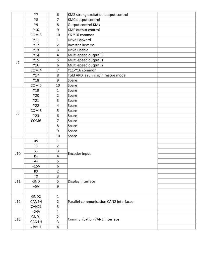
J7
Y11 1 Drive Forward
Y12 2 Inverter Reverse
Y13 3 Drive Enable
Y14 4 Multi-speed output I0
Y15 5 Multi-speed output I1
Y16 6 Multi-speed output I2
COM 4 7 Y11-Y16 common
Y17 8 Told ARD is running in rescue mode
Y18 9 Spare
COM 5 10 Spare
J8
Y19 1 Spare
Y20 2 Spare
Y21 3 Spare
Y22 4 Spare
COM 5 5 Spare
Y23 6 Spare
COM6 7 Spare
8 Spare
9 Spare
10 Spare
J10
0V 1
Encoder input
B- 2
A- 3
B+ 4
A+ 5
+15V 6
J11
RX 2
Display Interface
TX 3
GND 5
+5V 9
J12
GND2 1
Parallel communication CAN2 interfaces
CAN2H 2
CAN2L 3
J13
+24V 1
Communication CAN1 Interface
GND1 2
CAN1H 3
CAN1L 4

3.3.2 Car computer board SM5000-02A
Figure 3-3-1-1 cab computer board SM5000-02A Outline
1. Explanation (1) Within the election and answer floor
Car computer board SM5000-02A basic input and output interfaces, connected car after expansion board SM5000-02B up Extended to 64-layer control;
(2) Shows the car The car show outside the church through the use of computer and display board to achieve its interface
block diagram shown in Figure 3-4-2-4. When the outer Zhao and display computer Board when used as a display inside the car, J1 is connected to the car computer board J1, J2, J3 no wiring, floors address is set to zero (see setting method See PC board outside the church and display address setting section).
2. Connector specifications (SM5000-02A-V1/V2) (1) J1 pin single-row seat 3.96/4P (2) J2 ~ J4 pin single-row seat 5.08/10P (single sheath) (3) J5 single row socket 2.54/5P (4) J6 ~ J11 double socket 2.54/10P 3. Interface circuit

See Figure 3-3-2-2, 3-3-2-3 diagram, Figure 3-3-2-4. Figure 3-3-2-3 wiring diagram inside the Select All button
Figure 3-3-2-4 car computer board with expansion board connection diagram
Figure 3-3-2-2 car computer interface circuit board SM5000-02A
4. Interface definition and specifications Table 3-3-2 - car computer board SM5000-02A interface definition and specifications
Name Location Definition Use Interface Technical Specifications
J1
1 +24V
Power and Communication
2 GND
3 CANH
4 CANL

J2
1 A station clock
Export
2 Station clock B
3 A car lighting
4 Car light B
5 Spare A
6 Alternate B
7 Overload AV
8 Overload B
9 24V auxiliary power
10 Auxiliary power supply 0V
J3
1 Common terminal (24V ground)
Enter
2 Door open
3 Closed in place
4 Safety Edge 1
5 Overload
6 Full
7 Safety Edge 2
8 Light load
9 Load
10 Driver
J4
1 Dedicated
2 Straight on
3 Spare
4 Spare
5 Door open 2
6 Closed place 2
7 RT-
8 RT+
9 +24
10 Common terminal (24V ground)
J5
1 +24 V power input
Expansion board interface
2
3 +5 V power supply input
4
5 Power 0V input
6
7
The data signal line
8
9
10
11
12
13 Air
14
J6
1 Light
Open a
2 24V
3 24V
4 Push button
J7
1 Light
Close a
2 24V
3 24V
4 Push button
J8
1 Light
Door 2
2 24V
3 24V
4 Push button
J9
1 Light
Closed 2
2 24V
3 24V
4 Push button
J10
1 Light
Open delay
2 24V
3 24V
4 Push button
J11
1 Open output
Spare
2 Common
3 Closed output
4
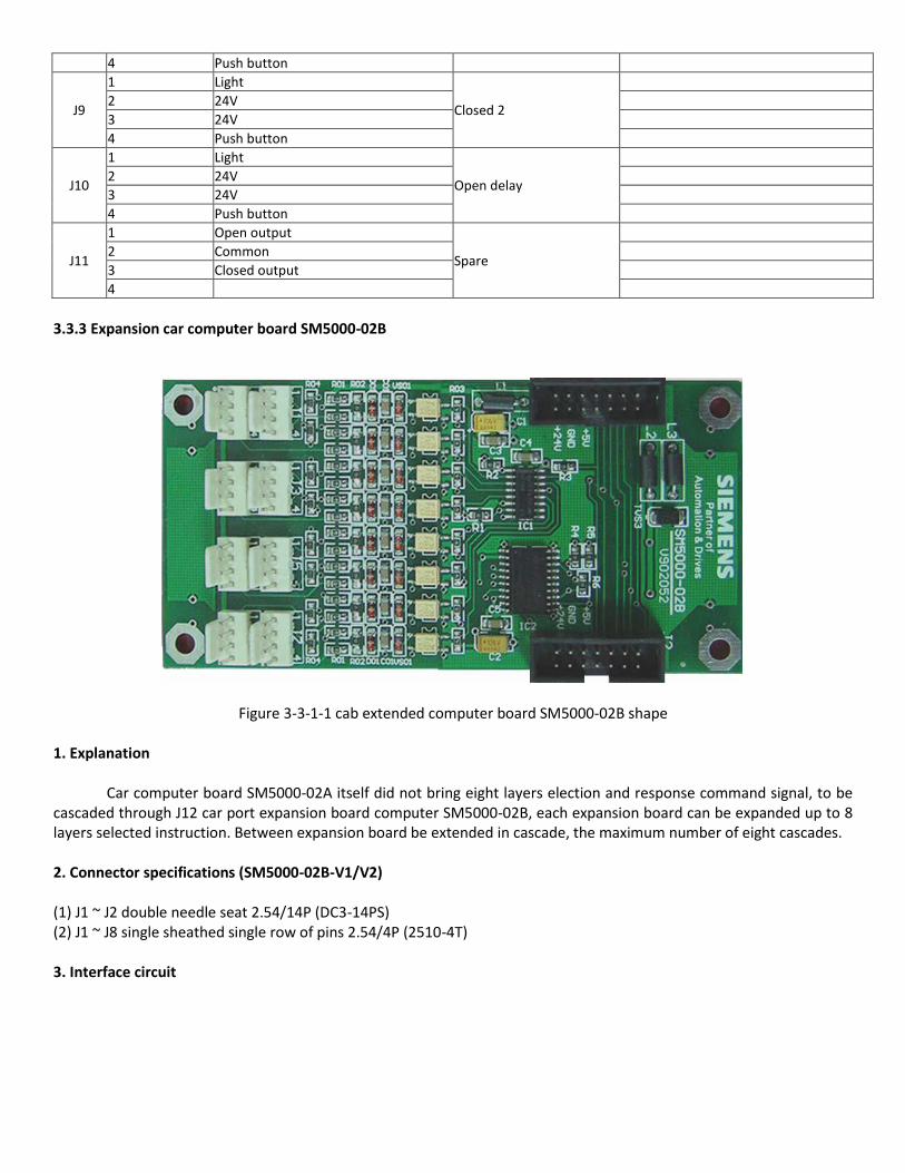
3.3.3 Expansion car computer board SM5000-02B
Figure 3-3-1-1 cab extended computer board SM5000-02B shape
1. Explanation
Car computer board SM5000-02A itself did not bring eight layers election and response command signal, to be cascaded through J12 car port expansion board computer SM5000-02B, each expansion board can be expanded up to 8 layers selected instruction. Between expansion board be extended in cascade, the maximum number of eight cascades. 2. Connector specifications (SM5000-02B-V1/V2) (1) J1 ~ J2 double needle seat 2.54/14P (DC3-14PS) (2) J1 ~ J8 single sheathed single row of pins 2.54/4P (2510-4T) 3. Interface circuit

3-3-3-2 Car expansion board SM5000-02B interface circuit
4. Interface definition and specifications Table 3-3-3 expansion board SM5000-02B car interface definition and Electrical Specifications
Name Port number Location Definition Use Interface Technical Specifications
Interface Type Rated load Maximum speed
PJ1
24V J1-1 - J1-2 +24 V power input
Car motherboard interface
5V J1-3 - J1-4 +5 V power supply input
0V J1-5 - J1-6 Power 0V input
J1-7 - J1-12 The data signal line
J1-13 - J1-14 Air
PJ2 With PJ1 And lower plate cascade Interface
J1
1 Light
2 24V Layer selected input and
3 24V Acknowledge Output Interface
4 Push button
J2
1 Light
2 24V Layer selected input and
3 24V Acknowledge Output Interface
4 Push button
J3
1 Light
2 24V Layer selected input and
3 24V Acknowledge Output Interface
4 Push button
J4
1 Light
2 24V Layer selected input and
3 24V Acknowledge Output Interface
4 Push button
J5
1 Light
2 24V Layer selected input and
3 24V Acknowledge Output Interface
4 Push button
J6
1 Light
2 24V Layer selected input and
3 24V Acknowledge Output Interface
4 Push button
J7
1 Light
2 24V Layer selected input and
3 24V Acknowledge Output Interface
4 Push button
J8
1 Light
2 24V Layer selected input and
3 24V Acknowledge Output Interface
4 Push button
Remark
3.3.4 Outer Zhao and display PC board SM5000-04A 1. Explanation
Outside the church and display PC board SM5000-04A more categories: Under the direction of the display block and display floor display block indicating the arrangement were divided into horizontal and vertical display; according to the display method is divided into blocks of luminous dot matrix display and seven-segment display; dot matrix display
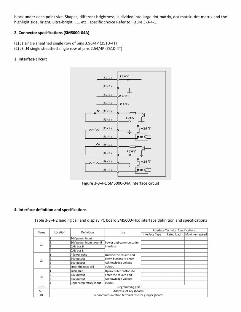
block under each point size, Shapes, different brightness, is divided into large dot matrix, dot matrix, dot matrix and the highlight side, bright, ultra-bright ...... etc., specific choice Refer to Figure 3-3-4-1. 2. Connector specifications (SM5000-04A) (1) J1 single sheathed single row of pins 3.96/4P (2510-4T) (2) J3, J4 single sheathed single row of pins 2.54/4P (Z510-4T) 3. Interface circuit
Figure 3-3-4-1 SM5000-04A interface circuit
4. Interface definition and specifications
Table 3-3-4-2 landing call and display PC board SM5000-Hxx interface definition and specifications
Name Location Definition Use Interface Technical Specifications
Interface Type Rated load Maximum speed
J1
1 24V power input
Power and communication interface
2 24V power input ground
3 CAN bus H
4 CAN bus L
J3
1 A lower echo Outside the church and down buttons to enter Acknowledge voltage output
2 24V output
3 24V output
4 Enter the next call
J4
1 Echo on A Uplink outer buttons to enter the church and Acknowledge voltage output
2 24V output
3 24V output
4 Upper respiratory input
IDE10 Programming port
SET Address set key (board)
JD Serial communication terminal resistor jumper (board)

5. Computer board outside the church address and display settings
Observed by means of the block matrix display and digital display board behind the SET pin for address setting: car dashboard address is set to 0, the outer Zhao / floor number display panel set up by the absolute address (1 to 64), the bottom address is set to 1, sub-bottom address is 2, and so on. (1) Short SET pin, set the unit address is displayed more than three seconds to enter set the address state. (2) The address in the settings mode, the number displayed on the dot matrix will be in ascending order, the address plus 1 until after 64 cycles. (3) Set the address is complete release the button for 2 seconds, the address number will flash and save the settings. ▲ Note: Only the lowest level (address number is 1) an outer Zhao and display board computer access terminal resistors. ▲ Note: Different models will vary, please refer to accompanying documents shall prevail.

Chapter IV SM5000 serial control system installation 4.1 Important 1. Where the company manufactured products, have been automated strict quality inspection test line , except during transport accidents ( please refer to the manual to Check the contents of the cargo ) , under normal circumstances can be operated normally put to install and use. 2. Where the purchase and use of our product users, installing or supporting before you read this manual and the system associated or ancillary equipment manuals. And in accordance with this manual and random data, and associated with this system or equipment manuals related content to install or support, to avoid being accidentally Losses. 3. Purchase and use of our control system bare metal and sheet metal parts product users , in addition to understand than its corresponding features , learn more The product scope of application conditions , performance indicators, installation size, interface component models and specifications , installation technical requirements , etc., in order to Free suffer unexpected losses. 4. If this manual does not meet your needs, please contact us to get help as soon as possible, to avoid you install and use Suffered unexpected losses. 4.2 Checks upon arrival 1. Open the package before the first check to manifest, invoice number and the arrival of the actual packaging (volume, weight, etc.) are the same; 2. Open the package check the packaging for damage before, whether internal parts may be damaged; 3. Check whether the package is unsealed original packaging (including packaging, inner packaging); 4. Open the package and check whether the appearance of internal parts package breakage; 5. Car loaded single check is consistent with the order form; 6. Checking and packing equipment compartment components within a single name, size, type, quantity, etc. are the same; 7. Other abnormal conditions. ▲ Note: If you find one of the above circumstances, as soon as possible with the shipper or the company. 4.3 System Installation 4.3.1 Installation Technical Requirements 1. Follow "(GB7588-2003) elevator manufacturing and installation specifications" for installation. 2. Please refer to with this system (components) and associated connecting devices (devices) technical requirements for the installation instructions to install it. 3. Make sure the environment does not install this system (components) and its installation resulting in adverse effects. 4. Make sure the installer has installed the system (part) qualification. 5. Are not mentioned in this manual follow the technical requirements of the industry or profession and practice for installation. 4.3.2. SM5000 Series Parts Installation 1. Circuit board mounting (1) Note the direction; (2) Main computer board, car computer board, car extended computer board, landing call and display PC board should be installed liner (accessories); (3) Do not twist (so as not to damage the circuit board), especially when tightening the screws mounting the circuit board should pay more attention; (4) Ensure insulation and grounding.

2. Connector installation (1) School line: patch before Verify control interface definition table corresponding pin connection cable with connector connected between pin insulated from each other (to be to communicate except); (2) Check the connection: plug and socket connector before checking specifications are the same, bent pins, Vacancies, Jack is unobstructed, etc.; (3) The correct patch: Note the corresponding label (ID) patch; (4) Note that patch in place, no gap between the plug and socket. 3. Note the difference between common terminals, power supply, and the external ground. 4.3.3 Install other system components 1. Rotary encoder installation and connection
Rotary encoders are important elevator control system detecting element, which directly affects the quality of the installation system performance. Under normal circumstances, rotary encoders Decoder should be entrusted tractor manufacturing plant installed as required. Need to install, please note the following:
(1) Using the rotary encoder on the shaft, shall be installed on the tractor tail section with flexible shaft coupling shaft coaxial with the department to ensure that trolling Cited machine shaft and encoder shaft concentricity ( see the installation instructions encoder part ) , or it may cause the encoder output Pulse instability, affecting the elevator speed stability, or even damage coupling section ; coupling section on the top wire to the top firmly in place on both sides of the shaft platform , Throw switch to prevent skidding ; loose coupling section feedback error may cause the system to make the elevator appear jitter and uneven layers and other faults. (2) If the tractor is not connected to the tail shaft, sleeve shaft encoder can be selected and installed on the motor shaft; when ordering prior express power mounting dimensions of shaft (shaft); installation do not knock gravity, so the encoder disc broken glass; encoder installed in the electric Machine rotation conditions should be no significant jitter. (3) Rotary encoder cable should be with the inverter specified port and main computer board should correspond to the specified port, wrong wiring may damage Rotary encoder; rotary encoder cable should be set in a metal tube, away from power lines individually furnished. (4) Refer to the specific coupling the relevant parts of the random electrical schematics. ▲ Note: The encoder cable shield is not connected with the tractor ground. 2. Door zone switches and door area deck installation and adjustment Elevator leveling control requires two door zone switches with several door areas Deck (each one). Two door zone switches mounted on the car roof, door area Deck mounted on the shaft, the size requirements and the installation location as 4-3-3-1 Follows: door zone switches adopt photoelectric switch or magnetic switch. 3. The lower end of the station switch installation and adjustment (1) The elevator speed ≤ 1m / s , the lift end station to the upper and lower strength of a Change-over switch. (2) Wherein the upper and lower end stop switch is mounted on the shaft, the end stop collision safety bow mounted on the car frame. (3) The lower end of the station switch should be installed in the car sill from the top (bottom) Floor landing door sill 1.5m (elevator speed ≤ 1m / s), the switch operation Position. (4) Elevator speed ≥ 1.5m / s ultra- high-speed elevators should increase the number of client stations Volume, in order to implement a more secure protection. Specific installation position See the following table is set . (5) End station switch recommended -contact limit switch. (6) See Figure 4-3-3-2

Figure 4-3-3-1 door zone switches and door area deck installation diagram
Table 4-3-2 different speed when on a ladder / bottom station installation position refer to Table
Lift Speed End station name
End station installation location
0.5m/s 1.0m/s 1.6m/s 2.0m/s 2.5m/s 4.0m/s
1.75m/s
Upper / lower station 1 1m 1.3m 1.3m 1.3m 2.5m 2.5m
Upper / lower station 2 2.8m 2.5m 4m 8m
Upper / lower station 3 4m 6.25m 12m
4.3.4 Control System Ground System installation, make sure that the system and its components reliable grounding ground. 1. Rotary encoder shielded wire grounded; 2. Hoistway cables and accompanying cable ground; 3. Control cabinet enclosure, the drive ground terminal envelope grounded motor housing and a car; 4. Other parts ground terminal to ground; 5. Note the difference between common terminals, power supply, and the external ground.
Home area sensor
Next door zone sensor
Door area deck
Car sill
Foyer sill
Sedan chair

Chapter V SM5000 serial control system parameters 5.1 Overview
In order to give the system debugging, maintenance, monitoring and other operations to provide a friendly man-machine communication interface, in the main computer board SM5000-V2, and a LCD display and keyboard. Commissioning, maintenance, monitoring personnel can monitor and keyboard operation, implement the entire elevator control system Operating parameter settings and system operation and the main input and output signals observed. 1. LCD display and keypad description Beneath the LCD monitor to set up six buttons, their appearance arrangement and are defined as follows:
Figure 5-1-1 LCD display and button layout
Enter key to enter the next level menu, modify data, instructions registration confirmation. Hair Esc Cancel Cancel to return to the previous menu. ↑ Menu key, number +1; ↓ next flip, digital -1; → Shift key 2 Parameter Setting (1) Basic parameters: total number of landings until ladder layers, system time, hold time to open the door, open the door back to the base station to extend time to time, automatically open staircase Time, auto-off time for an elevator, fire layer settings, lock ladder layer, input type, car input types, output types, F Parameters. (2) Operating parameters: elevator rated speed, motor rated speed, number of encoder pulses, inspection speed, creep speed, single speed, opens the door Speed, open the door overrun speed, leveling speed door, gate delay, start velocity curve, brake delay the acceleration ramp B1, accelerated slope B2, S curve P1 ~ P4, zero speed settings, zero speed time leveling adjustment, commissioning, flat layer micro- Tone. (3) Special parameters: Door relay hold time, restore factory settings, enabling parallel, group control is enabled, remote monitoring, fire mode, parallel No. ladder, running timeout, multi-speed V1 ~ V 4, change speed from S1 ~ S4, through the door, the door position detection, Inventer. (4) Hoistway self-learning (5) Save the parameter (6) Set the password 5.2 System Menu Structure and Process

Figure 5-2-1 System Menu main flow chart

5.2.1 Main Menu In the main menu, display the current floor, running direction, running status, fault status, lock status, operating speed.
1. Lift Status Display Maintenance, drivers, automatic, Fire, power locks closed, special. 2. Fault Status Display ER # faulty Blank trouble 3. Door status display Door closed, the door opened. 4. In addition to the hoistway self-learning, self-learning load detection, save outside the parameters; press the Menu key to unconditionally return to the main menu. 5.2.2 Communication Status menu 1. Show car communication computer board OK normal communication ER main computer board receive error (check the communication lines and car computer board). 2. System Communication Show OK normal communication Main computer board sends an error (please check the outer Zhao communication lines), when a certain value is displayed as the fault of the system communications Wrong times. 3. Shows the parallel communication OK two parallel systems communicating properly Two parallel system communications is not normal (optional feature) 5.2.3 Interface cryptographic checksum
When you need to enter the menu and save the settings and parameters, must be placed in the elevator maintenance status, enter the correct password before entering the corresponding menu Single as well as set and saved parameters. Password can be set in the Password to modify the specific operation method, see the following related content. 5.2.4 Monitoring menu and parameter setting menu
Monitor menu and basic parameters menu, operating parameters menu, special parameters menu is set up and run the system parameters of the basic state monitoring Interface.

Figure 5-2-4-1 menu flowcharts

5.2.5 Menu setting operation tips 1. Set the correct password after password verification before entering the menu; 2. Press the Enter key to enter and display the contents of the corresponding sub-interface; 3. When entering setup parameters interface, no cursor is displayed you cannot modify the parameters, press the Enter key to move the cursor appears, use ∧, ∨ button to modify the parameters Number, press> Rotate Right cursor. 4. Glossary (1) Floor - show floor; (2) The absolute floor - the lowest level as a floor, the second floor of 2 floor, 3rd floor ............ third layer. 5.3 Monitoring Parameters menu settings and operation 5.3.1 Monitoring Parameters Table
In the monitor menu, in addition to selected layer information, open / close input commands can be input operation, the rest are read-only parameters.
Table 5-3-1 Monitoring Parameters
No. Chinese Explanation
1 Select layer information Show instructions within each floor, up and down outside the church and the selection signals within the selected
2 Layer station information Each floor level position, and whether docked
3 Hoistway switch position Show the upper and lower limit, end station location
4 Input and output I / O port number in decimal portfolio adjusted for the corresponding binary I / O state
5 Speed feedback value Current motor speed (rpm) and elevator speed (m / s),
6 Operating records Total running time, number of
7 Fault History Record last 20 faults
8 Test call Test whether the communication is normal call
9 Input Signal Each input port corresponds to the state
10 Output Signal Each output port corresponds to the state
11 Car Signal Cab input / output port status
12 Open / close input Use the keyboard to type open / close commands
13 Communications Test Test each one outside the church board communications with the host computer case
14 Version Version number
5.3.2 Setting and Operation 1. Layer selection information
Displayed within S, Zhao, under Zhao, and can be selected within the command layer (for debugging). (1) In the main menu screen monitor ∨ key to enter the first page of the menu, choose the main interface layer
information:
(2) Press the Enter key to enter the selected layer information interface:

(3) The information in the interface layer selection button Press the ∧ or ∨ key to change the selected floor. Running
direction indicates the current direction of travel. Within selected within asterisk Blinking election Not blinking means no internal choice. Press Enter when debugging option in the observation of the inner layer selected (flashing asterisk), the realization express debugging. On vocations Under Zhao show "■" indicates outside Zhao, display "□" means no outside Zhao. F-XX show floor elevator currently located. Press Esc to return Select the main interface layer information. 2. Storey station information Interface the first line shows whether the landing dock layer (□ not docked, ■ docked). The second line shows the location of each floor leveling scale values, the starting point for the lower limit.
3. Hoistway switch position
Display, the lower limit, the upper and lower end of the station installation location, the starting point for the lower limit, in meters. (1) In the main screen, press the command information ∨ key to enter the Monitor menu the third (monitor interface switching ∧, ∨ turnkey, the following no longer tired), well Channel switch position main interface:
(2) Press the Enter key to enter the hoistway switch position interface:
(3) Into the hoistway switch position interface, press ∧, ∨ keys to change the observation items. Press Esc to return hoistway switch position interface.
∨
∨
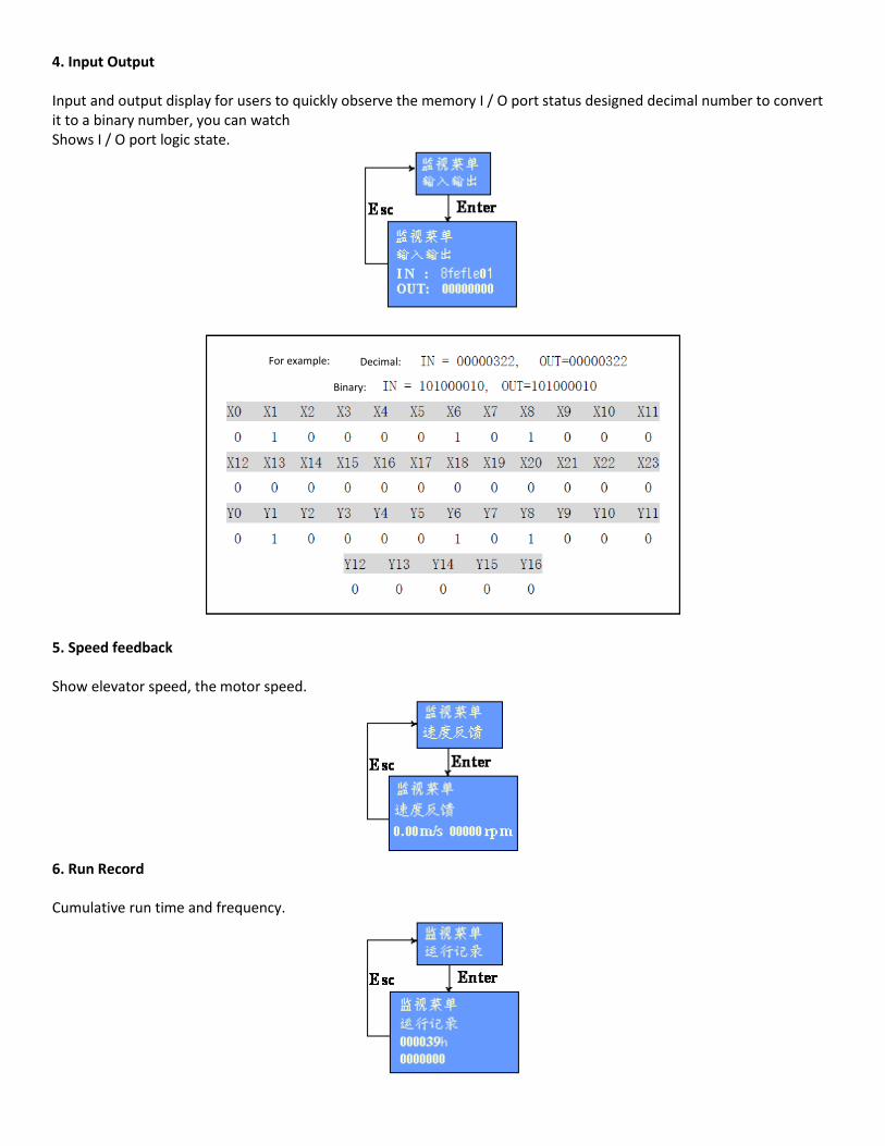
4. Input Output Input and output display for users to quickly observe the memory I / O port status designed decimal number to convert it to a binary number, you can watch Shows I / O port logic state.
5. Speed feedback Show elevator speed, the motor speed.
6. Run Record Cumulative run time and frequency.
For example: Decimal:
Binary:

7. Fault records Record last 20 fault types and occurred at a time and other information (retentive). Press the ∧, ∨ keys to observe each fault record.
8. Test call
9. Input signal
"■" indicates the input is 1, "□" indicates the input is 0. (□: Enter the lights off, ■: input light)
10. Output signal
"■" indicates that the output is 1 (output relay is energized), "□" indicates that the output is 0.

11. Car Signal
Table 5-3-2 (13) Car Signal Table No. Meaning No. Meaning No. Meaning No. Meaning
U00 Full U01 Open the door to a U02 Close to 1 U03 After the curtain
U04 Before the curtain U05 Light load U06 Overload U07 Load
U08 Driver U09 Spare 2 U10 Dedicated U11 Open the door to two
U12 Close to two U13 Straight on U14 Spare U15 Spare a
U16 Door extension U17 Spare 2 U18 Open a U19 Door 2
U20 U21 Closed 2 U22 Close a U23
U24 Spare U25 U26 U27
U28 U29 U30 U31
12. Open / close input
Press ∧ or ∨ buttons can be open / close operation. Show "■" indicates enter a valid closed, the same command
can be entered to open the door. With this interface can be carried out in the engine room elevator door open / close operation. 13. Communications Test
View outside the church and display the main control computer board computer board communication situation.
◆ Press the ∧, ∨ buttons to change the number of foreign Zhao;
◆ Communication circumstances indicate OK indicates correct, Wait said it is testing (if displayed Wait too long, check whether the system communication Normal). Fail indicates that the communication failure (check that the outer layer of Zhao and display PC board).
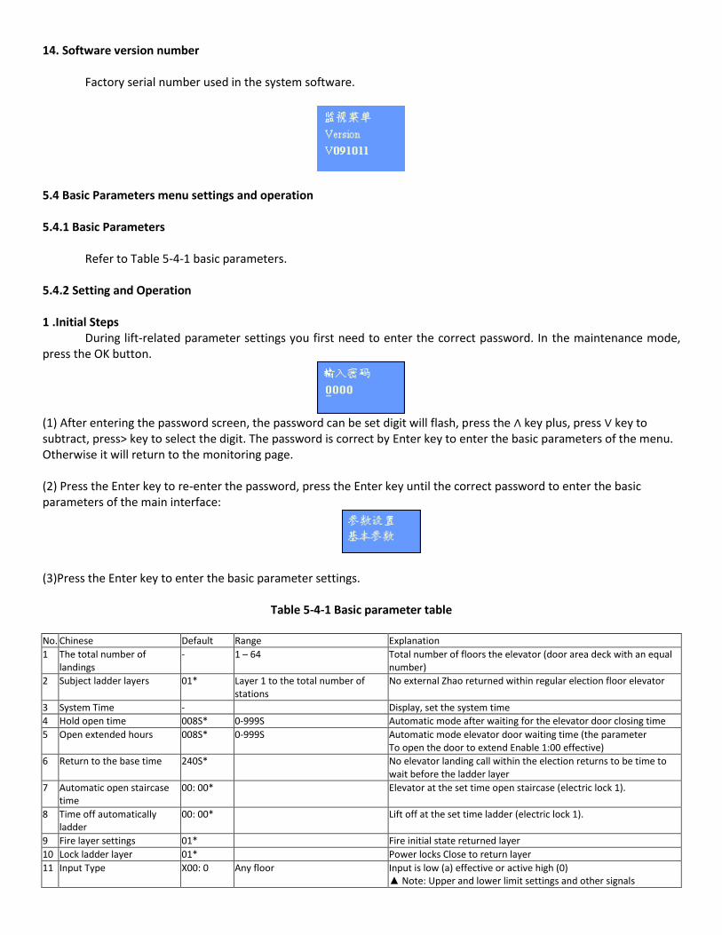
14. Software version number
Factory serial number used in the system software.
5.4 Basic Parameters menu settings and operation 5.4.1 Basic Parameters Refer to Table 5-4-1 basic parameters. 5.4.2 Setting and Operation 1 .Initial Steps
During lift-related parameter settings you first need to enter the correct password. In the maintenance mode, press the OK button.
(1) After entering the password screen, the password can be set digit will flash, press the ∧ key plus, press ∨ key to subtract, press> key to select the digit. The password is correct by Enter key to enter the basic parameters of the menu. Otherwise it will return to the monitoring page. (2) Press the Enter key to re-enter the password, press the Enter key until the correct password to enter the basic parameters of the main interface:
(3)Press the Enter key to enter the basic parameter settings.
Table 5-4-1 Basic parameter table
No. Chinese Default Range Explanation
1 The total number of landings
- 1 – 64 Total number of floors the elevator (door area deck with an equal number)
2 Subject ladder layers 01* Layer 1 to the total number of stations
No external Zhao returned within regular election floor elevator
3 System Time - Display, set the system time
4 Hold open time 008S* 0-999S Automatic mode after waiting for the elevator door closing time
5 Open extended hours 008S* 0-999S Automatic mode elevator door waiting time (the parameter To open the door to extend Enable 1:00 effective)
6 Return to the base time 240S* No elevator landing call within the election returns to be time to wait before the ladder layer
7 Automatic open staircase time
00: 00* Elevator at the set time open staircase (electric lock 1).
8 Time off automatically ladder
00: 00* Lift off at the set time ladder (electric lock 1).
9 Fire layer settings 01* Fire initial state returned layer
10 Lock ladder layer 01* Power locks Close to return layer
11 Input Type X00: 0 Any floor Input is low (a) effective or active high (0) ▲ Note: Upper and lower limit settings and other signals

12 Car Input Type U00: 0
13 Output Type Y00: 0 Output normally open relay points to 0, normally closed to 1.
14 Hall display 01*: 1 Set a layer display characters
15 Stop layer settings 01: YES Set each layer is docked (ON docked, OFF stop layer)
16 Enable extended door NO* Extension of time to enable the door (optional)
17 Brake testing YES* Select Yes to the system detects brake feedback system will select NO Does not detect brake feedback.
18 Select to open the door 01: Q=1 H=0
1. Total number of floors set
Set the total number of floors the elevator.
(1) Press the Enter key figures flickering lower right corner, then you can modify the total number of floors; (2) Modification is completed press the Enter key is successfully modified; (3) Press the Esc key to cancel the change to restore the original value; (4) Total number of floors the elevator hoistway doors shall be equal to the number deck area. 2. Subject to the ladder layer settings No outside and inside the church elevator election delay (back to the base station time) returns the floor, set the method above
3. Set the system time Set the system time (24 hours); Year - Month - Day Hour: Minute.
4. Automatic door hold time setting
Automatic mode hold time after the elevator door opened. The actual holding time the elevator door will cause adjustment stop. If only, pointed Order or outside the church and stop, then perform this hold time. Both within the church and outside instruction stops there, then this holding time based on the 2S.

5. Door extension of time setting
In automatic mode, pressing the button to open the door to extend (switch) allows the elevator door to keep longer hours. This feature is enabled only in open extension 1, Setting and effect. Extension of time in seconds.
6. Return to the base time setting
Automatically returns to standby ladder layer time; Set 0:00 ladder layer functions to be no return.
7. Automatic open staircase time setting
System according to the set time automatically open staircase (electric lock 1)
8. Automatic time setting off ladder
System according to the set time automatically turn staircase (electric lock 1). Automatic opening time and automatically turn staircase ladder the same time, the function fails.
9. Fire layer settings
Fire switch signal received after the elevator to eliminate internal and external Zhao arrived directly after fire evacuation floor.
10. Lock ladder layer settings
Lift off the power during normal operation lock, to lock the elevator ladder layer stops running.

11. Input Type
Table 5-4-2 - valid input level setting
Name Port number
Location Definition Corresponding parameter
Factory level setting
Display lights normality
Main X0 J1-1 Inspection / automatic input X0 0 Always
Computer X1 J1-2 Manual Uplink X1 1 Off
Board X2 J1-3 Hand down X2 1 Off
X3 J1-4 Is stronger for two X3 0 Always
X4 J1-5 Under strong for two X4 0 Always
X5 J1-6 Upper limit X5 1 Always
X6 J1-7 Lower limit X6 1 Always
X7 J1-8 UPLINK SPEED 1 SWITCH X7 0 Always
X8 J1-9 DOWNSTREAM SPEED 1 SWITCH X8 0 Always
X9 J1-10 On leveling sensors X9 1 Always
X10 J2-1 Under leveling Sensors X10 1 Always
X11 J2-2 Drive fault input X11 1 Always
X12 J2-3 Fire Switch Input X12 1 Always
X13 J2-4 Emergency stop input X13 1 Always
X14 J2-5 LANDING chain input X14 1 Always
X15 J2-6 Car door interlock input X15 1 Always
X16 J2-7 Run contactor input X16 1 Off
X17 J2-8 Mains contactor input X17 1 Always
X18 J2-9 Brake contactor input X18 1 Off
X19 J2-10 Lock staircase input X19 1 Off
X20 J3-1 Brake feedback input X20 1 Always
X21 J3-2 Emergency automatic leveling input
X21 1 Off
X22 J3-3 Inverter operation input X22 1 Off
X23 J3-4 Blocked loop input X23 1 Off
X24 J3-5 Re-leveling door area detection input
X24
X25 J3-6 On how strong reduction switch 3 X25
X26 J3-7 Strong reduction of multi-switch 3 X26
X27- J3-8 (-) INVERTER OPERATION INPUT
X27+ J3-9 (+) INVERTER OPERATION INPUT
X28 J5-1 Safety loop input X28 1 Always
X29 J5-2 LANDING chain input X29 1 Always
X30 J5-3 Car door interlock input X30

COM 0 J5-4 Circuit common terminal
X31 J5-5 Standby loop X30
X31_1 J5-6 Spare X31_1
KMV 1 J3-2 Door open U01
GMV 1 J3-3 Closed in place U02
KAB 1 J3-4 Safety Edge 1 U04
CZ J3-5 Overload U06
MZ J3-6 Full U00
Car KAB 2 J3-7 Safety Edge 2 U03
Computer QZ J3-8 Light load U05
Board KZ J3-9 Load U07
SZH J3-10 Driver U08
KMV 2 J4-1 Dedicated U10
GMV 2 J4-2 Straight on U13
SZY J4-3 Spare U
SZS J4-4 Spare U
ZHS J4-5 Door open 2 U11
ZHX J4-6 Closed place 2 U12
▲ Note: If the upper and lower limit circuit normally ON state, it should appear as a. If the upper and lower limit circuit is normal in a disconnected state, it should be displayed as 0. 12. Car Input Type
13. Output type (normally open temporarily out point processing)
When the output relay is normally open contacts, set to 0, the normally closed contact 1, factory setting all 0.
14. Landing display settings
Set each layer floor display symbol (show floor), can be set to English letters or signed numbers.

15. Docked layer settings
Set each layer is docked (YES to stop layer, NO to not stop layer).
16. Enable extended open set
Valid extension of time to open the door (optional).
17. Brake feedback detection enabled setting
(1) Select YES feedback system detects brake; select NO system will not detect brake feedback. (2) Recommends installing tractor brake detection switch, and the switch signal access the system and select this function. (3) Must be detected in the automatic mode, in the maintenance of the state cannot be detected. 18. Select Settings to open the door
n: the elevator floor. By ∧, ∨ key to change. Q: Indicates the front door. By> key selected, select whether through Enter the door, open the door to 1:00 for the 0:00 is not open. H: indicates the back door. By> key selected, select whether through Enter the door, open the door to 1:00 for the 0:00 is not open. Example: A through-door elevator on the 6th floor only open the front door, back door does not move, when the elevator on the 7th floor front and back doors are movements. Should be set as follows:
5.5 operating parameters menu settings and operation 5.5.1 Run the parameter table

Table 5-5-1 operating parameters table
No. Chinese English Default Range Explanation
1 △ elevator rated speed Car Speed 1.6m/s 1 - 2.5m/s Motor rated speed of the elevator speed
2 △ motor rated speed Motor Speed - 1 - 9999r Motor rated speed
3 △ encoder pulses Pulses - 500 - 9999 Main computer board receives encoder pulses per revolution
4 Inspection speed Insp Speed 0.3m/s* 0.01 - 0.6m/s Overhaul running speed
5 Crawling speed Start Speed 0.00m/s* 0 - 0.20m/s Before starting curve smoothing speed increase
7 Single Speed least Speed 1m/s* 0.01 - 1.0m/s Minimum speed curve steady speed value
8 Gate delay Break On Time 500ms* 10 - 9990ms Gate with hair running curve interval
9 Start speed curve
10 Brake delay Break Off Time 500ms* 10 - 9990ms Brake with automatic door interval
11 Acceleration slope B1 Acceleration b1 0.6* 0.1 - 9.99 Acceleration slope
12 Acceleration slope B2 Deceleration b2 0.6* 0.1 - 9.99 Deceleration slope
13 S-curve P1 S-curve P1 0.7* 0.1 - 9.99 S Time 1
14 S-curve P2 S-curve P2 0.7* 0.1 - 9.99 S time 2
15 S-curve P3 S-curve P3 0.7* 0.1 - 9.99 S Time 3
16 S-curve P4 S-curve P4 0.7* 0.1 - 9.99 S Time 4
17 Zero speed settings Zero Speed 5rpm* 0 - 9999 Zero speed threshold
18 Zero speed time Zero Time 300ms 0 - 999ms After the system detects zero speed brake delay time
19 Leveling adjustment Leveling Adj 50mm Adjust up / down leveling differences
20 Test run
21 Flat layer of fine-tuning
△: elevator rated speed, motor rated speed, the encoder pulse number three parameters is very important and
should be set according to the nominal value, or the elevator does not work properly OK (such as guns are not allowed, for speed point deviation, etc.). When any one of the three parameters is changed, you must re-hoistway self-learning before normal operation. When the system Received feedback pulse after pulse divider, set the number of encoder pulses should be translated, rather than the actual value of the encoder.
▲ Note: This system requires the encoder pulse number is greater than 500 lines (gearless traction machine encoder pulse number should be greater than 4096 lines), the pulse frequency at 6 kHz ~ 25kHz Range. Example: encoder 1024 pulses / turn, divided by 2 to the system, the number of encoder pulses = 1024/2 = 512. Motor rated speed and rated speed elevators must meet the following conditions:
Elevator rated speed = Rated motor speed * Pulley diameter reduction ratio * 3.14 *
60 * 1000 * Traction Ratio Example: Motor rated speed 1370 rev / min, traction wheel diameter 590 mm, reduction ratio 2/53, traction ratio of 1/1, then:
Elevator rated speed = 1370 * 590 * 3.14 * 2 = 1.6 m / s 60 * 53 * 1000 * 1
This interface is used with the elevator speed-related parameter settings.
Press the Enter key to enter the parameter setting.

1. Elevator rated speed setting
Elevator rated speed according to the rated motor rotation, traction ratio, gear ratio and traction sheave pitch diameter is calculated. Note: The elevator rated speed is used to calculate Rated motor speed with the elevator speed proportional relationship between the changes of the parameters cannot change the actual running speed elevators.
2. Motor nominal speed setting
Rated motor speed, according to the motor nameplate parameters.
3. Set the number of encoder pulses
Encoder pulse number: Refers to enter the number of pulses main computer board. Rated speed of the motor, when the encoder output pulse frequency is less than 30kHz When the encoder signals can be connected directly. When more than 30kHz, the need to divide after the access, but the divided signal frequency not less than 6kHz.
▲ Note: elevator rated speed, motor rated speed and the number of encoder pulses is to determine whether the normal operation of the elevator three important parameters, three parameters which have a change Change must be re hoistway self-learning. 4. Speed overhaul
Set maintenance operating speed. Accordance with the relevant standards, inspection speed not greater than 0.6m / s.

5. Starting smooth speed setting
When the tractor starting resistance is too large, may be appropriate to add smooth start speed, smooth start speed is set to 0:00, does not work.
6. Self-help speed setting
When the elevator stopped at the non-door zone fault, if the safety circuit, the inverter returns to normal, the elevator automatically by the station (self-running to the door area). This interface can be self-help speed setting range is 0.01 ~ 0.6m / s.
7. Single speed setting (1) single-speed steady speed value determines the size of spacing can run most small building; (2) Lift speed 1.5m / s or more, Elevator Single / Multi steady speed runs with different values; (3) If the floor space is too small, should be appropriately reduced single-speed, normally it should be set at 0.8 ~ 1.0m / s.
8. Start time setting multi-speed
Multi-speed startup time is to improve the starting point of comfort, allowing the system to adapt to different tractor brake opening time.
Leveling Speed 0.30 m / s
Self-running speed

9. Brake time setting
Adjust this parameter allows the system to the next gate and wait until traction sheave brake hold open the door, open the door so as not to stall torque converter removal Causing premature slip car parking comfort effect. 10. Acceleration slope b1 set
11. Deceleration slope b2 is set

12. S Time 1 - P1 Set
13. S Time 2 - P2 Set
14. S Time 3 - P3 Set
15. S Time 4 - P4 setting
▲ Note:
◇ b1, b2, P1, P2, P3, P4 for the operation of the six parameter settings to adjust the curve. These six parameters can be adjusted comfortably lift Sense (except comfort outside of the curve but also with the drive parameters relevant). b1, b2, P1, P2, P3, P4 corresponding to the six parameters between the curve As shown below.

◇ Increases the value, the corresponding part of the curve becomes anxious; decreases the value, the corresponding part of the curve slows; appropriate adjustments over six curve parameters Number availability of good comfort and meet the relevant provisions of the standard requirements of the elevator. 16. Zero speed settings
When the motor speed is less than this value, the system considers the elevator speed to zero speed and under the gate output signal.
The minimum value of the analog to the timing can be set to 0; multi-stage time the value is set to be greater with or equal to 1. 17. Zero speed time
Appropriate adjustments to this parameter, zero speed stabilization after a certain time under the gate, truly zero speed brake.
18. Flat layer of fine-tuning

19. Leveling adjustment
When the elevator on each floor, the downstream stop ladders are not in the same position, adjust the parameter (on high, down low, reduced, whereas the increase). Leveling adjustment is half the difference (the default is 50mm).
20. Test run
Elevator in the debugging process can adjust the parameters, let the elevator run automatically, can be set up (255 times), commissioning process does not completely respond to outgoing calls, Only in the forward direction when the response.
5.6 Special menu settings and operation parameters 5.6.1 The special parameter table
Table 5-6-1 special parameter table
No. Chinese English Default Range Explanation
1 Door relay hold time Door Run Time 5s* 0 – 999S
Door switch relay hold time
2 Restore factory settings
Factory parameter
NO Restore factory parameter values
3 Parallel Enable Twins Control 0* 0 - 1 (Optional)
4 Group control enabled Group Control 0* 0 - 1 (Optional)
5 Remote monitoring Far Monitor 0* 0 – 1 Set to enable remote monitoring and call phone numbers (Optional)
6 Way through the door Two Door Mode
0* 0 – 1 (Optional)
7 Fire way Fire Mode 0* 0 – 1 (Optional)

8 No parallel ladder Parallel No 0* A / B When connected in parallel so effective when either one elevator to A, another set B.
9 Multi-speed setting Multi Speed Give
0* 0 – 4M/S
When (9) is Yes, set the speed segment Speed value (with inverter speed set point corresponds).
10 Distance for speed Decel Distance 0* 0 – 10 Segments corresponding to different velocity deceleration distance.
11 Running out of time setting
Over Time 45* 0 – 999S
Single run time limits.
a) Note: The above with * factory parameters are initialized after the operation to restore factory settings, restore the factory values. 5.6.2 Setting and Operation
This interface allows the user to carry out special performance requirements of parameter settings.
1. Open / close relay hold time setting (1) Opening and closing command is issued, the command hold time thereby setting; (2) When the door is open or closed systems without limit, the open / close relay hold time this interface to determine; (3) When the door system has open / close limit, this time setting value should be higher than the actual opening and closing a long time about 1S.
2. To restore factory settings
Restore the factory set parameter values.
Yes determined parameters will be restored to factory default. When the system debug parameter settings confusion, need to re-commissioning can use this feature. 3. Parallel enable setting
1: Parallel operation, 0: single ladder operation.
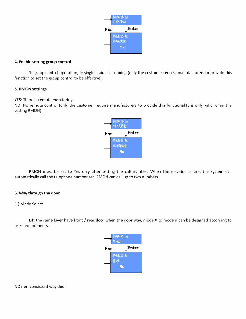
4. Enable setting group control
1: group control operation, 0: single staircase running (only the customer require manufacturers to provide this function to set the group control to be effective). 5. RMON settings YES: There is remote monitoring, NO: No remote control (only the customer require manufacturers to provide this functionality is only valid when the setting RMON)
RMON must be set to Yes only after setting the call number. When the elevator failure, the system can automatically call the telephone number set. RMON can call up to two numbers. 6. Way through the door (1) Mode Select
Lift the same layer have front / rear door when the door way, mode 0 to mode n can be designed according to user requirements.
NO non-consistent way door

YES open front doors can be opened through the basic menu options to select open front door; elevator leveling, when the car had a selection, If the front and rear doors can be opened to allow when both doors are open, or open only allowed to open the door, when an outgoing call over there outbound side of the door opening. (1) Zhao box board address setting
◆ When the main computer board through door way to set 0,1, box board outside the church addresses the same way as with the normal setting, please refer to the manual 3-2-3-4 (2);
◆ When the main computer board through door way to 2,3,4,5, the outer Zhao box board address set by the following principles:
◇ 1 ~ 32 for the front door of the corresponding absolute floor Address: 1 is the lowest, 2 for the second bottom, can be set up to 32, a total of 32 layers;
◇ 33 ~ 64 for the back door of the corresponding absolute floor Address: 33 is the lowest level, 34 for the second bottom, can be set up to 64, a total of 32 layers;
◇ a floor if only one gate, the other corresponding to the address of the door opening. Example 1 a lift with a layer of the basement, and the layer front and back doors are action, corresponding to the outside basement door called box address is 1, the basement Outside the church door corresponding box address is 33. Example 2 an elevator with a layer of the basement, but only the front door, while the first floor there are front and back doors, the front door of the basement of the church outside the box corresponding to the address is 1, Basement room outside the church door corresponding box address vacancies on the first floor outside the front door Zhao corresponding box address is 2, the first floor of the back door of the church outside the box corresponding to Address is 34.
7. Fire mode setting When the fire mode is set to 1, only the anti-fire base station functionality.
▲ Note: Select Fire mode 0 should consider whether the fire safety facilities outside the elevator to meet
national standards, or may cause adverse consequences. 8. Parallel ladder number setting
In a parallel Enable Set Yes, it should be set up in parallel lift No. A or B. Interface settings are as follows:
9. Multi-speed setting
When a multi-speed mode is set to 1, the need for multi-speed setting for speed and distance settings, see the table below specific values (for reference):

Table 5-6-2-1 Multi-speed setting
During multi-speed setting, should be set to the maximum speed V1 corresponding to the speed value segment will be set to the lowest speed V4 corresponding paragraph Speed value, the unit is m / s. Once the speed setting, the LCD screen will display the discounted value of the corresponding motor speed in rev / min (r = rpm).
▲ Note: The user must use the display value as the frequency corresponding to the speed set point to the drive settings; otherwise the speed would not meet the electrical requirements.
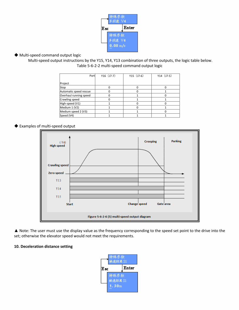
◆ Multi-speed command output logic
Multi-speed output instructions by the Y15, Y14, Y13 combination of three outputs, the logic table below. Table 5-6-2-2 multi-speed command output logic
Port
Project
Y16(J7-7) Y15(J7-6) Y14(J7-5)
Stop 0 0 0
Automatic speed rescue 0 0 1
Overhaul running speed 0 1 0
Crawling speed 0 1 1
High-speed (V1) 1 0 0
Medium 1 (V2) 1 0 1
Medium speed 2 (V3) 1 1 0
Speed (V4) 1 1 1
◆ Examples of multi-speed output
▲ Note: The user must use the display value as the frequency corresponding to the speed set point to the drive into the set; otherwise the elevator speed would not meet the requirements. 10. Deceleration distance setting

In the multi-speed mode, adjust the different speed ranges of deceleration distance can prevent the elevator nonzero speed or crawl under the gate long distances. Corresponding to different The deceleration rate is not the same distance, the debugging and tuning should be tested separately. (10) for setting reference table 5-6-2-1. ▲ Note: (10), (11) Multi-speed parameter is only valid when the mode is set to 1. 11. Running out of time setting
In order to prevent the rope slipping elevator car stuck on the system or cause harm to cope with elevator Express runs every time from start to stop between restrictions. This parameter is set only this time limit, if the elevator single run time exceeds this value, the system will stop immediately enter the protected status State, and only re-power, the system can only withdraw from protection.
Users should be based on speed and floor height ladder set this value, the default value is 45 seconds.

12. Door switch position detection
13. Inventer
5.7 Other parameters menu settings and operation 5.7.1. Hoistway self-learning 1. Into the normal operation of the elevator hoistway must be carried out before the self-learning; 2. Elevator hoistway self-learning before must have the following requirements:
(1) Upper / lower limit switch, upper / lower station switches and corresponding deck installed, the wiring is correct; (2) Up / down switches and door zone area bridge plate installed on each door, the wiring is correct; (3) Safety lock loop circuit and normal; (4) Basic system parameters, operating parameters setting; (5) May be normal for the entire elevator maintenance operation.
3. Hoistway self-learning must be carried out in the maintenance of the state and the car down to the lower limit switch can begin; 4 .If the elevator does not lower limit position is displayed To Down Limit, according to slow down the elevator opened to the lower limit position; 5. If the elevator next stop displays Enter To Start, press the Enter key, the elevator automatically self-learning; 6. Lift to the upper stop bit self-learning; 7. Self-learning success shows Success; 8. Shows self-learning fails Failure LER #, press the fault code prompt treatment after self-learning (see Appendix No. Meaning fault); 9. Since the learning process as you want to exit from the study, press the Esc key to display ER = 9, then press Esc to exit.

5.7.2 Parameters saved Enter to save the parameter menu and select Yes, press the Enter key, the system automatically save the modified parameters. Save Parameters successful show Success, Failed to save the parameters displayed Failure, if you save parameters failed, please contact the manufacturer.
‘
▲ Note: You can set the parameter changes take effect immediately after completion. But if you modify parameters without saving operation, the system powered off, the parameter value will restore the original value.
5.7.3 Password Settings
This interface allows the user password is set, modify, save.

Chapter VI SM5000 serial control system commissioning and operation 6.1 Important 1. Purchase and use our products user, commissioning and operation of the system, please read this manual and the system description associated or ancillary equipment Book and follow this manual and random data associated with this system as well as ancillary equipment specification or relevant content for debugging and running, to protect them from by accidental loss; 2. System debugging and running before you read this manual system parameter setting part of the contents, and in the process of commissioning and operation of reference. 3. On-site commissioning of all mechanical equipment required to ensure that the system, in particular the hoistway equipment, devices have been carried out after installation and reliable (located in the engine room The device, as the case may be ready room); 4. On-site commissioning shall ensure that all should be completed before commissioning the system installation and commissioning of equipment, devices have been reliable installation, commissioning; 5. Field commissioning personnel shall obtain prior to commissioning mechanical systems installation, commissioning responsible person, other systems (devices) installation, commissioning responsible person or can Bear the relevant responsibilities of the responsible person confirmed; 6. Site commissioning personnel must carefully check before commissioning and commissioning electrical systems related to mechanical equipment, other equipment or devices have been properly installed, commissioning Completion; 7. On-site commissioning personnel must carefully before commissioning check to make sure the scene does not exist on the human body, equipment and other unsafe factors (including potential, possible Insecurity ) ; 8. Commissioning personnel should have engaged in the elevator control system debugging qualification; 9. Debugging environment to meet system commissioning and operation of the necessary environment; 10. FBI electromechanical systems need some debugging, shall be responsible for the mechanical system commissioning responsibilities personnel present; 11. Such as the contents of this manual cannot meet your needs, please contact us to get help as soon as possible, to avoid you debug and used Cheng suffered unexpected losses; 12. on-site commissioning personnel must carefully before commissioning check to make sure the scene has had the control system can be debugged all conditions.
6.2 Check before electrify After installing electrical control systems, electrical parts must be checked and note the following: 1. Should control manuals and electrical schematics, checking each part is connected correctly. 2. Check the strong electric parts and electronic parts are associated. Check with a multimeter ohm resistor between different voltage circuits, ground resistance should be to ∞. 3. Carefully check the control cabinet power line and motor connections are correct, to avoid burning after power inverter. 4. Check the rotary encoder and inverter connections are correct, the rotary encoder connection with the tractor shaft concentricity, wiring is reasonable. 5. Check the control cabinet housing, motor housing; car grounding wire, grounding cable is reliable and safe landing door grounding to ensure safety. ▲ Main computer board SM5000-V2 power supply wiring and plug J4 terminals positioned correctly to avoid injury due to inversion and the main Control computer boards. ▲ Note: The main computer board keyboard in the lower part of the LCD screen 7. Would lift parked in the middle level position. 8. The electric lock switch to the ON position. 6.3 energized and inspection 6.3.1 Confirm energized 1. Confirm all control cabinet air switches are in the off state. 2. Verify that the control cabinets switch in the “maintenance “position, the emergency stop switch is pressed. 3. Confirm the car roof and the car inspection switch is in the “normal" position.

4. Confirm underlying foreign Zhao Box terminating resistors connected. 5. Check the fieldbus line voltage: three-phase line voltage should be 380 ± 7% VAC, phase deviation should be less than 15VAC. N line between each phase voltage should be Was 220 ± 7% VAC. 6. Confirm the line specifications and total switching capacities meets the design requirements. 6.3.2 Inspection after power 1. Close the main power switch, if the phase sequence relay KXX a green display, it means that the phase is correct. Otherwise, turn off the main power, replace any Two-phase line phase. Repeat the above checks. 2. Check the control cabinet of the terminal voltage transformer TC1, its value should be marked in all terminals within ± 7% value, if it exceeds the scope of the original inspection due and correct errors. 3. If the test is normal, then proceed as follows:
(1) Close the F2 terminal voltage should be between 100 to 101 of 110 ± 7% VAC Voltage between terminals 103 and 102 should be 110 ± 7% VDC (2) Close the F3 voltage between terminals 200 and 201 should be 220 ± 7% VAC (3) Host computer board power, the first observation LCD main menu is correct, such as: elevator status, fault status, locks status,Current floor, running speed, etc., to determine the main computer board work and the display is normal, 5V, 24V power supply is normal and so on.
(4) The terminal voltage switching power supply as follows:
Table 6-3-2 (4) of the terminal voltage switching power supply
Terminals L ~ N 5V~ G 24V~ G
Voltage 220 VAC ± 7% 5.0 ± 0.1VDC 24.0 ± 0.3VDC
(5) The control cabinet emergency stop switch reset, the relay KAS, contactors KMC should pull the inverter is energized work. (6) After the examination was normal, and further make the following checks:
◆ Check the door lock circuit is normal.
◆ Check the door zone signal, the lower limit signal is normal.
◆ Check the electric lock properly: set parameters automatically switch ladder times are set to zero, the electric lock switch set to 0N, the LCD screen on the elevator Work status should be displayed "lock ladder."
◆ Check the door switch system is working properly, if not normal, please make the appropriate checks. 6.4 System Parameter Settings
According to the actual situation correctly set system parameters, definitions and set specific parameters, refer to Chapter 5 System parameter setting. In addition, the system parameter setting, please note the following: 1. During slow debugging, you must correctly set the parameters of the inverter is configured; 2. Different types of drive specific parameter settings see appendix; 3. Motor parameter setting suggested by the drive of the motor self-learning function OK. Motor parameters self-learning method, see Variable used Tuner instruction manual.

6.5 idle test run 6.5.1 The equipment room inspection operation 1. Room inspection checklist before running
(1) Maintenance of the control cabinet switch to "maintenance" position, the car roof and the car inspection switch in the "normal" position. (2) Safety circuit, door lock circuit is working properly, cannot remember the door interlock shorted. (3) Encoder installed and wired properly. (4) After power control cabinet KAS, KMB relays, KMC contactor pull, the drive is displayed after power is normal and check the parameter settings No right, liquid crystal displays working status items are displayed in the elevator "overhaul." (5) The tractor brake control cabinet connections connected.
2. Run the engine room maintenance When the engine room maintenance operating conditions are met, according to the control cabinet slower
(down) button to set the overhaul of the elevator should speed (down) operation. (1) Observe the inverter displays the speed and direction of the motor feedback. Elevator row direction is positive, downlink direction is negative. (2) When you press the slower (down) button, if the inverter displays the motor feedback speed instability or with a given deviation is greater, will spin off Turn encoder A, B relative tune, re-run a check on power. (3) If the elevator speed run smoothly, but the opposite direction button, then power will drive to the motor swap any two phases, with the When the encoder, A, B relative tone, checking power on again. (4) If the elevator running direction and the feedback is correct, but the system occurred "Er30 (running in the wrong direction)" protected, the power control board will control the cabinet Encoder input A, B, the relative tone, checking power on again.
6.5.2. Jiaoding and car maintenance operation If the engine room maintenance is operating normally, and car repair car roof can be run. If the car top or car
overhaul, under the direction buttons and lift the actual Running in the opposite direction, you should check the corresponding direction buttons line maintenance, can no longer make changes to the line control cabinet. 6.6 hoistway self-learning
Hoistway self-learning operation is defined as a self-learning speed elevators and measure the position of each floor and each hoistway switch position, because Floors Elevator normal position, the braking operation base and floor display basis. Therefore, Elevator Express running, you must first be self hoistway Learning operation. Self-learning procedure is as follows: 1. Confirm the elevator to meet safety operating conditions; 2. wells within the switch mounting and wiring is correct, trailing cable and external Zhao cables are correctly connected and conduct foreign Zhao and display address setting; 3. The elevator into the maintenance state, climbing down the line pressure to the lower limit, and must now ensure that the leveling sensor in the door area, the next leveling sensors Outdoor area, or cannot enter the self-learning, and show "SSDS SQLU?", Prompted not meet the conditions for learning; 4. self-learning through the LCD screen to enter the menu, press the menu prompts; 5. speed elevators running up to overhaul Show start self-learning, the LCD screen displays the number of pulses and traversed converted into highly mm., Lift up Run until the pressure to the upper limit stop, then you must ensure that the leveling sensors go off the area, the next leveling sensor in the door area, otherwise it will be reported Impaired LER7 or LER8, learn unsuccessful. LCD "Success". 6. Learning outcomes can be monitored from the menu "hoistway switch position" and "landing position" is observed, the data in meters (m). 7. In the self-learning process, if found to have abnormal control system will stop halfway from the study, and the corresponding fault number, fault table please See Appendix. 6.7 Express trial run
In determining the accuracy of the hoistway self-learning, may be express test run. Proceed as follows: 1. Would lift the state placed a driver.

2. Through the liquid crystal display monitor interface layer selection menu, you can select the elevator floor, respectively, single, double, multi-layered and full the test run. 3. Confirm the elevator is running in the above range can normally start, accelerate, and decelerate to zero speed after leveling parking. 4. If abnormal operation, please carefully check parameter setting and main computer board inverter parameter settings are correct. 6.8 Lift comfort adjustment
If the elevator is running comfort and leveling accuracy is not ideal, you should first check the system mechanical condition: If the guide shoe clearance, lubrication, wires Tightness of the rope is uniform, rope cleat position is appropriate and other affected parts of elevator operation comfort. Mechanical part of the inspection no problem, The control section can be adjusted.
Because the frequency is at a given starting and braking curves to control the operation of the motor, so the given starting and braking curve shape, the drive control Motor feedback system tracking speed on the curve given the extent and main computer board inverter control signal timing logic will directly affect the lift op Line comfort. 6.8.1. Starting and braking curve adjustment (analog)
1. S-shaped curve starting segment consists of the following three parameters adjustment: (1) p1: Starting increased acceleration opening paragraph, the significance of the curve of the acceleration change rate, the smaller the value, the slower the start segment start feeling The more stable. (2) b1: start acceleration section, the significance of the curve of the speed change rate, the smaller the value, the slower start-up ramp segment, the more stable feeling. (3) p2: Starting Results acceleration lower speed range. The significance of the acceleration change rate of the curve, the smaller the value, the slower start-end section, feeling the more stable. 2. S-shaped curve brake segment consists of the following three parameter adjustment (1) P3: to increase the braking deceleration start segment: the significance of the change rate of deceleration curve, the smaller the value, the slower the start of deceleration section, feeling The more stable. (2) b2: acceleration deceleration section: the significance of the curve of the speed change rate, the smaller the value, the slower the braking deceleration section, the more stable feeling. (3) P4: Brake knot speed deceleration-reducing section, the significance of changes in the curve deceleration rate, the smaller the value, the slower the end of braking section, feeling the more stable.

Note: On-site commissioning should be to ensure efficient operation of the lift under the premise of the above six parameters appropriately adjusted to obtain optimum operation of the lift curve. 6.8.2. Tracking adjustment curve running
The drive must strictly control the motor speed so that the feedback given running curve tracking changes to achieve the desired comfort. Since the drive motor in accordance with user input parameters to establish the mathematical model and click the model to control the motor starting and braking operation. Accordingly, the user must enter the exact motor parameters. (Recommended for motor parameter self-learning)
Velocity loop proportional gain C5-01 (Yaskawa) and integral gain C5-02 (Yaskawa) parameters will also affect the curve with Trace level. Usually increase the proportional gain will improve the dynamic response of the system is running, improve tracking of fast. However, due to the proportional gain over the General Assembly Department the high frequency vibration system, the motor noise increases. Increased integration will improve the system disturbance rejection and tracking capabilities, improved leveling accuracy, but too much Integral gain causes the system to oscillate the performance of speed overshoot and wave run-time jitter.
Usually the first adjusting the proportional gain, to ensure the system does not oscillate under the premise of maximizing the value. Then adjust the integral gain, making the system both fast the response speed and small overshoot. 6.8.3 The elevator operation control timing adjustment
The elevator system as shown in the timing diagram shown in Figure 6-8-1 , main computer board internal program execution timing control as shown , for the user to adjust The parameters for the gate opening time and zero speed settings. 1. ahead of the gate opening time adjustment
Refers to the start command from the output gate delay time between issuing the curve, this parameter is to adapt the action tractor gate time setting them. The value adjustment was appropriate or not, the starting point of the elevator comforts greater impact. If the value is too small, it may cause band brake from the car. If too large, May cause starting to slip. 2. Zero speed setting
This parameter sets the system zero speed thresholds. Main computer board under this setting determines parking brake at the moment. If the value is too large will cause electric Ladder tape speeds gates, if too small will cause delay to open the door after stopping. Is normally set to 20mm / s.
6.8.4 Multi -speed mode adjustment 1. Multi-speed value is set When a multi-speed mode is set to Yes, the need for multi-speed setting for speed and distance settings, see the table below specific values (for Reference):
Table 6-8-4-1 multi-speed values and conversion speed distance setting table
Lift Speed
1.0m/s 1.5~1.75m/s 2.0m/s 2.5m/s Settings
Parameter
V1 1m/s 1.5~1.75m/s 2.0m/s 2.5m/s
V2 0 1.0m/s 1.6m/s 2.0m/s
V3 0 0 1.0m/s 1.6m/s
V4 0 0 0 1m/s
S1 1.3m 2.4m 4.2m 6.5m
S2 0 1.3m 2.4m 4.2m
S3 0 0 1.3m 2.4m
S4 0 0 0 1.3m
During multi-speed setting, should be set to the maximum speed V1 corresponding to the speed value segment
will be set to the lowest speed V4 corresponding paragraph
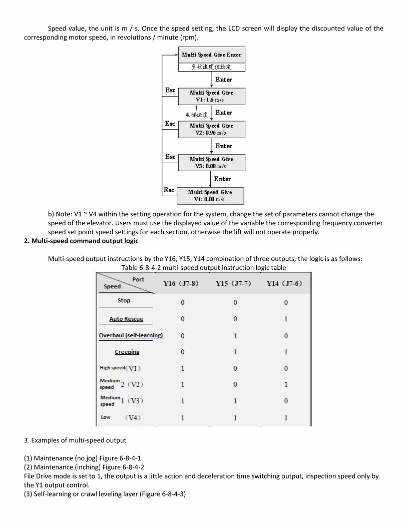
Speed value, the unit is m / s. Once the speed setting, the LCD screen will display the discounted value of the corresponding motor speed, in revolutions / minute (rpm).
b) Note: V1 ~ V4 within the setting operation for the system, change the set of parameters cannot change the speed of the elevator. Users must use the displayed value of the variable the corresponding frequency converter speed set point speed settings for each section, otherwise the lift will not operate properly.
2. Multi-speed command output logic
Multi-speed output instructions by the Y16, Y15, Y14 combination of three outputs, the logic is as follows: Table 6-8-4-2 multi-speed output instruction logic table
3. Examples of multi-speed output (1) Maintenance (no jog) Figure 6-8-4-1 (2) Maintenance (inching) Figure 6-8-4-2 File Drive mode is set to 1, the output is a little action and deceleration time switching output, inspection speed only by the Y1 output control. (3) Self-learning or crawl leveling layer (Figure 6-8-4-3)

(4) Protecting back base (and crawling screed as the door zone at the bottom of the door area is) (5) High-speed operation diagram (6-8-4-4)
6.9 Adjust leveling accuracy
Leveling accuracy of the adjustment should be basically completed in comfort after adjustment. 1. Ensure the basic conditions elevator leveling
(1) First, the need to ensure accurate leveling door area sensors and deck installation location is very accurate, which requires the installation of the elevator do: (2) The length of each gate area must be accurate and consistent deck; (3) Must stand firm; (4) Bridge plate mounting location must be very accurate. When the car is in level position when the center of the deck area with two distance between the sensor Coincides with the center (as shown in Figure 4-3-3-1), otherwise it will appear that the landing point offset flat layers, namely the upper and lower leveling points higher than or lower than the level Layer point. (5) If a magnetic switch, the installation should be inserted deep enough to ensure the deck, otherwise it will affect the sensor switch operating time, resulting in the Landing flat layers appear to compete on low phenomenon. (6) In order to ensure flat layer, the system also requires the elevator in the parking must be preceded by a short crawl. (7) In the actual adjustment, first an intermediate layer should be adjusted until the leveling up. Then, based on this parameter, and then adjust its It layer. (8) Through the upper section of the curve selection and proportional, integral gain adjustment, be sure to lift both upstream and downstream to the middle floor stop, stop Vehicle location repetitive (ie, each time stopping position error between ≤ ± 2 ~ 3mm.
2. Multi-speed mode, the adjustment of leveling accuracy (1) Long time no crawling or creeping
System Requirements elevator during deceleration, the first should go crawling state, which is to ensure that the
basic conditions elevator leveling. If you do not crawling, indicating Deceleration curve too slow; if crawling too long, indicating deceleration curve too fast. Then deceleration curve should be adjusted, so that both crawling, not too long. (2) Low uplink and downlink or uplink high-high, low down
When parking up after the low down high phenomenon, indicating low crawling speed; when parking after high uplink and downlink low phenomenon, says Ming crawling speed high. Then creep speed should be adjusted. (3) Low uplink and downlink or uplink high-low, high down
When the stop after the low uplink and downlink or uplink high-low, high downstream phenomenon, indicating the location of the door zone sedan plate biased, then the car door area should be adjusted Board location. (4) Upper and lower ends of the mounting position is not correct station
Bottom end station is installed incorrectly affect both ends of the elevator leveling precision. These end station, for example, end station to adjust the position as follows:
◆ The switch is mounted on the end station for speed distance greater than the position;
◆ Elevator quickly run to the end station, for quick stops will appear uneven layer;
◆ Immediately set to overhaul the system state;
◆ Measuring lift distance anomaly layer, this distance is the upper station upward adjustment distance. Similarly, the bottom stop can be adjusted.
6.10 Confirm the installation location end station
The upper and lower end station signal is forced to change speed elevators and floor position correction signal should be installed in the car from the top (bottom) layer level position at 2.5m Operating position (1.6m / s elevator). Recognized as follows: 1. Let the elevator is in service state; 2. Set the access speed of 0.3m / s, up (down) operation; 3. First (lower) end station when switching parking; 4. Car sill distance from the landing door sill should be 2.5 ± 0.1m.
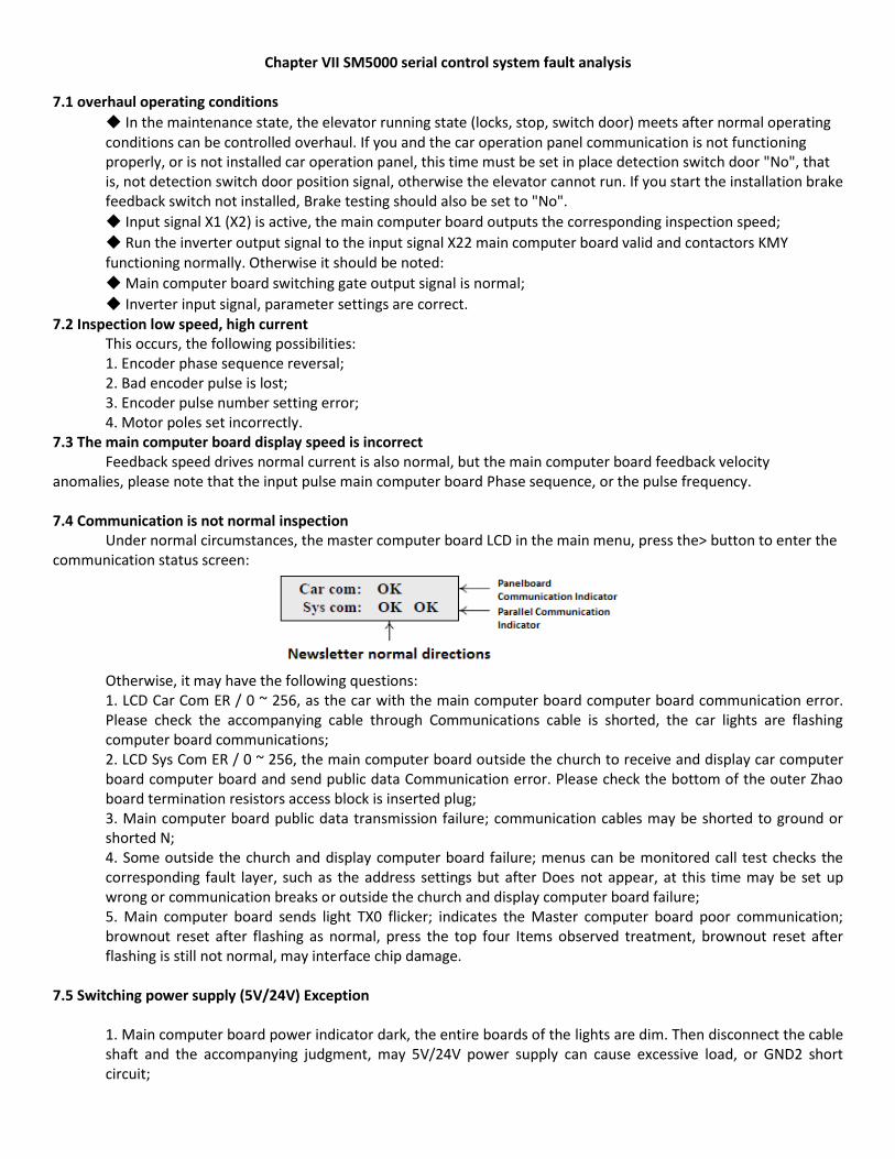
Chapter VII SM5000 serial control system fault analysis 7.1 overhaul operating conditions
◆ In the maintenance state, the elevator running state (locks, stop, switch door) meets after normal operating conditions can be controlled overhaul. If you and the car operation panel communication is not functioning properly, or is not installed car operation panel, this time must be set in place detection switch door "No", that is, not detection switch door position signal, otherwise the elevator cannot run. If you start the installation brake feedback switch not installed, Brake testing should also be set to "No".
◆ Input signal X1 (X2) is active, the main computer board outputs the corresponding inspection speed;
◆ Run the inverter output signal to the input signal X22 main computer board valid and contactors KMY functioning normally. Otherwise it should be noted:
◆ Main computer board switching gate output signal is normal;
◆ Inverter input signal, parameter settings are correct. 7.2 Inspection low speed, high current
This occurs, the following possibilities: 1. Encoder phase sequence reversal; 2. Bad encoder pulse is lost; 3. Encoder pulse number setting error; 4. Motor poles set incorrectly.
7.3 The main computer board display speed is incorrect Feedback speed drives normal current is also normal, but the main computer board feedback velocity
anomalies, please note that the input pulse main computer board Phase sequence, or the pulse frequency. 7.4 Communication is not normal inspection
Under normal circumstances, the master computer board LCD in the main menu, press the> button to enter the communication status screen:
Otherwise, it may have the following questions: 1. LCD Car Com ER / 0 ~ 256, as the car with the main computer board computer board communication error. Please check the accompanying cable through Communications cable is shorted, the car lights are flashing computer board communications; 2. LCD Sys Com ER / 0 ~ 256, the main computer board outside the church to receive and display car computer board computer board and send public data Communication error. Please check the bottom of the outer Zhao board termination resistors access block is inserted plug; 3. Main computer board public data transmission failure; communication cables may be shorted to ground or shorted N; 4. Some outside the church and display computer board failure; menus can be monitored call test checks the corresponding fault layer, such as the address settings but after Does not appear, at this time may be set up wrong or communication breaks or outside the church and display computer board failure; 5. Main computer board sends light TX0 flicker; indicates the Master computer board poor communication; brownout reset after flashing as normal, press the top four Items observed treatment, brownout reset after flashing is still not normal, may interface chip damage.
7.5 Switching power supply (5V/24V) Exception
1. Main computer board power indicator dark, the entire boards of the lights are dim. Then disconnect the cable shaft and the accompanying judgment, may 5V/24V power supply can cause excessive load, or GND2 short circuit;

2. Main PC board is running resets the elevator (lift caused a sudden stop), and later returned to normal. At this point may be GND2 for N Line or to a virtual company, resulting in the switching power supply disturbances.
7.6 There is no direction and the output signal of the brake check
In the lock contactor is closed, KMY contacts (between the drive and the motor contactor) closed conditions, it runs the input signal But there is no direction and the brake output. Reason for this phenomenon is probably due to lock contactor does not operate normally due, are as follows: 1. Lock failure
During the commissioning process, since landing door, car door is not installed, commissioning personnel tried to lock operation, this phenomenon is likely to occur. To pay attention to open the output signal of the closed door consistent contactor operation. ▲ Note: The short run lock signal can be inspected, but not express run.
2. Failure to open the door Reference solutions are as follows:
Set in the elevator maintenance status, input open command ( through the car door on the next button or the LCD menu given ) to observe whether there is open Signal output (Y4), if there are open signal output , please observe the open relay is closed ( if open relay ) . If you open the door lose Out normal, but not open door, check the door open signal and the engine room control cabinet wiring is correct, check the door status or whether it is Indeed.
Overhaul state, there are open command input , but no open output (Y4), at this time , please check the opening and closing limit input is correct. Watch Police U01 (opening limit), (through the back door when the door way U11 whether "■").
Normal circumstances , when the car door is closed in place U02 effective ( liquid crystal display by the "□" change "■"), U01 invalid ( liquid crystal display by the "■" Change "□"); opened the car door in place effective U01 , U02 invalid ; cabin doors open to the middle position U06, U07 should be invalid.
If you look at the results do not meet these conditions, you may be opening and closing limit switch is not installed correctly, or use a contact type is incorrect. If When the car door closed in place U02 invalid , U01 efficient car door open in place effective U11 , U12 invalid, belonging opening and closing limit switch Off -reverse, please be corrected ; If the door opens to the middle position , U01, U02 effective , it may be used normally open or normally closed Settings do not match the type of input , then change the contact type or modify the input port active level setting ( Please modify the menu Input Type The U01, U02, U11, U12 input type ) .
Elevators through the door, pay attention to the front door , back door open / close is set against , touch panels, whether the signal corresponding to the light curtain , please refer to the above on View menu cab signals. Note: The front / rear please provide confirmation.
7.7 The elevator does not close Under normal operating conditions the elevator, the elevator door closes automatically. If you did not shut the
door again to open the door, and repeated several times. Examination to determine the parties Act as follows: 1. Please check whether the closed blocked; 2. Please confirm whether the stroke of closing large; 3. If it is in the system to open / close running time cannot completely close the door, adjust the opening and closing running time (door relay hold time). 4. Door limit switch may be due to the installation or incorrect type contacts please refer to “open the door malfunction “Check solved. 5. If overhaul state opening and closing properly, but the elevator into the normal state when not close. At this point, check the safety switch or the touch pad to open off input type is correct. Watch " Car Signal " menu U04 safety edge switch signal ( through the back door of the door , see U03), Such as safety light curtain is obstructed or touch pad , U04 should be valid ( LCD by the "□" change "■"), such as security touch panel open , U04 should be invalid ( liquid Crystal display by the "■" change "□"). If on the contrary, replace or adjust the contact type input active level setting (input type Menu U04 ~ U03 input type setting). If U04 is always valid, check the safety of the car computer board touch panel touch input port and security Board switch wiring. If the security touch panel input is correct, please confirm whether overloading U06 valid (overload does not close).

7.8 Emergency stop contactor coil state inconsistent state (ER02) Emergency stop contactor coil state with an inconsistent state, ie X13 and X28 (port X13, X28) is inconsistent. 1. Observable inputs display indicator LED X13 with LED X28, emergency contact closure or a short open time LED X13 should be the same with LED X28 when the light is off. 2. If not the same light off, check external connections; 3. Such as simultaneous light off, please observe the monitoring menu should be displayed in the input signal and the LED status, if the input signal is displayed with X28 LED X28 LED status inconsistency, may be X22 input circuit voltage match.
7.9. KMY contactor output and feedback inconsistent results (ER04)
This occurs, the following possibilities: 1. KMY (contactors) adhesions; 2. After the main computer board Y9 output, KMY not closed. Connection broken or damaged KMY contactor; 3. KMY Feedback Contact poor.
7.10. Gate failure (ER18)
Main computer board Y6 output gate instruction is not received after the brake monitoring switches the feedback signal, or the brake relay post-release monitoring to contact adhesion, are given ER18 failure. If the elevator before starting protection sometimes, but once again from the car properly. There are more ER18 fault recording fault records, please Check the brake contactor feedback contact is bad, and replace the brake contactor. 7.11 elevator running direction and instruction in the opposite direction (ER30) 1. Main computer board A, B two -phase pulse is reversed, namely: the elevator is actually OK, main computer board display feedback speed is negative, the actual elevator down, Displaying feedback speed is positive. At this point, insert the master computer board A, B two -phase input pulse reversed. 2. If the elevator is running in the opposite direction with a given direction, change the phase sequence of the motor and encoder A, B phase sequence. 3. If the upstream or downstream, the display direction of the velocity constant of the feedback, it may result A, B phase input pulse phase. If either upward or elevator Downstream, the feedback velocity direction are positive, it may lack the B-phase. Solution as follows:
Please first main computer board to remove the A-phase pulse input, then run when no feedback speed display. Then remove the B-phase input , the A Inverting input connected to the B-phase ;
Run again, if the feedback speed display, you might divide the inverter board card and host computer is connected between the B-phase problems.
If the A-phase input connected to Phase B is also no feedback speed display , you may host computer board B phase input circuit is damaged , replace the main PC board retry ;
4. If either the elevator up or down, the master computer board feedback speed display are negative, contrary to the above judgment method. 2. The number of pulses too little or no pulse input
During the operation of the elevator to receive from the main computer board inverter (frequency divider cards) or the encoder pulse signal, if the detected pulse Punch too few or no pulse input, the following reasons: 1. Pulse input terminal and the connection is disconnected divider cards; 2. If the source is a long drive pulse signal type, possibly A, B phase line wrong connection (such as A and B,-A and -B mismatches use); 3. If the connection is correct, then use a multimeter to test voltage to determine:
If you use a push-pull pulse source: low speed motor J10-6 (n- table pen) and between J10-3, J10-6 and J10-2 voltage is between +6 V and so.
If you are using a line driver type pulse source: J10-5 (regular table pen) and J10-3 voltage between 2.5V or -2.5V, J10-4 (regular table pen) And J10-2 voltage should be between 2.5V and -2.5V.
The voltage is correct or not the basis for judging the cause of the malfunction: Voltage correct the fault occurred in the main computer board, otherwise the inverter Divide Card (encoder).

7.12. Door interlocks contactor coil inconsistent state
According to GB7588-2003 specification requirements for door lock circuit, SM5000 main computer board designed door lock relay coil and feedback contacts Monitoring function: normal coil and contacts (X14 and X29) action should be consistent, otherwise fault alarm.
Door interlock contactor coil state inconsistent state, ie X14 and X29 (port X14, X29) is inconsistent. Observable inputs means Indicator LED X14 with LED X29, door interlock contact closure or a short open time LED X14 should also be lit with LED X29 off.
1. If not the same light off, check external connections; 2. Such as simultaneous light off, please observe the monitoring menu should be displayed in the input signal and the LED status agreement , if X29 input signal status LED status display with LED X14 inconsistent , possibly X29 input circuit voltage match.
7.13. Low speed for speed distance greater than single spacing (ER41)
Elevator running distance is greater than the minimum speed required for single- floor space, which cannot run the elevator.
1. Using multi-segment to the timing, the minimum running distance running speed is greater than single- floor space, which elevator is running without optional transport layer Line speed. ▲ Note: The minimum operating speed of the change speed distance (m) × 2 +0.15 (m) < minimum floor spacing
(m) 7.14. Main computer board inverter operation signal is not received feedback (ER21)
Run command issued by the master computer board (direction, enabled), the inverter operation signal is not received feedback (X12). You should make the following checks:
1. Please check the drive direction, run enable signal and the signal output circuit; 2. Check the inverter relevant input and output parameters are set correctly; 3. Inverter is in the running state.
7.15 Cannot express run (ER25)
This phenomenon occurs no lift self-learning, self-learning can be after. 7.16 floor position counter error (ER28)
1. Encoder input disturbance is too large, the system ground to regulate; 2. Rope slip; 3. Pulse input frequency is too high. Main computer board pulse input maximum frequency is 30KHZ. If the pulse input frequency is greater than 30KHZ, Use divide card divide function, reduce the pulse frequency.
▲ Note: The pulse frequency is calculated and relationships should be:
Rated motor speed encoder pulses<30kHz 60 x Division factor x 1000
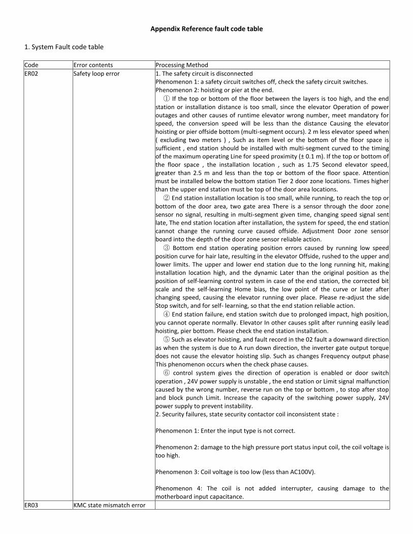
Appendix Reference fault code table 1. System Fault code table Code Error contents Processing Method
ER02 Safety loop error 1. The safety circuit is disconnected Phenomenon 1: a safety circuit switches off, check the safety circuit switches. Phenomenon 2: hoisting or pier at the end.
① If the top or bottom of the floor between the layers is too high, and the end station or installation distance is too small, since the elevator Operation of power outages and other causes of runtime elevator wrong number, meet mandatory for speed, the conversion speed will be less than the distance Causing the elevator hoisting or pier offside bottom (multi-segment occurs). 2 m less elevator speed when ( excluding two meters ) , Such as item level or the bottom of the floor space is sufficient , end station should be installed with multi-segment curved to the timing of the maximum operating Line for speed proximity (± 0.1 m). If the top or bottom of the floor space , the installation location , such as 1.75 Second elevator speed, greater than 2.5 m and less than the top or bottom of the floor space. Attention must be installed below the bottom station Tier 2 door zone locations. Times higher than the upper end station must be top of the door area locations.
② End station installation location is too small, while running, to reach the top or bottom of the door area, two gate area There is a sensor through the door zone sensor no signal, resulting in multi-segment given time, changing speed signal sent late, The end station location after installation, the system for speed, the end station cannot change the running curve caused offside. Adjustment Door zone sensor board into the depth of the door zone sensor reliable action.
③ Bottom end station operating position errors caused by running low speed position curve for hair late, resulting in the elevator Offside, rushed to the upper and lower limits. The upper and lower end station due to the long running hit, making installation location high, and the dynamic Later than the original position as the position of self-learning control system in case of the end station, the corrected bit scale and the self-learning Home bias, the low point of the curve or later after changing speed, causing the elevator running over place. Please re-adjust the side Stop switch, and for self- learning, so that the end station reliable action.
④ End station failure, end station switch due to prolonged impact, high position, you cannot operate normally. Elevator In other causes split after running easily lead hoisting, pier bottom. Please check the end station installation.
⑤ Such as elevator hoisting, and fault record in the 02 fault a downward direction as when the system is due to A run down direction, the inverter gate output torque does not cause the elevator hoisting slip. Such as changes Frequency output phase This phenomenon occurs when the check phase causes.
⑥ control system gives the direction of operation is enabled or door switch
operation , 24V power supply is unstable , the end station or Limit signal malfunction caused by the wrong number, reverse run on the top or bottom , to stop after stop and block punch Limit. Increase the capacity of the switching power supply, 24V power supply to prevent instability. 2. Security failures, state security contactor coil inconsistent state : Phenomenon 1: Enter the input type is not correct. Phenomenon 2: damage to the high pressure port status input coil, the coil voltage is too high. Phenomenon 3: Coil voltage is too low (less than AC100V). Phenomenon 4: The coil is not added interrupter, causing damage to the motherboard input capacitance.
ER03 KMC state mismatch error

ER04 KMY state mismatch error Phenomenon 1: The control system output contactor command to run, run contactor cannot be closed, check wiring Is correct, check the contacts for damage. Phenomenon 2: elevator stops running, disconnect the output of the control system, run the contactor cannot quickly bounce. This phenomenon occurs when parking the car will cause the command canceled. If there is an outgoing call reverse commutation transport OK, so that passengers cannot reach the target layer runs. Replace the contactor can solve the problem. (General Main contactor runs contactor with the same model. Main contactor after power is no longer on the action, on the bounce time Were no requirements and you can run the main contactor and contactor on the exchange in order to solve the problem).
ER05 KMB state mismatch error upper limit on the action of strong
ER06 For a no action (on a single strong conversion error) under the action of a strong lower limit
ER07 For a no action (strong orders for error)
ER11 Encoder pulse is too small, or the wrong direction
Phenomenon 1: The control system for a given speed, the drive fails a given speed. Possible reasons: 1. Speed set point cable is bad (multi-speed for a given signal line). 2. when the operation of the inverter is set Room is too long, multi-segment given time, there are some models inverter gate delay running time setting, when If greater than 2.5 seconds between prone to this protection. 3. Overload, inverter overload conditions cannot start or starting process is too slow. Phenomenon 2: encoder pulse input wiring is bad; pulses are not normal input board. Phenomenon 3: The inverter frequency output is damaged; you cannot enter divider pulses. Phenomenon 4: Motherboard encoder input corrupt and cannot receive the pulse input.
ER12 Much interference pulses.
ER15 Strong action for both the upper and lower switch
ER16 Door interlock state does not match
Door interlock relay coil and contacts inconsistent
ER18 BRAKE discrepancies wrong state Error
① System output gate instruction brake contactor is not within one second feedback signal to the motherboard, or system output hold Opening command within 1 second after the contactor is not disconnected.
② system output gate command within 2.5 seconds after the brake arm without
feedback, or brake, the brake arm switch is not off (hold Gate feedback is set to NO) Phenomenon 1: Elevator starting, ER18 failure occurred; mostly due to poor contact brake relay contacts cited Onwards. Down time to recover after starting again impose that protection. If too many starters appear 18 protections, built Proposed replacement relays. Phenomenon 2: 18 failures occurred when parking. Mostly brake relay cannot be fast bounce, When this happens, Replace the brake relay. Phenomenon 3: brake arm feedback is incorrect, gate lock loop has run, the brake relay contacts, each Contact may cause poor contact gates cannot open properly.

Phenomenon 4: brake arm switch mounting location is incorrect; brake arm switch does not operate normally. Two-speed freight elevator 18 failures will cause slip on, but need to adjust the gate ahead of time.
ER19 Inverter fault error Phenomenon 1: The inverter fault, the fault code determines the cause of the fault. Phenomenon 2: Some inverter due to power for too long, more than the system power-on wait time, the system At the inverter fails, the situation cannot handle, inverter power system will automatically resume after completion Phenomenon 3: If the inverter generates overcurrent protection, and it’s the same time protect the front there ER35 or ER02 Other protection, are generally due immediately stopped in front of protection caused by other system protection and restoration will Automatic recovery.
ER20 Speed is lower than the set speed 85%
ER21 No drive run signal Phenomenon 1: The system outputs the direction of the drive enable signal is not received properly check the direction to enable connection Lines have virtual access. Special attention enable signal line contacts are in series with the door contact failure. Phenomenon 2: Drive into the set state, prohibit running. Phenomenon 3: Inverter output definition error, failed to properly run the output signal. Phenomenon 4: The drive generates voltage protection; make sure that the braking resistor are in working order, Braking resistors is appropriate, whether the deceleration curve too fast. Phenomenon 5: Door with jitter, causing the drive enable signal is disconnected.
ER22 High-speed input error
ER23 Than the rated speed 115%
ER24 No deceleration 10s Stop
Interference distance is too large or too big minus v.
ER25 Hoistway no learning, well Road data errors, or Number of errors
Phenomenon 1: Motherboard not been hoistway self-learning, make hoistway self-learning. Phenomenon 2: Split running, and running count of the scale beyond the self-learning scale. Phenomenon 3: PG card output encoder or damaged, causing the input pulse is not normal. Phenomenon 4: pulse input circuit board is damaged, the pulse input is not normal, that is the case, the lift transport The feedback line velocity anomaly, are generally speed feedback larger than the given value. This situation can only Pulse input port on the motherboard for repair.
ER26 Car rolling over 100mm
ER27 Hoistway switch error shift Bit, or pulse counting Error
Phenomenon 1: Encoder input disturbance is too large, the solution can be encoded input line plus magnetic shielding Line connected to, you must use shielded twisted pair cable. Phenomenon 2: The encoder input frequency is too high, please enter the motherboard pulse frequency, and enable the board to receive The pulse frequency is less than 30KHZ. Meanwhile divided input pulse can enhance immunity. Phenomenon 3: The switch position of the hoistway, not for self- learning, the control system of records for each of the switching Scale value is inconsistent (end station, the location of the door zone plate), please re- hoistway self-learning. Phenomenon 4: Gate District switching jitter , please note that door zone plate into the depth of the door zone sensor , such as the depth Lack of action points right
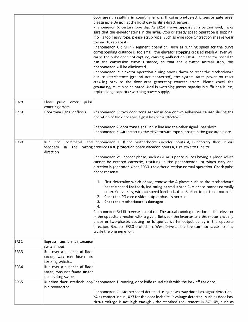
door area , resulting in counting errors. If using photoelectric sensor gate area, please note Do not let the hoistway lighting direct sensor. Phenomenon 5: certain rope slip. As ER14 always appears at a certain level, make sure that the elevator starts in the layer, Stop or steady speed operation is slipping. If oil is too heavy rope, please scrub rope. Such as wire rope Or traction sheave wear too much, replace it. Phenomenon 6 : Multi- segment operation, such as running speed for the curve corresponding distance is too small, the elevator stopping crossed mesh A layer will cause the pulse does not capture, causing malfunction ER14 . Increase the speed to run the conversion curve Distance, so that the elevator normal stop, this phenomenon will be eliminated. Phenomenon 7: elevator operation during power down or reset the motherboard due to interference (ground not connected), the system After power on reset crawling back to the door area generating counter errors. Please check the grounding, must also be noted Used in switching power capacity is sufficient, if less, replace large capacity switching power supply.
ER28 Floor pulse error, pulse counting errors,
ER29 Door zone signal or floors Phenomenon 1: two door zone sensor in one or two adhesions caused during the operation of the door zone signal has been effective. Phenomenon 2: door zone signal input line and the other signal lines short. Phenomenon 3: After starting the elevator wire rope slippage in the gate area place.
ER30 Run the command and feedback in the wrong direction
Phenomenon 1: If the motherboard encoder inputs A, B contrary then, it will produce ER30 protection board encoder inputs A, B relative to tune to. Phenomenon 2: Encoder phase, such as A or B-phase pulses having a phase which cannot be entered correctly, resulting in the phenomenon, to which only one direction is generated when ER30, the other direction normal operation. Check pulse phase reasons:
1. First determine which phase, remove the A phase, such as the motherboard has the speed feedback, indicating normal phase B, A phase cannot normally enter. Conversely, without speed feedback, then B phase input is not normal.
2. Check the PG card divider output phase is normal. 3. Check the motherboard is damaged. 4.
Phenomenon 3: Lift reverse operation. The actual running direction of the elevator in the opposite direction with a given. Between the inverter and the motor phase (a phase or two-phase), causing no torque converter output pulley in the opposite direction. Because ER30 protection, West Drive at the top can also cause hoisting tackle the phenomenon.
ER31 Express runs a maintenance switch input
ER33 Run over a distance of floor space, was not found on Leveling switch...
ER34 Run over a distance of floor space, was not found under the leveling switch
ER35 Runtime door interlock loop is disconnected
Phenomenon 1: running, door knife round clash with the lock off the door. Phenomenon 2 : Motherboard detected using a two-way door lock signal detection , X4 as contact input , X23 for the door lock circuit voltage detector , such as door lock circuit voltage is not high enough , the standard requirement is AC110V, such as
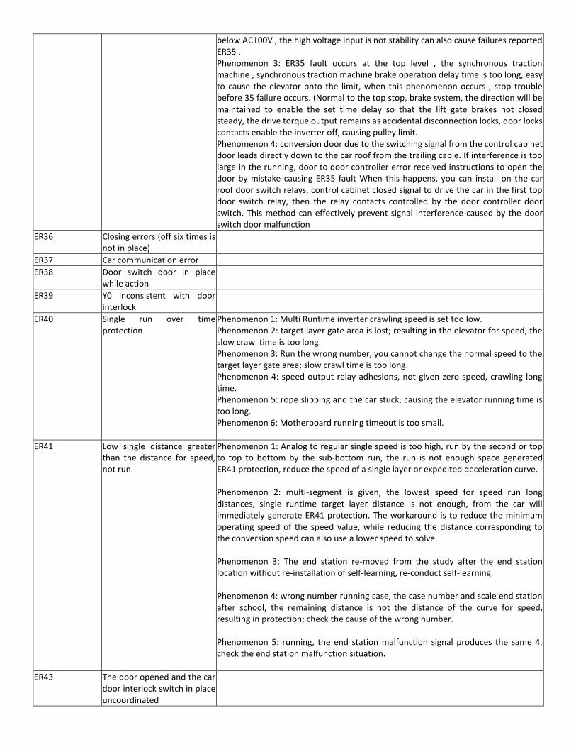
below AC100V , the high voltage input is not stability can also cause failures reported ER35 . Phenomenon 3: ER35 fault occurs at the top level , the synchronous traction machine , synchronous traction machine brake operation delay time is too long, easy to cause the elevator onto the limit, when this phenomenon occurs , stop trouble before 35 failure occurs. (Normal to the top stop, brake system, the direction will be maintained to enable the set time delay so that the lift gate brakes not closed steady, the drive torque output remains as accidental disconnection locks, door locks contacts enable the inverter off, causing pulley limit. Phenomenon 4: conversion door due to the switching signal from the control cabinet door leads directly down to the car roof from the trailing cable. If interference is too large in the running, door to door controller error received instructions to open the door by mistake causing ER35 fault When this happens, you can install on the car roof door switch relays, control cabinet closed signal to drive the car in the first top door switch relay, then the relay contacts controlled by the door controller door switch. This method can effectively prevent signal interference caused by the door switch door malfunction
ER36 Closing errors (off six times is not in place)
ER37 Car communication error
ER38 Door switch door in place while action
ER39 Y0 inconsistent with door interlock
ER40 Single run over time protection
Phenomenon 1: Multi Runtime inverter crawling speed is set too low. Phenomenon 2: target layer gate area is lost; resulting in the elevator for speed, the slow crawl time is too long. Phenomenon 3: Run the wrong number, you cannot change the normal speed to the target layer gate area; slow crawl time is too long. Phenomenon 4: speed output relay adhesions, not given zero speed, crawling long time. Phenomenon 5: rope slipping and the car stuck, causing the elevator running time is too long. Phenomenon 6: Motherboard running timeout is too small.
ER41 Low single distance greater than the distance for speed, not run.
Phenomenon 1: Analog to regular single speed is too high, run by the second or top to top to bottom by the sub-bottom run, the run is not enough space generated ER41 protection, reduce the speed of a single layer or expedited deceleration curve. Phenomenon 2: multi-segment is given, the lowest speed for speed run long distances, single runtime target layer distance is not enough, from the car will immediately generate ER41 protection. The workaround is to reduce the minimum operating speed of the speed value, while reducing the distance corresponding to the conversion speed can also use a lower speed to solve. Phenomenon 3: The end station re-moved from the study after the end station location without re-installation of self-learning, re-conduct self-learning. Phenomenon 4: wrong number running case, the case number and scale end station after school, the remaining distance is not the distance of the curve for speed, resulting in protection; check the cause of the wrong number. Phenomenon 5: running, the end station malfunction signal produces the same 4, check the end station malfunction situation.
ER43 The door opened and the car door interlock switch in place uncoordinated

ER44 Door and the door shut off switch in place in place while action
ER45 Landing door and car door interlock chain inconsistent
ER46 Simultaneous operation of the upper and lower limit switches
ER47 5 seconds after the vehicle does not start Leave the gate area
ER48 Upper limit movement, upward Cannot start car
ER49 Lower limit action, down Cannot start car
Self-learning fault code table
Code Error contents Processing Method
LER1 Next door area to enter, without the home district
LER2 Lower left door area, while home district
LER3 Leaving home district, next door area without
LER4 Sometimes there is next door zone into the gate area
LER5 Has not rushed upper limit to the top
LER6 Into the top left rear lower door area
LER7 To the upper bit no next door area
LER8 8 to the upper limit position after the home district
LER9 Press ESC to give up
LER10 Repeatedly detected SSDS
LER11 Repeatedly detected SSDM
LER12 Repeatedly detected SSUS
LER13 When multiple testing SSUM
LER14 Strong for three times lower error detected SSDV
LER15 Strong on error repeatedly detected for three SSUV
LER16 SSUS first met at SSDS
LER17 SSDS inappropriate location
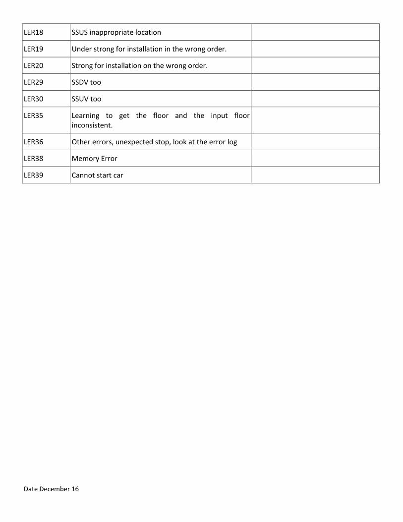
LER18 SSUS inappropriate location
LER19 Under strong for installation in the wrong order.
LER20 Strong for installation on the wrong order.
LER29 SSDV too
LER30 SSUV too
LER35 Learning to get the floor and the input floor inconsistent.
LER36 Other errors, unexpected stop, look at the error log
LER38 Memory Error
LER39 Cannot start car
Date December 16