small communication satellite mission for enhancement … · small communication satellite mission...
TRANSCRIPT

Small Communication Satellite Mission for Enhancement of Antarctic Investigations
Plamen Dankov1), Mario Gachev2), Vesselin Vassilev3), Kaloyan Zlatkov1), Zhivko Kiss'ovski1),
Dragomir Mateev3), Ognyan Ognyanov3), Iliyan Krassimirov 1), Cvetan Simeonov1) 1) Sofia University “St. Kliment Ohrisdski”, Faculty of Physics, J. Bauchier Blvd. 5
1164-Sofia, Bulgaria, http://www.uni-sofia.bg/index.php/eng/, Phone: +35928161806, Fax: +35929625276, [email protected]
2) RaySat BG Ltd, Mogilata Str. 2A, 1700-Sofia, Bulgaria, http://www.raysat.com/ Phone: +35929625665, Fax: +35929621315, [email protected]
3) CASTRA; Space Technology and Research Institute, Acad. G. Bonchev Str.1, 1113-Sofia, Bulgaria; Phone: +359887548201, http://www.castra.org/, [email protected]
Abstract: The proposed mission "SofiaUniversitySAT" is focused on development of the "communication function" of small university satellites for support and enhancement of science research and human activities in Antarctica. This function can provide a range of critically important services for Antarctic stations and expeditions, such as: high-speed two-way backhaul data transfer for scientific, safety and other applications using "store-and-forward" technology, off-line two-way operational communication services for professional, personal or rescue purposes, continental surface measurements of biological and natural phenomena; weather monitoring and forecasting, etc. Extensive preliminary investigation has been done: selection of suitable frequency bands for university satellites, optimization of on-board planar antenna arrays with adequate gain and directivity, link budget, etc. A concept of time-extended communication sessions between satellite and Antarctic ground station is developed, based on a switchable 5-face on-board antenna panels and steerable ground-station planar antenna panels. Three line-of-sight directions can be switched during a single session in "base" orbit (with trace over the ground station or max ±200 km away): forward, bottom and backward, and two additional lateral directions in two "side" orbits (±1500 km aside the ground station). Link budget in the X band shows that 30-60 Mbps bit rate for 3 min. or ~20 Mbps average bit rate for 9-10 min. in base orbit can be achieved in downlink direction using switchable on-board panels (~10 GB throughput). The proposed communication mode will be designed on a 50-kg small satellite similar to the Russian spacecraft "Yubileiny-1/2" at a 1500-km altitude near-to-polar orbit providing 11 Mbps in the C-band downlink channel during 15 min. long sessions. 1. INTRODUCTION
Antarctica is a great challenge for international expeditions aimed at its study and exploration for scientific purposes. On the one hand, there is extremely harsh environment and weather conditions all year round: low temperatures, snow, ice, cold water, strong winds, difficult terrain, etc., all of them making the human life and activities extremely difficult. On the other hand, there exists a special status of the ice continent, making it the biggest natural protected area on the Earth. Strong restrictions on human industrial and business activities that are observed in Antarctica bring additional difficulties to building commonly used elsewhere ground infrastructure that is needed to support full-scale human life. That is why design and use of small satellites in support of various human activities on the ice continent can provide numerous benefits to the international scientific community, having in mind recent alarming data about drastic reduction of planetary ice cover and the need of in-depth exploration of this process. At present, there are virtually no active satellite missions dedicated especially to the needs of Antarctic expeditions mostly because of absence of a single big customer and business niche justifying the cost for development, deployment and operation of a large mainstream satellite system [1, 2]. With recent advancement of small satellite technologies and related subsystems, it becomes possible (according to our investigations) to develop a low-cost, high-performance satellite mission for dealing with the above mentioned communication challenges. This is the goal of our "SofiaUniversitySAT" mission proposal.
2. MISSION OBJECTIVES
University small satellites (stand-alone or in a constellation) can provide crucially important services for Antarctic human activities such as high-speed two-way data transfer (e.g. between

various ground sensor networks needed for scientific, safety and other applications, and other continents), two-way communication services (e.g. file transfer, e-mail) for professional, personal or rescue purposes; permanent continental surface measurements of biological and natural phenomena; weather monitoring and forecasting, etc. The following mission objectives have been identified based on the above-mentioned communication capabilities of university small satellites, referred in this paper to as "communication function". 1) The primary objective of our mission is achievement of stable, relatively fast and cheap satellite data-transfer communication between Antarctic stations of different nations and the rest in support of various ground-based research projects (e. g. ground sensor networks), to meet Antarctic stations' logistics and security needs as well as personal needs of station team members (personal e-mail and multi-media communication in off-line mode, etc.). In particular, as a test Antarctic base application case for proving the concept, our project aims at providing such services to the Bulgarian Antarctic station [3] based on the Livingston Island (Fig. 1a,b) within the South Shetland Islands. We aim at providing capabilities for transfer of ~10GB data per day between the Antarctic station and the satellite control station in Sofia (or other suitable location). Similar service could be provided to other Antarctic stations.
2) The second mission objective is daily data transmission for meteorological purposes and Antarctic weather forecasts in required details. This would be achieved through satellite-based atmospheric sensors and ground-based meteorological sensor networks. The latter would be sending their data to a weather forecast data-processing center (e.g. in Bulgaria) through the communication capabilities outlined in Objective 1). For satellite-based atmospheric data collection, our primary aim is to implement optical sensors for monitoring of various cloud systems.
3) Our third mission objective is to provide permanent remote sensing data from Antarctic surface for the purpose of ground science projects and
4) The fourth mission objective is to provide data transfer for ground-level observation of natural and biological objects on the ice continent surface. In fact, Antarctic science missions collect plenty of data (meteorological, biological, physical, geological, medical, etc.), which usually have to be additionally processed after return of expedition. The proposed possibility for online data transfer and processing in big university centers before return of expedition will improve the efficiency of relatively expensive Antarctic research missions. Finally,
5) Our fifth mission objective is permanent data storage and sharing of information about location and course of ships in the Antarctic region for the purpose of expeditions' logistics and security.
3. CONCEPT OF OPERATIONS
3.1 Communications with Antarctica
Let us discuss current communication options of Antarctic stations and expeditions? The oldest type of communications on the ice continent is low-frequency amateur radio in the high-frequency (HF) band (for connections outside the continent) and in the very/ultra high-frequency (VHF/UHF) bands (useful for utility and emergency short-range connections) –Fig. 2a. They are extremely slow and strongly influenced by weather or atmospheric phenomena, but are still in use in many stations because they can be a matter of life and death. Considerable more convenient for Antarctic inhabitants are mobile low-Earth-orbit (LEO) satellite communications in on/off-line mode offering
Fig. 1a) Antarctic map and the Livingston island location; b) The Bulgarian station; c) A typical meteorological station
a) b) c)
62o38'29"S 60o21'53"W

many users suitable multiple access (e.g. Iridium – Fig. 2b; Globalstar, ORBICOMM, etc.). These commercial systems allow for use of small handheld devices mainly for voice calls; data can be sent by them at unacceptably low throughput. This telephone system in Antarctica is used as a back-up and allows for easy, but very expensive connections of expedition members to their station or other continents. Wider range of communication services is provided by fixed VSAT (Very Small Aperture Terminal) satellite systems that allow for both voice and data transfer to different points in Antarctica and even worldwide. These geostationary (GEO) satellite systems enable some Antarctic inhabitants to have Internet access, to send and receive e-mail, and to have also cheaper voice calls VoIP through Internet. The Earth antennas are not so big (typically less than 4 m). Fig. 2c shows an indicative example of necessary communication equipment at the Amundsen-Scott South Pole Station, supported by the US Antarctic Program [4]. This system uses NASA geosynchronous satellites from GOES and TDRSS series, which have lost their primary imaging functions (e.g. weather satellite GOES-3 launched in 1978), but have still functional communication transponders. These "permanently falling" satellites can ensure reasonable communication services for the US Antarctic base at 1-1.5 Mbps data rate for several minutes up to several hours per day depending on current elevation angle of used satellite (Fig. 2c). Although these systems look attractive, they are time and space restricted and unstable (the GEO satellites permanently change their position and expensive big tracing systems are necessary). Moreover, at lower elevation angle the effect of atmospheric scintillations and gas attenuation due to longer path to Antarctic base station increases and communication systems cannot satisfy quality-of-services (QoS) requirements.
A quite promising alternative for Antarctic communications is utilization of non-GEO satellite systems. There exist serious projects connected with implementation of broadband satellite communications in the Ka band to both Earth polar regions (e.g. in the Antarctic [5] and in the Arctic [6]) with deadlines before 2014-16. Both projects rely on utilization of two Molniya-orbit satellites in opposite phases to separately cover each of the polar regions (Fig. 3a, b) for 24-hours period. Their main feature is the different profile of possible communication users in these regions. Increased number of users in the Arctic region (Fig. 3c) is connected mainly with its “opening” due to faster ice melting on major transportation routes, such as Northwest, Northeast and North-North Passages [7]. As a result, increased navigation and activities related to fishing, oil and gas industries, etc., are already observed and needs of so-called "operational" communications will be decisive in the next few years exactly in these transportation corridors. At the opposite pole, a relatively wide continent exists with dimensions ~4000 km. There exist many scientific stations (population ~4000 in summer and ~1000 in winter) located mainly on the coast line (Fig. 3d), and many ships in similar location near the coast. Therefore, in Antarctica, the need of fast backhaul communications (less time-critical scientific and other data transfer) is considerably greater (one or two orders of magnitude larger in volume according to [8]) than operational communications (voice call for safety and logistics, on-line Supervisory Control and Data Acquisition (SCADA) and Internet access). All these considerations show that the need of stable data transfer communications will rapidly increase during the next few years in both Earth polar regions. Fig. 2 a) HF systems for amateur radio; b) LEO mobile telephone system Iridium; c) Satellite system [4] for the US
Amundsen-Scott South Pole Station (NASA GEO satellites from GOES and TDRSS series)
a) b) c)

In this paper we present our conception for communications with the Antarctic research stations based on the development of the "communication function" of university small satellites in close-to-circular polar orbit – Fig. 3e. In fact, primary application of actual micro- and nano-satellites for Earth exploration (EESS) is mainly connected with their remote sensing capabilities (or satellite "imaging function") [9-11]. However, as it is pointed in [12], these technologically up-to-date small-in-size MRI (medium-resolution image) instruments for Earth surface observation are clearly "downlink data limited" in predominantly used nowadays VHF/UHF/L and even S-bands. We describe in the next 3 sections our ideas for improvement of downlink/uplink data throughput using university small satellites.
3.2 Selection of the Suitable Frequency Bands
International Telecommunication Union (ITU) has allocated a lot of frequency bands for amateur-satellite services ASS [13], starting from the HF, VHF and UHF bands, in the cm-wave range up to the mm-wave range. Let us list the most important of them: 144-146 MHz, 435-438 MHz, 1.26-1.27 GHz (Earth-to-Space), 2.40-2.45 GHz, 5.65-5.67 GHz (E-S), 5.83-5.85 GHz (Space-to-Earth), 10.45-10.5 GHz; 24-24.05 GHz and eight another bands in the mm-wave range above 30 GHz. Part of these bands coincides with the free ISM (Industrial, Scientific, Medical) bands. We have to add also the frequency bands, assigned for EESS and similar space applications (the most familiar are: 1.675 -1.71 GHz, 2.025-2.11 GHz, 2.20-2.29 GHz, 8.025-8.40 GHz (S-E), 25.5-27.0 GHz (S-E), 28.5-29.1 GHz (E-S), 29.5-29.9 GHz (E-S), etc.). The national spectrum management organizations have accepted the most of these bands (for example, Russia reallocated the higher frequency bands for ASS in 2010-2011 [14]). The government administrations may assign some of the listed bands on a permanent or temporary use to particular space science institutions, according to the space activities in their countries. For example in Canada [15], there are assigned in the frequency range from 52 MHz to 38 GHz totally 6964 MHz for EESS applications and 8787.25 MHz for space research services, which clearly demonstrates the importance of the problem.
However, a glance over the satellite operating frequencies' list at the moment [16] shows that the most of the active small satellite use the lower frequency bands: VHF, UHF (extremely congested), L (1-2 GHz) and S (2-4 GHz). These bands are more or less suitable for telemetry applications, but the data rate is strongly restricted – maximum 55 kbps in the UHF band and ~5 Mbps in the S-band [12], which could not effectively serve the „imaging function“ of the small satellites. Nevertheless, a good flight-proven solution for in-situ biological research by GeneSat-1 is reported in [17] for 172 kbps data rate transfer using standard non-flight-qualified commercial-off-the-shelf electronic products in the 2.4-GHz ISM unlicensed band using low-gain single-patch microstrip on-board antenna. Contrariwise, the serious analysis in [12] shows that it is possible to achieve 100-Mbps downlink data transfer for improving of the "imaging function" of the small satellites in Ka band (29.975 GHz uplink UL; 19.725 GHz downlink DL) using relatively high-directivity horn antennas and effective modulation and coding schemes. The main disadvantages in the last case are the still expensive equipment in the Ka band, high on-board antenna profile, complex on-board antenna
Fig. 3 a,b) Two Molniya-orbit satellites may fully "cover" the Antarctic continent [5] or the Arctic region [6] for 24-hours period; c, d) Possible users' locations in the Arctic [7] and in the Antarctic [8] polar regions; e) circular-orbit
university small satellite with trace over the Livingston Island, Antarctica (our case)
a) b) c) e) d)
positioning equipment and the need for acquisition of specific frequency bands. In our paper we propose to use for the DL channel not so high frequencies (2.45, 5.8, 8.2 or 10.5 GHz), simple switchable on-board antenna arrays and less-expensive equipment for the UL channel.
3.3 Antenna selection
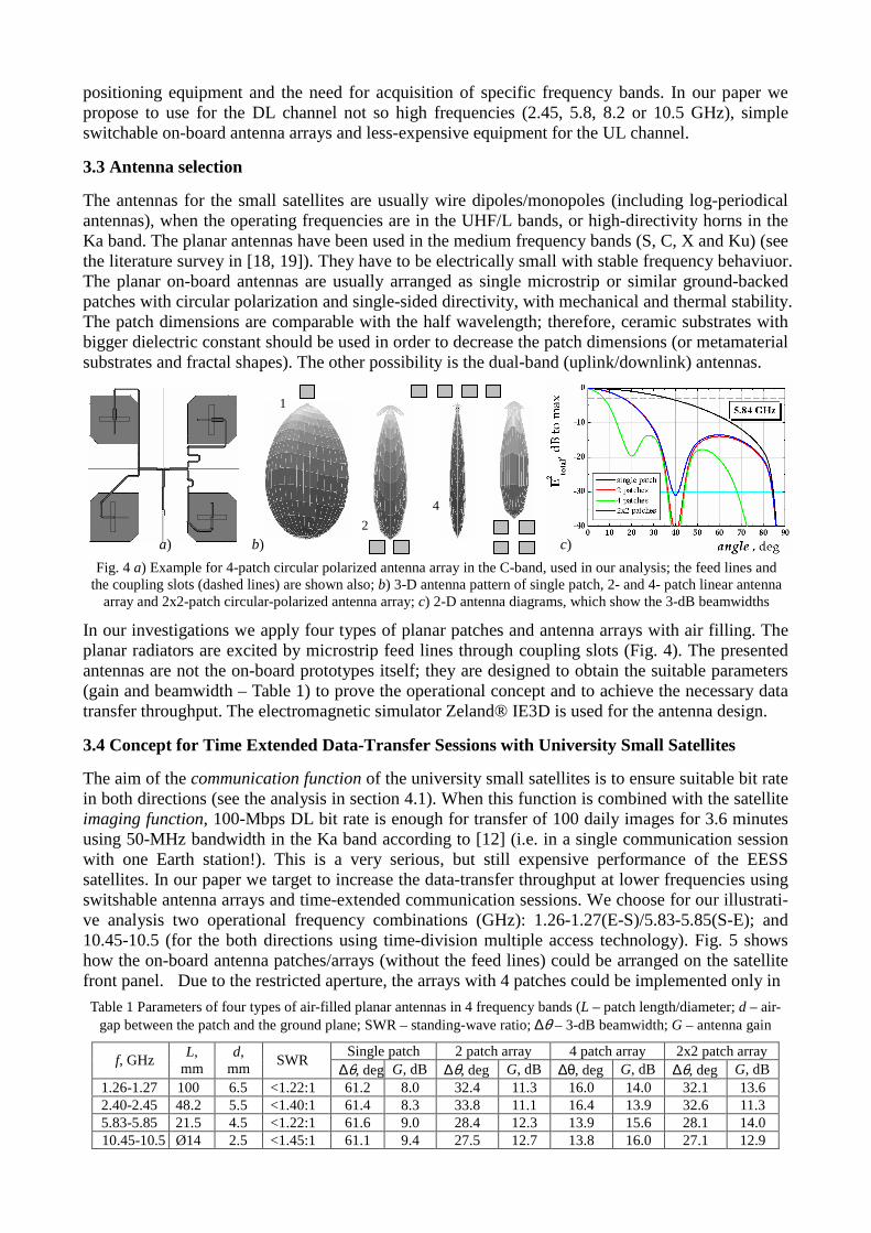
The antennas for the small satellites are usually wire dipoles/monopoles (including log-periodical antennas), when the operating frequencies are in the UHF/L bands, or high-directivity horns in the Ka band. The planar antennas have been used in the medium frequency bands (S, C, X and Ku) (see the literature survey in [18, 19]). They have to be electrically small with stable frequency behaviuor. The planar on-board antennas are usually arranged as single microstrip or similar ground-backed patches with circular polarization and single-sided directivity, with mechanical and thermal stability. The patch dimensions are comparable with the half wavelength; therefore, ceramic substrates with bigger dielectric constant should be used in order to decrease the patch dimensions (or metamaterial substrates and fractal shapes). The other possibility is the dual-band (uplink/downlink) antennas.
In our investigations we apply four types of planar patches and antenna arrays with air filling. The planar radiators are excited by microstrip feed lines through coupling slots (Fig. 4). The presented antennas are not the on-board prototypes itself; they are designed to obtain the suitable parameters (gain and beamwidth – Table 1) to prove the operational concept and to achieve the necessary data transfer throughput. The electromagnetic simulator Zeland® IE3D is used for the antenna design.
3.4 Concept for Time Extended Data-Transfer Sessions with University Small Satellites
The aim of the communication function of the university small satellites is to ensure suitable bit rate in both directions (see the analysis in section 4.1). When this function is combined with the satellite imaging function, 100-Mbps DL bit rate is enough for transfer of 100 daily images for 3.6 minutes using 50-MHz bandwidth in the Ka band according to [12] (i.e. in a single communication session with one Earth station!). This is a very serious, but still expensive performance of the EESS satellites. In our paper we target to increase the data-transfer throughput at lower frequencies using switshable antenna arrays and time-extended communication sessions. We choose for our illustrati-ve analysis two operational frequency combinations (GHz): 1.26-1.27(E-S)/5.83-5.85(S-E); and 10.45-10.5 (for the both directions using time-division multiple access technology). Fig. 5 shows how the on-board antenna patches/arrays (without the feed lines) could be arranged on the satellite front panel. Due to the restricted aperture, the arrays with 4 patches could be implemented only in
Fig. 4 a) Example for 4-patch circular polarized antenna array in the C-band, used in our analysis; the feed lines and the coupling slots (dashed lines) are shown also; b) 3-D antenna pattern of single patch, 2- and 4- patch linear antenna
array and 2x2-patch circular-polarized antenna array; c) 2-D antenna diagrams, which show the 3-dB beamwidths
4
a) b) c)
1
2
Table 1 Parameters of four types of air-filled planar antennas in 4 frequency bands (L – patch length/diameter; d – air-gap between the patch and the ground plane; SWR – standing-wave ratio; ∆θ – 3-dB beamwidth; G – antenna gain
Single patch 2 patch array 4 patch array 2x2 patch array f, GHz
L, mm
d, mm
SWR ∆θ, deg G, dB ∆θ, deg G, dB ∆θ, deg G, dB ∆θ, deg G, dB
1.26-1.27 100 6.5 <1.22:1 61.2 8.0 32.4 11.3 16.0 14.0 32.1 13.6 2.40-2.45 48.2 5.5 <1.40:1 61.4 8.3 33.8 11.1 16.4 13.9 32.6 11.3 5.83-5.85 21.5 4.5 <1.22:1 61.6 9.0 28.4 12.3 13.9 15.6 28.1 14.0 10.45-10.5 Ø14 2.5 <1.45:1 61.1 9.4 27.5 12.7 13.8 16.0 27.1 12.9

the X band and (with arrangement difficulties) in the C band. In order to increase the data through-put, we “multiply” the pairs of Tx/Rx (transmit/receive) antennas using a special 5-face panel with truncated pyramidal shape – Fig. 6 a,b. Thus, the on-board Tx/Rx modules can be consecutively connected to each of the panel faces in different time intervals during the LoS (Line-of-Sight) period (i.e. from "satellite rise" to "satellite set"), depending on the current satellite positions over the ground station – see the illustrations on Fig. 6c and Fig. 7a,b. The bottom panel "B" is placed parallel to the satellite front-end aperture; it is "responsible" for the communications to the ground station near to the nadir position, when the distance S-E is minimal. This is the basic part of the S-E communications with greatest value of the bit rate Rb (see Fig. 8a, where the parameter Rb is normalized). When the satellite is on the "Base" orbit (exactly over the Earth station; practically ±200 km aside, measured on the Earth surface), the turning on the forward "Bf" and the back-ward "Bb" panel faces can considerably increase the bit rate during the whole communication session (Fig. 8b,c,d), because their antennas can "look" directly to the ground station immediately after the "satellite set" and before the "satellite rise". Moreover, at least two additional communication sessions can be arranged on the both neighbor orbits – "Side left" and "Side right" (Fig. 6c). In this case the lateral panels "Sl" or "Sr" should be switched on. The data transfer capacity of these two additional sessions is restricted (see Fig. 8e), but it is enough for many additional applications. The-se sessions take place ~95 min. before or after the main communication session and may have two options: for shorter access time with bigger bit rate or vice versa, when the narrow side of the lateral antenna "hot spots" is orientated perpendicularly to the flight direction or v.v. (as in Fig. 7b,c). The switching procedure can be preliminary planned on the base of the daily updated satellite trajectory.
Fig. 5 Schematic front-end aperture of the satellite with a realizable disposition of the antenna patches and arrays
Patch for the UL antenna (Rx)
Patch for the DL antenna (Tx)
Camera aperture
Satellite front-end aperture
Fig. 7 Illustration of the proposed mechanism of time-extended communication session with one Earth station: a) on the "Base" orbit; b) on the "Side" orbit (3 cases) (only the antennas on the colored face of the 5-face panel are "active"
in a given time interval); c) "Hot spots" of the antenna-array beams over the Earth surface. The narrow axis of the antenna beam is orientated perpendicularly to the flight direction (marked with the arrows) or v. v. (not shown)
a) c) b)
1 2
4
2x2
Bf B Bb Sr
Case 1
Sr
Case 2 Case 3
a) c) b) Base orbit Side left orbit Side right orbit
B Bf Bb
Sr
Sl
Rx Tx
Fig. 6 a) Switchable on-board antenna panel with 5 pairs of Tx/Rx microstrip patches (S-band demonstrator to prove the concept); b) Illustration of the unfolded 5-face panel with the face denotations; c) Three neighbor orbits of the
satellite over the Bulgarian Antarctic station for realization of 3 communication sessions. Legend: / – satellite position/ direction; – Earth-station position; – approximate “coverage track” during a single session

4. KEY PERFORMANCE PARAMETERS
4.1 Achievable Total Data-Transfer Throughput
The daily data-transfer throughput is a key parameter for realization of the communication function of the small satellites. It depends on many factors, but the most important of them are: transmitted powers Psat (limited) and PGS, frequency bands and bandwidths (limited), antenna gain/directivity, antenna gain-over-temperature ratio (G/T), required digital modem input threshold Eb/N0, used modulation and coding schemes, lossless data compression, access time for a single communication session with one Earth station (limited), number of the Earth stations (optional), etc. Let us evaluate this important parameter using a simple analysis [1]. First of all, Table 2 presents the needed gross bit rate Margin),/(dBbps, 00 −−= /NENCR bb which allows the realization of maximal achievable bit
rate 10/10bps, bRbr = for BPSK/QPSK modulations in the effective bandwidth, reduced due to the
Doppler shift (without applying of any additional coding-gain or spread-spectrum schemes). The spectral density of the carrier-to-noise ratio C/N0, dB.Hz is calculated by
RxTxTGNC /EIRP/ 0 +=
BO Losses6.228 −−+ , where TxTxTxPG +=EIRP is the transmitter equivalent isotropically-radiated
power, the receiver Rx
TG / ratio (typically the noise temperature is accepted T~290 K for the UL
channel and T~30 K (the worst case) for the DL channel), BO is the input/output back-off (not taken into account here). The main part of the "Losses" is the free-space losses )/π4log(20 λd (d – distance); the other important part in our case is the antenna misalignment losses, but they are taken into account (for example, in Fig. 8) using the actual antenna pattern. Thus, Table 3 contains a lot of results from this simple link budget for different cases (for single patch on-board antenna – Table 3a, and for antenna arrays – Table 3b), which are presented in two options: values of the available Eb/N0 and the corresponding margin M for fixed powers Psat, GS, and vice versa, the required powers Psat, GS for fixed threshold Eb/N0 = 9.6 dB and margin M = 3.5 dB. We can see that the requirements are not satisfied for some cases (for single patch antenna) – small or even negative margin. Satisfied results
a) b)
c) d)
Fig. 8 Normalized bit rate v/s access time (elsewhere the value 1 is accepted for a single patch on face B in boreside position). Legend: a, b) Altitude 600 km; DL 10.45 GHz. On "Base" orbit for a single patch antenna without turn off the face B and for different antenna arrays by switching between Bf, B and Bb faces (the digit in brackets means the
number of patches; x2 means that the transmitted power is twice bigger). On "Side" orbit (c) (faces Sl or Sr) for 3 cases (see Fig. 7b). d) Altitude: 1500 km; DL 5.84 GHz; on "Base" orbit for a single patch and 2-patch antennas

are obtained for 2 or 4 patch antennas in the X band. Let us evaluate, for example, the data-transfer throughput in the X band for one two-way UL/DL channel. The simplified analysis for low-altitude orbits (e.g. ~600 km altitude and ~84 deg inclination) shows that our satellite will pass over the Bulgarian base on Livingston Island 2 times/daily, while over Bulgaria –1 time/daily. If we use single patch antenna with ~60 deg 3-dB beamwidth (or ~500 km "tape" over the Earth surface), the satellite will be "visible" for high-speed data transfer over a given Earth station (bit rate rb ~ 30-60 Mbps for QPSK modulation; Psat = 0.24, PGS = 2.3 W) for ~2-3 min. This is a small LoS period, but if we use switchable 4-patch antenna (Psat = 50, PGS = 490 mW), this period could increase up to 8-9 min with average rb ~ 0.35rb,max (see Fig. 8b). This value can increase at higher Psat. Therefore, the total data volume for a single communication session (on the "Base" orbit) is evaluated at no less than 10 GB for one shared UL/DL channel. Additional 1-2 GB data transfer can be realized on the both "Side" orbits. This is enough (according to us) for reliable maintenance of the important imaging function of the small satellite together with the communication data transfer. At higher-altitude orbit (e.g. 1500 km, Fig. 8d) the bit rate decrease with more than 6 times, but in this case the satellite imaging function could not be supported effectively due to the low resolution.
4.2 Meteorological Data Collection from the Antarctic Ground Stations
The typical meteorological station (Fig. 1c) consists of several sensors: thermometer (preferably with Pt fiber due to the linear temperature dependence of its resistance), barometer, anemometer with a wind vane (for determination of the wind speed and direction; both placed on a 10-m height mast), hygrometer (measuring air humidity); rain gauge (preferably heated for the Antarctic in order to melt the snow), etc. Such a meteorological station can work automatically and the collected data can be coded in different coded messages. The most common code is SYNOP (surface synoptic
Table 2 Maximal achievable bit rate for BPSK/QPSK modulations in the effective bandwidth due to the Doppler shift
Max bit rate rb, Mbps Needed gross bit rate Rb, dB.bps Frequency band, GHz
Available BW, MHz
Max Doppler shift, kHz
Effective BWeff, MHz BPSK QPSK BPSK QPSK
1.26-1.27 10 44.2 8.98 6.7 13.5 68.3 71.3 2.40-2.45 50 86.0 44.96 33.7 67.4 76.3 78.3 5.83-5.85 20 203,7 17.90 13.4 26.8 71.3 74.3 10.45-10.5 50 367.0 44.81 33.6 67.2 75.3 78.3
Table 3a. Available Eb/N0 and margin M, dB in the DL/UL channels for QPSK modulation, using single patch on-board
antennas (DL) and equivalent dish antennas with diameter 1.8 m for the ground station (UL)
Frequency band, GHz
Orbit altitude,
km
Path losses,
dB C/N0, dB.Hz
Available Eb/N0, dB / Margin M, dB
[Psat = 1 W; PGS = 4 W (1.8 m)]
Required Psat and PGS , W [Eb/N0 = 9.6 dB; M = 3.5 dB] (1.8 m equiv. dish antenna)
1.26-1.27 600 1500
150.0 158.0
UL 92.5 UL 84.5
UL 21.2./ 11.6 UL 13.2/ 3.6
PGS = 0.62 PGS = 3.8
2.40-2.45 600 1500
158.8 163.8
DL 96.6/UL 92.8 DL 88.7/UL 85.5
DL 18.3/8.7; UL 14.5/4.9 DL 10.4/0.8; UL 6.5/–3.1
Psat = 0.30 / PGS = 2.9 Psat = 1.88 / PGS = 18.1
5.83-5.85 600 1500
163.3 171.2
DL 97.3 DL 89.4
DL 23.0/ 13.4 DL 15.1/ 5.5
Psat = 0.10 Psat = 0.63
10.45-10.5 600 1500
168.0 176.3
DL 97.6/UL 93.8 DL 89.7/UL 85.8
DL 19.3/9.7; UL 15.5/5.9 DL 11.4/1.8; UL 7.5/–2.1
Psat = 0.24 / PGS = 2.3 Psat = 1.50 / PGS = 14.3
Table 3b. (cont. ) for different on-board antennas (Psat; PGS – transmitted powers in the satellite and the ground station)
On-board antennas (10.44-10.5 GHz)
Orbit altitude, km
C/N0, dB.Hz Available Eb/N0, dB /
Margin M, dB [Psat = 1 W; PGS = 4 W (1.8 m)]
Required Psat and PGS , W [Eb/N0 = 9.6 dB; M = 3.5 dB] (1.8 m equiv. dish antenna)
2-patch array 600 1500
DL 101.0/UL 97.2 DL 93.1/UL 89.2
DL 22.7/13.1; UL 18.9/9.3 DL 14.8/5.2; UL 10.9/1.3
Psat = 0.107 / PGS = 1.05 Psat = 0.68 / PGS = 6.6
4-patch array 600 1500
DL 104.3/UL100.5 DL 96.4 /UL 92.5
DL 26.0/16.4; UL 22.2/12.6 DL 18.1/8.5; UL 14.3/4.7
Psat = 0.051 / PGS = 0.49 Psat = 0.317 / PGS = 3.1
2x2-patch array 600 1500
DL 101.2/UL 97.4 DL 93.2/UL 89.4
DL 22.9/13.3; UL 19.1/9.6 DL 15.0/5.4; UL 11.2/1.6
Psat = 0.104 / PGS = 1.00 Psat = 0.65 / PGS = 6.30

observations). It is used as an easy way to shorten meteorological information from ground-based meteorological stations for local meteorological offices. A single measurement with all of the previously mentioned sensors "produces" data, which can be saved in 16 3-5 digit groups. If the data is collected every 10 minutes, the total 24-hour information volume will not exceed 24 kB.
4.3 Remote-Sensing, Biological and Geological Data Collection
Collecting of multi-spectral imaging data from the space is one of the common techniques to study objects on Earth surface or in the atmosphere [9]. This method is based on building of a hyper-spectral cube of data (x,y coordinates: spatial data, z-coordinate: wavelength data), which data (after processing) is used to extract quantitative information about the observed objects. A key element in providing such 3-D data is the on-board image-sensor. This is a device, which has to fulfill complex engineering requirements depending on its application (type of objects to be studied, satellite and mission design, etc.). In our project we consider using imaging sensors for two main applications: A) Study of ground/sea level objects in the Antarctic region, and, 2) Study of cloud systems for the purpose of collecting weather forecasts data. For the first mention application, it was identified that the sensor should be aimed to cover the following main specifications: spectral range: 400-800 nm;
spectral resolution (Rayleigh-criterion): bellow 2 nm; spatial resolution (Earth surface): bellow 20 m. For the second application: spectral ranges: 0.4-1.1 µm, 10-12 µm and 6-7 µm; spatial resolution (cloud level): 0.1-1 km. It is obvious that two different image sensors need to be placed on the board, with the second one having much-more relaxed requirements. An example of a possible sensor to be used in the first application is the imaging-spectro-meter prototype developed by the University of Bologna [20]. Its possible placement on-board (payload sector) is indicated in Fig. 9. For the second application, a sensor developed at STRI-BAS is to be used.
4.4 "Store-and-Forward" Communication Services
The proposed communication function of the university satellites is definitely "non-real time" type (data records by the on-board computer), based on the "store-and-forward" technology. Due to the small LoS period (9-10 min at 600-km up to 15-20 min at 1500-km orbit altitude), the delay bet-ween the possible sessions with the Antarctic bases and then with the bases on the other continents remains relatively big. Our idea for the extended sessions on "Base" and "Side" orbits may decrease this delay, but the communications could not be transformed into "online". A possible solution is to increase the number of the Earth stations on the other continents, where the communication network infrastructure is well developed. Another idea is to apply a combination between the LEO-satellite and terrestrial communications on the ice continent. In this case effective low-cost networks could be realized between the Antarctic science bases, applying the HF MIMO (Multiple-Input Multiple-Output) technology for low-speed long-range communications [7], or broadband WAN (Wide-Area) networks (for example WiMAX) for high-speed, but medium-range communications.
5. SPACE SEGMENT DESCRIPTION
5.1 Flight Antenna Systems
The important element for realization of the small-satellite communication function is the on-board antenna system, which includes: pair of Tx/Rx antenna arrays with the feeding lines, switching or combining schemes, transmitters/receivers and dc-biasing scheme. Variants of on-board antenna ar-rays in the S, C and X bands are given in Fig. 9. These systems are used as demonstrators to prove the concepts. No movable parts are used. Fig. 10 presents two receiver schemes for the both accep-ted options for the beam switching/steering (switching between the 5-face antenna panels and beam control of the linear patch antenna by set of electronically-tuned phase shifters, suitable for higher frequency, incl. Ka band). In our discussion in 3.4 we suppose that the Earth-station antenna beam
Fig. 9 Imaging-spectro-meter prototype [21]

always "tracks" the satellite. This is an important condition, but the control system is simple: special software helps the GS antenna to track the daily satellite trajectory after a permanent updating from the telemetry data. Instead of the traditional dish reflectors (~2-m diameter) we propose the use of easy-to-control tracking antenna panels with equivalent gain for the Earth stations (Fig. 9b) [21].
5.2 Host Satellites like “Yubileiny-1/2” [21, 22]: Possible Incorporation
Due to the fact, that our primary mission objective is connected with realization of the proposed communication function for any small satellite on near-to-polar LEO orbits, we don't describe in this paper concrete satellite parameters. According to our preliminary implementation plan the shortest way to realize the communication function is to incorporate the proposed communication systems in a satellite on higher orbit without the necessity of combination with the high-resolution imaging function. Similar characteristics have a flight-proven University satellite "Yubileiny-1" of the Siberian Aerospace University (SubSAU), Krasnoyarsk, the Russian federation [22]. This is 48-kg microsatellite with 30-W power supply, which has enough reserve for incorporation of the not so powerful Tx/Rx communication equipment and totally 25-kg payloads. It has relatively high-altitude orbit ~1500 km, without any cameras. This spacecraft is developed for passive transmitting of audio/video information through the slow bit-rate telemetry channels (DL435/UL145 MHz), and its main function is for education purposes. "Yubileiny-1" was launched on May 23, 2008, but is still in use. Recently, on July 28, 2012, the second generation University spacecraft "Yubileiny-2" was successfully launched [23]. The operating frequencies of this new satellite are DL2.45/
UL1.265 GHz [24]. Together with the education function [25], new systems have been incorporated for science research, two small web cameras and one remote-sensing camera. Our preliminary analysis shows that these two types of stable university satellites are very suitable for development of the communication function for support of the Antarctic science expeditions. Fig. 11 illustrates the possibility for mounting of the proposed in this paper 5-face switchable antenna panel, but the place of three sensors should be rearranged.
Fig. 11 „Yubileiny-1” in flight position (a) and its front-end view (b) with the marked area for possible incurpo-ration of the proposed on-board 5-face antenna panel
b) a)
a) c)
Fig. 10 Schemes for switchable 5-panel antenna receiver (a) and steerable multi-row conformal patch antenna (b) with 3-bit phase
shifters in the feed line (c), which allows forming of several beam elevation angles
b)
Fig. 9 Variants of steerable, switchable or fixed antennas for the satellite station (a) and for the Earth station (b)
a) b)
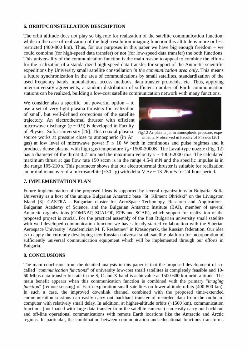
Fig.12 Ar-plasma jet in atmospheric pressure, expe-rimentally observed in Faculty of Physics [26]
6. ORBIT/CONSTELLATION DESCRIPTION
The orbit altitude does not play so big role for realization of the satellite communication function, while in the case of realization of the high-resolution imaging function this altitude is more or less restricted (400-800 km). Thus, for our purposes in this paper we have big enough freedom – we could combine (for high-speed data transfer) or not (for low-speed data transfer) the both functions. This universality of the communication function is the main reason to appeal to combine the efforts for the realization of a standardized high-speed data transfer for support of the Antarctic scientific expeditions by University small satellite constellation in the communication area only. This means a future synchronization in the area of communications by small satellites, standardization of the used frequency bands, modulations, access methods, data-transfer protocols, etc. Thus, applying inter-university agreements, a random distribution of sufficient number of Earth communication stations can be realized, building a low-cost satellite communication network with many functions.
We consider also a specific, but powerful option – to use a set of very light plasma thrusters for realization of small, but well-defined corrections of the satellite trajectory. An electrothermal thruster with efficient microwave discharge (η ~ 0.9) is developed in Faculty of Physics, Sofia University [26]. This coaxial plasma source works at pressure close to atmospheric (in Ar gas) at low level of microwave power P ≤ 10 W both in continuous and pulse regimes and it produces dense plasma with high gas temperature Tg ~1500-3000K. The Laval-type nozzle (Fig. 12) has a diameter of the throat 0.2 mm and the maximum velocity v ~ 1000-2000 m/s. The calculated maximum thrust at gas flow rate 150 sccm is in the range 4.5-9 mN and the specific impulse is in the range 105-210 s. This parameter shows that our electrothermal thruster is suitable for realization an orbital maneuver of a microsatellite (~30 kg) with delta-V ∆v ~ 13-26 m/s for 24-hour period.
7. IMPLEMENTATION PLAN
Future implementation of the proposed ideas is supported by several organizations in Bulgaria: Sofia University as a host of the unique Bulgarian Antarctic base "St. Kliment Ohridski" on the Livingston Island [3]; CASTRA – Bulgarian cluster for AeroSpace Technology, Research and Applications, Bulgarian Academy of Science, and the Bulgarian Antarctic Institute (BAI), member of several Antarctic organizations (COMNAP, SCALOP, EPB and SCAR), which support for realization of the proposed project is crucial. For the practical assembly of the first Bulgarian university small satellite with well-developed communication function we have already started collaboration with the Siberian Aerospace University "Academician M. F. Reshetnev" in Krasnoyarsk, the Russian federation. Our idea is to apply the currently developing new Russian universal small-satellite platform for incorporation of sufficiently universal communication equipment which will be implemented through our efforts in Bulgaria.
8. CONCLUSIONS
The main conclusion from the detailed analysis in this paper is that the proposed development of so-called "communication functions" of university low-cost small satellites is completely feasible and 10-60 Mbps data-transfer bit rate in the S, C and X band is achievable at 1500-600-km orbit altitude. The main benefit appears when this communication function is combined with the primary "imaging function" (remote sensing) of Earth-exploration small satellites on lower-altitude orbits (400-800 km). In such a case, the improved downlink channel combined with the proposed time-extended communication sessions can easily carry out backhaul transfer of recorded data from the on-board computer with relatively small delay. In addition, at higher-altitude orbits (~1500 km), communication functions (not loaded with large data transfer from the satellite cameras) can easily carry out backhaul and off-line operational communications with remote Earth locations like the Antarctic and Arctic regions. In particular, the combination between communication and educational functions transforms

university small satellites served by low-cost university ground stations into perfect high-performance scientific, communication and educational tools which will be continuously developed in the next few years.
9. ACKNOWLEDGEMENT The authors are grateful to the members of the Bulgarian Antarctic expeditions for their useful discussions and to RaySat BG Ltd. for the antenna demonstrators and software simulators. 7 scientific consultants, 3 PhD students, 14 MSc. students and 8 BSc students from Sofia University, Bulgaria, took part in these investigations. Special thanks to the National Research Fund of Bulgaria, to the Rector of Sofia University Prof. I. Ilchev and to the Rector of SibSAU, Krasnoyarsk Prof. I. Kovalev for their valuable support. Special thanks to Hridaya Ltd. for the consulting support.
10. REFERENCES
[1] M. Gachev “Satellite Communications”, Heron press, ISBN 978-954-580-223-0, (2007) [2] P. Dankov “Introduction to Wireless Communications”, Heron press, ISBN 978-954-580-221-8, Ch. 6 (2007) [3] St. Kliment Ohridski Base; online available: http://en.wikipedia.org/wiki/St._Kliment_Ohridski_Base [4] US Antarctic Program, South Pole Satellite Communications and Pass Schedules; online available: http://www.usap.gov/usapgov/technology/contentHandler.cfm?id=1935 [5] Antarctic Broadband project; online available: http://antarcticbroadband.com/projects/ [6] ESA maps communication gaps for Arctic “gold rush”; http://www.esa.int/esaTE/SEMEZ456JGG_index_0.html [7] M. Cheffena, High-Capacity Radio Communication for the Polar Region: Challenges and Potential Solutions. IEEE
Antennas and Propagation Magazine, Vol. 54, No. 2, 238-244, April 2012 (2012) [8] D. Faber, M. Brett, J. Kingt, S. Wilson, P. Guthrie, The Business Case for Delivering Broadband to the Antarctic
Using Micro-Satellites, Int. Astronautical Congress, Cape Town, South Africa, 3 -7 October 2011 (2011) [9] R Sandau, H.-P. Roser and A. Valenzuela (Eds.), Small Satellites for Earth Observation (selected contributions),
Springer Science + Business Media B.V., ISBN: 978-1-4020-6942-0, (2008) [10] The Role of Small Satellites in NASA and NOAA Earth Observation Programs, Committee on Earth Studies,
Space Studies Board, National Research Council, ISBN: 0-309-59409-X (2000), online available: http://www.nap.edu/catalog/9819.html
[11] A Wicks, A da Silva-Curiel, Dr. J Ward, Dr. M Fouquet, Advancing Small Satellite Earth Observation: Operatio-nal Spacecraft, Planned Missions and Future Concepts, 14th Annual AIAA/USU Conf. on Small Satellites (2000)
[12] J. A. King, J. Ness, G. Bonin, M. Brett, D. Faber, Nanosat Ka-Band Communications - A Paradigm Shift in Small Satellite Data Throughput, 26th Annual AIAA/USU Conf. on Small Satellites, Logan, Utah USA, Aug. 2012 (2012)
[13] ITU-R, Amateur and amateur-satellite services, Ch.3 „Amateur-satellite services“ (2008); online available: http://www.itu.int/en/ITU-R/space/AmateurDoc/AmateurSatServiceFreq.pdf
[14] Минкомсвязи России, Государственная комиссия по радиочастотам, Решение № 10-07-01 (2010) и № 10-07-01 (2011), online available: http://minsvyaz.ru/ru/doc/?id_4=477 (in Russian)
[15] Industry Canada, Spectrum Management and Telecomunications, Study of Future Demand for Radiospectrum in Canada 2011-2015, 6.13 Space Science Services: www.ic.gc.ca/eic/site/smt-gst.nsf/eng/sf10271.html
[16] The Radio Amateur Satellite Corporation, http://www.amsat.org/amsat-new/satellites/frequencies.php [17] I. A. Mas, C. A. Kitts, A Flight-Proven 2.4GHz ISM Band COTS Communications for Small Satellites, 21st
Annual AIAA/USU Conference on Small Satellites, Logan, Utah, USA, 13-16 August 2007 (2007) [18] J. Sosa-Pedroza, F. Martinez-Zuniga, M. Enciso-Aguilar, Planar Antennas for Satellite Communications, Satellite
Communications, N. Diodato (Ed.), InTech, ISBN: 978-953-307-135-0, p. 367-394 (2010), Online available from: http://www.intechopen.com/books/satellite-communications/planar-antennas-for-satellite-communications
[19] C. Kakoyiannis, P. Constantinou Electrically Small Microstrip Antennas Targeting Miniaturized Satellites: the CubeSat Paradigm, in Microstrip Antennas, N. Nasimuddin (Ed.), InTech, ISBN: 978-953-307-247-0, p. 273-316 (2011). Online available from: http://www.intechopen.com/books/microstrip-antennas/electrically-small-microstrip-antennas-targeting-miniaturized-satellites-the-cubesat-paradigm
[20] N. Melega et al., ”Multispectral Earth Observation Using The Enhanced ALMASAT Microsatelitte Bus”, in Proc. IAA Symposium, January 2011, Rome, Italy (2011) http://www.almasat.unibo.it/10_news/news_db/n_110117.htm
[21] RaySat antenna systems, Satcom on-the-move, http://www.raysat.com/ [22] Yubileiny-1, http://sat.sibsau.ru/index.php?option=com_content&view=section&layout=blog&id=3&Itemid=2 [23] Yubileiny-2, http://www.federalspace.ru/main.php?id=2&nid=19363 [24] S. O. Pazderin, Reasons for the Choice of the Operational Frequency for Creation of High-Speed Informational
Channel from Microsatellite “Yubileiny-2” (“MiR”), Proc. 15th Int. Science Conference “Reshetnev Readings”, p. 378-379, Nov. 2011, Krasnoyarsk, Russia (2011). Available from: http://reshetnev.sibsau.ru/ (in Russian)
[25] Y. Loginov, S. Galochkin, A. Yakovlev, M. Valov, K. Okhotkin, I. S. Kartsan, Siberian Scientific and Education Program of Development, Creation and Application of Microsatellites Series, Proc. Small Satellites Systems and Services – The 4S Symposium, June 2012, Portoroz, Slovenia (2012)
[26] Zh. Kiss'ovski, A. Ivanov, S. Iordanova and I. Koleva, J Phys. D: Appl. Phys., 44, 205203 (2011)