small hydropower and headworks modelling - alternate hydro ... papers... · small hydropower and...
TRANSCRIPT
84
SMALL HYDROPOWER AND HEADWORKS MODELLING
ABSTRACT It is obvious that headworks (HW) is one of the most decisive components of the Hydropower projects. Headworks structures in hydropower projects are to extract the design discharge properly by minimizing the problem cause by sediments in intake, settling basin and its flushing structures. Generally, the design of the headworks is project specific. Basically, special attention is required on layout and sizing of headworks in Himalayan Rivers from sediment handling point of view. Several existing small scheme ROR hydropower plants in Nepal are facing operational difficulties and loosing significant amount of revenue generation during operation phase due to shortcomings on HW design and layout. The severe chocking of the main river intake, heavy deposition in the gravel hopper, challenges in sediment flushing/handlings are the frequently encountering problems at the HW, as it is bitter fact that the Himalayan Rivers are transporting tremendous amount of sediment load during the monsoon flow. It is common that the HW design layout is carried out based on the conventional formulae as well as experience from the previously implemented projects. In addition to this, a physical model shall be used as a design tool for headworks design. It helps to verify the design. In case of unsatisfactory performance, it is possible to develop the new concept before to switch on construction. In this paper, there will be presenting a case study on physical hydraulic modeling of headworks of Khudi Hydropower Project, 3.8 MW. The authors believe that such information shall be useful for the hydropower developer in the coming future and will be possible to utilize water resources for the maximum benefit, preventing the investment in possible unsatisfactory theoretical design. INTRODUCTION Tough Environmental and Socio-economic concern against high dam is creating new base for the promotion of small hydro world wide, especially for the developing countries. Small hydropower as a renewable energy (suits for developing country) provides the energy for the development of remote areas, creates job opportunities, short time for planning and implementation, low cost, simple to medium technology for construction, small operation and maintenance (O and M) cost, less environmental impacts (Small is beautiful). These facts shall be taken as opportunities for developing the small hydropower projects. But there are numerous challenges as well. Insufficient database on small rivers, technology is still under the research and development phase for developing small hydropower in the mountainous (bed slope >1/100) and Foothill Rivers (bed slope >1/1000). The hydraulic parameters with high velocity, shallow flow depth, high bed load transportation etc are making design more challenging.
Himalayan Small Hydropower Summit (October 12-13, 2006), Dehradun
Manohar Shrestha Deputy General Manager
Hydro Lab, Pulchowk, Lalitpur, Nepal
Tulsi Prasad Phuyal Research Engineer
Hydro Lab, Pulchowk, Lalitpur, Nepal
85
It is obvious that headworks (HW) is one of the most decisive components of the Hydropower projects, as the major function of headworks is to divert the design discharge for power generation by handling sediment load properly so that the sediment exposure to the turbine is minimized. Hydropower projects are classified based on installed capacity, available head (Mosonyi, 1987) and storage. According to installed capacity, the hydropower projects are pico, micro, mini, small, medium and large, which is varying country to country for instance 10 MW capacity plant is small hydropower plant in Nepal but in China up to 50 MW is considered as a small hydropower. If the parameter head is considered as an index for hydropower classification, then the hydropower projects are Low (H<15 m), medium (50>H>15 m), and high head (H>50 m), scheme. Based on storage type, the projects are classified as Run-of-River, Peaking Run-of-River and storage. Most of the hydropower projects under operation and identified for development in the Himalayan region are ROR/PROR projects with high head scheme. The Himalayan Rivers are transporting tremendous amount of sediment load during the monsoon flow. It has significant and direct/immediate influence on headworks arrangement in ROR/PROR small hydropower projects than in bigger reservoirs projects. DESIGN CRITERIA Hydraulic design of headworks for small hydropower plants in steep rivers, have proven to be equally difficult and some times more challenging than for medium and large sized hydropower plants. Generally, the design of the headworks is project specific and mostly depends on diversion scheme and amount of intake discharge, sediment concentration in the rivers, etc. If the project falls under the small scale scheme and ROR/PROR, then HW layout and its component design shall be done so that design criteria met for efficient headworks operation. The design criteria should be; safe to hazardous floods, control of bed build in front of intake, passes of floating debris and proper sediment handling including air entry into the water conveyance system (Prof. Hakon Stole, NTNU, Norway). DESIGN TOOLS To fulfill above mentioned design criteria, a proper location, suitable arrangement and appropriately sized HW components are very much essential. It is required thorough study and understandings on HW layout in beginning of conceptual and design phase. Several existing ROR hydropower plants in Nepal are facing operational difficulties and loosing significant amount of revenue generation during operation phase. Mainly the following design tools shall be used for designing the hydropower projects.
• Theoretical
Mathematical equations and empirical relations • Experimental
Physical model tests, a short field trip, observations, investigations and measurements
86
• Professional experience Engineering experience gained from implemented projects (compensate lack of
direct observations)
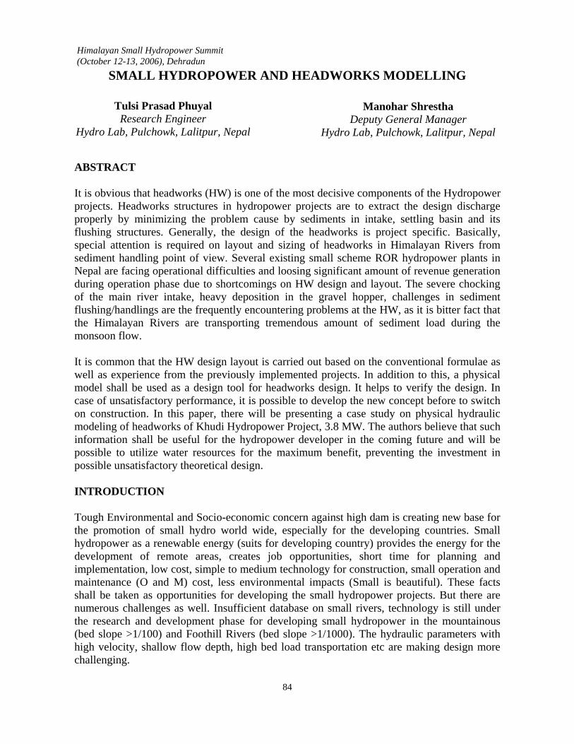
It is common practice that the HW design layout is carried out based on the conventional formulae as well as experience from the previously implemented projects. WHY A PHYSICAL MODEL AS A DESIGN TOOL? Super critical flow, high variation in flow throughout the year, unpredictable bed load, high variation of sediment size and complex sediment transport patterns are the most unfavorable phenomena that are common in steep Himalayan Rivers. During dry season, flows in the rivers are very lean and during the wet season the flows are very high and great challenge to manage. In this connection, design of headworks is challenging and satisfactory performance is not guaranteed always. The clear understanding of the river and location specific it is very useful to conduct physical modeling and minimize such unpredictable possibilities before the construction and operation of the power plants. It shall also be used as a reliable tool for finalizing the proposed headworks design and see the hydraulic response by releasing the different possible flow regimes in the river model. In addition to this, it helps In case of, unsatisfactory performance, it is possible to modify or develop totally new headworks arrangement. Or minor changes in headwork structures for satisfactory performance can be done, e.g, changes in angle or radius of guide wall, increase or decrease of intake sill level, dam height etc. The performances of overall hydraulic structures are associating with the different return period. It is very important to check the bed load and trash performance during 2, 5, 10, 20, 50 and say up to 100 years return period. It is not possible to see the flood behavior directly into the river within a limited time. CASE STUDY- KHUDI DESIGN AND MODEL STUDY General Khudi River is located in Lamjung district in the Western Development Region of Nepal and is one of the tributaries of the Marsyangdi River. It is a snow-fed river having an average slope of 1 in 30 with gravels and boulders forming the river bed. It has a high sediment transport capacity. The catchments area of the river at the confluence to the Marsyangdi River is about 127 km2. The mean annual flow in the river is about 9.8 m3/s and the mean dry season flow value is about 2.8 m3/s.
Figure 1 Khudi Khola during dry season

87
The Khudi Hydropower Project (KHP) is a run of the river project. The design flow is 4.9 m3/s. Since the average flow in dry periods is 2.8 m3/s, the plant can only have full capacity during the rainy season. The initial design of headworks of the KHP was proposed by consulting engineer Gestion Conseil SCP Inc, Canada and LEDCO Engineers. Before tendering the project for construction, the LEDCO decided to review the initial design by the experts of the BPCH (BPCHydroconsult the Engineering Department of Butwal Power Company) hydropower project owner, developer and designer; and later on reviewed by Dr. H. Stole, Professor at Norwegian University of Science and Technology (NTNU)/Hydro Lab for the proposed design. Based on Review by BPCH and Hydro Lab/NTNU felt the necessity of physical modeling of Khudi Hydropower Project and so physical hydraulic model was built in laboratory in 2002 to review the design. The tests on the model were carried out in Hydro Lab Pvt. Ltd., and the detailed of the report is available in Hydro Lab. Hydrology The flows presented in the table below were used during the model tests for headworks performance. It was important to observe the general headworks performance with respect to sediment transport, bed load passage, sediment control at the intake and floating debris transport patterns in different flooding scenario. Test situation Flow (m3/s) Low flow 5 Average flow in June and October 10 Normal monsoon flow 30 Normal monsoon flood 80 Flood with a return period of 2 years 105 Flood with a return period of 10 years 178 Flood with a return period of 20 years 208 Flood with a return period of 100 years 330 Design flood 330
To observe the different flood response of each headworks structure, the flows were gradually increased from 30m3/s to the design flood of 330 m3/s and then gradually reduced in steps in reverse order and finally stopped. During the test run the model was constantly fed with sediments and gravels of various sizes to represent the bed load transport in the river. As there was not sufficient sediment transport data available in Khudi river, sediment into the model was supplied based on the experience of sediment transport in similar rivers. The information on the hydrology was supplied by the Client Lamjung Electricity Development Company (LEDCO). PHYSICAL MODEL OF INITIAL ARRANGEMENT AND TEST In this arrangement, diversion structure consisting a 20 meter long free overflow weir with a one meter wide crest at elevation 939.20 masl, sloping 1:6 at the upstream face and 1:4 at the down stream face was built. A side intake furnished with a bed load hopper to draw the water.

88
There were two sluices for sediment handling, which were bed load sluice and gravel sluice. The 117 meters long, partly covered intake canal, where the downstream 33 metres were furnished with a side spillway is linking the intake gate with the settling basins. The sediments that settled at the bottom of the bed load hopper, will be flushed out to the river through the bed load flushing culvert of approximately the same length of intake canal, reference is made to Figure 2.
Figure 2 Initial HW layout and its model in laboratory
Several tests were carried out to verify the proposed design in different flow situations. Tests revealed that it was not possible to draw a desired flow rough the intake canal. When the river discharge was 5m3/s only 2.9 m3/s was abstracted from the river, but 96% of it was drawn through the bed load sluice rather than the intake canal (Heier, 2002). This observation revealed that the main problem was not to draw water from the river, but to get the water into the intake canal. Next, there was a problem on sediment exclusion at the headworks. The reason of the sediment clogging was due to low transport capacity in the flushing culvert. The transport capacity is dependent on the available energy head, which is a function of velocity, elevation difference, frictional loss in culvert and depth.
Figure 3 Deposition in front of intake

89
MODIFICATION ON INITIAL ARRANGEMENT To solve the hydraulic problem and sediment exclusion within the existing design, the weir crest was raised by 0.5 m and 1.0 m in two stages. A higher weir crest made it difficult for transport of sediments over the weir, unless the bed in front of the weir is raised. A huge amount of sediment was deposited in front of the intake. A modification on the flushing culvert was carried out by shortening its length by about 50% and the outlet released into the river directly. There was some improvement in bed load flushing after this modification.
Figure 4 Bed load culvert shortened Figure 5 Weir crest raised by 1 m and test RESULTS AND ITS CONSEQUENCES Ultimately, based on the model study results, the reviewer concluded that the proposed headworks arrangement would not function satisfactorily. Due to the lack of financial closure for KHP at that time it was not possible to continue further study as a contract research. Further, Hydro Lab on its own initiatives continued research on Khudi headworks to find a feasible headworks layout and its hydraulic design. The result of the research was planned to be sold to the potential developer in future. Further, two alternatives were developed to find satisfactory headworks arrangement, which are described in the following sections. The location as well as initial arrangement was discarded and the new location has been chosen at about 80 m upstream from the initially proposed location. Alternative 1: Headworks arrangement with frontal intake In this arrangement, a 20 meter long free overflow weir with a one meter wide crest at elevation 943.00 masl, sloping 1:4 at the upstream face and 1:10 at the downstream face was proposed for water diversion. Bed load sluicing channel and intake orifice are almost perpendicular to the river flow. An orifice type intake of size 5 m wide and 1.5 m high was designed to abstract the water. For bed load handling, there was a 3 m wide bed load sluicing channel was proposed adjacent to the intake. The invert level of bed load sluice and intake sill level difference was limited to 0.5 m only. There was a vertical drop of 1.5 m immediately
ed load culveshortened

90
after the bed load sluice gate in bed load flushing channel. The left bank sidewall from intake was extended 36 m downstream from the weir as a flood control wall.
Figure 6 Frontal intake and bed load deposition Figure 7 Modification on frontal intake, slab
introduced After having several tests run in different flow situations, the sediment deposition in front of intake was observed significant and significant amount of sediment particles entered into the gravel hopper, reference is made in figure 6. Further the frontal intake converted into the semi frontal intake by introducing inlet head wall. Meanwhile the bed load sluice was also lowered by about 2 m and introduced a slab at the intake sill level to check the entry of sediment through the intake; reference is made in figure 7. With this modification, test was carried out. A rotational turbulent flow was observed in front of intake orifice, reference is made in figure 6. The test runs with the sediment revealed sediment deposition under and over the slab and had entered through the intake. It was realized that the sediment deposition under the slab may pose quite serious problem during the operation of headworks. The velocity observed along the left bank wall upstream of the intake was low resulting in difficulty for floating debris passes. It was realized that a comprehensive modification may be needed. Based on the observations of Alternative 1, headworks arrangement with semi-frontal intake was developed and tested further. Alternative 2: Headworks arrangement with semi frontal intake The weir crest of 20 m long was kept at same crest level of 943.00 masl. The intake structure together with bed load sluice and gravel excluder was modified. The intake orifice size was changed from 5 m to 4 m and the invert level and top level of the intake opening was kept at 941.5 and 943.0 masl respectively. Two open channels were proposed for flushing the bed load. The right bank side channel is 3.0 m wide and the left bank side channel is 2.0 m wide and length of each channel is about 36.0 m. Both channels had a bed slope of 1 in 50.
Slab infront of intake

91
Figure 8 Double bed sluice channel Figure 9 Modification on bed load hopper
wall The river flow characteristics at upstream part of the weir were observed. The big boulder located at the upstream of the weir had an influence on the hydraulics of the approach flow to the intake. The boulder influenced the flow to concentrate on the right bank. As a result, low velocity was observed along the left bank resulting in difficulty of passing floating trashes and debris. While the riverside bed load flushing channel was in operation, a rolled flow was observed in front of intake orifice, which created problem for debris passing over the weir. While the hillside bed load flushing channel was in operation, less rolled flow was observed. The deposition of bed load in the river training upstream of the weir was considered to be fairly high during moderate flood in the river. The sediment control at the intake was good. Although there is sediment deposit in front of intake it was observed that sediment did not enter into the gravel hopper through intake orifice. Based on the above mentioned observations, minor modifications on the model were carried out and then tested for documentation. MODIFICATIONS In this arrangement, the river bed upstream of the weir was raised to elevation 942.0 masl. Boulder armouring was continued for approximately 60 m upstream of the weir. The existing big boulders at upstream of the weir were removed. The right bed load-flushing channel was permanently removed. The length of the weir crest was extended to about 23 m by the removal of right flushing channel. A depression of 0.3 m in 2 m length from the left bank sidewall was kept in the weir crest to minimize the rolled flow observed in intake and to allow floating materials near intake to pass during moderate flood in the river. The upstream slope from the weir was unchanged while the downstream slope was maintained at 1:10. The top level of intake was lowered by 0.3 m for submergence and accordingly the opening height is maintained at 1.2 m. The pier (size 0.6 m width and 1.5 m long) was introduced at the centre of intake orifice to minimize the stoplog span in operation phase. After this modification, there were two orifice openings of 1.2 m X 1.7 m on intake head wall. The bed load hopper was modified. Reference is made to Figure 9. The hopper wall was changed in convex shape with radius 7.0 m, which helped to minimize the circulating flow into the hopper to some extent.

92
Figure 10 Intake canal furnished with spillway
A modification was made in intake canal. The first 18 m length was kept as a closed rectangular culvert of size 1.5 X1.5 m. Immediately, after closed culvert a 10.0 m long spillway was furnished, reference is made to Figure 10. The spillway at this location didn’t function properly due to shooting flow at the end of closed culvert, reference is made to Figure 10. So the spillway was shifted further downstream and length limited to 8 m, reference is made to Figure 11. The open canal of size 2 m wide and 1.4 m depth was kept in between spillway and closed culvert. The culvert and canal bed slope was kept 1 in 500.
Figure 11 HW layout – Initial and New
Spillway
Spillway
End of culvert

93
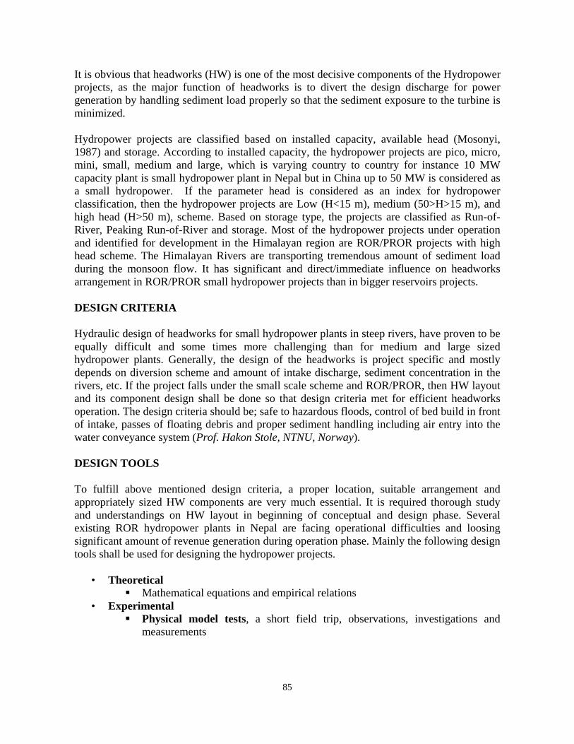
PERFORMANCE The boulder lining and the bed level raised at the upstream part of the weir provided a good uniform approach flow to the weir and intake at monsoon flood situations. Removal of the upstream boulders improved the approach flow towards the intake. The bed load was observed to pass over the weir at flows higher than the normal monsoon flows. The floating debris coming along the centre and right bank of the river passed over the weir without difficulty, but floats along the left bank are found to remain around intake head wall. Due to the introduction of depression on the left part of the weir, a rolling effect in front of the intake was minimized and depression assisted in providing an access to some of the floats. The proposed general layout (geometry) of the weir had a fairly satisfactory hydraulic performance. The intake was abstracting required water from the river without difficulty. The increment of submergence improved the flow condition through the intake orifice. Suction effect had been reduced to some extent. There was a bed load deposition in front of the intake in different flows. The bed load entering the bed load hopper was sluiced through the bed load flushing channel. A very negligible amount of sediment particles entered into the gravel hopper. An intermittent opening of gravel flushing gate sluiced all deposited sediment in the gravel hopper within a short interval of operation. The water surface profiles for selected discharges along the weir axis are presented in Figure 12. A rating curve for weir discharging capacity was developed, which is presented in Figure 13.
938
939
940
941
942
943
944
945
946
947
54.5 39.5 24.5 9.5 4 0 -18.75 -37.5
Chainage (m)
Leve
l (m
asl)
CL bed level 30 m3/sec 80 m3/sec 105 m3/sec 178 m3/sec 208 m3/sec 10 m3/sec
(Weir axis)
Figure 12 Water surface profiles upstream and downstream of the weir for selected discharges.
94
943
943.5
944
944.5
945
945.5
946
0 25 50 75 100 125 150 175 200 225 250 275 300 325 350
Discharge over the weir, m3/sec
Obse
rved
wat
er le
vel,
mas
l
Figure 13 Clean water capacity curve for the weir. CONCLUSIONS AND RECOMMENDATIONS The Alternative 2 headworks arrangement furnished with semi-frontal intake had been concluded as an appropriate headworks layout and this adopted new headworks was shifted by 80m u/s from the initially designed headworks location. The new arrangement is capable to abstract the design flow through the intake and smooth passage of floating debris as well as bed load through bed sluice structure. It was observed that the Alternative 2 arrangement not only improved the hydraulic performance of headworks structures but also improved the river bed stability and approach flow towards the intake.
• The physical modeling of Khudi Hydropower project proved that physical model test
is a design tool when headworks are required to design for small scheme hydropower project in steep rivers. Usually, the assumptions made on design while using the conventional formulae may not suit and expected performance will not be achieved. Model study- prevented from the investment disaster of the Khudi Small Hydropower Project
• It is possible to look after several options for Headworks design layouts within the selected river reach. It helps for designer as well as developer to understand the flood behavior and its impact when the designed structures are placed /constructed in the River.
From this study, the physical model study shall be recommended as a design tool to finalize the headworks design and layout during the feasibility study of small hydropower project. Generally, the developers are reluctant to carry out the physical hydraulic model study for

95
small scheme hydropower. Based on the prevailing labor and material cost in Nepal, such model study in Hydro Lab costs about 30,000 to 60,000 US $. In this connection, if the generation revenue from 5 MW plant is calculated for a week that is about 35,000 US $ (prevailing per unit cost is US 5 cents). The model test cost is incomparable with its benefits in long run of the power plant. Now, this project is constructing by the Butwal Power Company and LEDCO and almost complete. However flows were tested and Headworks (intake) operation showed as result revealed during physical modeling and recommended by Hydro Lab. Based on first year operation (Testing) it is good result in operation. REFERENCES Pradhan, P.M.S., P.N. Joshi and T.P. Phuyal, 2004, Report on Khudi Model Study - July 2004. Hydro Lab. Ernest Razvan, River intakes and diversion dams, Elsevier,1989 Guidelines for design of intakes for Hydroelectric plants, ASCE, 1995 Lecture materials, Hydropower Development Course, Norwegian University of Science and Technology (NTNU)