smart and hybrid balancing system: design, modeling, and
TRANSCRIPT
Publications of the DLR elib
This is the author’s copy of the publication as archived with the DLR’s electronic library at
http://elib.dlr.de . Please consult the original publication for citation.
Smart and Hybrid Balancing System: Design, Modeling,
and Experimental Demonstration
R. de Castro; C. Pinto; J. V. Barreras; R.E. Araújo; D. A. Howey
Performance of series connected batteries is limited by the “weakest link” effect, i.e., the cell or group of cells with
the poorest performance in terms of temperature, power, or energy characteristics. To mitigate the “weakest link”
effect, this study deals with the design, modeling, and experimental demonstration of a smart and hybrid balancing
system (SHBS). A cell-to-cell shared energy transfer configuration is proposed, including a supercapacitor bank in
the balancing bus, thus enabling hybridization. Energy is transferred from each battery module connected in series
to the balancing bus, and vice-versa, by means of low-cost bi-directional dc-dc converters. The current setpoints of
the converters are obtained by means of a smart balancing control strategy, implemented using convex
optimization. The strategy is called “smart” because it pursues goals beyond the conventional state-of-charge
equalization, including temperature and power capability equalization, and minimization of energy losses.
Simulations show that the proposed SHBS is able to achieve all these goals effectively in an e-mobility application
and are also used to assess the impact of different hybridization ratios and cooling conditions. Finally, an
experimental setup is developed to demonstrate the feasibility of the SHBS.
Copyright Notice ©2020 IEEE. Personal use of this material is permitted. Permission from IEEE must be obtained for all other uses, in any current or future media, including reprinting/republishing this material for advertising or promotional purposes,creating new collective works, for resale or redistribution to servers or lists, or reuse of any copyrighted component of this work in other works.
R. de Castro; C. Pinto; J. V. Barreras; R.E. Araújo; D. A. Howey, " Smart and Hybrid Balancing System: Design, Modeling, and Experimental Demonstration”, IEEE Transactions on Vehicular Technology, Volume: 68, Issue: 12, 11449 - 11461, 2019

IEEE TRANSACTIONS ON VEHICULAR TECHNOLOGY, VOL. XX, NO. XX, XXX 2019 1
Smart and Hybrid Balancing System: Design,Modeling and Experimental Demonstration
Ricardo de Castro, Senior Member, IEEE, Claudio Pinto, Jorge Varela Barreras, Member, IEEE,Rui Esteves Araujo, Member, IEEE, and David A. Howey, Senior Member, IEEE
Abstract—Performance of series connected batteries is limitedby the ‘weakest link’ effect, i.e. the cell or group of cells withthe poorest performance in terms of temperature, power, orenergy characteristics. To mitigate the ‘weakest link’ effect,this study deals with the design, modeling and experimentaldemonstration of a smart and hybrid balancing system (SHBS).A cell-to-cell shared energy transfer configuration is proposed,including a supercapacitor bank in the balancing bus, thusenabling hybridization. Energy is transferred from each batterymodule connected in series to the balancing bus, and viceversa, by means of low-cost bi-directional dc-dc converters. Thecurrent setpoints of the converters are obtained by means ofa smart balancing control strategy, implemented using convexoptimization. The strategy is called ‘smart’ because it pursuesgoals beyond conventional state-of-charge equalization, includingtemperature and power capability equalization, and minimizationof energy losses. Simulations show that the proposed SHBS is ableto achieve all these goals effectively in an e-mobility application,and are also used to assess the impact of different hybridizationratios and cooling conditions. Finally, an experimental setup isdeveloped to demonstrate the feasibility of the SHBS.
Index Terms—battery management system, supercapacitors,convex optimization, hybrid energy storage system, battery bal-ancing
I. INTRODUCTION
One of the main issues in the design of battery-basedelectric vehicles (EVs) is the non-uniformity in the capacity,inner resistance and thermal characteristics of the batterycells, which may result in performance degradation, limitedby the cell with the poorer performance, i.e. the ‘weakest-cell
Copyright (c) 2015 IEEE. Personal use of this material is permitted.However, permission to use this material for any other purposes must beobtained from the IEEE by sending a request to [email protected].
Ricardo de Castro is with Institute of System Dynamics and Control,German Aerospace Center (DLR), Wessling, D-82234, Germany (e-mail: [email protected]). His work was funded by the project Next GenerationCar, Antriebsstrang und Energiemanagement.
Claudio Pinto and Rui Esteves Araujo are with INESC TEC andFaculty of Engineering, University of Porto, Porto, 4200-465, Por-tugal (e-mail: [email protected], [email protected]). Their work wasfunded by FCT—Fundacao para a Ciencia e a Tecnologia, within theproject SAICTPAC/0004/2015—POCI-01-0145-FEDER-016434 and scholar-ship SFRH/BD/90490/2012.
Jorge Varela Barreras is with the Department of Mechanical Engineering,Imperial College London, London, UK (email: [email protected]), and TheFaraday Institution, Quad One, Harwell Science and Innovation Campus,Didcot, UK. He was with the Department of Engineering Science, Universityof Oxford, UK, until the end of 2018. His work was sponsored by FaradayInstitution (faraday.ac.uk; EP/S003053/1), grant number FIRG003
David A. Howey is with Department of Engineering Science, Universityof Oxford, Oxford, OX1 3PJ, UK (e-mail: [email protected]). Heacknowledges funding from the STFC Batteries Network (ST/N002385/1)and the Energy Storage for Low Carbon Grids Project (EPSRC referenceEP/K002252/1).
problem’ [1]. To minimize operational unbalances resultingfrom these mismatches, active and passive balancing systemscan be implemented. In the passive case, energy from thecells with the highest voltages is dissipated as heat, e.g.through shunt resistors (see Fig. 1a). Despite being simple,this approach is affected by high thermal losses [2].
Active balancing uses power converters to re-distributeenergy through the battery pack. It offers higher energyefficiency, potential for state-of-charge (SoC) [3] and thermalequalization [4], [5], but suffers from higher costs and com-plexity [2]. In the literature, several types of active balancingtopologies have been proposed, including, for example, cell-to-pack, pack-to-cell and cell-to-cell configurations (see Fig. 1a).In cell-to-pack configurations [6], [7] the excess energy ofthe cells is transferred to the battery pack, while pack-to-cell [2] performs the inverse operation, i.e. weaker cellsreceive energy from the pack. Cell-to-cell topologies allowthe transfer between individual cells; they can be divided intodistributed variants [8] (transfer of energy is only allowedbetween neighbor cells) and shared [9], [10] (energy is firsttransferred to an energy accumulator and then moved toanother cell). In our previous research [11], a benchmarkingof several balancing configurations was performed. It wasconcluded that the cell-to-cell shared (CCS) is one of mostpromising battery balancing configurations, offering superiorenergy efficiency and thermal performance. Building on theseprevious findings, the main aim of this work is to enhanceCCS configurations with an additional feature: hybridizationof batteries with supercapacitors (SCs).
The battery-SC hybridization is driven by the idea ofcombining energy storage units with complementary charac-teristics, such that the resulting hybrid energy storage system(HESS) provides better overall performance [12], [13]. Giventheir high power density, high number of charge-dischargecycles and efficiency, SCs are well suited to support the oper-ation of batteries. In particular, batteries with higher energydensity usually provide the average power of the vehicle,while SCs with higher power density, but lower energy density,handle power transients. Numerous studies have demonstratedthat battery-SC hybridization is able to reduce peak currentsand degradation of the battery pack [14]–[18], increasing thelifetime [19], [20] and potential value of batteries for second-life applications, such as grid support [21]. However, SCs alsoincrease costs, weight and volume, which introduce trade-offsin the design and sizing of the battery-SC HESS [19], [22].
The hybridization of battery and SCs can be classifiedin terms of degrees of freedom available to control: i) the

IEEE TRANSACTIONS ON VEHICULAR TECHNOLOGY, VOL. XX, NO. XX, XXX 2019 2
passive cell-to-cell
shared
0D hybridization
batteries
modules
1D hybridization
c) hybrid balancing sytem
SCs
2D hybridization
(b) battery-SC hybridization
(a) balancing systemscell-to-cell
shared
1D
hybridization+
+
-
+
-
+
-
+
-
pack-to-cell
+
-
+
-
cell-to-pack
+
-
+
-
bidirectional
dc-dc converter
unidirectional
dc-dc converter
+
-dc link
Fig. 1. Representation of some state-of-art balancing topologies (a), battery-supercapacitors hybridization configurations (b) and the proposed hybrid balancingconcept (c). Note: to simplify the presentation only 3 battery modules are shown.
power provided by the energy storage units, and ii) the dc-link voltage, which connects the energy storage unit with thevehicle’s driveline (see Fig. 1b). In configurations with zerodegrees (0D) of freedom , also known as passive hybridization,the SCs are directly connected to the batteries [23], [24].Due to the absence of power electronics, this solution is themost affordable. However, the power split is dictated by theinner impedance of the storage units and the dc-link voltageis fixed by the battery terminals, which limits the benefits ofthis configuration [25]. Hybridization with two degrees (2D) offreedom has dedicated dc-dc power converters for each storageunit, enabling the simultaneous control of the dc-link voltageand power provided by batteries and SCs [15], [16], [18], [26].Because of the variable dc-link voltage, higher voltages to thevehicle’s driveline can be applied, which allows the extensionof the maximum speed of the traction motor and reduction ofcopper losses [27]. The drawback of this approach lies in theincreased costs, weight and complexity due to the presenceof two power converters. Hybridization with one degree(1D) of freedom provides a good trade-off between costs andperformance, since only one power converter is employed.Given the wide operating range of the SCs voltage, the powerconverter is often connected with this energy unit [14], [19],but no variable dc-link voltage is offered.
The majority of previous research treated the battery bal-ancing and battery-SC hybridization as two separate functions.In contrast, we investigate here the possibility of integratingthese two functions into the same system. We exploit the powerelectronics embedded in the balancing system to simultane-ously enable battery balancing and battery-SC hybridizationwith one degree of freedom (see Fig. 1c). The main advantage
of this approach, called smart and hybrid balancing system(SHBS), is the low cost of hybridization, since we avoidthe incorporation of additional power converters to activelydistribute the power flow in the HESS. It is important tonote that previous research, such as [28], [29], also consideredthe inclusion of SCs in the balancing system. However, theseSCs are mainly used as a small energy buffer for balancingpurposes; they do not take advantage of the SCs to minimizeenergy losses or the stress in the battery cells, which isthe focus of battery-SC hybridization. Reference [9] uses thebalancing circuit to simultaneously achieve battery SoC equal-ization and charge a low-voltage battery (which supplies powerto the auxiliary systems of the vehicle), but no hybridizationis pursued.
In summary, our work provides three main contributions.First, we present a feasibility study on the use of a CCStopology to simultaneously perform battery balancing (i.e. SoCand temperature equalization) as well as hybridization withSCs. Second, a convex optimization framework for controllingthe hybrid balancing setup is developed. In comparison withother optimization frameworks – such as dynamic program-ming [20], [30], non-linear optimization [15] or gradient-free algorithms [31] – convex methods offer computationallyefficient solutions and attractive theoretical properties (e.g.,guarantee of an unique optimum [32]). These advantages haveencouraged the application of convex optimization in severalautomotive applications, including powertrain sizing [33], en-ergy management [34] and battery balancing circuits [11].To the best of the authors’ knowledge, it is the first timethat convex methods have been applied to the control ofhybrid balancing systems. The third contribution deals with

IEEE TRANSACTIONS ON VEHICULAR TECHNOLOGY, VOL. XX, NO. XX, XXX 2019 3
the investigation, through numerical simulations, of differentbalancing configurations, which enables us to quantify benefitsof hybrid vs non-hybrid balancing solutions. A preliminaryversion of this work was published at [35]; it is extendedhere by expanding the analysis of the SHBS properties andproviding experimental validation in a small scale prototype.
The remainder of this paper is organized as follows: Sec-tion II discusses the control architecture for the SHBS as wellas the energy management and battery balancing problems.These problems are then solved using convex optimizationmethods in Section III and validated through numerical sim-ulations in Sections IV and V. Experimental validation of theSHBS in a small scale prototype is presented in Section VI,while Section VII provides concluding remarks and outlookfor future work.
II. HYBRID BALANCING SYSTEM: OVERVIEW
A. Control Architecture
As depicted in Fig. 2, the hybrid balancing circuit is com-posed of n dc-dc converters. The primary side of each dc-dcconverter is connected to the terminals of the battery modules1,while the secondary side is coupled with an auxiliary energybuffer. In this CCS balancing configuration, the energy of thebattery modules is first transferred to the energy buffer andthen re-distributed to other modules. Previous applications ofthis balancing circuit implemented the auxiliary energy bufferthough small capacitors, operating as a filter for the output ofthe dc-dc converter (e.g. flyback-based converters [9], [36]).This work pursues a different route. Our first goal is to increasethe size of the secondary energy buffer, through the use ofSCs, such that a HESS (batteries + SCs) can be formed.The second goal deals with the control of the dc-dc powerconverters to simultaneously perform battery balancing andenergy management of the HESS.
To achieve these goals a two-layer control structure isadopted (see Fig. 2). The lower layer controls the balancingcurrents (iB,j , j ∈ J = 1, . . . , n), via manipulation of themodulation signals of the power converters, and estimates theSoC of the battery modules [37]. The higher layer performsthe energy management and battery balancing functions usingcurrents iB,j as control variables. The battery balancingfunction focuses on SoC and temperature equalization of thebattery modules, while the energy management prioritizespower division between batteries and SCs that minimizesenergy losses. In what follows, we will concentrate on thedesign and evaluation of the higher layer algorithm. Detailson the lower layer can be found in [38].
B. Problem Formulation
The energy management and battery balancing algorithmsmust cope with three sets of constraints. The first set isrelated to physical operation limits of the dc-dc converters,which introduce constraints in the allowed range of balancingcurrents:
iB ≤ iB,j(t) ≤ iB , (1)
1in this work, a battery module is comprised of one or more battery cellsconnected in parallel
iB,n
iB,1
iB,2
iout
iSC
supercapacitors
(SCs)
balancing circuit battery modules
converter #1
converter #2
converter #n
Lo
ad
iB,1
iB,1
*
-
current control #1
u1
current control #2current control #n
control signal ( )ui
energy management &
battery balancing algorithm
balancing current
reference ( )iB,j*
vehicle & enery
storage parameters
driving cycle
power (pout)
SoC
Estimation
modules currents &
temperature ( , )ijbalancing currents ( )iB,j Tj
battery
SoC ( )qj
u1
u2
un
#1
#2
#n
Fig. 2. Overview of the two-layer control structure for the hybrid balancingsystem. The higher layer provides energy management and battery balancingfunctions, while the lower layer handles the current control of the powerconverters.
where j ∈ J , iB represents the lower bound and iB the upperbound of the balancing currents.
The second set of constraints deals with safety limits in thecurrents (ij , iSC) and SoC (qj , qSC) of both batteries and SCs.This means:
ij ≤ ij(t) ≤ ij , iSC ≤ iSC(t) ≤ iSC , (2a)qj≤ qj(t) ≤ qj , q
SC≤ qSC(t) ≤ qSC , (2b)
where j ∈ J , x represents the lower bound and x the upperbound of the variable x.
The third set of constraints – the balancing constraints –enforces small variations in temperature (Tj) and SoC withinthe battery pack. Note that large temperature and SoC unbal-ances result in uneven aging mechanisms, which in turn leadto a rise in cell-to-cell variations, aggravating the ‘weakest-cellproblem’ [37]. To mitigate this issue, the following balancingconstraints are considered:
∆qj(t) = |qj(t)− qavg(t)| ≤ ∆q, (3a)∆Tj(t) = |Tj(t)− Tavg(t)| ≤ ∆T, (3b)
where j ∈ J , ∆q is the maximum allowed differencebetween module’s SoC (qj) and pack’s average SoC (qavg(t) =

IEEE TRANSACTIONS ON VEHICULAR TECHNOLOGY, VOL. XX, NO. XX, XXX 2019 4
iBo,1
Rn
is,n
in
vn
R1
is,1
i1
v1
R2
is,2
i2
v2iout
vSCRSC
iSC
supercapacitors
(SCs)
balancing circuit
& current control
battery modules
converter #1
converter #2
iB,1
RB
iBo,2 iB,2
RB
converter #n
iBo,n iB,n
RB
independent source
dependent source
vout
load
OCVSC
OCV1
OCV2+
-
+
-
+
-
OCVn+
-
Fig. 3. Electric-equivalent circuit model of the hybrid balancing system,battery modules and SCs. Since the balancing currents (iB,j ) are controlledvariables of the power converters, they are represented through independentcurrent sources. The output currents of the converters (iBo,j ) and the vehicleload (iout) are formulated as dependent current sources; their value can becomputed using the power balance relations (10), (18).
1n
∑j∈J qj(t)), while ∆T represents the maximum differ-
ence between module’s temperature (Tj) and pack’s averagetemperature (Tavg(t) = 1
n
∑j∈J Tj(t)). Perfect SoC and
temperature equalization is obtained when ∆qj = 0 and∆Tj = 0, for all j ∈ J .
In order to maximize the range of the vehicle, the energymanagement strategy focus on the minimization of energylosses (L) of the HESS. Theses energy losses are generated bythe SCs (LSC), battery modules (Lbat), and balancing circuit(Lbal) and are computed as:
L = LSC + Lbat + Lbal (4)
=
∫ tend
0
pl,SC(t) +∑j∈J
pl,j(t)∑j∈J
plB,j(t)
dt
where pl,SC , pl,j , plB,j are the power losses of SCs, batterymodules and balancing circuits, respectively; tend is the du-ration of the vehicle’s mission. Additionally, the total powerprovided by the HESS must match the load power (pout)requested by the vehicle’s driveline.
Based on these elements, the energy management andbattery balancing problem for the SHBS can be summarizedas:
Problem 1. Find the reference values for the balancingcurrents, i∗B,j(t), j ∈ J , such that the energy losses Lare minimized, while complying with physical, safety andbalancing constraints (1)-(3), and fulfilling the load powerpout(t), t ∈ [0, tend].
III. MODELING AND OPTIMAL CONTROL
This section presents the control-oriented models of thehybrid energy storage units and power converters, as well asa convex optimization method to tackle Problem 1.
A. Modeling
1) Battery and Supercapacitor: Problem 1 presupposes themodeling of a string of n battery modules. Since n might bevery large, the use of high-fidelity and dynamic battery modelsmight lead to a complex balancing optimization problem. Toavoid this hurdle, numerically efficient models – composedof an open-circuit voltage OCVj in series with an internalresistance Rj – are used for both battery modules and SCs(see Fig. 3). Their terminal voltage (vj) and SoC (qj) is givenby:
vj(t) = OCVj(qj(t))−Rjij(t), (5)
qj(t) = − 1
Qj
ij(t), (6)
where j ∈ J ∪ SC = 1, . . . , n, SC, Qj [As] is thenominal capacity, and Rj [Ω] is the cell’s inner resistance.To simplify the notation, the SCs pack is treated as the n+ 1module of the energy storage system.
The open-circuit voltage OCVj of the battery modules isapproximated here as an affine mapping, dependent on theSoC [4], [19], [20]. It is described by the relation:
OCVj(qj(t)) = aj + bjqj(t), (7)
where j ∈ J , aj [V] is the open-circuit voltage when themodule is fully discharged, and bj [V] is the SoC gain. Torepresent the open-circuit voltage of the SCs (OCVSC), weexploit the definition of the SCs capacitance (CSC), whichyields:
OCVSC(qSC(t)) =QSC
CSCqSC(t) = aSC + bSCqSC(t) (8)
where aSC = 0 V is the voltage offset and bSC = QSC/CSC
[V] the SoC gain.The thermal response of the battery modules relies on the
model discussed in [11] and assumes: i) a lumped capaci-tance, ii) over-potential heating as the main source of heatgeneration, and iii) dissipation of heat due to conduction andconvection. It is mathematically formulated as:
Ch,j Tj(t) = pl,j(t)− Qcnd,j − Qcnv,j , (9a)
Qcnv,j(t) =(Tj(t)− Tenv
)/Rcov, (9b)
Qcnd,j(t) =(2Tj(t)− Tj+1(t)− Tj−1(t)
)/Rcnd, (9c)
where j ∈ J , Tj [K] is the temperature in the batterymodules, Tenv [K] is the environment temperature, and Ch,j
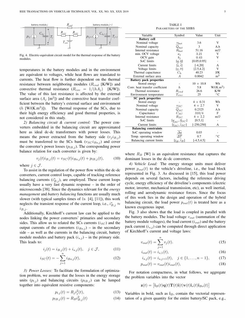
[J/K] is the thermal capacitance. The heat generated by batterymodule is captured by pl,j [J/s], i.e. internal power losses. Theterm Qcnd,j [J/s] represents the conductive heat flow betweenneighboring modules, while Qcnv,j [J/s] is the convective heatflow between battery modules and the environment. To betterunderstand this formulation, Fig. 4 represents the thermalmodel though an electric-equivalent circuit. In this circuit,
IEEE TRANSACTIONS ON VEHICULAR TECHNOLOGY, VOL. XX, NO. XX, XXX 2019 5
pl,j
Rcnd
Rcov Rcov
Tenv
Ch,jpl,j+1
Ch,j+1
......
battery module j battery module j+1
Tj Tj+1
Fig. 4. Electric-equivalent circuit model for the thermal response of the batterymodules.
temperatures in the battery modules and in the environmentare equivalent to voltages, while heat flows are translated tocurrents. The heat flow is further dependent on the thermalresistance between neighboring modules (Rcnd [K/W]) andconvective thermal resistance (Rcov = 1/(hAj) [K/W]).The value of this last resistance is affected by the externalsurface area (Aj [m2]) and the convective heat transfer coef-ficient between the battery’s external surface and environment(h [W/(K.m2)]). The thermal response of the SCs, due totheir high energy efficiency and good thermal properties, isnot considered in this study.
2) Balancing circuit & current control: The power con-verters embedded in the balancing circuit are approximatedhere as ideal dc-dc transformers with power losses. Thismeans the power extracted from the battery side (vjiB,j)must be transferred to the SCs bank (vSCiBo,j) and coverthe converter’s power losses (plB,j). The corresponding powerbalance relation for each converter is given by:
vj(t)iB,j(t) = vSC(t)iBo,j(t) + plB,j(t), (10)
where j ∈ J .To assist in the regulation of the power flow within the dc-dc
converters, current control loops, capable of tracking referencebalancing currents (i∗B,j), are employed. These current loopsusually have a very fast dynamic response – in the order ofmicroseconds [38]. Since the dynamics relevant for the energymanagement and battery balancing functions are usually muchslower (with typical samples times of 1s [4], [11]), this workneglects the transient response of the current loop, i.e., i∗B,j ≈iB,j .
Additionally, Kirchhoff’s current law can be applied to thenodes linking the power converters’ primaries and secondarysides. This allow us to related the SCs currents (iSC) and theoutput currents of the converters (iBo,j) – in the secondaryside – as well as the currents in the balancing circuit, batterymodule modules and battery pack (is,j) – in the primary side.This leads to:
ij(t) = iB,j(t) + is,j(t), j ∈ J , (11)
iSC(t) = −n∑
j=1
iBo,j(t), (12)
3) Power Losses: To facilitate the formulation of optimiza-tion problem, we assume that the losses in the energy storageunits (pl,j) and balancing circuits (plB,j) can be lumpedtogether into equivalent resistive components:
pl,j(t) = Rji2j (t), (13)
plB,j(t) = RBi2B,j(t) (14)
TABLE IPARAMETERS OF THE SHBS
Variable Symbol Value UnitBattery cell
Nominal voltage vbat 3.6 VNominal capacity Qbat 3 A.hInternal resistance Rbat 51.16 mΩmin. OCV voltage aj 3.21 V
OCV gain bj 0.43 VSoC limits [q, q] [0.05,0.95] -
Current limits [i, i] [-4,20] AVoltage limits [v, v] [2.5,4.2] V
Thermal capacitance Ch 40.23 J/KExternal surface area A 0.0042 m2
Battery pack propertiesStored energy - 10 × 10.8 Wh
Conv. heat transfer coefficient h 5.8 W/(K.m2)Thermal resistance Rcnd 26.6 K/W
Environment temperature Tenv 25 CSC pack properties
Stored energy - 4 × 0.31 WhNominal voltage vSC 4 × 2.7 VNominal capacity QSC 0.2325 A.h
Capacitance CSC 310/4 FInternal resistance RSC 4 × 2.2 mΩ
SoC limits [qSC, qSC ] [0.5,1] -
Current limits [iSC , iSC ] [-250,250] ABalancing constraintsSoC operating window ∆q 0.03 -
Temp. operating window ∆T 0.7 CBalancing current limits [iB , iB] [-4.5,4.5] A
where RB [W] is an equivalent resistance that captures thedominant losses in the dc-dc converters.
4) Vehicle Load: The energy storage units must deliverpower pout(t) to the vehicle’s driveline, i.e., the load blockrepresented in Fig. 3. As discussed in [15], this load powerdepends on several factors, including the reference drivingcycle, energy efficiency of the driveline’s components (electricmotor, inverter, mechanical transmission, etc), as well inertial,rolling and aerodynamic resistance forces. Since the focusof this work lies in the design and operation of the hybridbalancing circuit, the load power pout(t) is treated here as aknown exogenous input.
Fig. 3 also shows that the load is coupled in parallel withthe battery modules. The load voltage vout (summation of thebattery module voltages), the load current (iout) and the batterypack current (is,j) can be computed through direct applicationof Kirchhoff’s current and voltage laws:
vout(t) =
n∑j=1
vj(t). (15)
iout(t) = is,1(t), (16)is,j(t) = is,j+1(t), j ∈ 1, . . . , n− 1, (17)pout(t) = vout(t)iout(t), (18)
For notation compactness, in what follows, we aggregatethe problem variables into the vector
z(t) =[iB(t)q(t)T(t)i(t)v(t)is(t)iBo(t)
]Variables in bold, such as iB , contain the vectorial represen-tation of a given quantity for the entire battery/SC pack, e.g.,

IEEE TRANSACTIONS ON VEHICULAR TECHNOLOGY, VOL. XX, NO. XX, XXX 2019 6
iB =[iB,1. . .iB,n
]T. The parameters of the model are shown
in Table I.
B. Convex Optimization
The energy management and battery balancing tasks, for-mulated in Problem 1, can be translated into the followingnon-linear optimization formulation:
z∗(t) = arg minz(t)
L s.t. (1)− (3), (5)− (18).
The constraints of this problem are based on the safetyand balancing constraints (1)-(3), as well as the differential-algebraic equations associated with the control-oriented mod-els of the balancing circuit and storage units, (5)-(18). Becausesome of these constraints are non-convex – e.g. non-affineequalities (13),(18) – finding unique optimal solutions forthe above problem is a challenging task. To overcome thisissue, pragmatic convex approximations – based on change ofvariables and constraints’ relaxations [11], [39] – are pursuedin this work. Due to space constraints, only a short summaryof these approximations is provided.
The first step in the convexification process is the changeof variable. We consider the accumulated energy Ej , powerspj , ps,j , pB,j , and power losses pl,j , plB,j as new variables inthe problem, which leads to the following transformation:
φj =
Ej
Tjpjps,jpBj
pl,jplB,j
, gj(z) =
12Cj(aj + bjqj(t))
2 − E0j
Tj(aj + bjqj(t))ij(t)
(aj + bjqj(t))is,j(t)(aj + bjqj(t))iB,j(t)
Rji2j (t)
RBi2B,j(t)
,
(19)where φj aggregates the new dependent variables, E0c =12CjOCV
2j (qj(0)) [J] is the module’s initial energy, pj [W] the
internal power of the module and Cj = Qj/bj [F] a constant.Applying this change of variable to (5)− (18), allows us, forexample, to replace the SoC dynamics (6) with an equivalentenergy dynamics (20) and re-write the energy losses as aquadratic-over-affine function (21), dependent on pj and Ej .
Ej(t) = −pj(t), (20)
pl,j =RjCjp
2j (t)
2(Ej(t) + E0,j). (21)
In the second step, non-convex equality constraints arerelaxed into convex inequalities. This is performed, e.g., byapproximating (21) with the convex inequality:
pl,j ≥RjCjp
2j (t)
2(Ej(t) + E0,j). (22)
As discussed in [39], this relaxation is motivated by theinclusion of pl,j in the cost function L, which incentivizesthe numerical solver to minimize the power losses and ap-proach the lower bound (22). Similar approximations can beperformed for the power losses due to balancing current (plB,j)and battery pack current (pls,j = Rji
2s,j), as shown in Table II
(rows 4c and 4d).
TABLE IICONVEX FORMULATION FOR THE ENERGY MANAGEMENT AND BATTERY
BALANCING PROBLEM
Variables: Ej , Tj , pj , ps,j , pB,j , pl,j , plB,j
Objective:(A0)
min.
Nt∑k=0
pl,SC [k] +∑j∈J
pl,j [k] + plB,j [k]
∆t
︸ ︷︷ ︸≈L
+θ
Nt∑k=0
pls,j [k]∆t
Constraints:Safety constraints
1a : plB,j [k] ≤ RB
(iB)2, j ∈ J ,
1b : ij
√2
Cj
(Ej [k] + E0j
)≤ pj [k] ≤ ij
√2
Cj
(Ej [k] + E0j
),
1c :CjOCV
2j (q
j)
2≤ Ej [k] + E0j ≤
CjOCV2j (qj)
2,
j ∈ J ∪ SC,Balancing constraints
2a :
∣∣∣∣∣ 2
CjEj [k]−
1
n
n∑l=1
2
ClEl[k]
∣∣∣∣∣ ≤ (aj + bj∆q)2 − a2j ,
2b :
∣∣∣∣∣Tj [k]− 1
n
n∑l=1
Tl[k]
∣∣∣∣∣ ≤ ∆T, j ∈ J ,
Thermal model
3 : Ch,j (Tj [k + 1]− Tj [k])1
∆t= pl,j [k]−(
Tj(t)− Tenv)/Rcov −
(2Tj [k]− Tj+1[k]− Tj−1[k]
)/Rcnd,
Energy storage and power balance(A1)
4a : Ej [k + 1]− Ej [k] = −pj [k]∆t,
4b : pl,j [k] ≥RjCjpj
2[k]
2(Ej [k] + E0j
) , j ∈ J ∪ SC,
4c : plB,j [k] ≥RBCjpB,j
2[k]
2(Ej [k] + E0j
) ,4d : pls,j [k] ≥
RjCjps,j2[k]
2(Ej [k] + E0j
) ,4e : pout[k] =
n∑j=1
(pj [k]− pl,j [k]− plB,j [k]
)+ pSC [k]− pl,SC [k],
4f : pj [k] = ps,j [k] + pB,j [k],
4g : ps,j [k] = ps,j+1[k],
4h :
n∑j=1
(pB,j [k]− plB,j [k]−
1
2
(pl,j [k] +
Rj
RBplB,j [k]− pls,j [k]
))= −
(pSC [k]− pl,SC [k]
),
j ∈ J , k ∈ 0, . . . , Nt(A0) first component of the cost function represents the discrete approximation ofthe energy losses L; the second component is a penalization term to incentivize thenumerical solver to search for pls,j closer to the lower bound defined in constraint4d (note: θ is a weight).(A1) constraint 4g approximates (17) under the assumption that SoC deviations aresmall, which is justified due to equalization constraint (3a); derivation of constraint4h requires extensive algebraic manipulations (see [11, Appendix B]).
In the third and last step, the differential equations and costfunction are discretized with the forward Euler method usingthe sample time ∆t = 1s and Nt sample points. The resultingoptimal problem is described in Table II. This problem isconvex because [32]: i) the cost function is linear, ii) allequality constraints are affine in the decision variables, iii)the inequalities are either linear (e.g. rows 1a, 1c, 2, etc)

IEEE TRANSACTIONS ON VEHICULAR TECHNOLOGY, VOL. XX, NO. XX, XXX 2019 7
or convex non-linear (e.g., rows 1b, 4b, etc). To solve thisoptimal control problem, we employed the parser CVX [40]– a modeling framework for convex optimization – and thenumerical solver SPDT3 [41]. Finally, after computing theoptimal solution, the balancing currents can be obtained byinverting transformation (19).
The dimension of the optimal problem described in Table IIscales with the number of battery modules, i.e., large batterypacks –with dozens of battery modules– induce a large-scaleconvex optimization problem. This increases computationalcomplexity and complicates the online implementation inembedded control systems. Consequently, the convex problempresented in Table II should be seen as an offline benchmarkmethod to compute the theoretical optimum solution for theSHBS. The development of online variants for this problem,e.g. with linear [3] or quadratic [32] programming methods,will be tackled in future works.
IV. EXPERIMENTAL PROTOTYPE
To validate the SHBS concept, a small-scale prototype wasbuilt. As depicted in Fig. 5a, this prototype has four maincomponents: i) hybrid energy storage unit (batteries and SCs),ii) balancing circuit, iii) control unit and iv) load emulation.
A. Hybrid Energy Storage Unit
The hybrid energy storage is composed of 4 SCs (MaxwellBCAP0310 P270 T10) and 10 batteries cells (cylindrical Li-ion, LG 18650HG2). The SCs are connected in series, whilethe battery cells are divided in a string of 3 modules. Asshown in Fig. 5c, the first battery module contains 4 batterycells, connected in parallel, while the second and third have3 battery cells, also coupled in parallel. The goal of thisconfiguration is to artificially emulate imbalances in capacity,inner impedance and thermal properties of the battery pack,which might appear due to aging of the cells. As a result ofthis battery arrangement, module #1 has 25% higher capacityand 33% lower inner resistance than modules #2 and #3, i.e.,
[R1, R2, R3] = [Rbat/4, Rbat/3, Rbat/3] (23)[Q1, Q2, Q3
]=[4Qbat, 3Qbat, 3Qbat
](24)
where Rbat and Qbat are the nominal inner resistance andcapacity of the battery cells, respectively. The remainingparameters of the battery cells and SCs are shown in Table I.
B. Balancing Circuit and Current Control
For the implementation of the balancing circuit, a dual halfbridge (DHB) topology was selected. The DHB, depicted inFig. 5b, is particularly attractive for the SHBS applicationbecause it offers low current ripple, isolated operation and bi-directional flow of power between the battery modules andthe SCs [42]. The control of the balancing current (iB,j)is based on phase-shift and proportional and integral (PID)control action, which is implemented in an embedded controlsystem (TI TMS320F28377S microprocessor); further detailson the control of the balancing circuit can be found in [38].
programmable
load
SCs
battery
modulesbalancing
circuit
PC-based
monitoring
system
supercapacitor
bank
(a) experimental setup
TI TMS320F28377S
microprocessor
DC/DC power
converters
(dual half bridge)
(b) detailed view of the balancing circuit
(c) battery modules
Fig. 5. Small-scale prototype of the SHBS.
As previously mentioned, we assume that the vehicle powerprofile and status of the battery modules (i.e. SoC) are knownat the beginning of the journey. Based on this information, theoptimal current setpoints i∗B,j for the balancing circuit can becomputed offline (e.g. by solving the problem formulated inTable II at the beginning of the journey) and then stored in alook-up table inside the microprocessor.
A final note on the SCs pack. As with batteries, SCs are alsoaffected by non-uniform characteristics, such as variances incapacitance, internal resistance and self-discharge rate. Wheninterconnecting SCs in series, these non-uniform characteris-
IEEE TRANSACTIONS ON VEHICULAR TECHNOLOGY, VOL. XX, NO. XX, XXX 2019 8
0 500 1000 1500 2000-5
0
5
Bal
anci
ng C
urr
ent,
iB
,j[A
]
Module #1 Module #2 Module #3
0 500 1000 1500 20000.4
0.6
0.8
1
Bat
SoC
, q
j [-]
0 500 1000 1500 2000
26
28
30
32
Tem
per
ature
, T
j [ºC
]
0 500 1000 1500 2000
time [s]
0.4
0.6
0.8
1
SC
SoC
, q
SC
[-]
0 500 1000 1500 2000-5
0
5
Bal
anci
ng C
urr
ent,
iB
,j[A
]
Module #1 Module #2 Module #3
0 500 1000 1500 20000.4
0.6
0.8
1
Bat
SoC
, q
j [-]
0 500 1000 1500 2000
26
28
30
32
Tem
per
ature
, T
j [ºC
]
0 500 1000 1500 2000
time [s]
0.4
0.6
0.8
1
SC
SoC
, q
SC
[-]
0 500 1000 1500 2000-5
0
5
Bal
anci
ng C
urr
ent,
iB
,j[A
]
Module #1 Module #2 Module #3
0 500 1000 1500 20000.4
0.6
0.8
1
Bat
SoC
, q
j [-]
0 500 1000 1500 2000
26
28
30
32
Tem
per
ature
, T
j [ºC
]
0 500 1000 1500 2000
time [s]
0.4
0.6
0.8
1
SC
SoC
, q
SC
[-]
0 500 1000 1500 20000
0.05
0.1
So
C d
iff.
,
qj [
-]
0 500 1000 1500 2000
time [s]
0
0.5
1
1.5
2
Tem
p.
dif
f,
Tj [
°]
0 500 1000 1500 20000
0.05
0.1
SoC
dif
f.,
qj [
-]
0 500 1000 1500 2000
time [s]
0
0.5
1
1.5
2
Tem
p. dif
f,
Tj [
°]
0 500 1000 1500 20000
0.05
0.1S
OC
dif
f.,
qj [
-]
0 500 1000 1500 2000
time [s]
0
0.5
1
1.5
2
Tem
p. dif
f.,
Tj [
°]
(a) NB (b) SBS (c) SHBS
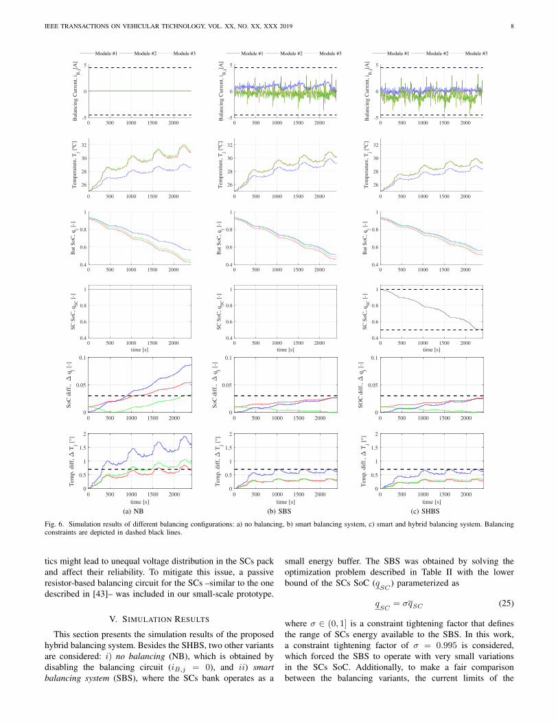
Fig. 6. Simulation results of different balancing configurations: a) no balancing, b) smart balancing system, c) smart and hybrid balancing system. Balancingconstraints are depicted in dashed black lines.
tics might lead to unequal voltage distribution in the SCs packand affect their reliability. To mitigate this issue, a passiveresistor-based balancing circuit for the SCs –similar to the onedescribed in [43]– was included in our small-scale prototype.
V. SIMULATION RESULTS
This section presents the simulation results of the proposedhybrid balancing system. Besides the SHBS, two other variantsare considered: i) no balancing (NB), which is obtained bydisabling the balancing circuit (iB,j = 0), and ii) smartbalancing system (SBS), where the SCs bank operates as a
small energy buffer. The SBS was obtained by solving theoptimization problem described in Table II with the lowerbound of the SCs SoC (q
SC) parameterized as
qSC
= σqSC (25)
where σ ∈ (0, 1] is a constraint tightening factor that definesthe range of SCs energy available to the SBS. In this work,a constraint tightening factor of σ = 0.995 is considered,which forced the SBS to operate with very small variationsin the SCs SoC. Additionally, to make a fair comparisonbetween the balancing variants, the current limits of the
IEEE TRANSACTIONS ON VEHICULAR TECHNOLOGY, VOL. XX, NO. XX, XXX 2019 9
8,5 9,1
8,1 8,5 7,9 7,2
8,5 7,8 7,1
0,0 0,0
2,6
0
2
4
6
8
10
NB SBS SHBS
RM
S c
urr
ent
[A]
Module #1 Module #2 Module #3 SC
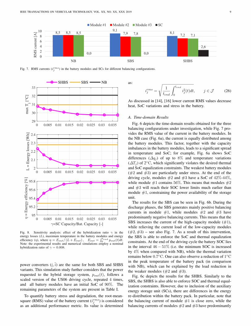
Fig. 7. RMS currents (irmsj ) in the battery modules and SCs for different balancing configurations.
0 0.005 0.01 0.015 0.02 0.025 0.03 0.03529
30
31
32
33
max
Tj [
°C]
0 0.005 0.01 0.015 0.02 0.025 0.03 0.0352
2.1
2.2
2.3
2.4
L =
Ener
gy l
oss
es [
Wh]
SHBS SBS NB
0 0.005 0.01 0.015 0.02 0.025 0.03 0.035
=SC Capacity/Bat. Capacity [-]
95
95.2
95.4
95.6
95.8
= E
ner
gy e
ffic
iency
[%
]
Fig. 8. Sensitivity analysis: effect of the hybridization ratio γ in theenergy losses (L), maximum temperature in the battery modules and energyefficiency (η), where η = Eout/ (L+ Eout) , Eout =
∫ tend0 pout(t)dt.
Note: the experimental results and numerical simulations employ a nominalhybridization ratio of γ = 0.008.
power converters (i, i) are the same for both SBS and SHBSvariants. This simulation study further considers that the powerrequested to the hybrid storage system, pout(t), follows ascaled version of the US06 driving cycle, repeated 4 times,and all battery modules have an initial SoC of 90%. Theremaining parameters of the system are present in Table I.
To quantify battery stress and degradation, the root-mean-square (RMS) value of the battery current (irms
j ) is consideredas an additional performance metric. Its value is determined
as:
irmsj =
√1
tend
∫ tend
0
i2j (t)dt, j ∈ J (26)
As discussed in [14], [16] lower current RMS values decreaseheat, SoC variations and stress in the battery.
A. Time-domain Results
Fig. 6 depicts the time-domain results obtained for the threebalancing configurations under investigation, while Fig. 7 pro-vides the RMS value of the current in the battery modules. Inthe NB case (Fig. 6a), the current is equally distributed amongthe battery modules. This factor, together with the capacityimbalances in the battery modules, leads to a significant spreadin temperature and SoC; for example, Fig. 6a shows SoCdifferences (∆qj) of up to 8% and temperature variations(∆Tj) of 2C, which significantly violates the desired thermaland SoC equalization constraints. The weakest battery modules(#2 and #3) are particularly under stress. At the end of thedriving cycle, modules #2 and #3 have a SoC of 42%-44%,while module #1 contains 56%. This means that modules #2and #3 will reach their SOC lower limits much earlier thanmodule #1, constraining the power availability of the storageunit.
The results for the SBS can be seen in Fig. 6b. During thedischarge phases, the SBS generates mainly positive balancingcurrents in module #1, while modules #2 and #3 havepredominantly negative balancing currents. This means that theSBS increases the current of the high-capacity module (#1),while relieving the current load of the low-capacity modules(#2,#3) – see also Fig. 7. As a result of this intervention,the SBS is able to enforce the SoC and thermal equalizationconstraints. At the end of the driving cycle the battery SOC liesin the interval 46− 51% (i.e. the minimum SOC is increasedby 4% when compared with NB), while the thermal variationremains below 0.7C. One can also observe a reduction of 1Cin the peak temperature of the battery pack (in comparisonwith NB), which can be explained by the load reduction inthe weaker modules (#2 and #3).
Fig. 6c depicts the results for the SHBS. Similarly to theSBS, the SHBS is also able to enforce SOC and thermal equal-ization constraints. However, due to inclusion of the auxiliaryenergy storage unit (SCs), there are differences in the energyre-distribution within the battery pack. In particular, note thatthe balancing current of module #1 is close zero, while thebalancing currents of modules #2 and #3 have predominantly
IEEE TRANSACTIONS ON VEHICULAR TECHNOLOGY, VOL. XX, NO. XX, XXX 2019 10
0 0.05 0.1 0.15 0.2 0.25 0.3 0.35 0.4
Lbal
= Balancing losses [Wh]
1.6
1.8
2
2.2
2.4
LB
at +
LS
C =
Bat
.+S
C l
oss
es [
Wh]
=0.0374
=0.0003
L=1.7 Wh
L=1.8 Wh
L=1.9 Wh
L=2.0 Wh
L=2.1 Wh
L=2.2 Wh
L=2.3 Wh
L=2.4 Wh
SHBS SBS NB
Fig. 9. Sensitivity analysis: effect of the hybridization ratio γ in the energystorage losses (Lbat +LSC ), balancing losses (Lbal) and overall losses (L).
negative currents. This means the SHBS exploits the auxiliaryenergy storage, the SCs, to decrease the current stress in thebattery modules (see Fig. 7). The current in module #1 is8.1 A rms (−4.7% than NB and −10% than SBS), whilemodule #2 and #3 have a current of 7.2 A rms (−15.2% thanNB and −8.8% than SBS). Additionally, the inclusion of theSCs contributes to a reduction in the maximum temperatureof the batteries: −1C in comparison with SBS and −2Cin comparison with NB. The SHBS also exhibits the highestbattery SoC at the end of the driving cycle. In particular,the SHBS’s minimum SoC is 2.5% higher than the SBS and6.5% higher than the NB, which has a positive impact on thevehicle’s range.
B. Sensitivity to SCs capacity
Let us now analyze in more detail the energy lossesand efficiency of the different balancing strategies. In thisanalysis we also consider the effect of the SCs capacity inthe energy performance; this variation is parameterized asQSC = γ
∑j∈J Qj , where γ > 0 represents a tunable
hybridization ratio of the energy storage system.The obtained results, depicted in Fig. 8, reveal that a mod-
erate increase in the hybridization ratio (γ ∈ [0.0003, 0.02])has a positive impact in the energy losses (L), maximumtemperature, and energy efficiency, improving the performanceof the SHBS over the baseline configurations SBS and NB.These positive impacts appear to saturate for higher values ofhybridization ratio, indicating that the maximum benefit of theSHBS configuration is obtained when γ ≈ 0.02. In comparisonwith the NB, the SHBS (γ = 0.02) is able to reduce the energylosses in 0.3 Wh (−13%), the maximum temperature in 2.5C(−7.8%), while the energy efficiency is increased in 0.76%.
Further insight into the SHBS performance limitations canbe obtained by inspecting the two main sources of losses:i) the energy storage losses (Lbat + LSC), and ii) balancinglosses (Lbal). Fig. 9 shows that higher hybridization ratios
6 8 10 12 14 16
Heat transfer coefficient, h [W/(K.m2)]
28
30
32
34
36
38
40
max
Tj [
°C]
SHBS SBS NB
Fig. 10. Impact of the heat transfer coefficient in the maximum temperatureof the battery modules.
contribute to a reduction in the energy storage losses; thiscan be justified by the greater usage of the SCs, which isthe most efficient energy storage unit (note that RSC Rj).However, the higher usage of SCs also raises the energy lossesin the balancing circuit, Lbal, which offsets the overall energygains and constraints the maximum benefits of the SHBS.This indicates that the SHBS indirectly transfers energy lossesfrom the battery pack into the balancing system, which mightfacilitate the cooling of the batteries.
C. Sensitivity to heat transfer coefficient
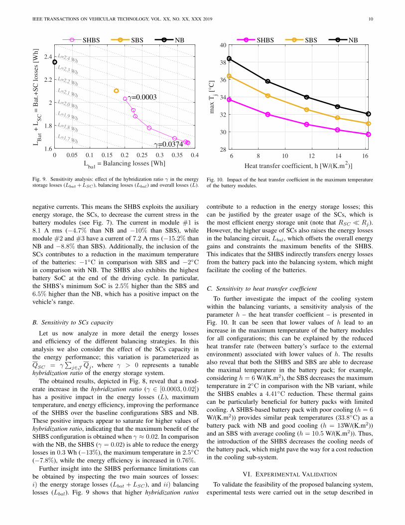
To further investigate the impact of the cooling systemwithin the balancing variants, a sensitivity analysis of theparameter h – the heat transfer coefficient – is presented inFig. 10. It can be seen that lower values of h lead to anincrease in the maximum temperature of the battery modulesfor all configurations; this can be explained by the reducedheat transfer rate (between battery’s surface to the externalenvironment) associated with lower values of h. The resultsalso reveal that both the SHBS and SBS are able to decreasethe maximal temperature in the battery pack; for example,considering h = 6 W/(K.m2), the SBS decreases the maximumtemperature in 2C in comparison with the NB variant, whilethe SHBS enables a 4.41C reduction. These thermal gainscan be particularly beneficial for battery packs with limitedcooling. A SHBS-based battery pack with poor cooling (h = 6W/(K.m2)) provides similar peak temperatures (33.8C) as abattery pack with NB and good cooling (h = 13W/(K.m2))and an SBS with average cooling (h = 10.5 W/(K.m2)). Thus,the introduction of the SHBS decreases the cooling needs ofthe battery pack, which might pave the way for a cost reductionin the cooling sub-system.
VI. EXPERIMENTAL VALIDATION
To validate the feasibility of the proposed balancing system,experimental tests were carried out in the setup described in

IEEE TRANSACTIONS ON VEHICULAR TECHNOLOGY, VOL. XX, NO. XX, XXX 2019 11
500 1000 1500 2000
0.2
0.4
0.6
0.8
Bat
So
C,
qj [
-]
500 1000 1500 2000
26
28
30
32
Tem
per
atu
re,
Tj [
ºC]
500 1000 1500 20000
0.02
0.04
0.06
0.08
0.1
So
C d
iff.
, q
j [-]
500 1000 1500 2000
time [s]
0
0.5
1
1.5
2
Tem
p.
dif
f.,
Tj [
°]
Module #1 Module #2 Module #3
500 1000 1500 2000
0.2
0.4
0.6
0.8
Bat
So
C,
qj [
-]
500 1000 1500 2000
26
28
30
32
Tem
per
atu
re,
Tj [
ºC]
500 1000 1500 20000
0.02
0.04
0.06
0.08
0.1
So
C d
iff.
, q
j [-]
500 1000 1500 2000
time [s]
0
0.5
1
1.5
2
Tem
p.
dif
f.,
Tj [
°]
Module #1 Module #2 Module #3
(a) NB (b) SHBS
Fig. 11. Experimental results: a) no balancing; b) smart and hybrid balancing system.
Section IV. These experiments use the same driving cycle asthe one employed in the previous section. Fig. 11 depicts theobtained experimental results for the SHBS and NB configura-tions. Overall, the experimental results are in accordance withthe numerical simulations. In the NB configuration, significantspread in SoC (up to 8%) and temperature (up to 1.8C) ofthe battery modules are observed. Battery modules #2 and#3 – the weaker modules with low-capacity and high innerresistance – suffer quicker discharge and higher temperatures.Conversely, the SHBS configuration (see Fig. 11b) is ableto successfully enforce the SoC and thermal constraints,staying below the 3% SoC difference and 0.7C temperaturedifference thresholds; the peak temperature in the batterypack is also reduced from 31.2C to 30.5C. These resultsdemonstrates the feasibility of the SHBS energy redistributionpolicy to compensate capacity and thermal imbalances withinthe battery pack.
Despite these encouraging results, there is one limitationworth mentioning: the optimal control policy of the SHBS
requires precise knowledge of the model parameters and dis-turbances. In the practical deployment of the control algorithmit might be difficult to fulfill this requirement. To mitigatethis limitation, future works should enhance the SHBS withfeedback control strategies (e.g. implement the optimal controlpolicy in a receding horizon fashion [44]). Furthermore, toimprove robustness of the optimal control policy against distur-bances, one might also need to relax the SoC and temperaturevariations constraints (3) into soft constraints.
VII. CONCLUSIONS & OUTLOOK
This work investigated the possibility to jointly balancebattery cells and perform hybridization of batteries with SCs.The proposed SHBS concept exploited the power convertersembedded in the balancing system to provide SoC/temperatureequalization and minimize the energy losses in the hybridstorage system. Pragmatic simplifications of the electric andthermal models were also employed, enabling the control of

IEEE TRANSACTIONS ON VEHICULAR TECHNOLOGY, VOL. XX, NO. XX, XXX 2019 12
the SHBS trough a numerically-efficient convex optimizationmethod. Simulation results showed that, in comparison withnon-hybrid balancing configurations, the SHBS is able to:• reduce the energy losses up to 13% and the maximum
temperature up to 7.8%, which has a positive impact onthe vehicle’s range and cooling needs
• decrease the current root-mean-square value in the batterycells up to 15%, reducing its stress and degradation
• diminish the SoC and temperature variations withinthe battery pack, attenuating the effect of the weakestcell/module
Experimental results, obtained with a small scale prototype,further demonstrated the effectiveness and feasibility of theSHBS concept.
Despite these promising results, one important questionremains open: are the SHBS advantages enough to offset itshigher costs, volume, weight and complexity? The authorsare optimistic about a positive answer to this question. Theaffordability and reliability of power electronics, necessary forthe implementation of the balancing system, is continuouslyincreasing. A new market for the second-life use of batteriesin grid-support applications is also emerging, which is furtherencouraging a careful management of the battery cells duringtheir first-life, within the electric vehicle. In our opinion, thesetrends will increase the competitiveness of the SHBS configu-rations in the near future, mitigating their higher initial costs.Nevertheless, further research is still needed to quantify cost-benefits of the SHBS, e.g. through techno-economic analysis.
Future works should also tackle online control schemesfor the SHBS. The convex optimization method employedin this work, despite providing unique optimal solutions,might require high computational effort, which complicatesits implementation in embedded control systems with limitedcomputational resources. To overcome this limitation, futureresearch should focus on the development of lightweightoptimization approaches, e.g. based on linear or quadraticoptimization problems. Furthermore, to demonstrate feasibilityof the SHBS for large battery packs, hardware-in-the-loop testsshould also be performed.
REFERENCES
[1] J. Barreras, D. Frost, and D. Howey, “Smart Balancing Systems: AnUltimate Solution to the Weakest Cell Problem?” IEEE VehicularTechnology Society Newsletter, 2018.
[2] J. Gallardo-Lozano, E. Romero-Cadaval, M. I. Milanes-Montero, andM. A. Guerrero-Martinez, “Battery equalization active methods,” Jour-nal of Power Sources, vol. 246, pp. 934–949, Jan. 2014.
[3] R. Gu, a. P. Malysz, M. Preindl, H. Yang, and A. Emadi, “Linearprogramming based design and analysis of battery pack balancingtopologies,” in IEEE Transportation Electrification Conference and Expo(ITEC), Jun. 2015, pp. 1–7.
[4] F. Altaf, B. Egardt, and L. J. Mardh, “Load Management of ModularBattery Using Model Predictive Control: Thermal and State-of-ChargeBalancing,” IEEE Transactions on Control Systems Technology, vol. 25,no. 1, pp. 47–62, Jan. 2017.
[5] J. V. Barreras, C. Pinto, R. d. Castro, E. Schaltz, S. J. Andreasen, andR. E. Araujo, “Multi-Objective Control of Balancing Systems for Li-Ion Battery Packs: A Paradigm Shift?” in 2014 IEEE Vehicle Powerand Propulsion Conference (VPPC), Oct. 2014, pp. 1–7.
[6] L. McCurlie, M. Preindl, and A. Emadi, “Fast Model Predictive Controlfor Redistributive Lithium-Ion Battery Balancing,” IEEE Transactionson Industrial Electronics, vol. 64, no. 2, pp. 1350–1357, Feb. 2017.
[7] D. F. Frost and D. A. Howey, “Completely Decentralized ActiveBalancing Battery Management System,” IEEE Transactions on PowerElectronics, vol. 33, no. 1, pp. 729–738, Jan. 2018.
[8] H. Rahimi-Eichi, U. Ojha, F. Baronti, and M.-Y. Chow, “Battery Man-agement System: An Overview of Its Application in the Smart Grid andElectric Vehicles,” IEEE Industrial Electronics Magazine, vol. 7, no. 2,pp. 4–16, Jun. 2013.
[9] M. Preindl, “A Battery Balancing Auxiliary Power Module With Pre-dictive Control for Electrified Transportation,” IEEE Transactions onIndustrial Electronics, vol. 65, no. 8, pp. 6552–6559, Aug. 2018.
[10] C. Karnjanapiboon, K. Jirasereeamornkul, and V. Monyakul, “Highefficiency battery management system for serially connected batterystring,” in IEEE International Symposium on Industrial Electronics.IEEE, 2009, pp. 1504–1509.
[11] C. Pinto, J. V. Barreras, E. Schaltz, and R. E. Araujo, “Evaluation ofAdvanced Control for Li-ion Battery Balancing Systems Using ConvexOptimization,” IEEE Transactions on Sustainable Energy, vol. 7, no. 4,pp. 1703–1717, Oct. 2016.
[12] A. Khaligh and Z. Li, “Battery, Ultracapacitor, Fuel Cell, and HybridEnergy Storage Systems for Electric, Hybrid Electric, Fuel Cell, andPlug-In Hybrid Electric Vehicles: State of the Art,” IEEE Transactionson Vehicular Technology, vol. 59, no. 6, pp. 2806–2814, Jul. 2010.
[13] S. Vazquez, S. M. Lukic, E. Galvan, L. G. Franquelo, and J. M. Carrasco,“Energy Storage Systems for Transport and Grid Applications,” IEEETransactions on Industrial Electronics, vol. 57, no. 12, pp. 3881–3895,Dec. 2010.
[14] B. H. Nguyen, R. German, J. P. F. Trovao, and A. Bouscayrol, “Real-Time Energy Management of Battery/Supercapacitor Electric VehiclesBased on an Adaptation of Pontryagin’s Minimum Principle,” IEEETransactions on Vehicular Technology, 2018.
[15] R. E. Araujo, R. de Castro, C. Pinto, P. Melo, and D. Freitas, “CombinedSizing and Energy Management in EVs With Batteries and Supercapac-itors,” IEEE Transactions on Vehicular Technology, vol. 63, no. 7, pp.3062–3076, Sep. 2014.
[16] J. P. F. Trovao, M. Roux, E. Menard, and M. R. Dubois, “Energy- andPower-Split Management of Dual Energy Storage System for a Three-Wheel Electric Vehicle,” IEEE Transactions on Vehicular Technology,vol. 66, no. 7, pp. 5540–5550, Jul. 2017.
[17] K. Alobeidli and V. Khadkikar, “A New Ultracapacitor State of ChargeControl Concept to Enhance Battery Lifespan of Dual Storage ElectricVehicles,” IEEE Transactions on Vehicular Technology, vol. 67, no. 11,pp. 10 470–10 481, Nov. 2018.
[18] A. Ostadi and M. Kazerani, “A Comparative Analysis of OptimalSizing of Battery-Only, Ultracapacitor-Only, and Battery–UltracapacitorHybrid Energy Storage Systems for a City Bus,” IEEE Transactions onVehicular Technology, vol. 64, no. 10, pp. 4449–4460, Oct. 2015.
[19] L. Zhang, X. Hu, Z. Wang, F. Sun, J. Deng, and D. G. Dorrell,“Multiobjective Optimal Sizing of Hybrid Energy Storage System forElectric Vehicles,” IEEE Transactions on Vehicular Technology, vol. 67,no. 2, pp. 1027–1035, Feb. 2018.
[20] J. Shen and A. Khaligh, “A Supervisory Energy Management ControlStrategy in a Battery/Ultracapacitor Hybrid Energy Storage System,”IEEE Transactions on Transportation Electrification, vol. 1, no. 3, pp.223–231, Oct. 2015.
[21] E. Martinez-Laserna, E. Sarasketa-Zabala, I. V. Sarria, D. Stroe,M. Swierczynski, A. Warnecke, J. Timmermans, S. Goutam, N. Omar,and P. Rodriguez, “Technical Viability of Battery Second Life: AStudy From the Ageing Perspective,” IEEE Transactions on IndustryApplications, vol. 54, no. 3, pp. 2703–2713, May 2018.
[22] H. H. Eldeeb, A. T. Elsayed, C. R. Lashway, and O. Mohammed,“Hybrid Energy Storage Sizing and Power Splitting Optimization forPlug-In Electric Vehicles,” IEEE Transactions on Industry Applications,vol. 55, no. 3, pp. 2252–2262, May 2019.
[23] Thorsten Grun, Anna Smithb, Helmut Ehrenbergb, and Martin Doppel-bauera, “Passive Hybrid Storage Systems: Influence of circuit and systemdesign on performance and lifetime,” in 12th International RenewableEnergy Storage Conference, 2018.
[24] F. M. Ibanez, A. M. B. Florez, S. Gutierrez, and J. M. Echeverrrıa,“Extending the Autonomy of a Battery for Electric Motorcycles,” IEEETransactions on Vehicular Technology, vol. 68, no. 4, pp. 3294–3305,Apr. 2019.
[25] A. Kuperman and I. Aharon, “Battery–ultracapacitor hybrids for pulsedcurrent loads: A review,” Renewable and Sustainable Energy Reviews,vol. 15, no. 2, pp. 981–992, Feb. 2011.
[26] Q. Zhang, W. Deng, and G. Li, “Stochastic Control of Predictive PowerManagement for Battery/Supercapacitor Hybrid Energy Storage Systems

IEEE TRANSACTIONS ON VEHICULAR TECHNOLOGY, VOL. XX, NO. XX, XXX 2019 13
of Electric Vehicles,” IEEE Transactions on Industrial Informatics,vol. 14, no. 7, pp. 3023–3030, Jul. 2018.
[27] N. Zhao, N. Schofield, R. Yang, and R. Gu, “Investigation of DC-LinkVoltage and Temperature Variations on EV Traction System Design,”IEEE Transactions on Industry Applications, vol. 53, no. 4, pp. 3707–3718, Jul. 2017.
[28] F. Baronti, G. Fantechi, R. Roncella, and R. Saletti, “High-EfficiencyDigitally Controlled Charge Equalizer for Series-Connected Cells Basedon Switching Converter and Super-Capacitor,” IEEE Transactions onIndustrial Informatics, vol. 9, no. 2, pp. 1139–1147, May 2013.
[29] Y. Ye and K. W. E. Cheng, “Modeling and Analysis of Series–ParallelSwitched-Capacitor Voltage Equalizer for Battery/SupercapacitorStrings,” IEEE Journal of Emerging and Selected Topics in PowerElectronics, vol. 3, no. 4, pp. 977–983, Dec. 2015.
[30] C.-C. Lin, H. Peng, J. W. Grizzle, and J.-M. Kang, “Power managementstrategy for a parallel hybrid electric truck,” IEEE Transactions onControl Systems Technology, vol. 11, no. 6, pp. 839–849, Nov. 2003.
[31] Ahmed Ali and Dirk Soffker, “Towards Optimal Power Managementof Hybrid Electric Vehicles in Real-Time: A Review on Methods,Challenges, and State-Of-The-Art Solutions,” Energies, vol. 11, no. 3,p. 476, Feb. 2018.
[32] S. Boyd and L. Vandenberghe, Convex optimization, 18th ed. Cam-bridge: Cambridge Univ. Press, 2015.
[33] M. Pourabdollah, B. Egardt, N. Murgovski, and A. Grauers, “ConvexOptimization Methods for Powertrain Sizing of Electrified Vehicles byUsing Different Levels of Modeling Details,” IEEE Transactions onVehicular Technology, vol. 67, no. 3, pp. 1881–1893, Mar. 2018.
[34] J. Platt, N. Moehle, J. D. Fox, and W. Dally, “Optimal Operation of aPlug-In Hybrid Vehicle,” IEEE Transactions on Vehicular Technology,vol. 67, no. 11, pp. 10 366–10 377, Nov. 2018.
[35] C. Pinto, R. de Castro, J. V. Barreras, R. E. Araujo, and D. Howey,“Smart Balancing Control of a Hybrid Energy Storage System based ona Cell-to-Cell Shared Energy Transfer Configuration,” in IEEE VehiclePower and Propulsion Conference, Chicago, USA, 2018.
[36] M. Preindl, C. Danielson, and F. Borrelli, “Performance evaluation ofbattery balancing hardware,” in European Control Conference (ECC),2013, pp. 4065–4070.
[37] J. V. Barreras, “Practical Methods in Li-ion Batteries: for simplifiedmodeling, battery electric vehicle design, battery management systemtesting and balancing system control,” PhD. Dissertation, University ofAalborg, 2017.
[38] C. Pinto, “Sizing and Energy Management of a Distributed Hybrid En-ergy Storage System for Electric Vehicles,” PhD. Dissertation, Universityof Porto, 2018.
[39] B. Egardt, N. Murgovski, M. Pourabdollah, and L. J. Mardh, “Elec-tromobility Studies Based on Convex Optimization: Design and ControlIssues Regarding Vehicle Electrification,” IEEE Control Systems, vol. 34,no. 2, pp. 32–49, Apr. 2014.
[40] M. Grant and S. Boyd, “CVX: Matlab software for disciplined convexprogramming, version 2.1,” 2018. [Online]. Available: http://cvxr.com/
[41] R. Tutuncu, K. Toh, and M. Todd, “Solving semidefinite-quadratic-linearprograms using SDPT3,” Mathematical Programming, vol. 95, pp. 189–217, 2013.
[42] H. Li, F. Z. Peng, and J. S. Lawler, “A natural ZVS medium-powerbidirectional DC-DC converter with minimum number of devices,” IEEETransactions on Industry Applications, vol. 39, no. 2, pp. 525–535, Mar.2003.
[43] D. Linzen, S. Buller, E. Karden, and R. W. D. Doncker, “Analysisand evaluation of charge-balancing circuits on performance, reliability,and lifetime of supercapacitor systems,” IEEE Transactions on IndustryApplications, vol. 41, no. 5, pp. 1135–1141, Sep. 2005.
[44] F. Borrelli, A. Bemporad, and M. Morari, Predictive control linear andhybrid systems. Cambridge University Press, 2017.
Ricardo de Castro (S’09, M’13, SM’19) was bornin Porto, Portugal, in 1983. He received the Licen-ciatura and Ph.D. degrees in electrical and comput-ers engineering from University of Porto, Portugal,in 2006 and 2013, respectively. During 2007-08, hewas an entrepreneur with the WeMoveU project,targeting the development of powertrain control so-lutions for light electric vehicles. Since 2013, hehas been with the German Aerospace Center (DLR),Institute of System Dynamics and Control (SR),where he is developing enabling technologies for
electric mobility and autonomous driving. His research interests includevehicle dynamics, tire-road friction estimation, trajectory control, torqueblending, platooning and battery-supercapacitor hybridization. Ricardo deCastro has been an expert evaluator for the European Union, Editor of IEEETransactions on Vehicular Technology and Associate Editor of IEEE Access.He is the author of three patents and more than 60 papers in internationaljournals, conferences and book chapters.
Claudio Pinto was born in Porto, Portugal. Hereceived the B.S. degree in electric engineering in2010, the M.S. degree in 2012 and the Ph.D. in 2017from University of Porto, Portugal. He is currentlya control engineer at Continental Engineering Ser-vices. His research interests are power electronics,electric vehicles, and energy management of hybridenergy storage systems.
Jorge Varela Barreras (M’14) received the M.Sc.degree in electrical engineering from the Universityof Vigo, Spain, in 2010, and the M.Sc. and Ph.D.degrees in power electronics and battery manage-ment systems from Aalborg University, Aalborg,Denmark, in 2009 and 2017. In 2010, he cofoundedan engineering consulting company. In 2011, hebecame a researcher at Aalborg University. FromJune 2016 to the end of 2018, he was a postdoctoralresearcher in battery management at the Universityof Oxford, Oxford, U.K. In 2019 he became a senior
battery researcher at Imperial College London, London, U.K. His researchinterests include e-mobility, lead acid, and lithium-ion battery electro-thermalmodelling, simulation, testing, monitoring, balancing, and management sys-tems. He is the joint chair of the IEEE UK and Ireland education societychapter, a fellow of the Faraday institution, a founder member of the Danishbattery society, and a member of the editorial board of ETransportation byElsevier, and Frontiers in Energy Research. He was a research member ofcommon room of Kellogg College, Oxford, and chairman of the Oxfordresearch staff society voice.
Rui Esteves Araujo (M’99) received the Elec-trical Engineering diploma, the M.Sc. and Ph.D.degrees from University of Porto, Porto, Portugal,in 1987, 1992, and 2001, respectively. From 1987 to1988, he was an Electrotechnical Engineer in ProjectDepartment, Adira Company, Porto, Portugal, andfrom 1988 to 1989, he was researcher with INESC,Porto, Portugal. Since 1989, he has been with theUniversity of Porto, where he is currently an As-sistant Professor with the Department of Electricaland Computer Engineering, Faculty of Engineering,
University of Porto. He is senior researcher in the INESC TEC, focusingon control theory and its industrial applications to motion control, electricvehicles and renewable energies.

IEEE TRANSACTIONS ON VEHICULAR TECHNOLOGY, VOL. XX, NO. XX, XXX 2019 14
David A. Howey (M’10–SM’17) received the B.A.and M.Eng. degrees from Cambridge University,Cambridge, U.K., in 2002, and the Ph.D. degreefrom Imperial College London, London, U.K., in2010. He is currently an Associate Professor in theDepartment of Engineering Science, University ofOxford, Oxford, U.K. His research interests focuson energy storage systems, including projects onmodel-based battery management, degradation, ther-mal management, and energy management for gridstorage.