smart car project - ccse.kfupm.edu.saakhayyat/files/coe485-132/final/smart.car... · gsm/gps and...
TRANSCRIPT

King Fahd University of Petroleum and Minerals
Computer Engineering Department
COE 485: Senior Design Project
Smart Car Project Report
Project Supervisor
Dr. Kamal Chenaoua
Project By
Mohammed Al-Shehri
200924950

Table of Contents
1. Introduction .................................................................................................................................. 6
2. Problem Statement ....................................................................................................................... 6
Negative Impacts ...................................................................................................................... 6
3. Project Specifications .................................................................................................................... 7
System Concept ........................................................................................................................ 8
4. Car Wirings Identification ............................................................................................................. 9
Ignition System Wirings ............................................................................................................ 9
Security System Wirings ......................................................................................................... 10
Door Locks Wirings ................................................................................................................. 10
Immobilizer Wirings ................................................................................................................ 11
Doors Status ............................................................................................................................ 11
Brakes Status .......................................................................................................................... 11
Horn Trigger ............................................................................................................................ 11
5. Hardware Engineering Design .................................................................................................... 12
Choosing Components ............................................................................................................ 12
Microcontroller ................................................................................................................. 12
Bluetooth Module ............................................................................................................ 13
GSM Modem ..................................................................................................................... 14
GPS Module ...................................................................................................................... 14
Relays ................................................................................................................................ 15
Engine Starting Hardware Design ........................................................................................... 16
Ignition Wirings Control .................................................................................................... 16
Car Security System .......................................................................................................... 17
Immobilizer System .......................................................................................................... 18
Car Control and Inputs Interfacing ......................................................................................... 20
Security System and Doors Lock Control .......................................................................... 20
Horn Control ..................................................................................................................... 20
Car Inputs (Ignition, Doors Status, Brake Pressed Status) ................................................ 21
Powering the system .............................................................................................................. 22
System Components ......................................................................................................... 22
Power system design ........................................................................................................ 23
GSM/GPS and Bluetooth Interfacing ...................................................................................... 25
Communication ................................................................................................................ 25
Bluetooth Module ............................................................................................................ 25
GSM/GPS Modem ............................................................................................................. 26
6. Microcontroller Software Engineering Design ........................................................................... 27
Code Sections Summary ......................................................................................................... 27
Use Case Diagram ................................................................................................................... 29
Communication Section .......................................................................................................... 30
Bluetooth Communication ............................................................................................... 30
SMS Communication ........................................................................................................ 32
Requests Processing Section .................................................................................................. 35
Engine Control Section............................................................................................................ 36
Powering accessories ON/OFF .......................................................................................... 38
Starting/Stopping Engine .................................................................................................. 39
Keep Engine Running without Key ................................................................................... 41
Engine Auto Shutdown ..................................................................................................... 42
Car Anti-Theft ................................................................................................................... 42
Design Violation Prevention ............................................................................................. 42
Car Interfacing and Control Section ........................................................................................ 43
Horn, doors lock & unlock, security arm & disarm ........................................................... 43
Panic Mode ....................................................................................................................... 44
Doors Auto Lock................................................................................................................ 45
User Interfacing ...................................................................................................................... 45
Memory System ...................................................................................................................... 46
Permanent Memory Storage ............................................................................................ 46
Constant Strings & Limited RAM ...................................................................................... 46
Global Positioning System (GPS) ............................................................................................. 48
Preparing the GPS engine ................................................................................................. 48
Getting a GPS fix ............................................................................................................... 48
Sending GPS Data to Clients ............................................................................................. 49
System Commands Summary ............................................................................................. 50
7. Android Software Engineering Design ........................................................................................ 51
Use Case Diagram ................................................................................................................... 51
Class Diagram .......................................................................................................................... 52
Application’s Permissions and Certificates ............................................................................. 54
Android Permissions ......................................................................................................... 54
Google Maps Certificate ................................................................................................... 54
Connectivity ............................................................................................................................ 55

Bluetooth Connectivity ..................................................................................................... 55
SMS Connectivity .............................................................................................................. 56
Cars Management ................................................................................................................... 57
Cars Data ........................................................................................................................... 57
Car Management Interface .............................................................................................. 57
Bluetooth Control ................................................................................................................... 59
Engine Control .................................................................................................................. 59
Car Locks Control .............................................................................................................. 60
Horn & Panic Control ........................................................................................................ 60
GPS Location ..................................................................................................................... 60
SMS Control ............................................................................................................................ 60
Engine Control, Car Locks, Horn and Panic Mode ............................................................ 60
GPS Location ..................................................................................................................... 60
8. Power Analysis ............................................................................................................................ 63
Prototype Power Consumption .............................................................................................. 63
Reducing power consumption ................................................................................................ 64
9. Universal Compatibility ............................................................................................................... 65
Cars with engine start button ................................................................................................. 65
10. Issues .......................................................................................................................................... 65
Development Issues ............................................................................................................ 65
11. Engineering Tools and Standards ............................................................................................... 66
12. Conclusion ................................................................................................................................... 66
List of Tables Table 1 Ignition wires connectivity in different switch modes .............................................................. 16 Table 2 Forwarding destination of the reply and broadcast functions ................................................. 35 Table 3 System external commands summary ...................................................................................... 50 Table 4 Summary for commands originated from the system .............................................................. 50 Table 5 Engine Control Commands available to the user per car status ............................................... 59 Table 6 System power consumption in different components modes ................................................. 63

List of Figures
Figure 1 Final concept for the system ..................................................................................................... 8 Figure 2 Location and extension of the security system control wirings .............................................. 10 Figure 3 Location and extension of the car locks control wirings ......................................................... 10 Figure 4 Arduino Mega 2560 board ....................................................................................................... 13 Figure 5 Bluetooth Module .................................................................................................................... 13 Figure 6 SIM908 development board .................................................................................................... 15 Figure 7 Automotive Relay rated at 40A 14V ........................................................................................ 15 Figure 8 Circuit for controlling one automotive relay from Arduino .................................................... 17 Figure 9 ‘Honda-SL3’ immobilizer bypasser by Fortin Electronics ........................................................ 19 Figure 10 Immobilizer bypasser connections to the microcontroller and the Accord .......................... 19 Figure 11 Circuit for sending ground pulses to external sources .......................................................... 20 Figure 12 Circuit Controlling Car Horn ................................................................................................... 21 Figure 13 Reading car input using voltage division circuit .................................................................... 22 Figure 14 7.5 Voltage regulation circuit using LM2596 ......................................................................... 24 Figure 15 Diagram illustrating the power design of the system ........................................................... 24 Figure 16 Voltage division circuit for 5v to 3.3v communication .......................................................... 25 Figure 17 Bluetooth module and the PINS used in Smart Car system .................................................. 26 Figure 18 Diagram of main Arduino code sections and their interrelations ......................................... 28 Figure 19 Use Case Diagram representing the main components of the microcontroller software .... 29 Figure 20 Activity diagram for the Bluetooth authorization use case ................................................... 31 Figure 21 Sequence Diagram showing the process of processing a user command ............................. 36 Figure 22 Activity Diagram for the method responsible for changing ignition mode ........................... 37 Figure 23 Activity diagram for 'Powering Accessories' use case ........................................................... 38 Figure 24 Activity diagram for 'Powering Accessories OFF'................................................................... 39 Figure 25 Activity diagram for the 'Start Engine' use case .................................................................... 40 Figure 26 Activity diagram for the 'Keep Engine Running' use case ..................................................... 41 Figure 27 Activity diagram for the ‘Unlock Car’ use case ...................................................................... 44 Figure 28 Activity diagram for the Lock Car use case ............................................................................ 44 Figure 29 Pattern for triggering the horn in panic mode ...................................................................... 44 Figure 30 Activity diagram for the 'Panic mode' use case ..................................................................... 45 Figure 31 Use case diagram for the Android software .......................................................................... 51 Figure 32 Class diagram for the Android application ............................................................................ 53 Figure 33 Asking the user before starting Bluetooth if needed ............................................................ 55 Figure 34 Connecting to the system ...................................................................................................... 55 Figure 35 Asking the user before sending SMS messages ..................................................................... 56 Figure 36 Car Managment Activity Snapshot ........................................................................................ 58 Figure 37 Pick Bluetooth Device Interface ............................................................................................ 58 Figure 38 Main interface at application start ........................................................................................ 58 Figure 39 Main interface snapshot when car engine is OFF .................................................................. 59 Figure 40 Main interface snapshot when car engine is ON ................................................................... 59 Figure 41 Snapshot for the main SMS control ....................................................................................... 61 Figure 42 Snapshot for SMS control with GPS data available ............................................................... 61 Figure 43 Remote GPS tracking with car in campus .............................................................................. 62 Figure 44 Nearby GPS tracking showing user location relative to car location ..................................... 62 Figure 45 Warning message reporting faulty relays .............................................................................. 62 Figure 46 Ammeter used for measuring system power consumption .................................................. 63

1. Introduction Remote starting the car is one of the great and important features that is missing from most
of the cars sold globally. Although some cars support the remote starting functionality, dealers usually limit such feature to cars sold in certain regions such as the US or to high-end models only. Additionally, manufacturers use short-range remote controllers, which limits the benefits of using the system. This project will help bring this important feature to almost all cars, either old or new, and will add many important features such as GPS tracking in the system, all without compromising the safety and security aspects.
2. Problem Statement The project should add the feature of remote starting the car to almost all cars that miss this
feature, and it is important to use long-range connections in order not to limit the usage of the system.
The ability to start the engine remotely is very useful in two conditions:
1. In extreme hot weather conditions, it is very convenient for drivers to start the car along with the air conditioner prior to getting out of the house and driving the car especially that the temperature inside the car is expected to be hotter than the hot outside temperature while it is parked. According to weather.com, the temperature of a car cabin can reach 59 Celsius if the outside temperature is 32 Celsius, an extra 27 Celsius degrees after parking the car for 90 minutes only.
2. Warming up the car in extreme cold weather conditions, which will save the time of drivers by letting the car warm before reaching it.
The other part of the system is GPS tracking. Such feature will be very useful in several situations such as:
1. If the car is stolen, the user can easily locate its location accurately 2. Locating a driver who needs help by giving access to relatives or trusted people 3. Locating the car after parking it in a large parking area
Negative Impacts There are negative impacts that may result from the usage of the remote starting system:
1. Users may start the engine much earlier than what they need. Leaving the engine running in idle mode for long periods consumes a lot of gas and affect the engine health negatively.
2. Leaving the engine running for long periods especially in idle mode can affect the environment and contribute negatively to the global warming issue. According to EDF (Environmental Defense Fund), one pound of carbon dioxide is released into air every 10 minutes of engine idling.
3. Having the car running in public without people inside may attract thieves to hijack the car. Although the system can be designed to prevent thieves from stealing the car, losses can happen during hijacks attempts such as windows glasses breakage.

The negative effect of idling engines can be limited by stopping the engine automatically if the driver does not reach the car within a certain time.
GPS tracking can have negative impacts as well, such as violating the privacy of other people by tracking their location in real time, especially if the driver is unaware of having such a system installed in the car if he is not the primary owner or if the car is rented.
3. Project Specifications The system must meet the following user requirements:
1. Ability to start the engine using mobile phone from long ranges. 2. Preventing thieves from stealing a car after remotely starting it 3. Locating the car location accurately from anywhere 4. The system must not interfere or disable the regular operation of starting the car
using the key.
The above user requirements can be translated into technical requirements as follows:
1. GSM modem will be used to communicate with the system from virtually anywhere in the world for performing the control functions as well as location tracking. GSM must not replace the short-range communication channel as GSM may have large latencies sometimes and the GSM network may fail at any time. Additionally, using the GSM network may require additional user costs that can be avoided in short ranges.
2. Bluetooth connection will be used as a short communication channel between mobile phones and the system
3. GPS module will be used for locating the car position through the GSM channel, and external antenna to the GPS should be used because the system will be installed in hidden locations in the car most of the times; signals in such locations are not strong enough to get a 3D GPS location.
4. The system should tap into all the required ignition wires and should minimize cutting wires or performing modifications. If doing modifications is necessary, the car should operate normally after doing all the required modifications in the absence of the system or in case of failure.
5. After remotely starting the car, the user should use the car original key to drive the car, otherwise the system should turn the engine off to prevent stealing the car.
6. An Android mobile application should be developed as a user interface to the system.

System Concept The final concept for the system can be pictured as shown in Figure 1.
Figure 1 Final concept for the system

4. Car Wirings Identification
Interfacing with the car requires identifying the location and color of several wires in the car.
Since the system will be prototyped and tested on a 2003 Honda Accord; this section will show the details of the wires identified in the 2003 Accord.
Ignition System Wirings These are the main wirings that will eventually be controlled using the high current relays.
Because they carry large current, they usually have large diameter compared to the other wirings which make them easier to locate.
Two methods helped in locating the ignition wires and verifying the identity of each wire. First, by reading the service manual of the car. This manual is intended to guide Honda dealers on how to identify the source of ignition problems, and the guide mentions the wiring colors of the ignition wires and their location. Second, by using a voltmeter and measuring the voltage of each wire relative to car ground in the different switch positions.
After tracking the wiring harness coming from the ignition switch under the steering column, the following ignition wires have been identified:
• White Wire:
This wire is directly connected to 12V battery. It’s used to provide battery power to the other wires when desired.
• White/Red Wire:
This wire powers the accessory part of the car such as the radio and DVD player when connected to 12V battery.
• Black/Yellow Wire:
This is the first main ignition wire that provides power to the several main components of the car when connected to 12V battery.
• Black/Red Wire:
This is the second ignition wire, it provides power to several secondary components of the car such as the heater and the AC when connected to 12V battery.
• Black/White Wire:
This is the starter wire that provides power to the starter motor while starting the car when connected to 12V battery.

Security System Wirings It’s necessary to find the wires that will give control of enabling and disabling the security
system of the car. This is needed to prevent the car and the original security system from starting the panic mode at the attempt of starting the engine remotely using our system.
After a deep search, the security system of the car is integrated in the door module of the driver side inside the door panel. Two wires were identified that can control the security system of the car. The white wire of the module disables the security system, while the white/red wire enables the system. Both are activated by sending a ground pulse.
Unfortunately, the two wires control the doors locks along with the security system. For example, disabling the security system unlocks all the doors of the car as well. No other wirings to disable or enable the security system without changing the doors lock position were found, which is not the case with several other car models. This could leave the doors of the car open after remotely starting it, but a workaround is to relock the doors after disabling the security system.
The two wires were tapped and extended to the under-dash panel of the car as shown in Figure 2.
Door Locks Wirings A way to control the doors locks without using the security system wirings is needed for two
reasons. First, to be able of relocking the doors after disabling the security system while remotely starting the car. Second, because the security system wirings do not respond to any pulses while the engine is running, while a user may want to lock or unlock the doors while it’s running from outside the car. Even the original car remote control do not work while the engine is running to lock or unlock the car, as most cars are not designed to have the engine running while the key and the driver are outside the car.
Again, it was not easy to find central wires that control all locks of the car except for two wires found in the module of the passenger side inside the door panel. The two wires control the locks of all doors without changing the security system status of the car.
These two wires were also tapped and extended to the under-dash panel of the car as shown in Figure 3.
Figure 2 Location and extension of the security system control wirings
Figure 3 Location and extension of the car locks control wirings

Immobilizer Wirings It is true that the car will not panic while remotely starting it after disabling the security
system of the car, but it will never start while the immobilizer system is working, also it cannot be disabled as the car computer will not allow fuel to flow to the engine without a confirmation from the immobilizer system. This system is almost present in all cars sold within 12 years from writing this report.
The car key has a built in RFID tag that is activated and read by an RFID loop near the key lock of the 2003 Accord. Other cars may have different designs. The data read from the key is sent to the immobilizer for verification. The data is sent on a blue/red wire near the key lock of the car under the steering column. Also, a security key sign lamp will flash at the instrument panel if the car was started without a key inserted in the key lock, a blue/orange wire powers the lamp of that sign. Details on how to bypass the immobilizer will be on the remote starting design section of the report.
Doors Status Some applications in the system will require a signal indicating the status of the doors of the
car –either open or closed-. The doors status can be identified per door by using the signal going to the lamp of every door which is activated when the door is open. Another simpler option is to find a central wire that outputs high when one of the doors is open. Such wire was identified in the Accord behind the fuse box near the kick panel which is not easy to reach. The wire color is green/red and it goes to one of the plugs their.
This wire was also tapped and extended to the under dash panel of the car.
Brakes Status A wire identifying the brakes status of the car which outputs high when the brakes are
pressed will be needed as well. This wire was easily found, it’s located just above the brakes pedal and it is originally responsible for powering the brake lamps behind the car. The wire color is white/black and it was tapped and extended to the under dash panel as well.
Horn Trigger The system may need to interact with the outside world using the car horn. To control the
horn of the car a wire with a yellow/green color was found. It’s located inside the steering column as expected. It was tapped and extended to the under dash panel as well.
Care must be taken while working with wirings near the steering column as some of them are responsible for activating the air bags.

5. Hardware Engineering Design Choosing Components
Performing this task started by analyzing the system technical requirements. The following major components needs to be purchased:
• Microcontroller • Bluetooth module • GSM modem • GPS module • Relays
There are several models from several companies for almost each of the components listed above, therefore, it was necessary to make a reasonable comparison on which model to buy and use for prototyping the system.
Microcontroller There are several candidates in the microcontroller section, they include PIC
microcontrollers, Arduino boards or even an FPGA chip, which is not considered a microcontroller.
The PIC microcontrollers are good for their cheap prices and the availability of huge models that vary according to the user needs. They seem like a right choice for final production with large quantities. However, for prototyping, their cost is not so cheap given the need for purchasing a development board or a programming board for programming the chips. Using PICs for prototyping has no justification over using an Arduino for example.
FPGAs are very powerful, however using a complete FPGA board for prototyping will be very costly, will take large space and doesn’t seem the right choice for final production as well. Additionally, although FPGAs are powerful, they don’t fit in this type of application where real time processing is not needed, and FPGA lack the availability of software libraries that will ease the process of development and integration with the system components.
Arduinos are the right choice for this type of applications; complete boards for prototyping are available with reasonable prices, also, the ATmega chips that are used with the Arduino are available with low prices for final production. Main advantages of the Arduino is its simple IDE that will ease the process of development, also the availability of huge range of software libraries that will accelerate developing the system and integrating its components.
The board that was chosen for prototyping is the MEGA2560 shown in Figure 4. It is based on the ATmega2560 chip and runs at 16 MHZ. It has four hardware UART interfaces, while the other models have only one UART interface which doesn’t fit the needs of this application. It also has all the needed features such as having 6 external interrupts among the 54 digital ports. It also has 16 analog inputs pins but only few of them will be used.

Figure 4 Arduino Mega 2560 board
The new Arduino Due board was an attractive candidate for the project. It is more powerful than the Mega board and runs at 84 MHZ, but it consumes more power during operation, which is a major disadvantage for our car application.
Bluetooth Module A wide range of Bluetooth modules was found and their prices vary a lot. Many of the
modules found that were part of ready development boards were limited in the pins offered. For this application, the module needs to support serial interface and must have pins available that indicate the connection status, and a pin to access the command mode to configure the module should be available.
Figure 5 Bluetooth Module
Five pieces of a cheap and very small module for prototyping that have all the requirements were purchased for ~17SR/module. One module will be used in this application. The module is shown in Figure 5.

GSM Modem The GSM modem is one of the important parts of the system. A good range of modems was
found. They vary a lot in prices as well as in features supported such as supporting 3G networks, quad or dual band GSM networks. The modem for this application must support sending and receiving text messages.
The Arduino GSM shield
The Arduino GSM shield was a very attractive board for prototyping especially that the Arduino community directly supports it, also libraries for easy and direct controlling of this modem were available. However, it was not chosen as the GSM modem for this application for the following reasons:
1. The version of this board that supports external antenna was not available at the time of purchasing.
2. The board is overpriced, offered at ~$100 3. It was not clear whether it is possible to put the modem into power saving modes to
save power.
The SIM900 modem
The SIM900 modem seems like the right choice as it supports all the application requirements. A wide range of boards that uses this modem was found, and they vary in prices and number of pins available to the user. The board chosen for prototyping is based on the SIM908 chip as shown in the GPS module section.
GPS Module GPS modules are one of the modules that are widely available. Similar to GSM modules, a lot
of options were evaluated before choosing the right components to purchase. They differ in power consumption as well as the number of satellites used.
The SIM908 modem The SIM908 modem packs all the GSM modem features of the previously mentioned SIM900
modem, but it is equipped with a GPS engine as well. What makes the SIM908 GPS special is that it uses A-GPS (Assisted GPS), a feature that is usually available in smartphones that uses the geographical location provided by the cellular network to accelerate the process of getting a 3D GPS fix. The modem also supports direct control of the GPS power system for power saving.

Figure 6 SIM908 development board
A board from a Chinese provider that uses the SIM908 chip was purchased for 96$. It has two antenna inputs for the GSM network and the GPS engine, and it is good for prototyping as it has an RS232 interface for PC debugging. The board is shown in Figure 6.
Relays
There are some ready to use relay boards in the market, however, they cannot be used in this application because all of them use relays that are rated for 10A DC or less. To control the ignitions wires of a car electronically, relays that can handle large current ~30-40A should be used. Relays that are marketed as automotive relays can handle such amounts of current. A pack of relays has been purchased for the purpose of controlling the ignition system of the car.
Figure 7 Automotive Relay rated at 40A 14V

Engine Starting Hardware Design This section will cover the design and integration of several components that are directly
related to starting the engine from a microcontroller.
Ignition Wirings Control The ignitions wires that were shown in the wires identification section before will be
controlled using high current rated relays, by measuring the voltage of each wire relative to ground in the different switch positions, the wires connect as shown in Table 1.
Table 1 Ignition wires connectivity in different switch modes
Wire
Mode
White/Red ACC
Black/Yellow IGN1
White 12V
Black/Red IGN2
Black/White Starter
OFF
ACC
ON
Start
The microcontroller must control the relays to connect all the ignition wires according to the connections shown in Table 1. The Atemga2560 uses 5v digital output with limited maximum current of 40mA which cannot drive the chosen relays. An external circuit driving the relays using the Arduino digital output can be designed by using a transistor allowing the 12v power source to pass through the relay coils when needed. A diode between the coils of the relay is needed as well to protect the transistor.
To calculate the needed current to drive the relay we need to measure the coils resistance of our relays. The multi-meter reads a value of 85ohms between the coils. Therefore, each relay needs a current of:
𝐼𝐼𝑐𝑐 =𝑉𝑉𝑅𝑅
=12𝑣𝑣
85𝑜𝑜ℎ𝑚𝑚𝑚𝑚= 141 𝑚𝑚𝑚𝑚
The 2N2222A transistor will be used in the circuit; it is available in the local market in cheap prices. Its maximum VCEO is 40v > 12v , and its maximum collector current is 600mA > 141mA.
From the datasheet of the 2N2222A, the transistor has an hFE (DC current gain) value of 100 at the conditions that are the closest to our application (10v , 150mA). Therefore, the resistance between the Arduino and the transistor can be calculated as the following:
𝑚𝑚𝐴𝐴𝐴𝐴𝐴𝐴𝐴𝐴𝐴𝐴𝑜𝑜 𝐴𝐴𝑛𝑛𝑛𝑛𝐴𝐴𝑛𝑛𝐴𝐴 𝑜𝑜𝐴𝐴𝑜𝑜𝑜𝑜𝐴𝐴𝑜𝑜 𝑐𝑐𝐴𝐴𝐴𝐴𝐴𝐴𝑛𝑛𝐴𝐴𝑜𝑜 = 𝐼𝐼𝑎𝑎 =𝐼𝐼𝑐𝑐ℎ𝐹𝐹𝐹𝐹
=141𝑚𝑚𝑚𝑚
100= 1.41 𝑚𝑚𝑚𝑚
𝑅𝑅𝑛𝑛𝑅𝑅𝐴𝐴𝐴𝐴𝐴𝐴𝑛𝑛𝐴𝐴 𝐴𝐴𝑛𝑛𝑚𝑚𝐴𝐴𝑚𝑚𝑜𝑜𝑟𝑟𝐴𝐴𝑐𝑐𝑛𝑛 <𝑉𝑉𝐼𝐼
=5𝑉𝑉
1.41𝑚𝑚𝑚𝑚= 3.5𝐾𝐾

Because the hFE value is not accurate, and to ensure that the relay will get enough current to drive it safely, a lower resistance of 1K will be used. Such resistance will only draw 5mA < 40mA from the Arduino digital output and the transistor will allow up to 0.5A > 0.14A to flow.
Note that driving the relays will be only when the engine is running or about to start which will not affect the battery life of the car and the power consumption of the system negatively.
Figure 8 shows the final circuit for controlling one relay, the relay is represented by its coils resistance of 85 ohms. The other three ignition relays will use identical circuits.
Figure 8 Circuit for controlling one automotive relay from Arduino
Software can activate the four relays according to the connections shown in Table 1 for each mode. The normally closed connection terminal of each relay will have no connection. The other two terminals will connect the white 12v wire to the other desired wire for each relay (ACC, IGN1, IGN2 and STARTER)
Car Security System
The security system will panic during the attempt of connecting the ignition wires while it is active. The first thing to do before setting the ignition to the ON mode is to disarm the security system by sending a ground pulse to the disarm wire.
As noted before, sending such signal and disabling the security system will also unlock all the doors of the car in some car designs, which is not desired. In such cases, it is necessary to relock the wires of the car by sending a ground signal to the central lock wire.
More on how to interface with the security system is on the car interfacing section of the report.

Immobilizer System
The immobilizer system is used to prevent thieves from hot wiring and starting the car, which is very close to what our system does. The Blue/Red wire mentioned in the wirings section of this report carries the data read from the key to the immobilizer system for verification. A method to bypass the system is needed in order to have a usable remote starting system. Several methods can be used to achieve this goal:
a. Placing a copy of the key near the key lock.
In this method, any user installing the remote starting system should make a copy of his key (The chip inside the key is enough) and place it near the key lock of the car. Whenever the system tries to remote start the car, the immobilizer will read the data from the copied key and will send its confirmation to the car ECU allowing fuel to flow to the engine.
This method has one major drawback, which is disabling the immobilizer functionality. Hot wiring the car will become easy and the immobilizer will allow any attempt to steal and start the car.
b. Designing the system to regenerate the signal
It is possible to design the system so it learns the data sent on the wire while starting the car using the key, and then regenerate the data on the same wire whenever the system tries to remote starting the car.
The only problem with this method is that it is very hard to design the system to work with all car models. Such solution will make the system limited to certain car models. For example, designing the system while prototyping on the Honda Accord will make the system work on that car and similar Honda cars. This solution violates the goal of making the system universal for all car models.
c. Immobilizer bypassing modules
The other solution is to use the bypassing modules available in the market. Its concept is very close to the concept described above which is regenerating the signal on the data wire. The bypassing modules are provided by specialized companies such as ‘Fortin Electronic Systems’. Bypassing modules for almost all car types have been designed and are available in the market.
The solution of using a bypasser module fits our application especially while prototyping. In terms of security, the bypassing module will be controlled from the microcontroller and it will be enabled only while remote starting the car. Additionally, no need to get involved with the different car immobilizer designs, the system will control the bypasser without the need of knowing which car model it is controlling.

For prototyping on the Accord. The ‘HONDA-SL3’ bypasser by Fortin Electronics is used.
The bypasser must be programmed to learn the code of the car key. Instructions on how to program each bypasser is available on the manual of each bypasser model per car.
Bypasser Connections In addition to the power inputs and the ignition signal, the bypasser will tap into the data
line to output the key data signal while remotely starting, and will also act as a bridge cutting the signal from the security lamp if the car is started without the key. The security lamp has no effect on the remote starting procedure after enabling the bypasser, but it will show a flashing lamp in the car instrument panel, which can affect the user experience, therefore it is recommended to cut that signal whenever the car is started remotely until it is stopped.
Figure 10 shows the connections of the bypasser to the car and to the microcontroller. If a bypasser from a different company is used, the connections may slightly vary and the wiring colors coming from the bypasser may not be the same.
Figure 10 Immobilizer bypasser connections to the microcontroller and the Accord
Figure 9 ‘Honda-SL3’ immobilizer bypasser by Fortin Electronics

Car Control and Inputs Interfacing Security System and Doors Lock Control
The four wires responsible for arming and disarming the security system and for locking and unlocking the car wires is triggered by sending a ground pulse.
To send ground pulses to any wire, a transistor connecting the wire to ground with its gate connected to the Arduino digital output is used as shown in Figure 11.
Figure 11 Circuit for sending ground pulses to external sources
The software part takes care of activating the transistor for only a short period to send a ground pulse to the desired wire.
Horn Control Controlling the horn of the car or any similar component that is activated by a ground signal
depends on the current drawn from that component. In the prototyped Accord, connecting the horn wire to ground using an Ammeter showed that only ~60mA is drawn from that wire. This indicates that the wire is not directly connected to the horn ground, because horns are known to use much larger amount of current. The wire is probably connected to a relay in the car.
The horn can be simply activated using the Arduino by connecting the wire to ground through a transistor only as shown in Figure 12. Please note that if the horn wire was directly connected to the horn ground, then a high power relay must be used.
Car wires to be pulsed
- Security Arm, Disarm - Doors lock, unlock

Figure 12 Circuit Controlling Car Horn
Car Inputs (Ignition, Doors Status, Brake Pressed Status) The system needs to read several inputs from the car for proper and interactive operation.
Some of the inputs have values that are either HIGH or LOW, such as the input coming from the ‘Doors Status’ wire. Other inputs such as the ‘Ignition’ and the ‘Brake’ wires are actually power wires, and they are either HIGH or floating (Z).
A voltage division circuit can be used to step down the voltage of the car input to the Arduino 5v input. This method is currently used in the prototype because of its simplicity.
The input source will go through a series of two resistors to the ground. The Arduino input will tap between the two resistors to read its lower voltage value. The current drawn from the input source will depend on the summation of the two resistors, while the amount of voltage drop will depend on the ratio between the two resistors.
The ratio of the two resistors should be selected based on several factors. First, the maximum input voltage coming from the car input. Second, the divided output should be high enough for the microcontroller when the input is at its nominal voltage.
For example, the usage of the two resistors 10K and 22K will have the following characteristics:
Division output = 1010+22
𝑣𝑣 = 0.3125𝑣𝑣
Given that Atmega2560 maximum input voltage = vcc + 0.5 = 5.5 volts
Car maximum input = 5.50.3125
= 17.6 𝑣𝑣𝑜𝑜𝑣𝑣𝑜𝑜𝑚𝑚
Division output at nominal car voltages
12v (Engine OFF) 3.75 volts 14v (Engine ON) 4.375 volts
Both values of 3.75 and 4.375 will be read as HIGH by the Arduino, given that the Atmega2560 VIH = 0.7vcc = 3.5 volts

The maximum voltage input can be increased if the Arduino analog inputs will be used instead of the digital ones, because the system will be able to detect lower voltages when the car inputs are at its nominal values. For example, if two resistors of value 10K and 33K are used:
Division output = 1010+33
𝑣𝑣 = 0.2326𝑣𝑣
Car maximum input = 5.50.3125
= 23.65 𝑣𝑣𝑜𝑜𝑣𝑣𝑜𝑜𝑚𝑚
Division output at nominal car voltages
12v (Engine OFF) 2.79 volts 14v (Engine ON) 3.26 volts
Note that the voltage division circuit will also pull the floating inputs to ground which is desired. Circuit shown in Figure 13.
Another method to step the inputs voltage down is by using opto-isolators. For final production, this method is recommended due to the fact that some car electrical environments are noisy and their electrical systems may generate high voltage sparks that will harm the system and the microcontroller. The opto-isolator will ensure that the car inputs are completely isolated from the system.
Powering the system If the car engine is off, the car battery is stable at voltages near 12v. However, if the car
engine is running, the car electrical system is noisy and the alternator produces a voltage near 14.5v. Clearly -in both situations-, our system needs power-regulating circuits to power the components of the system.
System Components The main components of the system that needs power are:
The Microcontroller The microcontroller in the current system runs at 5V. The Arduino 2560 board that is used in
prototyping is already equipped with an NCP1117ST50T3G voltage regulator. This regulator has a maximum voltage input of 20V, however the Arduino specifications recommends not exceeding an input voltage of 12v for overheating reasons. The microcontroller can also be powered directly using
Car Input
Arduino Input
Digital/Analog
Figure 13 Reading car input using voltage division circuit

an external 5V regulated source. The Arduino board has an additional lP2985 regulator that outputs 3.3v. It can provide current up to 150mA but the Arduino website specifies a maximum allowed current of 50mA.
The GSM/GPS module According to the datasheet of the SIM908, the board runs at 3.2-4.8 volts.
The board that is used in this prototype is equipped with two voltage regulators. First, the LM2576S voltage regulator. It has a wide range of allowed input voltage up to 40V and it can handle up to 3A of current. The second regulator is the adjustable LM2576-ADJ regulator. It was adjusted to provide a voltage of 4.08 volts to the SIM908 board. This regulator is also capable of handling current up to 3 amps with a max voltage of 40V.
The Bluetooth Chip The Bluetooth module runs at regulated 3.3v
Power system design It was decided to power the Arduino using an external regulated 5V instead of using the built
in regulator for several reasons. First, the maximum absolute rating of 20V for the on board NCP1117ST50T3G regulator makes it a non appropriate choice for a car application. Second, according to the Arduino website, and by experience, the regulator gets hot easily while operating at voltage around 15v. Third, it was noticed that the power consumption increases when the Arduino is powered using the on board regulator while measuring current consumption from the power source.
The first design was connecting the power source to the two LM2576 regulators that are built on the GSM/GPS board. This powers the SIM908 chip with 4.08V. Additionally, the other regulator produces clean 5.0v that is used to power the Atmega chip directly while bypassing the Arduino on board regulator. This design works correctly except for the fact that the regulators get very hot. Current drawn from all the regulators is small as shown in the power section, so it is not the source of heat dissipation. The reason is the voltage drop which is considered to be large, for example when the engine is running, one of the regulators will drop the car voltage from 14.5 to 4.08volts for the SIM908 chip. Installing heat sinks can help in minimizing the effects of over heat.
The final design was done by using two levels of regulations. An adjustable LM2596 regulator was used, it can accept voltage inputs up to 40V and can handle current up to 3A. This regulator is the first level of regulation, taking input from the car power source and producing 7.5volts. Then the adjustable LM2576 will use this 7.5v to produce the 4.08v required to power the SIM908 chip. Additionally, the 5v version of the LM2576 will produce clean 5v that will be used to power the Arduino board while bypassing the Arduino on board regulator. Although the on board Arduino regulator NCP1117ST50T3G is bypassed, the lP2985 regulator will keep operating as it uses the clean 5v source to produce 3.3v, it will be used to power the Bluetooth chip since it uses a maximum power of 50mA.
The datasheet of the LM2596 shows the steps of building the circuit and configuring the regulator to the desired output. For example, the desired output voltage can be selected by choosing the corresponding resistors according to the following equation:

𝑉𝑉𝑜𝑜𝑜𝑜𝑜𝑜 = 𝑉𝑉𝑅𝑅𝐹𝐹𝐹𝐹 ∗ �1 +𝑅𝑅2𝑅𝑅1� = 1.23 ∗ �1 +
𝑅𝑅2𝑅𝑅1�
The value of R1 should be between 240 Ω and 1.5K Ω. For an output of 7.5v, the choice of resistors can be 1K and 6.1K. Figure 14 shows the regulation circuit used, note that the feed forward capacitor (CFF) is not shown as it is not needed in applications with output less than approximately 10V.
Figure 14 7.5 Voltage regulation circuit using LM2596
The diagram in Figure 15 illustrates the final power design of the system.
Figure 15 Diagram illustrating the power design of the system

GSM/GPS and Bluetooth Interfacing Communication
The GSM/GPS module (SIM908) and the Bluetooth module (HC-05) both uses UART as a communication channel. However, they both operate at 3.3v while the Arduino in the current system is operating at 5.0v. The modules may get damaged from the Arduino voltage of 5 volts.
The issue of voltage difference is actually in one direction, the Arduino can detect 3.3 signals coming from the modules as a HIGH signals without problems. However, the problem relies in the other direction. There are two possible solutions to the issue:
• Logic Conversion Chips There are several chips that take care of doing the voltage logic conversion. They differ in speed as well as supported voltages.
• Voltage Division Circuit The problem can also be easily solved using simple voltage division circuit on the data lines. This will work especially if the data rate required is not very high. Figure 16 shows the circuit for UART communication between the 5.0v Arduino and a 3.3v device using voltage division. A choice of two resistors where R2= 2R1 will give an output of 3.333v from the Arduino TX line where: 𝑉𝑉𝑜𝑜𝑜𝑜𝑜𝑜 = 2𝑅𝑅1
2𝑅𝑅1+𝑅𝑅1∗ 𝑉𝑉𝐴𝐴𝐴𝐴 = 2
3∗ 5 = 3.333 𝑣𝑣𝑜𝑜𝑣𝑣𝑜𝑜𝑚𝑚
Figure 16 Voltage division circuit for 5v to 3.3v communication
Bluetooth Module The Bluetooth modules vary in terms of connection mode per model. The model HC-05 used
in this application supports slave and master modes. Other models such as the HC-06 support one of the two modes based on the firmware of the chip.
This application will use the slave mode where the system will receive connections from the Android phone or any other master device. The HC-05 model is configured as a slave device by default and the connection mode can be changed if necessary.

The Bluetooth module by default will send all the data received by Bluetooth to the TX line to the microcontroller and will also send all the data on the RX line to the Bluetooth connected device. This is enough for simple applications.
In the smart car system, it is important to know the connection status of the module for several reasons such as power saving and authentication issues. One pin in the chip can provide a signal indicating the connection status of the module. The actual purpose of the pin is to power an LED indicating the connection status, but clearly, the Arduino can use this signal as a digital input directly. Again, the HIGH output of the pin is 3.3v which will be read as HIGH by the Arduino 5v System.
Another important pin is the KEY pin. When this pin is pulled to low, the Bluetooth module will transfer the data between the Bluetooth node and the microcontroller as described before. However, pulling this pin HIGH will let the Bluetooth module enter the AT command mode where it’s possible to configure the chip such as changing its broadcasting name or PIN number.
Figure 17 Bluetooth module and the PINS used in Smart Car system
GSM/GPS Modem Beside the power and GND lines, only the UART lines are needed for interfacing with the
modem. All the functions, including GSM and GPS functions, can be done by AT commands to the SIM908 module. The modem does provide a dedicate UART interface for GPS data, but GPS can be controlled and its data can be obtained using the original UART interface.
Additionally, two separate antennas were used to ensure having a good GPS as well as GSM signal in all locations. By experience, the GSM reception is good enough without the antenna in some locations but the antenna ensures a very good reception. However, a GPS signal will never fix a position without an antenna even in clear sight.

6. Microcontroller Software Engineering Design The software of the microcontroller represents the heart of the system. It is the component
responsible for performing all the actions related to engine starting, control, security, communication and GPS tracking in a smart way.
Code Sections Summary During the software development of the microcontroller. The software code was divided
into several categories based on functionality and the interacting components. The main sections in summary are:
• Global Section This section includes the global variables that are used by most other sections such as the Microcontroller pins definitions.
• Communication Section This section contains the code of interfacing and communicating with the Bluetooth module, GSM and GPS modem. The communication section was also divided into subsections based on the interacting components. Other sections that need access to the communication channels use methods from this section.
• Request Processing Section This section contains the code responsible for processing users requests despite of its source, it represents the interface between the communication section and the control sections of the system.
• Arduino Main Section The code in this section contains the Microcontroller setup and loop functions. Inputs that needs to be checked periodically and time based actions take place in this section.
• User Interfacing Section Code for interfacing with external components such as LEDS or buzzers come here.
• Car Interfacing and Control Section Direct interaction with the car systems for controlling or reading inputs take place in this section for non-engine related components. Examples are sending pulse signals to the central lock of the car and reading the car brakes status.
• Engine Control Section This section contains the code that is directly related to engine controlling, such as controlling the ignition mode and the bypasser status.
Figure 18 shows a diagram representing the main sections and their interrelations in a class diagram manner.

Figure 18 Diagram of main Arduino code sections and their interrelations

Use Case Diagram Figure 19 shows a UML use case diagram representing the Main components of the software
part of the Microcontroller. Actors on the system are the Bluetooth User, SMS Command, Car Driver and a potential thieve as well as time based actors. Additionally, when a Bluetooth client is connected to the system, the system will keep reading the GPS location data and sending it to the user periodically, such time action is shown as an actor as well.
Figure 19 Use Case Diagram representing the main components of the microcontroller software

Communication Section Bluetooth Communication
Bluetooth is the communication channel that will provide complete functionality and interactive control with the system for Bluetooth clients such as mobile phone users. Therefore, it important that the system is reliable and secure.
Bluetooth Communication Format The format for communication between the system and Bluetooth clients was designed as
the following:
Header (4) Command (5) Optional Arguments (?) Trailer (1) BGN> XXXXX ? <CR>
• Header:
Fixed 4 bytes “BGN>” indicating the beginning of a message
• Command:
5 bytes indicating the command type
• Optional Arguments:
Variable size field for optional arguments based on the command type
• Trailer:
1 byte consisting of Carriage Return character indicating message completion
For example, a Bluetooth client can send a command requesting starting the engine by filling the command field with ‘ENGST’ and the optional argument with one byte ‘1’ indicating that the system should lock the car doors as well, as the following:
BGN>ENGST1<CR>
The header and trailer helps the system identify messages and extract them even if they are followed or preceded by an unexpected flow of characters.
Please note that throughout the report, the header and trailer of any message will not be shown intentionally in any communication example because they are fixed.
Bluetooth Authorization Upon the connectivity of any Bluetooth client, the system will immediately send a welcome
message “WELCM” indicating a successful connection with the system.
Any Bluetooth client must send an authorization request to the system before sending any command to the system. All commands will be automatically dropped by the system if a Bluetooth client did not authorize with the system.

To authorize with the system, the client needs to send an authorization command “AUTHR” followed by a 10 byte system device ID. For example, this command is used to authorize with a system of device ID equal to “1xW%3@100-“:
AUTHR1xW%3@100-
Upon receiving the authorization request, if the system accepts the device ID, it will change the internal state for the Bluetooth client to be authorised and will send an authorization acknowledgment “AUTHS”, the system will immediately send the current car status as well. Otherwise, the system will refuse the request and send an authorization failure reply “AUTHF”.
Figure 20 shows the activity diagram for the Bluetooth authorization use case.
Figure 20 Activity diagram for the Bluetooth authorization use case
If the Bluetooth device disconnected from the system, the internal state of Bluetooth authorization is reset before another Bluetooth client connects to the system.

SMS Communication SMS communication is the channel used for long range connectivity, due to the additional
costs that are usually carried by GSM operators in both directions of communication (between system and mobile device), the system will provide most of the control functions over this channel but in a limited way. Compared to Bluetooth communication channel, if the car status change due to an SMS, Bluetooth or driver interaction, the new car status will be reported immediately to the connected Bluetooth client. For SMS, and unlike the Bluetooth design, the system will only send the car status to the user phone through SMS but only when the user request it, or when there is a special case such as someone stealing the car.
Authorization Given the characteristics of SMS communication, its cost and speed, the authorization
between the system and mobile clients should be part of each message sent. This is illustrated in the message format below.
SMS Message Format for Receiving Commands Every message sent to the system should have the following format:
The message doesn’t need header and trailers similar to the Bluetooth design message format, because reliable transfer in the SMS case and receiving the message in one piece is the responsibility of the GSM modem and the GSM network.
• Header:
Fixed 9 bytes, the purpose of the header here is to easily identify messages that are directed to the Smart Car system, and to easily filter messages that are coming from other sources such as advertisement messages that are usually sent over the GSM network.
• Device ID:
10 bytes containing the device ID of the controlled Smart Car system. Device ID and authorization is sent along every command sent to the system using SMS.
• Command:
5 bytes indicating the command type
• Optional Arguments:
Variable size field for optional arguments based on the command type
Note that the command and the optional arguments fields are the same as the fields in the Bluetooth message format to facilitate the process of development.
Header (9) Device ID (10) Command (5) Optional Arguments (?) SmartCar: XXXXXXXXXX XXXXX ?
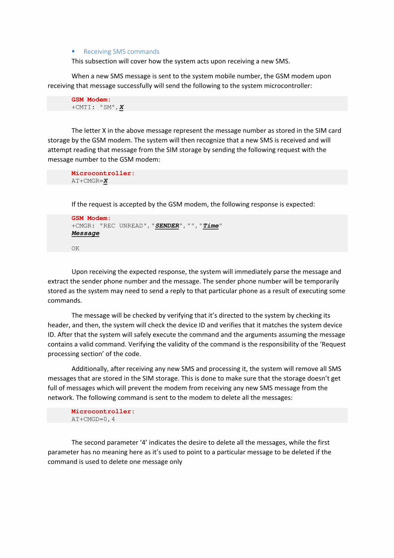
Receiving SMS commands This subsection will cover how the system acts upon receiving a new SMS.
When a new SMS message is sent to the system mobile number, the GSM modem upon receiving that message successfully will send the following to the system microcontroller:
GSM Modem: +CMTI: "SM",X
The letter X in the above message represent the message number as stored in the SIM card storage by the GSM modem. The system will then recognize that a new SMS is received and will attempt reading that message from the SIM storage by sending the following request with the message number to the GSM modem:
Microcontroller: AT+CMGR=X
If the request is accepted by the GSM modem, the following response is expected:
GSM Modem: +CMGR: "REC UNREAD","SENDER","","Time" Message OK
Upon receiving the expected response, the system will immediately parse the message and extract the sender phone number and the message. The sender phone number will be temporarily stored as the system may need to send a reply to that particular phone as a result of executing some commands.
The message will be checked by verifying that it’s directed to the system by checking its header, and then, the system will check the device ID and verifies that it matches the system device ID. After that the system will safely execute the command and the arguments assuming the message contains a valid command. Verifying the validity of the command is the responsibility of the ‘Request processing section’ of the code.
Additionally, after receiving any new SMS and processing it, the system will remove all SMS messages that are stored in the SIM storage. This is done to make sure that the storage doesn’t get full of messages which will prevent the modem from receiving any new SMS message from the network. The following command is sent to the modem to delete all the messages:
Microcontroller: AT+CMGD=0,4
The second parameter ‘4’ indicates the desire to delete all the messages, while the first parameter has no meaning here as it’s used to point to a particular message to be deleted if the command is used to delete one message only

Format and Destination for SMS messages sent from the system SMS messages sent from the system to the user mobile phone fall into two categories:
Human Readable Messages In some cases the system will send alarm messages to the user such as notifying him of a theft attempts. This messages are sent in plain human readable text. The destination of this type of messages is the master phone number that is stored in the system.
Data messages Those messages are directed to a client application running on the user mobile phone, this type of messages will have the following format:
This format is similar to the format of receiving SMS commands except that it does not have the device ID as it is not needed. If the client application is controlling more than one car system, the client can identify the system sending the message using the sender (system) mobile number. The destination for this type of messages is the phone number of the mobile that originated the SMS command to the system.
Sending SMS replies This section will cover how the system send SMS replies to mobile clients.
The destination of the SMS message is discussed in the previous subsection. To send an SMS command, the first step is to send a request to the GSM modem and then follow it by the message text:
Microcontroller: AT+CMGS=”PHONE NUMBER” MESSAGE <Ctrl+Z>
Please note that there should be a small time delay of at least 500ms after sending the AT+CMGS command and before writing the message text. This was observed by experience, because the modem needs this time delay to be ready and it doesn’t send any text after receiving the AT+CMGS command indicating that it is ready to receive the message text.
The <CTRL+Z> is the substitute character that has an ASCII code of 26.
Header (9) Command (5) Optional Arguments (?) SmartCar: XXXXX ?

Requests Processing Section This part of the Microcontroller code represent the bridge between the communication part
and the other parts of the system.
When a Bluetooth command is received, the Bluetooth communication section is responsible for extracting that command out of the communication stream and giving it to the request processing section. This applies to SMS commands as well.
This segment of the code will execute the command despite of its source, this makes development much easier and helps in avoiding safety violations in the system design while interfacing with the control sections of the system.
The only difference when executing commands that are originated from different sources is when the system wants to send a reply to the client that issued the command in the first place. The following should be taken into consideration:
The reply should go to the correct communication channel Some replies should not be sent to some communication channels. For example,
when the system receives an engine start command from a Bluetooth client it will send an acknowledgment to that client that the command was received. The system will send another confirmation after starting the engine successfully. However, an SMS client is only interested in that final confirmation message but not the first acknowledgment.
To achieve this, a separate reply function was written so that it supports directing the message to the appropriate communication channel, and it has a priority argument that control whether the message should be sent to an SMS client or not. Also, the function supports broadcasting that sends the message to multiple communication channels based on the priority value.
Table 2 summarizes the possible scenarios for a reply message:
Table 2 Forwarding destination of the reply and broadcast functions
Command Source Broadcast Reply Priority Forwarding Destination Bluetooth - Anything Bluetooth SMS - Low - SMS - High SMS Bluetooth Yes Low Bluetooth Bluetooth Yes High Bluetooth, SMS SMS Yes Anything Bluetooth, SMS
In the meantime, the system only supports Bluetooth and SMS controlling, but the current design of the request processing section of the system makes adding and integrating any new communication channel such as the Internet very easy. Figure 21 shows a sequence diagram for the system main sections while processing and executing an external user command.

Engine Control Section This section will cover the use cases and methods that are part of the Engine Control Section
code segment.
The method setIgnition(int) is responsible for changing the ignition mode of the car to the four possible modes which are: OFF, ACC, ON and Start. The ignition modes will be controlled using the four relays as shown previously in Table 1. This method will be used by several other methods such as the StartEngine() method.
In addition to controlling the ignition of the car, it is important to pay attention to the case where the user started the engine remotely, then stopped the engine control by the system while using the key to operate the car. In this case, it is important that the system does not turn off the bypasser until the car engine is completely stopped despite the scenario of how that would happen. Violating this and turning the bypasser off while the engine is running will show the key lamp to the driver in the instrument panel of the Accord. In cars other than the Accord 2003, this may cause other unexpected consequences.
Figure 22 shows the activity diagram for the changing the ignition mode.
Figure 21 Sequence Diagram showing the process of processing a user command

Figure 22 Activity Diagram for the method responsible for changing ignition mode

Powering accessories ON/OFF In terms of powering the accessories ON, the system will only check that the engine must be
OFF before proceeding. If the engine is ON, then the command has no meaning as the car accessories must already be ON. Figure 23 shows the activity diagram for the ‘Power Accessories’ use case.
For powering the accessories OFF, the system should check that the engine is not controlled by the system, because proceeding with changing the ignition mode to OFF in such case will lead to stopping the engine as well.
Figure 23 Activity diagram for 'Powering Accessories' use case

Figure 24 Activity diagram for 'Powering Accessories OFF'
Starting/Stopping Engine The ‘Start Engine’ use case checks first for the engine status to avoid attempting starting the
engine while it is already running either through the system or even through the car key. If the command is accepted, it will send a low priority acknowledgment reply to the client issuing the command. Then it will disable the security system of the car.
The system will also activate the horn for a short period as an acknowledgment to the nearby driver for receiving the command. However, the system will not activate the horn if the command was received through SMS to avoid attracting attention around the car while the driver is away.
Additionally, the system will lock all the car doors if needed and will attempt the engine starting operation. After starting the car, the system will send a low priority broadcast to connected clients. Figure 25 shows the activity diagram for the ‘Start Engine’ use case
Engine Stop Request Any engine stop command will be accepted immediately despite the status of the car. The
command will stop the engine and all running components.

Figure 25 Activity diagram for the 'Start Engine' use case

Keep Engine Running without Key
In some scenarios, the drive may want to leave the car and leave the engine running as well. Drivers some times leave the car key inside the car to achieve this. This is dangerous and may result in having the car stolen.
The system can provide a feasible solution by allowing the driver to take the car key with him and keep the engine running, despite whether he started the car using the system or by key only in the first place. To achieve this, the user sends a ‘Keep engine running’ command to the system and takes the car key. No need to start the bypasser and the engine is already ON. The system then will keep the engine running as if it was remotely started and will ensure it doesn’t get stolen.
The system should check that the engine is actually running, otherwise this will result in violating the bypassing system design. This feature is only available to Bluetooth clients as it is not suitable for SMS clients. Figure 26 shows the activity diagram for this use case.
Figure 26 Activity diagram for the 'Keep Engine Running' use case

Engine Auto Shutdown
When the driver starts the engine remotely, or even if he uses the keep engine running feature, if he doesn’t use the car within 10 minutes from starting the engine or asking to keep it running, the system will automatically shut the engine off and lock the car.
This is done to avoid having the engine running if the driver forgets about it, or if he was not able to reach the car within the period of 10 minutes. This feature is important for environmental reasons as well as maintaining the health of the engine and minimizing the gas consumption.
Car Anti-Theft An important aspect is preventing thieves from stealing the car if the original driver starts it
remotely or if he leaves and asks the system to keep the engine running. The system must identify the original driver by the car original key. This means that the point of detecting a non-authorized driver is if someone tries to drive the car without the key present in the key switch.
This is achieved by monitoring the brakes line of the car, if someone presses the brake pedals of the car without inserting the car keys in the ON position of the switch, the system will immediately shut the engine off. This will not even allow the thieve to change the gear position of the car –assuming the car uses an automatic gear-.
Once a theft attempt is detected, the system will send an alert human readable SMS to the master phone number stored in the system. The system can be designed to activate the panic mode as well, but this was not implemented because it is expected that car owners will fall in this scenario a lot by trying to drive the car without inserting the key in the switch.
Design Violation Prevention In all the engine control features, the system will never allow any violation of the original car
electrical design. Some scenarios were discussed in other sections, such as attempting to start the engine while it’s already running using the car key.
Starting the car with key while powering the accessories with the system Additionally, if the user power the car accessories such as the radio using the system, if he
attempts to start the car using his key, once he puts the key switch in the start position, a design violation of the electrical car system that was shown previously in Table 1 will happen, because the system is powering the accessories line with 12V while it should be OFF when the engine is cranking.
To prevent such scenario from happening, once the car accessories are powered by the system, the system will continuously watch the ignition line, if the car key switch goes to the ON position, the ignition line will read HIGH and the system will immediately power off the accessories of the car before the driver starts cranking the engine.

Car Interfacing and Control Section
Horn, doors lock & unlock, security arm & disarm
Pulsing Time All the functions of triggering the horn, locking and unlocking the car doors as well as
enabling and disabling the car security system depends on sending a signal to the desired digital output for a given period of time.
This can be easily achieved in software by writing a HIGH value to the output and then waiting for desired period of time before resetting that value to LOW.
In terms of the time needed for the signal to be HIGH, for triggering the horn it depends on how long the horn should be on, but for pulsing wires such as the central lock and the security wires, a minimum of 100ms was observed so that the car can detect the signal.
Command Source Controlled Wire Pulse Time (ms) Short Horn User Command Horn 120
Engine Start Acknowledgment Horn 80
Anything
Doors Lock
175 Doors Unlock Security Arm
Security Disarm
Car Lock & Unlock Commands Upon receiving a car lock or unlock command from the user, the system should act based on
the current status of the engine. If the car engine is running, then the system should simply control the lock and unlock wires. However, if the car engine is not running, then the system should control the security system wires, additionally, if the security system wires do not control the doors locks as well –which is not the case with prototypes accord- the system should use the lock & unlock wires as well. Figure 27 and Figure 28 show the activity diagram for the lock and unlock use cases.

Figure 27 Activity diagram for the ‘Unlock Car’ use case
Figure 28 Activity diagram for the Lock Car use case
Panic Mode In the panic mode the system will utilize the horn control to attract attention around the car
if the user desires. When the panic mode is activated, the system will trigger the horn in the following pattern:
Figure 29 Pattern for triggering the horn in panic mode
The user can send a stop panic command to deactivate the panic mode. Additionally, the system will automatically stop the panic mode after 3 minutes to avoid draining the car battery especially if the user is activating the panic mode remotely. The user can reactivate the panic mode if desired.
ON600ms
OFF350ms

Figure 30 Activity diagram for the 'Panic mode' use case
Doors Auto Lock If the driver uses the previously mentioned ‘Keep engine running’ feature, where the driver
asks the system to keep the engine running while removing the key from the car, the system will automatically close the car doors when the driver leaves the car. This is done to avoid having the engine running with the doors open without a driver although it cannot be stolen.
This feature requires monitoring the doors status as well. It was noticed that when the driver tries to close the door, sometime the door doesn’t get closed properly and stays in the middle, the system will keep reading random signals for the car doors status.
To solve this problem, whenever the system reads a signal that the doors are open, it will immediately record this signal as the current car doors status. However, the system will never record that the car doors are closed until the doors signal indicate that the doors are closed for a minimum of 3.5 seconds.
User Interfacing Bluetooth Interaction The system will provide Bluetooth clients with interactive information. Any change in the
current status of the car engine status, panic status or the latest GPS data will always be sent to connected Bluetooth clients despite of the source that changed the status of the system.

SMS Interaction SMS interaction will be limited. The system will send SMS messages only in the case of alerts
or as a result of responding to a user SMS command as discussed before.
Buzzer A buzzer will be used for in-car notifications for the driver. In the mean time, the buzzer is
used for one purpose which is reminding the driver of inserting the key in the car switch before driving the car to avoid identifying the driver as a thieve. The buzzer will keep playing tones as long as the engine is controlled by the system. Once the driver inserts his key and presses the brakes pedal, the system will stop controlling the engine and will stop the buzzer.
Memory System Permanent Memory Storage
The system needs a reliable storage area to store some local parameters such as the system device serial. The system will use the EEPROM built inside the Atmega2560 chip to store such values. The EEPROM was chosen for several reasons. First, it is already available in the system with a space of 4KB that is much more than what is needed. Second, it is reliable and easy to access from the Arduino environment.
Other options were evaluated such as using an external SD card, but this type of storage is applicable for applications that needs large space. One limitation in the usage of the EEPROM is that it has limited number of writing cycles, around 100K, but this does not violate the requirements of the Smart Car system.
System Device Serial As shown previously in the communication sections, clients need to authenticate with the
system using the device serial. This device serial is stored permanently in the system. The device serial should be unique for each smart car system. To achieve this, the system accept one command over Bluetooth ‘SETST’ followed by a 10 byte device serial to set the device serial number for the first time after manufacturing. The system will store the device serial upon receiving the command in the EEPROM, and will not allow executing the command or changing the device serial number any more in lifetime.
Master Phone Number A master phone number will also be stored in the EEPORM. It will be used whenever the
system wants to send an alert SMS to the user. The master phone number can always be changed by the user by sending a “SETMTP” command followed by the new phone number.
Constant Strings & Limited RAM Microcontrollers in general has low amount of RAM. The Atmega2560 used in this
application has 8Kbytes of SRAM, which is the highest among its siblings such as the ATMega168 that has only 1Kbytes of RAM.
Constant strings consume significant amount of RAM in runtime. For example, the String in the following code printing to the Serial UART interface will consume 31 bytes (30 characters + null character) of SRAM:
Serial.println("King Fahd University - COE 485");

One way of saving the RAM and preventing constant Strings from consuming large amount of RAM is to store such Strings in the program ROM. Starting from Arduino IDE version 1.0, constant Strings can be wrapped around the F() function and they will be stored automatically in the program memory. Example:
Serial.println(F("King Fahd University - COE 485"));
Please note that the return type of the F() function is not String, therefore it cannot be assigned to a String. The output is of Type FlashStringHelper, and it is accepted by several functions such as the print function of the serial interface.
The usage of the constant strings in the system requires the modifications of the implementation for methods that use such strings by overloading its arguments to accept the type FlashStringHelper as an argument type in addition to the String type. For example, the system had an internal function to send messages to a connected Bluetooth client.
void sendBluetooth(char* msg)
To use the previously mentioned F function with the Bluetooth function, the system needs to support the FlashStringHelper by providing an overloaded function:
void sendBluetooth(const __FlashStringHelper* msg)
Additionally, this raises another problem. If the system wants to send a message such as the car status. The message will be in the format
<HEADER><Car Status Command><Car Status><Trailer>
Usually, the car status command will use the F wrapper function, while arguments like the car status will be available in a String variable. The system can’t send the two fields in two consecutive calls because the sendBluetooth() function will include the HEADER and the TRAILER with both fields. This special case can be solved by providing another overloaded function that has one additional argument indicating whether the function should send the TRAILER only, the HEADER only, both of them or neither of them.
void sendBluetooth(char* msg)
void sendBluetooth(const __FlashStringHelper* msg)
void sendBluetooth(char* msg, byte mode)
void sendBluetooth(const __FlashStringHelper* msg, byte mode)
This applies to GSM communication as well. In the case of SMS communication, this get a little more complicated as SMS message sending requires communicating with the GSM modem first. However, it is achieved similar to the Bluetooth case, but upon calling the function with the first portion of the SMS message text, the function performs all the required communication with GSM that was mentioned in the communication section of the report.
void sendGSM(char* msg)
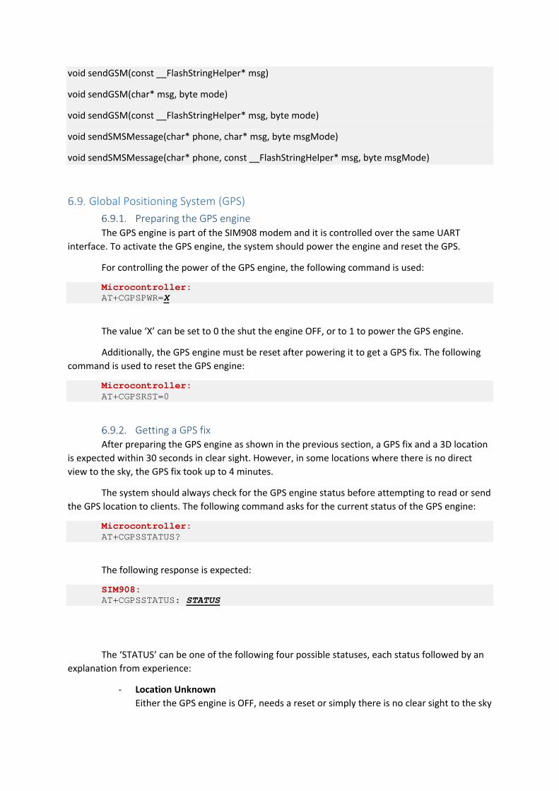
void sendGSM(const __FlashStringHelper* msg)
void sendGSM(char* msg, byte mode)
void sendGSM(const __FlashStringHelper* msg, byte mode)
void sendSMSMessage(char* phone, char* msg, byte msgMode)
void sendSMSMessage(char* phone, const __FlashStringHelper* msg, byte msgMode)
Global Positioning System (GPS) Preparing the GPS engine
The GPS engine is part of the SIM908 modem and it is controlled over the same UART interface. To activate the GPS engine, the system should power the engine and reset the GPS.
For controlling the power of the GPS engine, the following command is used:
Microcontroller: AT+CGPSPWR=X
The value ‘X’ can be set to 0 the shut the engine OFF, or to 1 to power the GPS engine.
Additionally, the GPS engine must be reset after powering it to get a GPS fix. The following command is used to reset the GPS engine:
Microcontroller: AT+CGPSRST=0
Getting a GPS fix After preparing the GPS engine as shown in the previous section, a GPS fix and a 3D location
is expected within 30 seconds in clear sight. However, in some locations where there is no direct view to the sky, the GPS fix took up to 4 minutes.
The system should always check for the GPS engine status before attempting to read or send the GPS location to clients. The following command asks for the current status of the GPS engine:
Microcontroller: AT+CGPSSTATUS?
The following response is expected:
SIM908: AT+CGPSSTATUS: STATUS
The ‘STATUS’ can be one of the following four possible statuses, each status followed by an explanation from experience:
- Location Unknown Either the GPS engine is OFF, needs a reset or simply there is no clear sight to the sky

- Location Not Fix - A GPS location is available, but it is not accurate
- Location 2D Fix
A GPS location is available, but with an estimated altitude. May result in a non-accurate horizontal coordinates. However, most of the time, it is accurate.
- Location 3D Fix An accurate GPS location is available
The smart car system will always treat the last two statuses, ‘2D’ and ‘3D’ fixes, as an available GPS coordinates.
If the system tries to read the GPS location for 5 minutes with no success, the system will automatically reset the GPS engine although it has been reset before, to ensure that the GPS engine does not enter a dead lock status.
Sending GPS Data to Clients Once the GPS data are available from the GPS engine, the system will send the following
command to read the GPS last available data:
Microcontroller: AT+CGPSINF=0
The following response is expected
SIM908: AT+CGPSINF= mode,longitude,latitude,altitude,UTC time,TTFF,num,speed,course
The fields ‘longitude’, ‘latitude’ and ‘altitude’ represent the GPS location. Speed represent the car speed over ground in meters per second. Other values are not of the system interest such as the ‘TTFF’ represent the time it took the engine to fix the signal.
Feeding Bluetooth Clients Bluetooth clients do not need to send any GPS request to locate the car GPS location. Once a
Bluetooth client is connected and authenticated, the system will automatically activate the GPS engine and start trying to fix the signal. It will keep informing the Bluetooth client about the GPS engine status, whether it has a fix or not. Once a GPS fix is available, it will start feeding the Bluetooth client with the latest available location until the client disconnects or the GPS signal is not available.
Fulfilling SMS requests If an authorized client sends an SMS message requesting the GPS location of the car. The
system will immediately response with the GPS location if it was available. If the GPS data is not available, the system will start the GPS engine and attempt reading the GPS data. It will keep trying until GPS data is available, it will then send one SMS response to the SMS client.

System Commands Summary System Commands from external clients Table 3 summarizes the possible commands that can be received from external clients
Table 3 System external commands summary
Command (Arguments) Description Originating Source AUTHR (Device Serial) Authentication Request Bluetooth SETSR (New Device Serial) Change Device Serial
Allowed once in lifetime Bluetooth
ENGST (Lock Car?) Start Engine Request and lock car if desired
Bluetooth, SMS
GETST Get Car Status including engine status and panic mode
SMS Bluetooth will receive status updates automatically
ACCOF Turn Car Accessories OFF Bluetooth, SMS ACCON Turn Car Accessories ON Bluetooth, SMS ENGOF Stop Engine & All Components Bluetooth, SMS SHORN Short Horn Bluetooth, SMS PANIC Activate Panic Mode Bluetooth, SMS PANCO Stop Panic Mode Bluetooth, SMS ENGKP Keep Engine Running Bluetooth SLOCK (Lock Car?) Lock or Unlock Car Bluetooth, SMS GTGPS Car GPS Location Request SMS
Bluetooth will receive GPS updates automatically
SETMP(PhoneNumber) Set the master phone for communication
Bluetooth, SMS
Messages originated from the system Table 4 shows a summary for the commands and messages that are originated from the
system to external clients
Table 4 Summary for commands originated from the system
Command (Arguments) Description Potential Destination WELCM Welcome Message Bluetooth AUTHS Authorization Succeeded Bluetooth AUTHF Authorization Failed Bluetooth ACKW=(arg) Acknowledgment for
commands received or executed
Bluetooth, SMS Some acknowledgments will not be sent to SMS clients
STAT=(STATUS) Car Status Details Used as acknowledgment as well
Bluetooth, SMS
GPSCO(GPSData) GPS Data Bluetooth, SMS GPSNO GPS Data not available
Waiting for fix Bluetooth

7. Android Software Engineering Design The Android application is the main user interface for interacting with the smart car system,
through either Bluetooth or SMS.
Use Case Diagram The use case diagram in shows the main actors on the android software, the phone user and
the commands coming from the system through the two communication channels.
Figure 31 Use case diagram for the Android software

Class Diagram Figure 32 shows the classes of the Android application. This section will summarize the role
of each class in the application.
- Car Class The car class contains data about a car that can be controlled by the system. Such data inlcudes the car system unique serial number, Bluetooth address and the phone number of the system. It also includes the car status as well as it’s GPS location.
- AppData Class This class holds data about the current status of the program such as the connection mode used for controlling a car and the current user view. The purpose of this class is to offer such data to all the activities of the application and to sustain the data even if the activities are destroied by the Android OS throughout the application lifecycle.
- Bluetooth Controller This class contains all the necessary methods and variables that are needed to establish a connection with the smart car system using Bluetooth and do all the required communication and data extraction and filteration.
- SMS Controller This class is responsible for delivering SMS messages from the application to the Android system for end delivery to the smart car system. The class is also responsible for listening for all incoming SMS message that are coming to the user phone and identify messages that are directed to the smart car application, such messages will be verified and extracted by the class.
- MainControlActivity This is the main activity class that is started at first by the Android OS when the user starts the application. It’s responsible for managing the main layout of the application and most of the user interaction with the software.
- BluetoothFragment - SMSFragment
These are two inner classes for the MainControlActivity class. They are responsible for the layout and interaction with the user in the corresponsing control communication method (Bluetooth or SMS).
- CarEditActivity This is the activity responsible for interacrting with the user while adding a new car to the system or while managing a previously added car.
- CarMapActivity This is the activity responsible for displaying the car GPS location on the map if the location is available.

Figure 32 Class diagram for the Android application
Diagram generated automatically using the free eclipse Add-On ‘Object Aid UML’

Application’s Permissions and Certificates Android Permissions
The application uses the following permissions, which are part of the application manifest XML. These permissions must be part of the application so the system can access the required Android services.
Storage android.permission.WRITE_EXTERNAL_STORAGE Bluetooth Connectivity android.permission.BLUETOOTH SMS Control android.permission.SEND_SMS android.permission.RECEIVE_SMS Google Maps Services android.permission.ACCESS_NETWORK_STATE android.permission.INTERNET com.google.android.providers.gsf.permission.READ_GSERVICES
Google Maps Certificate To integrate Google Maps in the Android application, a development account and a
certificate specific for this application must be obtained.
An account can be obtained from the Google Console website https://code.google.com/apis/console/?noredirect where a project can be added and a certificate for the application can be generated.
Additionally, several steps should be taken to integrate that certificate in the application, details can be read from this documentation https://developers.google.com/maps/documentation/android/start#getting_the_google_maps_android_api_v2

Connectivity Bluetooth Connectivity
The system uses the same Bluetooth messaging format shown in section 6.3.1 in both directions.
For details on how to use the Bluetooth classes of the Android OS please refer to http://developer.android.com/guide/topics/connectivity/bluetooth.html
Upon establishing a connection with the system, the application will create a separate thread for receiving and analyzing data from the smart car system. This is needed as the receive methods of the available Bluetooth classes will block the main thread of the application.
Additionally, when creating the Bluetooth socket while connecting to a standard Bluetooth serial port such as the one used by the chip in the smart car system, the value “00001101-0000-1000-8000-00805F9B34FB” should be used as a UUID:
blueSocket = device.createRfcommSocketToServiceRecord(UUID.fromString("00001101-0000-1000-8000-00805F9B34FB"));
If the Bluetooth adapter of the phone is turned off, the system can start Bluetooth automatically, however, the system will prompt the user first before starting Bluetooth following the convention of the Android OS development.
Figure 33 Asking the user before starting Bluetooth if
needed
Figure 34 Connecting to the system

SMS Connectivity The application uses the smsManager class provided by the Android OS to send SMS and
listen for incoming SMS messages. Please refer to the smsManager API for additional details: http://developer.android.com/reference/android/telephony/SmsManager.html
The Android application developed will allow the user to send SMS commands to the system automatically without the need for writing the commands in messaging applications manually.
For Android versions before KitKat 4.4, the Android system will not keep version of messages sent from the application in the user’s phone messaging application. However, starting from version 4.4, this is no longer the case. The messaging software will keep versions of the messages sent and received by the smart car application. This can be avoided only by being the master messaging application, or by asking the master application to delete the messages every time a message is sent or received, but this is not guaranteed to work on all devices especially if the system is using a messaging application other than the default one.
Given the type of messages sent and received by the software, there is no harm from keeping such messages in the messaging application.
Sending SMS messages The application will use the same messaging format discussed in the microcontroller section.
The system will not send any SMS message before prompting the user. This is done to avoid any unnecessary cost. Figure 35 shows a sample dialog requesting permission before sending an SMS message to start the engine.
Figure 35 Asking the user before sending SMS messages

Receiving SMS messages The application handler will receive all SMS messages received by the mobile phone of the
user. The application will accept the message if two conditions are met. First, if the message sender number is the same as the number stored in the controlled car. Second, if the message is originated to the application by checking the header of the message.
The application will use the PhoneNumberUtils class provided by the Android OS to compare the phone number of the sender and the stored number for the car. The class provides correct comparison when comparing phone numbers that are equal but not alphabetically identical. For example, the user may store the phone number in the format 05xxxxxxxx while the phone number provided by the network for the message is +9665xxxxxxx.
Cars Management Cars Data
The application will allow users to configure multiple cars on their phone for controlling.
Data stored for each car in the application are:
- Car Name A display name provided by the user
- Car Device ID The device ID for the system to be controlled; for authentication.
- Car Bluetooth Address The Bluetooth address of the Bluetooth chip of the system. Used to connect to the system over Bluetooth.
- Mobile Number The phone number of the SIM card used by the car system. Used to control the system over SMS.
- Car Status The car last recorded status including engine status, panic mode and the time this status was recorded.
- Car GPS Data The car last recorded GPS data including coordinates, speed and the time this data was recorded.
All cars data are stored in the phone storage using the ‘SharedPreferences’ classes provided by the Android system. All data are reloaded upon restarting the application.
Car Management Interface The user is required to enter the system device PIN and its phone number in plain text. In
terms of Bluetooth connectivity, the application will show the list of paired devices to the user to choose the system Bluetooth device of the car, and it will show the option to pair a new device if the device is used for the first time.
Figure 36 and Figure 37 show two snapshots for the car configuration interface.

Figure 36 Car Managment Activity Snapshot
Figure 37 Pick Bluetooth Device Interface
Figure 38 Main interface at application start
Figure 38 shows the main interface when the application starts. It allows the user from one window to select the desired connection method and car to control. The user can also manage one of the cars or add a new car to control.

Bluetooth Control As discussed in the Microcontroller section, the system will provide the latest car status
updates and GPS location to the connected Bluetooth client. Therefore, the Android application must provide an interactive interface that will show commands to the mobile user based on the status of the car.
Engine Control Table 5 shows list of the commands available to the mobile user based on the car status. The
commands shown in the table were previously discussed in the microcontroller section.
Table 5 Engine Control Commands available to the user per car status
Car Status Engine is OFF Engine is ON by system
Engine is ON by car key
Accessories are ON by system,
Engine is off
Commands Start Engine Stop Engine Keep Engine
Running Start Engine
Power Accessories ON Power Accessories
OFF Figure 39 and Figure 40 show the main interface in two of the possible statuses; when the
engine is OFF and when the engine is ON by system.
Figure 39 Main interface snapshot when car engine is OFF
Figure 40 Main interface snapshot when car engine is ON

Car Locks Control The two commands controlling the car locks by locking or unlocking the car will be shown to
the user in all car possible statuses. The description shown to the user for each command may differ in the different statuses because the lock command if the engine is OFF will enable the security system as well which is not the case when the engine is running.
Horn & Panic Control The ‘Short Horn’ command will be available to the user in all car statuses. The ‘Panic’
command will also be always available but it will be replaced by a ‘Stop Panic’ command when the panic mode is reported active by the system and vice verse.
GPS Location While the system is trying to fix the GPS location, the android application will show a
‘Waiting for GPS fix’ message to the user.
Once the system fixes the GPS location, the Android application will immediately show the GPS coordinates to the user as well as the current car speed. Additionally, the user will have the capability to view the car location on map using a Google Maps fragment integrated in the map Activity of the application, and the car speed will also be shown next to the car location in map. The GPS location on the map will be updated as long as the phone is connected to the system. Additionally, the map will show the phone location using the phone GPS along with the car location to locate the car more easily.
GPS Data Units The GPS speed will be received in m/s and they will be converted to km/h for user
convenience. Also, the GPS coordinates will be received in ‘Degrees Minutes’ format and they will be converted to decimals for proper viewing on Google Maps.
SMS Control As discussed before, the Application will not receive all car updates over SMS to minimize
operator costs. Therefore, the system will display all the possible commands to the user assuming the user is aware of the latest car status. The application in the SMS mode will show that latest known car status and the time of obtaining such data. Also, the user can request a status update from the system over SMS. It is the responsibility of the embedded system to ensure that no harmful action is taken, for example when receiving a ‘Start Engine’ command while the engine is already running, the embedded system will drop such command.
Engine Control, Car Locks, Horn and Panic Mode The system will show the latest car status known to the user, and will provide complete list
of the commands to the mobile user even the commands that don’t comply with the latest known status, because it’s possible that the Android application is not aware of a newly updated car status when controlling over SMS. However, commands such as ‘Keep Engine Running’ will not be shown as users are not expected to use such command using SMS from a long range.
GPS Location If the user starts the application for the first time, one command will be available to the user
in the GPS section which is requesting the GPS location form the system. Once GPS data is received from the system, the system will show the GPS data coordinates and speed, and will allow the user to view the location on map. Also, a command to update the GPS location will be shown to the user

as well if the user wants to refresh the GPS location. Similar to the Bluetooth mode, the map will show the phone location using the phone GPS along with the latest known car location to locate the car more easily.
Figure 41 shows a snapshot for the application in SMS control, and Figure 42 shows the same main Activity but with GPS data available.
Figure 43 and Figure 44 show the map Activity of the application while displaying the car location on the map. These two figures apply to the Bluetooth and SMS connections.
Figure 41 Snapshot for the main SMS control
Figure 42 Snapshot for SMS control with GPS data available

Figure 43 Remote GPS tracking with car in campus
;
Figure 44 Nearby GPS tracking showing user location relative to car location
Additionally, the application will show a warning message to the user if the relays are not operating as expected. This is done by comparing the values of the ignitions lines as reported by the system with the expected values for the current car mode. Figure 45
Figure 45 Warning message reporting faulty relays

8. Power Analysis Prototype Power Consumption
The section will cover the power consumption of the system using the prototype boards and components.
For an accurate measure of power consumption, the power will be measured at the source of power and before passing any of the regulators of the power system. This will ensure that the power numbers calculated in this section will cover all the aspects including power dissipated as a result of the regulators efficiency.
Figure 46 Ammeter used for measuring system power consumption
Table 6 System power consumption in different components modes
Mode GSM Modem GPS Microcontroller Bluetooth Total Current ~ @12V
1 Idle OFF ON ON 160mA 2 Idle OFF ON OFF 130mA 3 Idle ON ON ON 190mA 4 Idle OFF Idle* ON 150mA 5 Sleeping OFF ON ON 125mA
*idle: Putting the Atmega2560 on ‘Power_Mode_Idle’ and powering off all the ADCs.
Table 6 shows that the Bluetooth module saves 30mA if powered off, however the system will not turn the module off in the current design as this will disable Bluetooth connectivity on the system.
Turning the GPS engine OFF saves around 30mA as well. The system utilizes this important aspect because GPS engine will be used only when there is an SMS request from the user or when there is a Bluetooth connection to the system.
Putting the microcontroller on the idle mode saved only 10mA. Also, putting it on complete power down saving mode gave close results which is not expected. This can be explained by the non-efficient regulators on the Arduino board as well as the LEDs and the ATmega16U2 chip that consumes static power even when the micro controller is not operating. Bypassing the NCP1117ST50T3G regulator on the Arduino board which is explained in the power section helped greatly in reducing the power consumption.

Putting the SIM908 board on sleep mode saves around 35 mA. The system will utilize this mode in most of the operating times.
In the current system prototype, the system will operate on mode 5 that is shown in Table 6 most of the time. The system will operate on mode 3 only when there is a need to get the GPS location because of an SMS command requesting the location or when the user connects to the system using Bluetooth. The system will operate on mode 1 only when there is a need to communicate with the GSM modem such as when sending or receiving an SMS message.
Assuming that the current prototype is installed in a small sized car that is equipped with a 40AH battery. The system will drain the car battery if it is not used in:
=40𝑚𝑚ℎ
125𝑚𝑚𝑚𝑚ℎ= 320 ℎ𝑜𝑜𝐴𝐴𝐴𝐴𝑚𝑚 = 13.33 𝐴𝐴𝑟𝑟𝑑𝑑𝑚𝑚
Reducing power consumption System boardIt is expected that the power consumption will drop largely upon using our own system PCB
with the required components only, and by using efficient regulators such as the ones used in the current prototype to power the SIM908 chips and the Atemga2560. The Arduino and the GSM boards contain several non-necessary components and non-efficient regulators.
Bluetooth ChipThe usage of Bluetooth chips that are based on the new version 4.0 will save some power.
The system will use the low power services instead of the regular Bluetooth serial service. The only limitation is that it’s not supported by old phones.
Microcontroller PowerPowering the microcontroller with 3.3 volts instead of 5 volts will save power. Please note
that the Atmega2560 used in this application can be powered directly using 3.3 volts according to its datasheet. Additionally, all components in the system will be using 3.3 volts which will make power design as well as communication easier.

9. Universal Compatibility The aspect of universal compatibility for all cars was considered during the system design.
This include the usage of an external bypasser as well as dealing with the security system and car locks based on the car original design.
In terms of the ignition control, other car models are expected to have the same ignition requirements of the Accord discussed in the engine control sections. However, it is important to verify the electrical operation of the ignition switch of any new car to verify its compilation before installing the system, it must match the connections shown in Table 1, otherwise small modifications can be done to the system to ensure compatibility.
Cars with engine start button The current design works only with cars that uses the ignition key switch. However, cars that
are equipped with a start button are much easier to control.
The system will not worry about simulating the ignition switch positions. Actually, the system will not even need to use relays to start the car engine. A design suggestion is to have a copy of the Active RFID transmitter inside our system, the system will control the power going to the RFID chip, because powering it all the time will violate the security of the car. Once a remote start command is received, the system will enable the transmitter to simulate the presence of the driver inside the car, and will send a signal to the start button to start the car. The car itself will take care of starting the engine electronically. This method will not require even a bypasser, and its compatibility with all cars that use a start button is guaranteed since all the electrical part is taken care of by the car itself, unlike the regular method for cars with a key which is discussed in this report.
10. Issues The system in its current state is reliable and has no operating issues.
Development Issues Arduino Hanging In the first weeks of developing the embedded system, an issue was faced were the Arduino
hangs and does not respond to any external command. It was hard to debug such problem, however after tracking the code execution and printing debugging data to the PC serial, the problem was found. The problem was mainly a memory pointer that was incremented as the software needs but not reset to the previous location by mistake. This causes the system to access random memory location which causes unexpected behaviour.
Lack of documentation The Chinese GSM/GPS board is a complete development board but without any proper
documentation. The board has so many jumpers and pins without any proper documentation. I had to identify the pins by tracking the lines on the PCB coming from the components such as the SIM908.
I received the board around the third week of the semester, communicating with the supplier for more than 4 weeks finally resulted in receiving a schematic diagram explaining parts of the board. Development has started much before receiving such file, but this schematic was useful in helping me disable some of the non-used chips and components on the board for saving power.

11. Engineering Tools and Standards Arduino IDE The Arduino IDE was used for compiling the microcontroller C code and uploading it to the
microcontroller.
Notepad++ The Notepad++ is a rich text and code editor. It was used for writing the Arduino C code
because the Arduino IDE provides limited functionality in its code editor. The Notepad++ allows splitting the code into segments for easier navigation and it shows the methods of the class in the side of the application. It is a light, rich and free software.
Unfortunately, the Arduino IDE does not allow code compilation and uploading from external sources. However, Notepad++ allows configuring a keyboard shortcut that easily sends the code file to the Arduino IDE for compilation when desired.
Android SDK The Android SDK Tools and the Android Platform tools provide the APIs for different Android
versions as well as the tools needed for testing the software on a real device or an emulator.
Eclipse Eclipse is a very powerful and free development environment and it’s the official IDE for
developing Android applications. It was used for writing the JAVA code and debugging the android application, and for writing the XML files of the application, the Activities and View layouts.
TortoiseHg and Bitbucket TortoiseHg was used for creating and managing mercurial repositories for the source codes
of the Arduino and the Android as well. The usage of version control made the development much easier and safer.
Additionally, the BitBucket website was used for pushing the repositories commits, mainly to keep a backup of the source code during development.
Adobe Photoshop Photoshop was used to design the graphical part of the user interface for the Android
application. Some parts were designed from scratch while some parts were designed by modifying icons provided by free websites as needed.
PSpice PSpice was used to simulate the circuits that was used in the design.
12. Conclusion The project was a great learning experience. I am into the field of software development
from a long time, but this project had the special taste of integrating hardware and software to come up with a complete and useful product. The project added to my knowledge in several areas including hardware components integration, communication, electrical circuits designing, Android software development as well as microcontroller software designing.
Although all the basic requirements were met, I plan to continue the development of the project by adding more features that enhance the user experience to make cars more smarter.