smart home - welcome to the gmu ece department · a project report on smart home ... our team has...
TRANSCRIPT

ECE 511: MICROPROCESSORS
A project report on
SMART HOME
Under the guidance of Prof. Jens Peter Kaps
TEAM:
Raj Shah
Gaurav Shenoy
Amit Singh
Tejas Sontakke

INDEX
Abstract .............................................................................. .....................................1 Motivation ...............................................................................................................1 Block Diagram…………………………………………………………………….1 Components ............................................................................................................2
1. MSP 430....................................................................................................2
Hardware Interface ............................................................................2
2. Wi-Fi Module CC3100 .............................................................................2
Hardware Interface ............................................................................2
Software Interface .............................................................................2
3. SPST Relay ...............................................................................................3
Hardware Interface ............................................................................3
Software Interface .............................................................................3
4. IR Trans receiver Pair................................................................................3
Hardware Interface ……....................................................................3
Software Interface .............................................................................3
5. Internal Temperature Sensor of MSP 430……………………………….3
Hardware Interface……………………………………….…………3
Software Interface…………………………………………………..4
6. Liquid Crystal Display (LCD)…………………………………………..4 Hardware Interface……………………………………….…………4
Software Interface…………………………………………………..4
Software Interfacing……………………………………………………………....5 Results ....................................................................................................................6 Conclusion ..............................................................................................................6 References………………………………………………………………………....6 Appendix
A-Team Members and Task Division..................................................... 7
B-Components .........................................................................................7
C-Schematic …………………………………………………………….8
1
SMART HOME ABSTRACT: It’s the 21st Century: weren’t we all supposed to be living in automated homes by now? Where we walk in the door after a long day to have our home playing some soothing music, informing us that its run us a bath and that dinner will be ready in 45 minutes? Where a robot has done the cleaning, changed the flowers, accepted a parcel that arrived while we were at work and fed the cat? That dream seems to be a long time coming. Our team has designed ‘Smart Home Automation ‘ a project based on the amalgamation of some of our daily used appliances in home, to create a highly advanced technology for a smart and futuristic home environment. The Wifi Booster pack helps sending the commands received from the user remotely to the highly advanced 16- bit microcontroller to take the necessary control actions on the home appliances. In addition, IR sensors are used for detecting the presence of an objects (person) inside the room to control the lighting. The relay is used to control the motion of the projector inside the living room. The controller uses two ports to control he integral appliances, that is, it can be used to control the action of the heater, bring down a projector in a room and control the lighting in a room. The goal set by our team was to control and monitor some of the home appliances used in day to day routine. The purpose of this project is to demonstrate how simple algorithms can produce useful behavior of appliances reducing human efforts
MOTIVATION:
The current trend of Internet of Things was a major motivating factor for our design and development of the
SMART HOME prototype. Leveraging the capacities of highly efficient controller i.e. MSP430 to create an efficient
smart home with real time monitoring was the aim of our project.
A “smart system” is applicable in various fields such as automobile, laboratories, space, material handling, mining,
micro surgery to household applications as well. The need of automating things in all pervasive day to day lifestyle
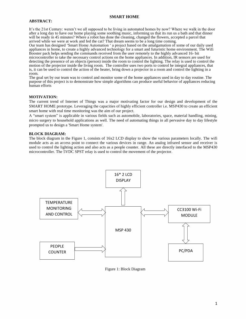
prompted us to design a 'Smart Home system'. BLOCK DIAGRAM: The block diagram in the Figure 1, consists of 16x2 LCD display to show the various parameters locally. The wifi module acts as an access point to connect the various devices in range. An analog infrared sensor and receiver is used to control the lighting action and also acts as a people counter. All these are directly interfaced to the MSP430 microcontroller. The 5VDC SPST relay is used to control the movement of the projector. Figure 1: Block Diagram
MSP 430
CC3100 Wi-Fi
MODULE
PC/PDA
TEMPERATURE
MONITORING
AND CONTROL
16* 2 LCD
DISPLAY
PEOPLE
COUNTER

2
COMPONENTS
1. MSP430F5529 MICROCONTROLLER
Hardware Description MSP430F5529 series is an ultra-low-power mixed signal microcontrollers with built-in 4x16-bit timers with PWM capability, up to 40 I/O pins, a 12 channel comparator, and built-in communication capability using the universal serial communication interface. In addition, it also has a 12-bit analog-to- digital (A/D) converter. It is the heart of the circuit, holds the logic to run each of the peripherals. Typical applications include low-cost sensor systems that capture analog signals, convert them to digital values, and then process the data for display or for transmission to a host system.
CC3100Wi-Fi MODULE
The CC3100 Wi-Fi Booster pack from TI provides functionality of Wi-Fi Access Point & HTTP Server.
Hardware Interface:It is interfaced to MSP430 using SPI protocol using port pins 2.0 (IRQ), 2.2(CS), 3.0(MOSI),
3.1(MISO) & 3.2(SPI Clk).
In addition to MSP430, CC3100 is interfaced to on-board Serial Flash memory (8Mbit), Chip Antenna & (optional,
used for firmware updates) can be interfaced to Emulation board as well.
CC3100 Software Interface:The communication between MSP430 & CC3100 is possible over a communication
port built upon the hardware interface. Software interface is based on function calls such as open & close
communication port, read & write data & interrupt handler routine. The exchange of data through this interface
follows a message format as follows:
MSP430 to CC3100
SYNC OP+LEN DESCRIPTORS PAYLOAD
32 bit 32 bit (16+16) Varies per OP (aligned to 32 bit) Variable (aligned to 32 bit)
CC3100 to MSP430
SYNC OP+LEN STATUS DESCRIPTORS PAYLOAD
32 bit 32 bit (16+16) 32 bit Varies per OP (aligned to 32 bit) Variable (aligned to 32 bit)

3
BASIC NETWORKING BLOCK DIAGRAM.
3. SPST RELAY OMR-C-105H SPST 5VDC relay is used for switching action in our project. Relay is used to simulate a projector in the living room at a prototype level by showing its switching action through a LED, where to show the movement of the projector we use an LED which switches on and off. Hardware Interface : The relay is interfaced with the MSP430 chip using GPIO pin. It is connected to a 1 pin of MSP430 which drives the coil to make the switching action. One pin of the relay is connected to 5VDC supply coming from the MSP430 and its other end is connected to LED via a 4.7KOHM resistor. Software Interface :The relay is in the normally open (NO) mode, so when the output of pin at MSP430 is high , it switches the wire making the circuit complete thus passing the 5V to the LED on the other end.
4. IR SENSOR AND ANALOG INFRA-RED RANGE FINDING SYSTEM
IR sensor –The model is 276-0142. This is used for edge detection system. IR sensor receiver is used to simulate
two major applications in our ‘SMART HOME’:
1. Automatic Lighting System.
2. People Counter.
Hardware Interface:
IR LED having a reverse breakdown voltage of 5V, continuous forward current of 100mA and wavelength of
850nm, is connected to 5VDC supply coming directly from MSP430. IR receiver which is placed head to head with
IR LED, and its output is taken at the cathode which is connected to the I/O pin of MSP430 which receives the input
signal from the receiver. An LED is used at the output of IR emitter receiver pair to show its working.
Software Interface:
IR LED is connected to 5VDC supply, which is continuously transmitting IR rays in the wavelength of 850 nm
(peak wavelength), received by the IR receiver, which is head-to-head to the IR LED. Whenever an object is
detected i.e. it cuts the IR rays from the trans receiver pair, it sends a low pulse to the MSP430, which is detected by
polling control structure i.e. continuous polling of the signals from IR transmitter receiver pair. With the active low
pulse detection, in the polling loop the LED glows. We have also implemented a counter in it that keeps a count of
the number of times the loop has been activated, which is used for our application of people counter.
5 . INTERNAL TEMPERATURE SENSOR MSP430F5529
We are using the internal negative temperature co-efficient (NTC) sensor of MSP430F5529. This is a prototype to
show to controlling of an Temperature heating cooling system of a house, where the user can set the required
temperature as per required convenience.
Hardware Interface : We use the on-chip temperature sensor, where we select the use the on-chip temperature
sensor, where we select the analog input channel INCHx = 1010. An LED is connected at the output pin of the
MSP430.

4
Software Interface:
The Code initiates by handing over the control to ADC12_A REF control registers by resetting the REFMSTR bit.
The ADC12CTL0 configures the internal temperature sensor by selecting sample and hold time to 256ADC12 clock
cycles (100b) . The ADC12ON is set to 1 to switch on ADC12_A. The bit 6 i.e. ADC12REF2_5V is set to 0
indicating 1.5V reference voltage and ADC12REFON is set to 1 to activate the reference generator. Sample timer is
enabled. The temperature sensor input is given to channel A10, which is compared with the internal reference
voltage to record the temperature. The interrupt is enabled where the sampling and conversion takes place. The
received temperature is in Degree Celsius, which can be converted to Degree Fahrenheit. This via the “sprintf” is
displayed on the 16x2 LCD.
6. LIQUID CRYSTAL DISPLAY:
A 16x2 LCD panel acts as the central information display in this project. The two significant roles of the LCD in
this project are given below.
1. Display temperature: The LCD should display the values sensed by the internal temperature sensor in real-time as
accurately as captured by it. The temperature is displayed in degrees Celsius unit.2. Display the people count: The
LCD should display the people count in the room as sensed by the IR LED and IR receiver pairs on the bottom row
of the screen. This value too is updated in real-time.
Hardware Interface:
The LCD is interfaced with the MSP430 chip using GPIO pins which are digital I/O pins. Four pins are used for
data, one for Enable and another one for Register Select. The LCD drives 3.3 Volts. Therefore, it is compatible with
the MSP430 chip. Additionally, a potentiometer is used to adjust the contrast of the LCD.
Software Interface:LCD was configured to 4 bit data mode (in order to save some pins on the chip), 2 line display
and 5x8 pixels on each character. The software that was used to control the LCD module was broken down to
different functions.
Port_init: The directions of the ports are configured and ports are initialized in this function.
LCD_init: In this function, the LCD commands are used to initialize the LCD by selecting the 4-bit mode,
clearing the screen, display on cursor on, auto-incrementing the cursor and setting the cursor to first line.
LCD busy: The LCD is checked for its business and accordingly the following instructions are executed.
LCD send data: This function enables LCD to receive data on the display when Register Select = 1.
LCD send command: This function makes the LCD capable of receiving commands when Register Select =
0.
LCD send string: This function sets up the LCD to print strings on the LCD particularly used to display
temperature and the people count in real-time.

5
D. SOFTWARE INTERFACING:

6
E. RESULT AND CONCLUSIONS:
Result:
The primary aim of the project to display measured parameters on the peripheral devices was successfully tested.We
were able to successfully control the peripherals connected to the MSP430 via the CC3100 Wifi module.
Conclusion:
The Smart Home project was set out to achieve a few specific goals. We wanted to maximize the resources available
in
the MSP430 while at the same time creating a fully functional home automation system.
Our goal was met as we made use of the MSP430 down to the last instruction possible.
Adding the intruder detection alarm system was a fun challenge.. In this process, the team gained valuable
experience integrating individual electronic components with a microcontroller and managing the software
accordingly.
F. REFERENCES: http://www.ti.com/product/CC3100/datasheet http://www.ti.com/product/CC3100/technicaldocuments http://www.ti.com/lit/ug/swru375a/swru375a.pdf. http://www.ti.com/lit/ug/swru368/swru368.pdf.
http://www.ti.com/lit/ug/swru371a/swru371a.pdf. http://www.ti.com/tool/cc31xxemuboost. http://www.ti.com/lit/ug/tidu520/tidu520.pdf. http://www.ti.com/product/msp430f5529.
7
APPENDIXA -List of team members and their tasks :
Amit & Tejas : Wi-Fi Interface with MSP430 ,coding and Debugging
Raj & Gaurav : Sensor Interfacing , LCD Interfacing , Relay and Coding & Debugging
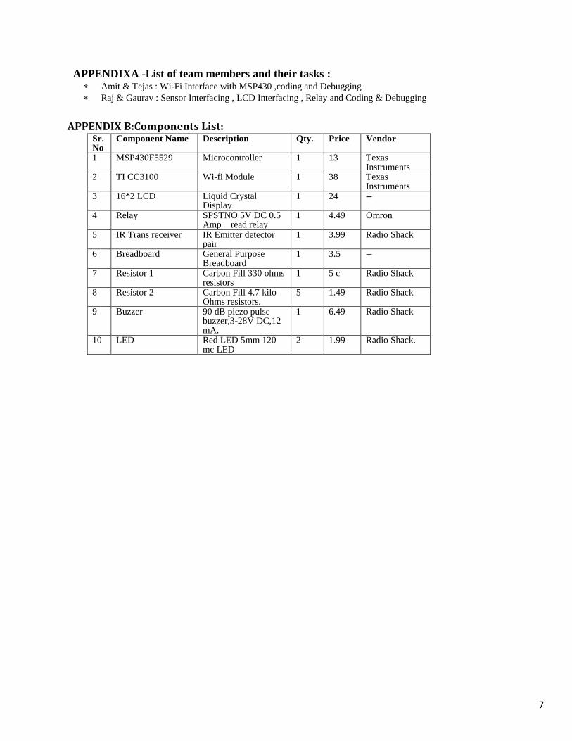
APPENDIX B:Components List: Sr. No
Component Name Description Qty. Price Vendor
1 MSP430F5529 Microcontroller 1 13 Texas Instruments
2 TI CC3100 Wi-fi Module 1 38 Texas Instruments
3 16*2 LCD Liquid Crystal Display
1 24 --
4 Relay SPSTNO 5V DC 0.5 Amp read relay
1 4.49 Omron
5 IR Trans receiver IR Emitter detector pair
1 3.99 Radio Shack
6 Breadboard General Purpose Breadboard
1 3.5 --
7 Resistor 1 Carbon Fill 330 ohms resistors
1 5 c Radio Shack
8 Resistor 2 Carbon Fill 4.7 kilo Ohms resistors.
5 1.49 Radio Shack
9 Buzzer 90 dB piezo pulse buzzer,3-28V DC,12 mA.
1 6.49 Radio Shack
10 LED Red LED 5mm 120 mc LED
2 1.99 Radio Shack.
8
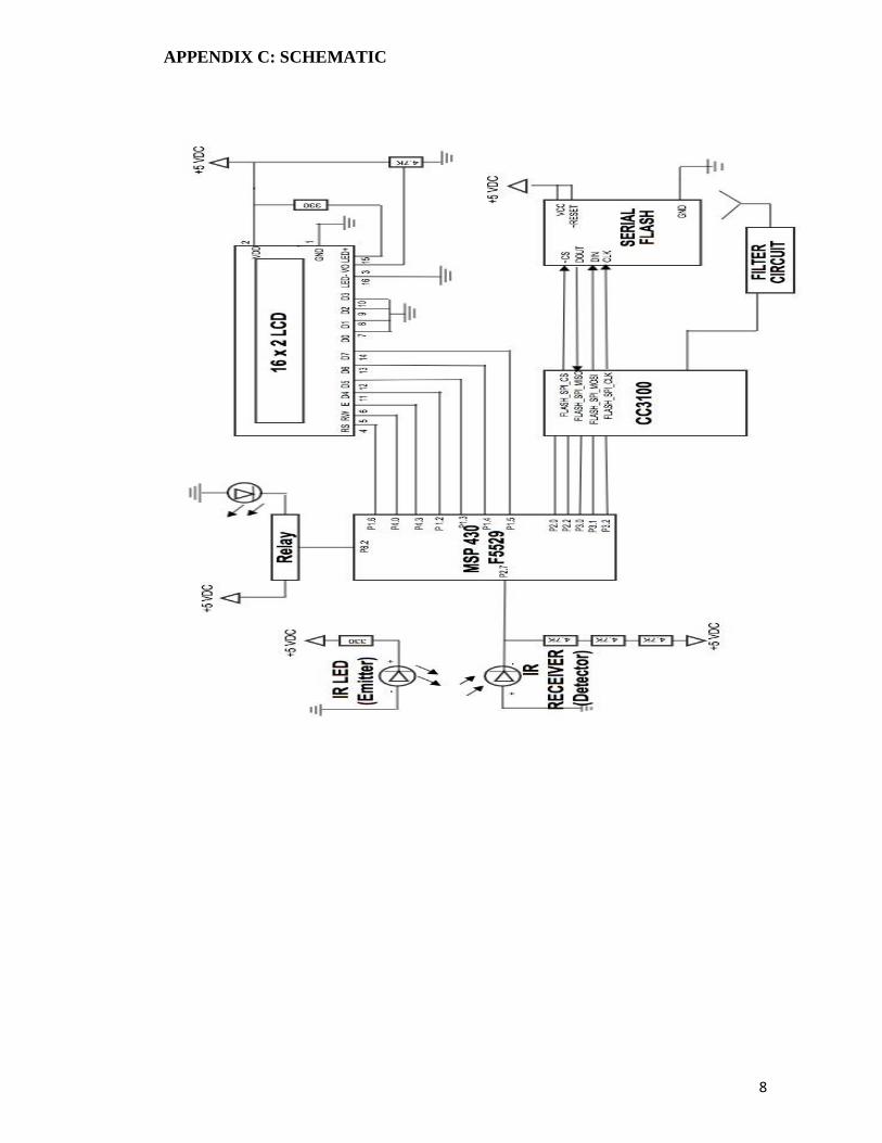
APPENDIX C: SCHEMATIC