smartcraft monitor 5 - brunswick marine in...
TRANSCRIPT

i
© 2
009
Mer
cury
Mar
ine
Smar
tCra
ft M
onito
r 5.0
v90
-879
1722
49 1
109

ii
TABLE OF CONTENTS
iii
General Information
MercMonitor Gateway Models Description..........................................1MercMonitor Gateway Protocol Acceptance Description....................5Connection to a Non‑SmartCraft Network...........................................7Basic Operation and Features.............................................................8Automatic Engine Detection Feature...................................................9Alarm Warnings with Descriptive Text.................................................9Identifying and Using the Screen Categories....................................12
Settings
Using the Light and Contrast Menu Options .....................................14Setting the Units................................................................................21Available Screens..............................................................................24Turning the Screens On....................................................................24Setting the Trim.................................................................................47Setting the Tanks...............................................................................52Setting the Alarms.............................................................................61Setting the External Sensors.............................................................67Setting the Offsets.............................................................................73Setting the Clock...............................................................................79Smart Tow Settings...........................................................................83Economy (ECO) Settings..................................................................86Setting the System............................................................................91Reset Gauge to the Factory Default Settings....................................94Gateway Settings..............................................................................95Help Menu.......................................................................................100

TABLE OF CONTENTS
iv
Propulsion Menu
Using Propulsion Screens ..............................................................103Available Propulsion Screens .........................................................103Troll Control Screen.........................................................................108Water Screen...................................................................................111Oil Screen........................................................................................111Peak Speed Screen.........................................................................112Fuel Pressure Screen......................................................................113RPM Synchronize Screen...............................................................113Engine Location Fuel Use ..............................................................114Double Screens...............................................................................115Analog Tachometer Screen.............................................................115Analog Speedometer Screen..........................................................116Volts/Hours Screen..........................................................................116Boost Pressure Screen....................................................................117Trim Synchronize Screen................................................................117Trim/Tab Screen..............................................................................118Smart Tow.......................................................................................118
Vessel Menu
Using the Vessel Screens...............................................................129Available Vessel Screens................................................................129Economy (ECO) Screen..................................................................133Trip Data Screen.............................................................................138Heating, Ventilation, and Air Conditioning Screen..........................141Generator Screen............................................................................142Range Screen..................................................................................143Trim Screen.....................................................................................144Tanks...............................................................................................145Tabs Screen....................................................................................146GPS Screen.....................................................................................147To Waypoint Screen........................................................................148Steering Screen...............................................................................149Depth Screen...................................................................................150

TABLE OF CONTENTS
v
Full Screens
Full Screens Features and Options ................................................151
Favorite Screens
Favorites Screen Features and Options..........................................156
Alarms
Alarms Screen.................................................................................162
Owners Assistance
Local Repair Service.......................................................................167Service Away from Home................................................................167Parts and Accessories Inquiries......................................................167Service Assistance..........................................................................167Mercury Marine Service Offices......................................................168Ordering Literature..........................................................................169

vi

GENERAL INFORMATION
1
MercMonitor Gateway Models DescriptionThere are four MercMonitor gateway models available; base model withnine gateway features, RPM Smart Tow model with 20 gatewayfeatures, Smart Tow Pro model with 25 gateway features (includes aGPS puck), and Gateway Premier model with 25 gateway features.Each model incorporates the use of NMEA 20001. and J1939 softwareinterface that allows or controls access to other programs.Each engine must have its own gateway monitor when using the baseor RPM Smart Tow models. Gateway Premier and Smart Tow Promodels can communicate and provide NMEA 2000/J11939 with fourengines or less. Gateway Premier and Smart Tow Pro models screenwill only display single engine data. Premier does not include Smart TowPro control capabilities.
Base Model (single engine, NMEA 2000 support selectable)
NMEA 2000 and J1939 in/out supported
RPMVoltageOil pressureCoolant temperatureFuel tank level percent
NMEA 2000 only in/out supported
Fluid level percent (Fuel 2, oil, water,waste)Trim positionWater pressureCheck engine alarm
IMPORTANT: NMEA 2000/J1939 alarmdata is limited, refer to the MercMonitordisplay for descriptive fault text.
1. NMEA 2000 pending certification.

GENERAL INFORMATION
2
RPM Smart Tow Model (single engine, NMEA 2000 support selectable)
NMEA 2000 and J1939 in/out supported
RPMVoltageOil pressureCoolant temperatureFuel tank level percentFuel flowEngine hoursBoost pressureOil temperature
NMEA 2000 only in/out supported
Fluid level percent (Fuel 2, oil, water,waste)Trim positionWater pressureCheck engine alarm
IMPORTANT: NMEA 2000/J1939 alarmdata is limited, refer to the MercMonitordisplay for descriptive fault text.TabsGPS speed/COG/latitude, longitude (inonly)DepthSeawater temperaturePaddle wheel speedPitot speed

GENERAL INFORMATION
3
Smart Tow Pro Model with GPS puck (four engine or less, NMEA 2000 supportselectable)
NMEA 2000 and J1939 in/out supported
RPMVoltageOil pressureCoolant temperatureFuel tank level percentFuel flowEngine hoursBoost pressureOil temperature
NMEA 2000 in/out supported (only)
Fluid level percent (Fuel 2, oil, water,waste)Trim positionWater pressureCheck engine alarm
IMPORTANT: NMEA 2000/J1939 alarmdata is limited, refer to the MercMonitordisplay for descriptive fault text.TabsGPS speed/COG/latitude, longitude (inonly)DepthSeawater temperaturePaddle wheel speedPitot speedRudder angleGear pressure (CMD diesel)Gear temperature (CMD diesel)Fuel pressureCapacity (English or metric)

GENERAL INFORMATION
4
Gateway Premier (four engine or less, NMEA 2000 support selectable) (includes RPMSmart Tow)
NMEA 2000 and J1939 in/out supported
RPMVoltageOil pressureCoolant temperatureFuel tank level percentFuel flowEngine hoursBoost pressureOil temperature
NMEA 2000 in/out supported (only)
Fluid level percent (Fuel 2, oil, water,waste)Trim positionWater pressureCheck engine alarm
IMPORTANT: NMEA 2000/J1939 alarmdata is limited, refer to the MercMonitordisplay for descriptive fault text.TabsGPS speed/COG/latitude, longitude (inonly)DepthSeawater temperaturePaddle wheel speedPitot speedRudder angleGear pressure (CMD diesel)Gear temperature (CMD diesel)Fuel pressureCapacity (English or metric)
GENERAL INFORMATION
5
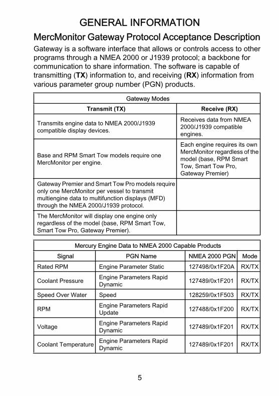
MercMonitor Gateway Protocol Acceptance DescriptionGateway is a software interface that allows or controls access to otherprograms through a NMEA 2000 or J1939 protocol; a backbone forcommunication to share information. The software is capable oftransmitting (TX) information to, and receiving (RX) information fromvarious parameter group number (PGN) products.
Gateway ModesTransmit (TX) Receive (RX)
Transmits engine data to NMEA 2000/J1939compatible display devices.
Receives data from NMEA2000/J1939 compatibleengines.
Base and RPM Smart Tow models require oneMercMonitor per engine.
Each engine requires its ownMercMonitor regardless of themodel (base, RPM SmartTow, Smart Tow Pro,Gateway Premier)
Gateway Premier and Smart Tow Pro models requireonly one MercMonitor per vessel to transmitmultiengine data to multifunction displays (MFD)through the NMEA 2000/J1939 protocol.The MercMonitor will display one engine onlyregardless of the model (base, RPM Smart Tow,Smart Tow Pro, Gateway Premier).
Mercury Engine Data to NMEA 2000 Capable ProductsSignal PGN Name NMEA 2000 PGN Mode
Rated RPM Engine Parameter Static 127498/0x1F20A RX/TX
Coolant Pressure Engine Parameters RapidDynamic 127489/0x1F201 RX/TX
Speed Over Water Speed 128259/0x1F503 RX/TX
RPM Engine Parameters RapidUpdate 127488/0x1F200 RX/TX
Voltage Engine Parameters RapidDynamic 127489/0x1F201 RX/TX
Coolant Temperature Engine Parameters RapidDynamic 127489/0x1F201 RX/TX

GENERAL INFORMATION
6
Mercury Engine Data to NMEA 2000 Capable ProductsSignal PGN Name NMEA 2000 PGN Mode
Fuel Pressure Engine Parameters RapidDynamic 127489/0x1F201 RX/TX
Fuel Level Fluid Level 127505/0x1F211 RX/TXFuel Tank Size Fluid Level 127505/0x1F211 RX/TX
Fuel Flow Engine Parameters RapidDynamic 127489/0x1F201 RX/TX
Oil Pressure Engine Parameters RapidDynamic 127489/0x1F201 RX/TX
Oil Temperature Engine Parameters RapidDynamic 127489/0x1F201 RX/TX
Gear Temp Transmission Dynamic 127493/0x1F205 RX/TXGear Pressure Transmission Dynamic 127493/0x1F205 RX/TX
Boost Pressure Engine Parameters RapidUpdate 127488/0x1F200 RX/TX
Trim position Engine Parameters RapidUpdate 127488/0x1F200 RX/TX
Rudder Angle Rudder 127245/0x1F10D RX/TXDepth Depth 128267/0x1F50B RX/TXDepth Offset Depth 128267/0x1F50B RX/TXSeawater Temp Environmental Parameters 130310/0x1FD06 RX/TX
Engine hours Engine Parameters RapidDynamic 127489/0x1F201 RX/TX
Manufacturer ID Address Claim (0 x 90 =Mercury) 060928/0xEE00 RX/TX
Alarm data Check Engine 127489/0x1F201 RX/TXTabs Small Craft Status 130576/0x1FE10 RX/TXCourse over Ground COG and SOG Rapid Update 129026/0x9F802 RXSpeed over Ground COG and SOG Rapid Update 129026/0x9F802 RXGPS Position Position Rapid Update 129025/0x1F801 RXBattery Battery Status 127508/0x1F214 RX/TX

GENERAL INFORMATION
7
Mercury Engine Data to J1939 Capable ProductsSignal PGN Name J1939 PGN Mode
RPM Electronic Engine Controller#1 61444/0xF004 TX
Voltage Vehicle Electrical Power 65271/0xFEF7 TXCoolant Temperature Engine Temperature #1 65262/0xFEEE TXFuel Level Dash Display 65276/0xFEFC TXFuel Consumption Fuel Economy (Liquid) 65266/0xFEF2 TXFuel Flow Fuel Economy (Liquid) 65266/0xFEF2 TXOil Pressure Engine Fluid Level/Press #1 65263/0xFEEF TXBoost Pressure Inlet/Exhaust Conditions 65270/0xFEF6 TXEngine hours Total Engine Hours 65253/0xFEE5 TX
Manufacturer ID Address Claim (0 x 90 =Mercury) 61182/0xEEFE TX
Alarm data(Diagnostic messagesupported)
Check Engine 65226/0xFECA TX
Line‑Line AC RMS Volt Generator Set Average 65030/0xFE06 RX/TXAC RMS Frequency Generator Set Average 65030/0xFE06 RX/TX
Connection to a Non‑SmartCraft NetworkThe use of the MercMonitor on a non‑SmartCraft network applicationrequires the MercMonitor gateway set to "Receive." Failure to set thegateway to "Receive" will cause numerous faults to appear that cannotbe resolved. Changing the gateway to "Receive" will clear the faults.The menu path to set the gateway to "Receive" is: "Main Menu," >"Settings," > "Gateway," > "Gateway."

GENERAL INFORMATION
8
Basic Operation and Features
MODE
Main MenuPropulsion / ST
Full ScreensFavoritesAlarms
Vessel
AL
36875
!
Power up: The gauge will power up when the ignition is turned on.Lights: Adjusts the brightness and contrast of the gauge.Buttons: The "MODE" button is used for selecting information screens.The "+" and "–" buttons are used for setting engine speed for cruisecontrol, launch control, and setting gauge calibrations. To return to theprevious screen, hold the "MODE" button down for three to fiveseconds.Cruise control: Sets and controls the speed of the engine for cruising.Launch control: Controls the speed of acceleration from idle to cruisespeed.Engine Guardian System: Monitors the critical sensors on the enginefor any early indication of problems. The system will respond to aproblem by reducing engine speed and alerting the operator to apotentially damaging situation.Warning system: The system sounds the warning horn and displaysthe warning "AL" in the right corner of the "Main Menu" screen. Thealarm screen will pop up, flashing a warning icon in the middle of thescreen and the "AL" in the upper right side of the screen. Press the "+"button to display the descriptive text.

GENERAL INFORMATION
9
IMPORTANT: Optional sensors such as depth, fuel, paddle wheel, andsteering angle, should always be connected to the starboard enginewhen using SmartCraft gauges version 4.0 or later.
Automatic Engine Detection FeatureThe SmartCraft monitor has an automatic engine detection feature. Thisfeature automatically detects which engine type is used and configuresthe gauge to match that engine type.The first power up of the gauge, or after a reset all to factory default2,the gauge will display "AUTODETECT." Press the "MODE" button tostart the automatic engine detection feature and the gauge willdetermine the engine type. This will preset the data monitoring screensto make the initial setup easier.
MODE35915
AUTODETECT
ENGINE SMARTSCREENPRESS MODE TO START
If the gauge shows a warning of "NO STARBOARD ENGINE" or"MULTIPLE STARBOARD ENGINES," the engine location (port andstarboard) must be selected by an authorized dealer equipped with thecomputer diagnostic system (CDS) tool.
Alarm Warnings with Descriptive TextIMPORTANT: Alarm warnings and descriptive fault text are onlyavailable on the MercMonitor screen. NMEA 2000/J1939 gateway islimited to seven alarm functions.

GENERAL INFORMATION
10
NOTE: Descriptive text alarm warning screens are displayed with GenI (2007) engines and newer.
a - Flashing "AL" alarmb - Flashing warning iconc - "+" button to show
descriptive text
When a problem is detected, the "AL" alarm appears and a pop‑upwindow with the alarm location and fault number will be displayed. Thefaulty component or warning is described in the text. Press the "+"button for more information. This screen gives a detailed description ofthe fault text. Press the "+" button to view the required corrective action.The alarm message will stay displayed until the "–" button is pressed.This action will exit the warning screen. If there are multiple alarms,press the "MODE" button to view the next warning display.If a problem can cause immediate engine damage, the Engine GuardianSystem will respond to the problem by limiting engine power.Immediately reduce the throttle speed to idle and refer to the warningmessages. If the "MODE" button is pressed to display a different screen,the flashing alarm signal "AL" will appear in the upper right corner toindicate there still is a problem. Refer to the appropriate service manualfor further explanation of the problem and the correct action to take.
MODE
Alarms AL
35736
![EXIT] [SHOW]
a
b
c
!
System

GENERAL INFORMATION
11
VIEWING DESCRIPTIVE TEXT1. When a problem is detected, the "AL" alarm will flash on the display
and a pop‑up window displays the system where the fault islocated, the fault code, and what component is identified as aproblem.
a - System fault and codeb - Component
2. Press the "+" button to view the descriptive warning text. Theidentified component expands to show additional text describingthe fault.
a - System fault and codeb - Additional text
describing the fault
MODE
Alarms AL
35737
[EXIT] [MORE]
a
b
[NEXT]
STBD Sys Fault 57<Ignition>
!
MODE
Alarms AL
35738
[EXIT] [ACTION]
a
b
[NEXT]
STBD Sys Fault 57<Ignition coil is not working properly>
!

GENERAL INFORMATION
12
3. Press the "+" button to view the descriptive recommended actionsto proceed with.
a - System fault and codeb - Recommended action
4. Press the "+" button to go back to the component identification orpress the "MODE" button to view the next descriptive warning text.
5. Press the "–" button to exit the alarm screen.
NMEA 2000/J1939 GATEWAY ALARMS• Check Engine• Over Temperature• Water in fuel (WIF)• Water Pressure• Low Oil Pressure• Low System Voltage• Engine Communication Error
Identifying and Using the Screen CategoriesThe monitor displays engine and vessel information through variousscreens. These screens can be selected to be favorites which will flashon the screen for a specific amount of time. The "Settings" menu optionallows the screens to be turned off or on. The "Settings" menu optionalso allows the calibration of the monitor to the various different sensorslike the fuel, trim, tabs, and steering to name a few.
MODE
Alarms AL
35739
[EXIT] [BACK]
a
b
[NEXT]
STBD Sys Fault 57<See Dealer Soon>
!

GENERAL INFORMATION
13
• "Propulsion" contains all screens related to the propulsionsystem; trim, engine performance, troll control, and Smart Tow.
• "Vessel" contains screens related to fuel use, tank levels, tabs,GPS data, steering position, and other items such as generators,heating, ventilation, and air conditioning (HVAC).
NOTE: HVAC currently has no validated manufacturers.• "Full Screens" displays various information from the propulsion
and vessel menu in large, easy to read letters. The full screen menualso displays some information as "Tri Data." There are five "TriData" screens. One of the "Tri Data" screens displays the vesselspeed as known through a paddle wheel sensor or GPS, the peakvessel speed, and the RPM at that vessel speed.
• "Favorites" are specific screens selected by the operator to bereviewed quickly. The favorites will remain on the screen for aspecific amount of time. This time can be one second up to 30seconds. A total of nine screens can be selected from the"Propulsion" menu, "Vessel" menu, or "Full Screens" menu. Pressand hold the "–" and "+" buttons down three to five seconds to addthe screen to the favorites menu.
• "Alarms" displays information on the location, identifies, andadvises a corrective action to take for all warning alarms. While inthe "Alarms" category, press the "+" button for more detaileddescriptive text about the fault. Press the "+" button again to reviewthe recommended corrective action to take. Press the "MODE"button to review the next fault, or press the "–" button to exit the"Alarms" descriptive text screen.
• "Settings" allows the user to turn on and off screens, select a typeof measurement (knots, kilometers, miles), select a screen color,adjust the contrast and brightness of the screen, select a digital oranalog clock display, adjust and correct various different sensorparameters (tanks, trim, tabs), activate a GPS interface with thegauge, give the gauge a specific name (up to 12 alpha characters),and reset the gauge to the factory default settings.

SETTINGS
14
Using the Light and Contrast Menu Options1. While in the "Main Menu," press the "–" or "+" button to highlight
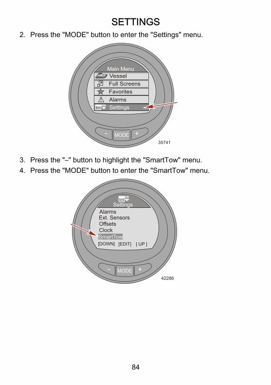
the "Settings" menu.2. Press the "MODE" button to enter the "Settings" menu.
MODE35741
Settings
Main Menu
Full ScreensFavorites
Vessel
Alarms!
3. Press the "MODE" button to edit the "Light/Contrast" menu.
CONTRAST1. Press the "MODE" button to edit the "Contrast" option.2. Press the "–" or "+" button to edit the contrast level of the monitor
screen.
MODE35797
BrightnessDisplay Color
Color SyncButton Color
[DOWN] [SAVE]
ContrastLight/Contrast
54100
BlueWhite
No[ UP ]
3. Press the "MODE" button to save the contrast setting.

SETTINGS
15
4. To exit the "Light/Contrast" menu, press the "–" or "+" button tohighlight the "Exit" option. Press the "MODE" button to exit the"Light/Contrast" menu.
BRIGHTNESS1. Press the "–" button to highlight the "Brightness" option.2. Press the "MODE" button to edit the brightness of the monitor
screen.3. Press the "–" or "+" button to change the brightness of the monitor
screen.
MODE35800
Display ColorButton Color
[DOWN] [EDIT]
ContrastLight/Contrast
54
[ UP ]
100Blue
White
Brightness
Color Sync No
4. Press the "MODE" button to save the brightness setting.5. To exit the "Light/Contrast" menu, press the "–" or "+" button to
highlight the "Exit" option. Press the "MODE" button to exit the"Light/Contrast" menu.
DISPLAY COLORThe display backlighting color can be changed to red, blue, green,white, yellow, purple, and ice blue. All the monitor colors can be selectedto be displayed for approximately 15 seconds each. After the 15seconds, the color will fade and change into the next color. This isreferred to as the color "Wave."1. Press the "–" button to highlight the "Display Color" option.2. Press the "MODE" button to edit the display color of the monitor
screen.

SETTINGS
16
3. Press the "–" or "+" button to select a color, or select "Wave" for thecolor of the monitor screen.
MODE35804
Button Color
[DOWN] [EDIT]
ContrastLight/Contrast
54
[ UP ]
100Blue
White
BrightnessDisplay Color
Color Sync No
4. Press the "MODE" button to save the display color setting.5. To exit the "Light/Contrast" menu, press the "–" or "+" button to
highlight the "Exit" option. Press the "MODE" button to exit the"Light/Contrast" menu.
BUTTON COLORThe "–," "+," and "MODE" button light color can be changed to red, blue,green, white, yellow, purple, and ice blue. All of the button colors canbe selected to be displayed for approximately 15 seconds each. Afterthe 15 seconds, the color will fade and change into the next color. Thisis referred to as the color "Wave."1. Press the "–" button to highlight the "Button Color" option.2. Press the "MODE" button to edit the button colors.

SETTINGS
17
3. Press the "–" or "+" button to select a color, or select "Wave" for thecolor of the buttons.
MODE35806
Button Color
[DOWN] [EDIT]
ContrastLight/Contrast
54
[ UP ]
100Blue
White
BrightnessDisplay Color
Color Sync No
4. Press the "MODE" button to save the button color setting.5. To exit the "Light/Contrast" menu, press the "–" or "+" button to
highlight the "Exit" option. Press the "MODE" button to exit the"Light/Contrast" menu.
COLOR SYNCThe "Color Sync" feature selects the same color for the backlight andthe buttons. Turning the color synchronize on ("Yes"), turns the "ButtonColor" control feature off.1. Press the "–" button to highlight the "Color Sync" option.

SETTINGS
18
2. Press the "MODE" button to turn the option on ("Yes"), or turn theoption off ("No").
MODE35810
Button Color
[DOWN] [EDIT]
ContrastLight/Contrast
54
[ UP ]
100Blue
White
BrightnessDisplay Color
Color Sync No
3. To exit the "Light/Contrast" menu, press the "–" or "+" button tohighlight the "Exit" option. Press the "MODE" button to exit the"Light/Contrast" menu.
REMOTE LIGHTThe "Remote Light" feature allows control of all the monitor gaugelighting from any monitor gauge. This feature controls the brightness,display color, button color, and night time mode. Two or more monitorgauges must have this feature turned on for the remote light feature tofunction.1. Press the "–" button to highlight the "Remote Light" option.

SETTINGS
19
2. Press the "MODE" button to turn the option on ("Yes"), or turn theoption off ("No").
MODE36307
Exit[DOWN] [EDIT]
Remote Light
Light/ContrastYes
[ UP ]
YesNoNo
Remote ContrastNight Time Mode
Color Sync
3. To exit the "Light/Contrast" menu, press the "–" or "+" button tohighlight the "Exit" option. Press the "MODE" button to exit the"Light/Contrast" menu.
REMOTE CONTRASTThe "Remote Contrast" feature allows control of all the monitor gaugecontrast from any monitor gauge. This feature controls only the contrast.Two or more monitor gauges must have this feature turned on for theremote contrast feature to function.1. Press the "–" button to highlight the "Remote Contrast" option.

SETTINGS
20
2. Press the "MODE" button to turn the option on ("Yes"), or turn theoption off ("No").
MODE35812
[DOWN] [EDIT]
Light/Contrast
[ UP ]Exit
Remote LightYesYes
NoRemote ContrastNight Time Mode
Color Sync
No
3. To exit the "Light/Contrast" menu, press the "–" or "+" button tohighlight the "Exit" option. Press the "MODE" button to exit the"Light/Contrast" menu.
NIGHT TIME MODE"Night Time Mode" darkens the monitor screen, turning the letters andnumbers to the color selected. This mode when turned on, significantlydecreases the amount of backlighting on the gauge.1. Press the "–" button to highlight the "Night Time Mode" option.

SETTINGS
21
2. Press the "MODE" button to turn the option on ("Yes"), or turn theoption off ("No"). A third option automatically ("AUTO") selects the"Night Time Mode" when the ambient light conditions fade.
MODE35813
Light/ContrastColor Sync
[DOWN] [EDIT] [ UP ]
WhiteYesRemote Light
Remote Contrast No
ExitNight Time Mode Yes
3. To exit the "Light/Contrast" menu, press the "–" or "+" button tohighlight the "Exit" option. Press the "MODE" button to exit the"Light/Contrast" menu.
Setting the UnitsThe "Units" menu option changes the display units of measurement toEnglish ("Eng") or metric ("Met"), and the speed display to miles perhour ("MPH"), kilometers per hour ("KMH"), or knots ("KN").1. While in the "Main Menu," press the "–" or "+" button to highlight
the "Settings" menu.

SETTINGS
22
2. Press the "MODE" button to enter the "Settings" menu.
MODE35741
Settings
Main Menu
Full ScreensFavorites
Vessel
Alarms!
3. Press the "–" button to highlight the "Units" menu.4. Press the "MODE" button to edit the "Units" menu.
MODE
Settings
35814
Screen
OffsetsTrim
[DOWN] [EDIT]
Light/ContrastUnits
[ UP ]

SETTINGS
23
5. Press the "MODE" button to change the display units to English("Eng"), or metric ("Met").
MODE35815
ExitSpeed
[DOWN] [EDIT]
UnitsDisplay Eng
MPH
6. Press the "–" button to highlight the "Speed" unit.7. Press the "MODE" button to change the speed units to miles per
hour ("MPH"), kilometers per hour ("KMH"), or knots ("KN").
MODE35816
ExitSpeed
[DOWN] [EDIT]
UnitsDisplay Eng
MPH
8. Press the "–" button to highlight the "Exit" option. Press the "MODE"button to exit the "Units" menu.
SETTINGS
24
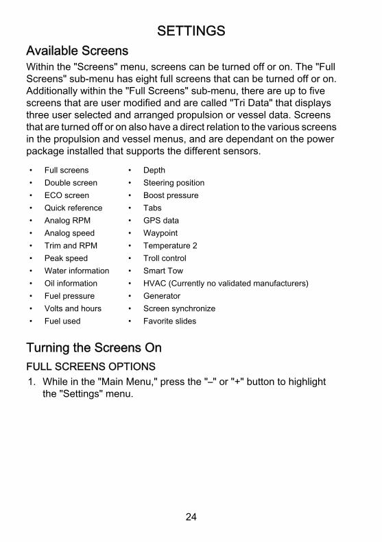
Available ScreensWithin the "Screens" menu, screens can be turned off or on. The "FullScreens" sub‑menu has eight full screens that can be turned off or on.Additionally within the "Full Screens" sub‑menu, there are up to fivescreens that are user modified and are called "Tri Data" that displaysthree user selected and arranged propulsion or vessel data. Screensthat are turned off or on also have a direct relation to the various screensin the propulsion and vessel menus, and are dependant on the powerpackage installed that supports the different sensors.
• Full screens• Double screen• ECO screen• Quick reference• Analog RPM• Analog speed• Trim and RPM• Peak speed• Water information• Oil information• Fuel pressure• Volts and hours• Fuel used
• Depth• Steering position• Boost pressure• Tabs• GPS data• Waypoint• Temperature 2• Troll control• Smart Tow• HVAC (Currently no validated manufacturers)• Generator• Screen synchronize• Favorite slides
Turning the Screens OnFULL SCREENS OPTIONS1. While in the "Main Menu," press the "–" or "+" button to highlight
the "Settings" menu.

SETTINGS
25
2. Press the "MODE" button to enter the "Settings" menu.
MODE35741
Settings
Main Menu
Full ScreensFavorites
Vessel
Alarms!
3. Press the "–" button to highlight the "Screens" menu.4. Press the "MODE" button to edit the "Screens" menu.
MODE
Settings
42175
TanksTrim
[DOWN] [EDIT]
Light/ContrastUnits
[ UP ]
Screens

SETTINGS
26
5. Press the "MODE" button to edit the "Full Screens" menu.
MODE
Screens
42176
Quick RefECO Screen
[DOWN] [EDIT]
Full ScreensDouble Screen
[ UP ]Analog RPM No
NoNo
6. Press the "MODE" button to turn the "Speed" option on ("Yes") oroff ("No").
MODE36375
[DOWN] [EDIT]
Full Screens
Oil Temp
DepthYesNo
NoCoolant TempClock
Speed
No
No
7. Press the "–" button to highlight the "Depth" option.

SETTINGS
27
8. Press the "MODE" button to turn the "Depth" option on ("Yes") oroff ("No").
MODE36379
[DOWN] [EDIT]
Full Screens
Oil Temp
DepthYes
NoCoolant TempClock
Speed
No
No
Yes
[ UP ]
9. Press the "–" button to highlight the "Coolant Temp" option.10.Press the "MODE" button to turn the "Coolant Temp" option on
("Yes") or off ("No").
MODE36380
[DOWN] [EDIT]
Full Screens
Oil Temp
DepthYes
NoCoolant TempClock
Speed
Yes
No
Yes
[ UP ]
11.Press the "–" button to highlight the "Clock" option.

SETTINGS
28
12.Press the "MODE" button to edit the "Clock" option to off ("NO").Press the "MODE" button again to change the clock to an "Analog"display, or press the "MODE" button again to change the displayto "Digital."
MODE36387
[DOWN] [EDIT]
Full Screens
Oil Temp
DepthYes
AnalogCoolant TempClock
Speed
Yes
No
Yes
[ UP ]
13.Press the "–" button to highlight the "Oil Temp" option.14.Press the "MODE" button to turn the "Oil Temp" option on ("Yes")
or off ("No").
MODE36388
[DOWN] [EDIT]
Full Screens
Oil Temp
DepthYes
DigitalCoolant TempClock
Speed
Yes
Yes
Yes
[ UP ]
15.Press the "–" button to highlight the "Fuel Pressure" option.

SETTINGS
29
16.Press the "MODE" button to turn the "Fuel Pressure" option on("Yes") or off ("No").
MODE36389
[DOWN] [EDIT]
Full Screens
Exit
Oil PressYes
Water PressTri Data
Fuel PressureNo
[ UP ]
No
17.Press the "–" button to highlight the "Oil Press" option.18.Press the "MODE" button to turn the "Oil Press" option on ("Yes")
or off ("No").
19.Press the "–" button to highlight the "Water Press" option.
SETTINGS
30
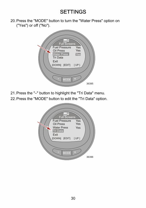
20.Press the "MODE" button to turn the "Water Press" option on("Yes") or off ("No").
MODE36395
[DOWN] [EDIT]
Full Screens
Exit
Oil PressYes
Water PressTri Data
Fuel PressureYes
[ UP ]
Yes
21.Press the "–" button to highlight the "Tri Data" menu.22.Press the "MODE" button to edit the "Tri Data" option.
MODE36396
[DOWN] [EDIT]
Full Screens
Exit
Oil PressYes
Water PressTri Data
Fuel PressureYes
[ UP ]
Yes
SETTINGS
31
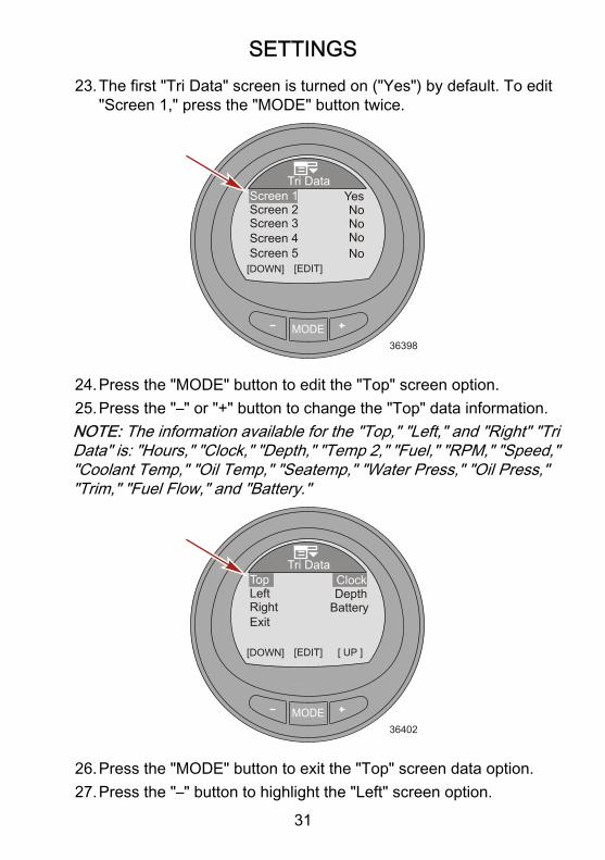
23.The first "Tri Data" screen is turned on ("Yes") by default. To edit"Screen 1," press the "MODE" button twice.
MODE36398
[DOWN] [EDIT]
Tri DataYesScreen 1
Screen 2Screen 3
Screen 5Screen 4
NoNo
NoNo
24.Press the "MODE" button to edit the "Top" screen option.25.Press the "–" or "+" button to change the "Top" data information.NOTE: The information available for the "Top," "Left," and "Right" "TriData" is: "Hours," "Clock," "Depth," "Temp 2," "Fuel," "RPM," "Speed,""Coolant Temp," "Oil Temp," "Seatemp," "Water Press," "Oil Press,""Trim," "Fuel Flow," and "Battery."
MODE36402
[DOWN] [EDIT]
Tri DataClockTop
LeftRightExit
DepthBattery
[ UP ]
26.Press the "MODE" button to exit the "Top" screen data option.27.Press the "–" button to highlight the "Left" screen option.

SETTINGS
32
28.Press the "MODE" button to edit the "Left" screen option.29.Press the "–" or "+" button to change the left side data information.
MODE36403
[DOWN] [EDIT]
Tri DataClockTop
LeftRightExit
DepthBattery
[ UP ]
30.Press the "MODE" button to exit the "Left" screen data option.31.Press the "–" button to highlight the "Right" screen option.32.Press the "MODE" button to edit the "Right" screen option.33.Press the "–" or "+" button to change the right side data information.
MODE36405
[DOWN] [EDIT]
Tri DataClockTop
LeftRightExit
DepthBattery
[ UP ]
34.Press the "MODE" button to exit the "Right" screen data option.35.Press the "–" button to highlight the "Exit" option.36.Press the "MODE" button to exit the "Screen 1" option.
SETTINGS
33
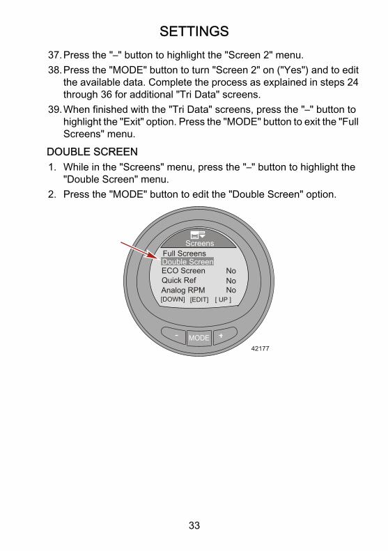
37.Press the "–" button to highlight the "Screen 2" menu.38.Press the "MODE" button to turn "Screen 2" on ("Yes") and to edit
the available data. Complete the process as explained in steps 24through 36 for additional "Tri Data" screens.
39.When finished with the "Tri Data" screens, press the "–" button tohighlight the "Exit" option. Press the "MODE" button to exit the "FullScreens" menu.
DOUBLE SCREEN1. While in the "Screens" menu, press the "–" button to highlight the
"Double Screen" menu.2. Press the "MODE" button to edit the "Double Screen" option.
MODE
Screens
42177
Quick RefECO Screen
[DOWN] [EDIT]
Full ScreensDouble Screen
[ UP ]Analog RPM No
NoNo

SETTINGS
34
3. The first screen is turned on ("Yes") by default. To edit "Screen 1,"press the "MODE" button twice.
MODE42178
[DOWN] [EDIT]
Double ScreenYesScreen 1
Screen 2Screen 3
Screen 5Screen 4
NoNo
NoNo
4. Press the "MODE" button to edit the "OUTER" screen data option.5. Press the "–" or "+" button to change the "OUTER" data information.NOTE: The information available for the "OUTER" and "INNER""Double Screen" is: "RPM," "Speed," "Coolant Temp," "Oil Temp,""Seatemp," "Water Press," "Oil Press," "Fuel Flow," "Fuel," "Battery,""Depth," and "Temp 2."
MODE42179
[DOWN] [SAVE]
Double ScreenRPMOUTER
INNERExit
Depth
[ UP ]
6. Press the "MODE" button to exit the "OUTER" screen data option.7. Press the "–" to highlight the "INNER" screen data option.

SETTINGS
35
8. Press the "MODE" button to edit the "INNER" screen data option.9. Press the "–" or "+" button to change the "INNER" data information.
MODE42180
[DOWN] [SAVE]
Double ScreenRPMOUTER
INNERExit
Depth
[ UP ]
10.Press the "MODE" button to exit the "INNER" screen data option.11.Press the "–" to highlight the "Exit" option.12.Press the "MODE" button to exit the "Screen 1" option.13.Press the "–" to highlight the "Screen 2" menu.14.Press the "MODE" button to turn "Screen 2" on ("Yes") and to edit
the available data. Complete the process as explained in steps 4through 11 for additional "Double Screen" options.
15.When finished with the "Double Screen" options, press the "–"button to highlight the "Exit" option. Press the "MODE" button toexit the "Double Screen" menu.
ADDITIONAL SCREENS OPTIONS1. While in the "Screens" menu, press the "–" button to highlight the
"ECO Screen" option.

SETTINGS
36
2. Press the "MODE" button to turn the option on ("Yes") or off ("No").
MODE
Screens
42181
Quick RefECO Screen
[DOWN] [EDIT]
Full ScreensDouble Screen
[ UP ]Analog RPM No
YesNo
3. Press the "–" button to highlight the "Quick Ref" option.4. Press the "MODE" button to turn the option on ("Yes") or off ("No").
MODE
Screens
42182
ECO Screen
[DOWN] [EDIT]
Full ScreensDouble Screen
[ UP ]Analog RPM No
YesYesQuick Ref
5. Press the "–" button to highlight the "Analog RPM" option.

SETTINGS
37
6. Press the "MODE" button to turn the option on ("Yes") or off ("No").
MODE
Screens
42183
ECO Screen
[DOWN] [EDIT]
Full ScreensDouble Screen
[ UP ]Analog RPM
YesYesQuick RefYes
7. Press the "–" button to highlight the "Analog Speed" option.8. Press the "MODE" button to turn the option on ("Yes") and to select
the maximum speed of the analog gauge.NOTE: Pressing the "MODE" button will page through the 0–80 ("80Dial"), 0–120 ("120 Dial"), and off ("No").
MODE
Screens
42184
Trim/RPM
[DOWN] [EDIT]
Analog RPMAnalog Speed
[ UP ]Water Info
Yes80 Dial
Peak SpeedNoNoNo
9. Press the "–" button to highlight the "Trim/RPM" option.

SETTINGS
38
10.Press the "MODE" button to turn the option on ("Yes") or off ("No").
MODE
Screens
42185
Trim/RPM
[DOWN] [EDIT]
Analog RPMAnalog Speed
[ UP ]Water Info
Yes80 Dial
Peak SpeedNoNo
Yes
11.Press the "–" button to highlight the "Peak Speed" option.12.Press the "MODE" button to turn the option on ("Yes") or off ("No").
MODE
Screens
42186
Trim/RPM
[DOWN] [EDIT]
Analog RPMAnalog Speed
[ UP ]Water Info
Yes80 Dial
Peak SpeedNo
YesYes
13.Press the "–" button to highlight the "Water Info" option.

SETTINGS
39
14.Press the "MODE" button to turn the option on ("Yes") or off ("No").
MODE
Screens
42188
Trim/RPM
[DOWN] [EDIT]
Analog RPMAnalog Speed
[ UP ]Water Info
Yes80 Dial
Peak SpeedYesYesYes
15.Press the "–" button to highlight the "Oil Info" option.16.Press the "MODE" button to turn the option on ("Yes") or off ("No").
MODE
Screens
36448
Fuel Pressure
[DOWN] [EDIT]
Water Info
[ UP ]
Oil InfoYesYes
Volts/HoursNoNo
Fuel Used No
17.Press the "–" button to highlight the "Fuel Pressure" option.

SETTINGS
40
18.Press the "MODE" button to turn the option on ("Yes") or off ("No").
MODE
Screens
36449
Fuel Pressure
[DOWN] [EDIT]
Water Info
[ UP ]
Oil InfoYesYes
Volts/HoursYesNo
Fuel Used No
19.Press the "–" button to highlight the "Volts/Hours" option.20.Press the "MODE" button to turn the option on ("Yes") or off ("No").
MODE
Screens
36451
Fuel Pressure
[DOWN] [EDIT]
Water Info
[ UP ]
Oil InfoYesYes
Volts/HoursYesYes
Fuel Used No
21.Press the "–" button to highlight the "Fuel Used" option.

SETTINGS
41
22.Press the "MODE" button to turn the option on ("Yes") or off ("No").
MODE
Screens
36454
Steering
[DOWN] [EDIT]
Fuel Used
[ UP ]
DepthYesNo
Boost PressureTabs
NoNo
No
23.Press the "–" button to highlight the "Depth" option.24.Press the "MODE" button to turn the option on ("Yes") or off ("No").NOTE: The "Depth" screen must be turned on to enable the depthalarms.
MODE
Screens
36455
Steering
[DOWN] [EDIT]
Fuel Used
[ UP ]
DepthYesYes
Boost PressureTabs
NoNo
No
25.Press the "–" button to highlight the "Steering" option.

SETTINGS
42
26.Press the "MODE" button to turn the option on ("Yes") or off ("No").
MODE
Screens
36456
Steering
[DOWN] [EDIT]
Fuel Used
[ UP ]
DepthYesYes
Boost PressureTabs
NoYes
No
27.Press the "–" button to highlight the "Boost Pressure" option.28.Press the "MODE" button to turn the option on ("Yes") or off ("No").
MODE
Screens
36459
Steering
[DOWN] [EDIT]
Fuel Used
[ UP ]
DepthYesYes
Boost PressureTabs
YesYes
No
29.Press the "–" button to highlight the "Tabs" option.

SETTINGS
43
30.Press the "MODE" button to turn the option on ("Yes") or off ("No").
MODE
Screens
36463
Steering
[DOWN] [EDIT]
Fuel Used
[ UP ]
DepthYesYes
Boost PressureTabs
YesYes
Yes
31.Press the "–" button to highlight the "GPS Data" option.32.Press the "MODE" button to turn the option on ("Yes") or off ("No").
MODE
Screens
42189
Temp 2
[DOWN] [EDIT]
GPS DataWaypoint
[ UP ]SmartTow
YesNo
Troll ControlN/ANoNo
33.Press the "–" button to highlight the "Waypoint" option.

SETTINGS
44
34.Press the "MODE" button to turn the option on ("Yes") or off ("No").
MODE
Screens
42190
Temp 2
[DOWN] [EDIT]
GPS DataWaypoint
[ UP ]SmartTow
Yes
Troll ControlN/ANoNo
Yes
35.Press the "–" button to bypass the "Temp 2" option and move tothe "Troll Control" option.
NOTE: The "Temp 2" option is not available at the time of this documentprinting.36.Press the "MODE" button to turn the option on ("Yes") or off ("No").
MODE
Screens
42191
Temp 2
[DOWN] [EDIT]
GPS DataWaypoint
[ UP ]SmartTow
Yes
Troll ControlN/A
No
Yes
Yes
37.Press the "–" button to highlight the "SmartTow" option.
SETTINGS
45
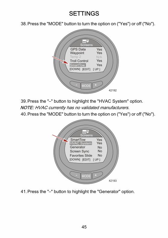
38.Press the "MODE" button to turn the option on ("Yes") or off ("No").
MODE
Screens
42192
Temp 2
[DOWN] [EDIT]
GPS DataWaypoint
[ UP ]SmartTow
Yes
Troll ControlN/AYes
YesYes
39.Press the "–" button to highlight the "HVAC System" option.NOTE: HVAC currently has no validated manufacturers.40.Press the "MODE" button to turn the option on ("Yes") or off ("No").
MODE
Screens
42193
Generator
[DOWN] [EDIT]
SmartTowHVAC System
[ UP ]Favorites Slide
Yes
Screen SyncNoNoNo
Yes
41.Press the "–" button to highlight the "Generator" option.

SETTINGS
46
42.Press the "MODE" button to turn the option on ("Yes") or off ("No").
MODE
Screens
42194
Screen Sync
[DOWN] [EDIT]
HVAC SystemGenerator
[ UP ]Exit
Yes
Favorite SlideNoNo
No
43.Press the "–" button to highlight the "Screen Sync" option.44.Press the "MODE" button to turn the option on ("Yes") or off ("No").
MODE
Screens
42195
Screen Sync
[DOWN] [EDIT]
HVAC SystemGenerator
[ UP ]Exit
Yes
Favorite Slide No
NoYes
45.Press the "–" button to highlight the "Favorite Slide" option.NOTE: The "Favorite Slide" seconds must be displayed for the"Favorites" menu option to function. Select from 1–30 seconds todisplay the selected favorites.46.Press the "MODE" button to edit the number of seconds the
favorites will display.

SETTINGS
47
47.Press the "+" or "–" to change the number of seconds.
MODE
Screens
42196
Screen Sync
[DOWN] [EDIT]
HVAC SystemGenerator
[ UP ]Exit
Yes
Favorite Slide
NoYes
4
48.Press the "MODE" button to exit the "Favorite Slide" option.49.Press the "–" button to highlight the "Exit" option. Press the "MODE"
button to exit the "Screens" menu.
Setting the TrimEditing the trim settings menu allows you to turn the trim pop‑up on oroff, change the length of time the pop‑up window remains on the screen,turn the high resolution on or off, and calibrate the gauge to the sensor.A high resolution setting will cause the monitor to display the trimposition with more detailed information.1. While in the "Main Menu," press the "–" or "+" button to highlight
the "Settings" menu.

SETTINGS
48
2. Press the "MODE" button to enter the "Settings" menu.
MODE35741
Settings
Main Menu
Full ScreensFavorites
Vessel
Alarms!
3. Press the "–" button to highlight the "Trim" menu.4. Press the "MODE" button to edit the "Trim" menu.
MODE
Settings
42218
Screen
TanksTrim
[DOWN] [EDIT]
Light/ContrastUnits
[ UP ]

SETTINGS
49
5. Press the "MODE" button to turn the trim "Popup" window optionon ("Yes") or off ("No").
MODE35928
Popup Time
Exit
Trim
[DOWN] [EDIT]
PopupHigh Resol.
Calibration
YesNo1 s
6. Press the "–" button to highlight the "High Resol" option.7. Press the "MODE" button to turn the high resolution option on
("Yes") or off ("No").
MODE35929
Popup Time
Exit
Trim
[DOWN] [EDIT]
PopupHigh Resol.
Calibration
Yes
1 s
[ UP ]
Yes
8. Press the "–" button to highlight the "Popup Time" option.9. Press the "MODE" button to edit the length of time the trim pop‑up
window option remains on the screen.

SETTINGS
50
10.Press the "–" or "+" to change the length of time the trim pop‑upwindow option remains on the screen. The trim pop‑up windowlength of time can be changed from 1 to 10 seconds.
MODE35932
Trim
[DOWN] [EDIT]
PopupHigh Resol.
Yes
5 s
[ UP ]
YesPopup Time
ExitCalibration
11.Press the "MODE" button to exit the "Popup Time" option.12.Press the "–" button to highlight the "Calibration" option.13.Press the "MODE" button to calibrate the gauge to the trim position
sensor. An instruction window will pop‑up stating to trim full downand press the "+" button when ready.
MODE35933
Trim
[ DFLT ] [QUIT]
PopupHigh Resol.
Yes
5 s
[SAVE ]
YesPopup Time
ExitCalibration
Trim full DOWNPress Plus Buttonwhen ready !
14.After pressing the "+" button, the pop‑up window instructions willchange stating to trim full up and press the "+" button when ready.

SETTINGS
51
IMPORTANT: To achieve accurate trim full up calibration, this must beperformed on the water while the vessel is running at cruising speed.While at cruising speed, trim up to the maximum trim angle before thevessel begins to porpoise then press the "+" button.
MODE35934
Trim
[ DFLT ] [QUIT]
PopupHigh Resol.
Yes
5 s
[SAVE ]
YesPopup Time
ExitCalibration
Trim full UPPress Plus Buttonwhen ready !
15.After pressing the "+" button, the pop‑up window instructions willchange stating to trim to the trailer point and press the "+" buttonwhen ready.
MODE35935
Trim
[ DFLT ] [QUIT]
PopupHigh Resol.
Yes
5 s
[SAVE ]
YesPopup Time
ExitCalibration
Trim to the TRAILERpointPress Plus Buttonwhen ready !
16.Press the "+" button to return to the "Calibration" option.17.Press the "–" button to highlight the "Exit" option. Press the "MODE"
button to return to the "Settings" menu.

SETTINGS
52
18.Press the "–" button to highlight the "Exit" option. Press the "MODE"button to return to the "Main Menu" screen.
Setting the TanksThere are two tanks available for each power package installed on thevessel. Tank number "1" can be designated as not installed ("Not inst")or fuel. When "Not inst" is selected, the options for setting the tankcapacity and the calibration cannot be edited. The maximum fuelcapacity is 2271 liter (600 US gal). The second tank can be designatedas not installed ("Not inst"), water, fuel, or waste on four‑stroke enginesand will automatically default to oil if the gauge is installed on a vesselwith a two‑stroke engine.Two different methods are available to calibrate the tanks: For linearshaped fuel tanks, choose "Default Calibration." "Default Calibration"assumes the tank is uniformly shaped and that each quarter of the tankholds a quarter of its total capacity. Water and waste tanks are typicalto this linear shape tank and are automatically set to the "DefaultCalibration." For irregularly shaped fuel tanks, choose "Add FuelMethod." Fuel must be added to the tank for each quarter of the capacitywhen using this method. The "Add Fuel Method" should be performedin the water for an accurate representation of the tank capacity.NOTE: Tank capacity must be calibrated by either the "DefaultCalibration," or "Add Fuel Method," or the capacity will revert back to itsformer value.TANK 11. While in the "Main Menu," press the "–" or "+" button to highlight
the "Settings" menu.

SETTINGS
53
2. Press the "MODE" button to enter the "Settings" menu.
MODE35741
Settings
Main Menu
Full ScreensFavorites
Vessel
Alarms!
3. Press the "–" button to highlight the "Tanks" menu.4. Press the "MODE" button to edit the "Tanks" menu.
MODE
Settings
42219
Screens
Light/Contrast
Trim
[DOWN] [EDIT]Tanks
Units
[ UP ]
5. Press the "MODE" button to edit the "Tank 1 Type" option.

SETTINGS
54
6. Press the "–" or "+" button to change the tank setting.
MODE35880
[DOWN] [SAVE]
TanksTank 1 Type
[ UP ]
Tank 1 VolTank 1 CalTank 2 TypeTank 2 Vol
0.0 G
Not inst.
Fuel
7. Press the "MODE" button to exit the "Tank 1 Type" option.8. Press the "–" button to highlight the "Tank 1 Vol" capacity.9. Press the "MODE" button to edit the capacity.NOTE: The maximum capacity is 2271 liter (600 US gal).10.Press the "–" or "+" button to change the capacity of the tank.
Holding the button down will scroll through the numbers.
MODE35881
[DOWN] [SAVE]
TanksTank 1 Type
[ UP ]
Tank 1 VolTank 1 CalTank 2 TypeTank 2 Vol
100.0 G
Not inst.
Fuel
11.Press the "MODE" button to exit the "Tank 1 Vol" option.

SETTINGS
55
12.Press the "–" button to highlight the "Tank 1 Cal" option.
MODE35886
[ DFLT ] [ QUIT ]
TanksTank 1 Type
[ ADD ]
Tank 1 VolTank 1 CalTank 2 TypeTank 2 Vol
100.0 G
Not inst.
Fuel
13.Press the "MODE" button to select the type of calibration.NOTE: Two different methods are available to calibrate the tanks: Forlinear shaped fuel tanks, choose "Default Calibration." "DefaultCalibration" assumes the tank is uniformly shaped and that eachquarter of the tank holds a quarter of its total capacity. Water and wastetanks are typical to this linear shape tank. For irregularly shaped fueltanks, choose "Add Fuel Method." Fuel must be added to the tank foreach quarter of the capacity when using this method. The "Add FuelMethod" should be performed in the water for an accuraterepresentation of the tank capacity.NOTE: The following procedure is used for the "Default Calibration"method.

SETTINGS
56
14.Press the "–" button to choose the "Default Calibration" method orpress the "MODE" button to quit the calibration.
MODE35882
[ DFLT ] [ QUIT ]
TanksTank 1 Type
[ ADD ]
Tank 1 VolTank 1 CalTank 2 TypeTank 2 Vol
100.0 G
Not inst.
FuelDefault Calibration orAdd Fuel Method
15.Press the "MODE" button to finish "(OK)" and exit the "Tank 1 Cal"option.
MODE35884
[ OK ]
TanksTank 1 TypeTank 1 VolTank 1 CalTank 2 TypeTank 2 Vol
100.0 G
Not inst.
FuelCalibration OK
NOTE: The following procedure is used for the "Add Fuel Method" ofcalibration.

SETTINGS
57
16.Press the "+" button to choose the "Add Fuel Method" or press the"MODE" button to quit the calibration.
MODE35887
[ DFLT ] [ QUIT ]
TanksTank 1 Type
[ ADD ]
Tank 1 VolTank 1 CalTank 2 TypeTank 2 Vol
100.0 G
Not inst.
FuelDefault Calibration orAdd Fuel Method
17.Press the "+" button to save and edit the "Add Fuel Method" ofcalibration.
MODE35889
TanksTank 1 Type
[ SAVE ]
Tank 1 VolTank 1 CalTank 2 TypeTank 2 Vol
100.0 G
Not inst.
FuelCalibrating Empty Tank: 0.0 GallonsPress Plus Buttonwhen ready!

SETTINGS
58
18.Add 25 percent of the fuel capacity to the empty fuel tank. Thegauge will list the quantity of fuel to add for each quarter. Press the"+" button to save the calibration.
MODE36788
TanksTank 1 Type
[ SAVE ]
Tank 1 VolTank 1 CalTank 2 TypeTank 2 Vol
100.0 G
Not inst.
FuelCalibrating 1/4 Tank:25.0 GallonsPress Plus Buttonwhen ready!
19.The fuel level sensor must change a minimal value when addingfuel. If the fuel level sensor does not change to the minimal valueany time during the add fuel calibration, an error message statingthe calibration is defaulting to values ("Error! Defaulting tovalues...") will be visible on the screen. The manual calibrationprocess will stop when the error message appears. The fuel tankmust be emptied and the manual calibration process must berepeated.
MODE36794
TanksTank 1 Type
[ OK ]
Tank 1 VolTank 1 CalTank 2 TypeTank 2 Vol
100.0 G
Not inst.
FuelError ! Defaulting tovalues....

SETTINGS
59
20.Add 25 percent more fuel capacity to the fuel tank. Press the "+"button to save the calibration.
MODE36790
TanksTank 1 Type
[ SAVE ]
Tank 1 VolTank 1 CalTank 2 TypeTank 2 Vol
100.0 G
Not inst.
FuelFill to 1/2: 50 Gallons
Press Plus Buttonwhen ready!
21.Add 25 percent more fuel capacity to the fuel tank. Press the "+"button to save the calibration.
MODE36791
TanksTank 1 Type
[ SAVE ]
Tank 1 VolTank 1 CalTank 2 TypeTank 2 Vol
100.0 G
Not inst.
FuelFill to 3/4: 75 Gallons
Press Plus Buttonwhen ready!

SETTINGS
60
22.Add 25 percent more fuel capacity to fill the fuel tank. Press the "+"button to save the calibration.
MODE36792
TanksTank 1 Type
[ SAVE ]
Tank 1 VolTank 1 CalTank 2 TypeTank 2 Vol
100.0 G
Not inst.
FuelFill until full: 100.0GallonsPress Plus Buttonwhen ready!
23.The screen on the monitor will state the fuel tank calibrations issuccessful ("Calibrations OK").
MODE36793
TanksTank 1 Type
[ OK ]
Tank 1 VolTank 1 CalTank 2 TypeTank 2 Vol
100.0 G
Not inst.
FuelCalibrations OK
24.Press the "MODE" button to exit the calibration process.25.Press the "–" button to edit the "Tank 2 Type" option.

SETTINGS
61
TANK 2The second tank can be designated as not installed ("Not inst"), water,fuel, or waste when installed on a vessel with a four‑stroke engine. Themaximum fuel capacity is 2271 liter (600 US gal). When the tank isdesignated as water or waste, the calibration is automatically selectedas default and will estimate the level based on a linear shape capacityand the calibration cannot be edited. When fuel is selected for tank 2,the calibration methods are the same as tank 1. Choose between the"Default Calibration" method or "Add Fuel Method."When the gauge is installed on a vessel with a two‑stroke engine, thesecond tank will default to oil automatically and cannot be calibrated.
Setting the AlarmsAlarm settings can be customized to the vessel specifications and tothe preference of the owner. Low fuel and critical fuel levels cannot bedisabled, but can be adjusted to the preference of the owner. Theselevels can be adjusted down to 10 percent of the fuel tank volume. Theshallow water depth, deep water depth, and waypoint distance alarmscan be turned off or on. The shallow water depth alarm can be adjustedto 0.1 m (0.3 ft) and the deep water depth alarm can be adjusted to300 m (984 ft). The pop‑up alarm warning for these settings can beturned off or on. Vessels equipped with a generator or a heating,ventilation, air conditioning (HVAC) unit, can have these alarms turnedoff or on.NOTE: HVAC currently has no validated manufacturers.1. While in the "Main Menu," press the "–" or "+" button to highlight
the "Settings" menu.

SETTINGS
62
2. Press the "MODE" button to enter the "Settings" menu.
MODE35741
Settings
Main Menu
Full ScreensFavorites
Vessel
Alarms!
3. Press the "–" button to highlight the "Alarms" menu.4. Press the "MODE" button to edit the "Alarms" menu.
MODE
Settings
42220
Offsets
SmartTow [DOWN] [EDIT]
AlarmsExt. Sensors
[ UP ]
Clock
5. Press the "MODE" button to enter the "Fuel Critical" option.

SETTINGS
63
6. Press the "–" or "+" to edit the "Fuel Critical" percentage. Thispercentage cannot be set lower than 10, or more than the "FuelLow" alarm setting.
MODE35859
Fuel Low
Depth DeepDepth Shallow
[DOWN] [EDIT]
AlarmsFuel Critical
[ UP ]
Waypoint Dist
10 %25 %OFFOFFOFF
7. Press the "MODE" button to exit the "Fuel Critical" option.8. Press the "–" button to highlight the "Fuel Low" option.9. Press the "MODE" button to enter the "Fuel Low" option.10.Press the "–" or "+" to edit the "Fuel Low" percentage. This
percentage cannot be set lower than 10, or more than 50 percent.
MODE35860
[DOWN] [EDIT]
AlarmsFuel Critical
[ UP ]
10 %25 %OFFOFFOFF
Fuel Low
Depth DeepDepth Shallow
Waypoint Dist
11.Press the "MODE" button to exit the "Fuel Low" option.12.Press the "–" button to highlight the "Depth Shallow" option.

SETTINGS
64
13.Press the "MODE" button to enter the "Depth Shallow" option.14.Press the "–" or "+" to edit the "Depth Shallow" option. The minimum
setting is 0.1 m (0.3 ft) and the maximum setting is 100 m (328 ft).
MODE35862
[DOWN] [EDIT]
AlarmsFuel Critical
[ UP ]
10 %25 %0.3 ft
OFF
Fuel Low
Depth DeepDepth Shallow
Waypoint DistOFF
15.Press the "MODE" button to exit the "Depth Shallow" option.16.Press the "–" button to highlight the "Depth Deep" option.17.Press the "MODE" button to enter the "Depth Deep" option.18.Press the "–" or "+" to edit the "Depth Deep" option. The minimum
setting is 0.2 m (0.7 ft) and the maximum setting is 300 m (984 ft).NOTE: The minimum setting can be set to 0.1 m (0.3 ft) when the"Depth Shallow" is set to "OFF."
MODE35864
[DOWN] [EDIT]
AlarmsFuel Critical
[ UP ]
10 %25 %0.3 ft
OFF
Fuel Low
Depth DeepDepth Shallow
Waypoint Dist0.7 ft

SETTINGS
65
19.Press the "MODE" button to exit the "Depth Deep" option.20.Press the "–" button to highlight the "Waypoint Dist" option.21.Press the "MODE" button to enter the "Waypoint Dist" option.22.Press the "–" or "+" to edit the "Waypoint Dist" option. The minimum
setting is 161 m (0.1 mile) and the maximum setting is 482 m(0.3 mile).
MODE35865
[DOWN] [EDIT]
AlarmsFuel Critical
[ UP ]
10 %25 %0.3 ft
0.1 M
Fuel Low
Depth DeepDepth Shallow
Waypoint Dist0.7 ft
23.Press the "MODE" button to exit the "Waypoint Dist" option.24.Press the "–" button to highlight the "Generator" option.NOTE: A generator capable of sending data on the control areanetwork (CAN) must be installed to edit this option.

SETTINGS
66
25.Press the "MODE" button to turn the "Generator" option on ("Yes")or off ("No").
MODE35872
[DOWN] [EDIT]
Alarms
[ UP ]Exit
YesNo
0.1 MGenerator
PopupHVAC
Waypoint Dist
No
26.Press the "–" button to highlight the "HVAC" option.NOTE: A HVAC unit capable of sending data on the control areanetwork (CAN) must be installed to edit this option.NOTE: HVAC currently has no validated manufacturers.27.Press the "MODE" button to turn the "HVAC" option on ("Yes") or
off ("No").
MODE35875
[DOWN] [EDIT]
Alarms
[ UP ]Exit
YesYes
0.1 MGenerator
PopupHVAC
Waypoint Dist
No
28.Press the "–" button to highlight the "Popup" option.

SETTINGS
67
29.Press the "MODE" button to turn the "Popup" option on ("Yes") oroff ("No").
MODE35876
[DOWN] [EDIT]
Alarms
[ UP ]Exit
Yes
Yes0.1 M
Generator
PopupHVAC
Waypoint Dist
Yes
30.Press the "–" button to highlight the "Exit" option. Press the "MODE"button to exit the "Alarms" menu.
Setting the External SensorsThe external sensors menu turns a number of sensors off or on. Theseinclude sea temperature, trim, GPS, speed, steering, and tabs. Theexternal sensors menu also can change how the speed is recognized;pitot, paddle wheel, GPS, and at what speed the transition to a differentsensor occurs. The type of pitot sensor can be changed from 689 kPa(100 psi) for most vessel applications, to a high speed 1379 kPa(200 psi) sensor. A high speed sensor must be installed for an accuratespeed to be displayed when the 1379 kPa (200 psi) is selected.1. While in the "Main Menu," press the "–" or "+" button to highlight
the "Settings" menu.

SETTINGS
68
2. Press the "MODE" button to enter the "Settings" menu.
MODE35741
Settings
Main Menu
Full ScreensFavorites
Vessel
Alarms!
3. Press the "–" button to highlight the "Ext. Sensors" menu.4. Press the "MODE" button to edit the "Ext. Sensors" menu.
MODE
Settings
42221
Offsets
SmartTow [DOWN] [EDIT]
AlarmsExt. Sensors
[ UP ]
Clock

SETTINGS
69
5. Press the "MODE" button to turn the "Depth/Seatemp" option on("Yes") or off ("No").
MODE42224
TabsSteeringSpeed
[DOWN] [EDIT]
Depth/SeatempExt. Sensors
YesTrim No
No
No
6. Press the "–" button to highlight the "Trim" option.7. Press the "MODE" button to turn the "Trim" option on ("Yes") or off
("No").
MODE42225
TabsSteeringSpeed
[DOWN] [EDIT]
Depth/SeatempExt. Sensors
YesTrim
No
No
Yes
8. Press the "–" button to highlight the "Speed" option.

SETTINGS
70
9. Press the "MODE" button to edit the "Speed" options.
MODE42226
TabsSteeringSpeed
[DOWN] [EDIT]
Depth/SeatempExt. Sensors
YesTrim
No
YesYes
10.Press the "MODE" button to turn the "Use Paddle" option on ("Yes")or off ("No").
MODE42227
Trans Speed
Speed
[DOWN] [EDIT]
Use PaddleUse Pitot
5
NoYes
100 PSIPitot Type
GPS Enabled No[ UP ]
11.Press the "–" button to highlight the "Use Pitot" option.

SETTINGS
71
12.Press the "MODE" button to turn the "Use Pitot" option on ("Yes")or off ("No").
MODE42228
Trans Speed
Speed
[DOWN] [EDIT]
Use PaddleUse Pitot
5
Yes
100 PSIPitot Type
GPS Enabled No[ UP ]
Yes
13.Press the "–" button to highlight the "Pitot Type" option.14.Press the "MODE" button to change the sensor to "100 PSI" or "200
PSI."
MODE42229
Trans Speed
Speed
[DOWN] [EDIT]
Use PaddleUse Pitot
5
Yes
100 PSIPitot Type
GPS Enabled No[ UP ]
Yes
15.Press the "–" button to highlight the "Trans Speed" option.16.Press the "MODE" button to edit the "Trans Speed" option.
SETTINGS
72
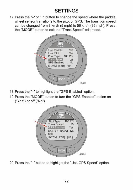
17.Press the "–" or "+" button to change the speed where the paddlewheel sensor transitions to the pitot or GPS. The transition speedcan be changed from 8 km/h (5 mph) to 56 km/h (35 mph). Pressthe "MODE" button to exit the "Trans Speed" edit mode.
MODE42230
Speed
[DOWN] [EDIT]
Use PaddleUse Pitot
25
Yes
100 PSIPitot Type
GPS Enabled No[ UP ]
Yes
Trans Speed
18.Press the "–" to highlight the "GPS Enabled" option.19.Press the "MODE" button to turn the "GPS Enabled" option on
("Yes") or off ("No").
MODE42231
Speed
[DOWN] [EDIT]
Pitot Type25
100 PSI
GPS Enabled
Exit[ UP ]
YesTrans Speed
Use GPS Speed No
20.Press the "–" button to highlight the "Use GPS Speed" option.

SETTINGS
73
21.Press the "MODE" button to turn the "Use GPS Speed" option on("Yes") or off ("No").
MODE42232
Speed
[DOWN] [EDIT]
Pitot Type25
100 PSI
GPS Enabled
Exit[ UP ]
YesTrans Speed
Use GPS Speed Yes
22.Press the "–" button to highlight the "Exit" option. Press the "MODE"button to exit the "Speed" menu.
Setting the OffsetsThe "Offsets" menu allows for compensation for inaccurate sensors,sets a transition speed from one speed sensor to another, inverts asteering sensor, and corrects the amount of fuel used. Sensors that canbe modified are; sea temperature, depth, paddle wheel hertz, pitotpressure, and steering position.1. While in the "Main Menu," press the "–" or "+" button to highlight
the "Settings" menu.

SETTINGS
74
2. Press the "MODE" button to enter the "Settings" menu.
MODE35741
Settings
Main Menu
Full ScreensFavorites
Vessel
Alarms!
3. Press the "–" button to highlight the "Offsets" menu.4. Press the "MODE" button to edit the "Offsets" menu.
MODE
Settings
42234
SmartTow [DOWN] [EDIT]
AlarmsExt. Sensors
[ UP ]
ClockOffsets
5. Press the "MODE" button to edit the "Seatemp" option.

SETTINGS
75
6. Press the "‑" or "+" button to change the sea temperature correctionfrom ‑23.3 to ‑12.2 °C (‑10 to 10 °F).
MODE42235
[DOWN] [SAVE]
Offsets
[ UP ]
6 F0 ft4.9
1.00No
SeatempDepthPaddlePitotSteer Inv
7. Press the "MODE" button to exit the "Seatemp" option.8. Press the "–" button to highlight the "Depth" option.9. Press the "MODE" button to edit the "Depth" option. The depth
offset can be changed ± 30.5 m (100 ft).10.Press the "–" or "+" button to change the depth offset.
MODE42236
[DOWN] [SAVE]
Offsets
[ UP ]
6 F6 ft4.9
1.00No
SeatempDepthPaddlePitotSteer Inv
11.Press the "MODE" button to exit the "Depth" option.12.Press the "–" button to highlight the "Paddle" option.13.Press the "MODE" button to edit the "Paddle" option.

SETTINGS
76
14.Press the "–" or "+" button to change the paddle offset. The offsetcan be changed from 3.4 Hz to 6.4 Hz.
MODE42237
[DOWN] [SAVE]
Offsets
[ UP ]
6 F6 ft4.9
1.00No
SeatempDepthPaddlePitotSteer Inv
15.Press the "MODE" button to exit the "Paddle" option.16.Press the "–" button to highlight the "Pitot" option.17.Press the "MODE" button to edit the "Pitot" option.18.Press the "–" or "+" button to change the pitot offset. The offset can
be changed from 0.50 to 1.50.
MODE42238
[DOWN] [SAVE]
Offsets
[ UP ]
6 F6 ft4.9
1.00No
SeatempDepthPaddlePitotSteer Inv
19.Press the "MODE" button to exit the "Pitot" option.20.Press the "–" button to highlight the "Steer Inv" option.

SETTINGS
77
21.Press the "MODE" button to turn the "Steer Inv" option on ("Yes")or off ("No").
MODE42239
[DOWN] [SAVE]
Offsets
[ UP ]
6 F6 ft4.9
1.00No
SeatempDepthPaddlePitotSteer Inv
22.Press the "MODE" button to exit the "Steer Inv" option.23.Press the "–" button to highlight the "Steering" option.24.Press the "MODE" button to edit the "Steering" option.25.Press the "–" or "+" button to change the steering offset. The offset
can be changed ± 30 degrees.
MODE42240
[DOWN] [SAVE]
Offsets
[ UP ]
10
1.00No
Fuel UsedSteering
Exit
PitotSteer Inv
26.Press the "MODE" button to exit the "Steering" option.27.Press the "–" button to highlight the "Fuel Used" option.

SETTINGS
78
28.Press the "MODE" button to edit the "Fuel Used" option.
MODE42241
[DOWN] [SAVE]
Offsets
[ UP ]
10
1.00No
Fuel UsedSteering
Exit
PitotSteer Inv
29.Press the "MODE" button to edit the "Multiplier" option.30.Press the "–" or "+" button to change the multiplier offset. The offset
can be changed from 0.50 to 1.50.NOTE: The "Multiplier" is used to fine‑tune the fuel gauge sender tocorrect for fuel used errors. If the gauge indicates that 10 gallons offuel was used, but the actual fuel that was added is 14 gallons, changethe multiplier to 1.40. If the gauge indicates that 10 gallons of fuel wasused, but the actual fuel that was added is only 8 gallons, change themultiplier to 0.80.
MODE35922
[DOWN] [SAVE] [ UP ]
Fuel Used
0.0 G1.0
Add FuelMultiplier
Exit
31.Press the "MODE" button to exit the "Multiplier" option.

SETTINGS
79
32.Press the "–" button to highlight the "Add Fuel" option.33.Press the "–" or "+" button to change the amount of fuel that was
actually added to the fuel tank to correct for fuel capacity errors.NOTE: The "Add Fuel" option functions the same as the multiplier. Ifthe gauge indicates that 10 gallons of fuel was used, but the actual fuelthat was added is 14 gallons, change the "Add Fuel" to 14.0. If thegauge indicates that 10 gallons of fuel was used, but the actual fuelthat was added is only 8 gallons, change the "Add Fuel" to 8.0 gallons.The gauge will calculate the multiplier and will automatically changethe number in the "Multiplier" option.34.Press the "–" button to highlight the "Exit" option. Press the "MODE"
button to exit the "Fuel Used" option.35.Press the "–" button to highlight the "Exit" option. Press the "MODE"
button to exit the "Offsets" menu.
Setting the ClockThe "Clock" can be set to display a 24 hour day or a 12 hour (AM, PM)day. It can also be updated automatically when using a GPS. The GPSmust be turned on ("Yes") in the external sensors ("Ext. Sensors") menufor the GPS menus to be enabled. The clock setting must have the "GPSUpdate" turned on ("Yes") for the universal time coordinated (UTC) tofunction. The UTC can be offset from ‑13 hours to +13 hours.1. While in the "Main Menu," press the "–" or "+" button to highlight
the "Settings" menu.

SETTINGS
80
2. Press the "MODE" button to enter the "Settings" menu.
MODE35741
Settings
Main Menu
Full ScreensFavorites
Vessel
Alarms!
3. Press the "–" button to highlight the "Clock" menu.
MODE
Settings
42284
SmartTow [DOWN] [EDIT]
AlarmsExt. Sensors
[ UP ]
ClockOffsets
4. Press the "MODE" button to edit the "Clock" menu.

SETTINGS
81
5. Press the "MODE button to change the "Clock Format" option to12 hour ("12h"), or 24 hour ("24h").
MODE35827
GPS UTCGPS Update
[DOWN] [EDIT]
Hour
[ UP ]
ClockClock Format 24h
Min1345No0h
6. Press the "–" button to highlight the "Hour" option.7. Press the "MODE" button to edit the "Hour" option.8. Press the "–" or "+" button to edit the hour time.
MODE35828
[DOWN] [EDIT] [ UP ]
ClockClock Format 24h
1345No0hGPS UTC
GPS Update
HourMin
9. Press the "Mode" button to exit the hour edit mode.10.Press the "–" button to highlight the "Min" option.11.Press the "MODE" button to edit the "Min" option.

SETTINGS
82
12.Press the "–" or "+" button to edit the minutes time.
MODE35829
[DOWN] [EDIT] [ UP ]
ClockClock Format 24h
1345No0hGPS UTC
GPS Update
HourMin
13.Press the "Mode" button to exit the minutes edit mode.NOTE: A GPS must be connected to the monitor for the "GPS Update"to function, set waypoints, display GPS speed, UTC time, latitude, andlongitude. A SmartCraft GPS puck must be installed to use the GPSspeed based cruise control. If a GPS is not available, press the "–"button to highlight the "Exit" option. Press the "MODE" button to exitthe clock menu.14.Press the "–" button to highlight the "GPS Update" option.15.Press the "MODE" button to change the "GPS Update" option to
on ("Yes") or off ("No").
MODE35830
[DOWN] [EDIT] [ UP ]
ClockClock Format 24h
1345Yes0hGPS UTC
GPS Update
HourMin

SETTINGS
83
16.Press the "–" button to highlight the "GPS UTC" option.17.Press the "MODE" button to edit the "GPS UTC" option.18.Press the "–" or "+" button to edit the UTC offset time according to
your vessel's location. The UTC can be offset from ‑13 hours to +13hours.
MODE35836
[DOWN] [EDIT] [ UP ]
Clock1345
Yes0hGPS UTC
GPS Update
HourMin
Exit
19.Press the "MODE" button to exit the "GPS UTC" option.20.Press the "–" to highlight the "Exit" option and press the "MODE"
button to exit the "Clock" menu.
Smart Tow SettingsThe "SmartTow" setting allows the user to select the type of speedsensor to use when Smart Tow is in use. "SmartTow" settings alsoallows the user to select the type of speed filter to use. Choose to turnthe filter off, low, medium, or high. Choosing "OFF" has the mostsensitivity and will maintain the vessel speed with less fluctuation in theactual speed. Use the filters if the paddle wheel speed is unstablecausing unwanted engine RPM fluctuation. The "LOW" filter setting isthe most responsive and will allow more actual speed fluctuation thanwhen the filter is turned "OFF." The "HIGH" filter setting is the leastresponsive and will allow the most speed fluctuation and will slow therate at which the speed changes.1. While in the "Main Menu," press the "–" or "+" button to highlight
the "Settings" menu.
SETTINGS
84
2. Press the "MODE" button to enter the "Settings" menu.
MODE35741
Settings
Main Menu
Full ScreensFavorites
Vessel
Alarms!
3. Press the "–" button to highlight the "SmartTow" menu.4. Press the "MODE" button to enter the "SmartTow" menu.
MODE
Settings
42286
SmartTow [DOWN] [EDIT]
AlarmsExt. Sensors
[ UP ]
ClockOffsets

SETTINGS
85
5. Press the "MODE" button to change the Smart Tow "Speed Input"option to paddle wheel ("Paddle") or to global position satellite"GPS."
MODE
SmartTow
35849
OFF
[DOWN] [EDIT]
Speed InputSpeed FilterExit
Paddle
6. Press the "–" button to highlight the "Speed Filter" option.7. Press the "MODE" button to change the filter to "OFF," "LOW,"
"MEDIUM," or "HIGH."
MODE
SmartTow
35854
OFF
[DOWN] [EDIT]
Speed InputSpeed FilterExit
Paddle
[ UP ]
8. Press the "–" button to highlight the "Exit" option and press "MODE"to exit the "SmartTow" menu.

SETTINGS
86
Economy (ECO) SettingsThe software for the ECO screen monitors the engine sensors and looksfor the best fuel economy number while the vessel is in opertation.When the software recognizes an improvement in the fuel economy,the gauge records what the trim and engine RPM values are at thattime. This calculation happens whether the ECO screen is visible or not.When the software has recorded the RPM and trim values, it will guidethe operator with arrows, to where that optimum running speed and trimsetting was. In most applications the ECO screen does not needany calibration, although there are settings to customize the gauge foryour boating style. The default settings are within acceptableparameters for most vessel applications.IMPORTANT: A manual trim calibration must be performed before theECO screen can be used. Using a default trim calibration will not allowthe ECO screen to function properly. The menu path is: "MAIN," >"Settings," > "Trim," > "Calibration."1. While in the "Main Menu," press the "–" or "+" button to highlight
the "Settings" menu.2. Press the "MODE" button to enter the "Settings" menu.
MODE35741
Settings
Main Menu
Full ScreensFavorites
Vessel
Alarms!
3. Press the "–" button to highlight the "ECO" menu.

SETTINGS
87
NOTE: The default settings are within acceptable parameters for mostvessel applications.
MODE
Settings
42288
Exit [DOWN] [EDIT]
ECOSystem
[ UP ]
HelpGateway
4. Press the "MODE" button to edit the "ECO" menu.5. Press the "MODE" button to edit the "Min. RPM" option.
• "Min. RPM" – Is used to customize the gauge for your boatingstyle. This is the lowest RPM value the engine needs to achievefor the gauge to begin monitoring for the best fuel economy. Thedefault setting is 2300 RPM.
6. Press the "–" or "+" button to change the minimum RPM.
MODE
ECO
42291
Trim Accuracy[%] [DOWN] [EDIT]
Min. RPMMax. RPM
MPG timeRPM time
23004300
0.74
0.7
7. Press the "MODE" button to exit the "Min. RPM" edit option.

SETTINGS
88
8. Press the "–" button to highlight the "Max. RPM" option.9. Press the "MODE" button to edit the "Max. RPM" option.
• "Max. RPM" – Is used to customize the gauge for your boatingstyle. This is the highest RPM value the engine needs to achievefor the gauge to stop monitoring for the best fuel economy. Thedefault setting is 4300 RPM.
10.Press the "–" or "+" button to change the maximum RPM.
MODE
ECO
42294
Trim Accuracy[%] [DOWN] [EDIT]
Min. RPMMax. RPM
MPG timeRPM time
23004300
0.74
0.7
[ UP ]
11.Press the "MODE" button to exit the "Max. RPM" edit option.12.Press the "–" button to highlight the "RPM time" option.13.Press the "MODE" button to edit the "RPM time" option.
• "RPM time" – Is used to customize the gauge for your boatingstyle. This is how much time (seconds) the RPM must remainconsistent at the maximum fuel economy value before thegauge records the RPM and trim targets. The time ranges from0.0–10.0 seconds. The default setting is 0.7.

SETTINGS
89
14.Press the "–" or "+" button to change the "RPM time."
MODE
ECO
42295
Trim Accuracy[%] [DOWN] [EDIT]
Min. RPMMax. RPM
MPG timeRPM time
23004300
0.74
0.7
[ UP ]
15.Press the "MODE" button to exit the "RPM time" edit option.16.Press the "–" button to highlight the "MPG time" option.17.Press the "MODE" button to edit the "MPG time" option.
• "MPG time" – Is used to customize the gauge for your boatingstyle. This is how much time (seconds) the best fuel economymust remain consistent at the maximum value before the gaugerecords the RPM and trim targets. The time ranges from 0.0–10.0 seconds. The default setting is 0.7.
18.Press the "–" or "+" button to change the "MPG time."
MODE
ECO
42296
Trim Accuracy[%] [DOWN] [EDIT]
Min. RPMMax. RPM
MPG timeRPM time
23004300
0.74
0.7
[ UP ]

SETTINGS
90
19.Press the "MODE" button to exit the "MPG time" edit option.20.Press the "–" button to highlight the "Trim Accuracy [%]" option.21.Press the "MODE" button to edit the "Trim Accuracy [%]" option.
• "Trim Accuracy [%]" – Is used to customize the gauge for yourboating style. This sets the size of the target window in the ECOscreen for the trim position. The percentage ranges from 1–75;the larger the number, the larger the target window. The defaultsetting is 4.
22.Press the "–" or "+" button to change the "Trim Accuracy [%]."
MODE
ECO
42297
Trim Accuracy[%] [DOWN] [EDIT]
Min. RPMMax. RPM
MPG timeRPM time
23004300
0.74
0.7
[ UP ]
23.Press the "MODE" button to exit the "Trim Accuracy [%]" editoption.
24.Press the "–" button to highlight the "RPM Accuracy [%]" option.25.Press the "MODE" button to edit the "RPM Accuracy [%]" option.
• "RPM Accuracy [%]" – Is used to customize the gauge for yourboating style. This sets the size of the target window in the ECOscreen for the RPM. The percentage ranges from 1–75; thelarger the number, the larger the target window. The defaultsetting is 4.

SETTINGS
91
26.Press the "–" or "+" button to change the "RPM Accuracy [%]."
MODE
ECO
42298
Trim Accuracy[%]
[DOWN] [EDIT]
MPG timeRPM time
0.74
0.7
[ UP ]
RPM Accuracy[%] Exit
4
27.Press the "MODE" button to exit the "RPM Accuracy [%]" editoption.
28.Press the "–" button to highlight the "Exit" option. Press the "MODE"button to exit the "ECO" menu.
Setting the SystemGAUGE IDENTIFICATION NAME1. While in the "Main Menu," press the "–" or "+" button to highlight
the "Settings" menu.2. Press the "MODE" button to enter the "Settings" menu.
MODE35741
Settings
Main Menu
Full ScreensFavorites
Vessel
Alarms!

SETTINGS
92
3. Press the "–" button to highlight the "System" menu.4. Press the "MODE" button to edit the "System" menu.
MODE
Settings
42302
Exit [DOWN] [EDIT]
ECOSystem
[ UP ]
HelpGateway
5. Press the "MODE" button to access the "Name" option. The namewindow will open up on the right side of the gauge.
MODE
Settings
42303
Exit
Simulator
[DOWN] [EDIT]
Name
Reset AllNo
6. Press the "–" or "+" to choose the first letter of the gauge name. Tosave the letter and move to the next letter selection, press the"MODE" button.

SETTINGS
93
NOTE: The gauge name can contain up to twelve characters. There isone empty character and 26 letter characters available. All twelvecharacters must be selected before exiting the "Name" option.
MODE
Settings
42304
Exit
Simulator
[DOWN] [EDIT]
Name
Reset AllNo
AAAA
7. After the last character is saved, the name window is not active andthe program returns to the "Name" option.
8. Press the "–" to highlight the "Exit" option and press "MODE" toreturn to the "Settings" menu.
NOTE: The "Simulator" option is available when the monitor is poweredwith a 12 volt source for display purpose only. This screen cannot beactivated when connected to a power package.
MODE
Settings
42307
[EDIT]
NameNo
AAAA
ExitReset AllSimulator
[ UP ]

SETTINGS
94
Reset Gauge to the Factory Default SettingsIMPORTANT: Performing a reset will return the gauge to the factorydefaults, eliminating any installation and calibrations performed duringthe set up of the product.1. While in the "Main Menu," press the "–" or "+" button to highlight
the "Settings" menu.2. Press the "MODE" button to enter the "Settings" menu.
MODE35741
Settings
Main Menu
Full ScreensFavorites
Vessel
Alarms!
3. Press the "–" button to highlight the "System" menu.4. Press the "MODE" button to edit the "System" menu.
MODE
Settings
42302
Exit [DOWN] [EDIT]
ECOSystem
[ UP ]
HelpGateway
5. Press the "–" button to highlight the "Reset All" option.

SETTINGS
95
6. Press the "MODE" button to edit the "Reset All" option.
MODE
Settings
42309
[EDIT]
NameNo
AAAA
ExitReset AllSimulator
[ UP ][DOWN]
7. Press the "+" to reset the gauge to the factory default settings orpress the "MODE" button to quit the reset function.
MODE
Settings
42310
[QUIT]
NameNo
AAAA
ExitReset AllSimulator
[ UP ]
RESET all your Settings to Factory Defaults?
Gateway SettingsGateway is a software interface that allows or controls access to otherprograms through a NMEA 2000 or J1939 protocol; a channel forcommunication to share information. The software is capable oftransmitting (TX) information to, and receiving (RX) information fromvarious parameter group number (PGN) products.

SETTINGS
96
1. While in the "Main Menu," press the "–" or "+" button to highlightthe "Settings" menu.
2. Press the "MODE" button to enter the "Settings" menu.
MODE35741
Settings
Main Menu
Full ScreensFavorites
Vessel
Alarms!
3. Press the "–" button to highlight the "Gateway" menu.4. Press the "MODE" button to edit the "Gateway" menu.
MODE
Settings
42315
Exit [DOWN] [EDIT]
ECOSystem
[ UP ]
HelpGateway

SETTINGS
97
5. Press the "MODE" button to edit the "Gateway" option to "NMEA2000," "J1939," or "OFF."
MODE42317
Tab Data [DOWN] [EDIT]
EngineGate Mode
GatewayGatewayGateway
NMEA 2000Receive
SingleSTBD
Receive
6. Press the "–" button to highlight the next "Gateway" menu.7. Press the "MODE" button to edit the "Gateway" option to "Transmit"
(TX) or "Receive" (RX).NOTE: Only choose "Receive" when the monitor is used with an enginethat is not SmartCraft compatible. The engine must be J1939 or NMEA2000 compatible.

SETTINGS
98
IMPORTANT: The use of the MercMonitor on non‑SmartCraft engines,requires the MercMonitor gateway set to "Receive." Failure to set thegateway to "Receive" will cause numerous faults to appear that cannotbe resolved. Changing the gateway to "Receive" will clear the faults.Refer to Section 1: General Information – MercMonitor GatewayProtocol Acceptance Description, to understand what data is availablefor non‑SmartCraft engine applications.
MODE42318
Tab Data [DOWN] [EDIT]
EngineGate Mode
GatewayGatewayGateway
NMEA 2000
Receive[ UP ]
ReceiveSingleSTBD
8. Press the "–" button to highlight the "Gate Mode" menu.9. Press the "MODE" button to edit the "Gate Mode" option to "Single,"
"Dual," Triple," or "Quad" engine power package.

SETTINGS
99
NOTE: Only the Gateway Premier MercMonitor can edit the "GateMode" option. All other MercMonitor models will default to "Single."
MODE42324
Tab Data [DOWN] [EDIT]
EngineGate Mode
GatewayGatewayGateway
NMEA 2000
Receive[ UP ]
ReceiveSingleSTBD
10.Press the "–" button to highlight the "Engine" menu.11.Press the "MODE" button to edit the "Engine" option to starboard
("STBD"), port ("PORT"), starboard 2 ("STB2"), or port 2 ("PRT2").IMPORTANT: This menu option assigns the gauge to a specificengine.
MODE42326
Tab Data [DOWN] [EDIT]
EngineGate Mode
GatewayGatewayGateway
NMEA 2000
Receive[ UP ]
ReceiveSingleSTBD
12.Press the "–" button to highlight the "Tab Data" menu.

SETTINGS
100
13.Press the "MODE" button to edit the "Tab Data" option to "Transmit"(TX) or "Receive" (RX).
MODE42327
Tab Data [DOWN] [EDIT]
EngineGate Mode
GatewayGatewayGateway
NMEA 2000
Receive[ UP ]
ReceiveSingleSTBD
14.Press the "–" button to highlight the "Exit" option. Press the "MODE"button to return to the "Settings" menu.
Help Menu1. While in the "Main Menu," press the "–" or "+" button to highlight
the "Settings" menu.2. Press the "MODE" button to enter the "Settings" menu.
MODE35741
Settings
Main Menu
Full ScreensFavorites
Vessel
Alarms!
3. Press the "–" button to highlight the "Help" menu.

SETTINGS
101
4. Press the "MODE" button to edit the "Help" menu.
MODE
Settings
42329
Exit [DOWN] [EDIT]
ECOSystem
[ UP ]
HelpGateway
5. Press the "MODE" button to view how to select a screen to bedisplayed as a favorite.
MODE
Help
36435
[DOWN] [EDIT]
ExitFavorites

SETTINGS
102
6. A window will pop‑up stating to hold the "+" and "–" button downwhen the screen you desire to be part of the "Favorites" is visibleon the monitor.
MODE
Help
36453
[ OK ]
ExitFavorites
Add your Favoritescreen by holding the + and - button in thescreen you like to add
7. Press the "MODE" button to return to the main "Help" menu.8. Press the "–" button to highlight the "Exit" option and press the
"MODE" button to exit the "Help" menu.9. Press the "–" button to highlight the "Exit" option and press the
"MODE" button to exit the "Settings" menu.

PROPULSION MENU
103
Using Propulsion ScreensThe "Propulsion" menu screens will display information about the boatpropulsion systems. Screens that are available in the "Propulsion"menu may vary according to the engine type, but may include thefollowing:• Battery voltage• RPM• Water pressure• Coolant temperature• Oil temperature• Oil pressure• Peak speed• Boost pressure• Peak RPM• Trim position• Tab position• Troll control• Smart Tow
Available Propulsion Screens
QuickReference
The quick reference screen viewscurrent data on the battery state ofcharge, engine temperature, and oilpressure. When these items are withinnormal operating parameters, eachreference will display "OK." Whenthese items are not within normaloperating parameters, a flashingtriangle icon will appear.
Quick Ref
36076
Bat Temp BarOK OK !
[ EXIT ] [ NEXT ]

PROPULSION MENU
104
Troll Control
Displays an icon to indicate the trollcontrol is turned on or off. It can becontrolled with the vessel speedthrough the active sensor or with theengine RPM.
Troll Control
[DOWN]36114
ON
[MODE] [ UP ]MUST BE IN IDLE
SETMPH
MPHPDL 4.5
4.8OFF
Water
Displays the engine RPM, vesselspeed through the active sensor,coolant temperature, and waterpressure.
RPMSpeed
Coolant TempWater Press
RPM
MPHPDL
oC
Bar
205012.71958.36
Water
36081[ EXIT ] [ NEXT ]
OilDisplays the engine RPM, vesselspeed through the active sensor, oiltemperature, and oil pressure.
RPMSpeed
Oil TempOil Press
RPM
MPHPDL
oC
Bar
205012.72052.84
Oil
36085[ EXIT ] [ NEXT ]
Peak Speed
Displays the engine RPM, vesselspeed through the active sensor, thepeak vessel speed, and what theengine RPM was at that peak vesselspeed. The peak values can be reset.
RPMSpeed
Peak SpeedRPM @ Speed
RPM
MPHPDL
RPM
205012.7
585800
MPH
[OPTION]
Peak Speed
36087[ EXIT ] [ NEXT ]

PROPULSION MENU
105
Fuel PressureDisplays the engine RPM, fuelpressure, and amount of fuel that iscurrently used per hour.
Fuel Pressure
[ EXIT ] [ NEXT ]
RPMFuel PressFuel Flow
RPM
BAR
205012.7
8 L/H
36095
RPM Synch
Displays the engine RPM and colorband indicating to increase ordecrease the RPM to synchronize theengines.
[ EXIT ] [ NEXT ]
RPM SYNCH
PORT
3750
42334
RPM
3250
STBD
EngineLocation FuelUse
Displays the engine location the gaugeis connected to, the amount of fuel thatis currently used per hour, and theamount of fuel that has been used. Theamount of fuel used can be reset.STBD (starboard engine)PORT (port engine)CNTR (center engine)STB2 (starboard center)PRT2 (port center)
STBD
[ EXIT ] [ NEXT ]
Fuel FlowFuel Used
L/H12.78.0 L
[OPTION]36099
DoubleScreens
The double screen displays twoselected data options on an outer andinner display. The outer data will bedisplayed as a bar graph with a smallwindow that moves with the bar graphleading edge. The inner data will bedisplayed as numbers. Options thatcan be selected are; "RPM," "Speed,""Coolant Temp," "Oil Temp,""Seatemp," "Water Press," "Oil Press,""Fuel Flow," "Fuel," "Battery," "Depth,""Temp 2."
42336
0
1
2
34
5
6
7
8
3280
RPM
Speed(MPH)
19.8

PROPULSION MENU
106
AnalogTachometer
Displays the engine RPM with asweeping pointer.
42338
0
1
2
34
5
6
7
8RPMX1000
AnalogSpeedometer
Displays the vessel speed with asweeping pointer. Two differentranges are available; 0–80 or 0–120 asknots, kilometers per hour, or miles perhour
42339
0
10
20
3040
50
60
70
80Speed(MPH)PDL
Volts/HoursDisplays the total hours the engine hasrun, the battery current state of charge,and the engine RPM.
Volts/Hours
[ EXIT ] [ NEXT ]
HoursBattery
H12.713.2 V
RPM RPM3250
36102
Boost PressureDisplays the engine RPM, the vesselspeed through the active sensor, andthe amount of manifold pressure.
Boost Pressure
[ EXIT ] [ NEXT ]
SPEED12.7
MPHPDL
RPM3250
36106
-2 +20
BAR

PROPULSION MENU
107
Trim Synch(Dual Engine)
Displays a color band indicating toincrease or decrease the trim tosynchronize the engines trim location.
[ EXIT ] [ NEXT ]
TRIM SYNCH
PORT0.0
42340
Trim
3.2STBD
Trim
Displays the position of the trim with amoving propeller icon and displays thetrim position number relative to thepropeller icon.
Trim
[ EXIT ] [ NEXT ]36109
10
0
25
9.5
Trim/Tab
Displays the position of the port andstarboard tabs with a moving tab iconand the trim position with a movingpropeller icon. A number relative to theposition of the icons is also displayedin the lower portion of the screen.
Trim/Tab
[ EXIT ] [ NEXT ]36527
10
0
25
25
STBDPORT
0.0 0.0
Smart Tow
Displays an icon to indicate Smart Towis turned on or off, selects cruisecontrol or launch control, selects thelaunch control level from one to five,allows the creation of up to eightcustomized launch levels beyondlaunch level five, selects if Smart Towis based on RPM or speed.
SmartTow
36125[DOWN] [MODE] [ UP ]
ON + / - TO ENGAGE SETRPM
ACTRPM 1000
850OFF
PROFILE : Cruise
RPM

PROPULSION MENU
108
Troll Control ScreenThe "Troll Control" screen displays an icon to indicate the troll controlis turned on or off, the engine RPM, or the vessel speed. Troll controlcan be controlled by the vessel speed or the engine RPM.
a - Icon indicating troll control isturned off
b - Set RPMc - Actual engine RPM
TURNING TROLL CONTROL ON AND OFF1. Ensure the engine is running and the remote control is in gear at
idle.2. To turn the troll control on, press the "–" and "+" buttons at the same
time. The troll control "ON" icon will be highlighted and theinformation below the RPM will change to "+/– TO DISENGAGE."
a - Troll control "ON" iconb - "+/– TO DISENGAGE"
3. Press the "–" or "+" button to decrease or increase the engine RPM.
MODE36115
Troll Control
[DOWN]
ON
[MODE] [ UP ]MUST BE AT IDLE
MINRPM
ACTRPM 563
550OFF b
c
a
RPM
MODE36117
Troll Control
[DOWN] [MODE] [ UP ] +/- TO DISENGAGE
OFFON
b
aMINRPM
ACTRPM 563
550 RPM

PROPULSION MENU
109
NOTE: The minimum RPM and the maximum RPM will depend on thepower package application.4. To turn the troll control off, press the "–" and "+" buttons at the same
time, or move the remote control handle into neutral. The trollcontrol "OFF" icon will be highlighted and the information below theRPM will change to "+/– TO ENGAGE."
a - Troll control "OFF" iconb - "+/– TO ENGAGE"
CHANGING THE TROLL CONTROL MODE OF CONTROLThe troll control function can be controlled with the engine RPM or thevessel speed. To use the vessel speed to control the troll function, apaddle wheel must be installed. Using the engine RPM to control thetroll function will cause the vessel speed to vary based on the conditionsthe vessel encounters: wind, waves, or current. Using the vessel speedto control the troll function will cause the engine RPM to fluctuate more,based on the conditions the vessel encounters: wind, waves, or current.Changing the troll control mode can be done when the troll control isturned on or off.
MODE36118
Troll Control
[DOWN] [MODE] [ UP ] +/- TO ENGAGE
OFFON
b
a
MINRPM
ACTRPM 563
550 RPM

PROPULSION MENU
110
1. While the troll control screen is visible, press and hold the "MODE"button until the screen changes mode.
a - RPM modeb - Speed mode
2. Press the "–" or "+" button to change the speed. The engine RPMwill react to the selected speed when the troll control is engaged.
3. To change back to the RPM mode, press and hold the "MODE"button until the screen changes from speed mode to the RPMmode.
4. If there is no paddle wheel installed on the vessel, the speed modeof control will show text below the "ACT SPEED" window indicatinga paddle wheel is required ("PADDLE REQUIRED").
36530
Troll Control
[DOWN]
ON
[MODE] [ UP ]
SETMPH
MPH PIT 4.5
4.8OFF
ACTSPEED
PADDLE REQUIRED
36529
Troll Control
[DOWN]
ON
[MODE] [ UP ]
SETMPH
MPH PDL 4.5
4.8OFF
+/- TO ENGAGE
ACTSPEED
Troll Control
[DOWN]
ON
[MODE] [ UP ]
MINRPM
ACTRPM 563
550OFF
RPM
+/- TO ENGAGE
a b

PROPULSION MENU
111
Water ScreenThe "Water" screen displays the engine RPM, vessel speed through theactive sensor, coolant temperature, and water pressure.
a - RPMb - Vessel speedc - Coolant temperatured - Water pressure
Oil ScreenThe "Oil" screen displays the engine RPM, vessel speed through theactive sensor, oil temperature, and oil pressure.
a - RPMb - Vessel speedc - Oil temperatured - Oil pressure
MODE36103
RPMSpeed
Coolant TempWater Press
RPM
MPHPDL
oC
Bar
205012.71958.36
Water
[ EXIT ] [ NEXT ]
a
bcd
MODE36105
RPMSpeed
Oil TempOil Press
RPM
MPHPDL
oC
Bar
205012.72052.84
Oil
[ EXIT ] [ NEXT ]
a
bcd

PROPULSION MENU
112
Peak Speed ScreenThe "Peak Speed" screen displays the engine RPM, vessel speedthrough the active sensor, the peak vessel speed, and what the engineRPM was at that peak vessel speed. The peak values information willautomatically update when the recorded values are exceeded.
MODE36089
RPMSpeed
Peak SpeedRPM @ Speed
RPM
MPHPDL
RPM
205012.7
585800
MPH
[OPTION]
Peak Speed
[ EXIT ] [ NEXT ]
RESET PEAK VALUESThe peak values can be reset to record new information.1. Press the "+" button to open the option to reset the peak values.2. Press the "–" ("YES") or "+" ("NO") to reset the peak values. The
screen will return to the "Peak Speed" screen.
MODE36092
RPMSpeed
Peak Speed
RPM
MPHPDL
RPM
205012.7
585800
MPH
[ NO ]
Peak Speed
[ YES ]
Reset Peak Values ?

PROPULSION MENU
113
Fuel Pressure ScreenThe "Fuel Pressure" screen displays the engine RPM, fuel pressure,and amount of fuel that is currently used per hour. The fuel flow iscalculated by the PCM/ECM.
a - RPMb - Fuel pressurec - Fuel flow
RPM Synchronize ScreenThe "RPM SYNCH" screen displays the engine RPM and a color bandthat expands under the engine with the lower RPM. The color band willdecrease in size as the engine RPM's near synchronization.
a - Port engine RPMb - Starboard engine RPMc - Color band indicating
starboard engine RPMis low
MODE36093
Fuel Pressure
[ EXIT ] [ NEXT ]
RPMFuel PressFuel Flow
RPM
BAR
205012.7
8 L/H
a
b
c
MODE42342
[ EXIT ] [ NEXT ]
RPM SYNCH
PORT
3750
RPM
3250
STBD
a b
c

PROPULSION MENU
114
Engine Location Fuel UseThe engine location fuel use screen shows the engine location thegauge is connected to in the upper part of the screen, the amount offuel that is currently used per hour, and the amount of fuel that has beenused for that particular engine. The amount of fuel used can be reset.
a - Engine location gauge isconnected to
b - Fuel flowc - Fuel used
FUEL USED RESET1. Press the "+" button to open the "Fuel Used" reset option.2. Press the "–" ("YES") button to reset the fuel used, or the "+" ("NO")
button to return to the fuel use per engine location screen.
MODE36098
STBD
[ YES ]
Fuel FlowFuel Used
L/H12.78.0 L
[ NO ]
Fuel Used Reset ?
MODE36097
STBD
[ EXIT ] [ NEXT ]
Fuel FlowFuel Used
L/H12.78.0 L
a
b
[OPTION]
c

PROPULSION MENU
115
Double ScreensThe double screen displays two selected data options on an outer andinner display. The outer data will be displayed as a bar graph with asmall window that moves with the bar graph leading edge. The innerdata will be displayed as numbers. Options that can be selected are;"RPM," "Speed," "Coolant Temp," "Oil Temp," "Seatemp," "WaterPress," "Oil Press," "Fuel Flow," "Fuel," "Battery," "Depth," "Temp 2."There are five double screens available.
a - Moving window showing theengine RPM
b - Vessel speed
Analog Tachometer ScreenThe analog tachometer displays the engine RPM with a sweepingpointer, simulating a mechanical analog tachometer.
a - Sweeping pointer
MODE42343
42336
0
1
2
34
5
6
7
8
3280
RPM
Speed(MPH)
19.8b
a
MODE42345
0
1
2
34
5
6
7
8RPMX1000
a

PROPULSION MENU
116
Analog Speedometer ScreenThe analog speedometer displays the vessel speed with a sweepingpointer, simulating a mechanical analog speedometer. Twospeedometer scales are available; 0–80 and 0–120.
a - Sweeping pointer
Volts/Hours ScreenThe "Volts/Hours" screen displays the total hours the engine has run,the battery current state of charge, and the engine RPM.
a - Total engine hoursb - Battery state of chargec - RPM
MODE42346
0
10
20
3040
50
60
70
80Speed(MPH)PDL
a
MODE36101
Volts/Hours
[ EXIT ] [ NEXT ]
HoursBattery
H12.713.2 V
abcRPM RPM3250

PROPULSION MENU
117
Boost Pressure ScreenThe "Boost Pressure" screen displays the engine RPM, the vesselspeed through the active sensor, and the amount of manifold pressure.
a - RPMb - Vessel speedc - Manifold pressure
Trim Synchronize ScreenThe "Trim Synch" screen displays a color band indicating to increaseor decrease the trim to synchronize the engines trim location. Thenumbers are a point of reference, relating to the position of the trimoutside of the synchronization.
a - Port engine trim point ofreference
b - Color bandc - Starboard engine trim
point of reference
MODE36107
Boost Pressure
[ EXIT ] [ NEXT ]
SPEED12.7
MPHPDL
RPM3250
-2 +20
BAR
a b
c
MODE42348
[ EXIT ] [ NEXT ]
TRIM SYNCH
PORT0.0
Trim
3.2STBD
a
b
c

PROPULSION MENU
118
Trim/Tab ScreenThe "Trim/Tab" screen displays the position of the port and starboardtabs with a moving icon that represents the relative position of the tabs.A number below the tab display will indicate the relative position of thetab. The center of the display will show the position of the trim with amoving icon that represents the relative position of the trim. A numberbelow the trim display will indicate the relative position of the trim.
a - Port tab indicatorb - Trim indicatorc - Starboard tab indicatord - Number indicating the
relative position
Smart TowSMART TOW OPERATIONNOTE: Cruise and launch control is only available with Gen I (2007) andnewer DTS engines.NOTE: The cruise control minimum and maximum range will varydepending on the type of power package application.
MODE36547
Trim/Tab
[ EXIT ] [ NEXT ]
10
0
25
25
STBDPORT
0.0 0.0
ab
c
d

PROPULSION MENU
119
There are two modes of cruise control: RPM mode and speed mode.The launch control will inherit the mode of control selected. There arefive launch levels. Level 1 is the most gradual and level 5 is the mostaggressive. Beyond launch level 5 are eight customized launchsettings. Each customized launch setting name can have up to sevencharacters to identify the custom launch. To use the speed settingcontrol, a paddle wheel must be installed, or a SmartCraft GPS puckmust be installed.
a - Off iconb - RPM set pointc - Actual engine RPMd - Mode of control
MODE36138
SmartTow
[DOWN]
ON
[MODE] [ UP ]
+ / - TO ENGAGE SETRPM
ACTRPM1000
1850OFF
PROFILE : Cruise
bcd
a

PROPULSION MENU
120
1. To engage the "Smart Tow" function, press the "–" and "+" buttonat the same time. The Smart Tow "ON" icon will be highlighted inthe upper left corner and the information above the "SET RPM"window will be changed to "+/– TO DISENGAGE." When SmartTow is engaged, the "ON" icon will remain on and be visible on allof the monitor screens.
a - "ON" iconb - "+/– TO DISENGAGE"
2. Shift the drive unit into forward gear. The throttle must be abovethe set cruise RPM or speed for the Smart Tow cruise to function.When the throttle is moved below the set cruise engine RPM orspeed, the engine RPM will decrease with the throttle movement.
3. Press the "–" button to decrease the engine RPM. Press the "+"button to increase the engine RPM.
4. To disengage the "Smart Tow" function, press the "–" and "+" buttonat the same time. The Smart Tow "OFF" icon will be highlighted inthe upper right corner, and the information above the "SET RPM"window will change to "+/– TO ENGAGE."
MODE36531
SmartTow
[DOWN] [MODE] [ UP ]
OFF
aST
ONON
[MODE] [ UP ]
+ / - TO DISENGAGE SETRPM
ACTRPM1000
1850OFF
PROFILE : Cruiseb

PROPULSION MENU
121
Changing the Cruise Control ModeThere are two modes of cruise control: RPM mode and speed mode.To use the vessel speed to control the cruise function, a paddle wheelmust be installed, or a SmartCraft GPS puck must be installed. Usingthe engine RPM to control the cruise function will cause the vesselspeed to vary based on the conditions the vessel encounters: wind,waves, or current. Using the vessel speed to control the cruise functionwill cause the engine RPM to fluctuate more, based on the conditionsthe vessel encounters: wind, waves, or current. Changing the cruisecontrol mode can be done when the troll control is turned on or off.1. To change the mode of cruise control, press and hold the "MODE"
button until the screen changes the mode of cruise control.
a - "ON" iconb - RPM set pointc - Actual engine RPMd - Mode of control
2. The operation of the cruise control in speed mode is the same asRPM mode. Shift the drive unit into forward gear. The throttle mustbe above the set cruise speed for the "Smart Tow" cruise tofunction. When the throttle is moved below the set cruise enginespeed, the engine RPM will decrease with the throttle movement.
3. Press the "–" button to decrease the speed. Press the "+" button toincrease the speed.
4. To disengage the "Smart Tow" function, press the "–" and "+" buttonat the same time. The Smart Tow "OFF" icon will be highlighted inthe upper right corner and the information above the "SET MPH"window will change to "+/– TO ENGAGE."
MODE36539
SmartTow
[DOWN] [MODE] [ UP ]
+ / - TO DISENGAGE SETMPH
ACTMPH 33.8
34.0OFF
PROFILE : Cruise
bcd
a
ON ST

PROPULSION MENU
122
Selecting a Launch Control1. While the "Smart Tow" cruise screen is visible, press the "MODE"
button and an icon of a person skiing will appear on the profilescreen for approximately three seconds.
MODE36144
SmartTow
[DOWN] [MODE] [ UP ]
OFF
PROFILE : Cruise
ONST
2. Press the "–" or "+" button when the profile screen is visible toadvance through or change the launch modes, including all of thecustomized launch settings.
MODE36544
SmartTow
[DOWN] [MODE] [ UP ]
ON OFF
PROFILE : Launch 4
ONST

PROPULSION MENU
123
3. After selecting the launch setting, the screen will return to the"Smart Tow" screen and the selected launch setting will populatethe lower window.
MODE36545
SmartTow
[DOWN] [MODE] [ UP ]
+ / - TO DISENGAGE SETMPH
ACTMPH 33.8
34.0OFFON
ST
PROFILE : Launch 4
4. To change the launch level, press the "MODE" button and pressthe "+" or "–" button to change the launch setting.
5. To change the mode of cruise control, press and hold the "MODE"button until the screen changes the mode of cruise control.
CREATING A CUSTOMIZED LAUNCH SETTINGNOTE: Cruise and launch control is only available with Gen I (2007) andnewer DTS engines.NOTE: The cruise control minimum and maximum range will varydepending on the type of power package application.Beyond launch level 5 are eight customized launch settings. Eachcustomized launch setting name can have up to seven characters toidentify the custom launch. The custom launch setting can be controlledby RPM or speed. To use the speed setting control, a paddle wheelmust be installed, or a SmartCraft GPS puck must be installed.1. While in the "Main Menu," press the "–" or "+" to highlight the
"Propulsion" menu. Press the "MODE" button to enter the"Propulsion" menu.
2. Press the "–" or "+" to highlight the "Smart Tow" screen.

PROPULSION MENU
124
3. Press the "MODE" button and an icon of a person skiing will appearon the profile screen for approximately three seconds.
4. While the screen with the icon of a person skiing is visible, pressthe "+" and go beyond "Launch 5."
MODE37184
SmartTow
[DOWN] [MODE] [ UP ]
+ / - TO DISENGAGE SETMPH
ACTMPH 33.8
34.0OFFON
ST
PROFILE : Launch 5
5. The "Profile" window will change to "New User."
MODE37188
SmartTow
[DOWN] [MODE] [ UP ]
ON OFF
PROFILE : New User
ONST
6. After approximately three seconds the edit mode of the "New User"will appear and the new user "Name" will be highlighted.
7. Press the "–" or "+" button to edit and change the alpha character.Press the "MODE" button to move to the next character. Press the"–" or "+" button to edit and change the next alpha character.Continue this process until the custom launch name is complete.
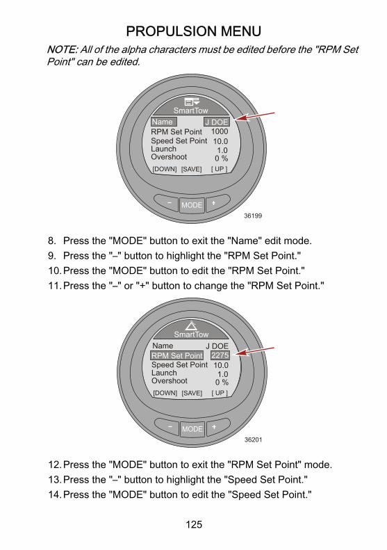
PROPULSION MENU
125
NOTE: All of the alpha characters must be edited before the "RPM SetPoint" can be edited.
MODE36199
SmartTow
[DOWN] [SAVE] [ UP ]
1000NameRPM Set Point
J DOE
Speed Set PointLaunchOvershoot
10.01.00 %
8. Press the "MODE" button to exit the "Name" edit mode.9. Press the "–" button to highlight the "RPM Set Point."10.Press the "MODE" button to edit the "RPM Set Point."11.Press the "–" or "+" button to change the "RPM Set Point."
MODE36201
SmartTow
[DOWN] [SAVE] [ UP ]
NameRPM Set Point
J DOE
Speed Set PointLaunchOvershoot
10.01.00 %
2275
12.Press the "MODE" button to exit the "RPM Set Point" mode.13.Press the "–" button to highlight the "Speed Set Point."14.Press the "MODE" button to edit the "Speed Set Point."

PROPULSION MENU
126
15.Press the "–" or "+" button to change the "Speed Set Point."
MODE36202
SmartTow
[DOWN] [SAVE] [ UP ]
NameRPM Set Point
J DOE
Speed Set PointLaunchOvershoot
10.01.00 %
2275
16.Press the "MODE" button to exit the "Speed Set Point" mode.17.Press the "–" button to highlight "Launch."18.Press the "MODE" button to edit "Launch."19.Press the "–" or "+" button to change the "Launch" setting.NOTE: There are five launch levels. Level 1 is the most gradual andlevel 5 is the most aggressive.
MODE36204
SmartTow
[DOWN] [SAVE] [ UP ]
NameRPM Set Point
J DOE
Speed Set PointLaunchOvershoot
10.03.80 %
2275
20.Press the "MODE" button to exit the "Launch" mode.21.Press the "–" button to highlight "Overshoot."22.Press the "MODE" button to edit "Overshoot."

PROPULSION MENU
127
NOTE: "Overshoot" is the amount of RPM the engine will achieveabove the "RPM Set Point."23.Press the "–" or "+" button to change the overshoot percentage
setting.
MODE36234
SmartTow
[DOWN] [SAVE] [ UP ]
NameRPM Set Point
J DOE
Speed Set PointLaunchOvershoot
10.03.8
10 %
2275
24.Press the "MODE" button to exit the "Overshoot" mode.25.Press the "–" button to highlight "Duration."26.Press the "MODE" button to edit "Duration."NOTE: "Duration" is the amount of time the engine RPM "Overshoot"will be allowed.IMPORTANT: The RPM and speed setpoints will change to the lastsetpoint used for that particular new user when using Smart Tow.

PROPULSION MENU
128
27.Press the "–" or "+" button to change the duration seconds.
MODE36236
SmartTow
[DOWN] [EDIT] [ UP ]ExitDuration
Speed Set PointLaunchOvershoot
10.03.8
10 %3.8 s
28.Press the "MODE" button to exit the "Duration" mode.29.Press the "–" button to highlight the "Exit" option.30.Press the "MODE" button to exit the custom launch mode.

VESSEL MENU
129
Using the Vessel ScreensThe vessel menu screens will display information concerning the vesseland associated systems. Screens that are available in the vessel menumay vary according to the engine type, but may include the following:• Economy (ECO)• Trip data• Heating, ventilation, and air conditioning (HVAC)• Generator data• Range• Trim• Fuel tank1• Tank 2• Tabs• GPS information• Waypoint information• Steering position• Depth
Available Vessel Screens
Economy(ECO)
The software for the economy screenmonitors the engine sensors and looks forthe best fuel economy number whilerunning the boat. When the softwarerecognizes an improvement in the fueleconomy, the gauge records what the trimand engine RPM values are at that time.This calculation happens whether the ECOscreen is visible or not. When the softwarehas recorded the RPM and trim values, itwill guide the operator with arrows, towhere that optimum running speed andtrim setting was. The ECO screen does notneed any calibration, although there aresettings to customize the gauge for yourboating style. The economy screenoptimized values can be reset.
[ EXIT ] [ NEXT ] [OPTION]
OKOK
OPTIMIZEDECONOMY
10 7
4
10
5 M/G
MPH
RPM
3.63450
24.3
42352
TRIM RPM

VESSEL MENU
130
Trip Data
Displays the vessel speed through theavailable sensor, the current trip distance,the total amount of fuel used, and thecurrent amount of time during the trip. Thedistance, fuel used, and time can be reset.
Total Used
SpeedTrip Dist
Trip Time
MI
MPHPDL
H
30.512.75.85.0
GAL
[OPTION]
Trip Data
[ EXIT ] [ NEXT ]36558
HVACSystem
Displays whether the unit is in a heating orcooling mode, the speed of the fan, and thecurrent temperature. The HVAC unit mustbe interfaced with the CAN communicationfor this option to display information.
NOTE: HVAC currently has no validatedmanufacturers.
MODE
[ NEXT ]
HVAC System
[ EXIT ]
- - -
LOW-99 oF
36569
Generator
Displays the AC voltage, the hertzfrequency, the generator location or name,and the generator running hours. Thegenerator unit must be interfaced with theCAN communication for this option todisplay information. [ NEXT ]
Generator
[ EXIT ]
GENERATOR - - - - - -
36613
OHOURS
OAC-VOLTAGE
OFREQUENCY
Range
Displays the current amount of fueleconomy, the average amount of fuel used,the estimated distance the vessel cantravel based on the current usage, and thetotal amount of fuel used. The average fuelused and the total amount used can bereset. [ NEXT ]
Range
[ EXIT ]36616
M/G- - -
[OPTION]
Inst.Average
Est. RangeTot. Used
MI
M/G
GAL
0.0- - -0.0

VESSEL MENU
131
TrimDisplays a number relating to the positionof the trim system, the engine waterpressure, and the engine RPM.
[ NEXT ]
Trim
[ EXIT ]36631
TrimWater Press
RPM RPM
PSI0.025
0
Fuel Tank1
Displays the level of the fuel tank, thelocation of the fuel tank, and will display"FAULT" when there is a problem with thefuel tank.
[ NEXT ]
Fuel Tank1
[ EXIT ]36635
FAULTE
F
STBD
Tank 2
Tank 2 can be selected as not installed,fuel, water, or waste when connected to afour‑stoke engine. When selected as fuel,the level can be calibrated with a defaultsetting, or by adding fuel. When selectedas water or waste, the level is calibrated tothe default setting. [ NEXT ]
Water Tank
[ EXIT ]36637
E
F
STBD
0%
Tabs Displays the position of the tabs withnumbers and a bar graph for each tab.
Tabs
[ EXIT ] [ NEXT ]36731
STBDPORT
0.0 0.0

VESSEL MENU
132
GPS
Displays the course over ground ("COG"),speed over ground ("SOG"), latitudeposition ("LAT"), and longitude position(LON"). A GPS must be installed for thisoption to display information.
[ NEXT ]
GPS
[ EXIT ]36642
COGSOGLATLON
O
- - - - - -
- - - - - -
MPH
ToWaypoint
Displays the amount of time to thewaypoint, the compass bearing towardsthe waypoint, the distance to the waypoint,and the amount of fuel required to thewaypoint. A GPS must be installed with aSmartCraft puck for this option to displayinformation. [ NEXT ]
To Waypoint
[ EXIT ]36645
TimeBearing
DistFuel
H
- - - - - -
- - - - - -
o
MI
GAL
Steering
Displays the engine RPM, the vesselspeed through the active sensor, and thedirection of the steering; port or starboard.A steering position sensor must beinstalled for this screen to display thesteering direction and relative position. [ NEXT ]
Steering
[ EXIT ]36647
PORT
SPEED MPHPDL
RPM
STBD
0 0.0
49o
DepthDisplays the depth of the water, thetemperature of the water, and the speed ofthe vessel through the active sensor.
[ NEXT ]
Depth
[ EXIT ]36650
MPHPDL
FT
- - - 0.0
- - - Fo
DepthSeatemp
Speed

VESSEL MENU
133
Economy (ECO) ScreenThe economy screen monitors the engine sensors and looks for the bestfuel economy number while the vessel is under way. When the softwarerecognizes an improvement in the fuel economy, the gauge recordswhat the trim and engine RPM values are at that time. This calculationhappens whether the ECO screen is visible or not. When the softwarehas recorded the RPM and trim values, it will guide the operator witharrows to where that optimum running speed and trim setting was. TheECO screen does not need any calibration, although there aresettings to customize the gauge for your boating style. The defaultsettings are within acceptable parameters for most vessel applications.When the economy screen is "OPTIMIZED," the backlighting of thescreen will turn to green. While "OPTIMIZED," the trim and RPM arrowswith be aligned with the economy target windows. When either the trimor RPM arrows are outside the target window, the arrows will becomehollow and the backlighting will turn to yellow. These color changes aredifficult to identify in the sunlight. The target windows can be madesmaller or larger. The menu path to change the target window size is:"Settings," > "ECO," > "Trim Accuracy [%]" for trim, or "RPM Accuracy[%]" for RPM. The default number of 4 is generally a good setting formost vessel configurations. The higher the number, the larger the targetwindow.
a - Trim target windowb - Economy optimizedc - Fuel economyd - RPM target windowe - RPMf - Vessel speed
MODE
[EXIT] [NEXT] [REFRESH]
OKOK
OPTIMIZEDECONOMY
10 5
20
5 M/G
MPH
RPM
3.63450
24.3TRIM RPM
ad
b
c
e
f
42354

VESSEL MENU
134
• If the software has recorded an economy value that is better thanwhere you are currently, the screen will show "NOT OPTIMIZED"at the top of the screen and the backlighting will turn to the coloryellow. This color change is difficult to identify in the sunlight. Thetrim position arrow will become hollow, a guide arrow will appearindicating the trim position must be changed either up or down, andthe recorded target window will appear in a new location. Pressingthe refresh button "+" ("REFRESH") at any time while the economyscreen is visible will restart the economy calculations.
a - New recorded targetwindow
b - Hollow arrowc - Guide arrow indicating
direction changed - Screen showing "NOT
OPTIMIZED"
• When the trim target is achieved, the trim position arrow will nolonger be hollow, and "OK" will replace the guide arrow.
a - Trim position arrow nothollow
b - "OK" replaces guide arrow
MODE
[ EXIT ] [ NEXT ] [REFRESH]
TRIM
OPTIMIZED10 5
20
5 M/G
MPH
RPM
3.63450
24.3TRIM RPM
a
b
c
42355
RPM
NOTECONOMY
d
MODE
[ EXIT ] [ NEXT ] [REFRESH]
OPTIMIZED10 5
20
5 M/G
MPH
RPM
3.63450
24.3TRIM RPM
a
b
42358
RPM
NOTECONOMY
OK

VESSEL MENU
135
• The RPM position arrow will become hollow, a guide arrow willappear indicating the RPM must be raised or lowered, and therecorded target window will appear in a new location.
a - Guide arrow indicatingdirection change
b - Hollow arrowc - New recorded target
window
• When the RPM target is achieved, the RPM arrow will no longer behollow, and "OK" will replace the guide arrow. The screen willchange color from yellow to green indicating the engine is at theoptimized running RPM and trim position. The color change isdifficult to identify in the sunlight.
a - "OK" replaces guidearrow
b - Trim position arrow nothollow
c - New recorded targetwindow
MODE
[ EXIT ] [ NEXT ] [REFRESH]
OPTIMIZED10 5
20
5 M/G
MPH
RPM
3.13350
22.3TRIM RPM
ab
42360
RPM
NOTECONOMY
OK c
MODE
[ EXIT ] [ NEXT ] [REFRESH]
OPTIMIZED10 5
20
5 M/G
MPH
RPM
4.23275
21.8TRIM RPM
ab
42361
ECONOMY
OK cOK

VESSEL MENU
136
• If the RPM exceeds the maximum selected RPM in the "Settings"menu, the screen will change color and advised to decrease theRPM below the selected RPM.
a - Decrease RPM screen
• To change the maximum selected RPM, go to the economy screenin the "Settings" menu. The menu path is: "Settings," > "ECO," >"Max RPM." The default setting is 4300.
MODE
ECO
42294
Trim Accuracy[%] [DOWN] [EDIT]
Min. RPMMax. RPM
MPG timeRPM time
23004300
0.74
0.7
[ UP ]
MODE
RPM10 5
20
5 M/G
MPH
RPM
1.94890
33.1TRIM RPM
a
42363
ECONOMYDECREASE
[ EXIT ] [ NEXT ] [REFRESH]

VESSEL MENU
137
• If the RPM drops below the minimum selected RPM in the"Settings" menu, the screen will change color and advised toincrease the RPM above the selected RPM.
a - Increase RPM screen
• To change the minimum selected RPM, go to the economy screenin the "Settings" menu. The menu path is: "Settings," > "ECO," >"Min RPM." The default setting is 2300 RPM.
MODE
ECO
42291
Trim Accuracy[%] [DOWN] [EDIT]
Min. RPMMax. RPM
MPG timeRPM time
23004300
0.74
0.7
MODE
RPM10 5
20
5 M/G
MPH
RPM
2.11205
5.0TRIM RPM
a
42365
ECONOMYINCREASE
[ EXIT ] [ NEXT ] [REFRESH]
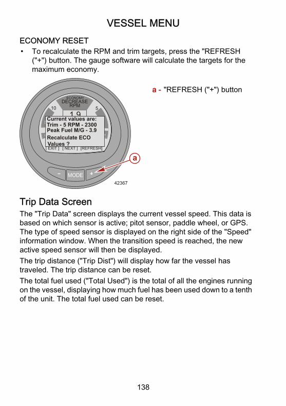
VESSEL MENU
138
ECONOMY RESET• To recalculate the RPM and trim targets, press the "REFRESH
("+") button. The gauge software will calculate the targets for themaximum economy.
a - "REFRESH ("+") button
Trip Data ScreenThe "Trip Data" screen displays the current vessel speed. This data isbased on which sensor is active; pitot sensor, paddle wheel, or GPS.The type of speed sensor is displayed on the right side of the "Speed"information window. When the transition speed is reached, the newactive speed sensor will then be displayed.The trip distance ("Trip Dist") will display how far the vessel hastraveled. The trip distance can be reset.The total fuel used ("Total Used") is the total of all the engines runningon the vessel, displaying how much fuel has been used down to a tenthof the unit. The total fuel used can be reset.
MODE
RPM10 5
20
5 M/G
MPH
RPM
1.94890
33.1TRIM RPM
a
42367
ECONOMYDECREASE
[ EXIT ] [ NEXT ] [REFRESH]
Recalculate ECOValues ?
Current values are:Trim - 5 RPM - 2300Peak Fuel M/G - 3.9

VESSEL MENU
139
The current amount of time the trip has taken ("Trip Time") will bedisplayed in tenths of an hour. The trip time can be reset.
a - Paddle wheel speedb - Trip distancec - Total fuel usedd - Trip time
RESETTING THE TRIP DATA INFORMATION1. While the "Trip Data" option screen is visible, press the "+" button
to open the reset option.2. A pop‑up window will appear asking to reset the trip distance ("Trip
Distance Reset?").3. Press the "–" button for "Yes," or press the "+" button for "No."
MODE36562
Total Used
SpeedTrip Dist
Trip Time
MI
MPHPDL
H
30.512.75.85.0
GAL
[ NO ]
Trip Data
[ YES ]
Trip Distance Reset?
4. The next pop‑up window will appear asking to reset the trip time("Trip Time Reset?").
MODE36561
Total Used
SpeedTrip Dist
Trip Time
MI
MPHPDL
H
30.512.75.85.0
GAL
[OPTION]
Trip Data
[ EXIT ] [ NEXT ]
a
b
c
d
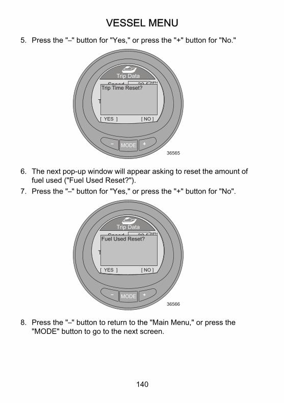
VESSEL MENU
140
5. Press the "–" button for "Yes," or press the "+" button for "No."
MODE36565
Total Used
SpeedTrip Dist
Trip Time
MI
MPHPDL
H
30.512.75.85.0
GAL
[ NO ]
Trip Data
[ YES ]
Trip Time Reset?
6. The next pop‑up window will appear asking to reset the amount offuel used ("Fuel Used Reset?").
7. Press the "–" button for "Yes," or press the "+" button for "No".
MODE36566
Total Used
SpeedTrip Dist
Trip Time
MI
MPHPDL
H
30.512.75.85.0
GAL
[ NO ]
Trip Data
[ YES ]
Fuel Used Reset?
8. Press the "–" button to return to the "Main Menu," or press the"MODE" button to go to the next screen.

VESSEL MENU
141
Heating, Ventilation, and Air Conditioning ScreenThe heating, ventilation, and air conditioning system ("HVAC System")screen displays the present state of the unit, whether it is in a coolingmode or heating mode. The HVAC fan speed and the currenttemperature is displayed. The HVAC unit must be interfaced with theCAN communication for this option to display information. By default,when the HVAC unit is not interfaced with the CAN communication, thetemperature will be displayed as a negative number.
MODE36568
MODE
[ NEXT ]
HVAC System
[ EXIT ]
- - -
LOW-99 oF
Press the "–" button to return to the "Main Menu," or press the "MODE"button to go to the next screen.

VESSEL MENU
142
Generator ScreenThe "Generator" screen displays the AC voltage, the hertz frequencythe generator is producing, the generator location or name, and thegenerator running hours. The generator unit must be interfaced with theCAN communication for this option to display information.
MODE36614
[ NEXT ]
Generator
[ EXIT ]
OFF / NA
OHOURS
OAC-VOLTAGE
OFREQUENCY
Press the "–" button to return to the "Main Menu," or press the "MODE"button to go to the next screen.

VESSEL MENU
143
Range ScreenThe "Range" screen displays the current amount of fuel economy, theaverage amount of fuel used, the estimated distance the vessel cantravel based on the current usage, and the total amount of fuel used.The average fuel used and the total amount used can be reset.
a - Current fuel economyb - Average fuel usedc - Estimated distanced - Total fuel used
RESET RANGE SCREEN OPTIONS1. To reset the average fuel used, press the "+" button to access the
reset option.2. A pop‑up screen will appear asking if the average fuel economy
should be reset ("Average Fuel Eco Reset?").3. Press the "–" button for "Yes," or press the "+" button for "No".
MODE36619
Range
[ YES ]
M/G- - -
[ NO ]
Inst.
Est. RangeTot. Used
MI
M/G
GAL
0.0- - -0.0
Average Fuel EcoReset ?
MODE36617
[ NEXT ]
Range
[ EXIT ]
M/G- - -
[OPTION]
Inst.Average
Est. RangeTot. Used
MI
M/G
GAL
0.0- - -0.0
a
b
c
d

VESSEL MENU
144
4. After pressing either button, a pop‑up window appears asking if thetotal fuel used should be reset ("Fuel Used Reset?").
5. Press the "–" button for "Yes," or press the "+" button for "No."
MODE36620
Range
[ YES ]
M/G- - -
[ NO ]
Inst.
Est. RangeTot. Used
MI
M/G
GAL
0.0- - -0.0
Fuel Used Reset ?
6. Press the "–" button to return to the "Main Menu," or press the"MODE" button to go to the next screen.
Trim ScreenThe "Trim" screen displays a number relating to the position of the trimsystem, the engine water pressure, and the engine RPM.
a - Trim position numberb - Water pressurec - Engine RPM
MODE36632
[ NEXT ]
Trim
[ EXIT ]
TrimWater Press
RPM RPM
PSI0.025
0
a
b
c

VESSEL MENU
145
Press the "–" button to return to the "Main Menu," or press the "MODE"button to go to the next screen.
TanksFUEL TANK 1The "Fuel Tank 1" screen displays the level of the fuel tank, the locationof the fuel tank, and will display "FAULT" when there is a problem withthe fuel tank. It can also be selected as not installed ("Not inst"). Whenselected as not installed, the "Fuel Tank 1" screen will not be accessible.
a - Fuel tank fault("FAULT")
b - Fuel levelc - Tank location
TANK 2"Tank 2" can be selected as not installed ("Not inst"), fuel, water, orwaste when connected to a four‑stroke engine. When selected as fuel,the level can be calibrated with a default setting, or by adding fuel. Whenselected as water or waste, the level is automatically calibrated to thedefault setting.
MODE36636
[ NEXT ]
Fuel Tank1
[ EXIT ]
FAULTE
F
STBD
ab
c

VESSEL MENU
146
When the gauge is installed on a vessel with a two‑stroke engine, "Tank2" will automatically default to oil.
a - Tank level percentageb - Tank typec - Tank leveld - Tank location
Press the "–" button to return to the "Main Menu," or press the "MODE"button to go to the next screen.
Tabs ScreenThe "Tabs" screen displays the port tab and starboard tab position witha bar graph and numbers.
a - Port tab bar graphb - Starboard tab bar graphc - Bar graph pointerd - Tab position number
Press the "–" button to return to the "Main Menu," or press the "MODE"button to go to the next screen.
MODE36638
[ NEXT ]
Water Tank
[ EXIT ]E
F
STBD
0%
a
b
c
d
MODE36900
Tabs
[ EXIT ] [ NEXT ]
STBDPORT
0.0 0.0
bac
d

VESSEL MENU
147
GPS ScreenThe "GPS" screen displays the course over ground ("COG"), speedover ground ("SOG"), latitude position ("LAT"), and longitude position("LON"). A GPS must be installed for this option to display information.
a - Course over ground("COG")
b - Speed over ground ("SOG")c - Latitude position ("LAT")d - Longitude position (LON")
Press the "–" button to return to the "Main Menu," or press the "MODE"button to go to the next screen.
MODE36643
[ NEXT ]
GPS
[ EXIT ]
COGSOGLATLON
O
- - - - - -
- - - - - -
MPH
a
b
c
d

VESSEL MENU
148
To Waypoint ScreenThe "To Waypoint" screen displays the amount of time required to reachthe waypoint, the compass bearing towards the waypoint, the distanceto the waypoint, and the amount of fuel required to the waypoint. A GPSmust be installed with a SmartCraft puck for this option to displayinformation.
a - Timeb - Compass bearingc - Distanced - Fuel
Press the "–" button to return to the "Main Menu," or press the "MODE"button to go to the next screen.
MODE36646
[ NEXT ]
To Waypoint
[ EXIT ]
TimeBearing
DistFuel
H
- - - - - -
- - - - - -
o
MI
GAL
a
b
c
d

VESSEL MENU
149
Steering ScreenThe "Steering" screen displays the engine RPM, the vessel speed, abar graph indicating the direction of the steering ("PORT" or "STBD"),and a number displayed to indicate the relative position of the steering.A steering position sensor must be installed for this screen to displaythe steering direction and relative position.
a - Engine RPMb - Vessel speedc - Steering bar graphd - Relative position of the
steering
Press the "–" button to return to the "Main Menu," or press the "MODE"button to go to the next screen.
MODE36648
[ NEXT ]
Steering
[ EXIT ]PORT
SPEED MPHPDL
RPM
STBD
0 0.0
49o
a b
c
d

VESSEL MENU
150
Depth ScreenThe "Depth" screen displays the depth of the water, the temperature ofthe water, and the speed of the vessel through the available sensor.The actual depth may be different from what is displayed and isdependant on the amount of offset that is programmed in the "Settings"menu.
a - Depthb - Water temperaturec - Vessel speed
Press the "–" button to return to the "Main Menu," or press the "MODE"button to go to the next screen.
MODE36651
[ NEXT ]
Depth
[ EXIT ]
MPHPDL
FT
- - - 0.0
- - - Fo
DepthSeatemp
Speed
a
b
c

FULL SCREENS
151
Full Screens Features and OptionsThe "Full Screens" menu displays large icon vessel and propulsion datain addition to "Tri Data" screens. Several screens show a minimum,maximum reference with an arrow directing your attention to the currentvalue displayed within the screen. The minimum, maximum referencelimits are the same minimum and maximum limits that are shown on aSystem Link gauge. Additionally, a number of screens allow theresetting of peak RPM or speed data. The "Full Screens" and "Tri Data"screen must be turned on ("Yes") for these screens to be active in the"Full Screens" menu. The menu path to turn the full screens data on is:"Main Menu," > "Settings," > "Screens," > "Full Screens." The menupath to select the "Tri Data" information is: "Main Menu," > "Settings,"> "Screens," > "Tri Data."• The following list shows the available information for selecting full
screens data.SpeedDepthCoolant temperatureClockOil temperatureFuel pressureOil pressureWater pressureTri data
• The following list shows the available information for setting up tofive tri data screens.
HoursClockDepthRPMSpeedCoolant temperature

FULL SCREENS
152
Oil temperatureSeawater temperatureWater pressureOil pressureTrimFuel flowBattery
RPM
Displays large numbers for the engineRPM, shows the peak speed, and thepeak RPM at speed. The peak valuescan be reset.
[ NEXT ]
RPM
[ EXIT ]36680
0RPM
[OPTION]RPM AT SPEED PEAK MPH
0.0 0
Speed
Displays large numbers for the vesselspeed through the available sensor,the peak speed, and the peak RPM atspeed. The peak values can be reset.
[ NEXT ]
Speed
[ EXIT ]36681
0.0MPH
[OPTION]RPM AT SPEED PEAK MPH
0.0 0
PDL
Depth Displays the water depth in largenumbers.
[ NEXT ]
Depth
[ EXIT ]36685
126 FT

FULL SCREENS
153
CoolantTemperature
Displays the engine coolanttemperature in large numbers.
[ NEXT ]
Coolant Temp
[ EXIT ]36686
186 F0
OilTemperature
Displays the engine oil temperature inlarge numbers.
[ NEXT ]
Oil Temp
[ EXIT ]36693
205 F0
Fuel Pressure Displays the engine fuel pressure inlarge numbers.
[ NEXT ]
Fuel Pressure
[ EXIT ]36697
42.8 PSI
Oil Pressure Displays the engine oil pressure inlarge numbers.
[ NEXT ]
Oil Pressure
[ EXIT ]36698
40.2 PSI

FULL SCREENS
154
Water Pressure Displays the engine water pressure inlarge numbers.
[ NEXT ]
Water Press
[ EXIT ]36701
30.2 PSI
ClockDisplays the time in large numbers.Can be displayed as 24 hour or 12hour.
[ NEXT ]
Clock
[ EXIT ]36702
23:15
Tri Data
Displays vessel and propulsion dataselected and arranged by the user. Upto five tri data screens can becustomized by the user.
[ NEXT ]
Clock
[ EXIT ]36678
SpeedSea- - : - -
- - - - Fo 0.0 MPH
RESETTING PEAK VALUESThe "RPM" and "Speed" full screens will record and store the vesselpeak speed and the RPM at that peak speed. These peak values canbe reset to capture new RPM and speed data.

FULL SCREENS
155
1. While the "RPM" or "Speed" full screen is visible, press the "+"button to open the reset option.
MODE36704
[ NEXT ]
Speed
[ EXIT ]
20.8MPH
[OPTION]RPM AT SPEED PEAK MPH
58.6 6120
PDL
2. A pop‑up window will appear asking if the peak values should bereset ("Reset Peak Values").
3. Press the "+" button if you do not want to reset the values "[NO]."4. Press the "–" button if you want to reset the values "[YES]."
MODE36706
Speed
[ YES ]
20.8MPH
[ NO ]RPM AT SPEED PEAK MPH
58.6 6120
PDLReset Peak Values ?
5. When the selection is "[YES]," the pop‑up window will close andthe new data will populate the peak values immediately.

FAVORITE SCREENS
156
Favorites Screen Features and OptionsThe "Favorites" is an optional feature that will show specific screensselected by the operator to be reviewed quickly. The favorites willremain on the screen for a specific amount of time. This time can beone second up to 30 seconds. Up to nine favorite screens can beselected from the "Propulsion" menu, "Vessel" menu, or "Full Screens"menu. After selecting the screen desired to be displayed on thefavorites, use the "–" or "+" button to highlight the "Favorites" menuoption. Press the "MODE" button to view the favorites.
MODE
Main MenuPropulsion
Full ScreensFavorites
Vessel
AL
36747
Alarms!

FAVORITE SCREENS
157
SELECTING A FAVORITE SCREEN1. From the "Main Menu," press the "–" or "+" button to select either
the "Propulsion," "Vessel," or "Full Screens" menu.
MODE
Main MenuPropulsion
Full ScreensFavorites
Vessel
AL
35724
Alarms!
2. Press the "MODE" button to enter the selected menu.3. Press the "–" or "+" button and select a screen to be a favorite.
MODE36089
RPMSpeed
Peak SpeedRPM @ Speed
RPM
MPHPDL
RPM
205012.7
585800
MPH
[OPTION]
Peak Speed
[ EXIT ] [ NEXT ]

FAVORITE SCREENS
158
4. Press the "–" button and the "+" button at the same time and holdthe buttons in until the pop‑up window appears asking to add thescreen to the favorites ("Add to Favorites?").
MODE36744
RPMSpeed
Peak SpeedRPM @ Speed
RPM
MPHPDL
RPM
205012.7
585800
MPH
[ YES ]
Peak Speed
[ NO ]
Add to Favorites ?
5. Press the "+" button to save the screen to the "Favorites" menu. Ifthe screen is not wanted, press the "–" button to discard the screenoption.
6. Press the "MODE" button to page through the menu to select adifferent screen, or press the "–" button to exit the menu and returnto the "Main Menu."
7. Continue the selection process for up to nine selected favorites.
CHANGING THE FAVORITES SCREEN DURATIONThe favorites individual screen will remain visible for a specific amountof time. This time can be set from one second up to 30 seconds.

FAVORITE SCREENS
159
1. To change the favorites screen duration, go to the "Main Menu"and press the "–" or "+" button to highlight the "Settings" menu.
MODE35741
Settings
Main Menu
Full ScreensFavorites
Vessel
Alarms!
2. Press the "MODE" button to enter the "Settings" menu.3. Press the "–" button to highlight the "Screen" menu.
MODE
Settings
36410
OffsetsTrim
[DOWN] [EDIT]
Light/ContrastUnits
[ UP ]
Screen
4. Press the "MODE" button to enter the "Screen" menu.5. Press the "–" or "+" button to highlight the "Favorites Slide" option.6. Press the "MODE" button to edit the number of seconds the
favorites will display.

FAVORITE SCREENS
160
7. Press the "–" or "+" button to change the number of seconds.
MODE
Screens
36474
Screen Sync
[DOWN] [EDIT]
Generator
[ UP ]
Simulator
Favorites SlideExit
No
10 sYes
No
DELETING A FAVORITE1. Select the screen that is to be deleted.2. Press the "–" button and the "+" button at the same time and hold
the buttons in until the pop‑up window appears asking to removethe screen from the favorites ("Remove from Favorites?").
MODE36943
RPMSpeed
Peak SpeedRPM @ Speed
RPM
MPHPDL
RPM
205012.7
585800
MPH
[ YES ]
Peak Speed
[ NO ]
Remove from Favorites?
3. Press the "+" button to remove the screen from the "Favorites"menu. Press the "–" button to keep the screen as a favorite.

FAVORITE SCREENS
161
4. Press the "MODE" button to page through the menu to select adifferent screen, or press the "–" button to exit the menu and returnto the "Main Menu."

ALARMS
162
Alarms ScreenThe "Alarms" screen will display two different fault screens. The screendisplays the flashing triangle for system related faults followed by thefault descriptive short text with the fault number. Press the "+" to viewthe fault descriptive long text, and the recommended action to take. Aflashing "AL" will be in the upper right side of the screen.1. To view all system alarms while in the "Main Menu," press the "–"
or "+" button to highlight the "Alarms" menu option.2. Press the "MODE" button to enter the "Alarms" menu option.
MODE
Main Menu
Full ScreensFavorites
Vessel
Alarms!Settings
36915

ALARMS
163
3. The first window will display a flashing triangle icon indicating thereis a fault within the system. The window will quickly change to thedescriptive text information.
a - Flashing "AL" alarmb - Flashing warning iconc - "+" button to show
descriptive text
4. The screen shows the fault location, fault code number, and thefaulty component in short descriptive text.
a - Locationb - Fault code numberc - Component
MODE
Alarms AL
35736
![EXIT] [SHOW]
a
b
c
!
System
MODE36658
[ NEXT ]
Alarms
[ EXIT ]
AL
[ MORE ]
STBD Sys Fault 57<Ignition>
a
b
c
!

ALARMS
164
5. Press the "+" button to view the long descriptive text.
MODE36659
[ NEXT ]
Alarms
[ EXIT ]
AL
[ACTION]
STBD Sys Fault 57<Ignition coil is notworking properly>
!
6. Press the "+" button to view the recommended action to take.
MODE36660
[ NEXT ]
Alarms
[ EXIT ]
AL
[BACK]
STBD Sys Fault 57<See Dealer Soon>
!

ALARMS
165
7. Press the "MODE" button to view the next fault text.
MODE36665
[ NEXT ]
Alarms
[ EXIT ]
AL
[MORE]
STBD Sys Fault 153<Drive Lube Low>
!
8. Press the "+" button to view the long descriptive text. When the longdescriptive text exceeds the screen capacity, several dots at theend of the screen text capacity will be visible.
MODE36667
[ NEXT ]
Alarms
[ EXIT ]
AL
[ACTION]
STBD Sys Fault 153<Drive Lube Low.Check level and refill asneeded. Continuedoperation may.....

ALARMS
166
9. Press the "+" button to view the remaining long descriptive text.
MODE36668
[ NEXT ]
Alarms
[ EXIT ]
AL
[ACTION]
STBD Sys Fault 153....may cause damage.>
10.Press the "+" button to view the recommended action to take.
MODE36669
[ NEXT ]
Alarms
[ EXIT ]
AL
[ BACK ]
STBD Sys Fault 153<Refer to Owner’smanual for serviceprocedure.>
11.Press the "+" button to return to the short descriptive text faultscreen, or press the "MODE" button to view the next alarm fault, orpress the "–" button to exit the descriptive text screen.
12.Press the "–" button to exit the "Alarms" menu and return to the"Main Menu."

OWNERS ASSISTANCE
167
Local Repair ServiceAlways return your outboard to your local authorized dealer should theneed for service arise. Only he has the factory trained mechanics,knowledge, special tools, equipment, and genuine parts andaccessories to properly service your engine should the need occur. Heknows your engine best.
Service Away from HomeIf you are away from your local dealer and the need arises for service,contact the nearest authorized dealer. Refer to the Yellow Pages of thetelephone directory. If, for any reason, you cannot obtain service,contact the nearest Mercury Marine Service Office.
Parts and Accessories InquiriesAll inquiries concerning genuine replacement parts and accessoriesshould be directed to your local authorized dealer. The dealer has thenecessary information to order parts and accessories for you. Wheninquiring on parts and accessories, the dealer requires the model andserial number to order the correct parts.
Service AssistanceYour satisfaction with your outboard product is very important to yourdealer and to us. If you ever have a problem, question or concern aboutyour outboard product, contact your dealer or any authorized MercuryMarine dealership. If additional assistance is required, take these steps.1. Talk with the dealership's sales manager or service manager. If this
has already been done, then contact the owner of the dealership.2. Should you have a question, concern, or problem that cannot be
resolved by your dealership, please contact Mercury MarineService Office for assistance. Mercury Marine will work with youand your dealership to resolve all problems.
The following information will be needed by the service office:• Your name and address• Daytime telephone number• Model and serial number of your outboard• The name and address of your dealership

OWNERS ASSISTANCE
168
• Nature of problem
Mercury Marine Service OfficesFor assistance, call, fax, or write. Please include your daytimetelephone number with mail and fax correspondence.
United States, Canada
Telephone English ‑ (920) 929‑5040Français ‑ (905) 636‑4751
Mercury MarineW6250 W. Pioneer RoadP.O. Box 1939Fond du Lac, WI 54936-1939Fax English ‑ (920) 929‑5893
Français ‑ (905) 636‑1704Website www.mercurymarine.com
Australia, PacificTelephone (61) (3) 9791‑5822 Brunswick Asia Pacific Group
132-140 Frankston RoadDandenong, Victoria 3164Australia
Fax (61) (3) 9706‑7228
Europe, Middle East, AfricaTelephone (32) (87) 32 • 32 • 11 Brunswick Marine Europe
Parc Industriel de Petit-RechainB-4800 Verviers,Belgium
Fax (32) (87) 31 • 19 • 65
Mexico, Central America, South America, CaribbeanTelephone (954) 744‑3500 Mercury Marine
11650 Interchange Circle NorthMiramar, FL 33025U.S.A.
Fax (954) 744‑3535
JapanTelephone 81‑053‑423‑2500 Mercury Marine - Japan
Anshin-cho 283-1HamamatsuShizuoka-ken, Japan 435-0005Japan
Fax 81‑053‑423‑2510

OWNERS ASSISTANCE
169
Asia, SingaporeTelephone 5466160 Mercury Marine Singapore
72 Loyang WaySingapore, 508762Fax 5467789
Ordering LiteratureBefore ordering literature, please have the following information aboutyour power package available:
EngineModel: Horsepower:
SerialNumber: Model year:
UNITED STATES AND CANADAFor information on additional literature that is available for yourparticular Mercury/MerCruiser power package and how to order thatliterature contact your nearest dealer or contact:
MERCURY MARINETelephone Fax Mail
(920) 929‑5110 (920) 929‑4894
Mercury MarineAttn: Publications Department
P.O. Box 1939Fond du Lac, WI 54936-1939,
OUTSIDE THE UNITED STATES AND CANADAContact your nearest dealer or Marine Power Service Center forinformation on additional literature that is available for your particularMercury/MerCruiser power package and how to order that literature.