smarteverything fox - rs components...
TRANSCRIPT

SmartEverything FOX
User Guide
Ver 1.0
Copyright 2015 Amel Technology
www.amel-tech.com

SmartEverything FOX User Guide 2 Ver. 1.0 – 23/06/2015
Copyright Notice and Disclaimer
All rights reserved. No parts of this manual may be reproduced in any form
without the express written permission of Amel Technology.
Amel Technology makes no representations or warranties with respect to the contents hereof. In addition, information contained herein are subject to change without notice.
Every precaution has been taken in the preparation of this manual. Nevertheless, Amel
Technology assumes no responsibility for errors or omissions or any damages resulting from the use of the information contained in this publication.
Amel Technology. does not assume any liability arising out of the application or use of any of its products or designs. Products designed or distributed by Amel Technology. are not
intended for, or authorized to be used in, applications such as life support systems or for any other use in which the failure of the product could potentially result in personal injury, death or property damage.
Revision Sheet
Release No. Date Revision Description
Ver 1.0 23/06/2015 First Release
Table 1: Document History

SmartEverything FOX User Guide 3 Ver. 1.0 – 23/06/2015
TABLE OF CONTENTS Chapter 1 Introduction ................................................................................................................. 5
1.1 Board Specifications ........................................................................................................ 5
Chapter 2 Hardware ..................................................................................................................... 6
2.1 External View .................................................................................................................. 6
2.2 SmartEverything FOX Block Diagram ............................................................................ 7
2.3 ATMEL SAMD21Ultra low-power ARM® Cortex®-M0+ MCU .................................... 7
2.3.1 ATMEL SAMD21 Internal Memory ........................................................................ 7
2.3.2 Power Supply Circuitry ............................................................................................ 8
2.4 Crypto Authentication Chip (ATMEL ATSHA204A) ....................................................... 9
2.4.1 Device Features ..................................................................................................... 10
2.4.2 Cryptographic Operation ........................................................................................ 10
2.5 Sigfox Module (Telit LE51-868 S) ................................................................................ 11
2.5.1 Main Features ........................................................................................................ 11
2.6 GPS Module with Embedded Antenna (Telit Jupiter SE868-A) ...................................... 11
2.7 Proximity sensor (ST VL6180X) ................................................................................... 12
2.8 Humidity and Temperature sensor (ST HTS221) ............................................................ 12
2.8.1 Characteristics ....................................................................................................... 12
2.9 Axis sensors (ST LSM9DS1) ......................................................................................... 12
2.10 Pressure Sensor (ST LPS25H) ....................................................................................... 12
2.10.1 Characteristics ....................................................................................................... 13
2.11 NFC NTAG I2C (NXP NTAG I
2C NT3H1101FHK) ...................................................... 13
2.12 Bluetooth Low Energy (TDK SESUB-PAN-T2541) ...................................................... 13
2.12.1 Characteristics ....................................................................................................... 14
2.13 Board Interfaces and Connector ..................................................................................... 14
Chapter 3 Mechanical Information ............................................................................................. 16
3.1 Main components layout ................................................................................................ 16
3.2 Mechanical Characteristics ............................................................................................ 16
Chapter 4 Software Development .............................................................................................. 17
Chapter 5 Getting Started with Arduino IDE and Sketch Projects ............................................... 17
5.1 Tools ............................................................................................................................. 17
5.2 Setup the Environment .................................................................................................. 18
5.3 Compile the Example project ......................................................................................... 20
5.4 Run the software ............................................................................................................ 23
5.5 Importing the Smart Everything Board Library .............................................................. 24
Chapter 6 References and Useful Links ..................................................................................... 25
6.1 Data sheets .................................................................................................................... 25
6.2 Tools ............................................................................................................................. 26
6.3 Web Sites ...................................................................................................................... 26
Chapter 7 Troubleshooting ......................................................................................................... 26
7.1 Driver installation problems .......................................................................................... 26

SmartEverything FOX User Guide 4 Ver. 1.0 – 23/06/2015
Tables Index Table 1: Document History _______________________________________________________ 2
Table 2: Board Specifications ____________________________________________________ 5
Table 3: Power Supply Step-Up management ______________________________________ 8
Table 4: Power Supply Connectors and ranges _____________________________________ 9
Table 5: Arduino Compatible Headers ____________________________________________ 15
Illustrations Index
Figure 1: Front View ____________________________________________________________ 6
Figure 2: SmartEverything Block Diagram _________________________________________ 7
Figure 3: Power Supply block diagram ____________________________________________ 9
Figure 4: NFC TAG Block Diagram _______________________________________________ 13
Figure 5: TDK SESUB-PAN-T2541 block diagram _________________________________ 14
Figure 6: Headers pinout _______________________________________________________ 14
Figure 7: Main Component layout (top) ___________________________________________ 16
Figure 8: Main Component layout (top #2) ________________________________________ 16
Figure 9: Dimensions __________________________________________________________ 17
Figure 10: Launch Board Manager _______________________________________________ 18
Figure 11ArduinoZero Core Installation _____________________________________________ 18
Figure 12: SmartEverything Core Installation ______________________________________ 19
Figure 13Driver Installation _____________________________________________________ 19
Figure 14: Driver correctly recognized ____________________________________________ 19
Figure 15: ArduinoIDE Select the board __________________________________________ 20
Figure 16: ArduinoIDE: Select the port ____________________________________________ 21
Figure 17: ArduinoIDE: Select the example _______________________________________ 21
Figure 19: ArduinoIDE: Verify the code ___________________________________________ 23
Figure 20: ArduinoIDE: Upload the code __________________________________________ 23
Figure 21: ArduinoIDE: Launch Manage Libraries interface __________________________ 24
Figure 22: ArduinoIDE: Library Manager __________________________________________ 25
Figure 23 Correct USB Driver installation _________________________________________ 26

SmartEverything FOX User Guide 5 Ver. 1.0 – 23/06/2015
Chapter 1 Introduction
This document describes Amel Technology SmartEverything FOX SoM (System On Module)
based on Atmel D21 Ultra low-power microcontroller using the 32-bit ARM® Cortex®-M0+ processor.
The SmartEverything FOX Board provides the following peripherals or modules:
• Atmel Crypto Authentication chpset
• Dynaflex 868Mhz Antenna
• Sigfox Module
• GPS Module with Embedded Antenna
• Proximity sensor
• Humidity and Temperature sensor
• Axis sensors
• Pressure Sensor
• NFC NTAG I2C Interface
• Bluetooth Low Energy (BLE) Interface
The SmartEverything FOX Board is supported by the Arduino IDE for a fast and easy
software development cycle. The software can also be developed using the Atmel Studio IDE commonly preferred by professional software engineers.
1.1 Board Specifications
Characteristics Value
Clock speed
Connector
Board supply voltage
Temperature 0°C to +70°C or -40°C to +85°C Dimensions RoHS status Compliant
Table 2: Board Specifications

SmartEverything FOX User Guide 6 Ver. 1.0 – 23/06/2015
Chapter 2 Hardware
2.1 External View
Figure 1: Front View
SmartEverything FOX User Guide 7 Ver. 1.0 – 23/06/2015
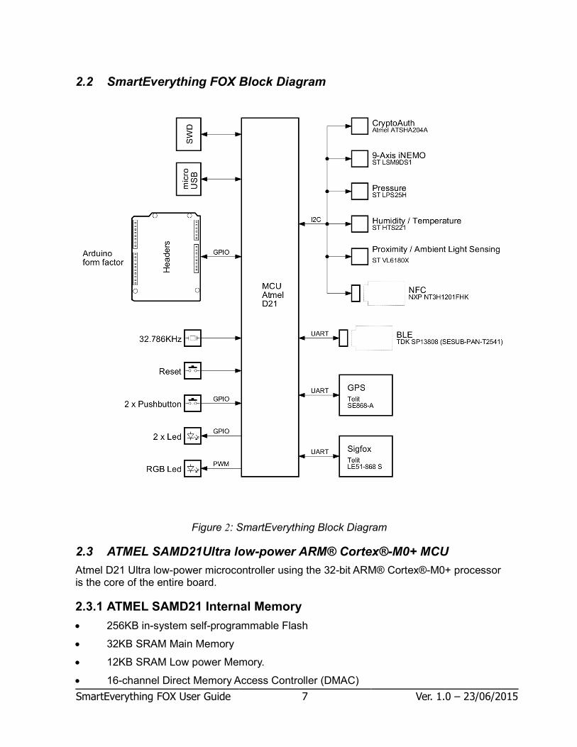
2.2 SmartEverything FOX Block Diagram
Figure 2: SmartEverything Block Diagram
2.3 ATMEL SAMD21Ultra low-power ARM® Cortex®-M0+ MCU
Atmel D21 Ultra low-power microcontroller using the 32-bit ARM® Cortex®-M0+ processor is the core of the entire board.
2.3.1 ATMEL SAMD21 Internal Memory
• 256KB in-system self-programmable Flash
• 32KB SRAM Main Memory
• 12KB SRAM Low power Memory.
• 16-channel Direct Memory Access Controller (DMAC)

SmartEverything FOX User Guide 8 Ver. 1.0 – 23/06/2015
• 12-channel Event System
• Up to five 16-bit Timer/Counters (TC), configurable as either: ◦ One 16-bit TC with compare/capture channels ◦ One 8-bit TC with compare/capture channels ◦ One 32-bit TC with compare/capture channels, by using two TCs
• Three 16-bit Timer/Counters for Control (TCC), with extended functions: ◦ Up to four compare channels with optional complementary output ◦ Generation of synchronized pulse width modulation (PWM) pattern across port pins ◦ Deterministic fault protection, fast decay and configurable dead-time between complementary output
• 32-bit Real Time Counter (RTC) with clock/calendar function
• Watchdog Timer (WDT)
• CRC-32 generator
• One full-speed (12Mbps) Universal Serial Bus (USB) 2.0 interface ◦ Embedded host and device functions ◦ Eight endpoints
• One True Random Generator (TRNG)
• One Configurable Custom Logic (CCL)
• One 12-bit, 1Msps Analog-to-Digital Converter (ADC) with up to 20 channels ◦ Differential and single-ended input ◦ Automatic offset and gain error compensation ◦ Oversampling and decimation in hardware to support 13-, 14-, 15- or 16-bit resolution
• 12-bit, 1Msps Dual Output Digital-to-Analog Converter (DAC)
• Two Analog Comparators (AC) with window compare function
• Three Operational Amplifiers (OPAMP)
2.3.2 Power Supply Circuitry
The board can be powered by three different power supply sources:
• 2 x AA 1,5 V batteries (1.4V to 3.2V)
• A 5V to 45V input
• A 5V Mini USB connector
Both the way to power supply the board guarantee the full functionality of all the components and peripherals. All the components can work with the voltage range provided by the batteries with the exception of the GPS module that require at least 2.8V. This voltage is provided by the Step-Up DC/DC converter directed controlled by the MCU When the Step-Up is off the input voltage is provided by the batteries.
Step-Up Status Power Supply Notes
Step-Up ON 3V
Step-Up OFF Batteries voltage (1.4V – 3.2V)
Table 3: Power Supply Step-Up management

SmartEverything FOX User Guide 9 Ver. 1.0 – 23/06/2015
The Step-Up is directed controlled by the MCU. The user, depending of the purpose of the application, can decide the better policy to use: If the Step-Up is normally off, the GPS can stay off and turned on only when necessary. This policy reduce the power consumption but the GPS require more time to acquire the coordinates. If the application requires a frequent usage of the GPS, it is better to keep the Step-Up and the GPS on.
Figure 3: Power Supply block diagram
Name Nominal Description Range
J12 3 V Battery Power Supply 1.4V to 3.2V J13 5V to 45V External Power Supply 5V to 45V USB 5V USB Port 5V
Table 4: Power Supply Connectors and ranges
More information can be found on the ATMEL SAMD21 Data Sheet (See the link in the References and Useful Links chapter)
2.4 Crypto Authentication Chip (ATMEL ATSHA204A)
The ATSHA204A is a member of the Atmel Crypto Authentication™ family of high-security
hardware authentication devices. It has a flexible command set that allows use in many
applications, including the following, among others:

SmartEverything FOX User Guide 10 Ver. 1.0 – 23/06/2015
• Anti-counterfeiting
• Protecting Firmware or Media
• Exchanging Session Keys
• Storing Data Securely
• Checking User Passwords
2.4.1 Device Features
The ATSHA204A device includes an Electrically Erasable Programmable Read-Only
Memory (EEPROM) array that can be used for key storage, miscellaneous read/write data,
read-only, secret data, consumption logging, and security configuration.
Access to the various sections of memory can be restricted in a variety of ways, and the
configuration can then be locked to prevent changes.
The ATSHA204A features a wide array of defense mechanisms specifically designed to
prevent physical attacks on the device itself or logical attacks on the data transmitted
between the device and the system
Hardware restrictions on the way keys are used or generated provide further defense
against certain styles of attack.
Access to the device is made through a standard I2C interface.
Each ATSHA204A ships with a guaranteed unique 9-byte (72-bit) serial number. Using the
cryptographic protocols supported by the device, a Host system or remote server can
prove that the serial number is authentic and is not a copy. Serial numbers are often stored
in a standard Serial EEPROM, which can be easily copied with no way for the Host to
know if the serial number is authentic or if it is a clone. The entire serial number must be
utilized to guarantee uniqueness.
2.4.2 Cryptographic Operation
The ATSHA204A supports a standard challenge-response protocol to simplify
programming. In its most basic installation, the Host system sends a challenge (i.e. a
number) to the device in the Client, which combines that challenge with a secret key by
using the Message Authentication Code (MAC) command from the system and sends that
response back to the system.
This basic operation can be expanded in many ways because of the flexible command set
of the ATSHA204A.
For a complete explanation about the possible Cryptographic Operations check the Data Sheet (See the link in the References and Useful Links chapter)

SmartEverything FOX User Guide 11 Ver. 1.0 – 23/06/2015
2.5 Sigfox Module (Telit LE51-868 S)
Telit LE51-868 S module is a high performance module designed to cover the 863-870MHz unlicensed band. It provides the Telit proprietary Star Network protocol and it is able to act as a certified Sigfox™ gateway.
The following protocol stack is preloaded:
• LE51-868 S SIGFOX™ Network Software.
• “Star Network” Protocol stack
2.5.1 Main Features
The LE51-868 S module is a complete solution from serial interface to RF interface. The LE51-868 module has a digital part and a RF part. The radio link on Sigfox network is a Half-Duplex bidirectional link.
The digital part has the following functionalities:
• Communication interface
• I/O management
• Micro controller with embedded Telit Software Stack supporting Sigfox protocol
The RF part has the following functionalities:
• Frequency synthesis
• Front-end
• Power amplification
• Packet handling
More information can be found on relevant Data Sheet (See the link in the References and Useful Links chapter)
2.6 GPS Module with Embedded Antenna (Telit Jupiter SE868-A)
The Telit Jupiter SE868-A is a GPS Module designed to fully support GPS, QZSS, GLONASS and it is Galileo ready. It has an embedded SMT antenna and it is able to track GPS + GLONASS (and eventually Galileo) constellations simultaneously and to provide the position through the standard serial interface (UART)
The module software can increase the position accuracy supporting:
• Ephemeris file injection (A-GPS)
• Satellite Based Augmentation System (SBAS)
More information can be found on relevant Data Sheet (See the link in the References and Useful Links chapter)

SmartEverything FOX User Guide 12 Ver. 1.0 – 23/06/2015
2.7 Proximity sensor (ST VL6180X)
The ST VL6180X is a proximity and light sensing module. The sensor precisely measures the time the light takes to travel to the nearest object and reflect back to the sensor (Time-of-Flight) and calculate the distance.
It combines an IR emitter, a range sensor and an ambient light sensor in a single package.
Atmel D21 MCU controls and reads the results using an I2C interface.
More information can be found on relevant Data Sheet (See the link in the References and Useful Links chapter)
2.8 Humidity and Temperature sensor (ST HTS221)
The HTS221 is a compact sensor for relative humidity and temperature. It provides the measurement information through digital serial interfaces to the Atmel D21 processor
The sensing element consists of a polymer dielectric planar capacitor structure capable of
detecting relative humidity variations and is manufactured using a dedicated ST process.
2.8.1 Characteristics
• 0 to 100% Relative Humidity range
• High rH sensitivity: 0.004% rH/LSB
• Humidity accuracy: ± 4.5% rH, 20 to +80% rH
• -40 to 120 °C Temperature range
• Temperature accuracy: ± 0.5 °C,15 to +40 °C
• Factory calibrated
More information can be found on relevant Data Sheet (See the link in the References and Useful Links chapter)
2.9 Axis sensors (ST LSM9DS1)
The LSM9DS1 is a 3D digital linear acceleration sensor, a 3D digital angular rate sensor, and a 3D digital magnetic sensor.
The LSM9DS1 has a linear acceleration full scale of ±2g/±4g/±8g, a magnetic field full scale of ±4/±8/±12/±16 gauss and an angular rate of ±245/±500/±2000 dps.
It communicates with the Atmel MCU through the I2C interface.
More information can be found on relevant Data Sheet (See the link in the References and Useful Links chapter)
2.10 Pressure Sensor (ST LPS25H)
The LPS25H is a compact absolute piezo resistive pressure sensor. It communicates with the Atmel MCU through the I2C interface. The sensing element consists of a suspended membrane realized inside a single mono-silicon substrate.
SmartEverything FOX User Guide 13 Ver. 1.0 – 23/06/2015
2.10.1 Characteristics
• 260 to 1260 hPa absolute pressure range
• High-resolution mode: 1 Pa RMS
• High overpressure capability: 20x full scale
• Embedded temperature compensation
More information can be found on relevant Data Sheet (See the link in the References and Useful Links chapter)
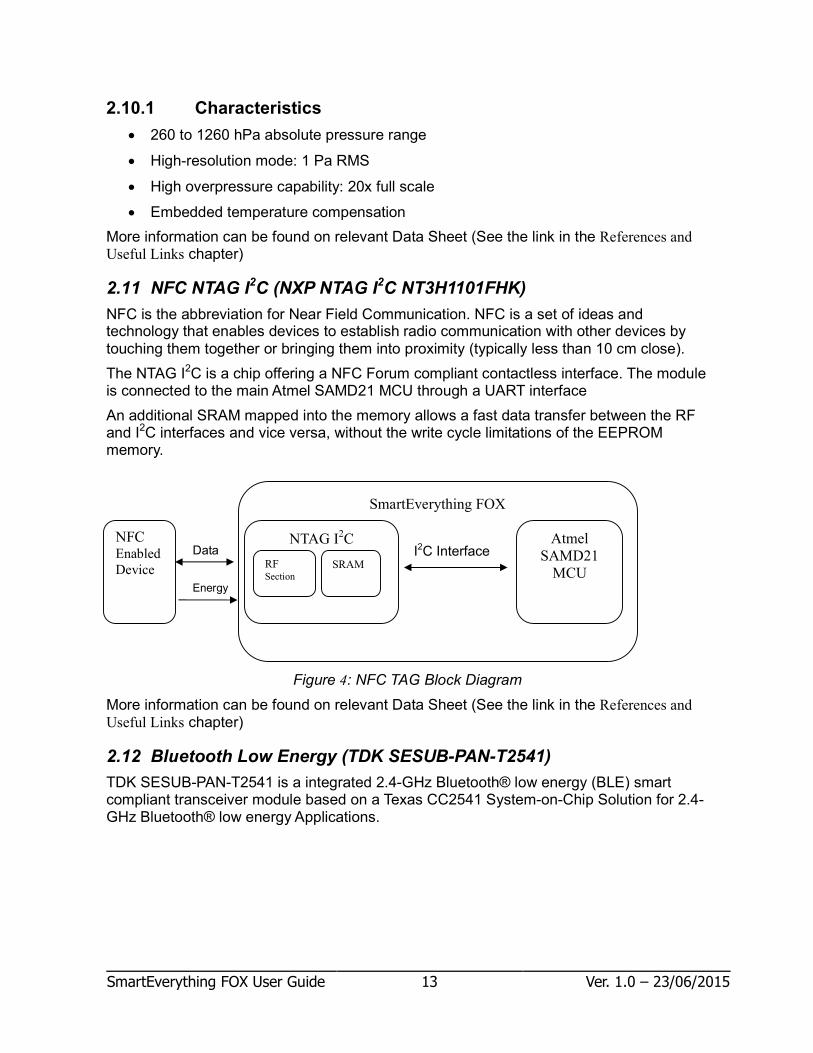
2.11 NFC NTAG I2C (NXP NTAG I2C NT3H1101FHK)
NFC is the abbreviation for Near Field Communication. NFC is a set of ideas and technology that enables devices to establish radio communication with other devices by touching them together or bringing them into proximity (typically less than 10 cm close).
The NTAG I2C is a chip offering a NFC Forum compliant contactless interface. The module is connected to the main Atmel SAMD21 MCU through a UART interface
An additional SRAM mapped into the memory allows a fast data transfer between the RF and I2C interfaces and vice versa, without the write cycle limitations of the EEPROM memory.
Figure 4: NFC TAG Block Diagram
More information can be found on relevant Data Sheet (See the link in the References and Useful Links chapter)
2.12 Bluetooth Low Energy (TDK SESUB-PAN-T2541)
TDK SESUB-PAN-T2541 is a integrated 2.4-GHz Bluetooth® low energy (BLE) smart compliant transceiver module based on a Texas CC2541 System-on-Chip Solution for 2.4-GHz Bluetooth® low energy Applications.
NFC Enabled
Device
SmartEverything FOX
NTAG I2C
Atmel
SAMD21
MCU
I2C Interface RF Section
SRAM
Data
Energy

SmartEverything FOX User Guide 14 Ver. 1.0 – 23/06/2015
Figure 5: TDK SESUB-PAN-T2541 block diagram
The Texas CC2541 System-on-Chip is based on a 8051 CPU core, and provide memory, peripherals and the RF receiver and transmitter The module is connected to the main Atmel SAMD21 MCU through a UART interface
2.12.1 Characteristics
Program Memory: In System Programmable 256K Flash Bluetooth Stack: Embedded BT-Stack from TI available TX Output Power: 0 dBm (typ) [Class 2] High RX Sensivity: -94 dBm (typ) More information can be found on relevant Data Sheet (See the link in the References and Useful Links chapter)
The module on the board is provided with the firmware able to communicate with the ATMEL SAMD21 MCU
2.13 Board Interfaces and Connector
Figure 6: Headers pinout

SmartEverything FOX User Guide 15 Ver. 1.0 – 23/06/2015
Name Conn. Pin Description Name used in the sketch
D8 J5 1 Digital I/O D8 / PWM 8
D9 J5 2 Digital I/O D9 / PWM 9
D10 J5 3 Digital I/O D10 / PWM 10
D11 J5 4 Digital I/O D11 / PWM 11
D12 J5 5 Digital I/O D12 / PWM 12 D13 J5 6 Digital I/O D13 / PWM 13
GND J5 7 Ground pin
AREF J5 8 Analogue Reference (used by ADC) SDA J5 9
SCL J5 10
NC J6 1 Not Connected VMCU J6 2
RESET J6 3 Reset
VMCU J6 4
Vcc 5V J6 5 GND J6 6 Ground pin
GND J6 7 Ground pin
Vin J6 8 External Power Supply Input A0 J8 1 Analog Input A0 A0
A1 J8 2 Analog Input A1 A1
A2 J8 3 Analog Input A2 A2 A3 J8 4 Analog Input A3 A3
A4 J8 5 Analog Input A4 A4
A5 J8 6 Analog Input A5 A5
D0 / RX J9 1 Digital I/O D0 / Serial1 (RX) 1
D1 / TX J9 2 Digital I/O D1 / Serial1 (TX) 2
D2 J9 3 Digital I/O D2 / PWM 3
D3 J9 4 Digital I/O D3 / PWM 4
D4 J9 5 Digital I/O D4 / PWM 5
D5 J9 6 Digital I/O D5 / PWM 6
D6 J9 7 Digital I/O D6 / PWM 7
D7 J9 8 Digital I/O D7 / PWM 8
Table 5: Arduino Compatible Headers

SmartEverything FOX User Guide 16 Ver. 1.0 – 23/06/2015
Chapter 3 Mechanical Information
3.1 Main components layout
Figure 7: Main Component layout (top)
Figure 8: Main Component layout (top #2)
3.2 Mechanical Characteristics
The maximum length and width of the Smarteverything FOX PCB are 2.7 and 2.1 inches
respectively, with the USB connectors,power jack and antenna extending beyond the

SmartEverything FOX User Guide 17 Ver. 1.0 – 23/06/2015
former dimension. Three screw holes allow the board to be attached to a surface or case.
Note that the distance between digital pins 7 and 8 is 160 mil (0.16"), not an even multiple
of the 100 mil spacing of the other pins. This made the SmartEverything FOX fully
compatible with most shields designed for the Uno, Diecimila or Duemilanove.
Figure 9: Dimensions
Chapter 4 Software Development
The following chapters provides an overview about how a user can develop its software and run it on the SmartEverything FOX board.
There are two main ways to develop a software load and debug it on the card:
• Using the Arduino IDE and Sketch Projects
• Using the Atmel Studio and Standard C/C++ language When developing a software running on a microcontroller it is important to have some tools to easily debug the code and fix what does not work as expected The Atmel SAMD21 provides the Atmel’s Embedded Debugger (EDBG): a full debug interface without the need for additional debugger. This feature makes easier the software debugging. EDBG supports a virtual COM port that can be used for device programming and allows a traditional Arduino boot loader functionality. The possibilities to use an external debugger like the JTAGICE3 is still available.
Chapter 5 Getting Started with Arduino IDE and Sketch Projects
5.1 Tools
The following tools are needed:
• Arduino IDE (Release 1.6.4 or newer)
• USB cable

SmartEverything FOX User Guide 18 Ver. 1.0 – 23/06/2015
5.2 Setup the Environment
Download and install the Arduino IDE from the Arduino web site (See the links in the References and Useful Links chapter)
The first time you run the ArduinoIDE it is necessary to load the Arduino Zero & SmartEverything Core. Click on the Tools � Boards � Boards ManagerU menu entry
Figure 10: Launch Board Manager
The two steps of installation shall be done as following 1) Select from “Type” combo Arduino and choose Arduino SAMD Boards in order to
install the core of the Arduino Zero.
Figure 11ArduinoZero Core Installation
SmartEverything FOX User Guide 19 Ver. 1.0 – 23/06/2015
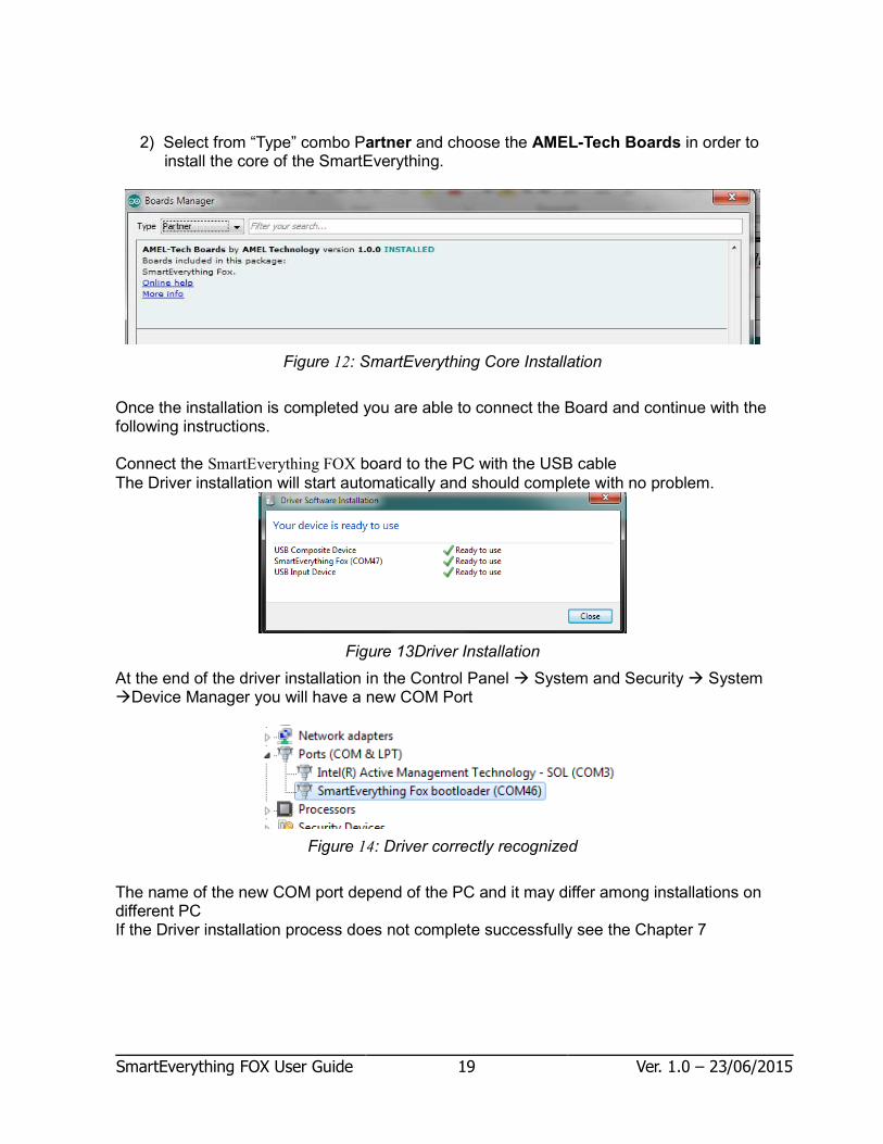
2) Select from “Type” combo Partner and choose the AMEL-Tech Boards in order to install the core of the SmartEverything.
Figure 12: SmartEverything Core Installation
Once the installation is completed you are able to connect the Board and continue with the following instructions. Connect the SmartEverything FOX board to the PC with the USB cable
The Driver installation will start automatically and should complete with no problem.
Figure 13Driver Installation
At the end of the driver installation in the Control Panel � System and Security � System �Device Manager you will have a new COM Port
Figure 14: Driver correctly recognized
The name of the new COM port depend of the PC and it may differ among installations on different PC If the Driver installation process does not complete successfully see the Chapter 7

SmartEverything FOX User Guide 20 Ver. 1.0 – 23/06/2015
5.3 Compile the Example project
SmartEverythin comes with some basic Examples, here how to compile and run using the one called blinkRG. Run the ArduinoIDE In the Tool � Board menu select the SmartEverything FOX board
Figure 15: ArduinoIDE Select the board

SmartEverything FOX User Guide 21 Ver. 1.0 – 23/06/2015
In the Tool � Port menu select the relevant installed port
Figure 16: ArduinoIDE: Select the port
In the File � Example � SME_basic menu select the blinkRGB sketch example
Figure 17: ArduinoIDE: Select the example

SmartEverything FOX User Guide 22 Ver. 1.0 – 23/06/2015
The Arduino IDE will shows the following Sketch int i = 0; void setup() { // LED & User Button are already initialized by the SME core. // it is not required to do here pinMode(PIN_LED_RXL, OUTPUT); pinMode(PIN_LED_TXL, OUTPUT); } void loop() {; switch (i) { case 0: i++; ledGreenLight(HIGH); break; case 1: i++; ledRedLight(HIGH); break; case 2: i = 0; ledBlueLight(HIGH); break; default: break; } digitalWrite(PIN_LED_RXL, LOW); digitalWrite(PIN_LED_TXL, LOW); delay(100); ledGreenLight(LOW); ledBlueLight(LOW); ledRedLight(LOW); digitalWrite(PIN_LED_RXL, HIGH); digitalWrite(PIN_LED_TXL, HIGH); delay(100); }

SmartEverything FOX User Guide 23 Ver. 1.0 – 23/06/2015
5.4 Run the software
Verify the code
Figure 18: ArduinoIDE: Verify the code
Load the software on the Connect the SmartEverything FOX board
Figure 19: ArduinoIDE: Upload the code
This example is very simple The SmartEverything FOX board is equipped with a RGB LED. The three PINS managing the RGB LED are:
• PIN_LED_RED
• PIN_LED_GREEN
• PIN_LED_BLUE The setup function shows that the RGB Led are already initialized by the SmartEverything itself, the user does not care about theire initilization

SmartEverything FOX User Guide 24 Ver. 1.0 – 23/06/2015
The loop function turn on alternately the three(3) Led. And the 2 Yellow Led present on the board..
5.5 Importing the Smart Everything Board Library
The SmartEverything FOX board will provide, immediately some days after it release on the market, some library useful to interface with some of its main components. In order to include the Smart Everything library use the menu Sketch �Include Library � Manage Libraries.
Figure 20: ArduinoIDE: Launch Manage Libraries interface
In order to include the Smart Everything library use the menu Sketch �Include Library � Manage LibrariesU Once the Library Manager is started, you can filter the available library writing SmartEverything in the right top text box end then you can select the necessary library. Some examples on how the will be available to the user are here showed by these three libraries:
• SmartEverything NFC NT3H1101 (Library for communication with NFC)
• SmartEverything SIGFOX LE51-868 (Library for SIGFOX communication)
• SmartEverything VL6180X (Library for Proximity sensor)

SmartEverything FOX User Guide 25 Ver. 1.0 – 23/06/2015
Figure 21: ArduinoIDE: Library Manager
Chapter 6 References and Useful Links
6.1 Data sheets
• ATMEL SAMD21 Ultra low-power ARM® Cortex®-M0+ MCU
• Crypto Authentication Chip (ATMEL ATSHA204A)
• Dynaflex 868Mhz Antenna (915/2)
• Sigfox Module (Telit LE51-868 S)
• GPS Module with Embedded Antenna (Telit Jupiter SE868-A)
• Proximity sensor (ST VL6180X)
• Humidity and Temperature sensor (ST HTS221)
• Axis sensors (ST LSM9DS1)
• Pressure Sensor (ST LPS25H)
• NFC NTAG I2C (NXP NTAG I2C NT3H1101FHK)
• Bluetooth Low Energy (TDK SESUB-PAN-T2541) (specification)

SmartEverything FOX User Guide 26 Ver. 1.0 – 23/06/2015
6.2 Tools
• Arduino IDE
• Atmel Studio
6.3 Web Sites
• Amel Technology – www.amel-tech.com
• Arduino – www.arduino.cc
• Atmel – www.atmel.com
Chapter 7 Troubleshooting
7.1 Driver installation problems
It can happen the installation of the driver does not automatically complete in a successful way. The driver to manage the COM Port are not properly installed and the device is reported as a Unknown Device. If this happen, it is necessary to install manually the driver. The driver can be found in the driver folder of the Arduino IDE folder tree: Example C:\Program Files (x86)\Arduino\drivers
Figure 22 Correct USB Driver installation