smartmesh ip easy start guide - farnell element14 ip easy start guide page 4 of 21 2 setup figure 2...
TRANSCRIPT

SmartMesh IP Easy Start Guide Page of 1 21
SmartMesh IP Easy Start
Guide
SmartMesh IP Easy Start Guide Page of 2 21
Table of Contents
1 Introduction _____________________________________________________________________________________ 3
1.1 Revision History _____________________________________________________________________________ 3
2 Setup __________________________________________________________________________________________ 4
3 Basic Steps _____________________________________________________________________________________ 6
3.1 Step 1: Form a Wireless Mesh Network ___________________________________________________________ 6
3.2 Step 2: Connect PC to Manager and Mote _________________________________________________________ 6
3.2.1 Manager _____________________________________________________________________________ 6
3.2.2 Mote ________________________________________________________________________________ 7
3.3 Step 3: Bring Up Manager CLI and Mote CLI _______________________________________________________ 8
3.3.1 Manager CLI _________________________________________________________________________ 8
3.3.2 Mote CLI ____________________________________________________________________________ 9
3.4 Step 4: Install SDK Software __________________________________________________________________ 11
3.5 Step 5: Join a Mote to the Manager using the API __________________________________________________ 11
4 Additional Tools _________________________________________________________________________________ 14
5 Steps in a Design ________________________________________________________________________________ 15
6 Troubleshooting ________________________________________________________________________________ 16
6.1 References ________________________________________________________________________________ 18

SmartMesh IP Easy Start Guide Page of 3 21
1 Introduction
The purpose of this document is to provide a quick and easy out-of-the-box experience with the andSmartMesh IP Starter Kit
Software Development Kit (SDK). A number of software components are available for demonstrating interaction with your
network. In this document, we will use the components highlighted in gray - FTDI drivers for converting USB connections to
virtual COM ports; a terminal application; and the SmartMesh SDK, which allows the user to interact graphically with Mote and
Manager application programming interfaces (APIs). Additional details on the SDK components are available in the
SmartMesh IP Tools Guide
Figure 1: SmartMesh Software Components
1.1 Revision History
Revision Date Description
1 03/18/2013 Initial Release
2 07/26/2013 Added DC9021A Kit
3 10/22/2013 Clarification of reset requirements, other minor corrections
4 04/04/2014 Numerous small clarifications

SmartMesh IP Easy Start Guide Page of 4 21
2 Setup
Figure 2 shows the SDK kit including a SmartMesh IP Manager (with interface board), five Eterna Motes, and an additional
interface board. There are different manager/mote combinations available, as shown in Table 1.
KIt Mote Manager* Notes
DC9000A DC9003A-B DC9001A Eval/Dev Kit with 32 mote Manager
DC9000B DC9003A-B DC9001B Eval/Dev kit with 100 mote Manager
DC9021A DC9018A-B DC9020A RF Certified Eval/Dev kit with 100 mote Manager
Table 1 - Kit configurations
*Orderable part number includes . Manager boards ( sticker) may be marked with a different sub-componentDC9006 yellow
part number (e.g. DC9011A) than the value in Table 1.
The interface boards for both the Manager and Mote are identical ( ).DC9006
All kits ship with chip antennas. RF Certified devices are available for order individually with MMCX connectors:
Mote - DC9018B-B (MMCX connector)
Manager - DC9020B (MMCX connector)

SmartMesh IP Easy Start Guide Page of 5 21
Figure 2: SmartMeshSDK Setup

SmartMesh IP Easy Start Guide Page of 6 21
1.
2.
3.
4.
5.
3 Basic Steps
There are five steps to get the SDK running:
Form a wireless mesh network - just power everything on, and a network will form
Get Manager and Mote COM ports working on two USB ports on your PC
Bring up the Manager command line interface (CLI) and Mote CLI
Install SDK Software
Bring up the Manager API and Mote API
Once you've done these 5 steps you'll perform one exercise - you'll use the Mote API to make a Mote join the Manager.
The CLI is intended for human interaction with a Mote or Manger, e.g. during development, or for interactive
troubleshooting. The API is intended for machine-to-machine communications, e.g. a host program talking to the
manager or a sensor processor talking to the mote.
3.1 Step 1: Form a Wireless Mesh Network
Even though much of the effort associated with this guide involves using the PC, it is important to point out that your PC has
nothing to do with forming a wireless mesh network. To illustrate this, power on the Manager using the slide switch in the
lower right corner. Note the Blue LED. That indicates that the Manager is on and is attempting to form a network by sending
out advertisements.
Power on one Mote, again using the slide switch. Watch the two green LEDs. One will blink slowly, indicating the Mote is
searching for the network. When that green LED changes from blinking to solid, that means the Mote has sent a join request.
When the second green LED turns on, the Mote has joined.
Power on all the remaining Motes, and within one or two minutes you will have a complete wireless mesh network running.
The rest of the steps we go through will provide ways to interact with that mesh network.
3.2 Step 2: Connect PC to Manager and Mote
You will now connect the PC to both the Manager and Mote through their respective serial ports.
3.2.1 Manager
Connect the Manager to the interface board using the side connector. Next, plug the USB cable into one of your PCDC9006
USB ports. Note which USB port you are using. You should consider this your Manager port for all future use with this PC.

SmartMesh IP Easy Start Guide Page of 7 21
Four virtual COM ports should automatically be added. These can be viewed using the Device Manager (Control Panel ->
System -> Hardware -> Device Manager -> Ports). You may have to install FTDI drivers if this doesn't happen automatically.
Refer to the for detailed instructions on how to install FTDI drivers.SmartMesh IP Tools Guide
Note the four COM port numbers - for example, they may be "COM7", "COM8", "COM9" and "COM10". You will be using the
(COM9) for CLI and the (COM10) for the API connection.third fourth
It has been observed in some installations under Windows 7 that the serial ports do not enumerate in order, and the
CLI and API ports may not be the 3rd and 4th ports, respectively. If this occurs, you will need to test each port
using APIExplorer (in the SmartMesh SDK) to find the API port, and use a terminal program to find the CLI port.
3.2.2 Mote
Repeat these steps for the Mote with a different PC USB port. Connect the Mote to the second interface board usingDC9006
the side connector. Since there are two interface boards included in the kit, you don't have to disconnect the ManagerDC9006
before connecting to the Mote.
Note which USB port you are using. Consider this as your Mote port for all future use with this PC. Another four COM ports
(e.g. COM11, COM12, COM13, and COM14) will be added automatically. You will be using the third (here COM13) for CLI and
the fourth (COM14) for the API connection.
If you forget which USB ports you used for the Manager and Mote and get them reversed later, the COM ports to
the two devices will also be flipped. If you plug either device into a third USB port, the drivers will be installed yet
again and a third set of four COM ports will be assigned. You should consider canceling the driver install and
switching USB ports until you match your original configuration.

SmartMesh IP Easy Start Guide Page of 8 21
3.3 Step 3: Bring Up Manager CLI and Mote CLI
The CLI for a device allows you to type commands from a PC to interact with the Manager or Mote. Interacting with the CLI
requires no software installation on the PC if you are running Windows XP, as it comes with the Hyperterminal program (Start
-> All Programs -> Accessories -> Communication). If you are running Windows 7, you will need to download a serial terminal
client (such as ). Note that the boards must be powered on (slide switch labeled Power) to access CLI.TeraTerm
3.3.1 Manager CLI
To connect to the Manager CLI open the terminal client program. Connect to the third COM port (e.g. COM 9 from step 2) that
was added when you plugged in the Manager. The COM port settings are:
9600 bits per second (sometimes listed as bps or baud)
8 data bits
No parity
1 stop bit
No flow control
Hit enter a few times and you should see a > prompt character. If so, type 'help' to see a list of commands:
> help
help <command>
Commands:
mlog
login
logout
Next login as 'user' by typing the command:
> login user

SmartMesh IP Easy Start Guide Page of 9 21
Use the command (this is short for "show motes") to obtain the list of connected Motes:sm
> sm
MAC MoteId State Nbrs Links Joins Age StateTime
00-17-0D-00-00-38-0E-4D 1 Oper 4 20 1 0 0-05:31:44
00-17-0D-00-00-38-0E-4E 2 Oper 5 16 1 25 0-05:30:40
00-17-0D-00-00-38-0E-CD 3 Oper 2 10 1 7 0-05:29:29
00-17-0D-00-00-38-0E-77 4 Oper 3 11 1 25 0-04:55:25
00-17-0D-00-00-38-0E-4C 5 Oper 2 10 1 41 0-04:55:18
00-17-0D-00-00-38-0E-78 6 Oper 2 10 1 18 0-04:53:37
Number of motes (max 17): Total 6, Live 6, Joining 0
Save this connection profile (in Hyperterm or TeraTerm) so that you can use it in future." "
There are many other things you can do with the Manager CLI. See the for details. Many ofSmartMesh IP Manager CLI Guide
the Application Notes involve interacting with the Manager CLI. Typing 'help' after logging in will reveal the full CLI command
set. The Manager commands are:
delete - allows you to delete a mote or its access control list (ACL) entry
logout - closes the current login session
exec - prefix for advanced control commands. Type 'help exec' for more details
ping - send a packet to a mote and get a reply
radiotest - enable/disable test mode and send or receive packets
onechan - set the network to single channel operation for compliance testing
reset - reset a mote or the system
set - set a configuration value or an ACL entry
show - show configuration values or statistics. Type 'help show' for more details
sm - show mote
su - change user level
trace - enable/disable various traces. Type 'help trace' for more details
Additional access point (AP) commands are described below in the mote CLI description.
3.3.2 Mote CLI
Connecting to the Mote CLI is very similar to connecting to the Manager CLI above. Open another terminal window (the
Manager terminal window can remain open) and connect it to the third COM port (e.g. COM13 from step 2) that was added
when you plugged in the Mote. The settings for this session are the same as for the Manager, 9600 bps, 8 data bits, no parity,
1 stop bit, no flow control.
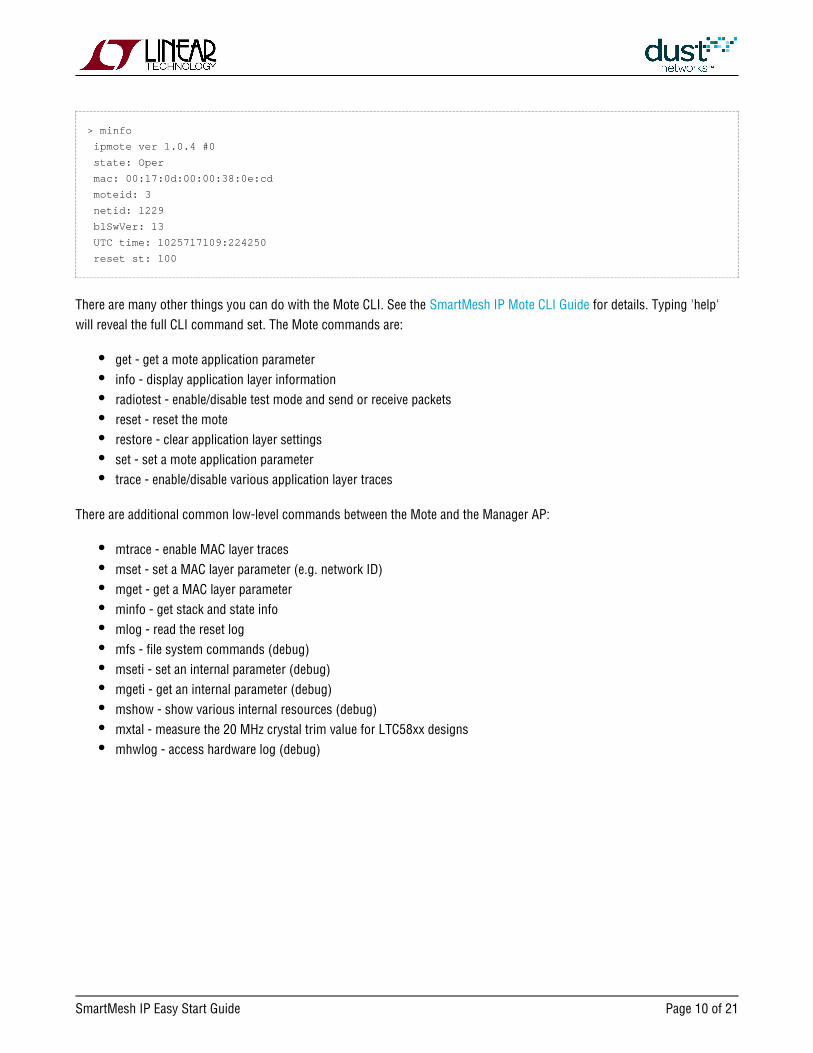
Hit enter a few times to get a ">" prompt, then type the command to get info from the Mote:minfo
SmartMesh IP Easy Start Guide Page of 10 21
> minfo
ipmote ver 1.0.4 #0
state: Oper
mac: 00:17:0d:00:00:38:0e:cd
moteid: 3
netid: 1229
blSwVer: 13
UTC time: 1025717109:224250
reset st: 100
There are many other things you can do with the Mote CLI. See the for details. Typing 'help'SmartMesh IP Mote CLI Guide
will reveal the full CLI command set. The Mote commands are:
get - get a mote application parameter
info - display application layer information
radiotest - enable/disable test mode and send or receive packets
reset - reset the mote
restore - clear application layer settings
set - set a mote application parameter
trace - enable/disable various application layer traces
There are additional common low-level commands between the Mote and the Manager AP:
mtrace - enable MAC layer traces
mset - set a MAC layer parameter (e.g. network ID)
mget - get a MAC layer parameter
minfo - get stack and state info
mlog - read the reset log
mfs - file system commands (debug)
mseti - set an internal parameter (debug)
mgeti - get an internal parameter (debug)
mshow - show various internal resources (debug)
mxtal - measure the 20 MHz crystal trim value for LTC58xx designs
mhwlog - access hardware log (debug)

SmartMesh IP Easy Start Guide Page of 11 21
Now we will enable this Mote's API port. Motes in the kit were shipped in mode. In mode, the Motes join onmaster master
their own, and the API is turned off. We will switch this Mote to mode. This mode turns on the API and the Mote willslave
only join when told to do so by an application (here APIExplorer). In this example, the PC plays the role of a sensor application
controlling a Mote.
You can get the current mode of the Mote with the 'get mode' command:
> get mode
To switch the Mote to mode, type the following command:slave
> set mode slave
The 'set mode' command stores the mode for use after the next boot. After setting the new mode you must reset the mote via
the reset button or by power cycling for the new mode to take effect.
Verify that you have set the Mote to by executing the command again.slave get mode
3.4 Step 4: Install SDK Software
While the CLI is designed for direct human interactions through text input, the API is a programmatic interface for interacting
with other processors. The SDK contains applications that perform various useful functions exercising the APIs through a GUI
interface. The SDK is based on the Python programming language, but you do not need to install Python to use the
pre-compiled applications.
Download the latest version of zip file.SmartMeshSDK
Extract (unzip) the file, and a folder with the same name will be created with 4 sub-folders: , , , and . Each ofapi doc src win
these have sub-folders. For step 5, the important folder is , where executable versions of several utilities are stored. The win
SmartMeshSDK folder can be moved to any convenient location on your computer. NO other installation is required.
3.5 Step 5: Join a Mote to the Manager using the API
Ensure that the PC is plugged into a Manager and a Mote. We will now connect simultaneously to the API of each of these
devices with the application APIExplorer.exe.
Although not used in this example, a CLI terminal window can remain open while you connect to the API in a
different application. This is possible because the CLI and API use different COM ports (e.g. COM 13 for CLI and
COM14 for API)

SmartMesh IP Easy Start Guide Page of 12 21
We now interact with the Mote API and make it join the Manager.
In the SmartMeshSDK directory, double click on the / application. This opens the APIExplorerwin/APIExplorer.exe
window (fig. 3). Tell the application you want to connect to a SmartMesh IP Mote by selecting as the networkSmarMesh IP
type and as device type:mote
Figure 3: APIExplorer Window
Click the button – this loads the API for the IP Mote.load
In the frame (fig. 4), enter the (e.g. COM14) of the API port - this is the 4th COM port added for theconnection port name
mote in step 2.
Figure 4: APIExplorer connection frame

SmartMesh IP Easy Start Guide Page of 13 21
1.
2.
3.
4.
1.
2.
3.
4.
5.
Click . The port field will turn green indicating the connection is successful.connect
This connection to the Mote won't work if the Mote is in mode. APIExplorer will also fail if anothermaster
application is trying to use the port.
To join the Mote to the Manager, go through these four steps:
The command can be used verify that your Mote is configured with the correct Network IDgetParameter.networkId
(1229 by default). After selecting the command from the drop-down menu, a second drop-down menugetParameter
will appear with a list of parameters. Select networkId, then press to issue to the command to the Mote.send
Issue a command to verify that your Mote is in the stategetParameter.moteStatus Idle
Issue a command to tell the Mote to search and join the networkjoin
Repeat the command a few times over the next 30 seconds or so and you should see thegetParameter.motestatus
Mote state proceed through to Operational
The Mote is now joined to the Manager.
Connecting to the Manager API is similar to connecting to the Mote API above. Launch a new instance of the APIExplorer,
select Manager for the device type, and follow the steps above until the connect field turns green to indicate a successful
connection. Make sure to use the fourth COM port (COM10 in this example) number that pertains to the Manager.We will now
one of the Motes in the network using a Manager API command.ping
Select subscribe and enter hex ffffffff in the box, and 00000000 in the box. After clicking , youfilter unackFilter send
have subscribed to all available notifications which you will see appear in the notifications frame.
The drop-down menu in the command frame lists all the commands defined in the .SmartMesh IP Manager API Guide
Issue a command with a macAddress of 0 and the next field set to true to obtain the macAddress of thegetMoteConfig
first mote in the network. Right clicking on the macAddress copies it.
Select the command and enter the MAC address of the Mote from the command.pingMote getMoteConfig
The Mote will respond with the round trip delay time (in ms), voltage (in mV), and temperature (in °C).
SmartMesh IP Easy Start Guide Page of 14 21
4 Additional Tools
Once you have demonstrated basic network formation and the ability to interact with a Mote and Manager, you are ready to
install the additional tools discussed in the . See the for installationSmartMesh IP Tools Guide SmartMesh IP Tools Guide
instructions. These additional tools provide additional visualization options (Stargazer), support testing of APIs, allow for
multiple simultaneous connections to the manager (Serial Mux), provide IPv6 routing (Low-power Border Router), and to
generally aid in application development.
SmartMesh IP Easy Start Guide Page of 15 21
5 Steps in a Design
With the starter kit, hardware design and software design may be done separately.
For Software design:
The application note "Data Publishing for SmartMesh IP" walks through the steps needed to use the mote APIs to join
a network and send data
The SmartMesh IP User's Guide defines basic network terms and concepts, and discusses the use of APIs at a high
level
At a minimum, a mote application needs to:
Configure any parameters needed prior to join (such as )joindutycyle
Use the API to cause a mote to being searching for a networkjoin
Monitor the mote state to see when it is ready to accept data
Request services in order to publish data
The SmartMesh IP Mote API guide covers other commands to configure the mote
The SmartMesh IP Mote CLI guide covers using the human interface to observe mote activity
At a minimum, a host application connected to the manager needs to:
Configure any parameters needed prior to join (such as )networkID
Subscribe to notifications to observe mote status and collect data
The SmartMesh IP Manager API guide covers other commands to configure the manager, e.g. configure
security (use of ACL), or collect detailed statistics from Health Report notifications
The SmartMesh IP Manager CLI guide covers using the human interface to observe manager activity (including
traces of mote state or data).
Advanced software topics covered in the SmartMesh IP User's Guide, SmartMesh IP Tools guide, and SmartMesh IP
Application Notes include Over-the-Air-Programming, using the TestRadio API commands for top-level assembly
testing, use of the Serial Multiplexer to support concurrent manager clients, and using a low-power border router for
internet connectivity, among others
For Hardware design:
Select a hardware platform - modularly certified or chip level?
The hardware integration application notes and integration guides cover the important considerations for robust
hardware development

SmartMesh IP Easy Start Guide Page of 16 21
6 Troubleshooting
1. The board with the yellow sticker is the Manager. Motes have a white sticker. The interface boards ( ) for bothDC9006
Manager and Mote are the same.
2. If you are consistent with which USB port you plug the Mote and Manager into, the COM port assignments should remain
consistent. Mark the physical USB ports on your machine for Manager and Mote usage respectively and then do not change or
mix their usage.
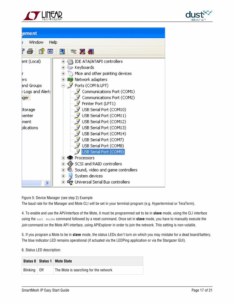
3. Using the Device Manager, make sure that the baud rate is set to 115,200 for the API COM ports.Double-click the port and
select the "Port Settings" tab. As an example, see Figure 5:
COM 7-10 are for the Manager: COM10 is for API
COM 11-14 are for the Mote: COM14 is for API
SmartMesh IP Easy Start Guide Page of 17 21
Figure 5: Device Manager (see step 2) Example
The baud rate for the Manager and Mote CLI will be set in your terminal program (e.g. Hyperterminal or TeraTerm).
4. To enable and use the API/interface of the Mote, it must be programmed set to be in mode, using the CLI interfaceslave
using the command followed by a reset command. Once set in mode, you have to manually execute the set mode slave
command on the Mote API interface, using APIExplorer in order to join the network. This setting is non-volatile.join
5. If you program a Mote to be in mode, the status LEDs don't turn on which you may mistake for a dead board/battery.slave
The blue indicator LED remains operational (if actuated via the LEDPing application or via the Stargazer GUI).
6. Status LED description:
Status 0 Status 1 Mote State
Blinking Off The Mote is searching for the network

SmartMesh IP Easy Start Guide Page of 18 21
On Off The Mote has found the network and is attempting to join
On On The Mote has joined the network and is operational
7. By default, a Mote joins automatically when it boots if it is in mode (default mode as shipped from the factory). In master
mode, a command must be given.slave join
8. The Manager command is a great way to get feedback from a Mote connected to a Manager, such as returningping
temperature, voltage and round trip delay. This is a very useful command to display functionality and can be easily executed
by from either the CLI or the API interface of the Manager.
9. Keep the device Manager connected when you install the Mote so that another set of COM ports can be assigned.
6.1 References
The following documents are available for the SmartMesh IP network:
Getting Started with a Starter Kit
- walks you through basic installation and a few tests to make sure your network isSmartMesh IP Easy Start Guide
working
- the Installation section contains instructions for installing the serial drivers and exampleSmartMesh IP Tools Guide
programs used in the Easy Start Guide and other tutorials.
User's Guide
- describes network concepts, and discusses how to drive mote and manager APIs toSmartMesh IP User's Guide
perform specific tasks, e.g. to send data or collect statistics. This document provides context for the API guides.
Interfaces for Interaction with a Device
- used for human interaction with a Manager (e.g. during development of a client,SmartMesh IP Manager CLI Guide
or for troubleshooting). This document covers connecting to the CLI and its command set.
- used for programmatic interaction with a manager. This document coversSmartMesh IP Manager API Guide
connecting to the API and its command set.
- used for human interaction with a mote (e.g. during development of a sensorSmartMesh IP Mote CLI Guide
application, or for troubleshooting). This document covers connecting to the CLI and its command set.
- used for programmatic interaction with a mote. This document covers connecting toSmartMesh IP Mote API Guide
the API and its command set.
Software Development Tools
- describes the various evaluation and development support tools included in the SmartMesh IP Tools Guide
, including tools for exercising mote and manager APIs and visualizing the network.SmartMesh SDK
SmartMesh IP Easy Start Guide Page of 19 21
Application Notes
- Cover a wide range of topics specific to SmartMesh IP networks and topics thatSmartMesh IP Application Notes
apply to SmartMesh networks in general.
Documents Useful When Starting a New Design
The Datasheet for the , or one of the based on it.LTC5800-IPM SoC modules
The Datasheet for the , or one of the based on it.LTC5800-IPR SoC embedded managers
A for the mote/manager SoC or - this discusses best practices for integrating theHardware Integration Guide module
SoC or module into your design.
A for the embedded manager - this discusses best practices for integrating the embeddedHardware Integration Guide
manager into your design.
A - For SoC motes and Managers. Discusses how to set default IO configuration andBoard Specific Integration Guide
crystal calibration information via a "fuse table".
- contains an SoC design checklist, antenna selection guide, etc.Hardware Integration Application Notes
The - a guide to the Programmer Board and ESP software used to load firmware on aESP Programmer Guide DC9010
device.
ESP software - used to program firmware images onto a mote or module.
Fuse Table software - used to construct the fuse table as discussed in the .Board Specific Configuration Guide
Other Useful Documents
A glossary of wireless networking terms used in SmartMesh documentation can be found in the SmartMesh IP User's
Guide
A list of Frequently Asked Questions

SmartMesh IP Easy Start Guide Page of 20 21
Trademarks
are trademarks of Dust Networks, Inc. The Dust Networks logo, Dust, DustEterna, Mote-on-Chip, and SmartMesh IP,
Networks, and SmartMesh are registered trademarks of Dust Networks, Inc. LT, LTC, LTM and are registered
All third-party brand and product names are the trademarks of their respective ownerstrademarks of Linear Technology Corp.
and are used solely for informational purposes.
Copyright
This documentation is protected by United States and international copyright and other intellectual and industrial property
laws. It is solely owned by Linear Technology and its licensors and is distributed under a restrictive license. This product, or
any portion thereof, may not be used, copied, modified, reverse assembled, reverse compiled, reverse engineered, distributed,
or redistributed in any form by any means without the prior written authorization of Linear Technology.
RESTRICTED RIGHTS: Use, duplication, or disclosure by the U.S. Government is subject to restrictions of FAR 52.227-14(g)
(2)(6/87) and FAR 52.227-19(6/87), or DFAR 252.227-7015 (b)(6/95) and DFAR 227.7202-3(a), and any and all similar and
successor legislation and regulation.
Disclaimer
This documentation is provided “as is” without warranty of any kind, either expressed or implied, including but not limited to,
the implied warranties of merchantability or fitness for a particular purpose.
This documentation might include technical inaccuracies or other errors. Corrections and improvements might be
incorporated in new versions of the documentation.
Linear Technology does not assume any liability arising out of the application or use of any products or services and
specifically disclaims any and all liability, including without limitation consequential or incidental damages.
Linear Technology products are not designed for use in life support appliances, devices, or other systems where malfunction
can reasonably be expected to result in significant personal injury to the user, or as a critical component in any life support
device or system whose failure to perform can be reasonably expected to cause the failure of the life support device or
system, or to affect its safety or effectiveness. Linear Technology customers using or selling these products for use in such
applications do so at their own risk and agree to fully indemnify and hold Linear Technology and its officers, employees,
subsidiaries, affiliates, and distributors harmless against all claims, costs, damages, and expenses, and reasonable attorney
fees arising out of, directly or indirectly, any claim of personal injury or death associated with such unintended or
unauthorized use, even if such claim alleges that Linear Technology was negligent regarding the design or manufacture of its
products.
Linear Technology reserves the right to make corrections, modifications, enhancements, improvements, and other changes to
its products or services at any time and to discontinue any product or service without notice. Customers should obtain the
latest relevant information before placing orders and should verify that such information is current and complete. All products
are sold subject to Dust Network's terms and conditions of sale supplied at the time of order acknowledgment or sale.

SmartMesh IP Easy Start Guide Page of 21 21
Linear Technology does not warrant or represent that any license, either express or implied, is granted under any Linear
Technology patent right, copyright, mask work right, or other Linear Technology intellectual property right relating to any
combination, machine, or process in which Linear Technology products or services are used. Information published by Linear
Technology regarding third-party products or services does not constitute a license from Linear Technology to use such
products or services or a warranty or endorsement thereof. Use of such information may require a license from a third party
under the patents or other intellectual property of the third party, or a license from Linear Technology under the patents or
other intellectual property of Linear Technology.
Dust Networks, Inc is a wholly owned subsidiary of Linear Technology Corporation.
© Linear Technology Corp. 2012-2014 All Rights Reserved.