smartmesh ip mote cli guide related documents the following documents are available for the...
TRANSCRIPT

SmartMesh IP Mote CLI Guide Page of 1 42
SmartMesh IP Mote CLI Guide

SmartMesh IP Mote CLI Guide Page of 2 42
Table of Contents
1 About This Guide _________________________________________________________________________________ 3
1.1 Related Documents __________________________________________________________________________ 3
1.2 Conventions Used ___________________________________________________________________________ 5
1.3 Revision History _____________________________________________________________________________ 7
2 Introduction _____________________________________________________________________________________ 8
2.1 CLI Access _________________________________________________________________________________ 8
3 Commands _____________________________________________________________________________________ 9
3.1 get _______________________________________________________________________________________ 9
3.2 help _____________________________________________________________________________________ 10
3.3 info ______________________________________________________________________________________ 11
3.4 loc ______________________________________________________________________________________ 12
3.5 mfs ______________________________________________________________________________________ 13
3.6 mget _____________________________________________________________________________________ 15
3.7 mgeti ____________________________________________________________________________________ 17
3.8 minfo ____________________________________________________________________________________ 18
3.9 mlog _____________________________________________________________________________________ 19
3.10 mset _____________________________________________________________________________________ 20
3.11 mseti ____________________________________________________________________________________ 22
3.12 mshow ___________________________________________________________________________________ 23
3.13 mtrace ___________________________________________________________________________________ 25
3.14 mxtal ____________________________________________________________________________________ 26
3.15 radiotest __________________________________________________________________________________ 28
3.15.1 radiotest on/off ______________________________________________________________________ 28
3.15.2 radiotest tx __________________________________________________________________________ 29
3.15.3 radiotest rx __________________________________________________________________________ 31
3.15.4 radiotest stat ________________________________________________________________________ 32
3.15.5 radiotest lps _________________________________________________________________________ 33
3.16 reset _____________________________________________________________________________________ 34
3.17 restore ___________________________________________________________________________________ 35
3.18 set ______________________________________________________________________________________ 36
3.19 trace _____________________________________________________________________________________ 37
4 Error Messages _________________________________________________________________________________ 38
SmartMesh IP Mote CLI Guide Page of 3 42
1 About This Guide
1.1 Related Documents
The following documents are available for the SmartMesh IP network:
Getting Started with a Starter Kit
- walks you through basic installation and a few tests to make sure your network isSmartMesh IP Easy Start Guide
working
- the Installation section contains instructions for installing the serial drivers and exampleSmartMesh IP Tools Guide
programs used in the Easy Start Guide and other tutorials.
User's Guide
- describes network concepts, and discusses how to drive mote and manager APIs toSmartMesh IP User's Guide
perform specific tasks, e.g. to send data or collect statistics. This document provides context for the API guides.
Interfaces for Interaction with a Device
- used for human interaction with a Manager (e.g. during development of a client,SmartMesh IP Manager CLI Guide
or for troubleshooting). This document covers connecting to the CLI and its command set.
- used for programmatic interaction with a manager. This document coversSmartMesh IP Manager API Guide
connecting to the API and its command set.
- used for human interaction with a mote (e.g. during development of a sensorSmartMesh IP Mote CLI Guide
application, or for troubleshooting). This document covers connecting to the CLI and its command set.
- used for programmatic interaction with a mote. This document covers connecting toSmartMesh IP Mote API Guide
the API and its command set.
Software Development Tools
- describes the various evaluation and development support tools included in the SmartMesh IP Tools Guide
, including tools for exercising mote and manager APIs and visualizing the network.SmartMesh SDK
Application Notes
- Cover a wide range of topics specific to SmartMesh IP networks and topics thatSmartMesh IP Application Notes
apply to SmartMesh networks in general.
Documents Useful When Starting a New Design
The Datasheet for the , or one of the based on it.LTC5800-IPM SoC modules
The Datasheet for the , or one of the based on it.LTC5800-IPR SoC embedded managers

SmartMesh IP Mote CLI Guide Page of 4 42
A for the mote/manager SoC or - this discusses best practices for integrating theHardware Integration Guide module
SoC or module into your design.
A for the embedded manager - this discusses best practices for integrating the embeddedHardware Integration Guide
manager into your design.
A - For SoC motes and Managers. Discusses how to set default IO configuration andBoard Specific Integration Guide
crystal calibration information via a "fuse table".
- contains an SoC design checklist, antenna selection guide, etc.Hardware Integration Application Notes
The - a guide to the Programmer Board and ESP software used to load firmware on aESP Programmer Guide DC9010
device.
ESP software - used to program firmware images onto a mote or module.
Fuse Table software - used to construct the fuse table as discussed in the .Board Specific Configuration Guide
Other Useful Documents
A glossary of wireless networking terms used in SmartMesh documentation can be found in the SmartMesh IP User's
Guide
A list of Frequently Asked Questions

SmartMesh IP Mote CLI Guide Page of 5 42
1.2 Conventions Used
The following conventions are used in this document:
indicates information that you enter, such as specifying a URL.Computer type
indicates buttons, fields, menu commands, and device states and modes.Bold type
is used to introduce a new term, and to refer to APIs and their parameters.Italic type
Tips provide useful information about the product.
Informational text provides additional information for background and context
Notes provide more detailed information about concepts.
Warning! Warnings advise you about actions that may cause loss of data, physical harm to the hardware or your
person.
code blocks display examples of code
The CLI commands are described using the following notations and terminology:
| Indicates alternatives for a field. For example,
indicates that you can specify a mote by its mote ID or MAC address.<moteId> | #<MAC>
< > Indicates a required field.
{ } Indicates a group of fields.
[ ] Indicates an optional field.

SmartMesh IP Mote CLI Guide Page of 6 42
MAC
address
When specifying a MAC address, do not use spaces. You may omit leading zeros and hyphens. In cases where the
command syntax allows either the MAC address or mote ID to be specified, the MAC address must be preceded
by the # symbol.
The following examples are all valid:
22CA
00000000000022CA
00-00-00-00-00-00-22-CA

SmartMesh IP Mote CLI Guide Page of 7 42
1.3 Revision History
Revision Date Description
1 07/17/2012 Initial release
2 08/10/2012 Updated radiotest command information
3 03/18/2013 Numerous small changes
4 10/22/2013 Added nwl command, minor corrections
5 04/04/2014 Updated and clarified radiotest commands;
6 10/28/2014 Added reset message codes; Other minor changes
7 04/22/2015 Clarified mfs command; Clarified advkey; Other minor changes
8 06/17/2015 Modified mxtal command to support H-Grade parts
9 12/03/2015 Added settings for EN 300 328 compliance
10 11/14/2016 Clarified radiotest tx and mget advkey commands; Added radiotest lps command; Added two fields
to minfo command

SmartMesh IP Mote CLI Guide Page of 8 42
2 Introduction
This guide describes the commands used to communicate with the SmartMesh IP mote through its command line interface
(CLI). The CLI is available by connecting a serial terminal program to the mote's CLI port. The CLI is intended for human
interaction with a manager, e.g. during development, or for interactive troubleshooting. Most commands are atomic - a
command and its arguments are typed into the CLI, and a response is returned. For example, the command returns ahelp
list of possible commands. Traces are not atomic - once started, they generate output asynchronously until cancelled.
For a machine-to-machine communications ( a sensor application talking to the mote), the e.g. SmartMesh IP Mote API Guide
is used. See the API guide for details on that interface.
2.1 CLI Access
There are two dedicated serial ports on the SmartMesh IP mote: one is for API communication with an external application,
and the other is dedicated to the Command Line Interface (CLI).
You can access the CLI from any serial terminal program (such as HyperTerminal):
If connecting to an evaluation board integrated with an FTDI serial-to-usb interface, the CLI will be found on the 3rd
COM port mapped onto your system.
The default serial port settings are as follows:
Bits per second: 9600
Data bits: 8
Parity: None
Stop bits: 1
Flow control: None

SmartMesh IP Mote CLI Guide Page of 9 42
3 Commands
3.1 get
Description
Get application parameters.
Syntax
get <parameter>
Parameters
Parameter Description
mode Returns the current mode (one of or )master slave
Example
> get mode
master

SmartMesh IP Mote CLI Guide Page of 10 42
3.2 help
Description
Show help. Entering this command without parameters displays the list of all available commands. Help on a specific
command may be obtained by entering that command as an argument.
Syntax
help [command]
Parameters
Parameter Description
command Any of the CLI commands
Example
help
SmartMesh IP Mote CLI Guide Page of 11 42
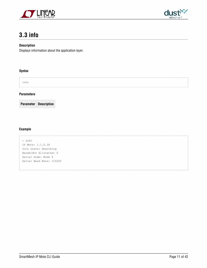
3.3 info
Description
Displays information about the application layer.
Syntax
info
Parameters
Parameter Description
Example
> info
IP Mote: 1.1.0.36
Join state: Searching
Bandwidth Allocated: 0
Serial mode: Mode 4
Serial Baud Rate: 115200

SmartMesh IP Mote CLI Guide Page of 12 42
3.4 loc
Description
Send a local command to the net layer. This command is intended for internal mote development, evaluation, and advanced
use as directed by an application note.
Syntax
loc <payload>
Parameters
Parameter Description
payload Binary string up to 90 bytes in length
Example
loc 0102030405
SmartMesh IP Mote CLI Guide Page of 13 42
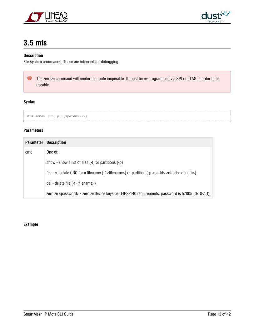
3.5 mfs
Description
File system commands. These are intended for debugging.
The zeroize command will render the mote inoperable. It must be re-programmed via SPI or JTAG in order to be
useable.
Syntax
mfs <cmd> {-f|-p} [<param>...]
Parameters
Parameter Description
cmd One of:
show - show a list of files (-f) or partitions (-p)
fcs - calculate CRC for a filename (-f <filename>) or partition (-p <parId> <offset> <length>)
del - delete file (-f <filename>)
zeroize <password> - zeroize device keys per FIPS-140 requirements. password is 57005 (0xDEAD).
Example

SmartMesh IP Mote CLI Guide Page of 14 42
> mfs show -p
ID Size Address Page
1 32768 0x000b7800 2048 exec
2 258048 0x00041000 2048 exec
4 227328 0x00080000 2048
6 2048 0x000bf800 2048
> mfs show -f
1mote.cfg 36 shadow
1ini.cfg 6 shadow
2main.cfg 29 shadow
2dout.cfg 6 shadow
2din.cfg 37 shadow
2ana.cfg 37 shadow
2temp.cfg 19 shadow
Partitions:
ID - the partition ID
Size - Partition size in bytes
Address - Starting address of partition
Page - Page size in bytes
Pages marked as exec can contain an executable image
Files:
1st column - Filename. Files starting with 1 are created by the network stack. Files starting with a 2 are created by the
mote application
2nd column - Size in bytes. 0 indicates an empty file
3rd column - Indicates whether the file is shadowed (there is a backup copy) or temporary

SmartMesh IP Mote CLI Guide Page of 15 42
3.6 mget
Description
Used to get parameters that are available to user for mote configuration.
Syntax
mget <parameter>
Parameters
Parameter Description
netid Network ID
rtmode 0: routing enabled (default) or 1: routing disabled (can be used to force a mote to be a leaf mote)
joindc Duty cycle used during join process ( 0 - 255 ) 255 = 100%
txpwr Transmit power. 8=PA on (default), 0=PA off
autojoin The netlayer will automatically try to join or not. 1=on - only valid in slave mode (See ), 0=off (default) set
macaddr MAC address (EUI-64), e.g.: 01-23-45-67-89-AB-CD-EF. Will return 00's if not previously set by mset.
otaplout Restrict over the air programming. 1=no OTAP allowed
advkey Advertisement key (16 bytes hex) - this key is used to authenticate advertisements, and can be set per
vendor/installation to prevent unauthorized devices from being able to respond to advertisements. In mote
prior to 1.4.1, returns 00's if not previously set by In mote 1.4.1 or later, returns " mset . advkey is hidden"
maxStCur Maximum current available (will be used by the manager to know how many links it can assign to this mote)
joincntr Join counter used in the mote join request
antGain Antenna gain (INT8S) - needed to properly calculate radiated power. Default = +2 dBi
compMode Constrains mote duty cycle to power-appropriate limits imposed by EN 300 328. 0=off (default), 1 = on.
Example

SmartMesh IP Mote CLI Guide Page of 16 42
mget netid

SmartMesh IP Mote CLI Guide Page of 17 42
3.7 mgeti
Description
Get internal configuration parameters. These are intended for internal mote development, evaluation, and advanced use.
Syntax
mgeti <param>
Parameters
Parameter Description
pftimer Path fail timer (in seconds)
traceflgs Traces enabled (see )mtrace
nwl Network White List - See mseti for complete description
Example
> mgeti pftimer
pftimer=60

SmartMesh IP Mote CLI Guide Page of 18 42
3.8 minfo
Description
This command will return information about the mote, namely the code version, current join state, MAC address, Mote ID,
Network ID, bootloader version, loader version, UTC time, and reset status. Prints "battery" (Vsupply) voltage and temperature
in mote 1.4.1 or later.
Syntax
minfo
Parameters
Parameter Description
Example
> minfo
Net stack v1.1.0.0
state: Oper
mac: 00:17:0d:00:00:38:09:8f
moteid: 7
netid: 63
blSwVer: 9
ldrSwVer: 1.0.3.11
UTC time: 1026005872:214750
reset st: 100
battery: 3609 mV
temp: 21 C

SmartMesh IP Mote CLI Guide Page of 19 42
3.9 mlog
Description
This command retrieves the internal mote log which may contain debug information based on the last reset.
Syntax
mlog
Parameters
Parameter Description
Example
> mlog
Low-level log: '<empty>'

SmartMesh IP Mote CLI Guide Page of 20 42
3.10 mset
Description
Set parameters available for mote configuration. Each parameter indicates whether it is entered in hex or decimal. These
parameters are persistent, and read from non-volatile storage when the mote is given a command. The txpwer and joindcjoin
parameters take effect immediately if changed, all others require reset to take effect if set post- .join
Syntax
mset <param> <value>
Parameters
Parameter Description
netid Network ID (decimal). As of version 1.4.x, 0xFFFF can be used to indicate that the mote should join the first
network heard.
jkey Join key (hex)
rtmode 0: routing enabled (default) or 1: routing disabled, which can be used to force a mote to be a leaf mote
joindc Duty cycle used during join process ( 0 - 255 ) 255 = 100% (decimal)
txpwr Transmit power. 8=PA on (default), 0=PA off (decimal)
autojoin The netlayer will automatically try to join or not. 1=on - only valid in slave mode (See ), 0=off (default)set
macaddr MAC address (EUI-64), e.g.: 01-23-45-67-89-AB-CD-EF (hex)
otaplout Restrict over the air programming. 1=no OTAP allowed
advkey Advertisement key (16 bytes hex) - this key is used to authenticate advertisements, and can be set per
vendor/installation to prevent unauthorized devices from being able to respond to advertisements. If changed,
it must match that set on the corresponding AP (using on the manager CLI) in order for the mote to join.mset
It can be reset to default via the commandrestore
maxStCur Maximum current available. Will be used by the manager to know how many links it can assign to this mote.
(decimal)
joincntr Join counter used in the mote join request (decimal)
antGain Antenna gain (INT8S) - needed to properly calculate radiated power. Default = +2 dBi
compMode Constrains mote duty cycle to power-appropriate limits imposed by EN 300 328. 0=off (default), 1 = on.

SmartMesh IP Mote CLI Guide Page of 21 42
Example
mset netid 1234

SmartMesh IP Mote CLI Guide Page of 22 42
3.11 mseti
Description
Set internal configuration parameters. These are intended for internal mote development, evaluation, and advanced use as
directed by an application note. This change is persistent.
Syntax
mseti <param> <value>
Parameters
Parameter Description
pftimer Path fail timer (in seconds)
nwl Network White List - sets neighbor that mote can join through (1st in the list), and neighbors that mote can
discover (the rest in the list). Up to total of 8 neighbors, IDs supported are 1 byte only. NOTE: this parameter is
available starting from release 1.2.0 only
Example
mseti pftimer 60

SmartMesh IP Mote CLI Guide Page of 23 42
3.12 mshow
Description
Show information about mote resources. Intended for debugging.
Syntax
mshow <object>
Parameters
Parameter Description
object One of:
links - assigned links
nbrs - list of neighbors
stacks - information about task RAM usage (in 32-bit words)
tasktime - amount of time processor is idle or executing tasks
pktstat - packet statistics
rstat - extended radiotest stats including average RSSI and LQI. Available in mote 1.4.0 or later.
Example

SmartMesh IP Mote CLI Guide Page of 24 42
> mshow links
4:84:0#65535 d:rf
5:68:0#65535 n:rlf
5:69:0#65535 n:rlf
5:70:0#65535 n:rlf
> mshow rstat
OkCnt : 2941
FailCnt : 104
AveRSSI : -67
AveLQI : 15
>

SmartMesh IP Mote CLI Guide Page of 25 42
3.13 mtrace
Description
Turn MAC layer traces on or off. This change is persistent if called with the save parameter. If called with no arguments,
returns current state of all mtraces.
Syntax
mtrace [save | {<parameter> on | off}]
Parameters
Parameter Description
save Save current trace flags to flash
mac MAC layer TXs and RXs
mac_tof Time of flight (mtrace mac must be on to see the mac_tof)
io Description of the commands in the packet
otap Progression/status of the over the air programming
all All trace elements
Example
> mtrace mac on
7497319 : MAC R: a=57423 t=7 ch=13 s=1 rc=0 rs=-23 ad=14 q=0,0
7497457 : MAC T: a=57442 t=7 ch=1 d=1 rc=0 ad=0 po=180 pe=460 q=0,0
7498385 : MAC T: a=57570 t=2 ch=0 d=2 rc=0 ad=-20 po=182 pe=460 q=0,0
7500575 : MAC T: a=57872 t=7 ch=3 d=1 rc=0 ad=0 po=180 pe=460 q=0,0
>
> mtrace mac off

SmartMesh IP Mote CLI Guide Page of 26 42
3.14 mxtal
Description
This command is used to determine the optimal trim value to center the 20MHz crystal oscillator frequency given a particular
PCB layout and crystal combination. It is used to measure the 20 MHz crystal, after which the user must enter trim values into
the device's fuse table for access by software. See the for fuse table details.Board Specific Configuration Guide
An additional optional temperature grade argument is available in mote >= 1.3.2. The command will return an error if the part
is tested using incorrect temperature grade parameters.
This command may only be used when the mote's radio is not active, i.e. in the mode and prior to joining theslave
network. After using this command, reboot the mote to continue normal operation.
Syntax
mxtal [trim|meas] [<i>|<h>]
Parameters
Parameter Description
trim Trims the adjustable load capacitance for the 20MHz crystal to match the frequency reference on the DC9010
programming board. Outputs the post-trim ppm error and the optimal value of the load-capacitance setting.
The trimmed value of the load capacitance is not stored in the mote application, rather in a custom fuse table;
the function output should be used to determine the the proper value of the load-capacitance setting for the
BSP fuse table parameter. This function requires the mote be connected to the DC9010 programming board. It
could take up to 30 sec for command to execute.
meas Outputs the ppm error of the 20MHz reference with value loaded from the fuse table . This function requires the
mote be connected to the DC9010 programming board. It could take up to 30 sec for command to execute.
i | h Temperature grade, one of i=industrial or h=high temperature - See device datasheet for details. Defaults to i
(industrial) if omitted.
Example
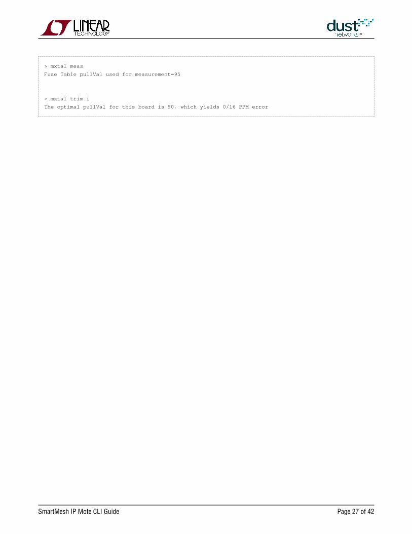
On an i-grade part:
SmartMesh IP Mote CLI Guide Page of 27 42
> mxtal meas
Fuse Table pullVal used for measurement=95
> mxtal trim i
The optimal pullVal for this board is 90, which yields 0/16 PPM error

SmartMesh IP Mote CLI Guide Page of 28 42
3.15 radiotest
3.15.1 radiotest on/off
Description
Enable or disable radiotest mode on the device. Radiotest functionality can be used to exercise the radio for certification and
testing purposes. This command takes effect after reboot and the selected mode persists until changed, i.e. if ON, it will
remain on even after reset or power cycle until the mode is set to OFF and the device is rebooted.
Syntax
radiotest <mode>
Parameters
Parameter Description
mode on - put device into radiotest mode after reboot
off - put device into normal master mode after reboot
Example
Put device into radiotest mode:
radiotest on
Return device to normal operational mode:
radiotest off

SmartMesh IP Mote CLI Guide Page of 29 42
3.15.2 radiotest tx
Description
The command allows the user to initiate a radio transmission test. This command may only be issued inradiotest tx
radiotest mode. Three types of transmission tests are supported:
pk - Packet Transmission
cm - Continuous Modulation
cw - Continuous Wave (unmodulated signal)
pkcca - Packet transmission with clear channel assessment (CCA) enabled (Available in IP Manager >= 1.3.0 and IP
mote >= 1.4.0)
In a packet transmission test, the device generates a number of packet sequences. Each sequence consists of up torepeatCnt
10 packets with configurable sizes and delays. Each packet consists of a payload of up to 125 bytes, and a 2-byte 802.15.4
CRC at the end. Byte 0 contains sender's stationId. Bytes 1 and 2 contain the packet number (in big-endian format) that
increments with every packet transmitted. Bytes 3..N contain a counter (from 0..N-3) that increments with every byte inside
payload. Transmissions occur on the set of channels defined by , selected in pseudo-random order.chanMask
In a continuous modulation test, the device generates continuous pseudo-random modulated signal, centered at the specified
single channel. The test is stopped by resetting the device.
In a continuous wave test, the device generates an unmodulated tone, centered at the specified single channel. The test tone is
stopped by resetting the device.
In a packet transmission with CCA test, the device is configured identically to that in the packet transmission test, however the
device does a clear channel assessment before each transmission and aborts that packet if the channel is busy.
Channel numbering is 0-15, corresponding to IEEE 2.4 GHz channels 11-26.
stationId is available in SmartMesh IP Mote >= 1.4, SmartMesh IP Manager >= 1.3.0, SmartMesh WirelessHART
mote >= 1.1.2
Syntax
radiotest tx <testType> <chanMask> <power> [<stationId> <repeatCnt> {<pkLen><delay>...}]

SmartMesh IP Mote CLI Guide Page of 30 42
Parameters
Parameter Description
testType Type of transmission test to initiate: 'pk' = packets, 'cm' = continuous modulation, 'cw' - continuous wave,
"pkcca" = packets with CCA.
chanMask Hexadecimal bitmask of channels (0–15) for the test. Bit 0 corresponds to channel 0. For continuous wave and
continuous modulation tests, only one channel should be enabled.
power Transmit power, in dB. Valid values are 0 and 8.
stationId Unique (0-255) station id of the sender. Must match station id value of the receiver.
repeatCnt Number of times to repeat the packet sequence (0=do not stop). Applies only to packet transmission tests.
pkLen Length of packet (2-125 bytes)
delay Delay after transmission (0-65535 microseconds)
Example
Initiate packet test on channels 0,1 (chMap=0x03), with output tx power of 0 dBm, station id = 26
Repeat the sequence 5 times: 50-byte packet, 20ms delay, 30-byte packet, 20msec delay
radiotest tx pk 0x3 0 26 5 50 20000 30 20000
Start transmission with continuous modulation on channel 0 with output tx power of 8 dB
radiotest tx cm 0x1 8
Start transmission with continuous wave on channel 1 with output tx power of 8 dB
radiotest tx cw 0x2 8

SmartMesh IP Mote CLI Guide Page of 31 42
3.15.3 radiotest rx
Description
The command puts the radio into receive mode where statistics on packet reception are collected. Theradiotest rx
nonzero station id specified must match station id of the sender, which is necessary to isolate traffic of multiple tests running
in the same radio space. Statistics may be viewed with the command.radiotest stat
Channel numbering is 0-15, corresponding to IEEE 2.4 GHz channels 11-26.
stationId is available in SmartMesh IP Mote >= 1.4, SmartMesh IP Manager >= 1.3.0, SmartMesh WirelessHART
mote >= 1.1.2
Syntax
radiotest rx <chanMask> <time> <stationId>
Parameters
Parameter Description
chanMask Hexadecimal bitmask of channels (0–15) for the test. Bit 0 corresponds to channel 0. Only a single channel
may be specified for this command.
time Duration of receive test, in seconds. 0=do not stop
stationId Unique (1-255) id of the receiver. Must match sender's station id. Station id 0 may be used to accept packets
from any sender.
Example
Put device into receive mode for 60 seconds on channel 2, use station id 26:
radiotest rx 0x4 60 26

SmartMesh IP Mote CLI Guide Page of 32 42
3.15.4 radiotest stat
Description
The command displays packet reception statistics collected during the previously run radiotest stat radiotest rx
command. This command may only be used when the device is in radiotest mode.
Syntax
radiotest stat
Parameters
Parameter Description
Example
>radiotest stat
Radio Test Statistics
OkCnt : 0
FailCnt : 0
SmartMesh IP Mote CLI Guide Page of 33 42
3.15.5 radiotest lps
Description
The command radiotest lps shuts down all peripherals and places the mote into Low Power Sleep mode. A hardware
it. reset is required to bring a mote out of
Syntax
radiotest lps
Parameters
Parameter Description
Example

SmartMesh IP Mote CLI Guide Page of 34 42
3.16 reset
Description
Reset the mote.
Syntax
reset
Parameters
Parameter Description
Example
> reset
SmartMesh IP mote, ver 1.1.0.41 (0x0)

SmartMesh IP Mote CLI Guide Page of 35 42
3.17 restore
Description
This command will clear all settings and parameters to their factory default values.
Syntax
restore
Parameters
Parameter Description
Example
restore

SmartMesh IP Mote CLI Guide Page of 36 42
3.18 set
Description
Set application parameters. This change is persistent.
Syntax
set <parameter> <value>
Parameters
Parameter Description
mode One of:
• master: the application will initiate joining and terminate all local commands. When in master mode, the
autoJoin parameter in the mote must be off as the application will initiate join
• slave: the local commands will be forwarded to the serial port.
rc One of:
on - disables the rate controller (packet generator) in master mode
off - enables the rate controller (packet generator) in master mode
Available in mote 1.4.0 or later.
Example
> set mode slave

SmartMesh IP Mote CLI Guide Page of 37 42
3.19 trace
Description
Turn application layer traces on or off. If called with no arguments, returns current state of all traces. If called with the
argument "save" it stores current settings to non-volatile memory.
Syntax
trace [save | {<module>|all on|off}]
Parameters
Parameter Description Actions
module One of the following modules
loc - local (net layer) commands
oap - application commands
ser - serial commands
all - reserved
rc - reserved
sm - reserved
Example
trace loc on
SmartMesh IP Mote CLI Guide Page of 38 42
4 Error Messages
Mote software is organized into various OSI-model layers, e.g. the Medium Access Control (MAC) layer is responsible for
packet delivery between neighbors, while the Network (NET) layer handles end-to-end delivery. When a stack layer encounters
an error, it will be printed on the CLI, starting with an OS timestamp in ms. For example:
39557 : LOC nack rx pk=4 ql=0 qm=1
The following tables explain the meaning of the various error messages.
MAC layer Meaning
PF: n= t= lh= d= disc= Path failure to neighbor 'n' at time 't', last communication time 'lh', 'd' is difference between 't'
and 'lh'
disc=a (disconnecting because mote received a disconnect command)
disc=m (disconnecting because of locally generated path failure)
MAC retry drop is
exceeded
Packet is dropped because number of source-route retries is exceeded
MAC pdu tout Packet is dropped because of PDU timeout
MAC no route found Packet is dropped because the graph to send it on was not found
Disconnecting 1 MAC started disconnecting process because of received command
Disconnecting 2 MAC started disconnecting process because of locally generated path failure
RX ADV SYNC failed Failed synchronization time bounds check when processing advertisement
listen chan = Channel switched in promiscuous mode (searching for network)
Local (API) layer Meaning
LOC nack rx pk=
ql= qm=
Local interface responded DN_API_RC_NO_RESOURCES to the received DN_API_LOC_CMD_SENDTO
or DN_API_LOC_SENDTO_MAC commands.
‘pk’ is number of available packets in the NET layer
‘ql’ is number of packets in the queue to local interface
‘qm’ is the number of packets in queue to MAC
Event NACKed Local interface received DN_ERR_NO_RESOURCES to sent event

SmartMesh IP Mote CLI Guide Page of 39 42
Rx Notif NACKed Local interface received DN_ERR_NO_RESOURCES to sent packet received notification
Time Notif
NACKed
Local interface received DN_ERR_NO_RESOURCES to sent time notification
Filesystem layer Meaning
'Filename' could not be created Could not open a file in file system
Error while deleting 'filename' Could not delete a file in file system
Network layer Meaning
Joining Mote sent join request
Join retry # Mote re-tried join request after timeout
Join failed Failed to join after maximum number of join retries
Disconnected Received event notification from MACdisconnected
Active Mote changed state to Operational
Connected Mote changed state to Connected
Lost Mote changed state to Lost
UDP socket for port N not found Application attempted to use an unopened socket ID
UDP socket for port N not bound Application attempted to use an open socket that is not bound to the named port
NET no pk for ping resp Packet could not be allocated for ping response as network queue was full
NET no pk for log trace Packet could not be allocated for log response as network queue was full
NET no pk for srv req Packet could not be allocated for service request as network queue was full
NET no pk for path alarm Packet could not be allocated for path alarm as network queue was full
NET no pk for src rt alarm Packet could not be allocated for source route alarm as network queue was full
NET no pk for HR Packet could not be allocated for device health report as network queue was full
NET no pk for Neighb HR Packet could not be allocated for neighbor health report as network queue was full

SmartMesh IP Mote CLI Guide Page of 40 42
Command Handler Meaning
CMD no pk from handler pk= qm- Command handler couldn't generate a packet
‘pk’ is number of available packets in the NET layer
‘qm’ is the number of packets in queue to MAC
CMD len err Command handler rejected a command - length does not match command definition
CMD handler N not found There is no handler implemented for command N
CMD inv len Command handler cannot parse a command since length is shorter than header
CMD handler access denied Command cannot be called from this interface
The mote will print a bitmap indicating the reason for the last reset
Reset Status Meaning
0x100 Watchdog
0x200 External reset pin asserted
0x400 Power-on
0x800 Brownout
0x40000 FLASH_P_EN was asserted at boot
0x40000000 CPU Lockup
0x80000000 Sysreset

SmartMesh IP Mote CLI Guide Page of 41 42
Trademarks
are trademarks of Dust Networks, Inc. The Dust Networks logo, Dust, DustEterna, Mote-on-Chip, and SmartMesh IP,
Networks, and SmartMesh are registered trademarks of Dust Networks, Inc. LT, LTC, LTM and are registered
All third-party brand and product names are the trademarks of their respective ownerstrademarks of Linear Technology Corp.
and are used solely for informational purposes.
Copyright
This documentation is protected by United States and international copyright and other intellectual and industrial property
laws. It is solely owned by Linear Technology and its licensors and is distributed under a restrictive license. This product, or
any portion thereof, may not be used, copied, modified, reverse assembled, reverse compiled, reverse engineered, distributed,
or redistributed in any form by any means without the prior written authorization of Linear Technology.
RESTRICTED RIGHTS: Use, duplication, or disclosure by the U.S. Government is subject to restrictions of FAR 52.227-14(g)
(2)(6/87) and FAR 52.227-19(6/87), or DFAR 252.227-7015 (b)(6/95) and DFAR 227.7202-3(a), and any and all similar and
successor legislation and regulation.
Disclaimer
This documentation is provided “as is” without warranty of any kind, either expressed or implied, including but not limited to,
the implied warranties of merchantability or fitness for a particular purpose.
This documentation might include technical inaccuracies or other errors. Corrections and improvements might be
incorporated in new versions of the documentation.
Linear Technology does not assume any liability arising out of the application or use of any products or services and
specifically disclaims any and all liability, including without limitation consequential or incidental damages.
Linear Technology products are not designed for use in life support appliances, devices, or other systems where malfunction
can reasonably be expected to result in significant personal injury to the user, or as a critical component in any life support
device or system whose failure to perform can be reasonably expected to cause the failure of the life support device or
system, or to affect its safety or effectiveness. Linear Technology customers using or selling these products for use in such
applications do so at their own risk and agree to fully indemnify and hold Linear Technology and its officers, employees,
subsidiaries, affiliates, and distributors harmless against all claims, costs, damages, and expenses, and reasonable attorney
fees arising out of, directly or indirectly, any claim of personal injury or death associated with such unintended or
unauthorized use, even if such claim alleges that Linear Technology was negligent regarding the design or manufacture of its
products.
Linear Technology reserves the right to make corrections, modifications, enhancements, improvements, and other changes to
its products or services at any time and to discontinue any product or service without notice. Customers should obtain the
latest relevant information before placing orders and should verify that such information is current and complete. All products
are sold subject to Dust Network's terms and conditions of sale supplied at the time of order acknowledgment or sale.

SmartMesh IP Mote CLI Guide Page of 42 42
Linear Technology does not warrant or represent that any license, either express or implied, is granted under any Linear
Technology patent right, copyright, mask work right, or other Linear Technology intellectual property right relating to any
combination, machine, or process in which Linear Technology products or services are used. Information published by Linear
Technology regarding third-party products or services does not constitute a license from Linear Technology to use such
products or services or a warranty or endorsement thereof. Use of such information may require a license from a third party
under the patents or other intellectual property of the third party, or a license from Linear Technology under the patents or
other intellectual property of Linear Technology.
Dust Networks, Inc is a wholly owned subsidiary of Linear Technology Corporation.
© Linear Technology Corp. 2012-2016 All Rights Reserved.