smartplc/opc 2008 - springerextras.springer.com/2009/978-3-642-00268-7/content cd/infoteam... ·...
TRANSCRIPT

© 1994 – 2006 infoteam Software GmbH • www.infoteam.de
1
Innovation in Automation
2008 SmartPLC/OPC SmartPLC/OPC
© 2008 infoteam Software GmbH • www.infoteam.de
En
glis
h
2
SmartPLC/OPC
3.1
User Manual
Content
1 PREFACE ................................................................................................... 4
2 HOW TO GET STARTED ........................................................................... 8
3 SMARTPLC/OPC USER GUIDE .............................................................. 26
4 SMARTHMI ............................................................................................... 34
5 ADVANCED TOPICS ................................................................................ 38
6 REFERENCE INFORMATION .................................................................. 41
7 TROUBLESHOOTING .............................................................................. 42
8 TABLE OF FIGURES ............................................................................... 47
9 INDEX ....................................................................................................... 48
1 Preface SmartPLC/OPC
© 2008 infoteam Software GmbH • www.infoteam.de
4 4
En
glis
h
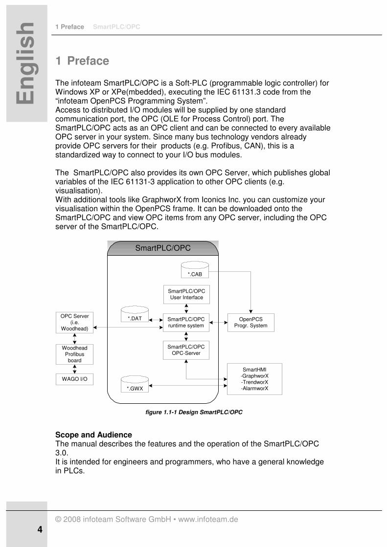
1 Preface The infoteam SmartPLC/OPC is a Soft-PLC (programmable logic controller) for Windows XP or XPe(mbedded), executing the IEC 61131.3 code from the “infoteam OpenPCS Programming System”. Access to distributed I/O modules will be supplied by one standard communication port, the OPC (OLE for Process Control) port. The SmartPLC/OPC acts as an OPC client and can be connected to every available OPC server in your system. Since many bus technology vendors already provide OPC servers for their products (e.g. Profibus, CAN), this is a standardized way to connect to your I/O bus modules. The SmartPLC/OPC also provides its own OPC Server, which publishes global variables of the IEC 61131-3 application to other OPC clients (e.g. visualisation). With additional tools like GraphworX from Iconics Inc. you can customize your visualisation within the OpenPCS frame. It can be downloaded onto the SmartPLC/OPC and view OPC items from any OPC server, including the OPC server of the SmartPLC/OPC.
SmartPLC/OPCruntime system
SmartPLC/OPCOPC-Server
SmartHMI-GraphworX-TrendworX-AlarmworX
OpenPCSProgr. System
*.DAT
*.GWX
*.CAB
SmartPLC/OPC
OPC Server(i.e.
Woodhead)
WoodheadProfibus
board
WAGO I/O
SmartPLC/OPCUser Interface
figure 1.1-1 Design SmartPLC/OPC
Scope and Audience The manual describes the features and the operation of the SmartPLC/OPC 3.0. It is intended for engineers and programmers, who have a general knowledge in PLCs.
SmartPLC/OPC 1 Preface
© 2008 infoteam Software GmbH • www.infoteam.de
5
En
glis
h
1.1 Table of Contents
1 PREFACE 4
1.1 Table of Contents 5
1.2 Predefinitions 7
2 HOW TO GET STARTED 8
2.1 System Requirements 9
2.2 Installing and Licensing the infoteam SmartPLC/OPC 10
2.3 Installing and Configuring the infoteam OpenPCS Programming System 12
2.4 Installing and configuring Profibus-IO Hardware and Software 14
2.4.1 Woodhead Direct Link PCI-DPIO Profibus card 14
2.4.2 SST Profibus card 17
2.5 Programming and Running an IEC 61131-3 application on the infoteam
SmartPLC/OPC 22
3 SMARTPLC/OPC USER GUIDE 26
3.1 SmartPLC/OPC User Interface 26
3.1.1 Operation Control 26
3.1.2 Displays 27
3.2 OPC Server SmartPLCDA 31
3.3 Start Configuration 32
4 SMARTHMI 34
4.1 GraphWorX-Files 34
4.1.1 Adding GraphWorX-Files in OpenPCS 34
4.1.2 Downloading GraphWorX-Files 36
5 ADVANCED TOPICS 38
5.1 Communication via DCOM 38
5.1.1 Check Requirements: 38
5.1.2 Setting up DCOM communication 38
5.1.3 Setting permissions for DCOM 39
5.2 Remote control 40
1 Preface SmartPLC/OPC
© 2008 infoteam Software GmbH • www.infoteam.de
6 6
En
glis
h
6 REFERENCE INFORMATION 41
6.1 Technical Data 41
6.2 Supported I/O boards and OPC servers 41
7 TROUBLESHOOTING 42
7.1 FAQ 42
7.2 Technical Support 46
8 TABLE OF FIGURES 47
9 INDEX 48

SmartPLC/OPC 1 Preface
© 2008 infoteam Software GmbH • www.infoteam.de
7
En
glis
h
1.2 Predefinitions
Selecting „File ÜÜÜÜ New“ activates the command “New” from the menu “File”. Small letters in italic mark a text, which has to be entered. (Example: c:\proj\sample)
Instructions for actions are labeled with an arrow symbol è .
� A hand signalizes special hints.

2 How To Get Started SmartPLC/OPC
© 2008 infoteam Software GmbH • www.infoteam.de
8 8
En
glis
h
2 How To Get Started This chapter describes how to easily install, configure and run an infoteam SmartPLC/OPC system. It guides through the following necessary steps to run a first IEC61131-3 application on the infoteam SmartPLC/OPC:
• System Requirements
• Installing and Licencing the infoteam SmartPLC/OPC
• Installing and configuring the infoteam OpenPCS programming system
• Installing and configuring Profibus-IO Hardware and Software
• Programming and running an IEC 61131-3 application on the infoteam SmartPLC/OPC

SmartPLC/OPC 2 How To Get Started
© 2008 infoteam Software GmbH • www.infoteam.de
9
En
glis
h
2.1 System Requirements
To use the infoteam SmartPLC/OPC your system must meet the following criteria:
Operating system
Windows XP SP2, Windows XP embedded
Hard drive A hard drive with 100 Mbytes of free space
Network interface
A standard Ethernet card to connect the SmartPLC/OPC to the OpenPCS programming system via TCP/IP
infoteam Software
• infoteam SmartPLC/OPC (version 3.0.0)
• infoteam OpenPCS (version 5.5.0) (usually installed on a separate system )
To be able to set up the system described in this chapter, the system need to provide the
following items:
Network interface
• one free PCI slot (Woodhead Profibus PCI card)
or
• PCMCIA slot ( SST Profibus card)
Processor and memory
Pentium 1 GHz 256 Mbytes

2 How To Get Started SmartPLC/OPC
© 2008 infoteam Software GmbH • www.infoteam.de
10 10
En
glis
h
2.2 Installing and Licensing the infoteam SmartPLC/OPC
Installation Please run the file Setup_SmartPLC_OPC.exe from the product CD and follow the installation steps. Licensing During the installation you will be prompted to register your infoteam SmartPLC/OPC on your system. For using the SmartPLC/OPC in DEMO mode (full functionality limited to 1 hour) you
can quit the dialog and register at a later date.
To fully register the product, please enter the product key from the label of the jewel case and create a challenge key (Step 1).
figure 2.2-1 SmartPLC/OPC Licensce Editor – Create Challenge
Please send this challenge key via email to [email protected]. After creating the challenge key you have an unlimited access to the product for 7 days. Within this period you will receive an activation key, which should be entered into the corresponding field in Step2. By "Verifying" the activation key you complete the licensing step of the SmartPLC/OPC on your system.

SmartPLC/OPC 2 How To Get Started
© 2008 infoteam Software GmbH • www.infoteam.de
11
En
glis
h
figure 2.2-2 SmartPLC/OPC License Editor – Entering Activation Key

2 How To Get Started SmartPLC/OPC
© 2008 infoteam Software GmbH • www.infoteam.de
12 12
En
glis
h
2.3 Installing and Configuring the infoteam OpenPCS Programming System
The infoteam SmartPLC/OPC executes IEC 61131-3 code programmed with the infoteam OpenPCS Automation Suite. It can be installed on the same system or a separate PC. The OpenPCS Automation Suite is not part of the SmartPLC/OPC product CD, but can be downloaded at www.infoteam.de. Installation To install OpenPCS please see the installation instruction for this product. Configuration To enable the OpenPCS Automation Suite to build and download IEC61131-3 application on the SmartPLC/OPC the following configuration need to be performed:
• Add hardware support for the infoteam SmartPLC/OPC by selecting
Extras ÜÜÜÜ Tool ÜÜÜÜDriver Install..
figure 2.3-1 Add Hardware Support for SmartPLC/OPC
Choose the respective cab driver bundle from the SmartPLC/OPC product CD.
This adds a hardware description of the SmartPLC/OPC and licenses the
SmartPLC/OPC within the programming system.

SmartPLC/OPC 2 How To Get Started
© 2008 infoteam Software GmbH • www.infoteam.de
13
En
glis
h
• Add a communication port by selecting PLC ÜÜÜÜ Connections.. Create a new or modify an existing connection "SmartPLC/OPC" with the following settings.
Driver: TCP432 Port number: 23042 IP address: IP address of the SmartPLC/OPC, e.g. 192.168.1.5
Note: If OpenPCS and SmartPLC are running on the same machine, use127.0.0.1 as IP-address
���� Ensure the flag "PLC uses big endian format" is
unchecked.
figure 2.3-2 Create Online Connection
���� To test the communication between OpenPCS and
target use ‘ping –n 1 <targetname>’
Note: If your Computer does not have an IP-address assigned, please select Networks from your System Control Panel and open/create a network with TCP/IP internet protocoll. Select properties and define a unique IP-address.
2 How To Get Started SmartPLC/OPC
© 2008 infoteam Software GmbH • www.infoteam.de
14 14
En
glis
h
2.4 Installing and configuring Profibus-IO Hardware and Software
This chapter explains step by step, how to install and set up a hardware to access I/Os via a Profibus. Described are two reference systems:
• Woodhead Direct Link PCI-DPIO Profibus card (DLR-DPM-PCI version 4.2.0, software version:2.2 rev1) + Wago Profibus I/O Modules (based on DP ECO Fieldbus Coupler 750-343)
• SST Profibus card (Type: 5136-PFB-PCM) + Wago Profibus I/O Modules (based on DP ECO Fieldbus Coupler 750-343)
2.4.1 Woodhead Direct Link PCI-DPIO Profibus card
Installing hardware and software components Install the Woodhead PCI-DPIO card in a free PCI slot of the SmartPLC/OPC system.
���� Before plugging the Woodhead PCI-board into your
system, ensure, that Internet Explorer 5.0 or greater
is installed.
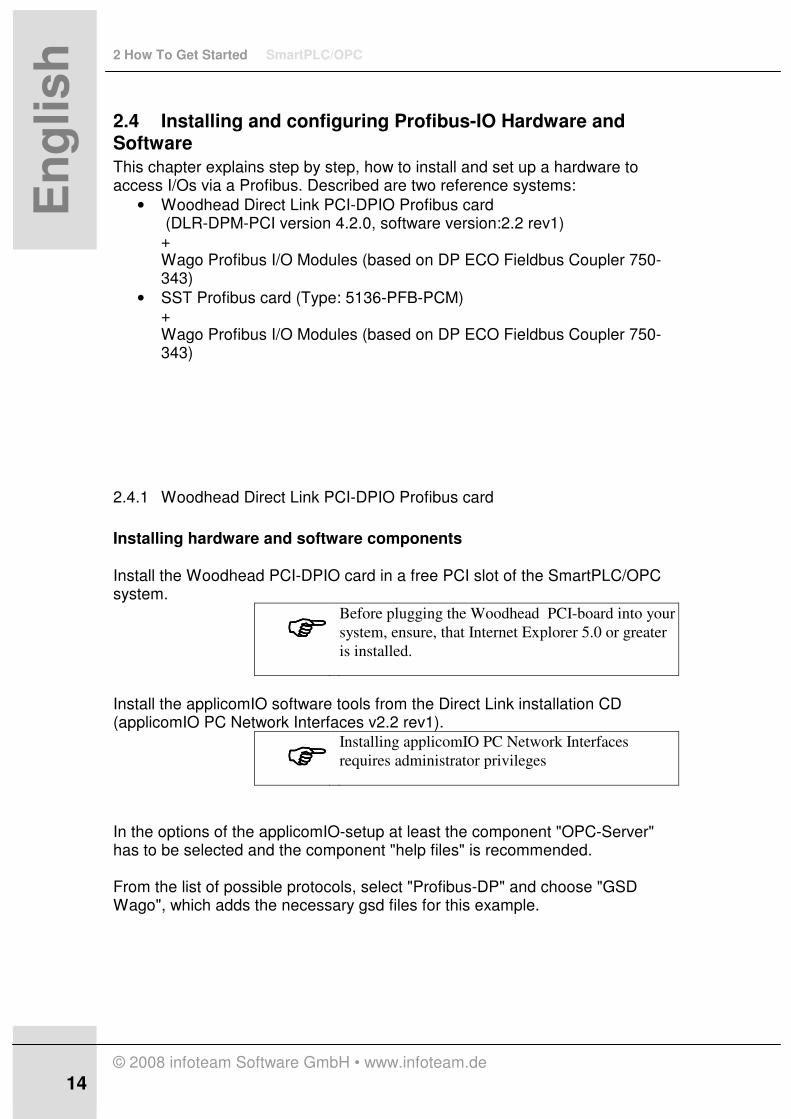
Install the applicomIO software tools from the Direct Link installation CD (applicomIO PC Network Interfaces v2.2 rev1).
���� Installing applicomIO PC Network Interfaces
requires administrator privileges
In the options of the applicomIO-setup at least the component "OPC-Server" has to be selected and the component "help files" is recommended. From the list of possible protocols, select "Profibus-DP" and choose "GSD Wago", which adds the necessary gsd files for this example.

SmartPLC/OPC 2 How To Get Started
© 2008 infoteam Software GmbH • www.infoteam.de
15
En
glis
h
figure 2.4-1 Setup applicomIO
For further details on the installation options, please consult the manual of Woodhead. For additional technical information on the WAGO I/O module please visit the Wago homepage at www.wago.com. Restart the system, the Woodhead PCI board will be automatically detected via plug&play. Configuring the Profibus and the OPC Server Start the applicomIO-console from the start menu and add the Woodhead PCI board to the configuration by selecting Add board from the context menu.
figure 2.4-2 applicomIO - Console
Check if your I/O modules are listed under "Equipment Available" in the Equipment Library pane.
2 How To Get Started SmartPLC/OPC
© 2008 infoteam Software GmbH • www.infoteam.de
16 16
En
glis
h
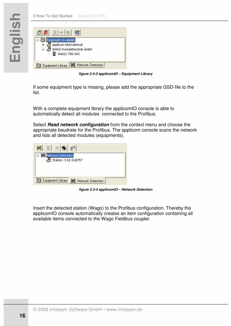
figure 2.4-3 applicomIO – Equipment Library
If some equipment type is missing, please add the appropriate GSD-file to the list. With a complete equipment library the applicomIO console is able to automatically detect all modules connected to the Profibus. Select Read network configuration from the context menu and choose the appropriate baudrate for the Profibus. The applicom console scans the network and lists all detected modules (equipments).
figure 2.4-4 applicomIO – Network Detection
Insert the detected station (Wago) to the Profibus configuration. Thereby the applicomIO console automatically creates an item configuration containing all available items connected to the Wago Fieldbus coupler.
SmartPLC/OPC 2 How To Get Started
© 2008 infoteam Software GmbH • www.infoteam.de
17
En
glis
h
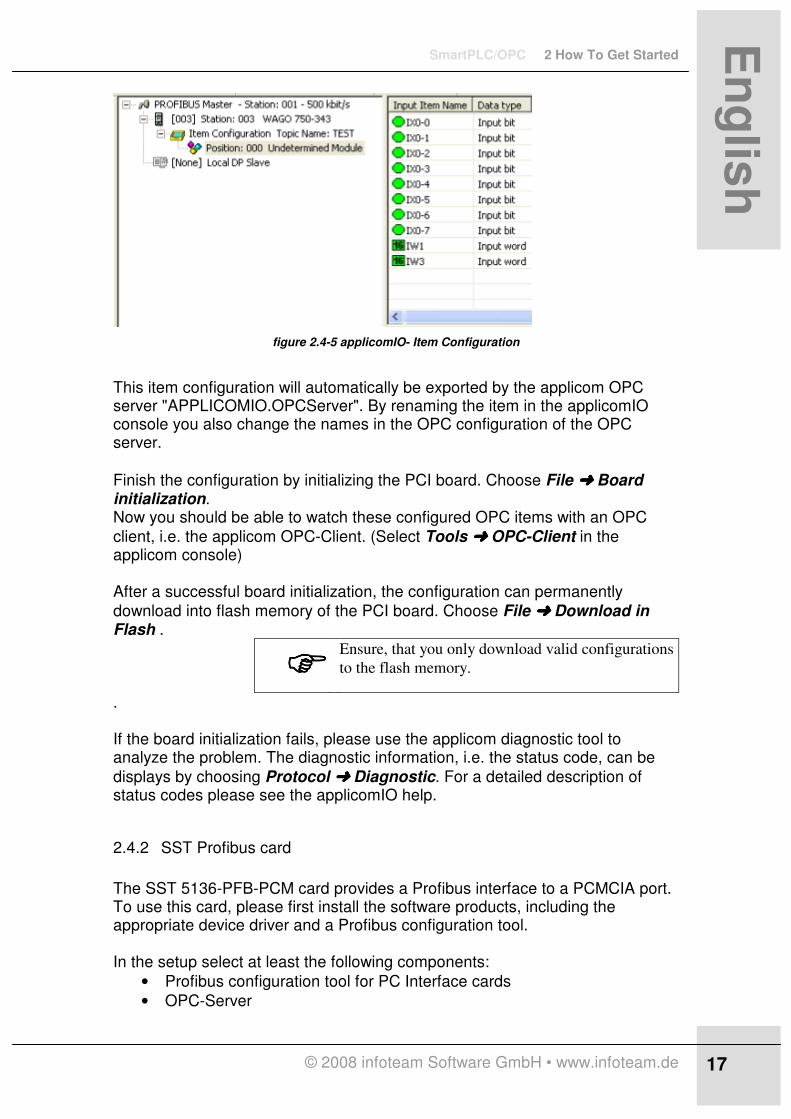
figure 2.4-5 applicomIO- Item Configuration
This item configuration will automatically be exported by the applicom OPC server "APPLICOMIO.OPCServer". By renaming the item in the applicomIO console you also change the names in the OPC configuration of the OPC server.
Finish the configuration by initializing the PCI board. Choose File ÜÜÜÜ Board initialization. Now you should be able to watch these configured OPC items with an OPC
client, i.e. the applicom OPC-Client. (Select Tools ÜÜÜÜ OPC-Client in the applicom console) After a successful board initialization, the configuration can permanently
download into flash memory of the PCI board. Choose File ÜÜÜÜ Download in Flash .
���� Ensure, that you only download valid configurations
to the flash memory.
. If the board initialization fails, please use the applicom diagnostic tool to analyze the problem. The diagnostic information, i.e. the status code, can be
displays by choosing Protocol ÜÜÜÜ Diagnostic. For a detailed description of status codes please see the applicomIO help.
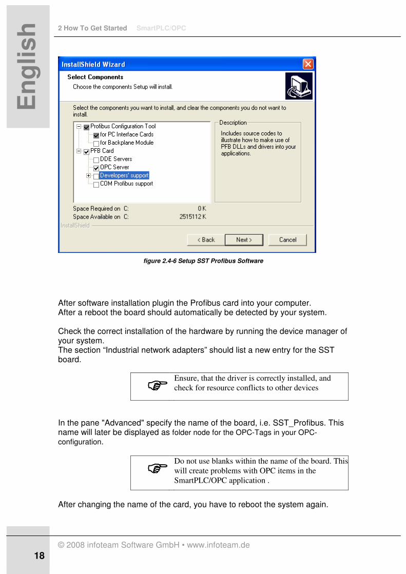
2.4.2 SST Profibus card
The SST 5136-PFB-PCM card provides a Profibus interface to a PCMCIA port. To use this card, please first install the software products, including the appropriate device driver and a Profibus configuration tool. In the setup select at least the following components:
• Profibus configuration tool for PC Interface cards
• OPC-Server
2 How To Get Started SmartPLC/OPC
© 2008 infoteam Software GmbH • www.infoteam.de
18 18
En
glis
h
figure 2.4-6 Setup SST Profibus Software
After software installation plugin the Profibus card into your computer. After a reboot the board should automatically be detected by your system. Check the correct installation of the hardware by running the device manager of your system. The section “Industrial network adapters” should list a new entry for the SST board.
���� Ensure, that the driver is correctly installed, and
check for resource conflicts to other devices
In the pane "Advanced" specify the name of the board, i.e. SST_Profibus. This name will later be displayed as folder node for the OPC-Tags in your OPC-
configuration.
���� Do not use blanks within the name of the board. This
will create problems with OPC items in the
SmartPLC/OPC application .
After changing the name of the card, you have to reboot the system again.
SmartPLC/OPC 2 How To Get Started
© 2008 infoteam Software GmbH • www.infoteam.de
19
En
glis
h
In the windows control panel a new entry, with the name “SST card configuration”, will be displayed. On opening this application, you can view all available SST cards. However, an editing of the assigned resources of the cards can only be done with the device manager.
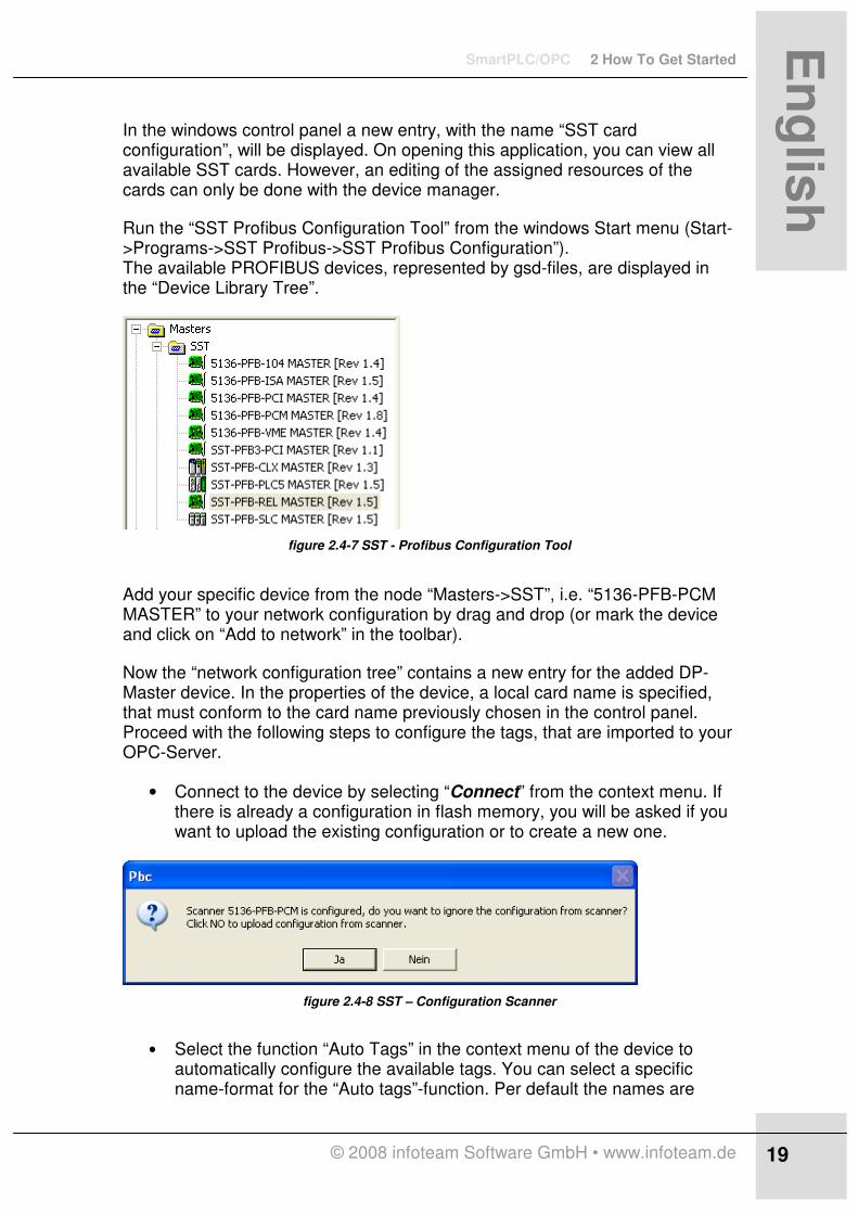
Run the “SST Profibus Configuration Tool” from the windows Start menu (Start->Programs->SST Profibus->SST Profibus Configuration”). The available PROFIBUS devices, represented by gsd-files, are displayed in the “Device Library Tree”.
figure 2.4-7 SST - Profibus Configuration Tool
Add your specific device from the node “Masters->SST”, i.e. “5136-PFB-PCM MASTER” to your network configuration by drag and drop (or mark the device and click on “Add to network” in the toolbar).
Now the “network configuration tree” contains a new entry for the added DP-Master device. In the properties of the device, a local card name is specified, that must conform to the card name previously chosen in the control panel. Proceed with the following steps to configure the tags, that are imported to your OPC-Server.
• Connect to the device by selecting “Connect” from the context menu. If there is already a configuration in flash memory, you will be asked if you want to upload the existing configuration or to create a new one.
figure 2.4-8 SST – Configuration Scanner
• Select the function “Auto Tags” in the context menu of the device to automatically configure the available tags. You can select a specific name-format for the “Auto tags”-function. Per default the names are
2 How To Get Started SmartPLC/OPC
© 2008 infoteam Software GmbH • www.infoteam.de
20 20
En
glis
h
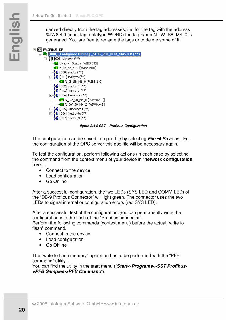
derived directly from the tag addresses, i.e. for the tag with the address %IW8.4.0 (input tag, datatype WORD) the tag-name N_IW_S8_M4_0 is generated. You are free to rename the tags or to delete some of it.
figure 2.4-9 SST – Profibus Configuration
The configuration can be saved in a pbc-file by selecting File ÜÜÜÜ Save as . For the configuration of the OPC server this pbc-file will be necessary again.
To test the configuration, perform following actions (in each case by selecting the command from the context menu of your device in “network configuration tree”).
• Connect to the device
• Load configuration
• Go Online After a successful configuration, the two LEDs (SYS LED and COMM LED) of the “DB-9 Profibus Connector” will light green. The connector uses the two LEDs to signal internal or configuration errors (red SYS LED).
After a successful test of the configuration, you can permanently write the configuration into the flash of the “Profibus connector”. Perform the following commands (context menu) before the actual "write to flash" command.
• Connect to the device
• Load configuration
• Go Offline The "write to flash memory" operation has to be performed with the “PFB command” utility. You can find the utility in the start menu (“Start->Programs->SST Profibus->PFB Samples->PFB Command”).

SmartPLC/OPC 2 How To Get Started
© 2008 infoteam Software GmbH • www.infoteam.de
21
En
glis
h
figure 2.4-10 SST – Profdibus Command Dialog
Switch to the state “Offline” (Select “Offline” and click on button “Execute”), before you can write down the configuration to the flash by executing the command “PGM_TO_FLASH”.
To configure the OPC-Server for your Profibus network, run the “SST OPC Profibus Configuration” (“Start->Programs->SST Profibus->Servers->DP Master OPC Server”) and create a new server configuration (“New”-Button).
figure 2.4-11 SST – Net Configuration
Specify the path to the configuration-file (pbc-file), that was saved in a previous step. “Net Interface” and “Card name” will automatically be filled by this step. Finally click on the Button “Done”, the Profibus configuration will directly be exported to the SST OPC server.
���� For every change on the configuration in respect to
the pbc-file, the “SST OPC Profibus Configuration”
has to be called again. Select the pbc-file and click
on the button “Done”. By that the OPC server
retrieves the new item-configuration and is again
2 How To Get Started SmartPLC/OPC
© 2008 infoteam Software GmbH • www.infoteam.de
22 22
En
glis
h
available for an OPC communication.
���� OPC clients can connect to the SST OPC
server via the server name “SST.PfbOpcSvr”. The path to an OPC-Tag of this OPC server could be as follows: “SST.PfbOpcSvr\SST_Profibus.N_IB_S8_M1_0”, whereat “SST_Profibus” respects to the self-defined name of your SST-card.
2.5 Programming and Running an IEC 61131-3 application on the infoteam SmartPLC/OPC
Creating a SmartPLC/OPC Application
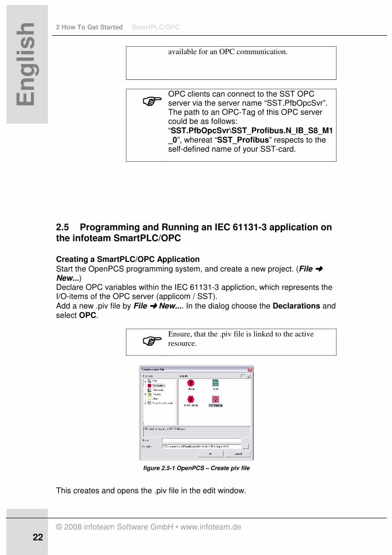
Start the OpenPCS programming system, and create a new project. (File ÜÜÜÜ New...) Declare OPC variables within the IEC 61131-3 appliction, which represents the I/O-items of the OPC server (applicom / SST).
Add a new .piv file by File ÜÜÜÜ New.... In the dialog choose the Declarations and select OPC.
���� Ensure, that the .piv file is linked to the active
resource.
figure 2.5-1 OpenPCS – Create piv file
This creates and opens the .piv file in the edit window.

SmartPLC/OPC 2 How To Get Started
© 2008 infoteam Software GmbH • www.infoteam.de
23
En
glis
h
Switch to the OPC pane (OPC-I/O ) and add the desired OPC items from the corresponding OPC Server (i.e. APPLICOMIO.OPCServer) via double-click into the .piv file.
���� If the OPC pane is not visible in the OpenPCS
browser window, select Extras ÜÜÜÜ Browser
Options... and check Enable OPC Browser pane.
figure 2.5-2 OpenPCS – OPC pane
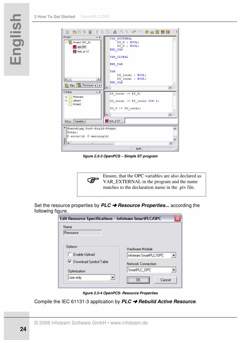
Select the appropriate IEC type and uncheck the Read-only flag (R/O) for output variables. Add a simple test program to the IEC project, which reads and writes from/onto your OPC variables declared in the .piv file. As an example use two BOOL variables for a DI (digital input) and a DO (digital output).
2 How To Get Started SmartPLC/OPC
© 2008 infoteam Software GmbH • www.infoteam.de
24 24
En
glis
h
figure 2.5-3 OpenPCS – Simple ST program
���� Ensure, that the OPC variables are also declared as
VAR_EXTERNAL in the program and the name
matches to the declaration name in the .piv file.
Set the resource properties by PLC ÜÜÜÜ Resource Properties... according the following figure.
figure 2.5-4 OpenPCS- Resource Properties
Compile the IEC 61131-3 application by PLC ÜÜÜÜ Rebuild Active Resource.

SmartPLC/OPC 2 How To Get Started
© 2008 infoteam Software GmbH • www.infoteam.de
25
En
glis
h
After a successful compilation step you can download an d run the application on the SmartPLC/OPC. Running a SmartPLC/OPC Application
èStart the SmartPLC/OPC through the Start menu or the Icon from the desktop. The running SmartPLC/OPC will be displayed by an icon in the system tray.
figure 2.5-5 SmartPLC/OPC – System Tray Icon
èStart the user interface of the SmartPLC/OPC by Start User Interface in the context menu of the system try icon, or via the Windows Start menu (infoteam SmartPLC UI).
figure 2.5-6 SmartPLC/OPC User Interface
è Press the Maintenance Button.
���� The Maintenance mode enables a write access from
OpenPCS to the SmartPLC/OPC. This is necessary
for downloading, debugging and a remote operation
control.
èDownload the IEC application by PLC ÜÜÜÜ Online (OpenPCS) and if there is
already an application on the SmartPLC/OPC select PLC ÜÜÜÜ OPC->PLC (Download)
èStart the application either with the user interface of he SmartPLC/OPC (Run)
or via an OpenPCS command PLC ÜÜÜÜ Coldstart The I/O variables will now react according to your IEC application.
3 SmartPLC/OPC User Guide SmartPLC/OPC
© 2008 infoteam Software GmbH • www.infoteam.de
26 26
En
glis
h
3 SmartPLC/OPC User Guide
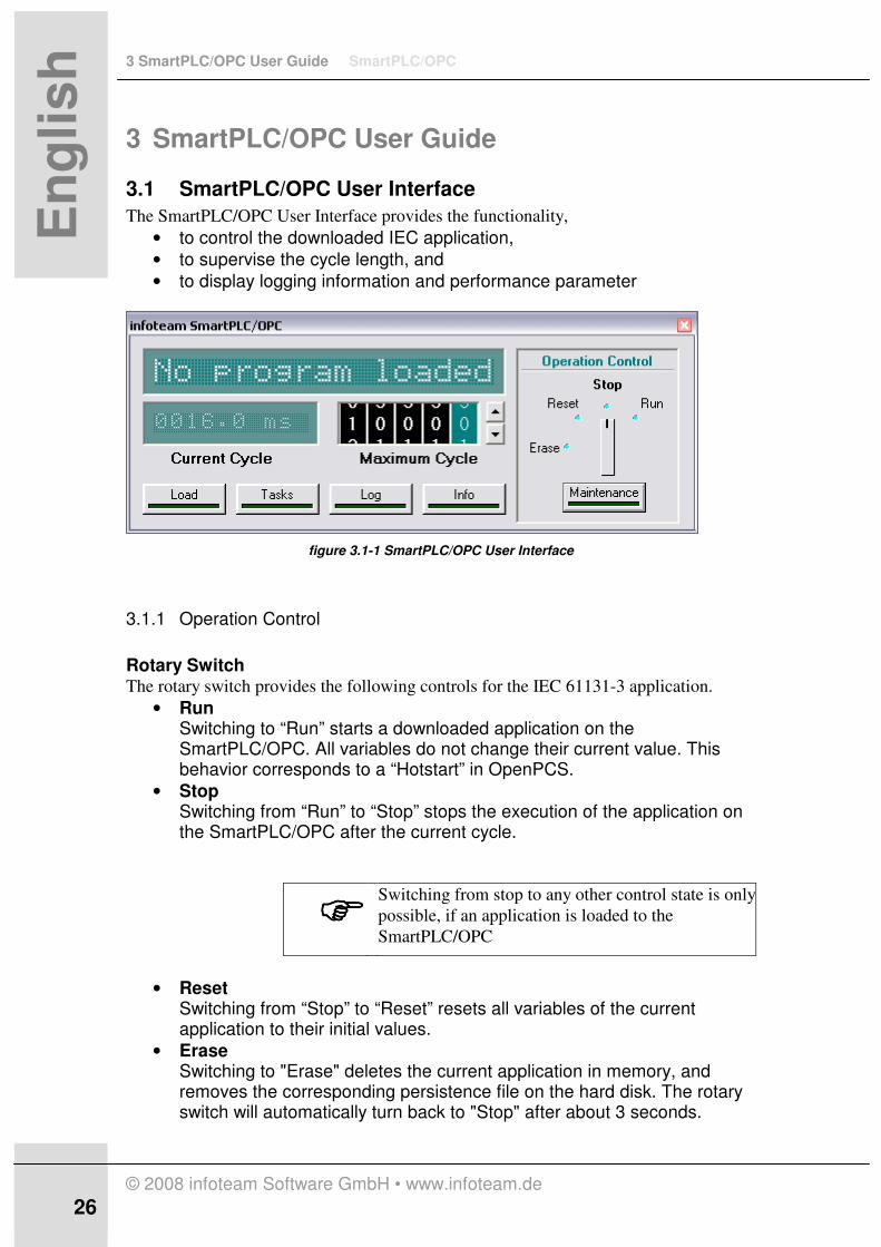
3.1 SmartPLC/OPC User Interface
The SmartPLC/OPC User Interface provides the functionality,
• to control the downloaded IEC application,
• to supervise the cycle length, and
• to display logging information and performance parameter
figure 3.1-1 SmartPLC/OPC User Interface
3.1.1 Operation Control
Rotary Switch The rotary switch provides the following controls for the IEC 61131-3 application.
• Run Switching to “Run” starts a downloaded application on the SmartPLC/OPC. All variables do not change their current value. This behavior corresponds to a “Hotstart” in OpenPCS.
• Stop Switching from “Run” to “Stop” stops the execution of the application on the SmartPLC/OPC after the current cycle.
���� Switching from stop to any other control state is only
possible, if an application is loaded to the
SmartPLC/OPC
• Reset Switching from “Stop” to “Reset” resets all variables of the current application to their initial values.
• Erase Switching to "Erase" deletes the current application in memory, and removes the corresponding persistence file on the hard disk. The rotary switch will automatically turn back to "Stop" after about 3 seconds.

SmartPLC/OPC 3 SmartPLC/OPC User Guide
© 2008 infoteam Software GmbH • www.infoteam.de
27
En
glis
h
Button Maintenance The Maintenance button controls the level of remote control of the SmartPLC/OPC with the OpenPCS Automation Suite.
• Maintenance mode disabled (button not pressed, LED dark) allows only the watching of variables.
• Maintenance mode enabled (button pressed, LED with green light) provides the full remote control functionality (Downloading, debugging, start and stop of applications, watching, setting and forcing variables)
3.1.2 Displays
Status Panel The status panel displays the current status of the SmartPLC/OPC. The following messages will be reported:
• No program loaded (no IEC application has been downloaded)
• Stopped (valid IEC application, which is currently stopped)
• Running (valid IEC application running)
• Reset (valid IEC application with initialized variables)
• All data erased ( status display after a Erase command) Current Cycle Panel The current cycle panel displays the length of the current (last) IEC Task in ms. Maximum Cycle Control With the "maximum cycle" spin control the maximum cycle duration can be set. If an IEC task exceeds this maximum cycle length , the IEC application will be stopped and the reason for this stop is displayed in the log window.

3 SmartPLC/OPC User Guide SmartPLC/OPC
© 2008 infoteam Software GmbH • www.infoteam.de
28 28
En
glis
h
Load Button/Window Pressing the load button opens an additional window, which displays the current cpu load and the usage of the IEC memory both in percent.
figure 3.1-2 SmartPLC/OPC User Interface - Load
SmartPLC/OPC 3 SmartPLC/OPC User Guide
© 2008 infoteam Software GmbH • www.infoteam.de
29
En
glis
h
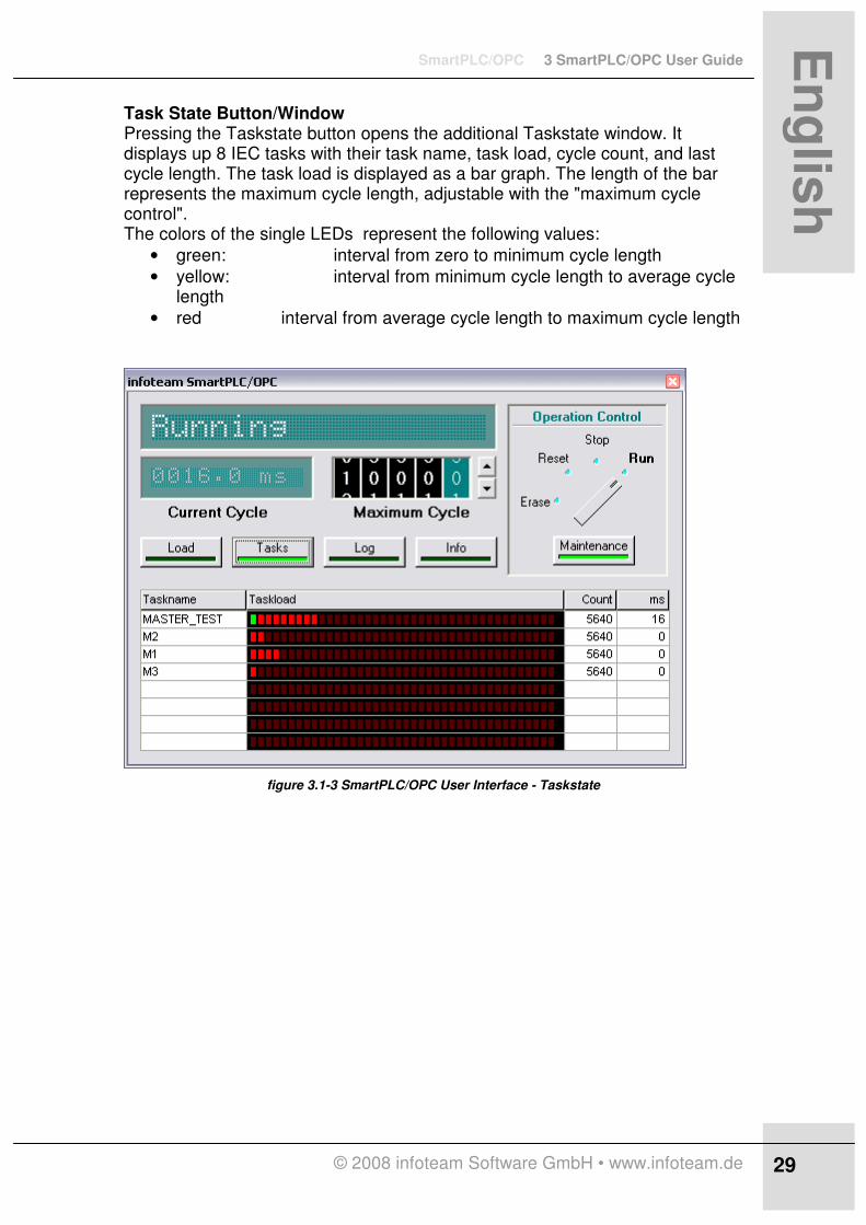
Task State Button/Window Pressing the Taskstate button opens the additional Taskstate window. It displays up 8 IEC tasks with their task name, task load, cycle count, and last cycle length. The task load is displayed as a bar graph. The length of the bar represents the maximum cycle length, adjustable with the "maximum cycle control". The colors of the single LEDs represent the following values:
• green: interval from zero to minimum cycle length
• yellow: interval from minimum cycle length to average cycle length
• red interval from average cycle length to maximum cycle length
figure 3.1-3 SmartPLC/OPC User Interface - Taskstate

3 SmartPLC/OPC User Guide SmartPLC/OPC
© 2008 infoteam Software GmbH • www.infoteam.de
30 30
En
glis
h
Log Button/Window Pressing the Log button activates the additional Log window. This displays all logging messages written by the SmartPLC/OPC user interface or sent by the SmartPLC/OPC runtime. A message is build of a time stamp and a message text. Examples for this text are:
• entered running state
• entered stop state
• cycle length exceeded
• reset
figure 3.1-4 SmartPLC/OPC User Interface - Log
SmartPLC/OPC 3 SmartPLC/OPC User Guide
© 2008 infoteam Software GmbH • www.infoteam.de
31
En
glis
h
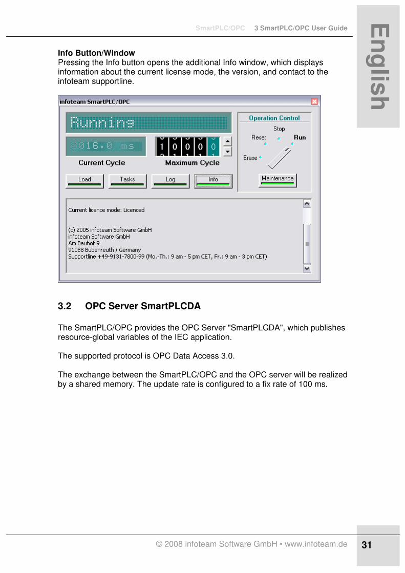
Info Button/Window Pressing the Info button opens the additional Info window, which displays information about the current license mode, the version, and contact to the infoteam supportline.
3.2 OPC Server SmartPLCDA
The SmartPLC/OPC provides the OPC Server "SmartPLCDA", which publishes resource-global variables of the IEC application. The supported protocol is OPC Data Access 3.0. The exchange between the SmartPLC/OPC and the OPC server will be realized by a shared memory. The update rate is configured to a fix rate of 100 ms.
3 SmartPLC/OPC User Guide SmartPLC/OPC
© 2008 infoteam Software GmbH • www.infoteam.de
32 32
En
glis
h
3.3 Start Configuration
Some parameters of the SmartPLC/OPC can be configured with a startup file. The file "Boot.iec" can be found at the location defined by the registry key “HKEY_LOCAL_MACHINE\SOFTWARE\infoteam Software GmbH \SmartPLC/OPC/3.1.0/ProgramDataDir”. The default path after the installation is Common Application Data Path, subfolder “Infoteam Software\SmartPLC_OPC”. (i.e. with Windows XP: “C:\Documents and Settings\All Users\Application Data\infoteam Software\ SmartPLC_OPC”. The startup file provides the following configuration parameters to be changed. Persistence File The entry IECPRG defines the path of the persistence file. The persistence file stores an IEC application as a file. At a start of the SmartPLC/OPC this file will be read and the resulting IEC application will automatically be started in the SmartPLC/OPC. The default entry is IECPRG=”C:\[Common Application Data Path]\Infoteam Software\ SmartPLC_OPC\IECPRG.DAT” Logging File The SmartPLC/OPC is logging errors within a text file. The name and the location of this file are represented by the entry LOGFILE. The default value is set to LOGFILE=”C:\[Common Application Data Path]\Infoteam Software\ SmartPLC_OPC\SPLCLOG.txt“ Logging of Debug Messages In case of problems running an application or connecting to other OPC servers than listed as the reference platforms, the SmartPLC/OPC provides a way to debug the application via Trace-Messages. The name and location can be configured by the entry DEBUGFILE. The default value is set as: DEBUGFILE=”C:\[Common Application Data Path]\Infoteam Software\ SmartPLC_OPC\SPLCDEBUG.txt” Visualisation Files With OpenPCS Automation Suite you will be able to download not only an IEC application onto the SmartPLC/OPC, but also to download and store .gdf files. These files represent a visualisation created with the tool GraphworX from Iconics Inc.. The storage location of these files can be set by the entry RAWFILEDIR. Default value: RAWFILEDIR=”C:\[Common Application Data Path]\Infoteam Software\ SmartPLC_OPC\temp” Remote Control It is possible to use SmartPLC/OPC in remote mode, which means without the usage of the SmartPLC_UI. Default remote control is disabled. The values of tags MAINTENANCE and CYCLETIMELIMIT will only be used if remote control

SmartPLC/OPC 3 SmartPLC/OPC User Guide
© 2008 infoteam Software GmbH • www.infoteam.de
33
En
glis
h
is enabled. MAINTENANCE sets the value for maintenance mode and CYCLETIMELIMIT the value of the used maximum cycle time in ms. The default values are set as: REMOTECONTROL=0 MAINTENANCE=1 CYCLETIMELIMIT=1000
4 SmartHMI SmartPLC/OPC
© 2008 infoteam Software GmbH • www.infoteam.de
34 34
En
glis
h
4 SmartHMI
4.1 GraphWorX-Files
GraphWorX (ICONICS Inc.) provides a complete set of scalable drawing and animation tools.It enables the user to easily generate an HMI, which interacts with the variables of the IEC 61131-3 application via OPC. The HMI can be generated within the OpenPCS programming system (with the GraphWorX-Editor) together with the corresponding IEC 61131-3 project, and will also be downloaded onto the SmartPLC/OPC system by the OpenPCS programming system. Note: GraphWorX is not part of the standard OpenPCS Automation Suite. It must be separately installed and licenced. For detailed information about the use of GraphWorX, please refer the Omline help of GraphWorX.
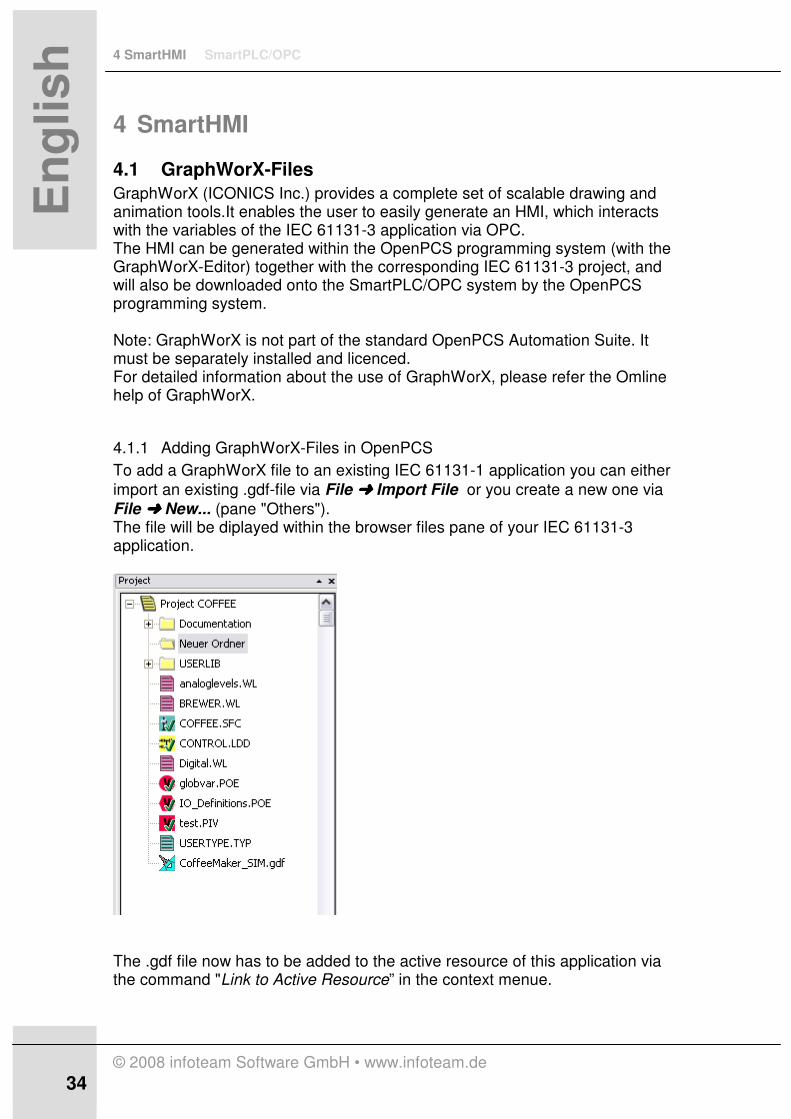
4.1.1 Adding GraphWorX-Files in OpenPCS
To add a GraphWorX file to an existing IEC 61131-1 application you can either
import an existing .gdf-file via File ÜÜÜÜ Import File or you create a new one via
File ÜÜÜÜ New... (pane "Others"). The file will be diplayed within the browser files pane of your IEC 61131-3 application.
The .gdf file now has to be added to the active resource of this application via the command "Link to Active Resource” in the context menue.

SmartPLC/OPC 4 SmartHMI
© 2008 infoteam Software GmbH • www.infoteam.de
35
En
glis
h
This sets the checkmark in the files view and adds the .gdf file to the resource view under a folder "Files".
4 SmartHMI SmartPLC/OPC
© 2008 infoteam Software GmbH • www.infoteam.de
36 36
En
glis
h
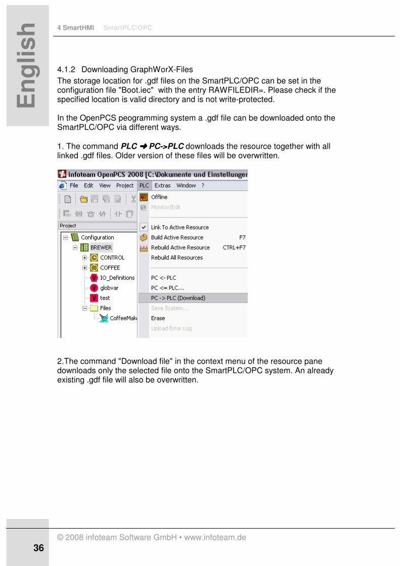
4.1.2 Downloading GraphWorX-Files
The storage location for .gdf files on the SmartPLC/OPC can be set in the configuration file "Boot.iec" with the entry RAWFILEDIR=. Please check if the specified location is valid directory and is not write-protected. In the OpenPCS peogramming system a .gdf file can be downloaded onto the SmartPLC/OPC via different ways.
1. The command PLC ÜÜÜÜ PC->PLC downloads the resource together with all linked .gdf files. Older version of these files will be overwritten.
2.The command "Download file" in the context menu of the resource pane downloads only the selected file onto the SmartPLC/OPC system. An already existing .gdf file will also be overwritten.

SmartPLC/OPC 4 SmartHMI
© 2008 infoteam Software GmbH • www.infoteam.de
37
En
glis
h
3. If more than one .gdf file is linked to the resource, the commands "Download all Files" or "Download modified Files" from the context menu of the selected "Files" folder provide a way to update all files. The command "Download modified Files" thereby downloads only files which are newer than the files on the SmartPLC/OPC system.
5 Advanced Topics SmartPLC/OPC
© 2008 infoteam Software GmbH • www.infoteam.de
38 38
En
glis
h
5 Advanced Topics
5.1 Communication via DCOM
For configuring the remote access from OPC-Clients to OPC-Server SmartPLCDA via DCOM, please follow the following steps. The steps are valid for WinXP with SP2 and Windows 2003Server.
5.1.1 Check Requirements:
• OS Requirement: WindowsXP with SP2 or Windows2003Server • The password must not be blank or “admin”. • For perfoming the next steps, you must have administrative privileges to
the local PC to change the DCOM settings.
5.1.2 Setting up DCOM communication
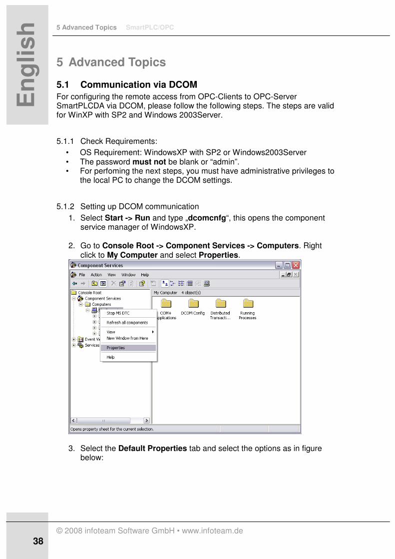
1. Select Start -> Run and type „dcomcnfg“, this opens the component service manager of WindowsXP.
2. Go to Console Root -> Component Services -> Computers. Right
click to My Computer and select Properties.
3. Select the Default Properties tab and select the options as in figure below:

SmartPLC/OPC 5 Advanced Topics
© 2008 infoteam Software GmbH • www.infoteam.de
39
En
glis
h
5.1.3 Setting permissions for DCOM
Default permissions have to be changed to establish communication. 1. Select the COM Security tab 2. Select Edit Default for Access Permissions
3. Make sure the access permissions window contains at least the following
entries: • Everyone • Interactive • Network

5 Advanced Topics SmartPLC/OPC
© 2008 infoteam Software GmbH • www.infoteam.de
40 40
En
glis
h
• System • Domain Administrators • Domain Users
If these entries are not shown, click the Add button, then click Advanced and Find Now. This lists all groups and users (if not, make sure that for object types Groups is selected). Select the groups and press OK, also in the next window. This adds these groups.
4. For domain users proceed as described in 3., but for location specify the domain name.
5. Repeat steps 2. to 4. for Launch and Activation Permission.
Afterwards close the My Computer Properties window. Now the setting changes are finished.
6. The computer has to be restarted to accept changes.
5.2 Remote control
Remote control provides the ability to run the SmartPLC/OPC without the user interface SmartPLC_UI. The SmartPLC/OPC will only be controlled by the programming system OpenPCS, which itself can be installed on a remote system. All settings which, in local control mode, are transmitted by the SmartPLC_UI will hereby be set via the configuration file “Boot.iec”. The following entries need to be set/adjusted REMOTECONTROL: 0 for deactivating remote control
1 for activating remotecontrol
MAINTENANCE: 0 for deactivating maintenance 1 for activating maintenance
(Corresponds to the maintenance button in the SmartPLC_UI, value will not be used in local control mode) CYCLETIMELIMIT: 1 ... 9999 (Corresponds to the "maximum cycle" spin control in the SmartPLC_UI, value will not be used in local control mode)
���� For using the SmartPLC/OPC with the Windows
“autostart” functionality in “remote control” mode,
ensure to call SmartPLC.exe.

SmartPLC/OPC 6 Reference Information
© 2008 infoteam Software GmbH • www.infoteam.de
41
En
glis
h
6 Reference Information
6.1 Technical Data
Operating system
Windows XP SP2, Windows XP embedded
Hard drive A hard drive with 100 Mbytes of free space
infoteam Software
• infoteam SmartPLC/OPC (version 3.0.0)
• infoteam OpenPCS (version 5.5.0) (usually installed on a separate system )
Maximum size for IEC applications
2 Mbytes, 400 IEC tasks (8 visible in the taskstate window), 8196 segments per task
Process Image I/O (OPC port)
Input: 10,000 Bytes (I0.0 to I10000.7) Output: 10,000 Bytes (Q0.0 to Q10000.7)
Supported IEC data types
BOOL, BYTE, WORD, DWORD SINT, INT, DINT USINT, UINT, UDINT REAL, STRUCT, ARRAY TIME, DATE, DATE_AND_TIME, TIME_OF_DAY (for additional information, please see the Compliance Statement in the OpenPCS User Help)
SmartPLCDA max. numbers of OPC items
~1000 (the exact number depends on the size of the variable description (per variable) in the Vartab segment
6.2 Supported I/O boards and OPC servers
The following I/O bus boards and their corresponding OPC servers has been tested.
• Woodhead Direct Link PCI-DPIO Profibus card (DLR-DPM-PCI version 4.2.0, software version:2.2 rev1)
• SST Interface card for Profibus PC card Type II ( 5136-PFB-PCM), Software: SST Profibus pfb Products 5.4

7 Troubleshooting SmartPLC/OPC
© 2008 infoteam Software GmbH • www.infoteam.de
42 42
En
glis
h
7 Troubleshooting
7.1 FAQ
The following FAQs list possible problems and their solutions. SmartPLC/OPC Q: When downloading a program, the PLC is signalling the error „Action not valid in current mode".
A: Active access of the programming system on the SmartPLC/OPC, i.e. download, run, stop program, is only allowed in "maintenance" mode. Please check, that the button "maintenance" on the UI is active. Q: When downloading a program, the PLC signals an error in I/O-Configuration.
A: Please check, that you have a valid configuration of the OPC variables in your OpenPCS project (you have to verify the file *.PIV) Q: When downloading a program, the Online-Server shows the message box: "Failed to launch SmartSim".
A: Please check the configuration of your connection. Probably you have used the IPC-driver instead of TCP. You must use the TCP432-driver and a valid IP-Address with Port-number 23042. Q: When building a project for SmartPLC/OPC, the compiler outputs "invalid license".
A: Please check, that you use the right smartPLC.ini and that you have entered a valid license in OpenPCS. Q: The rotary switch of the UI is blocked in the state "Stop". Switching to another state isn’t possible.
A: You must first download a valid program on the SmartPLC/OPC. Then you can move the rotary switch.

SmartPLC/OPC 7 Troubleshooting
© 2008 infoteam Software GmbH • www.infoteam.de
43
En
glis
h
applicom OPC-Server Q: When using an OPC client, the applicomIO OPC server doesn’t display any tags
A: First configure the Profibus using the applicomIO console. This will automatically export the OPC items to the applicomIO OPC server. Q: When monitoring with OPC-Client, all tags have the quality "Bad – Comm failure".
A: Check the station number in the properties of your station using the applicomIO console. SST OPC-Server Q: When connecting to the device in SST Profibus Configuration, a MessageBox signals the following: “The specified card is not found in registry”
A: Please check the correct installation of your SST-hardware with the device manager. You should find the SST-card in the section “Industrial network adapters”. Q: When going online with the device in the “SST Profibus configuration tool”, a “Online Run - error” is signalled.
A: Check, that the connector of the SST-card is coupled correctly to your Profibus I/O Modules. Q: The “PFB command” utility can’t execute the command “PGM_TO_FLASH”.
A: The device in the “STT Profibus configuration tool” must be in a specific state, before you are able to write the new configuration to flash. Check, that the device in the configurator is connected, has a loaded configuration and is offline. Q: When testing the configuration, the SYS LED on the Profibus connector lights RED.
A: The red light of the SYS LED means, that there is either an internal or a configuration error. A permanently state of the COM LED, indicates a configuration error. Then check your SST Profibus configuration. In the case of an internal error, the COM LED sequentially flashes an 8-bit error code from low bit to high bit. Please see the hardware manual of SST for the specific meaning of the error code.
7 Troubleshooting SmartPLC/OPC
© 2008 infoteam Software GmbH • www.infoteam.de
44 44
En
glis
h
Q: You have made modifications on the items in SST Profibus configuration, but the SST OPC-Server doesn’t update his address space.
A: Ensure, that the configuration was saved in your pbc-file. You have to tell the OPC server about the modified pbc-file by a repeat "select file" in the “SST OPC Profibus configuration” and clicking on “Done”. SmartPLCDA OPC-Server Q: I do not have an OPC test client available.
A: The setup of the SmartPLC/OPC also installs the OPC client "DataSpy" from ICONICS Inc. The freeware tool can be started via the Windows-Start menu and can be used for all kinds of OPC tests. Q: The connection to the OPC-Servers fails. How do I initialise the address space of the SmartPLC OPC-Server ?
A: Please run through the following steps:
• Your OpenPCS project must contain resource-global variables, that are linked to the active resource
• Ensure the "generate map file" flag is checked in the resource properties
• Rebuild the project
• Run the SmartPLC/OPC and download the resource
• You can now connect to the OPC-Server Q: After a new download with changes on the resource-global variables, the OPC-Server has still the old address space.
A: Disconnect and re-connect the OPC-Client. Then the OPC-Server will show the new configuration. Q: When connecting to the OPC server "SmartPLCDA", the OPC client signals an invalid path of the OPC server.
A: Repeat the registration of SmartPLCDA in your system. Perform the following steps:
• Open a windows console
• Switch to the install directory of the infoteam SmartPLC/OPC
• Run the command "SmartPLCDA.exe /RegServer" DCOM Communication

SmartPLC/OPC 7 Troubleshooting
© 2008 infoteam Software GmbH • www.infoteam.de
45
En
glis
h
Q: The DCOM communication doesn’t work.
A: Please check your firewall settings, port 135 has to be open. Q: Clients can not browse to the OPC Server.
A: Check DCOM settings: • Default Authentification Level: CONNECT • Default Impersonation Level: IDENTIFY
Check COM Security for the following entries: • Everyone • Interactive • Network • System • Domain Administrators • Domain Users
Q: Clients can not connect to OPC Server
A: The server MUST NOT run as launching user. Q: Client doesn’t receive call-backs from the OPC Server
A: For call-backs the client and the OPC Server change their roll. The OPC Server acts as a client and the client acts as a server. Therefore the client must set up the DCOM defaults as described in this manual to accept incoming calls from the server.

7 Troubleshooting SmartPLC/OPC
© 2008 infoteam Software GmbH • www.infoteam.de
46 46
En
glis
h
7.2 Technical Support
For assistance in answering technical question, please contact the infoteam Software GmbH supportline. email: [email protected] telephone: ++ 49 9131 780099 fax: ++ 49 9131 780050

SmartPLC/OPC 8 Table of Figures
© 2008 infoteam Software GmbH • www.infoteam.de
47
En
glis
h
8 Table of Figures figure 1.1-1 Design SmartPLC/OPC .................................................................. 4
figure 2.2-1 SmartPLC/OPC Licensce Editor – Create Challenge ................ 10
figure 2.2-2 SmartPLC/OPC License Editor – Entering Activation Key ....... 11
figure 2.3-1 Add Hardware Support for SmartPLC/OPC ............................... 12
figure 2.3-2 Create Online Connection ........................................................... 13
figure 2.4-1 Setup applicomIO ......................................................................... 15
figure 2.4-2 applicomIO - Console .................................................................. 15
figure 2.4-3 applicomIO – Equipment Library ................................................ 16
figure 2.4-4 applicomIO – Network Detection ................................................ 16
figure 2.4-5 applicomIO- Item Configuration .................................................. 17
figure 2.4-6 Setup SST Profibus Software...................................................... 18
figure 2.4-7 SST - Profibus Configuration Tool.............................................. 19
figure 2.4-8 SST – Configuration Scanner ...................................................... 19
figure 2.4-9 SST – Profibus Configuration ..................................................... 20
figure 2.4-10 SST – Profdibus Command Dialog ........................................... 21
figure 2.4-11 SST – Net Configuration ............................................................ 21
figure 2.5-1 OpenPCS – Create piv file ........................................................... 22
figure 2.5-2 OpenPCS – OPC pane ................................................................. 23
figure 2.5-3 OpenPCS – Simple ST program .................................................. 24
figure 2.5-4 OpenPCS- Resource Properties ................................................. 24
figure 2.5-5 SmartPLC/OPC – System Tray Icon ............................................ 25
figure 2.5-6 SmartPLC/OPC User Interface .................................................... 25
figure 3.1-1 SmartPLC/OPC User Interface .................................................... 26
figure 3.1-2 SmartPLC/OPC User Interface - Load ........................................ 28
figure 3.1-3 SmartPLC/OPC User Interface - Taskstate ................................ 29
figure 3.1-4 SmartPLC/OPC User Interface - Log .......................................... 30

9 Index SmartPLC/OPC
© 2008 infoteam Software GmbH • www.infoteam.de
48 48
En
glis
h
9 Index
A
activation key 10 applicomIO 14 applicomIO console 16 APPLICOMIO.OPCServer 17 autostart 40
C
challenge key 10 Configuration 12 connection 13 cpu lo 28 Current Cycle Panel 27 cycle count 29 cycle length 29
D
Debug Messages 32 DEMO 10
E
Equipment Library 15 Erase 26
F
flash memory 20
G
GSD 16
I
IEC memory 28 Info 31 infoteam SmartPLC UI 25 Installation 10
L
Licensing 10 Log 30

SmartPLC/OPC 9 Index
© 2008 infoteam Software GmbH • www.infoteam.de
49
En
glis
h
M
Maintenance mode 25 Maximum Cycle Control 27 maximum cycle length 29
N
network configuration 16 network configuration tree 19
O
OPC pane 23 OPC Server SmartPLCDA 31 OPC variables 23 OpenPCS 12
P
Persistence File 32 piv file 23 Predefinitions 7 Preface 4 product key 10 Profibus 15
R
Reference 41 Remote control 40 Remote Control 32 Requirements 9 Reset 26 resource properties 24 Run 26
S
Setup applicomIO 15 Setup SST Profibus Software 18 SmartPLC/OPC 25 SmartPLC/OPC User Interface 26 SmartPLCDA 31 SST 14 SST 5136-PFB-PCM 17 SST OPC server 21 SST Profibus Configuration Tool 19 Start Configuration 32 Status Panel 27 Stop 26
T
taskload 29 taskname 29 Taskstate 29 Technical Data 41

9 Index SmartPLC/OPC
© 2008 infoteam Software GmbH • www.infoteam.de
50 50
En
glis
h
Technical Support 46 Troubleshooting 42
V
VAR_EXTERNAL 24
W
Wago 14 Woodhead 14
infoteam Software GmbH Am Bauhof 9
91088 Bubenreuth Germany
Phone +49 9131 7800 0 Fax +49 9131 7800 50
[email protected] www.infoteam.de