smiha sayal left ventricular assist device (lvad) mechanical device that helps pump blood from the...
Post on 19-Dec-2015
244 views
TRANSCRIPT

LVAD System Review

System OverviewSmiha Sayal

System Overview
Left Ventricular Assist Device (LVAD) Mechanical device that
helps pump blood from the heart to the rest of the body.
Implanted in patients with heart diseases or poor heart function.

Engineering ProcessAll team members

Other LVAD Technologies
CorAide (NASA)

Other LVAD Technologies
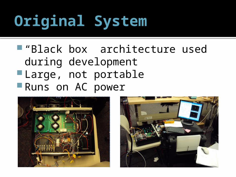
Original System
“Black box” architecture used during development
Large, not portable Runs on AC power

System Goal
Miniaturize the existing LVAD system to achieve portability while retaining its safety and reliability.

P10021’s System
Has both internal / external components Equivalent to our “Option 2” Unfinished implementation

Previous Team Shortcomings Microcontroller used in the last year’s
project did not work. The wires and the system were not robust
enough to perform testing of the system. Testing of levitation and rotation was not performed.
Space in the internal enclosure could have been optimized by better placement of internal components.
The enclosure was not ergonomic and nor was it the most physically biocompatible shape.

Customer Needs
System needs to work Safe Robust Affordable Easy to wear and use Interactive with user Controllable by skilled technician Comparable performance Compatible with existing pump

Concepts: Option 1
Control system all external

Concepts: Option 2
ADC internal only

Concepts: Option 3
Amplifiers + MCU internal

Concepts: Option 4
All electronics and battery internal

Concepts: Option 5
Amplifiers internal

Concept GenerationSee
Handout

Concept Generation Highlights
Option 1• Smallest internal volume• Feasible within timeline• Easiest to maintain• Minimum 20 wires
Option 2• Relatively small internal volume
• Slightly higher risk of internal failure
• Minimum 10 wires
Option 3• Large internal volume• Difficult to design• Electronics failure is fatal• Minimum 3 wires
Option 4• Large internal volume• Difficult to design• Electronics failure is fatal• Minimum 3 wires
Option 5• Moderate internal volume• Difficult to design• Electronics failure is fatal• Minimum X wires
Best Option
350
273
200
153
249

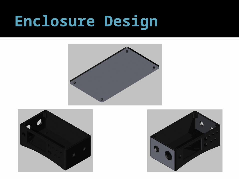
Enclosure DesignNicole Varble and Jason Walzer
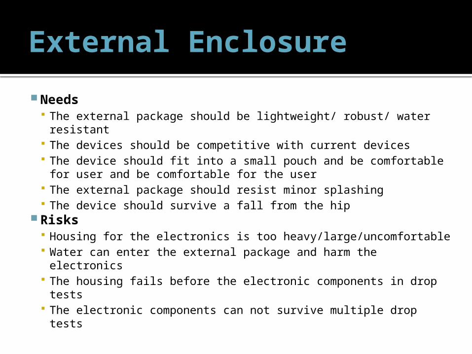
External Enclosure
Needs The external package should be lightweight/ robust/ water
resistant The devices should be competitive with current devices The device should fit into a small pouch and be comfortable for
user and be comfortable for the user The external package should resist minor splashing The device should survive a fall from the hip
Risks Housing for the electronics is too heavy/large/uncomfortable Water can enter the external package and harm the electronics The housing fails before the electronic components in drop tests The electronic components can not survive multiple drop tests

Concept Generation- Materials/Manufacturing Process
Concept Generation- Material and Manufacturing Processes
Manufacturing Processes
Rapid Prototyping (ABS
Plastic) Stereolithography Injection Molded Machine Metal or PolymerSelection Criteria Weight Rating Notes Score Rating Notes Score Rating Notes Score Rating Notes ScoreCost 9 4 36 1 9 1 $30k for mold 9 2 18Feasibility within timeline 10 5 50 4 long lead time 40 1 10 3 30Strength 6 4 37 MPa 24 5 58 MPa 30 5 35-70 MPa 30 5 ~580 MPa 30Material Interaction with water 4 2 8 4 resin based 16 5 20 4 16Ease of Manufacturing 3 5 15 5 15 3 9 3 9 0 0 0 0 20 wires 0 10 wires 0 3 wires 0 3 wires 0Net Score 133 110 78 103Rank 1 2 3 4
Continue? yes No no noweight 1- low importance
10- high importancerating 1- does not meet cirteria
5- meets cirteria
SeeHando
ut

Rapid Prototyping
• Machinable Material can be drilled and tapped
(carefully) • Accepts CAD drawings
– Complex geometries can be created easily
– Ideal for proposed ergonomic shape• Builds with support layer
– Models can be built with working/moving hinges without having to worry about pins
• Capable of building thin geometries• ABSplus– Industrial thermoplastic
• Lightweight - Specific gravity of 1.04• Porous– Does not address water resistant need
http://www.dimensionprinting.com/
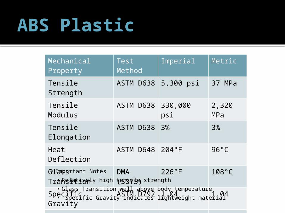
ABS Plastic
Mechanical Property
Test Method
Imperial Metric
Tensile Strength ASTM D638
5,300 psi 37 MPa
Tensile Modulus ASTM D638
330,000 psi 2,320 MPa
Tensile Elongation
ASTM D638
3% 3%
Heat Deflection ASTM D648
204°F 96°C
Glass Transition DMA (SSYS)
226°F 108°C
Specific Gravity ASTM D792
1.04 1.04
Coefficient of Thermal Expansion
ASTM E831
4.90E-5 in/in/F
• Important Notes• Relatively high tensile strength• Glass Transition well above body temperature• Specific Gravity indicates lightweight material

Feasibility- Water Ingress Test
• Need: The external package should resist minor splashing
• Specification: Water Ingress Tests– Once model is constructed, (user interface,
connectors sealed, lid in place) exclude internal electronics and perform test
– Monitor flow rate (length of time and volume) of water
– Asses the quality to which water is prevented from entering case by examining water soluble paper
• Risk: Water can enter the external package and harm the electronics
• Preventative measures: Spray on Rubber Coating or adhesive O-rings around each screw well and around the
lid Loctite at connectors
• Preliminary Tests without protective coating show no traceable water ingress
Spray on Rubberized CoatingLoctite

Feasibility- Water Ingress Test

Feasibility- Robustness Testing
Need: The device should survive a fall from the hip Specification: Drop Test
Drop external housing 3 times from 1.5 m, device should remain fully intact
Specify and build internal electrical components Identify the “most vulnerable” electrical component(s)
which may be susceptible to breaking upon a drop Mimic those components using comparable (but
inexpensive and replaceable) electrical components, solder on point to point soldering board
Goal Show the housing will not fail Show electronics package will not fail, when subjected
to multiple drop tests Risks
The housing fails before the electronic components in drop tests (proved unlikely with prototype enclosure)
The electronic components can not survive multiple drop tests
Preventative Measures Eliminate snap hinges from housing (tested and failed) Test the housing first Design a compact electronics package

Feasibility- Heat Dissipation of Internal Components
130°C is absolute maximum for chip junction temperature in order to function properly
Goal: comfort for the user Assumed steady state, heat only dissipated through 3 external surfaces Maximum heat dissipation: ~25W Actual heat dissipation: ~5W
t, k
Q
Tin
Tout
h
0 5 10 15 20 25 30 35 400
50
100
150
200
250
Tout= RoomTout = BodyAbsolute Max Tempera-ture
Heat Generation, Q [W]
Inte
rnal Tem
pera
ture
[°C
]

Prototype Enclosure
Survived drop test Water resistant Plastic is machinable
Drilled, tapped, milled Helicoils should be used to
tap holes Constant opening and
screwing and unscrewing of lid will result in stripped threads
Approximate wall thickness (6mm)
Distance between center of holes and wall needs to be increased Some cracking occurred
Latches are not feasible

User Interface - Components
LED Backlit display with waterproof bezel and o-ring
G/R/Y LEDs with O-ring and waterproof bezel
Waterproof buttons with O-ring

User Interface - Connectors
Current Model: Part # EGG 2K 326 CLL
Proposed: Part # EEG 2K 326 CLV
Straight-Through
Right-Angle, PCB mount

User Interface- IP Codes
UI Item IP Rating
Display IP 67
Buttons IP 67
LEDs IP 67
USB IP 68
Connector IP 68
See Handout
on IP Ratings

Enclosure Design
Enclosure Design

Enclosure Design

Electronics DesignZack Shivers

Overall System Architecture
See Handout

Interface Electronics
Interfaces: 26-pin pump connector Will be directly compatible with old
connector! JTAG (for direct programming) FTDI USB-to-serial converter Reset pushbutton
See Schematic
Page 2

Interface ElectronicsSee
Schematic Page 2
Transient voltage protection
USB connection
FTDI USB-to-Serial converter
RX / TX LEDs

Microcontroller
Microcontroller requires little electronics design
MCU needs: Clean 3.3V supply voltage I/O connections Programming interface (JTAG or BSL) Oscillator (optional)
See Schematic
Page 5

HESA Signal Conditioning
+
_
LPF Anti-aliasing filter
Hall Effect +Hall Effect -
ADC InputVoltage
Clamping+
Reference Voltage
See Schematic
Page 6
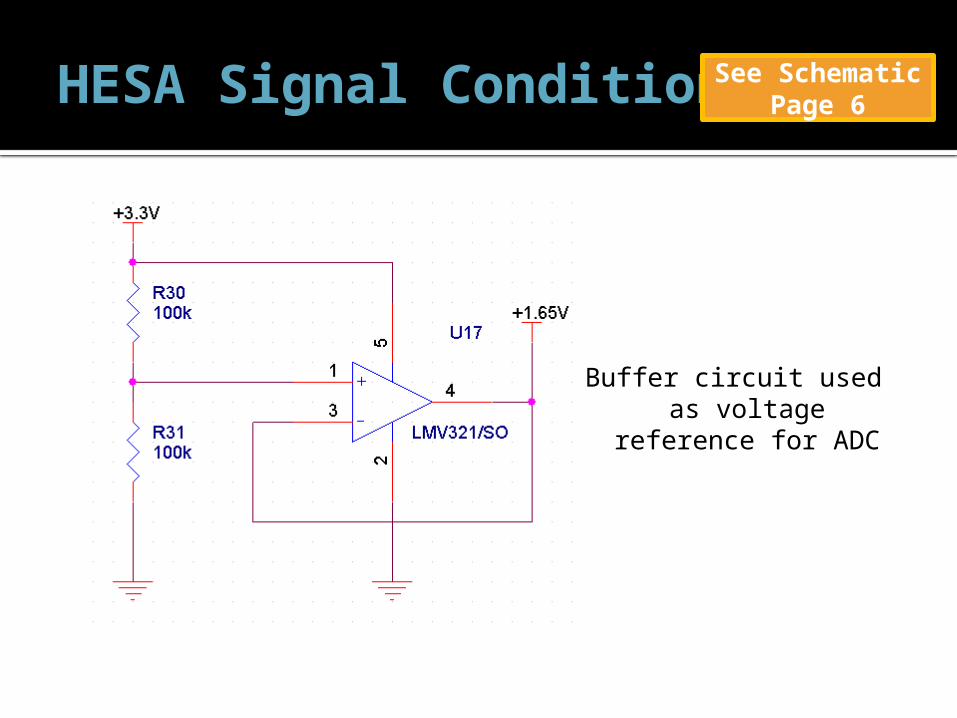
HESA Signal ConditioningSee
Schematic Page 6
Buffer circuit used as voltage
reference for ADC
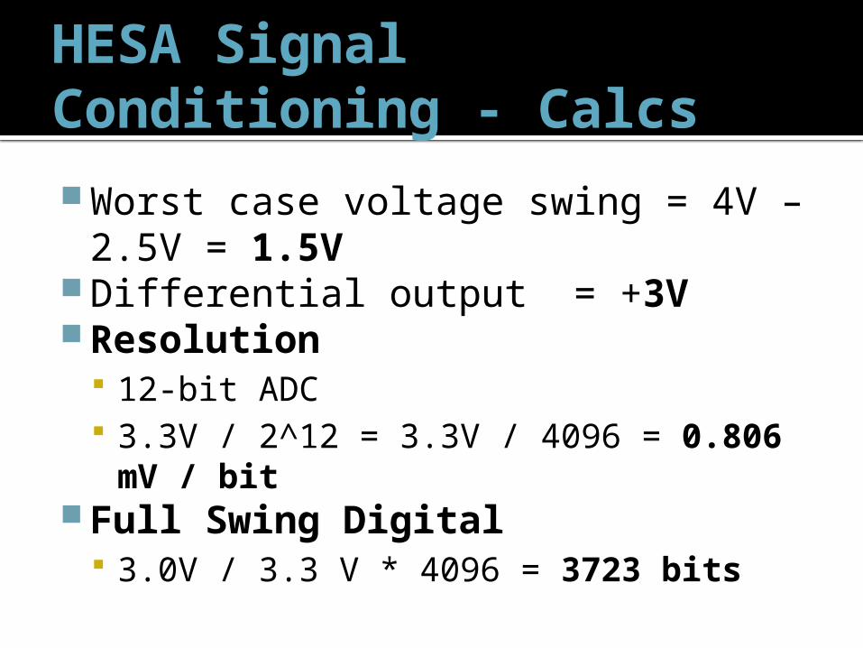
HESA Signal Conditioning - Calcs
Worst case voltage swing = 4V – 2.5V = 1.5V
Differential output = +3VResolution
12-bit ADC 3.3V / 2^12 = 3.3V / 4096 = 0.806
mV / bitFull Swing Digital
3.0V / 3.3 V * 4096 = 3723 bits

AWB H-Bridges
Using TI DRV8412 Dual Full-Bridge PWM Motor Controller
Heat dissipation PCB considerations Package is able to take 5W at 25 degrees C Worst case power calculation: Ptotal = VDD * Iq + 2( Icond^2 * RDS(on) )
= 12V (10.5 mA + 16 mA) + 2 * (1A)^2 * 120mΩ = 0.558W
Worst case power calculation does not exceed case No heatsink required, use grounded pad for
heatsink
See Schematic Page 7 & 8

Brushless Controller
Per customer request, we will continue to use the COTS PHX-35 controller from Castle Creations
Added connectors to board to interface with this part
See Schematic
Page 9

Voltage Regulation
Require multiple voltage supplies +3.3V, +5V, +12V Typical input voltage from batteries
ranges from 12V – 15V Step-down voltage converters
Efficiently (upwards of 90%) convert large voltage to smaller voltages
Disadvantage: injection of switching noise into supply voltages

Voltage Regulation
SwitcherPro from TI

Linear Technology “AN101: Minimizing Switching Regulator Residue in Linear Regulator Outputs”. July 2005.
Voltage Regulation
Switching supply regulates from 12-15V to 3.75V with added switching noise
Linear regulator attenuates switching noise, leaving clean 3.3V output
See Schematic Page 10

Feasibility
Why will the electronics work? Difference amplifiers with filter worked
for last team Brushless controller is COTS MCU crystal and JTAG circuitry taken
directly from TI development boards Professionally created tool SwitcherPRO
used for design of voltage regulation circuits
Electronics Testing
How will we verify electronics meet spec? Header breakouts for all signals allows for
debug and verify at each subsystem Unit tests
AWB amplifier test HESA signal acquisition PHX-35 test with MCU input Power regulation test LED + Button test Graphic LCD test

Embedded Control SystemAndrew Hoag and Zack Shivers

Control System
Requirements Selecting suitable embedded control
system Designing port of control logic to
embedded system architectureCustomer Needs
Device is compatible with current LVAD Device is portable/small Allows debug access

Impeller Levitation
Impeller must be levitating or “floating” Electromagnets control force exerted on impeller Keeps impeller stabilized in the center Position error measured by Hall Effect sensors

Levitation Algorithm
Algorithm complexity influences microcontroller choice Electronics choices affect volume / weight
Proportional – Integral – Derivative (PID) Very common, low complexity control scheme
http://en.wikipedia.org/wiki/PID_controller

Embedded System Selection
Requirements: Can handle PID calculations Has at least 8x 12-bit ADC for
sensors at 5000 samples/sec Multiple PWM outputs to motor
controller(s) Same control logic as current LVAD
system Reprogrammable

Embedded System Selection
Custom Embedded dsPIC
Microcontroller Blocks for Simulink Small Inexpensive (<$10 a
piece) TI MSP430 Inexpensive (<$8 a
piece) Small, low power
COTS Embedded National
Instruments Embedded Uses LabVIEW Manufacturer of current
test and data acquisition system in “Big Black Box”
Large to very large Very expensive (>$2000)

Microcontroller Selection
Microcontroller Setups
Selection Criteria Weight
dsPIC MSP430
NotesRating Score Rating ScoreCost 6 4 24 4 24 SimilarFeasibility within timeline 10 2 20 5 50 Zack has more MSP430 experienceA/D 8 5 40 4 32 MSP430 ADC is 3.3V, sensors are 5VEase of design 6 4 24 4 24 SimilarEase of manufacturing 6 4 24 4 24 SimilarNet Score 132 154 Rank 2 1 Continue? No Yes
Weight Scale 1 - Low importance10 - High importance
Rating Scale 1 - Does not meet cirteria 5 - Meets cirteria
Best Option
See Handout

MSP430F5438A - Specs
Specifications Max Frequency: 25MHz Operating voltage:
1.8V – 3.3V Package: 100 pin LQFP Flash Memory: 256 KB RAM: 16 KB 87 General I/O pins ADC: 12-bit SAR
4x USCI_A (UART/LIN/IrDA/SPI)
4x USCI_B (I2C/SPI) Timers
1x 16-bit (5CCR) 1x 16-bit (3CCR) 1x 16-bit (7CCR) Watchdog RTC

MSP430F5438A - ADC
Greater than 200-ksps maximum conversion rate
Able to acquire all 4 HESA signals in one shot without CPU intervention

MSP430F5438A - Feasibility How does this chip meet the specifications?
Fast Dedicated peripherals like timers and UART reduce CPU
usage Able to execute full PID algorithm with minimal CPU usage
Spacious Large RAM and program space Able to execute programs much larger this application
Able to generate 12 PWM signals (only need 5) Physical Size Small portion of expected PCB layout (only 16x16 mm) Marginally larger than 80 pin 5xx devices with much more
I/O and other peripherals

MSP430F5438A - Feasibility Confidence in ability to program and
interface with hardware Was able to program an actual chip with
breakout board Standard high-end TI MCU
Hundreds of code examples available for this specific chip
Previous experience Over 3 months of experience at TI with
this specific chip

MSP430F5438A – Cool Features
Optional / Cool Future Features Ability to program using bootstrap loader
(BSL) over USB instead of JTAG Data dump to USB Temperature, current, RPM
PONG (not really…)

User Interface Elements
Graphic LCD Buttons
LEDs Buzzer

User Interface ElementsSee Handout

User Interface
Why use an LCD? Display much more information Interactivity Allows interface modes for technician and user
Buttons Up, Down, and Menu for interaction IP67-rated
LEDs Provide basic, robust indicators
Buzzer Loud, high importance warnings Audible button feedback (beep when pressed)

User Interface ExamplesSee Handout

UI Feasibility
How do we know UI will work / meet specs? Portable, proven example code online for
LCD display Buttons / LED interfacing is standard and
very simple If graphic menu system is too complex,
can fall back to simpler modes LCD text only LED and button interaction only

Software Andrew Hoag
Quality
Described in Software Design Plan/Software Design Document Coding Standards – ANSI C, File headers,
comments Code Reviews – EE/CE team will review
all changes Unit and Integration testing
See Handout
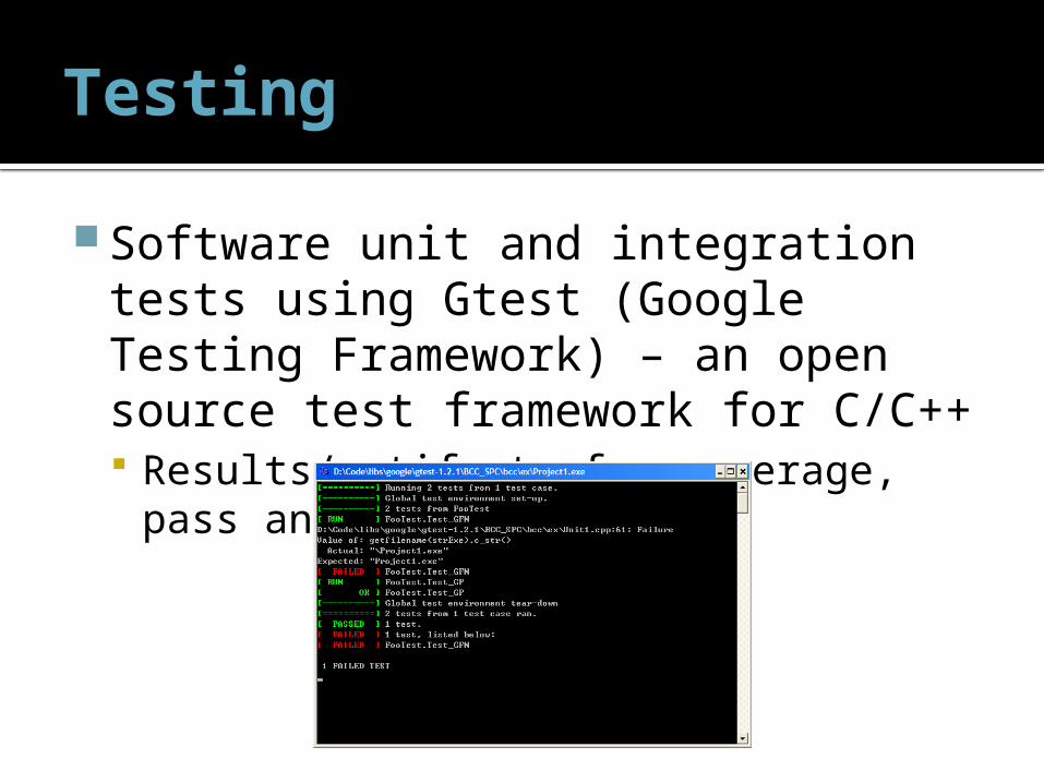
Testing
Software unit and integration tests using Gtest (Google Testing Framework) – an open source test framework for C/C++ Results/artifacts for coverage, pass and
failure.

Testing
Code Coverage – the degree to which source code has been covered in software tests. It is required in safety-critical systems.
FDA has released guidelines and recommendations for code coverage.
DO-178B

Software Use Cases
The software shall sample HESA values at fs=5000, input to the control loop, and update the AMB PWM outputs.
The software shall report battery level, faults, and status to the user.
The software shall respond to user input to adjust pump motor speed.
The software shall provide a verbose technician/engineering debug output.
The software shall be robust and reliable for a safety-critical system.
See Handout

A/D Sampling
Each of the HESA analog channels is sampled at 5 kilo-samples/second.
The software shall make use of the ADC timers and interrupts provided by the microcontroller architecture to control the sampling.
See Handout

PWM Output
Pulse-width Modulation is a digital signal that is used to simulate an analog output by varying high and low signals at intervals proportional to the value.
The AMB is controlled using 4 PWM signals. The pump motor is controlled using a single PWM output.
See Handout

Design: Control Law
PID: common feedback control loop that is currently used in the LVAD control system. The output signal is a function of the
error, the error’s history, and the error’s rate of change.
See Handout

Design: Flowcharts
Startup and Main Loop
A/D Interrupt Service Routine

Current State of Development
The current baseline is available on the team’s EDGE subversion repository:https://edge.rit.edu/dav/P11021/design/software
This includes 3rd party packages (Gtest), environment setup, and makefiles.

Power AmplifiersJuan Jackson

Amplifier Selection
•Higher power to load
•Low efficiency
Linear
•High frequency switching
•Capable of higher power than the linear amplifier
•Better performance at higher frequencies
•High efficiency
PWM
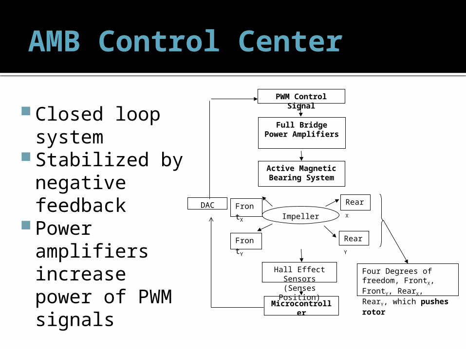
AMB Control Center
Four Degrees of freedom, FrontX, FrontY, RearX, RearY, which pushes rotor
DAC
Microcontroller
PWM Control Signal
Full BridgePower Amplifiers
Active Magnetic Bearing System
ImpellerFrontX
FrontY
RearX
RearY
Hall Effect Sensors(Senses Position)
Closed loop system
Stabilized by negative feedback
Power amplifiers increase power of PWM signals

Amplifier Selection
Linear Amplifier
PWM Amplifier
Selection Criteria Weight Rating Notes Score Rating Notes Score
Cost 5 3 15 5 25
Feasibility within timeline 10 5 50 5 50
Fits Customer Requests 10 2 20 5 50
Ease of Design 6 4 24 4 24
Net Score 109 149
Weight 1-Low importance
10-High importance
Rating1-Does not meet criteria
5-Meets criteria
Best Option

Amplifier Selection
AMB Amplifier Selection LMD1800 TLE6209R DRV8412
Selection Criteria WeightSpecificatio
n Rating Score Specification Rating Score Specification Rating ScoreContinuous Current Output (A) 10 3 5 50 3 5 50 6 5 50Switching Frequency (kHz) 10 100 5 50 2000 5 50 500 5 50Rdson (mΩ) 10 330 2 20 150 5 50 80 5 50Operating Supply Voltage (V) 10 12 to 55 5 50 up to 45 5 50 5 50
Temperature (°C) 10-40°C ~ 125°C 5 50
-40°C ~ 150°C 5 50 -40°C ~ 85°C 5 50
Package Type 8Through hole 2 16
Surface mount 5 40 5 40
Net Score 236 290 290Rank 2 1 1
Designer Choice 3rd 2nd 1st
Customer Choice 1st 2nd 3rd
See Handout
Best Option

Amplifier Proof of Concept
Texas Instrument Application Diagram for Full Bridge
Mode Operation

Amplifier Proof of Concept
Motor Control - DC Brushless
BLDC motors are more efficient, run faster and quieter, and require electronics to control the rotating field. BLDC motors are also cheaper to manufacture and easy to maintain
Recommended:MSP430F5438Also consider:Stellaris 5000 /8000 SeriesC2000 - Fixed Point / Piccolo, DelfinoMSP430 - F2xx /5xx 25MHz
ADS7953 - 1ch, 12 bit ADC
BQ2000T - Battery Charge Management
SN65HVD233 - 3.3V CAN Transceiver
TPS40305 - DC/DC Controllers
DRV8412 - PWM Power Driver
TPS54620 - Step-Down Regulators
Texas Instruments Microcontroller for Motor Control Applications : Component recommendation "MCU4Analog." Texas Instruments. Texas Instruments, n.d. Web. 4 Nov 2010. <http://focus.ti.com/mcu/docs/mcuorphan.tsp?contentId=73295&DCMP=MCU_other&HQS=Other+OT

Questions / CommentsHelp us improve our design!