smt breadboard prototyping using breakout pcbs
TRANSCRIPT

SMT Breadboard Prototyping Using Breakout PCBsCreated by Ladyada

2346
Guide Contents
Guide ContentsOverviewRequired ToolsSoldering an SOIC
© Adafruit Industries http://learn.adafruit.com/smt-prototyping-using-breakout-pcbs Page 2 of 8
Overview
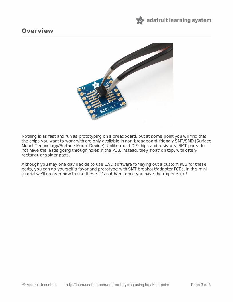
Nothing is as fast and fun as prototyping on a breadboard, but at some point you will find thatthe chips you want to work with are only available in non-breadboard-friendly SMT/SMD (SurfaceMount Technology/Surface Mount Device). Unlike most DIP chips and resistors, SMT parts donot have the leads going through holes in the PCB. Instead, they 'float' on top, with often-rectangular solder pads.
Although you may one day decide to use CAD software for laying out a custom PCB for theseparts, you can do yourself a favor and prototype with SMT breakout/adapter PCBs. In this minitutorial we'll go over how to use these. It's not hard, once you have the experience!
© Adafruit Industries http://learn.adafruit.com/smt-prototyping-using-breakout-pcbs Page 3 of 8

Required Tools
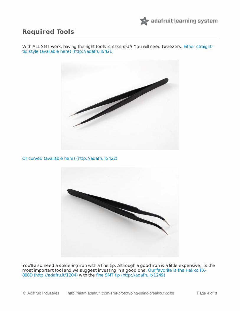
With ALL SMT work, having the right tools is essential! You will need tweezers. Either straight-tip style (available here) (http://adafru.it/421)
Or curved (available here) (http://adafru.it/422)
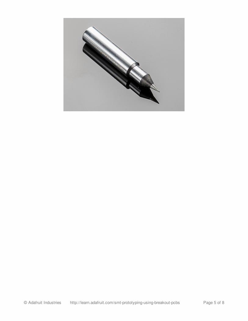
You'll also need a soldering iron with a fine tip. Although a good iron is a little expensive, its themost important tool and we suggest investing in a good one. Our favorite is the Hakko FX-888D (http://adafru.it/1204) with the fine SMT tip (http://adafru.it/1249)
© Adafruit Industries http://learn.adafruit.com/smt-prototyping-using-breakout-pcbs Page 4 of 8

© Adafruit Industries http://learn.adafruit.com/smt-prototyping-using-breakout-pcbs Page 5 of 8

Soldering an SOIC
We'll start by showing how to solder an SOIC component. Although we have many different'package' versions available (such as SOIC/TSSOP/QFP/QFN) SOIC is the easiest to start withand its the chip I needed to work with today so that's what we're going to do :)
Begin by placing the breakout adapterinto your vise/third hand to keep itsteady.
We'll start by melting a little solder onone corner pad. I like going with the topright corner. Melt just a tiny bit on, so itsrounded but not blobby
Next you need to place the part onto thepads, and you'll want to get theorientation right. You can look for a dot(indicating pin #1). In some cases, lookfor a flattened corner (on the left sidehere) which indicates which side is on theleft
© Adafruit Industries http://learn.adafruit.com/smt-prototyping-using-breakout-pcbs Page 6 of 8

Once you've identified which is pin 1,hold the chip with the tweezers over thepads and then re-heat the corner padyou soldered onto a few steps ago.
Now you can 'fix' the chip in place bysoldering in the opposite corner. The onepin you soldered will keep the chip inplace mostly, so you just have to solderthe other pin a little to make the setupsecure
Go ahead and solder the remaining pinsnow
© Adafruit Industries http://learn.adafruit.com/smt-prototyping-using-breakout-pcbs Page 7 of 8
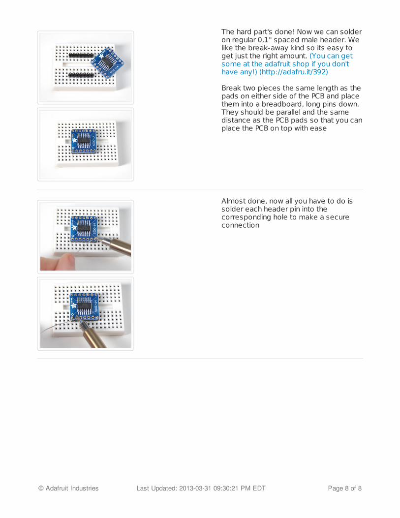
The hard part's done! Now we can solderon regular 0.1" spaced male header. Welike the break-away kind so its easy toget just the right amount. (You can getsome at the adafruit shop if you don'thave any!) (http://adafru.it/392)
Break two pieces the same length as thepads on either side of the PCB and placethem into a breadboard, long pins down.They should be parallel and the samedistance as the PCB pads so that you canplace the PCB on top with ease
Almost done, now all you have to do issolder each header pin into thecorresponding hole to make a secureconnection
© Adafruit Industries Last Updated: 2013-03-31 09:30:21 PM EDT Page 8 of 8
SMT Breadboard Prototyping Using Breakout PCBsCreated by Ladyada
2346
Guide Contents
Guide ContentsOverviewRequired ToolsSoldering an SOIC
© Adafruit Industries http://learn.adafruit.com/smt-prototyping-using-breakout-pcbs Page 2 of 8

Overview
Nothing is as fast and fun as prototyping on a breadboard, but at some point you will find thatthe chips you want to work with are only available in non-breadboard-friendly SMT/SMD (SurfaceMount Technology/Surface Mount Device). Unlike most DIP chips and resistors, SMT parts donot have the leads going through holes in the PCB. Instead, they 'float' on top, with often-rectangular solder pads.
Although you may one day decide to use CAD software for laying out a custom PCB for theseparts, you can do yourself a favor and prototype with SMT breakout/adapter PCBs. In this minitutorial we'll go over how to use these. It's not hard, once you have the experience!
© Adafruit Industries http://learn.adafruit.com/smt-prototyping-using-breakout-pcbs Page 3 of 8
Required Tools
With ALL SMT work, having the right tools is essential! You will need tweezers. Either straight-tip style (available here) (http://adafru.it/421)
Or curved (available here) (http://adafru.it/422)
You'll also need a soldering iron with a fine tip. Although a good iron is a little expensive, its themost important tool and we suggest investing in a good one. Our favorite is the Hakko FX-888D (http://adafru.it/1204) with the fine SMT tip (http://adafru.it/1249)
© Adafruit Industries http://learn.adafruit.com/smt-prototyping-using-breakout-pcbs Page 4 of 8
© Adafruit Industries http://learn.adafruit.com/smt-prototyping-using-breakout-pcbs Page 5 of 8

Soldering an SOIC
We'll start by showing how to solder an SOIC component. Although we have many different'package' versions available (such as SOIC/TSSOP/QFP/QFN) SOIC is the easiest to start withand its the chip I needed to work with today so that's what we're going to do :)
Begin by placing the breakout adapterinto your vise/third hand to keep itsteady.
We'll start by melting a little solder onone corner pad. I like going with the topright corner. Melt just a tiny bit on, so itsrounded but not blobby
Next you need to place the part onto thepads, and you'll want to get theorientation right. You can look for a dot(indicating pin #1). In some cases, lookfor a flattened corner (on the left sidehere) which indicates which side is on theleft
© Adafruit Industries http://learn.adafruit.com/smt-prototyping-using-breakout-pcbs Page 6 of 8

Once you've identified which is pin 1,hold the chip with the tweezers over thepads and then re-heat the corner padyou soldered onto a few steps ago.
Now you can 'fix' the chip in place bysoldering in the opposite corner. The onepin you soldered will keep the chip inplace mostly, so you just have to solderthe other pin a little to make the setupsecure
Go ahead and solder the remaining pinsnow
© Adafruit Industries http://learn.adafruit.com/smt-prototyping-using-breakout-pcbs Page 7 of 8

The hard part's done! Now we can solderon regular 0.1" spaced male header. Welike the break-away kind so its easy toget just the right amount. (You can getsome at the adafruit shop if you don'thave any!) (http://adafru.it/392)
Break two pieces the same length as thepads on either side of the PCB and placethem into a breadboard, long pins down.They should be parallel and the samedistance as the PCB pads so that you canplace the PCB on top with ease
Almost done, now all you have to do issolder each header pin into thecorresponding hole to make a secureconnection
© Adafruit Industries Last Updated: 2013-03-31 09:30:21 PM EDT Page 8 of 8

SMT Breakout PCB Set For SOT-23, SOT-89, SOT-223 and TO252PRODUCT ID: 1230

-DESCRIPTIONBeguiled by a fancy new chip, regulator or transistor that is only available in a SOT23-3, SOT23-5, SOT23-6, SOT-223, SOT-89, or TO-252 pinout? This set of breakout PCBs will make your life much much easier and get you prototyping faster than ever. This set comes with 3 different boards which fit 5 different packages and comes with five SOT-23 (fits 2 x SOT-23 on the back, and a single SOT-23-5 or SOT-23-6 on the front), four SOT-89 or SOT-223, and four TO-252. Each board has 0.1" spaced holes. Solder your chip to either side and you're ready to rock on any solderless breadboard.
Each item comes with 13 standard thickness PCBs.
SMT Breakout PCB Set For SOT-23, SOT-89, SOT-223 and TO252 (12:30 (https://www.youtube.com/watch?feature=player_detailpage&v=E6n2MKr2P8o#t=750))
10/23/2014http://www.adafruit.com/product/1230