snap sop november 2019
TRANSCRIPT

STANDARD OPERATING PROCEDURE
FOR THE SNAP SAMPLER® PASSIVE GROUNDWATER SAMPLING
METHOD (NOVEMBER 2019)
2019 UPDATE The 2019 update includes minor additions to reflect further technical validation of the Snap Sampler® method add and clarifications to some sample and equipment handling procedures, including the PFAS-‐Zero™ version of the Snap Sampler passive groundwater sampler. The update includes reference to the ASTM Standard Guide for Passive Sampling, D7929-‐14 (ASTM, 2014). This Standard Operating Procedure (SOP) should be used to familiarize the user with the application and protocol for use the Snap Sampler® passive groundwater monitoring system. The laminated picture instruction cards contain step-‐by-‐step field instructions. The picture instructions in the Appendices, rather than the SOP itself, should be the primary tool for Snap Sampler® operation in the field. The SOP is designed for overall understanding and rationale for passive groundwater sampling with the Snap Sampler®, and for regulatory submittal with Sampling and Analysis Plans. Should the user require information beyond that included in this SOP, additional information can be found on the Snap Sampler® website www.SnapSampler.com, www.qedenv.com/global or by contacting your Snap Sampler representative at QED Environmental Systems, Inc.
FORWARD This SOP was adapted from SOPs in USEPA’s groundwater guidance for RCRA and Superfund project managers (U.S. Environmental Protection Agency 2002). Portions of the applicable text are included here. With this forward, the authors and USEPA are acknowledged in sincerest appreciation. Edited and supplemental text is added to detail application information and procedures for use and deployment of the Snap Sampler® passive groundwater sampling device and method. INTRODUCTION The goal of groundwater sampling is to collect samples that are representative of in situ groundwater conditions and to minimize changes in groundwater chemistry during sample collection and handling. Experience has shown that groundwater sample collection and handling procedures can be a source of variability in water quality concentrations due to differences in sampling personnel, sampling procedures, and equipment (U.S. Environmental Protection Agency 1995; McHugh et al. 2010; Parker and Britt, 2012). Traditionally, the collection of representative water samples from wells is neither straightforward nor easily accomplished. Groundwater sample collection through pumping or bailing can be a source of variability through differences in sampling personnel and their individual sampling procedures, the equipment used, and ambient temporal variability in subsurface and environmental conditions. Many site inspections and remedial investigations require the sampling at groundwater monitoring wells within a defined criterion of data confidence or data quality, which necessitates that the personnel collecting the samples are trained and aware of proper sample collection procedures. The purpose of this SOP is to provide a description of the Snap Sampler® passive groundwater sampling method. The method and specialized equipment is designed to minimize the impact the sampling process on groundwater chemistry. This is accomplished through deployment and passive re-‐equilibration of the monitoring well to ambient groundwater flow and/or diffusive contaminant flux within the well/aquifer system. The Snap Sampler® method eliminates well purging prior to sample collection. As a passive groundwater sampling device, the Snap Sampler® is a proven, cost-‐effective alternative to well purge and low-‐flow sampling (Parker et al. 2011; Britt et al. 2010). Historical and recent research shows that most if not virtually all well screen zones exhibit ambient flow-‐through under natural groundwater gradients (Gillham

2
1982; Pankow et al. 1985; Robin and Gillham 1987; Powell and Puls 1993; Puls and Barcelona 1996; Vroblesky et al. 2001a; ASTM 2002; ITRC 2004, 2007, ASTM 2014). The screen sections of these wells naturally exchange formation water without pumping. Ongoing research suggests that natural ambient flow-‐through induces a contaminant redistribution effect within wells (Britt et al. 2011; Britt 2005, 2006; Martin-‐Hayden and Britt 2006; Vroblesky et al. 2006; Britt and Calabria 2008). This redistribution regularly results in a flow-‐weighted averaging effect in the well without purging. Though not all wells are thoroughly mixed, many wells show relatively narrow ranges of vertical concentrations when vertically profiled (Vroblesky et al. 2001b; Parsons 2003; Britt and Calabria 2008). These studies and others indicate flow-‐weighted contaminant concentration averaging within wells is common. The Snap Sampler® takes advantage of these “naturally purged” wells by capturing a whole water sample after a period of sampler deployment in the well. Wells in poor yielding formations with slow recharge during pumping have always been problematic for pumping methods. Wells with short water columns are also problematic for some of the same reasons. Passive sampling of poorly yielding wells has been suggested as a better method than purging to dryness in VOC impacted wells (McAlary and Barker 1987; Puls and Powell 1993; Puls and Barcelona 1996). The Snap Sampler® can be deployed in low yield and short water column wells to take advantage of this passive sampling approach. The Snap Sampler® (Figure 1) passive groundwater sampling method limits sample collection variables by sealing the sample while it is still in the well, at the same position in the well during each sampling event. Where appropriate, the sample is maintained in the same sample container that is transmitted to the laboratory rather than pouring into sample bottles at the ground surface. Using this approach, sampling personnel are essentially prevented from introducing error, variability, or bias during the sample collection process. Sample collection is virtually the same for any user because the sample is captured downhole the same way every event, without impact from user technique, and in many cases, not exposed to the ambient air from the well to the laboratory. Research shows that variability reduction may improve long-‐term data trend analysis (Britt et al. 2011; McHugh et al. 2010; Britt et al. 2010; Britt 2008). SCOPE AND APPLICATION This SOP should be used primarily for monitoring wells that have a screen or an open interval large enough to
FIGURE 1, example with 2 of the VOA-‐size Snap Sampler Modules. Up to 6 modules can be assembled in any combination of sizes. accept a downhole device of 1.8 inches (46mm) in diameter or larger. Long screen interval sampling may be conducted, but stratification testing may be warranted if previous information about aquifer and/or well contaminant stratification is not available. Vertical profiling requirements depend on site-‐specific data quality objectives (DQO’s) and site-‐specific requirements (ASTM 2014, Vroblesky 2001a; ITRC 2004, 2007). Groundwater samples that are collected using this procedure are useable for the analyses of groundwater contaminants that may be found at Superfund and RCRA contamination sites, as well as sites with a variety of contamination types. The analytes may be volatile organic compounds, semi-‐volatile organic compounds, pesticides, PCBs, metals, and other inorganic compounds, including perchlorate and other emerging contaminants
3
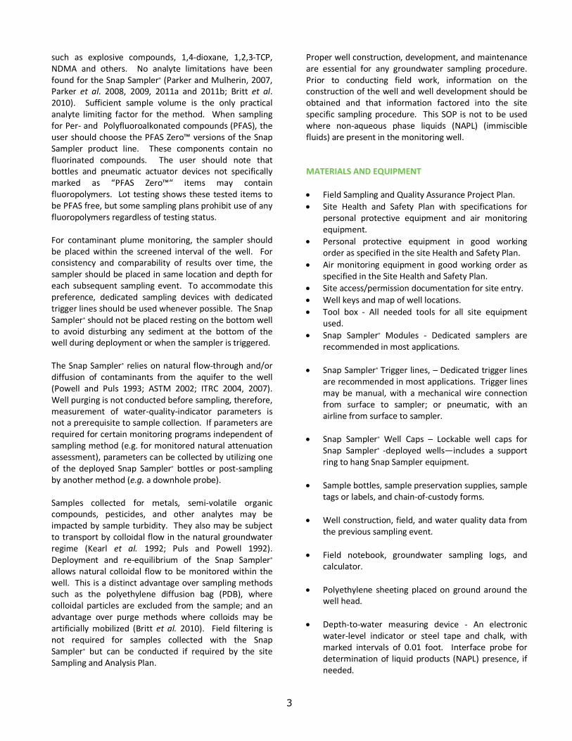
such as explosive compounds, 1,4-‐dioxane, 1,2,3-‐TCP, NDMA and others. No analyte limitations have been found for the Snap Sampler® (Parker and Mulherin, 2007, Parker et al. 2008, 2009, 2011a and 2011b; Britt et al. 2010). Sufficient sample volume is the only practical analyte limiting factor for the method. When sampling for Per-‐ and Polyfluoroalkonated compounds (PFAS), the user should choose the PFAS Zero™ versions of the Snap Sampler product line. These components contain no fluorinated compounds. The user should note that bottles and pneumatic actuator devices not specifically marked as “PFAS Zero™“ items may contain fluoropolymers. Lot testing shows these tested items to be PFAS free, but some sampling plans prohibit use of any fluoropolymers regardless of testing status. For contaminant plume monitoring, the sampler should be placed within the screened interval of the well. For consistency and comparability of results over time, the sampler should be placed in same location and depth for each subsequent sampling event. To accommodate this preference, dedicated sampling devices with dedicated trigger lines should be used whenever possible. The Snap Sampler® should not be placed resting on the bottom well to avoid disturbing any sediment at the bottom of the well during deployment or when the sampler is triggered. The Snap Sampler® relies on natural flow-‐through and/or diffusion of contaminants from the aquifer to the well (Powell and Puls 1993; ASTM 2002; ITRC 2004, 2007). Well purging is not conducted before sampling, therefore, measurement of water-‐quality-‐indicator parameters is not a prerequisite to sample collection. If parameters are required for certain monitoring programs independent of sampling method (e.g. for monitored natural attenuation assessment), parameters can be collected by utilizing one of the deployed Snap Sampler® bottles or post-‐sampling by another method (e.g. a downhole probe). Samples collected for metals, semi-‐volatile organic compounds, pesticides, and other analytes may be impacted by sample turbidity. They also may be subject to transport by colloidal flow in the natural groundwater regime (Kearl et al. 1992; Puls and Powell 1992). Deployment and re-‐equilibrium of the Snap Sampler® allows natural colloidal flow to be monitored within the well. This is a distinct advantage over sampling methods such as the polyethylene diffusion bag (PDB), where colloidal particles are excluded from the sample; and an advantage over purge methods where colloids may be artificially mobilized (Britt et al. 2010). Field filtering is not required for samples collected with the Snap Sampler® but can be conducted if required by the site Sampling and Analysis Plan.
Proper well construction, development, and maintenance are essential for any groundwater sampling procedure. Prior to conducting field work, information on the construction of the well and well development should be obtained and that information factored into the site specific sampling procedure. This SOP is not to be used where non-‐aqueous phase liquids (NAPL) (immiscible fluids) are present in the monitoring well. MATERIALS AND EQUIPMENT • Field Sampling and Quality Assurance Project Plan. • Site Health and Safety Plan with specifications for
personal protective equipment and air monitoring equipment.
• Personal protective equipment in good working order as specified in the site Health and Safety Plan.
• Air monitoring equipment in good working order as specified in the Site Health and Safety Plan.
• Site access/permission documentation for site entry. • Well keys and map of well locations. • Tool box -‐ All needed tools for all site equipment
used. • Snap Sampler® Modules -‐ Dedicated samplers are
recommended in most applications. • Snap Sampler® Trigger lines, – Dedicated trigger lines
are recommended in most applications. Trigger lines may be manual, with a mechanical wire connection from surface to sampler; or pneumatic, with an airline from surface to sampler.
• Snap Sampler® Well Caps – Lockable well caps for
Snap Sampler® -‐deployed wells—includes a support ring to hang Snap Sampler equipment.
• Sample bottles, sample preservation supplies, sample
tags or labels, and chain-‐of-‐custody forms. • Well construction, field, and water quality data from
the previous sampling event. • Field notebook, groundwater sampling logs, and
calculator. • Polyethylene sheeting placed on ground around the
well head. • Depth-‐to-‐water measuring device -‐ An electronic
water-‐level indicator or steel tape and chalk, with marked intervals of 0.01 foot. Interface probe for determination of liquid products (NAPL) presence, if needed.

4
• Steel tape and weight -‐ Used for measuring total depth of well.
• Multi-‐parameter meter, if required. The water-‐
quality-‐indicator parameters that may be monitored under common monitoring programs include pH, ORP/Eh, (ORP) dissolved oxygen (DO), turbidity, specific conductance, and temperature. Turbidity readings, if required, must be collected from a sacrificed Snap Sampler® bottle because retrieving the sampler may agitate the well, increasing turbidity values not present in the actual samples. Calibration fluids for all instruments should be traceable and there should be enough for daily calibration throughout the sampling event.
• Decontamination supplies, including a reliable and
documented source of distilled water and any solvents (if used). Pressure sprayers, buckets or decontamination tubes for pumps, brushes and non-‐phosphate soap will be needed for non-‐dedicated equipment that is moved from well to well.
• A suitable container for excess sample and
decontamination water, as needed or required. Construction materials of non-‐dedicated sampling equipment (samplers, tubing, and other equipment that comes in contact with the sample) should be limited to inert materials. This will reduce the chance that sampling materials alter the groundwater where concentrations of the site contaminants are expected to be near the detection limits. The tendency of organics to sorb into and desorb out of plastic materials makes dedicated equipment preferable where possible. It should be noted that plastic materials used in the Snap Sampler® are not usually problematic for sorption. Using methods described in this SOP, the sampler is deployed for one to two weeks (or more). This deployment period allows materials prone to sorption to achieve equilibrium with groundwater before the sample is collected (Parker, et al. 2007). DEPLOYMENT/SAMPLING PROCEDURES The following describes the deployment and sampling procedures for the Snap Sampler® passive groundwater sampling method. These procedures describe steps for dedicated and non-‐dedicated systems.
Pre-‐Sampling Activities 1. Well location maps, construction information, keys
and sampling equipment should be assembled and transported to the site.
2. Water level monitoring and sampling must begin at
the monitoring well with the least contamination, generally up-‐gradient or farthest from the site or suspected source. Then proceed systematically to the monitoring wells with the most contaminated ground water.
3. Check and record the condition of the monitoring
well for damage or evidence of tampering. Lay out polyethylene sheeting around the well to minimize the likelihood of contamination of sampling equipment from the soil and exposure of soil to liquids dripping from the sampling equipment.
4. Unlock well head. Record location, time, date, and
appropriate information in a field logbook or on the groundwater sampling log.
5. Remove inner casing cap. 6. If required, monitor the headspace of the monitoring
well at the rim of the casing for volatile organic compounds (VOC) with a photo-‐ionization detector (PID) or flame ionization detector (FID) and record in the logbook. If the existing monitoring well currently has or has a history of positive headspace readings, then the sampling must be conducted in accordance with the Health and Safety Plan.
7. Measure the depth to water (water level must be
measured to nearest 0.01 feet) relative to a reference measuring point on the well casing with an electronic water level indicator or other appropriate measuring device and record in logbook or groundwater sampling log. If no reference point is found, measure relative to the top of the inner casing, then mark that reference point and note that location in the field logbook. Record information on depth to ground water in the field logbook or groundwater sampling log. Measure the depth to water a second time to confirm initial measurement; measurement should agree within 0.01 feet or re-‐measure.
8. Check the available well information or field check
for the total depth of the monitoring well.
5
FIGURE 2
FIGURE 2
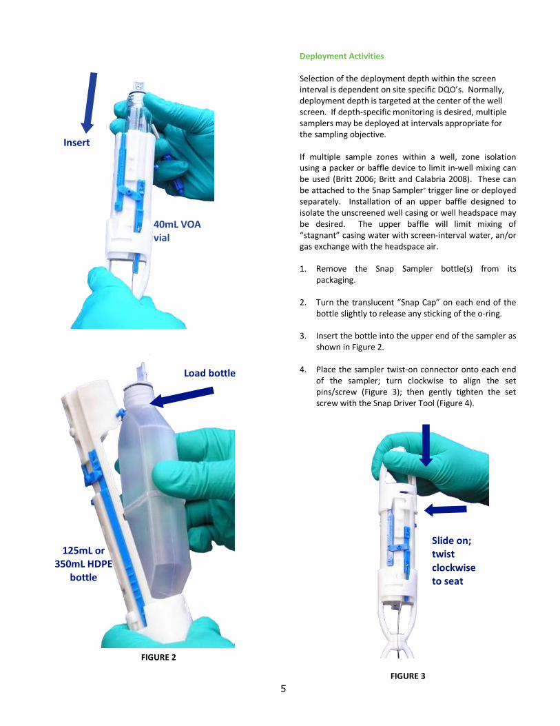
Deployment Activities Selection of the deployment depth within the screen interval is dependent on site specific DQO’s. Normally, deployment depth is targeted at the center of the well screen. If depth-‐specific monitoring is desired, multiple samplers may be deployed at intervals appropriate for the sampling objective. If multiple sample zones within a well, zone isolation using a packer or baffle device to limit in-‐well mixing can be used (Britt 2006; Britt and Calabria 2008). These can be attached to the Snap Sampler® trigger line or deployed separately. Installation of an upper baffle designed to isolate the unscreened well casing or well headspace may be desired. The upper baffle will limit mixing of “stagnant” casing water with screen-‐interval water, an/or gas exchange with the headspace air. 1. Remove the Snap Sampler bottle(s) from its
packaging. 2. Turn the translucent “Snap Cap” on each end of the
bottle slightly to release any sticking of the o-‐ring. 3. Insert the bottle into the upper end of the sampler as
shown in Figure 2. 4. Place the sampler twist-‐on connector onto each end
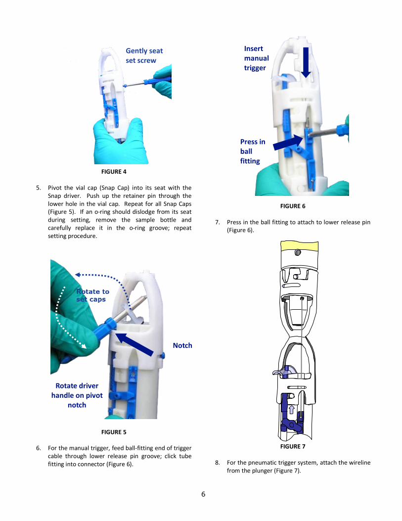
of the sampler; turn clockwise to align the set pins/screw (Figure 3); then gently tighten the set screw with the Snap Driver Tool (Figure 4).
FIGURE 3
40mL VOA vial
Insert
Load bottle
125mL or 350mL HDPE
bottle
Slide on; twist clockwise to seat
6
FIGURE 4
5. Pivot the vial cap (Snap Cap) into its seat with the
Snap driver. Push up the retainer pin through the lower hole in the vial cap. Repeat for all Snap Caps (Figure 5). If an o-‐ring should dislodge from its seat during setting, remove the sample bottle and carefully replace it in the o-‐ring groove; repeat setting procedure.
FIGURE 5 6. For the manual trigger, feed ball-‐fitting end of trigger
cable through lower release pin groove; click tube fitting into connector (Figure 6).
FIGURE 6
7. Press in the ball fitting to attach to lower release pin
(Figure 6).
FIGURE 7
8. For the pneumatic trigger system, attach the wireline
from the plunger (Figure 7).
Gently seat set screw
Gently seat set screw
Rotate
Insert manual trigger
Press in ball fitting
Rotate driver handle on pivot notch
Rotate driver handle on pivot
notch
Notch
7
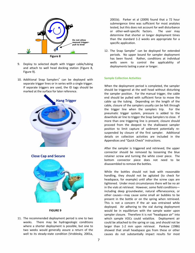
Figure 8 9. Deploy to selected depth with trigger cable/tubing
and attach to well head docking station (Figure 8, Figure 9).
10. Additional Snap Samplers® can be deployed with
separate trigger lines or in series with a single trigger. If separate triggers are used, the ID tags should be marked at the surface for later reference.
FIGURE 9
11. The recommended deployment period is one to two
weeks. There may be hydrogeologic conditions where a shorter deployment is possible, but one to two weeks would generally assure a return of the well to its steady-‐state condition (Vroblesky, 2001a,
2001b). Parker et al (2009) found that a 72 hour submergence time was sufficient for most analytes tested, but this does not account for well disturbance or other-‐well-‐specific factors. The user may determine that shorter or longer deployment times than the standard 1-‐2 weeks are appropriate for a specific application.
12. The Snap Sampler® can be deployed for extended
periods. No upper bound for sampler deployment has been found. Rather, conditions at individual wells seem to control the applicability of deployments lasting a year or longer.
Sample Collection Activities When the deployment period is completed, the sampler should be triggered at the well head without disturbing the sampler position. For the manual trigger, the cable end should be pulled with sufficient force to move the cable up the tubing. Depending on the length of the cable, closure of the samplers usually can be felt through the trigger line when the samplers trip. For the pneumatic trigger system, pressure is added to the downhole air line to trigger the Snap Samplers to close. If more than one triggering line is present, closure should proceed from the deepest to the shallowest sampler position to limit capture of sediment potentially re-‐suspended by closure of the first sampler. Additional details on collection activities are included in the Appendices and “Quick Check” instructions. After the sampler is triggered and retrieved, the upper connector should be removed by loosening the blue retainer screw and turning the white cover piece. The bottom connector piece does not need to be disassembled to remove the bottles. While the bottles should not leak with reasonable handling, they should not be agitated (to check for headspace, for example) until after the screw caps are tightened. Under most circumstances there will be no air in the vials at retrieval. However, some field conditions—including deep groundwater, natural effervescence, or other causes—may cause some small air bubbles to be present in the bottle or on the spring when retrieved. This is not a concern if the air was entrained while deployed. Air adhering to the vial during deployment would be in equilibrium with the sample water upon sampler closure. Therefore it is not “headspace air” into which sample VOCs could volatilize. Deployment air could be attached to the spring or cap, and should not be larger than 1-‐2 mm upon retrieval. Pankow (1986) showed that small headspace gas from these or other causes do not substantially impact results for most
Do not allow manual trigger-pull to bind
Close Cap and Secure
Hang Trigger
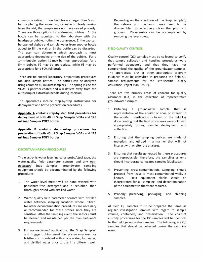
8
common volatiles. If gas bubbles are larger than 5 mm before placing the screw cap, or water is clearly leaking from the vial, the sample may not have sealed properly. There are three options for addressing bubbles: 1) the bottle can be submitted to the laboratory with the headspace bubble, noting the occurrence; 2) the cap can be opened slightly and sample water from another bottle added to fill the vial; or 3) the bottle can be discarded. The user can determine which approach is most appropriate depending on the size of the bubble. For a 1mm bubble, option #1 may be most appropriate; for a 5mm bubble, #2 may be appropriate, while #3 may be appropriate for a 50% full bottle. There are no special laboratory preparation procedures for Snap Sample bottles. The bottles can be analyzed using common 40-‐ml autosamplers. The spring inside the VOAs is polymer-‐coated and will deflect away from the autosampler extraction needle during insertion. The appendices include step-‐by-‐step instructions for deployment and bottle preparation procedures. Appendix A contains step-‐by-‐step field procedures for deployment of both 40 ml Snap Sampler VOAs and 125 ml Snap Sampler POLY bottles. Appendix B contains step-‐by-‐step procedures for preparation of both 40 ml Snap Sampler VOAs and 125 ml Snap Sampler POLY bottles. DECONTAMINATION PROCEDURES The electronic water level indicator probe/steel tape, the water-‐quality field parameter sensors and any non-‐dedicated Snap Sampler® groundwater sampling equipment should be decontaminated by the following procedures: 1. The water level meter will be hand washed with
phosphate-‐free detergent and a scrubber, then thoroughly rinsed with distilled water.
2. Water quality field parameter sensors with distilled
water between sampling locations where utilized. No other decontamination procedures are necessary or recommended for these probes since they are sensitive. After the sampling event, the sensors must be cleaned and maintained per the manufacturer’s requirements.
3. For non-‐dedicated applications, the Snap Sampler®
and trigger tubing must be pressure-‐sprayed or bristle-‐brush scrubbed with soapy water, tap water, and distilled water prior to use in a different well.
Depending on the condition of the Snap Sampler®, the release pin mechanism may need to be disassembled to effectively clean the pins and grooves. Disassembly can be accomplished by removing the lever screw.
FIELD QUALITY CONTROL Quality control (QC) samples must be collected to verify that sample collection and handling procedures were performed adequately and that they have not compromised the quality of the groundwater samples. The appropriate EPA or other appropriate program guidance must be consulted in preparing the field QC sample requirements for the site-‐specific Quality Assurance Project Plan (QAPP). There are five primary areas of concern for quality assurance (QA) in the collection of representative groundwater samples: 1. Obtaining a groundwater sample that is
representative of the aquifer or zone of interest in the aquifer. Verification is based on the field log documenting that the field procedures were followed appropriately during sample deployment and collection.
2. Ensuring that the sampling devices are made of
materials, and utilized in a manner that will not interact with or alter the analyses.
3. Ensuring that results generated by these procedures
are reproducible; therefore, the sampling scheme should incorporate co-‐located samples (duplicates).
4. Preventing cross-‐contamination. Sampling should
proceed from least to most contaminated wells, if known. Field equipment blanks should be incorporated for all sampling, and decontamination of the equipment is therefore required.
5. Properly preserving, packaging, and shipping
samples. All field QC samples must be prepared the same as regular investigation samples with regard to sample volume, containers, and preservation. The chain-‐of custody procedures for the QC samples will be identical to the field groundwater samples. The following are QC samples that should be collected during the sampling event:
9
Field duplicates See QAPP/SAP
Matrix spike See QAPP/SAP
Matrix spike dup. See QAPP/SAP
Equipment blank See QAPP/SAP
Trip blank (VOCs) See QAPP/SAP
Temperature blank See QAPP/SAP
HEALTH AND SAFETY CONSIDERATIONS Depending on the site-‐specific contaminants, various protective programs must be implemented prior to sampling the first well. The site Health and Safety Plan should be reviewed with specific emphasis placed on the protection program planned for the sampling tasks. Standard safe operating practices should be followed, such as minimizing contact with potential contaminants in both the liquid and vapor phase through the use of appropriate personal protective equipment. Depending on the type of contaminants expected or determined in previous sampling efforts, the following safe work practices should be employed: Particulate or metals contaminants 1. Avoid skin contact with, and incidental ingestion of
sample water. 2. Use protective gloves and splash protection. Volatile organic contaminants 1. Avoid breathing constituents venting from well. 2. Pre-‐survey the well head space with an appropriate
device as specified in the site Health and Safety Plan. 3. If monitoring results indicate elevated organic
constituents, sampling activities may be conducted in elevated protective equipment (e.g. level C protection). At a minimum, skin protection will be afforded by disposable protective clothing, such as Tyvek®, appropriate gloves and face protection.
General practices should include avoiding skin contact with water from preserved sample bottles, as this water will have pH less than 2 or greater than 10. Also, when field acidifying VOA bottles, hydrochloric acid fumes may be released and should not be inhaled. Acid should not contact skin, eyes, or unprotected clothing.
POST-‐SAMPLING ACTIVITIES Several activities need to be completed and documented once groundwater sampling has been completed. These activities include, but are not limited to the following: 1. Ensuring that all field equipment has been
decontaminated and returned to proper storage location. Once the individual field equipment has been decontaminated, tag it with date of cleaning, site name, and name of individual responsible.
2. Processing all sample paperwork, including copies
provided to the appropriate sample handling and tracking facility.
3. Compiling all field data for site records. 4. Verifying all analytical data processed by the
analytical laboratory against field sheets to ensure all data has been returned to sampler.
REFERENCES
American Society of Testing Materials (ASTM). 2002, Standard Practice for Low-‐Flow Purging and Sampling for Wells and Devices Used for Ground-‐Water Quality Investigations. ASTM Subcommittee D18.21: Designation D 6771-‐02.
ASTM, 2014, Standard Guide for Selection of Passive Techniques for Sampling Groundwater Monitoring Wells, 14p. ASTM International, West Conshohocken, Pennsylvania, United States. D7929-‐14
Britt, S.L., 2005, Testing the In-‐Well Horizontal Laminar Flow Assumption with a Sand Tank Well Model. Ground Water Monitoring and Remediation 25:3 p. 73-‐81.
Britt, S.L., 2006, Multilevel Sampling in Traditional Monitoring Wells: A Mixing-‐Limited Passive Sampling Approach, Proceedings of the Ground Resources Association of California High-‐Resolution Characterization and Monitoring Conference, November 14-‐16, 2006, Long Beach, California. Britt, S. L. and Calabria, 2008, Baffles may Allow Effective Multilevel Sampling in Traditional Monitoring Wells (Abstract), Proceedings of the Battelle Conference on Chlorinated and Recalcitrant Compounds, Monterey, California, May 2008.
Britt, S.L., B.L. Parker, and J.A Cherry, 2010, A Downhole Passive Sampling System to Avoid Bias and Error in Groundwater Sample Handling, Environmental Science and Technology, v.44 p 4917-‐4923
Britt, S.L., Plummer, M., Martin-‐Hayden, J.M, 2011, Groundwater Sampling Results May Differ when Sampling Methods Differ: Methods and Mechanisms, Proceedings of the North American Field Conference and Exposition, San Diego, California, January 10-‐13, 2011.
10
Gillham, R.W., 1982, Syringe Devices for Ground-‐Water Sampling, Ground Water Monitoring Review, Spring 1982 Issue, p. 36-‐39.
Kearl, P.M., N.E. Korte, and T.A. Cronk, 1992, Suggested Modifications to Ground Water Sampling Procedures Based on Observations from the Colloid Borescope. Ground Water Monitoring Review, Vol. 12, No. 2, pp. 155-‐161.
Martin-‐Hayden, J.A. and S.L. Britt, 2006, Revealing the Black Box of Groundwater Sampling: effects of Well-‐Bore Flow and Mixing, Proceedings of the North American Field Conference and Exposition, January 10-‐12, 2006, Tampa Florida.
McAlary, T.A. and J.F. Barker, 1987, Volatilization Losses of Organics During Ground Water Sampling from Low Permeability Materials. Ground Water Monitoring Review, Vol. 7, No. 4, pp. 63-‐68.
McHugh, T. 2010, Groundwater Sampling Variability, SERDP/ESTCP Partners Symposium, Washington, DC, December 2010.
Pankow, J.F., L.M. Isabelle, J.P. Hewetson, and J.A. Cherry, 1985, A Tube and Cartridge Method for Down-‐Hole Sampling for Trace Organic Compounds and Ground Water, Ground Water 6: 775-‐782.
Pankow, J.F. 1986, Magnitude of Artifacts Caused by Bubbles and Headspace in the Determination of Volatile Compounds in Water, Analytical Chemistry 58: 1822-‐1826.
Parker, Louise and Nathan Mulherin, 2007, Evaluation of the Snap Sampler for Sampling Ground Water Monitoring Wells for VOCs and Explosives. U.S. Army Corps of Engineers, ERDC/CRREL TR-‐07-‐14, 68p.
Parker, Louise V., Nathan D. Mulherin, and Gordon E. Gooch, 2008. Evaluation of the Snap Sampler for Sampling Ground Water Monitoring Wells for Inorganic Analytes. U.S. Army Corps of Engineers, ERDC/CRREL TR 08-‐25, 74p.
Parker, Louise, Nathan Mulherin, Gordon Gooch, William Major, Richard Willey, Thomas Imbrigiotta, Jacob Gibs, and Donald Gronstal, 2009, Demonstration/Validation of the Snap Sampler Passive Ground Water Sampling Device for Sampling Inorganic Analytes at the Former Pease Air Force Base, U.S. Army Corps of Engineers, ERDC/CRREL TR 09-‐12, 101p.
Parker, Louise, Nathan Mulherin, Gordon Gooch, Tommie Hall, Constance Scott, Jay Clausen, William Major, Richard Willey, Thomas Imbrigiotta, Jacob Gibs, and Donald Gronstal, 2011a, Environmental Security Technology Certification Program -‐ Project ER 0630, Demonstration/Validation of the Snap Sampler Passive Groundwater Sampling Device at the Former McClellan Air Force Base, U.S. Army Corps of Engineers, ERDC/CRREL TR 11-‐3, 117p.
Parker, Louise, Nathan Mulherin, Gordon Gooch, Tommie Hall, Constance Scott, Jay Clausen, William Major, Richard Willey, Thomas Imbrigiotta, Jacob Gibs, and Donald Gronstal, 2011b, ESTCP Cost and Performance Report – Demonstration/ Validation of the Snap Sampler -‐ Project ER-‐0630, U.S. Army Corps of Engineers, ERDC/CRREL TR 11-‐11, 55p.
Parker, L.V. and S.L. Britt, 2012, The Effect of Bottle Fill Rate and Pour Technique on the Recovery of Volatile Organics, submitted to Ground Water Monitoring and Remediation 32, no. 4/ Fall 2012/pages 78–86.
Parsons, 2003, Final Comprehensive Results Report for the Passive Diffusion Bag Sampler Demonstration. prepared for the Air Force Center for Environmental Excellence (AFCEE).
Powell, R.M., and R.W. Puls, 1993, Passive sampling of groundwater monitoring wells without purging: multilevel well chemistry and tracer disappearance. Journal of Contaminant Hydrology 12: 51-‐77.
Puls, R.W. and M.J. Barcelona, 1996, Low-‐Flow (Minimal Drawdown) Ground-‐Water Sampling Procedures, USEPA Ground Water Issue Paper, 12p. EPA/540/S-‐95/504.
Puls, R.W. and R.M. Powell, 1992, Acquisition of Representative Ground Water Quality Samples for Metals. Ground Water Monitoring Review, Vol. 12, No. 3, pp. 167-‐176.
Robin, M.J.L., and R.W. Gillham, 1987, Field Evaluation of Well Purging Procedures. Ground Water Monitoring Review 7, no. 4: 85-‐93.
U.S. Environmental Protection Agency, 1995, Ground Water Sampling -‐ A Workshop Summary. Texas, November 30-‐December 2, 1993, EPA/600/R-‐94/205, 146 pp.
U.S. Environmental Protection Agency, 2002, Ground-‐Water Sampling Guidelines for Superfund and RCRA Project Managers. Ground Water Forum Issue Paper by D. Yeskis and B. Zevala. EPA 542-‐S-‐02-‐001, 53 pp.
Vroblesky, D.A., 2001a, User’s Guide for Polyethylene-‐Based Passive Diffusion Bag Samplers to Obtain Volatile Organic Compound Concentrations in Wells, Part 1: Deployment, Recovery, Data Interpretation, and Quality Control and Assurance. U.S. Geological Survey Water-‐Resources Investigations Report 01-‐4060, 18 pp.
Vroblesky, D.A. ed., 2001b, User’s Guide for Polyethylene-‐Based Passive Diffusion Bag Samplers to Obtain Volatile Organic Compound Concentrations in Wells, Part 2: Field Tests. U.S. Geological Survey Water-‐Resources Investigations Report 01-‐4061.
Vroblesky, D.A., C.C. Casey, and M.A. Lowery, 2007, Influence of In-‐Well Convection on Well Sampling,, USGS Scientific Investigations Report 2006-‐5247, 21p.
Technology websites: www.QEDENV.com www.SnapSampler.com
QED Environmental Systems Inc.
2355 Bishop Circle West Dexter, MI 48130 UNITED STATES (800) 624-‐2026
QED Environmental Systems Ltd.
Cyan Park – Unit 3 Jimmy Hill Way Coventry CV2 4QP UNITED KINGDOM