soaring radi c ntr lleddigest · at construction sites. by scott rhoades 9 design and construction...
TRANSCRIPT

SoaringDigestRadi C ntr l led
November 2013 Vol. 30, No. 11
2 R/C Soaring Digest
November 2013
Vol. 30, No. 11C
ON
TEN
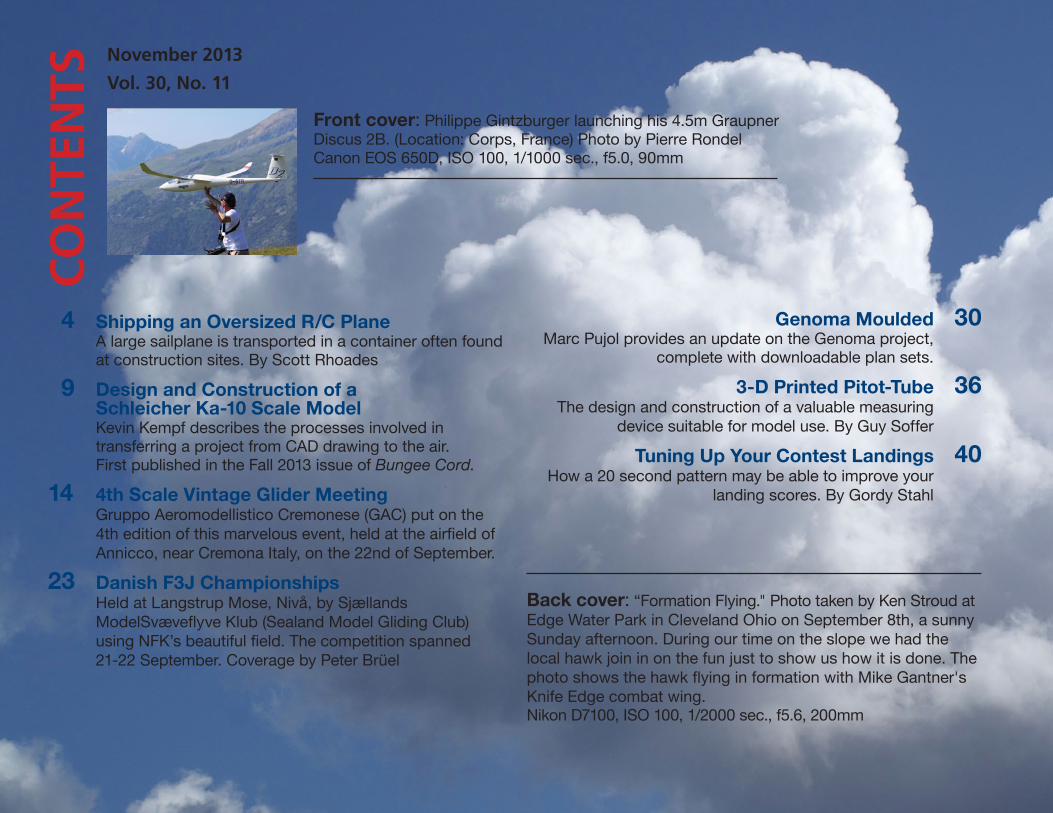
TSFront cover: Philippe Gintzburger launching his 4.5m Graupner Discus 2B. (Location: Corps, France) Photo by Pierre RondelCanon EOS 650D, ISO 100, 1/1000 sec., f5.0, 90mm
4 Shipping an Oversized R/C PlaneA large sailplane is transported in a container often found at construction sites. By Scott Rhoades
9 Design and Construction of aSchleicher Ka-10 Scale ModelKevin Kempf describes the processes involved in transferring a project from CAD drawing to the air.First published in the Fall 2013 issue of Bungee Cord.
14 4th Scale Vintage Glider MeetingGruppo Aeromodellistico Cremonese (GAC) put on the 4th edition of this marvelous event, held at the airfield of Annicco, near Cremona Italy, on the 22nd of September.
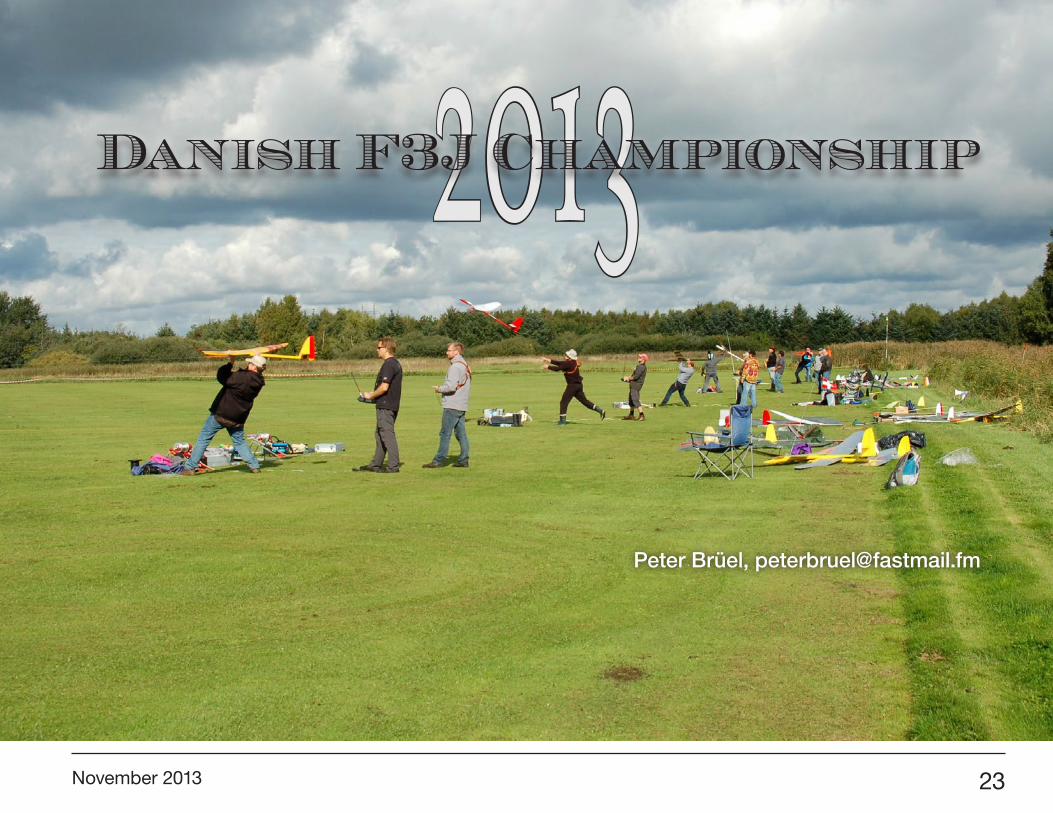
23 Danish F3J ChampionshipsHeld at Langstrup Mose, Nivå, by Sjællands ModelSvæveflyve Klub (Sealand Model Gliding Club) using NFK’s beautiful field. The competition spanned21-22 September. Coverage by Peter Brüel
Genoma Moulded 30Marc Pujol provides an update on the Genoma project,
complete with downloadable plan sets.
3-D Printed Pitot-Tube 36The design and construction of a valuable measuring
device suitable for model use. By Guy Soffer
Tuning Up Your Contest Landings 40How a 20 second pattern may be able to improve your
landing scores. By Gordy Stahl
Back cover: “Formation Flying." Photo taken by Ken Stroud at Edge Water Park in Cleveland Ohio on September 8th, a sunny Sunday afternoon. During our time on the slope we had the local hawk join in on the fun just to show us how it is done. The photo shows the hawk flying in formation with Mike Gantner's Knife Edge combat wing.Nikon D7100, ISO 100, 1/2000 sec., f5.6, 200mm
November 2013 3
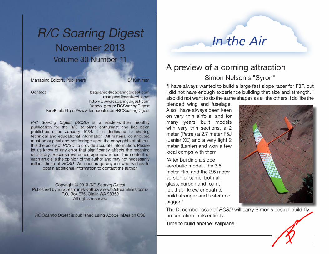
A preview of a coming attractionSimon Nelson's "Syron"
"I have always wanted to build a large fast slope racer for F3F, but I did not have enough experience building that size and strength. I also did not want to do the same shapes as all the others. I do like the blended wing and fuselage. Also I have always been keen on very thin airfoils, and for many years built models with very thin sections, a 2 meter (Petrel) a 2.7 meter F5J (Lanier XE) and a very light 2 meter (Lanier) and won a few local comps with them.
"After building a slope aerobatic model., the 3.5 meter Flip, and the 2.5 meter version of same, both all glass, carbon and foam, I felt that I knew enough to build stronger and faster and bigger."
The December issue of RCSD will carry Simon's design-build-fly presentation in its entirety.
Time to build another sailplane!
R/C Soaring DigestNovember 2013Volume 30 Number 11
Managing Editors, Publishers B2 Kuhlman
Contact [email protected]@centurytel.net
http://www.rcsoaringdigest.comYahoo! group: RCSoaringDigest
FaceBook: https://www.facebook.com/RCSoaringDigest
R/C Soaring Digest (RCSD) is a reader-written monthly publication for the R/C sailplane enthusiast and has been published since January 1984. It is dedicated to sharing technical and educational information. All material contributed must be original and not infringe upon the copyrights of others. It is the policy of RCSD to provide accurate information. Please let us know of any error that significantly affects the meaning of a story. Because we encourage new ideas, the content of each article is the opinion of the author and may not necessarily reflect those of RCSD. We encourage anyone who wishes to
obtain additional information to contact the author.
———
Copyright © 2013 R/C Soaring DigestPublished by B2Streamlines <http://www.b2streamlines.com>
P.O. Box 975, Olalla WA 98359All rights reserved
———
RC Soaring Digest is published using Adobe InDesign CS6
In the Air
4 R/C Soaring Digest
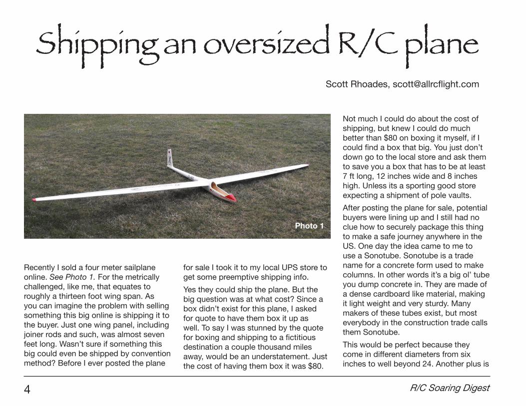
Recently I sold a four meter sailplane online. See Photo 1. For the metrically challenged, like me, that equates to roughly a thirteen foot wing span. As you can imagine the problem with selling something this big online is shipping it to the buyer. Just one wing panel, including joiner rods and such, was almost seven feet long. Wasn’t sure if something this big could even be shipped by convention method? Before I ever posted the plane
for sale I took it to my local UPS store to get some preemptive shipping info.
Yes they could ship the plane. But the big question was at what cost? Since a box didn’t exist for this plane, I asked for quote to have them box it up as well. To say I was stunned by the quote for boxing and shipping to a fictitious destination a couple thousand miles away, would be an understatement. Just the cost of having them box it was $80.
Not much I could do about the cost of shipping, but knew I could do much better than $80 on boxing it myself, if I could find a box that big. You just don’t down go to the local store and ask them to save you a box that has to be at least 7 ft long, 12 inches wide and 8 inches high. Unless its a sporting good store expecting a shipment of pole vaults.
After posting the plane for sale, potential buyers were lining up and I still had no clue how to securely package this thing to make a safe journey anywhere in the US. One day the idea came to me to use a Sonotube. Sonotube is a trade name for a concrete form used to make columns. In other words it’s a big ol’ tube you dump concrete in. They are made of a dense cardboard like material, making it light weight and very sturdy. Many makers of these tubes exist, but most everybody in the construction trade calls them Sonotube.
This would be perfect because they come in different diameters from six inches to well beyond 24. Another plus is
Shipping an oversized R/C planeScott Rhoades, [email protected]
Photo 1

November 2013 5
many of the specialty concrete suppliers that sell these do so by the foot, allowing you to buy only what is necessary. Home improvement stores do carry these, but diameter sizes are limited and I have only seen them in four foot lengths. I needed a 12 inch diameter tube about 8 feet long. At that length it gave me a little extra to work with and you will see why later.
With the container figured out I needed to answer the question on how to pack the plane inside so pieces didn’t bounce around and rub together during transport. I had a few ideas and called friends looking for certain materials that I thought would get the job done. However it was a call to my friend Mike, who has been mentioned in other articles on this site before, who had the perfect solution.
Mike’s idea was to use an extruded polystyrene insulation as bulk heads. Well Mike didn’t actually say extruded polystyrene. He called it what most everybody else calls it; “blue board” or “blue foam.” This is a high density foam insulation board that comes in various thicknesses from half an inch up to three inches. As a side note; it does come in colors other than blue, depending on who makes it. The stuff I used happened to be pink.
The plan was to make four bulkheads and at 12 inch diameter so I only needed
a 2' x 2' piece of foam board. Fortunately for me the local home improvement store sells pieces exactly that size. Perfect! Was worried I’d be left with the remainder of a 4' x 8' sheet wondering what the heck I was going to do with for the next 20 years.
With the tube and the foam board in my possession I was ready to start packing a plane for safe passage to my buyer on the other side of the country. First thing I did was cut about six inches off the end of the tube to use as a template for making the bulkheads. A word of warning about cutting these tubes: One
Photo 2
would be hard pressed to accomplish this task with a utility knife so a power saw is highly recommended. With that said; cutting with a power saw the tube can get a little unruly, so get some help to steady the tube and rotate it for you while cutting.
Using the template piece, I traced circles onto the foam board making sure they would be slightly undersized once cut. I did not want a tight fit inside the tube because everything needs to slide inside nicely. Even though the foam cuts easy with a knife I found the best way to make all my cuts was with the band saw. I
Template for cutting bulkheads
and ends.

6 R/C Soaring Digest
suppose a saber saw or jig saw would work just as well. Using a saw produces better results and is much easier than using a knife.
See Photo 2: Template for cutting bulkheads and ends.
With four bulkhead circles cut, two would be used to cradle the plane parts and the other two were for each end of the tube for added protection. Now for the tricky part; figuring out how to position the pieces so there was enough separation between each airplane piece and the wall of the tube.
Since the fuselage was going in the middle, that was tackled first. I cut those two bulkheads in half and made the desired cut outs so each half snugly held the fuse when it was taped back together. Satisfied with the fit and the bulkheads still on the fuse, I laid the wing panels next to fuse where I figured they would be a good fit. Then I simply took wing chord and thickness measurements at the point where it would rest in bulkheads. With those measurements I removed the bulkheads from the fuse and drew my best rendition of the wing profile on each half. I suggest going a little smaller with the wing profile. You want this to be a snug fit and you can always take more material off.
See Photo 3: The bulkheads on the fuselage and laying out the location for the wing.
Photo 3
Photo 4
The bulkheads on the fuselage
and laying out the location for the
wing.
Fuse and wing panels
cradled with the bulkheads.

November 2013 7
Here again I used my band saw to cut out the wing profiles. Starting the cut from the outside edge is actually a benefit when it comes time to inserting the wing panels. Being able to slightly pull the foam apart when inserting the wing makes that process a bit easier.
See Photo 4: Fuse and wing panels cradled with the bulkheads.
Once satisfied with how everything fit in the bulkheads I used tape just to make sure the bulkheads stayed where intended. With the bulkheads cradling the plane pieces the whole assembly slid nicely inside the tube. The two remaining pieces of foam board were taped flush into each end of the tube. Using the template again I cut pieces of cardboard for a more durable outer skin over the foam end pieces.
See Photos 5 and 6: Neatly tucked inside the tube and ready to be closed off for shipping.
I should also mention that before finalizing the capping of the ends, I cut the tube at a length that provided just enough room between the foam ends for the plane, so it would not slide.
Even though I resorted to using a Sonotube because I couldn’t find a box long enough to ship a four meter sailplane, I certainly would use this method to ship a plane of any size. It’s easy and in my opinion much more durable than a regular box.
Photo 5
Photo 6
Neatly tucked inside the tube and ready to be closed off for shipping.

8 R/C Soaring Digest
What do you think? Does this sound like a method you would use to ship a plane? Leave any questions, observations and rude comments in the “Speak your mind” section at <http://allrcflight.com/shipping-an-oversized-rc-plane/>.
*Update
Received an email from my buyer and he said the plane traveled very well. Some other information he added gave me great insight on what I should have done different. When making the cutouts for the wing panels the cuts were started from the outer edge, which allowed setting the bulkheads on the wing panels an easy task. With the information I received I should have altered where those cuts were made.
As you will see in the diagram, the original cuts, indicated by the black dotted line, are right straight back off the trailing edge.
See Drawing 1: Bulkhead diagram showing where cuts should have been made.
I imagine the TE of the wing would be able to move down into that cut. Those cuts should have come in from an angle, which is indicated by the red dotted line.
ABOUT THE AUTHOR
Scott Rhoades has been an aeromodeller for nearly three decades. Having tried a few different disciplines along the way, with sailplanes being the latest, he writes about his experiences, discoveries and follies on a blog called allrcflight.com <http://allrcflight.com>.
Drawing 1
Bulkhead diagram showing where cuts should have been made.
November 2013 9
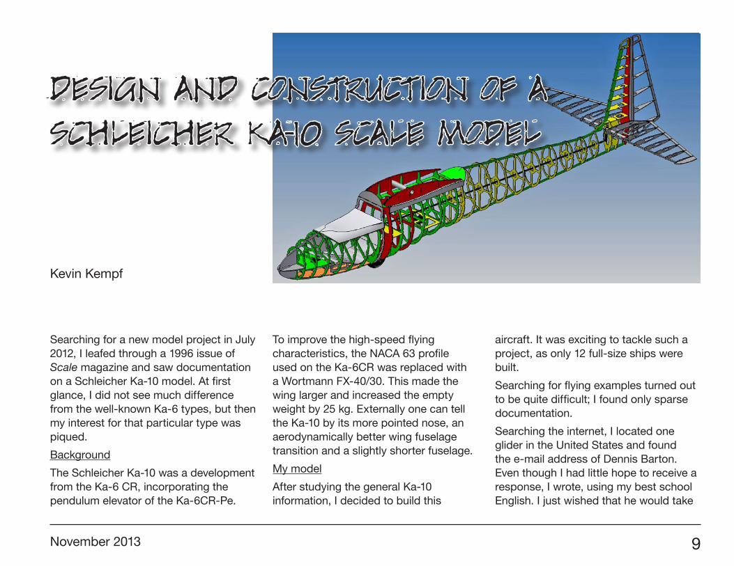
Design and Construction of a Schleicher Ka-10 Scale Model
Searching for a new model project in July 2012, I leafed through a 1996 issue of Scale magazine and saw documentation on a Schleicher Ka-10 model. At first glance, I did not see much difference from the well-known Ka-6 types, but then my interest for that particular type was piqued.
Background
The Schleicher Ka-10 was a development from the Ka-6 CR, incorporating the pendulum elevator of the Ka-6CR-Pe.
To improve the high-speed flying characteristics, the NACA 63 profile used on the Ka-6CR was replaced with a Wortmann FX-40/30. This made the wing larger and increased the empty weight by 25 kg. Externally one can tell the Ka-10 by its more pointed nose, an aerodynamically better wing fuselage transition and a slightly shorter fuselage.
My model
After studying the general Ka-10 information, I decided to build this
aircraft. It was exciting to tackle such a project, as only 12 full-size ships were built.
Searching for flying examples turned out to be quite difficult; I found only sparse documentation.
Searching the internet, I located one glider in the United States and found the e-mail address of Dennis Barton. Even though I had little hope to receive a response, I wrote, using my best school English. I just wished that he would take
Kevin Kempf

10 R/C Soaring Digest
me and my project seriously. But were my language skills sufficient that he could understand me at all? All of these banal thoughts went through my head as I was starting the new project.
Dennis responded a few hours later that he was glad to hear about my plans and ideas and promised his full support. He himself had owned such a glider and enjoyed flying it.
Now there were no more obstacles toward my dream to build my first big ship. The next step was to set-up dimensions for the model. The scale was to be 1:2.5, which meant a wing span of 6 m. The fuselage length is 2.65 m and the weight about 17-18 kg.
A common problem with larger models is transporting the glider to and from the airport. I would have to figure out how to separate the wing so as to fit it into my mid-size car.
To make the over-all package even smaller, I decided on making the rudder on my design removable. The goal was to build the model with practicality in mind, and to keep construction time and cost down. Also the set-up at the airfield should be quick, smooth and fun.
First I drew the 27 fuselage formers in a 3D-design program using the available documentation that I had gathered of the Ka-10. Next I placed the formers into their correct positions within the software program. I hoped to then build the structure as quickly as possible, but could not quite figure out how.
The construction of a nicely shaped fuselage was a bit problematic and worrisome, but the proven technology of half shells did not inspire me. So I thought of mounting all formers on a piece of square aluminum tubing, after sawing a square notch in each former. Now the orientation of each

November 2013 11
former was set in the horizontal and vertical axis, but to line them up in a row, something else needed to be considered.
I drew the top and bottom longerons and provided them with corresponding notches to allow the formers to be connected with a simple plug-in system. I then connected all parts quickly and squarely by means of white glue.
I also used this plug-in system on the tail sections. I calculated the elevator and rudder dimensions and geometry from the original.
I could lay-out the level areas for the RC electronics, such as batteries, servos and receiver system in my 3D design. I also included the tow attachment and the nose area as it was shown in the original. The fuselage bottom, seat pan and the instrument panel were properly positioned in the structure.
Since I intended to build several models of this type, I decided to build the wings of the prototype in a styrofoam sandwich construction. This would determine in flight whether the profiling was suitable.
I positioned the dive brakes, just like in the original, on the top and bottom of the wings. A wing surface showing the outline of the ribs was simply too costly on the prototype, but I intend to implement this on my next Ka-10.
After cutting all wooden parts on an in-house CNC milling machine, I assembled the model, piece by piece as laid out in the CAD program.
I was pleasantly surprised how quickly the model went together. It took just one weekend and the entire aircraft structure (apart from the wings) was standing in front of me.
The following weekend, I applied 2mm balsa wood to the fuselage. In the tricky areas where multiple radii and contours blend, I inserted filler blocks of balsa and finally smoothed them using various grinding tools.
The remaining parts, such as covering of the wings and the canopy frame, I built free-hand. For the canopy I used a design made for a Ka-6CR in a scale of 1:2.3. The construction of these remaining pieces are now also computerized. For the canopy I have created a 3D machined model that allows me to draw exactly matching canopies.
After the model was assembled, the entire hull was coated with a layer of fiberglass and painted using the same paint scheme as the Ka-10 owned by Dennis. The wings were covered with high-quality Oracover tissue foil, and then painted the same white and orange as the fuselage.
The final steps were the installation of the RC system, weight and balance and whatever final adjustments were necessary.

12 R/C Soaring Digest

November 2013 13
Early February 2013, half a year after beginning the project, it finally happened. I met with my father and fellow modelers on our model flying field for the first flight of my glider.
My father made the first flight as I had to fly the towplane. The towed flight was absolutely easy and my father released at an altitude of about 250 m.
The glider turned out a little tail-heavy, but this could be compensated by some elevator trim. The flight characteristics can be described as absolutely balanced and non-critical, but the Ka-10 wanted to be flown. Under no circumstances
can this glider be parked in the air after releasing from the towplane.
The glider flies beautifully using the HQ 3.0 wing profile. Even strong headwind does not appear to present a big problem.
After a ten-minute flight my Ka-10 came down in a pleasant descent to the landing spot.
The braking behaviour of the spoilers proved to be “right-on.” Pulling up the elevator slightly just before setting it down, the glider skimmed over the still frozen February ground to a perfect landing.
It was just an indescribable feeling when all the hard work paid off. All pilots present were completely amazed by this model that can not be seen every day.
Now, I enjoy fine flights with the Ka-10 and I admire this beautiful flying machine in the sky.
In Closing
In closing I would like to thank Dennis Barton for his many helpful e-mails and photos. I am very pleased that aviation, whether man-carrying or as a model, knows no boundaries and gives rise to new friendships.
This article appeared in Bungee Cord Volume 39 No. 3, Fall 2013, pp. 15-16.
Bungee Cord (ISSN 0194-6889/USPS 47-430) is the quarterly publication of the Vintage Sailplane Association, Inc., a nonprofit organization for the preservation and operation of vintage motorless aircraft.
Our sincere thanks to Simine and Jim Short, Bungee Cord Editors, and to Kevin Kempf for their cooperation in allowing reprinting within RC Soaring Digest.
14 R/C Soaring Digest
years and lead by Marco Pattoni and Tullio Facchin, this last one is the oldest member of the group (86 year old). The youngest member is Giorgio, Marco’s son, only 12 years old. Everyone is super active and super enthusiastic!There was a great variety of sailplanes designed in many parts of the world by famous glider designers, such as Hans Jakob, Slingsby, Bowlus, Schweizer, Wolf Hirt, George Mueller and others. The great news of this year was the presence of scale models of Italian origin. The Orione of Techfuss in 1/4 scale, built by Pietro Castelvecchio, was the most noticed sailplane of the meet. There was also a Borea in 1/5 scale, the last masterpiece of Teichfuss which never flew due to WWII.
Opposite page: Minimoa being towed to altitude
Annicco, ItalyA great success growing every year, both in terms of pilots attending and number of models.Just to speak numbers, on 22nd September in the airfield of Annicco, near Cremona, were present 35 glider pilots plus seven tow plane pilots. The vintage scale sailplanes which safely flew till late afternoon were 48. Two more important figures: 13 club members provided field support, and the BBQ team which cooked several meters of sausages to feed 74 people present at the event. I forgot to count the bottles of wine, but I observed that the pilots were very cautious not to drink too much wine, to avoid to radio control someone else’s model.The GAC is comprised of over 30 members with an average age of 45/50
Vincenzo Pedrielli, [email protected]
Gruppo Aeromodellistico Cremonese (GAC)
Scale Vintage Glider Meeting4th Edition

November 2013 15
From the Italian designer Vittorio Bonomi the famous Allievo Cantù, which in the 1930s was adopted by almost all gliding schools in Italy. For the first time in scale version, the Gheppio, designed by Gianfranco Rotondi in the beginning of the ’fifties. To close the “Italian Gallery,” the CVV3 Arcore built at the Politecnico of Milano and designed by Ermenegildo Preti.
By writing these last few lines I felt a sense of pride, as these vintage scale models have been built by the 3-view drawings within my recent book, “Italian Vintage Sailplanes.” It seems that this book, the first of its kind, has awakened by the model builders the nation’s pride. Hopefully that will continue in the future to see other models of Italian design participating in the next scale vintage glider meetings.

16 R/C Soaring Digest
Posing for the press
November 2013 17
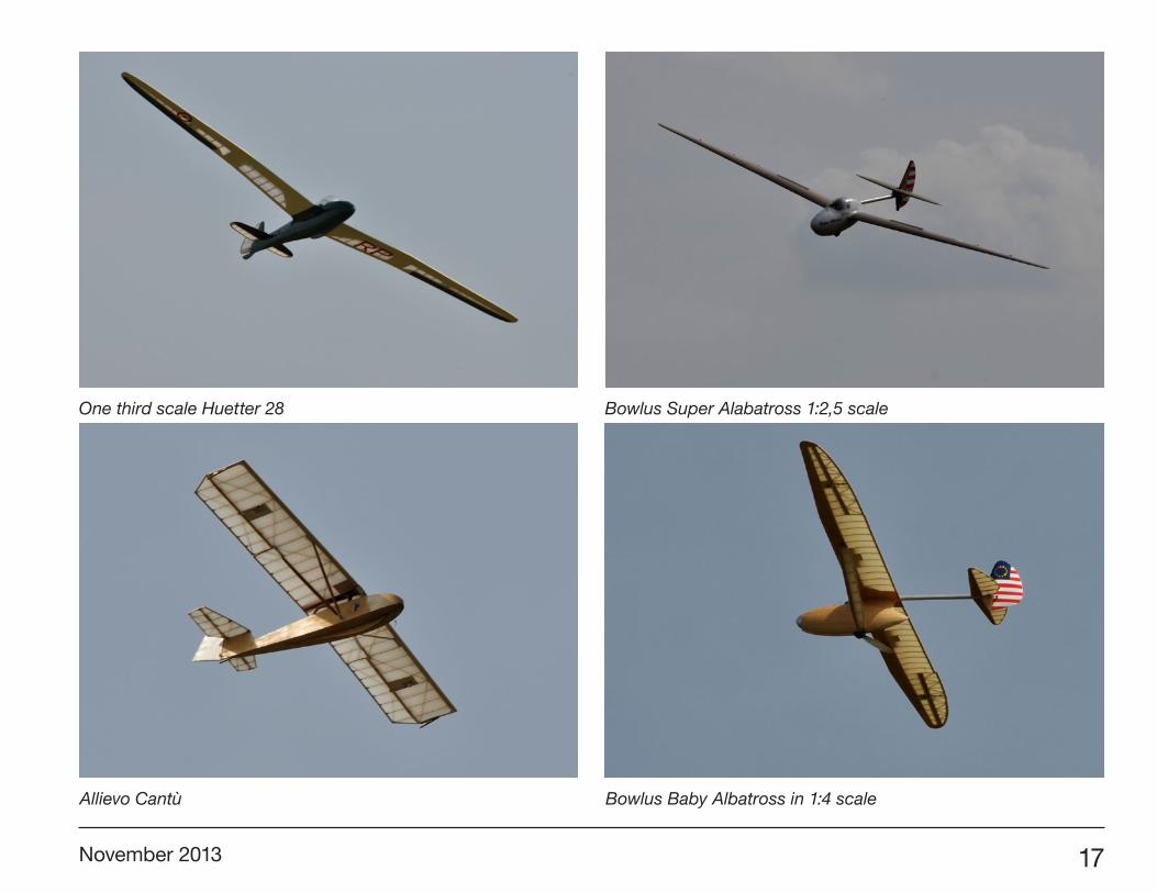
One third scale Huetter 28
Allievo Cantù
Bowlus Super Alabatross 1:2,5 scale
Bowlus Baby Albatross in 1:4 scale
18 R/C Soaring Digest
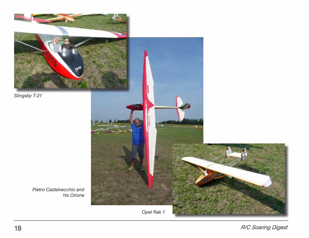
Slingsby T-21
Pietro Castelvecchio andhis Orione
Opel Rak 1
November 2013 19
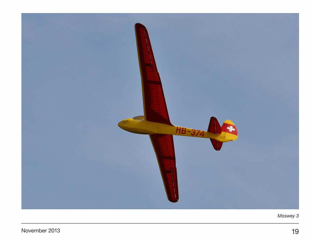
Moswey 3
20 R/C Soaring Digest
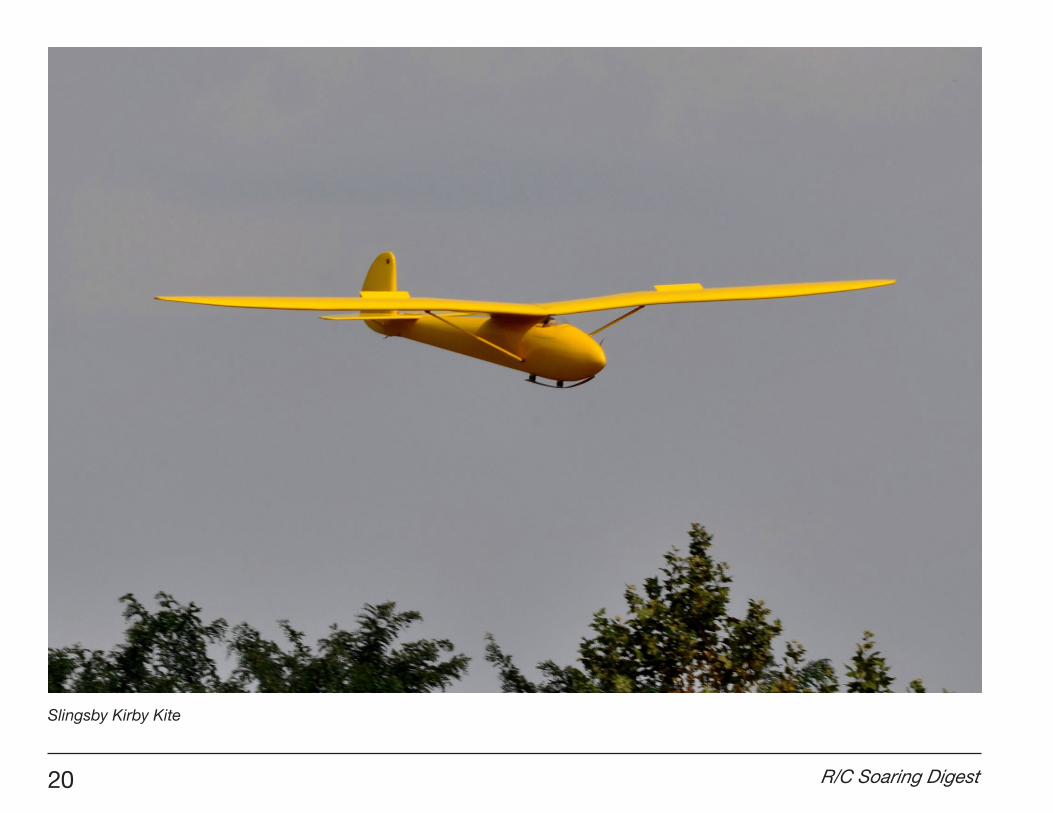
Slingsby Kirby Kite

November 2013 21
Participants 1 Quaglia Ettore (PC): Opel Rak 1, Komet 2 2 Debenedetti Carlo (SV): Ka 3, Lunak 3 Villa Alessandro (NO): Granau Baby 4 Giugni Pier Michele (BS): Scot Wikin 5 Bianconi Luca (BG): Bergfalke 6 Piensa Ezio (BS): Musger 19B 7 Simeoni Carlo (TN): Super Albatross, Kranich 2 8 Ruda Franco (VA): Musger MG 19 9 Tarter Renato (TN): SG 3810 Torchio Marco (CN): Bowlus Baby Albatross11 Corno Stefano (BG): Slingsby T-2112 Di Gennaro Guillermo (VI): ASK 13, Ka 813 Pellegrinelli Ovidio (BG): M10014 Restelli Alberto (BG): Komar15 Di Paolo Luca (GE): Fouga CM 8, Cherokee16 Crugnola Luigi (MI): Kirby Kite, Granau Baby, Minimoa17 Cobianchi Carlo (MI): Kranich 2, Hall Cherokee18 Ricci Mauro (GE): Ka 8B19 Pompele Nunzio (PV): Schweizer 2620 Rovida Roberto (CR): Hutter21 Prandelli Walter (BS): Ka 8B22 Mitterstainer Giorgio (GE): ASK 1823 Tenneriello Andrea (MI): Minimoa24 Mantovani Luca (TN): Harbinger, Reiher, Borea25 Panceri Carlo (MB): Arcore26 Sala Egidio (MB): Bocian27 Camellini Giuseppe (RE): Sperber Junior28 Zorzoli Carlo (PV): Allievo Cantù29 Duratti Cristian (MB): IS 4 Jastrzab30 Condotta Alessio (BZ): Fafnir31 Pattoni Giorgio (CR): Moswey 332 Pogliacomi Fabrizio (CR): Schweizer 2633 Castelvecchio Pietro (CR): Orione34 Ungari Simone (CR): Ka 8B35 Sacchi Massimiliano (MI): Jastrzab
Fouga CM-8
Schleicher Ka 8

22 R/C Soaring Digest
Tow plane pilots1 Zema Fabio (MI): Pilatus Porter (111cc)2 Fiorello Goletto (BG): Mega Patcwork (cc 180cc)3 Bertoli Wlady (VI) Kmelac - Wilga4 Simeoni Luca (TN): personal model (111cc)5 Mantovani Luca (TN): Bucher6 Pattoni Marco (CR): Piper PA18 (50cc)7 De Rosa Antonio (CR): Pilatus Porter (50cc)
Club member organization1 Pattoni Marco President2 Pogliacomi Fabrizio3 Castelvecchio Pietro4 Simone Ungari5 Matteo Inzani6 Angelo Severgnini7 Massimo Manzoni8 Pierantonio Jacchetti
9 Antonio De Rosa10 Ermanno Ungari11 Cristina Bodini12 Stefano Freri13 Oreste Ferrari
The Gheppio, mentioned in the
text
24 R/C Soaring Digest
The Danish F3J Championship 2013 was held in Langstrup Mose, Nivå, by Sjællands ModelSvæveflyve Klub (Sealand Model Gliding Club) <http://www.smsk-rc.dk>, using NFK’s beautiful field.
The competition spanned the days 21-22 of September and had 15 contenders divided into five groups of three persons each. The flight rules aligned rather closely to the FAI 2012 rules but there were exceptions e.g. the use of winches (150m to the turnaround).
It was the first time a Danish RC glider competition was granted an altitude of 1500 foot in a radius of 750m and we were in ’phone contact with Copenhagen Control under the whole competition. This lead to some delays as VFR general aviation aircraft occasionally intersected the 5km safety zone. All in all it ran smoothly.
Great teamwork was seen in all the groups.
The first day the weather was relatively nice and only few minor damages occurred.
The weather became far worse on the second day of the competition turning a Supra and two Ceres’ into “crunchies”
Damn! Niels’ beautiful Ceres Lift is severely “grounded”. The result of a powerful launch with absolutely no radio control. Somehow the thrower inadvertently had turned off the receiver switch by a fatal gesture seconds before release...
Title page: Five gliders at the sound of the launch tone. The red Pike Perfect is the first plane up the line. Nearest to the camera is a yellow-red Sharp Wind.
and gave rise to numerous broken lines. This years number two, Jesper, had three successive line breaks in the Fly-Off using all available winches - 100% fighter spirit.
Enjoy the various photos taken during the competition.

November 2013 25
The winner of this years danish F3J championship (and many previous...), Søren Krogh, launching a Freestyler. At his right Lars is ready to start the timer and be an observant spotter.
26 R/C Soaring Digest
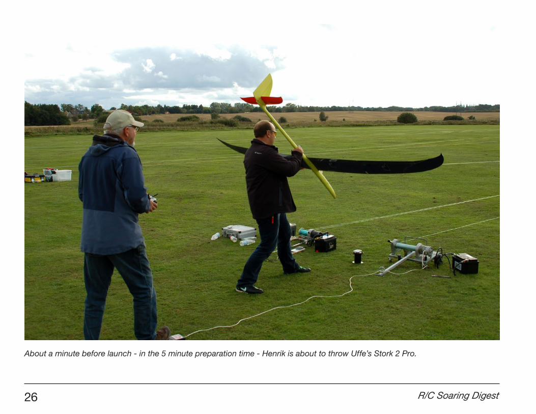
About a minute before launch - in the 5 minute preparation time - Henrik is about to throw Uffe’s Stork 2 Pro.
November 2013 27
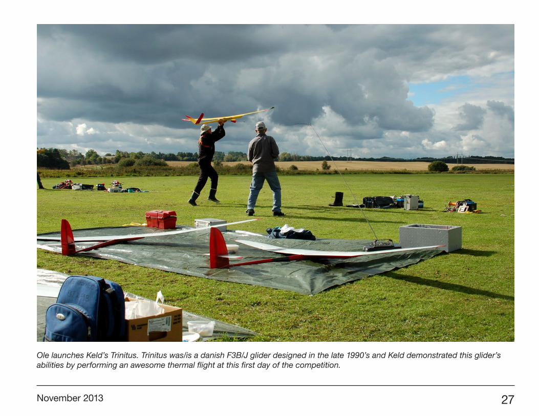
Ole launches Keld’s Trinitus. Trinitus was/is a danish F3B/J glider designed in the late 1990’s and Keld demonstrated this glider’s abilities by performing an awesome thermal flight at this first day of the competition.

28 R/C Soaring Digest
Lars’ beautiful Supra in low altitude fighting against the 10 minute timer in the windy (20 knots) and cloudy second day of the competition.
November 2013 29
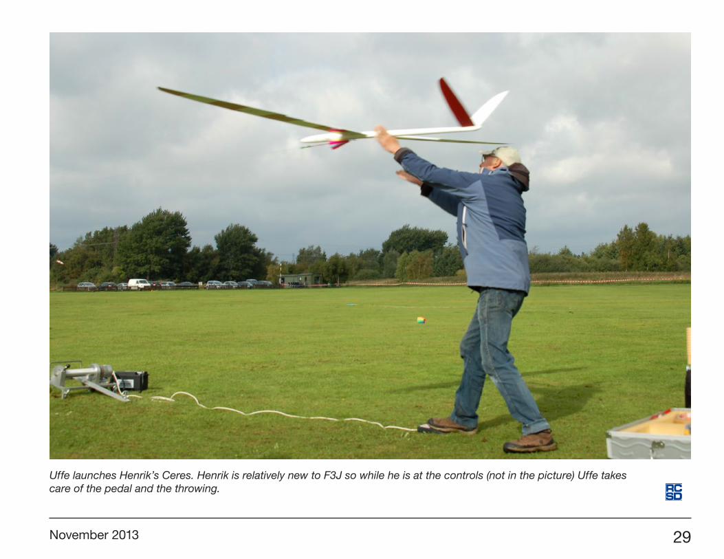
Uffe launches Henrik’s Ceres. Henrik is relatively new to F3J so while he is at the controls (not in the picture) Uffe takes care of the pedal and the throwing.

Many have been asking for more information on the Genoma2.
I would like to share with others what we have actually accomplished in our community in order for modellers to make our Genoma in an easy way. Thanks very much to those who have accessed the information thus far.
I provide you with two packages, one for standard construction and one for moulded construction.
I’m actually working on the second one. This will be a full CNC moulded plane. I will make it with a French University.
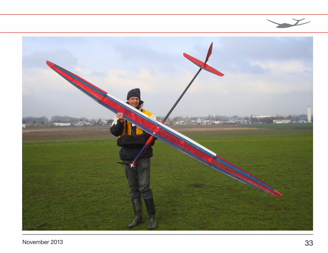
Several Genoma are now flying or on the way to flying. I know, and you also know, it takes quite a lot of time to build
it. But the work will provide you a lot of satisfaction.
I made comparison with other existing planes. The only one that can be compared to the Genoma is the Electra X. But I have to say that the Genoma2 has better circling capability. I made a competition against this plane (X and V version) and always succeeded in putting the plane the highest in the shortest period. And I’m not a very good pilot.
Thanks for allowing me to share with others our Genoma construction steps and final results (photos, comments, videos...). The Genoma is here and we are progressing with further improvements.
The last video I made of the Genoma is here: <http://f3news.big-forum.net/t7825p30-concours-le-29-9-dans-le-91-au-chouette-club>. It was made during our last competition in very light conditions. The flight at low altitude in the middle of the video is made with the Genoma2. The rest is the competition itself.
RCSD-2012-10: F5J AltitudeRCSD-2012-11: F5J Aircraft DesignRCSD-2012-12: Genoma2 Sections
URLs for individual plan sets are noted as appropriate. These ZIPped files open into a folder with relevant PDF, Excel, and/or TIFF files enclosed.
F5JGENOMA
MOULDED
Marc Pujol, [email protected]
The Genoma2 gets updated
30 R/C Soaring Digest

November 2013 31
Original Genoma drawings. <http://www.rcsoaringdigest.com/Pujol_Genoma/GenomaOriginal.zip>
32 R/C Soaring Digest
3x0,8mm Carbon
3mm Balsa
1,5 or 2mm Balsa covered with 60g/dm² carbon stribs
391,15
660
Carbon 93g/dm² or 60g/dm² Kevlar 45° Bias
9522
Design, Construction: Marc PujolPlan: Alexander Oertlin
Genoma2Stabilizer
4x 1mm Balsa + Carbon layer sandwich
5mm thick (4 times 1mm balsa + 3 times carbon ribs 3x 3mm Balsa, 2x 96g/dm² Carbon Sandwich
1160
Genoma2Wing
Design, Construction: Marc PujolPlan: Alexander Oertlin
260
15
10,24
110
50
5110
99
40
3537
2mm Balsa Covered with Carbon
3x0,8mm Carbon
3mm Balsa Carbon 93g/dm² or 60g/dm² Kevlar 45° Bias
Carbon 93g/dm² or 60g/dm² Kevlar 45° Bias
3mm Balsa
3mm Balsa
510
185
3015
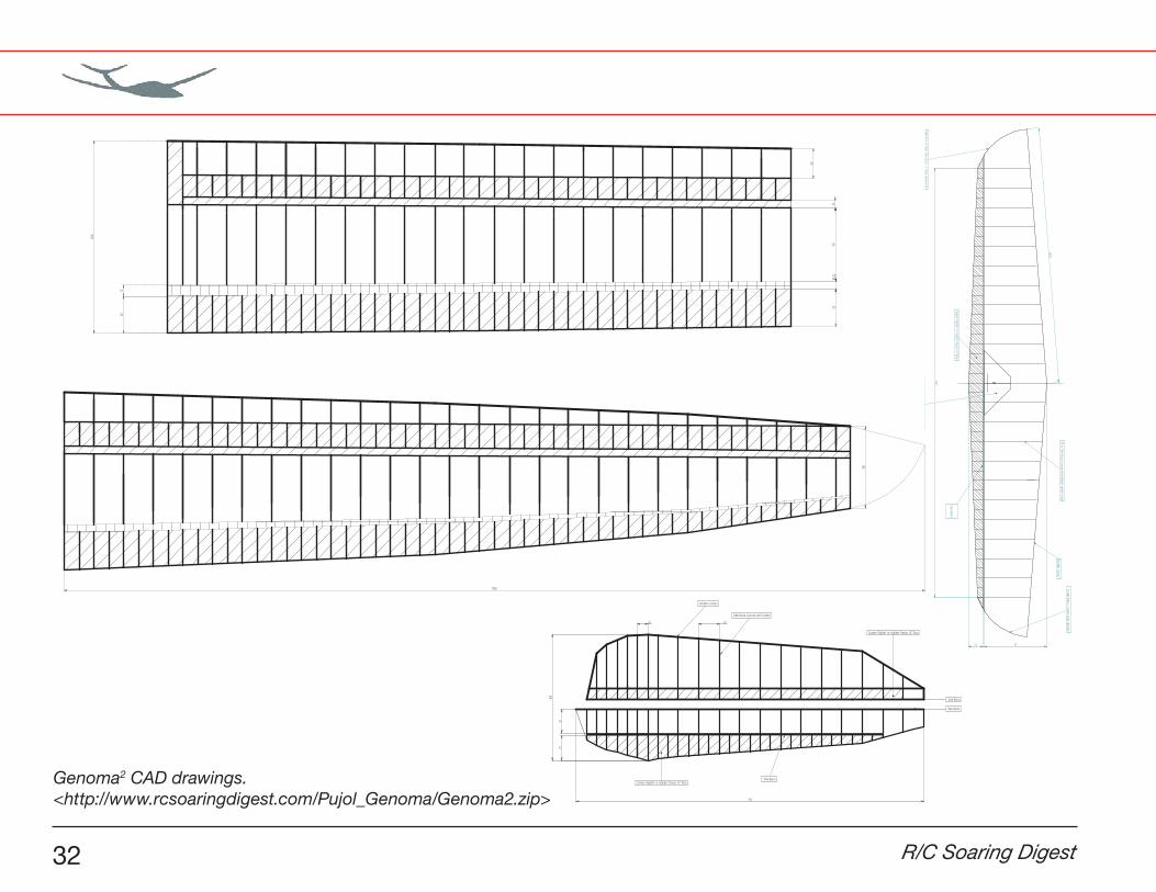
Genoma2 CAD drawings.<http://www.rcsoaringdigest.com/Pujol_Genoma/Genoma2.zip>
November 2013 33

34 R/C Soaring Digest
November 2013 35
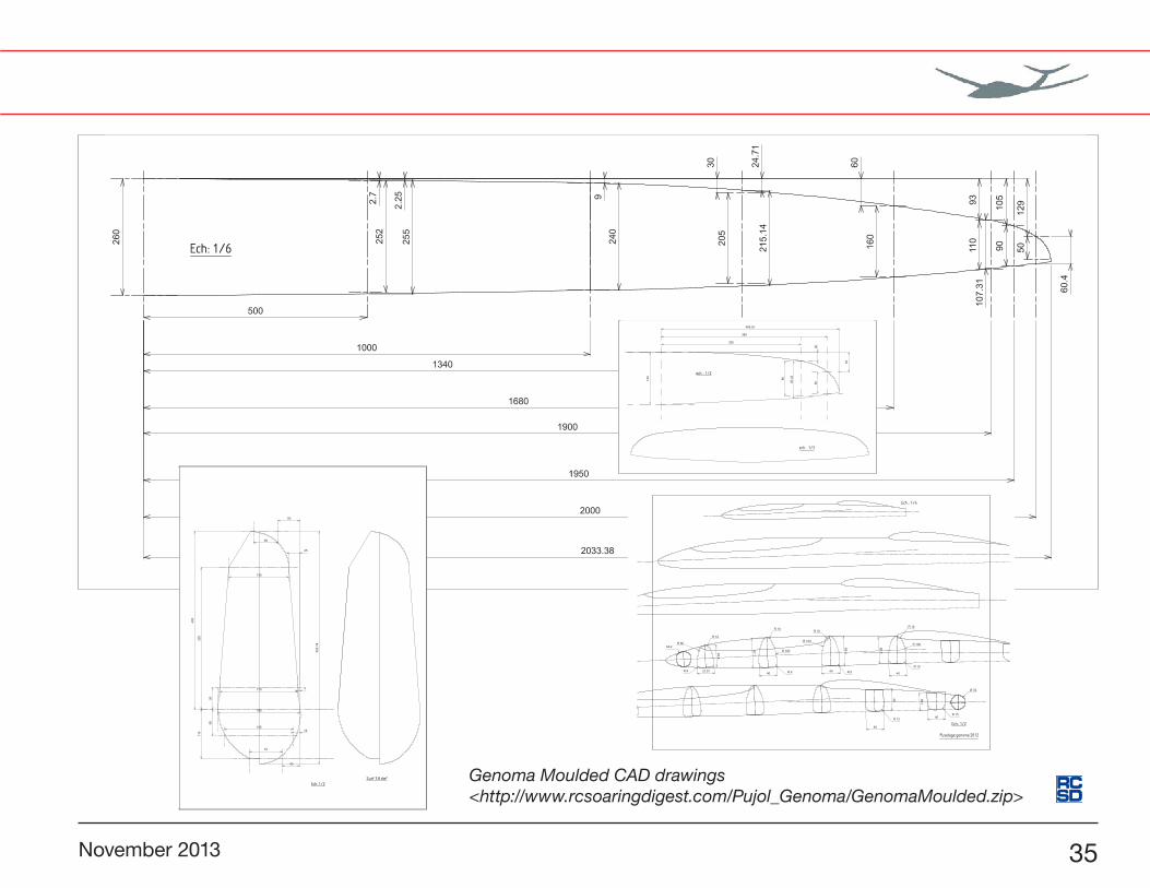
Genoma Moulded CAD drawings<http://www.rcsoaringdigest.com/Pujol_Genoma/GenomaMoulded.zip>
36 R/C Soaring Digest
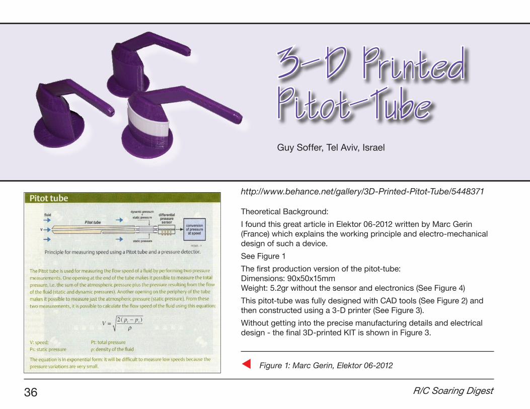
3-D Printed Pitot-Tube
Theoretical Background:
I found this great article in Elektor 06-2012 written by Marc Gerin (France) which explains the working principle and electro-mechanical design of such a device.
See Figure 1
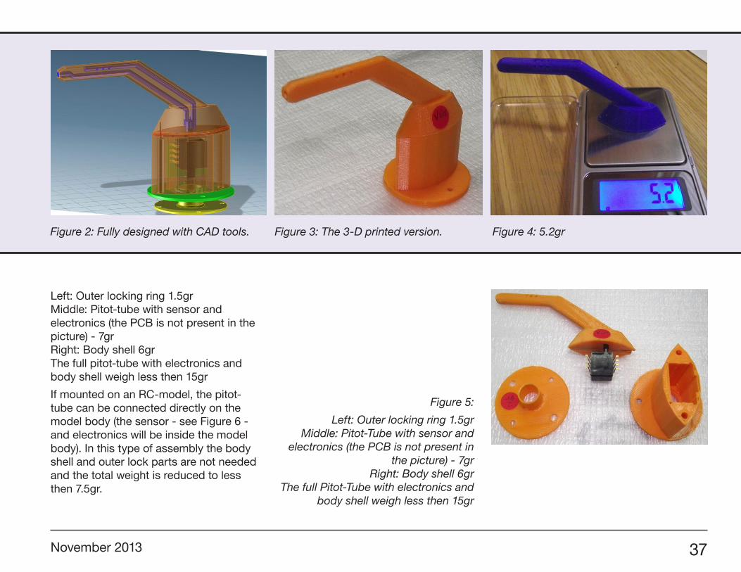
The first production version of the pitot-tube: Dimensions: 90x50x15mm Weight: 5.2gr without the sensor and electronics (See Figure 4)
This pitot-tube was fully designed with CAD tools (See Figure 2) and then constructed using a 3-D printer (See Figure 3).
Without getting into the precise manufacturing details and electrical design - the final 3D-printed KIT is shown in Figure 3.
Guy Soffer, Tel Aviv, Israel
Figure 1: Marc Gerin, Elektor 06-2012
http://www.behance.net/gallery/3D-Printed-Pitot-Tube/5448371
November 2013 37
Left: Outer locking ring 1.5gr Middle: Pitot-tube with sensor and electronics (the PCB is not present in the picture) - 7gr Right: Body shell 6gr The full pitot-tube with electronics and body shell weigh less then 15gr
If mounted on an RC-model, the pitot-tube can be connected directly on the model body (the sensor - see Figure 6 - and electronics will be inside the model body). In this type of assembly the body shell and outer lock parts are not needed and the total weight is reduced to less then 7.5gr.
Figure 2: Fully designed with CAD tools. Figure 3: The 3-D printed version. Figure 4: 5.2gr
Figure 5:
Left: Outer locking ring 1.5gr Middle: Pitot-Tube with sensor and
electronics (the PCB is not present in the picture) - 7gr
Right: Body shell 6gr The full Pitot-Tube with electronics and
body shell weigh less then 15gr
38 R/C Soaring Digest
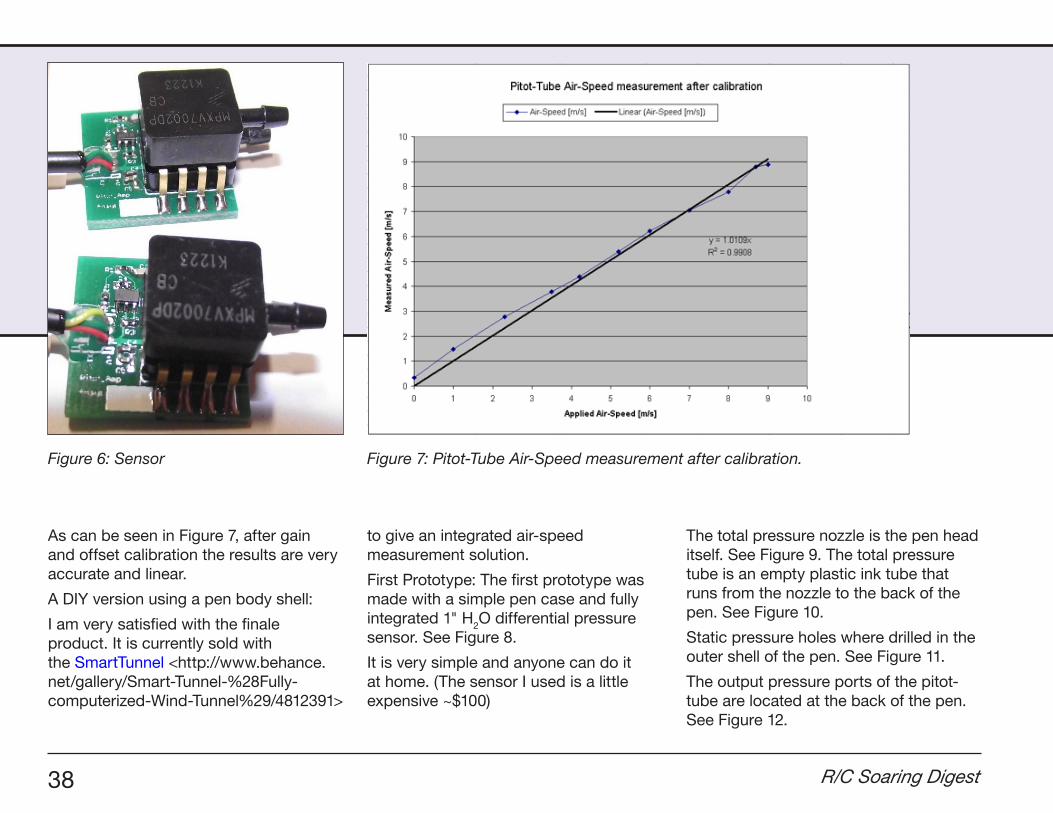
As can be seen in Figure 7, after gain and offset calibration the results are very accurate and linear.
A DIY version using a pen body shell:
I am very satisfied with the finale product. It is currently sold with the SmartTunnel <http://www.behance.net/gallery/Smart-Tunnel-%28Fully-computerized-Wind-Tunnel%29/4812391>
to give an integrated air-speed measurement solution.
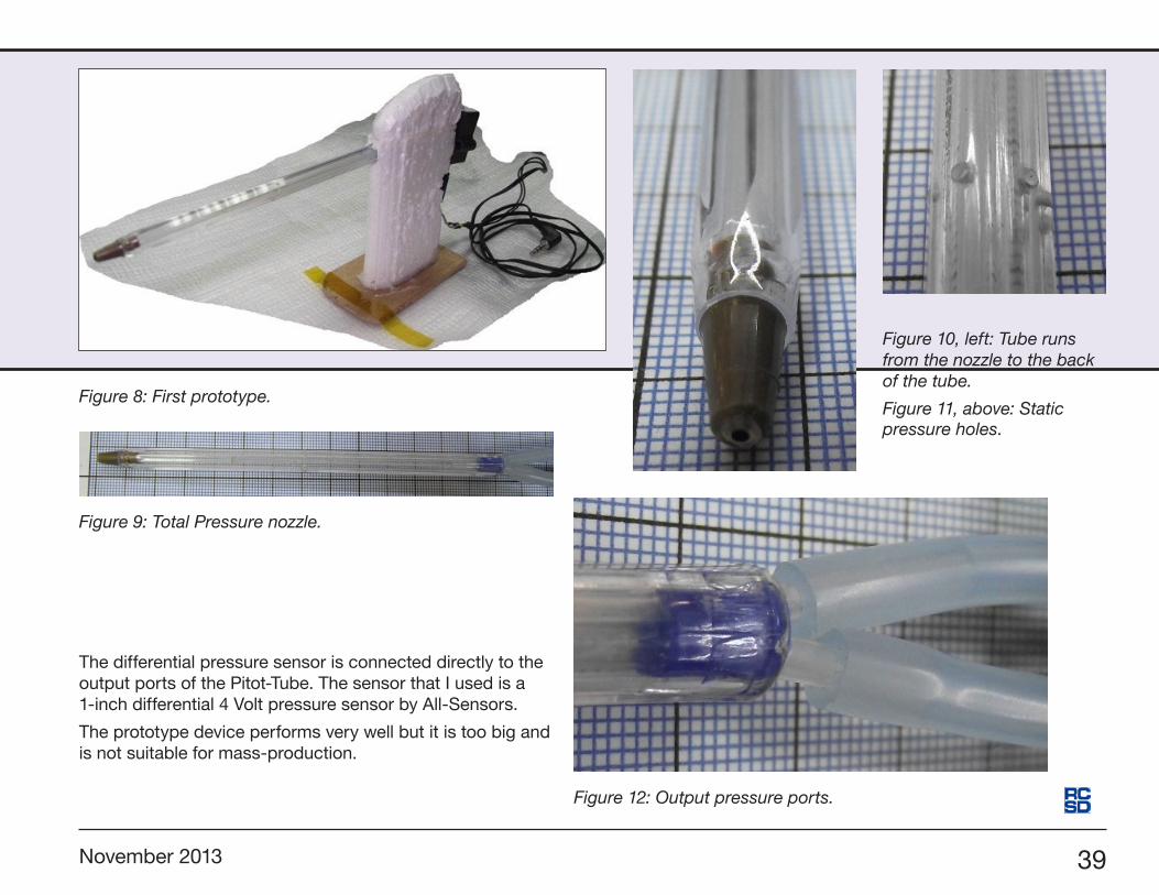
First Prototype: The first prototype was made with a simple pen case and fully integrated 1" H2O differential pressure sensor. See Figure 8.
It is very simple and anyone can do it at home. (The sensor I used is a little expensive ~$100)
The total pressure nozzle is the pen head itself. See Figure 9. The total pressure tube is an empty plastic ink tube that runs from the nozzle to the back of the pen. See Figure 10.
Static pressure holes where drilled in the outer shell of the pen. See Figure 11.
The output pressure ports of the pitot-tube are located at the back of the pen. See Figure 12.
Figure 6: Sensor Figure 7: Pitot-Tube Air-Speed measurement after calibration.
November 2013 39
The differential pressure sensor is connected directly to the output ports of the Pitot-Tube. The sensor that I used is a 1-inch differential 4 Volt pressure sensor by All-Sensors.
The prototype device performs very well but it is too big and is not suitable for mass-production.
Figure 8: First prototype.
Figure 9: Total Pressure nozzle.
Figure 10, left: Tube runsfrom the nozzle to the back of the tube.
Figure 11, above: Static pressure holes.
Figure 12: Output pressure ports.

40 R/C Soaring Digest
You’d think that as often as I fly and have flown, with the hundreds of contests I’ve flown and all I have gleaned from really great pilot friends over the years, that my landings would simply just stay grooved, but the crazy thing is that instead of holding on to the good parts of the landing technique, it was the bad parts that seemed to have crept in and took over!
In fact my style of crashing into the spot became a descriptor, “Gordy’s Sound-of-a-Screen Door Slamming Landing” - it got to the point where I suddenly couldn’t seem to hit within a meter of the spot no matter how much I practiced!
Frustrating and hard on my sailplanes to say the least, I found myself thinking about what it was that had gone wrong. I went to YouTube and studied Daryl Perkins landing practice videos and I watched him closely at this past Nationals.
Clearly there was no smashing into the spot. His model would circle around to the spot and by the time it got to the end of the tape was literally hovering to
Gordy’s Travels
Gordy Stahl, [email protected]
Tuning UpYourContest Landings
Ron Allen photo
November 2013 41
gently drop its nose on the nail… time after time.
I knew the key was in the approach, so I paid close attention to the timing of the three components of his landing pattern. But in spite of all my study I’d developed such bad habits that it just wasn’t sinking in during my practices or contests. I was doomed to the 60 point zone!
I’d attended Wil Lipscomb’s ESL club contest a few months back and watched Josh Glaab and DP both drop really nice landings - time after time, and at the MidSouth saw Chris Lee do the same approach for near perfect controlled
spots… and still I couldn’t seem to get a good pattern into my head and thumbs!
You can’t imagine how frustrated I was. I knew I had the skills, clearly more accrued stick time than most pilots, so it should be easy… ARGH!
I think the problem was the bad habits were so ingrained that I couldn’t see the forest for the trees. I’d always done the old “over your shoulder at 30, turn 180 at 20, pull the flaps to stop the plane then steer straight in to the spot.”
Now it may be that the new 4-meter ship giant flaps and lighter weights made that too hard to judge speed compared
to ships of my past, so I’d either end up with too little energy or too much.
I’d been visiting with our daughter in Lexington Kentucky and had been invited to come fly with the Bluegrass Soaring Society. It was a gorgeous calm day and only AJ and Dave were flying off the winch. I was determined to work on the new 20 second landing so before I launched I stood at the tape and envisioned the pattern and suddenly it clicked!
The pattern didn’t have the ‘hitch’ in its flow that the old system I’d grown up using. It was more of a round cornered triangle! It made sense, without the turn and stop I’d been using it was a lot easier to judge and recreate the pattern over and over.
The timing I’d observed was 20 over my head. The reason for “over your head” versus off to one side is pattern safety — often the sides can get congested. “Over your head” as a start to the approach provides a constant benchmark to the pattern (thanks JoJo!), going downwind slightly off on a diagonal, at 14 turn left (or right) so that at 12 seconds the final turn would have the model aligned with the runway (tape).
From my first attempt it worked!Sure, the seconds needed some adjusting, but clearly I could see the advantages of the pattern. Less time from the start over my head meant less chance for wind to vary
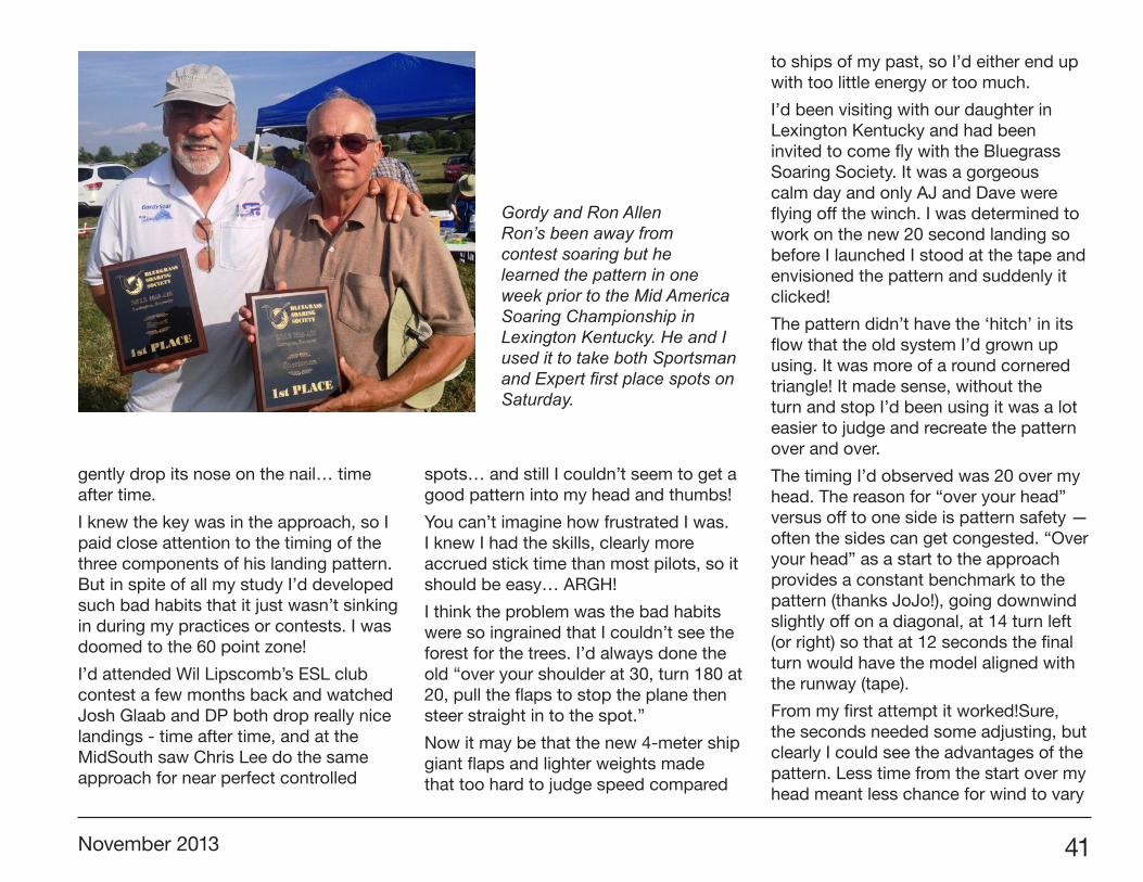
Gordy and Ron AllenRon’s been away from contest soaring but he learned the pattern in one week prior to the Mid America Soaring Championship in Lexington Kentucky. He and I used it to take both Sportsman and Expert first place spots on Saturday.

42 R/C Soaring Digest
the seconds and the flowing pattern kept the model in synch with the clock.
The next hitch in my approach was to hope that the flaps were going to stop my model, but what I found was that if the model got too slow with the flaps on, it would often become unstable and would drift off the spot, land short, or end up making sort of a hump versus a direct nose down to the spot, causing the model to over shoot by about a meter.
The system I’d seen the really good landers use was to apply the flaps hard and early, loose a lot of altitude far out, then pull them off to allow the model to fly smoothly toward the spot with good but controllable energy, energy the flaps could actually manage.
If after pulling the flaps the speed was a bit hot and the landing early, popping them fully down for a second then off would drop speed but not affect the glide path. I can tell you that was a challenge for me, since I’d previously been used to slamming them on and hoping for the best!
With each practice landing, those flaps suddenly were doing what I was hoping they’d do prior. It got to the point where I could see the model’s speed as it approached, and in a relaxed manner pump the flaps to “see” the speed I wanted by the time the model got over the tape. Then and only then would I drop the flaps fully to have the model’s nose drop ever closer to the spot with confidence!
Since that day I kiddingly tell my pals that I found my landings in Lexington, and since that day my confidence took me to the Overall Champion title at the BlueGrass Soaring Society’s Mid America Soaring Champs a few weeks back.
Left: Gordy’s landing pattern as sketched by Gordy.
November 2013 43
So to recap:
Your model passes over your head at 20 seconds, make your base turn at about 14 seconds (that’s a right or left that will put your model directly down the tape from you, but its not so much a turn as curving your model around), and at 12 seconds bring the model in line with the landing tape directly downwind of the spot. Use a lot of flap when you make the final to you, and lose a lot of altitude so that your model is about 20' or so high, pull your flaps off or to about a third on as it approaches, depending on head wind, etc. Oscillate the flaps full on and off to kill speed - its very effective but doesn’t severely change glide path much. Your model should be no more than about a meter high when it is over the end of the tape (lower especially if there is a tail wind to avoid any chance of a tip over from the wind push!), pull the flaps to full and watch it’s nose gently approach the spot.
Wait a second... While there ARE three legs to the landing approach, the most often neglected thing that sets the rest up is where to be BEFORE the first leg…that is where your model should be at 30 seconds!
Too often pilots don’t have a plan for this and as a result end up beginning the first leg, the down wind run, from different
spots. This sets up confusion and variance in the pattern.
I make sure that if I have maxed the time that I am fairly high (100') at a minute left and coming home. I want to be behind and around at 40 seconds, usually circling because I find that a circle usually takes about 10 seconds-ish. I’ll make those circles in time with the clock. I always ask my timer to give me every second beginning at 40 seconds.
The final circle ends up with the model passing over my head at 20 seconds with good speed and at an altitude of a tall tree, say 50' to 75', so that the model has enough distance to complete its landing circuit in time with the clock striking zero on landing. If there is some wind on the downwind, I’ll have my sailplane drag its feet some with 1/3 landing flap on its way down wind.
The KEY to consistent results is consistent components to the landing pattern!
A repetitive pattern produces repetitive
results. You want to make the pattern a muscle memory, so that it becomes “just something I always do.” Whether it’s during practice or fun flying, do your pattern... The key word here is “your.”
Okay let’s review the three legs of the pattern:
The downwind run of the rounded corner triangle pattern begins over your head at 20 seconds at approximately 50'/75'. Its path takes it slightly right (or left) and is losing altitude to approximately 30'.
At 14 seconds the model is guided around toward a line directly downwind of an imaginary line created by the landing tape. 1/3 landing flap can be deployed to slow the model some if needed.
At 12 seconds the flaps are deployed fully and more altitude is lost to approximately 15’.
Dissecting the third leg:
During this leg, the pilot has to keep his thumbs and mind relaxed.
The KEY to consistent results is consistent components to the
landing pattern!

44 R/C Soaring Digest
As the model approaches, say at about 8 seconds left, the flaps are completely pulled up, so that the model is clean and gliding. That will keep it coming straight and mostly unaffected by wind and micro thermals… and it will have enough energy to make it to the spot.
If the airspeed seems fast, you can fairly dramatically “brake” using full applications of the landing flaps for very brief applications. However, it is critical that the model approach with NO flaps deployed if you want to avoid being blown off line or landing short.
About 20' in front of the end of the landing tape, full flap is deployed if needed. If your elevator compensation is set up to keep the model level with full flap, it will slow down almost to a hover, allowing you to see both the nose of the model and its relationship to the spot, so that you can consistently push over, nose gently to spot... exactly on time!
For those reading this and saying the timing is wrong, the flap deployment is wrong, the pattern is wrong... you are RIGHT! But this is the kind of detail I had hoped to read about so that I could tune my own approach. Daryl’s videos showed us a pattern that was compact and one that produced results. My pattern shape isn’t his, but his got the light to come on for me to make one similar.
No more “Gordy’s Sound of a Screen Door Slamming” landings for me, and
with some practice hopefully no more for you!
Two more points from Jo Grini:
(1) Awareness of other planes is important!
Though most planes will be downwind during the last few seconds, it’s still important for you and your timer to scan “your” general pattern area for other sailplanes potentially intersecting your planned pattern. We need to get used to trusting that our models will continue their path so that as the pilot you are also looking at more than just your model.
(2) Don’t Crow too much!
Too many pilots have too much up aileron in Crow mode. While it does make your model lose altitude (loosing lift) it also causes the model to speed up (changing your ability to learn the model’s approach speed) and gives away important control authority. Just a few millimeters, typically only 3/4mm, speeds up the airfoil enough to give control and take away turbulent lift.
One key thing I have heard Daryl say, “Once you have set your flaps do not change them after 3 seconds to the spot.”
What I got from that is that the pattern should be set along its time and location path to end up perfectly; last second
reactions likely mean you have not managed the approach between 12 seconds and 3 seconds.
In no way do I mean that this pattern is DP’s or endorsed by DP. The goal of this article is to provide competition pilots with some detail to get their landings under control and improve landing energy and make scores more consistent.
Give it a try! Don’t worry so much about the details of seconds and flap actions. Do the pattern, keep the goal in mind, but DO pull the flaps off during those mid to final seconds on the approach and DO “try” oscillating the flaps as it approaches. Likely you too will find that your landings will become consistent and you will have a new confidence about the approach!
A note to guys flying non-competition sailplanes: This pattern works for you too! Any pattern that you use consistently will keep your sailplanes out of trees, legs, fences etc. Landing somewhere “on purpose” is a part of all aircraft piloting.
It’s silly that so many new and old pilots don’t bother with a pre-planned pattern... and again why so many nice sailplanes finish out their lives in treetops.
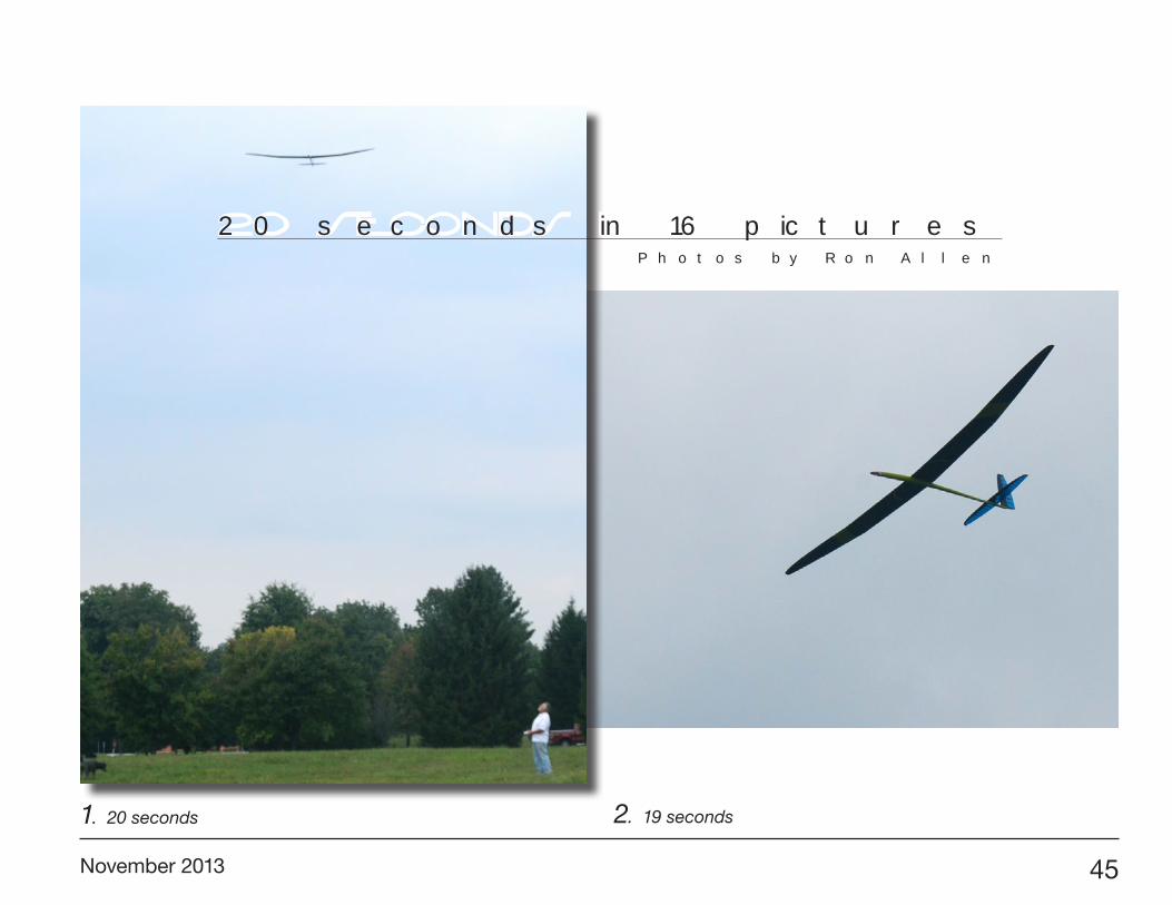
Ron Allen photographed several of Gordy’s twenty second landing approaches. An assembled 16 photo sequence is provided on pages 45-51.
November 2013 45
1. 20 seconds 2. 19 seconds
20 seconds in 16 picturesPhotos by Ron Allen

46 R/C Soaring Digest
5. 12 seconds
3. Turn at 14 seconds
4. Turn to final at 12 seconds
November 2013 47
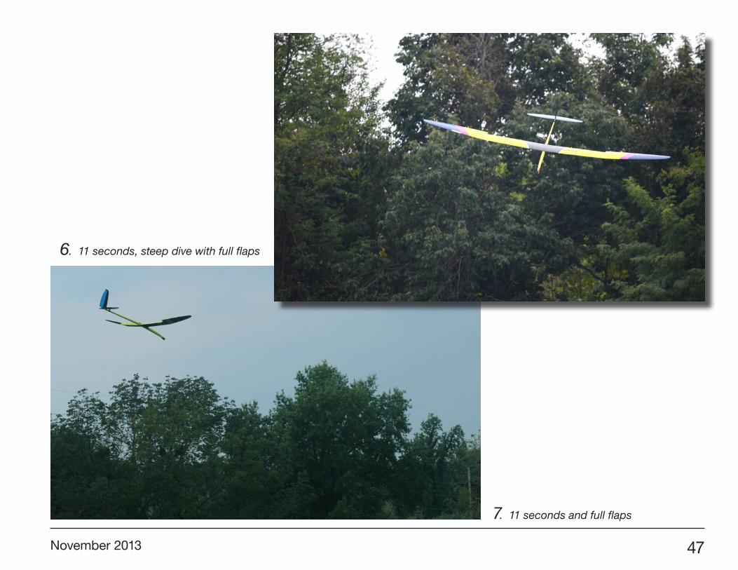
6. 11 seconds, steep dive with full flaps
7. 11 seconds and full flaps

48 R/C Soaring Digest
10. 6 seconds, too much speed
9. 9 seconds, flaps off
8. 10 seconds, flaps still on
November 2013 49
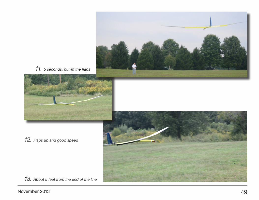
12. Flaps up and good speed
11. 5 seconds, pump the flaps
13. About 5 feet from the end of the line

50 R/C Soaring Digest
14. Push the nose over and... 15. the nose lightly drops
November 2013 51
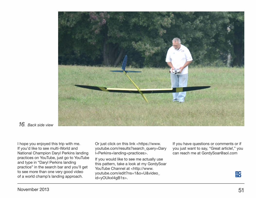
16. Back side view
I hope you enjoyed this trip with me. If you’d like to see multi-World and National Champion Daryl Perkins landing practices on YouTube, just go to YouTube and type in “Daryl Perkins landing practice” in the search bar and you’ll get to see more than one very good video of a world champ’s landing approach.
Or just click on this link <https://www.youtube.com/results?search_query=Daryl+Perkins+landing+practices>.
If you would like to see me actually use this pattern, take a look at my GordySoar YouTube Channel at <http://www.youtube.com/edit?ns=1&o=U&video_id=yOUkxI4gB1s>.
If you have questions or comments or if you just want to say, “Great article!,” you can reach me at [email protected]
