sodru pp0405 powersoftk10 e - soundmaster.ua™
TRANSCRIPT
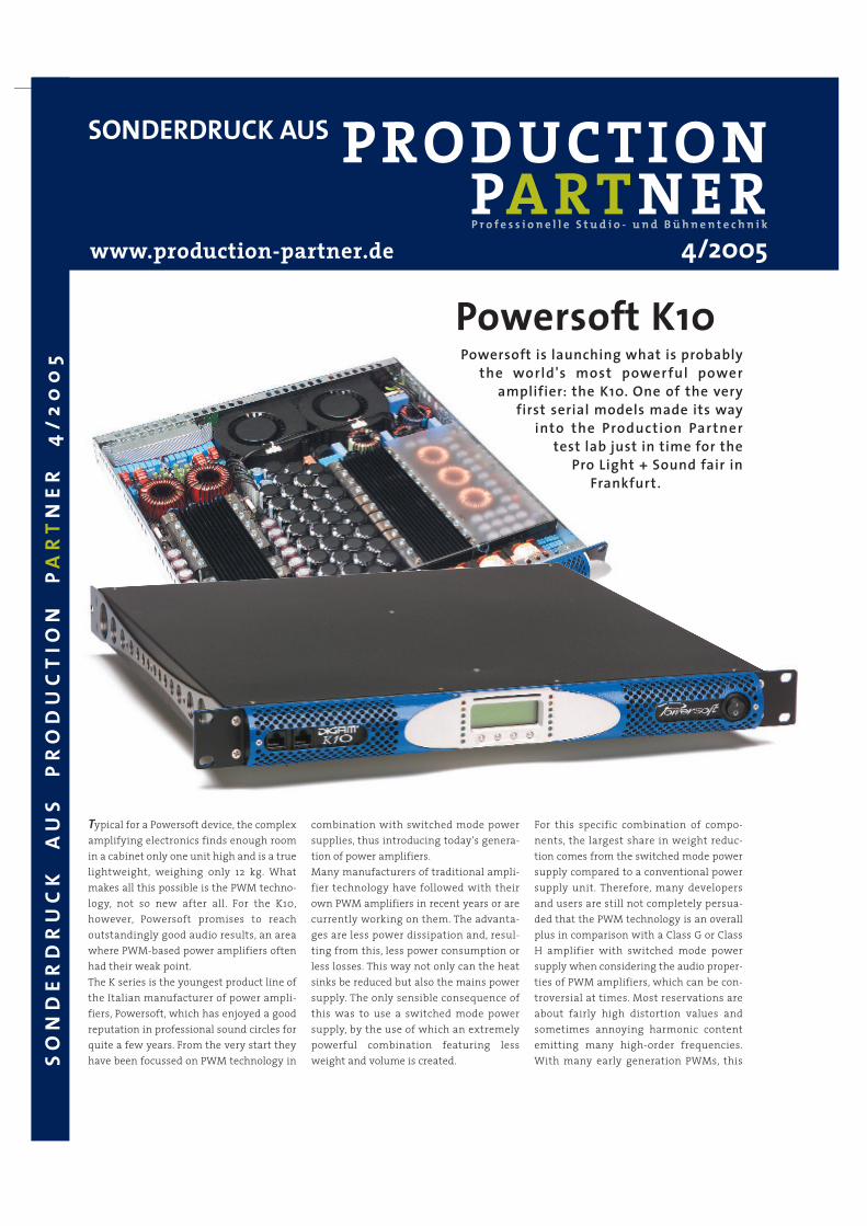
Powersoft K10Powersoft is launching what is probably
the world's most powerful poweramplifier: the K10. One of the very
first serial models made its wayinto the Production Partner
test lab just in time for thePro Light + Sound fair in
Frankfurt.
Typical for a Powersoft device, the complexamplifying electronics finds enough roomin a cabinet only one unit high and is a truelightweight, weighing only 12 kg. Whatmakes all this possible is the PWM techno-logy, not so new after all. For the K10,however, Powersoft promises to reachoutstandingly good audio results, an areawhere PWM-based power amplifiers oftenhad their weak point.The K series is the youngest product line ofthe Italian manufacturer of power ampli-fiers, Powersoft, which has enjoyed a goodreputation in professional sound circles forquite a few years. From the very start theyhave been focussed on PWM technology in
combination with switched mode powersupplies, thus introducing today's genera-tion of power amplifiers.Many manufacturers of traditional ampli-fier technology have followed with theirown PWM amplifiers in recent years or arecurrently working on them. The advanta-ges are less power dissipation and, resul-ting from this, less power consumption orless losses. This way not only can the heatsinks be reduced but also the mains powersupply. The only sensible consequence ofthis was to use a switched mode powersupply, by the use of which an extremelypowerful combination featuring lessweight and volume is created.
For this specific combination of compo-nents, the largest share in weight reduc-tion comes from the switched mode powersupply compared to a conventional powersupply unit. Therefore, many developersand users are still not completely persua-ded that the PWM technology is an overallplus in comparison with a Class G or ClassH amplifier with switched mode powersupply when considering the audio proper-ties of PWM amplifiers, which can be con-troversial at times. Most reservations areabout fairly high distortion values andsometimes annoying harmonic contentemitting many high-order frequencies.With many early generation PWMs, this
SONDERDRUCK AUS
SO
ND
ER
DR
UC
K
AU
S
PR
OD
UC
TIO
N
PA
RT
NE
R4
/20
05
www.production-partner.de 4/2005
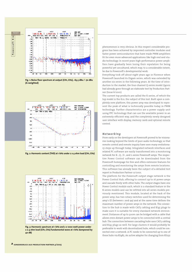
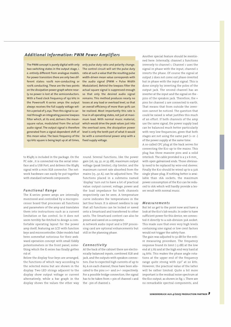
Fig. 1: Noise floor spectrum at output (CH1, CH2), -63.5 dBu / -70 dBu(A-weighted)
Fig. 2: Harmonic content (THD) at 1 kHz under 2 x 4 ohm load (CH1, CH2)
Fig. 3: Harmonic spectrum at 1 kHz and 2 x 1000 watt power under 2 x 4 ohm load (CH1, CH2) fundamental wave at 1 kHz dampened by40 dB)
Po
we
rso
ftK
10
T E ST
phenomenon is very obvious. In this respect considerable pro-gress has been achieved by improved controller modules andfaster power semiconductors that have made PWM amplifiersfit for even more advanced applications like high end and stu-dio technology. In recent years high-performance power ampli-fiers have gradually been losing their reputation for beingpowerful yet uncultured, which may, to a considerable extent,be due to Powersoft's developmental work.Everything took off about eight years ago in Florence whenPowersoft launched its Digam series, which was extended byanother six series in the following years. At the time of intro-duction to the market, the four-channel Q-series model Q4002had already gone through an elaborate test by Production Part-ner (Issue 6/2001).The current top products are called the K-series, of which thetop model is the K10, the subject of this test. Built upon a com-pletely new platform, this power amp was developed to repre-sent the peak of what is technically possible today in PWMtechnology. Further characteristics are a power supply unitusing PFC technology that can use the available power in anextremely efficient way, and the completely newly designeduser interface with display, memory cards and optional remotecontrol.
N e t w o r k i n gFrom early on the developers at Powersoft proved to be visiona-ries looking beyond the limits of pure audio technology, so thatremote control and remote inquiry have seen many evolutiona-ry steps up through today. Integrated network interfaces andrelated PC software are easily transformed into a monitoringnetwork for K-, Q-, D-, and L-series Powersoft amps. The respec-tive Power Control software can be downloaded from thePowersoft homepage for free and offers extensive features forcontrolling and monitoring the amps from remote locations.This software has already been the subject of a detailed testreport in Production Partner 12/2001.The platform for the Powersoft output stage network is thePower Control Hub, offering to connect up to 16 power ampsand cascade freely with other hubs. The output stages have onePower Control module each, which is a standard feature in theK-series models and can be refitted into all series models pre-viously mentioned. This module, located at the back of thepower amp, has two rotary switches used for determining theamp's ID (between 1 and 99) and at the same time defines themaximum number of power amps in the network. The connec-tion to the hub is made with CAT5 cabling and RJ45 plugs tomake sure it is suitable for every standard network environ-ment. Distances of up to 500m can be bridged with a cable thatallows even distant power amps to be connected with a centralhub. The connection between cascading hubs uses CAT5 cablingand RJ45 plugs as well. For large clusters it would probably bepreferable to work with decentralized hubs, which could be con-nected over a network. A PC needs to be connected up to one ofthese hubs via RS485. An active adapter for changing from RS232
2 sonderdruck aus production partner 4/2005
to RS485 is included in the package. On thePC side , it is connected via the serial inter-face and a USB Port, and delivers the RS485signal with a mini XLR connector. The net-work hardware can easily be put togetherwith standard network components.
F u n c t i o n a l R a n g eThe K-series power amps are internallymonitored and controlled by a micropro-cessor board that processes all functionsand parameters of the amp and translatesthem into instructions such as a currentlimitation or fan control. So it does notseem terribly far-fetched to design a com-fortable operating layout for the poweramp itself, featuring an LCD with functionkeys and microcontroller. Older models hadbeen somewhat notorious for their awk-ward operation concept with small fiddlypotentiometers in the front panel, some-thing which the K-series has finally gottenrid of.Below the display four keys are arranged,the functions of which vary according tothe selected menu but are shown in thedisplay. Two LED strings adjacent to thedisplay show output voltage or currentalternatively, while a bar graph in thedisplay shows the values the other way
round. Several functions, like the powergain (26, 29, 32, or 35 dB), maximum outputvoltage (peak limiter), clip limiter, and themaximum current rate absorbed from themains (15...32 A), can be adjusted here. Thefunctions placed in a submenu named'display' turn out to have a lot of practicalvalue: output current, voltage, power andthe load impedance for both channelsrespectively can be seen. A temperaturecurve indicates the temperatures in thelast four hours. It is almost needless to saythat all functions can be locked or savedonto a Smartcard and transferred to otherunits. The Smartcard content can also bepreset and saved on a computer.A network audio input and a DSP proces-sing card are optional enhancements butstill in the planning phase.
C o n n e c t i v i t yAt the back of the cabinet there are electro-nically balanced inputs, combined XLR andjack, and the outputs with speakon connec-tors. Due to expected high currents of up to65 A on each channel, these have been allo-cated to the pins 1+/- and 2+/- respectively.For a possible bridge connection, the signalhas to be taken from + pin of channel 1 andthe - pin of channel 2.
Another special feature should be mentio-ned here: Internally, channel 2 functionsinversely to channel 1. Channel 1 uses thesignal in phase with the input, channel 2inverts the phase. Of course the signal atoutput 2 does not come out phase-invertedbut in phase with the input signal. This isdone simply by inverting the poles of theoutput jack. The second channel has aninverter at the input and the signal on the -pins of the speakon jack. Therefore, the +pins for channel 2 are connected to earth.That means that from outside the inver-sion cannot be noticed. The question thatcould be raised is what justifies this muchof an effort. If both channels of the ampuse the same signal, the power supply loadcan be balanced much better particularlywith very low frequencies, given that bothstages are not using the same part (+ or -)of the power supply at the same time.A so-called CPC plug at the back serves forconnecting the K10 up to the mains. Thisplug has three massive pins and a solidinterlock. The cable provided is a 3 x 6 mm_with open galvanised ends. Those obvious-ly need to be replaced by wire-end sleeves.Finally the K10 should be wired up to a 32Asingle phase plug. If nothing better is avai-lable than 16A sockets, the maximumpower consumption of the K10 can be redu-ced to 16A which will hardly provide a les-ser result with normal music.
M e a s u r e m e n t sBut let us get to the point now and have alook at the K10's lab results. In order to havesufficient power for this device, we connec-ted it directly to a sub-division 32A socket.This made sure that even very high levelscontaining sine signal or low crest factorswould not trigger the safety fuse.The gain was adjusted to 32 dB for the enti-re measuring procedure. The frequencyresponse found its limit (-3 dB) at the lowend at 5 Hz and at the high end very hard at24 kHz. This makes the phase angle rota-tions at the upper end of the frequencyrange quite strong with 230° at 20 kHz.However, the practical value of the latterwill be rather limited. Quite a bit moreimportant is the residual noise spectrum atthe K10 output, as shown in fig. 1. There areno remarkable spectral components, and
The PWM concept is purely digital with onlytwo switching states in the output stage, i.e. entirely different from analogue models.For power transistors there are only two dif-ferent states: 100% non-conducting or100% conducting. These are the two pointson the dissipation power graph where near-ly no power is lost at the semiconductors.With a fixed clock frequency of 192 kHz inthe Powersoft K-series amps the outputalways receives the full supply voltage wit-hin a period of 5.21µs.Then this signal is car-ried through an integrating passive lowpassfilter which, at its end, delivers the mean-square value, modulated from the actualaudio signal. The output signal is thereforegenerated from a signal-dependent shift ofthis mean value. The basic frequency of the192 kHz square is being kept up at all times,
only pulse duty ratio and polarity change.The control circuit will set the pulse dutyratio at such a value that the resulting pulsewidth-driven mean value corresponds withthe audio signal (PWM = Pulse WidthModulation). Behind the lowpass filter theactual square signal is suppressed enoughso that only the desired audio signalremains. This method produces nearly nolosses at any load or overload level, so thatan overall efficiency of more than 90% canbe realized. Most importantly this rate istrue in all operating states, not just at maxi-mum load. With normal music material,which would drive the peak values just intothe overload zone, the dissipation powerlevel is only the tenth part of what it wouldbe with a conventional power amp with afixed supply voltage.
Additional Information: PWM Power Amplifiers
sonderdruck aus 4/2005 production partner 3

Fig. 4: Harmonic content (THD) versus frequency at 2x 1000 wattunder 2 x 4 ohm load (CH1, CH2)
Fig. 5: Intermodulation distortion DIM 100 (3.15 kHz and 15 kHz)under 2 x 4 ohm load (CH1, CH2)
Fig. 6: Power diagram for one channel with both channels drivensimultaneously and test signals of different crest factors from 3 to 18dB as well as peak power. The continuous rating measured was donewith 750 ms long sine bursts so that the mains current limiter hadnot been engaged on 4 ohm and 2 ohm loads. Otherwise, the outputpower measured with both channels would not be achievablewithout exceeding the mains current of 32 A.
the overall noise level is at -63.5dB (unweighted) and -70dBu(A-weighted) respectively. The big difference between theresults of linear and A-weighted measurements is caused bythe rising noise factor towards the high frequencies, which ishardly taken into account for the A measurement. In a secondbroadband measuring of residual noise spectrum, shown infig. 9, the context between rising noise factor and high fre-quencies becomes much more obvious. The remaining shareof the 192 kHz clock rate can be spotted easily as well as itreaches a level of -10 dBu.Relating the noise level for the frequency range up to 20 kHzto the extremely high output voltage turns out dynamicsfigures of 108.2 dB (linear weighted) and 114.5 db (A-weigh-ted). These values can be regarded as very good for a PWMpower amp and even bear comparison with conventionalamplifiers.The same is true for the THD values (fig. 2 and 10), sinking to aminimum of -90 dB and rising to -73 dB just short of the clip-ping limit. Being subject to the frequency at an output powerof 2 x 1 kW, the THD values up to 1 kHz are between -80 and -90 dB. For higher frequencies the THD curve shows the usualrise of 20 dB/decade. Another area, where there is hardly anynoticeable difference to the quality of analogue power amps.The only clear evidence of a PWM circuit among the distor-tion measurements is provided by the harmonic distortion(fig. 3). Here, an unusually large number of PWM-typical high-order distortion components can be found. From 4 kHzonwards, though, they no longer rise above the -90 dB line(0.003%).Generally, transient signals are considered to be particularlydifficult for PWM power amps. The K10, for an amplifier ofthis category, sets the standard by reaching DIM100 results of-70 dB and less (fig. 5). The progress made appears very clearwhen comparing it directly with Powersofts older modelsQ4002 and DIGAM 7000.
D a m p i n g Fa c t o rFor measuring the damping factor, the output voltage of theK10 was measured unloaded and with a load of 4 ohm alter-natively. The internal resistance of the amp is calculated bycomparing the voltage drop in loaded condition with themeasurement in unloaded condition. The frequency depen-dent relation of load resistance (4 ohm) to internal resistanceis called damping factor. How the output voltage in loadedcondition changes subject to the frequency in the case of theK10, is shown in fig. 7. By looking at the graph, it becomesimmediately obvious that the output voltage by no meansdecreases steadily, against all odds it rather goes up again ataround 10 kHz. The technical explanation for such behaviourwould be internal overcompensation which theoreticallyleads to a negative internal resistance from which the dam-ping factor can not be derived. This circuit helps to avoid thedamping factor dropping sharply through the output low-pass towards the higher frequencies.
sonderdruck aus 4/2005 production partner 4

5 sonderdruck aus production partner 4/2005
Fig. 7: Measuring of level change under a 2 x 4 ohm load in relationwith measuring in unloaded condition. The damping factor can becalculated from the level drop under load. Above from 7 kHz, the K10shows the effect of increasing output voltage under load, which the-oretically leads to a negative internal resistance and, as a conse-quence, to a infinite damping factor. This is caused by internal over-compensation.
Fig. 8: Limiter function of K10 with very short attack time and ca.30 ms release time
Fig. 9: Noise floor spectrum at output of K10 measured with exten-ded bandwidth up to 300 kHz. At 192 kHz the residual of the clocksignal can be seen.
Fig. 10: Harmonic distortion at 1 kHz (red) subject to input signalstrength at 32 dB gain, and the rated power under 4 ohm load (blue).For a continuous sine signal the maximum output power will be limi-ted to ca. 2.5 kW per channel.
Pe a k L i m i t e rOne of the K10-specific special functions isthe peak limiter for the output voltage. Asthe power amp is capable of giving off veryhigh output voltages of up to 135 Veff(equal to 191 Volts peak, this might proveto be a little too much even for large spe-akers and could lead to mechanicaldamage, including the voice coil rippingoff or beating at the membrane or themembrane tearing. The peak limiter canbe adjusted for each channel individuallywithin a threshold of between 40 and 200Volts peak. The attack time constant is setextremely short with a release time of ca.30 ms. The limiter's reaction to a sine burstof 100 ms length is shown in fig. 8. Thepeak limit for the measuring process wasset to 50 Volts peak.
Pe r fo r m a n c e a n d S a fe t yP r e c a u t i o n sFig. 6 shows the power diagram for the K10,indicating extremely impressive numbersof close to 8000 watts per channel. Whilewith loads of 4, 8, or 16 ohm there are nosignificant differences between music
power and rated power, the K10 can mobili-ze a lot of extra power when loaded with 2x 2 ohm and signals with crest factors of 6,12, and 18 db. Given the fact that a crest fac-tor of 12 db in the signal comes close to theaverage load in a regular usage setting, theK 10 offers 2 x 7.5 Kilowatts. This is serious

sonderdruck aus 4/2005 production partner 6
performance which takes a pair of sturdy18" subwoofers per channel to be dealtwith. And driving large subwoofers withmodern, heavy-duty chassis will probablybe the primary application of the K10 inpractice. It should, however, be kept inmind that for all their ability to take peak
power levels from theamps, these subs are still indanger of suffering fromthermal overloads. Here,400 Watt RMS is in mostcases the absolute long-term minimum. In caseof malfunctions, such ascontinuous low fre-quency turntable feed-back (happens quiteoften), the chassis willinevitably die fromoverheating. This is
not a problem ofthe nature of theK10, but everyoneshould be aware ofit when connec-
ting subwoofers to apower amp of this power class. An additio-nal RMS limiter with a very long time con-stant (50 - 100 s) for the signal path, adju-sted to the thermal capacity of the spea-kers, is the proper relief measure and savesthe life of the subwoofer's chassis. Duringnormal operation a RMS limiter with thatlong a time constant would not even beactivated, so no one would have to worryabout slowing down the overall perfor-mance of the sound system.
S u m m a r yThe K10 is the top model of renowned Itali-an manufacturer Powersoft's new K-series.This PWM power amplifier with switchedmode power supply and PFC was complete-ly newly designed and fitted with plenty ofadditional features.The K10 comes withintegrated remote control and remotemonitoring,new user interface with LCD,as well as the option of saving and pro-gramming via Smartcard, all of which arestandard features.With one look at the measurements of theK10 it is obvious that Powersoft's goal ofof significantly improving the audio perfor-mance has been achieved well and truly.Only a few details give an indication thatall this is about a PWM power amplifier,the technical data of which is reaching theperformances of a really good analogue powerpower amp. Considering the power of up to2 x 7.5 kw into a 2 ohm load and relating it
to the weight of 12 kg and height of 1 unit,itis not too far-fetched to say that the K10 mi-ght well be a record-breaking device in manyrespects. And if you are preparing to read asimilarly record-breaking figure on the pri-ce tag, you can stop worrying now - 5,790Euro is a very digestible offer.
◊ Text and Technical Data:Anselm Goertz
Photos: Dieter Stork
The power supply unit guarantees fulloutput power for line voltages of bet-ween 95 and 265 volts and a power fac-tor cosϕ of 0.95 at an absorbed powerrate of more than 200 VA. Thus thepower amp will probably function eve-rywhere in the world reliably andwithout switchover. The power factor,being close to 1, uses the available powerto the full and avoids having to deal withunwanted idle current. The sheer num-ber of the power factor expresses therelation of the ohmic part of a load tothe total impedance which may containsome inductive or capacitive load. Thelatter cause the so-called idle currents inthe power network which put load onpower lines and contacts and lead to vol-tage drops, but don't deliver any activepower for the user. A value of 0.95 bringsthe DIGAMs very close to the ideal scoreof 1.0.
Additional Information: PFC
Power Rated 12 dB Crest Peak4 Ω/2 ChW pro Ch 3.578 4.050 4.278-----------------------------------------------------------Noise dBu dBu(A)
–63,7 –70,0Dynamics dB dB(A)
108,2 114,5f[Hz] 20 1 k 20 kGain dB 31,9 32,1 31,3Phase ° +17,7 –9,6 –230HP-Filter 5 HzTP-Filter 24 kHz-----------------------------------------------------------f[Hz] 100 1 k 10 kCTC dB –67,7 –63,5 –58,7CMRR dB –73,7 –72,5 –73,2DF rel. 4 Ω 216 123 –-----------------------------------------------------------THD(f) @ 50 % Power –81 –78 –56
Min. before ClipTHD 1 kHz –90 dB –73 dBDIM100 –75 dB –55 dBSMPTE 60/7k –75 dB –46 dBDFD IEC268 –105 dB –80 dB-----------------------------------------------------------Power/Weight 675 Watt/kgPrice/Power 0,71 €/WattWeight kg 12,0Height Unit 1Price ca. 5.790 €
Remote Power Control
Overview
All power specifications measured under 2-channel load, Power/Weight and Price/Powerat 4 ohm for both channels added up with 12dB crest factor. Dynamics referenced to 4 ohmmusic power and noise level, CTC (stereo cros-stalk) at 10 watt, CMRR Common Mode Rejec-tion Ratio, Attenuation Factor ref. to 4 Ω.