soft-switching converters with constant switching...
TRANSCRIPT

ECEN5817, ECEE Department, University of Colorado at Boulder
Constant-Frequency Soft-Switching Converters
• Introduction and a brief survey
• Active-clamp (auxiliary-switch) soft-switching converters,
• Active-clamp forward converter
• Textbook 20.4.2 and on-line notes
• The zero-voltage transition full-bridge converter
• Textbook Section 20.4.1 and on-line notes
• DC Transformer
ECEN 58171
Soft-switching converters with constant switching frequency
• With two or more active switches, we can obtain zero-voltage switching in converters operating at constant switching frequency
• The second switch may be one that is already in the PWM parent converter (synchronous rectifier or part of a half or full bridge) In other cases the second(synchronous rectifier, or part of a half or full bridge). In other cases, the second switch is a (hopefully small) additional “auxiliary” switch
Examples:
• Two-switch quasi-square wave (with synchronous rectifier)
• Two-switch multiresonant (with synchronous rectifier)
• Active-clamp switch (forward, flyback, other converters)
ECEN 58172
• Phase-shifted bridge with zero voltage transitions
• These converters can exhibit stresses and characteristics that approach those of the parent hard-switched PWM converters, but with zero-voltage switching over a range of operating points

ECEN5817, ECEE Department, University of Colorado at Boulder
Two-switch ZVS-QSW converters: already studied
• Q2 can be viewed as a synchronous rectifier
Original one-switch version
synchronous rectifier
• Additional degree of control is possible: let Q2 conduct longer than D2 would otherwise conduct
• Constant switching frequency control is possible, with behavior
Add synchronous rectifier
ECEN 58173
similar to conventional PWM
• Can obtain µ < 0.5
The multiresonant switch
Basic single-transistor version
ECEN 58174
2-switch (synchronous rectifier) version

ECEN5817, ECEE Department, University of Colorado at Boulder
Multiresonant switch characteristicsSingle transistor version
ECEN 58175
Analysis via state plane in supplementary course notes
Multiresonant switch characteristicsTwo-transistor version with constant frequency
ECEN 58176
Favorable characteristics and wide ZVS range in constant-frequency operationVoltage and current stresses are 2-3 higher than in the PWM parent

ECEN5817, ECEE Department, University of Colorado at Boulder
ZVS active clamp circuitsThe auxiliary switch approach
Forward converter implementation Flyback converter implementation
• Active-clamp circuit can be added to any single switch in a PWM converter
ECEN 58177
Active clamp circuit can be added to any single switch in a PWM converter
• Main switch plus auxiliary switch behave as an (unloaded) ZVS-QSW converter resulting in zero-voltage transitions
• Improved transformer reset, improved transistor utilization
• Beware of various patents (e.g. Vinciarelli (1982) for use in forward converter)
Zero-voltage transition convertersThe phase-shifted full bridge converter
Buck-derived full-bridge converter
Zero-voltage switching of each half-
A popular converter for server front-end power systems
ECEN 58178
Zero-voltage switching of each half-bridge section
Each half-bridge produces a square wave voltage. Phase-shifted control of converter output
Efficiencies of 90% to 95% regularly attained
Controller chips available
ECEN5817, ECEE Department, University of Colorado at Boulder
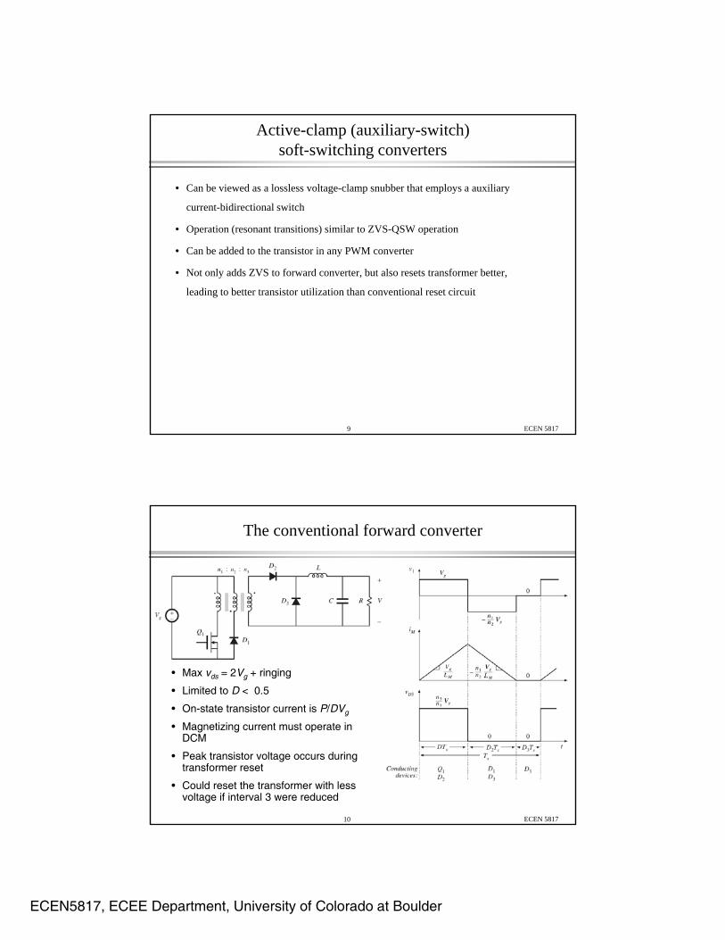
Active-clamp (auxiliary-switch) soft-switching converters
• Can be viewed as a lossless voltage-clamp snubber that employs a auxiliary
current-bidirectional switch
• Operation (resonant transitions) similar to ZVS-QSW operation
• Can be added to the transistor in any PWM converter
• Not only adds ZVS to forward converter, but also resets transformer better,
leading to better transistor utilization than conventional reset circuit
ECEN 58179
The conventional forward converter
• Max vds = 2Vg + ringing
• Limited to D < 0.5
• On-state transistor current is P/DVg
ECEN 581710
• Magnetizing current must operate in DCM
• Peak transistor voltage occurs during transformer reset
• Could reset the transformer with less voltage if interval 3 were reduced

ECEN5817, ECEE Department, University of Colorado at Boulder
The active-clamp forward converter
• Better transistor/transformer utilization
• ZVS
• Not limited to D < 0.5
Transistors are driven in usual half-bridge manner, similar to 2-switch ZVS-QSW:
ECEN 581711
Approximate analysis:ignore resonant transitions, dead times, and resonant elements
ECEN 581712

ECEN5817, ECEE Department, University of Colorado at Boulder
Charge balance
ECEN 581713
Vb can be viewed as a flyback converter output. By use of a current-bidirectional switch, there is no DCM, and LM operates in CCM
Similar to an unloaded two-switch ZVS-QSW converter
Peak transistor voltage
• Max vds = Vg + Vb = Vg /D’
which is less than the conventional value of 2 V when D > 0 5which is less than the conventional value of 2 Vg when D > 0.5
• This can be used to considerable advantage: improved transistor
and transformer utilization
• Design example:270 V ≤ Vg ≤ 350 Vmax Pload = P = 200 W
ECEN 581714
Compare designs using conventional 1:1 reset winding and using active clamp circuit

ECEN5817, ECEE Department, University of Colorado at Boulder
Conventional case
Peak vds = 2Vg + ringing= 700 V + ringing 700 V + ringing
Let’s let max D = 0.5 (at Vg = 270 V), which is optimistic
Then min D (at Vg = 350 V) is(0.5)(270)/(350) = 0.3857
The on-state transistor current neglecting ripple is given by
ECEN 581715
The on state transistor current, neglecting ripple, is given by ig = DnI = Did-on
with P = 200 W = Vg ig = DVg id-on
So id-on = P/DVg = (200W) / (0.5)(270 V) = 1.5 A
Active clamp case:scenario #1
Suppose we choose the same turns ratio as in the conventional design. Then the converter operates with the same range of duty cycles, and the on-state transistor current is the same. But the transistor voltage is equal to Vg / D’, and is reduced:
At Vg = 270 V: D = 0.5 peak vds = 540 V
At Vg = 350 V: D = 0.3857 peak vds = 570 V
which is considerably less than 700 V
ECEN 581716
ECEN5817, ECEE Department, University of Colorado at Boulder
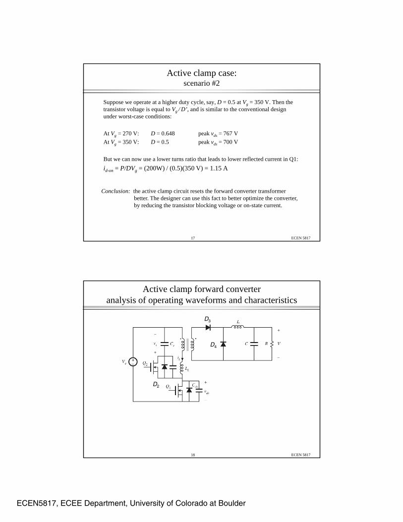
Active clamp case:scenario #2
Suppose we operate at a higher duty cycle, say, D = 0.5 at Vg = 350 V. Then the transistor voltage is equal to Vg / D’, and is similar to the conventional design under worst-case conditions:
At Vg = 270 V: D = 0.648 peak vds = 767 V
At Vg = 350 V: D = 0.5 peak vds = 700 V
But we can now use a lower turns ratio that leads to lower reflected current in Q1:
id-on = P/DVg = (200W) / (0.5)(350 V) = 1.15 A
ECEN 581717
Conclusion: the active clamp circuit resets the forward converter transformer better. The designer can use this fact to better optimize the converter, by reducing the transistor blocking voltage or on-state current.
Active clamp forward converteranalysis of operating waveforms and characteristics
D3
D4
D2
ECEN 581718

ECEN5817, ECEE Department, University of Colorado at Boulder
Waveforms(including Ll)
D3
D4
D2
ECEN 581719
Discussion
ECEN 581720

ECEN5817, ECEE Department, University of Colorado at Boulder
Details: different modes
• Interval 3 can end either when D3 becomes reverse-biased when il reaches
zero or by D2 becoming forward biased when v reaches V +Vzero, or by D2 becoming forward-biased when vds reaches Vg+Vb
• In either case, both end by the end of interval 4
• Similar discussion (in reverse) applies to intervals 7 and 8
ECEN 581721
Simplified waveforms(neglecting Ll)
ECEN 581722
D3
D4
D2 • Secondary-side D3/D4 switching is ideal instantaneous• Primary side ZVS predicted well (pessimistic ZVS boundary)

ECEN5817, ECEE Department, University of Colorado at Boulder
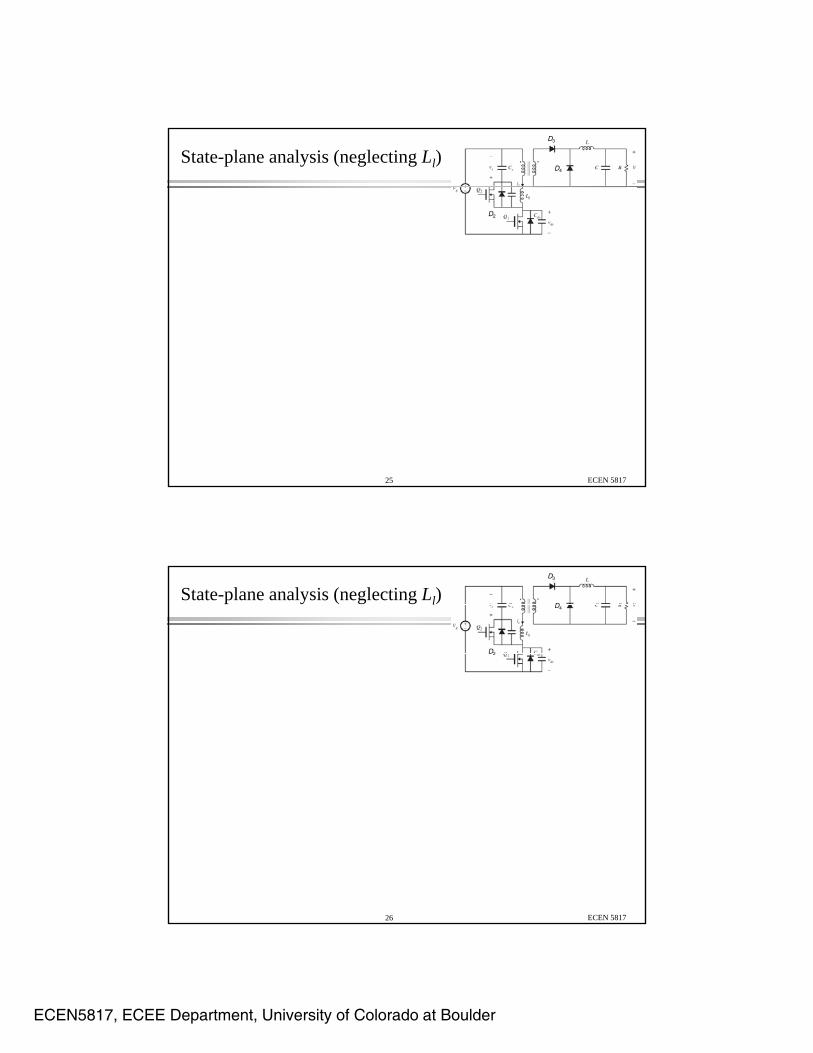
State-plane analysis (neglecting Ll)D3
D4
D2
ECEN 581723
State-plane analysis (neglecting Ll)D3
D4
D2
ECEN 581724
ECEN5817, ECEE Department, University of Colorado at Boulder
State-plane analysis (neglecting Ll)D3
D4
D2
ECEN 581725
State-plane analysis (neglecting Ll)D3
D4
D2
ECEN 581726
ECEN5817, ECEE Department, University of Colorado at Boulder
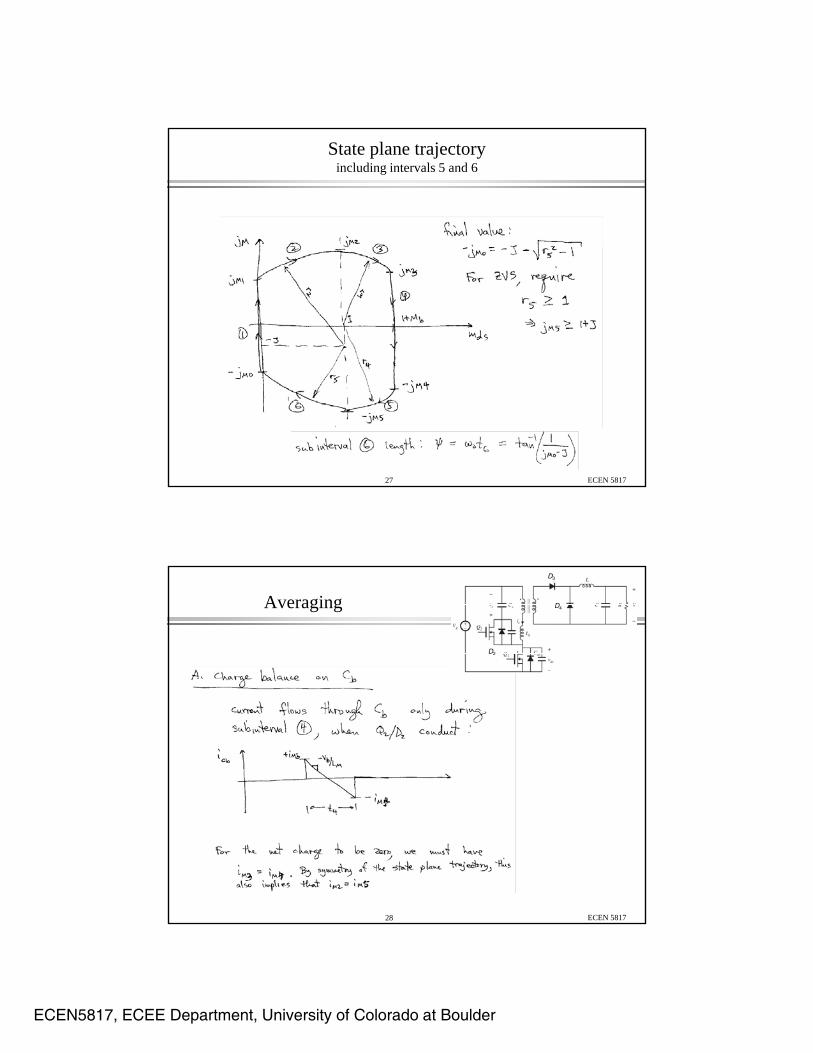
State plane trajectoryincluding intervals 5 and 6
ECEN 581727
Averaging
D3
D4
D2
ECEN 581728

ECEN5817, ECEE Department, University of Colorado at Boulder
Averaging
D3
D4
D2
ECEN 581729
Averaging
D3
D4
D2
ECEN 581730

ECEN5817, ECEE Department, University of Colorado at Boulder
Averageoutput voltage
ECEN 581731
The system of equationsthat describes this converter
page 1
ECEN 581732
ECEN5817, ECEE Department, University of Colorado at Boulder
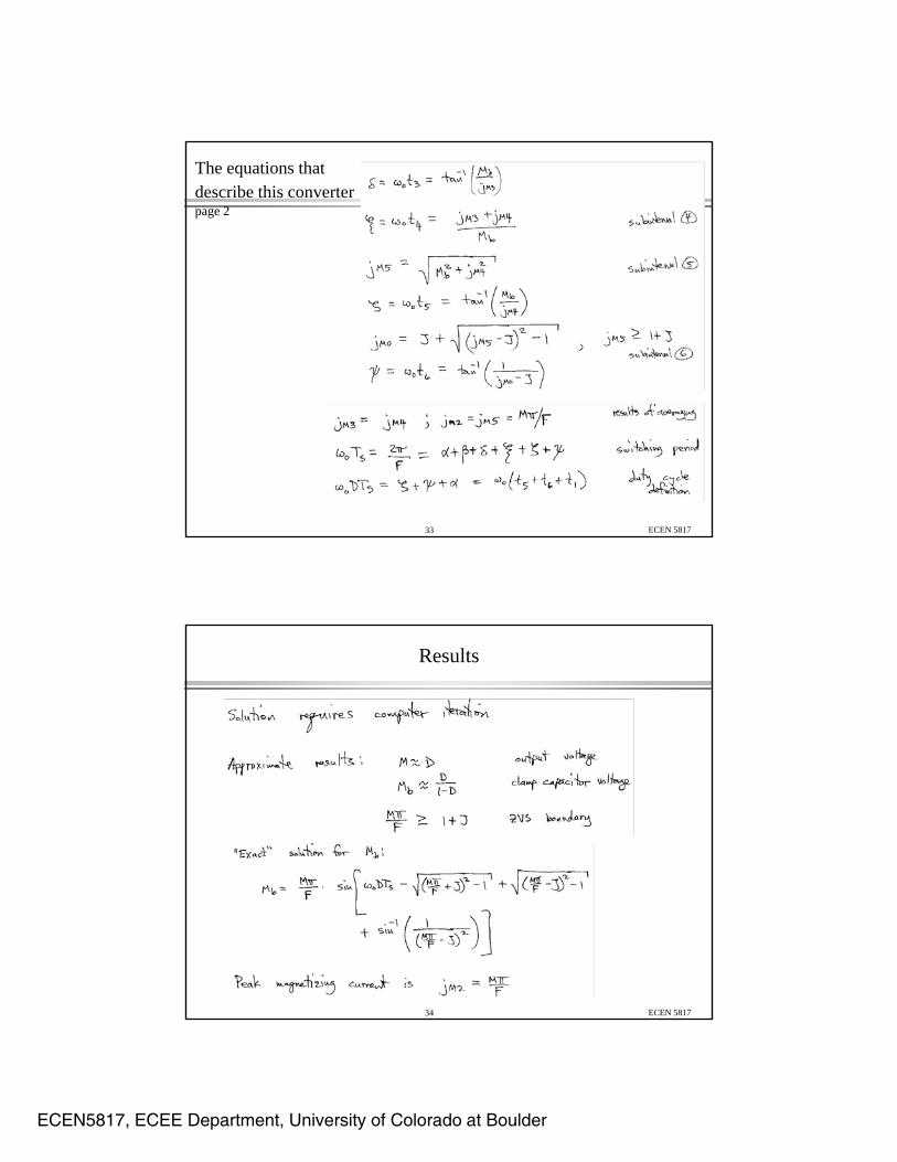
The equations that describe this converterpage 2
ECEN 581733
Results
ECEN 581734
ECEN5817, ECEE Department, University of Colorado at Boulder
Active clamp converters: other examples
Basic switch network reduces to:
(if the blocking capacitor (if the blocking capacitor is an ac short circuit, then we obtain alternately switching transistors—original MOSFET plus the auxiliary transistor, in parallel. The tank L and C ring only during the
ECEN 581735
C ring only during the resonant transitions)
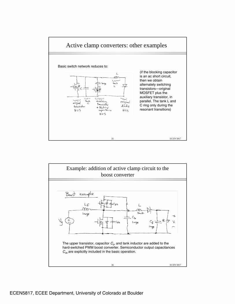
Example: addition of active clamp circuit to the boost converter
ECEN 581736
The upper transistor, capacitor Cb, and tank inductor are added to the hard-switched PWM boost converter. Semiconductor output capacitances Cds are explicitly included in the basic operation.

ECEN5817, ECEE Department, University of Colorado at Boulder
Active clamp circuit on the primary sideof the flyback converter
ECEN 581737