software architecture modeling - imag.friihm.imag.fr/publs/2001/encyclop01.chap.coutaz.doc · web...
TRANSCRIPT

1
SOFTWARE ARCHITECTURE MODELING FOR USER INTERFACES
Joëlle COUTAZ
Laboratoire CLIPS (IMAG)BP 53 , 38041 Grenoble Cedex, France
email: [email protected], http://iihm.imag.fr/
SUMMARY
Architectural modeling is becoming a central problem for large, complex systems. With the
advent of new technologies and user-centered concerns, the user interface portion of
interactive systems is becoming increasingly large and complex. This chapter is a reflection
on software architecture modeling for interactive systems. In this domain, a number of
architectural frameworks have emerged as canonical references. Although these models
provide useful insights about how to partition and organize interactive systems, they do not
always address important problems identified by main stream software architecture
modeling. We first introduce the notion of software architecture and make explicit the steps
and issues that architectural design involves and that most software designers tend to blend in
a rather fuzzy way. Building on general concepts, a comparative analysis of the most
significant refernce models developed for interactive systems is then presented: the Seeheim
and Arch models followed by the more recent agent-based approaches that can be shaped to
support multimodal interaction and groupware.
KEYWORDS
Seeheim model, Arch model, multi-agent model, PAC, MVC, PAC-Amodeus, user interface
software architecture, software architecture, Computer-Human Interaction.
INTRODUCTION
The design of software architecture has become an active area of research (Shaw, 1995;
Bass, 1998). Although the ad-hoc development of software is acceptable for throwaway
Published in The Encyclopedia of Software Engineering, J. Marciniak Ed., Wiley & Sons Publ., 1993, pp. 38-49.
2
prototypes, it is now widely recognized that architectural design of complex systems can no
longer simply emerge from craft skills. This shared scientific wisdom calls for increased
attention in the practice of user interface development.
In Human Computer Interaction (HCI), early prototypes are sometimes developed to elicit
users’ requirements or to make explicit the user interface of the target system. A simple
cost/benefit analysis indicates that a prototype does not require an “industrial strength”
software organization. In this case, software architecture is not the issue. The pitfall,
however, is to put too much effort into the prototype and thus, be tempted to turn the
software into a product. Then, in the absence of an explicit architectural framework and
sound design rationale, the resulting system is difficult to maintain and extend.
Current practice in prototyping is not the only motivation for paying attention to architectural
design. Emerging interaction techniques are more and more complex. These include:
- Groupware, i.e., systems that allow multiple users to achieve a common task either at the
same time or asynchronously, either at a distance or co-located (Baecker, 1993; Ellis
1994),
- Multimodal interaction, i.e., user interfaces that support multiple forms of interaction
such as the combination of speech and gesture (Nigay, 1995; Oviatt, 1997; Oviatt 2000),
- Virtual reality systems coined in 1989 by Jaron Lanier to refer to systems that immerse
the user in a simulated world (Rheingold, 1991),
- Augmented or mixed reality systems that bring together the real world with information
processing (Krueger, 1990; Wellner, 1993; Crowley, 2000),
- Situated interaction and context-aware computing that provides the user with relevant
information based on the knowledge of the current interaction context, such as location
and lighting conditions (Dey, 2001).
- Universal access (Shneiderman, 2000), i.e., the capacity of anybody (including
handicapped people) to access computer systems anywhere (e.g., at home, in the street,
etc.), using any device (from a high-end PC to a mobile phone) at any time.
Off-the-shelf tools such as application frameworks and user interface generators alleviate the
problem of designing the architecture but they can be applied in the design of casual
Graphical User Interfaces (GUI) running on standard workstations. For non-standard
situations such as those depicted above, programmers must reverse-engineer the architecture
Published in The Encyclopedia of Software Engineering, J. Marciniak Ed., Wiley & Sons Publ., 1993, pp. 38-49.

3
of object-oriented application frameworks in order to reuse and extend the existing code
appropriately. A similar observation holds for user interface generators. Again, software
designers must understand the functional coverage of the generated code in order to devise
what needs to be developed by hand. In addition, they must understand how to integrate and
coordinate the hand-coded portion with the generated code in a way that supports the system
requirements. Without an architectural framework to guide the decisions, it is difficult to
achieve this task properly.
In the light of the above analysis, software architecture modeling serves two distinct but
complementary purposes: the forward design and the reverse design of software structures.
On one hand, software architecture modeling guides the development of a future system; on
the other hand, it helps to understand the organization of existing code. In both cases, the
problem is how to capture architectural knowledge and convey this knowledge to software
designers and maintainers in a useful way.
This chapter reports a state of the art on software architecture modeling for interactive
systems. It is structured in the following way:
- First, we introduce the key concepts from software architecture research and make
explicit the design steps that most software designers in HCI tend to blend in a fuzzy
way.
- Building on general concepts and practice from mainstream software engineering, we
then present a comparative analysis of the most significant architecture models developed
in HCI.
The article will primarily concentrate on the conceptual aspects of architectural design.
The reification of conceptual architectures into implementation architectures (Anderson,
2000; Philips, 1999), which rely on the underlying platform and programming tools, will
not be addressed.
PRINCIPLES OF SOFTWARE ARCHITECTURE
Although “software architecture” is a popular term, it is used in various contexts with
different meanings. The IEEE 1471 standard approved in 2000 by the Computer Society,
acknowledges the difficulty of eliciting a consensual definition. In this section, we provide a
definition based on key reference works in software engineering followed by a short
Published in The Encyclopedia of Software Engineering, J. Marciniak Ed., Wiley & Sons Publ., 1993, pp. 38-49.

4
description of current knowledge in software practice: the software development process and
its core concepts followed by the representation and evaluation techniques of architectural
structures.
Definition
IEEE 1471 defines architecture as “the fundamental organization of a system embodied in its
components, their relationships to each other and to the environment, and the principles
guiding its design and evolution.” (IEEE, 2000). In other words, an architecture is the result
of a process constrained by the environment. The environment includes the stakeholders,
their culture in software quality, the development tools, business requirements, and so on.
“Fundamental” denotes issues about the system that are important for a particular stakeholder
involved in a particular step of the development process. IEEE 1471 stresses the distinction
between an architecture and an architecture description. An « architecture is a concept of a
system » (Maier, 2001). It exists without ever being observable. An architectural description
is a represention of that concept for others. It is a concrete thing.
Although similar in the spirit, Bass et al.’s definition is grounded on more operational issues.
The architecture of a computing system “is a set of structures which comprise software
components, the externally visible properties of these components and the relationships
among them" (Bass, 1998 pp. 23). Bass et al.’s definition makes explicit the multiplicity of
viewpoints on a particular architecture. A viewpoint corresponds to a structure and a
representation that best supports the needs and concerns of the specific step in the
development process. As in civil architecture, different blueprints are used to describe the
building, serving different purposes for different stakeholders.
The externally visible properties of a component define its expected behavior. They express
the hypotheses that other components can make on the component. These include the
services the component is able to provide, the resources it requires, its performance, as well
as its communication and synchronization mechanisms. "Externally visible" implies that a
component is an abstraction unit or, from a process-centered perspective, “a unit of
independent production, acquisition, and deployment that interact to form a functioning
system” (Szyperski, 1997). Depending on the nature of the structure considered in the
development process, this unit may be a service, a module, a library, a process, a procedure,
an object, an application, an agent, etc. The term “externally visible properties” proposed by
Published in The Encyclopedia of Software Engineering, J. Marciniak Ed., Wiley & Sons Publ., 1993, pp. 38-49.

5
Bass et al. is, in our opinion, more precise and more practical than the general term
“constraints” which represents “laws the system must observe” (Ellis, 1996).
The relationships of a component denote the connections that the component may have with
other components. The nature of the connections depends on the components and on the
structure at hand. A connector is the entity that realizes a connection between components
(Shaw, 1995). For example, a pipe, a procedure call, a remote method invocation, and a
socket are connectors between components of type filters, modules, processes, and
distributed objects respectively.
The development process and architectural concepts
The development process of software architecture covers a set of activities whose nature and
ordering depend on the particular system, on the designers' skills, and on the tools available.
Some of these activities are performed by hand while dedicated tools support others. In any
case, the key activities in software architectural design include: functional and modular
decompositions, functions allocation to modules, processes identification, mapping modules
with processes and mapping processes with processors. These activities bring to bear
architectural design guides such as software architecture reference models, architecture styles
and patterns, and result in the production of a conceptual architecture followed by an
implementation architecture. Figure 1 shows the design process for software architecture
ranging from reference models to implementation architecture.
Software Architecture Reference ModelsRequirementsspecifications Functional Structure Modular StructureCoordination structurePhysical structure
Conceptual architecture ImplementationarchitectureCode structure
Reverse DesignArchitectural styles and Patterns
Functional decomposition Modular decompositionProcesses identificationMapping between modules and processesMapping between processes and processors
Forward Design
Figure 1: Software architecture reference models, conceptual and implementation architectures in relations to
the activities involved in the design process of a software architecture (Functional decomposition, modular
Published in The Encyclopedia of Software Engineering, J. Marciniak Ed., Wiley & Sons Publ., 1993, pp. 38-49.

6
decomposition, processes identification, mapping between modules and processes and between processes and
processors). The arrows denote a top-down approach. Dotted lines show orthogonal notions involved across
the design process (architectural styles and patterns).
The functional decomposition of a system consists in expressing the functional requirements
of the system into a set of simpler units. The components of this structure are abstraction
units that express the functional requirements of the system. Their relations are of the type
"exchange data with". For example, the schema shown in Figure 13 is a representation of the
functional structure of the system MATIS. The design of a functional structure may be
derived from a software architecture reference model.
A software architecture reference model is a standard decomposition of known systems into
functional components coupled in a well-defined way. For example, a compiler is
decomposed into four (possibly five) successive well-defined functions: the lexical, the
syntactic, the semantic (and the pragmatic) analyses, followed by code generation. Seeheim
and PAC-Amodeus discussed next, serve as reference models in HCI. PAC-Amodeus has
been used to devise the functional structure of MATIS.
The modular decomposition results in the definition of a static view of the system: the
modular structure. The components of the structure are modules linked by relations such as
"is a sub-module-of". The decomposition is performed according to software engineering
rules and properties such as module dependency minimization. Based on the modular
structure, the project manager can dispatch the development of the system to different
programming teams. Function allocation is closely related to modular decomposition. It
consists of allocating the functions of the functional structure to the modules of the modular
structure. In other words, this activity results in the definition of the functional coverage of
each module. A module may cover multiple functions. Conversely, a function may be
distributed across multiple modules.
Whereas the modular structure is a static view of the system, the coordination structure
provides a dynamic view. The components of the coordination structure are processes or
threads whose relationships express synchronization and concurrency control policies
between the processes. Module allocation is related to the process decomposition. It consists
of allocating the modules of the modular structure to the processes of the coordination
Published in The Encyclopedia of Software Engineering, J. Marciniak Ed., Wiley & Sons Publ., 1993, pp. 38-49.

7
structure. Going one-step further, the physical structure describes the mapping between the
processes and the physical processors.
All together, the functional, the modular, the coordination and the physical structures are
different views on the conceptual architecture. The term conceptual architecture has been
coined to encompass the first set of decisions during the architectural design process
(Hofmeister, 2000). A conceptual architecture does not necessarily include all of the
structural views described above. Typically, it contains the functional structure. The others
views are not necessarily considered in the early phase of the design process, especially when
they are conveyed by implementation tools. For example, for groupware applications,
Groupkit (Roseman, 1992) and Suite (Dewan, 1990), which embed a physical and a
coordination structures, eliminate the problem of performing the process and processor
allocations.
The conceptual architecture is then mapped into an implementation architecture. In turn, the
implementation architecture is defined according to multiple views. The modular structure
may be refined in terms of units such as packages, procedures and object classes that depend
on the programming tools available. Connectors at one level of description may be refined as
substructures of components and connectors. Mappings may be expressed using dedicated
languages or performed automatically by the underlying infrastructure. Typically, agent-
based middleware infrastructures support code migration across the network in a transparent
way (Bellavista, 2001). Therefore, allocation of agents to processors is not an issue for the
user interface developer.
The refinement of a conceptual architecture into implementation structures may be
performed in three ways (Anderson, 2000): by applying heuristics as in (Duval, 1999), by
using development tools based on reference models such as application frameworks and User
Interface generators, or by using parameterized tools such as TCD. TCD, a tool based on the
Dragonfly (Anderson, 2000) reference model, maintains the correspondence between the
conceptual architecture and the implementational structures of the user interface portion of
an interactive system. Tools, such as TCD, support both the forward and reverse engineering
processes of the user interface portion of an interactive system. By so doing, they ensure that
modifications of the implementational structures are consistent with the conceptual
architecture and vice versa.
Published in The Encyclopedia of Software Engineering, J. Marciniak Ed., Wiley & Sons Publ., 1993, pp. 38-49.

8
The notion of architecture style is orthogonal to that of a reference model as well as to the
notions of conceptual and implementation architectures: the choice of a style comes into play
at every step of the design process. A style:
- includes a vocabulary of design elements (e.g., pipes and filters),
- imposes configuration constraints on these elements (e.g., pipes are mono-directional
connectors between two filter components), and
- determines a semantic interpretation that gives meaning to the system description
(Garlan, 1993).
A style is not an architecture but a guide for devising architectural structures. By analogy
with civil architecture, a style can be assimilated to a class of architectures. Just as one refers
to the Roman and Gothic styles, similarly, pipes and filters, clients and servers, and layers of
abstract machines, are architectural styles. On can find in Shaw and Clement (Shaw, 1997), a
preliminary classification of architectural styles.
As demonstrated by (Shaw, 1995), architectural styles have very specific properties. As a
result, a single style might not cover all of the system requirements. In architectural design,
heterogeneity is a necessary trouble. Heterogeneity has multiple causes:
- It may occur during the reification process. For example, data sharing in a conceptual
model may be refined at the implementation level as local storages linked by message
passing.
- It may occur within a level of the reification process. Typically, open systems and
reusability may bring in heterogeneous styles. For example, the user interface portion of
an interactive system is built, partly from existing code with its own style(s) (inherited
from toolboxes and interface builders), and partly from fresh code which, in turn, may
adopt yet another style.
Heterogeneity supports the ability to choose the style that best fits a particular set of
components of the architectural structure. Conversely, heterogeneity may engender
incompatibilities such as those observed between communication protocols. We will see how
adaptors components can be used to address this problem.
As for the concept of style, the notion of architectural pattern is orthogonal to that of
reference, conceptual, and implementation architectures. An architectural pattern is a set of
micro-architectural structures that corresponds to a recurring micro-design problem. Patterns
Published in The Encyclopedia of Software Engineering, J. Marciniak Ed., Wiley & Sons Publ., 1993, pp. 38-49.

9
as introduced by Gamma et al. include: a description of the problem that the pattern covers,
conceptual structures that address the problem (e.g., the functional decomposition and a
diagram that shows the interactions between the components), heuristic rules for how and
when to use the pattern, as well as an implemented example using C++ as a programming
tool (Gamma, 1995).
Just like a reference architecture model, an architectural pattern provides a generic solution.
At the opposite of a reference architecture model, which addresses a system as a whole, a
pattern covers a local problem. A pattern may be governed by a style. Some architectural
patterns are applicable at the conceptual level while others address implementation issues.
Gamma et al. propose a consistent set of patterns for implementation structures based on the
object-oriented style (Gamma, 1995). In this chapter, we will see examples of patterns at the
conceptual level for the PAC model.
We now need to discuss how an architecture is made concrete through structural
representations.
Representations
A representation supports analysis as well as communication. As an analytic tool, a
representation helps the authors to reason about design alternatives, to understand their
implications and to evaluate them against requirements criteria. As a communication tool, a
representation conveys the result of a design process to other team members. In this case, the
representation should be readable and not ambiguous: a wrong interpretation of the
description may result in a loss of conformity along the reification process.
As stressed above, an architectural representation is not the architecture of the system. It is
the representation of one of the structures of the system. In other word, one should not say
« this diagram is the global architecture of the system ». Instead, we should say « this
diagram depicts the functional structure of the system » or « the coordination structure of the
system », etc.
Boxes-and-Arrows diagrams and informal explanations are commonly used to describe
architectural structures. Boxes denote components and arrows correspond to relationships or
to connectors between the components. Graphical representations offer intuitive reading but,
Published in The Encyclopedia of Software Engineering, J. Marciniak Ed., Wiley & Sons Publ., 1993, pp. 38-49.

10
used without a clear semantics, they may be too informal to be useful. A variety of
Architecture Description Languages (ADL) have emerged in the last decade to express the
formal composition of components, their relationships and their external properties. A
detailed discussion on the nature of ADLs can be found in (Bass, 1998, chap. 12). Formal
notations open the way to code generation as well as to the automatic verification of system
properties. In some contexts however, the benefits of formal specification may not counter
balance the cost of producing a specification. In the following discussion, we will use a box-
and-arrow notation and specify their coverage.
As any design product, an architectural solution must be evaluated before coding can take
place. Late evaluations may result in a costly system revision.
Evaluation
A software architecture is neither intrinsically bad nor good. Instead, it is good or bad with
regard to a set of properties (i.e., requirements) that the software must satisfy. Technical
requirements such as portability and efficiency are not enough to explain a particular
architectural structure: the cultural context of the stakeholders, temporal and human
resources allocated to the project, etc. are important ingredients. In addition, these
requirements may evolve as the customer achieves greater understanding of the system
(Bachman, 2000). Nevertheless, at some point in the development process requirements have
to be established. While the application of principled design is widely recognized in the
software community, there is very little material to help architectural designers to cope with
these major difficulties. SAAM (Software Architecture Analysis Method), a scenario-based
method, offers a pragmatic approach to the problem of reasoning about architectural designs
(Kazman, 1994 ; Kazman, 1996 ; Kazman 1999).
Scenario-based approaches have been used in many areas including the object-oriented
community (e.g., Jacobson’s use cases) as well as in the HCI community (Carrol, 1995) to
test task models and external specifications of the user interface. A SAAM scenario must
anticipate the future use of the software and its evolutions. The set of scenarios must cover
all of the architectural structures devised for the system as well as the points of view of the
first class stakeholders involved in the design process (e.g., the end-user, the developer, the
maintainer, etc.). For example, a scenario would express the capacity for the end-user to
customize the user interface while minimizing changes in the current version of the system to
Published in The Encyclopedia of Software Engineering, J. Marciniak Ed., Wiley & Sons Publ., 1993, pp. 38-49.

11
be delivered in a week. A particular structural solution is analyzed within the context of these
scenarios.
In addition to software engineering properties (e.g., portability, efficiency, modifiability),
interactive systems are concerned with user-centered properties such as observability, task
interleaving, undo-redo features, consistent operation across multiple views, etc. (Gram,
1996). Connections between aspects of usability and architectural design can be found in
(Bass, 2001) where scenarios are used to illustrate aspects of usability along with their
corresponding architectural patterns.
In summary, software designers must consider multiple perspectives on architectural design.
As a result, there is no such thing as "the software architecture of a system". Instead, multiple
structures altogether constitute the concrete expression of an architecture. In addition, a
software architecture is neither intrinsically bad nor good. Instead, it is good or bad with
regard to a set of properties (i.e., requirements) that the software must satisfy. It is difficult
to find the right balance between multiple sources of requirements, to identify the right level
of refinement to reason about system properties (Kazman, 1999), and to cope with
heterogeneity. However, software architecture research is maturing with practical methods
and tools (Shaw, 2001).
Having presented a summary of the general principles developed in software architecture
research, we now consider the particular case of interactive systems. We focus on the most
widely used reference models: two seminal models are first introduced followed by a series
of models that address an increasing number of requirements. We will thus successively
present the Seeheim model and its revisited version, the Arch/slinky model. We will then
discuss two multi-agent approaches which explicitly deal with fine-grain modularity and
parallelism: MVC and PAC. Although MVC and PAC provide improvements over the
foundational Seeheim and Arch models, they suppose an homogeneous world. The PAC-
Amodeus model shows how to cope with heterogeneity. All of these models, however, have
been devised for single user systems and graphical user interfaces. Their adaptation to
groupware and multi-modal interaction are then presented. Finally, we briefly introduce new
avenues for context-sensitive interactive systems.
Published in The Encyclopedia of Software Engineering, J. Marciniak Ed., Wiley & Sons Publ., 1993, pp. 38-49.

12
THE FOUNDATIONS: THE SEEHEIM MODEL
The foundations for interactive systems architecture originated at a workshop in Seeheim,
Germany (Pfaff, 1985). The Seeheim model has provided developers with the very first
canonical functional decomposition of interactive systems.
As shown in Figure 2, the Application covers the domain-dependent functions and concepts
of the system. The Application Interface Model describes the Application semantics from the
viewpoint of the user interface: it describes the data structures and the procedures that the
Application exports to the user interface as well as constraints on the procedures sequencing.
The Presentation defines the behavior of the system as perceived and manipulated by the
user. The Dialogue Control is viewed as a mediator between the Application Interface Model
and the Presentation. The little box below expresses the possibility for the Application
Interface Model to bypass the Dialogue Control in order to improve performance. The
Dialogue Control, however, is the initiator of this one-way direct link.
Interactive System
User Interface
ApplicationInterface Model Dialogue Control Presentation
UserApplication
Figure 2: The Seeheim Model.
Portability and modifiability are the two architectural drivers of the Seeheim model.
Experience shows that the user interface portion of an interactive system is the most frequent
source of modifications. Therefore, the Application Interface Model is a way to preserve the
Application from modifications of the user interface.
The model is a framework for pure functional partitioning that opened the way to a large
number of interpretations. For example, in the mid-eighties, user-system interaction was
primarily viewed as a language-based dialogue (very few User Interface Management
Systems were based on the event paradigm). Consequently, the role of each component was
roughly described as the semantic, syntactic and lexical aspects of the interaction, and the
overall control structure of the system was assimilated as a pipe-line scheme. This view has
Published in The Encyclopedia of Software Engineering, J. Marciniak Ed., Wiley & Sons Publ., 1993, pp. 38-49.

13
permitted to apply advanced compilation techniques to the automatic generation of user
interfaces. With the advent of direct manipulation, the semantic-syntactic-lexical
interpretation of the Seeheim logical partitioning failed at supporting new requirements such
as interleaving system feedback with user’s inputs. The Arch/Slinky model is a first attempt
at addressing this problem.
THE ARCH/SLINKY MODEL The Arch model is a revisited Seeheim. As shown in Figure 3, it promotes a functional
decomposition similar to that of Seeheim but with a number of improvements: a clearer
identification of the level of abstraction of each component, an explicit definition of the data
structures exchanged between the components, adaptors between the major components of
the structure to improve modifiability and portability, and the slinky meta-model to balance
functions allocation across the system. These contributions are discussed next.
The Functional Components
As in Seeheim, the Application (also called the Functional Core) covers the domain-
dependent concepts and functions. At the other extreme, the Interaction Toolkit Component,
which is dependent on the actual toolkit used for implementing the look and feel of the
interactive system, is in charge of presenting the domain concepts and functions in terms of
physical interaction objects (also called widgets and interactors). The keystone of the arch
structure is the Dialogue Component whose role consists of regulating task-sequencing. For
example, the Dialogue Component ensures that the user executes the task “open document”
before performing any editing task. Typically, model-based user interface generators produce
the Dialogue Component from the specification of a task model (Paterno’, 1994).
Data structures
Arch has clarified the level of abstractions of the functional components by making explicit
the data structures transferred between the boundaries: the domain objects, the logical
presentation objects and the physical interaction objects. Domain objects are high-level data
structures that model domain-dependent concepts (for example, a real number to model the
notion of heat). In the context of this discussion, a domain object is an entity that the
designer of the interactive system wishes to make perceivable to, and manipulatable by the
user. Logical presentation objects are abstract entities that convey the presentation of domain
objects without being dependent on any particular run time toolkit. For example, a “choice”
Published in The Encyclopedia of Software Engineering, J. Marciniak Ed., Wiley & Sons Publ., 1993, pp. 38-49.

14
logical presentation object supports the rendering as well as the manipulation of a multi-
valued domain object. The concrete rendering of a domain object results from the mapping
of the logical presentation object to a physical interaction object. For example, the choice
logical presentation object can be mapped to the physical pull-down menu of a graphical
toolkit.
The Arch adaptors: the Functional Core Adaptor and the Logical Presentation
Adaptor
The iterative nature of user interface development as well as rapid advances in new forms of
interactive devices, stress the importance of modifiability and portability. As a result, just
like Seeheim, Arch has been shaped for modifiability and portability, but Arch pushes the
requirements one step further.
As shown in Figure 3, the major functional components of an interactive system, i.e., the
Application, the Dialogue and the Presentation, do not exchange data directly. Instead they
mediate through adaptors: the Functional Core Adaptor and the Logical Presentation
Component.
The Functional Core Adaptor (FCA) is intended to accommodate various forms of mismatch
between the Functional Core and the user interface of the system. In other word, the FCA
can be understood as the virtual application layer. As shown in Figure 3, data transfer
through the FCA is performed in terms of domain objects. Ideally, domain objects match the
user’s mental representation of a particular domain concept. It may be the case, however,
that the Functional Core, driven by software or hardware considerations, implements a
domain concept in a way that is not adequate for the user. Therefore, domain objects of the
functional core may need to be adapted. We call this transformation semantic enhancement.
Semantic enhancement (Bass, 1991) may be performed in the FCA by defining domain
objects that reorganize information maintained in the Functional Core. The reorganization
may take the form of aggregating data structures of the Functional Core into a single domain
object or, conversely, segmenting a concept into multiple domain objects. It may also take
the form of an extension by adding attributes and operators, which can then be exploited by
the other components of the user interface (Coutaz, 1991).
Published in The Encyclopedia of Software Engineering, J. Marciniak Ed., Wiley & Sons Publ., 1993, pp. 38-49.
15
In addition, the Functional Core and the user interface may be implemented with different
formalisms. For example, in an information retrieval system, queries are represented as C++
objects in the Dialogue Component while the Functional Core “speaks” SQL. The FCA is
then in charge of formalism transformation.
The second adaptor of Arch is the Logical Presentation Component. This component
insulates the rendering of domain objects from the actual interaction toolkit of the target
platform. It is expressed in terms of the logical presentation objects provided by a virtual
toolkit. By so doing, switching to a different physical interaction toolkit requires rewriting
mapping rules, but the logical presentation objects remain unchanged. AWT (Geary, 1997)
and XVT (Rochkind, 1989) are examples of virtual toolkits: they embed the mapping of the
logical widgets to the physical widgets of the target machine. Although, these tools satisfy
code portability, in practice they do not guarantee consistent behavior of the user interface
across platforms. More recently, multi-platform toolkits such as Java Swing (Geary, 1999)
and Ilog Views (Ilog, 1994) tend to alleviate this problem by re-implementing native toolkits
behavior for multiple target machines. This way, it is possible to obtain a Windows look and
feel on a Macintosh platform.
The two adaptor components minimize the effect of changes but may have an adverse effect
on efficiency. It is therefore legitimate to consider the suppression of the adaptors. When
efficiency prevails against toolkit portability, then the Logical Presentation Component can
be eliminated and the presentation level of the interactive system is directly expressed in a
native toolkit. If, the Functional Core provides an "interface" that conforms to the user's
requirements, and if it will not evolve in the future, then the Functional Core Adaptor can be
scaled down to a simple connector (e.g., a set of procedure calls). The slinky meta-model
provides the conceptual means to perform these adjustments.
The Slinky Meta-model
Slinky (from the child’s toy) expresses the capability, for the software designer, to shift
functionalities between the components. This feature may be used to accommodate
conflicting criteria or to support the evolution of implementation tools. For example, fifteen
years ago, the facilities provided by user interface toolkits were restricted to event
acquisition loops and low-level graphics primitives. Today, syntactic analysis of user’s input
is encapsulated within re-usable widgets. Therefore, syntactic analysis has been shifted to the
Published in The Encyclopedia of Software Engineering, J. Marciniak Ed., Wiley & Sons Publ., 1993, pp. 38-49.

16
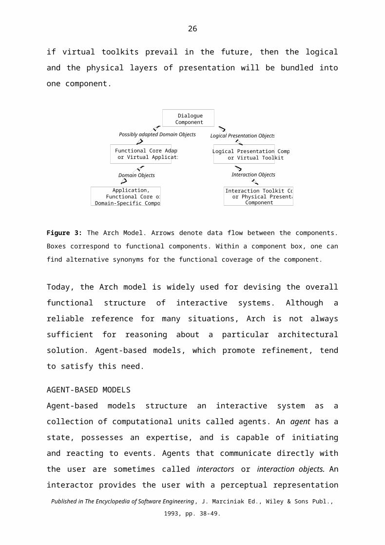
Interaction Toolkit Component. Similarly, if virtual toolkits prevail in the future, then the
logical and the physical layers of presentation will be bundled into one component.
Dialogue Component
Functional Core Adaptor or Virtual Application
Logical Presentation Componentor Virtual Toolkit
Interaction Toolkit Component or Physical Presentation
Component
Application,Functional Core or
Domain-Specific Component
Possibly adapted Domain Objects Logical Presentation Objects
Interaction ObjectsDomain Objects
Figure 3: The Arch Model. Arrows denote data flow between the components. Boxes correspond to
functional components. Within a component box, one can find alternative synonyms for the functional
coverage of the component.
Today, the Arch model is widely used for devising the overall functional structure of
interactive systems. Although a reliable reference for many situations, Arch is not always
sufficient for reasoning about a particular architectural solution. Agent-based models, which
promote refinement, tend to satisfy this need.
AGENT-BASED MODELSAgent-based models structure an interactive system as a collection of computational units
called agents. An agent has a state, possesses an expertise, and is capable of initiating and
reacting to events. Agents that communicate directly with the user are sometimes called
interactors or interaction objects. An interactor provides the user with a perceptual
representation of its internal state. The terms interactor and agent are sometimes used
indifferently even if the interactor has no direct interaction with the user. An object is a
generic term that covers a computational element with a local state. It can either be viewed as
a concept or as the technical structure that underpins the object-oriented programming
paradigm. In the following discussion, we will consider an object as a generic concept.
Our view of the concept of agent is one perspective of the more general definition used in
distributed Artificial Intelligence (A.I.). In A.I., agents may be cognitive or reactive
depending mainly on their reasoning and knowledge representation capabilities (Ferber,
1995). A cognitive agent is enriched with inference and decision making mechanisms to
Published in The Encyclopedia of Software Engineering, J. Marciniak Ed., Wiley & Sons Publ., 1993, pp. 38-49.

17
satisfy goals. At the opposite, a reactive agent has a limited computational capacity to
process stimuli. It has no goal per se but a competence coded (or specified) explicitly by the
human designer. In current interactive systems, agents are reactive. In the following
discussion, we will not make the distinction between cognitive and reactive agents.
All of the agent-based models developed in HCI follow the same principle as Seeheim and
Arch but they do so at a fine grain. Whereas Seeheim and Arch structure a complete
interactive system as three fundamental functions (Functional Core, Dialogue, and
Presentation), agent-models structure an interactive system as a collection of cooperating
agents where every agent is a mini-Seeheim-like structure. A number of agent-based styles
and tools have been developed along these lines: MVC (Krasner, 1988), PAC (Coutaz,
1987), Clock (Graham, 1997), C2 (Taylor, 1996), the LIM (Paterno', 1994) and York (Duke,
1993; Duke, 1994) interactors.
In the following sections, we will illustrate agent-based models with PAC and MVC for their
their early development and acceptance. We will then discuss the benefits and the drawbacks
of multi-agent approaches.
MVC and PAC
In MVC (Model, View Controller), an agent is modeled along three functional perspectives:
the Model, the View, and the Controller. A Model defines the abstract competence of the
agent (i.e., its functional core). The View defines the perceivable behavior of the agent for
output. The Controller denotes the perceivable behavior of the agent for inputs. The View
and the Controller cover the user interface of the agent, that is, its overall perceivable
behavior with regard to the user. MVC has influenced a number of architectural models such
as Chiron-2 also known as C2 (Taylor, 1996) and Clock (Graham, 1996).
Figure 4 shows the implementation of the MVC model in the Smalltalk environment. One
can observe that Controllers and Views are implemented as hierarchies of Smalltalk classes.
Models, which are domain-dependent, are organized according to the domain requirements.
They may, or may not, be organized hierarchically. An agent is instantiated by connectors
between a Model, a View and a Controller. Connectors are implemented as method
invocation and anonymous callbacks. Typically, the Controller translates the user’s actions
into method calls on the Model. The Model broadcasts a notification to the View and the
Published in The Encyclopedia of Software Engineering, J. Marciniak Ed., Wiley & Sons Publ., 1993, pp. 38-49.

18
Controller that its state has changed. The View queries the Model to determine the exact
change and upon reception of a response, updates the display accordingly. The same protocol
holds for the Controller. Whereas the View and the Controller have an explicit knowledge of
the Model, the Model is not wired to the View and to the Controller. Instead, the Model
offers a registration mechanism so that multiple Views and Controllers can express their
interest in the Model through anonymous callbacks. This allows an easy implementation of
multiple renderings of the same domain concept either on the same workstation or across
multiple workstations as in groupware applications. The View and the Controller can
communicate directly through method invocations.
C3V2
M2M3
M1
V4C1
C2
V1V3
Figure 4: Illustration of the implementation structure of the Smalltalk environment based on MVC. Thick
lines denote invocation methods and callbacks. Thin lines correspond to class-subclass relationships. The
diagram shows 3 Models, M1, M2, M3 where M2 is a subclass of M1. Views V2, V3, V4 are subclasses of
View V1, and controllers C2 and C3 are subclasses of Controller C1. The invocation methods and callbacks
make concrete two MVC agents: (M2, V2, C2) and (M3, V3, C3).
In PAC (Presentation, Abstraction, Control), an agent has a Presentation (i.e., its perceivable
input and output behavior), an Abstraction (i.e., its functional core), and a Control to express
multiple forms of dependencies. The Control of an agent is in charge of communicating with
other agents as well as of expressing dependencies between the Abstraction and the
Presentation facets of the agent. In the PAC style, no agent Abstraction is authorized to
communicate directly with its corresponding Presentation and vice versa. In PAC,
dependencies of any sort are conveyed via Controls. Controls serve as the glue mechanism to
express coordination as well as formalism transformations between the abstract and the
Published in The Encyclopedia of Software Engineering, J. Marciniak Ed., Wiley & Sons Publ., 1993, pp. 38-49.

19
concrete perspectives. As shown in Figure 5, the flow of information between agents transit
through the Controls in a hierarchical way. The connectors of a PAC hierarchy express
communication relationships. They do not represent class-subclass relations as in the object-
oriented implementation of the MVC model shown in Figure 4.
A PC
A PC
A PC
A PC
A PC
Figure 5: In PAC, the interactive system is modeled as a set of PAC agents whose
communication scheme forms a hierarchy. Arrows show the information flow. The Control
of an agent mediates between its Abstraction and Presentation facets and serves inter-agent
communication.
Figure 6 shows a PAC agent that renders the notion of heat metaphorically in the form of a
burner. The Presentation of the agent is in charge of drawing the picture of a burner as well
as of interpreting user’s actions. User’s actions include dragging the burner around with the
mouse or clicking the switch to turn the burner on or off. A mouse click on the switch has
the following effects: the Presentation of the agent updates the rendering of the swicth to
express that the burner is on or off, then sends a notification to the Control. In turn, the
Control which maintains the dependencies between the switch and the IsOn boolean variable,
notifies the Abstraction facet of a change for IsOn. The Abstraction, the functional core of
the burner agent, computes the heat according to the laws of thermodynamics. As the heat
crosses a threshold, the Abstraction notifies the Control of the fact. In turn, the Control,
which maintains the dependencies between the threshold values and the height of effluvia,
notifies the Presentation that effluvia should be redrawn. The Presentation changes the
rendering of the effluvia accordingly. As shown by this simple example, an agent is a micro-
interactive system, thus the generic term « interactor» introduced above.
Effluvia
SwicthHeat:Real;IsOn: Boolean
PresentationAbstractionControlBurner
Published in The Encyclopedia of Software Engineering, J. Marciniak Ed., Wiley & Sons Publ., 1993, pp. 38-49.

20
Figure 6: The Burner PAC agent.
In MVC, The Abstraction facet of the burner is implemented as an instance of a Model.
Mouse clicks are interpreted by an instance of a Controller and a View instance is in charge
of drawing the picture of the burner including providing continuous visual feedback as the
user acts on the View. Decoupling input from output processing offers a finer grain of
modifiability of the perceivable behavior but may result in a loss of efficiency. For example,
if moving the picture of the burner on the screen has no semantic side effect, then refreshing
the screen does not require that the Model be notified. This example shows that coupling
between input and output processing can be quite close. As a result, many MVC variants,
such as Swing (Geary, 1999), implement view-controller as combined objects.
In summary, MVC decouples input techniques from outputs, whereas PAC concentrates
them in the notion of Presentation. Contrary to PAC, MVC has no explicit notion of
mediator for expressing the relationships and the co-ordination between agents. Different
functional decompositions entail distinct architectural properties. Therefore, given a set of
criteria for a particular interactive system, an agent style (or a set of styles) may be more
appropriate than others.
Benefits from agent-based models
Agent-based models stress a highly parallel modular organization and distribute the state of
the interaction among a collection of co-operating units. Their functional decomposition can
be exploited in multiple ways to convey a variety of distributed services. Modularity,
parallelism and distribution are convenient mechanisms for supporting the iterative design of
user interfaces, for implementing physically distributed user interfaces and application, and
for handling multi-threaded dialogues:
- An agent defines the unit for functional modularity. It is thus possible to modify its
internal behavior without endangering the rest of the system.
- An agent can be associated to one thread of the user's activity. Since an agent maintains a
local state, the interaction between the user and the agent can be suspended and resumed
at the user's will. When a thread of activity is too complex or too rich to be represented
by a single agent, it is then possible to use a collection of co-operating agents.
Published in The Encyclopedia of Software Engineering, J. Marciniak Ed., Wiley & Sons Publ., 1993, pp. 38-49.

21
- The multi-faceted structure of an agent can be exploited in different ways and can be
enriched in as many ways as desired. As mentioned above, an architecture expresses what
is important. For example, in the AMF-C model (Multifaceted-Agent for Collaboration),
PAC agents are augmented with facets to provide the user with local help and to log
significant events to perform usability testing from observed behavior (Tarpin-Bernard,
1998). For groupware systems, PAC* refines PAC agents according to the Production-
Communication-Coordination services covered by groupware (Calvary, 1997). Domain-
dependent knowledge can migrate within the user interface portion to accommodate
efficiency and the need for immediate semantic feedback. Typically the
Abstraction/Model facets of PAC and MVC are the appropriate location for conveying
domain-dependent concepts. This capacity will be illustrated further with PAC-Amodeus.
- An agent defines the unit for processing. It can then migrate across the network. This
capacity opens the way to multi-surface interaction as exemplified by the Hyper-palette
(Ayatsuka, 2000) and the Pick-and-Drop (Rekimoto, 1997) systems. Figure 7 shows
another example of multi-surface interaction inspired from the "Painter metaphor”. A
Personal Digital Assistant (PDA), hold in the non-dominant hand, mimics the palette of
graphical tools. Meanwhile a PC-controlled large white board serves as the drawing
surface for the dominant hand (Lachenal, 2000). Here, the user interface of the "Multi-
surface Paint Program" is physically distributed across multiple processors.
Figure 7. The Painter metaphor using a Palm as the tools palette and an electronic white board as a drawing
area.
Figure 8 shows the functional structure of the system in terms of PAC agents. The palette agent runs on the PalmOS system, whereas the Drawing area agent is assigned to the PC. The top-level cement agent, which combines user's actions distributed over the sibling agents, is replicated on the two processors. Conceptually, the agents
Published in The Encyclopedia of Software Engineering, J. Marciniak Ed., Wiley & Sons Publ., 1993, pp. 38-49.
Waba 1.0 Java JDK 1.2.2Communication
via serial port

22
can migrate between the two platforms as the user reconfigures the user interface dynamically. Typically, the user can bring the palette back and forth between the PDA and the PC.
Figure 8. The functional structure of the Multisurface Paint Program in terms of PAC agents.
- In addition to satisfying requirements for better user interfaces, agent models can easily
be refined in terms of object-oriented languages: an object class defines a category of
agents where class operators and attributes respectively model the instruction set and the
state of an agent category, and where an event class denotes a method. An object and an
agent are both highly specialized processing units, and both decide about their own state:
a state is not manipulated by others but results from processing triggered by others. The
sub-classing mechanism provided by object-oriented languages can be usefully exploited
to modify a user interface without changing existing code.
Drawbacks of agent-based models
In practice, agent-based models are not necessarily easy to apply nor do they necessarily
comply with real world constraints such as heterogenity.
Difficulty in devising an agent-based architecture. The difficulty in devising an agent-based
structure may come from the absence of an explicit set of levels of abstraction such as those
of Arch. The Arch layers are sound landmarks that can be exploited to chunk the design
process. At the opposite, with agent-based models, information acquired by agents is
transformed by a population of agents before reaching the functional core of the system. In
the other direction, agents concretize information from the functional core into perceivable
behavior. The successive steps of such input and output transformations, called respectively
the interpretation function and the rendering function, are not structured in agent-based
Published in The Encyclopedia of Software Engineering, J. Marciniak Ed., Wiley & Sons Publ., 1993, pp. 38-49.
Palette Agent Drawing area Agent
Top level
Cement agent

23
models as clear levels of abstraction. Heuristic rules and patterns, such as those presented in
the next section tend to alleviate this difficulty.
Homogeneity. Agent-based models structure interactive systems in an homogeneous way: all
of the functional aspects of the system are expressed using a single style. This homogeneity
is desirable when the designer’s goal is to reason about the system properties. Homogeneity
is also acceptable when the style is conveyed by the implementation tool such as MVC
within the Smalltalk development environment and when the entire system can be developed
with the same tool. As mentioned in a previous section, heterogeneity is generally
unavoidable. PAC-Amodeus presented next has been designed to cope with this problem.
PAC-AMODEUS
PAC-Amodeus uses the Arch model as the foundation for the functional partitioning of an
interactive system and populates the Dialogue Component with PAC agents. We first present
the principles of PAC-Amodeus, then provide a set of heuristic rules to devise the
appropriate set of agents and illustrate the rules with a real case system: MATIS.
The principles
As discussed above, Arch supports the existence of reusable code (e.g., legacy Functional
Cores) and defines two adaptors for accommodating style heterogeneity and for anticipating
changes. On the other hand, Arch does not provide any guidance about how to structure the
Dialogue Component in a way that is compatible with the user’s task requirements. PAC (or
any agent-based model) supports task interleaving as well as multiple grains of task
decomposition but fails at making explicit the link with existing styles. PAC-Amodeus
gathers the best of the two worlds. Figure 9 shows the resulting functional breakdown.
As in Arch, PAC-Amodeus offers two-way information flows between the primary
components of the arch. The nature of the connectors between the functional boundaries is
left opened since it depends heavily on the case at hand. Within the Dialogue Component, we
observe two information flows: the hierarchical traversal of PAC agents, and in contrast with
the original PAC style, direct horizontal communications with the Functional Core Adaptor
and the Logical Presentation component.
Published in The Encyclopedia of Software Engineering, J. Marciniak Ed., Wiley & Sons Publ., 1993, pp. 38-49.
24
.
Functional CoreAdaptor
Functional Core
Logical Presentation Component
Device dependentDomain dependent
Dialogue Component
A
Domain Objects Interaction ObjectsLanguage dependent
Interaction Toolkit Component
C PDomainObjects
Logical PresentationObjects
Figure 9: The PAC-Amodeus functional components.
A PAC agent may be related to the Functional Core Adaptor (FCA) and to the Logical
Presentation Component through its Abstraction and Presentation facets respectively. Its
Abstraction facet may be connected to one or multiple domain objects of the FCA (or of the
Functional Core if the FCA does not exist). Similarly, a Presentation facet may be connected
to one or multiple Logical Presentation objects of the Logical Presentation Component (or to
interaction objects of the Interaction Toolkit Component, if the Logical Presentation
Component does not exist). Depending on the case at hand, connectors are implemented as
procedure calls, as pointers, or as any other protocol suitable for the system requirements.
The design rationale for the “horizontal flow” is performance. Abstract information from the
FCA may not need additional processing from the parent agents. Similar reasoning holds for
the presentation part. In this situation, traversing the PAC hierarchy would not only be time
consuming but useless.
Heuristics for devising agents
There are two approaches to the identification of agents hierarchies. Nigay advocates a bottom-up analysis (Nigay, 1991), whereas Paternò (Paternò, 1999) as well as Calvary et al. promote a top-down schema (Calvary, 2001). The bottom-up approach relies on the availability of the external specifications of the interactive system. In the context of this discussion, “external specifications” denote the description of the user interface in terms of windows and presentation objects, along with their dynamic relationships. At the opposite, the top-down approach consists of deriving the agent hierarchy from the task model. A task model is a tree structure that expresses tasks (or user’s goals) in terms of subtasks. The
Published in The Encyclopedia of Software Engineering, J. Marciniak Ed., Wiley & Sons Publ., 1993, pp. 38-49.

25
two approaches are equivalent provided that the external specifications are conformant with the task model. In the following, we present a subset of the heuristics developed by Nigay for PAC agents, but any agent-based model would apply. The complete list can be found in (Coutaz, 2001).
Rule 1: Model a “main-dialogue-thread window” as an agent.A main-dialogue-thread window defines a logical workspace for performing a set of related tasks. Generally speaking, a window is a rendering surface for displaying information on the physical screen. A distinction should be made between a main-dialogue-thread window and convenience windows, such as dialogue boxes and forms, used in micro-dialogues to inform the user that an abnormal condition has occurred. Convenience windows, which are implemented as toolkit widgets, are not agent but are part of the presentation of an agent.
Rule 2: Model the editable workspace of a window as an agent.A window may contain an area where the user can edit domain concepts. In this case, this area should be modeled as a “workspace” agent. A workspace agent is responsible for interpreting (1) the user actions on the background of the window, (2) the user actions on the physical representations of the editable concepts when these concepts are not managed by any special purpose agent, (3) messages from child agents when these agents represent editable concepts. In addition, a workspace agent may be in charge of maintaining graphical links to express logical relationships between the editable concepts. In summary, a workspace agent has the competence of a manager of a set of concepts. At the opposite, a non-editable area of a set of concepts is not modeled as an agent. It is part of the presentation of the "main-dialogue-thread window" agent which displays these concepts.
Rule 3: Model a tool palette as an agent.It is often the case that the user interface presents a list of the concepts classes from which the user can create instances. For example, a drawing editor includes classes circle, line, rectangle, and so forth. In general, these classes are gathered into palettes or tear-off menus. Let's call such presentation techniques "tool palettes". Tool palette agents provide a good basis for extensibility, reusability and modifiability. Note that we must make a distinction between tool palette agents, which render classes of concepts, and main-dialogue-thread-window agents or workspace agents, which represent instances of concepts.
Published in The Encyclopedia of Software Engineering, J. Marciniak Ed., Wiley & Sons Publ., 1993, pp. 38-49.
26
As shown in Figure 10, the Abstraction facet of a tool palette agent contains the list of the classes of instanciable concepts. In general, the Presentation facet of a tool palette agent is built from widgets offered by the Interaction Toolkit Component. It is in charge of the local lexical feedback when user actions occur on the physical representation of the concept classes (e.g., reverse video of the selected icon). These actions are then passed to the Control facet. The Control facet of a tool palette agent maps user actions to the list maintained in the abstraction facet. It transforms these actions into a message whose level of abstraction is enriched (e.g., a mouse click on the “circle” icon is translated into the message "current editing mode is circle").
Abstraction PresentationControlCurrent conceptConcepts list (e.g., circle,line, boxes, etc.)
Current mode is Circle
Row-Column Widget
Figure 10 : The tool palette agent.
Rule 4: An agent is introduced to synthesize actions distributed over multiple agents.Windows agents are related with a “syntactic link” when a set of user actions distributed over these windows can be synthesized into a higher abstraction. For example, to draw a circle, the user selects the “circle” icon in the tool palette agent, then draws the shape in the workspace agent. These distributed actions are synthesized by a cement agent into a higher abstraction (i.e., the command “create circle”). This agent, which maintains a syntactic link between its subagents, is called a “cement agent”. More generally, the cement agent is in charge of expressing any kind of dependency between the siblings. Typically, selecting the “circle” icon in the palette agent has a side-effect on the drawing area agent: the cursor shape of the drawing area must reflects the current drawing mode. In order to minimize the coupling between the palette and the drawing area, the notification is performed through the cement agent. Figure 11 shows the “cement agent” pattern.
Published in The Encyclopedia of Software Engineering, J. Marciniak Ed., Wiley & Sons Publ., 1993, pp. 38-49.

27
Cement agent
Palette agent Workspace agent
System command
Figure 11: The Cement agent pattern. User’s actions distributed over multiple agents are synthesized as a
higher level of abstraction message (typically a system command) by a cement agent. The cement agent acts
as a mediator between the siblings which have no mutual explicit knowledge. In the example, the tools palette
agent and the workspace mediate through the cement agent.
Rule 5: Use an agent to maintain visual consistency between multiple views.If multiple views of the same concept are allowed and if each view is modeled as an agent, then a Multiple View parent agent is introduced to express the logical link between the children view agents. Any user’s action with semantic and visual side effect on a view agent is reported by the view agent to its parent, the Multiple View agent, which in turn broadcasts the update to the other siblings. Figure 12 shows the multiple view pattern.
Multiple View agent
View 1 agent View 2 agentFigure 12: The multiple view agent pattern. The two agents (View 1 and View2) whose rendering must be
kept synchronized are updated through the multiple view agent.
Rule 6: Model a complex concept as an agent.A complex concept may be either a compound concept, or it may have a structured perceivable representation, or it may have multiple renderings.
Published in The Encyclopedia of Software Engineering, J. Marciniak Ed., Wiley & Sons Publ., 1993, pp. 38-49.

28
1. A compound concept is built from sub-concepts, and this construction must be made perceivable as is to the user. For example, a domain-concept modeled as a tree data structure must be rendered graphically as a tree. In this case, a tree of agents may be an appropriate way to model the complex concept.
2. When the rendering of a concept involves packaging a number of simpler units, then it is appropriate to model it as an agent. For example, the concept of wall, whose presentation is built up from a line, a hot-spot (to select it), and a popup menu (to invoke an operation on the wall), can be modeled as an agent.
3. An elementary concept may be rendered in multiple locations. In addition, each presentation may be different. For example, the domain concept temperature is represented as a number, or a thermometer or as a plot. This concept, although simple, should be modeled as an agent.
Illustration: MATIS
MATIS (Multimodal Airline Travel Information System) allows a user to retrieve
information about flight schedules using speech, direct manipulation, keyboard and mouse,
or a combination of these techniques (Nigay, 1993). For example, using a single modality,
the user can say “show me the USAir flights from Boston to Pittsburgh” or fill in a form
using the keyboard or selecting menu items with the mouse in the Request Tools palette. The
user can also combine speech and gesture as in “show me the USAir flights from Boston to
this city” along with the selection of ‘Pittsburgh’ with the mouse. In addition, the system is
able to support multithreading: a MATIS user can disengage from a partially formulated
request, start a new one, and return to the pending request. Figure 13 illustrates this feature:
two requests (bottom left of the screen) are currently being formulated. To make an old
request active, the user has to select the corresponding window. The request will come to the
front and will constitute the new current context for interaction.
Published in The Encyclopedia of Software Engineering, J. Marciniak Ed., Wiley & Sons Publ., 1993, pp. 38-49.

29
Figure 13: A View of the MATIS system. At the bottom left, two request forms are being filled in an interleaved way. At the bottom right, a result table obtained from a previous request. At the top, and from left to right: the Request Tools palette to select predefined list of items (e.g., city names); the office manager window used by the system to display recognized sentences. This window is also used by the user to type sentences in natural language.
Figure 14 illustrates the corresponding agents hierarchy. The request forms are workspaces. Therefore, rule 2 applies and every request form is modeled as an agent. The same rationale applies to result tables. The Request Tool is a palette of concepts: Rule 3 applies and the Request Tool is represented as an agent. The Recognition window is used by the system for displaying the recognized sentence. It is also editable by the user when typing natural sentences. Therefore, Rule 2 applies. At the top of the hierarchy, a cement agent controls the dependencies between the siblings. In particular, inputs from the Recognition window agent provokes the current request form to be updated with the relevant information (Rule 4 applies). When a request form is complete, a command message is sent to the functional core (i.e, the data base of flight schedules).
Syntactic cement
Result fromRequest j+1Feedback from SpeechRecognition
Request j+1 Current activerequestPalette
Results fromRequest j+k
Figure 14: The PAC hierarchy for the MATIS system.
MATIS is an example of multimodal system. In the next section we discuss issues that are specific to the software design of multimodal interaction.
Published in The Encyclopedia of Software Engineering, J. Marciniak Ed., Wiley & Sons Publ., 1993, pp. 38-49.

30
MULTIMODAL USER INTERFACESA multimodal system supports communication with the user through different modalities
such as voice, gesture, and typing. Literally, "multi" refers to “more than one” and the term
“modal” may cover the notion of “modality” as well as that of “mode”.
- Modality refers to the type of communication channel used to convey or acquire
information. It also covers the way an idea is expressed or perceived, or the manner an
action is performed.
- Mode refers to a state which determines the way information is interpreted to extract or
convey meaning.
In a communication act, whether it be between humans or between a computer system and a
user, both the notions of modality and mode come into play. The modality defines the type
of data exchanged whereas the mode determines the context in which the data is interpreted.
Thus, if we take a system-centered view, multimodality is the capacity of the system to
communicate with a user along different types of communication channels and to extract and
convey meaning automatically. We observe that both multimedia and multimodal systems
use multiple communication channels. But in addition, a multimodal system is able to
automatically model the content of the information at a high level of abstraction. A
multimodal system strives for meaning.
Having presented the essence of multimodal interaction, we present the requirements that are
relevent to the software architect, then provide examples of architectural frameworks that
support these requirements.
Requirements
In addition to meaning, parallelism, data fusion and time are important features in the design
of a multimodal user interface (Nigay, 1995 ; Oviatt et al. 2000).
Interaction techniques may be used concurrently or sequentially. This dimension covers the
absence or presence of parallelism at the user interface. A system that supports “Parallel use”
allows the user to employ multiple modalities simultaneously. Conversely, a system
characterized by the sequential use of modalities, forces the user to use the modalities one
after another. For example, in MATIS, the user would fill in a request form using the mouse
while uttering sentences. Sequentiality would force the user to use only one modality at a
time. Concurrency may lead to redundancy. For example, the user might utter « flight from
Published in The Encyclopedia of Software Engineering, J. Marciniak Ed., Wiley & Sons Publ., 1993, pp. 38-49.

31
Pittsburgh to Boston » while selecting Pittsburgh or Boston with the mouse. The system must
then be able to decide whether the user is refering to the same request or building another
request.
Fusion covers the combination of data from different communication channels as in the « put
that there » paradigm. The absence of fusion is called "independent" whereas the presence is
referred to as "combined" or complementary (Coutaz, 1995). Deictic expressions,
characterised by cross-modality references, are examples of complementarity. A MATIS user
can utter the sentence “flights to this city” (or simply “flights to”) and select a city name on
the screen. Here, the spoken sentence specifies the focus of interest (i.e., the destination of
the trip) while the mouse selection denotes a location. These two modalities complement each
other and must be combined to reach the intended goal. Note that in the absence of
parallelism at the user interface, the mouse click must not be performed while the oral
sentence is produced.
From this short presentation of the requirements, we observe that time is a first class
constraint in the implementation of multimodal user interfaces. Uncertainty is another
important issue that will not be addressed here.
Architectural frameworks
Since Bolt’s original « Put that there » concept demonstration (Bolt, 1980), considerable
efforts have been made in developing architectural frameworks (Oviatt, 2000). One approach
is inspired from the centralized blackboard style where a multitude of components run in
parallel and communicate through a central facilitator. These components include gesture
recognition and gesture understanding, speech recognition and natural language processing,
dialogue and context managements, multimodal integration, and application. The multimodal
integration agent decides whether and how long to wait for results from other modalities
based on temporal constraints. It then attempts to fuse the fragments into meaningful
messages back to the facilitator. QuickSet is organized according to this multi-agent model
where agents communicate using a dedicated communication language based on Horn clauses
(Cohen, 1994).
Figure 15 shows another view based on the structural decomposition of PAC-Amodeus.
Here, the boundaries between the Interaction Toolkit layer and the Logical Presentation
Published in The Encyclopedia of Software Engineering, J. Marciniak Ed., Wiley & Sons Publ., 1993, pp. 38-49.

32
Layers are defined in relation to the tools available for implementing multimodal interaction
as well as in relation to the notions of physical device and interaction language:
- A physical device is an artefact of the system that acquires (input device) or delivers
(output device) information. Examples of devices include the keyboard, the mouse,
microphone and screen.
- An interaction language defines a set of well-formed expressions (i.e., a conventional
assembly of symbols) that convey meaning. The generation of a symbol, or a set of
symbols, results from actions on physical devices. In MATIS, examples of interaction
languages include pseudo-natural language and direct manipulation.
- A modality is the coupling of a physical device with an interaction language.
With these definitions in mind, the following rules serve as drivers to allocate functionality
to the user interface components of the Arch:
- the Interaction Toolkit Component should be device dependent,
- the Logical Presentation Component should be device independent but interaction
language dependent,
- the Dialogue Component should be both device and interaction language independent
(i.e., modality independent). However, “modality independence” does not mean that the
Dialogue Component is ignorant of the modalities. It means that separation of concerns
should be applied: processing the language and/or device levels of interaction should not
appear in the Dialogue Controller.
Figure 15 illustrates the application of PAC-Amodeus to the software design of MATIS. The
Interaction Toolkit Component hosts two components inherited from the underlying
platform: (1) The NeXTSTEP event handler and graphics machine, and (2) the Sphinx
speech recognizer which produces character strings for recognized spoken utterances (Lunati,
1991). Mouse-key events, graphics primitives, and Sphinx character strings are the
interaction objects exchanged with the Logical Presentation Component.
In turn, the Logical Presentation Component is split into two main parts: the graphics objects
(used for both input and output) and the Natural Language (NL) parser (used for input only).
Graphics objects result from the code generation performed by Interface Builder. The Sphinx
parser analyzes strings received from the Interaction Toolkit using a grammar that defines
Published in The Encyclopedia of Software Engineering, J. Marciniak Ed., Wiley & Sons Publ., 1993, pp. 38-49.

33
the “NL” interaction language. The Logical Presentation is no longer dependent on devices,
but processes information using knowledge about interaction languages.
Set of melting pots
Fusion
LogicalPresentation
Parser Speech Input
Mapper
Functional CoreAdaptor
Requests
S.Q.L. RequestsTranslation
Database
requests S.Q.L.
(Interface formalism)
Results
Dialogue ComponentCement
ToolsNLRequests
...
Interaction Toolkit
Component
Speech Input
Recognition
MATISdictionary
Recognized utterances
FunctionalCore
Interface BuilderGraphic I/0
Int. Builder Graphic I/0
...Results
...
ti
tj
Figure 15: PAC-Amodeus applied to multimodal interaction. Illustration with MATIS.
At the other end of the spectrum, the Functional Core hosts the database of American cities,
airline companies, flight numbers, departure and arrival times, etc. SQL requests are required
to access information stored in the database. The Functional Core Adaptor operates as a
translator between the SQL formalism and the data structures used in the Dialogue
Component. It also manages inter-process communication between the database and the
MATIS user interface.
Having presented the overall structure of PAC-Amodeus, we need now to address the
problem of data fusion. Fusion occurs at every level of the arch components. For example,
within the Interaction Toolkit Component, typing the option key along with another key is
combined into one single event. Here, we are concerned with data fusion that occurs within
the Dialogue Component.
Within the Dialogue Component, data fusion is performed at a high level of abstraction (i.e.,
at the command or task level) by PAC agents. As shown in Figure 15, every PAC agent has
access to a fusion engine through its Control facet. This shared service can be viewed either
Published in The Encyclopedia of Software Engineering, J. Marciniak Ed., Wiley & Sons Publ., 1993, pp. 38-49.

34
as a reusable technical solution (i.e., a skeleton) or as a third dimension of the architectural
model.
Fusion is performed on the presentation objects received from the Logical Presentation
Component. These objects obey to a uniform format: the melting pot. As shown in Figures
16, a melting pot is a 2-D structure. On the vertical axis, the "structural parts" model the
composition of the domain objects that the Dialogue Component is able to handle. For
example, request slots such as destination and time departure, are the structural parts of the
domain objects that the Dialogue Component handles for MATIS. Events generated by user's
actions are abstracted through the Interaction Toolkit and the Logical Presentation and
mapped onto the structural parts of the melting pots. In addition, Interaction Toolkit events
are time-stamped. An event mapped with the structural parts of a melting pot defines a new
column along the temporal axis. The melting pot columns are the units of exchange between
the Logical Presentation and the Presentation facets of the PAC agents.
Time
Structural parts
t it i+1
FromTo
FromTo
FromTo
BosDen
BosDen
1rst received 2nd received
Figure 16: Fusion of two melting pots.
The structural decomposition of a melting pot is described in a declarative way outside the
engine. By so doing, the fusion mechanism is domain independent: structures that rely on the
domain are not “code-wired”. They are used as parameters for the fusion engine. Figure 16
illustrates the effect of a fusion on two melting pots: at time ti, a MATIS user has uttered the
sentence “Flights from Boston to this city” while selecting “Denver” with the mouse at ti+1.
The melting pot on the bottom left of Figure 16 is generated by the mouse selection action.
The speech act triggers the creation of the bottom right melting pot: the slot “from” is filled
in with the value “Boston”. The fusion engine combines the two melting pots into a new one
where the departure and destination slots are both specified. The new combined melting pot
is delivered to the calling agent. If the callee is a leaf agent, additional local processing may
Published in The Encyclopedia of Software Engineering, J. Marciniak Ed., Wiley & Sons Publ., 1993, pp. 38-49.
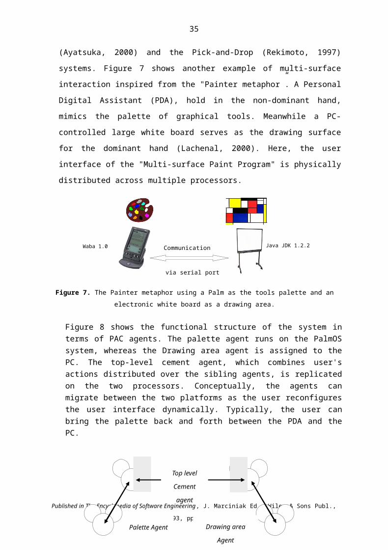
35
be performed with possibly local feedback via the Presentation facet before the melting pot is
sent higher in the hierarchy. In addition, if the Abstract facet of the agent is coupled with the
Functional Core Adaptor, the Functional Core Adaptor is warned about the agent’s state
change.
The criteria for triggering fusion are threefold: the logical complementarity of melting pots,
time proximity (to cope with simultaneous usage of multiple modalities), and context. The
detailed description of the algorithm can be found in (Nigay, 1995).
Multimodal interaction is a very active area of research for which no architectural reference
model has emerged yet. Currently, researchers are more concerned with uncertainty and
robustness issues than with the sound development of architectural models.
ARCHITECTURE MODELING FOR GROUPWARE
Software architecture modeling for groupware must accommodate a large variety of
requirements ranging from distributed systems and traditional HCI to more novel issues
related to CSCW. The diversity and the novelty of the technical problems explain both the
profusion of ad-hoc models and the lack of canonical models that would demonstrate
sufficient genericity and coverage. In the following discussion, the coverage of an
architectural model denotes its capacity to address the functional aspects of multi-user
systems. The “clover model”, presented next, provides a high level partitioning for reasoning
about the classes of functions a groupware may support. Using functional coverage as a
criterion, we then analyze two significant models applicable to groupware systems: Dewan’s
model based on a layer style and ALV based on an agent style.
The Clover model
As shown in Figure 17 a), a groupware system covers three domain specific functions:
production, coordination and communication (Calvary, 1997).
- The production space denotes the set of domain objects that model the multi-user
elaboration of common artefacts such as documents, or that motivate a common
undertaking such as flying an airplane between two places. Typically, shared editors
support the production space.
Published in The Encyclopedia of Software Engineering, J. Marciniak Ed., Wiley & Sons Publ., 1993, pp. 38-49.

36
- The coordination space covers activities dependencies including temporal relationships
between the multi-user activities. Workflow systems are primarily concerned with
coordination.
- The communication space supports person-to-person communication. Email and
mediaspaces (Coutaz, 1998; Dourish, 1992; Tang, 1994) are examples of systems
designed for supporting computer-mediated communication either asynchronously or
synchronously.
SpaceProduction
Space
CommunicationSpace
Coordination
t
a) b)
Figure 17: a) Groupware as a “functional clover” and b) its slinky property.
The notions of production and coordination spaces correspond to Ellis’ ontological and
coordination models while the communication space complements Ellis’ view of the
functional decomposition of groupware (Ellis, 1994). Contrary to Ellis’s model, user
interface issues do not constitute a third functional aspect of groupware. Instead, it is
orthogonal to all functional aspects of groupware. As for any domain specific function, the
services provided by each of the three functional spaces must be accessible and observable
through an appropriate user interface.
Interestingly, the relative importance of the three functional spaces depends on the particular
groupware system at hand and may vary over time. Typically, shared editors favor
production whereas communication functions are first class issues in mediaspaces. In
addition, this functional (slinky) shift may vary over time (see Figure 17b). For example, at
some point in the group activity, coordination is the focus of attention, possibly using
computer-mediated communication to plan future common production.
Dewan’ s model
The “generic multi-user architecture” model proposed by Dewan (Dewan, 1999) structures a
groupware system into a variable number of levels of abstraction ranging from the domain
specific level to the hardware level. Layers shared between users form the base of the system
(e.g., layers S to L+1 in Figure 18a). At some point, the base gives rise to branches which are
replicated for every user (see layers L to 0 in Figure 18a). Information flow between layers
Published in The Encyclopedia of Software Engineering, J. Marciniak Ed., Wiley & Sons Publ., 1993, pp. 38-49.

37
occurs vertically between adjacent layers along the input and output axis as well as
horizontally between peer and non peer replicated layers for synchronizing states.
Dewan’s model can be seen as an extension of Patterson’s “zipper model” (Patterson, 1994):
when a layer is replicated, all layers below it are necessarily replicated. This hypothesis does
not comply with situations where multiple users, like in MMM (Bier, 1991), share the same
physical workstation. On the other hand, this model offers a good basis for implementing
various forms of coupling as well as for allocating functions to processes (e.g., reasoning
about the granularity of parallelism, replication and distribution). For example, one can
choose to execute the base and each branch within distinct processes. Similarly, without any
automatic support from the underlying platform, the model helps reasoning about allocating
processes to processors.
Genericity in Dewan’s model comes from the notion of layer whose functional role and
number can be adapted to the case at hand. A layer can be viewed as a level of abstraction or
as a service that overlaps with other services as in SLICE (Fekete, 1996). Figure 18b) shows
an instantiation of Dewan's model using the functional layers of Arch. Although generic,
Dewan’s model does not convey any structuring mechanism to reason about the functional
aspects of the clover model.
Layer 1
Layer L
Layer L+1
Layer S (Semantic) Outputs Inputs
Layer L
Layer 1
Layer 0 (Hard.) Layer 0 (Hard.)
a) b)
FC
FCA FCA
IC IC
LP LP
DC DC
Figure 18: a) Dewan’s generic architecture for multi-user systems. Layers S to L+1 are common to all users and not replicated. Layers L to 0 are replicated. Arrows denote information flow: the horizontal ones express the existence of some coupling between peer layers ; the diagonal ones denote some coupling between non peer components. b) An instantiation of Dewan's model using the functional layers of Arch.
The ALV model
As shown in Figure 19, ALV associates a personal interface component, a View, to every
user and uses Link components to connect views to a shared Abstraction (Hill, 1992). Links
are in charge of expressing constraints between the views and the shared abstraction and of
maintaining their mutual dependencies by a bidirectional propagation of events. The Rendez-
Published in The Encyclopedia of Software Engineering, J. Marciniak Ed., Wiley & Sons Publ., 1993, pp. 38-49.

38
Vous language has been defined for expressing two-ways constraints between a View and the
Abstraction (Hill, 1994). Clearly, ALV addresses synchronous multi-user systems based on a
centralized shared functional core. ALV can be seen as an instantiation of Dewan’s model
using three layers where the semantic level is mapped to the shared abstraction and where
branches are comprised of links and views. Experimental evidence indicates that ALV
primarily covers the production space based on direct manipulation and, to a lower extent,
addresses the coordination space.
Figure 19: The ALV model.
Discussion
As for multimodal interaction, a large number of groupware applications are emerging bringing in new requirements. Currently, groupware architectural modeling needs to integrate a wide spectrum of knowledge including the well-established GUI technology and the work developed in distributed systems. It is our opinion than with an appropriate underlying middleware infrastructure, many of the functionalities groupware people are currently facing will be incorporated for free in the infrastructure. As a result, reference models developed for single-user applications will be directly applicable.
CONCLUSIONArchitectural modeling is becoming a central problem for large, complex systems. Although
interface builders tend to alleviate the problem, they are limited in scope and apply to
mundane cases for which the user interface is often a second class component. Architecture
design of user interfaces is not a luxury but a necessity and needs better support.
Although conceptual architecture modeling for interactive systems has been experimented in
length for the past 10 years, additional requirements are emerging with the need for
ubiquitous access to information processing, with the success of new consumer devices such
Published in The Encyclopedia of Software Engineering, J. Marciniak Ed., Wiley & Sons Publ., 1993, pp. 38-49.
A
L
V2V1
L V2V1
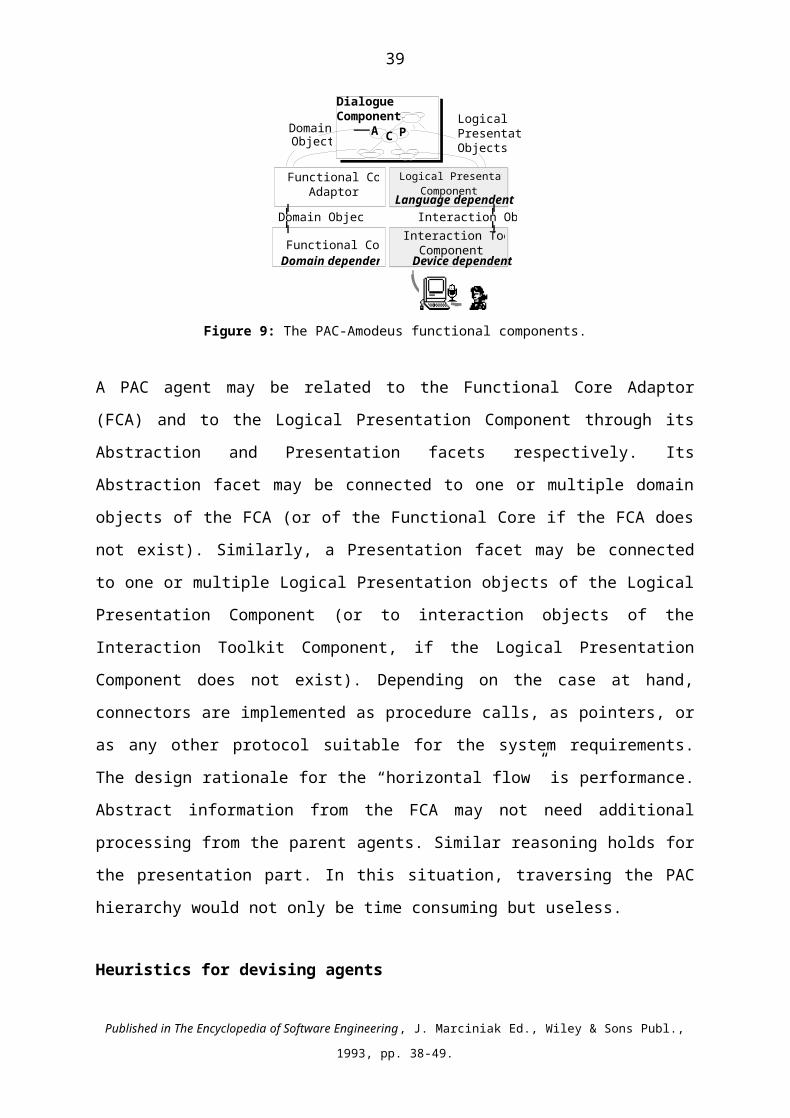
39
as pocket computers and wireless networks. In particular, user interfaces need to
accommodate the variability of a large set of interactional devices while preserving usability.
The plasticity (Thevenin, 1999; Calvary, 2001) of user interfaces is the next challenge
software architecture modelers need to address.
BIBLIOGRAPHY
G. Anderson, N. Graham, T. Wright, “Dragonfly: Linking Conceptual and Implementation Architectures of Multiuser Interactive Systems”, in Proc. International Conference of Software Engineering, ACM Press, 2522-261 (2000).
Arch, “A Metamodel for the Runtime Architecture of An Interactive System”, The UIMS Developers Workshop, SIGCHI Bulletin, 24(1), ACM (1992).
Y. Ayatsuka, N. Matsushita, J. Rekimoto. ‘HyperPalette: a Hybrid Computing Environment for Small Computing Devices”. In Proc. CHI2000 Extended Abstracts, Interactive Posters, ACM Publ., 133-134 (2000).
F. Bachmann, L. Bass, G. Chastek, P. Donohoe, F. Peruzzi, The Architecture Based design Method, CMU/SEI-2000-TR-001, Carnegie Mellon, Pittsburgh, (2000).
L. Bass, P. Clements, R. Kazman, Software Architecture in Practice. Addison Wesley Publ., ISBN 0-201-19930-0 (1998).
L. Bass, B.E. John, J. Kates, Achieving Usability through Software Architecture, CMU/SEI-2001-TR-005 ESC-TR-2001-005 (2001).
L. Bass and J. Coutaz, Developing Software for the User Interface, Addison Wesley Publ. (1991).
R.M. Baecker, D. Nastos, L.R. Posner, M.K. Mawlby, “The user-centered iterative design of collaborative writing software”, in Proceedings of theWorkshop on Real Time Group Drawing and Writing Tools, CSCW’ 92 (1992).
R.M. Beacker (ed.), Readings in Groupware and Computer-Supported Cooperative Work: Assisting Human-Human Collaboration. Morgan Kaufman Publ., ISBN 1-55860-241-0 (1993).
P. Bellavista, A. Corradi, C. Stefanelli, “Mobile Agent Middleware for Mobile Computing”, IEEE Computer, 34(3), 73-81 (2001).
E.A. Bier, S. Freeman, “MMM: A User Interface Architecture for Shared Editors on a Single Screen”, in Proc. UIST’ 91, ACM Symposium on User Interface Software and Technology, 79-86 (1991).
Published in The Encyclopedia of Software Engineering, J. Marciniak Ed., Wiley & Sons Publ., 1993, pp. 38-49.

40
R. Bolt, “Put-that-there: Voice and gesture at the graphics interface”, Computer Graphics, 14, 262-270 (1980).
G. Calvary, J. Coutaz, L. Nigay, “From Single-User Architectural Design to PAC*: a Generic Software Architecture Model for CSCW”, Proceedings of CHI 97, ACM publ., 242-249 (1997).
G. Calvary, J. Coutaz, D. Thevenin, “a Unifying Framework for the Development of Plastic User Interfaces”, in Proc. IFIP WG2.7 (13.) Working Conference on Engineering Human Computer Interaction, Springer Verlag, 218-238 (2001).
J. M. Carroll, "Introduction: The Scenario Perspective on System Development", In Scenario-Based Design: Envisioning Work and technology in System Development, J.M. Carroll (Ed.), J.Wiley Publ., NY, 1-17 (1995).
P. Cohen, A. Cheyer, M. Wang, S. Baeg, « An open agent architecture. Readings in agents, Kaufman San Francisco, 197-204 (1994).
J. Coutaz, PAC, “An Implemention Model for Dialog Design”, Proceedings of Interact'87, Stuttgart, September, 431-436 (1987).
J. Coutaz and S. Balbo, “Applications: A Dimension Space for UIMS’s”, Proceedings of the Computer Human Interaction Conference, ACM, 27-32 (1991).
J. Coutaz, L. Nigay, D. Salber, A. Blandford, J. May, R.M.Y. Young, “Four Easy Pieces for Assessing the Usability of Multimodal Interaction: The CARE properties”, Proceedings of the INTERACT'95 conference, S. A. Arnesen & D. Gilmore Eds., Chapman&Hall Publ., Lillehammer, Norway, 115-120 (1995).
J. Coutaz, F. Bérard, E. Carraux, J. Crowley, “Early Experience with the Mediaspace CoMedi”, Proceedings of Engineering Human Computer Interaction, EHCI’98, Héraklion, Sept. 1998, Kluver Academics Publ., 57-72 (1998).
J. Coutaz, L. Nigay, “Architecture logicielle conceptuelle des systèmes interactifs”, Analyse et Conception de l'Interaction Homme-Machine dans les systèmes d'information, Hermès publ. (2001).
J. Crowley, J. Coutaz, F. Bérard, “Things that See”, Communication of the ACM, Vol 43 (3), 54-64 (2000)
P. Dewan, “A tour of the Suite User Interface Software”, in Proceedings UIST'90, ACM, 57-65 (1990).
P. Dewan, “Architectures for Collaborative Applications”. In Computer Suported Co-operative Work, M. Beaudouin-Lafon (ed), John Wiley&Sons Ltd., ISBN 0-471-96736-X (1999).
A. Dey, G. Kortuen, D. Morse, A. Schmidt, Special Issue on Situated Interaction and Context-aware Computing, Personal and Ubiquitous Computing, 5(1), A. Dey, G. Kortuen, D. Morse, A. Schmidt Eds (2001),
Published in The Encyclopedia of Software Engineering, J. Marciniak Ed., Wiley & Sons Publ., 1993, pp. 38-49.

41
P. Dourish, S.A. Bly, “Portholes : Supporting Awareness in a Distributed Work Group”, in proceedings of the CHI’92 Conference on Human Factors in Computing Systems, 541-547 (1992).
D. Duke, M. Harrison, Towards a Theory of Interactors, The Amodeus Project, Esprit Basic Research 7040, Amodeus Project Document, System Modelling/WP6 (1993).
D. Duke, M. Harrison, “Folding Human Factors into Rigourous Development”, in the Proc. of Eurographics Workshop "Design, Specification, Verification of Interactive Systems, F. Paterno' ed., 335-352 (1994).
T. Duval, L. Nigay, "Implémentation d'une application de simulation selon le modèle PAC-AMODEUS", Actes des Journées IHM'99, Cépaduès, 86-93 (1999).
C. Ellis, J. Wainer, “A Conceptual Model of Groupware”, in Proceedings CSCW’94, ACM Conference on Computer Supported Cooperative Work, Furuta, R., Neuwirth, C. eds., 79-88 (1994).
W. Ellis, R. Hilliard II, P. Poon, D. Rayford, T. Saunders, B. Sherlund, R. Wade, “Toward a Recommended Practice for Architectural Description”. Proc. 2nd IEEE International Conference on Engineering of Complex Computer Systems, Montreal (1996).
D. Fekete, M. Beaudouin-Lafon, “Using the Multi-Layer Model for Building Interactive Graphical Applications”, in Proc. UIST'96, ACM, pp. 109-118 (1996).
D.M. Geary D.M., A.L. McClellan, Graphic Java: mastering the AWT, SunSoft Press, 1997.
D.M. Geary, Graphic Java 2, Volume 2, Swing, 3/e, Prentice Hall PTR, 1999.
J. Ferber, Les systèmes multi-agents, Vers une intelligence collective, IIA, InterEditions (1995).
E. Gamma, R. Helm, R. Johnson, J. Vlissides, Design Patterns: Elements of Reusable Object-Oriented Software, Addison-Wesley, Reading, MA (1995).
D. Garlan, M. Shaw, An Introduction to Software Architecture, Advances in Software Engineering and Knowledge Engineering, Ambriola, V. and Tortora, G. eds., Vol. 1, World Scientific Publ., 1-39 (1993).
T.C.N. Graham, T. Urnes, “Integrating Support for Temporal Media into an Architecture for Graphical User Interfaces”. In Proc. ICSE-19, ACM Press, 172-182 (1997).
Gram C. et Cockton G. (Eds.), Design Principles for Interactive Software, Chapman & Hall (1996).
R. Hill, “The Abstraction-Link-View Paradigm: Using Constraints to Connect User Interfaces to Applications”, in proceedings CHI'92 (NewYork), ACM, 335-342 (1992).
Published in The Encyclopedia of Software Engineering, J. Marciniak Ed., Wiley & Sons Publ., 1993, pp. 38-49.
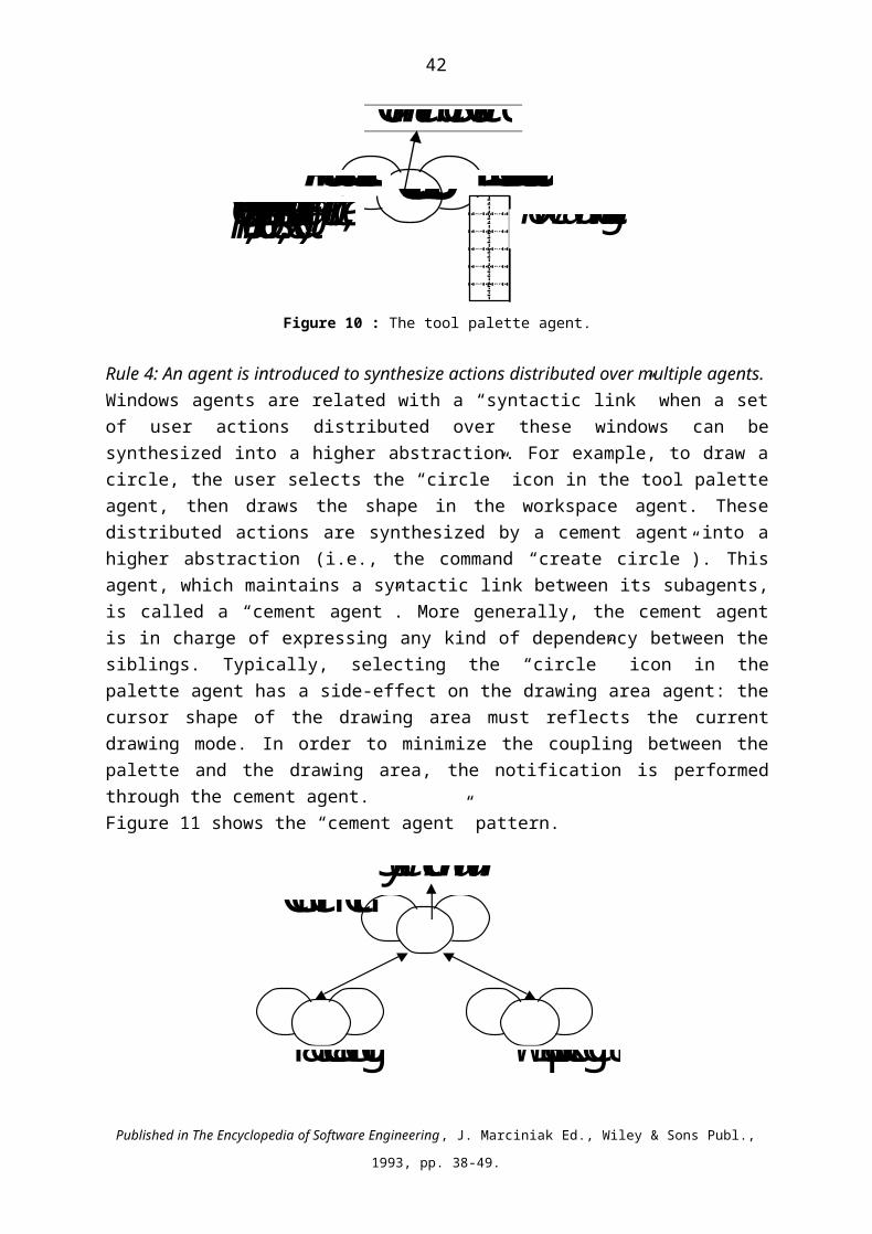
42
R. Hill, T. Brinck, S.L. Rohall, J.F. Patterson, W. Wilner, “The Rendez-vous language and architecture for constructing multi-user applications”. ACM TOCHI, 1(2), 81-125 (1994).
C. Hofmeister, R. Nord, D. Soni, Applied Software Architecture, Addison Wesley Publish., Reading, MA (2000).
ILOG S.A., ILOG Views Reference Manual. Version 2.1, 1994.
R. Kazman, L. Bass, G. Abowd, M. Webb, “SAAM: a Method for Analyzing the Properties of Software Architecture”, Proc. of the International Conference on Software Engineering, ICSE-16, 81-90 (1994).
R. Kazman, G. Abowd, L. Bass, P. Clements, “Scenario Based Analysis of Software Architecture”, IEEE Software, IEEE Cmputer Society Publ., 257-266 (1996).
R. Kazman, M. Barbacci, M. Klein, S.J. Carriere, S.G. Woods, “Experience with Performing Architecture Tradeoff Analysis”. Proc. of the 21rst International Conference on Software Engineering (ICSE 1999), IEEE Computer Society Publ., 54-63 (1999).
G.E. Krasner, S.T. Pope, “A cookbook for using the Model-View-Controller user interface paradigm in Smalltalk-80”. JOOP, 1(3), 26-49 (1988).
M. W. Krueger, Artificial Reality II, Addison-Wesley Publ. (1990).
IEEE. IEEE Standard 1471-2000, IEEE standard office, PO 1331, Piscataway, NJ 08855-1331, http://standards.ieee.org (2000).
C. Lachenal, J. Coutaz, G. Calvary, D. Thevenin Software Architecture Adaptivity for Multisurface Interaction and Plasticity, IFIP WG2.7 (13.2) Workshop, CSCW (2000).
M. Maier, D. Emery, R. Hilliard, “Software Architecture: Introducing IEEE Standard 1471”, IEEE Computer, 34(4), IEEE Computer Society Publ., 107-109 (2001).
L. Nigay, J. Coutaz, “Building user interfaces : Organizing software agents”, Proc. ESPRIT’91 conference, 707-719 (1991).
L. Nigay, J. Coutaz and D. Salber, MATIS, a Multimodal Travel Information System, The Amodeus Project, Esprit Basic Research 7040, Amodeus Project Document, SystemModelling/WP10 (1993).
L. Nigay, J. Coutaz, “A Generic Platform for Addressing the Multimodal Challenge”, in Proc. CHI’95 Human Factors in Computing Systems, ACM New York, Denver, 98-105 (1995).
S. Oviatt, Multimodal Interfaces, Special Issue, Human Computer Interaction, 12(1&2), Lawrence Erlbaum Ass., Mahwah, New Jersey (1997)
Published in The Encyclopedia of Software Engineering, J. Marciniak Ed., Wiley & Sons Publ., 1993, pp. 38-49.

43
S. Oviatt, P. Cohen, “Mutlimodal systems that process what comes naturally”, Communication of the ACM, ACM publ., 43(3), 45-53 (2000).
S. Oviatt, P. Cohen, L. Wu, J. Vergo, L. Duncan, B. Suhm, J. Bers, T. Holzman, T. Winograd, J. Landay, J. Larson, D. Ferro, “Designing the User Interface for Multimodal Speech and Pen-Based gesture Applications: State-of-the-Art Systems and Future Research Directions”, Human-Computer Interaction, vol. 15, Laurence Erlbaum Associates, Inc. Publ., 263-322 (2000).
F. Paternò, A. Leonardi, S. Pangoli, “A Tool Supported Approach to the Refinement of Interactive System”s, in the Proc. of Eurographics Workshop "Design, Specification, Verification of Interactive Systems", F. Paterno' Ed., 85-96 (1994).
F. Paternò, Model-based Design and Evaluation of Interactive Applications, Springer Verlag, ISBN 1-85233-155-0 (1999).
J.F. Patterson, A taxonomy of Architectures for Synchronous Groupware Applications, Workshop on Software Architectures for Cooperative Systems, CSCW’94, ACM Conference on Computer Supported Cooperative Work, (1994).
W.G. Phillips, Architectures for Synchronous Groupware. Technical report 1999-425, Dpt of Computing and Information Science, Queen's University, (1999).
G.E. Pfaff et al., User Interface Management Systems, G.E. Pfaff ed., Eurographics Seminars, Springer Verlag (1985).
J. Rekimoto. « Pick-and-Drop: A Direct Manipulation technique for Multiple Computer Environments », In Proc. UIST97, ACM Publ., 31-39 (1997)
H. Rheingold. Virtual Reality. Summit Books New York (1991).
M.J. Rochkind, "XVT: A Virtual Toolkit for Portability Between Window Systems", Proceedings of the Winter 1989 USENIX Conference, USENIX, 151-163 (1989).
M. Roseman, S. Greenberg, “GROUPKIT: A groupware Toolkit for Building Real-Time Conferencing Applications”, in Proc. CSCW'92, ACM Conference on CSCW, 43-50 (1992).
M. Shaw, D. Garlan, Software Architecture. Perspectives on an Emerging Discipline, Prentice Hall (1995).
M. Shaw, P. Clement, “ field Guide to Boxology: Preliminary Classification of Architectural Styles for Software Systems”, COMPSAC’97 International Computer Software and Applications Conference, 6-13 (1997)
M. Shaw, “The Coming-of-Age of Software Architecture Research” Proc. of the 23rd
International Conference on Software Engineering (ICSE 2001)”, IEEE Computer Society Publ., 657-665 (2001).
B. Shneiderman, “Universal Usability”, Communication of the ACM, 43(5), 17-22 (2000).
Published in The Encyclopedia of Software Engineering, J. Marciniak Ed., Wiley & Sons Publ., 1993, pp. 38-49.

44
C. Szyperski. Component-Oriented Software, Beyond Object-Oriented Programming. Addison Wesley (1997).
J.C. Tang, J.C., M. Rua, “Montage: Providing Teleproximity for Distributed Groups”, in Proc. of the Conference on Computer Human Interaction (CHI’94), 37-43 (1994).
R.N. Taylor, N. Medvidovic, K.M. Anderson, E.J. Whitehead, J.E. Robbins, K.A. Nies, P. Oreizy, D.L. Duborw, “A Component and Messsage-based architectural style for GUI software”. IEEE Trans. SW Engineering, 22(6), 390-406 (1996).
F. Tarpin-Bernard, B. David, P. Primet, “Framework and Patterns for synchronous groupware: AMF-C Approach”. In Proc. IFIP 2.7 (13.4) Working Conference on Engineering for Human-Computer Interaction, EHCI'98, Heraklion, (1998).
D. Thevenin, J. Coutaz, “Plasticity of User Interfaces: Framework and Research Agenda”. In Proc. Interact99, Edinburgh,A. Sasse & C. Johnson (eds.), IFIP IOS Press Publ.. 110-117(1999).
P. Wellner, W. E. Mackay, R. Gold, “Back to the Real World”, Communication of the ACM, 36(7), 24-27 (1993).
Published in The Encyclopedia of Software Engineering, J. Marciniak Ed., Wiley & Sons Publ., 1993, pp. 38-49.