software manual - ws1.necii.comws1.necii.com/ds2000/d2kdownloads/d2k files/software_manuals... ·...
TRANSCRIPT

Software Manual
Part No. 80000SWG14Issue 1-0, December 2001
Printed in U.S.A.020400
!! Important Notes for Software Version 02.04.00 !!
• Complete system documentation, including a
Software Manual
and detailed
Hardware Man-uals
, is provided on the System Document CD packed with your system.
• For additional resources, visit our Technical Support site on the web at
208.141.100.36/ds2000
.
•
If upgrading from a software version prior to 02.02.14, you must initialize Distinctive Ringing.
Use the new option
9803 - Ring Tone Setup
on page 661 to initialize Distinctive Ringing with a single command.
Following initialization, you must reset the system or unplug and then replug each telephone
.
• Be sure your system’s hardware configuration does not exceed the System Load Factor. See
DS2000 Load Factor
on page 3 and
DS1000 Load Factor
on page 9 for more.
When installing telephones and other station devices in software version 02.02.14 or higher:• Digital station ports (300-315 in DS1000, on installed and programmed PCBs in DS2000)
automatically
detect the type of connected device when the keyset, 2-OPX Module (both ports) or Digital Door Box is plugged in. It is no longer necessary to individually set circuit types
1801 - Extension Circuit Type
.
DS2000 Installation Notes
Software version 02.04.00 uses the following hardware default assignments:• Slot CN1 = 16DSTU PCB (Extensions 300-315).• Slot CN2-CN8 = Undefined.
When installing PCBs:• After plugging in your PCBs and powering up the system, use
9902 - Slot Assignment
on page 665 to enable the installed PCBs.

This manual has been developed by NEC America, Inc. It is intended for the use of its customers and service personnel, and should be read in its entirety before attempting to install or program the system. Any comments or suggestions for improving this manual would be appreciated. Forward your remarks to:
NEC America, Inc., Corporate Networks Group
4 Forest ParkwayShelton, CT 06484
cng.nec.com
Nothing contained in this manual shall be deemed to be, and this manual does not constitute, a warranty of, or representation with respect to, any of the equipment covered. This manual is subject to change without notice and NEC America, Inc. has no obligation to provide any updates or corrections to this manual. Further, NEC America, Inc. also reserves the right, without prior notice, to make changes in equipment design or components as it deems appropriate. No representation is made that this manual is complete or accurate in all respects and NEC America, Inc. shall not be liable for any errors or omissions. In no event shall NEC America, Inc. be liable for any incidental or consequential damages in connection with the use of this manual. This document contains proprietary information that is protected by copyright. All rights are reserved. No part of this document may be photocopied or reproduced without prior written consent of NEC America, Inc.
©2001 by NEC America, Inc. All Rights Reserved.Printed in U.S.A.

Table of Contents
DS1000/2000 Software Manual
Table of Contents
◆
i
Table of Contents
Chapter 1 Features . . . . . . . . . . . . . . . . . . . . . . . . . . . . . . . . . . . . . . . . . . . . . . . . . . . . . . 1
Introduction . . . . . . . . . . . . . . . . . . . . . . . . . . . . . . . . . . . . . . . . . . . . . . . . . . . . . . . . . . . . . . . . . . . .1Before Reading This Section . . . . . . . . . . . . . . . . . . . . . . . . . . . . . . . . . . . . . . . . . . . . . . .1Using This Section . . . . . . . . . . . . . . . . . . . . . . . . . . . . . . . . . . . . . . . . . . . . . . . . . . . . . . .1
DS2000 System Configuration . . . . . . . . . . . . . . . . . . . . . . . . . . . . . . . . . . . . . . . . . . . . . . . . . . . . .3DS2000 Load Factor . . . . . . . . . . . . . . . . . . . . . . . . . . . . . . . . . . . . . . . . . . . . . . . . . . . . . .3DS2000 System Load Factor Calculations . . . . . . . . . . . . . . . . . . . . . . . . . . . . . . . . . . . . 4Examples of Typical DS2000 4-Slot Cabinet Maximum Configurations . . . . . . . . . . . . . 5Examples of Typical DS2000 8-Slot Cabinet Maximum Configurations . . . . . . . . . . . . . 5DS2000 Default Setup . . . . . . . . . . . . . . . . . . . . . . . . . . . . . . . . . . . . . . . . . . . . . . . . . . . .6DS2000 4 Slot Cabinet (with Fixed Slot Software) Hardware Configuration . . . . . . . . . 6DS2000 4 Slot Cabinet (with U Slot Software) Hardware Configuration. . . . . . . . . . . . . 6DS2000 8 Slot Cabinet (with U Slot Software) Hardware Configuration. . . . . . . . . . . . . 8
DS1000 System Configuration . . . . . . . . . . . . . . . . . . . . . . . . . . . . . . . . . . . . . . . . . . . . . . . . . . . . .9DS1000 Load Factor . . . . . . . . . . . . . . . . . . . . . . . . . . . . . . . . . . . . . . . . . . . . . . . . . . . . . .9DS1000 System Load Factor Calculations . . . . . . . . . . . . . . . . . . . . . . . . . . . . . . . . . . . . 9DS1000 Default Setup . . . . . . . . . . . . . . . . . . . . . . . . . . . . . . . . . . . . . . . . . . . . . . . . . . .10
Initial System Startup. . . . . . . . . . . . . . . . . . . . . . . . . . . . . . . . . . . . . . . . . . . . . . . . . . . . . . . . . . . .11Default Feature Setup . . . . . . . . . . . . . . . . . . . . . . . . . . . . . . . . . . . . . . . . . . . . . . . . . . . .11DS2000 Fixed Slot Software (01.nn.nn) . . . . . . . . . . . . . . . . . . . . . . . . . . . . . . . . . . . . . 11DS2000 U Slot Software and DS1000 (02.03.nn). . . . . . . . . . . . . . . . . . . . . . . . . . . . . . 11Initial Startup Programming . . . . . . . . . . . . . . . . . . . . . . . . . . . . . . . . . . . . . . . . . . . . . . .12
Charts and Illustrations . . . . . . . . . . . . . . . . . . . . . . . . . . . . . . . . . . . . . . . . . . . . . . . . . . . . . . . . . .152-OPX Module . . . . . . . . . . . . . . . . . . . . . . . . . . . . . . . . . . . . . . . . . . . . . . . . . . . . . . . . . . . . . . . . .322500 Sets / Single Line Telephones . . . . . . . . . . . . . . . . . . . . . . . . . . . . . . . . . . . . . . . . . . . . . . . . .33Account Codes . . . . . . . . . . . . . . . . . . . . . . . . . . . . . . . . . . . . . . . . . . . . . . . . . . . . . . . . . . . . . . . . .34
Optional (Unforced) Account Codes . . . . . . . . . . . . . . . . . . . . . . . . . . . . . . . . . . . . . . . . 34Forced Account Codes. . . . . . . . . . . . . . . . . . . . . . . . . . . . . . . . . . . . . . . . . . . . . . . . . . . 34Verified Account Codes . . . . . . . . . . . . . . . . . . . . . . . . . . . . . . . . . . . . . . . . . . . . . . . . . 34Using Account Codes and Speed Dial. . . . . . . . . . . . . . . . . . . . . . . . . . . . . . . . . . . . . . . 34Using Account Codes with Last Number Redial and Save . . . . . . . . . . . . . . . . . . . . . . . 35Account Codes and Emergency Calls . . . . . . . . . . . . . . . . . . . . . . . . . . . . . . . . . . . . . . . 35General Account Codes Programming . . . . . . . . . . . . . . . . . . . . . . . . . . . . . . . . . . . . . . 38Optional (Unforced) Account Codes Programming . . . . . . . . . . . . . . . . . . . . . . . . . . . . 38Forced Account Codes Programming . . . . . . . . . . . . . . . . . . . . . . . . . . . . . . . . . . . . . . . 39Verified Account Codes Programming . . . . . . . . . . . . . . . . . . . . . . . . . . . . . . . . . . . . . . 39Account Codes Programming Examples . . . . . . . . . . . . . . . . . . . . . . . . . . . . . . . . . . . . . 40
Alphanumeric Display . . . . . . . . . . . . . . . . . . . . . . . . . . . . . . . . . . . . . . . . . . . . . . . . . . . . . . . . . . .43Attendant Call Queuing . . . . . . . . . . . . . . . . . . . . . . . . . . . . . . . . . . . . . . . . . . . . . . . . . . . . . . . . . .45
Operator Call Key . . . . . . . . . . . . . . . . . . . . . . . . . . . . . . . . . . . . . . . . . . . . . . . . . . . . . . 45Attendant Position . . . . . . . . . . . . . . . . . . . . . . . . . . . . . . . . . . . . . . . . . . . . . . . . . . . . . . . . . . . . . .47Automatic Handsfree . . . . . . . . . . . . . . . . . . . . . . . . . . . . . . . . . . . . . . . . . . . . . . . . . . . . . . . . . . . .51Automatic Ring Down . . . . . . . . . . . . . . . . . . . . . . . . . . . . . . . . . . . . . . . . . . . . . . . . . . . . . . . . . . .54Background Music . . . . . . . . . . . . . . . . . . . . . . . . . . . . . . . . . . . . . . . . . . . . . . . . . . . . . . . . . . . . . .55Barge In (Intrusion) . . . . . . . . . . . . . . . . . . . . . . . . . . . . . . . . . . . . . . . . . . . . . . . . . . . . . . . . . . . . .58Battery Backup. . . . . . . . . . . . . . . . . . . . . . . . . . . . . . . . . . . . . . . . . . . . . . . . . . . . . . . . . . . . . . . . .60Call Coverage Keys . . . . . . . . . . . . . . . . . . . . . . . . . . . . . . . . . . . . . . . . . . . . . . . . . . . . . . . . . . . . .62

Table of Contents
ii
◆
Table of Contents
DS1000/2000 Software Manual
Call Forwarding . . . . . . . . . . . . . . . . . . . . . . . . . . . . . . . . . . . . . . . . . . . . . . . . . . . . . . . . . . . . . . . .66Call Forwarding Timers. . . . . . . . . . . . . . . . . . . . . . . . . . . . . . . . . . . . . . . . . . . . . . . . . . 68
Call Timer . . . . . . . . . . . . . . . . . . . . . . . . . . . . . . . . . . . . . . . . . . . . . . . . . . . . . . . . . . . . . . . . . . . .72Call Waiting / Camp-On . . . . . . . . . . . . . . . . . . . . . . . . . . . . . . . . . . . . . . . . . . . . . . . . . . . . . . . . .75Callback . . . . . . . . . . . . . . . . . . . . . . . . . . . . . . . . . . . . . . . . . . . . . . . . . . . . . . . . . . . . . . . . . . . . . .79Caller ID. . . . . . . . . . . . . . . . . . . . . . . . . . . . . . . . . . . . . . . . . . . . . . . . . . . . . . . . . . . . . . . . . . . . . .82
Single and Multiple Message Format Compatibility. . . . . . . . . . . . . . . . . . . . . . . . . . . . 82Caller ID on the SMDR Report . . . . . . . . . . . . . . . . . . . . . . . . . . . . . . . . . . . . . . . . . . . . 82Caller ID Integration with Voice Mail. . . . . . . . . . . . . . . . . . . . . . . . . . . . . . . . . . . . . . . 83Second Call Caller ID (Extension Level Call Waiting Caller ID). . . . . . . . . . . . . . . . . . 83Third Party Caller ID Check . . . . . . . . . . . . . . . . . . . . . . . . . . . . . . . . . . . . . . . . . . . . . . 83Caller ID Display Separator. . . . . . . . . . . . . . . . . . . . . . . . . . . . . . . . . . . . . . . . . . . . . . . 83Caller ID to Single Line Telephones . . . . . . . . . . . . . . . . . . . . . . . . . . . . . . . . . . . . . . . . 83DSP-Based Caller ID. . . . . . . . . . . . . . . . . . . . . . . . . . . . . . . . . . . . . . . . . . . . . . . . . . . . 83
Caller ID Logging . . . . . . . . . . . . . . . . . . . . . . . . . . . . . . . . . . . . . . . . . . . . . . . . . . . . . . . . . . . . . .89Caller ID Logging Enhancements . . . . . . . . . . . . . . . . . . . . . . . . . . . . . . . . . . . . . . . . . . 90Some Common Caller ID Logging Examples . . . . . . . . . . . . . . . . . . . . . . . . . . . . . . . . . 9522-Button and 34-Button Display Telephone Operation. . . . . . . . . . . . . . . . . . . . . . . . . 96Super Display Telephone Operation . . . . . . . . . . . . . . . . . . . . . . . . . . . . . . . . . . . . . . . . 97
Central Office Calls, Answering . . . . . . . . . . . . . . . . . . . . . . . . . . . . . . . . . . . . . . . . . . . . . . . . . . .99Answering Priority. . . . . . . . . . . . . . . . . . . . . . . . . . . . . . . . . . . . . . . . . . . . . . . . . . . . . . 99Overflow . . . . . . . . . . . . . . . . . . . . . . . . . . . . . . . . . . . . . . . . . . . . . . . . . . . . . . . . . . . . . 99
Central Office Calls, Placing . . . . . . . . . . . . . . . . . . . . . . . . . . . . . . . . . . . . . . . . . . . . . . . . . . . . .105Expanded Dial Buffering (02.01.07 or Higher). . . . . . . . . . . . . . . . . . . . . . . . . . . . . . . 105
Check Key . . . . . . . . . . . . . . . . . . . . . . . . . . . . . . . . . . . . . . . . . . . . . . . . . . . . . . . . . . . . . . . . . . .115Class of Service . . . . . . . . . . . . . . . . . . . . . . . . . . . . . . . . . . . . . . . . . . . . . . . . . . . . . . . . . . . . . . .117Conference . . . . . . . . . . . . . . . . . . . . . . . . . . . . . . . . . . . . . . . . . . . . . . . . . . . . . . . . . . . . . . . . . . .124Conference, Meet-Me . . . . . . . . . . . . . . . . . . . . . . . . . . . . . . . . . . . . . . . . . . . . . . . . . . . . . . . . . .127Conference, Unsupervised . . . . . . . . . . . . . . . . . . . . . . . . . . . . . . . . . . . . . . . . . . . . . . . . . . . . . . .128Delayed Ringing . . . . . . . . . . . . . . . . . . . . . . . . . . . . . . . . . . . . . . . . . . . . . . . . . . . . . . . . . . . . . .129Dial Number Preview. . . . . . . . . . . . . . . . . . . . . . . . . . . . . . . . . . . . . . . . . . . . . . . . . . . . . . . . . . .131Direct Inward Line . . . . . . . . . . . . . . . . . . . . . . . . . . . . . . . . . . . . . . . . . . . . . . . . . . . . . . . . . . . . .133Direct Station Selection (DSS) . . . . . . . . . . . . . . . . . . . . . . . . . . . . . . . . . . . . . . . . . . . . . . . . . . .140Direct Station Selection (DSS) Console . . . . . . . . . . . . . . . . . . . . . . . . . . . . . . . . . . . . . . . . . . . .143Direct Trunk Access. . . . . . . . . . . . . . . . . . . . . . . . . . . . . . . . . . . . . . . . . . . . . . . . . . . . . . . . . . . .154Directed Call Pickup . . . . . . . . . . . . . . . . . . . . . . . . . . . . . . . . . . . . . . . . . . . . . . . . . . . . . . . . . . .156Directory Dialing . . . . . . . . . . . . . . . . . . . . . . . . . . . . . . . . . . . . . . . . . . . . . . . . . . . . . . . . . . . . . .158Display, Alphanumeric . . . . . . . . . . . . . . . . . . . . . . . . . . . . . . . . . . . . . . . . . . . . . . . . . . . . . . . . .161Distinctive Ringing . . . . . . . . . . . . . . . . . . . . . . . . . . . . . . . . . . . . . . . . . . . . . . . . . . . . . . . . . . . .162
The Distinctive Ringing Hierarchy . . . . . . . . . . . . . . . . . . . . . . . . . . . . . . . . . . . . . . . . 162Understanding Ring Types and Ring Sets . . . . . . . . . . . . . . . . . . . . . . . . . . . . . . . . . . . 163The Basics of How to Change the “Sound” of a Ring Type . . . . . . . . . . . . . . . . . . . . . 163When Multiple Calls Ring an Extension . . . . . . . . . . . . . . . . . . . . . . . . . . . . . . . . . . . . 164Programming Guidelines . . . . . . . . . . . . . . . . . . . . . . . . . . . . . . . . . . . . . . . . . . . . . . . . 164
Do Not Disturb. . . . . . . . . . . . . . . . . . . . . . . . . . . . . . . . . . . . . . . . . . . . . . . . . . . . . . . . . . . . . . . .183Door Box . . . . . . . . . . . . . . . . . . . . . . . . . . . . . . . . . . . . . . . . . . . . . . . . . . . . . . . . . . . . . . . . . . . .185Equal Access Compatibility. . . . . . . . . . . . . . . . . . . . . . . . . . . . . . . . . . . . . . . . . . . . . . . . . . . . . .190Extended Ringing. . . . . . . . . . . . . . . . . . . . . . . . . . . . . . . . . . . . . . . . . . . . . . . . . . . . . . . . . . . . . .191Extension Hunting . . . . . . . . . . . . . . . . . . . . . . . . . . . . . . . . . . . . . . . . . . . . . . . . . . . . . . . . . . . . .193
Circular Hunting . . . . . . . . . . . . . . . . . . . . . . . . . . . . . . . . . . . . . . . . . . . . . . . . . . . . . . 193Terminal Hunting. . . . . . . . . . . . . . . . . . . . . . . . . . . . . . . . . . . . . . . . . . . . . . . . . . . . . . 194Uniform Call Distribution (UCD) Hunting . . . . . . . . . . . . . . . . . . . . . . . . . . . . . . . . . . 194

Table of Contents
DS1000/2000 Software Manual
Table of Contents
◆
iii
Extension Hunting Timers. . . . . . . . . . . . . . . . . . . . . . . . . . . . . . . . . . . . . . . . . . . . . . . 200Flash . . . . . . . . . . . . . . . . . . . . . . . . . . . . . . . . . . . . . . . . . . . . . . . . . . . . . . . . . . . . . . . . . . . . . . . .207Flexible Numbering Plan . . . . . . . . . . . . . . . . . . . . . . . . . . . . . . . . . . . . . . . . . . . . . . . . . . . . . . . .209Forced Trunk Disconnect. . . . . . . . . . . . . . . . . . . . . . . . . . . . . . . . . . . . . . . . . . . . . . . . . . . . . . . .212Group Call Pickup . . . . . . . . . . . . . . . . . . . . . . . . . . . . . . . . . . . . . . . . . . . . . . . . . . . . . . . . . . . . .215Group Listen . . . . . . . . . . . . . . . . . . . . . . . . . . . . . . . . . . . . . . . . . . . . . . . . . . . . . . . . . . . . . . . . .219Group Ring. . . . . . . . . . . . . . . . . . . . . . . . . . . . . . . . . . . . . . . . . . . . . . . . . . . . . . . . . . . . . . . . . . .221
Overflow for Group Ring Calls . . . . . . . . . . . . . . . . . . . . . . . . . . . . . . . . . . . . . . . . . . . 221Handsfree and Handsfree Answerback . . . . . . . . . . . . . . . . . . . . . . . . . . . . . . . . . . . . . . . . . . . . .228
Handsfree. . . . . . . . . . . . . . . . . . . . . . . . . . . . . . . . . . . . . . . . . . . . . . . . . . . . . . . . . . . . 228Handsfree Answerback and Forced Intercom Ringing . . . . . . . . . . . . . . . . . . . . . . . . . 228
Headset Compatibility . . . . . . . . . . . . . . . . . . . . . . . . . . . . . . . . . . . . . . . . . . . . . . . . . . . . . . . . . .232Off-Hook Signaling and Headsets . . . . . . . . . . . . . . . . . . . . . . . . . . . . . . . . . . . . . . . . . 232
Hold . . . . . . . . . . . . . . . . . . . . . . . . . . . . . . . . . . . . . . . . . . . . . . . . . . . . . . . . . . . . . . . . . . . . . . . .235System (Regular) Hold . . . . . . . . . . . . . . . . . . . . . . . . . . . . . . . . . . . . . . . . . . . . . . . . . 235Exclusive Hold. . . . . . . . . . . . . . . . . . . . . . . . . . . . . . . . . . . . . . . . . . . . . . . . . . . . . . . . 235Automatic Hold . . . . . . . . . . . . . . . . . . . . . . . . . . . . . . . . . . . . . . . . . . . . . . . . . . . . . . . 235Intercom Hold . . . . . . . . . . . . . . . . . . . . . . . . . . . . . . . . . . . . . . . . . . . . . . . . . . . . . . . . 235Distinctive Flash Rate on Recall . . . . . . . . . . . . . . . . . . . . . . . . . . . . . . . . . . . . . . . . . . 236Enhanced Hold Recall Display . . . . . . . . . . . . . . . . . . . . . . . . . . . . . . . . . . . . . . . . . . . 236
Hotline . . . . . . . . . . . . . . . . . . . . . . . . . . . . . . . . . . . . . . . . . . . . . . . . . . . . . . . . . . . . . . . . . . . . . .240Interactive Soft Keys . . . . . . . . . . . . . . . . . . . . . . . . . . . . . . . . . . . . . . . . . . . . . . . . . . . . . . . . . . .244
Keyset Soft Keys . . . . . . . . . . . . . . . . . . . . . . . . . . . . . . . . . . . . . . . . . . . . . . . . . . . . . . 246Super Display Soft Keys . . . . . . . . . . . . . . . . . . . . . . . . . . . . . . . . . . . . . . . . . . . . . . . . 252Soft Key Index. . . . . . . . . . . . . . . . . . . . . . . . . . . . . . . . . . . . . . . . . . . . . . . . . . . . . . . . 259Call States . . . . . . . . . . . . . . . . . . . . . . . . . . . . . . . . . . . . . . . . . . . . . . . . . . . . . . . . . . . 265
Intercom . . . . . . . . . . . . . . . . . . . . . . . . . . . . . . . . . . . . . . . . . . . . . . . . . . . . . . . . . . . . . . . . . . . . .268Handsfree Answerback and Forced Intercom Ringing . . . . . . . . . . . . . . . . . . . . . . . . . 268
Key Ring . . . . . . . . . . . . . . . . . . . . . . . . . . . . . . . . . . . . . . . . . . . . . . . . . . . . . . . . . . . . . . . . . . . .273Overflow for Key Ring Calls. . . . . . . . . . . . . . . . . . . . . . . . . . . . . . . . . . . . . . . . . . . . . 273
Last Number Redial . . . . . . . . . . . . . . . . . . . . . . . . . . . . . . . . . . . . . . . . . . . . . . . . . . . . . . . . . . . .277Line Keys . . . . . . . . . . . . . . . . . . . . . . . . . . . . . . . . . . . . . . . . . . . . . . . . . . . . . . . . . . . . . . . . . . . .279
Answering Priority. . . . . . . . . . . . . . . . . . . . . . . . . . . . . . . . . . . . . . . . . . . . . . . . . . . . . 279Loop Keys . . . . . . . . . . . . . . . . . . . . . . . . . . . . . . . . . . . . . . . . . . . . . . . . . . . . . . . . . . . . . . . . . . .283
Switched Loop Keys . . . . . . . . . . . . . . . . . . . . . . . . . . . . . . . . . . . . . . . . . . . . . . . . . . . 283Fixed Loop Keys . . . . . . . . . . . . . . . . . . . . . . . . . . . . . . . . . . . . . . . . . . . . . . . . . . . . . . 283Answering Priority. . . . . . . . . . . . . . . . . . . . . . . . . . . . . . . . . . . . . . . . . . . . . . . . . . . . . 283
Meet-Me Conference . . . . . . . . . . . . . . . . . . . . . . . . . . . . . . . . . . . . . . . . . . . . . . . . . . . . . . . . . . .288Message Waiting . . . . . . . . . . . . . . . . . . . . . . . . . . . . . . . . . . . . . . . . . . . . . . . . . . . . . . . . . . . . . .291
Single Line Telephone Message Waiting Enhancements . . . . . . . . . . . . . . . . . . . . . . . 291Microphone Mute. . . . . . . . . . . . . . . . . . . . . . . . . . . . . . . . . . . . . . . . . . . . . . . . . . . . . . . . . . . . . .296Modem Cut-Through . . . . . . . . . . . . . . . . . . . . . . . . . . . . . . . . . . . . . . . . . . . . . . . . . . . . . . . . . . .298
Modem Setup. . . . . . . . . . . . . . . . . . . . . . . . . . . . . . . . . . . . . . . . . . . . . . . . . . . . . . . . . 298Monitor / Silent Monitor . . . . . . . . . . . . . . . . . . . . . . . . . . . . . . . . . . . . . . . . . . . . . . . . . . . . . . . .300Multiple Directory Numbers . . . . . . . . . . . . . . . . . . . . . . . . . . . . . . . . . . . . . . . . . . . . . . . . . . . . .302Music on Hold . . . . . . . . . . . . . . . . . . . . . . . . . . . . . . . . . . . . . . . . . . . . . . . . . . . . . . . . . . . . . . . .303Names for Extensions and Trunks . . . . . . . . . . . . . . . . . . . . . . . . . . . . . . . . . . . . . . . . . . . . . . . . .306Night Service / Night Ring. . . . . . . . . . . . . . . . . . . . . . . . . . . . . . . . . . . . . . . . . . . . . . . . . . . . . . .308
Night Service Keys . . . . . . . . . . . . . . . . . . . . . . . . . . . . . . . . . . . . . . . . . . . . . . . . . . . . 308Basic Night Service Types. . . . . . . . . . . . . . . . . . . . . . . . . . . . . . . . . . . . . . . . . . . . . . . 308
Off-Hook Signaling . . . . . . . . . . . . . . . . . . . . . . . . . . . . . . . . . . . . . . . . . . . . . . . . . . . . . . . . . . . .313Off-Hook Signaling for Trunk Calls . . . . . . . . . . . . . . . . . . . . . . . . . . . . . . . . . . . . . . . 313

Table of Contents
iv
◆
Table of Contents
DS1000/2000 Software Manual
Off-Hook Signaling for Intercom Calls . . . . . . . . . . . . . . . . . . . . . . . . . . . . . . . . . . . . . 313Off-Premise Extensions / On-Premise SLT Extensions. . . . . . . . . . . . . . . . . . . . . . . . . . . . . . . . .317
Ringing For Incoming Calls (Prior to Software Version 02.01.07) . . . . . . . . . . . . . . . 317Ringing For Incoming Calls (Software Version 02.01.07 and Higher). . . . . . . . . . . . . 318Ringer Equivalence Number (REN) Considerations. . . . . . . . . . . . . . . . . . . . . . . . . . . 318
One-Touch Keys . . . . . . . . . . . . . . . . . . . . . . . . . . . . . . . . . . . . . . . . . . . . . . . . . . . . . . . . . . . . . .325Paging. . . . . . . . . . . . . . . . . . . . . . . . . . . . . . . . . . . . . . . . . . . . . . . . . . . . . . . . . . . . . . . . . . . . . . .326
Internal Paging. . . . . . . . . . . . . . . . . . . . . . . . . . . . . . . . . . . . . . . . . . . . . . . . . . . . . . . . 326External Paging . . . . . . . . . . . . . . . . . . . . . . . . . . . . . . . . . . . . . . . . . . . . . . . . . . . . . . . 326Page Relay Control . . . . . . . . . . . . . . . . . . . . . . . . . . . . . . . . . . . . . . . . . . . . . . . . . . . . 327
Paging, Meet-Me Conference . . . . . . . . . . . . . . . . . . . . . . . . . . . . . . . . . . . . . . . . . . . . . . . . . . . .332Park . . . . . . . . . . . . . . . . . . . . . . . . . . . . . . . . . . . . . . . . . . . . . . . . . . . . . . . . . . . . . . . . . . . . . . . .333
Distinctive Flash Rate on Recall . . . . . . . . . . . . . . . . . . . . . . . . . . . . . . . . . . . . . . . . . . 334Enhanced Personal Park Orbit Recall Display . . . . . . . . . . . . . . . . . . . . . . . . . . . . . . . 334Enhanced System Park Orbit Recall Display . . . . . . . . . . . . . . . . . . . . . . . . . . . . . . . . 335
PBX/Centrex Compatibility . . . . . . . . . . . . . . . . . . . . . . . . . . . . . . . . . . . . . . . . . . . . . . . . . . . . . .339PBX/Centrex Access Codes . . . . . . . . . . . . . . . . . . . . . . . . . . . . . . . . . . . . . . . . . . . . . 339
Prime Line Preference . . . . . . . . . . . . . . . . . . . . . . . . . . . . . . . . . . . . . . . . . . . . . . . . . . . . . . . . . .342Idle Prime Line . . . . . . . . . . . . . . . . . . . . . . . . . . . . . . . . . . . . . . . . . . . . . . . . . . . . . . . 342Intercom Prime Line . . . . . . . . . . . . . . . . . . . . . . . . . . . . . . . . . . . . . . . . . . . . . . . . . . . 342Prime Line vs. Ringing Line Preference . . . . . . . . . . . . . . . . . . . . . . . . . . . . . . . . . . . . 342
Privacy . . . . . . . . . . . . . . . . . . . . . . . . . . . . . . . . . . . . . . . . . . . . . . . . . . . . . . . . . . . . . . . . . . . . . .345Privacy Release Groups . . . . . . . . . . . . . . . . . . . . . . . . . . . . . . . . . . . . . . . . . . . . . . . . . . . . . . . . .347Private Line . . . . . . . . . . . . . . . . . . . . . . . . . . . . . . . . . . . . . . . . . . . . . . . . . . . . . . . . . . . . . . . . . .350Programmable Function Keys . . . . . . . . . . . . . . . . . . . . . . . . . . . . . . . . . . . . . . . . . . . . . . . . . . . .354Pulse to Tone Conversion . . . . . . . . . . . . . . . . . . . . . . . . . . . . . . . . . . . . . . . . . . . . . . . . . . . . . . .360Removing Trunks and Extensions From Service. . . . . . . . . . . . . . . . . . . . . . . . . . . . . . . . . . . . . .362Reverse Voice Over . . . . . . . . . . . . . . . . . . . . . . . . . . . . . . . . . . . . . . . . . . . . . . . . . . . . . . . . . . . .364Ring Groups . . . . . . . . . . . . . . . . . . . . . . . . . . . . . . . . . . . . . . . . . . . . . . . . . . . . . . . . . . . . . . . . . .367Ringdown Extension . . . . . . . . . . . . . . . . . . . . . . . . . . . . . . . . . . . . . . . . . . . . . . . . . . . . . . . . . . .368Ringing Line Preference . . . . . . . . . . . . . . . . . . . . . . . . . . . . . . . . . . . . . . . . . . . . . . . . . . . . . . . .370Save Number Dialed . . . . . . . . . . . . . . . . . . . . . . . . . . . . . . . . . . . . . . . . . . . . . . . . . . . . . . . . . . .373Selectable Display Messaging . . . . . . . . . . . . . . . . . . . . . . . . . . . . . . . . . . . . . . . . . . . . . . . . . . . .376Silent Monitor . . . . . . . . . . . . . . . . . . . . . . . . . . . . . . . . . . . . . . . . . . . . . . . . . . . . . . . . . . . . . . . .380Single Line Telephones . . . . . . . . . . . . . . . . . . . . . . . . . . . . . . . . . . . . . . . . . . . . . . . . . . . . . . . . .381Soft Keys . . . . . . . . . . . . . . . . . . . . . . . . . . . . . . . . . . . . . . . . . . . . . . . . . . . . . . . . . . . . . . . . . . . .382Speed Dial . . . . . . . . . . . . . . . . . . . . . . . . . . . . . . . . . . . . . . . . . . . . . . . . . . . . . . . . . . . . . . . . . . .383
System Speed Dial . . . . . . . . . . . . . . . . . . . . . . . . . . . . . . . . . . . . . . . . . . . . . . . . . . . . . 383Personal Speed Dial . . . . . . . . . . . . . . . . . . . . . . . . . . . . . . . . . . . . . . . . . . . . . . . . . . . . 383Allocating Speed Dial Blocks . . . . . . . . . . . . . . . . . . . . . . . . . . . . . . . . . . . . . . . . . . . . 383Unique Speed Dial Entries. . . . . . . . . . . . . . . . . . . . . . . . . . . . . . . . . . . . . . . . . . . . . . . 384Storing Trunk Routing in a Speed Dial Bin. . . . . . . . . . . . . . . . . . . . . . . . . . . . . . . . . . 384Centrex Compatibility . . . . . . . . . . . . . . . . . . . . . . . . . . . . . . . . . . . . . . . . . . . . . . . . . . 385Chaining Bins for Dialing Long Numbers. . . . . . . . . . . . . . . . . . . . . . . . . . . . . . . . . . . 385
Split (Alternate) . . . . . . . . . . . . . . . . . . . . . . . . . . . . . . . . . . . . . . . . . . . . . . . . . . . . . . . . . . . . . . .395Station Instruments . . . . . . . . . . . . . . . . . . . . . . . . . . . . . . . . . . . . . . . . . . . . . . . . . . . . . . . . . . . .397
Ring/Message Lamp . . . . . . . . . . . . . . . . . . . . . . . . . . . . . . . . . . . . . . . . . . . . . . . . . . . 398Station Message Detail Recording . . . . . . . . . . . . . . . . . . . . . . . . . . . . . . . . . . . . . . . . . . . . . . . . .400
Sample SMDR Report . . . . . . . . . . . . . . . . . . . . . . . . . . . . . . . . . . . . . . . . . . . . . . . . . . 400SMDR Report Definitions . . . . . . . . . . . . . . . . . . . . . . . . . . . . . . . . . . . . . . . . . . . . . . . 401SMDR Report Format . . . . . . . . . . . . . . . . . . . . . . . . . . . . . . . . . . . . . . . . . . . . . . . . . . 401
System Diagnostics . . . . . . . . . . . . . . . . . . . . . . . . . . . . . . . . . . . . . . . . . . . . . . . . . . . . . . . . . . . .407

Table of Contents
DS1000/2000 Software Manual
Table of Contents
◆
v
System Identification . . . . . . . . . . . . . . . . . . . . . . . . . . . . . . . . . . . . . . . . . . . . . . . . . . . . . . . . . . .408System Programming Backup and Restore . . . . . . . . . . . . . . . . . . . . . . . . . . . . . . . . . . . . . . . . . .410
Versions 02.00.01 and Higher . . . . . . . . . . . . . . . . . . . . . . . . . . . . . . . . . . . . . . . . . . . . 410Versions Prior to 02.00.01 . . . . . . . . . . . . . . . . . . . . . . . . . . . . . . . . . . . . . . . . . . . . . . . 410Data Base Compatibility . . . . . . . . . . . . . . . . . . . . . . . . . . . . . . . . . . . . . . . . . . . . . . . . 410DS1000 Database Transfer Utility. . . . . . . . . . . . . . . . . . . . . . . . . . . . . . . . . . . . . . . . . 411Upgrading from 02.00.00 to a More Recent Version . . . . . . . . . . . . . . . . . . . . . . . . . . 413
System Programming List . . . . . . . . . . . . . . . . . . . . . . . . . . . . . . . . . . . . . . . . . . . . . . . . . . . . . . .414System Programming Password Protection . . . . . . . . . . . . . . . . . . . . . . . . . . . . . . . . . . . . . . . . . .416System Timers . . . . . . . . . . . . . . . . . . . . . . . . . . . . . . . . . . . . . . . . . . . . . . . . . . . . . . . . . . . . . . . .418System Timers, Stations. . . . . . . . . . . . . . . . . . . . . . . . . . . . . . . . . . . . . . . . . . . . . . . . . . . . . . . . .421System Timers, Trunks . . . . . . . . . . . . . . . . . . . . . . . . . . . . . . . . . . . . . . . . . . . . . . . . . . . . . . . . .426
Rules for Detecting Normal CO (Single) Ring . . . . . . . . . . . . . . . . . . . . . . . . . . . . . . . 430Rules for Detecting Loop Current . . . . . . . . . . . . . . . . . . . . . . . . . . . . . . . . . . . . . . . . . 431
Tandem Trunking / Unsupervised Conference . . . . . . . . . . . . . . . . . . . . . . . . . . . . . . . . . . . . . . .433Time and Date . . . . . . . . . . . . . . . . . . . . . . . . . . . . . . . . . . . . . . . . . . . . . . . . . . . . . . . . . . . . . . . .437Toll Restriction (Software Version 02.02.14 or Higher) . . . . . . . . . . . . . . . . . . . . . . . . . . . . . . . .439
The Toll Restriction Tables . . . . . . . . . . . . . . . . . . . . . . . . . . . . . . . . . . . . . . . . . . . . . . 440Toll Restriction Overview . . . . . . . . . . . . . . . . . . . . . . . . . . . . . . . . . . . . . . . . . . . . . . . 440Default Toll Restriction Configuration . . . . . . . . . . . . . . . . . . . . . . . . . . . . . . . . . . . . . 441Some Common Toll Restriction Examples . . . . . . . . . . . . . . . . . . . . . . . . . . . . . . . . . . 445
Toll Restriction (Prior to Software Version 02.02.14). . . . . . . . . . . . . . . . . . . . . . . . . . . . . . . . . .447Transfer . . . . . . . . . . . . . . . . . . . . . . . . . . . . . . . . . . . . . . . . . . . . . . . . . . . . . . . . . . . . . . . . . . . . .455
Distinctive Flash Rate on Recall . . . . . . . . . . . . . . . . . . . . . . . . . . . . . . . . . . . . . . . . . . 455Handsfree Transfer . . . . . . . . . . . . . . . . . . . . . . . . . . . . . . . . . . . . . . . . . . . . . . . . . . . . 456
Trunk Group Routing. . . . . . . . . . . . . . . . . . . . . . . . . . . . . . . . . . . . . . . . . . . . . . . . . . . . . . . . . . .461Trunk (Line) Queuing / Trunk Callback . . . . . . . . . . . . . . . . . . . . . . . . . . . . . . . . . . . . . . . . . . . .465
Trunk Queuing. . . . . . . . . . . . . . . . . . . . . . . . . . . . . . . . . . . . . . . . . . . . . . . . . . . . . . . . 465Trunk Callback . . . . . . . . . . . . . . . . . . . . . . . . . . . . . . . . . . . . . . . . . . . . . . . . . . . . . . . 465Trunk Queuing Priority . . . . . . . . . . . . . . . . . . . . . . . . . . . . . . . . . . . . . . . . . . . . . . . . . 465
Trunk Groups . . . . . . . . . . . . . . . . . . . . . . . . . . . . . . . . . . . . . . . . . . . . . . . . . . . . . . . . . . . . . . . . .468Trunk Timers . . . . . . . . . . . . . . . . . . . . . . . . . . . . . . . . . . . . . . . . . . . . . . . . . . . . . . . . . . . . . . . . .472User Programmable Features . . . . . . . . . . . . . . . . . . . . . . . . . . . . . . . . . . . . . . . . . . . . . . . . . . . . .473Voice Mail . . . . . . . . . . . . . . . . . . . . . . . . . . . . . . . . . . . . . . . . . . . . . . . . . . . . . . . . . . . . . . . . . . .477
Call Forwarding to Voice Mail . . . . . . . . . . . . . . . . . . . . . . . . . . . . . . . . . . . . . . . . . . . 477Leaving a Message . . . . . . . . . . . . . . . . . . . . . . . . . . . . . . . . . . . . . . . . . . . . . . . . . . . . 477Transferring to Voice Mail . . . . . . . . . . . . . . . . . . . . . . . . . . . . . . . . . . . . . . . . . . . . . . 477Conversation Record . . . . . . . . . . . . . . . . . . . . . . . . . . . . . . . . . . . . . . . . . . . . . . . . . . . 477Personal Answering Machine Emulation . . . . . . . . . . . . . . . . . . . . . . . . . . . . . . . . . . . 477Voice Mail Overflow. . . . . . . . . . . . . . . . . . . . . . . . . . . . . . . . . . . . . . . . . . . . . . . . . . . 478Message Center Mailbox . . . . . . . . . . . . . . . . . . . . . . . . . . . . . . . . . . . . . . . . . . . . . . . . 478Interactive Soft Key Shows New Messages . . . . . . . . . . . . . . . . . . . . . . . . . . . . . . . . . 478Setting Up NVM-Series Voice Mail . . . . . . . . . . . . . . . . . . . . . . . . . . . . . . . . . . . . . . . 478DS1000 Ring Assignments and Voice Mail Ports. . . . . . . . . . . . . . . . . . . . . . . . . . . . . 478Programming Your Voice Mail . . . . . . . . . . . . . . . . . . . . . . . . . . . . . . . . . . . . . . . . . . .480Call Forwarding Timers and Voice Mail. . . . . . . . . . . . . . . . . . . . . . . . . . . . . . . . . . . . 486
Voice Over . . . . . . . . . . . . . . . . . . . . . . . . . . . . . . . . . . . . . . . . . . . . . . . . . . . . . . . . . . . . . . . . . . .493Volume Controls . . . . . . . . . . . . . . . . . . . . . . . . . . . . . . . . . . . . . . . . . . . . . . . . . . . . . . . . . . . . . .496
Enhanced Volume and Contrast Control . . . . . . . . . . . . . . . . . . . . . . . . . . . . . . . . . . . . 496Enhanced Volume and Contrast Control Operation . . . . . . . . . . . . . . . . . . . . . . . . . . . 497
Year 2000 Compliance. . . . . . . . . . . . . . . . . . . . . . . . . . . . . . . . . . . . . . . . . . . . . . . . . . . . . . . . . .499

Table of Contents
vi
◆
Table of Contents
DS1000/2000 Software Manual
Chapter 2 Programming . . . . . . . . . . . . . . . . . . . . . . . . . . . . . . . . . . . . . . . . . . . . . . . 501
Introduction to Programming. . . . . . . . . . . . . . . . . . . . . . . . . . . . . . . . . . . . . . . . . . . . . . . . . . . . .501Before You Start Programming . . . . . . . . . . . . . . . . . . . . . . . . . . . . . . . . . . . . . . . . . . . .501
0100 - Class of Service . . . . . . . . . . . . . . . . . . . . . . . . . . . . . . . . . . . . . . . . . . . . . . . . . . . . . . . . .5060101 - Class of Service Options . . . . . . . . . . . . . . . . . . . . . . . . . . . . . . . . . . . . . . . . . . .506
0200 - Tenant Options . . . . . . . . . . . . . . . . . . . . . . . . . . . . . . . . . . . . . . . . . . . . . . . . . . . . . . . . . .5120201 - Tenant Option Programming . . . . . . . . . . . . . . . . . . . . . . . . . . . . . . . . . . . . . . . .512
0300 - System Options . . . . . . . . . . . . . . . . . . . . . . . . . . . . . . . . . . . . . . . . . . . . . . . . . . . . . . . . . .5160301 - System Options (Part 1) . . . . . . . . . . . . . . . . . . . . . . . . . . . . . . . . . . . . . . . . . . . .5160302 - System Identification . . . . . . . . . . . . . . . . . . . . . . . . . . . . . . . . . . . . . . . . . . . . . .519
0400 - Timers . . . . . . . . . . . . . . . . . . . . . . . . . . . . . . . . . . . . . . . . . . . . . . . . . . . . . . . . . . . . . . . . .5220401 - System Timers . . . . . . . . . . . . . . . . . . . . . . . . . . . . . . . . . . . . . . . . . . . . . . . . . . .5220402 - Trunk Timers . . . . . . . . . . . . . . . . . . . . . . . . . . . . . . . . . . . . . . . . . . . . . . . . . . . .5260403 - Station Timers . . . . . . . . . . . . . . . . . . . . . . . . . . . . . . . . . . . . . . . . . . . . . . . . . . .5330404 - Analog Station Timers . . . . . . . . . . . . . . . . . . . . . . . . . . . . . . . . . . . . . . . . . . . . .536
0500 - System Numbering . . . . . . . . . . . . . . . . . . . . . . . . . . . . . . . . . . . . . . . . . . . . . . . . . . . . . . .5390501 - Numbering Plan . . . . . . . . . . . . . . . . . . . . . . . . . . . . . . . . . . . . . . . . . . . . . . . . . .5390504 - Trunk Port Extension Numbers (Fixed Slot) . . . . . . . . . . . . . . . . . . . . . . . . . . . .5430504 - View Extension (U Slot and DS1000) . . . . . . . . . . . . . . . . . . . . . . . . . . . . . . . . .5450505 - Station Port Extension Numbers (Fixed Slot) . . . . . . . . . . . . . . . . . . . . . . . . . . .5470505 - Extension Assignment (U Slot and DS1000) . . . . . . . . . . . . . . . . . . . . . . . . . . . .5490510 - ACD/UCD Master Extension Numbers and Names . . . . . . . . . . . . . . . . . . . . . .5520511 - Ring Group Master Extension Numbers and Names . . . . . . . . . . . . . . . . . . . . . .555
0600 - Toll Restriction (Software Version 02.02.14 or Higher) . . . . . . . . . . . . . . . . . . . . . . . . . .5570601 - Configure Toll Level Options . . . . . . . . . . . . . . . . . . . . . . . . . . . . . . . . . . . . . . .5570602 - 1010 + XXX Equal Access Dialing . . . . . . . . . . . . . . . . . . . . . . . . . . . . . . . . . . .5610603 - 1 + NPA/NXX Dialing 3-Digit Table . . . . . . . . . . . . . . . . . . . . . . . . . . . . . . . . .5630604 - 1 + NPA + NXX Dialing 6-Digit Table . . . . . . . . . . . . . . . . . . . . . . . . . . . . . . . .5650605 - NPA/NXX Dialing 3-Digit Table. . . . . . . . . . . . . . . . . . . . . . . . . . . . . . . . . . . . .5670606 - NPA + NXX Dialing 6-Digit Table . . . . . . . . . . . . . . . . . . . . . . . . . . . . . . . . . . .5690610 - PBX Access Codes Table. . . . . . . . . . . . . . . . . . . . . . . . . . . . . . . . . . . . . . . . . . .571
0600 - Toll Restriction (Prior to Software Version 02.02.14) . . . . . . . . . . . . . . . . . . . . . . . . . . . .5720601 - Toll Restriction Options . . . . . . . . . . . . . . . . . . . . . . . . . . . . . . . . . . . . . . . . . . . .572
0800 - Display Messages . . . . . . . . . . . . . . . . . . . . . . . . . . . . . . . . . . . . . . . . . . . . . . . . . . . . . . . .5790801 - Selectable Display Messages . . . . . . . . . . . . . . . . . . . . . . . . . . . . . . . . . . . . . . . .579
1000 - Trunk Programming . . . . . . . . . . . . . . . . . . . . . . . . . . . . . . . . . . . . . . . . . . . . . . . . . . . . . .5811001 - Trunk Port Description. . . . . . . . . . . . . . . . . . . . . . . . . . . . . . . . . . . . . . . . . . . . .5811002 - Trunk Groups . . . . . . . . . . . . . . . . . . . . . . . . . . . . . . . . . . . . . . . . . . . . . . . . . . . .5901003 - Trunk Options. . . . . . . . . . . . . . . . . . . . . . . . . . . . . . . . . . . . . . . . . . . . . . . . . . . .5931005 - Trunk Caller ID Logging Group . . . . . . . . . . . . . . . . . . . . . . . . . . . . . . . . . . . . .598
1100 - Speed Dial. . . . . . . . . . . . . . . . . . . . . . . . . . . . . . . . . . . . . . . . . . . . . . . . . . . . . . . . . . . . . .5991101 - System Speed Dial Numbers . . . . . . . . . . . . . . . . . . . . . . . . . . . . . . . . . . . . . . . .599
1200 - Verified Account Codes . . . . . . . . . . . . . . . . . . . . . . . . . . . . . . . . . . . . . . . . . . . . . . . . . . .6011201 - Verified Account Codes Table . . . . . . . . . . . . . . . . . . . . . . . . . . . . . . . . . . . . . . .601
1300 - Caller ID Logging. . . . . . . . . . . . . . . . . . . . . . . . . . . . . . . . . . . . . . . . . . . . . . . . . . . . . . . .6031301 - Caller ID Group Configuration . . . . . . . . . . . . . . . . . . . . . . . . . . . . . . . . . . . . . .6031302 - Caller ID Outbound Line/Group . . . . . . . . . . . . . . . . . . . . . . . . . . . . . . . . . . . . .6041302 - 10 Digit Local Calls . . . . . . . . . . . . . . . . . . . . . . . . . . . . . . . . . . . . . . . . . . . . . . .6051303 - Home Area (HNPA) Codes . . . . . . . . . . . . . . . . . . . . . . . . . . . . . . . . . . . . . . . . .6061304 - Home Area (HNPA) Exception List . . . . . . . . . . . . . . . . . . . . . . . . . . . . . . . . . .6081305 - Foreign Area (FNPA) Exception List . . . . . . . . . . . . . . . . . . . . . . . . . . . . . . . . .610
1700 - Key Programming. . . . . . . . . . . . . . . . . . . . . . . . . . . . . . . . . . . . . . . . . . . . . . . . . . . . . . . .612

Table of Contents
DS1000/2000 Software Manual
Table of Contents
◆
vii
1701 - Programmable Function Key Assignments . . . . . . . . . . . . . . . . . . . . . . . . . . . . .6121702 - Personal Speed Dial . . . . . . . . . . . . . . . . . . . . . . . . . . . . . . . . . . . . . . . . . . . . . . .6181703 - DSS Key Assignment. . . . . . . . . . . . . . . . . . . . . . . . . . . . . . . . . . . . . . . . . . . . . .6201704 - DSS Console Key Assignment. . . . . . . . . . . . . . . . . . . . . . . . . . . . . . . . . . . . . . .622
1800 - Extension Options. . . . . . . . . . . . . . . . . . . . . . . . . . . . . . . . . . . . . . . . . . . . . . . . . . . . . . . .6291801 - Extension Port Description. . . . . . . . . . . . . . . . . . . . . . . . . . . . . . . . . . . . . . . . . .6291802 - Extension Options (Part 1) . . . . . . . . . . . . . . . . . . . . . . . . . . . . . . . . . . . . . . . . . .6351803 - Extension Line Access Assignments . . . . . . . . . . . . . . . . . . . . . . . . . . . . . . . . . .6421804 - Extension Trunk Group Access . . . . . . . . . . . . . . . . . . . . . . . . . . . . . . . . . . . . . .6451805 - Ring Assignments. . . . . . . . . . . . . . . . . . . . . . . . . . . . . . . . . . . . . . . . . . . . . . . . .6471806 - Ring Type Configuration . . . . . . . . . . . . . . . . . . . . . . . . . . . . . . . . . . . . . . . . . . .6491807 - Extension Options (Part 2) . . . . . . . . . . . . . . . . . . . . . . . . . . . . . . . . . . . . . . . . . .652
9800 - System Utilities, Part 1 . . . . . . . . . . . . . . . . . . . . . . . . . . . . . . . . . . . . . . . . . . . . . . . . . . . .6579801 - Copy Command . . . . . . . . . . . . . . . . . . . . . . . . . . . . . . . . . . . . . . . . . . . . . . . . . .6579802 - Swap Command Utility (U Slot) . . . . . . . . . . . . . . . . . . . . . . . . . . . . . . . . . . . . .6599803 - Ring Tone Setup. . . . . . . . . . . . . . . . . . . . . . . . . . . . . . . . . . . . . . . . . . . . . . . . . .6619804 - Initialize Caller ID Log Utility. . . . . . . . . . . . . . . . . . . . . . . . . . . . . . . . . . . . . . .663
9900 - System Utilities, Part 2 . . . . . . . . . . . . . . . . . . . . . . . . . . . . . . . . . . . . . . . . . . . . . . . . . . . .6649901 - Reset Station Port . . . . . . . . . . . . . . . . . . . . . . . . . . . . . . . . . . . . . . . . . . . . . . . . .6649902 - Slot Assignment . . . . . . . . . . . . . . . . . . . . . . . . . . . . . . . . . . . . . . . . . . . . . . . . . .6659905 - Password. . . . . . . . . . . . . . . . . . . . . . . . . . . . . . . . . . . . . . . . . . . . . . . . . . . . . . . .6699906 - Database Save. . . . . . . . . . . . . . . . . . . . . . . . . . . . . . . . . . . . . . . . . . . . . . . . . . . .6709907 - Database Load . . . . . . . . . . . . . . . . . . . . . . . . . . . . . . . . . . . . . . . . . . . . . . . . . . .6729908 - PC Card Erase Utility . . . . . . . . . . . . . . . . . . . . . . . . . . . . . . . . . . . . . . . . . . . . . .6739988 - DS1000 Database Transfer Utility . . . . . . . . . . . . . . . . . . . . . . . . . . . . . . . . . . . .6749999 - System Initialization. . . . . . . . . . . . . . . . . . . . . . . . . . . . . . . . . . . . . . . . . . . . . . .677

Table of Contents
viii
◆
Table of Contents
DS1000/2000 Software Manual

Introduction
DS1000/2000 Software Manual
Chapter 1: Features
◆
1
Chapter 1
Features
Introduction
Introduction
Before Reading This Section
This section provides detailed information on the system’s features. If you don’t know what the var-ious features are, review the Table of Contents for this section and the manual’s Index. After reviewing, turn back to this section for the specifics.
Using This Section
The features in this section are in alphabetical order, like a dictionary. This section subdivides each feature definition into headings as follows:
Description
Read
Description
to get an overview of the feature. Along with the feature’s description are the
Conditions
and
Default Setting
. Conditions provides the feature’s operational limits (if any). Default Setting outlines how the feature works with the default (factory installed) Programming List. When initially installed, the system uses the default setting. For specific default settings on each program, refer to the chart at the end of this manual.

Introduction
2
◆
Chapter 1: Features
DS1000/2000 Software Manual
In each feature description there are two icons which provide additional essential information about the feature:
To check your system’s software version:
1. Do not lift the handset, do not press
SPK
, and do not press
ICM
.
2. Dial 8.
Your system’s software version displays.
Programming Guide
The
Programming Guide
is an easy-to-use chart that guides you step-by-step through programming the feature. If you’re not sure how to set up a feature, start first with the Programming Guide.
Programming List
Programming List
explains the system Programming List that lets you customize the feature. Some features require Programming List; others don’t. If you decide to customize a feature, use Section 2 to enter the change into the system.
Other Related Features
Read this part to learn how the feature interacts with other features.
Feature Operation
This part provides you with instructions on how to use each feature. These instructions are also pro-vided in the following documents:
●
DS1000/2000 Feature Handbook (P/N 80000MFH**)
●
DS1000/2000 Multibutton Telephone Quick Reference Guide (P/N 80000MBG**)
●
DS1000/2000 Analog Single Line Quick Reference Guide (P/N 80000SLT**)
●
DS1000/2000 Soft Key Glossary (P/N 80000GLO**)
This is
Feature Benefit
icon. Read this text to find out how the feature can help co-worker’s become more productive and streamline company-wide communications.
This is the
Software History
icon. Since NEC America is constantly enhancing your system, all options may not be available in all software levels. Read this text to find out the specifics.• DS2000 Fixed Slot software is version
01.nn.nn
.• DS2000 U (Universal) Slot software is version
02.nn.nn
or higher.• DS1000 software is version
02.nn.nn
or higher.

DS2000 System Configuration
DS1000/2000 Software Manual
Chapter 1: Features
◆
3
DS2000 System Configuration
DS2000 Load Factor
The total number of components you can install and connect to your DS2000 system depends on power supply capacity and the System Load Factor. Read the following notes, then turn to
DS2000 System Load Factor Calculations
on page 4 to calculate the System Load Factor.
Notes for Fixed Slot Software
• Fixed slot (01.nn.nn) software is only compatible with 4 slot cabinets.
• Fixed slot software is no longer available, but you may encounter it in existing installations.• You can plug 16DSTU PCBs only into slots CN1 and CN2. Do not install more than 2
16DSTU PCBs under any circumstances.• You can plug an ASTU PCB only into slot CN2 (in place of the second DSTU PCB).• Install ATRU PCBs only into slots CN3 and CN4.
• System Load Factor in Fixed Slot systems is only an issue if you have DSS Consoles and 2-OPX Modules installed. Note that you cannot install more than 4 DSS Consoles, regard-less of System Load Factor.
• The
Release Notes
that came with your system indicate if it uses Fixed Slot software.• Check your system’s
Hardware Manual
for more installation details.
• Maximum configuration for 4-slot cabinets with Fixed Slot software is
16 trunks
,
32 exten-sions
and
48 ports
.
Notes for U Slot Software
• U Slot (02.nn.nn) software is available with both 4 and 8 slot cabinets.
4 Slot Cabinets• Do not install more than 2 16DSTU PCBs installed under any circumstances.• The first 16DSTU PCB you install must be in the first slot.• You can install up to
40 extensions
maximum, as follows:(2) 16DSTU PCBs = 32 digital extensions(1) 8ASTU PCB = 8 analog extensionsTotal = 40 extensions
• You can install up to
24 trunks
maximum, as follows:(3) 8ASTU PCBs = 24 analog trunks
• Maximum configuration is
48
ports
.• The total of all extensions and trunks cannot exceed
48
.• Always use the System Load Factor Table to check you system configuration.
DS2000 System Configuration
4
◆
Chapter 1: Features
DS1000/2000 Software Manual
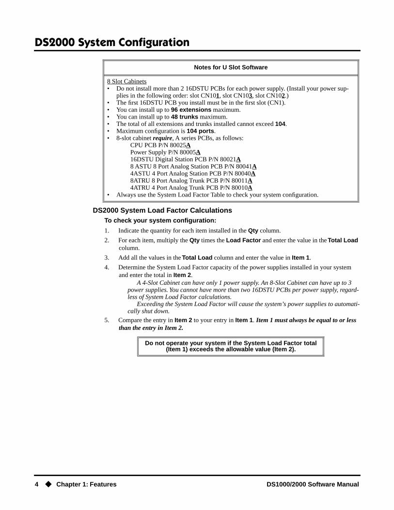
DS2000 System Load Factor Calculations
To check your system configuration:
1. Indicate the quantity for each item installed in the
Qty
column.
2. For each item, multiply the
Qty
times the
Load Factor
and enter the value in the
Total Load
column.
3. Add all the values in the
Total Load
column and enter the value in
Item
1
.
4. Determine the System Load Factor capacity of the power supplies installed in your system and enter the total in
Item
2
.
A 4-Slot Cabinet can have only 1 power supply. An 8-Slot Cabinet can have up to 3 power supplies. You cannot have more than two 16DSTU PCBs per power supply, regard-less of System Load Factor calculations.
Exceeding the System Load Factor will cause the system’s power supplies to automati-cally shut down.
5. Compare the entry in Item 2 to your entry in Item 1. Item 1 must always be equal to or less than the entry in Item 2.
8 Slot Cabinets• Do not install more than 2 16DSTU PCBs for each power supply. (Install your power sup-
plies in the following order: slot CN101, slot CN103, slot CN102.)• The first 16DSTU PCB you install must be in the first slot (CN1).• You can install up to 96 extensions maximum.• You can install up to 48 trunks maximum.• The total of all extensions and trunks installed cannot exceed 104.• Maximum configuration is 104 ports.• 8-slot cabinet require, A series PCBs, as follows:
CPU PCB P/N 80025APower Supply P/N 80005A16DSTU Digital Station PCB P/N 80021A8 ASTU 8 Port Analog Station PCB P/N 80041A4ASTU 4 Port Analog Station PCB P/N 80040A8ATRU 8 Port Analog Trunk PCB P/N 80011A4ATRU 4 Port Analog Trunk PCB P/N 80010A
• Always use the System Load Factor Table to check your system configuration.
Do not operate your system if the System Load Factor total (Item 1) exceeds the allowable value (Item 2).
Notes for U Slot Software

DS2000 System Configuration
DS1000/2000 Software Manual Chapter 1: Features ◆ 5
Examples of Typical DS2000 4-Slot Cabinet Maximum ConfigurationsNote that only the first configuration listed below (16 x 32) applies to Fixed Slot software. Refer to the Release Notes that came with your system to find out if you have Fixed Slot software.
● 16 x 32 (16 trunks and 32 digital extensions)Recommended for sites with no Voice Mail and high trunk usage.
● 24 x 16 (24 trunks and 16 digital extensions)Recommended for sites with no Voice Mail and very high trunk usage.
● 8 x 16 x 16 (8 trunks, 16 digital extensions and 16 analog extensions)Recommended for sites with Voice Mail, normal trunk usage and high analog extension usage.
● 16 x 16 x 8 (16 trunks, 16 digital extensions and 8 analog extensions)Recommended for sites with Voice Mail, high trunk usage and high analog extension usage.
● 8 x 32 x 8 (8 trunks, 32 digital extensions and eight analog extensions)Recommended for sites with Voice Mail, normal to low trunk usage and low analog extension usage.
Examples of Typical DS2000 8-Slot Cabinet Maximum Configurations● 32 x 64 (32 trunks and 64 digital extensions)
Recommended for sites with no Voice Mail and high trunk usage. This configuration requires 2 power supplies.
● 48 x 32 (48 trunks and 32 digital extensions)Recommended for sites with no Voice Mail and very high trunk usage. This configuration requires 1 power supply.
● 16 x 32 x 32 (16 trunks, 32 digital extensions and 32 analog extensions)Recommended for sites with Voice Mail, normal trunk usage and high analog extension usage. This configuration requires 2 power supplies.
System Load Factor Calculations
Description Load Factor Qty Total Load
16DSTU PCB 16
4ASTU PCB 8
8ASTU PCB 12
110-Button DSS Console 2
24-Button DSS Console 1
Total DSS Consoles installed cannot exceed 4.
2-OPX Module 3
Item 1: Total load for this configuration:
Item 2: If you have one power supply installed, enter 48.If you have two power supplies installed, enter 80.
If you have three power supplies installed, enter 112.
Notes: • A 4 slot cabinet can have only 1 power supply.• An 8-Slot Cabinet can have up to 3 power supplies. You cannot have more than two
16DSTU PCBs per power supply, regardless of System Load Factor calculations.

DS2000 System Configuration
6 ◆ Chapter 1: Features DS1000/2000 Software Manual
● 32 x 32 x 16 (32 trunks, 32 digital extensions and 16 analog extensions)Recommended for sites with Voice Mail, high trunk usage and high analog extension usage. This configuration requires 2 power supplies.
● 16 x 64 x 16 (16 trunks, 64 digital extensions and 16 analog extensions)Recommended for sites with Voice Mail, normal to low trunk usage and low analog extension usage. This configuration requires 3 power supplies.
DS2000 Default SetupEvery DS2000 system has a factory-installed default setup. The default setup determines the hard-ware you can install and how the system features work without reprogramming.
DS2000 4 Slot Cabinet (with Fixed Slot Software) Hardware ConfigurationFollowing is the default PCB configuration for a 4 slot cabinet using CPU P/N 80025 with Fixed Slot software. Although Fixed Slot software is no longer available, you may encounter it in existing installations. Note that an existing CPU P/N 80025 equipped with Fixed Slot software can be upgraded to U Slot software. Contact your Sales Representative for the specifics.
DS2000 4 Slot Cabinet (with U Slot Software) Hardware ConfigurationBoth CPU P/N 80025 and P/N 80025A can be equipped with U Slot software. When installed in a 4 slot cabinet, each version CPU will provide a unique configuration.
Configuration 1 - with CPU P/N 80025For Software Versions 02.01.07 and Higher● Slot CN1 = 16DSTU PCB (extensions 300-315)
● Slots CN2-CN4 = Undefined
● Slots CN5-CN8 are unavailable.
● The database is limited to 24 trunks and 40 extensions.
For Software Versions Prior to 02.01.07Following is the default PCB configuration for a 4 slot cabinet using CPU P/N 80025 equipped with U Slot software prior to software version 02.01.07.
Turn to Program 9902 - Slot Assignment (page 665) for information on how to change your PCB assignments. To swap the positions of PCBs, turn to Program 9802 - Swap Command Utility (U Slot) (page 659).
Slot PCB Extensions
1 16DSTU 300-315
2 16DSTU 316-331
3 8 ATRU 401-408
4 8 ATRU 409-416
Slot PCB Extensions
1 16DSTU 300-315
2 16DSTU 316-331
3 8 ATRU 401-408
4 8 ATRU 409-416
DS2000 System Configuration
DS1000/2000 Software Manual Chapter 1: Features ◆ 7
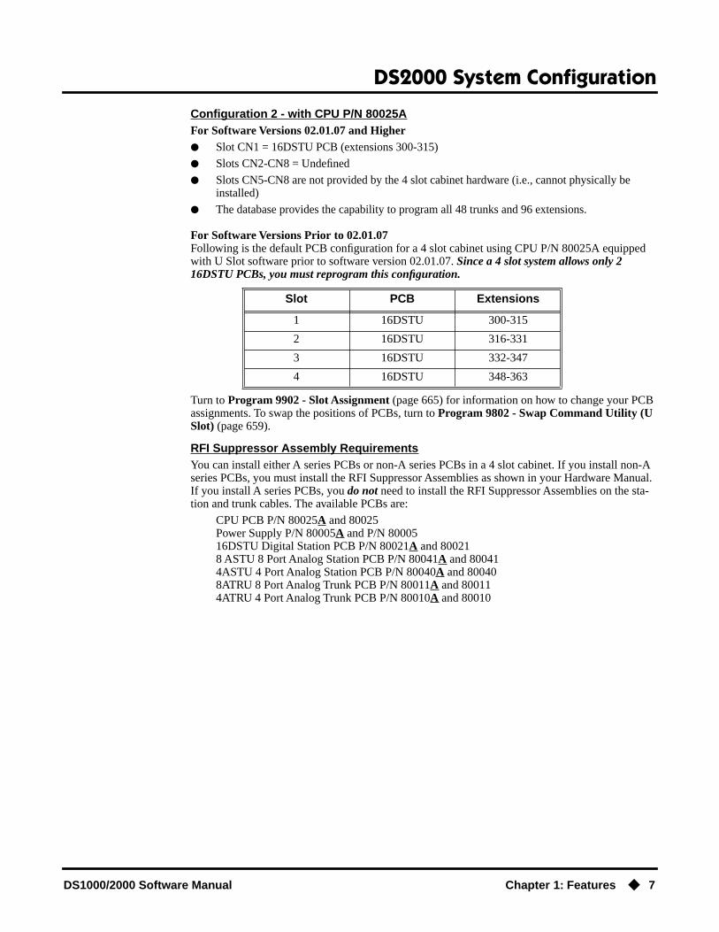
Configuration 2 - with CPU P/N 80025AFor Software Versions 02.01.07 and Higher● Slot CN1 = 16DSTU PCB (extensions 300-315)
● Slots CN2-CN8 = Undefined
● Slots CN5-CN8 are not provided by the 4 slot cabinet hardware (i.e., cannot physically be installed)
● The database provides the capability to program all 48 trunks and 96 extensions.
For Software Versions Prior to 02.01.07Following is the default PCB configuration for a 4 slot cabinet using CPU P/N 80025A equipped with U Slot software prior to software version 02.01.07. Since a 4 slot system allows only 2 16DSTU PCBs, you must reprogram this configuration.
Turn to Program 9902 - Slot Assignment (page 665) for information on how to change your PCB assignments. To swap the positions of PCBs, turn to Program 9802 - Swap Command Utility (U Slot) (page 659).
RFI Suppressor Assembly RequirementsYou can install either A series PCBs or non-A series PCBs in a 4 slot cabinet. If you install non-A series PCBs, you must install the RFI Suppressor Assemblies as shown in your Hardware Manual. If you install A series PCBs, you do not need to install the RFI Suppressor Assemblies on the sta-tion and trunk cables. The available PCBs are:
CPU PCB P/N 80025A and 80025Power Supply P/N 80005A and P/N 8000516DSTU Digital Station PCB P/N 80021A and 800218 ASTU 8 Port Analog Station PCB P/N 80041A and 800414ASTU 4 Port Analog Station PCB P/N 80040A and 800408ATRU 8 Port Analog Trunk PCB P/N 80011A and 800114ATRU 4 Port Analog Trunk PCB P/N 80010A and 80010
Slot PCB Extensions
1 16DSTU 300-315
2 16DSTU 316-331
3 16DSTU 332-347
4 16DSTU 348-363

DS2000 System Configuration
8 ◆ Chapter 1: Features DS1000/2000 Software Manual
DS2000 8 Slot Cabinet (with U Slot Software) Hardware ConfigurationFor Software Versions 02.01.07 and Higher● Slot CN1 = 16DSTU PCB (extensions 300-315)
● Slots CN2-CN8 = Undefined
● The database provides the capability to program all 48 trunks and 96 extensions.
For Software Versions Prior to 02.01.07Following is the default PCB configuration for an 8 slot cabinet with U Slot software prior to soft-ware version 2.01.07. Note that this configuration requires 3 power supplies. Refer to DS2000 Load Factor on page 3 for more. In addition, the 8 slot cabinet does not support Fixed Slot software.
If you need to modify your system’s configuration, turn to Program 9902 - Slot Assignment (page 665). To swap the positions of PCBs, turn to Program 9802 - Swap Command Utility (U Slot) (page 659). You should also review the installation in your Hardware Manual before proceeding.
RFI Suppressor Assembly RequirementsIn an 8 slot cabinet, you can only install A series PCBs. You do not need to install the RFI Suppres-sor Assemblies on your extension and trunk cabling. The available PCBs are:
CPU PCB P/N 80025APower Supply P/N 80005A16DSTU Digital Station PCB P/N 80021A8 ASTU 8 Port Analog Station PCB P/N 80041A4ASTU 4 Port Analog Station PCB P/N 80040A8ATRU 8 Port Analog Trunk PCB P/N 80011A4ATRU 4 Port Analog Trunk PCB P/N 80010A
Slot PCB Extensions
1 16DSTU 300-315
2 16DSTU 316-331
3 16DSTU 332-347
4 16DSTU 348-363
5 16DSTU 364-379
6 8 ATRU 401-408
7 8 ATRU 409-416
8 8 ATRU 417-424

DS1000 System Configuration
DS1000/2000 Software Manual Chapter 1: Features ◆ 9
DS1000 System Configuration
DS1000 Load Factor
DS1000 System Load Factor CalculationsThe combination of extensions, Digital Door Boxes, 2-OPX Modules, and DSS Consoles you can connect to your system may be limited by the System Load Factor. Use the DS1000 System Load Factor Calculations chart below to verify your system’s configuration.
To check your system configuration:
1. Indicate the quantity for each item installed in the Qty column.
2. For each item, multiply the Qty times the Load Factor and enter the value in Total Load.
3. Add all the values in the Total Load column and enter the value in Item 1.
4. Compare the entry in Item 2 to your entry in Item 1. Item 1 must always be equal to or less than the entry in Item 2.
Do not operate your system if the System Load Factor total (Item 1) exceeds the allowable load of 30 (Item 2).
DS1000 System Load Factor Calculations
Description Load Factor Qty Total Load
Digital Telephone and Digital Door Box
1
Analog Telephone 1
Analog Door Box 0
24-Button DSS Console 1
110-Button DSS Console 2
Total DSS Consoles installed cannot exceed 4
2-OPX Module 3
Item 1: Total load for this configuration
Item 2: Maximum allowable load 30
DS1000 System Configuration
10 ◆ Chapter 1: Features DS1000/2000 Software Manual
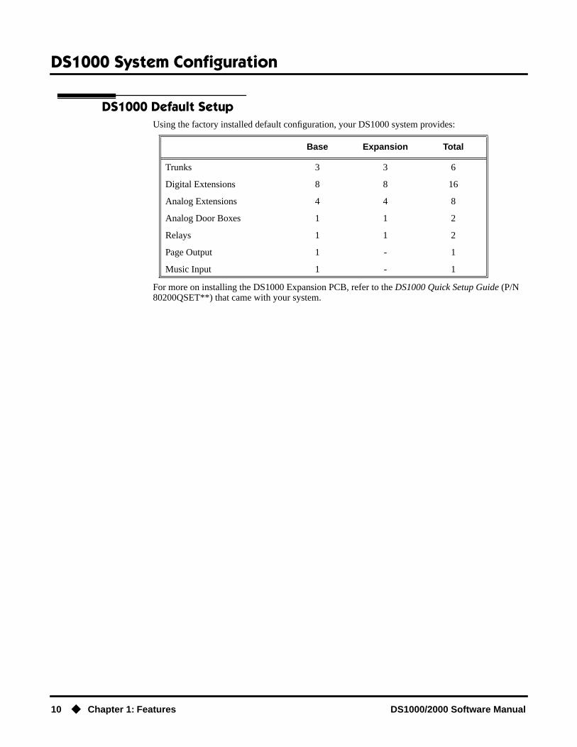
DS1000 Default SetupUsing the factory installed default configuration, your DS1000 system provides:
For more on installing the DS1000 Expansion PCB, refer to the DS1000 Quick Setup Guide (P/N 80200QSET**) that came with your system.
Base Expansion Total
Trunks 3 3 6
Digital Extensions 8 8 16
Analog Extensions 4 4 8
Analog Door Boxes 1 1 2
Relays 1 1 2
Page Output 1 - 1
Music Input 1 - 1
Initial System Startup
DS1000/2000 Software Manual Chapter 1: Features ◆ 11
Initial System Startup
Default Feature Setup
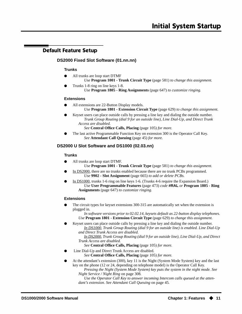
DS2000 Fixed Slot Software (01.nn.nn)
Trunks
● All trunks are loop start DTMFUse Program 1001 - Trunk Circuit Type (page 581) to change this assignment.
● Trunks 1-8 ring on line keys 1-8.Use Program 1805 - Ring Assignments (page 647) to customize ringing.
Extensions
● All extensions are 22-Button Display models.Use Program 1801 - Extension Circuit Type (page 629) to change this assignment.
● Keyset users can place outside calls by pressing a line key and dialing the outside number.Trunk Group Routing (dial 9 for an outside line), Line Dial-Up, and Direct Trunk
Access are disabled.See Central Office Calls, Placing (page 105) for more.
● The last active Programmable Function Key on extension 300 is the Operator Call Key.See Attendant Call Queuing (page 45) for more.
DS2000 U Slot Software and DS1000 (02.03.nn)
Trunks
● All trunks are loop start DTMF.Use Program 1001 - Trunk Circuit Type (page 581) to change this assignment.
● In DS2000, there are no trunks enabled because there are no trunk PCBs programmed.Use 9902 - Slot Assignment (page 665) to add or delete PCBs.
● In DS1000, trunks 1-6 ring on line keys 1-6. (Trunks 4-6 require the Expansion Board.)Use User Programmable Features (page 473) code #RAL or Program 1805 - Ring
Assignments (page 647) to customize ringing.
Extensions
● The circuit types for keyset extensions 300-315 are automatically set when the extension is plugged in.
In software versions prior to 02.02.14, keysets default as 22-button display telephones. Use Program 1801 - Extension Circuit Type (page 629) to change this assignment.
● Keyset users can place outside calls by pressing a line key and dialing the outside number.In DS1000, Trunk Group Routing (dial 9 for an outside line) is enabled. Line Dial-Up
and Direct Trunk Access are disabled.In DS2000, Trunk Group Routing (dial 9 for an outside line), Line Dial-Up, and Direct
Trunk Access are disabled.See Central Office Calls, Placing (page 105) for more.
● Line Dial-Up and Direct Trunk Access are disabled.See Central Office Calls, Placing (page 105) for more.
● At the attendant’s extension (300), key 11 is the Night (System Mode System) key and the last key on the phone (12 or 24, depending on telephone model) is the Operator Call Key.
Pressing the Night (System Mode System) key puts the system in the night mode. See Night Service / Night Ring on page 308.
Use the Operator Call Key to answer incoming Intercom calls queued at the atten-dant’s extension. See Attendant Call Queuing on page 45.

Initial System Startup
12 ◆ Chapter 1: Features DS1000/2000 Software Manual
Initial Startup Programming
Initial Startup Programming (Page 1 of 3)
Step 1: Check the system defaults.
• If you have a 4 slot Fixed Slot system, refer to DS2000 4 Slot Cabinet (with Fixed Slot Software) Hardware Configuration on page 6
• If you have a 4 slot U Slot system, refer to DS2000 4 Slot Cabinet (with U Slot Software) Hardware Configuration on page 6.
• If you have an 8 slot U Slot system, refer to DS2000 8 Slot Cabinet (with U Slot Software) Hardware Configuration on page 8.
• If you have a DS1000, refer to DS1000 Default Setup on page 10.
• To check the feature defaults, refer to Default Feature Setup on page 11.
Step 2: Does the current DS2000 U Slot PCB configuration meet the site requirements?
• Skip to the next step. Also skip this step if you have a DS1000.
• Review Program 9902 - Slot Assignment on page 665 and Program 9802 - Swap Command Utility (U Slot) on page 659.
Step 3: Enter the programming mode.
• From any display telephone:Press ICM + #*#* + Password + HOLD.
• The default system passwords are:Installer (level 3) = 372000System Administrator 2 (level 2) = 9999System Administrator 3 (level 1) = 0000
Step 4: Assign the correct circuit type to your installed trunks.
• In Program 1001 - Trunk Circuit Type (page 581), enter the correct circuit type for each installed trunk:
00 = Uninstalled51 = Loop start DTMF52 = Loop start DP
If yes
If no

Initial System Startup
DS1000/2000 Software Manual Chapter 1: Features ◆ 13
Step 5: For systems prior to software version 02.02.14, assign the correct circuit type to your installed extensions. (Systems at 02.02.14 and higher auto-ID extensions.)
• In Program 1801 - Extension Circuit Type (page 629), enter the correct circuit type for each installed extension:
00 = Uninstalled01 = 22-Button Standard02 = 22-Button Display06 = 34-Button Display09 = 34-Button Super Display10 = Digital Door Box [1]15 = Analog station21 = 2OPX (DS2000 Only)
• All keysets default to type 02 (22-Button Dis-play). If you don’t change the circuit type for 34-Button and 34-Button Super Display telephones, the bottom two rows of Programmable Function Keys will be unassigned (i.e., not functioning).
Step 6: By default, each extension has full access to each trunk. Do you want to change this assignment?
• For each extension in Program 1803 - Extension Line Access Assignments (page 642), assign the access options for each trunk. The options are:
0 = No access1 = Incoming only2 = Outgoing only3 = Full access
• Use Program 9801 - Copy Command (page 657), to simplify your programming.
• In Program 1803 - Extension Line Access Assign-ments (page 642), make no changes from the default assignments.
Step 7: Do you want to change the way extensions ring for incoming trunk calls?
• For each extension in Program 1805 - Ring Assignments (page 647), assign ringing for each trunk. The options are:
1 = Lamp only (day and night)2 = Ringing day and night3 = Night Ring only, lamp during the day4 = Delay ring day and night
• Use Program 9801 - Copy Command (page 657), to simplify your programming.
• The system attendant (extension 300) can put these trunks in the night mode by pressing their preassigned Night (System Mode System) key (key 11).
Initial Startup Programming (Page 2 of 3)
If yes
If no
If yes

Initial System Startup
14 ◆ Chapter 1: Features DS1000/2000 Software Manual
• For each extension in Program 1805 - Ring Assignments (page 647), make no changes from the default assignments.
Step 8: Does your system have Voice Mail?
• Turn to Voice Mail on page 477 and review the required Voice Mail programming.
• Go to the next step.
Step 9: Do you want to change the default system passwords?
• In Program 9905 - Password (page 669), change the passwords from their default settings.
• In Program 9905 - Password (page 669), do not change the passwords from their default settings.
Step 10: Do you want to return the system to its factory installed (default) programming?
• In Program 9999 - System Initialization (page 677), reinstate the factory installed pro-gramming. This erases all your programming and returns the system to its initial default set-tings.
• In Program 9999 - System Initialization (page 677), do not reinstate the factory installed programming.
Initial Startup Programming (Page 3 of 3)
If no
If yes
If no
If yes
If no
If yes
If no

Charts and Illustrations
DS1000/2000 Software Manual Chapter 1: Features ◆ 15
Charts and Illustrations
Table 1: Dial Codes (by Feature)
For this feature Dial this code When you are
Barge In (Intrusion) 4 Barging-In on a co-worker’s call
Call Forwarding ICM + ✽ 30 Canceling Call Forwarding at an extension
ICM + ✽ 32 + Extension or 0 (for the operator)
Enabling Call Forwarding Busy/No Answer
ICM + ✽ 34 + Extension or 0 (for the operator)
Enabling Call Forwarding All Calls
ICM + ✽ 36 + Extension or 0 (for the operator)
Enabling Call Forwarding No Answer
ICM + ✽ 37 + 2 (all calls) or 8 (out-side calls)
Setting up Personal Answering Machine Emulation
Call Waiting / Camp-On 2 + Do not hang up2 + Hang up
Camping-On to a co-workerLeaving a Callback for a co-worker
Central Office Calls, Placing ICM + #9 + Trunk number (e.g., 01) Using Line Dial-Up to place an out-side call
ICM + Trunk extension number (e.g., 401)
Using Direct Trunk Access to place an outside call
ICM + 9 or 90-98 Accessing a Trunk Group to place an outside call
Dial Number Preview ✽ Previewing a number before dialing
Directed Call Pickup ICM + ✽✽ + Extension Intercepting a call ringing a co-worker’s extension
Forced Trunk Disconnect # Using Forced Trunk Disconnect to disconnect a busy outside line
Group Call Pickup ICM + ✽ # Answering a call ringing a phone in your Pickup Group
Hold ICM + ✽ 4 + Trunk number (e.g., 01) Picking up an outside call on System Hold at a co-worker’s extension
Intercom ICM + Extension (e.g., 301) Placing an Intercom call to a co-worker
Meet-Me Conference ICM + #11 or # 12 Setting up or joining a Meet-Me Con-ference
Monitor / Silent Monitor 6 Setting up Monitor after calling a busy co-worker
Night Service / Night Ring ✽✽ + UNA code (01-04) Answering a call ringing UNA at night

Charts and Illustrations
16 ◆ Chapter 1: Features DS1000/2000 Software Manual
Paging ICM + ✽ 1 + Page zone (1-7 or 0 for All Call)
Making an internal Paging announce-ment
Park ICM + ✽ + System Park Orbit (60-69) Parking or retrieveing a call from Sys-tem Park Orbit
ICM + ✽✽ + Extension (e.g., 301) Using Personal Park to Park or retrieve a call at a co-workers extension
Removing Trunks and Extensions From Service
ICM + #40 + Extension (e.g., 301) or trunk (e.g., 401) + 4 (to return) or 6
(to remove)
Removing or returning an extension or trunk to service
Selectable Display Messaging ICM + ✽ 38 + Message (00-16) + Hold + Add additional digits + Hold
Enabling a Selectable Display Message
Speed Dial ICM + # + System bin (200-299) or Personal bin (701-720)
Dialing a System or Personal Speed Dial number
Transfer ICM + Extension (e.g., 301) Transferring a call to a co-worker’s extension
ICM + Extension (e.g., 301) + MW Transferring a call to a co-worker’s mailbox
Trunk (Line) Queuing / Trunk Call-back
2 Queuing or leaving a Callback for a busy trunk
Voice Mail ICM + MW Calling your mailbox from your keyset
Lift handset + ✽ 8 Calling your mailbox from your single line telephone
ICM + Extension (e.g., 301) + MW Transferring a call to a co-worker’s mailbox from your keyset
Hookflash + Extension (e.g., 301) + 8 Transferring a call to a co-worker’s mailbox from your single line
ICM + ✽ 37 + 2 (all calls) or 8 (outside calls)
Setting up Personal Answering Machine Emulation
ICM + ✽ 30 Canceling Personal Answering Machine Emulation
Voice Over 9 Initiating a Voice Over to a busy exten-sion (after hearing busy/ring tone)
Table 1: Dial Codes (by Feature)
For this feature Dial this code When you are

Charts and Illustrations
DS1000/2000 Software Manual Chapter 1: Features ◆ 17
Table 2: System Number Plan/Capacities (Page 1 of 3)
DS1000 DS2000 4-Slot DS2000 8-Slot
System Options
• Classes of Service 1-15(COS 1 normally reserved for attendants)
• Conference 32 simultaneous users in Conference (total of all Conferences system-wide)8 simultaneous Conferences maximum
8 parties maximum in any one Conference
• Extension Hunting (ACD/UCD) Master Numbers
8
• Extension Hunting Groups 8 (1-8)
• Group Call Pickup Groups 8 (1-8, 0 = unassigned)
• Privacy Release Groups 16 (1-16, 0 = unassigned)
• Speed Dial, Personal 20 bins at each extension (701-720)See Speed Dial (page 383) for additional information on Speed Dial capacities.
• Speed Dial. System 10 (20-29), 100 (200-299), 1000 (2000-2999)See Speed Dial (page 383) for additional information on Speed Dial capacities.
• Tenant Groups 1
• Timeslots Non-blocking
• Toll Restriction Levels 7 (1-7, 0 = no restriction)
Trunks
• Direct Trunk Access Codes 401-406 401-416 (Fixed Slot)401-424 (U Slot)
401-448
• Line Dial Up Codes #901-#906 #901-#916 (Fixed Slot)#901-#924 (U Slot)
#901-#948
• Ring Groups 8 (1-8)0 = No assignment
Ring Group master numbers can be 100-299, 332-400, or 417-899. They can-not be in the extension (300-395 in DS2000 or 300-325 in DS1000) or trunk (401-448 in DS2000 or 401-406 in DS1000) number range. By default, the
systems uses codes beginning with 0 for operator access and 9 for trunk/trunk group access.
• Trunk Group Access Codes 90-98
• Trunk Groups 9 (0-8)
• Trunk Ports 6 (1-6)Trunks 4-6 require the
Expansion Board.
16 (1-16) (Fixed Slot)24 (1-24) (U Slot)
48 (1-48)

Charts and Illustrations
18 ◆ Chapter 1: Features DS1000/2000 Software Manual
Extensions
• Attendant (Operator) Access Number
0 (single operator)01-04 (multiple operators)
• Attendants 4
• 2-OPX Modules Each 2-OPX Module uses one digital station port. The System Load Factor may limit the total number you can install. See DS2000 Load Factor on page 3 and DS1000 Load Factor on page 9. DS2000 requires software version 02.00.01 or
higher. DS1000 requires software version 02.02.14 or higher.
• Digital Door Boxes Each Digital Door Box uses one digital station port. The System Load Factor may limit the total number you can install. See DS2000 Load Factor on page 3 and DS1000 Load Factor on page 9. Not available in DS2000 Fixed Slot software.
• Analog Door Boxes 22nd Analog Door Box
requires Expansion PCB
0
• DSS Consoles 4The System Load Factor may limit the total number that you can install. See
DS2000 Load Factor on page 3 and DS1000 Load Factor on page 9.
• Telephone Extension Numbers 300-325 (which includes digital exten-sions 300-315, analog extensions 31-323, and
Analog Door Boxes 324 and 325)
32 (300-331) (Fixed Slot)
40 (300-339) (U Slot)
96 (300-395)
• Telephone Port Numbers 26 (1-26) 32 (1-32) (Fixed Slot)40 (1-40) (U Slot)
96 (1-96)
• Total Number of Station Devices
26 (which includes dig-ital extensions 300-315, analog extensions 31-323, and Analog Door Boxes 324 and 325)
32 (Fixed Slot) (may be limited by load factor)40 (U Slot) (may be
limited by load factor)
96 (may be limited by load factor)
• UCD Hunting Master Numbers 8 (1-8)Master numbers can be from 100-899, excluding those extension numbers
used by extensions and trunks. By default, the systems uses codes beginning with 0 for operator access and 9 for trunk/trunk group access.
• Voice Mail Master Numbers 1Master numbers can be from 100-899, excluding those extension numbers used by extensions and trunks. By default, the systems uses codes beginning with 0 for operator access and 9 for trunk/trunk group access.
• Voice Mail Ports Limited by available analog ports.
Table 2: System Number Plan/Capacities (Page 2 of 3)
DS1000 DS2000 4-Slot DS2000 8-Slot

Charts and Illustrations
DS1000/2000 Software Manual Chapter 1: Features ◆ 19
Paging and Park
• Page Zones (Internal) 7 zones (1-7) and All Call (0)
• Page Zone (External) All Call and zone 1 broadcast from Audio
jack (AUDIO)
All Call and zone 1 broadcast from the CPRU External Page port
• Page Relays One set in each Analog Door Box jack
(DOOR1 and DOOR2)
One set on CPRU
• Park Orbits 10 (60-69)Orbits 68 and 69 have extended (5 min.) timers
Passwords
• System Administrator 1(Level 1)
0000
• System Administrator 2(Level 2)
9999
• Installer (Level 3) 372000
Table 2: System Number Plan/Capacities (Page 3 of 3)
DS1000 DS2000 4-Slot DS2000 8-Slot

Charts and Illustrations
20 ◆ Chapter 1: Features DS1000/2000 Software Manual
Figure 1: 22-Button Display Telephone (Fixed Slot)
1 2 3
4 5 6
7 8 9
0
ABC DEFMW ICM
FLASH DND
DIAL MIC
LND SPK
CONFHOLD
GHI JKL MNOMNO
PQRS TUV
OPER
VOL
WXYZ
CLEAR
CHECK
80000 - 21A
LINE 1 LINE 2 LINE 3 LINE 4 LINE 5 LINE 6
LINE 7 LINE 8FIXED
LOOP 0FIXED
LOOP 0AUTOTIMER
ALLPAGE
BIN 1 BIN 2 BIN 3 BIN 4 BIN 5
BIN 6 BIN 7 BIN 8 BIN 9 BIN 10
For Attendants:Key 11=Night KeyKey 12=Operator Call Key

Charts and Illustrations
DS1000/2000 Software Manual Chapter 1: Features ◆ 21
Figure 2: 22-Button Display Telephone (U Slot and DS1000)
1 2 3
4 5 6
7 8 9
0
ABC DEFMW ICM
FLASH DND
DIAL MIC
LND SPK
CONFHOLD
GHI JKL MNOMNO
PQRS TUV
OPER
VOL
WXYZ
CLEAR
CHECK
80000 -70
LINE 1 LINE 2 LINE 3 LINE 4 LINE 5 LINE 6
LINE 7 LINE 8 LINE 9 LINE 10 LINE 11 LINE 12
BIN 1 BIN 2 BIN 3 BIN 4 BIN 5
BIN 6 BIN 7 BIN 8 BIN 9 BIN 10
For Attendants:Key 11=Night KeyKey 12=Operator Call Key
In DS1000:Keys 7-12 areundefined.
In DS2000 software versions 02.01.07 through 02.02.00, Programmable Function Keys are undefined for all extensions above 315.
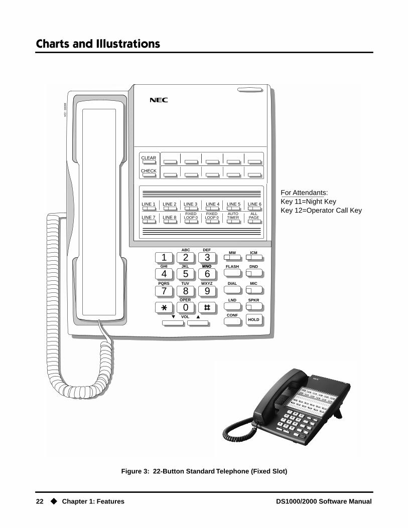
Charts and Illustrations
22 ◆ Chapter 1: Features DS1000/2000 Software Manual
Figure 3: 22-Button Standard Telephone (Fixed Slot)
1 2 3
4 5 6
7 8 9
0
ABC DEFMW ICM
FLASH DND
DIAL MIC
LND SPKR
CONFHOLD
GHI JKL MNOMNO
PQRS TUV
OPER
VOL
WXYZ
CLEAR
CHECK
80000 - 22A
LINE 1 LINE 2 LINE 3 LINE 4 LINE 5 LINE 6
LINE 7 LINE 8FIXED
LOOP 0FIXED
LOOP 0AUTOTIMER
ALLPAGE
For Attendants:Key 11=Night KeyKey 12=Operator Call Key

Charts and Illustrations
DS1000/2000 Software Manual Chapter 1: Features ◆ 23
Figure 4: 22-Button Standard Telephone (U Slot and DS1000)
1 2 3
4 5 6
7 8 9
0
ABC DEFMW ICM
FLASH DND
DIAL MIC
LND SPKR
CONFHOLD
GHI JKL MNOMNO
PQRS TUV
OPER
VOL
WXYZ
CLEAR
CHECK
80000 - 63A
LINE 1 LINE 2 LINE 3 LINE 4 LINE 5 LINE 6
LINE 7 LINE 8 LINE 9 LINE 10 LINE 11 LINE 12
For Attendants:Key 11=Night KeyKey 12=Operator Call Key
In DS1000:Keys 7-12 areundefined.
In DS2000 software versions 02.01.07 through 02.02.00, Programmable Function Keys are undefined for all extensions above 315.

Charts and Illustrations
24 ◆ Chapter 1: Features DS1000/2000 Software Manual
Figure 5: 34-Button Display Telephone (Fixed Slot)
1 2 3
4 5 6
7 8 9
0
ABC DEFMW ICM
FLASH DND
DIAL MIC
LND SPK
CONFHOLD
GHI JKL MNOMNO
PQRS TUV
OPER
VOL
WXYZ
CLEAR
CHECK
80000 - 10C
LINE 1 LINE 2 LINE 3 LINE 4 LINE 5 LINE 6
LINE 7 LINE 8
BIN 1 BIN 2 BIN 3 BIN 4 BIN 5
BIN 6 BIN 7 BIN 8 BIN 9 BIN 10
These keys areundefined
For Attendants:Key 11=Night KeyKey 24=Operator Call Key
FIXEDLOOP 0
FIXEDLOOP 0
AUTOTIMER
ALLPAGE
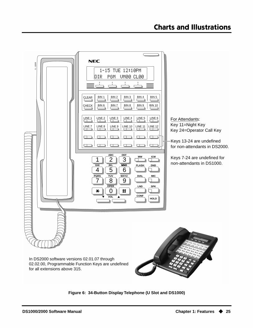
Charts and Illustrations
DS1000/2000 Software Manual Chapter 1: Features ◆ 25
Figure 6: 34-Button Display Telephone (U Slot and DS1000)
1 2 3
4 5 6
7 8 9
0
ABC DEFMW ICM
FLASH DND
DIAL MIC
LND SPK
CONFHOLD
GHI JKL MNOMNO
PQRS TUV
OPER
VOL
WXYZ
CLEAR
CHECK
80000 - 72
LINE 1 LINE 2 LINE 3 LINE 4 LINE 5 LINE 6
LINE 7 LINE 8
BIN 1 BIN 2 BIN 3 BIN 4 BIN 5
BIN 6 BIN 7 BIN 8 BIN 9 BIN 10
Keys 13-24 are undefinedfor non-attendants in DS2000.
Keys 7-24 are undefined fornon-attendants in DS1000.
LINE 9 LINE 10 LINE 11 LINE 12
For Attendants:Key 11=Night KeyKey 24=Operator Call Key
In DS2000 software versions 02.01.07 through 02.02.00, Programmable Function Keys are undefined for all extensions above 315.

Charts and Illustrations
26 ◆ Chapter 1: Features DS1000/2000 Software Manual
Figure 7: 34-Button Super Display Telephone (Fixed Slot)
1 2 3
4 5 6
7 8 9
0
ABC DEFMW ICM
FLASH DND
DIAL MIC
LND SPKR
CONFHOLD
GHI JKL MNO
PQRS TUV
OPER
VOL
WXYZ
80000 - 23A
CHECK CLEAR
LINE 1 LINE 2 LINE 3 LINE 4 LINE 5 LINE 6
LINE 7 LINE 8
These keys areundefined
FIXEDLOOP 0
FIXEDLOOP 0
AUTOTIMER
ALLPAGE
For Attendants:Key 11=Night KeyKey 24=Operator Call Key

Charts and Illustrations
DS1000/2000 Software Manual Chapter 1: Features ◆ 27
Figure 8: 34-Button Super Display Telephone (U Slot and DS1000)
1 2 3
4 5 6
7 8 9
0
ABC DEFMW ICM
FLASH DND
DIAL MIC
LND SPKR
CONFHOLD
GHI JKL MNO
PQRS TUV
OPER
VOL
WXYZ
80000 - 71
CHECK CLEAR
LINE 1 LINE 2 LINE 3 LINE 4 LINE 5 LINE 6
LINE 7 LINE 8
Keys 13-24 are undefinedfor non-attendants in DS2000.
Keys 7-24 are undefined fornon-attendants in DS1000.
LINE 9 LINE 10 LINE 11 LINE 12
For Attendants:Key 11=Night KeyKey 24=Operator Call Key
In DS2000 software versions 02.01.07 through 02.02.00, Programmable Function Keys are undefined for all extensions above 315.

Charts and Illustrations
28 ◆ Chapter 1: Features DS1000/2000 Software Manual
Figure 9: 24-Button DSS Console
80000 - 25
300 312
301 313
302 314
303 315
304 316
305 317
306 318
307 319
308 320
309 321
310 322
311 323

Charts and Illustrations
DS1000/2000 Software Manual Chapter 1: Features ◆ 29
Figure 10: 110-Button DSS Console (Fixed Slot)
80000 - 24
300 301 302 303 304 305 306 307 308 309
310 311 312 313 314 315 316 317 318 319
320 321 322 323 324 325 326 327 328 329
330 331 LINE 1 LINE 2 LINE 3 LINE 4 LINE 5 LINE 6 LINE 7 LINE 8
202 203 204 205 206 207 208 209 701 702
703 704 705 706 707 708 709 710 711 712
713 714 715 716 717 718 719 720 PG 0 PG 1
PK 0 PK 1
These keys areundefined
LINE 9 LINE 10 LINE 11 LINE 12 LINE 13 LINE 14 LINE 15 LINE 16 200 201

Charts and Illustrations
30 ◆ Chapter 1: Features DS1000/2000 Software Manual
Figure 11: 110-Button DSS Console (U Slot)
80000 - 66
300 301 302 303 304 305 306 307 308 309
310 311 312 313 314 315 316 317 318 319
320 321 322 323 324 325 326 327 328 329
330 331 332 333 334 335 336 337 338 339
350 351 352 353 354 355 356 357 358 359
360 361 362 363 364 365 366 367 368 369
370 371 372 373 374 375 376 377 378 379
PAGE 1 PAGE 2 PAGE 3PAGEALL
PARK 0 PARK 1 PARK 2 PARK 3 PARK 4 PARK 5 PARK 6 PARK 7 PARK 8 NIGHT
These keys areundefined
340 341 342 343 344 345 346 347 348 349

Charts and Illustrations
DS1000/2000 Software Manual Chapter 1: Features ◆ 31
80200 - 38
300 301 302 303 304 305 306 307 308 309
310 311 312 313 314 315 316 317 318 319
320 321 322 323 324 325
PAGE 1 PAGE 2 PAGE 3PAGEALL
PARK 0 PARK 1 PARK 2 PARK 3 PARK 4 PARK 5 PARK 6 PARK 7 PARK 8 NIGHT
Hotlinesto
Extensions
Note: Blank keys are undefined.
Figure 12: 110-Button DSS Console (DS1000)

2-OPX Module
32 ◆ Chapter 1: Features DS1000/2000 Software Manual
2-OPX Module
DescriptionDS2000 Fixed Slot
Available. See see Off-Premise Extensions / On-Premise SLT Extensions on page 317.DS2000 U Slot
DS1000

2500 Sets / Single Line Telephones
DS1000/2000 Software Manual Chapter 1: Features ◆ 33
2500 Sets / Single Line Telephones
DescriptionDS2000 Fixed Slot
Available. Refer to Off-Premise Extensions / On-Premise SLT Extensions on page 317 for more.DS2000 U Slot
DS1000

Account Codes
34 ◆ Chapter 1: Features DS1000/2000 Software Manual
Account Codes
Description
Account Codes are user-dialed codes that help categorize and/or restrict trunk calls. Account Codes are from 2-10 digits long, using any combination of the digits 0-9. There are three types of Account Codes:
● Optional (Unforced Account Codes)
● Forced Account Codes
● Verified Account Codes
Optional (Unforced) Account CodesOptional Account Codes allow a keyset extension user to enter an Account Code while placing a trunk call or any time while on a call. This type of Account Code is optional: the system does not require the user to enter it. If the keyset user is already talking on a trunk call, their conversation continues uninterrupted while they enter an Account Code.
Single line telephone users can only enter an Account Code while placing their trunk call.
Forced Account CodesForced Account Codes require an extension user to enter an Account Code every time they place a trunk call. If the user doesn’t enter the code, the system prevents the call. The system can require Forced Account Codes for all trunk calls, or just for toll calls (as determined by Toll Restriction programming). Note that Forced Account Codes do not pertain to incoming calls.
Verified Account CodesWith Verified Account Codes, the system compares the Account Code the user dials with a list of codes programmed into the Verified Account Code Table. If the Account Code is in the table, the call goes through (provided it is not prevented by an extension’s Toll Restriction programming). If the code is not in the table, the system prevents the call. Verified Account Codes, if enabled, apply only to Forced Account Codes.
Using Account Codes and Speed DialTo simplify Account Code operation, Personal and System Speed Dial bins can contain Account Codes. Keep the following in mind when using Speed Dial and Account Codes:
● The Account Code can be either the first or last entry in the bin, and must be preceded and fol-lowed by the # character. For example, the Account Code 1234 must be entered as #1234#.
● The Program 0201 - # Key to Enter Account Codes (page 514) option must be enabled in sys-tem programming. In addition, the Program 0201 - Enable Account Codes in Speed Dial (2.01.07 or higher) (page 513) option must also be enabled.
● The Speed Dial bin can contain an Account Code followed by an outside number, or just the Account Code. The Account Code must be preceded and followed by a # entry. If the bin contains just the Account Code, the user must be sure to press the bin key before dialing the outside number.
DS2000 Fixed Slot Not available.
DS2000 U Slot • Available. Requires software version 02.01.07 or higher.• Forced Account Codes by Trunk option requires software version 02.02.14
or higher.DS1000
Use Account Codes to categorize and/or restrict outside calls.

Account Codes
DS1000/2000 Software Manual Chapter 1: Features ◆ 35
● If the system has Verified Account Codes enabled, the Account Code entered in the Speed Dial bin must match an entry in the Verified Account Code Table.
● If the Speed Dial bin does not contain an Account Code, the user must enter the Account Code manually. If Forced Account Codes are enabled, the system requires the user to enter the Account Code before it outdials the stored Speed Dial number.
● An extension user can preselect a trunk for a Speed Dial call.
Using Account Codes with Last Number Redial and SaveLast Number Redial and Save do not store Account Codes. This means that the user must manually enter an Account Code to have it included with a call dialed using Last Number Redial and Save. If Forced Account Codes are enabled, the system requires the user to enter the Account Code before it outdials the stored number saved by Last Number Redial or Save.
An extension user can preselect a trunk for a Last Number Redial or Save call.
Account Codes and Emergency CallsAccount Codes are never enforced for emergency (911 and 1+911) calls.
ConditionsDo not use Account Codes that begin with 911 or 1911.
Default SettingAccount Codes disabled.

Account Codes
36 ◆ Chapter 1: Features DS1000/2000 Software Manual
Programming GuideStep-by-step guide for setting up
Account Codes (Page 1 of 3)
Step 1: Should users be able to store Account Codes in Speed Dial bins?
• In Program 0201 - Enable Account Codes in Speed Dial (2.01.07 or higher) (page 513), enter Y.
• In Program 0201 - Enable Account Codes in Speed Dial (2.01.07 or higher) (page 513), enter N. Any Account Codes stored in Speed Dial bins dial out as part of the stored number.
Step 2: While on an outside call, should an extension user be able to dial # to enter an Account Code?
• In Program 0201 - # Key to Enter Account Codes (page 514), enter Y.
• In Program 0201 - # Key to Enter Account Codes (page 514), enter N.
Step 3: Should Account Code entries be hidden (i.e., replaced by * characters) on each tele-phone’s display?
• In Program 0201 - View Account Codes (page 514), enter N.
• In Program 0201 - View Account Codes (page 514), enter Y.
Step 4: Should a keyset have an Account Code key to simplify entering Account Codes?
• In Program 1701 - Programmable Function Key Assignments (page 612), enter 26 to assign a key as an Account Code key.
• In Program 1701 - Programmable Function Key Assignments (page 612), do not assign a key with code 26.
If yes
If no
If yes
If no
If yes
If no
If yes
If no

Account Codes
DS1000/2000 Software Manual Chapter 1: Features ◆ 37
Step 5: Should an extension have Forced Account Codes (i.e., be required to enter an Account Code while placing a call)?
• In Program 0101 - Forced Account Codes (page 509), enter Y.
• Program 1801 - Extension Class of Service Assignment (page 631), assign Class of Service to extensions.
• (Software version 02.02.14 or higher)In Program 1001 - Disable Forced Account Codes (page 585), enable No (N) to have the system enforce Forced Account Codes for the trunk. ORIn Program 1001 - Disable Forced Account Codes (page 585), enable Yes (Y) to have the system not enforce Forced Account Codes for the trunk.
• In Program 0101 - Forced Account Codes (page 509), enter N.
• Program 1801 - Extension Class of Service Assignment (page 631), assign Class of Service to extensions.
Step 6: Should an extension have Forced Account Codes just for long distance (toll) calls?
• In Program 0101 - Forced Account Codes for Toll Calls Only (page 509), enter Y.
• In Program 0201 - Account Code Toll Level (page 514), enter the toll level (0-7) the system will use to determine toll calls. See Forced Account Codes Programming on page 39 for more on setting this up.
• Program 1801 - Extension Class of Service Assignment (page 631), assign Class of Service to extensions.
• In Program 0101 - Forced Account Codes for Toll Calls Only (page 509), enter N.
• Program 1801 - Extension Class of Service Assignment (page 631), assign Class of Service to extensions.
Step-by-step guide for setting up Account Codes (Page 2 of 3)
If yes
If no
If yes
If no

Account Codes
38 ◆ Chapter 1: Features DS1000/2000 Software Manual
Programming List
General Account Codes ProgrammingProgram 0201 - Enable Account Codes in Speed Dial (2.01.07 or higher) (page 513)
Enable (Y) this option if users should be able to store Account Codes in Speed Dial bins. This causes the stored Account Code to properly display in the SMDR report Account column. If you disable (N) this option, Account Codes stored in Speed Dial bins dial out as part of the stored number and display in the SMDR report Number Dialed column. They will not display in the Account column. This option is disabled by default.
Program 0201 - # Key to Enter Account Codes (page 514)Use this option to enable (Y) an extension user to dial # to enter an Account Code while on an outside call. If disabled (N), the extension user can only enter an Account Code by pressing the Account Code soft key or a uniquely programmed Account Code Programmable Function Key. This option is disabled by default.
Program 0201 - View Account Codes (page 514)Use this option to show or hide the Account Codes a user enters on their telephone’s display. If enabled (Y), the dialed Account Codes show on the display. This may be a security risk, since a co-worker can easily read the telephone display as the user enters their Account Code. If disabled (N), Account Codes are shown as * characters on the telephone display. This option is disabled by default.
Program 1701 - Programmable Function Key Assignments (page 612)Use this option to assign an Account Code Programmable Function Key to a keyset (code 26). There are no Account Code Programmable Function Keys assigned by default. The Account Code Programmable Function Key is not available on DSS Consoles.
Optional (Unforced) Account Codes ProgrammingOptional Account Codes are always available without programming.
Step 7: Should an extension have Verified Account Codes (i.e., be required to enter an Account Code from the Verified Account Codes Table while placing a call)?
• In Program 0101 - Verify Account Codes (page 509), enter Y.
• In Program 1201 - Verified Account Codes Table (page 601), enter codes into the Verified Account Codes table.
• In Program 1801 - Extension Class of Service Assignment (page 631), assign Class of Service to extensions.
• In Program 0101 - Verify Account Codes (page 509), enter N.
• Program 1801 - Extension Class of Service Assignment (page 631), assign Class of Service to extensions.
Step-by-step guide for setting up Account Codes (Page 3 of 3)
If yes
If no

Account Codes
DS1000/2000 Software Manual Chapter 1: Features ◆ 39
Forced Account Codes ProgrammingProgram 0101 - Forced Account Codes (page 509)
Use this option to enable (Y) or disable (N) Forced Account Codes. If disabled, Optional Account Codes are still available. This option is disabled by default.
Program 0101 - Forced Account Codes for Toll Calls Only (page 509)● Use this option to enable (Y) Forced Account Codes only for toll (long distance) calls. If
disabled (N), Forced Account Codes apply to all outgoing trunk calls. This option is dis-abled by default (i.e., Forced Account Codes, if enabled, apply to all outgoing trunk calls).
● The system identifies toll calls according to the settings in Program 0201 - Account Code Toll Level (page 514) programming below.
● If Program 0101 - Forced Account Codes (page 509) is disabled, the Program 0101 - Forced Account Codes for Toll Calls Only (page 509) option has no effect.
Program 0201 - Account Code Toll Level (page 514)If Program 0101 - Forced Account Codes for Toll Calls Only (page 509) is enabled, use this option to differentiate toll calls from local calls for Account Code purposes. If you enter 0 for this option, toll calls are any calls the user dials that begin with 0 or 1. If you enter a toll level for this option (1-7), the system uses the toll level options programmed in Program 0601 - Toll Restriction Level (page 572) for that level to determine if the call is local or toll.
● If the toll level is set to deny the call, it is considered to be a long distance call and the sys-tem requires that the user must have entered an Account Code.
● If the toll level permits the call, it is considered to be a local call and no Account Code entry is required.
● Note that additional dialing restrictions enforced by an extension’s toll level (set in Pro-gram 1801 - Extension Toll Level Day (page 631) and Program 1801 - Extension Toll Level Night (page 631) are in effect and may also restrict dialing.
Program 1001 - Disable Forced Account Codes (page 585)(Software version 02.02.14 or higher)Use this option to enable or disable Forced Account Codes for an individual trunk. If enabled (Y), the system will not enforce Forced Account Codes for the trunk. If disabled (N), the sys-tem will enforce Forced Account Codes for the trunk.
Program 1801 - Extension Class of Service Assignment (page 631)Assign Class of Service to extensions.
Verified Account Codes ProgrammingProgram 0101 - Verify Account Codes (page 509)
Use this option to enable (Y) or disable (N) Verified Account Codes. If enabled, the system compares the Account Code the user dials to the entries in 1201 - Verified Account Codes Table on page 601. There are no entries in this table by default.
Program 1201 - Verified Account Codes Table (page 601)● Use this option to enter codes into the Verified Account Codes Table. When Program 0101
- Verify Account Codes (page 509) is enabled, the system compares the Account Code the user dials to the entry in this table. If the entries match, the system allows the call (pro-vided it is not prevented by an extension’s Toll Restriction). If there is no match, the sys-tem denies the call.
● A Verified Account Code can be from 2 to 10 digits long, using the digits 0-9. You can use the * character as a wild card, which can be entered in any position in a Verified Account Code. A wild card allows the user to dial any digit in that position. For example, the entry 11*1 represents entries 1101, 1111, 1121, etc.
● DS1000 provides for 500 table entries. DS2000 provides for 1000 table entries.● Do not enter either 911 or 1911 into the Verified Account Codes Table. When a user
presses a line key and dials either 911 or 1911, the system immediately bypasses all Toll Restriction and Account Code programming and routes the call.
Program 1801 - Extension Class of Service Assignment (page 631)Assign Class of Service to extensions.

Account Codes
40 ◆ Chapter 1: Features DS1000/2000 Software Manual
Account Codes Programming Examples
Example 1: Forced Account Codes Require an Account Code only for 900 and 1 + 900 Long Distance Dialing
To set up Forced Account Codes to require entries for only 900 and 1 + 900 calls:
1. In 0101 - Forced Account Codes, enter Y.
2. In 0101 - Forced Account Codes for Toll Calls Only, enter Y.
3. In 0201 - Account Code Toll Level, enter 2 (for example).
4. In 0601 - Initialize Toll Restriction, be sure to initialize the Toll Restriction tables.
5. In 0601 - Toll Restriction for Toll Level 2:- Enable N11 Dialing (Y).- Enable 0 + Dialing (Y).- Enable International Dialing (Y).- For 10+XXX Dialing, make a deny table with no entries (i.e., deny nothing).- For NXX Dialing, make a deny table with no entries (i.e., deny nothing).- For NPA Dialing, make a deny table and enter 900.- For 6 DGT Analysis, make a deny table with no entries (i.e., deny nothing).
6. In 1801 - Extension Class of Service, assign the Class of Service with Forced Account Codes enabled to the extension.
An extension user can then:
1. Press a line key or dial a code for an outside line.
2. Wait for reminder tone (3 beeps).With Forced Account Codes enabled, the system automatically goes into the Account
code mode after you press a line key in step 1 above.If you have an Account Code Programmable Function Key, it flashes green.
3. Press # (if enabled), the Account Code soft key, or an Account Code Programmable Function Key (if programmed).
This exits the Account Code mode.
4. Dial any number that doesn’t begin with 900 or 1 + 900.
5. Have the call go through without an Account Code.If the user doesn’t enter an Account Code for 900 or 1 + 900 calls, the system will cut
off the call.The system will also cut off any call not allowed by the extension’s Toll Restriction pro-
gramming.
Example 2: Forced Account Codes Allow 800 and 1 + 800 Long Distance Dialing Without an Account Code
To set up Forced Account Codes to require entries for all calls except 800 and 1 + 800 Dialing:
1. In 0101 - Forced Account Codes, enter Y.
2. In 0101 - Forced Account Codes for Toll Calls Only, enter Y.
3. In 0201 - Account Code Toll Level, enter 2 (for example).
4. In 0601 - Toll Restriction for Toll Level 2:- Enable N11 Dialing (Y).- Enable 0 + Dialing (Y).- Enable International Dialing (Y).- For 10+XXX Dialing, make a deny table with no entries (i.e., deny nothing).

Account Codes
DS1000/2000 Software Manual Chapter 1: Features ◆ 41
- For NXX Dialing, make a deny table with no entries (i.e., deny nothing).- For NPA Dialing, make an allow table and enter 800.- For 6 DGT Analysis, make a deny table with no entries (i.e., deny nothing).
5. In 1801 - Extension Class of Service, assign the Class of Service with Forced Account Codes enabled to the extension.
An extension user can then:
1. Press a line key or dial a code for an outside line.
2. Wait for reminder tone (3 beeps).With Forced Account Codes enabled, the system automatically goes into the Account
code mode after you press a line key in step 1 above.If you have an Account Code Programmable Funtion Key, it flashes green.
3. Press # (if enabled), the Account Code soft key, or an Account Code Programmable Function Key (if programmed).
This exits the Account Code mode.
4. Dial any number that begins with 800 or 1 + 800.The call will go through without an Account Code. If the user doesn’t enter an Account
Code for all other calls, the system will cut off the call.The system will also cut off any call not allowed by the extension’s Toll Restriction pro-
gramming.

Account Codes
42 ◆ Chapter 1: Features DS1000/2000 Software Manual
Other Related FeaturesLast Number Redial (page 277) and Save Number Dialed (page 373)
Last Number Redial and Save do not store Account Codes. This means that the user must manually enter an Account Code to have it included with a call dialed using Last Number Redial and Save.
Speed Dial (page 383)An extension user can store an Account Code in a Speed Dial bin. See Using Account Codes and Speed Dial on page 34 for more.
Station Message Detail Recording (page 400)Account Codes print on the SMDR report.
Voice Mail (page 477)Voice Mail callout features (such as Message Notification) may interact with Account Codes if the callout number contains # characters.
Feature Operation
To enter an Optional (Unforced) Account Code:
For keysets, Optional Account Codes apply to both incoming and outgoing calls. For outgoing calls, you can enter the Account Code before or after dialing the outside number.
For Single Line sets, Optional Account Codes apply only to outgoing calls. You must enter the Account Code after getting dial tone on the trunk but before dialing the outside number.
1. Place or answer outside call.
2. Press Account Code soft key, Programmable Function Key, or dial # (if enabled).
3. Enter Account Code (up to 10 digits long, using the digits 0-9).
4. Press Account Code soft key, Programmable Function Key, or dial # (if enabled).
5. For Outgoing Calls OnlyDial your outside number.
Toll Restriction may still prevent you from dialing certain outside numbers.
To enter a Forced Account Code:
Forced Account Codes do not apply to incoming calls.
1. Access a line for an outgoing call.
2. Enter Account Code (up to 10 digits long, using the digits 0-9).If your system has Verified Account Codes enabled, you must enter one from the Veri-
fied Account Codes Table. If you enter an invalid Verified Account Code, your call will be cut off in the next step.
3. Press Account Code soft key, Programmable Function Key, or dial # (if enabled).
4. Dial your outside number.Toll Restriction may still prevent you from dialing certain outside numbers.
Three beeps.
Your telephone display prompts you to enter an Account Code.
Dial tone on your outside line.
N/A.

Alphanumeric Display
DS1000/2000 Software Manual Chapter 1: Features ◆ 43
Alphanumeric Display
Description
The 22- and 34-Button Display Telephones have a two-line, 20-character per line alphanumeric dis-play. The first line displays the date and time (while idle) and feature status messages. The second line displays the Soft Key definitions.
The 34-Button Super Display Telephone has an eight-line, 20-character per line alphanumeric dis-play. The first line displays the date and time (while idle) and feature status messages, just like the 22- and 34-Button Display Telephones. Lines 2-8 are the comprehensive Super Display Telephone soft key definitions.
● To learn more about the display telephones:- see 22-Button Display Telephone (Fixed Slot) on page 20- see 22-Button Display Telephone (U Slot and DS1000) on page 21- see 34-Button Display Telephone (Fixed Slot) on page 24- see 34-Button Display Telephone (U Slot and DS1000) on page 25- see 34-Button Super Display Telephone (Fixed Slot) on page 26- see 34-Button Super Display Telephone (U Slot and DS1000) on page 27
● To learn more about the Soft Keys, see Soft Keys on page 382.
ConditionsNone
Default SettingEnabled for all display telephones.
Programming GuideNone
Programming ListNone
Other Related FeaturesSoft Keys (page 382)
The interactive Soft keys provide users with intuitive access to the telephone’s features.
DS2000 Fixed Slot
Available.DS2000 U Slot
DS100
The Alphanumeric Display messages help the display telephone user process calls, identify callers and customize features.

Alphanumeric Display
44 ◆ Chapter 1: Features DS1000/2000 Software Manual
Volume Controls (page 496)
● While a feature is active, pressing VOL ▲ and VOL ▼ adjusts the volume of the active fea-ture. While a 22-Button or 34-Button Display telephone is idle, pressing VOL ▲ and VOL ▼ adjusts the display contrast. Note that 34-Button Super Display Telephones do not pro-vide contrast adjustments. A system reset or power down returns the user-set contrast set-ting to a median level.
● Software versions 02.02.14 and higher provide enhanced volume and contrast controls.
Feature OperationRefer to the individual features for feature operation.

Attendant Call Queuing
DS1000/2000 Software Manual Chapter 1: Features ◆ 45
Attendant Call Queuing
Description
An unlimited number of callers can queue for the attendant. The callers hear ringback while they wait for the attendant to answer — not busy tone. If you have the attendant as the overflow destina-tion for Direct Inward Lines, for example, unanswered DILs will “stack up” at the attendant until they are answered
Operator Call KeyThe last programmable key on an attendant telephone is permanently assigned as an Operator Call Key. When the operator has Intercom calls waiting to be answered, the calls queue under this key. The key winks (on) when calls are queued.
The Operator Call Key is a permanent assignment for all extensions assigned as operators. You can-not change this assignment. Attendant Call Queuing is a permanent, non-programmable feature.
ConditionsNone
Default SettingAt attendant (extension 300 by default), key 12 (on 22-button) or key 24 (on 34-button) is an Oper-ator Call Key.
Programming GuideNone
Programming ListNone
Other Related FeaturesAttendant Position (page 47)
Assign system attendants.Off-Hook Signaling (page 313)
The Operator Call Key does not activate off-hook signaling.Ringing Line Preference (page 370)
Ringing Line Preference will not answer a call ringing the Operator Call Key.Voice Mail (page 477)
● TRF transfers to the attendant from the Voice Mail Automated Attendant flash the Operator Call key and the Ring Indicator lamp. The call does not flash a line/loop key. (Note that Ringing Line Preference will not pick up a call ringing the attendant’s Call Queue key.)
DS2000 Fixed Slot
Available.DS2000 U Slot
DS1000
Attendant Call Queuing helps minimize call congestion in systems that use the attendant as the overflow destination for unanswered calls.
Attendant Call Queuing
46 ◆ Chapter 1: Features DS1000/2000 Software Manual
● UTRF transfers to the attendant from the Voice Mail Automated Attendant flash the trunk’s line/loop key and the Ring Indicator lamp.
Feature Operation
To answer a call flashing the Operator Call Key:
1. Press the flashing Operator Call Key.This places your outside call on Hold and answers the waiting call.
Attendant Position
DS1000/2000 Software Manual Chapter 1: Features ◆ 47
Attendant Position
Description
The attendant is the focal point for call procesing within the system. The system can have up to four attendants. In addition to the features of a standard keyset, the attendant also has the following unique capabilities (refer to the respective feature for details):
● Attendant Call Queuing (page 45)Incoming Intercom calls from co-workers queue for the attendant. The callers never hear busy tone.
● Barge In (Intrusion) (page 58)The attendant can break into another extension user’s established call. This option is enabled in the attendant’s Class of Service (COS 1).
● Direct Trunk Access (page 154)Direct Trunk Access lets the attendant user dial a code to access an individual trunk. This option is enabled in the attendant’s Class of Service (COS 1).
● Forced Trunk Disconnect (page 212)In an emergency, the attendant can release (disconnect) another user’s active trunk call. This option is enabled in the attendant’s Class of Service (COS 1).
● Night Service / Night Ring (page 308)An attendant with a Night (System Mode System) key can put the system in the night mode. This option is enabled in the attendant’s Class of Service (COS 1).
● Removing Trunks and Extensions From Service (page 362)The attendant can remove problem trunks from service —then return them to service once the problem is corrected. This option is enabled because the attendant has Direct Trunk Access enabled in their Class of Service (COS 1).
● Trunk (Line) Queuing / Trunk Callback (page 465)The attendant can Camp On (queue) for a busy trunk. This option is enabled in the attendant’s Class of Service (COS 1).
The attendant should use a 34-Button Display or 34-Button Super Display Telephone. In addition, most attendants should find a 24-Button or 110-Button Direct Station Selection (DSS) Console helpful when processing calls.
Conditions
● Ringing Line Preference will not pick up a call ringing the attendant’s Call Queue key.
● System operators will not ring for Ring Group calls.
Default SettingThe system has one operator assigned to extension 300.
DS2000 Fixed Slot
Available.DS2000 U Slot
DS1000
The attendant is the system’s call processing focal point.

Attendant Position
48 ◆ Chapter 1: Features DS1000/2000 Software Manual
Programming GuideStep-by-step guide for setting up Attendant
Position (Page 1 of 2)
Step 1: Install a 34-Button Display or 34-Button Super Display telephone for the attendant.
• A 24-Button or 110-Button DSS Console will also help the attendant process calls more quickly.
Step 2: Should the system have more than one attendant?
• In Program 0301 - Number of Operators (page 516), enter 2-4 or press CLEAR (to unde-fine all operators).
• In Program 0301 - Operator 1 Extension (page 516), Program 0301 - Operator 2 Exten-sion (page 516), Program 0301 - Operator 3 Extension (page 516), and Program 0301 - Oper-ator 4 Extension (page 516), assign the operator extensions.
• In Program 1802 - Extension’s Operator (page 637), assign an operator to each extension.
• In Program 0301 - Number of Operators (page 516), enter1 or press CLEAR (to undefine all operators).
• In Program 0301 - Operator 1 Extension (page 516), assign the system operator’s exten-sion (normally 300).
• In Program 1802 - Extension’s Operator (page 637), assign each extension to the operator (normally 300).
Step 3: While busy on a call, should the attendant be audibly notified of incoming calls?
• Program 1802 - Off-Hook Signaling for CO Calls (page 636), at the attendant’s extension enter 1 for Call Waiting beeps, 2 for off-hook ringing.
• Program 1802 - Off-Hook Signaling for CO Calls (page 636), enter 0 for the attendant’s extension.
Step 4: Should the first digit an extension user dials to reach an operator be 0 (e.g., 0 for single operator systems, 01-04 for multiple operator systems)?
• In Program 0501 - Digit 0 Options (page 539), be sure this option is left at its default setting (Func-tion Type = 1 and Expected Digits = 2).
If yes
If No
If yes
If No
If yes

Attendant Position
DS1000/2000 Software Manual Chapter 1: Features ◆ 49
Programming ListNote: Designating an extension as an operator in Program 0301 automatically assigns Class of Service 01
to that extension. If you change your operator setup and make an operator a “normal” extension, be sure to go back and manually reassign a new Class of Service (2-15) to that extension. Note that the attendant’s Class of Service options are fully customizable.
Program 0301 - Number of Operators (page 516)Specify the number of operators in the system (1-4) or press CLEAR (to undefine all operators)
Program 0301 - Operator 1 Extension (page 516)Assign the 1st operator’s extension number. Be sure you have entered the correct number in the Number of Operators option above.
Program 0301 - Operator 2 Extension (page 516)Assign the 2nd operator’s extension number. Be sure you have entered the correct number in the Number of Operators option above.
Program 0301 - Operator 3 Extension (page 516)Assign the 3rd operator’s extension number. Be sure you have entered the correct number in the Number of Operators option above.
Program 0301 - Operator 4 Extension (page 516)Assign the 4th operator’s extension number. Be sure you have entered the correct number in the Number of Operators option above.
Program 0501 - Digit 0 Options (page 539)Assign the digit(s) the system will use for operator access (normally 0 and 01-04). Do not change the Expected Digits entry for the digit 0.
Program 1802 - Extension’s Operator (page 637)Assign the extension’s operator (300-395 in DS2000, 300-315 in DS1000). This is the co-worker the extension user reaches when they dial 0.
Program 1802 - Off-Hook Signaling for CO Calls (page 636)To have the system audibly alert the operator when trunk calls are waiting, assign an exten-sion’s Off-Hook Signaling options for trunk calls (0 = no Off-Hook Signaling, 1 = Call Wait beeps over speaker, 2 = Off hook ringing.
Other Related Features
Barge In (Intrusion) (page 58)Since the attendant is never busy, Intercom callers cannot Barge In on an attendant.
Call Waiting / Camp-On (page 75)Since the attendant is never busy, Intercom callers cannot Camp On to an attendant.
Callback (page 79)Since the attendant is never busy, Intercom callers cannot leave a Callback for an attendant.
• In Program 0501 - Digit 0 Options (page 539), exchange the digit 0 settings with the new digit.
• Do not change the Expected Digits entry for the digit 0.
Step-by-step guide for setting up Attendant Position (Page 2 of 2)
If no

Attendant Position
50 ◆ Chapter 1: Features DS1000/2000 Software Manual
Class of Service (page 117)By default, the system assigns Class of Service 1 to the attendant. This provides the attendant with Alternate Attendant, Barge In, Call Forwarding Off Premise, Direct Trunk Access, Forced Trunk Disconnect, Night Service, and Trunk Queuing (Camp On) capability.
Do Not Disturb (page 183)The attendant can have Do Not Disturb. In addition, pressing DND at the attendant activates the night mode for any trunks directly terminated to the attendant.
Group Ring (page 221)System operators will not ring for Ring Group calls.
Intercom (page 268)Designate each extension’s operator.
Monitor / Silent Monitor (page 300)Since the attendant is never busy, Intercom callers cannot Monitor an attendant.
Privacy (page 345)Since the attendant is never busy for Intercom calls, the attendant always has Privacy enabled.
Removing Trunks and Extensions From Service (page 362)Normally, the attendant should be able to remove extensions and trunks from service.
Voice Mail (page 477)
● TRF transfers to the attendant from the Voice Mail Automated Attendant flash the Operator Call key and the Ring Indicator lamp. The call does not flash a line/loop key. (Note that Ringing Line Preference will not pick up a call ringing the attendant’s Call Queue key.)
● UTRF transfers to the attendant from the Voice Mail Automated Attendant flash the trunk’s line/loop key and the Ring Indicator lamp.
Feature Operation
To call the attendant:
1. Press ICM.
2. Dial 0.
This calls the attendant assigned to your extension. If your system has multiple atten-dants, you can reach them by dialing 01-04.
Dial tone.
ICM and SPK on.
Two beeps.
ICM and SPK on.
Automatic Handsfree
DS1000/2000 Software Manual Chapter 1: Features ◆ 51
Automatic Handsfree
Description
Automatic Handsfree allows a keyset user to place or answer a call Handsfree by just pressing a key — without lifting the handset or pressing SPK first. If enabled, the system provides Automatic Handsfree for:
● Call Coverage Keys
● Central Office Calls (line and loop calls)
● Group Call Pickup keys
● Hotline Keys
● Intercom (ICM key)
● Last Number Redial (LND key)
● Paging keys
● Park keys
● Personal Speed Dial bin keys
● Personal and System Speed Dial keys
The system always provides Automatic Handsfree for:
● Dial Number Preview
● Directory Dialing
ConditionsNone
Default SettingEnabled
DS2000 Fixed Slot
Available.DS2000 U Slot
DS1000
Automatic Handsfree is a convenience for workers who don’t have a free hand to answer a call or use a feature.
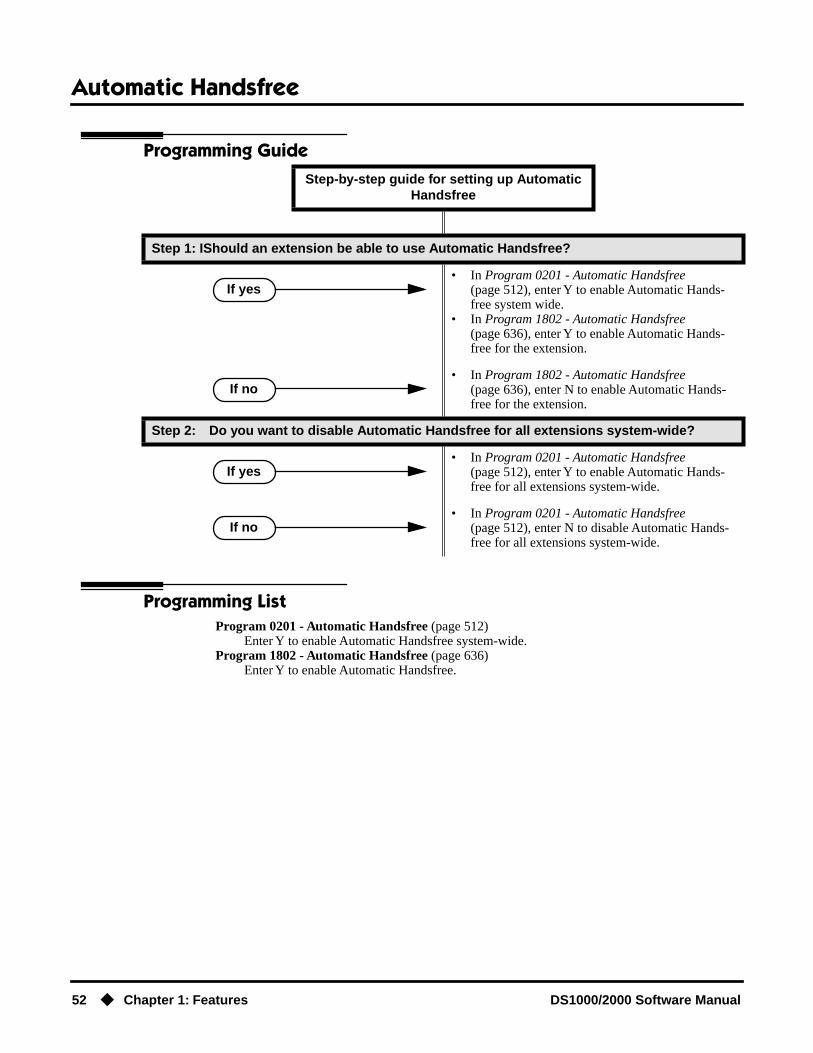
Automatic Handsfree
52 ◆ Chapter 1: Features DS1000/2000 Software Manual
Programming Guide
Programming ListProgram 0201 - Automatic Handsfree (page 512)
Enter Y to enable Automatic Handsfree system-wide.Program 1802 - Automatic Handsfree (page 636)
Enter Y to enable Automatic Handsfree.
Step-by-step guide for setting up Automatic Handsfree
Step 1: IShould an extension be able to use Automatic Handsfree?
• In Program 0201 - Automatic Handsfree (page 512), enter Y to enable Automatic Hands-free system wide.
• In Program 1802 - Automatic Handsfree (page 636), enter Y to enable Automatic Hands-free for the extension.
• In Program 1802 - Automatic Handsfree (page 636), enter N to enable Automatic Hands-free for the extension.
Step 2: Do you want to disable Automatic Handsfree for all extensions system-wide?
• In Program 0201 - Automatic Handsfree (page 512), enter Y to enable Automatic Hands-free for all extensions system-wide.
• In Program 0201 - Automatic Handsfree (page 512), enter N to disable Automatic Hands-free for all extensions system-wide.
If yes
If no
If yes
If no

Automatic Handsfree
DS1000/2000 Software Manual Chapter 1: Features ◆ 53
Other Related FeaturesCentral Office Calls, Placing (page 105)
With Automatic Handsfree, an extension user can press a line key to place a trunk call without first lifting the handset or pressing SPK. Users without Automatic Handsfree can preselect a line key before lifting the handset or pressing SPK.
Handsfree and Handsfree Answerback (page 228)Process calls using the speaker and microphone in the telephone (instead of the handset).
Headset Compatibility (page 232)While in the headset mode, Automatic Handsfree simplifies answering trunk calls.
Line Keys (page 279)Automatic Handsfree allows the keyset user to answer a call ringing a line key without lifting the handset; they just press the line key instead.
Loop Keys (page 283)Automatic Handsfree allows the keyset user to answer a call ringing a loop key without lifting the handset; they just press the loop key instead.
Feature OperationIf enabled, Automatic Handsfree operation is automatic when you press the key.

Automatic Ring Down
54 ◆ Chapter 1: Features DS1000/2000 Software Manual
Automatic Ring Down
DescriptionDS2000 Fixed Slot
Available. See Ringdown Extension on page 368.DS2000 U Slot
DS1000

Background Music
DS1000/2000 Software Manual Chapter 1: Features ◆ 55
Background Music
Description
Background Music (BGM) sends music from a customer-provided music source to speakers in key-sets. If an extension user activates it, BGM plays whenever the extension is idle. Incoming calls and Paging announcements temporarily override (turn off) Background Music.
Background Music requires a customer-provided music source. This source is also used by Music on Hold. In DS2000, you connect the music source to the CPU’s 8-pin mod jack. In DS1000, you connect the music source to the Main Equipment Cabinet AUDIO jack. The music source you use must be compatible with the following specifications:
For more on connecting a customer-provided music source, refer to the system’s Hardware Manual.
Note:
In accordance with U.S. copyright law, a license may be required from the America Society of Composers, Authors and Publishers (ASCAP) or other similar organizations, if radio, television broadcasts or music other than material not in the public domain are transmitted through the Back-ground Music feature of telecommunications systems. NEC America, Inc. hereby disclaims any lia-bility arising out of the failure to obtain such a license.
ConditionsNone
Default SettingEnabled system-wide and at each extension.
DS2000 Fixed Slot
Available.DS2000 U Slot
DS1000
Broadcast music through the telephone speaker for a more pleasing work environment.
Table 3: Music Source Specifications
Input Impedance 10K Ohms
Relative Input Level +18 dBr (+/- dBr) at 1.0 kHz

Background Music
56 ◆ Chapter 1: Features DS1000/2000 Software Manual
Programming Guide
Programming ListProgram 0201 - Background Music (page 513)
Enter Y for this option to enable Background Music system-wide.Program 1802 - BGM (page 637)
Enter Y to enable Background Music at the extension.
Other Related FeaturesDo Not Disturb (page 183)
DND does not affect the operation of Background Music.Headset Compatibility (page 232)
Background Music plays in the headset when the extension is in the headset mode.Music on Hold (page 303)
Background Music and Music on Hold share the same music source.Off-Premise Extensions / On-Premise SLT Extensions (page 317)
Background Music is not available to On- and Off-Premise extensions.
Step-by-step guide for setting up Background Music
Step 1: Should Background Music be enabled system-wide?
• In Program 0201 - Background Music (page 513), enter Y to enable Backgorund Music system-wide.
• Connect the music source to the CPRU music ter-minals.
• In Program 0201 - Background Music (page 513), enter N to disable Backgorund Music system-wide.
Step 2: Once enabled system-wide, should individual extension have Background Music?
• In Program 1802 - BGM (page 637), enter Y to enable Backgorund Music for the extension.
• In Program 1802 - BGM (page 637), enter N to disable Backgorund Music for the extension.
If yes
If no
If yes
If no

Background Music
DS1000/2000 Software Manual Chapter 1: Features ◆ 57
Feature Operation
To turn Background Music on and off:
1. Do not lift handset or press SPK.
2. Press HOLD.
Barge In (Intrusion)
58 ◆ Chapter 1: Features DS1000/2000 Software Manual
Barge In (Intrusion)
Description
Barge In permits an extension user to break into another extension user’s established call. This sets up a three-way conversation between the intruding extension and the two parties on the initial call. The user can Barge In on an Intercom call or a trunk call.
ConditionsBarge-In uses a system Conference circuit. See Conference on page 124 for more.
Default SettingDisabled
Programming Guide
DS2000 Fixed Slot
Available.DS2000 U Slot
DS1000
In an emergency, use Barge In to get through to a co-worker right away.
!! CAUTION !!
Unauthorized intrusion on calls using this feature may be interpreted as an invasion of privacy.
Step-by-step guide for setting up Barge In
Step 1: Should an extension be able to Barge In on a co-worker’s call?
• In Program 0101 - Barge-In (Intrusion) (page 506), enter Y to enable Barge In in the extension’s Class of Service.
• In Program 0101 - Privacy (page 507), enter N to disable Privacy in the extension’s Class of Ser-vice.
• In Program 1801 - Extension Class of Service Assignment (page 631), assign Class of Service to extensions.
• In Program 0101 - Barge-In (Intrusion) (page 506), enter N to disable Barge In in the extension’s Class of Service.
• In Program 1801 - Extension Class of Service Assignment (page 631), assign Class of Service to extensions
If yes
If no

Barge In (Intrusion)
DS1000/2000 Software Manual Chapter 1: Features ◆ 59
Programming ListProgram 0101 - Barge-In (Intrusion) (page 506)
In an extension’s Class of Service, enter Y to allow the extension to Barge In on another extension.
Program 0101 - Privacy (page 507)In an extension’s Class of Service, enter N to disable Privacy for the extension.
Program 1801 - Extension Class of Service Assignment (page 631)Assign Class of Service to extensions.
Other Related FeaturesAttendant Position (page 47)
Since the attendant is never busy, Intercom callers cannot Barge In on an attendant.Conference (page 124)
An extension user can Barge In on a Conference.Forced Trunk Disconnect (page 212)
As an alternative to Barging In, disconnect the trunk instead.Privacy (page 345)
Privacy blocks Barge In attempts.
Feature Operation
To Barge-In on a call:
1. Call busy extension.OR
Press line key for busy trunk.OR
Press ICM and dial 401 for busy trunk (i.e., using Direct Trunk Access).OR
Press ICM and dial #901 for busy trunk (i.e., using Line Dial-up).OR
Press ICM and dial Trunk Group access code (e.g., 9).
2. Dial 4.
3. Join the conversation in progress.
Busy tone.
N/A
Two beeps.
N/A

Battery Backup
60 ◆ Chapter 1: Features DS1000/2000 Software Manual
Battery Backup
Description
In the event of commercial AC power failure, the battery on the CPU PCB provides short-term backup of system memory and the system time and date (Real Time Clock). This battery will hold memory and time and date for up to 10-14 days. When commercial AC power is restored, the sys-tem restarts with all programming and the time and date intact.
Additional Battery Backup capability can be provided by a customer-supplied Uninterruptable Power Supply (UPS). The length of the time the UPS will power the system when power fails depends on the capacity of the UPS unit. Consult with the UPS manufacturer for the specifics. When sizing a UPS unit, keep in mind that a fully-loaded 4-slot cabinet requires 165 VA. Refer to the Hardware Manual for additional details.
ConditionsNone
Default SettingNone
Programming ListNone
Other Related FeaturesWhen commercial AC power fails, the CPU battery does not back up the status of the following:
● Call Forwarding
● Call Waiting / Camp On
● Do Not Disturb
● Message Waiting
● Microphone Mute
● Trunk Queuing
System Programming Backup and Restore (page 410)You can use PC Card P/N 85880 or P/N 80050-V**.**.** (with system software preloaded) to back up and restore your site data.
Time and Date (page 437)The battery on the CPU PCB backs up the CPU Real Time Clock for 10-14 days.
DS2000 Fixed Slot
Available.DS2000 U Slot
DS1000
The CPU PCB provides temporary backup of system memory and the time and date.

Battery Backup
DS1000/2000 Software Manual Chapter 1: Features ◆ 61
Feature OperationIf properly installed, Battery Backup is automatic during AC power failures and brownouts.

Call Coverage Keys
62 ◆ Chapter 1: Features DS1000/2000 Software Manual
Call Coverage Keys
Description
A keyset can have Call Coverage Keys for a co-worker’s extensions, Ring Group master numbers and UCD group master numbers. The Call Coverage Key lights when the co-worker’s extension is busy, flashes slowly when the co-worker has an incoming call, and flashes fast when the co-worker is in Do Not Disturb. The Call Coverage Key can ring immediately when a call comes into the cov-ered extension, ring after a delay or not ring at all. In addition, the keyset user can press the Call Coverage Key to intercept their co-worker’s incoming call. They can also go off hook and press the Call Coverage key to call the covered extension. An extension can have as many Call Coverage Keys as they have available Programmable keys on their telephone.
Call Coverage Keys will intercept the following types of calls:
● Key Ring Calls
● Ringing Intercom calls
ConditionsNone
Default SettingNo Call Coverage Keys assigned.
DS2000 Fixed Slot Available.
DS2000 U Slot Available. User Programmable Feature steps added.
DS1000 Available. Includes User Programmable Feature steps.
Call Coverage keys allow an extension user to cover a co-worker’s calls from their own telephone.
Call Coverage Key Busy Lamp Indications
When the key is: The covered extension is:
Off Idle or not installed
On Busy
Flashing slowly Ringing
Flashing fast In Do Not Disturb

Call Coverage Keys
DS1000/2000 Software Manual Chapter 1: Features ◆ 63
Programming Guide
Step-by-step guide for setting up Call Coverage Keys
Step 1: Should the Call Coverage key have Immediate Ring, No Ring or Delayed Ring?
• For keysets, in Program 1701 - Call Coverage Immediate Ring (page 613), enter code 06 + the covered extension, Ring Group master number or UCD Group master number to assign an Immedi-ate Ring Call Coverage Key.
• For DSS Consoles, in Program 1704 - Call Cov-erage Immediate Ring (page 624), enter code 06 + the covered extension, Ring Group master num-ber or UCD Group master number to assign an Immediate Ring Call Coverage Key.
• For keysets, in Program 1701 - Call Coverage No Ring (page 613), enter code 07 + the covered extension, Ring Group master number or UCD Group master number to assign a No Ring (lamp only) Call Coverage Key.
• For DSS Consoles, in Program 1704 - Call Cov-erage No Ring (page 624), enter code 07 + the covered extension, Ring Group master number or UCD Group master number to assign a No Ring (lamp only) Call Coverage Key.
• For keysets, in Program 1701 - Call Coverage Delay Ring (page 613), enter 08 + the covered extension, Ring Group master number or UCD Group master number to assign a Delay Ring Call Coverage Key.
• For DSS Consoles, in Program 1704 - Call Cov-erage Delay Ring (page 625), enter 08 + the cov-ered extension, Ring Group master number or UCD Group master number to assign a Delay Ring Call Coverage Key.
• In Program 0403 - Call Coverage Delay (page 534), enter the interval after which a Delay Ring Call Coverage Key begins to ring.
Immediate Ring
No Ring
Delay Ring

Call Coverage Keys
64 ◆ Chapter 1: Features DS1000/2000 Software Manual
Programming ListProgram 0403 - Call Coverage Delay (page 534)
For extensions with Delayed Ringing Call Coverage keys, set how long a call flashes the key at an extension before it starts to ring.
Program 1701 - Programmable Function Key Assignments (page 612)Assign a programmable key on an extension as a Call Coverage Key (code 06 = immediate ring key, code 07 = no ring key, code 08 = delay ring key). The option is the covered extension (300-395 in DS2000, 300-325 in DS1000).
Program 1704 - DSS Console Key Assignment (page 622)Assign a programmable key on an extension as a Call Coverage Key (code 06 = immediate ring key, code 07 = no ring key, code 08 = delay ring key). The option is the covered extension (300-395 in DS2000, 300-325 in DS1000).
Other Related FeaturesDirect Station Selection (DSS) Console (page 143)
DSS Consoles can have Call Coverage keys.Distinctive Ringing (page 162)
By using Key Ring Override, Distinctive Ringing allows an extension user to set up unique ringing for their Call Coverage keys.
Door Box (page 185)If you enter Door Chime type 0 (normal ring) above, you can set up Call Coverage keys for the Door Box Ring Group. This allows extensions that are not members of the Ring Group to answer Door Box calls. Extensions with Call Coverage keys to the Door Box Ring Group can also activate the relay.
Extension Hunting (page 193)A keyset can have Call Coverage keys for UCD Group master numbers.
Group Ring (page 221)A keyset can have Call Coverage keys for Ring Group master numbers.
Hotline (page 240)Hotline keys provide many of the features available with Call Coverage keys.
Intercom (page 268)A user can press a Call Coverage Key as an alternative to dialing Intercom numbers.
Key Ring (page 273)Call Coverage will pick up Key Ring calls.
Transfer (page 455)An extension user can Transfer a call to the covered extension by pressing the Call Coverage key.
Voice Over (page 493)After calling a co-worker by pressing their Call Coverage key, and extension user can dial 9 to leave a Voice Over (if enabled in programming).

Call Coverage Keys
DS1000/2000 Software Manual Chapter 1: Features ◆ 65
Feature Operation
To answer a call ringing or flashing a Call Coverage Key:
1. Press flashing Call Coverage Key.
To place a call from an idle Call Coverage Key to the covered extension:
1. Press Call Coverage Key.
2. Speak with co-worker at the covered extension.
User Programmable Feature
Feature Mnemonic Operation Access Level
The shaded row below shows the Fixed Slot software User Programmable Feature.
Call Coverage #RC # + R C + Press Call Coverage key repeatedly to select ringing mode
N/A
Programmable Function Key Ringing
#RA Call Coverage Keys: #RAC + Call Cover-age Key repeatedly to select ringing mode + SPK to exit.Call Coverage Keys flash as follows: Lamp only=On red, Immediate ring=On green, Delay ring=Fast flash green.
2-5
(Optional) Ringing.
Slowly flashing Call Coverage Key.
Two beeps.
Call Coverage Key lights green.

Call Forwarding
66 ◆ Chapter 1: Features DS1000/2000 Software Manual
Call Forwarding
Description
Call Forwarding permits an extension user to redirect their call to another extension. The types of Call Forwarding are:
● Call Forwarding when Not AnsweredCalls ringing the extension forward when not answered.
● Call Forwarding when Busy or Not AnsweredCalls ringing the extension forward when not answered, and all calls forward while the exten-sion is busy.
● Call Forwarding ImmediateAll calls to the extension forward immediately.
Extension user’s can chain Call Forwards. For example, extension 301 can forward all calls imme-diately to 304, which in turn can forward all calls immediately to extension 302. Any co-worker calling 301 or 304 goes to 302 instead. If extension 302 is Call Forwarded to Voice Mail, callers to 301 or 304 go directly to 302’s mailbox.
ConditionsA system reset or power failure cancels Call Forwarding.
Default SettingEnabled
Programming Guide
DS2000 Fixed Slot
Available.DS2000 U Slot
DS1000
Call Forwarding ensures that the user’s calls are covered when they are away from their work area.
Step-by-step guide for setting up Call Forwarding
Step 1: Should an extension be able to forward their calls to a co-worker?
• In Program 0101 - Internal Call Forwarding (page 506), enter Y to enable Call Forwarding.
• In Program 1801 - Extension Class of Service Assignment (page 631), assign Class of Service to extensions.
If yes

Call Forwarding
DS1000/2000 Software Manual Chapter 1: Features ◆ 67
• In Program 0101 - Internal Call Forwarding (page 506), enter N to disable Call Forwarding.
• In Program 1801 - Extension Class of Service Assignment (page 631), assign Class of Service to extensions.
Step 2: When a user enables Ring No Answer forwarding, does an unanswered call ring the forwarding destination after the correct interval?
• In Program 0403 - Call Forward Ring No Answer (page 533), leave at the current setting.
• In Program 0403 - Call Forward Ring No Answer (page 533), change the entry to meet the site’s requirements.
Step-by-step guide for setting up Call Forwarding
If no
If yes
If no

Call Forwarding
68 ◆ Chapter 1: Features DS1000/2000 Software Manual
Call Forwarding TimersThe following diagrams show how the system implements various timers when handling for-warded calls.
Transferred Trunk Call to Forwarded Extension
DIL (no overflow) to Forwarded Extension
0401 - Transfer Recall
0403 - Call Forward RNA
The trunk rings extension B for the Transfer Recall time. See Transfer on page 455 for more.
Extension A transfers trunk to extension B, which is forwarded Busy/No Answer (type 2) to exten-sion C.
In unanswered, the call then rings extension C (the forward destination) for the Call Forward Ring No Answer time.
If still unanswered, call diverts to Key Ring
0403 - Call Forward RNAIf still unanswered, the call rings the extension that initially transferred the call (A) for the Call Forward Ring No Answer time.
0401 - DIL No Answer
0401 - DIL No Answer
DIL rings programmed DIL destination for the DIL No Answer time.
DIL (with no overflow) rings programmed desti-nation, which is forwarded Busy/No Answer (type 2) to a co-worker.
In unanswered, the call rings the extension to which it is call forwarded for the DIL No Answer time.
If still unanswered, call diverts to Key Ring
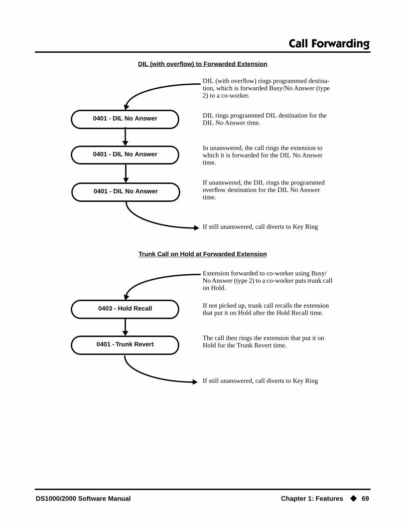
Call Forwarding
DS1000/2000 Software Manual Chapter 1: Features ◆ 69
DIL (with overflow) to Forwarded Extension
Trunk Call on Hold at Forwarded Extension
0401 - DIL No Answer
0401 - DIL No Answer
DIL rings programmed DIL destination for the DIL No Answer time.
DIL (with overflow) rings programmed destina-tion, which is forwarded Busy/No Answer (type 2) to a co-worker.
In unanswered, the call rings the extension to which it is forwarded for the DIL No Answer time.
If still unanswered, call diverts to Key Ring
0401 - DIL No AnswerIf unanswered, the DIL rings the programmed overflow destination for the DIL No Answer time.
0403 - Hold Recall
0401 - Trunk Revert
If not picked up, trunk call recalls the extension that put it on Hold after the Hold Recall time.
Extension forwarded to co-worker using Busy/No Answer (type 2) to a co-worker puts trunk call on Hold.
The call then rings the extension that put it on Hold for the Trunk Revert time.
If still unanswered, call diverts to Key Ring

Call Forwarding
70 ◆ Chapter 1: Features DS1000/2000 Software Manual
Programming ListProgram 0101 - Internal Call Forwarding (page 506)
In an extension’s Class of Service, enter Y to enable internal Call Forwarding.Program 0403 - Call Forward Ring No Answer (page 533)
For Call Forwarding Ring No Answer, set how long a forwarded call rings an unanswered extension before routing to the forwarding destination.
Program 1801 - Extension Class of Service Assignment (page 631)Assign Class of Service to extensions.
Other Related FeaturesCall Coverage Keys (page 62)
Call Forwarding will not reroute a call ringing a Call Coverage Key.Direct Inward Line (page 133)
Call Forwarding will reroute Direct Inward Lines.Do Not Disturb (page 183)
Call Forwarding considers an extension in DND as busy. In addition, an extension can have both DND and Call Forwarding enabled at the same time.
Extension Hunting (page 193)If a member of a Circular or Terminal Hunting group forwards their calls, hunting will follow Call Forwarding. If a member of a UCD Hunting group forwards their calls, calls to the exten-sion follow forwarding but calls to the UCD master number do not.
Group Ring (page 221)Call Forwarding will not reroute Group Ring calls.
Intercom (page 268)Call Forwarding when Busy and Call Forwarding when Busy/Not Answered will not reroute voice-announced Intercom calls. It will reroute only ringing Intercom calls.
Key Ring (page 273)Call Forwarding will not reroute Key Ring calls.
Line Keys (page 279)Call Forwarding will not reroute calls ringing line keys.
Loop Keys (page 283)Call Forwarding will not reroute a call ringing a loop key (unless the call is a DIL).
Message Waiting (page 291)
● An extension user cannot leave a Message Waiting at an co-worker that has Call Forwarding Immediate (*34) enabled. Pressing MW automatically leaves a message at the forwarding desti-nation instead.
● An extension user cannot leave a Message Waiting at a busy co-worker that has Call Forwarding Busy/No Answer (*32) enabled. Pressing MW will automatically leave a message at the for-warding destination instead.
Selectable Display Messaging (page 376)Enabling or canceling Call Forwarding cancels an extension’s Selectable Display Messaging.
Transfer (page 455)Call Forwarding will reroute transferred calls.

Call Forwarding
DS1000/2000 Software Manual Chapter 1: Features ◆ 71
Feature Operation
To activate or cancel Call Forwarding:
1. Press ICM.
2. Dial *3.
3. Dial Call Forwarding type:0 = Cancel your extension’s Call Forwarding2 = Call Forwarding Busy/No Answer4 = Call Forwarding Immediate6 = Call Forwarding No Answer7 = Personal Answering Machine Emulation (see Voice Mail on page 477 for more).
4. Dial destination extension (or 0 for your operator).OR
Dial Voice Mail master number.OR
Press MW.
5. Press SPK to hang up.
Once you forward, only the user at the forwarding destination can place an intercom call to you.
You can forward your phone to another destination without first canceling Call For-warding. For example, you can dial *34 + 0 to immediately forward to the operator, then later on dial *34 + 700 to immediately forward to Voice Mail.
Dial tone.
ICM and SPK on.
Dial tone stops.
ICM and SPK on.
Dial tone.
ICM, DND and SPK on.
Dial tone off.
ICM and SPK off. DND on.
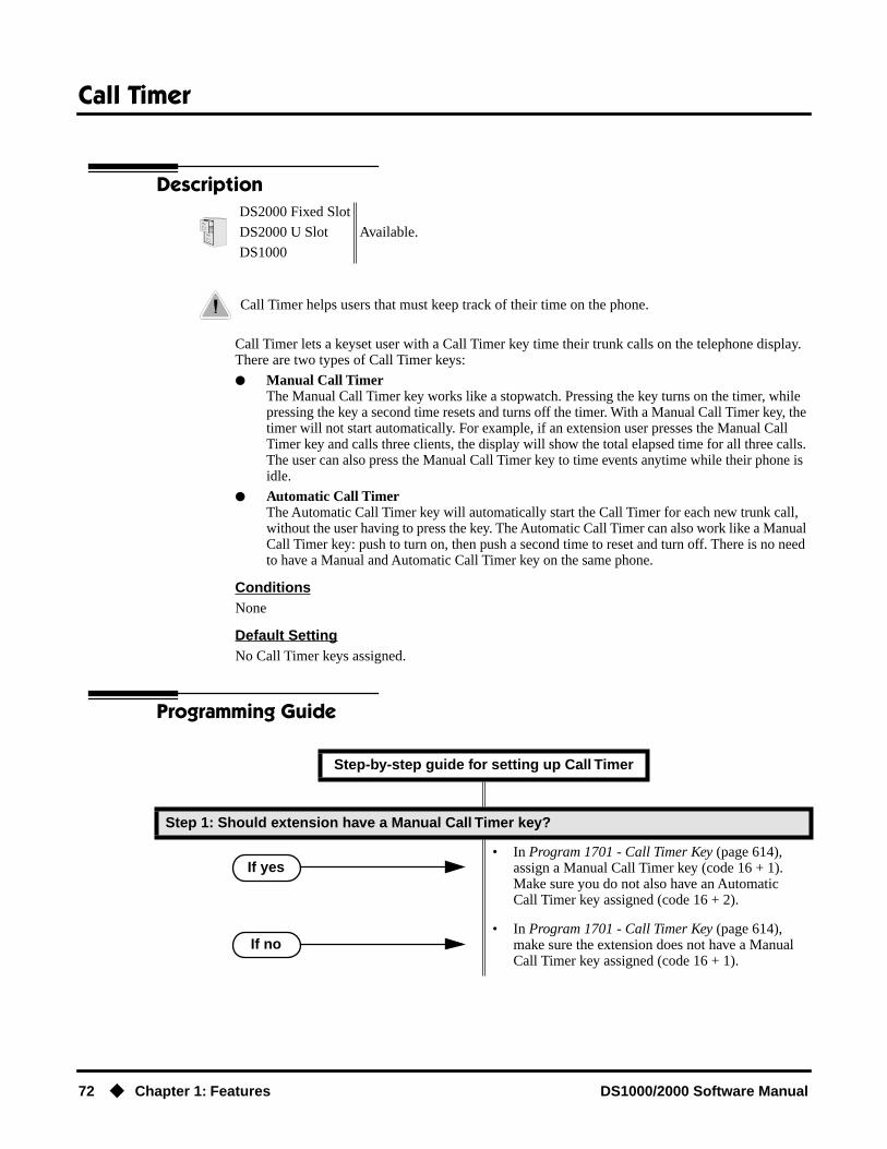
Call Timer
72 ◆ Chapter 1: Features DS1000/2000 Software Manual
Call Timer
Description
Call Timer lets a keyset user with a Call Timer key time their trunk calls on the telephone display. There are two types of Call Timer keys:
● Manual Call Timer The Manual Call Timer key works like a stopwatch. Pressing the key turns on the timer, while pressing the key a second time resets and turns off the timer. With a Manual Call Timer key, the timer will not start automatically. For example, if an extension user presses the Manual Call Timer key and calls three clients, the display will show the total elapsed time for all three calls. The user can also press the Manual Call Timer key to time events anytime while their phone is idle.
● Automatic Call TimerThe Automatic Call Timer key will automatically start the Call Timer for each new trunk call, without the user having to press the key. The Automatic Call Timer can also work like a Manual Call Timer key: push to turn on, then push a second time to reset and turn off. There is no need to have a Manual and Automatic Call Timer key on the same phone.
ConditionsNone
Default SettingNo Call Timer keys assigned.
Programming Guide
DS2000 Fixed Slot
Available.DS2000 U Slot
DS1000
Call Timer helps users that must keep track of their time on the phone.
Step-by-step guide for setting up Call Timer
Step 1: Should extension have a Manual Call Timer key?
• In Program 1701 - Call Timer Key (page 614), assign a Manual Call Timer key (code 16 + 1). Make sure you do not also have an Automatic Call Timer key assigned (code 16 + 2).
• In Program 1701 - Call Timer Key (page 614), make sure the extension does not have a Manual Call Timer key assigned (code 16 + 1).
If yes
If no

Call Timer
DS1000/2000 Software Manual Chapter 1: Features ◆ 73
Programming ListProgram 1701 - Call Timer Key (page 614)
Assign a programmable key on an extension as a Call Timer key (code 16). The options are manual (1) and automatic (2).
Other Related FeaturesCaller ID (page 82)
The Auto Timer feature interacts with Caller ID on the first line of the telephone display.Central Office Calls, Placing (page 105)
Call Timer shows the time a user has been on a trunk call.Flash (page 207)
Flash restarts the Call Timer.Hold (page 235)
A user’s Call Timer starts when they pick up a call from Hold. If they place the call on Hold and another user picks it up, the timer restarts for the new user.
Station Message Detail Recording (page 400)The SMDR report also keeps track of the time on a call.
Step 2: Should extension have an Automatic Call Timer key?
• In Program 1701 - Call Timer Key (page 614), assign an Automatic Call Timer key (code 16 + 2). Make sure you do not also have a Manual Call Timer key assigned (code 16 + 1).
• In Program 1701 - Call Timer Key (page 614), make sure the extension does not have an Auto-matic Call Timer key assigned (code 16 + 2).
Step-by-step guide for setting up Call Timer
If yes
If no

Call Timer
74 ◆ Chapter 1: Features DS1000/2000 Software Manual
Feature Operation
To time your trunk call if you have an Automatic Call Timer key:
1. Place or answer trunk call.
2. The Call Timer starts automatically.
You can press the Automatic Call Timer key once to turn the timer off. Press the key a second time to restart the timer.
You can also press CHECK + the timer key to restart the timer.
To time your call if you have a Manual Call Timer key:
You can also use your Manual Call timer key as a stop watch while your phone is idle.
1. Place or answer Intercom or trunk call.
2. Press Manual Call Timer key.
You can press the Manual Call Timer key once to turn the timer off. Press the key a sec-ond time to restart the timer.
You can also press CHECK + the timer key to restart the timer.
Conversation with caller.
Automatic Call Timer key on.Timer in first line of display.
Conversation with caller.
Manual Call Timer key on.Timer in first line of display.

Call Waiting / Camp-On
DS1000/2000 Software Manual Chapter 1: Features ◆ 75
Call Waiting / Camp-On
Description
With Call Waiting, an extension user may call a busy extension and wait in line (Camp-On) without hanging up. When the user Camps-On (by dialing 2), the system signals the busy extension with two beeps indicating the first waiting call. (The busy extension can be on a handset or Handsfree call.) The call goes through when the extension becomes free.
If an extension has more than one caller waiting, they queue on a first-in/first-out basis (FIFO). The extension will not hear Camp-On beeps for additional waiting calls.
Off-Hook Signaling also alerts the user when unanswered calls are waiting to get through. Turn to Off-Hook Signaling on page 313 for more.
The following chart shows when the two types of Off-Hook Signaling occur. Note that Camp-On tones occur for an extension when they are the exclusive recipient of the call (such as a DIL).
Conditions
● A system reset or power failure cancels all Camp-Ons system wide.
● While busy on a call, Camp-On tones occur only for the first incoming call and do not repeat.
Default SettingCall Waiting tones enabled.
DS2000 Fixed Slot
Available.DS2000 U Slot
DS1000
Call Waiting helps busy extension users know when they have additional waiting calls. It also lets callers wait in line for a busy extension without being forgotten.
Off-Hook Ringing1
Camp-On Tones2
Key Ring Yes No
Transferred Trunk Call Yes Yes
Direct Inward Line Yes Yes
Transfer from Voice Mail (UTRF) Yes Yes
Call Coverage Key Yes No
Group Call Pickup Key Yes No
1 For Off-Hook ringing, 1802 - Off-Hook Signaling for CO Calls = 2.2 For Camp-On tones, 1802 - Off-Hook Signaling for CO Calls = 1.

Call Waiting / Camp-On
76 ◆ Chapter 1: Features DS1000/2000 Software Manual
Programming Guide
Step-by-step guide for setting up Call Waiting / Camp-On
Step 1: Should extension be able to Camp On to a busy co-worker?
• In Program 0101 - Camp-On to Busy Extension (page 506), enter Y in each Class of Service that should allow users to Camp-On to a busy exten-sion.
• In Program 0101 - Privacy (page 507), be sure Privacy is disabled at the destination extension (N).
• In Program 1801 - Extension Class of Service Assignment (page 631), assign Class of Service to extensions.
• Assign Class of Service (1-15) to extensions.
• In Program 0101 - Camp-On to Busy Extension (page 506), enter N in each Class of Service that should prevent users from Camping-on to a busy extension. Entering N automatically converts an extension’s Camp On to Callback.
• In Program 1801 - Extension Class of Service Assignment (page 631), assign Class of Service to extensions.
Step 2: Should an extension hear Camp-On tones when a co-worker camps-on to their extension?
• In Program 0201 - Call Waiting (Camp-On) Tone (page 512), enter Y to enable Camp-On tones sys-tem-wide.
• InProgram 0403 - Call Waiting Tone Interval (page 534), set the interval between Camp-On tones.
• InProgram 1802 - Off-Hook Signaling for Inter-com Calls (page 635), enter 1.
• In Program 0201 - Call Waiting (Camp-On) Tone (page 512), enter N to disable Camp-On tones system-wide.
If yes
If no
If yes
If no

Call Waiting / Camp-On
DS1000/2000 Software Manual Chapter 1: Features ◆ 77
Programming ListProgram 0101 - Camp-On to Busy Extension (page 506)
In an extension’s Class of Service, enter Y to allow the extension to Camp-On to a busy co-worker. Enter N to prevent the extension from Camping-On to a busy co-worker. Entering N also automatically converts an extension’s Camp On to Callback.
Program 0101 - Privacy (page 507)An extension with Privacy enabled (Y) will block Camp On / Call Waiting.
Program 0201 - Call Waiting (Camp-On) Tone (page 512)Enter Y to enable Camp-On tones system-wide. Enter N to disable Camp-On Tones system-wide.
Program 0403 - Call Waiting Tone Interval (page 534)Set the interval between Camp-On tones.
Program 1801 - Extension Class of Service Assignment (page 631)Assign Class of Service (1-15) to extensions.
Program 1802 - Off-Hook Signaling for Intercom Calls (page 635)To enable Camp On tones for Intercom calls, enter 1.
Other Related FeaturesAttendant Position (page 47)
An extension user cannot Camp-On to the attendant because the attendant’s extension is never busy.
Callback (page 79)If an extension user Camps-On and then hangs up, the system converts the Camp-On to a Callback.
Caller ID (page 82)An extension programmed to receive Camp On tones or Off-Hook Ringing from a waiting call will also receive Second Call Caller ID.
Direct Inward Line (page 133),DILs to a busy extension automatically send Camp-On tones.
Do Not Disturb (page 183)An extension cannot Camp-On to a busy co-worker that is also in Do Not Disturb.
Key Ring (page 273)A Key Ring call will not send Camp-On beeps to a busy extension that normally rings for that call.
Intercom (page 268)A user can Camp-On after placing an Intercom call to a busy co-worker.
Privacy (page 345)Privacy blocks Camp-On / Call Waiting.
Split (Alternate) (page 395)Camp-On lets an extension user know that a call is waiting to be answered. The user can Split between the waiting call and their current call.
Transfer (page 455)An extension user may be able to Transfer a call to a busy extension.
Trunk (Line) Queuing / Trunk Callback (page 465)Trunk Queuing lets an extension user Camp-On to a busy trunk.
Volume Controls (page 496)The extension user cannot adjust the volume of incoming Camp On tone.

Call Waiting / Camp-On
78 ◆ Chapter 1: Features DS1000/2000 Software Manual
Feature Operation
To Camp-On to a busy extension:
1. Call busy extension.
2. Dial 2; do not hang up.
If you hang up, the system converts your Camp-On to a Callback.
3. When your co-worker hangs up their initial call:
4. Speak to your co-worker when they answer their Camp-On ring.
Busy tone.
ICM and SPK on.
Busy tone stops.
ICM and SPK on.
Ringback. Camp-On rings your co-worker’s phone also.
ICM and SPK on.

Callback
DS1000/2000 Software Manual Chapter 1: Features ◆ 79
Callback
Description
When an extension user calls a busy co-worker, they can leave a Callback request for a return call. The system services Callback requests as follows:
● Caller at extension A leaves a Callback at extension B.Caller can place or answer additional calls in the mean time.
● When extension B becomes idle, the system rings extension A. This is the Callback ring.
● Once caller A answers the Callback ring, the system rings (formerly busy) extension B.If caller A doesn’t answer the Callback ring, the system cancels the Callback.
● As soon as caller B answers, the system sets up an Intercom call between A and B.
An extension user can leave a Callback at many extensions simultaneously. The system processes the Callbacks as the extensions become free. In addition, many extensions can leave a Callback at the same extension. The system processes these Callbacks on a first-in/first-out (FIFO) basis.
If an extension user leaves a Callback request and then fails to answer within four rings, the system cancels the Callback.
ConditionsA system reset or power failure cancels all Callbacks system-wide.
Default SettingCallback enabled.
Programming Guide
DS2000 Fixed Slot
Available.DS2000 U Slot
DS1000
With Callback, a user does not have to repeatedly call a busy extension back, hoping to find it idle.
Step-by-step guide for setting up Callback
Step 1: Should extension be able to leave a Callback for a busy co-worker?
• In Program 0101 - Camp-On to Busy Extension (page 506), enter Y in each Class of Service that should allow users to leave a Callback at a busy extension.
• In Program 0101 - Camp-On to Busy Extension (page 506), enter N in each Class of Service that should prevent users from leaving a Callback at a busy extension.
If yes
If no
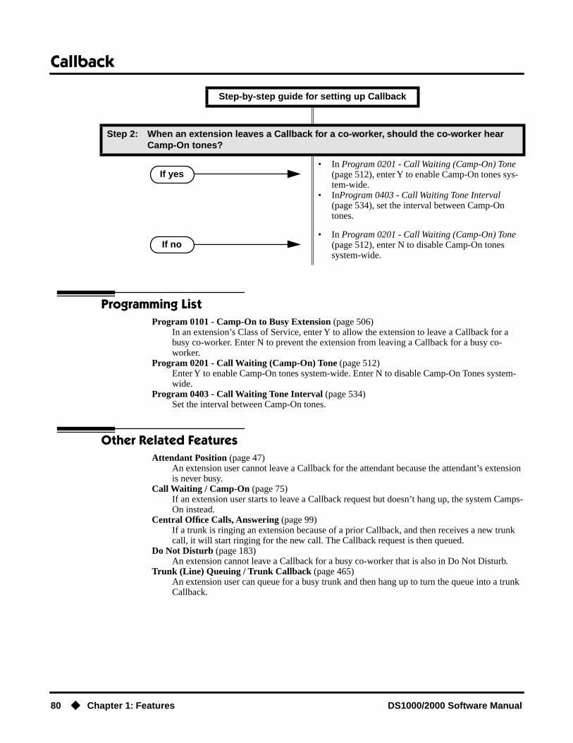
Callback
80 ◆ Chapter 1: Features DS1000/2000 Software Manual
Programming ListProgram 0101 - Camp-On to Busy Extension (page 506)
In an extension’s Class of Service, enter Y to allow the extension to leave a Callback for a busy co-worker. Enter N to prevent the extension from leaving a Callback for a busy co-worker.
Program 0201 - Call Waiting (Camp-On) Tone (page 512)Enter Y to enable Camp-On tones system-wide. Enter N to disable Camp-On Tones system-wide.
Program 0403 - Call Waiting Tone Interval (page 534)Set the interval between Camp-On tones.
Other Related FeaturesAttendant Position (page 47)
An extension user cannot leave a Callback for the attendant because the attendant’s extension is never busy.
Call Waiting / Camp-On (page 75)If an extension user starts to leave a Callback request but doesn’t hang up, the system Camps-On instead.
Central Office Calls, Answering (page 99)If a trunk is ringing an extension because of a prior Callback, and then receives a new trunk call, it will start ringing for the new call. The Callback request is then queued.
Do Not Disturb (page 183)An extension cannot leave a Callback for a busy co-worker that is also in Do Not Disturb.
Trunk (Line) Queuing / Trunk Callback (page 465)An extension user can queue for a busy trunk and then hang up to turn the queue into a trunk Callback.
Step 2: When an extension leaves a Callback for a co-worker, should the co-worker hear Camp-On tones?
• In Program 0201 - Call Waiting (Camp-On) Tone (page 512), enter Y to enable Camp-On tones sys-tem-wide.
• InProgram 0403 - Call Waiting Tone Interval (page 534), set the interval between Camp-On tones.
• In Program 0201 - Call Waiting (Camp-On) Tone (page 512), enter N to disable Camp-On tones system-wide.
Step-by-step guide for setting up Callback
If yes
If no

Callback
DS1000/2000 Software Manual Chapter 1: Features ◆ 81
Feature Operation
To place a Callback:
1. Call busy extension.
2. Dial 2 and hang up.
Stay on the line without hanging up if you want to Camp-On instead.
3. When the busy co-worker becomes free:
4. Lift handset to answer.
5. Speak to your co-worker when call goes through.
Busy tone.
ICM and SPK on.
Busy tone stops.
ICM and SPK off.
Intercom ring.
ICM and SPK off.
Two beeps.
ICM on.

Caller ID
82 ◆ Chapter 1: Features DS1000/2000 Software Manual
Caller ID
Description
Caller ID allows a display keyset to show an incoming caller’s telephone number (called Directory Number or DN) and optional name. Caller ID supports the telco’s Called Number Identification (CNI) and Called Number Delivery (CND) service, when available. These services provide the Caller ID information (i.e., messages) between the first and second ring burst of an incoming call.
Caller ID provides the following features:
Single and Multiple Message Format CompatibilityThere are two types of Caller ID message formats currently available: Single Data Message Format (SDMF) and Multiple Data Message Format (MDMF). With Single Message Data Format, the telco sends only the caller’s phone number (DN). The DN can be up to 10 digits long. In Multiple Data Message Format, the telco sends the DN and the caller’s name. The DN for this format can be up to 15 digits long, and the name provided can consist of up to 15 ASCII characters.
If no DN is received, no number or error message displays.
Caller ID on the SMDR ReportCaller ID data prints on the SMDR report. SDMF records print a single line which shows just the incoming number. MDMF records print on two lines, with the first line showing the number and the second line showing the name. Unlike the telephone display, the SMDR report can show the entire 15 digits in the DN, if required.
Following is a same SMDR report showing Caller ID data. The first two lines of the report show a complete MDMF record with both the caller’s number and name. The last two lines of the report show two Caller ID error messages: Private Number and Out of Area. The “IN” in the type column indicates that the records shown are for incoming calls.
If no DN is received, no number or error message displays.
DS2000 Fixed Slot Not available.
DS2000 U Slot
Available.• Caller ID Separator requires software version 02.00.01.• In Program 1001 - Caller ID (page 586), the entries are changed from Y
(Caller ID enabled) to 2 in software version 02.00.06.• Post-answer Caller ID display for Ring Group calls requires 02.00.04.• Pre-answer Caller ID display for Ring Group calls requires 02.01.07.• Caller ID to single line telephones requires 02.02.14.
DS1000
Available.• Post-answer Caller ID display for Ring Group available.• Pre-answer Caller ID display for Ring Group calls requires 02.01.07.• Caller ID to single line telephones requires 02.02.14.
Caller ID automatically displays the phone number and optional name for incoming trunk calls.

Caller ID
DS1000/2000 Software Manual Chapter 1: Features ◆ 83
Station Message Detail Recording03/10/2000 11:11A
---+---+--------------------------------+----------+---------+--------+---Sta|Lin| Number Dialed | Account | Start |Duration| T ---+---+--------------------------------+----------+---------+--------+---301| 02| 2139261000| |11:11:39A|00:00:13|IN 301| 02| ANDERSON ALLEN| |11:11:39A|00:00:13|IN 301| 02| Private Number| |11:12:26A|00:00:12|IN 301| 02| Out of Area Number| |11:13:16A|00:00:12|IN
Caller ID Integration with Voice MailCaller ID fully integrates with NVM-Series Voice Mail systems. This enables Voice Mail features such as Make Call with Caller ID. Make Call allows the Voice Mail subscriber to return a call to someone who left them a message without knowing the calling party’s phone number.
Second Call Caller ID (Extension Level Call Waiting Caller ID)While a display keyset user is busy on a call, the system can show the Caller ID information for a waiting call. If the busy extension is programmed to receive Camp On tones or Off-Hook Ringing from the waiting call, the system will send the Caller ID data to the busy telephone’s display. If the busy extension does not receive Camp On tones or Off-Hook Ringing, it will also not receive the waiting call’s Caller ID. (Note that Caller ID data from a Camp On is displayed only once, corre-sponding to the single Camp On beep.)
Third Party Caller ID CheckThird Party Caller ID Check allows an idle or busy keyset user to display the Caller ID data for another trunk. The trunk that the user checks can be ringing or busy.
Caller ID Display SeparatorAn extension’s display can optinally show a calling party number separator. The separator is a dash after the area code and after the local exchange on a 7 or 10 digit number. If disabled, the calling party number displays without a separator.
Caller ID to Single Line Telephones(Software version 02.02.14 or higher)The system provides Caller ID data to single line ports. This allows single line Caller ID telephones to receive the Caller ID data also available at keysets. Up to 8 single line telephones can receive Caller ID data simultaneously. (To conserve system resources, consider turning off Caller ID in Program 0101 - CLID Display (page 509) for extensions that do not require or support Caller ID.)
On Intercom calls, the single line telephone display will show the extension number and name (if programmed) of the internal caller.
Hardware RequirementsIn DS2000, Caller ID to single line ports requires either 4ASTU Analog Station (ASTU) PCBs P/N 80040B or 8ASTU Analog Station PCBs P/N 80041B. Caller ID to single line ports in DS1000 does not require any updated or additional components.
DSP-Based Caller ID(Software version 02.02.14 or higher)With DS2000 DSP-based Caller ID, Caller ID is built into the system’s ATRU Analog Trunk PCBs and does not require Caller ID daughter boards. DS2000 4ATRU PCB P/N 80010B and 8ATRU PCB 80011B provide this capability. DSP-based Caller ID is the only type of Caller ID available in DS1000 and does not require any updated or additional components.
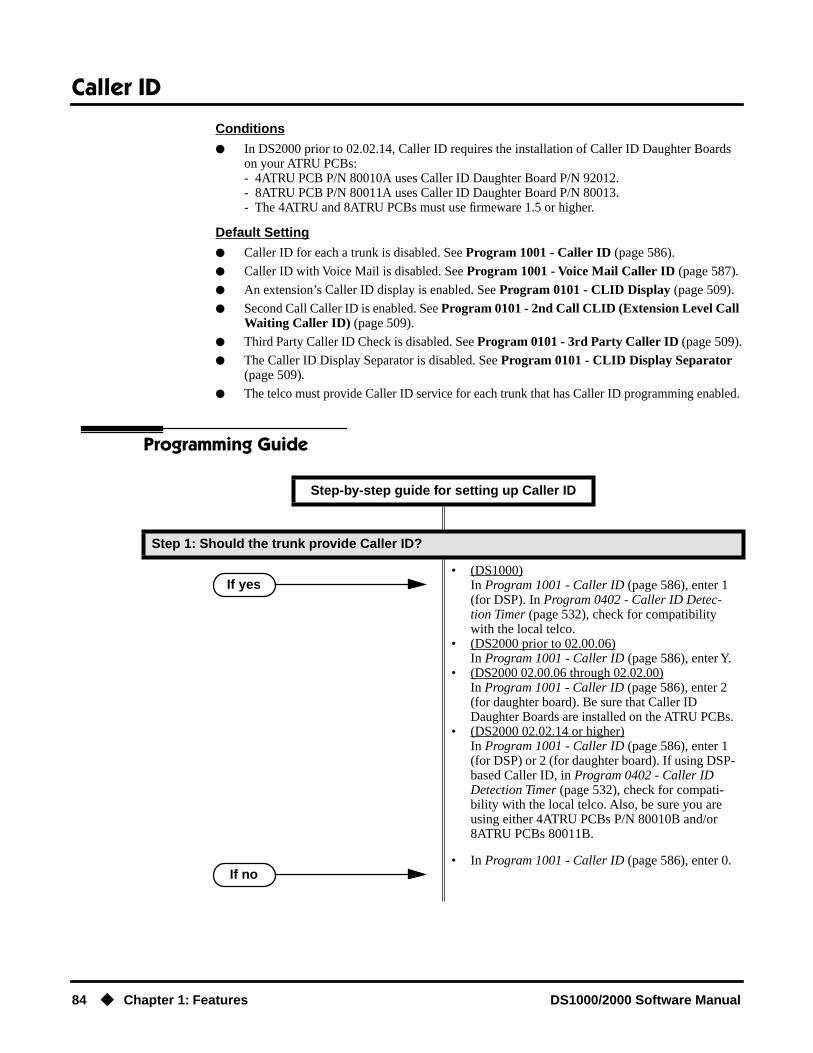
Caller ID
84 ◆ Chapter 1: Features DS1000/2000 Software Manual
Conditions
● In DS2000 prior to 02.02.14, Caller ID requires the installation of Caller ID Daughter Boards on your ATRU PCBs:- 4ATRU PCB P/N 80010A uses Caller ID Daughter Board P/N 92012.- 8ATRU PCB P/N 80011A uses Caller ID Daughter Board P/N 80013.- The 4ATRU and 8ATRU PCBs must use firmeware 1.5 or higher.
Default Setting
● Caller ID for each a trunk is disabled. See Program 1001 - Caller ID (page 586).
● Caller ID with Voice Mail is disabled. See Program 1001 - Voice Mail Caller ID (page 587).
● An extension’s Caller ID display is enabled. See Program 0101 - CLID Display (page 509).
● Second Call Caller ID is enabled. See Program 0101 - 2nd Call CLID (Extension Level Call Waiting Caller ID) (page 509).
● Third Party Caller ID Check is disabled. See Program 0101 - 3rd Party Caller ID (page 509).
● The Caller ID Display Separator is disabled. See Program 0101 - CLID Display Separator (page 509).
● The telco must provide Caller ID service for each trunk that has Caller ID programming enabled.
Programming Guide
Step-by-step guide for setting up Caller ID
Step 1: Should the trunk provide Caller ID?
• (DS1000)In Program 1001 - Caller ID (page 586), enter 1 (for DSP). In Program 0402 - Caller ID Detec-tion Timer (page 532), check for compatibility with the local telco.
• (DS2000 prior to 02.00.06)In Program 1001 - Caller ID (page 586), enter Y.
• (DS2000 02.00.06 through 02.02.00)In Program 1001 - Caller ID (page 586), enter 2 (for daughter board). Be sure that Caller ID Daughter Boards are installed on the ATRU PCBs.
• (DS2000 02.02.14 or higher)In Program 1001 - Caller ID (page 586), enter 1 (for DSP) or 2 (for daughter board). If using DSP-based Caller ID, in Program 0402 - Caller ID Detection Timer (page 532), check for compati-bility with the local telco. Also, be sure you are using either 4ATRU PCBs P/N 80010B and/or 8ATRU PCBs 80011B.
• In Program 1001 - Caller ID (page 586), enter 0.
If yes
If no

Caller ID
DS1000/2000 Software Manual Chapter 1: Features ◆ 85
Step 2: Should the extension display Caller ID?
• In Program 0101 - CLID Display (page 509), enter Y.
• In Program 0101 - CLID Display (page 509), enter N.
Step 3: Should the extension display 2nd Call Caller ID (Extension Level Call Waiting Caller ID)?
• In Program 0101 - 2nd Call CLID (Extension Level Call Waiting Caller ID) (page 509), enter Y.
• In Program 1802 - Off-Hook Signaling for CO Calls (page 636), enter 1 for Camp On Tones or 2 for Off Hook Ringing. See the Programming List below for more.
• In Program 1701 - Call Timer Key (page 614), disable the Call Timer key (code 16). The Caller Timer will block the first line (caller’s name) of the 2nd Call Caller ID display.
• In Program 0101 - 2nd Call CLID (Extension Level Call Waiting Caller ID) (page 509), enter N.
Step 4: Should the extension use 3rd Party Caller ID?
• In Program 0101 - 3rd Party Caller ID (page 509), enter Y.
• In Program 0101 - 3rd Party Caller ID (page 509), enter N.
Step 5: Should the extension use the Caller ID Display Separator?
• In Program 0101 - CLID Display Separator (page 509), enter Y.
• In Program 0101 - CLID Display Separator (page 509), enter N.
Step-by-step guide for setting up Caller ID
If yes
If no
If yes
If no
If yes
If no
If yes
If no

Caller ID
86 ◆ Chapter 1: Features DS1000/2000 Software Manual
Programming ListProgram 0101 - CLID Display (page 509)
This option enables (Y) or disables (N) Caller ID in an extension’s Class of Service. If enabled, Caller ID will occur for all extensions with this Class of Service provided Caller ID is enabled in other system programming. If disabled (N), Caller ID will never occur for exten-sions with this Class of Service.
Program 0101 - 2nd Call CLID (Extension Level Call Waiting Caller ID) (page 509)This option enables (Y) or disables (N) Second Call Caller ID in an extension’s Class of Ser-vice. If enabled, Second Call Caller ID will occur for all extensions with this Class of Service provided Second Call Caller ID is enabled in other system programming. If disabled (N), Sec-ond Call Caller ID will never occur for extensions with this Class of Service.
Program 0101 - 3rd Party Caller ID (page 509)This option enables (Y) or disables (N) Third Party Call Caller ID Check in an extension’s Class of Service. If enabled, Third Party Caller ID Check is available to all extensions with this Class of Service provided Caller ID is enabled in other system programming. If disabled (N), Third party Caller ID check is unavailable to extensions with this Class of Service.
Program 0101 - CLID Display Separator (page 509)This option enables (Y) or disables (N) the Caller ID display separator. If enabled, the tele-phone displays a dash separator after the area code and after the local exchange ona 7 or 10 digit number. If disabled (N), the calling party number displays without a separator.
Program 0402 - Caller ID Detection Timer (page 532)With DSP-based Caller ID, the Caller ID Detection Timer is the amount of time between the first and second ring bursts that the system can detect Caller ID digits. If this timer is set too long, the outside caller will hear ringing followed by reorder tone. If set too short, all the Caller ID digits may not be detected. This timer is not used with DS2000 daughter board-based Caller ID.
Program 1001 - Caller ID (page 586)This option enables or disables Caller ID for each trunk. If enabled, Caller ID will occur if also enabled by the other Caller ID programmable options. To disable this option, enter 0. To enable this option:(DS1000)Enter 1 (for DSP). (DS2000 prior to 02.00.06)Enter Y.
Step 6: Assign Class of Service to Extensions
• In Program 1801 - Extension Class of Service Assignment (page 631), assign Class of Service to extensions.
Step 7: Should the system send Caller ID data to Voice Mail for a trunk?
• In Program 1001 - Voice Mail Caller ID (page 587), enter Y. You should enable Program 1001 - Caller ID (page 586), as well.
• In Program 1001 - Voice Mail Caller ID (page 587), enter N.
Step-by-step guide for setting up Caller ID
If yes
If yes
If no

Caller ID
DS1000/2000 Software Manual Chapter 1: Features ◆ 87
(DS2000 02.00.06 through 02.02.00)Enter 2 (for daughter board). Be sure that Caller ID Daughter Boards are installed on the ATRU PCBs.(DS2000 02.02.14 or higher)Enter 1 (for DSP) or 2 (for daughter board). Also, be sure you are using either 4ATRU PCBs P/N 80010B and/or 8ATRU PCBs 80011B.
Program 1001 - Voice Mail Caller ID (page 587)This option enables (Y) or disables (N) the capability of the telephone system to send Caller ID data to an NVM-Series Voice Mail. If enabled, the telephone system will send incoming Caller ID data for any trunk answered by Voice Mail. (This will occur, for example, for DILs terminated to the Voice Mail master number.) If disabled (N), the telephone system will not provide a trunk’s Caller ID data to Voice Mail. If you enable this option, you must also enable (Y) 1001: Caller ID.
Program 1701 - Call Timer Key (page 614)If an extension has Call Timer enabled (code 16), the first line (i.e., caller’s name) of the Sec-ond Call Caller ID display won’t show. The user will only see the caller’s number (in the sec-ond line).
Program 1801 - Extension Class of Service Assignment (page 631)Assign Class of Service to extensions.
Program 1802 - Off-Hook Signaling for CO Calls (page 636)
● If an extension is set up to receive Off Hook Ringing (entry = 2), it will receive Second Call Caller ID for each new trunk call. The display returns to idle when the second call stops ringing.
● If an extension is set up to receive Off Hook Ringing (entry = 1), it will receive Second Call Caller ID only for the first call. This occurs, for example, for DILs and transferred trunk calls. With transferred trunk calls, the Second Call Caller ID displays until the call recalls the transfer-ring destination (if not picked up). With DILs, the Second Call Caller ID displays remains until the extension activates another feature.
Other Related FeaturesCall Timer (page 72)
The Auto Timer feature interacts with Caller ID on the first line of the telephone display. If an extension has Call Timer enabled, the first line (i.e., caller’s name) of the Second Call Caller ID display won’t show. The user will only see the caller’s number (in the second line).
Call Waiting / Camp-On (page 75) and Off-Hook Signaling (page 313)An extension programmed to receive Camp On tones or Off-Hook Ringing from a waiting call will also receive Second Call Caller ID.
Caller ID Logging (page 89)An extension can store the caller’s name and phone number for easy review and redialing.
Group Ring (page 221)
● DS2000 02.00.04 and DS1000 Prior to 02.01.07An extension’s display will show Caller ID data for a trunk terminated to a Ring Group master number after the user answers the call. In prior DS2000 software versions, the Caller ID data for the Ring Group call would show only when the extension user pressed the CHECK key after answering or after the call diverted to Key Ring.
● DS1000/2000 02.01.07 and HigherAn extension’s display will show Caller ID data for a trunk terminated to a Ring Group master number as the call is ringing.
Station Message Detail Recording (page 400)Caller ID prints out on the SMDR report.
Voice Mail (page 477)Caller ID fully integrates with NVM-Series Voice Mail systems.

Caller ID
88 ◆ Chapter 1: Features DS1000/2000 Software Manual
Feature Operation
To cancel the Caller ID display and return your phone to its normal display:
You can only do this while you’re on a call, not while your phone is ringing.
1. Press CLEAR.
To turn the Caller ID display back on (after you press CLEAR to cancel it):
1. Press CHECK.
To display the Caller ID data for the third party’s call (i.e., use Third Party Caller ID check):
1. Press ICM + CHECK.
2. Press the key for the call you want to check.You can press a line key, loop key, Hotline key, or Call Coverage key:
- Press a line key while the call is ringing or connected to the third pary.- Press a loop key while the call is ringing the third party.- Press a Hotline key while the call is connected to the third party.- Press a Call Coverage key while the call is ringing the third party.
3. Hang up when you are done.
N/A
Your phone’s display returns to normal.
N/A
The Caller ID number and optional name displays.
N/A
You see Caller ID data for the trunk you selected.

Caller ID Logging
DS1000/2000 Software Manual Chapter 1: Features ◆ 89
Caller ID Logging
Description
When caller ID is enabled, Caller ID Logging stores a record of the caller’s number and name (if pro-vided by the telco) for each outside call that rings an extension. This allows an extension user to eas-ily review and redial their calls. The system can log records directly to an extension or to one of 8 Caller ID Logging Groups. All the extensions in the same Logging Group share the same Caller ID records. Each extension or Logging Group can store up to 99 Caller ID records. DS2000 stores up to 1000 Caller ID records, allocated among all extensions and Caller ID Logging Groups. DS1000 stores up to 500. All Caller ID records are retained when the system is powered down or reset. If a trunk rings more than one extension simultaneously, the system logs the call at all ringing extensions.
Caller ID Logging also provides:
● Programmable Caller ID Callback RoutingYou can set up Caller ID Callbacks (return calls) to select either a trunk or Trunk Group to redial calls allowed by the extension’s Toll Restriction. Caller ID Callback Routing can also optionally:- Strip the area code from the number dialed.- Strip the leading 1 from the number dialed.- Add a leading 1 to the number dialed.
● Soft Key IntegrationUnique Caller ID soft keys provide the extension user with the capability to view all of their Caller ID records or just records for unanswered calls. Super Display telephone users can additionally view records of answered calls.
● Save Number to Speed DialWhile reviewing a Caller ID record, the extension user can optionally store the number and optional name directly in an Extension Speed Dial bin.
Call ID Logging will make a record of any trunk call to an extension that can normally be answered using Ringing Line Preference. These include:
● Line key (Key Ring) and Loop Key calls
● Transfers
● Direct Inward Lines (DILs)
● Group Ring calls
DS2000 Fixed Slot Not available.
DS2000 U Slot • Requires software version 02.02.14 or higher.• Caller ID Logging Enhancements requires software version 02.02.17 or
higher.DS1000
An extension can store the caller’s name and phone number for easy review and redialing.

Caller ID Logging
90 ◆ Chapter 1: Features DS1000/2000 Software Manual
Caller ID Logging Enhancements(Software version 02.02.17 or higher)Caller ID Logging is enhanced as follows:
● New Record for Calls on Hold and Parked CallsThe system creates a new Caller ID record for a call retrieved from Hold at an extension other than the one that initially placed it on Hold.- A new call rings the system and creates a CID record.- Extension 301 answers the call and places it on Hold.- Extension 302 retrieves the call from Hold.- The system creates another record of the call at extension 302.
The same is also true for Parked calls. Note that in software versions 02.02.14 and 02.02.15, the system would not create a new call record after extension 302 retrieved the call from Hold.
● New Record for Transferred CallA transferred call creates a new call record each time it is transferred. For example:- A new call rings the system and creates a CID record.- Extension 300 answers the call and transfers it to extension 301.- The system creates a new (answered) record for the call at extension 301.- Extension 301 transfers the call to extension 302.- The system creates another new (answered) record for the call at extension 302.
Note that in software versions 02.02.14 and 02.02.15, the system would not create a new call record after it was transferred.
● Answered Status for Calls Answered at Analog PortsCalls answered by keyset (digital) and single line (analog) extensions are marked as answered. Note that in software versions 02.02.14 and 02.02.15, only calls answered by key-set extensions were marked as answered.
Calls answered by Voice Mail ports are not marked as answered.
● Record Created for Voice Mail Park and PageIf a call is placed in Personal Park Orbit by Voice Mail, the system creates a record for the call on the extension at which it is parked, and at the extension that picked up the call. (Note that there is no record created at the Voice Mail port.) In software versions 02.02.14 and 02.02.15, there were no records created for Voice Mail Park and Page calls.
ConditionsNone
Default SettingCaller ID Logging is disabled:
● There is no Caller ID outbound line/group specified.
● There is no home area code specified. In addition, all local calls are 7 digits long.
● Extensions 300-315 are set up for personal logging with 10 records each. There are no records assigned to other extensions.
● Caller ID Logging Group 1 can store 99 records. All other groups are blank.
● All trunks are assigned to Caller ID Logging Group 1.

Caller ID Logging
DS1000/2000 Software Manual Chapter 1: Features ◆ 91
Programming Guide
Step-by-step guide for setting up Caller ID Logging (Page 1 of 3)
Step 1: Is Caller ID installed?
• Go to step 2.
• Go to Caller ID (page 82) and set up your sys-tem’s Caller ID.
Step 2: Assign the trunk or Trunk Group the system will use for Caller ID callbacks?
• InProgram 1302 - Caller ID Outbound Line/Group (page 604), specify the trunk (1-6 in DS1000, 1-48 in DS2000) or Trunk Group (90-98) the sysem will use when redialing Caller ID calls. You must make an assignment in this pro-gram.
Step 3: Designate the system’s home area code (i.e., the area code in which the system is installed).
• InProgram 1303 - Home Area (HNPA) Codes (page 606), initialize the table and enter the area code in which the system is installed. You must make an assignment in this program so that Caller ID can properly process callbacks (return calls).
If yes
If no

Caller ID Logging
92 ◆ Chapter 1: Features DS1000/2000 Software Manual
Step 4: Should the extension have personal Caller ID Logging or group Caller ID Logging?
• In Program 1807 - Caller ID Log Type (Software version 02.02.14 or higher) (page 654), enter 1.
• In Program 1807 - Caller ID Personal Records (page 654), specify the number of Caller ID records (0-99) the extension should have. When assigning records, be careful not to exceed the sys-tem record total (500 in DS1000, 1000 in DS2000).
• In Program 1807 - Caller ID Log Type (Software version 02.02.14 or higher) (page 654), enter 2.
• In Program 1807 - Caller ID Logging Group (page 654), specify the Caller ID Logging Group to which the extension should belong (1-8).
• In Program 1005 - Trunk Caller ID Logging Group (page 598), enter the Caller ID Logging Group (1-8) into which the trunk should log its calls. The trunk can be a member of any or all Caller ID Logging Groups.
• In Program 1301 - Caller ID Group Configura-tion (page 603), specify the total number of Caller ID records that can be stored in the Caller ID Logging Group (1-99). When assigning records, be careful not to exceed the system record total (500 in DS1000, 1000 in DS2000).
Step 5: Does the area in which the system is installed use 10-digit local calling? (This entry is required for Caller ID callbacks.)
• In Program 1302 - 10 Digit Local Calls (page 605), enter Y.
• In Program 1302 - 10 Digit Local Calls (page 605), enter N.
Step 6: Are any calls within the system’s home area code toll calls? (This entry is required for Caller ID callbacks.)
• In Program 1304 - Home Area (HNPA) Exception List (page 608), configure the table so Caller ID callbacks can properly process the toll calls.
• In Program 1304 - Home Area (HNPA) Exception List (page 608), do not make any entries.
Step-by-step guide for setting up Caller ID Logging (Page 2 of 3)
Personal
Group
Yes
No
Yes
No

Caller ID Logging
DS1000/2000 Software Manual Chapter 1: Features ◆ 93
Programming ListProgram 1005 - Trunk Caller ID Logging Group (page 598)
Enter a Logging Group (1-8) to have any call coming in on the trunk be logged directly into the group. A trunk can be a member of any or all of the 8 Caller ID groups. You specify the type of logging for extensions in Program 1807 - Caller ID Log Type (Software version 02.02.14 or higher) (page 654).
Program 1301 - Caller ID Group Configuration (page 603)Determine the total number of Caller ID records (1-99) that can be stored in each Caller ID Group. Each group can contain up to 99 records. In DS2000, the system-wide total is 1000. In DS1000, the system-wide total is 500.
When assigning records, you cannot exceed the total allowed by the system. For exam-ple, if you attempt to assign 50 records and there are only 10 left, the system will automat-ically change your entry to 10.
Program 1302 - Caller ID Outbound Line/Group (page 604)Use this option to specify the trunk (1-6 in DS1000, 1-48 in DS2000) or trunk group (90-98) the system will use when redialing Caller ID calls. You must make an assignment in this pro-gram to enable Caller ID callbacks (return calls).
Step 7: Are there any calls in an area code adjacent to the home area code that are local calls? (This entry is required for Caller ID callbacks.)
• In Program 1305 - Foreign Area (FNPA) Excep-tion List (page 610), enter the codes in the adja-cent area code that are local calls.
• In Program 1305 - Foreign Area (FNPA) Excep-tion List (page 610), do not make any entries.
Step 8: Do you want to initialize (clear) all the Caller ID logs system-wide?
• In Program 9804 - Initialize Caller ID Log Utility (page 663), enter Y to initialize (clear) all the Caller ID logs system-wide.
• In Program 9804 - Initialize Caller ID Log Utility (page 663), enter N to cancel the utility without initializing.
Programs 1302 though 1305 determine how the system redials Caller ID calls received as 10 digits or less. This is the US standard (i.e., the leading 1 is not received from telco for long distance calls). If the system is in an area where the telco provides more than 10 digits, the digits are redialed as is (with no modification).
Step-by-step guide for setting up Caller ID Logging (Page 3 of 3)
Yes
No
Yes
No

Caller ID Logging
94 ◆ Chapter 1: Features DS1000/2000 Software Manual
Program 1302 - 10 Digit Local Calls (page 605)Use this option to indicate if the system is installed in an area that uses 10 digit local calling. Enable (Y) this option if the system is in a 10-digit local calling area. Disable (N) this option if the system is not in a 10-digit local calling area.
● If enabled, the system will dial all your local Caller ID callbacks as 10-digit calls.
● If disabled, the system will dial all your local Caller ID callbacks as 7-digit calls.
Program 1303 - Home Area (HNPA) Codes (page 606)Use this option to specify your system’s home area code. This is the area code in which the system is installed. Use the same keys and procedures to program this table that you use for Toll Restriction. (See Toll Restriction (Prior to Software Version 02.02.14) (page 447) for more.) You must make an assignment in this program so that Caller ID can properly pro-cess callbacks (return calls).
Program 1304 - Home Area (HNPA) Exception List (page 608)Use this option to identify which (if any) calls within your home area code are toll calls. You can set up the Exception List table as a local table (L) or toll table (T). By default, the HNPA Exception List is a Toll Table with no entries. (This means that the system outdials all calls within the home area code without the leading 1.)
● When set up as a Local Table, the system identifies the NPA + NXX codes you enter as local codes. All other NPA + NXX combinations within your home area code are flagged as toll calls.- If 1302 - 10 Digit Local Calls is enabled (Y), the system dials all local calls as 10-digit (NPA + NNX + xxxx).- If 1302 - 10 Digit Local Calls is disabled (N), the system strips the NPA and dials all local calls as 7-digit (NXX + xxxx).
● When set up as a Toll Table, the system identifies the NPA + NXX codes you enter as toll calls. The system outdials them with a leading 1. All other NPA + NXX combinations are considered local codes.- If 1302 - 10 Digit Local Calls is enabled (Y), the system dials all local calls as 10-digit (NPA + NNX + xxxx).- If 1302 - 10 Digit Local Calls is disabled (N), the system strips the NPA and dials all local calls as 7-digit (NXX + xxxx).
Program 1305 - Foreign Area (FNPA) Exception List (page 610)If your dialing area has calls in an adjacent area code that are local calls, enter those codes in this table. If the system finds the code in the table, it will dial it as 10-digit (without the lead-ing 1). If the system does not find the code, the system will outdial it as 1 + 10-digit.
Program 1807 - Caller ID Log Type (Software version 02.02.14 or higher) (page 654)Use this option to specify the type of Caller ID Logging at an extension. The options are 0 (no logging), 1 (personal logging), or 2 (group logging). With personal logging, an extension’s records are stored on their phone. With group logging, all extensions within the same Caller ID logging group share the same records. If the number of records is exceeded at the exten-sion or in a group, new call records overwrite old call records (FIFO, or first-in, first-out).
Program 1807 - Caller ID Personal Records (page 654)If 1807 - Caller ID Log Type is 1 (Personal Logging), use this option to specify the number of Caller ID records (0-99) the extension should have.
Program 1807 - Caller ID Logging Group (page 654)If 1807 - Caller ID Log Type is 2 (Group Logging), use this option to specify to which Caller ID Logging Group the extension belongs (1-8).
!! Important !!
• Initializing program 0601 automatically initializes programs 0602 through 0606, as well programs 1303 through 1305.
• Programs 1303 through 1305 can be individually initialized, if required.

Caller ID Logging
DS1000/2000 Software Manual Chapter 1: Features ◆ 95
Program 9804 - Initialize Caller ID Log Utility (page 663)Use this option to initialize (clear) all the Caller ID logs system-wide. This utility clears all the personal logs as well as all the group logs. It has no effect on other Caller ID programming.
Some Common Caller ID Logging Examples
Example 1Enable Caller ID callbacks (return calls) for a system in area code 203 (where there is no 10-digit local calling or other special requirements).
1. In Program 1001 - Caller ID (page 586), enable Caller ID for each trunk. Enter 1 for DSP Caller ID or 2 for Daughter Board Caller ID (DS2000 only).
2. In Program 1302 - Caller ID Outbound Line/Group (page 604), select a trunk (1-6 in DS1000, 1-48 in DS2000) or trunk group (90-98) that the system should use when process-ing Caller ID callbacks.
3. In Program 1303 - Home Area (HNPA) Codes (page 606), enter 203.
● The system will add a leading 1 to all calls to all area codes other than 203.
● Calls to area code 203 will be redialed as 7-digit calls.
Example 2Enable Caller ID callbacks (return calls) for a system in area code 203 where there is 10-digit local calling and a local exchange in adjacent area code 860.
1. In Program 1001 - Caller ID (page 586), enable Caller ID for each trunk. Enter 1 for DSP Caller ID or 2 for Daughter Board Caller ID (DS2000 only).
2. In Program 1302 - Caller ID Outbound Line/Group (page 604), select a trunk (1-6 in DS1000, 1-48 in DS2000) or trunk group (90-98) that the system should use when process-ing Caller ID callbacks.
3. In Program 1302 - 10 Digit Local Calls (page 605), enter Y.
4. In Program 1303 - Home Area (HNPA) Codes (page 606), enter 203.
5. In Program 1304 - Home Area (HNPA) Exception List (page 608):
● Configure the table as a local table (L)
● Enter the local exchanges within area code 203.
● Calls within area code 203 that are found in the list are redialed as 10-digit local calls. Calls within area code 203 not found in the list are redialed as 1 + 10 digit toll calls.
6. In Program 1305 - Foreign Area (FNPA) Exception List (page 610), enter the NPA + NXX combination for area code 860 that is a local call. The call is redialed as a 10-digit local call.
Other Related FeaturesCaller ID (page 82)
Caller ID automatically displays the phone number and optional name for incoming trunk calls.

Caller ID Logging
96 ◆ Chapter 1: Features DS1000/2000 Software Manual
Feature OperationSee 22-Button and 34-Button Display Telephone Operation and Super Display Telephone Operation below.
22-Button and 34-Button Display Telephone Operation
To review your Caller ID log:
1. Press CLnn (where nn is the number of Caller ID records currently logged at your phone).
● Your Ring/Message Lamp (the large green LED on the upper right corner of your phone) winks on (green) when you have Caller ID records you have not reviewed.
● After pressing CLnn, you see:
● Total = the total number of Caller ID records in your log.
● New = the number of new calls since you last reviewed your log.
2. While this display is on screen, you can:
● Press ALL to review all your Caller ID records.
● Press UNAN to review the records just for calls that rang your phone but were unan-swered in the system.
● Press DEL* to delete all Caller ID records logged at your phone
● Press EXIT or dial 9 to exit to the idle mode without making any changes.
3. If you pressed ALL or UNAN in the previous step, you see (for example):
This display is page 1 of a Caller ID record. It shows:
● The name of the person that called (if available). The most recent call displays first.● The call record number (e.g., 03).
● The date they called (i.e., Yesterday, Today, or day of week and date).
4. Press the CHECK key. You see (for example):
This display is page 2 of a Caller ID record. It shows:
● Your caller’s phone number.
● The call record number (e.g., 03).
● The trunk number (or name - if programmed) the call came in on.
● The extension that answered the call, or if it was unanswered.
5. Use the Vol Up and Vol Down keys to scroll through the Caller ID records logged at your phone.
6. Press the CHECK key to toggle between the page 1 and page 2 displays.
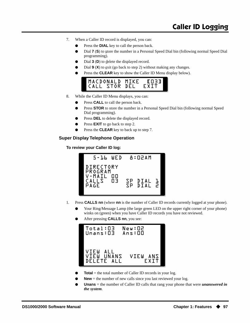
Caller ID Logging
DS1000/2000 Software Manual Chapter 1: Features ◆ 97
7. When a Caller ID record is displayed, you can:
● Press the DIAL key to call the person back.
● Dial 7 (S) to store the number in a Personal Speed Dial bin (following normal Speed Dial programming).
● Dial 3 (D) to delete the displayed record.
● Dial 9 (X) to exit (go back to step 2) without making any changes.
● Press the CLEAR key to show the Caller ID Menu display below).
8. While the Caller ID Menu displays, you can:
● Press CALL to call the person back.
● Press STOR to store the number in a Personal Speed Dial bin (following normal Speed Dial programming).
● Press DEL to delete the displayed record.
● Press EXIT to go back to step 2.
● Press the CLEAR key to back up to step 7.
Super Display Telephone Operation
To review your Caller ID log:
1. Press CALLS nn (where nn is the number of Caller ID records currently logged at your phone).
● Your Ring/Message Lamp (the large green LED on the upper right corner of your phone) winks on (green) when you have Caller ID records you have not reviewed.
● After pressing CALLS nn, you see:
● Total = the total number of Caller ID records in your log.
● New = the number of new calls since you last reviewed your log.
● Unans = the number of Caller ID calls that rang your phone that were unanswered in the system.

Caller ID Logging
98 ◆ Chapter 1: Features DS1000/2000 Software Manual
● Ans = the number of Caller ID calls that rang your phone that were answered in the system.
2. While this display is on screen, you can:
● Press VIEW ALL to review all your Caller ID records.
● Press VIEW UNANS to review the records just for calls that rang your phone but were unanswered in the system.
● Press DELETE ALL to delete all Caller ID records logged at your phone.
● Press VIEW ANS to review the records just for the calls that rang your phone that were answered in the system.
● Press EXIT or dial 9 to exit to the idle mode without making any changes.
3. If you pressed VIEW ALL, VIEW UNANS, or VIEW ANS in the previous step, you see (for example):
This display is a Caller ID record. It shows:
● The name of the person that called (if available). The most recent call displays first.
● The call record number (e.g., 03).
● Your caller’s phone number.
● The date they called (i.e., Yesterday, Today, or day of week and date).
● The time they called.
● The trunk number (or name - if programmed) the call came in on.
● The extension that answered the call, or if it was unanswered.
4. Use the Vol Up and Vol Down keys to scroll through the Caller ID records logged at your phone.
5. While a Caller ID record is displayed, you can:
● Press CALLBACK to call the person back.
● Press DELETE to delete the displayed record.
● Press STORE BIN to store the number in a Personal Speed Dial bin (following normal Speed Dial programming steps).
● Press DELETE ALL to delete all your Caller ID records.
● Press EXIT to go back to step 1 without making any changes.

Central Office Calls, Answering
DS1000/2000 Software Manual Chapter 1: Features ◆ 99
Central Office Calls, Answering
Description
The system provides flexible routing of incoming CO (trunk) calls to meet the exact site requirements.
Answering PriorityWhen multiple calls ring an extension simultaneously, the system services the ringing calls in the following order:
1. Line key (from lowest to highest)
2. Fixed Loop Key (from lowest to highest)
3. Switched Loop Key (from lowest to highest)
4. ICM Key
OverflowRefer to Overflow for Key Ring Calls on page 273 for details on the overflow options.
Conditions
● The system provides analog trunk CO service via ATRU PCBs. ATRU PCBs can connect to either loop start or ground start trunks (depending on circuit type programming). Refer to the Hardware Manual for additional details on installing ATRU PCBs and connecting trunks.
● Per FCC regulations, do not set 1001- Trunk Transmit Gain on page 582 higher than 0 dB.
Default SettingDS2000
● All extensions have full access on all trunks.
Fixed Slot
● Trunks 1-8 ring extensions on line keys 1-8.
U Slot Prior to 02.01.07
● Trunks 1-12 ring extensions on line keys 1-12.
U Slot 02.01.07 or Higher
● Extensions 300-315 (the first DSTU) have immediate ring for trunks 1-24 and lamp only for trunks 25-48. All other extensions have lamp only for all trunks.
● Trunks 1-12 ring extensions 300-315 on line keys 1-12. In DS2000 software versions 02.01.07 through 02.02.00, keys are undefined for all extensions above 315.
● Single line sets ring according to 1805 - Ring Assignment programming. (By default, all single line sets are lamp only.)
DS2000 Fixed Slot Available.• See Default Setting below for specifics on the initial trunk setup.
DS2000 U Slot Avalable.• In version 02.01.07 and higher, single line sets ring according to 1805 -
Ring Assignment programming (just like keysets).• See Default Setting below for specifics on the initial trunk setup.
DS1000
The system allows trunk calls to ring and be answered at any combination of system extensions.

Central Office Calls, Answering
100 ◆ Chapter 1: Features DS1000/2000 Software Manual
DS1000
● All extensions have full access on all trunks.
● Trunks 4-6 require the Expansion Board.
Prior to 02.00.09
● Extensions have immediate day/night ring on trunks 1-4 (line keys 1-4), and delay ring on trunks 5 and 6 (line keys 5 and 6).
2.00.09 or Higher
● Extensions have immediate day/night ring on all trunks.
● Trunks 1-6 ring extensions on line keys 1-6.
2.01.07 or higher
● Extensions have immediate day/night ring on all trunks.
● Single line sets ring according to 1805 - Ring Assignment programming (just like keysets).
● Trunks 1-6 ring extensions on line keys 1-6.
Programming GuideStep-by-step guide for setting up Central
Office Calls, Answering (Page 1 of 3)
Step 1: Check to be sure each trunk’s circuit type and loop length setting matches the con-nected trunk circuit.
• In Program 1001 - Trunk Circuit Type (page 581), enter the correct circuit type for each trunk (51 = loop start DTMF, 52 = loop start DP).
• In Program 1001 - Loop Length (page 586), use this option to compensate for a trunk’s loop length. Use the short option (1) only when the system is very close to the central office or behind a PBX. Use the long option (2) for normal instal-lations.
Step 2: Review System Timers, Trunks on page 426 for compatibility with the connected telco or PBX/Centrex.
Step 3: Set the trunk access options at each extension for each trunk.
• In Program 1803 - Extension Line Access Assign-ments (page 642), enter 0 to prevent both incom-ing and outgoing access on the trunk.
• In Program 1803 - Extension Line Access Assign-ments (page 642), enter 1 to allow incoming access only.
• In Program 1803 - Extension Line Access Assign-ments (page 642), enter 2 to allow outgoing access only.
No access
Incoming
Outgoing

Central Office Calls, Answering
DS1000/2000 Software Manual Chapter 1: Features ◆ 101
• In Program 1803 - Extension Line Access Assign-ments (page 642), enter 3 to allow full access (both incoming and outgoing).
Step 4: Set the ringing options at each extension for each trunk.
• In Program 1805 - Ring Assignment (page 647), enter 1 for each trunk that should lamp only (day and night).
• In Program 1805 - Ring Assignment (page 647), enter 2 for each trunk that should ring during the day and at night.
• In Program 1805 - Ring Assignment (page 647), enter 3 for each trunk that should ring at night and lamp only during the day.
• In Program 1805 - Ring Assignment (page 647), enter 4 for each trunk that should delay ring dur-ing the day and at night.
• InProgram 0401 - Trunk Delay Ring (page 524), enter the interval after which a delay ring trunk will change from flashing to ringing.
Step 5: Should extension have line keys for answering trunk calls?
• In Program 1701 - Line Key (page 613), assign programmable keys as line keys (code 03). The options are 1-48 (for trunks 1-48) in DS2000, and 1-6 in DS1000.
• In Program 1701 - Line Key (page 613), make sure no keys are assigned as line keys (code 03).
• In Program 1701 - Switched Loop Key (page 612), or in Program 1701 - Fixed Loop Key (page 612), assign a loop key to any extension without line keys. This allows the extension to answer trunk calls.
Step 6: Should DSS Console have line keys for answering trunk calls?
• In Program 1704 - Line Key (page 624), assign programmable keys as line keys (code 03). The options are 1-48 (for trunks 1-48) in DS2000, 1-6 in DS1000..
• In Program 1704 - Line Key (page 624), make sure no keys are assigned as line keys (code 03).
Step-by-step guide for setting up Central Office Calls, Answering (Page 2 of 3)
Full
Lamp only
Ring
Night Ring
Delay Ring
If yes
If no
If yes
If no

Central Office Calls, Answering
102 ◆ Chapter 1: Features DS1000/2000 Software Manual
Step 7: While on a trunk call, is a user’s conversation transmitted to the caller at a comfort-able level?
• In Program 1001 - Trunk Transmit Gain (page 582), leave this option at its current setting.
• In Program 1001 - Trunk Transmit Gain (page 582), increase or decrease the trunk trans-mit gain for the optimum transmission level for the connected telco or PBX.
Step 8: While on a trunk call, is the conversation received by the user at a comfortable level?
• In Program 1001 - Trunk Receive Gain (page 584), leave this option at its current setting. The setting is applied to each line seizure.
• In Program 1001 - Trunk Receive Gain (page 584), increase or decrease the trunk receive gain for the optimum reception level for the con-nected telco or PBX. The setting is applied to each line siezure.
Step 9: Does the system properly detect ringing trunks?
• In Program 0402 - Minimum Ring Detection Timer (page 528), leave this option at its current setting.
• In Program 0402 - Minimum Ring Detection Timer (page 528), set the ring detect threshold for compatibility with the connected telco or PBX.
Step 10: Do trunks inadvertantly disconnect while users are on a call?
• In Program 0402 - Loop Current Detection Time (page 530), set the loop disconnect interval for compatibility with the connected telco or PBX.
• In Program 0402 - Loop Current Detection Time (page 530), leave this option at its current setting.
Step-by-step guide for setting up Central Office Calls, Answering (Page 3 of 3)
If yes
If no
If yes
If no
If yes
If no
If yes
If no
Central Office Calls, Answering
DS1000/2000 Software Manual Chapter 1: Features ◆ 103
Programming ListProgram 0401 - Trunk Delay Ring (page 524)
Set how long the system flashes a line key before ringing an extension that has the Delayed Ringing option enabled.
Program 0402 - Minimum Ring Detection Timer (page 528)Set the threshold for ring detection. If the ring signal is longer than this interval, the system interprets the signal as valid ringing. If the signal is equal to or shorter than this interval, the system ignores the ringing.
Program 0402 - Loop Current Detection Time (page 530)Set the loop disconnect interval for trunk calls. If the system detects a loop current interrup-tion longer than this interval it assumes the telco has disconnected the trunk. It then returns the trunk trunk to idle.
Program 0402 - Ringing Signal End Detect Timer (page 531)If the ringing signal on a trunk call is interrupted for longer than this interval, the system assumes ringing has stopped and terminates the call. If this interval is set to short, valid ring-ing will be inadvertantly cut off. If too long, the system will leave the call set up even after ringing has stopped.
Program 1001 - Trunk Circuit Type (page 581)Set the trunk’s circuit type for compatibility with the connected telco or PBX. The options are 51 (loop start DTMF), 52 (loop start DP), 53 (ground start DTMF) or 54 (ground start DP).
Program 1001 - Trunk Transmit Gain (page 582)Set the trunk’s transmit gain to compensate for the transmit gain characteristics of the con-nected telco or PBX. The setting is applied to each line siezure.
Program 1001 - Trunk Receive Gain (page 584)Set the trunk’s receive gain to compensate for the receive gain characteristics of the connected telco or PBX. The setting is applied to each line siezure.
Program 1001 - Loop Length (page 586)Use this option to compensate for a trunk’s loop length. Use the short option (1) only when the system is very close to the central office or behind a PBX. Use the long option (2) for nor-mal installations.
Program 1701 - Line Key (page 613)Assign a programmable key on an extension as a line key (code 03). The options are 1-48 (for trunks 1-48) in DS2000, 1-6 in DS1000.
Program 1701 - Switched Loop Key (page 612)Program 1701 - Fixed Loop Key (page 612)
In order to answer trunk calls, extensions without line keys should have loop keys.Program 1704 - Line Key (page 624)
Assign a programmable key on a DSS Console as a line key (code 03). The options are 1-48 (for trunks 1-48) in DS2000, 1-6 in DS1000.
Program 1803 - Extension Line Access Assignments (page 642)For each extension, assign the access options for each trunk (0 = No access, 1 = Incoming only. 2 = Outgoing only, 3 = Full access).
Program 1805 - Ring Assignments (page 647)Assign ringing for each trunk at each extension (1 = Lamp only [day and night], 2 = Ringing day and night, 3 = Night Ring only, lamp during the day, 4 = Delay ring day and night).

Central Office Calls, Answering
104 ◆ Chapter 1: Features DS1000/2000 Software Manual
Other Related FeaturesCall Timer (page 72)
The Call Timer helps a user keep track of the time they spend on the phone.Direct Inward Line (page 133)
A DIL rings an extension directly.Line Keys (page 279)
Line keys simplify answering trunk calls.Loop Keys (page 283)
In order to answer trunk calls, extensions without line keys should have loop keys.Night Service / Night Ring (page 308)
Night Service determines how outside calls ring at night.System Timers, Trunks (page 426)
Always review the system’s trunk timers for compatibility with the connected telco or PBX/Centrex.
Feature Operation
To answer an incoming trunk call:
1. Lift handset.If you have Ringing Line Preference, lifting the handset answers the call.If you have Automatic Handsfree, you can press the line or loop key without first lifting
the handset.
2. Press flashing line or loop key.
Trunk ring.
Line or loop key flashing red for key ring call.Line key flashing green for DIL.
Conversation with caller.
Line or loop key on.

Central Office Calls, Placing
DS1000/2000 Software Manual Chapter 1: Features ◆ 105
Central Office Calls, Placing
Description
The system provides flexibility in the way each extension user can place outgoing trunk calls. A user can place a call by:
● Pressing a Line KeyAny keyset can have line keys for one-touch access to specific trunks. See Line Keys on page 279 for more.
● Pressing a Loop KeyLoop Keys provide a user with one-touch access to the assigned Loop Group. Loop Groups can consist of one or more Trunk Groups. See Loop Keys on page 283 for more.
● Using Line Dial-UpWith Line Dial-Up, a user can select a specific trunk by pressing ICM and dialing the Line Dial-Up code (#9) followed by the trunk number (1-48 for trunks 1-48 in DS2000, 1-6 in DS1000).
● Using Direct Trunk AccessDirect Trunk Access allows a user to access a trunk by pressing ICM and dialing the trunk’s extension number (e.g., 401 for trunk 1, 402 for trunk 2. etc.).See Direct Trunk Access on page 154 for more.
● Dialing a Trunk Group Access CodeUser’s can also place trunk calls by pressing ICM and dialing a Trunk Group Access Code (90-98). See Trunk Groups on page 468 for more.
● Trunk Group RoutingIf the system has Trunk Group Routing enabled, user’s get the first available trunk when they press ICM and dial 9. See Trunk Group Routing on page 461 for more.
Expanded Dial Buffering (02.01.07 or Higher)When placing a trunk call, extension users can dial an unlimited number of digits. Users are assured that they can use services such as telephone banking without encountering restrictions imposed by the telephone system. In software versions prior to 02.01.07, callers are restricted to dialing 32 dig-its maximum if they dialed continuously.
Conditions
● Systems using Trunk Groups or Trunk Group Access should use the hybrid FCC registration number (i.e., the number that ends in MF-E). Look at the label on the bottom of your equipment cabinet for more information.
● Per FCC regulations, do not set 1001- Trunk Transmit Gain on page 582 higher than 0 dB.
DS2000 Fixed Slot Available.• See Default Setting below for specifics on the initial trunk setup.
DS2000 U SlotAvailable.• See Default Setting below for specifics on the initial trunk setup.• In 02.01.07 and higher, dial 9 is disabled by default.
DS1000Available.• See Default Setting below for specifics on the initial trunk setup.• In 02.00.09 and higher, dial 9 is enabled by default.
Customize the call placing options to meet the site requirements and each individual’s needs.

Central Office Calls, Placing
106 ◆ Chapter 1: Features DS1000/2000 Software Manual
Default SettingDS2000
Fixed Slot
● Keys 1-8 are line keys, keys 9 and 10 are Fixed Loop keys for trunk group 0, key 11 is an Auto Timer key and key 12 is an All Call Page key. (The last key on an attendant telephone is automatically an Operator Call key.)
● Trunk Group Routing (dial 9) is assigned to trunk group 1 (which contains trunks 9-16). Dial 9 does not work by default.
● All extensions have full access on all trunks.
U Slot Prior to 02.01.07
● Keys 1-12 are line keys for trunks 1-12.
● Trunk Group Routing (dial 9) is assigned to trunk group 0 (which contains trunks 1-8). Dial 9 works by default. The outgoing trunk priority for the dial 9 group is as follows:Order 1 = trunk 8Order 2 = trunk 7Order 3 = trunk 6Order 4 = trunk 5Order 5 = trunk 4Order 6 = trunk 3Order 7 = trunk 2Order 8 = trunk 1
● All extensions have full access on all trunks.
● Introduces User Programmable Feature steps for line keys.
U Slot 02.01.07 and Higher
● Keys 1-12 are line keys for trunks 1-12. In DS2000 software versions 02.01.07 through 02.02.00, Programmable Function Keys are undefined for all extensions above 315.
● All extensions have full access on all trunks.
● Trunk Group assignments are not defined, so there is no Trunk Group Routing (dial 9) by default.
DS1000
● Keys 1-6 are line keys for trunks 1-6.
● All extensions have full access on all trunks.
● Trunks 4-6 require the Expansion Board.
● All versions have User Programmable Feature steps for line keys.
DS1000 prior to 02.00.09.
● Trunk Group assignments are not defined, so there is no Trunk Group Routing (dial 9) by default.
DS1000 02.00.09 and Higher
● Trunk Group Routing (dial 9) is assigned to trunk group 0 (which contains trunks 1-6). Dial 9 works by default. The outgoing trunk priority for the dial 9 group is as follows:Order 1 = trunk 6Order 2 = trunk 5Order 3 = trunk 4Order 4 = trunk 3Order 5 = trunk 2Order 6 = trunk 1

Central Office Calls, Placing
DS1000/2000 Software Manual Chapter 1: Features ◆ 107
Programming Guide
Step-by-step guide for setting up Central Office Calls, Placing (Page 1 of 5)
Step 1: Check to be sure each trunk’s circuit type and loop length setting matches the con-nected trunk circuit.
• In Program 1001 - Trunk Circuit Type (page 581), enter the correct circuit type for each trunk (51 = loop start DTMF, 52 = loop start DP).
• In Program 0402 - Codec Digitizing Method (page 530), be sure to always set this option to 0 (µ-law companding enabled). Do not set this option to 1.
• In Program 1001 - Loop Length (page 586), use this option to compensate for a trunk’s loop length. Use the short option (1) only when the system is very close to the central office or behind a PBX. Use the long option (2) for normal instal-lations.
Step 2: Review System Timers, Trunks on page 426 for compatibility with the connected telco or PBX/Centrex.
Step 3: Are connected trunks DTMF or Dial Pulse (DP)?
• In Program 0402 - Manual DTMF Tone On (page 529), set the DTMF on duration for com-patibility with the connected telco or PBX.
• Program 0402 - Manual DTMF Tone Off (page 529), se the DTMF off duration for compat-ibility with the connected telco or PBX.
• In Program 0402 - DP Make Timer (page 528), set the DP make (on) interval for compatibility with the connected telco or PBX.
• In Program 0402 - DP Break Timer (page 528), set the DP break (off) interval for compatibility with the connected telco or PBX.
• In Program 0402 - DP Interdigit Timer (page 528), set the DP interdigit (time between digits) interval for compatibility with the con-nected telco or PBX.
DTMF
DP

Central Office Calls, Placing
108 ◆ Chapter 1: Features DS1000/2000 Software Manual
Step 4: For Direct Trunk Access, should trunk extension numbers be left at their default set-ting (e.g., 401-448in DS2000 or 401-406 in DS1000).
• In Program 0504 - Trunk Port Extension Numbers (Fixed Slot) (page 543), leave the trunk extension numbers at their default settings (401-448 in DS2000 or 401-406 in DS1000).
• In Program 0504 - Trunk Port Extension Numbers (Fixed Slot) (page 543), change the trunk exten-sion numbers to meet the site requirements (e.g., 501-516).
Step 5: Should trunk names be left at their default setting (Trunk 1, Trunk 2 etc.).
• In Program 1001 - Trunk Name (page 581), leave the trunk names at their default setting.
• In Program 1001 - Trunk Name (page 581), change the trunk names to meet the site require-ments.
Step 6: Set the trunk access options at each extension for each trunk.
• In Program 1803 - Extension Line Access Assign-ments (page 642), enter 0 to prevent both incom-ing and outgoing access on the trunk.
• In Program 1803 - Extension Line Access Assign-ments (page 642), enter 1 to allow incoming access only.
• In Program 1803 - Extension Line Access Assign-ments (page 642), enter 2 to allow outgoing access only.
• In Program 1803 - Extension Line Access Assign-ments (page 642), enter 3 to allow full access (both incoming and outgoing).
Step 7: Should extension have line keys for placing trunk calls?
• In Program 1701 - Line Key (page 613), assign programmable keys as line keys (code 03). The options are 1-48 (for trunks 1-48) in DS2000, 1-6 in DS1000.
Step-by-step guide for setting up Central Office Calls, Placing (Page 2 of 5)
If yes
If no
If yes
If no
No access
Incoming
Outgoing
Full
If yes

Central Office Calls, Placing
DS1000/2000 Software Manual Chapter 1: Features ◆ 109
• In Program 1701 - Line Key (page 613), make sure no keys are assigned as line keys (code 03).
• In Program 1701 - Switched Loop Key (page 612), or in Program 1701 - Fixed Loop Key (page 612), assign a loop key to any extension without line keys. This allows the extension to answer trunk calls.
Step 8: Should DSS Console have line keys for placing trunk calls?
• In Program 1704 - Line Key (page 624), assign programmable keys as line keys (code 03). The options are 1-48 (for trunks 1-48) in DS2000, 1-6 in DS1000.
• In Program 1704 - Line Key (page 624), make sure no keys are assigned as line keys (code 03).
Step 9: Should extension user have single digit (dial 9) access to outside calls?
• In Program 0501 - Single Digit Access (page 542), enter Y.
• In Program 1802 - Station’s Dial 9 Group (page 636), assign the Trunk Group (0-8) the sta-tion will select after the user dials 9.
• In Program 1002 - Trunk Groups (page 590), assign trunks to Trunk Groups.
• In Program 0501 - Single Digit Access (page 542), enter N. Users dial 9 followed by the Trunk Group number (0-8).
• In Program 1002 - Trunk Groups (page 590), assign trunks to Trunk Groups (0-8).
Step 10: Should extension have Line Dial-up capability (i.e., the ability to dial #901-#916).
• In Program 1802 - Line Dial Up (page 636), Enter Y.
• In Program 1802 - Line Dial Up (page 636), enter N.
Step 11: While on a trunk call, is a user’s conversation transmitted to the caller at a comfort-able level?
• In Program 1001 - Trunk Transmit Gain (page 582), leave this option at its current setting.
Step-by-step guide for setting up Central Office Calls, Placing (Page 3 of 5)
If no
If yes
If no
If yes
If no
If yes
If no
If yes

Central Office Calls, Placing
110 ◆ Chapter 1: Features DS1000/2000 Software Manual
• In Program 1001 - Trunk Transmit Gain (page 582), increase or decrease the trunk trans-mit gain for the optimum transmission level for the connected telco or PBX.
Step 12: While on a trunk call, is the conversation received by the user at a comfortable level?
• In Program 1001 - Trunk Receive Gain (page 584), leave this option at its current setting.
• In Program 1001 - Trunk Receive Gain (page 584), increase or decrease the trunk receive gain for the optimum reception level for the con-nected telco or PBX.
Step 13: Do trunks inadvertantly disconnect while users are on a call?
• In Program 0402 - Loop Current Detection Time (page 530), set the loop disconnect interval for compatibility with the connected telco or PBX.
• In Program 0402 - Loop Current Detection Time (page 530), leave this option at its current setting.
Step 14: Do users ever experience call colissions (i.e., connect to an incoming call while placing an outgoing call)?
• In Program 0402 - Force Idle (Trunk Guard Time) (page 527), lengthen the trunk guard time.
• In Program 0402 - Force Idle (Trunk Guard Time) (page 527), leave the trunk guard time at its cur-rent setting.
Step 15: If the system encounters a defective trunk while placing a call, does it wait the proper interval before automatically cycling to the next trunk?
• In Program 0402 - Line Response (page 526), leave this interval at its current setting.
• In Program 0402 - Line Response (page 526), set the Line Response interval to meet the site’s requirements.
Step 16: Should 4 be the first digit in the Direct Trunk Access code?
• In Program 0501 - Numbering Plan (page 539), leave the parameters for digit 4 at their default settings.
Step-by-step guide for setting up Central Office Calls, Placing (Page 4 of 5)
If no
If yes
If no
If yes
If no
If yes
If no
If yes
If no
If yes

Central Office Calls, Placing
DS1000/2000 Software Manual Chapter 1: Features ◆ 111
Programming ListProgram 0402 - Line Response (page 526)
When the system fails to detect loop current on a trunk, it will wait this interval before mark-ing the trunk as defective. Be sure the value you enter is compatible with the local telco.
Program 0402 - Force Idle (Trunk Guard Time) (page 527)Set the guard time for trunks. When the system disconnects a trunk (e.g., after a user hang up), the system keeps the line idle until this timer expires. The Trunk Guard Time helps prevent call collisions.
Program 0402 - DP Make Timer (page 528)Set the duration of the Dial Pulse Make signal (i.e., relay closed). This is the “on” time in a Dial Pulse digit. Set this timer for compatability with the connected telco or PBX/Centrex. Keep in mind that there are three components of a Dial Pulse digit: Make interval, Break interval and Interdigit interval.
Program 0402 - DP Break Timer (page 528)Use this timer to set the duration of the Dial Pulse Break signal (i.e., relay open). This is the “off” time in a Dial Pulse digit. Set this timer for compatability with the connected telco or PBX/Centrex.
Program 0402 - DP Interdigit Timer (page 528)Set the duration of the Dial Pulse Interdigit signal (i.e., relay open time between each digit). Set this timer for compatability with the connected telco or PBX/Centrex.
Program 0402 - Manual DTMF Tone On (page 529)Set the duration of DTMF digits for trunk calls manually dialed by an extension user. This is required because the system buffers the digits the user dials. Set this timer for compatibility with the connected telco or PBX/Centrex.
Program 0402 - Manual DTMF Tone Off (page 529)Set the duration of the interval between DTMF digits for trunk calls manually dialed by an extension user. This is required because the system buffers the digits the user dials. Set this timer for compatibility with the connected telco or PBX/Centrex.
Program 0402 - Loop Current Detection Time (page 530)Set the loop disconnect interval for trunk calls. If the system detects a loop current interrup-tion longer than this interval it assumes the telco has disconnected the trunk. It then returns the trunk trunk to idle.
Program 0402 - Codec Digitizing Method (page 530)Be sure this option is always set to 0 (µ-law companding enabled). Do not set this option to 1 (A-law companding enabled).
Program 0501 - Numbering Plan (page 539)Review this option when if you want to change the digits user’s dial for Direct Trunk Access (normally 4 followed by the trunk number).
Program 0501 - Single Digit Access (page 542)Use this option to enable or disable single digit access. If enabled (Y), users can dial 9 to select their assigned dial 9 Trunk Group. If disabled, users must dial 9 followed by the Trunk Group number (0-8 for Trunk Groups 0-8).
Program 1001 - Trunk Circuit Type (page 581)Set the trunk’s circuit type for compatiblity with the connected telco or PBX. The options are 51 (loop start DTMF), 52 (loop start DP), 53 (ground start DTMF) or 54 (ground start DP).
• In Program 0501 - Numbering Plan (page 539), set up another digit (in place of 4) that meets the site’s requirements.
Step-by-step guide for setting up Central Office Calls, Placing (Page 5 of 5)
If no

Central Office Calls, Placing
112 ◆ Chapter 1: Features DS1000/2000 Software Manual
Program 1001 - Trunk Name (page 581)Assign extension numbers and names to trunk ports.
Program 1001 - Trunk Transmit Gain (page 582)Set the trunk’s transmit gain (0-60) to compensate for the transmit gain characteristics of the connected telco or PBX.
Program 1001 - Trunk Receive Gain (page 584)Set the trunk’s receive gain (0-60) to compensate for the receive gain characteristics of the connected telco or PBX.
Program 1001 - Loop Length (page 586)Use this option to compensate for a trunk’s loop length. Use the short option (1) only when the system is very close to the central office or behind a PBX. Use the long option (2) for nor-mal installations.
Program 1002 - Trunk Groups (page 590)Assign trunk Trunk Groups (0-8).
Program 1701 - Line Key (page 613)Assign a programmable key on a extension as a line key (code 03). The options are 1-48 (for trunks 1-48) in DS2000, 1-6 in DS1000.
Program 1704 - Line Key (page 624)Assign a programmable key on a DSS Console as a line key (code 03). The options are 1-48 (for trunks 1-48) in DS2000, 1-6 in DS1000.
Program 1802 - Line Dial Up (page 636)Enter Y to allow an extension to access lines (1-48 in DS2000, 1-6 in DS1000) by dialing trunk access codes (#901-#948 in DS2000, #901-#906 in D1000).
Program 1802 - Station’s Dial 9 Group (page 636)Assign the trunk group (0-8) a user accesses when they dial 9 for an outside line or press a switched loop key. This option does not apply to systems with ARS installed.
Program 1802 - Key Access to Outbound Lines (page 637)Enter Y to enable an extension user to press a Programmable Function Key to access and out-side line.
Program 1803 - Extension Line Access Assignments (page 642)For each extension, assign the access options for each trunk (0 = No access, 1 = Incoming only. 2 = Outgoing only, 3 = Full access).
Program 1804 - Trunk Group Access (page 645)For each extension, enter Y to allow or N to prevent outgoing trunk group access. The system always allows incoming trunk group access.
Other Related FeaturesAutomatic Handsfree (page 51)
With Automatic Handsfree, an extension user can press a line key to place a trunk call without first lifting the handset or pressing SPK. Users without Automatic Handsfree can preselect a line key before lifting the handset or pressing SPK.
Call Timer (page 72)The Call Timer helps a user keep track of the time they spend on the phone.
Dial Number Preview (page 131)Dial Number Preview allows an extension user to review a number before the system dials it out.
Direct Trunk Access (page 154)Direct Trunk Access allows an extension user to seize an individual trunk and place a call without restriction.
Equal Access Compatibility (page 190)The system is compatible with Equal Access numbers (e.g., 10-10-321).
Last Number Redial (page 277)Easily redial the last number dialed.
Line Keys (page 279)Line Keys give a user one-touch access to specific trunks.

Central Office Calls, Placing
DS1000/2000 Software Manual Chapter 1: Features ◆ 113
Loop Keys (page 283)An extension user may also be able to press a Loop Key to place an outside call.
Save Number Dialed (page 373)Save a number you dialed, then easily redial it later on.
Speed Dial (page 383)You can store outside numbers in Speed Dial bins for quick access to frequently called num-bers.
System Timers, Trunks (page 426)Always review the system’s trunk timers for compatibility with the connected telco or PBX/Centrex.
Trunk Group Routing (page 461)With Trunk Group Routing enabled, an extension user can dial 9 to place a trunk call.
Trunk (Line) Queuing / Trunk Callback (page 465)An extension user can queue for a busy trunk, or queue and hang up to leave a callback for a busy trunk.
Feature Operation
To place a call over a specific trunk using a line key:
1. Lift handset.
2. Press line key.
You may also be able to press a Loop Key. See Loop Keys on page 283 for more.
3. Dial outside number.
To place a call over a specific trunk (using Line Dial-up or Direct Trunk Access):
1. Lift handset.
2. Press ICM.
If you hear busy tone, you may be able to dial 2 to queue for the busy trunk. See Trunk (Line) Queuing / Trunk Callback on page 465 for more.
3. For Line dial-up: Dial #9 followed by the trunk number (e.g., #901 for trunk 1).OR
For Direct Trunk Access: Dial 4 plus the trunk number (e.g., 401 for trunk 1).
4. Dial outside number.
To place a call over a trunk group:
1. Lift handset.
2. Press ICM.
Trunk dial tone.
Line key on.
Intercom dial tone.
ICM on.
Trunk dial tone, followed by digits outdialing on the trunk.
ICM on.
Intercom dial tone.
ICM on.

Central Office Calls, Placing
114 ◆ Chapter 1: Features DS1000/2000 Software Manual
3. Dial trunk group code (90-98).
If you hear dial tone as soon as you dial 9, your system has Trunk Group Routing enabled. SeeTrunk Group Routing on page 461 for more.
4. Dial outside number.
Trunk dial tone.
Line key on.

Check Key
DS1000/2000 Software Manual Chapter 1: Features ◆ 115
Check Key
Description
A display telephone user can use the CHECK key to check keyset and DSS Console Programmable Function Key assignments and Personal Speed Dial bin names.
ConditionsNone
Default SettingEnabled
Programming GuideNone
Programming ListNone
Other Related FeaturesProgrammable Function Keys (page 354)
Check Programmable Function Key assignments.Speed Dial (page 383)
Check Personal Speed Dial bin assignments.
Feature Operation
To check a Programmable Function Key assignment:
1. Press CHECK
2. Press the Programmable Function KeyThe key assignment displays.
3. Press another key or SPK to exit the check mode.
DS2000 Fixed Slot
Available.DS2000 U Slot
DS1000
Quickly check keyset and DSS Console Programmable Function Key assignments.
N/A
SPK flashes fast.

Check Key
116 ◆ Chapter 1: Features DS1000/2000 Software Manual
To check a Personal Speed Dial bin name and number:
1. Press CHECK.
2. Press the Personal Speed Dial Key once to display the name for the lower numbered bin.For example, pressing bin 1 in this step displays the name for 701.
3. Press the Personal Speed Dial Key a second time to display the number stored in the lower numbered bin.
For example, pressing bin 1 in this step displays the number stored for 701.
4. Press the Personal Speed Dial Key a third time to display the name for the higher numbered bin.
For example, pressing bin 1 in this step displays the name for 711.
5. Press the Personal Speed Dial Key a fourth time to display the number stored in the higher numbered bin.
For example, pressing bin 1 in this step displays the number stored for 711.
6. Press another key or SPK to exit the check mode.
N/A
SPK flashes fast.
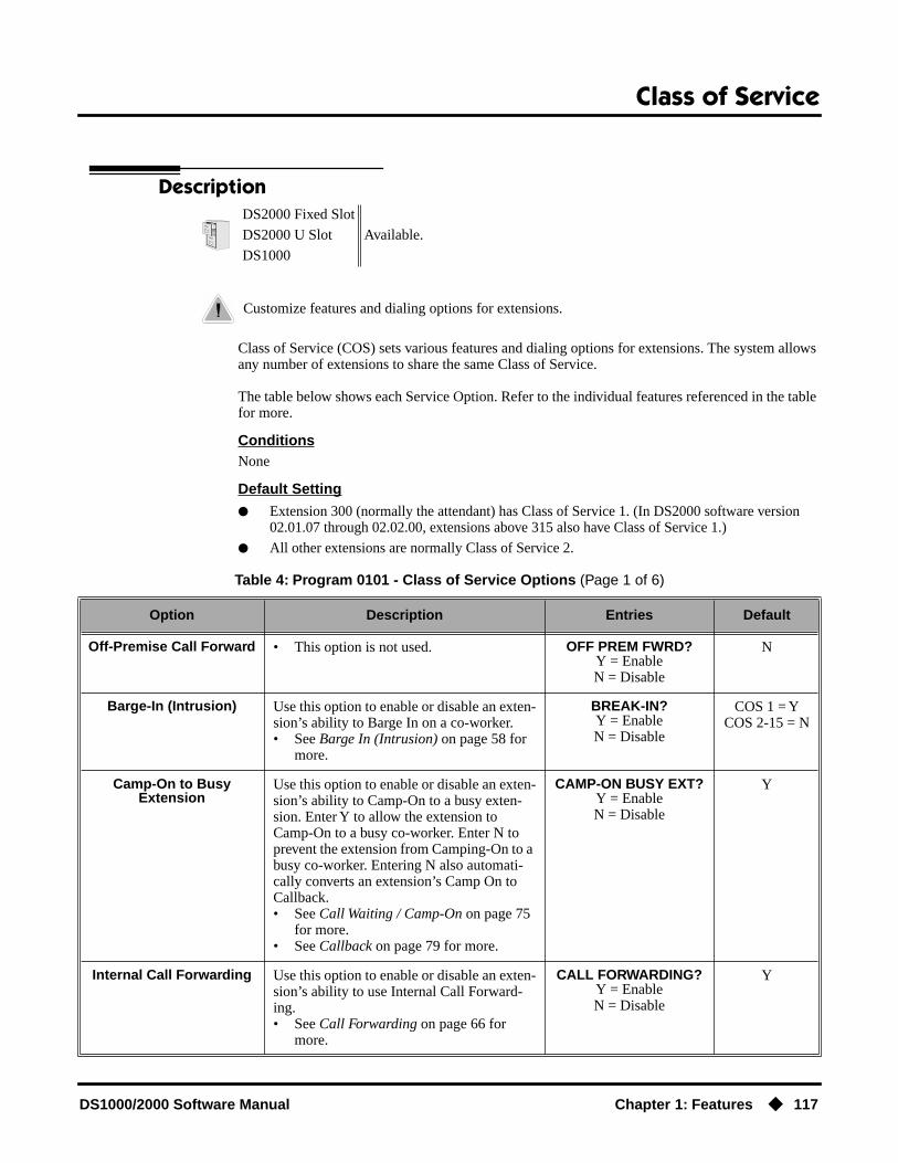
Class of Service
DS1000/2000 Software Manual Chapter 1: Features ◆ 117
Class of Service
Description
Class of Service (COS) sets various features and dialing options for extensions. The system allows any number of extensions to share the same Class of Service.
The table below shows each Service Option. Refer to the individual features referenced in the table for more.
ConditionsNone
Default Setting
● Extension 300 (normally the attendant) has Class of Service 1. (In DS2000 software version 02.01.07 through 02.02.00, extensions above 315 also have Class of Service 1.)
● All other extensions are normally Class of Service 2.
DS2000 Fixed Slot
Available.DS2000 U Slot
DS1000
Customize features and dialing options for extensions.
Table 4: Program 0101 - Class of Service Options (Page 1 of 6)
Option Description Entries Default
Off-Premise Call Forward • This option is not used. OFF PREM FWRD?Y = EnableN = Disable
N
Barge-In (Intrusion) Use this option to enable or disable an exten-sion’s ability to Barge In on a co-worker.• See Barge In (Intrusion) on page 58 for
more.
BREAK-IN?Y = EnableN = Disable
COS 1 = YCOS 2-15 = N
Camp-On to Busy Extension
Use this option to enable or disable an exten-sion’s ability to Camp-On to a busy exten-sion. Enter Y to allow the extension to Camp-On to a busy co-worker. Enter N to prevent the extension from Camping-On to a busy co-worker. Entering N also automati-cally converts an extension’s Camp On to Callback.• See Call Waiting / Camp-On on page 75
for more.• See Callback on page 79 for more.
CAMP-ON BUSY EXT?Y = EnableN = Disable
Y
Internal Call Forwarding Use this option to enable or disable an exten-sion’s ability to use Internal Call Forward-ing. • See Call Forwarding on page 66 for
more.
CALL FORWARDING?Y = EnableN = Disable
Y

Class of Service
118 ◆ Chapter 1: Features DS1000/2000 Software Manual
System Speed Dial Access
Use this option to enable or disable an exten-sion’s ability to access System Speed Dial. • See System Speed Dial on page 383 for
more.
SYS SPDL ACCESS?Y = EnableN = Disable
Y
Extended Ring Use this option to enable or disable Extended Ringing at the extension.• See Extended Ringing on page 191 for
more.
EXTENDED RING?Y = EnabledN = Disable
N
Privacy Use this option to enable or disable Privacy at the extension.• See Privacy on page 345 for more.
PRIVACY?Y = EnableN = Disable
N
Trunk (Line) Queuing Priority
Use this option to enable or disable Trunk (Line) Queuing Priority at the extension. If more than one extension with Priority is queued on a busy trunk, the system services the Priority extensions on a first-queued, first-served basis.• See Trunk Queuing Priority on page 465
for more.
LINE Q PRIORITY?Y = EnableN = Disable
N
Forced Trunk Disconnect Use this option to enable or disable an exten-sion’s ability to use Forced Trunk Discon-nect.• See Forced Trunk Disconnect on
page 212 for more.
FORCEDISCONNECT?
Y = EnableN = Disable
COS 1 = YCOS 2-15 = N
Camp-On to Busy Line Use this option to enable or disable an exten-sion’s ability to Camp-On to a busy trunk.• See Trunk (Line) Queuing / Trunk Call-
back on page 465 for more.
CAMP ON TO LINES?Y = EnableN = Disable
COS 1 = YCOS 2-15 = N
Initiate All Call Page Use this option to enable or disable an exten-sion’s ability to make an All Call Paging announcement.• See Paging on page 326 for more.
PAGE ALL CALL?Y = EnableN = Disable
Y
Access Page Zone 1 Use this option to enable or disable an exten-sion’s ability to make a Paging announce-ment into zone 1.• See Paging on page 326 for more.
PAGE ZONE 1?Y = EnableN = Disable
Y
Access Page Zone 2 Use this option to enable or disable an exten-sion’s ability to make a Paging announce-ment into zone 2.• See Paging on page 326 for more.
PAGE ZONE 2?Y = EnableN = Disable
Y
Access Page Zone 3 Use this option to enable or disable an exten-sion’s ability to make a Paging announce-ment into zone 3.• See Paging on page 326 for more.
PAGE ZONE 3?Y = EnableN = Disable
Y
Table 4: Program 0101 - Class of Service Options (Page 2 of 6)
Option Description Entries Default

Class of Service
DS1000/2000 Software Manual Chapter 1: Features ◆ 119
Access Page Zone 4 Use this option to enable or disable an exten-sion’s ability to make a Paging announce-ment into zone 4.• See Paging on page 326 for more.
PAGE ZONE 4?Y = EnableN = Disable
Y
Access Page Zone 5 Use this option to enable or disable an exten-sion’s ability to make a Paging announce-ment into zone 5.• See Paging on page 326 for more.
PAGE ZONE 5?Y = EnableN = Disable
Y
Access Page Zone 6 Use this option to enable or disable an exten-sion’s ability to make a Paging announce-ment into zone 6.• See Paging on page 326 for more.
PAGE ZONE 6?Y = EnableN = Disable
Y
Access Page Zone 7 Use this option to enable or disable an exten-sion’s ability to make a Paging announce-ment into zone 7.• See Paging on page 326 for more.
PAGE ZONE 7?Y = EnableN = Disable
Y
Silent Monitor Use this option to enable or disable an exten-sion’s ability to use Silent Monitor.• See Monitor / Silent Monitor on
page 300 for more.
SILENT MONITOR?Y = EnableN = Disable
N
Flash for Single Line Sets
• Not currently supported. FLASH FOR SLT?Y = EnableN = Disable
N
ACD Supervisor • This option is currently not imple-mented.
ACD SUPERVISOR?Y = EnableN = Disable
N
Single Ring for Single Line Sets
• Use this option to enable or disable sin-gle ring for single line telephones. This option only apples to single line tele-phones. See Central Office Calls, Answering on page 99 for more.
SINGLE RING?Y = EnableN = Disable
N
View System Alarms Use this option to enable or disable an exten-sion’s ability to view the system alarms.• See Attendant Position on page 47 for
more.
VIEW SYS ALARMS?Y = EnableN = Disable
COS 1 = NCOS 2-15 = N
Automatic Hold Use this option to enable or disable Auto-matic Hold at an extension.• See Hold on page 235 for more.
AUTO HOLD?Y = EnableN = Disable
COS 1 = NCOS 2-15 = N
Activate Night Mode Use this option to enable or disable an exten-sion’s ability to activate Night Service.• See Night Service / Night Ring on
page 308 for more.
ACTIVATE NITES?Y = EnableN = Disable
COS 1 = YCOS 2-15 = N
Table 4: Program 0101 - Class of Service Options (Page 3 of 6)
Option Description Entries Default

Class of Service
120 ◆ Chapter 1: Features DS1000/2000 Software Manual
Direct Trunk Access Use this option to enable or disable an exten-sion’s ability to use Direct Trunk Access. Note that enabling Direct Trunk Access allows the user to bypass Toll Restriction.• See Central Office Calls, Placing on
page 105 for more.
DIRECT TRK ACCES?Y = EnableN = Disable
COS 1 = YCOS 2-15 = N
Remote Call Forwarding / Alternate Attendant
• This option is currently not imple-mented.
REMOTE FWRD?Y = EnableN = Disable
COS 1 = YCOS 2-15 = N
Soft Keys Use this option to enable or disable a display set’s Interactive Soft Keys.• See See Interactive Soft Keys on
page 244 for more.
SOFTKEYSY = EnableN = Disable
Y
Conversation Record Use this option to enable or disable an exten-sion’s ability to record conversations into their Voice Mail mailbox. If enabled, the user can press either their Conversation Record key or RECORD soft key to initiate recording.• See Voice Mail on page 477 for more.
RECORD CONVY = EnableN = Disable
N
CLID Display Use this option to enable or disable Caller ID.• See Caller ID on page 82 for more.
CLID DISPLAY?Y = EnableN = Disable
Y
2nd CALL CLID (Extension Level Call
Waiting Caller ID)
Use this option to enable or disable Second Call Caller ID.• See Caller ID on page 82 for more.
2nd CALL CLID?Y = EnableN = Disable
Y
3rd Party Caller ID Use this option to enable or disable Third Party Call Caller ID Check.• See Caller ID on page 82 for more.
3rd PARTY CLID?Y = EnableN = Disable
N
CLID Display Separator Use this option to enable or disable the Caller ID display separator.• See Caller ID on page 82 for more.
‘-’ IN CID DISP?Y = EnableN = Disable
N
Forced Account Codes Use this option to enable or disable Forced Account Codes. disabled, Optional Account Codes are still available.• See Account Codes on page 34 for more.
FORCE AC CODES?Y = EnableN = Disable
N
Verify Account Codes Use this option to enable or disable Verified Account Codes. If enabled, the system com-pares the Account Code the user dials to the entries in Program 1201 - Verified Account Codes Table (page 601), .• See Account Codes on page 34 for more.
VERIFY AC CODES?Y = EnableN = Disable
N
Table 4: Program 0101 - Class of Service Options (Page 4 of 6)
Option Description Entries Default

Class of Service
DS1000/2000 Software Manual Chapter 1: Features ◆ 121
Forced Account Codes for Toll Calls Only
Use this option to enable or disable Forced Account Codes for toll (long distance) calls. If disabled, Forced Account Codes apply to all outgoing trunk codes. • See Account Codes on page 34 for more.
AC FOR TOLL ONLY?Y = EnableN = Disable
N
Ring Type Configuration(Software version 02.02.14
or higher)
Use this option to enable or disable Ring Type Configuration. If enabled, the extension user can customize the sound of their Ring Types by pressing their CONFIG (CNFG) soft key. If disabled, the extension user can-not customize their Ring types and the sys-tem hides the CONFIG (CNFG) soft key.• See Distinctive Ringing on page 162 for
more.
RING TYPE CONFIG?Y = EnableN = Disable
N
Extension Ring Override(Software version 02.02.14
or higher)
Use this option to enable or disable an exten-sions ability to customize the distinctive ringing for Day Ring, Night Ring, and Delay Ring trunk calls on line keys by pressing the ASSIGN (ASGN) soft key. If disabled, the extension cannot customize the distinctive ringing and the system hides the ASSIGN (ASGN) soft key.
If you enable this option, and the user cus-tomizes their Extension Override settings, disabling this option will cancel the user’s custom settings.• See Distinctive Ringing on page 162 for
more.
EXT RING OVRD?Y = EnableN = Disable
N
Key Ring Override(Software version 02.02.14
or higher)
Use this option to enable or disable Key Ring Override. If enabled, this option allows an extension to customize the distinctive ringing of individual Call Coverage, Group Call Pickup, and Line Keys by pressing the KEY soft key. If disabled (N), the extension cannot customize the distinctive ringing. The default setting for this option is disabled (N).
If you enable this option, and the user cus-tomizes their Key Ring Override settings, disabling this option will cancel the user’s custom settings.• See Distinctive Ringing on page 162 for
more.
KEY RING OVRD?Y = EnableN = Disable
N
Table 4: Program 0101 - Class of Service Options (Page 5 of 6)
Option Description Entries Default

Class of Service
122 ◆ Chapter 1: Features DS1000/2000 Software Manual
SLT Special Dial Tone(Software version 02.02.14
or higher)
Use this option to enable or disable SLT Special Dial Tone in a single line port’s Class of Service. (Note that this option has no effect of keyset ports with the same COS.)• See Message Waiting on page 291 for
more.
SLT SP DIALTONE?Y = EnableN = Disable
N
SLT High Voltage Message Waiting
(DS2000 Software version 02.02.14 or higher)
Use this option to enable or disable High Voltage Message Waiting for single line ports. High Voltage Message Waiting is not available in DS1000. If both this option and 0101 - SLT FSK Message Waiting are enabled, the system uses FSK Message Waiting.• See Message Waiting on page 291 for
more.
SLT MW LAMP HV?Y = EnableN = Disable
N
SLT FSK Message Waiting
(Software version 02.02.14 or higher)
Use this option to enable or disable FSK Message Waiting for single line ports. If both this option and 0101 - SLT High Volt-age Message Waiting are enabled, the system uses FSK Message Waiting.• See Message Waiting on page 291 for
more.
SLT MW LAMP FSK?Y = EnableN = Disable
N
SLT Loop Disconnect(Software version 02.03.03
or higher)
Use this option to enable or disable the abil-ity of the system to send a loop supervision disconnect signal (i.e., drop pulse) to single line ports. Set this option for compatibility with the connected SLT device. (This option is always disabled for Voice Mail ports.)• See Off-Premise Extensions / On-
Premise SLT Extensions on page 317 for more.
SLT LOOP DISCON?Y = EnableN = Disable
N
Table 4: Program 0101 - Class of Service Options (Page 6 of 6)
Option Description Entries Default
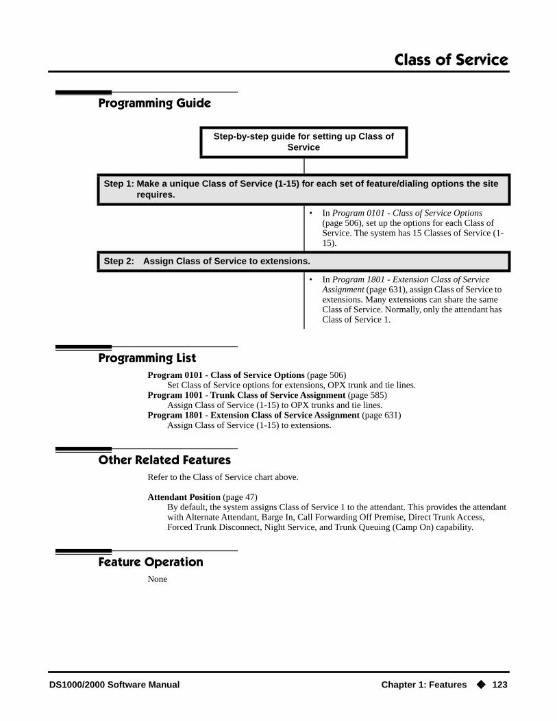
Class of Service
DS1000/2000 Software Manual Chapter 1: Features ◆ 123
Programming Guide
Programming ListProgram 0101 - Class of Service Options (page 506)
Set Class of Service options for extensions, OPX trunk and tie lines.Program 1001 - Trunk Class of Service Assignment (page 585)
Assign Class of Service (1-15) to OPX trunks and tie lines.Program 1801 - Extension Class of Service Assignment (page 631)
Assign Class of Service (1-15) to extensions.
Other Related FeaturesRefer to the Class of Service chart above.
Attendant Position (page 47)By default, the system assigns Class of Service 1 to the attendant. This provides the attendant with Alternate Attendant, Barge In, Call Forwarding Off Premise, Direct Trunk Access, Forced Trunk Disconnect, Night Service, and Trunk Queuing (Camp On) capability.
Feature OperationNone
Step-by-step guide for setting up Class of Service
Step 1: Make a unique Class of Service (1-15) for each set of feature/dialing options the site requires.
• In Program 0101 - Class of Service Options (page 506), set up the options for each Class of Service. The system has 15 Classes of Service (1-15).
Step 2: Assign Class of Service to extensions.
• In Program 1801 - Extension Class of Service Assignment (page 631), assign Class of Service to extensions. Many extensions can share the same Class of Service. Normally, only the attendant has Class of Service 1.

Conference
124 ◆ Chapter 1: Features DS1000/2000 Software Manual
Conference
Description
Conference lets an extension user add additional inside and outside callers to their conversation. The following table shows the system’s Conference capacities:
The system’s 32 Conference circuits are dynamically allocated as users request them.
ConditionsNone
Default SettingConference enabled.
Programming GuideNone
Programming ListProgram 1803 - Extension Line Access Assignments (page 642)
An extension can join a Conference with a trunk to which they normally cannot access.
Other Related Features
The following features also allow different types of multiple party calls:
Barge In (Intrusion) (page 58)An extension user can Barge In on a Conference.
Group Listen (page 219)
DS2000 Fixed Slot Available.
DS2000 U Slot Available. In software versions 02.02.14 or higher, a single line telephone user can place a call and immediately add a party into the Conference. In prior soft-ware versions, the user had to wait 6 seconds. DS1000
A user can set up a multiple-party telephone meeting without leaving the office.
Description Capacity
Conference circuits 32
Maximum simultaneous users in Conference(total of all Conferences system-wide)
32
Maximum simultaneous conferences 8
Maximum parties in any one Conference(trunks and/or extensions)
8

Conference
DS1000/2000 Software Manual Chapter 1: Features ◆ 125
Meet-Me Conference (page 288)Monitor / Silent Monitor (page 300)
An extension user cannot Monitor a Conference.Privacy Release Groups (page 347)Tandem Trunking / Unsupervised Conference (page 433)
Off-Hook Signaling (page 313)After hearing off-hook signals, an extension user can Conference their active call with the waiting call.
Off-Premise Extensions / On-Premise SLT Extensions (page 317)On- and off-premise SLT extensions can use Conference.
Reverse Voice Over (page 364)An extension user cannot add an incoming Reverse Voice Over call to a Conference.
Voice Over (page 493)An extension user cannot Voice Over to a co-worker busy on a Conference call.
Feature Operation
To establish a Conference:
1. Establish Intercom or trunk call.
2. Press CONF.
Your caller hears Music On Hold (if installed) while they wait for you to set up the Conference.
3. Dial extension you want to add.OR
Place or answer trunk callOR
Retrieve call from Park Orbit.
4. Press CONF to set up the Conference.
If you cannot add additional parties to your Conference, you have exceeded the sys-tem’s Conference limit.
5. Repeat steps 2-4 to add additional parties to your Conference.You can optionally place the Conference on hold. Your callers hear Music on Hold (if
installed) while waiting on Hold. Press CONF to reinstate the Conference.
To exit a Conference without affecting the other parties:
1. Hang up.The remaining parties can continue their conversation uninterrupted. If you were in
Conference with two trunks, this may set up a tandem call. Refer to Tandem Trunking / Unsupervised Conference on page 433 for more.
Conversation with caller.
ICM, Line Key or Loop Key on.
Intercom dial tone.
If a trunk call: ICM on and Line/Loop Key flashing.If an Intercom call: ICM on.
Conversation with your conferenced callers.
If a trunk call: ICM on and Line/Loop Key on.If an Intercom call: ICM on.

Conference
126 ◆ Chapter 1: Features DS1000/2000 Software Manual
To use Conference at an on- or off-premise single line telephone:
1. Establish Intercom or trunk call.In software versions 02.02.14 or higher, a single line telephone user can place a call
and immediately go to step 2 to add another party into the Conference. In prior software versions, the user had to wait 6 seconds before going to step 2.
2. Hookflash and dial extension or trunk you want to add.
3. Hookflash and dial #10 to set up Conference.If you cannot add additional parties to your Conference, you have exceeded the sys-
tem’s Conference limit.
4. Repeat steps 2 and 3 to add aditional parties to your Conference.

Conference, Meet-Me
DS1000/2000 Software Manual Chapter 1: Features ◆ 127
Conference, Meet-Me
DescriptionDS2000 Fixed Slot
Available. Refer to Meet-Me Conference on page 288 for more.DS2000 U Slot
DS1000
Conference, Unsupervised
128 ◆ Chapter 1: Features DS1000/2000 Software Manual
Conference, Unsupervised
DescriptionDS2000 Fixed Slot
Available. Refer to Tandem Trunking / Unsupervised Conference on page 433 for more.DS2000 U Slot
DS1000
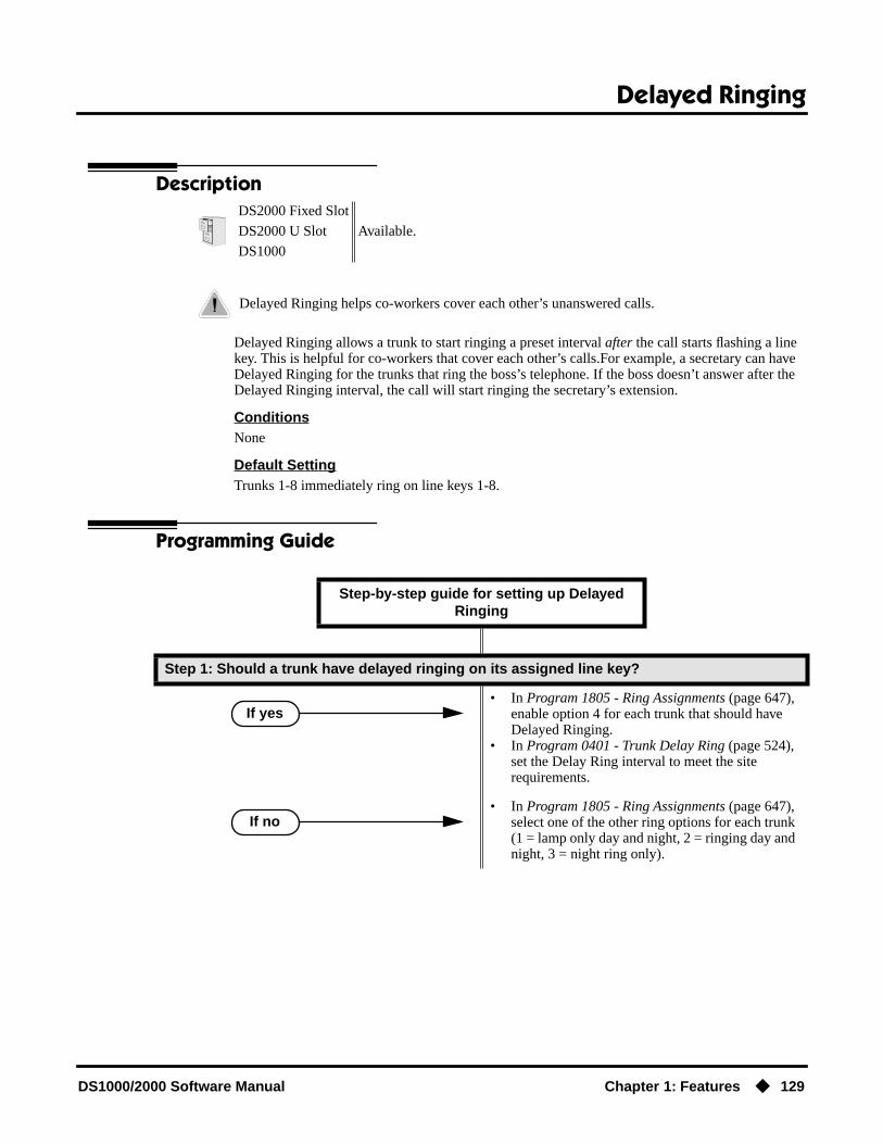
Delayed Ringing
DS1000/2000 Software Manual Chapter 1: Features ◆ 129
Delayed Ringing
Description
Delayed Ringing allows a trunk to start ringing a preset interval after the call starts flashing a line key. This is helpful for co-workers that cover each other’s calls.For example, a secretary can have Delayed Ringing for the trunks that ring the boss’s telephone. If the boss doesn’t answer after the Delayed Ringing interval, the call will start ringing the secretary’s extension.
ConditionsNone
Default SettingTrunks 1-8 immediately ring on line keys 1-8.
Programming Guide
DS2000 Fixed Slot
Available.DS2000 U Slot
DS1000
Delayed Ringing helps co-workers cover each other’s unanswered calls.
Step-by-step guide for setting up Delayed Ringing
Step 1: Should a trunk have delayed ringing on its assigned line key?
• In Program 1805 - Ring Assignments (page 647), enable option 4 for each trunk that should have Delayed Ringing.
• In Program 0401 - Trunk Delay Ring (page 524), set the Delay Ring interval to meet the site requirements.
• In Program 1805 - Ring Assignments (page 647), select one of the other ring options for each trunk (1 = lamp only day and night, 2 = ringing day and night, 3 = night ring only).
If yes
If no

Delayed Ringing
130 ◆ Chapter 1: Features DS1000/2000 Software Manual
Programming ListProgram 0401 - Trunk Delay Ring (page 524)
Set how long the system waits before ringing an extension that has the Delayed Ringing option enabled.
Program 1805 - Ring Assignments (page 647)For the selected trunk, set the ring assignment to 4 to enable Delayed Ringing. The other options are: 1 (lamp only day and night), 2 (ringing day and night) and 3 (night ring only, lamp during the day).
Other Related FeaturesCall Coverage Keys (page 62)
Delayed Ringing is also available for Call Coverage Keys.Private Line (page 350)
Consider having Delayed Ringing for Private Lines. Users with Delayed Ringing will ring for the Private Line only if it is not answered.
Feature OperationNone

Dial Number Preview
DS1000/2000 Software Manual Chapter 1: Features ◆ 131
Dial Number Preview
Description
Dialing Number Preview lets a display keyset user dial and review a number before the system dials it out.
ConditionsNone
Default SettingEnabled
Programming GuideNone
Programming ListNone
Other Related FeaturesCentral Office Calls, Placing (page 105)
Dial Number Preview allows an extension user to review a number before the system dials it out.
Feature Operation
To dial using Dial Number Preview:
1. Do not lift the handset, press SPK or press ICM.
2. Dial *.
3. Dial the number you want to call.
DS2000 Fixed Slot
Available.DS2000 U Slot
DS1000
Dial Number Preview helps the user avoid dialing errors.
N/A
Your display shows: DIAL PREVIEW
N/A
Your display shows the digits dialed, with a cursor (-) after the last digit.

Dial Number Preview
132 ◆ Chapter 1: Features DS1000/2000 Software Manual
4. Press line key.
To correct the displayed digits before dialing them out:
1. Use VOL ▲ and VOL ▼ until the cursor replaces the digit you want to change.VOL ▲ moves the cursor to the left. VOL ▼ moves the cursor to the right.
2. Dial the digit that you want to replace the cursor.
3. Press VOL ▲ and VOL ▼ to place the cursor over any other digits you want to edit.OR
Press VOL ▼ until the entire number displays to the left of the cursor.The system will only dial the digits to the left of the cursor.
4. Press a line key to have the system automatically dial the displayed number.
Dial tone on the selected trunk, then your digits dialing out.
Line key on (green).
Dial Number Preview Editing Example
To replace 2049265410 with 2039265400:
Step 1: Dial * followed by 2049265410. You see: 2049265410-
Step 1: Press Vol ▲ until you see: 20-9265410
Step 2: Dial 3. You see: 203-265410
Step 3: Press VOL ▼ until you see: 20392654-0
Step 4: Dial 0. You see: 203926540-
Step 5: Press Vol ▼ until the entire number displays to the left of the cursor.
2039265400-
Step 6: Press line key to dial number.

Direct Inward Line
DS1000/2000 Software Manual Chapter 1: Features ◆ 133
Direct Inward Line
Description
A Direct Inward Line (DIL) is a trunk that rings an extension directly. Since DILs only ring one extension, employees always know which calls are for them. For example, a company operator can have a Direct Inward Line for International Sales Information. When outside callers dial the DIL’s phone number, the call rings the operator on the International Sales line key. The DIL does not ring other extensions.
Assigning a DIL to an extension automatically provides immediate ringing and incoming access for the trunk, with no additional programming required.
The extension to which the trunk is terminated controls the night mode of the trunk. For example, if extension 301 has trunk 1 assigned as a DIL, the user can press DND to switch trunk 1 to its night routing destination. Switching trunk 1 to night mode at extension 304 has no affect on the night mode of the system. This flexibility could allow a service dispatcher with several DILs to indepen-dently send trunks to their night destinations without affecting the night mode of the entire system.
A DIL can ring:
● Extension numbers (including the attendant’s extension)
● Ring Group master numbers
● UCD Group master numbers (including the Voice Mail master number)
Overflow for Direct Inward LinesIf unanswered, DILs calls can route to a programmed overflow destination. The overflow destina-tion can be an extension, Ring Group, UCD Group or Voice Mail (i.e., DIL destination’s mailbox). You can set up separate DIL overflow destinations for the day mode and at night. If unanswered at the overflow destination, the call diverts to Key Ring.
ConditionsNone
Default SettingNo DILs assigned.
DS2000 Fixed Slot
Available.DS2000 U Slot
DS1000
A DIL lets an employee know which calls are just for them.

Direct Inward Line
134 ◆ Chapter 1: Features DS1000/2000 Software Manual
Programming Guide
Step-by-step guide for setting up Direct Inward Line (Page 1 of 3)
Step 1: Check to be sure each trunk’s circuit type matches the connected trunk circuit.
• In Program 1001 - Trunk Circuit Type (page 581), enter the correct circuit type for each trunk (51 = loop start DTMF, 52 = loop start DP).
Step 2: Assign the DIL day mode destination.
• In Program 1003 - Direct Termination (Day) (page 593), assign the DIL day mode termination. The destination can be an extension, UCD Group master number, Ring Group master number or Voice Mail master number.
Step 3: Do you want an unanswered DIL to overflow during the day mode?
• In Program 1003 - Activate Overflow During the Day (page 593), enter Y.
• In Program 1003 - Activate Overflow During the Day (page 593), enter N.
Step 4: Assign the DIL day overflow destination.
• In Program 1003 - Day Overflow Destination (page 593), assign the DIL day mode termination. The destination can be an extension, UCD Group master number, Ring Group master number, Voice Mail master number or Key Ring (by press-ing CLEAR).
Step 5: Assign the DILnight mode destination.
• In Program 1003 - Direct Termination (Night) (page 594), assign the DIL night mode termina-tion. The destination can be an extension, UCD Group master number, Ring Group master num-ber or Voice Mail master number. (An extension puts their DIL in the night mode by pressing DND.)
If yes
If no

Direct Inward Line
DS1000/2000 Software Manual Chapter 1: Features ◆ 135
Step 6: Do you want an unanswered DIL to overflow during the night mode?
• In Program 1003 - Activate Overflow at Night (page 594), enter Y.
• In Program 1003 - Activate Overflow at Night (page 594), enter N.
Step 7: Assign the DIL night overflow destination.
• In Program 1003 - Night Overflow Destination (page 594), assign the DIL night mode termina-tion. The destination can be an extension, UCD Group master number, Ring Group master num-ber, Voice Mail master number or Key Ring (by pressing CLEAR).
Step 8: Does extension have a line key for their DIL?
• In Program 1701 - Line Key (page 613), no pro-gramming changes are required.
• In Program 1701 - Line Key (page 613), make sure the DIL has a line key assigned (code 03). DILs can optionally ring Loop Keys (codes 01 and 02).
Step 9: Do you want to put the DIL on a DSS Console key?
• In Program 1704 - Line Key (page 624), make sure the DIL has a DSS Console line key assigned (code 03).
• In Program 1704 - Line Key (page 624), make sure the DIL does not have a DSS Console line key assigned (code 03).
Step 10: If a DIL to an extension is unanswered, does call divert to its overflow destination (If programmed) or Key Ring (if no overflow exists) after the proper interval?
• In Program 0401 - DIL No Answer (page 523), leave the DIL No Answer time at its current set-ting.
• In Program 0401 - DIL No Answer (page 523), change the DIL No Answer time to meet the site requirements.
Step-by-step guide for setting up Direct Inward Line (Page 2 of 3)
If yes
If no
If yes
If no
If yes
If no
If yes
If no

Direct Inward Line
136 ◆ Chapter 1: Features DS1000/2000 Software Manual
Programming ListProgram 0401 - DIL No Answer (page 523)
When the DIL destination is an extension:If DIL Overflow is set up, this interval determines how long a DIL rings its destination before ringing its programmed overflow destination. If DIL Overflow is not set up, this interval deter-mines how long a DIL rings is destination before diverting to Key Ring.
Step 11: If a DIL to a Ring Group master number is unanswered, does call divert to its over-flow destination (If programmed) or Key Ring (if no overflow exists) after the proper interval?
• In Program 0401 - Trunk Revert (page 523), leave the Trunk Revert time at its current setting.
• In Program 0401 - Trunk Revert (page 523), change the Trunk Revert time to meet the site requirements.
Step 12: If DIL is unanswered at the overflow destination, does call divert to Key Ring after the proper interval.
• In Program 0401 - Transfer Recall (page 522), leave the Transfer Recall time at its current set-ting.
• In Program 1805 - Ring Assignments (page 647), make sure you have extensions assigned to Key Ring.
• In Program 0401 - Transfer Recall (page 522), change the Transfer Recall time to meet the site requirements.
• In Program 1805 - Ring Assignments (page 647), make sure you have extensions assigned to Key Ring.
Step 13: If DIL is terminated to Voice Mail or a UCD master number, set up a Night key that controls the night mode status of the DIL.
• In Program 1701 - Night Key (page 615), set up a Night (System Mode UCD Master) key for the Voice Mail master number (code 18 + Voice Mail or UCD master number) OR
• In Program 1704 - Night Key (page 626), set up a Night (System Mode UCD Master) key for the Voice Mail master number (code 18 + Voice Mail or UCD master number).
Step-by-step guide for setting up Direct Inward Line (Page 3 of 3)
If yes
If no
If yes
If no

Direct Inward Line
DS1000/2000 Software Manual Chapter 1: Features ◆ 137
Program 0401 - DIL No Answer (page 523)When the DIL destination is a Ring Group master number:If DIL Overflow is set up, this interval determines how long a DIL rings its destination before ringing its programmed overflow destination. If DIL Overflow is not set up, this interval deter-mines how long a DIL rings is destination before diverting to Key Ring.
Program 0401 - Transfer Recall (page 522)This interval sets how long a call will ring the day or night overflow destination before divert-ing to key ring.
Program 1001 - Trunk Circuit Type (page 581)Set the trunk’s circuit type for compatiblity with the connected telco or PBX. The options are 51 (loop start DTMF), 52 (loop start DP), 53 (ground start DTMF) or 54 (ground start DP).
Program 1003 - Direct Termination (Day) (page 593)Set the day termination (answering point) for the DIL. The DIL rings the answering point directly. The destination can be an extension, UCD Group master number, Ring Group master number or Voice Mail master number.
Program 1003 - Activate Overflow During the Day (page 593)Enter Y to enable DIL overflow during the day mode. (Entering N for this option has the same affect as entering Y followed by Key Ring in the following option.)
Program 1003 - Day Overflow Destination (page 593)Set the overflow destination for day mode calls. The overflow destination can be an extension, UCD Group master number, Ring Group master number, Voice Mail master number or Key Ring (by pressing CLEAR).
Program 1003 - Direct Termination (Night) (page 594)Set the night termination (answering point) for the DIL. The DIL rings the answering point directly. The destination can be an extension, UCD Group master number, Ring Group master number or Voice Mail master number.
Program 1003 - Activate Overflow at Night (page 594)Enable Y to enable DIL overflow during the night mode. (Entering N for this option has the same affect as entering Y followed by Key Ring in the following option.)
Program 1003 - Night Overflow Destination (page 594)Set the overflow destination for night mode calls.The destination can be an extension, UCD Group master number, Ring Group master number or Voice Mail master number.
Program 1701 - Line Key (page 613)Make sure the extension has a line key (code 03) for the DIL.
Program 1701 - Night Key (page 615)If the DIL is terminated to a Voice Mail or UCD master number, a Night (System Mode UCD Master) key key (code 18 + the Voice Mail or UCD master number) controls the night mode of the DIL.
Program 1704 - Line Key (page 624)The extension can optionally have a line key (code 03) for their DIL on a DSS Console.
Program 1704 - Night Key (page 626)If the DIL is terminated to a Voice Mail or UCD master number, a Night (System Mode UCD Master) key key (code 18 + the Voice Mail or UCD master number) controls the night mode of the DIL.
Program 1805 - Ring Assignments (page 647)Make sure you have extensions assigned to Key Ring.

Direct Inward Line
138 ◆ Chapter 1: Features DS1000/2000 Software Manual
Other Related FeaturesCall Forwarding (page 66)
Call Forwarding will reroute an extension’s DILs.Call Waiting / Camp-On (page 75)
A DIL to a busy extension will send Camp-On tones (if the extension is programmed to nor-mally receive Camp-On tones).
Central Office Calls, Answering (page 99)Central Office Calls, Placing (page 105)
Refer to these features to set additional parameters for trunks (such as transmit gain, receive gain and sidetone level). In addition, extension users can place calls on DILs, just like other trunks (depending on programming).
Delayed Ringing (page 129)DILs automatically override Delayed Ringing.
Do Not Disturb (page 183)Enabling Do Not Disturb at an extension puts that extension’s DILs into Night Mode.
Extended Ringing (page 191)With Extended Ringing enabled, DIL trunks ring for the Number of Extended Rings before routing to the overflow destination.
Extension Hunting (page 193)DILs to a Circular or Terminal Hunting group member initiate hunting. In addition, DILs to a UCD master number ring the UCD group directly.
Group Ring (page 221)A DIL can ring a Ring Group master number.
Key Ring (page 273)An unanswered DIL diverts to all extensions with Key Ring for the trunk.
Line Keys (page 279)Loop Keys (page 283)
When you assign a trunk as a DIL, it continues to flash its previously programmed line/loop key assignments. It will not, however, ring those phones.
Names for Extensions and Trunks (page 306)Programming names for DILs makes it easier to identify incoming callers.
Night Service / Night Ring (page 308)The extension to which the DIL is terminated controls the night mode of the DIL by pressing their DND key.
Off-Hook Signaling (page 313)A DIL ringing a busy extension can automatically initiate Off-Hook Signaling.
Prime Line Preference (page 342)If an extension’s Prime Line is another extension’s DIL, lifting the handset will answer the call even though it does not ring the phone.
Voice Mail (page 477)
● The Voice Mail Automated Attendant will answer a DIL terminated to the Voice Mail Master Number.
● If a DIL is terminated to the Voice Mail master number, a System Mode key (code 18 + the Voice Mail number) controls the night mode status of the DIL.

Direct Inward Line
DS1000/2000 Software Manual Chapter 1: Features ◆ 139
Feature Operation
To answer a call on your Direct Inward Line:
1. Lift handset.
To place your DIL into Night Mode
1. Press DND.
This also enables Do Not Disturb at the extension.
Ringing.
DIL’s line key flashing (green).
Conversation with caller.
DIL’s line key on (green).
N/A
DND flashes.

Direct Station Selection (DSS)
140 ◆ Chapter 1: Features DS1000/2000 Software Manual
Direct Station Selection (DSS)
Description
If an extension’s Direct Station Selection (DSS) Keys are enabled, Programmable Function Keys automatically become Direct Station Selection (DSS) keys when the user presses ICM. Direct Sta-tion Selection provides an extension user with one-button Intercom access and Transfer to co-work-ers. Each DSS key also provides a Busy Lamp Field (BLF) for the assigned co-worker.
ConditionsDSS keys do not pick up ringing calls.
Default SettingNot assigned. DSS capability is disabled.
DS2000 Fixed Slot Available - DSS keys enabled (but unassigned) by default.
DS2000 U Slot Available - DSS keys disabled by default. User Programmable steps added.
DS1000 Available - DSS keys disabled by default.
Quickly place and Transfer calls to co-workers, without having to look up or dial extension numbers.
Important
• If you enable an extension’s DSS Keys and leave the extension’s default Prime Line programming intact, the line keys automatically change to DSS keys when the user lifts the handset. To avoid confusion, be sure to explain this to your users.
• You may prefer to use the Call Coverage Keys (page 62) or Hotline (page 240) features instead. Remember, in addition to providing one-button Intercom access and Transfer, Call Coverage Keys also provide call pickup capability.
When the DSS/BLF key is: The covered extension is:
Off Idle
On Busy or ringing
Flashing fast In Do Not Disturb

Direct Station Selection (DSS)
DS1000/2000 Software Manual Chapter 1: Features ◆ 141
Programming Guide
Programming ListProgram 1703 - DSS Key Assignment (page 620)
Program the extension’s DSS assignments.Program 1802 - Busy Lamp Field (page 636)
Enter Y to enable DSS capability for an extension’s programmable keys.Program 1807 - Prime Line Key (page 653)
If you enable DSS capability in the option above, consider turning off Intercom Prime Line in this program. If you don’t, the extension’s line keys switch to DSS mode whenever the user lifts the handset while idle. (If a trunk call is ringing the phone, Ringing Line Preference will nor-mally answer the call when the user lifts the handset — even with Intercom Prime Line enabled.)
Other Related FeaturesIntercom (page 268)
A user can press a DSS key as an alternative to dialing Intercom numbers.Prime Line Preference (page 342)
With Intercom Prime Line, an idle extension user hears Intercom dial tone whenever they lift the handset or press SPK. Since each extension’s Busy Lamp Field is disabled by default in U Slot, the Programmable Function Keys do not go into the DSS mode when the user lifts the handset while idle. (If a trunk call is ringing the phone, Ringing Line Preference will normally answer the call when the user lifts the handset — even with Intercom Prime Line enabled.)
Step-by-step guide for setting up Direct Station Selection
Step 1: Should extension have DSS capability on their programmable keys?
• In Program 1802 - Busy Lamp Field (page 636), enter Y.
• In Program 1807 - Prime Line Key (page 653), turn off Intercom Prime Line to prevent the the extension’s line keys from switching to DSS mode when the user lifts the handset while idle.
• In Program 1802 - Busy Lamp Field (page 636), enter N.
Step 2: Should extension have preprogrammed DSS keys?
• In Program 1703 - DSS Key Assignment (page 620), program the extension’s DSS assign-ments.
• In Program 1703 - DSS Key Assignment (page 620), leave the extension’s DSS keys unas-signed.
If yes
If no
If yes
If no

Direct Station Selection (DSS)
142 ◆ Chapter 1: Features DS1000/2000 Software Manual
Speed Dial (page 383)The Personal Speed Dial Keys also provide one-button access to extensions.
Transfer (page 455)You can press your DSS key to Transfer a call instead of dialing a co-worker’s extension number.
Voice Over (page 493)An extension can Voice Over after using Direct Station Selection to call a co-worker.
Feature Operation
To place a call to a co-worker using a DSS key:
1. Lift handset.
2. Press ICM .
3. Press DSS key for co-worker you want to call.
To Transfer a call to a co-worker using a DSS key:
1. Place or answer trunk call.
2. Press ICM .
3. Press DSS key for co-worker.
4. Hang up to have the Transfer go through unscreened.OR
Wait for the called party to answer if you want them to screen the Transfer.
User Programmable Feature
Feature Mnemonic Operation Access Level
This option is not available with Fixed Slot software.
DSS #BLF #BLF + Press DSS key + HOLD + Enter extension + VOL ▲ + Program another key or SPK to exit.
1-5
Intercom dial tone.
DSS keys show status of covered co-workers (off = idle, on = busy or ringing, flashing fast = in Do Not Disturb).
Two beeps or ringing.
N/A
Conversation with caller.
Line or Loop Key on (green).
Intercom dial tone.
DSS keys show status of covered co-workers (off = idle, on = busy or ringing, flashing fast = in Do Not Disturb).
Two beeps or ringing.
N/A

Direct Station Selection (DSS) Console
DS1000/2000 Software Manual Chapter 1: Features ◆ 143
Direct Station Selection (DSS) Console
Description
The DSS Console gives a 34-Button Display or 34-Button Super Display user a Busy Lamp Field (BLF) and one-button access to extensions, trunks, and selected system features. This saves time for users that do a lot of call processing (such as operators or dispatchers). There are two DSS Con-soles types: the 24-Button (P/N 80556) and the 110-Button (P/N 80555).
Figure 13: 24-Button and 110-Button DSS Consoles
The system allows you to install 4 DSS Consoles maximum. In addition, System Load Factor may further reduce the number that you can install. See DS2000 Load Factor on page 3 for more on the System Load Factor. You cannot connect multiple DSS Consoles to the same keyset. DSS Consoles do not use a station port and do not require their own power supply.
The system provides four unique DSS configurations (called blocks). If you want your DSS Con-soles to have unique key configurations, assign them to different blocks. If you want your consoles to share the same configuration, assign them to the same block. Note that DSS Console Personal Speed Dial bins are the same as the extension to which the console is attached. This means that DSS Consoles that share the same block number still have unique Personal Speed Dial.
DS2000 Fixed Slot Available - with unique default settings.
DS2000 U Slot Available - with unique default settings.
DS1000 Available - with unique default settings.
DSS Consoles provide one-touch access to extensions, trunks and system features.

Direct Station Selection (DSS) Console
144 ◆ Chapter 1: Features DS1000/2000 Software Manual
You can assign DSS Console keys to the following functions:
Conditions
● You cannot connect a DSS Console to a 22-button telephone.
● You must consider the System Load Factor when installing DSS Consoles. See DS2000 Load Factor on page 3 for more.
• ACD Log On (future) • Message Center • Speed Dial, Personal
• Call Coverage (immedi-ate, delayed or no ring)
• Multiple Directory Num-bers (future)
• Reverse Voice Over
• Data (future) • Night Key • Split
• Group Pickup (immedi-ate, delayed or no ring)
• Page Zones • Speed Dial, System
• Hotline • Park Orbit • Trunks (line keys)
• ICM Directory • Save • Voice Mail Record

Direct Station Selection (DSS) Console
DS1000/2000 Software Manual Chapter 1: Features ◆ 145
Default Setting
Fixed Slot DSS Console Default Assignments
These keys: Have this function:
24-Button DSS Console
1-24 Hotlines to extensions 300-323
110-Button DSS Console
1-32 Hotlines to extensions 300-331
33-48 Lines 1-16
49-58 System Speed Dial bins 200-209
59-78 Personal Speed Dial bins 700-719
79, 80 Page zones 0 (All Call) and 1.
81-82 System Park Orbits 0 and 1.
83-110 Unassigned
U Slot DSS Console Default Assignments
These keys: Have this function:
24-Button DSS Console
1-24 Hotlines to extensions 300-323
110-Button DSS Console
1-80 Hotlines to extensions 300-379
81-96 Hotlines to undefined destinations.
97-99 Page Zones 1-3
100 All Call Page
101-109 Park Orbits 0-8
110 Night (System Mode System) key

Direct Station Selection (DSS) Console
146 ◆ Chapter 1: Features DS1000/2000 Software Manual
Programming Guide
DS1000 DSS Console Default Assignments
These keys: Have this function:
24-Button DSS Console
1-24 Hotlines to extensions 300-323
110-Button DSS Console
1-26 Hotlines to extensions 300-325
27-58 Hotlines to undefined extensions
59-64 Hotlines to trunks 1-6 (401-406)1
65-96 Hotlines to undefined destinations.
97-99 Page Zones 1-3
100 All Call Page
101-109 Park Orbits 0-8
110 Night (System Mode System) key
1 Trunk Hotlines require that the extension have Direct Trunk Access enabled. See Direct Trunk Access on page 154 for more. These keys do not exist in software versions 02.01.07 and higher.
Step-by-step guide for setting up DSS Consoles
Step 1: Does the extension have a DSS Console connected?
• In Program 1801 - DSS Type (page 630), enter 1 if the extension has a 24-button console con-nected. Enter 2 if the extension has a 110-button console connected. You cannot have more than 4 DSS Consoles installed.
• In Program 1801 - DSS Type (page 630), enter 0 if the extension does not have a DSS Console connected.
If yes
If no
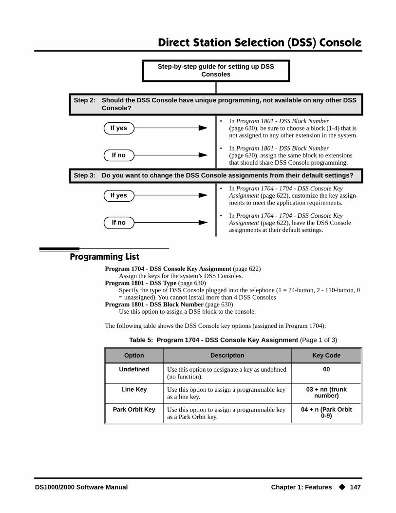
Direct Station Selection (DSS) Console
DS1000/2000 Software Manual Chapter 1: Features ◆ 147
Programming ListProgram 1704 - DSS Console Key Assignment (page 622)
Assign the keys for the system’s DSS Consoles.Program 1801 - DSS Type (page 630)
Specify the type of DSS Console plugged into the telephone (1 = 24-button, 2 - 110-button, 0 = unassigned). You cannot install more than 4 DSS Consoles.
Program 1801 - DSS Block Number (page 630)Use this option to assign a DSS block to the console.
The following table shows the DSS Console key options (assigned in Program 1704):
Step 2: Should the DSS Console have unique programming, not available on any other DSS Console?
• In Program 1801 - DSS Block Number (page 630), be sure to choose a block (1-4) that is not assigned to any other extension in the system.
• In Program 1801 - DSS Block Number (page 630), assign the same block to extensions that should share DSS Console programming.
Step 3: Do you want to change the DSS Console assignments from their default settings?
• In Program 1704 - 1704 - DSS Console Key Assignment (page 622), customize the key assign-ments to meet the application requirements.
• In Program 1704 - 1704 - DSS Console Key Assignment (page 622), leave the DSS Console assignments at their default settings.
Table 5: Program 1704 - DSS Console Key Assignment (Page 1 of 3)
Option Description Key Code
Undefined Use this option to designate a key as undefined (no function).
00
Line Key Use this option to assign a programmable key as a line key.
03 + nn (trunknumber)
Park Orbit Key Use this option to assign a programmable key as a Park Orbit key.
04 + n (Park Orbit0-9)
Step-by-step guide for setting up DSS Consoles
If yes
If no
If yes
If no
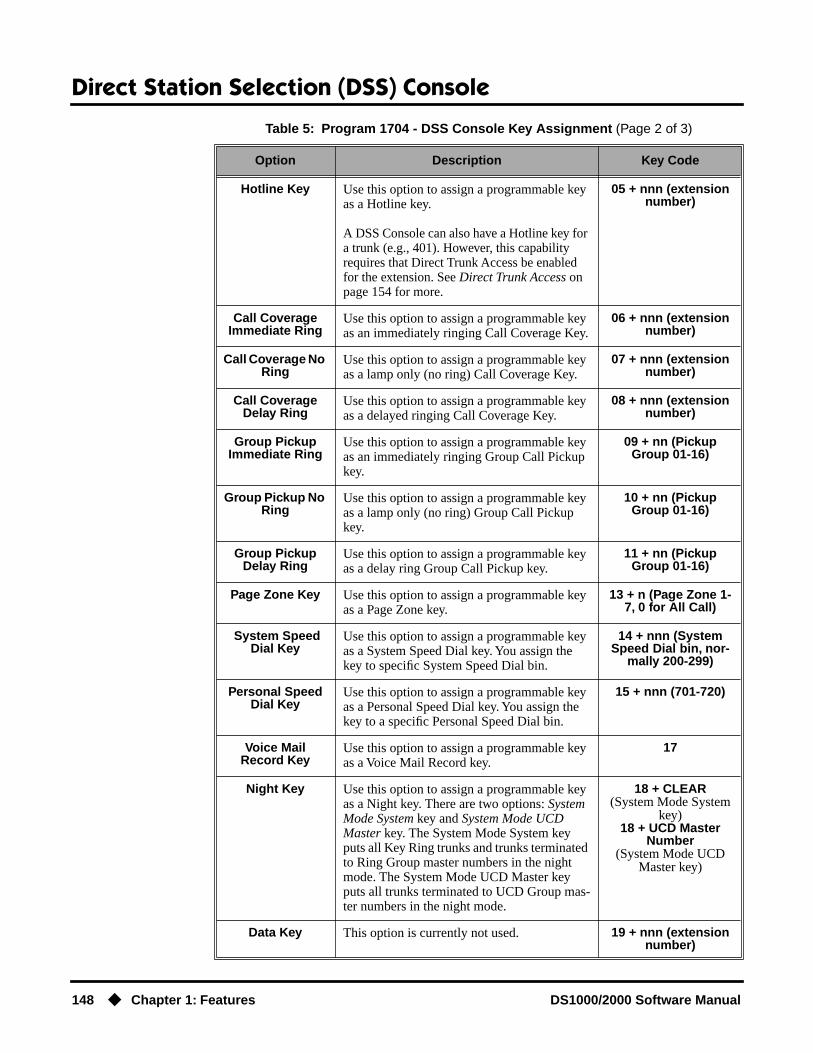
Direct Station Selection (DSS) Console
148 ◆ Chapter 1: Features DS1000/2000 Software Manual
Hotline Key Use this option to assign a programmable key as a Hotline key.
A DSS Console can also have a Hotline key for a trunk (e.g., 401). However, this capability requires that Direct Trunk Access be enabled for the extension. See Direct Trunk Access on page 154 for more.
05 + nnn (extension number)
Call Coverage Immediate Ring
Use this option to assign a programmable key as an immediately ringing Call Coverage Key.
06 + nnn (extension number)
Call Coverage No Ring
Use this option to assign a programmable key as a lamp only (no ring) Call Coverage Key.
07 + nnn (extension number)
Call Coverage Delay Ring
Use this option to assign a programmable key as a delayed ringing Call Coverage Key.
08 + nnn (extension number)
Group Pickup Immediate Ring
Use this option to assign a programmable key as an immediately ringing Group Call Pickup key.
09 + nn (Pickup Group 01-16)
Group Pickup No Ring
Use this option to assign a programmable key as a lamp only (no ring) Group Call Pickup key.
10 + nn (Pickup Group 01-16)
Group Pickup Delay Ring
Use this option to assign a programmable key as a delay ring Group Call Pickup key.
11 + nn (Pickup Group 01-16)
Page Zone Key Use this option to assign a programmable key as a Page Zone key.
13 + n (Page Zone 1-7, 0 for All Call)
System Speed Dial Key
Use this option to assign a programmable key as a System Speed Dial key. You assign the key to specific System Speed Dial bin.
14 + nnn (System Speed Dial bin, nor-
mally 200-299)
Personal Speed Dial Key
Use this option to assign a programmable key as a Personal Speed Dial key. You assign the key to a specific Personal Speed Dial bin.
15 + nnn (701-720)
Voice Mail Record Key
Use this option to assign a programmable key as a Voice Mail Record key.
17
Night Key Use this option to assign a programmable key as a Night key. There are two options: System Mode System key and System Mode UCD Master key. The System Mode System key puts all Key Ring trunks and trunks terminated to Ring Group master numbers in the night mode. The System Mode UCD Master key puts all trunks terminated to UCD Group mas-ter numbers in the night mode.
18 + CLEAR(System Mode System
key)18 + UCD Master
Number(System Mode UCD
Master key)
Data Key This option is currently not used. 19 + nnn (extension number)
Table 5: Program 1704 - DSS Console Key Assignment (Page 2 of 3)
Option Description Key Code

Direct Station Selection (DSS) Console
DS1000/2000 Software Manual Chapter 1: Features ◆ 149
Other Related FeaturesCall Coverage Keys (page 62)
DSS Consoles can have Call Coverage keys.Directory Dialing (page 158)
Assign a Directory Dialing key on a DSS Console.Group Call Pickup (page 215)
DSS Consoles can have Group Call Pickup keys.Hotline (page 240)
DSS Consoles can have Hotline keys.Night Service / Night Ring (page 308)
A DSS Console with a Night (System Mode System) key can put the system in the night mode.Paging (page 326)
DSS Consoles can have Page zone keys.Park (page 333)
DSS Consoles can have Park keys.Reverse Voice Over (page 364)
A DSS Console can have a Reverse Voice Over key.Save Number Dialed (page 373)
A DSS Console can have a Save key.Speed Dial (page 383)
The DSS Console Personal Speed Dial bins are the same as the extension to which the console is attached. This means that DSS Consoles that share the same block number still have unique Personal Speed Dial.
Voice Mail (page 477)A DSS Console can have Voice Mail Record and Message Center keys.
Split Key Use this option to assign a programmable key as a Split key.
20
ICM Directory Key
Use this option to assign a programmable key as an Intercom Directory Dialing key.
21
ACD Log On Key This option is currently not used. 22
Reverse Voice Over Key
Use this option to assign a programmable key as a Reverse Voice Over key.
23
Message Center Key
Use this option to assign a programmable key as a Message Center key.
24 + nnn (extension number)
Save Key Use this option to assign a programmable key as a Save Number Dialed key.
25
Table 5: Program 1704 - DSS Console Key Assignment (Page 3 of 3)
Option Description Key Code

Direct Station Selection (DSS) Console
150 ◆ Chapter 1: Features DS1000/2000 Software Manual
Feature Operation
To use your DSS Console trunk (line) key:
1. Press the DSS Console trunk key.
To use your DSS Console Park key:
1. Press DSS Console Park key to Park or retrieve call.
To use your DSS Console Hotline key:
1. Press key to call Hotline partner.
To use your DSS Console Call Coverage key:
You can set up the Call Coverage key for immediate ring, delayed ring , or no ring.
1. Press key to call covered extension or pick up ringing call.
DSS Console Trunk Key Busy Lamp Indications
When the key is: The assigned trunk is:
Off Idle or not installed
On Busy
Slow Flash Ringing
DSS Console Park Key Busy Lamp Indications
When the key is: The assigned orbit is:
Off Idle
On Holding a call that has been parked by a co-worker
Wink On Holding a call that you parked
DSS Console Hotline Key Busy Lamp Indications
When the key is: The Hotline partner is:
Off Idle
On Busy or ringing
Fast Flash In Do Not Disturb
DSS Console Call Coverage Key Busy Lamp Indications
When the key is: The covered extension is:
Off Idle

Direct Station Selection (DSS) Console
DS1000/2000 Software Manual Chapter 1: Features ◆ 151
To use your DSS Console Group Call Pickup key:
You can set up the Group Call Pickup key for immediate ring, delayed ring , or no ring.
1. Press key to answer call ringing Pickup Group.
To use your DSS Console Page Zone key:
1. Press key to Page into assigned zone.
To use your DSS Console System Speed dial key:
1. Press key to dialed stored number.System Speed Dial keys provide no BLF.
To use your DSS Console Personal Speed dial key:
1. Press key to dialed stored number.Personal Speed Dial keys provide no BLF.
To use your DSS Console Conversation Record key:
You must have Voice Mail installed to use this key. A voice prompt and a periodic beep will remind you that your calls are being recorded.
On Busy
Fast Flash In DND
Slow Flash Ringing
DSS Console Group Call Pickup Key Busy Lamp Indications
When the key is: The Pickup Group:
Off Does not have a call ringing
Slow Flash Has a call ringing
DSS Console Page Zone Key Busy Lamp Indications
When the key is: The assigned zone is:
On Busy
Off Idle
DSS Console Call Coverage Key Busy Lamp Indications

Direct Station Selection (DSS) Console
152 ◆ Chapter 1: Features DS1000/2000 Software Manual
1. Press key to record conversation in mailbox.
To use your DSS Console Night (System Mode System) key:
1. Press key to put the Key Ring trunks and trunks terminated to Ring Group master numbers into the night mode.
To use your DSS Console ICM Directory key:
1. Press key to access Intercom Directory Dialing.
To use your DSS Console Reverse Voice Over key:
1. While on a handset call, press key to place Private Intercom call to covered extension.
DSS Console Conversation Record Key Busy Lamp Indications
When the key is: Recording is:
On Being set up
Off Off
Fast Flash On
DSS Console Night Key Busy Lamp Indications
When the key is: The system is:
On In the night mode
Off In the day mode
DSS Console ICM Directory Key Busy Lamp Indications
When the key is: ICM Directory Dialing is:
On Active
Off Inactive
DSS Console Reverse Voice Over Key Busy Lamp Indications
When the key is: Assigned extension is:
On Busy or ringing
Off Idle
Fast Flash In Do Not Disturb

Direct Station Selection (DSS) Console
DS1000/2000 Software Manual Chapter 1: Features ◆ 153
To use your DSS Console Message Center key:
1. Press key to see how many messages are waiting in the Message Center.OR
Press SPK + key to call Message Center mailbox.
To use your DSS Console Save key:
1. While on a call, press key to Save the number you just dialed.OR
While idle, press key to redial a previously saved number.Save keys provide no BLF.
DSS Console Message Center Key Busy Lamp Indications
When the key is: There are:
Off No messages waiting in the Message Center mailbox
Fast Flash Messages waiting in the Message Center mailbox
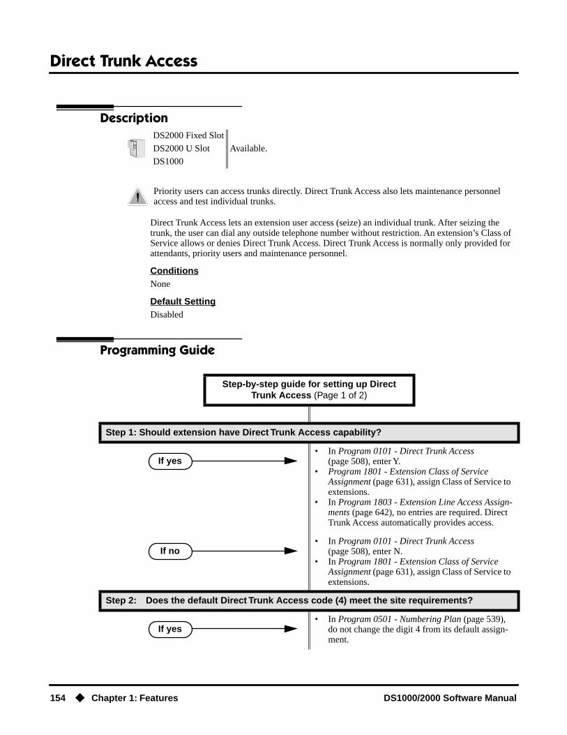
Direct Trunk Access
154 ◆ Chapter 1: Features DS1000/2000 Software Manual
Direct Trunk Access
Description
Direct Trunk Access lets an extension user access (seize) an individual trunk. After seizing the trunk, the user can dial any outside telephone number without restriction. An extension’s Class of Service allows or denies Direct Trunk Access. Direct Trunk Access is normally only provided for attendants, priority users and maintenance personnel.
ConditionsNone
Default SettingDisabled
Programming Guide
DS2000 Fixed Slot
Available.DS2000 U Slot
DS1000
Priority users can access trunks directly. Direct Trunk Access also lets maintenance personnel access and test individual trunks.
Step-by-step guide for setting up Direct Trunk Access (Page 1 of 2)
Step 1: Should extension have Direct Trunk Access capability?
• In Program 0101 - Direct Trunk Access (page 508), enter Y.
• Program 1801 - Extension Class of Service Assignment (page 631), assign Class of Service to extensions.
• In Program 1803 - Extension Line Access Assign-ments (page 642), no entries are required. Direct Trunk Access automatically provides access.
• In Program 0101 - Direct Trunk Access (page 508), enter N.
• In Program 1801 - Extension Class of Service Assignment (page 631), assign Class of Service to extensions.
Step 2: Does the default Direct Trunk Access code (4) meet the site requirements?
• In Program 0501 - Numbering Plan (page 539), do not change the digit 4 from its default assign-ment.
If yes
If no
If yes

Direct Trunk Access
DS1000/2000 Software Manual Chapter 1: Features ◆ 155
Programming ListProgram 0501 - Numbering Plan (page 539)
Change the digit that user’s dial for Direct Trunk Access if 4 does not meet the site require-ments.
Program 0101 - Direct Trunk Access (page 508)Enter Y to enable an extension to use Direct Trunk Access.
Program 1801 - Extension Class of Service Assignment (page 631)Assign Class of Service to extensions.
Program 1803 - Extension Line Access Assignments (page 642)Direct Trunk Access overrides an extension’s access assignments. A extension can directly access a trunk for which they normally do not have access.
Other Related FeaturesCentral Office Calls, Placing (page 105)
Refer to this feature for other methods of placing trunk calls.Forced Trunk Disconnect (page 212)
An extension user with Direct Trunk Access can use Forced Trunk Disconnect.Removing Trunks and Extensions From Service (page 362)
An extension user with Direct Trunk Access can remove trunks from service.Toll Restriction (Software Version 02.02.14 or Higher) (page 439)
Direct Trunk Access does not bypass Toll Restriction.Toll Restriction (Prior to Software Version 02.02.14) (page 447)
Direct Trunk Access does not bypass Toll Restriction.
Feature Operation
To place a call over a specific trunk using Direct Trunk Access:
1. Lift handset.
2. Press ICM.
3. Dial 4 plus the trunk number (e.g., 401 for trunk 1).
If you hear busy tone, you may be able to dial 2 to queue for the busy trunk. See Trunk (Line) Queuing / Trunk Callback on page 465 for more.
4. Dial outside number.
• In Program 0501 - Numbering Plan (page 539), reassign digits to meet the site requirements.
Intercom dial tone.
ICM on.
Trunk dial tone, followed by digits outdialing on the trunk.
ICM on.
Step-by-step guide for setting up Direct Trunk Access (Page 2 of 2)
If no

Directed Call Pickup
156 ◆ Chapter 1: Features DS1000/2000 Software Manual
Directed Call Pickup
Description
Directed Call Pickup permits an extension user to intercept a call ringing another extension. With Directed Call Pickup, an extension user can pick up:
● Trunk (Key Ring) calls ringing an extension
● Direct Inward Lines
● Transferred trunk calls
● Ringing Intercom calls.
● Recalls (e.g., Hold recall).
● Ring Group Calls (by dialing either the ringing extension’s number or the Ring Group mas-ter number)
ConditionsNone
Default SettingEnabled
Programming GuideNone
Programming ListProgram 1803 - Extension Line Access Assignments (page 642)
Directed Call Pickup can intercept a call on a trunk to which it normally does not have access.
Other Related FeaturesDoor Box (page 185)
Directed Call Pickup cannot intercept a Door Box call ringing an extension.Hold (page 235)
Directed Call Pickup can pick up Hold recalls.Park (page 333)
Personal Park allows an extension user to pick up a call parked at a co-worker’s extension.
The following features also let co-workers cover each other’s calls:
Call Coverage Keys (page 62)Group Call Pickup (page 215)Hotline (page 240)
DS2000 Fixed Slot
Available.DS2000 U Slot
DS1000
Directed Call Pickup allows co-worker’s to answer each other’s calls.

Directed Call Pickup
DS1000/2000 Software Manual Chapter 1: Features ◆ 157
Feature Operation
To use Directed Call Pickup to intercept a call to a co-worker’s extension:
1. Lift handset.
2. Dial * *.
3. Dial number of extension whose call you want to intercept.
To intercept a call ringing an attendant, dial the attendant’s extension number (e.g., 300). Do not dial 0 or 01-04.
Call ringing co-worker’s extension.
N/A.
Conversation with intercepted caller.
N/A.

Directory Dialing
158 ◆ Chapter 1: Features DS1000/2000 Software Manual
Directory Dialing
Description
Directory Dialing allows a display keyset user to select a co-worker or outside call from a list of names, rather than dialing the phone number. There are three types of directory Dialing:
● C – System (Company-Wide) Speed Dial names.
● I – Intercom names (including extension, Ring Group and UCD Group names).
● P – Personal Speed Dial names.
ConditionsNone
Default SettingDirectory Dialing always enabled, but no Intercom or Speed Dial names are stored.
Programming Guide
DS2000 Fixed Slot
Directory Dialing available.DS2000 U Slot
DS1000
Allows users to place Intercom or Speed Dial calls from a displayed list of names.
Step-by-step guide for setting up Directory Dialing (Page 1 of 2)
Step 1: Do extension users have adequate time to enter their Directory Dialing options?
• In Program 0401 - Intercom Inter-digit (page 522), leave this option at its currently assigned value.
• In Program 0401 - Intercom Inter-digit (page 522), change the Interdigit Interval to meet the site requirements. Keep in mind that this affects all Intercom dialing (in addition to Direc-tory Dialing).
Step 2: Should extension have one-touch access to Intercom Directory Dialing?
• To put an ICM Directory key on a keyset:In Program 1701 - ICM Directory Key (page 615), assign an Intercom Directory Dialing key (code 21).
• To put an ICM Directory key on a DSS Console:In Program 1704 - ICM Directory Key (page 626), assign an Intercom Directory Dialing key (code 21).
If yes
If no
If yes

Directory Dialing
DS1000/2000 Software Manual Chapter 1: Features ◆ 159
Programming ListProgram 0401 - Intercom Inter-digit (page 522)
If an extension user initiates Directory Dialing but doesn’t make an entry within this interval, the system automatically cancels Directory Dialing.
Program 1701 - ICM Directory Key (page 615)Assign an Intercom Directory Dialing key to a keyset (code 21).
Program 1704 - ICM Directory Key (page 626)Assign an Intercom Directory Dialing key to a DSS Console (code 21).
Other Related FeaturesDirect Station Selection (DSS) Console (page 143)
Assign a Directory Dialing key on a DSS Console.Extension Hunting (page 193)
Intercom Directory Dialing will show UCD Group names.Group Ring (page 221)
Intercom Directory dialing will show Ring Group names.Intercom (page 268)
Directory Dialing is a convenient alternative to manually dialing Intercom numbers.Names for Extensions and Trunks (page 306)
Set up the names for extensions and trunks.Speed Dial (page 383)
Set up Speed Dial names.
• In Program 1701 - ICM Directory Key (page 615), and in Program 1704 - ICM Direc-tory Key (page 626), do not assign an Intercom Directory Dialing key (code 21).
Step-by-step guide for setting up Directory Dialing (Page 2 of 2)
If no

Directory Dialing
160 ◆ Chapter 1: Features DS1000/2000 Software Manual
Feature Operation
To place a call using Directory Dialing:
1. Do not lift handset or press SPK.
1. Dial 3.
2. Dial the type of Directory Dialing from the table below:
To scroll alphabetically through the selected directory, press VOL ▲ or VOL ▼. To call the displayed name, just press DIAL.
3. Dial the first letter of the desired name.For example, dial 4 if the first letter in the name begins with G, H or I. The display
4. Look at your phone’s display and dial the digit for the letter/number you want to call.In the example above, if the name begins with G, dial 1. If the name begins with H, dial
2. If the name begins with I, dial 3.The first name/number that begins with your selection displays. If you see UNLISTED
NAME, there is no name stored for your selection.
5. Press VOL ▲ or VOL ▼ to scroll through all the names/numbers that begin with the letter/num-ber you selected.
ORSkip to the next step if the displayed name/number is the one you want to call.
6. Press DIAL to have the system dial your call.
To exit Directory Dialing at any time.
1. Press SPK.
Pressing this key: Selects Directory Dialing for:
2 C System (Company-Wide) Speed Dial names.
4 I Intercom names.
7 P Personal Speed Dial names.
N/A
SPK on.
N/A
For the example above (i.e., when you dial 4), the display shows:1 = G, 2 = H, 3 = I

Display, Alphanumeric
DS1000/2000 Software Manual Chapter 1: Features ◆ 161
Display, Alphanumeric
DescriptionDS2000 Fixed Slot
Available. Refer to Alphanumeric Display on page 43 for more.DS2000 U Slot
DS1000

Distinctive Ringing
162 ◆ Chapter 1: Features DS1000/2000 Software Manual
Distinctive Ringing
Description
Distinctive Ringing allows the installer or keyset extension user to customize keyset ringing. This permits the user to determine the type of call just by listening to their keyset ring. Distinctive Ring-ing provides:
● Distinctive Ring Configuration at Each KeysetA keyset user can follow intuitive soft key menus to set up distinctive ringing for their phone. Their phone will even play back the new ring tones as the distinctive rings are being set up. This option is controlled by the extension’s Class of Service.
● Trunk Override (Distinctive Ringing by Trunk and Ringing Mode)Each trunk can have its own distinctive ringing for each ring mode (day, night, or delay). This allows a keyset user, for example, to easily differentiate between new ringing calls and calls that are ringing their phone after a delay.
● Extension Ring OverrideEach keyset extension can additionally override a trunk’s distinctive ringing with the exten-sion’s own unique settings. Extension Ring Override helps identify ringing phones in large, open work areas. This option is controlled by the extension’s Class of Service.
● Key Ring OverrideA keyset extension can set up unique ringing for each of its Call Coverage, Group Call Pickup, and Line keys. If a user needs to know what type of call is ringing their phone, Key Ring Over-ride will help. The ability to set up this option is controlled by the extension’s Class of Service.
● Unique Ringing for UCD Hunting Groups and Ring GroupsUCD Hunting and Ring Groups can have their own distinctive rings. This allows a user to tell the difference between Intercom calls ringing their phone and UCD or Ring Group Calls.
● Fully Customizable Ring TonesThe tones that comprise ringing are fully customizable. See The Basics of How to Change the “Sound” of a Ring Type below for more.
● Distinctive Ringing AdministrationThe Distinctive Ringing Administration (Admin) features allow a keyset extension user to store the unique ring settings they set up at their phone. Super Display users can also save their settings in the system so they are available to other keyset users.
The Distinctive Ringing HierarchyAn extension’s Distinctive Ringing uses the following hierarchy:
1. Key Ring Override
DS2000 Fixed Slot Not available.
DS2000 U Slot • Requires software version 02.02.14 or higher.• Distinctive Ring Initialization in 9803 - Ring Tone Setup requires software
version 02.02.17 or higher.DS1000
Allows users to customize their telephone’s ringing so they’ll know when calls are just for them.
!! Important !!
If upgrading from a software version prior to 02.02.14, you must initialize Distinctive Ringing. Use Program 9803 - Ring Tone Setup (page 661) to initialize Distinctive Ringing with a single command. Following initialization, you must reset the system or unplug and then replug each telephone.

Distinctive Ringing
DS1000/2000 Software Manual Chapter 1: Features ◆ 163
2. Extension Ring Override
3. Trunk Override
4. Default ringing assigned by the system
This means that Trunk Override will replace the default ringing assigned by the system. Extension Ring Override will in turn replace ringing set by Trunk Override. Finally, Key Ring Override will replace ringing set by Extension Override or ringing set by Trunk Override.
Understanding Ring Types and Ring Sets!! Important !!
The Ring Set determines how a call rings an extension. It assigns unique ringing patterns (called Ring Types) to different types of calls. By default, there are four different types of ringing calls: Intercom, Ring Group, Recall, and trunk. They ring differently because the Ring Types assigned to each of these four call types sound unique.
As shown in the chart below, each Ring Set provides 6 Ring Types at each extension which control how the extension rings. Four (1-4) are assigned to a call type by default; the remaining two (5 and 6) are spare. Each extension has 3 Ring Sets from which to choose: the default and two alternates. The alternates have the same Ring Type to Call Type assignment as the default, but their Ring Types sound different.
The Basics of How to Change the “Sound” of a Ring TypeEach Ring Type consists of a Ring Tone and a Cadence.
● A Ring Tone is comprised of two frequencies, modulated (i.e., varied) by a third frequency. The system allows up to 10 Ring Tones. In programming, you can customize each component of a Ring Tone.
● A Cadence is the pattern of the ring. It determines the number of bursts in the ring (1-4), the length of the bursts (100 mS to 2 seconds), and how often the ring pattern repeats (from 4 to 7 seconds). The system provides up to 10 cadences. In programming, you can customize each component of a Cadence.
The Ring Set
Ring Type Call Type
1 Intercom ringingThis includes ringing Intercom calls, as well as calls ringing Exten-sion Hunting groups, Call Coverage keys and the operator’s Call key.
2 Ring Group ringing
3 Recall ringingThis includes Hold, Park or Transfer recall ringing.
4 Type A ringingThis includes line key, loop key, Transfer, and DIL ringing. (You can reassign types A, B, and C ringing in Extension Override and Key Ring Override below.)
5 Type B ringingNot used (unassigned) by default. (You can reassign types A, B, and C ringing in Extension Override and Key Ring Override below.)
6 Type C ringingNot used (unassigned) by default. (You can reassign types A, B, and C ringing in Extension Override and Key Ring Override below.)

Distinctive Ringing
164 ◆ Chapter 1: Features DS1000/2000 Software Manual
● Since there are 10 Ring Tones and 10 cadences, there are 100 possible combinations for each Ring Type.
When Multiple Calls Ring an ExtensionWhen multiple calls with different priorities are ringing an extension, the system prioritizes ringing according to the list below. All LEDs will flash as appropriate for the type of call, but the telephone will ring only for the highest priority call.
● Intercom and Ring Group ringing
● Trunk ringing, including line key (Key Ring), loop key, Transfer and DIL ringing.
● Operator Call Key ringing
● Call Coverage Key ringing
Programming GuidelinesThe steps that follow guide you through all aspects of Distinctive Ringing setup.
Step 1: Setting Up Distinctive Ringing (Distinctive Ring Configuration) at a Keyset
From the Programming List
● Be sure the extension has Program 0101 - Ring Type Configuration (page 510), enabled (Y) in their Class of Service.
From the Soft Key Programming
● Go to Distinctive Ring Configuration. and select new tones and/or cadences for the Ring Types you want to customize. This cannot be done from system programming.
Step 2: Setting Up Trunk Override (Distinctive Ringing by Trunk and Ringing Mode)
From the Programming List
● In Program 1003 - Day Ring Type (page 594), Program 1003 - Night Ring Type (page 594), and Program 1003 - Delay Ring Type (page 595), set up ringing for trunks.
From the Soft Key Programming
● None
Step 3: Setting Up Extension Override
From the Programming List
● In Program 0101 - Extension Ring Override (page 510), be sure the extension has this option enabled (Y) in their Class of Service.
● In Program 1801 - Extension Class of Service Assignment (page 631), assign Class of Service to extensions.
● In Program 1806 - Day Ring Type (page 649), Program 1806 - Night Ring Type (page 650), and Program 1806 - Delay Ring Type (page 650), assign new Ring Sets to an extension’s trunk calls. You can make a unique assignment for each ringing mode (day, night, and delay). (You can also use the soft keys to do this - see below.)
From the Soft Key Programming
● Go to Extension Override and assign new Ring Sets to your extension’s trunk calls. You can make a unique assignment for each ringing mode (day, night, and delay). (You can also do this from system programming - see above.)

Distinctive Ringing
DS1000/2000 Software Manual Chapter 1: Features ◆ 165
Step 4: Setting Up Key Ring Override
From the Programming List
● In Program 0101 - Key Ring Override (page 510), be sure the extension has this option enabled (Y) in their Class of Service.
● In Program 1801 - Extension Class of Service Assignment (page 631), assign Class of Service to extensions.
From the Soft Key Programming
● Go to Key Ring Override and assign new Ring Types to your extension’s Call Coverage, Group Call Pickup, and line keys. This cannot be done from system programming.
Step 5: Setting Up Unique Ringing for UCD Hunting and Ring Groups
From the Programming List
● In Program 0510 - Hunt Group Ring Type (page 553), change the Ring Type assignment for Hunt Group calls.
● In Program 0511 - Ring Group Ring Type (page 555), change the Ring Type assignment of Ring Group calls.
From the Soft Key Programming
● None
Step 6: Changing the Ring Tone and Cadence Frequencies
From the Programming List
● In Program 9803 - Ring Tone Setup (page 661), change the two Ring Tone frequencies and/or the cadence frequency.
From the Soft Key Programming
● None
Step 7: Using Distinctive Ringing Administration
From the Programming List
● In Program 1806 - Initialize Ring Type (page 650), use this option to load a previously saved default Ring Set into an extension. (You can also do this from the soft keys - see below.)
From the Soft Key Programming
● To load a previously saved default Ring Set into your extension, go to Admin: Selecting a Default Ring Tone Set. (You can also do this from the Programming List - see above.)
● To save the changes you make to your Ring Tones as one of the Default Ring Tone Sets, go to Admin: Saving a New Default Ring Tone Set. (This is only available at super display keysets. It is not available from the Programming List.)
Step 8: Reinstating Default Ringing
● To reinstate the default Ring Set and Ring Tones at an extension, press:At a Super Display Telephone- PROGRAM + RING + CONFIG + DEFAULT + Select a Ring Set (1-3)At a 22-Button or 34 Button Display Keyset- PGM + RING + CNFG + MORE + MORE + DFLT + Select a Ring Set (1-3)
● To cancel user-entered Extension Override settings:- In 0101 - Extension Ring Override, enter N (No).

Distinctive Ringing
166 ◆ Chapter 1: Features DS1000/2000 Software Manual
● To cancel user-entered Key Ring Override settings:- in 0101 - Key Ring Override, enter N (No).
ConditionsNone
Default SettingDistinctive Ringing disabled.
Programming Guide
Step-by-step guide for setting up Distinctive Ringing (Page 1 of 6)
Step 1: Do you want to set up Distinctive Ring (i.e., use Distinctive Ring Configuration)?
Using the extension’s soft keys:• In Program 0101 - Ring Type Configuration
(page 510), enter Y to allow the extension to set up Distinctive Ring Configuration by enabling the CONFIG (CNFG) soft key.
• In Program 1801 - Extension Class of Service Assignment (page 631), assign Class of Service to extensions.
Using system programming:• Distinctive Ring Configuration cannot be set up
from system programming.
Using the extension’s soft keys:• In Program 0101 - Ring Type Configuration
(page 510), enter N to pevent the extension from setting up Distinctive Ring Configuration by hid-ing the CONFIG (CNFG) soft key.
• In Program 1801 - Extension Class of Service Assignment (page 631), assign Class of Service to extensions.
Using system programming:• Distinctive Ring Configuration cannot be set up
from system programming.
If yes
If no

Distinctive Ringing
DS1000/2000 Software Manual Chapter 1: Features ◆ 167
Step 2: Do you want to set up Trunk Override (i.e., Distinctive Ringing by Trunk and Ringing Mode)?
Using the extension’s soft keys:• Trunk Override cannot be set up from an exten-
sion’s soft keys.Using system programming:• In Program 1003 - Day Ring Type (page 594),
change the Ring Type for the trunk (1=Ring Type A [default], 2=Ring Type B, 3=Ring Type C).
• Program 1003 - Night Ring Type (page 594), change the Ring Type for the trunk (1=Ring Type A [default], 2=Ring Type B, 3=Ring Type C).
• Program 1003 - Delay Ring Type (page 595), change the Ring Type for the trunk (1=Ring Type A [default], 2=Ring Type B, 3=Ring Type C).
Using the extension’s soft keys:• Trunk Override cannot be set up from an exten-
sion’s soft keys.Using system programming:• In Program 1003 - Day Ring Type (page 594),
leave the Ring Type for the trunk at its default set-ting (1=Ring Type A).
• In Program 1003 - Night Ring Type (page 594), leave the Ring Type for the trunk at its default set-ting (1=Ring Type A).
• In Program 1003 - Delay Ring Type (page 595), leave the Ring Type for the trunk at its default set-ting (1=Ring Type A).
Step-by-step guide for setting up Distinctive Ringing (Page 2 of 6)
If yes
If no

Distinctive Ringing
168 ◆ Chapter 1: Features DS1000/2000 Software Manual
Step 3: Do you want to set up Extension Override?
Using the extension’s soft keys:• In Program 0101 - Extension Ring Override
(page 510), enter Y to enable the extension’s ASSIGN (ASGN) soft key.
• In Program 1801 - Extension Class of Service Assignment (page 631), assign Class of Service to extensions.
Using system programming:• In Program 1806 - Day Ring Type (page 649), set
the Extension Override Ring Type option for “Day Ring” trunks ringing the extension. The entries are 1 (Ring Type A), 2 (Ring Type B), 3 (Ring Type C), and 0 (LINE - or default).
• In Program 1806 - Night Ring Type (page 650), set the Extension Override Ring Type option for “Night Ring” trunks ringing the extension. The entries are 1 (Ring Type A), 2 (Ring Type B), 3 (Ring Type C), and 0 (LINE - or default).
• In Program 1806 - Delay Ring Type (page 650), set the Extension Override Ring Type option for “Delay Ring” trunks ringing the extension. The entries are 1 (Ring Type A), 2 (Ring Type B), 3 (Ring Type C), and 0 (LINE - or default).
Using the extension’s soft keys:• In Program 0101 - Extension Ring Override
(page 510), enter N to hide the extension’s ASSIGN (ASGN) soft key.
• In Program 1801 - Extension Class of Service Assignment (page 631), assign Class of Service to extensions.
Using system programming:• In Program 1806 - Day Ring Type (page 649),
enter 0 (LINE) to use the default system ringing.• In Program 1806 - Night Ring Type (page 650),
enter 0 (LINE) to use the default system ringing.• In Program 1806 - Delay Ring Type (page 650),
enter 0 (LINE) to use the default system ringing.
Step-by-step guide for setting up Distinctive Ringing (Page 3 of 6)
If yes
If no
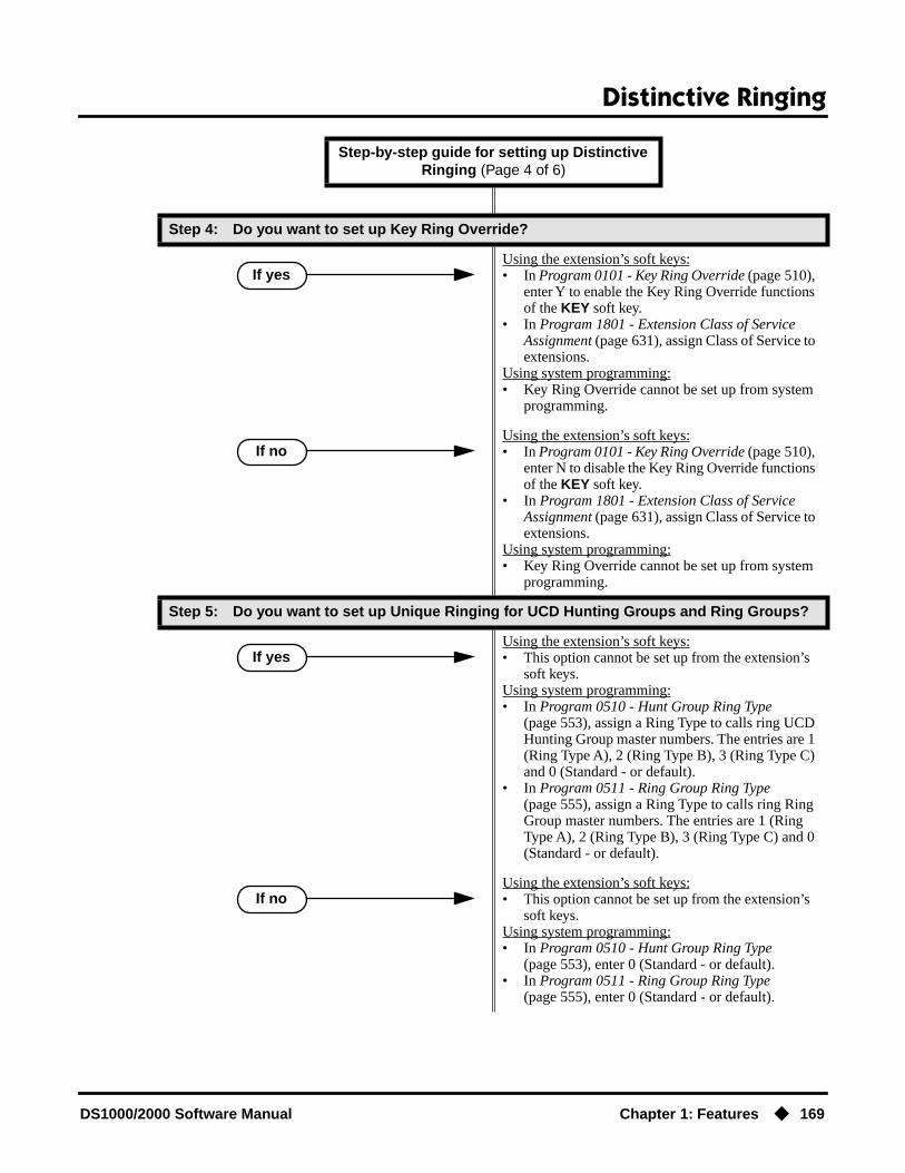
Distinctive Ringing
DS1000/2000 Software Manual Chapter 1: Features ◆ 169
Step 4: Do you want to set up Key Ring Override?
Using the extension’s soft keys:• In Program 0101 - Key Ring Override (page 510),
enter Y to enable the Key Ring Override functions of the KEY soft key.
• In Program 1801 - Extension Class of Service Assignment (page 631), assign Class of Service to extensions.
Using system programming:• Key Ring Override cannot be set up from system
programming.
Using the extension’s soft keys:• In Program 0101 - Key Ring Override (page 510),
enter N to disable the Key Ring Override functions of the KEY soft key.
• In Program 1801 - Extension Class of Service Assignment (page 631), assign Class of Service to extensions.
Using system programming:• Key Ring Override cannot be set up from system
programming.
Step 5: Do you want to set up Unique Ringing for UCD Hunting Groups and Ring Groups?
Using the extension’s soft keys:• This option cannot be set up from the extension’s
soft keys.Using system programming:• In Program 0510 - Hunt Group Ring Type
(page 553), assign a Ring Type to calls ring UCD Hunting Group master numbers. The entries are 1 (Ring Type A), 2 (Ring Type B), 3 (Ring Type C) and 0 (Standard - or default).
• In Program 0511 - Ring Group Ring Type (page 555), assign a Ring Type to calls ring Ring Group master numbers. The entries are 1 (Ring Type A), 2 (Ring Type B), 3 (Ring Type C) and 0 (Standard - or default).
Using the extension’s soft keys:• This option cannot be set up from the extension’s
soft keys.Using system programming:• In Program 0510 - Hunt Group Ring Type
(page 553), enter 0 (Standard - or default).• In Program 0511 - Ring Group Ring Type
(page 555), enter 0 (Standard - or default).
Step-by-step guide for setting up Distinctive Ringing (Page 4 of 6)
If yes
If no
If yes
If no
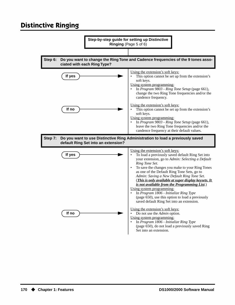
Distinctive Ringing
170 ◆ Chapter 1: Features DS1000/2000 Software Manual
Step 6: Do you want to change the Ring Tone and Cadence frequencies of the 9 tones asso-ciated with each Ring Type?
Using the extension’s soft keys:• This option cannot be set up from the extension’s
soft keys.Using system programming:• In Program 9803 - Ring Tone Setup (page 661),
change the two Ring Tone frequencies and/or the candence frequency.
Using the extension’s soft keys:• This option cannot be set up from the extension’s
soft keys.Using system programming:• In Program 9803 - Ring Tone Setup (page 661),
leave the two Ring Tone frequencies and/or the candence frequency at their default values.
Step 7: Do you want to use Distinctive Ring Administration to load a previously saved default Ring Set into an extension?
Using the extension’s soft keys:• To load a previously saved default Ring Set into
your extension, go to Admin: Selecting a Default Ring Tone Set.
• To save the changes you make to your Ring Tones as one of the Default Ring Tone Sets, go to Admin: Saving a New Default Ring Tone Set. (This is only available at super display keysets. It is not available from the Programming List.)
Using system programming:• In Program 1806 - Initialize Ring Type
(page 650), use this option to load a previously saved default Ring Set into an extension.
Using the extension’s soft keys:• Do not use the Admin option.Using system programming:• In Program 1806 - Initialize Ring Type
(page 650), do not load a previously saved Ring Set into an extension.
Step-by-step guide for setting up Distinctive Ringing (Page 5 of 6)
If yes
If no
If yes
If no
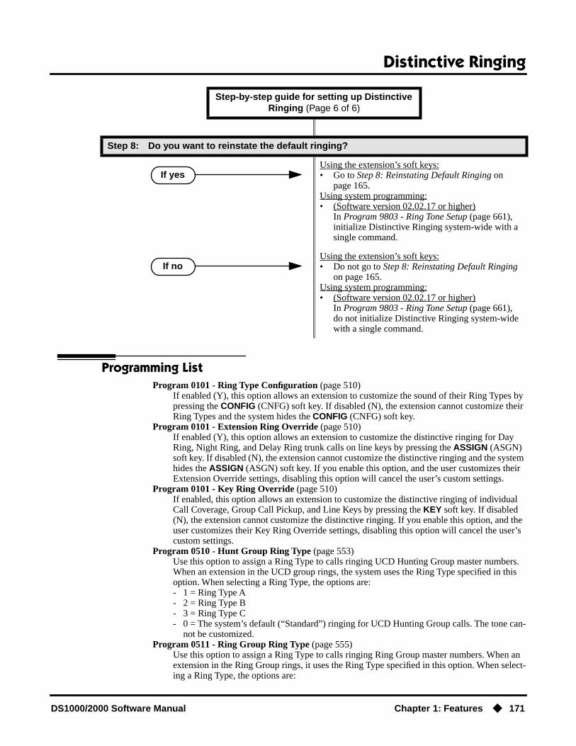
Distinctive Ringing
DS1000/2000 Software Manual Chapter 1: Features ◆ 171
Programming ListProgram 0101 - Ring Type Configuration (page 510)
If enabled (Y), this option allows an extension to customize the sound of their Ring Types by pressing the CONFIG (CNFG) soft key. If disabled (N), the extension cannot customize their Ring Types and the system hides the CONFIG (CNFG) soft key.
Program 0101 - Extension Ring Override (page 510)If enabled (Y), this option allows an extension to customize the distinctive ringing for Day Ring, Night Ring, and Delay Ring trunk calls on line keys by pressing the ASSIGN (ASGN) soft key. If disabled (N), the extension cannot customize the distinctive ringing and the system hides the ASSIGN (ASGN) soft key. If you enable this option, and the user customizes their Extension Override settings, disabling this option will cancel the user’s custom settings.
Program 0101 - Key Ring Override (page 510)If enabled, this option allows an extension to customize the distinctive ringing of individual Call Coverage, Group Call Pickup, and Line Keys by pressing the KEY soft key. If disabled (N), the extension cannot customize the distinctive ringing. If you enable this option, and the user customizes their Key Ring Override settings, disabling this option will cancel the user’s custom settings.
Program 0510 - Hunt Group Ring Type (page 553)Use this option to assign a Ring Type to calls ringing UCD Hunting Group master numbers. When an extension in the UCD group rings, the system uses the Ring Type specified in this option. When selecting a Ring Type, the options are:- 1 = Ring Type A- 2 = Ring Type B- 3 = Ring Type C- 0 = The system’s default (“Standard”) ringing for UCD Hunting Group calls. The tone can-
not be customized.Program 0511 - Ring Group Ring Type (page 555)
Use this option to assign a Ring Type to calls ringing Ring Group master numbers. When an extension in the Ring Group rings, it uses the Ring Type specified in this option. When select-ing a Ring Type, the options are:
Step 8: Do you want to reinstate the default ringing?
Using the extension’s soft keys:• Go to Step 8: Reinstating Default Ringing on
page 165.Using system programming:• (Software version 02.02.17 or higher)
In Program 9803 - Ring Tone Setup (page 661), initialize Distinctive Ringing system-wide with a single command.
Using the extension’s soft keys:• Do not go to Step 8: Reinstating Default Ringing
on page 165.Using system programming:• (Software version 02.02.17 or higher)
In Program 9803 - Ring Tone Setup (page 661), do not initialize Distinctive Ringing system-wide with a single command.
Step-by-step guide for setting up Distinctive Ringing (Page 6 of 6)
If yes
If no

Distinctive Ringing
172 ◆ Chapter 1: Features DS1000/2000 Software Manual
- 1 = Ring Type A- 2 = Ring Type B- 3 = Ring Type C- 0 = The system’s default (“Standard”) ringing for Ring Group calls. The tone cannot be
customized. This is the default setting for this option.Program 1003 - Day Ring Type (page 594)
Use this option to assign a Ring Type for the trunk’s Day Ringing. When the trunk rings an extension in the Day Ring mode, it uses the Ring Type specified in this option. When selecting a Ring Type, the options are:- 1 = Ring Type A (This is the default setting.)- 2 = Ring Type B- 3 = Ring Type C.
Program 1003 - Night Ring Type (page 594)Use this option to assign a Ring Type for the trunk’s Night Ringing. When the trunk rings an extension in the Night Ring mode, it uses the Ring Type specified in this option. When select-ing a Ring Type, the options are:- 1 = Ring Type A (This is the default setting.)- 2 = Ring Type B- 3 = Ring Type C
Program 1003 - Delay Ring Type (page 595)Use this option to assign a Ring Type for the trunk’s Delay Ringing. When the trunk rings an extension in the Delay Ring mode, it uses the Ring Type specified in this option. When select-ing a Ring Type, the options are:- 1 = Ring Type A (This is the default setting.)- 2 = Ring Type B- 3 = Ring Type C
Program 1801 - Extension Class of Service Assignment (page 631)Assign Class of Service to extensions.
Program 1806 - Day Ring Type (page 649)Use this option to set the Extension Override Ring Type option for “Day Ring” trunks ringing the extension. This is the same as following the ASSIGN (ASGN) soft key. If 1003 - Day Ring Type (page 594) is 0 (Standard Group), the setting you make in this option will take effect. If 1003 - Day Ring Type (page 594) is 1-3, the setting you make in this option will only take effect if 0101 - Extension Ring Override (page 510) is also enabled (Y). The entry options are:- 1 = Ring Type A- 2 = Ring Type B- 3 = Ring Type C- 0 = LINE (follows the setting for the trunk in 1003). This is the default setting.
Program 1806 - Night Ring Type (page 650)Use this option to set the Extension Override Ring Type option for “Night Ring” trunks ring-ing the extension. This is the same as following the ASSIGN (ASGN) soft key. If 1003 - Night Ring Type (page 594) is 0 (Standard Group), the setting you make in this option will take effect. If 1003 - Night Ring Type (page 594) is 1-3, the setting you make in this option will only take effect if 0101 - Extension Ring Override (page 510) is also enabled (Y). The entry options are:- 1 = Ring Type A- 2 = Ring Type B- 3 = Ring Type C- 0 = LINE (follows the setting for the trunk in 1003). This is the default setting.
Program 1806 - Delay Ring Type (page 650)Use this option to set the Extension Override Ring Type option for “Delay Ring” trunks ring-ing the extension. This is the same as following the ASSIGN (ASGN) soft key. If 1003 - Delay Ring Type (page 595) is 0 (Standard Group), the setting you make in this option will take effect. If 1003 - Delay Ring Type (page 595) is 1-3, the setting you make in this option will only take effect if 0101 - Extension Ring Override (page 510) is also enabled (Y). The entry options are:- 1 = Ring Type A

Distinctive Ringing
DS1000/2000 Software Manual Chapter 1: Features ◆ 173
- 2 = Ring Type B- 3 = Ring Type C- 0 = LINE (follows the setting for the trunk in 1003). This is the default setting.
Program 1806 - Initialize Ring Type (page 650)If you used the CONFIG soft key to save a Ring Set as a system default, use this option to load the saved set into an extension. Use this program as an alternative to going to each extension and using the following to select a default Ring Set:Super Display: PROGRAM + RING + CONFIG + DEFAULT OR22-Button or 34-Button Display: PGM + RING + CNFG + MORE + MORE + DFLT
Program 9803 - Ring Tone Setup (page 661)
● Use 9803 - Ring Tone Setup to customize the 9 tones associated with each Ring Type.
● (Software version 02.02.17 or higher)You can also use 9803 - Ring Tone Setup to initialize Distinctive Ringing system-wide with a single command. You must initialize Distinctive Ringing if upgrading from a sys-tem software version prior to version 02.02.14. Following initialization, you must reset the system or unplug and then replug each telephone.
Other Related FeaturesCall Coverage Keys (page 62)
By using Key Ring Override, Distinctive Ringing allows an extension user to set up unique ringing for their Call Coverage keys.
Group Call Pickup (page 215)By using Key Ring Override, Distinctive Ringing allows an extension user to set up unique ringing for their Group Call Pickup keys.
Line Keys (page 279)By using Key Ring Override, Distinctive Ringing allows an extension user to set up unique ringing for their line keys.
Feature Operation
Soft Key Programming for 22-Button and 34-Button Display Telephones
Distinctive Ring Configuration
To customize a Ring Set for your extension (if allowed by your extension’s Class of Service):
1. From the idle state, press PGM. You see:
2. Press RING. You see:

Distinctive Ringing
174 ◆ Chapter 1: Features DS1000/2000 Software Manual
3. Press CNFG. You see:
If you press MORE, you see:
If you press MORE again, you see:
From the choices above:- Press ICM to change the Intercom Ring Type.- Press RGRP to change the Ring Group Ring Type.- Press RCL to change the Recall Ring Type.- Press “A” to change the Type A Ring Type.- Press “B” to change the Type B Ring Type.- Press “C” to change the Type C Ring Type.- Press DFLT to select another default Ring Set (1-3) and cancel your custom settings.
4. When you select a Ring Type to configure, you hear the current selection for the Ring Type selected and you see the type number displayed (Intercom Ring Type shown):
- Press TONE to select a new Ring Tone (0-9).- Press CDNC to select a new Cadence (0-9).- Press CNCL to cancel your selection and return to the previous step.- Press SAVE to save the current selection and return to the previous step.- Press the SPK key to exit.
5. To change the Ring Tone or Cadence (Ring Tone screen shown below):
- Dial 0-9 to select a new Ring Tone or Cadence for the selected Ring Type. (You’ll hear the ringing change after you enter your selection.)- Press CNCL to cancel your selection and return to the previous step.- Press OK to accept your selection and return to the previous step.
Extension Override
To customize ringing for your extension’s outside calls (if allowed by your exten-

Distinctive Ringing
DS1000/2000 Software Manual Chapter 1: Features ◆ 175
sion’s Class of Service):
1. From idle, press PGM. You see:
2. Press RING. You see:
3. To change Extension Override ringing, press ASGN. You see:
4. Select the ringing mode you want to change (day, night, or delay). You see (example shown if you select day ringing):
If you press MORE, you see:
- Select a Ring Type option (A, B or C), or- Select LINE to have ringing follow trunk ring programming (set up in Program 1003).
Key Ring Override
To assign a Ring Type to an individual Call Coverage, Group Call Pickup, or Line Key (if allowed by your extension’s Class of Service):
1. From your idle display, press PGM + RING + KEY. You see:
2. Select the type of key you want to program (e.g., Call Coverage, Group Call Pickup, or Line).- After your selection, the keys of the chosen type will illuminate.
3. Press the individual key you want to program.- The Ring Type you choose in the next step will be assigned to the key you press in this step.
4. After you press a key, you see (example for Line Key 01 shown below):

Distinctive Ringing
176 ◆ Chapter 1: Features DS1000/2000 Software Manual
- Dial 1 to select Ring Type A.- Dial 2 to select Ring Type B.- Dial 3 to select Ring Type C.- Dial 0 to select Standard (i.e., normal ringing for this type of call).- You can also optionally set up ringing (just like using the #RAC, #RAP, and #RAL User-Programming Feature steps).
5. Press another key to program, or press the SPK key to exit.

Distinctive Ringing
DS1000/2000 Software Manual Chapter 1: Features ◆ 177
Admin: Selecting a Default Ring Tone Set
To select one of the default Ring Tone Sets for your phone:
1. From your idle display, press PGM + RING + CNFG + MORE (twice) + DFLT. You see:
2. Select the default Ring Tone set you want to use.(By default, all extensions use Ring Tone Set 1.
3. When you see Are You Sure? (Y/N):- Dial 9 (for yes) to confirm your selection, or- Dial 6 (for no) to exit without making a selection.
4. Press PREVIOUS to return to the previous screen or the SPK key to exit.
Soft Key Programming for Super Display Telephones
Distinctive Ring Configuration
To customize a Ring Set for your extension (if allowed by your extension’s Class of Service):
1. From idle, press PROGRAM. You see:
2. Press RING. You see:

Distinctive Ringing
178 ◆ Chapter 1: Features DS1000/2000 Software Manual
3. Press CONFIG. You see:
From the choices above:- Press INTERCOM to change the Intercom Ring Type.- Press RING GROUP to change the Ring Group Ring Type.- Press RECALL to change the Recall Ring Type.- Press RING ’A’ to change the Type A Ring Type.- Press RING ‘B’ to change the Type B Ring Type.- Press RING ‘C’ to change the Type C Ring Type.- Press DEFAULT to select another default Ring Set (1-3) and cancel your custom settings.
4. When you select a Ring Type to configure, you hear the current selection for the Ring Type selected and you see (Intercom Ring Type shown):
- Press RING TONE to select a new Ring Tone (0-9).- Press CADENCE to select a new Cadence (0-9).- Press CANCEL to cancel your selection and return to the previous step.- Press SAVE to save the current selection and return to the previous step.- Press the SPK key to exit.
5. To change the Ring Tone or Cadence (Ring Tone screen shown below):
- Dial 0-9 to select a new Ring Tone or Cadence for the selected Ring Type. (You’ll hear the ringing change after you enter your selection.)- Press CANCEL to cancel your selection and return to the previous step.- Press OK to accept your selection and return to the previous step.

Distinctive Ringing
DS1000/2000 Software Manual Chapter 1: Features ◆ 179
Extension Override
To customize ringing for your extension’s outside calls (if allowed by your exten-sion’s Class of Service):
1. Press PROGRAM. You see:
2. Press RING. You see:
3. To change Extension Override ringing, press ASSIGN. You see:
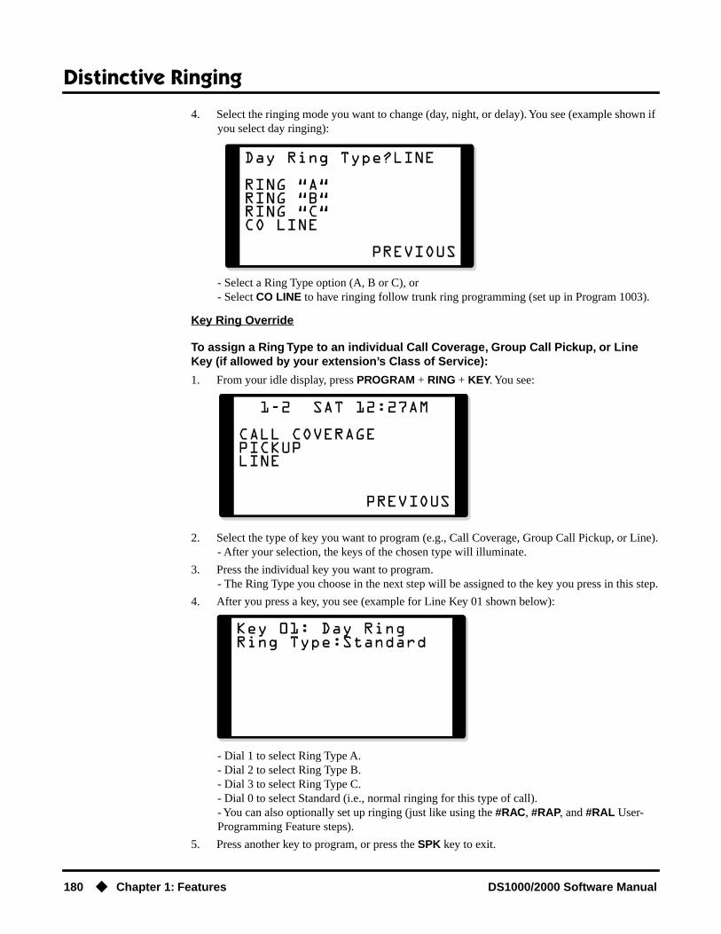
Distinctive Ringing
180 ◆ Chapter 1: Features DS1000/2000 Software Manual
4. Select the ringing mode you want to change (day, night, or delay). You see (example shown if you select day ringing):
- Select a Ring Type option (A, B or C), or- Select CO LINE to have ringing follow trunk ring programming (set up in Program 1003).
Key Ring Override
To assign a Ring Type to an individual Call Coverage, Group Call Pickup, or Line Key (if allowed by your extension’s Class of Service):
1. From your idle display, press PROGRAM + RING + KEY. You see:
2. Select the type of key you want to program (e.g., Call Coverage, Group Call Pickup, or Line).- After your selection, the keys of the chosen type will illuminate.
3. Press the individual key you want to program.- The Ring Type you choose in the next step will be assigned to the key you press in this step.
4. After you press a key, you see (example for Line Key 01 shown below):
- Dial 1 to select Ring Type A.- Dial 2 to select Ring Type B.- Dial 3 to select Ring Type C.- Dial 0 to select Standard (i.e., normal ringing for this type of call).- You can also optionally set up ringing (just like using the #RAC, #RAP, and #RAL User-Programming Feature steps).
5. Press another key to program, or press the SPK key to exit.
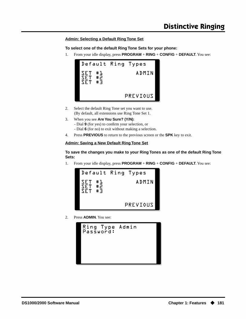
Distinctive Ringing
DS1000/2000 Software Manual Chapter 1: Features ◆ 181
Admin: Selecting a Default Ring Tone Set
To select one of the default Ring Tone Sets for your phone:
1. From your idle display, press PROGRAM + RING + CONFIG + DEFAULT. You see:
2. Select the default Ring Tone set you want to use.(By default, all extensions use Ring Tone Set 1.
3. When you see Are You Sure? (Y/N):- Dial 9 (for yes) to confirm your selection, or- Dial 6 (for no) to exit without making a selection.
4. Press PREVIOUS to return to the previous screen or the SPK key to exit.
Admin: Saving a New Default Ring Tone Set
To save the changes you make to your Ring Tones as one of the default Ring Tone Sets:
1. From your idle display, press PROGRAM + RING + CONFIG + DEFAULT. You see:
2. Press ADMIN. You see:

Distinctive Ringing
182 ◆ Chapter 1: Features DS1000/2000 Software Manual
3. Enter the System Administrator 1 (0000), System Administrator 2 (9999), or Installer (372000) password. You see:
4. Enter the number of the default Ring Set (1-3) to which you want to save your phone’s config-uration.
5. When you see Are You Sure? (Y/N):- Dial 9 (for yes) to confirm your selection, or- Dial 6 (for no) to exit without making a selection.
6. Press the SPK key to return step 2.

Do Not Disturb
DS1000/2000 Software Manual Chapter 1: Features ◆ 183
Do Not Disturb
Description
Do Not Disturb (DND) blocks incoming calls, Off-Hook Signaling and Paging announcements. An extension user can activate DND anytime while on a call or while their phone is idle. Once acti-vated, incoming trunk calls still flash the line keys. The user may use the phone in the normal man-ner for placing and processing calls.
ConditionsA system reset or power failure cancels DND.
Default SettingDo Not Disturb enabled.
Programming Guide
Programming ListProgram 1802 - Do Not Disturb (page 635)
Enter Y to enable Do Not Disturb at the extension.
Other Related FeaturesAttendant Position (page 47)
The attendant can have Do Not Disturb. In addition, pressing DND at the attendant actives the night mode for any trunks directly terminated to the attendant.
DS2000 Fixed Slot
Available.DS2000 U Slot
DS1000
DND permits an extension user to work by the phone undisturbed by incoming calls and announcements.
Step-by-step guide for setting up Do Not Disturb
Step 1: Should an extension be allowed to enable Do Not Disturb?
• In Program 1802 - Do Not Disturb (page 635), enter Y to enable Do Not Disturb.
• In Program 1802 - Do Not Disturb (page 635), enter N to disable Do Not Disturb.
If yes
If no

Do Not Disturb
184 ◆ Chapter 1: Features DS1000/2000 Software Manual
Background Music (page 55)DND does not affect the operation of Background Music.
Call Forwarding (page 66)Call Forwarding considers an extension in DND as busy. In addition, an extension can have both DND and Call Forwarding enabled at the same time.
Call Waiting / Camp-On (page 75)An extension cannot Camp-On to a busy co-worker that is in Do Not Disturb.
Callback (page 79)An extension cannot leave a Callback for a busy co-worker that is in Do Not Disturb.
Night Service / Night Ring (page 308)The attendant presses DND to put the system in the night mode.
Extension Hunting (page 193)Placing an agent in DND temporarily removes it from the UCD group.
Hotline (page 240)An extension user can press their Hotline key twice to override their Hotline partner’s DND.
Message Waiting (page 291)An extension user can leave a Message Waiting at an extension in Do Not Disturb.
Night Service / Night Ring (page 308)A DIL destination activates the night mode for the DIL when they press DND.
Off-Premise Extensions / On-Premise SLT Extensions (page 317)On- and Off-Premise extensions cannot use DND.
Paging (page 326)DND blocks Paging announcements.
Reverse Voice Over (page 364)DND does not block Reverse Voice Over.
Transfer (page 455)DND blocks Transfer.
Feature Operation
To activate DND at your extension:
You can activate DND anytime while idle or on a call.
1. Press DND.
To cancel Do Not Disturb:
1. Press DND.
N/A
DND flashes fast.
N/A
DND flashes fast.
N/A
DND goes out.

Door Box
DS1000/2000 Software Manual Chapter 1: Features ◆ 185
Door Box
Description
The Door Box is a self-contained Intercom unit typically used to monitor an entrance door. A visi-tor at the door can press the Door Box call button (like a door bell). The Door Box then sends chime tones to all extensions programmed to receive chimes. To answer the chime, the called extension user just lifts the handset. This lets the extension user talk to the visitor at the Door Box. The Door Box is convenient to have at a delivery entrance, for example. It is not necessary to have company personnel monitor the delivery entrance; they just answer the Door Box chimes instead.
There are two types of Door Boxes: Analog Door Box P/N 92245 and Digital Door Box P/N 80560. Both Door Boxes operate identically. There are, however, some differences:
● The Digital Door Box connects to a digital station port (300-395 in DS2000 or 300-315 in DS1000).The number of Digital Door Boxes you can install may be liminted by the System Load Factor. Turn to DS2000 Load Factor on page 3 and DS1000 Load Factor on page 9 for more.
● The Analog Door Box connects to one of the dedicated DS1000 Door Box ports (i.e., DOOR1 or DOOR2).
● The Analog Door Box is not available in DS2000.
● The Analog Door Box can be mounted outside. Refer to Section 4, Optional Equipment in the Hardware Manual on the DS1000 System Document CD for more.
The system uses Ring Groups to control Door Box chimes. When a visitor at the door presses the Door Box call button, the Door Box will alert (chime) all the extensions in the Ring Group to which the Door Box belongs. For example, if the Door Box and extensions 301 and 302 are in Ring Group 1, pressing the call button alerts 301 and 302.
Any keyset extension that receives Door Box chimes can control a system relay, which in turn typi-cally enables an electric strike on an entrance door next to a Door Box. After answering the Door Box chimes, the extension user can press FLASH or a soft key to enable the associated relay. The visitor at the door can then enter without having an employee open the entrance for them. In DS2000, there is a single relay on the CPRU PCB. DS1000 has 2 relays, located in the DOOR1 and DOOR2 Analog Door Box jacks. In either system, you can assign these relays for Door Box strike control or Page Relay Control, but not both. (In DS1000, Digital Door Boxes cannot control system relays.)
DS2000 Fixed Slot Not available.
DS2000 U Slot Digital Door Boxes are available. Analog Door Boxes are not available. Addi-tional relay control options added in 02.00.04.
DS1000 Both Digital and Analog Door Boxes are available. The Expansion Board is required for the second Analog Door Box and relay.
Use a Door Box to remotely monitor an entrance door.

Door Box
186 ◆ Chapter 1: Features DS1000/2000 Software Manual
The equipment you connect to a system relay must be compatible with the following specifications. Refer to your system’s Hardware Manual for more on connecting to the system relay contacts.
Conditions
● The Digital Door Box is a weather-tight unit, with an operating temperature range of 0 to 45 degrees C (32 to 113 degrees F) and a relative humidity of 10-95%, non-condensing. It is not intended for outdoor installation.
● The Analog Door Box is also a weather-tight unit, and can be mounted outside. It has an operat-ing temperature range of -20 to 60 degrees C (-4 to 140 degrees F) and a relative humidity of 10-95%, non-condensing.
Default Setting
● No Digital Door Boxes enabled.
● In DS1000, Analog Door Boxes are automatically set up at extensions 324 (DOOR1) and 325 (DOOR 2).
Programming Guide
Table 6: Relay Contact Specifications
DS1000
Contact Configuration: Normally open
Maximum Load: 0.5A @ 120 VAC1A @ 24 VDC
Maximum Initial Contact Resistance 100 mOhms
D2000
Contact Configuration: Normally open
Maximum Load: 60 mA @ 30 VDC10 mA @ 90 VDC
Maximum Initial Contact Resistance 50 mOhms
Step-by-step guide for setting up Door Box (Page 1 of 3)
Step 1: At the Door Box extension, assign the Door Box circuit type (required for Digital Door Boxes only).
• In Program 1801 - Extension Circuit Type (page 629), enter 10 to assign the extension as a Door Box.
• In DS1000, Analog Door Boxes are automatically enabled at extensions 324 (DOOR1) and 325 (DOOR2).

Door Box
DS1000/2000 Software Manual Chapter 1: Features ◆ 187
Step 2: At the Door Box extension, assign the Door Box chime pattern (i.e., how the Door Box alerts other extensions).
• In Program 1801 - Door Chime (page 630), assign the chime pattern to the Door Box:0 = Normal Ring Group ringing1 = Low pitch chime pattern2 = Mid range pitch chime pattern3 = High pitch chime pattern
Step 3: Set up the Door Box Ring Group. (Pressing the Door Box call button chimes all extensions in the Door Box Ring Group.)
• In Program 0511 - Ring Group Master Extension Numbers and Names (page 555), assign a Ring Group master number to the Ring Group assigned as the Door Box Ring Group.
• In Program 1802 - Ring Group Number (page 635), assign the Door Box and the exten-sions that should alert to the same Ring Group.
Step 4: In DS2000, after answering a Door Box call, should an extension be able to remotely release the door strike (via the CPRU relay)?
• In Program 1801 - Relay Owner (page 630), for the Door Box extension enter 1 to assign the CPRU PCB relay to the Door Box.
• In Program 0201 - CPRU Relay (page 515), enter 1 to assign the CPRU relay for Door Box control.
• In Program 1801 - Relay Owner (page 630), enter 0 to disable the CPRU PCB relay for Door Box calls.
Step 5: In DS1000, after answering an Analog Door Box call, should an extension be able to remotely release the door strike (via the DOOR1 or DOOR2 relays)?
• In Program 1801 - Relay Owner (page 630), for the Analog Door Box extension, assign the DOOR1 or DOOR2 relays.- If programming extension 324 (DOOR1), enter 1.- If programming extension 325 (DOOR2), enter 2.This option does not apply to Digital Door Boxes in DS1000.
• In Program 0201 - DOOR1 Relay (page 515), enter 1 to assign the DOOR1 relay for Analog Door Box control (extension 324). ORIn Program 0201 - DOOR2 Relay (page 515), enter 1 to assign the DOOR2 relay for Analog Door Box control (extension 324).
Step-by-step guide for setting up Door Box (Page 2 of 3)
If yes
If no
If yes

Door Box
188 ◆ Chapter 1: Features DS1000/2000 Software Manual
Programming ListProgram 0201 - CPRU Relay (page 515)
DS2000 OnlyEnter 1 to assign the CPRU relay for Door Box control.
Program 0201 - DOOR1 Relay (page 515)DS1000 OnlyEnter 1 to assign the DOOR1 relay for Analog Door Box control (extension 324).
Program 0201 - DOOR2 Relay (page 515)DS1000 OnlyEnter 1 to assign the DOOR2 relay for Analog Door Box control (extension 325).
Program 0401 - Door Unlock (page 523)Enter the interval that the relay should remain closed after a keyset user activates (closes) the relay. After this interval, the relay automatically returns to its idle (open) state.
Program 0511 - Ring Group Master Extension Numbers and Names (page 555)Assign a Ring Group master number to the Ring Group assigned as the Door Box Ring Group.
Program 1801 - Extension Circuit Type (page 629)Enter 10 to assign the extension as a Door Box.
Program 1801 - Door Chime (page 630)For a Door Box extension, enter the Door Chime type (0=normal Ring Group ringing, 1=low pitch chime pattern, 2=mid range pitch chime pattern, 3=high pitch chime pattern).
Program 1801 - Relay Owner (page 630)DS2000 OnlyFor the Door Box extension, enter 1 to assign the CPRU PCB relay to the Door Box. Enter 0 to disable the CPRU PCB relay for Door Box calls.DS1000 OnlyFor the Analog Door Box extensions, use this option to assign the DOOR1 or DOOR2 relays.- When programming extension 324 (DOOR1), enter 1.- When programming extension 325 (DOOR2), enter 2.This option does not apply to Digital Door Boxes in DS1000.
Program 1802 - Ring Group Number (page 635)Assign the Door Box and the extensions that should alert to the same Ring Group.
• In Program 1801 - Relay Owner (page 630), enter 0 to disable the CPRU PCB relay for Door Box calls.
Step 6: When an extension user activates (closes) the relay, does it stay closed for the proper interval?
• In Program 0401 - Door Unlock (page 523), do not change the Door Unlock interval.
• In Program 0401 - Door Unlock (page 523), change the Door Unlock interval to meet the site requirements. After user activation, the relay remains closed for the Door Unlock interval. After the interval expires, the relay returns to its idle (open) state.
Step-by-step guide for setting up Door Box (Page 3 of 3)
If no
If yes
If no

Door Box
DS1000/2000 Software Manual Chapter 1: Features ◆ 189
Other Related FeaturesCall Coverage Keys (page 62)
If you enter Door Chime type 0 (normal ring) above, you can set up Call Coverage keys for the Door Box Ring Group. This allows extensions that are not members of the Ring Group to answer Door Box calls. Extensions with Call Coverage keys to the Door Box Ring Group can also activate the relay.
Hotline (page 240)An extension user can have Hotline keys for Door Boxes.
Message Waiting (page 291)An extension user cannot leave a Message Waiting at a Door Box.
Off-Hook Signaling (page 313)A Door Box can automatically send off-hook signals to the assigned extension.
Off-Premise Extensions / On-Premise SLT Extensions (page 317)Single line telephones can only receive Door Chime type 0 (normal ring). While connected to the Door Box, an SLT can hookflash to control the system relay.
Feature Operation
To place a call from the Door Box:
1. Press the Door Box call button.
2. When someone inside the building answers your call, speak toward the Door Box.
To place a call to the Door Box:
1. Lift handset and press ICM.
2. Dial the Door Box extension number.
To answer the Door Box chimes from a keyset:
1. Lift handset or press SPK.
To control the relay which in turn controls the door strike:
Once set up in programming, this option is available to any member of the Door Box Ring Group as well as any extension with a Call Coverage Key for the Door Box Ring Group.
1. Place call to Door Box.
2. To open the relay, press FLASH key or OPEN soft key.
3. To close the relay, press FLASH key again or CLOSE soft key.
Ringing or chimes.
N/A.
Intercom dial tone.
ICM and SPK on.
Two beeps, then conversation with visitor at door.
ICM and SPK on.
Ringing or chimes.
N/A.

Equal Access Compatibility
190 ◆ Chapter 1: Features DS1000/2000 Software Manual
Equal Access Compatibility
DescriptionDS2000 Fixed Slot
See Toll Restriction (Prior to Software Version 02.02.14) on page 447.DS2000 U Slot
DS1000

Extended Ringing
DS1000/2000 Software Manual Chapter 1: Features ◆ 191
Extended Ringing
Description
Extended Ringing forces an unanswered call to ring a telephone an extended number of times before rerouting. This helps users that cannot get to their phones quickly to pick up calls (such as a warehouse worker). Extended Ringing is available with the following features:
● Direct Inward LineDILs ring for an extended period before routing to the overflow destination.
● TransferTransferred trunks ring for an extended period before recalling the transferring extension.
ConditionsNone
Default SettingDisabled.
Programming Guide
DS2000 Fixed Slot
Available.DS2000 U Slot
DS1000
Lets calls ring longer that usual to assist co-workers that can’t readily get to their phones.
Step-by-step guide for setting up Extended Ringing
Step 1: Should extension have Extended Ringing capability?
• In Program 0101 - Extended Ring (page 507), enter Y to enable Extended Ringing.
• In Program 1801 - Extension Class of Service Assignment (page 631), assign Class of Service to extensions.
• In Program 0101 - Extended Ring (page 507), enter N to disable Extended Ringing.
Step 2: When Extended Ringing is enabled, does the extension ring an adequate number of times before the call reroutes?
• In Program 0403 - Number of Extended Rings (page 534), leave the entry at its current setting.
If yes
If no
If yes
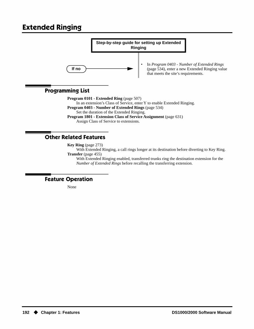
Extended Ringing
192 ◆ Chapter 1: Features DS1000/2000 Software Manual
Programming ListProgram 0101 - Extended Ring (page 507)
In an extension’s Class of Service, enter Y to enable Extended Ringing.Program 0403 - Number of Extended Rings (page 534)
Set the duration of the Extended Ringing.Program 1801 - Extension Class of Service Assignment (page 631)
Assign Class of Service to extensions.
Other Related FeaturesKey Ring (page 273)
With Extended Ringing, a call rings longer at its destination before diverting to Key Ring.Transfer (page 455)
With Extended Ringing enabled, transferred trunks ring the destination extension for the Number of Extended Rings before recalling the transferring extension.
Feature OperationNone
• In Program 0403 - Number of Extended Rings (page 534), enter a new Extended Ringing value that meets the site’s requirements.
Step-by-step guide for setting up Extended Ringing
If no

Extension Hunting
DS1000/2000 Software Manual Chapter 1: Features ◆ 193
Extension Hunting
Description
Extension Hunting routes calls to a predefined group of hunt group member extensions. A call rings in sequence through the hunt group until answered at a member extension. Extension Hunting is helpful, for example, for a group of co-workers that share responsibility for answering calls. Each call cycles through the group until an available member picks it up.
There are three types of Extension Hunting:
● Circular Hunting
● Terminal Hunting
● Uniform Call Distribution (UCD) Hunting
Circular HuntingA Circular Hunting group consists of a group of extensions programmed into a Circular Hunting list. A call unanswered at a member extension rings the next extension in the programmed list. If unanswered, the call will continue to cycle through the hunt group. Depending on the hunt type (see below), Circular Hunting will occur for transferred trunk calls, DILs to a hunt group member, and ringing Intercom calls. Hunting does not occur for Key Ring and Ring Group calls.
There are four types of Circular Hunting:
● Ring No Answer Trunk (Option 1)Hunting will occur for unanswered trunk calls. Hunting will not occur for unanswered ringing Intercom calls or while the member extension is busy.
● Busy/Ring No Answer Trunk (Option 2)Hunting will occur for unanswered trunk calls and for trunk calls to the member extension while it is busy. Hunting will not occur for ringing Intercom calls.
● Busy/Ring No Answer All Calls (Option 3)Hunting will occur for unanswered trunk and ringing Intercom calls, and for trunk and ringing Intercom calls to the member extension while it is busy.
● Busy Trunk (Option 4)Hunting will occur for trunk calls to the member extension while it is busy. Hunting will not occur for unanswered trunk and ringing Intercom calls.
Circular Hunting Notes:● If a call cycles through the entire Circular Hunting group and remains unanswered, it follows
normal recall/routing programming. For example, a transferred call will recall the transferring extension and, if still unanswered, go to Key Ring.
● For type 3 hunting, an Intercom call will stop hunting when it voice-announces. Extension Hunting follows the Handsfree Answerback/Forced Intercom Ringing setup at each extension.
● Placing an extension in DND temporarily removes it from the Circular Hunting group.
DS2000 Fixed Slot Available.
DS2000 U Slot Available. UCD Hunting group members can dial a code to log in and out of their UCD group.DS1000
Automatically route calls to co-workers that work closely together.

Extension Hunting
194 ◆ Chapter 1: Features DS1000/2000 Software Manual
Terminal HuntingA Terminal Hunting group consists of a group of extensions programmed into a Terminal Hunting list. A call unanswered at a member extension rings the next extension in the programmed list. The call will cycle through the group once, until it reaches the last extension in the list. Unlike Circular Hunting, the call will not cycle back to the top of the hunt list. Depending on the hunt type (see below), Terminal Hunting will occur for transferred trunk calls, DILs to a hunt group member, and ringing Intercom calls. Hunting does not occur for Key Ring and Ring Group calls.
Just like Circular Hunting, there are four types of Terminal Hunting:
● Ring No Answer Trunk (Option 1)Hunting will occur for unanswered trunk calls. Hunting will not occur for unanswered ringing Intercom calls or while the member extension is busy.
● Busy/Ring No Answer Trunk (Option 2)Hunting will occur for unanswered trunk calls and for trunk calls to the member extension while it is busy. Hunting will not occur for ringing Intercom calls.
● Busy/Ring No Answer All Calls (Option 3)Hunting will occur for unanswered trunk and ringing Intercom calls, and for trunk and ringing Intercom calls to the member extension while it is busy.
● Busy Trunk (Option 4)Hunting will occur for trunk calls to the member extension while it is busy. Hunting will not occur for unanswered trunk and ringing Intercom calls.
Terminal Hunting Notes:● If a call cycles through the entire Terminal Hunting group and remains unanswered, it follows
normal recall/routing programming. For example, a transferred call will recall the transferring extension and, if still unanswered, go to Key Ring.
● Placing an extension in DND temporarily removes it from the Terminal Hunting group.
● For type 3 hunting, an Intercom call will stop hunting when it voice-announces. Extension Hunting follows the Handsfree Answerback/Forced Intercom Ringing setup at each extension.
Uniform Call Distribution (UCD) HuntingLike Circular and Terminal Hunting, a UCD Hunting group also consists of a group of extensions programmed into a hunt list. The system routes calls into a UCD group according to the frequency of use of the member extensions. The first extension rung is the member that has been idle the long-est. The last extension rung is the member that has been idle the shortest.
Each member of the group is additionally associated with a UCD Master Extension Number. To active UCD hunting, an incoming call must route to the UCD master number. This is done by plac-ing an Intercom call to the master number, transferring a call to the master number or setting up a DIL to the master number. When all members of the UCD Hunting group are busy, the call can route to the programmed UCD Overflow destination.
UCD Hunting Notes:● Unanswered transferred calls and DILs continue to cycle through the UCD group as long as an
agent is available.
● Placing an extension in Do Not Disturb temporarily removes it from the UCD group.
● Intercom calls to the UCD master number always ring the agent extensions.
● You can set up a UCD Group to overflow to Voice Mail. Use Program 0510 - Overflow Destina-tion on page 552 to set up this option. Do not use Program 1003 - Day Overflow Destination on page 593.
● To put DILs to a UCD master number into the night mode, press a uniquely programmed Sys-tem Mode UCD Master Night key. See Night Service / Night Ring (page 308) for more.

Extension Hunting
DS1000/2000 Software Manual Chapter 1: Features ◆ 195
ConditionsNone
Default SettingHunting not set up.
Programming Guide
Step-by-step guide for setting up Circular Hunting
Step 1: Assign the hunt type to each extension in the Circular Hunting group.
• In Program 1807 - Hunt Type (page 653), enter the hunt type for each extension in the hunt group:1 = Ring No Answer Trunk2 = Busy/Ring No Answer Trunk3 = Busy/Ring No Answer All Calls4 = Busy Trunk
Step 2: Set up the hunt destination routing.
• In Program 1807 - Hunt Destination (page 653), set up the circular hunt routing. Each extension should route to the next in the group. In addition, the last extension should route back to the first.
Step 3: Do calls ring each hunt group member for the correct interval (i.e., neither too long nor too short) before routing to the next extension in the group?
• In Program 0401 - Transfer Recall (page 522), leave the entry at its current setting.
• In Program 0401 - Transfer Recall (page 522), change the Transfer Recall interval to meet the site requirements. (This setting also determines how long a trunk call waits at a busy member extension before routing.)
Step 4: Does a DIL to a hunt group member ring for the correct interval (i.e., neither too long nor too short) before routing to the next extension in the group?
• In Program 0401 - DIL No Answer (page 523), leave the entry at its current setting.
• In Program 0401 - DIL No Answer (page 523), change the DIL No Answer interval to meet the site requirements.
If yes
If no
If yes
If no

Extension Hunting
196 ◆ Chapter 1: Features DS1000/2000 Software Manual
Step-by-step guide for setting up Terminal Hunting (Page 1 of 2)
Step 1: Assign the hunt type to each extension (except for the last) in the Terminal Hunting group.
• In Program 1807 - Hunt Type (page 653), enter the hunt type for each extension in the hunt group:1 = Ring No Answer Trunk2 = Busy/Ring No Answer Trunk3 = Busy/Ring No Answer All Calls4 = Busy Trunk
Step 2: Make sure the last extension in the Terminal Hunting group has hunting undefined.
• In Program 1807 - Hunt Type (page 653), press CLEAR for the last extension in the Terminal Hunting group.
Step 3: Set up the hunt destination routing (except for the last extension in the group).
• In Program 1807 - Hunt Destination (page 653), set up the terminal hunt routing. Each extension should route to the next in the group (except for the last — see below).
Step 4: Make sure the last extension in the Terminal Hunting group has no hunt destination.
• In Program 1807 - Hunt Destination (page 653), press CLEAR for the last extension in Terminal Hunting group.
Step 5: Do calls ring each hunt group member for the correct interval (i.e., neither too long nor too short) before routing to the next extension in the group?
• In Program 0401 - Transfer Recall (page 522), leave the entry at its current setting.
• In Program 0401 - Transfer Recall (page 522), change the Transfer Recall interval to meet the site requirements. (This setting also determines how long a trunk call waits at a busy member extension before routing.)
If yes
If no

Extension Hunting
DS1000/2000 Software Manual Chapter 1: Features ◆ 197
Step 6: Does a DIL to a hunt group member ring for the correct interval (i.e., neither too long nor too short) before routing to the next extension in the group?
• In Program 0401 - DIL No Answer (page 523), leave the entry at its current setting.
• In Program 0401 - DIL No Answer (page 523), change the DIL No Answer interval to meet the site requirements.
Step 7: Do you want to set up an extension to overflow to Voice Mail when unanswered, busy or in DND?
• In Program 1807 - Hunt Type (page 653), enter 3.• In Program 1807 - Hunt Destination (page 653),
enter the Voice Mail master number.
• Stop.
Step-by-step guide for setting up Terminal Hunting (Page 2 of 2)
If yes
If no
If yes
If no

Extension Hunting
198 ◆ Chapter 1: Features DS1000/2000 Software Manual
Step-by-step guide for setting up UCD Hunting (Page 1 of 2)
Step 1: Set up the UCD Hunting group master number.
• In Program 0510 - Hunt Group Master Number (page 552), assign the UCD Hunting group mas-ter number.
• UCD Hunting group master numbers can be 100-299, 332-400, or 417-899. They cannot be in the extension (300-395 in DS2000 or 300-325 in DS1000) or trunk (401-448 in DS2000 or 401-406 in DS1000) number range. By default, the system uses codes beginning with 0 for operator access and 9 for trunk/trunk group access.
Step 2: When all extensions in the UCD group are busy, should calls to the UCD group over-flow to an alternate destination?
• In Program 0510 - Overflow Destination (page 552), enter the UCD overflow destination. The destination can be an extension, Ring Group master number or another UCD Hunting group master number.
Step 3: Assign hunt type 05 to each member of the UCD group.
• In Program 1807 - Hunt Type (page 653), make sure each extension in the UCD group has hunt type 05.
Step 4: Make sure each extension in the hunt group has the same master number assign-ment.
• In Program 1807 - Hunt Master Number (page 653), make sure each extension in the same UCD group has the same master number. Refer to Program 0510 - Hunt Group Master Number (page 552) when setting up master numbers.
Step 5: When all UCD group members are busy, do calls queue for the correct interval (i.e., neither too long nor too short) before routing to the overflow destination?
• In Program 0401 - ACD/UCD Overflow (page 524), leave the entry at its current setting.
• In Program 0401 - ACD/UCD Overflow (page 524), change the ACD/UCD Overflow interval to meet the site requirements.
If yes
If no

Extension Hunting
DS1000/2000 Software Manual Chapter 1: Features ◆ 199
Step 6: Do calls ring each idle hunt group member for the correct interval (i.e., neither too long nor too short) before routing to the next extension in the group?
• In Program 0403 - Call Forward Ring No Answer (page 533), leave the entry at its current setting.
• In Program 0403 - Call Forward Ring No Answer (page 533), change the Call Forward Ring No Answer interval to meet the site requirements.
Step 7: Does a DIL to the UCD master ring an idle group member for the correct interval (i.e., neither too long nor too short) before routing to the next extension in the group?
• In Program 0401 - DIL No Answer (page 523), leave the entry at its current setting.
• In Program 0401 - DIL No Answer (page 523), change the DIL No Answer interval to meet the site requirements.
Step-by-step guide for setting up UCD Hunting (Page 2 of 2)
If yes
If no
If yes
If no

Extension Hunting
200 ◆ Chapter 1: Features DS1000/2000 Software Manual
Extension Hunting TimersThe following diagrams show how the system implements various timers when handling Extension Hunting calls.
Transfer to Hunt GroupBusy/Ring No Answer All Calls (Type 3)
Circular and Terminal Hunting
0401 - Transfer Recall
0403 - Call Fwd Ring No Answer
Call rings first member for Transfer Recall time.
Call transferred into hunt group.
In unanswered, call rings the next and succeeding members for the Call Forward Ring No Answer time.
300 In unanswered, call rings extension 300.
0403 - Call Fwd Ring No AnswerIn unanswered at extension 300 for the Call For-ward Ring No Answer time, the call diverts to Key Ring.
Key Ring
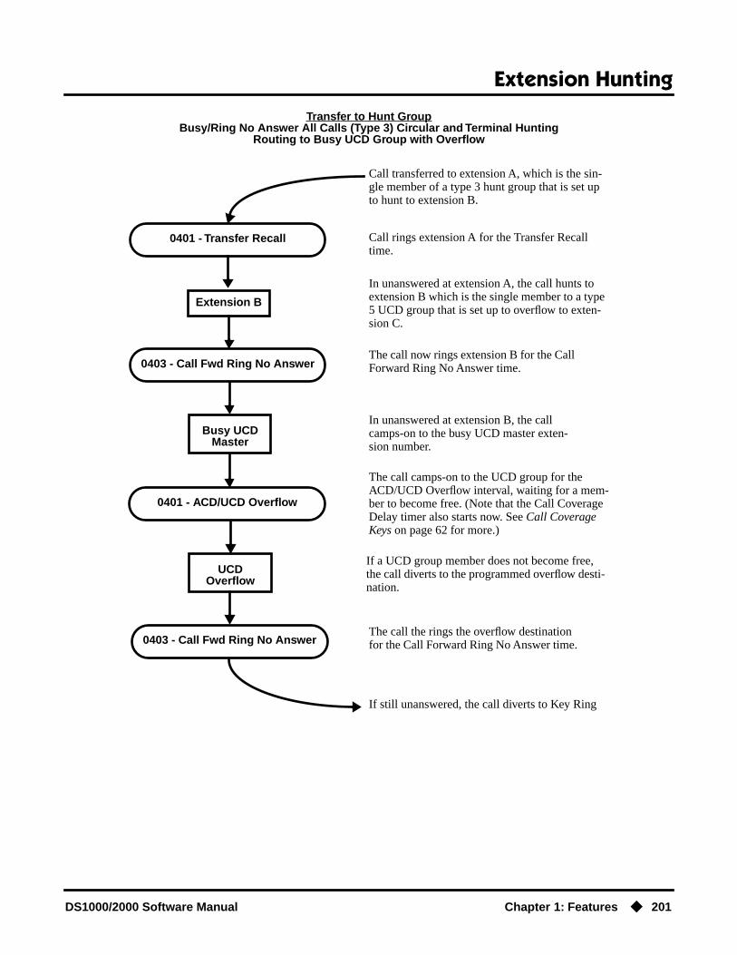
Extension Hunting
DS1000/2000 Software Manual Chapter 1: Features ◆ 201
Transfer to Hunt GroupBusy/Ring No Answer All Calls (Type 3) Circular and Terminal Hunting
Routing to Busy UCD Group with Overflow
0401 - Transfer Recall
0403 - Call Fwd Ring No Answer
Call rings extension A for the Transfer Recall time.
Call transferred to extension A, which is the sin-gle member of a type 3 hunt group that is set up to hunt to extension B.
In unanswered at extension A, the call hunts to extension B which is the single member to a type 5 UCD group that is set up to overflow to exten-sion C.
Extension B
The call now rings extension B for the Call Forward Ring No Answer time.
0403 - Call Fwd Ring No Answer
If a UCD group member does not become free, the call diverts to the programmed overflow desti-nation.
If still unanswered, the call diverts to Key Ring
Busy UCDMaster
In unanswered at extension B, the call camps-on to the busy UCD master exten-sion number.
0401 - ACD/UCD Overflow
The call camps-on to the UCD group for the ACD/UCD Overflow interval, waiting for a mem-ber to become free. (Note that the Call Coverage Delay timer also starts now. See Call Coverage Keys on page 62 for more.)
UCD Overflow
The call the rings the overflow destination for the Call Forward Ring No Answer time.

Extension Hunting
202 ◆ Chapter 1: Features DS1000/2000 Software Manual
DIL (no overflow) to Hunt GroupBusy/Ring No Answer All Calls (Type 3)
Circular and Terminal Hunting
DIL (with overflow) to Hunt GroupBusy/Ring No Answer All Calls (Type 3)
Circular and Terminal Hunting
0401 - DIL No Answer
0401 - DIL No Answer
DIL rings programmed DIL destination for the DIL No Answer time.
DIL (with no overflow) directly rings hunt group member.
In unanswered, call rings the next and succeeding members for the DIL No Answer time.
If still unanswered, call diverts to Key Ring
0401 - DIL No Answer
0401 - DIL No Answer
DIL rings programmed DIL destination for the DIL No Answer time.
DIL (with overflow) directly rings hunt group member.
In unanswered, call rings the next and succeeding members for the DIL No Answer time.
If still unanswered, call diverts to Key Ring
0401 - DIL No AnswerIf unanswered at the last extension, the DIL rings the programmed overflow destination for the DIL No Answer time.

Extension Hunting
DS1000/2000 Software Manual Chapter 1: Features ◆ 203
Trunk Call on Hold at Hunt Group MemberBusy/Ring No Answer All Calls (Type 3)
Circular and Terminal Hunting
Programming List
Circular HuntingProgram 0401 - Transfer Recall (page 522)
Set how long a trunk call waits at a busy member extension. This interval also sets how long a call rings each member extension as it cycles through the group.
Program 0401 - DIL No Answer (page 523)Set how long a DIL rings its destination member extension before cycling through the group.
Program 0403 - Call Forward Ring No Answer (page 533)Set how long a call rings an idle UCD Hunting group member before cycling to the next extension in the group.
Program 1807 - Hunt Type (page 653)Enter the same hunt type for all extensions in the Circular Hunting group. The available hunt types are: 1 (Ring No Answer Trunk), 2 (Busy/Ring No Answer Trunk), 3 (Busy/Ring No Answer All Calls), and 4 (Busy Trunk)
Program 1807 - Hunt Destination (page 653)For each extension, enter the next extension in the hunt group. Be sure the last extension points back to the first extension.
Refer to the table below for a Circular Hunting programming example.
Circular Hunting Programming (for 301, 303 and 304)
1807: Hunt Type Enter the same Hunt Type for all three extensions:1 = Ring No Answer Trunk
2 = Busy/Ring No Answer Trunk3 = Busy/Ring No Answer All Calls
4 = Busy Trunk
1807: Hunt Destination
301 303
303 304
0403 - Hold Recall
0401 - Trunk Revert
If not picked up, trunk call recalls the extension that put it on Hold after the Hold Recall time.
Hunt group member puts trunk call on Hold.
The call then rings the extension that put it on Hold for the Trunk Revert time.
If still unanswered, call diverts to Key Ring

Extension Hunting
204 ◆ Chapter 1: Features DS1000/2000 Software Manual
Terminal Hunting Program 0401 - Transfer Recall (page 522)
Set how long a trunk call waits at a busy member extension. This interval also sets how long a call rings each member extension as it cycles through the group.
Program 0401 - DIL No Answer (page 523)Set how long a DIL rings its destination member extension before cycling through the group.
Program 1807 - Hunt Type (page 653)Enter the same hunt type for all extensions in the Terminal Hunting group, except for the last extension. The last extension should have hunting undefined (by pressing CLEAR).The avail-able hunt types are: 1 (Ring No Answer Trunk), 2 (Busy/Ring No Answer Trunk), 3 (Busy/Ring No Answer All Calls), and 4 (Busy Trunk)
Program 1807 - Hunt Destination (page 653)For each extension except for the last extension, enter the next extension in the hunt group. Be sure the destination for the last extension is undefined (by pressing CLEAR).
Refer to the table below for a Terminal Hunting programming example.
UCD HuntingProgram 0401 - ACD/UCD Overflow (page 524)
This timer sets when UCD overflow occurs. When all UCD agents are busy, a queued call rings for this interval and then overflows to the destination set in Program 0510 - Overflow Destination (page 552).
304 301(This causes hunting to loop back to 301)
0401: Transfer Recall Time This timer sets how long a trunk call waits at a busy member extension. It also sets how long a call rings each member
extension as it cycles through the group.
0401: DIL No Answer Time This timer sets how long a DIL rings its destination member extension before cycling through the group.
Terminal Hunting Programming (for 301 and 303)
1807: Hunt Type Enter the same Hunt Type for all three extensions:1 = Ring No Answer Trunk
2 = Busy/Ring No Answer Trunk3 = Busy/Ring No Answer All Calls
4 = Busy Trunk(Make sure hunting is not defined at 304.)
1807: Hunt Destination
301 303
303 304
304 Press CLEAR to undefine entry.(Hunting stops at 304.)
0401: Transfer Recall Time This timer sets how long a trunk call waits at a busy member extension. It also sets how long a call rings each member
extension as it cycles through the group.
0401: DIL No Answer Time This timer sets how long a DIL rings its destination member extension before cycling through the group.
Circular Hunting Programming (for 301, 303 and 304)

Extension Hunting
DS1000/2000 Software Manual Chapter 1: Features ◆ 205
Program 0510 - Hunt Group Master Number (page 552)Define the master extension number for the UCD hunt group. UCD Hunting group master numbers can be 100-299, 332-400, or 417-899. They cannot be in the extension (300-395 in DS2000 or 300-325 in DS1000) or trunk (401-448 in DS2000 or 401-406 in DS1000) number range. By default, the systems uses codes beginning with 0 for operator access and 9 for trunk/trunk group access.
Program 0510 - Overflow Destination (page 552)Define the overflow destination for the UCD hunt group. When all UCD group members are busy, calls the to master number ring the overflow destination instead.
Program 1807 - Hunt Type (page 653)Enter hunt type 05 for all extensions in the UCD Hunting group.
Program 1807 - Hunt Destination (page 653)For each extension in the UCD Hunting group, enter the master number defined in Program 0510 - Hunt Group Master Number (page 552).
Refer to the table below for a UCD Hunting programming example.
Other Related FeaturesCall Coverage Keys (page 62)
A keyset can have Call Coverage keys for UCD Group master numbers.Call Forwarding (page 66)
If a member of a Circular or Terminal Hunting group forwards their calls, hunting will follow Call Forwarding. If a member of a UCD Hunting group forwards their calls, calls to the exten-sion follow forwarding but calls to the UCD master number do not.
Direct Inward Line (page 133)DILs to a Circular or Terminal Hunting group member initiate hunting. In addition, DILs to a UCD master number ring the UCD group directly. To put DILs to a UCD master number into the night mode, press a uniquely programmed System Mode UCD Master Night key. See Night Service / Night Ring (page 308) for more.
Directory Dialing (page 158)Intercom Directory Dialing will show UCD Group names.
Do Not Disturb (page 183)Placing an agent in DND temporarily removes it from the UCD group.
Flexible Numbering Plan (page 209)UCD Hunting group master numbers can be 100-299, 332-400, or 417-899. They cannot be in the extension (300-395 in DS2000 or 300-325 in DS1000) or trunk (401-448 in DS2000 or 401-406 in DS1000) number range. By default, the systems uses codes beginning with 0 for operator access and 9 for trunk/trunk group access.
Group Ring (page 221)Group Ring calls do not activate hunting.
UCD Hunting Programming (for 301, 303 and 304 with master 750)
0510: Hunt Group Master Number
Select UCD Group 2 and assign master number 750.
0510: UCD Overflow Destina-tion
Enter 305
1807: Hunt Type Enter the Hunt Type 5 for all three extensions.
1807: Hunt Master Number Enter 750 for all three extensions.
0401: UCD Overflow Timer This timer sets when UCD overflow occurs. When all UCD agents are busy, a queued call rings for this interval and then overflows to the destination set in Program 0510 - Over-
flow Destination (page 552).

Extension Hunting
206 ◆ Chapter 1: Features DS1000/2000 Software Manual
Intercom (page 268)Voice-announced Intercom calls do not initiate hunting.
Music on Hold (page 303)If Music on Hold is enabled for transferred calls in software versions 02.03.03 and higher, a caller transferred to a busy UCD group hears MOH. In software versions prior to 02.03.03, the caller hears ringback.
Night Service / Night Ring (page 308)To put DILs to a UCD master number into the night mode, press a uniquely programmed Sys-tem Mode UCD Master Night key.
Transfer (page 455)Trunk calls transferred to a Terminal or Circular Hunting group member activate hunting. In addition, trunk calls transferred to a UCD group master number activate hunting.
Voice Mail (page 477)
● To set up extension overflow to Voice Mail:- In Program 1807 - Hunt Type on page 653, enter Hunt Type 3.- In Program 1807 - Hunt Destination on page 653, designate the Voice Mail master number as the Hunt Destination.Unanswered calls, in addition to calls to the extension while it is busy or in DND, route the the extension’s mailbox.
● For Terminal and Circular Hunting, unsupervised transfers (UTRF) from the Voice Mail Auto-mated Attendant route like trunk calls. Supervised transfers (TRF) from the Voice Mail Auto-mated Attendant route like Intercom calls. In either case, unanswered calls eventually route the initially called extension’s mailbox.
Feature Operation
To send a call to a Terminal or Circular Hunting group:
The options available depend on the type of hunting set up.
● Transfer a trunk call to a hunt group member.
● Set up a DIL to a hunt group member.
● Place a ringing Intercom call to a hunt group member.
● Set up a hunt group member as a trunk’s overflow destination.
To send a call to a UCD Hunting group:
● Transfer a call to the UCD master number.
● Set up a DIL to the UCD master number.
● Place an Intercom call to the UCD master number.
● Set up the UCD master number as a trunk’s overflow destination.
To temporarily remove/reinstall your extension from your UCD group:
1. Press ICM and dial *5.
2. Dial 4 to return your extension to your UCD group.OR
Dial 6 to remove your extension from your UCD group.
3. Press SPK to hang up when you are done.
Intercom dial tone stops.
ICM and SPK on.

Flash
DS1000/2000 Software Manual Chapter 1: Features ◆ 207
Flash
Description
Flash allows an extension user to access certain CO and PBX features by interrupting trunk loop current. Flash lets an extension user take full advantage of whatever features the connected telco or PBX offers. You must set the Flash parameters for compatibility with the connected telco.
ConditionsNone
Default SettingEnabled
Programming Guide
Programming ListProgram 0402 - PBX/Centrex Flash (page 527)
Set the Flash interval. When a user flashes a trunk, the system opens the trunk circuit for this interval. Be sure to set this interval for compatibility with the connected telco or PBX/Centrex.
DS2000 Fixed Slot Available.
DS2000 U Slot Available. In software version 02.02.14 or higher, single line users can Flash a trunk.DS1000
Extension users can access certain CO and PBX features by interrupting trunk loop current.
Step-by-step guide for setting up Flash
Step 1: When an extension flashes a trunk, does the telco/PBX return new dial tone on the same trunk without dropping the line?
• In Program 0402 - PBX/Centrex Flash (page 527), do not change the setting of the Flash Response timer.
• In Program 0402 - PBX/Centrex Flash (page 527), change the setting of the Flash Response timer for compatiblity with the con-nected telco/PBX.
If yes
If no

Flash
208 ◆ Chapter 1: Features DS1000/2000 Software Manual
Other Related FeaturesCall Timer (page 72)
Flash restarts the Call Timer.PBX/Centrex Compatibility (page 339)
Flash allows an extension user to access certain telco or PBX features.Toll Restriction (Software Version 02.02.14 or Higher) (page 439)
When an extension user with Toll Restriction enabled flashes a trunk, the system enforces toll Restriction on any digits the user dials from the new dial tone. For example, if an extension user cannot dial 203 926 5400 before they flash, they cannot dial 203 926 5400 after they flash.
Toll Restriction (Prior to Software Version 02.02.14) (page 447)When an extension user with Toll Restriction enabled flashes a trunk, the system enforces toll Restriction on any digits the user dials from the new dial tone. For example, if an extension user cannot dial 203 926 5400 before they flash, they cannot dial 203 926 5400 after they flash.
Feature Operation
To Flash the trunk you are on:
1. Press FLASH
At a single line telephone (in software versions 02.02.14 or higher), hookflash and dial #3 to flash the trunk.
2. Dial the code for the desired CO/PBX feature.
A brief interruption, followed by new CO/PBX dial tone.
Line/loop key on (green).

Flexible Numbering Plan
DS1000/2000 Software Manual Chapter 1: Features ◆ 209
Flexible Numbering Plan
Description
The system’s Flexible Numbering Plan allows you to change the digits users dial to reach the atten-dant, other co-worker’s and trunks. The following chart shows the areas of the system number plan you can change.
ConditionsNone
Default SettingSee the table above.
Programming Guide
DS2000 Fixed Slot
Available.DS2000 U Slot
DS1000
Change the digits users dial for co-workers and other features.
For this feature: You can change the digits a user dials to:
These digits are normally:
Attendant Position Reach the system operator(s) 0 or 01-04
Intercom Call a co-worker over the Intercom 300-395 in DS2000300-325 in DS1000
Direct Trunk Access Directly access a trunk 401-448 in DS2000401-406 in DS1000
Central Office Calls, Placing Access a Trunk Group 90-98
Step-by-step guide for setting up Flexible Numbering Plan (Page 1 of 3)
Step 1: Do you want to change the digits users dial to reach the system operator(s)?
• In Program 0501 - Numbering Plan (page 539), change the options for digit 0 and the new opera-tor access digit. Review your new choice to be sure it does not affect other system operations.
• In Program 0501 - Numbering Plan (page 539), leave the options for digit 0 at their default set-ting.
If yes
If no

Flexible Numbering Plan
210 ◆ Chapter 1: Features DS1000/2000 Software Manual
Step 2: Do you want to change the digits users dial to reach coworkers over the Intercom?
• In Program 0501 - Numbering Plan (page 539), change the options for digit 3 and the new Inter-com access digit. Review your new choice to be sure it does not affect other system operations.
• In Program 0505 - Station Port Extension Num-bers (Fixed Slot) (page 547), assign new exten-sion numbers to station ports. ORIn Program 0505 - Extension Assignment (U Slot and DS1000) (page 549), assign new extension numbers to station ports.
• In Program 0501 - Numbering Plan (page 539), leave the options for digit 3 at their default set-ting.
Step 3: Do you want to change the digits users dial to directly access a trunk?
• In Program 0501 - Numbering Plan (page 539), change the options for digit 4 and the new trunk access digit. Review your new choice to be sure it does not affect other system operations.
• In Program 0504 - Trunk Port Extension Numbers (Fixed Slot) (page 543), assign new extension numbers to trunk ports. ORIn Program 0505 - Extension Assignment (U Slot and DS1000) (page 549), assign new extension numbers to trunk ports
• In Program 0501 - Numbering Plan (page 539), leave the options for digit 4 at their default set-ting.
Step 4: Do you want to change the digits users dial to access a Trunk Group?
• In Program 0501 - Numbering Plan (page 539), change the options for digit 9 and the new Trunk Group access digit. Review your new choice to be sure it does not affect other system operations.
• In Program 0501 - Numbering Plan (page 539), leave the options for digit 9 at their default set-ting.
Step-by-step guide for setting up Flexible Numbering Plan (Page 2 of 3)
If yes
If no
If yes
If no
If yes
If no

Flexible Numbering Plan
DS1000/2000 Software Manual Chapter 1: Features ◆ 211
Programming ListProgram 0501 - Numbering Plan (page 539)
Customize the system’s number plan by changing the digits users dial to reach an operator, co-workers (i.e., Intercom), Direct Trunk Access and Trunk Group Access.
Program 0504 - Trunk Port Extension Numbers (Fixed Slot) (page 543)Enter the extension number associated with each trunk port.
Program 0504 - View Extension (U Slot and DS1000) (page 545)Select an extension or trunk for which you want to view the slot and port (circuit) assignment.
Program 0505 - Station Port Extension Numbers (Fixed Slot) (page 547)Enter the extension number associated with each station port.
Program 0505 - Extension Assignment (U Slot and DS1000) (page 549)Enter the extension or trunk number associated with each port (circuit).
Other Related FeaturesAttendant Position (page 47)
Change the digits users dial to reach the system operators (normally 0 or 01-04).Central Office Calls, Placing (page 105)
Change the digits users dial to access a Trunk Group for an outside call (normally 90-98).Direct Trunk Access (page 154)
Change the digits users dial to directly access a trunk (normally 401-448 in DS2000 or 401-406 in DS1000).
Extension Hunting (page 193)UCD Hunting group master numbers can be 100-299, 332-400, or 417-899. They cannot be in the extension (300-395 in DS2000 or 300-325 in DS1000) or trunk (401-448 in DS2000 or 401-406 in DS1000) number range. By default, the systems uses codes beginning with 0 for operator access and 9 for trunk/trunk group access.
Intercom (page 268)Change the digits users dial to reach co-worker’s over the Intercom (normally 300-395 in DS2000 or 300-325 in DS1000).
Feature OperationNone
Step 5: With U Slot software, do you want to view the current slot and port (circuit) assign-ment for an extension or trunk?
• In Program 0504 - View Extension (U Slot and DS1000) (page 545), select an extension or trunk for which you want to view the slot and port (cir-cuit) assignment.
• No action.
Step-by-step guide for setting up Flexible Numbering Plan (Page 3 of 3)
If yes
If no

Forced Trunk Disconnect
212 ◆ Chapter 1: Features DS1000/2000 Software Manual
Forced Trunk Disconnect
Description
Forced Trunk Disconnect allows an extension user to disconnect (release) another extension’s active trunk call. Forced Trunk Disconnect lets a user access a busy trunk in an emergency, when no other trunks are available. Maintenance technicians can also use Forced Trunk Disconnect to release a trunk on which there is no conversation. This can happen if a trunk does not properly dis-connect when the outside party hangs up.
ConditionsNone
Default SettingEnabled for attendants (COS 1). Disabled for all other extensions (COS 2-15).
Programming Guide
DS2000 Fixed Slot
Available.DS2000 U Slot
DS1000
Disconnect a co-worker’s outside call in an emergency.
CAUTION
Forced Trunk Disconnect abruptly terminates the active call on the trunk. Only use this feature in an emergency and when no other trunks are available.
Step-by-step guide for setting up Forced Trunk Disconnect (Page 1 of 2)
Step 1: Do you want to be able to disconnect another extension’s active trunk call?
• In Program 0101 - Forced Trunk Disconnect (page 507), enter Y to enable Forced Trunk Dis-connect for the extension.
• In Program 1801 - Extension Class of Service Assignment (page 631), assign Class of Service to extension.
• Program 1803 - Extension Line Access Assign-ments (page 642), make sure the extension has outgoing (option 2) or full (option 3) access to the trunks it should be able to disconnect.
If yes

Forced Trunk Disconnect
DS1000/2000 Software Manual Chapter 1: Features ◆ 213
Programming ListProgram 0101 - Forced Trunk Disconnect (page 507)
In an extension’s Class of Service, enter Y to enable the ability to use Forced Trunk Discon-nect.
Program 1801 - Extension Class of Service Assignment (page 631)Assign Class of Service to extensions.
Program 1803 - Extension Line Access Assignments (page 642)An extension can only use Forced Trunk Disconnect on a trunk to which it has outgoing (option 2) or full (option 3) access.
Other Related FeaturesAttendant Position (page 47)
System attendants normally have Forced Trunk Disconnect capability.Barge In (Intrusion) (page 58)
As an alternative to disconnecting the trunk, Barge In instead.Direct Trunk Access (page 154)
An extension user with Direct Trunk Access can dial a code for the busy trunk before using Forced Trunk Disconnect.
Tandem Trunking / Unsupervised Conference (page 433)An extension user can end an Unsupervised Conference by using Forced Trunk Disconnect on one of the trunks in the tandem call.
Toll Restriction (Software Version 02.02.14 or Higher) (page 439)Forced Trunk Disconnect does not bypass Toll Restriction.
Toll Restriction (Prior to Software Version 02.02.14) (page 447)Forced Trunk Disconnect does not bypass Toll Restriction.
• In Program 0101 - Forced Trunk Disconnect (page 507), enter N to disable Forced Trunk Dis-connect for the extension.
• In Program 1801 - Extension Class of Service Assignment (page 631), assign Class of Service to extension.
Step-by-step guide for setting up Forced Trunk Disconnect (Page 2 of 2)
If no

Forced Trunk Disconnect
214 ◆ Chapter 1: Features DS1000/2000 Software Manual
Feature Operation
To disconnect a busy trunk:
1. Press line key for busy trunk.OR
Press ICM and dial the trunk’s Direct Trunk Access code (e.g., 401 for trunk 1).
Refer to Direct Trunk Access for the specifics.
2. Dial # to disconnect the line.The line key goes out and you hear Intercom dial tone. To place a call on the trunk,
press the line key and dial the number.
Busy tone.
Line/loop key on (red).

Group Call Pickup
DS1000/2000 Software Manual Chapter 1: Features ◆ 215
Group Call Pickup
Description
Group Call Pickup allows an extension user to answer a call ringing an extension in their assigned Pickup Group.This permits co-workers in the same Pickup Group to easily answer each other’s ring-ing calls. The user can intercept the ringing call by dialing a code or pressing a programmed Group Call Pickup key. The system has a maximum of eight Pickup Groups, with an unlimited number of extensions in each group. However, an extension can be a member of only one pickup group.
Group Call Pickup can answer the following types of calls:
● Ringing Intercom calls
● Transfered calls
● Direct Inward Lines
● Calls on trunks assigned to the Pickup Group
To simplify picking up calls, an extension can have Programmable Function Keys assigned as Group Call Pickup keys. There are three types of Group Call Pickup keys: immediate ring, no ring (lamp only) or delayed ring.
ConditionsNone
Default SettingNo Pickup Groups assigned.
Programming Guide
DS2000 Fixed Slot Available.
DS2000 U Slot Available. User Programmable Feature steps added.
DS1000 Available.
Easily answer a call ringing your Pickup Group, even if you don’t know which extension is ringing.
Step-by-step guide for setting up Group Call Pickup (Page 1 of 2)
Step 1: Should extension be part of a Pickup Group?
• In Program 1802 - Call Pickup Group Number (page 635), enter the number (1-8) of the Pickup Group to which the extension should belong.
• In Program 1802 - Call Pickup Group Number (page 635), assign the extension to Pickup Group 0.
If yes
If no

Group Call Pickup
216 ◆ Chapter 1: Features DS1000/2000 Software Manual
Step 2: Should an incoming call on a trunk ring all extensions in a Pickup Group?
• In Program 1003 - Call Pickup Group (page 593), assign the trunk to a Pickup Group (1-8).
• In Program 1803 - Extension Line Access Assign-ments (page 642), make sure extensions in the Pickup Group have incoming (option 1) or full (option 3) access to the trunk.
• In Program 1805 - Ring Assignments (page 647), make sure to enable ringing for all extensions in the Pickup Group that should ring for the trunk.
• In Program 1003 - Call Pickup Group (page 593), assign the trunk to Pickup Group 0.
Step 3: Should extension have one-touch Group Call Pickup?
• In Program 1701 - Group Pickup Immediate Ring (page 614), use code 09 to assign a key as an immediate ring Group Call Pickup key.
OR• In Program 1701 - Group Pickup No Ring
(page 614), use code 10 to assign a key as a no ring (lamp only) Group Call Pickup key.
OR• In Program 1701 - Group Pickup Delay Ring
(page 614), use code 11 to assign a key as a delayed ring Group Call Pickup key.
• In Program 1701 - Programmable Function Key Assignments (page 612), do not assign a key as a Group Pickup key (codes 09, 10 or 11).
Step 4: Should DSS Console have one-touch Group Call Pickup?
• In Program 1704 - Group Pickup Immediate Ring (page 625), use code 09 to assign a key as an immediate ring Group Call Pickup key.
OR• In Program 1704 - Group Pickup No Ring
(page 625), use code 10 to assign a key as a no ring (lamp only) Group Call Pickup key.
OR• In Program 1704 - Group Pickup Delay Ring
(page 625), use code 11 to assign a key as a delayed ring Group Call Pickup key.
• In Program 1704 - DSS Console Key Assignment (page 622), do not assign a key as a Group Pickup key (codes 09, 10 or 11).
Step-by-step guide for setting up Group Call Pickup (Page 2 of 2)
If yes
If no
If yes
If no
If yes
If no

Group Call Pickup
DS1000/2000 Software Manual Chapter 1: Features ◆ 217
Programming ListProgram 1003 - Call Pickup Group (page 593)
Have an incoming call on the trunk ring all the extensions in the assigned pickup group.Program 1701 - Programmable Function Key Assignments (page 612)
Assign a programmable key on an extension as a Group Call Pickup key (09 = Immediate Ring, 10 = No Ring, 11 = Delayed Ring). The options are 1-8 (Pickup Groups 1-8) or 0 (unas-signed).
Program 1704 - DSS Console Key Assignment (page 622)Assign a programmable key on an extension as a Group Call Pickup key (09 = Immediate Ring, 10 = No Ring, 11 = Delayed Ring). The options are 1-8 (Pickup Groups 1-8) or 0 (unas-signed).
Program 1802 - Call Pickup Group Number (page 635)Assign the Call Pickup Group (1-8, 0 = undefined) for each extension.
Program 1803 - Extension Line Access Assignments (page 642)For each extension, assign the access options for each trunk (0 = No access, 1 = Incoming only. 2 = Outgoing only, 3 = Full access).
Program 1805 - Ring Assignments (page 647)Assign ringing for each trunk at each extension (1 = Lamp only [day and night], 2 = Ringing day and night, 3 = Night Ring only, lamp during the day, 4 = Delay ring day and night).
Other Related FeaturesDirect Inward Line (page 133)
DILs to an extension activate Group Call Pickup if the extension ringing is a member of a Pickup Group.
Direct Station Selection (DSS) Console (page 143)DSS Consoles can have Group Call Pickup keys.
Directed Call Pickup (page 156)Directed Call Pickup is another way to pick up calls ringing an extension.
Distinctive Ringing (page 162)By using Key Ring Override, Distinctive Ringing allows an extension user to set up unique ringing for their Group Call Pickup keys.
Intercom (page 268)Ringing Intercom calls activate Group Call Pickup if the extension ringing is a member of a Pickup Group.
Transfer (page 455)A trunk call transferred to an extension in a Pickup Group activates Group Call Pickup.

Group Call Pickup
218 ◆ Chapter 1: Features DS1000/2000 Software Manual
Feature Operation
To answer a call ringing a phone in your Pickup Group:
1. Lift handset.
2. Press flashing Group Pickup key.
ORDial * #.
User Programmable Feature
Feature Mnemonic Operation Access Level
The shaded row below shows the Fixed Slot software User Programmable Feature..
Group Call Pickup #RG #RG + press Group Call Pickup key repeatedly to select ringing mode.
N/A
Group Call Pickup #RA #RAP + Group Call Pickup Key repeat-edly to select ringing mode + SPK to exit.Group Call Pickup Keys flash as follows: Lamp only=On red, Immediate ring=On green, Delay ring=Fast flash green.
1-5
Trunk ringing.
(Optional) Group Pickup flashing (red).
Conversation with caller.
N/A.
Conversation with caller.
N/A.

Group Listen
DS1000/2000 Software Manual Chapter 1: Features ◆ 219
Group Listen
Description
Group Listen permits a keyset user to talk on the handset and have their caller’s voice broadcast over the telephone speaker. This lets the keyset user’s co-workers listen to the conversation. Group Listen turns off the keyset’s Handsfree microphone so the caller does not hear the co-worker’s voices during a Group Listen.
ConditionsNone
Default SettingEnabled
Programming List
Programming ListProgram 1807 - Headset (page 652)
Extensions in the Headset mode cannot use Group Listen. If you need Group Listen, be sure to enter N to disable the Headset mode.
Other Related FeaturesSingle Line Telephones (page 381)
Group Listen is not available to single line telephones.
DS2000 Fixed Slot
Available.DS2000 U Slot
DS1000
Use Group Listen to talk to an important client or customer and have your co-workers listen in on the meeting.
Step-by-step guide for setting up Group Listen
Step 1: Should extension be able to use Group Listen?
• Extensions in the Headset mode cannot use Group Listen. In Program 1807 - Headset (page 652), enter N to disable the Headset mode.
• N/A
If yes
If no

Group Listen
220 ◆ Chapter 1: Features DS1000/2000 Software Manual
Feature Operation
To initiate Group Listen:
1. Place or answer call using the handset.
2. Press SPK twice (but do not hang up).
You can talk to the caller through your handset. You and your co-workers hear your caller’s voice over your phone’s speaker.
Your handsfree microphone and handset receiver are off.
To talk handsfree after initiating Group Listen:
1. Press SPK twice.
2. Hang up.
To cancel Group Listen and return to your handset:
1. Do not hang up.
2. Press flashing SPK.
You can talk to your caller over your handset. Your co-workers can no longer hear your caller’s voice.
Use handset to speak to caller. Caller’s voice will broadcast over the telephone speaker.
SPK flashes slowly (red).
N/A.
SPK on.
Handsfree conversation with caller.
SPK on.
Handset conversation with caller.
SPK off.

Group Ring
DS1000/2000 Software Manual Chapter 1: Features ◆ 221
Group Ring
Description
Group Ring allows you to arrange extensions into Ring Groups for answering calls. When a call comes into the Ring Group master number, all extensions in the group ring simultaneously. Any user in the Ring Group can answer the call just by lifting the handset. The ringing call can be:
● A Direct Inward Line to the Ring Group (i.e., terminated to the Ring Group master number)
● An trunk call transferred to the Ring Group master number
● An intercom call to the Ring Group master number
The system provides up to 8 Ring Groups (1-8). The Ring Group master number can be any valid extension number not already in use.
Overflow for Group Ring CallsIf unanswered, DILs to a Ring Group can route to a programmed overflow destination. The over-flow destination can be an extension, another Ring Group, UCD Group or Voice Mail. You can set up separate DIL overflow destinations for the day mode and at night. If unanswered at the overflow destination, the call diverts to Key Ring. Note that a Ring Group DIL goes into the night mode when any extension with night mode capability presses their Night (System Mode System) key. See Night Service / Night Ring on page 308 for more.
If the Ring Group DIL does not have overflow programmed, the call will divert to Key Ring after the Trunk Revert interval.
Conditions
● Do not program any of the 1800 series options for Ring Group master extension numbers. The options you assign in 1800 - Extension Options do not apply to Ring Group master extension numbers.
● System operators will not ring for Ring Group calls. Do not include the operator in a Ring Group.
Default SettingNo Ring Groups assigned.
DS2000 Fixed Slot Available.DS2000 U Slot Available. Post-answer Caller ID display for Ring Group calls requires
DS2000 02.00.04 or DS1000.DS1000
Use Group Ring to call a group of co-worker’s simultaneously.
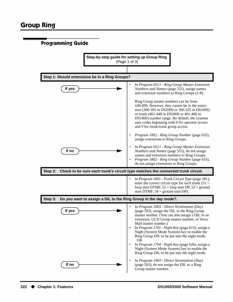
Group Ring
222 ◆ Chapter 1: Features DS1000/2000 Software Manual
Programming Guide
Step-by-step guide for setting up Group Ring (Page 1 of 3)
Step 1: Should extensions be in a Ring Groups?
• In Program 0511 - Ring Group Master Extension Numbers and Names (page 555), assign names and extension numbers to Ring Groups (1-8).
Ring Group master numbers can be from 100-899. However, they cannot be in the exten-sion (300-395 in DS2000 or 300-325 in DS1000) or trunk (401-448 in DS2000 or 401-406 in DS1000) number range. By default, the systems uses codes beginning with 0 for operator access and 9 for trunk/trunk group access.
• Program 1802 - Ring Group Number (page 635), assign extensions to Ring Groups.
• In Program 0511 - Ring Group Master Extension Numbers and Names (page 555), do not assign names and extension numbers to Ring Groups.
• Program 1802 - Ring Group Number (page 635), do not assign extensions to Ring Groups.
Step 2: Check to be sure each trunk’s circuit type matches the connected trunk circuit.
• In Program 1001 - Trunk Circuit Type (page 581), enter the correct circuit type for each trunk (51 = loop start DTMF, 52 = loop start DP, 53 = ground start DTMF, 54 = ground start DP).
Step 3: Do you want to assign a DIL to the Ring Group in the day mode?.
• In Program 1003 - Direct Termination (Day) (page 593), assign the DIL to the Ring Group master number. (You can also assign a DIL to an extension, UCD Group master number, or Voice Mail master number.)
• In Program 1701 - Night Key (page 615), assign a Night (System Mode System) key to enable the Ring Group DIL to be put into the night mode. OR
• In Program 1704 - Night Key (page 626), assign a Night (System Mode System) key to enable the Ring Group DIL to be put into the night mode.
• In Program 1003 - Direct Termination (Day) (page 593), do not assign the DIL to a Ring Group master number.
If yes
If no
If yes
If no

Group Ring
DS1000/2000 Software Manual Chapter 1: Features ◆ 223
Step 4: Do you want an unanswered Ring Group DIL to overflow during the day mode?
• In Program 1003 - Activate Overflow During the Day (page 593), enter Y.
• In Program 1003 - Activate Overflow During the Day (page 593), enter N.
Step 5: Assign the Ring Group DIL day overflow destination.
• In Program 1003 - Day Overflow Destination (page 593), assign the DIL day mode termination. The destination can be an extension, UCD Group master number, Ring Group master number, Voice Mail master number or Key Ring (by press-ing CLEAR).
Step 6: Do you want to assign a DIL to a Ring Group in the night mode?
• In Program 1003 - Direct Termination (Day) (page 593), assign the DIL to the Ring Group master number.(You can also assign a DIL to an extension, UCD Group master number, or Voice Mail master number.)
• In Program 1003 - Direct Termination (Night) (page 594), do not assign the DIL to a Ring Group master number.
Step 7: Do you want an unanswered DIL to overflow during the night mode?
• In Program 1003 - Activate Overflow at Night (page 594), enter Y.
• In Program 1003 - Activate Overflow at Night (page 594), enter N.
Step 8: Assign the DIL night overflow destination.
• In Program 1003 - Night Overflow Destination (page 594), assign the DIL night mode termina-tion. The destination can be an extension, UCD Group master number, Ring Group master num-ber, Voice Mail master number or Key Ring (by pressing CLEAR).
Step-by-step guide for setting up Group Ring (Page 2 of 3)
If yes
If no
If yes
If no
If yes
If no

Group Ring
224 ◆ Chapter 1: Features DS1000/2000 Software Manual
Step 9: Make sure the extension has a line key for the Ring Group DIL?
• In Program 1701 - Line Key (page 613), make sure the DIL has a line key assigned (code 03).
• This is the default setting in DS1000, since all keysets have line keys for trunks 1-6.
Step 10: Do you want to put the Ring Group DIL on a DSS Console key?
• In Program 1704 - Line Key (page 624), make sure the DIL has a DSS Console line key assigned (code 03).
• In Program 1704 - Line Key (page 624), make sure the DIL does not have a DSS Console line key assigned (code 03).
Step 11: If the Ring Group DIL is unanswered, does call divert to its programmed overflow destination after the proper interval.
• In Program 0401 - DIL No Answer (page 523), leave the DIL No Answer time at its current set-ting.
• In Program 0401 - DIL No Answer (page 523), change the DIL No Answer time to meet the site requirements.
Step 12: If DIL is unanswered at the overflow destination, does call divert to Key Ring after the proper interval.
• In Program 0401 - Transfer Recall (page 522), leave the Transfer Recall time at its current set-ting.
• In Program 0401 - Transfer Recall (page 522), change the Transfer Recall time to meet the site requirements.
Step 13: If the DIL doesn’t have overflow enabled and is unanswered, does the call divert to Key Ring after the proper interval.
• In Program 0401 - Trunk Revert (page 523), leave the Transfer Recall time at its current setting.
• In Program 0401 - Trunk Revert (page 523), change the Transfer Recall time to meet the site requirements.
Step-by-step guide for setting up Group Ring (Page 3 of 3)
If yes
If no
If yes
If no
If yes
If no
If yes
If no

Group Ring
DS1000/2000 Software Manual Chapter 1: Features ◆ 225
Programming ListProgram 0401 - Transfer Recall (page 522)
This interval sets how long a call will ring the day or night overflow destination before divert-ing to key ring. It also sets how long a call transferred to a Ring Group will ring before recall-ing the extension that initially transferred it.
Program 0401 - DIL No Answer (page 523)Set how long a DIL rings its destination before ringing its programmed overflow destination.
Program 0401 - Trunk Revert (page 523)For DILs to a Ring Group that don’t have overflow enabled, set how long the call rings the Ring Group before diverting to Key Ring.
Program 0511 - Ring Group Master Extension Numbers and Names (page 555)Assign extension numbers and names to the Ring Group master extensions.
Program 1001 - Trunk Circuit Type (page 581)Set the DIL trunk’s circuit type for compatiblity with the connected telco or PBX. The options are 51 (loop start DTMF), 52 (loop start DP), 53 (ground start DTMF) or 54 (ground start DP).
Program 1003 - Direct Termination (Day) (page 593)To have a DIL ring the Ring Group directly during the day mode, enter the Ring Group master number.
Program 1003 - Activate Overflow During the Day (page 593)Enter Y to enable DIL overflow during the day mode. (Entering N for this option has the same affect as entering Y followed by Key Ring in the following option.)
Program 1003 - Day Overflow Destination (page 593)Set the overflow destination for the Ring Group’s DIL during the day. The overflow destina-tion can be an extension, UCD Group master number, another Ring Group master number, Voice Mail master number or Key Ring (by pressing CLEAR).
Program 1003 - Direct Termination (Night) (page 594)To have a DIL ring the Ring Group directly during the night mode, enter the Ring Group mas-ter number. You can optionally have the trunk ring a different destination at night, such as anextension, UCD Group master number, or Voice Mail master number.
Program 1003 - Activate Overflow at Night (page 594)Enable Y to enable DIL overflow during the night mode. (Entering N for this option has the same affect as entering Y followed by Key Ring in the following option.)
Program 1003 - Night Overflow Destination (page 594)Set the overflow destination for the Ring Group’s DIL during the night mode calls.The desti-nation can be an extension, UCD Group master number, another Ring Group master number, or Voice Mail master number.
Program 1701 - Line Key (page 613)A Ring Group DIL should also appear on a line key (code 03).
Program 1701 - Night Key (page 615)Assign a Night (System Mode System) key to enable the Ring Group DIL to be put into the night mode.
Program 1704 - Line Key (page 624)A Ring Group DIL can optionally appear on a DSS Console line key (code 03).
Program 1704 - Night Key (page 626)Assign a Night (System Mode System) key to enable the Ring Group DIL to be put into the night mode.
Program 1802 - Ring Group Number (page 635)Assign extensions to Ring Groups (1-8, 0 = no assignment).
Other Related FeaturesAttendant Position (page 47)
System operators will not ring for Ring Group calls. Do not include the operator in a Ring Group.
Group Ring
226 ◆ Chapter 1: Features DS1000/2000 Software Manual
Call Coverage Keys (page 62)A keyset can have Call Coverage keys for Ring Group master numbers.
Call Forwarding (page 66)Call Forwarding does not reroute Ring Group calls.
Call Waiting / Camp-On (page 75)An extension user cannot Camp On to a busy Ring Group. When all extensions in the Ring Group are busy, the call continues to ring until an extension becomes free.
Caller ID (page 82)
● DS2000 02.00.04 and DS1000 Prior to 02.01.07An extension’s display will show Caller ID data for a trunk terminated to a Ring Group master number after the user answers the call. In prior DS2000 software versions, the Caller ID data for the Ring Group call would show only when the extension user pressed the CHECK key after answering or after the call diverted to Key Ring.
● DS1000/2000 02.01.07 and HigherAn extension’s display will show Caller ID data for a trunk terminated to a Ring Group master number as the call is ringing.
Direct Inward Line (page 133)A DIL can terminate to a Ring Group master number. When a call comes in on the trunk, all phones in the Ring Group ring simultaneously.
Directed Call Pickup (page 156)Directed Call Pickup can intercept Ring Group calls.
Directory Dialing (page 158)Intercom Directory dialing will show Ring Group names.
Extension Hunting (page 193)Group Ring calls do not activate hunting.
Night Service / Night Ring (page 308)The Night (System Mode System) key sets the day/night status of a DIL terminated to a Ring Group.
Transfer (page 455)An extension user can Transfer a call to a Ring Group master number. If unanswered, the call will recall the extension from which it was transferred.
Feature Operation
To make an Intercom call to a Ring Group:
1. Lift handset and press ICM.
2. Dial Ring Group number (e.g., 350).
3. Wait for co-worker to answer.If all Ring Group members are busy, your call will continue to ring until a group mem-
ber becomes free.
To Transfer your trunk call to a Ring Group:
1. Press ICM.
Intercom dial tone.
ICM on.
Intercom ringing.
ICM on.
Intercom dial tone.
ICM on.
Group Ring
DS1000/2000 Software Manual Chapter 1: Features ◆ 227
2. Dial Ring Group number (e.g., 350).
3. To screen (announce) the Transfer:● Wait for Ring Group member to answer before hanging up.
ORTo have the call go through unscreened (unannounced):● Hang up.
ORTo return to call before a Ring Group member picks it up:● Press flashing (green) line key.
An unanswered Transfer to a Ring Group will continue to ring the group until a mem-ber picks it up. It will not recall to the transferring extension.
To answer a call that rings your Ring Group:
1. If call doesn’t appear on a line/loop key:● Lift handset.
ORIf line appears on a line/loop key:● Press flashing line/loop key.
To answer a call that ringing another group (of which you are not a member):
1. Lift handset and press ICM.
2. Dial ** and the Ring Group number (e.g., 350).
Intercom ringing.
ICM on and line key flashes (green).
Ringing
N/A
Ringing
N/A
Intercom dial tone.
ICM on.
Conversation with caller.
ICM on.

Handsfree and Handsfree Answerback
228 ◆ Chapter 1: Features DS1000/2000 Software Manual
Handsfree and Handsfree Answerback
Description
HandsfreeHandsfree allows a keyset user to process calls using the speaker and microphone in the telephone (instead of the handset). Handsfree is a convenience for workers who don’t have a free hand to pick up the handset. For example, a terminal operator could continue to enter data with both hands while talking on the phone.
Handsfree Answerback and Forced Intercom RingingHandsfree Answerback permits an extension user to respond to a voice-announced Intercom call by speaking toward the phone, without lifting the handset. Like Handsfree, this is a convenience for workers who don’t have a free hand to pick up the handset. Incoming Intercom calls alert with two beeps if the extension has Handsfree Answerback — a single beep if it does not.
Forced Intercom Ringing causes an Intercom call to ring the destination extension. You can enable Forced Intercom Ringing system-wide (for all extensions), or a user can dial a code to have their Intercom call ring the destination.
ConditionsSince Handsfree switching is handled in each telephone, there is no limit to the number of simulta-neouls Handsfree calls system-wide.
Default SettingEnabled
DS2000 Fixed Slot Available.
DS2000 U Slot Available. User Programmable Feature steps added for voice-announced Inter-com calls.
DS1000 Available. Includes User Programmable Feature steps for voice-announced Intercom calls.
● Talk over the phone Handsfree, using the built-in speaker and microphone. ● With Handsfree Answerback, answer an Intercom call by just speaking toward your phone.

Handsfree and Handsfree Answerback
DS1000/2000 Software Manual Chapter 1: Features ◆ 229
Programming Guide
Programming ListProgram 0201 - Handsfree Reply on Intercom Calls (page 512)
Enter Y to allow extension user to respond to voice-announced Intercom calls by just speaking toward the phone (i.e., by using Handsfree Answerback). When you enter N, the extension user must lift the handset to speak.
Program 0201 - Voice-Announced Intercom Calls (page 512)Enter Y to enable voice-announced Intercom calls system-wide. If disabled, all Intercom calls ring (i.e., Forced Intercom Ringing is enabled).
Program 1802 - Handsfree Reply on Intercom Calls (page 636)Enter Y to enable Handsfree reply (Handsfree Answerback) on a per-extension basis. Inter-com calls initially ring when this option is disabled. This option requires that you have previ-ously enabled 0201 - Handsfree Reply on Intercom Calls.
Step-by-step guide for setting up Handsfree Answerback
Step 1: Should Intercom calls voice-announce system-wide?
• In Program 0201 - Voice-Announced Intercom Calls (page 512), enter Y to allow Intercom calls to voice-announce system-wide. Users can still dial 1 to have their calls ring.
• In Program 1807 - Station Voice Announced Intercom Calls (page 652), enter Y to enable voice-announced intercom calls for specific extensions. The User-Programmable Options # IV (#48) and # IR (#47) locally override this setting.
• In Program 0201 - Voice-Announced Intercom Calls (page 512), enter N to have all Intercom calls ring system-wide. Users cannot dial 1 to have their calls voice-announce.
Step 2: Should user be able to respond to a voice-announced Intercom call without lifting the handset (i.e., by using Handsfree Answerback)?
• In Program 0201 - Handsfree Reply on Intercom Calls (page 512), enter Y to enable Handfree Answerback system-wide.
• In Program 1802 - Handsfree Reply on Intercom Calls (page 636), enter Y to enable Handsfree Answerback for specific extensions.
• In Program 0201 - Handsfree Reply on Intercom Calls (page 512), enter N to disable Handsfree answerback system-wide. Users must lift the handset to respond to voice-announced Intercom calls.
If yes
If no
If yes
If no

Handsfree and Handsfree Answerback
230 ◆ Chapter 1: Features DS1000/2000 Software Manual
Program 1807 - Station Voice Announced Intercom Calls (page 652)Enter Y to enable voice-announced Intercom calls on a per-extension basis. This option requires that you have previously enabled 0201 - Voice-Announced Intercom Calls. The User-Programmable Options # IV (#48) and #IR #47) locally override this setting.
Other Related FeaturesAutomatic Handsfree (page 51)
Automatic Handsfree allows a keyset user to place or answer a call Handsfree by just pressing a key — without pressing SPK first.
Headset Compatibility (page 232)Handsfree is not available to extensions in the headset mode. Handsfree Answerback still available — depending on system programming.
Intercom (page 268)Handsfree Answerback allows a user to answer an Intercom call by just speaking toward the phone.
Microphone Mute (page 296)Use Microphone Mute to temporarily turn off the Handsfree microphone.
Off-Premise Extensions / On-Premise SLT Extensions (page 317)On- and Off-Premise Extensions do not have Handsfree and Handsfree Answerback capability.
Feature Operation
Handsfree
To activate Handsfree instead of lifting the handset:
1. Press SPK.
To talk on a Handsfree call:
1. Speak toward phone.To temporarily turn off the Handsfree microphone, see Microphone Mute on page 296.
To hang up a Handsfree call:
1. Press SPK.
To change a handset call into a Handsfree call:
1. Press SPK.
2. Hang up the handset.
Handsfree conversation with caller.
SPK on.
Conversation stops.
SPK off.
N/A.
SPK on.

Handsfree and Handsfree Answerback
DS1000/2000 Software Manual Chapter 1: Features ◆ 231
To change a Handsfree call into a handset call:
1. Lift handset.
Handsfree AnswerbackOperation is automatic if enabled in system programming.
Conversation with caller in handset.
SPK off.
User Programmable Feature
#IV #48 Handsfree Answerback On (Forced Intercom Ringing Off)
#IR #47 Forced Intercom Ringing On (Handsfree Answerback Off)
Headset Compatibility
232 ◆ Chapter 1: Features DS1000/2000 Software Manual
Headset Compatibility
Description
A keyset user can utilize a customer-provided headset in place of the handset. Like using Hands-free, using the headset frees up the user’s hands for other work. However, the headset provides pri-vacy not available from Handsfree.
An example of a compatible headset is UNEX Model Pro-MP10A.
Off-Hook Signaling and Headsets
Outside Calls (transfers and DILs)If the extension is set up to receive Camp-On tones for waiting (transferred) outside calls, the user will hear the Camp-On tones in their headset. They will also hear Camp-On tones in their headset for a waiting Direct Inward Line (DIL). The extension will not, however, receive Camp On tones for Key Ring calls ringing the phone while it is in the headset mode.
An extension in the headset mode will not hear Off-Hook Ringing.
Intercom CallsIf the extension is set up to receive Camp-On tones for waiting Intercom calls, the user will hear tones in their headset when a co-worker dials 2 to wait in line.
An extension in the headset mode will not receive a Voice Over.
ConditionsNone
Default SettingDisabled
DS2000 Fixed Slot Available.
DS2000 U Slot Available. User Programmable Feature steps added. Headset Voice-Announced Intercom Calls option requires version 02.02.14 or higher.
DS1000 Avalable. Includes User Programmable Feature steps. Headset Voice-Announced Intercom Calls option requires version 02.02.14 or higher.
Have the privacy of a handset call without having to hold the handset

Headset Compatibility
DS1000/2000 Software Manual Chapter 1: Features ◆ 233
Programming Guide
Programming ListProgram 1807 - Headset Voice-Announced Intercom Calls (page 652)
(Requires software version 02.02.14 or higher.)If enabled (Y), the user hears 2 beeps in the headset when they receive an incoming Intercom call. If disabled (N), the user hears ringing over the telephone speaker.
Program 1807 - Headset (page 652)Enter Y to enable the Headset mode.
Other Related FeaturesAutomatic Handsfree (page 51)
While in the headset mode, Automatic Handsfree simplifies answering trunk calls.Background Music (page 55)
Background Music plays in the headset when the extension is in the headset mode.Group Listen (page 219)
Group Listen is not available to extensions in the headset mode.Handsfree and Handsfree Answerback (page 228)
Handsfree is not available to extensions in the headset mode. Handsfree Answerback is avail-able — depending on system programming.
Off-Hook Signaling (page 313)Turn to Off-Hook Signaling and Headsets on page 232 for more on how Off-Hook Signaling interacts with headsets.
Off-Premise Extensions / On-Premise SLT Extensions (page 317)On- and Off-Premise Extensions do not have headset capability.
Step-by-step guide for setting up Headset Compatibility
Step 1: Should extension be in the headset mode?
• In Program 1807 - Headset (page 652), enter Y to enable the headset mode.
• In Program 1807 - Headset (page 652), enter N to disable the headset mode.
Step 2: Should incoming Intercom calls beep in the headset or ring over the telephone speaker?
• In Program 1807 - Headset Voice-Announced Intercom Calls (page 652), enter Y.
• In Program 1807 - Headset Voice-Announced Intercom Calls (page 652), enter N
If yes
If no
Beep
Ring

Headset Compatibility
234 ◆ Chapter 1: Features DS1000/2000 Software Manual
Paging (page 326)While in the headset mode, the extension user can hear Paging announcements in the headset.
Single Line Telephones (page 381)Headset Compatibility is not available to single line telephones.
Voice Over (page 493)An extension user cannot Voice Over to a co-worker in the headset mode.
Feature Operation
To enable the headset mode:
1. Unplug the telephone handset but leave it in the handset cradle.
2. Plug in the headset.
When in the headset mode:
● Press a line key to place or answer a trunk call.OR
● Press ICM to get Intercom dial tone.OR
● If on a call, press SPK to hang up.
User Programmable Feature
Feature Mnemonic Operation Access Level
This option is not available in Fixed Slot software.
Headset #HS #HS + Y to enable or N to disable + SPK to exit
3-5

Hold
DS1000/2000 Software Manual Chapter 1: Features ◆ 235
Hold
Description
Hold lets an extension user put a call in a temporary waiting state. The caller on Hold hears silence or Music on Hold, not conversation in the extension user’s work area. While the call waits on Hold, the extension user may process calls or use a system feature. Outside calls left on Hold too long recall the extension that placed them on Hold. If the recall is unanswered, the call diverts to Key Ring.
There are four types of Hold:
System (Regular) HoldWith System Hold, an outside call a user places on Hold flashes the line key (if programmed) at all other keysets. Any keyset user with the flashing line key can pick up the call.
Exclusive HoldWhen a user places a call on Exclusive Hold, only that user can pick up the call from Hold. The trunk appears busy to all other keysets that have a key for the trunk. Exclusive Hold is important if the user doesn’t want a co-worker picking up their call on Hold.
Automatic HoldAutomatic Hold allows a user to be on a trunk call, activate a feature and automatically place the call on Hold without first pressing the HOLD key. The system places a call on Hold automatically when the user presses CONF or ICM, a Call Coverage Key or a Hotline key.
Intercom HoldA user can place an Intercom call on Hold. The Intercom call on Hold does not indicate at any other extension. There is no Hold Recall for Intercom calls.
DS2000 Fixed Slot Available.
DS2000 U Slot • Extension users can dial a code to pick up a trunk on Hold at a co-worker’s extension.
• Distinctive flash rate for Hold and Exclusive Hold Recall requires DS2000 software version 02.00.01 or DS1000.
• Enhanced Hold Recall Display requires software version 02.02.14 or higher.DS1000
Have a call wait on Hold, then pick it up to continue the conversation.

Hold
236 ◆ Chapter 1: Features DS1000/2000 Software Manual
Distinctive Flash Rate on RecallSystem Hold and Exclusive Hold recall feature a distinctive flash rate for line keys (see the chart below). This allows the keyset extension user to easily differentiate new calls that are ringing from Held calls that are recalling.
Enhanced Hold Recall Display(Software version 02.02.14 or higher)The Hold recall display is enhanced to identify:
● The type of call recalling the extension.
● The extension which initially placed the call on Hold.
Following are sample Hold recall displays. In the first example, the call was placed on Hold at extension 301 (which does not have a name). In the second example, the call was placed on Hold at extension 300 (which has the name ATTENDANT).
The Hold recall displays occurs as the call is ringing the extension that initially placed it on Hold, and after the call diverts to Key Ring.
ConditionsNone
Default SettingSystem Hold, Exclusive Hold and Automatic Hold enabled.
Distinctive Flash Rate on Recall
For this type of call:You see this flash rate:
System Hold Exclusive Hold
Call that you placed on Hold Single Wink On (Green) Double Wink On (Green)
Call that you initially placed on Hold recalling your phone Double Wink On (Green) Double Wink On (Green)
Call a co-worker placed on Hold at their extension Single Wink On (Red) None (On Red)
Call a co-worker initially placed on Hold recalling
your phoneDouble Wink On (Red) Double Wink On (Red)

Hold
DS1000/2000 Software Manual Chapter 1: Features ◆ 237
Programming Guide
Step-by-step guide for setting up Hold
Step 1: Should extension be able to use Automatic Hold?
• In Program 0101 - Automatic Hold (page 508), enter Y to enable Automatic Hold.
• Program 1801 - Extension Class of Service Assignment (page 631), assign Class of Service to extensions.
• In Program 0101 - Automatic Hold (page 508), enter N to disable Automatic Hold.
• Program 1801 - Extension Class of Service Assignment (page 631), assign Class of Service to extensions.
Step 2: Does an unanswered call on System Hold recall the extension that placed it on Hold after the correct interval?
• In Program 0403 - Hold Recall (page 533), leave the Hold Recall interval at its current setting.
• In Program 0403 - Hold Recall (page 533), change the Hold Recall interval to meet the site requirements.
Step 3: Does an unanswered call on Exclusive Hold recall the extension that placed it on Hold after the correct interval?
• In Program 0403 - Exclusive Hold (page 533), leave the Exclusive Hold Recall interval at its cur-rent setting.
• In Program 0403 - Exclusive Hold (page 533), change the Exclusive Hold Recall interval to meet the site requirements.
Step 4: Does an unanswered Hold recall revert to Key Ring after the proper interval?
• In Program 0401 - Trunk Revert (page 523), leave the Trunk Revert interval at its current setting.
• In Program 0401 - Trunk Revert (page 523), change the Trunk Revert interval to meet the site requirements.
If yes
If no
If yes
If no
If yes
If no
If yes
If no
Hold
238 ◆ Chapter 1: Features DS1000/2000 Software Manual
Programming ListProgram 0101 - Automatic Hold (page 508)
Enter Y to enable Automatic Hold at an extension.Program 0401 - Trunk Revert (page 523)
This timer sets how long Hold Recall rings the extension that placed the call on hold before Key Ring occurs. Key Ring rings all extensions programmed to ring for that line.
Program 0403 - Hold Recall (page 533)Set how long a call stays on Hold before it recalls the extension that initially placed it on Hold.
Program 0403 - Exclusive Hold (page 533)Set how long a call stays on Exclusive Hold before it recalls the extension that initially placed it on Exclusive Hold.
Program 1801 - Extension Class of Service Assignment (page 631)Assign Class of Service to extensions.
Other Related FeaturesCall Timer (page 72)
A user’s Call Timer starts when they pick up a call from Hold. If they place the call on Hold and another user picks it up, the timer restarts for the new user.
Directed Call Pickup (page 156)Directed Call Pickup can pick up Hold recalls.
Key Ring (page 273)Unanswered Hold Recalls revert to Key Ring if not picked up.
Music on Hold (page 303)If installed, Music on Hold plays to callers on Hold.
Off-Hook Signaling (page 313)An extension user can place their current call on Hold and answer the waiting call.
Transfer (page 455)If an extension receiving a screened Transfer answers the screen and immediately hangs up (before the transferring extension), the call goes on Exclusive Hold at the transferring extension.
Feature Operation
To place a trunk call on System Hold:
1. Press HOLD.
2. Hang up.
To pick up a trunk call on System Hold:
1. Press flashing line key.
N/A
The line key winks (on) while on Hold, flashes slowly while recalling. The line key is green for your calls - red for your co-workers.
Conversation with caller.
Line key on (green).

Hold
DS1000/2000 Software Manual Chapter 1: Features ◆ 239
To pick up a trunk call on system Hold at a co-worker’s extension:
You must know the number of the trunk that is on Hold.
1. Lift handset and press ICM.
2. Dial *4.
3. Dial the number of the trunk that is on Hold (e.g., 01 for trunk 1).
To place a trunk call on Exclusive Hold:
1. Press HOLD twice.
2. Hang up.
To pick up a trunk call on Exclusive Hold:
1. Press flashing line key.
To place an Intercom call on Hold:
You can place both voice-announced and ringing Intercom calls on Hold.
1. Press HOLD.
2. Hang up.
To pick up a call on Intercom Hold:
1. Lift handset.
2. If you don’t hear Intercom dial tone, press ICM.
3. Press HOLD.
Intercom dial tone.
ICM and SPK on (red).
Intercom dial tone stops.
ICM and SPK on (red).
Conversation with the outside caller that was on Hold.
Line key on.
N/A
For you, the line key winks (on - green) while on Hold, flashes slowly while recalling. For your co-worker’s the line key is on (red).
Conversation with caller.
Line key on (green).
N/A
ICM goes out.
Conversation with caller.
ICM on.

Hotline
240 ◆ Chapter 1: Features DS1000/2000 Software Manual
Hotline
Description
Hotline gives a keyset user with a programmed Hotline key one-button calling and Transfer to another extension (the Hotline partner). Hotline helps co-workers that work closely together. The Hotline partners can call or Transfer calls to each other just by pressing a single key.
In addition, the Hotline key shows the status of the partner’s extension:
Conditions
● An extension’s Hotline partner can be any other keyset (e.g., physical port). An extension can-not have a Hotline key for master numbers or virtual ports.
● A Hotline partner can also be a trunk (e.g., 401). However, this capability requires that Direct Trunk Access be enabled. See Direct Trunk Access on page 154 for more.
Default SettingNo Hotline keys programmed.
Programming Guide
DS2000 Fixed Slot Available.
DS2000 U Slot Available. User Programmable Feature steps added.
DS1000 Available. Includes User Programmable Feature steps.
Hotline provides partner extensions with one-button calling and Transfer.
Hotline Busy Lamp Indications
When the key is: The covered extension is:
Off Idle or not installed
On Busy or ringing1
Flashing fast In Do Not Disturb
1 Ringing ICM and Group Ring calls light the Hotline key. DILs, Key Ring calls and transferred calls do not.
Step-by-step guide for setting up Hotline
Step 1: Should extension have a Hotline partner?
• In Program 1701 - Hotline Key (page 613), enter code 05 + the covered extension (300-395 in DS2000 or 300-325 in DS1000) to assign a Hot-line key.
If yes

Hotline
DS1000/2000 Software Manual Chapter 1: Features ◆ 241
• In Program 1701 - Hotline Key (page 613), do not enter code 05 to assign a key as a Hotline key.
Step 2: Should DSS Console also have a Hotline partners?
• In Program 1704 - Hotline Key (page 624), enter code 05 + the covered extension (300-395 in DS2000 or 300-325 in DS1000) to assign a Hot-line key.
• In Program 1704 - Hotline Key (page 624), do not enter code 05 to assign a key as a Hotline key.
Step 3: Should Hotline partner initiate Voice Over, Camp-On tones, or no Off-Hook Signal-ing when they press their Hotline key to call a busy extension?
• In Program 1802 - Off-Hook Signaling for Hot-line Partner (page 635), enter 3. Refer to Voice Over on page 493 for additional programming information.
• In Program 1802 - Off-Hook Signaling for Hot-line Partner (page 635), enter 1. Refer to Call Waiting / Camp-On on page 75 for additional pro-gramming information.
• In Program 1802 - Off-Hook Signaling for Hot-line Partner (page 635), enter 0.
Step-by-step guide for setting up Hotline
If no
If yes
If no
Voice Over
Camp On
No Signals
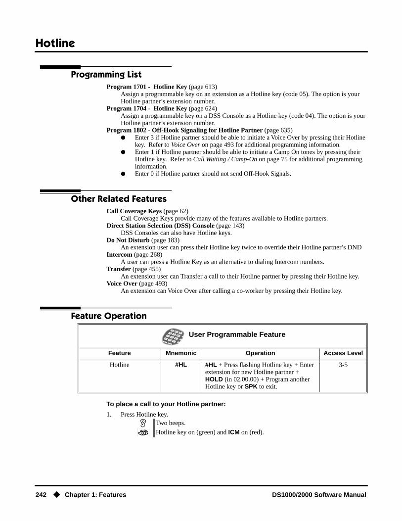
Hotline
242 ◆ Chapter 1: Features DS1000/2000 Software Manual
Programming ListProgram 1701 - Hotline Key (page 613)
Assign a programmable key on an extension as a Hotline key (code 05). The option is your Hotline partner’s extension number.
Program 1704 - Hotline Key (page 624)Assign a programmable key on a DSS Console as a Hotline key (code 04). The option is your Hotline partner’s extension number.
Program 1802 - Off-Hook Signaling for Hotline Partner (page 635)● Enter 3 if Hotline partner should be able to initiate a Voice Over by pressing their Hotline
key. Refer to Voice Over on page 493 for additional programming information.● Enter 1 if Hotline partner should be able to initiate a Camp On tones by pressing their
Hotline key. Refer to Call Waiting / Camp-On on page 75 for additional programming information.
● Enter 0 if Hotline partner should not send Off-Hook Signals.
Other Related FeaturesCall Coverage Keys (page 62)
Call Coverage Keys provide many of the features available to Hotline partners.Direct Station Selection (DSS) Console (page 143)
DSS Consoles can also have Hotline keys.Do Not Disturb (page 183)
An extension user can press their Hotline key twice to override their Hotline partner’s DNDIntercom (page 268)
A user can press a Hotline Key as an alternative to dialing Intercom numbers.Transfer (page 455)
An extension user can Transfer a call to their Hotline partner by pressing their Hotline key.Voice Over (page 493)
An extension can Voice Over after calling a co-worker by pressing their Hotline key.
Feature Operation
To place a call to your Hotline partner:
1. Press Hotline key.
User Programmable Feature
Feature Mnemonic Operation Access Level
Hotline #HL #HL + Press flashing Hotline key + Enter extension for new Hotline partner + HOLD (in 02.00.00) + Program another Hotline key or SPK to exit.
3-5
Two beeps.
Hotline key on (green) and ICM on (red).
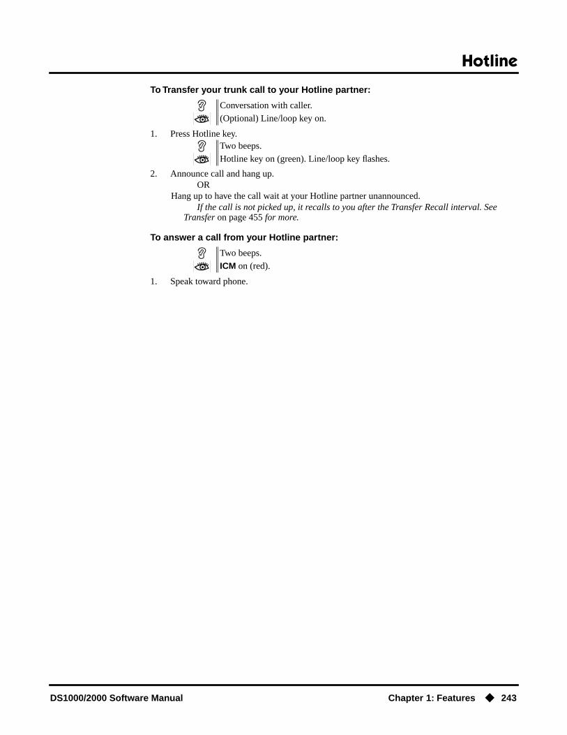
Hotline
DS1000/2000 Software Manual Chapter 1: Features ◆ 243
To Transfer your trunk call to your Hotline partner:
1. Press Hotline key.
2. Announce call and hang up.OR
Hang up to have the call wait at your Hotline partner unannounced.If the call is not picked up, it recalls to you after the Transfer Recall interval. See
Transfer on page 455 for more.
To answer a call from your Hotline partner:
1. Speak toward phone.
Conversation with caller.
(Optional) Line/loop key on.
Two beeps.
Hotline key on (green). Line/loop key flashes.
Two beeps.
ICM on (red).

Interactive Soft Keys
244 ◆ Chapter 1: Features DS1000/2000 Software Manual
Interactive Soft Keys
Description
Interactive Soft Keys provide intuitive feature access. It is no longer necessary to remember feature codes to access the telephone’s advanced features because the function of the soft keys change as the user process calls. For example, while on a trunk call a display keyset user can press the PARK soft key to Park their call in orbit.
For additional information on Interactive Soft Key operation, refer to Feature Operation below.
ConditionsWhen an extension’s soft keys are enabled or disabled in programming, the user must take some action at the telephone (such as lifting and replacing the handset) before the change takes effect.
Default SettingSoft keys enabled.
Programming Guide
DS2000 Fixed Slot
Available.DS2000 U Slot
DS1000
Use advanced telephone features just by pressing a soft key, without remembering feature codes.
Step-by-step guide for setting up Interactive Soft Keys
Step 1: Should extension have Interactive Soft Keys?
• In Program 0101 - Soft Keys (page 509), enter Y to enable soft keys.
• In Program 1801 - Extension Class of Service Assignment (page 631), assign Class of Service to extensions.
• Take some action at the telephone (such as lifting and replacing the handset) so the change will take effect.
• In Program 0101 - Soft Keys (page 509), enter N to enable soft keys.
• In Program 1801 - Extension Class of Service Assignment (page 631), assign Class of Service to extensions.
• Take some action at the telephone (such as lifting and replacing the handset) so the change will take effect.
If yes
If no

Interactive Soft Keys
DS1000/2000 Software Manual Chapter 1: Features ◆ 245
Programming ListProgram 0101 - Soft Keys (page 509)
Enable (Y) or disable (Y) an extension’s soft keys.Program 1801 - Extension Class of Service Assignment (page 631)
Assign Class of Service to extensions.
Other Related FeaturesNone
Feature OperationSee the charts beginning on the following page.

Interactive Soft Keys
246 ◆ Chapter 1: Features DS1000/2000 Software Manual
Keyset Soft Keys
Global Navigation Soft Keys You May See At Any Time
Soft Key Definition
PREV Press this Soft Key to back up to the previous set of options.
MORE Press this Soft Key to display additional options for your call.
CNCL Press to return your telephone to the idle mode.
While Your Telephone Is Idle (Page 1 of 3)
Soft Key Feature Definition
Use Directory Dialing to select a call from a list of names:
DIR Press to access Directory Dialing, Paging and Meet Me Conference
INT Directory Dialing
ICM Directory VOL ▲ or VOL ▼ + DIAL to select co-worker from a list of extension names.
EXT
PERS VOL ▲ or VOL ▼ + DIAL to select one of your Personal Speed Dial bins.
CMPY VOL ▲ or VOL ▼ + DIAL to select a System Speed Dial bin.
PAGE Paging
Dial a page zone Dial a zone (1-7) or press ALL for All Call.
MT11 or MT12 Meet Me Conference Press key to set up a Meet Me Conference.
Set up Call Forwarding, Distinctive Ringing, Speed Dial, Volume Controls and Intercom voice-announcements
PGM Press to set up Call Forwarding, Programmable Function Key ringing, Speed Dial, Do Not Disturb, and Intercom voice-announcements.
CFWD Call Forwarding
Enter Call FWD type
Enter the Call Forwarding type + Co-worker’s extension, 0 (operator) or MW (Voice Mail) + SPK.0 = Cancel forwarding2 = Busy/No Answer4 = Immediate6 = No answer7 = Personal Answering Machine Emulation8 = Selectable Display Messaging
RING Press to set up Distinctive Ringing.
ASGN Distinctive Ringing Press to select the Extension Override option.
DAY Press to select the ringing mode for day mode calls.

Interactive Soft Keys
DS1000/2000 Software Manual Chapter 1: Features ◆ 247
“A” Distinctive Ringing For the type of calls selected (day, night, or delay), press to select ring type A.
“B” For the type of calls selected (day, night, or delay), press to select ring type B.
“C” For the type of calls selected (day, night, or delay), press to select ring type C.
LINE For the type of calls selected (day, night, or delay), press to select the system default ring type.
NGT Press to select the ringing mode for night mode calls, then choose from “A”, “B”, “C” or LINE above.
DLY Press to select the ringing mode for delay ring calls, then choose from “A”, “B”, “C” or LINE above.
CNFG Press to select the Distinctive Ring Configuration option.
ICM Press to change the sound of your Intercom ringing.
TONE For the type of ring selected (Intercom, Ring Group, recall, “A”, “B”, or “C”), press to change the ringing pitch.
CDNC For the type of ring selected (Intercom, Ring Group, recall, “A”, “B”, or “C”), press to change the ringing cadence.
CNCL Press to return to the previous Distinctive Ringing screen.
SAVE After selecting a new cadence and/or tone, press to save your entry.
RGRP Press to change the sound of your Ring Group ringing.
RCL Press to change the sound of your Hold, Park, and Transfer Recall ringing.
“A” Press to change the sound of your type “A” ringing.
“B” Press to change the sound of your type “B” ringing.
“C” Press to change the sound of your type “C” ringing.
DFLT Press to select one of the 3 default ringing setups (1-3) and cancel your custom settings.
KEY Press to select the Key Ring Override option.
CCK • If the Key Ring Override option is enabled, press a lit Call Cover-age key and then select the key’s ring type (1=”A”, 2=”B”, 3=”C”, 0=default).
• Press the lit Call Coverage key repeatedly to select the key’s ring-ing mode (day, night, delay, or lamp only).
PKUP • If the Key Ring Override option is enabled, press a lit Group Call Pickup key and then select the key’s ring type (1=”A”, 2=”B”, 3=”C”, 0=default).
• Press the lit Group Call Pickup key repeatedly to select the key’s ringing mode (day, night, delay, or lamp only).
While Your Telephone Is Idle (Page 2 of 3)
Soft Key Feature Definition

Interactive Soft Keys
248 ◆ Chapter 1: Features DS1000/2000 Software Manual
LINE Distinctive Ringing • If the Key Ring Override option is enabled, press a lit line key and then select the key’s ring type (1=”A”, 2=”B”, 3=”C”, 0=default).
• Press the lit line key repeatedly to select the key’s ringing mode (day, night, delay, or lamp only).
SPD Speed Dial Enter bin (200-299 for System, 701-720 for Personal) + HOLD + Line (1-16), Group (90-98) or ICM + HOLD + Number + HOLD + Name + HOLD + SPK.
VOL Volume Control Press to access the Volume Control feature.
RING Press to select the ringing volume control, then VOL ▲ or VOL ▼ to adjust the volume.
OFHK Press to select the off-hook ringing volume control, then VOL ▲ or VOL ▼ to adjust the volume.
PAGE Press to select the Paging volume control, then VOL ▲ or VOL ▼ to adjust the volume.
VANN Intercom
VAON Press to enable voice-announcements for incoming Intercom calls.
VAOFF Press to have all incoming Intercom calls ring (i.e., disable voice-announce).
Call Your Mailbox
VM00 Voice Mail Press to call your Voice Mail mailbox. The numbers after VM show the number of new messages in your mailbox.
Use Caller ID Logging
CL00 Caller ID Logging Press to review your Caller ID log.
ALL Press to review all your Caller ID logs.
UNAN Press to review the records just for calls that rang your phone but were unanswered in the system.
DEL* Press to delete all Caller ID records logged at your phone.
YES After you press DEL*, press to confirm the deletion.
NO After you press DEL*, press to cancel the deletion.
EXIT Press to exit Caller ID Logging and return to the idle display.
Outside Calls (Page 1 of 3)
Soft Key Feature Definition
After you get trunk dial tone for a new call (but before you dial the outside number):
LND Last Number Redial Automatically redial the last outside number you called.
DLSV Save Number Dialed Automatically redial the stored Save Number Dialed number.
RLS Hang up (disconnect) the call and return to Intercom dial tone.
While Your Telephone Is Idle (Page 3 of 3)
Soft Key Feature Definition
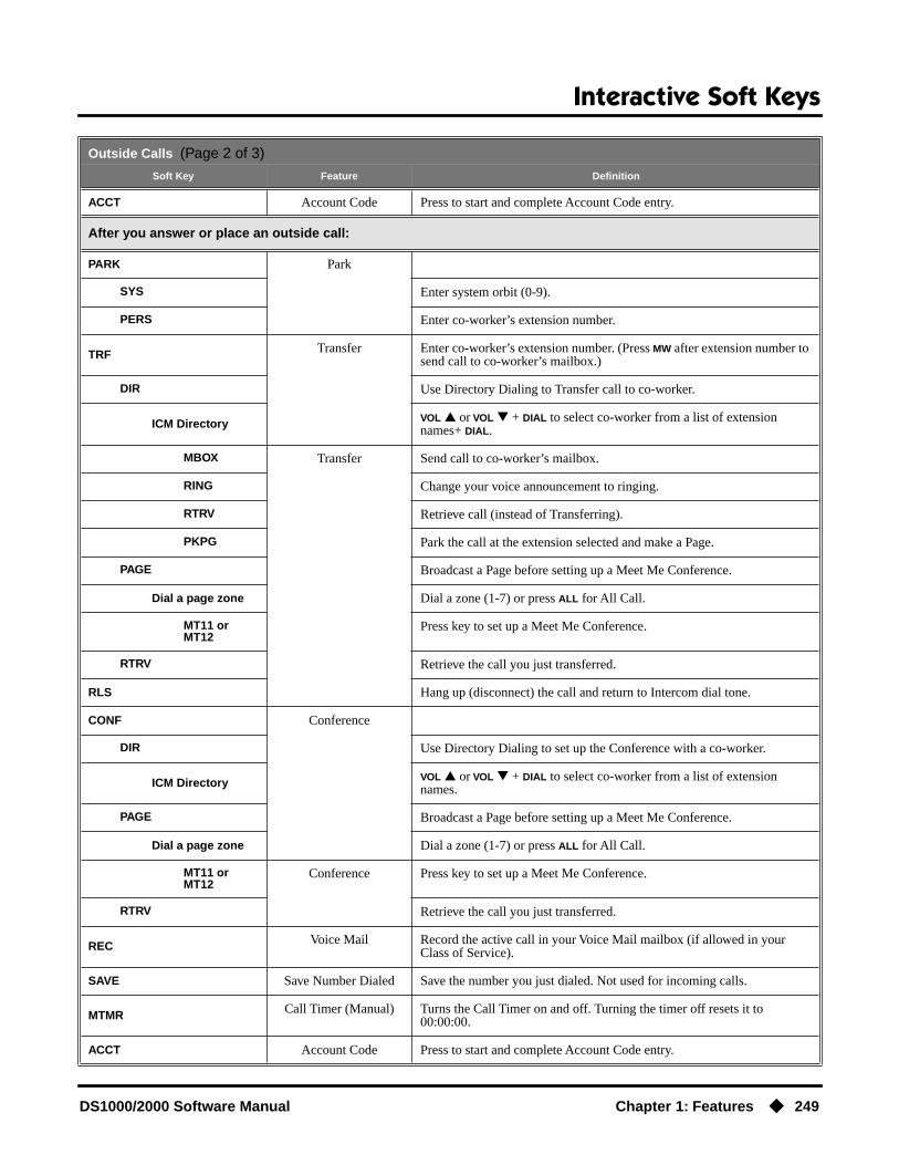
Interactive Soft Keys
DS1000/2000 Software Manual Chapter 1: Features ◆ 249
ACCT Account Code Press to start and complete Account Code entry.
After you answer or place an outside call:
PARK Park
SYS Enter system orbit (0-9).
PERS Enter co-worker’s extension number.
TRF Transfer Enter co-worker’s extension number. (Press MW after extension number to send call to co-worker’s mailbox.)
DIR Use Directory Dialing to Transfer call to co-worker.
ICM Directory VOL ▲ or VOL ▼ + DIAL to select co-worker from a list of extension names+ DIAL.
MBOX Transfer Send call to co-worker’s mailbox.
RING Change your voice announcement to ringing.
RTRV Retrieve call (instead of Transferring).
PKPG Park the call at the extension selected and make a Page.
PAGE Broadcast a Page before setting up a Meet Me Conference.
Dial a page zone Dial a zone (1-7) or press ALL for All Call.
MT11 or MT12
Press key to set up a Meet Me Conference.
RTRV Retrieve the call you just transferred.
RLS Hang up (disconnect) the call and return to Intercom dial tone.
CONF Conference
DIR Use Directory Dialing to set up the Conference with a co-worker.
ICM Directory VOL ▲ or VOL ▼ + DIAL to select co-worker from a list of extension names.
PAGE Broadcast a Page before setting up a Meet Me Conference.
Dial a page zone Dial a zone (1-7) or press ALL for All Call.
MT11 or MT12
Conference Press key to set up a Meet Me Conference.
RTRV Retrieve the call you just transferred.
REC Voice Mail Record the active call in your Voice Mail mailbox (if allowed in your Class of Service).
SAVE Save Number Dialed Save the number you just dialed. Not used for incoming calls.
MTMR Call Timer (Manual) Turns the Call Timer on and off. Turning the timer off resets it to 00:00:00.
ACCT Account Code Press to start and complete Account Code entry.
Outside Calls (Page 2 of 3)
Soft Key Feature Definition
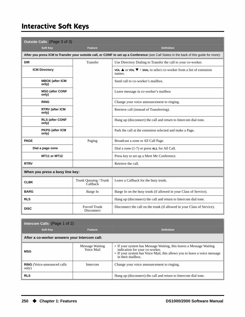
Interactive Soft Keys
250 ◆ Chapter 1: Features DS1000/2000 Software Manual
After you press ICM to Transfer your outside call, or CONF to set up a Conference (see Call States in the back of this guide for more):
DIR Transfer Use Directory Dialing to Transfer the call to your co-worker.
ICM Directory VOL ▲ or VOL ▼ + DIAL to select co-worker from a list of extension names.
MBOX (after ICM only)
Send call to co-worker’s mailbox.
MSG (after CONF only)
Leave message in co-worker’s mailbox
RING Change your voice announcement to ringing.
RTRV (after ICM only)
Retrieve call (instead of Transferring).
RLS (after CONF only)
Hang up (disconnect) the call and return to Intercom dial tone.
PKPG (after ICM only)
Park the call at the extension selected and make a Page.
PAGE Paging Broadcast a zone or All Call Page.
Dial a page zone Dial a zone (1-7) or press ALL for All Call.
MT11 or MT12 Press key to set up a Meet Me Conference.
RTRV Retrieve the call.
When you press a busy line key:
CLBK Trunk Queuing / Trunk Callback
Leave a Callback for the busy trunk.
BARG Barge In Barge In on the busy trunk (if allowed in your Class of Service).
RLS Hang up (disconnect) the call and return to Intercom dial tone.
DISC Forced Trunk Disconnect
Disconnect the call on the trunk (if allowed in your Class of Service).
Intercom Calls (Page 1 of 2)
Soft Key Feature Definition
After a co-worker answers your Intercom call:
MSG
Message WaitingVoice Mail
• If your system has Message Waiting, this leaves a Message Waiting indication for your co-worker.
• If your system has Voice Mail, this allows you to leave a voice message in their mailbox.
RING (Voice-announced calls only)
Intercom Change your voice announcement to ringing.
RLS Hang up (disconnect) the call and return to Intercom dial tone.
Outside Calls (Page 3 of 3)
Soft Key Feature Definition

Interactive Soft Keys
DS1000/2000 Software Manual Chapter 1: Features ◆ 251
After you call a co-worker and hear busy tone:
MSG
Message WaitingVoice Mail
• If your system has Message Waiting, this leaves a Message Waiting indication for your co-worker.
• If your system has Voice Mail, this allows you to leave a voice message in their mailbox.
CAMP Call Waiting / Camp-On
Send Camp On tones to your busy co-worker. If you hang up, your Camp On converts to a Callback.
CLBK Callback Leave a Callback for busy co-worker.
BARG Barge In Barge In on busy co-worker (if allowed in your Class of Service).
MON Monitor / Silent Monitor
Monitor your co-worker’s call (if allowed in your Class of Service).
After you call a co-worker and hear busy/ring tone:
MSG
Message WaitingVoice Mail
• If your system has Message Waiting, this leaves a Message Waiting indication for your co-worker.
• If your system has Voice Mail, this allows you to leave a voice message in their mailbox.
VOVR Voice Over Initiate a Voice Over with your busy co-worker.
BARG Barge In Barge In on your busy co-worker (if allowed in your Class of Service).
MON Monitor / Silent Monitor
Monitor your co-worker’s call (if allowed in your Class of Service).
After you call a co-worker and hear Do Not Disturb tone:
MSG
Message WaitingVoice Mail
• If your system has Message Waiting, this leaves a Message Waiting indication for your co-worker.
• If your system has Voice Mail, this allows you to leave a voice message in their mailbox.
OVRD Do Not Disturb Override an extension’s Do Not Disturb (if allowed in your Class of Service).
RLS Hang up (disconnect) the call and return to Intercom dial tone.
After you answer an Intercom call:
CONF Conference Set up a Conference with your caller.
RLS Hang up (disconnect) the call and return to Intercom dial tone.
After you place or answer a Door Box call:
OPEN Door Box Press to activate (open) the system relay associated with the Door Box door strike (if programmed and installed).
CLOSEAfter pressing OPEN above, press CLOSE to deactivate (close) the system relay associated with the Door Box door strike (if programmed and installed).
RLS Hang up (disconnect) the call and return to Intercom dial tone.
Intercom Calls (Page 2 of 2)
Soft Key Feature Definition

Interactive Soft Keys
252 ◆ Chapter 1: Features DS1000/2000 Software Manual
Super Display Soft Keys
Global Navigation Soft Keys You May See At Any Time
Soft Key Feature Definition
PREVIOUS Press this Soft Key to back up to the previous set of options.
MORE Press this Soft Key to display additional options for your call.
CANCEL Press to return your telephone to the idle mode.
While Your Telephone Is Idle (Page 1 of 4)
Soft Key Feature Definition
Use Directory Dialing to select a call from a list of names:
DIRECTORY Press to access Directory Dialing
INTERCOM Directory Dialing
ICM Directory VOL ▲ or VOL ▼ + DIAL to select co-worker from a list of extension names.
PERSONAL VOL ▲ or VOL ▼ + DIAL to select one of your Personal Speed Dial bins.
COMPANY VOL ▲ or VOL ▼ + DIAL to select a System Speed Dial bin.
Set up Call Forwarding, Distinctive Ringing, Speed Dial, Volume Controls and Intercom voice-announcements
PROGRAM Press to set up Call Forwarding, Programmable Function Key ringing, Speed Dial, Do Not Disturb, and Intercom voice-announcements.
CALL FWRD Call Forwarding
Enter Call FWD type
Enter the Call Forwarding type + Co-worker’s extension, 0 (operator) or MW (Voice Mail) + SPK.0 = Cancel forwarding2 = Busy/No Answer4 = Immediate6 = No answer7 = Personal Answering Machine Emulation8 = Selectable Display Messaging
RING Press to set up ringing Distinctive Ringing.
ASSIGN Distinctive Ringing Press to select the Extension Override option.
DAY RING Press to select the ringing mode for day mode calls.
RING “A”
For the type of call selected (day, night or delay), press to select ring type A.
RING “B”
For the type of call selected (day, night or delay), press to select ring type B.
RING “C”
For the type of call selected (day, night or delay), press to select ring type C.

Interactive Soft Keys
DS1000/2000 Software Manual Chapter 1: Features ◆ 253
CO LINE
Distinctive Ringing For the type of call selected (day, night, or delay), press to select the system default ring type.
NIGHT RING Press to select the ringing mode for night mode calls, then choose from RING “A”, RING “B”, RING “C”, or CO LINE above.
DELAY RING Press to select the ringing mode for delay ring calls, then choose from RING “A”, RING “B”, RING “C”, or CO LINE above.
CONFIG Press to select the Distinctive Ring Configuration option.
INTERCOM Press to change the sound of your Intercom ringing.
RING TONE
For the type of ring selected (Intercom, Ring Group, recall, “A”, “B”, or “C”), press to change the ringing pitch.
CADENCE
For the type of ring selected (Intercom, Ring Group, recall, “A”, “B”, or “C”), press to change the ringing cadence.
CAN-CEL
Press to return to the previous Distinctive Ringing screen.
SAVE After selecting a new cadence and/or tone, press to save your entry.
RING GROUP
Press to change the sound of your Ring Group ringing.
RECALL Press to change the sound of your Hold, Park, and Transfer Recall ringing.
RING “A” Press to change the sound of your type “A” ringing.
RING “B” Press to change the sound of your type “B” ringing.
RING “C” Press to change the sound of your type “C” ringing.
DEFAULT Press to select one of the 3 default ringing setups (1-3) and cancel your custom settings. Also provides access to the Administration (ADMIN) feature.
KEY Press to select the Key Ring Override option.
CALLCOVERAGE
• If the Key Ring Override option is enabled, press a lit Call Coverage key and then select the key’s ring type (1=”A”, 2=”B”, 3=”C”, 0=default).
• Press the lit Call Coverage key repeatedly to select the key’s ringing mode (day, night, delay, or lamp only).
PICKUP • If the Key Ring Override option is enabled, press a lit Group Call Pickup key and then select the key’s ring type (1=”A”, 2=”B”, 3=”C”, 0=default).
• Press the lit Group Call Pickup key repeatedly to select the key’s ringing mode (day, night, delay, or lamp only).
LINE • If the Key Ring Override option is enabled, press a lit line key and then select the key’s ring type (1=”A”, 2=”B”, 3=”C”, 0=default).
• Press the lit line key repeatedly to select the key’s ringing mode (day, night, delay, or lamp only).
SPEED DIAL Speed Dial Enter bin (200-299 for System, 701-720 for Personal) + HOLD + Line (1-16), Group (90-98) or ICM + HOLD + Number + HOLD + Name + HOLD + SPK.
While Your Telephone Is Idle (Page 2 of 4)
Soft Key Feature Definition

Interactive Soft Keys
254 ◆ Chapter 1: Features DS1000/2000 Software Manual
VOLUME Volume Control Press to access the Volume Control feature.
RING Press to select the ringing volume control, then VOL ▲ or VOL ▼ to adjust the volume.
OFF-HK RING Press to select the off-hook ringing volume control, then VOL ▲ or VOL ▼ to adjust the volume.
PAGE Press to select the Paging volume control, then VOL ▲ or VOL ▼ to adjust the volume.
VOICE ANNOUNCE Intercom
VOICE ANNOUNCE ON
Press to enable voice-announcements for incoming Intercom calls.
VOICE ANNOUNCE OFF
Press to have all incoming Intercom calls ring (i.e., disable voice-announce).
Call Your Mailbox
V-MAIL 00 Voice Mail Press to call your Voice Mail mailbox. The numbers after VM show the number of new messages in your mailbox.
Use Caller ID Logging
CL00 Caller ID Logging Press to review your Caller ID log.
VIEW ALL Press to review all your Caller ID logs.
VIEW UNANS Press to review the records just for calls that rang your phone but were unanswered in the system.
VIEW ANS Press to review the records just for calls that rang your phone that were answered in the system.
DELETE ALL Press to delete all Caller ID records logged at your phone.
YES After you press DELETE ALL, press to confirm the deletion.
NO After you press DELETE ALL, press to cancel the deletion.
EXIT Press to exit Caller ID Logging and return to the idle display.
Page a Co-worker
PAGE Paging Press to access Paging options.
ALL Make an All Call Page.
MEET ME 11 or 12 Press to set up Meet Me Conference with code 11 or 12.
ZONE 1 thru ZONE 7 Page into zone selected (1-7).
MEET ME 11 or 12 Press to set up Meet Me Conference with code 11 or 12.
While Your Telephone Is Idle (Page 3 of 4)
Soft Key Feature Definition
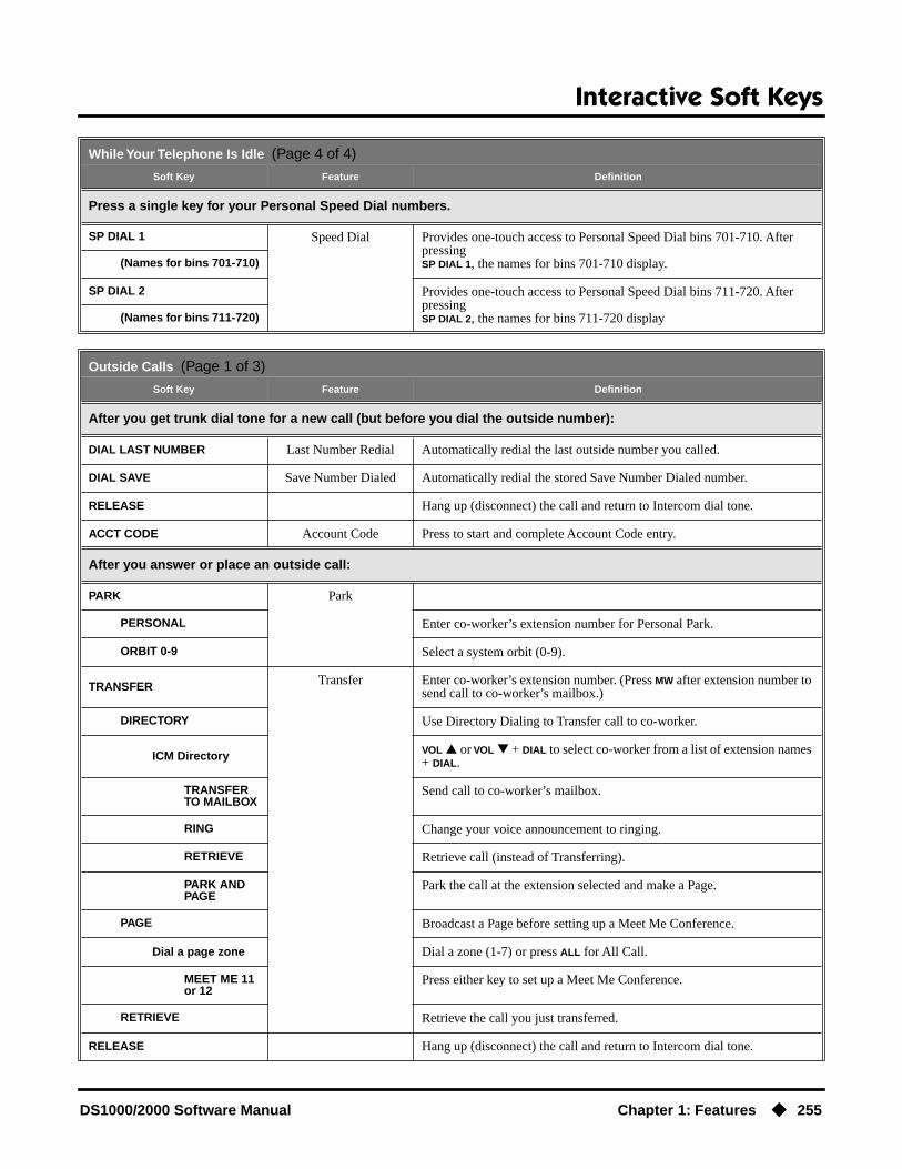
Interactive Soft Keys
DS1000/2000 Software Manual Chapter 1: Features ◆ 255
Press a single key for your Personal Speed Dial numbers.
SP DIAL 1 Speed Dial Provides one-touch access to Personal Speed Dial bins 701-710. After pressingSP DIAL 1, the names for bins 701-710 display.(Names for bins 701-710)
SP DIAL 2 Provides one-touch access to Personal Speed Dial bins 711-720. After pressingSP DIAL 2, the names for bins 711-720 display(Names for bins 711-720)
Outside Calls (Page 1 of 3)
Soft Key Feature Definition
After you get trunk dial tone for a new call (but before you dial the outside number):
DIAL LAST NUMBER Last Number Redial Automatically redial the last outside number you called.
DIAL SAVE Save Number Dialed Automatically redial the stored Save Number Dialed number.
RELEASE Hang up (disconnect) the call and return to Intercom dial tone.
ACCT CODE Account Code Press to start and complete Account Code entry.
After you answer or place an outside call:
PARK Park
PERSONAL Enter co-worker’s extension number for Personal Park.
ORBIT 0-9 Select a system orbit (0-9).
TRANSFER Transfer Enter co-worker’s extension number. (Press MW after extension number to send call to co-worker’s mailbox.)
DIRECTORY Use Directory Dialing to Transfer call to co-worker.
ICM Directory VOL ▲ or VOL ▼ + DIAL to select co-worker from a list of extension names + DIAL.
TRANSFER TO MAILBOX
Send call to co-worker’s mailbox.
RING Change your voice announcement to ringing.
RETRIEVE Retrieve call (instead of Transferring).
PARK AND PAGE
Park the call at the extension selected and make a Page.
PAGE Broadcast a Page before setting up a Meet Me Conference.
Dial a page zone Dial a zone (1-7) or press ALL for All Call.
MEET ME 11 or 12
Press either key to set up a Meet Me Conference.
RETRIEVE Retrieve the call you just transferred.
RELEASE Hang up (disconnect) the call and return to Intercom dial tone.
While Your Telephone Is Idle (Page 4 of 4)
Soft Key Feature Definition

Interactive Soft Keys
256 ◆ Chapter 1: Features DS1000/2000 Software Manual
CONFERENCE Conference
DIRECTORY Use Directory Dialing to set up the Conference with a co-worker.
ICM Directory VOL ▲ or VOL ▼ + DIAL to select co-worker from a list of extension names.
PAGE Broadcast a Page before setting up a Meet Me Conference.
Dial a page zone Dial a zone (1-7) or press ALL for All Call.
MEET ME 11or 12
Press key to set up a Meet Me Conference.
RETRIEVE Retrieve the call you just transferred.
RECORD Voice Mail Record the active call in your Voice Mail mailbox (if allowed in your Class of Service).
SAVE Save Number Dialed Save the number you just dialed. Not used for incoming calls.
MAN TIMER Call Timer (Manual) Turns the Call Timer on and off. Turning the timer off resets it to 00:00:00.
ACCT CODE Account Code Press to start and complete Account Code entry.
After you press ICM to Transfer your outside call, or CONF to set up a Conference (see Call States in the back of this guide for more):
DIRECTORY Transfer Use Directory Dialing to Transfer the call to your co-worker.
ICM Directory VOL ▲ or VOL ▼ + DIAL to select co-worker from a list of extension names.
TRANSFER TO MAILBOX (after ICM only)
Send call to co-worker’s mailbox.
LEAVE MESSAGE (after CONF only)
Leave message in co-worker’s mailbox
RING Change your voice announcement to ringing.
RETRIEVE (after ICM only)
Retrieve call (instead of Transferring).
RELEASE (after CONF only)
Hang up (disconnect) the call and return to Intercom dial tone.
PARK AND PAGE (after ICM only)
Park the call at the extension selected and make a Page.
PAGE Paging Broadcast a zone or All Call Page.
ALL Make an All Call Page.
MEET ME 11 or 12 Press to set up Meet Me Conference with code 11 or 12.
ZONE 1 thru ZONE 7 Page into zone selected (1-7).
MEET ME 11 or 12 Press to set up Meet Me Conference with code 11 or 12.
RETRIEVE Retrieve the call.
Outside Calls (Page 2 of 3)
Soft Key Feature Definition

Interactive Soft Keys
DS1000/2000 Software Manual Chapter 1: Features ◆ 257
When you press a busy line key:
CALLBACK Trunk Queuing / Trunk Callback
Leave a Callback for the busy trunk.
RELEASE Hang up (disconnect) the call and return to Intercom dial tone.
BARGE IN Barge In Barge In on the busy trunk (if allowed in your Class of Service).
FORCED DISCONNECT Forced Trunk Disconnect
Disconnect the call on the trunk (if allowed in your Class of Service).
Intercom Calls (Page 1 of 2)
Soft Key Feature Definition
After a co-worker answers your Intercom call:
LEAVE MESSAGE
Message WaitingVoice Mail
• If your system has Message Waiting, this leaves a Message Waiting indication for your co-worker.
• If your system has Voice Mail, this allows you to leave a voice message in their mailbox.
RING Intercom Change your voice announcement to ringing.
RELEASE Hang up (disconnect) the call and return to Intercom dial tone.
After you call a co-worker and hear busy tone:
LEAVE MESSAGE
Message WaitingVoice Mail
• If your system has Message Waiting, this leaves a Message Waiting indication for your co-worker.
• If your system has Voice Mail, press to leave a voice message in their mailbox.
CAMP ON Call Waiting / Camp-On
Send Camp On tones to your busy co-worker. If you hang up, your Camp On converts to a Callback.
CALLBACK Callback Leave a Callback for busy co-worker.
BARGE IN Barge In Barge In on busy co-worker (if allowed in your Class of Service).
SILENT MONITOR Monitor / Silent Monitor
Monitor your co-worker’s call (if allowed in your Class of Service).
After you call a co-worker and hear busy/ring tone:
LEAVE MESSAGE
Message WaitingVoice Mail
• If your system has Message Waiting, this leaves a Message Waiting indication for your co-worker.
• If your system has Voice Mail, this allows you to leave a voice message in their mailbox.
VOICE OVER Voice Over Initiate a Voice Over with your busy co-worker.
BARGE IN Barge In Barge In on your busy co-worker (if allowed in your Class of Service).
SILENT MONITOR Monitor / Silent Monitor
Monitor your co-worker’s call (if allowed in your Class of Service).
Outside Calls (Page 3 of 3)
Soft Key Feature Definition

Interactive Soft Keys
258 ◆ Chapter 1: Features DS1000/2000 Software Manual
After you call a co-worker and hear Do Not Disturb tone:
LEAVE MESSAGE
Message WaitingVoice Mail
• If your system has Message Waiting, this leaves a Message Waiting indication for your co-worker.
• If your system has Voice Mail, this allows you to leave a voice message in their mailbox.
DND OVERRIDE Do Not Disturb Override an extension’s Do Not Disturb (if allowed in your Class of Service).
RELEASE Hang up (disconnect) the call and return to Intercom dial tone.
After you answer an Intercom call:
CONFERENCE Conference Set up a Conference with your caller.
RELEASE Hang up (disconnect) the call and return to Intercom dial tone.
After you place or answer a Door Box call:
OPEN DOOR Door Box Press to activate (open) the system relay associated with the Door Box door strike (if programmed and installed).
CLOSE DOORAfter pressing OPEN DOOR above, press CLOSE DOOR to deactivate (close) the system relay associated with the Door Box door strike (if programmed and installed).
RELEASE Hang up (disconnect) the call and return to Intercom dial tone.
Intercom Calls (Page 2 of 2)
Soft Key Feature Definition

Interactive Soft Keys
DS1000/2000 Software Manual Chapter 1: Features ◆ 259
Soft Key Index
• Following is an alphabetical index of your telephone’s soft keys.
Soft Key Feature Phone Type Definition
“A” Distinctive Ringing Keyset Press to select ring type A.
ACCTAccount Code
KeysetPress to start and complete Account Code entry.
ACCT CODE Super Display
ALL PageKeyset
Make an All Call Page.Super Display
ALL Caller ID Logging Keyset Press to review all your Caller ID logs.
ASGNDistinctive Ringing
KeysetPress to select the Extension Override option.
ASSIGN Super Display
“B” Distinctive Ringing Keyset Press to select ring type B.
BARGBarge In
KeysetBarge In on a busy trunk.
BARGE IN Super Display
“C” Distinctive Ringing Keyset Press to select ring type C.
CAMPCall Waiting / Camp On
KeysetSend Camp-On tones to a busy co-worker.
CAMP ON Super Display
CCKDistinctive Ringing
Keyset Press lit Call Coverage key to select key’s ring type and ringing mode.
CALL COVERAGE Super Display
CDNCDistinctive Ringing
KeysetPress to change the ringing cadence.
CADENCE Super Display
CFWDCall Forwarding
KeysetAccess Call Forwarding options.
CALL FWD Super Display
CL00 Caller ID LoggingKeyset
Press to review your Caller ID log.Super Display
CLBK CallbackTrunk Queuing and
Trunk Callback
KeysetLeave Callback for a busy trunk or co-worker.
CALLBACK Super Display
CLOSE Door BoxKeyset Press to Deactivate (close) the system relay associated with
the Door Box door strike (if programmed and installed).Super Display
CMPYDirectory Dialing
KeysetAccess your company’s System Speed Dial bins.
COMPANY Super Display

Interactive Soft Keys
260 ◆ Chapter 1: Features DS1000/2000 Software Manual
CNCLN/A
KeysetReturn to idle.
CANCEL Super Display
CNCLDistinctive Ringing
KeysetPress to return to the previous Distinctive Ringing screen.
CANCEL Super Display
CNFGDistinctive Ringing
KeysetPress to select the Distinctive Ring Configuration option.
CONFIG Super Display
CO LINE Distinctive Ringing Super Display Press to select the system default ring type.
CONFConference
KeysetSet up a Conference.
CONFERENCE Super Display
DAYDistinctive Ringing
KeysetPress to select the ringing mode for day mode calls.
DAY RING Super Display
DEL*Caller ID Logging
KeysetPress to delete all Caller ID records logged at your phone.
DELETE ALL Super Display
DFLTDistinctive Ringing
Keyset Press to select one of the 3 default ringing setups (1-3) and cancel your custom settings.
DEFAULT Super Display
DIAL LAST NUMBER Last Number Redial Super Display Automatically redial the last outside number you called.
DIR ConferenceDirectory Dialing
Transfer
KeysetAccess Directory Dialing, Paging and Meet Me Conference.
DIRECTORY Super Display
DISC Forced Trunk Disconnect Keyset Disconnect the call on the trunk.
DLSVSave Number Dialed
KeysetRedial the number saved by Save Number Dial.
DIAL SAVE Super Display
DLYDistinctive Ringing
KeysetPress to select the ringing mode for delay ring calls.
DELAY RING Super Display
DND Do Not DisturbKeyset
Enable or disable Do Not Disturb.Super Display
DND OVERRIDE Do Not Disturb Super Display Override an extension’s Do Not Disturb.
Enter Call FWD type Call ForwardingKeyset
Enter the Call Forwarding type (0, 2, 4, 6, 7, 8).Super Display
EXIT Caller ID LoggingKeyset
Press to exit Caller ID Logging and return to the idle display.Super Display
EXT Directory Dialing Keyset Access Personal and System Speed Dial bins.
Soft Key Feature Phone Type Definition

Interactive Soft Keys
DS1000/2000 Software Manual Chapter 1: Features ◆ 261
FORCED DISCONNECT Forced Trunk Disconnect Super Display Disconnect the call on the trunk.
ICM DirectoryConference
Directory DialingTransfer
KeysetSelect a co-worker from a list of names.
Super Display
ICMDistinctive Ringing
KeysetPress to change the sound of your Intercom ringing.
INTERCOM Super Display
INTDirectory Dialing
KeysetAccess Intercom Directory Dialing.
INTERCOM Super Display
KEY Distinctive RingingKeyset
Press to select the Key Ring Override option.Super Display
LEAVE MESSAGE Message WaitingVoice Mail Super Display Leave Message Waiting or message in Voice Mail mailbox.
LINE Distinctive Ringing Keyset Press to select the system default ring type.
LINE Distinctive RingingKeyset
Press lit line key to select key’s ring type and ringing mode.Super Display
LND Last Number Redial Keyset Redial the last outside number you dialed.
MBOX Transfer Keyset Send a call to your co-worker’s mailbox.
MON Monitor / Silent Monitor Keyset Monitor your co-worker’s call.
MORE N/AKeyset
Display additional options for your call.Super Display
MSG Message WaitingVoice Mail Keyset Leave a Message Waiting or a Voice Mail message.
MT11 ConferenceMeet Me Conference
Transfer
KeysetSet up a Meet Me Conference on circuit 11.
MEET ME 11 Super Display
MT12 ConferenceMeet Me Conference
Transfer
KeysetSet up a Meet Me Conference on circuit 12.
MEET ME 12 Super Display
MTMRCall Timer (Manual)
KeysetStart and stop the Call Timer.
MAN TIMER Super Display
NGTDistinctive Ringing
KeysetPress to select the ringing mode for night mode calls.
NIGHT RING Super Display
NO Caller ID LoggingKeyset After you press DEL* or DELETE ALL, press to cancel the
deletion.Super Display
Soft Key Feature Phone Type Definition
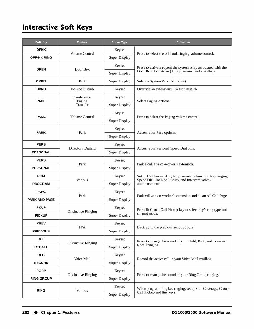
Interactive Soft Keys
262 ◆ Chapter 1: Features DS1000/2000 Software Manual
OFHKVolume Control
KeysetPress to select the off-hook ringing volume control.
OFF-HK RING Super Display
OPEN Door BoxKeyset Press to activate (open) the system relay associated with the
Door Box door strike (if programmed and installed).Super Display
ORBIT Park Super Display Select a System Park Orbit (0-9).
OVRD Do Not Disturb Keyset Override an extension’s Do Not Disturb.
PAGEConference
PagingTransfer
KeysetSelect Paging options.
Super Display
PAGE Volume ControlKeyset
Press to select the Paging volume control.Super Display
PARK ParkKeyset
Access your Park options.Super Display
PERSDirectory Dialing
KeysetAccess your Personal Speed Dial bins.
PERSONAL Super Display
PERSPark
KeysetPark a call at a co-worker’s extension.
PERSONAL Super Display
PGMVarious
Keyset Set up Call Forwarding, Programmable Function Key ringing, Speed Dial, Do Not Disturb, and Intercom voice-announcements.PROGRAM Super Display
PKPGPark
KeysetPark call at a co-worker’s extension and do an All Call Page.
PARK AND PAGE Super Display
PKUPDistinctive Ringing
Keyset Press lit Group Call Pickup key to select key’s ring type and ringing mode.
PICKUP Super Display
PREVN/A
KeysetBack up to the previous set of options.
PREVIOUS Super Display
RCLDistinctive Ringing
Keyset Press to change the sound of your Hold, Park, and Transfer Recall ringing.
RECALL Super Display
RECVoice Mail
KeysetRecord the active call in your Voice Mail mailbox.
RECORD Super Display
RGRPDistinctive Ringing
KeysetPress to change the sound of your Ring Group ringing.
RING GROUP Super Display
RING VariousKeyset When programming key ringing, set up Call Coverage, Group
Call Pickup and line keys.Super Display
Soft Key Feature Phone Type Definition

Interactive Soft Keys
DS1000/2000 Software Manual Chapter 1: Features ◆ 263
RING Transfer Keyset Change your voice announcement to ringing.
RING Volume ControlKeyset
Press to select the ringing volume control.Super Display
RING “A”
Distinctive Ringing Super Display
Press to select ring type A.
RING “B” Press to select ring type B.
RING “C” Press to select ring type C.
RING TONE Distinctive Ringing Super Display Press to change the ringing pitch.
RLSVarious
Keyset Hang up (disconnect) the call and return to Intercom dial tone.
RELEASE Super Display
RTRVConference
Transfer
KeysetRetrieve call (instead of transferring it).
RETRIEVE Super Display
SAVE Distinctive RingingKeyset After selecting a new cadence and/or tone, press to save your
entry.Super Display
SAVE Save Number DialedKeyset
Save the number you just dialed.Super Display
SILENT MONITOR Monitor / Silent Monitor Super Display Monitor your co-worker’s call.
SP DIAL 1 Speed Dial Super Display Select keys for Personal Speed Dial bins 701-710. After pressing SP DIAL 1, the names for bins 701-710 display.
SP DIAL 2 Speed Dial Super Display Select keys for Personal Speed Dial bins 711-720. After pressing SP DIAL 2, the names for bins 711-720 display.
SPDSpeed Dial
KeysetPress then enter your Speed Dial data (bin, etc.).
SPEED DIAL Super Display
SYS Park Keyset Select a system Park orbit (0-9).
TONE Distinctive Ringing Keyset Press to change the ringing pitch.
TRFTransfer
KeysetTransfer a call to a co-worker.
TRANSFER Super Display
TRANSFER TO MAILBOX Transfer Super Display Send call to co-worker’s mailbox.
UNAN Caller ID Logging Keyset Press to review the records just for calls that rang your phone but were unanswered in the system.
VANNIntercom
KeysetAccess the Intercom voice-announce options.
VOICE ANNOUNCE Keyset
VAOFF
Intercom
Keyset
Turn off Intercom voice-announce.VOICE ANNOUNCE
ON Super Display
Soft Key Feature Phone Type Definition

Interactive Soft Keys
264 ◆ Chapter 1: Features DS1000/2000 Software Manual
VAON
Intercom
Keyset
Turn on Intercom voice-announce.VOICE ANNOUNCE
OFF Super Display
VIEW ALL
Caller ID Logging Super Display
Press to review all your Caller ID logs.
VIEW ANS Press to review the records just for calls that rang your phone.
VIEW UNANS Press to review the records just for calls that rang your phone but were unanswered in the system.
VM00Voice Mail
Keyset Call your Voice Mail mailbox. The numbers after VM show the number of new messages in your mailbox.
V-MAIL 00 Super Display
VOLVolume Control
KeysetPress to access the Volume Control feature.
VOLUME Super Display
VOVRVoice Over
KeysetInitiate a Voice Over.
VOICE OVER Super Display
YES Caller ID LoggingKeyset After you press DEL* or DELETE ALL, press to confirm the
deletion.Super Display
ZONE 1-7 Paging Super Display Page into zone selected (1-7).
Soft Key Feature Phone Type Definition

Interactive Soft Keys
DS1000/2000 Software Manual Chapter 1: Features ◆ 265
Call States
• Following is a list of the available soft keys based on the telephone’s call state.
Call States (Page 1 of 3)
State Phone Type Keys
Idle
Keyset DIR PGM VM00 CLOO
Super Display DIRECTORY PROGRAM V-MAIL 00 CALLS 00 PAGE SP DIAL 1 SP DIAL 2
Intercom Dial Tone
From Idle (after pressing ICM)
Keyset DIR PAGE PKUP
Super Display DIRECTORY PAGE PICKUP
From trunk talk state
After pressing ICMKeyset DIR PAGE RTRV
Super Display DIRECTORY PAGE RETRIEVE
After pressing CONF
Keyset DIR PAGE RTRV PKUP (from Conference call only)
Super Display DIRECTORY PAGE RETRIEVE PICKUP (from Conference call only)
From Intercom talk state
After pressing ICMKeyset DIR PAGE PKUP
Super Display DIRECTORY PAGE PICKUP
After pressing CONF
Keyset DIR PAGE RTRV
Super Display DIRECTORY PAGE RETRIEVE
After calling an extension
From idle
If called extension answers using Handsfree Answerback
Keyset MSG RING RLS
Super Display LEAVE MESSAGE RING RELEASE
If called extension is ringing
Keyset MSG RLS
Super Display LEAVE MESSAGE RELEASE
If called extension is busy
Keyset MSG CAMP CLBK MORE BARG MON PREV
Super Display LEAVE MESSAGE CAMP ON CALLBACK BARGE INSILENT MONITOR
If called extension is in Do Not Disturb
Keyset MSG OVRD RLS
Super Display LEAVE MESSAGE DND OVERRIDE RELEASE

Interactive Soft Keys
266 ◆ Chapter 1: Features DS1000/2000 Software Manual
If you hear busy/ring
Keyset MSG VOVR BARG MON
Super Display LEAVE MESSAGE VOICE OVER BARGE IN SILENT MONITOR
After using ICM key to Transfer (but before destination answers)
If called extension answers announcement using Handsfree Answerback
Keyset MBOX RING RTRV PKPG
Super Display TRANSFER TO MAILBOX RING RETRIEVE PARK AND PAGE
If called extension is ringing
Keyset MBOX RTRV PKPG
Super Display TRANSFER TO MAILBOX RETRIEVE PARK AND PAGE
If called extension is busy
Keyset MBOX RTRV PKPG
Super Display TRANSFER TO MAILBOX RETRIEVE PARK AND PAGE
If called extension is in Do Not Disturb
Keyset MSG OVRD RTRV PKPG
Super Display TRANSFER TO MAILBOX DND OVERRIDE RETRIEVE PARK AND PAGE
If you hear busy/ring
Keyset MBOX VOVR RTRV PKPG
Super Display TRANSFER TO MAILBOX VOICE OVER RETRIEVE PARK AND PAGE
After using CONF to set up a Conference (but before destination answers)
If called extension answers announcement using Handsfree Answerback
Keyset MSG RING RLS
Super Display LEAVE MESSAGE RING RELEASE
If called extension is ringing
Keyset MSG RLS
Super Display LEAVE MESSAGE RELEASE
If called extension is busy
Keyset MSG CAMP CLBK MORE BARG MON PREV
Super Display LEAVE MESSAGE CAMP ON CALLBACK BARGE IN SILENT MONITOR
If called extension is in Do Not Disturb
Keyset MSG OVRD RLS
Super Display LEAVE MESSAGE DND OVERRIDE RELEASE
If you hear busy/ring
Keyset MSG VOVR BARGE MON
Super Display LEAVE MESSAGE VOICE OVER BARGE IN SILENT MONITOR
Door Box calls in the talk state
After placing or answering a Door Box call
Keyset OPEN RLS
Super Display OPEN DOOR RELEASE
After pressing OPEN to release the door strike
Keyset CLOSE RLS
Super Display CLOSE DOOR RELEASE
Call States (Page 2 of 3)
State Phone Type Keys

Interactive Soft Keys
DS1000/2000 Software Manual Chapter 1: Features ◆ 267
Outside calls before talk state (interdigit time) set up
After pressing line key from idle
Keyset LND DLSV RLS ACCT
Super Display DIAL LAST NUMBER DIAL SAVE RELEASE ACCT CODE
After pressing ICM while on an outside call
Keyset System drops trunk.
Super Display System drops trunk.
After pressing CONF while on an outside call
Keyset N/A
Super Display N/A
Outside calls in the talk state
Outgoing
Keyset PARK TRF RLS MORE CONF REC SAVE MORE MTMR ACCT PREV
Super Display PARK TRANSFER RELEASE CONFERENCE RECORD SAVE MAN TIMER ACCT CODE
Incoming
Keyset PARK TRF RLS MORE CONF REC SAVE MORE MTMR ACCT PREV
Super Display PARK TRANSFER RELEASE CONFERENCE RECORD SAVEMAN TIMER ACCT CODE
While in a Conference
Keyset N/A
Super Display N/A
Intercom call
Answered Keyset CONF RLS
Super Display CONFERENCE RELEASE
Paging
While receiving a Page broadcast
Keyset N/A
Super Display N/A
While Meet Me Paging is active
Keyset N/A
Super Display N/A
Call States (Page 3 of 3)
State Phone Type Keys

Intercom
268 ◆ Chapter 1: Features DS1000/2000 Software Manual
Intercom
Description
Intercom gives extension users access to other extensions. This provides the system with complete internal calling capability.
Handsfree Answerback and Forced Intercom RingingHandsfree Answerback permits an extension user to respond to a voice-announced Intercom call by speaking toward the phone, without lifting the handset. Like Handsfree, this is a convenience for workers who don’t have a free hand to pick up the handset. Incoming Intercom calls alert with two beeps if the extension has Handsfree Answerback — a single beep if it does not.
Forced Intercom Ringing causes an Intercom call to ring the destination extension. You can enable Forced Intercom Ringing system-wide (for all extensions), or a user can dial a code to have their Intercom call ring the destination.
For more on setting up Handsfree Answerback and Forced Intercom Ringing, see Handsfree and Handsfree Answerback (page 228) for more.
ConditionsNone
Default SettingIntercom calling always enabled.
Programming Guide
DS2000 Fixed Slot Available.
DS2000 U Slot Available. User Programmable Feature steps added for voice-announced Inter-com calls.
DS1000 Available. Includes User Programmable Feature steps for voice-announced Intercom calls.
Use Intercom to call any co-worker.
Step-by-step guide for setting up Intercom
Step 1: When placing Intercom calls, do extension users have adequate time to dial their Intercom digits before the system disables dialing?
• In Program 0401 - Intercom Inter-digit (page 522), leave the Intercom Interdigit time at its default setting.
• In Program 0401 - Intercom Inter-digit (page 522), change the Intercom Interdigit time to meet the site requirements.
If yes
If no

Intercom
DS1000/2000 Software Manual Chapter 1: Features ◆ 269
Step 2: Should Intercom calls voice-announce system-wide?
• In Program 0201 - Voice-Announced Intercom Calls (page 512), enter Y to allow Intercom calls to voice-announce system-wide. Users can still dial 1 to have their calls ring.
• In Program 1807 - Station Voice Announced Intercom Calls (page 652), enter Y to enable voice-announced intercom calls for specific extensions. The User-Programmable Options #IV (#48) and #IR (#47) locally override this setting.
• In Program 0201 - Voice-Announced Intercom Calls (page 512), enter N to have all Intercom calls ring system-wide. Users cannot dial 1 to have their calls voice-announce.
Step 3: Should user be able to respond to a voice-announced Intercom call without lifting the handset (i.e., by using Handsfree Answerback)?
• In Program 0201 - Handsfree Reply on Intercom Calls (page 512), enter Y to enable Handsfree Answerback system-wide.
• In Program 1802 - Handsfree Reply on Intercom Calls (page 636), enter Y to enable Handsfree Answerback for specific extensions.
• In Program 0201 - Handsfree Reply on Intercom Calls (page 512), enter N to disable Handsfree answerback system-wide. Users must lift the handset to respond to voice-announced Intercom calls.
Step-by-step guide for setting up Intercom
If yes
If no
If yes
If no
Intercom
270 ◆ Chapter 1: Features DS1000/2000 Software Manual
Programming ListProgram 0201 - Handsfree Reply on Intercom Calls (page 512)
Enter Y to allow extension user to respond to voice-announced Intercom calls by just speaking toward the phone (i.e., by using Handsfree Answerback). When you enter N, the extension user must lift the handset to speak.
Program 0201 - Voice-Announced Intercom Calls (page 512)Enter Y to enable voice-announced Intercom calls system-wide. If disabled, all Intercom calls ring (i.e., Forced Intercom Ringing is enabled).
Program 1802 - Handsfree Reply on Intercom Calls (page 636)Enter Y to enable Handsfree reply (Handsfree Answerback) on a per-extension basis. Inter-com calls initially ring when this option is disabled. This option requires that you have previ-ously enabled 0201 - Handsfree Reply on Intercom Calls.
Program 0401 - Intercom Inter-digit (page 522)When an extension user places a call, they must dial each succeeding digit within this interval.
Program 1807 - Station Voice Announced Intercom Calls (page 652)Enter Y to enable voice-announced Intercom calls on a per-extension basis. This option requires that you have previously enabled 0201 - Voice-Announced Intercom Calls. The User-Programmable Options #IV (#48) and #IR (#47) locally override this setting.
Other Related FeaturesAttendant Position (page 47)
Designate each extension’s operator.Call Coverage Keys (page 62)
A user can press a Call Coverage Key as an alternative to dialing Intercom numbers.Call Waiting / Camp-On (page 75)
A user can Camp-On after placing an Intercom call to a busy co-worker.Callback (page 79)
A user can leave a Callback request after placing an Intercom call to a busy co-worker.Direct Station Selection (DSS) (page 140)
A user can press a DSS key as an alternative to dialing Intercom numbers.Directory Dialing (page 158)
Directory Dialing is a convenient alternative to manually dialing Intercom numbers.Extension Hunting (page 193)
Voice-announced Intercom calls do not initiate hunting.Flexible Numbering Plan (page 209)
Change the digits users dial to place Intercom calls to co-workers.Group Call Pickup (page 215)
Ringing Intercom calls activate Group Call Pickup if the extension ringing is a member of a Pickup Group.
Handsfree and Handsfree Answerback (page 228)Handsfree Answerback allows a user to answer an Intercom call by just speaking toward the phone.
Headset Compatibility (page 232)Extensions with headsets cannot receive voice-announced Intercom calls.
Hotline (page 240)A user can press a Hotline Key as an alternative to dialing Intercom numbers.
Last Number Redial (page 277)Last Number Redial cannot redial Intercom calls.
Message Waiting (page 291)A user can leave a Message Waiting after placing an Intercom call to a busy co-worker.
Music on Hold (page 303)Music on Hold plays to Intercom callers on Hold.

Intercom
DS1000/2000 Software Manual Chapter 1: Features ◆ 271
Names for Extensions and Trunks (page 306)Extension names help identify Intercom callers to co-workers.
Off-Premise Extensions / On-Premise SLT Extensions (page 317)All Intercom calls to On- and Off-Premise Extensions ring.
Ringdown Extension (page 368)Ringdown Extension follows the voice-announce status of destination extension. For exam-ple, if an extension usually voice-announces Intercom calls, a ringdown to that extension will also voice-announce.
Ringing Line Preference (page 370)Ringing Line Preference answers a ringing Intercom call before a ringing trunk call.
Single Line Telephones (page 381)Single line telephones cannot receive voice-announced Intercom calls.
Transfer (page 455)The system cannot Transfer Intercom calls.
Voice Over (page 493)An extension user can Voice Over to a co-worker busy on an Intercom call.
Volume Controls (page 496)The default Intercom (station-to-station) gain is 0 dB. While on an Intercom call, use VOL ▲ and VOL ▼ to change this setting.
Feature Operation
To place an Intercom call:
1. Lift handset and press ICM.
2. Dial extension number (300-316).
To call the operator, dial the operator s extension number or dial 0 or 01-04 (depend-ing on how your system is set up).
If your call voice-announces the destination, you can dial 1 to force the call to ring.
User Programmable Feature
Feature Mnemonic Operation Access Level
The shaded row below shows the Fixed Slot software User Programmable Feature.
Voice Announce (for your incoming Intercom calls)
#IV or #IR # + I V to enable voice-announce for your incoming Intercom calls
# + I R to enable ringing for your incom-ing Intercom calls
N/A
Voice Announce (for your incoming Intercom calls)
#VA #VA + V for voice announce or R for ring + SPK to exit.
3-5
Intercom dial tone.
ICM on (red).
Two beeps (if voice-announced) or ringing.
N/A

Intercom
272 ◆ Chapter 1: Features DS1000/2000 Software Manual
To answer an Intercom call (if you hear two beeps and your phone has Handsfree Answerback):
1. Speak toward phone.OR
Lift the handset for privacy.
To answer an Intercom call (if you hear one beep and your phone does not have Handsfree Answerback):
1. Lift the handset.
To answer an Intercom call (if you hear ringing):
1. Lift the handset.
Two beeps.
ICM and SPK on (red).
One beep.
ICM and SPK on (red).
Intercom ringing.
ICM flashes.

Key Ring
DS1000/2000 Software Manual Chapter 1: Features ◆ 273
Key Ring
Description
A Key Ring trunk rings an extension according to the settings in Program 1805 - Ring Assign-ments (page 647). Multiple extensions can be enabled to ring immediately or after a programmed delay for each incoming trunk call. In addition, under certain conditions other types of trunk calls divert to Key Ring if unanswered. The following conditions also initiate Key Ring:
● Direct Inward LineAn unanswered DIL diverts to Key Ring if unanswered at the extension to which it is terminated (see Direct Inward Line on page 133 for more).
● HoldCalls left on Hold too long recall the extensions that initially placed them on Hold. If still unan-swered, they divert to Key Ring.
● ParkCalls parked in orbit recall the extension that initially parked them. If unanswered, the call diverts to Key Ring.
● TransferAn unanswered Transfer recalls the extension that initially transferred it. If still unanswered, the trunk diverts to Key Ring.
Overflow for Key Ring CallsIf unanswered, Key Ring calls can route to a programmed overflow destination. The overflow desti-nation can be an extension, Ring Group, UCD Group or Voice Mail. You can set up separate Key ring overflow destinations for the day mode and at night. If unanswered at the overflow destination, the call again diverts to Key Ring. Note that a Key Ring trunk goes into the night mode when any extension with night mode capability presses their Night (System Mode System) key. See Night Service / Night Ring on page 308 for more.
ConditionsNone
Default SettingEnabled. (In DS2000 software version 02.01.007 and higher, Key Ring is enabled by default only at extensions 300-315.)
DS2000 Fixed Slot Available.
DS2000 U Slot Available. In software version 02.01.007 and higher, Key Ring is enabled by default only at extensions 300-315.
DS1000 Available.
So they are not forgotten, unanswered calls automatically ring co-worker’s extensions.

Key Ring
274 ◆ Chapter 1: Features DS1000/2000 Software Manual
Programming Guide
Step-by-step guide for setting up Key Ring (Page 1 of 2)
Step 1: Should extension have Key Ring for trunk?
• In Program 1805 - Ring Assignments (page 647), - Enter 2 for day & night Key Ring,- Enter 3 for night only Key Ring,- Enter 4 for delayed day & night Key Ring.
• To ensure that a trunk will always have a ring des-tination, consider making at least one extension in the system type 2 for all trunks.
• In Program 1805 - Ring Assignments (page 647), enter 1 for lamp only (no Key Ring).
Step 2: Should trunk be a Key Ring trunk during the day?
• In Program 1003 - Direct Termination (Day) (page 593), press CLEAR to assign the trunk as a day mode Key Ring trunk.
• Refer to Direct Inward Line on page 133 to make a different day mode assignment for the trunk.
Step 3: Should trunk overflow during the day mode?
• In Program 1003 - Activate Overflow During the Day (page 593), enter Y.
• In Program 1003 - Day Overflow Destination (page 593), assign the extension, Ring Group, UCD Group master number or Voice Mail master number you want to use for the trunk’s day mode overflow destination.
• In Program 1003 - Activate Overflow During the Day (page 593), enter N.
Step 4: Should trunk be a Key Ring trunk during the night?
• In Program 1003 - Direct Termination (Night) (page 594), press CLEAR to assign the trunk as a night mode Key Ring trunk.
• Refer to Direct Inward Line on page 133 to make a different night mode assignment for the trunk.
If yes
If no
If yes
If no
If yes
If no
If yes
If no

Key Ring
DS1000/2000 Software Manual Chapter 1: Features ◆ 275
Programming ListProgram 0401 - Transfer Recall (page 522)
This interval sets how long a call will ring the day or night overflow destination before divert-ing to key ring.
Program 0401 - Trunk Revert (page 523)This interval sets how long a call will ring its initial day or night mode destination before rout-ing to the programmed overflow destination.
Program 1003 - Direct Termination (Day) (page 593)Press CLEAR to assign the trunk to Key Ring in the day mode.
Program 1003 - Activate Overflow During the Day (page 593)Enter Y if unanswered day mode calls on the trunk should route to the day overflow destina-tion. Enter N if unanswered calls should stay at Key Ring.
Program 1003 - Day Overflow Destination (page 593)Enter the extension, Ring Group, UCD Group master number or Voice Mail master number that you want to assign as the day overflow destination.
Step 5: Should trunk overflow during the night mode?
• In Program 1003 - Activate Overflow at Night (page 594), enter Y.
• In Program 1003 - Night Overflow Destination (page 594), assign the extension, Ring Group, UCD Group master number or Voice Mail master number you want to use for the trunk’s night mode overflow destination.
• In Program 1003 - Activate Overflow at Night (page 594), enter N.
Step 6: Do the trunks ring their initial mode destinations for the correct interval before diverting to the overflow destination?
• In Program 0401 - Trunk Revert (page 523), leave the Trunk Revert interval at is currently assigned value.
• In Program 0401 - Trunk Revert (page 523), change the Trunk Revert interval to meet the site requirements.
Step 7: Do the trunks ring their overflow destinations for the correct interval before divert-ing to the Key Ring?
• In Program 0401 - Transfer Recall (page 522), leave the Transfer Recall interval at is currently assigned value.
• In Program 0401 - Transfer Recall (page 522), change the Transfer Recall interval to meet the site requirements.
Step-by-step guide for setting up Key Ring (Page 2 of 2)
If yes
If no
If yes
If no
If yes
If no

Key Ring
276 ◆ Chapter 1: Features DS1000/2000 Software Manual
Program 1003 - Direct Termination (Night) (page 594)Press CLEAR to assign the trunk to Key Ring in the night mode.
Program 1003 - Activate Overflow at Night (page 594)Enter Y if unanswered night mode calls on trunk should route to the night overflow destina-tion. Enter N if unanswered calls should stay at Key Ring.
Program 1003 - Night Overflow Destination (page 594)Enter the extension, Ring Group, UCD Group master number or Voice Mail master number that you want to assign as the night overflow destination.
Program 1805 - Ring Assignments (page 647)Assign ringing for each trunk at each extension (1 = Lamp only [day and night], 2 = Ringing day and night, 3 = Night Ring only, lamp during the day, 4 = Delay ring day and night). To ensure that a trunk will always have a ring destination, consider making at least one extension in the system type 2 for all trunks.
Other Related FeaturesCall Coverage Keys (page 62)
Call Coverage will pick up Key Ring calls.Call Forwarding (page 66)
A Key Ring call will not follow an extension’s Call Forwarding.Call Waiting / Camp-On (page 75)
A Key Ring call will not send Camp-On beeps to a busy extension that normally rings for that call.
Direct Inward Line (page 133)An unanswered DIL reverts to all extensions with Key Ring for the trunk.
Extended Ringing (page 191)With Extended Ringing, a call rings longer at its destination before diverting to Key Ring.
Hold (page 235)Unanswered Hold Recalls revert to Key Ring if not picked up.
Off-Hook Signaling (page 313)Off-Hook Signaling can occur for Key Ring calls.
Park (page 333)An unanswered Park recall diverts to Key Ring.
Transfer (page 455)An unanswered call transferred to an extension diverts to Key Ring if unanswered at the transferring extension.
Feature OperationKey Ring is automatic for those extensions programmed to receive it.

Last Number Redial
DS1000/2000 Software Manual Chapter 1: Features ◆ 277
Last Number Redial
Description
Last Number Redial allows an extension user to quickly redial the last outside number dialed. For example, a user may quickly recall a busy or unanswered number without manually dialing the dig-its. Last Number Redial saves in system memory the last 20 digits a user dials. The number can be any combination of digits 0-9, # and *. The system remembers the digits regardless of whether the call was answered, unanswered or busy. The system normally uses the same trunk as for the initial call. However, if that trunk is busy and is part of a trunk group, Last Number Redial will automati-cally select the next trunk in the group. The user can also preselect a specific trunk if desired.
ConditionsNone
Default SettingEnabled
Programming Guide
Programming ListProgram 1803 - Extension Line Access Assignments (page 642)
An extension can only use trunks for Last Number Redial for which it has outgoing access. The access options are: 0 = No access, 1 = Incoming only. 2 = Outgoing only, 3 = Full access.
DS2000 Fixed SlotAvailable. Last Number Redial saves up to 20 digits. Prior to software version 02.01.07, Last Number Redial would save up to 32 digits.DS2000 U Slot
DS1000
Quickly redial the last number dialed.
Step-by-step guide for setting up Last Number Redial
Step 1: Should extension be able to use Last Number Redial on the trunk?
• In Program 1803 - Extension Line Access Assign-ments (page 642), - Enter 2 for outgoing only access,- Enter 3 for full access.
• In Program 1803 - Extension Line Access Assign-ments (page 642), enter 0 for no access.
If yes
If no

Last Number Redial
278 ◆ Chapter 1: Features DS1000/2000 Software Manual
Other Related FeaturesAccount Codes (page 34)
Last Number Redial does not store Account Codes. This means that the user must manually enter an Account Code to have it included with a call dialed using Last Number Redial.
Central Office Calls, Placing (page 105)Users can easily redial the last outside number dialed.
Intercom (page 268)Last Number Redial cannot redial Intercom calls.
Save Number Dialed (page 373)Save also simplifies dialing important numbers.
Toll Restriction (Software Version 02.02.14 or Higher) (page 439)Last Number Redial will not store a number denied by Toll Restriction.
Toll Restriction (Prior to Software Version 02.02.14) (page 447)Last Number Redial will not store a number denied by Toll Restriction.
Trunk (Line) Queuing / Trunk Callback (page 465)If all trunks are busy and Last Number Redial cannot go through, the user can dial 2 a queue for a trunk to become free. If the user hangs up, the system converts the queue to a Trunk Callback.
Feature Operation
To redial your last call:
1. Lift the handset.
2. (Optional) Press an idle line key to preselect a trunk.If you skip this step, the system automatically selects a trunk from the same group as
your original call.
3. Press LND.
If you hear busy tone, you can dial 2 to queue for a trunk to become free. If you hang up, the system converts the queue to a Trunk Callback.
Dial tone, then your call dialing out.
Line key on (green).

Line Keys
DS1000/2000 Software Manual Chapter 1: Features ◆ 279
Line Keys
Description
A line key provides an extension user with one-button access to trunks. The extension user just presses a line key to place or answer a call on the trunk. There is no need to dial codes to access or intercept trunk calls. In addition, a line key provides a Busy Lamp Field (BLF) for the trunk to which it is assigned (see the table below).
Answering PriorityWhen multiple calls ring an extension simultaneously, the system services the ringing calls in the following order:
1. ICM Key
2. Line Key (from lowest to highest)
3. Loop Key (from lowest to highest)
ConditionsNone
Default Setting(Fixed Slot) Keys 1-8 are line keys for trunks 1-8.(U Slot) Keys 1-12 are line keys for trunks 1-12. In DS2000 software versions 02.01.07 through 02.02.00, Programmable Function Keys are undefined for all extensions above 315.(DS1000) Keys 1-6 are line keys for trunks 1-6.
DS2000 Fixed Slot
Available.DS2000 U Slot
DS1000
Press a line key for one-touch access to an outside line.
Line Key BLF Indications
When the key is: The trunk is:
Off Idle or not installed
On (red) In use or on Exclusive Hold at a co-worker’s extension
On (green) In use at your extension
Winking on (red) On System Hold at a co-worker’s extension
Winking on (green) On System Hold at your extension
Flashing slowly (red) Ringing into the system
Flashing slowly (green) Ringing or recalling directly to your extension
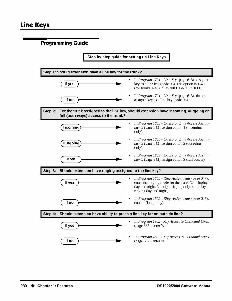
Line Keys
280 ◆ Chapter 1: Features DS1000/2000 Software Manual
Programming Guide
Step-by-step guide for setting up Line Keys
Step 1: Should extension have a line key for the trunk?
• In Program 1701 - Line Key (page 613), assign a key as a line key (code 03). The option is 1-48 (for trunks 1-48) in DS2000, 1-6 in DS1000.
• In Program 1701 - Line Key (page 613), do not assign a key as a line key (code 03).
Step 2: For the trunk assigned to the line key, should extension have incoming, outgoing or full (both ways) access to the trunk?
• In Program 1803 - Extension Line Access Assign-ments (page 642), assign option 1 (incoming only).
• In Program 1803 - Extension Line Access Assign-ments (page 642), assign option 2 (outgoing only).
• In Program 1803 - Extension Line Access Assign-ments (page 642), assign option 3 (full access).
Step 3: Should extension have ringing assigned to the line key?
• In Program 1805 - Ring Assignments (page 647), enter the ringing mode for the trunk (2 = ringing day and night, 3 = night ringing only, 4 = delay ringing day and night).
• In Program 1805 - Ring Assignments (page 647), enter 1 (lamp only).
Step 4: Should extension have ability to press a line key for an outside line?
• In Program 1802 - Key Access to Outbound Lines (page 637), enter Y.
• In Program 1802 - Key Access to Outbound Lines (page 637), enter N.
If yes
If no
Incoming
Outgoing
Both
If yes
If no
If yes
If no

Line Keys
DS1000/2000 Software Manual Chapter 1: Features ◆ 281
Programming ListProgram 1701 - Line Key (page 613)
Assign a programmable key as a line key (code 03). The option is 1-48 (for trunks 1-48) in DS2000, 1-6 in DS1000.
Program 1802 - Key Access to Outbound Lines (page 637)Enter Y to enable or N to disable key access to outbound lines.
Program 1803 - Extension Line Access Assignments (page 642)For each extension, assign the access options for each trunk (0 = No access, 1 = Incoming only. 2 = Outgoing only, 3 = Full access).
Program 1805 - Ring Assignments (page 647)Assign ringing for each trunk at each extension (1 = Lamp only [day and night], 2 = Ringing day and night, 3 = Night Ring only, lamp during the day, 4 = Delay ring day and night).
Other Related FeaturesAutomatic Handsfree (page 51)
Automatic Handsfree allows the keyset user to answer a call ringing a line key without lifting the handset; they just press the line key instead.
Central Office Calls, Placing (page 105)Line Keys give a user one-touch access to specific trunks.
Direct Inward Line (page 133)When you assign a trunk as a DIL, it continues to flash its previously programmed line/loop key assignments. It will ring line/loop keys only after diverting to Key Ring.
Distinctive Ringing (page 162)By using Key Ring Override, Distinctive Ringing allows an extension user to set up unique ringing for their line keys.
Loop Keys (page 283)Loop keys also provide one-button access to trunks.
Ringing Line Preference (page 370)Ringing Line Preference allows an extension user to answer a call ringing a line key just by lifting the handset.
Feature Operation
To place a call over a specific trunk using a line key:
1. Lift handset.
User Programmable Feature
Feature Mnemonic Operation Access Level
The shaded row below shows the Fixed Slot software User Programmable Feature.
Line Keys #RL # + R L + Press Line Key repeatedly to select ringing mode
N/A
Line Keys #RA #RAL + Call Coverage Key repeatedly to select ringing mode + SPK to exit.Line keys flash as follows: Lamp only=On red, Immediate ring=On green, Delay ring=Fast flash green, Night ring=Slow flash green.
2-5
Line Keys
282 ◆ Chapter 1: Features DS1000/2000 Software Manual
2. Press line key.
You may also be able to press a Loop Key. See Loop Keys on page 283 for more.
3. Dial outside number.
To answer an incoming trunk call:
1. Lift handset.If you have Ringing Line Preference, lifting the handset answers the call.If you have Automatic Handsfree, you can press the line or loop key without first lifting
the handset.
2. Press flashing line key.
Trunk dial tone.
Line key on.
Trunk ring.
Line key flashing red for calls that ring you and your co-workers.Line key flashing green for calls that ring you directly (such as DILs and trans-fers).
Conversation with caller.
Line key on.

Loop Keys
DS1000/2000 Software Manual Chapter 1: Features ◆ 283
Loop Keys
Description
Loop keys are programmable keys that simplify the way extension users place and answer outside calls. There are two types of loop keys: Switched Loop Keys and Fixed Loop Keys.
Switched Loop KeysFor incoming calls, Switched Loop Keys provide an appearance for any trunk not assigned to a line key for which the extension has access and ringing. Switched Loop Keys insure that there is a visual appearance for trunks that do not ring an extension’s line keys.
For outgoing calls, Switched Loop Keys provide convenient access to the “dial 9” trunk groups. For example, instead of pressing ICM and dialing 90 for trunk group 0, the user can just press the Switched Loop Key and dial 0 instead.
Fixed Loop KeysFor outgoing calls, a Fixed Loop Key is a loop key assigned to a specific trunk group. When the extension user presses the Fixed Loop Key for an outgoing call, they get the first trunk in the group assigned to the key.
For incoming calls, the Fixed Loop Key works just like a Switched Loop Key. It provides an appearance for any trunk not assigned to a line key for which the extension has access and ringing.
Answering PriorityWhen multiple calls ring an extension simultaneously, the system services the ringing calls in the following order:
1. ICM Key
2. Line Key (from lowest to highest)
3. Loop Key (from lowest to highest)
ConditionsNone
Default Setting
● (Fixed Slot) No Switched Loop Keys assigned. In addition, on all keysets keys 9 and 10 are assigned as Fixed Loop Keys (trunk group 0).
● (U Slot and DS1000) No Switched Loop or Fixed Loop Keys assigned.
DS2000 Fixed Slot
Available.DS2000 U Slot
DS1000
Loop keys simplify answering and placing calls.

Loop Keys
284 ◆ Chapter 1: Features DS1000/2000 Software Manual
Programming Guide
Step-by-step guide for setting up Loop Keys
Step 1: Should extension have a Switched Loop Key?
• In Program 1701 - Switched Loop Key (page 612), assign a key as a Switched Loop Key (code 01).
• In Program 1701 - Switched Loop Key (page 612), do not assign a key as a Switched Loop Key (code 01).
Step 2: Should extension be able to use Switched Loop Key for answering outside calls?
• In Program 1803 - Extension Line Access Assign-ments (page 642), assign incoming (1) or full (3) access to the trunks that should be able to ring the Switched Loop Key. Be sure all trunks assigned ringing in 1805 below also have incoming or full access.
• In Program 1805 - Ring Assignments (page 647), assign day/night ringing (2), night only ringing (3), or delayed day/night ringing (4) to each trunk that should be able to ring the Switched Loop Key.
• In Program 1803 - Extension Line Access Assign-ments (page 642), do not assign incoming (1) or full (3) access to the trunks that should be able to ring the Switched Loop Key.
Step 3: Should extension user be able to place outgoing calls on Switched Loop Keys?
• In Program 1002 - Trunk Groups (page 590), assign installed trunks to trunk groups.
• In Program 1803 - Extension Line Access Assign-ments (page 642), assign outgoing (2) or full (3) access to the trunks that should be available for placing calls from the Switched Loop Key.
• In Program 1002 - Trunk Groups (page 590), do not assign installed trunks to trunk groups.
If yes
If no
If yes
If no
If yes
If no

Loop Keys
DS1000/2000 Software Manual Chapter 1: Features ◆ 285
Programming ListProgram 1002 - Trunk Groups (page 590)
Assign trunks to trunk groups.Program 1701 - Switched Loop Key (page 612)
Assign a programmable key on an extension as a Switched Loop Key (code 01).Program 1701 - Fixed Loop Key (page 612)
Assign a programmable key on an extension as a Loop Key (code 02). The options are 0-8 (Trunk Groups 0-8).
Step 4: Should extension have Fixed Loop Keys?
• In Program 1701 - Fixed Loop Key (page 612), assign a key as a Fixed Loop Key (code 02 + Trunk Group 0-8).
• In Program 1002 - Trunk Groups (page 590), assign installed trunks to the trunk groups assigned to the Fixed Loop Keys.
• In Program 1701 - Fixed Loop Key (page 612), do not assign a key as a Fixed Loop Key (code 02).
Step 5: Should extension have Fixed Loop Keys for answering outside calls?
• In Program 1803 - Extension Line Access Assign-ments (page 642), assign incoming (1) or full (3) access to the trunks in the assigned group that should be able to ring the Fixed Loop Key. Be sure all trunks assigned ringing in 1805 below also have incoming or full access.
• In Program 1805 - Ring Assignments (page 647), assign day/night ringing (2), night only ringing (3), or delayed day/night ringing (4) to each trunk in the group that should be able to ring the Fixed Loop Key.
• In Program 1803 - Extension Line Access Assign-ments (page 642), do not assign incoming (1) or full (3) access to the trunks in the assigned group that should be able to ring the Fixed Loop Key.
Step 6: Should extension user be able to place outgoing calls on Fixed Loop Keys?
• In Program 1803 - Extension Line Access Assign-ments (page 642), assign outgoing (2) or full (3) access to the trunks that should be available for placing calls from the Fixed Loop Key.
• In Program 1803 - Extension Line Access Assign-ments (page 642), do not assign outgoing (2) or full (3) access to the trunks that should be avail-able for placing calls from the Fixed Loop Key.
Step-by-step guide for setting up Loop Keys
If yes
If no
If yes
If no
If yes
If no
Loop Keys
286 ◆ Chapter 1: Features DS1000/2000 Software Manual
Program 1803 - Extension Line Access Assignments (page 642)For each extension, assign the access options for each trunk (0 = No access, 1 = Incoming only. 2 = Outgoing only, 3 = Full access).
Program 1805 - Ring Assignments (page 647)Assign ringing for each trunk at each extension (1 = Lamp only [day and night], 2 = Ringing day and night, 3 = Night Ring only, lamp during the day, 4 = Delay ring day and night).
Other Related FeaturesAutomatic Handsfree (page 51)
Automatic Handsfree allows the keyset user to answer a call ringing a line key without lifting the handset; they just press the line key instead.
Call Forwarding (page 66)Call Forwarding will not reroute a call ringing a loop key (unless the call is a DIL or trans-ferred call).
Central Office Calls, Answering (page 99)An extension user can press a Loop Key to answer an outside call.
Central Office Calls, Placing (page 105)An extension user can press a Loop Key to place an outside call.
Direct Inward Line (page 133)When you assign a trunk as a DIL, it continues to flash its previously programmed line/loop key assignments. It will ring line/loop keys only after diverting to Key Ring.
Line Keys (page 279)Loop keys also provide one-button access to trunks.
Ringing Line Preference (page 370)Ringing Line Preference allows an extension user to answer a call ringing a loop key just by lifting the handset.
Trunk Groups (page 468)Switched and Fixed Loop Keys use the system’s Trunk Groups.

Loop Keys
DS1000/2000 Software Manual Chapter 1: Features ◆ 287
Feature Operation
To answer a call on a Loop Key:
1. Lift handset.
2. Press Switched Loop Key.
To place a call on a Loop Key:
1. Lift handset.
2. Press Loop Key.
3. Dial trunk group code (0-8).
4. Dial outside number.
Trunk ringing.
Loop Key flashing (red).
Conversation with caller.
Loop Key on (green).
Intercom dial tone.
Loop Key on (green).
Trunk dial tone.
Loop Key on (green).

Meet-Me Conference
288 ◆ Chapter 1: Features DS1000/2000 Software Manual
Meet-Me Conference
Description
With Meet-Me Conference, an extension user can set up a telephone meeting with their co-workers. Each party joins the Conference by dialing a Meet Me Conference code. Meet Me Conference lets extension users have a telephone meeting — without leaving the office. Users must join the meeting within the Meet-Me Conference interval.
The system has two Meet-Me Conference codes (#11 and #12). After a Meet-Me Conference is set up and the Meet-Me Conference interval expires, the code used becomes available for a new meet-ing. Since Meet-Me Conference is a type of Conference, the system’s Conference capacity deter-mines:
● The number of users that can join a Meet-Me Conferenceand
● The number of simultaneous conferences.
The following table shows the Conference capacities:
The system’s 32 Conference circuits are dynamically allocated as users request them.
ConditionsNone
Default SettingMeet-Me Conference enabled.
DS2000 Fixed Slot
Available.DS2000 U Slot
DS1000
Set up a multiple-party telephone conversation with your co-workers.
Description Capacity
Conference circuits 32
Maximum simultaneous users in Conference(total of all Conferences system-wide)
32
Maximum simultaneous conferences 8
Maximum parties in any one Conference(trunks and/or extensions)
8

Meet-Me Conference
DS1000/2000 Software Manual Chapter 1: Features ◆ 289
Programming Guide
Programming ListProgram 0401 - Meet-Me Conference (page 523)
When a user initiates a Meet-Me Conference, the system waits this interval for the Paged party to join the call.
Other Related Features
The following features also allow different types of multiple party calls:
Barge In (Intrusion) (page 58)Conference (page 124)Group Listen (page 219)Privacy (page 345)Tandem Trunking / Unsupervised Conference (page 433)
Step-by-step guide for setting up Meet-Me Conference
Step 1: When a co-worker hears a Page for them to join a Meet-Me Conference, do they have enough time to join the telephone meeting?
• In Program 0401 - Meet-Me Conference (page 523), leave the Meet Me Conference inter-val at its assigned value.
• In Program 0401 - Meet-Me Conference (page 523), lengthen the Meet Me Conference interval to meet the site requirements.
Step 2: When co-worker’s are joining a Meet-Me Conference, is the length of time they have to join the meeting excessive?
• In Program 0401 - Meet-Me Conference (page 523), shorten the the Meet Me Conference interval.
• In Program 0401 - Meet-Me Conference (page 523), leave the Meet Me Conference inter-val at its currently assigned value.
If yes
If no
If yes
If no

Meet-Me Conference
290 ◆ Chapter 1: Features DS1000/2000 Software Manual
Feature Operation
To set up a Meet-Me Conference:
1. Page parties and announce the Meet-Me Conference code (#11 or #12).See Paging on page 326 for more on how to page your co-workers.
2. Do not hang up.
3. Press ICM.
4. Dial announced Meet-Me Conference code (#11 or #12).
Your co-worker’s must join the telephone meeting within the Meet Me Conference time.
To join a Meet-Me Conference:
1. Listen for paged invitation to join the Conference.
2. Press ICM.
3. Dial announced Meet-Me Conference code (#11 or #12).
You can join the telephone meeting within the Meet Me Conference time.
Intercom dial tone.
ICM on (red).
Conversation with coworkers.• When the first co-worker joins the Conference, ICM flashes fast (until the
Meet-Me Conference interval expires).• When the second and succeeding co-worker’s join, ICM goes out.
Intercom dial tone.
ICM on (red).
Conversation with coworkers.• When the first co-worker joins the Conference, ICM flashes fast (until the
Meet-Me Conference interval expires).• When the second and succeeding co-worker’s join, ICM goes out.

Message Waiting
DS1000/2000 Software Manual Chapter 1: Features ◆ 291
Message Waiting
Description
An extension user can leave a Message Waiting indication at a busy or unanswered extension requesting a return call. The indication is a flashing MW key at the called extension. Answering the Message Waiting automatically calls the extension which left the indication. Message Waiting ensures that a user will not have to recall an unanswered extension. It also ensures that a user will not miss calls when their extension is busy or unattended.
Additionally, Message Waiting lets extension users:
● Cancel all messages left at their extension.
● Cancel message they left at co-worker’s extensions.
● Scroll through their Messages Waiting and select a co-worker to call back.
An extension user can leave Messages Waiting at any number of extensions. Also, any number of extensions can leave a Message Waiting at the same extension.
Single Line Telephone Message Waiting Enhancements (Software version 02.02.14 or higher)
Message Wait LampingThe system provides two types of Message Wait lamping at single line telephone ports: High Volt-age and FSK (Frequency Shift Keying).
● High Voltage Message WaitingWith High Voltage Message Waiting, the system switches the 100 VDC signal required to light the Message Waiting lamps on analog telephones with messages waiting. This type of lamping is typically used on conventional 2500 type sets with Message Waiting lamps. Check your system’s single line sets to see if they require High Voltage Message Waiting.High Volt-age Message waiting is not available in DS1000.
● FSK Message WaitingThe system can alternately provide an FSK signal to light the Message Waiting lamp on an ana-log telephone. Instead of 90 VDC, FSK Message Waiting uses a modulated carrier signal to control lamping. This type of Message Wait signaling is typically used on new, electronic single line sets. Check your system’s single line sets to see if they require FSK Message Waiting.
SLT Special Dial ToneEither type of Message Wait lamping can be used with SLT Special Dial Tone. When SLT Special Dial Tone is enabled, an SLT user with messages waiting hears a pulsating Intercom dial tone when they lift the handset. Intercom dial tone returns to normal only after the SLT user dials *8 to answer all their Messages Waiting.
Hardware RequirementsFSK Message Waiting and Special Dial Tone have no unique hardware requirements. In DS2000, High Voltage Message Waiting requires analog station PCBs P/N 80040B (4ASTU) and P/N 80041B (8ASTU). High Voltage Message Waiting is not available in DS1000.
DS2000 Fixed Slot • Available.• The single line telephone Message Waiting enhancements require software
version 02.02.14 or higher.DS2000 U Slot
DS1000
Leave a Message Waiting request for a return call.

Message Waiting
292 ◆ Chapter 1: Features DS1000/2000 Software Manual
ConditionsA power failure or system reset cancels all Messages Waiting system wide.
Default SettingEnabled
Programming Guide
Step-by-step guide for setting up Message Waiting
Step 1: Should the system have Message Waiting capability (applicable only when Voice Mail is not installed)?
• In Program 0201 - Voice Mail Installed (page 513), enter N to disable Voice Mail.
• The system can have Message Waiting or Voice Mail, not both.
• In Program 0201 - Voice Mail Installed (page 513), enter Y to enable Voice Mail.
Step 2: Should single line set have SLT Special Dial Tone?
• (Software version 02.02.14 or higher)In Program 0101 - SLT Special Dial Tone (page 510), enable (Y) SLT Special Dial Tone in the single line port’s Class of Service. (Note that this option has no affect on keyset ports with the same COS.)
• In Program 0101 - Extension Class of Service Assignment (page 631), assign Class of Service to extensions.
• (Software version 02.02.14 or higher)In Program 0101 - SLT Special Dial Tone (page 510), disable (N) SLT Special Dial Tone in the single line port’s Class of Service. (Note that this option has no affect on keyset ports with the same COS.)
• In Program 0101 - Extension Class of Service Assignment (page 631), assign Class of Service to extensions.
If yes
If no
If yes
If no

Message Waiting
DS1000/2000 Software Manual Chapter 1: Features ◆ 293
Step 3: Should single line set have high voltage Message Waiting?
• (Software version 02.02.14 or higher)In Program 0101 - SLT High Voltage Message Waiting (page 511), enable (Y) High Voltage Message Waiting in the single line port’s Class of Service. High Voltage Message Waiting is not available in DS1000. If both this option and0101 - SLT FSK Message Waiting are enabled, the system uses FSK Message Waiting.
• In Program 0101 - Extension Class of Service Assignment (page 631), assign Class of Service to extensions.
• (Software version 02.02.14 or higher)In Program 0101 - SLT High Voltage Message Waiting (page 511), disable (N) High Voltage Message Waiting in the single line port’s Class of Service.
• In Program 0101 - Extension Class of Service Assignment (page 631), assign Class of Service to extensions.
Step 4: Should single line set have FSK Message Waiting?
• (Software version 02.02.14 or higher)In Program 0101 - SLT High Voltage Message Waiting (page 511), enable (Y) FSK Message Waiting in the single line port’s Class of Service. If both this option and 0101 - SLT High Voltage Message Waiting are enabled, the system uses FSK Message Waiting.
• In Program 0101 - Extension Class of Service Assignment (page 631), assign Class of Service to extensions.
• (Software version 02.02.14 or higher)In Program 0101 - SLT High Voltage Message Waiting (page 511), disable (N) FSK Message Waiting in the single line port’s Class of Service.
• In Program 0101 - Extension Class of Service Assignment (page 631), assign Class of Service to extensions.
Step-by-step guide for setting up Message Waiting
If yes
If no
If yes
If no
Message Waiting
294 ◆ Chapter 1: Features DS1000/2000 Software Manual
Programming ListProgram 0101 - SLT Special Dial Tone (page 510)
(Software version 02.02.14 or higher)Use this option to enable (Y) or disable (N) SLT Special Dial Tone in a single line port’s Class of Service. (Note that this option has no affect on keyset ports with the same COS.)
Program 0101 - SLT High Voltage Message Waiting (page 511)(Software version 02.02.14 or higher)Use this option to enable (Y) or disable (N) High Voltage Message Waiting for single line ports. High Voltage Message Waiting is not available in DS1000. If both this option and0101 - SLT FSK Message Waiting are enabled, the system uses FSK Message Waiting.
Program 0101 - SLT FSK Message Waiting (page 511)(Software version 02.02.14 or higher)Use this option to enable (Y) or disable (N) FSK Message Waiting for single line ports. If both this option and 0101 - SLT High Voltage Message Waiting are enabled, the system uses FSK Message Waiting.
Program 0201 - Voice Mail Installed (page 513)Enter N to disable Voice Mail and enable Message Waiting.
Program 1801 - Extension Class of Service Assignment (page 631)Assign Class Of Service to extensions.
Other Related FeaturesCall Forwarding (page 66)
● An extension user cannot leave a Message Waiting at an co-worker that has Call Forwarding Immediate (*34) enabled. Pressing MW automatically leaves a message at the forwarding desti-nation instead.
● An extension user cannot leave a Message Waiting at a busy co-worker that has Call Forwarding Busy/No Answer (*32) enabled. Pressing MW will automatically leave a message at the for-warding destination instead.
Do Not Disturb (page 183)An extension user can leave a Message Waiting at an extension in Do Not Disturb.
Intercom (page 268)A user can leave a Message Waiting after placing an Intercom call to a busy co-worker.
Voice Mail (page 477)A system can have either Voice Mail or Message Waiting activated — not both.
Voice Over (page 493)An extension user cannot leave a Message Waiting after using Voice Over.
Feature Operation
To leave a Message Waiting:
1. Place Intercom call to co-worker.The extension you call can be unanswered, busy or in Do Not Disturb.
2. Press MW.
3. Hang up.MW flashes fast at the extension you call.
Intercom dial tone.
ICM on (red).

Message Waiting
DS1000/2000 Software Manual Chapter 1: Features ◆ 295
To answer a Message Waiting:
1. Lift handset.
2. Press MW.
If the extension you call is unanswered, busy or in DND, the system cancels Message Waiting.
If the called extension doesn’t answer, press your MW key to automatically leave them a message.
Normally, your MW key goes out. If it continues to flash, you have additional Messages Waiting.
To review your Messages Waiting and then select a message for a return call:
1. Do not lift the handset.
2. Press MW.The first message displays. Press MW repeatedly to display additional Messages Wait-
ing, if any.
3. When the extension you want to call displays, lift the handset.
4. Press MW.
If the extension you call is unanswered, busy or in DND, the system cancels Message Waiting.
If the called extension doesn’t answer, press your Message Waiting key to automati-cally leave them a message.
N/A
ICM on (red).
Two beeps or ringing, then conversation with co-worker.
ICM on (red).
N/A
MW flashing fast (red).
Two beeps or ringing.
MW flashing fast (red).

Microphone Mute
296 ◆ Chapter 1: Features DS1000/2000 Software Manual
Microphone Mute
Description
Microphone Mute lets a keyset user turn off their phone’s Handsfree microphone at any time. Once activated, Microphone Mute prevents the caller from hearing Handsfree conversations in the user’s work area. The user can turn off the Handsfree microphone while their telephone is idle, busy on a call, in DND or while a call is ringing. The microphone stays off until the user turns it back on.
While an extension has their microphone muted, the calling party hears a single beep when the called extension’s mic is muted.
ConditionsA system reset or power failure cancels all Microphone Mutes system wide.
Default SettingEnabled.
Programming ListNone
Other Related FeaturesExtension Hunting (page 193)
If Music on Hold is enabled for transferred calls in software versions 02.03.03 and higher, a caller transferred to a busy UCD group hears MOH. In software versions prior to 02.03.03, the caller hears ringback.
Handsfree and Handsfree Answerback (page 228)Use Microphone Mute to temporarily turn off the Handsfree microphone.
Feature Operation
To activate Microphone Mute:
1. Press MIC.
You can do this any time while on the phone or while your phone is idle.
DS2000 Fixed Slot
Available.DS2000 U Slot
DS1000
Talk to a co-worker in your office without your caller hearing the conversation.
The systems mutes your Handsfree microphone.
MIC on.

Microphone Mute
DS1000/2000 Software Manual Chapter 1: Features ◆ 297
To deactivate Microphone Mute:
1. Press MIC.
N/A.
MIC on.
N/A.
MIC off.

Modem Cut-Through
298 ◆ Chapter 1: Features DS1000/2000 Software Manual
Modem Cut-Through
Description
The unique DS1000 Modem Cut-Through feature allows a modem connected to the system’s ana-log modem port to achieve maximum throughput speeds on outside calls. In addition, a single line set plugged into the modem is a fully functinoal internal analog extension. this same single ine set is also the system’s power-failure telephone. It directly connexcts to an outside line if there is a commercial power failure.
With Modem Cut-Though, the system can automatically switch an outgoing call from the modem plugged into the PFT/MDM jack directly to trunk 1 or trunk 2. This effectively bypasses the sys-tem, allowing modem calls to achieve maximum modem connect speeds. Modem Cut-Through can also bypass the system on an incoming call to the extension plugged into the PFT/MDM jack (extension 316).
To have your modem directly answer incoming calls on trunk 1 or 2, make the trunk a DIL to the PFT/MDM extension. Turn to Direct Inward Line on page 133 for more.
Modem SetupWhen using Modem Cut-Through, the modem’s dial string for outgoing calls must contain the codes to access trunk 1 or trunk 2. There are several methods you can use:
● Line Dial-up (#9 followed by the trunk number 01-06)Turn to Central Office Calls, Placing on page 105 for the programming required to enable Line Dial-up.
● Direct Trunk Access (4 plus the trunk number 01-06)Turn to Direct Trunk Access on page 154 for the programming required to enable Direct Trunk Access.
● Trunk Group Routing (9 or 90-98)Turn to Trunk Group Routing on page 461 for the programming required to enable Trunk Group Routing.
Conditions
● If you have a modem or power failure telephone connected to the PFT/MDM port, do not con-nect a Voice Mail port to extension 316. This is because extension 316 is in parallel with the PFT/MDM port.
● If you are going to use Modem Cut-Through, be sure your telco provides loop supervision for trunks 1 and 2.
Default SettingModem Cut-Through is always available, if connected.
DS2000 Fixed SlotNot available.
DS2000 U Slot
DS1000 Available.
Maximize modem throughput speeds and obtain power failure cu-through on the same port.

Modem Cut-Through
DS1000/2000 Software Manual Chapter 1: Features ◆ 299
Programming ListProgram 0401 - Intercom Inter-digit (page 522)
The system uses this interval for an extension going into the talk state, which affects the Modem Cut-Though timing. Setting this timer too short or too long could effect DTMF receiver usage and create blocking. Normally, you should leave this timer at its default value (6 seconds). Some applications may require that it be shortened, but it is recommended that it not be lengthened.
Program 0402 - PBX/Centrex Flash (page 527)When a call is recieved or placed on trunk 1 or trunk 2, the system waits this interval plus 100 mS) to determine if a system extension or the PFT/MDM port is connected to the call. If the PFT/MDM port is on the call, the system connects the port directly to the trunk.
Other Related FeaturesVoice Mail (page 477)
If you have a modem or power failure telephone connected to the PFT/MDM port, do not con-nect a Voice Mail port to extension 316. This is because extension 316 is in parallel with the PFT/MDM port.
Feature OperationOperation is automatic if:
● Your modem is properly installed and connected to the PFT/MDM jack.
● The system programming provides a dialing method to access trunks 1 and/or 2.
● The codes to access trunks 1 or 2 are in the modem’s dial string.

Monitor / Silent Monitor
300 ◆ Chapter 1: Features DS1000/2000 Software Manual
Monitor / Silent Monitor
Description
Monitor lets an extension user listen to the conversation at a busy extension. To implement Monitor, an extension user just calls a busy extension and dials the Monitor code. The busy extension and their caller have no indication of the intusion. There are no tones heard and there is no visual indi-cation that monitoring is occuring. For example, Monitor could help the superisor of a service department. The department supervisor could listen to the questions that callers ask without dis-turbing the service call.
ConditionsMonitor uses a system Conference circuit. See Conference on page 124 for more.
Default SettingDisabled
Programming Guide
DS2000 Fixed Slot
Available.DS2000 U Slot
DS1000
Monitor a co-worker’s phone conversation without them knowing you are on the phone.
!! CAUTION !!
Monitor provides no warning tones prior to intrusion. Monitor may be interpreted as an invasion of privacy.
Step-by-step guide for setting up Monitor
Step 1: Should an extension be able to Monitor a co-worker’s call?
• In Program 0101 - Silent Monitor (page 508), enter Y to enable Monitor in the extension’s Class of Service.
• In Program 1801 - Extension Class of Service Assignment (page 631), assign Class of Service to extensions.
• In Program 0101 - Silent Monitor (page 508), enter N to disable Monitor in the extension’s Class of Service.
• In Program 1801 - Extension Class of Service Assignment (page 631), assign Class of Service to extensions
If yes
If no
Monitor / Silent Monitor
DS1000/2000 Software Manual Chapter 1: Features ◆ 301
Programming ListProgram 0101 - Barge-In (Intrusion) (page 506)
In an extension’s Class of Service, enter Y to allow the extension to Barge In on another extension.
Program 1801 - Extension Class of Service Assignment (page 631)Assign Class of Service to extensions.
Other Related FeaturesAttendant Position (page 47)
Since the attendant is never busy, Intercom callers cannot Monitor an attendant.Conference (page 124)
An extension user cannot Monitor a Conference.Privacy (page 345)
Privacy does not block Monitor.
Feature Operation
To Monitor a call:
1. Call busy extension.
2. Dial 6.
3. Listen to the conversation in progress.
Busy tone.
N/A
Two beeps.
N/A

Multiple Directory Numbers
302 ◆ Chapter 1: Features DS1000/2000 Software Manual
Multiple Directory Numbers
DescriptionDS2000 Fixed Slot
See Call Coverage Keys on page 62.DS2000 U Slot
DS1000

Music on Hold
DS1000/2000 Software Manual Chapter 1: Features ◆ 303
Music on Hold
Description
Music on Hold (MOH) plays music to calls on Hold, parked calls, and transferred calls. The music lets the caller know that their calls is waiting, not forgotten. Without Music on Hold, the system provides silence to these types of calls. Music on Hold is available from three sources: two internal beep tones and an external source connected to the CPU music input terminals. The external source typically connects to a customer-provided music source (such as a CD player or FM receiver).
Music on Hold requires a customer-provided music source. This source is also used by Back-ground Music. In DS2000, you connect the music source to the CPU’s 8-pin mod jack. In DS1000, you connect the music source to the Main Equipment Cabinet AUDIO jack. The music source you use must be compatible with the following specifications:
For more on connecting a customer-provided music source, refer to the system’s Hardware Manual.
With Music on Hold enabled, transferred callers can optionally listen to ringback or MOH while their call waits at the transfer destination.
Note:
In accordance with U.S. copyright law, a license may be required from the America Society of Composers, Authors and Publishers (ASCAP) or other similar organizations, if radio, television broadcasts or music other than material not in the public domain are transmitted through the Music on Hold feature of telecommunications systems. NEC America, Inc. hereby disclaims any liability arising out of the failure to obtain such a license.
ConditionsNone
Default SettingExternal MOH enabled.
DS2000 Fixed Slot
Available.DS2000 U Slot
DS1000
Callers can listen to music while waiting for their call to go through.
Table 7: Music Source Specifications
Input Impedance 10K Ohms
Relative Input Level +18 dBr (+/- dBr) at 1.0 kHz

Music on Hold
304 ◆ Chapter 1: Features DS1000/2000 Software Manual
Programming Guide
Programming ListProgram 0201 - Music on Hold (page 512)
Enter Y for this option to enable Music on Hold system-wide.Program 0201 - MOH on Transfer (page 513)
Enter Y for this option to enable Music on Hold for transferred calls.
Step-by-step guide for setting up Music on Hold
Step 1: Should the system have Music on Hold?
• In Program 0201 - Music on Hold (page 512), enter Y to enable Music on Hold system wide.
• In Program 0201 - Music on Hold (page 512), enter N to disable Music on Hold system wide.
Step 2: Assign the Music on Hold source.
• In Program 1003 - MOH Source (page 595), assign the MOH source.The options are:0 - No MOH1 - External at CPU terminals2 - Tone 1 (low pitch)3 - Tone 2 (high pitch)4 - ACI port (currently not used)When entering data, be sure to press VOL ▲ or VOL ▼ after entering your data. Do not press CONF or HOLD instead.
Step 3: Should transferred callers listen to MOH or ringback while waiting?
• In Program 0201 - MOH on Transfer (page 513), enter Y to enable Music on Hold for transferred calls.
• In Program 0201 - MOH on Transfer (page 513), enter N to enable ringback for transferred calls.
If yes
If no
MOH
Ringback

Music on Hold
DS1000/2000 Software Manual Chapter 1: Features ◆ 305
Program 1003 - MOH Source (page 595)Assign the MOH source for the trunk. The options are:0 - No MOH1 - External at CPU terminals2 - Tone 1 (low pitch)3 - Tone 2 (high pitch)4 - ACI port ( currently not used). When entering data, be sure to press VOL ▲ or VOL ▼ after entering your data. Do not press CONF or HOLD instead.
Other Related FeaturesBackground Music (page 55)
Background Music and Music on Hold share the same external music source.Hold (page 235)
If installed, Music on Hold plays to callers on Hold. Intercom (page 268)
Music on Hold plays to Intercom callers on Hold. Intercom callers always hear internal Tone 1.Park (page 333)
If installed, Music on Hold plays to parked callers.Transfer (page 455)
With Music on Hold enabled, transferred callers can optionally listen to ringback or MOH while their call waits at the transfer destination. In software versions 02.03.03 and higher, Music on Hold will also play to transferred callers camped-on to a busy UCD Hunting Group.
Feature OperationMusic on Hold is automatic once enabled.
Names for Extensions and Trunks
306 ◆ Chapter 1: Features DS1000/2000 Software Manual
Names for Extensions and Trunks
Description
Extensions and trunks can have names instead of just circuit numbers. These names show on a key-set’s display when the user places or answers calls. Extension and trunk names make it easier to identify callers. The user does not have to refer to a directory when processing calls. Extension and trunk names can consist of upper and lower case letters,spaces and punctuation, and can be up to 15 characters long.
Extension names display when placing or answering Intercom calls. Trunk names display when using the following features:
● Central Office Calls, Answering
● Central Office Calls, Placing
● Direct Inward Line
● Direct Trunk Access
● Directed Call Pickup
● Last Number Redial
● Line Keys
● Loop Keys
● Night Service / Night Ring
● Park
● Speed Dial
● Transfer
Refer to Programming Names and Text Messages on page 505 when entering names.
ConditionsNone
Default Setting
● No extension names assigned (the extension’s number displays instead).
● All trunk names are TRUNK followed by the trunk’s number (e.g., TRUNK 2 for trunk 2).
DS2000 Fixed Slot
Available.DS2000 U Slot
DS1000
Names help identify trunks and extension.

Names for Extensions and Trunks
DS1000/2000 Software Manual Chapter 1: Features ◆ 307
Programming Guide
Programming ListProgram 1001 - Trunk Extension Number (page 581)
Enter the name for the trunk port. The trunk name can be up to 15 characters long.Program 1801 - Extension Name (page 630)
Enter the name for the extension port. The extension name can be up to 15 characters long.
Other Related FeaturesSee the list under Description above.
Feature OperationTrunk and extension names automatically display once programmed.
Step-by-step guide for setting up Names for Extensions and Trunks
Step 1: Do you want to program names for trunks?
• In Program 1001 - Trunk Name (page 581), assign names to trunks (up to 15 characters).
• In Program 1001 - Trunk Name (page 581), do not change the trunk names from their default entries.
Step 2: Do you want to program names for extensions.
• In Program 1801 - Extension Name (page 630), assign names to extensions (up to 15 characters).
• In Program 1801 - Extension Name (page 630), do not change the extension names from their default entries.
If yes
If no
If yes
If no

Night Service / Night Ring
308 ◆ Chapter 1: Features DS1000/2000 Software Manual
Night Service / Night Ring
Description
Night Service redirects trunk calls to their night mode destination. Typically, the attendant or super-visor activates Night Service after normal working hours, when most employees are unavailable to answer calls. There are two basic types of Night Service: Assigned Night Answer and Universal Night Answer.
Assigned Night Answer rings extensions directly at Night, providing specific answering points for Night Service calls. (For example, you can program trunks to ring the security station at night.)
Universal Night Answer (UNA) allows a user to pick up a call ringing the system at night. With UNA, an employee can go to any telephone and dial a UNA code to answer the call. The extension does not need to have a line/loop key assigned for the ringing call.
Night Service KeysThe night mode status of the system is controlled by the following 3 types of keys:
● Night Key Assigned as a System Mode System KeyThis type of key controls the night mode status of all Key Ring trunks as well as all trunks that are Direct Inward Lines (DILs) to Ring Group master numbers. To program this type of key, see Program 1701 - Night Key (page 615) and Program 1704 - Night Key (page 626). The entry is 18 + CLEAR. Also see Direct Inward Line (page 133).
● Night Key Assigned as a System Mode UCD Master KeyThis type of key controls the night mode status of all trunks terminated to UCD master numbers. It has no affect on Key Ring trunks or trunks terminated to Ring Group master numbers. To program this type of key, see Extension Hunting on page 193, Program 1701 - Night Key (page 615), and Program 1704 - Night Key (page 626). The entry is 18 + UCD Master Number.1
● An Extension’s DND KeyThe DND key controls the night mode status of all trunks that are DILs to the extension. In the day, the trunk rings the extension. When the user presses DND, the DILs ring their programmed night mode destinations. Also see Direct Inward Line (page 133).
Basic Night Service TypesFollowing are the four basic types of Night Service operation for a trunk. Note that only option 3 enables Universal Night Answer.
● Option 1: Key Ring Day and NightThe trunk is a Key Ring trunk during the day and at night. The trunk rings according to the set-tings in Program 1805 - Ring Assignments (page 647). An extension’s Night (System Mode System) key controls the day/night mode of the trunk. The trunk will not enable Universal Night Answer pickup. Turn to Key Ring on page 273 for more on setting up Key Ring trunks.
DS2000 Fixed Slot
Available.DS2000 U Slot
DS1000
Use Night Service to reroute calls after hours.
1. Do not use this option if you want trunks to overflow to Voice Mail. See the progrmming steps on page 274 instead.

Night Service / Night Ring
DS1000/2000 Software Manual Chapter 1: Features ◆ 309
● Option 2: Key Ring During the Day, DIL at NightThe trunk is a Key Ring trunk during the day and a DIL at night. During the day, the trunk rings according to the settings in Program 1805 - Ring Assignments (page 647). At night, the trunk rings the DIL destination (i.e., extension, Ring Group, UCD Hunting group or Voice Mail). An extension’s Night (System Mode System) key controls the day/night mode of the trunk. The trunk will not enable Universal Night Answer pickup. Turn to Key Ring on page 273 for more on setting up Key Ring trunks. Turn to Direct Inward Line on page 133 for more on setting up Direct Inward Lines.
● Option 3: DIL During the Day, Key Ring at NightThe trunk is a DIL during the day and a Key Ring trunk at night. The trunk rings the DIL desti-nation during the day and rings according to the settings in Program 1805 - Ring Assign-ments (page 647) at night. The DIL destination’s DND key controls the night mode of the trunk. If the DIL destination is extension 300 (normally the attendant), pressing the DND key also enables Universal Night Answer pickup. Turn to Direct Inward Line on page 133 for more on setting up Direct Inward Lines. Turn to Key Ring on page 273 for more on setting up Key Ring trunks.
● Option 4: DIL Day and NightThe trunk is a DIL during the day and at night. The DIL destination’s DND key controls the night mode of the trunk. Pressing the DND key will not enable Universal Night Answer pickup. Turn to Direct Inward Line on page 133 for more on setting up Direct Inward Lines.
At attendant (extension 300 by default), key 11 is a Night (System Mode System) key. This allows the attendant to activate the Night Mode system-wide for Key Ring trunks and trunks terminated to Ring Group master numbers.
ConditionsNone
Default Setting
● Trunks 1-8 ring extensions on line keys 1-8 in the day and at night.
● At attendant (extension 300 by default), key 11 is a Night (System Mode System) key. This allows the attendant to activate the Night Mode system-wide for Key Ring trunks and trunks terminated to Ring Group master numbers.
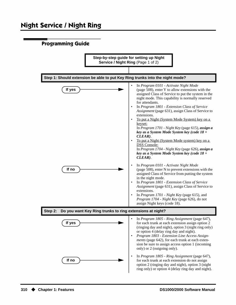
Night Service / Night Ring
310 ◆ Chapter 1: Features DS1000/2000 Software Manual
Programming Guide
Step-by-step guide for setting up Night Service / Night Ring (Page 1 of 2)
Step 1: Should extension be able to put Key Ring trunks into the night mode?
• In Program 0101 - Activate Night Mode (page 508), enter Y to allow extensions with the assigned Class of Service to put the system in the night mode. This capability is normally reserved for attendants.
• In Program 1801 - Extension Class of Service Assignment (page 631), assign Class of Service to extensions.
• To put a Night (System Mode System) key on a keyset:In Program 1701 - Night Key (page 615), assign a key as a System Mode System key (code 18 + CLEAR).
• To put a Night (System Mode system) key on a DSS Console:In Program 1704 - Night Key (page 626), assign a key as a System Mode System key (code 18 + CLEAR).
• In Program 0101 - Activate Night Mode (page 508), enter N to prevent extensions with the assigned Class of Service from putting the system in the night mode.
• In Program 1801 - Extension Class of Service Assignment (page 631), assign Class of Service to extensions.
• In Program 1701 - Night Key (page 615), and Program 1704 - Night Key (page 626), do not assign Night keys (code 18).
Step 2: Do you want Key Ring trunks to ring extensions at night?
• In Program 1805 - Ring Assignment (page 647), for each trunk at each extension assign option 2 (ringing day and night), option 3 (night ring only) or option 4 (delay ring day and night).
• Program 1803 - Extension Line Access Assign-ments (page 642), for each trunk at each exten-sion be sure to assign access option 1 (incoming only) or 2 (outgoing only).
• In Program 1805 - Ring Assignment (page 647), for each trunk at each extension do not assign option 2 (ringing day and night), option 3 (night ring only) or option 4 (delay ring day and night).
If yes
If no
If yes
If no

Night Service / Night Ring
DS1000/2000 Software Manual Chapter 1: Features ◆ 311
Programming ListProgram 0101 - Activate Night Mode (page 508)
Enter Y to allow an extension to activate the Night Mode for Key Ring trunks.Program 1003 - Direct Termination (Day) (page 593)
To enable UNA pickup for a trunk (e.g., ** + 01 at night), terminate the trunk to extension 300 during the day. UNA pickup only applies to Option 3.
Program 1003 - Direct Termination (Night) (page 594)To enable UNA pickup for the trunk (e.g., ** + 021 at night), terminate the trunk to Key Ring at night (by pressing CLEAR). UNA pickup only applies to Option 3.
Program 1701 - Night Key (page 615)Assign a programmable key as a Night (System Mode System) key (code 18 + CLEAR). Pressing the Night Key puts trunks terminated to Key Ring and Ring Group master numbers during the day into the night mode.
Program 1704 - Night Key (page 626)Assign a DSS Console key as a Night (System Mode System) key (code 18 + CLEAR). Pressing the Night Key puts trunks terminated to Key Ring and Ring Group master numbers during the day into the night mode.
Program 1801 - Extension Class of Service Assignment (page 631)Assign Class of Service to extensions.
Program 1803 - Extension Line Access Assignments (page 642)For each extension, assign the access options for each trunk (0 = No access, 1 = Incoming only. 2 = Outgoing only, 3 = Full access).
Program 1805 - Ring Assignments (page 647)Assign ringing for each trunk at each extension (1 = Lamp only [day and night], 2 = Ringing day and night, 3 = Night Ring only, lamp during the day, 4 = Delay ring day and night).
Other Related FeaturesDirect Inward Line (page 133)
● The extension to which the DIL is terminated controls the night mode of the DIL.
● If a DIL is terminated to the Voice Mail master number, a System Mode key (code 18 + the Voice Mail number) controls the night mode status of the DIL.
Direct Station Selection (DSS) Console (page 143)A DSS Console with a Night (System Mode System) key can put the system in the night mode.
Step 3: Do you want trunks to enable Universal Night Answer pickup?
Implement Night Service option 3:• In Program 1003 - Direct Termination (Day)
(page 593), terminate the trunk to extension 300 during the day.
• In Program 1003 - Direct Termination (Night) (page 594), terminate the trunk to Key Ring at night (by pressing CLEAR).
• Implement one of the other basic types of Night Service operation (option 1, 2 or 4).
Step-by-step guide for setting up Night Service / Night Ring (Page 2 of 2)
If yes
If no
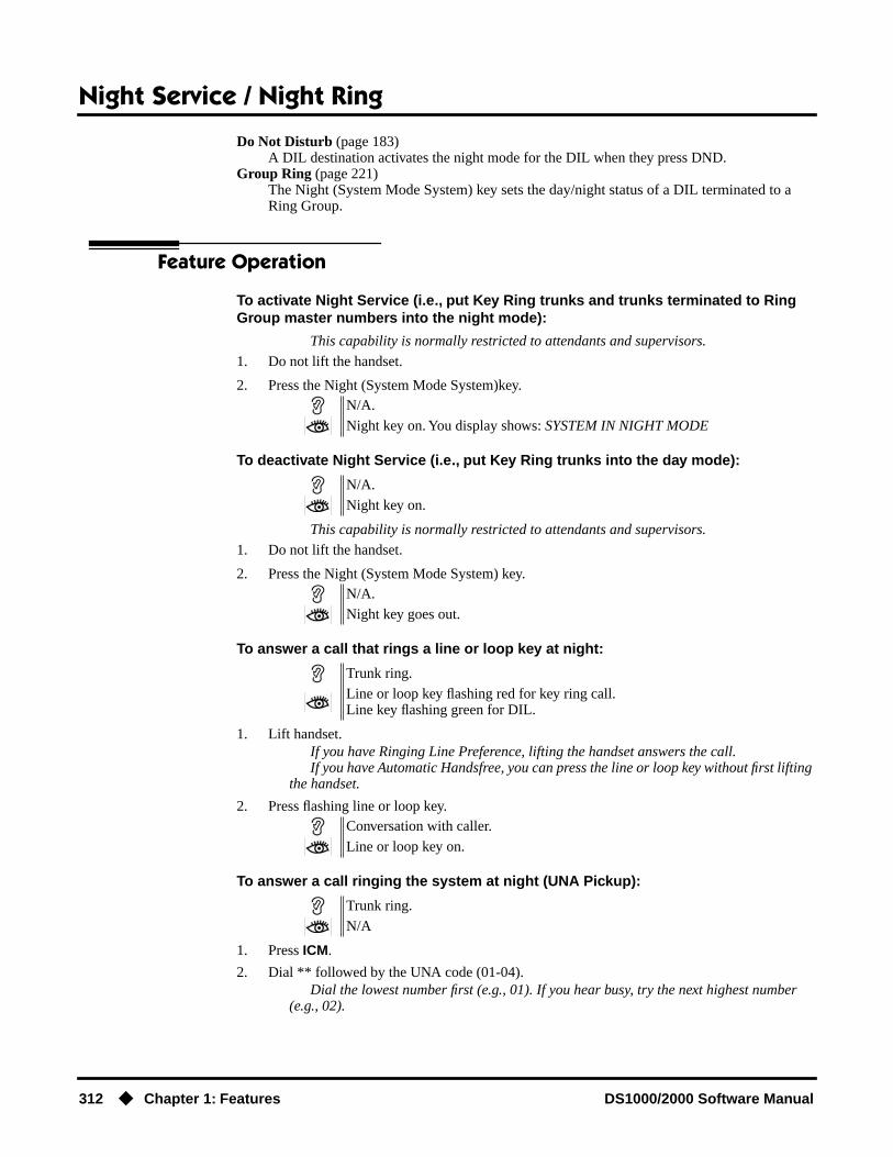
Night Service / Night Ring
312 ◆ Chapter 1: Features DS1000/2000 Software Manual
Do Not Disturb (page 183)A DIL destination activates the night mode for the DIL when they press DND.
Group Ring (page 221)The Night (System Mode System) key sets the day/night status of a DIL terminated to a Ring Group.
Feature Operation
To activate Night Service (i.e., put Key Ring trunks and trunks terminated to Ring Group master numbers into the night mode):
This capability is normally restricted to attendants and supervisors.
1. Do not lift the handset.
2. Press the Night (System Mode System)key.
To deactivate Night Service (i.e., put Key Ring trunks into the day mode):
This capability is normally restricted to attendants and supervisors.
1. Do not lift the handset.
2. Press the Night (System Mode System) key.
To answer a call that rings a line or loop key at night:
1. Lift handset.If you have Ringing Line Preference, lifting the handset answers the call.If you have Automatic Handsfree, you can press the line or loop key without first lifting
the handset.
2. Press flashing line or loop key.
To answer a call ringing the system at night (UNA Pickup):
1. Press ICM.
2. Dial ** followed by the UNA code (01-04).Dial the lowest number first (e.g., 01). If you hear busy, try the next highest number
(e.g., 02).
N/A.
Night key on. You display shows: SYSTEM IN NIGHT MODE
N/A.
Night key on.
N/A.
Night key goes out.
Trunk ring.
Line or loop key flashing red for key ring call.Line key flashing green for DIL.
Conversation with caller.
Line or loop key on.
Trunk ring.
N/A

Off-Hook Signaling
DS1000/2000 Software Manual Chapter 1: Features ◆ 313
Off-Hook Signaling
Description
When a user is busy on a call, Off-Hook Signaling indicates that another caller is trying to get through. Off-Hook Signaling helps important callers get through, without waiting in line for the called extension to become free. After the user hears the off-hook signal, they can use other system features (such as Hold or Park) to process their active call and then answer the waiting call.
Off-Hook Signaling for Trunk CallsWhile a keyset user is on a call, Off-Hook Signaling for trunk calls can be:
● While on a handset call, a flashing green Ring/Message lamp, line/loop key, and muted off-hook ringing. (While Off-Hook Signaling ringing is occuring, use VOL ▲ and VOL ▼ to adjust the volume of ringing.)
OR
● While on a handset or Handsfree call, a flashing green line/loop key and Camp-On tones.
The following chart shows when the two types of Off-Hook Signaling occur. Note that Camp-On tones occur for an extension when they are the exclusive recipient of the call (such as a DIL).
Off-Hook Signaling for Intercom CallsWhile an extension user is on a handset or Handsfree call, they can receive Camp-On tones from a co-worker that called them and dialed 2 to Camp-On. Turn to Call Waiting / Camp-On on page 75 for more on how to set this up. Off-hook ringing for Intercom calls is not available.
ConditionsNone
DS2000 Fixed Slot Available.
DS2000 U Slot Available. User Programmable Feature steps added.
DS1000 Available. Includes User Programmable Feature steps.
Off-Hook Signaling helps important callers get through.
Off-Hook Ringing1
Camp-On Tones2
Key Ring Yes No
Transferred Trunk Call Yes Yes
Direct Inward Line Yes Yes
Transfer from Voice Mail (UTRF) Yes Yes
Call Coverage Key Yes No
Group Call Pickup Key Yes No
1 For Off-Hook ringing, 1802 - Off-Hook Signaling for CO Calls = 2.2 For Camp-On tones, 1802 - Off-Hook Signaling for CO Calls = 1.
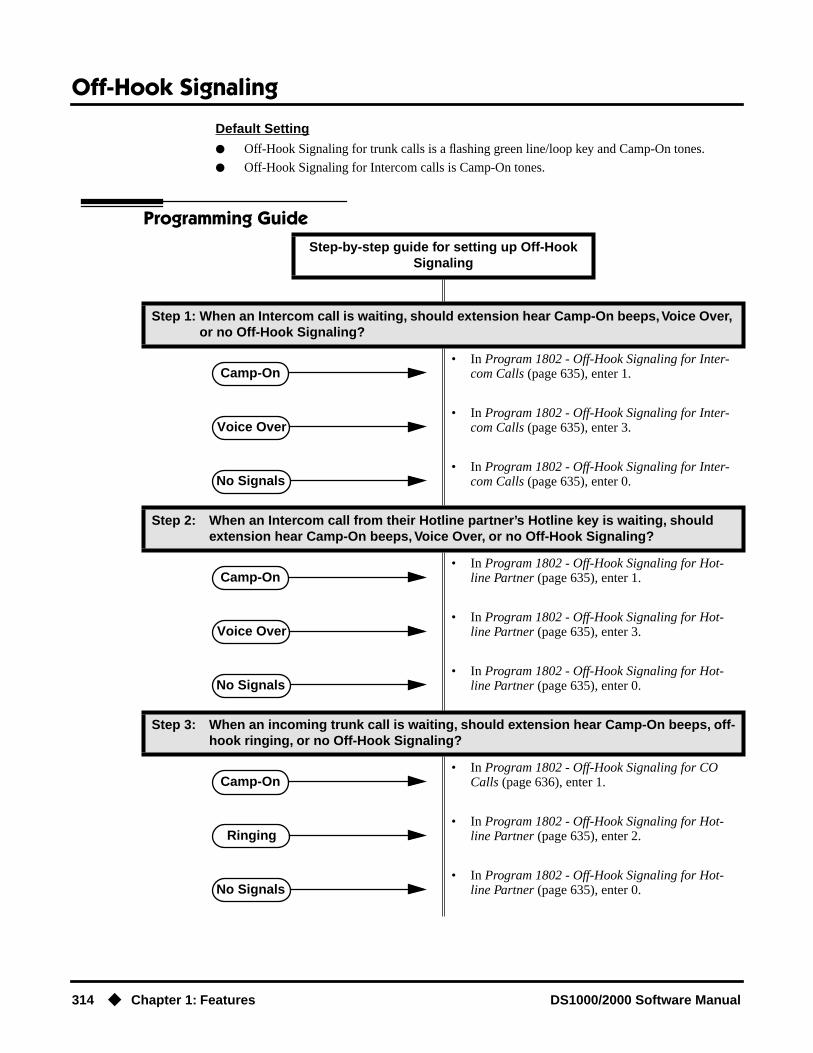
Off-Hook Signaling
314 ◆ Chapter 1: Features DS1000/2000 Software Manual
Default Setting
● Off-Hook Signaling for trunk calls is a flashing green line/loop key and Camp-On tones.
● Off-Hook Signaling for Intercom calls is Camp-On tones.
Programming GuideStep-by-step guide for setting up Off-Hook
Signaling
Step 1: When an Intercom call is waiting, should extension hear Camp-On beeps, Voice Over, or no Off-Hook Signaling?
• In Program 1802 - Off-Hook Signaling for Inter-com Calls (page 635), enter 1.
• In Program 1802 - Off-Hook Signaling for Inter-com Calls (page 635), enter 3.
• In Program 1802 - Off-Hook Signaling for Inter-com Calls (page 635), enter 0.
Step 2: When an Intercom call from their Hotline partner’s Hotline key is waiting, should extension hear Camp-On beeps, Voice Over, or no Off-Hook Signaling?
• In Program 1802 - Off-Hook Signaling for Hot-line Partner (page 635), enter 1.
• In Program 1802 - Off-Hook Signaling for Hot-line Partner (page 635), enter 3.
• In Program 1802 - Off-Hook Signaling for Hot-line Partner (page 635), enter 0.
Step 3: When an incoming trunk call is waiting, should extension hear Camp-On beeps, off-hook ringing, or no Off-Hook Signaling?
• In Program 1802 - Off-Hook Signaling for CO Calls (page 636), enter 1.
• In Program 1802 - Off-Hook Signaling for Hot-line Partner (page 635), enter 2.
• In Program 1802 - Off-Hook Signaling for Hot-line Partner (page 635), enter 0.
Camp-On
Voice Over
No Signals
Camp-On
Voice Over
No Signals
Camp-On
Ringing
No Signals

Off-Hook Signaling
DS1000/2000 Software Manual Chapter 1: Features ◆ 315
Programming ListProgram 1802 - Off-Hook Signaling for Intercom Calls (page 635)
● Set an extension’s Off-Hook Signaling options for incoming Intercom calls. The options are 0 (no Off-Hook Signaling), 1 (Call Wait beeps over speaker), and 3 (Voice Over).
● Turn to Call Waiting / Camp-On on page 75 for more on setting up Camp On.● Turn to Voice Over on page 493 for more on setting up Voice Over.
Program 1802 - Off-Hook Signaling for Hotline Partner (page 635)● Set an extension’s Off-Hook Signaling options for incoming Intercom calls from their
Hotline partner that were placed using the Hotline key. The options are 0 (no Off-Hook Signaling), 1 (Call Wait beeps over speaker), or 3 (Voice Over).
● Note that incoming Intercom calls dialed from the Hotline partner follow the Off-Hook Signaling for Intercom Calls option above.
● Turn to Voice Over on page 493 for more on setting up Voice Over.Program 1802 - Off-Hook Signaling for CO Calls (page 636)
Set an extension’s Off-Hook Signaling options for incoming trunk calls. The options are 0 (no Off-Hook Signaling),1 (Camp-On tones) and 2 (off-hook ringing).
Other Related FeaturesAttendant Call Queuing (page 45)
The Operator Call Key does not activate off-hook signaling.Caller ID (page 82)
An extension programmed to receive Camp On tones or Off-Hook Ringing from a waiting call will also receive Second Call Caller ID.
Conference (page 124)An extension user can Conference their active call with the waiting call.
Direct Inward Line (page 133)DILs can initiate Off-Hook Signaling beeps.
Headset Compatibility (page 232)Turn to Off-Hook Signaling and Headsets on page 232 for more on how Off-Hook Signaling interacts with headsets.
Hold (page 235)An extension user can place their current call on Hold and answer the waiting call.
Hotline (page 240)Hotline activates Off-Hook Signaling.
Key Ring (page 273)Off-Hook Signaling can occur for Key Ring calls.
Park (page 333)An extension user can Park their current call and answer the waiting call.
Split (Alternate) (page 395)An extension user can alternate between their active call and their waiting call.
Transfer (page 455)An extension user can Transfer their current call to a co-worker or Voice Mail and then answer the waiting call. In addition, transferred calls can initiate Off-Hook Signaling.
Voice Over (page 493)Voice Over also lets a user get through to a keyset extension user busy on a handset call. The busy keyset extension user hears an alert tone followed by the voice of the interrupting party.

Off-Hook Signaling
316 ◆ Chapter 1: Features DS1000/2000 Software Manual
Feature Operation
Off-Hook Signaling is automatic for camped-on Intercom calls, Direct Inward Lines and trans-ferred trunk calls.
User Programmable Feature
Feature Mnemonic Operation Access Level
This option is not available in Fixed Slot software.
Off Hook Signaling #OHR #OHS + Select mode (C=Outside line, D=DSS, I=ICM) + Select option (see below) + SPK to exit.Outside line options: C=Camp On tone, O=Off Hook Ringing, 0 = NoneIntercom options: C=Camp On, O=Off Hook Ringing, V=Voice Over, 0 = NoneDSS/Hotline Options: C=Camp On, O=Off Hook Ringing, 0 = None
3-5
Off-Premise Extensions / On-Premise SLT Extensions
DS1000/2000 Software Manual Chapter 1: Features ◆ 317
Off-Premise Extensions / On-Premise SLT Extensions
Description
The system is compatible with 500 type (dial pulse) and 2500 type (DTMF) analog telephone devices. This includes telco OPX circuits (DS2000 only), on-premise single line telephones (SLTs), fax machines, modems, and voice mail ports. In DS2000, off-premise SLTs can connect to 2-OPX Modules. On-premise SLTs connect to 2-OPX Modules or ASTU PCBs. In DS1000, on-premise SLTs connect to dedicated analog ports 316-323 in the main equipment cabinet. DS1000 off-premise extensions are not available.
DS2000 ASTU PCBs and the DS1000 analog ports do not provide the signaling required to light SLT Message Waiting lamps
DS2000 ASTU PCBs are available in two models, providing 4 and 8 ports, respectively. Each ASTU port provides power and ring voltage for the connected SLT. ASTU PCBs use system DTMF receivers, and do not provide the signaling required to light SLT Message Waiting lamps. The CPU provides 10 DTMF receivers that are shared by all devices connected to ASTU ports.
Each 2-OPX Module (P/N 92177A) provides two OPX ports. The first 2-OPX extension number is the same as the port’s extension number. The second 2-OPX extension number is the first port plus 201. For example, the two extension numbers for the 2-OPX module plugged into extension 314 are 314 and 515.
In addition, the 2-OPX Module has its own DTMF receivers (one for each port), internal ring gen-erator and power supply to provide the connected SLT with power and ring voltage. The 2-OPX Module does not provide the signaling required to light SLT Message Waiting lamps.
Fixed Slot systems have unique 2-OPX Module extension numbering. Refer to the system Hard-ware Manual that came with your Fixed Slot system for additional details.
Ringing For Incoming Calls (Prior to Software Version 02.01.07)On- and Off-Premise single line extensions do not ring according to the settings in Program 1805 - Ring Assignments (page 647). They can, however, directly ring for the following:
● Direct Inward Line (page 133)
● Intercom (page 268)
● Group Ring (page 221)
● Ringdown Extension (page 368)
● Transfer (page 455)
DS2000 Fixed Slot Available.
DS2000 U Slot • In DS2000, 2-OPX Modules require software version 2.00.01 or higher. In DS1000, 2-OPX Modules require software version 02.02.14 or higher.
• In software versions 02.02.14 or higher, a single line telephone user can place a call and immediately add a party into the Conference. In prior soft-ware versions, the user had to wait 6 seconds.
• In software versions 02.02.14 or higher, single line telephone users can flash a trunk.
DS1000
Connect analog devices such as single line telephones, fax machines and voice mail systems to the system.

Off-Premise Extensions / On-Premise SLT Extensions
318 ◆ Chapter 1: Features DS1000/2000 Software Manual
Ringing For Incoming Calls (Software Version 02.01.07 and Higher)On- and Off-Premise single line extensions ring according to the settings in Program 1805 - Ring Assignments (page 647). It is no longer necessary to assign single line sets to Ring Groups to make them ring for incoming calls; they follow Key Ring instead. In DS2000 by default, extensions in the first DSTU PCB (300-315) ring (option 2) for trunks 1-24 and flash (option 1) for trunks 25-48. All other extensions have lamp only for all trunks. In DS1000 by default, all extensions (including sin-gle line sets) have immediate ring for all trunks. Refer to Ringer Equivalence Number (REN) Considerations below.
Ringer Equivalence Number (REN) Considerations
DS1000Single line telephones assigned to Key Ring or the same Ring Group will ring simultaneously. This is also true for single line telephones connected to the same port. Since the Ringer Equivalence Numbers of connected single line telephones are cumulative, you must do the following:
● Add up the RENs of all connected single line telephones.
● Be sure the total REN does not exceed 4 on any single port or system-wide.
Note that a REN of 1 is normal for an industry standard 2500 set with electromechanical ringer. Many phones with electronic ringers have significantly lower REN's. Check the label on the bottom of each single line telephone for the
DS2000Single line telephones assigned to Key Ring or the same Ring Group ring in pairs according to their ASTU PCB port assignment. For example, ports 1 and 2 ring together, followed by 3 and 4, 5 and 6, and finally 7 and 8. If the system has more than one ASTU PCB installed, the respective port pairs ring simultaneously on each card (e.g., ports 1 and 2 ring simultaneously on each PCB). The ASTU provides the capability to support this ringing arrangement, and REN calculations are not required. In DS2000, there is not a REN limitation.
Conditions
● 2-OPX Module circuits meet the requirements of EIA Specification RS-464-A for OPS Class C (loop resistance to 3,300 ohms, loop current = 16 mA or greater). The 2-OPX Module provides far end loop disconnect supervision for the connected circuits.
● Dial Pulse (500 type) single line telephones cannot access any features that require the user to dial # or *.
● The system provides a pool of 10 DTMF receivers that are dynamically allocated as required.
Default SettingThe system’s 2-OPX Modules do not auto-ID. See the Programming List below more.

Off-Premise Extensions / On-Premise SLT Extensions
DS1000/2000 Software Manual Chapter 1: Features ◆ 319
Programming GuideStep-by-step guide for setting up Off-Premise Extensions / On-Premise SLT
Extensions
Step 1: Program SLT and 2-OPX Module circuit types (DS2000 only).
• In Program 1801 - Extension Circuit Type (page 629), assign circuit type 15 to each ASTU port. Assign circuit type 21 to the DSTU port to which the 2-OPX Module is connected.
• In software version 02.02.14 or higher, digital station ports on installed and programmed PCBs automatically detect the type of connected device when the 2-OPX Module is plugged in.
Step 2: Does the device conneced to the analog port require a loop disconnect signal (i.e., drop pulse)?
• In Program 0101 - SLT Loop Disconnect (page 511), enable (Y) the ability of the system to send a drop pulse to single line ports with this Class of Service.
• In Program 0403 - Drop Pulse Send (page 534), set the duration of the drop pulse sent to single line ports.
• In Program 1801 - Extension Circuit Type (page 629), assign Class of Service to extensions.
• In Program 0101 - SLT Loop Disconnect (page 511), disable (N) the ability of the system to send a drop pulse to single line ports with this Class of Service.
• In Program 1801 - Extension Circuit Type (page 629), assign Class of Service to extensions.
Step 3: Is the DTMF detection from the analog port correct?
• In Program 0403 - DTMF Detect (page 534), do not change the DTMF Detect interval.
• In Program 0403 - DTMF Detect (page 534), change the DTMF Detect interval to meet the requirements of the connected device.
If yes
If no
If yes
If no

Off-Premise Extensions / On-Premise SLT Extensions
320 ◆ Chapter 1: Features DS1000/2000 Software Manual
Programming ListProgram 0101 - SLT Loop Disconnect (page 511)
Use this option to enable (Y) or disable (N) the ability of the system to send a loop supervi-sion disconnect signal (i.e., drop pulse) to single line ports. Set this option for compatibility with the connected SLT device. (This option is always disabled for Voice Mail ports.)
Program 0403 - Drop Pulse Send (page 534)Use this timer to set the duration of the ASTU PCB drop pulse. This pulse is sent to the con-nected analog device to initiate a disconnect.
Program 0403 - DTMF Detect (page 534)Set the DTMF detection threshold for single line (analog device) ports. If the analog device sends a DTMF signal longer than this interval, the system recognizes it as a valid DTMF tone and decodes it. If the DTMF signal is equal to or less than this interval, the system ignores it
Program 1801 - Extension Circuit Type (page 629)DS2000 OnlyAssign circuit type 15 to each ASTU port. Assign circuit type 21 to the DSTU port to which the 2-OPX is connected. In software version 02.02.14 or higher, digital station ports on installed and programmed PCBs automatically detect the type of connected device when the 2-OPX Module is plugged in.
Program 1801 - Extension Class of Service Assignment (page 631)Assign Class of Service to extensions.
Other Related FeaturesBackground Music (page 55)
Background Music is not available to On- and Off-Premise extensions.Conference (page 124)
On- and off-premise SLT extensions can use Conference.Do Not Disturb (page 183)
On- and Off-Premise extensions cannot use DND.Handsfree and Handsfree Answerback (page 228)
On- and Off-Premise Extensions do not have Handsfree and Handsfree Answerback capabil-ity.
Headset Compatibility (page 232)On- and Off-Premise Extensions do not have headset capability.
Intercom (page 268)All Intercom calls to On- and Off-Premise Extensions ring.
Paging (page 326)On- and Off-Premise Extensions can make Paging announcements, but cannot receive Paging announcements.
Prime Line Preference (page 342)On- and off-premise extensions cannot use Prime Line Preference.
Save Number Dialed (page 373)Save Number Dialed is not available to SLTs.
Single Line Telephones (page 381)Single line telephones connect to either 2-OPX Modules or ASTU PCBs. On-premise single line telephones have the same capability as Off-Premise Extensions.
Off-Premise Extensions / On-Premise SLT Extensions
DS1000/2000 Software Manual Chapter 1: Features ◆ 321
Feature Operation
Call Forwarding (page 66)
1. Lift handset + Dial *3 + Dial Call Forwarding type:0 = Cancel your extension’s Call Forwarding2 = Call Forwarding Busy/No Answer4 = Call Forwarding Immediate6 = Call Forwarding No Answer
2. Dial destination extension, 0 for your operator, or Voice Mail master number.
3. Hang up.
Call Waiting / Camp-On (page 75)
1. Call busy extension + Dial 2 + Do not hang up.If you hang up, the system converts your Camp-On to a Callback.
2. Speak to your co-worker when they answer their Camp-On ring.
Callback (page 79)
1. Call busy extension + Dial 2 and hang up.Stay on the line without hanging up if you want to Camp-On instead.
2. When Callback rings your phone, lift handset to answer.
3. Speak to your co-worker when call goes through.
Central Office Calls, Answering (page 99)
1. When your telephone rings, lift the handset.
Central Office Calls, Placing (page 105)
Line Dial-Up1. Lift handset + Dial #9 followed by the trunk number (e.g., #901 for trunk 1).Direct Trunk Access1. Dial 4 plus the trunk number (e.g., 401 for trunk 1) + Dial outside number.Trunk Group Access1. Lift handset + Dial trunk group code (9 or 90-98) + Dial outside number.
Conference (page 124)
1. Establish Intercom or trunk call.In software versions 02.02.14 or higher, a single line telephone user can place a call
and immediately go to step 2 to add another party into the Conference. In prior software versions, the user had to wait 6 seconds before going to step 2.
2. Hookflash and dial extension or trunk you want to add.
3. Hookflash and dial #10 to set up Conference.If you cannot add additional parties to your Conference, you have exceeded the sys-
tem’s Conference limit.
4. Repeat steps 2 and 3 to add additional parties to your Conference.
Off-Premise Extensions / On-Premise SLT Extensions
322 ◆ Chapter 1: Features DS1000/2000 Software Manual
Direct Trunk Access (page 154)
1. Dial 4 plus the trunk number (e.g., 401 for trunk 1) + Dial outside number.
Directed Call Pickup (page 156)
1. Lift handset + Dial * * + Dial number of extension whose call you want to intercept.To intercept a call ringing an attendant, dial the attendant’s extension number (e.g.,
300). Do not dial 0 or 01-04.
Flash (page 207)
(Software version 02.02.14 or higher)
1. Place or answer trunk call.
2. Hookflash and dial #3.When you hear CO/PBX/Centrex dial tone, dial a new call or use other features pro-
vided externally by the connected service.
Forced Trunk Disconnect (page 212)
1. Lift handset + Dial the trunk’s Direct Trunk Access code (e.g., 401 for trunk 1).
2. Dial # to disconnect the line.You hear Intercom dial tone. To place a call on the trunk, dial a trunk access code and
then dial the number.
Group Call Pickup (page 215)
1. Lift handset + Dial *#.
Hold (page 235)
Place1. Hookflash.
This places a trunk call on Exclusive Hold.
2. (Optional) Hang up.
Retrieve1. From Intercom dial tone, dial *7.
Retrieve trunk on Hold at a Co-worker’s Extension1. From Intercom dial tone, dial *4.
2. Dial the number of the trunk that is on Hold (e.g., 01 for trunk 1).
Intercom (page 268)
Place1. Lift handset + Dial extension number (300-316).
To call the operator, dial the operator s extension number or dial 0 or 01-04 (depend-ing on how your system is set up).
If your call voice-announces the destination, you can dial 1 to force the call to ring.Answer1. Lift handset.

Off-Premise Extensions / On-Premise SLT Extensions
DS1000/2000 Software Manual Chapter 1: Features ◆ 323
Last Number Redial (page 277)
1. Lift handset + Dial #5.The system automatically selects a trunk from the same group as your original call.If you hear busy tone, you can dial 2 to queue for a trunk to become free. If you hang
up, the system converts the queue to a Trunk Callback.
Meet-Me Conference (page 288)
Setting Up1. Page parties and announce the Meet-Me Conference code (#11 or #12).
See Paging on page 326 for more on how to page your co-workers.
2. Hang up + Lift Handset + Dial announced Meet-Me Conference code (#11 or #12).Your co-worker’s must join the telephone meeting within the Meet Me Conference
time.
Joining1. Listen for paged invitation to join the Conference + Dial announced Meet-Me Conference
code (#11 or #12).You can join the telephone meeting within the Meet Me Conference time.
Message Waiting (page 291)
Leaving a Message Waiting1. Place Intercom call to co-worker.
The extension you call can be unanswered, busy or in Do Not Disturb.
2. Dial 8 + Hang up.MW flashes fast at the extension you call.
Answering a Message WaitingThe system currently provides no indication that an on- or off-premise extension has
messages waiting.
1. Lift handset + Dial *8.
Night Service / Night Ring (page 308)
1. Dial ** + UNA code (01-04).Dial the lowest code first (e.g., 01). If you hear busy, try the next highest code (e.g.,
02).
Paging (page 326)
SLTs cannot receive Paging announcements.
1. Lift handset + Dial *1 + Dial Paging zone (1-7 or 0 for all call).
Park (page 333)
Park a Call1. Place or answer call + Hookflash + Dial * + Dial orbit (60-69 for system orbits, *300-*331 for
Personal Park)Retrieve a Parked Call1. Lift handset + Dial * + Dial orbit (60-69 for system orbits, *300-*331 for Personal Park)
Pulse to Tone Conversion (page 360)
Must be switched manually from the telephone. The system does not provide Pulse to Tone Conversion for SLTs.

Off-Premise Extensions / On-Premise SLT Extensions
324 ◆ Chapter 1: Features DS1000/2000 Software Manual
Removing Trunks and Extensions From Service (page 362)
1. Lift handset + Dial #40 + Dial trunk (401-448 in DS2000 or 104-406 in DS1000) or extension (300-395 in DS2000 or 300-325 in DS1000) you want to remove or return to service + Dial 4 to return or 6 to remove. Hang up.
Speed Dial (page 383)
To dial a Speed Dial Number:
1. Lift handset and dial #.
2. Dial the Personal Speed Dial bin number (701-720).OR
Dial the System Speed Dial bin number (normally 200-299).The stored number dials out.
Tandem Trunking / Unsupervised Conference (page 433)
1. Establish trunk call (e.g., lift handset, dial 9, and dial outside number).
2. Hookflash and dial another trunk call.
3. Hookflash and dial #10 to set up Conference.
4. Hang up.If the outside parties disconnect, the trunks you selected do not have Tandem Trunking
capability.
Transfer (page 455)
To Transfer your call:
1. Place or answer call.
2. Hookflash + Dial extension to which you want to transfer the call.To Transfer the call to the Voice Mail Automated Attendant, dial the Voice Mail master
number.
3. To Transfer the call unscreened, hang up.OR
To screen the Transfer, wait for the called party to answer before hanging up.
To return to the call if the calling party doesn’t want the Transfer:
1. Hang up + Lift handset + Dial ** and co-worker’s extension number.Do not hookflash or the call will go on Hold at the destination extension.
To receive a Transfer (if you get an intercom call announcing it):
1. Stay on the line.The Transfer goes through when the calling party hangs up.
Voice Mail (page 477)
1. Lift handset + Dial *8.

One-Touch Keys
DS1000/2000 Software Manual Chapter 1: Features ◆ 325
One-Touch Keys
DescriptionDS2000 Fixed Slot
Available for Personal Speed Dial. Refer to Speed Dial on page 383.DS2000 U Slot
DS1000

Paging
326 ◆ Chapter 1: Features DS1000/2000 Software Manual
Paging
Description
Paging lets extension users broadcast announcements to other keyset users and to external Paging speakers. Paging allows a user to locate a co-worker or make an announcement without calling each extension individually. There are two types of Paging: Internal Paging and External Paging.
Internal PagingInternal Paging allows extension users to broadcast announcements into 7 internal Paging Zones and All Call (all zone). When a user makes a zone page, the announcement broadcasts to all exten-sions assigned to the specified zone. If the user makes an All Call announcement, the announce-ment simultaneously broadcasts to extensions in all zones. All Call Paging automatically overrides any zone pages already in progress. A system timer can optionally limit the duration of Paging announcements.
To simplify Paging access, a keyset can have Programmable Function Keys assigned as Page keys.
External PagingWhen a user pages into Internal All Call Page or Internal page Zone 1, the system simultaneously broadcasts the announcement into the External Paging Zone. In DS2000, access to the external zone is via pins in the CPU’s 8-pin mod jack. In DS1000, access to the external zone is via the AUDIO jack in the main equipment cabinet. Refer to the system’s Hardware Manual for additional installation details.
When connecting External Paging equipment, be sure to adhere to the following requirements:
DS2000 Fixed Slot Available.
DS2000 U Slot Available. User Programmable Feature steps added. Version 02.00.04 adds Page Relay Control.
DS1000 Available. Provides Page Relay Control. Includes User Programmable Feature steps.
Use Paging to broadcast announcements or quickly locate co-workers.
Paging Key Busy Lamp Indications
When the key is: The zone is:
Off Idle
On (red) A co-worker is Paging into the assigned zone
On (green) The extension user is Paging into the assigned zone.
Table 8: Audio/Paging Output
Output Impedance 600 Ohms @ 1 KHz
Output Level 0 dBr at 1.0 KHz

Paging
DS1000/2000 Software Manual Chapter 1: Features ◆ 327
Page Relay ControlPage Relay Control allows an announcement broadcast into a Paging zone to activate a system relay. This relay is typically used to activate a customer-provided Paging amplifier. In DS2000, there is a single relay on the CPRU PCB. DS1000 has 2 relays: one in the DOOR1 jack and another in the DOOR2 jack. In either system, you can assign these relays for Door Box strike control or Page Relay Control, but not both.
The equipment you connect to a system relay must be compatible with the following specifications. Refer to your system’s Hardware Manual for more on connecting to the system relay contacts.
ConditionsNone
Default SettingAll Call and Zone Paging allowed.
Programming Guide
Table 9: Relay Contact Specifications
DS1000
Contact Configuration: Normally open
Maximum Load: 0.5A @ 120 VAC1A @ 24 VDC
Maximum Initial Contact Resistance 100 mOhms
D2000
Contact Configuration: Normally open
Maximum Load: 60 mA @ 30 VDC10 mA @ 90 VDC
Maximum Initial Contact Resistance 50 mOhms
Step-by-step guide for setting up Paging
Step 1: Should extension be able to receive Paging announcements?
• In Program 1807 - Paging Through Speaker (page 652), enter Y to allow the extension to receive paging announcements.
• In Program 1802 - Page Zone Member (page 637), assign extension to the zone for which it should receive page announcements (1-7, 0 for All Call only).
• In Program 1807 - Paging Through Speaker (page 652), enter N to prevent extension from receiving paging announcements.
If yes
If no

Paging
328 ◆ Chapter 1: Features DS1000/2000 Software Manual
Step 2: Should extension be able to make (broadcast) Paging announcements?
• In Program 0101 - Initiate All Call Page (page 507), enter Y to allow extensions with the assigned Class of Service to make All Call Paging announcements.
• In Program 0101 - Access Page Zone 1 (page 507), through Program 0101 - Access Page Zone 7 (page 508), enter Y to allow extensions with the assigned Class of Service to make announcements into zones 1-7.
• In Program 1801 - Extension Class of Service Assignment (page 631), assign Class of Service to extensions.
• In Program 0101 - Initiate All Call Page (page 507), enter N to prevent extensions with the assigned Class of Service from making All Call Paging announcements.
• In Program 0101 - Access Page Zone 1 (page 507), through Program 0101 - Access Page Zone 7 (page 508), enter N to prevent extensions with the assigned Class of Service from making announcements into zones 1-7.
• In Program 1801 - Extension Class of Service Assignment (page 631), assign Class of Service to extensions.
Step 3: When a user makes a Paging announcement, is the length of time the system allows to make the page announcement adequate?
• In Program 0401 - Page Duration (page 523), leave the Page Duration interval at its currently assigned value.
• In Program 0401 - Page Duration (page 523), change the Page Duration interval to meet the site requirements.
Step 4: Should extension have one-touch Paging?
• In Program 1701 - Page Zone Key (page 614), assign a programmable function key as a Page Zone key (code 13 + zones 1-7 or 0 for All Call).
• In Program 1701 - Page Zone Key (page 614), do not assign a programmable function key as a Page Zone key (code 13).
Step-by-step guide for setting up Paging
If yes
If no
If yes
If no
If yes
If no

Paging
DS1000/2000 Software Manual Chapter 1: Features ◆ 329
Programming ListProgram 0101 - Initiate All Call Page (page 507)
Enter Y to enable an extension’s ability to make an All Call Paging announcement.Program 0101 - Access Page Zone 1 (page 507)
Enter Y to enable an extension’s ability to make a zone 1 Paging announcment.Program 0101 - Access Page Zone 2 (page 507)
Enter Y to enable an extension’s ability to make a zone 2 Paging announcment.
Step 5: Should DSS Console have one-touch Paging?
• In Program 1704 - Page Zone Key (page 625), assign a programmable function key as a Page Zone key (code 13 + zones 1-7 or 0 for All Call).
• In Program 1704 - Park Orbit Key (page 624), do not assign a programmable function key as a Page Zone key (code 13).
Step 6: In DS2000, should a Paging announcement activate the CPRU relay?
• In Program 0201 - CPRU Relay (page 515), enter 2 to assign the CPRU relay for Page control.
• In Program 0201 - CPRU Relay Page Zone Assignment (page 515), enter the Page zone that should activate the relay (1 = External Paging [zone 1 and All Call], 2-7 = Internal zones 2-7).
• In Program 0201 - CPRU Relay (page 515), enter 0 to disable the CPRU PCB relay for Page control.
Step 7: In DS1000, should a Paging announcement activate the DOOR1 or DOOR2 relay?
For the DOOR1 relay:• In Program 0201 - DOOR1 Relay (page 515),
enter 2 to assign the DOOR1 relay for Page control.• In Program 0201 - DOOR1 Relay Page Zone
Assignment (page 515), enter the Page zone that should activate the relay (1 = External Paging [zone 1 and All Call], 2-7 = Internal zones 2-7).
For the DOOR2 relay:• In Program 0201 - DOOR2 Relay (page 515),
enter 2 to assign the DOOR2 relay for Page control.• In Program 0201 - DOOR2 Relay Page Zone
Assignment (page 515), enter the Page zone that should activate the relay (1 = External Paging [zone 1 and All Call], 2-7 = Internal zones 2-7).
• In Program 0201 - CPRU Relay (page 515), enter 0 to disable the CPRU PCB relay for Page control.
Step-by-step guide for setting up Paging
If yes
If no
If yes
If no
If yes
If no

Paging
330 ◆ Chapter 1: Features DS1000/2000 Software Manual
Program 0101 - Access Page Zone 3 (page 507)Enter Y to enable an extension’s ability to make a zone 3 Paging announcment.
Program 0101 - Access Page Zone 4 (page 507)Enter Y to enable an extension’s ability to make a zone 3 Paging announcment.
Program 0101 - Access Page Zone 5 (page 508)Enter Y to enable an extension’s ability to make a zone 3 Paging announcment.
Program 0101 - Access Page Zone 6 (page 508)Enter Y to enable an extension’s ability to make a zone 3 Paging announcment.
Program 0101 - Access Page Zone 7 (page 508)Enter Y to enable an extension’s ability to make a zone 3 Paging announcment.
Program 0201 - CPRU Relay (page 515)For DS2000 OnlyEnter 2 to assign the CPRU relay for Page control.
Program 0201 - CPRU Relay Page Zone Assignment (page 515)For DS2000 OnlyEnter the Page zone that should activate the relay (1 = External Paging [zone 1 and All Call], 2-7 = Internal zones 2-7).
Program 0201 - DOOR1 Relay (page 515)DS1000 OnlyEnter 2 to assign the DOOR1 relay for Page control.
Program 0201 - DOOR1 Relay Page Zone Assignment (page 515)DS1000 OnlyEnter the Page zone that should activate the relay (1 = External Paging [zone 1 and All Call], 2-7 = Internal zones 2-7).
Program 0201 - DOOR2 Relay (page 515)DS1000 OnlyEnter 2 to assign the DOOR2 relay for Page control.
Program 0201 - DOOR2 Relay Page Zone Assignment (page 515)DS1000 OnlyEnter the Page zone that should activate the relay (1 = External Paging [zone 1 and All Call], 2-7 = Internal zones 2-7).
Program 0401 - Page Duration (page 523)Use this timer to set the maximum length of Page announcements.
Program 1701 - Page Zone Key (page 614)Assign a programmable key on an extension as a Page Zone key (code 13). The options are 0-7 (Page Zones 1-7 or 0 for All Call Page).
Program 1704 - Page Zone Key (page 625)Assign a programmable key on a DSS Console as a Page Zone key (code 13). The options are 0-7 (Page Zones 1-7 or 0 for All Call Page).
Program 1801 - Extension Class of Service Assignment (page 631)Assign Class of Service to extensions.
Program 1802 - Page Zone Member (page 637)Assign the extension to a Page Zone (1-7, 0 for All Call only).
Program 1807 - Paging Through Speaker (page 652)Enter Y to enable Paging through the telephone speaker.
Other Related FeaturesDirect Station Selection (DSS) Console (page 143)
DSS Consoles can have Page zone keys.Do Not Disturb (page 183)
DND blocks Paging announcements.Headset Compatibility (page 232)
While in the headset mode, the extension user can hear Paging announcements in the headset.

Paging
DS1000/2000 Software Manual Chapter 1: Features ◆ 331
Feature Operation
To make an Internal Paging announcement:
1. Lift handset.
2. Press ICM.
3. Dial *1 and page zone number (1-7 or 0 for All Call).
4. Make announcement and hang up.The system may limit the length of your announcement.
OR
1. Lift handset.
2. Press Paging key.
3. Make announcement and hang up.The system may limit the length of your annoucement.
User Programmable Feature
Feature Mnemonic Operation Access Level
This option is not available in Fixed Slot software.
Paging (Incoming) #VP #VP + Y to enable or N to disable + SPK to exit.
3-5
Intercom dial tone.
ICM on.
Two beeps.
N/A
Two beeps.
N/A

Paging, Meet-Me Conference
332 ◆ Chapter 1: Features DS1000/2000 Software Manual
Paging, Meet-Me Conference
DescriptionDS2000 Fixed Slot
Available. Refer to Meet-Me Conference on page 288 for more.DS2000 U Slot
DS1000

Park
DS1000/2000 Software Manual Chapter 1: Features ◆ 333
Park
Description
Park places a trunk call in a waiting state (called a Park Orbit) so that an extension user may pick it up. There are two types of Park: System and Personal. Use System Park when you want to have the call wait in one of 10 system orbits (60-69). Personal Park allows you to Park a call at an extension so a co-worker can pick it up. After parking a call, a user can Page the person receiving the call and hang up. The paged party dials a code or presses a programmed System Park key to pick up the call. Many calls can be parked at the same extension, and are retrieved in LIFO (last-in, first-out) order.
A call parked in System Park Orbit for too long will recall the extension that initially parked it. The recall for System Park Orbits 68 and 69 is permanently fixed at 5 minutes. If the recall remains unanswerd, the call diverts to Key Ring.
A call parked in Personal Park Orbit for too long will initially recall to the extension at which it is parked. If unanswered there, it recalls to the extension that parked the call. If still unanswered, it diverts to Key Ring.
When an an extension has System Park keys, the keys provide a Busy Lamp Field (BLF) for the orbit assigned to the key.
DS2000 Fixed Slot Available.
DS2000 U Slot • Distinctive flash rate for Park Recall requires DS2000 software version 02.00.01 or DS1000.
• Unanswered calls Parked by an extension that has RNA/Busy Terminal Hunting to Voice Mail do not route to Voice Mail in DS2000 02.00.01 or higher and DS1000.
• Enhanced Park Orbit Recall Display requires software version 02.02.14 or higher.
DS1000
Park a call in orbit so a co-worker can pick it up. With Park, it is not necessary to locate a person to handle their calls.
Park Key Busy Lamp Indications
When the key is: The Park orbit is:
Off Idle
On (red) A co-worker has parked a call in the orbit assigned to the key.
Single wink on (green) The extension user has parked a call in the orbit assigned to the key.

Park
334 ◆ Chapter 1: Features DS1000/2000 Software Manual
Distinctive Flash Rate on RecallPark recall features a distinctive flash rate for line keys (see the chart below). This allows the keyset extension user to easily differentiate new calls that are ringing from Parked calls that are recalling.
Enhanced Personal Park Orbit Recall Display(Software version 02.02.14 or higher)The Personal Park Orbit recall display shows:
● On all extensions that are ringing with the recall:- The type of recall (i.e., Personal Park).
● On the extension at which the call is parked (while it is ringing):- The extension which initially parked the call.
● On all other extensions as they are ringing with the recall:- The extension at which the call was initially parked.
Following are sample Personal Park Orbit recall displays. In the first example, the extension 301 does not have a programmed name. In the second example, extension 300 does has the programmed name ATTENDANT.
The Personal Park Orbit recall display occurs:- At the extension which initially received the Personal Park.- At the extension which initially parked the call.- Al all other extensions after the call diverts to Key Ring.
Distinctive Flash Rate on Park Recall
For this type of call: You see this flash rate:
Call that you Parked Double Wink On (Green)
Call that you initially Parked recalling your phone Double Wink On (Green)
Call Parked by a co-worker On (Red)
Call initially Parked by a co-workerthat is recalling your
phoneDouble Wink On (Red)

Park
DS1000/2000 Software Manual Chapter 1: Features ◆ 335
Enhanced System Park Orbit Recall Display(Software version 02.02.14 or higher)The System Park Orbit recall display shows:
● The orbit from which the call is recalling (e.g., 60.
● The extension that initially parked the call (e.g., 301).
Following are sample System Park Orbit recall displays. In the first example, the call was parked in system orbit 60 by extension 301 (which does not have a name). In the second example, the call was parked in system orbit 60 by extension 300 (which has the name ATTENDANT).
The System Park Orbit recall display occurs as the call is ringing the extension that initially parked it, and after the call diverts to Key Ring.
ConditionsNone
Default Setting
● Park available.
● No System Park keys assigned.
Programming Guide
Step-by-step guide for setting up Park
Step 1: If a parked call is not picked up, does it recall the extension that initially parked it at after the desired interval?
• In Program 0401 - Park Orbit (page 522), leave the Park Orbit interval at its currently assigned value.
• In Program 0401 - Park Orbit (page 522), change the Park Orbit interval to meet the site require-ments.
Step 2: Should extension have System Park Orbit keys?
• In Program 1701 - Park Orbit Key (page 613), assign a key as a Park Orbit Key (code 04 + Sys-tem Park Orbit 60-69).
• In Program 1701 - Park Orbit Key (page 613), do not assign a key as a Park Orbit Key (code 04).
If yes
If no
If yes
If no

Park
336 ◆ Chapter 1: Features DS1000/2000 Software Manual
Programming ListProgram 0401 - Park Orbit (page 522)
Set how long a call stays in System Park Orbits 60-67 only before recalling. Note that the recall for orbits 68 and 69 is fixed at 5 minutes.
Program 1701 - Park Orbit Key (page 613)Assign a programmable key on an extension as a Park Orbit key (code 04). The options are 60-69 (System Park Orbits 60-69).
Program 1704 - Park Orbit Key (page 624)Assign a programmable key on a DSS Console as a Park Orbit key (code 04). The options are 60-69 (System Park Orbits 60-69).
Other Related FeaturesDirect Station Selection (DSS) Console (page 143)
DSS Consoles can have Park keys.Directed Call Pickup (page 156)
Directed Call Pickup also allows an extension user to pick up a call at a co-worker’s exten-sion.
Key Ring (page 273)Unanswered Park recalls divert to key ring.
Music on Hold (page 303)If installed, Music on Hold plays to parked callers.
Off-Hook Signaling (page 313)An extension user can Park their current call and answer the waiting call.
Voice Mail (page 477)(DS2000 02.00.01 or higher and DS1000 Only)When an extension user with Ring No Answer/Busy Terminal Hunting to Voice Mail parks a call at a co-worker’s extension, the call recalls to them if not picked up. If still unanswered, the call diverts to Key Ring. (In prior DS2000 versions, the call would route to Voice Mail.)
Step 3: Should DSS Console have System Park Orbit keys?
• In Program 1704 - Park Orbit Key (page 624), assign a key as a Park Orbit Key (code 04 + Sys-tem Park Orbit 60-69).
• In Program 1704 - Park Orbit Key (page 624), do not assign a key as a Park Orbit Key (code 04).
Step-by-step guide for setting up Park
If yes
If no

Park
DS1000/2000 Software Manual Chapter 1: Features ◆ 337
Feature Operation
To Park a call in system orbit:
1. While on a trunk call, press ICM.
2. Dial * + System Park Orbit (60-69).
3. Hang up.
OR
1. While on a trunk call, press Park key.
2. Hang up.
To retrieve a call from system Park orbit:
1. Lift handset.
2. Press ICM.
3. Dial * + System Park Orbit (60-69).
OR
1. Lift handset.
2. Press Park key.
To Park a call at an extension (using Personal Park):
1. While on a trunk call, press ICM.
2. Dial * * + Number of extension at which you want to park the call (300-395 in DS2000 or 300-323 in DS1000).
3. Hang up.
Intercom dial tone.
ICM on.
N/A
Line/loop key triple Wink On (green).
N/A
Line/loop key triple wink on (green). Park key single wink on (green).
Intercom dial tone.
ICM on.
Conversation with caller.
Line/loop key on (green).
N/A
Line/loop key on.
Intercom dial tone.
ICM on.
N/A
For the extension that parked the call and for the extension at which the call is parked: Line/loop key triple wink on (green).

Park
338 ◆ Chapter 1: Features DS1000/2000 Software Manual
To retrieve a call parked at an extension:
1. Lift handset.
2. Press ICM.
3. Dial * * + Number of extension at which the call is parked.
Intercom dial tone.
ICM on.
Conversation with caller.
Line/loop key on (green).

PBX/Centrex Compatibility
DS1000/2000 Software Manual Chapter 1: Features ◆ 339
PBX/Centrex Compatibility
Description
PBX/Centrex Access CodesPBX Access Codes are the digits PBX extension users must dial to obtain outside lines. When the DS1000/2000 is installed behind a PBX, DS1000/2000 users must dial these codes before the digits for their outside call. For example, if the PBX access code is 98, and the DS1000/2000 user wants to reach 203-926-5400, they must dial 98-1-203-926-5400. Normally, DS1000/2000 Toll Restric-tion and Forced Account Codes are applied to the digits dialed after the PBX Access Code. This is because any call dialed without the PBX access code is an internal PBX call, and usually won’t require the restrictions imposed by Forced Account Codes and Toll Restriction.
To keep track of valid PBX Access Codes, the DS1000/2000 allows you to enter up to 10 PBX access codes in the PBX Access Codes Table. Each code is either 1 or 2 digits long, using the digits 0-9. You can use the * character as a wild card, which can be entered in any position in the PBX Access Codes table. A wild card allows the user to dial any digit in that position. For example, the entry 7* represents entries 70, 71, 72, etc.
In addition to entering codes in the PBX Access Codes Table, you must also indicate in programming which DS1000/2000 trunks are PBX lines (i.e., connected to the PBX - not the Central Office).
PBX/Centrex Access Codes and Toll RestrictionThe following occurs if a DS1000/2000 trunk is programmed as a PBX line and access codes are properly entered in the PBX Access Codes Table (see Programming below):
● If an extension user seizes the trunk and dials a number without a valid PBX access code, the DS1000/2000 assumes the call is an internal PBX call and allows it without restriction.
● If an extension user seizes the trunk and dials a number preceded by a valid PBX access code, the DS1000/2000 enforces Toll Restriction based on the digits following the PBX access code.
PBX/Centrex Access Codes and Account Codes
Forced Account Codes for All Calls
If Forced Account Codes for All Calls is enabled, and Forced Account Codes are enabled for the trunk (see Programming below), the system always requires Account Code entry on PBX trunks.
Forced Account Codes for Toll Calls Only
If Forced Account Codes for Toll Calls Only is enabled, the trunk is programmed as a PBX line, access codes are properly entered in the PBX Access Codes Table, and Forced Account Codes are enabled for the trunk:
● If an extension user:- Seizes the trunk.- Dials a number without a valid PBX access code.- The DS1000/2000 assumes the call is an internal PBX call and does not require the user to
enter an Account Code for the call.
If 0201 - Account Code Toll Level = 1-7
● If an extension user:- Seizes the trunk,- Dials a valid PBX Access Code,
DS2000 Fixed Slot Not available.
DS2000 U SlotPBX/Centrex Codes require software version 02.02.14 or higher.
DS1000

PBX/Centrex Compatibility
340 ◆ Chapter 1: Features DS1000/2000 Software Manual
- Dials a number restricted by the Toll Level specified,- The DS1000/2000 requires the user to enter an Account Code for the call.
If 0201 - Account Code Toll Level = 0
● If an extension user:- Seizes the trunk,- Dials a valid PBX Access Code,- Dials a number that begins with 0 or 1,- The DS1000/2000 requires the user to enter an Account Code for the call.
PBX/Centrex Access Codes and SMDRThe following occurs if a DS1000/2000 trunk is programmed as a PBX line and access codes are properly entered in the PBX Access Codes Table:
● If an extension user dials a call that includes a valid PBX Access Code, the entire number dialed is printed in the Number Dialed column and OUT is printed in the Type column (indicating that the call is an outgoing call).
● If an extension user dials a call that does not include a valid PBX Access Code, the entire num-ber dialed is printed in the Number Dialed column and PBX is printed in the Type column (indi-cating that the calls is an internal PBX call).
ConditionsNone
Default SettingNo PBX/Centrex Access Codes programmed.
Programming GuideStep-by-step guide for setting up
PBX/Centrex Codes
Step 1: Do you want to set up PBX Access Codes?
• In Program 0610 - PBX Access Codes Table (page 571), enter codes into the PBX Access Codes table. You can enter up to 10 PBX Access Codes. Each code is either 1 or 2 digits long, using the digits 0-9. You can use * as a wild card character that can be entered in any position.
• In Program 1001 - PBX Line (page 585), identify a trunk as a PBX line. You must enable (Y) a trunk as a PBX line if you want the system to use the 0610 - PBX Access Code entries.
• In Program 0610 - PBX Access Codes Table (page 571), do not enter codes into the PBX Access Codes table.
• In Program 1001 - PBX Line (page 585), disable (N) the trunk as a PBX line.
If yes
If no

PBX/Centrex Compatibility
DS1000/2000 Software Manual Chapter 1: Features ◆ 341
Programming ListProgram 0610 - PBX Access Codes Table (page 571)
Use this option to enter codes into the PBX Access Codes table. You can enter up to 10 PBX Access Codes. Each code is either 1 or 2 digits long, using the digits 0-9. You can use * as a wild card character that can be entered in any position.
Program 1001 - PBX Line (page 585)Use this option identify a trunk as a PBX line. You must enable (Y) a trunk as a PBX line if you want the system to use the 0610 - PBX Access Code entries. If disabled (N), the trunk will not use the 0610 - PBX Access Code entries.
Other Related FeaturesSpeed Dial (page 383)
Speed Dial offers unique compatibility with connected Centrex services.
Feature OperationOperation is automatic when the feature is properly set up.

Prime Line Preference
342 ◆ Chapter 1: Features DS1000/2000 Software Manual
Prime Line Preference
Description
Prime Line Preference allows a keyset user to place or answer a call by just lifting the handset. The user does not have to press a line key, loop key, or the ICM key first. This simplifies handling calls. In programming, you designate a line key, loop key, or the ICM key as a Prime Line Key. With a line or loop key, the trunk or trunk group assigned to that key becomes your Prime Line. With the ICM key, you get Intercom dial tone when you lift the handset. Any number of extensions can have the same Prime Line assignment.
There are two types of Prime Line Preference: Idle Prime Line and Intercom Prime Line.
Idle Prime LineIdle Prime Line lets a user place or answer a Prime Line call by just lifting the handset. If the Prime Line Key is a line key, lifting the handset places or answers a call on the trunk assigned to the key. If the Prime Line key is a Loop Key, lifting the handset places or answers a call on a trunk assigned to the key.
Intercom Prime LineWith Intercom Prime Line, an idle extension user hears Intercom dial tone whenever they lift the handset or press SPK. Intercom Prime Line may help the extension user that most often uses Inter-com functions or calls co-workers. If an extension’s Busy Lamp Field is disabled (the default in U Slot and DS1000), the Programmable Function Keys do not go into the DSS mode when the user lifts the handset.
Prime Line vs. Ringing Line PreferenceRinging Line Preference has priority over Prime Line. For example, an extension with Ringing Line Preference will answer a ringing trunk, not get dial tone on their Prime Line. In addition, a Ringing Prime Line will have priority over any other ringing trunk. The seize priority is as follows:
● Ringing Prime Line
● Ringing non-Prime Line
● Prime Line
ConditionsNone
Default Setting
● (Fixed Slot) Prime Lines are not set up.
● (U Slot) Intercom Prime Line enabled.
DS2000 Fixed Slot Idle Prime Line for trunks available.
DS2000 U Slot Intercom Prime Line enabled by default. User Programmable Feature steps added.
DS1000 Intercom Prime Line enabled by default. Includes User Programmable Feature steps.
Place or answer an outside call on your Prime Line just by lifting the handset.
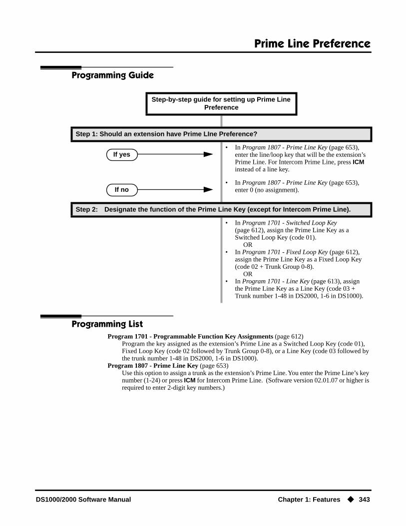
Prime Line Preference
DS1000/2000 Software Manual Chapter 1: Features ◆ 343
Programming Guide
Programming ListProgram 1701 - Programmable Function Key Assignments (page 612)
Program the key assigned as the extension’s Prime Line as a Switched Loop Key (code 01), Fixed Loop Key (code 02 followed by Trunk Group 0-8), or a Line Key (code 03 followed by the trunk number 1-48 in DS2000, 1-6 in DS1000).
Program 1807 - Prime Line Key (page 653)Use this option to assign a trunk as the extension’s Prime Line. You enter the Prime Line’s key number (1-24) or press ICM for Intercom Prime Line. (Software version 02.01.07 or higher is required to enter 2-digit key numbers.)
Step-by-step guide for setting up Prime Line Preference
Step 1: Should an extension have Prime LIne Preference?
• In Program 1807 - Prime Line Key (page 653), enter the line/loop key that will be the extension’s Prime Line. For Intercom Prime Line, press ICM instead of a line key.
• In Program 1807 - Prime Line Key (page 653), enter 0 (no assignment).
Step 2: Designate the function of the Prime Line Key (except for Intercom Prime Line).
• In Program 1701 - Switched Loop Key (page 612), assign the Prime Line Key as a Switched Loop Key (code 01). OR
• In Program 1701 - Fixed Loop Key (page 612), assign the Prime Line Key as a Fixed Loop Key (code 02 + Trunk Group 0-8). OR
• In Program 1701 - Line Key (page 613), assign the Prime Line Key as a Line Key (code 03 + Trunk number 1-48 in DS2000, 1-6 in DS1000).
If yes
If no
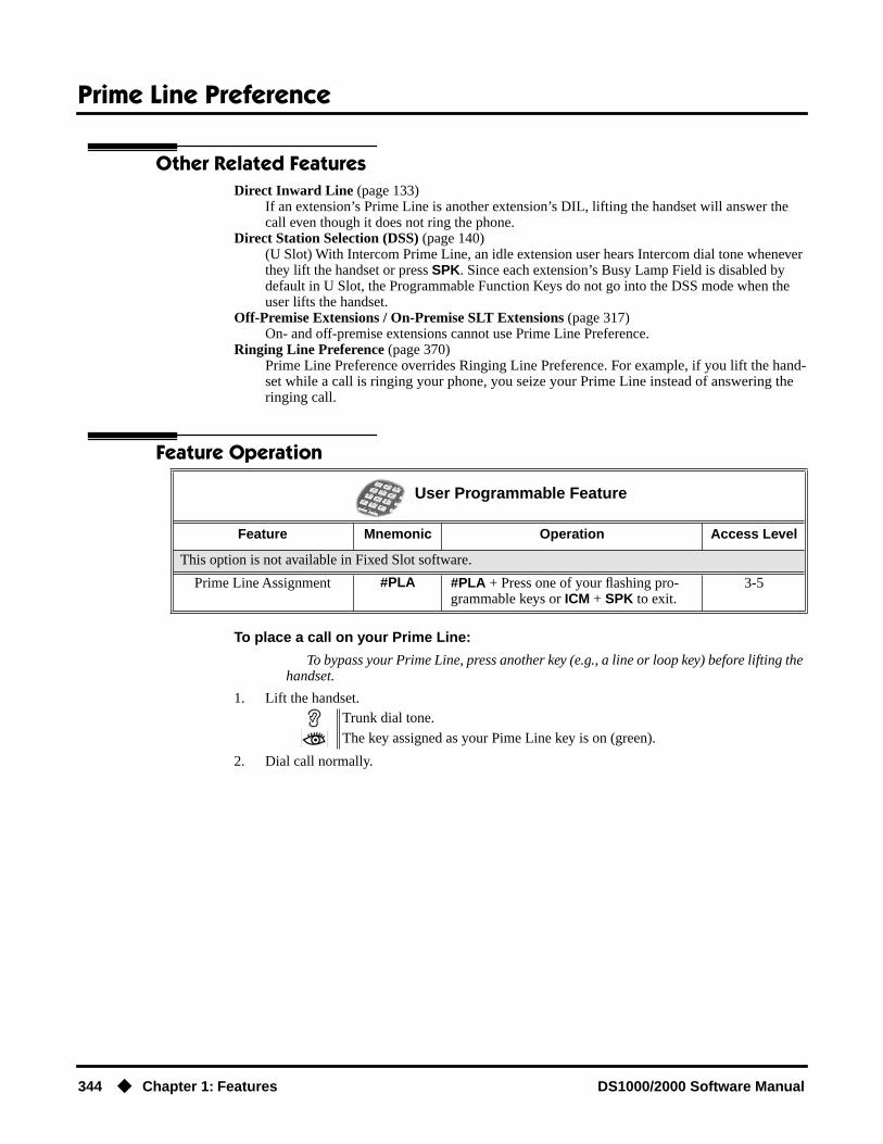
Prime Line Preference
344 ◆ Chapter 1: Features DS1000/2000 Software Manual
Other Related FeaturesDirect Inward Line (page 133)
If an extension’s Prime Line is another extension’s DIL, lifting the handset will answer the call even though it does not ring the phone.
Direct Station Selection (DSS) (page 140)(U Slot) With Intercom Prime Line, an idle extension user hears Intercom dial tone whenever they lift the handset or press SPK. Since each extension’s Busy Lamp Field is disabled by default in U Slot, the Programmable Function Keys do not go into the DSS mode when the user lifts the handset.
Off-Premise Extensions / On-Premise SLT Extensions (page 317)On- and off-premise extensions cannot use Prime Line Preference.
Ringing Line Preference (page 370)Prime Line Preference overrides Ringing Line Preference. For example, if you lift the hand-set while a call is ringing your phone, you seize your Prime Line instead of answering the ringing call.
Feature Operation
To place a call on your Prime Line:
To bypass your Prime Line, press another key (e.g., a line or loop key) before lifting the handset.
1. Lift the handset.
2. Dial call normally.
User Programmable Feature
Feature Mnemonic Operation Access Level
This option is not available in Fixed Slot software.
Prime Line Assignment #PLA #PLA + Press one of your flashing pro-grammable keys or ICM + SPK to exit.
3-5
Trunk dial tone.
The key assigned as your Pime Line key is on (green).

Privacy
DS1000/2000 Software Manual Chapter 1: Features ◆ 345
Privacy
Description
An extension with Privacy blocks incoming Barge In attempts, and Call Waiting (Camp-On) sig-nals. Privacy helps extension users that don’t want their conversations interrupted.
Note that if an extension with Privacy enabled is on a call with an extension with Privacy disabled, they are still subject to Barge In attempts and Call Waiting signals to the non-private extension.
ConditionsNone
Default SettingPrivacy disabled in an extension’s Class of Service.
Programming Guide
Programming ListProgram 0101 - Privacy (page 507)
In an extension’s Class of Service, enter Y to enable Privacy.Program 1801 - Extension Class of Service Assignment (page 631)
Assign Class of Service to extensions.
DS2000 Fixed Slot
Available.DS2000 U Slot
DS1000
Use Privacy to prevent interruptions at high priority extensions.
Step-by-step guide for setting up Privacy
Step 1: Should an extension have Privacy?
• In Program 0101 - Privacy (page 507), enter Y.• Program 1801 - Extension Class of Service
Assignment (page 631), assign the extension’s Class of Service.
• In Program 0101 - Privacy (page 507), enter N.• In Program 1801 - Extension Class of Service
Assignment (page 631), assign the extension’s Class of Service.
If yes
If no

Privacy
346 ◆ Chapter 1: Features DS1000/2000 Software Manual
Other Related FeaturesAttendant Position (page 47)
Since the attendant is never busy for Intercom calls, the attendant always has Privacy enabled.Call Waiting / Camp-On (page 75)
Privacy blocks Camp-On beeps.Barge In (Intrusion) (page 58)
Privacy blocks Barge In attempts.Monitor / Silent Monitor (page 300)
Privacy does not block Monitor.Privacy Release Groups (page 347)
There is no interaction between Privacy and Privacy Release Groups.
Feature OperationNone

Privacy Release Groups
DS1000/2000 Software Manual Chapter 1: Features ◆ 347
Privacy Release Groups
Description
You can program extensions into Privacy Release Groups to simplify sharing trunk calls. Co-work-ers in the same Privacy Release Group can easily join another group member’s trunk call just by pressing the busy line key. The co-worker immediately joins in unannounced and uninvited. Privacy Release Groups are a quick alternative to Conference where control over the Conference is not required. In a Customer Service group, for example, a supervisor could just press a busy line key to monitor any agent’s call.
If desired, an extension user can prevent other members of their Privacy Release Group from inter-rupting their active call. This ensures that group members will not interrupt confidential calls.
Any number of extensions can be in the same Privacy Release Group. However, an extension can only be in a single group. Members of the Privacy Release Group must have line keys and access to the trunks they want to share.
Privacy Release Groups utilizes a Conference circuit. The following table shows the Conference capacities:
The system’s 32 Conference circuits are dynamically allocated as users request them.
ConditionsNone
Default SettingNo Privacy Release groups assigned.
DS2000 Fixed Slot
Available.DS2000 U Slot
DS1000
Quickly join in a co-worker’s outside call.
Description Capacity
Conference circuits 32
Maximum simultaneous users in Conference(total of all Conferences system-wide)
32
Maximum simultaneous conferences 8
Maximum parties in any one Conference(trunks and/or extensions)
8

Privacy Release Groups
348 ◆ Chapter 1: Features DS1000/2000 Software Manual
Programming Guide
Programming ListProgram 1701 - Line Key (page 613)
Assign a programmable key as a line key. Users in the Privacy Release Group must have line keys for the trunks they want to share.
Program 1704 - Line Key (page 624)Optionally assign a programmable key on a DSS Console as a line key. Users in the Privacy Release Group must have line keys for the trunks they want to share.
Program 1802 - Privacy Release Group (page 635)Assign an extension to a Privacy Release Group (1-16, 0 = Unassigned).
Program 1803 - Extension Line Access Assignments (page 642)Users in the Privacy Release Group must have access for the trunks they want to share.The options are 0 (no access), 1 (incoming only), 2 (outgoing only) and 3 (full access).
Step-by-step guide for setting up Privacy Release Groups
Step 1: Should extension be in a Privacy Release Group?
• In Program 1802 - Privacy Release Group (page 635), assign the extension to a Privacy Release Group (1-16). Users in the Privacy Release Group must have line keys for the trunks they want to share.
• In Program 1701 - Line Key (page 613), assign the extension’s line keys. Users in the Privacy Release Group must have line keys for the trunks they want to share.
• In Program 1704 - Line Key (page 624), option-ally assign line keys to the extension’s DSS Con-sole. Users in the Privacy Release Group must have line keys for the trunks they want to share.
• In Program 1803 - Extension Line Access Assign-ments (page 642), assign access to the trunks the Privacy Release Group members want to share. The options are 0 (no access), 1 (incoming only), 2 (outgoing only) and 3 (full access).
• In Program 1802 - Privacy Release Group (page 635), assign the extension to Privacy Release Group 0.
If yes
If no

Privacy Release Groups
DS1000/2000 Software Manual Chapter 1: Features ◆ 349
Other Related Features
The following features also allow different types of multiple party calls:
Barge In (Intrusion) (page 58)Conference (page 124)Group Listen (page 219)Meet-Me Conference (page 288)Tandem Trunking / Unsupervised Conference (page 433)
Privacy (page 345)There is no interaction between Privacy and Privacy Release Groups.
Feature Operation
To join a trunk call with a member of your Privacy Release Group:
1. Press line key.You can optionally press a line key on your DSS Console.
To prevent a member of your Privacy Release Group from joining your call:
1. Place or answer trunk call on line key.
2. Press line key.
A Privacy Release Group member cannot join your call.
3. Repeat step 2 to allow or prevent users to join your call.
N/A.
Line key on(red).The line key is on (orange) at the extension that initially placed or answered the call.
Conversation with caller.
Line key on (green) for every Privacy Release Group member that joins the call.
Conversation with caller.
Line key on (orange).
Conversation with caller continues.
Line key on (green).

Private Line
350 ◆ Chapter 1: Features DS1000/2000 Software Manual
Private Line
Description
A Private Line is a trunk reserved for a keyset for placing and answering calls. A user with a Private Line knows when important calls are for them. Additionally, the user has their own trunk for plac-ing calls that is not available to others in the system.
There are three types of Private Lines:
● Incoming OnlyThe keyset has a Private Line only for incoming calls. The user cannot place a call on the Pri-vate Line. A customer service representative may want an incoming only Private Line to be sure customers can always get through.
● Outgoing OnlyThe keyset has a Private Line only for outgoing calls. The Private Line does not ring for incom-ing calls. A service dispatcher may want an ougoing only Private Line so they can always get in touch with field technicians.
● Both WaysThe keyset has a Private Line for both incoming and outgoing calls. An executive may want a both ways Private Line that is available only to them for placing and answering calls.
You can optionally set up shared Private Lines between a group of co-workers that work closely together.
ConditionsNone
Default SettingNo Private Lines programmed.
DS2000 Fixed Slot
Available.DS2000 U Slot
DS1000
You can have a line reserved exclusively for your own use.

Private Line
DS1000/2000 Software Manual Chapter 1: Features ◆ 351
Programming Guide
Step-by-step guide for setting up Private Lines (Page 1 of 2)
Step 1: Should extension have a Private Line
• In Program 1001 - Trunk Circuit Type (page 581), assign the correct circuit type to the Private Line.
• Stop.
Step 2: Should Private Line be exclusively for only one extension?
• In Program 1701 - Line Key (page 613), make sure that only the extension with the Private Line has a line key for the trunk (code 03 followed by the trunk number 1-48 in DS2000, 1-6 in DS1000). ORIn Program 1704 - Line Key (page 624), option-ally assign the Private Line to a key on the DSS Console (code 01 followed by the trunk number 1-48 in DS2000, 1-6 in DS1000).
• In Program 1803 - Extension Line Access Assign-ments (page 642), make sure that the extension with the Private Line is the only phone that has access to the trunk. See step 3 below for the spe-cifics.
• In Program 1701 - Line Key (page 613), assign line keys (code 03 followed by the trunk number [1-48 in DS2000, 1-6 in DS1000]) for all exten-sions that will share the Private Line. ORIn Program 1704 - Line Key (page 624), option-ally assign the Private Line to a key on the DSS Console (code 01 followed by the trunk number [1-48 in DS2000, 1-6 in DS1000]).
If yes
If no
If yes
If no

Private Line
352 ◆ Chapter 1: Features DS1000/2000 Software Manual
Programming ListProgram 1001 - Trunk Circuit Type (page 581)
Assign the correct circuit type to the Private Line.Program 1701 - Line Key (page 613)
Assign the Private Line to a line key (code 03 followed by the trunk number [1-48 in DS2000, 1-6 in DS1000]).
Program 1704 - Line Key (page 624)Optionally assign the Private Line to a key on the DSS Console (code 01 followed by the trunk number [1-48 in DS2000, 1-6 in DS1000]).
Program 1803 - Extension Line Access Assignments (page 642)For each extension, assign the access options for each trunk (0 = No access, 1 = Incoming only. 2 = Outgoing only, 3 = Full access).
Program 1805 - Ring Assignments (page 647)Assign ringing for each trunk at each extension (1 = Lamp only [day and night], 2 = Ringing day and night, 3 = Night Ring only, lamp during the day, 4 = Delay ring day and night). Check to be sure this program applies to this feature.
Step 3: Should Private Line be incoming, outgoing or both ways?
• In Program 1803 - Extension Line Access Assign-ments (page 642), enter 1 for incoming only access.
• In Program 1805 - Ring Assignments (page 647), make sure only the extension with the Private Line rings for the trunk.
• In Program 1803 - Extension Line Access Assign-ments (page 642), enter 2 for outgoing only access.
• In Program 1805 - Ring Assignments (page 647), make sure no extensions ring for the trunk.
• In Program 1803 - Extension Line Access Assign-ments (page 642), enter 3 for full access.
• In Program 1805 - Ring Assignments (page 647), make sure only the extension with the Private Line rings for the trunk.
Step-by-step guide for setting up Private Lines (Page 2 of 2)
Incoming
Outgoing
Both

Private Line
DS1000/2000 Software Manual Chapter 1: Features ◆ 353
Other Related Features
The following features work normally for Private Lines.
Automatic Handsfree (page 51)Delayed Ringing (page 129)Group Ring (page 221)Hold (page 235)Last Number Redial (page 277)Night Service / Night Ring (page 308)Park (page 333)Prime Line Preference (page 342)Save Number Dialed (page 373)Speed Dial (page 383)Toll Restriction (Software Version 02.02.14 or Higher) (page 439)Toll Restriction (Prior to Software Version 02.02.14) (page 447)Transfer (page 455)
The following features do not apply to Private Lines
Call Forwarding (page 66)If you want to be able to forward a private trunk, consider setting up a Direct Inward Line.
Feature Operation
To answer an incoming call on your Private Line:
1. Lift handset..
To place a call over your Private Line:
1. Lift handset.
2. Press line key.
3. Dial outside number.
Trunk ring.
Privalte Line flashing red.
Conversation with caller.
Private Line key on (green).
Trunk dial tone.
Private Line key on (green).

Programmable Function Keys
354 ◆ Chapter 1: Features DS1000/2000 Software Manual
Programmable Function Keys
Description
Each keyset has Programmable Function Keys. These Programmable Function Keys simplify plac-ing calls, answering calls and using certain features. You can customize the function of any keyset’s Programmable Function Keys from the sytem program.
The 22-Button Standard and Display Tele-phones feature 12 Programmable Function Keys.
The 34-Button Display Telephone features 24 Programmable Function Keys.
The 34-Button Super Display Telephone also features 24 Programmable Function Keys.
DS2000 Fixed Slot Available - unique defaults.
DS2000 U Slot
Available - unique defaults.• User Programmable Feature steps added.• In 02.01.07 and higher, all Programmable Function Keys are undefined
for extensions above 315.
DS1000 Available - unique defaults.• Includes User Programmable Feature steps.
Programmable Function Keys simplify feature operation.

Programmable Function Keys
DS1000/2000 Software Manual Chapter 1: Features ◆ 355
The following chart lists the available Programmable Function Key assignments.
ConditionsIf you unplug a 34-button telephone and replace it with a 22-button telephone, Programmable Func-tion Keys 13-24 are inaccessible. However, the system still retains the programming for those keys.
Default Setting
● Fixed Slot Software:- Keys 1-8 are line keys for trunks 1-8.- Keys 9 and 10 are fixed loop keys.- Key 11 is an auto timer key.- Key 12 is an All Call Page key.For attendants (extension 300 by default)- Key 11 is a Night (System Mode System) key- Key 12 (on 22-button) or key 24 (on 34-button) is an Operator Call Key.
● U Slot and DS1000 Software:- In U Slot, keys 1-12 are line keys for trunks 1-12 and keys 13-24 are undefined. In DS2000 software versions 02.01.07 through 02.02.00, Programmable Function Keys are undefined for all extensions above 315.- In DS1000, keys 1-6 are line keys for trunks 1-6 and keys 7-24 are undefined.For attendants (extension 300 by default)- Key 11 is a Night (System Mode System) key.- Key 12 (on 22-button) or key 24 (on 34-button) is an Operator Call Key.
• Account Code • Line Key • Park Orbit
• Call Coverage • Loop Key, Fixed • Reverse Voice Over
• Call Timer • Loop Key, Switched • Speed Dial, Personal
• Data Key (Future) • Message Center • Speed Dial, System
• Group Pickup • Multiple Directory Num-bers (Future)
• Split Key
• Hotline • Night Key • Voice Mail Record Key
• Intercom DirectoryDialing
• Page Zones

Programmable Function Keys
356 ◆ Chapter 1: Features DS1000/2000 Software Manual
Programming Guide
Programming ListProgram 1701 - Programmable Function Key Assignments (page 612)
Assign programmable key functions per the following chart.
Step-by-step guide for setting up Programmable Function Keys
Step 1: Do you want to customize an extension’s Programmable Function Keys?
• In Program 1701 - Programmable Function Key Assignments (page 612), review the options and set up the Programmable Function Keys to meet the site requirments.
• In Program 1701 - Programmable Function Key Assignments (page 612), leave each extension’s Programmable Function Keys at their default settings.
Step 2: Are any of an extension’s Programmable Function Keys set up as line keys?
• In Program 1802 - Key Access to Outbound Lines (page 637), enter Y to enable line key access to trunks.
• Also, reviewCentral Office Calls, Answering on page 99 and Central Office Calls, Placing on page 105 for more on setting up trunk calling.
• To provide an answering point for incoming calls, you should have at least one Loop Key reserved for incoming calls. Refer to Loop Keys on page 283 for more.
Option Description Key Code
Undefined Use this option to designate a key as undefined (no function).
00
Switched Loop Key
Use this option to assign a programmable key as a switched loop key.
01
Fixed Loop Key Use this option to assign a programmable key as a Fixed Loop Key.
02 + nn (trunk group)
Line Key Use this option to assign a programmable key as a line key.
03 + nn (trunknumber)
If yes
If no
If yes
If no

Programmable Function Keys
DS1000/2000 Software Manual Chapter 1: Features ◆ 357
Park Orbit Key Use this option to assign a programmable key as a Park Orbit key.
04 + nn (Park Orbit60-69)
Hotline Key Use this option to assign a programmable key as a Hotline key.
An extension can also have a Hotline key for a trunk (e.g., 401). However, this capability requires that Direct Trunk Access be enabled. See Direct Trunk Access on page 154 for more.
05 + nnn (extension number)
Call Coverage Immediate Ring
Use this option to assign a programmable key as an immediately ringing Call Coverage Key.
06 + nnn (extension number)
Call Coverage No Ring
Use this option to assign a programmable key as a lamp only (no ring) Call Coverage Key.
07 + nnn (extension number)
Call Coverage Delay Ring
Use this option to assign a programmable key as a delayed ring Call Coverage Key.
08 + nnn (extension number)
Group Pickup Immediate Ring
Use this option to assign a programmable key as an immediate ring Group Call Pickup key.
09 + nn (Pickup Group 01-08)
Group Pickup No Ring
Use this option to assign a programmable key as a lamp only (no ring) Group Call Pickup key.
10 + nn (Pickup Group 01-08)
Group Pickup Delay Ring
Use this option to assign a programmable key as a delay ring Group Call Pickup key.
11 + nn (Pickup Group 01-08)
Page Zone Key Use this option to assign a programmable key as a Page Zone key.
13 + n (Page Zone 1-7, 0 for All Call)
System Speed Dial Key
Use this option to assign a programmable key as a One-Touch System Speed Dial key. You assign the key to specific System Speed Dial bin.
14 + nnn (System Speed Dial bin, nor-
mally 200-299)
Personal Speed Dial Key
Use this option to assign a programmable key as a Personal Speed Dial key. You assign the key to a specific Personal Speed Dial bin.
15 + nnn (701-720)
Call Timer Key Use this option to assign a programmable key as a Call Timer key. There are two types of timer key: manual and automatic.
16 + n (1 = Manual Call Timer, 2 = Auto-
matic Call Timer)
Voice Mail Record Key
Use this option to assign a programmable key as a Voice Mail Record key.
17
Option Description Key Code

Programmable Function Keys
358 ◆ Chapter 1: Features DS1000/2000 Software Manual
Program 1802 - Key Access to Outbound Lines (page 637)Enter Y to enable an extension user to press a Programmable Function Key to access and out-side line.
Other Related FeaturesCheck Key (page 115)
Check Programmable Function Key assignments.Direct Station Selection (DSS) (page 140)
If enabled in programming, Programmable Function Keys become DSS keys when the user presses ICM.
Night Key Use this option to assign a programmable key as a Night Key. There are two options: System Mode System key and System Mode UCD Master key. The System Mode System key puts all Key Ring trunks and trunks terminated to Ring Group master numbers in the night mode. The System Mode UCD Master key puts all trunks terminated to UCD Group mas-ter numbers in the night mode.
18 + CLEAR(System Mode System
key)18 + UCD Master
Number(System Mode UCD
Master key)
Data Key This option is currently not used. 19 + nnn (extension number)
Split Key Use this option to assign a programmable key as a Split key.
20
ICM Directory Key
Use this option to assign a programmable key as an Intercom Directory Dialing key.
21
ACD Log On Key • This option is currently not used. 22
Reverse Voice Over Key
Use this option to assign a programmable key as a Reverse Voice Over key.
23
Message Center Key
Use this option to assign a programmable key as a Message Center key.
24 + nnn (extension number)
Note that the extension number does not have
to be an installed exten-sion.
Save Key Use this option to assign a programmable key as a Save Number Dialed key.
25
Account Code Key
Use this option to assign a programmable key as an Account Code key.
26
Option Description Key Code

Programmable Function Keys
DS1000/2000 Software Manual Chapter 1: Features ◆ 359
Feature Operation
Refer to the individual features in the chart above.
User Programmable Feature
Feature Mnemonic Operation Access Level
This option is not available in Fixed Slot software.
Programmable Funtion Key Assignments
#KP #KP + Press key you want to program + HOLD + ICM + Press VOL Up or VOL Down to select key option + HOLD + (Enter any additional data, if required + HOLD) + Press VOL Up or VOL Down to select another key to program, or CONF + SPK to exit.
3-5
Pulse to Tone Conversion
360 ◆ Chapter 1: Features DS1000/2000 Software Manual
Pulse to Tone Conversion
Description
An extension can use Pulse to Tone Conversion while placing a trunk call to change the dialing mode from dial pulse to DTMF. For a system in a dial pulse area, this permits users to access DTMF services (such as telephone banking) from their DP area. Pulse to tone conversion also helps dial pulse callers use another company’s automated attendant dialing options. The user can, for example:
● Place a call to their bank over a DP trunk.
● After the banking service answers, wait 6 seconds. (The system automatically converts dialing to DTMF.)
● Dial additional banking options.
Refer to Central Office Calls, Answering on page 99 and Central Office Calls, Placing on page 105 for the specifics on setting up your trunk calling.
ConditionsNone
Default SettingPulse to Tone Conversion always enabled for dial pulse trunks.
Programming GuideNone
Programming ListProgram 1001 - Trunk Circuit Type (page 581)
Be sure to program your DP trunk with circuit type 52.
Other Related FeaturesPulse to Tone Conversion (page 360)
The system does not provide Pulse to Tone Conversion for SLTs. The conversion must be switched manually from the telephone.
Speed Dial (page 383)If a Speed Dial number using a dial pulse trunk contains a pause, the digits following the pause automatically dial out as DTMF.
DS2000 Fixed Slot
Available.DS2000 U Slot
DS1000
Use special services (such as telephone banking) over dial pulse trunks.

Pulse to Tone Conversion
DS1000/2000 Software Manual Chapter 1: Features ◆ 361
Feature Operation
To convert your phone’s dialing to DTMF after placing your call on a DP trunk:
1. Dial initial digits for call.
2. Wait 6 seconds.
3. Dial additional digits.
Digits dial out as dial pulse.
N/A
Additional digits dial out as DTMF.
N/A

Removing Trunks and Extensions From Service
362 ◆ Chapter 1: Features DS1000/2000 Software Manual
Removing Trunks and Extensions From Service
Description
Supervisors and attendants can remove problem trunks and extensions from service. This helps ensure maximum system performance. For example, the attendant can busy-out a noisy trunk or problem extension until service personnel can repair the problem. The trunk or extension the appears busy to all callers. Following repair, the attendant or supervisor can return the trunk to ser-vice.
The extension or trunk removed from service shows as busy on the appropriate key (e.g., line key or Hotline key). The port activity LED on the ATRU PCB indicates that the trunk is busy.
ConditionsNone
Default SettingDisabled
Programming Guide
DS2000 Fixed Slot
Available.DS2000 U Slot
DS1000
Temporarily remove problem extensions and trunks from service until they can be repaired.
Step-by-step guide for setting up Removing Trunks and Extensions from Service
Step 1: Should extension be able to remove another extension or trunk from service?
• In Program 0101 - Direct Trunk Access (page 508), enter Y to enable Direct Trunk Access.
• In Program 1801 - Extension Class of Service Assignment (page 631), assign Class of Service to extensions.
• In Program 0101 - Direct Trunk Access (page 508), enter N to disable Direct Trunk Access.
• In Program 1801 - Extension Class of Service Assignment (page 631), assign Class of Service to extensions.
If yes
If no

Removing Trunks and Extensions From Service
DS1000/2000 Software Manual Chapter 1: Features ◆ 363
Programming ListProgram 0101 - Direct Trunk Access (page 508)
Enter Y to enable an extension to use Direct Trunk Access. Note that enabling Direct Trunk Access allows the user to bypass Toll Restriction.
Program 1801 - Extension Class of Service Assignment (page 631)Assign Class of Service to extensions.
Other Related FeaturesAttendant Position (page 47)
Normally, system attendants should have the ability to remove trunks and extensions from ser-vice.
Call Forwarding (page 66)If Call Forwarding is enabled at an extension when it is removed from service, it is reinstated when the extension is returned to service.
Direct Trunk Access (page 154)An extension user with Direct Trunk Access can remove trunks from service.
Selectable Display Messaging (page 376)Removing and returning an extension to service does not cancel an extension’s Selectable Display Messaging.
Feature Operation
To remove or return an extension or trunk to service:
1. Press ICM and dial #40.
2. Dial the number of the extension you want to remove or return to service (300-395 in DS2000 or 300-325 in DS1000).
ORDial the number of the trunk you want to remove or return to service (401-448 in DS2000 or 401-406 in DS1000).
3. Dial 4 to return.OR
Dial 6 to remove.
4. Press SPK to hang up.
Dial tone.
The display on a telephone removed from service shows: Out of ServiceThe line key for a trunk removed from service is on (red).

Reverse Voice Over
364 ◆ Chapter 1: Features DS1000/2000 Software Manual
Reverse Voice Over
Description
While on a handset call, Reverse Voice Over lets a busy keyset user make a private Intercom call to an idle co-worker. The busy user just presses and holds down a programmed Reverse Voice Over key to make a private call to the assigned co-worker. The initial caller cannot hear the Reverse Voice Over conversation. The private Intercom call continues until the Reverse Voice Over caller releases the key again. The initial handset call can be a trunk call or an Intercom call. An extension can have Reverse Voice Over keys for more than one co-worker.
Reverse Voice Over could help a salesperson, for example, when placing a call to an important cli-ent. The salesperson can talk with the client and give special instructions to an assistant — without interrupting the initial call.
When the keyset is idle, the Reverse Voice Over key functions the same as a Hotline key. The key also shows at a glance the status of the associated extension:
Reverse Voice Over uses a system Conference circuit while it is active. The following table shows the system’s Conference capacities:
The system’s 32 Conference circuits are dynamically allocated as users request them.
DS2000 Fixed Slot
Available.DS2000 U Slot
DS1000
Privately call a co-worker while you’re busy on your handset.
Reverse Voice Over Busy Lamp Indications
When the key is: The covered extension is:
Off Idle or not installed
On Busy or ringing
Flashing fast In Do Not Disturb
Description Capacity
Conference circuits 32
Maximum simultaneous users in Conference(total of all Conferences system-wide)
32
Maximum simultaneous conferences 8
Maximum parties in any one Conference(trunks and/or extensions)
8

Reverse Voice Over
DS1000/2000 Software Manual Chapter 1: Features ◆ 365
ConditionsNone
Default SettingNo Reverse Voice Over keys assigned
Programming Guide
Programming ListProgram 1701 - Reverse Voice Over Key (page 615)
Assign a keyset programmable key as a Reverse Voice Over key (code 23 followed by the assigned extension number).
Program 1704 - Reverse Voice Over Key (page 626)Assign a DSS Console programmable key as a Reverse Voice Over key (code 23 followed by the assigned extension number).
Other Related FeaturesConference (page 124)
An extension user cannot add an incoming Reverse Voice Over call to a Conference.Direct Station Selection (DSS) Console (page 143)
A DSS Console can have a Reverse Voice Over key.Do Not Disturb (page 183)
DND does not block Reverse Voice Over.Hold (page 235)
An extension cannot put an incoming Reverse Voice Over call on Hold.
Step-by-step guide for setting up Reverse Voice Over
Step 1: Should extension have Reverse Voice Over Capability?
• To put a Reverse Voice Over key on a keyset:In Program 1701 - Reverse Voice Over Key (page 615), assign a Reverse Voice Over key (code 23 followed by the assigned extension number). OR
• To put a Reverse Voice Over key on a DSS Console:In Program 1704 - Reverse Voice Over Key (page 626), assign a Reverse Voice Over key (code 23 followed by the assigned extension number).
• In Program 1701 - Reverse Voice Over Key (page 615), and in Program 1704 - Reverse Voice Over Key (page 626), do not assign any Reverse Voice Over keys (code 23).
If yes
If no

Reverse Voice Over
366 ◆ Chapter 1: Features DS1000/2000 Software Manual
Transfer (page 455)While idle, an extension user can use their Reverse Voice Over key to Transfer calls.
Feature Operation
To place a Reverse Voice Over call:
1. While on a handset call, press and hold your Reverse Voice Over key.
To return to your initial caller:
1. Release your Reverse Voice Over key.
To place a call to your assigned Reverse Voice Over destination:
1. While your telephone is idle, press your Reverse Voice Over key.
You can optionally lift the handset for Privacy.
To Transfer a call using you Reverse Voice Over key:
1. While on a call, press ICM.
2. Press Reverse Voice Over key.
3. Announce the call to make a Screened Transfer.OR
Press the flashing line key to return to the call if you co-worker doesn’t want it (i.e., rejects your screen).
ORHang up to send the call through unscreened.
The call will recall to you if unanswered at the destination extension. If you don’t answer the recall, it diverts to Key Ring.
Two beeps, then conversation with called co-worker.
Reverse Voice Over key on (red).
Conversation with initial caller in handset.
Reverse Voice Over key off.
Two beeps, then conversation with called co-worker.
Reverse Voice Over key on (green).
Intercom dial tone.
ICM key on (red).
Two beeps, then conversation with called co-worker.
Reverse Voice Over key on (green).
Ring Groups
DS1000/2000 Software Manual Chapter 1: Features ◆ 367
Ring Groups
DescriptionDS2000 Fixed Slot
Available. Refer to Group Ring on page 221 for more information.e.DS2000 U Slot
DS1000

Ringdown Extension
368 ◆ Chapter 1: Features DS1000/2000 Software Manual
Ringdown Extension
Description
A Ringdown Extension automatically calls a co-worker, Voice Mail, a Ring Group or a UCD Hunt-ing group when the user lifts the handset. The call automatically goes through — there is no need for the user to dial digits or press additional keys. Ringdown extension are frequently used for lobby phones, where the caller just lifts the handset to get the information desk.
ConditionsNone
Default SettingRing Down disabled.
Programming ListProgram 1802 - Ring Down Destination (page 637)
Assign the extension’s Ringdown destination. The destination can be an extension, the Voice Mail master number, a Ring Group number, or a UCD master number. The Ringdown destina-tion cannot be a trunk (e.g., 401).
Other Related FeaturesIntercom (page 268)
Ringdown Extension follows the voice-announce status of destination extension. For exam-ple, if an extension usually voice-announces Intercom calls, a ringdown to that extension will also voice-announce.
Ringing Line Preference (page 370)Ringing Line Preference has precedence over Ringdown Extension. If Ringing Line Prefer-ence is ringing the phone, lifting the handset answers the call. Lifting the handset does not call the Ringdown destination.
Voice Mail (page 477)If the Ringdown destination is the Voice Mail master number, the Ringdown Extension user hears the Voice Mail main greeting (“Please enter your mailbox number”) after the call connects.
DS2000 Fixed Slot
Available.DS2000 U Slot
DS1000
Call another extension, group or Voice Mail just by lifting the handset.

Ringdown Extension
DS1000/2000 Software Manual Chapter 1: Features ◆ 369
Feature Operation
To use Ringdown Extension:
1. Lift handset or press SPK.
If you hear ringing, wait for the called pary to answer. If you hear two beeps, you may begin speaking.
To bypass Ringdown (if your keyset is set up as a Ringdown Extension):
1. Before lifting the handset or pressing SPK, press one of the following:- ICM- Line key- Programmable Function Key
Two beeps or ringing.
ICM on.
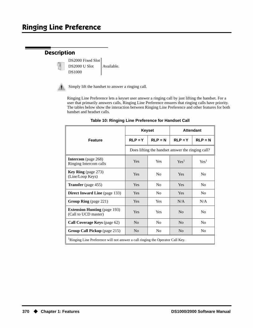
Ringing Line Preference
370 ◆ Chapter 1: Features DS1000/2000 Software Manual
Ringing Line Preference
Description
Ringing Line Preference lets a keyset user answer a ringing call by just lifting the handset. For a user that primarily answers calls, Ringing Line Preference ensures that ringing calls have priority. The tables below show the interaction between Ringing Line Preference and other features for both handset and headset calls.
DS2000 Fixed Slot
Available.DS2000 U Slot
DS1000
Simply lift the handset to answer a ringing call.
Table 10: Ringing Line Preference for Handset Call
Feature
Keyset Attendant
RLP = Y RLP = N RLP = Y RLP = N
Does lifting the handset answer the ringing call?
Intercom (page 268)Ringing Intercom calls Yes Yes Yes1 Yes1
Key Ring (page 273)(Line/Loop Keys) Yes No Yes No
Transfer (page 455) Yes No Yes No
Direct Inward Line (page 133) Yes No Yes No
Group Ring (page 221) Yes Yes N/A N/A
Extension Hunting (page 193)(Call to UCD master) Yes Yes No No
Call Coverage Keys (page 62) No No No No
Group Call Pickup (page 215) No No No No
1Ringing Line Preference will not answer a call ringing the Operator Call Key.

Ringing Line Preference
DS1000/2000 Software Manual Chapter 1: Features ◆ 371
When multiple calls ring an extension simultaneously, the system services the ringing calls in the following order:
1. ICM Key
2. Line Key (from lowest to highest)
3. Loop Key (from lowest to highest)
In addition, if two extensions with Ringing Line Preference answer the same trunk call simulta-neously, the system connects the call to the lowest numbered extension.
Prime Line vs. Ringing Line PreferenceRinging Line Preference has priority over Prime Line. For example, an extension with Ringing Line Preference will answer a ringing trunk, not get dial tone on their Prime Line. In addition, a ringing Prime Line will have priority over any other ringing trunk. The seize priority is as follows:
● Ringing Prime Line
● Ringing non-Prime Line
● Prime Line
ConditionsNone
Default SettingEnabled. In DS2000 software versions 02.01.07 through 02.02.00, Ringing Line Preference was disabled for all extensions above 315.
Table 11: Ringing Line Preference for Headset Calls
Feature
Keyset Attendant
RLP = Y RLP = N RLP = Y RLP = N
Does pressing SPK while in the Headset mode answer the ringing call?
Intercom (page 268)Ringing Intercom calls
Yes Yes Yes Yes
Key Ring (page 273)(Line/Loop Keys)
Yes No Yes No
Transfer (page 455) Yes No Yes No
Direct Inward Line (page 133) Yes No Yes No
Group Ring (page 221) Yes Yes N/A N/A
Extension Hunting (page 193)(Call to UCD master)
Yes Yes No No
Call Coverage Keys (page 62) No No No No
Group Call Pickup (page 215) No No No No

Ringing Line Preference
372 ◆ Chapter 1: Features DS1000/2000 Software Manual
Programming ListProgram 1807 - Ringing Line Preference (page 653)
Enter Y to enable Ringing Line Preference.
Other Related FeaturesAttendant Call Queuing (page 45)
Ringing Line Preference will not answer a call ringing the Operator Call Key.Intercom (page 268)
Ringing Line Preference answers a ringing Intercom call before a ringing trunk call.Prime Line Preference (page 342)
Prime Line Preference overrides Ringing Line Preference. For example, if you lift the handset while a call is ringing your phone, you seize your Prime Line instead of answering the ringing call.
Ringdown Extension (page 368)Ringing Line Preference has precedence over Ringdown Extension. If Ringing Line Prefer-ence is ringing the phone, lifting the handset answers the call. Lifting the handset does not call the Ringdown destination.
Feature Operation
To use Ringing Line Preference:
1. Lift handset or press SPK.You automatically answer the call.
To bypass Ringing Line Preference:
1. Before lifting the handset or pressing SPK, press one of the following:- ICM- Line key- Programmable Function Key
User Programmable Feature
Feature Mnemonic Operation Access Level
This option is not available in Fixed Slot software.
Ringing Line Preference #RLP #RLP + Y to enable or N to disable + SPK to exit.
2-5

Save Number Dialed
DS1000/2000 Software Manual Chapter 1: Features ◆ 373
Save Number Dialed
Description
Save Number Dialed permits an extension user to save their last outside number and easily redial it later on. For example, an extension user can recall a busy or unanswered number without manually dialing the digits. The system retains the saved number until the user stores a new one in its place.
Save Number Dialed saves in system memory a dialed number up to 20 digits. The system remem-bers the digits regardless of whether the call was answered, unanswered or busy. The system nor-mally uses the same trunk as for the initial call. However, if that trunk is busy and is part of a trunk group, Save Number Dialed will automatically select the next trunk in the group. The user can also preselect a specific trunk if desired.
Save Number Dialed requires a uniquely programmed Programmable Function Key or DSS Con-sole Key.
ConditionsNone
Default SettingNo Save keys programmed.
Programming Guide
DS2000 Fixed SlotAvailable. Save Number Dialed saves up to 20 digits. Prior to software version 02.01.07, Save Number Dialed would save up to 32 digits.DS2000 U Slot
DS1000
Save the number you just dialed for quick redialing.
Step-by-step guide for setting up Save Number Dialed (Page 1 of 2)
Step 1: Should extension have a Save key?
• In Program 1701 - Save Key (page 616), enter code 25.
• In Program 1701 - Save Key (page 616), do not enter code 25 to assign a key as a Save key.
If yes
If no

Save Number Dialed
374 ◆ Chapter 1: Features DS1000/2000 Software Manual
Programming ListProgram 1701 - Save Key (page 616)
Assign a Save key to a keyset Programmable Function Key (code 25).Program 1704 - Save Key (page 627)
Assign a Save key to a DSS Console (code 25).
Other Related FeaturesAccount Codes (page 34)
Save Number Dialed does not store Account Codes. This means that the user must manually enter an Account Code to have it included with a call dialed using Save Number Dialed.
Central Office Calls, Placing (page 105)Save an outside number, then easily redial it later on.
Direct Station Selection (DSS) Console (page 143)A DSS Console can have a Save key.
Last Number Redial (page 277)Last Number Redial also simplifies dialing important numbers.
Off-Premise Extensions / On-Premise SLT Extensions (page 317)Save Number Dialed is not available to on- and off-premise SLTs.
Single Line Telephones (page 381)Save Number Dialed is not available to SLTs.
Toll Restriction (Software Version 02.02.14 or Higher) (page 439)Save Number Dialed will not store a number denied by Toll Restriction.
Toll Restriction (Prior to Software Version 02.02.14) (page 447)Save Number Dialed will not store a number denied by Toll Restriction.
Trunk (Line) Queuing / Trunk Callback (page 465)If an extension user presses their Save key and hears busy, they can dial 2 to wait in line for the trunk to become available. The system will automatically redial the call. However, if the user hangs up to convert the queue to a Trunk Callback, the system will not redial the saved call once the trunk connects.
Step 2: Should DSS Console have a Save key?
• In Program 1704 - Save Key (page 627), enter code 25.
• In Program 1704 - Save Key (page 627), do not enter code 25 to assign a key as a Save key.
Step-by-step guide for setting up Save Number Dialed (Page 2 of 2)
If yes
If no

Save Number Dialed
DS1000/2000 Software Manual Chapter 1: Features ◆ 375
Feature Operation
To save the outside number you just dialed (up to 32 digits):
1. Press Save Number Dialed Key.The system stores the number you just dialed.
To redial a saved number:
1. (Optional) Press a line key to preselect a trunk for the call.
2. Press Save Number Dialed key.
The stored number dials out.If you hear busy, you may be able to dial 2 and wait in line for the trunk to become
free.
Stored number dialing out.
Line/loop key triple Wink On (green).
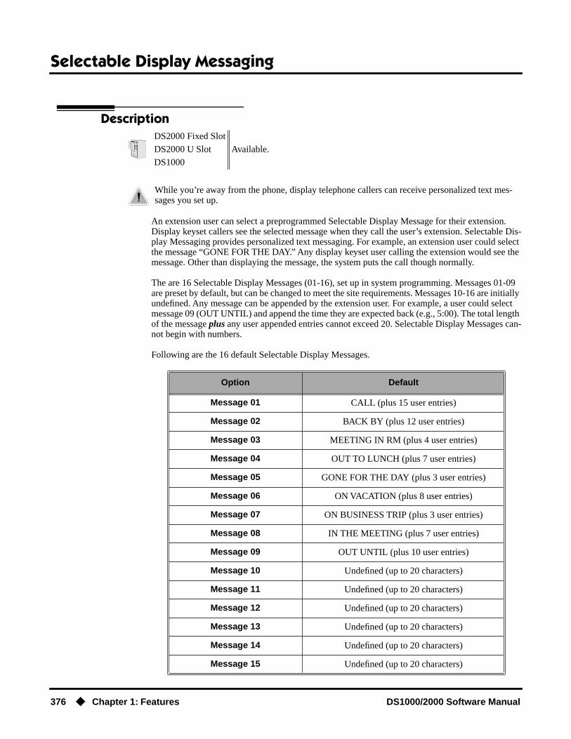
Selectable Display Messaging
376 ◆ Chapter 1: Features DS1000/2000 Software Manual
Selectable Display Messaging
Description
An extension user can select a preprogrammed Selectable Display Message for their extension. Display keyset callers see the selected message when they call the user’s extension. Selectable Dis-play Messaging provides personalized text messaging. For example, an extension user could select the message “GONE FOR THE DAY.” Any display keyset user calling the extension would see the message. Other than displaying the message, the system puts the call though normally.
The are 16 Selectable Display Messages (01-16), set up in system programming. Messages 01-09 are preset by default, but can be changed to meet the site requirements. Messages 10-16 are initially undefined. Any message can be appended by the extension user. For example, a user could select message 09 (OUT UNTIL) and append the time they are expected back (e.g., 5:00). The total length of the message plus any user appended entries cannot exceed 20. Selectable Display Messages can-not begin with numbers.
Following are the 16 default Selectable Display Messages.
DS2000 Fixed Slot
Available.DS2000 U Slot
DS1000
While you’re away from the phone, display telephone callers can receive personalized text mes-sages you set up.
Option Default
Message 01 CALL (plus 15 user entries)
Message 02 BACK BY (plus 12 user entries)
Message 03 MEETING IN RM (plus 4 user entries)
Message 04 OUT TO LUNCH (plus 7 user entries)
Message 05 GONE FOR THE DAY (plus 3 user entries)
Message 06 ON VACATION (plus 8 user entries)
Message 07 ON BUSINESS TRIP (plus 3 user entries)
Message 08 IN THE MEETING (plus 7 user entries)
Message 09 OUT UNTIL (plus 10 user entries)
Message 10 Undefined (up to 20 characters)
Message 11 Undefined (up to 20 characters)
Message 12 Undefined (up to 20 characters)
Message 13 Undefined (up to 20 characters)
Message 14 Undefined (up to 20 characters)
Message 15 Undefined (up to 20 characters)

Selectable Display Messaging
DS1000/2000 Software Manual Chapter 1: Features ◆ 377
ConditionsNone
Default SettingSee the table above.
Programming Guide
Programming ListProgram 1001 - Internal Call Forwarding (page 506)
Enter Y to enable Call Forwarding.Program 0801 - Selectable Display Messages (page 579)
Program the system’s 16 Selectable Display Messages (up to 20 characters long).Program 1801 - Extension Class of Service Assignment (page 631)
Assign an extension’s Class of Service.
Message 16 Undefined (up to 20 characters)
Step-by-step guide for setting up Selectable Display Messaging
Step 1: Should extension be able to enable Selectable Display Messaging?
• In Program 1001 - Internal Call Forwarding (page 506), enter Y.
• In Program 1801 - Extension Class of Service Assignment (page 631), assign an extension’s Class of Service.
• In Program 1001 - Internal Call Forwarding (page 506), enter N.
• In Program 1801 - Extension Class of Service Assignment (page 631), assign an extension’s Class of Service.
Step 2: Do you want to change the default Selectable Display Messages or create new ones?
• In Program 0801 - Selectable Display Messages (page 579), edit the Selectable Display Messages.
• Do not make any changes to Program 0801 - Selectable Display Messages (page 579).
Option Default
If yes
If no
If yes
If no

Selectable Display Messaging
378 ◆ Chapter 1: Features DS1000/2000 Software Manual
Other Related FeaturesCall Forwarding (page 66)
Enabling or canceling Call Forwarding cancels an extension’s Selectable Display Messaging.Removing Trunks and Extensions From Service (page 362)
Removing and returning an extension to service does not cancel an extension’s Selectable Display Messaging.
Single Line Telephones (page 381)SLTs cannot use Selectable Display Messaging.
Speed Dial (page 383)Personal Speed Dial keys can store the codes that enable Selectable Display Messaging.
Feature Operation
To select a Selectable Display Message:
1. Press ICM.
2. Dial *38 + Message number (01-16).
You can press VOL ▲ or VOL ▼ to scroll through the messages instead of dialing the message number.
3. Press HOLD.
4. Enter any additional digits.The total number of digits/characters in the message cannot exceed 20. Use any valid
characters, digits or symbols (just as if you were entering names). Refer to the table below when entering digits.
5. Press HOLD.
6. Press SPK to hang up.DND is on while the Selectable Display Message is active.
To cancel a Selectable Display Message:
1. Press ICM.
2. Dial *30.
3. Press SPK to hang up.
Dial tone.
ICM and SPK on.
Dial tone stops.
ICM on, SPK flashes.
Dial tone.
ICM and SPK on.
Dial tone.
ICM and SPK on.
Dial tone stops.
ICM, SPK and DND go out.

Selectable Display Messaging
DS1000/2000 Software Manual Chapter 1: Features ◆ 379
Use the following table when entering or appending messages:
Keys for Entering Names
Press this key:
Then one of these keys to enter the character in the white cell:
1 2 3 4 #
1 & - (dash)1 / (backslash)1 ‘(apostrophe)1 1
2 A B C 2
3 D E F 3
4 G H I 4
5 J K L 5
6 M N O 6
7 P Q R S 7
8 T U V 8
9 W X Y Z 9
0 SPACE : 0
* *
#
To enter characters in lower case (e.g., e instead of E), press MW before pressing the key in the first shaded column. Use LND to backspace over (erase) any characters you want to correct.1In software versions prior to 02.00.00, the codes for 1 + 2, 1 + 3, and 1 + 4 were not available.
Silent Monitor
380 ◆ Chapter 1: Features DS1000/2000 Software Manual
Silent Monitor
DescriptionDS2000 Fixed Slot
See Monitor / Silent Monitor on page 300.DS2000 U Slot
DS1000
Single Line Telephones
DS1000/2000 Software Manual Chapter 1: Features ◆ 381
Single Line Telephones
DescriptionDS2000 Fixed Slot
Available. Refer to Off-Premise Extensions / On-Premise SLT Extensions on page 317 for more.DS2000 U Slot
DS1000

Soft Keys
382 ◆ Chapter 1: Features DS1000/2000 Software Manual
Soft Keys
DescriptionDS2000 Fixed Slot
See Interactive Soft Keys on page 244.DS2000 U Slot
DS1000

Speed Dial
DS1000/2000 Software Manual Chapter 1: Features ◆ 383
Speed Dial
Description
Speed Dial gives an extension user quick access to frequently called numbers. There are two types of Speed Dial: System and Personal. Speed Dial numbers can be up to 32 digits long, using 0-9, # and *. Every Speed Dial can have a programmed name up to 16 characters long. The name shows in the telephone display as the Speed Dial number dials out.
Speed Dial can store outside numbers and Intercom digits. The capability to store Intercom digits provides the user with “one-touch” access to features they use most often. For example, a user can have a Speed Dial bin that simplifies forwarding calls to Voice Mail or a co-worker.
System Speed DialSystem Speed Dial gives every extension access to the same set of stored numbers. The system pro-vides up to 1000 System Speed Dial numbers. Depending on the system option selected (see Pro-gramming Guide below), the system provides either 10, 100 or 1000 System Speed Dial numbers.
Personal Speed DialPersonal Speed Dial provides extensions with 20 numbers stored privately for their own use. The Per-sonal Speed Dial keys on a DSS Console access the same bins as the extension to which it is attached.
Allocating Speed Dial BlocksThe system allows up to 1240 unique Speed Dial numbers (bins). Bins are grouped into 62 distinct blocks, with 20 numbers in each block. Review the table below and keep the following bullets in mind when setting up Speed Dial:
DS2000 Fixed Slot Available.
DS2000 U Slot
• The Super Display telephone display shows the first 10 characters of the programmed Personal Speed Dial name (or first 10 digits of stored number if there is no name). Previous versions showed bin number only.
• User Programmable Feature steps added.• Software version 02.01.07 or higher is recommended for Speed Dial bin
chaining applications.
DS1000
• The Super Display telephone display shows the first 10 characters of the programmed Personal Speed Dial name (or first 10 digits of stored number if there is no name). Previous versions showed bin number only.
• Software version 02.01.07 or higher is recommended for Speed Dial bin chaining applications.
Instead of dialing a long telephone number to reach a client or customer, use Speed Dial instead. Also, store Intercom digits for quick access to commonly used features.
System Speed Dial Personal Speed Dial
Total Bins Total Blocks Block Numbers Total Bins Total Blocks Block Numbers
10 (20-29) 1 1(10 bins not used)
1220 61 2-61
100 (200-299) 5 1-5 1140 57 6-62
1000(2000-2999)
50 1-50 240 12 51-62

Speed Dial
384 ◆ Chapter 1: Features DS1000/2000 Software Manual
● The system automatically assigns System Speed Dial blocks. By default, Personal Speed Dial Blocks are assigned as follows.
● You can change the Personal Speed Dial block assignment for an extension in system program-ming. Always be careful, however, to not assign a Personal Speed Dial block that is already in use for System Speed Dial. If you do, that extension’s personal entries will overwrite the system entries, and vice-versa.
● Extensions with the same Personal Speed Dial block share the same Personal Speed Dial numbers.
● The Personal Speed Dial keys on a DSS Console access the same bins as the extension to which it is attached. DSS Consoles do not have unique Personal Speed Dial numbers.
Unique Speed Dial EntriesIn addition to the digits 0-9, # and *, you can enter the following for additional dialing options:
Storing Trunk Routing in a Speed Dial BinWhen you program a Speed Dial bin, you can select either a trunk or a Trunk Group over which the call should route. For example, you can enter 1 for trunk 1 or 90 for Trunk Group 0.
● If you enter a Trunk Group number, the system will select the lowest numbered trunk in the group for the call. If that trunk is busy, the system will select the next highest trunk.
● If you enter a trunk number, the system initially selects that specific trunk for the call. If the trunk is busy, the system automatically tries the next trunk in that trunk’s group (if any). If there is no other installed trunk in that group, the user hears busy tone and the call doesn’t go through.
● The capability to dial 90-98 to select a Trunk Group for a Speed Dial call is not affected by the setting of Program 0501 - Single Digit Access (page 542). It is a permanent feature.
Extension Personal Speed DialBlock Assignment
300 6
301 7
through
356 62
For this option Or use this telephone Programming List option:
Pause MIC
Flash FLASH
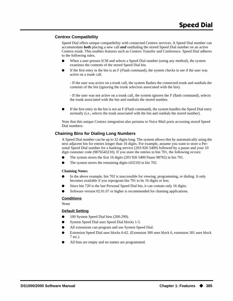
Speed Dial
DS1000/2000 Software Manual Chapter 1: Features ◆ 385
Centrex CompatibilitySpeed Dial offers unique compatibility with connected Centrex services. A Speed Dial number can accommodate both placing a new call and outdialing the stored Speed Dial number on an active Centrex trunk. This enables features such as Centrex Transfer and Conference. Speed Dial adheres to the following rules.
● When a user presses ICM and selects a Speed Dial number (using any method), the system examines the contents of the stored Speed Dial bin.
● If the first entry in the bin is an F (Flash command), the system checks to see if the user was active on a trunk call.
- If the user was active on a trunk call, the system flashes the connected trunk and outdials the contents of the bin (ignoring the trunk selection associated with the bin).
- If the user was not active on a trunk call, the system ignores the F (flash command), selects the trunk associated with the bin and outdials the stored number.
● If the first entry in the bin is not an F (Flash command), the system handles the Speed Dial entry normally (i.e., selects the trunk associated with the bin and outdials the stored number).
Note that this unique Centrex integration also pertains to Voice Mail ports accessing stored Speed Dial numbers.
Chaining Bins for Dialing Long NumbersA Speed Dial number can be up to 32 digits long. The system allows this by automatically using the next adjacent bin for entries longer than 16 digits. For example, assume you want to store a Per-sonal Speed Dial number for a banking service (203-926 5400) followed by a pause and your 10 digit customer code (9876543210). If you store the entries in bin 701, the following occurs:
● The system stores the first 16 digits (203 926 5400 Pause 98765) in bin 701.
● The system stores the remaining digits (43210) in bin 702.
Chaining Notes:● In the above example, bin 702 is inaccessible for viewing, programming, or dialing. It only
becomes available if you reprogram bin 701 to be 16 digits or less.
● Since bin 720 is the last Personal Speed Dial bin, it can contain only 16 digits.
● Software version 02.01.07 or higher is recommended for chaining applications.
ConditionsNone
Default Setting
● 100 System Speed Dial bins (200-299).
● System Speed Dial uses Speed Dial blocks 1-5.
● All extensions can program and use System Speed Dial.
● Extension Speed Dial uses blocks 6-62. (Extension 300 uses block 6, extension 301 uses block 7 etc.)
● All bins are empty and no names are programmed.
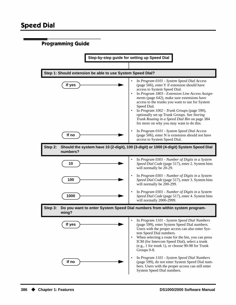
Speed Dial
386 ◆ Chapter 1: Features DS1000/2000 Software Manual
Programming Guide
Step-by-step guide for setting up Speed Dial
Step 1: Should extension be able to use System Speed DIal?
• In Program 0101 - System Speed Dial Access (page 506), enter Y if extension should have access to System Speed Dial.
• In Program 1803 - Extension Line Access Assign-ments (page 642), make sure extensions have access to the trunks you want to use for System Speed Dial.
• In Program 1002 - Trunk Groups (page 590), optionally set up Trunk Groups. See Storing Trunk Routing in a Speed Dial Bin on page 384 for more on why you may want to do this.
• In Program 0101 - System Speed Dial Access (page 506), enter N is extension should not have access to System Speed Dial.
Step 2: Should the system have 10 (2-digit), 100 (3-digit) or 1000 (4-digit) System Speed Dial numbers?
• In Program 0301 - Number of Digits in a System Speed Dial Code (page 517), enter 2. System bins will normally be 20-29.
• In Program 0301 - Number of Digits in a System Speed Dial Code (page 517), enter 3. System bins will normally be 200-299.
• In Program 0301 - Number of Digits in a System Speed Dial Code (page 517), enter 4. System bins will normally 2000-2999.
Step 3: Do you want to enter System Speed Dial numbers from within system program-ming?
• In Program 1101 - System Speed Dial Numbers (page 599), enter System Speed Dial numbers. Users with the proper access can also enter Sys-tem Speed Dial numbers.
• When selecting a route for the bin, you can press ICM (for Intercom Speed Dial), select a trunk (e.g., 1 for trunk 1), or choose 90-98 for Trunk Groups 0-8.
• In Program 1101 - System Speed Dial Numbers (page 599), do not enter System Speed Dial num-bers. Users with the proper access can still enter System Speed Dial numbers.
If yes
If no
10
100
1000
If yes
If no

Speed Dial
DS1000/2000 Software Manual Chapter 1: Features ◆ 387
Step 4: Should extension or DSS Console have Programmable Function Key access to Sys-tem Speed Dial numbers.
• In Program 1701 - System Speed Dial Key (page 614), assign a keyset programmable key as a System Speed Dial Key (code 14 + System Speed Dial bin number).
• In Program 1704 - System Speed Dial Key (page 625), assign a DSS Console key as a Sys-tem Speed Dial Key (code 14 + System Speed Dial bin number).
• Do not assign keyset or DSS Console keys for System Speed Dial access.
Step 5: Should extension be able to use Personal Speed DIal?
• In Program 1802 - Speed Dial Block (page 637), assign Personal Speed Dial Blocks to extensions. Refer to Allocating Speed Dial Blocks on page 383 for help with assigning blocks. By default, 300=6, 301=7, through 356=62.
• In Program 1803 - Extension Line Access Assign-ments (page 642), make sure extensions have access to the trunks you want to use for Personal Speed Dial.
• In Program 1002 - Trunk Groups (page 590), optionally set up Trunk Groups. See Storing Trunk Routing in a Speed Dial Bin on page 384 for more on why you may want to do this.
• In Program 1802 - Speed Dial Block (page 637), assign the extension to Personal Speed Dial block 0.
Step 6: Do you want to enter Personal Speed Dial numbers from within system program-ming?
• In Program 1702 - Personal Speed Dial (page 618), enter Personal Speed Dial numbers. Users can also enter Personal Speed Dial num-bers from their own phone.
• When selecting a route for the bin, you can press ICM (for Intercom Speed Dial), select a trunk (e.g., 1 for trunk 1), or choose 90-98 for Trunk Groups 0-8.
• In Program 1702 - Personal Speed Dial (page 618), do not enter Personal Speed Dial numbers. Users can still enter Personal Speed Dial numbers from their own phone.
Step-by-step guide for setting up Speed Dial
If yes
If no
If yes
If no
If yes
If no

Speed Dial
388 ◆ Chapter 1: Features DS1000/2000 Software Manual
Step 7: Should extension or DSS Console have Programmable Function Key access to Per-sonal Speed Dial numbers.
• In Program 1701 - Personal Speed Dial Key (page 614), assign a keyset programmable key as a Personal Speed Dial Key (code 15 + System Speed Dial bin number).
• In Program 1704 - Personal Speed Dial Key (page 625), assign a DSS Console key as a Per-sonal Speed Dial Key (code 10 + System Speed Dial bin number).
• Do not assign keyset or DSS Console keys for System Speed Dial access.
Step 8: Should the system be able to dial out any # characters stored in a Speed Dial bin?
You may not want to enable the dialing of stored # characters if your system is installed behind a PBX.
• In Program 0201 - Enable Account Codes in Speed Dial (2.01.07 or higher) (page 513), enter Y.
• In Program 0201 - Enable Dial-out of # in a Speed Dial Number (Prior to 2.01.07) (page 514), enter Y.
• In Program 0201 - Enable Account Codes in Speed Dial (2.01.07 or higher) (page 513), enter N.
• In Program 0201 - Enable Dial-out of # in a Speed Dial Number (Prior to 2.01.07) (page 514), enter N.
Step 9: When the system encounters a pause stored in a Speed Dial bin, does it wait the proper interval before outdialing the remainder of the number?
• In Program 0401 - Dialing Pause (page 523), do not change the entry from its assigned value.
• In Program 0401 - Dialing Pause (page 523), change the pause duration for compatibility with the connected telco or PBX/Centrex.
Step-by-step guide for setting up Speed Dial
If yes
If no
If yes
If no
If yes
If no

Speed Dial
DS1000/2000 Software Manual Chapter 1: Features ◆ 389
Programming ListProgram 0101 - System Speed Dial Access (page 506)
In an extension’s Class of Service, enter Y to allow the extension to access System Speed Dial numbers.
Program 0201 - Enable Account Codes in Speed Dial (2.01.07 or higher) (page 513)Program 0201 - Enable Dial-out of # in a Speed Dial Number (Prior to 2.01.07) (page 514)
Enter Y for this option if you want the system to outdial any # characters stored in the Speed Dial number. Enter N to have the system suppress outdialing the #. (You may want to enter N if the system is installed behind a PBX.)
Step 10: When the system encounters a Flash stored in a Speed Dial bin, does it open the loop on the trunk for the proper interval before outdialing the remainder of the number?
• In Program 0402 - PBX/Centrex Flash (page 527), do not change the entry from its assigned value.
• In Program 0402 - PBX/Centrex Flash (page 527), change the Flash duration for com-patibility with the connected telco or PBX/Cen-trex.
Step 11: Does the system properly detect dial tone for Speed Dial calls?
• In Program 0402 - Dial Tone Detect (page 526), do not change the entry from its assigned value.
• In Program 0402 - Dial Tone Detect (page 526), change the Dial Tone Detect duration for compat-ibility with the connected telco or PBX/Centrex.
Step 12: When the system outdials DTMF Speed Dial calls, are the DTMF digits properly interpreted by the connected telco or PBX/Centrex.
• In Program 0402 - Speed Dial DTMF Tone On (page 529), do not change the entry from its assigned value.
• In Program 0402 - Speed Dial DTMF Tone Off (page 530), do not change the entry from its assigned value.
• In Program 0402 - Speed Dial DTMF Tone On (page 529), change the DTMF on interval the sys-tem uses for Speed Dial calls to match the con-nected telco or PBX/Centrex.
• In Program 0402 - Speed Dial DTMF Tone Off (page 530), change the DTMF on interval the sys-tem uses for Speed Dial calls to match the con-nected telco or PBX/Centrex.
Step-by-step guide for setting up Speed Dial
If yes
If no
If yes
If no
If yes
If no

Speed Dial
390 ◆ Chapter 1: Features DS1000/2000 Software Manual
Program 0301 - Number of Digits in a System Speed Dial Code (page 517)Assign the number of digits the system uses to designate System Speed Dial bins (2, 3 or 4). With 2-digit bins, the system has 10 bins numbered 20-29. With 3-digit bins, the system has 100 bins numbered 200-299. With 4-digit bins, the system as 1000 bins numbered 2000-2999.
Program 0401 - Dialing Pause (page 523)For Speed Dial, the system waits this interval when it encounters a pause in a Speed Dial bin.
Program 0402 - Dial Tone Detect (page 526)When the system seizes a line to place a Speed Dial call, it waits this interval for dial tone before outdialing the call.
Program 0402 - PBX/Centrex Flash (page 527)When the system encounters a flash in a Speed Dial bin, it opens the loop on the trunk for this interval for outdialing the remainder of the call.
Program 0402 - Speed Dial DTMF Tone On (page 529)Set the duration of DTMF digits for Speed Dial trunk calls automatically dialed by the sys-tem. Set this timer for compatibility with the connected telco or PBX/Centrex.
Program 0402 - Speed Dial DTMF Tone Off (page 530)Sets the duration the the quiet time between DTMF digits for Speed Dial trunk calls automatically dialed by the system. Set this timer for compatibility with the connected telco or PBX/Centrex.
Program 1002 - 1002 - Trunk Groups (page 590)Set up Trunk Groups if you want Speed Dial to use or overflow to Trunk Groups.
Program 1101 - System Speed Dial Numbers (page 599)Enter System Speed Dial bin names and numbers. When selecting a route for the bin, you can press ICM (for Intercom Speed Dial), select a trunk (e.g., 1 for trunk 1), or choose 90-98 for Trunk Groups 0-8.
Program 1701 - System Speed Dial Key (page 614)Assign a programmable key on an extension as a System Speed Dial key (code 14). You assign the key to specific System Speed Dial bin (normally 200-299).
Program 1701 - Personal Speed Dial Key (page 614)Assign a programmable key on an extension as a Personal Speed Dial key (code 15). You assign the key to a specific Personal Speed Dial bin (e.g., 701-720).
Program 1702 - Personal Speed Dial (page 618)Enter Personal Speed Dial bin names and numbers. An extension user can also enter their Per-sonal Speed Dial numbers from their own telephone. When selecting a route for the bin, you can press ICM (for Intercom Speed Dial), select a trunk (e.g., 1 for trunk 1), or choose 90-98 for Trunk Groups 0-8.
Program 1704 - System Speed Dial Key (page 625)Assign a programmable key on an extension as a System Speed Dial key (code 14). You assign the key to specific System Speed Dial bin (normally 200-299).
Program 1704 - Personal Speed Dial Key (page 625)Assign a programmable key on an extension as a Personal Speed Dial key (code 15). You assign the key to a specific Personal Speed Dial bin (e.g., 701-720).
Program 1802 - Speed Dial Block (page 637)Assign a Speed Dial block (6-62) to an extension. By default, 300=6, 301=7, through 356=62.
Program 1803 - Extension Line Access Assignments (page 642)For each extension, assign the access options for each trunk (0 = No access, 1 = Incoming only. 2 = Outgoing only, 3 = Full access).
When Number of Digits in a System Speed Dial
Code is:
System Speed Dial bin numbers are:
And the total number of System Speed Dial
bins is:
2 20-29 10
3 200-299 100
4 2000-2999 1000

Speed Dial
DS1000/2000 Software Manual Chapter 1: Features ◆ 391
Other Related FeaturesAccount Codes (page 34)
An extension user can store an Account Code in a Speed Dial bin. See Using Account Codes and Speed Dial (page 34) for more.
Central Office Calls, Placing (page 105)You can store outside numbers in Speed Dial bins for quick access to frequently called numbers.
Check Key (page 115)Check Personal Speed Dial bin assignments.
Direct Station Selection (DSS) Console (page 143)The DSS Console Personal Speed Dial bins are the same as the extension to which the console is attached. This means that DSS Consoles that share the same block number still have unique Personal Speed Dial.
Toll Restriction (Software Version 02.02.14 or Higher) (page 439)The system enforces Toll Restriction on Speed Dial numbers as they are dialed, not as they are stored.
Toll Restriction (Prior to Software Version 02.02.14) (page 447)The system enforces Toll Restriction on Speed Dial numbers as they are dialed, not as they are stored.
Voice Over (page 493)An extension user can Voice Over after calling a co-worker by using Personal Speed Dial.
Feature Operation
Personal Speed Dial
To program a Personal Speed Dial number:
1. With U Slot software: Dial #SPWith Fixed Slot software: Press ICM and dial ##.
2. Dial the Personal Speed Dial bin number (701-720).OR
Press Personal Speed Dial Key (for bins 1-10).OR
Press DIAL and the Personal Speed Dial Key for bins 11-20.
User Programmable Feature
Feature Mnemonic Operation Access Level
The shaded row below shows the Fixed Slot software User Programmable Feature.
Speed Dial, Personal ICM + ## + 701-720 N/A
Speed Dial, Personal #SP #SP + Press bin key (for bins 701-710) or DIAL then bin key (for bins 711-720) + HOLD + Enter outside line (e.g., 1), line group (90-98), or ICM for Intercom fea-ture + HOLD + Number to store + HOLD + Name + HOLD + Press another bin key or SPK to exit.
1-5
With Fixed Slot software, Intercom dial tone comes on - then goes off.
SPK flashes slowly.

Speed Dial
392 ◆ Chapter 1: Features DS1000/2000 Software Manual
3. Press HOLD.
4. Enter the trunk number you want the system to use when dialing your stored number (1-48 in DS2000, 1-6 in DS1000).
OREnter the Trunk Group number you want the system to use when dialing your stored number (i.e.., 90-98 for Trunk Groups 0-8).
ORPress ICM if you want to enter Intercom codes.
5. Press HOLD.
6. Enter the number you want to store (up to 30 digits long).If storing Intercom codes, you can enter any valid dial sequence consisting of the dig-
its 0-9, # and *. To insert a pause, press MIC. To insert a Flash, press FLASH.
7. Press HOLD.
8. Enter a name for the Speed Dial numberFor help on programming names, see Keys for Entering Names on page 505.
9. Press HOLD.
10. Repeat from step 2 to program another bin number.OR
Press SPK to exit.
To dial a Personal Speed Dial number:
1. Press ICM and dial #.
2. Dial the Personal Speed Dial bin number (701-720).The stored number dials out. To chain Personal Speed Dial bins, wait for the first bin to
dial out and then press the second bin key.
For one-button access to your Personal Speed Dial numbers:
1. Press Personal Speed Dial Key for bins 1-10.OR
Press DIAL then Personal Speed Dial key for bins 11-20.OR
Press Programmable Function key for Personal Speed Dial bin.The stored number dials out.
Intercom dial tone comes on - then goes off.
SPK and ICM on.

Speed Dial
DS1000/2000 Software Manual Chapter 1: Features ◆ 393
System Speed Dial
To program a System Speed Dial number:
1. With U Slot software: Dial #SPWith Fixed Slot software: Press ICM and dial ##.
2. Dial the System Speed Dial bin number (normally 200-299).
3. Press HOLD.
4. Enter the trunk number you want the system to use when dialing your stored number (1-48 in DS2000, 1-6 in DS1000).
OREnter the Trunk Group number you want the system to use when dialing your stored number (i.e.., 90-98 for Trunk Groups 0-8).
ORPress ICM if you want to enter Intercom codes.
5. Press HOLD.
6. Enter the number you want to store (up to 30 digits long).You can enter any combination of the digits 0-9, # and *. To store a pause with your
Speed Dial number, press MIC. To insert a Flash, press FLASH.
7. Press HOLD.
8. Enter a name for the Speed Dial numberFor help on programming names, see Keys for Entering Names on page 505.
9. Press HOLD.
10. Repeat from step 2 to program another bin number.OR
Press SPK to exit.
To dial a System Speed Dial number:
1. Press ICM and dial #.
2. Dial the System Speed Dial bin number (normally 200-299).OR
Press Programmable Function Key for System Speed Dial bin.
User Programmable Feature
Feature Mnemonic Operation Access Level
The shaded row below shows the Fixed Slot software User Programmable Feature.
Speed Dial, System ICM + ## + 200-299 N/A
Speed Dial, System #SP #SP + Dial System Speed Dial bin num-ber (e.g., 200) + HOLD + Enter outside line (e.g., 1), line group (e.g., 90), or ICM for Intercom feature + HOLD + Number to store + HOLD + Name + HOLD + Press another bin key or SPK to exit.
4 and 5
With Fixed Slot software, Intercom dial tone comes on - then goes off.
SPK flashes slowly.
Intercom dial tone comes on - then goes off.
SPK and ICM on.

Speed Dial
394 ◆ Chapter 1: Features DS1000/2000 Software Manual
The stored number dials out.
To chain Speed Dial bins:
1. Access the first Speed Dial bin and wait for the number to dial out.
2. Press another Personal Speed Dial bin key.OR
Press a Personal or System Speed Dial Programmable Function Key.OR
Press a DSS Console Personal or System Speed Dial Key.
3. Repeat step 2 to chain additional numbers.

Split (Alternate)
DS1000/2000 Software Manual Chapter 1: Features ◆ 395
Split (Alternate)
Description
With Split, an extension user can split (alternate) between a current call and a new call. Split lets the extension user easily alternate between the calls without joining (Conferencing) the parties together.
ConditionsNone
Default SettingSplit disabled (no Split keys programmed).
Programming Guide
Programming ListProgram 1701 - Split Key (page 615)
Assign a Programmable Function Key as a Split key (code 20).Program 1704 - Split Key (page 626)
Assign a DSS Console key as a Split key (code 20).
DS2000 Fixed Slot
Available.DS2000 U Slot
DS1000
Switch between active calls without Conferencing the calls together.
Step-by-step guide for setting up Split
Step 1: Should keyset be able to Split between calls?
• In Program 1701 - Split Key (page 615), assign a Programmable Function Key as a Split key (code 20). OR
• In Program 1704 - Split Key (page 626), assign a DSS Console key as a Split key (code 20).
• In Program 1701 - Split Key (page 615), do not assign a Programmable Function Key as a Split key (code 20). OR
• In Program 1704 - Split Key (page 626), do not assign a DSS Console key as a Split key (code 20).
If yes
If no

Split (Alternate)
396 ◆ Chapter 1: Features DS1000/2000 Software Manual
Other Related FeaturesCall Waiting / Camp-On (page 75)
Camp-On lets an extension user know that a call is waiting to be answered. The user can Split between the waiting call and their current call.
Direct Station Selection (DSS) Console (page 143)A DSS Console can have a Split key.
Off-Hook Signaling (page 313)An extension user can alternate between their active call and their waiting call.
Feature Operation
To Split between your current Intercom call and a new Intercom call:
Your extension must have a Split Programmable Function Key.
1. Press HOLD to place your current Intercom call on Hold, then hang up.
2. Place or answer Intercom call.
3. Press the Split key to switch between your two Intercom calls.
To Split between your current trunk call and an Intercom call:
Your extension must have a Split Programmable Function Key.
1. Press ICM to place trunk call on Hold, then hang up.
2. Place or answer waiting Intercom call.
3. Press the Split key to switch between the Intercom call and the trunk call.Repeat this step to alternate between the callers.
To Split between your current Intercom call and a trunk call:
Your extension must have a Split Programmable Function Key.
1. Press HOLD to place your current Intercom call on Hold.
2. Answer trunk call.
3. Press the Split key to switch between your two calls.
To Split between your current trunk call and a waiting trunk call:
Your extension must have a Split Programmable Function Key.
1. Press ICM to place your current trunk call on Hold, then hang up.
2. Place or answer new trunk call.
3. Press the Split key to switch between your two calls.
Intercom Callback ring from waiting Intercom call.
ICM slow flash.
Intercom Callback ring from waiting Intercom call.
Line key flutter on (green). ICM slow flash.
Conversation with trunk caller.
ICM slow flash.
Conversation with trunk caller.
Line key on (green) for active call, flutter on (green) for call on Hold.

Station Instruments
DS1000/2000 Software Manual Chapter 1: Features ◆ 397
Station Instruments
Description
The system offers 22-Button Display, 22-Button Standard, 34-Button Display, and 34-Button Super Display keyset telephones.
DS2000 Fixed Slot Available.
DS2000 U Slot DTMF supervisory tones play through the keyset handset or speaker whenever the user lifts the handset. Supervisor tones play whether the keyset is on-hook, on a call or in the programming mode.DS1000
System keysets provide a host of sophisticated extension features.
22-Button Display Telephone
The 22-Button Display Telephone features a 2-by-20 alphanumeric display with 4 Interactive Soft Keys for intuitive feature access, 10 Per-sonal Speed Dial bin keys, 12 Programmable Function Keys and 14 fixed feature keys. It also provides a built-in speakerphone, Dual LEDs and a built-in desk stand.
22-Button Standard Telephone
The 22-Button Telephone also has 10 Personal Speed Dial bin keys, 12 Programmable Func-tion Keys and 14 fixed feature keys. It also pro-vides a built-in speakerphone, Dual LEDs and a built-in desk stand. It does not, however, have a 2-line display and Interactive Soft Keys.
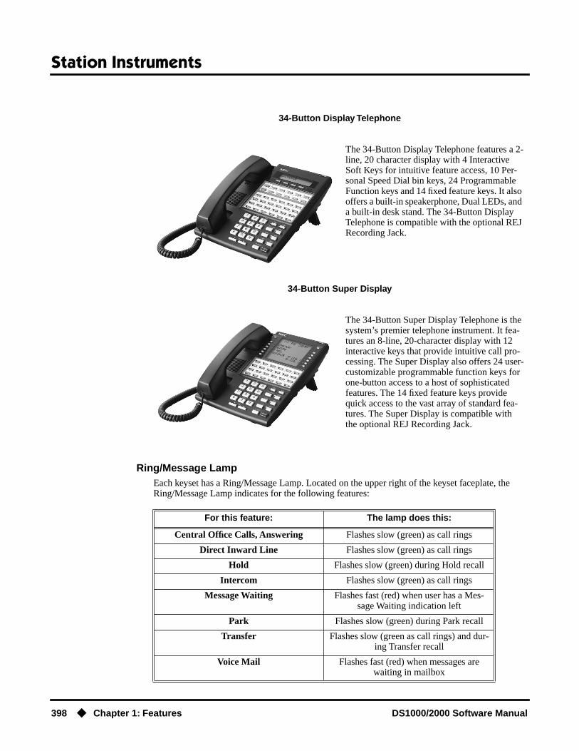
Station Instruments
398 ◆ Chapter 1: Features DS1000/2000 Software Manual
Ring/Message LampEach keyset has a Ring/Message Lamp. Located on the upper right of the keyset faceplate, the Ring/Message Lamp indicates for the following features:
34-Button Display Telephone
The 34-Button Display Telephone features a 2-line, 20 character display with 4 Interactive Soft Keys for intuitive feature access, 10 Per-sonal Speed Dial bin keys, 24 Programmable Function keys and 14 fixed feature keys. It also offers a built-in speakerphone, Dual LEDs, and a built-in desk stand. The 34-Button Display Telephone is compatible with the optional REJ Recording Jack.
34-Button Super Display
The 34-Button Super Display Telephone is the system’s premier telephone instrument. It fea-tures an 8-line, 20-character display with 12 interactive keys that provide intuitive call pro-cessing. The Super Display also offers 24 user-customizable programmable function keys for one-button access to a host of sophisticated features. The 14 fixed feature keys provide quick access to the vast array of standard fea-tures. The Super Display is compatible with the optional REJ Recording Jack.
For this feature: The lamp does this:
Central Office Calls, Answering Flashes slow (green) as call rings
Direct Inward Line Flashes slow (green) as call rings
Hold Flashes slow (green) during Hold recall
Intercom Flashes slow (green) as call rings
Message Waiting Flashes fast (red) when user has a Mes-sage Waiting indication left
Park Flashes slow (green) during Park recall
Transfer Flashes slow (green as call rings) and dur-ing Transfer recall
Voice Mail Flashes fast (red) when messages are waiting in mailbox

Station Instruments
DS1000/2000 Software Manual Chapter 1: Features ◆ 399
ConditionsNone
Default Setting
● (Prior to software version 02.02.14)All extensions set up as 22-Button Display keysets (circuit type 02).
● (Software version 02.02.14 or higher)Digital station ports (300-315 in DS1000, on installed and programmed PCBs in DS2000) automatically detect the type of connect device when the keyset, 2-OPX Module (both ports) or Digital Door Box is plugged in.
Programming ListProgram 1801 - Extension Circuit Type (page 629)
Assign the correct circuit type for each extension:
● 01 = 22-Button Standard
● 02 = 22-Button Display
● 06 = 34-Button Display
● 09 = 34-Button Super Display
Other Related FeaturesNone
Feature OperationRefer to the individual features in this manual.

Station Message Detail Recording
400 ◆ Chapter 1: Features DS1000/2000 Software Manual
Station Message Detail Recording
Description
Station Message Detail Recording (SMDR) provides a record of the system’s trunk calls. Typically, the record outputs to a customer-provided printer, terminal or SMDR data collection device. SMDR allows you to monitor the usage at each extension and trunk. This makes charge-back and traffic management easier. SMDR includes both incoming and outgoing calls, and can be turned off sys-tem-wide or selectively for each trunk.
The SMDR call record outputs when the call completes. The system assigns the SMDR record to the last extension on the call. For example, if extension 306 answers the call, talks for 20 minutes, and then Transfers the call to extension 302, extension 302 “owns” the entire call record as soon as they hang up.
When connecting SMDR in DS2000, use cable P/N 80893 and adaptor P/N 85980 to connect the 8-pin DIN connector on the CPU to the 9-pin COM port on the customer-provided laptop or data collection device. In DS1000, use adaptor P/N 85980 and a Mod-8 patch cord to connect the sys-tem’s RS-232-C jack to the 9-pin COM port on a customer-provided laptop or data collection device. By default, the data rate is 19200 baud (9600 baud in Fixed Slot), 8 data bits, 1 stop bit and no parity (typically referred to as 19200 8N1).
The system buffers 50 SMDR call records. When the SMDR buffer fills, new call records will over-write previously buffered call records.
Sample SMDR ReportFollowing is a sample SMDR report:
Station Message Detail Recording05/07/1999 09:10P
---+---+--------------------------------+----------+---------+--------+---Sta|Lin| Number Dialed | Account | Start |Duration| T ---+---+--------------------------------+----------+---------+--------+---306| 01| 12039265400| |09:10:18P|00:00:05|OUT306| 01| 19055072888| |09:10:48P|00:01:13|OUT301| 02| -| |09:12:13P|00:01:12|IN 304| 01| -| |09:12:07P|00:01:20|IN 306| 01| 18003651928| |09:15:38P|00:00:14|OUT
DS2000 Fixed Slot Available. Default COM port baud rate is 9600.
DS2000 U Slot Available.• Default COM port baud rate is 19200.• DS2000 version 02.00.01 changes programmable baud rate range.• Last column in report is expanded from 1 to 3 characters.
DS1000
SMDR provides a printed record of your calls.

Station Message Detail Recording
DS1000/2000 Software Manual Chapter 1: Features ◆ 401
SMDR Report Definitions
SMDR Report Format
SMDR Report Definitions
Sta The extension that placed or answered the call
Lin The trunk used for the call
Number Dialed For outgoing calls, the number dialed on the trunk (up to 20 digits)
Account Account code
Start The time the call was initially answered
Duration The total duration of the call
T In Fixed Slot:O = Outgoing trunk callI = Incoming trunk call
In U Slot:OUT = Outgoing trunk callIN = Incoming trunk call
RNA = trunk that rang but was not answered
SMDR Report Format (Page 1 of 3)
Line Character Field
Report Start Header
1 1-32 STATION MESSAGE DETAIL RECORDING
33,34 Carriage return, line feed
2 1-10 Date (mm/dd/yyyy)
11 Space
12-16 Time (hh:mm:ss)
17 A (for am) or P (for pm)
18,19 Carriage return, line feed
3 1,2 Carriage return, line feed

Station Message Detail Recording
402 ◆ Chapter 1: Features DS1000/2000 Software Manual
Call Record Header
1 1-3 - characters
4 + character
5-7 - characters
8 + character
9-40 - characters
41 + character
42-51 - characters
52 + character
53-61 - characters
62 + character
63-70 - characters
71 + character
U Slot 72-74 - characters
Fixed Slot 72 - character
2 1-3 Sta
4 | character
5-7 Lin
8 | character
9-40 (9 spaces) Number Dialed (10 spaces)
41 | character
42-51 (2 spaces) Account (1 space)
52 | character
53-61 (2 spaces) Start (2 spaces)
62 | character
63-70 Duration
71 | character
U Slot
72 Space
73 T
74 Space
Fixed Slot 72 T
SMDR Report Format (Page 2 of 3)
Line Character Field

Station Message Detail Recording
DS1000/2000 Software Manual Chapter 1: Features ◆ 403
ConditionsNone
Default SettingSMDR output disabled.
3 1-3 - characters
4 + character
5-7 - characters
8 + character
9-40 - characters
41 + character
42-51 - characters
52 + character
53-61 - characters
62 + character
63-70 - characters
71 + character
U SLot 72-74 - characters
Fixed Slot 72 - character
Call Record
1 1-3 Extension number
4 | character
5-7 Trunk number (2 digits, right justified, preceded by one space)
8 | character
9-40 Number dialed (up to 20 characters, right justified, preceded by spaces)
41 | character
42-51 Account Code (right justified, preceded by spaces)
52 | character
53-61 Start time of call (hh:mm:ssA or P)
62 | character
63-70 Duration of call (hh:mm:ss)
71 | character
U Slot 72-74 Type of call
Fixed Slot 72 Type of call
SMDR Report Format (Page 3 of 3)
Line Character Field

Station Message Detail Recording
404 ◆ Chapter 1: Features DS1000/2000 Software Manual
Programming Guide
Step-by-step guide for setting up SMDR
Step 1: Should system output SMDR?
• In Program 0301 - SMDR Port (page 517), enter 1 to enable SMDR at the CPU RS-232-C port.
• In Program 0301 - CPU Baud Rate (page 517), set the baud rate on the RS-232-C port to match the requirements of the connected SMDR device. The entries are 1-5 in DS1000; 1-7 in DS1000.
• In Program 0301 - SMDR Port (page 517), enter 0 to prevent the CPU from outputting SMDR.
Step 2: Should the SMDR report include the header?
• In Program 0301 - Print SMDR Header (page 517), enter Y to enable the SMDR header.
• In Program 0301 - Print SMDR Header (page 517), enter N to disable the SMDR header.
Step 3: Should a specific trunk be included in the SMDR report?
• In Program 1001 - Print SMDR (page 586), enter Y to have the system include the trunk in the SMDR report.
• In Program 1001 - Print SMDR (page 586), enter N to have the system exclude the trunk from the SMDR report.
Step 4: Should a Ctrl-Break at the connected PC or laptop toggle to the next available baud rate?
• In Program 0301 - Fixed Baud Rate (page 517), disable (N) this option. If disabled, a Ctrl-Break at the connected PC or laptop will toggle to the next available baud rate.
• In Program 0301 - Fixed Baud Rate (page 517), enable (Y) this option. If enabled (Y), a Ctrl-Break at the connected PC or laptop will have no effect.
If yes
If no
If yes
If no
If yes
If no
If yes
If no

Station Message Detail Recording
DS1000/2000 Software Manual Chapter 1: Features ◆ 405
Programming ListProgram 0301 - CPU Baud Rate (page 517)
Assign the baud rate for the RS-232-C port on the CPU. The options are as followsFixed Slot and U Slot prior to 02.00.01:- 1 (1200)- 2 (2400)- 3 (4800)- 4 (9600)- 5 (19200)U Slot 02.00.01 and higher and DS1000:- 1 (2400)- 2 (4800)- 3 (9600)- 4 (19200)- 5 (38400)- 6 (57600) - DS1000 02.00.00 through 02.02.14 only.- 7 (115000) - DS1000 02.00.00 through 02.02.14 only.You can also use Ctrl + Break from a laptop connected to the CPU RS-232-C port to step through the available baud rates. See 0301 - Fixed Baud Rate below.
Program 0301 - Fixed Baud Rate (page 517)Use this option to control the ability of a PC or laptop to change the baud rate of the system’s RS-232C serial port. If disabled (N), a Ctrl-Break at the connected PC or laptop will toggle to the next available baud rate. If enabled (Y), a Ctrl-Break at the connected PC or laptop will have no effect.
Program 0301 - SMDR Port (page 517)Enter 1 to enable SMDR output from the CPU RS-232-C port, or enter 0 to disable SMDR at the CPU RS-232-C port.
Program 0301 - Print SMDR Header (page 517)Enter Y to have the beginning of the SMDR report include the column header data. Enter N to have the SMDR report only include the call data (without the header).
Program 1001 - Print SMDR (page 586)Enter Y to have the SMDR report include calls on the trunk. Enter N to have the SMDR report exclude calls on the trunk.
Other Related FeaturesAccount Codes (page 34)
Account Codes print on the SMDR report.Call Timer (page 72)
The Call Timer also helps users keep track of their time on the phone.Caller ID (page 82)
Caller ID prints out on the SMDR report.Time and Date (page 437)
Time and date appear on the SMDR report.Transfer (page 455)
The system assigns the SMDR record to the last extension on the call. For example, if exten-sion 306 answers the call, talks for 20 minutes, and then Transfers the call to extension 302, extension 302 “owns” the entire call record as soon as they hang up.
Year 2000 Compliance (page 499)The SMDR report displays four digits for the year (i.e., 2000, 2001).
Station Message Detail Recording
406 ◆ Chapter 1: Features DS1000/2000 Software Manual
Feature OperationSMDR is automatic once enabled.

System Diagnostics
DS1000/2000 Software Manual Chapter 1: Features ◆ 407
System Diagnostics
Description
To check your system’s software version:
1. Do not lift the handset, do not press SPK, and do not press ICM.
2. Dial 8.Your system’s software version displays.
DS2000 Fixed Slot
See steps below.DS2000 U Slot
DS1000
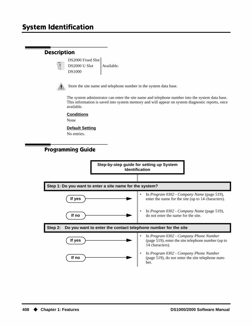
System Identification
408 ◆ Chapter 1: Features DS1000/2000 Software Manual
System Identification
Description
The system adminstrator can enter the site name and telephone number into the system data base. This information is saved into system memory and will appear on system diagnostic reports, once available.
ConditionsNone
Default SettingNo entries.
Programming Guide
DS2000 Fixed Slot
Available.DS2000 U Slot
DS1000
Store the site name and telephone number in the system data base.
Step-by-step guide for setting up System Identification
Step 1: Do you want to enter a site name for the system?
• In Program 0302 - Company Name (page 519), enter the name for the site (up to 14 characters).
• In Program 0302 - Company Name (page 519), do not enter the name for the site.
Step 2: Do you want to enter the contact telephone number for the site
• In Program 0302 - Company Phone Number (page 519), enter the site telephone number (up to 14 characters).
• In Program 0302 - Company Phone Number (page 519), do nor enter the site telephone num-ber.
If yes
If no
If yes
If no
System Identification
DS1000/2000 Software Manual Chapter 1: Features ◆ 409
Programming ListProgram 0302 - Company Name (page 519)
14 Enter the name of the company (up to 14 characters) at which the system is installed. The name appears on top of various system reports.
Program 0302 - Company Phone Number (page 519)Enter the number that the system should call to report a fault. This is not the number of the company where the system is installed. It is the number of the remote service center.
Other Related FeaturesSystem Diagnostics (page 407)
The company name and phone number will display on system diagnostic reports.
Feature OperationNone

System Programming Backup and Restore
410 ◆ Chapter 1: Features DS1000/2000 Software Manual
System Programming Backup and Restore
Description
The PC Card provides a permanent, non-volatile backup of all the site’s programming. If you have backed up your site data to a PC Card, for example, you can easily restore all site programming after an extended power failure.
Versions 02.00.01 and HigherUse PC Card P/N 85880 to back up and restore your site data. Each PC card can store up to 16 com-plete data bases. In addition, you can assign a name (up to 10 characters long) to each stored data base. You cannot use PC Card P/N 80051-V**.**.** (with system software preloaded) to store site data. This PC Card contains only the system’s operating software and the default data base.
Versions Prior to 02.00.01Use PC Card P/N 85880 or P/N 80050-V**.**.** (with system software preloaded) to back up and restore your site data. Each PC card can store up to 12 complete data bases. In addition, you can assign a name (up to 10 characters long) to each stored data base.
Data Base CompatibilityProgram 9906 - Database Save (page 670) and Program 9907 - Database Load (page 672) show the type of data base stored. There are currently two types of data bases:
● DB8 (U Slot software with CPU P/N 80025A)
● DB4 (U Slot software with CPU P/N 80025)
DS2000 Fixed Slot Available. • Versions prior to 02.00.01 used PC Card P/N 80050-V**.**. **. Versions
02.00.01 and higher user PC Card P/N 80051-V**.**.**.• PC Card Erase utility requires software version 02.00.01 or higher.
DS2000 U Slot
DS1000 • Database Transfer Utility requires software version 02.03.03 or higher.
Backup and restore site data to a PC card.
Compatibility Guidelines
Refer to your system’s Hardware Manual or instruction sheet P/N 85880INS** for details on how to load your system software.
When loading system software, a U Slot data base (version 02.nn.nn) is not backward compatible with a Fixed Slot data base (version 01.nn.nn). When updating to U Slot from Fixed Slot, the system must be reinitialized (and reprogrammed) after the new software is loaded.
If restoring a data base from software version 02.00.00 to a higher version, the data base addresses are offset by 8. For example, a 02.00.00 data base you store in address 00 becomes adress 08 when the same PC card is used with software version 02.01.00.
You can only back up and restore data bases of the same type (DB8 or DB4). If you attempt to restore a data base of the wrong type, you’ll see and error message and the operation will abort.
There is a unique upgrade procedure you must use when upgrading from software 02.00.00 to a more recent version. Turn to Upgrading from 02.00.00 to a More Recent Version on page 413.

System Programming Backup and Restore
DS1000/2000 Software Manual Chapter 1: Features ◆ 411
DS1000 Database Transfer Utility
Use 9988 - DS1000 Database Transfer Utility to transfer the contents of one DS1000 system (called the source) to another DS1000 system (called the destination). All programming is trans-ferred, including user-set options such as Personal Speed Dial, Distinctive Ringing and custom Vol-ume/Contrast Control settings.
ConditionsSee Compatiblity Guidelines above.
Default SettingNo data bases stored.
Programming Guide
!! Important Notes When Upgrading or Transferring a Database !!
If upgrading or transferring a database from a software version prior to 02.02.14:• Use Program 9803 - Ring Tone Setup (page 661) to initialize Distinctive Ringing system-
wide with a single command. Following initialization, you must reset the system or unplug and then replug each telephone.
• Use Program 9804 - Initialize Caller ID Log Utility (page 663) to initialize (clear) your Caller ID logs.
Step-by-step guide for setting up System Programming Backup and Restore (Page 1 of
2)
Step 1: Do you want to back up the site data to a PC Card?
• In Program 9906 - Database Save (page 670), back up the site data to one of the 12 available PC card addresses.
• Refer to the system Hardware Manual for addi-tional information on using the PC card for backup and restore.
• In Program 9906 - Database Save (page 670), do not back up the site data to the PC card.
Step 2: Do you want to restore the site data from a PC card.
• In Program 9907 - Database Load (page 672), restore the site data from one of the 12 available PC card addresses.
• After restoring the site data in software versions 02.00.01 and higher, the system will automati-cally reset.
• Refer to the system Hardware Manual for addi-tional information on using the PC card for backup and restore.
If yes
If no
If yes

System Programming Backup and Restore
412 ◆ Chapter 1: Features DS1000/2000 Software Manual
Programming ListProgram 9906 - Database Save (page 670)
Save (back up) site data to a PC card.Program 9907 - Database Load (page 672)
Restore (load) site data from a PC card.Program 9908 - PC Card Erase Utility (page 673)
Erase all the data bases in Data Base PC Card P/N 85880.Program 9988 - DS1000 Database Transfer Utility (page 674)
Transfer the contents of one DS1000 system (called the source) to another DS1000 system (called the destination).
Other Related FeaturesSystem Diagnostics (page 407)
If the system diagnostics report a critical fault that requires a CPU change or system initializa-tion, the installer can quickly restore site programming from the PC card.
Battery Backup (page 60)In the event of commercial AC power failure, the battery on the CPU PCB provides short-term backup of system memory and the system time and date (Real Time Clock).
• In Program 9907 - Database Load (page 672), do not restore the site data from the PC card.
Step 3: Do you want to completely erase all the data in Data Base PC Card P/N 85880?
• In Program 9908 - PC Card Erase Utility (page 673), erase the PC card data.
• Do not use Program 9908 - PC Card Erase Utility.
Step 4: Do you want to transfer the contents of one DS1000 system database into another DS1000 system?
• Following Program 9988 - DS1000 Database Transfer Utility (page 674), transfer the contents of one DS1000 system (called the source) to another DS1000 system (called the destination).
• Do not use Program 9988 - DS1000 Database Transfer Utility.
Step-by-step guide for setting up System Programming Backup and Restore (Page 2 of
2)
If no
If yes
If no
If yes
If no

System Programming Backup and Restore
DS1000/2000 Software Manual Chapter 1: Features ◆ 413
Feature Operation
Upgrading from 02.00.00 to a More Recent VersionUse the following procedure if you need to upgrade an existing 02.00.00 system using CPU 80025A to a more recent version (e.g., 02.01.00) that is also using CPU 80025A. This method gives you a way to retain your stored site-specific data. The following steps explain how to upgrade from 02.00.00 to 02.10.00, as an example.
1. With version 02.00.00 System Software PC Card installed (P/N 80050-V02.00.00), use 9906 - Database Save to save the data base to one of the available address (00-07).
2. Without powering down, remove the 02.00.00 PC Card and install the new System Software PC Card (P/N 80051-V02.01.00).
3. Set the CPU mode switch to BOOT and press the RESET switch. This will restart your sys-tem with software version 02.01.00, using the factory installed (default) settings.
4. After the system restarts, switch the CPU mode switch back to RUN.
5. Reinstall the 02.00.00 System Software PC card you removed in step 2 above.
6. Use 9907 - Database Load to restore the database from the address you specified in step 1 above, offset by 8 (e.g., 02.00.00 address 00 becomes address 08 in 02.01.00).
7. Remove the 02.00.00 System Software PC card and install a new Data Base PC Card(P/N 85880).
8. Use 9906 - Database Save to store your site-specific data in one of the 16 available dat base addresses (00-15).

System Programming List
414 ◆ Chapter 1: Features DS1000/2000 Software Manual
System Programming List
Description
The following system programs are available:
Program 0100 - Class of Service (page 506)Program 0101 - Class of Service Options (page 506)
Program 0200 - Tenant Options (page 512)Program 0201 - Tenant Option Programming (page 512)
Program 0300 - System Options (page 516)Program 0301 - System Options (Part 1) (page 516)Program 0302 - System Identification (page 519)
Program 0400 - Timers (page 522)Program 0401 - System Timers (page 522)Program 0402 - Trunk Timers (page 526)Program 0403 - Station Timers (page 533)Program 0404 - Analog Station Timers (page 536)
Program 0500 - System Numbering (page 539)Program 0501 - Numbering Plan (page 539)Program 0504 - Trunk Port Extension Numbers (Fixed Slot) (page 543)Program 0504 - View Extension (U Slot and DS1000) (page 545)Program 0505 - Station Port Extension Numbers (Fixed Slot) (page 547)Program 0505 - Extension Assignment (U Slot and DS1000) (page 549)Program 0510 - ACD/UCD Master Extension Numbers and Names (page 552)Program 0511 - Ring Group Master Extension Numbers and Names (page 555)
Program 0600 - Toll Restriction (Software Version 02.02.14 or Higher) (page 557)Program 0601 - Configure Toll Level Options (page 557)Program 0602 - 1010 + XXX Equal Access Dialing (page 561)Program 0603 - 1 + NPA/NXX Dialing 3-Digit Table (page 563)Program 0604 - 1 + NPA + NXX Dialing 6-Digit Table (page 565)Program 0605 - NPA/NXX Dialing 3-Digit Table (page 567)Program 0606 - NPA + NXX Dialing 6-Digit Table (page 569)
Program 0600 - Toll Restriction (Prior to Software Version 02.02.14) (page 572)Program 0601 - Toll Restriction Options (page 572)
Program 0800 - Display Messages (page 579)Program 0801 - Selectable Display Messages (page 579)
Program 1000 - Trunk Programming (page 581)Program 1001 - Trunk Port Description (page 581)Program 1002 - Trunk Groups (page 590)Program 1003 - Trunk Options (page 593)Program 1005 - Trunk Caller ID Logging Group (page 598)
DS2000 Fixed Slot
Available.DS2000 U Slot
DS1000

System Programming List
DS1000/2000 Software Manual Chapter 1: Features ◆ 415
Program 1100 - Speed Dial (page 599)Program 1101 - System Speed Dial Numbers (page 599)
Program 1200 - Verified Account Codes (page 601)Program 1201 - Verified Account Codes Table (page 601)
Program 1300 - Caller ID Logging (page 603)Program 1301 - Caller ID Group Configuration (page 603)Program 1302 - Caller ID Outbound Line/Group (page 604)Program 1302 - 10 Digit Local Calls (page 605)Program 1303 - Home Area (HNPA) Codes (page 606)Program 1304 - Home Area (HNPA) Exception List (page 608)Program 1305 - Foreign Area (FNPA) Exception List (page 610)
Program 1700 - Key Programming (page 612)Program 1701 - Programmable Function Key Assignments (page 612)Program 1702 - Personal Speed Dial (page 618)Program 1703 - DSS Key Assignment (page 620)Program 1704 - DSS Console Key Assignment (page 622)
Program 1800 - Extension Options (page 629)Program 1801 - Extension Port Description (page 629)Program 1802 - Extension Options (Part 1) (page 635)Program 1803 - Extension Line Access Assignments (page 642)Program 1804 - Extension Trunk Group Access (page 645)Program 1805 - Ring Assignments (page 647)Program 1807 - Extension Options (Part 2) (page 652)
Program 9800 - System Utilities, Part 1 (page 657)Program 9801 - Copy Command (page 657)Program 9802 - Swap Command Utility (U Slot) (page 659)Program 9803 - Ring Tone Setup (page 661)Program 9804 - Initialize Caller ID Log Utility (page 663)
Program 9900 - System Utilities, Part 2 (page 664)Program 9901 - Reset Station Port (page 664)Program 9902 - Slot Assignment (page 665)Program 9905 - Password (page 669)Program 9906 - Database Save (page 670)Program 9907 - Database Load (page 672)Program 9908 - PC Card Erase Utility (page 673)Program 9988 - DS1000 Database Transfer Utility (page 674)Program 9999 - System Initialization (page 677)

System Programming Password Protection
416 ◆ Chapter 1: Features DS1000/2000 Software Manual
System Programming Password Protection
Description
The system controls access to the programmable options according to the programming password the administrator enters. There are three password levels:
ConditionsNone
Default SettingSee the table above.
Programming ListProgram 9905 - Password (page 669)
Review the complete list of programmable options.
DS2000 Fixed Slot
Available.DS2000 U Slot
DS1000
Control access to system programming.
Logging On with this Password: Gives you access to these programs:
System Administrator 1 (level 1)Password = 0000
Program 0302 - System Identification (page 519)Program 1101 - System Speed Dial Numbers (page 599)
System Administrator 2 (level 1)Password = 9999
Program 0302 - System Identification (page 519)Program 0801 - Selectable Display Messages (page 579)Program 1101 - System Speed Dial Numbers (page 599)Program 1701 - Programmable Function Key Assign-
ments (page 612)Program 1702 - Personal Speed Dial (page 618)Program 1703 - DSS Key Assignment (page 620)
Installer (level 3)Password - 372000
All

System Programming Password Protection
DS1000/2000 Software Manual Chapter 1: Features ◆ 417
Other Related FeaturesSystem Programming Backup and Restore (page 410)
Backup your system programming to a PC card provides for a permanent, non-volatile backup of all the site’s programming.
System Programming List (page 414)Review the complete list of programmable options.
Feature OperationNone

System Timers
418 ◆ Chapter 1: Features DS1000/2000 Software Manual
System Timers
Description
The system-wide timers allow the adminstrator system performance to meet the specific application requirements. Review the table below for a description of each timer.
Following is a summary of the Program 0401 - System Timers (page 522) options.
DS2000 Fixed Slot
Available.DS2000 U Slot
DS1000
Use the system-side timers to tailor the system to the site’s requirements.
Table 12: Program 0401 - System Timers (Page 1 of 2)
Option Description Default
Park Orbit Use this timer to set how long a call stays in System Park Orbit before it recalls the extension that parked it. This timer if for orbits 60-67 only. The recall for orbits 68 and 69 is fixed at 5 minutes.
60 sec.
Modem Reserve Use this timer to set how long the system reserves a modem, once requested by an extension user, from the modem pool before returning in to the pool.
30 sec.
Transfer Recall Use this timer to set how long a transferred call rings an idle destination extension or Ring Group before recalling the extension from which it was initially transferred.
In addition, use this timer to set how long a trans-ferred call rings a busy operator extension before recalling the extension from which it was initially transferred.
30 sec.(Fixed Slot)
20 sec.(U Slot)
Intercom Inter-digit When an extension user places a call, they must dial each succeeding digit within this interval.
6 sec.
Meet-Me Conference When a user initiates a Meet-Me Conference, the sys-tem waits this interval for the Paged party to join the call.
30 sec.
Dialing Pause For Speed Dial, the system waits this interval when it encounters a pause in a Speed Dial bin.
1 sec.
Page Duration Use this timer to set the maximum length of Page announcements.
30 sec.
Door Unlock When a single line (2500 type) user hookflashes while talking to a Door Box, the Door Box strike opens for this interval.
30 sec.

System Timers
DS1000/2000 Software Manual Chapter 1: Features ◆ 419
ConditionsNone
Default SettingSee the table above.
DIL No Answer This timer sets how long a DIL to an extension rings before Key Ring or overflow occurs. Key Ring rings all extensions programmed to ring for that line.
15 sec.
Trunk Revert This timer sets how long Hold Recall rings the exten-sion that placed the call on hold before Key Ring occurs. Key Ring rings all extensions programmed to ring for that line.
This timer also sets how long a DIL to a Ring Group master number rings before Key Ring or overflow occurs. Key Ring rings all extensions programmed to ring for that line.
In addition, this timer sets how long a Transfer Recall rings the extension that initially transferred the call before Key Ring occurs.
15 sec.
Trunk Delay Ring Use this timer to set how long the system waits before ringing an extension that has the Delayed Ringing option enabled.
10 sec.
Trunk Overflow Not used. 20 sec.
Centrex Type Feature Key Delay
This timer sets how long the system waits when it finds a Centrex delay (i.e., D) programmed in a Cen-trex Feature Key.
50 sec.
ACD/UCD Overflow This timer sets when UCD overflow occurs. When all UCD agents are busy, a queued call rings for this interval and then overflows to the UCD Overflow des-tination.
60 sec
Number of Password Attempts
Use this option to set how many times the system allows a user to enter the incorrect programming password before locking them out.
3
Program Lockout Time Once the system locks out a user, it will wait this interval before allowing the user to reenter the pro-gramming mode.
10 sec.
Force Program Exit If a telephone in the programming mode is inactive longer than this interval, the system automatically cancels the programming mode and makes the tele-phone idle.
10 sec.
Table 12: Program 0401 - System Timers (Page 2 of 2)
Option Description Default

System Timers
420 ◆ Chapter 1: Features DS1000/2000 Software Manual
Programming ListProgram 0401 - System Timers (page 522)
The system-wide timers allow the adminstrator system performance to meet the specific appli-cation requirements.
Other Related Features
Refer to the following for related feature information:
Program 0401 - System Timers (page 522)
Feature OperationNone

System Timers, Stations
DS1000/2000 Software Manual Chapter 1: Features ◆ 421
System Timers, Stations
Description
The system provides many station timers that the administrator can customize. Review the tables below for a description of each station timer.
Following is a summary of the Program 0403 - Station Timers (page 533).
DS2000 Fixed Slot
Available.DS2000 U Slot
DS1000
Adjustable station timers allow the system to more precisely meet the site requirements.
Table 13: Program 0403 - Station Timers (Page 1 of 2)
Option Description Default
Hold Recall Use this timer to set how long a call stays on Hold before it recalls the extension that initially placed it on Hold.
60 sec.
Exclusive Hold Use this timer to set how long a call stays on Exclu-sive Hold before it recalls the extension that initially placed it on Exclusive Hold.
90 sec.
Camp-On Use this timer to set how long a transferred call camps-on to a busy single line phone before recalling the extension that initially transferred the call.
60 sec.
Call Forward Ring No Answer
When Call Forwarding Ring No Answer is enabled, this timer sets how long a forwarded call rings an unanswered extension before routing to the forward-ing destination.
In addition, use this timer to set how long a trans-ferred call rings a busy non-operator extension before recalling the extension from which it was initially transferred.
10 sec.
Call Waiting Tone Interval Use this timer to set the interval between Call Waiting tones.
Also use this timer to set the interval between Off Hook Signaling alert tones.
10 sec.
Call Coverage Delay For extensions with Delayed Ringing Call Coverage keys, this timer sets how long a call flashes the key at an extension before it starts to ring.
10 sec.
Hook flash Transfer This timer is currently not implemented. 2 sec.
Hook Flash Disconnect This timer is currently not implemented. 12 sec.
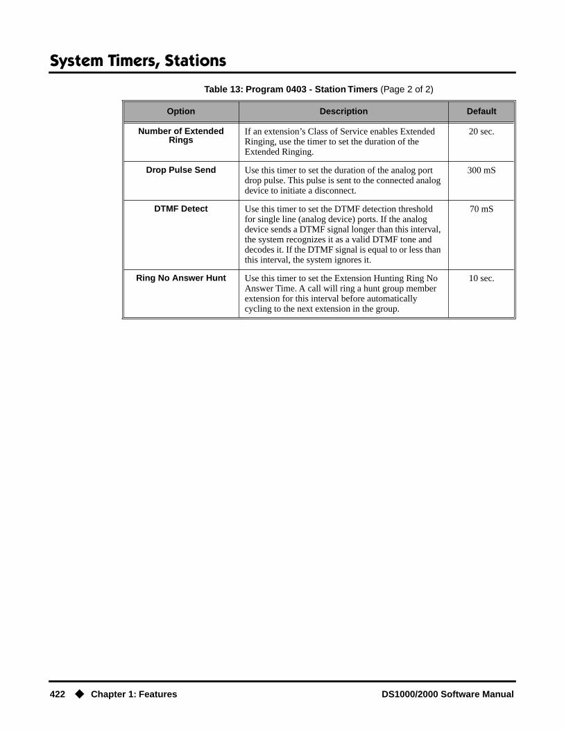
System Timers, Stations
422 ◆ Chapter 1: Features DS1000/2000 Software Manual
Number of Extended Rings
If an extension’s Class of Service enables Extended Ringing, use the timer to set the duration of the Extended Ringing.
20 sec.
Drop Pulse Send Use this timer to set the duration of the analog port drop pulse. This pulse is sent to the connected analog device to initiate a disconnect.
300 mS
DTMF Detect Use this timer to set the DTMF detection threshold for single line (analog device) ports. If the analog device sends a DTMF signal longer than this interval, the system recognizes it as a valid DTMF tone and decodes it. If the DTMF signal is equal to or less than this interval, the system ignores it.
70 mS
Ring No Answer Hunt Use this timer to set the Extension Hunting Ring No Answer Time. A call will ring a hunt group member extension for this interval before automatically cycling to the next extension in the group.
10 sec.
Table 13: Program 0403 - Station Timers (Page 2 of 2)
Option Description Default

System Timers, Stations
DS1000/2000 Software Manual Chapter 1: Features ◆ 423
Following is a summary of the Program 0404 - Analog Station Timers (page 536).
Table 14: Program 0404 - Analog Station Timers (Page 1 of 2)
Option Description Default
Country Data Use this option to define the country of use and the codec digitizing method for ASTU PCBs. This timer consists of two bits (xy), with bit x defining the coun-try and bit y defining the digitization method. For example, the default entry 00 is for North America (x=0) and u-law digitization method (y=0). Do not change this entry from its default value (00).
00(xy)
Rotary Dial Type Use this option to define the rotary dial pulsing method for the system’s ASTU PCBs. Do not change this entry from its default value (01).
Standard(0)
Loop Current Use this option to set the maximum allowed loop cur-rent for the system’s ASTU PCBs. Normally choose 25mA for short loops and 35mA for long loops. In general, a long loop is 3000 feet or longer and a short loop is less than 3000 feet.
25mA (0)
Ringing Frequency Use this option to define the AC ringing frequency for the system’s ASTU PCBs. Do not change this entry from its default value (20 Hz).
20 Hz (1)
Minimum Break Time This timer defines the minimum amount of time the loop must be opened to properly decode the dial pulse digits sent from analog devices connected to ASTU PCBs. Change this value only if the connected ana-log devices are set to dial at a rate other than 10 PPS.
2 (10 mS)
Maximum Break Time This timer defines the maximum amount of time the loop must be opened to properly decode the dial pulse digits sent from analog devices connected to ASTU PCBs. Change this value only if the connected ana-log devices are set to dial at a rate other than 10 PPS.
20 (100 mS)
Minimum Make Time This timer defines the minimum amount of time the loop must be closed to properly decode the dial pulse digits sent from analog devices connected to ASTU PCBs. Change this value only if the connected ana-log devices are set to dial at a rate other than 10 PPS.
2 (10 mS)
Maximum Make Time This timer defines the maximum amount of time the loop must be closed to properly decode the dial pulse digits sent from analog devices connected to ASTU PCBs. Change this value only if the connected ana-log devices are set to dial at a rate other than 10 PPS.
20 (100 mS)

System Timers, Stations
424 ◆ Chapter 1: Features DS1000/2000 Software Manual
ConditionsNone
Default SettingRefer to the charts above.
Minimum Hookflash Time For ASTU PCBs, this timer defines the minimum amount of time the loop must be opened before the system starts to detect a transfer or hang up sequence. Open loop intervals shorter than the setting are ignored by the ASTU PCB.
21 (105 MS)
Maximum Hookflash Time
For ASTU PCBs, this timer defines the maximum amount of time the loop can be opened in order for the system to detect a Transfer sequence. Open loop intervals longer than the setting are interpreted as hang up.
200 (1000 mS / 1 second)
Minimum Ground Flash Time
For ground start applications with ASTU PCBs, this timer sets the amount of time a ground must be applied before the system detects a transfer sequence. The ASTU uses this timer when analog telephones use ground Transfer instead of open loop Transfer. This timer is not used in North America. Do not change this timer from its default value.
21 (105 mS)
Minimum Off-Hook Time For ASTU PCBs, this timer defines how long a con-nected analog device must remain off-hook before the system recognizes the off-hook status.
21 (105 mS)
Off-Hook Guard Time The ASTU PCB waits this interval after an analog device hangs up before accepting any additional input from the device. This timer helps prevent erroneous detection due to hardware stabilization.
60 (300 mS)
Dial Pulse Guard Timer The ASTU PCB waits this interval between dial pulse digits before attempting to detect any additional DP digits. This timer helps prevent erroneous DP dialing due to hardware stabilization.
70 (350 mS)
Loop Disconnect Time When the far end disconnects, the ASTU PCB opens the loop to the connected analog device for this inter-val.
40 (200 mS)
Ring/MW Wait Period Time
This timer determines the ringing sequence for the devices connected ASTU PCBs. Because of power consumption, it is not possible to ring all analog devices on an ASTU simultaneously. Instead, the card is divided into 4 groups with two ports in each group. Ringing cycles between the 4 groups, ringing each group for this interval.
15 (750 mS)
Table 14: Program 0404 - Analog Station Timers (Page 2 of 2)
Option Description Default

System Timers, Stations
DS1000/2000 Software Manual Chapter 1: Features ◆ 425
Programming ListProgram 0403 - Station Timers (page 533)
Customize general station timers.Program 0404 - Analog Station Timers (page 536)
Customize analog station timers.
Other Related Features
Refer to the following for related feature information:
Program 0403 - Station Timers (page 533)Program 0404 - Analog Station Timers (page 536)
Feature OperationNone

System Timers, Trunks
426 ◆ Chapter 1: Features DS1000/2000 Software Manual
System Timers, Trunks
Description
The system provides many trunk timers that the administrator can customize. Review the table below for a description of each trunk timer.
Following is a summary of the Program 0402 - Trunk Timers (page 526). Refer also to:
● Rules for Detecting Normal CO (Single) Ring on page 430.
● Rules for Detecting Special (Double) Ring on page 430.
● Rules for Detecting Loop Current on page 431.
DS2000 Fixed Slot
Available.DS2000 U Slot
DS1000
Customize critical trunk timers for compatibility with the connected telco or PBX/Centrex.
Table 15: Program 0402 - Trunk Timers (Page 1 of 5)
Option Description Default
Camp-On Not used. 60 sec.
Line Response When the system fails to detect loop current on a trunk, it will wait this interval before marking the trunk as defective.
Be sure the value you enter is compatible with the local telco. If you set this value too short, the system may mark properly functioning trunks as defective. If too long, defective trunks may be left in service.
100(10 seconds)
Dial Tone Detect When the system seizes a line to place a Speed Dial call, it waits this interval for dial tone before outdial-ing the call. The system requires that the first dial tone be at least.5 seconds long and the second dial tone to be at least 2.5 seconds long.
Be sure the value you enter is compatible with the local telco. If you set this value too short, the system may not seize properly functioning trunks. If too long, there will be too long a delay before the system skips over a defective trunk.
10 (1 second)
PBX/Centrex Flash Use this timer to set the Flash interval. When a user flashes a trunk, the system opens the trunk circuit for this interval. For accurate flash function, be sure to set this interval for compatibility with the connected telco or PBX/Centrex.
If you set this interval too short, the telco may not always register the flash. If too long, inadvertent dis-connects may occur.
800 mS

System Timers, Trunks
DS1000/2000 Software Manual Chapter 1: Features ◆ 427
Flash Disconnect Not used. 2496mS
Force Idle (Trunk Guard Time)
Use this timer to set the guard time for trunks. When the system disconnects a trunk (e.g., after a user hang up), the system keeps the line idle until this timer expires. The Trunk Guard Time helps prevent call col-lisions.
If you set this interval too short, call collisions may occur. If too long, there will be unnecessary delays before you can use the trunk for a new call.
25 (2.5 sec)(Fixed Slot)10 (1 sec)(U Slot)
PBX Pause Not used. 0
Minimum Ring Detection Timer
Use this timer to set the threshold for ring detection. If the ring signal is longer than this interval, the sys-tem interprets the signal as valid ringing. If the signal is equal to or shorter than this interval, the system ignores the ringing.
Be sure the value you enter is compatible with the local telco. If you set this value too short, the system may detect line spikes and anomalies as ringing. If too long, the system may not properly interpret a valid ringing signal.
104 mS
DP Make Timer Use this timer to set the duration of the Dial Pulse Make signal (i.e., relay closed). This is the “on” time in a Dial Pulse digit. Set this timer for compatibility with the connected telco or PBX/Centrex. Keep in mind that there are three components of a Dial Pulse digit: Make interval, Break interval and Interdigit interval. An improper setting may cause misdialing.
40 mS
DP Break Timer Use this timer to set the duration of the Dial Pulse Break signal (i.e., relay open). This is the “off” time in a Dial Pulse digit. Set this timer for compatability with the connected telco or PBX/Centrex. Keep in mind that there are three components of a Dial Pulse digit: Make interval, Break interval and Interdigit interval. An improper setting may cause misdialing.
60 mS
DP Interdigit Timer Use this timer to set the duration of the Dial Pulse Interdigit signal (i.e., relay open time between each digit). Set this timer for compatability with the con-nected telco or PBX/Centrex. Keep in mind that there are three components of a Dial Pulse digit: Make interval, Break interval and Interdigit interval. An improper setting may cause misdialing.
800 mS
Table 15: Program 0402 - Trunk Timers (Page 2 of 5)
Option Description Default

System Timers, Trunks
428 ◆ Chapter 1: Features DS1000/2000 Software Manual
Manual DTMF Tone On This timer sets the duration of DTMF digits for trunk calls manually dialed by an extension user. This is required because the system buffers the digits the user dials.
Set this timer for compatibility with the connected telco or PBX/Centrex. If you set this interval too short, the telco or PBX/Centrex may not be able to properly detect the DTMF digit. If too long, outbound dialing is unnecessarily slowed down.
150 mS
Manual DTMF Tone Off This timer sets the duration of the interval between DTMF digits for trunk calls manually dialed by an extension user. This is required because the system buffers the digits the user dials. Note that this is the minimum DTMF Tone off time guaranteed by the system.
Set this timer for compatibility with the connected telco or PBX/Centrex. If you set this interval too short, the telco or PBX/Centrex may not be able to set up to receive the next DTMF digit. If too long, out-bound dialing is unnecessarily slowed down.
(02.02.14 or higher)100 mS(Prior to 02.02.14)
50 mS
Speed Dial DTMF Tone On
This timer sets the duration of DTMF digits for Speed Dial trunk calls automatically dialed by the system.
Set this timer for compatibility with the connected telco or PBX/Centrex. If you set this interval too short, the telco or PBX/Centrex may not be able to properly detect the DTMF digit. If too long, outbound dialing is unnecessarily slowed down.
100 mS
Speed Dial DTMF Tone Off
This timer sets the duration the quiet time between DTMF digits for Speed Dial trunk calls automatically dialed by the system.
Set this timer for compatibility with the connected telco or PBX/Centrex. If you set this interval too short, the telco or PBX/Centrex may not be able to set up to receive the next DTMF digit. If too long, out-bound dialing is unnecessarily slowed down.
100 mS
Loop Current Detection Time
For loop start trunks, loop current must be present for this interval before the system seizes the trunk.
Set this interval for compatibility with the connected telco or PBX/Centrex. If you set this interval too short, the system may inadvertently seize unstable trunks. If too long, the system may not properly seize a valid trunk.
800 mS
Codec Digitizing Method Use this option to set the system’s codec companding method type for the trunk. Be sure this option is always set to 0 (µ-law companding enabled). Do not set this option to 1 (A-law companding enabled).
0 (µ-law)
Table 15: Program 0402 - Trunk Timers (Page 3 of 5)
Option Description Default

System Timers, Trunks
DS1000/2000 Software Manual Chapter 1: Features ◆ 429
Setting for International Rotary Disk
Set this option for compatibility with the type of rotary dial (500 type) telephone used. Be sure to always set this option to 0.
0(US standard)
Far End Disconnect Use this timer to set the loop disconnect interval for trunk calls. If the system detects a loop current inter-ruption longer than this interval it assumes the telco has disconnected the trunk. It then returns the trunk trunk to idle.
Set this interval for compatibility with the connected telco or PBX/Centrex. If you set this interval too short, the system may inadvertently disconnect valid trunks. If too long, the system may leave trunks con-nected that it should tear down.
300 mS
Minimum Single Ring Detection Timer
The system uses this timer to detect valid ringing sig-nal from the connected telco or PBX. Valid single ring must be longer than this interval.
1004 mS(504mS prior to 02.02.17)
Minimum Double Ring Detection Off Timer
The system uses this timer to detect valid double ring from the connected PBX. Valid double ring must be longer than this interval.
104 mS
Maximum Double Ring Detection Off Timer
The system uses this timer to detect valid double ring from the connected PBX. Valid double ring must be less than this interval.
504 mS(304 mS prior to 02.02.17)
Ringing Signal End Detect Timer
If the ringing signal on a trunk call is interrupted for longer than this interval, the system assumes ringing has stopped and terminates the call.
Set this option for compatibility with the connected telco or PBX Centrix. If this interval is set to short, valid ringing will be inadvertently cut off. If too long, the system will leave the call set up even after ringing has stopped.
6016 mS
Caller ID Detection Timer With DSP-based Caller ID, the Caller ID Detection Timer is the amount of time between the first and sec-ond ring bursts that the system can detect Caller ID digits. If this timer is set too long, the outside caller will hear ringing followed by reorder tone. If set too short, all the Caller ID digits may not be detected. This timer is not used with DS2000 daughter board-based Caller ID.
3268 mS
Table 15: Program 0402 - Trunk Timers (Page 4 of 5)
Option Description Default

System Timers, Trunks
430 ◆ Chapter 1: Features DS1000/2000 Software Manual
Rules for Detecting Normal CO (Single) Ring
1. The ring signal must be longer than the Minimum Ring Detection Timer (normally 104 mS).
2. The ring signal must also be longer than the Minimum Single Ring Detection Timer (normally 504 mS).
3. The interval between ring bursts must not be longer than the Ringing Signal End Detection Timer (normally 6016 mS).
Rules for Detecting Special (Double) Ring(This option is normally not required and is intended for only for certain Centrex/PBX applications
Ground Start Timer Before the system can start a ground start trunk, the telco’s tip ground must be present for longer than this interval.
Set this interval for compatibility with the connected telco or PBX/Centrex. If you set this interval too short, the system may inadvertently start a trunk it should not set up. If too long, the system may not start trunks that are functioning normally.
800 mS
Pause Timer Not used. 3008 mS
DP Mute Timer Not used.. 8 mS
P.F. Recovery Detect Timer
When the ATRU PCB recovers from a power failure, it checks the power failure trunk (trunk 1) for loop current for the P.F. Recovery Detect interval. If loop current is detected, it assumes the Power Failure Tele-phone is still connected and does not tear down the call. If loop current is not detected, the ATRU PCB switches the trunk out of the power failure mode.
3008 mS
Table 15: Program 0402 - Trunk Timers (Page 5 of 5)
Option Description Default
Minimum Single Ring Detection Timer (504 mS)
Minimum Ring Detection Timer (104 mS)
Ringing Signal End Detection Timer (6016 mS)
Incoming Ring SignalRing On
Ring Off
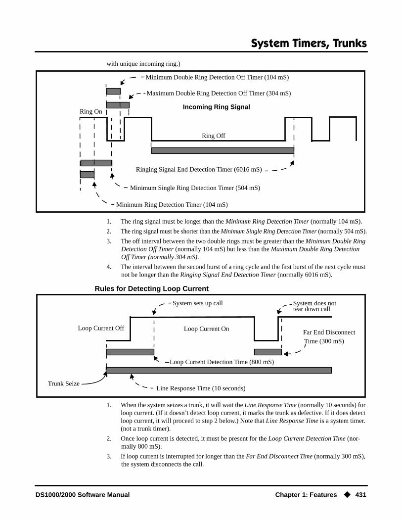
System Timers, Trunks
DS1000/2000 Software Manual Chapter 1: Features ◆ 431
with unique incoming ring.)
1. The ring signal must be longer than the Minimum Ring Detection Timer (normally 104 mS).
2. The ring signal must be shorter than the Minimum Single Ring Detection Timer (normally 504 mS).
3. The off interval between the two double rings must be greater than the Minimum Double Ring Detection Off Timer (normally 104 mS) but less than the Maximum Double Ring Detection Off Timer (normally 304 mS).
4. The interval between the second burst of a ring cycle and the first burst of the next cycle must not be longer than the Ringing Signal End Detection Timer (normally 6016 mS).
Rules for Detecting Loop Current
1. When the system seizes a trunk, it will wait the Line Response Time (normally 10 seconds) for loop current. (If it doesn’t detect loop current, it marks the trunk as defective. If it does detect loop current, it will proceed to step 2 below.) Note that Line Response Time is a system timer. (not a trunk timer).
2. Once loop current is detected, it must be present for the Loop Current Detection Time (nor-mally 800 mS).
3. If loop current is interrupted for longer than the Far End Disconnect Time (normally 300 mS), the system disconnects the call.
Minimum Single Ring Detection Timer (504 mS)
Minimum Ring Detection Timer (104 mS)
Ringing Signal End Detection Timer (6016 mS)
Incoming Ring SignalRing On
Ring Off
Maximum Double Ring Detection Off Timer (304 mS)
Minimum Double Ring Detection Off Timer (104 mS)
Line Response Time (10 seconds)
Far End Disconnect
Loop Current Detection Time (800 mS)
Loop Current On
Trunk Seize
Loop Current Off
System sets up call System does nottear down call
Time (300 mS)

System Timers, Trunks
432 ◆ Chapter 1: Features DS1000/2000 Software Manual
ConditionsNone
Default SettingRefer to the chart above.
Programming ListRefer to the chart above.
Other Related Features
Refer to the following for related feature information:
Program 0402 - Trunk Timers (page 526)
Feature OperationNone
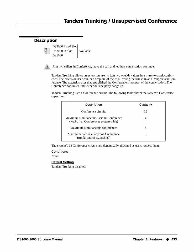
Tandem Trunking / Unsupervised Conference
DS1000/2000 Software Manual Chapter 1: Features ◆ 433
Tandem Trunking / Unsupervised Conference
Description
Tandem Trunking allows an extension user to join two outside callers in a trunk-to-trunk confer-ence. The extension user can then drop out of the call, leaving the trunks in an Unsupervised Con-ference. The extension user that established the Conference is not part of the conversation. The Conference continues until either outside party hangs up.
Tandem Trunking uses a Conference circuit. The following table shows the system’s Conference capacities:
The system’s 32 Conference circuits are dynamically allocated as users request them.
ConditionsNone
Default SettingTandem Trunking disabled.
DS2000 Fixed Slot
Available.DS2000 U Slot
DS1000
Join two callers in Conference, leave the call and let their conversation continue.
Description Capacity
Conference circuits 32
Maximum simultaneous users in Conference(total of all Conferences system-wide)
32
Maximum simultaneous conferences 8
Maximum parties in any one Conference(trunks and/or extensions)
8

Tandem Trunking / Unsupervised Conference
434 ◆ Chapter 1: Features DS1000/2000 Software Manual
Programming Guide
Programming ListProgram 0402 - Far End Disconnect (page 531)
Set the Far End Disconnect time for compatibility with the local telco.Program 1003 - Tandem Trunk (page 595)
Enabled (Y) or disable (N) the trunk’s ability to be included in an Unsupervised Conference. Only one of the trunks in the tandem call must have this option enabled.
Other Related Features
The following features also allow different types of multiple party calls:
Barge In (Intrusion) (page 58)An extension user can Barge In on a tandem call.
Conference (page 124)Group Listen (page 219)Meet-Me Conference (page 288)Privacy Release Groups (page 347)
Forced Trunk Disconnect (page 212)An extension user can end an Unsupervised Conference by using Forced Trunk Disconnect on one of the trunks in the tandem call.
Off-Premise Extensions / On-Premise SLT Extensions (page 317)Tandem Trunking is available at Single Line extensions.
Step-by-step guide for setting up Tandem Trunking / Unsupervised Conference
Step 1: Should trunk have the ability to be included in an Unsupervised Conference?
• In Program 1003 - Tandem Trunk (page 595), enter Y. Note that only one of the trunks in the tandem call must have this option enabled.
• In Program 0402 - Far End Disconnect (page 531), set the Far End Disconnect time for compatiblity with the local telco.
• In Program 1003 - Tandem Trunk (page 595), enter N. Note that only one of the trunks in the tandem call must have this option enabled.
If yes
If no

Tandem Trunking / Unsupervised Conference
DS1000/2000 Software Manual Chapter 1: Features ◆ 435
Feature Operation
To set up a tandem call (Unsupervised Conference):
1. Establish trunk call.
2. Press CONF.
Your caller hears Music On Hold (if installed) while they wait for you to set up the Conference.
3. Place or answer trunk callOR
Retrieve trunk call from Park Orbit.
4. Press CONF to set up the Conference.
If you cannot add additional parties to your Conference, you have exceeded the sys-tem’s Conference limit.
5. Hang up.
If the outside parties disconnect, the trunks you selected do not have Tandem Trunking capability.
To disconnect a tandem call (using Forced Trunk Disconnect):
1. Press line key for busy trunk.OR
Press ICM and dial the trunk’s Direct Trunk Access code (e.g., 401 for trunk 1).
Refer to Direct Trunk Access for the specifics.
2. Dial # to disconnect the line.The tandem call disconnects.
To Barge In on a tandem call:
1. Press line key for busy trunk.OR
Press ICM and dial the trunk’s Direct Trunk Access code (e.g., 401 for trunk 1).
Refer to Direct Trunk Access for the specifics.
2. Dial 4.
You can optionally place the Conference on hold. Your callers hear Music on Hold (if
Conversation with caller.
Line Key or Loop Key on.
Intercom dial tone.
ICM on and Line/Loop Key flashing.
Conversation with your conferenced callers.
Line/Loop Keys on (green).
N/A
Line/Loop Keys on (red)
Busy tone.
Line/loop key on (red).
Busy tone.
Line/loop key on (red).
You hear two beeps and you join the tandem call.
Line/loop keys on (green).

Tandem Trunking / Unsupervised Conference
436 ◆ Chapter 1: Features DS1000/2000 Software Manual
installed) while waiting on Hold. Press CONF to reinstate the Conference.
To set up Tandem Trunking at a Single Line Telephone:
1. Establish trunk call (e.g., lift handset, dial 9, and dial outside number).
2. Hookflash and dial another trunk call.
3. Hookflash and dial #10 to set up Conference.
4. Hang up.If the outside parties disconnect, the trunks you selected do not have Tandem Trunking
capability.
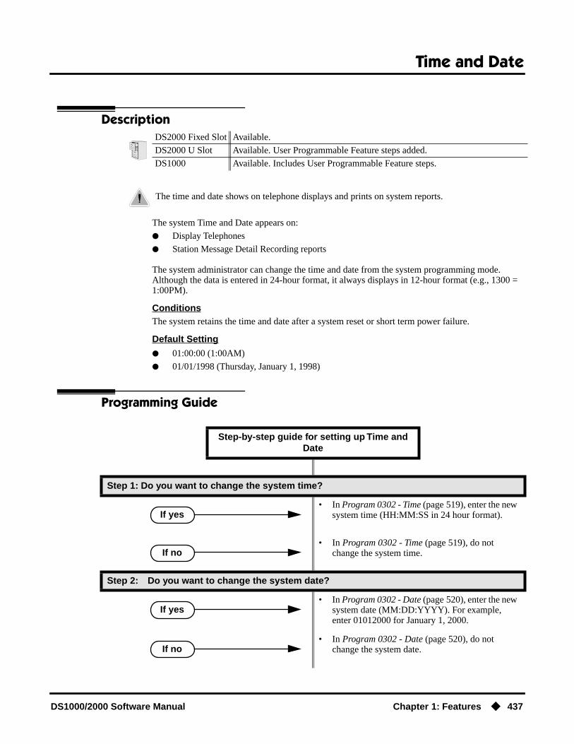
Time and Date
DS1000/2000 Software Manual Chapter 1: Features ◆ 437
Time and Date
Description
The system Time and Date appears on:
● Display Telephones
● Station Message Detail Recording reports
The system administrator can change the time and date from the system programming mode. Although the data is entered in 24-hour format, it always displays in 12-hour format (e.g., 1300 = 1:00PM).
ConditionsThe system retains the time and date after a system reset or short term power failure.
Default Setting
● 01:00:00 (1:00AM)
● 01/01/1998 (Thursday, January 1, 1998)
Programming Guide
DS2000 Fixed Slot Available.
DS2000 U Slot Available. User Programmable Feature steps added.
DS1000 Available. Includes User Programmable Feature steps.
The time and date shows on telephone displays and prints on system reports.
Step-by-step guide for setting up Time and Date
Step 1: Do you want to change the system time?
• In Program 0302 - Time (page 519), enter the new system time (HH:MM:SS in 24 hour format).
• In Program 0302 - Time (page 519), do not change the system time.
Step 2: Do you want to change the system date?
• In Program 0302 - Date (page 520), enter the new system date (MM:DD:YYYY). For example, enter 01012000 for January 1, 2000.
• In Program 0302 - Date (page 520), do not change the system date.
If yes
If no
If yes
If no

Time and Date
438 ◆ Chapter 1: Features DS1000/2000 Software Manual
Programming ListProgram 0302 - Time (page 519)
Enter the system time.Program 0302 - Date (page 520)
Enter the system date.
Other Related FeaturesBattery Backup (page 60)
The battery on the CPU PCB backs up the CPU Real Time Clock for 10-14 days.Station Message Detail Recording (page 400)
Time and date appear on the SMDR report.Year 2000 Compliance (page 499)
The system is fully Y2K (year 2000) compliant. The year always displays as four digits and the system correctly recognizes leap years.
Feature Operation
User Programmable Feature
Feature Mnemonic Operation Access Level
This option is not available in Fixed Slot software.
Time and Date #TD #TD + Enter time in 24-hour clock using hours (2 digits), minutes (2 digits) and seconds (2 digits) + HOLD + Enter date using month (2 digits), day (2 digits) and year (4 digits) + HOLD + SPK to exit.
4 and 5

Toll Restriction (Software Version 02.02.14 or Higher)
DS1000/2000 Software Manual Chapter 1: Features ◆ 439
Toll Restriction (Software Version 02.02.14 or Higher)
Description
Toll Restriction limits the numbers an extension user may dial. By allowing extensions to place only certain types of calls, the system administrator can control long distance costs. The system applies Toll Restriction according to an extension’s Toll Restriction Level. For each of the 7 Toll Restriction Levels, the administrator can enable or disable the following options.
● Active Dial Pad (Continuous Dialing)Active Dial Pad continuously enables the telephone dial pad. This is important if co-workers typically use dial-up services (such as automated banking) or frequently dial into Voice Mail systems. With Active Dial Pad disabled, the system disables the telephone dial pad 6 seconds after the user has dialed their last digit. Toll Restriction controls Active Dial Pad for both incoming and outgoing calls.
● N11 DialingN11 Dialing enables or disables an extension’s ability to use N11 services such as directory assistance (411) and repair (611). Consider enabling this option if the connected telco charges by the call (i.e., meters) these services. Note that the system never restricts a user from dial-ing 911 or 1 + 911.
● 0 + Dialing0 + Dialing enables or disables an extension’s ability to manually dial 0 + (operator assisted) calls. These calls typically include collect calls and credit card calls. Be sure to disable this option if you don’t want co-workers making these types of calls. The setting of 0 + Dialing does not affect the operation of international dialing (see the option immediately following).
● International (011) DialingUse the International Dialing option to restrict extension access to high-cost international (011) dialing. You can, for example, enable international dialing for high priority users and executives while disabling international dialing for all other co-workers.
● Equal Access (1010 + XXX) DialingEqual Access allows users to select long distance carriers other than your primary carrier. Your primary carrier is the long distance provider you access when you seize a trunk and dial 1. To reach another provider, dial 1010 and that provider’s three-digit code (e.g., 1010220). The system does not restrict the numbers dialed after the Equal Access code, but can prevent users from dialing specific Equal Access codes.
● 1 + DialingThis type of Toll Restriction can restrict:- 1 + 3-digit (1 + NPA and 1 + NXX) dialing.- 1 + 6-digit (1 + NPA + NXX) dialing.
● Dialing without a Leading 1This type of Toll Restriction can restrict:- 3-digit (NPA and NXX) dialing.- 6-digit (NPA + NXX) dialing.
DS2000 Fixed Slot
Available.DS2000 U Slot
DS1000
Use Toll Restriction to help you control the costs of outgoing long distance calls. In this version of Toll Restriction, the Toll Restriction Tables previously combined in 0601 - Toll Restriction are split off into separate, easy-to-use programs. This new version also provides 1010 + XXX Equal Access Dialing.

Toll Restriction (Software Version 02.02.14 or Higher)
440 ◆ Chapter 1: Features DS1000/2000 Software Manual
The Toll Restriction TablesThere are 5 separate tables (for each Toll Restriction Level) that individually restrict:
● Equal Access Dialing
● Calls dialed with a leading 1 (1 + Dialing)
● Calls dialed without a leading 1
The following chart summarizes these tables.
Toll Restriction Overview● When you dial: Telephone Banking
Continued Dialing (Active Dial Pad) is enabled or disabled by the setting of 0601 - Active Dial Pad.
● When you dial: 411, 811N11 Dialing is enabled or disabled by the setting of 0601 - N11 Dialing.
● When you dial: 0 203 926 54000+ Dialing is enabled or disabled by the setting of 0601 - 0 + Dialing.
● When you dial: 011 International CallsInternational (011) Dialing is enabled or disabled by the setting of 0601 - International Dialing.
● When you dial: 1015 220 203 926 5400Equal Access (101X XXX) Dialing is enabled or disabled in 0601 - 101X Dialing,- This option restricts Equal Access Codes 1011 through 1019 and has no affect on the more common 1010 XXX Equal Access Codes.
● When you dial: 1010 220 203 926 5400Equal Access (1010 XXX) Dialing is controlled by the Equal Access codes entered in 0602 - 1010 + XXX Equal Access Dialing Table.- The table entries have no affect on the less common 101X XXX Equal Access dialing.
Enhanced Toll Restriction Tables
Dialing Type Program Description
Equal Access Dialing Program 0602 - 1010 + XXX Equal Access Dialing on page 561
Lookup table that restricts 1010 + XXX dialing. Can be set up as an allow or deny table.Example1: 1010 220 203 926 5400
1 + Dialing Program 0603 - 1 + NPA/NXX Dialing 3-Digit Table on page 563
3-digit lookup table that handles restric-tion for 1 + NPA and 1 + NXX dialing. Can be set up as an allow or deny table.Example1: 1 203 926 5400
Program 0604 - 1 + NPA + NXX Dialing 6-Digit Table on page 565
6-digit lookup table that handles 1 + NPA + NXX dialing. Can be set up as an allow or deny table.Example1: 1 203 926 5400
Dialing without a leading 1
Program 0605 - NPA/NXX Dial-ing 3-Digit Table on page 567
3-digit lookup table that handles NPA and NXX dialing. Can be set up as an allow or deny table.Example1: 203 926 5400
Program 0606 - NPA + NXX Dialing 6-Digit Table on page 569
6-digit lookup table that handles NPA + NXX dialing. This is a deny-only table.Example1: 203 926 5400
1 The underline bold digits are the digits looked up by the specified table for the type of call dialed.

Toll Restriction (Software Version 02.02.14 or Higher)
DS1000/2000 Software Manual Chapter 1: Features ◆ 441
● When you dial: 1 800 365 1928, 1 900 555 1212, 1 926 54001 + NPA and 1 + NXX dialing is controlled by the entries in 0603 - 1 + NPA/NXX Dialing 3-Digit Table and 0604 - 1 + NPA + NXX Dialing 6-Digit Table.- These tables work together. For example, you can deny an NPA in 0603 and allow a specific NPA + NXX combination in 0604.
● When you dial: 203 926 5400, 926 5400NPA and NXX dialing (without the leading 1) is controlled by the entries in 0605 - NPA/NXX Dialing 3-Digit Table and 0606 - NPA + NXX Dialing 6-Digit Table.- These tables work together. For example, you can allow an NPA in 0605 and deny a specific NPA + NXX combination in 0606.
Default Toll Restriction ConfigurationWhen you assign a Toll Level to an extension, the extension has the following Toll Restriction by default:
● Active Dial Pad is enabled.
● N11 Dialing is enabled.
● 0 + Dialing is enabled.
● International (011) Dialing is enabled.
● Equal Access (101X + XXX) Dialing is enabled.
● Equal Access (1010 + XXX) Dialing is enabled without restriction because the 1010 + XXX Equal Access Table is a deny table with no entries (i.e., it denies nothing).
● 1 + NPA/NXX Dialing is enabled without restriction because the 1 + NPA/NXX Dialing 3-Digit and 1 + NPA + NXX Dialing 6-Digit Tables are deny tables with no entries (i.e., they deny nothing).
● NPA/NXX Dialing and NPA + NXX Dialing are enabled without restriction because the NPA/NXX Dialing 3-Digit Table is a deny table with no entries (i.e., it denies nothing). In addition, the NPA + NXX Dialing 6-Digit Table does not restrict because it is a deny table with no entries (i.e., it also denies nothing).
ConditionsNone
Default SettingSee Default Toll Restriction Configuration above.

Toll Restriction (Software Version 02.02.14 or Higher)
442 ◆ Chapter 1: Features DS1000/2000 Software Manual
Programming Guide
!! Important !!
• You should initialize programs 0601 through 0606 prior to programming.• Initializing program 0601 automatically initializes programs 0602 through 0606, as
well programs 1303 through 1305.• Programs 0602 through 0606 can be individually initialized, if required.
Step-by-step guide for setting up Toll Restriction (Page 1 of 3)
Step 1: Do you want to enable Active Dial Pad (Continuous Dialing)?
• In Program 0601 - Active Dial Pad (page 557), enter Y.
• In Program 0601 - Active Dial Pad (page 557), enter N.
Step 2: Do you want to enable N11 dialing?
• In Program 0601 - N11 Dialing (page 558), enter Y.
• In Program 0601 - N11 Dialing (page 558), enter N. Note that 911 and 1 + 911 calls are never restricted.
Step 3: Do you want to enable 0+ (Operator Assisted) dialing?
• In Program 0601 - 0+ Dialing (page 558), enter Y.
• In Program 0601 - 0+ Dialing (page 558), enter N.
Step 4: Do you want to enable International (011) Dialing?
• In Program 0601 - International (011) Dialing (page 558), enter Y.
• In Program 0601 - International (011) Dialing (page 558), enter N.
If yes
If no
If yes
If no
If yes
If no
If yes
If no

Toll Restriction (Software Version 02.02.14 or Higher)
DS1000/2000 Software Manual Chapter 1: Features ◆ 443
Step 5: Do you want to enable the dialing of Equal Access Codes 1011 through 1019?
• In Program 0601 - Equal Access (101X + XXX) Dialing (page 558), enter Y.
• In Program 0601 - Equal Access (101X + XXX) Dialing (page 558), enter N.
Step 6: Do you want to allow or restrict Equal Access 1010 + XXX dialing?
• In Program 0602 - 1010 + XXX Equal Access Dialing (page 561), set up the Equal Access dial-ing table. By default, this type of dialing is enabled because the 1010 + XXX table is a deny table with no entries (i.e., it denies nothing).
• In Program 0602 - 1010 + XXX Equal Access Dialing (page 561), make no entries.
Step 7: Do you want to allow or restrict 1 + NPA or 1 + NXX dialing?
• In Program 0603 - 1 + NPA/NXX Dialing 3-Digit Table (page 563), set up this 1 + 3-digit dialing table. By default, this type of dialing is enabled because the 1 + NPA/NNX Dialing 3-Digit Table is a deny table with no entries (i.e., it denies nothing).
• In Program 0603 - 1 + NPA/NXX Dialing 3-Digit Table (page 563), make no entries.
Step 8: Do you want to allow or restrict 1 + NPA + NXX dialing?
• In Program 0604 - 1 + NPA + NXX Dialing 6-Digit Table (page 565), set up this 6-digit dialing table. By default, this type of dialing is enabled because the 1 + NPA + NNX Dialing 6-Digit Table is a deny table with no entries (i.e., it denies nothing).
• In Program 0604 - 1 + NPA + NXX Dialing 6-Digit Table (page 565), make no entries.
Step-by-step guide for setting up Toll Restriction (Page 2 of 3)
If yes
If no
If yes
If no
If yes
If no
If yes
If no

Toll Restriction (Software Version 02.02.14 or Higher)
444 ◆ Chapter 1: Features DS1000/2000 Software Manual
Step 9: Do you want to allow or restrict NPA or NXX dialing?
• In Program 0605 - NPA/NXX Dialing 3-Digit Table (page 567), set up this 3-digit dialing table. By default, this type of dialing is enabled because the NPA/NNX Dialing 3-Digit Table is a deny table with no entries (i.e., it denies nothing).
• In Program 0605 - NPA/NXX Dialing 3-Digit Table (page 567), make no entries.
Step 10: Do you want to set up additional NPA + NXX dialing restrictions?
• In Program 0606 - NPA + NXX Dialing 6-Digit Table (page 569), set up this 6-digit dialing table. By default, this table provides no additional dial-ing restriction because the NPA + NNX Dialing 6-Digit Table is a deny table with no entries (i.e., it denies nothing).
• In Program 0606 - NPA + NXX Dialing 6-Digit Table (page 569), make no entries.
Step-by-step guide for setting up Toll Restriction (Page 3 of 3)
If yes
If no
If yes
If no

Toll Restriction (Software Version 02.02.14 or Higher)
DS1000/2000 Software Manual Chapter 1: Features ◆ 445
Programming List
Program 0601 - Active Dial Pad (page 557)Use this option to enable (Y) or disable (N) Active Dial Pad (continuous dialing) for trunk calls. This option is enabled (Y) by default.
Program 0601 - N11 Dialing (page 558)Use this option to enable (Y) or disable (N) dialing N11 services such as directory assistance (411) and repair (611). This option does not restrict 911 or 1 + 911 calls. These calls are always allowed. This option is enabled (Y) by default.
Program 0601 - 0+ Dialing (page 558)Use this option to enable (Y) or disable (N) an extension’s ability to manually dial 0+ (opera-tor assisted) calls. This option is enabled (Y) by default.
Program 0601 - International (011) Dialing (page 558)Use this option to enable (Y) or disable (N) 011 (international) dialing. This option is enabled (Y) by default.
Program 0601 - Equal Access (101X + XXX) Dialing (page 558)Use this option to enable (Y) or disable (N) the dialing of Equal Access Codes 1011 through 1019. It has no affect on the more common 1010 XXX Equal Access Codes. Use 0602 - 1010 + XXX Equal Access Dialing to restrict the more common 1010 codes.This option is enabled (Y) by default.
Program 0602 - 1010 + XXX Equal Access Dialing (page 561)Use this option to set up to 1010 + XXX Equal Access dialing table. By default, this type of dialing is enabled because the 1010 + XXX table is a deny table with no entries (i.e., it denies nothing).
Program 0603 - 1 + NPA/NXX Dialing 3-Digit Table (page 563)Use this option to set up the 1 + NPA/NNX Dialing 3-Digit Table. By default, this type of dialing is enabled because the 1 + NPA/NNX Dialing 3-Digit Table is a deny table with no entries (i.e., it denies nothing).
Program 0604 - 1 + NPA + NXX Dialing 6-Digit Table (page 565)Use this option to set up the 1 + NPA + NNX Dialing 6-Digit Table. By default, this type of dialing is enabled because the 1 + NPA + NNX Dialing 6-Digit Table is a deny table with no entries (i.e., it denies nothing).
Program 0605 - NPA/NXX Dialing 3-Digit Table (page 567)Use this option to set up the NPA/NXX Dialing 3-Digit Table. By default, this type of dialing is enabled because the NPA/NXX Dialing 3-Digit Table is a deny table with no entries (i.e., it denies nothing).
Program 0606 - NPA + NXX Dialing 6-Digit Table (page 569)Use this option to set up the NPA + NXX Dialing 6-Digit Table. By default, this table provides no additional restriction because it is a deny table with no entries (i.e., it denies nothing).
Some Common Toll Restriction ExamplesNote that all 3 examples can be simultaneously programmed in the same system.
Example 1: Restrict 1 + 203 calls in a neighboring (foreign) area code, but allow 203 10-digit calls in the home area code.
1. Initialize 0601 - Configure Toll Level Options and the Toll Restriction Tables (programs 0602 through 0606).
2. For Toll Level 1, be sure Toll Restriction Tables 0602 through 0605 are deny tables with no
!! Important !!
• You should initialize programs 0601 through 0606 prior to programming.• Initializing program 0601 automatically initializes programs 0602 through 0606, as
well programs 1303 through 1305.• Programs 0602 through 0606 can be individually initialized, if required.

Toll Restriction (Software Version 02.02.14 or Higher)
446 ◆ Chapter 1: Features DS1000/2000 Software Manual
entries. (This will allow unrestricted dialing).
3. In 0603 - 1 + NPA/NXX Dialing 3-Digit Table, add code 203.
4. In 1801 - Extension Toll Level Day and 1801 - Extension Toll Level Night, assign Toll Level 1 to extensions.
Example 2: Restrict 1 + 900 calls.
1. Initialize 0601 - Configure Toll Level Options and the Toll Restriction Tables (programs 0602 through 0606).
2. For Toll Level 2, be sure Toll Restriction Tables 0602 through 0605 are deny tables with no entries. (This will allow unrestricted dialing).
3. In 0603 - 1 + NPA/NXX Dialing 3-Digit Table, add code 900.
4. In 1801 - Extension Toll Level Day and 1801 - Extension Toll Level Night, assign Toll Level 2 to extensions.
Example 3: Allow only 1 + 800 long distance calls.
1. Initialize 0601 - Configure Toll Level Options and the Toll Restriction Tables (programs 0602 through 0606).
2. For Toll Level 3, be sure Toll Restriction Tables 0602, 0604, and 0605 are deny tables with no entries. (This will allow unrestricted dialing).
3. In 0603 - 1 + NPA/NXX Dialing 3-Digit Table, set this table up as an allow table and add code 800.
4. In 1801 - Extension Toll Level Day and 1801 - Extension Toll Level Night, assign Toll Level 3 to extensions.
Other Related FeaturesDirect Trunk Access (page 154)
Direct Trunk Access does not bypass Toll Restriction.Flash (page 207)
When an extension user with Toll Restriction enabled flashes a trunk, the system enforces toll Restriction on any digits the user dials from the new dial tone. For example, if an extension user cannot dial 203 926 5400 before they flash, they cannot dial 203 926 5400 after they flash.
Forced Trunk Disconnect (page 212)Forced Trunk Disconnect does not bypass Toll Restriction.
Last Number Redial (page 277)Last Number Redial will not store a number denied by Toll Restriction.
Private Line (page 350)Toll Restriction restricts Private Lines just like any other trunk.
Save Number Dialed (page 373)Save Number Dialed will not store a number denied by Toll Restriction.
Speed Dial (page 383)The system enforces Toll Restriction on Speed Dial numbers as they are dialed, not as they are stored.
Feature OperationToll Restriction operation is automatic.

Toll Restriction (Prior to Software Version 02.02.14)
DS1000/2000 Software Manual Chapter 1: Features ◆ 447
Toll Restriction (Prior to Software Version 02.02.14)
Description
Toll Restriction limits the numbers an extension user may dial. By allowing extensions to place only certain types of calls, the system administrator can control long distance costs. The system applies Toll Restriction according to an extension’s Toll Restriction Level. For each of the 7 Toll Restriction Levels, the administrator can enable or disable the following options.
● Active Dial Pad (Continuous Dialing)Active Dial Pad continuously enables the telephone dial pad. This is important if co-workers typically use dial-up services (suck as automated banking) or frequently dial into Voice Mail systems. With Active Dial Pad disabled, the system disables the telephone dial pad 6 seconds after the user has dialed their last digit. Toll Restriction controls Active Dial Pad for both incoming and outgoing calls.
● N11 DialingN11 Dialing enables or disables an extension’s ability to use N11 services such as directory assistance (411) and repair (611). Consider enabling this option if the connected telco charges by the call (i.e., meters) these services. Note that the system never restricts a user from dial-ing 911 or 1 + 911. (Toll Restriction uses the NPA Dialing table to control 1 + N11 dialing.)
● 0 + Dialing0 + Dialing enables or disables an extension’s ability to manually dial 0 + (operator assisted) calls. These calls typically include collect calls and credit card calls. Be sure to disable this option if you don’t want co-workers making these types of calls. The setting of 0 + Dialing does not affect the operation of international dialing (see the option immediately following).
● International (011) DialingUse the International Dialing option to restrict extension access to high-cost international (011) dialing. You can, for example, enable international dialing for high priority users and executives while disabling international dialing for all other co-workers.
● Equal Access (10XXX) DialingEqual Access allows users to select long distance carriers other than your primary carrier. Your primary carrier is the long distance provider you access when you seize a trunk and dial 1. To reach another provider, dial 10 and that provider’s three-digit code (e.g., 10321). The system does not restrict the numbers dialed after the Equal Access code, but can prevent users from dialing specific 10XXX codes. Enter the codes you want to deny or allow in the 10XXX Toll Restriction Table.
● NXX DialingNXX Dialing provides restriction for calls not exceeding 7 digits that begin with the digits 2-9. These are typically local exchanges. Enter the codes you want to deny or allow in the NXX Dialing Toll Restriction Table. You might want to prevent local calling to all exchanges that are not in the immediate vicinity of your company.
DS2000 Fixed Slot
Available.DS2000 U Slot
DS1000
Use Toll Restriction to help you control the costs of outgoing long distance calls.

Toll Restriction (Prior to Software Version 02.02.14)
448 ◆ Chapter 1: Features DS1000/2000 Software Manual
● NPA DialingNPA Dialing performs 3-digit analysis on numbers dialed that exceed 7 digits and are not 0+, 011, or 10XXX calls. Enter the codes you want to deny or allow in the NPA Dialing Toll Restriction Table. To control long distance costs, for example, you might want to limit NPA calls to in-state or neighboring state area codes. Note that if a number is allowed or denied by NPA Dialing, it can be further allowed or denied by 6-Digit Analysis below.
● 6-Digit Analysis (NPA + NXX translation)The 6-Digit Analysis option evaluates both the NPA and NXX component of the number dialed. Enter the 6-digit codes you want to deny or allow in the 6-Digit Analysis Toll Restric-tion Table. This option allows for more flexible Toll Restriction assignments. For example, you can allow calls only to the area code and exchange for your out-of-state branch and restrict all other exchanges within that area code.
Refer to the Toll Restriction Rules table for additional routing information.
ConditionsNone
Default Setting
● Toll Restriction disabled (Toll Level 0 assigned to all extensions).
For Toll Levels 1-7 (once assigned):
● Active Dial enabled (Yes).
● N11 Dialing enabled (Yes).
● 0+ Dialing enabled (Yes).
● International Dialing enabled (Yes).
● Equal Access (10+XXX) Dialing disabled (allow table with no entries).
● NXX Dialing disabled (allow table with no entries).
● NPA Dialing disabled (allow table with no entries).
● 6-Digit Analysis disabled (allow table with no entries)
Programming ListProgram 0601 - Program Toll Restriction (page 572)
Use this option to program Toll Restriction. (You must always use the following option to ini-tialze Toll Restriction before using it for the first time.)
Program 0601 - Initialize Toll Restriction (page 572)Use this option to initialize Toll Restriction. You must always initialize Toll Restriction before using if for the first time. If you have already programmed Toll Restriction, initializing will erase all your entries and reinstate the default Toll Restriction values.
Program 0601 - Toll Restriction Level (page 572)Use this option to select the Toll Restriction level you want to program. The entries that follow pertain to the Toll Restriction Level you select in this option.
Toll Level Rules1. Toll Level follows the day/night mode of the trunk used for the call. If a trunk is ter-
minated to Key Ring in Program 1003 - Direct Termination (Day) (page 593), an extension’s Night (System Mode System) key controls the day/night mode of the trunk. (A uniquely programmed System Mode UCD Master Night key controls the day/night mode of trunks terminated to UCD Hunting or Ring Groups.) If a trunk is terminated to an extension in Program 1003 - Direct Termination (Day) (page 593), the extension’s DND key controls the day/night mode of the trunk.

Toll Restriction (Prior to Software Version 02.02.14)
DS1000/2000 Software Manual Chapter 1: Features ◆ 449
2. If a trunk has 1001: Override Extension Toll Level enabled (Y), the system uses the Toll Level assigned to the trunk in 1001: Trunk Toll Level. The entries are 1-7, 0 = no Toll Restriction applied.
3. If a trunk has Program 1001 - Override Extension Toll Restriction (page 586) dis-abled (N), and the trunk is in the day mode, the system uses the Toll Level assigned in Program 1801 - Extension Toll Level Day (page 631). The entries are 1-7, 0 = no Toll Restriction applied.
4. If a trunk has Program 1001 - Override Extension Toll Restriction (page 586) dis-abled (N), and the trunk is in the night mode, the system uses the Toll Level assigned in Program 1801 - Extension Toll Level Night (page 631). The entries are 1-7, 0 = no Toll Restriction applied.
5. When an extension user with Toll Restriction enabled flashes a trunk, the system enforces toll Restrictin on any digits the user dials from the new dial tone. For exam-ple, if an extension user cannot dial 203 926 5400 before they flash, they cannot dial 203 926 5400 after they flash.
Program 0601 - Active Dial Pad (page 572)Enable (Y) or disable (N) Active Dial Pad (continued dialing). With Active Dial Pad enabled, the telephone outputs a digit over the trunk each time the user presses a dial pad key. With Active Dial Pad disabled, the the system turns off the extension’s dial pad six seconds after the user dials their last digit. Toll Restriction controls Active Dial Pad for both incoming and out-going calls.
Program 0601 - N11 Dialing (page 572)Enable (Y) or disable (N) N11 Dialing. If disabled, the system terminates the call on the third digit of an N11 call. The system never restricts 911 calls. To control 0NN and 1 + 0NN calls, refer to the 0 + Dialing and International Dialing options below. Toll Restriction controls 1 + N11 calls through the NPA Dialing table.
Program 0601 - 0 + Dialing (page 573)Enable (Y) or disable (N) 0 + dialing. If enabled, the telephone can dial operator assisted calls and credit card calls. If disabled, the system terminates the call as soon as the user dials 0.
Program 0601 - International Dialing (page 573)Enable (Y) or disable (N) International Dialing. If enabled, the extension can directly dial 011 international calls. If disabled, the system terminates the call as soon as the user dials 01.
Program 0601 - Equal Access Dialing (page 573)This option allows/prevents an extension user from directly dialing Equal Access (10XXX) calls. The system compares the 10XXX code the user dials to the 10XXX table that you pro-gram. You can set up the table as an allow or deny table. If set up as an allow table, the system will allow only those codes you enter into the table, and deny all others. If set up as a deny table, the system will deny only those codes you enter into the table, and allow all others.
Program 0601 - NXX Dialing (page 573)This option allows/prevents an extension user from directly dialing NXX (local exchange) calls. The system compares the NXX code the user dials to the NXX table that you program. You can set up the table as an allow or deny table. If set up as an allow table, the system will allow only those codes you enter into the table, and deny all others. If set up as a deny table, the system will deny only those codes you enter into the table, and allow all others.
Program 0601 - NPA Dialing (page 574)This option allows/prevents an extension user from directly dialing NPA (area code) calls. The system compares the NPA code the user dials to the NPA table that you program. You can set up the table as an allow or deny table. If set up as an allow table, the system will allow only those codes you enter into the table, and deny all others. If set up as a deny table, the system will deny only those codes you enter into the table, and allow all others. (Note that if you want to do 6-Digit Analysis on an NPA, be sure the NPA Dialing Table doesn’t restrict the code.)

Toll Restriction (Prior to Software Version 02.02.14)
450 ◆ Chapter 1: Features DS1000/2000 Software Manual
Program 0601 - 6-Digit Analysis (page 574)This option enables/disables 6-Digit Analysis. With 6-Digit Analysis, the system restricts a call according to the NPA and NXX the user dials. If 6-Digit Analysis is allowed, the system com-pares the NPA and NXX code the user dials to the 6-Digit Table that you program. You can set up the table as an allow or deny table. If set up as an allow table, the system will allow only those codes you enter into the table, and deny all others. If set up as a deny table, the system will deny only those codes you enter into the table, and allow all others. (Note that if you want to do 6-Digit Analysis on an NPA, be sure the NPA Dialing Table doesn’t restrict the code.)
Additional Toll Restriction Programming Notes● Valid Toll Restriction table entries are the digits 0-9. Use * as a wild card to represent any digit
0-9. For example 20* = 200 through 209.
● The system provides a total of 600 Toll Restriction Elements. Each element corresponds to a 3-digit Toll Restriction Table entry. For example, the 10XXX Table, NXX Dialing Table, and the NPA Dialing Table use one element for each entry. The 6-Digit Analysis Table uses two ele-ments for each entry.
● To set up a global deny table (i.e., denies all entries), you have two choices:- Set up an allow table and leave it empty.- Set up a deny table and enter *** (3-digit entry) or ****** (6-Digit Analysis entry).
● To set up a global allow table (i.e., allows all entries), you have two choices:- Set up a deny table and leave it empty.- Set up an allow table and enter *** (3-digit entry) or ****** (6-Digit Analysis entry).
Toll Restriction Rules
Toll Restriction Rules (Page 1 of 4)
Step 1: Has caller dialed 911 or 1911?
• The system allows the call.
• Wait for caller to dial 3 or more digits, then go to next step.
If yes
If no
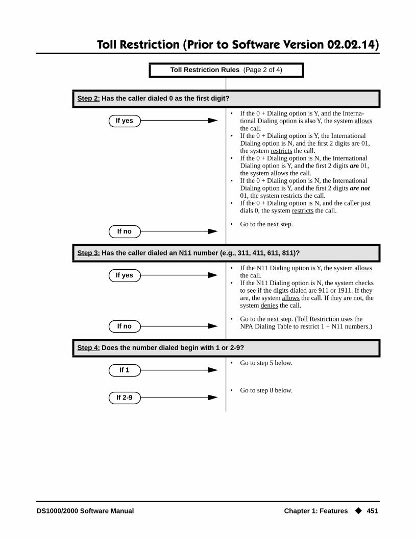
Toll Restriction (Prior to Software Version 02.02.14)
DS1000/2000 Software Manual Chapter 1: Features ◆ 451
Step 2: Has the caller dialed 0 as the first digit?
• If the 0 + Dialing option is Y, and the Interna-tional Dialing option is also Y, the system allows the call.
• If the 0 + Dialing option is Y, the International Dialing option is N, and the first 2 digits are 01, the system restricts the call.
• If the 0 + Dialing option is N, the International Dialing option is Y, and the first 2 digits are 01, the system allows the call.
• If the 0 + Dialing option is N, the International Dialing option is Y, and the first 2 digits are not 01, the system restricts the call.
• If the 0 + Dialing option is N, and the caller just dials 0, the system restricts the call.
• Go to the next step.
Step 3: Has the caller dialed an N11 number (e.g., 311, 411, 611, 811)?
• If the N11 Dialing option is Y, the system allows the call.
• If the N11 Dialing option is N, the system checks to see if the digits dialed are 911 or 1911. If they are, the system allows the call. If they are not, the system denies the call.
• Go to the next step. (Toll Restriction uses the NPA Dialing Table to restrict 1 + N11 numbers.)
Step 4: Does the number dialed begin with 1 or 2-9?
• Go to step 5 below.
• Go to step 8 below.
Toll Restriction Rules (Page 2 of 4)
If yes
If no
If yes
If no
If 1
If 2-9
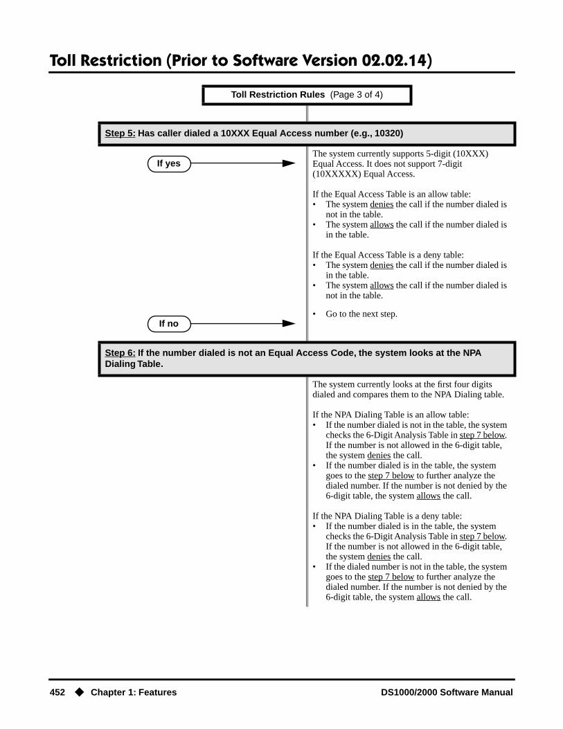
Toll Restriction (Prior to Software Version 02.02.14)
452 ◆ Chapter 1: Features DS1000/2000 Software Manual
Step 5: Has caller dialed a 10XXX Equal Access number (e.g., 10320)
The system currently supports 5-digit (10XXX) Equal Access. It does not support 7-digit (10XXXXX) Equal Access.
If the Equal Access Table is an allow table:• The system denies the call if the number dialed is
not in the table.• The system allows the call if the number dialed is
in the table.
If the Equal Access Table is a deny table:• The system denies the call if the number dialed is
in the table.• The system allows the call if the number dialed is
not in the table.
• Go to the next step.
Step 6: If the number dialed is not an Equal Access Code, the system looks at the NPA Dialing Table.
The system currently looks at the first four digits dialed and compares them to the NPA Dialing table.
If the NPA Dialing Table is an allow table:• If the number dialed is not in the table, the system
checks the 6-Digit Analysis Table in step 7 below. If the number is not allowed in the 6-digit table, the system denies the call.
• If the number dialed is in the table, the system goes to the step 7 below to further analyze the dialed number. If the number is not denied by the 6-digit table, the system allows the call.
If the NPA Dialing Table is a deny table:• If the number dialed is in the table, the system
checks the 6-Digit Analysis Table in step 7 below. If the number is not allowed in the 6-digit table, the system denies the call.
• If the dialed number is not in the table, the system goes to the step 7 below to further analyze the dialed number. If the number is not denied by the 6-digit table, the system allows the call.
Toll Restriction Rules (Page 3 of 4)
If yes
If no

Toll Restriction (Prior to Software Version 02.02.14)
DS1000/2000 Software Manual Chapter 1: Features ◆ 453
Other Related FeaturesDirect Trunk Access (page 154)
Direct Trunk Access does not bypass Toll Restriction.Flash (page 207)
When an extension user with Toll Restriction enabled flashes a trunk, the system enforces toll Restriction on any digits the user dials from the new dial tone. For example, if an extension user cannot dial 203 926 5400 before they flash, they cannot dial 203 926 5400 after they flash.
Step 7: Before denying or allowing the call based on the NPA Dialing Table, the system looks at the 6-Digit Analysis Table (i.e., uses NPA + NNX analysis).
If the number dialed is accepted by the NPA Dialing Table above, the system waits for 7 digits and then compares them to the 6-Digit Analysis Table entries.
If the 6-Digit Analysis Table is an allow table:• The system denies the call if the number dialed is
not in the table.• The system allows the call if the number dialed is
in the table.
If the 6-Digit Analysis Table is a deny table:• The system denies the call if the number dialed is
in the table.• The system allows the call if the number dialed is
not in the table.
Step 8: If the first digit dialed is 2-9, the system waits for timeout or for more than 7 digits.
If the dialing times out before more than 7 digits are dialed, the system looks at the NXX Dialing Table.
If the NXX Dialing Table is an allow table:• The system denies the call if the NXX portion of
the number dialed is not in the table.• The system allows the call if the NXX portion of
the number dialed is in the table.
If the NXX Dialing Table is a deny table:• The system denies the call if the NXX portion of
the number dialed is in the table.
The system allows the call if the NNX portion of the number dialed is not in the table.
If more than 7 digits are dialed, the system goes back to step 6 and reanalyzes the NPA Dialing Table and the 6-Digit Analysis Table.
Toll Restriction Rules (Page 4 of 4)

Toll Restriction (Prior to Software Version 02.02.14)
454 ◆ Chapter 1: Features DS1000/2000 Software Manual
Forced Trunk Disconnect (page 212)Forced Trunk Disconnect does not bypass Toll Restriction.
Last Number Redial (page 277)Last Number Redial will not store a number denied by Toll Restriction.
Private Line (page 350)Toll Restriction restricts Private Lines just like any other trunk.
Save Number Dialed (page 373)Save Number Dialed will not store a number denied by Toll Restriction.
Speed Dial (page 383)The system enforces Toll Restriction on Speed Dial numbers as they are dialed, not as they are stored.
Feature OperationToll Restriction operation is automatic.
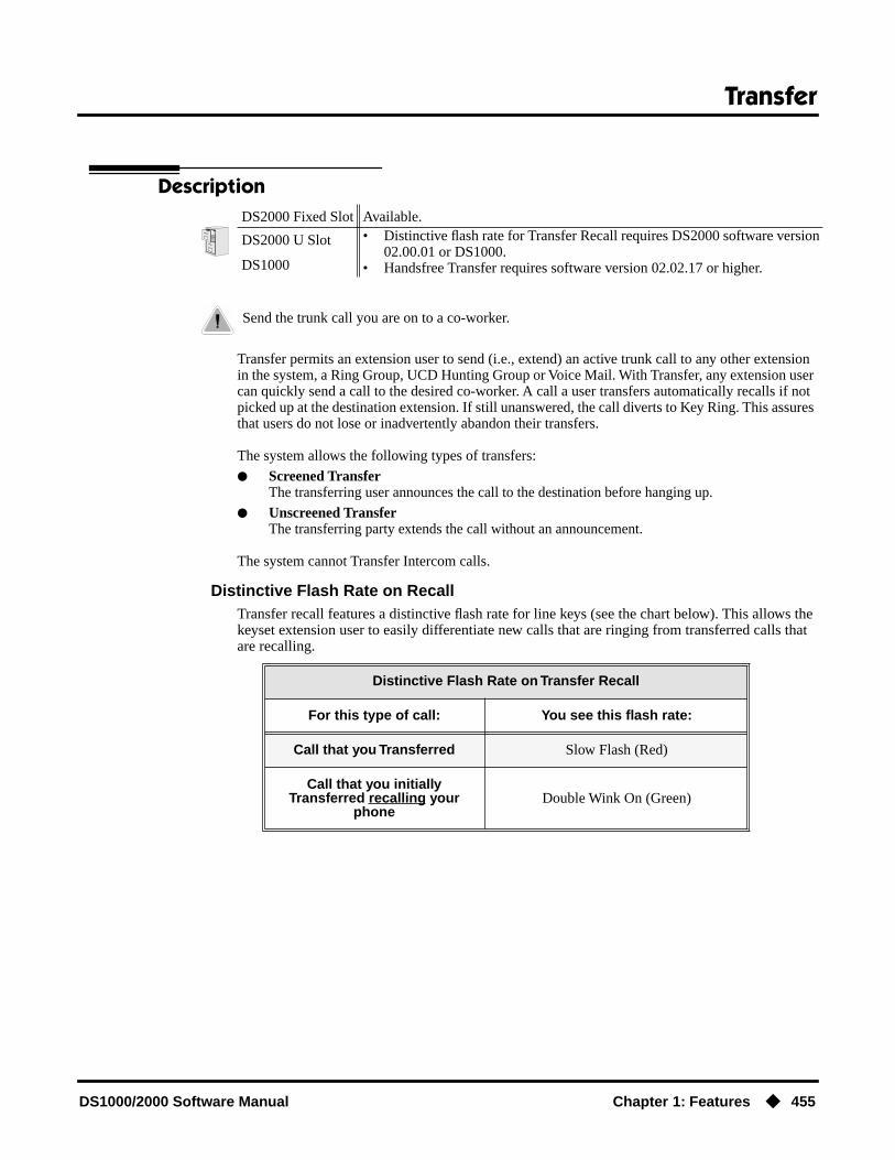
Transfer
DS1000/2000 Software Manual Chapter 1: Features ◆ 455
Transfer
Description
Transfer permits an extension user to send (i.e., extend) an active trunk call to any other extension in the system, a Ring Group, UCD Hunting Group or Voice Mail. With Transfer, any extension user can quickly send a call to the desired co-worker. A call a user transfers automatically recalls if not picked up at the destination extension. If still unanswered, the call diverts to Key Ring. This assures that users do not lose or inadvertently abandon their transfers.
The system allows the following types of transfers:
● Screened TransferThe transferring user announces the call to the destination before hanging up.
● Unscreened TransferThe transferring party extends the call without an announcement.
The system cannot Transfer Intercom calls.
Distinctive Flash Rate on RecallTransfer recall features a distinctive flash rate for line keys (see the chart below). This allows the keyset extension user to easily differentiate new calls that are ringing from transferred calls that are recalling.
DS2000 Fixed Slot Available.
DS2000 U Slot • Distinctive flash rate for Transfer Recall requires DS2000 software version 02.00.01 or DS1000.
• Handsfree Transfer requires software version 02.02.17 or higher.DS1000
Send the trunk call you are on to a co-worker.
Distinctive Flash Rate on Transfer Recall
For this type of call: You see this flash rate:
Call that you Transferred Slow Flash (Red)
Call that you initially Transferred recalling your
phoneDouble Wink On (Green)

Transfer
456 ◆ Chapter 1: Features DS1000/2000 Software Manual
Enhanced Recall DisplayThe Transfer recall display identifies:
● The type of call recalling the extension.
● The extension to which the call was initially transferred.
Following are sample Transfer recall displays. In the first example, the call was transferred by exctension 301 (which does not have a name). In the second example, the call was transferred by extension 300 (which has the name ATTENDANT).
The Transfer recall displays occurs as the call is ringing the extension that initially transferred it, and after the call diverts to Key Ring.
Handsfree Transfer(Software version 02.02.17 or higher)Handsfree Transfer allows an extension user to Transfer a trunk call directly to the speakerphone of a co-worker.
ConditionsNone
Default SettingEnabled
Programming Guide
Step-by-step guide for setting up Transfer (Page 1 of 3)
Step 1: Does an unanswered Transfer ring an idle destination extension or Ring Group long enough before recalling the extension that initially transferred it?
• In Program 0401 - Transfer Recall (page 522), leave the Transfer Recall interval at it’s currently assigned value.
• In Program 0401 - Transfer Recall (page 522), change the Transfer Recall interval to meet the site requirements.
If yes
If no
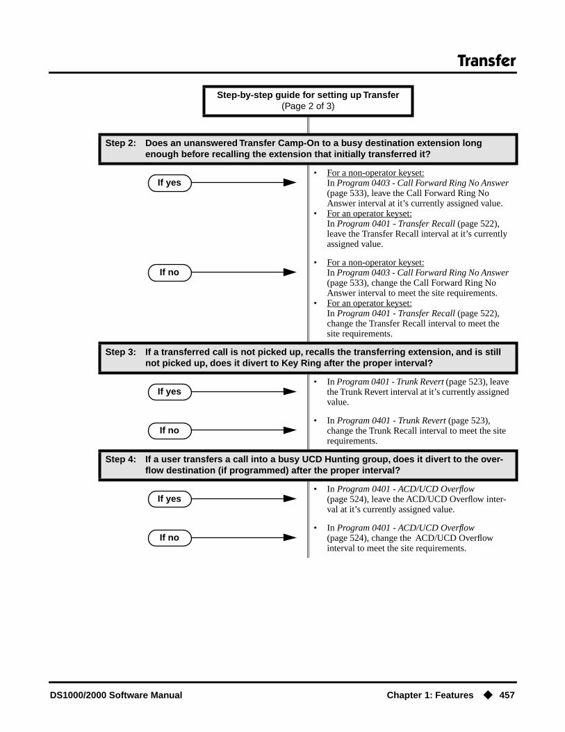
Transfer
DS1000/2000 Software Manual Chapter 1: Features ◆ 457
Step 2: Does an unanswered Transfer Camp-On to a busy destination extension long enough before recalling the extension that initially transferred it?
• For a non-operator keyset:In Program 0403 - Call Forward Ring No Answer (page 533), leave the Call Forward Ring No Answer interval at it’s currently assigned value.
• For an operator keyset:In Program 0401 - Transfer Recall (page 522), leave the Transfer Recall interval at it’s currently assigned value.
• For a non-operator keyset:In Program 0403 - Call Forward Ring No Answer (page 533), change the Call Forward Ring No Answer interval to meet the site requirements.
• For an operator keyset:In Program 0401 - Transfer Recall (page 522), change the Transfer Recall interval to meet the site requirements.
Step 3: If a transferred call is not picked up, recalls the transferring extension, and is still not picked up, does it divert to Key Ring after the proper interval?
• In Program 0401 - Trunk Revert (page 523), leave the Trunk Revert interval at it’s currently assigned value.
• In Program 0401 - Trunk Revert (page 523), change the Trunk Recall interval to meet the site requirements.
Step 4: If a user transfers a call into a busy UCD Hunting group, does it divert to the over-flow destination (if programmed) after the proper interval?
• In Program 0401 - ACD/UCD Overflow (page 524), leave the ACD/UCD Overflow inter-val at it’s currently assigned value.
• In Program 0401 - ACD/UCD Overflow (page 524), change the ACD/UCD Overflow interval to meet the site requirements.
Step-by-step guide for setting up Transfer (Page 2 of 3)
If yes
If no
If yes
If no
If yes
If no

Transfer
458 ◆ Chapter 1: Features DS1000/2000 Software Manual
Programming ListProgram 0201 - Music on Hold (page 512)
Enter Y for this option to enable Music on Hold system-wide (if you also enabled MOH on Transfer below).
Program 0201 - MOH on Transfer (page 513)Enter Y for this option to enable Music on Hold for transferred callers.
Program 0401 - Transfer Recall (page 522)Set how long a transferred call rings an idle destination extension or Ring Group before recall-ing the extension from which it was initially transferred. In addition, use this timer to set how long a transferred call rings a busy operator extension before recalling the extension from which it was initially transferred.
Program 0401 - Trunk Revert (page 523)Sets how long a Transfer Recall rings the extension that initially transferred the call before Key Ring occurs. Key Ring rings all extensions programmed to ring for that line.
Program 0401 - ACD/UCD Overflow (page 524) Set how long a transferred call (or DIL) camps on to a busy UCD Hunt Group before ringing the overflow destination.
Program 0403 - Call Forward Ring No Answer (page 533)Use this timer to set how long a transferred call rings a busy non-operator extension before recalling the extension from which it was initially transferred.
Other Related FeaturesCall Forwarding (page 66)
Call Forwarding will reroute transferred calls.Call Coverage Keys (page 62)
An extension user can Transfer a call to the covered extension by pressing the Call Coverage key.Call Waiting / Camp-On (page 75)
Transfer can automatically Camp-On to a busy extension.Direct Station Selection (DSS) (page 140)
You can press your DSS key to Transfer a call instead of dialing a co-worker’s extension number.Do Not Disturb (page 183)
DND blocks Transfer.
Step 5: While a transferred caller is waiting to be picked up, should they hear Music on Hold instead of ringback?
• In Program 0201 - Music on Hold (page 512), enter Y for this option to enable Music on Hold system-wide.
• Program 0201 - MOH on Transfer (page 513), enter Y for this option to enable Music on Hold for transferred callers.
• In Program 0201 - MOH on Transfer (page 513), enter N for this option to disable Music on Hold for transferred callers.
Step-by-step guide for setting up Transfer (Page 3 of 3)
If yes
If no

Transfer
DS1000/2000 Software Manual Chapter 1: Features ◆ 459
Extended Ringing (page 191)With Extended Ringing enabled, transferred trunks ring the destination extension for the Number of Extended Rings before recalling the transferring extension.
Extension Hunting (page 193)Trunk calls transferred to a Terminal or Circular Hunting group member activate hunting. In addition, trunk calls transferred to a UCD group master number activate hunting.
Group Call Pickup (page 215)A trunk call transferred to an extension in a Pickup Group activates Group Call Pickup.
Group Ring (page 221)An extension user can Transfer a call to a Ring Group master number. If unanswered, the call will recall the extension from which it was transferred.
Hold (page 235)If an extension receiving a screened Transfer answers the screen and immediately hangs up (before the transferring extension), the call goes on Exclusive Hold at the transferring extension.
Hotline (page 240)An extension user can Transfer a call to their Hotline partner by pressing their Hotline key.
Intercom (page 268)The system cannot Transfer Intercom calls.
Key Ring (page 273)An unanswered call transferred to an extension diverts to Key Ring if unanswered at the transferring extension.
Music on Hold (page 303)With Music on Hold enabled, transferred callers can optionally listen to ringback or MOH while their call waits at the transfer destination. In software versions 02.03.03 and higher, Music on Hold will also play to transferred callers camped-on to a busy UCD Hunting Group.
Off-Hook Signaling (page 313)An extension user can Transfer their current call to a co-worker or Voice Mail and then answer the waiting call. In addition, transferred calls can initiate Off-Hook Signaling.
Reverse Voice Over (page 364)While idle, an extension user can use their Reverse Voice Over key to Transfer calls.
Station Message Detail Recording (page 400)The system assigns the SMDR record to the last extension on the call. For example, if exten-sion 306 answers the call, talks for 20 minutes, and then Transfers the call to extension 302, extension 302 “owns” the entire call record as soon as they hang up.
Voice Over (page 493)An extension user can Voice Over after making a Screened Transfer and hearing busy/ring tone.

Transfer
460 ◆ Chapter 1: Features DS1000/2000 Software Manual
Feature Operation
To Transfer your call:
You cannot Transfer Intercom calls.
1. Do not hang up.
2. Press ICM.
You can press your Call Coverage or Hotline key instead of ICM.
3. Dial your co-worker’s extension.OR
Press a DSS key.OR
Dial a Ring Group or UCD Hunting group master number.
4. Announce call to make a Screened Transfer.OR
Press the flashing line key to return to the call if your co-worker doesn’t want it (i.e., rejects your screen).
ORHang up to send the call through Unscreened.
The call will recall to you if unanswered at the destination extension. If you don’t answer the recall, it diverts to Key Ring.
To Transfer your call to a co-worker’s mailbox:
1. Do not hang up.
2. Press ICM.
You can press your Call Coverage or Hotline key instead of ICM.
3. Dial your co-worker’s extension.
4. Press MW.
5. Hang up.
To transfer a call to a co-worker’s speakerphone (i.e., use Handsfree Transfer):
1. While on a trunk call, press ICM and dial your co-worker’s extension number.OR
Press Hotline key for your co-worker.
Listen for two beeps. This indicates that your Transfer announcement has voice-announced at your co-worker’s extension.
If your co-worker’s phone is set up to ring instead of Voice Announce, you cannot use Handsfree Transfer.
2. Press FLASH to send the call directly to your co-worker’s speakerphone.OR
Press ICM to get Intercom dial tone and select another co-worker for the Transfer.
Intercom dial tone.
ICM anbd SPK on
Intercom dial tone.
ICM anbd SPK on
Two beeps.
ICM anbd SPK on

Trunk Group Routing
DS1000/2000 Software Manual Chapter 1: Features ◆ 461
Trunk Group Routing
Description
With Trunk Group Routing enabled, an extension user can just press ICM and dial 9 to place a trunk call. Trunk Group Routing automatically selects the first available trunk in the extension’s pro-grammed “dial 9” trunk group. This simplifies placing calls in systems that have a lot of trunks for outgoing calls. Rather than press one of many line keys, the user just dials 9 instead.
ConditionsSystems using Trunk Groups or Trunk Group Access should use the hybrid FCC registration num-ber (i.e., the number that ends in MF-E). Look at the label on the bottom of your equipment cabinet for more information.
Default SettingDS2000
Fixed Slot
● Trunk Group Routing (dial 9) is assigned to trunk group 1 (which contains trunks 9-16). Dial 9 does not work by default.
● All extensions have full access on all trunks.
U Slot Prior to 02.01.07
● Trunk Group Routing (dial 9) is assigned to trunk group 0 (which contains trunks 1-8). Dial 9 works by default. The outgoing trunk priority for the dial 9 group is as follows:Order 1 = trunk 8Order 2 = trunk 7Order 3 = trunk 6Order 4 = trunk 5Order 5 = trunk 4Order 6 = trunk 3Order 7 = trunk 2Order 8 = trunk 1
● All extensions have full access on all trunks.
● Introduces User Programmable Feature steps for line keys.
U Slot 02.01.07 and Higher
● All extensions have full access on all trunks.
● Trunk Group assignments are not defined, so there is no Trunk Group Routing (dial 9) by default.
DS2000 Fixed Slot Available. • See Default Setting below for specifics on the initial trunk setup.
DS2000 U SlotAvailable.• See Default Setting below for specifics on the initial trunk setup.• In 02.01.07 and higher, dial 9 is disabled by default.
DS1000Available.• See Default Setting below for specifics on the initial trunk setup.• In 02.00.09 and higher, dial 9 is enabled be default.
Dial a single code to place a call over the first available trunk in a trunk group.

Trunk Group Routing
462 ◆ Chapter 1: Features DS1000/2000 Software Manual
DS1000
● All extensions have full access on all trunks.
● Trunks 4-6 require the Expansion Board.
● All versions have User Programmable Feature steps for line keys.
DS1000 prior to 02.00.09.
● Trunk Group assignments are not defined, so there is no Trunk Group Routing (dial 9) by default.
DS1000 02.00.09 and Higher
● Trunk Group Routing (dial 9) is assigned to trunk group 0 (which contains trunks 1-6). Dial 9 works by default. The outgoing trunk priority for the dial 9 group is as follows:Order 1 = trunk 6Order 2 = trunk 5Order 3 = trunk 4Order 4 = trunk 3Order 5 = trunk 2Order 6 = trunk 1
Programming Guide
Step-by-step guide for setting up Trunk Group Routing (Page 1 of 2)
Step 1: Should dial 9 capability be available system-wide?
• In Program 0501 - Single Digit Access (page 542), enter Y.
• In Program 0501 - Single Digit Access (page 542), enter N.
Step 2: Should extension have dial 9 capability?
• In Program 1802 - Station’s Dial 9 Group (page 636), assign a trunk group that has valid, installed trunks to which the extension has access. Also review the steps below.
• In Program 1002 - Trunk Groups (page 590), assign installed trunks to the extension’s dial 9 trunk group assigned above.
• In Program 1802 - Station’s Dial 9 Group (page 636), assign a trunk group that does not have valid, installed trunks to which the extension has access.
If yes
If no
If yes
If no
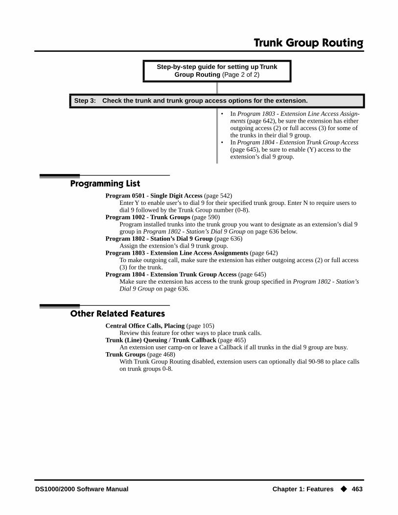
Trunk Group Routing
DS1000/2000 Software Manual Chapter 1: Features ◆ 463
Programming ListProgram 0501 - Single Digit Access (page 542)
Enter Y to enable user’s to dial 9 for their specified trunk group. Enter N to require users to dial 9 followed by the Trunk Group number (0-8).
Program 1002 - Trunk Groups (page 590)Program installed trunks into the trunk group you want to designate as an extension’s dial 9 group in Program 1802 - Station’s Dial 9 Group on page 636 below.
Program 1802 - Station’s Dial 9 Group (page 636)Assign the extension’s dial 9 trunk group.
Program 1803 - Extension Line Access Assignments (page 642)To make outgoing call, make sure the extension has either outgoing access (2) or full access (3) for the trunk.
Program 1804 - Extension Trunk Group Access (page 645)Make sure the extension has access to the trunk group specified in Program 1802 - Station’s Dial 9 Group on page 636.
Other Related FeaturesCentral Office Calls, Placing (page 105)
Review this feature for other ways to place trunk calls.Trunk (Line) Queuing / Trunk Callback (page 465)
An extension user camp-on or leave a Callback if all trunks in the dial 9 group are busy.Trunk Groups (page 468)
With Trunk Group Routing disabled, extension users can optionally dial 90-98 to place calls on trunk groups 0-8.
Step 3: Check the trunk and trunk group access options for the extension.
• In Program 1803 - Extension Line Access Assign-ments (page 642), be sure the extension has either outgoing access (2) or full access (3) for some of the trunks in their dial 9 group.
• In Program 1804 - Extension Trunk Group Access (page 645), be sure to enable (Y) access to the extension’s dial 9 group.
Step-by-step guide for setting up Trunk Group Routing (Page 2 of 2)

Trunk Group Routing
464 ◆ Chapter 1: Features DS1000/2000 Software Manual
Feature Operation
To place a call over a trunk group:
1. Lift handset.
2. Press ICM.
3. Dial 9.
If you don’t hear dial tone as soon as you dial 9, your system does not have Trunk Group Routing enabled. SeeCentral Office Calls, Placing on page 105 for more.
If you hear busy tone after dialing 9, all the trunks in your dial 9 group are busy. You can dial 2 to wait in line for a trunk to become free, or dial 2 to have an available trunk call you back. See Trunk (Line) Queuing / Trunk Callback on page 465 for more.
4. Dial outside number.
Intercom dial tone.
ICM on.
Trunk dial tone.
Line key on.

Trunk (Line) Queuing / Trunk Callback
DS1000/2000 Software Manual Chapter 1: Features ◆ 465
Trunk (Line) Queuing / Trunk Callback
Description
Trunk QueuingTrunk Queueing permits an extension user to queue (wait in line) on hook for a busy trunk or trunk group to become free. The system recalls the queued extension as soon as the trunk is available. The user does not have to manually retry the trunk later.
Trunk CallbackAfter queuing for a trunk, the extension user just hangs up to convert the Trunk Queue into a Trunk Callback. When the trunk becomes free, the system automatically recalls the extension. As soon as the extension user answers the callback ring, the system connects the extension to the trunk.
An extension user can leave a Trunk Callbackfor many trunks. The system processes the callbacks as the trunks become free. In addition, many extensions can leave a Trunk Callback for the same trunk. The system processes the Trunk Callbacks on a first-in/first-out (FIFO) basis.
If an extension user leaves a Trunk Callback request and then fails to answer the calback ring within four rings, the system cancels the Callback.
Trunk Queuing PrioritySelected extensions can have Trunk Queuing Priority enabled in their Class of Service. If more than one extension queues for a busy trunk, the system services the extension with Trunk Queuing Prior-ity first. If more than one extension with priority is queued for the same busy trunk, the system ser-vices the priority extensions on a first-in/first-out (FIFO) basis.
ConditionsA system reset or power failure cancels all Trunk Callbacks system-wide.
Default Setting
● Trunk (Line) Queuing / Trunk Callback enabled for attendants (COS 1), but disabled for all other extensions (COS 2-15).
● Trunk Queuing Priority disabled for all extensions (COS 1-15).
DS2000 Fixed Slot
Available.DS2000 U Slot
DS1000
When all trunks are busy, Trunk Queuing lets a user wait in line for a trunk to become free.Trunk Callback will automatically call the user back when a trunk is available.

Trunk (Line) Queuing / Trunk Callback
466 ◆ Chapter 1: Features DS1000/2000 Software Manual
Programming Guide
Programming ListProgram 0101 - Trunk (Line) Queuing Priority (page 507)
In an extension’s Class of Service, enter Y to enable Trunk (Line) Queuing Priority.Program 0101 - Camp-On to Busy Line (page 507)In an extension’s Class of Service, enter Y to allow camping on to a busy trunk.Program 1801 - Extension Class of Service Assignment (page 631)
Assign Class of Service to extensions.
Other Related FeaturesCallback (page 79)
An extension user can Camp-On to a busy co-worker then hang up to turn the Camp-On into a Callback.
Call Waiting / Camp-On (page 75)Camp-On lets an extension user Camp-On to a busy extension.
Central Office Calls, Answering (page 99)If a trunk is ringing an extension because of a prior Callback, and then receives a new trunk call, it will start ringing for the new call. The Callback request is then queued.
Step-by-step guide for setting up Trunk (Line) Queuing / Trunk Callback
Step 1: Should extension be able to queue for a busy trunk?
• In Program 0101 - Camp-On to Busy Line (page 507), enter Y to enable Trunk (Line) Queueing.
• In Program 0101 - Camp-On to Busy Line (page 507), enter N to disable Trunk (Line) Queueing.
Step 2: Should extension have Trunk Queuing Priority?
• In Program 0101 - Trunk (Line) Queuing Priority (page 507), enter Y to enable Trunk Queuing Pri-ority.
• In Program 0101 - Trunk (Line) Queuing Priority (page 507), enter N to disable Trunk Queuing Pri-ority.
Step 3: Assign Class of Service to extensions.
• In Program 1801 - Extension Class of Service Assignment (page 631), assign Class of Service to extensions.
If yes
If no
If yes
If no
Trunk (Line) Queuing / Trunk Callback
DS1000/2000 Software Manual Chapter 1: Features ◆ 467
Central Office Calls, Placing (page 105)An extension user can queue for a busy trunk, or queue and hang up to leave a callback for a busy trunk.
Last Number Redial (page 277)If all trunks are busy and Last Number Redial cannot go through, the user can dial 2 a queue for a trunk to become free. If the user hangs up, the system converts the queue to a Trunk Callback.
Save Number Dialed (page 373)If an extension user presses their Save key and hears busy, they can dial 2 to wait in line for the trunk to become available. The system will automatically redial the call. However, if the user hangs up to convert the queue to a Trunk Callback, the system will not redial the saved call once the trunk connects.
Feature Operation
To queue for a busy trunk:
1. Press line key for busy trunk.OR
Press ICM and dial the trunk’s Direct Trunk Access code (e.g., 401 for trunk 1).
After you hang up a trunk call on one of your line keys, and the trunk immediately becomes busy, wait a few seconds before queuing for that same trunk.
2. Dial 2; do not hang up.
If you hang up, the system converts your queue to a Trunk Callback.
3. When the trunk becomes free, you are automatically connected.
4. Place your outside call.
Busy tone.
Line/loop key on (red).
Busy tone stops.
ICM and SPK on.
• If you initially queued for the trunk, you hear trunk dial tone so you can place your call again.
• If you left a Trunk Callback, your hear Trunk Callback ring. If you answer within four rings, you will hear dial tone from the trunk. You can then place your call again.
ICM and SPK on.
Trunk Groups
468 ◆ Chapter 1: Features DS1000/2000 Software Manual
Trunk Groups
Description
Extension users can optionally dial trunk group access codes 90-98 to select trunk groups 0-8 for outgoing calls. This is helpful in applications that have different services arranged into trunk groups. For example, dialing 90 could access a group of DDD trunks for local calls, and dialing 91 could access a group of WATS trunks for long distance calls. (Note that systems with Trunk Group Routing (page 461) enabled cannot also dial trunk group access codes 90-98.)
When a user dials a trunk group access code (90-98), the system selects the lowest number in the group that is available. If that trunk is busy, it automatically selects the next highest trunk. If all trunks in the group are busy, the user can optionally queue for a trunk to become free. See Trunk (Line) Queuing / Trunk Callback (page 465) for more.
Systems using Trunk Groups or Trunk Group Access should use the hybrid FCC registration num-ber (i.e., the number that ends in MF-E). Look at the label on the bottom of your equipment cabinet for more information.
Conditions
● Systems using Trunk Groups or Trunk Group Access should use the system’s hybrid FCC regis-tration number (i.e., the number that ends in MF-E). Look at the label on the bottom of your equipment cabinet for more information.
● A trunk can only be in one group.
DS2000 Fixed Slot Available. • See Default Setting below for specifics on the initial trunk setup.
DS2000 U SlotAvailable.• See Default Setting below for specifics on the initial trunk setup.• In 02.01.07 and higher, dial 9 is disabled by default.
DS1000Available.• See Default Setting below for specifics on the initial trunk setup.• In 02.00.09 and higher, dial 9 is enabled be default.
Dial codes to access trunk groups for outgoing calls.

Trunk Groups
DS1000/2000 Software Manual Chapter 1: Features ◆ 469
Default SettingDS2000
Fixed Slot
● Trunk Group Routing (dial 9) is assigned to trunk group 1 (which contains trunks 9-16). Dial 9 does not work by default.
● All extensions have full access on all trunks.
U Slot Prior to 02.01.07
● Trunk Group Routing (dial 9) is assigned to trunk group 0 (which contains trunks 1-8). Dial 9 works by default. The outgoing trunk priority for the dial 9 group is as follows:Order 1 = trunk 8Order 2 = trunk 7Order 3 = trunk 6Order 4 = trunk 5Order 5 = trunk 4Order 6 = trunk 3Order 7 = trunk 2Order 8 = trunk 1
● All extensions have full access on all trunks.
● Introduces User Programmable Feature steps for line keys.
U Slot 02.01.07 and Higher
● All extensions have full access on all trunks.
● Trunk Group assignments are not defined, so there is no Trunk Group Routing (dial 9) by default.
DS1000
● All extensions have full access on all trunks.
● Trunks 4-6 require the Expansion Board.
● All versions have User Programmable Feature steps for line keys.
DS1000 prior to 02.00.09.
● Trunk Group assignments are not defined, so there is no Trunk Group Routing (dial 9) by default.
DS1000 02.00.09 and Higher
● Trunk Group Routing (dial 9) is assigned to trunk group 0 (which contains trunks 1-6). Dial 9 works by default. The outgoing trunk priority for the dial 9 group is as follows:Order 1 = trunk 6Order 2 = trunk 5Order 3 = trunk 4Order 4 = trunk 3Order 5 = trunk 2Order 6 = trunk 1

Trunk Groups
470 ◆ Chapter 1: Features DS1000/2000 Software Manual
Programming Guide
Programming ListProgram 0501 - Single Digit Access (page 542)
Enter N to disable single digit access. With single digit access disabled, an extension user can dial 90-98 to access trunk groups 0-8.
Program 1002 - Trunk Groups (page 590)Assign trunks to Trunk Groups (0-8).
Program 1803 - Extension Line Access Assignments (page 642)For each extension, assign the access options for each trunk (0 = No access, 1 = Incoming only. 2 = Outgoing only, 3 = Full access). This feature may not require access - check into this when the feature is working.
Program 1804 - Trunk Group Access (page 645)For each extension, enter Y to allow or N to prevent outgoing trunk group access. The system always allows incoming trunk group access.
Step-by-step guide for setting up Trunk Groups
Step 1: Should extension be able to dial codes 90-98 to place calls on trunk group.
• In Program 0501 - Single Digit Access (page 542), enter N to disable single digit access (dial 9).
• In Program 1002 - Trunk Groups (page 590), check your system’s trunk group assignments.
• In Program 0501 - Single Digit Access (page 542), enter Y to enable single digit access (dial 9).
Step 2: Should extension be able to access all installed trunks in all trunk groups for plac-ing calls (via codes 90-98)?
• In Program 1803 - Extension Line Access Assign-ments (page 642), assign either outgoing (2) or full (3) access to each trunk the extension should be able to use for outgoing calls.
• In Program 1804 - Extension Trunk Group Access (page 645), be sure the extension has access (Y) to each trunk group it should be able to use for outging calls.
• In Program 1803 - Extension Line Access Assign-ments (page 642), assign either no (0) or incom-ing (1) access to each trunks the extension should not be able to use for outgoing calls.
• In Program 1804 - Extension Trunk Group Access (page 645), be sure the extension has no access (N) to each trunk group it should not be able to use for outging calls.
If yes
If no
If yes
If no

Trunk Groups
DS1000/2000 Software Manual Chapter 1: Features ◆ 471
Other Related FeaturesLoop Keys (page 283)
Switched and Fixed Loop Keys use the system’s Trunk Groups.Trunk Group Routing (page 461)
With Trunk Group Routing enabled, extension users can press ICM and dial 9 to place outgo-ing calls.
Feature Operation
To place a call over a trunk group:
1. Lift handset.
2. Press ICM.
3. Dial trunk group code (90-98).
If you hear dial tone as soon as you dial 9, your system has Trunk Group Routing enabled. SeeTrunk Group Routing on page 461 for more.
4. Dial outside number.
Intercom dial tone.
ICM on.
Trunk dial tone.
Line key on.

Trunk Timers
472 ◆ Chapter 1: Features DS1000/2000 Software Manual
Trunk Timers
DescriptionDS2000 Fixed Slot
Available. See System Timers, Trunks on page 426 for more.DS2000 U Slot
DS1000
User Programmable Features
DS1000/2000 Software Manual Chapter 1: Features ◆ 473
User Programmable Features
Description
User Programmable Features allow an extension user to customize their telephone to work just the way they want. With User Programmable Features, there is no need to rely on a System Administrator or Communications Manager to set up each phone. These User-Programmable Features include:
● Direct Station Selection (DSS) Assignment1
See Direct Station Selection (DSS) on page 140 for more.
● Headset Mode1
See Headset Compatibility on page 232 for more.
● Hotline Key Assignment1
See Hotline on page 240 for more.
● Off Hook Signaling Setup1
See Off-Hook Signaling on page 313 for more.
● Paging (Incoming)1
See Paging on page 326 for more.
● Prime Line Assignment1
See Prime Line Preference on page 342 for more.
● Programmable Function Key Assignment1
See Programmable Function Keys on page 354 for more.
● Programmable Function Key Ringing (Call Coverage Keys, Group Call Pickup Keys, and Line Keys)See Call Coverage Keys on page 62 for more.See Group Call Pickup on page 215 for more.See Line Keys on page 279 for more.
● Ringing Line Preference1
See Ringing Line Preference on page 370 for more.
● Speed Dial Bin Setup (Personal and System)See Speed Dial on page 383 for more.Note that in U Slot systems, the ##2 and ##7 Speed Dial procedures are no longer available.
● Time and Date1
See Time and Date on page 437 for more.
● Voice Announce (For incoming Intercom calls)See Intercom on page 268 for more.
● Voice Over1
See Voice Over on page 493 for more.1 Feature only available in U Slot systems.
DS2000 Fixed Slot Basic User Programmable Features available. Access is fixed (enabled) at each extension.
DS2000 U Slot Extensive User Programmable Features available. Access depends on an exten-sion’s programmed access level.DS1000
Extension users can set up their telephones to meet their own unique requirements.

User Programmable Features
474 ◆ Chapter 1: Features DS1000/2000 Software Manual
Table 16: User Programmable Features
Feature Mnemonic Operation Access Level
The shaded rows below show the Fixed Slot software User Programmable Features.
Call Coverage #RC # + R C + Press Call Coverage key repeatedly to select ringing mode
N/A
DSS #BLF See Direct Station Selection (DSS) (page 140) before using this option. #BLF + Press DSS key + HOLD + Enter extension + VOL Up + Program another key or SPK to exit.
1-5
Group Call Pickup #RG # + R G + Press Group Call Pickup key repeatedly to select ringing mode
N/A
Headset #HS #HS + Y to enable or N to disable + SPK to exit
3-5
Hotline #HL #HL + Press flashing Hotline key + Enter extension for new Hotline partner + HOLD + Program another Hotline key or SPK to exit.
3-5
Line Keys #RL # + R L + Press Line Key repeatedly to select ringing mode
N/A
Off Hook Signaling and Voice Over
#OHS #OHS + Select mode (C=Outside line, D=Hotline, I=ICM) + Select option (see below) + SPK to exit.Outside line options: C=Camp On tone, O=Off Hook Ringing, 0 = NoneIntercom options: C=Camp On, V=Voice Over, 0 = NoneHotline Options: C=Camp On, 0 = None
3-5
Paging (Incoming) #VP #VP + Y to enable or N to disable + SPK to exit.
3-5
Prime Line Assignment #PLA #PLA + Press one of your flashing pro-grammable keys or ICM + SPK to exit.
3-5
Programmable Funtion Key Assignments
#KP #KP + Press key you want to program + HOLD + ICM + Press VOL Up or VOL Down to select key option + HOLD + (Enter any additional data if required + HOLD) + Press VOL Up or VOL Down to select another key to program, or CONF + SPK to exit.
3-5
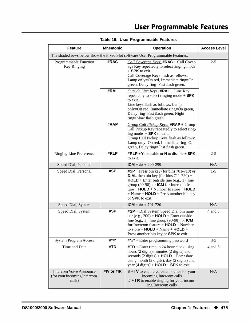
User Programmable Features
DS1000/2000 Software Manual Chapter 1: Features ◆ 475
Programmable Function Key Ringing
#RAC Call Coverage Keys: #RAC + Call Cover-age Key repeatedly to select ringing mode + SPK to exit.Call Coverage Keys flash as follows: Lamp only=On red, Immediate ring=On green, Delay ring=Fast flash green.
2-5
#RAL Outside Line Keys: #RAL + Line Key repeatedly to select ringing mode + SPK to exit.Line keys flash as follows: Lamp only=On red, Immediate ring=On green, Delay ring=Fast flash green, Night ring=Slow flash green.
#RAP Group Call Pickup Keys: #RAP + Group Call Pickup Key repeatedly to select ring-ing mode + SPK to exit.Group Call Pickup Keys flash as follows: Lamp only=On red, Immediate ring=On green, Delay ring=Fast flash green.
Ringing Line Preference #RLP #RLP + Y to enable or N to disable + SPK to exit.
2-5
Speed Dial, Personal ICM + ## + 200-299 N/A
Speed Dial, Personal #SP #SP + Press bin key (for bins 701-710) or DIAL then bin key (for bins 711-720) + HOLD + Enter outside line (e.g., 1), line group (90-98), or ICM for Intercom fea-ture + HOLD + Number to store + HOLD + Name + HOLD + Press another bin key or SPK to exit.
1-5
Speed Dial, System ICM + ## + 701-720 N/A
Speed Dial, System #SP #SP + Dial System Speed Dial bin num-ber (e.g., 200) + HOLD + Enter outside line (e.g., 1), line group (90-98), or ICM for Intercom feature + HOLD + Number to store + HOLD + Name + HOLD + Press another bin key or SPK to exit.
4 and 5
System Program Access #*#* #*#* + Enter programming password 3-5
Time and Date #TD #TD + Enter time in 24-hour clock using hours (2 digits), minutes (2 digits) and seconds (2 digits) + HOLD + Enter date using month (2 digits), day (2 digits) and year (4 digits) + HOLD + SPK to exit.
4 and 5
Intercom Voice Announce (for your incoming Intercom
calls)
#IV or #IR # + I V to enable voice-announce for your incoming Intercom calls
# + I R to enable ringing for your incom-ing Intercom calls
N/A
Table 16: User Programmable Features
Feature Mnemonic Operation Access Level
The shaded rows below show the Fixed Slot software User Programmable Features.

User Programmable Features
476 ◆ Chapter 1: Features DS1000/2000 Software Manual
ConditionsNone
Default Setting
● Extension 300 has its access level fixed at 5. (This means that by default only extension 300 can dial #TD to change the system time and date.)
● All other extensions have access level 3.
Programming ListProgram 1801 - Access Level (page 631)
Use this option to set an extension’s access level (1-5). Access level 5 has the most capability (see the tables above). Access level 1 has the least capability. By default, extension 300 has it’s access level fixed at 5. All other extensions have Access Level 3.
Other Related FeaturesSee features listed under Description heading above.
Feature OperationSee tables under Description heading above.
Intercom Voice Announce (for incoming Intercom calls)
#VA #VA + V for voice announce or R for ring + SPK to exit.
3-5
Table 16: User Programmable Features
Feature Mnemonic Operation Access Level
The shaded rows below show the Fixed Slot software User Programmable Features.

Voice Mail
DS1000/2000 Software Manual Chapter 1: Features ◆ 477
Voice Mail
Description
The system is fully compatible with the NVM-Series Voice Mail with Automated Attendant Sys-tems. These systems provide telephone users with comprehensive Voice Mail and Automated Attendant features. Automated Attendant automatically answers the system’s incoming calls. After listening to a customized message, an outside caller can dial a system extension or use Voice Mail. Integrated Voice Mail enhances the telephone system with the following features:
Call Forwarding to Voice MailAn extension user can forward their calls to Voice Mail. Once forwarded, calls to the extension con-nect to that extension’s mailbox. The caller can leave a message in the mailbox instead of calling back later. Forwarding can occur for all calls immediately, for unanswered calls or when the exten-sion is busy, or just for unanswered calls.
Leaving a MessageVoice Mail lets a keyset extension user easily leave a message at an extension that is unanswered, busy in Do Not Disturb. The caller just presses their Voice Mail key to leave a message in the called extension’s mailbox. There is no need to call back later.
Transferring to Voice MailBy using Transfer to Voice Mail, an extension user can Transfer a call to the user’s own or a coworker’s mailbox. After the Transfer goes through, the caller can leave a message in the mailbox.
Conversation RecordWhile on a call, an extension user can have Voice Mail record the conversation. The keyset user just presses their Voice Mail Record Key. Once recorded, the Voice Mail stores the conversation as a new message in the user’s mailbox. After calling their mailbox, a user can save, edit or delete the recorded conversation. The ability to use Conversation Record is controlled by an extension’s Class of Service.
Personal Answering Machine EmulationA keyset user can have their idle extension emulate a personal answering machine. This lets Voice Mail screen their calls, just like their answering machine at home. If activated, the extension’s incoming calls route to the user’s subscriber mailbox. Once the mailbox answers, the user hears two alert tones followed by the caller’s incoming message. The keyset user can then:
● Let the call go through to their mailbox.
DS2000 Fixed Slot Available. Check with your Sales Representative for the availability of Park and Page.
DS2000 U Slot • Display and Super Display Telephone displays show the number of new messages in the user’s mailbox.
• Unanswered calls Parked by an extension that has RNA/Busy Terminal Hunting to Voice Mail do not route to Voice Mail in DS2000 02.00.01 or higher and DS1000.
• In DS2000 02.00.06 or higher and DS1000, the Transfer to Mailbox feature doesn’t require that the user wait for splash tone before hanging up.
• The capability to press a line key to stop Conversation Record requires software version 02.01.07 or higher.
DS1000
Voice Mail ends the frustration of and cost of missed calls, inaccurate written messages and tele-phone tag, freeing up the company’s receptionists and secretaries for more production work.

Voice Mail
478 ◆ Chapter 1: Features DS1000/2000 Software Manual
● Intercept the call before it goes to their mailbox.
Voice Mail OverflowIf Voice Mail automatically answers trunks, Voice Mail Overflow can reroute those trunks to an extension, Ring Group or UCD Hunting group when all Voice Mail ports are busy. During periods of high traffic, this prevents the outside calls from ringing Voice Mail for an inordinate amount of time. Without overflow, the outside calls ring Voice Mail until a port becomes available or the out-side caller hangs up.
In addition, Voice Mail can be the overflow destination for the following types of calls (refer to the individual features for the specifics):
● Direct Inward Line (page 133)A trunk that directly rings an extension can overflow to Voice Mail.
● Extension Hunting (page 193)A trunk that rings an Extension Hunting group can overflow to Voice Mail.
● Group Ring (page 221)A trunk that rings a group of extensions can overflow to Voice Mail.
● Key Ring (page 273)A trunk ringing extension’s line keys can overflow to Voice Mail.
Message Center MailboxA Message Center Mailbox is a mailbox shared by more than one extension. Any keyset that has a Message Center Key for the shared mailbox can:
● Listen to the messages stored in the mailbox.
● Transfer calls to the shared mailbox.
● Use many other Voice Mail features previously available only at an extension’s individual mailbox.
A Message Center Mailbox helps co-workers that work together closely - such as members of the same Pickup Group. For example, the group supervisor can send important messages to the shared Message Center Mailbox, to which any group member can respond when time allows. Each group member’s Message Center Key flashes (green) when messages are waiting.
Interactive Soft Key Shows New MessagesThe Display and Super Display Telephone interactive soft keys show the number of new messages in the user’s mailbox. For example, if a Display Telpehone user has 2 new messages in their mail-box, their Voice Mail soft key shows: VM02. If a Super Display Telephone user has 2 new messages in their mailbox, their Voice Mail soft key shows V-MAIL 02. The new message count resets to 00 as soon as the user calls their mailbox (regardless of whether the new messages were listened to). The message count returns when the system updates the MW key on the phone.
Setting Up NVM-Series Voice MailYou should complete your DS1000/2000 Voice Mail programming before using the following setup instructions.
DS1000 Ring Assignments and Voice Mail PortsIn DS1000 software version 02.01.07 and higher, the system automatically disables the1805 - Ring Assignments programming for all single line ports assigned as Voice Mail ports in 1802 - Voice Mail Port. To have Voice Mail answer an outside call, the trunk should be a Direct Inward Line (i.e., directly terminated) to the Voice Mail master number.
Voice Mail
DS1000/2000 Software Manual Chapter 1: Features ◆ 479
Conditions
● If an extension has a flashing MW lamp and the system resets or power fails, the MW key con-tinues to flash after the system restarts.
● When using ASTU PCBs, the number of Voice Mail ports you can install is limited by available system DTMF receivers.
● When the system rings an idle Voice Mail port, it will continue to ring the port until answered. The call will not cycle to a another member of the UCD Group (as it will for voice calls).
● In software versions 02.03.03 and higher, the system will never send a loop supervision dis-connect signal (i.e., drop pulse) to Voice Mail ports.
Default SettingVoice Mail not installed.

Voice Mail
480 ◆ Chapter 1: Features DS1000/2000 Software Manual
Programming Your Voice Mail
VANGARD Mail and NVM-1000/2000
To set up VANGARD Mail and NVM-2000 for DS1000/2000:
1. Following the instructions in your Voice Mail manual, connect the Voice Mail to the telephone system.
2. From the Voice Mail Main Menu, enter IN + Enter.
3. Enter the Voice Mail password (CTL) + Enter.
4. When you see the Install System Menu, enter 7 + Enter (to select DS2000) and follow the prompts.
NVM-2e and NVM-1000/2000
To set up NVM-2e for DS1000/2000:
1. Following the instructions in your NVM-2e manual, connect the Voice Mail system.The steps that follow assume your NVM-2e still has its default programming.
2. From any extension:- Press ICM.- Dial the voice Mail master number (e.g., 700).- (NVM-2e version 2.0 or higher) Dial 301, wait for the main menu.- (NVM-2e version prior to 2.0) Dial 10, wait for the main menu.
3. At the main menu, dial DM (36) for the Database Management Menu.
4. Dial SI (74) for System Initialization.
5. Dial 3 to initialize the Voice Mail database.
6. Dial 4 to install the database for DS1000/2000.
7. Press #, then follow the voice prompts to answer.
Older NVM-Series Voice Systems without DS1000/2000 IntegrationIf your NVM-Series Voice Mail does not have DS2000 as a menu selection in IN - INSTALL SYS-TEM, do the following:
● Set up the Voice Mail database.1. Select IN - Install System
2. Reinstall the Voice Mail for DS01/VS (24 x 72) and customize the trunk numbers to begin with 401.
● Change the Voice Mail Call Pickup String.1. Select CU - Customize Database.
2. Select SO - System Options.
3. Change the Call Pickup String option to W**.
● Change the Voice Mail Park and Page String.1. Select CU - Customize Database.
2. Select MO - Mailbox Options
3. Enter the the extension’s mailbox number (e.g., 300 for extension 300).

Voice Mail
DS1000/2000 Software Manual Chapter 1: Features ◆ 481
4. For the mailbox selected (e.g., 300), change the Park/Paging string option to: FW**nnn/*10 (where nnn is the extension’s number).
For extension 300, for example, the string would be FW**300/*10.
● Change the Voice Mail Off Hook Call Announce and Ringdown Strings.The Ringdown String is required for Voice Mail Call Announce options 1, 2 and 3. The
Off Hook Call Announce String is required for Voice Mail Call Announce Options 2 and 3.
1. Select CU - Customize Database.
2. Select SO - System Options.
3. Change the Off Hook Call Announce String option to: 9P@A|2.This option may not be available on all Voice Mail systems.
4. Change the Ringdown String to B (DTMF digit B).This option may not be available on all Voice Mail systems.
Refer to your NVM-Series Documentation for additional details.

Voice Mail
482 ◆ Chapter 1: Features DS1000/2000 Software Manual
Programming Guide
Step-by-step guide for setting up Voice Mail (Page 1 of 4)
Step 1: Make sure you have analog ports reserved for Voice Mail.
• If you are using a 2-OPX Module, in Program 1801 - Extension Circuit Type (page 629), be sure to enter type 21. The 2-OPX Module must be P/N 92177A.
• If you are using ports on an ASTU PCB, in Pro-gram 1801 - Extension Circuit Type (page 629), be sure to enter type 15.
• Following the instructions in your Voice Mail documentation, connect the analog ports to Voice Mail system.
Step 2: Assign a UCD Hunt Group for Voice Mail.
• In Program 0510 - Group Number (page 552), select an available UCD Hunt Group for Voice Mail.
• In Program 0510 - Hunt Group Master Number (page 552), assign a master number to the hunt group you designate for Voice Mail.
Step 3: Enable Voice Mail programming.
• In Program 0201 - Voice Mail Installed (page 513), enter Y. (Entering N enables Message Waiting.) You must assign a Hunt Group Master Number in the previous step before program-ming this option.
• In Program 0201 - Voice Mail Master Extension Number (page 513), enter the Voice Mail master extension number (e.g., 700).
Step 4: Set up the Voice Mail ports.
• In Program 1802 - Voice Mail Port (page 638), enter Y for each analog extension connected to Voice Mail.
• In Program 1807 - Hunt Type (page 653), enter hunt type 05 (for UCD hunting) for each analog extension connected to Voice Mail.
• In Program 1807 - Hunt Master Number (page 653), enter the Voice Mail UCD Group master number (assigned in step 2 above) for each analog extension connected to Voice Mail.

Voice Mail
DS1000/2000 Software Manual Chapter 1: Features ◆ 483
Step 5: Do you want the Voice Mail Automated Attendant to answer trunk calls?
• In Program 1003 - Direct Termination (Day) (page 593), enter the Voice Mail master extension number (e.g., 700). The Automated Attendant will now also answer calls at night.
• In Program 1701 - Night Key (page 615), set up a System Mode UCD Master key to be able to con-trol the night mode of the DIL terminated to Voice Mail during the day. ORIn Program 1704 - Night Key (page 626), set up a System Mode UCD Master key to be able to con-trol the night mode of the DIL terminated to Voice Mail during the day.
• In Program 1003 - Direct Termination (Day) (page 593), make sure the trunk is not terminated to the Voice Mail master extension number.
Step 6: Do you want the Voice Mail Automated Attendant to answer trunk calls only at night?
• In Program 1003 - Direct Termination (Day) (page 593), make sure the trunk is not terminated to the Voice Mail master extension.
• In Program 1003 - Direct Termination (Night) (page 594), enter the Voice Mail master extension number (e.g., 700). The Automated Attendant will now also answer calls when the system is in the night mode.
• In Program 1003 - Direct Termination (Day) (page 593), make sure the trunk is not terminated to the Voice Mail master extension number.
• Program 1003 - Direct Termination (Night) (page 594), make sure the trunk is not terminated to the Voice Mail master extension.
Step 7: When all Voice Mail ports are busy, do you want Automated Attendant calls to ring a designated overflow destination?
• In Program 0510 - Overflow Destination (page 552), enter the Voice Mail overflow destina-tion. The destination can be an extension, Ring Group master number of a UCD Group master number.
• In Program 0510 - Overflow Destination (page 552), press CLEAR to remove the overflow destination.
Step-by-step guide for setting up Voice Mail (Page 2 of 4)
If yes
If no
If yes
If no
If yes
If no
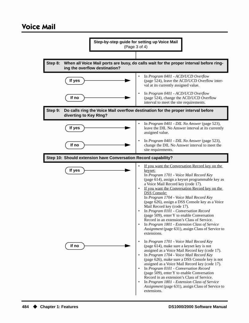
Voice Mail
484 ◆ Chapter 1: Features DS1000/2000 Software Manual
Step 8: When all Voice Mail ports are busy, do calls wait for the proper interval before ring-ing the overflow destination?
• In Program 0401 - ACD/UCD Overflow (page 524), leave the ACD/UCD Overflow inter-val at its currently assigned value.
• In Program 0401 - ACD/UCD Overflow (page 524), change the ACD/UCD Overflow interval to meet the site requirements.
Step 9: Do calls ring the Voice Mail overflow destination for the proper interval before diverting to Key RIng?
• In Program 0401 - DIL No Answer (page 523), leave the DIL No Answer interval at its currently assigned value.
• In Program 0401 - DIL No Answer (page 523), change the DIL No Answer interval to meet the site requirements.
Step 10: Should extension have Conversation Record capability?
• If you want the Conversation Record key on the keyset:In Program 1701 - Voice Mail Record Key (page 614), assign a keyset programmable key as a Voice Mail Record key (code 17).
• If you want the Conversation Record key on the DSS Console:In Program 1704 - Voice Mail Record Key (page 626), assign a DSS Console key as a Voice Mail Record key (code 17).
• In Program 0101 - Conversation Record (page 509), enter Y to enable Conversation Record in an extension’s Class of Service.
• In Program 1801 - Extension Class of Service Assignment (page 631), assign Class of Service to extensions.
• In Program 1701 - Voice Mail Record Key (page 614), make sure a keyset key is not assigned as a Voice Mail Record key (code 17).
• In Program 1704 - Voice Mail Record Key (page 626), make sure a DSS Console key is not assigned as a Voice Mail Record key (code 17).
• In Program 0101 - Conversation Record (page 509), enter Y to enable Conversation Record in an extension’s Class of Service.
• In Program 1801 - Extension Class of Service Assignment (page 631), assign Class of Service to extensions.
Step-by-step guide for setting up Voice Mail (Page 3 of 4)
If yes
If no
If yes
If no
If yes
If no

Voice Mail
DS1000/2000 Software Manual Chapter 1: Features ◆ 485
Step 11: Should extension have access to a Message Center?
• If you want the Message Center key on the key-set:In Program 1701 - Message Center Key (page 615), assign a keyset programmable key as a Message Center key (code 24). You must also enter the Message Center mailbox number. The Message Center can be an installed or uninstalled extension, but must be in the system’s number plan (e.g., 300-379 in U Slot).
• If you want the Message Center key on the DSS Console:In Program 1704 - Message Center Key (page 627), assign a DSS Console key as a Mes-sage Center key (code 24). You must also enter the Mesage Center mailbox number. The Mes-sage Center can be an installed or uninstalled extension, but must be in the system’s number plan (e.g., 300-379 in U Slot).
• In Program 1701 - Message Center Key (page 615), make sure a keyset key is not assigned as a Message Center key (code 24).
• In Program 1704 - Message Center Key (page 627), make sure a DSS Console key is not assigned as a Message Center key (code 22).
Step-by-step guide for setting up Voice Mail (Page 4 of 4)
If yes
If no
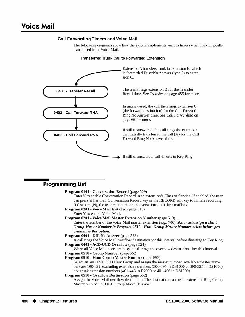
Voice Mail
486 ◆ Chapter 1: Features DS1000/2000 Software Manual
Call Forwarding Timers and Voice MailThe following diagrams show how the system implements various timers when handling calls transferred from Voice Mail.
Transferred Trunk Call to Forwarded Extension
Programming ListProgram 0101 - Conversation Record (page 509)
Enter Y to enable Conversation Record in an extension’s Class of Service. If enabled, the user can press either their Conversation Record key or the RECORD soft key to initiate recording. If disabled (N), the user cannot record conversations into their mailbox.
Program 0201 - Voice Mail Installed (page 513)Enter Y to enable Voice Mail.
Program 0201 - Voice Mail Master Extension Number (page 513)Enter the number of the Voice Mail master extension (e.g., 700). You must assign a Hunt Group Master Number in Program 0510 - Hunt Group Master Number below before pro-gramming this option.
Program 0401 - DIL No Answer (page 523)A call rings the Voice Mail overflow destination for this interval before diverting to Key Ring.
Program 0401 - ACD/UCD Overflow (page 524)When all Voice Mail ports are busy, a call rings the overflow destination after this interval.
Program 0510 - Group Number (page 552)Program 0510 - Hunt Group Master Number (page 552)
Select an available UCD Hunt Group and assign the master number. Available master num-bers are 100-899, excluding extension nuumbers (300-395 in DS1000 or 300-325 in DS1000) and trunk extension numbers (401-448 in D2000 or 401-406 in DS1000).
Program 0510 - Overflow Destination (page 552)Assign the Voice Mail overflow destination. The destination can be an extension, Ring Group Master Number, or UCD Group Master Number
0401 - Transfer Recall
0403 - Call Forward RNA
The trunk rings extension B for the Transfer Recall time. See Transfer on page 455 for more.
Extension A transfers trunk to extension B, which is forwarded Busy/No Answer (type 2) to exten-sion C.
In unanswered, the call then rings extension C (the forward destination) for the Call Forward Ring No Answer time. See Call Forwarding on page 66 for more.
If still unanswered, call diverts to Key Ring
0403 - Call Forward RNAIf still unanswered, the call rings the extension that initially transferred the call (A) for the Call Forward Ring No Answer time.

Voice Mail
DS1000/2000 Software Manual Chapter 1: Features ◆ 487
Program 1003 - Direct Termination (Day) (page 593)To have the Voice Mail Automated Attendant answer the trunk in the day or at night, assign the Voice Mail master number (e.g., 700) as the day termination.
Program 1003 - Direct Termination (Night) (page 594)To have the Voice Mail Automated Attendant answer the trunk at night (if it has a different ter-mination in the day), assign the Voice Mail Master number (e.g., 700) as the night termination. If the day termination above is the Voice Mail master, the system ignores the assignment in this program.
Program 1701 - Voice Mail Record Key (page 614)Assign a programmable key on an extension as a Voice Mail Record key (code 17).
Program 1701 - Night Key (page 615)Set up a System Mode UCD Master key to be able to control the night mode of a DIL termi-nated to Voice Mail during the day.
Program 1701 - Message Center Key (page 615)Assign a programmable key as a Voice Mail Message Center key (code 24). The option is the extension number assigned as the Message Center. The Message Center can be an installed or uninstalled extension, but must be in the system’s number plan (e.g., 300-379 in U Slot).
Program 1704 - Voice Mail Record Key (page 626)Assign a programmable key on an extension as a Voice Mail Record key (code 17).
Program 1704 - Night Key (page 626)Set up a System Mode UCD Master key to be able to control the night mode of a DIL termi-nated to Voice Mail during the day.
Program 1704 - Message Center Key (page 627)Assign a programmable key as a Voice Mail Message Center key (code 24). The option is the extension number assigned as the Message Center. The Message Center can be an installed or uninstalled extension, but must be in the system’s number plan (e.g., 300-379 in U Slot).
Program 1801 - Extension Circuit Type (page 629)Enter 15 for each Voice Mail analog port connected to an ASTU PCB.Enter 21 for each Voice Mail analog port connected to a 2-OPX Module.
Program 1801 - Extension Class of Service Assignment (page 631)Assign Class of Service to extensions.
Program 1802 - Voice Mail Port (page 638)Enter Y for each analog extension connected to Voice Mail.
Program 1807 - Hunt Type (page 653)For each extension designated as a Voice Mail port in Program 1802 - Voice Mail Port (page 638), enter hunt type 05 (for UCD hunting).
Program 1807 - Hunt Master Number (page 653)Enter the extension hunting group master number created for Voice Mail in Program 0510 - Hunt Group Master Number (page 552).
Other Related FeaturesAccount Codes (page 34)
Voice Mail callout features (such as Message Notification) may interact with Account Codes if the callout number contains # characters.
Attendant Position (page 47)
● TRF transfers to the attendant from the Voice Mail Automated Attendant flash the Opera-tor Call key and the Ring Indicator lamp. The call does not flash a line/loop key. (Note that Ringing Line Preference will not pick up a call ringing the attendant’s Call Queue key.)
● UTRF transfers to the attendant from the Voice Mail Automated Attendant flash the trunk’s line/loop key and the Ring Indicator lamp.
Call Forwarding (page 66)You can forward calls Voice Mail.
Caller ID (page 82)Caller ID fully integrates with NVM-Series Voice Mail systems.

Voice Mail
488 ◆ Chapter 1: Features DS1000/2000 Software Manual
Direct Inward Line (page 133)
● The Voice Mail Automated Attendant will answer a DIL terminated to the Voice Mail Master Number.
● If a DIL is terminated to the Voice Mail master number, a System Mode key (code 18 + the Voice Mail number) controls the night mode status of the DIL.
Direct Station Selection (DSS) Console (page 143)A DSS Console can have Voice Mail Record and Message Center keys.
Extension Hunting (page 193)
● To set up extension overflow to Voice Mail:- In Program 1807 - Hunt Type on page 653, enter Hunt Type 3.- In Program 1807 - Hunt Destination on page 653, designate the Voice Mail master number as the Hunt Destination.Unanswered calls, in addition to calls to the extension while it is busy or in DND, route the the extension’s mailbox.
● For Terminal and Circular Hunting, unsupervised transfers (UTRF) from the Voice Mail Automated Attendant route like trunk calls. Supervised transfers (TRF) from the Voice Mail Automated Attendant route like Intercom calls. In either case, unanswered calls even-tually route the initially called extension’s mailbox.
● (DS2000 02.00.01 or higher and DS1000 Only)When an extension user with Ring No Answer/Busy Terminal Hunting to Voice Mail parks a call at a co-worker’s extension, the call recalls to them if not picked up. If still unan-swered, the call diverts to Key Ring. (In prior DS2000 versions, the call would route to Voice Mail.)
Message Waiting (page 291)A system can have either Voice Mail or Message Waiting activated — not both.
Ringdown Extension (page 368)If the Ringdown destination is the Voice Mail master number, the Ringdown Extension user hears the Voice Mail main greeting (“Please enter your mailbox number”) after the call connects.
Feature Operation
Calling Your Mailbox
To call your mailbox:
Your Voice Mail key flashes fast when you have new messages in your mailbox. Your display shows the number of new messages in your mailbox.
1. Press ICM.
2. Press MW.OR
Dial Voice Mail master number (e.g., 700) followed by your mailbox number.Your mailbox number is normally the same as your extension number. You may option-
ally dial a co-worker’s mailbox – or use this procedure to call your mailbox from a co-worker’s phone.
3. If requested by Voice Mail, enter your security code.Your MW LED goes out.
Dial tone.
ICM and SPK on.
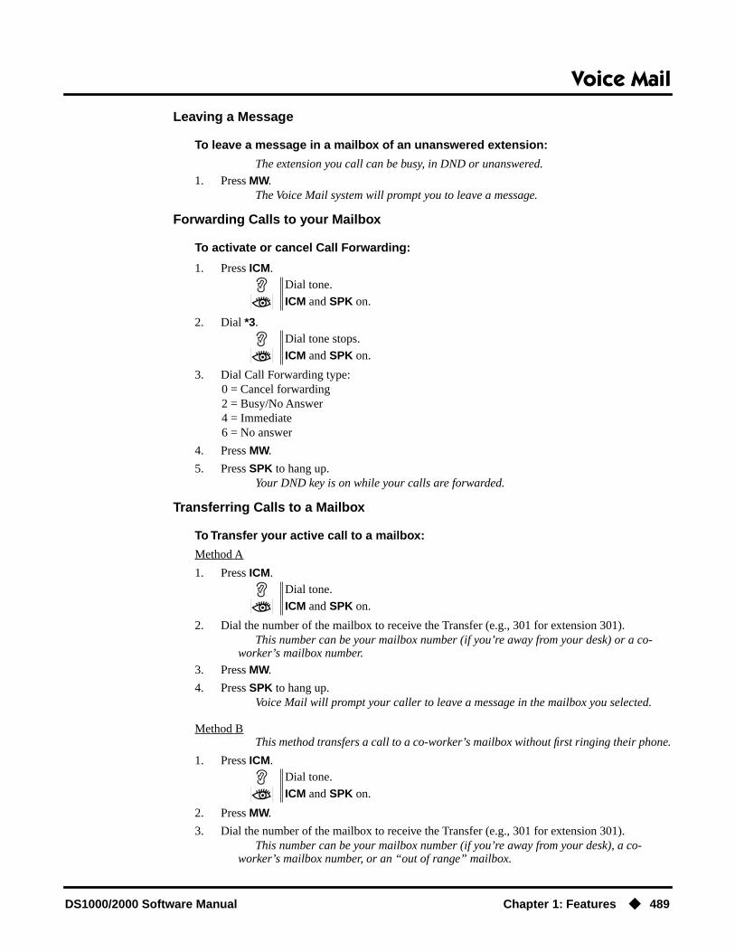
Voice Mail
DS1000/2000 Software Manual Chapter 1: Features ◆ 489
Leaving a Message
To leave a message in a mailbox of an unanswered extension:
The extension you call can be busy, in DND or unanswered.
1. Press MW.The Voice Mail system will prompt you to leave a message.
Forwarding Calls to your Mailbox
To activate or cancel Call Forwarding:
1. Press ICM.
2. Dial *3.
3. Dial Call Forwarding type:0 = Cancel forwarding2 = Busy/No Answer4 = Immediate6 = No answer
4. Press MW.
5. Press SPK to hang up.Your DND key is on while your calls are forwarded.
Transferring Calls to a Mailbox
To Transfer your active call to a mailbox:
Method A
1. Press ICM.
2. Dial the number of the mailbox to receive the Transfer (e.g., 301 for extension 301).This number can be your mailbox number (if you’re away from your desk) or a co-
worker’s mailbox number.
3. Press MW.
4. Press SPK to hang up.Voice Mail will prompt your caller to leave a message in the mailbox you selected.
Method BThis method transfers a call to a co-worker’s mailbox without first ringing their phone.
1. Press ICM.
2. Press MW.
3. Dial the number of the mailbox to receive the Transfer (e.g., 301 for extension 301).This number can be your mailbox number (if you’re away from your desk), a co-
worker’s mailbox number, or an “out of range” mailbox.
Dial tone.
ICM and SPK on.
Dial tone stops.
ICM and SPK on.
Dial tone.
ICM and SPK on.
Dial tone.
ICM and SPK on.

Voice Mail
490 ◆ Chapter 1: Features DS1000/2000 Software Manual
4. Press SPK to hang up.Voice Mail will prompt your caller to leave a message in the mailbox you selected.
Method C
1. Press ICM.
2. Press DSS key for co-worker’s extension + MW.
3. Press SPK to hang up.Voice Mail will prompt your caller to leave a message in the mailbox you selected.
Method D
1. Press keyset or DSS Console Hotline or Call Coverage key.
2. Press MW.
3. Press SPK to hang up.Voice Mail will prompt your caller to leave a message in the mailbox you selected.
Recording your call
To record your active call in your mailbox:
Only one party on a call can use Conversation Record at any one time. This includes Intercom calls and Conference calls.
1. Press Voice Mail Record key or RECORD soft key.The key lights green while the system calls your mailbox. Once recording begins, the
key flashes fast you and your caller hear the voice prompt “Recording.”You can also have a Record key on your DSS Console. It lights red while the system
calls your mailbox and flashes fast once recording begins.
To turn coversation record off:
1. Press Voice Mail Record key or line key for your active call.Recording stops. The capability to press a line key to stop recording requires software
version 02.01.07 or higher.
Dial tone.
ICM and SPK on.
Dial tone.
ICM and SPK on.

Voice Mail
DS1000/2000 Software Manual Chapter 1: Features ◆ 491
Personal Answering Machine Emulation
To activate Answering Machine Emulation:
1. Press ICM.
2. Dial *3.
3. Dial 7.
4. Dial Answering Machine Emulation option (2 or hang up to forward all calls, 8 to forward just trunk calls).
5. Press SPK to hang up.
To cancel Answering Machine Emulation:
1. Press ICM.
2. Dial *30.
3. Press SPK to hang up.
When Answering Machine Emulation broadcasts your caller’s message, you can:
● Do nothing to have the caller’s message automatically recorded in your mailbox,
● Lift the handset to intercept the call and speak to your caller.
Checking Your Messages
To check your messages:
1. Press MW.You see: Number of MSG = n (where n is the number of new messages in your mail-
box).
Dial tone.
ICM and SPK on.
Dial tone stops.
ICM and SPK on.
Dial tone.
ICM and SPK on.
Dial tone.
ICM and SPK on.
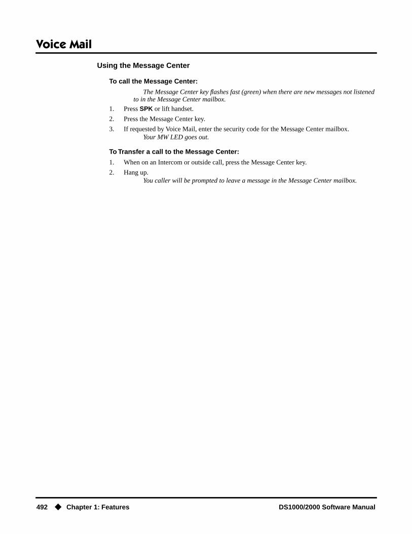
Voice Mail
492 ◆ Chapter 1: Features DS1000/2000 Software Manual
Using the Message Center
To call the Message Center:
The Message Center key flashes fast (green) when there are new messages not listened to in the Message Center mailbox.
1. Press SPK or lift handset.
2. Press the Message Center key.
3. If requested by Voice Mail, enter the security code for the Message Center mailbox.Your MW LED goes out.
To Transfer a call to the Message Center:
1. When on an Intercom or outside call, press the Message Center key.
2. Hang up.You caller will be prompted to leave a message in the Message Center mailbox.

Voice Over
DS1000/2000 Software Manual Chapter 1: Features ◆ 493
Voice Over
Description
Voice Over lets a user get through to a keyset extension user busy on a handset call. With Voice Over, the busy keyset extension user hears an alert tone followed by the voice of the interrupting party. The keyset extension user can respond to the interrupting party without being heard by the original caller. If desired, the keyset extension user can easily switch between their original caller and the interrupting co-worker. The original caller and the interrupting party can never hear each other’s conversation.
Voice Over could help a lawyer, for example, waiting for an urgent call. While on a call with another client, the lawyer’s paralegal could announce the urgent call as soon as it comes in. The lawyer could then give the paralegal instructions on how to handle the situation — all without the original client hearing the conversation.
Either a keyset or SLT can initiate a Voice Over, but only a keyset can receive a Voice Over.
Voice Over uses a system Converence circuit. The following table shows the system’s Conference capacities:
The system’s 32 Conference circuits are dynamically allocated as users request them.
ConditionsNone
Default SettingDisabled
DS2000 Fixed Slot
Available.DS2000 U Slot
DS1000
Get through to a co-worker busy on a handset call — without interrupting their call.
Description Capacity
Conference circuits 32
Maximum simultaneous users in Conference(total of all Conferences system-wide)
32
Maximum simultaneous conferences 8
Maximum parties in any one Conference(trunks and/or extensions)
8

Voice Over
494 ◆ Chapter 1: Features DS1000/2000 Software Manual
Programming Guide
Programming ListProgram 1802 - Off-Hook Signaling for Intercom Calls (page 635)
Enter 3 for each extension that should be able to receive Voice Over.Program 1802 - Off-Hook Signaling for Hotline Partner (page 635)
Enter 3 for each extension that should be able to receive Voice Over when their Hotline part-ner presses their Hotline key.
Other Related FeaturesCall Coverage Keys (page 62)
An extension can Voice Over after calling a co-worker by pressing their Call Coverage key.Conference (page 124)
An extension user cannot Voice Over to a co-worker busy on a Conference call.Direct Station Selection (DSS) (page 140)
An extension can Voice Over after using Direct Station Selection to call a co-worker.Headset Compatibility (page 232)
An extension user cannot Voice Over to a co-worker in the headset mode.Hotline (page 240)
An extension can Voice Over after calling a co-worker by pressing their Hotline key.Intercom (page 268)
An extension user can Voice Over to a co-worker busy on an Intercom call.Message Waiting (page 291)
An extension user cannot leave a Message Waiting after using Voice Over.Off-Hook Signaling (page 313)
When a user is busy on a call, Off-Hook Signaling indicates that another caller is trying to get through.
Step-by-step guide for setting up Voice Over
Step 1: When an Intercom call is waiting, should extension be able to receive a Voice Over?
• In Program 1802 - Off-Hook Signaling for Inter-com Calls (page 635), enter 3.
• In Program 1802 - Off-Hook Signaling for Inter-com Calls (page 635), 0 for no Off-Hook Signal-ing or 1 for Camp-On beeps.
Step 2: When an Intercom call from their Hotline partner’s Hotline key is waiting, should extension be able to receive a Voice Over?
• In Program 1802 - Off-Hook Signaling for Hot-line Partner (page 635), enter 3.
• In Program 1802 - Off-Hook Signaling for Hot-line Partner (page 635), 0 for no Off-Hook Sig-naling or 1 for Camp-On beeps.
If yes
If no
If yes
If no

Voice Over
DS1000/2000 Software Manual Chapter 1: Features ◆ 495
Single Line Telephones (page 381)An SLT can initiate a Voice Over but cannot receive a Voice Over.
Speed Dial (page 383)An extension user can Voice Over after calling a co-worker by using Personal Speed Dial.
Transfer (page 455)An extension user can Voice Over after making a Screened Transfer and hearing busy/ring tone.
Feature Operation
To initiate a Voice Over to a busy extension:
You can only leave a Voice Over if you hear busy/ring tone.
1. Dial 9.
To respond to a Voice Over alert tone to your extension:
1. Press and hold MIC.Release MIC to talk to your initial caller. You can repeat this procedure as long as the
Voice Over initiator doesn’t hang up.
Two beeps, then you can speak with your co-worker.
N/A
Two beeps while on a handset call.
N/A.

Volume Controls
496 ◆ Chapter 1: Features DS1000/2000 Software Manual
Volume Controls
Description
A keyset user can press VOL ▲ and VOL ▼ to adjust the volume of the following features while they are active. Note that the categories grouped together are the same control. For example, adjust-ing Intercom ringing also adjusts trunk ringing.
● Incoming Intercom and trunk ringing1 2
● Background Music, Paging, Handsfree speaker, and incoming Intercom voice announcements broadcast through your telephone speaker1
● Handset/headset receiver volume and incoming Voice Over announcements1
● Off Hook Ringing1 2
1These features retain the volume levels set by the keyset user.2These features retain the user-set volume levels after a system reset or power-down.
There are six steps in the Volume Control adjustment range. This makes it easier for the keyset user to set up just the right volume levels.
Enhanced Volume and Contrast Control(Software version 02.02.14 or higher)
Volume ControlEnhanced Volume/Contrast control provides individual controls for:
● Intercom handset calls
● Intercom Handsfree calls
● Trunk handset calls
● Trunk Handsfree calls
● Paging receive volume
● Background Music
● Ringing
● Off-Hook Ringing
There are seven user-selectable values for each setting, and each of these settings is “remembered” by the system. In the event of a power down or system reset, each setting is automatically restored. The user can set the volume while the feature is active or by using the Volume Control Soft Key Menu (see Operation below).
Contrast ControlWhile a 22-Button or 34-Button Display Telephone is idle, pressing Vol ▲ or Vol ▼ adjusts the con-trast of the display. There are seven user-selectable contrast control values. The value a user sets is “remembered” by the system and automatically restored in the event of a power down or system reset. Contrast Control is not available in Super Display Telephones.
DS2000 Fixed Slot Available.
DS2000 U Slot Enhanced Volume and Contrast Control requires software version 02.02.14 or higher.DS1000
Easily adjust the volume of ringing, Paging and other features.

Volume Controls
DS1000/2000 Software Manual Chapter 1: Features ◆ 497
ConditionsNone
Default SettingEnabled
Programming List(Software version 02.02.14 or higher)Program 1802 - Retain Trunk Volume Setting (page 637)
If this option is enabled (Y), the system remembers the user-set handset and Handsfree vol-ume for each trunk call. If disabled (N), the system uses a median handset and Handsfree vol-ume setting each time the user places a trunk call.
Other Related FeaturesAlphanumeric Display (page 43)
While the telephone is idle, pressing VOL ▲ and VOL ▼ adjusts the contrast of the 22-Button and 34-Button telephone display. Note that 34-Button Super Display telephones do not pro-vide a contrast adjustment. A system reset or power down returns the user-set contrast setting to a median level.
Call Waiting / Camp-On (page 75)The extension user cannot adjust the volume of incoming Camp On tone.
Intercom (page 268)The default Intercom (station-to-station) gain is 0 dB. While on an Intercom call, use VOL ▲ and VOL ▼ to change this setting.
Feature Operation
To adjust the volume of a feature while it is active:
While your keyset is idle, pressing VOL ▲ and VOL ▼ adjusts the display contrast.
1. Press VOL ▲ and VOL ▼.
Enhanced Volume and Contrast Control Operation
22-Button and 34-Button Display Telephone Volume Control Soft Key Menu
To adjust the ringing, off-hook ringing or incoming Page volume:
1. Press PGM + MORE + VOL. You see:
2. Press the key for the type of volume you want to adjust (i.e., ringing, off-hook ringing, or incoming Page). You see (ringing shown):
3. Press Vol Up or Vol Down to adjust the selected volume.

Volume Controls
498 ◆ Chapter 1: Features DS1000/2000 Software Manual
- The number to the right of the display indicates the current setting (1-7).
Super Display Telephone Volume Control Soft Key Menu
To adjust the ringing, off-hook ringing or incoming Page volume:
1. Press PROGRAM + VOLUME. You see:
2. Press the key for the type of volume you want to adjust (i.e., ringing, off-hook ringing, or incoming page). You see (ringing shown):
3. Press Vol Up or Vol Down to adjust the selected volume.- The number to the right of the display indicates the current setting (1-7).
22-Button and 34-Button Display Telephone Contrast Control Soft Key Menu
To adjust the display contrast:
● While your telephone is idle, press Vol Up or Vol Down. You see:
- If you see BGM VOL instead, your phone is in the Background Music mode. Press HOLD and try again.- Contrast control is not available on Super Display telephones.

Year 2000 Compliance
DS1000/2000 Software Manual Chapter 1: Features ◆ 499
Year 2000 Compliance
Description
The system provides Year 2000 Compliance. The change of the date from one century to the next is handled by the system software and is no different than the change from one year to the next. The day following 12/31/1999 will be 01/01/2000. The system will process the leap year correctly and will not require an upgrade or reprogramming. In addition, the SMDR report will properly show the years in the 21st century.
ConditionsNone
Default SettingYear 2000 Compliance always enabled.
Programming ListNone
Other Related FeaturesStation Message Detail Recording (page 400)
The SMDR report displays four digits for the year (i.e., 2000, 2001).Time and Date (page 437)
The system is fully Y2K (year 2000) compliant. The year always displays as four digits and the system correctly recognizes leap years.
Feature OperationNone
DS2000 Fixed Slot
Available.DS2000 U Slot
DS1000
The system is fully Y2K (Year 2000) compliant.

Year 2000 Compliance
500 ◆ Chapter 1: Features DS1000/2000 Software Manual

Introduction to Programming
DS1000/2000 Software Manual Chapter 2: Programming ◆ 501
Chapter 2
Programming
Introduction to Programming
Before You Start Programming
Before You Start Programming
Before Reading This SectionThis section provides you with detailed information about the system programs. By changing a pro-gram, you change the way the feature associated with that program works. In this section, you find out about each program, the features that the program affects and how to enter the program data into system memory.
When you want to customize a feature, find it in Section 1 and learn about it. (If you have trouble finding the feature, try cross-referencing it in the Index at the back of this book.) Section 1 will tell you what programs you have to change to get the operation you want. Then, look the program up in this section if you have any questions about how to enter the data.
How to Use This SectionThis section lists each program in numerical order. For example, Program 0101 is at the beginning of the section and Program 9905 is at the end. The information on each program is subdivided into the following headings:
DescriptionDescription tells what the program is. Along with the Description are the Conditions which describe any limits or special considerations that may apply to the program. get an overview of the feature. For the Default Settings of each programmable option, refer to the information provided with each program. When you first install the system, it uses the Default Setting for all programs.
In each program description there are is a Software History icon which summarizes how the pro-gram works with different system software levels:
Do not start customizing your system without first reading Section 1, Features.

Introduction to ProgrammingBefore You Start Programming
502 ◆ Chapter 2: Programming DS1000/2000 Software Manual
Telephone Programming InstructionsTelephone Programming Instructions shows you how to enter the program’s data into system mem-ory. For example:
1. Enter the programming mode.
2. 0101 + HOLD
tells you to enter the programming mode, dial 0101 from the telephone dial pad and then press the HOLD key. After you do, you’ll see the message “COS NUM?xx” on the telephone display. To learn how to enter the programming mode, see How to Enter the Programming Mode below.
How to Enter the Programming Mode
To enter the programming mode:
1. Go to any working display telephone.In a newly installed system, use extension 300 (port 1).
2. Do not lift the handset.
3. Press ICM.
4. # * # *
5. Dial the system password + HOLDRefer to the following table for the default system passwords.
To change the passwords, use Program 9905 - Password on page 669.
This is the Software History icon. Since NEC America is constantly enhancing your system, all options may not be available in all software levels. Read this text to find out the specifics.
0101:CLASS OF SERVICCOS NUM?XX
LCCPU VER nn.nn.nnEnter Password:
Table 17: Password Levels
Password Level Password Level
System Administrator 1 0000 1
System Administrator 2 9999 2
Installer 372000 3
USER: nnnENTER PROGRAM?

Introduction to ProgrammingBefore You Start Programming
DS1000/2000 Software Manual Chapter 2: Programming ◆ 503
How to Exit the Programming Mode
To exit the programming mode:
1. When you see:
OR
Press and release the hookswitch,.OR
Press SPK.If you don’t see one of the above prompts, press CONF until you do.When you exit programming, the system automatically stores your entries in Random
Access Memory (RAM).
Using Keys to Move Around in the ProgramsOnce you enter the programming mode, use the keys in the following chart to enter data, edit data and move around in the menus.
Logging On with this Password: Gives you access to these programs:
System Administrator 1 (level 1)Password = 0000
Program 0302 - System Identification (page 519)Program 1101 - System Speed Dial Numbers (page 599)
System Administrator 2 (level 1)Password = 9999
Program 0302 - System Identification (page 519)Program 0801 - Selectable Display Messages (page 579)Program 1101 - System Speed Dial Numbers (page 599)Program 1701 - Programmable Function Key Assign-
ments (page 612)Program 1702 - Personal Speed Dial (page 618)Program 1703 - DSS Key Assignment (page 620)
Program 1704 - DSS Console Key Assignment (page 622) (U Slot only)
Installer (level 3)Password - 372000
All
USER: nnnENTER PROGRAM?
nnnnn VER nn.nn.nnPASSWORD:
Table 18: Keys for Entering Data
Use this key: When you want to:
0-9, # and * Enter data into the program.

Introduction to ProgrammingBefore You Start Programming
504 ◆ Chapter 2: Programming DS1000/2000 Software Manual
Connecting a PC or PrinterRefer to your system’s Hardware Manual or the DS1000 Quick Setup Guide.
HOLD Complete the programming step you just made (like pressing Enter on a PC keyboard). When a program entry displays, press HOLD to accept the entry (i.e., bypass the entry without chang-ing it).
CONF Complete the programming step you just made (like pressing Enter on a PC keyboard) and back up one step in the program.
LND Delete the entry to the left (like pressing Backspace on a PC keyboard.
To delete an entire name entry (without backspacing over each letter), just reenter the name without pressing LND first.
CLEAR Erase the entire command line you just entered and undefine the entry. In many cases, this changes a Yes entry to No.
CHECK Erase the entry you just made and replace it with the prior stored entry.
VOL ▲ Scroll forward through a list of entries in a program. If you enter data and then press this key, the system accepts the data before scrolling forward to the next entry.
VOL ▼ Scroll backward through a list of entries in a program. If you enter data and then press this key, the system accepts the data before scrolling backward to the previous entry.
ICM Enable the scroll mode. When you press this key and it lights, you can then press VOL ▲ and VOL ▼ to scroll through the options. To choose the displayed value, press HOLD.
Table 18: Keys for Entering Data
Use this key: When you want to:

Introduction to ProgrammingBefore You Start Programming
DS1000/2000 Software Manual Chapter 2: Programming ◆ 505
Programming Names and Text MessagesSeveral programs reference require you to enter text. Use the following chart when entering and editing text.
Table 19: Keys for Entering Names
Keys for Entering Names
Press this key:
Then one of these keys to enter the character in the white cell:
1 2 3 4 #
1 & - (dash)1 / (backslash)1 ‘(apostrophe)1 1
2 A B C 2
3 D E F 3
4 G H I 4
5 J K L 5
6 M N O 6
7 P Q R S 7
8 T U V 8
9 W X Y Z 9
0 SPACE : 0
* *
#
To enter characters in lower case (e.g., e instead of E), press MW before pressing the key in the first shaded column. Use LND to backspace over (erase) any characters you want to correct.1In software versions prior to 02.00.00, the codes for 1 + 2, 1 + 3, and 1 + 4 were not available.

0100 - Class of Service0101 - Class of Service Options
506 ◆ Chapter 2: Programming DS1000/2000 Software Manual
0100 - Class of Service
0101 - Class of Service Options
Description
Use Program 0101- Class of Service Programming to set up the Class of Service options. The system has 15 Classes of Service, numbered 1-15. You assign Classes of Service to extensions in Program 1801: Extension Class of Service Assignment on page 631. Many extensions can have the same Class of Service. Class of Service 1 is normally reserved for the attendant (port 1).
Note: If you are doing extensive programming, you may find Program 9801 - Copy Command (page 657) saves you time when customizing this option.
ConditionsNone
DS2000 Fixed Slot Available.
DS2000 U Slot Enables the following options:• CLID Display• 2nd Call CLID (Extension Level Call Waiting Caller ID)• 3rd Party Caller ID
DS1000
Table 20: Program 0101 - Class of Service Options
Option Description Entries Default
Off-Premise Call Forward • This option is not used. OFF PREM FWRD?Y = EnableN = Disable
N
Barge-In (Intrusion) Use this option to enable or disable an exten-sion’s ability to Barge In on a co-worker.• See Barge In (Intrusion) on page 58 for
more.
BREAK-IN?Y = EnableN = Disable
COS 1 = YCOS 2-15 = N
Camp-On to Busy Extension
Use this option to enable or disable an exten-sion’s ability to Camp-On to a busy exten-sion. Enter Y to allow the extension to Camp-On to a busy co-worker. Enter N to prevent the extension from Camping-On to a busy co-worker. Entering N also automati-cally converts an extension’s Camp On to Callback.• See Call Waiting / Camp-On on page 75
for more.• See Callback on page 79 for more.
CAMP-ON BUSY EXT?Y = EnableN = Disable
Y
Internal Call Forwarding Use this option to enable or disable an exten-sion’s ability to use Internal Call Forward-ing. • See Call Forwarding on page 66 for
more.
CALL FORWARDING?Y = EnableN = Disable
Y
System Speed Dial Access
Use this option to enable or disable an exten-sion’s ability to access System Speed Dial. • See System Speed Dial on page 383 for
more.
SYS SPDL ACCESS?Y = EnableN = Disable
Y

0100 - Class of Service0101 - Class of Service Options
DS1000/2000 Software Manual Chapter 2: Programming ◆ 507
Extended Ring Use this option to enable or disable Extended Ringing at the extension.• See Extended Ringing on page 191 for
more.
EXTENDED RING?Y = EnabledN = Disable
N
Privacy Use this option to enable or disable Privacy at the extension.• See Privacy on page 345 for more.
PRIVACY?Y = EnableN = Disable
N
Trunk (Line) Queuing Priority
Use this option to enable or disable Trunk (Line) Queuing Priority at the extension. If more than one extension with Priority is queued on a busy trunk, the system services the Priority extensions on a first-queued, first-served basis.• See Trunk Queuing Priority on page 465
for more.
LINE Q PRIORITY?Y = EnableN = Disable
N
Forced Trunk Disconnect Use this option to enable or disable an exten-sion’s ability to use Forced Trunk Discon-nect.• See Forced Trunk Disconnect on
page 212 for more.
FORCEDISCONNECT?
Y = EnableN = Disable
COS 1 = YCOS 2-15 = N
Camp-On to Busy Line Use this option to enable or disable an exten-sion’s ability to Camp-On to a busy trunk.• See Trunk (Line) Queuing / Trunk Call-
back on page 465 for more.
CAMP ON TO LINES?Y = EnableN = Disable
COS 1 = YCOS 2-15 = N
Initiate All Call Page Use this option to enable or disable an exten-sion’s ability to make an All Call Paging announcement.• See Paging on page 326 for more.
PAGE ALL CALL?Y = EnableN = Disable
Y
Access Page Zone 1 Use this option to enable or disable an exten-sion’s ability to make a Paging announce-ment into zone 1.• See Paging on page 326 for more.
PAGE ZONE 1?Y = EnableN = Disable
Y
Access Page Zone 2 Use this option to enable or disable an exten-sion’s ability to make a Paging announce-ment into zone 2.• See Paging on page 326 for more.
PAGE ZONE 2?Y = EnableN = Disable
Y
Access Page Zone 3 Use this option to enable or disable an exten-sion’s ability to make a Paging announce-ment into zone 3.• See Paging on page 326 for more.
PAGE ZONE 3?Y = EnableN = Disable
Y
Access Page Zone 4 Use this option to enable or disable an exten-sion’s ability to make a Paging announce-ment into zone 4.• See Paging on page 326 for more.
PAGE ZONE 4?Y = EnableN = Disable
Y
Table 20: Program 0101 - Class of Service Options
Option Description Entries Default

0100 - Class of Service0101 - Class of Service Options
508 ◆ Chapter 2: Programming DS1000/2000 Software Manual
Access Page Zone 5 Use this option to enable or disable an exten-sion’s ability to make a Paging announce-ment into zone 5.• See Paging on page 326 for more.
PAGE ZONE 5?Y = EnableN = Disable
Y
Access Page Zone 6 Use this option to enable or disable an exten-sion’s ability to make a Paging announce-ment into zone 6.• See Paging on page 326 for more.
PAGE ZONE 6?Y = EnableN = Disable
Y
Access Page Zone 7 Use this option to enable or disable an exten-sion’s ability to make a Paging announce-ment into zone 7.• See Paging on page 326 for more.
PAGE ZONE 7?Y = EnableN = Disable
Y
Silent Monitor Use this option to enable or disable an exten-sion’s ability to use Silent Monitor.• See Monitor / Silent Monitor on
page 300 for more.
SILENT MONITOR?Y = EnableN = Disable
N
Flash for Single Line Sets
• This option is not used. FLASH FOR SLT?Y = EnableN = Disable
N
ACD Supervisor • This option is not used. ACD SUPERVISOR?Y = EnableN = Disable
N
Single Ring for Single Line Sets
• Use this option to enable or disable sin-gle ring for single line telephones. This option only apples to single line tele-phones. See Central Office Calls, Answering on page 99 for more.
SINGLE RING?Y = EnableN = Disable
N
View System Alarms • This option is not used. VIEW SYS ALARMS?Y = EnableN = Disable
N
Automatic Hold Use this option to enable or disable Auto-matic Hold at an extension.• See Hold on page 235 for more.
AUTO HOLD?Y = EnableN = Disable
N
Activate Night Mode Use this option to enable or disable an exten-sion’s ability to activate Night Service.• See Night Service / Night Ring on
page 308 for more.
ACTIVATE NITES?Y = EnableN = Disable
COS 1 = YCOS 2-15 = N
Direct Trunk Access Use this option to enable or disable an exten-sion’s ability to use Direct Trunk Access. Note that enabling Direct Trunk Access allows the user to bypass Toll Restriction.• See Central Office Calls, Placing on
page 105 for more.
DIRECT TRK ACCES?Y = EnableN = Disable
COS 1 = YCOS 2-15 = N
Table 20: Program 0101 - Class of Service Options
Option Description Entries Default

0100 - Class of Service0101 - Class of Service Options
DS1000/2000 Software Manual Chapter 2: Programming ◆ 509
Remote Call Forwarding / Alternate Attendant
• This option is not used. REMOTE FWRD?Y = EnableN = Disable
COS 1 = YCOS 2-15 = N
Soft Keys Use this option to enable or disable a display set’s Interactive Soft Keys.• See See Interactive Soft Keys on
page 244 for more.
SOFTKEYSY = EnableN = Disable
Y
Conversation Record Use this option to enable or disable an exten-sion’s ability to record conversations into their Voice Mail mailbox. If enabled, the user can press either their Conversation Record key or RECORD soft key to initiate recording.• See Voice Mail on page 477 for more.
RECORD CONVY = EnableN = Disable
N
CLID Display Use this option to enable or disable Caller ID.• See Caller ID on page 82 for more.
CLID DISPLAY?Y = EnableN = Disable
Y
2nd Call CLID (Extension Level Call Waiting Caller
ID)
Use this option to enable or disable Second Call Caller ID.• See Caller ID on page 82 for more.
2nd CALL CLID?Y = EnableN = Disable
Y
3rd Party Caller ID Use this option to enable or disable Third Party Call Caller ID Check.• See Caller ID on page 82 for more.
3rd PARTY CLID?Y = EnableN = Disable
N
CLID Display Separator Use this option to enable or disable the Caller ID display separator.• See Caller ID on page 82 for more.
‘-’ IN CID DISP?Y = EnableN = Disable
N
Forced Account Codes Use this option to enable or disable Forced Account Codes. disabled, Optional Account Codes are still available.• See Account Codes on page 34 for more.
FORCE AC CODES?Y = EnableN = Disable
N
Verify Account Codes Use this option to enable or disable Verified Account Codes. If enabled, the system com-pares the Account Code the user dials to the entries in 1201 - Verified Account Codes Table on page 601.• See Account Codes on page 34 for more.
VERIFY AC CODES?Y = EnableN = Disable
N
Forced Account Codes for Toll Calls Only
Use this option to enable or disable Forced Account Codes for toll (long distance) calls. If disabled, Forced Account Codes apply to all outgoing trunk codes. • See Account Codes on page 34 for more.
AC FOR TOLL ONLY?Y = EnableN = Disable
N
Table 20: Program 0101 - Class of Service Options
Option Description Entries Default

0100 - Class of Service0101 - Class of Service Options
510 ◆ Chapter 2: Programming DS1000/2000 Software Manual
Ring Type Configuration(Software version 02.02.14
or higher)
Use this option to enable or disable Ring Type Configuration. If enabled, the extension user can customize the sound of their Ring Types by pressing their CONFIG (CNFG) soft key. If disabled, the extension user can-not customize their Ring types and the sys-tem hides the CONFIG (CNFG) soft key.• See Distinctive Ringing on page 162 for
more.
RING TYPE CONFIG?Y = EnableN = Disable
N
Extension Ring Override(Software version 02.02.14
or higher)
Use this option to enable or disable an exten-sions ability to customize the distinctive ringing for Day Ring, Night Ring, and Delay Ring trunk calls on line keys by pressing the ASSIGN (ASGN) soft key. If disabled, the extension cannot customize the distinctive ringing and the system hides the ASSIGN (ASGN) soft key.
If you enable this option, and the user cus-tomizes their Extension Override settings, disabling this option will cancel the user’s custom settings.• See Distinctive Ringing on page 162 for
more.
EXT RING OVRD?Y = EnableN = Disable
N
Key Ring Override(Software version 02.02.14
or higher)
Use this option to enable or disable Key Ring Override. If enabled, this option allows an extension to customize the distinctive ringing of individual Call Coverage, Group Call Pickup, and Line Keys by pressing the KEY soft key. If disabled (N), the extension cannot customize the distinctive ringing. The default setting for this option is disabled (N).
If you enable this option, and the user cus-tomizes their Key Ring Override settings, disabling this option will cancel the user’s custom settings.• See Distinctive Ringing on page 162 for
more.
KEY RING OVRD?Y = EnableN = Disable
N
SLT Special Dial Tone(Software version 02.02.14
or higher)
Use this option to enable or disable SLT Special Dial Tone in a single line port’s Class of Service. (Note that this option has no effect of keyset ports with the same COS.)• See Message Waiting on page 291 for
more.
SLT SP DIALTONE?Y = EnableN = Disable
N
Table 20: Program 0101 - Class of Service Options
Option Description Entries Default

0100 - Class of Service0101 - Class of Service Options
DS1000/2000 Software Manual Chapter 2: Programming ◆ 511
Telephone Programming Instructions1. Enter the programming mode.
2. 0101 + HOLD
3. Dial the Class of Service you want to program (1-15) + HOLD
4. Press VOL ▲ or VOL ▼ to scroll to the option you want to change + HOLD
5. Enter Y or N for displayed option + HOLD
6. Press VOL ▲ or VOL ▼ to scroll to another option.OR
Press HOLD to return to step 3 and select another Class of Service.OR
Press HOLD twice to return to step 2 and enter another program number.
SLT High Voltage Message Waiting
(DS2000 Software version 02.02.14 or higher)
Use this option to enable or disable High Voltage Message Waiting for single line ports. High Voltage Message Waiting is not available in DS1000. If both this option and 0101 - SLT FSK Message Waiting are enabled, the system uses FSK Message Waiting.• See Message Waiting on page 291 for
more.
SLT MW LAMP HV?Y = EnableN = Disable
N
SLT FSK Message Waiting
(Software version 02.02.14 or higher)
Use this option to enable or disable FSK Message Waiting for single line ports. If both this option and 0101 - SLT High Volt-age Message Waiting are enabled, the system uses FSK Message Waiting.• See Message Waiting on page 291 for
more.
SLT MW LAMP FSK?Y = EnableN = Disable
N
SLT Loop Disconnect(Software version 02.03.03
or higher)
Use this option to enable or disable the abil-ity of the system to send a loop supervision disconnect signal (i.e., drop pulse) to single line ports. Set this option for compatibility with the connected SLT device. (This option is always disabled for Voice Mail ports.)• See Off-Premise Extensions / On-
Premise SLT Extensions on page 317 for more.
SLT LOOP DISCON?Y = EnableN = Disable
N
0101:CLASS OF SERVICCOS NUM?XX
Table 20: Program 0101 - Class of Service Options
Option Description Entries Default

0200 - Tenant Options0201 - Tenant Option Programming
512 ◆ Chapter 2: Programming DS1000/2000 Software Manual
0200 - Tenant Options
0201 - Tenant Option Programming
Description
Use Program 0201- Tenant Option Programming to set up various options for Tenant Groups.
ConditionsNone
DS2000 Fixed Slot Available.
DS2000 U Slot Available. Version 02.00.04 adds additional relay control options.
DS1000 Available. Relay control available.
Table 21: Program 0201 - Tenant Options
Option Description Entries Default
Call Waiting (Camp-On) Tone
Use this option to enable or disable system wide Call Waiting Tones (double beeps).• See Call Waiting / Camp-On on page 75
for more.
CALL WAIT?Y = EnableN = Disable
Y
Handsfree Reply on Intercom Calls
Use this option to enable or disable system-wide Handsfree Reply for voice-announced Intercom calls. If you enable this option, you must also enable Voice-Announced Intercom Calls below.• See Handsfree and Handsfree Answer-
back on page 228 for more.
HF REPLY ON ICM?Y = EnableN = Disable
Y
Voice-Announced Intercom Calls
Use this option to enable or disable system-wide voice-announced Intercom calls. You must enable this option if you have Hands-free Reply on Intercom Calls enabled above. If you disable this option, extension users can only receive ringing Intercom calls.• See Handsfree and Handsfree Answer-
back on page 228 for more.
VOICE ANNOUNCE?Y = EnableN = Disable
Y
Automatic Handsfree Use this option to enable or disable Auto-matic Handsfree system-wide.• See Automatic Handsfree on page 51 for
more.• See Handsfree and Handsfree Answer-
back on page 228 for more.
AUTO HANDSFREE?Y = EnableN = Disable
Y
Music on Hold Use this option to enable or disable Music on Hold system wide.• See Music on Hold on page 303 for
more.
ENABLE MOH?Y = EnableN = Disable
Y

0200 - Tenant Options0201 - Tenant Option Programming
DS1000/2000 Software Manual Chapter 2: Programming ◆ 513
MOH on Transfer Use this option to enable or disable MOH for transferred calls system-wide. If enabled, transferred callers hear Music on Hold while waiting. If disabled, transferred callers hear ringback.• See Transfer on page 455 for more.
MOH ON TRANSFER?Y = EnableN = Disable
Y
Background Music Use this option to enable or disable Back-ground Music system-wide.• See Background Music on page 55 for
more.
ENBLE BGM?Y = EnableN = Disable
Y
Voice Mail Installed Enable this option if you have an NVM-series Voice Mail system installed. Disable this option if you don’t have Voice Mail installed. If you enable this option, be sure to specify a Voice Mail master extension num-ber in the option below.• See Voice Mail on page 477 for more.
V-MAIL INSTALLED?Y = EnableN = Disable
N
Voice Mail Master Extension Number
Use this option to specify the Voice Mail master extension number. Be sure to make an entry for this item if you enabled the Voice Mail Installed option above. The entry you make must be within the system’s num-ber plan.• You must set the Voice Mail master
number in 0510 - Hunt Group Master Number on page 552 before program-ming this option.
• See Voice Mail on page 477 for more.
V-MAIL MST EXT?nnn (extension number)
000
Enable Account Codes in Speed Dial
(2.01.07 or higher)
Enable (Y) this option if users should be able to store Account Codes in Speed Dial bins. This causes the stored Account Code to properly display in the SMDR report Account column. They do not dial out as part of the stored number.
If you disable (N) this option, Account Codes stored in Speed Dial bins dial out as part of the stored number and display in the SMDR report Number Dialed column.• See Account Codes on page 34 for more.• See Speed Dial on page 383 for more.
AC CODES IN SPDL?Y = EnableN = Disable
N
Table 21: Program 0201 - Tenant Options
Option Description Entries Default
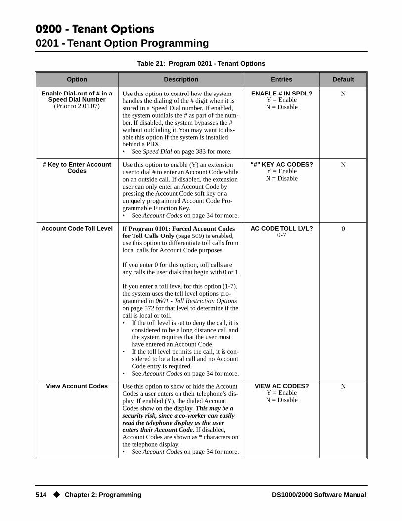
0200 - Tenant Options0201 - Tenant Option Programming
514 ◆ Chapter 2: Programming DS1000/2000 Software Manual
Enable Dial-out of # in a Speed Dial Number
(Prior to 2.01.07)
Use this option to control how the system handles the dialing of the # digit when it is stored in a Speed Dial number. If enabled, the system outdials the # as part of the num-ber. If disabled, the system bypasses the # without outdialing it. You may want to dis-able this option if the system is installed behind a PBX.• See Speed Dial on page 383 for more.
ENABLE # IN SPDL?Y = EnableN = Disable
N
# Key to Enter Account Codes
Use this option to enable (Y) an extension user to dial # to enter an Account Code while on an outside call. If disabled, the extension user can only enter an Account Code by pressing the Account Code soft key or a uniquely programmed Account Code Pro-grammable Function Key.• See Account Codes on page 34 for more.
“#” KEY AC CODES?Y = EnableN = Disable
N
Account Code Toll Level If Program 0101: Forced Account Codes for Toll Calls Only (page 509) is enabled, use this option to differentiate toll calls from local calls for Account Code purposes.
If you enter 0 for this option, toll calls are any calls the user dials that begin with 0 or 1.
If you enter a toll level for this option (1-7), the system uses the toll level options pro-grammed in 0601 - Toll Restriction Options on page 572 for that level to determine if the call is local or toll.• If the toll level is set to deny the call, it is
considered to be a long distance call and the system requires that the user must have entered an Account Code.
• If the toll level permits the call, it is con-sidered to be a local call and no Account Code entry is required.
• See Account Codes on page 34 for more.
AC CODE TOLL LVL?0-7
0
View Account Codes Use this option to show or hide the Account Codes a user enters on their telephone’s dis-play. If enabled (Y), the dialed Account Codes show on the display. This may be a security risk, since a co-worker can easily read the telephone display as the user enters their Account Code. If disabled, Account Codes are shown as * characters on the telephone display.• See Account Codes on page 34 for more.
VIEW AC CODES?Y = EnableN = Disable
N
Table 21: Program 0201 - Tenant Options
Option Description Entries Default

0200 - Tenant Options0201 - Tenant Option Programming
DS1000/2000 Software Manual Chapter 2: Programming ◆ 515
Telephone Programming Instructions1. Enter the programming mode.
2. 0201 + HOLD
3. Enter Y or N for the displayed option.OR
Press VOL ▲ or VOL ▼ to scroll to the option you want to change + HOLD
4. Enter Y or N for displayed option + HOLD
5. Press VOL ▲ or VOL ▼ to scroll to another option.OR
Press HOLD to return to step 2 and enter another program number.
CPRU Relay(DS2000 Only)
Use this option to control the CPRU relay. This relay can activate for a Digital Door Box or External Paging.• See Door Box on page 185 for more.• See Paging on page 326 for more.
CPU RELAY?0 = Not assigned
1 = Door Box relaycontrol
2 = Page Zone control
0 = Not assigned
CPRU Relay Page Zone Assignment
(DS2000 Only)
If the CPRU is assigned to Page Zone con-trol (2) in the previous option, use this option to designate the Page Zone that will activate the relay.• See Paging on page 326 for more.
PAGE ZONE1 = External Paging (zone 1 and All Call)
2-7 = Internal zones 2-7
1(ExternalPaging)
DOOR1 Relay(DS1000 Only)
Use this option to control the relay in the DS1000 DOOR1 jack. This relay can acti-vate for an Analog Door Box or Paging.• See Door Box on page 185 for more.• See Paging on page 326 for more.
DOOR1 RELAY?0 = Not assigned
1 = Analog Door Box relay control
2 = Page Zone control
0 (Not assigned)
DOOR1 Relay Page Zone Assignment
(DS1000 Only)
If the DOOR1 relay is assigned to Page Zone control (2) in the previous option, use this option to designate the Page Zone that will activate the relay.• See Paging on page 326 for more.
PAGE ZONE1 = External Paging (zone 1 and All Call)
2-7 = Internal zones 2-7
1(ExternalPaging)
DOOR2 Relay(DS1000 Only)
Use this option to control the relay in the DS1000 DOOR2 jack. This relay can acti-vate for an Analog Door Box or Paging.• See Door Box on page 185 for more.• See Paging on page 326 for more.
DOOR2 Relay?0 = Not assigned
1 = Analog Door Box relay control
2 = Page Zone control
0 (Not assigned)
DOOR2 Relay Page Zone Assignment
(DS1000 Only)
If the DOOR2 relay is assigned to Page Zone control (2) in the previous option, use this option to designate the Page Zone that will activate the relay.• See Paging on page 326 for more.
PAGE ZONE1 = External Paging (zone 1 and All Call)
2-7 = Internal zones 2-7
1(ExternalPaging)
0101:TENANT OPTIONSCALL WAIT?XX
Table 21: Program 0201 - Tenant Options
Option Description Entries Default

0300 - System Options0301 - System Options (Part 1)
516 ◆ Chapter 2: Programming DS1000/2000 Software Manual
0300 - System Options
0301 - System Options (Part 1)
Description
Use Program 0301- System Options to set up various options system-wide options.
ConditionsNone
DS2000 Fixed Slot Available. Default CPU Baud Rate is 4 (9600).
DS2000 U Slot Available.• In U Slot prior to 02.00.01, the default CPU Baud Rate is 5 (19200).• In U Slot 02.00.01 and higher and DS1000, the default CPU Baud Rate is
4 (19200).DS1000
Table 22: Program 0301 - System Options
Option Description Entries Default
Number of Operators Use this option to set the number of opera-tors (attendants) in the system. The system can have up to four operators.• See Attendant Position on page 47 for
more.
NUM OFOPERATORS?
1-4CLEAR = Undefine all
operators
01
Operator 1 Extension Use this option to assign the 1st operator’s extension number.• See Attendant Position on page 47 for
more.
OPERATOR 1 EXT?Enter any valid extension
number
300
Operator 2 Extension Use this option to assign the 2nd operator’s extension number. Before assigning this option, be sure you have entered the correct number in the Number of Operators option.• See Attendant Position on page 47 for
more.
OPERATOR 2 EXT?Enter any valid extension
number
Undefined
Operator 3 Extension Use this option to assign the 3rd operator’s extension number. Before assigning this option, be sure you have entered the correct number in the Number of Operators option.• See Attendant Position on page 47 for
more.
OPERATOR 3 EXT?Enter any valid extension
number
Undefined
Operator 4 Extension Use this option to assign the 4th operator’s extension number. Before assigning this option, be sure you have entered the correct number in the Number of Operators option.• See Attendant Position on page 47 for
more.
OPERATOR 4 EXT?Enter any valid extension
number
Undefined

0300 - System Options0301 - System Options (Part 1)
DS1000/2000 Software Manual Chapter 2: Programming ◆ 517
Number of Digits in a System Speed Dial Code
Use the option to assign the number of digits the system uses to designate System Speed Dial bins (2, 3 or 4). With 2-digit bins, the system has 10 bins numbered 20-29. With 3-digit bins, the system has 100 bins numbered 200-299. With 4-digit bins, the system as 1000 bins numbered 2000-2999.• See Speed Dial on page 383 for more.
SYS SPDL CODE DGTS?
2 = 2-digit (20-29)3 = 3-digit (200-299)
4 = 4-digit (2000-2999)
3
CPU Baud Rate Use this option to set the speed of the LCCPU PCB RS-232-C port. You may want to connect a PC or SMDR printer to this port.• See Connecting a PC or Printer on
page 504 for more.• See Station Message Detail Recording
on page 400 for more.
1 Available in DS1000 02.00.00 through 02.02.14 only.
BAUD RATE?Fixed Slot and U Slot
prior to 02.00.011 = 12002 = 24003 = 48004 = 96005 = 19200
U Slot 02.00.01 and higher and DS1000
1 = 24002 = 48003 = 96004 = 192005 = 384006 = 576001
7 = 1152001
Fixed Slot4 (9600)
U Slot prior to 02.00.015 (19200)
U Slot 02.00.01 and higher and DS1000
4 (19200)
Fixed Baud Rate Use this option to control the ability of a PC or laptop to change the baud rate of the sys-tem’s RS-232C serial port. If disabled (N), a Ctrl-Break at the connected PC or laptop will toggle to the next available baud rate. If enabled (Y), a Ctrl-Break at the connected PC or laptop will have no effect.• See Station Message Detail Recording
on page 400 for more.
FIXED BAUD RATE?Y (Yes)N (No)
No
SMDR Port Use this option to specify the port the system uses for SMDR.• See Connecting a PC or Printer on
page 504 for more.• See Station Message Detail Recording
on page 400 for more.
SMDR PORT?0 = NONE
1 = CPU Serial Port
0
Print SMDR Header Use this option to include or exclude the header from the SMDR report.• See Connecting a PC or Printer on
page 504 for more.• See Station Message Detail Recording
on page 400 for more.
PRINT SMDR HEADR?Y = Enable headerN = Disable header
Y
Table 22: Program 0301 - System Options
Option Description Entries Default

0300 - System Options0301 - System Options (Part 1)
518 ◆ Chapter 2: Programming DS1000/2000 Software Manual
Telephone Programming Instructions1. Enter the programming mode.
2. 0301 + HOLD
3. Enter Y or N for the displayed option.OR
Press VOL ▲ or VOL ▼ to scroll to the option you want to change + HOLD
4. Enter Y or N for displayed option + HOLD
5. Press VOL ▲ or VOL ▼ to scroll to another option.OR
Press HOLD to return to step 2 and enter another program number.
0301:SYSTEM OPTIONSNUM OF OPERATORS?

0300 - System Options0302 - System Identification
DS1000/2000 Software Manual Chapter 2: Programming ◆ 519
0302 - System Identification
Description
Use Program 0302- System Identification enter information about the system and to set the Time and Date. This information is used in various system reports.
ConditionsNone
DS2000 Fixed Slot
Available.DS2000 U Slot
DS1000
Table 23: Program 0302 - System Identification Options
Option Description Entries Default
Company Name Use this option to enter your company’s name. The name prints in system reports.• See System Identification on page 408
for more.
NAME?24 characters max
(For instructions on entering names. see Keys for Entering Names on
page 505.)
No entry
Company Phone Number Use this option to enter your company’s phone number. This is the number the sys-tem will call to report a problem (not the system’s number). You must enter a trunk access code (9, 9X or #9XX) before the number. For more information about trunk access codes, see Central Office Calls, Plac-ing on page 105.• See System Identification on page 408
for more.
PHONE?24 digits max, using:
0-9, # and *P = Pause
T = Tone DetectionF = FlashD = Delay
No entry
System Type This option displays your system’s type. It shows DS-2000. You cannot edit this option.• See System Identification on page 408
for more.
SYS TYP:Automatically displayed.
DS-2000
Software Version This option displays your system’s software level. It is for viewing only. You cannot edit this option.• See System Identification on page 408
for more.
S/W VER:Automatically displayed.
Depends on software level
Time Use this option to set the system time. Enter data using the 24-hour format HH:MM:SS. For example, 13:00:00 = 1:00 PM. • See Time and Date on page 437 for
more.
TIME?HH:MM:SS
HH = Hours (0-24)MM = Minutes (0-59)
SSS = SecondsEnter in 24-hour format
Current time

0300 - System Options0302 - System Identification
520 ◆ Chapter 2: Programming DS1000/2000 Software Manual
Telephone Programming Instructions1. Enter the programming mode.
2. 0302 + HOLD
3. Enter the system name (up to 14 characters) + VOL ▲.(Refer to Programming Names and Text Messages on page 505 if you need help in entering names)
ORPress VOL ▲ to scroll to the next option.
After pressing VOL ▲ to scroll to the next entry, you can press CONF to exit the pro-gram.
4. Enter the site phone number (up to 14 digits) + VOL ▲.OR
Press VOL ▲ to scroll to the next option.
You cannot edit this entry.
5. Press VOL ▲ to scroll to the next option.
You cannot edit this entry.
6. Press VOL ▲ to scroll to the next option.
7. Enter the system time (HH:MM:SS in 24-hour format) + VOL ▲.OR
Press VOL ▲ to scroll to the next option.
8. Enter the system date (MM:DD:YYYY) + VOL ▲.OR
Press VOL ▲ to scroll to the next option.
Date Use this option to enter the system Time and Date. The system shows Time and Date on telephone displays and in various system reports.• See Time and Date on page 437 for
more.
DATE?MM-DD-YY
MM = Month (1-12)DD = Day (1-31)
YYYY = Year (e.g., 2000)
Current date
0302:SYSTEM IDNAME?
0302:SYSTEM IDPHONE?
0302:SYSTEM IDSYS TYP:DS-1000
0302:SYSTEM IDS/W VER:
0302:SYSTEM IDTIME?
0302:SYSTEM IDDATE?:
Table 23: Program 0302 - System Identification Options
Option Description Entries Default

0300 - System Options0302 - System Identification
DS1000/2000 Software Manual Chapter 2: Programming ◆ 521
ORPress CONF to exit the program.
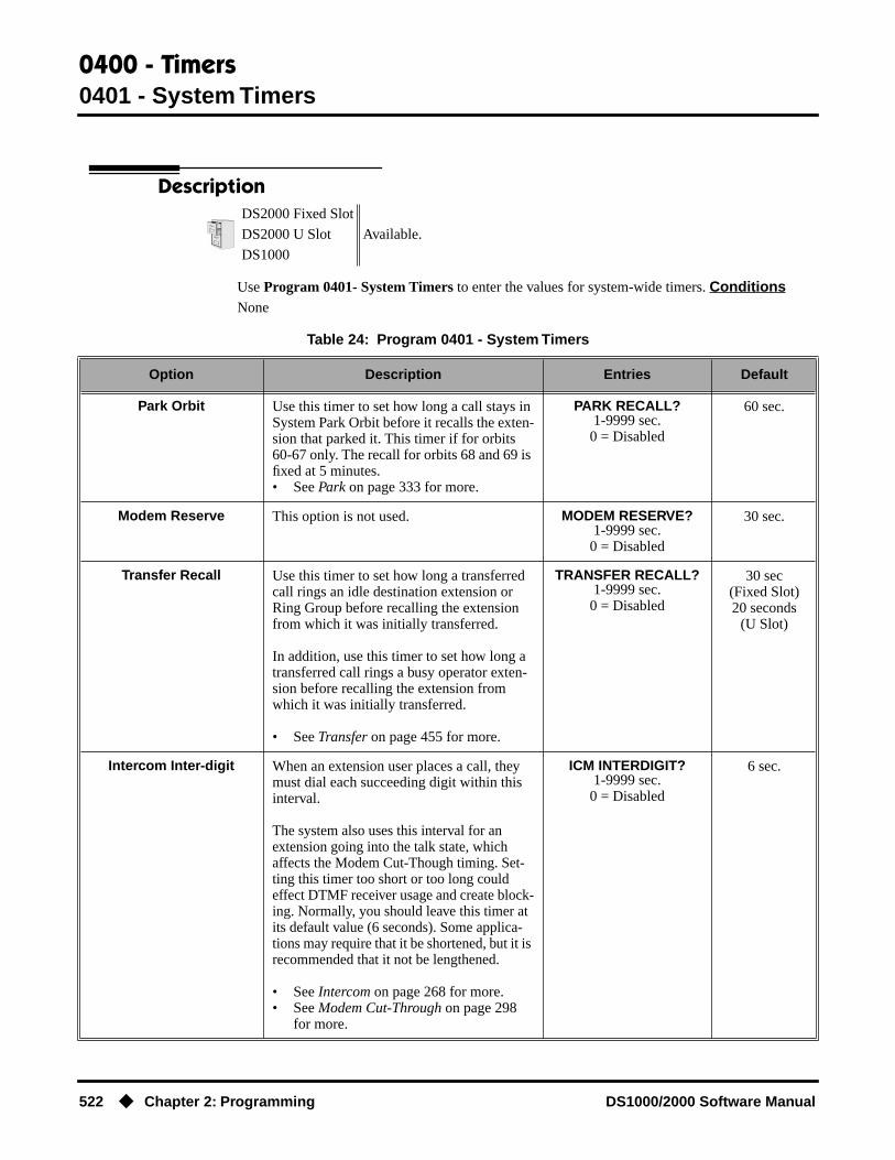
0400 - Timers0401 - System Timers
522 ◆ Chapter 2: Programming DS1000/2000 Software Manual
0400 - Timers
0401 - System Timers
Description
Use Program 0401- System Timers to enter the values for system-wide timers. ConditionsNone
DS2000 Fixed Slot
Available.DS2000 U Slot
DS1000
Table 24: Program 0401 - System Timers
Option Description Entries Default
Park Orbit Use this timer to set how long a call stays in System Park Orbit before it recalls the exten-sion that parked it. This timer if for orbits 60-67 only. The recall for orbits 68 and 69 is fixed at 5 minutes.• See Park on page 333 for more.
PARK RECALL?1-9999 sec.
0 = Disabled
60 sec.
Modem Reserve This option is not used. MODEM RESERVE?1-9999 sec.
0 = Disabled
30 sec.
Transfer Recall Use this timer to set how long a transferred call rings an idle destination extension or Ring Group before recalling the extension from which it was initially transferred.
In addition, use this timer to set how long a transferred call rings a busy operator exten-sion before recalling the extension from which it was initially transferred.
• See Transfer on page 455 for more.
TRANSFER RECALL?1-9999 sec.
0 = Disabled
30 sec(Fixed Slot)20 seconds
(U Slot)
Intercom Inter-digit When an extension user places a call, they must dial each succeeding digit within this interval.
The system also uses this interval for an extension going into the talk state, which affects the Modem Cut-Though timing. Set-ting this timer too short or too long could effect DTMF receiver usage and create block-ing. Normally, you should leave this timer at its default value (6 seconds). Some applica-tions may require that it be shortened, but it is recommended that it not be lengthened.
• See Intercom on page 268 for more.• See Modem Cut-Through on page 298
for more.
ICM INTERDIGIT?1-9999 sec.
0 = Disabled
6 sec.
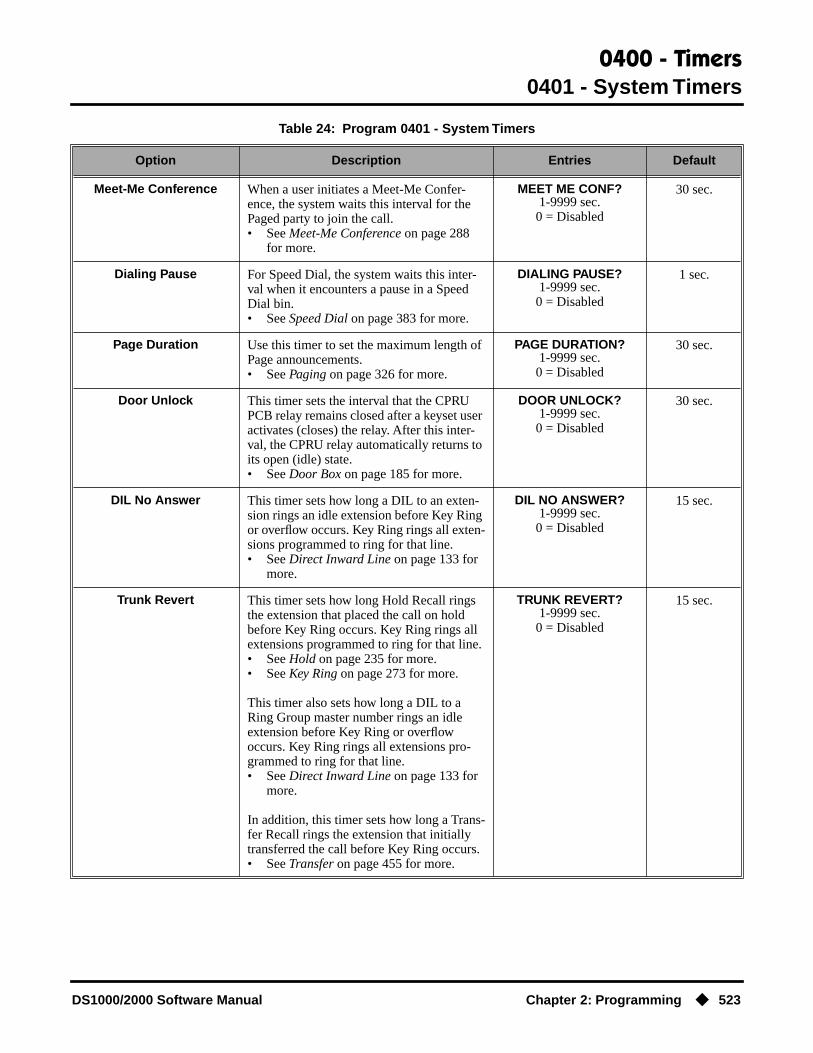
0400 - Timers0401 - System Timers
DS1000/2000 Software Manual Chapter 2: Programming ◆ 523
Meet-Me Conference When a user initiates a Meet-Me Confer-ence, the system waits this interval for the Paged party to join the call.• See Meet-Me Conference on page 288
for more.
MEET ME CONF?1-9999 sec.
0 = Disabled
30 sec.
Dialing Pause For Speed Dial, the system waits this inter-val when it encounters a pause in a Speed Dial bin.• See Speed Dial on page 383 for more.
DIALING PAUSE?1-9999 sec.
0 = Disabled
1 sec.
Page Duration Use this timer to set the maximum length of Page announcements.• See Paging on page 326 for more.
PAGE DURATION?1-9999 sec.
0 = Disabled
30 sec.
Door Unlock This timer sets the interval that the CPRU PCB relay remains closed after a keyset user activates (closes) the relay. After this inter-val, the CPRU relay automatically returns to its open (idle) state.• See Door Box on page 185 for more.
DOOR UNLOCK?1-9999 sec.
0 = Disabled
30 sec.
DIL No Answer This timer sets how long a DIL to an exten-sion rings an idle extension before Key Ring or overflow occurs. Key Ring rings all exten-sions programmed to ring for that line.• See Direct Inward Line on page 133 for
more.
DIL NO ANSWER?1-9999 sec.
0 = Disabled
15 sec.
Trunk Revert This timer sets how long Hold Recall rings the extension that placed the call on hold before Key Ring occurs. Key Ring rings all extensions programmed to ring for that line.• See Hold on page 235 for more.• See Key Ring on page 273 for more.
This timer also sets how long a DIL to a Ring Group master number rings an idle extension before Key Ring or overflow occurs. Key Ring rings all extensions pro-grammed to ring for that line.• See Direct Inward Line on page 133 for
more.
In addition, this timer sets how long a Trans-fer Recall rings the extension that initially transferred the call before Key Ring occurs.• See Transfer on page 455 for more.
TRUNK REVERT?1-9999 sec.
0 = Disabled
15 sec.
Table 24: Program 0401 - System Timers
Option Description Entries Default
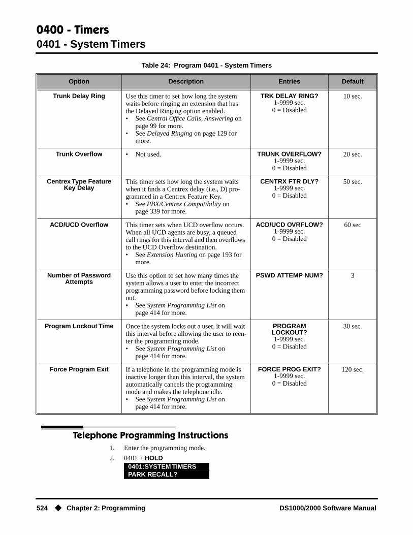
0400 - Timers0401 - System Timers
524 ◆ Chapter 2: Programming DS1000/2000 Software Manual
Telephone Programming Instructions1. Enter the programming mode.
2. 0401 + HOLD
Trunk Delay Ring Use this timer to set how long the system waits before ringing an extension that has the Delayed Ringing option enabled.• See Central Office Calls, Answering on
page 99 for more.• See Delayed Ringing on page 129 for
more.
TRK DELAY RING?1-9999 sec.
0 = Disabled
10 sec.
Trunk Overflow • Not used. TRUNK OVERFLOW?1-9999 sec.
0 = Disabled
20 sec.
Centrex Type Feature Key Delay
This timer sets how long the system waits when it finds a Centrex delay (i.e., D) pro-grammed in a Centrex Feature Key.• See PBX/Centrex Compatibility on
page 339 for more.
CENTRX FTR DLY?1-9999 sec.
0 = Disabled
50 sec.
ACD/UCD Overflow This timer sets when UCD overflow occurs. When all UCD agents are busy, a queued call rings for this interval and then overflows to the UCD Overflow destination.• See Extension Hunting on page 193 for
more.
ACD/UCD OVRFLOW?1-9999 sec.
0 = Disabled
60 sec
Number of Password Attempts
Use this option to set how many times the system allows a user to enter the incorrect programming password before locking them out.• See System Programming List on
page 414 for more.
PSWD ATTEMP NUM? 3
Program Lockout Time Once the system locks out a user, it will wait this interval before allowing the user to reen-ter the programming mode.• See System Programming List on
page 414 for more.
PROGRAMLOCKOUT?1-9999 sec.
0 = Disabled
30 sec.
Force Program Exit If a telephone in the programming mode is inactive longer than this interval, the system automatically cancels the programming mode and makes the telephone idle.• See System Programming List on
page 414 for more.
FORCE PROG EXIT?1-9999 sec.
0 = Disabled
120 sec.
0401:SYSTEM TIMERSPARK RECALL?
Table 24: Program 0401 - System Timers
Option Description Entries Default

0400 - Timers0401 - System Timers
DS1000/2000 Software Manual Chapter 2: Programming ◆ 525
3. Enter data for the displayed timer + HOLD.OR
Press VOL ▲ or VOL ▼ to scroll to the timer you want to change + HOLD
4. Enter data for the displayed timer + HOLD
5. Press VOL ▲ or VOL ▼ to scroll to another timer.OR
Press HOLD to return to step 2 and enter another program number.

0400 - Timers0402 - Trunk Timers
526 ◆ Chapter 2: Programming DS1000/2000 Software Manual
0402 - Trunk Timers
Description
Use Program 0402- Trunk Timers to enter the values for trunk timers.
ConditionsNone
DS2000 Fixed Slot
Available.DS2000 U Slot
DS1000
Table 25: Program 0402 - Trunk Timers
Option Description Entries Default
Camp-On • Not used. CAMP ON?0-9999 sec.
60 sec.
Line Response When the system fails to detect loop current on a trunk, it will wait this interval before marking the trunk as defective.
Be sure the value you enter is compatible with the local telco. If you set this value too short, the system may mark properly func-tioning trunks as defective. If too long, defective trunks may be left in service.• See System Timers, Trunks on page 426
for more.
LINE RESPONSE?4-1020 in 100 mS incre-ments (e.g., 4 = 400 mS,
10 - 1000 mS)
100(10 seconds)
Dial Tone Detect When the system seizes a line to place a Speed Dial call, it waits this interval for dial tone before outdialing the call. The system requires that the first dial tone be at least 5 seconds long and the second dial tone to be at least 2.5 seconds long.
Be sure the value you enter is compatible with the local telco. If you set this value too short, the system may not seize properly functioning trunks. If too long, there will be too long a delay before the system skips over a defective trunk. • See Speed Dial on page 383 for more.• See System Timers, Trunks on page 426
for more.
DL TONE DETECT?0-9999 in 100 mS incre-ments (e.g., 10 = 1 sec-ond, 100 = 10 seconds)
10 (1 second)

0400 - Timers0402 - Trunk Timers
DS1000/2000 Software Manual Chapter 2: Programming ◆ 527
PBX/Centrex Flash Use this timer to set the Flash interval. When a user flashes a trunk (manually or in a Speed Dial number), the system opens the trunk circuit for this interval. For accurate flash function, be sure to set this interval for compatibility with the connected telco or PBX/Centrex.
If you set this interval too short, the telco may not always register the flash. If too long, inadvertent disconnects may occur.• See Flash on page 207 for more.• See Modem Cut-Through on page 298
for more.• See PBX/Centrex Compatibility on
page 339 for more.• See Speed Dial on page 383 for more.• See System Timers, Trunks on page 426
for more.
FLASH PBX?16-4080 mS
800 mS
Flash Disconnect • Not used. FLASH DISC.?16-4080 mS
2496mS
Force Idle (Trunk Guard Time)
Use this timer to set the guard time for trunks. When the system disconnects a trunk (e.g., after a user hang up), the system keeps the line idle until this timer expires. The Trunk Guard Time helps prevent call colli-sions.
If you set this interval too short, call colli-sions may occur. If too long, there will be unnecessary delays before you can use the trunk for a new call.• See System Timers, Trunks on page 426
for more.
FORCE IDLE?10-9999 in 100 mS
increments (e.g., 10 = 1 second)
25 (2.5 sec)(Fixed Slot)10 (1 sec)
(U Slot and DS1000)
PBX Pause • Not used. PBX PAUSE?0-9999 sec.
0 = No pause
0
Table 25: Program 0402 - Trunk Timers
Option Description Entries Default

0400 - Timers0402 - Trunk Timers
528 ◆ Chapter 2: Programming DS1000/2000 Software Manual
Minimum Ring Detection Timer
Use this timer to set the threshold for ring detection. If the ring signal is longer than this interval, the system interprets the signal as valid ringing. If the signal is equal to or shorter than this interval, the system ignores the ringing.
Be sure the value you enter is compatible with the local telco. If you set this value too short, the system may detect line spikes and anomalies as ringing. If too long, the system may not properly interpret a valid ringing signal.• See System Timers, Trunks on page 426
for more.
MIN RING DET?8-2040 mS
104 mS
DP Make Timer Use this timer to set the duration of the Dial Pulse Make signal (i.e., relay closed). This is the “on” time in a Dial Pulse digit. Set this timer for compatibility with the connected telco or PBX/Centrex. Keep in mind that there are three components of a Dial Pulse digit: Make interval, Break interval and Interdigit interval. An improper setting may cause misdialing.• See System Timers, Trunks on page 426
for more.
PULSE DIAL MAKE?4-1020 mS
40 mS
DP Break Timer Use this timer to set the duration of the Dial Pulse Break signal (i.e., relay open). This is the “off” time in a Dial Pulse digit. Set this timer for compatibility with the connected telco or PBX/Centrex. Keep in mind that there are three components of a Dial Pulse digit: Make interval, Break interval and Interdigit interval. An improper setting may cause misdialing.• See System Timers, Trunks on page 426
for more.
PULSE DIAL BRK?4-1020 mS
60 mS
DP Interdigit Timer Use this timer to set the duration of the Dial Pulse Interdigit signal (i.e., relay open time between each digit). Set this timer for com-patibility with the connected telco or PBX/Centrex. Keep in mind that there are three components of a Dial Pulse digit: Make interval, Break interval and Interdigit inter-val. An improper setting may cause misdial-ing.• See System Timers, Trunks on page 426
for more.
PULSE INTRDIGIT?100-9999 mS
800 mS
Table 25: Program 0402 - Trunk Timers
Option Description Entries Default

0400 - Timers0402 - Trunk Timers
DS1000/2000 Software Manual Chapter 2: Programming ◆ 529
Manual DTMF Tone On This timer sets the duration of DTMF digits for trunk calls manually dialed by an exten-sion user. This is required because the sys-tem buffers the digits the user dials.
Set this timer for compatibility with the con-nected telco or PBX/Centrex. If you set this interval too short, the telco or PBX/Centrex may not be able to properly detect the DTMF digit. If too long, outbound dialing is unnecessarily slowed down.• See System Timers, Trunks on page 426
for more.
MAN DTMF ON?10-2550 mS
150 mS
Manual DTMF Tone Off This timer sets the duration of the interval between DTMF digits for trunk calls manu-ally dialed by an extension user. This is required because the system buffers the dig-its the user dials. Note that this is the mini-mum DTMF Tone off time guaranteed by the system.
Set this timer for compatibility with the con-nected telco or PBX/Centrex. If you set this interval too short, the telco or PBX/Centrex may not be able to set up to receive the next DTMF digit. If too long, outbound dialing is unnecessarily slowed down.• See System Timers, Trunks on page 426
for more.
MANB DTMF OFF?10-2550 mS
(02.02.14 or higher)100 mS(Prior to 02.02.14)
50 mS
Speed Dial DTMF Tone On
This timer sets the duration of DTMF digits for Speed Dial trunk calls automatically dialed by the system.
Set this timer for compatibility with the con-nected telco or PBX/Centrex. If you set this interval too short, the telco or PBX/Centrex may not be able to properly detect the DTMF digit. If too long, outbound dialing is unnecessarily slowed down.• See Speed Dial on page 383 for more.• See System Timers, Trunks on page 426
for more.
SPDL DTMF ON?10-2550 mS
100 mS
Table 25: Program 0402 - Trunk Timers
Option Description Entries Default

0400 - Timers0402 - Trunk Timers
530 ◆ Chapter 2: Programming DS1000/2000 Software Manual
Speed Dial DTMF Tone Off
This timer sets the duration the quiet time between DTMF digits for Speed Dial trunk calls automatically dialed by the system.
Set this timer for compatibility with the con-nected telco or PBX/Centrex. If you set this interval too short, the telco or PBX/Centrex may not be able to set up to receive the next DTMF digit. If too long, outbound dialing is unnecessarily slowed down.• See Speed Dial on page 383 for more.• See System Timers, Trunks on page 426
for more.
SPDL DTMF ON?10-2550 mS
100 mS
Loop Current Detection Time
For loop start trunks, loop current must be present for this interval before the system seizes the trunk.
Set this interval for compatibility with the connected telco or PBX/Centrex. If you set this interval too short, the system may inad-vertently seize unstable trunks. If too long, the system may not properly seize a valid trunk.• See System Timers, Trunks on page 426
for more.
LOOP CURRENT?4-1020 mS
800 mS
Codec Digitizing Method Use this option to set the system’s codec companding method type for the trunk. Be sure this option is always set to 0 (µ-law companding enabled). Do not set this option to 1 (A-law companding enabled).• See System Timers, Trunks on page 426
for more.
CODEC A/D TYPE?0 = µ-law1 = A-law
0 (µ-law)
Setting for International Rotary Disk
Set this option for compatibility with the type of rotary dial (500 type) telephone used. Be sure to always set this option to 0.• See System Timers, Trunks on page 426
for more.
DP FOR INT’L?0 = US standard1 = Norwegian
2 = Swedish
0(US standard)
Table 25: Program 0402 - Trunk Timers
Option Description Entries Default

0400 - Timers0402 - Trunk Timers
DS1000/2000 Software Manual Chapter 2: Programming ◆ 531
Far End Disconnect Use this timer to set the loop disconnect interval for trunk calls. If the system detects a loop current interruption longer than this interval it assumes the telco has discon-nected the trunk. It then returns the trunk trunk to idle.
Set this interval for compatibility with the connected telco or PBX/Centrex. If you set this interval too short, the system may inad-vertently disconnect valid trunks. If too long, the system may leave trunks connected that it should tear down. • See System Timers, Trunks on page 426
for more.
FAR END DISC.?4-1020 mS
300 mS
Minimum Single Ring Detection Timer
The system uses this timer to detect valid ringing signal from the connected telco or PBX. Valid single ring must be longer than this interval.• See System Timers, Trunks on page 426
for more.
SNGL RG MIN DET?8-2040 mS
1004 mS(504 mS prior to 02.02.17)
Minimum Double Ring Detection Off Timer
The system uses this timer to detect valid double ring from the connected PBX. Valid double ring must be longer than this interval.• See System Timers, Trunks on page 426
for more.
DBL RG MIN OFF?8-2040 mS
104 mS
Maximum Double Ring Detection Off Timer
The system uses this timer to detect valid double ring from the connected PBX. Valid double ring must be less than this interval.• See System Timers, Trunks on page 426
for more.
DBL RG MAX OFF?8-2040 mS
504 mS(304 mS prior to 02.02.17)
Ringing Signal End Detect Timer
If the ringing signal on a trunk call is inter-rupted for longer than this interval, the sys-tem assumes ringing has stopped and terminates the call.
Set this option for compatibility with the connected telco or PBX Centrex. If this interval is set to short, valid ringing will be inadvertently cut off. If too long, the system will leave the call set up even after ringing has stopped.• See System Timers, Trunks on page 426
for more.
SIGNAL STOP DET?64-16320 mS
6016 mS
Table 25: Program 0402 - Trunk Timers
Option Description Entries Default

0400 - Timers0402 - Trunk Timers
532 ◆ Chapter 2: Programming DS1000/2000 Software Manual
Telephone Programming Instructions1. Enter the programming mode.
2. 0402 + HOLD
3. Enter data for the displayed timer + HOLD.OR
Press VOL ▲ or VOL ▼ to scroll to the timer you want to change + HOLD
4. Enter data for the displayed timer + HOLD
5. Press VOL ▲ or VOL ▼ to scroll to another timer.OR
Press HOLD to return to step 2 and enter another program number.
Caller ID Detection Timer With DSP-based Caller ID, the Caller ID Detection Timer is the amount of time between the first and second ring bursts that the system can detect Caller ID digits. If this timer is set too long, the outside caller will hear ringing followed by reorder tone. If set too short, all the Caller ID digits may not be detected. This timer is not used with DS2000 daughter board-based Caller ID.• See Caller ID on page 82 for more.• See System Timers, Trunks on page 426
for more.
CID DETECT64-16320 mS
3268 mS
Ground Start Timer • This option is not used. GROUNDING16-4080 mS
800 mS
Pause Timer Not used. PAUSE64-16320 mS
3008 mS
DP Mute Timer Not used.• See System Timers, Trunks on page 426
for more.
DP MUTE4-1020 mS
8 mS
P.F. Recovery Detect Timer
When the ATRU PCB recovers from a power failure, it checks the power failure trunk (trunk 1) for loop current for the P.F. Recov-ery Detect interval. If loop current is detected, it assumes the Power Failure Tele-phone is still connected and does not tear down the call. If loop current is not detected, the ATRU PCB switches the trunk out of the power failure mode.• See System Timers, Trunks on page 426
for more.
PF RECOVERY64-16320 mS
3008 mS
0402:TRUNK TIMERSCAMP ON?
Table 25: Program 0402 - Trunk Timers
Option Description Entries Default

0400 - Timers0403 - Station Timers
DS1000/2000 Software Manual Chapter 2: Programming ◆ 533
0403 - Station Timers
Description
Use Program 0403- Station Timers to enter the values for station timers.
ConditionsNone
DS2000 Fixed Slot
Available.DS2000 U Slot
DS1000
Table 26: Program 0403 - Station Timers
Option Description Entries Default
Hold Recall Use this timer to set how long a call stays on Hold before it recalls the extension that ini-tially placed it on Hold.• See Hold on page 235 for more.
HOLD RECALL?0-9999 sec.
60 sec.
Exclusive Hold Use this timer to set how long a call stays on Exclusive Hold before it recalls the exten-sion that initially placed it on Exclusive Hold.• See Hold on page 235 for more.
EX-HOLD RECALL?0-9999 sec.
90 sec.
Camp-On • Not used. CAMP_ON?0-9999 sec.
60 sec.
Call Forward Ring No Answer
When Call Forwarding Ring No Answer is enabled, this timer sets how long a for-warded call rings an unanswered extension before routing to the forwarding destination.
In addition, use this timer to set how long a transferred call rings a busy non-operator extension before recalling the extension from which it was initially transferred.
This timer also sets how long a call will ring an idle UCD Hunting group member before cycling to the next member of the group.• See Call Forwarding on page 66 for
more.• See Extension Hunting on page 193 for
more.
FWRD NO ANSWER?0-9999 sec.
10 sec.
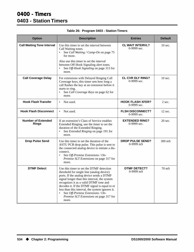
0400 - Timers0403 - Station Timers
534 ◆ Chapter 2: Programming DS1000/2000 Software Manual
Call Waiting Tone Interval Use this timer to set the interval between Call Waiting tones.• See Call Waiting / Camp-On on page 75
for more.
Also use this timer to set the interval between Off Hook Signaling alert tones.• See Off-Hook Signaling on page 313 for
more.
CL WAIT INTERVL?0-9999 sec.
10 sec.
Call Coverage Delay For extensions with Delayed Ringing Call Coverage keys, this timer sets how long a call flashes the key at an extension before it starts to ring.• See Call Coverage Keys on page 62 for
more.
CL CVR DLY RING?0-9999 sec.
10 sec.
Hook Flash Transfer • Not used. HOOK FLASH XFER?0-9999 sec.
2 sec.
Hook Flash Disconnect • Not used. FLSH DISCONNECT?0-9999 sec.
12 sec.
Number of Extended Rings
If an extension’s Class of Service enables Extended Ringing, use the timer to set the duration of the Extended Ringing.• See Extended Ringing on page 191 for
more.
EXTENDED RING?0-9999 sec.
20 sec.
Drop Pulse Send Use this timer to set the duration of the ASTU PCB drop pulse. This pulse is sent to the connected analog device to initiate a dis-connect.• See Off-Premise Extensions / On-
Premise SLT Extensions on page 317 for more.
DROP PULSE SEND?0-9999 mS
300 mS
DTMF Detect Use this timer to set the DTMF detection threshold for single line (analog device) ports. If the analog device sends a DTMF signal longer than this interval, the system recognizes it as a valid DTMF tone and decodes it. If the DTMF signal is equal to or less than this interval, the system ignores it.• See Off-Premise Extensions / On-
Premise SLT Extensions on page 317 for more.
DTMF DETECT?0-9999 mS
70 mS
Table 26: Program 0403 - Station Timers
Option Description Entries Default

0400 - Timers0403 - Station Timers
DS1000/2000 Software Manual Chapter 2: Programming ◆ 535
Telephone Programming Instructions1. Enter the programming mode.
2. 0403 + HOLD
3. Enter data for the displayed timer + HOLD.OR
Press VOL ▲ or VOL ▼ to scroll to the timer you want to change + HOLD
4. Enter data for the displayed timer + HOLD
5. Press VOL ▲ or VOL ▼ to scroll to another timer.OR
Press HOLD to return to step 2 and enter another program number.
Ring No Answer Hunt Use this timer to set the Extension Hunting Ring No Answer Time. A call will ring a hunt group member extension for this inter-val before automatically cycling to the next extension in the group.• See Extension Hunting on page 193 for
more.
RG NO ANS HUNT?0-9999 sec.
10 sec.
0403:STATION TIMERSHOLD RECALL?
Table 26: Program 0403 - Station Timers
Option Description Entries Default

0400 - Timers0404 - Analog Station Timers
536 ◆ Chapter 2: Programming DS1000/2000 Software Manual
0404 - Analog Station Timers
Description
Use 0404: Analog Station Timers to set parameters and timers for ASTU PCBs.
ConditionsNone
DS2000 Fixed Slot
Available.DS2000 U Slot
DS1000
Option Description Entries Default
Country Data Use this option to define the country of use and the codec digitizing method for ASTU PCBs. This timer consists of two bits (xy), with bit x defining the country and bit y defining the digitization method. For exam-ple, the default entry 00 is for North America (x=0) and u-law digitization method (y=0). Do not change this entry from its default value (00).
COUNTRY DATA?xy
x= 0 (North America), 1 (International) or 2
(Japan)y = 0 (u-law) or 1 (A-
law)
00(xy)
Rotary Dial Type Use this option to define the rotary dial puls-ing method for the system’s ASTU PCBs. Do not change this entry from its default value (01).
ROTARY TYPE?0 = Standard (1-10)
1 = Norwegian (9-1, 10)2 = Swedish (10, 1-9)
Standard(0)
Loop Current Use this option to set the maximum allowed loop current for the system’s ASTU PCBs. Normally choose 25mA for short loops and 35mA for long loops. In general, a long loop is 3000 feet or longer and a short loop is less than 3000 feet.
LOOP CURRENT0 = 25mA (short loop)1 = 35 mA (long loop)
25mA (0)
Ringing Frequency Use this option to define the AC ringing fre-quency for the system’s ASTU PCBs. Do not change this entry from its default value (20 Hz).
RINGING FREQ?0 = 25 Hz1 = 20 Hz2 = 16 Hz
20 Hz (1)
Minimum Break Time This timer defines the minimum amount of time the loop must be opened to properly decode the dial pulse digits sent from analog devices connected to ASTU PCBs. Change this value only if the connected analog devices are set to dial at a rate other than 10 PPS.
MIN BREAK TIME?1-255
(5-1275 mS in 5 mS increments [e.g., 2 =
10mS, 3 = 15 mS, 4 = 20 mS)
2 (10 mS)

0400 - Timers0404 - Analog Station Timers
DS1000/2000 Software Manual Chapter 2: Programming ◆ 537
Maximum Break Time This timer defines the maximum amount of time the loop must be opened to properly decode the dial pulse digits sent from analog devices connected to ASTU PCBs. Change this value only if the connected analog devices are set to dial at a rate other than 10 PPS.
MAX BREAK TIME?1-255
(5-1275 mS in 5 mS increments [e.g., 2 =
10mS, 3 = 15 mS, 4 = 20 mS)
20 (100 mS)
Minimum Make Time This timer defines the minimum amount of time the loop must be closed to properly decode the dial pulse digits sent from analog devices connected to ASTU PCBs. Change this value only if the connected analog devices are set to dial at a rate other than 10 PPS.
MIN MAKE TIME?1-255
(5-1275 mS in 5 mS increments [e.g., 2 =
10mS, 3 = 15 mS, 4 = 20 mS)
2 (10 mS)
Maximum Make Time This timer defines the maximum amount of time the loop must be closed to properly decode the dial pulse digits sent from analog devices connected to ASTU PCBs. Change this value only if the connected analog devices are set to dial at a rate other than 10 PPS.
MAX MAKE TIME?1-255
(5-1275 mS in 5 mS increments [e.g., 2 =
10mS, 3 = 15 mS, 4 = 20 mS)
20 (100 mS)
Minimum Hookflash Time For ASTU PCBs, this timer defines the mini-mum amount of time the loop must be opened before the system starts to detect a transfer or hang up sequence. Open loop intervals shorter than the setting are ignored by the ASTU PCB.
MIN FLASH TIME?1-255
(5-1275 mS in 5 mS increments [e.g., 2 =
10mS, 3 = 15 mS, 4 = 20 mS)
21 (105 mS)
Maximum Hookflash Time
For ASTU PCBs, this timer defines the max-imum amount of time the loop can be opened in order for the system to detect a Transfer sequence. Open loop intervals longer than the setting are interpreted as hang up.
MAX FLASH TIME?1-255
(5-1275 mS in 5 mS increments [e.g., 2 =
10mS, 3 = 15 mS, 4 = 20 mS)
200 (1000 mS / 1 second)
Minimum Ground Flash Time
For ground start applications with ASTU PCBs, this timer sets the amount of time a ground must be applied before the system detects a transfer sequence. The ASTU uses this timer when analog telephones use ground Transfer instead of open loop Trans-fer. This timer is not used in North Amer-ica. Do not change this timer from its default value.
MIN GND TIME?1-255
(5-1275 mS in 5 mS increments [e.g., 2 =
10mS, 3 = 15 mS, 4 = 20 mS)
21 (105 mS)
Minimum Off-Hook Time For ASTU PCBs, this timer defines how long a connected analog device must remain off-hook before the system recognizes the off-hook status.
MIN GND TIME?1-255
(5-1275 mS in 5 mS increments [e.g., 2 =
10mS, 3 = 15 mS, 4 = 20 mS)
21 (105 mS)
Option Description Entries Default

0400 - Timers0404 - Analog Station Timers
538 ◆ Chapter 2: Programming DS1000/2000 Software Manual
Telephone Programming Instructions1. Enter the programming mode.
2. 0404 + HOLD
3. Enter data for the displayed timer + HOLD.OR
Press VOL ▲ or VOL ▼ to scroll to the timer you want to change + HOLD
4. Enter data for the displayed timer + HOLD
5. Press VOL ▲ or VOL ▼ to scroll to another timer.OR
Press HOLD to return to step 2 and enter another program number.
Off-Hook Guard Time The ASTU PCB waits this interval after an analog device hangs up before accepting any additional input from the device. This timer helps prevent erroneous detection due to hardware stabilization.
OFF HOOK GUARD?1-255
(5-1275 mS in 5 mS increments [e.g., 2 =
10mS, 3 = 15 mS, 4 = 20 mS)
60 (300 mS)
Dial Pulse Guard Timer The ASTU PCB waits this interval between dial pulse digits before attempting to detect any additional DP digits. This timer helps prevent erroneous DP dialing due to hard-ware stabilization.
DIAL GUARD?1-255
(5-1275 mS in 5 mS increments [e.g., 2 =
10mS, 3 = 15 mS, 4 = 20 mS)
70 (350 mS)
Loop Disconnect Time When the far end disconnects, the ASTU PCB opens the loop to the connected analog device for this interval.
LOOP DISC TIME?1-255
(5-1275 mS in 5 mS increments [e.g., 2 =
10mS, 3 = 15 mS, 4 = 20 mS)
40 (200 mS)
Ring/MW Wait Period Time
This timer determines the ringing sequence for the devices connected ASTU PCBs. Because of power consumption, it is not pos-sible to ring all analog devices on an ASTU simultaneously. Instead, the card is divided into 4 groups with two ports in each group. Ringing cycles between the 4 groups, ring-ing each group for this interval.
RING/MW PERIOD?1-255
(50-12750 mS in 50 mS increments [e.g., 2 = 100 mS, 3 = 150 mS, 4 = 200
mS)
15 (750 mS)
0403:ASTU TIMERSCOUNTRY DATA?
Option Description Entries Default
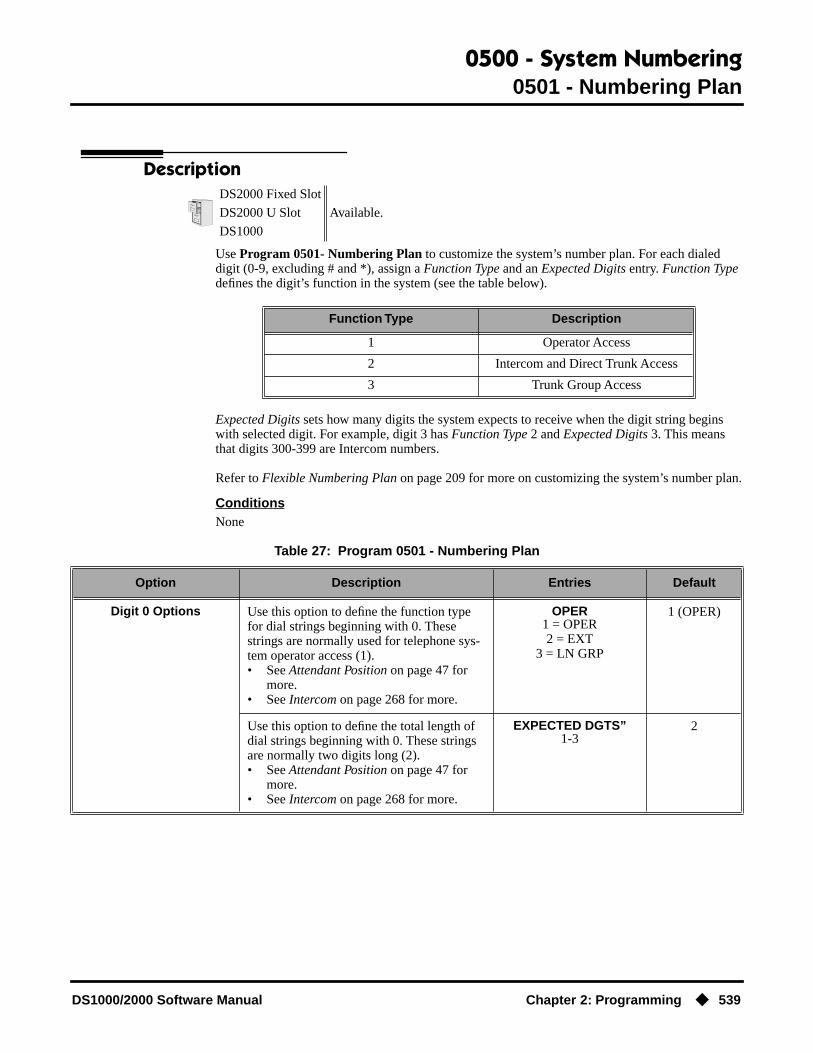
0500 - System Numbering0501 - Numbering Plan
DS1000/2000 Software Manual Chapter 2: Programming ◆ 539
0500 - System Numbering
0501 - Numbering Plan
Description
Use Program 0501- Numbering Plan to customize the system’s number plan. For each dialed digit (0-9, excluding # and *), assign a Function Type and an Expected Digits entry. Function Type defines the digit’s function in the system (see the table below).
Expected Digits sets how many digits the system expects to receive when the digit string begins with selected digit. For example, digit 3 has Function Type 2 and Expected Digits 3. This means that digits 300-399 are Intercom numbers.
Refer to Flexible Numbering Plan on page 209 for more on customizing the system’s number plan.
ConditionsNone
DS2000 Fixed Slot
Available.DS2000 U Slot
DS1000
Function Type Description
1 Operator Access
2 Intercom and Direct Trunk Access
3 Trunk Group Access
Table 27: Program 0501 - Numbering Plan
Option Description Entries Default
Digit 0 Options Use this option to define the function type for dial strings beginning with 0. These strings are normally used for telephone sys-tem operator access (1).• See Attendant Position on page 47 for
more.• See Intercom on page 268 for more.
OPER1 = OPER2 = EXT
3 = LN GRP
1 (OPER)
Use this option to define the total length of dial strings beginning with 0. These strings are normally two digits long (2).• See Attendant Position on page 47 for
more.• See Intercom on page 268 for more.
EXPECTED DGTS”1-3
2

0500 - System Numbering0501 - Numbering Plan
540 ◆ Chapter 2: Programming DS1000/2000 Software Manual
Digit 1 Options Use this option to define the function type for dial strings beginning with 1. These strings are normally reserved for Intercom access (2).• See Intercom on page 268 for more.
EXT1 = OPER2 = EXT
3 = LN GRP
2 (EXT)
Use this option to define the total length of dial strings beginning with 1. These strings are normally three digits long (3).• See Intercom on page 268 for more.
EXPECTED DGTS”1-3
3
Digit 2 Options Use this option to define the function type for dial strings beginning with 2. These strings are normally reserved for Intercom access (2).• See Intercom on page 268 for more.
EXT1 = OPER2 = EXT
3 = LN GRP
2 (EXT)
Use this option to define the total length of dial strings beginning with 2. These strings are normally three digits long (3).• See Intercom on page 268 for more.
“2” EXPECTED DGTS”1-3
3
Digit 3 Options Use this option to define the function type for dial strings beginning with 3. These strings are by default assigned to Intercom access (2).• See Intercom on page 268 for more.
EXT1 = OPER2 = EXT
3 = LN GRP
2 (EXT)
Use this option to define the total length of dial strings beginning with 3. These strings are normally three digits long (3).• See Intercom on page 268 for more.
“3” EXPECTED DGTS”1-3
3
Digit 4 Options Use this option to define the function type for dial strings beginning with 4. These strings are by default assigned to Direct Trunk Access (2).• See Central Office Calls, Placing on
page 105 for more.• See Direct Trunk Access on page 154 for
more.
EXT1 = OPER2 = EXT
3 = LN GRP
2 (EXT)
Use this option to define the total length of dial strings beginning with 4. These strings are normally three digits long (3).• See Central Office Calls, Placing on
page 105 for more.• See Direct Trunk Access on page 154 for
more.
“4” EXPECTED DGTS”1-3
3
Table 27: Program 0501 - Numbering Plan
Option Description Entries Default

0500 - System Numbering0501 - Numbering Plan
DS1000/2000 Software Manual Chapter 2: Programming ◆ 541
Digit 5 Options Use this option to define the function type for dial strings beginning with 5. These strings are normally reserved for Intercom access (2).• See Intercom on page 268 for more.
EXT1 = OPER2 = EXT
3 = LN GRP
2 (EXT)
Use this option to define the total length of dial strings beginning with 5. These strings are normally three digits long (3).• See Intercom on page 268 for more.
“5” EXPECTED DGTS”1-3
3
Digit 6 Options Use this option to define the function type for dial strings beginning with 6. These strings are normally reserved for Intercom access (2).• See Intercom on page 268 for more.
EXT1 = OPER2 = EXT
3 = LN GRP
2 (EXT)
Use this option to define the total length of dial strings beginning with 6. These strings are normally three digits long (3).• See Intercom on page 268 for more.
“6” EXPECTED DGTS”1-3
3
Digit 7 Options Use this option to define the function type for dial strings beginning with 7. These strings are normally reserved for Intercom access (2).• See Intercom on page 268 for more.
EXT1 = OPER2 = EXT
3 = LN GRP
2 (EXT)
Use this option to define the total length of dial strings beginning with 7. These strings are normally three digits long (3).• See Intercom on page 268 for more.
“7” EXPECTED DGTS”1-3
3
Digit 8 Options Use this option to define the function type for dial strings beginning with 8. These strings are normally reserved for Intercom access (2).• See Intercom on page 268 for more.
EXT1 = OPER2 = EXT
3 = LN GRP
2 (EXT)
Use this option to define the total length of dial strings beginning with 8. These strings are normally three digits long (3).• See Intercom on page 268 for more.
“8” EXPECTED DGTS”1-3
3
Digit 9 Options Use this option to define the function type for dial strings beginning with 9. These strings are normally reserved to trunk access (3).• See Central Office Calls, Placing on
page 105 for more.• See Trunk Group Routing on page 461
for more.• See Trunk Groups on page 468 for more.
LN GRP1 = OPER2 = EXT
3 = LN GRP
3 (LN GRP)
Table 27: Program 0501 - Numbering Plan
Option Description Entries Default

0500 - System Numbering0501 - Numbering Plan
542 ◆ Chapter 2: Programming DS1000/2000 Software Manual
Telephone Programming Instructions1. Enter the programming mode.
2. 0501 + HOLD
3. Enter data for the displayed option + VOL ▲.OR
Press VOL ▲ or VOL ▼ to scroll to the option you want to change + HOLD
4. Enter data for the displayed option + HOLD
5. Press VOL ▲ or VOL ▼ to scroll to another option.OR
Press CONF to return to step 2 and enter another program number.
Single Digit Access Use this option to enable or disable single digit access. If enabled (Y), users can dial 9 to select their assigned dial 9 Trunk Group. If disabled, users must dial 9 followed by the Trunk Group number (0-8 for Trunk Groups 0-8).• See Central Office Calls, Placing on
page 105 for more.• See Trunk Group Routing on page 461
for more.
SINGL DGT ACCESS?Y or N
Y
0501:NUMBERING PLAN“0” FUNCTION TYP?
Table 27: Program 0501 - Numbering Plan
Option Description Entries Default

0500 - System Numbering0504 - Trunk Port Extension Numbers (Fixed Slot)
DS1000/2000 Software Manual Chapter 2: Programming ◆ 543
0504 - Trunk Port Extension Numbers (Fixed Slot)
Description
Use Program 0504- Trunk Port Extension Numbers to assign extension numbers to trunk ports. The extension numbers you enter must be unique and not overlap extension numbers used for extensions, ACI ports, DCI ports and Extension Hunting master numbers.
● Ports 001 -016 are the system’s physical trunk ports.
ConditionsNone
Telephone Programming Instructions1. Enter the programming mode.
2. 0504 + HOLD
3. Enter the number of the trunk port you want to program (01-32) + HOLD.
The previously programmed extension number displays.
4. Enter the number of the extension you want assigned to the port.OR
Press HOLD to leave the entry unchanged.
DS2000 Fixed Slot Available.
DS2000 U SlotSee the following program.
DS1000
Table 28: Program 0504 - Trunk Port Extension Numbers (Fixed Slot)
Option Description Entries Default
Extension Number For the trunk port selected, use this option to enter the extension number associated with the port.• See Central Office Calls, Placing on
page 105 for more.• See Flexible Numbering Plan on
page 209 for more.
EXT NUM? Not assigned
Name For the trunk port selected, this option shows the name associated with the port.• See Names for Extensions and Trunks on
page 306 for more.•
NAME?View only
View only
0504:TRUNK IDTRUNK PORT?
0504:TRUNK ID-PT:nnnEXT NUM?nnn
0504:TRUNK ID-PT:nnnNAME?(name)

0500 - System Numbering0504 - Trunk Port Extension Numbers (Fixed Slot)
544 ◆ Chapter 2: Programming DS1000/2000 Software Manual
The previously programmed name displays.
5. Return to step 3 and enter another trunk port.OR
Press HOLD to return to step 2 and enter another program number.

0500 - System Numbering0504 - View Extension (U Slot and DS1000)
DS1000/2000 Software Manual Chapter 2: Programming ◆ 545
0504 - View Extension (U Slot and DS1000)
Description
Use Program 0504- View Extension to view the extension assignments for each port (circuit) for each PCB.
ConditionsNone
Telephone Programming Instructions1. Enter the programming mode.
2. 0504 + HOLD
3. Enter the number of the trunk (401-448 in DS2000 or 401-406 in DS1000) or extension (300-395 in DS2000 or 300-325 in DS1000) you want to view + HOLD.In DS2000, you see:
The slot and circuit for the extension or trunk you selected displays.
DS2000 Fixed Slot See the previous program.
DS2000 U SlotAvailable.
DS1000
Table 29: Program 0504 - View Extension (U Slot)
Option Description Entries Default
Extension Number Use this option to select the trunk (401-448 in DS2000 or 401-406 in DS1000) or exten-sion (300-395 in DS2000 or 300-325 in DS1000) you want to view.• See Flexible Numbering Plan on
page 209 for more.
EXT NUM? Not assigned
Slot and Circuit Assignment (DS2000)
This option displays the DS2000 Main Equipment Cabinet slot number and port (circuit) assignment for the extension selected in the option above.• Extension numbers are 300-395.• Trunk extension numbers are 401-448.
SLOT:n CIRCUIT:nView only
View only
Port Assignment (DS1000)
Use this option to view the DS1000 port assigned to each station, trunk, or Analog Door Box.• Digital extension numbers are 300-315.• Analog extension numbers are 316-323.• Analog Door Box extension numbers are
324 and 325.• Trunk extension numbers are 401-406.
STATION nDOOR BOX n
CO LINE nView only
View only
0504:VIEW EXTENSIONEXT NUM?
0504:EXTENSION:nnnSLOT:n CIRCUIT:n
0500 - System Numbering0504 - View Extension (U Slot and DS1000)
546 ◆ Chapter 2: Programming DS1000/2000 Software Manual
SLOT is the Main Equipment Cabinet slot where the extension or trunk is located. CIRCUIT is the port (circuit) on the PCB assigned to the slot.
In DS1000, you see:
The system shows the associated port number.
4. Press HOLD and return to step 3 above to view another extension or trunk.OR
Press CONF to exit.
0504:EXTENSION:nnnnnnnnn nn

0500 - System Numbering0505 - Station Port Extension Numbers (Fixed Slot)
DS1000/2000 Software Manual Chapter 2: Programming ◆ 547
0505 - Station Port Extension Numbers (Fixed Slot)
Description
Use Program 0505- Station Port Extension Numbers to assign extension numbers to station ports. The extension numbers you enter must be unique and not overlap extension numbers used for trunks, ACI ports, DCI ports and Extension Hunting master numbers.
● Ports 001-096 are the system’s physical extension ports.
ConditionsNone
Telephone Programming Instructions1. Enter the programming mode.
2. 0505 + HOLD
3. Enter the number of the station port you want to program (01-96) + HOLD.
The previously programmed extension number displays.
4. Enter the number of the extension you want assigned to the port + HOLD.OR
Press HOLD to leave the entry unchanged.OR
Press CLEAR + HOLD to undefine the selected port (see comment below).
If you are swapping ports that are within the extension number range (e.g., 300-395), press CLEAR to undefine the two ports you want to swap before reprogramming them. If
DS2000 Fixed Slot Available. Will swap port/extension numbers but not programming.
DS2000 U SlotSee the following program.
DS1000
Table 30: Program 0505 - Station Port Extension Numbers (Fixed Slot)
Option Description Entries Default
Extension Number For the station port selected, use this option to enter the extension number associated with the port.• See Flexible Numbering Plan on
page 209 for more.
EXT NUM? Not assigned
Name For the station port selected, this option shows the name associated with the port.• See Names for Extensions and Trunks on
page 306 for more.•
NAME?View only
View only
0505:STA IDSTATION PORT?
0505:STA ID-PT:nnnEXT NUM?nnn
0505:STA ID-PT:nnnNAME?(name)
0500 - System Numbering0505 - Station Port Extension Numbers (Fixed Slot)
548 ◆ Chapter 2: Programming DS1000/2000 Software Manual
you don’t undefine the ports first, you will see the message EXT ALREADY EXISTS!5. Return to step 3 and enter another station port.
ORPress HOLD to return to step 2 and enter another program number.

0500 - System Numbering0505 - Extension Assignment (U Slot and DS1000)
DS1000/2000 Software Manual Chapter 2: Programming ◆ 549
0505 - Extension Assignment (U Slot and DS1000)
Description
In DS2000, use Program 0505- Extension Assignment to view and change the extension or trunk number assigned to a port (circuit) on an installed PCB. You make the selection based on slot and port (circuit) number.
In DS1000, use Program 0505 - Extension Assignment to view and change the extension number for each extension, trunk, or Analog Door Box assigned to each port. You make the selection based on the port for each device type.
ConditionsNone
DS2000 Fixed Slot See the previous program.
DS2000 U SlotAvailable.
DS1000
Table 31: Program 0505 - Extension Assignment (U Slot)
Option Description Entries Default
Slot Number(DS2000 Only)
Use this option to select the Main Equip-ment Cabinet slot that has the extension or trunk you want to change.• See Flexible Numbering Plan on
page 209 for more.
SLOT NUMBER? Not assigned
Circuit Number(DS2000 Only)
For the slot selected in the previous option, use this option to select the port (circuit) you want to change.• Extension ports 1-80 are assigned to
extensions 300-379.• Trunk ports 1-48 are assigned to trunks
401-448,
CIRCUIT NUM? Not assigned
Type(DS1000 Only)
Use this option to select the type of device you want to change.
TYPE?1 = Extensions
2 = Trunks3 = Analog Door Boxes
Not assigned
Extension Number Use this option to enter the extension num-ber for the port (circuit) selected. The exten-sion number you choose must be from the pool of unassigned extensions.
EXT NUM?100-899
-

0500 - System Numbering0505 - Extension Assignment (U Slot and DS1000)
550 ◆ Chapter 2: Programming DS1000/2000 Software Manual
Telephone Programming Instructions
DS2000 U SLOT
1. Enter the programming mode.
2. 0505 + HOLD
3. Enter the Main Equipment Cabinet slot number (1-8) for the trunk (401-448) or extension (300-395) you want to view + HOLD.
The first line of the display shows the slot you selected.
4. For the slot selected, enter the number of the port (circuit) you want to change + HOLD.
For example, the 16DSTU plugged into slot 1 has 16 circuits numbered 1-16.The currently programmed extension number for slot and circuit you selected displays.
5. Enter a new extension number from the pool of unassigned extensions (e.g., extension 380 in the default database) + HOLD.
If the number is already assigned to another extension, you see EXTENSION ASSIGNED! Press HOLD and start over again from step 3.
6. Return to step 3 and enter another extension to change.OR
Press CONF to exit.
DS1000
1. Enter the programming mode.
2. 0505 + HOLD
3. To view extensions, enter 1 + HOLD.
Or, to view trunks, enter 2 + HOLD.
Or, to view Analog Door Boxes, enter 3 + HOLD.
0505:EXT ASSIGNMENTSLOT NUMBER?
0505:SLOT:nCIRCUIT NUM?
0505:SLOT:n CIR:EXT NUM?nnn
0505:SLOT:n CIR:EXT NUM?nnn
0505:EXT ASSIGNMENTTYPE?
0505:EXT ASSIGNMENTSTATION:n
0505:EXT ASSIGNMENTCO LINE:n
0505:EXT ASSIGNMENTDOOR BOX:n

0500 - System Numbering0505 - Extension Assignment (U Slot and DS1000)
DS1000/2000 Software Manual Chapter 2: Programming ◆ 551
4. Enter the port number for the device you want to view. For example,- For extension 302, enter 2.- For trunk 4, enter 4.- For the second Analog Door Box, enter 2.
Note that each device type (extension, trunk, or Analog Door Box) has its own set of port numbers.
5. Press HOLD. The currently assigned extension number for the port selected displays. If you selected an extension, for example, you see:
6. Enter the new extension number for the port (100-899) + HOLD. You see:
The system provides a single pool of extension numbers (100-899). Any port can use any available extension number.
If you see ASSIGNMENT FAILED, the extension number you entered is already assigned to another port.
7. Press HOLD to go back to step 5 if you want to change your assignment.OR
Press HOLD + CONF to go back to step 4 and select another port.OR
Press HOLD + CONF twice to go back to step 3 and select another type.OR
Press HOLD + CONF three times to exit program 0505.
0505:STATION:nEXT NUM?nnn
0505:STATION:nEXTENSION ASSIGNED !

0500 - System Numbering0510 - ACD/UCD Master Extension Numbers and Names
552 ◆ Chapter 2: Programming DS1000/2000 Software Manual
0510 - ACD/UCD Master Extension Numbers and Names
Description
Use Program 0510- ACD/UCD Master Extension Numbers and Names to assign extension numbers and names to the ACD/UCD master extensions. The system can have up to eight ACD/UCD groups (1-8). The extension numbers you enter must be unique and cannot be a physical port (e.g., 300).
ConditionsNone
DS2000 Fixed Slot
Available.DS2000 U Slot
DS1000
Table 32: Program 0510 - ACD/UCD Master Extension Numbers and Names
Option Description Entries Default
Group Number Use this option to select the ACD/UCD group you want to program.
GROUP NUM? N/A
Hunt Group Master Number
Use this option to enter the master extension number associated with the group selected.• See Flexible Numbering Plan on
page 209 for more.• See Extension Hunting on page 193 for
more.
EXT NUM?UCD Hunting group
master numbers can be 100-299, 332-400, or
417-899. They cannot be in the extension (300-395 or 300-325 in DS1000) or
trunk (401-448 in DS2000 or 401-406 in
DS1000) number range. By default, the systems uses codes beginning
with 0 for operator access and 9 for trunk/trunk
group access.
None
Overflow Destination Use this option to assign the ACD/UCD Group overflow destination.• See Extension Hunting on page 193 for
more.
OVERFLOW DEST?300-395 in DS2000 or
300-325 in DS1000, Ring Group Master Number, or UCD Group Master
Number
Not assigned
Name Use this option to enter the name associated with the group selected.• See Extension Hunting on page 193 for
more.• When entering names, use Table 19:
Keys for Entering Names on page 505.
NAME? Not assigned

0500 - System Numbering0510 - ACD/UCD Master Extension Numbers and Names
DS1000/2000 Software Manual Chapter 2: Programming ◆ 553
Telephone Programming Instructions1. Enter the programming mode.
2. 0510 + HOLD
3. Enter the number of the group you want to program (1-8) + HOLD.
The previously programmed extension number displays.
4. Enter the number of the extension you want assigned to the group + VOL ▲.OR
Press VOL ▲to leave the entry unchanged.
The previously programmed overflow destination displays.
5. Assign the group overflow destination + VOL ▲.OR
Press VOL ▲to leave the entry unchanged.
The previously programmed name displays.
6. Enter the name for the group (10 character maximum) + VOL ▲.OR
Press VOL ▲to leave the displayed name unchanged.
7. Enter the Distinctive Ringing ring type for the group (1=Ring Type A, 2=Ring Type B, 3=Ring Type C, 0=Standard Group/default) + HOLD.
OR
Press VOL ▲to leave the current entry unchanged.
Hunt Group Ring Type(Software version 02.02.14
or higher)
Use this option to assign a Ring Type to calls ringing UCD Hunting Group master num-bers. When an extension in the UCD Group rings, the system uses the Ring Type speci-fied in this option.
Note that entry 0 is the system’s default (“Standard”) ringing for UCD Hunting Group calls. The tone cannot be customized.• See Distinctive Ringing on page 162 for
more.
RING TYPE?1 (Ring Type A)2 (Ring Type B)3 (Ring Type C)
0 (Standard Group)
0 (Standard Group)
0510:ACD IDGROUP NUM?n
0510:ACD ID-GROUP:nnEXT NUM?nnn
0510:ACD ID-GROUP:nnOVERFLOW DEST?nnn
0510:ACD ID-GROUP:nnNAME?(name)
0510:ACD IDRING TYPE ?nnn nnnn
Table 32: Program 0510 - ACD/UCD Master Extension Numbers and Names
Option Description Entries Default

0500 - System Numbering0510 - ACD/UCD Master Extension Numbers and Names
554 ◆ Chapter 2: Programming DS1000/2000 Software Manual
8. Press CONF to return to step 3 and program another group.OR
Press CONF twice to exit program 0510.

0500 - System Numbering0511 - Ring Group Master Extension Numbers and Names
DS1000/2000 Software Manual Chapter 2: Programming ◆ 555
0511 - Ring Group Master Extension Numbers and Names
Description
Use Program 0511- Ring Group Master Extension Numbers and Names to assign extension numbers and names to the Ring Group master extensions. The system can have up to eight Ring Groups (1-8). The extension numbers you enter must be unique and not overlap extension numbers used for trunks, extensions, or Extension Hunting master numbers.
ConditionsNone
DS2000 Fixed Slot
Available.DS2000 U Slot
DS1000
Table 33: Program 0511 - Ring Group Master Extension Numbers and Names
Option Description Entries Default
Extension Number Use this option to enter the extension num-ber associated with the Ring Group selected.• See Central Office Calls, Answering on
page 99 for more.• See Flexible Numbering Plan on
page 209 for more.• See Ring Groups on page 367 for more.
EXT NUM?Ring Group master num-
bers can be 100-899. They cannot be in the extension (300-395 or 300-325 in DS1000) or
trunk (401-448 in DS2000 or 401-406 in
DS1000) number range. By default, the systems uses codes beginning
with 0 for operator access and 9 for trunk/trunk
group access.
Not assigned
Name Use this option to enter the name associated with the Ring Group selected.• See Central Office Calls, Answering on
page 99 for more.• See Ring Groups on page 367 for more.• When entering names, use Table 19:
Keys for Entering Names on page 505.
NAME? Not assigned
Ring Group Ring Type(Software version 02.02.14
or higher)
Use this option to assign a Ring Type to calls ringing Ring Group master numbers. When an extension in the Ring Group rings, the sys-tem uses the Ring Type specified in this option.
Note that entry 0 is the system’s default (“Standard”) ringing for Ring Group calls. The tone cannot be customized.• See Distinctive Ringing on page 162 for
more.
RING TYPE?1 (Ring Type A)2 (Ring Type B)3 (Ring Type C)
0 (Standard Group)
0 (Standard Group)

0500 - System Numbering0511 - Ring Group Master Extension Numbers and Names
556 ◆ Chapter 2: Programming DS1000/2000 Software Manual
Telephone Programming Instructions1. Enter the programming mode.
2. 0511 + HOLD
3. Enter the number of the group you want to program (1-8) + HOLD.
The previously programmed name displays.
4. Enter the name for the group (10 character maximum) + Vol ▲.OR
Press Vol ▲ to leave the displayed name unchanged.
5. Enter the number of the extension you want assigned to the group + Vol ▲.OR
Press Vol ▲to leave the entry unchanged.
The previously programmed Ring Type displays.
6. Enter the Distinctive Ringing ring type for the Ring Group (1=Ring Type A, 2=Ring Type B, 3=Ring Type C, 0=Standard Group/default) + HOLD.
OR
Press VOL ▲to leave the current entry unchanged.
7. Press CONF to return to step 3 and program another group.OR
Press CONF twice to exit program 0511.
0511:RING GROUP IDGROUP NUM?
0511:RING GROUP:nnNAME:nnn
0511:RING GROUP:nnEXT NUM?nnn
0511:RING GROUP:nnRING TYPE ?nnn nnnnn

0600 - Toll Restriction (Software Version 02.02.14 or Higher)0601 - Configure Toll Level Options
DS1000/2000 Software Manual Chapter 2: Programming ◆ 557
0600 - Toll Restriction (Software Version 02.02.14 or Higher)
0601 - Configure Toll Level Options
Description
Use Program 0601 - Configure Toll Level Options to enable or disable various options for the selected toll level. You can also use this program to initialize the Toll Restriction tables. Initializing program 0601 automatically initializes programs 0602 through 0606 and programs 1303 through 1305.
ConditionsNone
DS2000 Fixed Slot Not available.
DS2000 U SlotRequires software version 02.02.14 or higher.
DS1000
Table 34: Program 0601 - Configure Toll Level Options
Option Description Entries Default
Program Toll Restriction Use this option to program Toll Restriction. (You should use 0601 - Initialize Toll Restriction to initialize Toll Restriction before using it for the first time.)• See Toll Restriction (Software Version
02.02.14 or Higher) on page 439 for more.
PROG-PP = Program
N/A
Initialize Toll Restriction Use this option to initialize Toll Restriction. You should initialize Toll Restriction before using if for the first time. Initializing pro-gram 0601 automatically initializes pro-grams 0602 through 0606 and programs 1303 through 1305.• See Toll Restriction (Software Version
02.02.14 or Higher) on page 439 for more.
INIT-II = Initialize
N/A
Toll Restriction Level Use this option to select the Toll Restriction level you want to program. The entries that follow pertain to the Toll Restriction Level you select in this step.• See Toll Restriction (Software Version
02.02.14 or Higher) on page 439 for more.
TOLL LEVEL1-7
1
Active Dial Pad Use this option to enable or disable Active Dial Pad (continuous dialing) for trunk calls.• See Toll Restriction (Software Version
02.02.14 or Higher) on page 439 for more.
ACTIVE DIAL PAD?Y = EnabledN = Disabled
Y (Enabled)

0600 - Toll Restriction (Software Version 02.02.14 or Higher)0601 - Configure Toll Level Options
558 ◆ Chapter 2: Programming DS1000/2000 Software Manual
Telephone Programming Instructions1. 0601 + HOLD.
2. Enter P (7) to program Toll Restriction and go to the next step.
OREnter I (4) + HOLD to initialize Toll Restriction and return to the previous step.
You should initialize Toll Restriction when programming it for the first time. If you ini-tialize an existing Toll Restriction setup, you’ll return all your programmed entries to their factory-installed initial values. Initializing program 0601 automatically initializes pro-grams 0602 through 0606 and programs 1303 through 1305.
N11 Dialing Use this option to enable or disable dialing N11 services such as directory assistance (411) and repair (611). This option does not restrict 911 or 1 + 911 calls. These calls are always allowed.• See Toll Restriction (Software Version
02.02.14 or Higher) on page 439 for more.
N11 DIALING?Y = EnabledN = Disabled
Y (Enabled)
0+ Dialing Use this option to enable or disable an exten-sion’s ability to manually dial 0 + (operator assisted) calls.• See Toll Restriction (Software Version
02.02.14 or Higher) on page 439 for more.
0 + DIALING?Y = EnabledN = Disabled
Y (Enabled)
International (011) Dialing
Use this option to enable or disable 011 (international) dialing.• See Toll Restriction (Software Version
02.02.14 or Higher) on page 439 for more.
INT’L DIAL?Y = EnabledN = Disabled
Y (Enabled)
Equal Access (101X + XXX) Dialing
This option disables (N) or enables (Y) the dialing of Equal Access Codes 1011 through 1019. It has no affect on the more common 1010 XXX Equal Access Codes. Use 0602 - 1010 + XXX Equal Access Dialing to restrict the more common 1010 codes.• See Toll Restriction (Software Version
02.02.14 or Higher) on page 439 for more.
101X DIALING?Y = EnabledN = Disabled
Y (Enabled)
0601:TOLL RESTRICTPROG-P / INIT-I?
0601:TOLL RESTRICTTOLL LEVEL?1
0601:TOLL RESTRICTTABLES INITIALIZED!
Table 34: Program 0601 - Configure Toll Level Options
Option Description Entries Default

0600 - Toll Restriction (Software Version 02.02.14 or Higher)0601 - Configure Toll Level Options
DS1000/2000 Software Manual Chapter 2: Programming ◆ 559
Toll Level
3. Enter the Toll Level you want to program (1-7) + HOLDOR
Press HOLD to select the currently displayed Toll Level.
The options that follow pertain to the Toll Level selected.
Active Dial Pad
4. Enter Y to enable or N to disable Active Dial Pad + VOL ▲.OR
Press VOL ▲ to select the currently displayed value.
The previously programmed value displays.
N11 Dialing
5. Enter Y to enable or N to disable N11 Dialing + VOL ▲.OR
Press VOL ▲ to select the currently displayed value.
The previously programmed value displays
0+ Dialing
6. Enter Y to enable or N to disable 0+ Dialing + VOL ▲.OR
Press VOL ▲ to select the currently displayed value.
The previously programmed value displays
International Dialing
7. Enter Y to enable or N to disable International Dialing + VOL ▲.OR
Press VOL ▲ to select the currently displayed value.
The previously programmed value displays
Equal Access (10XXX) Dialing
8. Enter Y to enable or N to disable the dialing of Equal Access Codes 1011 through 1019. It has no affect on the more common 1010 XXX Equal Access Codes. Use 0602 - 1010 + XXX Equal Access Dialing to restrict the more common 1010 codes. + VOL ▲.
ORPress VOL ▲ to go back to step 4 and program the Active Dial Pad option.
0601:n:TOLL OPTIONSACTIVE DIAL PAD?n
0601:n:TOLL OPTIONSN11 DIALING?nnn
0601:n:TOLL OPTIONS0 + DIALING?nnn
0601:n:TOLL OPTIONSINT’L DIAL?nnn
0601:n:TOLL OPTIONS101X DIALING?nnn
0601:n:TOLL OPTIONSACTIVE DIAL PAD?nnn

0600 - Toll Restriction (Software Version 02.02.14 or Higher)0601 - Configure Toll Level Options
560 ◆ Chapter 2: Programming DS1000/2000 Software Manual
9. Press CONF to go back to step 3 and select another Toll Level to program.OR
Press CONF twice to go back to step 2.OR
Press CONF 3 times to exit program 0601.
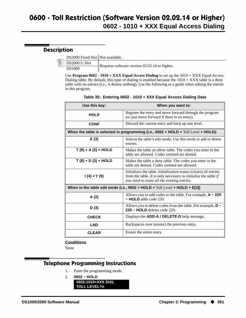
0600 - Toll Restriction (Software Version 02.02.14 or Higher)0602 - 1010 + XXX Equal Access Dialing
DS1000/2000 Software Manual Chapter 2: Programming ◆ 561
0602 - 1010 + XXX Equal Access Dialing
Description
Use Program 0602 - 1010 + XXX Equal Access Dialing to set up the 1010 + XXX Equal Access Dialing table. By default, this type of dialing is enabled because the 1010 + XXX table is a deny table with no entries (i.e., it denies nothing). Use the following as a guide when editing the entries in this program.
ConditionsNone
Telephone Programming Instructions1. Enter the programming mode.
2. 0602 + HOLD
DS2000 Fixed Slot Not available.
DS2000 U SlotRequires software version 02.02.14 or higher.
DS1000
Table 35: Entering 0602 - 1010 + XXX Equal Access Dialing Data
Use this key: When you want to:
HOLD Register the entry and move forward through the program (or just move forward if there is no entry).
CONF Discard the current entry and back up one level.
When the table is selected in programming (i.e., 0602 + HOLD + Toll Level + HOLD):
E (3) Selects the table’s edit mode. Use this mode to add or delete entries.
T (8) + A (2) + HOLD Makes the table an allow table. The codes you enter in the table are allowed. Codes omitted are denied.
T (8) + D (3) + HOLD Makes the table a deny table. The codes you enter in the table are denied. Codes omitted are allowed.
I (4) + Y (9)Initializes the table. Initialization erases (clears) all entries from the table. It is only necessary to initialize the table if you need to erase all the existing entries.
When in the table edit mode (i.e., 0602 + HOLD + Toll Level + HOLD + E[3])
A (2) Allows you to add codes to the table. For example, A + 220 + HOLD adds code 220.
D (3) Allows you to delete codes from the table. For example, D + 220 + HOLD deletes code 220.
CHECK Displays the ADD-A / DELETE-D help message.
LND Backspaces over (erases) the previous entry.
CLEAR Erases the entire entry.
0602:1010+XXX DIALTOLL LEVEL?n

0600 - Toll Restriction (Software Version 02.02.14 or Higher)0602 - 1010 + XXX Equal Access Dialing
562 ◆ Chapter 2: Programming DS1000/2000 Software Manual
3. Enter the Toll Level you want to program (1-7) + HOLD.OR
Press HOLD to select Toll Level 1.
4. Follow the guidelines in Table 35: Entering 0602 - 1010 + XXX Equal Access Dialing Data on page 561 and program the table data.
ORPress CONF to select another Toll Level to program.
ORPress CONF twice to exit program 0602.
0602:n:1010+XXX :DNYEDIT-E/TYPE-T/INIT-I

0600 - Toll Restriction (Software Version 02.02.14 or Higher)0603 - 1 + NPA/NXX Dialing 3-Digit Table
DS1000/2000 Software Manual Chapter 2: Programming ◆ 563
0603 - 1 + NPA/NXX Dialing 3-Digit Table
Description
Use Program 0603 - 1 + NPA/NXX Dialing 3-Digit Table to set up the 1 + NPA/NXX Dialing 3-Digit table. By default, this type of dialing is enabled because the 1 + NPA/NXX Dialing 3-Digit table is a deny table with no entries (i.e., it denies nothing). Use the following as a guide when editing the entries in this program.
ConditionsNone
Telephone Programming Instructions1. Enter the programming mode.
2. 0603 + HOLD
DS2000 Fixed Slot Not available.
DS2000 U SlotRequires software version 02.02.14 or higher.
DS1000
Table 36: Entering 0603 - 1 + NPA/NXX Dialing 3-Digit Table Data
Use this key: When you want to:
HOLD Register the entry and move forward through the program (or just move forward if there is no entry).
CONF Discard the current entry and back up one level.
When the table is selected in programming (i.e., 0603 + HOLD + Toll Level + HOLD):
E (3) Selects the table’s edit mode. Use this mode to add or delete entries.
T (8) + A (2) + HOLD Makes the table an allow table. The codes you enter in the table are allowed. Codes omitted are denied.
T (8) + D (3) + HOLD Makes the table a deny table. The codes you enter in the table are denied. Codes omitted are allowed.
I (4) + Y (9)Initializes the table. Initialization erases (clears) all entries from the table. It is only necessary to initialize the table if you need to erase all the existing entries.
When in the table edit mode (i.e., 0603 + HOLD + Toll Level + HOLD + E[3])
A (2) Allows you to add codes to the table. For example, A + 203 + HOLD adds code 203.
D (3) Allows you to delete codes from the table. For example, D + 203 + HOLD deletes code 203.
CHECK Displays the ADD-A / DELETE-D help message.
LND Backspaces over (erases) the previous entry.
CLEAR Erases the entire entry.
0603:1+NPA DIALINGTOLL LEVEL?n

0600 - Toll Restriction (Software Version 02.02.14 or Higher)0603 - 1 + NPA/NXX Dialing 3-Digit Table
564 ◆ Chapter 2: Programming DS1000/2000 Software Manual
3. Enter the Toll Level you want to program (1-7) + HOLD.OR
Press HOLD to select Toll Level 1.
4. Follow the guidelines in Table 36: Entering 0603 - 1 + NPA/NXX Dialing 3-Digit Table Data on page 563 and program the table data.
ORPress CONF to select another Toll Level to program.
ORPress CONF twice to exit program 0603.
0603:n:1+NPA :ALWEDIT-E/TYPE-T/INIT-I

0600 - Toll Restriction (Software Version 02.02.14 or Higher)0604 - 1 + NPA + NXX Dialing 6-Digit Table
DS1000/2000 Software Manual Chapter 2: Programming ◆ 565
0604 - 1 + NPA + NXX Dialing 6-Digit Table
Description
Use Program 0604 - 1 + NPA + NXX Dialing 6-Digit Table to set up the 1 + NPA + NXX Dialing 6-Digit table. By default, this type of dialing is enabled because the 1 + NPA + NXX Dialing 6-Digit table is a deny table with no entries (i.e., it denies nothing). Use the following as a guide when editing the entries in this program.
ConditionsNone
Telephone Programming Instructions1. Enter the programming mode.
2. 0604 + HOLD
DS2000 Fixed Slot Not available.
DS2000 U SlotRequires software version 02.02.14 or higher.
DS1000
Table 37: Entering 0604 - 1 + NPA + NXX Dialing 6-Digit Table Data
Use this key: When you want to:
HOLD Register the entry and move forward through the program (or just move forward if there is no entry).
CONF Discard the current entry and back up one level.
When the table is selected in programming (i.e., 0604 + HOLD + Toll Level + HOLD):
E (3) Selects the table’s edit mode. Use this mode to add or delete entries.
T (8) + A (2) + HOLD Makes the table an allow table. The codes you enter in the table are allowed. Codes omitted are denied.
T (8) + D (3) + HOLD Makes the table a deny table. The codes you enter in the table are denied. Codes omitted are allowed.
I (4) + Y (9)Initializes the table. Initialization erases (clears) all entries from the table. It is only necessary to initialize the table if you need to erase all the existing entries.
When in the table edit mode (i.e., 0604 + HOLD + Toll Level + HOLD + E[3])
A (2) Allows you to add codes to the table. For example, A + 203926 + HOLD adds code 203926.
D (3) Allows you to delete codes from the table. For example, D + 203926 + HOLD deletes code 203926.
CHECK Displays the ADD-A / DELETE-D help message.
LND Backspaces over (erases) the previous entry.
CLEAR Erases the entire entry.
0604:1+NPA+NXX DIALTOLL LEVEL?n

0600 - Toll Restriction (Software Version 02.02.14 or Higher)0604 - 1 + NPA + NXX Dialing 6-Digit Table
566 ◆ Chapter 2: Programming DS1000/2000 Software Manual
3. Enter the Toll Level you want to program (1-7) + HOLD.OR
Press HOLD to select Toll Level 1.
4. Follow the guidelines in Table 37: Entering 0604 - 1 + NPA + NXX Dialing 6-Digit Table Data on page 565 and program the table data.
ORPress CONF to select another Toll Level to program.
ORPress CONF twice to exit program 0604.
0604:n:1+NPA+NXX:DNYEDIT-E/TYPE-T/INIT-I

0600 - Toll Restriction (Software Version 02.02.14 or Higher)0605 - NPA/NXX Dialing 3-Digit Table
DS1000/2000 Software Manual Chapter 2: Programming ◆ 567
0605 - NPA/NXX Dialing 3-Digit Table
Description
Use Program 0605 - NPA/NXX Dialing 3-Digit Table to set up the NPA/NXX Dialing 3-Digit table. By default, this type of dialing is enabled because the NPA/NXX Dialing 3-Digit table is a deny table with no entries (i.e., it denies nothing). Use the following as a guide when editing the entries in this program.
ConditionsNone
Telephone Programming Instructions1. Enter the programming mode.
2. 0605 + HOLD
DS2000 Fixed Slot Not available.
DS2000 U SlotRequires software version 02.02.14 or higher.
DS1000
Table 38: Entering 0605 - NPA/NXX Dialing 3-Digit Table Data
Use this key: When you want to:
HOLD Register the entry and move forward through the program (or just move forward if there is no entry).
CONF Discard the current entry and back up one level.
When the table is selected in programming (i.e., 0605 + HOLD + Toll Level + HOLD):
E (3) Selects the table’s edit mode. Use this mode to add or delete entries.
T (8) + A (2) + HOLD Makes the table an allow table. The codes you enter in the table are allowed. Codes omitted are denied.
T (8) + D (3) + HOLD Makes the table a deny table. The codes you enter in the table are denied. Codes omitted are allowed.
I (4) + Y (9)Initializes the table. Initialization erases (clears) all entries from the table. It is only necessary to initialize the table if you need to erase all the existing entries.
When in the table edit mode (i.e., 0605 + HOLD + Toll Level + HOLD + E[3])
A (2) Allows you to add codes to the table. For example, A + 203 + HOLD adds code 203.
D (3) Allows you to delete codes from the table. For example, D + 203 + HOLD deletes code 203.
CHECK Displays the ADD-A / DELETE-D help message.
LND Backspaces over (erases) the previous entry.
CLEAR Erases the entire entry.
0605:=NPA/NXX DIALINGTOLL LEVEL?n

0600 - Toll Restriction (Software Version 02.02.14 or Higher)0605 - NPA/NXX Dialing 3-Digit Table
568 ◆ Chapter 2: Programming DS1000/2000 Software Manual
3. Enter the Toll Level you want to program (1-7) + HOLD.OR
Press HOLD to select Toll Level 1.
4. Follow the guidelines in Table 38: Entering 0605 - NPA/NXX Dialing 3-Digit Table Data on page 567 and program the table data.
ORPress CONF to select another Toll Level to program.
ORPress CONF twice to exit program 0605.
0605:n:NPA/NXX :DNYEDIT-E/TYPE-T/INIT-I
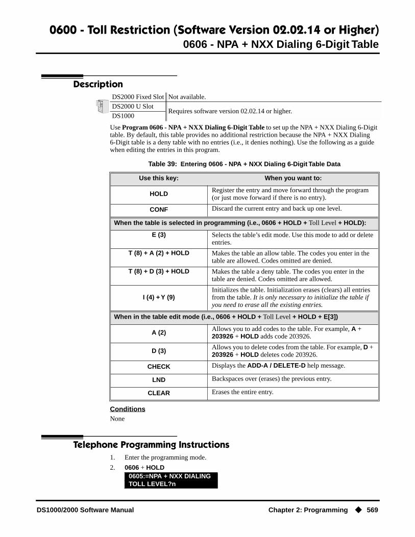
0600 - Toll Restriction (Software Version 02.02.14 or Higher)0606 - NPA + NXX Dialing 6-Digit Table
DS1000/2000 Software Manual Chapter 2: Programming ◆ 569
0606 - NPA + NXX Dialing 6-Digit Table
Description
Use Program 0606 - NPA + NXX Dialing 6-Digit Table to set up the NPA + NXX Dialing 6-Digit table. By default, this table provides no additional restriction because the NPA + NXX Dialing 6-Digit table is a deny table with no entries (i.e., it denies nothing). Use the following as a guide when editing the entries in this program.
ConditionsNone
Telephone Programming Instructions1. Enter the programming mode.
2. 0606 + HOLD
DS2000 Fixed Slot Not available.
DS2000 U SlotRequires software version 02.02.14 or higher.
DS1000
Table 39: Entering 0606 - NPA + NXX Dialing 6-Digit Table Data
Use this key: When you want to:
HOLD Register the entry and move forward through the program (or just move forward if there is no entry).
CONF Discard the current entry and back up one level.
When the table is selected in programming (i.e., 0606 + HOLD + Toll Level + HOLD):
E (3) Selects the table’s edit mode. Use this mode to add or delete entries.
T (8) + A (2) + HOLD Makes the table an allow table. The codes you enter in the table are allowed. Codes omitted are denied.
T (8) + D (3) + HOLD Makes the table a deny table. The codes you enter in the table are denied. Codes omitted are allowed.
I (4) + Y (9)Initializes the table. Initialization erases (clears) all entries from the table. It is only necessary to initialize the table if you need to erase all the existing entries.
When in the table edit mode (i.e., 0606 + HOLD + Toll Level + HOLD + E[3])
A (2) Allows you to add codes to the table. For example, A + 203926 + HOLD adds code 203926.
D (3) Allows you to delete codes from the table. For example, D + 203926 + HOLD deletes code 203926.
CHECK Displays the ADD-A / DELETE-D help message.
LND Backspaces over (erases) the previous entry.
CLEAR Erases the entire entry.
0605:=NPA + NXX DIALINGTOLL LEVEL?n

0600 - Toll Restriction (Software Version 02.02.14 or Higher)0606 - NPA + NXX Dialing 6-Digit Table
570 ◆ Chapter 2: Programming DS1000/2000 Software Manual
3. Enter the Toll Level you want to program (1-7) + HOLD.OR
Press HOLD to select Toll Level 1.
4. Follow the guidelines in Table 39: Entering 0606 - NPA + NXX Dialing 6-Digit Table Data on page 569 and program the table data.
ORPress CONF to select another Toll Level to program.
ORPress CONF twice to exit program 0606.
0606:n:NPA+NXX :DNYEDIT-E/TYPE-T/INIT-I

0600 - Toll Restriction (Software Version 02.02.14 or Higher)0610 - PBX Access Codes Table
DS1000/2000 Software Manual Chapter 2: Programming ◆ 571
0610 - PBX Access Codes Table
Description
Use 0610 - PBX Access Codes Table to enter the system’s PBX Access Codes. You can enter up to 10 PBX Access Codes. Each code is either 1 or 2 digits long, using the digits 0-9. You can use * as a wild card character that can be entered in any position. Use the following as a guide when programming.
ConditionsNone
Telephone Programming Instructions1. Enter the programming mode.
2. 0610 + HOLD
3. Press Vol ▲ or Vol ▼ to scroll to the code you want to program (0-9) + HOLD.OR
Press HOLD to program PBX Access Code 0.
4. Following the guidelines in Table 40: Entering 0610 - PBX Access Codes Table Data on page 571, enter your PBX Access Codes into the table.
5. Program the next consecutive PBX Access Code.OR
Press Vol ▲ or Vol ▼ to scroll to the code you want to program (0-9) + HOLD.OR
Press CONF to exit program 0610.
DS2000 Fixed Slot Not available.
DS2000 U SlotRequires software version 02.02.14 or higher.
DS1000
Table 40: Entering 0610 - PBX Access Codes Table Data
When entering a code into the table (i.e., 0610 + HOLD + HOLD):
HOLD Registers the entry and moves forward through the program (or just moves forward if there is no entry).
CONF Discards the current entry and backs up one level.
CLEAR Erases the current entry.
CHECK Restores the previous entry.
Vol ▲ and Vol ▼ Scrolls through the table entries.
0610:PBX CODE TABLEPBX CODE # ?(0-9)n
0610:PBX CODE #nACCESS CODE ?
0610:PBX CODE TABLEPBX CODE # ?(0-9)n

0600 - Toll Restriction (Prior to Software Version 02.02.14)0601 - Toll Restriction Options
572 ◆ Chapter 2: Programming DS1000/2000 Software Manual
0600 - Toll Restriction (Prior to Software Version 02.02.14)
0601 - Toll Restriction Options
Description
Use Program 0601- Toll Restriction Options to assign Toll Restriction options to each of the seven Toll Levels (1-7). When you assign a Toll Level to an extension, the extension uses the options set up in this program.
ConditionsNone
DS2000 Fixed Slot
Not available.DS2000 U Slot
DS1000
Table 41: Program 0601 - Toll Restriction Options
Option Description Entries Default
Program Toll Restriction Use this option to program Toll Restriction. (You must always use the following option to initialize Toll Restriction before using it for the first time.)• See Toll Restriction (Prior to Software
Version 02.02.14) on page 447 for more.
PROG-PP = Program
N/A
Initialize Toll Restriction Use this option to initialize Toll Restriction. You must always initialize Toll Restriction before using if for the first time. If you have already programmed Toll Restriction, initial-izing will erase all your entries and reinstate the default Toll Restriction values.• See Toll Restriction (Prior to Software
Version 02.02.14) on page 447 for more.
INIT-II = Initialize
N/A
Toll Restriction Level Use this option to select the Toll Restriction level you want to program. The entries that follow pertain to the Toll Restriction Level you select in this step.• See Toll Restriction (Prior to Software
Version 02.02.14) on page 447 for more.
TOLL LEVEL1-7
1
Active Dial Pad Use this option to enable or disable Active Dial Pad (continuous dialing) for trunk calls.• See Toll Restriction (Prior to Software
Version 02.02.14) on page 447 for more.
ACTIVE DIAL PAD?Y = EnableN = Disable
Y
N11 Dialing Use this option to enable or disable dial N11 services such as directory assistance (411) and repair (611). This option does not restrict 911 or 1 + 911 calls. These calls are always allowed.• See Toll Restriction (Prior to Software
Version 02.02.14) on page 447 for more.
N11 DIALING?Y = EnableN = Disable
Y

0600 - Toll Restriction (Prior to Software Version 02.02.14)0601 - Toll Restriction Options
DS1000/2000 Software Manual Chapter 2: Programming ◆ 573
0 + Dialing Use this option to enable or disable an exten-sion’s ability to manually dial 0 + (operator assisted) calls.• See Toll Restriction (Prior to Software
Version 02.02.14) on page 447 for more.
0 + DIALING?Y = EnableN = Disable
Y
International Dialing Use this option to enable or disable 011 (international) dialing.• See Toll Restriction (Prior to Software
Version 02.02.14) on page 447 for more.
INT’L DIAL?Y = EnableN = Disable
Y
Equal Access Dialing This option allows/prevents an extension user from directly dialing Equal Access (10XXX) calls. The system compares the 10XXX codes the user dials to the 10XXX table that you program.• See Toll Restriction (Prior to Software
Version 02.02.14) on page 447 for more.• See Toll Restriction Rules on page 450
for more.
10+XXX DIALINGALLOW OR DENY
TABLE?A = Allow TableD = Deny Table
A(Allow table)
• Enter A to set the table up as an allow table, or D to set the table up as a deny table.
• D to convert an existing allow table into a deny table, or enter A to convert an existing deny table into an allow table.
ADD-A/VIEW-V/DEL-DA = Add a code to the
tableD = Delete a code from
the tableV = View the table entries
N/A
NXX Dialing This option allows/prevents an extension user from directly dialing NXX (local exchange) calls. The system compares the NXX codes the user dials to the NXX table that you program.• See Toll Restriction (Prior to Software
Version 02.02.14) on page 447 for more.• See Toll Restriction Rules on page 450
for more.
NXX DIALINGALLOW OR DENY
TABLE?A = Allow TableD = Deny Table
A(Allow table)
• Enter A to set the table up as an allow table, or D to set the table up as a deny table.
• D to convert an existing allow table into a deny table, or enter A to convert an existing deny table into an allow table.
ADD-A/VIEW-V/DEL-DA = Add a code to the
tableD = Delete a code from
the tableV = View the table entries
N/A
Table 41: Program 0601 - Toll Restriction Options
Option Description Entries Default

0600 - Toll Restriction (Prior to Software Version 02.02.14)0601 - Toll Restriction Options
574 ◆ Chapter 2: Programming DS1000/2000 Software Manual
Telephone Programming InstructionsTo quickly locate the procedure for a Toll Restriction option, go to the steps listed below:
● To select the Toll Level you want to program, go to step 4.
● To enable or disable Active Dial Pad, go to step 5.
● If setting up N11 Dialing, go to step 6.
● When enabling or disabling 0+ Dialing, go to step 7.
● For International Dialing options, go to step 8.
● When programming Equal Access (10XXX) Dialing, go to step 9.
● If you want to configure NXX Dialing, go to step 12.
● To select the NPA Dialing options, go to step 15.
● To set up 6-Digit Analysis, go to 18.
NPA Dialing This option allows/prevents an extension user from directly dialing NPA (area code) calls. The system compares the NPA codes the user dials to the NPA table that you pro-gram.• See Toll Restriction (Prior to Software
Version 02.02.14) on page 447 for more.• See Toll Restriction Rules on page 450
for more.
NPA DIALINGALLOW OR DENY
TABLE?A = Allow TableD = Deny Table
A(Allow table)
• Enter A to set the table up as an allow table, or D to set the table up as a deny table.
• D to convert an existing allow table into a deny table, or enter A to convert an existing deny table into an allow table.
ADD-A/VIEW-V/DEL-DA = Add a code to the
tableD = Delete a code from
the tableV = View the table entries
N/A
6-Digit Analysis This option enables/disables 6-Digit Analy-sis. With 6-Digit Analysis, the system restricts a call according the NPA and NXX the user dials. The system compares the codes the user dials to the 6-Digital Analysis table that you program.• See Toll Restriction (Prior to Software
Version 02.02.14) on page 447 for more.• See Toll Restriction Rules on page 450
for more.
6 DGT ANALYSISALLOW OR DENY
TABLE?A = Allow TableD = Deny Table
A(Allow table)
• Enter A to set the table up as an allow table, or D to set the table up as a deny table.
• D to convert an existing allow table into a deny table, or enter A to convert an existing deny table into an allow table.
ADD-A/VIEW-V/DEL-DA = Add a code to the
tableD = Delete a code from
the tableV = View the table entries
N/A
Table 41: Program 0601 - Toll Restriction Options
Option Description Entries Default

0600 - Toll Restriction (Prior to Software Version 02.02.14)0601 - Toll Restriction Options
DS1000/2000 Software Manual Chapter 2: Programming ◆ 575
1. Enter the programming mode.
2. 0601 + HOLD.
3. Enter P (7) to program Toll Restriction and go to the next step.
OREnter I (4) + HOLD to initialize Toll Restriction and return to the previous step.
You must always initialize Toll Restriction when programming it for the first time. If you initialize an existing Toll Restriction setup, you’ll return all your programmed entries to their factory-installed initial values.
Toll Level
4. Enter the Toll Level you want to program (1-7) + HOLDOR
Press HOLD to select the currently displayed Toll Level.
The options that follow pertain to the Toll Level selected.
Active Dial Pad
5. Enter Y to enable or N to disable Active Dial Pad + VOL ▲.OR
Press VOL ▲ to select the currently displayed value.
The previously programmed value displays.
N11 Dialing
6. Enter Y to enable or N to disable N11 Dialing + VOL ▲.OR
Press VOL ▲ to select the currently displayed value.
The previously programmed value displays
0+ Dialing
7. Enter Y to enable or N to disable 0+ Dialing + VOL ▲.OR
Press VOL ▲ to select the currently displayed value.
The previously programmed value displays
0601:TOLL RESTRICTPROG-P / INIT-I?
0601:TOLL RESTRICTTOLL LEVEL?1
0601:TOLL RESTRICTTABLES INITIALIZED!
0601:TOLL LEVEL:nACTIVE DIAL PAD?n
0601:TOLL LEVEL:nN11 DIALING?nnn
0601:TOLL LEVEL:n0 + DIALING?nnn
0601:TOLL LEVEL:nINT’L DIAL?nnn

0600 - Toll Restriction (Prior to Software Version 02.02.14)0601 - Toll Restriction Options
576 ◆ Chapter 2: Programming DS1000/2000 Software Manual
International Dialing
8. Enter Y to enable or N to disable International Dialing + VOL ▲.OR
Press VOL ▲ to select the currently displayed value.
The previously programmed table type displays (A = allow, D = deny).
Equal Access (10XXX) Dialing
9. Enter A to set up the table as an allow table.OR
Enter D to set up the table as a deny table.
OR
Enter D to convert an existing allow table into a deny table, or enter A to convert an existing deny table into an allow table.
10. Press A to add codes into the table.OR
Press D to delete codes from the table.OR
Press V to view the current contents of the table.If you press V to view the table, the bottom line of the display will show the first set of
table entries. Press V to see the remaining entries. The prompt TABLE DONE tells you when you are at the end of the table or the table is empty. The prompt > tells you that there is additional data in the table to view.
If you press A or D to add codes into the table, you see the prompt DATA. Just enter the codes you want into the table. When entering data, new data appears to the right of the previously entered data. (The system automatically assumes that every group of three dig-its is an entry.)
11. When you are done entering data, press VOL ▲ to go to the next option.
The previously programmed table type displays (A = allow, D = deny).
NXX Dialing
12. Enter A to set up the table as an allow table.OR
Enter D to set up the table as a deny table.
OR
Enter D to convert an existing allow table into a deny table, or enter A to convert an existing deny table into an allow table.
13. Press A to add codes into the table.
0601:10+XXX DIALINGALLOW OR DENY TABLE?
0601:10+XXX ALLW TBLADD-A/VIEW-V/DEL-D?
0601:10+XXX DENY TBLADD-A/VIEW-V/DEL-D?
0601:NXX DIALINGALLOW OR DENY TABLE?
0601:NXX ALLOW TABLEADD-A/VIEW-V/DEL-D?
0601:NXX DENY TABLEADD-A/VIEW-V/DEL-D?

0600 - Toll Restriction (Prior to Software Version 02.02.14)0601 - Toll Restriction Options
DS1000/2000 Software Manual Chapter 2: Programming ◆ 577
ORPress D to delete codes from the table.
ORPress V to view the current contents of the table.
If you press V to view the table, the bottom line of the display will show the first set of table entries. Press V to see the remaining entries. The prompt TABLE DONE tells you when you are at the end of the table or the table is empty. The prompt > tells you that there is additional data in the table to view.
If you press A or D to add codes into the table, you see the prompt DATA. Just enter the codes you want into the table. When entering data, new data appears to the right of the previously entered data. (The system automatically assumes that every group of three dig-its is an entry.)
14. When you are done entering data, press VOL ▲ to go to the next option.
The previously programmed table type displays (A = allow, D = deny).
NPA Dialing
15. Enter A to set up the table as an allow table.OR
Enter D to set up the table as a deny table.
OR
Enter D to convert an existing allow table into a deny table, or enter A to convert an existing deny table into an allow table.
16. Press A to add codes into the table.OR
Press D to delete codes from the table.OR
Press V to view the current contents of the table.If you press V to view the table, the bottom line of the display will show the first set of
table entries. Press V to see the remaining entries. The prompt TABLE DONE tells you when you are at the end of the table or the table is empty. The prompt > tells you that there is additional data in the table to view.
If you press A or D to add codes into the table, you see the prompt DATA. Just enter the codes you want into the table. When entering data, new data appears to the right of the previously entered data. (The system automatically assumes that every group of three dig-its is an entry.)
17. When you are done entering data, press VOL ▲ to go to the next option.
The previously programmed table type displays (A = allow, D = deny).
6-Digit Analysis
18. Enter A to set up the table as an allow table.OR
0601:NPA DIALINGALLOW OR DENY TABLE?
0601:NPA ALLOW TABLEADD-A/VIEW-V/DEL-D?
0601:NPA DENY TABLEADD-A/VIEW-V/DEL-D?
0601:6 DGT ANALYSISALLOW OR DENY TABLE?

0600 - Toll Restriction (Prior to Software Version 02.02.14)0601 - Toll Restriction Options
578 ◆ Chapter 2: Programming DS1000/2000 Software Manual
Enter D to set up the table as a deny table.
OR
Enter D to convert an existing allow table into a deny table, or enter A to convert an existing deny table into an allow table.
19. Press A to add codes into the table.OR
Press D to delete codes from the table.OR
Press V to view the current contents of the table.If you press V to view the table, the bottom line of the display will show the first set of
table entries. Press V to see the remaining entries. The prompt TABLE DONE tells you when you are at the end of the table or the table is empty. The prompt > tells you that there is additional data in the table to view.
If you press A or D to add codes into the table, you see the prompt DATA. Just enter the codes you want into the table. When entering data, new data appears to the right of the previously entered data. (The system automatically assumes that every group of six digits is an entry.)
20. When you are done entering data, press VOL ▲ to go back to the Active Dial Pad option for the currently selected Toll Level.
ORPress CONF to go back to the Program/Initialize option.
ORPress CONF twice to exit Toll Restriction programming.
0601:6 DGT ALLOW TBLADD-A/VIEW-V/DEL-D?
0601:6 DGT ALLOW TBLADD-A/VIEW-V/DEL-D?
0601:TOLL LEVEL:nACTIVE DIAL PAD?nn
0601:TOLL RESTRICTPROG-P / INIT-I

0800 - Display Messages0801 - Selectable Display Messages
DS1000/2000 Software Manual Chapter 2: Programming ◆ 579
0800 - Display Messages
0801 - Selectable Display Messages
Description
Use Program 0801 - Selectable Display Messages to program the system’s 16 Selectable Display Messages. Each message can be up to 20 characters long, including a blank spaces you may want to ad for readability. All messages are appendable by user-entered digits.
When entering names, use Table 19: Keys for Entering Names on page 505. When creating a new user-appendable message, consider adding a space at the end of the text portion to improve read-ability. In the table, the X characters reserve space for user-entered digits.
● See Selectable Display Messaging on page 376 for more.
ConditionsNone
DS2000 Fixed Slot
Available.DS2000 U Slot
DS1000
Table 42: Program 0801 - Selectable Display Messages
Option Default
Message 01 CALL (plus 15 user entries)
Message 02 BACK BY (plus 12 user entries)
Message 03 MEETING IN RM (plus 4 user entries)
Message 04 OUT TO LUNCH (plus 7 user entries)
Message 05 GONE FOR THE DAY (plus 3 user entries)
Message 06 ON VACATION (plus 8 user entries)
Message 07 ON BUSINESS TRIP (plus 3 user entries)
Message 08 IN THE MEETING (plus 7 user entries)
Message 09 OUT UNTIL (plus 10 user entries)
Message 10 Undefined (up to 20 characters)
Message 11 Undefined (up to 20 characters)
Message 12 Undefined (up to 20 characters)
Message 13 Undefined (up to 20 characters)
Message 14 Undefined (up to 20 characters)
Message 15 Undefined (up to 20 characters)
Message 16 Undefined (up to 20 characters)

0800 - Display Messages0801 - Selectable Display Messages
580 ◆ Chapter 2: Programming DS1000/2000 Software Manual
Telephone Programming Instructions1. Enter the programming mode.
2. 0801 + HOLD
3. Enter the number of the message you want to program + HOLD.
The previously programmed message displays.
4. Enter the new display message + HOLD.OR
Press HOLD to leave the current value unchanged.
0801:DISPLAY MESSAGEMESSAGE NUM?
0801:DISPLAY MESSAGE(message text)
0801:DISPLAY MESSAGEMESSAGE NUM?

1000 - Trunk Programming1001 - Trunk Port Description
DS1000/2000 Software Manual Chapter 2: Programming ◆ 581
1000 - Trunk Programming
1001 - Trunk Port Description
Description
Use Program 1001 - Trunk Port Description to program various options for trunks ports.
Note: If you are doing extensive programming, you may find Program 9801 - Copy Command (page 657) saves you time when customizing this option.
Also see Program 1003 - Trunk Options on page 593.
ConditionsPer FCC regulations, do not set 1001- Trunk Transmit Gain on page 582 higher than 0 dB.
DS2000 Fixed Slot Available.
DS2000 U Slot Enables the following options:• Caller ID• Voice Mail Caller IDIn DS1000, Trunks 4-6 require the Expansion Board.
DS1000
Table 43: Program 1001 - Trunk Port Description
Option Description Entries Default
Trunk Circuit Type Use this option to set the trunk’s circuit type. Set this option for compatibility with the connected telco or PBX.• See Central Office Calls, Answering on
page 99 for more.• See Central Office Calls, Placing on
page 105 for more.• See Direct Inward Line on page 133 for
more.• See Pulse to Tone Conversion on
page 360 for more.
TYP?00 = Uninstalled
51 = Loop start DTMF52 = Loop start DP
51
Trunk Extension Number This option displays the trunk’s extension number programmed in 0504 - Trunk Port Extension Numbers (Fixed Slot) on page 543. This is for viewing only. You can-not edit this option from Program 1001.
EXT:(View only)
4nn(View only)
Trunk Name Use this option to assign a name to the trunk port.• Refer to Table 19: Keys for Entering
Names on page 505 when entering names.
• See Names for Extensions and Trunks on page 306 for more.
NAME: TRUNK nn

1000 - Trunk Programming1001 - Trunk Port Description
582 ◆ Chapter 2: Programming DS1000/2000 Software Manual
Trunk Transmit Gain Use this option to set the trunk’s transmit gain. This gain setting allows you to com-pensate for the transmit gain characteristics of the connected telco or PBX. The setting is applied to each line seizure.• See Central Office Calls, Answering on
page 99 for more.• See Central Office Calls, Placing on
page 105 for more.•• See PBX/Centrex Compatibility on
page 339 for more.
TRANSMIT GAIN?0 = 0 dB gain1 = .5 dB gain2 = 1 dB gain
3 = 1.5 dB gain4 = 2 dB gain
5 = 2.5 dB gain6 = 3 dB gain
7 = 3.5 dB gain8 = 4 dB gain
9 = 4.5 dB gain10 = 5 dB gain
11 = 5.5 dB gain12 = 6 dB gain
13 = 6.5 dB gain14 = 7 dB gain
15 = 7.5 dB gain16 = 8 dB gain
17 = 8.5 dB gain18 = 9 dB gain
19 = 9.5 dB gain20 = 10 dB gain
21 = 10.5 dB gain22 = 11 dB gain
23 = -11.5 dB gain24 = 12 dB gain
25 = 12.5 dB gain26 = 13 dB gain
27 = 13.5 dB gain28 = 14 dB gain
29 = 14.5 dB gain30 = 15 dB gain
0
Table 43: Program 1001 - Trunk Port Description
Option Description Entries Default

1000 - Trunk Programming1001 - Trunk Port Description
DS1000/2000 Software Manual Chapter 2: Programming ◆ 583
TRANSMIT GAIN? (Cont’d)
31 = .5 dB loss32 = 1 dB loss
33 = 1.5 dB loss34 = 2 dB loss
35 = 2.5 dB loss36 = 3 dB loss
37 = 3.5 dB loss38 = 4 dB loss
39 = 4.5 dB loss40 = 5 dB loss
41 = 5.5 dB loss42 = 6 dB loss
43 = 6.5 dB loss44 = 7 dB loss
45 = 7.5 dB loss46 = 8 dB loss
47 = 8.5 dB loss48 = 9 dB loss
49 = 9.5 dB loss50 = 10 dB loss
51 = 10.5 dB loss52 = 11 dB loss
53 = 11.5 dB loss54 = 12 db loss
55 = 12.5 dB loss56 = 13 dB loss
57 = 13.5 dB loss58 = 14 dB loss59 = 14.5 loss
60 = 15 dB loss
0
Table 43: Program 1001 - Trunk Port Description
Option Description Entries Default

1000 - Trunk Programming1001 - Trunk Port Description
584 ◆ Chapter 2: Programming DS1000/2000 Software Manual
Trunk Receive Gain Use this option to set the trunk’s receive gain. This gain setting allows you to com-pensate for the receive gain characteristics of the connected telco or PBX. The setting is applied to each line siezure.• See Central Office Calls, Answering on
page 99 for more.• See Central Office Calls, Placing on
page 105 for more.• See PBX/Centrex Compatibility on
page 339 for more.
RECEIVE GAIN?0 = 0 dB gain1 = .5 dB gain2 = 1 dB gain
3 = 1.5 dB gain4 = 2 dB gain
5 = 2.5 dB gain6 = 3 dB gain
7 = 3.5 dB gain8 = 4 dB gain
9 = 4.5 dB gain10 = 5 dB gain
11 = 5.5 dB gain12 = 6 dB gain
13 = 6.5 dB gain14 = 7 dB gain
15 = 7.5 dB gain16 = 8 dB gain
17 = 8.5 dB gain18 = 9 dB gain
19 = 9.5 dB gain20 = 10 dB gain
21 = 10.5 dB gain22 = 11 dB gain
23 = -11.5 dB gain24 = 12 dB gain
25 = 12.5 dB gain26 = 13 dB gain
27 = 13.5 dB gain28 = 14 dB gain
29 = 14.5 dB gain30 = 15 dB gain
0
Table 43: Program 1001 - Trunk Port Description
Option Description Entries Default

1000 - Trunk Programming1001 - Trunk Port Description
DS1000/2000 Software Manual Chapter 2: Programming ◆ 585
RECEIVE GAIN? (Cont’d)
31 = .5 dB loss32 = 1 dB loss
33 = 1.5 dB loss34 = 2 dB loss
35 = 2.5 dB loss36 = 3 dB loss
37 = 3.5 dB loss38 = 4 dB loss
39 = 4.5 dB loss40 = 5 dB loss
41 = 5.5 dB loss42 = 6 dB loss
43 = 6.5 dB loss44 = 7 dB loss
45 = 7.5 dB loss46 = 8 dB loss
47 = 8.5 dB loss48 = 9 dB loss
49 = 9.5 dB loss50 = 10 dB loss
51 = 10.5 dB loss52 = 11 dB loss
53 = 11.5 dB loss54 = 12 db loss
55 = 12.5 dB loss56 = 13 dB loss
57 = 13.5 dB loss58 = 14 dB loss59 = 14.5 loss
60 = 15 dB loss
0
Trunk Class of Service Assignment
Use this option to assign Class of Service (1-15) to trunks.
CLASS OF SERVICE?1-15
1
PBX Line Use this option to designate a trunk as a PBX line. Enable this option if the trunk connects to a PBX instead of the telco.• See PBX/Centrex Compatibility on
page 339 for more.
PBX LINEY = EnableN = Disable
N
Disable Forced Account Codes
Use this option to enable or disable forced Account Codes for the trunk. If Y (Yes), the system will not enforce Forced Account Codes. If N (No), the system will enforce Forced Account Codes.• See Account Codes on page 34 for more.
DISABLENo (Forced Account Codes are enabled)
Yes (Forced Account Codes are disabled)
No (Forced Account
Codes are enabled)
Table 43: Program 1001 - Trunk Port Description
Option Description Entries Default

1000 - Trunk Programming1001 - Trunk Port Description
586 ◆ Chapter 2: Programming DS1000/2000 Software Manual
Loop Length Use this option to compensate for a trunk’s loop length. Use the short option (1) only when the system is very close to the central office or behind a PBX. Use the long option (2) for normal installations.• See Central Office Calls, Answering on
page 99 for more.• See Central Office Calls, Placing on
page 105 for more.
LOOP LENGTH1 = Short loop2 = Long loop
2 (Long loop)
Trunk Toll Restriction Level
Use this option to set the Toll Level of the trunk during the day mode. If this Toll Level is higher than the extension’s Toll Level, it may cause additional dialing restrictions. If it is lower, it will have no effect.• See Toll Restriction (Prior to Software
Version 02.02.14) on page 447 for more.
TOLL LEVEL?0-7
0
Override Extension Toll Restriction
Use this option to “release” the Toll Restric-tion on a trunk. If enabled, any user can dial any number on the trunk without restriction.• See Toll Restriction (Prior to Software
Version 02.02.14) on page 447 for more.
OVRD EXT TL LVL?Y = Toll Restriction over-
riddenN = Toll Restriction not
overridden
No
Print SMDR Use this option to have the SMDR report include or exclude the trunk.• See Station Message Detail Recording
on page 400 for more.
PRINT SMDR?Y = Yes (include in
SMDR report)N = No (exclude from
SMDR report)
Yes
Caller ID Use this option to enable or disable Caller ID for each trunk. If enabled, Caller ID will occur if also enabled by the other Caller ID programmable options.• To enable Daughter Board Caller ID in
DS2000, enter 2.• To enable DSP Caller ID, enter 1.• If disabled (by entering 0), Caller ID will
never occur.• See Caller ID on page 82 for more.
CALLER ID?DS1000
0 = CLID disabled1 = DSP CLID enabled
DS2000 prior to 02.00.06Y = Yes (Caller ID
allowed)N = No (Caller ID pre-
vented)
DS2000 02.00.06 through 02.02.00
0 = CLID disabled2 = Daughter Board
DS2000 02.02.14 or higher
0 = CLID disabled1 = DSP CLID enabled
2 = Daughter Board CLID enabled
No
Table 43: Program 1001 - Trunk Port Description
Option Description Entries Default
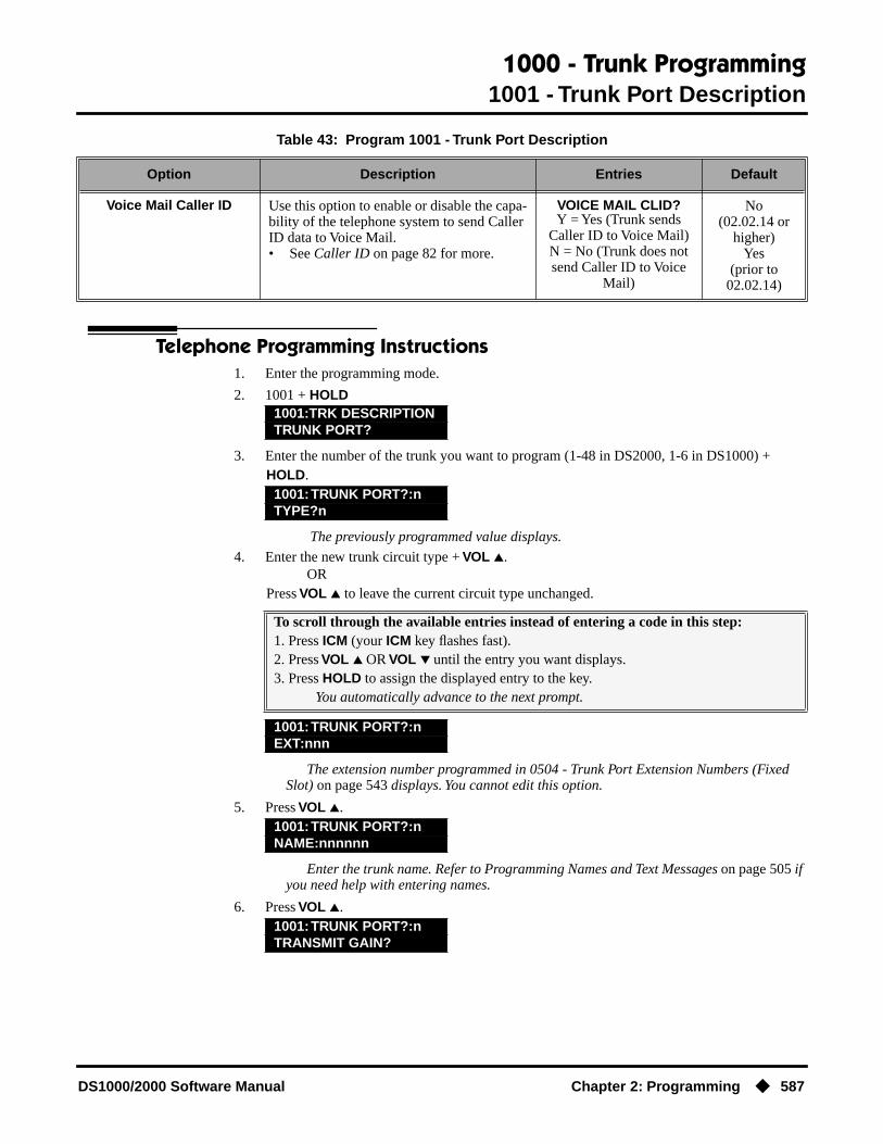
1000 - Trunk Programming1001 - Trunk Port Description
DS1000/2000 Software Manual Chapter 2: Programming ◆ 587
Telephone Programming Instructions1. Enter the programming mode.
2. 1001 + HOLD
3. Enter the number of the trunk you want to program (1-48 in DS2000, 1-6 in DS1000) + HOLD.
The previously programmed value displays.
4. Enter the new trunk circuit type + VOL ▲.OR
Press VOL ▲ to leave the current circuit type unchanged.
The extension number programmed in 0504 - Trunk Port Extension Numbers (Fixed Slot) on page 543 displays. You cannot edit this option.
5. Press VOL ▲.
Enter the trunk name. Refer to Programming Names and Text Messages on page 505 if you need help with entering names.
6. Press VOL ▲.
Voice Mail Caller ID Use this option to enable or disable the capa-bility of the telephone system to send Caller ID data to Voice Mail.• See Caller ID on page 82 for more.
VOICE MAIL CLID?Y = Yes (Trunk sends
Caller ID to Voice Mail)N = No (Trunk does not send Caller ID to Voice
Mail)
No(02.02.14 or
higher)Yes
(prior to 02.02.14)
1001:TRK DESCRIPTIONTRUNK PORT?
1001: TRUNK PORT?:nTYPE?n
To scroll through the available entries instead of entering a code in this step:1. Press ICM (your ICM key flashes fast).2. Press VOL ▲ OR VOL ▼ until the entry you want displays.3. Press HOLD to assign the displayed entry to the key.
You automatically advance to the next prompt.
1001: TRUNK PORT?:nEXT:nnn
1001: TRUNK PORT?:nNAME:nnnnnn
1001: TRUNK PORT?:nTRANSMIT GAIN?
Table 43: Program 1001 - Trunk Port Description
Option Description Entries Default

1000 - Trunk Programming1001 - Trunk Port Description
588 ◆ Chapter 2: Programming DS1000/2000 Software Manual
7. Enter the new transmit gain + VOL ▲.OR
Press VOL ▲ to leave the transmit gain unchanged.
8. Enter the new receive gain + VOL ▲.OR
Press VOL ▲ to leave the current receive gain unchanged.
9. Enter the new Class of Service for the trunk + VOL ▲.OR
Press VOL ▲ to leave the current Class of Service unchanged.
10. Enter Y to assign or N to unassign the line as a PBX line + VOL ▲.OR
Press VOL ▲ to leave the current assignment unchanged.
11. Enter Y to enable or N to disable Forced Account Codes for the trunk + VOL ▲.OR
Press VOL ▲ to leave the current assignment unchanged.
12. Enter 1 for short loop or 2 for long loop (the normal setting) + VOL ▲.OR
Press VOL ▲ to leave the current assignment unchanged.
13. Enter the new Toll Level for the trunk (1-7) + HOLD.OR
Press VOL ▲ to leave the current Toll Level unchanged.
Press VOL ▲ to leave the current assignment unchanged.14. Enter Y + VOL ▲ to override (release) Toll Restriction for the trunk.
OREnter N + VOL ▲ to enforce the extension’s Toll Restriction.
ORPress VOL ▲ to leave the current assignment unchanged.
15. Enter Y + VOL ▲ to have calls on the trunk included on the SMDR report.OR
Enter N + VOL ▲ to have the calls excluded from the SMDR report.OR
1001: TRUNK PORT?:nRECEIVE GAIN?
1001: TRUNK PORT?:nCLASS OF SERVICE?
1001: TRUNK PORT?:nPBX LINE?
1001: TRUNK PORT?:nDISABLE FORCE AC?nn
1001: TRUNK PORT?:nLOOP LENGTH?
1001: TRUNK PORT?:nTOLL LEVEL?
1001: TRUNK PORT?:nOVRD EXT TL LVL?
1001: TRUNK PORT?:nPRINT SMDR?
1000 - Trunk Programming1001 - Trunk Port Description
DS1000/2000 Software Manual Chapter 2: Programming ◆ 589
Press VOL ▲ to leave the current assignment unchanged.
16. Enter 0 to disable Caller ID on the trunk, 1 to enable DSP Caller ID on the trunk, or 2 to enable Daughter Board Caller ID on the trunk (DS2000 only) + VOL ▲.
ORPress VOL ▲ to leave the current assignment unchanged.
With DS2000 DSP Caller ID in software versions 02.04.00 or higher, after you enter 1 and press Vol ▲ the prompt will show DSP (ATRUv2.0+) indicating that ATRU PCB firm-ware 2.0 or higher is required.
17. Enter Y to enable or N to disable the capability of the phone system to send Caller ID data to Voice Mail + VOL ▲.
ORPress VOL ▲ to leave the current assignment unchanged.
18. Go back to step 4 and enter a new circuit type data for the selected trunk.OR
Press CONF and go back to step 3 to select another trunk.OR
Press CONF twice to exit the program.
1001: TRUNK PORT?:nCLID?nnnn
1001: TRUNK PORT?:nVOICE MAIL CLID?nn
1001:TRUNK PORT?:nTYPE?nnnnnnnn

1000 - Trunk Programming1002 - Trunk Groups
590 ◆ Chapter 2: Programming DS1000/2000 Software Manual
1002 - Trunk Groups
Description
Use Program 1002 - Trunk Groups to assign trunks (1-48 in DS2000, 1-6 in DS1000) to trunk groups (0-8). This program also lets you assign the priority of trunks within each group. When a user seizes a trunk group, the system selects the lowest order trunk in the group first. If the lowest order trunk is busy or out of service, the system searches sequentially by order number (e.g., from order 01 to order 02) for the first available trunk.
When entering data, software version 02.01.07 and higher provide the following additional entry options. These options make it easier to enter data and help prevent inadvertent entry errors.
Pressing HOLD validates and registers entries.When you are done entering data for a Trunk Group, you must press HOLD. When you press HOLD:
● The system compares the Trunk Group you just programmed against all other Trunk Groups. If a trunk exists in more than one group, the system retains it in the last Trunk Group you pro-grammed and deletes it from all other groups. For example, if group 1 has trunks1 2 3 4, and you program group 2 with trunks 4 5 6, the system will automatically change group 1 to trunks 1 2 3.
● The system checks the Trunk Group you just programmed for duplicate entries. If you have entered a trunk more than once into the group, the system retains the first entry you made. It dis-cards all other duplicate entries. For example, if you enter trunks 1 2 3 1 4, the system stores 1 2 3 4. You’ll see “DUPLICATE TRK ERASED” if the system deletes any duplicate entries.
Pressing CONF cancels program entry.
● While programming a Trunk Group, press CONF to exit the group and return to the TRUNK GROUP prompt. Any changes you made to the group before pressing CONF are not saved.
Pressing CHECK restores previous entries.
● While programming a Trunk Group, press CHECK to restore the group to its previously saved data and return to the ORDR n: TRK NUM prompt. You might want to do this if you lose track of what you are programming in a group and want to start over.
Pressing CLEAR deletes entries.
● While programming a Trunk Group, press CLEAR to erase the entries from the current posi-tion to the end of the group. For example, in the default program if you press CLEAR at the ORDER 2:TRK NUM?5 prompt, you’ll only retain the ORDER 1:TRK NUM?6 entry. All other entries for the group are erased.
DS2000 Fixed Slot Available. • See Default Setting below for specifics on the initial trunk setup.
DS2000 U Slot
Available.• See Default Setting below for specifics on the initial trunk setup.• In 02.01.07 and higher, dial 9 is disabled by default.• Version 02.01.07 and higher provide additional data entry options.
DS1000
Available.• See Default Setting below for specifics on the initial trunk setup.• In 02.00.09 and higher, dial 9 is enabled be default.• Version 02.01.07 and higher provide additional data entry options.

1000 - Trunk Programming1002 - Trunk Groups
DS1000/2000 Software Manual Chapter 2: Programming ◆ 591
In DS2000, trunks must be on installed PCBs.
● You can only enter a trunk into a Trunk Group it the PCB for that trunk has been properly installed in 9902 - Slot Assignment.
● In addition, if you program a trunk into a group and later on use 9902 - Slot Assignment to remove that trunk’s PCB, the system automatically removes the trunk from the group.
ConditionsNone
Table 44: Program 1002 - Trunk Groups
Option Description Entries Default
Trunk Group • Use this option to select the trunk group you want to program. A trunk can only be in one group.See Loop Keys on page 283 for more.
• See Trunk Group Routing on page 461 for more.
• See Trunk Groups on page 468 for more.
TRUNK GROUP?0-8
Fixed SlotTrunks 1-8 are not
assigned to a trunk group.Trunks 9-16 are in group
1. U Slot Prior to 02.01.07Trunks 1-8 are in group
0.U Slot 02.01.07 or
HigherTrunks are not assigned
to a group.DS1000 Prior to 02.00.09Trunks are not assigned
to a group.DS1000 02.00.09 or
HigherTrunks 1-6 are in group
0.
Order Number Use this option to set the priority of the trunk within the group. When a user seizes a trunk group, the system selects the lowest priority trunk within the group first.• See Trunk Groups on page 468 for more.
ORDER nn:TRK NUM?nn
Fixed SlotThe trunk’s order is the same as its port number
(e.g., 1=1, 2=2).U Slot
Order 1=Trk 8Order 2=Trk 7Order 3=Trk 6Order 4=Trk 5Order 5=Trk 4Order 6=Trk 3Order 7=Trk 2Order 8=Trk 1
DS1000Order 1=Trk 6Order 2=Trk 5Order 3=Trk 4Order 4=Trk 3Order 5=Trk 2Order 6=Trk 1

1000 - Trunk Programming1002 - Trunk Groups
592 ◆ Chapter 2: Programming DS1000/2000 Software Manual
Telephone Programming Instructions1. Enter the programming mode.
2. 1002 + HOLD
3. Select the trunk group you want to program + HOLD.
The trunk currently assigned to order 01 displays.
4. Enter the trunk you want to assign to order 01 + VOL ▲.OR
Press VOL ▲ to leave the current assignment unchanged and advance to the next entry.
5. When you are done entering data for the group, press HOLD
6. Return to step 2 and select another trunk group to program.OR
Press CONF to exit the program.
1002: TRUNK GROUPSTRUNK GROUP?
1002: TRUNK GROUP nnORDER 01: TRK NUM?nn
1002:TRUNK GROUP nnORDER 02: TRK NUM?nn

1000 - Trunk Programming1003 - Trunk Options
DS1000/2000 Software Manual Chapter 2: Programming ◆ 593
1003 - Trunk Options
Description
Use Program 1003 - Trunk Options to program various options for trunks.
Note: If you are doing extensive programming, you may find Program 9801 - Copy Command (page 657) saves you time when customizing this option.
Also see Program 1001 - Trunk Port Description on page 581.
ConditionsNone
DS2000 Fixed SlotAvailable.
DS2000 U Slot
DS1000 Available. Trunks 4-6 require the Expansion Board.
Table 45: Program 1003 - Trunk Options (Part 2)
Option Description Entries Default
Call Pickup Group Use this option to have an incoming call on the trunk ring all the extensions in the assigned pickup group.• See Group Call Pickup on page 215 for
more.
PICK-UP GROUP?1-8
0 = Unassigned
0
Direct Termination (Day) If the trunk is a Direct Inward Line, use this option to set the day termination (answering point). The DIL rings the answering point directly. This option has no effect on other types of trunks.• See Direct Inward Line on page 133 for
more.• See Key Ring on page 273 for more.
DAY TERM?Extension (300-395 in DS2000 or 300-325 in DS1000), UCD master
number, Voice Mail mas-ter number, Ring Group master number or Key
Ring (by pressing CLEAR, or 0 in software
version 02.03.00)
Key Ring
Activate Overflow During the Day
Use this option to enable or disable overflow during the day mode.• See Direct Inward Line on page 133 for
more.• See Key Ring on page 273 for more.
DAY OVERFLOW?Y = Day overflow
enabledN = Day overflow dis-
abled
N
Day Overflow Destination
Use this option to set the overflow destina-tion for day mode calls (including DILs).• See Direct Inward Line on page 133 for
more.• See Key Ring on page 273 for more.
DAY OVRFLW DEST?Extension (300-395 in DS2000 or 300-325 in DS1000), UCD master
number, Voice Mail mas-ter number, Ring Group master number or Key
Ring (by pressing CLEAR, or 0 in software
version 02.03.00)
300

1000 - Trunk Programming1003 - Trunk Options
594 ◆ Chapter 2: Programming DS1000/2000 Software Manual
Direct Termination (Night)
If the trunk is a Direct Inward Line, use this option to set the night termination (answer-ing point). The DIL rings the answering point directly at night. This option has no effect on other types of trunks.• See Direct Inward Line on page 133 for
more.• See Key Ring on page 273 for more.
NIGHT TERM?Extension (300-395 in DS2000 or 300-325 in DS1000), UCD master
number, Voice Mail mas-ter number, Ring Group master number or Key
Ring (by pressing CLEAR, or 0 in software
version 02.03.00)
Key Ring
Activate Overflow at Night
Use this option the enable or disable Night Ring (Universal Night Answer). If enabled, the trunk will activate UNA if it rings while the system is in the night mode.• See Direct Inward Line on page 133 for
more.• See Key Ring on page 273 for more.• See Night Service / Night Ring on
page 308 for more.
NIGHT OVERFLOW?Y = Night overflow
enabledN = Night overflow dis-
abled
N
Night Overflow Destination
Use this option to set the overflow destina-tion for Night Mode calls.• See Direct Inward Line on page 133 for
more.• See Key Ring on page 273 for more.• See Night Service / Night Ring on
page 308 for more.
NT OVRFLW DEST?Extension (300-395 in DS2000 or 300-325 in DS1000), UCD master
number, Voice Mail mas-ter number, Ring Group master number or Key
Ring (by pressing CLEAR, or 0 in software
version 02.03.00)
300
Distinctive Ring (Prior to software version 02.02.14)Use this option to set the Distinctive Ring tone for the trunk. Extension users can adjust the ring frequency of tones 1-6. Tones 7 and 8 are fixed.
DISTINCTIVE RING?1-8
1
Day Ring Type(Software version 02.02.14
or higher)
Use this option to assign a Ring Type for the trunk’s Day Ringing. When the trunk rings an extension in the Day Ring mode, it uses the Ring Type specified in this option.• See Distinctive Ringing on page 162 for
more.
DAY RING TYPE1 (Ring Type A)2 (Ring Type B)3 (Ring Type C)
1(Ring Type A)
Night Ring Type(Software version 02.02.14
or higher)
Use this option to assign a Ring Type for the trunk’s Night Ringing. When the trunk rings an extension in the Night Ring mode, it uses the Ring Type specified in this option.• See Distinctive Ringing on page 162 for
more.
NIGHT RING TYPE1 (Ring Type A)2 (Ring Type B)3 (Ring Type C)
1(Ring Type A)
Table 45: Program 1003 - Trunk Options (Part 2)
Option Description Entries Default

1000 - Trunk Programming1003 - Trunk Options
DS1000/2000 Software Manual Chapter 2: Programming ◆ 595
Telephone Programming Instructions1. Enter the programming mode.
2. 1003 + HOLD
3. Select the trunk port you want to program + HOLD.
The previously programmed Pickup Group displays.
4. Enter the number of the Pickup Group to which the trunk should belong (1-8, 0 for unas-signed) + VOL ▲.
ORPress VOL ▲ to leave the current assignment unchanged and advance to the next entry.
The previously programmed assignment displays.
5. Enter the day mode termination for the trunk + VOL ▲.OR
Press VOL ▲ to leave the current assignment unchanged and advance to the next entry.
The previously programmed assignment displays.
Delay Ring Type(Software version 02.02.14
or higher)
Use this option to assign a Ring Type for the trunk’s Delay Ringing. When the trunk rings an extension in the Delay Ring mode, it uses the Ring Type specified in this option.• See Distinctive Ringing on page 162 for
more.
DELAY RING TYPE1 (Ring Type A)2 (Ring Type B)3 (Ring Type C)
1(Ring Type A)
MOH Source Use this option to assign the Music on Hold music source.• See Music on Hold on page 303 for
more.
MOH SOURCE?0 = None
1 = External (CPU termi-nals)
2 = Tone 1 (low pitch)3 = Tone 2 (high pitch)4 = ACI port (currently
not used)
1
Tandem Trunk Use this option to enable or disable a trunk’s ability to be included in an Unsupervised Conference.• See Tandem Trunking / Unsupervised
Conference on page 433 for more.
TANDEM TRUNK?Y = Unsupervised Con-
ference enabledN = Unsupervised Con-
ference disabled
N
1003: TRUNK OPTIONTRUNK PORT?
1003: TRUNK PORT?:nPICK-UP GROUP?nn
1003: TRUNK PORT?:nDAY TERM?nnn
1003: TRUNK PORT?:nDAY OVERFLOW?n
Table 45: Program 1003 - Trunk Options (Part 2)
Option Description Entries Default

1000 - Trunk Programming1003 - Trunk Options
596 ◆ Chapter 2: Programming DS1000/2000 Software Manual
6. Enter Y to enable or N to disable day mode ringing for the trunk + VOL ▲.OR
Press VOL ▲ to leave the current assignment unchanged and advance to the next entry.
The previously programmed assignment displays.
7. Enter the day mode overflow destination + VOL ▲.OR
Press VOL ▲ to leave the current assignment unchanged and advance to the next entry.
The previously programmed assignment displays.
8. Enter the night mode termination for the trunk + VOL ▲.OR
Press VOL ▲ to leave the current assignment unchanged and advance to the next entry.
The previously programmed assignment displays.
9. Enter Y to enable or N to disable night mode ringing for the trunk + VOL ▲.OR
Press VOL ▲ to leave the current assignment unchanged and advance to the next entry.
The previously programmed assignment displays.
10. Enter the night mode overflow destination + VOL ▲.OR
Press VOL ▲ to leave the current assignment unchanged and advance to the next entry.
The previously programmed assignment displays.
11. Enter the Distinctive Ringing day ring Ring Type (1 =Ring Type A, 2=Ring Type B, 3=Ring Type C) + VOL ▲.
ORPress VOL ▲ to leave the current assignment unchanged and advance to the next entry.
The previously programmed assignment displays.
12. Enter the Distinctive Ringing night ring Ring Type (1 =Ring Type A, 2=Ring Type B, 3=Ring Type C) + VOL ▲.
ORPress VOL ▲ to leave the current assignment unchanged and advance to the next entry.
The previously programmed assignment displays.
1003: TRUNK PORT?:nDAY OVRFLW DEST?nnn
1003: TRUNK PORT?:nNIGHT TERM?nnn
1003: TRUNK PORT?:nNIGHT OVERFLOW?n
1003: TRUNK PORT?:nNT OVRFLW DEST?nnn
1003: TRUNK PORT?:nDAY RING TYPE?n
1003: TRUNK PORT?:nNIGHT RING TYPE?n
1003: TRUNK PORT?:nDELAY RING TYPE?n

1000 - Trunk Programming1003 - Trunk Options
DS1000/2000 Software Manual Chapter 2: Programming ◆ 597
13. Enter the Distinctive Ringing delay ring Ring Type (1 =Ring Type A, 2=Ring Type B, 3=Ring Type C) + VOL ▲.
ORPress VOL ▲ to leave the current assignment unchanged and advance to the next entry.
The previously programmed assignment displays.
14. Enter the MOH source for the trunk (0 = No MOH, 1 = External at CPU terminals, 2 = Tone 1 [low pitch], 3 = Tone 2 [high pitch], 4 = ACI port [currently not used]) + VOL ▲.
ORPress VOL ▲ to leave the current assignment unchanged and advance to the next entry.
The previously programmed assignment displays.
15. Enter Y to enable or N to disable Tandem Trunking capability for the trunk + VOL ▲.OR
Press VOL ▲ to leave the current assignment unchanged and go back to step 4.OR
Press CONF to return to step 3 and program another trunk.OR
Press CONF twice to exit this program.
1003: TRUNK PORT?:nMOH SOURCE?nnn
1003: TRUNK PORT?:nTANDEM TRUNK?n
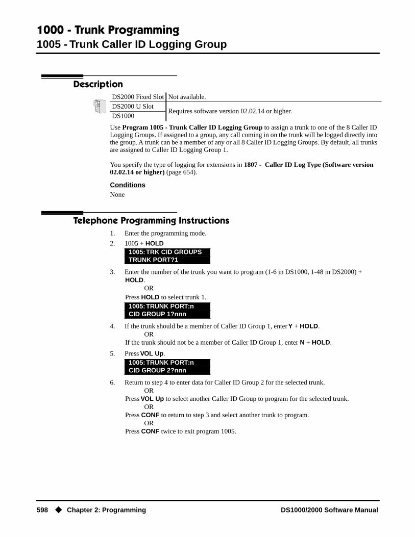
1000 - Trunk Programming1005 - Trunk Caller ID Logging Group
598 ◆ Chapter 2: Programming DS1000/2000 Software Manual
1005 - Trunk Caller ID Logging Group
Description
Use Program 1005 - Trunk Caller ID Logging Group to assign a trunk to one of the 8 Caller ID Logging Groups. If assigned to a group, any call coming in on the trunk will be logged directly into the group. A trunk can be a member of any or all 8 Caller ID Logging Groups. By default, all trunks are assigned to Caller ID Logging Group 1.
You specify the type of logging for extensions in 1807 - Caller ID Log Type (Software version 02.02.14 or higher) (page 654).
ConditionsNone
Telephone Programming Instructions1. Enter the programming mode.
2. 1005 + HOLD
3. Enter the number of the trunk you want to program (1-6 in DS1000, 1-48 in DS2000) + HOLD.
ORPress HOLD to select trunk 1.
4. If the trunk should be a member of Caller ID Group 1, enter Y + HOLD.OR
If the trunk should not be a member of Caller ID Group 1, enter N + HOLD.
5. Press VOL Up.
6. Return to step 4 to enter data for Caller ID Group 2 for the selected trunk.OR
Press VOL Up to select another Caller ID Group to program for the selected trunk.OR
Press CONF to return to step 3 and select another trunk to program.OR
Press CONF twice to exit program 1005.
DS2000 Fixed Slot Not available.
DS2000 U SlotRequires software version 02.02.14 or higher.
DS1000
1005: TRK CID GROUPSTRUNK PORT?1
1005: TRUNK PORT:nCID GROUP 1?nnn
1005: TRUNK PORT:nCID GROUP 2?nnn

1100 - Speed Dial1101 - System Speed Dial Numbers
DS1000/2000 Software Manual Chapter 2: Programming ◆ 599
1100 - Speed Dial
1101 - System Speed Dial Numbers
Description
Use Program 1101 - System Speed Dial Numbers to enter numbers and names into the System Speed Dial bins. The system has up to 1000 Speed Dial bins, depending on the setting of Program 0301 - Number of Digits in a System Speed Dial Code on page 517.
Speed Dial numbers can be up to x?x? digits long, use 0-9, # and *. In addition, you can enter the following for additional dialing options:
ConditionsNone
DS2000 Fixed SlotAvailable.DS2000 U Slot
DS1000
When Number of Digits in a System Speed Dial
Code is:
System Speed Dial bin numbers are:
And the total number of System Speed Dial
bins is:
2 20-29 10
3 200-299 100
4 2000-2999 1000
For this option Or use this telephone programming option:
Pause MIC
Flash FLASH
Table 46: Program 1101 - System Speed Dial Numbers
Option Description Entries Default
System Speed Dial Bin Use this option to select the System Speed Dial bin you want to program.• See Speed Dial on page 383 for more.
BIN?20-29
200-2992000-2999
Not assigned
Line/Group/ICM Use this option to choose the route System Speed Dial normally selects for the bin you are programming. When selecting a route for the bin, you can press ICM (for Intercom Speed Dial), select a trunk (e.g., 1 for trunk 1), or choose 90-98 for Trunk Groups 0-8.• See Speed Dial on page 383 for more.
LINE/GRP/ICMICM (Intercom),
1-48 (for trunks 1-48 in DS2000),
1-6 (for trunks 1-6 in DS1000),
90-98 (for Trunk Groups 0-8)
1

1100 - Speed Dial1101 - System Speed Dial Numbers
600 ◆ Chapter 2: Programming DS1000/2000 Software Manual
Telephone Programming Instructions1. Enter the programming mode.
2. 1101 + HOLD
The previously programmed bin displays.
3. Press VOL ▲ to select the System Speed Dial bin you want to program (20-29, 200-299 or 2000-2999) + HOLD.
ORPress HOLD to program the currently selected bin.
4. Enter the trunk number (1-48 in DS2000, 1-6 in DS1000) you want the system to use when dialing the stored number + HOLD.
OREnter the Trunk Group number (90-98 for Trunk Groups 0-8) you want the system to use when dialing the stored number + HOLD.
ORPress ICM + HOLD if you want to enter Intercom codes.
The System Speed Dial number previously programmed for this selected bin displays.
5. Enter the System Speed Dial number for the selected bin + HOLD.OR
Press HOLD to leave the current assignment unchanged and advance to the next entry.
6. Enter the name for the selected System Speed Dial bin + HOLD + Go back to step 3, ORPress HOLD to leave the current assignment unchanged + Go back to step 3.
System Speed Dial Number
For the bin selected above, use this option to enter the System Speed Dial number. The number can be up to x?x? digits long, using 0-9, # and *. You can also enter special char-acters (see the table above). Special charac-ters count as a single digit.• See Speed Dial on page 383 for more.
NUM?0-9, #, *, MIC (Pause),
DND (Dial Tone Detect), FLASH (Flash) or DIAL
(Delay)
Not assigned
System Speed Dial Name Use this option to enter the name for the System Speed Dial bin (up to 16 characters).• See Speed Dial on page 383 for more.• When entering names, see Programming
Names and Text Messages on page 505.
NA?Not assigned
Not assigned
1101: SYSTEM SPD DIALBIN?nnn
1101:SPDL BIN:nnnLINE/GRP/ICM:nnn
1101:SPDL BIN:nnnNUM?
1101:SPDL BIN:nnnNA?
Table 46: Program 1101 - System Speed Dial Numbers
Option Description Entries Default

1200 - Verified Account Codes1201 - Verified Account Codes Table
DS1000/2000 Software Manual Chapter 2: Programming ◆ 601
1200 - Verified Account Codes
1201 - Verified Account Codes Table
Description
Use Program 1201 - Verified Account Codes Table to enter codes into the Verified Account Codes table. When Program 0101: Verify Account Codes (page 509) is enabled, the system compares the Account Code the user dials to the entry in this table. If the entries match, the system allows the call (provided it is not prevented by an extension’s Toll Restriction). If there is no match, the system denies the call. In DS2000, the Verified Account Codes table can contain up to 1000 entries. In DS1000, the Verified Account Codes table can contain up to 500 entries.
A verified Account Code can be from 2 to 10 digits long, using the digits 0-9. You can use the * character as a wild card, which can be entered in any position in the Verified Account Code. A wild card allows the user to dial any digit in that position. For example, the entry 11*1 represents entries 1101, 1111, 1121, etc.
Use the following keys when entering data in the Verified Account Codes Table.
ConditionsDo not enter 911 or 1911 into the Verified Account Codes Table. When a user presses a line key and dials either 911 or 1911, the system immediately bypasses all Toll Restriction and Account Code programming and routes the call.
DS2000 Fixed Slot Not available.
DS2000 U Slot Requires software version 02.01.07 or higher. The Verified Account Codes table can contain up to 1000 entries.
DS1000 Requires software version 02.01.07 or higher. The Verified Account Codes table can contain up to 500 entries.
Table 47: Entering Verified Account Code Table Data
Use this key: When you want to:
Key 0-9 Make table entries
* Enter a wild card (representing any digit 0-9)
LND Backspace (erase previous entry)
CLEAR Erase the entire entry
Volume Up Go to the next table entry
Volume Down Go to the previous table entry.

1200 - Verified Account Codes1201 - Verified Account Codes Table
602 ◆ Chapter 2: Programming DS1000/2000 Software Manual
Telephone Programming Instructions1. Enter the programming mode.
2. 1201 + HOLD
3. Enter the number of the table entry you want to program (e.g., 100) + HOLD.OR
Press VOL ▲ to select the table entry you want to program + HOLD.OR
Press HOLD to program the currently selected table entry.
The previously programmed table entry displays.
4. Enter the Verified Account Code for the table entry selected + HOLD.A verified Account Code can be from 2 to 10 digits long, using the digits 0-9. You can use the * character as a wild card, which can be entered in any position in the
Verified Account Code. A wild card allows the user to dial any digit in that position. For example, the entry 11*1 represents entries 1101, 1111, 1121, etc.
5. Go back to step 3 and select another table entry to program.OR
Press CONF to exit Program 1201.
1201: VERIFIED AC CDENTRY?(1-1000)n
1201: VERIFIED AC CDnnn: nnn

1300 - Caller ID Logging1301 - Caller ID Group Configuration
DS1000/2000 Software Manual Chapter 2: Programming ◆ 603
1300 - Caller ID Logging
1301 - Caller ID Group Configuration
Description
Use Program 1301 - Caller ID Group Configuration to determine the total number of Caller ID records (1-99) that can be stored in each Caller ID Group. Each group can contain up to 99 records. In DS2000, the system-wide total is 1000. In DS1000, the system-wide total is 500. By default, group 1 has 99 records and all other groups are blank.
When assigning records, you cannot exceed the total allowed by the system. For example, if you attempt to assign 50 records and there are only 10 left, the system will automatically change your entry to 10.
ConditionsNone
Telephone Programming Instructions1. Enter the programming mode.
2. 1301 + HOLD
3. Enter the number of the Caller ID Group (1-8) you want to program + HOLD.OR
Press HOLD to select Caller ID Group 1.
4. Enter the number of records you want to assign to the group (1-99) + HOLD. (You automati-cally advance to the next group.)
ORPress VOL ▲ to advance to the next group without changing the current entry.
ORPress CONF to go back to step 3 and select another group to program.
ORPress CONF twice to exit program 1301.
DS2000 Fixed Slot Not available.
DS2000 U SlotRequires software version 02.02.14 or higher.
DS1000
1301: CID GROUP PROGCID GROUP?1
1301: CID GROUP:nCID CALL RECORDS?nn

1300 - Caller ID Logging1302 - Caller ID Outbound Line/Group
604 ◆ Chapter 2: Programming DS1000/2000 Software Manual
1302 - Caller ID Outbound Line/Group
Description
Use Program 1302 - Caller ID Outbound Line/Group to specify the trunk (1-6 in DS1000, 1-48 in DS2000) or Trunk Group (90-98) the system will use when redialing Caller ID calls. You must make an assignment in this program to enable Caller ID callbacks (return calls).
ConditionsPrograms 1302 through 1305 determine how the system redials Caller ID calls received as 10 digits or less. This is the US standard (i.e., the leading 1 is not received from telco for long distance calls). If the system is in an area where the telco provides more than 10 digits, the digits are redialed as is (with no modification).
Telephone Programming Instructions1. Enter the programming mode.
2. 1302 + HOLD
3. Enter the number of the trunk (1-6 in DS1000, 1-48 in DS2000) or Trunk Group (90-98) the system will use when redialing Caller ID calls + HOLD
ORPress HOLD to leave the current entry unchanged and go to 1302 - 10 Digit Local Calls
ORPress CONF to exit program 1302.
DS2000 Fixed Slot Not available.
DS2000 U SlotRequires software version 02.02.14 or higher.
DS1000
1302: CID DIALINGLINE/GROUP:nnn

1300 - Caller ID Logging1302 - 10 Digit Local Calls
DS1000/2000 Software Manual Chapter 2: Programming ◆ 605
1302 - 10 Digit Local Calls
Description
Use Program 1302 - 10 Digit Local Calls to indicate if the system is installed in an area that uses 10 digit local calling. Enable (Y) this option if the system is in a 10-digit local calling area. Disable (N) this option if the system is not in a 10-digit local calling area. The default for this option is N (local calls are 7 digits).
● If enabled, the system will dial all your local Caller ID callbacks as 10-digit calls.
● If disabled, the system will dial all your local Caller ID callbacks as 7-digit calls.
ConditionsPrograms 1302 through 1305 determine how the system redials Caller ID calls received as 10 digits or less. This is the US standard (i.e., the leading 1 is not received from telco for long distance calls). If the system is in an area where the telco provides more than 10 digits, the digits are redialed as is (with no modification).
Telephone Programming Instructions1. Enter the programming mode.
2. 1302 + HOLD
3. Press VOL ▲.
4. Dial N (6) + HOLD to disable 10 digit local calls.OR
Dial Y (9) + HOLD to enable 10 digital local calls
5. You automatically exit program 1302.
DS2000 Fixed Slot Not available.
DS2000 U SlotRequires software version 02.02.14 or higher.
DS1000
1302: CID DIALINGLINE/GROUP:nnn
1302: CID DIALING10 DIGIT LOCAL?nn

1300 - Caller ID Logging1303 - Home Area (HNPA) Codes
606 ◆ Chapter 2: Programming DS1000/2000 Software Manual
1303 - Home Area (HNPA) Codes
Description
Program 1303 - Home Area (HNPA) Codes is the home area code table. Use this table to specify your system’s home area code (i.e., the area code in which the system is installed). You must make an assignment in this program so that Caller ID can properly process callbacks (return calls). By default, there is no home area code entry. Use the following as a guide when editing the entries in this program.
Conditions
● Programs 1302 through 1305 determine how the system redials Caller ID calls received as 10 digits or less. This is the US standard (i.e., the leading 1 is not received from telco for long distance calls). If the system is in an area where the telco provides more than 10 digits, the digits are redialed as is (with no modification).
● Initializing program 0601 automatically initializes programs 0602 through 0606 and pro-grams 1303 through 1305. You can individually initialize program 1302, if required.
DS2000 Fixed Slot Not available.
DS2000 U SlotRequires software version 02.02.14 or higher.
DS1000
Table 48: Entering 1303 - Home Area (HNPA) Code Data
Use this key: When you want to:
HOLD Register the entry and move forward through the program (or just move forward if there is no entry).
CONF Discard the current entry and back up one level.
When the table is selected in programming (i.e., 1303 + HOLD):
E (3) Selects the table’s edit mode. Use this mode to add or delete entries.
I (4)Initializes the table. Initialization erases (clears) all entries from the table. It is only necessary to initialize the table if you need to erase all the existing entries.
When in the table edit mode (i.e., 1303 + HOLD + E (3)
A (2) Allows you to add codes to the table. For example, A + 203 + HOLD adds code 203.
D (3) Allows you to delete codes from the table. For example, D + 203 + HOLD deletes code 203.
CHECK Displays the ADD-A / DELETE-D help message.
LND Backspaces over (erases) the previous entry.
CLEAR Erases the entire entry.

1300 - Caller ID Logging1303 - Home Area (HNPA) Codes
DS1000/2000 Software Manual Chapter 2: Programming ◆ 607
Telephone Programming Instructions1. Enter the programming mode.
2. 1303 + HOLD
3. Follow the guidelines in Table 48: Entering 1303 - Home Area (HNPA) Code Data on page 606 and enter your system’s home area code.
ORPress CONF to exit program 1303.
1303: HNPA CODESEDIT-E/INIT- I

1300 - Caller ID Logging1304 - Home Area (HNPA) Exception List
608 ◆ Chapter 2: Programming DS1000/2000 Software Manual
1304 - Home Area (HNPA) Exception List
Description
Program 1304 - Home Area (HNPA) Exception List is the home area code exception table. Use this option to identify which (if any) calls within your home area code are toll calls. You can set up the Exception List table as a local table (L) or toll table (T). By default, the HNPA Exception List is a Toll Table with no entries. (This means that the system outdials all calls within the home area code without the leading 1.)
● When set up as a Local Table, the system identifies the NPA + NXX codes you enter as local codes. All other NPA + NXX combinations within your home area code are flagged as toll calls.
- If 1302 - 10 Digit Local Calls is enabled (Y), the system dials all local calls as 10-digit (NPA + NNX + xxxx).
- If 1302 - 10 Digit Local Calls is disabled (N), the system strips the NPA and dials all local calls as 7-digit (NXX + xxxx).
● When set up as a Toll Table, the system identifies the NPA + NXX codes you enter as toll calls. The system outdials them with a leading 1. All other NPA + NXX combinations are con-sidered local codes.
- If 1302 - 10 Digit Local Calls is enabled (Y), the system dials all local calls as 10-digit (NPA + NNX + xxxx).
- If 1302 - 10 Digit Local Calls is disabled (N), the system strips the NPA and dials all local calls as 7-digit (NXX + xxxx).
Use the following as a guide when editing the entries in this program.
DS2000 Fixed Slot Not available.
DS2000 U SlotRequires software version 02.02.14 or higher.
DS1000
Table 49: Entering 1304 - Home Area (HNPA) Exception List Data (Page 1 of 2)
Use this key: When you want to:
HOLD Register the entry and move forward through the program (or just move forward if there is no entry).
CONF Discard the current entry and back up one level.
When the table is selected in programming (i.e., 1304 + HOLD):
E (3) Selects the table’s edit mode. Use this mode to add or delete entries.
I (4)Initializes the table. Initialization erases (clears) all entries from the table. It is only necessary to initialize the table if you need to erase all the existing entries.
T (8)
Selects the table type:• T (8) + L (5) + HOLD makes the Exception List table a
local table.• T (8) + T (8) + HOLD makes the Exception List table a
local table.
When in the table edit mode (i.e., 1304 + HOLD + E (3)
A (2) Allows you to add codes to the table. For example, A + 203999 + HOLD adds code 203999.

1300 - Caller ID Logging1304 - Home Area (HNPA) Exception List
DS1000/2000 Software Manual Chapter 2: Programming ◆ 609
Conditions
● Programs 1302 through 1305 determine how the system redials Caller ID calls received as 10 digits or less. This is the US standard (i.e., the leading 1 is not received from telco for long distance calls). If the system is in an area where the telco provides more than 10 digits, the digits are redialed as is (with no modification).
● Initializing program 0601 automatically initializes programs 0602 through 0606 and pro-grams 1303 through 1305. You can individually initialize program 1302, if required.
Telephone Programming Instructions1. Enter the programming mode.
2. 1304 + HOLD
3. Follow the guidelines in Table 49: Entering 1304 - Home Area (HNPA) Exception List Data on page 608 and enter your system’s home area code.
ORPress CONF to exit program 1304.
D (3) Allows you to delete codes from the table. For example, D + 203999 + HOLD deletes code 203999.
CHECK Displays the ADD-A / DELETE-D help message.
LND Backspaces over (erases) the previous entry.
CLEAR Erases the entire entry.
1304: HNPA-NXX : nnnnEDIT-E/TYPE-T/INIT- I
Table 49: Entering 1304 - Home Area (HNPA) Exception List Data (Page 2 of 2)
Use this key: When you want to:

1300 - Caller ID Logging1305 - Foreign Area (FNPA) Exception List
610 ◆ Chapter 2: Programming DS1000/2000 Software Manual
1305 - Foreign Area (FNPA) Exception List
Description
Program 1305 - Foreign Area (FNPA) Exception List is the foreign area code exception table. If your dialing area has calls in an adjacent area code that are local calls, enter those codes in this table. If the system finds the code in the table, it will dial it as 10-digit (without the leading 1). If the system does not find the code, the system will outdial it as 1 + 10-digit. By default, this table has no entries.
Use the following as a guide when editing the entries in this program.
Conditions
● Programs 1302 through 1305 determine how the system redials Caller ID calls received as 10 digits or less. This is the US standard (i.e., the leading 1 is not received from telco for long distance calls). If the system is in an area where the telco provides more than 10 digits, the digits are redialed as is (with no modification).
● Initializing program 0601 automatically initializes programs 0602 through 0606 and pro-grams 1303 through 1305. You can individually initialize program 1302, if required.
DS2000 Fixed Slot Not available.
DS2000 U SlotRequires software version 02.02.14 or higher.
DS1000
Table 50: Entering 1305 - Foreign Area (FNPA) Exception List Data
Use this key: When you want to:
HOLD Register the entry and move forward through the program (or just move forward if there is no entry).
CONF Discard the current entry and back up one level.
When the table is selected in programming (i.e., 1305 + HOLD):
E (3) Selects the table’s edit mode. Use this mode to add or delete entries.
I (4)Initializes the table. Initialization erases (clears) all entries from the table. It is only necessary to initialize the table if you need to erase all the existing entries.
When in the table edit mode (i.e., 1305 + HOLD + E (3)
A (2) Allows you to add codes to the table. For example, A + 212999 + HOLD adds code 212999.
D (3) Allows you to delete codes from the table. For example, D + 212999 + HOLD deletes code 212999.
CHECK Displays the ADD-A / DELETE-D help message.
LND Backspaces over (erases) the previous entry.
CLEAR Erases the entire entry.

1300 - Caller ID Logging1305 - Foreign Area (FNPA) Exception List
DS1000/2000 Software Manual Chapter 2: Programming ◆ 611
Telephone Programming Instructions1. Enter the programming mode.
2. 1305 + HOLD
3. Follow the guidelines in Table 50: Entering 1305 - Foreign Area (FNPA) Exception List Data on page 610 and enter your system’s home area code.
ORPress CONF to exit program 1305.
1305: FNPA-NXX : nnnnEDIT-E/INIT- I

1700 - Key Programming1701 - Programmable Function Key Assignments
612 ◆ Chapter 2: Programming DS1000/2000 Software Manual
1700 - Key Programming
1701 - Programmable Function Key Assignments
Description
Use Program 1701 - Programmable Function Key Assignments to assign the programmable keys on a keyset. The defaults are as follows:
● Fixed Slot Software:- Keys 1-8 are line keys for trunks 1-8.- Keys 9 and 10 are fixed loop keys.- Key 11 is an auto timer key.- Key 12 is an All Call Page key.For attendants (extension 300 by default)- Key 11 is a Night (System Mode System) key- Key 12 (on 22-button) or key 24 (on 34-button) is an Operator Call Key.
● U Slot and DS1000 Software:- In U Slot, keys 1-12 are line keys for trunks 1-12 and keys 13-24 are undefined. In software versions 02.01.07 through 02.02.00, Programmable Function Keys are undefined for all exten-sions above 315.- In DS1000, keys 1-6 are line keys for trunks 1-6 and keys 7-24 are undefined.For attendants (extension 300 by default)- Key 11 is a Night (System Mode System) key.- Key 12 (on 22-button) or key 24 (on 34-button) is an Operator Call Key.
Note: If you are doing extensive programming, you may find Program 9801 - Copy Command (page 657) saves you time when customizing this option.
ConditionsNone
DS2000 Fixed Slot Available - unique defaults.
DS2000 U SlotAvailable - unique defaults.• In 02.01.07 and higher, all Programmable Function Keys are undefined
for extensions above 315.DS1000 Available - unique defaults.
Table 51: Program 1701 - Programmable Function Key Assignments
Option Description Key Code Entry
Undefined Use this option to designate a key as undefined (no function).• See Programmable Function Keys on
page 354 for more.
00 UNDEFINED
Switched Loop Key
Use this option to assign a programmable key as a switched loop key.• See Loop Keys on page 283 for more.• See Programmable Function Keys on
page 354 for more.
01 SWITCH LOOP(01)
Fixed Loop Key Use this option to assign a programmable key as a Fixed Loop Key.• See Loop Keys on page 283 for more.• See Programmable Function Keys on
page 354 for more.
02 + nn (trunk group) FIXED LOOP GRP0-8 = Trunk Groups 0-8

1700 - Key Programming1701 - Programmable Function Key Assignments
DS1000/2000 Software Manual Chapter 2: Programming ◆ 613
Line Key Use this option to assign a programmable key as a line key.• See Central Office Calls, Answering on
page 99 for more.• See Central Office Calls, Placing on
page 105 for more.• See Line Keys on page 279 for more.• See Private Line on page 350 for more.• See Programmable Function Keys on
page 354 for more.
03 + nn (trunknumber)
LINE1-48 (for trunks 1-48)
in DS2000, 1-6 in DS1000
Park Orbit Key Use this option to assign a programmable key as a Park Orbit key.• See Park on page 333 for more.• See Programmable Function Keys on
page 354 for more.
04 + nn (Park Orbit60-69)
PARK ORBIT?n60-69 = System Park
Orbits 60-69
Hotline Key Use this option to assign a programmable key as a Hotline key.• See Hotline on page 240 for more.• See Programmable Function Keys on
page 354 for more.
An extension can also have a Hotline key for a trunk (e.g., 401). However, this capability requires that Direct Trunk Access be enabled. See Direct Trunk Access on page 154 for more.
05 + nnn (extension number)
HOTLINEnnnHotline partner’s exten-sion number (300-395 in DS2000 or 300-325
in DS1000)
Call Coverage Immediate Ring
Use this option to assign a programmable key as an immediately ringing Call Coverage Key.• See Call Coverage Keys on page 62 for
more.• See Programmable Function Keys on
page 354 for more.
06 + nnn (extension number)
CALL CVR RINGCovered extension
number, Ring Group master number, or UCD Group master number
Call Coverage No Ring
Use this option to assign a programmable key as a lamp only (no ring) Call Coverage Key.• See Call Coverage Keys on page 62 for
more.• See Programmable Function Keys on
page 354 for more.
07 + nnn (extension number)
CALL CVR NO RINGCovered extension
number, Ring Group master number, or UCD Group master number
Call Coverage Delay Ring
Use this option to assign a programmable key as a delayed ring Call Coverage Key.• See Call Coverage Keys on page 62 for
more.• See Programmable Function Keys on
page 354 for more.
08 + nnn (extension number)
CALL CVR DELAYCovered extension
number, Ring Group master number, or UCD Group master number
Table 51: Program 1701 - Programmable Function Key Assignments
Option Description Key Code Entry

1700 - Key Programming1701 - Programmable Function Key Assignments
614 ◆ Chapter 2: Programming DS1000/2000 Software Manual
Group Pickup Immediate Ring
Use this option to assign a programmable key as an immediate ring Group Call Pickup key.• See Group Call Pickup on page 215 for
more.• See Programmable Function Keys on
page 354 for more.
09 + nn (Pickup Group 01-08)
GRP PCKUP RING01-08 = pickup groups
1-8
Group Pickup No Ring
Use this option to assign a programmable key as a lamp only (no ring) Group Call Pickup key.• See Group Call Pickup on page 215 for
more.• See Programmable Function Keys on
page 354 for more.
10 + nn (Pickup Group 01-08)
GRP PCKUP NO RING
01-08 = pickup groups 1-8
Group Pickup Delay Ring
Use this option to assign a programmable key as a delay ring Group Call Pickup key.• See Group Call Pickup on page 215 for
more.• See Programmable Function Keys on
page 354 for more.
11 + nn (Pickup Group 01-08)
GRP PCKUP DELAY01-08 = pickup groups
1-8
Page Zone Key Use this option to assign a programmable key as a Page Zone key.• See Paging on page 326 for more.• See Programmable Function Keys on
page 354 for more.
13 + n (Page Zone 1-7, 0 for All Call)
PAGE ZONE0-7 (Page Zones 1-7 or
0 for All Call Page)
System Speed Dial Key
Use this option to assign a programmable key as a System Speed Dial key. You assign the key to specific System Speed Dial bin.• See Programmable Function Keys on
page 354 for more.• See Speed Dial on page 383 for more.
14 + nnn (System Speed Dial bin nor-
mally 200-299)
SYS SPDL BIN
Personal Speed Dial Key
Use this option to assign a programmable key as a Personal Speed Dial key. You assign the key to a specific Personal Speed Dial bin.• See Programmable Function Keys on
page 354 for more.• See Speed Dial on page 383 for more.
15 + nnn (701-720) PERS SPDL BIN
Call Timer Key Use this option to assign a programmable key as a Call Timer key. There are two types of timer key: manual and automatic.• See Call Timer on page 72 for more.• See Programmable Function Keys on
page 354 for more.
16 + n (1 = Manual Call Timer, 2 = Auto-
matic Call Timer)
CALL TIMER
Voice Mail Record Key
Use this option to assign a programmable key as a Voice Mail Record key.• See Programmable Function Keys on
page 354 for more.• See Voice Mail on page 477 for more.
17 RECORD
Table 51: Program 1701 - Programmable Function Key Assignments
Option Description Key Code Entry

1700 - Key Programming1701 - Programmable Function Key Assignments
DS1000/2000 Software Manual Chapter 2: Programming ◆ 615
Night Key Use this option to assign a programmable key as a Night Key. There are two options: System Mode System key and System Mode UCD Master key. The System Mode System key puts all Key Ring trunks and trunks terminated to Ring Group master numbers in the night mode. The System Mode UCD Master key puts all trunks terminated to UCD Group mas-ter numbers in the night mode.• See Direct Inward Line on page 133 for
more.• See Extension Hunting on page 193 for
more.• See Night Service / Night Ring on
page 308 for more.• See Programmable Function Keys on
page 354 for more.
18 + CLEAR(System Mode System
key)18 + UCD Master
Number(System Mode UCD
Master key)
SYS MODE
Data Key • This option is currently not used. 19 + nnn (extension number)
DATA
Split Key Use this option to assign a programmable key as a Split key.• See Programmable Function Keys on
page 354 for more.• See Split (Alternate) on page 395 for more.
20 SPLIT
ICM Directory Key
Use this option to assign a programmable key as an Intercom Directory Dialing key.• See Directory Dialing on page 158 for
more.• See Programmable Function Keys on
page 354 for more.
21 ICM DIR
ACD Log On Key • This option is currently not used. 22 ACD LOG
Reverse Voice Over Key
Use this option to assign a programmable key as a Reverse Voice Over key.• See Programmable Function Keys on
page 354 for more.• See Reverse Voice Over on page 364 for
more.
23 + nnn (extension number)
REV VOICE OVER
Message Center Key
Use this option to assign a programmable key as a Message Center key.• See Programmable Function Keys on
page 354 for more.• See Voice Mail on page 477 for more.
24 + nnn (extension number)
Note that the extension number does not have
to be an installed exten-sion.
MESSAGE CTR300-395 (extension numbers 300-395)
Table 51: Program 1701 - Programmable Function Key Assignments
Option Description Key Code Entry

1700 - Key Programming1701 - Programmable Function Key Assignments
616 ◆ Chapter 2: Programming DS1000/2000 Software Manual
Save Key Use this option to assign a programmable key as a Save Number Dialed key.• See Programmable Function Keys on
page 354 for more.• See Save Number Dialed on page 373 for
more.
25 SAVE
Account Code Key
Use this option to assign a programmable key as an Account Code key.• See Account Codes on page 34 for more.• See Programmable Function Keys on
page 354 for more.
26 ACCT CODE
Table 51: Program 1701 - Programmable Function Key Assignments
Option Description Key Code Entry

1700 - Key Programming1701 - Programmable Function Key Assignments
DS1000/2000 Software Manual Chapter 2: Programming ◆ 617
Telephone Programming Instructions1. Enter the programming mode.
2. 1701 + HOLD
3. Enter the number of the extension you want to program + HOLDOR
Press HOLD to select the currently displayed extension.
4. Enter the number of the key you want to program + HOLD.OR
Press VOL ▲ or VOL ▼ + HOLD to select another key to program.OR
Press HOLD to select the currently displayed key.
The previously programmed key definition displays.
5. Enter key code and options as required + VOL ▲.OR
Press VOL ▲ to leave the current assignment unchangedOR
Press ICM + VOL ▲ to scroll.
6. Enter data for another key.OR
Press CONF to return to step 4 and select another key to program.OR
Press CONF twice to return to step 3 and select another extension to program.OR
Press CONF three times to exit the program.
1701:KEY PROGRAMMINGSTATION #?
1701:STA:nnnKEY NUMBER 1?
1701:STA:nnn KEY:nnnnnnnnnn n?
To scroll through the available entries instead of entering a code in this step:1. Press ICM (your ICM key flashes fast).2. Press VOL ▲ OR VOL ▼ until the entry you want displays.3. Press HOLD to assign the displayed entry to the key.
You automatically advance to the next consecutive key.

1700 - Key Programming1702 - Personal Speed Dial
618 ◆ Chapter 2: Programming DS1000/2000 Software Manual
1702 - Personal Speed Dial
Description
Use Program 1702 - Personal Speed Dial to program an extension’s Personal Speed Dial bins (1-20). Extension users can also program their Personal Speed Dial bins from their own telephone.
Note: If you are doing extensive programming, you may find Program 9801 - Copy Command (page 657) saves you time when customizing this option.
Personal Speed Dial numbers can be up to x?x? digits long, use 0-9, # and *. In addition, you can enter the following for additional dialing options:
ConditionsNone
DS2000 Fixed Slot
Available.DS2000 U Slot
DS1000
For this option Or use this telephone programming option:
Pause MIC
Flash FLASH
Table 52: Program 1702 - Personal Speed Dial
Option Description Entries Default
Personal Speed Dial Bin Use this option to select the Personal Speed Dial bin you want to program.• See Speed Dial on page 383 for more.
BIN?0-19
Not assigned
Personal Speed Dial Number
For the bin selected above, use this option to enter the Personal Speed Dial number. The number can be up to x?x? digits long, using 0-9, # and *. You can also enter special char-acters (see the table above). Special charac-ters count as a single digit.• See Speed Dial on page 383 for more.
NUM?Not assigned
Not assigned
Personal Speed Dial Name
Use this option to enter the name for the Per-sonal Speed Dial bin (up to 16 characters).• See Speed Dial on page 383 for more.• When entering names, see Programming
Names and Text Messages on page 505.
NA?Not assigned
Not assigned

1700 - Key Programming1702 - Personal Speed Dial
DS1000/2000 Software Manual Chapter 2: Programming ◆ 619
Telephone Programming Instructions1. Enter the programming mode.
2. 1702 + HOLD
3. Press VOL ▲ to select the extension you want to program (300-395 in DS2000 or 300-323 in DS1000) + HOLD.
ORPress HOLD to program the currently selected extension.
4. For the extension selected, press VOL ▲ to select the bin you want to program (701-720) + HOLD.
ORPress HOLD to program the currently selected bin.
5. Enter the trunk number (1-48 in DS2000, 1-6 in DS1000) you want the system to use when dialing the stored number + HOLD.
OREnter the Trunk Group number (90-98 for Trunk Groups 0-8) you want the system to use when dialing the stored number + HOLD.
ORPress ICM + HOLD if you want to enter Intercom codes.
The Personal Speed Dial number previously programmed for this selected bin displays.
6. Enter the Personal Speed Dial number for the selected bin + HOLD.OR
Press HOLD to leave the current assignment unchanged and advance to the next entry.
7. Enter the name for the selected Personal Speed Dial bin + HOLD + Go back to step 3.OR
Press HOLD to leave the current assignment unchanged + Go back to step 3.
1702: Personal SPDStation #?300
1702:STA:BIN?:nnn
1702:SPDL BIN:nnnLINE/GRP/ICM:nnn
1702:STA:nnn BIN:nnnNUM?
1702:STA:nnn BIN:nnnNA?

1700 - Key Programming1703 - DSS Key Assignment
620 ◆ Chapter 2: Programming DS1000/2000 Software Manual
1703 - DSS Key Assignment
Description
Use Program 1703 - DSS Key Assignment to program an extension’s DSS keys. Programmable Function Keys automatically become DSS keys when the user press ICM. While in the DSS mode, the extension has one button Intercom access and a Busy Lamp Field for the assigned co-worker. By default, BLF keys are undefined.
Note: If you are doing extensive programming, you may find Program 9801 - Copy Command (page 657) saves you time when customizing this option.
ConditionsNone
Telephone Programming Instructions1. Enter the programming mode.
2. 1703 + HOLD
3. Enter the number of the station port (1-32) you want to program + HOLD
4. For the station port selected, enter the number of the key (1-24) you want to program + HOLD
The previously programmed assignment displays.
DS2000 Fixed Slot
Available.DS2000 U Slot
DS1000
Table 53: Program 1703 - DSS Key Assignment
Option Description Entries Default
Key Number Use this option to select the key you want to program.• See Direct Station Selection (DSS) on
page 140 for more.
KEY?1-24
Not assigned
BLF Extension Assignment
Use this option to assign an extension to the BLF key.• See Direct Station Selection (DSS) on
page 140 for more.
BLF EXT NUM?300-395 in DS2000 or
300-315 in DS1000
Not assigned
1703:BLF LEVEL KEYSSTATION PORT?
1703:BLF LEVEL KEYSKEY?
1703:BLF LEVEL KEYSBLF EXT NUM?nnn

1700 - Key Programming1703 - DSS Key Assignment
DS1000/2000 Software Manual Chapter 2: Programming ◆ 621
5. Enter the number of the extension (300-395 in DS2000 or 300-325 in DS1000) assigned to the BLF key + HOLD
ORPress VOL ▲ to leave the current assignment unchanged.1703:BLF LEVEL KEYSKEY?

1700 - Key Programming1704 - DSS Console Key Assignment
622 ◆ Chapter 2: Programming DS1000/2000 Software Manual
1704 - DSS Console Key Assignment
Description
Use Program 1704 - DSS Console Key Assignment to assign the keys for the system’s DSS Con-soles. There are two types of DSS Consoles: 24-button and 110 button. For default assignments, refer to the following tables.
Default Setting
DS2000 Fixed Slot Available - with unique defaults.
DS2000 U Slot Available - with unique defaults.
DS1000 Available - with unique defaults.
Fixed Slot DSS Console Default Assignments
These keys: Have this function:
24-Button DSS Console
1-24 Hotlines to extensions 300-323
110-Button DSS Console
1-32 Hotlines to extensions 300-331
33-48 Lines 1-16
49-59 System Speed Dial bins 200-209
59-78 Personal Speed Dial bins 700-719
79, 80 Page zones 0 (All Call) and 1.
81-82 System Park Orbits 0 and 1.
83-110 Unassigned

1700 - Key Programming1704 - DSS Console Key Assignment
DS1000/2000 Software Manual Chapter 2: Programming ◆ 623
U Slot DSS Console Default Assignments
These keys: Have this function:
24-Button DSS Console
1-24 Hotlines to extensions 300-323
110-Button DSS Console
1-80 Hotlines to extensions 300-379
81-96 Hotlines to undefined destinations.
97-99 Page Zones 1-3
100 All Call Page
101-109 Park Orbits 0-8
110 Night (System Mode System) key
DS1000 DSS Console Default Assignments
These keys: Have this function:
24-Button DSS Console
1-24 Hotlines to extensions 300-323
110-Button DSS Console
1-26 Hotlines to extensions 300-325
27-58 Hotlines to undefined extensions
59-64 Hotlines to trunks 1-6 (401-406)1
65-96 Hotlines to undefined destinations.
97-99 Page Zones 1-3
100 All Call Page
101-109 Park Orbits 0-8
110 Night (System Mode System) Key
1 Trunk Hotlines require that the extension have Direct Trunk Access enabled. See Direct Trunk Access on page 154 for more. These keys do not exist in software version 02.01.07 or higher.

1700 - Key Programming1704 - DSS Console Key Assignment
624 ◆ Chapter 2: Programming DS1000/2000 Software Manual
ConditionsWhen the system initially powers up, Hotline keys for extensions are defined only for extensions 300-315. As DSTU PCBs are added in 9902 - Slot Assignment on page 665, the corresponding DSS Console Hotline keys for those extensions are automatically enabled (provided you use the standard extension numbering plan). Note that the features permanently assigned to keys 97-110 still avail-able on initial power-up.
Table 54: Program 1704 - DSS Console Key Assignment
Option Description Key Code Entry
Undefined Use this option to designate a key as undefined (no function).• See Direct Station Selection (DSS) Con-
sole on page 143 for more.
00 UNDEFINED(00)
Line Key Use this option to assign a programmable key as a line key.• See Central Office Calls, Answering on
page 99 for more.• See Central Office Calls, Placing on
page 105 for more.• See Direct Station Selection (DSS) Con-
sole on page 143 for more.
03 + nn (trunknumber)
LINE?nn1-48 (for trunks 1-48)
in DS2000, 1-6 in DS1000
Park Orbit Key Use this option to assign a programmable key as a Park Orbit key.• See Direct Station Selection (DSS) Con-
sole on page 143 for more.• See Park on page 333 for more.
04 + n (Park Orbit60-69)
PARK ORBIT?n60-69 = System Park
Orbits 60-69
Hotline Key Use this option to assign a programmable key as a Hotline key.• See Direct Station Selection (DSS) Con-
sole on page 143 for more.• See Hotline on page 240 for more.
A DSS Console can also have a Hotline key for a trunk (e.g., 401). However, this capability requires that Direct Trunk Access be enabled for the extension. See Direct Trunk Access on page 154 for more.
05 + nnn (extension number)
HOTLINE?nnnHotline partner’s exten-sion number (300-395 in DS2000 or 300-325
in DS1000)
Call Coverage Immediate Ring
Use this option to assign a programmable key as an immediately ringing Call Coverage Key.• See Call Coverage Keys on page 62 for
more.• See Direct Station Selection (DSS) Con-
sole on page 143 for more.
06 + nnn (extension number)
CALL CVR RINGCovered extension
number, Ring Group master number, or UCD Group master number
Call Coverage No Ring
Use this option to assign a programmable key as a lamp only (no ring) Call Coverage Key.• See Call Coverage Keys on page 62 for
more.• See Direct Station Selection (DSS) Con-
sole on page 143 for more.
07 + nnn (extension number)
CALL CVR NO RINGCovered extension
number, Ring Group master number, or UCD Group master number

1700 - Key Programming1704 - DSS Console Key Assignment
DS1000/2000 Software Manual Chapter 2: Programming ◆ 625
Call Coverage Delay Ring
Use this option to assign a programmable key as a delayed ringing Call Coverage Key.• See Call Coverage Keys on page 62 for
more.• See Direct Station Selection (DSS) Con-
sole on page 143 for more.
08 + nnn (extension number)
CALL CVR DELAYCovered extension
number, Ring Group master number, or UCD Group master number
Group Pickup Immediate Ring
Use this option to assign a programmable key as an immediately ringing Group Call Pickup key. • See Direct Station Selection (DSS) Con-
sole on page 143 for more.• See Group Call Pickup on page 215 for
more.
09 + nn (Pickup Group 01-08)
GRP PKUP RING01-16 = pickup groups
1-16
Group Pickup No Ring
Use this option to assign a programmable key as a lamp only (no ring) Group Call Pickup key. • See Direct Station Selection (DSS) Con-
sole on page 143 for more.• See Group Call Pickup on page 215 for
more.
10 + nn (Pickup Group 01-08)
GRP PKUP NO RING01-16 = pickup groups
1-16
Group Pickup Delay Ring
Use this option to assign a programmable key as a delay ring Group Call Pickup key. • See Direct Station Selection (DSS) Con-
sole on page 143 for more.• See Group Call Pickup on page 215 for
more.
11 + nn (Pickup Group 01-08)
GRP PKUP DELAY01-16 = pickup groups
1-16
Page Zone Key Use this option to assign a programmable key as a Page Zone key.• See Direct Station Selection (DSS) Con-
sole on page 143 for more.• See Paging on page 326 for more.
13 + n (Page Zone 1-7, 0 for All Call)
PAGE ZONE?0-7 (Page Zones 1-7 or
0 for All Call Page)
System Speed Dial Key
Use this option to assign a programmable key as a System Speed Dial key. You assign the key to specific System Speed Dial bin.• See Direct Station Selection (DSS) Con-
sole on page 143 for more.• See Speed Dial on page 383 for more.
14 + nnn (System Speed Dial bin, nor-
mally 200-299)
SYS SPDL BIN?
Personal Speed Dial Key
Use this option to assign a programmable key as a Personal Speed Dial key. You assign the key to a specific Personal Speed Dial bin. The DSS Console shares Personal Speed Dial bins with the extension to which it is attached.• See Direct Station Selection (DSS) Con-
sole on page 143 for more.• See Speed Dial on page 383 for more.
15 + nnn (701-720) PERS SPDL BIN?
Table 54: Program 1704 - DSS Console Key Assignment
Option Description Key Code Entry

1700 - Key Programming1704 - DSS Console Key Assignment
626 ◆ Chapter 2: Programming DS1000/2000 Software Manual
Voice Mail Record Key
Use this option to assign a programmable key as a Voice Mail Record key.• See Direct Station Selection (DSS) Con-
sole on page 143 for more.• See Voice Mail on page 477 for more.
17 RECORD?
Night Key Use this option to assign a DSS Console key as a Night Key. There are two options: System Mode System key and System Mode UCD Master key. The System Mode System key puts all Key Ring trunks and trunks terminated to Ring Group master numbers in the night mode. The System Mode UCD Master key puts all trunks terminated to UCD Group mas-ter numbers in the night mode.• See Direct Inward Line on page 133 for
more.• See Extension Hunting on page 193 for
more.• See Night Service / Night Ring on
page 308 for more.• See Programmable Function Keys on
page 354 for more.
18 + CLEAR(System Mode System
key)18 + UCD Master
Number(System Mode UCD
Master key)
SYS MODE?
Data Key • This option is currently not used. 19 + nnn (extension number)
DATA?
Split Key Use this option to assign a programmable key as a Split key.• See Direct Station Selection (DSS) Con-
sole on page 143 for more.• See Split (Alternate) on page 395 for more.
20 SPLIT
ICM Directory Key
Use this option to assign a programmable key as an Intercom Directory Dialing key.• See Direct Station Selection (DSS) Con-
sole on page 143 for more.• See Directory Dialing on page 158 for
more.
21 ICM DIR
ACD Log On Key • This option is currently not used. 22 ACD LOG
Reverse Voice Over Key
Use this option to assign a programmable key as a Reverse Voice Over key.• See Direct Station Selection (DSS) Con-
sole on page 143 for more.• See Reverse Voice Over on page 364 for
more.
23 + nnn (extension number)
REV VOICE OVER
Table 54: Program 1704 - DSS Console Key Assignment
Option Description Key Code Entry

1700 - Key Programming1704 - DSS Console Key Assignment
DS1000/2000 Software Manual Chapter 2: Programming ◆ 627
Telephone Programming Instructions1. Enter the programming mode.
2. 1704 + HOLD
3. Select the block that corresponds to the DSS Console you want to program + HOLD
4. For the console selected, enter the number of the key you want to program + HOLD.OR
Press VOL ▲ or VOL ▼ + HOLD to select another key to program.OR
Press HOLD to select key 1.
The previously programmed key definition displays.
5. Enter key code and options as required + VOL ▲.OR
Press VOL ▲ to leave the current assignment unchanged.
6. Enter data for another key.OR
Press CONF to return to step 4 and select another key to program.OR
Press CONF twice to return to step 3 and select another console.OR
Message Center Key
Use this option to assign a programmable key as a Message Center key.• See Direct Station Selection (DSS) Con-
sole on page 143 for more.• See Voice Mail on page 477 for more.
24 + nnn (extension number)
Note that the extension number does not have
to be an installed exten-sion.
MESSAGE CTR300-395 (extension numbers 300-395)
Save Key Use this option to assign a programmable key as a Save Number Dialed key.• See Direct Station Selection (DSS) Con-
sole on page 143 for more.• See Save Number Dialed on page 373 for
more.
25 SAVE
1704:DSS KEY PROGDSS BLOCK NUM?
1704:DSS KEY PROGDSS KEY 1
DSS BLOCK:n KEY:nnnnnnnnnn n?
To scroll through the available entries instead of entering a code in this step:1. Press ICM (your ICM key flashes fast).2. Press VOL ▲ OR VOL ▼ until the entry you want displays.3. Press HOLD to assign the displayed entry to the key.
You automatically advance to the next consecutive key.
Table 54: Program 1704 - DSS Console Key Assignment
Option Description Key Code Entry

1700 - Key Programming1704 - DSS Console Key Assignment
628 ◆ Chapter 2: Programming DS1000/2000 Software Manual
Press CONF three times to exit the program.

1800 - Extension Options1801 - Extension Port Description
DS1000/2000 Software Manual Chapter 2: Programming ◆ 629
1800 - Extension Options
1801 - Extension Port Description
Description
Use Program 1801 - Extension Port Description to set up various options for extensions. Also see Program 1802 - Extension Options (Part 1) on page 635 and Program 1807 - Extension Options (Part 2) on page 652.
Note: If you are doing extensive programming, you may find Program 9801 - Copy Command (page 657) saves you time when customizing this option.
ConditionsNone
DS2000 Fixed Slot • Available.• Automatic Telephone Type Detection requires software version 02.02.14 or
higher. This means that digital station ports (300-315 in DS1000, on installed and programmed PCBs in DS2000) automatically detect the type of connect device when the keyset, 2-OPX Module (both ports) or Digital Door Box is plugged in. It is no longer necessary to individually set circuit types in 1801 - Extension Circuit Type.
DS2000 U Slot
DS1000
Table 55: Program 1801 - Extension Options (Part 1)
Option Description Entries Default
Extension Circuit Type Use this option to assign circuit type to sta-tion devices. In the column at right, the num-bers in square brackets [ ] indicate how many ports the device requires.• See Door Box on page 185 for more.• See Initial Startup Programming on
page 12 for more.• See Off-Premise Extensions / On-
Premise SLT Extensions on page 317 for more.
• See Station Instruments on page 397 for more.
PT TYP?00 = Uninstalled [1]
01 = 22-ButtonStandard [1]
02 = 22-ButtonDisplay [1]
06 = 34-ButtonDisplay [1]
09 = 34-Button Super Display [1]
10 = Door Box [1]15 = Analog station [1]
21 = 2OPX [2]
02 (22-Button Display)
Extension Numbering This option shows the extension number assigned to the station port. This option is view only — you cannot edit this entry.• See 0505 - Station Port Extension Num-
bers (Fixed Slot) on page 547 for more.
EXT:View only
View only
DCI Type • This option is currently not used. DCI TYP? 0
Device Number • This option is currently not used. DEVICE ORDER NUM? 1

1800 - Extension Options1801 - Extension Port Description
630 ◆ Chapter 2: Programming DS1000/2000 Software Manual
Extension Name Use this option to assign a name to the extension port.• Refer to Table 19: Keys for Entering
Names on page 505 when entering names.
• See Names for Extensions and Trunks on page 306 for more.
NAME: STATION nn
DSS Type Use this option to specify the type of DSS Console plugged into the telephone (1 = 24-button, 2 = 110-button, 0 = unassigned). You cannot install more than 4 DSS Consoles.• See Direct Station Selection (DSS) Con-
sole on page 143 for more.
DSS TYP?0 = Uninstalled1 = 24-Button2 = 110 Button
300 = 1301-331 = 0
DSS Block Number Use this option to assign a DSS block to the console.• See Direct Station Selection (DSS) Con-
sole on page 143 for more.
DSS BLOCK NUM?00 = Unassigned
01-04
01
Door Chime Use this option to assign a chime pattern to a Door Box. In DS2000, this option is only available when Extension Circuit Type above is 10 (Door Box). In DS1000, This option is available to both Digital Door Boxes (circuit type 10) and Analog Door Boxes (extensions 324 and 325).• See Door Box on page 185 for more.
DOOR CHIME?0 = Normal Ring Group
ringing1 = Low pitch chime pat-
tern2 = Mid range pitch
chime pattern3 = High pitch chime pat-
tern
None (0)
Relay Owner DS2000For the Door Box extension, use this option to assign the relay on the CPRU PCB to the Door Box. This option is only available when Extension Circuit Type above is 10 (Door Box).
RELAY OWNER?0 = CPRU relay not
assigned to Door Box1 = CPRU relay assigned
to Door Box
None (0)
DS1000For the Analog Door Box extension (324 or 325), use this option to assign the DOOR1 or DOOR2 relays to the Door Box. Nor-mally, you assign the DOOR1 relays to Ana-log Door Box 324 and DOOR2 relays to Analog Door Box 325.• See Door Box on page 185 for more.
RELAY OWNER?0 = Relay no assigned1 = Relay assigned to
DOOR12 = Relay assigned to
DOOR2
None (0)
Second Channel Option • This option is currently not used. 2ND CHANNEL?N = NoY = Yes
N
Table 55: Program 1801 - Extension Options (Part 1)
Option Description Entries Default
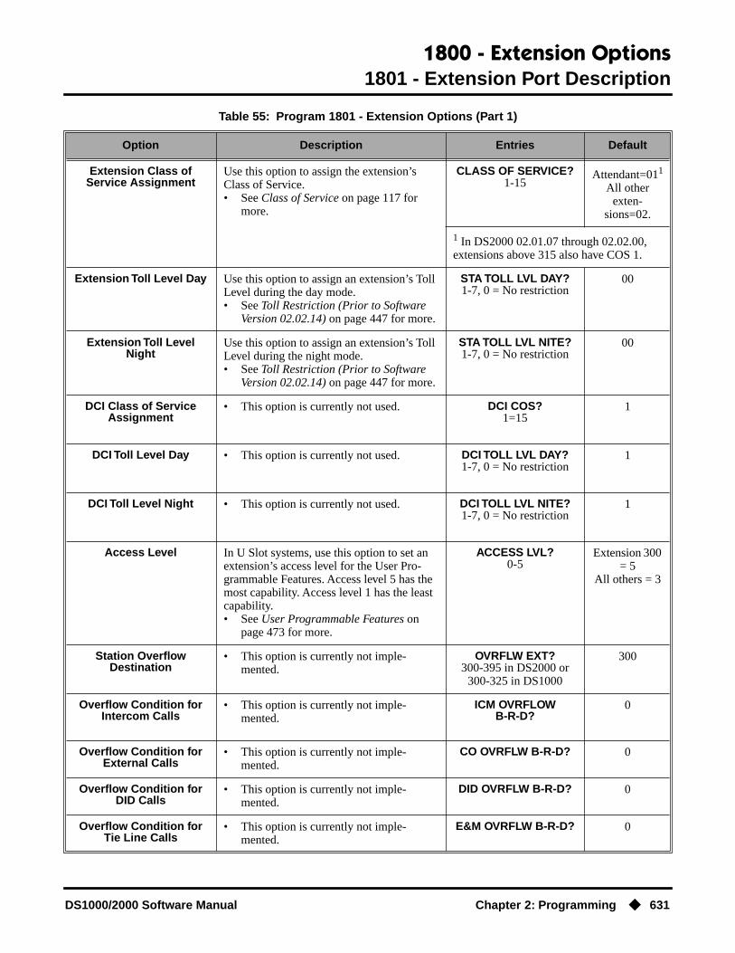
1800 - Extension Options1801 - Extension Port Description
DS1000/2000 Software Manual Chapter 2: Programming ◆ 631
Extension Class of Service Assignment
Use this option to assign the extension’s Class of Service.• See Class of Service on page 117 for
more.
CLASS OF SERVICE?1-15
Attendant=011
All other exten-
sions=02.
1 In DS2000 02.01.07 through 02.02.00, extensions above 315 also have COS 1.
Extension Toll Level Day Use this option to assign an extension’s Toll Level during the day mode.• See Toll Restriction (Prior to Software
Version 02.02.14) on page 447 for more.
STA TOLL LVL DAY?1-7, 0 = No restriction
00
Extension Toll Level Night
Use this option to assign an extension’s Toll Level during the night mode.• See Toll Restriction (Prior to Software
Version 02.02.14) on page 447 for more.
STA TOLL LVL NITE?1-7, 0 = No restriction
00
DCI Class of Service Assignment
• This option is currently not used. DCI COS?1=15
1
DCI Toll Level Day • This option is currently not used. DCI TOLL LVL DAY?1-7, 0 = No restriction
1
DCI Toll Level Night • This option is currently not used. DCI TOLL LVL NITE?1-7, 0 = No restriction
1
Access Level In U Slot systems, use this option to set an extension’s access level for the User Pro-grammable Features. Access level 5 has the most capability. Access level 1 has the least capability.• See User Programmable Features on
page 473 for more.
ACCESS LVL?0-5
Extension 300 = 5
All others = 3
Station Overflow Destination
• This option is currently not imple-mented.
OVRFLW EXT?300-395 in DS2000 or
300-325 in DS1000
300
Overflow Condition for Intercom Calls
• This option is currently not imple-mented.
ICM OVRFLOWB-R-D?
0
Overflow Condition for External Calls
• This option is currently not imple-mented.
CO OVRFLW B-R-D? 0
Overflow Condition for DID Calls
• This option is currently not imple-mented.
DID OVRFLW B-R-D? 0
Overflow Condition for Tie Line Calls
• This option is currently not imple-mented.
E&M OVRFLW B-R-D? 0
Table 55: Program 1801 - Extension Options (Part 1)
Option Description Entries Default

1800 - Extension Options1801 - Extension Port Description
632 ◆ Chapter 2: Programming DS1000/2000 Software Manual
Telephone Programming Instructions1. Enter the programming mode.
2. 1801 + HOLD
3. Enter the number of the extension you want to program (300-395) + HOLD.OR
Press HOLD to select extension 300.
The previously programmed value displays. See the chart above for valid circuit types.
4. Enter the new station circuit type + VOL ▲.OR
Press VOL ▲ to leave the current circuit type unchanged.
This display shows the extension number assigned to the port. This option is view only — you cannot edit or change it from this program.
5. Press VOL ▲.
The previously programmed value displays.
6. The option is not used. Press VOL ▲.
The previously programmed value displays.
7. This option is not used. Press VOL ▲.
Use this option to enter or change the extension’s name. Refer to Programming Names and Text Messages on page 505 for more.
8. Press VOL ▲.
The previously programmed value displays.If you already have 4 DSS Consoles installed, and you try to install a 5th, you see the
message: TABLE FULL. You cannot install more than 4 DSS Consoles.
9. If installed, enter the DSS Console type (00-02) + VOL ▲OR
1801:EXTENSION PROGSTATION #?
1801: STA:nnnPT TYPE?n
To scroll through the available entries instead of entering a code in this step:1. Press ICM (your ICM key flashes fast).2. Press VOL ▲ OR VOL ▼ until the entry you want displays.3. Press HOLD to assign the displayed entry to the key.
You automatically advance to the next prompt.
1801: STA:nnnEXT:300
1801: STA:nnnDCI TYP?n
1801: STA:nnnDEVICE ORDER NUM?n
1801: STA:nnnNAME:nnnnnnn
1801: STA:nnnDSS TYP?n

1800 - Extension Options1801 - Extension Port Description
DS1000/2000 Software Manual Chapter 2: Programming ◆ 633
Press VOL ▲ to leave the current entry unchanged.
10. If installed, enter the DSS Console block number (if installed) + VOL ▲OR
Press VOL ▲ to leave the current entry unchanged.
The previously programmed value displays.
11. This option is not used. Press VOL ▲.
The previously programmed value displays.
12. Enter extension’s Class of Service (1-15) + VOL ▲.OR
Press VOL ▲ to leave the current entry unchanged.
The previously programmed value displays.
13. Enter the extension’s day mode Toll Level (1-7, 0 = No restriction) + VOL ▲.OR
Press VOL ▲ to leave the current entry unchanged.
The previously programmed value displays.
14. Enter the extension’s night mode Toll Level (1-7, 0 = No restriction) + VOL ▲.OR
Press VOL ▲ to leave the current entry unchanged.
The previously programmed value displays.
15. This option is not used. Press VOL ▲.
The previously programmed value displays.
16. This option is not used. Press VOL ▲.
The previously programmed value displays.
17. This option is not used. Press VOL ▲.
The previously programmed value displays.
18. Enter the extension’s Access Level (0-5) + VOL ▲.OR
1801: STA:nnnDSS BLOCK NUM?
1801: STA:nnn2nd CHANNEL?n
1801: STA:nnnCLASS OF SERVICE?n
1801: STA:nnnSTA TOLL LVL DAY?n
1801: STA:nnnSTA TOLL LVL NITE?n
1801: STA:nnnDCI COS?n
1801: STA:nnnDCI TOLL LVL DAY?n
1801: STA:nnnDCI TOLL LVL NITE?n
1801: STA:nnnACCESS LEVEL?n

1800 - Extension Options1801 - Extension Port Description
634 ◆ Chapter 2: Programming DS1000/2000 Software Manual
Press VOL ▲ to leave the current entry unchanged.
The previously programmed value displays.
19. This option is not used. Press VOL ▲.
The previously programmed value displays.
20. This option is not used. Press VOL ▲.
The previously programmed value displays.
21. This option is not used. Press VOL ▲.
The previously programmed value displays.
22. This option is not used. Press VOL ▲.
The previously programmed value displays.
23. This option is not used. Press VOL ▲.
The previously programmed value displays.
24. Press CONF to select another station port to program.OR
Press CONF twice to exit this program.
1801: STA:nnnOVRFLW EXT?nnn
1801: STA:nnnICM OVRFLW B-R-D?n
1801: STA:nnnCO OVRFLW B-R-D?n
1801: STA:nnnDID OVRFLW B-R-D?n
1801: STA:nnnE&M OVRFLW B-R-D?n
1801: STA:nnnPT TYP?n

1800 - Extension Options1802 - Extension Options (Part 1)
DS1000/2000 Software Manual Chapter 2: Programming ◆ 635
1802 - Extension Options (Part 1)
Description
Use Program 1802 - Extension Options (Part 1) to set up additional options for extensions. Also see Program 1801 - Extension Port Description on page 629 and Program 1807 - Extension Options (Part 2) on page 652.
Note: If you are doing extensive programming, you may find Program 9801 - Copy Command (page 657) saves you time when customizing this option.
ConditionsNone
DS2000 Fixed Slot
Available.DS2000 U Slot
DS1000
Table 56: Program 1802 - Extension Options (Part 1)
Option Description Entries Default
Do Not Disturb Use this option to enable or disable Do Not Disturb at the extension.• See Do Not Disturb on page 183 for
more.
ALLOW DND?Y = EnableN = Disable
Y
Ring Group Number Use this option to assign an extension to a Ring Group.• See Group Ring on page 221 for more.• See Ring Groups on page 367 for
more.This may be the same as Group Ring.
RING GROUP NUM?1-8
0 = Unassigned
0
Call Pickup Group Number
Use this option to assign an extension to a Pickup Group.• See Group Call Pickup on page 215 for
more.
PK-UP GROUP NUM?1-8
0 = Unassigned
0
Privacy Release Group Use this option to assign an extension to a Privacy Release Group.• See Privacy on page 345 for more.
PRIV REL GRP NUM?1-16
0 = Unassigned
0
Off-Hook Signaling for Intercom Calls
Use this option to assign an extension’s Off-Hook Signaling options for Intercom calls.• See Voice Over on page 493 for more.
OHS ICM?0 = No Off-Hook
Signaling1 = Call Wait beeps over
speaker3 = Voice Over
1
Off-Hook Signaling for Hotline Partner
Use this option to assign an extension’s Off-Hook Signaling options for calls from the Hotline partner.• See Hotline on page 240 for more.• See Off-Hook Signaling on page 313 for
more.
OHS HL?0 = No Off-Hook
Signaling3 = Voice Over
2

1800 - Extension Options1802 - Extension Options (Part 1)
636 ◆ Chapter 2: Programming DS1000/2000 Software Manual
Off-Hook Signaling for CO Calls
Use this option to assign an extension’s Off-Hook Signaling options for trunk calls.• See Attendant Position on page 47 for
more.• See Central Office Calls, Answering on
page 99 for more.• See Off-Hook Signaling on page 313 for
more.
OHS CO?0 = No Off-Hook
Signaling1 = Camp On tone
2 = Off hook ringing
1
Handsfree Reply on Intercom Calls
Use this option to enable or disable Hands-free reply (Handsfree Answerback). Calls ring if disabled.• See Handsfree and Handsfree Answer-
back on page 228 for more.
HF REPLY ON ICM?Y = EnableN = Disable
Y
Automatic Handsfree Use this option to enable or disable Auto-matic Handsfree.• See Automatic Handsfree on page 51 for
more.• See Handsfree and Handsfree Answer-
back on page 228 for more.
AUTO HANDSFREE?Y = EnableN = Disable
Y
Busy Lamp Field Use this option to enable or disable the DSS function for an extension’s Programmable Function Keys.• See Direct Station Selection (DSS) on
page 140 for more.
BUSY LAMP FIELD?Y = EnableN = Disable
Y(Fixed Slot)
N(U Slot)
Line Dial Up Use this option to enable or disable an exten-sion’s ability to access lines 1-48 in DS2000 by dialing trunk access codes #901-#948, or 1-6 in DS1000 by dialing codes #901-#906.• See Central Office Calls, Placing on
page 105 for more.
LINE DIAL UP?Y = EnableN = Disable
N
Station’s Dial 9 Group Use this option to assign the trunk group a user accesses when they dial 9 for an outside line or press a switched loop key. This option does not apply to systems with ARS installed.• See Central Office Calls, Placing on
page 105 for more.• See Trunk Group Routing on page 461
for more.• See Trunk Groups on page 468 for more.
DIAL 9 GROUP?0-8
1 (Fixed Slot)0 (U Slot and
DS1000)
Table 56: Program 1802 - Extension Options (Part 1)
Option Description Entries Default
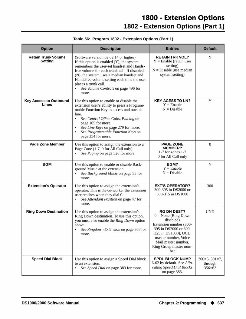
1800 - Extension Options1802 - Extension Options (Part 1)
DS1000/2000 Software Manual Chapter 2: Programming ◆ 637
Retain Trunk Volume Setting
(Software version 02.02.14 or higher)If this option is enabled (Y), the system remembers the user-set handset and Hands-free volume for each trunk call. If disabled (N), the system uses a median handset and Handsfree volume setting each time the user places a trunk call.• See Volume Controls on page 496 for
more.
RETAIN TRK VOL?Y = Enable (retain user
setting)N = Disable (use median
system setting)
Y
Key Access to Outbound Lines
Use this option to enable or disable the extension user’s ability to press a Program-mable Function Key to access and outside line.• See Central Office Calls, Placing on
page 105 for more.• See Line Keys on page 279 for more.• See Programmable Function Keys on
page 354 for more.
KEY ACESS TO LN?Y = EnableN = Disable
Y
Page Zone Member Use this option to assign the extension to a Page Zone (1-7, 0 for All Call only).• See Paging on page 326 for more.
PAGE ZONEMEMBER?
1-7 for zones 1-70 for All Call only
0
BGM Use this option to enable or disable Back-ground Music at the extension.• See Background Music on page 55 for
more.
BGM?Y = EnableN = Disable
Y
Extension’s Operator Use this option to assign the extension’s operator. This is the co-worker the extension user reaches when they dial 0.• See Attendant Position on page 47 for
more.
EXT’S OPERATOR?300-395 in DS2000 or
300-315 in DS1000
300
Ring Down Destination Use this option to assign the extension’s Ring Down destination. To use this option, you must also enable the Ring Down option above.• See Ringdown Extension on page 368 for
more.
RG DN DEST?0 = None (Ring Down
disabled)Extension number (300-395 in DS2000 or 300-325 in DS1000), UCD master number, Voice Mail master number,
Ring Group master num-ber
UND
Speed Dial Block Use this option to assign a Speed Dial block to an extension.• See Speed Dial on page 383 for more.
SPDL BLOCK NUM?6-62 by default. See Allo-cating Speed Dial Blocks
on page 383.
300=6, 301=7,through 356=62
Table 56: Program 1802 - Extension Options (Part 1)
Option Description Entries Default
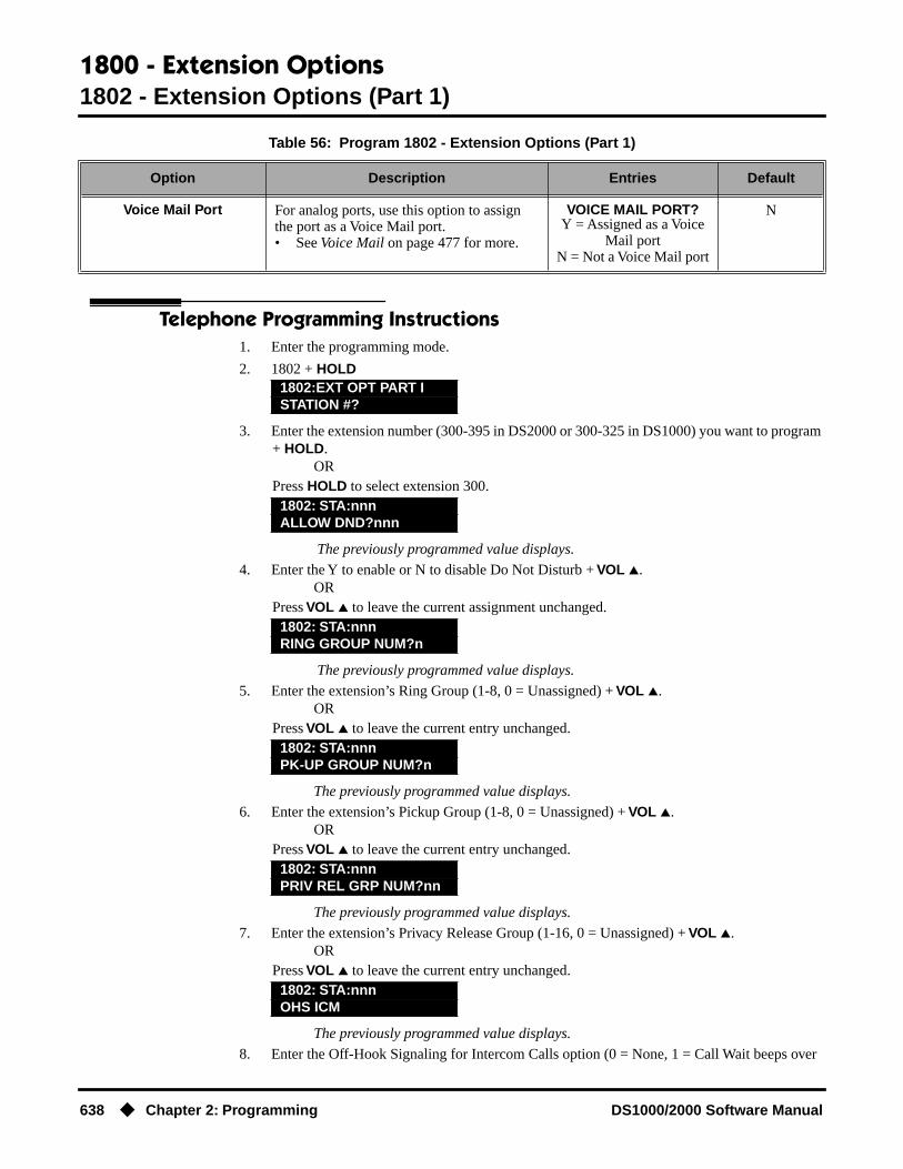
1800 - Extension Options1802 - Extension Options (Part 1)
638 ◆ Chapter 2: Programming DS1000/2000 Software Manual
Telephone Programming Instructions1. Enter the programming mode.
2. 1802 + HOLD
3. Enter the extension number (300-395 in DS2000 or 300-325 in DS1000) you want to program + HOLD.
ORPress HOLD to select extension 300.
The previously programmed value displays.
4. Enter the Y to enable or N to disable Do Not Disturb + VOL ▲.OR
Press VOL ▲ to leave the current assignment unchanged.
The previously programmed value displays.
5. Enter the extension’s Ring Group (1-8, 0 = Unassigned) + VOL ▲.OR
Press VOL ▲ to leave the current entry unchanged.
The previously programmed value displays.
6. Enter the extension’s Pickup Group (1-8, 0 = Unassigned) + VOL ▲.OR
Press VOL ▲ to leave the current entry unchanged.
The previously programmed value displays.
7. Enter the extension’s Privacy Release Group (1-16, 0 = Unassigned) + VOL ▲.OR
Press VOL ▲ to leave the current entry unchanged.
The previously programmed value displays.
8. Enter the Off-Hook Signaling for Intercom Calls option (0 = None, 1 = Call Wait beeps over
Voice Mail Port For analog ports, use this option to assign the port as a Voice Mail port.• See Voice Mail on page 477 for more.
VOICE MAIL PORT?Y = Assigned as a Voice
Mail portN = Not a Voice Mail port
N
1802:EXT OPT PART ISTATION #?
1802: STA:nnnALLOW DND?nnn
1802: STA:nnnRING GROUP NUM?n
1802: STA:nnnPK-UP GROUP NUM?n
1802: STA:nnnPRIV REL GRP NUM?nn
1802: STA:nnnOHS ICM
Table 56: Program 1802 - Extension Options (Part 1)
Option Description Entries Default
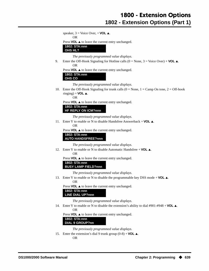
1800 - Extension Options1802 - Extension Options (Part 1)
DS1000/2000 Software Manual Chapter 2: Programming ◆ 639
speaker, 3 = Voice Over, + VOL ▲.OR
Press VOL ▲ to leave the current entry unchanged.
The previously programmed value displays.
9. Enter the Off-Hook Signaling for Hotline calls (0 = None, 3 = Voice Over) + VOL ▲.OR
Press VOL ▲ to leave the current entry unchanged.
The previously programmed value displays.
10. Enter the Off-Hook Signaling for trunk calls (0 = None, 1 = Camp On tone, 2 = Off-hook ringing) + VOL ▲.
ORPress VOL ▲ to leave the current entry unchanged.
The previously programmed value displays.
11. Enter Y to enable or N to disable Handsfree Answerback + VOL ▲.OR
Press VOL ▲ to leave the current entry unchanged.
The previously programmed value displays.
12. Enter Y to enable or N to disable Automatic Handsfree + VOL ▲.OR
Press VOL ▲ to leave the current entry unchanged.
The previously programmed value displays.
13. Enter Y to enable or N to disable the programmable key DSS mode + VOL ▲.OR
Press VOL ▲ to leave the current entry unchanged.
The previously programmed value displays.
14. Enter Y to enable or N to disable the extension’s ability to dial #901-#948 + VOL ▲.OR
Press VOL ▲ to leave the current entry unchanged.
The previously programmed value displays.
15. Enter the extension’s dial 9 trunk group (0-8) + VOL ▲.OR
1802: STA:nnnOHS HL?
1802: STA:nnnOHS CO
1802: STA:nnnHF REPLY ON ICM?nnn
1802: STA:nnnAUTO HANDSFREE?nnn
1802: STA:nnnBUSY LAMP FIELD?nnn
1802: STA:nnnLINE DIAL UP?nnn
1802: STA:nnnDIAL 9 GROUP?nn

1800 - Extension Options1802 - Extension Options (Part 1)
640 ◆ Chapter 2: Programming DS1000/2000 Software Manual
Press VOL ▲ to leave the current entry unchanged.
The previously programmed value displays.
16. Enter Y to retain user setting or N to use median system setting + VOL ▲.OR
Press VOL ▲ to leave the current entry unchanged.
The previously programmed value displays.
17. Enter Y to enable or N to disable programmable key access to trunks + VOL ▲.OR
Press VOL ▲ to leave the current entry unchanged.
The previously programmed value displays.
18. Enter the Page Zone to which the extension belongs (1-7, 0 for All Call only) + VOL ▲.OR
Press VOL ▲ to leave the current entry unchanged.
The previously programmed value displays.
19. Enter Y to enable or N to disable Background Music at the extension + VOL ▲.OR
Press VOL ▲ to leave the current entry unchanged.
The previously programmed value displays.
20. Enter the extension’s operator (300-395 in DS2000, 300-315 in DS100, 0 = Unassigned) + VOL ▲.
ORPress VOL ▲ to leave the current entry unchanged.
The previously programmed value displays.
21. Enter the extension’s Ring Down destination (300-395, 0 = Unassigned) + VOL ▲.OR
Press VOL ▲ to leave the current entry unchanged.
The previously programmed value displays.
22. Enter the extension’s Speed Dial block (6-62, 0 = Unassigned) + VOL ▲.OR
Press VOL ▲ to leave the current entry unchanged.
1802: STA:nnnRETAIN TRK VOL?nnn
1802: STA:nnnKEY ACCESS TO LN?nnn
1802: STA:nnnPAGE ZONE MEMBER?nnn
1802: STA:nnnBGM?nnn
1802: STA:nnnEXT’S OPERATOR?nnn
1802: STA:nnnRG DN DEST?nnn
1802: STA:nnnSPDL BLOCK NUM?nn
1802: STA:nnnVOICE MAIL PORT?nnn

1800 - Extension Options1802 - Extension Options (Part 1)
DS1000/2000 Software Manual Chapter 2: Programming ◆ 641
The previously programmed value displays.
23. For analog ports, enter Y to assign or N to unassign the port as a Voice Mail port + VOL ▲.OR
Press VOL ▲ to leave the current entry unchanged.
The previously programmed value displays.
24. Press CONF to select another extension port.OR
Press CONF twice to exit the program.
1802: STA:nnnALLOW DND?nnn

1800 - Extension Options1803 - Extension Line Access Assignments
642 ◆ Chapter 2: Programming DS1000/2000 Software Manual
1803 - Extension Line Access Assignments
Description
Use Program 1803 - Extension Line Access Assignments to assign the incoming and outgoing trunk access for extensions.
Note: If you are doing extensive programming, you may find Program 9801 - Copy Command (page 657) saves you time when customizing this option.
ConditionsNone
DS2000 Fixed SlotAvailable.
DS2000 U Slot
DS1000
In software version 02.00.09, all extension have full access to all trunks. In prior software versions, analog extensions 316-332 had full access to trunks 3-6 but incoming only access to trunks 1 and 2. Trunks 4-6 require the Expan-sion Board.

1800 - Extension Options1803 - Extension Line Access Assignments
DS1000/2000 Software Manual Chapter 2: Programming ◆ 643
Telephone Programming Instructions1. Enter the programming mode.
2. 1803 + HOLD
3. Enter the number of the station you want to program + HOLDOR
Press HOLD to select extension 300.
The previously programmed value displays.
4. Enter the number of the trunk you want to program + HOLD
Table 57: Program 1803 - Extension Line Access Assignments
Option Description Entries Default
Access Option For each extension, use this option to assign the access option for each trunk.• See Initial System Startup on page 11 for
more.• See Central Office Calls, Answering on
page 99 for more.• See Central Office Calls, Placing on
page 105 for more.• See Conference on page 124 for more.• See Direct Trunk Access on page 154 for
more.• See Forced Trunk Disconnect on
page 212 for more.• See Group Call Pickup on page 215 for
more.• See Last Number Redial on page 277 for
more.• See Line Keys on page 279 for more.• See Loop Keys on page 283 for more.• See Night Service / Night Ring on
page 308 for more.• See Privacy Release Groups on page 347
for more.• See Private Line on page 350 for more.• See Save Number Dialed on page 373 for
more.• See Speed Dial on page 383 for more.• See Tandem Trunking / Unsupervised
Conference on page 433 for more.• See Trunk Group Routing on page 461
for more.• See Trunk Groups on page 468 for more.
NO ACCESS?0 = No access
INCOMING ONLY?1 = Incoming only
OUTGOING ONLY?2 = Outgoing onlyFULL ACCESS?3 = Full access
3 (All trunks, all extensions)
1803:LINE ACCESSSTATION #?nnn
1803: STA:nnnLINE NUMBER?n

1800 - Extension Options1803 - Extension Line Access Assignments
644 ◆ Chapter 2: Programming DS1000/2000 Software Manual
ORPress HOLD to select trunk 1.
The previously programmed value displays on the second line. The first line of the dis-play shows the extension and trunk you are programming.
5. Enter the access option for the trunk selected (0 = No access, 1 = Incoming only, 2 = Outgoing only, 3 = Full access) + VOL ▲
ORPress VOL ▲ to leave the current unchanged.
You see the options for the next consecutive trunk. The previously programmed value displays.
6. Enter the access option for the currently selected trunk + VOL ▲OR
Press CONF to select another trunk.OR
Press CONF twice to select another extension port.OR
Press CONF three times to exit the program.
1803:STA:nnn LINE:nnnnnnnnnnnn
1803:S_PT:n LINE:nnnnnnnnnnnn

1800 - Extension Options1804 - Extension Trunk Group Access
DS1000/2000 Software Manual Chapter 2: Programming ◆ 645
1804 - Extension Trunk Group Access
Description
Use Program 1804 - Extension Trunk Group Access to assign the outgoing access to trunk groups. Incoming trunk group access is always allowed.
Note: If you are doing extensive programming, you may find Program 9801 - Copy Command (page 657) saves you time when customizing this option.
ConditionsNone
Telephone Programming Instructions1. Enter the programming mode.
2. 1804 + HOLD
3. Enter the number of the extension you want to program + HOLDOR
Press HOLD to select extension 300.
The previously programmed value displays.
4. Enter the number of the trunk group (0-8) you want to program + HOLDOR
Press HOLD to select trunk group 1.
The previously programmed value displays on the second line. The first line of the dis-play shows the extension and trunk group you are programming.
5. Enter Y to allow or N to prevent outgoing access to the trunk group selected + VOL ▲OR
DS2000 Fixed SlotAvailable.
DS2000 U Slot
DS1000 Available. Trunks 4-6 require the Expansion Board.
Table 58: 1804 - Extension Trunk Group Access
Option Description Entries Default
Trunk Group Access For each extension, use this option to assign outgoing access for each trunk group.• See Initial System Startup on page 11 for
more.• See Central Office Calls, Placing on
page 105 for more.• See Trunk Groups on page 468 for more.
LINE GROUP n:nnnY = Allow
N = Prevent
Y (All exten-sions, all trunk
groups)
1804:LINE GRP ACCESSSTATION #?nnn
1804: STA:nnnLINE GROUP?n
1804:STA:nnn GRP:nLINE GROUP n:nnn

1800 - Extension Options1804 - Extension Trunk Group Access
646 ◆ Chapter 2: Programming DS1000/2000 Software Manual
Press VOL ▲ to leave the current unchanged.
You see the options for the next consecutive trunk group. The previously programmed value displays.
6. Enter Y to allow or N to prevent outgoing access to the trunk group selected + VOL ▲OR
Press CONF to select another trunk group.OR
Press CONF twice to select another extension.OR
Press CONF three times to exit the program.
1804:STA:nnn GRP:nLINE GROUP n:nnn

1800 - Extension Options1805 - Ring Assignments
DS1000/2000 Software Manual Chapter 2: Programming ◆ 647
1805 - Ring Assignments
Description
Use Program 1805 - Ring Assignments to set up incoming ringing for each trunk at each exten-sion.
Note: If you are doing extensive programming, you may find Program 9801 - Copy Command (page 657) saves you time when customizing this option.
ConditionsIn DS1000 software version 02.01.07 and higher, the system automatically disables the1805 - Ring Assignments programming for all single line ports assigned as Voice Mail ports in 1802 - Voice Mail Port. To have Voice Mail answer an outside call, the trunk should be a Direct Inward Line (i.e., directly terminated) to the Voice Mail master number.
Telephone Programming Instructions1. Enter the programming mode.
DS2000 Fixed Slot Available.
DS2000 U Slot
Available.• See Default in the table below for the initial ring assignment setup.• In version 02.01.07 and higher, single line sets ring according to 1805 -
Ring Assignment programming (just like keysets).
DS1000
Available.• See Default in the table below for the initial ring assignment setup.• In version 02.01.07 and higher, single line sets ring according to 1805 -
Ring Assignment programming (just like keysets).
Table 59: 1805 - Ring Assignments
Option Description Entries Default
Ring Assignment For each extension, use this option to assign the access option for each trunk.• See Initial System Startup on
page 11 for more.• See Central Office Calls, Answering
on page 99 for more.• See Delayed Ringing on page 129
for more.• See Group Call Pickup on page 215
for more.• See Key Ring on page 273 for more.• See Line Keys on page 279 for more.• See Loop Keys on page 283 for
more.• See Night Service / Night Ring on
page 308 for more.• See Private Line on page 350 for
more.
1 = Lamp only (day and night)
2 = Ringing day and night
3 = Night Ring only, lamp during the day
4 = Delay ring day and night
Fixed Slot2 (All trunks for all exten-
sions)U Slot Prior to 02.01.07
2 (All trunks for all exten-sions,)
U Slot 02.01.07 or Higher2 (All trunks for extensions
300-315)1 (All trunks for extensions
above 315)DS1000 Prior to 02.00.09
2 (Trunks 1-4 for all exten-sions)
4 (Trunks 5 and 6 for all extensions)
DS1000 02.00.09 or Higher2 (All trunks for all exten-
sions)
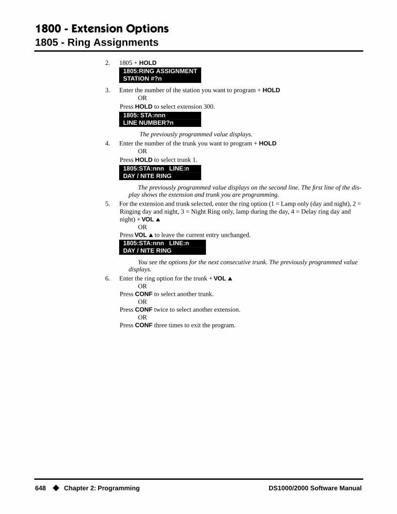
1800 - Extension Options1805 - Ring Assignments
648 ◆ Chapter 2: Programming DS1000/2000 Software Manual
2. 1805 + HOLD
3. Enter the number of the station you want to program + HOLDOR
Press HOLD to select extension 300.
The previously programmed value displays.
4. Enter the number of the trunk you want to program + HOLDOR
Press HOLD to select trunk 1.
The previously programmed value displays on the second line. The first line of the dis-play shows the extension and trunk you are programming.
5. For the extension and trunk selected, enter the ring option (1 = Lamp only (day and night), 2 = Ringing day and night, 3 = Night Ring only, lamp during the day, 4 = Delay ring day and night) + VOL ▲
ORPress VOL ▲ to leave the current entry unchanged.
You see the options for the next consecutive trunk. The previously programmed value displays.
6. Enter the ring option for the trunk + VOL ▲OR
Press CONF to select another trunk.OR
Press CONF twice to select another extension.OR
Press CONF three times to exit the program.
1805:RING ASSIGNMENTSTATION #?n
1805: STA:nnnLINE NUMBER?n
1805:STA:nnn LINE:nDAY / NITE RING
1805:STA:nnn LINE:nDAY / NITE RING

1800 - Extension Options1806 - Ring Type Configuration
DS1000/2000 Software Manual Chapter 2: Programming ◆ 649
1806 - Ring Type Configuration
Description
Use Program 1806 - Ring Type Configuration to set up the Distinctive Ringing Extension Over-ride feature. This option sets the type of ringing the extension will use for trunk calls in the day, night, and delay ring mode. Note that display keyset users may also be able to set up this feature using the ASSIGN (ASGN) soft key.
Also use this option to load a Ring Set (1-3) into an extension. You may want to do this, for exam-ple, if you used the CONFIG soft key to save a Ring Set as a system default. Use this option as an alternative to going to each extension and using the following to select a default Ring Set:
● Super Display: PROGRAM + RING + CONFIG + DEFAULT● 22-Button or 34-Button Display: PGM + RING + CNFG + MORE + MORE + DFLT
ConditionsNone.
DS2000 Fixed Slot Not available.
DS2000 U SlotRequires software version 02.02.14 or higher,
DS1000
Table 60: 1806 - Ring Type Configuration
Option Description Entries Default
Day Ring Type Use this option to set the Extension Override Ring Type option for “Day Ring” trunks ringing the extension. This is the same as following the ASSIGN (ASGN) soft key.• If 1003 - Day Ring Type (page 594)
is 0 (Standard Group), the setting you make in this option will take effect. If 1003 - Day Ring Type (page 594) is 1-3, the setting you make in this option will only take effect if 0101 - Extension Ring Override (page 510) is also enabled (Y).
• See Distinctive Ringing on page 162 for more.
DAY RING TYPE?1 = Ring Type A2 = Ring Type B3 = Ring Type C
0 = LINE (follows the setting for the trunk in program 1003 - Day
Ring Type)
0 (LINE)

1800 - Extension Options1806 - Ring Type Configuration
650 ◆ Chapter 2: Programming DS1000/2000 Software Manual
Telephone Programming Instructions1. Enter the programming mode.
2. 1806 + HOLD
3. Enter the number of the station you want to program + HOLDOR
Press HOLD to select extension 300.
The previously programmed Ring Type displays.
Night Ring Type Use this option to set the Extension Override Ring Type option for “Night Ring” trunks ringing the extension. This is the same as following the ASSIGN (ASGN) soft key.• If 1003 - Night Ring Type (page 594)
is 0 (Standard Group), the setting you make in this option will take effect. If 1003 - Night Ring Type (page 594) is 1-3, the setting you make in this option will only take effect if 0101 - Extension Ring Override (page 510) is also enabled (Y).
• See Distinctive Ringing on page 162 for more.
NIGHT RING TYPE?1 = Ring Type A2 = Ring Type B3 = Ring Type C
0 = LINE (follows the setting for the trunk in program 1003 - Night
Ring Type)
0 (LINE)
Delay Ring Type Use this option to set the Extension Override Ring Type option for “Delay Ring” trunks ringing the extension. This is the same as following the ASSIGN (ASGN) soft key.• If 1003 - Delay Ring Type (page 595)
is 0 (Standard Group), the setting you make in this option will take effect. If 1003 - Delay Ring Type (page 595) is 1-3, the setting you make in this option will only take effect if 0101 - Extension Ring Override (page 510) is also enabled (Y).
• See Distinctive Ringing on page 162 for more.
DELAY RING TYPE?1 = Ring Type A2 = Ring Type B3 = Ring Type C
0 = LINE (follows the setting for the trunk in program 1003 - Delay
Ring Type)
0 (LINE)
Initialize Ring Type
Use this option to load one of the 3 default Ring Sets (1-3) into an extension.• See Distinctive Ringing on page 162
for more.
RING TYPE SET#?1 = Ring Set 12 = Ring Set 23 = Ring Set 3
1 (Ring Set 1)
1806:RING TYPE CFGSTATION #?nnn
1806: STA:nnnDAY RING TYPE?nnnn
Table 60: 1806 - Ring Type Configuration
Option Description Entries Default

1800 - Extension Options1806 - Ring Type Configuration
DS1000/2000 Software Manual Chapter 2: Programming ◆ 651
4. For the extension selected, enter the day ring Ring Type (1=Ring Type A, 2=Ring Type B, 3=Ring Type C, 0=Line)+ HOLD
ORPress HOLD to leave the current value unchanged.
The previously programmed Ring Type displays.
5. For the extension selected, enter the night ring Ring Type (1=Ring Type A, 2=Ring Type B, 3=Ring Type C, 0=Line)+ HOLD
ORPress HOLD to leave the current value unchanged.
The previously programmed Ring Type displays.
6. For the extension selected, enter the delay ring Ring Type (1=Ring Type A, 2=Ring Type B, 3=Ring Type C, 0=Line)+ HOLD
ORPress HOLD to leave the current value unchanged.
7. To select a new Ring Set for the selected extension, press Y.OR
To skip this option without selecting a new Ring Set (and go back to step 4), press N.
8. If you entered Y in the previous step, you see:
9. Select the Ring Set (1-3) for the selected extension + HOLD.
10. Press Y to select the ring set and return to step 4.OR
Press N to return to step 9 without selecting a Ring Set.OR
Press CONF to return to step 4 without making a selection.OR
Press CONF twice to return to step 3 without making a selection.OR
Press CONF three times to exit program 1806.
1806: STA:nnnNIGHT RING TYPE?nnnn
1806: STA:nnnDELAY RING TYPE?nnnn
1806: STA:nnnINIT RING TYPE?(Y/N)
1806: STA:nnnRING TYPE SET#?n
1806: STA:nnnARE YOU SURE?(Y/N)
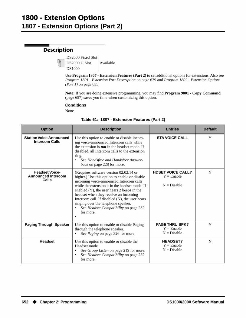
1800 - Extension Options1807 - Extension Options (Part 2)
652 ◆ Chapter 2: Programming DS1000/2000 Software Manual
1807 - Extension Options (Part 2)
Description
Use Program 1807 - Extension Features (Part 2) to set additional options for extensions. Also see Program 1801 - Extension Port Description on page 629 and Program 1802 - Extension Options (Part 1) on page 635.
Note: If you are doing extensive programming, you may find Program 9801 - Copy Command (page 657) saves you time when customizing this option.
ConditionsNone
DS2000 Fixed Slot
Available.DS2000 U Slot
DS1000
Table 61: 1807 - Extension Features (Part 2)
Option Description Entries Default
Station Voice Announced Intercom Calls
Use this option to enable or disable incom-ing voice-announced Intercom calls while the extension is not in the headset mode. If disabled, all Intercom calls to the extension ring.• See Handsfree and Handsfree Answer-
back on page 228 for more.
STA VOICE CALL Y
Headset Voice-Announced Intercom
Calls
(Requires software version 02.02.14 or higher.) Use this option to enable or disable incoming voice-announced Intercom calls while the extension is in the headset mode. If enabled (Y), the user hears 2 beeps in the headset when they receive an incoming Intercom call. If disabled (N), the user hears ringing over the telephone speaker.• See Headset Compatibility on page 232
for more.•
HDSET VOICE CALL?Y = Enable
N = Disable
Y
Paging Through Speaker Use this option to enable or disable Paging through the telephone speaker.• See Paging on page 326 for more.
PAGE THRU SPK?Y = EnableN = Disable
Y
Headset Use this option to enable or disable the Headset mode.• See Group Listen on page 219 for more.• See Headset Compatibility on page 232
for more.
HEADSET?Y = EnableN = Disable
N

1800 - Extension Options1807 - Extension Options (Part 2)
DS1000/2000 Software Manual Chapter 2: Programming ◆ 653
Ringing Line Preference Use this option to enable or disable Ringing Line Preference.• See Ringing Line Preference on
page 370 for more.
RING LINE PREF?Y = Enable (i.e., enable
Ringing Line Preference)N = Disable (i.e., enable
idle line preference)
Y(In DS2000
software ver-sions 02.01.07
through 02.02.00,
Ringing Line Preference
was disabled for all exten-sions above
315.)
Hunt Type Use this option to assign the hunt type for the extension. The options are:1 = Ring No Answer Trunk (TRUNK RNA)2 = Busy/Ring No Answer Trunk (T BUSY
RNA)3 = Busy/Ring No Answer All Calls (A
BUSY RNA)4 = Busy Trunk (TRUNK BUSY)5 = Uniform Call Distribution (UCD)6 = Automatic Call Distribution (ACD)• See Extension Hunting on page 193 for
more.
HUNT TYPE?0 = None
1= Trunk RNA2 = T Busy RNA3 = A Busy RNA4 = Trunk Busy
5 = UCD6 = ACD
None
Hunt Destination (For type 1-4 hunting only) Use this option to assign the next extension in a Circular or Terminal Hunt group.• See Extension Hunting on page 193 for
more.
HUNT DEST?300-395 in DS2000300-325 in DS1000
CLEAR = Undefined
Undefined
Hunt Master Number (For type 5 and 6 hunting only) Use this option to assign the hunt group master num-ber to the member extension. These numbers are set up in 0510 - ACD/UCD Master Extension Numbers and Names on page 552.• See Extension Hunting on page 193 for
more.
ENTER MASTER NUM:Any valid master number
CLEAR = Undefined
Undefined
Prime Line Key Use this option to assign a trunk as the extension’s Prime Line. You enter the Prime Line’s key number (1-24), press the key, or press ICM for Intercom Prime Line. (Soft-ware version 02.01.07 or higher is required to enter 2-digit key numbers.)• See Prime Line Preference on page 342
for more.
PRIME LINE KEY?1-24
0 = UnassignedICM = Intercom Prime
Line
0(Fixed Slot)
ICM(U Slot)
Walking Class of Service Security Code
• This option is currently not used. W-COS CODE?8-digits long, using 0-9, #
and *.
No entry
Table 61: 1807 - Extension Features (Part 2)
Option Description Entries Default

1800 - Extension Options1807 - Extension Options (Part 2)
654 ◆ Chapter 2: Programming DS1000/2000 Software Manual
Telephone Programming Instructions1. Enter the programming mode.
2. 1807 + HOLD
3. Enter the number of the extension you want to program (300-395) + HOLD.OR
Press HOLD to select extension 300.
The previously programmed value displays. The top line of the display indicates the extension you are programming.
4. Enter Y to enable or N to disable voice-announced Intercom calls while the extension is not in the headset mode + VOL ▲.
ORPress VOL ▲ to leave the current entry unchanged.
5. Enter Y to enable or N to disable incoming voice-announced Intercom calls while the exten-sion is in the headset mode + VOL ▲.
OR
Caller ID Log Type(Software version 02.02.14
or higher)
Use this option to specify the type of Caller ID Logging at an extension. With personal logging, an extension’s records are stored on their phone. With group logging, all exten-sions within the same Caller ID logging group share the same records. If the number of records is exceeded at the extension, new call records overwrite old call records (FIFO, or first-in, first out).• See Caller ID Logging on page 89 for
more.
CID LOG?0 (no logging)
1 (personal logging)2 (group logging)
1 (personal logging) for
300-315, 0 (no logging) for
all other exten-sions
Caller ID Personal Records
(Software version 02.02.14 or higher)
If Caller ID Log Type above is 1 (personal logging), use this option to specify the num-ber of Caller ID records the extension should have.• See Caller ID Logging on page 89 for
more.
CID CALL RECORDS?0-99
10 for 300-315, 0 for all other exten-
sions
Caller ID Logging Group(Software version 02.02.14
or higher)
• If Caller ID Log Type above is 2 (group logging), use this option to specify to which Caller ID Logging Group the extension belongs.
CID LOG GROUP#?1-8
None
1807:EXT OPT PART IISTATION #?n
1807:STA:nnnSTA VOICE CALL?nnn
1807:STA:nnnHDSET VOICE CALL?nnn
Table 61: 1807 - Extension Features (Part 2)
Option Description Entries Default

1800 - Extension Options1807 - Extension Options (Part 2)
DS1000/2000 Software Manual Chapter 2: Programming ◆ 655
Press VOL ▲ to leave the current entry unchanged.
The previously programmed value displays.
6. Enter Y to enable or N to disable Paging through the telephone speaker + VOL ▲.OR
Press VOL ▲ to leave the current entry unchanged.
The previously programmed value displays.
7. Enter Y to enable or N to disable the headset mode + VOL ▲.OR
Press VOL ▲ to leave the current entry unchanged.
The previously programmed value displays.
8. Enter Y to enable or N to disable Ringing Line Preference + VOL ▲.OR
Press VOL ▲ to leave the current entry unchanged.
The previously programmed value displays.
9. Enter the hunt type for the extension (1=Trunk RNA, 2=Trunk Busy/RNA, 3=All Calls Busy/RNA, 4=Trunk Busy, 5=UCD, 6=ACD) + VOL ▲.
ORPress VOL ▲ to leave the current entry unchanged.
10. If you entered 1-4 in the previous step, you see:
Assign the next extension in the Circular or Terminal Hunt group + VOL ▲.OR
If you entered 5 in the previous step, you see:
Assign the hunt group master number to the extension + VOL ▲.
The previously programmed value displays.
11. Press the line key to be used for the extension’s Prime Line, dial the Prime Line key number (1-24), or press ICM for Intercom Prime Line + VOL ▲.
ORPress VOL ▲ to leave the current entry unchanged.
The previously programmed value displays.
1807:STA:nnnPAGE THRU SPK?nnn
1807:STA:nnnHEADSET?nnn
1807:STA:nnnRING LINE PREF?nnn
1807:STA:nnnHUNT TYPE?nnn
1807:STA:nnnHUNT DEST?nnn
1807:STA:nnnMASTER NUM?nnn
1807:STA:nnnPRIME LINE KEY?ICM
1807:STA:nnnW-COS CODE?

1800 - Extension Options1807 - Extension Options (Part 2)
656 ◆ Chapter 2: Programming DS1000/2000 Software Manual
12. Press VOL ▲. This entry is currently unused.
The previously programmed value displays.
13. Enter the Caller ID Logging type (0=no logging, 1=personal logging, 2=group logging) + HOLD.
ORPress VOL ▲ to leave the current entry unchanged.
14. If you entered 1 in the previous step, you see:
Enter the number of personal logging call records (0-99) + HOLD + VOL ▲.OR
If you entered 2 in the previous step, you see:
Enter the number of the Caller ID Logging Group to which the extension belongs (1-8) to HOLD + VOL ▲.
ORIf you entered 0 in the previous step, press VOL ▲ to go to the next step.
15. Go back to step 4 and reprogram the voice-announced Intercom call option.OR
Press CONF to go back to step 3 and select another extension to program.OR
Press CONF twice to exit the program.
1807:STA:nnnCID LOG?nnnnnnnn
1807:STA:nnnCID CALL RECORDS?n
1807:STA:nnnCID LOG GROUP#?nnnn
1807:STA:nnnSTA VOICE CALL?nnn

9800 - System Utilities, Part 19801 - Copy Command
DS1000/2000 Software Manual Chapter 2: Programming ◆ 657
9800 - System Utilities, Part 1
9801 - Copy Command
Description
Use Program 9801 - Copy Command to copy Class of Service, extension and trunk data. You can copy data from a single source to a single destination, or from a single source to a range of COSs, extensions or trunks.
Program 9801 - Copy Command will copy data in the following programs:Program 0101: Class of Service OptionsProgram 1001: Trunk Port DescriptionProgram 1003: Trunk OptionsProgram 1701: Programmable Function Key AssignmentsProgram 1702: Personal Speed DialProgram 1703: DSS Key AssignmentProgram 1801: Extension Port DescriptionProgram 1802: Extension Options (Part 1)Program 1803: Extension Line Access AssignmentsProgram 1804: Extension Trunk Group AccessProgram 1805: Ring AssignmentsProgram 1807: Extension Options (Part 2)
ConditionsNone
Telephone Programming Instructions1. Enter the programming mode.
2. 9801 + HOLD
3. Enter the number of the program in which you want to copy data.
COPY displays the program you selected. SOURCE will display the trunk or extension that will be the source for the copied data.
4. Enter the source (extension or trunk) from which you want to copy data + HOLD.
5. If copying to a single destination, enter the destination trunk or extension number.OR
If copying to a range of extensions or trunks, enter the lowest numbered extension or trunk in the range.
6. Press HOLD.
DS2000 Fixed Slot
Available.DS2000 U Slot
DS1000
9801:COPY COMMANDENTER PGM#
COPY: nnnnSOURCE nnnn
COPY (program) (source)DEST RANGE
COPY (program) (source)DEST RANGE nnn-
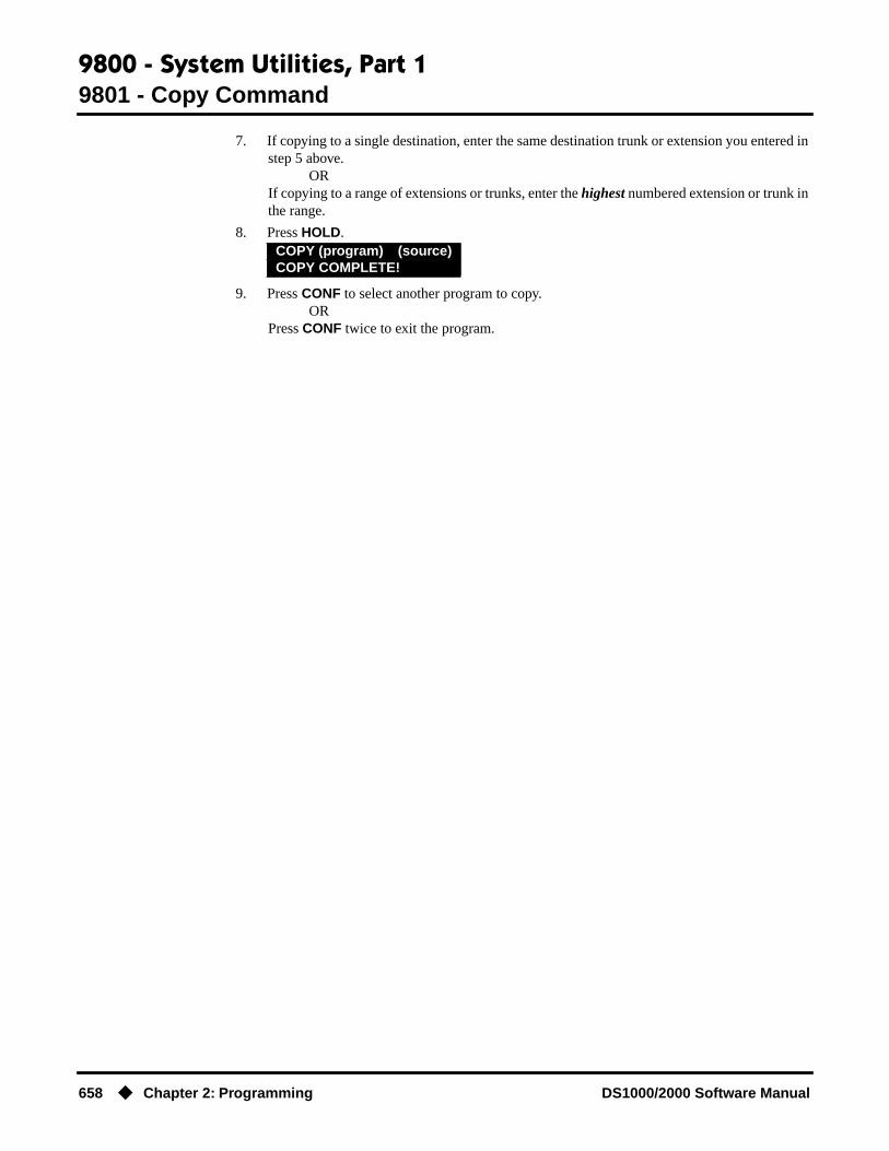
9800 - System Utilities, Part 19801 - Copy Command
658 ◆ Chapter 2: Programming DS1000/2000 Software Manual
7. If copying to a single destination, enter the same destination trunk or extension you entered in step 5 above.
ORIf copying to a range of extensions or trunks, enter the highest numbered extension or trunk in the range.
8. Press HOLD.
9. Press CONF to select another program to copy.OR
Press CONF twice to exit the program.
COPY (program) (source)COPY COMPLETE!

9800 - System Utilities, Part 19802 - Swap Command Utility (U Slot)
DS1000/2000 Software Manual Chapter 2: Programming ◆ 659
9802 - Swap Command Utility (U Slot)
Description
Use 9802: Swap Command to swap extensions, trunks, or slot positions. Use this option as an alternative to manual cross-connect or extensive reprogramming.
Keep the following in mind when using 9802: Swap Command:
● The system will prevent you from swapping an extension with a trunk.
● When you swap extensions, all the programmed parameters swap also. For example, swap-ping keyset 301 with Voice Mail port 316 creates keyset 316 and Voice Mail port 301, with all programming intact.
● When you swap PCBs (slots), all the programmed parameters swap also.
● You cannot swap slot 1; that assignment is fixed.
● The system will not currently swap operator assignments.
ConditionsNone
Telephone Programming Instructions
To swap extensions or trunks:
1. Enter the programming mode.
2. 9802 + HOLD.
3. Enter E. You see:
4. Enter the number of the first extension or trunk you want to swap + HOLD.
5. Enter the number of the second extension or trunk you want to swap + HOLD.
SWAP FAILED indicates that you tried to make an illegal swap.
6. Press HOLD to return to step 2 to make another swap.OR
Press HOLD + CONF to exit.
To swap PCBs (slots):
1. Enter the programming mode.
DS2000 Fixed Slot Not available.
DS2000 U Slot Available.
DS1000 Not applicable.
9802:SWAP COMMAND EXT-E / SLOT-S ?
9802:SWAP COMMAND FIRST EXT
9802:SWAP COMMANDSECOND EXT nnn &
9802:SWAP COMMANDSWAPPED !

9800 - System Utilities, Part 19802 - Swap Command Utility (U Slot)
660 ◆ Chapter 2: Programming DS1000/2000 Software Manual
2. 9802 + HOLD.
3. Enter E. You see:
4. Enter the number of the first PCB/slot you want to swap + HOLD.
5. Enter the number of the second PCB/slot you want to swap + HOLD.
6. Following the instructions in your Hardware Manual, unplug the swapped PCBs/slots and plug them into their new locations.
7. Press HOLD to retrun to step 2 to make another swap.OR
Press HOLD + CONF to exit.
9802:SWAP COMMAND EXT-E / SLOT-S ?
9802:SWAP COMMAND FIRST SLOT
9802:SWAP COMMANDSECOND SLOT n &
9802:SWAP COMMANDSWAPPED !

9800 - System Utilities, Part 19803 - Ring Tone Setup
DS1000/2000 Software Manual Chapter 2: Programming ◆ 661
9803 - Ring Tone Setup
Description
Use 9803 - Ring Tone Setup to customize the 9 tones associated with each Ring Type. You can also use 9803 - Ring Tone Setup to initialize Distinctive Ringing system-wide with a single command. You must initialize Distinctive Ringing if upgrading from a system software version prior to ver-sion 02.02.14. This option initializes the following:
● Distinctive Ringing configuration at each keyset
● Trunk Override (Distinctive Ringing by trunk and ringing mode)
● Extension Ring Override
● Key Ring Override
● The tones in 9803 - Ring Tone Setup
ConditionsNone
Telephone Programming Instructions
To initialize Distinctive Ringing:
1. Enter the programming mode.
2. 9803 + HOLD.
3. To initialize Distinctive Ringing, press Y:
4. Press Y to initialize Distinctive Ringing and return to step 3.OR
Press N to cancel without initializing and return to step 3.
5. Press CONF to exit program 9803.OR
Go to the following procedure to use 9803 - Ring Tone Setup.Following initialization, you must reset the system or unplug and then replug each
telephone.
Following initialization, you must reset the system or unplug and then replug eachtelephone.
Prior to the implementation of this option, it was necessary to use 1806 - Initialize Ring Type to individually initialize Distinctive Ringing at each keyset when upgrading from a system prior to 02.02.14. This could be done in two ways:
● Use 1806 - Initialize Ring Type.● Use the telephone’s soft keys.
22-button and 34-Button TelephonePGM + RING + CNFG + MORE + MORE + DFLT
DS2000 Fixed Slot Not available.
DS2000 U Slot • Requires software version 02.02.14 or higher.• The initialization option requires software version 02.02.17 or higher.DS1000
9803:RING TONE SETUPPROG-P / INIT-I?
9803:INIT DIST RINGARE YOU SURE?(Y?N)

9800 - System Utilities, Part 19803 - Ring Tone Setup
662 ◆ Chapter 2: Programming DS1000/2000 Software Manual
Super Display TelephonePROGRAM + RING + CONFIG + DEFAULT
To set up the Ring Tones:
1. Enter the programming mode.
2. 9803 + HOLD.
3. To customize the Ring tones, press P.
4. Select the ring tone number (0-9) + HOLD.
The tone you select consists of two frequencies (Frequency #1 and Frequency #2) and the Modulation Rate.
5. Press HOLD to select Frequency # 1 for the tone selected.OR
Press Vol ▲+ HOLD to select Frequency # 2 for the tone selected.OR
Press Vol ▲twice + HOLD to select the Modulation Rate for the frequency selected.For Frequency #1 and Frequency #2, there are 97 frequencies (1-97), from 302 Hz to
3200 Hz. The higher the number, the lower the frequency.For the Modulation Rate, there are 255 rates (1-255), from 7.81 Hz to 1000 Hz. The
higher the number, the lower the frequency.
6. Press Vol ▲ and Vol ▼ to scroll through the selections, then HOLD to make the selection.
7. Repeat from step 5 and select another item to program.OR
Press CONF to go back to step 4 and select another one of the 9 Ring Tones to program.OR
Press CONF twice to go back to step 3.OR
Press CONF 3 times to exit program 9803.
9803:RING TONE SETUPPROG-P / INIT-I?
9803:RING TONE SETUPRING TONE # (0-9)?
9803:RING TONE:0FREQUENCY#1? 888 Hz

9800 - System Utilities, Part 19804 - Initialize Caller ID Log Utility
DS1000/2000 Software Manual Chapter 2: Programming ◆ 663
9804 - Initialize Caller ID Log Utility
Description
Use 9804 - Initialize Caller ID Log Utility to initialize (clear) all the Caller ID logs system-wide. This utility clears all the personal logs as well as all the group logs. It has no effect on other Caller ID programming.
ConditionsNone
Telephone Programming Instructions
To initialize the Caller ID Logs:
1. Enter the programming mode.
2. 9804 + HOLD.
3. Press Y to initialize the Caller ID logs and exit program 9804.OR
Press N to cancel without initializing and exit program 9804.
DS2000 Fixed Slot Not available.
DS2000 U SlotRequires software version 02.03.03 or higher.
DS1000
9804:INIT CID LOGSARE YOU SURE?(Y/N)
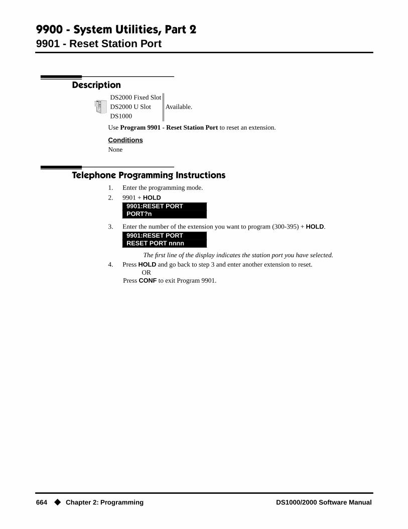
9900 - System Utilities, Part 29901 - Reset Station Port
664 ◆ Chapter 2: Programming DS1000/2000 Software Manual
9900 - System Utilities, Part 2
9901 - Reset Station Port
Description
Use Program 9901 - Reset Station Port to reset an extension.
ConditionsNone
Telephone Programming Instructions1. Enter the programming mode.
2. 9901 + HOLD
3. Enter the number of the extension you want to program (300-395) + HOLD.
The first line of the display indicates the station port you have selected.
4. Press HOLD and go back to step 3 and enter another extension to reset.OR
Press CONF to exit Program 9901.
DS2000 Fixed Slot
Available.DS2000 U Slot
DS1000
9901:RESET PORTPORT?n
9901:RESET PORTRESET PORT nnnn
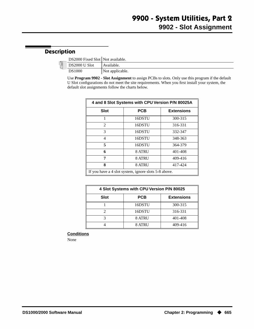
9900 - System Utilities, Part 29902 - Slot Assignment
DS1000/2000 Software Manual Chapter 2: Programming ◆ 665
9902 - Slot Assignment
Description
Use Program 9902 - Slot Assignment to assign PCBs to slots. Only use this program if the default U Slot configurations do not meet the site requirements. When you first install your system, the default slot assignments follow the charts below.
ConditionsNone
DS2000 Fixed Slot Not available.
DS2000 U Slot Available.
DS1000 Not applicable.
4 and 8 Slot Systems with CPU Version P/N 80025A
Slot PCB Extensions
1 16DSTU 300-315
2 16DSTU 316-331
3 16DSTU 332-347
4 16DSTU 348-363
5 16DSTU 364-379
6 8 ATRU 401-408
7 8 ATRU 409-416
8 8 ATRU 417-424
If you have a 4 slot system, ignore slots 5-8 above.
4 Slot Systems with CPU Version P/N 80025
Slot PCB Extensions
1 16DSTU 300-315
2 16DSTU 316-331
3 8 ATRU 401-408
4 8 ATRU 409-416

9900 - System Utilities, Part 29902 - Slot Assignment
666 ◆ Chapter 2: Programming DS1000/2000 Software Manual
Telephone Programming Instructions
Using Program 9902: Slot Assignment
Step 1: Review the Default Configuration
1.1 Check the default configuration to see if it meets the site requirements. If it does, you won’t have to make any of the changes in the following steps.
Step 2: Map Out Your Installation
2.1 If you need to reconfigure your PCBs, use the table below to determine in which slots you want to install your PCBs. Be sure to assign the extension numbers. Note that the 16DSTU in slot 1 is a permanent assignment and cannot be changed.
Step 3: Install the Common Equipment.
3.1 Following the instructions in your system’s Hardware Manual, install your common equipment, system power supplies and CPU PCB. You should also plug a 16DSTU PCB into slot 1. (This is a permanent system assignment.)
Step 4: Turn on your system.
4.1 Once your system starts up, connect a display telephone assigned to the 16DSTU PCB in slot 1.
Step 5: Clear Out Existing Slot Control ProgrammingIf the default setup does not meet the site requirements, you may have to delete some existing slot programming:
5.1 Enter ICM + #*#* + 372000 to enter the programming mode.
5.2 Dial 9902 + HOLD to enter program 9902: Slot Control.
5.3 Press HOLD again. You see the programmed slot information for slot 2, or EMPTY SLOT if there is no assignment.
5.4 Press VOL ▲ or VOL ▼ to check the current assignments for slots 2-8. (Note that slot 1 is permanently assigned as a 16DSTU PCB. You cannot change this assignment.)
5.5 Access the slot you want to change and press HOLD. You see REMOVE CARD (Y/N)?5.6 Press N to return to step 5.4 without deleting, or press Y to remove the assignment. You see: SLOT DATA WILL BE LOST! ABORT (Y/N)?5.7 Press N. You see SLOT CONFIG CHANGED.
5.8 Press HOLD.
Slot PCB Description Extensions
1 16DSTU 16 Digital Station 300-315
2
3
4
5
6
7
8

9900 - System Utilities, Part 29902 - Slot Assignment
DS1000/2000 Software Manual Chapter 2: Programming ◆ 667
5.9 VOL ▲ or VOL ▼ to select another slot, or press CONF to exit program 9902.
Step 6: Programming (Adding) an Empty Slot
During programming, you may see the following error messages:
6.1 Enter the programming mode and dial 9902 + HOLD to enter program 9902: Slot Con-trol.
6.2 Press HOLD then VOL ▲ or VOL ▼ until you select the empty slot you want to program (2-8).
6.3 Press HOLD. You see ADD CARD (Y/N).6.4 Press N + HOLD to return to step 6.2 without adding a PCB, or press Y to enter a new PCB assignment.
6.5 Press ICM, then VOL ▲ or VOL ▼ to scroll through the available circuit types for the slot selected.
OREnter one of the circuit types from the table below.
6.6 When the circuit type you want displays, press HOLD. You see: FIRST EXTENSION.
6.7 Enter the first extension number for the PCB. Refer to the chart in Step 2: Map Out Your Installation above. (For example, if you have a second DSTU in slot 2, and you want the extension numbers to flow consecutively from slot 1, enter 316.) If you make an entry mis-take, use LND to backspace over (erase) the incorrect entry and then enter the correct digits.
6.8 Press HOLD. You see SLOT CONFIG CHANGED!6.10 Press HOLD twice + VOL ▲ or VOL ▼ to select another slot to program (2-8), or press CONF to exit program 9902.
9902 Error Message Description
ERR! NO SLOT CHANGE Occurs if you are trying to assign an extension range that already exists. Also occurs if your assignment will exceed the system maximums (e.g., assigning a 7th 16DSTU).
SLOT 1 IS FIXED! You are trying to change the assignment for slot 1, which is fixed for a 16DSTU PCB.
SLOT IN USE! You have attempted to delete the slot that supports the extension from which you are programming.
Enter this: For this PCB circuit type
0 Empty Slot
1 8 DSTU
2 16 DSTU
3 4 ASTU
4 8 ASTU
5 4 ASTU with Message Waiting(currently not available)
6 8 ASTU with Message Waiting(currently not available)
7 4 ATRU (loop start)
8 8 ATRU (loop start)
9 Empty Slot

9900 - System Utilities, Part 29902 - Slot Assignment
668 ◆ Chapter 2: Programming DS1000/2000 Software Manual
Step 7: Verify Your Slot EntriesUse the following steps to check your 9902: Slot Control programmed entries.
7.1 Enter the programming mode and dial 9902 + HOLD to enter program 9902: Slot Con-trol.
7.2 Press HOLD then VOL Up or VOL Down until you select the slot you want to check (1-8).
7.4 Once you’ve selected the slot you want to check, press V. The display shows the number of circuits currently displayed and the extension numbers assigned to the circuits. For exam-ple, if you plugged your first 8ATRU into slot 8, you would see:SLOT:8 CIRCUIT:1-5401 402 403 404 4057.5 Press V to check any additional circuits on the PCB, press CONF + HOLD to return to step 7.2, or press CONF twice to exit program 9902.
Step 8: Plug in Your PCBs.Plug in your PCBs according to the installation map (step 2) and your slot programming (step 6).

9900 - System Utilities, Part 29905 - Password
DS1000/2000 Software Manual Chapter 2: Programming ◆ 669
9905 - Password
Description
Use Program 9905 - Password to change the system passwords. The table below shows the default system passwords. Turn to System Programming List on page 414 for more on the system pass-words.
ConditionsNone
Telephone Programming Instructions1. Enter the programming mode.
2. 9905 + HOLD
3. Enter the level (1-3) for the password you want to change + HOLD.
4. Enter the new password for the level selected (up to 8 digits) + HOLD.
5. Reenter the password you entered in step 4 above + HOLD.
6. Press CONF to return to step 3 and select another password to program.OR
Press CONF twice to exit the program.
DS2000 Fixed Slot
Available.DS2000 U Slot
DS1000
Table 62: Password Levels
Password Level Password Level
System Administrator 1 0000 1
System Administrator 2 9999 2
Installer 372000 3
9905:PASSWORD PROGPASSWORD LVL?
9905:PASSWORD PROGNEW PASS?
9905:PASSWORD PROGCONFIRM?
9905:PASSWORD PROGPASSWORD ACCEPTED

9900 - System Utilities, Part 29906 - Database Save
670 ◆ Chapter 2: Programming DS1000/2000 Software Manual
9906 - Database Save
Description
Use Program 9906 - Database Save to back up site data to PC Card P/N 85880 or P/N 80050-V**.**. Refer to your Hardware Manual for the specifics.
ConditionsThe following table lists the PC Card Backup Error Messages that you may see when using the instructions below.
Telephone Programming Instructions1. Insert the PC Card into the CPU.
Refer to the Hardware Manual for additional information.
2. Be sure the CPU mode switch is set to RUN.
3. Enter the programming mode.
4. 9906 + HOLD
5. Enter Y + HOLD.
To quit program 9906 instead, enter N + HOLD.
6. Enter a name for the database you want to save (up to 10 characters long).
Refer to Programming Names and Text Messages on page 505 if you need help when entering names.
Skip this step if you want to save data in an address that already has a name assigned.
7. When you are done entering the name, press HOLD.
DS2000 Fixed SlotAvailable.
DS2000 U Slot
DS1000 Not applicable.
This error message: Means this:
No PCCARDThe PC Card is not installed.
Install the PC Card and try again.
ERASE FAILED
The system could not overwrite an existing data base on the PC Card.
Repeat the procedure. If you get the message again, try another PC Card.
SAVE FAILEDThe system could not save data to the PC Card.
Repeat the procedure. Of you get the error message again, try another PC Card.
9906:DATABASE SAVESTART?
9906:DATABASE NAME
9906:DATABASE NAME(name)
9906:DB 00 (time)
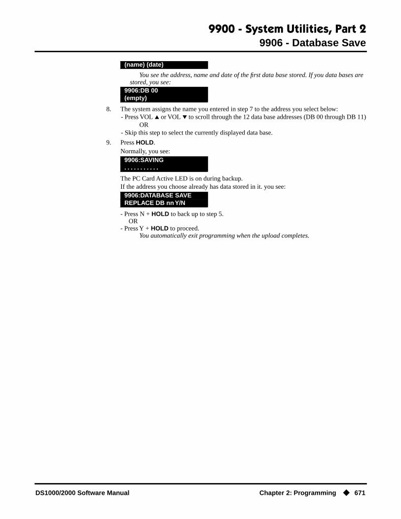
9900 - System Utilities, Part 29906 - Database Save
DS1000/2000 Software Manual Chapter 2: Programming ◆ 671
You see the address, name and date of the first data base stored. If you data bases are stored, you see:
8. The system assigns the name you entered in step 7 to the address you select below:- Press VOL ▲ or VOL ▼ to scroll through the 12 data base addresses (DB 00 through DB 11)
OR- Skip this step to select the currently displayed data base.
9. Press HOLD.Normally, you see:
The PC Card Active LED is on during backup.If the address you choose already has data stored in it. you see:
- Press N + HOLD to back up to step 5. OR- Press Y + HOLD to proceed.
You automatically exit programming when the upload completes.
(name) (date)
9906:DB 00(empty)
9906:SAVING. . . . . . . . . . .
9906:DATABASE SAVEREPLACE DB nn Y/N
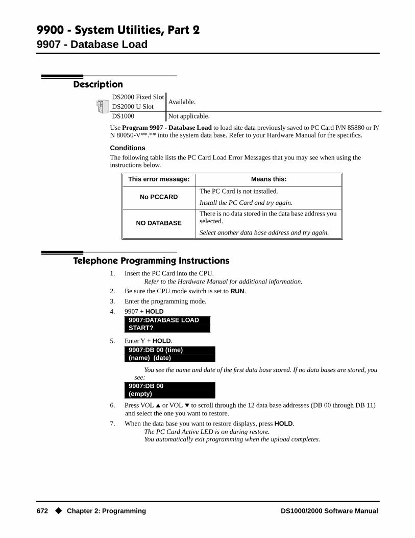
9900 - System Utilities, Part 29907 - Database Load
672 ◆ Chapter 2: Programming DS1000/2000 Software Manual
9907 - Database Load
Description
Use Program 9907 - Database Load to load site data previously saved to PC Card P/N 85880 or P/N 80050-V**.** into the system data base. Refer to your Hardware Manual for the specifics.
ConditionsThe following table lists the PC Card Load Error Messages that you may see when using the instructions below.
Telephone Programming Instructions1. Insert the PC Card into the CPU.
Refer to the Hardware Manual for additional information.
2. Be sure the CPU mode switch is set to RUN.
3. Enter the programming mode.
4. 9907 + HOLD
5. Enter Y + HOLD.
You see the name and date of the first data base stored. If no data bases are stored, you see:
6. Press VOL ▲ or VOL ▼ to scroll through the 12 data base addresses (DB 00 through DB 11) and select the one you want to restore.
7. When the data base you want to restore displays, press HOLD.The PC Card Active LED is on during restore.You automatically exit programming when the upload completes.
DS2000 Fixed SlotAvailable.
DS2000 U Slot
DS1000 Not applicable.
This error message: Means this:
No PCCARDThe PC Card is not installed.
Install the PC Card and try again.
NO DATABASEThere is no data stored in the data base address you selected.
Select another data base address and try again.
9907:DATABASE LOADSTART?
9907:DB 00 (time)(name) (date)
9907:DB 00(empty)

9900 - System Utilities, Part 29908 - PC Card Erase Utility
DS1000/2000 Software Manual Chapter 2: Programming ◆ 673
9908 - PC Card Erase Utility
Description
Use Program 9908 - PC Card Erase Utility to completely erase all the data bases in a Data Base PC Card (P/N 85880).
ConditionsNone
Telephone Programming Instructions1. Following the instructions in your Hardware Manual, insert Data Base PC Card (P/N 85880)
into the CPU.
2. Be sure the CPU mode switch is set to RUN.
3. Enter the programming mode.
4. 9908 + HOLD
5. To erase all data on the PC Card, enter Y + HOLD and go to the next step. You see:
ORTo exit the program without erasing the PC Card, enter N + CONF.
6. To erase all data on the PC Card, enter N + HOLD. You see:
After about 30 seconds, you see:
ORTo exit the program without erasing the PC Card, enter Y + HOLD.
In software versions prior to 02.00.04, press CONF instead of HOLD.
7. Press CONF twice to exit.
DS2000 Fixed Slot Not available.
DS2000 U Slot• Requires software version 02.00.01.• Exit procedure from the Abort screen is modified in software version
02.00.04.
DS1000 Not applicable.
9908:FORMAT PCCARDERASE ALL (Y/N):
9908:FORMAT PCCARDABORT (Y/N)?
9908:FORMAT PCCARD. . . .
9908:FORMAT PCCARDPCCARD ERASED !

9900 - System Utilities, Part 29988 - DS1000 Database Transfer Utility
674 ◆ Chapter 2: Programming DS1000/2000 Software Manual
9988 - DS1000 Database Transfer Utility
Description
Use program 9988 - DS1000 Database Transfer Utility to transfer the contents of one DS1000 system (called the source) to another DS1000 system (called the destination). All programming is transferred, including user-set options such as Personal Speed Dial, Distinctive Ringing and custom Volume/Contrast Control settings.
Connecting the Systems
To connect the DS1000 systems for Database Transfer.
1. Be sure both systems are turned on and operating properly.
2. Check the programming in the source system to be sure the configuration you are going to transfer is correct.
3. Plug one end of the special Database Transfer Cable (P/N 80228) into the RS-232 port of the destination system (i.e., the system that will receive the new programming).
4. Plug the other end of the Database Transfer Cable (P/N 80228) into the RS-232 port of the source system (i.e., the system that currently has the programming you want to transfer).
DS2000 Fixed SlotNot available.
DS2000 U Slot
DS1000 Requires software version 02.03.03 or higher.
!! Important Notes When Upgrading or Transferring a Database !!
If upgrading or transferring a database from a software version prior to 02.02.14:• Use the new option 9803 - Initialize Distinctive Ringing to initialize Distinctive Ringing
system-wide with a single command. Following initialization, you must reset the system or unplug and then replug each telephone.
• Use the new option 9804 - Initialize Caller ID Log Utility to initialize (clear) your Caller ID logs.

9900 - System Utilities, Part 29988 - DS1000 Database Transfer Utility
DS1000/2000 Software Manual Chapter 2: Programming ◆ 675
Notes:
● If making your own Database Transfer Cable:- Use standard RJ45 (8-conductor mod jack) connectors on both ends.- Connect the wires to the mod jack pins as follows: 4 ---> 4 5 ---> 6 6 ---> 5- All other pins must be unterminated.
● When transferring data between systems that have different software levels, use the DS1000/2000 Upgrade Table (P/N 80000UPG**) to verify the settings of the new options installed after upgrade.
● Using the DS1000 Database Transfer Utility does not affect the system software level of either the source or destination system.
● Caller ID Logging log data is not saved between systems with dissimilar software levels. Although all Caller ID and Caller ID Logging programming will be transferred, the actual logs will not.
● The DS1000 Database Transfer Utility does not transfer the Time and Date. The destination system retains its own Time and Date settings.
● The DS1000 Database Transfer Utility will transfer the 1801-Circuit Type settings. However, after the transfer completes the destination system will automatically reset and auto-ID all connected station devices.
ConditionsNone
Telephone Programming InstructionsImportant: Follow these steps exactly as written.
1. Make sure the destination system is idle.
2. On the destination system, enter the programming mode.
3. Enter 9988 + HOLD.
4. Dial 9 (Y) to begin the database transfer.OR
Dial 6 (N) to abort the procedure without transferring.
5. If you pressed 9 (Y) in step 4, you see:
9988:DATA TRANSFERARE YOU SURE?(Y/N)
RESET SOURCE KSU...THEN PRESS HOLD KEY

9900 - System Utilities, Part 29988 - DS1000 Database Transfer Utility
676 ◆ Chapter 2: Programming DS1000/2000 Software Manual
6. On the source system, set the MODE switch to LOAD and press the red reset button.The source system’s Power LED turns red.The source system’s database will be unaffected by the database transfer.
7. On the destination system, press HOLD. While the data is transferring, you see
The destination system is inoperable while Database Transfer takes place.If you forget to press HOLD, the Database Transfer Utility will eventually abort.
8. When the Database Transfer completes, the destination system automatically resets. Once the destination system restarts, you’ll normally see:
To clear the TRANSFER OK display, either lift and replace the telephone handset or reset the system again.
If the Database Transfer fails, you’ll see >>> TRANSFER FAILED after the system resets. The destination system will restart with the default (initialized) database. All prior programming in the destination system will be lost.
If the destination system does not recover from the reset, the transfer was incomplete and the database has become corrupted. You’ll need to shut the system down, pull the bat-tery from the CPU (for about 5 minutes) and then restart the system. The default database will automatically be reinstalled.
9. When the Database Transfer completes, set the MODE switch on the source system back to RUN and press the red reset button.
10. To repeat the Database Transfer procedure, you must start over again from step 1.
Table below explains the Power LED flash rates that occur during Database Transfer.
9988:DATA TRANSFERIN PROGRESS . . . . . . . . .
11-20 WED 2:15PM>>> TRANSFER OK
Power LED Flash Rates During Database Transfer
Source System Destination System
While Database Transfer is in progress:
Flashes briefly red, then flashes green.
Flashes briefly green, the alter-nately flashes red and green.
When Database Transfer completes:
Flashes red/green. Flashes slowly green.

9900 - System Utilities, Part 29999 - System Initialization
DS1000/2000 Software Manual Chapter 2: Programming ◆ 677
9999 - System Initialization
Description
Use Program 9999 - System Initialization to initialize the system database.
ConditionsNone
Telephone Programming Instructions1. Enter the programming mode.
2. 9999 + HOLD
3. Enter Y + HOLD to initialize the system.OR
Enter N + HOLD to exit the program without initializing.If you enter Y, the system will initialize with the factory-installed default and return to
the idle state.
DS2000 Fixed Slot
Available.DS2000 U Slot
DS1000
! Warning!
Initializing the system erases all your programmed entries and replaces them with the factory-installed default values.
9999:INITIALIZATIONINITIALIZE SYS?nnn

9900 - System Utilities, Part 29999 - System Initialization
678 ◆ Chapter 2: Programming DS1000/2000 Software Manual

DS1000/2000 Software Manual Index ◆ i
Numerics2500 Sets. . .3172-OPX Module. . .32, 31736441
heading 3Storing Trunk Routing in a Speed Dial Bin. . .384
AAccount Codes. . .34
And Emergency Calls. . .35Last Number Redial and Save. . .35
Alphanumeric Display. . .43Alternate. . .395Analog Extensions. . .317Announced Transfer. . .455Answer Machine Emulation. . .477Answering Outside Calls. . .99Attendant Call Queuing. . .45Attendant Position. . .47Automatic Call Timer. . .72Automatic Handsfree. . .51Automatic Hold. . .235Automatic Ring Down. . .54Available. . .360
BBackground Music. . .55Barge In (Intrusion). . .58Battery Backup. . .60
CCall Coverage Keys. . .62Call Forwarding. . .66Call Forwarding to Voice Mail. . .477Call Park. . .333Call Pickup
Directed. . .156Group. . .215
Call Pickup, Group. . .215Call Timer. . .72
Automatic. . .72Manual. . .72
Call Waiting. . .75Callback. . .79Caller ID. . .82
Caller ID Integration with Voice Mail. . .83Caller ID on the SMDR Report. . .82Caller ID to Single Line Telephones. . .83Display Separator. . .83Second Call Caller ID. . .83
Single and Multiple Message Format Compatibility. . .82
Third Party Caller ID Check. . .83Caller ID Logging. . .89Camp-On. . .75Central Office Calls
Answering. . .99Loop Keys. . .283Private Line. . .350Placing. . .105
Line Keys. . .279Loop Keys. . .283Private Line. . .350
Chaining Speed Dial Bins. . .385Chapter. . .1Check Key. . .115Circular Hunting. . .193Class of Service. . .117Conference. . .124
Meet Me. . .288Console
DSS. . .143Conversation Record with Voice Mail. . .477
DDatabase Transfer Utility, DS1000. . .411Date and Time. . .437Delayed Ringing. . .129Dial Codes (by Number). . .15Dial Number Preview. . .131Dialing Equal Access Codes. . .190DIL. . .133Direct Inward Line. . .133Direct Messaging. . .291Direct Station Selection (DSS). . .140Direct Station Selection (DSS) Console. . .143Direct Trunk Access. . .154Directed Call Pickup. . .156Directory Dialing. . .158, 162Distinctive Ringing. . .162DND. . .183Do Not Disturb. . .183Door Box. . .185DP to DTMF Conversion. . .360DS1000 Database Transfer Utility. . .411DSS. . .140Dummy Extensions. . .302
EEqual Access Capability. . .190Exclusive Hold. . .235
ii ◆ Index DS1000/2000 Software Manual
Extended Ringing. . .191Extension Class of Service. . .117Extension DSS. . .140Extension Hunting. . .193Extension Names. . .306Extension Ringdown. . .368External Paging. . .326
FFlash. . .207Flexible Numbering Plan. . .209Forced Account Codes. . .34Forced Trunk Disconnect. . .212Forwarding Your Calls. . .66
GGroup Call Pickup. . .215Group Listen. . .219Group Ring. . .221
HHandsfree and Handsfree Answerback. . .228Headset Compatibility. . .232Hold. . .235
Automatic Hold. . .235Exclusive Hold. . .235Intercom Hold. . .235System Hold. . .235
Hotline. . .240Hunting. . .193
Circular. . .193Terminal. . .194UCD. . .194
IIdle Prime Lines. . .342Initial Startup Programming. . .12Installing Voice Mail. . .478Integrated Voice Mail. . .477Interactive Soft Keys. . .244Intercom. . .268
Handsfree Answerback. . .228Intercom Calls
Off-Hook Signaling. . .313Intercom Hold. . .235Intercom Prime Line. . .342Internal Paging. . .326
KKey Ring. . .273
LLast Number Redial. . .277Leaving a Message in Voice Mail. . .477Line Keys. . .279Load Factor
DS1000. . .9DS2000. . .3
Loop Keys. . .283
MManual Call Timer. . .72Meet Me Conference. . .288Message Center Mailbox. . .478Message Waiting. . .291Microphone Mute. . .296Monitor (Silent Monitor). . .300Multiple Directory Numbers. . .302Music On Hold. . .303
NNames for Extensions and Trunks. . .306Night Service (Night Ring). . .308Number Redial, Last. . .277NVM-Series Voice Mail with Automated
Attendant. . .477
OOff-Hook Signaling. . .313Off-Premise Extensions. . .317One-Touch Keys. . .325On-Premise Extensions. . .317Optional (Unforced) Account Codes. . .34Orbits. . .333Overflow
Voice Mail. . .478
PPage Relay Control. . .327Paging. . .326PAME. . .477Park. . .333PBX Compatibility. . .339Personal Answering Machine Emulation with Voice
Mail. . .477Personal Park. . .333Pickup, Group Call. . .215

DS1000/2000 Software Manual Index ◆ iii
Placing Outside Calls. . .105Prime Line Preference. . .342
Intercom Prime Line. . .342Priority vs. Ringing Line Preference. . .342
PriorityPrime Line vs. Ringing Line Preference. . .342,
371Privacy. . .345Privacy Release Groups. . .347Private Line. . .350Programmable Function Keys. . .354Programming List. . .414Pulse to Tone Conversion. . .360
QQueuing
Trunks. . .465
RRedial, Last Number. . .277Removing Trunks and Extensions From Service. . .362Reports
SMDR Report. . .400Reverse Voice Over. . .364, 367Ring Groups. . .221Ringdown Extension. . .368Ringing
Delayed. . .129Extended. . .191
Ringing Line Preference. . .370Priority vs. Prime Line. . .371
SSave Number Dialed. . .373Screened Transfer. . .455Selectable Display Messaging. . .376Setting the Time and Date. . .437Setting Up Voice Mail. . .478Silent Monitor. . .300Single Line Telephones. . .317SMDR. . .400Soft Keys. . .244Speakerphone. . .228Speed Dial. . .383Station Call Coverage. . .62Station Class of Service. . .117Station DSS. . .140Station Instruments. . .397
Ring/Message Lamp (00.01.16)Station Timers. . .421
Storing Intercom Features. . .383Switching Between Calls. . .395System Configuration. . .3System Hold. . .235System Number Plan/Capacities. . .17System Park Orbits. . .333System Programming List. . .414System Speed Dial. . .383System Timers. . .418
TTandem Trunking. . .433Terminal Hunting. . .194Text Messaging. . .376Time and Date. . .437Timers. . .418
Station Timers. . .421System. . .418Trunks. . .426
Toll Restriction. . .439, 447Transfer. . .455
Screened. . .455Unscreened. . .455
Transfer Utility, DS1000. . .411Transferring to Voice Mail. . .477Trunk Callback. . .465Trunk Calls
Off Hook Signaling. . .313Private Line. . .350Toll Restriction. . .439, 447
Trunk Group Routing. . .461, 468, 590, 598Trunk Names. . .306Trunk Timers. . .426
UUCD Hunting. . .194Unannounced Transfer. . .455Unsupervised Conference. . .433User Programmable Features. . .473
VVerified Account Codes. . .34Voice Mail. . .477
Call Forwarding to Voice Mail. . .477Conversation Record. . .477Leaving a Message. . .477Message Center Mailbox. . .478Overflow. . .478Personal Answering Machine Emulation. . .477Setting Up Voice Mail. . .478

iv ◆ Index DS1000/2000 Software Manual
Transferring to Voice Mail. . .477Voice Over. . .493
Reverse Voice Over. . .364, 367Volume Controls. . .496
YY2K Compliance. . .499Year 2000 Compliance. . .499

NEC America, Inc., Corporate Networks Group4 Forest Parkway, Shelton, CT 06484
Tel: 800-365-1928 Fax: 203-926-5458cng.nec.com
Other Important Telephone Numbers
Sales: . . . . . . . . . . . . . . . . . . . . . . . . . . . . . . . . . . . .203-926-5450Customer Service: . . . . . . . . . . . . . . . . . . . . . . . . . . .203-926-5444Customer Service FAX: . . . . . . . . . . . . . . . . . . . . . . .203-926-5454Technical Service - Shelton, CT: . . . . . . . . . . . . . . . .203-925-8801Technical Service - Kent, WA . . . . . . . . . . . . . . . . . . .253-872-7447Discontinued Product Service: . . . . . . . . . . . . . . . . . .900-990-2541Technical Training: . . . . . . . . . . . . . . . . . . . . . . . . . . .203-926-5430Emergency Technical Service (After Hours) . . . . . . . .203-929-7920
(Excludes discontinued products)
