software user manual - johnson controls
TRANSCRIPT

P2000Security Management System
software
user manual
version 3.14 SP5
24-10832-194 Revision EDecember 2017

Copyright 2017Johnson Controls
All Rights Reserved
No part of this document may be reproduced without the prior permission of Johnson Controls.
If this document is translated from the original English version by Johnson Controls, all reasonable endeavors will be used to ensure the accuracy of translation. Johnson Controls shall not be liable for any translation errors contained herein or for incidental or consequential damages in connection with the furnishing or use of this translated material.
Due to continuous development of our products, the information in this document is subject to change without notice. Johnson Controls shall not be liable for errors contained herein or for incidental or consequential damages in connection with furnishing or use of this material. Contents of this publication may be preliminary and/or may be changed at any time without any obligation to notify anyone of such revision or change, and shall not be regarded as a warranty.
Other Manufacturer’s Documentation
Johnson Controls does not duplicate documentation of other equipment manufacturers. When necessary, Johnson Controls provides documentation that supplements that of other manufacturers. When unpacking your equipment, keep all original manufacturer documentation for future reference.
Technical Support
For factory technical support, Johnson Controls authorized field technicians or authorized dealer representatives can contact Global Security Solutions Technical Support by phone at (866) 893-0423 or (414) 524-1214, or by email at [email protected]. They can also call the Field Support Center at (800) 524-1330 or (414) 524-5000 and use options 6, 1, 7.
End users and customers should contact their local Johnson Controls branch or authorized dealer for any of their support needs (technical support, maintenance contracts, on-site field support, P2000 Software Service Agreements, Service Partnerships, and so on). Visit http://www.johnsoncontrols.com/location-finder to find your local Johnson Controls office.
For material returns contact the branch if the material was purchased through a Johnson Controls branch or through the Product Sales Operations Team, if ordered through the Advanced Order Management System (AOMS) and follow the RMA process; or contact the authorized dealer representative where the material was purchased directly.
Acknowledgment
Metasys® and Johnson Controls® are trademarks of Johnson Controls. All other company and product names are trademarks or registered trademarks of their respective owners.
Table of Contents
i
Chapter 1: Introduction ..................................................................................................1
Getting Started ........................................................................................................................1Chapter Summaries ................................................................................................................1Manual Conventions................................................................................................................2Basic System Components .....................................................................................................2Main Menu...............................................................................................................................4Registration Parameters..........................................................................................................5System Overview ....................................................................................................................5
P2000 Application Programming Interface........................................................................5Basic Configuration ...........................................................................................................5
Network Communication.............................................................................................5Communication Modes .....................................................................................................6
Types of Communication ............................................................................................6Access Requests ..............................................................................................................7
Time and Time Zones.................................................................................................7Valid or Invalid Badges ...............................................................................................7Badge Privileges.........................................................................................................7
Controlling Special Access................................................................................................7Overriding Basic Access.............................................................................................7Granting Badge Privileges ..........................................................................................8
Alarms...............................................................................................................................8External Device Alarms ..............................................................................................8Door Alarms................................................................................................................8Software-Only Alarms.................................................................................................8P2000 Host Alarms.....................................................................................................8Remote Alarms ...........................................................................................................8
Non-alarm Input Points .....................................................................................................8Output Relays ...................................................................................................................9
Input and/Output Linking.............................................................................................9Activating Outputs by Events......................................................................................9Activating Outputs Manually .......................................................................................9
Events ...............................................................................................................................9Database Partitioning........................................................................................................9
Logging On to the P2000 System Software ..........................................................................10Changing the Default Login Values.......................................................................................11Logging Off from the P2000 System Software ......................................................................12Navigating through the P2000 System..................................................................................12
Mouse Conventions ........................................................................................................12
24-10832-194 Rev. E

ii TABLE OF CONTENTS
24-10832-194 Rev. E
Instruction Conventions.........................................................................................................13Menu Shortcuts...............................................................................................................13Verification Passwords....................................................................................................14Context Sensitive Help....................................................................................................14Online Help .....................................................................................................................14P2000 Tutorial.................................................................................................................14Viewing the Toolbar ........................................................................................................15
Chapter 2: Configuring the System.....................................................................17
System Configuration Overview ............................................................................................17Using the System Configuration Window........................................................................17
Set Up Workstations and Operators......................................................................................19Set Up Workstations .......................................................................................................19
Workstation Field Definitions ....................................................................................20Add Operators to the System..........................................................................................21
Creating Permission Groups.....................................................................................21Assigning Operators .................................................................................................23P2000 Directory Services Password Validation........................................................27Changing the User Password ...................................................................................28
Set Up User Accounts.....................................................................................................29Adding a P2000 Login Name and Password into the Operating System .................29
Configure System Components ............................................................................................31Registration Parameters .................................................................................................31Site Parameters ..............................................................................................................32
Site Parameters Field Definitions .............................................................................33Setting Up External IPs...................................................................................................46Local Site ........................................................................................................................47Local Configuration .........................................................................................................48Time Zones .....................................................................................................................49
Configuring Time Blocks...........................................................................................49Holiday Types ...........................................................................................................51
Holidays ..........................................................................................................................51Using the Holiday Calendar ......................................................................................52Assigning Holiday Types ..........................................................................................52
Configure Hardware Components.........................................................................................53Hardware Configuration Sequence.................................................................................53Configure Panels ............................................................................................................53
Panel Naming Conventions ......................................................................................53Panel Configuration ..................................................................................................53Soft Input Points .......................................................................................................54Edit Panel Field Definitions.......................................................................................55
Configure Panel Components.........................................................................................61Configure Panel Time Zones ....................................................................................62Configure Panel Holidays .........................................................................................63Configure Air Crew PIN Numbers.............................................................................63
iii
Configure Panel Card Formats .................................................................................64Configure Additional Panel Components..................................................................64
Configure Terminals........................................................................................................65Set up Terminals for each Panel ..............................................................................65Edit Terminal Field Definitions ..................................................................................66Use the Add Hardware Module.................................................................................76Create Terminal Groups ...........................................................................................78
Configure PIN Codes ......................................................................................................78PIN Only ...................................................................................................................78PIN + Card ID ...........................................................................................................79PIN............................................................................................................................79Four-Digit PINs .........................................................................................................80PIN Duress ...............................................................................................................80PIN Retry Alarm........................................................................................................80
Configure Input and Output Points and Groups..............................................................80Create Output Points and Groups ............................................................................80Create Input Points and Groups ...............................................................................82Create Input Points ...................................................................................................82Input Point Field Definitions ......................................................................................82Configuring Reader Terminal Hardwired Input Points ..............................................88Using Reader Terminal Door Contact Input Points...................................................88Using the Terminal Down Input Point .......................................................................89Create Input Groups .................................................................................................89Configure Instruction Text.........................................................................................90
Configure Panel Card Events..........................................................................................91Panel Card Event Field Definitions ...........................................................................92
Configure Soft Alarms.....................................................................................................93Soft Alarms Field Definitions.....................................................................................94
Configure OSI Panels and Components .........................................................................95Unsupported OSI Features.......................................................................................95Unsupported P2000 Features...................................................................................95System Architecture..................................................................................................95Hardware Detection ..................................................................................................96Badge Access Rights................................................................................................97Configuration Sequence ...........................................................................................97Configure OSI Facility Parameters ...........................................................................97OSI Facility Field Definitions.....................................................................................98Add New Portals .....................................................................................................102Configure OSI Panels .............................................................................................103Configure OSI Terminals ........................................................................................104OSI Terminal Field Definitions ................................................................................105Viewing OSI Wireless Devices Status ....................................................................107
Configure S321-IP Panels and Components ................................................................108S321-IP Naming Conventions ................................................................................108Configure S321-IP Panels ......................................................................................108S321-IP Panel Field Definitions ..............................................................................109
24-10832-194 Rev. E
iv TABLE OF CONTENTS
24-10832-194 Rev. E
Configure S321-IP Terminals .................................................................................112S321-IP Terminal Field Definitions .........................................................................113Configure S321-IP Input Points ..............................................................................116S321-IP Input Point Field Definitions ......................................................................118Configure S321-IP Output Points ...........................................................................120
Configure HID Panels and Components.......................................................................122Hardware Requirements.........................................................................................122HID Panel Naming Conventions .............................................................................122Configure HID Facility Parameters .........................................................................123Configure HID Panels .............................................................................................124HID Panel Field Definitions.....................................................................................124Configure HID Terminals ........................................................................................128HID Terminal Field Definitions ................................................................................128Configure HID Input Points .....................................................................................131HID Input Point Field Definitions.............................................................................132Configure HID Output Points ..................................................................................134Troubleshooting Misconfigured HID Readers.........................................................135Override and Lockout Reader Operation................................................................135
Configure Assa Abloy® IP Door Locks and Components.............................................136Hardware Requirements.........................................................................................136Assa Abloy Component Naming Conventions........................................................137Configure Assa Abloy Facility Parameters .............................................................137Using the Card ID feature with Assa Abloy Locks ..................................................140Add a Door Service Router (DSR)..........................................................................140Edit Assa Abloy Panels...........................................................................................143Assa Abloy Panel Time Zones................................................................................145Assa Abloy Holiday Definition.................................................................................146Configure Assa Abloy Terminals ............................................................................146Assa Abloy Terminal Field Definitions ....................................................................147Configure Assa Abloy Soft Input Points..................................................................148Assa Abloy Status Information................................................................................149Real Time Functions...............................................................................................150Change of State Reporting .....................................................................................150Lockout Mode with Assa Abloy PoE Locks.............................................................150File Maintenance on the DSR Server .....................................................................150
Configure Mercury Panels and Components ................................................................151Configure Mercury Facility Parameters ..................................................................151Mercury Facility Field Definitions ............................................................................151Configure Mercury Panels ......................................................................................156Mercury Panel Field Definitions ..............................................................................157Configure Mercury Terminals .................................................................................160Mercury Terminal Field Definitions .........................................................................163Configure Mercury Inputs .......................................................................................172Mercury Input Field Definitions ...............................................................................174Configure Mercury Outputs.....................................................................................176Aperio Locks Particularities ....................................................................................177
v
Schlage ENGAGE Particularities............................................................................178OSDP Reader Particularities ..................................................................................179Configure Mercury Procedures and Triggers..........................................................180Configuring Procedures ..........................................................................................180Configuring Triggers ...............................................................................................182Configure Mercury Elevators ..................................................................................184Best Practices.........................................................................................................188
P2000 Badge Format ....................................................................................................193Configure Elevators and Cabinets.......................................................................................196
Elevator Access Control................................................................................................196General Overview ...................................................................................................196Basic Definitions .....................................................................................................197
Defining Floor Names ...................................................................................................197Defining Floor Masks ....................................................................................................198Configuring Elevators....................................................................................................199
Low Level Interface.................................................................................................199Configuring Floors ..................................................................................................201KONE HLI ...............................................................................................................202Otis EMS - Security / BMS......................................................................................203Otis Compass .........................................................................................................204KONE IP .................................................................................................................208ThyssenKrupp Serial ..............................................................................................213Otis EMS Serial ......................................................................................................214
Defining Floor Groups...................................................................................................216Creating Access Groups for Elevator Floors ..........................................................216
Cabinet Access Control.................................................................................................216Defining Door Names .............................................................................................217Defining Door Masks ..............................................................................................218Configuring Cabinets ..............................................................................................218Cabinet Configuration Field Definitions ..................................................................218Configuring Doors...................................................................................................220Defining Door Groups .............................................................................................220Creating Access Groups for Cabinet Doors............................................................221
Configure Message Filtering and Message Routing ...........................................................221Operators and Messages..............................................................................................221Basic Principles and Definitions ....................................................................................221Sequence of Steps........................................................................................................222Message Filtering..........................................................................................................222
Create Message Filter Groups................................................................................229Message Routing ..........................................................................................................230
Configure P2000 Remote Servers..........................................................................230P2000 Remote Server Field Definitions..................................................................230
Set up Access Groups and Cardholders .............................................................................232Create Access Groups..................................................................................................232Define Cardholder Options............................................................................................234
Define Companies and Departments......................................................................234
24-10832-194 Rev. E
vi TABLE OF CONTENTS
24-10832-194 Rev. E
Create Access Templates.......................................................................................236Access Template Edit Field Definitions ..................................................................236Create Badge Formats ...........................................................................................237Create Badge Purposes .........................................................................................238Create Badge Reasons ..........................................................................................238Create Required Cardholder Fields ........................................................................239Create User Defined Fields ....................................................................................239Define Automatic Employee IDs .............................................................................241Entering Cardholders..............................................................................................242
Chapter 3: Operating the System .......................................................................243
Provide Access to Cardholders and Visitors .......................................................................243Entering Cardholder Information...................................................................................244
Viewing Cardholder Information .............................................................................244Cardholder Field Definitions ...................................................................................245Adding a Cardholder Image....................................................................................247Adding a Cardholder Journal ..................................................................................248User Defined Fields ................................................................................................249
Entering Badge Information ..........................................................................................251Badge Field Definitions...........................................................................................252Viewing Badge Data ...............................................................................................258Bulk Badge Change................................................................................................259
Entering Visitor Information...........................................................................................261Add Visitor Field Definitions....................................................................................261
Defining Automatic Badge Numbers.............................................................................264Synchronizing Badge Status.........................................................................................265Recalling Images ..........................................................................................................267
Image Recall Filters ................................................................................................267Image Recall FS (Full Screen)................................................................................268To Activate Image Recall FS ..................................................................................268
Monitor Alarms ....................................................................................................................270Alarm Configuration ......................................................................................................270Alarm Handling .............................................................................................................271Monitoring Remote Alarms ...........................................................................................272
Alarm Monitor Definitions........................................................................................273Configuring Alarm Colors..............................................................................................277Creating Predefined Alarm Response Text ..................................................................279Monitoring Alarms Using the SIA Interface ...................................................................279Message Forwarding ....................................................................................................281Fire Alarm Control .........................................................................................................282
Basic Definitions .....................................................................................................282Basic Fire Alarm Components ................................................................................283Fire Alarm Server Configuration .............................................................................283Fire Alarm Configuration.........................................................................................286Fire Alarm Management .........................................................................................288

vii
Monitoring Fire Alarms using the Alarm Monitor Window.......................................289Viewing Fire Transactions Using the Real Time List ..............................................289Monitoring Fire Components Using the Real Time Map.........................................289Viewing Fire Components Using the System Status Window ................................289Fire Component Events ..........................................................................................289
Perform Operator Controls ..................................................................................................290Controlling Doors ..........................................................................................................290Controlling Outputs .......................................................................................................291Controlling Panel Relays...............................................................................................292Security Threat Level Control........................................................................................293
Defining Security Levels .........................................................................................293Applying Security Level ..........................................................................................293
Input Point Suppression ................................................................................................295Control Areas and Muster Zones ........................................................................................296
Area Control ..................................................................................................................296Configuring the Area...............................................................................................296Controlling the Area ................................................................................................299Defining Area Filters ...............................................................................................301Displaying Area Details...........................................................................................301Area Details Field Definitions..................................................................................302Area Layout ............................................................................................................303Area Reports...........................................................................................................304
Mustering ......................................................................................................................305Basic Definitions .....................................................................................................305Sequence of Steps .................................................................................................306Define Risk Areas and Muster Zones .....................................................................306Muster Zone Definition Fields .................................................................................307Defining Zone Terminals.........................................................................................310Defining Muster Terminals......................................................................................310Defining Sequester Terminals ................................................................................311Mustering Events ....................................................................................................312Controlling Muster Zones........................................................................................313Muster Zone Status and Control Field Definitions ..................................................313Viewing and Printing Muster Transactions in Real Time ........................................316Muster Reports .......................................................................................................316
Detect and Control Intrusion................................................................................................317Basic Definitions............................................................................................................318Sequence of Steps........................................................................................................319Intrusion Configuration ..................................................................................................319
OPC Aritech Intrusion Interface ..............................................................................319Bosch Intrusion Interface ........................................................................................320Mercury Intrusion Interface .....................................................................................323Configuring Mercury Intrusion Zones......................................................................323Mercury Intrusion Zone Field Definitions ................................................................323Configuring Mercury Intrusion Areas ......................................................................324Mercury Intrusion Area Field Definitions.................................................................325
24-10832-194 Rev. E

viii TABLE OF CONTENTS
24-10832-194 Rev. E
Intrusion Alarms ............................................................................................................326Intrusion Management ..................................................................................................328
Controlling Intrusion Items Using the Intrusion Control Window.............................328Viewing Intrusion Transactions Using the Real Time List.......................................330Monitoring Intrusion Using the Real Time Map.......................................................330Viewing and Controlling Intrusion Items Using the System Status Window ...........330
Intrusion Events ............................................................................................................331Track Hours On Site............................................................................................................332
Configuring Hours On Site Zones .................................................................................332Hours On Site Reporting...............................................................................................333
Hours On Site (Detail) Report.................................................................................334Hours On Site - Simple Report ...............................................................................335
Create Events......................................................................................................................335Using Event Configuration Dialog Boxes ......................................................................335Creating Triggers ..........................................................................................................336
Trigger Field Definitions..........................................................................................337Creating Actions............................................................................................................337
Event Actions Field Definitions ...............................................................................338OPC Server Event Actions .....................................................................................339
Counting Events............................................................................................................340Creating Manual Triggers .............................................................................................341
Monitor the System in Real Time ........................................................................................342Using the Real Time List ...............................................................................................342
Monitoring Remote Messages in Real Time...........................................................342Viewing Real Time List Transactions......................................................................343To Display Color-Coded Transactions....................................................................345
Printing the Real Time List ............................................................................................345Using the Real Time Map .............................................................................................346
Sub Maps and Attachments....................................................................................346Unlocking a Door ....................................................................................................348Activating Events from the Real Time Map.............................................................348
Creating a Real Time Map ............................................................................................348Set up the Map Maker Window...............................................................................348Create an Importable Image...................................................................................349Import an Image to Map Maker...............................................................................349Place Device Icons on a Real Time Map................................................................350Handling Alarms from the Real Time Map..............................................................351Add Map Attachments ............................................................................................352Duplicate Maps .......................................................................................................352
Adding Image Sets........................................................................................................352
Chapter 4: Advanced Features .............................................................................355
Partitions .............................................................................................................................355Partition Types ..............................................................................................................356Creating Partitions ........................................................................................................357
ix
Video Imaging .....................................................................................................................358Video Imaging Specifications........................................................................................358Defining a Video Imaging Workstation ..........................................................................358Badge Design ...............................................................................................................359
Set Up Badge Fields...............................................................................................359Encode Mag Track Formulas..................................................................................360Create a Badge Layout...........................................................................................362Set Up Badge Devices............................................................................................362
Printing a Badge ...........................................................................................................363Capturing the Portrait and Signature Images .........................................................363Viewing and Printing the Badge..............................................................................364
MIS Interface .......................................................................................................................365MIS Prerequisites..........................................................................................................365Understanding the Input and Output Tables .................................................................366MIS and Partitioned Systems........................................................................................366Using the MIS Interface.................................................................................................366
pivCLASS Integration ..........................................................................................................367Specifications ................................................................................................................367
Configure the pivCLASS Integration Component ...................................................367Metasys System Integration ................................................................................................368
Defining MSEA Graphics ..............................................................................................368Registering the P2000 Server with a Site Director........................................................368Defining SNMP Traps ...................................................................................................370
Alarm Forwarding from the Metasys System to the P2000 System .......................371SNMP Registration .................................................................................................371SNMP Object Browser............................................................................................372SNMP Object Properties and Alarm Options..........................................................373
Guard Tour ..........................................................................................................................374Basic Principles and Definitions ....................................................................................374Sequence of Steps........................................................................................................375Define System Hardware for Guard Tour Operation.....................................................375Assign Tour Badges......................................................................................................375Configure Guard Tours .................................................................................................376
Use the Guard Tour Configuration Window............................................................376Timezones, Start and Abort Times .........................................................................378Additional Guard Tour Options ...............................................................................379
Add Stations to the Guard Tour ....................................................................................380Tour Station Definition Fields..................................................................................381
Control Guard Tours .....................................................................................................383Guard Tour Handling ..............................................................................................385Guard Tour Details .................................................................................................386Guard Tour Notes ...................................................................................................387
View and Print Transactions in Real Time ....................................................................387Generate Guard Tour Reports ......................................................................................388
Tour Configuration Report ......................................................................................388Tour Transaction History Report.............................................................................388
24-10832-194 Rev. E
x TABLE OF CONTENTS
24-10832-194 Rev. E
Tour Notes Report ..................................................................................................388CCTV...................................................................................................................................389DVR/VMS............................................................................................................................390Redundancy ........................................................................................................................390
Configuring everRun Enterprise Hosts .........................................................................391FDA Part 11.........................................................................................................................392Intercom ..............................................................................................................................393
Hardware Requirements ...............................................................................................393Intercom System Hardware Verification .................................................................393
Intercom Configuration..................................................................................................394Intercom Exchange.................................................................................................394Intercom Stations....................................................................................................397
Intercom Control ...........................................................................................................398Controlling Intercom Stations using the Real Time Map.........................................400
Intercom Events ............................................................................................................401Intercom Transaction History Reports ..........................................................................401
P2000 Enterprise.................................................................................................................402Define Enterprise Parameters.......................................................................................403Assign Cardholders Enterprise Access.........................................................................404Define Global Badge Access Rights .............................................................................405
Web Access ........................................................................................................................406Sequence of Steps........................................................................................................407Creating and Assigning Web Access Menu Permissions .............................................407Defining Web Access Options ......................................................................................408
Web Access Options Field Definitions....................................................................408Defining Request Approvers .........................................................................................410Submitting Requests using Web Access ......................................................................413Web Access Functions .................................................................................................413
Employee Services .................................................................................................413Guard Services .......................................................................................................414Management Services ............................................................................................415Visitor Management................................................................................................415Emergency Access Disable ....................................................................................416
Processing Web Access Requests ...............................................................................416Visitor Request Management Field Definitions.......................................................418
Customizing the Web Access Interface ........................................................................420Assigning Styles to Web Access Users ..................................................................420
Configuring the Web Access Smart Card Encoder.......................................................421
Chapter 5: System Maintenance..........................................................................425
Downloading Data to Panels ...............................................................................................425Monitoring Downloads.........................................................................................................426Controlling Smart Download................................................................................................427Controlling P2000 Services .................................................................................................428
Service Startup Configuration .......................................................................................428
xi
P2000 Services Definitions.....................................................................................429Starting and Stopping Service Control ..........................................................................432Controlling Services through the Service Monitor .........................................................432
Viewing Workstation Status.................................................................................................433Automatic Software Updates.........................................................................................434
Viewing System Status........................................................................................................435Writing Panel Database to Flash Memory...........................................................................444Updating CK721-A Panels ..................................................................................................444Updating Mercury Panels ....................................................................................................446Performing Database Maintenance.....................................................................................447
To Perform Database Maintenance Functions .......................................................447Database Maintenance Actions ....................................................................................448Database Backup..........................................................................................................451
Configuring a Backup Device .................................................................................451Manual Backups .....................................................................................................452Advanced Backups .................................................................................................452Automatic Backups .................................................................................................453FDA Part 11 Backups .............................................................................................454
Database Restore .........................................................................................................455System Validation .........................................................................................................457CK721-A and S321-IP Data Import and Export ............................................................458
Importing CK721-A and S321-IP Data....................................................................458Evaluating Imported Data .......................................................................................461Saving the Log File .................................................................................................463Exporting CK721-A and S321-IP Data ...................................................................463Evaluating Exported Data .......................................................................................464
Item Synchronization.....................................................................................................464Viewing Request Queue......................................................................................................466
Searching Specific Requests ........................................................................................468Viewing Request Details ...............................................................................................469
Chapter 6: System Reports .....................................................................................471
Using P2000 Standard Reports...........................................................................................471P2000 Standard Report Definitions.....................................................................................474Selected Sample Reports....................................................................................................479
Run the Alarm History Report.................................................................................479Run the Cardholders - Preprocessed Report .........................................................481Run the Cardholders without Badges Report .........................................................483Run the Panel Report .............................................................................................484Run the Transaction History Report .......................................................................485
Creating Custom Reports....................................................................................................486Creating a Custom Report Using SAP Crystal Reports ................................................486
Database Table Definitions.....................................................................................486To Import a Custom Report into the P2000 System ...............................................486
Editing a P2000 Standard Report in SAP Crystal Reports............................................487
24-10832-194 Rev. E
xii TABLE OF CONTENTS
24-10832-194 Rev. E
To Export an Existing Standard Report from the P2000 System............................487To Edit the P2000 Report in SAP Crystal Reports .................................................487
Appendix A: Event Triggers/Actions................................................................489
Trigger Types ......................................................................................................................489Category: Alarm ............................................................................................................489Category: Area..............................................................................................................490Category: Audio-Visual .................................................................................................490Category: Audit .............................................................................................................491Category: Badge ...........................................................................................................491Category: Counter.........................................................................................................492Category: External Trigger ............................................................................................492Category: Fire Detector.................................................................................................493Category: Fire IO Module..............................................................................................493Category: Fire Panel .....................................................................................................493Category: Fire Zone ......................................................................................................494Category: Inputs............................................................................................................494Category: Integration Component.................................................................................494Category: Intercom .......................................................................................................495Category: Intrusion Annunciator ...................................................................................495Category: Intrusion Area ...............................................................................................495Category: Intrusion Device............................................................................................496Category: Intrusion Zone ..............................................................................................496Category: Mustering......................................................................................................497Category: Operator .......................................................................................................497Category: Outputs.........................................................................................................497Category: Panel ............................................................................................................498Category: Terminal .......................................................................................................498Category: Time Zone ....................................................................................................499Category: Time/Date.....................................................................................................499
Event Action Types .............................................................................................................499Category: Audio-Visual .................................................................................................499Category: Badge ...........................................................................................................500Category: CCTV............................................................................................................500Category: Download .....................................................................................................501Category: Host ..............................................................................................................501Category: Inputs............................................................................................................504Category: Intercom .......................................................................................................504Category: Intrusion Annunciator ...................................................................................504Category: Intrusion Area ...............................................................................................504Category: Intrusion Zone ..............................................................................................505Category: Metasys Interlock .........................................................................................505Category: Mustering......................................................................................................505Category: OPC Server ..................................................................................................505Category: Outputs.........................................................................................................505

xiii
Category: Panel ............................................................................................................505Category: Security Level ...............................................................................................506Category: Terminal........................................................................................................506
Appendix B: Message Types and Sub-Types ............................................509
Appendix C: Panel Comparison Matrix ..........................................................513
Appendix D: Using a Keypad Reader on CK721-A Panels ...............517
Invoking Access Requests from a Keypad..........................................................................517To invoke access with a Badge: .............................................................................517To invoke access with PIN Only: ............................................................................517To invoke access with Card ID: ..............................................................................517To invoke access with PIN and Card ID: ................................................................517To invoke access using PIN and Badge: ................................................................518To invoke access with PIN and Badge, allowing PIN after Badge:.........................518
Invoking Air Crew Access Requests from a Keypad ...........................................................518To invoke Air Crew access: ....................................................................................518
Invoking Timed Overrides from a Keypad ...........................................................................518To invoke Timed Override with Badge:...................................................................518To invoke Timed Override with PIN Only:...............................................................518To invoke Timed Override with Card ID:.................................................................519To invoke Timed Override with PIN and Card ID:...................................................519To invoke Timed Override with PIN and Badge:.....................................................520To invoke Timed Override with PIN and Badge, allowing PIN after badge: ...........520
Invoking Panel Card Events from a Keypad........................................................................521To invoke Panel Card Events with Badge: .............................................................521To invoke Panel Card Events with PIN Only: .........................................................521To invoke Panel Card Events with Card ID: ...........................................................521To invoke Panel Card Events with PIN and Card ID: .............................................522To invoke Panel Card Events with PIN and Badge: ...............................................522To invoke Panel Card Events with PIN and Badge, allowing PIN after badge: ......523
Quick Guide to Using Keypad Readers...............................................................................523
Appendix E: Troubleshooting ...............................................................................527
Authentication Process........................................................................................................527Windows Authentication................................................................................................527SQL Server Authentication............................................................................................527P2000 Authentication....................................................................................................528Testing the Workstation ................................................................................................528Troubleshooting Workstation Problems ........................................................................528
P2000 Login Troubleshooting.................................................................................529
24-10832-194 Rev. E
xiv TABLE OF CONTENTS
24-10832-194 Rev. E
P2000 Network Troubleshooting ............................................................................530CCTV Control Troubleshooting...............................................................................531
Appendix F: Secured Premises Notification Settings .........................533
Configuration.................................................................................................................533Sequence of Events......................................................................................................534
Appendix G: Secured Premises Notification Settings for Mercury Panels with Keypad DM-21 (MRDT) ...................................535
Configuration.................................................................................................................535Sequence of Events......................................................................................................536
Index.........................................................................................................................................537

1
Chapter 1: Introduction
he Johnson Controls® P2000 security management system represents the latest technology in integrated security solutions. Using Microsoft®
Windows® operating systems, operators can easily configure and use the P2000 software.
Through its intuitively laid-out menus, users can create cardholder records, define hardware components, and control access using badging, Closed Circuit Television (CCTV), Digital Video Recorder (DVR) or Video Management System (VMS), area control, mustering, and elevator control to name a few, as well as mon-itor local and remote transactions and alarm activity in real time.
Note: The screen captures shown in this man-ual may differ slightly, depending on the software version you are using.
Getting Started
Operators familiar with Windows-based pro-grams should easily master the P2000 soft-ware. This manual provides complete instruc-tions on configuring and operating the system; and virtually the entire manual content is accessible from the P2000 online Help.
Take a few moments to review the information in this chapter and get familiar with the P2000 system basics.
Chapter Summaries
Chapter 1: Introduction. Presents the con-ventions used throughout this manual, an overview of basic system components, and menu options available in the system. The system overview familiarizes you with P2000 system capabilities and how to log on, log off, and navigate through the system.
Chapter 2: Configuring the System. Directs you through tasks to properly con-figure your system for operation. Elements featured in this chapter include: Worksta-tions, Operators, Permissions, Site Parame-ters, Local Configuration, Time Zones, Holidays, Panels, Terminals, Input and Out-put definitions, Elevators and Cabinets, Message Filtering and Routing, Access Groups, and Cardholder Options.
Chapter 3: Operating the System. Describes the primary features used to run the P2000 system. It shows you how to pro-vide access to cardholders and visitors, monitor alarms, control doors, set outputs and panel relays, control areas and muster zones, control and detect intrusion in a facility, create events, and monitor the sys-tem in real time.
Chapter 4: Advanced Features. Describes features that provide a more efficient way to operate and monitor your access control system. These include Partitioning, Video Imaging, MIS Interface, pivCLASS Integra-tion, Metasys® System, Guard Tour, CCTV, DVR/VMS, Redundancy, FDA Part 11, Intercom, P2000 Enterprise, and Web Access.
T
24-10832-194 Rev. E

2 CHAPTER 1
Introduction
24-10832-194 Rev. E
Chapter 5: System Maintenance. Describes the tools available to maintain your system in optimum operating condition.
Chapter 6: System Reports. Includes a complete list of P2000 Standard Reports, along with a brief description of each and how they might be used.
Appendix A: Event Triggers/Actions. Lists all trigger categories, types, condi-tions, and event action types available for Event configuration.
Appendix B: Message Types and Sub-Types. Lists all message types and sub-types available for Message Filtering.
Appendix C: Panel Comparison Matrix. Lists the panel types supported by the P2000 system, including their features and capabilities.
Appendix D: Using a Keypad Reader on CK721-A Panels. Presents the sequence of actions at a keypad reader.
Appendix E: Troubleshooting. Explains connection problems and how to solve them.
Appendix F: Secured Premises Notifica-tion Settings. Describes the sequence of actions needed to notify operators when a panel card event is used to unsuppress alarm signals.
Appendix G: Secured Premises Notifica-tion Settings for Mercury Panels with Keypad DM-21 (MRDT). Describes the sequence of actions needed to notify opera-tors when a Mercury intrusion keypad ter-minal is used to unsuppress alarm signals.
Manual Conventions
The following terms and conventions are used throughout this manual.
Note: Notes indicate important points or excep-tions to the information provided in the main text.
TIP: Tips describe time-saving or additional information.
Provides essential information relevant to the program.
APPLICATION NOTE
IMPORTANT: Important messages remind you that certain actions, if not performed exactly as stated, may cause damage to equipment or make your system non-operational.
Basic System Components
The following terms describe the P2000 sys-tem, including hardware and software terms, computer equipment, and field equipment. The following illustration displays a basic configu-ration of the P2000 system with CK721-A net-work panels. For hardware installation infor-mation, refer to the instructions provided with your panel type.
P2000 Server – The main computer in the sys-tem. The system Server runs the P2000 system software, stores database information, and com-municates with the field panels. The P2000 Server may also be referred to as the Database (DB) and Communications (Comms.) Server.
3
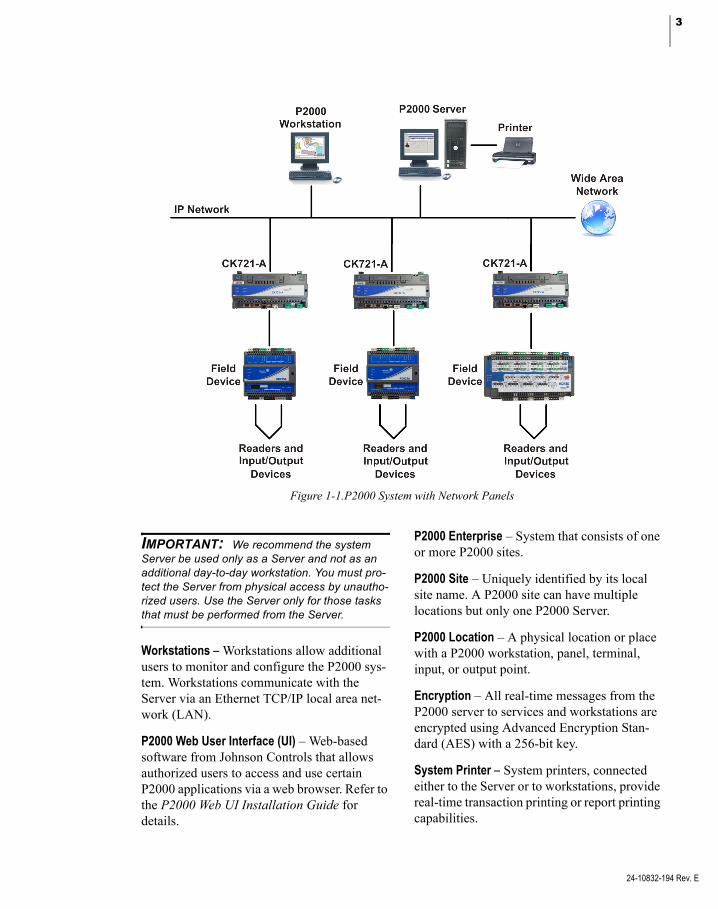
Figure 1-1.P2000 System with Network Panels
IMPORTANT: We recommend the system Server be used only as a Server and not as an additional day-to-day workstation. You must pro-tect the Server from physical access by unautho-rized users. Use the Server only for those tasks that must be performed from the Server.
Workstations – Workstations allow additional users to monitor and configure the P2000 sys-tem. Workstations communicate with the Server via an Ethernet TCP/IP local area net-work (LAN).
P2000 Web User Interface (UI) – Web-based software from Johnson Controls that allows authorized users to access and use certain P2000 applications via a web browser. Refer to the P2000 Web UI Installation Guide for details.
P2000 Enterprise – System that consists of one or more P2000 sites.
P2000 Site – Uniquely identified by its local site name. A P2000 site can have multiple locations but only one P2000 Server.
P2000 Location – A physical location or place with a P2000 workstation, panel, terminal, input, or output point.
Encryption – All real-time messages from the P2000 server to services and workstations are encrypted using Advanced Encryption Stan-dard (AES) with a 256-bit key.
System Printer – System printers, connected either to the Server or to workstations, provide real-time transaction printing or report printing capabilities.
24-10832-194 Rev. E

4 CHAPTER 1
Introduction
24-10832-194 Rev. E
Field Panels – This term refers to CK721-A S321-IP, OSI, HID®, Assa Abloy®, and Mer-cury network panels. These connect to termi-nals and communicate with the Server. See Appendix C: Panel Comparison Matrix for a detailed list of features and capabilities.
Terminals – Terminals provide a point of con-tact with panels to facilitate a variety of func-tions. Depending on your panel type, some ter-minal boards can be used to connect readers, input points, and output points and can be mounted in the basic panel enclosure or an expansion enclosure. CK721-A terminals con-nect to RDR2S-A and RDR8S modules.
External Device – This general term describes any device wired to one of the terminal types, such as readers, motion sensors or other input devices, door strikes, or audible alarm devices.
Main Menu
The Main menu is the backbone of the P2000 system. From here, you select each feature and option available in the system. While logical operation of the system does not follow the Main menu from right-to-left, every menu and option is displayed.

5
Registration Parameters
Parameters associated with your system, such as maximum number of badges, terminals, and workstations are enabled via the entry of a Registration Key. Also, if your system takes advantage of advance features such as Enter-prise or integrate with third-party hardware such as OSI devices, it requires the entry of Option Keys to control those features (some of these features must be selected during installa-tion). Both the Registration and Option keys are provided by Johnson Controls and are associated with your purchase contract. Refer to the P2000 Software Installation manual for instructions.
System Overview
This section is designed to help P2000 users understand basic concepts before configuring the system. The following topics are covered:
P2000 Application Programming Interface – Provides information on P2000 application programming interfaces.
Basic Configuration – Describes an overview of system configuration.
Communication Modes – Describes P2000 system operating modes and communications types.
Access Requests – Shows how the system determines whether a cardholder is granted or denied access at a door.
Controlling Special Access – Describes fea-tures that can override normal system opera-tion.
Alarms – Describes various types of alarms.
Non-alarm Input Points – Provides a basic description of input points.
Output Relays – Provides a basic description of output relays.
Events – Describes how input points and out-put relays can be manipulated automatically or manually in various ways to create events.
Database Partitioning – Provides an over-view of how database partitioning is used within the P2000 system.
P2000 Application Programming Interface
Various published P2000 Application Pro-gramming Interfaces (APIs) are available for third-party integrations into the P2000 system. The APIs published by Johnson Controls are product features that are tested and validated; customer issues related to their use can be resolved through Hotfixes and Service Packs by raising cases through the appropriate sup-port channels. Full technical support is avail-able for tickets associated with P2000 system APIs published by Johnson Controls.
IMPORTANT: Direct database manipulation may void all warranties, and may render the P2000 system unsupportable.
Basic Configuration
Network Communication
CK721-A panels support terminals, readers, input, and output devices, and connect to the P2000 Server via a network card. Each panel has an embedded 32-bit processor, with 64-reader capability.
24-10832-194 Rev. E

6 CHAPTER 1
Introduction
24-10832-194 Rev. E
You can configure an entire system using CK721-A panels, or use them in combination with S321-IP panels; or use third-party devices such as OSI, HID, Assa Abloy, or Mercury panels.
A single workstation is shown in Figure 1-1 on page 3; however, a fully configured Server can support multiple workstations. The number of workstations (including the Server) depends on the type of system you purchased.
If Integrated Video Imaging is part of the con-figuration, the Video Imaging workstation is attached to the network similarly to the work-stations.
Communication Modes
The P2000 Server communicates with panels that provide reader interfaces, input points, or output relays. Communication is bi-direc-tional, some messages are sent from the Server to the field panels, other messages are sent from the panels to the Server, and then can be distributed within the system (through work-stations). The volume of messages across the communication link depends, in part, on the overall operating mode of the system.
While several factors affect overall system per-formance (performance is defined as the speed with which communication occurs between the Server, workstations, and field panels), the most significant factor is operating mode, which is defined when configuring the system. The P2000 system provides the following three operating modes for CK721-A panels:
Local – In this mode, the field panels make all access decisions. This eliminates the need for panels to communicate with the Server every time an access request is presented at a reader. Local mode provides the best overall system capability; however, access is denied to those badges not stored in the panel memory.
Central – This mode is useful when you want to assign access restrictions on a global scale (throughout the entire system). All access requests are forwarded to the Server for an access grant or deny decision. Central mode has the most impact on system performance (the slowest), and should be used only when necessary.
Shared – Access decisions are made either at the panel level or by the Server. Field panels first search for a badge in their memory, as in Local mode. If a badge’s record is not found at the panel level, the access request is then for-warded to the Server, as in Central mode. Shared mode is useful when a panel’s badge capacity is exceeded.
Shared mode is the preferred method of opera-tion. This mode not only gives you the high performance of Local mode for badges stored in the panel memory, but also gives proper access to all badges even if they are not stored in the panel memory.
Types of Communication
The P2000 Server communicates with system field panels via Transactions, Downloads, and Commands.
Transactions – Transactions indicate some form of system activity. They can include items such as access requests and general sys-tem messages such as when a panel loses com-munication with a reader. Typically, transac-tions represent communication initiated at field panels and sent to the P2000 Server.
Downloads – Downloads refer to the transfer of system configuration information from the P2000 Server to the memory of the field pan-els. This includes information such as badge records and access rights. Network panels can be downloaded in minutes using the download feature.
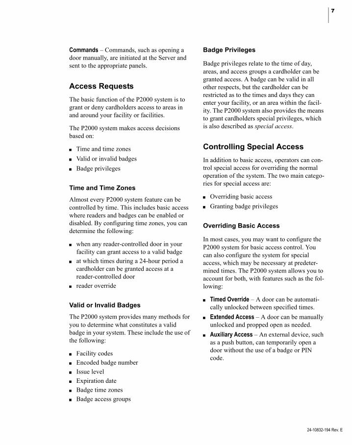
7
Commands – Commands, such as opening a door manually, are initiated at the Server and sent to the appropriate panels.
Access Requests
The basic function of the P2000 system is to grant or deny cardholders access to areas in and around your facility or facilities.
The P2000 system makes access decisions based on:
Time and time zones
Valid or invalid badges
Badge privileges
Time and Time Zones
Almost every P2000 system feature can be controlled by time. This includes basic access where readers and badges can be enabled or disabled. By configuring time zones, you can determine the following:
when any reader-controlled door in your facility can grant access to a valid badge
at which times during a 24-hour period a cardholder can be granted access at a reader-controlled door
reader override
Valid or Invalid Badges
The P2000 system provides many methods for you to determine what constitutes a valid badge in your system. These include the use of the following:
Facility codes
Encoded badge number
Issue level
Expiration date
Badge time zones
Badge access groups
Badge Privileges
Badge privileges relate to the time of day, areas, and access groups a cardholder can be granted access. A badge can be valid in all other respects, but the cardholder can be restricted as to the times and days they can enter your facility, or an area within the facil-ity. The P2000 system also provides the means to grant cardholders special privileges, which is also described as special access.
Controlling Special Access
In addition to basic access, operators can con-trol special access for overriding the normal operation of the system. The two main catego-ries for special access are:
Overriding basic access
Granting badge privileges
Overriding Basic Access
In most cases, you may want to configure the P2000 system for basic access control. You can also configure the system for special access, which may be necessary at predeter-mined times. The P2000 system allows you to account for both, with features such as the fol-lowing:
Timed Override – A door can be automati-cally unlocked between specified times.
Extended Access – A door can be manually unlocked and propped open as needed.
Auxiliary Access – An external device, such as a push button, can temporarily open a door without the use of a badge or PIN code.
24-10832-194 Rev. E
8 CHAPTER 1
Introduction
24-10832-194 Rev. E
Granting Badge Privileges
The other means of providing special access is through badge privileges. Privileges are con-figured as part of a badge’s definition. Badge privileges allow the cardholder the following access:
access to the facility outside normal operat-ing hours.
access using different access times, to sat-isfy the requirements for assisted access according to ADA (Americans with Dis-abilities Act).
extended access by manually executing override features.
Alarms
Another fundamental principle of P2000 sys-tem operation is to report alarm activities. Alarms can be triggered by several methods including the following:
External device alarms
Door alarms
Software-only alarms
P2000 host alarms
Remote alarms
External Device Alarms
External devices, such as motion or glass break sensors, can be wired to P2000 input points. When these devices become active, as in a motion sensor detecting movement, they trig-ger the input point, which causes an alarm. You can define how input points respond when acti-vated, whether or not they trigger output relays, and at which times an alarm can be acti-vated. This offers you the flexibility of auto-mating the alarm operation.
Door Alarms
When a door is unsecured because of unautho-rized activities, the door is considered to be in a forced alarm state and is reported to the sys-tem. The system can also monitor cases where the door is propped open after a valid access grant.
Software-Only Alarms
Software-only alarms are unlike external device alarms in that software alarms are trig-gered by system activities (such as when a panel loses AC power), rather than by external devices, which are wired to the system panels and terminals.
P2000 Host Alarms
The P2000 system also reports host alarms, such as alarms originated by P2000 event actions, mustering alarms, or FDA record retention alarms.
Remote Alarms
These are external device alarms, door alarms, software-only alarms, and host alarms that are generated at remote sites.
Non-alarm Input Points
The P2000 system allows you to use input points for activities other than alarms. For example, a motion sensor wired to an input might be used to turn on lights.

9
Output Relays
Where input points are triggered by external devices, output relays allow you to trigger external devices using the P2000 system. These devices might include warning indica-tors for alarm situations or non-alarm related functions such as lighting or environment con-trol. In general, output relays are activated by one of the following:
Input and output linking
Events
Manually
Input and/Output Linking
The P2000 system allows you to form individ-ual output relays into groups (as a note, you can also group input points). The primary pur-pose of linking inputs to output relays is to trigger external devices, such as:
in emergency situations, using room light-ing or warning indicators like flashing lights or sirens,
automatically activating a building function such as lighting or environment control.
Activating Outputs by Events
As an alternative to input and output linking, output relays can also be activated either man-ually or automatically by events.
Activating Outputs Manually
Operators can manually activate outputs using the P2000 Output Control application.
EventsEvents are sequences of system commands or actions that may be activated at a predefined time or on an as-needed basis. You can use the P2000 system to activate and deactivate events either manually or automatically. Examples of events include the following:
Card Events – A badge is assigned event privi-leges and may execute an event from a reader equipped with a keypad.
Timed Events – Events are assigned specific activation dates and times, and are activated or deactivated automatically by the P2000 system.
System Events – Event triggers can be based on a variety of system activities, such as when an operator attempts to log on with an invalid user name or password.
Database PartitioningYou can divide the P2000 database into smaller sections that can be individually man-aged. Database partitioning structures define what data is accessible by an individual opera-tor, or by a group of operators. You can create as many partitions as you need, depending on your system requirements. After partitions are created, they can be assigned to all major sys-tem components. See Partitions on page 355 for more information.
There are two types of partitions:
Super User – This partition is automatically created by the system and is the main partition in the database. Only one Super User partition can be defined. This partition can be assigned to multiple operators and has access to all par-titions of the system.
Regular – Regular partitions are assigned to operators. These partitions allow the operator to add, modify, delete, or view records within their assigned partition.
24-10832-194 Rev. E

10 CHAPTER 1
Introduction
24-10832-194 Rev. E
If you are new to the P2000 system or new to security management in general, it is important you have at least a basic understanding of these principles before configuring the system. What is important to keep in mind is the relationship between the various system features.
As you work through Chapters 2 and 3, these principles are reinforced as you learn which options relate to which specific system fea-tures.
Logging On to the P2000 System Software
The P2000 system uses a user name and unique password to establish each authorized user. Passwords are used to protect access within a database or system. A password is a unique combination of alphanumeric charac-ters, such as in a string of letters and numbers.
Logging on to the P2000 system is similar for the Server and for a workstation.
1. Double-click the P2000 icon on your Win-dows desktop,
or, from your Windows desktop, select Start>Programs>Johnson Controls> P2000>P2000. The Login window opens.
2. Place the cursor in the User Name field and enter Cardkey.
3. Press <Tab> to move to the Password field and enter master.
4. Click OK or press <Enter> to continue. The P2000 Main menu bar displays.
5. The Partition selection box that appears on the right side of the P2000 toolbar, shows Super User as the default Partition option. Operators that belong to the Super User partition have access to all areas of the P2000 program, see Partitions on page 355.
Note: The Lock icon on the right hand corner of the P2000 menu bar indicates that all real-time messages from the P2000 server to the worksta-tion are operating in Encrypted mode.
Note: By default, the Alarm Monitor window automatically opens when logging on to the Server. For detailed information, see Monitor Alarms on page 270.

11
Changing the Default Login Values
By using the default User Name and Password, whether at the Server or at a workstation, you are logging on to the system with Super User privileges. This account has, by default, full privileges for viewing and changing system parameters. After initially logging on to the system, you have the option to change the default login User Name and Password to pre-vent unauthorized users full access to the sys-tem.
You cannot remove the default account from the system. Instead, use the following steps to change the default user name and password, thereby restricting access to the Super User account.
To Change the Default User Name and Password
1. From the P2000 Main menu, select Opera-tor>Operator Account/Profile.
2. The password verification dialog box dis-plays. Type master and click OK or press <Enter> to continue.
3. The Operator Account/Profile window dis-plays.
4. Select Cardkey and click Edit. The Edit Operator dialog box opens.
5. Information for the Cardkey user displays. To change the User Name and Password, go to each field and enter the new informa-tion.
6. Re-enter the password in the Confirm Password field.
IMPORTANT: Once you change the default login password, you can only use the new User Name and Password to access the Super User account.
24-10832-194 Rev. E

12 CHAPTER 1
Introduction
24-10832-194 Rev. E
7. You may also enter the Full Name of the operator assigned to the User Name. For more details on adding operator informa-tion into the P2000 system, see Add Opera-tors to the System on page 21.
8. Click OK to save your settings.
9. Click Done to close the window.
Note: You must log off from the P2000 system for the changes to take effect (see the following section for details).
Logging Off from the P2000 System Software
After changing the default User Name and Password, you must log off from the P2000 system. You are not required to shut down the Server or workstation.
To Log Off from the P2000 System:
1. From the P2000 Main menu, select Exit>Exit.
2. The system prompts for logoff verification.
3. Click Yes or press <Enter>. The system returns to the Windows desktop.
Navigating through the P2000 System
The P2000 system provides an easy-to-use graphical user interface (GUI) for making selections and entering data.
Mouse Conventions
The standard pointing device for the P2000 Server and workstations is a two-button mouse. The left mouse button is the primary mouse button. The following terms are used throughout this manual to describe how you navigate through the P2000 system.
Pointer – The pointer may display differently depending on the action that you are perform-ing. For example, the pointer is normally an arrow, but changes to an hourglass to denote the system is saving, retrieving, or compiling information. When in a text field, the pointer changes to a cursor.
Select – This term directs you to select a menu, submenu, or list item. For example, select Control>Output Control means to click on the Control option from the Main menu bar, then click on the Output Control submenu.
Clear – Click again on a selected radio button or check box to clear the option.
Click – Press and release the left mouse button once. Note that click always refers to the left mouse button, unless the right mouse button is specifically called out in the text.
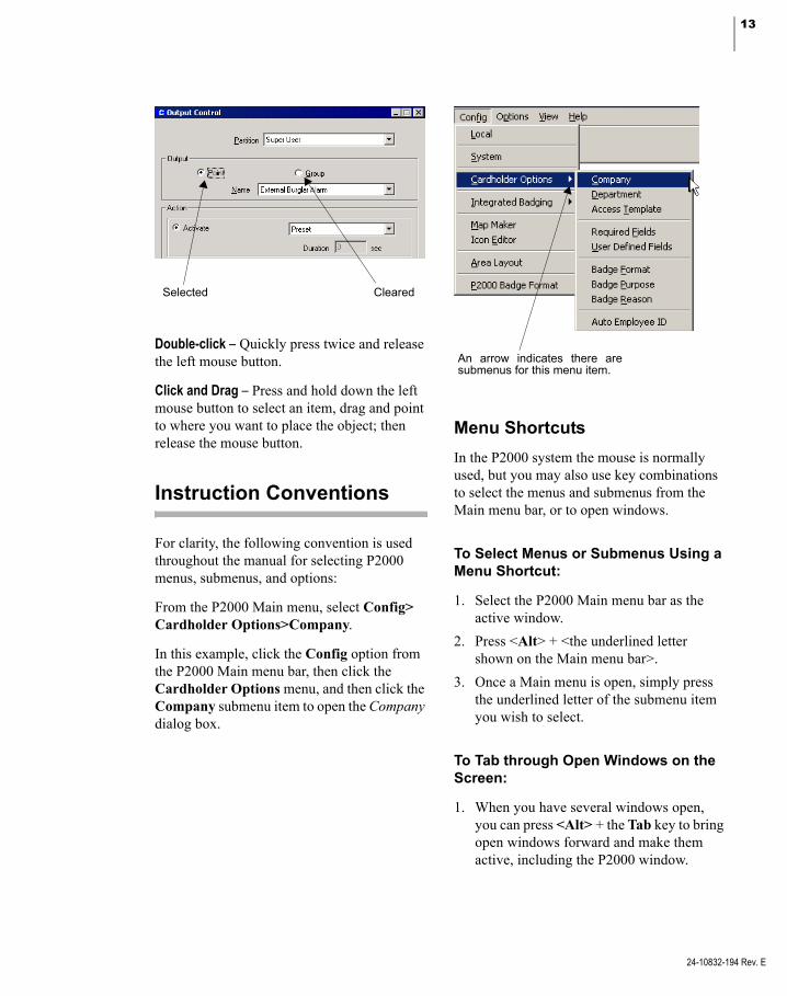
13
Selected Cleared
Double-click – Quickly press twice and release the left mouse button.
Click and Drag – Press and hold down the left mouse button to select an item, drag and point to where you want to place the object; then release the mouse button.
Instruction Conventions
For clarity, the following convention is used throughout the manual for selecting P2000 menus, submenus, and options:
From the P2000 Main menu, select Config> Cardholder Options>Company.
In this example, click the Config option from the P2000 Main menu bar, then click the Cardholder Options menu, and then click the Company submenu item to open the Company dialog box.
An arrow indicates there are submenus for this menu item.
Menu Shortcuts
In the P2000 system the mouse is normally used, but you may also use key combinations to select the menus and submenus from the Main menu bar, or to open windows.
To Select Menus or Submenus Using a Menu Shortcut:
1. Select the P2000 Main menu bar as the active window.
2. Press <Alt> + <the underlined letter shown on the Main menu bar>.
3. Once a Main menu is open, simply press the underlined letter of the submenu item you wish to select.
To Tab through Open Windows on the Screen:
1. When you have several windows open, you can press <Alt> + the Tab key to bring open windows forward and make them active, including the P2000 window.
24-10832-194 Rev. E

14 CHAPTER 1
Introduction
24-10832-194 Rev. E
To Tab through Fields on a Window:
1. Once an active window is selected, you can use the Tab key to tab through fields on the window.
Verification Passwords
The P2000 software offers added security by requiring operators to verify their login pass-word when performing certain system-critical functions. If the Verify Password for Critical Functions option is selected in the Edit Opera-tor dialog box (see User Info Tab on page 24), when operators access some functions, a pass-word verification dialog box displays for the operators to enter their login password.
The purpose of a verification password is to prevent unauthorized users from performing system-critical functions at unattended PCs.
Context Sensitive Help
Help is available from most P2000 windows or dialog boxes by pressing F1. Once you press F1, help text for the selected item displays in a separate window.
Online Help
The P2000 software contains virtually the entire User’s Guide in online documentation accessed via the Help option on the Main menu. You can also press F1 for context-sensi-tive help from most windows in the program and most individual fields.
Access information under Introduction, Sys-tem Configuration, System Operation, Advanced Features, System Maintenance, or System Reports; or use the Index to search for specific topics.
P2000 Tutorial
The tutorial presents an overview of the P2000 security system’s major features and options. It also covers several system configuration, installation, and troubleshooting tips. Adobe® Flash is required to run the tutorial and can be installed when you start the tutorial program from the Help option in the P2000 menu bar.
The modular design enables navigation to all or specific tutorial topics. The tutorial intro-duces topics and sub-topics, which are dis-cussed through Flash presentations that pro-vide audio narration (with matching text if desired) to guide users on how to make the most of P2000 main popular features. Software screenshots are used to walk the user through actual configuration and installation steps.

15
Viewing the Toolbar
The toolbar gives you easy access to the more commonly used windows in the P2000 system.
To Use the Toolbar:
1. If the toolbar is not visible, from the P2000 Main menu select View>Toolbar. The toolbar displays.
Click and drag to another position
2. Place the mouse over an icon to display the name of the icon.
3. To open a dialog box from the toolbar, click the desired icon. Choices are: Access Cardholder, Alarm Monitor, Real Time List, Real Time Map, System Configura-tion, System Status, Security Level Con-trol, and Launch AV Player (if the DVR/VMS option is available in your facility).
4. To position the toolbar anywhere on the screen, double-click the left handle, click the title bar and drag it to the desired posi-tion.
5. To close the toolbar, click the Close button, or select View>Toolbar from the P2000 Main menu.
Note: A Partition selection box is available on the right side of the toolbar and can also be posi-tioned anywhere on the screen
24-10832-194 Rev. E

16 CHAPTER 1
Introduction
24-10832-194 Rev. E

17
Chapter 2: Configuring the System
o operate your P2000 Security Manage- After you configure your system components,
ment System, you must set up and con-figure the software to communicate with the system hardware. After youcomplete all hardware installations, you are ready to configure the P2000 software. Config-uration is typically performed by a System Engineer or System Administrator.
System Configuration Overview
Configuration should progress in a logical sequence. For example, you must configure the system site parameters before you can assign them to panels; you must configure panels before you can assign terminals to them; and you must configure terminals before you can create terminal groups, inputs, and outputs. This chapter guides you through a logical pro-gression. After you configure the system, you always have the option to return to a compo-nent and make changes if necessary.
The following elements must be set up to com-plete system configuration:
Set Up Workstations and Operators
Configure System Components
Configure Hardware Components
Configure Elevators and Cabinets
Configure Message Filtering and Message Routing
Set up Access Groups and Cardholders
these items are available to you as you work your way through hardware configuration. The parameters set up during hardware configura-tion are accessible when you begin creating your database. As soon as the system is com-pletely configured, you are ready to begin sys-tem operation.
Note: We recommend you develop a naming convention plan to apply to panels, terminals, inputs, outputs, and other system components when you configure the P2000 software. The fol-lowing characters are not allowed when defining P2000 components: @ . , ? * # : ' " / \ [ ] < > | $.
Using the System Configuration Window
The System Configuration window provides quick access to many component configura-tions. Select Config>System from the P2000 Main menu bar and enter your password if prompted. The System Configuration window opens, as shown in the following page. All root items in the system configuration tree display on the left side of the window (windowpane). A plus (+) sign next to an item indicates that branches exist beneath them. When you select a branch in the tree, the detailed settings and values relating to that selection are listed on the right windowpane.
You can add as many items to the configura-tion as you need, depending on your Registra-tion Parameters. After you add items to the system, you can modify them as desired.
T
24-10832-194 Rev. E
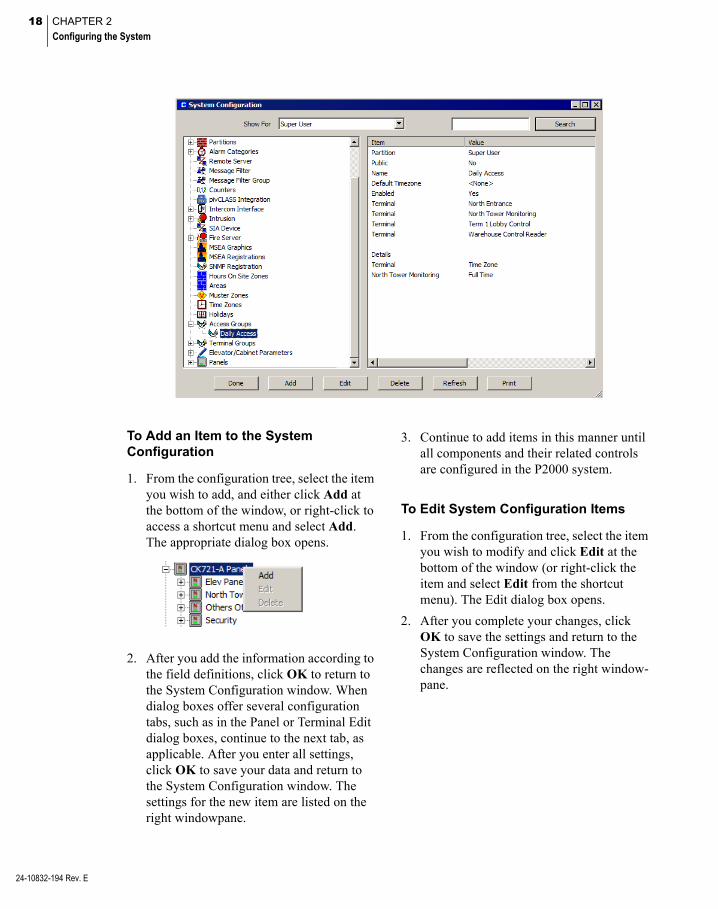
18 CHAPTER 2
Configuring the System
24-10832-194 Rev. E
To Add an Item to the System Configuration
1. From the configuration tree, select the item you wish to add, and either click Add at the bottom of the window, or right-click to access a shortcut menu and select Add. The appropriate dialog box opens.
2. After you add the information according to the field definitions, click OK to return to the System Configuration window. When dialog boxes offer several configuration tabs, such as in the Panel or Terminal Edit dialog boxes, continue to the next tab, as applicable. After you enter all settings, click OK to save your data and return to the System Configuration window. The settings for the new item are listed on the right windowpane.
3. Continue to add items in this manner until all components and their related controls are configured in the P2000 system.
To Edit System Configuration Items
1. From the configuration tree, select the item you wish to modify and click Edit at the bottom of the window (or right-click the item and select Edit from the shortcut menu). The Edit dialog box opens.
2. After you complete your changes, click OK to save the settings and return to the System Configuration window. The changes are reflected on the right window-pane.
19
To Search for System Configuration Items
1. If you wish to search for a specific item, enter the name of the item in the Search field at the top right corner of the System Configuration window.
You can enter complete or partial words; no wildcards are needed, and this field is not case sensitive.
2. Click Search. The System Configuration window displays the match entered in the search field.
3. Continue clicking Search until you find the item you are looking for.
Refreshing the System Con-figuration Window: The Re-fresh button is used to update changes made at the Server or other workstations.APPLICATION NOTE
To Print System Configuration Items
1. From the configuration tree, select the item you wish to print. The settings associated with the selected item are listed on the right windowpane.
2. Click Print at the bottom of the window.
3. Select a printer name and any other infor-mation for the printer to be used. Printers must first be set up using the Windows Printer Settings dialog box. See your sys-tem administrator if you need more infor-mation, or refer to your Microsoft Windows documentation.
4. Click OK to print.
Set Up Workstations and Operators
Before configuring system and hardware com-ponents, Workstations and Operators should be properly set up to communicate with the Server. While Workstations are assigned from the System Configuration window, Operators are assigned via the P2000 Main menu. The following sections describe how to:
Set Up Workstations
Add Operators to the System
Set Up User Accounts
Set Up Workstations
Workstations communicate with the Server via the network. The Server can communicate with a maximum number of Workstations con-currently, based on your registration options. Workstations are assigned a partition, a name, a time zone, and designated as public to make the workstation visible to all partitions. A workstation must be configured as a Badge Station if it operates Video Imaging. When you click a Workstation on the System Config-uration window, the current settings display on the right windowpane.
Note: To log on from a workstation to the P2000 system, you must set up user accounts in the Windows operating system. See Set Up User Accounts on page 29.
To Add a Workstation
1. In the System Configuration window, expand Site Parameters.
2. Select Workstation and click Add to access the Workstation dialog box.
24-10832-194 Rev. E

20 CHAPTER 2
Configuring the System
24-10832-194 Rev. E
3. Enter the information required. (See Work-station Field Definitions for detailed infor-mation.)
4. Click OK to save your entries and return to the System Configuration window. The new Workstation displays beneath the main Workstation icon.
5. Click the new Workstation icon to display the current settings on the right window-pane. It may be necessary to click the plus (+) sign to display all configured Worksta-tions on the system.
Note: Only operators that belong to the Super User partition can add, edit, or delete any worksta-tion. In addition, operators cannot delete their cur-rently logged on workstation; however, an operator can delete other workstations that are currently active. A message displays to confirm the deletion.
Workstation Field Definitions
Partition – Select the partition to which the Workstation has access. See Partitions on page 355.
Public – Click this check box to make this Workstation visible to all partitions.
Note: A workstation must be made Public to allow users from different partitions to log on at that workstation.
Name – Enter the name of the Workstation. This must be the name of this workstation, as configured in the Windows operating system. You can also click the [...] button to find a workstation on your network (see your system administrator).
Location – Enter the location of the worksta-tion. If you define this as a Badge Station (see page 358), this field describes the location where badges are issued. You can also enter the name of the local site (see page 47).
Inactivity Timeout – Enter the number of min-utes (between 0 and 480) that this workstation waits without any activity. When this time elapses, the currently logged in operator is automatically logged out of this workstation (all P2000 applications, including the P2000 Main menu are automatically closed). A higher value gives the workstation more time to respond. The default value of 0 indicates that this feature is disabled.
Enable – Click to have the system recognize this Workstation.
Badge Station – Click to define this worksta-tion as a Video Imaging station.
Server – Identifies the workstation that oper-ates as the system Server.
Alarm Monitor – Settings in this box define whether or not the Alarm Monitor window dis-plays at the workstation after logging on. Select one of the following options:
Normal – Default option for workstations. Enables an authorized operator to open and close the Alarm Monitor window on this workstation.

21
Launch Automatically – The Alarm Monitor window automatically starts after logging on. Operators with the appropriate permis-sions can open and close the Alarm Monitor window, if required.
Always Active – Default option for Server stations. The Alarm Monitor automatically starts after logging on and cannot be closed by the operator. This is the required option for UL listed sites, where all alarms must always be visible at the Server to meet UL requirements.
Timezone – Assign a time zone to the worksta-tion to define the days and hours it can be used. See Time Zones on page 49 for detailed information.
Note: After your change the time zone, you must close all P2000 applications and restart all P2000 services.
Message Filter Group – Assign a Message Fil-ter Group to define which messages are trans-mitted to this workstation. Select <none> if you wish to transmit all messages to this work-station. See Configure Message Filtering and Message Routing on page 221 for detailed information.
Add Operators to the System
Access to the system is controlled by operators that have been assigned system privileges and permissions that allow them to perform vari-ous system functions. Therefore, you must first create operator records for each person who operates the Server or a workstation in the P2000 system. The operator record consists of the operator’s login name, password, menu permissions, and other features that determine how this person operates. Menu permissions are assigned by group and must be created before they can be available for assignment to the operators.
Note: You can also use Active Directory accounts (user or group accounts) to provide operator access to the P2000 system.
Creating Permission Groups
Menu permissions define the system elements to which an operator has access. For example, a guard operating a P2000 workstation at a warehouse gate may need to have access to alarm monitoring, but may not need access to the Cardholder functions. Some operators may need to view system functions, but are not allowed to edit features, and some operators may need full permissions such as a system administrator or designee.
The P2000 software is delivered with a default operator (Cardkey) that can be used to config-ure the system, and therefore has all menu per-missions. You can completely configure the system using only the default operator, or you can create additional groups that include vari-ous combinations of permissions depending on the responsibilities and access needs of the individual operators. Once permission groups have been created, they are accessible from the Edit Operator dialog box. Menu Permission Groups are password protected.
Menu permission groups can also be created for cardholders. These are assigned via the Cardholder Edit dialog box and provide per-missions to Web Access functions; see Web Access on page 406.
To Create a Permission Group
1. From the P2000 Main menu, select Opera-tor>Menu Permission Groups.
2. Enter your password if prompted. The Menu Permission Groups dialog box opens.
24-10832-194 Rev. E
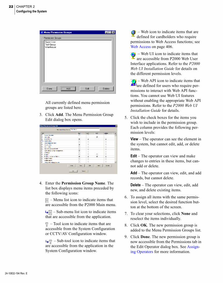
22 CHAPTER 2
Configuring the System
24-10832-194 Rev. E
All currently defined menu permission groups are listed here.
3. Click Add. The Menu Permission Group Edit dialog box opens.
4. Enter the Permission Group Name. The list box displays menu items preceded by the following icons:
– Menu list icon to indicate items that are accessible from the P2000 Main menu.
– Sub-menu list icon to indicate items that are accessible from the application.
– Tool icon to indicate items that are accessible from the System Configuration or CCTV/AV Configuration window.
– Sub-tool icon to indicate items that are accessible from the application in the System Configuration window.
– Web icon to indicate items that are defined for cardholders who require
permissions to Web Access functions; see Web Access on page 406.
– Web UI icon to indicate items that are accessible from P2000 Web User
Interface applications. Refer to the P2000 Web UI Installation Guide for details on the different permission levels.
– Web API icon to indicate items that are defined for users who require per-
missions to interact with Web API func-tions. You cannot use Web UI features without enabling the appropriate Web API permissions. Refer to the P2000 Web UI Installation Guide for details.
5. Click the check boxes for the items you wish to include in the permission group. Each column provides the following per-mission levels:
View – The operator can see the element in the system, but cannot edit, add, or delete items.
Edit – The operator can view and make changes to entries in these items, but can-not add or delete.
Add – The operator can view, edit, and add records, but cannot delete.
Delete – The operator can view, edit, add new, and delete existing items.
6. To assign all items with the same permis-sion level, select the desired function but-ton at the bottom of the screen.
7. To clear your selections, click None and reselect the items individually.
8. Click OK. The new permission group is added to the Menu Permission Groups list.
9. Click Done. The new permission group is now accessible from the Permissions tab in the Edit Operator dialog box. See Assign-ing Operators for more information.
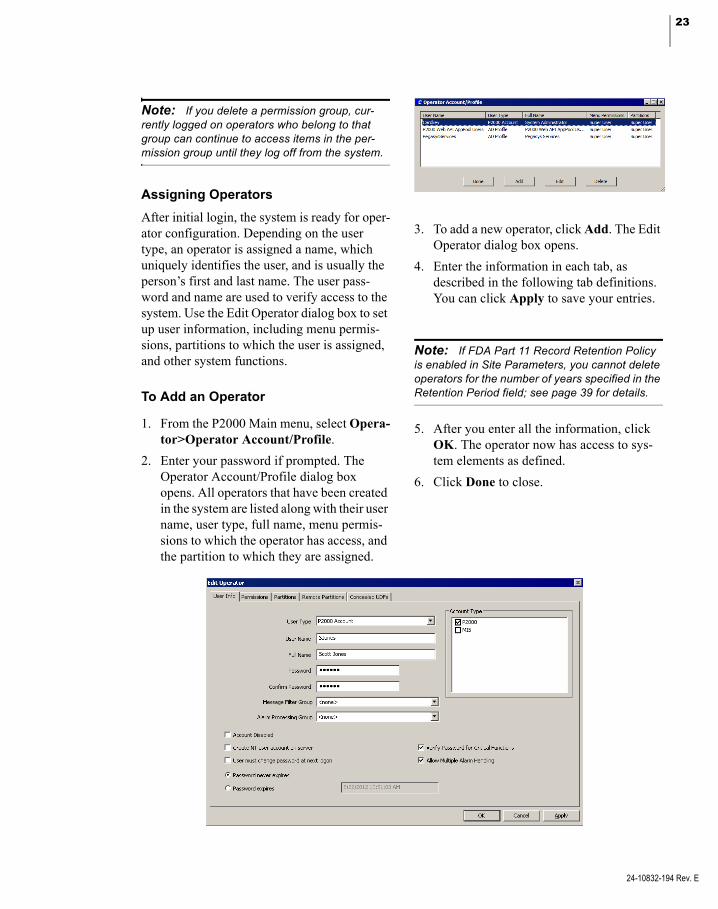
23
Note: If you delete a permission group, cur-rently logged on operators who belong to that group can continue to access items in the per-mission group until they log off from the system.
Assigning Operators
After initial login, the system is ready for oper-ator configuration. Depending on the user type, an operator is assigned a name, which uniquely identifies the user, and is usually the person’s first and last name. The user pass-word and name are used to verify access to the system. Use the Edit Operator dialog box to set up user information, including menu permis-sions, partitions to which the user is assigned, and other system functions.
To Add an Operator
1. From the P2000 Main menu, select Opera-tor>Operator Account/Profile.
2. Enter your password if prompted. The Operator Account/Profile dialog box opens. All operators that have been created in the system are listed along with their user name, user type, full name, menu permis-sions to which the operator has access, and the partition to which they are assigned.
3. To add a new operator, click Add. The Edit Operator dialog box opens.
4. Enter the information in each tab, as described in the following tab definitions. You can click Apply to save your entries.
Note: If FDA Part 11 Record Retention Policy is enabled in Site Parameters, you cannot delete operators for the number of years specified in the Retention Period field; see page 39 for details.
5. After you enter all the information, click OK. The operator now has access to sys-tem elements as defined.
6. Click Done to close.
24-10832-194 Rev. E

24 CHAPTER 2
Configuring the System
24-10832-194 Rev. E
User Info Tab
User Type – Select one of the following user types to be assigned to this operator:
P2000 Account – This is the default P2000 user type. Users can log on to the P2000 system by entering their password.
AD Account – This is an Active Directory user account. Users can log on to the P2000 system if their user name and password combination can be validated by the Direc-tory Services Password Validation (see Directory Services Password Validation on page 41), and not by the P2000 system.
Note: AD Account and AD Profile user types require Windows Active Directory to be installed and configured on your network. When you select these user types, other password related fields are disabled. See P2000 Directory Services Password Validation on page 27 for more infor-mation.
AD Profile – This is an Active Directory Group. Users can log on to the P2000 sys-tem if their Active Directory account belongs to this Active Directory group and their user name and password combination can be validated by the Directory Services Password Validation (see Directory Ser-vices Password Validation on page 41), and not by the P2000 system. The Active Direc-tory Profile name must match the Active Directory group name. A user can only belong to one P2000 AD group; otherwise, this is considered as an invalid active direc-tory configuration.
IMPORTANT: Two AD Profile operators are automatically created during software installation: P2000 Web API AppPool Users and Pegasys-Services. Do not edit these operator accounts, as they are created for internal use only.
User Name – Enter the name the operator must type when logging on to the system. Although not required, it is recommended that you use the same user name that the operator uses to log on to Windows (passwords can be different).
Full Name – Enter the operator’s full name.
Password – Enter the password the operator must type when logging on to the P2000 sys-tem. If you wish to change the password at a later time, see Changing the User Password on page 28. In addition, see Password Policy Tab on page 40 for additional password complexity rules.
Confirm Password – Enter the password again to confirm.
Message Filter Group – Select the Message Fil-ter Group that defines which messages the operator can see. If you select <none> the operator can see all messages, provided the operator has access to the Super User partition (or records are marked Public), and the Mes-sage Filter Group field defined at the worksta-tion is also set to <none> (see Workstation Field Definitions on page 20). Also, see Con-figure Message Filtering and Message Routing on page 221 and Operators and Messages on page 221.
Alarm Processing Group – Select the Message Filter Group that defines which alarms the operator can process (acknowledge, respond, or complete). If you select <none> the opera-tor can process all alarms that pass the Mes-sage Filter Group selection. If an operator is allowed to receive and process all alarms, then both the Message Filter Group and Alarm Processing Group selections should be set to <none>.
Note: Message Filtering and Alarm Processing Groups apply on P2000 Workstations only, not on P2000 Servers. In addition, partitioning rules still apply, regardless of filter group selections.
25
Account Type – Select the type of account that the operator is authorized to access. If FDA Part 11 Password Policy is enabled in Site Parameters (see page 40), then only one account type can be selected.
Account Disabled – Select this option if you wish to disable this account. Once this option is selected, this account can no longer be used for logging into the P2000 system, until the account is enabled again. A message displays at the next login informing the operator that the account has been disabled.
Create NT user account on server – If selected, a user account is automatically added to the operating system on the Server. You must have administrative rights on the P2000 Server to select this option. This option is not available for selection if your Server is part of a domain. As an alternative, you can manually add the account using the Windows interface; see Set Up User Accounts on page 29.
Note: The Create NT user account on server option only creates the Windows account and associated privileges on the P2000 Server and Database Server, not on the local Workstation, where you need to create the account manually.If you create the account on the P2000 Server, the account is assigned with Users privileges on the P2000 Server but not on the Database Server, which means that account can be used to access Windows on the P2000 Server, but not on the Database Server.If you create the from the Workstation, then the account is only associated with the Windows group Pegasys Users on P2000 Server and the Database Server.
User must change password at next logon – If a user forgets his or her password, the system administrator may grant a temporary password and force the user to change the password at the beginning of the next login. This option is only available if the Account Type selected is P2000; a password cannot be changed for MIS or XML RPC users.
Password never expires – Select this option to define passwords that never expire, for MIS users for example. This option is not available if FDA Part 11 Password Policy is enabled in Site Parameters (see page 40).
Password expires – If you select this option, the password expires on the displayed date. This date depends on the value defined in Site Parameters (page 40).
Verify Password for Critical Functions – If selected, the operator is required to enter the login password to access certain system-criti-cal functions.
Allow Multiple Alarm Handling – If selected, the operator can process more than one alarm at a time. This option is always enabled by default. When selected, the operator can acknowledge or complete multiple alarms in the Alarm Monitor window.
Permissions Tab
Permissions determine the functions that an operator can perform in the system. Each oper-ator can be associated with different rights to different functions. Menu permissions must be defined, otherwise the table is empty. See Cre-ating Permission Groups on page 21 for more information.
24-10832-194 Rev. E

26 CHAPTER 2
Configuring the System
24-10832-194 Rev. E
1. Select from the Available Groups box, the permission group that defines the functions that the operator can view or change. You can select multiple items by holding down the <Shift> key.
2. Click << to move the permission group to the Member Of box.
Note: An operator can perform any function if at least one menu permission group assigned to the operator allows permission to that function.
Partitions Tab
Operators can be assigned to single or multiple partitions and have unique access restrictions, such as the ability to add, modify, or view data-base information within their assigned parti-tions. See Partitions on page 355 for more information.
1. Select from the Available Partitions box, the partition to which this operator can access. You can select multiple items by holding down the <Shift> key.
2. Click << to move the partition name to the Member Of box.
Note: An operator can see alarms and real time messages that are associated with the parti-tions selected here, unless records are marked Public or the operator is monitoring the system from the Server, where all alarms and real time messages are visible, regardless of the partitions selected here. Operators that belong to the Super User partition have access to all partitions of the system.
Remote Partitions Tab
If the operator monitors remote messages, use this tab to define the partitions to which the operator can access. If you do not enter any partition names, the operator can monitor all messages from the remote site.
Note: Remote messages are any alarm or transaction messages originated at another P2000 site. See Message Filtering on page 222.
1. Enter the name of the partition at the remote site and click Add. The remote par-tition name displays in the Remote Parti-tions box.

27
2. If you wish to modify an existing remote partition name, select the name in the Remote Partitions box, make the change, then click Update.
3. If you wish to delete a remote partition name from the list, select the name in the Remote Partitions box and click Delete.
Concealed UDFs Tab
Use this tab if you wish to restrict operators from viewing certain fields in the Cardholder dialog box. For example, a guard operating a P2000 workstation at a parking structure may need to have access to car and parking infor-mation, but may not need to view personal Cardholder information.
1. All UDFs are selected by default. Clear the check boxes next to the UDFs that you wish to restrict from viewing.
2. Click OK to save.
Only the selected UDFs are visible in the Cardholder dialog box. In addition, other P2000 applications that use UDFs, such as the Search tool, do not display the UDFs that are restricted from viewing.
P2000 Directory Services Password Validation
Authentication of P2000 operators can now be handled by a centralized directory service such as Microsoft Active Directory or other direc-tory service using the Lightweight Directory Access Protocol (LDAP). This feature pro-vides a single point of authentication - when a user enters the credentials to log on to the P2000 system, the P2000 server generates an authentication request to the LDAP server. Once the LDAP server authenticates the user, the P2000 server logs on the user and autho-rizes certain permissions, as defined in the user’s AD account or group operator settings.
This feature eliminates operator passwords from the P2000 database and is useful when passwords are periodically changed, eliminat-ing the need to update passwords in the P2000 system and passwords that are used to log on to Windows.
To use directory service password validation, the following elements must be set up in the P2000 system:
24-10832-194 Rev. E

28 CHAPTER 2
Configuring the System
24-10832-194 Rev. E
The Directory Services Path field must be set in the Password Policy tab of Site Parameters (see Directory Services Pass-word Validation on page 41). The actual value to use for the Directory Services Path is unique to your specific network configu-ration and needs to be obtained from your network administrator.
For each P2000 operator that you want their password verified by directory services, you need to select the AD Account or AD Pro-file User Type in the Edit Operator dialog box (see User Info Tab on page 24).
Directory Services Path
The Directory Services Path is specific to your network layout and configuration. You must consult with your network administrator for the correct path. The path statement provides the network location for the Users object within the directory services hierarchy.
The P2000 software includes a utility that allows you to test the correct path statement. You can find the ActiveDirectoryTest.exe application in the bin folder of the P2000 soft-ware installation. By using this application, you can easily try different path values to help determine the correct value for your network.
See the following examples:
Directory Services Path for a Windows domain named companyname:
WinNT://companyname/Users
Directory Services Path for an Active Direc-tory domain named companyname.com:
LDAP://companyname.com/CN=Users,DC=compa-nyname,DC=com
For more details on path values and typical examples, refer to LDAP ADsPath and to WinNT ADsPath on Microsoft’s MSDN Library.
Changing the User Password
Use the Change Password option to change a user’s password. Depending on the permis-sions assigned using the Menu Permission Groups, some or all users may be able to change their own password at any time.
To Change a Password
1. From the P2000 Main menu, select Opera-tor>Change Password. The Change Pass-word dialog box opens.
2. Enter your Current Password.
3. Enter your New Password.
4. Re-enter your new password in the Con-firm Password field.

29
5. Click OK to save your new password. There is no need to log out of the system. The new password is now valid within the P2000 system.
Set Up User Accounts
To add operators to the P2000 system, accounts must be set up in the operating sys-tem. Without proper authorizations, the system may not allow connections to the Server.
Note: If the Create NT user account on server option (see User Info Tab on page 24) was selected at the time you added the user to the P2000 system, the following steps were per-formed automatically by the P2000 system.
Adding a P2000 Login Name and Password into the Operating System
When you add operators into the Windows list of valid users on the server, you must assign this user account as a member of the PEGASYS Users group to give them rights to connect to the P2000 database. Use the same user name and password that the operator uses to log on to Windows at the workstation.
The user account may be assigned member-ship of other groups as desired. The commonly used groups are explained:
PEGASYS Users – Gives rights to log on to the P2000 database.
PEGASYS Administrators – Gives rights to administrate the P2000 database (create and drop tables, restore the database, and so on).
Users – Gives rights to log on to the server computer locally.
Administrators – Gives rights to administrate the server computer (add users, change hard-ware configuration, and so on).
Note: The following instructions are provided for Windows Server® 2008 R2 operating sys-tems. For other operating systems, follow the general outline to enter your settings.
Add Users to Windows Server 2008 R2 Details
1. Run the Computer Management program; select Start>Settings>Control Panel> Administrative Tools. Double-click the Computer Management icon.
2. Click System Tools>Local Users and Groups>Users.
3. From the Computer Management menu, select Action>New User. The New User dialog box opens.
24-10832-194 Rev. E
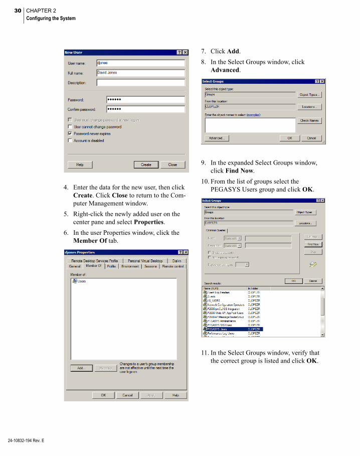
30 CHAPTER 2
Configuring the System
24-10832-194 Rev. E
4. Enter the data for the new user, then click Create. Click Close to return to the Com-puter Management window.
5. Right-click the newly added user on the center pane and select Properties.
6. In the user Properties window, click the Member Of tab.
7. Click Add.
8. In the Select Groups window, click Advanced.
9. In the expanded Select Groups window, click Find Now.
10. From the list of groups select the PEGASYS Users group and click OK.
11. In the Select Groups window, verify that the correct group is listed and click OK.

31
12. Repeat steps 7 - 11 for other groups you want to add, (see page 29), this time select-ing that particular group from the list.
13. Click OK to close the user Properties win-dow.
Configure System Components
System components that operate globally throughout the P2000 system include Site Parameters, Partitions, Local Configuration, Time Zones, and Holidays. To speed the con-figuration process, we recommend that you set up system components in the following order:
1. Site Parameters – Site Parameters define general system information, real time printing, panel types, facility codes, record retention times, and other parameters that are specific for the entire facility.
2. Partitions – You can divide the P2000 data-base into smaller sections that can be indi-vidually managed. Partitions allow a system to function as multiple, separate systems.
3. Local Configuration – With Local Configu-ration, you can enter the database server source and application path of your P2000 system, select the language in which to run your P2000 software, and define the data-base connection settings for your local computer.
4. Time Zones – Times Zones are used throughout the system to define active and inactive time periods for various system components.
5. Holidays – Holidays are defined for the entire facility. Holiday start and stop times may be different for different access rights.
Registration Parameters
You can review the maximum number of ter-minals and workstations, the maximum badges allowed, and other parameters specified for your system. Select Config>System from the P2000 Main menu bar, enter your password if prompted, and click the Registration Param-eters icon at the top of the configuration tree in the System Configuration window. The parameters display on the right windowpane. In addition, you can expand Registration Parameters and select Option Keys to dis-play additional P2000 features available for your system.
All these parameters are enabled via the entry of your valid Registration Key and Option Keys provided by Johnson Controls. These keys are associated with your purchase con-tract and cannot be modified within the pro-gram.
Note: If you wish to remove configured items that are associated with an Option Keys, delete the items first, then proceed to delete the associ-ated Option Key.
24-10832-194 Rev. E

32 CHAPTER 2
Configuring the System
24-10832-194 Rev. E
Site Parameters
The elements that define how your access con-trol system operates are entered in Site Param-eters. The P2000 system uses the information in Site Parameters to determine how system and hardware components can be configured. It is important to plan your access require-ments by establishing elements such as visitor badge validity period, the server that handles system communications, real time printing, panel types, facility codes, record retention times, and other parameters that are specific for the entire facility. Setup information associ-ated with the MIS and Web Access features is described in Chapter 4: Advanced Features.
When you click Site Parameters in the System Configuration window, the current settings dis-play on the right windowpane. You may mod-ify these settings as desired. The Backup Device, DB Server, and Real Time Printer in Site Parameters can only be set at the Server. On a partitioned system, only users that belong to the Super User partition can modify Site Parameters.
IMPORTANT: The Communication and Data-base Server settings are advanced settings and should be changed only at the direction of our Technical Support team. If these settings are changed, the system may not work properly.
Displays the default partition Details of Current SiteParameter Configuration
Right WindowpaneRoot SystemComponents Tree

33
To Edit Site Parameters
1. With Site Parameters selected, click Edit. The Edit Site Parameters dialog box opens at the General tab.
2. Enter the information in each tab accord-ing to your system requirements. (See Site Parameters Field Definitions for detailed information.)
3. As you work through the tabs, you may click Apply to save your entries.
4. After you have entered all the information, click OK to save the settings and return to the System Configuration window. The new values display on the right window-pane.
Site Parameters Field Definitions
General Tab
Visitor Validity Period – Enter the time, between 1 and 80 hours, after which a Visitor badge expires by default.
Max Visitor Validity Period – Enter the maxi-mum number of days that a Visitor badge may be valid. If an operator tries to set the validity period for a Visitor badge longer than the con-figured value, an error message displays and the badge is not saved.
Max Inactive Period – Enter the number of days after which a badge is disabled because of inactivity. The operator has to manually reacti-vate the badge when needed.
Global In-X-It Tracking – If selected, messages are sent to the real time list to report global entry or exit violations. A global entry or exit violation occurs when access is granted after presenting a valid badge at, for example an entry reader and then that badge is presented again at another entry reader, despite the requirement to badge at entry and exit readers alternately.
After you enable or disable Global In-X-It Tracking or the following Global Badge Entry/Exit Status Synchronization feature, settings may only take effect after you stop and restart the following services:
P2000 CK721-A Download Service P2000 CK721-A Priority Service P2000 CK721-A Upload Service
See Starting and Stopping Service Control on page 432 for details.
Global Badge Entry/Exit Status Synchronization – Select to allow synchronization of badge sta-tus across multiple panels. This feature is not recommended for medium and large systems, unless using CK721-A panels.
Note: This feature must never be combined with the Peer to Peer Badge Sync option (see page 57). Selecting both features causes badge entry/exit enforcement errors across multiple panels.
24-10832-194 Rev. E

34 CHAPTER 2
Configuring the System
24-10832-194 Rev. E
Badge Trace Alarm for Granted Access – Select to generate an alarm when a badge with the Trace flag set is granted access at any reader in the system.
Badge Trace Alarm for Denied Access – Select to generate an alarm when a badge with the Trace flag set is denied access at any reader in the system.
Alarm Options – Click to open the Alarm Cate-gories window and assign alarm options asso-ciated with the Badge Trace Alarms. For detailed instructions, see Alarm Configuration on page 270.
Comms Server – Defaults to the server that handles communications.
DB Server – Displays the name of the server that handles the databases.
System Information URL – This field displays the location of the server that is hosting the P2000 Web services. In the following URL example:
https://<ComputerName>/jcihostingenvironment/ systeminformation/v1/api
<ComputerName> is the name of the com-puter where the P2000 Web API is deployed.
Number of Floors – Enter the maximum num-ber of floors at your facility (up to 128) for ele-vator access. This is the number of floors that displays in the Floor Name Configuration list.
Number of Doors – Enter the maximum number of doors at your facility (up to 128) for cabinet access. This is the number of doors that dis-plays in the Door Name Configuration list.
Cross Site Access Group Editing – Select to allow modifying access groups for other Enter-prise sites.
Display asterisks instead of pin code – If selected, the PIN code entered in the Badge dialog box displays as asterisks.
Max PIN Code Digits – Select the maximum number of PIN code digits that can be entered in the Badge dialog box.
Note: If your facility uses Mercury panels, you must restart the P2000 Mercury Interface Service for this change to be effective. You must also download all items to all Mercury panels with the Reset Panel Before Download flag selected; see Downloading Data to Panels on page 425.
Special Access – The system provides three Special Access flags to satisfy the require-ments for assisted access according to Ameri-cans with Disabilities Act (ADA). The Special Access fields A, B, and C can be renamed according to your facility needs, Handicap Access for example. The names entered in these fields become effective throughout the system. For configuring special access for your panel type, see your specific hardware configu-ration section for information on setting up these flags.
Printing Tab
Real Time printers can be set up only from the system Server, even if the operators have per-missions to modify Site Parameters at their workstations. Printers to be used by the P2000 system must first be set up using the Windows printer set up function. If you need assistance adding printers to the system, see your system administrator or refer to your Windows docu-mentation.

35
Note: While the same options are offered from Real Time Printing, this function operates inde-pendently from the Real Time List viewed on screen. It is not connected in any way to a history file. It simply prints the transaction types selected as they occur.
IMPORTANT: Real time printing is not guar-anteed on foreign language systems.
Printing – If you wish to print any transaction, select this box and choose a printer. We recom-mend a dot matrix printer be used exclusively for printing the following transaction types as they occur.
Set All – Select if you wish to print all transac-tions.
Clear All – Select to clear the selections. To limit the type of transactions printed, select any of the following options:
Host – Prints triggered and system events.
Panel – Prints reader strikes and status, termi-nal and panel status changes, and so on.
Audit – Prints operator actions such as add an alarm instruction, edit an event, run a report, and so on.
Alarm – Prints all alarm messages.
Elevators – Prints all elevator messages.
Areas – Prints all area messages.
AV – Prints all audio-visual messages. See DVR/VMS on page 390 for details.
Access Deny – Prints all Access Deny messages.
Access Grant – Prints all Access Grant mes-sages.
Trace – Prints all transactions associated with a badge. The Trace option must also be enabled on the Badge dialog box; see page 253.
Guard Tour – Prints all guard tour messages. See Guard Tour on page 374 for details.
Cabinets – Prints all cabinet messages.
Mustering Zones – Prints all mustering zone messages.
Intrusion – Prints all intrusion messages.
Fire – Prints messages generated by the fire alarm panel.
As a reference, see Using the Real Time List on page 342.
Panel Types Tab
Use this tab to select the panel types and related parameters that define how your sys-tem can be configured.
24-10832-194 Rev. E
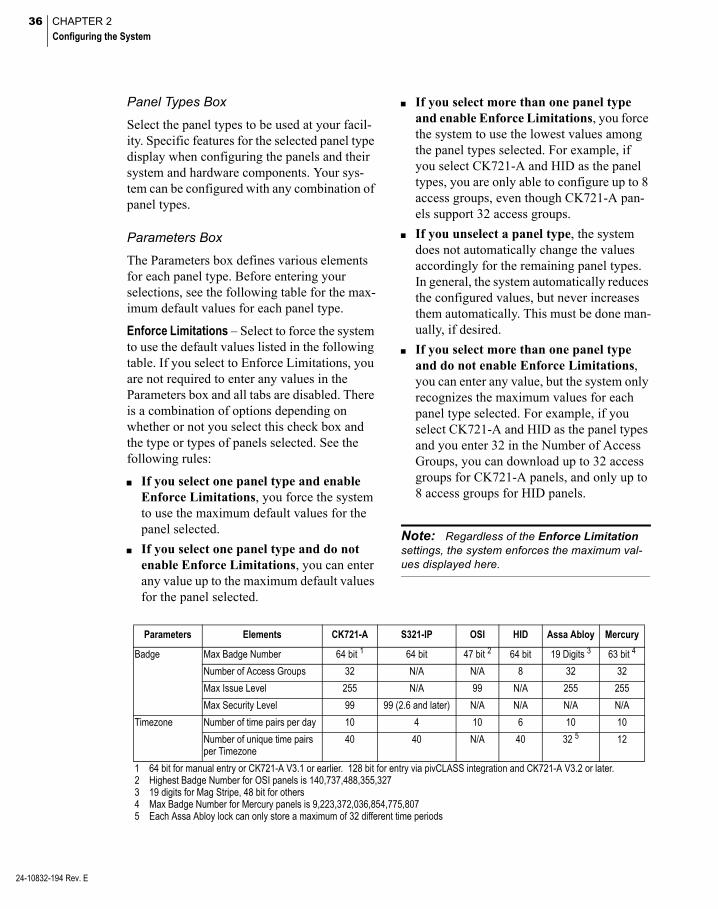
36 CHAPTER 2
Configuring the System
24-10832-194 Rev. E
Panel Types Box
Select the panel types to be used at your facil-ity. Specific features for the selected panel type display when configuring the panels and their system and hardware components. Your sys-tem can be configured with any combination of panel types.
Parameters Box
The Parameters box defines various elements for each panel type. Before entering your selections, see the following table for the max-imum default values for each panel type.
Enforce Limitations – Select to force the system to use the default values listed in the following table. If you select to Enforce Limitations, you are not required to enter any values in the Parameters box and all tabs are disabled. There is a combination of options depending on whether or not you select this check box and the type or types of panels selected. See the following rules:
If you select one panel type and enable Enforce Limitations, you force the system to use the maximum default values for the panel selected.
If you select one panel type and do not enable Enforce Limitations, you can enter any value up to the maximum default values for the panel selected.
If you select more than one panel type and enable Enforce Limitations, you force the system to use the lowest values among the panel types selected. For example, if you select CK721-A and HID as the panel types, you are only able to configure up to 8 access groups, even though CK721-A pan-els support 32 access groups.
If you unselect a panel type, the system does not automatically change the values accordingly for the remaining panel types. In general, the system automatically reduces the configured values, but never increases them automatically. This must be done man-ually, if desired.
If you select more than one panel type and do not enable Enforce Limitations, you can enter any value, but the system only recognizes the maximum values for each panel type selected. For example, if you select CK721-A and HID as the panel types and you enter 32 in the Number of Access Groups, you can download up to 32 access groups for CK721-A panels, and only up to 8 access groups for HID panels.
Note: Regardless of the Enforce Limitation settings, the system enforces the maximum val-ues displayed here.
Parameters Elements CK721-A S321-IP OSI HID Assa Abloy Mercury
Badge Max Badge Number 64 bit 1 64 bit 47 bit 2 64 bit 19 Digits 3 63 bit 4
Number of Access Groups 32 N/A N/A 8 32 32
Max Issue Level 255 N/A 99 N/A 255 255
Max Security Level 99 99 (2.6 and later) N/A N/A N/A N/A
Timezone Number of time pairs per day 10 4 10 6 10 10
Number of unique time pairs per Timezone
40 40 N/A 40 32 5 12
1 64 bit for manual entry or CK721-A V3.1 or earlier. 128 bit for entry via pivCLASS integration and CK721-A V3.2 or later.2 Highest Badge Number for OSI panels is 140,737,488,355,3273 19 digits for Mag Stripe, 48 bit for others4 Max Badge Number for Mercury panels is 9,223,372,036,854,775,8075 Each Assa Abloy lock can only store a maximum of 32 different time periods
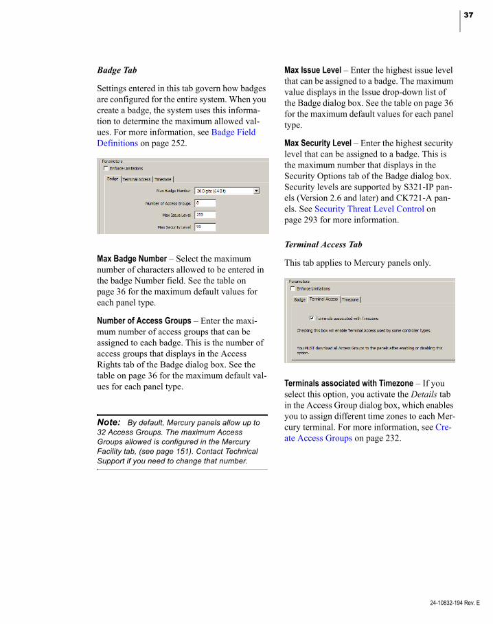
37
Badge Tab
Settings entered in this tab govern how badges are configured for the entire system. When you create a badge, the system uses this informa-tion to determine the maximum allowed val-ues. For more information, see Badge Field Definitions on page 252.
Max Badge Number – Select the maximum number of characters allowed to be entered in the badge Number field. See the table on page 36 for the maximum default values for each panel type.
Number of Access Groups – Enter the maxi-mum number of access groups that can be assigned to each badge. This is the number of access groups that displays in the Access Rights tab of the Badge dialog box. See the table on page 36 for the maximum default val-ues for each panel type.
Note: By default, Mercury panels allow up to 32 Access Groups. The maximum Access Groups allowed is configured in the Mercury Facility tab, (see page 151). Contact Technical Support if you need to change that number.
Max Issue Level – Enter the highest issue level that can be assigned to a badge. The maximum value displays in the Issue drop-down list of the Badge dialog box. See the table on page 36 for the maximum default values for each panel type.
Max Security Level – Enter the highest security level that can be assigned to a badge. This is the maximum number that displays in the Security Options tab of the Badge dialog box. Security levels are supported by S321-IP pan-els (Version 2.6 and later) and CK721-A pan-els. See Security Threat Level Control on page 293 for more information.
Terminal Access Tab
This tab applies to Mercury panels only.
Terminals associated with Timezone – If you select this option, you activate the Details tab in the Access Group dialog box, which enables you to assign different time zones to each Mer-cury terminal. For more information, see Cre-ate Access Groups on page 232.
24-10832-194 Rev. E

38 CHAPTER 2
Configuring the System
24-10832-194 Rev. E
Timezone Tab
Use the Timezone tab to enter the maximum number of time pairs per day and the maxi-mum number of unique time pairs per time zone that are allowed for the entire system. A time pair is defined as a period of the day, with a starting and ending time. See Time Zones on page 49 for configuration instructions. To have a better understanding of how the time pairs work, see the following illustration.
Number of time pairs per day – Enter the maxi-mum number of time pairs per day that can be configured for the entire system. The number of time pairs per day display in the Time Zone dialog box (see the following illustration). See the table on page 36 for the maximum default values for each panel type.
Number of unique time pairs per Timezone – Enter the maximum number of unique time pairs that can be created for each Time Zone. See the table on page 36 for the maximum default values for each panel type.
Options Box
Set Terminal Status to “Unknown” when Panel Offline – Select to set a terminal status to Unknown when a panel goes offline. For Assa Abloy panels, this setting becomes effective after the P2000 Assa Abloy DSR Interface Ser-vice is restarted. For CK721-A panels, this set-ting becomes effective after the following ser-vices are restarted:
P2000 CK721-A Download Service
P2000 CK721-A Priority Service
P2000 CK721-A Upload Service
This option is not recommended for Mercury panels, since terminal offline alarms cannot be generated while the panel is offline.
... and allow you to configure up to 40 unique time pairs for the entire Time Zone.
Using the preceding values, the Time Zone dialog box displays 4 time pairs for each day...
Assume you selected the S321-IPpanel type.S321-IP allows:4 time pairs per day40 unique time pairs per Timezone
Assume you selected the CK721-A panel type.CK721-A allows:10 time pairs per day40 unique time pairs per Timezone
Assume you enableEnforce Limitations
NOTE: According to the Enforce Limitation rules (see page 36), the system uses the lowest values among the panel types selected. In this case 4 pairs per day.

39
Facility Code Tab
Some of the codes stored in every badge are known as facility codes. These codes allow you to identify the badges that belong to your facility. See the instructions provided on page 251 to assign facility codes to badges.
You can define up to eight facility codes. The box displays the Default Facility Code with a default value of 0. Double-click these fields to enter the facility code Name and correspond-ing Value. If you use badges with different facility codes, enter the names and correspond-ing values for each group of badges. You can-not delete facility codes that have been assigned to badges.
Retention Policy Tab
Enter in the Retention Time box, the amount of time and select Days, Hours, or Minutes after which all records are deleted from the system. If you enter 1440 Minutes on any of the fields, the system automatically converts it into 1 Day. If you enter 1441 Minutes, the sys-tem leaves the value as is. The system converts even values only. The maximum retention period is 24,855 days (about 68 years).
Audit Trail – Enter the time after which all audit records at the Server, such as logins, logouts, and record changes are purged.
Transactions – Enter the time after which all system and badge transactions are purged.
Alarms – Enter the time after which all alarm records are purged.
Note: The number of days history should be stored on the Server hard drive depends on the amount of activity at your site. If you continually fill up the server hard drive, you can reduce the number of days history is stored.
Muster Data – Enter the time after which all Muster data is deleted from the system.
Request Queue – Enter the time after which all Request Queue records are deleted from the sys-tem. See Viewing Request Queue on page 466.
Tour Note – If your facility uses the Guard Tour feature, enter the time after which all notes are deleted from the system. See Guard Tour Notes on page 387.
24-10832-194 Rev. E

40 CHAPTER 2
Configuring the System
24-10832-194 Rev. E
FDA Retention Policy
Settings in this box are available if your facil-ity uses the FDA Part 11 option. See FDA Part 11 on page 392.
Enforce FDA Title 21 CRF Part 11 Record Reten-tion and Validation Policy – Select to enable FDA Part 11 record retention policy, which addresses the protection of records for a speci-fied period.
Retention Period – Enter the number of years that the system keeps all records in the system.
Violation Alert Period – Enter the number of days to generate a warning message before records are deleted from the system. If the Retention Period is longer than any of the val-ues entered in the Retention Time box, an alarm message is generated, and repeated on a daily basis, until the operator performs the FDA Backup procedure; see page 454.
Last FDA Backup – This is a displayed field only and shows the date you informed the sys-tem that a backup was archived, according to your company policies to comply with FDA Part 11 record retention requirements.
IMPORTANT: Changes to any of the FDA Record Retention Policy settings take effect only after all services have stopped and restarted using Service Control. You must also log off and on at the Server computer to see these changes.
Backup Device – Select the name of the device that indicates the location where automatic database backups are saved, see Configuring a Backup Device on page 451 for details. Auto-matic backups (see page 453), are performed using host event actions. For the location of manual backups, see page 452.
Password Policy Tab
Settings in this tab provide additional security to your system by allowing the system admin-istrator to define several parameters to set up strong passwords, passwords that are hard to break.
Password Validation – Enter the number of days during which a changed password remains valid. Users are required to change their password within this period; otherwise, the account is automatically disabled. The user is informed of the password expiration at the next login. If you enter 0 in this field, the pass-word remains valid indefinitely. If complying with FDA Part 11, FDA recommends that the password be changed every 30 days.
Max. consecutive Invalid Logins – If users exceed the maximum number of consecutive invalid login attempts entered in this field, they immediately lose their ability to access the P2000 system and the account is automatically disabled for one hour. There are no limitations if you enter 0. FDA recommends no more than three invalid attempts.

41
Minimum Length – Enter the minimum number of characters in a password. FDA recommends the password to be at least 6 characters long.
‘A’ to ‘Z’ or ‘a’ to ‘z’ – Enter the number of let-ters (uppercase and lowercase) required in a password.
‘0’ to ‘9’ – Enter the number of numerals required in a password.
Other – If you wish to use characters not defined as letters or numerals (symbols such as & or !), enter the number of symbols required in a password.
Enforce FDA Title 21 CFR Part 11 Password Pol-icy – This feature is available for selection if your facility uses the FDA Part 11 feature. Select this box to enable FDA Part 11 pass-word policy. For more information, see FDA Part 11 on page 392.
IMPORTANT: Changes to any of the FDA Password Policy settings take effect only after all services have stopped and restarted using Ser-vice Control. You must also log off and on at the Server computer to see these changes.
Directory Services Password Validation
Directory Services Path – This is the Light-weight Directory Access Protocol (LDAP) path for the directory server. This setting is specific to the network; contact your network administrator for assistance. See P2000 Direc-tory Services Password Validation on page 27 for more information.
Username Formatting – This is the formatting of the username passed to Directory Services for authentication. The username is the string as entered with $USERNAME replaced by the actual username. For Windows Active Direc-tory the default $USERNAME is recom-mended. Special formatting may be needed for LDAP systems or when requested by your Directory Services administrator.
Principal – This is a service account that is used to connect to the LDAP source for single sign-on login of an Active Directory Group account.
Password – Enter a password for the Principal service account.
Use Encryption – Forces the connection to the Directory Services to use data encryption for network communications. Not recommended for Windows Active Directory. May be requested by your Directory Services adminis-trator.
Secure Authentication – Requests the connec-tion to the Directory Services to be made using secure communications such as Kerberos. Recommended for Windows Active Directory. May be requested by your Directory Services administrator.
Bind Server – Requests the Directory Services to bind to the server. Not needed for Windows Active Directory. May be needed for LDAP systems if your Directory Services Path includes a server name or when requested by your Directory Services administrator.
Download Tab
Use this tab to define different downloading options.
24-10832-194 Rev. E
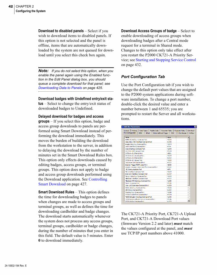
42 CHAPTER 2
Configuring the System
24-10832-194 Rev. E
Download to disabled panels – Select if you wish to download items to disabled panels. If this option is not selected and the panel is offline, items that are automatically down-loaded by the system are not queued for down-load until you select this check box again.
Note: If you do not select this option, when you enable the panel again using the Enabled func-tion in the Edit Panel dialog box, you should queue a complete download for that panel; see Downloading Data to Panels on page 425.
Download badges with Undefined entry/exit sta-tus – Select to change the entry/exit status of downloaded badges to Undefined.
Delayed download for badges and access groups – If you select this option, badge and access group downloads to panels are per-formed using Smart Download instead of per-forming the download immediately. This moves the burden of building the download from the workstation to the server, in addition to delaying the download by the number of minutes set in the Smart Download Rules box. This option only effects downloads caused by editing badges, access groups, or terminal groups. This option does not apply to badge and access group downloads performed using the Download application. See Controlling Smart Download on page 427.
Smart Download Rules – This option defines the time for downloading badges to panels when changes are made to access groups and terminal groups, as well as defines the time for downloading cardholder and badge changes. The download starts automatically whenever the system does not process any access groups, terminal groups, cardholder or badge changes, during the number of minutes that you enter in this field. The default value is 5 minutes. Enter 0 to download immediately.
Download Access Groups of badge – Select to enable downloading of access groups when downloading badges after a Central mode request for a terminal in Shared mode. Changes to this option only take effect after you restart the P2000 CK721-A Priority Ser-vice; see Starting and Stopping Service Control on page 432.
Port Configuration Tab
Use the Port Configuration tab if you wish to change the default port values that are assigned to the P2000 system applications during soft-ware installation. To change a port number, double-click the desired value and enter a number between 1 and 65535; you are prompted to restart the Server and all worksta-tions.
The CK721-A Priority Port, CK721-A Upload Port, and CK721-A Download Port values (firmware Version 2.2 and later) must match the values configured at the panel, and must use TCP/IP port numbers above 41000.

43
If the mix of panel versions in the P2000 sys-tem does not need a particular port, set the value to 0 to disable that port.
Note: We recommend not changing the P2000 XmlRpc Interface Port. If you need to do so, con-tact Technical Support for further instructions.
RMS Tab
Settings in the Remote Message Service (RMS) tab determine if your P2000 site receives messages from remote P2000 sites. In addition, you can define whether remote mes-sages indicating alarm status changes for local or remote alarms are to be processed.
Process Received Remote Messages – Select if you wish to receive messages from remote P2000 sites. If you select this option, the P2000 Remote Message Service processes incoming messages and passes them on to RTLRoute for distribution within the local sys-tem and, if applicable, to other remote sites.
Message Filter Group – Select the Message Fil-ter Group that defines which remote messages your P2000 Remote Message Service pro-cesses. If you select <None>, your local P2000 site can receive all remote messages. See Con-figure Message Filtering and Message Routing on page 221 for detailed information.
Local Alarms – Select to allow operators at a remote site to acknowledge, respond, and complete alarms originated at your P2000 site. By default, this option is not selected.
Remote Alarms – Select to allow operators at a remote site to acknowledge, respond, and complete alarms originated at other P2000 sites. By default, this option is selected.
Note: Although the Alarm Status column in the Alarm Monitor window displays a Responded status, the alarm response entered at a remote P2000 site is NOT part of the P2000 alarm his-tory in your P2000 site.
Receiving Messages (sec) – Enter the time in seconds after which the P2000 system gener-ates an alarm because no messages are received from a remote server. If you enter 0, an alarm is not generated.
Transmitting Messages (sec) – Enter the time in seconds after which the P2000 system gen-erates an alarm because no messages are trans-mitted to a remote server. If you enter 0, an alarm is not generated.
Note: The time configured here is applicable to all remote server connections from or to this com-puter. Inactivity periods are checked every 30 seconds by the Remote Message Service. These periods should be configured in line with the max-imum duration of session configured in the Trans-mit Session tab in the P2000 Remote Server dialog box of the transmitting system. See Con-figure P2000 Remote Servers on page 230.
24-10832-194 Rev. E
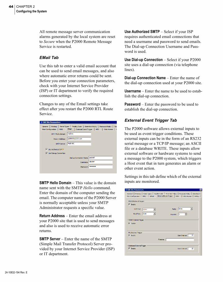
44 CHAPTER 2
Configuring the System
24-10832-194 Rev. E
All remote message server communication alarms generated by the local system are reset to Secure when the P2000 Remote Message Service is restarted.
EMail Tab
Use this tab to enter a valid email account that can be used to send email messages, and also where automatic error returns could be sent. Before you enter your connection parameters, check with your Internet Service Provider (ISP) or IT department to verify the required connection settings.
Changes to any of the Email settings take effect after you restart the P2000 RTL Route Service.
SMTP Hello Domain – This value is the domain name sent with the SMTP Hello command. Enter the domain of the computer sending the email. The computer name of the P2000 Server is normally acceptable unless your SMTP Administrator requests a specific value.
Return Address – Enter the email address at your P2000 site that is used to send messages and also is used to receive automatic error returns.
SMTP Server – Enter the name of the SMTP (Simple Mail Transfer Protocol) Server pro-vided by your Internet Service Provider (ISP) or IT department.
Use Authorized SMTP – Select if your ISP requires authenticated email connections that need a username and password to send emails. The Dial-up Connection Username and Pass-word is used.
Use Dial-up Connection – Select if your P2000 site uses a dial-up connection (via telephone lines).
Dial-up Connection Name – Enter the name of the dial-up connection used at your P2000 site.
Username – Enter the name to be used to estab-lish the dial-up connection.
Password – Enter the password to be used to establish the dial-up connection.
External Event Trigger Tab
The P2000 software allows external inputs to be used as event trigger conditions. These external inputs can be in the form of an RS232 serial message or a TCP/IP message; an ASCII file or a database WRITE. These inputs allow external software or hardware systems to send a message to the P2000 system, which triggers a Host event that in turn generates an alarm or other event action.
Settings in this tab define which of the external inputs are monitored.

45
RS232 External Trigger – If you select Enable, the P2000 system opens the configured RS232 port and listens for incoming characters. When characters are received, they are placed into an input buffer. When a carriage return is received, the current contents of the input buf-fer is processed and checked to see if it meets a trigger condition. When the input buffer has been processed, it is cleared and P2000 starts waiting for the next message. If you select this option, you must specify the COM Port to use. The RS232 port is initialized with the Baud Rate, Parity, and Stop Bits configured for that port.
TCP/IP External Trigger – If you select Enable, the P2000 system creates a TCP/IP socket on the configured IP port and listens for incoming characters. When characters are received, they are placed into an input buffer. When a car-riage return is received, the current contents of the input buffer is processed and checked to see if it meets a trigger condition. When the input buffer has been processed, it is cleared and the P2000 starts waiting for the next mes-sage. The external system may connect to this TCP/IP socket and remain connected or it may disconnect after each message. If the external system remains connected, then only one external system may send messages. If the external system connects, sends the message, and then disconnects, then multiple external systems may send messages. If the P2000 detects a network error or if the external sys-tem closes its connection, the P2000 returns to the listen state waiting for new incoming con-nections.
File External Trigger – If you select Enable, the P2000 system periodically checks the config-ured location to look for the existence of the configured file name. When the specified file is found it is renamed to <original name>.BAK. After it has been renamed, the lines in the file are processed. The file must contain only ASCII text. If the file contains multiple lines, each line must be separated by a carriage return. The last line in the file may optionally include the carriage return or not. Each line in the file is processed separately and checked to see if it meets a trigger condi-tion. After the file has been processed, it is deleted. If you select this option, you must enter the path and Filename of the ASCII file to look for, as well as the Scan Interval time (1 to 65535 seconds) between scans.
Database External Trigger – If you select Enable, the P2000 system periodically checks for any records in the external trigger database table. Each row found in this table is processed separately and checked to see if it meets a trig-ger condition. After a row has been processed, it is deleted. If you select this option, you must enter the Scan Interval time (1 to 65535 sec-onds) between scans.
Note: Since these external inputs do not authenticate the user sending the incoming mes-sage, enabling any of these inputs may cause the P2000 system to be non-compliant with FDA Title 21 CFR Part 11. When you enable any of these external inputs, Site Parameters checks the Enforce FDA Rules setting. If this setting is on, then a warning message displays to inform that the P2000 system may now be non-compliant if the events modify database records. See FDA Part 11 on page 392.
24-10832-194 Rev. E
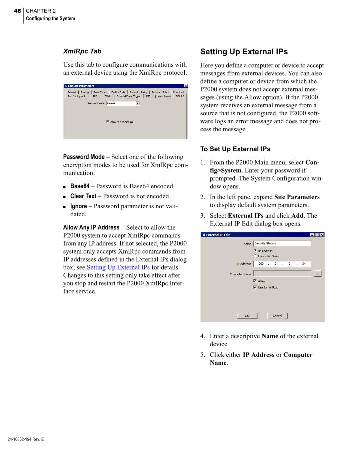
46 CHAPTER 2
Configuring the System
24-10832-194 Rev. E
XmlRpc Tab
Use this tab to configure communications with an external device using the XmlRpc protocol.
Password Mode – Select one of the following encryption modes to be used for XmlRpc com-munication:
Base64 – Password is Base64 encoded.
Clear Text – Password is not encoded.
Ignore – Password parameter is not vali-dated.
Allow Any IP Address – Select to allow the P2000 system to accept XmlRpc commands from any IP address. If not selected, the P2000 system only accepts XmlRpc commands from IP addresses defined in the External IPs dialog box; see Setting Up External IPs for details. Changes to this setting only take effect after you stop and restart the P2000 XmlRpc Inter-face service.
Setting Up External IPs
Here you define a computer or device to accept messages from external devices. You can also define a computer or device from which the P2000 system does not accept external mes-sages (using the Allow option). If the P2000 system receives an external message from a source that is not configured, the P2000 soft-ware logs an error message and does not pro-cess the message.
To Set Up External IPs
1. From the P2000 Main menu, select Con-fig>System. Enter your password if prompted. The System Configuration win-dow opens.
2. In the left pane, expand Site Parameters to display default system parameters.
3. Select External IPs and click Add. The External IP Edit dialog box opens.
4. Enter a descriptive Name of the external device.
5. Click either IP Address or Computer Name.
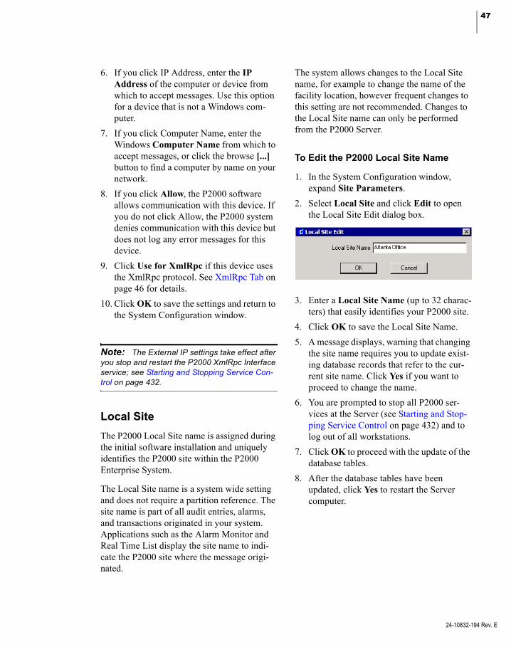
47
6. If you click IP Address, enter the IP Address of the computer or device from which to accept messages. Use this option for a device that is not a Windows com-puter.
7. If you click Computer Name, enter the Windows Computer Name from which to accept messages, or click the browse [...] button to find a computer by name on your network.
8. If you click Allow, the P2000 software allows communication with this device. If you do not click Allow, the P2000 system denies communication with this device but does not log any error messages for this device.
9. Click Use for XmlRpc if this device uses the XmlRpc protocol. See XmlRpc Tab on page 46 for details.
10. Click OK to save the settings and return to the System Configuration window.
Note: The External IP settings take effect after you stop and restart the P2000 XmlRpc Interface service; see Starting and Stopping Service Con-trol on page 432.
Local Site
The P2000 Local Site name is assigned during the initial software installation and uniquely identifies the P2000 site within the P2000 Enterprise System.
The Local Site name is a system wide setting and does not require a partition reference. The site name is part of all audit entries, alarms, and transactions originated in your system. Applications such as the Alarm Monitor and Real Time List display the site name to indi-cate the P2000 site where the message origi-nated.
The system allows changes to the Local Site name, for example to change the name of the facility location, however frequent changes to this setting are not recommended. Changes to the Local Site name can only be performed from the P2000 Server.
To Edit the P2000 Local Site Name
1. In the System Configuration window, expand Site Parameters.
2. Select Local Site and click Edit to open the Local Site Edit dialog box.
3. Enter a Local Site Name (up to 32 charac-ters) that easily identifies your P2000 site.
4. Click OK to save the Local Site Name.
5. A message displays, warning that changing the site name requires you to update exist-ing database records that refer to the cur-rent site name. Click Yes if you want to proceed to change the name.
6. You are prompted to stop all P2000 ser-vices at the Server (see Starting and Stop-ping Service Control on page 432) and to log out of all workstations.
7. Click OK to proceed with the update of the database tables.
8. After the database tables have been updated, click Yes to restart the Server computer.
24-10832-194 Rev. E

48 CHAPTER 2
Configuring the System
24-10832-194 Rev. E
Local Configuration
Use the Local Configuration window to enter the database server source and application path of your P2000 system. You can also select the language in which you wish the P2000 soft-ware to run. Incorrect settings in this dialog box may cause the P2000 software not to func-tion properly.
1. From the P2000 Main menu, select Con-fig>Local. Enter your password if prompted. The Local Configuration dialog box opens.
2. The ODBC Data Source field displays the name of the Open Database Connectivity (ODBC) data source that communicates with the database server.
3. Click Optimize for LAN to set the data-base connection settings for the local com-puter to values that are appropriate to a Local Area Network (LAN).
4. The Application Path field displays the location of the P2000 program. Click Browse to find another path, if the location has changed.
5. If you wish to run the P2000 software in a language that is different from the Win-dows operating system language, select the desired Language from the drop-down list, otherwise use the default <system set-tings> option.
Note: Contact your Johnson Controls repre-sentative if you wish to run the P2000 software in a different language.
6. Click OK to save your settings. If you are switching languages, you are prompted to close all P2000 programs and restart for the changes to take effect.
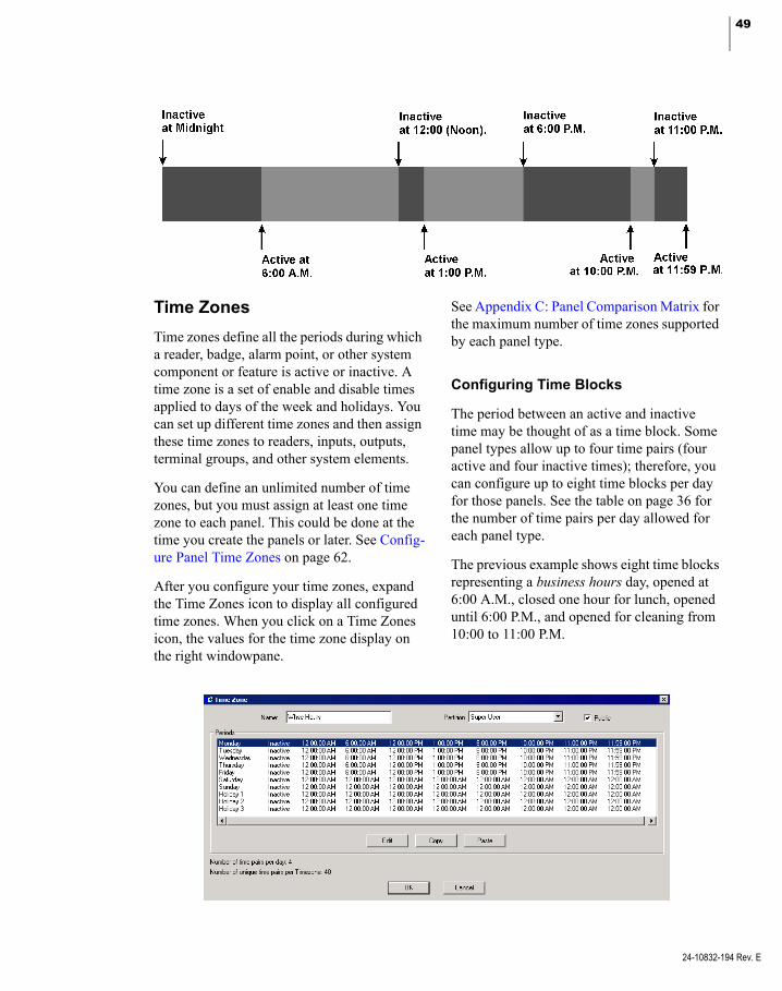
49
Time Zones
Time zones define all the periods during which a reader, badge, alarm point, or other system component or feature is active or inactive. A time zone is a set of enable and disable times applied to days of the week and holidays. You can set up different time zones and then assign these time zones to readers, inputs, outputs, terminal groups, and other system elements.
You can define an unlimited number of time zones, but you must assign at least one time zone to each panel. This could be done at the time you create the panels or later. See Config-ure Panel Time Zones on page 62.
After you configure your time zones, expand the Time Zones icon to display all configured time zones. When you click on a Time Zones icon, the values for the time zone display on the right windowpane.
See Appendix C: Panel Comparison Matrix for the maximum number of time zones supported by each panel type.
Configuring Time Blocks
The period between an active and inactive time may be thought of as a time block. Some panel types allow up to four time pairs (four active and four inactive times); therefore, you can configure up to eight time blocks per day for those panels. See the table on page 36 for the number of time pairs per day allowed for each panel type.
The previous example shows eight time blocks representing a business hours day, opened at 6:00 A.M., closed one hour for lunch, opened until 6:00 P.M., and opened for cleaning from 10:00 to 11:00 P.M.
24-10832-194 Rev. E

50 CHAPTER 2
Configuring the System
24-10832-194 Rev. E
To Create a New Time Zone
1. In the System Configuration window, select Time Zones and click Add. The Time Zone dialog box opens displaying the maximum number of time pairs, as defined in Site Parameters; see Timezone Tab on page 38.
2. Select the day of the week (or a holiday) you wish to define and click Edit. A time zone dialog box opens with the name of the day in the title block. The number of time periods available depends on the parame-ters selected in Site Parameters.
3. In the Start As box, select whether, starting at midnight, this time zone is Inactive or Active.
If you select Inactive, the time period between 12:00 A.M. and the hour entered in the first field in the list is labeled Inac-tive. (See the Period group box.) If you select Active from the Start As box, the time period between 12:00 A.M. and the hour entered in the first field in the list is labeled Active.
4. In the Period group box, define the time at which the period between 12:00 A.M. changes status (from Active to Inactive or vice versa).
Note: The time format displayed throughout the P2000 software is set up in the Windows Control Panel, Regional Options.
Check the box and select the hour from the spin box. For example, if the time period starting at midnight is Inactive, enter the hour at which the time period becomes Active. In the next field, select the time at which the period returns to Inactive. You can include minutes, if needed.
Note: The number of Active and Inactive times is limited to the number of time pairs per day defined in Site Parameters. Select only those time check boxes you wish to enable. For exam-ple, to create a Time Zone that is active from 6:00 A.M. to 6:00 P.M., select the first check box and set the time to 6:00 A.M.; then select the second check box and set the time to 6:00 P.M.
5. The Set Default button sets all times to 12:00, and either Active or Inactive as defined in the Start As box.
6. Click OK to save the settings and return to the Time Zone dialog box.
7. Continue to edit and enter time zones, until all days of the week and any applicable holidays have been defined. See the next section To Copy a Time Zone.
8. Enter a descriptive Name for the new time zone (Day Shift, Full Time, and so on).
9. If this is a partitioned system, select the Partition in which this time zone is active.
10. If this is a partitioned system, select Public if you wish this time zone to be visible to all partitions.
11. Click OK. If you wish to add this time zone to all panels, click Yes. Otherwise, you must add the new time zone for each panel separately using the Panel Timezone application; see page 62.
The new time zone displays under the root Time Zones icon. These time zones are now accessible to other system features such as panels, workstations, cardholders, and so on, for the partition selected.

51
To Copy a Time Zone
You can copy a time zone from one day to the next, or to all of the days.
1. In the Time Zone dialog box, define one time zone (a day of the week or a holiday).
2. Select the defined time zone and click Copy.
3. Select the day to which you wish to copy the time zone and click Paste.
Holiday Types
When the system reaches midnight prior to a day defined as a holiday it switches to Active and Inactive periods, depending on the Holi-day Type specified for that time zone.
You can define three Holiday Types. For example, you may want to define a Type 1 hol-iday to indicate a full day, such as Christmas Day; and a Type 2 holiday as a half-day, such as Christmas Eve; and a Type 3 that is specific to your company.
You can set different Holiday Types for differ-ent Time Zones. For example, Night Shift full-day holiday hours may begin and end at different times than Day Shift full-day holiday hours.
IMPORTANT: See Assa Abloy Holiday Defini-tion on page 146 for specific instructions associ-ated with Assa Abloy locks.
To Create Holiday Types
1. In the Time Zone window, select Holiday 1 and click Edit.
2. Define the Active and Inactive periods as described for the other days of the week.
3. Define Holiday 2 and 3, if needed.
4. Click OK to save your settings and return to the System Configuration window.
These holiday types correspond directly to Type 1, 2, and 3 in the Edit Holiday dialog box.
Holidays
Use the Holiday window to define dates when the system uses Holiday 1, 2, or 3 active and inactive periods rather than the usual time zones set for those days of the week. When the system reaches midnight prior to a day defined as a Holiday, it switches to Active and Inactive periods, depending on the Holiday type speci-fied for that time zone.
Each day of a Holiday period must be assigned separately. For example, you may plan to allow two days off for the Christmas holiday. You must define two separate holidays with separate names and dates, such as Christmas 1 for the first date, and Christmas 2 for the sec-ond date.
You can define an unlimited number of holi-days.
To Add a Holiday
1. In the System Configuration window, select Holidays and click Add. The Edit Holiday dialog box opens.
Select a Type as defined onthe Time Zone dialog box
2. If this is a partitioned system, select the Partition to which the Holiday applies, and select Public if you wish this Holiday to be visible to all partitions.
24-10832-194 Rev. E

52 CHAPTER 2
Configuring the System
24-10832-194 Rev. E
3. Enter the Name of the Holiday.
4. Enter the Date of the Holiday. (See Using the Holiday Calendar for details.)
5. Select the Type: 1, 2, or 3 depending on the Holiday types set up in the Time Zone dialog box.
6. Click OK to save the new Holiday. If you wish to add this Holiday to all panels, click Yes. Otherwise, you must add the new Hol-iday for each panel separately using the Panel Holiday application; see page 63.
Note: If you select to add the new Holiday to all panels, the system may display a message indi-cating that the number of panel holidays has exceeded for the panel names that display in the list box.
Using the Holiday Calendar
When you click the Date down arrow on the Edit Holiday dialog box, a calendar displays where you can select a specific date for the Holiday.
To Change the Calendar Month
Do one of the following:
1. Use the left or right arrows in the Calendar header to move forward or backward through the months.
2. Press Page Up or Page Down to move through the months.
To Change the Calendar Year
Do one of the following:
1. Use the left or right arrows in the Calendar header to move forward or backward through the months into the next or last year.
2. Click the year in the Calendar header. Use the left or right arrows to move forward or backward through the years.
Assigning Holiday Types
Holiday Types correspond directly to Holiday 1, 2, and 3 on the Time Zone dialog box. You can define different hours for each holiday type, depending on your facility’s preferences. For example, in the Time Zone window, you may designate Holiday 1 as a full day and Hol-iday 2 as a half day. You can then create a holi-day in the Holiday dialog box, such as New Year’s Eve, as Type 2, changing the active and inactive times for that holiday to correspond with a half-day schedule. (See Time Zones on page 49 for more information on creating Holi-day types.)
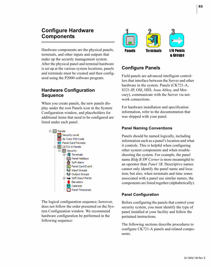
53
Configure Hardware Components
Hardware components are the physical panels, terminals, and other inputs and outputs that make up the security management system. After the physical panel and terminal hardware is set up at the various system locations, panels and terminals must be created and then config-ured using the P2000 software program.
Hardware Configuration Sequence
When you create panels, the new panels dis-play under the root Panels icon in the System Configuration window, and placeholders for additional items that need to be configured are listed under each panel.
The logical configuration sequence; however, does not follow the order presented on the Sys-tem Configuration window. We recommend hardware configuration be performed in the following sequence:
Configure Panels
Field panels are advanced intelligent control-lers that interface between the Server and other hardware in the system. Panels (CK721-A, S321-IP, OSI, HID, Assa Abloy, and Mer-cury), communicate with the Server via net-work connections.
For hardware installation and specification information, refer to the documentation that was shipped with your panel.
Panel Naming Conventions
Panels should be named logically, including information such as a panel’s location and what it controls. This is helpful when configuring other system components and when trouble-shooting the system. For example, the panel name Bldg B SW Corner is more meaningful to an operator than Panel 1B. Descriptive names cannot only identify the panel name and loca-tion; but also, when terminals and time zones associated with a panel use similar names, the components are listed together (alphabetically).
Panel Configuration
Before configuring the panels that control your security system, you must identify the type of panel installed at your facility and follow the pertained instructions.
The following sections describe procedures to configure CK721-A panels and related compo-nents.
24-10832-194 Rev. E
54 CHAPTER 2
Configuring the System
24-10832-194 Rev. E
The steps to configure other panel types differ from the procedures described here. If you plan to configure OSI, S321-IP, HID, Assa Abloy, or Mercury panels, you must skip the remain-ing sections and proceed to one of the follow-ing sections:
Configure OSI Panels and Components on page 95.
Configure S321-IP Panels and Components on page 108.
Configure HID Panels and Components on page 122.
Configure Assa Abloy® IP Door Locks and Components on page 136.
Configure Mercury Panels and Components on page 151.
Also, see Appendix C: Panel Comparison Matrix to see the features supported by each panel type.
To Add a New Panel
1. In the System Configuration window, expand Panels to display the panel types.
2. Select one of the following panel types:
CK721-A Panels – To configure CK721-A panels.
S321-IP Panels – To configure S321-IP panels, go to page 108 for details.
HID Network Panels – To configure HID panels, go to page 122 for details.
Mercury Panels – To configure Mercury panels, go to page 151 for details.
OSI Panels – To configure OSI panels, go to page 95 for details.
Assa Abloy Panels – To configure Assa Abloy panels, go to page 136 for details.
3. Click Add. The Edit Panel dialog box opens at the General tab.
4. Fill in the information on each tab. (See Edit Panel Field Definitions for details.)
5. As you work through the tabs, you may click Apply to save your entries.
6. Click OK to save your entries. A message box displays asking if you wish to auto-matically add all time zones to the new panel. If you select No, you can add the time zones later; see Configure Panel Time Zones on page 62.
7. If you select Yes, the time zones are auto-matically added. When you return to the System Configuration window, the new panel name displays under the selected panel type.
Note: For CK721-A panels, the panel version number displays on the right windowpane of the System Configuration window, after that panel establishes communication with the Server.
Soft Input Points
When a panel is created in the system, a Panel Down soft input point is automatically created for input point 25 and displays under the Soft Input Point icon as Panel Down <panel name>. If you wish to report this type of alarm, edit the input point and make sure the Disable Alarm option is not selected in the General tab of Alarm Options, otherwise the alarm does not report to the Alarm Queue, but continues to report to the Real Time List (see Alarm Options Tab on page 83).
If you rename the panel, you must edit the input point to manually enter the new panel name, as in Panel Down <panel name>. See Create Input Points on page 82 for detailed information.

55
Edit Panel Field Definitions
General Tab
This dialog box defines descriptive informa-tion of the panel.
Partition – If you use Partitioning, select the Partition that has access to this panel informa-tion.
Public – If you use Partitioning, click Public to allow all partitions to see this panel.
Name – Enter a descriptive name for the panel.
Type – Displays the panel type. Select the firmware version from the drop-down list.
Note: Certain features are enabled or disabled depending on the panel version selected. The version selected is validated when the panel con-nects. CK721-A panels that do not match are put into a misconfigured state and are not allowed to fully communicate until the problem is resolved.
Enabled – The system does not recognize the panel unless you click Enabled. If you wish to temporarily disable the panel, without having to delete the panel or disconnect the network cable, click again to clear the check box to dis-able it. When you disable a panel, the readers continue to grant access, but the panel does not communicate with the Server until you enable the panel again.
Query String – This value is used with message filtering (see Define Query String Filters on page 225).
RS-485 Baud Rate – Select the RS-485 commu-nication rate. Options are: 9600, 19200, and 38400. The 38400 rate is only available with panels Version 3.4 and later.
No Badge Archive to Flash – If enabled, the Badge database is not saved to Flash during a Write-Flash operation.
No Access Group Archive to Flash – If enabled, the Access Group database (including elevator Access Groups) is not saved to Flash during a Write-Flash operation.
No Configuration Archive to Flash – If enabled, the Configuration databases such as Panel, Ele-vator, Terminal, Input, Output, Time Zones, Holidays, Soft Alarms, and Card Events are not saved to Flash during a Write-Flash operation.
Backup DB to Flash Interval – Enter the time interval (in hours) to schedule automatic backup of the panel database to flash memory. The default backup period is once every 24 hours. A backup period of 0 hours disables automatic database backups to flash memory. This feature is to be used in conjunction with the Write DB to Flash feature; see page 444 for details.
Custom Configuration Number – This option allows you to enter a number that is provided by Johnson Controls, to enable special custom features.
24-10832-194 Rev. E

56 CHAPTER 2
Configuring the System
24-10832-194 Rev. E
Address Tab
This dialog box defines Primary IP addresses for the panel. (You cannot complete panel con-figuration unless you assign an IP address.)
Note: You must first configure the panel at the Server, then proceed to configure the panel using the CK721-A panel user interface.
Panel IP Address – Enter the IP Address. This entry must match the IP address at the panel.
Panel Poll Interval – Enter the number of days, hours, minutes, and seconds to set up the maxi-mum time that the panel should be without contact with the Server. This value is down-loaded to the panel.
Note: To set the Panel Poll Interval and the Host Poll Timeout, use the following values: 0 to 29 days, 0 to 23 hours, 0 to 59 minutes, and 0 to 59 seconds.
Host Poll Timeout – Enter the number of days, hours, minutes and seconds that the Server waits without receiving a poll, until it declares the panel down.
History Tab
History settings govern how the panel uploads data to the Server, and how long the panel retains data in the transaction database before older data is deleted.
Timezone – Select a time zone during which the panel uploads data to the Server.
Upload only when greater than – To limit the panel from always uploading data to the Server during the time zone selected, click and select a percentage from the spin box only after which data is uploaded.
Always upload when greater than – Click and select a percentage from the spin box after which the panel always uploads data to the Server.
Delete history older than – Click and enter the number of days the panel holds data before deletion. Select a time at which the history is deleted.

57
Access Tab
This dialog box defines Time Offsets for com-municating with remote panels and other time zone-related information. Here you enable or disable Timed Override/Anti-Tailgate, Entry/Exit, and System Override parameters; and set the PIN Code type used at the panel. (See the Tip box on page 58 for more informa-tion on PIN types.)
Time Offset – Click if the panel is in a different geographical time zone from the P2000 server. Enter the appropriate hours and minutes for the time offset. For example, if the P2000 server is in California and the panel is in New York, click the plus (+) sign, and select 3 hours from the spin box.
Timezone Checking – Click if the panel is to check for valid reader and badge time zones, badge access requests, PIN code suppression, and upload suppression during the assigned time zones. If disabled, badge access decisions are made based on valid badge and valid access group parameters only.
Enforce Entry/Exit – Click if the panel operates Entry and Exit terminals. Entry and Exit termi-nals require the cardholder to badge at Entry and Exit terminals alternately. For example, badging at an Entry terminal and then badging again at another Entry terminal is invalid. If Entry and Exit terminals are installed in the panel, this option must be enabled for the Entry and Exit requirements to operate.
Timed Override/Anti-Tailgate – If enabled, a Reader-controlled door in a state of manual Timed Override is locked automatically when the door is closed. If disabled, the Reader-con-trolled door remains in override mode even when the door is closed. Using this feature requires the desired terminal’s Anti-Tailgate check box to be enabled (see Flags Tab on page 67).
System Override – If enabled, all doors con-trolled by the panel are set in the unlocked position. If disabled, all doors are set to their normal position.
Note: The override state gets cancelled when communication with the panel is lost for more than 20 seconds. The override resumes when communication is reestablished. In addition, be aware that if you perform the Resume Normal Operation function from the Control All Doors application, the override state gets cancelled, but the System Override option remains enabled.
Peer to Peer Badge Sync – Click to have entry and exit privileges enforced on reader termi-nals connected to different CK721-A panels. This feature allows a CK721-A panel to broad-cast the entry and exit status of a badge to mul-tiple CK721-A panels, via User Datagram Pro-tocol (UDP). This allows an entry and exit zone to span across multiple panels within the same subnet or across multiple subnets using a properly configured multicast router.
24-10832-194 Rev. E

58 CHAPTER 2
Configuring the System
24-10832-194 Rev. E
IMPORTANT: This feature must never be combined with the Global Badge Entry/Exit Sta-tus Synchronization option selection (see page 33). Selecting both features causes badge entry and exit enforcement errors across multiple panels.
Broadcast Port Number – Enter the UDP port number used by the Peer to Peer Badge Sync UDP Broadcast agents. This number must match that configured at the other CK721-A panels.
PIN Code Type – Select Algorithmic or Cus-tom. An algorithmic PIN is determined by an algorithm programmed in the terminal. A cus-tom PIN code must be entered in the Badge window for each individual cardholder. (See the following Tip box for more information on PIN types, and see Configure PIN Codes on page 78 for instructions.) Algorithmic codes need to be requested from Technical Support.
PIN Code Digits – Select the number of PIN code digits that allow access at a keypad termi-nal. See Appendix C: Panel Comparison Matrix for the maximum number of PIN code digits supported by each panel type.
TIP: We recommend all panels in the system that use PIN code readers be defined to use the same number of PIN code digits and to have the same PIN type, or access may be denied. Access could be denied because of mismatches in PIN code length and type between the PINs defined here and the PINs defined in the Badge window.
Scramble Mode – Eight algorithms are embed-ded in the terminal. If Algorithmic was selected in the PIN Code Type field, enter a number from 0 through 7 to choose the appro-priate algorithm.
Source Time Zone – Select the source time zone that identifies the geographical time zone of this panel, if the panel is in a different time zone from the P2000 server.
Alarm Tab
Panel relay, latch output functionality, and other parameters are set up in the Alarm tab.
Reporting Delay – If enabled, the alarm is delayed by the number of seconds (0 to 60) set in the Reporting Delay field. If the input point returns to the secure state before the delay expires, the panel does not report the alarm to the Server at all. If disabled, the alarm is reported immediately. Open and short condi-tions for 4-state input points are reported immediately regardless of this setting.
Latch Output – If enabled, the alarm relay is activated whenever an alarm occurs, and remains latched (activated) until reset by a card activated event, or acknowledged at the panel. If disabled, the panel alarm relay is activated whenever an alarm occurs and deactivated when all alarms are reset (if configured to do so in the Input Point dialog box).

59
Enable Panel Relay Group Outputs – If enabled, two output groups are created to represent two physical output points on the panel CPU board: Relay 1 and Relay 2. Although both relays display under the Output Groups icon for the panel selected, only Relay 1 is sup-ported in this release. This output group can be controlled as any other output group in the sys-tem.
Output Delay – Enter the number of seconds before the latch in the Latch Output field is to be activated. Use this field only when the Latch Output field is enabled. You can define a time interval before the panel’s alarm relay activates; for example, if an input point has been configured to activate the panel’s alarm relay, this could be the selectable delay in sec-onds (0 to 60), before the relay activates. The delay starts after the input point has activated.
Enable Input Suppression Messages – If enabled, input points that enter suppression are reported as being suppressed. When the input is no longer suppressed, the current input point state is reported.
Elevator Tab
Use this tab to configure CK721-A panels to communicate with High Level Interface eleva-tor control equipment via a protocol. Once the elevator protocol parameters are defined, use the Elevator Configuration dialog box to define the readers and associated outputs and inputs that operate with your particular eleva-tor controller. For details, see Elevator Access Control on page 196.
Protocol Type – Select the elevator protocol type to be used at your facility. Choices are: <none>, KONE HLI, Otis® EMS - Security/ BMS, Otis Compass, Kone IP, ThyssenKrupp Serial, and Otis EMS Serial. If you select <none>, you can only configure Low Level Interface elevators. See Appendix C: Panel Comparison Matrix for the elevator protocols supported by each panel version. Also, see Configuring Elevators on page 199 for specific configuration instructions. The following con-figuration fields are enabled depending on the elevator protocol type selected.
Note: Mercury elevators are configured in a different manner. See Configure Mercury Eleva-tors on page 184 for instructions.
Baud Rate – Available when configuring KONE HLI elevators. Select the baud rate, options are 9600 or 1200. This setting must match the baud rate configured at the elevator group controller.
Group Controller Address – Available when configuring KONE HLI elevators. Select an address (1 to 8). This setting must match the address of the elevator group controller. An incorrect setting does not permit the integra-tion to be operational.
24-10832-194 Rev. E
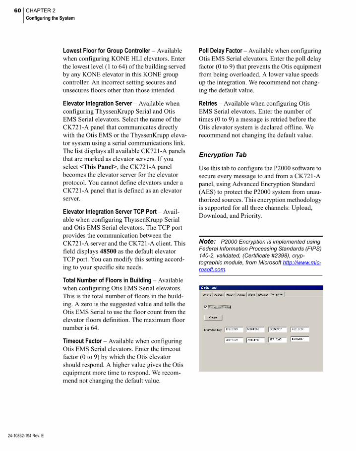
60 CHAPTER 2
Configuring the System
24-10832-194 Rev. E
Lowest Floor for Group Controller – Available when configuring KONE HLI elevators. Enter the lowest level (1 to 64) of the building served by any KONE elevator in this KONE group controller. An incorrect setting secures and unsecures floors other than those intended.
Elevator Integration Server – Available when configuring ThyssenKrupp Serial and Otis EMS Serial elevators. Select the name of the CK721-A panel that communicates directly with the Otis EMS or the ThyssenKrupp eleva-tor system using a serial communications link. The list displays all available CK721-A panels that are marked as elevator servers. If you select <This Panel>, the CK721-A panel becomes the elevator server for the elevator protocol. You cannot define elevators under a CK721-A panel that is defined as an elevator server.
Elevator Integration Server TCP Port – Avail-able when configuring ThyssenKrupp Serial and Otis EMS Serial elevators. The TCP port provides the communication between the CK721-A server and the CK721-A client. This field displays 48500 as the default elevator TCP port. You can modify this setting accord-ing to your specific site needs.
Total Number of Floors in Building – Available when configuring Otis EMS Serial elevators. This is the total number of floors in the build-ing. A zero is the suggested value and tells the Otis EMS Serial to use the floor count from the elevator floors definition. The maximum floor number is 64.
Timeout Factor – Available when configuring Otis EMS Serial elevators. Enter the timeout factor (0 to 9) by which the Otis elevator should respond. A higher value gives the Otis equipment more time to respond. We recom-mend not changing the default value.
Poll Delay Factor – Available when configuring Otis EMS Serial elevators. Enter the poll delay factor (0 to 9) that prevents the Otis equipment from being overloaded. A lower value speeds up the integration. We recommend not chang-ing the default value.
Retries – Available when configuring Otis EMS Serial elevators. Enter the number of times (0 to 9) a message is retried before the Otis elevator system is declared offline. We recommend not changing the default value.
Encryption Tab
Use this tab to configure the P2000 software to secure every message to and from a CK721-A panel, using Advanced Encryption Standard (AES) to protect the P2000 system from unau-thorized sources. This encryption methodology is supported for all three channels: Upload, Download, and Priority.
Note: P2000 Encryption is implemented using Federal Information Processing Standards (FIPS) 140-2, validated, (Certificate #2398), cryp-tographic module, from Microsoft http://www.mic-rosoft.com.

61
IMPORTANT: You must define the encryption key before enabling encryption.
Encryption Enabled – Click to allow encryp-tion of all messaging between the CK721-A Version 3.1 (and later) panel and the P2000 Server. Encryption must be enabled at the CK721-A panel using its local user interface.
Note: While encryption is enabled, Telnet and FTP network connections are rejected by the CK721-A panel.
Create – Click to generate a random encryp-tion key.
Encryption Key – The Encryption Key text boxes display the key to be used for encrypted communications. If you prefer you may enter your own key (not to exceed 64 digits) in the text boxes. This key must match the key con-figured at the CK721-A panel using its local user interface. Refer to the CK721-A Installa-tion and Operation Manual for details.
Configure Panel Components
When a new panel is created, the new Panel icon is listed under the root Panels icon in the System Configuration window, and placehold-ers for all panel components are added under the new panel.
Some components must be configured before they can be applied to other components; how-ever, the System Configuration window does not list them in a logical configuration sequence. For example, you must configure Panel Time Zones before you can complete Terminal configuration, but you must config-ure Terminals before you can create Soft Alarms, Input and Output Points and Groups, and Panel Card Events. For this reason, it is important to configure Panel Time Zones and Panel Holidays (if used), and then configure Terminals before continuing with other panel components.
We recommend the following configuration sequence:
Configure Panel Time Zones
Configure Panel Holidays
Configure Air Crew PIN Numbers
Configure Panel Card Formats
Configure Additional Panel Components
Complete instructions are presented in the fol-lowing sections.
24-10832-194 Rev. E

62 CHAPTER 2
Configuring the System
24-10832-194 Rev. E
Configure Panel Time Zones
Time Zones (created during System Configura-tion) can be applied to a specific panel and its associated components. See Appendix C: Panel Comparison Matrix for the number of panel time zones supported for each panel type. You must apply at least one time zone to each panel in your system. If time zones are applicable to other panel components such as readers, inputs, or outputs, these time zones must also be defined.
Note: Each Assa Abloy lock can only store a maximum of 32 different time periods. Make sure the panel time zones assigned to an Assa Abloy panel do not exceed this number; otherwise the panel is out of sync. See the table on page 36 for the number of time periods for other panel types.
Note: Any changes to the panel time zones for Mercury panels requires downloading Access Groups and Card Events to the affected panel.
You can automatically operate outputs such as lights, air conditioning, and so on, by associat-ing Output Groups with Panel Time Zones (not available for OSI, S321-IP, HID, Assa Abloy, or Mercury panels).
Panel Time Zones must be defined before you can complete Terminal configuration. If you have not yet configured Terminals and Output Groups, you should enter Panel Time Zones now, and return to add the Output Groups and any additional time zones.
To Assign a Panel Time Zone
1. In the System Configuration window, expand the Panel to which you wish to assign the Time Zone. The panel compo-nents are listed below the panel icon.
2. Select Panel Timezones and click Edit. The Panel Timezone Edit dialog box opens.
3. Use the drop-down lists to select any time zones configured in the system.
4. If your panel type allows it and you need to assign more than 16 time zones, click the Timezones 17–32 tab and continue to add time zones as in step 3. Select additional tabs and enter additional time zones as needed, up to a total of 64.
5. After all time zones (and Output Groups, if applicable) are assigned, click OK to save your entries and return to the System Con-figuration window.
To Assign an Output Group to a Panel Time Zone
1. In the Panel Timezone Edit dialog box, select the Time Zone to which you wish to associate an Output Group.
2. Select the associated Output Group. Out-put Groups must be created before they can be accessible from the Panel Time Zone drop-down lists. (See Create Output Points and Groups on page 80.)

63
Configure Panel Holidays
Panel Holidays are not required for system operation; however, they may be useful in cer-tain applications. For example, you may want to allow facility access during a Holiday period, but limit the number of entry doors. You can assign a specific Holiday Time Zone to restrict access at a specific panel.
See Appendix C: Panel Comparison Matrix for the number of panel holidays supported for each panel type.
To Assign a Panel Holiday
1. In the System Configuration window, expand the Panel to which you wish to assign a Panel Holiday.
2. Select Panel Holidays and click Edit. The Panel Holiday Edit dialog box opens.
3. Use the drop-down lists to select the sys-tem Holidays that apply to this panel.
4. When all Holidays are defined, click OK to save the settings and return to the Sys-tem Configuration window.
Configure Air Crew PIN Numbers
The P2000 system allows you to define air crew personal identification numbers (PIN) to be used at PIN readers connected to CK721-A panels. Once the Air Crew PIN numbers are defined, a system administrator can enable or disable the Air Crew PIN feature from the Edit Terminal dialog box; see page 75 for details. When this feature is enabled, entering the assigned Air Crew PIN number allows access at the door. You can create an Air Crew PIN number to be assigned to a group of people, or create a PIN number to be assigned individu-ally to an Air Crew member with different access needs. Presenting a badge is not required when using the Air Crew PIN Num-ber feature.
As an alternative, you can also see the instruc-tions in Appendix D: Using a Keypad Reader on CK721-A Panels.
To Define Air Crew PIN Numbers
1. In the System Configuration window, expand Panels.
2. Select Air Crew PIN Code and click Edit. The Edit Air Crew PIN Number dialog box opens.
24-10832-194 Rev. E

64 CHAPTER 2
Configuring the System
24-10832-194 Rev. E
3. Double-click to enter the Name and corre-sponding Code to define each Air Crew PIN Number. The Code number can have up to 16 digits.
4. When you finish defining all Air Crew PIN numbers, click OK to return to the System Configuration window. These names dis-play in the Air Crew Pin tab of the Edit Terminal dialog box.
Configure Panel Card Formats
P2000 supports up to eight custom card for-mats that can be downloaded to CK721-A and S321-IP panels. Upon selection, custom card files are stored in a separate database table. Once the selected card formats have been com-piled, they are available for selection using the Card Type tab in the Terminal dialog box.
Note: Contact Johnson Controls for instruc-tions in generating Custom Card Format files.
To Add Custom Card Formats
1. In the System Configuration window, expand Panels.
2. Select Panel Card Formats and click Edit. The Panel Card Formats dialog box opens.
3. To add a custom card format, click the line item you wish to define and click Add.
4. Navigate to the directory where your card format files are stored and double-click the <name>.txt file you wish to use. Click Yes if you wish to enable the format for all CK721-A terminals and also want to add it to S321-IP terminals with no custom card assignment. The name and description of the selected card format file displays in the line item selected. You can add up to eight custom card format files.
5. If you wish to update or replace an existing file, select the file name from the list and click Update. A verification message dis-plays, click Yes then proceed to select the replacement file.
6. To delete a file format, select the file name from the list and click Delete. You are prompted for verification.
7. To view the contents of a file format, select the file from the list and click View. A text file displays the format code string of the selected format. When you finish viewing the file, close the window.
8. Click Done to close the Panel Card For-mats dialog box. The new card formats are available from the Card Type tab in the Terminal dialog box.
Configure Additional Panel Components
Soft Alarms, Input and Output Points and Groups, and Panel Card Events all use Termi-nal information in their configuration; there-fore, you must create and configure terminals before you can configure these components. See Configure Terminals for more information.

65
Configure Terminals
Terminals are add-in boards such as reader boards and input and output boards. These are installed into the panels to communicate with devices such as card readers; inputs such as alarm monitoring devices; and output devices that control other devices such as lights, air conditioning, alarm annunciators, and so forth.
Each terminal installed in your system must be set up and configured in the P2000 software to establish communication and control. Once terminals are configured, they may be included in Terminal Groups and associated with Input Points and Groups to report alarms and trigger events. We recommend the following setup and configuration sequence:
Set up Terminals for each Panel
Create Terminal Groups
Configure Input and Output Points and Groups
These sections present instructions to config-ure terminals installed on CK721-A panels. If you have not already developed naming con-ventions for these program elements, we rec-ommend you do so before beginning this pro-cedure. See Panel Naming Conventions on page 53 for more information.
Set up Terminals for each Panel
Terminals can control card readers, input points, output points, or a combination of the three, depending on the type of board installed in the panel. You must set up terminals for each panel configured in the P2000 software. As with all configuration operations, the Edit Terminal dialog box is accessed from the Sys-tem Configuration window.
Note: Not all terminal options are available to all panel versions. Certain features are enabled or disabled depending on the panel version where the terminals are installed.
To Create a New Terminal
1. In the System Configuration window, expand Panels to display the panel types.
2. Expand CK721-A Panels. The panel names created under this type display.
3. Expand the panel in which the terminal is installed. All the items that can be config-ured for the panel are listed under it.
4. Select Terminals and click Add. The Edit Terminal dialog box opens at the General tab. Enter the information in each tab according to your system requirements and naming conventions. (See Edit Terminal Field Definitions for detailed information.) As you work through the tabs, click Apply to save your settings.
5. When all entries are complete, click OK to save your settings and return to the System Configuration window. Your new terminal is listed under the Terminal icon. In the following example, Terminals named Whse Entry Reader, Whse Exit Reader, and Whse I/O8 were created for the Ware-house panel.
24-10832-194 Rev. E

66 CHAPTER 2
Configuring the System
24-10832-194 Rev. E
6. Continue to create terminals for every panel in which they are installed.
Note: You must perform the Write DB to Flash function (see page 444) when adding or deleting RDR2S-A or RDR8S terminals, or when modify-ing any field on the General tab of an existing RDR2S-A or RDR8S terminal (except Name, Public, or Query String fields).
Edit Terminal Field Definitions
The Edit Terminal dialog box opens at the General tab. Enter the required information on each tab to complete the configuration.
General Tab
Name – Enter the name of the new terminal. Use descriptive names according to your Nam-ing Conventions Plan.
Panel – This field displays the name of the panel you selected from the System Configura-tion window.
Query String – This value is used with message filtering (see Define Query String Filters on page 225).
Number – Select a terminal number. This ter-minal number differs from the physical address as installed at the panel. (Refer to your specific hardware configuration documentation if you need more information on terminal number assignment.)
Public – If this is a partitioned system, select Public if you wish this terminal to be visible to all partitions.
Enable – Click Enable for the system to recog-nize the terminal.
Input – Select to define this terminal as an alarm monitor terminal or as a terminal that provides input points.
Output – Select to define this terminal as an output control terminal or as a terminal that provides output points.
Module Type – Select one of the following module types connected to your input or output terminal: RDR2SA, RDR8S, I8O4, or I32O16.
Address – Select the address (0 to 31) of the hardware module.
Index – Select the index number of the terminal on the hardware module.
Note: The specific number of readers, input points, output points, and the terminal features supported depend on the type of hardware Mod-ule Type selected.
Reader – Select to define this terminal as a card reader terminal. If selected, additional tabs are added.
Module Type – Select one of the following module types connected to your reader termi-nal: RDR2SA or RDR8S.
Address – Select the address (0 to 31) of the hardware module.
Index – Select the index number of the hard-ware module.
Reader Type – Select if this is an Access, an Entry, or an Exit reader terminal.
Note: For Entry and Exit to work, all Entry and all Exit terminals must run in Central mode or they must all be defined on the same panel and run in Local mode.
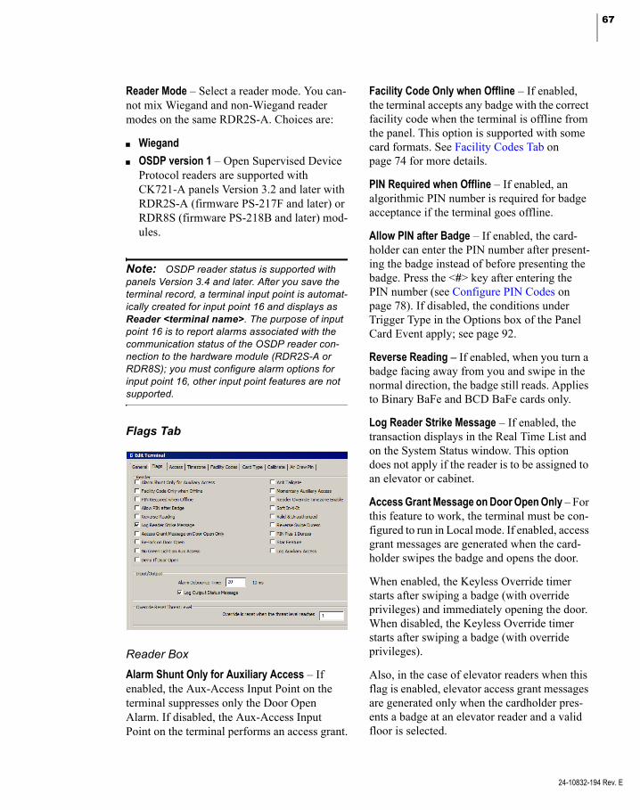
67
Reader Mode – Select a reader mode. You can-not mix Wiegand and non-Wiegand reader modes on the same RDR2S-A. Choices are:
Wiegand
OSDP version 1 – Open Supervised Device Protocol readers are supported with CK721-A panels Version 3.2 and later with RDR2S-A (firmware PS-217F and later) or RDR8S (firmware PS-218B and later) mod-ules.
Note: OSDP reader status is supported with panels Version 3.4 and later. After you save the terminal record, a terminal input point is automat-ically created for input point 16 and displays as Reader <terminal name>. The purpose of input point 16 is to report alarms associated with the communication status of the OSDP reader con-nection to the hardware module (RDR2S-A or RDR8S); you must configure alarm options for input point 16, other input point features are not supported.
Flags Tab
Reader Box
Alarm Shunt Only for Auxiliary Access – If enabled, the Aux-Access Input Point on the terminal suppresses only the Door Open Alarm. If disabled, the Aux-Access Input Point on the terminal performs an access grant.
Facility Code Only when Offline – If enabled, the terminal accepts any badge with the correct facility code when the terminal is offline from the panel. This option is supported with some card formats. See Facility Codes Tab on page 74 for more details.
PIN Required when Offline – If enabled, an algorithmic PIN number is required for badge acceptance if the terminal goes offline.
Allow PIN after Badge – If enabled, the card-holder can enter the PIN number after present-ing the badge instead of before presenting the badge. Press the <#> key after entering the PIN number (see Configure PIN Codes on page 78). If disabled, the conditions under Trigger Type in the Options box of the Panel Card Event apply; see page 92.
Reverse Reading – If enabled, when you turn a badge facing away from you and swipe in the normal direction, the badge still reads. Applies to Binary BaFe and BCD BaFe cards only.
Log Reader Strike Message – If enabled, the transaction displays in the Real Time List and on the System Status window. This option does not apply if the reader is to be assigned to an elevator or cabinet.
Access Grant Message on Door Open Only – For this feature to work, the terminal must be con-figured to run in Local mode. If enabled, access grant messages are generated when the card-holder swipes the badge and opens the door.
When enabled, the Keyless Override timer starts after swiping a badge (with override privileges) and immediately opening the door. When disabled, the Keyless Override timer starts after swiping a badge (with override privileges).
Also, in the case of elevator readers when this flag is enabled, elevator access grant messages are generated only when the cardholder pres-ents a badge at an elevator reader and a valid floor is selected.
24-10832-194 Rev. E

68 CHAPTER 2
Configuring the System
24-10832-194 Rev. E
Re-lock on Door Open – If enabled, the door is re-locked when the door is opened. Shunt remains active until after temporary override timers (if any) expire and then after the shunt time also expires. When the Anti-Tailgate or Timed Shunt options are enabled, shunt can end earlier if the door closes. The Re-lock on Door Open option is disabled during scheduled override periods.
No Green Light on Aux Access – If enabled, no green light displays on auxiliary access.
Deny If Door Open – If enabled, an access denied message is generated when the card-holder swipes the badge at an opened door.
Anti Tailgate – If enabled, the strike and shunt timers are immediately reset and the door immediately locks, following an access grant when a door closes. This prevents reopening the door using one badge access. When used with the Re-lock on Door Open option, open-ing a door immediately re-locks the door.
Momentary Auxiliary Access – If enabled, the Access Time begins timing when a switch shorts the terminal’s Aux-Access input point contact. If disabled, the terminal’s Aux-Access input point contact energizes the door relay as long as the contact is shorted.
Reader Override Timezone Enable – If enabled, the reader does not require a badge to open the door during the reader override time zone. (A time zone must be selected in the Override field of the Timezone tab to enable this func-tion.)
Soft In-X-It – If enabled, cardholders have access even though the In-X-It status is incor-rect. (A soft alarm can be triggered if config-ured through the Soft Alarms dialog box; see page 93.)
Valid & Unauthorized – If enabled, a green light indicates that badging has taken place; how-ever, the system does not grant access to the cardholder. A security guard must manually unlock the door with a key or push a button to open the door and allow access.
Reverse Swipe Duress – If enabled, you can turn the badge away from you and swipe in the normal direction to report a duress alarm. (Soft alarm must be configured for this reader; see Soft Alarms Field Definitions on page 94.) Applies to Binary BaFe and BCD BaFe cards only. When you enable Reverse Swipe Duress, the Reverse Reading option is automatically enabled.
PIN Plus 1 Duress – If enabled, a duress alarm is generated when a cardholder adds 1 to the last digit of the PIN code (for example, 6 becomes 7, not 61). When this option is enabled, the 9 does not create a duress alarm. If the last digit of the PIN code is a 9, then the user substitutes a 0 for the 9 and this triggers the duress alarm. This feature only works if the Duress soft alarm is enabled.
Star Feature – If enabled, the cardholder can press the star (*) key at the keypad plus a fea-ture number, to activate some of the panel’s functions that are normally invoked from key-pads that contain the A, B, C, or D keys. The (#) key acts as the Enter key, it wraps-up the previously entered keys and starts the process-ing of the key sequence. It also clears the key-pad buffer for the next command to be entered. The (*) key starts the feature selection process. Once pressed, the cardholder can activate one of the following features:
0 = Local Override, followed by number of minutes
1 = Enable event, followed by event number
2 = Air Crew PIN
4 = Disable event, followed by event number

69
* = Clear the keypad buffer. This works inde-pendently of the Star Feature setting
The cardholder must enter all PIN and Card ID information before selecting a feature. As an alternative, instead of pressing the (#) key, the cardholder can swipe the badge to wrap-up the previously entered keys and start the process-ing of the key sequence; however, with the Allow PIN after badge option the (#) key is always required.
For details, see Appendix D: Using a Keypad Reader on CK721-A Panels.
Log Auxiliary Access – If enabled, the system reports when a Request to Exit (REX) input point activation allows a door to open, without generating a forced door alarm (someone exits). When the REX input point grants Aux-iliary Access and a door opens, the system reports this as a panel event. We recommend that the REX inputs operate in 4-state mode. Also make sure you enable Forced/Propped soft alarms. You should also note that:
Reporting REX transactions is not sup-ported on devices operating in legacy addressing mode.
Log Auxiliary Access is not supported when door inputs are reassigned as general purpose inputs.
Input/Output Box
Alarm Debounce Time – (Inputs only) Enter a delay time in milliseconds that the system waits to sample this terminal’s Supervised Input Point Circuits. The default is 20 msec. This improves system performance by ignor-ing a circuit disturbance, such as a door jiggle as it closes, rather than reporting an alarm.
Log Output Status Message – (Outputs only) Click to send output relay messages from the panel to the P2000 Server (whether or not access is granted). Must be selected to show as active on the System Status window. This option is disabled for output points assigned to an elevator or cabinet.
Override Reset Threat Level Box
Each reader terminal defined for a CK721-A panel can be configured with an Override Reset Threat Level ranging between 0 and 99. A value of 0 disables the Override Reset fea-ture; a value between 1 and 99 invokes the fol-lowing behavior:
Whenever a terminal’s Security Level reaches or exceeds the terminal’s Override Reset Threat Level, all time zone based overrides, host initiated overrides and cardholder over-rides are immediately disabled. Subsequent attempts to invoke host initiated overrides or cardholder overrides are denied.
Once a terminal’s Security Level drops below the terminal’s Override Reset Threat Level, the time zone based override is restored immedi-ately. Host initiated overrides and cardholder overrides are not automatically restored, but subsequent attempts to invoke host initiated overrides or cardholder overrides are granted, provided the configuration allows these over-rides.
The System Override feature is not affected by the Override Reset Threat Level, and remains in effect as long as the panel’s System Over-ride flag is set.
To Create an Input/Output Terminal
1. From the System Configuration window, select the panel to which the Input/Output terminal is added.
24-10832-194 Rev. E
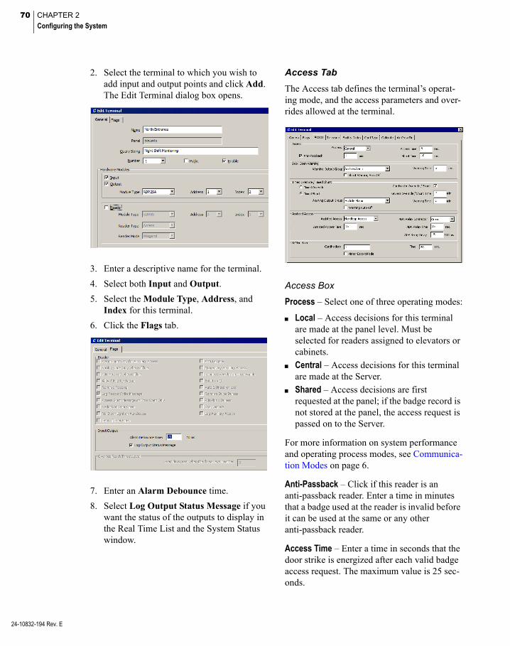
70 CHAPTER 2
Configuring the System
24-10832-194 Rev. E
2. Select the terminal to which you wish to add input and output points and click Add. The Edit Terminal dialog box opens.
3. Enter a descriptive name for the terminal.
4. Select both Input and Output.
5. Select the Module Type, Address, and Index for this terminal.
6. Click the Flags tab.
7. Enter an Alarm Debounce time.
8. Select Log Output Status Message if you want the status of the outputs to display in the Real Time List and the System Status window.
Access Tab
The Access tab defines the terminal’s operat-ing mode, and the access parameters and over-rides allowed at the terminal.
Access Box
Process – Select one of three operating modes:
Local – Access decisions for this terminal are made at the panel level. Must be selected for readers assigned to elevators or cabinets.
Central – Access decisions for this terminal are made at the Server.
Shared – Access decisions are first requested at the panel; if the badge record is not stored at the panel, the access request is passed on to the Server.
For more information on system performance and operating process modes, see Communica-tion Modes on page 6.
Anti-Passback – Click if this reader is an anti-passback reader. Enter a time in minutes that a badge used at the reader is invalid before it can be used at the same or any other anti-passback reader.
Access Time – Enter a time in seconds that the door strike is energized after each valid badge access request. The maximum value is 25 sec-onds.
71
Shunt Time – Enter a time in seconds that the door open alarm is suppressed after a valid badge access request. The shunt time should be longer than the access time. The maximum value is 255 seconds.
Note: If Anti-Tailgate is enabled, after an access grant, the shunt time is cancelled once the door status changes to locked and closed, even if the shunt time has not yet expired.
Door Open Warning Box
Warning Output Group – Select the output group that is to be activated when the Warning Time is reached.
Warning Time – Enter the time in seconds (0 to 255) before the Shunt Time expires for the Warning Output Group to be activated if the door remains open.
Shunt Warning Auto Off – If enabled, the Warn-ing Output Group is reset when the door is closed, access is granted, or the door is over-ridden. Therefore, the Door Open Warning is deactivated when there is no Propped Door alarm in the immediate future.
Timed Override/Timed Shunt Box
A temporary override allows access times to be temporarily extended by a number of min-utes and can be generated through a panel card event, the Keyless Override option, the Door Control application, or by entering a number at a keypad reader (see Cardholder Over-ride/Shunt in this section).
If you enable the Re-lock on Door Open option, when the door is opened during the access time the door is re-locked. If you also enable the Anti-Tailgate option, after a door is re-locked by the Re-lock on Door Open option, if the door is closed again, the shunt time is also cancelled.
There are two modes of temporary override:
Timed Override – Select this option if you want to unlock the door for an extended period of time.
Timed Shunt – If you select this option, only the shunt time is extended by the number of minutes in the temporary override. The access time remains at the configured value. Use the Timed Shunt mode if you want the door to be held open for an extended period of time, but do not want the door to be unlocked for that time.
Note: In Timed Shunt mode, if the door is not opened while it is unlocked, the access ends, even if the shunt time has not yet expired.
For a cardholder to activate a local override, the presented badge must have the Override option enabled in the Badge dialog box, and the Cardholder Override/Shunt option must be enabled in this tab.
Cardholder Override/Shunt – If enabled, an authorized cardholder may temporarily over-ride the shunt time and access time by per-forming a badging procedure at a keypad reader. The timed override/shunt establishes an extended shunt time and access time period from 0 to 1440 minutes (24 hours). The card-holder must have the Override option enabled in the Badge dialog box. Follow these instruc-tions to perform a timed override/shunt access at a keypad:
1. Enter your PIN code on the keypad (if PIN codes are part of your system configura-tion).
2. Press the <*> key (or <*> 0 if the Star Fea-ture is selected in the Flags tab).
3. Enter the number of minutes desired for the override/shunt period.
4. Press the <#> key.
24-10832-194 Rev. E

72 CHAPTER 2
Configuring the System
24-10832-194 Rev. E
5. Badge into the keypad reader, so that the override/shunt privilege can be checked against the badge record.
6. If you wish to terminate the timed over-ride/shunt period (before the number of minutes selected have run out), repeat steps 1 through 5, entering 0 minutes in step 3.
For details, see Appendix D: Using a Keypad Reader on CK721-A Panels.
Keyless Override/Shunt Time – Instead of hav-ing to enter the number of minutes for the timed override/shunt at a keypad reader, you can have the system do it for you. Entering a time from 1 to 1440 minutes into this field treats a qualifying badging procedure as if the number of minutes had been entered at the keypad. You can still choose to enter a differ-ent number of minutes at the keypad reader, which takes priority over the configured over-ride/shunt time. Entering a 0 into the Keyless Override/Shunt Time field turns this feature off. The rules as to who can invoke a keyless timed override/shunt are identical to those gov-erning the keypad invoked override. When the Access Grant Message on Door Open Only flag is selected in the Flags Tab, the keyless override timer starts after the cardholder swipes the badge with override privileges and then opens the door.
Warning Output Group – Select the output group to be activated when the timed over-ride/shunt expiration for this terminal falls within the time set in the Warning Time field.
Warning Time – Enter the time (0 to 10 min-utes) to activate the Warning Output Group to warn operators that the override/shunt is about to expire. For example, if you have created a temporary door override/shunt for 8 hours, you can create an audible output group that acti-vates 10 minutes before the override/shunt expires to let operators know the door shortly begins operating in normal mode.
Warning Auto Off – If enabled, the Warning Output Group is reset when the door closes or when override is extended past the point when the warning should be triggered. Just an access grant alone does not deactivate the Override Warning. This feature is most useful in connec-tion with the Timed Override/Anti-Tailgate option enabled. If Timed Override/Anti-Tail-gate is not enabled, it is possible that the Over-ride Warning is deactivated before the override actually expires. If you want to avoid this sce-nario, disable this option.
Assisted Access Box
Note: This feature only works on terminals that operate in Local mode.
This option allows you to set up a door’s access time to be different, to satisfy the requirements for assisted access according to ADA (Americans with Disabilities Act). The system provides three Special Access flags, A, B, and C, which can be renamed in the Site Parameters dialog box according to your facil-ity needs, and then assigned to a cardholder that requires special access at a door.
Additionally, you may activate an ADA relay in conjunction with granting assisted access.
Assisted Access – Select one of the following options:
Never – Assisted Access is not available at the door, even if the cardholder’s badge has the Special Access A flag enabled.
Always – The door is always opened for the Assisted Access Time, regardless if the cardholder’s badge has the Special Access A flag enabled.
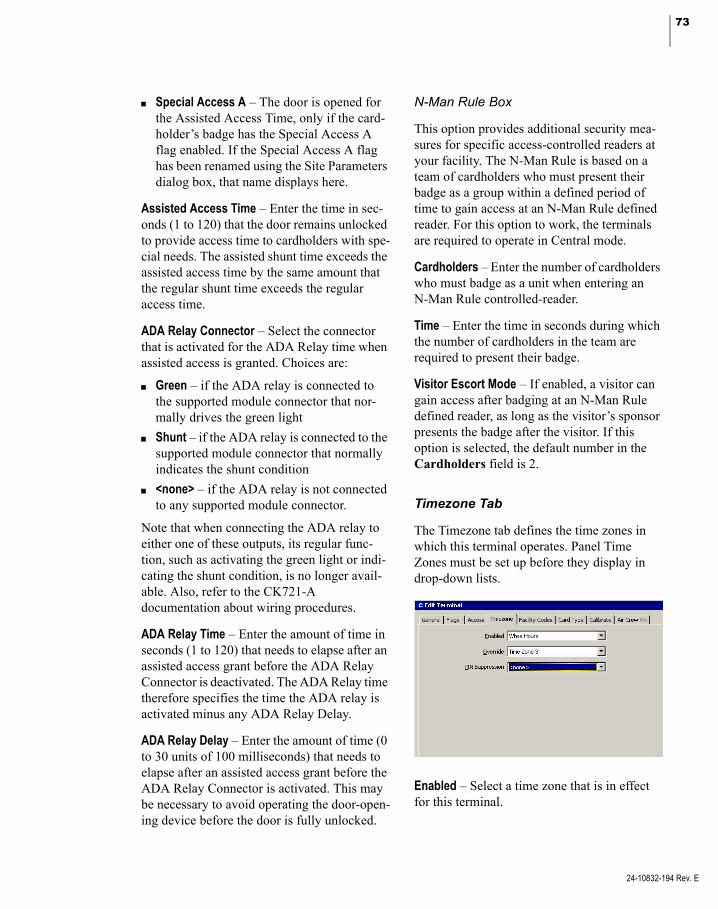
73
Special Access A – The door is opened for the Assisted Access Time, only if the card-holder’s badge has the Special Access A flag enabled. If the Special Access A flag has been renamed using the Site Parameters dialog box, that name displays here.
Assisted Access Time – Enter the time in sec-onds (1 to 120) that the door remains unlocked to provide access time to cardholders with spe-cial needs. The assisted shunt time exceeds the assisted access time by the same amount that the regular shunt time exceeds the regular access time.
ADA Relay Connector – Select the connector that is activated for the ADA Relay time when assisted access is granted. Choices are:
Green – if the ADA relay is connected to the supported module connector that nor-mally drives the green light
Shunt – if the ADA relay is connected to the supported module connector that normally indicates the shunt condition
<none> – if the ADA relay is not connected to any supported module connector.
Note that when connecting the ADA relay to either one of these outputs, its regular func-tion, such as activating the green light or indi-cating the shunt condition, is no longer avail-able. Also, refer to the CK721-A documentation about wiring procedures.
ADA Relay Time – Enter the amount of time in seconds (1 to 120) that needs to elapse after an assisted access grant before the ADA Relay Connector is deactivated. The ADA Relay time therefore specifies the time the ADA relay is activated minus any ADA Relay Delay.
ADA Relay Delay – Enter the amount of time (0 to 30 units of 100 milliseconds) that needs to elapse after an assisted access grant before the ADA Relay Connector is activated. This may be necessary to avoid operating the door-open-ing device before the door is fully unlocked.
N-Man Rule Box
This option provides additional security mea-sures for specific access-controlled readers at your facility. The N-Man Rule is based on a team of cardholders who must present their badge as a group within a defined period of time to gain access at an N-Man Rule defined reader. For this option to work, the terminals are required to operate in Central mode.
Cardholders – Enter the number of cardholders who must badge as a unit when entering an N-Man Rule controlled-reader.
Time – Enter the time in seconds during which the number of cardholders in the team are required to present their badge.
Visitor Escort Mode – If enabled, a visitor can gain access after badging at an N-Man Rule defined reader, as long as the visitor’s sponsor presents the badge after the visitor. If this option is selected, the default number in the Cardholders field is 2.
Timezone Tab
The Timezone tab defines the time zones in which this terminal operates. Panel Time Zones must be set up before they display in drop-down lists.
Enabled – Select a time zone that is in effect for this terminal.
24-10832-194 Rev. E
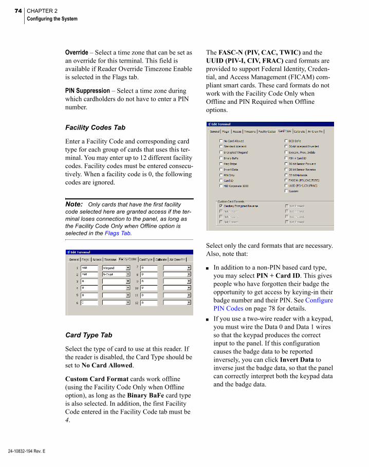
74 CHAPTER 2
Configuring the System
24-10832-194 Rev. E
Override – Select a time zone that can be set as an override for this terminal. This field is available if Reader Override Timezone Enable is selected in the Flags tab.
PIN Suppression – Select a time zone during which cardholders do not have to enter a PIN number.
Facility Codes Tab
Enter a Facility Code and corresponding card type for each group of cards that uses this ter-minal. You may enter up to 12 different facility codes. Facility codes must be entered consecu-tively. When a facility code is 0, the following codes are ignored.
Note: Only cards that have the first facility code selected here are granted access if the ter-minal loses connection to the panel, as long as the Facility Code Only when Offline option is selected in the Flags Tab.
Card Type Tab
Select the type of card to use at this reader. If the reader is disabled, the Card Type should be set to No Card Allowed.
Custom Card Format cards work offline (using the Facility Code Only when Offline option), as long as the Binary BaFe card type is also selected. In addition, the first Facility Code entered in the Facility Code tab must be 4.
The FASC-N (PIV, CAC, TWIC) and the UUID (PIV-I, CIV, FRAC) card formats are provided to support Federal Identity, Creden-tial, and Access Management (FICAM) com-pliant smart cards. These card formats do not work with the Facility Code Only when Offline and PIN Required when Offline options.
Select only the card formats that are necessary. Also, note that:
In addition to a non-PIN based card type, you may select PIN + Card ID. This gives people who have forgotten their badge the opportunity to get access by keying-in their badge number and their PIN. See Configure PIN Codes on page 78 for details.
If you use a two-wire reader with a keypad, you must wire the Data 0 and Data 1 wires so that the keypad produces the correct input to the panel. If this configuration causes the badge data to be reported inversely, you can click Invert Data to inverse just the badge data, so that the panel can correctly interpret both the keypad data and the badge data.

75
CK721-A panels Version 3.5 and later sup-port HID Corporate 1000 card types that use 48-bit formats, in addition to the 35-bit format currently supported. The 48-bit for-mat cannot be used with RDR2S-A and RDR8S modules in offline mode (using the Facility Code Only when Offline option). In offline mode both modules only process 35-bit formats.
The Custom Card Formats box displays the card formats that were downloaded into the panel, using the Panel Card Formats dialog box; see page 64 for detailed instructions.
Calibrate Tab
Use this tab to calibrate auxiliary access input point contacts on the terminal, as well as door contact input points.
To calibrate or uncalibrate the auxiliary access, you must enable the Propped Door (24) soft alarm. After the calibration command has been successfully issued, input point 24 can be deleted if it is not being used.
IMPORTANT: During the entire input calibra-tion procedure, the input’s contact must be physi-cally closed. Otherwise, the input’s status is unreliable.
If you click either of the Calibrate buttons, the Server sends a calibration command to the panel, the panel then forwards the command to the RDR2S-A or RDR8S module to initiate the input’s calibration. When the module com-pletes its calibration, typically within a few seconds, the panel sends a transaction message to the Real Time List indicating the calibration result. After a successful calibration, four-state input statuses are functional for the input point; however, auxiliary access inputs do not report Open and Short conditions to the P2000 system.
If you click either of the Uncalibrate buttons, the Server sends a command to the panel to uncalibrate the module’s input. The panel then sends a transaction message to the Real Time List indicating the uncalibration result. After the uncalibration, four-state input statuses are no longer functional for the input, only two-state statuses.
TIP: Once an input is calibrated, you do not need to use this feature again, unless you change the controller hardware or the input point’s wiring.
Note: RDR2S-A and RDR8S modules with optional calibration resistors attached automati-cally use this reference for calibration. Inputs cal-ibrated in this way do not need to be secured at the time of calibration.
Air Crew Pin Tab
To enable the use of PIN codes at this terminal, select from the list any or all previously defined Air Crew PIN Codes that were set up in the Edit Air Crew PIN Number dialog box (see page 63 for details).
24-10832-194 Rev. E

76 CHAPTER 2
Configuring the System
24-10832-194 Rev. E
When this feature is enabled, entering an assigned Air Crew PIN code allows access at the door. If selected, other terminal access options are still available (Card ID, PIN Only or PIN + Card ID). Follow these instructions to use the Air Crew PIN:
1. If you use the Star Feature, press the *2 keys to initiate the sequence. If you do not use the Star Feature, press the B key.
2. Enter the unique Air Crew PIN code. If an error is made, press the ** keys (with Star Feature) to clear the keypad buffer and start with step 1. To clear the keypad with-out the Star Feature, press the C key.
3. Press the # key to complete the sequence.
Use the Add Hardware Module
The Add Hardware Module command starts a wizard style interface that simplifies the pro-cess of adding a new module to a CK721-A panel. It supports module types RDR2S-A and RDR8S. The wizard asks the operator some basic configuration information specific to the module being added and automatically adds the necessary configuration items (terminals, input points, and output points) to the P2000 system.
To Add a Hardware Module
1. In the System Configuration window, expand Panels to display the panel types.
2. Expand CK721-A Panels and select the panel name where you want to add the new hardware module.
3. Right-click the panel name and select Add Hardware Module from the shortcut menu. The Module Type dialog box opens.
4. Select from the Module Type drop-down list one of the following options:
RDR2SA – The wizard creates two RDR2S-A reader terminals.
RDR8S – The wizard creates eight RDR8S reader terminals.
5. Make your selection and click Next. The Terminal Number dialog box opens.

77
6. Select from the Base Number drop-down list the terminal address that corresponds to the physical address as installed at the panel.
7. Select the Module Address.
8. Click Next. The Module Name dialog box opens.
9. The Base Name displays the name of the selected CK721-A panel. You can how-ever, change the name if you wish.
10. Select from the Style drop-down list one of the following name styles:
Base Name First, Space
Base Name First, Underscore
Base Name Last, Space
Base Name Last, Underscore
The Item Names box displays the items created with the name style selected.
11. Click Next, the Template dialog box opens.
12. Select from the Template Terminal drop-down list, an existing reader terminal from which the access configuration parameters are copied. Click Next.
13. The Summary dialog box opens.
14. Click Finish. The Create Items progress bar displays.
15. A message displays indicating that all items were successfully created. Click OK to finish. The System Configuration win-dow displays the created items. You can edit any of the items to change configura-tion parameters.
24-10832-194 Rev. E
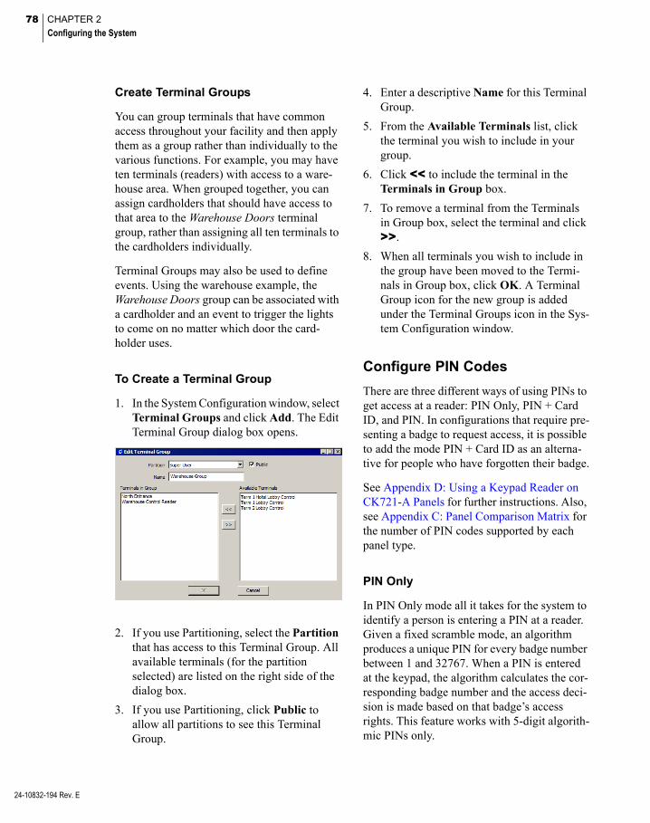
78 CHAPTER 2
Configuring the System
24-10832-194 Rev. E
Create Terminal Groups
You can group terminals that have common access throughout your facility and then apply them as a group rather than individually to the various functions. For example, you may have ten terminals (readers) with access to a ware-house area. When grouped together, you can assign cardholders that should have access to that area to the Warehouse Doors terminal group, rather than assigning all ten terminals to the cardholders individually.
Terminal Groups may also be used to define events. Using the warehouse example, the Warehouse Doors group can be associated with a cardholder and an event to trigger the lights to come on no matter which door the card-holder uses.
To Create a Terminal Group
1. In the System Configuration window, select Terminal Groups and click Add. The Edit Terminal Group dialog box opens.
2. If you use Partitioning, select the Partition that has access to this Terminal Group. All available terminals (for the partition selected) are listed on the right side of the dialog box.
3. If you use Partitioning, click Public to allow all partitions to see this Terminal Group.
4. Enter a descriptive Name for this Terminal Group.
5. From the Available Terminals list, click the terminal you wish to include in your group.
6. Click << to include the terminal in the Terminals in Group box.
7. To remove a terminal from the Terminals in Group box, select the terminal and click >>.
8. When all terminals you wish to include in the group have been moved to the Termi-nals in Group box, click OK. A Terminal Group icon for the new group is added under the Terminal Groups icon in the Sys-tem Configuration window.
Configure PIN Codes
There are three different ways of using PINs to get access at a reader: PIN Only, PIN + Card ID, and PIN. In configurations that require pre-senting a badge to request access, it is possible to add the mode PIN + Card ID as an alterna-tive for people who have forgotten their badge.
See Appendix D: Using a Keypad Reader on CK721-A Panels for further instructions. Also, see Appendix C: Panel Comparison Matrix for the number of PIN codes supported by each panel type.
PIN Only
In PIN Only mode all it takes for the system to identify a person is entering a PIN at a reader. Given a fixed scramble mode, an algorithm produces a unique PIN for every badge number between 1 and 32767. When a PIN is entered at the keypad, the algorithm calculates the cor-responding badge number and the access deci-sion is made based on that badge’s access rights. This feature works with 5-digit algorith-mic PINs only.

79
For PIN Only to work, you need to configure the following parameters:
1. The panel’s PIN Code Type must be set to Algorithmic (see page 58).
2. The panel’s PIN Code Digits must be set to 5 (see page 58).
3. The panel’s Scramble Mode must be set to the value used to create the PINs from the badge numbers (see page 58).
4. The terminal’s PIN Only card type must be selected in the Card Type tab. All other card types must not be selected (see page 74).
5. The terminal’s Allow PIN after Badge in the Flags tab has no effect (see page 67).
6. The terminal’s PIN Suppression in the Timezone tab has no effect. For obvious reasons you cannot waive the requirement to enter a PIN in PIN Only mode.
To use PIN Only mode, simply enter your 5-digit algorithmic PIN at the keypad followed by the # key, and the access decision is made.
PIN + Card ID
In this mode the badge does not have to be pre-sented at the reader. The numeric keypad is used to enter the PIN and the badge number. This feature works with 4 or 5-digit algorith-mic and with 4 up to 9-digit custom PINs.
For PIN + Card ID to work, you need to con-figure the following parameters:
1. The terminal’s PIN + Card ID must be selected in the Card Type tab. All other card types should not be selected, unless you want to use the PIN + Card ID mode only as an alternative for people who have forgotten their badge (see page 74).
2. The terminal’s Allow PIN after Badge in the Flags tab has no effect (see page 67).
3. The terminal’s PIN Suppression in the Timezone tab has no effect, that is, you cannot use time zones to waive the require-ment to enter a PIN in PIN + Card ID mode.
To use PIN + Card ID mode, you must enter your PIN followed by your 5-digit badge num-ber, followed by the # key. You must enter leading zeros if your badge number has fewer than 5 digits.
PIN
In this mode, the PIN needs to be entered in conjunction with a valid badge presented at the reader. This feature works with 4 or 5-digit algorithmic and with 4 up to 9-digit custom PINs.
For PIN to work, you need to configure the following parameters:
1. Select a card type in the terminal’s Card Type tab that matches the reader’s technol-ogy (see page 74).
2. All other card types should not be selected.
3. The terminal’s PIN Only card type in the Card Type tab must not be selected.
4. The terminal’s PIN + Card ID card type in the Card Type tab should not be selected, unless you want to use the PIN + Card ID mode as an alternative for people who have forgotten their badge.
5. The terminal’s PIN Suppression in the Timezone tab must be set to a defined time zone. PINs are only required to be entered when the time zone is inactive.
To use PIN mode when the terminal’s Allow PIN after Badge option in the Flags tab is not set, you must key in the entire PIN before pre-senting the badge. The PIN does not need to be terminated with a # key.
24-10832-194 Rev. E

80 CHAPTER 2
Configuring the System
24-10832-194 Rev. E
To use PIN mode when the terminal’s Allow PIN after Badge option in the Flags tab is set, the PIN must be terminated with a # key. You can enter the PIN and the # key before, during, or after the badge is presented.
To use PIN mode when you also have the PIN + Card ID card type selected, as an alternative for people who have forgotten their badge, the # key must not be entered before the badge is presented.
Four-Digit PINs
A four-digit custom PIN is defined by the first four digits entered in the PIN Code field in the Badge dialog box (see page 252). Algorithmic codes need to be requested from Technical Support.
PIN Duress
The PIN Duress feature in the Soft Alarm dia-log box, creates an access grant and a duress alarm only if all of the following conditions apply:
1. The duress soft alarm is defined at the panel (see page 94).
2. The cardholder is required to enter a PIN at the terminal.
3. Exactly one digit of the PIN is replaced by the digit 9.
4. All other digits match the badge’s PIN.
5. The card type selected in the terminal’s Card Type tab is not PIN Only.
PIN Retry Alarm
A PIN Code Retry alarm is generated when the respective soft alarm is defined at the panel, and three consecutive unsuccessful attempts to enter a PIN were made for the same badge (see page 94). In Local mode, the three consecutive attempts can be made at any terminal of a sin-gle panel. In Central mode, the three consecu-tive attempts can be made at any terminal at any panel.
Configure Input and Output Points and Groups
Input and output points and groups work together to control devices connected to the system terminals. For example, an input can be configured for a broken window contact and this can generate an output to an alarm annun-ciator. A group of inputs can generate the same output, no matter which input point in the group is activated.
Create Output Points and Groups
Output Points are dry contact relays located on the Terminal boards. These are opened or closed by the system to control devices con-nected to them such as lights, air conditioning, alarm annunciators, parking barriers, and so on. After output points are created, they can be grouped with other output points that have a common purpose in the system and then used in conjunction with specific inputs.
To Create Output Points
1. In the System Configuration window, select a Terminal that has been configured for outputs.
2. Select Output Points and click Add. The Output Point dialog box opens.

81
3. If this is a partitioned system, select in the Output Point box the active Partition and click Public if you wish the output point to be visible to all partitions.
4. Enter a descriptive Name for the output point.
5. Select an output point Number. This num-ber represents the physical connection to the I/O terminal.
6. The Query String value is used with mes-sage filtering (see Define Query String Fil-ters on page 225).
7. The output point Status is Enable by default.
8. In the State Option box, select the Active State from the drop-down list. See the fol-lowing definitions:
Reset – Reserved for diagnostic purposes.
Set – Turns on the output point. This option must be selected for output points assigned to elevators or cabinets.
Fast Flash – Toggles the output point on and off quickly (once per second).
Slow Flash – Toggles the output point on and off slowly (once per two seconds).
Timed – Turns on the output point for a specified time in seconds.
9. If the Active State is Timed, you must enter a Duration in seconds.
10. The Output Group box is view-only. Each output point can belong to three output groups.
11. Click OK to save your settings. The new output point is listed under the Output Points icon.
Note: You must perform the Write DB to Flash function (see page 444) when adding or deleting RDR2S-A or RDR8S output points.
To Create Output Groups
Output Points can be grouped together to per-form common functions. For example, an input such as an air-sampling device can be configured to activate a group of exhaust fans connected to output points on a terminal.
1. In the System Configuration window, expand the panel that contains the output points you wish to group.
2. Select Output Groups and click Add. The Output Group dialog box opens.
3. Enter a Name for the Output Group.
24-10832-194 Rev. E
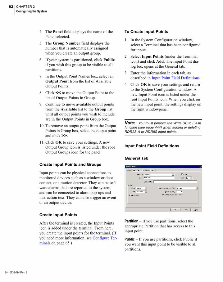
82 CHAPTER 2
Configuring the System
24-10832-194 Rev. E
4. The Panel field displays the name of the Panel selected.
5. The Group Number field displays the number that is automatically assigned when you create an output group.
6. If your system is partitioned, click Public if you wish this group to be visible to all partitions.
7. In the Output Point Names box, select an Output Point from the list of Available Output Points.
8. Click << to move the Output Point to the list of Output Points in Group.
9. Continue to move available output points from the Available list to the Group list until all output points you wish to include are in the Output Points in Group box.
10. To remove an output point from the Output Points in Group box, select the output point and click >>.
11. Click OK to save your settings. A new Output Group icon is listed under the root Output Groups icon for the panel.
Create Input Points and Groups
Input points can be physical connections to monitored devices such as a window or door contact, or a motion detector. They can be soft-ware alarms that are reported to the system, and can be connected to alarm pop-ups and instruction text. They can also trigger an event or an output device.
Create Input Points
After the terminal is created, the Input Points icon is added under the terminal. From here, you create the input points for the terminal. (If you need more information, see Configure Ter-minals on page 65.)
To Create Input Points
1. In the System Configuration window, select a Terminal that has been configured for inputs.
2. Select Input Points (under the Terminal icon) and click Add. The Input Point dia-log box opens at the General tab.
3. Enter the information in each tab, as described in Input Point Field Definitions.
4. Click OK to save your settings and return to the System Configuration window. A new Input Point icon is listed under the root Input Points icon. When you click on the new input point, the settings display on the right windowpane.
Note: You must perform the Write DB to Flash function (see page 444) when adding or deleting RDR2S-A or RDR8S input points.
Input Point Field Definitions
General Tab
Partition – If you use partitions, select the appropriate Partition that has access to this input point.
Public – If you use partitions, click Public if you want this input point to be visible to all partitions.

83
Name – Enter a descriptive Name for the input point.
Number – Select an input point number.
Query String – This value is used with message filtering (see Define Query String Filters on page 225).
Status – If you select Enable, all input point changes of state are reported. Select Disable if you do not want these changes reported.
Disabled During Time Zone – Select a Time Zone during which the input point is disabled. For example, it is impractical to report a door contact alarm during business hours when the door is in constant use.
Type – Choose either Two State or Four State. Changing the input type requires using the Un-calibrate command (for two-state inputs) or the Calibrate command (for four-state inputs) in the Misc Tab.
Entry Exit Delay – Enter a time (0 to 600 sec-onds) that the alarm is suppressed until an event disables the alarm. If a delayed entry/exit value is defined for an input point, the system delays reporting activation of this input point for the time value specified. If the input point is suppressed within this delay period (that is, by a card event), the alarm is not reported. For example, a cardholder can badge at a reader, open the door, and then badge at a second reader to suppress the door alarm before it reports. If the cardholder does not badge and suppress the alarm (by card event) at the second reader within the specified time, the alarm is reported.
Report Delay – If enabled, the alarm is delayed by the number of seconds set in the Reporting Delay field in the Alarm Tab of the Edit Panel dialog box. If the input point returns to the secure state before the delay expires, the panel does not report the alarm to the Server at all. If disabled, the alarm is reported immediately.
Open and short conditions for 4-state input points are reported immediately.
Set Panel Relay When Active – If enabled, the relay on the panel activates when the input point is activated. If disabled, the relay on the panel does not activate.
Alarm Options Tab
Use this tab to configure alarm options for P2000 devices that generate alarms, such as input points, cameras, switches, and so on. Each alarm must belong to at least one Alarm Category (see Alarm Configuration on page 270 for details), but can also be assigned to multiple alarm categories, each with its own set of alarm options.
For example, if an input point connected to a glass breakage sensor generates an alarm, the P2000 system may create two separate alarms for two configured alarm categories: P2000\Maintenance\Building 1 and P2000\ Security\Building 1. Typically, a single opera-tor is configured to receive only a single cate-gory of alarms, and therefore could only receive a single alarm. However, higher level operators such as supervisors, or an operator at a central alarm monitoring location, may be configured to receive both of these alarms.
1. Click the Alarm Options tab. The P2000 Alarm Category displays by default.
24-10832-194 Rev. E
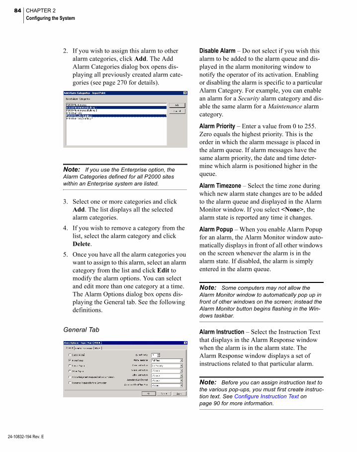
84 CHAPTER 2
Configuring the System
24-10832-194 Rev. E
2. If you wish to assign this alarm to other alarm categories, click Add. The Add Alarm Categories dialog box opens dis-playing all previously created alarm cate-gories (see page 270 for details).
Note: If you use the Enterprise option, the Alarm Categories defined for all P2000 sites within an Enterprise system are listed.
3. Select one or more categories and click Add. The list displays all the selected alarm categories.
4. If you wish to remove a category from the list, select the alarm category and click Delete.
5. Once you have all the alarm categories you want to assign to this alarm, select an alarm category from the list and click Edit to modify the alarm options. You can select and edit more than one category at a time. The Alarm Options dialog box opens dis-playing the General tab. See the following definitions.
General Tab
Disable Alarm – Do not select if you wish this alarm to be added to the alarm queue and dis-played in the alarm monitoring window to notify the operator of its activation. Enabling or disabling the alarm is specific to a particular Alarm Category. For example, you can enable an alarm for a Security alarm category and dis-able the same alarm for a Maintenance alarm category.
Alarm Priority – Enter a value from 0 to 255. Zero equals the highest priority. This is the order in which the alarm message is placed in the alarm queue. If alarm messages have the same alarm priority, the date and time deter-mine which alarm is positioned higher in the queue.
Alarm Timezone – Select the time zone during which new alarm state changes are to be added to the alarm queue and displayed in the Alarm Monitor window. If you select <None>, the alarm state is reported any time it changes.
Alarm Popup – When you enable Alarm Popup for an alarm, the Alarm Monitor window auto-matically displays in front of all other windows on the screen whenever the alarm is in the alarm state. If disabled, the alarm is simply entered in the alarm queue.
Note: Some computers may not allow the Alarm Monitor window to automatically pop up in front of other windows on the screen; instead the Alarm Monitor button begins flashing in the Win-dows taskbar.
Alarm Instruction – Select the Instruction Text that displays in the Alarm Response window when the alarm is in the alarm state. The Alarm Response window displays a set of instructions related to that particular alarm.
Note: Before you can assign instruction text to the various pop-ups, you must first create instruc-tion text. See Configure Instruction Text on page 90 for more information.
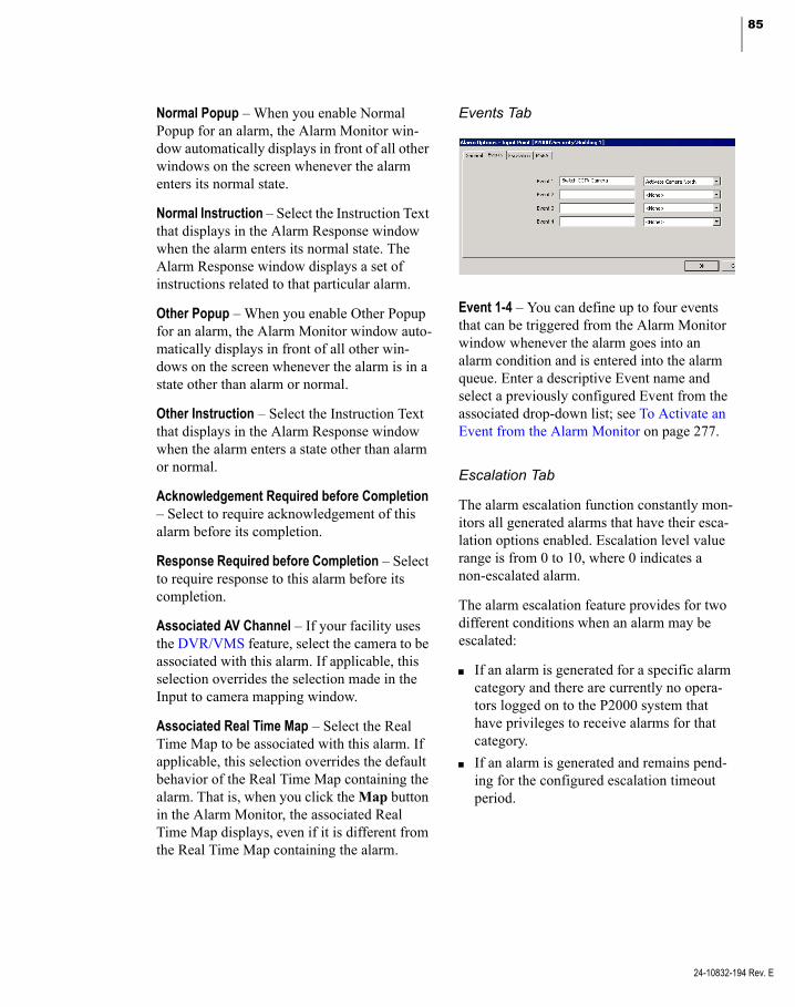
85
Normal Popup – When you enable Normal Popup for an alarm, the Alarm Monitor win-dow automatically displays in front of all other windows on the screen whenever the alarm enters its normal state.
Normal Instruction – Select the Instruction Text that displays in the Alarm Response window when the alarm enters its normal state. The Alarm Response window displays a set of instructions related to that particular alarm.
Other Popup – When you enable Other Popup for an alarm, the Alarm Monitor window auto-matically displays in front of all other win-dows on the screen whenever the alarm is in a state other than alarm or normal.
Other Instruction – Select the Instruction Text that displays in the Alarm Response window when the alarm enters a state other than alarm or normal.
Acknowledgement Required before Completion – Select to require acknowledgement of this alarm before its completion.
Response Required before Completion – Select to require response to this alarm before its completion.
Associated AV Channel – If your facility uses the DVR/VMS feature, select the camera to be associated with this alarm. If applicable, this selection overrides the selection made in the Input to camera mapping window.
Associated Real Time Map – Select the Real Time Map to be associated with this alarm. If applicable, this selection overrides the default behavior of the Real Time Map containing the alarm. That is, when you click the Map button in the Alarm Monitor, the associated Real Time Map displays, even if it is different from the Real Time Map containing the alarm.
Events Tab
Event 1-4 – You can define up to four events that can be triggered from the Alarm Monitor window whenever the alarm goes into an alarm condition and is entered into the alarm queue. Enter a descriptive Event name and select a previously configured Event from the associated drop-down list; see To Activate an Event from the Alarm Monitor on page 277.
Escalation Tab
The alarm escalation function constantly mon-itors all generated alarms that have their esca-lation options enabled. Escalation level value range is from 0 to 10, where 0 indicates a non-escalated alarm.
The alarm escalation feature provides for two different conditions when an alarm may be escalated:
If an alarm is generated for a specific alarm category and there are currently no opera-tors logged on to the P2000 system that have privileges to receive alarms for that category.
If an alarm is generated and remains pend-ing for the configured escalation timeout period.
24-10832-194 Rev. E

86 CHAPTER 2
Configuring the System
24-10832-194 Rev. E
If either of these conditions occurs, that alarm is regenerated with an elevated escalation level. The escalation level is incremented by the configured escalation increment value. This process may be repeated multiple times until a high enough escalation level is reached that matches the privileges of a currently logged on operator. If no operators are logged on to the P2000 system, the alarm is regener-ated until the maximum escalation level is reached, and then no further action is taken.
After an escalated alarm has been completed, the next occurrence of that alarm is created with no escalation level.
Enable – Select to enable alarm escalation.
Escalation Repeat – Select to allow escalation to occur more than once for the alarm. For example, if the Escalation Timeout is set to 30 minutes, and the Escalation Increment is set to 2, every half an hour the escalation value for alarms remaining in pending state goes up by 2 until it reaches the maximum value. If this check box is not selected, escalation can occur only once for this alarm. To avoid the delay when the alarm cannot be seen and actioned by an active operator, click the Escalation based upon visibility check box.
Escalation based upon visibility – If selected, the alarm is immediately escalated by a defined increment if, at the time of occurrence, no operator able to receive alarms from this Alarm Category is logged on. This includes operators that are logged on to the Web UI Alarm Manager interface via a browser.
Escalation Timeout (1 to 1440 minutes) – Enter the time period (in minutes) after which an alarm remaining in pending state is escalated by the Escalation Increment.
Escalation Increment (1 to 10) – Enter the value by which to escalate an alarm each time the escalation takes place.
MSEA Tab
In facilities that use the Metasys system, this feature allows an alarm that is forwarded to the Metasys system to contain an embedded refer-ence to a Metasys graphic. For more informa-tion, see Defining MSEA Graphics on page 368.
Select from the drop-down list the MSEA Graphic to reference in this alarm. When an alarm is received and displayed by the Metasys system, the Metasys operator can simply click the alarm to display the graphic item associ-ated with the alarm and the item that caused the alarm.
I/O Linking Tab
Use the I/O Linking tab to link I/O Types to specific output groups. You must define output groups in the Output Group dialog box before you can use this function. See Create Output Points and Groups on page 80 for detailed information.
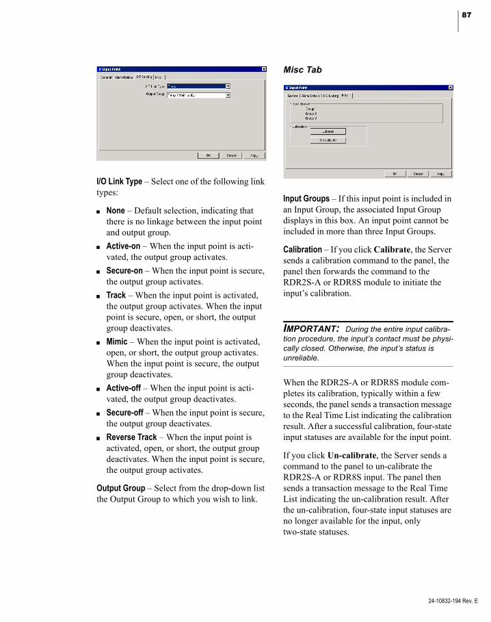
87
I/O Link Type – Select one of the following link types:
None – Default selection, indicating that there is no linkage between the input point and output group.
Active-on – When the input point is acti-vated, the output group activates.
Secure-on – When the input point is secure, the output group activates.
Track – When the input point is activated, the output group activates. When the input point is secure, open, or short, the output group deactivates.
Mimic – When the input point is activated, open, or short, the output group activates. When the input point is secure, the output group deactivates.
Active-off – When the input point is acti-vated, the output group deactivates.
Secure-off – When the input point is secure, the output group deactivates.
Reverse Track – When the input point is activated, open, or short, the output group deactivates. When the input point is secure, the output group activates.
Output Group – Select from the drop-down list the Output Group to which you wish to link.
Misc Tab
Input Groups – If this input point is included in an Input Group, the associated Input Group displays in this box. An input point cannot be included in more than three Input Groups.
Calibration – If you click Calibrate, the Server sends a calibration command to the panel, the panel then forwards the command to the RDR2S-A or RDR8S module to initiate the input’s calibration.
IMPORTANT: During the entire input calibra-tion procedure, the input’s contact must be physi-cally closed. Otherwise, the input’s status is unreliable.
When the RDR2S-A or RDR8S module com-pletes its calibration, typically within a few seconds, the panel sends a transaction message to the Real Time List indicating the calibration result. After a successful calibration, four-state input statuses are available for the input point.
If you click Un-calibrate, the Server sends a command to the panel to un-calibrate the RDR2S-A or RDR8S input. The panel then sends a transaction message to the Real Time List indicating the un-calibration result. After the un-calibration, four-state input statuses are no longer available for the input, only two-state statuses.
24-10832-194 Rev. E

88 CHAPTER 2
Configuring the System
24-10832-194 Rev. E
TIP: Once an input is calibrated, you do not need to use this feature again, unless you change the controller hardware or the input point’s wiring.
Note: RDR2S-A and RDR8S modules with optional calibration resistors attached automati-cally use this reference for calibration. Inputs cali-brated in this way do not need to be secured at the time of calibration.
Configuring Reader Terminal Hardwired Input Points
When a reader terminal is created, three input points are reserved for specific inputs: input points for reader terminal door contact points (these have to be configured in the Soft Alarm window; see Configure Soft Alarms on page 93), and an input point for a terminal down input point. In the following example, Input Points Forced Door Office Entry Reader, Propped Door Office Entry Reader, and Term Down Office Entry Reader were created for the Office Entry Reader terminal in the Ware-house panel.
Using Reader Terminal Door Contact Input Points
When you configure a reader terminal and enable the Forced Door, Propped Door option in the Edit Soft Alarm window, the sys-tem creates the Input Points icon with two entries beneath it. The first input point, named Forced Door <terminal name> is created for input point 18. The second input point, named Propped Door <terminal name> is created for input point 24. You can use these input points as a door contact alarm. If enabled in the Input Point dialog box, these input points report to the Alarm Queue and Real Time List if the door contact is broken, or if left open longer than the configured alarm suppression for the reader.
To Edit a Reader Terminal Door Contact Input Point
1. Select the Forced Door or Propped Door <terminal name> icon under the reader ter-minal you wish to configure and click Edit to open the Input Point dialog box. If Forced Door was selected, input point 18 displays in the Number field. If Propped Door was selected, input point 24 displays in the Number field. These are hardwired to points 18 or 24 on the reader terminal.
2. Enter the information on each tab as you do for any other input point.
3. Click OK to save your settings and return to the System Configuration window.
Note: If you rename a terminal that has a Forced Door or Propped Door input point, you must edit the input points to manually enter the new terminal name, as in Forced Door <terminal name> or Propped Door <terminal name>. As an alternative, you could also disable the Forced Door, Propped Door in the Soft Alarm window and then enable it again to automatically create the input points under the new terminal name.
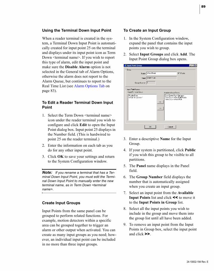
89
Using the Terminal Down Input Point
When a reader terminal is created in the sys-tem, a Terminal Down Input Point is automati-cally created for input point 25 on the terminal and displays under its input point icon as Term Down <terminal name>. If you wish to report this type of alarm, edit the input point and make sure the Disable Alarm option is not selected in the General tab of Alarm Options, otherwise the alarm does not report to the Alarm Queue, but continues to report to the Real Time List (see Alarm Options Tab on page 83).
To Edit a Reader Terminal Down Input Point
1. Select the Term Down <terminal name> icon under the reader terminal you wish to configure and click Edit to open the Input Point dialog box. Input point 25 displays in the Number field. (This is hardwired to point 25 on the reader terminal.)
2. Enter the information on each tab as you do for any other input point.
3. Click OK to save your settings and return to the System Configuration window.
Note: If you rename a terminal that has a Ter-minal Down Input Point, you must edit the Termi-nal Down Input Point to manually enter the new terminal name, as in Term Down <terminal name>.
Create Input Groups
Input Points from the same panel can be grouped to perform related functions. For example, motion detectors within a specific area can be grouped together to trigger an alarm or other output when activated. You can create as many input groups as you need; how-ever, an individual input point can be included in no more than three input groups.
To Create an Input Group
1. In the System Configuration window, expand the panel that contains the input points you wish to group.
2. Select Input Groups and click Add. The Input Point Group dialog box opens.
3. Enter a descriptive Name for the Input Group.
4. If your system is partitioned, click Public if you wish this group to be visible to all partitions.
5. The Panel name displays in the Panel field.
6. The Group Number field displays the number that is automatically assigned when you create an input group.
7. Select an input point from the Available Input Points list and click << to move it to the Input Points in Group list.
8. Select all the input points you wish to include in the group and move them into the group list until all have been added.
9. To remove an input point from the Input Points in Group box, select the input point and click >>.
24-10832-194 Rev. E
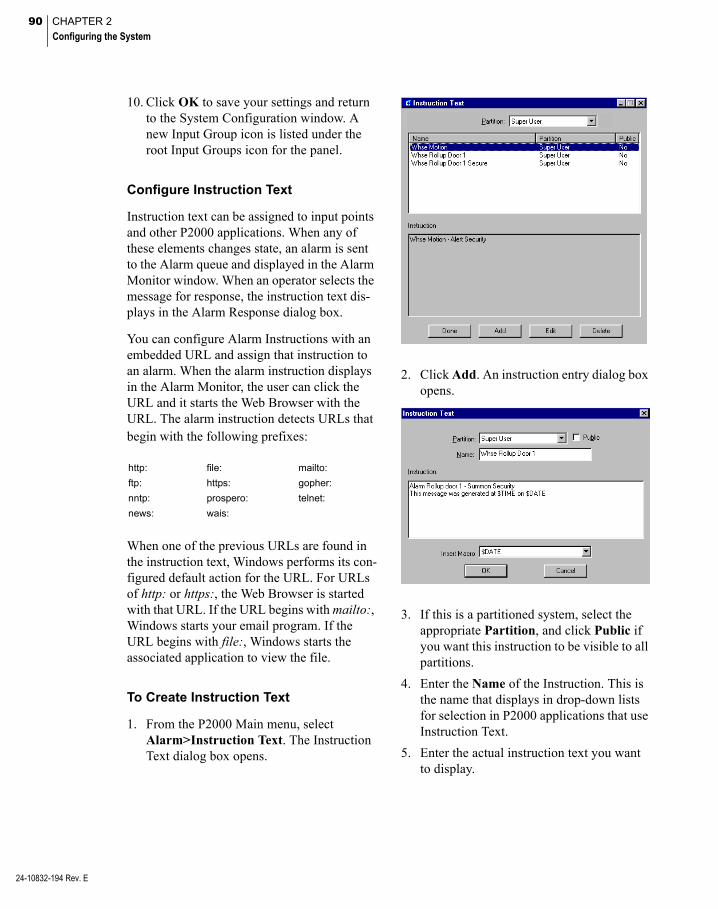
90 CHAPTER 2
Configuring the System
24-10832-194 Rev. E
10. Click OK to save your settings and return to the System Configuration window. A new Input Group icon is listed under the root Input Groups icon for the panel.
Configure Instruction Text
Instruction text can be assigned to input points and other P2000 applications. When any of these elements changes state, an alarm is sent to the Alarm queue and displayed in the Alarm Monitor window. When an operator selects the message for response, the instruction text dis-plays in the Alarm Response dialog box.
You can configure Alarm Instructions with an embedded URL and assign that instruction to an alarm. When the alarm instruction displays in the Alarm Monitor, the user can click the URL and it starts the Web Browser with the URL. The alarm instruction detects URLs that begin with the following prefixes:
http: file: mailto:
ftp: https: gopher:
nntp: prospero: telnet:
news: wais:
When one of the previous URLs are found in the instruction text, Windows performs its con-figured default action for the URL. For URLs of http: or https:, the Web Browser is started with that URL. If the URL begins with mailto:, Windows starts your email program. If the URL begins with file:, Windows starts the associated application to view the file.
To Create Instruction Text
1. From the P2000 Main menu, select Alarm>Instruction Text. The Instruction Text dialog box opens.
2. Click Add. An instruction entry dialog box opens.
3. If this is a partitioned system, select the appropriate Partition, and click Public if you want this instruction to be visible to all partitions.
4. Enter the Name of the Instruction. This is the name that displays in drop-down lists for selection in P2000 applications that use Instruction Text.
5. Enter the actual instruction text you want to display.
91
6. If you wish to insert a macro to be part of the instruction text, select a macro from the Insert Macro drop-down list. See the following table.
Use Macro.... To Insert...
$ASCII(xxx) ASCII Character
$BADGE_DESCRIPTION Badge Description
$BADGE_NUMBER Badge Number
$BS Backspace
$CARDHOLDER_FIRSTNAME Cardholder’s First Name
$CARDHOLDER_LASTNAME Cardholder’s Last Name
$CARDHOLDER_NAME Cardholder’s First <space> Last Name
$CR Carriage Return
$DATE Today’s Date
$FF Form Feed
$INPUT_NAME Input Name
$INPUT_NUMBER Input Number
$LF Line Feed
$OPERATOR Operator Name
$PANEL_NAME Panel Name
$TAB TAB
$TERMINAL_NAME Terminal Name
$TIME Current Time
$UDF_x* User Defined Field
* The x must be replaced with the UDF order number. This macro is used with Host events, where the triggering message is directly associated with a Cardholder, such as an Access Grant message.
Note: Do not include macros in Instruction Text that is used in delayed event actions. The infor-mation needed for the macros is not available when the action is delayed. See Creating Actions on page 337.
7. Click OK to save the Instruction Text entry and return to the Instruction Text dia-log box. Click Done.
Configure Panel Card Events
Panel Card Events operate independently from the Server and therefore affect only the Panel for which they are configured. Panel Card Events are particularly useful for panels that operate offline, such as in areas that must remain operable if the network goes down.
Note: Panel Card Events are configured for each panel while System Events are configured for the Server. For more information on System Events, see Create Events on page 335.
A Panel Card Event is based on badge (trigger) activity and used to suppress or unsuppress an input group, activate or deactivate an output group, operate a door strike, and reset a panel alarm relay.
The following section presents steps to create Panel Card Events. To invoke panel card events using a keypad, see Appendix D: Using a Keypad Reader on CK721-A Panels.
To Create a Panel Card Event
1. From the System Configuration window, select the panel to which you wish to assign a Panel Card Event.
2. Select Panel Card Event and click Add. The Panel Card Event dialog box opens.
24-10832-194 Rev. E

92 CHAPTER 2
Configuring the System
24-10832-194 Rev. E
3. Enter the information according to the Panel Card Event Field Definitions.
4. When all information is added, click OK to save your settings and return to the System Configuration window.
Panel Card Event Field Definitions
Panel Card Event
Name – Enter a descriptive event name.
Panel – Displays the selected panel name.
Number – Enter an event number from 1 to 20.
Option
Privilege Level – This entry corresponds to the Cardholder’s privilege level (from 0 to 7, with 0 being the lowest). The Cardholder’s privilege level must be equal to or greater than the Privi-lege Level defined here to initiate the event; see Entering Badge Information on page 251 for more information.
Trigger Type – Indicates the condition that trig-gers this card event. Select one of the follow-ing:
Card Only – Present badge. This trigger type does not generate Invalid Event Privilege Level messages.
Card/PIN Code – Enter PIN code, then pres-ent badge.
Card/Keypad Code – Enter activation or deactivation code, followed by the code specified in the Keypad Code field, then present badge.
Card/PIN/Keypad Code – Enter PIN and acti-vation or deactivation code, followed by the keypad code, then present badge.
Any Void Card – Present any void badge (a badge that does not provide access to the door). In this case the card event’s privilege level should be set to 0, as void badges do not have any privilege level. For this condi-tion to trigger a card event with a consistent behavior, the terminal should run in Local mode. The card event may not be triggered on terminals running on Shared mode, depending on the generated card message.
Special Access Flags – Select one of the three Special Access flags A, B, or C that can trigger this card event. The list displays the special access flag names as configured in Site Parameters. Special access condi-tions are set up in the Access tab of the ter-minal dialog box; see page 72.
Note: If Allow PIN after Badge is enabled in the Terminal dialog box, the cardholder can enter the PIN number after presenting the badge; see page 67 for more information.
Keypad Code – Enter a four-digit keypad code that must be entered to activate or deactivate the event. Deactivating an event can only accomplished by using a keypad code.

93
Event Duration – Enter the duration, in minutes that the event is active (up to 1440 minutes). If the event activates an output group, the output group is deactivated after this time period. If the event suppresses an input group, the input group is unsuppressed after this time period. Event duration applies only to event activa-tion, and not to event deactivation. Further-more, only output group activation and input group suppression may be assigned a duration, but not output group deactivation and input group unsuppression.
Input Group
Enable – Click to enable the Input Group Sup-pression function.
Suppress – Click to suppress the specific Input Group when this event is activated. Do not select Suppress to unsuppress the specific Input Group when this event is activated. When this event is deactivated, the selected action is inverted; that is, an event that suppresses an input group on activation, unsuppresses that input group on deactivation, and an event that unsuppresses an input group on activation, sup-presses that input group on deactivation.
Input Group – Select the name of the Input Group that can be suppressed or unsuppressed.
Output Group
Enable – Click to enable the Output Group Activate function.
Activate – Click to activate the specific Output Group when this event is activated. Do not select Activate to deactivate the specific Out-put Group when this event is activated. When this event is deactivated, the selected action is inverted; that is, an event that activates an out-put group on activation, deactivates that output group on deactivation, and an event that deac-tivates an output group on activation, activates that output group on deactivation.
Output Group – Select the name of the Output Group that can be activated or deactivated.
Misc.
Operate Door Strike – If not selected, a valid event invokes the event action only, but does not unlock the door. This setting does not apply to badges with executive privilege. Also, events with trigger type Any Void Card never unlock the door.
Reset Panel Alarm Relay (Acknowledge Alarm) – If selected, the panel alarm relay is reset.
Note: If a panel card event is created for CK721-A panels and none of the boxes to sup-press output points or strike readers are enabled, the panel card event still shows in the Real Time List, as an activated event.
Valid Readers for Current Event
The terminals connected to this panel display in the list. Select those terminals that are used to initiate this card event. Select terminals run-ning in Local mode; the card event may not be triggered on terminals running on Shared mode. Terminals not selected are not affected by the event.
Configure Soft Alarms
Soft alarm points and their addresses are cre-ated by the system during installation rather than hardwired to an actual input point. You can enable these soft alarms for readers or panels.
The alarm point numbers may be different, depending on the type of panel selected.
To Enable Soft Alarms
1. From the System Configuration window, select the Panel for which you wish to enable soft alarms.
24-10832-194 Rev. E

94 CHAPTER 2
Configuring the System
24-10832-194 Rev. E
2. Select Soft Alarm and click Edit. The Edit Soft Alarm dialog box opens.
3. Select the Reader or Panel Soft Alarms you wish to enable, and click the corre-sponding Relay box to activate the panel relay. See Soft Alarms Field Definitions for detailed information.
Note: Make sure the Set Panel Relay When Active check box is selected in the Input Point dialog box to activate the relay on the panel when the input point is activated, see Input Point Field Definitions on page 82.
4. Click OK to save your settings and return to the System Configuration window.
Soft Alarms Field Definitions
Duress – If enabled, an alarm is generated when an authorized cardholder reverse-swipes the badge, provided that the terminals’ Reverse Swipe Duress feature is enabled, or substitutes a 9 for one of their PIN code digits. The PIN is used with the badge and grants access to avoid compromising the personal safety of the card-holder. The panel relay for a duress alarm is only activated when the reader is either in Local mode, or in Shared mode and the panel knows the badge.
PIN Code Retry – When enabled, an alarm is generated when three consecutive invalid PIN codes are entered at a keypad reader.
Note: If you enable the Relay box associated with a Duress or PIN Code Retry alarm to activate the panel relay, you must also enable the Latch Output option on the Alarm tab of the Edit Panel dialog box; see page 58.
Forced Door/Propped Door – If enabled, a Forced Door alarm message is printed when-ever there is a door open condition without a valid badge read detected first; and a Propped Door alarm message is printed whenever there is a door open condition with a valid badge, but the door is left open past the entry time.
Soft In-X-It – If enabled, the Soft In-X-It over-rides the system In-X-It control function for a specified reader and allows cardholders to gain access at that reader even though they have the wrong In-X-It status. An alarm is generated when a violation occurs.
Panel Lost AC – Used with the UPS option, this soft alarm sends an alarm if the panel loses power. For this to work, you must follow the wiring instructions provided in the CK721-A hardware manual.
Panel Low Battery – With UPS equipped pan-els, an alarm is sent when the battery in the panel is low.
Panel Tamper – The panel has an internal hard-ware connection for its own enclosure tamper switch that generates a special message when-ever the enclosure is opened or closed.
Report on Terminal – Select a terminal from the drop-down list. This is the actual terminal con-nection associated with the Soft Alarm and is used for panel soft alarms only.

95
Configure OSI Panels and Components
IMPORTANT: This release of the P2000 soft-ware is compatible with Stanley® Wi-Q™ Version 3.00.38, Portal Firmware Version 3.0.17.155, and Reader Version 3.00.039. Older versions of the OSI software are not compatible with this P2000 release.
Use this section to configure your P2000 sys-tem to communicate with OSI Wireless Access Management Solutions (WAMS) hardware. It is assumed that the OSI hardware is already installed before you can configure and use the essential functions described in this section. Refer to the OSI documentation for hardware installation instructions and to the P2000 Soft-ware Installation Manual for instructions asso-ciated with the installation of the OSI Interface software.
IMPORTANT: The installation of the Stanley Wi-Q software must follow some specific instruc-tions. Contact Technical Support for detailed instructions.
The OSI Interface that resides on the P2000 Server is called P2000 OSI Interface Service, and provides an interface between the P2000 system and Stanley OSI OMNILOCK® 2000 Series readers. This integration allows P2000 operators to configure and control OSI readers to provide badge access. Transactions and alarm messages associated with these readers are sent to the Alarm Monitor and the Real Time List.
The OSI hardware consists of a Portal Gate-way that provides wireless communications to the individual readers.
The portal gateway communicates with the P2000 Server via standard 10/100Base-T Ethernet connectors. The transmit range from portal gateway to reader is typically 150 to 300 feet. Each portal gateway supports up to 128 readers. The wireless reader performs the actual access validation and can support up to 65,000 badges. The OSI interface has no hard limit on the number of portal gateways but enforces the existing P2000 limits on the num-ber of readers.
The portal gateway includes a built-in Web server that provides a simple easy-to-use user interface for configuring the portal, monitoring the status of the portal, and updating the firm-ware loaded into the portal and the readers.
Unsupported OSI Features
The following OSI system features are not compatible with the P2000 system architecture:
Access and Shunt Time per Badge
PIN Expiration Dates
Unlock with ID access mode
OSI I/O modules
Unsupported P2000 Features
The following P2000 system features are not supported by the OSI system:
Extensive badge specific time-controlled access rights (see Badge Access Rights on page 97 for more information)
Quick detection of hardware offline
System Architecture
The communication to the OSI portal gateway is performed by the OSI Web Service, which is installed with the OSI Interface. The portal gateway in turn provides the wireless commu-nication path to the individual OSI readers.
24-10832-194 Rev. E
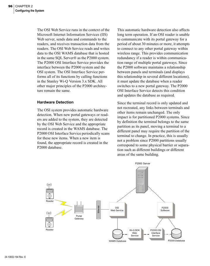
96 CHAPTER 2
Configuring the System
24-10832-194 Rev. E
The OSI Web Service runs in the context of the Microsoft Internet Information Services (IIS) Web server, sends data and commands to the readers, and receives transaction data from the readers. The OSI Web Service reads and writes data to the OSI WAMS database that is hosted in the same SQL Server® as the P2000 system. The P2000 OSI Interface Service provides the interface between the P2000 system and the OSI system. The OSI Interface Service per-forms all of its functions by calling functions in the Stanley Wi-Q Version 3.x SDK. All other major principles of the P2000 architec-ture remain the same.
Hardware Detection
The OSI system provides automatic hardware detection. When new portal gateways or read-ers are added to the system, they are detected by the OSI Web Service and the appropriate record is created in the WAMS database. The P2000 OSI Interface Service periodically scans for these new items. When a new item is found, the appropriate record is created in the P2000 database.
This automatic hardware detection also affects long term operation. If an OSI reader is unable to communicate with its portal gateway for a period of about 30 minutes or more, it attempts to connect to any other portal gateway within wireless range. This provides communication redundancy if a reader is within communica-tion range of multiple portal gateways. Since the P2000 software maintains a relationship between panels and terminals (and displays this relationship in several different locations), it must update the database when a reader switches to a new portal gateway. The P2000 OSI Interface Service detects this condition and updates the database as required.
Since the terminal record is only updated and not recreated, any links between terminals and other items remain unchanged. The only impact is for partitioned P2000 systems. Since by definition the terminal belongs to the same partition as its panel, moving a terminal to a different panel may require the partition of the terminal to change. In practice, this is usually not a problem since P2000 partitions usually correspond to some physical barrier or separa-tion such as different buildings or different areas of the same building.
P2000 Server
Eth
erne
t
P2000Software
P2000 OSI Interface Service
WAMS Database P2000 Database
OSIWeb Service
Portal Gateway
Reader
Reader Wi-Q SDKWeb
Service

97
In most cases the physical separation between these areas prevents readers from communicat-ing with portals in other partitions.
Badge Access Rights
The P2000 software defines access rights for individual badges through multiple pairs of Access Groups and Timezones. OSI readers do not support this model of badge access rights. The OSI model consists of a list of readers that a badge has rights to use at any time in combi-nation with membership in up to 32 User Groups. Since the P2000 system operates with a set of badge access rights across multiple types of controllers and readers, the P2000 OSI Facility Edit application is provided to configure these settings.
Using the OSI Facility Edit application, a P2000 operator can configure up to 32 pairs of Access Groups and Timezones as Facility Access Groups. These Facility Access Group pairs correspond to OSI User Groups. When Access Groups and Timezone pairs are assigned to an individual badge (using the Badge application), the Timezone values are ignored unless the Access Group has been configured as an OSI Facility Access Group. If the Access Group corresponds to an existing OSI Facility Access Group, then the Timezone configured for the Facility Access Group defines the time when access is allowed. If the Access Group is not defined as a Facility Access Group, then the badge is granted access on a 24/7 basis.
Configuration Sequence
Once the hardware is installed, we recommend the following configuration sequence:
Configure OSI Facility Parameters
Add New Portals
Configure OSI Panels
Configure OSI Terminals
Configure OSI Facility Parameters
Before bringing any OSI hardware online, the OSI Facility record must be added to the P2000 database. The OSI Facility record defines settings that control all OSI portal gateways and wireless readers connected to a single P2000 server.
To Configure OSI Facility Parameters
1. From the P2000 Main menu, select Con-fig>System. Enter your password if prompted. The System Configuration win-dow opens.
2. Expand Panels to display the panel types.
3. Expand OSI Panels to open the OSI com-ponents.
Note: If the OSI Panels branch does not dis-play, you need to enable the OSI panel type in the Panel Types Tab of Site Parameters. This should only be necessary if you have upgraded from a previous version of the P2000 software.
4. Select OSI Facility and click Add. The OSI Facility Edit dialog box opens at the General tab.
5. Fill in the information on each tab accord-ing to the following OSI Facility Field Definitions.
6. As you work through the tabs, you may click Apply at any time to save your entries.
7. After you have entered all the information, click OK to save the settings and return to the System Configuration window.
24-10832-194 Rev. E
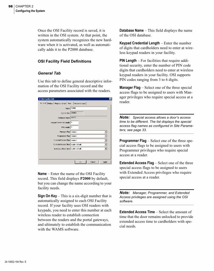
98 CHAPTER 2
Configuring the System
24-10832-194 Rev. E
Once the OSI Facility record is saved, it is written in the OSI system. At that point, the system automatically recognizes the new hard-ware when it is activated, as well as automati-cally adds it to the P2000 database.
OSI Facility Field Definitions
General Tab
Use this tab to define general descriptive infor-mation of the OSI Facility record and the access parameters associated with the readers.
Name – Enter the name of the OSI Facility record. This field displays P2000 by default, but you can change the name according to your facility needs.
Sign On Key – This is a six-digit number that is automatically assigned to each OSI Facility record. If your facility uses OSI readers with keypads, you need to enter this number at each wireless reader to establish connection between the readers and the portal gateways, and ultimately to establish the communication with the WAMS software.
Database Name – This field displays the name of the OSI database.
Keypad Credential Length – Enter the number of digits that cardholders need to enter at wire-less keypad readers in your facility.
PIN Length – For facilities that require addi-tional security, enter the number of PIN code digits that cardholders need to enter at wireless keypad readers in your facility. OSI supports PIN codes ranging from 3 to 6 digits.
Manager Flag – Select one of the three special access flags to be assigned to users with Man-ager privileges who require special access at a reader.
Note: Special access allows a door’s access time to be different. The list displays the special access flag names as configured in Site Parame-ters; see page 33.
Programmer Flag – Select one of the three spe-cial access flags to be assigned to users with Programmer privileges who require special access at a reader.
Extended Access Flag – Select one of the three special access flags to be assigned to users with Extended Access privileges who require special access at a reader.
Note: Manager, Programmer, and Extended Access privileges are assigned using the OSI software.
Extended Access Time – Select the amount of time that the door remains unlocked to provide extended access time to cardholders with spe-cial needs.

99
Extended Shunt Time – Select the amount of time that the door alarm is suppressed to allow access to cardholders with special needs. The Extended Shunt Time must exceed the Extended Access Time.
Note: The reader default option in the Extended Access Time and the Extended Shunt Time is the time defined at the Access tab of the OSI Terminal Edit dialog box; see page 106 for details.
Badges Tab
Use this tab to define the badge formats and type that can be used at all OSI readers. In addition, if the OSI readers do not have key-pads, you need to enter the Reader Sign On Badge information to be used at your facility.
Primary Badge Format – Click the [...] button and select the primary badge format to be used at your facility. The P2000 software provides badge formats that are located in the \Program Files (x86)\Johnson Controls\P2000\ BadgeFormats folder. If a different format is needed, create a new badge format file by using the P2000 Badge Format tool; see page 193 for details.
Use Secondary Badge Format – Click if your facility uses a secondary badge format.
Secondary Badge Format – Click the [...] but-ton and select the secondary badge format to be used at your facility.
Badge Type – Select the badge type to be used at your facility. Options are: Prox Badge, Mag Stripe Badge, and Smart Card Badge.
Create Keypad Credential – Keypad Credential numbers are codes stored in every badge and allow you to identify the badges that belong to your facility. Click if you wish to automati-cally assign these codes to all badges in your facility that can be used with OSI wireless readers.
Reader Sign On Badge
If your facility uses OSI readers with no key-pads, you can create a master badge that can be assigned with a facility number. This badge can be used to establish communication between the readers and the software.
Number – Enter a badge number that can be used for the facility number. This badge num-ber does not need to be a valid P2000 badge assigned to a cardholder.
Issue – Select the issue level from 0 to 255 to use for the facility number.
Facility Code – Enter the facility code number to use for the facility.
24-10832-194 Rev. E

100 CHAPTER 2
Configuring the System
24-10832-194 Rev. E
Magnetic Stripe Tab
If your facility uses Magnetic Stripe cards, use this tab to configure the software to accept the card types and settings. Default settings are sufficient for most systems.
Card Track – Select Track 2 or Track 3 mag-netic cards. The system can be used with either Track 2 or 3 cards; however, you cannot use both types within the same facility. Most users use Track 2 cards and do not need to set up any type of advanced card parameters.
Card Track Limit – There is a limitation on the number of characters for each track. These characters include any digits and field separa-tors; however, they exclude the starting and ending sentinels. The maximum number of characters that the system can read on Track 2 is 26 characters; Track 3 can read up to 70 characters. The P2000 software does not enforce these limits.
Expiration Date Format – Select the card expi-ration date format.
Expiration Date Position – Enter the position in the card of the expiration date field.
Expiration Date Position Type – Select if the position type is a Character, a Field, or Unused.
Expiration Date Valid – Select if the expiration date is valid Thru Expiration Date (includes the day of expiration), or To Expiration Date (expires at midnight the previous day).
Facility Code – Enter the facility code number to assign to your cards.
Facility Code Position – Enter the position in the card of the facility code field.
Facility Code Position Type – Select if the posi-tion type is a Character, a Field, or Unused.
Issue Number Position – Enter the position in the card of the issue number field.
Issue Number Position Type – Select if the posi-tion type is a Character, a Field, or Unused.
ID Position – Enter the position in the card of the ID field.
ID Position Type – Select if the position type is a Character, a Field, or Unused.
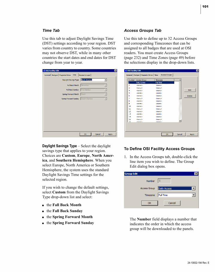
101
Time Tab
Use this tab to adjust Daylight Savings Time (DST) settings according to your region. DST varies from country to country. Some countries may not observe DST, while in many other countries the start dates and end dates for DST change from year to year.
Daylight Savings Type – Select the daylight savings type that applies to your region. Choices are Custom, Europe, North Amer-ica, and Southern Hemisphere. When you select Europe, North America or Southern Hemisphere, the system uses the standard Daylight Savings Time settings for the selected region.
If you wish to change the default settings, select Custom from the Daylight Savings Type drop-down list and select:
the Fall Back Month
the Fall Back Sunday
the Spring Forward Month
the Spring Forward Sunday
Access Groups Tab
Use this tab to define up to 32 Access Groups and corresponding Timezones that can be assigned to all badges that are used at OSI readers. You must create Access Groups (page 232) and Time Zones (page 49) before the selections display in the drop-down lists.
To Define OSI Facility Access Groups
1. In the Access Groups tab, double-click the line item you wish to define. The Group Edit dialog box opens.
The Number field displays a number that indicates the order in which the access group will be downloaded to the panels.
24-10832-194 Rev. E
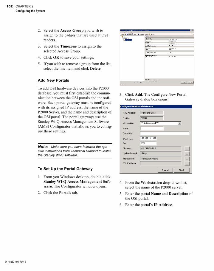
102 CHAPTER 2
Configuring the System
24-10832-194 Rev. E
2. Select the Access Group you wish to assign to the badges that are used at OSI readers.
3. Select the Timezone to assign to the selected Access Group.
4. Click OK to save your settings.
5. If you wish to remove a group from the list, select the line item and click Delete.
Add New Portals
To add OSI hardware devices into the P2000 database, you must first establish the commu-nication between the OSI portals and the soft-ware. Each portal gateway must be configured with its assigned IP address, the name of the P2000 Server, and the name and description of the OSI portal. The portal gateways use the Stanley Wi-Q Access Management Software (AMS) Configurator that allows you to config-ure these settings.
Note: Make sure you have followed the spe-cific instructions from Technical Support to install the Stanley Wi-Q software.
To Set Up the Portal Gateway
1. From you Windows desktop, double-click Stanley Wi-Q Access Management Soft-ware. The Configurator window opens.
2. Click the Portals tab.
3. Click Add. The Configure New Portal Gateway dialog box opens.
4. From the Workstation drop-down list, select the name of the P2000 server.
5. Enter the portal Name and Description of the OSI portal.
6. Enter the portal’s IP Address.
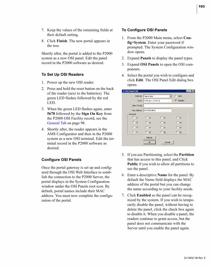
103
7. Keep the values of the remaining fields at their default setting.
8. Click Finish. The new portal appears in the tree.
Shortly after, the portal is added to the P2000 system as a new OSI panel. Edit the panel record in the P2000 software as desired.
To Set Up OSI Readers
1. Power up the new OSI reader.
2. Press and hold the reset button on the back of the reader (next to the batteries). The green LED flashes followed by the red LED.
3. When the green LED flashes again, enter 5678 followed by the Sign On Key from the P2000 OSI Facility record, see the General Tab on page 98.
4. Shortly after, the reader appears in the AMS Configurator and then in the P2000 system as a new OSI terminal. Edit the ter-minal record in the P2000 software as desired.
Configure OSI Panels
Once the portal gateway is set up and config-ured through the OSI Web Interface to estab-lish the connection to the P2000 Server, the portal displays in the System Configuration window under the OSI Panels root icon. By default, portal names include their MAC address. You must now complete the configu-ration of the portal.
To Configure OSI Panels
1. From the P2000 Main menu, select Con-fig>System. Enter your password if prompted. The System Configuration win-dow opens.
2. Expand Panels to display the panel types.
3. Expand OSI Panels to open the OSI com-ponents.
4. Select the portal you wish to configure and click Edit. The OSI Panel Edit dialog box opens.
5. If you use Partitioning, select the Partition that has access to this panel, and Click Public if you wish to allow all partitions to see the panel.
6. Enter a descriptive Name for the panel. By default the Name field displays the MAC address of the portal but you can change the name according to your facility needs.
7. Click Enabled so the panel can be recog-nized by the system. If you wish to tempo-rarily disable the panel, without having to delete the panel, click the check box again to disable it. When you disable a panel, the readers continue to grant access, but the panel does not communicate with the Server until you enable the panel again.
24-10832-194 Rev. E

104 CHAPTER 2
Configuring the System
24-10832-194 Rev. E
8. The Query String value is used with mes-sage filtering (see Define Query String Fil-ters on page 225).
9. The Mac Address field displays the Media Access Control address automatically assigned to the portal.
10. Select from the Channels box, the Radio Frequency (RF) channels or frequency bands that this panel uses to communicate with the readers.
11. The Reboot button is provided to restart the portal; for example, if the portal is not responding or to recover from an error.
12. Click OK to save your entries.
After you create the OSI panel, the system automatically creates a Panel Down soft input point for input point 25 and displays it under the Soft Input Points icon. If you wish to report this type of alarm, edit the input point and make sure the Disable Alarm option is not selected in the General tab of Alarm Options, otherwise the alarm does not report to the Alarm Queue, but continues to report to the Real Time List (see Alarm Options Tab on page 83).
Configure OSI Terminals
After a portal is up and functional, you can add new readers to the system. A new reader needs to be enrolled into the OSI system to become functional. The enrollment process is different for readers that have keypads and readers that do not.
Readers with Keypads – For a reader with a keypad, you must enter the Sign On Key from the P2000 OSI Facility record into the keypad; see page 98. To place the reader into enroll-ment mode, enter 5678 on the keypad. A green light on the reader flashes three times. Within five to six seconds, enter the six-digit Sign On Key from the OSI Facility record. The reader goes through a sequence of alternating red and green lights and should finish with three green flashes. That means the reader successfully communicated with the portal.
Readers without Keypads – For a reader with-out a keypad, the reader is placed into enroll-ment mode by presenting the default badge that was included in your package from OSI. Within five to six seconds, present the badge that was defined in the Reader Sign On Badge box of the OSI Facility record; see page 99. The reader goes through a sequence of alter-nating red and green lights and should finish with three green flashes. That means the reader successfully communicated with the portal.
After a successful sign on, the reader should be detected and automatically added to the P2000 database as a new terminal. Note that the Real Time List displays messages associated with the new OSI components.
Each reader installed in your system must be set up and configured in the P2000 software to establish communication and control. Once Terminals are configured, they may be included in Terminal Groups to provide com-mon access throughout your facility.
To Create OSI Terminals
1. In the System Configuration window, expand Panels to display the panel types.
2. Expand OSI Panels. All OSI portals cur-rently configured in the system are listed.

105
3. Expand the portal that contains the readers you wish to configure.
4. Expand Terminals to display the readers that were successfully enrolled. By default, the reader names include their MAC address.
5. Select the reader you wish to configure and click Edit. The OSI Terminal Edit dialog box opens at the General tab. Enter the information in each tab according to your system requirements. See the following OSI Terminal Field Definitions for detailed information.
6. As you work through the tabs, you may click Apply to save your settings.
7. When all entries are complete, click OK to save your settings and return to the System Configuration window.
8. If you wish to group OSI terminals that provide common access, see Create Termi-nal Groups on page 78 for detailed instruc-tions.
After you create the OSI reader terminal, the system automatically creates three soft input points: Low Battery, Tamper, and Term Down. These input points display under the Input Points icon as Low Battery <reader name>, Tamper <reader name>, and Term Down <reader name>. If you wish to report the asso-ciated alarms, edit the input point and make sure the Disable Alarm option is not selected in the General tab of Alarm Options, otherwise the alarm does not report to the Alarm Queue, but continues to report to the Real Time List (see Alarm Options Tab on page 83). Also, if you rename the reader, you must edit the input point to manually enter the new reader name, as in Term Down <reader name>.
Note: The Tamper alarm for OSI soft input points is generated after five consecutive invalid credential attempts.
OSI Terminal Field Definitions
General Tab
Use this tab to enter general descriptive infor-mation of the OSI reader.
Name – Enter a descriptive Name for the ter-minal. By default the Name field displays the MAC address of the reader but you can change the name according to your facility needs.
Panel – This field displays the name of the por-tal you selected from the System Configura-tion window, which provides the wireless communication to the reader.
Query String – This value is used with message filtering (see Define Query String Filters on page 225).
Mac Address – This field displays the Media Access Control address automatically assigned to the reader.
24-10832-194 Rev. E

106 CHAPTER 2
Configuring the System
24-10832-194 Rev. E
Enable – Click if you wish the system to recog-nize this terminal.
Public – If you use Partitioning, click if you wish this terminal to be visible to all partitions.
Door Sensors – Click if your reader has the optional Door Sense Module for monitoring of the actual strike status.
Channels – Click the Radio Frequency (RF) channels or frequency bands that this terminal uses to communicate with the readers.
Access Tab
This tab defines the OSI reader’s time parame-ters.
Access Time – Select the amount of time that the door remains unlocked to provide access.
Shunt Time – Select the amount of time that the door alarm is suppressed to allow access at the door. The Shunt Time should be longer than the Access Time.
Statistics Update Interval – Select the frequency at which the reader sends messages to the por-tal gateway with signal strength, battery volt-age, external supply voltage and packet trans-fer ratio information.
Note: The smaller the interval, the greater the battery use. For a high volume area, you may want to keep the interval time at 1 minute to ensure adequate coverage. (You need to monitor battery use to ensure adequate power supply.) However, for little used areas, you can set the update interval up to 24 hours to preserve battery life.
Timezone Tab
The Timezone tab defines the time zones in which the OSI reader operates. Time Zones must be set up before they display in drop-down lists.
Badge Required – Select the time zone during which the reader requires a badge to allow access. If you do not wish to enable this func-tion, select <none - 24 hour enable> to allow access at all times.
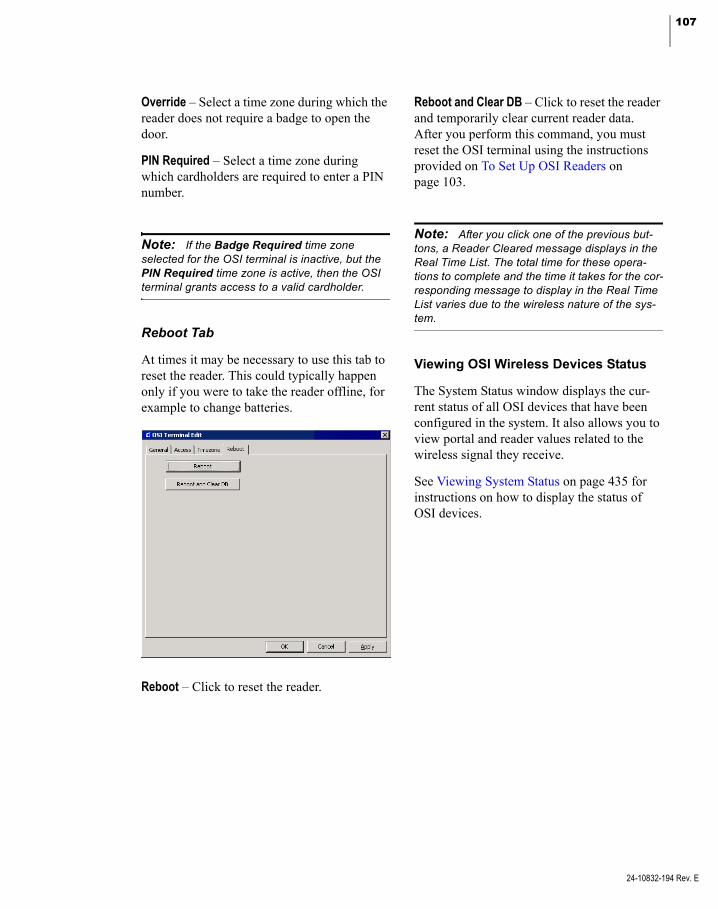
107
Override – Select a time zone during which the reader does not require a badge to open the door.
PIN Required – Select a time zone during which cardholders are required to enter a PIN number.
Note: If the Badge Required time zone selected for the OSI terminal is inactive, but the PIN Required time zone is active, then the OSI terminal grants access to a valid cardholder.
Reboot Tab
At times it may be necessary to use this tab to reset the reader. This could typically happen only if you were to take the reader offline, for example to change batteries.
Reboot – Click to reset the reader.
Reboot and Clear DB – Click to reset the reader and temporarily clear current reader data. After you perform this command, you must reset the OSI terminal using the instructions provided on To Set Up OSI Readers on page 103.
Note: After you click one of the previous but-tons, a Reader Cleared message displays in the Real Time List. The total time for these opera-tions to complete and the time it takes for the cor-responding message to display in the Real Time List varies due to the wireless nature of the sys-tem.
Viewing OSI Wireless Devices Status
The System Status window displays the cur-rent status of all OSI devices that have been configured in the system. It also allows you to view portal and reader values related to the wireless signal they receive.
See Viewing System Status on page 435 for instructions on how to display the status of OSI devices.
24-10832-194 Rev. E

108 CHAPTER 2
Configuring the System
24-10832-194 Rev. E
Configure S321-IP Panels and Components
Use this section to configure your P2000 sys-tem to communicate with S321-IP panels. S321-IP panels communicate with the P2000 Server using a standard TCP/IP network proto-col to provide badge access, alarm monitoring, history reporting, input/output linking, and card and system activated events.
The S321-IP is an advanced, intelligent, net-work panel capable of monitoring and con-trolling one or two fully configured doors. The S321-IP panel provides the ability to configure supervised 4-state inputs and unsupervised 2-state inputs. When interfacing to a single door, you can configure the unused points as general purpose input/output points.
It is assumed that the S321-IP hardware is already connected to the P2000 Server before you can configure and use the functions described in this section. Refer to the S321-IP Network Controller Hardware Installation Manual for hardware installation instructions.
S321-IP Naming Conventions
S321-IP panel components are named using a consistent naming scheme. Terminals, input, and output point are automatically allocated an identifying name. This name consists of a fixed description of the item (such as Term 1 for terminals or Panel Battery for inputs), plus the panel name. In the case of terminal input and output points, the name of the terminal is also appended to the input and output names, so that an input point for example, is recog-nized by its panel and terminal name.
You should logically name S321-IP panels, including information such as a panel’s loca-tion or what it controls, but bear in mind that the maximum number of characters allowed in an S321-IP component name is 32. When you use long panel names, you need to remember that a terminal input point name is <input name> <terminal name> <panel name> and therefore, that combination should not exceed 32 characters. If the combination does exceed 32 characters the resulting name is truncated to 32 characters.
IMPORTANT: Although the P2000 system allows S321-IP component names to have up to 32 characters, the S321-IP panel user interface only supports names of up to 16 bytes long.
Configure S321-IP Panels
To enable communication between the S321-IP panel and the P2000 Server, you have to configure the connection at both sides. First, you need to define the P2000 Server at the S321-IP panel, and then you need to enter the S321-IP information in the P2000 S321-IP Panel Edit dialog box.
Note: You must generate a Certificate using the S321-IP user interface to enable encrypted communications between the P2000 Server and the S321-IP panel.
Refer to the S321-IP Configuration and Oper-ation Manual to prepare the S321-IP panel for integration with the P2000 system.
Note: Because of S321-IP requirements, there must be at least one time zone available before creating or editing an S321-IP panel.
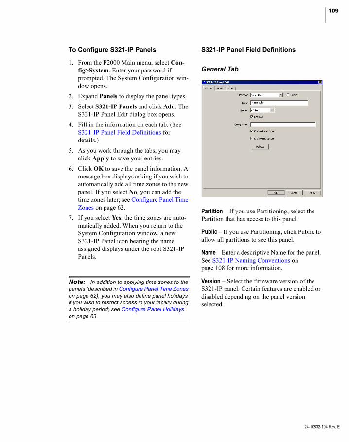
109
To Configure S321-IP Panels
1. From the P2000 Main menu, select Con-fig>System. Enter your password if prompted. The System Configuration win-dow opens.
2. Expand Panels to display the panel types.
3. Select S321-IP Panels and click Add. The S321-IP Panel Edit dialog box opens.
4. Fill in the information on each tab. (See S321-IP Panel Field Definitions for details.)
5. As you work through the tabs, you may click Apply to save your entries.
6. Click OK to save the panel information. A message box displays asking if you wish to automatically add all time zones to the new panel. If you select No, you can add the time zones later; see Configure Panel Time Zones on page 62.
7. If you select Yes, the time zones are auto-matically added. When you return to the System Configuration window, a new S321-IP Panel icon bearing the name assigned displays under the root S321-IP Panels.
Note: In addition to applying time zones to the panels (described in Configure Panel Time Zones on page 62), you may also define panel holidays if you wish to restrict access in your facility during a holiday period; see Configure Panel Holidays on page 63.
S321-IP Panel Field Definitions
General Tab
Partition – If you use Partitioning, select the Partition that has access to this panel.
Public – If you use Partitioning, click Public to allow all partitions to see this panel.
Name – Enter a descriptive Name for the panel. See S321-IP Naming Conventions on page 108 for more information.
Version – Select the firmware version of the S321-IP panel. Certain features are enabled or disabled depending on the panel version selected.
24-10832-194 Rev. E

110 CHAPTER 2
Configuring the System
24-10832-194 Rev. E
Enabled – The system does not recognize the panel unless you click Enabled. If you wish to temporarily disable the panel, without having to delete the panel, click the check box again to disable it. When you disable a panel, the read-ers continue to grant access, but the panel does not communicate with the Server until you enable the panel again.
Query String – This value is used with message filtering (see Define Query String Filters on page 225).
Enable Panel Inputs – Click to create two panel soft input points: Panel Tamper and Power Failure.
Enable Encryption – Click to allow encryption of all messaging between S321-IP panels and the P2000 Server.
Note: To use encrypted communications, you must also configure the Secure Sockets Layer (SSL) settings at the S321-IP panel.
Note: You must disable the Enable Encryp-tion option when performing the S321-IP firm-ware upgrade process. After the panel is updated, you can enable the encryption option again.
Reboot – Click to reboot the S321-IP panel. The Reboot button is provided to force the panel to restart, for example in cases when the panel is not functioning properly. This feature is available after you save the panel informa-tion.
Address Tab
Name for DNS Address Resolution – Click and enter the name assigned to the S321-IP panel. This name is used to communicate with the panel instead of the IP address if the Domain Name Server (DNS) is present on the network. This field must exactly match the S321-IP name defined using the S321-IP panel user interface.
Fixed IP Address – If your facility uses fixed IP addresses, click and enter the IP address assigned to the S321-IP panel.
MAC Address – Enter the Media Access Control (MAC) address assigned to the S321-IP panel.
Note: Changes to any of the following Panel Communication Parameters may cause the panel to go down and then up again.
Heartbeat Transmit Interval – Enter the number of hours, minutes, and seconds that determines how often the S321-IP panel sends keepalive messages to the P2000 system.

111
Host No Reception Timeout – Enter the number of hours, minutes, and seconds that must pass without receiving any notification, before the P2000 system assumes the S321-IP panel is no longer available. If this value is set below 60 seconds, the P2000 system may report the S321-IP offline when a large number of badges are downloaded, because of S321-IP internal processing.
Note: Be aware that the communication between the P2000 server and the S321-IP panel may be significantly slow if the Data Center TCP feature is enabled in certain Windows operating systems. Refer to the P2000 Software Installation manual for instructions.
Resend Attempt Interval – Enter the number of hours, minutes, and seconds to define how long the S321-IP panel waits before resending a message after the previous attempt failed.
HTTP Disconnect Delay – Determines how long the S321-IP panel holds on to a connection if there is no activity. Select one of the follow-ing:
Time Delay – Click to tell the S321-IP panel to keep the underlying HTTP connection for the time specified in the Hours, Minutes and Seconds fields.
Never – Click to tell the S321-IP panel to never drop the underlying HTTP connec-tion.
Immediate – Click to tell the S321-IP panel to drop the underlying HTTP connection immediately after each transmission.
Restore Defaults – Click to restore default val-ues of all related communication timed values.
Other Tab
History Retention Period – This setting defines how long the panel retains data in the transac-tion database before older data is deleted. Click Delete history older than and enter the number of days the panel holds data before deletion.
Enable Secondary Interfaces – Use this setting if you wish to use an external device to config-ure, monitor, and control the S321-IP panel.
SNMP – The Simple Network Management Protocol (SNMP) option is used mostly by network connected devices to report condi-tions such as a high temperature alarm. You would have to provide a third party device for doing this monitoring.
Web UI – The Web UI option is the interface method necessary for using a Web Browser to communicate with the S321-IP panel. You must enable this option to run the S321-IP Firmware Update application. Refer to your S321-IP documentation for details.
24-10832-194 Rev. E
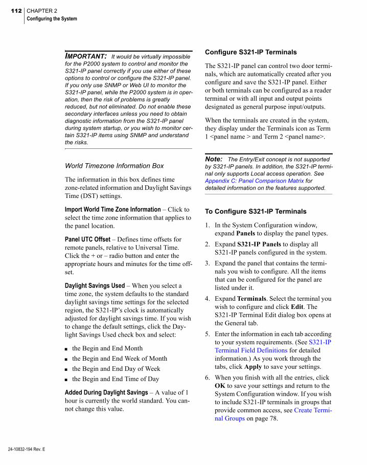
112 CHAPTER 2
Configuring the System
24-10832-194 Rev. E
IMPORTANT: It would be virtually impossible for the P2000 system to control and monitor the S321-IP panel correctly if you use either of these options to control or configure the S321-IP panel. If you only use SNMP or Web UI to monitor the S321-IP panel, while the P2000 system is in oper-ation, then the risk of problems is greatly reduced, but not eliminated. Do not enable these secondary interfaces unless you need to obtain diagnostic information from the S321-IP panel during system startup, or you wish to monitor cer-tain S321-IP items using SNMP and understand the risks.
World Timezone Information Box
The information in this box defines time zone-related information and Daylight Savings Time (DST) settings.
Import World Time Zone Information – Click to select the time zone information that applies to the panel location.
Panel UTC Offset – Defines time offsets for remote panels, relative to Universal Time. Click the + or – radio button and enter the appropriate hours and minutes for the time off-set.
Daylight Savings Used – When you select a time zone, the system defaults to the standard daylight savings time settings for the selected region, the S321-IP’s clock is automatically adjusted for daylight savings time. If you wish to change the default settings, click the Day-light Savings Used check box and select:
the Begin and End Month
the Begin and End Week of Month
the Begin and End Day of Week
the Begin and End Time of Day
Added During Daylight Savings – A value of 1 hour is currently the world standard. You can-not change this value.
Configure S321-IP Terminals
The S321-IP panel can control two door termi-nals, which are automatically created after you configure and save the S321-IP panel. Either or both terminals can be configured as a reader terminal or with all input and output points designated as general purpose input/outputs.
When the terminals are created in the system, they display under the Terminals icon as Term 1 <panel name > and Term 2 <panel name>.
Note: The Entry/Exit concept is not supported by S321-IP panels. In addition, the S321-IP termi-nal only supports Local access operation. See Appendix C: Panel Comparison Matrix for detailed information on the features supported.
To Configure S321-IP Terminals
1. In the System Configuration window, expand Panels to display the panel types.
2. Expand S321-IP Panels to display all S321-IP panels configured in the system.
3. Expand the panel that contains the termi-nals you wish to configure. All the items that can be configured for the panel are listed under it.
4. Expand Terminals. Select the terminal you wish to configure and click Edit. The S321-IP Terminal Edit dialog box opens at the General tab.
5. Enter the information in each tab according to your system requirements. (See S321-IP Terminal Field Definitions for detailed information.) As you work through the tabs, click Apply to save your settings.
6. When you finish with all the entries, click OK to save your settings and return to the System Configuration window. If you wish to include S321-IP terminals in groups that provide common access, see Create Termi-nal Groups on page 78.
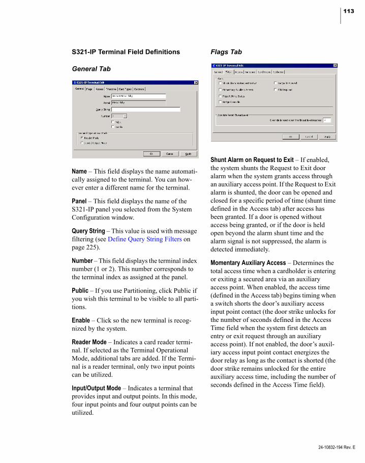
113
S321-IP Terminal Field Definitions
General Tab
Name – This field displays the name automati-cally assigned to the terminal. You can how-ever enter a different name for the terminal.
Panel – This field displays the name of the S321-IP panel you selected from the System Configuration window.
Query String – This value is used with message filtering (see Define Query String Filters on page 225).
Number – This field displays the terminal index number (1 or 2). This number corresponds to the terminal index as assigned at the panel.
Public – If you use Partitioning, click Public if you wish this terminal to be visible to all parti-tions.
Enable – Click so the new terminal is recog-nized by the system.
Reader Mode – Indicates a card reader termi-nal. If selected as the Terminal Operational Mode, additional tabs are added. If the Termi-nal is a reader terminal, only two input points can be utilized.
Input/Output Mode – Indicates a terminal that provides input and output points. In this mode, four input points and four output points can be utilized.
Flags Tab
Shunt Alarm on Request to Exit – If enabled, the system shunts the Request to Exit door alarm when the system grants access through an auxiliary access point. If the Request to Exit alarm is shunted, the door can be opened and closed for a specific period of time (shunt time defined in the Access tab) after access has been granted. If a door is opened without access being granted, or if the door is held open beyond the alarm shunt time and the alarm signal is not suppressed, the alarm is detected immediately.
Momentary Auxiliary Access – Determines the total access time when a cardholder is entering or exiting a secured area via an auxiliary access point. When enabled, the access time (defined in the Access tab) begins timing when a switch shorts the door’s auxiliary access input point contact (the door strike unlocks for the number of seconds defined in the Access Time field when the system first detects an entry or exit request through an auxiliary access point). If not enabled, the door’s auxil-iary access input point contact energizes the door relay as long as the contact is shorted (the door strike remains unlocked for the entire auxiliary access time, including the number of seconds defined in the Access Time field).
24-10832-194 Rev. E

114 CHAPTER 2
Configuring the System
24-10832-194 Rev. E
Report Strike Status – Click to report the status of the door strike associated with the reader. Unchecking this flag leaves the last reported door strike status in place. This means that the terminal may show as locked or unlocked, regardless of whether the door is actually locked or unlocked.
Badge Override – If enabled, cardholders with their badge’s Override option enabled can unlock the door controlled by the selected reader for a specified time period.
Badge ID Allowed – If enabled, a cardholder may enter the badge number at a keypad to access a secured area. This feature enables cardholders who have forgotten their badge the opportunity to gain entry by keying in their badge number.
PIN Required – If enabled, all cardholders must enter a custom PIN on the selected reader when attempting to access a secured area.
Override Reset Threat Level Box
Each reader terminal defined for an S321-IP panel can be configured with an Override Reset Threat Level ranging between 0 and 99.
Whenever a terminal’s Security Level reaches or exceeds the terminal’s Override Reset Threat Level, all overrides are immediately disabled. Subsequent attempts to invoke over-rides are denied.
All overrides are restored once a terminal’s Security Level drops below the terminal’s Override Reset Threat Level. For more infor-mation, see Security Threat Level Control on page 293.
Access Tab
Access Time – Enter the time (in seconds) that the door strike remains energized after a card-holder presents a valid badge at the selected reader. The cardholder has up to 60 seconds to open the unlocked door before it re-locks when the access time elapses.
Shunt Time – Enter a time in seconds that the door open alarm is suppressed after a valid badge access request. The Shunt Time should be longer than the Access Time.
Anti Passback – This feature prevents unautho-rized persons from using the badge of an authorized cardholder to gain access to a con-trolled area. Once an authorized cardholder presents a valid badge to access the facility, the cardholder cannot access the facility again until the anti-passback time entered expires.

115
Timezone Tab
This tab defines the time zones in which this terminal operates. Time Zones must be set up before they display in drop-down lists.
Enabled – Select a time zone during which the terminal is active. For example, you may not want the reader to be used between midnight and 5:00 AM, so assign a time zone with the desired inactive time period. If you select <none>, the terminal is always active and allows unrestricted access.
Override – Select a time zone that can be set as an override for this terminal. If you select <none>, this terminal is never in override.
PIN Suppression – Select a time zone during which cardholders do not have to enter a PIN number. If you select <none>, cardholders are never required to enter their PIN number.
Card Types Tab
This tab determines which card type can be used at the selected reader. If a presented badge does not match the selected card type, the system denies access to the cardholder.
The S321-IP panel supports one built-in card type at a time, therefore select only one card type.
Select No Card Types if this reader is dis-abled.
The Sensor 26 Bit card format is compati-ble with the 26-bit Wiegand Inverted card format.
If you select Raw 128 Bit, enter the Num-ber of bits to use (12 - 64).
If your facility uses Custom Card For-mats, select one of the formats previously downloaded into the panel using the Panel Card Formats application; see page 64 for detailed instructions.
Calibrate Tab
Use this tab to calibrate door contact input points as well as auxiliary access input point contacts on the terminal.
24-10832-194 Rev. E

116 CHAPTER 2
Configuring the System
24-10832-194 Rev. E
IMPORTANT: During the entire input calibra-tion procedure, the input’s contact must be physi-cally closed. Otherwise, the input’s status is unreliable.
Calibrate – This command calibrates the S321-IP’s selected input point contacts without using the panel’s CAL RESISTOR points. Issuing this command determines the door’s secure state and sets the selected input point as supervised (4-state).
Note: A Reader Status Input Fault message displays in the Real Time List when Door Contact or Exit Request 4-state inputs are opened or shorted.
Uncalibrate – This command uncalibrates the selected input point and sets it as unsupervised (2-state). After you uncalibrate the input point, four-state input statuses are no longer available for the input, only two-state statuses.
Calibrate with Resistor – This command cali-brates the S321-IP’s selected input point con-tacts using the panel’s CAL RESISTOR points. Issuing this command determines the door’s secure state and sets the selected input point as supervised (4-state). Calibrating the input point based on the CAL RESISTOR points does not require the door to be in the secure state during the calibration process.
Note: Once you perform a calibration proce-dure on an input point, you should not use this feature again, unless you change the input point’s wiring.
Configure S321-IP Input Points
S321-IP Panel and Terminal applications auto-matically generate input points and their addresses. These input points can be enabled to indicate the current state of a device and can be used for alarm or non-alarm purposes.
Some S321-IP input points have a predefined and unchanging purpose – indicating panel power failure and low battery power. When terminals are enabled, some input points are dedicated to access control functions, such as receiving input from door contacts and REX devices. Other input points can be used for a variety of purposes and devices (motion sen-sors, tamper switches, and so on) – these input points are referred to as general purpose inputs. The number of terminals enabled determines the available number of general purpose inputs.
Panel input points are automatically created under the selected S321-IP panel and are named using the input name and <panel name>, as in Power Failure <panel name>. Terminal input points are created under the selected S321-IP terminal and are named using the input name and <terminal name> <panel name>, as in Forced Door <terminal name> <panel name>. If you rename the panel or ter-minal, you can edit the input point to manually enter the new panel or terminal name.
The following possible input points are avail-able:

117
Input Type Input Name Generated for... Description
Panel Inputs Panel Tamper S321-IP panels with the Enable Panel Inputs option selected.
General purpose input. Typically wired to a tamper switch on an enclosure to indi-cate tampering.
Power Failure With battery backup employed, this input point indicates power failure.
Panel Soft Inputs Panel Battery All S321-IP panels. With battery backup employed, this input point provides a low battery indication during power failure.
Clock Battery Indicates when the panel’s lithium battery, which is used to back up the real-time clock, is low.
Panel Down Internal to the P2000 system to indicate that the panel is not active.
Terminal Inputs Forced Door S321-IP terminals with the Reader Mode option selected.
Indicates when there is a door open con-dition without a valid badge read detected first.
Propped Door Indicates when there is a door open con-dition with a valid badge, but the door is left open past the entry time.
Door Contact S321-IP terminals with the Input/Output Mode option selected.
In Reader Mode, this input point receives input from the door contact associated with the terminal. In Input/Output Mode, this input point can be used as a general purpose input.
Exit Request In Reader Mode, this input point receives input from the REX device associated with the terminal. In Input/Output Mode, this input point can be used as a general purpose input.
Spare All S321-IP terminals. General purpose input.
Tamper General purpose input.
Term Down Internal to the P2000 system to indicate that panel communications have ceased.
24-10832-194 Rev. E

118 CHAPTER 2
Configuring the System
24-10832-194 Rev. E
To Configure S321-IP Inputs
1. In the System Configuration window, expand Panels to display the panel types.
2. Expand S321-IP Panels to display all S321-IP panels configured in the system.
3. Expand the panel that contains the input points you wish to configure.
To configure panel inputs, expand Input Points, select the input point you wish to configure and click Edit.
To configure terminal inputs, expand the terminal that contains the input point you wish to configure, then expand Input Points, select the input point you wish to configure and click Edit.
The S321-IP Input Point dialog box opens at the General tab.
4. Enter the information in each tab according to your system requirements. The fields available for configuration depend on the type of input point selected. (See S321-IP Input Point Field Definitions for detailed information.) As you work through the tabs, click Apply to save your settings.
5. When you finish with all the entries, click OK to save your settings and return to the System Configuration window.
S321-IP Input Point Field Definitions
General Tab
Partition – If you use partitions, select the appropriate Partition that has access to this input point.
Public – If you use partitions, click Public if you want this input point to be visible to all partitions.
Name – This field displays the name automati-cally assigned to the input point, which con-sists of the <point name> <panel name>; the <terminal name> displays for terminal inputs. If you wish to change it, enter a descriptive name for the input point.
Query String – This value is used with message filtering (see Define Query String Filters on page 225).
Point Name – Displays the point name defined by the S321-IP panel.
Point Number – Displays the number associ-ated with the input point. This number rep-resents the physical connection to the I/O ter-minal.
Enable – Click to report all input point changes of state.
Suppress During Timezone – Select a Time Zone during which the input point is disabled. For example, it is impractical to report a door contact alarm during business hours when the door is in constant use. This option is not avail-able for Panel Down, Forced Door, Propped Door, and Term Down input points.

119
Alarm Options Tab
Alarm options are described in detail on page 83.
Misc Tab
Settings in this tab are not available for Panel Down, Forced Door, Propped Door, and Term Down input points.
Debounce Time – Enter the time in tens of mil-liseconds that the input must remain in a tran-sition state to establish the detected state. Without a debounce time, the panel may detect that the input is in an incorrect state because of the bouncing of the input device’s contacts.
Output Link – This option links the input point to an output point, so that the output point can be triggered by a change in the input point’s state. For example, when an input point, such as a motion sensor, is tripped (the input point state changes from secure to alarm), an output point triggers an external device (a light is turned on). Select the number of the output point that can be triggered by the selected input point. The list display the output point number preceded by the terminal number, as in <terminal number>-<output number>.
Calibrate – This command calibrates the S321-IP’s selected input point contacts with-out using the panel’s CAL RESISTOR points. Issuing this command determines the door’s secure state and sets the selected input point as supervised (4-state).
IMPORTANT: During the entire input calibra-tion procedure, the input’s contact must be physi-cally closed. Otherwise, the input’s status is unreliable.
Uncalibrate – This command uncalibrates the selected input point and sets it as unsupervised (2-state). After you uncalibrate the input point, four-state input statuses are no longer available for the input, only two-state statuses.
Calibrate with Resistor – This command cali-brates the S321-IP’s selected input point con-tacts using the panel’s CAL RESISTOR points. Issuing this command determines the door’s secure state and sets the selected input point as supervised (4-state). Calibrating the input point based on the CAL RESISTOR points does not require the door to be in the secure state during the calibration process.
Note: Once you perform a calibration proce-dure on an input point, you should not use this feature again, unless you change the input point’s wiring.
24-10832-194 Rev. E

120 CHAPTER 2
Configuring the System
24-10832-194 Rev. E
Configure S321-IP Output Points
S321-IP output points are automatically cre-ated under terminals that operate with the Input/Output Mode enabled. These output points are used to trigger external devices using the S321-IP panel. These devices might include warning indicators for alarm situations or non-alarm related functions, such as lighting or environmental control.
When the terminal operates in Reader Mode, the output points are dedicated to access con-trol functions, such as controlling the door strike, shunting an alarm, and turning green and red LEDs on and off to indicate access granted or denied.
If the terminal operates in Input/Output Mode, the output points that were used by the reader can be used to trigger external devices, such as lights and sirens – these output points are referred to as general purpose outputs.
Output points are created under the selected S321-IP terminal and are named using the out-put name and <terminal name> <panel name>, as in Shunt <terminal name> <panel name>. If you rename the panel or terminal, you can edit the output point to manually enter the new panel or terminal name.
The following possible output points are avail-able:
Output Name Description
Green If the terminal is enabled, this out-put point controls a green LED associated with the terminal. When access is granted, this output is activated. If the terminal is disabled, this output point can be used as a general purpose output.
Red If the terminal operates in Reader Mode, this output point controls a red LED associated with the termi-nal. When access is denied, this output is activated. If the terminal operates in Input/Output Mode, this output point can be used as a gen-eral purpose output.
Shunt If the terminal operates in Reader Mode, the alarm shunt prevents the external alarm system from sound-ing an alarm when a valid access occurs. When a valid access occurs, the shunt relay is energized for the number of seconds entered in the Shunt Time field on the Access tab of the S321-IP Terminal Edit application. If the terminal operates in Input/Output Mode, this output point can be used as a gen-eral purpose output.
Strike If the terminal operates in Reader Mode, the door strike controlled by the terminal unlocks for the number of seconds entered in the Access Time field on the Access tab of the S321-IP Terminal Edit application. If the terminal operates in Input/Out-put Mode, this output point can be used as a general purpose output.
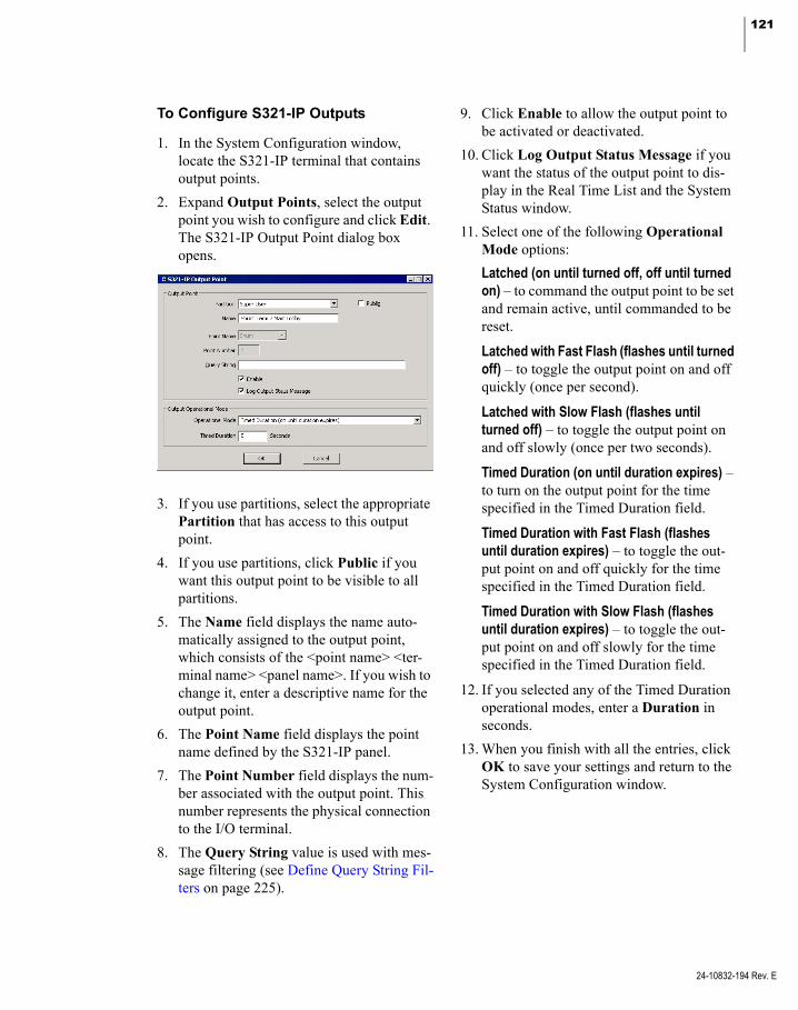
121
To Configure S321-IP Outputs
1. In the System Configuration window, locate the S321-IP terminal that contains output points.
2. Expand Output Points, select the output point you wish to configure and click Edit. The S321-IP Output Point dialog box opens.
3. If you use partitions, select the appropriate Partition that has access to this output point.
4. If you use partitions, click Public if you want this output point to be visible to all partitions.
5. The Name field displays the name auto-matically assigned to the output point, which consists of the <point name> <ter-minal name> <panel name>. If you wish to change it, enter a descriptive name for the output point.
6. The Point Name field displays the point name defined by the S321-IP panel.
7. The Point Number field displays the num-ber associated with the output point. This number represents the physical connection to the I/O terminal.
8. The Query String value is used with mes-sage filtering (see Define Query String Fil-ters on page 225).
9. Click Enable to allow the output point to be activated or deactivated.
10. Click Log Output Status Message if you want the status of the output point to dis-play in the Real Time List and the System Status window.
11. Select one of the following Operational Mode options:
Latched (on until turned off, off until turned on) – to command the output point to be set and remain active, until commanded to be reset.
Latched with Fast Flash (flashes until turned off) – to toggle the output point on and off quickly (once per second).
Latched with Slow Flash (flashes until turned off) – to toggle the output point on and off slowly (once per two seconds).
Timed Duration (on until duration expires) – to turn on the output point for the time specified in the Timed Duration field.
Timed Duration with Fast Flash (flashes until duration expires) – to toggle the out-put point on and off quickly for the time specified in the Timed Duration field.
Timed Duration with Slow Flash (flashes until duration expires) – to toggle the out-put point on and off slowly for the time specified in the Timed Duration field.
12. If you selected any of the Timed Duration operational modes, enter a Duration in seconds.
13. When you finish with all the entries, click OK to save your settings and return to the System Configuration window.
24-10832-194 Rev. E

122 CHAPTER 2
Configuring the System
24-10832-194 Rev. E
Configure HID Panels and Components
HID Edge® readers interface with the P2000 Server using a TCP/IP connection to provide a single-door access control solution. The HID Edge readers are IP-based readers with Power over Ethernet (POE) capabilities and can be initially configured remotely over the network via standard Web browser.
IMPORTANT: This release of the P2000 soft-ware works with HID Edge readers that use firm-ware Version 2.2.7.568 and HID Edge EVO® readers that use firmware Version 3.5.2. Other versions may not be compatible with this release of the P2000 software. The upgrade of HID firm-ware must follow specific instructions. Contact Technical Support for details.
Hardware Requirements
Before you can use the functions described in this section, the HID hardware must be prop-erly installed and configured to communicate with the P2000 Server. Refer to the HID docu-mentation for hardware installation instruc-tions.
Note: Edge EVO devices require at least one Highly Intelligent Opening (HI-O) module to be connected; otherwise, a “Mode 0” error may be displayed preventing the HID panel from coming online.
The connection settings are determined by HID guidelines; however, to ensure proper operation with the P2000 system, the follow-ing is required:
If your HID model requires an external reader, we recommend using the following connections:
Pwr Gnd
Data0 Data1 GrnLED RedLED (optional) Beeper Hold
When configuring the HID device via its built-in Web page, you must enter a value (no less than 20 seconds), in the Here I Am Interval (sec): field; otherwise, the reader does not attempt to communicate with the P2000 Server.
HID Panel Naming Conventions
HID panel components are named using a con-sistent naming scheme. The system automati-cally allocates an identifying name to the ter-minals and associated input and output points. This name consists of a fixed description of the item (such as Term 1 for a terminal or Request to Exit for an input), plus the panel name. In addition, the name of the terminal is also appended to the input and output names, that way, you can for example recognize an input point by its panel and terminal name.
You should logically name HID panels, includ-ing information such as the panel’s location or what it controls. The maximum number of characters allowed for an HID component name is 32. If you use long panel names, you need to remember that a terminal input point name is <input name> <terminal name> <panel name> and therefore, that combination should not exceed 32 characters.
Note: Although panel components display names that are automatically assigned, you can rename those components according to your facility's needs.

123
Configure HID Facility Parameters
Before configuring your HID components, use the following instructions to define facility parameters associated with HID readers.
To Configure HID Facility Parameters
1. From the P2000 Main menu, select Con-fig>System. Enter your password if prompted. The System Configuration win-dow opens.
2. Expand Panels to display the panel types.
3. Expand HID Network Panels to open the HID components.
4. Select HID Facility and click Add. The HID Facility Edit dialog box opens.
5. Enter the Name of the HID Facility record. This field displays P2000 by default, but you can change the name according to your facility needs.
6. Select from the Extended Access Flag drop-down list, one of the three special access flags that are used by cardholders with extended access privileges who require special access at a reader. Special access allows a door’s access time to be different. The list displays the special access flag names as configured in Site Parameters; see page 33.
7. Enter the Controller Buffer Size that defines the number of events buffered on the HID controllers when offline.
8. In the Badge Formats box, click Add to define the badge formats to be used at your facility. The Badge Format Edit dialog box opens.
9. Click the [...] button, select a *.bft file from the list, and click Open. The name of the selected *.bft file displays in the Name field. You cannot edit this name.
10. Select the Technology type.
11. Enter the total number of Bits expected to be returned from the reader when the badge is read.
12. Select a Qualifier number. The number selected represents a 32-bit numerical value that allows differentiating formats with the same technology and the same number of bits. The default value is 1.
IMPORTANT: The Technology, Bits, and Qualifier badge format settings must match the badge format settings defined for a cardholder badge (see Create Badge Formats on page 237).
13. Click OK.
14. Repeat these steps for each badge format to be used with HID readers.
Note: The system may generate “Facility code too large” Event Log error messages when the facility code is too large for the selected format.
24-10832-194 Rev. E

124 CHAPTER 2
Configuring the System
24-10832-194 Rev. E
15. After you enter all the information, click OK to save the settings and return to the System Configuration window.
Configure HID Panels
After you install the hardware and use the HID tools to locate and configure the HID reader, you are ready to configure the P2000 Server to communicate with the HID device by defining communication, time, and hardware parame-ters. In addition, if you wish to protect the P2000 system from unauthorized sources, you can implement encryption using Advanced Encryption Standard (AES) to secure each and every message to and from the HID panel.
To Configure HID Panels
1. From the P2000 Main menu, select Con-fig>System. Enter your password if prompted. The System Configuration win-dow opens.
2. Expand Panels to display the panel types.
3. Select HID Network Panels and click Add. The HID Panel Edit dialog box opens.
4. Fill in the information on each tab. (See HID Panel Field Definitions for details.)
5. Click OK to save the panel information. A message box displays asking if you wish to automatically add all time zones to the new panel. If you select No, you can add the time zones later; see Configure Panel Time Zones on page 62.
6. If you select Yes, the time zones are auto-matically added. When you return to the System Configuration window, a new panel icon bearing the name assigned dis-plays under the root HID Network Panels.
Note: In addition to applying time zones to the panels (described in Configure Panel Time Zones on page 62), you may also define panel holidays if you wish to restrict access in your facility during a holiday period; see Configure Panel Holidays on page 63.
HID Panel Field Definitions
Note: Changes to any of the following HID Panel parameters causes the panel to go offline momentarily. Also, be aware that some down-loads associated with HID panels may take over 40 seconds to process. Some downloads may cause the door to be in unsecure state for a short period.
General Tab
Partition – If you use Partitioning, select the Partition that has access to this panel.
Public – If you use Partitioning, click Public to allow all partitions to see this panel.
Hardware – Select the HID hardware type. Cer-tain features are enabled or disabled depending on the hardware type selected here. The P2000 server can communicate with the following HID panel types:
125
Panel Type Description
Edge Controller with internal reader, inputs, and outputs.
Edge EVO EH400 Controller only, no internal reader, inputs, or outputs.
Edge EVO EHR40 Integrated with 13.56 MHz reader, no inputs or outputs.
Edge EVO EHRP40 Integrated with 13.56 MHz and 125 kHz readers, no inputs or outputs.
See EVO Hardware Tab on page 127 for the different hardware modules supported with each Edge EVO panel hardware type.
Note: You can convert an existing HID Edge panel into an HID Edge EVO EH400 panel. You must disable the HID Edge panel before chang-ing the hardware type. After you save the panel record, the change cannot be reverted. After con-version, you can edit the panel configuration, also you can change the EVO hardware type to EHR40 or EHRP40 as required.
Name – Enter a descriptive Name for the panel.
Enabled – The Enabled check box is automati-cally selected for the system to recognize this panel. If you wish to temporarily disable the panel, without having to delete the panel, click the check box to disable it. When you disable a panel, the reader continues to grant access, but the panel does not communicate with the Server until you enable the panel again.
Query String – This value is used with message filtering (see Define Query String Filters on page 225).
IMPORTANT: The Encryption Control param-eters described next, are not available until the panel information is saved. Communications with the panel must be established in a non-encrypted way before encrypted communications can be established.
Encryption Enabled – Click to allow encryp-tion of all messaging between the HID panel and the P2000 Server. If you choose to enable encryption, you may click Create to generate a random HID encryption key, or if you prefer you may enter your own key (not to exceed 200 digits).
The Encryption Key box displays the key to be used for encrypted communications.
Important Notes
When any encryption setting is changed, a warning message displays notifying the user that communications must exist and must not be interrupted while encrypted communications are established or ended.
Only one encryption setting change can be made using the HID Panel Edit application per session (before the panel information is saved after clicking OK). The user must restart the HID Panel Edit application to make another change.
If the user chooses to delete an HID panel from the System Configuration window, and that panel has encryption enabled, a warning message displays indicating the risk involved.
EVO Hardware Inputs – The following EVO hardware inputs can be enabled for monitoring (these panel input points are automatically cre-ated for Edge panels):
Tamper – to indicate tampering if the panel is wired to a tamper switch on an enclosure.
Low Battery – to indicate that the battery is low.
Power Failure – to indicate a power failure if the panel uses a battery backup.
24-10832-194 Rev. E

126 CHAPTER 2
Configuring the System
24-10832-194 Rev. E
Communications Tab
MAC Address – Enter the Media Access Con-trol (MAC) address assigned to the HID panel.
Heartbeat Transmit Interval – Enter the number of hours, minutes, and seconds that determines how often the HID panel sends heart beat mes-sages that confirm successful communication. If you change the heartbeat interval, the panel is rebooted after the update. You must confirm if you wish to continue.
Host No Reception Timeout – Enter the number of hours, minutes, and seconds that must pass without receiving a heartbeat notification, before the P2000 system assumes the HID panel is no longer available.
Resend Attempt Interval – Enter the number of hours, minutes, and seconds to define how long the HID panel waits before resending a message after the previous attempt failed.
Restore Defaults – Click if you wish to restore default values of all related communication timed values.
Time Information Tab
The information in this box defines time zone-related information and Daylight Savings Time (DST) settings.
Import World Time Zone Information – Click to select the time zone information that applies to the panel location.
Panel UTC Offset – Defines time offsets for remote panels, relative to Universal Time. Click the + or – radio button and enter the appropriate hours and minutes for the time off-set.
Daylight Savings Used – When you select a time zone, the system uses the standard day-light savings time settings for the selected region, the HID’s clock is automatically adjusted for daylight savings time. If you wish to change the default settings, click Daylight Savings Used and select:
the Begin and End Month
the Begin and End Week of Month
the Begin and End Day of Week
the Begin and End Time of Day
Note: Because of HID limitations, all minutes and seconds values must always be zero.
Added During Daylight Savings – A value of 1 hour is currently the world standard. You can-not change this value.

127
EVO Hardware Tab
Information in this tab allows you to select the hardware module connected to Edge EVO panels. The specific number of readers, input points, output points, and the terminal features supported depend on the type of module selected here.
Hardware – Displays the hardware type selected in the General Tab.
Built-in Reader – This is selected by default for EHR40 and EHRP40 panels, and indicates that a reader is integrated into the panel. Not avail-able for EH400.
Hi-O Modules Connected – Select the HI-O hardware module connected to the HID panel. Depending on the selections made in the check boxes, other check boxes are enabled or dis-abled. The final selection must not exceed 2 readers, 12 inputs, and 3 outputs. The follow-ing table displays the options provided with each module type:
Module Type Specification
EDM (Hi-O Grp 1) 4 dedicated input points2 output points *
EDM (Hi-O Grp 2) 4 general purpose input points2 output points **
EWM (Hi-O Grp 1) 1 reader terminal. Can be defined as a Keypad reader.
EWM (Hi-O Grp 2) *** 1 reader terminal. Can be defined as a Keypad reader.
EIM (Hi-O Grp 1) 4 general purpose input points
EIM (Hi-O Grp 2) 4 general purpose input points
ELM (Hi-O Grp 1) **** 1 output point. Can be defined as a Fail Safe output.
ELM (Hi-O Grp 2) ***** 1 output point
* Not available if ELM (Hi-O Grp 1) is selected.
** Not available if ELM (Hi-O Grp 2) is selected.
*** Not available for panels (EHR40 and EHRP40) with integrated readers.
**** Not available if EDM (Hi-O Grp 1) is selected.
***** Not available if EDM (Hi-O Grp 2) is selected.
Important Notes:
The P2000 system does not monitor the sta-tus of HI-O bus modules.
EVO panels may display download errors unless the items selected on this tab match exactly the HI-O bus modules physically connected. P2000 configuration should be updated after new HI-O modules are added and rebooted. P2000 configuration should be changed before old HI-O modules are removed.
If you select any group 1 module type, a P2000 terminal number 1 is automatically created. If you select any group 2 module type, a P2000 terminal number 2 is auto-matically created.
Tabs in the HID Terminal Edit are available for configuration, depending on the module type selected.
When you define two readers for a single door, most terminal parameters are synchro-nized between the two readers to ensure a predictable behavior of the door.
Terminal Inputs are available for configura-tion if terminal 1 contains an EDM module.
You can configure input points, if the termi-nal contains an EIM or EDM group 2 mod-ule for the selected group number.
You can configure output points, if the ter-minal contains an EDM or an ELM module for the selected group number.
Module Type Specification
24-10832-194 Rev. E
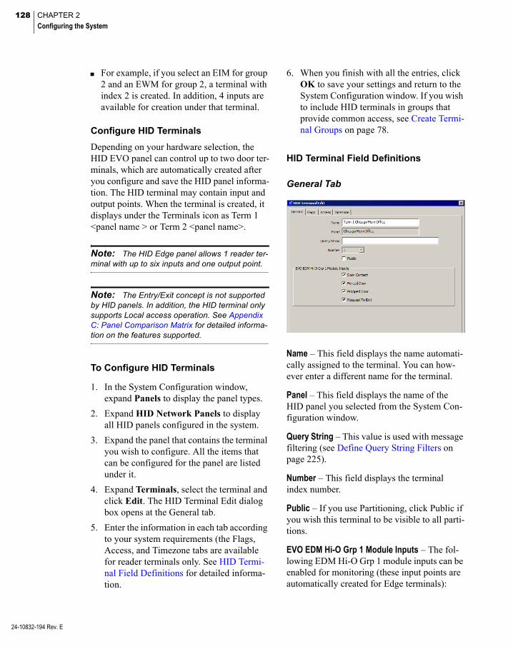
128 CHAPTER 2
Configuring the System
24-10832-194 Rev. E
For example, if you select an EIM for group 2 and an EWM for group 2, a terminal with index 2 is created. In addition, 4 inputs are available for creation under that terminal.
Configure HID Terminals
Depending on your hardware selection, the HID EVO panel can control up to two door ter-minals, which are automatically created after you configure and save the HID panel informa-tion. The HID terminal may contain input and output points. When the terminal is created, it displays under the Terminals icon as Term 1 <panel name > or Term 2 <panel name>.
Note: The HID Edge panel allows 1 reader ter-minal with up to six inputs and one output point.
Note: The Entry/Exit concept is not supported by HID panels. In addition, the HID terminal only supports Local access operation. See Appendix C: Panel Comparison Matrix for detailed informa-tion on the features supported.
To Configure HID Terminals
1. In the System Configuration window, expand Panels to display the panel types.
2. Expand HID Network Panels to display all HID panels configured in the system.
3. Expand the panel that contains the terminal you wish to configure. All the items that can be configured for the panel are listed under it.
4. Expand Terminals, select the terminal and click Edit. The HID Terminal Edit dialog box opens at the General tab.
5. Enter the information in each tab according to your system requirements (the Flags, Access, and Timezone tabs are available for reader terminals only. See HID Termi-nal Field Definitions for detailed informa-tion.
6. When you finish with all the entries, click OK to save your settings and return to the System Configuration window. If you wish to include HID terminals in groups that provide common access, see Create Termi-nal Groups on page 78.
HID Terminal Field Definitions
General Tab
Name – This field displays the name automati-cally assigned to the terminal. You can how-ever enter a different name for the terminal.
Panel – This field displays the name of the HID panel you selected from the System Con-figuration window.
Query String – This value is used with message filtering (see Define Query String Filters on page 225).
Number – This field displays the terminal index number.
Public – If you use Partitioning, click Public if you wish this terminal to be visible to all parti-tions.
EVO EDM Hi-O Grp 1 Module Inputs – The fol-lowing EDM Hi-O Grp 1 module inputs can be enabled for monitoring (these input points are automatically created for Edge terminals):
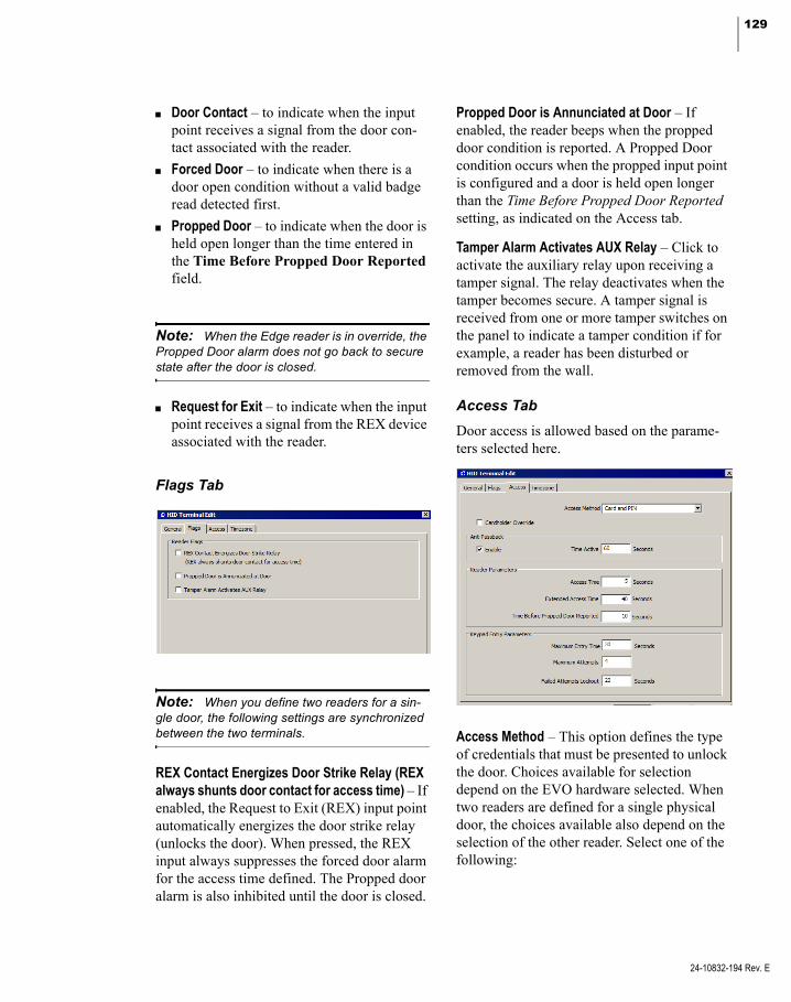
129
Door Contact – to indicate when the input point receives a signal from the door con-tact associated with the reader.
Forced Door – to indicate when there is a door open condition without a valid badge read detected first.
Propped Door – to indicate when the door is held open longer than the time entered in the Time Before Propped Door Reported field.
Note: When the Edge reader is in override, the Propped Door alarm does not go back to secure state after the door is closed.
Request for Exit – to indicate when the input point receives a signal from the REX device associated with the reader.
Flags Tab
Note: When you define two readers for a sin-gle door, the following settings are synchronized between the two terminals.
REX Contact Energizes Door Strike Relay (REX always shunts door contact for access time) – If enabled, the Request to Exit (REX) input point automatically energizes the door strike relay (unlocks the door). When pressed, the REX input always suppresses the forced door alarm for the access time defined. The Propped door alarm is also inhibited until the door is closed.
Propped Door is Annunciated at Door – If enabled, the reader beeps when the propped door condition is reported. A Propped Door condition occurs when the propped input point is configured and a door is held open longer than the Time Before Propped Door Reported setting, as indicated on the Access tab.
Tamper Alarm Activates AUX Relay – Click to activate the auxiliary relay upon receiving a tamper signal. The relay deactivates when the tamper becomes secure. A tamper signal is received from one or more tamper switches on the panel to indicate a tamper condition if for example, a reader has been disturbed or removed from the wall.
Access Tab
Door access is allowed based on the parame-ters selected here.
Access Method – This option defines the type of credentials that must be presented to unlock the door. Choices available for selection depend on the EVO hardware selected. When two readers are defined for a single physical door, the choices available also depend on the selection of the other reader. Select one of the following:
24-10832-194 Rev. E
130 CHAPTER 2
Configuring the System
24-10832-194 Rev. E
Card only – The cardholder must swipe the badge to gain access.
Card and PIN – The cardholder must swipe the badge and is also required to enter a PIN code. If this option is selected, you must complete the Keypad Entry Parameters set-tings. Selection is not available when the other reader is in Card ID only mode or Card or Card ID mode.
Card ID only – The cardholder must enter the badge number at the keypad. If this option is selected, you must complete the Keypad Entry Parameters settings. Selection is not available when the other reader is in Card and PIN mode.
Card or Card ID – The cardholder could either swipe the badge or enter the badge number at the keypad. If this option is selected, you must complete the Keypad Entry Parameters settings. Selection is not available when the other reader is in Card and PIN mode.
Note: PIN or Card ID entries are completed by pressing the # key. Also, if you make any badge format changes, you must download all badges to the HID panels that have the Card ID only or Card or Card ID terminal option selected.
Cardholder Override – This feature is not avail-able if the Access Method is Card only. If Cardholder Override is enabled, an authorized cardholder may place the reader in an override condition by performing a badging procedure at the reader’s keypad. The override remains in effect until:
An authorized cardholder takes it out of override by performing a badging procedure at the reader’s keypad.
The reader’s override timezone enables or disables the door.
A command is received from the Door Con-trol application to change the door’s condi-tion.
The following describes the keypad sequence necessary to unlock the door and return the door to normal operation.
Depending on the Access Method used (Card and PIN, Card ID only, or Card or Card ID) gain access and enter 9 9 # to unlock the door.
Depending on the Access Method used (Card and PIN, Card ID only, or Card or Card ID) gain access and enter 0 0 # to return the door to normal operation.
Note: HID panels do not report transactions associated with Cardholder Override.
Anti Passback
Enable – Click to enable the anti-passback fea-ture at this reader for the number of seconds entered in the Time Active field. The anti-passback function prevents cardholders from using their badge at the same reader until the timer has expired.
Note: If cardholders swipe their badge while the anti-passback timer is active, access is denied because the anti-passback timer is on.
Time Active – Enter the time in seconds that a badge used at the reader is invalid before it can be used at the same reader.
Reader Parameters
Note: When you define two readers for a single door, the “Access Time,” “Extended Access Time,” and “Time Before Propped Door Reported” values are propagated to the other reader termi-nal.
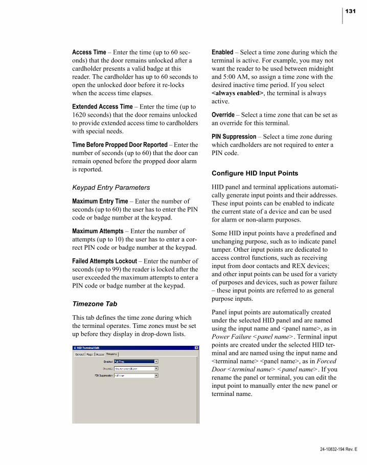
131
Access Time – Enter the time (up to 60 sec-onds) that the door remains unlocked after a cardholder presents a valid badge at this reader. The cardholder has up to 60 seconds to open the unlocked door before it re-locks when the access time elapses.
Extended Access Time – Enter the time (up to 1620 seconds) that the door remains unlocked to provide extended access time to cardholders with special needs.
Time Before Propped Door Reported – Enter the number of seconds (up to 60) that the door can remain opened before the propped door alarm is reported.
Keypad Entry Parameters
Maximum Entry Time – Enter the number of seconds (up to 60) the user has to enter the PIN code or badge number at the keypad.
Maximum Attempts – Enter the number of attempts (up to 10) the user has to enter a cor-rect PIN code or badge number at the keypad.
Failed Attempts Lockout – Enter the number of seconds (up to 99) the reader is locked after the user exceeded the maximum attempts to enter a PIN code or badge number at the keypad.
Timezone Tab
This tab defines the time zone during which the terminal operates. Time zones must be set up before they display in drop-down lists.
Enabled – Select a time zone during which the terminal is active. For example, you may not want the reader to be used between midnight and 5:00 AM, so assign a time zone with the desired inactive time period. If you select <always enabled>, the terminal is always active.
Override – Select a time zone that can be set as an override for this terminal.
PIN Suppression – Select a time zone during which cardholders are not required to enter a PIN code.
Configure HID Input Points
HID panel and terminal applications automati-cally generate input points and their addresses. These input points can be enabled to indicate the current state of a device and can be used for alarm or non-alarm purposes.
Some HID input points have a predefined and unchanging purpose, such as to indicate panel tamper. Other input points are dedicated to access control functions, such as receiving input from door contacts and REX devices; and other input points can be used for a variety of purposes and devices, such as power failure – these input points are referred to as general purpose inputs.
Panel input points are automatically created under the selected HID panel and are named using the input name and <panel name>, as in Power Failure <panel name>. Terminal input points are created under the selected HID ter-minal and are named using the input name and <terminal name> <panel name>, as in Forced Door <terminal name> <panel name>. If you rename the panel or terminal, you can edit the input point to manually enter the new panel or terminal name.
24-10832-194 Rev. E

132 CHAPTER 2
Configuring the System
24-10832-194 Rev. E
The following input points are available:
Input Type Input Name Description
Panel Input Points
Power Failure Indicates the reader has a power failure.
Panel Battery Provides low battery indication.
Panel Down Internal to the P2000 system to indicate that the panel is not active.
Tamper Switch (for Edge EVO)
Typically wired to a tam-per switch to indicate tampering.A tamper alarm may be generated in configura-tions where there are multiple enclosures whenever the tamper sensor on one those enclosures is activated.
Terminal Input Points
Door Contact This input point receives signal from the door con-tact device associated with the reader.
Forced Door Indicates when there is a door open condition without a valid badge read detected first.
Propped Door Indicates when there is a door open condition with a valid badge, but the door is left open past the entry time
Request To Exit
This input point receives signal from the REX device associated with the reader.
Tamper Switch (for Edge)
General purpose input. Typically wired to a tam-per switch to indicate tampering.
Terminal Down
Internal to the P2000 system to indicate that panel communications have ceased.
To Configure HID Inputs
1. In the System Configuration window, expand Panels to display the panel types.
2. Expand HID Network Panels to display all HID panels configured in the system.
3. Expand the panel that contains the input points you wish to configure.
To configure panel inputs, expand Input Points, select the input point you wish to configure and click Edit.
To configure terminal inputs, expand the terminal that contains the input point you wish to configure, then expand Input Points, select the input point you wish to configure and click Edit.
Note: Depending on your HID EVO hardware, you can also add terminal input points.
The HID Input Point Edit dialog box opens at the General tab.
4. Enter the information in each tab according to your system requirements. The fields available for configuration depend on the type of input point selected. (See HID Input Point Field Definitions for detailed infor-mation.) As you work through the tabs, click Apply to save your settings.
5. When you finish with all the entries, click OK to save your settings and return to the System Configuration window.
HID Input Point Field Definitions
General Tab
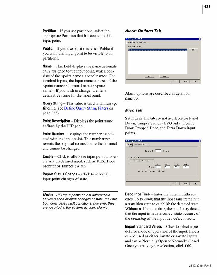
133
Partition – If you use partitions, select the appropriate Partition that has access to this input point.
Public – If you use partitions, click Public if you want this input point to be visible to all partitions.
Name – This field displays the name automati-cally assigned to the input point, which con-sists of the <point name> <panel name>. For terminal inputs, the input name consists of the <point name> <terminal name> <panel name>. If you wish to change it, enter a descriptive name for the input point.
Query String – This value is used with message filtering (see Define Query String Filters on page 225).
Point Description – Displays the point name defined by the HID panel.
Point Number – Displays the number associ-ated with the input point. This number rep-resents the physical connection to the terminal and cannot be changed.
Enable – Click to allow the input point to oper-ate as a predefined input, such as REX, Door Monitor or Tamper Switch.
Report Status Change – Click to report all input point changes of state.
Note: HID input points do not differentiate between short or open changes of state, they are both considered fault conditions; however, they are reported in the system as short alarms.
Alarm Options Tab
Alarm options are described in detail on page 83.
Misc Tab
Settings in this tab are not available for Panel Down, Tamper Switch (EVO only), Forced Door, Propped Door, and Term Down input points.
Debounce Time – Enter the time in millisec-onds (15 to 2040) that the input must remain in a transition state to establish the detected state. Without a debounce time, the panel may detect that the input is in an incorrect state because of the bouncing of the input device’s contacts.
Import Standard Values – Click to select a pre-defined mode of operation of the input. Inputs can be used as either 2-state or 4-state inputs and can be Normally Open or Normally Closed. Once you make your selection, click OK.
24-10832-194 Rev. E

134 CHAPTER 2
Configuring the System
24-10832-194 Rev. E
A/D values – The Analog to Digital (A/D) default values displayed here represent the High Range Upper Limit (HRUL), High Range Lower Limit (HRLL), Low Range Upper Limit (LRUL), and Low Range Lower Limit (LRLL) values assigned for each operational mode and that match the end of line (EOL) resistors. You can however, change any of the four A/D val-ues at any time.
Note: The A/D Values Define field displays how HID uses the four values. It also shows errors when an illegal combination of values is entered. This field is updated every time you make changes to the A/D values
Configure HID Output Points
Depending on your hardware selection, the HID panel can control up to three auxiliary output points. The auxiliary output point can be activated in response to an activated input point, and can be used to trigger external devices, such as alarm warning indicators or emergency lights. It can also be commanded from the P2000 Output Control application.
To Configure HID Outputs
1. In the System Configuration window, locate the HID terminal that contains the output point.
2. Select Output Points and click Add. The HID Output Point Edit dialog box opens.
Note: Depending on your HID hardware, you can also edit output points that are automatically created.
3. If you use partitions, select the appropriate Partition that has access to this output point.
4. If you use partitions, click Public if you want this output point to be visible to all partitions.
5. Enter a descriptive Name for the output point.
6. The Query String value is used with mes-sage filtering (see Define Query String Fil-ters on page 225).
7. Select the Point Description of the output point.
8. Select the Point Number associated with the output point.
9. Click Enable to allow the output point to be activated or deactivated.
10. Select from the Active State drop-down list, the state in which the output point operates. If you select Set, the output point remains active, until commanded to be Reset.
11. When you finish with all the entries, click OK to save your settings and return to the System Configuration window.

135
Troubleshooting Misconfigured HID Readers
Some HID Edge readers (built-in or external), may ship from HID configured to either hold one card swipe or ignore all card swipes when disabled. If configured to hold a card swipe, when the device is re-enabled, card data is pre-sented to the Edge device for an access deci-sion, possibly granting access. The ability to disable the reader is used within the P2000 software by Reader Enable Timezone, Reader Override Timezone, and Door Control.
To Determine if an HID Reader is Storing Card Information
1. From the P2000 Main menu select Con-trol>Door Control.
2. Enter your password if prompted. The Door Control dialog box opens.
3. If this is a partitioned system, select the Partition in which the HID door is active.
4. Click Door.
5. Select the HID door you wish to test.
6. Click Lockout to prevent access at the door.
7. Click Perform. The door is locked. This puts the door into lockout.
8. With the door in lockout swipe a card at the reader.
9. If the reader is configured incorrectly the reader beeps.
10. To return the door to its previous state, click Return to Normal.
11. Click Perform. The Door Control lockout is reversed. The Real Time List shows the results of the card swipe if the reader is not properly configured.
Note: Contact HID if you encounter this type of problem.
Override and Lockout Reader Operation
The following table shows how Edge EVO readers behave based on reader mode interac-tions.
Reader 2 Normal Reader 2 Override Reader 2 Lockout
Reader 1 Reader 2 Reader 1 Reader 2 Reader 1 Reader 2
Reader 1 Normal LED Red Red Green Green Red Red
Access Mode Normal Normal Normal Override* Normal Locked*
Reader 1 Override LED Green Green Green Green Red Red
Access Mode Override* Normal Override* Override* Normal Locked*
Reader 1 Lockout LED Red Red Red Red Red Red
Access Mode Locked* Normal Locked* Normal Locked* Locked*
* Badge swipes are rejected by the reader.
24-10832-194 Rev. E

136 CHAPTER 2
Configuring the System
24-10832-194 Rev. E
Configure Assa Abloy® IP Door Locks and Components
Assa Abloy Intelligent Locks provide a wired (PoE) and wireless (Wi-Fi) door locking secu-rity solution that can be integrated with the P2000 system. Integration between these two systems is possible via the Assa Abloy Door Service Router (DSR), which is installed on the DSR server, and the P2000 Assa Abloy DSR Interface Service, which runs on the P2000 server.
IMPORTANT: This release of the P2000 soft-ware works with Assa Abloy locks that use firm-ware Version N14, Version N11, and Version P04. Other versions may not be compatible with this release of the P2000 software. Refer to the P2000 Software Installation Manual for firmware upgrade instructions.
This P2000 software version requires DSR Version 7.0.5 or Version 7.0.4, other previous versions are not supported. For optimal system performance, we recommend you configure your system with few DSRs as possible; each DSR can connect with up to 1024 locks.
The DSR can be on a separate server or on a virtual computer on the P2000 server, and must have network access to the P2000 server.
The following figure illustrates DSR running on physical computers.
P2000 Workstation
Wide Area Network
DSR Server- Operating System- Database Engine- DSR Software Package
IP Network
P2000 Server
Additional DSR Server(as needed)
ASSA ABLOY Wired Locks
ASSA ABLOY Wireless Locks
The following figure illustrates a DSR running in a virtual environment.
P2000 Workstation
Wide Area Network
IP Network
P2000 Server
ASSA ABLOY Wired Locks
ASSA ABLOY Wireless Locks
DSR Server (Virtual)- Operating System- Database Engine- DSR Software Package
Hardware Requirements
Before you use the functions described in this section, the Assa Abloy hardware and DSR servers must be properly installed. Refer to the Assa Abloy documentation for hardware installation assistance.
Also, refer to the Assa Abloy Lock Configura-tion Tool (LCT) documentation for alarm con-figuration instructions. The following table displays LCT settings that provide a good compromise for both response time and battery life. We highly recommend configuring these settings during the initial installation phase to view relevant messages during testing:
Alarm Name Security Mode
Passage Mode
Rx Held Mode
Door Secured ON OFF ON
Door Forced ON OFF ON
Door Ajar ON OFF ON
Low Battery ON ON ON
RTC Failure ON ON ON
Tamper Alarm ON ON ON
Tamper Restore ON ON ON
For DSR installation information, refer to the P2000 Software Installation Manual.

137
Assa Abloy Component Naming Conventions
Each Assa Abloy Intelligent Lock is repre-sented by a panel and a single reader terminal in the P2000 software. The P2000 system automatically adds Assa Abloy panels, termi-nals, and associated soft input points to the P2000 system configuration tree after the DSR detects the corresponding locks, which occurs after the DSR Interface Service restarts or when a change occurs to the fields on the Assa Abloy DSR Edit dialog box (see page 141). Each component has a predefined name, including a 16-character string identifying the panel serial number as defined in the DSR.
Panel names have the following predefined structure:
[PoE or Wi-Fi] [Lock Serial Number]
Example: PoE IT107E2577PA0BCE
Terminal names have the following predefined structure:
[PoE or Wi-Fi] [Lock Serial Number] Term
Example: PoE IT107E2577PA0BCE Term
Soft input points have the following pre-defined structure:
[Soft input point alarm name] [Lock Serial Number]
Example: Forced PoE IT107E2577PA0BCE
When renaming Assa Abloy panels, terminals, and soft input points, use a consistent naming scheme to avoid panel and component identifi-cation confusion.
Use logical names for Assa Abloy panels. For example, consider a name that identifies the panel’s location. The maximum number of characters allowed for an Assa Abloy compo-nent name is 32.
Configure Assa Abloy Facility Parameters
Before configuring your Assa Abloy compo-nents, use the following instructions to define facility parameters associated with Assa Abloy panels.
Note: Facility parameter modifications affect all Assa Abloy panels and associated compo-nents defined in the P2000 System Configura-tion.
Configuring Assa Abloy facility parameters consists of the following:
Assigning special access requirements for Assa Abloy panels (see Special Access for Assa Abloy Panels on page 137)
Setting up badge formats for use with Assa Abloy panels (see Set Up Badge Formats for Assa Abloy Panels on page 138)
Note: Changing any Assa Abloy Facility parameters requires a manually initiated down-load of all badges to the DSR. This can be most efficiently done by using the Full Download but-ton on the Assa Abloy DSR Edit dialog box.
Special Access for Assa Abloy Panels
In addition to basic access, operators can con-trol special access for overriding the normal operation of Assa Abloy panels. Special access options include:
Extended Access – Extends the time a card-holder is permitted to hold a door open, which can be used to comply with Ameri-cans with Disabilities Act (ADA) require-ments.
24-10832-194 Rev. E
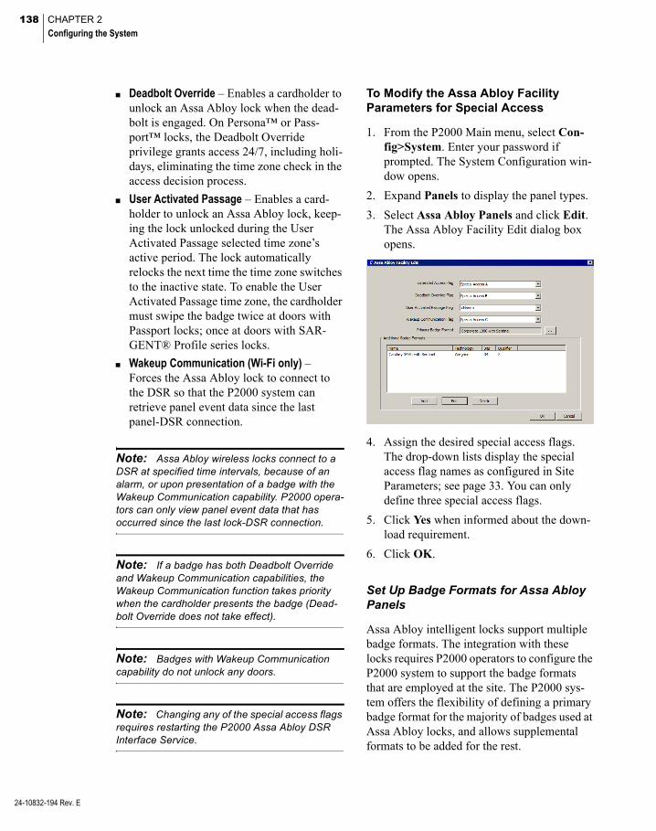
138 CHAPTER 2
Configuring the System
24-10832-194 Rev. E
Deadbolt Override – Enables a cardholder to unlock an Assa Abloy lock when the dead-bolt is engaged. On Persona™ or Pass-port™ locks, the Deadbolt Override privilege grants access 24/7, including holi-days, eliminating the time zone check in the access decision process.
User Activated Passage – Enables a card-holder to unlock an Assa Abloy lock, keep-ing the lock unlocked during the User Activated Passage selected time zone’s active period. The lock automatically relocks the next time the time zone switches to the inactive state. To enable the User Activated Passage time zone, the cardholder must swipe the badge twice at doors with Passport locks; once at doors with SAR-GENT® Profile series locks.
Wakeup Communication (Wi-Fi only) – Forces the Assa Abloy lock to connect to the DSR so that the P2000 system can retrieve panel event data since the last panel-DSR connection.
Note: Assa Abloy wireless locks connect to a DSR at specified time intervals, because of an alarm, or upon presentation of a badge with the Wakeup Communication capability. P2000 opera-tors can only view panel event data that has occurred since the last lock-DSR connection.
Note: If a badge has both Deadbolt Override and Wakeup Communication capabilities, the Wakeup Communication function takes priority when the cardholder presents the badge (Dead-bolt Override does not take effect).
Note: Badges with Wakeup Communication capability do not unlock any doors.
Note: Changing any of the special access flags requires restarting the P2000 Assa Abloy DSR Interface Service.
To Modify the Assa Abloy Facility Parameters for Special Access
1. From the P2000 Main menu, select Con-fig>System. Enter your password if prompted. The System Configuration win-dow opens.
2. Expand Panels to display the panel types.
3. Select Assa Abloy Panels and click Edit. The Assa Abloy Facility Edit dialog box opens.
4. Assign the desired special access flags. The drop-down lists display the special access flag names as configured in Site Parameters; see page 33. You can only define three special access flags.
5. Click Yes when informed about the down-load requirement.
6. Click OK.
Set Up Badge Formats for Assa Abloy Panels
Assa Abloy intelligent locks support multiple badge formats. The integration with these locks requires P2000 operators to configure the P2000 system to support the badge formats that are employed at the site. The P2000 sys-tem offers the flexibility of defining a primary badge format for the majority of badges used at Assa Abloy locks, and allows supplemental formats to be added for the rest.

139
The P2000 software provides the following formats to be used with Assa Abloy locks:
Cardkey 34 bit with Sentinel
Corporate 1000 with Sentinel
H10301 with Sentinel (this is the 26 Bit Wiegand format)
H10302 with Sentinel (this is the HID Pro-prietary 37 Bit Wiegand format. As this for-mat does not have a facility code, use facility code 0 for all badges of this format.)
Note: If any other binary card formats are to be used for Assa Abloy locks, a Sentinel version of the card format must be created. In addition, a card format for Magnetic stripe cards must be created to match the encoding on the magnetic stripe cards. Contact Technical Support for assis-tance in creating card formats.
Note: The system may generate “Badge num-ber encode failed” Event Log error messages when the badge number or facility code is too large for the selected format.
To start, add any badge formats (*.bft files) not already defined that are required by Assa Abloy locks. See P2000 Badge Format on page 193 for more information. All badge for-mats (*.bft files) are located in \Program Files (x86)\Johnson Controls\P2000\BadgeFormats.
In addition to creating *.bft files, you must perform additional badge format configuration steps specific to Assa Abloy panels, as described in this section. These steps consist of the following:
Creating badge formats to be assigned to cardholder badges (see Create Badge For-mats on page 237). These settings must match the settings defined for Assa Abloy supplemental badge formats.
Selecting the primary badge format for Assa Abloy locks (see To Select a Primary Badge Format for Assa Abloy Locks on page 139).
Adding supplemental badge formats, as needed (see To Add Supplemental Badge Formats on page 140).
To Select a Primary Badge Format for Assa Abloy Locks
1. From the P2000 Main menu, select Con-fig>System. Enter your password if prompted. The System Configuration win-dow opens.
2. Expand Panels to display the panel types.
3. Select Assa Abloy Panels and click Edit. The Assa Abloy Facility Edit dialog box opens.
4. In the Primary Badge Format field, click the [...] button and select the badge format that is the primary format used at the site for Assa Abloy locks.
Note: If a P2000 operator does not assign a badge format to a cardholder badge, the Primary Badge Format is used.
5. Click Apply.
24-10832-194 Rev. E

140 CHAPTER 2
Configuring the System
24-10832-194 Rev. E
To Add Supplemental Badge Formats
1. On the Assa Abloy Facility Edit dialog box, click Add. The Badge Format Edit dialog box opens.
2. Click the [...] button, select a *.bft file from the list, and click Open. The name of the selected *.bft file displays in the Name field. You cannot edit this name.
3. Select the Technology type.
4. Enter the total number of Bits expected to be returned from the reader when the badge is read.
5. Select a Qualifier number. The number selected represents a 32-bit numerical value that allows differentiating formats with the same technology and the same number of bits. The default value is 1.
IMPORTANT: The Assa Abloy Technology, Bits, and Qualifier badge format settings must match the badge format settings defined for a cardholder badge (see Create Badge Formats on page 237).
6. Click OK.
7. Verify that the badge format is listed under Additional Badge Formats.
8. If you do not wish to keep the recently added badge format, select it from the list, click Delete, then Yes to confirm. The Can-cel button in the Assa Abloy Facility Edit dialog box does not cancel changes made on the Badge Format Edit dialog box.
9. Repeat these steps for each badge format to be used with Assa Abloy locks.
Using the Card ID feature with Assa Abloy Locks
The following instructions allow you to use the Card ID feature with Assa Abloy Locks:
First you need to use the instructions pro-vided in Create Badge Formats on page 237 to define a badge format of Technology PIN Only, set Bits to 0, and Qualifier to 1. Name this format Card ID.
Use the Badge application (see page 251), to select from the Format field, the Card ID format previously defined. Also, enter in the Number field, the Card ID number that the cardholder must enter at an Assa Abloy keypad lock.
We recommend defining a Facility Code of 0 to be assigned to this type of badge for-mat.
On magstripe locks, the Card ID must con-tain exactly 6 digits, no leading zeros allowed. The cardholder must enter the # key followed by the 6 digit number.
On non magstripe locks, the Card ID may contain from 1 to 6 digits, no leading zeros allowed. The cardholder must enter the number followed by the * key.
Add a Door Service Router (DSR)
The Assa Abloy DSR is the communication link between the P2000 server and Assa Abloy panels. Once you add a DSR on the P2000 System Configuration window, the P2000 sys-tem automatically adds all of the Assa Abloy panels and sub-components associated with the DSR.

141
To Add an Assa Abloy DSR
1. From the P2000 Main menu, select Con-fig>System. Enter your password if prompted. The System Configuration win-dow opens.
2. Expand Panels to display the panel types.
3. Expand Assa Abloy Panels.
4. Right-click over Integration Components and click Add. The Assa Abloy DSR Edit dialog box opens.
5. If this is a partitioned system, select the Partition in which the Assa Abloy DSR is active.
6. Click Public if you wish the Assa Abloy DSR to be visible to all partitions.
7. Enter a descriptive Name for this DSR.
8. The Query String value is used with mes-sage filtering (see Define Query String Fil-ters on page 225).
9. Enter the IP Address of the DSR.
10. Enter the TCP Port address of the DSR.
11. The Encryption feature is currently not supported in this release.
12. When a DSR status changes to Down, the P2000 system receives notifications about the panel status, according to the following selections in the Panel Status When DSR is Down drop-down list:
Down – The P2000 system receives a panel down notification for each panel associ-ated with the DSR.
No Change – The P2000 system receives only a single notification that the DSR is currently down. The P2000 system does not receive panel down notifications for each panel associated with the DSR. This option is recommended for large instal-lations.
13. Click the Clear DSR button if you wish to delete all P2000 data (for example, badge data or access groups) from the DSR. Use the Clear DSR button only if the DSR has gone through abnormal conditions that make its database inconsistent with the P2000 data, such as restoring the DSR database to an earlier backup, or using a DSR that was previously loaded by a dif-ferent P2000 system.
IMPORTANT: After clearing the DSR of P2000 data, and once the DSR downloads these changes to the Assa Abloy locks, cardholders are unable to gain access.
14. Click the Quick Restore button if you wish to download the DSR with the most important data to get the system going again. If you do not have important data to download, you may skip this step and pro-ceed directly to Full Download.
15. Click the Full Download button to down-load the DSR with all data to ensure its provisioning data matches the P2000 data.
16. Click OK to close.
24-10832-194 Rev. E
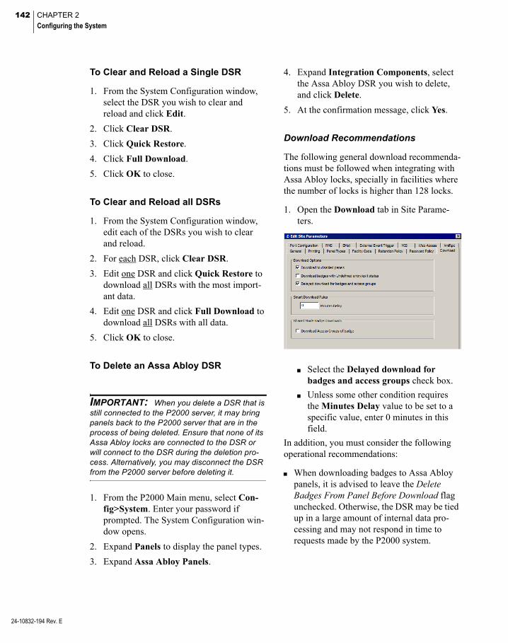
142 CHAPTER 2
Configuring the System
24-10832-194 Rev. E
To Clear and Reload a Single DSR
1. From the System Configuration window, select the DSR you wish to clear and reload and click Edit.
2. Click Clear DSR.
3. Click Quick Restore.
4. Click Full Download.
5. Click OK to close.
To Clear and Reload all DSRs
1. From the System Configuration window, edit each of the DSRs you wish to clear and reload.
2. For each DSR, click Clear DSR.
3. Edit one DSR and click Quick Restore to download all DSRs with the most import-ant data.
4. Edit one DSR and click Full Download to download all DSRs with all data.
5. Click OK to close.
To Delete an Assa Abloy DSR
IMPORTANT: When you delete a DSR that is still connected to the P2000 server, it may bring panels back to the P2000 server that are in the process of being deleted. Ensure that none of its Assa Abloy locks are connected to the DSR or will connect to the DSR during the deletion pro-cess. Alternatively, you may disconnect the DSR from the P2000 server before deleting it.
1. From the P2000 Main menu, select Con-fig>System. Enter your password if prompted. The System Configuration win-dow opens.
2. Expand Panels to display the panel types.
3. Expand Assa Abloy Panels.
4. Expand Integration Components, select the Assa Abloy DSR you wish to delete, and click Delete.
5. At the confirmation message, click Yes.
Download Recommendations
The following general download recommenda-tions must be followed when integrating with Assa Abloy locks, specially in facilities where the number of locks is higher than 128 locks.
1. Open the Download tab in Site Parame-ters.
Select the Delayed download for badges and access groups check box.
Unless some other condition requires the Minutes Delay value to be set to a specific value, enter 0 minutes in this field.
In addition, you must consider the following operational recommendations:
When downloading badges to Assa Abloy panels, it is advised to leave the Delete Badges From Panel Before Download flag unchecked. Otherwise, the DSR may be tied up in a large amount of internal data pro-cessing and may not respond in time to requests made by the P2000 system.
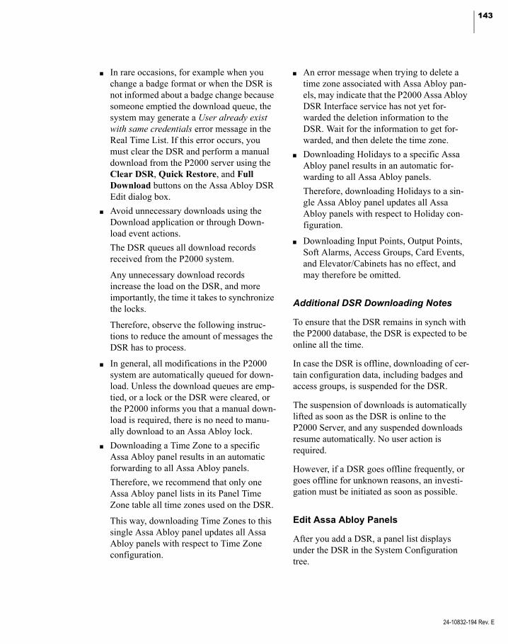
143
In rare occasions, for example when you change a badge format or when the DSR is not informed about a badge change because someone emptied the download queue, the system may generate a User already exist with same credentials error message in the Real Time List. If this error occurs, you must clear the DSR and perform a manual download from the P2000 server using the Clear DSR, Quick Restore, and Full Download buttons on the Assa Abloy DSR Edit dialog box.
Avoid unnecessary downloads using the Download application or through Down-load event actions.
The DSR queues all download records received from the P2000 system.
Any unnecessary download records increase the load on the DSR, and more importantly, the time it takes to synchronize the locks.
Therefore, observe the following instruc-tions to reduce the amount of messages the DSR has to process.
In general, all modifications in the P2000 system are automatically queued for down-load. Unless the download queues are emp-tied, or a lock or the DSR were cleared, or the P2000 informs you that a manual down-load is required, there is no need to manu-ally download to an Assa Abloy lock.
Downloading a Time Zone to a specific Assa Abloy panel results in an automatic forwarding to all Assa Abloy panels.
Therefore, we recommend that only one Assa Abloy panel lists in its Panel Time Zone table all time zones used on the DSR.
This way, downloading Time Zones to this single Assa Abloy panel updates all Assa Abloy panels with respect to Time Zone configuration.
An error message when trying to delete a time zone associated with Assa Abloy pan-els, may indicate that the P2000 Assa Abloy DSR Interface service has not yet for-warded the deletion information to the DSR. Wait for the information to get for-warded, and then delete the time zone.
Downloading Holidays to a specific Assa Abloy panel results in an automatic for-warding to all Assa Abloy panels.
Therefore, downloading Holidays to a sin-gle Assa Abloy panel updates all Assa Abloy panels with respect to Holiday con-figuration.
Downloading Input Points, Output Points, Soft Alarms, Access Groups, Card Events, and Elevator/Cabinets has no effect, and may therefore be omitted.
Additional DSR Downloading Notes
To ensure that the DSR remains in synch with the P2000 database, the DSR is expected to be online all the time.
In case the DSR is offline, downloading of cer-tain configuration data, including badges and access groups, is suspended for the DSR.
The suspension of downloads is automatically lifted as soon as the DSR is online to the P2000 Server, and any suspended downloads resume automatically. No user action is required.
However, if a DSR goes offline frequently, or goes offline for unknown reasons, an investi-gation must be initiated as soon as possible.
Edit Assa Abloy Panels
After you add a DSR, a panel list displays under the DSR in the System Configuration tree.
24-10832-194 Rev. E

144 CHAPTER 2
Configuring the System
24-10832-194 Rev. E
New panels cannot be added manually. How-ever, you can edit or delete the panels, as nec-essary.
To Edit an Assa Abloy Panel
1. From the P2000 Main menu, select Con-fig>System. Enter your password if prompted. The System Configuration win-dow opens.
2. Expand Panels to display the panel types.
3. Expand Assa Abloy Panels.
4. Expand Integration Components.
5. Expand the DSR that has the panel you wish to edit.
6. Right-click over the panel you wish to edit and select Edit. The Assa Abloy Panel Edit dialog box opens.
7. If this is a partitioned system, select the Partition in which the Assa Abloy panel is active.
8. Click Public if you wish the Assa Abloy panel to be visible to all partitions.
9. The Name field displays the name auto-matically assigned to the panel. You can however enter a different name.
10. Click Enabled to enable the Assa Abloy panel.
Note: When a panel is disabled, and the Download to disabled panels check box is selected in the Download tab of Site Parameters, data to be downloaded to an Assa Abloy panel is added to the download queue (it is not down-loaded to the DSR until the panel is enabled). If the Download to disabled panels check box is not selected, no Assa Abloy data is added to the queue for download.
11. The Query String value is used with mes-sage filtering (see Define Query String Fil-ters on page 225).
12. Click the Clear Lock button if you wish to delete all P2000 data (for example, badge data or access groups) from the Assa Abloy panel. For more information, see To Clear and Reload a Single Lock and To Clear and Reload Several Locks.
IMPORTANT: After clearing a lock, and once the DSR downloads these changes to the panel, cardholders are unable to gain access via the Assa Abloy door locks.
13. Click OK to save the panel information.
To Clear and Reload a Single Lock
1. From the System Configuration window, select the Assa Abloy panel you wish to clear and reload and click Edit.
2. Click Clear Lock.
3. Click OK to close.
4. Open the Download application and select the Assa Abloy panel.
5. From the Item to Download box, select Terminals and Badges. Make sure that the Delete Badges From Panel Before Down-load flag is not selected; otherwise, the download process takes much longer.
6. Click Download.

145
To Clear and Reload Several Locks
1. From the System Configuration window, edit each of the Assa Abloy panels you wish to clear and reload.
2. For each panel click Clear Lock.
3. Click OK to close.
4. Open the Download application and select all Assa Abloy panels that were cleared.
5. From the Item to Download box, select Terminals and Badges. Make sure that the Delete Badges From Panel Before Download flag is not selected; otherwise, the download process takes much longer.
6. Click Download.
To Move a Panel to a Different DSR
Use the following instructions to properly relocate an Assa Abloy panel to a different DSR. In this example a lock is moved from DSR1 to DSR2:
1. Ensure that DSR1 is online to the P2000 system.
2. Use the LCT configuration tool to config-ure the lock to not talk to any existing DSR; that is, neither DSR1 nor DSR2.
3. Delete the panel from the P2000 system, under the DSR1 integration component.
4. Use the LCT to configure the lock to talk to the new DSR; that is, DSR2.
5. Ensure that DSR2 is online to the P2000 system.
6. The panel shows up under the DSR2 inte-gration component.
7. Clear the lock and download from the P2000 system.
To Delete an Assa Abloy Panel
IMPORTANT: You should only delete an Assa Abloy panel from the P2000 system if the lock is no longer connected to the DSR. Otherwise, the panel may be automatically added again to the system.
1. From the P2000 Main menu, select Con-fig>System. Enter your password if prompted. The System Configuration win-dow opens.
2. Expand Panels to display the panel types.
3. Expand Assa Abloy Panels.
4. Expand Integration Components.
5. Expand the DSR that has the panel you wish to delete.
6. Right-click over the panel you wish to delete and select Delete.
7. Click Yes to confirm.
Assa Abloy Panel Time Zones
Note: Each Assa Abloy lock can only store up to 32 different time blocks. A time zone may have multiple time blocks.
To keep the number of time blocks inside each lock to a minimum, we recommend using a very basic Time Zone strategy for Assa Abloy locks.
The access rights of a badge are determined by the combination of Access Groups and Time Zones.
Ensure that Access Groups containing Assa Abloy panels are only paired with Time Zones that are suitable for Assa Abloy pan-els.
It is not required to list a Time Zone in the Panel Time Zone table of an Assa Abloy panel in order for it to be used to grant access to badges.
24-10832-194 Rev. E

146 CHAPTER 2
Configuring the System
24-10832-194 Rev. E
It is required to list a Time Zone in the Panel Time Zone table of an Assa Abloy panel in order for it to be used as the “Over-ride Timezone” in the terminal definition.
The exclusion of a Time Zone from the Panel Time Zone table cannot be used to curtail the access rights of defined badges. Instead, the Access Groups shall be chosen to only include the applicable Assa Abloy panels.
In general, removing or rearranging Time Zones in a Panel Time Zone table is not advisable. If such actions are necessary, we recommend downloading all Time Zones and badges to the affected panel after the changes were made by using the Full Download button on the Assa Abloy DSR Edit dialog box.
It is recommended to select one Assa Abloy panel and list in its Panel Time Zone table all time zones that are used on the DSRs. This panel can then be selected in the Download application to download Time Zones, if necessary.
IMPORTANT: Keep the Time Zone strategy for Assa Abloy locks as simple as possible.
Assa Abloy Holiday Definition
Holiday periods behave differently for Assa Abloy locks. See the following notes:
If a day is defined as a Holiday in an Assa Abloy Time Zone, that Time Zone does not grant access to anyone during the entire day, regardless of the Holiday’s defined time periods.
If a day is defined as a Holiday in an Assa Abloy Time Zone, and that Time Zone is used to drive the Unlock or First Person Through feature, those features do not work during the entire day, regardless of the Time Zone’s defined time periods.
Define a specific day to be an Assa Abloy Holiday by doing two things:
declare the specific day as a Holiday (of Type 1, 2, or 3) in the Edit Holiday application (see page 51), and
define the time blocks in a Time Zone for the Holiday’s Type as always Inac-tive.
This configuration matches the intent to have no access and no overrides during the entire holiday.
If in a Time Zone there is any Active period defined for a Holiday of Type 1, 2, or 3, then this configuration is not supported by Assa Abloy locks, and the Assa Abloy inte-gration ignores the particular holiday type for that Time Zone and treat the day as a regular day.
Configure Assa Abloy Terminals
Each Assa Abloy panel controls a single door terminal, which is automatically created with each panel added to the System Configuration window via the DSR. The Assa Abloy terminal consists of seven soft input points.
To Configure Assa Abloy Terminals
1. From the P2000 Main menu, select Con-fig>System. Enter your password if prompted. The System Configuration win-dow opens.
2. Expand Panels to display the panel types.
3. Expand Assa Abloy Panels.
4. Expand Integration Components.
5. Expand the DSR that has the panel or ter-minal you wish to configure.
6. Expand the panel that has the terminal you wish to configure.
7. Right-click over the terminal and select Edit. The Assa Abloy Terminal Edit dialog box opens at the General tab.
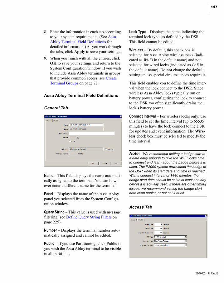
147
8. Enter the information in each tab according to your system requirements. (See Assa Abloy Terminal Field Definitions for detailed information.) As you work through the tabs, click Apply to save your settings.
9. When you finish with all the entries, click OK to save your settings and return to the System Configuration window. If you wish to include Assa Abloy terminals in groups that provide common access, see Create Terminal Groups on page 78.
Assa Abloy Terminal Field Definitions
General Tab
Name – This field displays the name automati-cally assigned to the terminal. You can how-ever enter a different name for the terminal.
Panel – Displays the name of the Assa Abloy panel you selected from the System Configu-ration window.
Query String – This value is used with message filtering (see Define Query String Filters on page 225).
Number – Displays the terminal number auto-matically assigned and cannot be edited.
Public – If you use Partitioning, click Public if you wish the Assa Abloy terminal to be visible to all partitions.
Lock Type – Displays the name indicating the terminal lock type, as defined by the DSR. This field cannot be edited.
Wireless – By default, this check box is selected for Assa Abloy wireless locks (indi-cated as Wi-Fi in the default name) and not selected for wired locks (indicated as PoE in the default name). Do not change the default setting unless special circumstances require it.
This field enables you to define the time inter-val when the lock connect to the DSR. Since wireless Assa Abloy locks typically run on battery power, configuring the lock to connect to the DSR too often significantly drains the lock’s battery power.
Connect Interval – For wireless locks only; use this field to set the time interval (up to 65535 minutes) to have the lock connect to the DSR for updates and event information. The Wire-less check box must be selected to modify the time interval.
Note: We recommend setting a badge start to a date early enough to give the Wi-Fi locks time to connect and learn about the badge before it is used. The P2000 system downloads the badge to the DSR when its start date and time is reached. With a connect interval of 1440 minutes, the badge start date should be set to at least one day before it is actually used. If there are other timing issues, we recommend setting the badge start date even earlier, or not set it at all.
Access Tab
24-10832-194 Rev. E

148 CHAPTER 2
Configuring the System
24-10832-194 Rev. E
Access Time – Enter a time in seconds that the door strike is energized after each valid badge access request. The default value is 5 seconds.
Shunt Time – Enter a time in seconds that the door open alarm is suppressed after a valid badge access request. The shunt time should be longer than the access time. The default value is 10 seconds.
Extended Access Time – Select the amount of time that the door remains unlocked to provide extended access time to cardholders with spe-cial needs.
PIN Type – Determines the use of PIN codes. Select one of the following options:
No PIN Required – In this mode, cardholders do not enter a PIN to gain access through a door.
PIN Required – In this mode, cardholders that have a PIN must enter their PIN in con-junction with presenting a valid badge. PIN codes can be entered before or after present-ing a badge. This feature is not supported on all locks (for example, Persona or Passport locks). Check with your local Assa Abloy dealer for information on PIN support with other locks. Cardholders that do not have a PIN, do not have to enter a PIN in conjunc-tion with presenting a valid badge.
PIN After Badge – In this mode, cardholders that have a PIN must enter their PIN in con-junction with presenting a valid badge. PIN codes must be entered after presenting a badge. Cardholders that do not have a PIN, do not have to enter a PIN in conjunction with presenting a valid badge.
Note: For information on the number of sup-ported PIN digits on Assa Abloy locks, check with your local Assa Abloy dealer.
Override Type – If a time zone is selected in the Override Timezone drop-down list, the Over-ride feature functions according to one of the following options:
Unlock – The door automatically unlocks and remains unlocked during the active period of the selected time zone.
First Person Through – The door remains locked during the active period of the selected time zone until a cardholder pres-ents a valid badge at the reader, at which time the door remains unlocked for the remainder of the time zone’s active period.
Override Timezone – To disable the Override feature, select <never overridden>. To use the Override feature in accordance with the Over-ride Type selected, select a time zone during which the override period is active.
Configure Assa Abloy Soft Input Points
The P2000 system monitors the following soft input points for Assa Abloy panels and termi-nals:
Low Battery (Low Batt) – Indicates that the wireless lock’s battery is failing. Does not apply to wired locks.
Forced Door (Forced) – Indicates when the door has been opened without a valid badge having been presented to the reader first.
Out of Sync (OutOfSync) – Indicates when the DSR and lock are out of sync, which can be caused by numerous events (for example, downloading a badge with an invalid badge format for the lock or exceeding the number of time periods for the lock).
Propped Door (Propped) – Indicates when a door has been opened with a valid badge but has been held open longer than the shunt time.

149
Tamper – Indicates when someone has tam-pered with the lock or firmware.
Terminal Down (Term Down) – Since an Assa Abloy panel and terminal are essentially the same in the P2000 system, watch for panel down indications.
Panel Down (PanelDown) – Listed under Soft Input Points in the System Configuration tree; this soft input point indicates when panel communications have ceased.
To Configure Assa Abloy Soft Input Points
1. From the P2000 Main menu, select Con-fig>System. Enter your password if prompted. The System Configuration win-dow opens.
2. Expand Panels to display the panel types.
3. Expand Assa Abloy Panels.
4. Expand Integration Components.
5. Expand the DSR that has the panel or ter-minal and the soft input point you wish to configure.
6. Expand the panel that has the terminal and soft input point you wish to configure.
7. Expand the terminal to view the available soft input points.
8. Right-click over the soft input point you wish to edit and select Edit. The Input Point dialog box opens. This dialog box consists of four tabs: General, Alarm Options, I/O Linking, and Misc.
Note: All of the fields on the I/O Linking and Misc tabs, including many fields on the General tab, cannot be modified.
9. Modify the fields on the desired tabs accordingly. For information on the Gen-eral and Alarm Options tabs, see Input Point Field Definitions on page 82.
10. Click OK.
Assa Abloy Status Information
The status of Assa Abloy components can be monitored on the P2000 System Status win-dow.
DSR Status Information
The DSR is represented as an Integration Component in System Status with the follow-ing states:
Unknown – The status has not yet been determined.
Up – The P2000 system is communicating with the DSR.
Down – The P2000 system is not communi-cating with the DSR.
Panel and Terminal Status Information
Each door lock is represented in the P2000 system as a panel in System Status with the following states:
Unknown – The status has not yet been deter-mined.
Up – The panel is currently online with the DSR.
Down – The panel is currently offline with the DSR. This is the normal state for wireless locks.
Disabled – The P2000 system has been instructed not to communicate with the panel.
24-10832-194 Rev. E

150 CHAPTER 2
Configuring the System
24-10832-194 Rev. E
Real Time Functions
When access is denied, the Real Time List shows one of three different reasons why access is denied.
Invalid Card is shown when:
a badge has recently expired
the presented badge is not known to the lock
the wrong card format was selected
Invalid Card Timezone is shown when a badge has access rights to the door, but not at the current time. This message is not gen-erated for Assa Abloy PoE locks, but only the Assa Abloy Wi-Fi locks.
Invalid Reader is shown for all other rea-sons, including:
the deadbolt is thrown
the lock is currently in Lockout mode
the Wi-Fi lock is currently communicat-ing with the DSR
the badge is presented outside of a valid time zone
Even though the last two cases traditionally would be mapped to an Invalid Card message, the information received from the DSR does not distinguish this case from some other cases that would traditionally be mapped to the Invalid Reader message. Therefore, the Invalid Reader message needs to be understood as the generic message for access being denied by an Assa Abloy lock.
For information, see Using the Real Time List on page 342.
Assa Abloy Wi-Fi locks are not permanently connected to the DSR. For this reason, real-time functions, such as operating a door, and real time database modification and event reporting are not supported.
Communication between the DSR and the locks may be as frequent as once per day, but can be less frequent.
Assa Abloy PoE locks are permanently con-nected to the DSR, and real-time operations as well as real-time database modification and event reporting are supported.
Change of State Reporting
Assa Abloy locks report the following condi-tions to the P2000 system: Reader Down, Reader Up/Normal, Override, and Lockout, as well as Forced Door and Propped Door through the respective soft input points. The temporary unlocking of a door because of an access grant, or the Unlock for Access Time command, or the Open Door action from the Real Time Map, is not reported.
Lockout Mode with Assa Abloy PoE Locks
The P2000 Door Control application supports the ability to set an Assa Abloy PoE door into Lockout mode. In this mode, the lock denies access to all users, except those that have the Assa Abloy Emergency privilege. P2000 oper-ators cannot assign this privilege because of restrictions with the DSR.
For information see, Controlling Doors on page 290.
File Maintenance on the DSR Server
The DSR produces *.zip and *.log files that contain archived logs; and which are stored on the computer hosting the DSR. These files are normally located in the \Program Files (x86)\ DSR\logs and the \Program Files (x86)\DSR\ logarchives folders.
However, the DSR does not purge them auto-matically or regularly.
To avoid running out of disk space on the com-puter that hosts the DSR, we recommend peri-odically deleting these files manually.

151
Configure Mercury Panels and Components
The P2000 system can communicate with a variety of Mercury Security Corporation’s access control hardware products to provide access control, alarm monitoring, and other security operations.
Mercury panels offer different solutions to fit your access control needs, such as IP and Power over Ethernet (PoE) capabilities, up to 64 doors per panel, support for installations that use RS-485 communications, and other configuration options for small-to-large secu-rity applications, whether you are installing a new security system or retrofitting an existing one. The following panel types are supported:
Panel Type Max. Number of Terminals
EP1501 17
EP1502 64
EP2500 64
Schlage PIM400-1501* 16
* Does not offer many of the features provided with the other Mercury panel types.
Before you use the functions described in this section, the Mercury hardware must be prop-erly installed and configured to communicate with the P2000 system. Refer to the hardware installation instructions that were shipped with your Mercury equipment.
Once you define your Mercury panels, termi-nals, inputs, and outputs, see Configure Mer-cury Elevators on page 184 for specific instructions to implement elevator access con-trol using Mercury panels, and also see Mer-cury Intrusion Interface on page 323 for spe-cific instructions to implement intrusion detection using Mercury panels.
IMPORTANT: This P2000 software release is compatible with Mercury panels that use firmware Versions 1.18.7,1.19, or 1.22. Other versions may not be compatible with this release of the P2000 software.
Configure Mercury Facility Parameters
Before configuring Mercury hardware compo-nents, you must define facility wide settings associated with your Mercury devices.
To Configure Mercury Facility Settings
1. From the P2000 Main menu, select Con-fig>System. Enter your password if prompted. The System Configuration win-dow opens.
2. Expand Panels to display the panel types.
3. Select Mercury Panels and click Edit. The Mercury Facility dialog box opens.
4. Fill in the information on each tab accord-ing to the following Mercury Facility Field Definitions.
5. As you work through the tabs, click Apply at any time to save your entries.
6. After you have entered all the information, click OK to save your settings.
Mercury Facility Field Definitions
Facility Tab
Use this tab to define access parameters asso-ciated with Mercury readers.
24-10832-194 Rev. E
152 CHAPTER 2
Configuring the System
24-10832-194 Rev. E
Access Levels – Displays the maximum num-ber of access groups (up to 32), that can be assigned to a badge.
Multi-Card Access Time Out (sec) – Enter the time in seconds (0 to 60) that the system waits for a subsequent card to be presented at readers that require more than one card. For systems using the Two Badge Access function (see page 167), we recommend entering a value of 1 to 60 seconds. If you enter 0, the system reverts to the default value of 15 seconds.
Note: Changes to Multi-Card Access Time Out require performing a Panel Download procedure to all Mercury panels.
Reader Feedback Mode – Select the option that determines the acoustic feedback that the read-ers produce upon access grant or access deny activity.
Mercury Default – If selected, an access grant results in one short beep, and an access deny results in three short beeps.
Custom – If selected, an access grant results in two short beeps, and an access deny results in three short beeps
Note: To use this feature, the buzzer output of the Mercury hardware must be connected to the reader’s beeper/buzzer control line. You must also set the LED Mode in the Terminal Reader Tab to Generic 1-wire, tri-state, bi-color.
Note: The Reader Feedback Mode has no influence on the behavior of any Schlage or Aperio locks.
PIN Duress Mode – Select one of the following PIN code modes used for detecting duress:
Note: To report duress with a PIN code, you must also select the Allow PIN before Badge option in the Terminal Access Tab, to allow users to enter the PIN code before swiping their badge. This applies only to PIN Append and only when the PINs have the maximum number of digits.
Mercury Legacy Mode – Uses the normal duress PIN codes, where a value of 1 is added to the last PIN digit. For example, PIN 1234 would become 1235. If the last PIN digit is a 9, the last digit in the PIN code becomes 0, for example PIN 1239 would become 1230.
PIN Append – Appends a duress value (0 to 9) to the PIN code. For example, PIN 1234 with a duress value of 8 would become 12348.
PIN Code Offset – Adds a duress value (1 to 9) to the last PIN digit. For example, PIN 1234 with a duress value of 2 would become 1236, PIN 1239 would become 1231.
Offset / Append Value – Select the value that identifies the PIN append or PIN code offset value.
Note: Changes to the PIN Duress Mode and to the Offset / Append Value require restarting the P2000 Mercury Interface Service for the change to be effective. You must also download panel information to all Mercury panels.
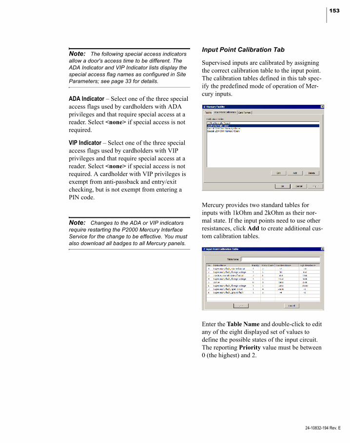
153
Note: The following special access indicators allow a door's access time to be different. The ADA Indicator and VIP Indicator lists display the special access flag names as configured in Site Parameters; see page 33 for details.
ADA Indicator – Select one of the three special access flags used by cardholders with ADA privileges and that require special access at a reader. Select <none> if special access is not required.
VIP Indicator – Select one of the three special access flags used by cardholders with VIP privileges and that require special access at a reader. Select <none> if special access is not required. A cardholder with VIP privileges is exempt from anti-passback and entry/exit checking, but is not exempt from entering a PIN code.
Note: Changes to the ADA or VIP indicators require restarting the P2000 Mercury Interface Service for the change to be effective. You must also download all badges to all Mercury panels.
Input Point Calibration Tab
Supervised inputs are calibrated by assigning the correct calibration table to the input point. The calibration tables defined in this tab spec-ify the predefined mode of operation of Mer-cury inputs.
Mercury provides two standard tables for inputs with 1kOhm and 2kOhm as their nor-mal state. If the input points need to use other resistances, click Add to create additional cus-tom calibration tables.
Enter the Table Name and double-click to edit any of the eight displayed set of values to define the possible states of the input circuit. The reporting Priority value must be between 0 (the highest) and 2.
24-10832-194 Rev. E
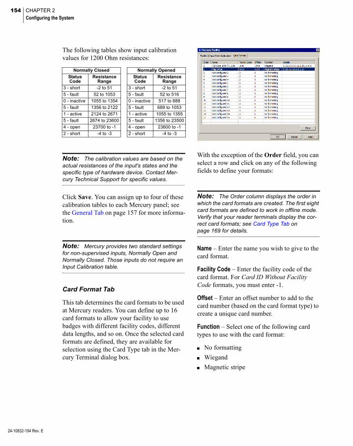
154 CHAPTER 2
Configuring the System
24-10832-194 Rev. E
The following tables show input calibration values for 1200 Ohm resistances:
Normally Closed Normally Opened
Status Code
Resistance Range
Status Code
Resistance Range
3 - short -2 to 51 3 - short -2 to 51
5 - fault 52 to 1053 5 - fault 52 to 516
0 - inactive 1055 to 1354 0 - inactive 517 to 688
5 - fault 1356 to 2122 5 - fault 689 to 1053
1 - active 2124 to 2671 1 - active 1055 to 1355
5 - fault 2674 to 23600 5 - fault 1356 to 23500
4 - open 23700 to -1 4 - open 23600 to -1
2 - short -4 to -3 2 - short -4 to -3
Note: The calibration values are based on the actual resistances of the input's states and the specific type of hardware device. Contact Mer-cury Technical Support for specific values.
Click Save. You can assign up to four of these calibration tables to each Mercury panel; see the General Tab on page 157 for more informa-tion.
Note: Mercury provides two standard settings for non-supervised inputs, Normally Open and Normally Closed. Those inputs do not require an Input Calibration table.
Card Format Tab
This tab determines the card formats to be used at Mercury readers. You can define up to 16 card formats to allow your facility to use badges with different facility codes, different data lengths, and so on. Once the selected card formats are defined, they are available for selection using the Card Type tab in the Mer-cury Terminal dialog box.
With the exception of the Order field, you can select a row and click on any of the following fields to define your formats:
Note: The Order column displays the order in which the card formats are created. The first eight card formats are defined to work in offline mode. Verify that your reader terminals display the cor-rect card formats; see Card Type Tab on page 169 for details.
Name – Enter the name you wish to give to the card format.
Facility Code – Enter the facility code of the card format. For Card ID Without Facility Code formats, you must enter -1.
Offset – Enter an offset number to add to the card number (based on the card format type) to create a unique card number.
Function – Select one of the following card types to use with the card format:
No formatting
Wiegand
Magnetic stripe
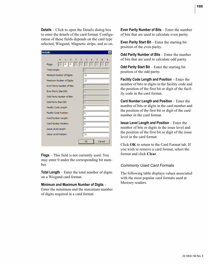
155
Details – Click to open the Details dialog box to enter the details of the card format. Configu-ration of these fields depends on the card type selected, Wiegand, Magnetic stripe, and so on.
Flags – This field is not currently used. You may enter 0 under the corresponding bit num-ber.
Total Length – Enter the total number of digits on a Wiegand card format.
Minimum and Maximum Number of Digits – Enter the minimum and the maximum number of digits required in a card format.
Even Parity Number of Bits – Enter the number of bits that are used to calculate even parity.
Even Parity Start Bit – Enter the starting bit position of the even parity.
Odd Parity Number of Bits – Enter the number of bits that are used to calculate odd parity.
Odd Parity Start Bit – Enter the starting bit position of the odd parity.
Facility Code Length and Position – Enter the number of bits or digits in the facility code and the position of the first bit or digit of the facil-ity code in the card format.
Card Number Length and Position – Enter the number of bits or digits in the card number and the position of the first bit or digit of the card number in the card format.
Issue Level Length and Position – Enter the number of bits or digits in the issue level and the position of the first bit or digit of the issue level in the card format.
Click OK to return to the Card Format tab. If you wish to remove a card format, select the format and click Clear.
Commonly Used Card Formats
The following table displays values associated with the most popular card formats used at Mercury readers.
24-10832-194 Rev. E

156 CHAPTER 2
Configuring the System
24-10832-194 Rev. E
Fla
g T
o B
e S
et t
o 1
Tota
l L
eng
th
Min
imu
m N
um
ber
of
Dig
its
Ma
xim
um
Nu
mb
er
of
Dig
its
Eve
n P
arit
y N
um
ber
of
Bit
s
Ev
en P
arit
y S
tart
Bit
Od
d P
arit
y N
um
be
r o
f B
its
Od
d P
arit
y S
tart
Bit
Fac
ility
Co
de
Len
gth
Fac
ility
Co
de
Po
siti
on
Car
d N
um
ber
Le
ng
th
Car
d N
um
ber
Po
siti
on
Issu
e L
evel
Len
gth
Issu
e L
evel
Po
siti
on
Magnetic Stripe (example) – – 12 12 – – – – 5 0 6 5 1 11
26-bit Wiegand Standard – 26 – – 13 0 13 13 8 1 16 9 0 0
34-bit Wiegand Standard – 34 – – 0 0 0 0 -13 32 -16 16 -3 19
35-bit HID Corporate 1000 – 35 – – 0 0 0 0 12 2 20 14 0 0
37-bit HID H10302 – 37 – – 19 0 19 18 0 0 32 4 0 0
37-bit HID H10304 – 37 – – 19 0 19 18 16 1 19 17 0 0
Card ID with Facility Code* – – F + C F + C – – – – F 0 C F 0 0
Card ID without Facility Code *
– – C C – – – – 0 0 C 0 0 0
* F = number of digits in a facility code C = number of digits in a card number.
Configure Mercury Panels
After you install the Mercury hardware and define facility parameters, you must configure the P2000 Server to communicate with Mer-cury panels by defining connection settings, time information, and other parameters.
Note: Encryption of all messaging between Mercury panels and the P2000 Server is done through the Transport Layer Security (TLS) proto-col. The encrypted communication uses the TLS If Available setting, which is configured using Mercury’s web browser interface.
To Configure Mercury Panels
1. From the P2000 Main menu, select Con-fig>System. Enter your password if prompted. The System Configuration win-dow opens.
2. Expand Panels to display the panel types.
3. Select Mercury Panels and click Add. The Mercury Panel Edit dialog box opens.
4. Fill in the information on each tab. (See Mercury Panel Field Definitions for details.)
5. As you work through the tabs, you may click Apply to save your entries.
IMPORTANT: You cannot modify certain panel parameters after you save the panel infor-mation in the database.
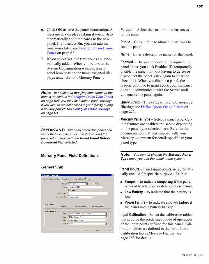
157
6. Click OK to save the panel information. A message box displays asking if you wish to automatically add time zones to the new panel. If you select No, you can add the time zones later; see Configure Panel Time Zones on page 62.
7. If you select Yes, the time zones are auto-matically added. When you return to the System Configuration window, a new panel icon bearing the name assigned dis-plays under the root Mercury Panels.
Note: In addition to applying time zones to the panels (described in Configure Panel Time Zones on page 62), you may also define panel holidays if you wish to restrict access in your facility during a holiday period; see Configure Panel Holidays on page 63.
IMPORTANT: After you create the panel and verify that it is online, you must download the panel information with the Reset Panel Before Download flag selected.
Mercury Panel Field Definitions
General Tab
Partition – Select the partition that has access to this panel.
Public – Click Public to allow all partitions to see this panel.
Name – Enter a descriptive name for the panel.
Enabled – The system does not recognize the panel unless you click Enabled. To temporarily disable the panel, without having to delete or disconnect the panel, click again to clear the check box. When you disable a panel, the readers continue to grant access, but the panel does not communicate with the Server until you enable the panel again.
Query String – This value is used with message filtering; see Define Query String Filters on page 225.
Mercury Panel Type – Select a panel type. Cer-tain features are enabled or disabled depending on the panel type selected here. Refer to the documentation that was shipped with your Mercury equipment for details specific to your panel type.
Note: You cannot change the Mercury Panel Type once you add the panel to the system.
Panel Inputs – Panel input points are automati-cally created for specific purposes. Enable:
Tamper – to indicate tampering if the panel is wired to a tamper switch on an enclosure.
Low Battery – to indicate that the battery is low.
Power Failure – to indicate a power failure if the panel uses a battery backup.
Input Calibration – Select the calibration tables that provide the predefined mode of operation of the input points defined for this panel. Cali-bration tables are defined in the Input Point Calibration tab in Mercury Facility, see page 153 for details.
24-10832-194 Rev. E
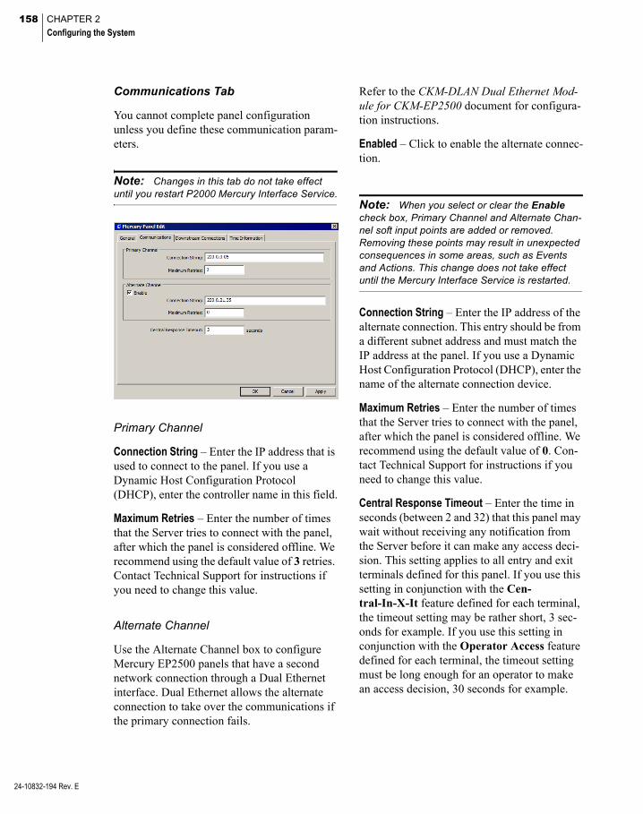
158 CHAPTER 2
Configuring the System
24-10832-194 Rev. E
Communications Tab
You cannot complete panel configuration unless you define these communication param-eters.
Note: Changes in this tab do not take effect until you restart P2000 Mercury Interface Service.
Primary Channel
Connection String – Enter the IP address that is used to connect to the panel. If you use a Dynamic Host Configuration Protocol (DHCP), enter the controller name in this field.
Maximum Retries – Enter the number of times that the Server tries to connect with the panel, after which the panel is considered offline. We recommend using the default value of 3 retries. Contact Technical Support for instructions if you need to change this value.
Alternate Channel
Use the Alternate Channel box to configure Mercury EP2500 panels that have a second network connection through a Dual Ethernet interface. Dual Ethernet allows the alternate connection to take over the communications if the primary connection fails.
Refer to the CKM-DLAN Dual Ethernet Mod-ule for CKM-EP2500 document for configura-tion instructions.
Enabled – Click to enable the alternate connec-tion.
Note: When you select or clear the Enable check box, Primary Channel and Alternate Chan-nel soft input points are added or removed. Removing these points may result in unexpected consequences in some areas, such as Events and Actions. This change does not take effect until the Mercury Interface Service is restarted.
Connection String – Enter the IP address of the alternate connection. This entry should be from a different subnet address and must match the IP address at the panel. If you use a Dynamic Host Configuration Protocol (DHCP), enter the name of the alternate connection device.
Maximum Retries – Enter the number of times that the Server tries to connect with the panel, after which the panel is considered offline. We recommend using the default value of 0. Con-tact Technical Support for instructions if you need to change this value.
Central Response Timeout – Enter the time in seconds (between 2 and 32) that this panel may wait without receiving any notification from the Server before it can make any access deci-sion. This setting applies to all entry and exit terminals defined for this panel. If you use this setting in conjunction with the Cen-tral-In-X-It feature defined for each terminal, the timeout setting may be rather short, 3 sec-onds for example. If you use this setting in conjunction with the Operator Access feature defined for each terminal, the timeout setting must be long enough for an operator to make an access decision, 30 seconds for example.

159
Downstream Connections Tab
IMPORTANT: You cannot modify certain parameters in this tab after you save the panel information in the database.
Mercury panels connect to their terminals using downstream ports. These ports contain parameters that define the port’s behavior, including the type of devices that can be con-nected. The availability of the ports varies by panel type. Also, the options in the Mercury Terminal configuration depend on the choices made in the port definition.
Port – Displays the available ports for the selected panel type. See the following table for details.
Panel Type Port Protocol
Mercury EP1501
Primary 10/100 Ethernet MSP1
TB2 (RS-485) MSP1Schlage PIMDirect Reader *
Mercury EP1502
Primary 10/100 Ethernet MSP1
TB3 (RS-485) MSP1
Mercury EP2500
Primary 10/100 Ethernet MSP1
Port 2 (RS-485) MSP1Schlage PIM
Port 3 (RS-485) MSP1Schlage PIM
Schlage PIM400-1501
TB2 (RS-485) Schlage PIM (uses a fixed 9600 baud rate)
* Select Direct Reader for the EP1501 panel if you want to use a reader on connector TB2 instead of an MSP1 bus.
Baud Rate – Select the specific baud rate for the selected port. Confirm that all terminals associated with the panel are set to the same baud rate. Mismatching of the baud rate between the panel and terminals causes the Real Time List to display a download failure message for the terminal.
Reply Timeout (ms) – Select the time in milli-seconds that the panel waits for a response.
Protocol – Select the type of protocol specific to the selected port; see the table in this section for details.
Dialect – Always use the Default setting.
24-10832-194 Rev. E
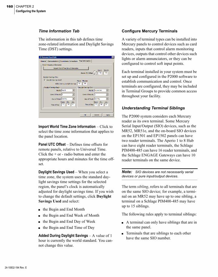
160 CHAPTER 2
Configuring the System
24-10832-194 Rev. E
Time Information Tab
The information in this tab defines time zone-related information and Daylight Savings Time (DST) settings.
Import World Time Zone Information – Click to select the time zone information that applies to the panel location.
Panel UTC Offset – Defines time offsets for remote panels, relative to Universal Time. Click the + or - radio button and enter the appropriate hours and minutes for the time off-set.
Daylight Savings Used – When you select a time zone, the system uses the standard day-light savings time settings for the selected region, the panel’s clock is automatically adjusted for daylight savings time. If you wish to change the default settings, click Daylight Savings Used and select:
the Begin and End Month
the Begin and End Week of Month
the Begin and End Day of Week
the Begin and End Time of Day
Added During Daylight Savings – A value of 1 hour is currently the world standard. You can-not change this value.
Configure Mercury Terminals
A variety of terminal types can be installed into Mercury panels to control devices such as card readers, inputs that control alarm monitoring devices, outputs that control other devices such lights or alarm annunciators, or they can be configured to control soft input points.
Each terminal installed in your system must be set up and configured in the P2000 software to establish communication and control. Once terminals are configured, they may be included in Terminal Groups to provide common access throughout your facility.
Understanding Terminal Siblings
The P2000 system considers each Mercury reader as its own terminal. Some Mercury Serial Input/Output (SIO) devices, such as the MR52, MR51e, and the on-board SIO devices on the EP1501 and EP1502 panels can have two reader terminals. The Aperio 1 to 8 Hub can have eight reader terminals, the Schlage PIM400-485 can have 16 reader terminals, and the Schlage ENGAGE Gateways can have 10 reader terminals on the same device.
Note: SIO devices are not necessarily serial devices or pure input/output devices.
The term sibling, refers to all terminals that are on the same SIO device; for example, a termi-nal on an MR52 may have up to one sibling, a terminal on a Schlage PIM400-485 may have up to 15 siblings.
The following rules apply to terminal siblings:
A terminal can only have siblings that are in the same panel.
Terminals that are siblings to each other have the same SIO number.

161
Terminals that are siblings to each other have the same address configuration (such as Port, Address, IP Address, or MAC Address), but a different Index.
If you change the address configuration (such as Port, Address, IP Address, or MAC Address) of a terminal, the following warn-ing message displays:
If you click Yes, the same change is also made to all siblings of the terminal.
If you change the Enabled flag of a termi-nal, the following warning message dis-plays:
If you click Yes, the same change is also made to all siblings of the terminal.
Updating the firmware of a terminal applies automatically to all of its siblings.
For Mercury terminals MR52, MR51e, and the on-board SIO devices on the EP1501 and EP1502 panels, the following additional rules apply:
Note: These rules do not apply to the Aperio 1 to 8 Hub, the Schlage PIM, or the Schlage ENGAGE devices.
Siblings share their P2000 inputs and P2000 outputs on a first come first serve basis. This allows a more flexible assign-ment of inputs and outputs, in case one ter-minal needs more inputs/outputs than the other. For example:
Out of the 8 inputs of an MR52 there may be 6 assigned to terminal 1 and the remaining 2 to terminal 2.
Out of the 8 inputs of an MR52 there may be 8 assigned to terminal 1 and none left for terminal 2.
Out of the 8 inputs of an MR52 there may be 8 assigned to terminal 2 and none left for terminal 1.
Out of the 8 inputs of an MR52 there may be 4 assigned to terminal 1 and the remaining 4 to terminal 2.
All inputs of an SIO device are equally visi-ble in the System Configuration tree under the Mercury Input Points branch for all of the siblings on that SIO device.
The System Configuration tree under the P2000 Input Points branch shows only P2000 inputs assigned to that specific ter-minal, and not to a sibling.
All outputs of an SIO device are equally visible in the System Configuration tree under the Mercury Output Points branch for all of the siblings on that SIO device.
The System Configuration tree under the P2000 Output Points branch shows only P2000 outputs assigned to that specific ter-minal, and not to a sibling.
24-10832-194 Rev. E
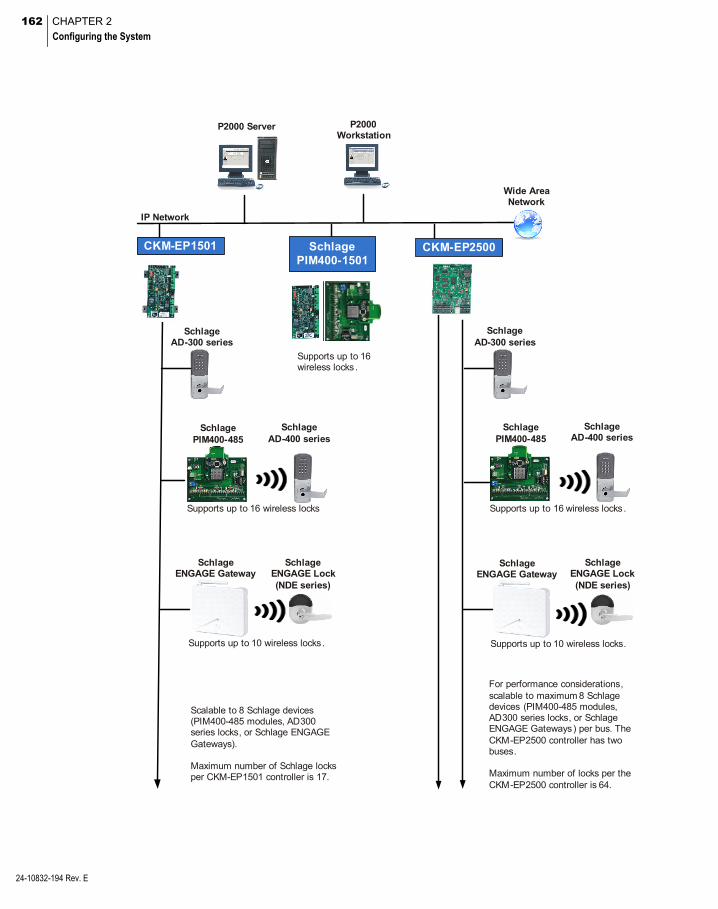
162 CHAPTER 2
Configuring the System
24-10832-194 Rev. E
Wide Area Network
IP Network
P2000 Server P2000 Workstation
CKM-EP1501
SchlageAD-300 series
SchlageAD-400 series
Schlage PIM400-485
Supports up to 16 wireless locks
For performance considerations, scalable to maximum 8 Schlage devices (PIM400-485 modules, AD300 series locks, or Schlage ENGAGE Gateways) per bus. The CKM-EP2500 controller has two buses.
Maximum number of locks per the CKM-EP2500 controller is 64.
CKM-EP2500
Supports up to 16 wireless locks .
Schlage PIM400-1501
Scalable to 8 Schlage devices (PIM400-485 modules, AD300 series locks, or Schlage ENGAGE Gateways).
Maximum number of Schlage locks per CKM-EP1501 controller is 17.
SchlageENGAGE Gateway
Supports up to 10 wireless locks.
SchlageENGAGE Lock(NDE series)
SchlageAD-300 series
SchlageAD-400 series
Schlage PIM400-485
Supports up to 16 wireless locks.
SchlageENGAGE Gateway
Supports up to 10 wireless locks.
SchlageENGAGE Lock(NDE series)

163
To Configure Mercury Terminals
1. In the System Configuration window, expand Panels to display the panel types.
2. Expand Mercury Panels to display all Mercury panels configured in the system.
3. Expand the panel for which you wish to configure the terminal. All the items that can be configured for the panel are listed under it.
4. Select Terminals and click Add. The Mer-cury Terminal Edit dialog box opens at the General tab. Enter the information in each tab according to your system requirements. See the following Mercury Terminal Field Definitions for detailed information.
5. As you work through the tabs, click Apply to save your settings.
6. When all entries are complete, click OK to save the terminal information.
7. Continue to create terminals for every Mercury panel in which they are installed. If you wish to group Mercury terminals that provide common access, see Create Terminal Groups on page 78.
Note: If you delete a Mercury terminal from the system, you must download at a convenient time, all items to the affected panel with the Reset Panel Before Download flag selected. Failure to do so may prevent you from adding another ter-minal to the same address as the deleted termi-nal.
Note: Deleting a Schlage ENGAGE Gateway terminal requires that you first delete all Schlage ENGAGE Locks that are connected to the gate-way.
Mercury Terminal Field Definitions
General Tab
Name – Enter a descriptive name for the termi-nal.
Panel – This field displays the name of the Mercury panel you selected from the System Configuration window.
Query String – This value is used with message filtering; see Define Query String Filters on page 225.
Number – Select a terminal number. Refer to your specific hardware configuration docu-mentation if you need more information on terminal address assignment.
Public – If you use Partitioning, click Public if you wish the Mercury terminal to be visible to all partitions.
Enable – Click if you wish the system to recog-nize this terminal.
Type – Select the terminal module type installed. The specific number of readers, input points, output points, and the terminal features supported depend on the type of module selected here. You cannot change the terminal type after the terminal information is saved.
24-10832-194 Rev. E
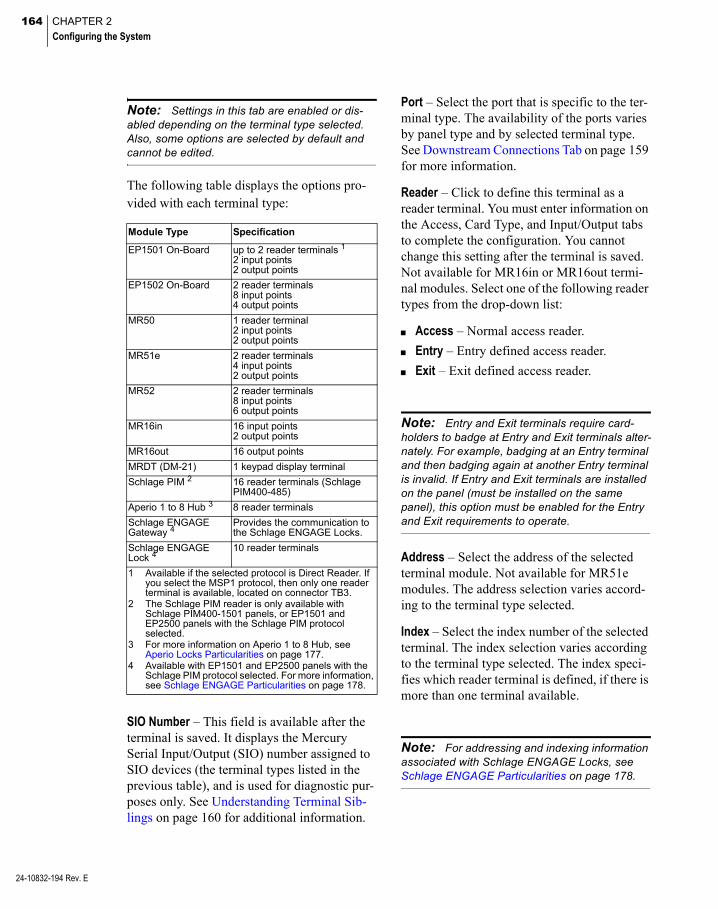
164 CHAPTER 2
Configuring the System
24-10832-194 Rev. E
Note: Settings in this tab are enabled or dis-abled depending on the terminal type selected. Also, some options are selected by default and cannot be edited.
The following table displays the options pro-vided with each terminal type:
Module Type Specification
EP1501 On-Board up to 2 reader terminals 1
2 input points2 output points
EP1502 On-Board 2 reader terminals8 input points4 output points
MR50 1 reader terminal2 input points2 output points
MR51e 2 reader terminals4 input points2 output points
MR52 2 reader terminals8 input points6 output points
MR16in 16 input points2 output points
MR16out 16 output points
MRDT (DM-21) 1 keypad display terminal
Schlage PIM 2 16 reader terminals (Schlage PIM400-485)
Aperio 1 to 8 Hub 3 8 reader terminals
Schlage ENGAGE Gateway 4
Provides the communication to the Schlage ENGAGE Locks.
Schlage ENGAGE Lock 4
10 reader terminals
1 Available if the selected protocol is Direct Reader. If you select the MSP1 protocol, then only one reader terminal is available, located on connector TB3.
2 The Schlage PIM reader is only available with Schlage PIM400-1501 panels, or EP1501 and EP2500 panels with the Schlage PIM protocol selected.
3 For more information on Aperio 1 to 8 Hub, see Aperio Locks Particularities on page 177.
4 Available with EP1501 and EP2500 panels with the Schlage PIM protocol selected. For more information, see Schlage ENGAGE Particularities on page 178.
SIO Number – This field is available after the terminal is saved. It displays the Mercury Serial Input/Output (SIO) number assigned to SIO devices (the terminal types listed in the previous table), and is used for diagnostic pur-poses only. See Understanding Terminal Sib-lings on page 160 for additional information.
Port – Select the port that is specific to the ter-minal type. The availability of the ports varies by panel type and by selected terminal type. See Downstream Connections Tab on page 159 for more information.
Reader – Click to define this terminal as a reader terminal. You must enter information on the Access, Card Type, and Input/Output tabs to complete the configuration. You cannot change this setting after the terminal is saved. Not available for MR16in or MR16out termi-nal modules. Select one of the following reader types from the drop-down list:
Access – Normal access reader.
Entry – Entry defined access reader.
Exit – Exit defined access reader.
Note: Entry and Exit terminals require card-holders to badge at Entry and Exit terminals alter-nately. For example, badging at an Entry terminal and then badging again at another Entry terminal is invalid. If Entry and Exit terminals are installed on the panel (must be installed on the same panel), this option must be enabled for the Entry and Exit requirements to operate.
Address – Select the address of the selected terminal module. Not available for MR51e modules. The address selection varies accord-ing to the terminal type selected.
Index – Select the index number of the selected terminal. The index selection varies according to the terminal type selected. The index speci-fies which reader terminal is defined, if there is more than one terminal available.
Note: For addressing and indexing information associated with Schlage ENGAGE Locks, see Schlage ENGAGE Particularities on page 178.
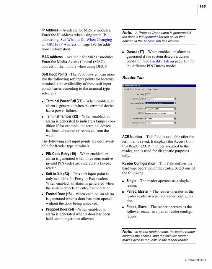
165
IP Address – Available for MR51e modules. Enter the IP address when using static IP addressing. See What to Do When Changing an MR51e IP Address on page 192 for addi-tional information.
MAC Address – Available for MR51e modules. Enter the Media Access Control (MAC) address of the module when using DHCP.
Soft Input Points –The P2000 system can mon-itor the following soft input points for Mercury terminals (the availability of these soft input points varies according to the terminal type selected):
Terminal Power Fail (21) – When enabled, an alarm is generated when the terminal device has a power failure.
Terminal Tamper (22) – When enabled, an alarm is generated to indicate a tamper con-dition if for example, the terminal device has been disturbed or removed from the wall.
The following soft input points are only avail-able for Reader type terminals.
PIN Code Retry (19) – When enabled, an alarm is generated when three consecutive invalid PIN codes are entered at a keypad reader.
Soft-In-X-It (23) – This soft input point is only available for Entry or Exit readers. When enabled, an alarm is generated when the system detects an entry/exit violation.
Forced Door (18) – When enabled, an alarm is generated when a door has been opened without the door being unlocked.
Propped Door (24) – When enabled, an alarm is generated when a door has been held open longer than allowed.
Note: A Propped Door alarm is generated if the door is left opened after the shunt time defined in the Access Tab has expired.
Duress (17) – When enabled, an alarm is generated if the system detects a duress condition. See Facility Tab on page 151 for the different PIN Duress modes.
Reader Tab
ACR Number – This field is available after the terminal is saved. It displays the Access Con-trol Reader (ACR) number assigned to the reader, and is used for diagnostic purposes only.
Reader Configuration – This field defines the hardware operation of the reader. Select one of the following:
Single – The reader operates as a single reader.
Paired, Master – The reader operates as the leader reader in a paired reader configura-tion.
Paired, Slave – The reader operates as the follower reader in a paired reader configu-ration.
Note: In paired reader mode, the leader reader controls the access, and the follower reader makes access requests to the leader reader.
24-10832-194 Rev. E

166 CHAPTER 2
Configuring the System
24-10832-194 Rev. E
Turnstile – The reader provides turnstile access. Security personnel can provide access through turnstile devices using a sin-gle badge to control and count the flow of pedestrian traffic in and out of a facility.
Elevator without feedback – This option is not available for selection. It displays in this field after the reader is assigned to an eleva-tor without the Floor Tracking option selected; see page 185 for details.
Elevator with feedback – This option is not available for selection. It displays in this field after the reader is assigned to an eleva-tor with the Floor Tracking option selected; see page 185 for details.
Paired Reader Terminal – If your reader oper-ates as a leader reader, select the follower reader that defines the paired reader configura-tion. If your reader operates as a follower reader, then select the leader reader that defines the paired reader configuration. You can only select reader terminals that are installed on the same panel.
Keypad Mode – If this is a keypad reader, select one of the following keypad modes to be used with your reader.
<none> Motorola / Indala 8-bit HID 4-bit MR20 8-bit with tamper MR20 8-bit without tamper
Note: Some Schlage Magstripe keypad read-ers are not compatible with Motorola/Indala 8-bit. For those Schlage devices, select MR20 8-bit without tamper.
LED Mode – Select one of the following LED modes associated with the reader:
<none>
Separate red and green, no buzzer
Generic 1-wire, tri-state, bi-color
Dorado 780
LCD
OSDP (for more information, see OSDP Reader Particularities on page 179).
Note: The Generic 1-wire, tri-state, bi-color mode is required if you use the BZR output of the Mercury boards for explicit beeper/buzzer control.
Offline Reader Mode – This option is not avail-able for Schlage or Aperio readers. Select one of the following behavior modes of the reader if the terminal loses communication with the panel:
No Change Disable Reader, no REX Unlocked Locked (No Access, REX Active) Facility Code Only
Default Reader Mode – Select one of the fol-lowing reader default mode of operation (make your selection after the panels starts up):
Disable Reader, no REX Unlocked Locked (No Access, REX Active) Card Only Card and PIN Required
Note: Changes to the Default Reader Mode become effective after you download all items to the affected panel, with the Reset Panel Before Download flag selected. Otherwise, changes become effective the next time the panel is restarted.
Note: The Default Reader Mode selection remains in effect until it is changed either through Door Control, Host Events, Mercury Procedures, or Web UI Maps.
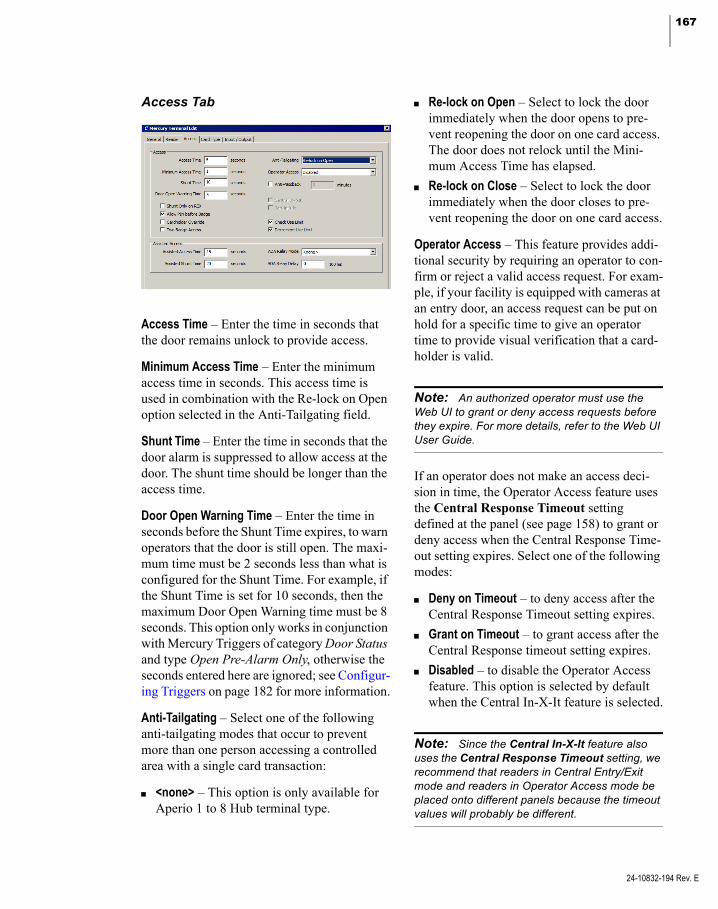
167
Access Tab
Access Time – Enter the time in seconds that the door remains unlock to provide access.
Minimum Access Time – Enter the minimum access time in seconds. This access time is used in combination with the Re-lock on Open option selected in the Anti-Tailgating field.
Shunt Time – Enter the time in seconds that the door alarm is suppressed to allow access at the door. The shunt time should be longer than the access time.
Door Open Warning Time – Enter the time in seconds before the Shunt Time expires, to warn operators that the door is still open. The maxi-mum time must be 2 seconds less than what is configured for the Shunt Time. For example, if the Shunt Time is set for 10 seconds, then the maximum Door Open Warning time must be 8 seconds. This option only works in conjunction with Mercury Triggers of category Door Status and type Open Pre-Alarm Only, otherwise the seconds entered here are ignored; see Configur-ing Triggers on page 182 for more information.
Anti-Tailgating – Select one of the following anti-tailgating modes that occur to prevent more than one person accessing a controlled area with a single card transaction:
<none> – This option is only available for Aperio 1 to 8 Hub terminal type.
Re-lock on Open – Select to lock the door immediately when the door opens to pre-vent reopening the door on one card access. The door does not relock until the Mini-mum Access Time has elapsed.
Re-lock on Close – Select to lock the door immediately when the door closes to pre-vent reopening the door on one card access.
Operator Access – This feature provides addi-tional security by requiring an operator to con-firm or reject a valid access request. For exam-ple, if your facility is equipped with cameras at an entry door, an access request can be put on hold for a specific time to give an operator time to provide visual verification that a card-holder is valid.
Note: An authorized operator must use the Web UI to grant or deny access requests before they expire. For more details, refer to the Web UI User Guide.
If an operator does not make an access deci-sion in time, the Operator Access feature uses the Central Response Timeout setting defined at the panel (see page 158) to grant or deny access when the Central Response Time-out setting expires. Select one of the following modes:
Deny on Timeout – to deny access after the Central Response Timeout setting expires.
Grant on Timeout – to grant access after the Central Response timeout setting expires.
Disabled – to disable the Operator Access feature. This option is selected by default when the Central In-X-It feature is selected.
Note: Since the Central In-X-It feature also uses the Central Response Timeout setting, we recommend that readers in Central Entry/Exit mode and readers in Operator Access mode be placed onto different panels because the timeout values will probably be different.
24-10832-194 Rev. E
168 CHAPTER 2
Configuring the System
24-10832-194 Rev. E
The Operator Access feature makes an auto-matic access decision in case a valid access request is not handled by the operator within the Central Response Timeout. Every addi-tional valid access request that is made at a reader that already has access requests pend-ing, restarts that timeout counter, so that all accumulated valid access requests will have their automatic access decision made at the same time, that is, once the central response timeout has elapsed after the last valid access request. Invalid access requests (requests made by people that do not have access rights to the reader) are denied access immediately and do not restart the timeout counter.
Anti-Passback – Select to enable the anti-pass-back feature to prevent cardholders from using their badge again at this reader until the anti-passback time entered expires.
Note: If cardholders use their badge at a differ-ent reader on the same panel and are granted access, the system resets the anti-passback period to its initial value.
Shunt Only on REX – If enabled, the door alarm is suppressed when a Request to Exit (REX) input signal is received from a REX device associated with the reader, which prompts the door contact to be shunted without setting off the alarm.
Allow PIN before Badge – If enabled, the card-holder can enter the PIN number before pre-senting the badge. The cardholder must press the <#> key after entering the PIN number.
Cardholder Override – If enabled, an authorized cardholder can suppress a propped alarm by performing a badging procedure at the reader’s keypad. The cardholder must have the Over-ride option enabled in the Badge dialog box. Use this activation sequence to perform a card-holder override:
1. Present a valid badge.
2. Within 30 seconds enter the following key sequence at the keypad: *, 0, nnn, # (nnn is the desired shunt time in minutes, with leading zeros if necessary).
3. The door will unlock for a normal access time. During this time, prop the door.
The propped door alarm is suppressed for up to 999 minutes (16 hours and 39 minutes).
Suppression of the propped alarm ends if the door is closed or the time expires. If the door is still propped open when the time expires, a propped door alarm will occur.
Performing the activation sequence while the timer is running will again unlock the door for a normal access time and start a new timer.
Entering *0600# starts or extends an override for 10 hours.
Entering *0000# starts an override that will end immediately.
Note: The door remains locked after being unlocked for the normal access.
Two Badge Access – If enabled, the system requires presenting two badges to grant access.
Central In-X-It – Available for entry and exit readers. If enabled, this terminal operates in Central Entry/Exit mode regardless of the entry/exit status maintained by the panel.
Soft-In-X-It – Available for entry or exit readers. If enabled, this function overrides the system entry and exit control function and allows cardholders to gain access at that reader even though they have the wrong entry and exit sta-tus. An alarm is generated when a violation occurs.

169
Check Use Limit – If enabled, a badge is denied access when its Uses Left counter reaches zero. The maximum number of times a badge can be used is defined in the Security Options tab of the Badge dialog box, see page 253.
Decrement Use Limit – If enabled, a badge dec-rements its Uses Left counter by one every time it is granted access.
Note: The Use Limit options are provided to control the maximum number of times a badge can be granted access.
Assisted Access Box
The Assisted Access option allows you to set up a different access time, to satisfy the requirements for assisted access according to ADA (Americans with Disabilities Act).
Note: Schlage readers support the Assisted Access feature if connected to Mercury EP2500 panels that use firmware versions 1.18.7, 1.19, or 1.22.
Assisted Access Time – Enter the time in sec-onds that the door remains unlocked to provide additional access time to cardholders with spe-cial needs.
Assisted Shunt Time – Enter the time in sec-onds that the door alarm is suppressed to allow additional access time to cardholders with spe-cial needs. The assisted shunt time should exceed the assisted access time by the same amount that the regular shunt time exceeds the regular access time.
ADA Relay Mode – Select one of the following relay modes that specifies the time the ADA relay is activated minus any ADA Relay Delay.
<none> – if there is no ADA Relay support.
Same as Access Time – if an ADA Relay is used, make sure you select the ADA Relay button in the Input/Output tab.
Note: Activation of the ADA Relay is indepen-dent of the special ADA access flag assigned to a cardholder. Also, you must define a Door Contact to make the ADA Relay work, and you must also define the reader on the same terminal as the Door Strike.
ADA Relay Delay – Enter the amount of time (in 100 milliseconds) that needs to elapse after the door is unlocked before the ADA Relay is activated. This may be necessary to avoid operating the door-opening device before the door is fully unlocked.
Card Type Tab
Card Data Formatting – Select the type of card format to be used with this reader.
For magnetic stripe cards, select the Trim Zero Bits and Format To Nibble Array for-mats. Make sure the Data1 / Data0, Wie-gand Pulses format is not selected.
For magnetic stripe cards, you can select the Allow Bi-Directional Mag Decode format to also read cards that are reverse swiped.
For readers that send their input as a Wie-gand signal, select the Data1 / Data0, Wie-gand Pulses format and make sure the Trim Zero Bits, Format To Nibble Array, and Allow Bi-Directional Mag Decode formats are not selected.
To use Card ID, see How to Use Card ID using a Keypad Reader on page 188.
24-10832-194 Rev. E
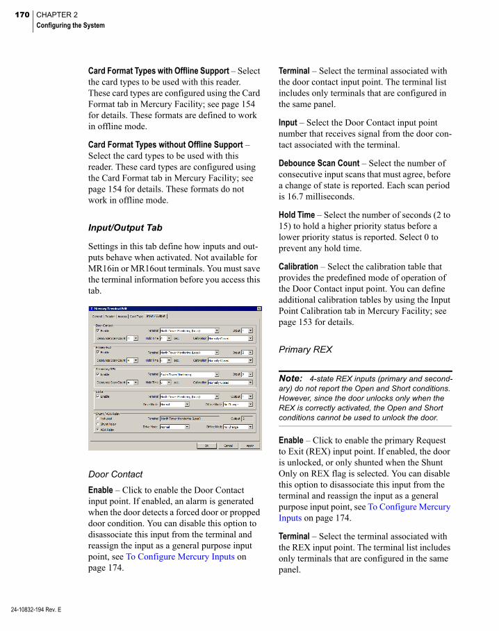
170 CHAPTER 2
Configuring the System
24-10832-194 Rev. E
Card Format Types with Offline Support – Select the card types to be used with this reader. These card types are configured using the Card Format tab in Mercury Facility; see page 154 for details. These formats are defined to work in offline mode.
Card Format Types without Offline Support – Select the card types to be used with this reader. These card types are configured using the Card Format tab in Mercury Facility; see page 154 for details. These formats do not work in offline mode.
Input/Output Tab
Settings in this tab define how inputs and out-puts behave when activated. Not available for MR16in or MR16out terminals. You must save the terminal information before you access this tab.
Door Contact
Enable – Click to enable the Door Contact input point. If enabled, an alarm is generated when the door detects a forced door or propped door condition. You can disable this option to disassociate this input from the terminal and reassign the input as a general purpose input point, see To Configure Mercury Inputs on page 174.
Terminal – Select the terminal associated with the door contact input point. The terminal list includes only terminals that are configured in the same panel.
Input – Select the Door Contact input point number that receives signal from the door con-tact associated with the terminal.
Debounce Scan Count – Select the number of consecutive input scans that must agree, before a change of state is reported. Each scan period is 16.7 milliseconds.
Hold Time – Select the number of seconds (2 to 15) to hold a higher priority status before a lower priority status is reported. Select 0 to prevent any hold time.
Calibration – Select the calibration table that provides the predefined mode of operation of the Door Contact input point. You can define additional calibration tables by using the Input Point Calibration tab in Mercury Facility; see page 153 for details.
Primary REX
Note: 4-state REX inputs (primary and second-ary) do not report the Open and Short conditions. However, since the door unlocks only when the REX is correctly activated, the Open and Short conditions cannot be used to unlock the door.
Enable – Click to enable the primary Request to Exit (REX) input point. If enabled, the door is unlocked, or only shunted when the Shunt Only on REX flag is selected. You can disable this option to disassociate this input from the terminal and reassign the input as a general purpose input point, see To Configure Mercury Inputs on page 174.
Terminal – Select the terminal associated with the REX input point. The terminal list includes only terminals that are configured in the same panel.

171
Input – Select the REX input point number that receives signal from the primary REX associ-ated with the terminal.
Debounce Scan Count – Select the number of consecutive input scans that must agree, before a change of state is reported. Each scan period is 16.7 milliseconds.
Hold Time – Select the number of seconds (2 to 15) to hold a higher priority status before a lower priority status is reported. Select 0 to prevent any hold time.
Calibration – Select the calibration table that provides the predefined mode of operation of the primary REX input point. You can define additional calibration tables by using the Input Point Calibration tab in Mercury Facility; see page 153 for details.
Secondary REX
Enable – Click to enable the secondary Request to Exit (REX) input point. If enabled, the door is unlocked, or only shunted when the Shunt Only on REX flag is selected. You can disable this option to disassociate this input from the terminal and reassign the input as a general purpose input point, see To Configure Mercury Inputs on page 174.
Terminal – Select the terminal associated with the REX input point. The terminal list includes only terminals that are configured in the same panel.
Input – Select the REX input point number that receives signal from the secondary REX asso-ciated with the terminal.
Debounce Scan Count – Select the number of consecutive input scans that must agree, before a change of state is reported. Each scan period is 16.7 milliseconds.
Hold Time – Select the number of seconds (2 to 15) to hold a higher priority status before a lower priority status is reported. Select 0 to prevent any hold time.
Calibration – Select the calibration table that provides the predefined mode of operation of the secondary REX input point. You can define additional calibration tables by using the Input Point Calibration tab in Mercury Facility; see page 153 for details.
Strike
Enable – Click to enable the Strike output point. You can disable this option to disassoci-ate this output from the terminal and reassign the output as a general purpose output point, see To Configure Mercury Outputs on page 176.
Terminal – Select the terminal associated with the door strike output point. The terminal list includes only terminals that are configured in the same panel.
Output – Select the door strike output point number that is activated after each valid badge access request.
Drive Mode – Select one of the following modes that define the door strike output point behavior upon activation:
Normal – This mode locks the door when the strike output state is Inactive, and unlocks the door when the strike output state is Active.
Inverted – This mode unlocks the door when the strike output state is Inactive, and locks the door when the strike output state is Active.
Offline Mode – Select one of the following modes that define the door strike state when the terminal goes offline:
24-10832-194 Rev. E
172 CHAPTER 2
Configuring the System
24-10832-194 Rev. E
No Change – The strike output state does not change.
Inactive – This mode locks the door when the strike output drive mode is Normal, and unlocks the door when the strike output drive mode is Inverted.
Active – This mode unlocks the door when the strike output drive mode is Normal, and locks the door when the strike output drive mode is Inverted.
Shunt/ADA Relay
Note: The Shunt Relay or ADA Relay output point is always defined as the next output point of the selected Strike output point. If the Shunt Relay or ADA Relay output point is not available, the Not used option is automatically selected. Also, you must define a Door Contact to make the Shunt Relay or ADA Relay work, and you must also define the reader on the same terminal as the Door Strike.
Not used – Select if there is no output relay connected to the reader.
Shunt Relay – Select if the relay is connected to an output point that indicates a shunt condi-tion.
ADA Relay – Select if the relay is connected to an output point that controls a door opening device.
Terminal – Displays the name of the terminal associated with the shunt/ADA relay output point.
Output – Displays the shunt/ADA relay output point number that is activated after each valid badge access request.
Drive Mode – Select one of the following modes that define the output point behavior upon activation:
Normal – This mode sets the output point if the output state is Active, and resets the out-put point if the output state is Inactive.
Inverted – This mode resets the output point if the output state is Active, and sets the out-put point if the output state is Inactive.
Offline Mode – Select one of the following modes that define the output point state when the terminal goes offline:
No Change – The output state does not change.
Inactive – This mode resets the output point when the output drive mode is Normal, and sets the output point when the output drive mode is Inverted.
Active – This mode sets the output point when the output drive mode is Normal, and resets the output point when the output drive mode is Inverted.
Configure Mercury Inputs
The Mercury configuration provides several types of input points. Some of these input points have a predefined and unchanging pur-pose, such as to indicate panel tamper. Other input points are dedicated to access control functions, such as receiving input from door contacts and REX devices; and other input points can be used for a variety of purposes and devices, such as power failure.
The system automatically creates panel input points under the selected Mercury panel and can be enabled for alarm and non-alarm pur-poses.
The system also automatically creates two sets of terminal input points under the selected ter-minal: P2000 Input Points and Mercury Input Points. The terminal hardware type determines the available number of input points on both sets. See the table on page 163 for the number of inputs provided with each module type.
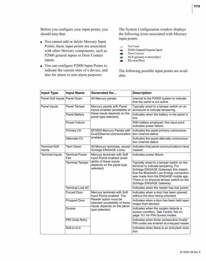
173
Before you configure your input points, you should note that:
You cannot add or delete Mercury Input Points; those input points are associated with other Mercury components, such as P2000 general inputs or Door Contact inputs.
You can configure P2000 Input Points to indicate the current state of a device, and also for alarm or non-alarm purposes.
The System Configuration window displays the following icons associated with Mercury input points:
The following possible input points are avail-able:
Input Type Input Name Generated for... Description
Panel Soft Inputs Panel Down All Mercury panels. Internal to the P2000 system to indicate that the panel is not active.
Panel Inputs Panel Tamper Mercury panels with Panel Inputs enabled (availability of these inputs depends on the panel type selected).
Typically wired to a tamper switch on an enclosure to indicate tampering.
Panel Battery Indicates when the battery in the panel is low.
Power Failure With battery employed, this input point indicates power failure.
Primary Ch EP2500 Mercury Panels with Dual Ethernet communication enabled.
Indicates the panel primary communica-tion channel status.
Alternate Ch Indicates the panel alternate communica-tion channel status.
Terminal Soft Inputs
Term Down All Mercury terminals, except Schlage ENGAGE Locks.
Indicates that panel communications have ceased.
Terminal Inputs Terminal Power Fail
Mercury terminals with Soft Input Points enabled (avail-ability of these inputs depends on the panel type selected).
Indicates power failure.
Terminal Tamper Typically wired to a tamper switch on the terminal to indicate tampering. For Schlage ENGAGE Gateways this means that the Bluetooth Low Energy connection was made from the ENGAGE mobile app. There is no physical tamper switch on the Schlage ENGAGE Gateway.
Terminal Lost AC Indicates when the reader has lost power.
Forced Door Mercury terminals with Soft Input Points enabled. The Reader option must be selected (availability of these inputs depends on the panel type selected).
Indicates when a door has been opened without the door being unlocked.
Propped Door Indicates when a door has been held open longer than allowed.
Duress Indicates when the system detects a duress condition. See Facility Tab on page 151 for PIN Duress modes.
PIN Code Retry Indicates when three consecutive invalid PIN codes are entered at a keypad reader.
Soft-In-X-It Indicates when there is an entry/exit viola-tion.
24-10832-194 Rev. E
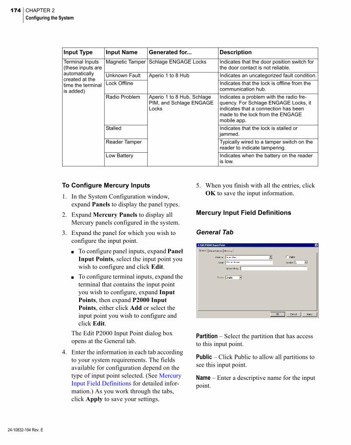
174 CHAPTER 2
Configuring the System
24-10832-194 Rev. E
To Configure Mercury Inputs
1. In the System Configuration window, expand Panels to display the panel types.
2. Expand Mercury Panels to display all Mercury panels configured in the system.
3. Expand the panel for which you wish to configure the input point.
To configure panel inputs, expand Panel Input Points, select the input point you wish to configure and click Edit.
To configure terminal inputs, expand the terminal that contains the input point you wish to configure, expand Input Points, then expand P2000 Input Points, either click Add or select the input point you wish to configure and click Edit.
The Edit P2000 Input Point dialog box opens at the General tab.
4. Enter the information in each tab according to your system requirements. The fields available for configuration depend on the type of input point selected. (See Mercury Input Field Definitions for detailed infor-mation.) As you work through the tabs, click Apply to save your settings.
5. When you finish with all the entries, click OK to save the input information.
Mercury Input Field Definitions
General Tab
Partition – Select the partition that has access to this input point.
Public – Click Public to allow all partitions to see this input point.
Name – Enter a descriptive name for the input point.
Terminal Inputs (these inputs are automatically created at the time the terminal is added)
Magnetic Tamper Schlage ENGAGE Locks Indicates that the door position switch for the door contact is not reliable.
Unknown Fault Aperio 1 to 8 Hub Indicates an uncategorized fault condition.
Lock Offline Indicates that the lock is offline from the communication hub.
Radio Problem Aperio 1 to 8 Hub, Schlage PIM, and Schlage ENGAGE Locks
Indicates a problem with the radio fre-quency. For Schlage ENGAGE Locks, it indicates that a connection has been made to the lock from the ENGAGE mobile app.
Stalled Indicates that the lock is stalled or jammed.
Reader Tamper Typically wired to a tamper switch on the reader to indicate tampering.
Low Battery Indicates when the battery on the reader is low.
Input Type Input Name Generated for... Description
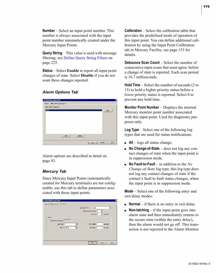
175
Number – Select an input point number. This number is always associated with the input point number automatically created under the Mercury Input Points.
Query String – This value is used with message filtering; see Define Query String Filters on page 225.
Status – Select Enable to report all input point changes of state. Select Disable if you do not want these changes reported.
Alarm Options Tab
Alarm options are described in detail on page 83.
Mercury Tab
Since Mercury Input Points (automatically created for Mercury terminals) are not config-urable, use this tab to define parameters asso-ciated with those input points.
Calibration – Select the calibration table that provides the predefined mode of operation of this input point. You can define additional cali-bration by using the Input Point Calibration tab in Mercury Facility; see page 153 for details.
Debounce Scan Count – Select the number of consecutive input scans that must agree, before a change of state is reported. Each scan period is 16.7 milliseconds.
Hold Time – Select the number of seconds (2 to 15) to hold a higher priority status before a lower priority status is reported. Select 0 to prevent any hold time.
Monitor Point Number – Displays the internal Mercury monitor point number associated with this input point. Used for diagnostic pur-poses only.
Log Type – Select one of the following log types that are used for status notifications:
All – logs all status change.
No Change-of-State – does not log any con-tact changes of state when the input point is in suppression mode.
No Fault-to-Fault – in addition to the No Change-of-State log type, this log type does not log any contact changes of state if the contact’s fault to fault status changes, when the input point is in suppression mode.
Mode – Select one of the following entry and exit delay modes:
Normal – if there is no entry or exit delay.
Non-latching – if the input point goes into alarm state and then immediately returns to the secure state (within the entry delay), then the alarm would not go off. This trans-action is not reported to the Alarm Monitor.
24-10832-194 Rev. E

176 CHAPTER 2
Configuring the System
24-10832-194 Rev. E
Latching – if the input point goes into alarm, regardless if the input point is secure, the alarm goes off, (unless the input point is suppressed). This transaction is reported to the Alarm Monitor and the Real Time List.
Entry Delay – Enter the time in seconds (from 0 to 65,535) that the system delays reporting an entry. This value must be 0 if the entry/exit Mode selected before is Normal.
Exit Delay – Enter the time in seconds (from 0 to 65,535) that the system delays reporting an alarm after the input point is unsuppressed. This value must be 0 if the entry/exit Mode selected before is Normal.
Configure Mercury Outputs
Mercury outputs are provided to trigger exter-nal devices, such as lights and sirens, or can be activated in response to access transactions, such as controlling a door strike or shunting an alarm.
The system automatically creates two sets of terminal output points under the selected ter-minal: P2000 Output Points and Mercury Out-put Points. The terminal hardware type deter-mines the available number of output points on both sets.
As in the input point configuration, you cannot add or delete Mercury Output Points; those output points are associated with other Mer-cury components, such as P2000 general out-puts or Elevator Floor outputs.
The System Configuration window displays the following icons associated with Mercury output points:
To Configure Mercury Outputs
1. In the System Configuration window, expand the terminal that contains the out-put you wish to configure.
2. Expand Output Points, then expand P2000 Output Points and click Add. The Edit Mercury Output Point dialog box opens.
3. If you use partitions, select the appropriate Partition that has access to this output point.
4. If you use partitions, click Public if you want this output point to be visible to all partitions.
5. Enter a descriptive Name for the output point.
6. Select the output point Number. This num-ber is always associated with the output point number automatically created under the Mercury Output Points.
7. The Query String value is used with mes-sage filtering; see Define Query String Fil-ters on page 225.
8. From the Status drop-down list, select Enable if you wish to allow the output point to be activated or deactivated.
9. The Control Point Number displays the internal Mercury control point number associated with this output point. Used for diagnostic purposes only.

177
10. Select one of the following Drive Modes that define the output point behavior upon activation:
Normal – This mode sets the output point if the output state is Active, and resets the output point if the output state is Inactive.
Inverted – This mode resets the output point if the output state is Active, and sets the output point if the output state is Inactive.
11. Select one of the following Offline Modes that define the output point state when the terminal goes offline:
No Change – The output state does not change.
Inactive – Resets the output point when the output drive mode is Normal, and sets the output point when the output drive mode is Inverted.
Active – Sets the output point when the output drive mode is Normal, and resets the output point when output drive mode is Inverted.
12. Select one of the following Active States that are used with the Preset command in the Output Control application:
Reset – to reset the output point.
Set – to set the output point.
Flash – to toggle the output point on and off with the specified On Time and Off Time pattern.
Timed – to turn on the output point for the specified time entered in the Dura-tion field.
13. If the Active State is Timed, enter the Duration in seconds that the output point is turned on.
14. If the Active State is Flash, enter the fol-lowing parameters:
On Time – to toggle the output point on for the time specified here.
Off Time – to toggle the output point off for the time specified here.
Repeat Count – the number of times to repeat the flash cycle.
15. When you finish with all the entries, click OK to save your settings.
Aperio Locks Particularities
Doors connected to Aperio devices cannot be unlocked using Door Control, Control All Doors, or Real Time Map applications.
Doors connected to Aperio devices cannot be controlled using Mercury Procedures and Triggers.
Some Aperio devices that are configured with the Card and PIN Required option, do not grant access after presenting a valid badge and PIN code. After presenting the badge, there is a 2-3 second window in which the Aperio lock does not accept any key presses. As a general recommendation, wait until you see the red LED light up before entering the PIN. In Allow PIN before Badge mode, wait to present your badge until the red LED has flashed 3 times after you enter your PIN followed by the # sign. This also takes about 2-3 seconds. Also, some locks require that you enter the asterisk key (*) key after the PIN code instead of the pound key (#).
The Door Override feature is not available for Aperio locks. It is also not available at the door, that is, the door cannot be overrid-den by keying in a number of minutes.
24-10832-194 Rev. E
178 CHAPTER 2
Configuring the System
24-10832-194 Rev. E
Schlage ENGAGE Particularities
The integration with Schlage ENGAGE devices requires using Mercury firmware version 1.22 and the latest Schlage ENGAGE Gateway firmware version.
Commissioning a Schlage ENGAGE lock for the first time requires downloading and installing the ENGAGE mobile app onto your iOS or Android device. Refer to the installation instructions that are provided with your equipment. Thereafter, you will continue to use the ENGAGE mobile app to log in to connect to the locks. The ENGAGE mobile app is used to configure the locks, configure the gateway, and for maintenance.
Be aware that every time you use the ENGAGE mobile app to connect to the lock, the Radio Problem soft input point goes into the Alarm state. When you dis-connect the ENGAGE mobile app from the lock the soft input point goes into the Secure state.
Connecting the ENGAGE mobile app to an ENGAGE gateway causes the Terminal Tamper soft input point to go into Alarm. Disconnecting the ENGAGE mobile app from the ENGAGE gateway causes it to go into the Secure state.
A Radio Problem soft input point also goes into the Alarm state to indicate the lock’s battery has reached a critically low level, which causes the lock to lose communica-tion with the gateway. It is therefore import-ant to replace the batteries as soon as possible after a Low Battery soft input point goes into the Alarm state, as there is no additional warning whenever the battery level goes critically low.
The Strike Mode and Strike Time settings that are configured using the ENGAGE mobile app are overwritten by settings con-figured in the P2000 software.
A Magnetic Tamper soft alarm is generated when there is a sudden and extreme increase in the magnetic field near the wireless door sensor. While the Magnetic Tamper is in the Short condition (only Short and Secure con-ditions are reported), the lock continues to behave normally with the exception of Door Position Sensor related features; for exam-ple, alarms may be generated reporting Forced Door or Propped Door conditions, and in some cases the door status may be reported as open. You must use the ENGAGE mobile app to recalibrate the Door Position Sensor to correct the mag-netic tamper condition.
A Schlage ENGAGE door requires two ter-minals, one for the Lock and one for the designated Gateway. On an EP2500 panel, the terminal numbers to use for the Locks are 1 to 64, for the Gateways use 65 to 128. On an EP1501 panel, the terminal numbers to use for the Locks are 1 to 17, for the Gateways use 18 to 25.
Note: Schlage ENGAGE Gateway terminals do not count toward the maximum number of termi-nals allowed under EP1501 or EP2500 panels.
We recommend planning for each Schlage PIM bus addressing schema ahead of time. Locks, gateways, and PIM400-485 can all share the same Schlage PIM bus. On the Schlage PIM bus not only device addresses matter, but also the Schlage door numbers, also known as Wireless Access Point Mod-ule (WAPM) numbers. WAPM number 170 cannot be used. When configuring the Schlage Door Numbers via the Schlage tools, always avoid a Low Door High Door range that stretches across WAPM number 170.

179
The terminal Address field of a Schlage ENGAGE Lock must be set to the Address on an already existing Schlage ENGAGE Gateway under the same panel and the same RS-485 bus.
The terminal Index field (1 to 10) of a Schlage ENGAGE device refers to the rela-tive number of the door on this module.
You should become familiar with the LED Indicator Guide, which explains the differ-ent LED colors and blink sequences. Refer to the instructions provided with your equipment.
Be aware that a Magnetic Tamper alarm is reported on the Web UI as a Forced Open alarm with an alarm condition of Trouble.
OSDP Reader Particularities
P2000 supports OSDP readers connected to MR50, MR52, MR51e, EP1501, and EP1502 Mercury devices.
Only one OSDP reader can be connected to a single Mercury device reader port. The OSDP reader must be set to address 0, except the second reader on EP1501, which must be set to address 1. The baud rate is fixed to 9600 Baud.
P2000 does not signal any reader offline condition for OSDP readers connected to Mercury devices.
P2000 does not support biometric template information transfer using OSDP readers.
The following table provides the different OSDP reader messages displayed on the LCD and under what circumstances each message displays:
LCD Message Displays when ...
Ready the reader is in Card Only or Card and PIN Required mode and is waiting for a badge to be presented.
Unlocked the reader is in Override mode.
Lockout the reader is in Disable Reader, no REX or in Locked (No Access, REX Active) mode.
Access Denied the reader signals Access Deny.
Access Granted the reader signals Access Grant or Unlocked for Access Time.
Enter Badge the reader is in Card and PIN Required mode and is waiting for the badge after the PIN was entered.
Enter PIN the reader is in Card and PIN Required mode and is waiting for the PIN to be entered. For each key pressed, an asterisk is shown after the question mark.
Next Request the reader uses the Two Badge Access feature and is waiting for the second badge.
Enter Next PIN the reader uses the Two Badge Access feature and is waiting for a PIN to be entered for the second badge
... the reader is offline to the Mercury device.
In addition to the messages described in the table above, the LCD shows the current time of the day in AM/PM format.
24-10832-194 Rev. E

180 CHAPTER 2
Configuring the System
24-10832-194 Rev. E
Configure Mercury Procedures and Triggers
You can set up terminals, inputs, or output points to activate specific actions based on input points or time zones changes of state.
Mercury Procedures and Triggers affect only the panel for which they are configured. Trig-gers define the actions (procedures) that must be performed when the specified Trigger Cate-gory selected changes state.
For example, you can define triggers that sup-press an input point, activate or deactivate an output point, or temporarily change the reader mode of operation whenever a specified time zone becomes active or inactive.
Configuring Procedures
Procedures allow you to define a sequence of actions that can be executed based on the selected trigger category. For example, a pro-cedure could unlock a door, suppress an alarm, and then turn on the lights. You can create sev-eral actions within a procedure that can occur in the order they are defined.
To Configure a Procedure
1. In the System Configuration window, expand Panels to display the panel types.
2. Expand Mercury Panels to display all Mercury panels configured in the system.
3. Expand the panel for which you wish to define a procedure.
4. Select Procedure and click Add. The Mer-cury Procedure Edit dialog box opens.
5. Enter a descriptive Procedure Name.
6. Click Public to allow all partitions to see this procedure.
7. The Query String value is used with mes-sage filtering; see Define Query String Fil-ters on page 225.
8. Click Add. The action number automati-cally displays in the No. column.
9. Select the row, click the corresponding Group field, and select a group number from 1 to 4. Only actions that belong to the group selected in the Mercury Trigger defi-nition will be activated.
10. Click the corresponding Category field and select Terminal, Input, Output, or Timezone. The choices in the Type, Value, and Details columns determine how the terminal, input, output, or timezone behaves upon activation. The following table describes all possible action types.
Note: The Timezone procedure category allows a reader terminal behavior to be controlled by a predicted time schedule, such as a coming snow storm, for more information see How to Interrupt a Normal Door Schedule on page 190.
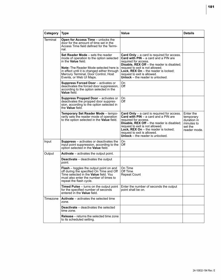
181
Category Type Value Details
Terminal Open for Access Time – unlocks the door for the amount of time set in the Access Time field defined for the Termi-nal.
Set Reader Mode – sets the reader mode of operation to the option selected in the Value field.
Note: The Reader Mode selected here is in effect until it is changed either through Mercury Terminal, Door Control, Host Events, or Web UI Maps.
Card Only – a card is required for access.Card with PIN – a card and a PIN are required for access.Disable, REX Off – the reader is disabled; request to exit is not allowed.Lock, REX On – the reader is locked; request to exit is allowed.Unlock – the reader is unlocked.
Suppress Forced Door – activates or deactivates the forced door suppression, according to the option selected in the Value field.
OnOff
Suppress Propped Door – activates or deactivates the propped door suppres-sion, according to the option selected in the Value field.
OnOff
Temporary Set Reader Mode – tempo-rarily sets the reader mode of operation to the option selected in the Value field.
Card Only – a card is required for access.Card with PIN – a card and a PIN are required for access.Disable, REX Off – the reader is disabled; request to exit is not allowed.Lock, REX On – the reader is locked; request to exit is allowed.Unlock – the reader is unlocked.
Enter the temporary duration in minutes to set the reader mode.
Input Suppress – activates or deactivates the input point suppression, according to the option selected in the Value field.
OnOff
Output Activate – activates the output point.
Deactivate – deactivates the output point.
Flash – toggles the output point on and off during the specified On Time and Off Time selected in the Value field. You must also enter the number of times to repeat the flash cycle.
On TimeOff TimeRepeat Count
Timed Pulse – turns on the output point for the specified number of seconds entered in the Value field.
Enter the number of seconds the output point shall be on.
Timezone Activate – activates the selected time zone.
Deactivate – deactivates the selected time zone.
Release – returns the selected time zone to its scheduled setting.
24-10832-194 Rev. E

182 CHAPTER 2
Configuring the System
24-10832-194 Rev. E
11. Click the corresponding Item field and select the name of the terminal, input, or output.
12. If you wish to add additional actions to the procedure, click Add and repeat the previ-ous steps.
13. The actions within a procedure are exe-cuted in the order they are added. If you wish to change the sequence of the actions, select the action line and click Up or Down.
14. Once you define your actions, click Apply or OK to save the Procedure.
Configuring Triggers
Triggers are defined to detect a specific trans-action, such as a time zone or input point change of state, and to invoke a procedure that in turn executes a list of actions.
To Configure a Trigger
1. In the System Configuration window, expand Panels to display the panel types.
2. Expand Mercury Panels to display all Mercury panels configured in the system.
3. Expand the panel that contains the trigger you wish to configure.
4. Select Trigger and click Add. The Mer-cury Trigger Edit dialog box opens.
5. Enter a Name to describe the function of the trigger.
6. Click Public to allow all partitions to see this trigger.
7. The Query String value is used with mes-sage filtering; see Define Query String Fil-ters on page 225.
8. Click Enabled to allow the system to per-form the trigger.
9. Select the Time Zone during which this trigger is operational. If you select <always enabled>, this trigger is always operational.
Note: If you set the Time Zone to a time zone defined as “Never,” the trigger is never opera-tional. If you set the Time Zone to a time zone defined as “8 to 5,” the trigger is only operational from 8:00 to 5:00. Therefore, when triggering on a time zone going active or inactive, we do not rec-ommend using the same time zone to make the trigger operational, as you will miss either the activation or the deactivation. When triggering on a time zone, we recommend to set the Time Zone field to <always enabled>.
10. Select from the Category drop-down list if the trigger is to be activated by Access Granted transactions, Door Status (alarm), Door Status (secure), Input Point changes, or Timezone transitions.
11. If you select Access Granted, the Any Access Grant Type displays by default indicating that the trigger is to be activated upon any access grant operation.
If you select Door Status (alarm), select from the Type drop-down list if the trigger is activated when the door status is Forced Open, Forced or Propped Open (only first), Forced then Propped Open, Propped Open (always), or Propped Open (only after nor-mal access cycle).

183
If you select Door Status (secure), select from the Type drop-down list if the trigger is activated when the door status is Door Closed, Door Opened, Forced Open Can-celled, Forced or Propped Open Cancelled, Open Pre-Alarm Only, or Propped Open Cancelled.
If you select Input Point, select from the Type drop-down list if the trigger is acti-vated when the input goes into Alarm, Fault, or Secure state.
If you select Timezone, select from the Type drop-down list if the trigger is acti-vated when the time zone becomes Active or Inactive.
12. Select from the Item drop-down list, the name of the door, input point, or time zone that activates the trigger upon change of state.
13. Select the Procedure that contains the actions that can be activated when the selected item changes state.
14. Select a Group number from 1 to 4. Only actions that belong to this group can be triggered.
15. Click Apply to save the Trigger informa-tion.
In the following example, the procedure pro-vides access to the cleaning crew. First, the door alarm is suppressed, the door is unlocked, and the lights turn on. These three actions belong to Group 1.
The defined trigger specifies that all three actions in Group 1 will be triggered when the selected time zones becomes active.
You can create another trigger that includes the defined Group 2 actions, and that will be trig-gered when the selected time zone becomes inactive.
24-10832-194 Rev. E

184 CHAPTER 2
Configuring the System
24-10832-194 Rev. E
Configure Mercury Elevators
The Mercury elevator integration is a low level interface that allows you to configure one out-put for each floor. If you select floor tracking, you must also configure one input for each floor.
Input and output points are selected by picking terminal boards. The start point can be selected on the first board only. Each subsequent board must start on point one.
The Mercury elevator integration supports up to 128 floors, and each elevator must be defined with a minimum of two floors.
User experience varies depending on floor tracking selection:
Without floor tracking, elevator users can select more than one floor per access grant. The system does not keep any records of what floors were selected.
With floor tracking, elevator users can only select one floor at a time. The system keeps records of which floor was selected.
When defining access groups for Mercury ele-vators, the readers in the access group are auto-matically assigned the default timezone of the access group. Floor masks are also assigned to the default timezone.
The Mercury elevator integration allows you to configure and control one or more Mercury elevators at a facility.
Before you can configure Mercury elevators, you must configure the Mercury panels and terminals that are to be part of the elevator sys-tem.
Output and Input Point Chain Rules
The Mercury elevator control requires that you configure one physical output for each elevator floor. If floor tracking is enabled, you must also configure one physical input for each ele-vator floor.
All input and output points used for an elevator must be continuous. That means that if floor 1 uses output point 1, floor 2 must use output point 2. Output point 2 cannot be used for any other purpose.
To support the desired number of elevator floors, you may need to chain the points from one terminal board to the next. You must fol-low specific rules when chaining points, which is done on the Output Board and Input Board tabs. Note that the same rules apply to chaining both output and input points.
If you need more output or input points to sup-port the number of elevator floors that are on the terminal you started with, those extra ter-minals are called additional terminals.
Starting the Output Point/Input Point Chain
Any terminal on the panel that has spare points can be used to start the chain.
Before you define the number of the starting point for the chain, make sure that either enough consecutive points are available to support the number of defined floors or that all of the points to the end of the board are available.
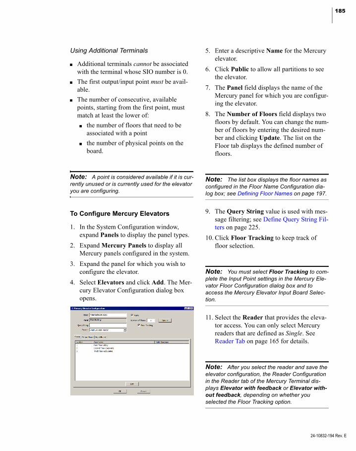
185
Using Additional Terminals
Additional terminals cannot be associated with the terminal whose SIO number is 0.
The first output/input point must be avail-able.
The number of consecutive, available points, starting from the first point, must match at least the lower of:
the number of floors that need to be associated with a point
the number of physical points on the board.
Note: A point is considered available if it is cur-rently unused or is currently used for the elevator you are configuring.
To Configure Mercury Elevators
1. In the System Configuration window, expand Panels to display the panel types.
2. Expand Mercury Panels to display all Mercury panels configured in the system.
3. Expand the panel for which you wish to configure the elevator.
4. Select Elevators and click Add. The Mer-cury Elevator Configuration dialog box opens.
5. Enter a descriptive Name for the Mercury elevator.
6. Click Public to allow all partitions to see the elevator.
7. The Panel field displays the name of the Mercury panel for which you are configur-ing the elevator.
8. The Number of Floors field displays two floors by default. You can change the num-ber of floors by entering the desired num-ber and clicking Update. The list on the Floor tab displays the defined number of floors.
Note: The list box displays the floor names as configured in the Floor Name Configuration dia-log box; see Defining Floor Names on page 197.
9. The Query String value is used with mes-sage filtering; see Define Query String Fil-ters on page 225.
10. Click Floor Tracking to keep track of floor selection.
Note: You must select Floor Tracking to com-plete the Input Point settings in the Mercury Ele-vator Floor Configuration dialog box and to access the Mercury Elevator Input Board Selec-tion.
11. Select the Reader that provides the eleva-tor access. You can only select Mercury readers that are defined as Single. See Reader Tab on page 165 for details.
Note: After you select the reader and save the elevator configuration, the Reader Configuration in the Reader tab of the Mercury Terminal dis-plays Elevator with feedback or Elevator with-out feedback, depending on whether you selected the Floor Tracking option.
24-10832-194 Rev. E
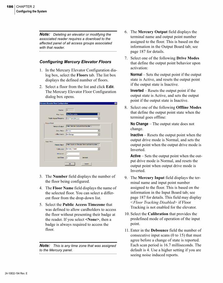
186 CHAPTER 2
Configuring the System
24-10832-194 Rev. E
Note: Deleting an elevator or modifying the associated reader requires a download to the affected panel of all access groups associated with that reader.
Configuring Mercury Elevator Floors
1. In the Mercury Elevator Configuration dia-log box, select the Floors tab. The list box displays the defined number of floors.
2. Select a floor from the list and click Edit. The Mercury Elevator Floor Configuration dialog box opens.
3. The Number field displays the number of the floor being configured.
4. The Floor Name field displays the name of the selected floor. You can select a differ-ent floor from the drop-down list.
5. Select the Public Access Timezone that was defined to allow cardholders to access the floor without presenting their badge at the reader. If you select <None>, then a badge is always required to access the floor.
Note: This is any time zone that was assigned to the Mercury panel.
6. The Mercury Output field displays the terminal name and output point number assigned to the floor. This is based on the information in the Output Board tab; see page 187 for details.
7. Select one of the following Drive Modes that define the output point behavior upon activation:
Normal – Sets the output point if the output state is Active, and resets the output point if the output state is Inactive.
Inverted – Resets the output point if the output state is Active, and sets the output point if the output state is Inactive.
8. Select one of the following Offline Modes that define the output point state when the terminal goes offline:
No Change – The output state does not change.
Inactive – Resets the output point when the output drive mode is Normal, and sets the output point when the output drive mode is Inverted.
Active – Sets the output point when the out-put drive mode is Normal, and resets the output point when output drive mode is Inverted.
9. The Mercury Input field displays the ter-minal name and input point number assigned to the floor. This is based on the information in the Input Board tab; see page 187 for details. This field may display <Floor Tracking Disabled> if Floor Tracking is not enabled for the elevator.
10. Select the Calibration that provides the predefined mode of operation of the input point.
11. Enter in the Debounce field the number of consecutive input scans (0 to 15) that must agree before a change of state is reported. Each scan period is 16.7 milliseconds. The default is 4. Use a higher setting if you are seeing noise induced reports.

187
12. In the Hold Time field enter a hold time in seconds (2 to 15) to hold a higher priority status before a lower priority status is reported. Enter 0 to prevent any hold time.
Configuring Mercury Elevator Outputs
Use the Output Board tab to define the chain of terminals that identify the output points used for the elevator floor. See Output and Input Point Chain Rules on page 184 for more information.
1. In the Mercury Elevator Configuration dia-log box, select the Output Board tab.
2. Click Add to add an output board. The Mercury Elevator Output Board Configu-ration dialog box opens.
3. Select an Output Terminal Name.
4. Select the First Board Start Point num-ber. This number is always assigned to the lowest floor number.
5. The Output Points Available field dis-plays the number of available output points on the selected terminal. This number is determined automatically and must be suf-ficient to support the number of defined floors.
6. Click OK to return to the Mercury Eleva-tor Configuration dialog box.
7. You can use the Up or Down buttons to change the order of the output terminals, if necessary.
Note: The list box displays all defined output boards, including the total number of points on each board, and the total point count.
Configuring Mercury Elevator Inputs
Use the Input Board tab to define the chain of terminals that identify the input points used for the elevator floor. See Output and Input Point Chain Rules on page 184 for more informa-tion.
1. In the Mercury Elevator Configuration dia-log box, select the Input Board tab.
2. Click Add to add an input board. The Mer-cury Elevator Input Board Configuration dialog box opens.
3. Select an Input Terminal Name.
4. Select the First Board Start Point num-ber. This number is always assigned to the lowest floor number.
5. The Input Points Available field displays the number of available input points on the selected terminal. This number is deter-mined automatically and must be sufficient to support the number of defined floors.
6. Click OK to return to the Mercury Eleva-tor Configuration dialog box.
7. You can use the Up or Down buttons to change the order of the input terminals, if necessary.
Note: The list box displays all defined input boards, including the total number of points on each board, and the total point count.
24-10832-194 Rev. E
188 CHAPTER 2
Configuring the System
24-10832-194 Rev. E
Best Practices
This section provides a description of how to accomplish common tasks associated with Mercury components.
How to Override a Reader Based on a Time Zone
Follow the instructions provided in Configure Mercury Procedures and Triggers on page 180. Also, see How to Change Reader Mode Based on Time Zone Change of State on page 189.
How to Use Card ID using a Keypad Reader
To authenticate a user via an entered Card ID at a Mercury keypad reader, the following con-ditions must be met.
1. You must define a card format with a Function value of Magnetic Stripe (even if you are using a Wiegand reader).
This card format defines how many digits need to be entered for the facility code, and how many digits need to be entered for the Card ID. If no facility code is entered, the card format uses a Facility Code value of -1. See Card Format Tab on page 154 for details.
2. You must select the Card ID format in the Card Type tab of the terminal configura-tion; and must also select the correct Card Data Formatting (select Data1 / Data0, Wiegand Pulses for Wiegand readers; or select Trim Zero Bits and Format To Nibble Array for Magnetic Stripe readers). See Card Type Tab on page 169 for details.
It is possible to combine the Card ID for-mat with other badge based formats at the same reader; however, some combinations may not be operational. Contact Technical Support for instructions if you need to use a specific combination.
3. If you select Card Only as the Default Reader Mode in the Reader tab of the ter-minal configuration (see Reader Tab on page 165 for details), you must enter your credentials at the keypad reader by press-ing the * key, enter the Facility Code, enter the Card ID, and press the # key.
The Facility Code and the Card ID must be filled up with leading zeros to match the number of digits specified in the format defined in step 1.
Note: A Facility Code may be absent if the card format was defined without it.
4. If you select Card and PIN Required as the Default Reader Mode in the Reader tab of the terminal configuration (see Reader Tab on page 165 for details), you must enter your credentials at the keypad reader by pressing the * key, enter the Facility Code, enter the Card ID, press the # key, and enter the PIN number.
The Facility Code and the Card ID must be filled up with leading zeros to match the number of digits specified in the format defined in step 1.
If the PIN has fewer digits than specified in the General Tab in Site Parameters, the # key must be pressed after the PIN is entered (you cannot enter PIN numbers with leading zeros).
Note: A Facility Code may be absent if the card format was defined without it.
5. The Allow PIN before Badge option in the Access tab has no effect in the operation of Card ID and PIN. The required sequence is always as specified in step 4.

189
How to Save Data to the Mercury Panel in the Event of Power Loss
Ensure that all three of the following require-ments are met for all Mercury panels:
1. The on-board coin cell is electrically con-nected and the isolation strip is removed.
2. The firmware version is 1.18.7, 1.19, or 1.22, as displayed in the Panel Details of the System Status window.
3. The following Auto-Save settings in the Mercury Configuration Manager are enabled:
Restore from the last saved settings
Auto Save is enabled
Delay before save is 30 seconds
How to Change Reader Mode Based on Time Zone Change of State
1. Create a Procedure (see page 180 for details) that includes the following param-eters:
Group: make appropriate selection. This number must match the Group number selected in the Trigger defined in Step 2.
Category: select Terminal.
Type: select Set Reader Mode.
Item: make appropriate selection.
Value: make appropriate selection (for example, Unlock).
2. Create a Trigger (see page 182 for details) that includes the following parameters:
Time Zone: select the time zone during which the trigger is operational. Select <always enabled>, if this trigger is always operational.
Category: select Timezone.
Type: select if the trigger is activated when the time zone becomes Active or Inactive.
Item: select the name of the time zone that activates the trigger upon change of state.
Procedure: select the name of the pro-cedure defined in Step. 1.
Group: make appropriate selection. This number must match the Group number defined in the Procedure.
In the previous example, the selected terminal unlocks every time the selected time zones becomes active or inactive, depending on your selection.
How to Delay the Override of a Reader Based on an Active Time Zone until the First Valid Card is Presented
Use the following procedure to avoid starting the override when no authorized person is present.
1. Follow the same steps in How to Change Reader Mode Based on Time Zone Change of State and create a second trigger that includes the following parameters:
Time Zone: select the time zone defined with an override period.
Category: select Access Granted.
Type: select the default option Any Access Grant. This indicates that the trigger will be activated upon any access grant activity.
Item: select the name of the reader that will start the override when access was granted.
Note: In paired reader mode, the leader reader controls the access; therefore, the override is only reported on leader readers.
Procedure: select the name of the pro-cedure.
Group: make appropriate selection. This number must match the Group number defined in the Procedure.
24-10832-194 Rev. E

190 CHAPTER 2
Configuring the System
24-10832-194 Rev. E
How to Interrupt a Normal Door Schedule
Note: Interrupting a normal schedule is possi-ble by using Mercury panels’ capability that allows times zones to be overridden within a con-troller.
The following instructions are provided for sit-uations in which a facility or a section in a facility must be placed in a different operating mode than during regular days, such as for a snow day situation.
A snow day operating mode for example, may be scheduled in advance and may have a preset duration. For example, an operator may decide on Monday that as of Wednesday through Fri-day the building will operate in snow day mode. If on Thursday the conditions have improved, the building can go back to normal operating mode immediately.
To Prepare the System for a Snow Day
You must prepare the system for a snow day operating mode that includes doors that should not be in override during snow days, and doors that should provide access to a more limited population.
Note: You need to define a procedure that overrides normal access, and define triggers that change that normal access based on time zone changes, for more information see How to Change Reader Mode Based on Time Zone Change of State on page 189.
To Configure a Snow Day Schedule
Use the Time Zone application to configure for example, a Snow Day Time Zone that includes the appropriate time periods of the anticipated snow days. This can be done sev-eral days in advance or during the snow day.
A time zone defined with specific hours during specific days. The snow day operation is active from Wednesday 4:00 PM through Friday 8:00 AM.
Option 1: Define specific time periods
A time zone that uses the Holiday feature to define entire days. The snow day operation is active from 12/14/2016 12:00 AM through 12/16/2016 11:59 PM.
Option 2: Define entire days as snow days

191
To Create a Snow Day Procedure
1. Create a Procedure (see page 180 for details) that includes the following param-eters:
Group: select a group number. This number must match the Group number selected in the Trigger defined in To Create a Snow Day Start Trigger.
Category: select Timezone.
Type: select Deactivate to interrupt the normal door schedule.
Item: select the name of the time zone that normally overrides the doors.
2. Click Add to add a second action to the procedure and that includes the following parameters:
Group: select a group number. This number must match the Group number selected in the Trigger defined in To Create a Snow Day Stop Trigger.
Category: select Timezone.
Type: select Release to return the time zone to its normal schedule setting.
Item: select the name of the time zone that normally overrides the doors.
To Create a Snow Day Start Trigger
1. Create a Trigger (see page 182 for details), that includes the following param-eters:
Time Zone: select the time zone during which the trigger is operational. Select <always enabled>, if this trigger is always operational.
Category: select Timezone.
Type: select Active to indicate that the trigger is activated when the time zone becomes active.
Item: select the name of the time zone created for the snow day mode, Snow Day Time Zone for example.
24-10832-194 Rev. E
192 CHAPTER 2
Configuring the System
24-10832-194 Rev. E
Procedure: select the name of the pro-cedure defined in To Create a Snow Day Procedure.
Group: select the group number defined in step 1 of To Create a Snow Day Pro-cedure.
To Create a Snow Day Stop Trigger
1. Create a second Trigger with the following parameters:
Time Zone: select the time zone during which the trigger is operational. Select <always enabled>, if this trigger is always operational.
Category: select Timezone.
Type: select Inactive to indicate that the trigger is activated when the time zone is no longer active.
Item: select the name of the time zone created for the snow day mode, Snow Day Time Zone for example.
Procedure: select the name of the pro-cedure defined in To Create a Snow Day Procedure.
Group: select the group number defined in step 2 of To Create a Snow Day Pro-cedure.
Additional Notes
The interruption of a normal door schedule does not apply to badges with executive privileges.
The snow day time zone must take into account P2000 holidays. For example, if Wednesday through Friday are configured to be snow days, and Thursday is a Holiday of Type 1, that holiday type needs to also be configured as active in the snow day time zone.
Unless the Holiday feature is used to declare a snow day, it is important to remove any active periods from the snow day time zone after the condition has cleared. Otherwise, seven days later the building will go into the different operating mode again.
Unless the Holiday feature is used to declare a snow day, snow days may be scheduled at most one week in advance.
What to Do When Relocating a Mercury Panel
If you install a Mercury panel that was previ-ously configured for a different site or location, you must use the panel’s Bulk Erase Configu-ration Memory function to reset the panel to factory conditions. This prevents the P2000 system from processing transaction messages that are not applicable to the panel’s current use. Refer to your panel’s hardware installation manual for details on the Bulk Erase Configu-ration Memory function.
What to Do When Changing an MR51e IP Address
If you change the IP address using the P2000 Mercury Terminal Edit application, the MR51e goes offline. If you change this field again back to the correct IP address, you must download all items to the panel with the Reset Panel Before Download flag selected to return the MR51e to normal operation.
If you change the IP address using the MSC MR51e Address Configuration Tool before changing the IP address using the P2000 Mercury Terminal Edit application, when the MR51e is reset to begin the IP address change (using its S2 push button), the MR51e goes offline. You must download all items to the panel with the Reset Panel Before Download flag selected to return the MR51e to normal operation.
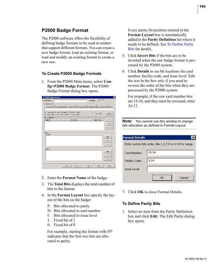
193
P2000 Badge Format
The P2000 software offers the flexibility of defining badge formats to be used at readers that support different formats. You can create a new badge format, load an existing format, or load and modify an existing format to create a new one.
To Create P2000 Badge Formats
1. From the P2000 Main menu, select Con-fig>P2000 Badge Format. The P2000 Badge Format dialog box opens.
2. Enter the Format Name of the badge.
3. The Total Bits displays the total number of bits in the format.
4. In the Format Layout box specify the lay-out of the bits on the badge:
P: Bits allocated to parityN: Bits allocated to card numberI: Bits allocated to issue level1: Fixed bit of 10: Fixed bit of 0
For example, starting the format with PP indicates that the first two bits are allo-cated to parity.
Every parity bit position entered in the Format Layout box is automatically added to the Parity Definition list where it needs to be defined. See To Define Parity Bits for details.
5. Click Invert Bits if the bits are to be inverted when the raw badge format is pro-cessed by the P2000 system.
6. Click Details to see bit locations for card number, facility code, and issue level. Edit the text in the box only if you need to reverse the order of the bits when they are processed by the P2000 system.
For example, if the raw card number bits are 15-34, and they must be reversed, enter 34-15.
Note: You cannot use this window to change bits allocation as defined in Format Layout.
7. Click OK to close Format Details.
To Define Parity Bits
1. Select an item from the Parity Definition box and click Edit. The Edit Parity dialog box opens.
24-10832-194 Rev. E
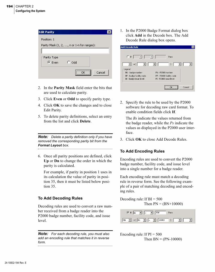
194 CHAPTER 2
Configuring the System
24-10832-194 Rev. E
2. In the Parity Mask field enter the bits that are used to calculate parity.
3. Click Even or Odd to specify parity type.
4. Click OK to save the changes and to close Edit Parity.
5. To delete parity definitions, select an entry from the list and click Delete.
Note: Delete a parity definition only if you have removed the corresponding parity bit from the Format Layout box.
6. Once all parity positions are defined, click Up or Dn to change the order in which the parity is calculated.
For example, if parity in position 1 uses in its calculation the value of parity in posi-tion 35, then it must be listed below posi-tion 35.
To Add Decoding Rules
Decoding rules are used to convert a raw num-ber received from a badge reader into the P2000 badge number, facility code, and issue level.
Note: For each decoding rule, you must also add an encoding rule that matches it in reverse form.
1. In the P2000 Badge Format dialog box click Add in the Decode box. The Add Decode Rule dialog box opens.
2. Specify the rule to be used by the P2000 software for decoding raw card format. To enable condition fields click If.
The Bs indicate the values returned from the badge reader, while the Ps indicate the values as displayed in the P2000 user inter-face.
3. Click OK to close Add Decode Rules.
To Add Encoding Rules
Encoding rules are used to convert the P2000 badge number, facility code, and issue level into a single number for a badge reader.
Each encoding rule must match a decoding rule in reverse form. See the following exam-ple of a pair of matching decoding and encod-ing rules.
Decoding rule: If BI = 500 Then PN = (BN+10000)
Encoding rule: If PI = 500 Then BN = (PN-10000)

195
Follow the next steps to create an encoding rule.
1. In the P2000 Badge Format dialog box click Add in the Encode box. The Add Encode Rule dialog box opens.
2. Specify the rule to be used by the P2000 software for encoding card format. To enable condition fields click If.
The Ps indicate the values as displayed in the P2000 user interface, while the Bs indi-cate the values for the badge reader.
3. Click OK to close Add Encode Rules.
To Test the Badge Format
1. To test the format, click Test at the bottom of the P2000 Badge Format dialog box. The Test Format dialog box opens.
2. In the upper boxes enter the card number, facility code, and issue level as would be displayed in the P2000 interface.
3. Click To Raw Data. The bit string dis-played in the lower box should be a valid raw data card number.
4. Click to clear the Raw data box and enter in it the single number as would be received from a badge reader. The number has to be provided in the data type selected.
5. Click To 2000. The card number, facility code, and issue level as would be dis-played in the P2000 interface should appear in the upper boxes.
6. Click Close to return to the P2000 Badge Format dialog box.
7. Click Save to save the badge format.
8. The Save As window opens. Enter the file name and click Save.
9. In the P2000 Badge Format window click Close.
To Load/Edit Badge Format
1. From the P2000 Main menu, select Con-fig>P2000 Badge Format. The P2000 Badge Format dialog box opens.
2. Click Load.
3. Browse for the badge format to load and select the appropriate *.bft file.
24-10832-194 Rev. E

196 CHAPTER 2
Configuring the System
24-10832-194 Rev. E
4. Click Open.
5. Edit the badge format if desired.
Note: Each modified format should be tested before saving.
6. Click Save.
7. The Save As window opens. Enter the file name and click Save.
8. To define additional badge formats, click Clear and enter the new data.
9. In the P2000 Badge Format window click Close.
Configure Elevators and Cabinets
The P2000 system supports the elevator and cabinet access control using CK721-A panels.
The following sections describe how to config-ure:
Elevator Access Control Cabinet Access Control
Note: To configure elevators that use Mercury panels, see page 184.
Elevator Access Control
General Overview
The elevator access control gives you the abil-ity to assign cardholders access to various ele-vators and floors in your facility, through their access groups.
Elevator floors cannot be overridden by a Local Cardholder Override or a Timed Over-ride, and do not allow the Auxiliary Access input to grant access to any floors.
Also, panel card events cannot be used to con-trol elevator floors.
Elevators are assigned floors and floor groups, then these floors and floor groups are included in access groups which are assigned to card-holders.
The basic procedures for defining and imple-menting the elevator access control are:
Defining Floor Names Defining Floor Masks Configuring Elevators Configuring Floors Defining Floor Groups Creating Access Groups for Elevator Floors
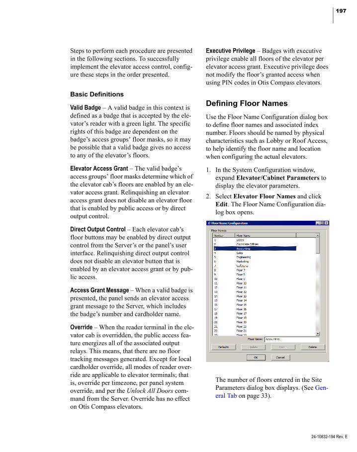
197
Steps to perform each procedure are presented in the following sections. To successfully implement the elevator access control, config-ure these steps in the order presented.
Basic Definitions
Valid Badge – A valid badge in this context is defined as a badge that is accepted by the ele-vator’s reader with a green light. The specific rights of this badge are dependent on the badge’s access groups’ floor masks, so it may be possible that a valid badge gives no access to any of the elevator’s floors.
Elevator Access Grant – The valid badge’s access groups’ floor masks determine which of the elevator cab’s floors are enabled by an ele-vator access grant. Relinquishing an elevator access grant does not disable an elevator floor that is enabled by public access or by direct output control.
Direct Output Control – Each elevator cab’s floor buttons may be enabled by direct output control from the Server’s or the panel’s user interface. Relinquishing direct output control does not disable an elevator button that is enabled by an elevator access grant or by pub-lic access.
Access Grant Message – When a valid badge is presented, the panel sends an elevator access grant message to the Server, which includes the badge’s number and cardholder name.
Override – When the reader terminal in the ele-vator cab is overridden, the public access fea-ture energizes all of the associated output relays. This means, that there are no floor tracking messages generated. Except for local cardholder override, all modes of reader over-ride are applicable to elevator terminals; that is, override per timezone, per panel system override, and per the Unlock All Doors com-mand from the Server. Override has no effect on Otis Compass elevators.
Executive Privilege – Badges with executive privilege enable all floors of the elevator per elevator access grant. Executive privilege does not modify the floor’s granted access when using PIN codes in Otis Compass elevators.
Defining Floor Names
Use the Floor Name Configuration dialog box to define floor names and associated index number. Floors should be named by physical characteristics such as Lobby or Roof Access, to help identify the floor name and location when configuring the actual elevators.
1. In the System Configuration window, expand Elevator/Cabinet Parameters to display the elevator parameters.
2. Select Elevator Floor Names and click Edit. The Floor Name Configuration dia-log box opens.
The number of floors entered in the Site Parameters dialog box displays. (See Gen-eral Tab on page 33).
24-10832-194 Rev. E

198 CHAPTER 2
Configuring the System
24-10832-194 Rev. E
3. Select the floor you wish to rename. The floor name displays in the Floor Name field at the bottom of the window.
4. Rename the floor accordingly and click Insert. The new name displays and the list of floor names moves down one position. For example, if you rename floor 1 and floor 2, number 3 on the list becomes Floor 1.
5. If you wish to edit a floor name, select the floor name, rename it, then click Update.
6. If you delete a floor name, using the Delete button, the next floor on the list moves up one position.
7. To restore the default floor names, click Defaults.
8. When you finish configuring floor names, click OK to return to the System Configu-ration window.
Defining Floor Masks
You can group floors that have common access throughout your facility and then apply them as a group to associate them with physical ele-vators when configuring Floor Groups. For example, your facility may have three floors that access the Operations department. When floors are grouped, you can assign cardholders that should have access to the three floors to the Operations group, rather than assigning all three floors to the cardholders individually.
1. In the System Configuration window, expand Elevator/Cabinet Parameters to display the elevator parameters.
2. Select Elevator Floor Masks and click Add. The Floor Mask dialog box opens.
3. If you use Partitioning, select the Partition that has access to this Floor Mask. All available floors (for the partition selected) are listed on the right side of the dialog box.
4. If you use Partitioning, click Public to allow all partitions to see this Floor Mask.
5. Enter a descriptive Name for this Floor Mask.
6. From the Available Floors list, select the floor you wish to include in your group.
7. Click <<. The floor moves to the left side of the dialog box, to be included in the Selected Floors box.
8. To remove a floor from the Selected Floors box, select the floor and click >>.
9. When all floors you wish to include in the group have been moved to the Selected Floors box, click OK. A Floor Mask icon for the new group is added under the Ele-vator Floor Masks root icon in the System Configuration window.
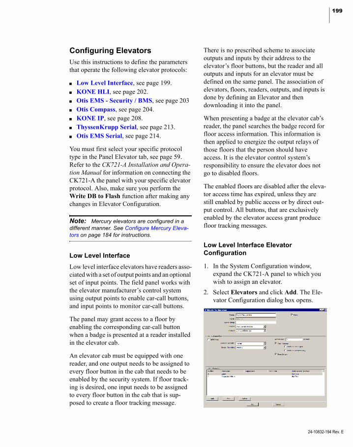
199
Configuring ElevatorsUse this instructions to define the parameters that operate the following elevator protocols:
Low Level Interface, see page 199. KONE HLI, see page 202. Otis EMS - Security / BMS, see page 203 Otis Compass, see page 204. KONE IP, see page 208. ThyssenKrupp Serial, see page 213. Otis EMS Serial, see page 214.
You must first select your specific protocol type in the Panel Elevator tab, see page 59. Refer to the CK721-A Installation and Opera-tion Manual for information on connecting the CK721-A the panel with your specific elevator protocol. Also, make sure you perform the Write DB to Flash function after making any changes in Elevator Configuration.
Note: Mercury elevators are configured in a different manner. See Configure Mercury Eleva-tors on page 184 for instructions.
Low Level Interface
Low level interface elevators have readers asso-ciated with a set of output points and an optional set of input points. The field panel works with the elevator manufacturer’s control system using output points to enable car-call buttons, and input points to monitor car-call buttons.
The panel may grant access to a floor by enabling the corresponding car-call button when a badge is presented at a reader installed in the elevator cab.
An elevator cab must be equipped with one reader, and one output needs to be assigned to every floor button in the cab that needs to be enabled by the security system. If floor track-ing is desired, one input needs to be assigned to every floor button in the cab that is sup-posed to create a floor tracking message.
There is no prescribed scheme to associate outputs and inputs by their address to the elevator’s floor buttons, but the reader and all outputs and inputs for an elevator must be defined on the same panel. The association of elevators, floors, readers, outputs, and inputs is done by defining an Elevator and then downloading it into the panel.
When presenting a badge at the elevator cab’s reader, the panel searches the badge record for floor access information. This information is then applied to energize the output relays of those floors that the person should have access. It is the elevator control system’s responsibility to ensure the elevator does not go to disabled floors.
The enabled floors are disabled after the eleva-tor access time has expired, unless they are still enabled by public access or by direct out-put control. All buttons, that are exclusively enabled by the elevator access grant produce floor tracking messages.
Low Level Interface Elevator Configuration
1. In the System Configuration window, expand the CK721-A panel to which you wish to assign an elevator.
2. Select Elevators and click Add. The Ele-vator Configuration dialog box opens.
24-10832-194 Rev. E

200 CHAPTER 2
Configuring the System
24-10832-194 Rev. E
3. Enter a descriptive Name for this elevator.
4. Click Public if you wish the elevator to be visible to all partitions.
5. The Panel field displays the name of the panel you selected from the System Con-figuration window.
6. If you wish, enter a Query String. This value is used with message filtering (see Define Query String Filters on page 225).
7. Select an available Reader that has not yet been assigned to an elevator or cabinet.
8. Select from the Protocol drop-down list, Low Level Interface.
9. If you enable the D620 Mode option, when a badge is presented at the elevator cab’s reader, the panel searches the badge record for floor access information. The floor access information is compared with the floor button selection input point. If the floor button selection input point matches the floor access information, then the out-put (timed) point for the floor the person should have access to is enabled. It is the elevator control system’s responsibility to ensure the elevator does not go to disabled floors.
Note: If you configure a low level elevator with D620 Mode enabled, you must create new panel and terminal definitions. You cannot convert existing panels and terminals into an elevator application with D620 mode enabled.
The cab’s floor button selection must be made before the elevator access time has expired, unless the floor call-button is enabled by public access or by direct out-put control. The floor car-call button that is exclusively enabled by the elevator access grant produces floor tracking message.
10. If the elevator has a Fireman Override switch, select an available input point that has not yet been assigned to an elevator or cabinet. The only purpose of this input point is to send messages to the Real Time List; it does not control Fireman Override.
11. If the elevator has a Service Override switch, select an available input point that has not yet been assigned to an elevator or cabinet. The only purpose of this input point is to send messages to the Real Time List; it does not control Service Override.
12. Enter in the Access Time field, the time in seconds (2 to 600) that cardholders have to press a car-call button after badging at the elevator. At the time a valid badge is pre-sented to the elevator reader, the elevator access time starts. The elevator access time starts over with every subsequent presenta-tion of a valid badge.
Note: At the beginning of the elevator access time certain floor buttons are enabled by the panel outputs per elevator access grant. Subse-quent presentation of other badges therefore may enable more outputs. Only outputs exclusively enabled by elevator access grants are disabled at the end of the elevator access time.
13. Enable Floor Tracking if you wish the panel to generate a history message identi-fying the badge number, cardholder’s name, elevator, and floor selected when the car-call button is pressed.
Floor tracking messages are generated only for floors whose associated output is exclu-sively enabled by the elevator access grant, and not enabled by public access or by direct output control. A floor tracking mes-sage is generated for each elevator input that experiences a transition from the nor-mal into the off-normal state during the elevator access time; or that is in the off-normal state at the time a valid badge is presented.
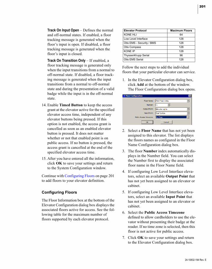
201
Track On Input Open – Defines the normal and off-normal states. If enabled, a floor tracking message is generated when the floor’s input is open. If disabled, a floor tracking message is generated when the floor’s input is closed.
Track On Transition Only – If enabled, a floor tracking message is generated only when the input transitions from a normal to off-normal state. If disabled, a floor track-ing message is generated when the input transitions from a normal to off-normal state and during the presentation of a valid badge while the input is in the off-normal state.
14. Enable Timed Button to keep the access grant at the elevator active for the specified elevator access time, independent of any elevator buttons being pressed. If this option is not enabled, the access grant is cancelled as soon as an enabled elevator button is pressed. It does not matter whether or not that enabled point is on public access. If no button is pressed, the access grant is cancelled at the end of the specified elevator access time.
15. After you have entered all the information, click OK to save your settings and return to the System Configuration window.
Continue with Configuring Floors on page 201 to add floors to your elevator definition.
Configuring Floors
The Floor Information box at the bottom of the Elevator Configuration dialog box displays the associated floors active for access. See the fol-lowing table for the maximum number of floors supported by each elevator protocol.
Elevator Protocol Maximum Floors
KONE HLI 64
Low Level Interface 128
Otis EMS - Security / BMS 128
Otis Compass 128
KONE IP 128
ThyssenKrupp Serial 96
Otis EMS Serial 128
Follow the next steps to add the individual floors that your particular elevator can service.
1. In the Elevator Configuration dialog box, click Add at the bottom of the window. The Floor Configuration dialog box opens.
2. Select a Floor Name that has not yet been assigned to this elevator. The list displays the floors names as configured in the Floor Name Configuration dialog box.
3. The floor Number index automatically dis-plays in the Number field. You can select the Number first to display the associated floor name in the Floor Name field.
4. If configuring Low Level Interface eleva-tors, select an available Output Point that has not yet been assigned to an elevator or cabinet.
5. If configuring Low Level Interface eleva-tors, select an available Input Point that has not yet been assigned to an elevator or cabinet.
6. Select the Public Access Timezone defined to allow cardholders to use the ele-vator without presenting their badge at the reader. If no time zone is selected, then this floor is not active for public access.
7. Click OK to save your settings and return to the Elevator Configuration dialog box.
24-10832-194 Rev. E
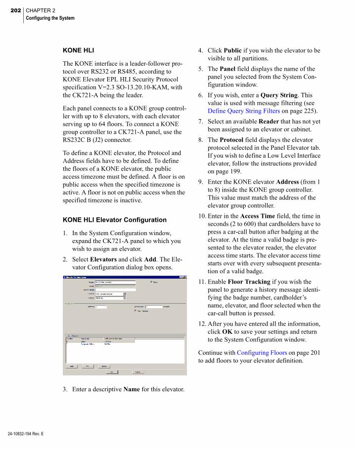
202 CHAPTER 2
Configuring the System
24-10832-194 Rev. E
KONE HLI
The KONE interface is a leader-follower pro-tocol over RS232 or RS485, according to KONE Elevator EPL HLI Security Protocol specification V=2.3 SO-13.20.10-KAM, with the CK721-A being the leader.
Each panel connects to a KONE group control-ler with up to 8 elevators, with each elevator serving up to 64 floors. To connect a KONE group controller to a CK721-A panel, use the RS232C B (J2) connector.
To define a KONE elevator, the Protocol and Address fields have to be defined. To define the floors of a KONE elevator, the public access timezone must be defined. A floor is on public access when the specified timezone is active. A floor is not on public access when the specified timezone is inactive.
KONE HLI Elevator Configuration
1. In the System Configuration window, expand the CK721-A panel to which you wish to assign an elevator.
2. Select Elevators and click Add. The Ele-vator Configuration dialog box opens.
3. Enter a descriptive Name for this elevator.
4. Click Public if you wish the elevator to be visible to all partitions.
5. The Panel field displays the name of the panel you selected from the System Con-figuration window.
6. If you wish, enter a Query String. This value is used with message filtering (see Define Query String Filters on page 225).
7. Select an available Reader that has not yet been assigned to an elevator or cabinet.
8. The Protocol field displays the elevator protocol selected in the Panel Elevator tab. If you wish to define a Low Level Interface elevator, follow the instructions provided on page 199.
9. Enter the KONE elevator Address (from 1 to 8) inside the KONE group controller. This value must match the address of the elevator group controller.
10. Enter in the Access Time field, the time in seconds (2 to 600) that cardholders have to press a car-call button after badging at the elevator. At the time a valid badge is pre-sented to the elevator reader, the elevator access time starts. The elevator access time starts over with every subsequent presenta-tion of a valid badge.
11. Enable Floor Tracking if you wish the panel to generate a history message identi-fying the badge number, cardholder’s name, elevator, and floor selected when the car-call button is pressed.
12. After you have entered all the information, click OK to save your settings and return to the System Configuration window.
Continue with Configuring Floors on page 201 to add floors to your elevator definition.
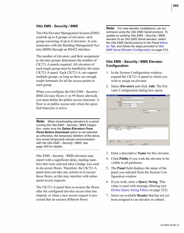
203
Otis EMS - Security / BMS
The Otis Elevator Management System (EMS) controls up to 8 groups of elevators, each group consisting of up to 8 elevators. It com-municates with the Building Management Sys-tem (BMS) through an RS422 interface.
The number of elevators, and their assignment to elevator groups determines the number of CK721-A panels required. All elevators of each single group must be handled by the same CK721-A panel. Each CK721-A can support multiple groups, as long as there are enough reader terminals for all the access points in each group.
When you configure the Otis EMS - Security / BMS elevator floors (1 to 99 floors allowed), you must define the public access timezone. A floor is on public access only when the speci-fied timezone is active.
Note: When downloading elevators to a panel running the Otis EMS - Security / BMS integra-tion, make sure the Delete Elevators From Panel Before Download option is not selected, as otherwise, the temporary deletion of the eleva-tors would temporarily disrupt communication with the Otis EMS - Security / BMS; see page 425 for details.
Otis EMS - Security / BMS elevators may report with a significant delay, landing num-bers that were selected after a badge was used to de-secure floors. Therefore, the CK721-A panel does not take any actions to re-secure those floors, as this may interfere with subse-quent access requests.
The CK721-A panel then re-secures the floors after the configured elevator access time has elapsed, or when a new access request is pro-cessed that de-secures different floors.
Note: For new elevator installations, we rec-ommend using the Otis EMS Serial protocol. To update an existing Otis EMS - Security / BMS elevator to an Otis EMS Serial elevator, select the Otis EMS Serial protocol in the Panel Eleva-tor Tab, and follow the steps provided in Otis EMS Serial Elevator Configuration on page 215.
Otis EMS - Security / BMS Elevator Configuration
1. In the System Configuration window, expand the CK721-A panel to which you wish to assign an elevator.
2. Select Elevators and click Add. The Ele-vator Configuration dialog box opens.
3. Enter a descriptive Name for this elevator.
4. Click Public if you wish the elevator to be visible to all partitions.
5. The Panel field displays the name of the panel you selected from the System Con-figuration window.
6. If you wish, enter a Query String. This value is used with message filtering (see Define Query String Filters on page 225).
7. Select an available Reader that has not yet been assigned to an elevator or cabinet.
24-10832-194 Rev. E
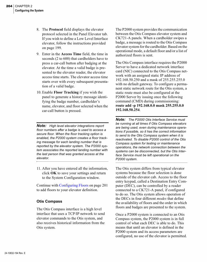
204 CHAPTER 2
Configuring the System
24-10832-194 Rev. E
8. The Protocol field displays the elevator protocol selected in the Panel Elevator tab. If you wish to define a Low Level Interface elevator, follow the instructions provided on page 199.
9. Enter in the Access Time field, the time in seconds (2 to 600) that cardholders have to press a car-call button after badging at the elevator. At the time a valid badge is pre-sented to the elevator reader, the elevator access time starts. The elevator access time starts over with every subsequent presenta-tion of a valid badge.
10. Enable Floor Tracking if you wish the panel to generate a history message identi-fying the badge number, cardholder’s name, elevator, and floor selected when the car-call button is pressed.
Note: High level elevator integrations report floor numbers after a badge is used to access a secure floor. When the floor tracking option is enabled, the P2000 system creates a floor track-ing message for each landing number that is reported by the elevator system. The P2000 sys-tem associates the reported landing number with the last person that was granted access at the elevator.
11. After you have entered all the information, click OK to save your settings and return to the System Configuration window.
Continue with Configuring Floors on page 201 to add floors to your elevator definition.
Otis Compass
The Otis Compass interface is a high level interface that uses a TCP/IP network to send elevator commands to the Otis system, and also receives historical information from the Otis system.
The P2000 system provides the communication between the Otis Compass elevator system and CK721-A panels. When a cardholder swipes a badge, a message is routed to the Otis Compass elevator system for the cardholder. Based on the operational mode, a default floor and/or a list of authorized floors is sent.
The Otis Compass interface requires the P2000 Server to have a dedicated network interface card (NIC) connected to the Otis Compass net-work with an assigned static IP address of 192.168.50.250 and a mask of 255.255.255.0 with no default gateway. To configure a perma-nent static network route for the Otis system, a static route must also be configured at the P2000 Server by issuing once the following command (CMD) during commissioning: route add -p 192.168.0.0 mask 255.255.0.0 192.168.50.254.
Note: The P2000 Otis Interface Service must be running at all times if Otis Compass elevators are being used, even during maintenance opera-tions if possible, so it has the correct information to send to the Otis Compass system when it is reactivated. To disable P2000 control of the Otis Compass system for testing or maintenance operations, the network connection between the systems can be disconnected, but the Otis Inter-face Service must be left operational on the P2000 system.
The Otis system differs from typical elevator systems because the floor selection is done outside of the elevator cab. Access to the floor entry keypad, called a Destination Entry Com-puter (DEC), can be controlled by a reader connected to a CK721-A panel, if configured to do so. The Otis system allows operation of the DECs in four different modes that define the availability of floors and the order in which floors and badges are presented to the system.
Once a P2000 system is connected to an Otis Compass system, the P2000 system is in full control of what each DEC is able to do. This means that until an elevator is defined in the P2000 system and its access parameters are configured, no use of the elevator is permitted.
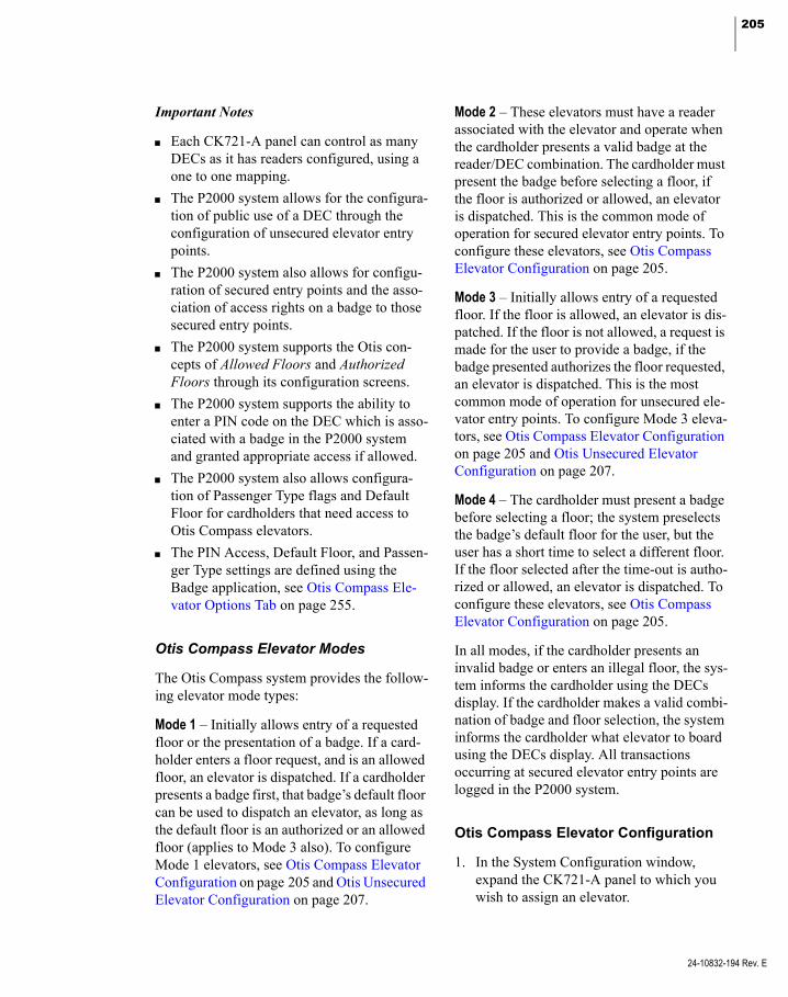
205
Important Notes
Each CK721-A panel can control as many DECs as it has readers configured, using a one to one mapping.
The P2000 system allows for the configura-tion of public use of a DEC through the configuration of unsecured elevator entry points.
The P2000 system also allows for configu-ration of secured entry points and the asso-ciation of access rights on a badge to those secured entry points.
The P2000 system supports the Otis con-cepts of Allowed Floors and Authorized Floors through its configuration screens.
The P2000 system supports the ability to enter a PIN code on the DEC which is asso-ciated with a badge in the P2000 system and granted appropriate access if allowed.
The P2000 system also allows configura-tion of Passenger Type flags and Default Floor for cardholders that need access to Otis Compass elevators.
The PIN Access, Default Floor, and Passen-ger Type settings are defined using the Badge application, see Otis Compass Ele-vator Options Tab on page 255.
Otis Compass Elevator Modes
The Otis Compass system provides the follow-ing elevator mode types:
Mode 1 – Initially allows entry of a requested floor or the presentation of a badge. If a card-holder enters a floor request, and is an allowed floor, an elevator is dispatched. If a cardholder presents a badge first, that badge’s default floor can be used to dispatch an elevator, as long as the default floor is an authorized or an allowed floor (applies to Mode 3 also). To configure Mode 1 elevators, see Otis Compass Elevator Configuration on page 205 and Otis Unsecured Elevator Configuration on page 207.
Mode 2 – These elevators must have a reader associated with the elevator and operate when the cardholder presents a valid badge at the reader/DEC combination. The cardholder must present the badge before selecting a floor, if the floor is authorized or allowed, an elevator is dispatched. This is the common mode of operation for secured elevator entry points. To configure these elevators, see Otis Compass Elevator Configuration on page 205.
Mode 3 – Initially allows entry of a requested floor. If the floor is allowed, an elevator is dis-patched. If the floor is not allowed, a request is made for the user to provide a badge, if the badge presented authorizes the floor requested, an elevator is dispatched. This is the most common mode of operation for unsecured ele-vator entry points. To configure Mode 3 eleva-tors, see Otis Compass Elevator Configuration on page 205 and Otis Unsecured Elevator Configuration on page 207.
Mode 4 – The cardholder must present a badge before selecting a floor; the system preselects the badge’s default floor for the user, but the user has a short time to select a different floor. If the floor selected after the time-out is autho-rized or allowed, an elevator is dispatched. To configure these elevators, see Otis Compass Elevator Configuration on page 205.
In all modes, if the cardholder presents an invalid badge or enters an illegal floor, the sys-tem informs the cardholder using the DECs display. If the cardholder makes a valid combi-nation of badge and floor selection, the system informs the cardholder what elevator to board using the DECs display. All transactions occurring at secured elevator entry points are logged in the P2000 system.
Otis Compass Elevator Configuration
1. In the System Configuration window, expand the CK721-A panel to which you wish to assign an elevator.
24-10832-194 Rev. E
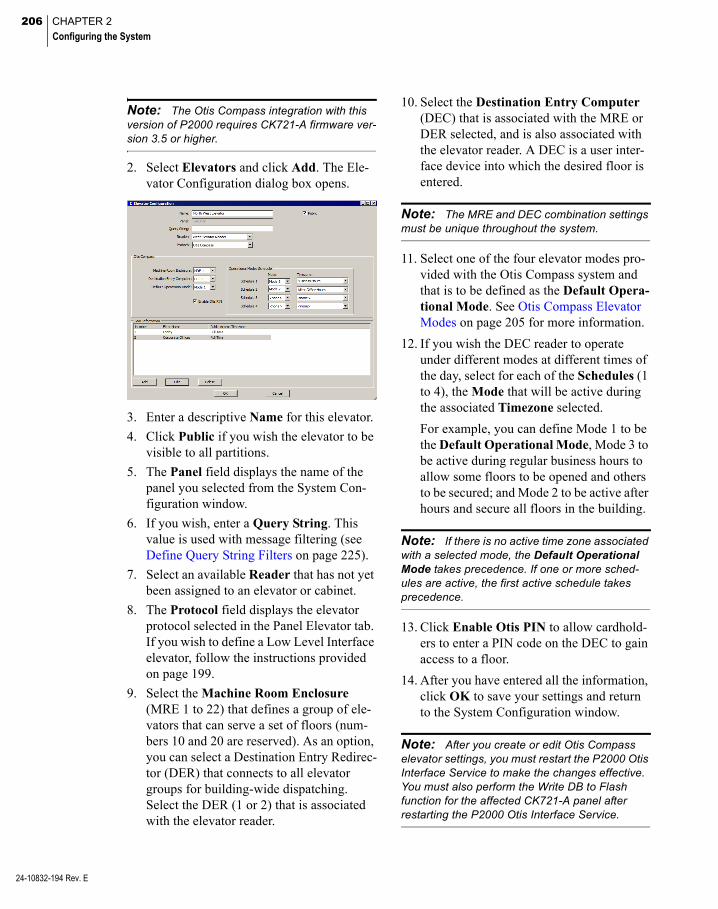
206 CHAPTER 2
Configuring the System
24-10832-194 Rev. E
Note: The Otis Compass integration with this version of P2000 requires CK721-A firmware ver-sion 3.5 or higher.
2. Select Elevators and click Add. The Ele-vator Configuration dialog box opens.
3. Enter a descriptive Name for this elevator.
4. Click Public if you wish the elevator to be visible to all partitions.
5. The Panel field displays the name of the panel you selected from the System Con-figuration window.
6. If you wish, enter a Query String. This value is used with message filtering (see Define Query String Filters on page 225).
7. Select an available Reader that has not yet been assigned to an elevator or cabinet.
8. The Protocol field displays the elevator protocol selected in the Panel Elevator tab. If you wish to define a Low Level Interface elevator, follow the instructions provided on page 199.
9. Select the Machine Room Enclosure (MRE 1 to 22) that defines a group of ele-vators that can serve a set of floors (num-bers 10 and 20 are reserved). As an option, you can select a Destination Entry Redirec-tor (DER) that connects to all elevator groups for building-wide dispatching. Select the DER (1 or 2) that is associated with the elevator reader.
10. Select the Destination Entry Computer (DEC) that is associated with the MRE or DER selected, and is also associated with the elevator reader. A DEC is a user inter-face device into which the desired floor is entered.
Note: The MRE and DEC combination settings must be unique throughout the system.
11. Select one of the four elevator modes pro-vided with the Otis Compass system and that is to be defined as the Default Opera-tional Mode. See Otis Compass Elevator Modes on page 205 for more information.
12. If you wish the DEC reader to operate under different modes at different times of the day, select for each of the Schedules (1 to 4), the Mode that will be active during the associated Timezone selected.
For example, you can define Mode 1 to be the Default Operational Mode, Mode 3 to be active during regular business hours to allow some floors to be opened and others to be secured; and Mode 2 to be active after hours and secure all floors in the building.
Note: If there is no active time zone associated with a selected mode, the Default Operational Mode takes precedence. If one or more sched-ules are active, the first active schedule takes precedence.
13. Click Enable Otis PIN to allow cardhold-ers to enter a PIN code on the DEC to gain access to a floor.
14. After you have entered all the information, click OK to save your settings and return to the System Configuration window.
Note: After you create or edit Otis Compass elevator settings, you must restart the P2000 Otis Interface Service to make the changes effective. You must also perform the Write DB to Flash function for the affected CK721-A panel after restarting the P2000 Otis Interface Service.

207
Continue with Configuring Floors on page 201 to add floors to your elevator definition.
Otis Unsecured Elevator Configuration
Use this section to configure unsecured Otis Compass elevators. Unsecured elevators are not associated with readers, input, or output points and include floors that users are allowed to access without any specific access right.
1. From the System Configuration window, expand Elevator/Cabinet Parameters to display the elevator parameters.
2. Select Otis Unsecured Elevators and click Add. The Otis Unsecured Elevator Configuration dialog box opens.
3. Enter a descriptive Name for this elevator.
4. Click Public if you wish the elevator to be visible to all partitions.
5. If you wish, enter a Query String. This value is used with message filtering (see Define Query String Filters on page 225).
6. Select the Machine Room Enclosure MRE (1 to 22) that defines a group of ele-vators that can serve a set of floors. As an option, you can select the Destination Entry Redirector (DER 1 or 2) that con-nects to all elevator groups for build-ing-wide dispatching.
7. Select from the Destination Entry Com-puter drop-down list, the user interface device number into which the desired floor is entered. This DEC number is associated with the MRE or DER selected.
Note: The MRE and DEC combination settings must be unique throughout the system.
8. Select from the Operational Mode drop- down list whether this is a Mode 1 or Mode 3 elevator. See Otis Compass Elevator Modes on page 205 for more information.
9. Click Enable Otis PIN to allow unsecured elevators to accept a PIN code to gain access to a floor.
10. Select from the Report on Terminal drop-down list, the terminal that is used to report access grant decisions.
11. Click Add at the bottom of the window. The Floor Configuration dialog box opens.
12. Select a Floor Name. The list displays the floors names as configured in the Floor Name Configuration dialog box; see page 197.
13. The floor Number index automatically dis-plays in the Number field. You could select the Number first, and the associated floor name displays in the Floor Name field.
14. Click OK to return to the Otis Unsecured Elevator Configuration dialog box.
15. After you enter all the information, click OK to save your settings and return to the System Configuration window. You must stop and restart the P2000 Otis Interface Service to make the changes effective, and also perform the Write DB to Flash function for the affected CK721-A panel after restarting the P2000 Otis Interface Service.
24-10832-194 Rev. E
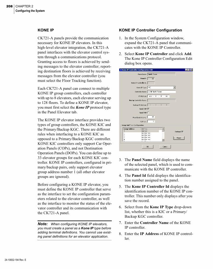
208 CHAPTER 2
Configuring the System
24-10832-194 Rev. E
KONE IP
CK721-A panels provide the communication necessary for KONE IP elevators. In this high-level elevator integration, the CK721-A panel interfaces with the elevator control sys-tem through a communications protocol. Granting access to floors is achieved by send-ing messages to the elevator controller; report-ing destination floors is achieved by receiving messages from the elevator controller (you must select the Floor Tracking function).
Each CK721-A panel can connect to multiple KONE IP group controllers, each controller with up to 8 elevators, each elevator serving up to 128 floors. To define a KONE IP elevator, you must first select the Kone IP protocol type in the Panel Elevator tab.
The KONE IP elevator interface provides two types of group controllers, the KONE KIC and the Primary/Backup KGC. There are different rules when interfacing to a KONE KIC as opposed to a Primary/Backup KGC controller. KONE KIC controllers only support Car Oper-ation Panels (COPs), and not Destination Operation Panels (DOPs). You can define up to 33 elevator groups for each KONE KIC con-troller. KONE IP controllers, configured in pri-mary/backup pairs, only support elevator group address number 1 (all other elevator groups are ignored).
Before configuring a KONE IP elevator, you must define the KONE IP controller that serve as the interface to set the configuration param-eters related to the elevator controller, as well as the interface to monitor the status of the ele-vator controller and its communication with the CK721-A panel.
Note: When configuring KONE IP elevators, you must create a panel as a Kone IP type before adding terminal definitions. You cannot use exist-ing panel definitions for an elevator application.
KONE IP Controller Configuration
1. In the System Configuration window, expand the CK721-A panel that communi-cates with the KONE IP Controller.
2. Select Kone IP Controller and click Add. The Kone IP Controller Configuration Edit dialog box opens.
3. The Panel Name field displays the name of the selected panel, which is used to com-municate with the KONE IP controller.
4. The Panel Id field displays the identifica-tion number assigned to the panel.
5. The Kone IP Controller Id displays the identification number of the KONE IP con-troller. This number only displays after you save the record.
6. Select from the Kone IP Type drop-down list, whether this is a KIC or a Primary/ Backup KGC controller.
7. Enter the Controller Name of the KONE IP controller.
8. Enter the IP Address of KONE IP control-ler.

209
9. If you selected a Primary/Backup KGC controller type, enter the Backup Control-ler Name and Backup IP Address of the primary/backup controller.
10. Click Send COP if you wish the system to send COP global default masks messages to the KONE IP elevator controller.
11. Click Send DOP if you wish the system to send DOP global default masks messages to the KONE IP elevator controller.
12. In the Heartbeat Interval field, enter the time interval at which heartbeat messages are sent to the KONE IP elevator control-ler.
13. Enter the TCP Port number of the KONE IP elevator controller.
Kone IP Group and Floor Configuration
The Group and Floor Configuration box at the bottom of the Kone IP Controller Configura-tion dialog box displays the Group Number of the KONE IP controller and whether the group was defined. You can define up to 33 elevator groups for each KONE KIC controller. Pri-mary/Backup KGC controllers only support elevator group address number 1 (all other ele-vator groups are ignored).
1. In the Group and Floor Configuration box, select the group number you wish to define and click Floors. The Kone IP Floor Con-figuration dialog box opens.
2. The Floor Number column displays the number of floors configured in Site Param-eters.
3. The Floor Name column displays the floor name assigned to each floor number. See Defining Floor Names on page 197.
4. Enter the floor Level Number as defined by the KONE equipment.
5. Select the Elevator Side through which the selected floor is accessible.
6. Click COP Destination When Connected to specify whether the selected floor is publicly accessible as a COP destination when the KONE IP controller is online. This value is ignored when communicating to KONE KIC controllers.
7. Click COP Destination When Discon-nected to specify whether the selected floor is publicly accessible as a COP desti-nation when the KONE IP controller is offline. This value is ignored when com-municating to KONE KIC controllers.
24-10832-194 Rev. E

210 CHAPTER 2
Configuring the System
24-10832-194 Rev. E
8. Click DOP Destination When Connected to specify whether the selected floor is publicly accessible as a DOP destination when the KONE IP controller is online. This value is ignored when communicating to KONE KIC controllers.
9. Click DOP Destination When Discon-nected to specify whether the selected floor is publicly accessible as a DOP desti-nation when the KONE IP controller is offline. This value is ignored when com-municating to KONE KIC controllers.
10. Click DOP Source When Connected to specify whether the selected floor is pub-licly accessible as a DOP source when the KONE IP controller is online. This value is ignored when communicating to KONE KIC controllers.
11. Click DOP Source When Disconnected to specify whether the selected floor is publicly accessible as a DOP source when the KONE IP controller is offline. This value is ignored when communicating to KONE KIC controllers.
12. Click OK to save the KONE IP group and floor configuration.
13. Select the KONE IP group number just defined and click Defined.
14. Click OK to save the KONE IP controller.
KONE IP Elevator Configuration
1. In the System Configuration window, expand the CK721-A panel that communi-cates with the KONE IP elevator.
2. Select Kone IP Elevator and click Add. The Kone IP Elevator Configuration dialog box opens.
3. Enter a descriptive Name for the KONE IP elevator.
4. Click Public if you wish the elevator to be visible to all partitions.
5. The Panel Name field displays the panel you selected from the System Configura-tion window.
6. The Panel Id field displays the identifica-tion number assigned to the panel.
7. Select the Reader terminal that provides the access in the elevator cab.
8. In the Access Time field, enter the time (0 to 30 seconds) that cardholders have to press a car-call button after badging at the elevator.
9. Click Floor Tracking to allow the panel to generate a history message identifying the badge number, cardholder’s name, eleva-tor, and floor selected when the car-call button is pressed.
10. Select from the Type drop-down list, whether this is a COP or DOP KONE IP elevator.
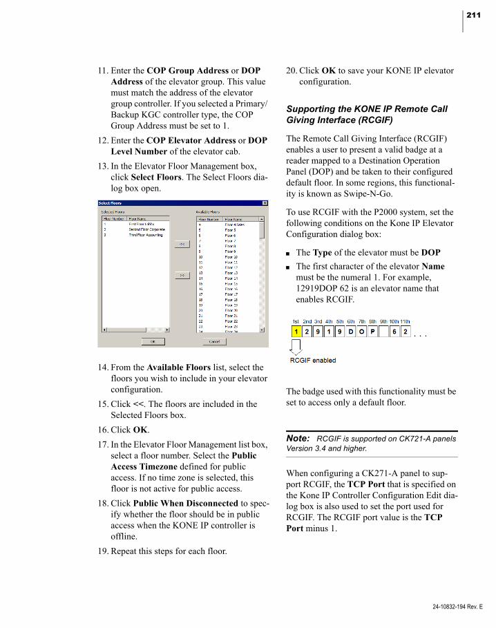
211
11. Enter the COP Group Address or DOP Address of the elevator group. This value must match the address of the elevator group controller. If you selected a Primary/ Backup KGC controller type, the COP Group Address must be set to 1.
12. Enter the COP Elevator Address or DOP Level Number of the elevator cab.
13. In the Elevator Floor Management box, click Select Floors. The Select Floors dia-log box open.
14. From the Available Floors list, select the floors you wish to include in your elevator configuration.
15. Click <<. The floors are included in the Selected Floors box.
16. Click OK.
17. In the Elevator Floor Management list box, select a floor number. Select the Public Access Timezone defined for public access. If no time zone is selected, this floor is not active for public access.
18. Click Public When Disconnected to spec-ify whether the floor should be in public access when the KONE IP controller is offline.
19. Repeat this steps for each floor.
20. Click OK to save your KONE IP elevator configuration.
Supporting the KONE IP Remote Call Giving Interface (RCGIF)
The Remote Call Giving Interface (RCGIF) enables a user to present a valid badge at a reader mapped to a Destination Operation Panel (DOP) and be taken to their configured default floor. In some regions, this functional-ity is known as Swipe-N-Go.
To use RCGIF with the P2000 system, set the following conditions on the Kone IP Elevator Configuration dialog box:
The Type of the elevator must be DOP
The first character of the elevator Name must be the numeral 1. For example, 12919DOP 62 is an elevator name that enables RCGIF.
The badge used with this functionality must be set to access only a default floor.
Note: RCGIF is supported on CK721-A panels Version 3.4 and higher.
When configuring a CK271-A panel to sup-port RCGIF, the TCP Port that is specified on the Kone IP Controller Configuration Edit dia-log box is also used to set the port used for RCGIF. The RCGIF port value is the TCP Port minus 1.
24-10832-194 Rev. E

212 CHAPTER 2
Configuring the System
24-10832-194 Rev. E
For example, if the TCP Port value is set to 2005, then the following socket connections are open:
Port 2005 for the KONE IP primary control-ler ELI (Elevator Locking Interface)
Port 2004 for the KONE IP primary control-ler RCGIF
Port 2005 for the KONE IP backup control-ler ELI
Port 2004 for the KONE IP backup control-ler RCGIF
Refer to the CK721-A Installation and Opera-tion Manual for details on panel port numbers.
Supporting KONE IP Special Access Privileges
The KONE IP special access privileges Handi-cap Access Time and Priority Access Time are used primarily to comply with Americans with Disabilities Act (ADA) requirements.
The Name field on the Kone IP Elevator Con-figuration dialog box is used to set these spe-cial access privileges.
The second and third digits of the elevator name in the Name field set the Handicap Access Time. Valid values are from 1 to 30 seconds.
The fourth and fifth digits of the elevator name in the Name field set the Priority Access Time. Valid values are from 1 to 30 seconds.
In the following example, the elevator name 12919DOP 62 sets the Handicap Access Time to 29 seconds and the Priority Access Time to 19 seconds.
When configuring badges for use with the spe-cial access privileges, specify the Security Options on the Badge dialog box as follows:
Select Special Access A to use Handicap Access Time
Select Special Access B or Executive access to use Priority Access Time
When both Special Access A and Special Access B are selected, Priority Access Time takes precedence.
Controlling the KONE IP Portal
Operators with the appropriate permissions can manually change a specific KONE IP eleva-tor’s mode of operation from a workstation.
To Change Mode of Operation of a KONE IP Elevator
1. From the P2000 Main menu select Con-trol>Kone IP Portal Command. The Kone IP Portal Command dialog box opens.
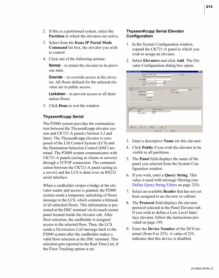
213
2. If this is a partitioned system, select the Partition in which the elevators are active.
3. Select from the Kone IP Portal Mode Command list box, the elevator you wish to control
4. Click one of the following actions:
Normal – to return the elevator to its previ-ous state.
Override – to override access at the eleva-tor. All floors defined for the selected ele-vator are in public access.
Lockdown – to prevent access to all desti-nation floors.
5. Click Done to exit the window.
ThyssenKrupp Serial
The P2000 system provides the communica-tion between the ThyssenKrupp elevator sys-tem and CK721-A panels (Version 3.2 and later). The ThyssenKrupp elevator is com-posed of the Lift Control System (LCS) and the Destination Selection Control (DSC) ter-minal. The P2000 system communicates with CK721-A panels (acting as clients or servers) through a TCP/IP connection. The communi-cation between the CK721-A panel (acting as a server) and the LCS is done over an RS232 serial interface.
When a cardholder swipes a badge at the ele-vator reader and access is granted, the P2000 system sends a temporary unlocking of floors message to the LCS, which contains a bitmask of all unlocked floors. This information is pre-sented at the DSC terminal via its touch screen panel located inside the elevator cab. After floor selection, the cardholder is assigned access to the selected floor. Then, the LCS sends a Destination Call message back to the P2000 system after the cardholder makes a valid floor selection at the DSC terminal. This selection gets reported to the Real Time List, if the Floor Tracking option is set.
ThyssenKrupp Serial Elevator Configuration
1. In the System Configuration window, expand the CK721-A panel to which you wish to assign an elevator.
2. Select Elevators and click Add. The Ele-vator Configuration dialog box opens.
3. Enter a descriptive Name for this elevator.
4. Click Public if you wish the elevator to be visible to all partitions.
5. The Panel field displays the name of the panel you selected from the System Con-figuration window.
6. If you wish, enter a Query String. This value is used with message filtering (see Define Query String Filters on page 225).
7. Select an available Reader that has not yet been assigned to an elevator or cabinet.
8. The Protocol field displays the elevator protocol selected in the Panel Elevator tab. If you wish to define a Low Level Inter-face elevator, follow the instructions pro-vided on page 199.
9. Enter the Device Number of the DCS ter-minal (from 0 to 255). A value of 255, indicates that this device is disabled.
24-10832-194 Rev. E
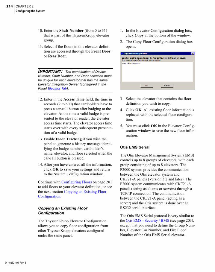
214 CHAPTER 2
Configuring the System
24-10832-194 Rev. E
10. Enter the Shaft Number (from 0 to 31) that is part of the ThyssenKrupp elevator group.
11. Select if the floors in this elevator defini-tion are accessed through the Front Door or Rear Door.
IMPORTANT: The combination of Device Number, Shaft Number, and Door selection must be unique for each elevator that has the same Elevator Integration Server (configured in the Panel Elevator Tab).
12. Enter in the Access Time field, the time in seconds (2 to 600) that cardholders have to press a car-call button after badging at the elevator. At the time a valid badge is pre-sented to the elevator reader, the elevator access time starts. The elevator access time starts over with every subsequent presenta-tion of a valid badge.
13. Enable Floor Tracking if you wish the panel to generate a history message identi-fying the badge number, cardholder’s name, elevator, and floor selected when the car-call button is pressed.
14. After you have entered all the information, click OK to save your settings and return to the System Configuration window.
Continue with Configuring Floors on page 201 to add floors to your elevator definition, or see the next section Copying an Existing Floor Configuration.
Copying an Existing Floor Configuration
The ThyssenKrupp Elevator Configuration allows you to copy floor configuration from other ThyssenKrupp elevators configured under the same panel.
1. In the Elevator Configuration dialog box, click Copy at the bottom of the window.
2. The Copy Floor Configuration dialog box opens.
3. Select the elevator that contains the floor definition you wish to copy.
4. Click OK. All existing floor information is replaced with the selected floor configura-tion.
5. You must click OK in the Elevator Config-uration window to save the new floor infor-mation.
Otis EMS Serial
The Otis Elevator Management System (EMS) controls up to 8 groups of elevators, with each group consisting of up to 8 elevators. The P2000 system provides the communication between the Otis elevator system and CK721-A panels (Version 3.2 and later). The P2000 system communicates with CK721-A panels (acting as clients or servers) through a TCP/IP connection. The communication between the CK721-A panel (acting as a server) and the Otis system is done over an RS232 serial interface.
The Otis EMS Serial protocol is very similar to the Otis EMS - Security / BMS (see page 203), except that you need to define the Group Num-ber, Elevator Car Number, and Fire Floor Number of the Otis EMS Serial elevator.

215
Otis EMS Serial Elevator Configuration
1. In the System Configuration window, expand the CK721-A panel to which you wish to assign an elevator.
2. Select Elevators and click Add. The Ele-vator Configuration dialog box opens.
3. Enter a descriptive Name for this elevator.
4. Click Public if you wish the elevator to be visible to all partitions.
5. The Panel field displays the name of the panel you selected from the System Con-figuration window.
6. If you wish, enter a Query String. This value is used with message filtering (see Define Query String Filters on page 225).
7. Select an available Reader that has not yet been assigned to an elevator or cabinet.
8. The Protocol field displays the elevator protocol selected in the Panel Elevator tab. If you wish to define a Low Level Inter-face elevator, follow the instructions pro-vided on page 199.
9. Enter the Otis elevator Group Number (from 1 to 8).
10. Enter the Elevator Car Number (from 1 to 8) that is part of the Otis elevator group.
11. Enter the Fire Floor Number (from 1 to 64). If there is a fire in the building, the elevator proceeds to the designated fire floor and stops with its doors open.
IMPORTANT: The combination of Group Number and Elevator Car Number selection must be unique for each elevator that has the same Elevator Integration Server (configured in the Panel Elevator Tab).
12. Enter in the Access Time field, the time in seconds (2 to 600) that cardholders have to press a car-call button after badging at the elevator. At the time a valid badge is pre-sented to the elevator reader, the elevator access time starts. The elevator access time starts over with every subsequent presenta-tion of a valid badge.
13. Enable Floor Tracking if you wish the panel to generate a history message identi-fying the badge number, cardholder’s name, elevator, and floor selected when the car-call button is pressed.
14. After you have entered all the information, click OK to save your settings and return to the System Configuration window.
Continue with Configuring Floors on page 201 to add floors to your elevator definition.
24-10832-194 Rev. E
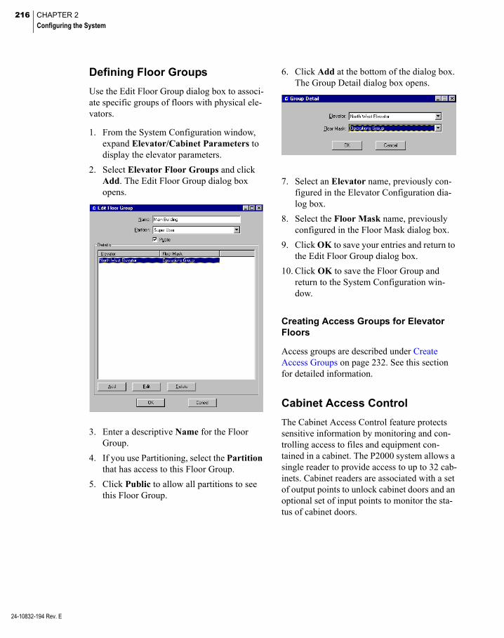
216 CHAPTER 2
Configuring the System
24-10832-194 Rev. E
Defining Floor Groups
Use the Edit Floor Group dialog box to associ-ate specific groups of floors with physical ele-vators.
1. From the System Configuration window, expand Elevator/Cabinet Parameters to display the elevator parameters.
2. Select Elevator Floor Groups and click Add. The Edit Floor Group dialog box opens.
3. Enter a descriptive Name for the Floor Group.
4. If you use Partitioning, select the Partition that has access to this Floor Group.
5. Click Public to allow all partitions to see this Floor Group.
6. Click Add at the bottom of the dialog box. The Group Detail dialog box opens.
7. Select an Elevator name, previously con-figured in the Elevator Configuration dia-log box.
8. Select the Floor Mask name, previously configured in the Floor Mask dialog box.
9. Click OK to save your entries and return to the Edit Floor Group dialog box.
10. Click OK to save the Floor Group and return to the System Configuration win-dow.
Creating Access Groups for Elevator Floors
Access groups are described under Create Access Groups on page 232. See this section for detailed information.
Cabinet Access Control
The Cabinet Access Control feature protects sensitive information by monitoring and con-trolling access to files and equipment con-tained in a cabinet. The P2000 system allows a single reader to provide access to up to 32 cab-inets. Cabinet readers are associated with a set of output points to unlock cabinet doors and an optional set of input points to monitor the sta-tus of cabinet doors.

217
The panel may grant access to a cabinet by unlocking the corresponding door when a badge is presented at a reader installed at the cabinet.
The cabinet access control gives you the abil-ity to assign cardholders access to various cab-inets and doors in your facility, through their access groups.
Cabinets are assigned doors and door groups, then these doors and door groups are included in access groups which are assigned to card-holders.
The basic procedures for defining and imple-menting the cabinet access control are:
Defining Door Names
Defining Door Masks
Configuring Cabinets
Configuring Doors
Defining Door Groups
Creating Access Groups for Cabinet Doors
Steps to perform each procedure are presented in the following sections. To successfully implement the cabinet access control, config-ure these steps in the order presented.
Defining Door Names
Use the Door Name Configuration dialog box to define door names and associated index number. Doors should be named by physical characteristics such as Supply Cabinet 1 or Electronics Bay 1, to help identify the door name and location when configuring the actual cabinets. The system supports up to 128 doors.
1. In the System Configuration window, expand Elevator/Cabinet Parameters to display the cabinet parameters.
2. Select Cabinet Door Names and click Edit. The Door Name Configuration dia-log box opens.
The number of doors entered in the Site Parameters dialog box displays. (See Gen-eral Tab on page 33.)
3. Click on the door you wish to rename. The door name displays in the Door Name field at the bottom of the window.
4. Rename the door accordingly and click Insert. The new name displays and the list of door names moves down one position. For example, if you rename door 1 and door 2, Number 3 on the list becomes Door 1.
5. If you wish to edit a door name, click on the door name, rename it, then click Update.
6. If you delete a door name, using the Delete button, the next door on the list moves up one position.
7. To restore the default door names, click Defaults.
24-10832-194 Rev. E
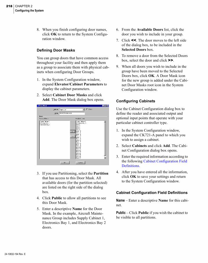
218 CHAPTER 2
Configuring the System
24-10832-194 Rev. E
8. When you finish configuring door names, click OK to return to the System Configu-ration window.
Defining Door Masks
You can group doors that have common access throughout your facility and then apply them as a group to associate them with physical cab-inets when configuring Door Groups.
1. In the System Configuration window, expand Elevator/Cabinet Parameters to display the cabinet parameters.
2. Select Cabinet Door Masks and click Add. The Door Mask dialog box opens.
3. If you use Partitioning, select the Partition that has access to this Door Mask. All available doors (for the partition selected) are listed on the right side of the dialog box.
4. Click Public to allow all partitions to see this Door Mask.
5. Enter a descriptive Name for the Door Mask. In the example, Aircraft Mainte-nance Group includes Supply Cabinet 1, Electronics Bay 1, and Electronics Bay 2 doors.
6. From the Available Doors list, click the door you wish to include in your group.
7. Click <<. The door moves to the left side of the dialog box, to be included in the Selected Doors box.
8. To remove a door from the Selected Doors box, select the door and click >>.
9. When all doors you wish to include in the group have been moved to the Selected Doors box, click OK. A Door Mask icon for the new group is added under the Cabi-net Door Masks root icon in the System Configuration window.
Configuring Cabinets
Use the Cabinet Configuration dialog box to define the reader and associated output and optional input points that operate with your particular cabinet controller type.
1. In the System Configuration window, expand the CK721-A panel to which you wish to assign a cabinet.
2. Select Cabinets and click Add. The Cabi-net Configuration dialog box opens.
3. Enter the required information according to the following Cabinet Configuration Field Definitions.
4. After you have entered all the information, click OK to save your settings and return to the System Configuration window.
Cabinet Configuration Field Definitions
Name – Enter a descriptive Name for this cabi-net.
Public – Click Public if you wish the cabinet to be visible to all partitions.
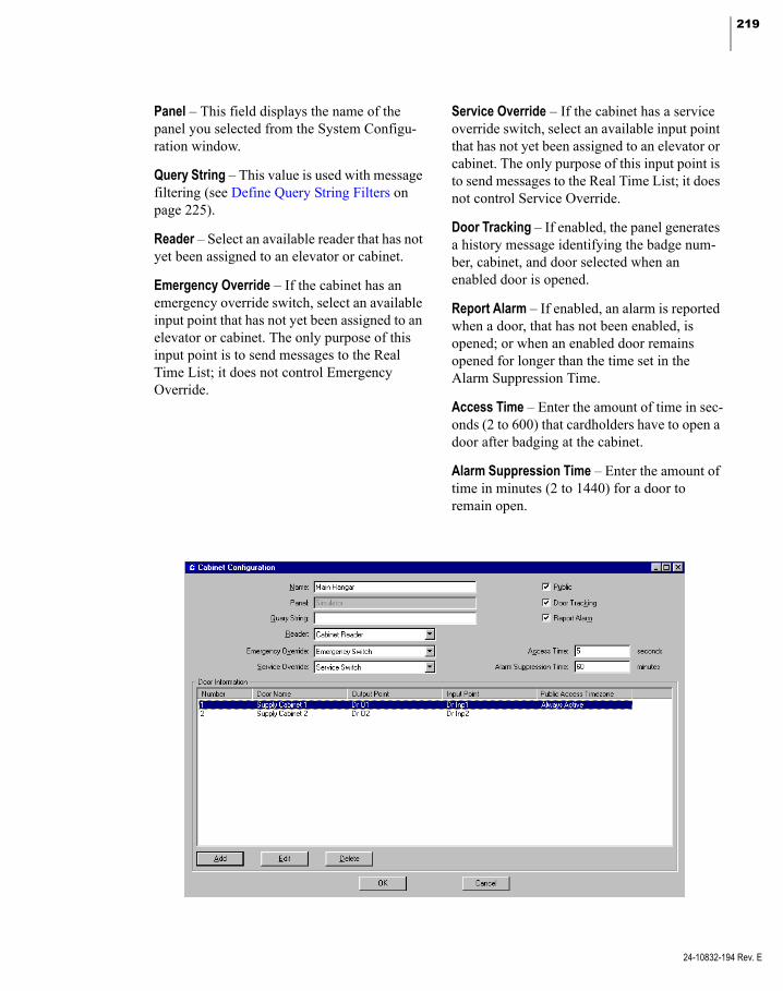
219
Panel – This field displays the name of the panel you selected from the System Configu-ration window.
Query String – This value is used with message filtering (see Define Query String Filters on page 225).
Reader – Select an available reader that has not yet been assigned to an elevator or cabinet.
Emergency Override – If the cabinet has an emergency override switch, select an available input point that has not yet been assigned to an elevator or cabinet. The only purpose of this input point is to send messages to the Real Time List; it does not control Emergency Override.
Service Override – If the cabinet has a service override switch, select an available input point that has not yet been assigned to an elevator or cabinet. The only purpose of this input point is to send messages to the Real Time List; it does not control Service Override.
Door Tracking – If enabled, the panel generates a history message identifying the badge num-ber, cabinet, and door selected when an enabled door is opened.
Report Alarm – If enabled, an alarm is reported when a door, that has not been enabled, is opened; or when an enabled door remains opened for longer than the time set in the Alarm Suppression Time.
Access Time – Enter the amount of time in sec-onds (2 to 600) that cardholders have to open a door after badging at the cabinet.
Alarm Suppression Time – Enter the amount of time in minutes (2 to 1440) for a door to remain open.
24-10832-194 Rev. E
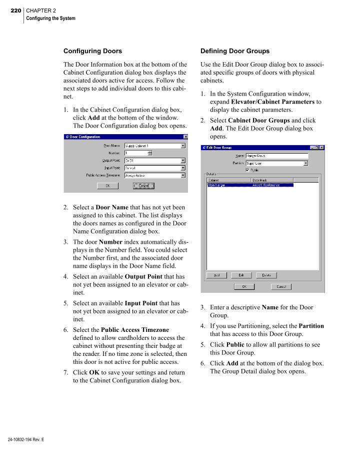
220 CHAPTER 2
Configuring the System
24-10832-194 Rev. E
Configuring Doors
The Door Information box at the bottom of the Cabinet Configuration dialog box displays the associated doors active for access. Follow the next steps to add individual doors to this cabi-net.
1. In the Cabinet Configuration dialog box, click Add at the bottom of the window. The Door Configuration dialog box opens.
2. Select a Door Name that has not yet been assigned to this cabinet. The list displays the doors names as configured in the Door Name Configuration dialog box.
3. The door Number index automatically dis-plays in the Number field. You could select the Number first, and the associated door name displays in the Door Name field.
4. Select an available Output Point that has not yet been assigned to an elevator or cab-inet.
5. Select an available Input Point that has not yet been assigned to an elevator or cab-inet.
6. Select the Public Access Timezone defined to allow cardholders to access the cabinet without presenting their badge at the reader. If no time zone is selected, then this door is not active for public access.
7. Click OK to save your settings and return to the Cabinet Configuration dialog box.
Defining Door Groups
Use the Edit Door Group dialog box to associ-ated specific groups of doors with physical cabinets.
1. In the System Configuration window, expand Elevator/Cabinet Parameters to display the cabinet parameters.
2. Select Cabinet Door Groups and click Add. The Edit Door Group dialog box opens.
3. Enter a descriptive Name for the Door Group.
4. If you use Partitioning, select the Partition that has access to this Door Group.
5. Click Public to allow all partitions to see this Door Group.
6. Click Add at the bottom of the dialog box. The Group Detail dialog box opens.
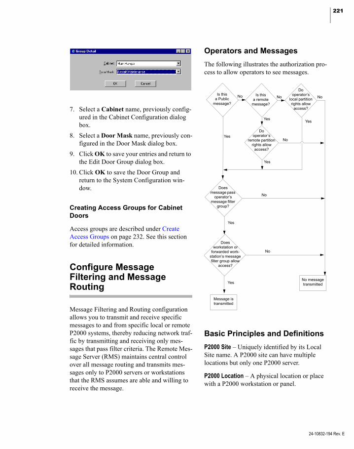
221
7. Select a Cabinet name, previously config-ured in the Cabinet Configuration dialog box.
8. Select a Door Mask name, previously con-figured in the Door Mask dialog box.
9. Click OK to save your entries and return to the Edit Door Group dialog box.
10. Click OK to save the Door Group and return to the System Configuration win-dow.
Creating Access Groups for Cabinet Doors
Access groups are described under Create Access Groups on page 232. See this section for detailed information.
Configure Message Filtering and Message Routing
Message Filtering and Routing configuration allows you to transmit and receive specific messages to and from specific local or remote P2000 systems, thereby reducing network traf-fic by transmitting and receiving only mes-sages that pass filter criteria. The Remote Mes-sage Server (RMS) maintains central control over all message routing and transmits mes-sages only to P2000 servers or workstations that the RMS assumes are able and willing to receive the message.
Operators and Messages
The following illustrates the authorization pro-cess to allow operators to see messages.
Does message pass
operator’s message filter
group?
Doesworkstation or
forwarded work-station’s message filter group allow
access?
Dooperator’s
remote partition rights allow
access?
Dooperator’s
local partition rights allow
access?
Is thisa remote
message?
Is thisa Public
message?
No message transmitted
Yes
No
Yes
No
Yes
YesYes
No No
No
Message is transmitted
No
Yes
Basic Principles and Definitions
P2000 Site – Uniquely identified by its Local Site name. A P2000 site can have multiple locations but only one P2000 server.
P2000 Location – A physical location or place with a P2000 workstation or panel.
24-10832-194 Rev. E

222 CHAPTER 2
Configuring the System
24-10832-194 Rev. E
P2000 Server – A single server that communi-cates with the panels for that site. Typically, it is also the database server for that site, but it is possible for another computer to act as the database server for performance reasons.
P2000 Workstation – A single computer that is connected to one P2000 server and is used to run the P2000 software.
P2000 System – A P2000 system is defined by what is controlled by the P2000 server. A P2000 system has no relationship to geogra-phy, so a single P2000 system can and often contains multiple facilities in multiple loca-tions.
Local P2000 Server/Workstations – A P2000 server or P2000 workstations are local to each other, if they are part of the same P2000 sys-tem.
P2000 Remote Server – A P2000 server that controls a different P2000 system to the one where the transaction was originated. The P2000 Remote Server is the recipient of a for-warded transaction and has no knowledge of the access control hardware and system infor-mation related to the originating P2000 sys-tem.
Remote Transactions – Remote Transactions are messages received from another P2000 system.
Message Forwarding – Message Forwarding is the ability to temporarily forward messages from one P2000 operator logged on at a local P2000 workstation “A” to another local P2000 workstation “B.” The forwarded messages are only visible at the P2000 workstation “B,” if the operator at workstation “B” has sufficient rights to view these messages.
Message Filtering – Reduces network traffic by only transmitting a sub-set of P2000 messages that pass a filter criteria.
Message Routing – Allows the system to route a sub-set of messages to a remote P2000 sys-tem.
Remote Message Service (RMS) – P2000 ser-vice that receives messages from the local RTL Route Service and transmits these messages to the remote P2000 Remote Message Service. When receiving a remote message, the local Remote Message Service processes the mes-sage and passes it on to the local RTL Route Service for distribution to the local worksta-tions.
Sequence of Steps
The basic procedures for defining and imple-menting message filtering and routing are:
Define Message Filtering
Create Message Filter Groups
Configure P2000 Remote Servers
Assign message filter groups to worksta-tions (see page 20), operators (see page 24), and remote servers (see page 231).
Define Remote Message Service settings in Site Parameters; see RMS Tab on page 43.
Message Filtering
Message filtering allows you to control the types of messages transmitted to local worksta-tions or remote servers, thereby reducing net-work traffic by only transmitting a sub-set of P2000 messages that pass filter criteria.
Messages are sent to all workstations by default, provided the message is marked Pub-lic or the logged on operator has the proper access. Depending on the parameters selected in the Message Filter Configuration dialog box, you can filter which messages are to be transmitted when alarm and transaction mes-sages are generated. The system only transmits messages that pass the filter criteria defined.

223
You can, for instance, filter messages to send a specific group to one workstation and a differ-ent group to another. By using message filters you may for example, limit the alarm mes-sages sent to workstations located in Building A to only those alarms originating in Building A, and do the same for Building B. For a com-plete list of all available message types and associated sub-types, see Appendix B: Mes-sage Types and Sub-Types.
Note: All messages are sent by default to the local Server at all times, therefore this feature cannot be used at the Server.
To Create a Message Filter
1. From the P2000 Main menu, select Con-fig>System. Enter your password if prompted. The System Configuration win-dow opens.
2. Select Message Filter and click Add. The Message Filter Configuration dialog box opens.
3. If you use Partitioning, select the Partition that has access to this Message Filter.
4. If you use Partitioning, click Public to allow all partitions to see this Message Fil-ter.
5. Enter a descriptive Name for this Message Filter.
6. See the following sections to define mes-sage types, filters, and ranges.
Note: The length of all filter strings entered in each Selected List is limited to approximately 1000 characters.
7. As you work through the tabs, you may click Apply at any time to save your entries.
8. After you have entered all the information, click OK to save the settings and return to the System Configuration window.
24-10832-194 Rev. E

224 CHAPTER 2
Configuring the System
24-10832-194 Rev. E
Define Message Types
1. Click the Message Type tab.
2. In the Available Type box, click the mes-sage type you wish to define.
3. In the Available Subtype box, click the message subtype you wish to define. The selections in this box are dependent on the type selected in the Available Type box.
4. Click Add. The message type and subtype code are automatically entered in the Selected List box.
5. To enter messages from third-party soft-ware or any currently unknown message, enter the text in the Manual Edit Box, then click Add.
6. To edit your selection, select the message code from the Selected List box, make the change, then click Update.
7. To delete a message type from the Selected List, select the message code and click Delete.
8. Once the message types are selected, click Include in the Selected List box to accept these types of messages.
9. To reject all messages of the type selected, click Exclude.
Define Site Name Filters
Messages associated with the Site Name selected in this tab are either accepted or rejected. For example, you can select to see Area Alarm messages originated only at the Chicago Office, or you can select to see all Area Alarm messages, except the ones origi-nated at the Chicago Office, if the Exclude option is selected.
1. Click the Site Name tab.
2. Select from the Available List the Site Name and click << to move it to the Selected List. To remove it from the Selected List, click >>.
Note: The Available List displays the Local Site Name only. All other site names need to be entered in the Site Name field. Site Name entries are case sensitive.
3. To add a remote site name to the Selected List, enter the name in the Site Name field and click Add.
If the Site Name changes either at the local site or at the remote site, you must re-select the name from the Available List or re-enter the new name in the Site Name field.
Entries may contain a filter string to spec-ify more than one Site Name, for example enter New* to add Site Names such as New York, New Jersey, or New Security.
Note: The wildcard character * (asterisk) in a filter string means that all possible selections are listed. The wildcard character is supported at the end of the filter value only.
4. To edit a remote site name or filter string, select the name, make the change, then click Update.

225
5. To delete a remote site name or filter string from the list, select the name and click Delete.
6. Once the Site Names are selected, click Include in the Selected List box to accept messages associated with the Site Names.
7. To reject all messages associated with the Site Names selected, click Exclude.
Define Partition Name Filters
The system either accepts or rejects messages associated with the Partition Names selected in this tab. The Available List displays all parti-tion names within the local system, including any Remote Partitions entered in the Edit Operator dialog box.
1. Click the Partition Name tab.
2. Select from the Available List the Parti-tion Name and click << to move it to the Selected List. To remove it from the Selected List, click >>.
3. To add a remote partition name to the Selected List, enter the name in the Parti-tion Name field and click Add.
If the Partition Name changes either at the local site or at the remote site, you must re-select the name from the Available List or re-enter the new name in the Partition Name field.
You may enter a filter string to specify more than one Partition Name, for example enter Main* to add Partition Names such as Main Office - Atlanta and Main Office - New York.
4. To edit a remote partition name or filter string, select the name, make the change, then click Update.
5. To delete a remote partition name or filter string from the list, select the name and click Delete.
6. Once the Partition Names are selected, click Include in the Selected List box to accept messages associated with the Parti-tion Names.
7. To reject all messages associated with the Partition Names selected, click Exclude.
8. If the Message passes filter criteria, if message has no filter value check box is enabled, the message meets the filter crite-ria even if there is no filter value. Do not select the check box to stop the message from passing the filter criteria if there is no filter value.
Define Query String Filters
Use this tab to filter messages by Query Strings. Query Strings are filled by querying Panels, Terminals, Input Points, and Output Points. The Available List displays all query strings defined within the local system.
24-10832-194 Rev. E

226 CHAPTER 2
Configuring the System
24-10832-194 Rev. E
1. Click the Query String tab.
2. Select from the Available List the Query String and click << to move it to the Selected List. To remove it from the Selected List, click >>.
3. To add a remote query string to the Selected List, enter the query string in the Query String field and click Add.
If the Query String Name changes either at the local site or at the remote site, you must re-select the name from the Available List or re-enter the new name in the Query String field.
You may enter a filter string to specify more than one Query String, then click Add.
4. To edit a remote query string name or filter string, select the name, make the change, then click Update.
5. To delete a remote query string name or fil-ter string from the list, select the name and click Delete.
6. Once the Query Strings are selected, click Include in the Selected List box to accept messages associated with the Query Strings.
7. To reject all messages associated with the Query String selected, click Exclude.
8. If the Message passes filter criteria, if message has no filter value check box is enabled, the message meets the filter crite-ria even if there is no filter value. Do not select the check box to stop the message from passing the filter criteria if there is no filter value.
Define Item Name Filters
Use this tab to filter messages by Item Names. The Available List displays all Panels, Termi-nals, Input and Output Points defined within the local system.
1. Click the Item Name tab.
2. Select from the Available List the Item Name and click << to move it to the Selected List. To remove it from the Selected List, click >>.
3. To add an item from a remote site to the Selected List, enter the name in the Item Name field and click Add.
If the Item Name changes either at the local site or at the remote site, you must re-select the name from the Available List or re-enter the new name in the Item Name field.
You may enter a filter string to specify more than one Item Name.
4. To edit a remote item name or filter string, select the name, make the change, then click Update.
5. To delete a remote item name or filter string from the list, select the name and click Delete.
6. Once the Item Names are selected, click Include in the Selected List box to accept messages associated with the Item Names.
7. To reject all messages associated with the Item Name selected, click Exclude.
8. If the Message passes filter criteria, if message has no filter value check box is enabled, the message meets the filter crite-ria even if there is no filter value. Do not select the check box to stop the message from passing the filter criteria if there is no filter value.
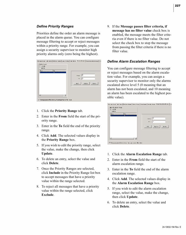
227
Define Priority Ranges
Priorities define the order an alarm message is placed in the alarm queue. You can configure message filtering to accept or reject messages within a priority range. For example, you can assign a security supervisor to monitor high priority alarms only (zero being the highest).
1. Click the Priority Range tab.
2. Enter in the From field the start of the pri-ority range.
3. Enter in the To field the end of the priority range.
4. Click Add. The selected values display in the Priority Range box.
5. If you wish to edit the priority range, select the value, make the change, then click Update.
6. To delete an entry, select the value and click Delete.
7. Once the Priority Ranges are selected, click Include in the Priority Range list box to accept messages that have a priority value within the range selected.
8. To reject all messages that have a priority value within the range selected, click Exclude.
9. If the Message passes filter criteria, if message has no filter value check box is enabled, the message meets the filter crite-ria even if there is no filter value. Do not select the check box to stop the message from passing the filter criteria if there is no filter value.
Define Alarm Escalation Ranges
You can configure message filtering to accept or reject messages based on the alarm escala-tion value. For example, you can assign a security supervisor to monitor only the alarms escalated above level 5 (0 meaning that an alarm has not been escalated, and 10 meaning an alarm has been escalated to the highest pos-sible value).
1. Click the Alarm Escalation Range tab.
2. Enter in the From field the start of the alarm escalation range.
3. Enter in the To field the end of the alarm escalation range.
4. Click Add. The selected values display in the Alarm Escalation Range box.
5. If you wish to edit the alarm escalation range, select the value, make the change, then click Update.
6. To delete an entry, select the value and click Delete.
24-10832-194 Rev. E

228 CHAPTER 2
Configuring the System
24-10832-194 Rev. E
7. Once the Alarm Escalation Ranges are selected, click Include in the Alarm Esca-lation Range list box to accept messages that have an alarm escalation value within the range selected.
8. To reject all messages that have an alarm escalation value within the range selected, click Exclude.
9. If the Message passes filter criteria, if message has no filter value check box is enabled, the message meets the filter crite-ria even if there is no filter value. Do not select the check box to stop the message from passing the filter criteria if there is no filter value.
Define Operator Name Filters
Use this tab to accept or reject messages asso-ciated with the operator names selected here. For example, you can limit the number of operators who respond to alarm messages gen-erated at your local site. The Available List dis-plays the names of all the operators within the local system.
1. Click the Operator Name tab.
2. Select from the Available List the Opera-tor Name and click << to move it to the Selected List. To remove it from the Selected List, click >>.
3. To add remote operator names to the Selected List, enter the name in the Opera-tor Name field and click Add.
If the Operator Name changes either at the local site or at the remote site, you must re-select the name from the Available List or re-enter the new name in the Operator Name field.
You may enter a filter string to specify more than one Operator Name.
4. To edit a remote operator name or filter string, select the name, make the change, then click Update.
5. To delete a remote operator name or filter string from the list, select the name and click Delete.
6. Once the Operator Names are selected, click Include in the Selected List box to accept messages associated with the Oper-ator Names.
7. To reject all messages associated with the Operator Names selected, click Exclude.
8. If the Message passes filter criteria, if message has no filter value check box is enabled, the message meets the filter crite-ria even if there is no filter value. Do not select the check box to stop the message from passing the filter criteria if there is no filter value.
Define Alarm Category Filters
The system either accepts or rejects messages associated with the Alarm Category Names selected in this tab. The Available List displays the default P2000 category and all user-defined categories. If you use the Enter-prise option, the Alarm Categories defined for all P2000 sites within an Enterprise system are listed.

229
1. Click the Alarm Category Name tab.
2. Select from the Available List the Alarm Category Name and click << to move it to the Selected List. To remove it from the Selected List, click >>.
3. To add an alarm category name, enter the name in the Alarm Category Name field and click Add.
You may enter a filter string to specify more than one Alarm Category Name.
4. To edit a remote alarm category name or filter string, select the name, make the change, then click Update.
5. To delete an alarm category name or filter string from the list, select the name and click Delete.
6. Once the Alarm Category Names are selected, click Include in the Selected List box to accept messages associated with the Alarm Category Names.
7. To reject all messages associated with the Alarm Category Name selected, click Exclude.
8. If the Message passes filter criteria, if message has no filter value check box is enabled, the message meets the filter crite-ria even if there is no filter value. Do not select the check box to stop the message from passing the filter criteria if there is no filter value.
Create Message Filter Groups
Message filters are assigned by groups; there-fore, you must create Message Filter Groups before they are available to be assigned to workstations, operators, and remote servers.
A Message Filter Group can contain multiple message filters, but if at least one message fil-ter within the group passes the filter criteria, the message is transmitted.
To Create a Message Filter Group
1. From the System Configuration window, select Message Filter Group and click Add. The Edit Message Filter Group dia-log box opens.
2. If you use Partitioning, select the Partition that has access to this Message Filter Group. All available message filters (for the partition selected) are listed on the right side of the dialog box.
3. If you use Partitioning, click Public to allow all partitions to see this Message Fil-ter Group.
4. Enter a descriptive Name for this Message Filter Group.
5. From the Available list, click the message filter you wish to include in your group.
24-10832-194 Rev. E
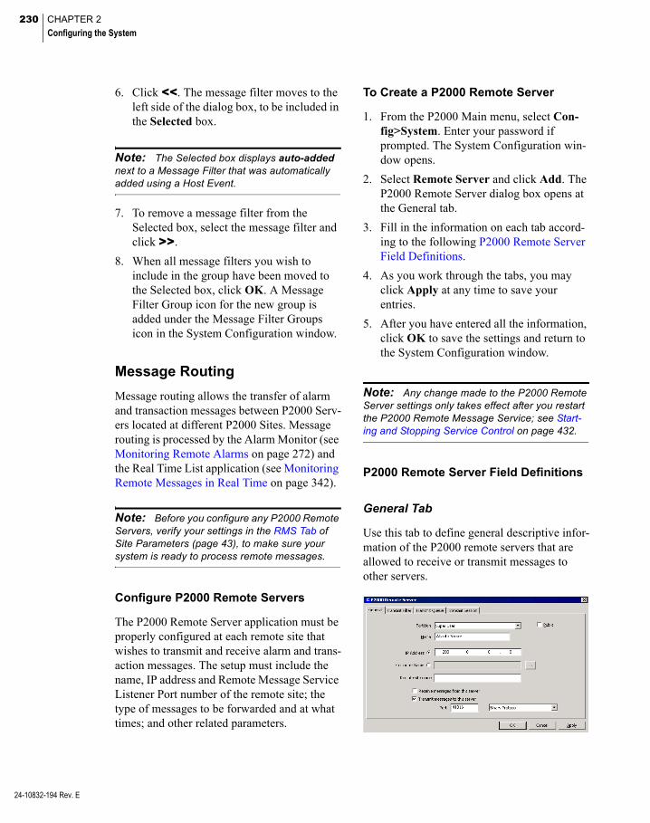
230 CHAPTER 2
Configuring the System
24-10832-194 Rev. E
6. Click <<. The message filter moves to the left side of the dialog box, to be included in the Selected box.
Note: The Selected box displays auto-added next to a Message Filter that was automatically added using a Host Event.
7. To remove a message filter from the Selected box, select the message filter and click >>.
8. When all message filters you wish to include in the group have been moved to the Selected box, click OK. A Message Filter Group icon for the new group is added under the Message Filter Groups icon in the System Configuration window.
Message Routing
Message routing allows the transfer of alarm and transaction messages between P2000 Serv-ers located at different P2000 Sites. Message routing is processed by the Alarm Monitor (see Monitoring Remote Alarms on page 272) and the Real Time List application (see Monitoring Remote Messages in Real Time on page 342).
Note: Before you configure any P2000 Remote Servers, verify your settings in the RMS Tab of Site Parameters (page 43), to make sure your system is ready to process remote messages.
Configure P2000 Remote Servers
The P2000 Remote Server application must be properly configured at each remote site that wishes to transmit and receive alarm and trans-action messages. The setup must include the name, IP address and Remote Message Service Listener Port number of the remote site; the type of messages to be forwarded and at what times; and other related parameters.
To Create a P2000 Remote Server
1. From the P2000 Main menu, select Con-fig>System. Enter your password if prompted. The System Configuration win-dow opens.
2. Select Remote Server and click Add. The P2000 Remote Server dialog box opens at the General tab.
3. Fill in the information on each tab accord-ing to the following P2000 Remote Server Field Definitions.
4. As you work through the tabs, you may click Apply at any time to save your entries.
5. After you have entered all the information, click OK to save the settings and return to the System Configuration window.
Note: Any change made to the P2000 Remote Server settings only takes effect after you restart the P2000 Remote Message Service; see Start-ing and Stopping Service Control on page 432.
P2000 Remote Server Field Definitions
General Tab
Use this tab to define general descriptive infor-mation of the P2000 remote servers that are allowed to receive or transmit messages to other servers.

231
Partition – If you use Partitioning, select the Partition that has access to this P2000 Remote Server.
Public – Click to allow all partitions to see this P2000 Remote Server.
Name – Enter a descriptive Name of the P2000 Remote Server. This name must match exactly the name of the server at the remote site, including the case.
IP Address – If you select the IP Address option, enter the IP Address of the P2000 Remote Server that is used to receive or trans-mit messages.
Computer Name – If you select the Computer Name option, enter the Windows computer name that is used to receive or transmit mes-sages, or click the [...] button to find a com-puter by name on your network.
Remote Site Name – Enter the name of the remote site that can send messages to your local site. You must enter a name in this field if you select the Receive messages from this server option.
Receive messages from this server – Click if you wish to receive messages from this remote server.
Transmit messages to this server – Click if you wish to transmit messages to this remote server.
Port – Enter the Remote Message Service Lis-tener Port number of the remote site, and select the protocol to be used for transmitting mes-sages to the remote server. Options are: Binary Protocol, HTTP Post XML Protocol, and XML Protocol.
Transmit Filter Tab
This tab defines what type of messages and during which times you want to send messages to a remote server.
Timezone – Select the time zone during which messages, that pass the Message Filter Group criteria, are transmitted to the P2000 remote server. Select <Always Enabled> if you wish to send messages at all times.
IMPORTANT: If the P2000 Remote Server is down during an active time zone, messages are not transmitted and they are not available for later transmission.
Message Filter Group – Select the Message Fil-ter Group that defines which messages are transmitted to this P2000 remote server. Select <None> if you wish to transmit all messages to this remote server.
Transmit Queue Tab
Use this tab to define message queue parame-ters for the remote server.
24-10832-194 Rev. E

232 CHAPTER 2
Configuring the System
24-10832-194 Rev. E
Maximum Queue Length – Enter the maximum number of messages to place in the transmis-sion queue. Messages are transmitted based on the First-In-First-Out (FIFO) principle.
Message Void Period – Enter the time in sec-onds after which the system declares messages in the buffer as obsolete.
Transmit Session Tab
Parameters specific to individual transmission sessions are set up in the Transmit Session tab. You must select the Binary Protocol in the Gen-eral Tab to complete the settings in this tab.
Maximum Number of Records – Enter the maxi-mum number of messages than can be trans-mitted within one session.
Maximum Duration – Enter the maximum dura-tion in seconds that a session is kept open.
Timeout Period for Session End Message – Enter the number of seconds that the session waits without receiving a message, until it declares the session closed.
Set up Access Groups and Cardholders
After you have configured your panels, termi-nals, terminal groups and various input and outputs, you are ready to complete system con-figuration by adding Access Groups and Card-holder Options. While Access Groups are assigned from the System Configuration win-dow, Cardholder Options are assigned via the P2000 Main menu. We recommend these ele-ments be assigned in the following sequence:
After these final elements are added, you are ready to move on to operating the system.
Create Access Groups
After terminals and terminal groups have been configured, you can group them together to create common access groups. For example, you can assign two terminals that control the doors into a common area, such as a ware-house, to an access group. When you assign a cardholder badge to that access group, the cardholder is granted access to both doors in the group. This is a quick way to assign badges access to a large number of doors and areas.
If your system is configured to operate eleva-tors and cabinets, elevators floors and cabinet doors can also be assigned to control which floors and doors a cardholder can access.

233
Once access groups are created, they are avail-able for assignment in the applications that use access groups. You can assign up to 32 access groups to a badge (depending on the parame-ters selected in Site Parameters; see Number of Access Groups in the Badge Tab on page 37). In addition, you can also define per-sonalized access groups for each individual cardholder. (See Personalized Access Groups on page 258).
To Create an Access Group
1. In the System Configuration window, select Access Groups.
2. Click Add. The Access Group Edit dialog box opens at the General tab.
3. Enter a descriptive Name for the Access Group.
4. Click Enable for the system to recognize this access group. If at any time you wish to temporarily disable access to any of the items in this group, without having to delete the access group, click to clear this box.
5. Select the Default Timezone during which all terminals (Mercury only) included in this access group are active. To assign dif-ferent time zones to the Mercury terminals in this access group, click the Details tab and follow the instructions provided in step 14.
Note: The Details tab is only available if you select the Terminals associated with Timezone option in the Edit Site Parameters dialog box.
6. If this is a partitioned system, select the Partition name in which the items for this access group reside.
7. Click Public if you wish this Access Group to be visible to other partitions.
8. From the list of Available Terminals list at the far right of the dialog box, select the terminal to include in the Access Group.
9. Click << to move the terminal into the Terminals box.
10. From the Available Terminal Groups list, select the Terminal Group to include in the Access Group.
11. Click << to move it into the Terminals Groups box.
24-10832-194 Rev. E

234 CHAPTER 2
Configuring the System
24-10832-194 Rev. E
12. To add elevator floors to the Access Group, click the Elevator tab and select from the Available Floor Groups list, the Floor Group to include in the Access Group.
13. To add cabinet doors to the Access Group, click the Cabinet tab and select from the Available Door Groups list, the Door Group to include in the Access Group.
14. If you wish to assign a different time zone to the any of the Mercury terminals selected in this access group, click the Details tab, double click the time zone name you wish to change, and select a new time zone from the drop-down list.
Note: The Details tab displays Mercury termi-nals that are defined in the General tab, and also Mercury terminals that are assigned to elevators included in the Floor Groups defined in the Eleva-tor tab.
15. Click OK. The new access group displays under the root Access Groups icon. When you click on the new Access Group icon, the parameters display on the right window-pane of the System Configuration window.
Define Cardholder Options
At a minimum, a first and last name must be entered into the Cardholder database for each person who needs access to your facility. Card-holder data entry is typically performed as part of system operation, which is described in detail in Chapter 3: Operating the System.
However, if your facility takes advantage of additional cardholder information, such as company and department definition, and any other information specific to each facility (defined in User Defined fields), these must be configured before adding cardholders, to make this information accessible from the Card-holder Edit dialog box.
You can also create access templates to speed cardholder and badge data entry, as well as cre-ate badge purposes to specify the badge’s intention. Complete instructions are presented in the following sections:
Define Companies and Departments
Create Access Templates
Create Badge Formats
Create Badge Purposes
Create Badge Reasons
Create Required Cardholder Fields
Create User Defined Fields
Define Automatic Employee IDs
Entering Cardholders
Define Companies and Departments
If your facility includes Company and Depart-ment as part of Cardholder definition, you must first configure Companies and Depart-ments from the Config>Cardholder Options menu. The company and department names are then available for assignment to cardholders in the Cardholder Edit dialog box.
To Define a Company
1. From the P2000 Main menu, select Con-fig>Cardholder Options>Company. The Company dialog box opens.

235
2. Click Add. The Edit Company dialog box opens.
3. If this is a partitioned system, select the Partition to which this company belongs and click Public if you wish this company to be visible to all partitions.
4. Enter the Name of the company.
5. Click OK. The new company name dis-plays in the Company dialog box.
The Auto Added column displays com-pany names that were added using other P2000 applications.
6. Click Done. Company names are accessi-ble from the Cardholder Edit dialog box. (See Entering Cardholder Information on page 244.)
To Define a Department
1. From the P2000 Main menu, select Con-fig>Cardholder Options>Department. The Department dialog box opens.
2. Click Add. The Edit Department dialog box opens.
3. If this is a partitioned system, select the Partition to which this department belongs and click Public if you wish this department to be visible to all partitions.
4. Enter the Name of the department.
5. Click OK. The new department name dis-plays in the Department dialog box.
6. Click Done. This department name is now accessible from the Cardholder Edit dialog box.
24-10832-194 Rev. E
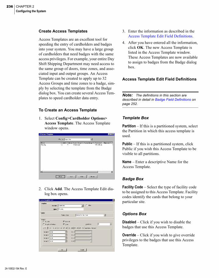
236 CHAPTER 2
Configuring the System
24-10832-194 Rev. E
Create Access Templates
Access Templates are an excellent tool for speeding the entry of cardholders and badges into your system. You may have a large group of cardholders that need badges with the same access privileges. For example, your entire Day Shift Shipping Department may need access to the same group of doors, time zones, and asso-ciated input and output groups. An Access Template can be created to apply up to 32 Access Groups and time zones to a badge, sim-ply by selecting the template from the Badge dialog box. You can create several Access Tem-plates to speed cardholder data entry.
To Create an Access Template
1. Select Config>Cardholder Options> Access Template. The Access Template window opens.
2. Click Add. The Access Template Edit dia-log box opens.
3. Enter the information as described in the Access Template Edit Field Definitions.
4. After you have entered all the information, click OK. The new Access Template is listed in the Access Template window. These Access Templates are now available to assign to badges from the Badge dialog box.
Access Template Edit Field Definitions
Note: The definitions in this section are described in detail in Badge Field Definitions on page 252.
Template Box
Partition – If this is a partitioned system, select the Partition in which this access template is used.
Public – If this is a partitioned system, click Public if you wish this Access Template to be visible to all partitions.
Name – Enter a descriptive Name for the Access Template.
Badge Box
Facility Code – Select the type of facility code to be assigned to this Access Template. Facility codes identify the cards that belong to your particular site.
Options Box
Disabled – Click if you wish to disable the badges that use this Access Template.
Override – Click if you wish to give override privileges to the badges that use this Access Template.

237
Executive Privilege – Click if you wish to give executive privileges to the badges that use this Access Template.
Trace – Click if you wish the badges that use this Access Template to be traced throughout the facility.
Event Privilege – Select a privilege level you wish to assign to the badges that use this Access Template.
1-4 through 29-32 Tabs
Use these tabs to select the Access Groups and associated Time Zones to be assigned to the badges that use this Access Template.
Additional Options Tab
Security Level – Select a security level number from 0 (lowest) to 99 that defines the access privilege to be assigned to badges that use this Access Template.
Guard Tour Priority – Select a priority number from 1 (lowest) to 99 that determines which tours the badges that use this Access Template can perform.
Special Access – Select the special access flags that are assigned to badges that use this Access Template.
Create Badge Formats
This feature allows you to configure badge format categories to assign to badges. This allows facilities that use multiple badge tech-nologies or formats to differentiate their badges.
To Create Badge Formats
1. From the P2000 Main menu, select Con-fig>Cardholder Options>Badge For-mat. The Badge Format dialog box opens.
2. Click Add. The Edit Badge Format dialog box opens.
3. If this is a partitioned system, select the Partition in which the badge format is active.
4. Click Public if you wish the badge format to be visible to all partitions.
5. Enter a descriptive Name for this badge format.
24-10832-194 Rev. E

238 CHAPTER 2
Configuring the System
24-10832-194 Rev. E
6. Select the Technology type.
7. Enter the total number of Bits expected to be returned from the reader when the badge is read.
8. Select a Qualifier number. The number selected represents a 32-bit numerical value that allows differentiating formats with the same technology and the same number of bits. The default value is 1.
9. Click OK.
10. Click Done.
Create Badge Purposes
Users can assign a purpose to a badge for example, to specify the badge’s intention. The Purpose field can be used for different applica-tions. For example, an airport employee may have multiple badges, one for each airline ter-minal the employee is allowed to access. The Purpose field for each badge could be used to identify the airline where the badge is valid. Use the Badge Purpose tool to create the differ-ent Purpose field values that can be available for assignment in the Badge dialog box.
To Create Badge Purpose Fields
1. From the P2000 Main menu, select Con-fig>Cardholder Options>Badge Pur-pose. The Badge Purpose dialog box opens.
2. Click Add. The Edit Badge Purpose dialog box opens.
3. If this is a partitioned system, select the Partition to which this badge purpose field belongs and click Public if you wish this purpose field to be visible to all partitions.
4. Enter the Name of the badge purpose.
5. Click OK. The new badge purpose field displays in the Badge Purpose dialog box.
6. Click Done. This purpose field is now available from the Badge dialog box.
Create Badge Reasons
The P2000 system provides a list of predefined badges reasons that are used to indicate why a badge is being issued. This application allows you to define new badge reasons or modify existing ones according to your facility needs, and then assign these reasons to badge records for filtering and reporting purposes.
Note: Only operators that belong to the Super User partition can add, edit, or delete badge rea-sons.
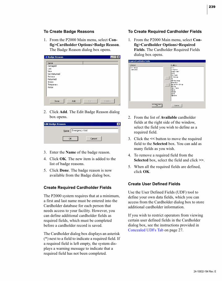
239
To Create Badge Reasons
1. From the P2000 Main menu, select Con-fig>Cardholder Options>Badge Reason. The Badge Reason dialog box opens.
2. Click Add. The Edit Badge Reason dialog box opens.
3. Enter the Name of the badge reason.
4. Click OK. The new item is added to the list of badge reasons.
5. Click Done. The badge reason is now available from the Badge dialog box.
Create Required Cardholder Fields
The P2000 system requires that at a minimum, a first and last name must be entered into the Cardholder database for each person that needs access to your facility. However, you can define additional cardholder fields as required fields, which must be completed before a cardholder record is saved.
The Cardholder dialog box displays an asterisk (*) next to a field to indicate a required field. If a required field is left empty, the system dis-plays a warning message to indicate that a required field has not been completed.
To Create Required Cardholder Fields
1. From the P2000 Main menu, select Con-fig>Cardholder Options>Required Fields. The Cardholder Required Fields dialog box opens.
2. From the list of Available cardholder fields at the right side of the window, select the field you wish to define as a required field.
3. Click the << button to move the required field to the Selected box. You can add as many fields as you wish.
4. To remove a required field from the Selected box, select the field and click >>.
5. When all the required fields are defined, click OK.
Create User Defined Fields
Use the User Defined Fields (UDF) tool to define your own data fields, which you can access from the Cardholder dialog box to store additional cardholder information.
If you wish to restrict operators from viewing certain user defined fields in the Cardholder dialog box, see the instructions provided in Concealed UDFs Tab on page 27.
24-10832-194 Rev. E
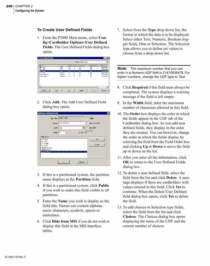
240 CHAPTER 2
Configuring the System
24-10832-194 Rev. E
To Create User Defined Fields
1. From the P2000 Main menu, select Con-fig>Cardholder Options>User Defined Fields. The User Defined Fields dialog box opens.
2. Click Add. The Add User Defined Field dialog box opens.
3. If this is a partitioned system, the partition name displays in the Partition field.
4. If this is a partitioned system, click Public if you wish to make this field visible to all partitions.
5. Enter the Name you wish to display as the field title. Names can contain alphanu-meric characters, symbols, spaces or underlines.
6. Click Hide from MIS if you do not wish to display this field in the MIS Interface tables.
7. Select from the Type drop-down list, the format in which the data is to be displayed. Select either Text, Numeric, Boolean (tog-gle field), Date or Selection. The Selection type allows you to define set values to choose from a drop-down list.
Note: The maximum number that you can enter in a Numeric UDF field is 21474836478. For higher numbers, change the UDF type to Text.
8. Click Required if this field must always be completed. The system displays a warning message if the field is left empty.
9. In the Width field, enter the maximum number of characters allowed in this field.
10. The Order box displays the order in which the fields appear in the UDF tab of the Cardholder dialog box. As you add user defined fields, they display in the order they are created. You can however, change the order in which the fields display by selecting the field from the Field Order box and clicking Up or Down to move the field up or down on the list.
11. After you enter all the information, click OK to return to the User Defined Fields dialog box.
12. To delete a user defined field, select the field from the list and click Delete. A mes-sage displays if there are cardholders with values entered in this field. Click Yes to continue. When the Delete User Defined field dialog box opens, click Yes to delete the field.
13. To add choices to Selection type fields, select the field from the list and click Choices. The Choices dialog box opens displaying the name of the UDF and the current number of choices.

241
14. Click Add. The Choice dialog box opens.
15. Enter the set value for this field and click OK.
16. The choice displays in the list. Click Done to return to the User Defined Fields dialog box.
17. If you wish to convert a Text type field into a Selection type field, select the Text field from the list and click Migrate. In the New Type dialog box click Next.
18. A Summary window displays a description of the change. All previously values defined for the Text field are converted to Choices for the new Selection field. Click Finish.
19. A message indicates that the UDF was suc-cessfully migrated. Click OK.
20. Click Done to close the User Defined Fields dialog box.
Define Automatic Employee IDs
Use the Auto Employee Id Configuration tool to define a pool of consecutive ID numbers that can be automatically assigned to each cardholder record created in the system. This means that every time you create a cardholder record you no longer have to keep track of the last number assigned or the minimum number of characters used for each ID number.
Note: Only operators that belong to the Super User partition can modify Auto Employee Id Con-figuration parameters.
To Configure Automatic Employee ID Numbers
1. From the P2000 Main menu, select Con-fig>Cardholder Options>Auto Employee ID. The Auto Employee Id Configuration dialog box opens.
2. Click Enable to enable the automatic gen-eration of employee IDs. If you wish to use a different number scheme for a particular cardholder, click to clear this check box and manually assign the ID number.
3. Click Prevent Editing Employee ID if you wish to make the ID field a display field, no editing allowed.
24-10832-194 Rev. E
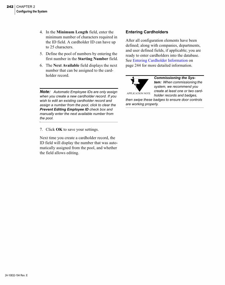
242 CHAPTER 2
Configuring the System
24-10832-194 Rev. E
4. In the Minimum Length field, enter the minimum number of characters required in the ID field. A cardholder ID can have up to 25 characters.
5. Define the pool of numbers by entering the first number in the Starting Number field.
6. The Next Available field displays the next number that can be assigned to the card-holder record.
Note: Automatic Employee IDs are only assign when you create a new cardholder record. If you wish to edit an existing cardholder record and assign a number from the pool, click to clear the Prevent Editing Employee ID check box and manually enter the next available number from the pool.
7. Click OK to save your settings.
Next time you create a cardholder record, the ID field will display the number that was auto-matically assigned from the pool, and whether the field allows editing.
Entering Cardholders
After all configuration elements have been defined; along with companies, departments, and user defined fields, if applicable; you are ready to enter cardholders into the database. See Entering Cardholder Information on page 244 for more detailed information.
Commissioning the Sys-tem: When commissioning the system, we recommend you create at least one or two card-holder records and badges,
then swipe these badges to ensure door controls are working properly.
APPLICATION NOTE
243
Chapter 3: Operating the System
his section describes procedures typi-
cally performed by operators of the P2000 Security Management System, assuming all system configuration hasbeen completed. If you have not completed Chapter 2: Configuring the System, some of the functions described here may not be ready to operate.
Operations typically performed as part of sys-tem maintenance, such as downloading data, updating software and panels, starting and stopping service control, and reviewing system and workstation status; are typically performed by a system administrator and are described in Chapter 5: System Maintenance.
The following sections describe how to:
Provide Access to Cardholders and Visitors
Monitor Alarms
Perform Operator Controls
Control Areas and Muster Zones
Detect and Control Intrusion
Track Hours On Site
Create Events
Monitor the System in Real Time
IMPORTANT: All configuration steps outlined in Chapter 2: Configuring the System, must be completed before you can program and use the essential functions described in this section and some system features require specific configura-tion settings before others can be enabled. These are described in the appropriate sections that fol-low.
Provide Access to Cardholders and Visitors
Access privileges define which cardholder or visitor may enter a specific area of the facility, and at what time they may enter. Access privi-leges are assigned to individual reader termi-nals or group of reader terminals; these devices are assigned to specific access groups, and then when cardholder records are added to the data-base, the cardholders are assigned to the access groups.
The Access feature provides flexible tools to create cardholder records and assign badges with which to grant or deny facility access. At a minimum, a first and last name must be entered into the Cardholder database for each person who needs to have access to your facil-ity. Additional cardholder information can include personal information such as address and phone; company information such as a company name and department; a Photo ID; and any additional information such as eye color, height, weight, or other information you can define in User Defined Fields.
MIS Interface: Cardholder information can be added, deleted, or updated from a database outside the P2000 software using the MIS Inter-
face; see page 365 for more information. MIS is a low-level interface that requires programming to implement.
APPLICATION NOTE
T
24-10832-194 Rev. E
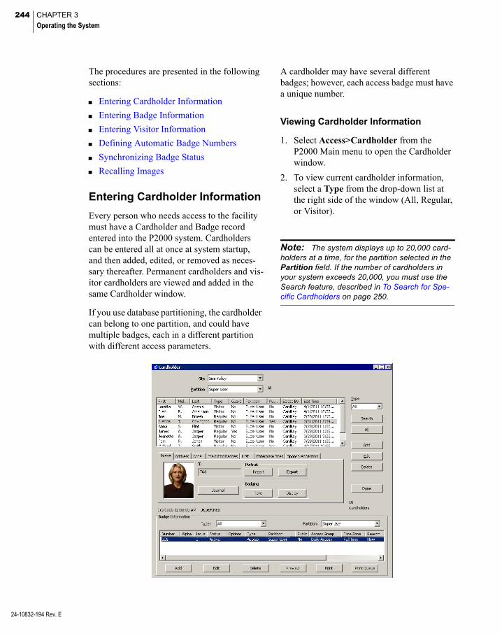
244 CHAPTER 3
Operating the System
24-10832-194 Rev. E
The procedures are presented in the following sections:
Entering Cardholder Information
Entering Badge Information
Entering Visitor Information
Defining Automatic Badge Numbers
Synchronizing Badge Status
Recalling Images
Entering Cardholder Information
Every person who needs access to the facility must have a Cardholder and Badge record entered into the P2000 system. Cardholders can be entered all at once at system startup, and then added, edited, or removed as neces-sary thereafter. Permanent cardholders and vis-itor cardholders are viewed and added in the same Cardholder window.
If you use database partitioning, the cardholder can belong to one partition, and could have multiple badges, each in a different partition with different access parameters.
A cardholder may have several different badges; however, each access badge must have a unique number.
Viewing Cardholder Information
1. Select Access>Cardholder from the P2000 Main menu to open the Cardholder window.
2. To view current cardholder information, select a Type from the drop-down list at the right side of the window (All, Regular, or Visitor).
Note: The system displays up to 20,000 card-holders at a time, for the partition selected in the Partition field. If the number of cardholders in your system exceeds 20,000, you must use the Search feature, described in To Search for Spe-cific Cardholders on page 250.

245
Cardholder Types
Regular – These are the permanent cardholders in the system. Their access begins with a start date, but unless terminated or temporarily reassigned, no end date is specified. Select Regular from the Cardholder window Type drop-down list to view only the regular card-holders.
Visitor – A visitor is given temporary access to the system on a limited basis. Their access is limited by start and end dates and times, and they are assigned a company Sponsor to take responsibility for them while visiting the facil-ity. Select Visitor from the Cardholder window Type drop-down list to view only visitor card-holders in the system.
All – When you select All from the Cardholder window Type drop-down list, all cardholders currently in the system display, regardless of cardholder type.
Additional Cardholder Data
When you select a cardholder from the list, additional cardholder data such as Image, Address, Start/End Badges, UDFs, and other information display in the tabs in the middle of the Cardholder window. If the cardholder selected is a Visitor, a Sponsor tab is added to the window and displays limited Sponsor information. Regular cardholders display the Sponsored Visitors tab, which displays the vis-itors sponsored by the selected cardholder. If your facility uses P2000 Enterprise, a Site field is added at the top of the window, which allows you to view only cardholders that belong to the selected Site name. In addition, the Enterprise Sites tab is also added to the window to display the site names assigned to the cardholder. See P2000 Enterprise on page 402 for details.
To Enter New Cardholder Information
1. From the Cardholder window, click Add. The Cardholder dialog box opens at the Cardholder Edit tab.
2. Enter the information as described in the Cardholder Field Definitions. Required fields are indicated by an asterisk and must be completed before a record is saved.
3. You may click Apply at any time to save your settings. When you finish click OK to return to the Cardholder window, the name of the newly added cardholder displays selected in the list box.
Cardholder Field Definitions
Cardholder Tab
Partition – If this is a partitioned system, select from the drop-down list the Partition to which this cardholder is assigned.
Public – If this is a partitioned system, click Public if you wish this cardholder record to be visible to all partitions.
24-10832-194 Rev. E
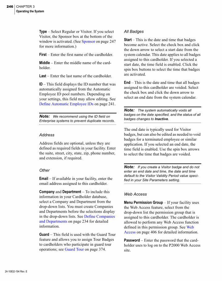
246 CHAPTER 3
Operating the System
24-10832-194 Rev. E
Type – Select Regular or Visitor. If you select Visitor, the Sponsor box at the bottom of the window is activated. (See Sponsor on page 247 for more information.)
First – Enter the first name of the cardholder.
Middle – Enter the middle name of the card-holder.
Last – Enter the last name of the cardholder.
ID – This field displays the ID number that was automatically assigned from the Automatic Employee ID pool numbers. Depending on your settings, this field may allow editing. See Define Automatic Employee IDs on page 241.
Note: We recommend using the ID field on Enterprise systems to prevent duplicate records.
Address
Address fields are optional, unless they are defined as required fields in your facility. Enter the suite, street, city, state, zip, phone number, and extension, if required.
Other
Email – If available in your facility, enter the email address assigned to this cardholder.
Company and Department – To include this information in your Cardholder database, select a Company and Department from the drop-down lists. You must create Companies and Departments before the selections display in the drop-down lists. See Define Companies and Departments on page 234 for detailed information.
Guard – This field is used with the Guard Tour feature and allows you to assign Tour Badges to cardholders who participate in guard tour operations; see Guard Tour on page 374.
All Badges
Start – This is the date and time that badges become active. Select the check box and click the down arrow to select a start date from the system calendar. This date applies to all badges assigned to this cardholder. If you selected a start date, the time field is enabled. Click the spin box buttons to select the time that badges are activated.
End – This is the date and time that all badges assigned to this cardholder are voided. Select the check box and click the down arrow to select an end date from the system calendar.
Note: The system automatically voids all badges on the date specified, and the status of all badges changes to Inactive.
The end date is typically used for Visitor badges, but can also be edited as needed to void badges for a terminated employee or similar application. If you selected an end date, the time field is enabled. Use the spin box arrows to select the time that badges are voided.
Note: If you create a Visitor badge and do not enter an end date and time, the date and time default to the Visitor Validity Period value speci-fied in your Site Parameters setting.
Web Access
Menu Permission Group – If your facility uses the Web Access feature, select from the drop-down list the permission group that is assigned to this cardholder. The cardholder is allowed to perform any Web Access function defined in this permission group. See Web Access on page 406 for detailed information.
Password – Enter the password that the card-holder uses to log on to the P2000 Web Access site.

247
Enterprise
If your facility uses P2000 Enterprise, the Enterprise box displays all the sites defined in the system. Select the check box next to the site that this cardholder may access. See P2000 Enterprise on page 402.
Sponsor
If you selected Visitor as the Cardholder Type, the Sponsor box is activated. A sponsor is the cardholder responsible for the visitor.
To Enter a Visitor Sponsor
1. Once the Sponsor box is activated at the bottom of the Cardholder Edit dialog box, after you select Visitor as the Cardholder Type, click Select. The Cardholder – Find Sponsor dialog box opens.
2. Enter a value in any of the fields. The list box displays the cardholder records that match the entered values.
3. Select a cardholder name and click OK to save the setting and return to the Card-holder Edit dialog box. Basic Cardholder information displays in the Sponsor box.
This information also displays in the Sponsor tab of the Cardholder window.
In addition, when you select a sponsor name from the Cardholder window and click the Sponsored Visitors tab, the list displays all vis-itors sponsored by the selected cardholder. If you double-click a visitor name in the list, the visitor becomes the selected cardholder.
Adding a Cardholder Image
You can import an existing image to display in the Cardholder Image tab. The P2000 system supports a large number of image formats; however, if your image format is not sup-ported, you may need to use an image-editing program to convert to a supported format. See To Import an Image on page 364.
24-10832-194 Rev. E
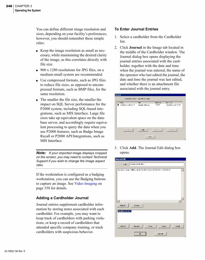
248 CHAPTER 3
Operating the System
24-10832-194 Rev. E
You can define different image resolution and sizes, depending on your facility’s preferences; however, you should remember these simple rules:
Keep the image resolution as small as nec-essary, while maintaining the desired clarity of the image, as this correlates directly with file size.
960 x 1280 resolutions for JPG files, on a medium-small system are recommended.
Use compressed formats, such as JPG files to reduce file sizes, as opposed to uncom-pressed formats, such as BMP files, for the same resolution.
The smaller the file size, the smaller the impact on SQL Server performance for the P2000 system, including SQL-based inte-grations, such as MIS Interface. Large file sizes take up equivalent space on the data-base server, and accordingly require equiva-lent processing to query the data when you use P2000 features, such as Badge Image Recall or P2000 API/Integrations, such as MIS Interface.
Note: If your imported image displays cropped on the screen, you may need to contact Technical Support if you wish to change the image aspect ratio.
If the workstation is configured as a badging workstation, you can use the Badging buttons to capture an image. See Video Imaging on page 358 for details.
Adding a Cardholder Journal
Journal entries supplement cardholder infor-mation by storing notes associated with each cardholder. For example, you may want to keep track of cardholders with parking viola-tions, or keep a record of cardholders that attended specific company training, or track cardholders with suspicious behavior.
To Enter Journal Entries
1. Select a cardholder from the Cardholder list.
2. Click Journal in the Image tab located in the middle of the Cardholder window. The Journal dialog box opens displaying the journal entries associated with the card-holder, together with the date and time when the journal was entered, the name of the operator who last edited the journal, the date and time the journal was last edited, and whether there is an attachment file associated with the journal entry.
3. Click Add. The Journal Edit dialog box opens.
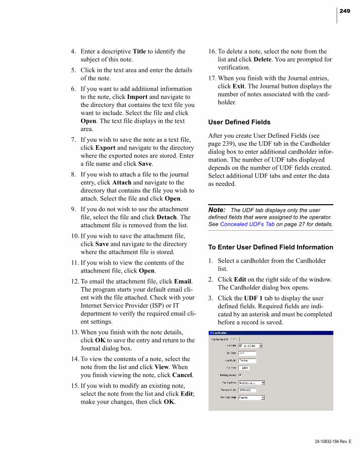
249
4. Enter a descriptive Title to identify the subject of this note.
5. Click in the text area and enter the details of the note.
6. If you want to add additional information to the note, click Import and navigate to the directory that contains the text file you want to include. Select the file and click Open. The text file displays in the text area.
7. If you wish to save the note as a text file, click Export and navigate to the directory where the exported notes are stored. Enter a file name and click Save.
8. If you wish to attach a file to the journal entry, click Attach and navigate to the directory that contains the file you wish to attach. Select the file and click Open.
9. If you do not wish to use the attachment file, select the file and click Detach. The attachment file is removed from the list.
10. If you wish to save the attachment file, click Save and navigate to the directory where the attachment file is stored.
11. If you wish to view the contents of the attachment file, click Open.
12. To email the attachment file, click Email. The program starts your default email cli-ent with the file attached. Check with your Internet Service Provider (ISP) or IT department to verify the required email cli-ent settings.
13. When you finish with the note details, click OK to save the entry and return to the Journal dialog box.
14. To view the contents of a note, select the note from the list and click View. When you finish viewing the note, click Cancel.
15. If you wish to modify an existing note, select the note from the list and click Edit; make your changes, then click OK.
16. To delete a note, select the note from the list and click Delete. You are prompted for verification.
17. When you finish with the Journal entries, click Exit. The Journal button displays the number of notes associated with the card-holder.
User Defined Fields
After you create User Defined Fields (see page 239), use the UDF tab in the Cardholder dialog box to enter additional cardholder infor-mation. The number of UDF tabs displayed depends on the number of UDF fields created. Select additional UDF tabs and enter the data as needed.
Note: The UDF tab displays only the user defined fields that were assigned to the operator. See Concealed UDFs Tab on page 27 for details.
To Enter User Defined Field Information
1. Select a cardholder from the Cardholder list.
2. Click Edit on the right side of the window. The Cardholder dialog box opens.
3. Click the UDF 1 tab to display the user defined fields. Required fields are indi-cated by an asterisk and must be completed before a record is saved.
24-10832-194 Rev. E

250 CHAPTER 3
Operating the System
24-10832-194 Rev. E
4. After you enter the information, click OK to return to the Cardholder window.
5. Click the UDF tab located in the middle of the Cardholder window. The User Defined Fields and entries display for the card-holder selected.
To Edit Cardholder Information
1. From the Cardholder window, select a cardholder from the Cardholder list.
2. Click Edit. The Cardholder dialog box opens.
3. Enter the necessary changes.
4. Click OK to save your changes and return to the Cardholder window. Changes are reflected in the Cardholder list and in the appropriate tabs in the center of the win-dow.
To Search for Specific Cardholders
1. In the Cardholder window, click Search on the right side of the cardholder list. The Database Search dialog box opens.
Click to select Enter UDFa UDF search criteria
2. Enter or select from the associated drop-down lists, the information for any or all of the fields to search for specific card-holders.
3. If you wish to search by Company and Department, select a previously defined name from the drop-down list.
4. You can also search by UDF (up to two UDF fields). Select any of the previously defined UDFs from the drop-down lists (Date type UDFs cannot be included in the search). Then enter the UDF search criteria in the associated fields. (Fields associated with Selection type UDFs are selected from drop-down lists.)
Note: The UDF list only displays the UDF fields associated with the operator record; see Con-cealed UDFs Tab on page 27 for details.
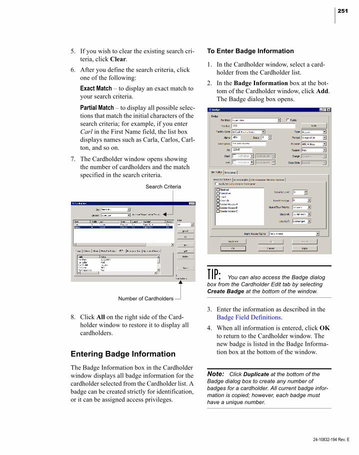
251
Search Criteria
Number of Cardholders
5. If you wish to clear the existing search cri-teria, click Clear.
6. After you define the search criteria, click one of the following:
Exact Match – to display an exact match to your search criteria.
Partial Match – to display all possible selec-tions that match the initial characters of the search criteria; for example, if you enter Carl in the First Name field, the list box displays names such as Carla, Carlos, Carl-ton, and so on.
7. The Cardholder window opens showing the number of cardholders and the match specified in the search criteria.
8. Click All on the right side of the Card-holder window to restore it to display all cardholders.
Entering Badge Information
The Badge Information box in the Cardholder window displays all badge information for the cardholder selected from the Cardholder list. A badge can be created strictly for identification, or it can be assigned access privileges.
To Enter Badge Information
1. In the Cardholder window, select a card-holder from the Cardholder list.
2. In the Badge Information box at the bot-tom of the Cardholder window, click Add. The Badge dialog box opens.
TIP: You can also access the Badge dialog box from the Cardholder Edit tab by selecting Create Badge at the bottom of the window.
3. Enter the information as described in the Badge Field Definitions.
4. When all information is entered, click OK to return to the Cardholder window. The new badge is listed in the Badge Informa-tion box at the bottom of the window.
Note: Click Duplicate at the bottom of the Badge dialog box to create any number of badges for a cardholder. All current badge infor-mation is copied; however, each badge must have a unique number.
24-10832-194 Rev. E
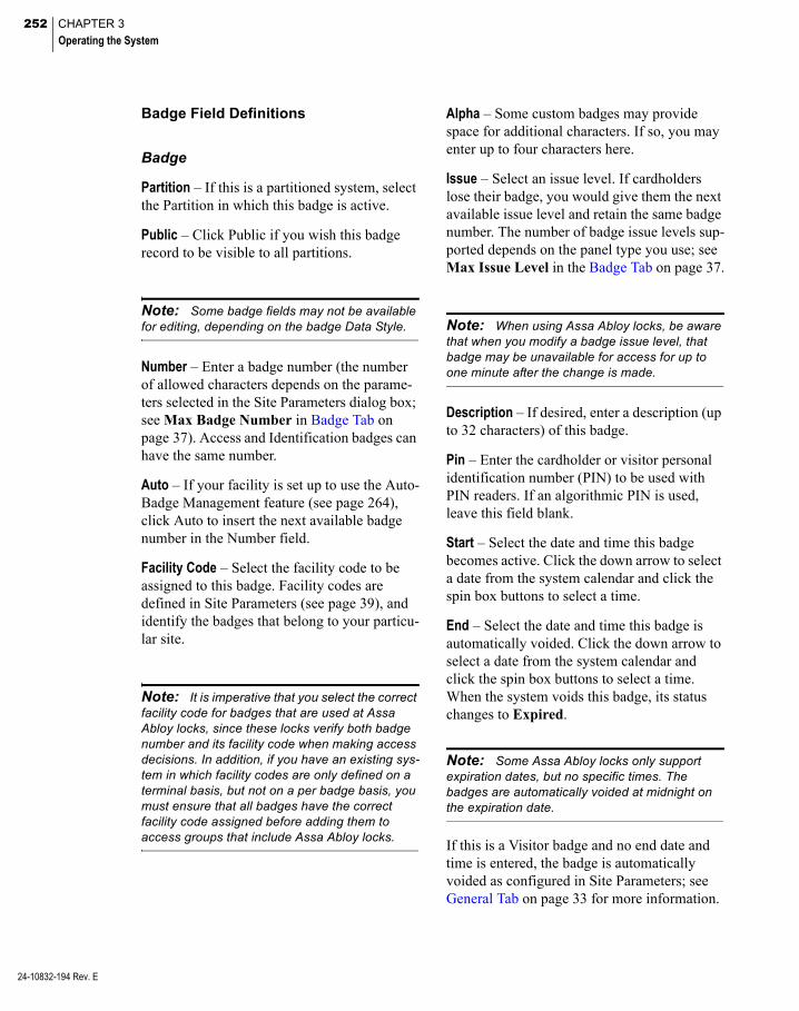
252 CHAPTER 3
Operating the System
24-10832-194 Rev. E
Badge Field Definitions
Badge
Partition – If this is a partitioned system, select the Partition in which this badge is active.
Public – Click Public if you wish this badge record to be visible to all partitions.
Note: Some badge fields may not be available for editing, depending on the badge Data Style.
Number – Enter a badge number (the number of allowed characters depends on the parame-ters selected in the Site Parameters dialog box; see Max Badge Number in Badge Tab on page 37). Access and Identification badges can have the same number.
Auto – If your facility is set up to use the Auto-Badge Management feature (see page 264), click Auto to insert the next available badge number in the Number field.
Facility Code – Select the facility code to be assigned to this badge. Facility codes are defined in Site Parameters (see page 39), and identify the badges that belong to your particu-lar site.
Note: It is imperative that you select the correct facility code for badges that are used at Assa Abloy locks, since these locks verify both badge number and its facility code when making access decisions. In addition, if you have an existing sys-tem in which facility codes are only defined on a terminal basis, but not on a per badge basis, you must ensure that all badges have the correct facility code assigned before adding them to access groups that include Assa Abloy locks.
Alpha – Some custom badges may provide space for additional characters. If so, you may enter up to four characters here.
Issue – Select an issue level. If cardholders lose their badge, you would give them the next available issue level and retain the same badge number. The number of badge issue levels sup-ported depends on the panel type you use; see Max Issue Level in the Badge Tab on page 37.
Note: When using Assa Abloy locks, be aware that when you modify a badge issue level, that badge may be unavailable for access for up to one minute after the change is made.
Description – If desired, enter a description (up to 32 characters) of this badge.
Pin – Enter the cardholder or visitor personal identification number (PIN) to be used with PIN readers. If an algorithmic PIN is used, leave this field blank.
Start – Select the date and time this badge becomes active. Click the down arrow to select a date from the system calendar and click the spin box buttons to select a time.
End – Select the date and time this badge is automatically voided. Click the down arrow to select a date from the system calendar and click the spin box buttons to select a time. When the system voids this badge, its status changes to Expired.
Note: Some Assa Abloy locks only support expiration dates, but no specific times. The badges are automatically voided at midnight on the expiration date.
If this is a Visitor badge and no end date and time is entered, the badge is automatically voided as configured in Site Parameters; see General Tab on page 33 for more information.
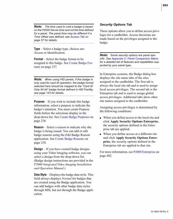
253
Note: The time used to void a badge is based on the P2000 Server time and not the time defined for a panel. The panel time may be different if a Time Offset was defined; see Access Tab on page 57 for details.
Type – Select a badge type, choices are: Access or Identification.
Format – Select the badge format to be assigned to this badge. See Create Badge For-mats on page 237.
Note: When using HID panels, if this badge is only used for card ID operation, the badge format selected here should be mapped to the “Card ID Only 64 bit” badge format defined in HID Facility, see page 123 for details.
Purpose – If you wish to include this badge information, select a purpose to indicate the badge’s intention. You must create Purpose fields before the selections display in the drop-down list. See Create Badge Purposes on page 238.
Reason – Select a reason to indicate why the badge is being issued. You can add or edit badge reasons using the Edit Badge Reason application. See Create Badge Reasons on page 238.
Design – If you have created badge designs using your Video Imaging software, you can select a design from the drop-down list. (Badge design instructions are provided in the P2000 Integrated Video Imaging Installation and Operation Manual.)
Data Style – Displays the badge data style. This field always displays Normal for badges that are created using the Badge application. You can add badges with other badge data styles through MIS, but not through the Badge appli-cation.
Security Options Tab
These options allow you to define access privi-leges for a cardholder. Access decisions are made based on the privileges assigned to the badge.
Note: Some security options are panel spe-cific. See Appendix C: Panel Comparison Matrix for a detailed list of features and capabilities sup-ported by your panel type.
In Enterprise systems, the Badge dialog box displays the site name tabs of the sites assigned to the cardholder. The first tab is always the local site tab and is used to assign local access privileges. The second tab is the Enterprise tab and is used to assign global access privileges. Additional tabs show other site names assigned to the cardholder.
Assigning access privileges is determined by the following conditions:
When you define access to the local site and click Apply Security Options Enterprise, the security options defined in the Enter-prise tab are applied.
When you define access at a different site and click Apply Security Options Enter-prise, the security options defined in the Enterprise tab are applied to that site.
For more information, see P2000 Enterprise on page 402.
24-10832-194 Rev. E

254 CHAPTER 3
Operating the System
24-10832-194 Rev. E
Disabled – When a badge is created, it is auto-matically enabled. Click this check box to dis-able this badge. This function is useful when you wish to disable a badge, but do not wish to re-issue or redefine a badge for this cardholder.
Executive – If enabled, the cardholder has unlimited access to all operational doors con-trolled by the access control system, regardless of any other privileges programmed for this badge. (If a specific terminal requires the use of a PIN code with a badge, the PIN code is still required.)
Note: For badges that are used with Mercury panels, the badge must be in the same partition as the panel, or the panel must be set as Public.
Note: When using HID panels, the P2000 sys-tem emulates the executive privilege in the panel, using standard access methods. Therefore, exec-utive privilege badges are not exempt from access rules in the panel, such as anti-passback.
Trace – Enable to trace cardholder movement throughout the facility. Badge transactions are printed, as they occur, on any printer config-ured to print trace transactions, as long as the Badge Trace and Printing options are selected in the Real Time List window.
Override – If enabled, the cardholder can unlock any door controlled by a keypad reader that has the Override option enabled. See your specific hardware configuration section for information on setting up this option.
Special Access – Special Access flags are defined in the Site Parameters dialog box; see General Tab on page 33. Click any of the three special access flags if the cardholder requires special access at a reader. Special access allows a door’s access time to be different. See your specific hardware configuration section for information on setting up this option.
Security Level
Select a security level number from 0 (lowest) to 99 or the maximum security level set up at the Site Parameters dialog box. To obtain access at a door, this number must be equal to or greater than the security level set up at the terminal. If the security level at the terminal is raised, cardholders are denied access, unless the badge has the Executive privilege enabled.
Event Privilege
Every badge has an event privilege level, rang-ing from 0 to 7, with zero as the lowest level. If a cardholder’s badge is to initiate a card event, this event privilege level must be equal to or greater than the privilege level defined in the Panel Card Event dialog box.
Guard Tour
Select a Guard Tour Priority number from 1 (lowest) to 99. This number determines which tours the selected cardholder can perform. Only tour badges with equal to or greater than this priority can perform a tour.
Card Use Limit
Card use limit options are provided to control the maximum number of times a badge can be granted access.
Use Limit – This feature controls the maximum number of times that a Mercury panel can grant access to this badge. Select the number of times (0 to 254) or <unlimited> from the drop-down list.
Uses Left – Select Unchanged (default option) to keep the Uses Left counters unaffected; or select Reinitialize to reset the counters to Use Limit value.

255
Additional Card Use Limit Notes
The card Use Limit of a badge applies to a site. In an enterprise system, a badge may have a different card Use Limit on each site.
The P2000 system sets the Use Limit of a badge to zero as soon as it learns that the badge’s Uses Left counter has reached zero on any Mercury panel. It will then apply this new Use Limit of zero to all Mercury panels that have the badge, along with the instructions to reinitialize the Uses Left counter to this zero value. This effectively prevents the badge from being granted access at all Mercury readers that enforce the card Use Limit feature.
The Uses Left counter for each badge is kept on a per panel basis. This means, that the system wide maximum number of uses may be higher, and that the Uses Left counter may have reached zero on one panel, but still is positive on another panel.
Rebooting a Mercury panel or performing a Reset Panel Before Download restores the Uses Left counter to the value defined in the Use Limit.
Access Rights Tab
Use this tab to define the Access Groups and corresponding Time Zones that can be assigned to this badge. The number of groups displayed here depends on the parameters selected in the Site Parameters dialog box (see Number of Access Groups in the Badge Tab on page 37). See Badge Access Rights on page 97 for details associated with OSI panels. Also, see To Define Access Rights on page 256 for complete instructions.
Otis Compass Elevator Options Tab
Use this tab to define parameters for cardhold-ers that need access to Otis Compass elevators, see Otis Compass on page 204 for more infor-mation.
Floor Mask – For Otis Compass elevators that are configured for PIN entry, select the floor mask that contains the floors that this badge is able to gain access to when they enter a PIN code at the elevator.
Floor – Select the default floor for the user. When the badge is swiped, depending on the operational mode of the elevator that is being used, that badge’s default floor is used to dis-patch an elevator, assuming the default floor is an authorized or an allowed floor.
Passenger Type – Select the passenger types that identify special conditions that can be assigned to a cardholder. When the badge is presented, a message is sent to the Otis Com-pass elevator system to dispatch a specific ele-vator car that the cardholder can board.
Standard – Select for cardholders that do not require special access. This is the default selection for all badges.
Disability – Select for cardholders that require special elevator accommodations; for example, bigger elevator cars, extended time to board the elevator, or audible announcements at each floor.
A cardholder can be assigned with a Standard or a Disability flag, in addition to any of the following conditions:
24-10832-194 Rev. E
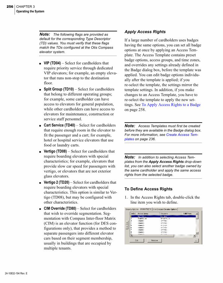
256 CHAPTER 3
Operating the System
24-10832-194 Rev. E
Note: The following flags are provided as default for the corresponding Type Descriptor (TD) values. You must verify that these flags match the TDs configured at the Otis Compass elevator system.
VIP (TD04) – Select for cardholders that require priority service through dedicated VIP elevators; for example, an empty eleva-tor that runs non-stop to the destination floor.
Split Group (TD10) – Select for cardholders that belong to different operating groups; for example, some cardholder can have access to elevators for general population, while other cardholders can have access to elevators for maintenance, construction or service staff personnel.
Cart Service (TD40) – Select for cardholders that require enough room in the elevator to fit the passenger and a cart; for example, hotel or hospital service elevators that use food or laundry carts.
Vertigo (TD08) – Select for cardholders that require boarding elevators with special characteristics; for example, elevators that provide slow car speed for passengers with vertigo, or elevators that are not exterior glass elevators.
Vertigo 2 (TD20) – Select for cardholders that require boarding elevators with special characteristics. This option is similar to Ver-tigo (TD08), but may be configured with other characteristics.
CIM Override (TD80) – Select for cardholders that wish to override segmentation. Seg-mentation with Compass Inter-floor Matrix (CIM) is an elevator function (for DES con-figurations only), that provides a method to separate passengers into different elevator cars based on their segment membership, usually in buildings that are occupied by multiple tenants.
Apply Access Rights
If a large number of cardholders uses badges having the same options, you can set all badge options at once by applying an Access Tem-plate. The Access Template contains preset badge options, access groups, and time zones, and overrides any settings already defined in the Badge dialog box, before the template was applied. You can edit badge options individu-ally after the template is applied; if you re-select the template, the settings mirror the template settings. In addition, if you make changes to an Access Template, you have to re-select the template to apply the new set-tings. See To Apply Access Rights to a Badge on page 258.
Note: Access Templates must first be created before they are available in the Badge dialog box. For more information, see Create Access Tem-plates on page 236.
Note: In addition to selecting Access Tem-plates from the Apply Access Rights drop-down list, you can also select another badge owned by the same cardholder and apply the same access rights from the selected badge.
To Define Access Rights
1. In the Access Rights tab, double-click the line item you wish to define.
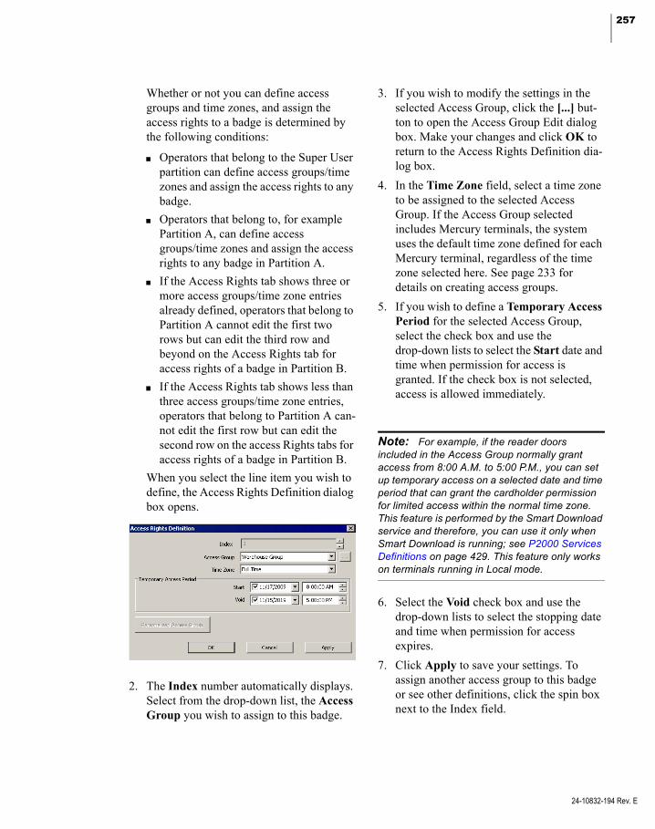
257
Whether or not you can define access groups and time zones, and assign the access rights to a badge is determined by the following conditions:
Operators that belong to the Super User partition can define access groups/time zones and assign the access rights to any badge.
Operators that belong to, for example Partition A, can define access groups/time zones and assign the access rights to any badge in Partition A.
If the Access Rights tab shows three or more access groups/time zone entries already defined, operators that belong to Partition A cannot edit the first two rows but can edit the third row and beyond on the Access Rights tab for access rights of a badge in Partition B.
If the Access Rights tab shows less than three access groups/time zone entries, operators that belong to Partition A can-not edit the first row but can edit the second row on the access Rights tabs for access rights of a badge in Partition B.
When you select the line item you wish to define, the Access Rights Definition dialog box opens.
2. The Index number automatically displays. Select from the drop-down list, the Access Group you wish to assign to this badge.
3. If you wish to modify the settings in the selected Access Group, click the [...] but-ton to open the Access Group Edit dialog box. Make your changes and click OK to return to the Access Rights Definition dia-log box.
4. In the Time Zone field, select a time zone to be assigned to the selected Access Group. If the Access Group selected includes Mercury terminals, the system uses the default time zone defined for each Mercury terminal, regardless of the time zone selected here. See page 233 for details on creating access groups.
5. If you wish to define a Temporary Access Period for the selected Access Group, select the check box and use the drop-down lists to select the Start date and time when permission for access is granted. If the check box is not selected, access is allowed immediately.
Note: For example, if the reader doors included in the Access Group normally grant access from 8:00 A.M. to 5:00 P.M., you can set up temporary access on a selected date and time period that can grant the cardholder permission for limited access within the normal time zone. This feature is performed by the Smart Download service and therefore, you can use it only when Smart Download is running; see P2000 Services Definitions on page 429. This feature only works on terminals running in Local mode.
6. Select the Void check box and use the drop-down lists to select the stopping date and time when permission for access expires.
7. Click Apply to save your settings. To assign another access group to this badge or see other definitions, click the spin box next to the Index field.
24-10832-194 Rev. E

258 CHAPTER 3
Operating the System
24-10832-194 Rev. E
8. To define personalized settings, click Per-sonalized Access Group and enter your settings. See Personalized Access Groups for details.
9. Click OK to return to the Access Rights tab.
10. To remove a definition, select the line item and click Remove.
11. The list displays the access groups assigned to the badge. To edit an access group, select the line item and click the [...] button.
Personalized Access Groups
When assigning access groups to a badge, you can use personalized access group for each cardholder. The Personalized Access Group button provides a shortcut to set up access groups without the need of scanning through all existing access groups.
By default, the Name of the access group is always the name of the cardholder. However, be aware that the name of the access group is not automatically modified if you change the name of the cardholder.
Once you have all the access group elements defined, such as terminals, terminal groups, elevators, or cabinets, click OK. The new per-sonalized access group displays automatically in the Access Group field. Assign a time zone to the new access group as you would for any other access group.
Note: Although initially created for a particular cardholder, a personalized access group becomes a standard access group within the P2000 system and can also be assigned to other cardholders.
To Apply Access Rights to a Badge
1. From the Apply Access Rights drop-down list, at the bottom of the Badge dialog box, select the Access Template or badge num-ber you wish to apply to the badge. All access options defined for the Access Tem-plate or selected badge number are applied to the badge.
2. If you wish to change specific badge options, access groups, or time zones for this badge, you may do so. All other set-tings remain in effect.
Viewing Badge Data
Badge information such as Number, Status, Options, Type, Partition, and Access Group displays in the list box at the bottom of the Cardholder window. When you select a card-holder from the Cardholder list, all badges assigned to that cardholder display in the Badge Information box. You can also display the badge’s transaction history.
To Display Badge Transaction History
1. In the Cardholder window, select a card-holder from the list.
2. In the Badge Information box, right-click the badge number you wish to view.

259
3. From the shortcut menu select Transac-tion History. The Badge Transaction His-tory dialog box opens displaying the selected Cardholder name and Badge num-ber.
The list box displays the date, transaction type, and location where the badge was presented.
4. To change the number of transactions dis-played, enter the desired number in the Num Records field.
5. To update the list box with new data, click Refresh.
6. Click Done to close the dialog box.
Bulk Badge Change
The Bulk Badge Change tool is used to change badge parameters across multiple records, in a single operation. This feature not only allows you to save time by modifying multiple records at once, but also improves the accu-racy from single record editing, and avoids the hassle of updating badge records one entry at a time. In addition, you can also delete multiple badges and associated cardholder records at the same time.
To Bulk Change Badge Records
1. From the P2000 Main menu, select Access>Bulk Badge Change. The Bulk Badge Change dialog box opens.
2. Enter or select from the associated drop-down lists, the information for any or all of the fields.
Note: The list box displays cardholders that match all fields in the search criteria. Make sure you use the AND logic to define your search.
3. If you wish to search by Company and Department, select a previously defined name from the drop-down list.
4. You can also search by UDF (up to two fields). Select any of the previously defined UDFs from the drop-down lists (Date type UDFs cannot be included in the search), then enter or select the UDF search criteria in the associated fields.
5. If you wish to search for badges that have not been used for a while, enter in the Badge Unused For field the number of days that the badges have not been used.
6. After you define the search criteria, click one of the following buttons:
Exact Match – to display an exact match to your search criteria.
24-10832-194 Rev. E

260 CHAPTER 3
Operating the System
24-10832-194 Rev. E
Partial Match – to display all possible selec-tions that match the initial characters of the search criteria; for example, if you enter Carl in the First Name field, the list box displays names such as Carla, Carlos, Carl-ton, and so on.
7. Once the list box displays the cardholders specified in the search criteria, select from the Action drop-down list one of the fol-lowing options:
Add Access Group – to assign all badges in the list box with access to all terminals defined in the access group. Select the Access Group and Timezone to be assigned to the selected badges. The access group is added to the first available slot on the badges.
Apply Access Template – to apply all preset access privileges, badge options, access groups, and time zones that were defined in the access template. Select from the Access Template drop-down list, the Access Tem-plate to be applied to the selected badges.
Note: You cannot apply Facility Code settings using the Bulk Badge Change function.
Change Badge Format – to change the for-mat of all badges in the list box. Select the New Badge Format to be applied to the selected badges.
Delete Access Group – to remove from the selected badges access to all terminals defined in the access group. Select the Access Group to remove.
Delete Badge – to delete all badges in the list box.
Delete Badge and Cardholder – to delete all badges and associated cardholders in the list box.
Note: If a cardholder owns more than one badge, and that badge is not included in the list box, the cardholder record is not deleted.
Disable Badge – to disable all badges in the list box.
Replace Access Group – to replace the existing access group. Select from the New Access Group drop-down list the access group you wish to assign. Select from the Old Access Group, the access group you wish to replace. The original timezone for the access group does not change.
8. If you wish to print the data in the list box, click Print.
9. Click Apply to change the selected badge records.
10. Click Done to close Bulk Badge Change.
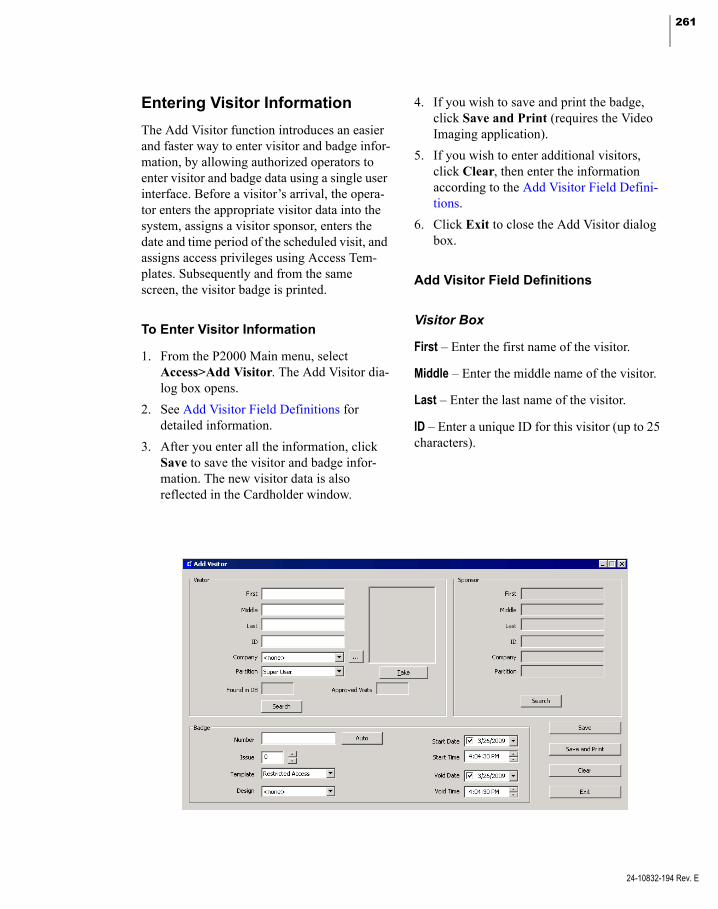
261
Entering Visitor Information
The Add Visitor function introduces an easier and faster way to enter visitor and badge infor-mation, by allowing authorized operators to enter visitor and badge data using a single user interface. Before a visitor’s arrival, the opera-tor enters the appropriate visitor data into the system, assigns a visitor sponsor, enters the date and time period of the scheduled visit, and assigns access privileges using Access Tem-plates. Subsequently and from the same screen, the visitor badge is printed.
To Enter Visitor Information
1. From the P2000 Main menu, select Access>Add Visitor. The Add Visitor dia-log box opens.
2. See Add Visitor Field Definitions for detailed information.
3. After you enter all the information, click Save to save the visitor and badge infor-mation. The new visitor data is also reflected in the Cardholder window.
4. If you wish to save and print the badge, click Save and Print (requires the Video Imaging application).
5. If you wish to enter additional visitors, click Clear, then enter the information according to the Add Visitor Field Defini-tions.
6. Click Exit to close the Add Visitor dialog box.
Add Visitor Field Definitions
Visitor Box
First – Enter the first name of the visitor.
Middle – Enter the middle name of the visitor.
Last – Enter the last name of the visitor.
ID – Enter a unique ID for this visitor (up to 25 characters).
24-10832-194 Rev. E
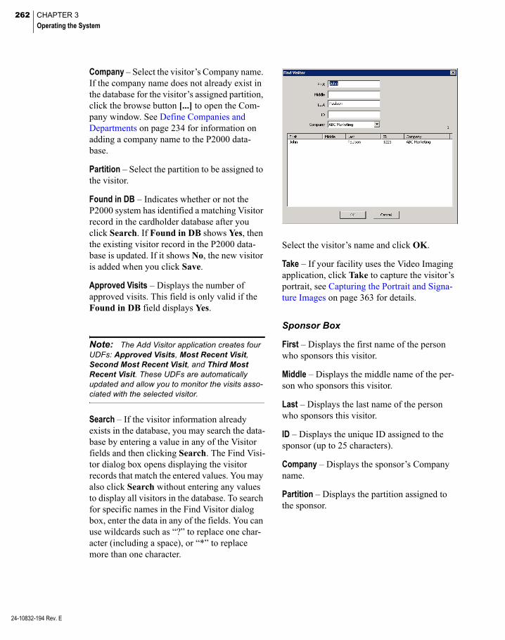
262 CHAPTER 3
Operating the System
24-10832-194 Rev. E
Company – Select the visitor’s Company name. If the company name does not already exist in the database for the visitor’s assigned partition, click the browse button [...] to open the Com-pany window. See Define Companies and Departments on page 234 for information on adding a company name to the P2000 data-base.
Partition – Select the partition to be assigned to the visitor.
Found in DB – Indicates whether or not the P2000 system has identified a matching Visitor record in the cardholder database after you click Search. If Found in DB shows Yes, then the existing visitor record in the P2000 data-base is updated. If it shows No, the new visitor is added when you click Save.
Approved Visits – Displays the number of approved visits. This field is only valid if the Found in DB field displays Yes.
Note: The Add Visitor application creates four UDFs: Approved Visits, Most Recent Visit, Second Most Recent Visit, and Third Most Recent Visit. These UDFs are automatically updated and allow you to monitor the visits asso-ciated with the selected visitor.
Search – If the visitor information already exists in the database, you may search the data-base by entering a value in any of the Visitor fields and then clicking Search. The Find Visi-tor dialog box opens displaying the visitor records that match the entered values. You may also click Search without entering any values to display all visitors in the database. To search for specific names in the Find Visitor dialog box, enter the data in any of the fields. You can use wildcards such as “?” to replace one char-acter (including a space), or “*” to replace more than one character.
Select the visitor’s name and click OK.
Take – If your facility uses the Video Imaging application, click Take to capture the visitor’s portrait, see Capturing the Portrait and Signa-ture Images on page 363 for details.
Sponsor Box
First – Displays the first name of the person who sponsors this visitor.
Middle – Displays the middle name of the per-son who sponsors this visitor.
Last – Displays the last name of the person who sponsors this visitor.
ID – Displays the unique ID assigned to the sponsor (up to 25 characters).
Company – Displays the sponsor’s Company name.
Partition – Displays the partition assigned to the sponsor.
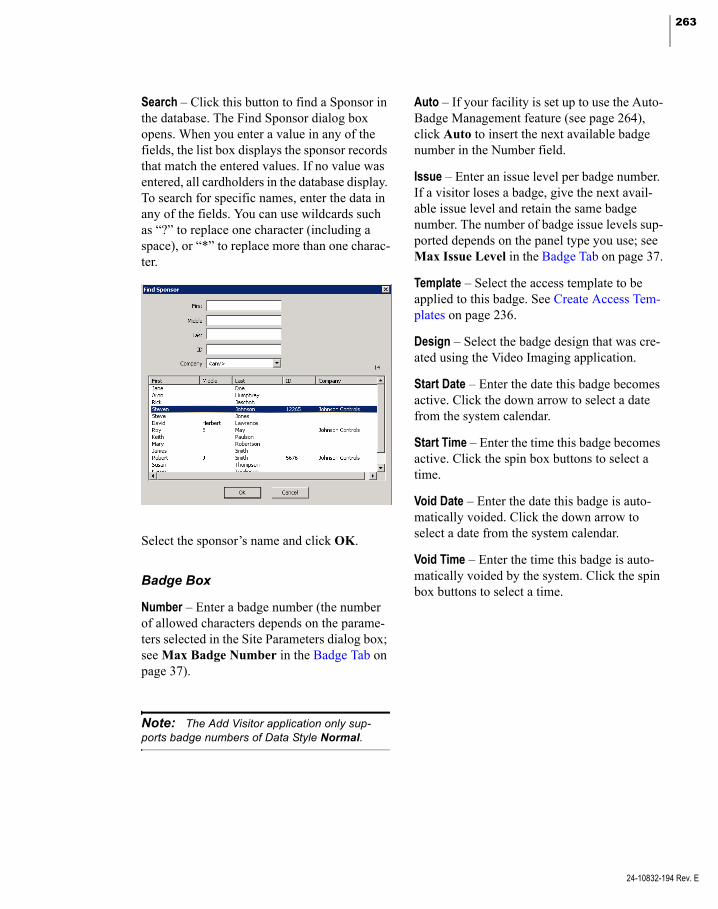
263
Search – Click this button to find a Sponsor in the database. The Find Sponsor dialog box opens. When you enter a value in any of the fields, the list box displays the sponsor records that match the entered values. If no value was entered, all cardholders in the database display. To search for specific names, enter the data in any of the fields. You can use wildcards such as “?” to replace one character (including a space), or “*” to replace more than one charac-ter.
Select the sponsor’s name and click OK.
Badge Box
Number – Enter a badge number (the number of allowed characters depends on the parame-ters selected in the Site Parameters dialog box; see Max Badge Number in the Badge Tab on page 37).
Note: The Add Visitor application only sup-ports badge numbers of Data Style Normal.
Auto – If your facility is set up to use the Auto-Badge Management feature (see page 264), click Auto to insert the next available badge number in the Number field.
Issue – Enter an issue level per badge number. If a visitor loses a badge, give the next avail-able issue level and retain the same badge number. The number of badge issue levels sup-ported depends on the panel type you use; see Max Issue Level in the Badge Tab on page 37.
Template – Select the access template to be applied to this badge. See Create Access Tem-plates on page 236.
Design – Select the badge design that was cre-ated using the Video Imaging application.
Start Date – Enter the date this badge becomes active. Click the down arrow to select a date from the system calendar.
Start Time – Enter the time this badge becomes active. Click the spin box buttons to select a time.
Void Date – Enter the date this badge is auto-matically voided. Click the down arrow to select a date from the system calendar.
Void Time – Enter the time this badge is auto-matically voided by the system. Click the spin box buttons to select a time.
24-10832-194 Rev. E
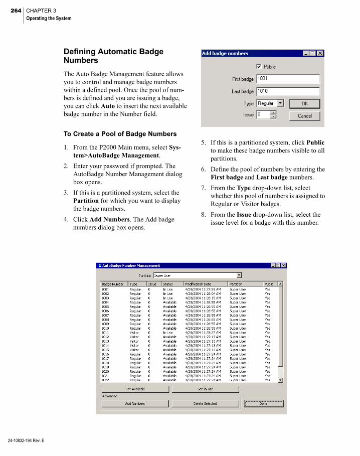
264 CHAPTER 3
Operating the System
24-10832-194 Rev. E
Defining Automatic Badge Numbers
The Auto Badge Management feature allows you to control and manage badge numbers within a defined pool. Once the pool of num-bers is defined and you are issuing a badge, you can click Auto to insert the next available badge number in the Number field.
To Create a Pool of Badge Numbers
1. From the P2000 Main menu, select Sys-tem>AutoBadge Management.
2. Enter your password if prompted. The AutoBadge Number Management dialog box opens.
3. If this is a partitioned system, select the Partition for which you want to display the badge numbers.
4. Click Add Numbers. The Add badge numbers dialog box opens.
5. If this is a partitioned system, click Public to make these badge numbers visible to all partitions.
6. Define the pool of numbers by entering the First badge and Last badge numbers.
7. From the Type drop-down list, select whether this pool of numbers is assigned to Regular or Visitor badges.
8. From the Issue drop-down list, select the issue level for a badge with this number.
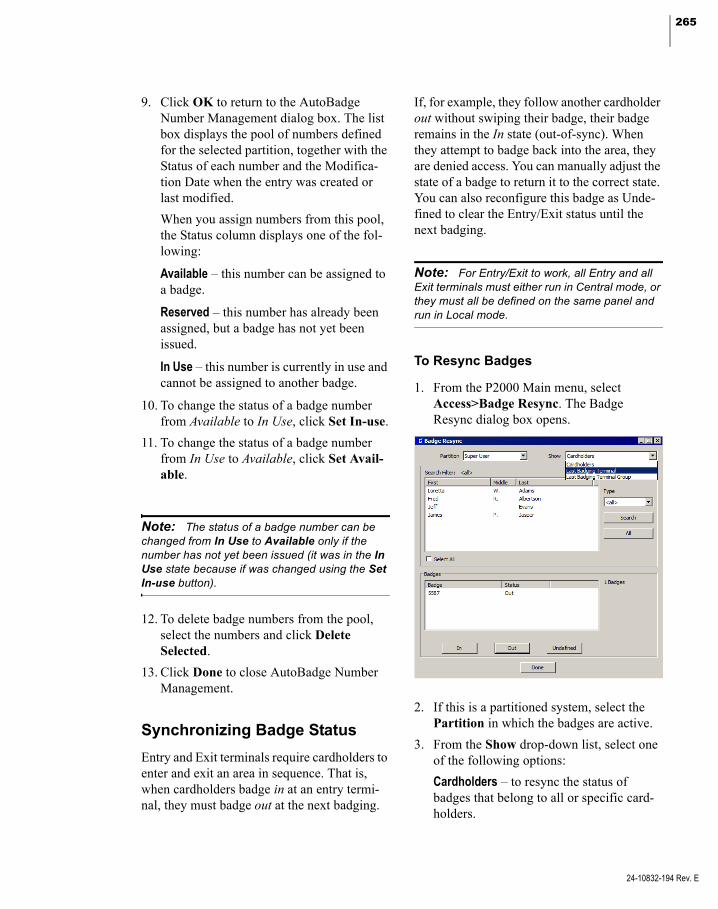
265
9. Click OK to return to the AutoBadge Number Management dialog box. The list box displays the pool of numbers defined for the selected partition, together with the Status of each number and the Modifica-tion Date when the entry was created or last modified.
When you assign numbers from this pool, the Status column displays one of the fol-lowing:
Available – this number can be assigned to a badge.
Reserved – this number has already been assigned, but a badge has not yet been issued.
In Use – this number is currently in use and cannot be assigned to another badge.
10. To change the status of a badge number from Available to In Use, click Set In-use.
11. To change the status of a badge number from In Use to Available, click Set Avail-able.
Note: The status of a badge number can be changed from In Use to Available only if the number has not yet been issued (it was in the In Use state because if was changed using the Set In-use button).
12. To delete badge numbers from the pool, select the numbers and click Delete Selected.
13. Click Done to close AutoBadge Number Management.
Synchronizing Badge Status
Entry and Exit terminals require cardholders to enter and exit an area in sequence. That is, when cardholders badge in at an entry termi-nal, they must badge out at the next badging.
If, for example, they follow another cardholder out without swiping their badge, their badge remains in the In state (out-of-sync). When they attempt to badge back into the area, they are denied access. You can manually adjust the state of a badge to return it to the correct state. You can also reconfigure this badge as Unde-fined to clear the Entry/Exit status until the next badging.
Note: For Entry/Exit to work, all Entry and all Exit terminals must either run in Central mode, or they must all be defined on the same panel and run in Local mode.
To Resync Badges
1. From the P2000 Main menu, select Access>Badge Resync. The Badge Resync dialog box opens.
2. If this is a partitioned system, select the Partition in which the badges are active.
3. From the Show drop-down list, select one of the following options:
Cardholders – to resync the status of badges that belong to all or specific card-holders.
24-10832-194 Rev. E

266 CHAPTER 3
Operating the System
24-10832-194 Rev. E
Last Badging Terminal – to resync the status of all badges last presented at the selected terminal.
Last Badging Terminal Group – to resync the status of all badges last presented at all terminals in the selected terminal group.
Note: The Last Badging Terminal and Last Badging Terminal Group options are used, for example, to quickly reset the status of all badges after a mustering event or reset the status of badges in situations when cardholders badged in at an entry terminal and they were unable to badge out at an exit terminal because the exit ter-minal was down.
4. If you selected Last Badging Terminal or Last Badging Terminal Group, select a terminal or terminal group from the list and continue with step 16.
5. If you selected Cardholders, select the Type of cardholder (Regular, Visitor, or <all>) that you wish to display in the list box.
6. If you wish to display specific cardholders (within the type selected), click Search. The Database Search dialog box opens.
7. Enter the information on any or all of the fields to search for specific cardholders.
8. If you wish to search by Company and Department, select a previously defined name from the drop-down list.
9. You can also search by UDF. Select any of the previously defined UDFs from the drop-down list (Date type UDFs cannot be included in the search). Then enter or select the UDF search criteria in the associ-ated field.
10. If you wish to clear the existing search cri-teria, click Clear.
11. After you define the search criteria, click one of the following buttons:
Exact Match – to display an exact match to your search criteria.
Partial Match – to display all possible selec-tions that match the initial characters of the search criteria; for example, if you enter Carl in the First Name field, the list box displays names such as Carla, Carlos, Carl-ton, and so on.
12. The list box in the Badge Resync dialog box opens displaying the cardholders spec-ified in the search criteria.
13. If you wish to display all cardholders again (within the type selected), click All.
14. After you define the cardholders you wish to display in the list box, select a card-holder name from the list.
15. The badge number and status of all badges assigned to this cardholder display in the Badges list. Select the badge or badges to be resync.
Note: Click Select All if you wish to resync the status of all badges in the system.

267
16. Click the appropriate button, In, Out, or Undefined to change the status of the badges.
17. Click Done. The badge status is now changed.
Recalling Images
If the Image Recall window is open on the workstation, any badging (for the partition selected in Image Recall Filters) displays the cardholder’s image and information. An oper-ator with proper menu permissions can define access conditions and other filter criteria (transactions set up in the Image Recall Filter Edit dialog box, such as an Access Grant or any invalid transaction), to determine if an image displays in the Image Recall window.
Image Recall Filters
1. From the P2000 Main menu, select Access>Image Recall Filters. The Image Recall Filters dialog box opens.
2. Click Add. The Image Recall Filter Edit dialog box opens.
3. If this is a partitioned system, select the Partition in which this image recall filter is active.
4. Click Public if you wish this image recall filter to be visible to all partitions.
5. Enter a descriptive Name for the image recall filter.
6. From the Type to Display box, select the transactions that you wish to monitor. You do not need to select all conditions. If you select Any Deny, all other filtering condi-tions are dimmed, except Access Grant and Duress.
Note: Cardholder image and information always display in the Image Recall window if the associated badge has the Trace option enabled, regardless of the filter conditions selected here.
7. Select a Terminal name to specify the ter-minal to be monitored.
8. Select a Terminal Group name if you wish to monitor a Terminal Group.
9. Click OK. The new image recall filter dis-plays in the Image Recall Filters list.
10. Click Done.
24-10832-194 Rev. E

268 CHAPTER 3
Operating the System
24-10832-194 Rev. E
To Activate Image Recall
1. From the P2000 Main menu, select Access>Image Recall. The Image Recall window opens.
2. If this is a partitioned system, select the Partition in which the image recall is active.
3. Select Popup if the Image Recall window is to move to the front of all windows on the P2000 screen whenever an access attempt that matches the current filter occurs.
Note: Some computers may not allow the Image Recall window to automatically pop up in front of other windows on the screen; instead, the Image Recall button begins flashing in the Win-dows taskbar.
4. Click Show UDF Fields, if you wish to display the user defined fields associated with the cardholder.
5. In the Blanking Time field, enter the time in minutes after which the image and the data are cleared. If you enter a value of zero, the display is not blanked.
6. Select a Filter from the drop-down list.
7. When a cardholder presents a badge at a terminal or group of terminals that meets the filtering conditions, the cardholder’s image displays, along with the current cardholder information.
8. This image and information remain in the window until another cardholder badges within the partition, or until the Blanking Time defined elapses, or until you click Clear to clear the information in the Image Recall window.
9. Leave the Image Recall window open on the workstation to view images displayed as a result of subsequent badgings.
Image Recall FS (Full Screen)
The Image Recall FS feature offers a simpli-fied display and works in both default and full screen modes.
When the Image Recall FS window is open and a cardholder presents a badge at a terminal or group of terminals that meets the filtering conditions, the cardholder’s image displays along with the cardholder name. Optionally, one or two of the following can also display: Company, Department, ID, and any text or numeric user defined field (UDF).
To Activate Image Recall FS
1. From the P2000 Main menu, select Access>Image Recall FS. The Image Recall FS window opens.

269
2. Select Edit>Options to open the Image Recall Options dialog box and define the elements you wish to display.
3. If this is a partitioned system, select the Partition in which the image recall is active.
4. Select a Filter that contains the access con-ditions that determine which images to dis-play. See Image Recall Filters on page 267.
5. Select Popup if the Image Recall FS win-dow is to move to the front of all windows on the P2000 screen whenever an access attempt that matches the current filter occurs.
Note: Some computers may not allow the Image Recall window to automatically pop up in front of other windows on the screen; instead, the Image Recall button begins flashing in the Win-dows taskbar.
6. From Line 1, Line 2, or Line 3, select the data to be displayed in the first, second, or third line under the cardholder’s image. You can select Badge Expiration Date, Cardholder Expiration Date, Cardholder First Name, Cardholder Full Name, Card-holder Last Name, Company, Department, ID, or any text or numeric user defined field.
7. Click the Text Font browse button [...] to open the Font window and select the font type you wish to display. The font style and size are not configurable.
8. Click the Text Color browse button [...] to open the standard Color window and select the text color you wish to display.
9. Click the Background Color browse but-ton [...] to open the standard Color window and select the background color you wish to display.
10. Click the Background Image browse but-ton [...] to select a background image.
11. In the Blanking Time field, enter the time in minutes after which the image and the data are erased and the background is dis-played. If you enter a value of zero, the display is not blanked.
12. Click OK to save your options and return to the Image Recall FS window.
13. Select View>Full Screen to change the display mode to full screen. Click <Esc> to return to previous view.
14. The image and information remain in the window until another cardholder badges within the partition, or until the Blanking Time defined in Image Recall Options elapses, or until you select View>Clear to clear the information.
15. Leave the Image Recall FS window open on the workstation to view images dis-played as a result of badgings, or select File>Exit to close.
24-10832-194 Rev. E

270 CHAPTER 3
Operating the System
24-10832-194 Rev. E
Monitor Alarms
Alarm monitoring is at the heart of the P2000 Security Management system. According to system devices configuration, alarms display in the Alarm Monitor queue as they occur.
Operators assigned to monitor alarms respond according to individual company policy, and the alarm instruction and response text config-ured for the various alarm types. The Alarm Response text can be pre-configured for opera-tor selection or set to enter manually for a more appropriate response.
The Alarm Monitor window opens immedi-ately after logging on to the Server, so that ongoing alarms are always visible. The Alarm Monitor window cannot be closed at the Server, to ensure that alarm conditions do not go unnoticed. However, it can be minimized using the minimize button on the title bar.
If the Alarm Monitor window is minimized, an alarm message pop-up can alert the operator that a new alarm has been reported. When an alarm is reported, the operator acknowledges the alarm, makes the appropriate response, and then completes the response.
Note: Some computers may not allow the Alarm Monitor window to automatically pop up in front of other windows on the screen; instead, the Alarm Monitor button begins flashing in the Win-dows taskbar.
Pending alarm messages remain in the Alarm Queue until acknowledged and removed by an operator. Alarm History is stored in the system as configured in Site Parameters.
Note: Elements that report alarms, such as input points, must NOT have the Disable Alarm option selected to have the alarm displayed in the Alarm Monitor window; see page 84.
Alarm Configuration
Every alarm in the system must belong to at least one Alarm Category, but can also be assigned to multiple alarm categories, each with its own set of alarm options. The system creates a P2000 base alarm category, which cannot be deleted or renamed.
An operator can define an unlimited hierarchal tree of Alarm Categories under the P2000 base alarm category. When an alarm category dis-plays in various P2000 screens, it typically dis-plays in the form of a URL, for example: P2000\Maintenance\Building 1.
You can for example, define an input point to generate upon activation, two separate alarms for two configured alarm categories: P2000\Maintenance\Building 1 and P2000\Security\Building 1. Typically, a single operator is configured to receive only a single category of alarms, and therefore would only receive a single alarm. However, higher level operators such as supervisors, or an operator at a central alarm monitoring location, may be configured to receive both of these alarms.
When deleting an existing Alarm Category, the P2000 searches the database and issues a warn-ing if the category is referenced by any alarm configurations. If the operator chooses to con-tinue, all existing references to the category being deleted are changed to its parent cate-gory.
Alarm Categories are an Enterprise-wide con-figuration and therefore, if you are using the Enterprise feature, a single set of categories is shared by all P2000 sites within an Enterprise system.

271
To Create Alarm Categories
1. From the P2000 Main menu, select Con-fig>System. Enter your password if prompted. The System Configuration win-dow opens.
2. In the left pane, expand Alarm Categories to display the default P2000 alarm cate-gory.
3. Select the P2000 alarm category and click Add. The Alarm Category dialog box opens.
4. Enter a Name for the alarm category.
5. Click OK to save the new alarm category.
The new alarm category is listed under the default P2000 category. You can create unlimited trees of alarm categories.
Alarm Handling
As an operator, you may be required to handle alarm conditions, depending on the Message Filter Group and Alarm Processing Group assigned; see User Info Tab on page 24. The Alarm Monitor verifies that alarms pass the Alarm Processing Group filter (if any) for the operator before allowing the operator to acknowledge, respond or complete alarms.
Note: Message Filtering and Alarm Processing Groups apply on P2000 Workstations only, not on P2000 Servers.
The alarm response typically includes steps similar to the following:
1. Acknowledge that an alarm condition has been reported by the system.
2. Respond by entering the appropriate response.
3. Complete the alarm.
4. Remove the completed alarm condition from the Alarm Monitor window.
Acknowledging an alarm – An operator may be required to acknowledge a new alarm as soon as it is received (see To Acknowledge an Alarm on page 275). They may do so and then return later to actually respond to the alarm, depending on company policy and the priori-ties assigned to that alarm. The time and date of the acknowledgment is recorded in the alarm history. Acknowledging an alarm silences the audible beep (unacknowledged alarms continue to beep until recognized). Alarm acknowledgment is optional and does not need to occur before a response; its use is typically dictated by company policy.
Responding to an alarm – When an operator responds to an alarm, the operator name is entered in the User Name column of the Alarm Monitor window. The Response time is date and time stamped for the alarm history record. The operator would typically review the Alarm State and Description to note any known conditions. Specific instructions cre-ated for the particular alarm display in the Instruction box during the response to help the operator perform the appropriate action. (See To Respond to an Alarm on page 275.)
24-10832-194 Rev. E
272 CHAPTER 3
Operating the System
24-10832-194 Rev. E
Completing an alarm – Several actions may take place during the handling of an alarm. When all actions needed to process the alarm have been completed, the operator completes the alarm. This action is date and time stamped for the alarm history record. (See To Complete an Alarm on page 277.) An alarm can only be completed if the alarm state is secure. Some alarms in secure state, such as Guard Tour alarms, must first be acknowledged or responded, before they can be completed.
Note: Responding to an alarm that has not been acknowledged automatically causes an acknowledgment to occur. Similarly, completing an alarm causes an automatic acknowledge, if needed.
Removing the Alarm from the queue – Accord-ing to company policy, operators may remove completed alarms from the alarm queue. The alarm response sequence remains in the alarm history record. (See To Remove an Alarm Message from the Queue on page 277.)
Refreshing the Alarm Monitor window – The Refresh button on the Alarm Monitor window is used to read again all current alarms from the database (this should not be needed unless there was a loss of communication with the Server).
Access the Alarm Monitor from the P2000 Main menu. Select Alarm>Alarm Monitor, or if minimized just click the Alarm Monitor button to restore it.
The Alarm Monitor queue displays alarms in a scrolling list, as they occur. The alarm response changes as the operator performs the response steps (see the Alarm Status column header in the Alarm Monitor window); and the date and time of each step is recorded in the alarm history record.
When a new alarm displays in the Alarm Mon-itor window, an audible beep sounds, and a red color bell icon in the line item entry message begins flashing. The entry continues in this Pending state until an operator acknowledges the alarm, after which the beep stops and the bell icon changes to yellow.
TIP: You can right-click a line item in the Alarm Monitor window to acknowledge, respond, complete, or remove alarms from the shortcut menu. The shortcut menu also allows you to see the location of the alarm on a Real Time Map, dis-play live or stored AV video (if available), or view all items when you click Display All. In addition, if the element that generated the alarm was config-ured to manually activate events, the event name also displays in the shortcut menu. Also, you can select from the shortcut menu to Print All alarms in the queue or select Print Displayed to print only the alarms that display in the list box.
Monitoring Remote AlarmsYou can configure your system to receive alarm messages from remote P2000 sites, allowing operators to simultaneously monitor alarms locally and at multiple remote sites. This feature is useful to monitor alarms at unattended sites that are closed for the week-end or a holiday, and ensures that all alarm conditions, even at far away locations, are watched closely at all times.
To be able to monitor remote alarms, both your local and the remote site have to be properly configured. The following conditions must be met:
The Remote Message Service must be up and running at both the remote site (to send the alarm message) and at your local site (to receive the alarm message). The Remote Message Service can be started and stopped using the P2000 Service Control feature, just like the other P2000 services. See Starting and Stopping Service Control on page 432.

273
The Message Filter Configuration appli-cation (page 222), must be properly config-ured at your local site and each remote site, to control the type of messages transmitted between Servers, thereby reducing network traffic by transmitting only messages that pass the filter criteria.
The P2000 Remote Server application (page 230), must be properly configured at each remote site to be able to send their alarm messages to your local site. The setup must include the name, IP address and Remote Message Service Listener Port number of your local site; the type of mes-sages that is forwarded to your site and at what times; and other related parameters.
The Process Received Remote Messages option in the RMS tab of Site Parameters (page 43), must be selected at your local site to be able to receive messages from remote P2000 sites. If you select this option, the Remote Message Service processes incom-ing messages and pass them on to RTLRoute for distribution within the local system and, if applicable, to other remote sites.
The Message Filter Group selected in the RMS tab of Site Parameters (page 43), defines which remote messages your Remote Message Service processes. If you select <None>, your local P2000 site receives all remote messages.
The Local Alarms option in the RMS tab of Site Parameters (page 43), must be selected at the remote site to allow remote operators to acknowledge, respond, and complete alarms originated at your local site.
The Remote Alarms option in the RMS tab of Site Parameters (page 43), must be selected at the remote site to allow remote operators to acknowledge, respond, and complete alarms originated at other P2000 sites.
If these conditions are met, your local Alarm Monitor window displays alarm messages that are generated at remote sites when their alarm status or state changes.
The procedures for handling remote alarms are similar as for local alarms; however, the fol-lowing points should be noted:
Responding to remote alarms – Alarm instruc-tions are sent to remote sites; however, the alarm responses remain local. While the Alarm Status column in the Alarm Monitor displays a Responded status, the alarm response entered at a remote site is not part of the alarm history in your local site.
Completing remote alarms – Remote alarms can be completed, regardless of the current alarm state.
Removing remote alarms – Remote alarms can be removed from the queue, regardless of the current alarm state. Removed alarm are auto-matically completed.
Alarm Monitor Definitions
Date/Time – Displays the date and time the alarm was reported to the system. Alarms that are originated at remote sites with different geographical time zones display the actual time at the remote site.
Note: Click any of the column headings to sort the alarms by the selected column heading.
Escalation – Displays the escalation level of the alarm (the highest is 10).
Priority – Displays the Alarm Priority set for each alarm type (the highest is 0).
24-10832-194 Rev. E

274 CHAPTER 3
Operating the System
24-10832-194 Rev. E
You can assign sounds to Alarm Priorities 0 to 255 in groups of 10. The sound files can be set up from Control Panel in your Windows desk-top, clicking the Sounds icon. In the Sounds tab, select any of the Pegasys Alarm Priorities from the Program events box, then select the corresponding sound file from the Sounds drop-down list.
Note: To access the P2000 alarm priority sounds, you must open the Alarm Monitor win-dow at least once at the workstation.
Alarm Status – Displays one of the following:
Pending – Not yet acknowledged.
Acknowledged – Acknowledged but no action taken.
Responding – Acknowledged and response action in progress.
Complete – Action taken.
Alarm State – Indicates the state of the alarm, such as Secure, Alarm, Open, Short, Sup-pressed, Tamper, Bypassed, and so on.
Description – Displays a description of the ele-ment that activated the alarm.
Alarm Category – Displays the Alarm Category to which the alarm belongs. The default cate-gory is P2000. When an alarm is assigned to multiple Alarm Categories, and the operator is configured to view alarms from these multiple categories, the alarm displays separately for each category.
User Site – Displays the site name from where the operator is handling the alarm.
User Name – Displays the name of the operator who handles the alarm.
275
Action Date/Time – Displays the date and time the action (respond, complete, and so on) takes place. This is always the local time, regardless if a remote site is in a different geographical time zone.
Query String – Displays the query string value (if it was defined) of the item associated with the alarm.
Alarm Site – Displays the name of the P2000 site where the alarm was originated.
Partition – Displays the name of the partition containing the item (input point, terminal, panel, and so on) that originated the alarm.
Public – Displays whether the alarm message is visible to other partitions.
Audible Alarm Button – Click the Audible Alarm button to temporarily disable the audible alarm beep. All
alarms are affected. Unless you acknowledge, respond, or complete the alarm, the beep becomes audible again in 40 seconds. If you wish to turn off the audible alarm beep, select from the Sounds dialog box in Control Panel, any of the Pegasys Alarm Priorities, then browse for the None.wav file located in the bin folder of the P2000 software installation.
Msg Routing Status – The Message Routing Status indicator displays in green to indicate that all communica-
tions between the workstation and the Server are up. If communications go down, the Mes-sage Routing Status indicator turns red.
Total – Displays the total alarm count in the Alarm Monitor window.
Pending – Displays the number of pending alarms in the Alarm Monitor window.
Map Button – You can see the location of an alarm on a Real Time Map from the Alarm Monitor window. Select an
alarm and click the Map button. The map dis-plays and the icon blinks indicating the loca-tion of the alarm. For more information, see Using the Real Time Map on page 346. This feature is available for local alarms only.
AV – This button is enabled if your facility uses the DVR/VMS feature. If the alarm message displayed is associated with a camera, you can select the message line from the list and click the AV arrow, then select whether you want to display live or stored video. For more informa-tion, refer to your DVR/VMS documentation.
Print – Click the Print arrow and select whether you want to Print All alarms in the queue or select Print Displayed to print the alarms that are visible in the Alarm Monitor list box.
To Acknowledge an Alarm
1. Click the line item you wish to respond to and click Ack. The Alarm Status changes to Acknowledged. This informs the system and anyone else monitoring the system that the alarm has been recognized.
2. If several alarms come in at once, you can acknowledge them in any order you wish; however, company policy may dictate that you respond by priority. If desired, select the highest priority by number, or click the Priority column title to sort by priority, moving the highest priority to the top of the list.
To Respond to an Alarm
1. With the line item to which you wish to respond selected, click Respond. The Alarm Response dialog box opens.
24-10832-194 Rev. E

276 CHAPTER 3
Operating the System
24-10832-194 Rev. E
2. The Description box displays the descrip-tion for the line item selected in the Alarm Monitor window.
3. The Condition box displays the alarm con-dition.
4. The Instruction box displays any instruc-tion text associated with the alarm.
5. The History box displays all stored history for the line item selected from the Alarm Monitor.
6. If you wish to add a predefined response, click the Predefined Alarm Response Text drop-down list and select the desired response. The response text displays in the Text box. Click Add to add the selected response to the History box. The Alarm Status changes to Responding. This stores a record of the response in the transaction history.
Note: See Creating Predefined Alarm Response Text on page 279 for information on adding different responses for specific alarms.
7. If you wish, you can also enter a specific response in the Text box and click Add to add your response to the History box.
8. Click Done to return to the Alarm Monitor window.
Note: You can have multiple Alarm Response windows open and respond to multiple alarms simultaneously. You can also acknowledge or complete alarms in the Alarm Monitor window while the Alarm Response window is open, but you cannot acknowledge or complete those alarms that are currently open in the Alarm Response windows.

277
To Complete an Alarm
1. Click Complete to end the alarm process-ing sequence. The Alarm Status changes to Complete. Alarms can only be completed if the alarm state is secure.
To Remove an Alarm Message from the Queue
The Complete and Remove buttons do not become active until the alarm is in the secure state.
1. Select a line item from the scrolling list.
2. Click Remove.
To Display Alarm Details
1. In the Alarm Monitor window, select an alarm from the list.
2. Right-click to open the shortcut menu and select Details.
The window displays the alarm details for the line item selected, together with the associated alarm instruction, alarm history, and any response entered for the alarm.
3. Click Done to close.
To View Alarm Instructions
Instruction text associated with an alarm can be viewed from the Alarm Response window, the Alarm Details window, or by right-clicking an alarm in the Alarm Monitor window and selecting Instructions.
To Activate an Event from the Alarm Monitor
1. In the Alarm Monitor window, select the line item you are responding to and right-click to open the shortcut menu.
2. Click the event name you wish to activate. The event is triggered.
Configuring Alarm Colors
The P2000 system provides color configura-tion capability for each alarm priority (0 to 255) and its corresponding alarm status. Each alarm status can have a unique color assigned to help operators recognize specific alarms. When a new alarm displays in the Alarm Mon-itor window, the line for the affected alarm dis-plays in the color that was assigned using the Default Alarm Colors dialog box.
To Define Color-Coded Alarms
1. From the P2000 Main menu, select Con-fig>System. Enter your password if prompted. The System Configuration win-dow opens.
2. In the left pane, expand Site Parameters.
3. Select Default Alarm Colors and click Edit. The Default Alarm Colors dialog box opens.
24-10832-194 Rev. E
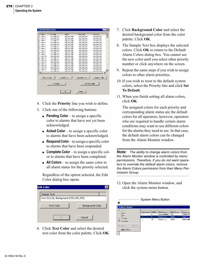
278 CHAPTER 3
Operating the System
24-10832-194 Rev. E
4. Click the Priority line you wish to define.
5. Click one of the following buttons:
Pending Color – to assign a specific color to alarms that have not yet been acknowledged.
Acked Color – to assign a specific color to alarms that have been acknowledged.
Respond Color – to assign a specific color to alarms that have been responded.
Complete Color – to assign a specific col-or to alarms that have been completed.
All Colors – to assign the same color to all alarm status for the priority selected.
Regardless of the option selected, the Edit Color dialog box opens.
6. Click Text Color and select the desired text color from the color palette. Click OK.
7. Click Background Color and select the desired background color from the color palette. Click OK.
8. The Sample Text box displays the selected colors. Click OK to return to the Default Alarm Colors dialog box. You cannot see the new color until you select other priority number or click anywhere on the screen.
9. Repeat the same steps if you wish to assign colors to other alarm priorities.
10. If you wish to reset to the default system colors, select the Priority line and click Set To Default.
11. When you finish setting all alarm colors, click OK.
The assigned colors for each priority and corresponding alarm status are the default colors for all operators; however, operators who are required to handle certain alarm conditions may want to use different colors for the alarms they need to see. In that case, the default alarm colors can be changed from the Alarm Monitor window.
System Menu Button
Note: The ability to change alarm colors from the Alarm Monitor window is controlled by menu permissions. Therefore, if you do not want opera-tors to override the default alarm colors, remove the Alarm Colors permission from their Menu Per-mission Group.
12. Open the Alarm Monitor window, and click the system menu button.

279
13. From the control menu select Alarm Col-ors. The Alarm Colors dialog box opens displaying the default colors that were defined from the System Configuration window.
14. Assign the desired colors as described before, then click OK to save your settings.
Note: Alarm colors that are assigned from the Alarm Monitor window are associated with the operator who made the changes. In addition, the Set To Default button resets to the default colors assigned from the System Configuration window.
Creating Predefined Alarm Response Text
You can create Response text to speed alarm response to specific types of alarms. For exam-ple, when panels go down for regular mainte-nance, a Panel Down soft alarm is sent to the Alarm Queue. The operator can quickly respond by selecting a predefined response from the drop-down list.
To Create Predefined Alarm Response Text
1. From the P2000 Main menu, select Alarm>Alarm Response Text. The Alarm Response Text list opens.
2. If this is a partitioned system, select the Partition in which this alarm response text applies.
3. The Name, Text, Partition, and whether or not the text is Public display in the list.
4. Click Add. The Alarm Response Text dia-log box opens.
5. Select a Partition, if applicable, and click Public if you wish the text to be seen by all partitions.
6. Enter a descriptive Name for the text.
7. Enter the actual Text you wish to enter into the Alarm Response record.
8. Click OK. The Response text name is now available in the drop-down list of the Alarm Response dialog box.
Monitoring Alarms Using the SIA Interface
Note: The P2000 system only supports the Bosch® (formerly Radionics) system SIA mode using ADEMCO Contact ID protocol.
The Bosch D6600 Security Receiver/Control-ler is capable of receiving alarm and supervi-sory messages from the Bosch digital dialers over analog telephone lines. It can process up to eight individual telephone lines simultane-ously. The Bosch Receiver/Controller is con-nected to the P2000 system via a standard RS232 serial interface.
The Bosch Receiver/Controller can also be programmed to send alarm messages through the COM RS232 port. The communications parameters must be programmed using a hand-held Bosch programmer. (Refer to the Bosch manual for programming instructions.)
24-10832-194 Rev. E

280 CHAPTER 3
Operating the System
24-10832-194 Rev. E
The communication takes place only in one direction; from the Bosch system to the P2000 Server. The P2000 Server does not transmit commands to the Bosch Receiver/Controller and cannot suppress any Bosch capabilities such as print or display audible indications. The P2000 Server acknowledges messages as they are received.
This section describes the configuration of the Bosch interface to the P2000 system. You must program the Bosch system before connecting it to the P2000 Server. All information must be supplied by the Bosch installer.
To Configure the SIA Interface
1. From the P2000 Main menu, select Con-fig>System. Enter your password if prompted. The System Configuration win-dow opens.
2. Select SIA Device and click Add. The SIA Device Edit dialog box opens.
3. If this is a partitioned system, select the Partition to which the SIA device has access.
4. Click Public to make this SIA device visi-ble to all partitions.
5. Enter the Name that identifies the SIA device.
6. Click Enable to enable the SIA device.
7. Click P2000 Alarms to display messages from the SIA device in the Alarm Monitor (in addition to the SIA Message Viewer window, where they display by default).
8. Select the Comm. Port to which the SIA device is physically connected. Choices include serial input and output ports COM1 to COM32.
9. Select the Baud Rate for the SIA device communications. The recommended value is 9600.
10. Select the number of Data Bits for the SIA device communications. The recom-mended value is 8.
11. Select the appropriate Parity for the SIA device communications. The recom-mended value is None.
12. Select the number of Stop Bits for the SIA device communications. The recom-mended value is 1.
13. Click OK to save your settings.
To View Messages from the SIA Device
1. From the P2000 Main menu, select Alarm>SIA Message View. The SIA Mes-sage View dialog box opens.
The Date/Time column displays the date and time the message originated.
The Message column displays the text of the message.

281
The Partition column displays the name of the partition containing the SIA device that originated the alarm.
The Public column indicates whether the message is visible to other partitions.
Note: The Message Routing Status indicator displayed in green indicates that all communica-tions between the workstation and the Server are up. If communications go down, the Message Routing Status indicator turns red.
2. Click Clear List to remove all messages from the list.
3. Click Done to close the window.
Message Forwarding
Message Forwarding is useful when using message filters. At times, it may be necessary to temporarily forward messages from one workstation to another; for example, if an operator must leave the workstation for a short period of time, or during a vacation or sick leave. When the operator is ready to receive messages at the workstation again, message forwarding for the workstation can be deleted.
Note: When forwarding messages from one workstation to another, the system must decide which messages are to be forwarded depending on the operator that is logged on at the receiving workstation. The system only transmits mes-sages that pass the filter criteria associated with the operator. See Operators and Messages on page 221.
To Forward Messages from One Workstation to Another
1. From the P2000 Main menu, select Alarm>Message Forwarding. The Mes-sage Forwarding dialog box opens listing the workstations from where and to where all current messages are forwarded.
2. If this is a partitioned system, select the Partition in which the workstations are active.
3. Click Add. The Message Forwarding Edit dialog box opens.
4. From the From Station drop-down list, select the workstation from which to for-ward the messages.
5. From the To Station drop-down list, select the workstation to which you wish to for-ward the messages.
6. Click OK. The new entry displays in the Message Forwarding list.
7. Click Done.
24-10832-194 Rev. E
282 CHAPTER 3
Operating the System
24-10832-194 Rev. E
Fire Alarm Control
The fire alarm function allows the P2000 sys-tem to monitor alarms generated by fire devices connected to Notifier® and IFC (Intel-ligent Fire Control) fire panels. The fire system consists of sensors, connected to the fire panel, capable of detecting fire events. These detec-tors are grouped into zones that use audible signals (input/output modules) to indicate that a zone is in alarm condition.
Note: To avoid conflict, do not configure your P2000 system to use a combination of Notifier and IFC fire panels. You may only use one fire panel type within the P2000 system.
The Notifier fire alarm panel communicates with the P2000 server using Johnson Controls Fire OPC Server. It uses the P2000 OPC Proxy Service to provide the communication between the P2000 server and the Notifier fire panel. Use the instructions provided in the Notifier® AMx000 unit OPC Server Application to define your fire system, such as fire detectors, input/output modules, and how these input and output devices can be associated with fire zones.
Note: The P2000 system has been validated to support up to 4,000 OPC points.
IMPORTANT: The Notifier panel is not avail-able in North America. Contact Johnson Controls Systems Integration Services Europe for informa-tion.
The IFC fire alarm system uses the P2000 IFC Interface Service to communicate IFC panels with the P2000 server using the BACnet proto-col. This service allows the P2000 system to monitor alarms generated by devices con-nected to IFC panels. The P2000 system cur-rently supports IFC-320, IFC2-640, and IFC2-3030 fire panels. Complete hardware installation and operation instructions are pro-vided with the IFC panel option requested for your facility.
Both fire systems benefit from the P2000 sys-tem powerful alarm capability by providing the tools that define how these alarms respond when activated, whether or not they trigger output relays, and at which times an alarm can be activated.
When properly configured, the P2000 system should:
receive notification from the fire panel that a fire has been detected in the building
identify the location of the fire
inform building personnel that a fire has been detected
warn the occupants of the building that a fire has been detected to ensure that all are able to exit the building before escape routes become impassable.
Basic Definitions
Activated – The state of a device connected to a fire input/output module, such as evacuation signals or a sprinkler system.
Deactivated – The state of a device connected to a fire input/output module after the fire alarm is reset.
Detector – Device connected to the fire panel and that reports physical changes associated with fire such as a heat detector, a smoke detector, or a carbon monoxide detector.

283
Disabled – The state of a fire detector, zone or input/output module that is disabled from reporting fire alarms. This state is typically used with devices that report false alarms or can be used to turn off fire devices after an alarm condition.
Enabled – The state of a fire detector, zone or input/output module that is enabled for report-ing fire alarms.
Fire Panel – Device that is the controlling com-ponent of a fire alarm system. The panel receives information from sensors designed to detect changes associated with fire (detectors), monitors the operation of these detectors, and activates equipment (input/output modules) designed to alert building personnel of poten-tial danger.
Input/Output Modules – Device connected to a fire panel that can detect input from switched devices, such as sprinkler systems; and acti-vate notification signals, such as alarm bells or telephone dialers. Traditionally, when an input device is activated, a certain output device (or relay) is also activated.
Zone – An area in a facility that is associated with fire detectors and input/output modules.
Basic Fire Alarm Components
This section describes the basic components of a fire alarm control system. The fire alarm control system consists of the P2000 software, the panel (Notifier or IFC) firmware, and the panel components (fire detector, zone, and input/output modules).
The P2000 software is used to:
Provide the communication between P2000 applications and the Fire OPC Server (when using Notifier panels), using the P2000 OPC Proxy Service; see page 432.
Provide the communication between P2000 applications and IFC panels through the BACnet protocol, using the P2000 IFC Interface Service; see page 432.
Enable the fire server; see page 283.
Configure alarm options for fire alarm pan-els, detectors, zones, and input/output mod-ules; see page 286.
Monitor and display the status of fire detec-tors, zones, and input/output modules; see page 288.
Define event triggers associated with fire detectors, zones, and input/output modules; see page 289.
Run alarm activity and alarm history reports associated with fire alarms; see page 471.
The above sections describe fire alarm config-uration and control procedures using the P2000 software.
Fire Alarm Server Configuration
After you configure your fire panel and associ-ated items using the instructions provided with your fire unit, you must define fire compo-nents in the P2000 System Configuration win-dow to populate the associated data into the P2000 database.
24-10832-194 Rev. E

284 CHAPTER 3
Operating the System
24-10832-194 Rev. E
To Enable the Notifier Fire Server
IMPORTANT: We recommend using the Fire OPC Server Configurator to remove fire detector loops that are not physically configured in the Notifier panel, to avoid reporting unknown states to the P2000 system. Do this before enabling fire components in the P2000 system. Otherwise, you must remove any unused fire component using the Empty Fire Data task in Database Mainte-nance.
1. From the P2000 Main menu, select Con-fig>System. Enter your password if prompted. The System Configuration win-dow opens.
2. In the left pane, expand Fire Server.
3. Expand Notifier.
4. Select the fire server name and click Edit. The Fire Server Config dialog box opens.
5. Verify that the fire server name displays in the Name field.
6. Select the Enable check box.
7. Click OK.
Once you enable the fire server, the System Configuration window is automatically popu-lated with the fire panel and associated fire zones, detectors, and input/output modules.
The P2000 system is now ready to operate with the Notifier fire panel, continue with Fire Alarm Configuration on page 286.
To Configure the IFC BACnet Gateway
Keep in mind the following points before con-figuring the IFC BACnet Gateway:
The P2000 system communicates with IFC panels through the BACNET-GW-3 module using the BACnet over IP protocol on UDP port 47808. You cannot edit this port using the Port Configuration tab in Site Parame-ters.
Verify that the P2000 server that integrates with IFC panels has its firewall disabled.
Make sure the device ID of the IFC panel is not set as 0.
You cannot define two IFC objects (gate-way, panel, input/output modules, or detec-tors) with the same device ID.
If you enable or disable LAN communica-tions on the P2000 server, you must restart the P2000 system to successfully integrate with IFC panels.
Note: The BACnet Gateway Configuration application provides a mechanism to discover the IFC panel and associated fire zones, fire detec-tors and input/output modules from the actual hardware devices.
1. From the P2000 Main menu, select Con-fig>System. Enter your password if prompted. The System Configuration win-dow opens.

285
2. In the left pane, expand Fire Server.
3. Select IFC and click Add. The BACnet Gateway Configuration dialog box opens.
4. Select the Partition in which the BACnet Gateway and associated IFC panel and devices are active.
5. Click Public to allow all partitions to view this BACnet Gateway.
6. Enter the Gateway Name that describes the BACnet Gateway or IFC panel.
7. Enter the Gateway IP address of the BAC-net Gateway. This IP address is used to discover the associated IFC objects. You must configure the BACnet Gateway and the P2000 server on the same subnet.
8. Enter the Polling Interval (in seconds) that is used by the P2000 IFC Interface Service for polling the BACnet Gateway to obtain IFC panel status information.
9. Enter the number of times that the Server Retries to connect with the IFC panel, after which the panel is considered offline.
10. Enter the time in seconds by which the P2000 system can keep searching for IFC objects until the Wait Time elapses.
11. Click Explore Device to display the IFC panel and devices associated with the BACnet gateway.
12. Select the fire objects to be imported to the P2000 database. When you select a check box for a parent object, all its children objects are also selected and imported. You can manually clear check boxes for any objects you do not want to import.
13. Click OK to return to the BACnet Gate-way Configuration dialog box.
14. Click OK to save the BACnet Gateway information. The System Configuration window is automatically populated with the fire panel and associated fire zones, detectors, and input/output modules selected.
24-10832-194 Rev. E

286 CHAPTER 3
Operating the System
24-10832-194 Rev. E
The P2000 system is now ready to operate with the IFC fire panel, continue with Fire Alarm Configuration on page 286.
Note: You can configure multiple BACnet gate-ways that contain multiple IFC fire panels to allow the P2000 system to receive alarms from multiple IFC systems; however, the P2000 system can only communicate with up to five IFC panels.
Note: The IFC panel may show a Trouble con-dition on the control module and on the relay module, but the P2000 system shows Enabled. This is because the P2000 systems gets the Enabled status from the BACnet gateway.
Fire Alarm Configuration
Every alarm that is generated in the P2000 sys-tem, must belong to at least one Alarm Cate-gory (see Alarm Configuration on page 270 for details), but can also be assigned to multiple alarm categories, each with its own set of alarm options. For example, if a fire input/out-put module connected to a push-button switch generates an alarm, you can define this push-button switch to generate upon activation two separate alarms for two configured alarms categories, for example one for P2000\Mainte-nance\Building 1 and one for P2000\Fire\ Building 1. The P2000\Fire alarm can be con-figured with a higher priority, enabled escala-tion settings, and to be monitored by security personnel. The P2000/Maintenance alarm can be configured with a lower priority, no escala-tion settings, and to be monitored by mainte-nance personnel.
Use the following instructions to assign fire related alarms to one or more Alarm Catego-ries.
To Configure Notifier Fire Alarms
1. In the System Configuration window, expand Fire Server.
2. Expand Notifier, then expand the fire server name to display all the fire panel components.
3. Select a Fire Panel or component (Zone, Detector, or IO Module). Click Edit.
4. The Fire Devices Configuration dialog box opens for the selected item.
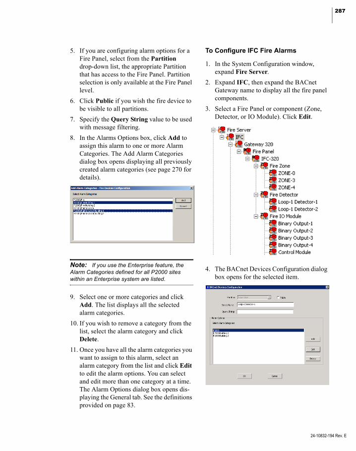
287
5. If you are configuring alarm options for a Fire Panel, select from the Partition drop-down list, the appropriate Partition that has access to the Fire Panel. Partition selection is only available at the Fire Panel level.
6. Click Public if you wish the fire device to be visible to all partitions.
7. Specify the Query String value to be used with message filtering.
8. In the Alarms Options box, click Add to assign this alarm to one or more Alarm Categories. The Add Alarm Categories dialog box opens displaying all previously created alarm categories (see page 270 for details).
Note: If you use the Enterprise feature, the Alarm Categories defined for all P2000 sites within an Enterprise system are listed.
9. Select one or more categories and click Add. The list displays all the selected alarm categories.
10. If you wish to remove a category from the list, select the alarm category and click Delete.
11. Once you have all the alarm categories you want to assign to this alarm, select an alarm category from the list and click Edit to edit the alarm options. You can select and edit more than one category at a time. The Alarm Options dialog box opens dis-playing the General tab. See the definitions provided on page 83.
To Configure IFC Fire Alarms
1. In the System Configuration window, expand Fire Server.
2. Expand IFC, then expand the BACnet Gateway name to display all the fire panel components.
3. Select a Fire Panel or component (Zone, Detector, or IO Module). Click Edit.
4. The BACnet Devices Configuration dialog box opens for the selected item.
24-10832-194 Rev. E
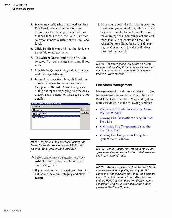
288 CHAPTER 3
Operating the System
24-10832-194 Rev. E
5. If you are configuring alarm options for a Fire Panel, select from the Partition drop-down list, the appropriate Partition that has access to the Fire Panel. Partition selection is only available at the Fire Panel level.
6. Click Public if you wish the fire device to be visible to all partitions.
7. The Object Name displays the fire item selected. You can change this name, if you wish.
8. Specify the Query String value to be used with message filtering.
9. In the Alarms Options box, click Add to assign this alarm to one or more Alarm Categories. The Add Alarm Categories dialog box opens displaying all previously created alarm categories (see page 270 for details).
Note: If you use the Enterprise feature, the Alarm Categories defined for all P2000 sites within an Enterprise system are listed.
10. Select one or more categories and click Add. The list displays all the selected alarm categories.
11. If you wish to remove a category from the list, select the alarm category and click Delete.
12. Once you have all the alarm categories you want to assign to this alarm, select an alarm category from the list and click Edit to edit the alarm options. You can select and edit more than one category at a time. The Alarm Options dialog box opens display-ing the General tab. See the definitions provided on page 83.
Note: Be aware that if you delete an Alarm Category, all existing IFC fire object alarms that belong to that Alarm Category are not deleted from the Alarm Monitor.
Fire Alarm Management
Management of fire alarms includes displaying fire alarm information in the Alarm Monitor, Real Time List, Real Time Map, and System Status windows. See the following sections:
Monitoring Fire Alarms using the Alarm Monitor Window
Viewing Fire Transactions Using the Real Time List
Monitoring Fire Components Using the Real Time Map
Viewing Fire Components Using the System Status Window
Note: The IFC panel may report to the P2000 system an alarmed status for items that are actu-ally in pre alarmed state.
Note: When you disconnect the Network Com-munications Module (NCM) used by the IFC panel, the P2000 system may show the panel sta-tus as Trouble instead of Down. Also, be aware that the P2000 system does not display alarms associated with NCM Error and Ground faults generated by the IFC panel.

289
Monitoring Fire Alarms using the Alarm Monitor Window
Fire alarms can be monitored, acknowledged, and removed using the Alarm Monitor win-dow. For detailed information, see Monitor Alarms on page 270.
Viewing Fire Transactions Using the Real Time List
All fire transactions are sent through real time messages to the Real Time List. As the status of defined fire detectors, zones, and input/out-put modules changes, corresponding related messages are generated and displayed. You must select the Fire check box in the Real Time List window to display all fire transac-tions as they occur. See Using the Real Time List on page 342 for more information.
Note: If you wish to print fire transactions as they occur, you can either print them from the Real Time List window, or select the Fire check box in the Site Parameters dialog box, Printing tab; see page 34.
Monitoring Fire Components Using the Real Time Map
The Real Time Map displays the status of fire panels, detectors, zones, and input/output modules on a map layout of your facility. Upon fire alarm activity, the map shows the state change and the exact location of the activity. See Using the Real Time Map on page 346.
When a status changes, the associated fire icon starts flashing. If the fire component was con-figured to allow the operator to activate events, the event name also displays in the shortcut menu.
To add fire icons to the Real Time Map, follow the instructions provided in Creating a Real Time Map on page 348.
Map Maker provides a default fire component image set to display various fire states. How-ever, you can use your own icons to create cus-tom image sets. See Adding Image Sets on page 352 for details.
Viewing Fire Components Using the System Status Window
The System Status window displays the cur-rent status of fire zones, detectors, and input/output modules that have been config-ured for fire alarm control.
See Viewing System Status on page 435 for instructions on how to display fire component status.
Fire Component Events
The fire alarm system connected to the P2000 system can trigger events and respond to event actions using the P2000 Event application. For specific instructions, see Create Events on page 335. Typical fire commands to be included and linked to specific actions are as follows:
An alarmed fire zone (trigger) forces a door to be locked to control the spread of smoke fumes and fire (action).
A fire panel that enters the trouble state (trigger) sets the badge security level at a specified value (action).
For a complete list of event triggers associated with fire panels, detectors, zones, and input/output modules, see Appendix A: Event Triggers/Actions.
24-10832-194 Rev. E

290 CHAPTER 3
Operating the System
24-10832-194 Rev. E
Perform Operator Controls
Most system functions operate automatically; however, some functions may be operated manually from a workstation. Operators with the appropriate permissions can manually con-trol doors, output devices, and panel relays. For example, an operator can unlock all doors at once, manually trigger a certain event, or allow a guard to manually control access to a specific door during off business hours. Opera-tor controls are panel specific. See Appendix C: Panel Comparison Matrix for a detailed list of features and capabilities supported by your panel type.
Controlling Doors
An operator can manually control a door, a group of doors, or all doors (override system controls) for a specific time period. (The oper-ator must first have menu permissions for Door Control to use this feature.) If this is a parti-tioned system, the doors or door groups avail-able from the drop-down list are those active in the operator’s partition.
To Manually Control Doors
1. From the P2000 Main menu select Con-trol>Door Control.
2. Enter your password if prompted. The Door Control dialog box opens.
3. If this is a partitioned system, select the Partition in which this door is active.
4. In the Control box, select either Door or Group to populate the Name drop-down list with selections.
5. Select a Name from the drop-down list.
6. In the Action box, select one the following:
Return to Normal – to return the door to its normal state. For CK721-A terminals, this command can also be used to shorten the access time after access was granted.
Open for Access Time – to unlock the door for the time set in the Access Time field defined in the Terminal dialog box. This command cannot be used for some Aperio locks.
When using Schlage AD400 locks, the Reader Override message displays on the Real Time List, the Reader Terminal on System Status changes from Terminal Up to Terminal Override, and the door stays unlocked for 20 seconds.
When using Schlage AD300 locks, the Reader Override message does not display on the Real Time List, and the Reader Ter-minal on the System Status does not change.
Unlock – to unlock the door for the number of minutes entered (up to 1440 minutes) in the Duration field, after which the door reverts back to their original system-con-trolled condition. Not available for HID panels and some Aperio locks.
Lockout – to prevent access by all badges at the door. Only supported by OSI, Assa Abloy PoE, and HID panels. The Lockout door command is not available in the Web Access interface.
Set Reader Mode – to set the reader mode of operation to one of the following options. Only supported by Mercury pan-els.

291
Card Only – a card is required for access.
Card and PIN Required – a card and a PIN are required for access.
Disable Reader, no REX – the reader is disabled; request to exit is not allowed.
Locked (No Access, REX Active) – the reader is locked; request to exit is allowed.
Unlocked – the reader is unlocked.
Do not use the Return to Normal com-mand if you wish to reverse the Set Reader Mode – Unlocked option. Instead use Set Reader Mode – Card Only or Set Reader Mode – Card and PIN Required.
Note: The Reader Mode selected here is in effect until it is changed either through Mercury Terminal, Mercury Procedure, Host Events, or Web UI Maps.
7. Click Perform. The Action selection goes into effect.
8. Click Done to exit the window.
To Control all Doors at once
Note: This feature only applies to terminals that support door control from the P2000 system. Whether or not a terminal supports door control from the P2000 system depends on the type of panel where the terminal is defined, the termi-nal’s hardware type (in some cases the terminal’s firmware revision), and local terminal settings.
1. From the P2000 Main menu select Con-trol>Control All Doors.
2. Enter your password if prompted. The Control All Doors dialog box opens.
3. If this is a partitioned system, select the Partition in which the doors are active.
4. Click All Panels if you wish to control all doors in the system, or click Selected Panel and select a panel to control all doors connected to the selected panel.
5. Click Unlock All Doors if you wish to unlock all doors.
6. Click Perform. The system informs you that the doors will remain unlocked until you lock the doors again, and prompt you to continue.
7. Click Yes. This overrides the system con-trol until you reverse the command.
8. To return the doors to their previous state, click Resume Normal Operation.
9. Click Perform. The system prompts for verification.
10. Click Yes. The Door Control override is reversed.
Controlling OutputsAn operator can manually control an output (override system controls) for a specific output point or group. (The operator must first have menu permissions for Output Control to use this feature.) If it is a partitioned system, the outputs available from the drop-down list are those active in the operator’s partition.
24-10832-194 Rev. E

292 CHAPTER 3
Operating the System
24-10832-194 Rev. E
Note: HID panels do not report transactions associated with output point status changes.
To Manually Control an Output Point
1. From the P2000 Main menu, select Con-trol>Output Control. The Output Control dialog box opens.
2. If this is a partitioned system, select the Partition in which this output is active.
3. In the Output box, click either Point or Group to populate the Name drop-down list with selections.
4. Select an output point or output group Name from the drop-down list.
5. Click Activate to activate the output point (or group) and select from the drop-down list one of the following choices (the actions available in the list depend on the panel type):
Preset – to turn the output point to a pre-defined state.
Set On – to turn on the output point.
Slow Flash – to toggle the output point on and off slowly.
Fast Flash – to toggle the output point on and off quickly.
Timed/Pulse – to turn the output point for a specified time in seconds. If you select this option, you must enter the time in seconds in the Duration field.
6. Click Perform to manually activate the output point.
7. If you wish to return the output point to a Normal state, click Deactivate, then click Perform.
8. If you wish to temporary disable an output point, click Disable, then click Perform. Available only for some output point types.
9. Click Exit to close the dialog box.
Controlling Panel Relays
An operator with permissions can manually override system control of specific panel relays. For example, a panel relay may auto-matically operate lights in a specific area. An operator can manually set the panel relay to override system control and turn on the lights when they would normally be off.
To Manually Control a Panel Relay
1. From the P2000 Main menu, select Con-trol>Panel Relay. The Panel Relay dialog box opens.
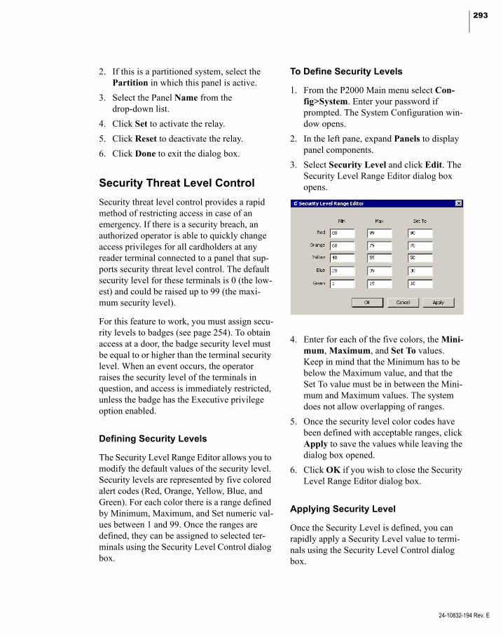
293
2. If this is a partitioned system, select the Partition in which this panel is active.
3. Select the Panel Name from the drop-down list.
4. Click Set to activate the relay.
5. Click Reset to deactivate the relay.
6. Click Done to exit the dialog box.
Security Threat Level Control
Security threat level control provides a rapid method of restricting access in case of an emergency. If there is a security breach, an authorized operator is able to quickly change access privileges for all cardholders at any reader terminal connected to a panel that sup-ports security threat level control. The default security level for these terminals is 0 (the low-est) and could be raised up to 99 (the maxi-mum security level).
For this feature to work, you must assign secu-rity levels to badges (see page 254). To obtain access at a door, the badge security level must be equal to or higher than the terminal security level. When an event occurs, the operator raises the security level of the terminals in question, and access is immediately restricted, unless the badge has the Executive privilege option enabled.
Defining Security Levels
The Security Level Range Editor allows you to modify the default values of the security level. Security levels are represented by five colored alert codes (Red, Orange, Yellow, Blue, and Green). For each color there is a range defined by Minimum, Maximum, and Set numeric val-ues between 1 and 99. Once the ranges are defined, they can be assigned to selected ter-minals using the Security Level Control dialog box.
To Define Security Levels
1. From the P2000 Main menu select Con-fig>System. Enter your password if prompted. The System Configuration win-dow opens.
2. In the left pane, expand Panels to display panel components.
3. Select Security Level and click Edit. The Security Level Range Editor dialog box opens.
4. Enter for each of the five colors, the Mini-mum, Maximum, and Set To values. Keep in mind that the Minimum has to be below the Maximum value, and that the Set To value must be in between the Mini-mum and Maximum values. The system does not allow overlapping of ranges.
5. Once the security level color codes have been defined with acceptable ranges, click Apply to save the values while leaving the dialog box opened.
6. Click OK if you wish to close the Security Level Range Editor dialog box.
Applying Security Level
Once the Security Level is defined, you can rapidly apply a Security Level value to termi-nals using the Security Level Control dialog box.
24-10832-194 Rev. E
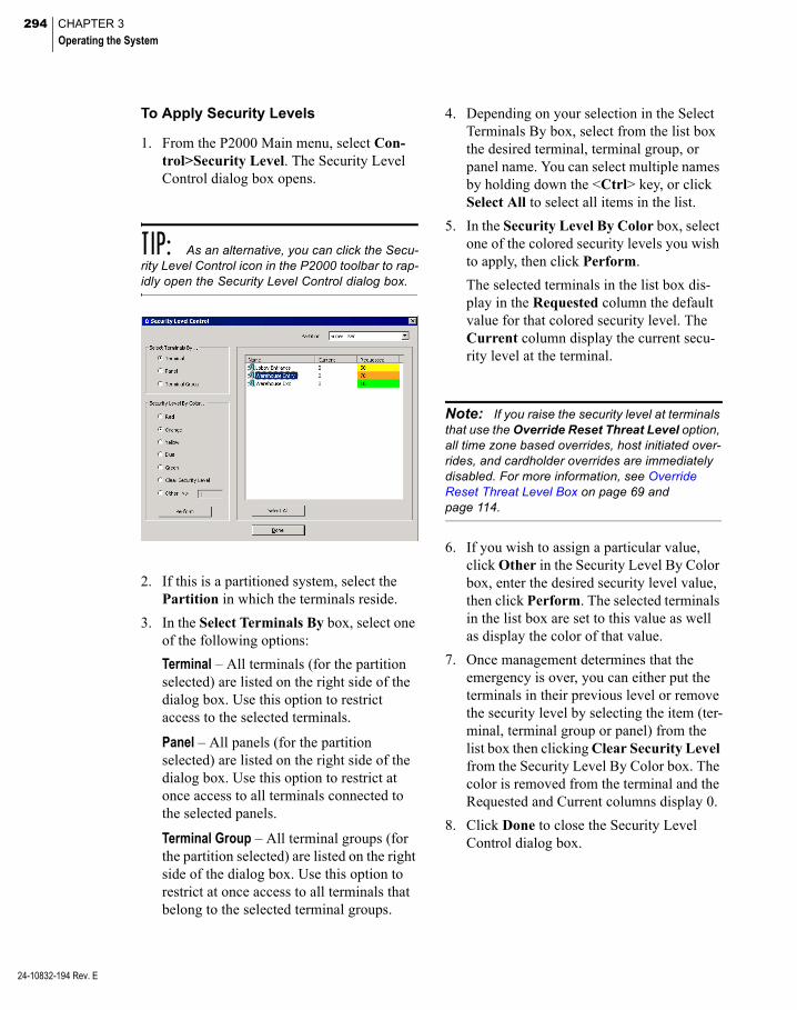
294 CHAPTER 3
Operating the System
24-10832-194 Rev. E
To Apply Security Levels
1. From the P2000 Main menu, select Con-trol>Security Level. The Security Level Control dialog box opens.
TIP: As an alternative, you can click the Secu-rity Level Control icon in the P2000 toolbar to rap-idly open the Security Level Control dialog box.
2. If this is a partitioned system, select the Partition in which the terminals reside.
3. In the Select Terminals By box, select one of the following options:
Terminal – All terminals (for the partition selected) are listed on the right side of the dialog box. Use this option to restrict access to the selected terminals.
Panel – All panels (for the partition selected) are listed on the right side of the dialog box. Use this option to restrict at once access to all terminals connected to the selected panels.
Terminal Group – All terminal groups (for the partition selected) are listed on the right side of the dialog box. Use this option to restrict at once access to all terminals that belong to the selected terminal groups.
4. Depending on your selection in the Select Terminals By box, select from the list box the desired terminal, terminal group, or panel name. You can select multiple names by holding down the <Ctrl> key, or click Select All to select all items in the list.
5. In the Security Level By Color box, select one of the colored security levels you wish to apply, then click Perform.
The selected terminals in the list box dis-play in the Requested column the default value for that colored security level. The Current column display the current secu-rity level at the terminal.
Note: If you raise the security level at terminals that use the Override Reset Threat Level option, all time zone based overrides, host initiated over-rides, and cardholder overrides are immediately disabled. For more information, see Override Reset Threat Level Box on page 69 and page 114.
6. If you wish to assign a particular value, click Other in the Security Level By Color box, enter the desired security level value, then click Perform. The selected terminals in the list box are set to this value as well as display the color of that value.
7. Once management determines that the emergency is over, you can either put the terminals in their previous level or remove the security level by selecting the item (ter-minal, terminal group or panel) from the list box then clicking Clear Security Level from the Security Level By Color box. The color is removed from the terminal and the Requested and Current columns display 0.
8. Click Done to close the Security Level Control dialog box.
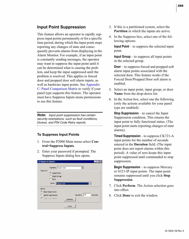
295
Input Point Suppression
This feature allows an operator to rapidly sup-press input points permanently or for a specific time period, during which the input point stops reporting any changes of state and conse-quently prevents alarms from displaying in the Alarm Monitor. For example, if an input point is constantly sending messages, the operator may want to suppress the input point until it can be determined what is causing the prob-lem, and keep the input suppressed until the problem is resolved. This applies to forced door and propped door soft alarm inputs, as well as hardware input points. See Appendix C: Panel Comparison Matrix to verify if your panel type supports this feature. The operator must have Suppress Inputs menu permissions to use this feature.
Note: Input point suppression has certain security exemptions, such as fault conditions, Duress, and PIN Code Retry reports.
To Suppress Input Points
1. From the P2000 Main menu select Con-trol>Suppress Inputs.
2. Enter your password if prompted. The Suppress Inputs dialog box opens.
3. If this is a partitioned system, select the Partition in which the inputs are active.
4. In the Suppress box, select one of the fol-lowing options:
Input Point – to suppress the selected input point.
Input Group – to suppress all input points in the selected group.
Door – to suppress forced and propped soft alarm input points associated with the selected door. This feature works if the Forced Door/Propped Door soft alarm is enabled.
5. Select an input point, input group, or door Name from the drop-down list.
6. In the Action box, select one the following (only the actions available for your panel type are enabled):
Stop Suppression – to cancel the Input Suppression condition. This returns the input point to fully functional status. (The input point starts reporting changes of state alarms).
Timed Suppression – to suppress CK721-A input points for the number of seconds entered in the Duration field. (The input point does not report alarms within this period). A value of zero keeps this input point suppressed until commanded to stop suppression.
Begin Suppression – to suppress Mercury or S321-IP input points. The input point remains suppressed until you click Stop Suppression.
7. Click Perform. The Action selection goes into effect.
8. Click Done to exit the window.
24-10832-194 Rev. E

296 CHAPTER 3
Operating the System
24-10832-194 Rev. E
Control Areas and Muster Zones
The Area Control and Mustering features pro-vide additional security measures in specific areas of your facility, such as highly sensitive areas, dangerous areas, or areas that contain high-value materials. Using Area Control for example, an operator can define a minimum number of cardholders allowed in a controlled area, such as a bank vault. Alternatively, if using Mustering, the operator can define mus-ter terminals as places of assembly, for track-ing the location and movement of personnel in the event of an emergency.
Area Control
An Area is a designated section of a facility with one or more readers or input points assigned. The Area can be monitored at any time to determine the current count and the entry, or entry and exit of personnel or vehicles to, for example, a paint shop or parking struc-ture within a plant or facility.
You can group readers and input points that are related to a particular section of your facility, for the purpose of reporting on the current whereabouts of cardholders. Areas do not have any access control or transaction processing functions; they are set up for reporting pur-poses only. This feature is useful on large sites with many card-controlled access points.
Configuring the Area
Use the Area Configuration dialog box to define the readers and input points that monitor the entry and exit of cardholders or vehicles. Here you name and describe the specific Area, define the maximum and minimum cardhold-ers allowed in the Area at any given time, and the count mode for the specific Area.
To Configure the Area
1. From the P2000 Main menu, select Con-fig>System. Enter your password if prompted. The System Configuration win-dow opens.
2. Select Areas and click Add. The Area Configuration dialog box opens.
3. If this is a partitioned system, select the Partition that has access to this Area, and click Public if you wish the Area to be vis-ible to other partitions.
4. Enter a descriptive Name for the Area.
5. Enter an Area Description that is meaning-ful to the operator.
6. Select the Area Type from the drop-down list. The options are:
Access – Select to monitor cardholder count on a specific Area, for example a Main Vault.
Facility – Select to monitor cardholder count on the entire facility, for example Bank ABC.
Parking – Select to monitor cardholder count in a parking structure, for example Parking One.

297
Note: It is possible for a cardholder to be counted on all three Area types at the same time; for example, when the cardholder badges at the parking structure reader (Parking One), then badges at the facility reader (Bank ABC), and then proceeds to badge at a specific access Area (Main Vault).
7. Click Alarm to define any or all of the fol-lowing alarm fields:
Max Allowed – An alarm is generated when the maximum number of cardholders entered in this field has been exceeded. The status column in the Area Control dia-log box displays Max Allowed Alarmed.
Min Required – An alarm is generated when the minimum number of cardholders entered in this field is not present at the same time in the specific Area. The status column in the Area Control dialog box dis-plays Min Required Alarmed.
Pre Max Allowed – An alarm is generated when the pre-maximum number of card-holders entered in this field is exceeded. This field is available only if the Area Type selected is Parking. For example, if the Max Allowed is 100 and the Pre-Max Allowed is 95, an alarm is generated when 96 vehicles have entered the parking struc-ture, that way the operator may advise other cardholders that the lot is full.
Note: In the Adjustment field, select the + or – sign, and enter a number to adjust any of the pre-vious counts by this number. For example if the Max Allowed is 100 and you entered a +2 in this field, an alarm is not generated if the Max Allowed count is 102.
24-10832-194 Rev. E
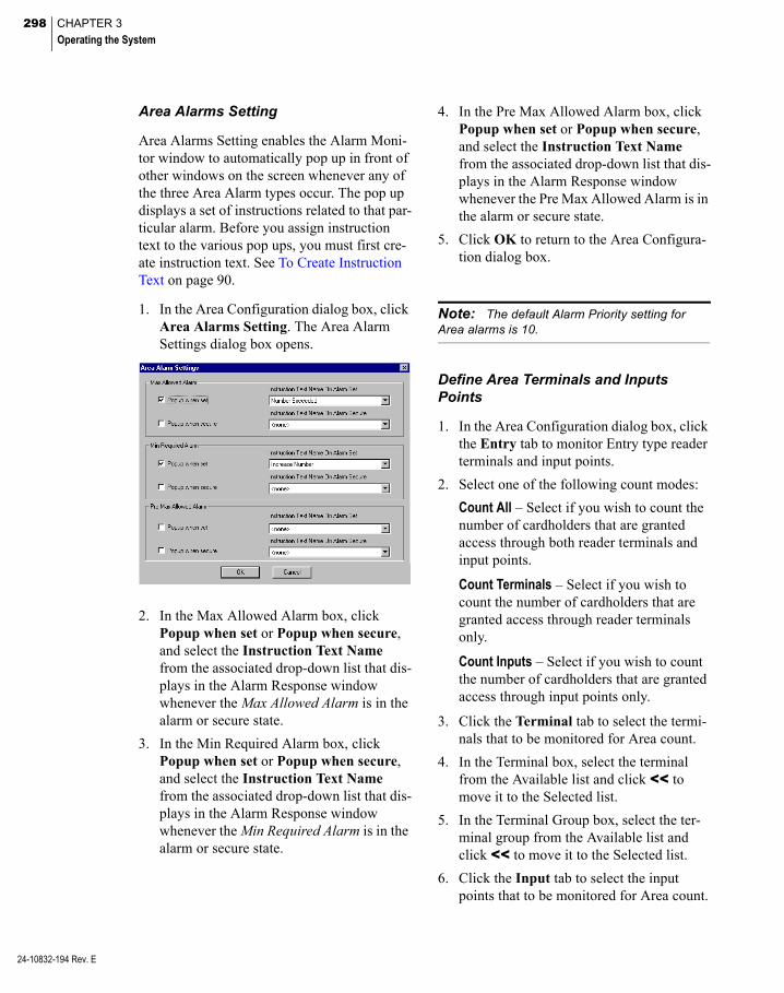
298 CHAPTER 3
Operating the System
24-10832-194 Rev. E
Area Alarms Setting
Area Alarms Setting enables the Alarm Moni-tor window to automatically pop up in front of other windows on the screen whenever any of the three Area Alarm types occur. The pop up displays a set of instructions related to that par-ticular alarm. Before you assign instruction text to the various pop ups, you must first cre-ate instruction text. See To Create Instruction Text on page 90.
1. In the Area Configuration dialog box, click Area Alarms Setting. The Area Alarm Settings dialog box opens.
2. In the Max Allowed Alarm box, click Popup when set or Popup when secure, and select the Instruction Text Name from the associated drop-down list that dis-plays in the Alarm Response window whenever the Max Allowed Alarm is in the alarm or secure state.
3. In the Min Required Alarm box, click Popup when set or Popup when secure, and select the Instruction Text Name from the associated drop-down list that dis-plays in the Alarm Response window whenever the Min Required Alarm is in the alarm or secure state.
4. In the Pre Max Allowed Alarm box, click Popup when set or Popup when secure, and select the Instruction Text Name from the associated drop-down list that dis-plays in the Alarm Response window whenever the Pre Max Allowed Alarm is in the alarm or secure state.
5. Click OK to return to the Area Configura-tion dialog box.
Note: The default Alarm Priority setting for Area alarms is 10.
Define Area Terminals and Inputs Points
1. In the Area Configuration dialog box, click the Entry tab to monitor Entry type reader terminals and input points.
2. Select one of the following count modes:
Count All – Select if you wish to count the number of cardholders that are granted access through both reader terminals and input points.
Count Terminals – Select if you wish to count the number of cardholders that are granted access through reader terminals only.
Count Inputs – Select if you wish to count the number of cardholders that are granted access through input points only.
3. Click the Terminal tab to select the termi-nals that to be monitored for Area count.
4. In the Terminal box, select the terminal from the Available list and click << to move it to the Selected list.
5. In the Terminal Group box, select the ter-minal group from the Available list and click << to move it to the Selected list.
6. Click the Input tab to select the input points that to be monitored for Area count.
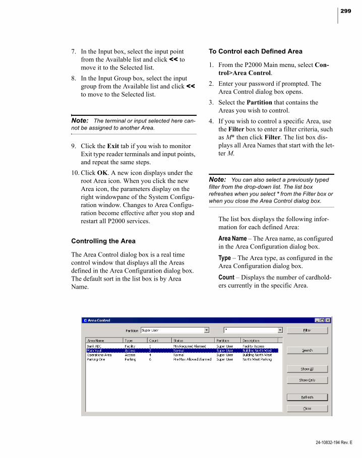
299
7. In the Input box, select the input point from the Available list and click << to move it to the Selected list.
8. In the Input Group box, select the input group from the Available list and click << to move to the Selected list.
Note: The terminal or input selected here can-not be assigned to another Area.
9. Click the Exit tab if you wish to monitor Exit type reader terminals and input points, and repeat the same steps.
10. Click OK. A new icon displays under the root Area icon. When you click the new Area icon, the parameters display on the right windowpane of the System Configu-ration window. Changes to Area Configu-ration become effective after you stop and restart all P2000 services.
Controlling the Area
The Area Control dialog box is a real time control window that displays all the Areas defined in the Area Configuration dialog box. The default sort in the list box is by Area Name.
To Control each Defined Area
1. From the P2000 Main menu, select Con-trol>Area Control.
2. Enter your password if prompted. The Area Control dialog box opens.
3. Select the Partition that contains the Areas you wish to control.
4. If you wish to control a specific Area, use the Filter box to enter a filter criteria, such as M* then click Filter. The list box dis-plays all Area Names that start with the let-ter M.
Note: You can also select a previously typed filter from the drop-down list. The list box refreshes when you select * from the Filter box or when you close the Area Control dialog box.
The list box displays the following infor-mation for each defined Area:
Area Name – The Area name, as configured in the Area Configuration dialog box.
Type – The Area type, as configured in the Area Configuration dialog box.
Count – Displays the number of cardhold-ers currently in the specific Area.
24-10832-194 Rev. E
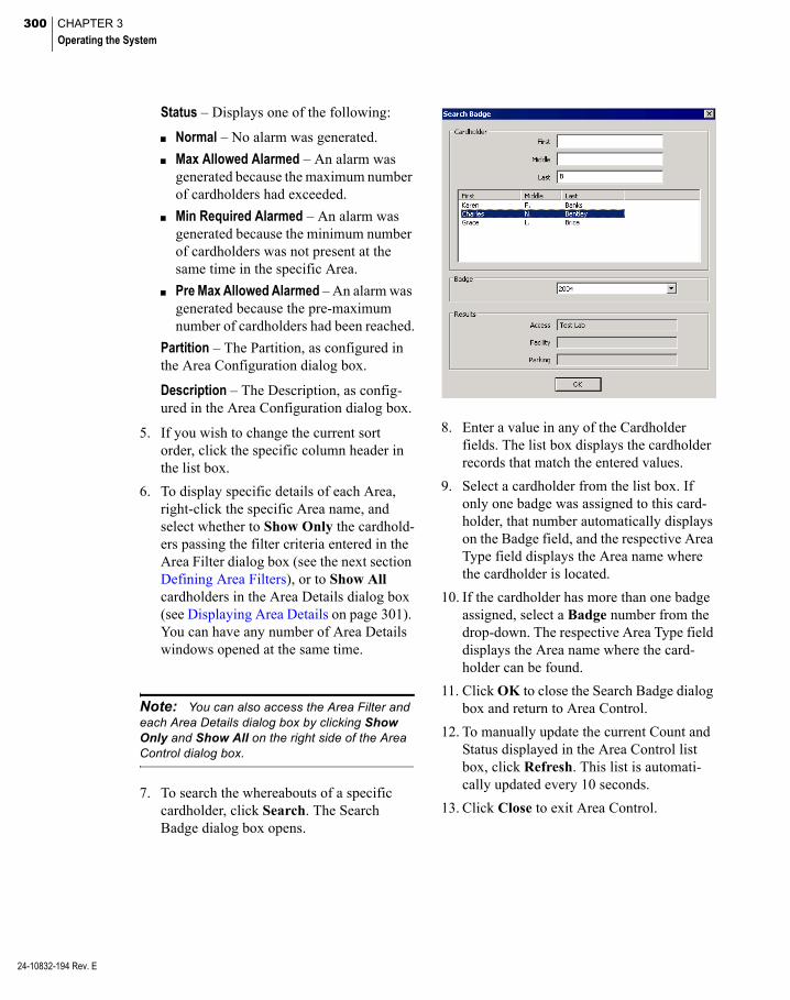
300 CHAPTER 3
Operating the System
24-10832-194 Rev. E
Status – Displays one of the following:
Normal – No alarm was generated.
Max Allowed Alarmed – An alarm was generated because the maximum number of cardholders had exceeded.
Min Required Alarmed – An alarm was generated because the minimum number of cardholders was not present at the same time in the specific Area.
Pre Max Allowed Alarmed – An alarm was generated because the pre-maximum number of cardholders had been reached.
Partition – The Partition, as configured in the Area Configuration dialog box.
Description – The Description, as config-ured in the Area Configuration dialog box.
5. If you wish to change the current sort order, click the specific column header in the list box.
6. To display specific details of each Area, right-click the specific Area name, and select whether to Show Only the cardhold-ers passing the filter criteria entered in the Area Filter dialog box (see the next section Defining Area Filters), or to Show All cardholders in the Area Details dialog box (see Displaying Area Details on page 301). You can have any number of Area Details windows opened at the same time.
Note: You can also access the Area Filter and each Area Details dialog box by clicking Show Only and Show All on the right side of the Area Control dialog box.
7. To search the whereabouts of a specific cardholder, click Search. The Search Badge dialog box opens.
8. Enter a value in any of the Cardholder fields. The list box displays the cardholder records that match the entered values.
9. Select a cardholder from the list box. If only one badge was assigned to this card-holder, that number automatically displays on the Badge field, and the respective Area Type field displays the Area name where the cardholder is located.
10. If the cardholder has more than one badge assigned, select a Badge number from the drop-down. The respective Area Type field displays the Area name where the card-holder can be found.
11. Click OK to close the Search Badge dialog box and return to Area Control.
12. To manually update the current Count and Status displayed in the Area Control list box, click Refresh. This list is automati-cally updated every 10 seconds.
13. Click Close to exit Area Control.

301
Defining Area Filters
Each Area Details dialog box displays the total count of all cardholders that have been granted access to the specified Area. You can, how-ever, define filter criteria to help you locate specific cardholders quickly and easily.
1. From the Area Control dialog box, right-click the Area Name that you wish to monitor and click Show Only, or select the Area Name and click Show Only on the right side of the screen. The Area Filter dialog box opens.
2. Enter the information on any or all of the fields to display specific cardholder count.
3. If you wish to search all cardholders that belong to the same Company or Depart-ment, select any of the previously defined Companies or Departments.
4. To search by location, select the Terminal where cardholders last presented their badge.
5. If you wish to search by UDF, select any of the previously defined UDFs (Date type UDFs cannot be included in the search). Enter or select the UDF search criteria in the next field.
6. If you wish to search by specific date and time, enter the information on the Date/Time box.
7. After you define the search criteria, click one of the following buttons:
Exact Match – to display an exact match to your search criteria.
Partial Match – to display all possible selec-tions that match the initial characters of the search criteria; for example, if you enter Carl in the First Name field, the list box displays names such as Carla, Carlos, Carl-ton, and so on.
8. The Area Details dialog box opens, dis-playing all the cardholders passing the fil-ters defined in the Area Filter dialog box.
Displaying Area Details
The Area Details dialog box displays current count details and status information for the Area selected. Here you can monitor and man-ually change current cardholder count.
The Area Details can be accessed from the Area Control dialog box in one of the follow-ing ways:
When you select an Area Name from the Area Control list box and click Show All, or right-click the Area Name and click Show All; or
When you select an Area Name from the Area Control list box and click Show Only, or right-click the Area Name and click Show Only, and enter the criteria in the Area Filter dialog box.
In either case, the Area Details dialog box opens, showing the Area Name and Area Type in the window title. See Area Details Field Definitions for details.
24-10832-194 Rev. E

302 CHAPTER 3
Operating the System
24-10832-194 Rev. E
Area Details Field Definitions
Area Name – Displays the Area Name selected in the Area Control dialog box.
Current Status – Displays the current status of the Area. See the Status definitions on page 300.
Current Count – Shows the total number of cardholders currently in the Area, which were granted access through either reader terminals or input points.
Terminal Count – Shows the total number of cardholders currently in the Area, which were granted access through a reader terminal.
Input Count – Shows the total number of card-holders currently in the Area, which were granted access through an input point.
Set – This button is activated when the Current Count is manually changed, for example to add cardholders that you know are currently in the Area, but you do not know who they are. After entering the new count, click Set, then click Yes to confirm. The Input Count increases or decreases by the number you manually enter in the Current Count field.
If you enter a new count in the Current Count field that is less than the total number of card-holders showing in the list box, you are asked to remove some cardholders from the list, or set the count to a larger value.
Refresh – To manually update the Area Details list box, click Refresh. If a change in the Area count occurs, only the Count fields are updated automatically and the Refresh button changes color displaying a message to refresh the list to see the changes.
Add – If a cardholder is currently in the Area, but does not display in the Area Details list box, click Add and select the cardholder name and badge number, click OK, then click Yes to confirm. The cardholder is added to the list and the Current Count and Terminal Count values are updated.
Remove – This button is activated if one or more cardholders are selected in the list box. Click Remove if you wish to manually remove a selected cardholder, then click Yes to con-firm. The Current Count and Terminal Count values are updated.
The word All displays if you select Show All from the Area Control dialog box, which shows all cardholders currently in the Area. If you select Show Only, to display specific cardholders, the criteria entered in the Area Filter dialog box displays here.
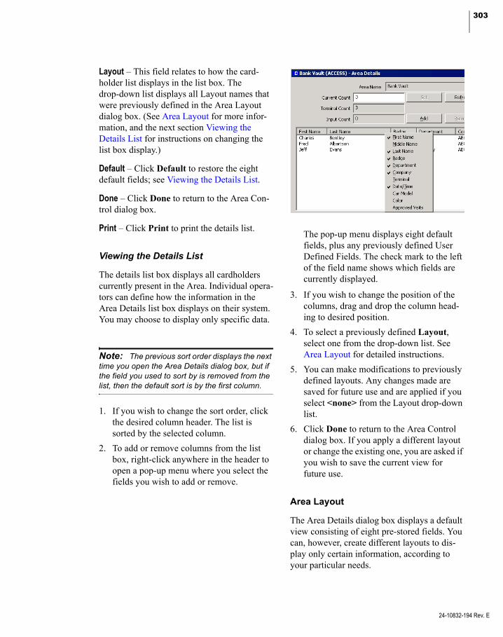
303
Layout – This field relates to how the card-holder list displays in the list box. The drop-down list displays all Layout names that were previously defined in the Area Layout dialog box. (See Area Layout for more infor-mation, and the next section Viewing the Details List for instructions on changing the list box display.)
Default – Click Default to restore the eight default fields; see Viewing the Details List.
Done – Click Done to return to the Area Con-trol dialog box.
Print – Click Print to print the details list.
Viewing the Details List
The details list box displays all cardholders currently present in the Area. Individual opera-tors can define how the information in the Area Details list box displays on their system. You may choose to display only specific data.
Note: The previous sort order displays the next time you open the Area Details dialog box, but if the field you used to sort by is removed from the list, then the default sort is by the first column.
1. If you wish to change the sort order, click the desired column header. The list is sorted by the selected column.
2. To add or remove columns from the list box, right-click anywhere in the header to open a pop-up menu where you select the fields you wish to add or remove.
The pop-up menu displays eight default fields, plus any previously defined User Defined Fields. The check mark to the left of the field name shows which fields are currently displayed.
3. If you wish to change the position of the columns, drag and drop the column head-ing to desired position.
4. To select a previously defined Layout, select one from the drop-down list. See Area Layout for detailed instructions.
5. You can make modifications to previously defined layouts. Any changes made are saved for future use and are applied if you select <none> from the Layout drop-down list.
6. Click Done to return to the Area Control dialog box. If you apply a different layout or change the existing one, you are asked if you wish to save the current view for future use.
Area Layout
The Area Details dialog box displays a default view consisting of eight pre-stored fields. You can, however, create different layouts to dis-play only certain information, according to your particular needs.
24-10832-194 Rev. E

304 CHAPTER 3
Operating the System
24-10832-194 Rev. E
For example, a system administrator may want to monitor how many cardholders from a spe-cific department are currently in the Area. In that case an Area Layout is created to display only the fields selected on the Area Layout Edit dialog box.
To Define Area Layouts
1. From the P2000 Main menu, select Con-fig>Area Layout. The Area Layout dialog box opens.
2. Click Add. The Area Layout Edit dialog box opens.
3. If you use partitioning, select the Partition that has access to this Area Layout.
4. Click Public if you wish this Area Layout to be visible to all partitions.
5. Enter the Name of the Area Layout. This name displays in the Layout field of the Area Details dialog box.
6. The Items box displays eight default fields, plus any User Defined Fields, previously defined. Click the check box to select the fields you wish to display on the Area Details list box. The default width (in char-acters) of the selected field displays.
7. To change the width, either double-click the width field, or click Change Width and enter the new width.
8. If you wish to change the order in which the fields display, click Up or Down to move the field up or down on the list.
9. When all information is entered, click OK. The new Area Layout displays in the Area Layout dialog box.
10. Click Done. This Area Layout is now accessible from the Area Details dialog box.
Area Reports
Five Area reports are provided as part of the standard P2000 reports:
All Areas to Cardholder - Preprocessed – Lists by cardholder name, all areas the cardholder can access and the terminal doors defined for the area.
All Cardholders to Area - Preprocessed – Lists by area name, the cardholders and badges that have access to the area.
Note: Preprocessed reports display current data. Any changes made to database items are not reflected until the following day, unless you manually update the report table using the Update Preprocessed Reports table task in Data-base Maintenance; see page 447.
305
Area Configuration – Lists by area name, all configuration information entered in the Area Configuration dialog box.
Area Control – Lists the cardholders currently in the area, including the total number of card-holders for each count mode.
Area Transaction – Lists all transactions per-formed in the system for the specific area. You can select to run the report on transactions at your local site or you can enter the name of the remote site that you want to report on.
See Chapter 6: System Reports for detailed instructions on running P2000 Standard Reports.
Mustering
The Mustering feature provides the capability of tracking personnel movement in the event of an emergency.
During the emergency, all personnel within a risk area are expected to evacuate and are required to badge at a reader outside the risk area, thereby providing real time printed reports and online display information as to who may still be in a hazard area. The report and online display can be used to direct search and rescue operations. The list of personnel still in the risk area is derived from the last known access data, and then refined by track-ing badge activity as personnel move out of the risk area.
Mustering is initiated by a P2000 event, which triggers a Muster; or by manual action using the Muster Zone Status and Control dialog box. Once management or emergency person-nel determine that the emergency is over, the Muster is terminated by an event that stops the Muster, or by manual action using the Muster Zone Status and Control dialog box.
Basic Definitions
Muster Zone – A Muster Zone is defined as any area within a facility that presents some risk to personnel; for example, a paint shop, an oil refinery, or a building’s electrical control cen-ter. In the P2000 Mustering feature, a Muster Zone is represented by one or more badge reader terminals.
Zone Terminal – Zone terminals are badge reader terminals that define a Muster Zone. These reader terminals can control entry to a zone, a paint shop for example, where the zone terminals would control the access. Zone ter-minals could also be readers at various loca-tions where personnel are required to badge as they move around, but which do not control access, as in an oil refinery for example. The general requirement is that when someone has badged at a zone reader terminal, it means that person is in the zone.
Muster Terminal – In an emergency, personnel are expected to move from the Muster Zone to a safe area, where muster terminals for the zone are located. As personnel arrive, they badge at the muster terminal, allowing the sys-tem to know that they are no longer at risk. There can be any number of safe areas and muster terminals for a zone.
Sequester Terminal – Any terminal installed in a sequester zone. A sequester zone is defined as a secondary Muster Zone when the initial mustering may not provide permanent safety. In some cases a muster safe area may only pro-vide temporary safety. If so, it is desirable to move people to a safer (sequestered) area, where sequester terminals are set up and where arrival of personnel is recorded in the same way as muster terminals. Sequester Terminals are optional.
24-10832-194 Rev. E

306 CHAPTER 3
Operating the System
24-10832-194 Rev. E
Muster – A Muster occurs when an event repre-senting an emergency within the Muster Zone is triggered. Personnel in the Muster Zone are then expected to move to safety and badge at a muster terminal to indicate that they are out of danger.
At Risk – When a Muster begins, all personnel within a Muster Zone are considered to be at risk until they badge at a muster terminal so that their status can be upgraded according to the last used terminal.
Trapped – Personnel are considered trapped if they badge at one or more zone terminal after the Muster begins, indicating that they are moving but possibly unable to escape the Mus-ter Zone, for example because of a blocked exit.
Wandering – Personnel are considered to be wandering if they badge at a terminal outside the Muster Zone, but not at a designated mus-ter terminal. Wanderers are assumed to be on their way to a muster terminal, but because of circumstances, may be having difficulty find-ing a safe path. For example, a hazard may be spreading to other parts of the facility, causing difficulty escaping from the original event.
Mustered – Mustered personnel are those who have badged at a designated muster terminal since the start of a Muster.
Sequestered – Sequestered personnel are those who have badged at a designated sequester ter-minal since the start of the Muster.
Rescuer – Rescuers are personnel who badge into the Muster Zone during the Muster. Res-cuers are assumed to be carrying out search, rescue, or emergency control activities, and are tracked until they badge at a muster or seques-ter terminal.
Note: Trapped, Wandering, and Rescuer groups are only tracked if Track Movement is selected in the Muster Terminals tab; see page 311.
Sequence of Steps
The basic procedures for defining and imple-menting Mustering are:
Define Muster Zones and the terminals that are associated with it.
Define the Events that start and end the Muster (alarms, card events, inputs), or any Events that are to be triggered when a Mus-ter starts or stops (set outputs to turn lights on, open doors, activate alarms, and so on.)
Control Muster Zones before, during, and after a Muster.
Generate reports and analysis reports.
Define Risk Areas and Muster Zones
Careful examination of a facility can disclose any potential risks and allow you to physically define the necessary Muster Zones. Following this process, use the Muster Zone Definition dialog box to define the Muster Zone, associ-ate the necessary zone, muster, and sequester reader terminals with the Muster Zone, and select the appropriate options to control it.
To Define Muster Zones
1. From the P2000 Main menu, select Con-fig>System. Enter your password if prompted. The System Configuration win-dow opens.
2. Select Muster Zones and click Add. The Muster Zone Definition dialog box opens at the General tab.

307
3. Enter the required information in each tab according to your system requirements. See the following Muster Zone Definition Fields for details. As you work through the tabs, click Apply to save your settings.
4. When all entries are complete click OK to return to the System Configuration win-dow. A new icon displays under the root Muster Zones icon. When you click the new Muster Zone icon, the parameters dis-play on the right windowpane.
Muster Zone Definition Fields
Zone Name – Enter a meaningful zone name. All zone names must be unique. Zones should be named logically, including information such as the zone location and what it contains, to be easily identified by rescue personnel in the event of an emergency.
Partition – Select the partition in which this Zone Name is active.
Public – Click Public if you wish this Zone Name to be visible to all partitions.
Enabled – Click Enabled for the system to rec-ognize this Zone Name. If you wish to tempo-rarily disable the Zone, click to clear the check box.
Automatically start the Muster Control Dialog – Click if you wish to automatically open the Muster Zone Status and Control dialog box as soon as a Muster begins. If you enable this option, select from the drop-down list the workstation that automatically displays the Muster Zone Status and Control dialog box when a Muster begins.
Note: To take advantage of this option, the P2000 software must be running at the desig-nated workstation when the Muster begins.
24-10832-194 Rev. E

308 CHAPTER 3
Operating the System
24-10832-194 Rev. E
One line abbreviated content – If enabled, a one-line report is automatically printed when a Muster begins. This report is printed at the Report Interval selected and includes first and last name, badge number, and last badging date and time.
Two line full content – Select this option if you wish to automatically print more detailed card-holder information when a Muster begins. This report is printed at the Report Interval selected and includes first and last name, badge num-ber, last badging date and time, terminal name, company, and department name.
Report Interval – Select from the spin box the report interval (in minutes) at which mustering reports is printed during an emergency. When a Muster starts, the first report is printed imme-diately.
IMPORTANT: Printing muster reports is not guaranteed on foreign language systems.
No automatic reports – Click if you do not wish to generate any of the previous automatic reports.
Select Printers – Click to select a printer where Muster reports are printed as soon as a Muster begins. When the Select Report Printers dialog box opens, select a printer name from the list and click OK. You can select one or more printers, as long as the PegasysServices Win-dows user account that runs the P2000 Muster Service has the appropriate access rights to those printers. Automatic muster reports can only be printed from a printer connected to the P2000 Server.
Note: We recommend setting up a printer to be used exclusively for printing Muster reports.
Muster Startup Rules
Several rules are provided to guide you in determining whether a cardholder’s last badge location means that the cardholder is inside or outside the Zone when a Muster is started.
For mustering purposes, either the last valid or last invalid badging is used, depending on which has the latest date and time. You can prevent invalid badging from being used to determine the initial At Risk group; see Use only valid badging at startup on page 309 for details. Thereafter, a muster in progress always uses the last known badge activity, valid or invalid. Even invalid badging shows the card-holder’s current location.
If the badge status shows that the holder is in the zone, assume holder is in the zone (select one of the following options):
regardless of last badge time – Select this option to include all cardholders regardless of the last badge time.
only if last badge is today – Select this option if you wish to monitor who badged today.
unless last badge is older than – Select this option to assume the cardholder is in the zone only if the last access grant was within the number of days, hours, or minutes selected.
unless last badge is for prior shift – Select this option if your facility does shift work and the cardholder’s last access grant was during a previous shift, to assume that the cardholder is no longer in the area. If enabled, the Shift Setup box is activated.
A basic rule for applying this option is to set up your time zones to start one after the other in the correct correlative order, for example Shift 2 should always start after Shift 1, and Shift 3 should always start after Shift 2. See the following example:

309
Shift Work Schedule Week Days Time Zone
Shift 1 8:00am - 5:00pm Mon-Fri 7:30am - 5:30pm
Shift 2 5:00pm - 2:00am Mon-Sat 4:30pm - 2:30am
Shift 3 2:00am - 8:00am Tue-Sat 1:30am - 8:30am
Shift Setup
Number of shifts – If you enable unless last badge is for prior shift, select from the spin box the number (1 to 3) of shifts in your facil-ity.
Shift 1 - 3 Timezone – Select from the drop-down list the time zone assigned to each shift in your facility.
Muster Zone Definition Options
Allow expansion – If selected, the Zone can be dynamically expanded during a Muster. This is useful in cases where the Zones are overlapped or not very rigidly defined. For example, an emergency event in one part of the facility might spread to adjacent areas and the Zone could be expanded to include terminals in those areas as the need arises. As expansion takes place, the badging activity at the newly incorporated terminals is examined to deter-mine which personnel need to be added to the At Risk group.
Use only valid badging at startup – If selected, only valid badging determines if the card-holder is inside a risk area. If this option is not selected, any invalid badging inside a risk area is included in determining if the cardholder is inside the risk area.
Enable de-muster – If selected, and a Muster has been stopped, and before returning the Zone to the Ready status again, you can click De-Muster in the Muster Zone Status and Control dialog box to put all personnel who were in the At Risk group back at their initial location when the Muster began. De-Muster can also be activated by a P2000 Event if desired.
Note: To end an emergency by a specific event, you must specify any number of different events as Muster terminating events. See Mus-tering Events on page 312.
Muster Zone Alarm Settings
Muster Zone Alarm Settings enable the Alarm Monitor window to automatically pop up in front of all other windows on the screen when-ever a Muster alarm condition occurs.
You can also specify instruction text that dis-plays when an operator responds to a Muster alarm going into a Set or Secure state. Enabling the Popup feature and selecting Instruction Text are independent tasks, and can be used in any combination.
Before you assign instruction text to the vari-ous pop ups, you must first create instruction text. See To Create Instruction Text on page 90.
1. In the Muster Zone Definition dialog box, click Muster Zone Alarm Settings. The Muster Zone Alarm Settings dialog box opens.
24-10832-194 Rev. E
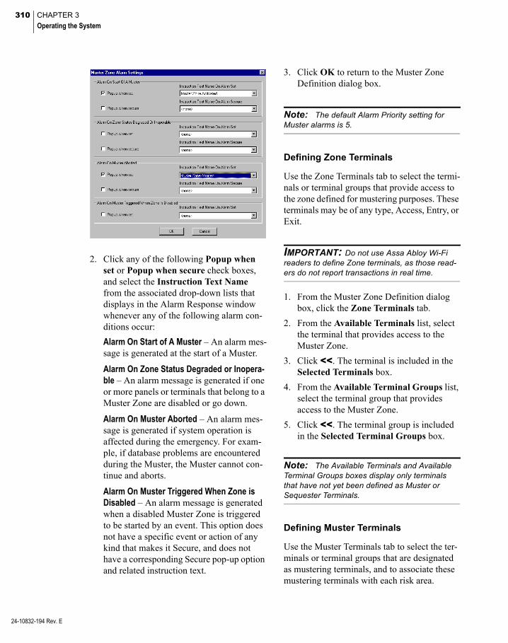
310 CHAPTER 3
Operating the System
24-10832-194 Rev. E
2. Click any of the following Popup when set or Popup when secure check boxes, and select the Instruction Text Name from the associated drop-down lists that displays in the Alarm Response window whenever any of the following alarm con-ditions occur:
Alarm On Start of A Muster – An alarm mes-sage is generated at the start of a Muster.
Alarm On Zone Status Degraded or Inopera-ble – An alarm message is generated if one or more panels or terminals that belong to a Muster Zone are disabled or go down.
Alarm On Muster Aborted – An alarm mes-sage is generated if system operation is affected during the emergency. For exam-ple, if database problems are encountered during the Muster, the Muster cannot con-tinue and aborts.
Alarm On Muster Triggered When Zone is Disabled – An alarm message is generated when a disabled Muster Zone is triggered to be started by an event. This option does not have a specific event or action of any kind that makes it Secure, and does not have a corresponding Secure pop-up option and related instruction text.
3. Click OK to return to the Muster Zone Definition dialog box.
Note: The default Alarm Priority setting for Muster alarms is 5.
Defining Zone Terminals
Use the Zone Terminals tab to select the termi-nals or terminal groups that provide access to the zone defined for mustering purposes. These terminals may be of any type, Access, Entry, or Exit.
IMPORTANT: Do not use Assa Abloy Wi-Fi readers to define Zone terminals, as those read-ers do not report transactions in real time.
1. From the Muster Zone Definition dialog box, click the Zone Terminals tab.
2. From the Available Terminals list, select the terminal that provides access to the Muster Zone.
3. Click <<. The terminal is included in the Selected Terminals box.
4. From the Available Terminal Groups list, select the terminal group that provides access to the Muster Zone.
5. Click <<. The terminal group is included in the Selected Terminal Groups box.
Note: The Available Terminals and Available Terminal Groups boxes display only terminals that have not yet been defined as Muster or Sequester Terminals.
Defining Muster Terminals
Use the Muster Terminals tab to select the ter-minals or terminal groups that are designated as mustering terminals, and to associate these mustering terminals with each risk area.

311
Muster terminals should be dedicated to the mustering function; they should not control access. From an operational viewpoint, it does not matter if badges are valid at muster termi-nals. As long as they are recognized by the P2000 system, its use at muster terminals is recognized during the Muster, regardless if a red or green light displays at the terminal.
During an emergency, all personnel within the risk zone are required to badge at any defined muster terminal to provide real time informa-tion as to their location.
IMPORTANT: Do not use Assa Abloy Wi-Fi readers to define Muster terminals, as those readers do not report transactions in real time.
1. From the Muster Zone Definition dialog box, click the Muster Terminals tab.
2. From the Available Terminals list, select the terminal where cardholders can badge in an emergency.
3. Click <<. The terminal is included in the Selected Terminals box.
4. From the Available Terminal Groups list, select the terminal group where cardhold-ers can badge in an emergency.
5. Click <<. The terminal group is included in the Selected Terminal Groups box.
6. Click Muster At Any Non Zone Termi-nal if in an emergency you wish to allow cardholders the option of badging at any terminal that has not been defined as a Zone Terminal.
If this option is selected, terminals not assigned to the zone are treated as muster terminals, and Movement Tracking is lim-ited to Trapped and Rescuers only.
7. Click Muster Only At Terminals Selected Here to have cardholders, in an emergency, badge only at the muster termi-nals selected in this tab. This is the default option, and allows you to select specific muster terminals for the zone.
8. Click Track Movement if you wish to trace cardholder movement within the defined Muster Zone. Cardholders may be considered Trapped, Wandering, or Rescu-ers, depending on where and when they badge. See Basic Definitions on page 305 for details. To get the best use of this fea-ture, do not click Muster At Any Non Zone Terminal.
9. When you finish defining the zone and muster terminals, you may click Apply to save your entries and continue with defin-ing the optional sequester terminals; or click OK to save your entries and close the Muster Zone Definition dialog box.
Note: The Available Terminals and Available Terminal Groups boxes display only terminals that have not yet been defined as Zone or Sequester Terminals.
Defining Sequester Terminals
In an emergency, personnel who initially badged at a muster terminal can be moved in groups to a safer offsite location, a sequester zone, where they are required to badge at a sequester terminal, and therefore, provide real time information that they have been moved outside the risk area to a safer location.
Use the Sequester Terminals tab to define the terminals or terminal groups that are desig-nated as sequester terminals. Sequester termi-nals are optional.
24-10832-194 Rev. E

312 CHAPTER 3
Operating the System
24-10832-194 Rev. E
IMPORTANT: Do not use Assa Abloy Wi-Fi readers to define Sequester terminals, as those readers do not report transactions in real time.
1. From the Muster Zone Definition dialog box, click the Sequester Terminals tab.
2. From the Available Terminals list, select the terminal where cardholders can badge once they are moved to a safer location.
3. Click <<. The terminal is included in the Selected Terminals box.
4. From the Available Terminal Groups list, select the terminal group where cardhold-ers can badge once they are moved to a safer location.
5. Click <<. The terminal group is included in the Selected Terminal Groups box.
6. When you finish defining the zone, muster, and optional sequester terminals, you may click Apply to save your entries, or click OK to close the Muster Zone Definition dialog box.
Note: The Available Terminals and Available Terminal Groups boxes display only terminals that have not yet been defined as Zone or Muster Terminals.
Mustering Events
After Muster Zones are defined, they can be associated with one or more events, each of which can trigger a Muster for that zone as one of its actions.
Event Actions allow an event to start and stop a Muster, while Event Triggers allow the start-ing and stopping of a Muster to trigger addi-tional P2000 events, such as unlocking doors or turning on audible or visual alarms to alert personnel of danger in the area.
The events used can include one or more inputs going to an alarm state in response to a variety of possible signaling devices, alarms, or manual actions. You can also specify one or more output points that can be set upon trigger-ing of a Muster.
In the following example, the Paint Shop Emergency Event has been programmed to start the mustering, turn emergency lights on, and activate an audible alarm (actions) when input point Manual Alarm goes into alarm after the operator presents the badge at the Emer-gency Terminal (triggers).
You can end the emergency (de-mustering) by a specified event or events, and specify any number of different events as muster terminat-ing events.
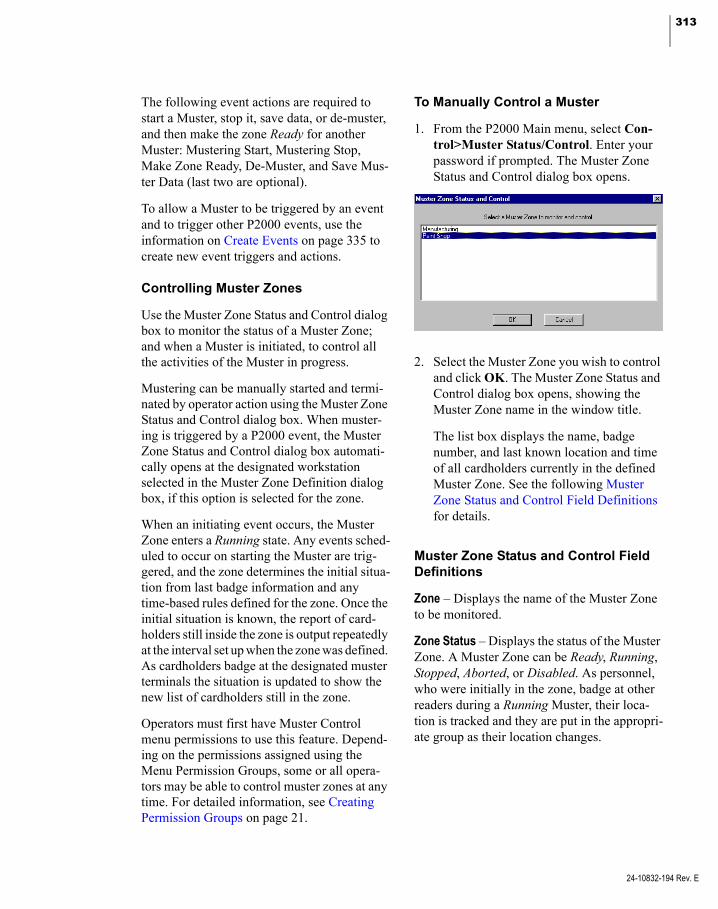
313
The following event actions are required to start a Muster, stop it, save data, or de-muster, and then make the zone Ready for another Muster: Mustering Start, Mustering Stop, Make Zone Ready, De-Muster, and Save Mus-ter Data (last two are optional).
To allow a Muster to be triggered by an event and to trigger other P2000 events, use the information on Create Events on page 335 to create new event triggers and actions.
Controlling Muster Zones
Use the Muster Zone Status and Control dialog box to monitor the status of a Muster Zone; and when a Muster is initiated, to control all the activities of the Muster in progress.
Mustering can be manually started and termi-nated by operator action using the Muster Zone Status and Control dialog box. When muster-ing is triggered by a P2000 event, the Muster Zone Status and Control dialog box automati-cally opens at the designated workstation selected in the Muster Zone Definition dialog box, if this option is selected for the zone.
When an initiating event occurs, the Muster Zone enters a Running state. Any events sched-uled to occur on starting the Muster are trig-gered, and the zone determines the initial situa-tion from last badge information and any time-based rules defined for the zone. Once the initial situation is known, the report of card-holders still inside the zone is output repeatedly at the interval set up when the zone was defined. As cardholders badge at the designated muster terminals the situation is updated to show the new list of cardholders still in the zone.
Operators must first have Muster Control menu permissions to use this feature. Depend-ing on the permissions assigned using the Menu Permission Groups, some or all opera-tors may be able to control muster zones at any time. For detailed information, see Creating Permission Groups on page 21.
To Manually Control a Muster
1. From the P2000 Main menu, select Con-trol>Muster Status/Control. Enter your password if prompted. The Muster Zone Status and Control dialog box opens.
2. Select the Muster Zone you wish to control and click OK. The Muster Zone Status and Control dialog box opens, showing the Muster Zone name in the window title.
The list box displays the name, badge number, and last known location and time of all cardholders currently in the defined Muster Zone. See the following Muster Zone Status and Control Field Definitions for details.
Muster Zone Status and Control Field Definitions
Zone – Displays the name of the Muster Zone to be monitored.
Zone Status – Displays the status of the Muster Zone. A Muster Zone can be Ready, Running, Stopped, Aborted, or Disabled. As personnel, who were initially in the zone, badge at other readers during a Running Muster, their loca-tion is tracked and they are put in the appropri-ate group as their location changes.
24-10832-194 Rev. E

314 CHAPTER 3
Operating the System
24-10832-194 Rev. E
Zone Hardware Status – Displays one of the following:
Inoperable – If a panel (that contains zone or muster terminals) is disabled or down. Also if zone or muster terminals are disabled or down.
Degraded – If a panel (that contains seques-ter terminals) is disabled or down. Also if sequester terminals are disabled or down.
OK – If all mustering terminals or panels are enabled.
Show Group – Select the group you wish to dis-play. This allows switching the display to any of the available groups. Choices are: At Risk, Trapped, Wandering, Mustered, Sequestered, and Rescuer. See Basic Definitions on page 305 for details. The At Risk group is the default display.
Personnel In Group – Displays the current number of cardholders in the group selected in the Show Group drop-down list.
Enabled – Click Enabled for the system to con-trol this Zone. If you wish to temporarily dis-able the Zone, click to clear the check box. You can disable a Zone only when it is in the Ready status.
Start Time – Displays the time the Muster was triggered or manually started.
Elapsed Time – Displays the time that has gone by since the Muster started.
Start – Click Start to manually start a Muster. To manually start a Muster, the Zone must be in the Ready status. Once started, the Muster Service determines the initial state of the Zone and the At Risk group displays by default.
Stop – Mustering is stopped by triggering an event designated to automatically stop a Mus-ter. If you wish to manually terminate a Mus-ter, click Stop. The Zone Status displays the Stopped state and analysis reports become available by clicking first Save Data and then Reports.
A warning message NoPrinter For Muster Reportsdisplays here if no printerwas selected in the MusterZone Definition dialog box.

315
Once the Muster is stopped the Zone Control quits updating the list of cardholders.
Ready – When a Muster is manually stopped, it may be necessary to ensure that all trigger-ing devices, such as alarms, manual switches, or push buttons are reset so that another Mus-ter cannot be inadvertently started. Once it is determined that the Zone can be made ready for another Muster, click Ready to enter the Ready state.
Drill – To participate in a disaster preparedness exercise, a Muster can also be run as a drill by clicking Drill. A drill differs from the real thing by the fact that during a drill, events that would otherwise send external alarms to out-side emergency response agencies can be sup-pressed.
This feature applies only to events triggered by the starting or stopping of a Muster; it cannot be applied to the events that normally start a muster. When you define the trigger, and click Do not trigger for muster drill it prevents any event action from being carried out when a drill is in progress. A drill can only be initiated through the Muster Zone Status and Control dialog box.
De-Muster – Click to put all personnel who were initially in the zone back to their location when the muster began. This option is used when muster terminals are located within the Zone, in that case cardholders are not required to badge back into the Zone.
All mustered cardholders can be automatically restored to their last badge location through the De-Muster capability, as long as the Enable de-muster option is selected in the Muster Zone Definition dialog box. This func-tion is password protected.
Reset – Click to stop a Muster in progress and reset the Zone Status back to Ready. The Reset function is not normally used, but under unusual circumstances, such as database prob-lems during a Muster causing the Muster to abort, the Reset button must then be used to reset the Zone.
Note: A Muster in progress resets itself after the P2000 system recovers from a database fail-ure.
Suspend Printing – Enable this option to momentarily suspend the automatic printing of the selected group, to add paper or take care of some other printer problem.
IMPORTANT: Printing muster reports is not guaranteed on foreign language systems.
Refresh List – Click to update the list box.
Number Mustered – Displays the total number of cardholders who have badged at a desig-nated muster terminal.
Number Sequestered – Displays the total num-ber of cardholders who have badged at a desig-nated sequester terminal.
Remove Selected Individuals – This button can be used to manually move one or more card-holders from any group to any other group while a Muster is Running. You can use it to make the final group content reflect a situation where, for example, some personnel left the Muster Zone but did not badge at a muster ter-minal, yet their current location is known.
24-10832-194 Rev. E

316 CHAPTER 3
Operating the System
24-10832-194 Rev. E
Print Group – Click to print the group currently being displayed. Printing is done at the desig-nated printers selected in the Muster Zone Definition dialog box.
Expand Zone – Use this option if you wish to expand a Muster Zone during an emergency. For instance, a hazard may spread requiring zones that initially were not involved, to be added to the active Muster Zone. You can only use this option if Allow expansion was enabled in the Muster Zone Definition dialog box. When you click this button, a list of avail-able terminals displays, where you can select the terminals you wish to add. All personnel who last badged at any of the new terminals are added to the At Risk group.
View Inoperable Hardware – Click this button to view muster terminals or panels that are not enabled or are down.
Note: The Message Routing Status indicator at the bottom of the window displays in green to indicate that all communications between the workstation and the Server are up. If communica-tions go down, the Message Routing Status indi-cator turns red.The Muster Service Status indicator displays in green to indicate that Muster Service is up and running. If Muster Service goes down, the indica-tor turns red.
Save Data – After the Muster is terminated, you may click this button to store the Muster data in the database for later evaluation.
Reports – Once the Muster is stopped and data has been saved, analysis reports can be run by clicking this button. These reports are run using the P2000 Standard Report feature. Reports can be run during the Stopped state, or at a later time when the Muster data has been saved. For more information, see Muster Reports.
Viewing and Printing Muster Transac-tions in Real Time
Once a Muster is started, an alarm is generated and displayed in the Alarm Monitor window, and all mustering transactions are sent through real time messages to the Real Time List. As the Muster Zone status changes, corresponding Muster-related messages are generated and displayed. You must select the Mustering check box in the Real Time List window to display all mustering transactions as they occur. See Using the Real Time List on page 342 for more information.
If you wish to print mustering transactions as they occur, you can either print them from the Real Time List window, or select the Muster-ing Zones check box in the Site Parameters dialog box, Printing tab. See Printing Tab on page 34 for more information.
Note: The Muster Zone hardware status also displays in the System Status window, see View-ing System Status on page 435 for details.
Muster Reports
Muster reports are available while the Muster is in the Stopped state, or afterward if the Mus-ter state is saved before returning the zone to the Ready state. These reports allow manage-ment to assess preparedness for emergencies and improvement of procedures for handling future events.
When you click Reports in the Muster Zone Status and Control dialog box, the Muster Analysis dialog box opens.

317
The Muster Zone Name and Available Date/Time fields only display selections if the Muster Zone was started at least once.
In the Group Type drop-down list select one of the following reports:
At Risk – Displays the list of personnel who are within the Muster Zone and have not yet checked-in at a muster terminal.
Trapped – Displays the list of all personnel who may be trapped in the Muster Zone.
Wandering – Displays the list of all person-nel who are not believed to be in the Muster Zone, but who have not yet checked-in at a muster terminal.
Mustered – Displays the list of all personnel who have badged at a muster terminal.
Sequester – Displays the list of all personnel who have badged at a sequester terminal.
Rescuer – This report tracks all rescue per-sonnel throughout the site.
In the Started By drop-down list select whether this Muster Zone was started by an Operator or by an Event.
In the Reason drop-down list select the reason why this Muster was started, whether it was a real Muster, a drill, or both.
After you have entered your selections, the Muster Analysis Report displays in the Crystal preview window showing the criteria selected and the total number of cardholders in the Muster Zone. This report lists all Mustering activity within a specified time frame by zone name, start and stop times and whether it was a drill or real emergency.
This report can also be generated using the Report>Run Report option and selecting the Muster Analysis report.
In addition to the Muster Analysis report, the P2000 Standard Reports set includes the Mus-tering Configuration report, which lists by Muster Zone name, all the zone definition con-figuration, as set up in the Muster Zone Defini-tion dialog box. This report lists each Muster Zone and shows its defining and mustering ter-minals, and all associated events.
Detect and Control Intrusion
The Intrusion Detection function has been designed to sense an intrusion into a protected building (detection) and report it to responsible parties (annunciation). This is accomplished with a combination of detection, control, and reporting devices such as a control panel, input devices (sensors), and output devices (bells, sirens).
The Intrusion Detection system consists of sensors, connected to the intrusion panel, capable of detecting various intrusion or bur-glary events. These intrusion detection sensors are associated with physical zones/points and grouped into areas; also intrusion events use audible annunciators to signal that a zone or area is in alarm condition.
The P2000 Intrusion Service resides on the P2000 Server and provides the communication between the P2000 system and intrusion pan-els. This service allows the P2000 system to obtain status information whenever an intru-sion component changes and issues commands to control the intrusion zones/points, areas, and annunciators that are part of the intrusion system.
The P2000 system supports three intrusion detection integrations: OPC Aritech, Bosch® (GV3 and GV4 series), and Mercury. Com-plete hardware installation and operation instructions are provided with the intrusion system that is shipped with your option.
24-10832-194 Rev. E
318 CHAPTER 3
Operating the System
24-10832-194 Rev. E
Note: Mercury intrusion panels require both the P2000 Intrusion Interface Service and the P2000 Mercury Interface Service to communicate with the server.
IMPORTANT: The Aritech panel is not avail-able in North America. Contact Johnson Controls Systems Integration Services Europe for informa-tion.
Areas are used to control zones and can be commanded to be armed or disarmed. An authorized user at a P2000 workstation can arm or disarm an area, bypass a zone, and silence or activate an annunciator, assuming that the user has the appropriate authorization.
When an Aritech area is armed or disarmed, it causes all associated zones to become armed or disarmed (or if armed, possibly alarmed). Ari-tech Areas are objects that are used to control zones. Zones maintain state and can be in states such as bypassed or alarmed.
A properly configured intrusion detection sys-tem should:
Detect an unlawful intrusion
Identify the location of the intrusion
Signal an alarm to inform local security forces that an intrusion has been detected
Signal intruders that they have been detected
Basic Definitions
Annunciator – (Not supported by Mercury) An annunciator is any electrical device connected to an Aritech or Bosch output point, which is activated when an intrusion is detected (for example, a siren). An annunciator can be silenced or activated manually.
Area – A group of zones/points within a facil-ity (for example, the perimeter, the main entrance, the entire facility).
Armed – (Aritech and Mercury) The state of a zone that reports intrusions unless it is bypassed. When an area is armed or disarmed, it arms or disarms all associated zones.
Armed – (Bosch) The state of an area that reports intrusions.
Bypassed – The state of a zone/point that does not report intrusions. This state is intended for maintenance use. If a zone is bypassed an intrusion is not detected nor sent to the P2000 Server.
Disarmed – The state of a zone/point that is dis-abled from reporting intrusion alarms. This state is typically used during hours when zones are occupied.
Intrusion – An unauthorized entry to an area or zone that results in an alarm state for the area or zone.
Intrusion Input Point – A device used to detect a change in a facility. A point senses an event that could represent intrusion such as a glass break, motion or door contact.
Intrusion Interface – TCP/IP, RS232C, or OPC that is used to communicate with one or more intrusion servers.
Intrusion Server – A physical device or soft-ware component that controls one or more intrusion zones or areas.
Zone – A collection of one or more input points (or Mercury readers) that are used to monitor a particular zone within the facility.

319
Sequence of Steps
The following sequence of steps are involved in the process of configuring, controlling, and monitoring intrusion components:
Create and assign menu permissions to per-form Intrusion Configuration and Control functions; see page 21.
Enable the intrusion server (Aritech only); see page 319.
Configure the Bosch intrusion panel; see page 320.
Configure Mercury intrusion components and alarms; see page 323.
Configure alarm options for Aritech and Bosch intrusion devices. This allows you to view intrusion-related alarms on the P2000 Alarm Monitor and act accordingly, such as acknowledging the alarm; see page 326.
Issue commands to control intrusion com-ponents; see page 328.
View and monitor intrusion activity from the Real Time List and Real Time Map as they occur; see page 330.
Control, monitor, and display the status of intrusion devices, areas, zones, and annun-ciators; see page 330.
Define event triggers and actions associated with intrusion devices, areas, zones, and annunciators; see page 331.
Intrusion Configuration
The intrusion detection system consists of the P2000 software, the panel firmware (OPC Ari-tech, Bosch, or Mercury), and I/O modules (attached to sensors and annunciators). Use the instructions provided with your intrusion hard-ware to define your intrusion system, such as the number and type of sensors, number of annunciators required, how these input and output devices are associated with zones/points, and how zones/points are included within areas.
The following sections describe intrusion con-figuration and operation procedures using the P2000 software.
OPC Aritech Intrusion Interface
This interface controls the Intrusion OPC Server, which connects to Aritech devices to control intrusion zones, areas, and annuncia-tors. The P2000 Intrusion Service connects to a single Intrusion OPC Server to support mul-tiple intrusion devices.
Note: The P2000 system has been validated to support up to 4,000 OPC points.
Once you use the instructions provided with your Aritech panel to configure your intrusion panel and associated items, you must enable the intrusion server in the P2000 System Con-figuration window to populate the associated data into the P2000 database.
Note: Requires OPC Server Version 2.7.
To Enable the Aritech Intrusion Server
1. From the P2000 Main menu, select Con-fig>System. Enter your password if prompted. The System Configuration win-dow opens.
2. In the left pane, expand Intrusion.
3. Select Intrusion Server and click Add. The Intrusion Server Config dialog box opens.
4. Verify that the Aritech intrusion server name displays in the Name field.
5. Click Enable.
6. Click OK.
24-10832-194 Rev. E

320 CHAPTER 3
Operating the System
24-10832-194 Rev. E
Once you enable the Aritech intrusion server, the System Configuration window is automati-cally populated with the intrusion device and associated intrusion areas, zones, and annunci-ators.
The P2000 system is now ready to operate with the Aritech intrusion panel, continue with Intrusion Alarms on page 326.
OPC Tags
The P2000 Intrusion Service obtains status information by monitoring the OPC tags defined within the Intrusion OPC Server and issue commands by writing values to the appropriate OPC tags.
The following table displays nine tags that are associated with the OPC Aritech panel, includ-ing the corresponding value for each of the tags. You must set up the panel correctly to communicate with the P2000 system to achieve these values.
Tag Number Description Value
1 Connected True
2 InvalidVendorAddress False
3 PortOpened True
4 MainsFailure False
5 BatteryLow False
6 BatteryTest False
7 BatteryTestFail False
8 BatteryMissing False
9 Tamper False
Be aware that under certain conditions, the P2000 system may indicate that the Aritech panel is in fault status, but the overall opera-tion of the Aritech interface is normal. For example:
If tags 2, 4, and 5 are set with a value of True, it indicates that:
2 = vendor address format is incorrect
4 = Aritech panel is working in battery mode
5 = battery charge is low
Under these conditions, the Aritech panel is still operational because:
Tag 2: Vendor Address is invalid – Even if the address format is invalid, maybe that default values are already correct. If the panel address is equal to 1 and the password is set to the default value 0000000000, the Aritech panel still communicates with OPC Server; there-fore, the invalid address fault is displayed but ignored. Also, note that each field (Address, Password, and System) is independent from others. For example, if the Password field is correct and the Address field is incorrect, the driver successfully parses the password value and returns the InvalidVendorAddress condi-tion because the Address is wrong (but it sets the Address to the default value 1).
Tag 4: Mains failure – This means that the Ari-tech panel is working in battery mode, but it stays online while the battery works.
Tag 5: Battery charge is Low – In this case the Aritech panel is working with a battery in low condition, but not yet exhausted. So, it com-municates until power is present.
Note: Be aware that if you disconnect the bat-tery from the Aritech panel, the panel may indi-cate unusual status and send multiple fault messages to the Real Time List.
Bosch Intrusion Interface
This integration allows P2000 operators to configure and control Bosch intrusion devices. The intrusion system may have multiple, inde-pendent Bosch intrusion panels, and each Bosch intrusion panel can support multiple intrusion areas/zones.

321
IMPORTANT: This release of the P2000 soft-ware works with Bosch GV3 intrusion panels firmware Version 8.13 and GV4 intrusion panels firmware Version 2.03. Other versions may not be compatible with this P2000 release.
Before you configure your Bosch intrusion pan-els, ensure that the following settings are in place to establish the communication between the P2000 Server and the Bosch intrusion panel:
You should modify some parameters using Bosch Remote Programming Software (RPS) to program the panel.
1. Verify that under the AUXPARM set-tings, the SDI RPS Automation is enabled. This enables the third-party communication for the panel.
2. If you use GV4 panels, set the Automa-tion device under AUXPARM to the appropriate address based on the network interface connection.
3. To be fully compatible with the P2000 system, you should verify that under the POINTS section, the point indexes have the parameters listed as follows:
a. Bypassable (enables bypassing from the Third party automation) : -
Yes
b. Defer Bypass Report : - No
c. Alarm Abort :- No
Note: We recommend the point response type for immediate response to be A for non 24-hour points, and 0 or 2 for 24-hour points.
The Bosch intrusion integration uses the TCP/IP protocol to communicate between the Bosch panel and the P2000 Server; therefore, you must establish the availability of Conettix DX4020 or B426 network inter-face. This is provided by Bosch to connect with the Bosch panel via a TCP/IP protocol. Make sure the B426 network module uses the latest Bosch intrusion firmware version.
DX4020 Configuration Rules (GV3 and GV4 Panels)
1. After setting up the DX4020 module based on the instructions provided by Bosch, change the dip switch address on the net-work interface module to reflect address 80 to connect to the P2000 system.
2. Telnet into the network module via the command Telnet <ip address> 9999 and change the channel 1 settings.
a. Set Connectmode to c0 for P2000/third party automation.
b. Do not change any other settings and press <Return> to leave the default set-tings.
B426 Configuration Rules (GV3 Panels)
For RPS:
1. Set the physical switch address on the B426 to 4.
2. Set Automation TCP Enable to No.
For Automation (P2000 Integration):
1. Set the physical switch address on the B426 to 3.
2. Set Automation TCP Enable to Yes.
B426 Configuration Rules (GV4 Panels)
For RPS:
1. Set the physical switch address on the B426 to 4, or 2 or 1. Use this value to set the panel address using the AUXPARM settings.
Send ‘+++’ in Modem Mode (Y) ?
Auto increment source port (N) ?
Remote IP Address : (000) .(000) .(000) .(000)
Remote Port (0) ?
DisConnMode (02) ?
FlushMode (00) ?
DisConnTime (00:00) ?:
24-10832-194 Rev. E
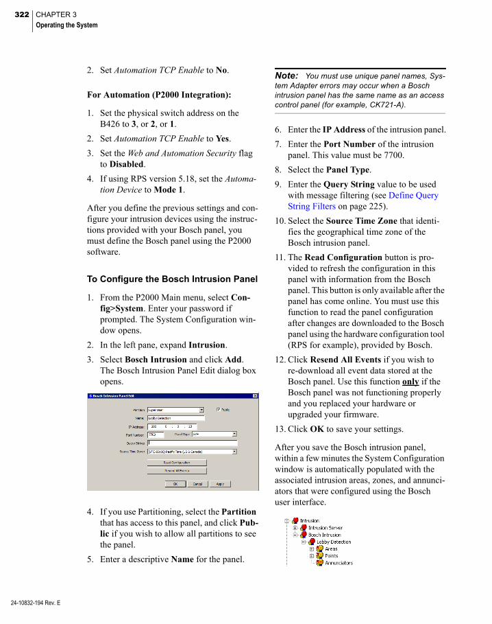
322 CHAPTER 3
Operating the System
24-10832-194 Rev. E
2. Set Automation TCP Enable to No.
For Automation (P2000 Integration):
1. Set the physical switch address on the B426 to 3, or 2, or 1.
2. Set Automation TCP Enable to Yes.
3. Set the Web and Automation Security flag to Disabled.
4. If using RPS version 5.18, set the Automa-tion Device to Mode 1.
After you define the previous settings and con-figure your intrusion devices using the instruc-tions provided with your Bosch panel, you must define the Bosch panel using the P2000 software.
To Configure the Bosch Intrusion Panel
1. From the P2000 Main menu, select Con-fig>System. Enter your password if prompted. The System Configuration win-dow opens.
2. In the left pane, expand Intrusion.
3. Select Bosch Intrusion and click Add. The Bosch Intrusion Panel Edit dialog box opens.
4. If you use Partitioning, select the Partition that has access to this panel, and click Pub-lic if you wish to allow all partitions to see the panel.
5. Enter a descriptive Name for the panel.
Note: You must use unique panel names, Sys-tem Adapter errors may occur when a Bosch intrusion panel has the same name as an access control panel (for example, CK721-A).
6. Enter the IP Address of the intrusion panel.
7. Enter the Port Number of the intrusion panel. This value must be 7700.
8. Select the Panel Type.
9. Enter the Query String value to be used with message filtering (see Define Query String Filters on page 225).
10. Select the Source Time Zone that identi-fies the geographical time zone of the Bosch intrusion panel.
11. The Read Configuration button is pro-vided to refresh the configuration in this panel with information from the Bosch panel. This button is only available after the panel has come online. You must use this function to read the panel configuration after changes are downloaded to the Bosch panel using the hardware configuration tool (RPS for example), provided by Bosch.
12. Click Resend All Events if you wish to re-download all event data stored at the Bosch panel. Use this function only if the Bosch panel was not functioning properly and you replaced your hardware or upgraded your firmware.
13. Click OK to save your settings.
After you save the Bosch intrusion panel, within a few minutes the System Configuration window is automatically populated with the associated intrusion areas, zones, and annunci-ators that were configured using the Bosch user interface.
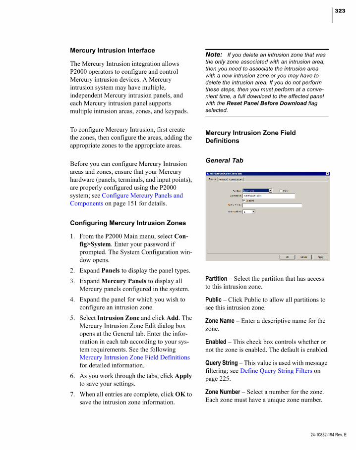
323
Mercury Intrusion Interface
The Mercury Intrusion integration allows P2000 operators to configure and control Mercury intrusion devices. A Mercury intrusion system may have multiple, independent Mercury intrusion panels, and each Mercury intrusion panel supports multiple intrusion areas, zones, and keypads.
To configure Mercury Intrusion, first create the zones, then configure the areas, adding the appropriate zones to the appropriate areas.
Before you can configure Mercury Intrusion areas and zones, ensure that your Mercury hardware (panels, terminals, and input points), are properly configured using the P2000 system; see Configure Mercury Panels and Components on page 151 for details.
Configuring Mercury Intrusion Zones
1. From the P2000 Main menu, select Con-fig>System. Enter your password if prompted. The System Configuration win-dow opens.
2. Expand Panels to display the panel types.
3. Expand Mercury Panels to display all Mercury panels configured in the system.
4. Expand the panel for which you wish to configure an intrusion zone.
5. Select Intrusion Zone and click Add. The Mercury Intrusion Zone Edit dialog box opens at the General tab. Enter the infor-mation in each tab according to your sys-tem requirements. See the following Mercury Intrusion Zone Field Definitions for detailed information.
6. As you work through the tabs, click Apply to save your settings.
7. When all entries are complete, click OK to save the intrusion zone information.
Note: If you delete an intrusion zone that was the only zone associated with an intrusion area, then you need to associate the intrusion area with a new intrusion zone or you may have to delete the intrusion area. If you do not perform these steps, then you must perform at a conve-nient time, a full download to the affected panel with the Reset Panel Before Download flag selected.
Mercury Intrusion Zone Field Definitions
General Tab
Partition – Select the partition that has access to this intrusion zone.
Public – Click Public to allow all partitions to see this intrusion zone.
Zone Name – Enter a descriptive name for the zone.
Enabled – This check box controls whether or not the zone is enabled. The default is enabled.
Query String – This value is used with message filtering; see Define Query String Filters on page 225.
Zone Number – Select a number for the zone. Each zone must have a unique zone number.
24-10832-194 Rev. E
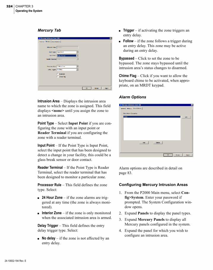
324 CHAPTER 3
Operating the System
24-10832-194 Rev. E
Mercury Tab
Intrusion Area – Displays the intrusion area name to which the zone is assigned. This field displays <none> until you assign the zone to an intrusion area.
Point Type – Select Input Point if you are con-figuring the zone with an input point or Reader Terminal if you are configuring the zone with a reader terminal.
Input Point – If the Point Type is Input Point, select the input point that has been designed to detect a change in your facility, this could be a glass break sensor or door contact.
Reader Terminal – If the Point Type is Reader Terminal, select the reader terminal that has been designed to monitor a particular zone.
Processor Rule – This field defines the zone type. Select:
24 Hour Zone – if the zone alarms are trig-gered at any time (the zone is always moni-tored).
Interior Zone – if the zone is only monitored when the associated intrusion area is armed.
Delay Trigger – This field defines the entry delay trigger type. Select:
No delay – if the zone is not affected by an entry delay.
Trigger – if activating the zone triggers an entry delay.
Follow – if the zone follows a trigger during an entry delay. This zone may be active during an entry delay.
Bypassed – Click to set the zone to be bypassed. The zone stays bypassed until the intrusion area’s status changes to disarmed.
Chime Flag – Click if you want to allow the keyboard chime to be activated, when appro-priate, on an MRDT keypad.
Alarm Options
Alarm options are described in detail on page 83.
Configuring Mercury Intrusion Areas
1. From the P2000 Main menu, select Con-fig>System. Enter your password if prompted. The System Configuration win-dow opens.
2. Expand Panels to display the panel types.
3. Expand Mercury Panels to display all Mercury panels configured in the system.
4. Expand the panel for which you wish to configure an intrusion area.

325
5. Select Intrusion Area and click Add. The Mercury Intrusion Area Edit dialog box opens at the General tab. Enter the infor-mation in each tab according to your sys-tem requirements. See the following Mercury Intrusion Area Field Definitions for detailed information.
6. As you work through the tabs, click Apply to save your settings.
7. When all entries are complete, click OK to save the intrusion area information.
Note: If you wish to delete an intrusion area, you must first delete it from the System Configu-ration window, then you must perform at a conve-nient time, a full download to the affected panel with the Reset Panel Before Download flag selected; see page 425 for details.
Mercury Intrusion Area Field Defini-tions
General Tab
Partition – Select the partition that has access to this intrusion area.
Public – Click Public to allow all partitions to see this intrusion area.
Name – Enter a descriptive name for the area.
Query String – This value is used with message filtering; see Define Query String Filters on page 225.
Number – Select a number for the area. Each area must have a unique area number.
Mercury Tab
Default Status – Select Disarmed or Armed as the default status for the intrusion area.
Entry Delay – Enter the number of seconds from 0 to 32767 (default is 60) that alarms are sup-pressed after someone enters the intrusion area.
Exit Delay – Enter the number of seconds from 0 to 32767 (default is 60) that alarms are sup-pressed after the intrusion area is armed.
Auto Disarm – When selected, the intrusion area is automatically disarmed when access to the area is granted via an access control reader. This applies only to the default intrusion area, the intrusion area defined as number 1.
Skip Alarm Cancel – This option is selected by default and cannot be modified. It allows an area to go directly from Disarmed to Armed or from Armed to Disarmed, as appropriate.
Report Disarmed Not Ready to Arm – This option is not selected by default and cannot be modified. The intrusion area does not report when it is not ready to be armed.
24-10832-194 Rev. E
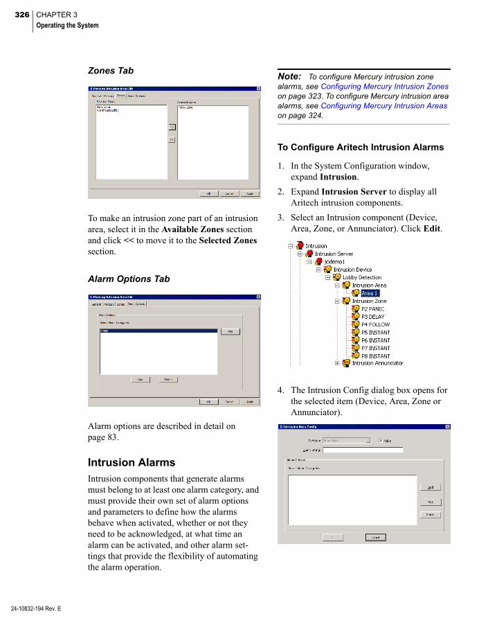
326 CHAPTER 3
Operating the System
24-10832-194 Rev. E
Zones Tab
To make an intrusion zone part of an intrusion area, select it in the Available Zones section and click << to move it to the Selected Zones section.
Alarm Options Tab
Alarm options are described in detail on page 83.
Intrusion AlarmsIntrusion components that generate alarms must belong to at least one alarm category, and must provide their own set of alarm options and parameters to define how the alarms behave when activated, whether or not they need to be acknowledged, at what time an alarm can be activated, and other alarm set-tings that provide the flexibility of automating the alarm operation.
Note: To configure Mercury intrusion zone alarms, see Configuring Mercury Intrusion Zones on page 323. To configure Mercury intrusion area alarms, see Configuring Mercury Intrusion Areas on page 324.
To Configure Aritech Intrusion Alarms
1. In the System Configuration window, expand Intrusion.
2. Expand Intrusion Server to display all Aritech intrusion components.
3. Select an Intrusion component (Device, Area, Zone, or Annunciator). Click Edit.
4. The Intrusion Config dialog box opens for the selected item (Device, Area, Zone or Annunciator).
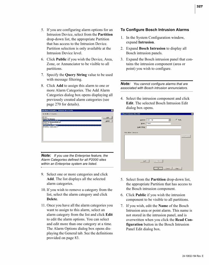
327
5. If you are configuring alarm options for an Intrusion Device, select from the Partition drop-down list, the appropriate Partition that has access to the Intrusion Device. Partition selection is only available at the Intrusion Device level.
6. Click Public if you wish the Device, Area, Zone, or Annunciator to be visible to all partitions.
7. Specify the Query String value to be used with message filtering.
8. Click Add to assign this alarm to one or more Alarm Categories. The Add Alarm Categories dialog box opens displaying all previously created alarm categories (see page 270 for details).
Note: If you use the Enterprise feature, the Alarm Categories defined for all P2000 sites within an Enterprise system are listed.
9. Select one or more categories and click Add. The list displays all the selected alarm categories.
10. If you wish to remove a category from the list, select the alarm category and click Delete.
11. Once you have all the alarm categories you want to assign to this alarm, select an alarm category from the list and click Edit to edit the alarm options. You can select and edit more than one category at a time. The Alarm Options dialog box opens dis-playing the General tab. See the definitions provided on page 83.
To Configure Bosch Intrusion Alarms
1. In the System Configuration window, expand Intrusion.
2. Expand Bosch Intrusion to display all Bosch intrusion panels.
3. Expand the Bosch intrusion panel that con-tains the intrusion component (area or point) you wish to configure.
Note: You cannot configure alarms that are associated with Bosch intrusion annunciators.
4. Select the intrusion component and click Edit. The selected Bosch Intrusion Edit dialog box opens.
5. Select from the Partition drop-down list, the appropriate Partition that has access to the Bosch intrusion component.
6. Click Public if you wish the intrusion component to be visible to all partitions.
7. If you wish, edit the Name of the Bosch Intrusion area or point alarm. This name is not stored in the intrusion panel, and is overwritten when you click the Read Con-figuration button in the Bosch Intrusion Panel Edit dialog box.
24-10832-194 Rev. E
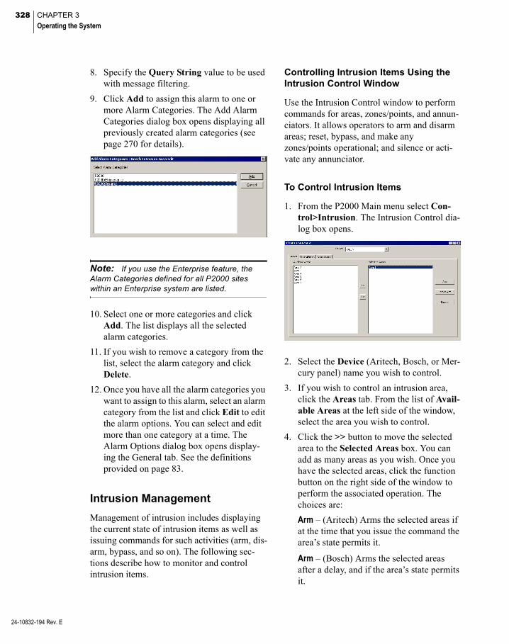
328 CHAPTER 3
Operating the System
24-10832-194 Rev. E
8. Specify the Query String value to be used with message filtering.
9. Click Add to assign this alarm to one or more Alarm Categories. The Add Alarm Categories dialog box opens displaying all previously created alarm categories (see page 270 for details).
Note: If you use the Enterprise feature, the Alarm Categories defined for all P2000 sites within an Enterprise system are listed.
10. Select one or more categories and click Add. The list displays all the selected alarm categories.
11. If you wish to remove a category from the list, select the alarm category and click Delete.
12. Once you have all the alarm categories you want to assign to this alarm, select an alarm category from the list and click Edit to edit the alarm options. You can select and edit more than one category at a time. The Alarm Options dialog box opens display-ing the General tab. See the definitions provided on page 83.
Intrusion Management
Management of intrusion includes displaying the current state of intrusion items as well as issuing commands for such activities (arm, dis-arm, bypass, and so on). The following sec-tions describe how to monitor and control intrusion items.
Controlling Intrusion Items Using the Intrusion Control Window
Use the Intrusion Control window to perform commands for areas, zones/points, and annun-ciators. It allows operators to arm and disarm areas; reset, bypass, and make any zones/points operational; and silence or acti-vate any annunciator.
To Control Intrusion Items
1. From the P2000 Main menu select Con-trol>Intrusion. The Intrusion Control dia-log box opens.
2. Select the Device (Aritech, Bosch, or Mer-cury panel) name you wish to control.
3. If you wish to control an intrusion area, click the Areas tab. From the list of Avail-able Areas at the left side of the window, select the area you wish to control.
4. Click the >> button to move the selected area to the Selected Areas box. You can add as many areas as you wish. Once you have the selected areas, click the function button on the right side of the window to perform the associated operation. The choices are:
Arm – (Aritech) Arms the selected areas if at the time that you issue the command the area’s state permits it.
Arm – (Bosch) Arms the selected areas after a delay, and if the area’s state permits it.
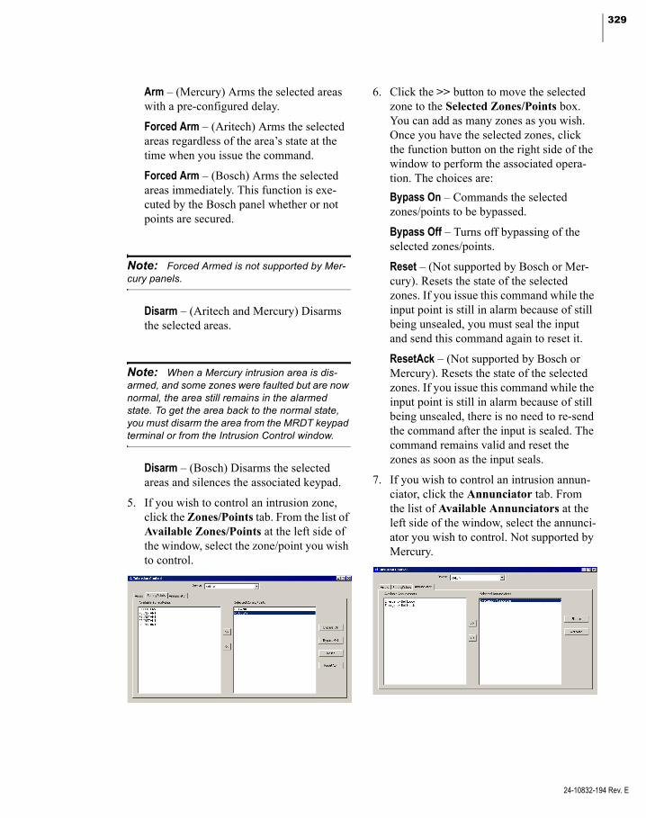
329
Arm – (Mercury) Arms the selected areas with a pre-configured delay.
Forced Arm – (Aritech) Arms the selected areas regardless of the area’s state at the time when you issue the command.
Forced Arm – (Bosch) Arms the selected areas immediately. This function is exe-cuted by the Bosch panel whether or not points are secured.
Note: Forced Armed is not supported by Mer-cury panels.
Disarm – (Aritech and Mercury) Disarms the selected areas.
Note: When a Mercury intrusion area is dis-armed, and some zones were faulted but are now normal, the area still remains in the alarmed state. To get the area back to the normal state, you must disarm the area from the MRDT keypad terminal or from the Intrusion Control window.
Disarm – (Bosch) Disarms the selected areas and silences the associated keypad.
5. If you wish to control an intrusion zone, click the Zones/Points tab. From the list of Available Zones/Points at the left side of the window, select the zone/point you wish to control.
6. Click the >> button to move the selected zone to the Selected Zones/Points box. You can add as many zones as you wish. Once you have the selected zones, click the function button on the right side of the window to perform the associated opera-tion. The choices are:
Bypass On – Commands the selected zones/points to be bypassed.
Bypass Off – Turns off bypassing of the selected zones/points.
Reset – (Not supported by Bosch or Mer-cury). Resets the state of the selected zones. If you issue this command while the input point is still in alarm because of still being unsealed, you must seal the input and send this command again to reset it.
ResetAck – (Not supported by Bosch or Mercury). Resets the state of the selected zones. If you issue this command while the input point is still in alarm because of still being unsealed, there is no need to re-send the command after the input is sealed. The command remains valid and reset the zones as soon as the input seals.
7. If you wish to control an intrusion annun-ciator, click the Annunciator tab. From the list of Available Annunciators at the left side of the window, select the annunci-ator you wish to control. Not supported by Mercury.
24-10832-194 Rev. E
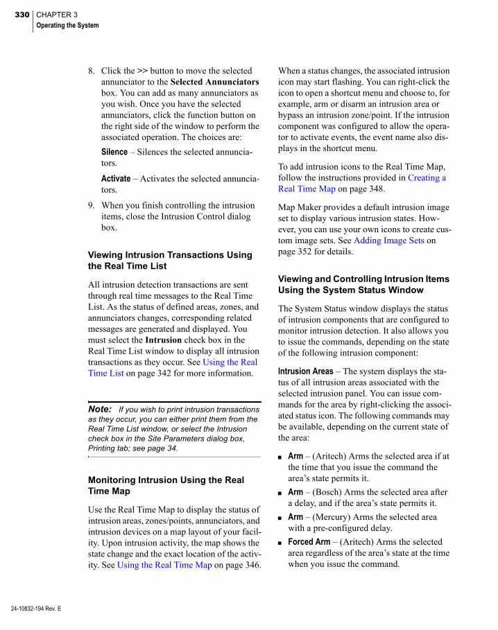
330 CHAPTER 3
Operating the System
24-10832-194 Rev. E
8. Click the >> button to move the selected annunciator to the Selected Annunciators box. You can add as many annunciators as you wish. Once you have the selected annunciators, click the function button on the right side of the window to perform the associated operation. The choices are:
Silence – Silences the selected annuncia-tors.
Activate – Activates the selected annuncia-tors.
9. When you finish controlling the intrusion items, close the Intrusion Control dialog box.
Viewing Intrusion Transactions Using the Real Time List
All intrusion detection transactions are sent through real time messages to the Real Time List. As the status of defined areas, zones, and annunciators changes, corresponding related messages are generated and displayed. You must select the Intrusion check box in the Real Time List window to display all intrusion transactions as they occur. See Using the Real Time List on page 342 for more information.
Note: If you wish to print intrusion transactions as they occur, you can either print them from the Real Time List window, or select the Intrusion check box in the Site Parameters dialog box, Printing tab; see page 34.
Monitoring Intrusion Using the Real Time Map
Use the Real Time Map to display the status of intrusion areas, zones/points, annunciators, and intrusion devices on a map layout of your facil-ity. Upon intrusion activity, the map shows the state change and the exact location of the activ-ity. See Using the Real Time Map on page 346.
When a status changes, the associated intrusion icon may start flashing. You can right-click the icon to open a shortcut menu and choose to, for example, arm or disarm an intrusion area or bypass an intrusion zone/point. If the intrusion component was configured to allow the opera-tor to activate events, the event name also dis-plays in the shortcut menu.
To add intrusion icons to the Real Time Map, follow the instructions provided in Creating a Real Time Map on page 348.
Map Maker provides a default intrusion image set to display various intrusion states. How-ever, you can use your own icons to create cus-tom image sets. See Adding Image Sets on page 352 for details.
Viewing and Controlling Intrusion Items Using the System Status Window
The System Status window displays the status of intrusion components that are configured to monitor intrusion detection. It also allows you to issue the commands, depending on the state of the following intrusion component:
Intrusion Areas – The system displays the sta-tus of all intrusion areas associated with the selected intrusion panel. You can issue com-mands for the area by right-clicking the associ-ated status icon. The following commands may be available, depending on the current state of the area:
Arm – (Aritech) Arms the selected area if at the time that you issue the command the area’s state permits it.
Arm – (Bosch) Arms the selected area after a delay, and if the area’s state permits it.
Arm – (Mercury) Arms the selected area with a pre-configured delay.
Forced Arm – (Aritech) Arms the selected area regardless of the area’s state at the time when you issue the command.
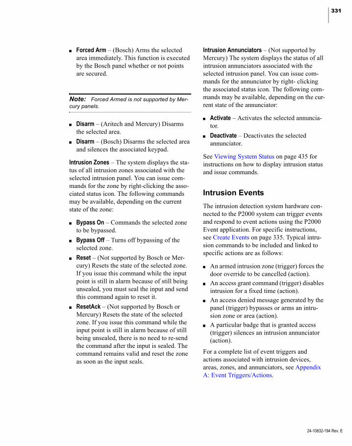
331
Forced Arm – (Bosch) Arms the selected area immediately. This function is executed by the Bosch panel whether or not points are secured.
Note: Forced Armed is not supported by Mer-cury panels.
Disarm – (Aritech and Mercury) Disarms the selected area.
Disarm – (Bosch) Disarms the selected area and silences the associated keypad.
Intrusion Zones – The system displays the sta-tus of all intrusion zones associated with the selected intrusion panel. You can issue com-mands for the zone by right-clicking the asso-ciated status icon. The following commands may be available, depending on the current state of the zone:
Bypass On – Commands the selected zone to be bypassed.
Bypass Off – Turns off bypassing of the selected zone.
Reset – (Not supported by Bosch or Mer-cury) Resets the state of the selected zone. If you issue this command while the input point is still in alarm because of still being unsealed, you must seal the input and send this command again to reset it.
ResetAck – (Not supported by Bosch or Mercury) Resets the state of the selected zone. If you issue this command while the input point is still in alarm because of still being unsealed, there is no need to re-send the command after the input is sealed. The command remains valid and reset the zone as soon as the input seals.
Intrusion Annunciators – (Not supported by Mercury) The system displays the status of all intrusion annunciators associated with the selected intrusion panel. You can issue com-mands for the annunciator by right- clicking the associated status icon. The following com-mands may be available, depending on the cur-rent state of the annunciator:
Activate – Activates the selected annuncia-tor.
Deactivate – Deactivates the selected annunciator.
See Viewing System Status on page 435 for instructions on how to display intrusion status and issue commands.
Intrusion Events
The intrusion detection system hardware con-nected to the P2000 system can trigger events and respond to event actions using the P2000 Event application. For specific instructions, see Create Events on page 335. Typical intru-sion commands to be included and linked to specific actions are as follows:
An armed intrusion zone (trigger) forces the door override to be cancelled (action).
An access grant command (trigger) disables intrusion for a fixed time (action).
An access denied message generated by the panel (trigger) bypasses or arms an intru-sion zone or area (action).
A particular badge that is granted access (trigger) silences an intrusion annunciator (action).
For a complete list of event triggers and actions associated with intrusion devices, areas, zones, and annunciators, see Appendix A: Event Triggers/Actions.
24-10832-194 Rev. E

332 CHAPTER 3
Operating the System
24-10832-194 Rev. E
Track Hours On Site
This feature allows you to record a card-holder’s accumulated number of hours present at a site. The Hours On Site application is used exclusively for tracking and reporting purposes and works by recording the cardholder’s time interval between an in badging and out badg-ing at reader terminals that are defined to mon-itor Hours on Site.
Time is accrued only from the latest in and out badging. For example, when a cardholder badges at a reader defined as an Entry Terminal, the cardholder’s time is accrued. If the same cardholder badges at the same or other Entry Terminal, the first badging is ignored and the time is accrued from the latest badging. The reverse is true for an Exit Terminal. Hours On Site accurately reports hours present between matched pairs of in and out badgings (that is, an in badging followed by an out badging, with no other badgings in between).
Configuring Hours On Site Zones
Before you initiate data collection, you must define the readers that provide real time infor-mation to track a cardholder’s time spent at a particular area.
Use readers that are related to a particular sec-tion of your facility. For example, you may want to select readers located at the entrance of a production facility that provide for the in hours, and select readers located at the exit of the facility that can be used for the purpose of reporting the out hours.
The Hours On Site feature does not determine where and when cardholders have access in and around a facility – there is no access con-trol or transaction processing associated with this function, the terminals that are selected for this feature are defined for time tracking pur-poses only.
To Define Hours On Site Zones
1. From the P2000 Main menu, select Con-fig>System. Enter your password if prompted. The System Configuration win-dow opens.
2. Select Hours On Site Zones and click Add. The Hours On Site Zone dialog box opens.
3. If this is a partitioned system, select the Partition that has access to this Hours On Site zone, and click Public if you wish the Hours on Site zone to be visible to other partitions.
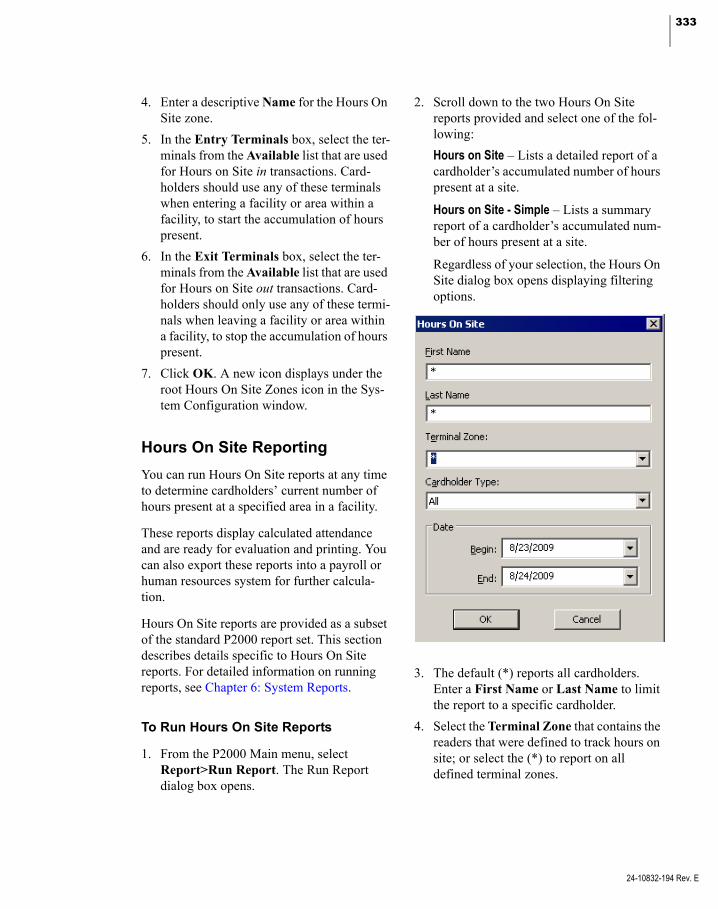
333
4. Enter a descriptive Name for the Hours On Site zone.
5. In the Entry Terminals box, select the ter-minals from the Available list that are used for Hours on Site in transactions. Card-holders should use any of these terminals when entering a facility or area within a facility, to start the accumulation of hours present.
6. In the Exit Terminals box, select the ter-minals from the Available list that are used for Hours on Site out transactions. Card-holders should only use any of these termi-nals when leaving a facility or area within a facility, to stop the accumulation of hours present.
7. Click OK. A new icon displays under the root Hours On Site Zones icon in the Sys-tem Configuration window.
Hours On Site Reporting
You can run Hours On Site reports at any time to determine cardholders’ current number of hours present at a specified area in a facility.
These reports display calculated attendance and are ready for evaluation and printing. You can also export these reports into a payroll or human resources system for further calcula-tion.
Hours On Site reports are provided as a subset of the standard P2000 report set. This section describes details specific to Hours On Site reports. For detailed information on running reports, see Chapter 6: System Reports.
To Run Hours On Site Reports
1. From the P2000 Main menu, select Report>Run Report. The Run Report dialog box opens.
2. Scroll down to the two Hours On Site reports provided and select one of the fol-lowing:
Hours on Site – Lists a detailed report of a cardholder’s accumulated number of hours present at a site.
Hours on Site - Simple – Lists a summary report of a cardholder’s accumulated num-ber of hours present at a site.
Regardless of your selection, the Hours On Site dialog box opens displaying filtering options.
3. The default (*) reports all cardholders. Enter a First Name or Last Name to limit the report to a specific cardholder.
4. Select the Terminal Zone that contains the readers that were defined to track hours on site; or select the (*) to report on all defined terminal zones.
24-10832-194 Rev. E

334 CHAPTER 3
Operating the System
24-10832-194 Rev. E
5. From the Cardholder Type drop-down list, select whether you want to report on Regular cardholders, Visitors, or All.
6. Select a Begin and End date for the trans-actions you wish to see. Only records within these dates are listed in the report.
7. Click OK. Select a printer name and any other information for the printer to be used. See your system administrator if you need more information, or refer to your Micro-soft Windows documentation.
8. Click OK. The Hours On Site report dis-plays in the Crystal preview window. The top section of the report displays informa-tion according to the filtering options that you selected in the Hours On Site dialog box. You can use the arrows at the top of the window to scroll forward and back through the pages; resize the window for the best display, and export or print all or single pages of the report.
Hours On Site (Detail) Report
This report provides detail cardholder activity based on your selected search criteria. The report displays the cardholder name, badge number used, specific terminal name where the badge was presented, the terminal zone that contains the specified terminal, and the in and out date and time when the cardholder badged at the terminal. In addition, this report also dis-plays the total number of hours on site per day, per badge, and for the entire report.
This information is updated each time the card-holder badges at the terminals included in Hours On Site zones.
Note that records marked with an asterisk (*) indicate out of sequence in or out times. This occurs when:
a cardholder badged more than once at des-ignated in readers without badging at an out reader
a cardholder badged more than once at des-ignated out readers without badging at an in reader
a cardholder badged in and no subsequent out badging occurred on that calendar day
the first badging of the first day of the report is an out
the last badging of the last day of the report is an in.
The asterisk could also indicate that the report might be displaying incomplete badging infor-mation, depending on what time of day and date the report is run.
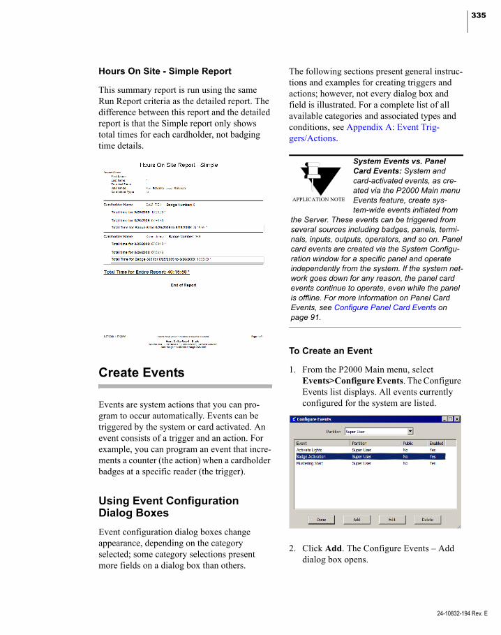
335
Hours On Site - Simple Report
This summary report is run using the same Run Report criteria as the detailed report. The difference between this report and the detailed report is that the Simple report only shows total times for each cardholder, not badging time details.
Create Events
Events are system actions that you can pro-gram to occur automatically. Events can be triggered by the system or card activated. An event consists of a trigger and an action. For example, you can program an event that incre-ments a counter (the action) when a cardholder badges at a specific reader (the trigger).
Using Event Configuration Dialog Boxes
Event configuration dialog boxes change appearance, depending on the category selected; some category selections present more fields on a dialog box than others.
The following sections present general instruc-tions and examples for creating triggers and actions; however, not every dialog box and field is illustrated. For a complete list of all available categories and associated types and conditions, see Appendix A: Event Trig-gers/Actions.
System Events vs. Panel Card Events: System and card-activated events, as cre-ated via the P2000 Main menu Events feature, create sys-tem-wide events initiated from
the Server. These events can be triggered from several sources including badges, panels, termi-nals, inputs, outputs, operators, and so on. Panel card events are created via the System Configu-ration window for a specific panel and operate independently from the system. If the system net-work goes down for any reason, the panel card events continue to operate, even while the panel is offline. For more information on Panel Card Events, see Configure Panel Card Events on page 91.
APPLICATION NOTE
To Create an Event
1. From the P2000 Main menu, select Events>Configure Events. The Configure Events list displays. All events currently configured for the system are listed.
2. Click Add. The Configure Events – Add dialog box opens.
24-10832-194 Rev. E
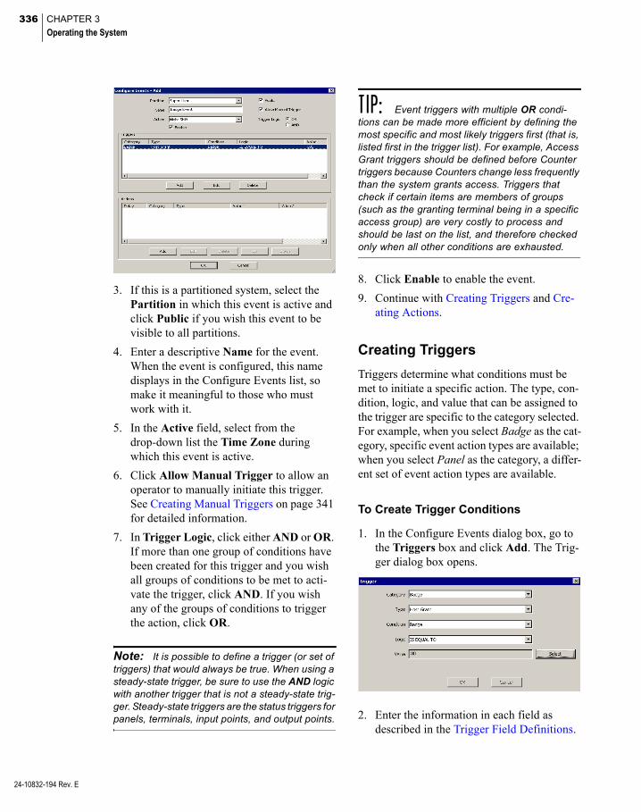
336 CHAPTER 3
Operating the System
24-10832-194 Rev. E
3. If this is a partitioned system, select the Partition in which this event is active and click Public if you wish this event to be visible to all partitions.
4. Enter a descriptive Name for the event. When the event is configured, this name displays in the Configure Events list, so make it meaningful to those who must work with it.
5. In the Active field, select from the drop-down list the Time Zone during which this event is active.
6. Click Allow Manual Trigger to allow an operator to manually initiate this trigger. See Creating Manual Triggers on page 341 for detailed information.
7. In Trigger Logic, click either AND or OR. If more than one group of conditions have been created for this trigger and you wish all groups of conditions to be met to acti-vate the trigger, click AND. If you wish any of the groups of conditions to trigger the action, click OR.
Note: It is possible to define a trigger (or set of triggers) that would always be true. When using a steady-state trigger, be sure to use the AND logic with another trigger that is not a steady-state trig-ger. Steady-state triggers are the status triggers for panels, terminals, input points, and output points.
TIP: Event triggers with multiple OR condi-tions can be made more efficient by defining the most specific and most likely triggers first (that is, listed first in the trigger list). For example, Access Grant triggers should be defined before Counter triggers because Counters change less frequently than the system grants access. Triggers that check if certain items are members of groups (such as the granting terminal being in a specific access group) are very costly to process and should be last on the list, and therefore checked only when all other conditions are exhausted.
8. Click Enable to enable the event.
9. Continue with Creating Triggers and Cre-ating Actions.
Creating Triggers
Triggers determine what conditions must be met to initiate a specific action. The type, con-dition, logic, and value that can be assigned to the trigger are specific to the category selected. For example, when you select Badge as the cat-egory, specific event action types are available; when you select Panel as the category, a differ-ent set of event action types are available.
To Create Trigger Conditions
1. In the Configure Events dialog box, go to the Triggers box and click Add. The Trig-ger dialog box opens.
2. Enter the information in each field as described in the Trigger Field Definitions.

337
3. When all information is completed, click OK to save the trigger conditions and return to the Configure Events dialog box. The new conditions are listed in the Trig-gers list.
Note: Event triggers that use steady-state con-ditions, which can be modified by other event actions such as Output Status and Host Count-ers, may not be triggered reliably when AND is used with other conditions. For example, creating two triggers that activate when a badge is pre-sented at a door and a counter is set at a certain value, may fail if one of the actions changes the value of the counter.
Trigger Field Definitions
Category – Select a category from the drop-down list.
Type – Select a type from the drop-down list. The types available for selection are limited to those appropriate to the category selected.
Condition – Select a condition from the drop-down list. The conditions available are limited to those appropriate for the category and type selected.
Logic – Select the logic that applies to the con-dition from the drop-down list. The choices are: is equal to, is not equal to, is less than or equal to, is greater than or equal to, is less than, and is greater than.
Value – Click Select to select a value that applies from the Select list. For example, if the category is Badge you could select is less than or equal to and select a badge number from the list to create the condition all badges less than or equal to a specific badge number.
In the previous example, we have created a trigger using the Badge category, with a type Host Grant that triggers an event action if the value (in this case, the badge number) is equal to 30.
To Edit a Trigger Condition
1. From the Configure Events list, select an event and click Edit. The Configure Events dialog box opens, displaying the current settings for that event.
2. In the Triggers box, select the trigger you wish to change and click Edit. The Trigger dialog box opens.
3. Change the selections as appropriate and click OK to return to the Configure Events dialog box. The Triggers list reflects the changes.
Creating Actions
An Action, as defined in the Actions list at the bottom of the Configure Events dialog box, is performed by the system when the related trig-ger occurs. You can program a wide variety of event actions using the Category and Type fields provided in the Action dialog box. As with Triggers, the Action types available depend on the Category type selected.
An event can trigger more than one action. You can create several actions and specify in what order the actions occur.
24-10832-194 Rev. E

338 CHAPTER 3
Operating the System
24-10832-194 Rev. E
To Create an Action
1. In the Configure Events dialog box, go the Actions box at the bottom of the dialog box and click Add. The Action dialog box opens.
2. Enter the information according to Event Actions Field Definitions.
3. When all conditions are defined, click OK to return to the Configure Events dialog box. The new Action displays in the Actions list.
4. Continue to add actions as required.
To Change Event Action Order of Occurrence
1. From the Actions box at the bottom of the Configure Events dialog box, select an action line.
2. Click Up or Down at the bottom of the dia-log box to move the line item as desired. The action displayed at the top of the list occurs first.
Event Actions Field Definitions
The available fields to define any Action are dependent on which category is selected. Because there are so many combinations of categories, types, and related selections, the following list of field definitions contains only a sampling of available fields. For a complete list of categories and related selections, see Appendix A: Event Triggers/Actions.
Order – If more than one action has been defined for this trigger, the order of the action displays in this field. For example, if the action selected is first in the Action list, this field dis-plays 1. You should define a delay between event actions to avoid executing them in ran-dom order.
Delay (H:M:S) – Select hour, minutes, and sec-onds from the spin box to enter a delay time after which the action occurs. This would be useful with an anti-passback action, for exam-ple.
Note: Delayed event actions should not con-tain macros. The information needed for the mac-ros is not available when the action is delayed. Also, event actions that need information from a trigger cannot be delayed.
Category – Select a category from the drop-down list. The category selected deter-mines what Action types are available.
Type – Select a type from the drop-down list. The type selected may add, remove, or change any additional fields available for definition. For example, when Increment Counter is selected as the Type for the Host Category, an additional field is created that lists the counters available.

339
If Display Message is selected as the Type for the Host Category, additional fields are added from which to select the Instruction Text to be used and the workstation on which to display the message.
OPC Server Event Actions
IMPORTANT: Do not configure OPC Server Event actions before reading and understanding OPC Server. If OPC Server Event actions are not configured correctly, the equipment may not work properly.
The following applies to OPC (OLE for Pro-cess Control) Server events:
If the computer on which the selected Server resides is switched OFF, then the event would have no effect.
However, if the computer is ON and the OPC Server has been switched OFF, then the event would only be acted upon if the appropriate launch and access rights are granted.
Similarly, if the computer and the OPC Server are running, then the event would only be acted upon if it has the correct access rights (that is, the sending user and password must be correctly set up at the receiving computer together with the cor-rect DCOM rights). Note that the setup is correct when the software is installed.
To select an OPC Server and view the avail-able tags, a tag browser is provided in the event Action dialog box. Note that to select an OPC Server, the OPC Server must be running and you must have the appropriate rights.
1. In the Action dialog box, click the Cate-gory drop-down list and select OPC Server.
2. From the Type drop-down list select OPCWrite.
3. To select an OPC Tag from those available for the selected OPC Server, click the [...] button. The Items dialog box opens.
4. Click the [...] button to locate the OPC Server, or select the Server from the OPC Servers drop-down list.
5. Select the Data Type (the default option is Use native type, which displays all tags).
6. In the Browse Items box, select the item and the tag for the event action.
The selected item displays in the Item Name field.
24-10832-194 Rev. E
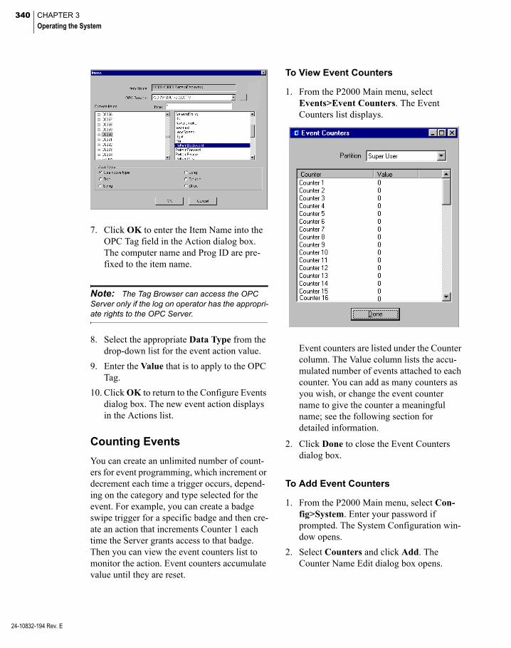
340 CHAPTER 3
Operating the System
24-10832-194 Rev. E
7. Click OK to enter the Item Name into the OPC Tag field in the Action dialog box. The computer name and Prog ID are pre-fixed to the item name.
Note: The Tag Browser can access the OPC Server only if the log on operator has the appropri-ate rights to the OPC Server.
8. Select the appropriate Data Type from the drop-down list for the event action value.
9. Enter the Value that is to apply to the OPC Tag.
10. Click OK to return to the Configure Events dialog box. The new event action displays in the Actions list.
Counting Events
You can create an unlimited number of count-ers for event programming, which increment or decrement each time a trigger occurs, depend-ing on the category and type selected for the event. For example, you can create a badge swipe trigger for a specific badge and then cre-ate an action that increments Counter 1 each time the Server grants access to that badge. Then you can view the event counters list to monitor the action. Event counters accumulate value until they are reset.
To View Event Counters
1. From the P2000 Main menu, select Events>Event Counters. The Event Counters list displays.
Event counters are listed under the Counter column. The Value column lists the accu-mulated number of events attached to each counter. You can add as many counters as you wish, or change the event counter name to give the counter a meaningful name; see the following section for detailed information.
2. Click Done to close the Event Counters dialog box.
To Add Event Counters
1. From the P2000 Main menu, select Con-fig>System. Enter your password if prompted. The System Configuration win-dow opens.
2. Select Counters and click Add. The Counter Name Edit dialog box opens.

341
3. If this is a partitioned system, select a Par-tition where the counter applies and click Public if you wish this counter to be visi-ble to all partitions.
4. Enter a descriptive Name for the counter.
5. Click OK. The new counter displays beneath the main Counters icon.
To Reset Event Counters
1. From the P2000 Main menu, select Sys-tem>Database Maintenance. Enter your password if prompted. The Database Maintenance dialog box opens.
2. Under Maintenance Action, select Reset Counters to Zero.
3. Click Perform. Since this action cannot be undone, a verification message displays to confirm your action.
4. Click Yes if you wish to reset counters to zero. The Reset Counters dialog box opens.
5. If this is a partitioned system, select the Partition in which the counters are active.
6. Click Reset to Zero. All values in the Event Counters list are reset to zero.
7. Click Done to return to the Database Maintenance dialog box.
8. Click Exit.
Creating Manual Triggers
Triggers can be programmed to be activated manually by an operator. In this case, the Con-figure Events window is set to Allow Manual Trigger and linked to an action. The event is then initiated by the operator from the Events>Trigger Manually menu, rather than by trigger conditions set up in the Configure Events window.
Note: Events can also be manually initiated by an operator from the Alarm Monitor window (see page 277), as long as the item that generated the alarm was configured to activate events; or can also be manually initiated from the Real Time Map (see page 348), regardless if the Allow Manual Trigger option was enabled in the Con-figure Events dialog box.
To Manually Trigger an Event
1. From the P2000 Main menu, select Events>Trigger Manually. The Trigger Manually dialog box opens.
2. All the events that have the Allow Manual Trigger option selected in the Configure Events window display in the list.
3. Select an event from the list, and click Perform. The trigger is activated.
4. Click Done to close the window.
24-10832-194 Rev. E

342 CHAPTER 3
Operating the System
24-10832-194 Rev. E
Monitor the System in Real Time
The Real Time List and Real Time Map are dynamic displays of system transactions and operations. The Real Time List is a time-stamped display of all (or specified) local or remote transactions as they occur. The Real Time Map displays the current status of local terminals, inputs, outputs, and other defined elements on a map layout of your site. The Real Time List and Real Time Maps are typi-cally used by operators and system administra-tors not only to view current status, but as trou-bleshooting tools.
Note: HID panels do not report transactions associated with lock or output point status changes. Point status may appear as ‘Unknown” on the Real Time List and Real Time Map.
Using the Real Time ListThe Real Time List is a time-stamped display of all system transactions as they occur. If desired, an operator can monitor only specific transaction types. For example, an operator concerned with learning when a cardholder is denied access can select only Access Deny to filter the information displayed. The Real Time List then displays only who, what, when, where, and why the access was denied.
You can open multiple windows of the Real Time List. For example, you could have one window open with all the types enabled. You could open a second window with only the Badge Trace option selected that would display only those transactions.
Note: A description of each transaction type is presented in the Printing tab of Site Parameters on page 34. The Printing function of Site Parame-ters operates independently from the Real Time List function.
A system administrator may want to look at the Real Time List as a health check; for example, to ensure all transaction types are being pro-cessed, or trace why a specific cardholder is being denied access.
Monitoring Remote Messages in Real Time
As with remote alarm monitoring (page 272), you can monitor transactions from multiple facilities at multiple geographical locations. Although each remote site administrator has total control over their access control hardware and system information related to their site, operators can control system and event infor-mation from different sites. This means that remote operators might, for example, monitor their transactions locally during normal work-ing hours, while your local operators might monitor transactions messages generated at their remote sites after hours, as long as both the local and remote P2000 sites are set up and con-figured to receive and send transaction mes-sages across P2000 sites during such periods.
With the proper configuration, an unlimited number of sites can be monitored simultane-ously, allowing operators to administer multi-ple regions from a single site. To monitor remote messages, both your local and the remote sites have to be properly configured. The following conditions must be met:
The Remote Message Service must be up and running at both the remote site (to send the transaction messages) and at your local site (to receive the transaction messages). See Starting and Stopping Service Control on page 432.
The Message Filter Configuration appli-cation (page 223), must be properly config-ured at your local site and each remote site, to control the type of messages transmitted between Servers, thereby reducing network traffic by transmitting only messages that pass the filter criteria.
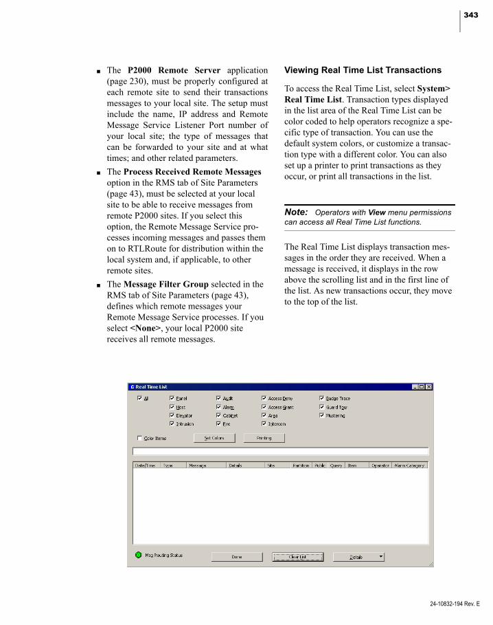
343
The P2000 Remote Server application (page 230), must be properly configured at each remote site to send their transactions messages to your local site. The setup must include the name, IP address and Remote Message Service Listener Port number of your local site; the type of messages that can be forwarded to your site and at what times; and other related parameters.
The Process Received Remote Messages option in the RMS tab of Site Parameters (page 43), must be selected at your local site to be able to receive messages from remote P2000 sites. If you select this option, the Remote Message Service pro-cesses incoming messages and passes them on to RTLRoute for distribution within the local system and, if applicable, to other remote sites.
The Message Filter Group selected in the RMS tab of Site Parameters (page 43), defines which remote messages your Remote Message Service processes. If you select <None>, your local P2000 site receives all remote messages.
Viewing Real Time List Transactions
To access the Real Time List, select System> Real Time List. Transaction types displayed in the list area of the Real Time List can be color coded to help operators recognize a spe-cific type of transaction. You can use the default system colors, or customize a transac-tion type with a different color. You can also set up a printer to print transactions as they occur, or print all transactions in the list.
Note: Operators with View menu permissions can access all Real Time List functions.
The Real Time List displays transaction mes-sages in the order they are received. When a message is received, it displays in the row above the scrolling list and in the first line of the list. As new transactions occur, they move to the top of the list.
24-10832-194 Rev. E

344 CHAPTER 3
Operating the System
24-10832-194 Rev. E
When you open the Real Time List for the first time in the session, the scrolling list is empty. Depending on the transaction types selected at the top of the window, transactions begin to display in date and time order at the top of the list. As transactions occur, the older ones scroll down in the list as the newer ones are added at the top.
The following information is shown for each transaction in the list.
Date/Time – Displays the date and time of the message. Transaction messages that are origi-nated at remote sites with different geographi-cal time zones display the actual time at the remote site. However, remote alarms display the time at which they were received at your local site.
Note: Workstation messages display the same timestamp as their servers, regardless of the time zone configuration of the workstation or the server.
Type – Displays the transaction types that were selected for monitoring (Audit, Access Deny, Badge Trace, and so on).
Message – Displays a message related to the transaction type, for example, Invalid Card for an Access Deny transaction type.
Details – Displays details related to the mes-sage, such as Badge number, Terminal and Cardholder name.
Site – Displays the name of the local or remote P2000 site where the message was originated.
Partition – Normally displays the name of the partition containing the item (input point, ter-minal, panel, and so on) associated with the message.
Public – If the item associated with the mes-sage is marked as Public, this column normally displays whether the message is visible to other partitions.
Query – Displays the query string value (if it was defined) of the item associated with the message.
Item – Displays the name of the item (panel, terminal, input point, and so on) that is associ-ated with the message.
Operator – Displays the name of the operator who handled the message (alarms in non pend-ing state or audit messages only).
Alarm Category – Displays the Alarm Category to which the associated alarm belongs.
Note: The Message Routing Status indicator at the bottom of the Real Time List window displays in green to indicate that all communications between the workstation and the Server are up. If communications go down, the Message Routing Status indicator turns red.
Note: If your facility uses the DVR/VMS feature and the selected transaction message displayed is associated with a camera, click Details located at the bottom of the window to start the AV Player in live mode. As an alternative, you can click the Details drop-down arrow and select AV Player (Live) to start AV Player in live mode or select AV Player (Stored) to start AV Player in video retrieval mode. For more information, refer to your DVR/VMS documentation.
To View all Options in the Real Time List
1. In the Real Time List window, click All from the options at the top of the window. All transactions begin to accumulate in the scrolling list.
To View Specific Options in the Real Time List
1. Click to clear the All option and select only those options you wish to view. Only those options begin to accumulate in the scroll-ing list.

345
To Display Color-Coded Transactions
1. Click Color Items. All transactions dis-play in a different color, using the default system colors.
2. To display a transaction type with a differ-ent color, click Set Colors. The Set Colors dialog box opens.
3. Select a transaction type, then click Select. A Color dialog box opens.
4. Select the desired color and click OK to return to the Set Colors dialog box.
5. Click Defaults if you wish to reset the col-ors to the default system colors.
6. Click OK to return to the Real Time List window.
To Display Cardholder Details
1. Select from the scrolling list, the transac-tion line item associated with a cardholder (Access Deny, Access Grant or Badge Trace transactions).
2. Click the Details drop-down arrow located at the bottom of the window, and select Cardholder Info. The Cardholder Info dialog box opens.
The top portion of the window shows the cardholder details including image, if available.
The bottom portion includes a chronologi-cal list of badge transactions associated with the cardholder.
3. If you wish to manually adjust the In or Out state of a badge until next badging, click Set Undefined.
4. To change the number of transactions dis-played, enter the desired number in the Num Records field.
5. To update the list box with new data, click Refresh.
6. Click Done to return to the Real Time List.
Printing the Real Time List
An operator can print from the workstation, all (or all displayed) transactions in the Real Time List, or print individual transactions as they occur.
IMPORTANT: Real time printing is not guaran-teed on foreign language systems.
Printers must first be set up using the Win-dows Printer Settings dialog box. See your system administrator if you need more infor-mation, or refer to your Microsoft Windows documentation.
24-10832-194 Rev. E

346 CHAPTER 3
Operating the System
24-10832-194 Rev. E
To Print the Real Time List
1. In the Real Time List window, click Print-ing in the top portion of the window. The Printing dialog box opens.
2. Click Print Displayed to print the transac-tions that are visible in the Real Time List box, or click Print All to print all transac-tions in the list.
3. Select a printer name and any other infor-mation for the printer to be used.
4. Click OK to start printing.
To Print Real Time List Line Items
1. In the Real Time List window, click Print-ing in the top portion of the window. The Printing dialog box opens.
2. Click Enable Printing. Line items contin-uously print as long as the Real Time List window is open or minimized on the work-station. Line items stop printing when the Real Time List window is closed.
3. Click Setup to select a printer name and any other information for the printer to be used.
Note: We recommend a dot matrix printer be used exclusively for printing line items from the Real Time List, and independently from the trans-actions printed from the Site Parameters window.
4. Click OK. The printer name displays.
5. Click OK to enable printing.
Note: Printing transactions from the Real Time List (performed from a workstation) is different from Real Time Printing (performed at the System Server). For information on Real Time Printing, see Site Parameters Printing Tab on page 34.
Using the Real Time Map
The Real Time Map displays the current status of terminals, inputs, outputs, and other defined elements on a map layout of your facility and can be used similarly to the System Status win-dow. Maps are created using the Map Maker feature to drag-and-drop dynamic icons to their actual locations on imported layout images. All you need are simple layout maps that can be scanned or drawn in any draw application, then saved in an importable format.
Once the maps are created, they are accessed from the P2000 System menu. If a terminal goes down or an alarm sets, the Real Time Map shows you the state change and exactly where the device is located.
Sub Maps and Attachments
You can create facility-level maps and attach sub maps (Normal and Popup maps) that detail specific areas in the facility. Sub maps may also contain sub maps to add further detail; you can create as many levels as you need.
If an alarm sets in an area detailed in a sub map, the sub map icon blinks, indicating the location of the alarm. You can double-click the blinking sub map icon to jump to the associ-ated detail map. (See Add Map Attachments on page 352 for more information about creat-ing multi-level maps.)

347
Map Maker provides image sets to display var-ious device states such as panel up, panel down, input set, and so on. However, you can create your own icons and include them in image sets in Map Maker. See Adding Image Sets on page 352 for details.
Note: The Message Routing Status indicator at the bottom of the Real Time Map window dis-plays in green to indicate that all communications between the workstation and the Server are up. If communications go down, the Message Routing Status indicator turns red.
To View the Real Time Map
1. From the P2000 Main menu, select Sys-tem>Real Time Map. The Real Time Map window opens.
2. The current status of Panels, I/O Terminals, Readers, Input and Output points, and other defined elements display as designed in Map Maker. The Main Map displays as assigned on Map Maker; however, you can select any map created in the system.
Note: Icons that are crossed out with a yellow bar indicate that the items’ parent devices are not functioning. For example, an input point is marked as unreliable if its parent terminal or panel is down.
Note: If your facility uses the DVR/VMS fea-ture, when you right-click a map icon that is asso-ciated with a camera, a pop-up menu displays the AV Player (Live) option. If there are stored vid-eos (associated with alarms), the pop-up menu displays the Show Alarm Video and Start Recording options. For more information, refer to your DVR/VMS documentation.
3. From the drop-down list at the bottom of the window, select the name of the map you wish to view. The list only displays Normal maps.
4. If your facility uses Map Attachments, click Prev to return to the previous map, or click Home to return to the main facil-ity-level map. Clicking Up level takes you to the previous facility-level map.
Note: The Prev, Home, and Up level naviga-tion tools are not used with Popup Map Attach-ments.
5. Use the slider control to enlarge or reduce the view of the active map. The zooming of the map can also be controlled with the mouse wheel. You can also use keyboard commands to enlarge or reduce the view of the active map. Use the Up or Left arrow keys to reduce the view and the Down or Right arrow keys to enlarge the view.
6. Click Done to exit the window.
24-10832-194 Rev. E

348 CHAPTER 3
Operating the System
24-10832-194 Rev. E
Unlocking a Door
You can unlock a door from a Real Time Map. The door remains unlocked for the time con-figured in the door terminal’s access settings, and then locks. Use the instructions in Place Device Icons on a Real Time Map on page 350 to insert a door icon.
Note: The Open Door command does not unlock Assa Abloy Wi-Fi readers, since those readers are normally not connected to the P2000 system.
Note: The Open Door command does not unlock doors on S321-IP panels, as this function-ality is not supported by these devices. To do so you must use the Unlock function on the Door Control application.
Note: For doors on a CK721-A panel whose terminal has the Log Reader Strike Message flag selected, the map icon image for the terminal changes from a closed door to an opened door, as long as the door is unlocked, then reverts back to a closed door image when the door locks.
To Unlock a Door from a Real Time Map
1. Locate the door terminal icon for the door you wish to unlock.
2. Right-click the icon and select Open Door from the shortcut menu. The door unlocks for the configured time period, then locks.
Note: If you need to unlock the door for a period other than that configured, you must do so using the Door Control function.
Activating Events from the Real Time Map
Events can be manually activated by an opera-tor from the Real Time Map, rather than by the trigger conditions set up in the Configure Events dialog box. Icons on the Real Time Map, such as Panels, Terminals or Input Points, can be configured to initiate events; or you can just place Event icons on the Map.
To Activate an Event from a Real Time Map
1. In the Real Time Map, locate the icon that contains the event you wish to activate.
2. Right-click the icon and select the Event name from the shortcut menu. The event is triggered.
Creating a Real Time Map
The following steps allow you to create a Real Time Map:
Set up the Map Maker Window
Create an Importable Image
Import an Image to Map Maker
Place Device Icons on a Real Time Map
Add Map Attachments
Duplicate Maps
Set up the Map Maker Window
1. From the P2000 Main menu, select Con-fig>Map Maker. The Map Maker dialog box opens.

349
2. Click Add. The Map Editor window opens.
3. If this is a partitioned system, select the Partition in which the map is active and click Public if you wish the map to be vis-ible in all partitions.
4. Enter a descriptive Map Name.
5. From the drop-down list, on the right side of the Map Name, select one of the follow-ing options:
System – A system map automatically dis-plays when you open the Real Time Map. You can only create one system map. The system map displays any defined sub maps (Normal or Popup).
Normal – A normal map is a sub map that can be used as a Map Attachment or Popup Map Attachment on another map. It can also be selected from the drop-down list at the bottom of the Real Time Map window.
Popup – A pop-up map is a sub map that can be used as a Map Attachment or Popup Map Attachment on another map. It is not selectable from the Real Time Map drop-down list.
Note: Normal and Popup maps that are used as Popup Map Attachments do not provide tools to navigate to other maps.
Create an Importable Image
Map Maker can import most popular image formats: .bmp, .tif, .wmf, .jpg, .pcx, and .eps, to name a few. (To see all available formats, see the Files of type drop-down list when you click the Import button.)
1. If floor plans or maps exist in a compati-ble electronic format, you can import them directly.
2. If floor plans or maps exist in hard copy, have them scanned and saved in a compat-ible format.
3. If floor plans or maps do not exist, you can create them using a draw program such as Microsoft Paint, CorelDRAW®, or other drawing utility, then save or export the image in a compatible format.
4. Copy the image file to a directory that is accessible to the P2000 system.
Import an Image to Map Maker
1. From the P2000 Main menu, select Con-fig>Map Maker. The Map Maker dialog box opens.
2. Click Add. The Map Editor window opens.
3. In the Map Image box at the bottom of the window, click Import and navigate to the directory in which your layout image is stored.
4. Select an image to import.
5. Click Open. The image displays in the background of the image area of the Map Editor window. You can use the mouse pointer to pull the corners and sides of the window to increase the size as necessary, or click the maximize/minimize button in the top right of the window.
24-10832-194 Rev. E

350 CHAPTER 3
Operating the System
24-10832-194 Rev. E
Note: If you wish to export the map image, click Export. Navigate to the directory where the exported map is stored, give it a name, and select the file type and other related parameters.
Place Device Icons on a Real Time Map
When you open Map Maker, map icons repre-senting Panels, Terminals, Inputs, Outputs, and other system elements are listed on the right windowpane.
Note: If your facility uses advanced features, such as Intercom or DVR/VMS, the associated map icons display in the list. See the respective section in Chapter 4: Advanced Features, for more information.
1. Expand the element you wish to add. To add an input point for example, click the plus (+) sign next to the Input Point icon. An Input icon is added under it.
Note: Placing an Assa Abloy Wi-Fi reader on a Real Time Map has little value, as those readers do not provide real time information to the P2000 system.
2. Use the left mouse button to drag the new icon to the desired position on the map. For example, an input point could be dragged near the door representing where the input point is actually installed. When you release the mouse button, a Properties dia-log box opens.
TIP: The top left corner of the icon is anchored exactly where the tip of the mouse pointer is released.
351
3. In the Label field, enter a descriptive name that can easily identify the icon in the Real Time Map. This name displays under the icon on your layout.
4. The Font box displays the default font or the font selected for the icon name.
5. In the Font Size box enter the font size for the name appearing under the icon.
6. To make all font changes at once, click Choose Font and select a font type, style, and size for the name appearing under the icon.
7. If you wish to change the Font Style, select from the drop-down list whether the text should be Bold, Bold Italic, Italic, or Normal.
8. To display the text in a different color, click the Text Color browse button [...] and select a color from the Color dialog box.
9. Click the Background Color browse but-ton [...] to open the Color dialog box and select the background color for the icon name.
10. Click Transparent Background if you wish the background of the text to be trans-parent.
11. From the Text Position drop-down list, select whether you want to place the text at the Bottom, Left, Right, or Top of the icon.
12. Select from the drop-down list the name of the item you wish to place in the map. If you are placing an input point, all available input points (or all input points in the parti-tion selected) display in the drop-down list. If you are placing a panel, the drop-down list includes all panels (or all panels in the partition).
Note: You can also place static text objects in the map to indicate for example, the name of an entire area, or a number to dial in case of emer-gency.
13. To assign events to the item, enter a descriptive event name and select a previ-ously configured event from the associated drop-down list. You can define up to four events for each map icon.
14. Click OK to close the Properties dialog box. The icon is inserted in the map.
15. Repeat the same steps for each device or event you wish to add to the map.
16. When all elements have been added, click OK to close the Map Editor window. The map is now available to choose from the Real Time Map drop-down list.
17. Click Done to close the Map Maker dialog box.
Handling Alarms from the Real Time Map
You can place an Alarm Category icon on a Real Time Map and issue commands for all P2000 items that generate alarms, (such as input points or cameras) and that use the Alarm Category selected.
When an alarm is reported in the system, the Alarm Category icon flashes on the map. You can right-click the icon to issue from a shortcut menu one of the alarm commands (acknowl-edge, respond, or complete). If you select Acknowledge or Complete, all alarms that use the Alarm Category selected are acknowl-edged or completed at once. However, if you select Respond, the Alarm Monitor window displays so you can respond to each alarm by entering specific instructions for each particu-lar alarm.
In addition, the shortcut menu allows you to open the Alarm Monitor window or display the alarm details associated with the Alarm Category selected.
24-10832-194 Rev. E

352 CHAPTER 3
Operating the System
24-10832-194 Rev. E
Add Map Attachments
You can add map attachments to Real Time Maps that, when right-clicked, can open another map. For example, you can place a map attachment on the Office map that can open the Warehouse map. Or you can place several area map attachments on the System Map.
To Add a Map Attachment
1. From the P2000 Main menu, select Con-fig>Map Maker. The Map Maker list box opens.
2. Select the map to which you wish to add a map attachment.
3. Click Edit. The Map Editor window opens with the selected map in the image area.
4. Drag a Map Attachment icon to the image area. When you release the mouse button, select from the drop-down list the map you wish to attach.
5. Click OK. Now when you open the map in Real Time Map, you can right-click the Attachment icon and select Open to open the attached map.
Duplicate Maps
The Duplicate Map feature allows the duplica-tion of existing maps. This feature is useful in buildings where the layout is the same throughout all floors. You can create a master map with default information, and then use that map as a template to create additional maps. All current map information is copied; however, each map must have a unique name.
To Duplicate a Map
1. From the P2000 Main menu, select Con-fig>Map Maker. The Map Maker list box opens.
2. Select the map you wish to duplicate and click the Duplicate button. The Duplicate Map dialog box opens.
3. Enter the New Map Name.
4. Click Keep Items if you wish to keep all items from the master map.
5. Click Keep Item Labels if you wish to keep the labels from the master map.
6. Click Keep Item References if you wish to keep all references from the master map.
7. Click OK to create the new map. The Map Editor window opens displaying the selected items. Make any additional changes if necessary.
Adding Image Sets
Map Maker provides image sets to display var-ious device states such as panel up, panel down, input set, and so on. However, you can use your own icons to create custom image sets.
To Create a Custom Image Set for Map Maker
1. From the P2000 Main menu, select Con-fig>Icon Editor. The Icon Editor dialog box lists the default image set names.

353
2. Click Add. The Image Set Bitmap Editor opens.
3. Select the Image Set Type you wish to create. The default image for each state displays in the Icon list.
4. Enter an Image Set Name for the new image set.
5. Select an icon from the list, and click one of the following function buttons:
Edit – The Edit Button Image dialog box opens. Use the editing tools and colors to edit the existing icon. Click OK to save.
Import – Select if you wish to replace the existing icon. Navigate to the directory where your new images are stored, select the image and click Open. The default icon in your new image set is replaced with the new icon.
Export – Select if you wish to export the existing icon.
6. Click OK. Your new image set displays in the Icon Editor list, and is now accessible from the right windowpane in the Map Editor window.
24-10832-194 Rev. E

354 CHAPTER 3
Operating the System
24-10832-194 Rev. E
355
Chapter 4: Advanced Features
his chapter describes several advanced DVR/VMS – Provide controls to search,
T features that, when properly config-ured and utilized, allow for a more secure and efficient way to operate andmonitor your access control system. Some of these features are bundled separately from the P2000 software, and some of them are shipped with their own manuals. Refer to your pur-chase contract to see what is available in your system. This chapter presents the information you need to set up and configure each of the following features:
Partitions – Divide your P2000 system data-bases into sections that can be managed individually.
Video Imaging – Improve your security by creating badges to provide a visual identifi-cation of every cardholder.
MIS Interface – Add, update, delete, or query the P2000 cardholder database from an external database system.
pivCLASS Integration – Support of Federal Identity, Credential, and Access Manage-ment (FICAM) compliant smart cards and readers.
Metasys System Integration – Allow several P2000 security tasks to be handled via the Metasys system user interface.
Guard Tour – Define a sequence of transac-tions that must occur at specific intervals to ensure security personnel properly monitors your facility.
CCTV – Provides controls to operate cam-eras, monitors, and other CCTV elements.
retrieve, and download real-time or archived audio and video recording from surveillance cameras.
Redundancy – Run the P2000 software in a recovery configuration to ensure uninter-rupted operations.
FDA Part 11 – Define parameters to assure FDA Title 21, Code of Federal Regulation (CFR) Part 11 compliance.
Intercom – Define and control intercom calls from P2000 Workstations.
P2000 Enterprise – Allow multiple P2000 sites to communicate with each other to share cardholder and badge data.
Web Access – Perform various P2000 tasks from any Web-ready computer.
Partitions
You can divide the P2000 database into smaller sections that can be individually managed. Par-titions structure what data is accessible by an individual operator, or by a group of operators. You can create as many partitions as you need, depending on your system requirements. For example, if you manage a building with sev-eral tenants, you could use partitions to segre-gate the databases and system functions, so that Tenant A cannot see, access, or change Tenant B’s records.
Operators select the partition to which they are assigned, from the Partition selection box on the right side of the P2000 toolbar.
24-10832-194 Rev. E
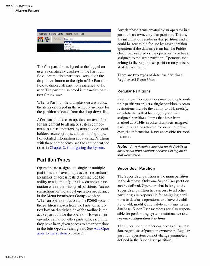
356 CHAPTER 4
Advanced Features
24-10832-194 Rev. E
The first partition assigned to the logged on user automatically displays in the Partition field. For multiple partition users, click the drop-down button to the right of the Partition field to display all partitions assigned to the user. The partition selected is the active parti-tion for the user.
When a Partition field displays on a window, the items displayed in the window are only for the partition selected from the drop-down list.
After partitions are set up, they are available for assignment to all major system compo-nents, such as operators, system devices, card-holders, access groups, and terminal groups. For detailed information about using Partitions with these components, see the component sec-tions in Chapter 2: Configuring the System.
Partition Types
Operators are assigned to single or multiple partitions and have unique access restrictions. Examples of access restrictions include the ability to add, modify, or view database infor-mation within their assigned partitions. Access restrictions for individual operators are defined in the Menu Permission Groups window. When an operator logs on to the P2000 system, the partition chosen from the Partition selec-tion box on the right side of the toolbar is the active partition for the operator. However, an operator can select other partitions, assuming they have been given access to other partitions in the Edit Operator dialog box. See Add Oper-ators to the System on page 21.
Any database items created by an operator in a partition are owned by that partition. That is, the information resides in that partition and it could be accessible for use by other partition operators if the database item has the Public check box enabled or the operators have been assigned to the same partition. Operators that belong to the Super User partition may access all database items.
There are two types of database partitions: Regular and Super User.
Regular Partitions
Regular partition operators may belong to mul-tiple partitions or just a single partition. Access restrictions include the ability to add, modify, or delete items that belong only to their assigned partitions. Items that have been marked as Public in other than their assigned partitions can be selected for viewing; how-ever, the information is not accessible for mod-ification.
Note: A workstation must be made Public to allow users from different partitions to log on at that workstation.
Super User Partition
The Super User partition is the main partition in the database. Only one Super User partition can be defined. Operators that belong to the Super User partition have access to all other partitions; are responsible for assigning parti-tions to database operators; and have the abil-ity to add, modify, and delete any items in the database. Super User members are also respon-sible for performing system maintenance and system configuration functions.
The Super User member can access all system data regardless of partition ownership. Regular partition operators cannot change parameters defined in the Super User partition.

357
Creating Partitions
Create partitions to divide the P2000 database into smaller sections. The newly created parti-tions are added under the root partition icon, and display in drop-down list boxes through-out the system. Once partitions have been defined, operators can be assigned to a specific partition or to multiple partitions by using the Edit Operator dialog box.
Note: If the MIS Interface feature is available in your system, you need database administrative rights to add, edit, or delete partitions. (See Set Up User Accounts on page 29).
Create a New Partition
1. In the left pane of the System Configura-tion window, select Partitions
Note: In Enterprise systems, you can only cre-ate partitions at central sites.
2. Click Add to access the Partition Add dia-log box.
3. Enter a Name for the new partition. Do not use “Administrator” or “Everyone” as those names are reserved for internal use.
4. Click OK to save the partition name and return to the System Configuration win-dow.
Delete a Partition
1. In the left pane of the System Configura-tion window, expand Partitions. All the partitions currently configured in the sys-tem are listed.
2. Select the partition you wish to delete, and click Delete.
3. The Partition Selection dialog box opens. Select the New Partition to which all items from the deleted partition will be moved.
4. Click OK.
5. At the Confirm Delete dialog box, click Yes. All items under the deleted partition are moved to the new partition.
6. Operators cannot delete a partition that is associated with their currently logged on workstation; however, an operator can delete a partition that is associated with other active workstations. A message dis-plays to confirm the deletion and all active workstations are forcefully logged off.
Note: Deleting a partition may take a consider-able amount of time, if records are still associated with the deleted partition.
24-10832-194 Rev. E

358 CHAPTER 4
Advanced Features
24-10832-194 Rev. E
Video Imaging
Video Imaging is a full-featured video imaging and badging system that is fully integrated with your P2000 Security Management Sys-tem. Video Imaging improves security by pro-viding a visual identification of every card-holder.
Through the imaging software’s graphical user interface, you can create custom badge layouts easily and quickly. You can include several elements on a badge, such as company logos or other important identifying images, cardholder photographs, custom text, barcodes, and signa-tures. You can also add User-Defined Fields (UDFs) to give you the flexibility to produce sophisticated designs with a minimum of time and effort. You can also create two-sided badges, use mag stripe encoding, or print badges or adhesive labels using the sheet for-matting feature.
The P2000 system supports two Video Imag-ing software options: ID Server (Version 4.02) and EPI Builder® (Version 6.3). Complete software and hardware installation and opera-tion instructions are provided in the P2000 Integrated Video Imaging Installation and Operation Manual that was shipped with your Video Imaging option.
The following sections describe basic video imaging configuration and use, including:
Video Imaging Specifications
Defining a Video Imaging Workstation
Badge Design
Printing a Badge
Video Imaging Specifications
Video Imaging provides a full-featured badge design and imaging solution, providing the fol-lowing:
Integration with the P2000 Security Man-agement System. The P2000 server cen-trally stores all cardholder records, images, and so on.
A fully-capable P2000 workstation that you can also use as a badging station
Easy-to-use WYSIWYG (what you see is what you get) badge design
Badge design storage limited only by avail-able hard disk space
Digital camera and signature pad video cap-ture support options
Simple to capture photos and signatures
Magnetic stripe or smart card encoding
Support with partitioned or non-partitioned P2000 systems
Defining a Video Imaging Workstation
Like any P2000 workstation, you must define the Video Imaging workstation at the P2000 server before the station can properly connect to the server.
To Configure a Workstation for Badging
1. From the P2000 Main menu, select Con-fig>System. Enter your password if prompted. The System Configuration win-dow opens.
2. In the left pane, expand Site Parameters.
3. Select Workstation, and click Add. The Workstation dialog box opens.

359
4. Enter the information required; see Set Up Workstations on page 19.
5. Click Badge Station to define this work-station as a Video Imaging station.
Note: If you edit an existing workstation and define it as a Video Imaging station, you must exit the P2000 software and restart the application for the change to take effect.
6. Click OK.
Note: Configuring a workstation as a Badge Station only authorizes that workstation to per-form badging operation. You must still correctly install the badging software at that workstation.
Badge Design
Once you have configured the capture devices, and you have become familiar with navigating through the Video Imaging user interface, you are ready to design badges that meet your spe-cific requirements.
The following sections provide basic instruc-tions on how to custom design a badge layout using your Video Imaging application. For detailed instructions, refer to your P2000 Inte-grated Video Imaging Installation and Opera-tion Manual that was shipped with your Video Imaging option.
See the following sections to:
Set Up Badge Fields
Encode Mag Track Formulas
Create a Badge Layout
Set Up Badge Devices
We recommend you follow the previous steps in order.
Set Up Badge Fields
Use these instructions to create fields that can be placed on a badge design. The screens may be slightly different, depending on your Video Imaging software option.
To Create Badge Fields
1. From the P2000 Main menu, select Con-fig>Integrated Badging>Badge Layout. The Badge Layout dialog box appears.
2. In the Badge Layout dialog box, select the Fields tab.
24-10832-194 Rev. E

360 CHAPTER 4
Advanced Features
24-10832-194 Rev. E
3. Click Add. The Database Field Select dia-log box appears.
4. Select an entry from the Database Field Name drop-down list.
5. Click OK to return to the Badge Layout dialog box.
To Delete Badge Fields
1. In the Badge Layout dialog box, select the field you wish to delete, and click Delete.
2. When the system prompts you to confirm the deletion, click Yes.
The system deletes the field from the list and also removes it from all magnetic stripe formu-las.
Encode Mag Track Formulas
With Video Imaging, you can use magnetic stripe encoding on your badges.
To Add Mag Track Formula to the Badge Design
Note: The following instructions apply only to the ID Server software option.
1. From the Badge Layout dialog box, select the Encode tab.
2. Select the Magnetic Formula Track you wish to set, and click Edit. The Edit Mag-netic Formula dialog box appears.

361
3. In the Available Fields list, select the fields you wish to insert, and click <<. The selected fields appear on the Track Fields list.
To remove fields from the Track Fields list, select the desired fields and click >>.
4. In the Track Fields list, select the field you want to set, and click Edit. The Edit Track Field Settings dialog box appears.
5. Enter a value in the Minimum length field.
6. Enter a value in the Maximum length field.
7. Enter a Pad character value.
8. Click Left padding or Right padding.
9. Enter a Delimiter character.
10. Click OK to return to the Edit Magnetic Formula dialog box.
11. Click Up or Down to move the field up or down on the Track Fields list.
To Insert a Text Field
Note: The following instructions apply only to the ID Server software option.
1. On the Edit Magnetic Formula dialog box, click Insert Text. The Edit Field Text dia-log box appears.
2. Enter the field text you wish to insert in the Track Fields list.
3. Enter a value in the Minimum length field.
4. Enter a value in the Maximum length field.
5. Enter a value in the Pad field.
6. Click Left padding or Right padding.
7. Enter a Delimiter character.
8. Click OK to return to the Edit Magnetic Formula dialog box.
9. Click Up or Down to move the field up or down on the Track Fields list.
10. Click OK to return to the Badge Layout dialog box.
24-10832-194 Rev. E
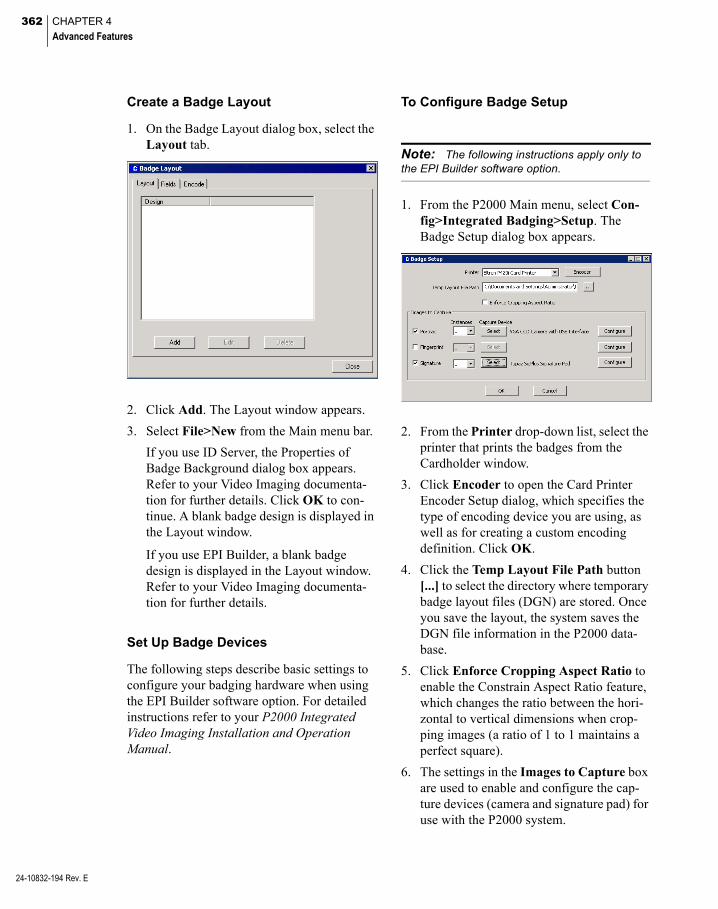
362 CHAPTER 4
Advanced Features
24-10832-194 Rev. E
Create a Badge Layout
1. On the Badge Layout dialog box, select the Layout tab.
2. Click Add. The Layout window appears.
3. Select File>New from the Main menu bar.
If you use ID Server, the Properties of Badge Background dialog box appears. Refer to your Video Imaging documenta-tion for further details. Click OK to con-tinue. A blank badge design is displayed in the Layout window.
If you use EPI Builder, a blank badge design is displayed in the Layout window. Refer to your Video Imaging documenta-tion for further details.
Set Up Badge Devices
The following steps describe basic settings to configure your badging hardware when using the EPI Builder software option. For detailed instructions refer to your P2000 Integrated Video Imaging Installation and Operation Manual.
To Configure Badge Setup
Note: The following instructions apply only to the EPI Builder software option.
1. From the P2000 Main menu, select Con-fig>Integrated Badging>Setup. The Badge Setup dialog box appears.
2. From the Printer drop-down list, select the printer that prints the badges from the Cardholder window.
3. Click Encoder to open the Card Printer Encoder Setup dialog, which specifies the type of encoding device you are using, as well as for creating a custom encoding definition. Click OK.
4. Click the Temp Layout File Path button [...] to select the directory where temporary badge layout files (DGN) are stored. Once you save the layout, the system saves the DGN file information in the P2000 data-base.
5. Click Enforce Cropping Aspect Ratio to enable the Constrain Aspect Ratio feature, which changes the ratio between the hori-zontal to vertical dimensions when crop-ping images (a ratio of 1 to 1 maintains a perfect square).
6. The settings in the Images to Capture box are used to enable and configure the cap-ture devices (camera and signature pad) for use with the P2000 system.
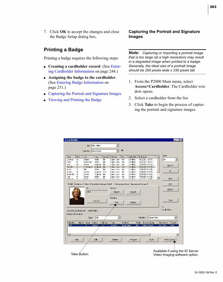
363
7. Click OK to accept the changes and close the Badge Setup dialog box.
Printing a Badge
Printing a badge requires the following steps:
Creating a cardholder record. (See Enter-ing Cardholder Information on page 244.)
Assigning the badge to the cardholder. (See Entering Badge Information on page 251.)
Capturing the Portrait and Signature Images
Viewing and Printing the Badge
Capturing the Portrait and Signature Images
Note: Capturing or importing a portrait image that is too large (at a high resolution) may result in a degraded image when printed to a badge. Generally, the ideal size of a portrait image should be 290 pixels wide x 330 pixels tall.
1. From the P2000 Main menu, select Access>Cardholder. The Cardholder win-dow opens.
2. Select a cardholder from the list.
3. Click Take to begin the process of captur-ing the portrait and signature images.
Take ButtonAvailable if using the ID ServerVideo Imaging software option.
24-10832-194 Rev. E
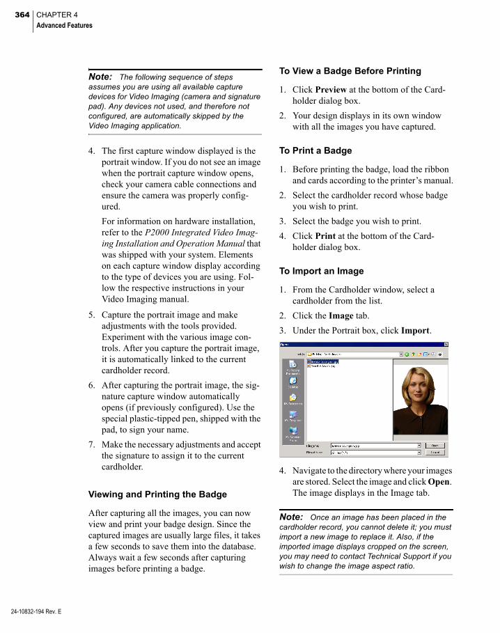
364 CHAPTER 4
Advanced Features
24-10832-194 Rev. E
Note: The following sequence of steps assumes you are using all available capture devices for Video Imaging (camera and signature pad). Any devices not used, and therefore not configured, are automatically skipped by the Video Imaging application.
4. The first capture window displayed is the portrait window. If you do not see an image when the portrait capture window opens, check your camera cable connections and ensure the camera was properly config-ured.
For information on hardware installation, refer to the P2000 Integrated Video Imag-ing Installation and Operation Manual that was shipped with your system. Elements on each capture window display according to the type of devices you are using. Fol-low the respective instructions in your Video Imaging manual.
5. Capture the portrait image and make adjustments with the tools provided. Experiment with the various image con-trols. After you capture the portrait image, it is automatically linked to the current cardholder record.
6. After capturing the portrait image, the sig-nature capture window automatically opens (if previously configured). Use the special plastic-tipped pen, shipped with the pad, to sign your name.
7. Make the necessary adjustments and accept the signature to assign it to the current cardholder.
Viewing and Printing the Badge
After capturing all the images, you can now view and print your badge design. Since the captured images are usually large files, it takes a few seconds to save them into the database. Always wait a few seconds after capturing images before printing a badge.
To View a Badge Before Printing
1. Click Preview at the bottom of the Card-holder dialog box.
2. Your design displays in its own window with all the images you have captured.
To Print a Badge
1. Before printing the badge, load the ribbon and cards according to the printer’s manual.
2. Select the cardholder record whose badge you wish to print.
3. Select the badge you wish to print.
4. Click Print at the bottom of the Card-holder dialog box.
To Import an Image
1. From the Cardholder window, select a cardholder from the list.
2. Click the Image tab.
3. Under the Portrait box, click Import.
4. Navigate to the directory where your images are stored. Select the image and click Open. The image displays in the Image tab.
Note: Once an image has been placed in the cardholder record, you cannot delete it; you must import a new image to replace it. Also, if the imported image displays cropped on the screen, you may need to contact Technical Support if you wish to change the image aspect ratio.
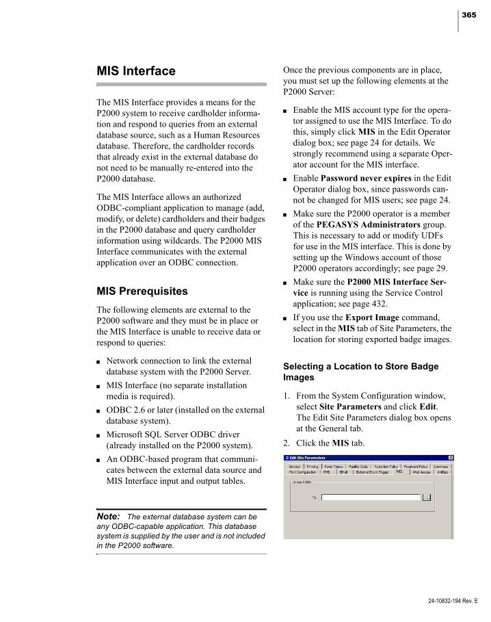
365
MIS Interface
The MIS Interface provides a means for the P2000 system to receive cardholder informa-tion and respond to queries from an external database source, such as a Human Resources database. Therefore, the cardholder records that already exist in the external database do not need to be manually re-entered into the P2000 database.
The MIS Interface allows an authorized ODBC-compliant application to manage (add, modify, or delete) cardholders and their badges in the P2000 database and query cardholder information using wildcards. The P2000 MIS Interface communicates with the external application over an ODBC connection.
MIS Prerequisites
The following elements are external to the P2000 software and they must be in place or the MIS Interface is unable to receive data or respond to queries:
Network connection to link the external database system with the P2000 Server.
MIS Interface (no separate installation media is required).
ODBC 2.6 or later (installed on the external database system).
Microsoft SQL Server ODBC driver (already installed on the P2000 system).
An ODBC-based program that communi-cates between the external data source and MIS Interface input and output tables.
Note: The external database system can be any ODBC-capable application. This database system is supplied by the user and is not included in the P2000 software.
Once the previous components are in place, you must set up the following elements at the P2000 Server:
Enable the MIS account type for the opera-tor assigned to use the MIS Interface. To do this, simply click MIS in the Edit Operator dialog box; see page 24 for details. We strongly recommend using a separate Oper-ator account for the MIS interface.
Enable Password never expires in the Edit Operator dialog box, since passwords can-not be changed for MIS users; see page 24.
Make sure the P2000 operator is a member of the PEGASYS Administrators group. This is necessary to add or modify UDFs for use in the MIS interface. This is done by setting up the Windows account of those P2000 operators accordingly; see page 29.
Make sure the P2000 MIS Interface Ser-vice is running using the Service Control application; see page 432.
If you use the Export Image command, select in the MIS tab of Site Parameters, the location for storing exported badge images.
Selecting a Location to Store Badge Images
1. From the System Configuration window, select Site Parameters and click Edit. The Edit Site Parameters dialog box opens at the General tab.
2. Click the MIS tab.
24-10832-194 Rev. E
366 CHAPTER 4
Advanced Features
24-10832-194 Rev. E
3. Enter the name of the Image Folder or click [...] to find the folder for storing the badge images.
4. Click OK to save the settings and return to the System Configuration window.
Understanding the Input and Output Tables
The MIS Interface communicates with the external application via an ODBC connection to receive data and return command and query results through two database tables: an Input table and an Output table. These tables are cre-ated automatically. The Input table receives data and commands from the external system. The results of the commands issued to the P2000 system from the Input table are returned to the Output table.
When the external program writes a record into the Input table, the P2000 system reads that record and performs the requested action (Add, Delete, Update, Query, Query Multiple, Export Images, or Delete Badge). The results of that operation are written to the Output table and the record in the Input table is deleted. The external software should enter a unique Request ID for each record. Results are reported by Record ID and can be reviewed via the external program.
Results can be either successful or report an error on a specific Request ID. If multiple records are sent to the Input table, they are pro-cessed in the same manner: as a group of records is processed and clears the Input table, the next group is read and processed. (Request IDs remain intact, though records may not nec-essarily be processed in any particular order.) Records are removed from the Output table by the external system. All successful operations that modify a P2000 record generate a message in the normal P2000 Audit log.
MIS and Partitioned Systems
On P2000 systems that use the Partitioning feature, a set of input and output tables is cre-ated for each partition. The table names are prefixed by the partition name. These tables are in addition to the normal input and output tables, which are used for the Super User parti-tion.
Using the MIS Interface
Running the MIS Interface continuously or at prescribed intervals is up to your management procedures.
For example, you may want to run the MIS Interface to populate the P2000 cardholder database for the first time, entering all card-holder information for all personnel at one time. After that is done, you may want to only run the MIS Interface once a day or once a week.
MIS Interface Application: The MIS Interface is intended only as a tool to allow an external database source to export images and add, update, delete, or query the
P2000 cardholder database. It is not intended to keep the P2000 database and the external data in perfect “sync.” Records deleted from the P2000 database are not automatically deleted from the external database. You should establish specific procedures to manage your use of the MIS Interface.
APPLICATION NOTE
For detailed information, refer to the MIS Interface Configuration documentation.

367
pivCLASS Integration
The P2000 pivCLASS integration enables the support of Federal Identity, Credential, and Access Management (FICAM) compliant smart cards and readers. The basic concepts of this integration are based on:
Cardholder and Badge enrollment – The P2000 installation provides the FICAM-compliant HID Global pivCLASS P2000 Plug-In that contains a template for inserting cardholder and badge information. The enrollment is done from the HID piv-CLASS Registration Engine through the P2000 MIS Interface.
FICAM-compliant re-validation of smart cards – The pivCLASS integration validates card-holder badges periodically and at the time of access to confirm that the badge is not coun-terfeited, cloned, copied, lost, or stolen.
Processing of events generated at the piv-CLASS system – The P2000 pivCLASS Interface Service provides the communica-tion between the P2000 Server and the piv-CLASS system with respect to events generated at the pivCLASS system.
Note: This section provides basic configuration and use of the pivCLASS Integration. For settings and procedures that are specific to configuring HID Global pivCLASS for use with the P2000 system, refer to the HID Global pivCLASS Inte-gration Manual.
Specifications
The P2000 pivCLASS integration allows:
128-bit badge numbers, using CK721-A panels version 3.2 and later.
Configuration of the pivCLASS integration component (only one pivCLASS integra-tion component can be configured per P2000 site).
Card format selection, using the Card Type tab in the Terminal application to define FASC-N (PIV, CAC, TWIC) or UUID (PIV-I, CIV, FRAC) card formats.
Configure the pivCLASS Integration Component
1. From the P2000 Main menu, select Con-fig>System. Enter your password if prompted. The System Configuration win-dow opens.
2. Select pivCLASS Integration and click Add. The pivCLASS Integration dialog box opens.
3. If this is a partitioned system, select the Partition in which this pivCLASS Integra-tion component is active.
4. Select Public if you wish this pivCLASS Integration component to be visible to all partitions.
5. Enter a descriptive Name to identify the pivCLASS Integration component.
Note: The pivCLASS Integration component must not have the same name as a terminal.
6. Enter the Query String value that is used with message filtering (see Define Query String Filters on page 225).
7. Click OK to save the pivCLASS Integra-tion component.
24-10832-194 Rev. E
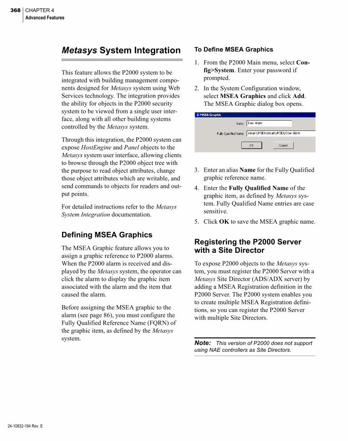
368 CHAPTER 4
Advanced Features
24-10832-194 Rev. E
Metasys System Integration
This feature allows the P2000 system to be integrated with building management compo-nents designed for Metasys system using Web Services technology. The integration provides the ability for objects in the P2000 security system to be viewed from a single user inter-face, along with all other building systems controlled by the Metasys system.
Through this integration, the P2000 system can expose HostEngine and Panel objects to the Metasys system user interface, allowing clients to browse through the P2000 object tree with the purpose to read object attributes, change those object attributes which are writable, and send commands to objects for readers and out-put points.
For detailed instructions refer to the Metasys System Integration documentation.
Defining MSEA Graphics
The MSEA Graphic feature allows you to assign a graphic reference to P2000 alarms. When the P2000 alarm is received and dis-played by the Metasys system, the operator can click the alarm to display the graphic item associated with the alarm and the item that caused the alarm.
Before assigning the MSEA graphic to the alarm (see page 86), you must configure the Fully Qualified Reference Name (FQRN) of the graphic item, as defined by the Metasys system.
To Define MSEA Graphics
1. From the P2000 Main menu, select Con-fig>System. Enter your password if prompted.
2. In the System Configuration window, select MSEA Graphics and click Add. The MSEA Graphic dialog box opens.
3. Enter an alias Name for the Fully Qualified graphic reference name.
4. Enter the Fully Qualified Name of the graphic item, as defined by Metasys sys-tem. Fully Qualified Name entries are case sensitive.
5. Click OK to save the MSEA graphic name.
Registering the P2000 Server with a Site Director
To expose P2000 objects to the Metasys sys-tem, you must register the P2000 Server with a Metasys Site Director (ADS/ADX server) by adding a MSEA Registration definition in the P2000 Server. The P2000 system enables you to create multiple MSEA Registration defini-tions, so you can register the P2000 Server with multiple Site Directors.
Note: This version of P2000 does not support using NAE controllers as Site Directors.

369
ADS/ADX Tower
Wide Area Network
IP Network
P2000 Server
ADS/ADX Tower
Metasys Client
Site Directors Registered in P2000
In addition, you may register certain partitions with a particular Site Director, so that only those P2000 objects associated with the selected partitions are visible from the Metasys system (see the following illustration).
ADS/ADX 1 ADS/ADX 2
Partition A Partition B Partition C
P2000 Server
In the previous illustration, the P2000 objects associated with Partition A are only visible from ADS/ADX 1; the P2000 objects associ-ated with Partition B are only visible from ADS/ADX 2; and the P2000 objects associ-ated with Partition C are only visible from ADS/ADX 2.
Note: The partition rule previously described has the following exceptions: 1) If you register the Super User partition to a particular Site Director, P2000 objects are visible from all partitions, even from those that were not registered with the Site Director. 2) Any P2000 device, such as a panel or terminal, set to Public is visible from all parti-tions, regardless of the ones registered to a par-ticular Site Director.
To Register a P2000 Server with one or more Site Directors
1. From the P2000 Main menu, select Con-fig>System. Enter your password if prompted. The System Configuration win-dow opens.
2. Select MSEA Registrations and click Add. The MSEA Registration dialog box opens.
24-10832-194 Rev. E
370 CHAPTER 4
Advanced Features
24-10832-194 Rev. E
3. Enter the Site Director Name where the Site Director is installed (the server name of the ADS/ADX).
4. Enter the Site Director IP Address of the server where the Site Director is installed (the IP address of the ADS/ADX).
5. Enter the Device ID. Enter 377 or contact Johnson Controls Technical Support for the Device ID used on the version of Metasys currently running.
6. Enter the ADS Repository Name (com-puter name) of the Metasys ADS Reposi-tory.
7. Enter the P2000 Server IP Address.
8. In the Available Partitions box, select the partition you wish to register with the Metasys Site Director. To assign partitions, simply select one or more partitions and click the left arrow button to move them to the Selected Partitions box.
9. Click OK to save the MSEA Registration.
10. Repeat the previous steps for each Site Director with which you wish to register the P2000 Server.
11. To complete the P2000 MSEA Registra-tion, you must stop and restart the P2000 XmlRpc Interface Service. For details, see Starting and Stopping Service Control on page 432.
The P2000 Server should now appear as a device in the Metasys system user interface for the associated Site Director. Refer to the Metasys System Integration manual for information on starting and logging into the Metasys system user interface.
Defining SNMP Traps
The P2000 system can receive Simple Net-work Management Protocol (SNMP) Traps from the Metasys system (Version 6.5 and later). Through the use of SNMP Traps, the P2000 system can receive Metasys alarms and associate them with P2000 alarm options, such as instruction texts and escalation rules. Alarms generated in the Metasys system can be processed like regular P2000 alarms and can be used with all P2000 alarm-related applica-tions and features.
The integration with the Metasys system enables P2000 operators to:
Browse and import selected Metasys objects.
Receive Metasys alarm messages associated with the selected Metasys objects.
Define P2000 alarm options for the imported Metasys objects, translating Meta-sys alarms into P2000 alarms, where they become subject to the standard P2000 rules and are processed like any other P2000 alarm.
Note: Alarm actions for SNMP are not synchro-nized between the P2000 and the Metasys sys-tem. For example, when you acknowledge an alarm in the P2000 system, the alarm is not auto-matically acknowledged in the Metasys system.
Limitations
The P2000 system does not monitor the sta-tus of the integration device itself (ADX, ADS, or NAE). Therefore, alarms and mes-sages associated with the integration device being up or down are not supported.
The Metasys integration generates alarm messages only. It does not generate transac-tion history messages.
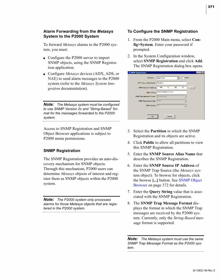
371
Alarm Forwarding from the Metasys System to the P2000 System
To forward Metasys alarms to the P2000 sys-tem, you must:
Configure the P2000 server to import SNMP objects, using the SNMP Registra-tion application.
Configure Metasys devices (ADX, ADS, or NAE) to send alarm messages to the P2000 system (refer to the Metasys System Inte-gration documentation).
Note: The Metasys system must be configured to use SNMP Version 2c and “String-Based” for-mat for the messages forwarded to the P2000 system.
Access to SNMP Registration and SNMP Object Browser applications is subject to P2000 menu permissions.
SNMP Registration
The SNMP Registration provides an auto-dis-covery mechanism for SNMP objects. Through this mechanism, P2000 users can determine Metasys objects of interest and reg-ister them as SNMP objects within the P2000 system.
Note: The P2000 system only processes alarms for those Metasys objects that are regis-tered in the P2000 system.
To Configure the SNMP Registration
1. From the P2000 Main menu, select Con-fig>System. Enter your password if prompted.
2. In the System Configuration window, select SNMP Registration and click Add. The SNMP Registration dialog box opens.
3. Select the Partition in which the SNMP Registration and its objects are active.
4. Click Public to allow all partitions to view this SNMP Registration.
5. Enter the SNMP Source Alias Name that describes the SNMP Registration.
6. Enter the SNMP Source IP Address of the SNMP Trap Source (the Metasys sys-tem object). To browse for objects, click the browse [...] button. See SNMP Object Browser on page 372 for details.
7. Enter the Query String value that is asso-ciated with the SNMP Registration.
8. The SNMP Trap Message Format dis-plays the format in which the SNMP Trap messages are received by the P2000 sys-tem. Currently, only the String-Based mes-sage format is supported.
Note: The Metasys system must use the same SNMP Trap Message Format as the P2000 sys-tem.
24-10832-194 Rev. E
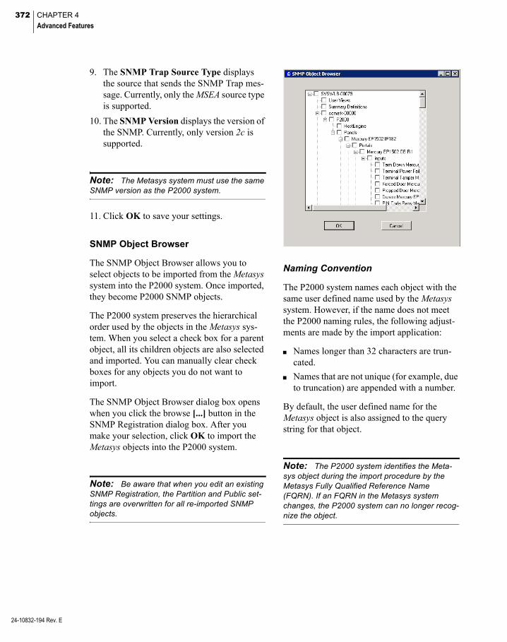
372 CHAPTER 4
Advanced Features
24-10832-194 Rev. E
9. The SNMP Trap Source Type displays the source that sends the SNMP Trap mes-sage. Currently, only the MSEA source type is supported.
10. The SNMP Version displays the version of the SNMP. Currently, only version 2c is supported.
Note: The Metasys system must use the same SNMP version as the P2000 system.
11. Click OK to save your settings.
SNMP Object Browser
The SNMP Object Browser allows you to select objects to be imported from the Metasys system into the P2000 system. Once imported, they become P2000 SNMP objects.
The P2000 system preserves the hierarchical order used by the objects in the Metasys sys-tem. When you select a check box for a parent object, all its children objects are also selected and imported. You can manually clear check boxes for any objects you do not want to import.
The SNMP Object Browser dialog box opens when you click the browse [...] button in the SNMP Registration dialog box. After you make your selection, click OK to import the Metasys objects into the P2000 system.
Note: Be aware that when you edit an existing SNMP Registration, the Partition and Public set-tings are overwritten for all re-imported SNMP objects.
Naming Convention
The P2000 system names each object with the same user defined name used by the Metasys system. However, if the name does not meet the P2000 naming rules, the following adjust-ments are made by the import application:
Names longer than 32 characters are trun-cated.
Names that are not unique (for example, due to truncation) are appended with a number.
By default, the user defined name for the Metasys object is also assigned to the query string for that object.
Note: The P2000 system identifies the Meta-sys object during the import procedure by the Metasys Fully Qualified Reference Name (FQRN). If an FQRN in the Metasys system changes, the P2000 system can no longer recog-nize the object.

373
SNMP Object Properties and Alarm Options
After you import the Metasys objects into the P2000 system, you need to configure proper-ties and alarm options for each imported SNMP object.
To Edit SNMP Object Properties
1. In the System Configuration window, expand SNMP Registration to display all the defined SNMP registrations in the sys-tem.
2. Expand the SNMP registration that con-tains the SNMP object you want to edit.
3. Select the SNMP object and click Edit. The SNMPObjectEdit dialog box opens at the General tab.
4. Select the Partition in which this SNMP object is active.
5. Click Public to allow all partitions to view this SNMP object.
6. The Name field displays the name of the SNMP object as defined in the Metasys system, if the name matches the P2000 naming rules. Otherwise, the P2000 sys-tem changes the name according to the naming rules. You can edit this name later.
7. The FQRN field displays the Fully Quali-fied Reference Name as defined in the Metasys system.
8. By default, the SNMP object name is assigned to the Query String, but you can enter any query string value for the object.
9. Click the Alarm Options tab. SNMP objects must belong to at least one alarm category, and must provide their own set of alarm options and parameters to define how the alarms behave when activated, whether or not they need to be acknowl-edged, at what time an alarm can be acti-vated, and other alarm settings.
10. Click Add. The Add Alarm Categories dialog box opens displaying all previously created alarm categories (see Alarm Con-figuration on page 270 for details).
11. Select one or more categories and click Add. The list displays all the selected alarm categories.
12. Once you have all the alarm categories you want to assign to the SNMP object, select an alarm category from the list and click Edit to edit the alarm options. The Alarm Options dialog box opens displaying the General tab. See the definitions provided in Alarm Options Tab on page 83.
Note: By default, all alarms received through the use of SNMP Traps have priority 1.
13. After you define the SNMP object proper-ties and alarm options, click OK to save.
24-10832-194 Rev. E
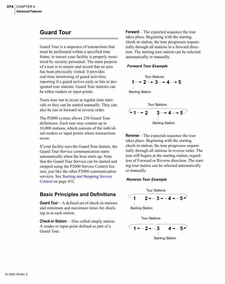
374 CHAPTER 4
Advanced Features
24-10832-194 Rev. E
Guard Tour
Guard Tour is a sequence of transactions that must be performed within a specified time frame, to ensure your facility is properly moni-tored by security personnel. The main purpose of a tour is to ensure and record that an area has been physically visited. It provides real-time monitoring of guard activities, reporting if a guard arrives early or late at des-ignated tour stations. Guard Tour stations can be either readers or input points.
Tours may run to occur at regular time inter-vals or they can be started manually. They can also be run in forward or reverse order.
The P2000 system allows 256 Guard Tour definitions. Each tour may contain up to 16,000 stations, which consists of the individ-ual readers or input points where transactions occur.
If your facility uses the Guard Tour feature, the Guard Tour Service communication starts automatically when the host starts up. Note that the Guard Tour Service can be started and stopped using the P2000 Service Control fea-ture, just like the other P2000 communication services. See Starting and Stopping Service Control on page 432.
Basic Principles and Definitions
Guard Tour – A defined set of check-in stations and minimum and maximum times for check-ing in at each station.
Check-in Station – Also called simply station. A reader or input point defined as part of a Guard Tour.
Forward – The expected sequence the tour takes place. Beginning with the starting check-in station, the tour progresses sequen-tially through all stations in a forward direc-tion. The starting tour station can be selected automatically or manually.
1 2 3 4 5Tour Stations
Starting Station
1 2 3 4 5
Tour Stations
Starting Station
Forward Tour Example
Reverse – The expected sequence the tour takes place. Beginning with the starting check-in station, the tour progresses sequen-tially through all stations in reverse order. The tour still begins at the starting station, regard-less of Forward or Reverse direction. The start-ing tour station can be selected automatically or manually.
1 2 3 4 5
Tour Stations
Starting Station
1 2 3 4 5
Tour Stations
Starting Station
Reverse Tour Example
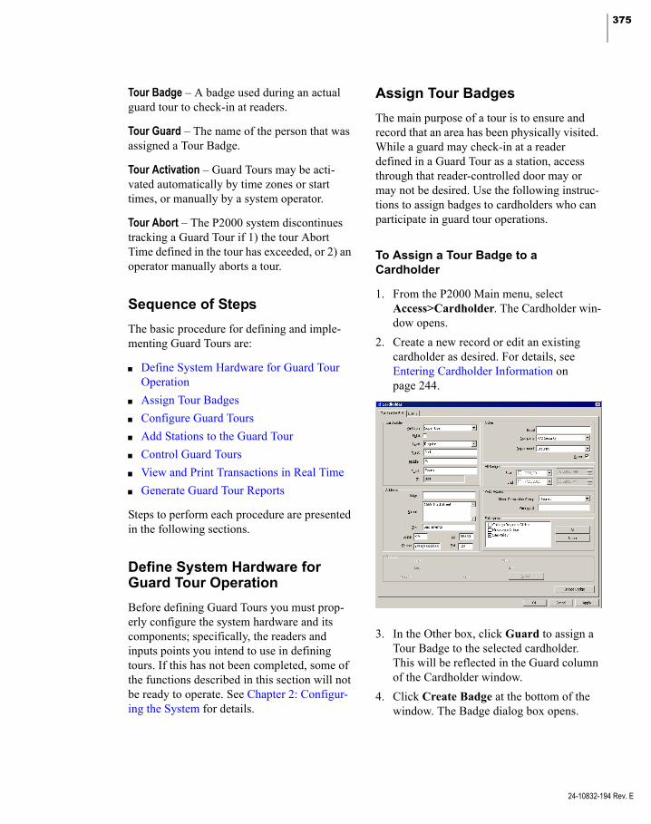
375
Tour Badge – A badge used during an actual guard tour to check-in at readers.
Tour Guard – The name of the person that was assigned a Tour Badge.
Tour Activation – Guard Tours may be acti-vated automatically by time zones or start times, or manually by a system operator.
Tour Abort – The P2000 system discontinues tracking a Guard Tour if 1) the tour Abort Time defined in the tour has exceeded, or 2) an operator manually aborts a tour.
Sequence of Steps
The basic procedure for defining and imple-menting Guard Tours are:
Define System Hardware for Guard Tour Operation
Assign Tour Badges
Configure Guard Tours
Add Stations to the Guard Tour
Control Guard Tours
View and Print Transactions in Real Time
Generate Guard Tour Reports
Steps to perform each procedure are presented in the following sections.
Define System Hardware for Guard Tour Operation
Before defining Guard Tours you must prop-erly configure the system hardware and its components; specifically, the readers and inputs points you intend to use in defining tours. If this has not been completed, some of the functions described in this section will not be ready to operate. See Chapter 2: Configur-ing the System for details.
Assign Tour Badges
The main purpose of a tour is to ensure and record that an area has been physically visited. While a guard may check-in at a reader defined in a Guard Tour as a station, access through that reader-controlled door may or may not be desired. Use the following instruc-tions to assign badges to cardholders who can participate in guard tour operations.
To Assign a Tour Badge to a Cardholder
1. From the P2000 Main menu, select Access>Cardholder. The Cardholder win-dow opens.
2. Create a new record or edit an existing cardholder as desired. For details, see Entering Cardholder Information on page 244.
3. In the Other box, click Guard to assign a Tour Badge to the selected cardholder. This will be reflected in the Guard column of the Cardholder window.
4. Click Create Badge at the bottom of the window. The Badge dialog box opens.
24-10832-194 Rev. E

376 CHAPTER 4
Advanced Features
24-10832-194 Rev. E
5. Enter the badge number and optional description. For detailed information, see Entering Badge Information on page 251.
6. Click the Security Options tab. If this is an Enterprise system, see Define Global Badge Access Rights on page 405 for addi-tional information when assigning access privileges to Enterprise badges.
7. Assign a Guard Tour Priority to the Tour Badge.
Guard Tour Priority: When you define a Guard Tour, it is assigned a priority number from 1 to 99. In the cardholder badge record, the Tour Priority
determines which tours the selected cardholder can perform. These can be all defined tours with a priority less than or equal to the badge’s assigned Tour Priority. For example, a cardholder badge with Tour Priority 45 is authorized to com-plete tours with a priority of 1 through 45. If the cardholder badge is used to attempt to check-in at stations of a tour defined as priority 46, their badgings is ignored by the Guard Tour.
APPLICATION NOTE
8. After adding the Tour Badge, click OK to return to the Cardholder window.
Configure Guard Tours
The following steps are used to define Guard Tours. Before proceeding, you must define input points and terminals (readers) to be used in tours. In addition, tour badges should have been assigned to the appropriate cardholders.
Use the Guard Tour Configuration Window
The Guard Tour Configuration window pro-vides quick access to all guard tour component configurations. When you select Options> Guard Tour>Tour Configuration from the P2000 Main menu bar, the Guard Tour Config-uration window opens, displaying the actual Partition, Workstation, and User Name on the right windowpane. All defined Guard Tours display on the left side of the window. A plus (+) sign next to a defined Guard Tour indicates that Tour Stations exist beneath it. When you select a Guard Tour or Tour Station, the detailed settings and values relating to that selection are listed on the right windowpane.
Note: You cannot edit Tour Definitions or Sta-tions from the Guard Tour Configuration window while a tour is running.
To search for specific items, enter the name of the item in the search field at the top right cor-ner of the window. You can enter complete or partial words; no wildcards are needed, and this field is not case sensitive.
Click Search. The window displays the match entered in the search field. Continue clicking Search until you find the item you are looking for.

377
Define a Guard Tour
1. From the P2000 Main menu, select Options>Guard Tour>Tour Configura-tion. The Guard Tour Configuration win-dow opens.
2. Select Guard Tours then click Add to access the Guard Tour Definition dialog box.
3. If this is a partitioned system, select the Partition that has access to this Tour, and click Public if you wish to make this Tour visible to all partitions.
4. Enter the Tour Name and optional Description.
5. From the Priority drop-down list, select the tour’s priority from 1 (lowest) to 99.
24-10832-194 Rev. E

378 CHAPTER 4
Advanced Features
24-10832-194 Rev. E
Only tour badges with equal to or greater than this priority can perform the tour.
6. Select one of the following Tour Types from the drop-down list:
Manual – The tour must be initiated manu-ally from the Guard Tour Control window, see Control Guard Tours on page 383.
Auto Forward – The tour is initiated at a time specified by the Timezone or Start Time fields. The guard is expected to begin at the first defined station and proceed through all stations in a forward direction.
Auto Reverse – The tour is initiated at a time specified by the Timezone or Start Time fields. The guard is expected to begin at the first defined station, and proceed through all stations in a reverse direction.
Random Watch – There is no sequencing in this mode. All defined stations are moni-tored at all times, until the time entered in the Run Time expires. This is to assure that no station goes unchecked for greater than a specific stated time.
Timezones, Start and Abort Times
If you select Manual as the tour type, the Time-zone and Start Time fields are disabled; these are only enabled when you select Auto For-ward, Auto Reverse, or Random Watch.
Timezones – The purpose of selecting a Time-zone is to provide an automatic starting time for the Guard Tour. You need to define Time Zones before defining Guard Tours. See Time Zones on page 49 for detailed instructions.
In the following example, a Time Zone was defined to be assigned to a tour, the start (active) time for the tour is 8:00 p.m. Monday through Friday.
Note: Stop (inactive) times are not necessary in a Time Zone, unless a Guard Tour is to be run more than once per day. In this case, you would enter a stop time to disable the time zone so it can become active again that day, at another time.
If you define several time blocks, ensure that enough time is allotted between the active and inactive times to realistically complete the tour.
Start Time – When you click the Start Time check box, the Timezone field is automatically disabled. Enter the time (hours and minutes only) the tour is scheduled to start.
Abort Time – Enter the time in minutes (from 2 to 1440). This is the maximum time allowed to expire, before a tour is automatically aborted. This field changes to Run Time if Random Watch is selected as the Tour Type.
Note: A tour is automatically aborted only if there are no tour alarms or the Manual Reset option is not enabled.
Once these times are assigned, you can assign the tour to a specific guard, or allow any guard with the appropriate priority to perform the tour.

379
Assign the Tour to a Specific Guard
1. In the Guard Tour Definition dialog box, click the Tour Guard 1 drop-down list and select a name. Only cardholders with the Guard option enabled in the Cardholder Edit dialog box display in the list.
2. Once a Tour Guard is selected, the corre-sponding Badge ID field is enabled. Select a badge from the drop-down list. Only badge numbers with priority greater than or equal to the Tour Priority display in the list.
3. If you wish to select additional guards, select Tour Guard 2 and Tour Guard 3, and their corresponding Badge ID num-bers.
4. To allow any guard with the proper priority to perform the tour, click the Any Guard box. See Additional Guard Tour Options for more information.
Note: One guard can run only one tour at the same time. In addition, one tour can be run only by one guard, even if two guards were to walk the same tour; it is the guard that badged at the initial station who must complete the tour using the same badge at the remaining stations.
Additional Guard Tour Options
The remaining options in the Guard Tour Defi-nition dialog box are described in the follow-ing paragraphs.
Alarm Priority – Select from the drop-down list an alarm priority from 0 to 255, in which the Guard Tour alarm message is placed in the queue.
Set Default – Click the Set Default button to store the default preference values, which include Tour Priority, Tour Type, Alarm Prior-ity, and all check boxes.
Reset – Click the Reset button to restore the pre-stored preference values.
Any Guard – Click to allow any guard with the proper priority to perform the tour. When you click this box, the Tour Guard 1 to 3 and corre-sponding Badge ID fields become disabled.
Manual Reset – If selected, the user has to click the Complete button in the Guard Tour Control dialog box to remove the tour from the tour list. This is to indicate that the tour has completed.
Auto Duress Alarm – If selected, an auto duress alarm is generated when a guard registers three consecutive times at a station within one min-ute, for example by swiping the badge three times, or by activating a tour input three times. If Manual Reset is not selected and Auto Duress Alarm is enabled, the tour status changes to Idle after one minute when it completes.
Alarm Late – If selected, an alarm is generated when a guard checks in later than expected at a station. If the check box is not selected and a guard is late, this is simply considered as a tour operation event.
Note: Operation events include, for example, Tour Alarmed, Tour Started, Station Checked in On Time, Station Checked in Early, Station Checked in Late, Station Checked in Out of Order, Tour Stopped, Tour Restarted, Tour Aborted, Tour Completed, Tour Terminated, Sta-tion Late Timer Reached.
Alarm Skip – If selected, an alarm is generated when a guard skips a tour station. If the check box is not selected and a guard skips a station, this is simply considered as a tour operation event.
Grant Only – If selected, the system registers only access grant transaction messages when the guard swipes the badge at the station. If not selected, either access grant or deny messages are registered.
24-10832-194 Rev. E

380 CHAPTER 4
Advanced Features
24-10832-194 Rev. E
Log Tour Operation – If selected, all tour opera-tion events are logged to the system as events, and therefore are available for history, event processing, and so forth.
Log Operator Action – If selected, all operator actions, such as starting or aborting a tour are logged as events.
Tour Alarms Setting
Tour Alarms Settings enable the Alarm Moni-tor window to automatically pop up in front of all other windows on the screen whenever a Guard Tour alarm condition occurs. Be aware that Guard Tour alarms in secure state must first be acknowledged or responded, before they can be completed.
You can also specify instruction text that dis-plays when an operator responds to a Guard Tour alarm going into a Set or Secure state. Enabling the Popup feature and selecting Instruction Text are independent tasks, and can be used in any combination.
Before you assign instruction text to the vari-ous pop ups, you must first create instruction text. See To Create Instruction Text on page 90.
1. In the Guard Tour Definition dialog box, click Tour Alarms Setting. The Guard Tour Alarm Settings dialog box opens.
2. Enable any of the following Popup when set or Popup when secure check boxes, and select the Instruction Text Name from the associated drop-down lists that displays in the Alarm Response window whenever any of the following alarm con-ditions occur:
Late Alarm – An alarm message is gener-ated when a guard checks in later than expected at a station. This option is avail-able if you select Alarm Late in the Guard Tour Definition dialog box.
Out Of Order Alarm – An alarm message is generated if a guard skips a tour station. This option is available if you select Alarm Skip in the Guard Tour Definition dialog box.
Duress Alarm – An alarm message is gener-ated if a guard registers three consecutive times at a station within one minute or by activating a tour input three times. This option is available if you select Auto Duress Alarm in the Guard Tour Definition dialog box.
3. Click OK to return to the Guard Tour Defi-nition dialog box.
Add Stations to the Guard Tour
Tour Station information, such as Station Name, Sequence Number, Type, Device, and Description displays in the list box at the bot-tom of the Guard Tour Definition dialog box, for all the stations assigned to that Guard Tour.
Guard Tour Stations can be either readers or input points.
To Add Stations to the Guard Tour
1. Click Add at the bottom of the Guard Tour Definition dialog box. The Tour Station Definition dialog box opens showing the Guard Tour Definition name on the title bar.
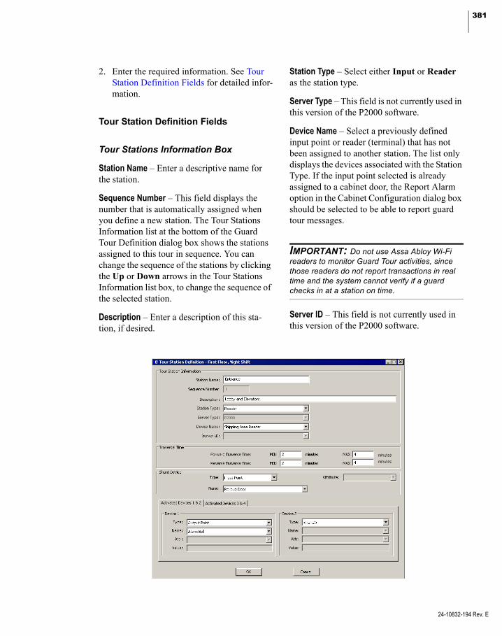
381
2. Enter the required information. See Tour Station Definition Fields for detailed infor-mation.
Tour Station Definition Fields
Tour Stations Information Box
Station Name – Enter a descriptive name for the station.
Sequence Number – This field displays the number that is automatically assigned when you define a new station. The Tour Stations Information list at the bottom of the Guard Tour Definition dialog box shows the stations assigned to this tour in sequence. You can change the sequence of the stations by clicking the Up or Down arrows in the Tour Stations Information list box, to change the sequence of the selected station.
Description – Enter a description of this sta-tion, if desired.
Station Type – Select either Input or Reader as the station type.
Server Type – This field is not currently used in this version of the P2000 software.
Device Name – Select a previously defined input point or reader (terminal) that has not been assigned to another station. The list only displays the devices associated with the Station Type. If the input point selected is already assigned to a cabinet door, the Report Alarm option in the Cabinet Configuration dialog box should be selected to be able to report guard tour messages.
IMPORTANT: Do not use Assa Abloy Wi-Fi readers to monitor Guard Tour activities, since those readers do not report transactions in real time and the system cannot verify if a guard checks in at a station on time.
Server ID – This field is not currently used in this version of the P2000 software.
24-10832-194 Rev. E

382 CHAPTER 4
Advanced Features
24-10832-194 Rev. E
Traversal Time Box
Traverse Time (Forward or Reverse) sets the amount of time in minutes a guard has to reach the defined station. The maximum Traversal Time must be less than the maximum value entered in the Run Time field. Traverse Times work in relation to a tour’s Start and Abort/ Run Times. One of six possible values is assigned when a guard reaches a station:
Early
Running
Late
Out of Order
Completed
Idle
Traverse Times are started at station check-in. For example, suppose the guard reaches station one at the two-minute mark (see illustration). The check-in would be reported as Early and the Traverse Timer for the next station would start. If the minimum and maximum values were set at 2 for station two, the on time check-in for station 2 would be between the 4 and 6-minute marks. These same timing princi-ples apply to all stations defined in the tour as well as Guard Tours designed to run in reverse order.
Note: If the Tour Type selected is Random Watch, the Forward Traverse Time defines how often the guard checks a defined station. Reverse Traverse Time is not available if Random Watch is selected.
0 1 2 3 4 5 6 7 8
Assume the tour has:Start Time: 5:30:35 PMAbort Time: 5 minutes
Forward Traverse Time Min: 2Forward Traverse Time Max: 4
Assume Station 1 is defined as:
Tour Starts
Time allowed for the guard to reach thefirst station (FwdTraverse Time Min)
If the guard has notreached the first station,tour is aborted (Abort Time)
Guard will be shownEarly at firststation check-in
Time frame in which guard is expected toreach first station(difference betweenMin and Max TraverseTimes)
Guard will be shownOn Time at firststation check-in
Time frame in whichguard can still checkin at first station, butwill be shown as Late(difference betweenMax Traverse Time and Abort Time)
0 - 8 are minute increments
If the expected maximumforward traverse time isexceeded, the Guard Tour
Tour is reported asAborted
at 5:30:35 PM
is reported as Late
Time allowed for the guard to reach thesecond station (FwdTraverse Time Min)
Guard will be shownEarly at secondstation check-in
Time frame in which guard is expected toreach second station(difference betweenMin and Max TraverseTimes)
Guard will be shownOn Time at secondstation check-in
383
Shunt Device Box
During the course of the Guard Tour, you may need to suppress alarms (shunt input points) as part of the tour.
This operation is similar to disabling an input point or input group as part of an Event, except that an input point or input group remain dis-abled until the next station in the tour is reached, a tour alarm is set, or the tour is aborted.
Type – Select either Input Point or Input Group as the Shunt Device Type.
Name – Select a previously defined input point or input group. The list only displays the devices associated with the Shunt Device Type.
Attribute – This field is not currently used in this version of the P2000 software.
Activated Devices Box
During the course of the Guard Tour, you may need to activate devices (set or reset output points) as part of the tour.
This operation is similar to setting or resetting an output point or output group in the main Control menu, except that an output point or output group remain set until the next station in the tour is reached, a tour alarm is set, or the tour is aborted.
Type – Select either Output Point or Output Group as the Activated Device Type.
Name – Select a previously defined output point or output group. The list only displays the devices associated with the Activated Device Type.
Attribute – This field is not currently used in this version of the P2000 software.
Value – This field is not currently used in this version of the P2000 software.
If you wish to activate more than one device, you can define them in the Device 2 box, then click the Activated Devices 3 & 4 tab and fol-low the same steps.
Note: The system does not shunt input points or activate output points assigned to the last sta-tion defined in the tour.
Saving the Station as Part of the Tour
After defining a station, click OK to return to the Guard Tour Definition dialog box, the sta-tion displays in the Tour Stations Information box.
Continue to add stations as necessary. When finished, click OK to return to the Guard Tour Configuration window. The Guard Tour is written to the database.
Control Guard Tours
Use the Guard Tour Control window to start and stop tours and monitor their progress.
To Control Guard Tours
1. From the P2000 Main menu, select Options>Guard Tour>Tour Control. Enter your password if prompted. The Guard Tour Control dialog box opens.
2. Select the Partition that contains the Guard Tours you wish to control.
3. Select Active Tours if you wish to display all tours currently in the status database, for the partition selected, and that are in non-idle state.
4. Select All Tours if you wish to display all tours currently in the database, for the par-tition selected, regardless of their state.
24-10832-194 Rev. E
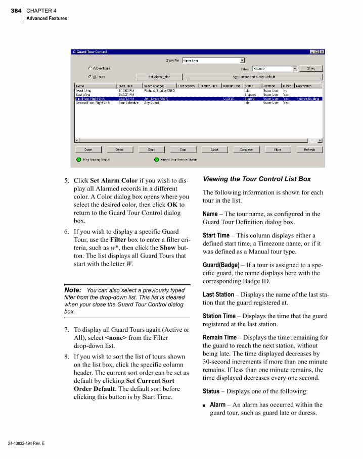
384 CHAPTER 4
Advanced Features
24-10832-194 Rev. E
5. Click Set Alarm Color if you wish to dis-play all Alarmed records in a different color. A Color dialog box opens where you select the desired color, then click OK to return to the Guard Tour Control dialog box.
6. If you wish to display a specific Guard Tour, use the Filter box to enter a filter cri-teria, such as w*, then click the Show but-ton. The list displays all Guard Tours that start with the letter W.
Note: You can also select a previously typed filter from the drop-down list. This list is cleared when your close the Guard Tour Control dialog box.
7. To display all Guard Tours again (Active or All), select <none> from the Filter drop-down list.
8. If you wish to sort the list of tours shown on the list box, click the specific column header. The current sort order can be set as default by clicking Set Current Sort Order Default. The default sort before clicking this button is by Start Time.
Viewing the Tour Control List Box
The following information is shown for each tour in the list.
Name – The tour name, as configured in the Guard Tour Definition dialog box.
Start Time – This column displays either a defined start time, a Timezone name, or if it was defined as a Manual tour type.
Guard(Badge) – If a tour is assigned to a spe-cific guard, the name displays here with the corresponding Badge ID.
Last Station – Displays the name of the last sta-tion that the guard registered at.
Station Time – Displays the time that the guard registered at the last station.
Remain Time – Displays the time remaining for the guard to reach the next station, without being late. The time displayed decreases by 30-second increments if more than one minute remains. If less than one minute remains, the time displayed decreases every one second.
Status – Displays one of the following:
Alarm – An alarm has occurred within the guard tour, such as guard late or duress.

385
Started – The tour has been started, either manually or automatically, but the first sta-tion has not been reached.
Running – Status given to an active tour after the first station has been reached.
Early – When a tour station check-in is sooner than expected.
Late – When a tour station check-in is later than expected.
Out of Order – When a tour station check-in occurs out of sequence.
Stopped – The tour has been manually stopped.
Aborted – The tour has been cancelled either manually or because of an expired Abort Time (stations not reached in time).
Completed – The tour has completed suc-cessfully without any alarms.
Idle – The tour is not running.
Partition – Displays the partition as configured in the Guard Tour Definition dialog box.
Public – Displays whether or not this guard tour is made public, as configured in the Guard Tour Definition dialog box.
Description – Displays the description of the tour, as configured in the Guard Tour Defini-tion dialog box.
Note: The Message Routing Status indicator at the bottom of the window displays in green to indicate that all communications between the workstation and the Server are up. If communica-tions go down, the Message Routing Status indi-cator turns red.The Guard Tour Service Status indicator displays in green to indicate that the Guard Tour Service is up and running. If Guard Tour Service goes down, the indicator turns red.
To Start a Manual Tour
1. Select a tour from the Guard Tour Control list that has a Manual tour type in the Start Time column.
2. Click Start at the bottom of the Guard Tour Control dialog box. The Start Tour dialog box opens.
3. Select the Guard assigned to run the selected tour. If only one guard was defined to run this tour, the name of the guard automatically displays on this field.
4. Select the guard’s Badge number. If only one badge was assigned to this guard, that number automatically displays on this field.
Note: If Any Guard was selected in the Guard Tour Definition dialog box, the previous fields are disabled.
5. From the Starting Station drop-down list, select any station in the tour to be station 1.
6. Select whether this tour starts in Forward or Reverse order.
7. Click OK to start the tour.
Guard Tour Handling
The Guard Tour Service communication checks the Start Time or Timezone definitions every one minute to determine whether to start automatic tours.
24-10832-194 Rev. E
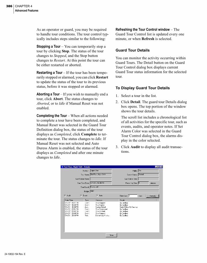
386 CHAPTER 4
Advanced Features
24-10832-194 Rev. E
As an operator or guard, you may be required to handle tour conditions. The tour control typ-ically includes steps similar to the following:
Stopping a Tour – You can temporarily stop a tour by clicking Stop. The status of the tour changes to Stopped, and the Stop button changes to Restart. At this point the tour can be either restarted or aborted.
Restarting a Tour – If the tour has been tempo-rarily stopped or alarmed, you can click Restart to update the status of the tour to its previous status, before it was stopped or alarmed.
Aborting a Tour – If you wish to manually end a tour, click Abort. The status changes to Aborted, or to Idle if Manual Reset was not enabled.
Completing the Tour – When all actions needed to complete a tour have been completed, and Manual Reset was selected in the Guard Tour Definition dialog box, the status of the tour displays as Completed, click Complete to ter-minate the tour. The status changes to Idle. If Manual Reset was not selected and Auto Duress Alarm is enabled, the status of the tour displays as Completed and after one minute changes to Idle.
Refreshing the Tour Control window – The Guard Tour Control list is updated every one minute, or when Refresh is selected.
Guard Tour Details
You can monitor the activity occurring within Guard Tours. The Detail button on the Guard Tour Control dialog box displays current Guard Tour status information for the selected tour.
To Display Guard Tour Details
1. Select a tour in the list.
2. Click Detail. The guard tour Details dialog box opens. The top portion of the window shows the tour details.
The scroll list includes a chronological list of all activities for the specific tour, such as events, audits, and operator notes. If Set Alarm Color was selected in the Guard Tour Control dialog box, the alarms dis-play in the color selected.
3. Click Audit to display all audit transac-tions.

387
4. Click Event to display all event transac-tions.
5. Click Note to display all Notes related to this tour. See the following section Guard Tour Notes for more information.
6. In the Show Last box, enter the number of days of tour activity you wish to display.
7. Click Refresh to update the list.
8. Click Close to return to the Guard Tour Control dialog box.
Guard Tour Notes
The tour Note dialog box provides a place to enter instructions for a particular tour. The amount of time after which all notes are purged is set up in Site Parameters.
1. From the System Configuration window select Site Parameters and click Edit. The Edit Site Parameters dialog box opens at the General tab.
2. Click the Retention Policy tab and enter the amount of time and select Minutes, Hours, or Days from the Tour Note drop-down list, after which all notes are deleted from the system.
3. Click OK to save the settings and return to the System Configuration window.
To Add Tour Notes
1. From the Guard Tour Control dialog box, select a non-Idle tour from the list.
2. Click Note. The Note dialog box opens.
3. Enter the note you want to display in the Detail dialog box.
4. Click Add. The list box displays the Date and Time the note was added, with the User Name, and the actual note text.
5. Click Done to return to the Guard Tour Control dialog box.
View and Print Transactions in Real Time
Tour transactions are sent through real time messages to the Real Time List. You can mon-itor real time messages, such as tour alarm messages and see the status of a tour. Once the status changes or the tour proceeds, corre-sponding real time messages are generated. Select the Guard Tour box in the Real Time List window, to display all guard tour transac-tions as they occur. See Using the Real Time List on page 342 for more information.
24-10832-194 Rev. E
388 CHAPTER 4
Advanced Features
24-10832-194 Rev. E
If you wish to print tour transactions as they occur, you can either print them from the Real Time List window, or select Guard Tour in the Printing tab of Site Parameters. See Printing Tab on page 34 for more information.
Generate Guard Tour Reports
Guard Tour reports are provided as a subset of the standard P2000 report set. For detailed information on running reports, see Chapter 6: System Reports.
Three types of Guard Tour reports are pro-vided: Tour Configuration Report, Tour Trans-action History Report, and Tour Notes Report. The following sections describe each of these reports.
Tour Configuration Report
The Tour Configuration report lists by tour name, all tour definition configuration, and associated stations, as set up in the Guard Tour Definition window. When you select Tour Configuration from the Run Report window, the Tour Configuration dialog box opens. You can select a Tour Name from the drop-down list to limit the report to a specific tour or leave the default (*) to report on all tours configured in the system.
Tour Transaction History Report
This report lists every guard tour transaction in the system, or can be filtered to list by specific Partition, Tour Name, Transaction Type, spe-cific Dates and Times, and any combination of these. In addition, you can select to run the report on transactions at your local site or you can enter the name of the remote site that you want to report on.
When you select Tour Transaction History from the Run Report window, the Tour Trans-action History dialog box opens. Select either your local Site or enter the name of the remote site that you want to report on. The default (*) reports all tours in the system, or you can select a specific Partition, Tour Name, and Transaction Type from the drop-down lists. After you select a Begin and End Date and Time for the transactions you wish to see, the Tour Transaction History report displays in the Crystal preview window. The top of the report shows the Tour Name, Transaction Type and Site, and the date and time settings selected. Each transaction is listed as a separate date and time stamped record.
Tour Notes Report
This report lists all the tour notes assigned to a specific tour name, as set up in the Guard Tour Control window, or can be filtered to list by specific Tour Name, specific Dates and Times, and any combination of these. When you select Tour Notes from the Run Report window, the Tour Notes dialog box opens. The default (*) reports all tours in the system, or you can select a specific Tour Name from the drop-down list. After you select a Begin and End Date and Time for the notes you wish to see, the Tour Notes report displays in the Crys-tal preview window. The top of the report shows the date and time settings for the report and the Tour Name selected. Each note is listed as a separate date and time stamped record.
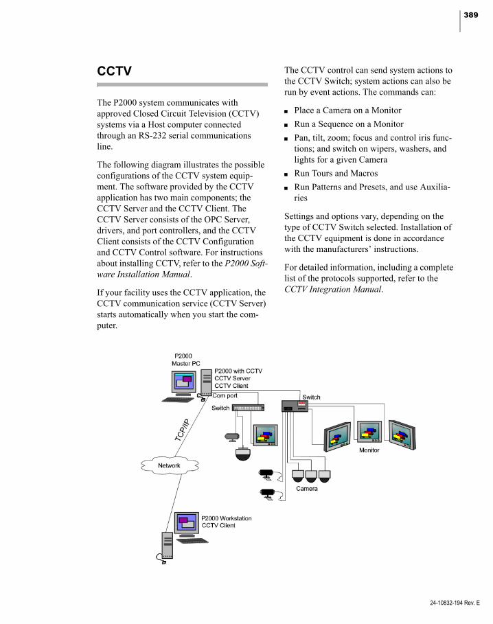
389
CCTV
The P2000 system communicates with approved Closed Circuit Television (CCTV) systems via a Host computer connected through an RS-232 serial communications line.
The following diagram illustrates the possible configurations of the CCTV system equip-ment. The software provided by the CCTV application has two main components; the CCTV Server and the CCTV Client. The CCTV Server consists of the OPC Server, drivers, and port controllers, and the CCTV Client consists of the CCTV Configuration and CCTV Control software. For instructions about installing CCTV, refer to the P2000 Soft-ware Installation Manual.
If your facility uses the CCTV application, the CCTV communication service (CCTV Server) starts automatically when you start the com-puter.
The CCTV control can send system actions to the CCTV Switch; system actions can also be run by event actions. The commands can:
Place a Camera on a Monitor
Run a Sequence on a Monitor
Pan, tilt, zoom; focus and control iris func-tions; and switch on wipers, washers, and lights for a given Camera
Run Tours and Macros
Run Patterns and Presets, and use Auxilia-ries
Settings and options vary, depending on the type of CCTV Switch selected. Installation of the CCTV equipment is done in accordance with the manufacturers’ instructions.
For detailed information, including a complete list of the protocols supported, refer to the CCTV Integration Manual.
24-10832-194 Rev. E

390 CHAPTER 4
Advanced Features
24-10832-194 Rev. E
DVR/VMS
The P2000 software provides seamless integra-tion with approved Digital Video Recorders (DVRs) or Video Management Systems (VMS). The integration allows authorized users to manage camera functions from a sin-gle P2000 workstation, and to tie an event gen-erated on the P2000 system to a live audio-visual (AV) recording. Depending on the digital video equipment used at the site, the P2000 software also enables users to search, retrieve, and download real-time or archived AV recordings from any transaction or surveil-lance camera, from any place and at any time.
You can recall audio-visual files by a variety of query options, including date and time, alarm events, camera ID, or DVR ID. Live video and audio playback options are available from the Alarm Monitor, Real Time List, and Real Time Map.
The digital video system communicates with the P2000 Server through a TCP/IP connection. The P2000 CCTV Server, a software compo-nent installed automatically with the Digital Video option, provides communication.
Additionally, you can configure the digital video integration feature with a CCTV Switch for added control of the CCTV cameras and monitors. For detailed configuration instruc-tions, refer to the DVR/VMS Integration docu-mentation.
Redundancy
Johnson Controls provides a Fault Tolerance (FT) or High Availability (HA) solution (with Stratus® everRun 7.x Enterprise™) to their P2000 Security Management System.
Stratus Technologies everRun Enterprise soft-ware runs on CentOS® integrated with their software to create, manage, and deploy a vir-tual Windows Server® that provides a fault tolerant solution for the P2000 Security Man-agement System.
The Stratus everRun Enterprise 7.x software is layered on to CentOS Linux® operating sys-tem. It creates the Stratus fault tolerant virtual server, ensures FT (Fault Tolerant) everRun, and maintains full data integrity between two redundant physical servers, eliminating trans-action loss, data loss, and application down-time.
The everRun software transparently protects an application by creating a redundant environ-ment for a virtual machine running across two physical servers.
The following illustration shows the two parts of a protected virtual machine that are located on separate physical servers, but everRun treats them as a single Windows environment.

391
The everRun management software easily cre-ates a virtual machine into an everRun-pro-tected virtual machine. By creating an identi-cal instance of the P2000 virtual machine on a second host, it provides FT-class protection of the virtual machine. The system administrator manages this single entity from a separate, browser-based management console, as indi-cated in the previous illustration.
Neither the application nor the user is exposed to the redundant computing resources on the two hosts. There is only one host name, one IP address, and one MAC address for the applica-tion. As the system administrator, you load and configure your applications on the protected virtual machine, just as if you were loading them onto a physical server.
If a fault or failure occurs in a disk or network device, everRun automatically redirects I/O to the paired host to permit continuous operation. While there is a loss of redundancy until the failure is repaired, there is no interruption to client connectivity and no loss of data. The application continues to execute as if nothing had happened. The redundancy, fault detec-tion, isolation, and management are com-pletely transparent to the Windows environ-ment running the P2000 application.
Repair is equally transparent and automatic. When a failed component or everRun host is repaired, everRun automatically incorporates the repaired components into the protected environment and restores redundancy without interrupting the application.
Configuring everRun Enterprise Hosts
A basic configuration requires two servers that are similarly configured and outfitted with everRun-compatible processors.
The following illustration shows a basic ever-Run configuration that contains two Physical Machines in the same server rack and eAC (everRun Activity Console).
Servers can be separated geographically, but this option requires a everRun splitsite license, additional hardware, and network components.
IMPORTANT: The installation and configura-tion of a P2000 redundancy system with Stratus everRun must be performed by qualified profes-sionals who possess a reasonable level of expe-rience with advanced configurations. You must contact Technical Support to complete appropri-ate training before installing and configuring this software.
Contact your sales representative for more detailed information.
24-10832-194 Rev. E

392 CHAPTER 4
Advanced Features
24-10832-194 Rev. E
FDA Part 11
The P2000 software provides change tracking parameters designed to assist facilities that may be subject to Food and Drug Administra-tion (FDA) Title 21, Code of Federal Regula-tion (CFR) Part 11 for electronic records and electronic signatures. The Title 21 CRF Part 11 provides the criteria under which the FDA accepts electronic records and electronic signa-tures as equivalent to paper-based records and traditional handwritten signatures, and regu-lates how these electronic records should be created, modified, maintained, archived, and transmitted.
Note: An electronic record is a combination of text, graphics, or data that is created, modified, maintained, archived, retrieved, or distributed by a computer system. An electronic signature is a computer data compilation of any symbol or series of symbols (ID and password combina-tion), and is the electronic equivalent of a hand-written pen on paper signature.
The P2000 system allows customers to define parameters to assure Part 11 compliance. The following are general Part 11 requirements applicable to the P2000 system.
Audit Trail – The P2000 system provides valu-able time-stamped reports to monitor day-to-day operator activity, such as how the hardware is controlled, when alarms are acknowledged, when cardholder records are changed, and more. A complete list of P2000 Standard Reports is presented in P2000 Stan-dard Report Definitions on page 474, along with a brief description of each and how they can be used.
Authorized Users – The P2000 software limits system access only to authorized individuals. Authorized users are identified by their unique combination of user name and password. The passwords for these individuals can be config-ured to change periodically and have a mini-mum password length. Additionally, the soft-ware disables user access on multiple invalid log on attempts and provides for automatic log off because of user inactivity. See Assigning Operators on page 23 for detail instructions on adding operators to the system. In addition, the Password Policy Tab on page 40 presents sev-eral parameters to define passwords that com-ply with FDA regulations.
Record Validation – The P2000 software pro-vides a tampering tool to detect unauthorized record modifications. See System Validation on page 457 for instructions on how the system validates digital signatures, points out discrep-ancies, and corrects discrepancies to ensure that records now have a valid digital signature.
Record Persistence – All original records are saved in the P2000 database, even if records are modified. The P2000 software generates detailed, time-stamped audit trails reports, assuring that all record changes maintain the original recorded information and thereby pro-tecting all previous data. See P2000 Standard Report Definitions on page 474 for a complete list of P2000 Standard Reports.
Record Retention – Through software configu-ration, a system administrator can define parameters to back up and retrieve records to ensure the availability of all records for a spec-ified period of time. See Retention Policy Tab on page 39 to enforce FDA Part 11 record retention policy. Also, FDA Part 11 Backups on page 454 provide instructions to perform periodic backups to comply with FDA Part 11 record retention requirements.

393
Intercom
The P2000 Intercom interface allows the P2000 server to retrieve messages coming from approved intercom equipment and use them for event processing and distribution to P2000 workstations for the processing of inter-com history messages and alarms. The P2000 Intercom Interface Service that resides on the P2000 server provides the communication between the P2000 system and the intercom equipment. This interface enables audio com-munication links between any two or more defined intercom stations.
The P2000 system provides applications to control and display all intercom call requests coming from defined intercom stations. The operator can select a call request from the list and connect to any single intercom station, or to a group of stations.
The P2000 system supports two intercom inte-grations: Zenitel AlphaCom M (AMC 07.60) and Commend™ (GE300, GE800, and any Commend intercom model compatible with the ICX Protocol Version 1.1/0910) systems. Com-plete intercom hardware installation and opera-tion instructions are provided with the intercom system that was shipped with your option.
Hardware Requirements
Before configuring the P2000 software com-ponents to control the intercom equipment, you must ensure that at least basic intercom hardware components are up and running. Installation of the intercom equipment must be made in accordance with the manufacturer’s instructions.
For Zenitel AlphaCom systems ensure that:
The AlphaCom intercom system is opera-tional. Refer to the manufacturer’s docu-mentation for assistance.
The MPC data output port in the AlphaCom intercom system is enabled.
The Intercom Exchange box is connected to the P2000 Server. Use an RS232 DB9 cable to connect the specific COM port on the Exchange box to an available COM port on the P2000 Server.
Note: The COM port to be used at the Exchange box depends on the AlphaCom model used at your facility.
At least one Master Station is configured in the intercom system.
At least one Sub-Station is configured to link to the Master Station. The Sub-Station should be configured to send call requests to its Master Station.
For Commend systems ensure that:
The Intercom Server is defined using the Commend system software, including con-nection settings and other system parame-ters. Refer to the manufacturer’s documentation for assistance.
If your intercom system supports output setting, use the Commend system software to configure these outputs, and then add them to the intercom exchange and station definition.
The Commend Intercom Server is licensed and configured to use a TCP/IP channel.
You have configured at least two stations that can communicate with each other.
Intercom System Hardware Verification
1. From the Master Station, dial a Sub-Sta-tion.
2. Verify that the call is received and that the Sub-Station name displays on the Master Station control screen.
24-10832-194 Rev. E
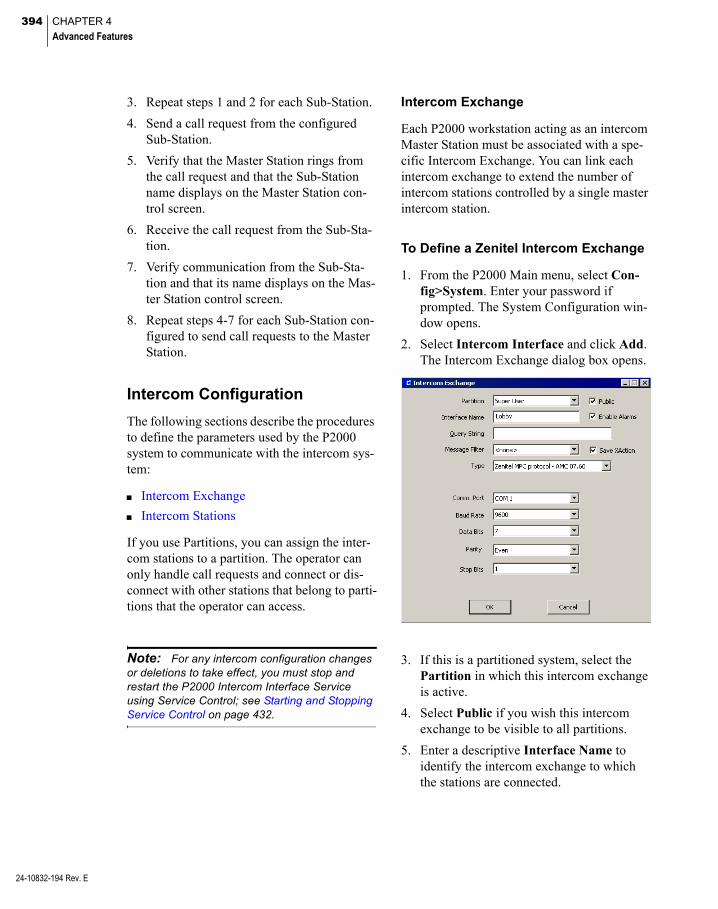
394 CHAPTER 4
Advanced Features
24-10832-194 Rev. E
3. Repeat steps 1 and 2 for each Sub-Station.
4. Send a call request from the configured Sub-Station.
5. Verify that the Master Station rings from the call request and that the Sub-Station name displays on the Master Station con-trol screen.
6. Receive the call request from the Sub-Sta-tion.
7. Verify communication from the Sub-Sta-tion and that its name displays on the Mas-ter Station control screen.
8. Repeat steps 4-7 for each Sub-Station con-figured to send call requests to the Master Station.
Intercom Configuration
The following sections describe the procedures to define the parameters used by the P2000 system to communicate with the intercom sys-tem:
Intercom Exchange
Intercom Stations
If you use Partitions, you can assign the inter-com stations to a partition. The operator can only handle call requests and connect or dis-connect with other stations that belong to parti-tions that the operator can access.
Note: For any intercom configuration changes or deletions to take effect, you must stop and restart the P2000 Intercom Interface Service using Service Control; see Starting and Stopping Service Control on page 432.
Intercom Exchange
Each P2000 workstation acting as an intercom Master Station must be associated with a spe-cific Intercom Exchange. You can link each intercom exchange to extend the number of intercom stations controlled by a single master intercom station.
To Define a Zenitel Intercom Exchange
1. From the P2000 Main menu, select Con-fig>System. Enter your password if prompted. The System Configuration win-dow opens.
2. Select Intercom Interface and click Add. The Intercom Exchange dialog box opens.
3. If this is a partitioned system, select the Partition in which this intercom exchange is active.
4. Select Public if you wish this intercom exchange to be visible to all partitions.
5. Enter a descriptive Interface Name to identify the intercom exchange to which the stations are connected.
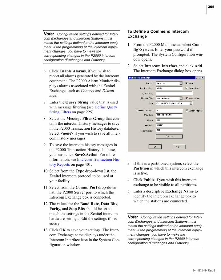
395
Note: Configuration settings defined for Inter-com Exchanges and Intercom Stations must match the settings defined at the intercom equip-ment. If the programming at the intercom equip-ment changes, you have to make the corresponding changes in the P2000 intercom configuration (Exchanges and Stations).
6. Click Enable Alarms, if you wish to report all alarms generated by the intercom equipment. The P2000 Alarm Monitor dis-plays alarms associated with the Zenitel Exchange, such as Connect and Discon-nect.
7. Enter the Query String value that is used with message filtering (see Define Query String Filters on page 225).
8. Select the Message Filter Group that con-tains the intercom history messages to save in the P2000 Transaction History database. Select <none> if you wish to save all inter-com history messages.
9. To save the intercom history messages in the P2000 Transaction History database, you must click SaveXAction. For more information, see Intercom Transaction His-tory Reports on page 401.
10. Select from the Type drop-down list, the Zenitel intercom protocol to be used at your facility.
11. Select from the Comm. Port drop-down list, the P2000 Server port to which the Intercom Exchange box is connected.
12. The values for the Baud Rate, Data Bits, Parity, and Stop Bits should be set to match the settings in the Zenitel intercom hardware settings. Edit the settings if nec-essary.
13. Click OK to save your settings. The Inter-com Exchange name displays under the Intercom Interface icon in the System Con-figuration window.
To Define a Commend Intercom Exchange
1. From the P2000 Main menu, select Con-fig>System. Enter your password if prompted. The System Configuration win-dow opens.
2. Select Intercom Interface and click Add. The Intercom Exchange dialog box opens.
3. If this is a partitioned system, select the Partition in which this intercom exchange is active.
4. Click Public if you wish this intercom exchange to be visible to all partitions.
5. Enter a descriptive Exchange Name to identify the intercom exchange box to which the stations are connected.
Note: Configuration settings defined for Inter-com Exchanges and Intercom Stations must match the settings defined at the intercom equip-ment. If the programming at the intercom equip-ment changes, you have to make the corresponding changes in the P2000 intercom configuration (Exchanges and Stations).
24-10832-194 Rev. E

396 CHAPTER 4
Advanced Features
24-10832-194 Rev. E
6. Click Enable Alarms, if you wish to report all alarms generated by the intercom equipment. The P2000 Alarm Monitor dis-plays alarms associated with the Commend Exchange, such as Connect and Discon-nect; and alarms associated with Commend stations, such as Station Alarm Set and Sta-tion Alarm Reset.
7. Enter the Query String value that is used with message filtering (see Define Query String Filters on page 225).
8. Select the Message Filter Group that con-tains the intercom history messages to save in the P2000 Transaction History database. Select <none> if you wish to save all inter-com history messages.
9. To save the intercom history messages in the P2000 Transaction History database, you must click SaveXAction. For more information, see Intercom Transaction His-tory Reports on page 401.
10. Select from the Type drop-down list, the Commend intercom protocol to be used at your facility.
11. In the Dial Number Length field, enter the number of digits to assign to each sta-tion call number.
12. Click Support Regions if your facility supports logical grouping of one or more intercom servers.
13. Enter the IP Address of the Commend Intercom Server.
14. Enter the IP Port number for communicat-ing with the Commend Intercom Server.
15. Enter the Password that to use for connect-ing to the Commend Intercom Server.
16. If your facility supports regions, enter Region Number assigned to the group of intercom servers.
17. If your intercom system supports output setting, click Outputs. The Commend Out-puts dialog box opens.
Note: The Commend interface allows you to set or reset outputs that for example, open doors, turn on lights, or activate alarm sirens. You must first configure these outputs using the Commend software and then add them to the intercom exchange definition. Intercom exchange outputs are only used for event processing and reporting purposes. If you wish to control these outputs, you must add them to the intercom station defini-tion.
18. The default Type is Output. In the Address field enter the Output address and click Add. You may add as many outputs as needed. If you wish to remove an output from the list, select the output item and click Delete.
19. Click Close to save your settings and return to the Intercom Interface configura-tion.
20. Click OK to save your settings. The Inter-com Exchange name displays under the Intercom Interface icon in the System Con-figuration window.

397
Intercom Stations
Once you create an Intercom Exchange in the System Configuration window, an Intercom Station icon is automatically added under the Intercom Exchange name. Now you should define the intercom call stations to use for audio channel communication. The P2000 sys-tem establishes a connection between the selected stations and the workstation where the operator is logged on. The P2000 workstation associated with the exchange can control the calls from the stations assigned to that exchange, as well as process intercom history messages and alarms.
To Add an Intercom Station
1. In the left pane of the System Configura-tion window, expand the Intercom Exchange name where you want to define the stations.
2. Select Intercom Station and click Add. The Intercom Station dialog box opens.
3. Enter a descriptive Name that identifies the location of the station.
4. If this is a partitioned system, select the Partition in which this intercom station is active.
5. Click Public if you wish this intercom sta-tion to be visible to all partitions.
6. Enter the Query String value that is used with message filtering (see Define Query String Filters on page 225).
7. Enter the Address assigned to this station. The P2000 system connects to the station based upon the address entered here. This address has to match the address assigned at the station equipment.
Note: For a Commend station group, you can enter a 1-digit number. This number must match the 1-digit Direct Dialing number configured for a Master station (using the Commend interface), and that can be used to activate a group number.
8. From the Priority drop-down list, select a priority value from 0 (highest) to 255 that determines the order the call request is placed in the Intercom Control queue.
9. From the Type drop-down list, select one of the following:
Sub-Station – You should configure at least one Sub-Station to send call requests to its Master Station.
Global Sub-Station – Select to allow Sub-Stations to connect to other Master Stations.
Station Group – Select to connect to multi-ple stations at the same time. The P2000 system establishes a connection between the stations that are part of the group selected and the workstation where the operator is logged on.
Master Station – The Intercom Exchange must have at least one Master Station to link to other stations.
24-10832-194 Rev. E
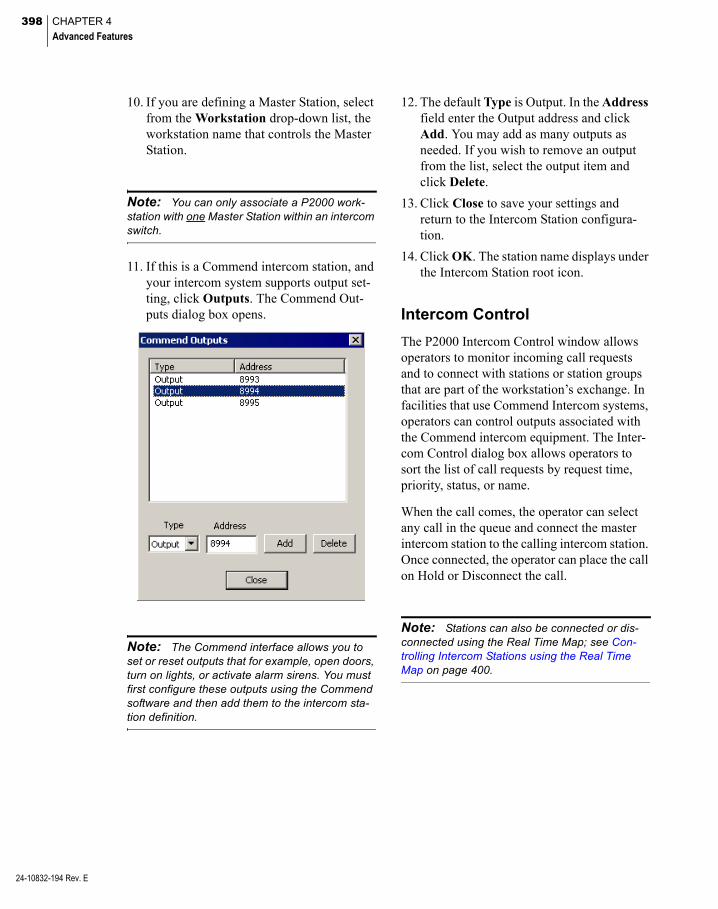
398 CHAPTER 4
Advanced Features
24-10832-194 Rev. E
10. If you are defining a Master Station, select from the Workstation drop-down list, the workstation name that controls the Master Station.
Note: You can only associate a P2000 work-station with one Master Station within an intercom switch.
11. If this is a Commend intercom station, and your intercom system supports output set-ting, click Outputs. The Commend Out-puts dialog box opens.
Note: The Commend interface allows you to set or reset outputs that for example, open doors, turn on lights, or activate alarm sirens. You must first configure these outputs using the Commend software and then add them to the intercom sta-tion definition.
12. The default Type is Output. In the Address field enter the Output address and click Add. You may add as many outputs as needed. If you wish to remove an output from the list, select the output item and click Delete.
13. Click Close to save your settings and return to the Intercom Station configura-tion.
14. Click OK. The station name displays under the Intercom Station root icon.
Intercom Control
The P2000 Intercom Control window allows operators to monitor incoming call requests and to connect with stations or station groups that are part of the workstation’s exchange. In facilities that use Commend Intercom systems, operators can control outputs associated with the Commend intercom equipment. The Inter-com Control dialog box allows operators to sort the list of call requests by request time, priority, status, or name.
When the call comes, the operator can select any call in the queue and connect the master intercom station to the calling intercom station. Once connected, the operator can place the call on Hold or Disconnect the call.
Note: Stations can also be connected or dis-connected using the Real Time Map; see Con-trolling Intercom Stations using the Real Time Map on page 400.

399
To Control Intercom Stations
1. From the P2000 Main menu, select Con-trol>Intercom. The Intercom Exchange Selection dialog box opens.
2. Select the intercom exchange you wish to control and click OK. This selection list only displays in facilities that have more than one Intercom Exchange defined. The Intercom Control dialog box opens at the Call Queue tab.
The top right section of the dialog box dis-plays general information related to the Master Station. The list box displays the calls currently in the queue, either from Sub-Stations or Station Groups. The fol-lowing information is shown for each call in the list:
Time/Date – The date and time when the call was placed.
Priority – The priority that was set in the Intercom Station dialog box.
Status – The status of the selected station, such as Call Request, On Hold, Idle, Busy, and so on.
Name – The name of the Sub-Station or Station Group that is placing the call.
Address – The address assigned to the Sub-Station or Station that is placing the call.
3. Select any call in the queue and click Con-nect. This connects your master intercom station to the calling intercom station selected.
4. Once connected, you may communicate (talk and listen) with the person at the Sub-Station. You can also perform the fol-lowing actions:
Push to Talk – Click and hold to talk (not listen) to the person at the selected calling station. Release the button to only listen (not talk) to the person at the Sub-Station. To return to duplex communication (the ability to talk and listen without holding and releasing the button), click the Push to Talk button without holding it down.
Hold – Disconnects from the calling station and leaves the call in the queue.
Disconnect – Disconnects from the calling station and removes the entry from the queue.
Connect – Selecting another entry in the queue and clicking Connect performs a Hold on the currently connected call.
5. Click Exit to close the Intercom Control dialog box.
24-10832-194 Rev. E

400 CHAPTER 4
Advanced Features
24-10832-194 Rev. E
To Control Sub-Stations Only
1. In the Intercom Control dialog box, click the Station tab.
The list box displays the Name, Address, and Priority of the Sub-Station, as well as the current status of the call request and the time and date when the change of status took place.
2. In the list box, select a station to which you wish to connect.
3. Click Connect.
4. You may now communicate with the per-son at the selected station. You may also perform the actions described earlier (Push to Talk, Hold, and so on).
5. If the selected intercom station is associ-ated with outputs (Commend systems only), select the output from the Output list box and click Set Output to activate the output, or Reset Output to reset the out-put.
6. Click Exit to close the Intercom Control dialog box.
To Control Station Groups
1. In the Intercom Control dialog box, click the Station Group tab.
The list box displays the Name, Address, and Priority of the Station Group.
2. In the list box, select a station group to which you wish to connect.
3. Click Connect.
4. You may now communicate with the per-son at the stations of the Station Group selected. You may also perform the actions described earlier (Push to Talk, Hold, and so on).
5. Click Exit to close the Intercom Control dialog box.
Controlling Intercom Stations using the Real Time Map
The Real Time Map displays the status of intercom stations on a map layout of your facility. If an intercom status changes, the Real Time Map shows the state change and the loca-tion of the intercom device. See Using the Real Time Map on page 346.
Note: Intercom station groups are stateless; therefore, the Real Time Map does not display status changes associated with intercom station groups.
401
When you receive a call request for a station, the intercom icon starts flashing. You can right-click the icon to open a shortcut menu and choose to connect or disconnect the call. If you configured the intercom to allow the oper-ator to activate events, the event name also dis-plays in the shortcut menu. In addition, if the intercom station is associated with outputs (Commend systems only), you can choose from the shortcut menu to set or reset all out-puts associated with the station.
To add intercom icons to the Real Time Map, follow the instructions provided in Place Device Icons on a Real Time Map on page 350 and select from the drop-down list the Inter-com stations you wish to display in the Real Time Map.
Note: Map Maker provides a default intercom image set to display various intercom states such as Station Idle, Station Busy, Station Call Request, and so on. However, you can use your own icons to create custom image sets. See Add-ing Image Sets on page 352 for details.
Intercom Events
The intercom equipment connected to the sys-tem can respond to event actions using the P2000 Event application. You can define Event Actions that Connect or Disconnect sta-tions, or events that are to be triggered upon a Station Busy, Station Call Request, Station Connected, or Station Idle. See Create Events on page 335 to create new event triggers and actions.
Note: The Station Connected trigger type is not supported by Commend Intercom station groups.
Intercom Transaction History Reports
The SaveXAction option in the intercom exchange definition allows you to save all intercom transactions in the P2000 Transaction History database.
Once the transaction history messages are saved, you can use the P2000 Transaction His-tory report to list all intercom transactions in the system. The Transaction History report can be filtered to list by specific Site, Partition, Date and Time, and any combination of these. You can also select to run the report to list all intercom history types, or select a specific type such as Intercom - Station Busy or Intercom - Call Station OK. The options available for selection in the History Type field depend on the equipment used at your facility.
For detailed information on running reports, see Chapter 6: System Reports.
24-10832-194 Rev. E
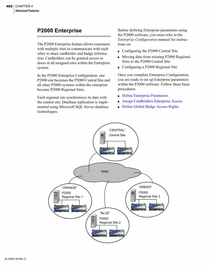
402 CHAPTER 4
Advanced Features
24-10832-194 Rev. E
P2000 Enterprise
The P2000 Enterprise feature allows customers with multiple sites to communicate with each other to share cardholder and badge informa-tion. Cardholders can be granted access to doors at all assigned sites within the Enterprise system.
In the P2000 Enterprise Configuration, one P2000 site becomes the P2000 Central Site and all other P2000 systems within the enterprise become P2000 Regional Sites.
Each regional site synchronizes its data with the central site. Database replication is imple-mented using Microsoft SQL Server database technologies.
Before defining Enterprise parameters using the P2000 software, you must refer to the Enterprise Configuration manual for instruc-tions on:
Configuring the P2000 Central Site
Moving data from existing P2000 Regional Sites to the P2000 Central Site
Configuring a P2000 Regional Site
Once you complete Enterprise Configuration, you are ready to set up Enterprise parameters within the P2000 software. Follow these basic procedures:
Define Enterprise Parameters
Assign Cardholders Enterprise Access
Define Global Badge Access Rights
P2000 Regional Site 3
“GREEN”
Central Site
“CENTRAL”
P2000 Regional Site 2
“BLUE”
P2000 Regional Site 1
“ORANGE”
WAN

403
Define Enterprise Parameters
Before assigning cardholders access to multi-ple sites, you should Define Enterprise Sites, Define Enterprise Parameters, Define Enter-prise Time Zones, and Define Enterprise Access Groups.
Define Enterprise Sites
1. From the P2000 Main menu, select Con-fig>System. Enter your password if prompted. The System Configuration win-dow opens.
2. In the left pane, expand Enterprise Parameters to display the enterprise parameters.
3. Select Enterprise Sites and click Add. The Enterprise Site Edit dialog box opens. The list box displays the name of your local site.
4. Enter the Name of the regional Site exactly as defined at the P2000 site that provides access.
5. Enter the Database Server name of the regional site.
6. In the Subscription Sites box, select the site names that can be associated with this site. Any changes in this Site are reflected on the site names selected in this box.
7. If you wish to select all sites, click All. This option allows you to unselect site names individually.
8. If you wish to clear your selections, click None.
9. If you wish to select all sites, click All sites. This option does not allow editing.
10. Click OK to save your settings.
Define Enterprise Parameters
1. From the P2000 Main menu, select Con-fig>System. Enter your password if prompted. The System Configuration win-dow opens.
2. Select Enterprise Parameters and click Edit. The Enterprise Parameters Edit dia-log box opens.
3. Select from the Enterprise Site drop-down list, the site name to be defined as the central Enterprise site.
4. Select one of the following Central Con-trol of Badge Enabling/Disabling options:
Note: This feature is provided to allow badge enabling and disabling on Enterprise systems. For the central control of badge enable/disable feature to operate, each regional site must sub-scribe to the central site.
MIS – To enable or disable badges on the central site, through the MIS Interface.
24-10832-194 Rev. E

404 CHAPTER 4
Advanced Features
24-10832-194 Rev. E
User Interface – To enable or disable badges on the central site, through Web Access or the Badge application.
Host Event – To enable or disable badges on the central site, through Host Events.
5. Click OK to save your settings.
Define Enterprise Time Zones
1. Expand Enterprise Parameters to display the enterprise parameters.
2. Select Time Zones and click Add. The Enterprise Time Zone Edit dialog box opens.
3. Enter the Name of the Time Zone exactly as defined at the P2000 site that provides access.
4. Click OK to save your settings.
Define Enterprise Access Groups
1. Expand Enterprise Parameters to display the enterprise parameters.
2. Select Access Groups and click Add. The Enterprise Access Group Edit dialog box opens.
3. Enter the Name of the Access Group exactly as defined at the P2000 site that provides access.
4. Click OK to save your settings.
Assign Cardholders Enterprise Access
Use the Cardholder application to assign the sites a cardholder can access. Once the sites are assigned, the cardholder information is sent to the selected sites for download.
To Assign Enterprise Access to a Cardholder
1. From the P2000 Main menu, select Access>Cardholder. The Cardholder win-dow opens.
2. Create a new record or edit an existing cardholder as desired. For details, see Entering Cardholder Information on page 244. The Cardholder Edit dialog box opens.
The Enterprise box displays all the sites defined in the System Configuration win-dow. See Define Enterprise Sites on page 403.
3. In the Enterprise box, select the check box next to the site that this cardholder may access. You may select as many sites as needed.
4. To select all sites, click All.
5. To clear your selections, click None.

405
6. Once the sites are assigned, click OK to return to the Cardholder window. The information also displays in the Enterprise Sites tab located in the center of the win-dow.
Define Global Badge Access Rights
Once the cardholder has been assigned to the selected sites, you may define the security privileges and access rights using the Badge application.
To Define Badge Access Rights
1. In the Cardholder window, select a card-holder from the Cardholder list that has Enterprise access.
2. In the Badge Information box at the bot-tom of the Cardholder window, click Add. The Badge dialog box opens.
3. Enter the badge number and optional de-scription. For detailed information, see En-tering Badge Information on page 251.
The Badge dialog box displays the site name tabs of the sites assigned to this card-holder. The first tab is always the local site tab and is used to assign local access privi-leges. The second tab is the Enterprise tab and is used to assign global access privi-leges. Additional tabs show other site names assigned to the cardholder.
Assigning access privileges is determined by the following conditions:
When you define access to the local site, and click Apply Security Options ‘Enterprise’, the security options defined in the Enterprise tab are applied.
When you define access at a different site, and click Apply Security Options ‘Enterprise’, the security options defined in the Enterprise tab are applied to that site.
Access Groups and Time Zones can be accessed for your own site, the Enter-prise site or for any site within the Enterprise system.
On each site, a maximum of 64 Access Groups and Time Zones are applicable (32 local and 32 Enterprise).
The P2000 system only downloads the maximum number of Access Groups and Time Zones for each panel type, giving priority to the local settings.
4. Once the badge access parameters are defined, click OK to return to the Card-holder window. This initiates all required downloads.
Note: The Status column in the Badge Infor-mation box at the bottom of the Cardholder win-dow, displays the status of badges for the local site only.
24-10832-194 Rev. E

406 CHAPTER 4
Advanced Features
24-10832-194 Rev. E
Web Access
Web Access is a suite of applications that enables users to perform various P2000 tasks from any web-ready computer. Web Access offers many features such as employee, visitor, and contractor management applications; badge activity tracking and synchronization; alarm monitoring; emergency access disable; web badging capabilities; and a customizable user interface.
The P2000 server runs the Web Access front-end and back-end services. The front-end services handle the web browser HTTP requests, while the back-end services handle the application’s XML requests from the front end.
Before you define Web Access parameters using the P2000 software, you must refer to the Web Access Manual for the software compo-nents required to operate the P2000 Web Access application.
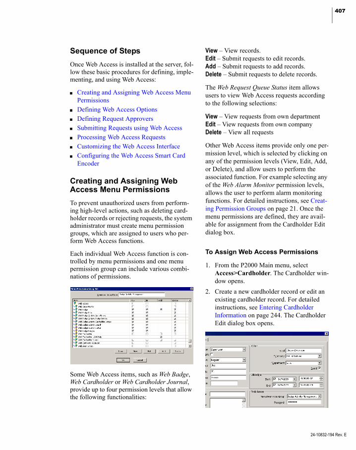
407
Sequence of Steps
Once Web Access is installed at the server, fol-low these basic procedures for defining, imple-menting, and using Web Access:
Creating and Assigning Web Access Menu Permissions
Defining Web Access Options
Defining Request Approvers
Submitting Requests using Web Access
Processing Web Access Requests
Customizing the Web Access Interface
Configuring the Web Access Smart Card Encoder
Creating and Assigning Web Access Menu Permissions
To prevent unauthorized users from perform-ing high-level actions, such as deleting card-holder records or rejecting requests, the system administrator must create menu permission groups, which are assigned to users who per-form Web Access functions.
Each individual Web Access function is con-trolled by menu permissions and one menu permission group can include various combi-nations of permissions.
Some Web Access items, such as Web Badge, Web Cardholder or Web Cardholder Journal, provide up to four permission levels that allow the following functionalities:
View – View records.Edit – Submit requests to edit records.Add – Submit requests to add records.Delete – Submit requests to delete records.
The Web Request Queue Status item allows users to view Web Access requests according to the following selections:
View – View requests from own departmentEdit – View requests from own companyDelete – View all requests
Other Web Access items provide only one per-mission level, which is selected by clicking on any of the permission levels (View, Edit, Add, or Delete), and allow users to perform the associated function. For example selecting any of the Web Alarm Monitor permission levels, allows the user to perform alarm monitoring functions. For detailed instructions, see Creat-ing Permission Groups on page 21. Once the menu permissions are defined, they are avail-able for assignment from the Cardholder Edit dialog box.
To Assign Web Access Permissions
1. From the P2000 Main menu, select Access>Cardholder. The Cardholder win-dow opens.
2. Create a new cardholder record or edit an existing cardholder record. For detailed instructions, see Entering Cardholder Information on page 244. The Cardholder Edit dialog box opens.
24-10832-194 Rev. E
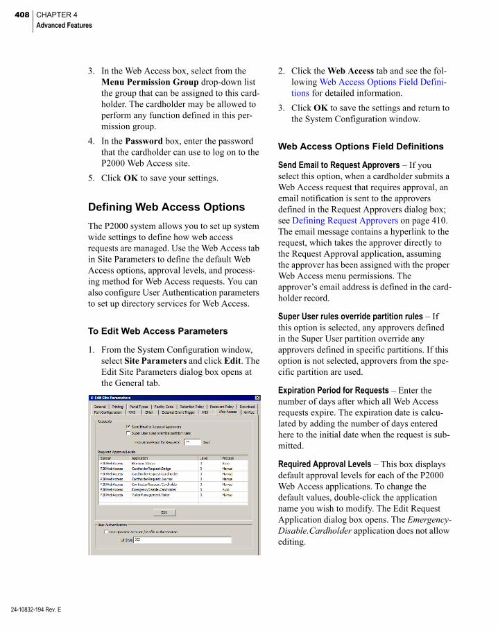
408 CHAPTER 4
Advanced Features
24-10832-194 Rev. E
3. In the Web Access box, select from the Menu Permission Group drop-down list the group that can be assigned to this card-holder. The cardholder may be allowed to perform any function defined in this per-mission group.
4. In the Password box, enter the password that the cardholder can use to log on to the P2000 Web Access site.
5. Click OK to save your settings.
Defining Web Access Options
The P2000 system allows you to set up system wide settings to define how web access requests are managed. Use the Web Access tab in Site Parameters to define the default Web Access options, approval levels, and process-ing method for Web Access requests. You can also configure User Authentication parameters to set up directory services for Web Access.
To Edit Web Access Parameters
1. From the System Configuration window, select Site Parameters and click Edit. The Edit Site Parameters dialog box opens at the General tab.
2. Click the Web Access tab and see the fol-lowing Web Access Options Field Defini-tions for detailed information.
3. Click OK to save the settings and return to the System Configuration window.
Web Access Options Field Definitions
Send Email to Request Approvers – If you select this option, when a cardholder submits a Web Access request that requires approval, an email notification is sent to the approvers defined in the Request Approvers dialog box; see Defining Request Approvers on page 410. The email message contains a hyperlink to the request, which takes the approver directly to the Request Approval application, assuming the approver has been assigned with the proper Web Access menu permissions. The approver’s email address is defined in the card-holder record.
Super User rules override partition rules – If this option is selected, any approvers defined in the Super User partition override any approvers defined in specific partitions. If this option is not selected, approvers from the spe-cific partition are used.
Expiration Period for Requests – Enter the number of days after which all Web Access requests expire. The expiration date is calcu-lated by adding the number of days entered here to the initial date when the request is sub-mitted.
Required Approval Levels – This box displays default approval levels for each of the P2000 Web Access applications. To change the default values, double-click the application name you wish to modify. The Edit Request Application dialog box opens. The Emergency-Disable.Cardholder application does not allow editing.

409
Sender – This field displays the Sender that originated the Web Access request.
Application – This field displays the name of the P2000 Web Access application you are currently modifying.
Approval Levels – Select a number from the drop-down list to define how many approvers are required to approve this type of Web Access request. If you select 0, the Web Access request is sent directly for processing.
Processing Mode – This field defines how the request is processed after the Web Access request has been approved. Select from the drop-down list one of the following options:
Auto – Select this option if the request is processed automatically (without interven-tion). Not available for the VisitorManage-ment.Visitor application.
Manual – Select this option if this applica-tion requires an authorized user to manually process the request; see Processing Web Access Requests on page 416.
User Authentication Box
P2000 Web Access operator passwords can be authenticated against a directory service such as Microsoft Active Directory or Lightweight Directory Access Protocol (LDAP). This elim-inates operator passwords from the P2000 database.
This feature is useful in situations where pass-words are periodically changed and therefore, eliminates the need to update passwords in the P2000 system and also passwords that are used to log on to Windows.
To use directory service password validation, set up the following elements:
Configure the Directory Services Pass-word Validation fields on the Password Policy tab of Site Parameters (see page 40). The actual value to use for the Directory Services Path is unique to your specific net-work configuration and needs to be obtained from the network administrator.
Create an AD Account or AD Profile oper-ator account on the Edit Operator dialog box (see page 24) for each P2000 Web Access operator whose password is to be verified by directory services.
Once the previous elements are configured, define the following parameters in the User Authentication box:
Use Operator Account / Profile Authentication – Click if you wish to use the P2000 Account, AD Account, or AD Profile operator user type for Web Access login (see User Info Tab on page 24). If you wish to log in to Web Access using a cardholder account (the cardholder first and last name, for example, john.smith), you must clear this check box. Changes to this option requires restarting all P2000 Services and IIS, or restarting the P2000 Server.
UI Style – Enter the Web Access user interface style that users are assigned when logging on using directory services authentication.
Note: The UI Style assigned affects all P2000 operators whose accounts are enabled for direc-tory services authentication. This parameter can-not be assigned individually (you cannot assign styles to specific users).
24-10832-194 Rev. E

410 CHAPTER 4
Advanced Features
24-10832-194 Rev. E
Defining Request Approvers
Depending on settings previously defined in Site Parameters, each Web Access request may require up to three active approvers. The approver is a cardholder who has been assigned Web Request Approval menu permis-sions. Approvers are ordered in a sequence and approve requests in the same order.
For example, an application requires three approvers: John (Level 1), Mary (Level 2), and Bob (Level 3). When a request is submitted, an email notification is sent to John, who approves the request first. After John approves the request, an email notification is sent to Mary; then after Mary approves the request, an email notification is sent to Bob. After Bob approves the request, the approval process is complete. Bob never sees requests that are not approved by Mary, and Mary never sees requests that are not approved by John.
Approvers only see requests that are waiting for their approval and each request waits for a single approver at any time. When a request becomes ready for the next approver an email notification is sent to the approver.
If an application requires a single approver, after the approver approves the request, the approval process is complete.
The P2000 system ignores all requests that do not have all required approvals completed.
The approver’s email address for sending noti-fications is entered in the cardholder record.
To Enter the Cardholder Email Address
1. From the P2000 Main menu, select Access>Cardholder. The Cardholder win-dow opens.
2. Create a new cardholder record or edit an existing cardholder record. For detailed instructions, see Entering Cardholder Information on page 244. The Cardholder Edit dialog box opens.
3. Enter the Email address that has been assigned to this cardholder and where noti-fications are sent to approve Web Access requests.
Note: To configure your Email Server, see EMail Tab on page 44, and also check with your IT department for the required email settings in your facility.
4. Click OK to save your settings.
To Define Request Approvers
1. In the left pane of the System Configura-tion window, expand Site Parameters.
2. Select Request Approvers and click Edit. The Request Approvers dialog box opens.

411
3. Select the Partition from the drop-down list that contains the cardholders that are assigned as approvers. Requesters and approvers need to be in the same partition, unless the approver is in the Super User partition.
4. Click Add. The Edit Approval Rule dialog box opens. If you leave an asterisk (*) in a field, the Approval Rule includes all records for that field.
5. Select from the drop-down list, the Sender that originated the request. The selected cardholder can only approve requests com-ing from this sender.
6. From the Application drop-down list, select the name of the Web Access func-tion that the selected cardholder is allowed to approve.
7. Select the type of Operation (Add, Delete, or Update) that the selected cardholder is allowed to approve.
8. Select a Company name if you wish to have the selected cardholder approve only requests coming from the company selected here.
9. Select a Department name if you wish to have the selected cardholder approve only requests coming from the department selected here.
10. Select the Level 1 tab and click Add. The Select Cardholder dialog box opens.
11. Enter the First Name and/or Last Name (or leave the default *), and click Search.
24-10832-194 Rev. E

412 CHAPTER 4
Advanced Features
24-10832-194 Rev. E
12. Select a cardholder from the list and click OK. The name is added to the Level 1 list box. You can add as many Level 1 approv-ers as needed, but only one can be the active Level 1 approver.
13. From the Level 1 list box, select the card-holder who is the active Level 1 approver of the type of application and operation selected (for the company and department selected, if applicable). Click Active. You can change the Active approver as needed.
14. To remove a cardholder from the list, select the name and click Delete.
15. Repeat the procedure, starting with step 4, for the Web Access requests that require Level 2 and Level 3 approvers.
Note: The system generates an error message if a request is submitted and the number of required approvers has not been defined.
16. Once you define the rules for the requests that require approvals, click OK. The Request Approvers dialog box displays a list of approval filters. To move an approval filter up or down on the list, select the line item and click Up or Down.
The order in which approval filters display in the Request Approvers list box is signif-icant. When a request is submitted, the approval filters in the list are scanned from the top down until the first request and fil-ter match is found. When a match is found the attached approver list is used. If two approval filters include the same rules, the filter above has precedence over the one below.
Rule 1 requires three approvers for adding cardholders (from any company and department).
Rule 4 requires one approver for any request submitted, except that new cardholders (rule 1), new visitors (rule 2), and DEFG company (rule 3) requests will be approved by the ap-proval filters above.
Rule 2 requires only one approver for adding visitors (from any company and department).
Rule 3 requires one approver for any type of request submitted for the DEFG company (any department), except that new cardhold-ers (rule 1) and new visitors (rule 2) will be approved by the approval filters above.
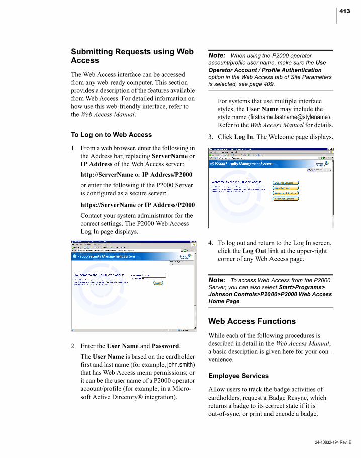
413
Submitting Requests using Web Access
The Web Access interface can be accessed from any web-ready computer. This section provides a description of the features available from Web Access. For detailed information on how use this web-friendly interface, refer to the Web Access Manual.
To Log on to Web Access
1. From a web browser, enter the following in the Address bar, replacing ServerName or IP Address of the Web Access server:
http://ServerName or IP Address/P2000
or enter the following if the P2000 Server is configured as a secure server:
https://ServerName or IP Address/P2000
Contact your system administrator for the correct settings. The P2000 Web Access Log In page displays.
2. Enter the User Name and Password.
The User Name is based on the cardholder first and last name (for example, john.smith) that has Web Access menu permissions; or it can be the user name of a P2000 operator account/profile (for example, in a Micro-soft Active Directory® integration).
Note: When using the P2000 operator account/profile user name, make sure the Use Operator Account / Profile Authentication option in the Web Access tab of Site Parameters is selected, see page 409.
For systems that use multiple interface styles, the User Name may include the style name (firstname.lastname@stylename). Refer to the Web Access Manual for details.
3. Click Log In. The Welcome page displays.
4. To log out and return to the Log In screen, click the Log Out link at the upper-right corner of any Web Access page.
Note: To access Web Access from the P2000 Server, you can also select Start>Programs> Johnson Controls>P2000>P2000 Web Access Home Page.
Web Access Functions
While each of the following procedures is described in detail in the Web Access Manual, a basic description is given here for your con-venience.
Employee Services
Allow users to track the badge activities of cardholders, request a Badge Resync, which returns a badge to its correct state if it is out-of-sync, or print and encode a badge.
24-10832-194 Rev. E

414 CHAPTER 4
Advanced Features
24-10832-194 Rev. E
Cardholder Search
Allows searching for cardholder records in the P2000 database. Users may search by card-holder name, badge number, ID number, department, and company.
Area Search
Allows users to view which cardholders cur-rently occupy a specific controlled area in a facility. A controlled area is a designated sec-tion of a facility, with one or more readers or input points assigned, with the purpose of reporting on the current whereabouts of card-holders.
In Out Displays
Allows users to see which cardholders are In or Out of the facility, or specific areas of the facility, based on their badge activity. If a card-holder has badged to enter the facility the sta-tus is In. If a cardholder has not badged to enter the facility, the status is Out.
Badge Resync
Allows users to manually adjust the status of their badge if it has been placed in an out-of-sync state. A badge is out-of sync when cardholders (that are required to enter and exit an area in sequence using entry and exit termi-nals), badge In at an entry terminal and don’t badge Out at the next badging if, for example, they follow another cardholder out without swiping their badge. In that case, the badge remains in the In state (out-of-sync) and is denied access the next time they attempt to badge back into the area.
Badge Print
Allows users to locate cardholder records using various search filters. After performing a search, Web Access lists the badge ID number, cardholder name, personal identification num-ber, company, and department of each card-holder record located in the search; then users can preview, print, and encode a cardholder’s badge by clicking the badge ID number.
Guard Services
These services allow authorized users to per-form several guard-related actions, such as view, acknowledge, and remove alarms; and manually control doors and output devices.
Alarm Monitor
P2000 alarms can be monitored, acknowl-edged, and removed using the Web Access interface. This feature is useful to monitor alarms at unattended sites, allowing authorized users to acknowledge alarm conditions as soon as they are reported. Once an alarm is in a secure state, the user can remove the alarm from the queue.
Command Outputs
Output devices can be manually activated or deactivated by authorized users to control devices connected to them such as lights, warning indicators or sirens.
Door Command
This feature allows an authorized user to man-ually lock or unlock a door (override system controls) for a specific time. The user is able to unlock all doors at once or return all doors to their previous state.
415
Management Services
Through Management Services, an authorized user can add or edit cardholder records, includ-ing badge and associated cardholder informa-tion. In addition, the user can also view, approve, and process Web Access requests.
Request Status
The Request Status page allows authorized users to view the status of their requests, and depending on their menu permissions, the sta-tus of all requests or the status of requests sub-mitted by other users that belong to the same department or company. The top portion of the screen displays the Request Parameters box where users can search for specific requests. The bottom portion displays the Request List, which displays requests in the order they are received. The links under the Request column allows you to view the details of the requests.
Request Approval
The approval process provides additional security measures by confirming the validity of a request before the request is presented for processing. Depending on the settings previ-ously defined in Site Parameters (see Defining Web Access Options on page 408), up to three authorized users may be required to approve Web Access requests.
Add Cardholder
This feature allows authorized users to submit requests to enter cardholder information into the system. Depending on the permissions assigned, users can enter cardholder related information such as user-defined fields, jour-nals, badge information, sponsor information (if the cardholder is a visitor), or attach a por-trait to the cardholder record.
Edit Cardholder
In addition to submitting requests for new cardholders, authorized users can also request to change existing cardholder records, includ-ing deleting records from the system.
Validate
This function is used to process Web Access requests that require manual processing. See Processing Web Access Requests on page 416.
Audit
This feature allows authorized users to track changes to the software based on who per-formed the action, the data affected by the action, the date and time the action occurred, and the action itself, such as Add Badge, Edit Cardholder, Execute Application, and so on.
WebBadging Setup
Allows you to download and run the Web-BadgingSetup.exe file, which installs the WebUSB application to enable the use of USB-compatible badging devices via the P2000 Web Access interface. This service must be running on the client computer run-ning Web Access or the badging devices can-not be controlled.
Visitor Management
Allows authorized users to request a visitor badge or request to extend the validation period of a cardholder badge. In addition, users can also view the status of their requests.
24-10832-194 Rev. E
416 CHAPTER 4
Advanced Features
24-10832-194 Rev. E
Visitor Request
Web Access provides a faster way for users to make visitor badge requests, so badges are ready when a visitor arrives at a building. Users can simply enter the appropriate visitor data into the system, assign a visitor sponsor, enter the date and time period of the scheduled visit, and enter notes for visitors with special needs. Visitor requests are processed using the P2000 Visitor Request Management application; see To Process Visitor Requests on page 416.
Contractor Request
Enables authorized users to extend the badge validity period for selected cardholders. This feature is typically used for visitor badges that are about to expire, but can also be used as needed to extend the badge validity period for regular cardholders. Users can only extend the badge validity period for cardholders who belong to the same company as the user.
Request Status
This function is also accessed from Manage-ment Services; see Request Status on page 415.
Emergency Access Disable
This feature provides a rapid method of dis-abling access in case of an emergency. An authorized user can quickly disable all badges associated with selected cardholders and access is immediately denied at all doors. In addition, the selected cardholders are unable to perform any Web Access functions. Once it is determined that the emergency is over, the badges can be enabled again using the Badge application.
Note: Badges cannot be enabled using the Web Access interface.
Processing Web Access Requests
Web Access requests are processed either auto-matically or manually, depending on the con-figuration defined in Site Parameters (see Defining Web Access Options on page 408).
With the exception of Visitor Requests, all Web Access requests can be processed auto-matically. Once a request is submitted and the approval is completed (if approval is part of the process), the request is added to the P2000 database. If an error occurs during this process, the request displays in the Request Queue table (see Viewing Request Queue on page 466) as Error or Rejected and the requester is subse-quently notified of the problem.
Web Access requests that are set to Manual process, require an authorized user to manually process the request. After the request is sub-mitted and the approval is completed (if approval is part of the process), the request is sent out for validation. With the exception of Visitor Requests, all Web Access requests are processed from the Validation page. See To Process Visitor Requests for instructions on manually processing Visitor Requests.
To Process Visitor Requests
1. From the P2000 Main menu, select Access>Visitor Request Management. The Visitor Request Management dialog box opens. The list box (top portion of the screen) displays a queue of requests sub-mitted using Web Access.
Note: The Visitor Request Management dialog box should be kept opened at all times for the person to manually process and act upon incom-ing visitor requests.
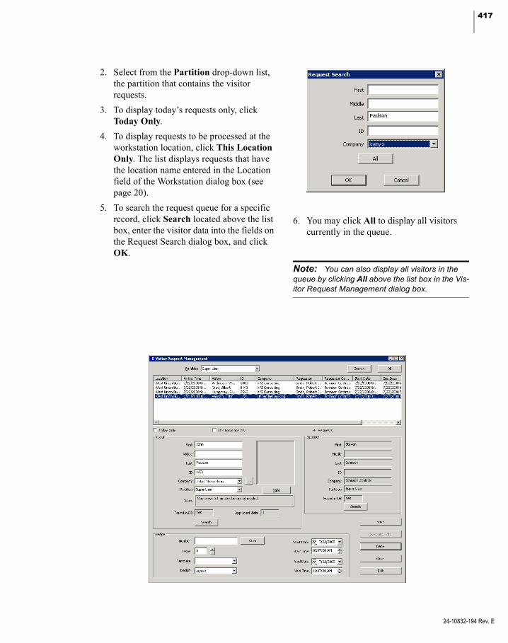
417
2. Select from the Partition drop-down list, the partition that contains the visitor requests.
3. To display today’s requests only, click Today Only.
4. To display requests to be processed at the workstation location, click This Location Only. The list displays requests that have the location name entered in the Location field of the Workstation dialog box (see page 20).
5. To search the request queue for a specific record, click Search located above the list box, enter the visitor data into the fields on the Request Search dialog box, and click OK.
6. You may click All to display all visitors currently in the queue.
Note: You can also display all visitors in the queue by clicking All above the list box in the Vis-itor Request Management dialog box.
24-10832-194 Rev. E

418 CHAPTER 4
Advanced Features
24-10832-194 Rev. E
7. Select an entry from the queue to pre-fill the Visitor and Sponsor fields. Other infor-mation related to the selected Visitor, such as Request Notes, also display.
Note: The Found in DB fields indicate whether or not the P2000 system has identified a match-ing Visitor or Sponsor record in the cardholder database. A picture also displays, if there is one previously saved for the selected visitor.
8. See the following Visitor Request Manage-ment Field Definitions for more detailed information.
9. When all the information is entered, click Save to complete the request and save the visitor and badge information. The new visitor data is also reflected in the Card-holder window.
10. If you wish to save and print the badge, click Save and Print (requires the Video Imaging application).
11. To process additional visitor requests, click Clear to clear the information on the screen, then select another visitor name from the queue or enter the information according to the Visitor Request Manage-ment Field Definitions.
12. If a visitor request is to be rejected, select the name from the queue and click Deny.
13. Click Exit to close the Visitor Request Management dialog box.
Visitor Request Management Field Definitions
Visitor Box
First – Displays the first name of the visitor selected in the queue. You may also enter a value to search the cardholder database by first name.
Middle – Displays the middle name of the visi-tor. You may also enter a value to search the cardholder database by middle name.
Last – Displays the last name of the visitor. You may also enter a value to search the card-holder database by last name.
ID – Displays the ID of the visitor. You may also enter a value to search the cardholder database by this field.
Company – Displays the visitor’s Company name. You may also enter a value to search the cardholder database by company name.
If the company name does not already exist in the database for the visitor’s assigned partition, you are notified upon selecting the visitor request in the queue. To add the company name to the P2000 database, click the browse button to open the Company window. See Define Companies and Departments on page 234 for information on adding a company name to the P2000 database.
Partition – Displays the partition assigned to the visitor. To change the assigned partition, select a new one from the drop-down list. If you change the partition, you may also have to reassign the visitor’s company to a company that belongs to the same partition.
Notes – Displays the visitor request notes entered by the requestor.
Found in DB – Indicates whether or not the P2000 system has identified a matching Visitor record in the cardholder database. If no match is identified, click Search to manually search for a matching record.
If Found in DB shows Yes, then the existing visitor record in the P2000 database is updated. If it shows No, the new visitor is added when you click Save.
Approved Visits – Displays the number of approved visits. This field is only valid if the Found in DB field displays Yes.

419
Note: The Visitor Request Management appli-cation creates four UDFs: Approved Visits, Most Recent Visit, Second Most Recent Visit, and Third Most Recent Visit. These UDFs are automatically updated and allow you to monitor the visits associated with the selected visitor.
Search – If the P2000 system did not identify a matching Visitor record in the database, you may search the database by entering a value in any of the Visitor fields and then clicking Search. The Find Visitor dialog box opens dis-playing the visitor records that match the entered values. You may also click Search without entering any values to display all visi-tors in the database. To search for specific names in the Find Visitor dialog box, enter the data in any of the fields. You can use wildcards such as “?” to replace one character (including a space), or “*” to replace more than one char-acter.
Select the visitor’s name and click OK.
Take – If your facility uses the Video Imaging application, click Take to capture the visitor’s portrait. See the instructions on page 363 (Step 4.) for details on capturing portrait images.
Sponsor Box
First – Displays the first name of the person who sponsors this visitor.
Middle – Displays the middle name of the per-son who sponsors this visitor.
Last – Displays the last name of the person who sponsors this visitor.
ID – Displays the unique ID assigned to the sponsor.
Company – Displays the sponsor’s Company name.
Partition – Displays the partition assigned to the sponsor.
Found in DB – Indicates whether or not the P2000 system has identified a matching Spon-sor record in the cardholder database. If no match is identified, click Search to manually search for a matching record.
Search – If the P2000 system did not identify a matching Sponsor record in the database, you may search the database by clicking Search. The Find Sponsor dialog box opens displaying the sponsor records that match the entered val-ues. If no value was entered, all cardholders in the database are displayed. To search for spe-cific names, enter the data in any of the fields. You can use wildcards such as “?” to replace one character (including a space), or “*” to replace more than one character.
Select the sponsor’s name and click OK.
24-10832-194 Rev. E

420 CHAPTER 4
Advanced Features
24-10832-194 Rev. E
Badge Box
Number – Enter a badge number (the number of allowed characters depends on the parame-ters selected in the Site Parameters dialog box; see Max Badge Number in the Badge Tab on page 37).
Auto – If your facility is set up to use the Auto-Badge Management feature (see page 264), click Auto to insert the next available badge number in the Number field.
Issue – Enter an issue level per badge number. If a visitor loses a badge, you would give the next available issue level and retain the same badge number. The number of badge issue lev-els supported depends on the panel type you use; see Max Issue Level in the Badge Tab on page 37.
Template – Select from the drop-down list the access template to be applied to this badge. See Create Access Templates on page 236.
Design – Select from the drop-down list the badge design that was created using the Video Imaging application.
Start Date – Enter the date this badge becomes active. Click the down arrow to select a date from the system calendar.
Start Time – Enter the time this badge becomes active. Click the spin box buttons to select a time.
Void Date – Enter the date this badge is auto-matically voided. Click the down arrow to select a date from the system calendar.
Void Time – Enter the time this badge is auto-matically voided by the system. Click the spin box buttons to select a time.
Customizing the Web Access Interface
Web Access graphical user interface is con-trolled by styles, which can be fully custom-ized according to individual needs. The inter-face is built with XML (Extensible Markup Language) technology and can be customized using the Altova® StyleVision® designer soft-ware tool to modify the following Web Access interface components:
Caption font size, type, and color
Images (for example, a company logo)
Field type (combo box, text box, and so on), location, and size
Button types
Background colors
Note: The customization feature also allows Web Access pages to be displayed in different languages.
Web Access provides a default style (jci), which is assigned to all Web Access users. You can however, modify the default style and assign it to all users, or create multiple styles to be assigned to specific users via UDFs (see Assigning Styles to Web Access Users for details).
For detailed instructions on creating custom-ized styles, refer to the Web Access Manual.
Assigning Styles to Web Access Users
Once the Web Access interface styles have been created using the instructions provided in the Web Access Manual, they are available for assignment via the UIstyle user-defined field (UDF).
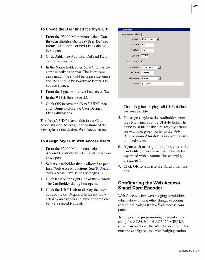
421
To Create the User Interface Style UDF
1. From the P2000 Main menu, select Con-fig>Cardholder Options>User Defined Fields. The User Defined Fields dialog box opens.
2. Click Add. The Add User Defined Field dialog box opens.
3. In the Name field, enter UIstyle. Enter the name exactly as shown. The letter case must match: UI should be uppercase letters and style should be lowercase letters. Do not add spaces.
4. From the Type drop-down list, select Text.
5. In the Width field enter 32.
6. Click OK to save the UIstyle UDF, then click Done to close the User Defined Fields dialog box.
The UIstyle UDF is available in the Card-holder window to assign one or more of the new styles to the desired Web Access users.
To Assign Styles to Web Access Users
1. From the P2000 Main menu, select Access>Cardholder. The Cardholder win-dow opens.
2. Select a cardholder that is allowed to per-form Web Access functions. See To Assign Web Access Permissions on page 407.
3. Click Edit on the right side of the window. The Cardholder dialog box opens.
4. Click the UDF 1 tab to display the user defined fields. Required fields are indi-cated by an asterisk and must be completed before a record is saved.
The dialog box displays all UDFs defined for your facility.
5. To assign a style to the cardholder, enter the style name into the UIstyle field. The name must match the directory style name; for example, green. Refer to the Web Access Manual for details in creating cus-tomized styles.
6. If you wish to assign multiple styles to the cardholder, enter the names of the styles separated with a comma; for example, green,basic.
7. Click OK to return to the Cardholder win-dow.
Configuring the Web Access Smart Card Encoder
Web Access offers web badging capabilities, which allow among other things, encoding cardholder badges from a Web Access com-puter.
To support the programming of smart cards using the ACS® Model ACR120 MIFARE smart card encoder, the Web Access computer must be configured as a web badging station.
24-10832-194 Rev. E
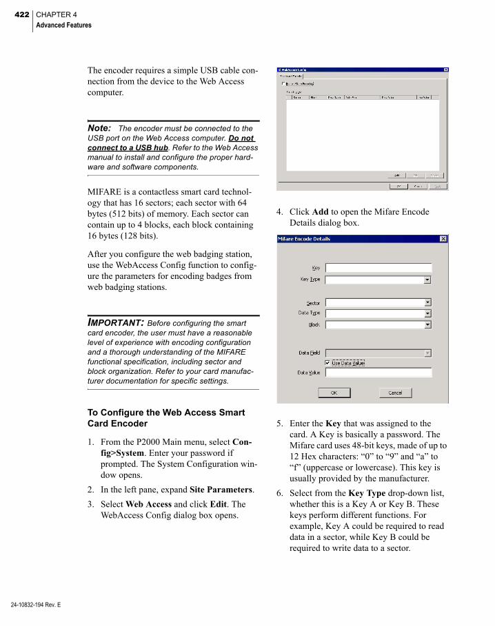
422 CHAPTER 4
Advanced Features
24-10832-194 Rev. E
The encoder requires a simple USB cable con-nection from the device to the Web Access computer.
Note: The encoder must be connected to the USB port on the Web Access computer. Do not connect to a USB hub. Refer to the Web Access manual to install and configure the proper hard-ware and software components.
MIFARE is a contactless smart card technol-ogy that has 16 sectors; each sector with 64 bytes (512 bits) of memory. Each sector can contain up to 4 blocks, each block containing 16 bytes (128 bits).
After you configure the web badging station, use the WebAccess Config function to config-ure the parameters for encoding badges from web badging stations.
IMPORTANT: Before configuring the smart card encoder, the user must have a reasonable level of experience with encoding configuration and a thorough understanding of the MIFARE functional specification, including sector and block organization. Refer to your card manufac-turer documentation for specific settings.
To Configure the Web Access Smart Card Encoder
1. From the P2000 Main menu, select Con-fig>System. Enter your password if prompted. The System Configuration win-dow opens.
2. In the left pane, expand Site Parameters.
3. Select Web Access and click Edit. The WebAccess Config dialog box opens.
4. Click Add to open the Mifare Encode Details dialog box.
5. Enter the Key that was assigned to the card. A Key is basically a password. The Mifare card uses 48-bit keys, made of up to 12 Hex characters: “0” to “9” and “a” to “f” (uppercase or lowercase). This key is usually provided by the manufacturer.
6. Select from the Key Type drop-down list, whether this is a Key A or Key B. These keys perform different functions. For example, Key A could be required to read data in a sector, while Key B could be required to write data to a sector.
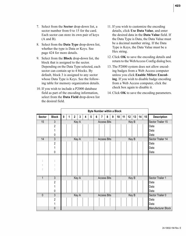
423
7. Select from the Sector drop-down list, a sector number from 0 to 15 for the card. Each sector can store its own pair of keys (A and B).
8. Select from the Data Type drop-down list, whether the type is Data or Keys. See page 424 for more details.
9. Select from the Block drop-down list, the block that is assigned to the sector. Depending on the Data Type selected, each sector can contain up to 4 blocks. By default, block 3 is assigned to any sector whose Data Type is Keys. See the follow-ing table for memory organization details.
10. If you wish to include a P2000 database field as part of the encoding information, select from the Data Field drop-down list the desired field.
11. If you wish to customize the encoding details, click Use Data Value, and enter the desired data in the Data Value field. If the Data Type is Data, the Data Value must be a decimal number string. If the Data Type is Keys, the Data Value must be a Hex string.
12. Click OK to save the encoding details and return to the WebAccess Config dialog box.
13. The P2000 system does not allow encod-ing badges from a Web Access computer unless you click Enable Mifare Encod-ing. If you wish to disable badge encoding from a Web Access computer, click the check box again to disable it.
14. Click OK to save the encoding parameters.
Byte Number within a Block
Sector Block 0 1 2 3 4 5 6 7 8 9 10 11 12 13 14 15 Description
15 3 Key A Access Bits Key B Sector Trailer 152 Data1 Data0 Data
14 3 Key A Access Bits Key B Sector Trailer 142 Data1 Data0 Data
: :: :: :
1 3 Key A Access Bits Key B Sector Trailer 12 Data1 Data0 Data
0 3 Key A Access Bits Key B Sector Trailer 02 Data1 Data0 Manufacturer Block
24-10832-194 Rev. E

424 CHAPTER 4
Advanced Features
24-10832-194 Rev. E
Mifare Encoding Scheme
Data Type: Data / User Data Value: false
If the value of the selected Data Field is a number, it is encoded in binary with an end-ing semi-byte ‘0x0’; example:
for data field Cardholder ID with a value of 123.
123 in binary is 0000007B and with the end-ing semi-byte ‘0x0’ it is encoded as 000007B0.
If the value of the selected Data Field is not a number, it is treated as ASCII string and attached with a leading semi-byte ‘0x0’; example:
for data field first name with a value of John.
John in ASCII is 6A6F686E and with a leading semi-byte ‘0x0’ it is encoded as 06A6F686E0.
Data Type: Key / User Data Value: false
The selected Data Field is treated as Hex string with an ending semi-byte ‘0x0’
If the Data Field cannot be translate into Hex string, it is converted as ‘0x00’; exam-ple:
if the selected datafield’s value is E324FD it is encoded as 0E324FD0
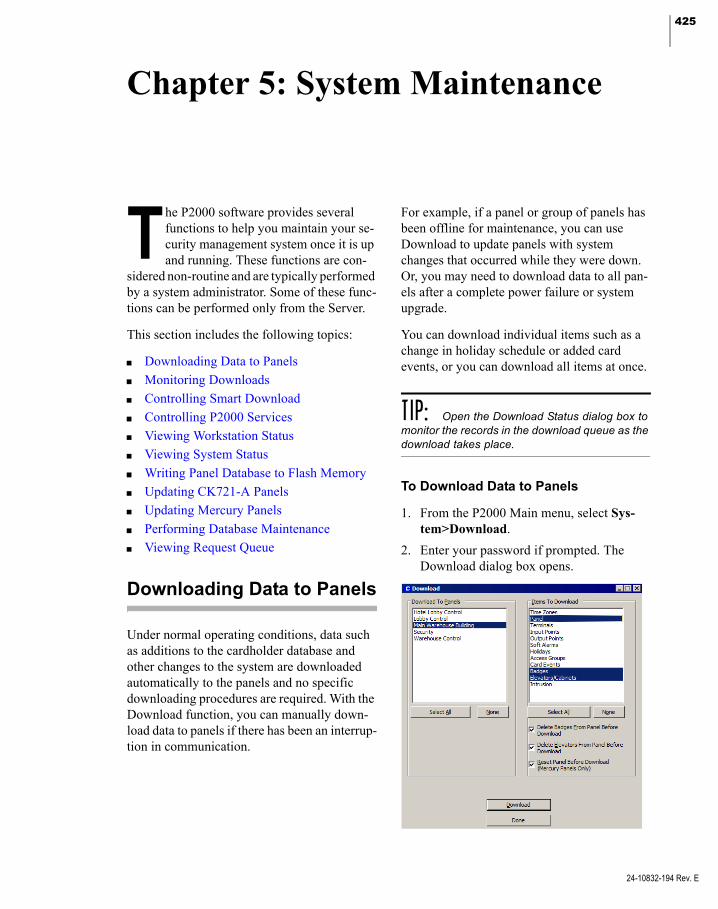
425
Chapter 5: System Maintenance
he P2000 software provides several For example, if a panel or group of panels has
T functions to help you maintain your se-curity management system once it is up and running. These functions are con-
sidered non-routine and are typically performed by a system administrator. Some of these func-tions can be performed only from the Server.
This section includes the following topics:
Downloading Data to Panels
Monitoring Downloads
Controlling Smart Download
Controlling P2000 Services
Viewing Workstation Status
Viewing System Status
Writing Panel Database to Flash Memory
Updating CK721-A Panels
Updating Mercury Panels
Performing Database Maintenance
Viewing Request Queue
Downloading Data to Panels
Under normal operating conditions, data such as additions to the cardholder database and other changes to the system are downloaded automatically to the panels and no specific downloading procedures are required. With the Download function, you can manually down-load data to panels if there has been an interrup-tion in communication.
been offline for maintenance, you can use Download to update panels with system changes that occurred while they were down. Or, you may need to download data to all pan-els after a complete power failure or system upgrade.
You can download individual items such as a change in holiday schedule or added card events, or you can download all items at once.
TIP: Open the Download Status dialog box to monitor the records in the download queue as the download takes place.
To Download Data to Panels
1. From the P2000 Main menu, select Sys-tem>Download.
2. Enter your password if prompted. The Download dialog box opens.
24-10832-194 Rev. E

426 CHAPTER 5
System Maintenance
24-10832-194 Rev. E
3. From the Download To Panels box, select the panel or panels to which you wish to download data, or click Select All to select all panels in the list. Click None to clear your selections and reselect the panels individually.
4. From the Items To Download box, select the items you wish to download to the panel or panels, or click Select All to select all items in the list. Click None to clear your selec-tions and reselect the items individually.
Note: HID panels go temporarily offline when a panel download is initiated. Also, when an HID terminal or input configuration is downloaded, there is a 7 to 8 second window when a card-holder may gain access, even if the enabled time zone does not allow it.
Note: On P2000 systems that use HID panels, the download speed per badge decreases as the number of badges downloaded increases.
Note: OSI readers are temporarily disabled during the download operation and deny access until the download is completed.
5. If you wish to download all badges to a panel and still allow access through a door of the panel while being updated, select Badges from the Items To Download box, and click to clear Delete Badges From Panel Before Download.
Note: If the panel being updated contains badges that should not be there, the system does not remove them from the panel, unless you delete those badges before the download.
6. To download elevator data without deleting all elevators from the panel, select Eleva-tors/Cabinets from the Item To Download box, and click to clear Delete Elevators From Panel Before Download.
7. If you wish to reset a Mercury panel before download, select Panel from the Item To Download box (make sure a Mercury panel type is selected in the Download To Panels box), then click Reset Panel Before Download option.
Note: Since the Reset Panel Before Down-load option is provided to delete all data from the selected panel, you are required to perform a full download to restore the panel’s database. Click Select All in the Items To Download box to restore the selected panel’s database.
8. After you make your selections, click Download. The records queued during the download display in the Download Status message box. In large downloads, the num-ber of items queued may fluctuate if data is transferred faster than the panels can receive it. This is normal. The download is complete when the Records Queued returns to 0.
Monitoring Downloads
Download Status displays the status of any items that the system automatically downloads. Use this application in conjunction with the Download function.
To Monitor Download Status
1. From the P2000 Main menu, select Sys-tem>Download Status. The Download Status message box opens.
2. Drag the Download Status message box to where it is visible during the download process. The number of records queued during the download displays as the down-load progresses.
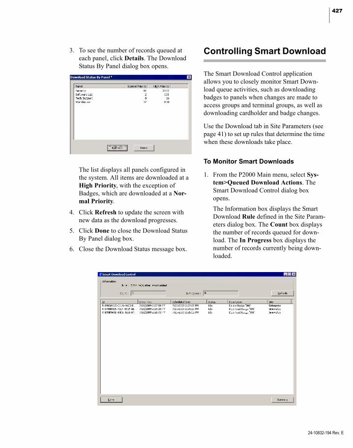
427
3. To see the number of records queued at each panel, click Details. The Download Status By Panel dialog box opens.
The list displays all panels configured in the system. All items are downloaded at a High Priority, with the exception of Badges, which are downloaded at a Nor-mal Priority.
4. Click Refresh to update the screen with new data as the download progresses.
5. Click Done to close the Download Status By Panel dialog box.
6. Close the Download Status message box.
Controlling Smart Download
The Smart Download Control application allows you to closely monitor Smart Down-load queue activities, such as downloading badges to panels when changes are made to access groups and terminal groups, as well as downloading cardholder and badge changes.
Use the Download tab in Site Parameters (see page 41) to set up rules that determine the time when these downloads take place.
To Monitor Smart Downloads
1. From the P2000 Main menu, select Sys-tem>Queued Download Actions. The Smart Download Control dialog box opens.
The Information box displays the Smart Download Rule defined in the Site Param-eters dialog box. The Count box displays the number of records queued for down-load. The In Progress box displays the number of records currently being down-loaded.
24-10832-194 Rev. E

428 CHAPTER 5
System Maintenance
24-10832-194 Rev. E
The following information displays for each download in the queue:
ID – Shows a number that the system auto-matically assigns to each download.
Entry Time – Displays the time of each download request entry.
Scheduled Time – Displays the scheduled download time of each timed download request entry.
Status – Displays the status of each down-load request entry.
Description – Displays the text description of each download request entry.
Site – Displays the site name where the download request entry originated.
2. Click Refresh to update the screen with new data as the download progresses.
3. Click Summary to display a summary of record counts and time information associ-ated with the records currently displayed. Click Cancel to return to the Smart Down-load Control screen.
4. Click Done to close.
Controlling P2000 Services
A service is a process that performs specific system functions and operates in the back-ground without user intervention.
This section describes the procedures for con-trolling and monitoring P2000 services, as well as outlines the steps to customize which of these services automatically initiate at system startup.
Service Startup Configuration
Service Startup Configuration allows you to enable or disable any of the P2000 services at the start of communications, as well as set up recovery actions to take place if a service fails. If you enable the Auto Start flag for a particu-lar service, that service starts automatically and you can stop it or restart it using the Service Control or the Service Monitor application. If you disable the Auto Start flag, the service does not start automatically and does not dis-play in Service Control.
By managing P2000 services, you can reduce system load by running only the required ser-vices. Before disabling a service, you must ensure that this service is not required to sup-port a particular system function. If your facil-ity uses advanced features, such as Guard Tour or Intercom, you could also enable or disable those services to start automatically when the Server starts up.
Access this function through the System Con-figuration window from the Server or a work-station. We recommend defining Menu Per-missions to restrict access to this feature only to system administrators to prevent unautho-rized personnel from stopping critical services.
To Edit Service Startup Configuration
1. From the P2000 Main menu, select Con-fig>System. Enter your password if prompted. The System Configuration win-dow opens.
2. In the left pane, expand Site Parameters to display default system parameters.
3. Select Service Startup Configuration, and click Edit. The Edit Service Startup Configuration dialog box opens.
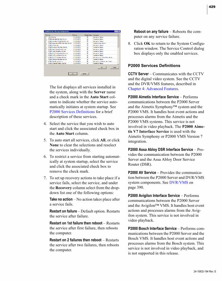
429
The list displays all services installed in the system, along with the Server name and a check mark in the Auto Start col-umn to indicate whether the service auto-matically initiates at system startup. See P2000 Services Definitions for a brief description of these services.
4. Select the service that you wish to auto start and click the associated check box in the Auto Start column.
5. To auto start all services, click All, or click None to clear the selections and reselect the services individually.
6. To restrict a service from starting automat-ically at system startup, select the service and click the associated check box to remove the check mark.
7. To set up recovery actions to take place if a service fails, select the service, and under the Recovery column select from the drop- down list one of the following options:
Take no action – No action takes place after a service fails.
Restart on failure – Default option. Restarts the service after failure.
Restart on 1st failure then reboot – Restarts the service after first failure, then reboots the computer.
Restart on 2 failures then reboot – Restarts the service after two failures, then reboots the computer.
Reboot on any failure – Reboots the com-puter on any service failure.
8. Click OK to return to the System Configu-ration window. The Service Control dialog box displays only the enabled services.
P2000 Services Definitions
CCTV Server – Communicates with the CCTV and the digital video system. See the CCTV and the DVR/VMS features, described in Chapter 4: Advanced Features.
P2000 Aimetis Interface Service – Performs communications between the P2000 Server and the Aimetis Symphony™ system and the P2000 VMS. It handles host event actions and processes alarms from the Aimetis and the P2000 VMS systems. This service is not involved in video playback. The P2000 Aime-tis V7 Interface Service is used with the Aimetis Symphony or P2000 VMS Version 7 integration.
P2000 Assa Abloy DSR Interface Service – Pro-vides the communication between the P2000 Server and the Assa Abloy Door Service Router (DSR).
P2000 AV Service – Provides the communica-tion between the P2000 Server and DVR/VMS system components. See DVR/VMS on page 390.
P2000 Avigilon Interface Service – Performs communications between the P2000 Server and the Avigilon™ VMS. It handles host event actions and processes alarms from the Avig-ilon system. This service is not involved in video playback.
P2000 Bosch Interface Service – Performs com-munications between the P2000 Server and the Bosch VMS. It handles host event actions and processes alarms from the Bosch system. This service is not involved in video playback, and is not supported in this release.
24-10832-194 Rev. E

430 CHAPTER 5
System Maintenance
24-10832-194 Rev. E
P2000 Cisco Interface Service – Performs com-munications between the P2000 Server and the Cisco® VMS. It handles host event actions and processes alarms from the Cisco system. This service is not involved in video playback, and is not supported in this release.
P2000 CK721-A Download Service – Performs Server downloads going to all CK721-A pan-els in the system.
P2000 CK721-A Priority Service – Performs CK721-A panel online and offline notifica-tions.
P2000 CK721-A Upload Service – Performs CK721-A panel uploads to the Server.
P2000 Endura Interface Service – Performs communications between the P2000 Server and the Pelco® Endura™ VMS. It handles host event actions and processes alarms from the Pelco Endura system. This interface service uses Pelco API that supports H.264 cameras. This service is not involved in video playback, and is not supported in this release.
P2000 Escalation Service – Performs the alarm escalation function to monitor alarms that have the escalation option enabled.
P2000 External Trigger Service – Receives mes-sages from external systems to be used as P2000 host event triggers.
P2000 Genetec Security Center Interface Service – Performs communications between the P2000 Server and the Genetec™ Security Cen-ter (GSC) VMS. It handles host event actions and processes alarms from the GSC system.
P2000 Guard Tour Service – Starts Guard Tour Service and receives real-time event messages from RTLRoute services. See Guard Tour on page 374.
P2000 HID Interface Service – Provides the communication between the P2000 Server and HID panels.
P2000 IFC Interface Service – Provides the communication between the P2000 Server and IFC panels using the BACnet protocol. This service allows the P2000 system to monitor alarms generated by devices connected to IFC panels.
P2000 Intercom Interface Service – Provides the communication with the Intercom hardware. See Intercom on page 393.
P2000 Intrusion Interface Service – Provides the communication between the P2000 system and intrusion panels. This service allows the P2000 system to obtain status information whenever an intrusion component changes and issues commands to control the intrusion zones, areas, and annunciators that are part of the intrusion system.
P2000 Mercury Interface Service – Provides the interface between the P2000 Server and Mer-cury panels.
P2000 Milestone MIP Interface Service – Per-forms communications between the P2000 Server and Milestone Interface Protocol (MIP) XProtect® Corporate and XProtect Enterprise VMSes. It handles host event actions and pro-cesses alarms from the Milestone system. This service is not involved in video playback.
P2000 MIS Interface Service – Imports and exports data for the MIS Interface. See MIS Interface on page 365.
P2000 Muster Control Service – Monitors the status of all muster zones, and when a muster is initiated, controls all the activities of the muster.
P2000 Nice Interface Service – Performs com-munications between the P2000 Server and the Nice™ VMS. It handles host event actions and processes alarms from the Nice system. This service is not involved in video playback, and is not supported in this release.

431
P2000 OnSSI Interface Service – Performs com-munications between the P2000 Server and the OnSSI® VMS. It handles host event actions and processes alarms from the OnSSI system. This service is not involved in video playback, and is not supported in this release.
P2000 OPC Proxy Service – Provides the com-munication between P2000 applications and certain servers, such as the CCTV Server or the OPC Server.
P2000 OSI Interface Service – Provides the interface between the P2000 system and the OSI system.
P2000 Otis Interface Service – Provides the interface between the P2000 system and the Otis Compass Destination Entry elevator sys-tem. The P2000 Server acts as a message router for the messages going between the Otis system and CK721-A panels.
P2000 Periodic Service – Performs periodic tasks such as deleting old history, synchroniz-ing time of panels with server, and enabling or disabling badges based upon badge start and void dates.
P2000 pivCLASS Interface Service – Provides the communication between the P2000 Server and the pivCLASS system with respect to events generated at the pivCLASS system.
P2000 Rapid Eye Interface Service – Performs communications between the P2000 Server and Honeywell® Rapid Eye® DVRs. It han-dles host event actions and processes alarms from the Rapid Eye DVR. This service is not involved in video playback, and is not sup-ported in this release.
P2000 Remote Message Service – Receives messages from the local RTL Route Service and transmits these messages to the remote P2000 Remote Message Service. When receiv-ing a remote message, the local Remote Mes-sage Service processes the message and passes it on to the local RTL Route Service for distri-bution to the local workstations.
P2000 Request Queue Service – Processes request queue entries into the P2000 database.
P2000 RTL Route Service – Routes all real-time messages to workstations and services. Also processes host events.
P2000 S321-IP Interface Service – Provides the communication between the P2000 Server and S321-IP panels.
P2000 SIA Interface Service – Provides the communication with configured SIA devices.
P2000 Smart Download Service – Downloads badges to panels when changes are made to access groups and terminal groups. It also downloads cardholder and badge changes. In addition, controls badges with temporary access.
P2000 SNMP Trap Receiver Service – Receives SNMP traps from the Metasys system, trans-lates them to the P2000 alarm structure, and sends them to RTL Route Service.
P2000 System Adapter Service – Provides the communication between the P2000 Server and the P2000 Web UI software to allow access and use of certain P2000 applications via a web browser. The System Adapter Service transmits system configuration data; as well as audit, alarm, and transaction messages to be accessed from the Web UI; and in turn, the P2000 Server receives item actions and alarm actions performed using the Web UI.
P2000 Watchdog Service – Monitors other P2000 services to verify that they are operat-ing and generates an alarm when a P2000 ser-vice fails.
P2000 XmlRpc Interface Service – Provides communication over the network, using the XML-RPC interface to communicate with remote devices such as building management components designed for Metasys system inte-gration, or with Web Access servers.
24-10832-194 Rev. E

432 CHAPTER 5
System Maintenance
24-10832-194 Rev. E
P2000 XPortal Interface Service – Performs communications between the P2000 Server and the Pelco VMS (Endura). It handles host event actions and processes alarms from the Pelco system. This interface service uses Pelco API that does not support H.264 cameras. This service is not involved in video playback, and is not supported in this release.
Starting and Stopping Service Control
Service controls are provided specifically to stop and restart communications between pan-els and the Server to perform system mainte-nance functions, or during network trouble-shooting operations. For example, the system administrator would be required to stop all communication services between panels and the Server when performing a P2000 version upgrade; or could stop uploads only between panels and the Server as part of system trouble-shooting.
Note: If you restart the SQL Server, after reconnecting you may have to restart P2000 ser-vices and possibly the P2000 application.
Service Control should be used only as directed by our Technical Support personnel, and should be performed only by a system administrator at the Server or workstation.
Note: The procedure to control services at redundancy systems might be different from the steps described here. Refer to your redundancy documentation for details.
To Stop or Start All Services
1. From the P2000 Main menu, select Sys-tem>Service Control. Enter your pass-word if prompted. The Service Control dialog box opens.
The Service Control dialog box displays all services installed in the system, along with the Server name and its current status (Stopped or Running).
2. Click All, then click Stop or Start. If you click Stop, all services stop and no com-munication occurs between the Server and the panels. If you click Start, all services start running again.
3. Click Done.
To Stop or Start a Specific Service
1. Select the service to be stopped (or started) from the scrolling list and click Stop (or Start). Only the services selected stop (or start) and the Stopped (or Running) status displays.
2. Click Done.
Controlling Services through the Service MonitorThe P2000 Service Monitor application is automatically installed at the Server during ini-tial software installation. This application is represented by a traffic signal icon located in the system tray (right side of the Windows taskbar).
Each color in the traffic signal represents the status of P2000 services:
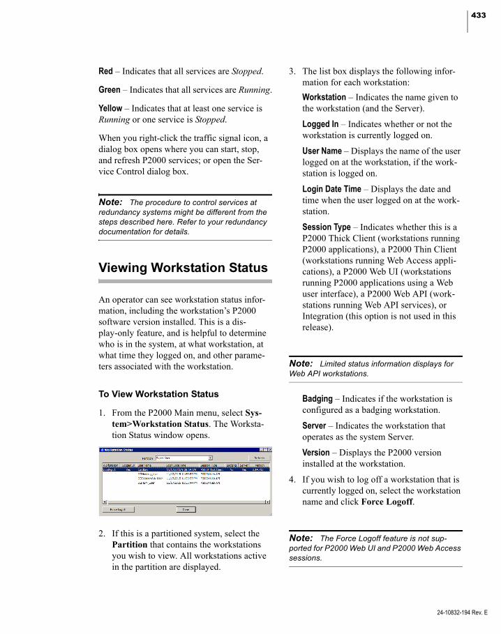
433
Red – Indicates that all services are Stopped.
Green – Indicates that all services are Running.
Yellow – Indicates that at least one service is Running or one service is Stopped.
When you right-click the traffic signal icon, a dialog box opens where you can start, stop, and refresh P2000 services; or open the Ser-vice Control dialog box.
Note: The procedure to control services at redundancy systems might be different from the steps described here. Refer to your redundancy documentation for details.
Viewing Workstation Status
An operator can see workstation status infor-mation, including the workstation’s P2000 software version installed. This is a dis-play-only feature, and is helpful to determine who is in the system, at what workstation, at what time they logged on, and other parame-ters associated with the workstation.
To View Workstation Status
1. From the P2000 Main menu, select Sys-tem>Workstation Status. The Worksta-tion Status window opens.
2. If this is a partitioned system, select the Partition that contains the workstations you wish to view. All workstations active in the partition are displayed.
3. The list box displays the following infor-mation for each workstation:
Workstation – Indicates the name given to the workstation (and the Server).
Logged In – Indicates whether or not the workstation is currently logged on.
User Name – Displays the name of the user logged on at the workstation, if the work-station is logged on.
Login Date Time – Displays the date and time when the user logged on at the work-station.
Session Type – Indicates whether this is a P2000 Thick Client (workstations running P2000 applications), a P2000 Thin Client (workstations running Web Access appli-cations), a P2000 Web UI (workstations running P2000 applications using a Web user interface), a P2000 Web API (work-stations running Web API services), or Integration (this option is not used in this release).
Note: Limited status information displays for Web API workstations.
Badging – Indicates if the workstation is configured as a badging workstation.
Server – Indicates the workstation that operates as the system Server.
Version – Displays the P2000 version installed at the workstation.
4. If you wish to log off a workstation that is currently logged on, select the workstation name and click Force Logoff.
Note: The Force Logoff feature is not sup-ported for P2000 Web UI and P2000 Web Access sessions.
24-10832-194 Rev. E
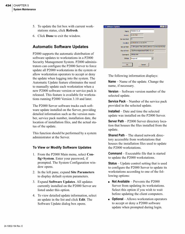
434 CHAPTER 5
System Maintenance
24-10832-194 Rev. E
5. To update the list box with current work-stations status, click Refresh.
6. Click Done to exit the window.
Automatic Software Updates
P2000 supports the automatic distribution of software updates to workstations in a P2000 Security Management System. P2000 adminis-trators can configure the P2000 Server to force update all P2000 workstations in the system or allow workstation operators to accept or deny the update when logging into the system. The Automatic Update feature eliminates the need to manually update each workstation when a new P2000 software version or service pack is released. This feature is available for worksta-tions running P2000 Version 3.10 and later.
The P2000 Server software tracks each soft-ware update installed on the Server, providing detailed information such as the version num-ber, service pack number, installation date, the location of installation files, and the actual sta-tus of the update.
This function should be performed by a system administrator at the Server.
To View or Modify Software Updates
1. From the P2000 Main menu, select Con-fig>System. Enter your password, if prompted. The System Configuration win-dow opens.
2. In the left pane, expand Site Parameters to display default system parameters.
3. Expand Software Updates. All updates currently installed on the P2000 Server are listed under this option.
4. To view detailed update information, select an update in the list and click Edit. The Software Update dialog box opens.
The following information displays:
Name – Name of the update. Change the name, if necessary.
Version – Software version number of the selected update.
Service Pack – Number of the service pack provided in the selected update.
Installed – Date and time the selected update was installed on the P2000 Server.
Server Path – P2000 Server directory loca-tion that houses the files installed from the update.
Shared Path – The shared network direc-tory accessible from workstations that houses the installation files used to update the P2000 workstations.
Command – Executable file that is started to update the P2000 workstations.
Status – Update control setting that is used to configure the P2000 Server to update its workstations according to one of the fol-lowing options:
Not Available – Prevents the P2000 Server from updating its workstations. Select this option if you wish to wait before updating the client computers.
Optional – Allows workstation operators to accept or deny a P2000 software update when prompted during login.

435
IMPORTANT: The P2000 Server and its work-stations must run the same software version and service pack. If operators deny an update to their workstation, the P2000 software may not function correctly.
Required – Force updates all P2000 workstations in the system. When selected, workstations are unable to log on if they deny a software update.
Note: After you update the P2000 Server soft-ware, the system does not automatically update P2000 workstations (or prompt the operator to install the update) if the workstation operator is currently logged into the P2000 software. The operator must log out and log back into the P2000 system before the software can be auto-matically updated (some platforms may require users to use the Run as Administrator option when logging on to the P2000 system for the automatic software update to work). To help avoid mismatched software versions between the P2000 Server and its workstations, you may per-form a Force Logoff command, if needed, to force the user to log off of a selected workstation; see page 433 for details.
Note: After you update the P2000 Server soft-ware, the default Status setting may vary accord-ing to the type of update (for example, new version or service pack). Always verify and change, if necessary, the current Status setting after each server update.
5. In the Status drop-down list, change the update control setting, if necessary.
6. Click OK.
Viewing System Status
The System Status window is a dynamic dis-play of the status of panels, associated devices, and other integration components configured in the system. This useful troubleshooting tool allows you to quickly determine if panels and connected devices are communicating. If com-munications go down between the Server and the panels, the System Status window reports the last known status of the devices.
The System Status window is view only. You can manually change the status of a compo-nent using features accessed from the Control menu. See Perform Operator Controls on page 290.
To Access the System Status Window
1. From the P2000 Main menu, select Sys-tem>System Status. The System Status window opens.
2. Select a component from the drop-down list at the top left of the window. Informa-tion for each component is presented start-ing on page 438.
3. If this is a partitioned system, select the Partition to which the component belongs.
4. Click Refresh to update the system status display.
24-10832-194 Rev. E
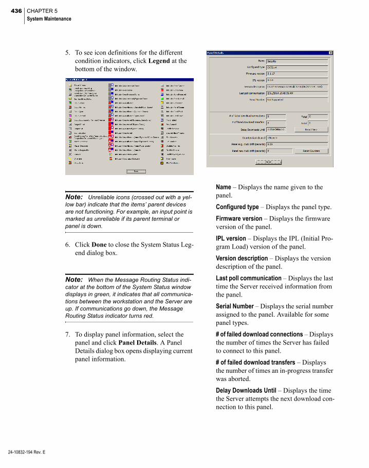
436 CHAPTER 5
System Maintenance
24-10832-194 Rev. E
5. To see icon definitions for the different condition indicators, click Legend at the bottom of the window.
Note: Unreliable icons (crossed out with a yel-low bar) indicate that the items’ parent devices are not functioning. For example, an input point is marked as unreliable if its parent terminal or panel is down.
6. Click Done to close the System Status Leg-end dialog box.
Note: When the Message Routing Status indi-cator at the bottom of the System Status window displays in green, it indicates that all communica-tions between the workstation and the Server are up. If communications go down, the Message Routing Status indicator turns red.
7. To display panel information, select the panel and click Panel Details. A Panel Details dialog box opens displaying current panel information.
Name – Displays the name given to the panel.
Configured type – Displays the panel type.
Firmware version – Displays the firmware version of the panel.
IPL version – Displays the IPL (Initial Pro-gram Load) version of the panel.
Version description – Displays the version description of the panel.
Last poll communication – Displays the last time the Server received information from the panel.
Serial Number – Displays the serial number assigned to the panel. Available for some panel types.
# of failed download connections – Displays the number of times the Server has failed to connect to this panel.
# of failed download transfers – Displays the number of times an in-progress transfer was aborted.
Delay Downloads Until – Displays the time the Server attempts the next download con-nection to this panel.

437
Reset Time – Click to immediately try a new download connection to this panel.
Counters last cleared – Displays the last time you clicked Reset Counters.
Panel avg. clock drift (seconds) – Displays the average time difference between the Server and the panel.
Panel max clock drift (seconds) – Displays the largest time difference between the Server and the panel.
Reset Counters – Click to reset the values to 0.
8. Click Done to close the Panel Details dia-log box and return to the System Status window.
9. Click Done to close the System Status window.
To Display the Status of Aritech Intrusion Panels
1. In the System Status window, select one of the intrusion components (Intrusion Areas, Intrusion Zones, or Intrusion Annuncia-tors) from the drop-down list at the top left of the window, the associated intrusion panel displays.
2. Select the intrusion panel from the list box, then click Panel Details. The Intrusion Panel Status dialog box opens.
Name – Displays the name of the intrusion panel.
Connected – Displays whether the panel is connected.
Invalid Vendor Address – Displays whether the vendor address of the intrusion panel is invalid.
Port Opened – Displays whether the intru-sion panel port is open.
MainsFailure – Displays whether the main-tenance of the intrusion panel has failed.
Battery Low – Displays whether the battery of the intrusion panel is low.
Battery Test – Displays whether the battery of the intrusion panel is in test.
Battery Test Fail – Displays whether the battery of the intrusion panel has failed its test.
Battery Missing – Displays whether the bat-tery of the intrusion panel is missing.
Tamper – Displays whether the intrusion panel has been tampered.
3. Click Done to close the Intrusion Panel Status dialog box.
To Display the Status of Fire Alarm Panels
1. In the System Status window, select one of the fire alarm components (Fire Zone, Fire Detector, or Fire IO Module) from the drop-down list at the top left of the win-dow, the associated fire alarm panel dis-plays.
2. Select the fire alarm panel from the list box, then click Panel Details. The Fire Panel Status dialog box opens.
24-10832-194 Rev. E

438 CHAPTER 5
System Maintenance
24-10832-194 Rev. E
Name – Displays the name of the fire alarm panel.
Connected – Displays whether the fire alarm panel is connected.
Invalid Vendor Address – Displays whether the vendor address of the fire alarm panel is invalid.
Port Opened – Displays whether the fire alarm panel port is open.
General Failure – Displays whether the fire alarm panel has failed.
3. Click Done to close the Fire Panel Status dialog box.
System Status – Reader Terminals
When you select Reader Terminals, all panels in the system are listed by name in the Panels column. An icon next to the panel name indi-cates the status of the panel.
The reader terminals connected to the panels are displayed in the same row as their panel, and are listed under the corresponding terminal number assigned during configuration. The displayed icon indicates the status of the termi-nal. When you place the cursor over the termi-nal icon, a tooltip displays showing the termi-nal name assigned.
Note: HID panels do not support the unlocked status for terminals. System status shows over-ride for each terminal that is in override and lock-out mode for each terminal that is manually locked out.
Note: The P2000 system does not monitor the status of HI-O bus modules.
System Status – Input Terminals
When you select Input Terminals, all panels in the system are listed by name in the Panels column. An icon next to the panel name indi-cates the status of the panel.
The input terminals connected to the panels are displayed in the same row as their panel, and are listed under the corresponding terminal number assigned during configuration. The displayed icon indicates the status of the termi-nal. When you place the cursor over the termi-nal icon, a tooltip displays showing the termi-nal name assigned.
System Status – Output Terminals
When you select Output Terminals, all panels in the system are listed by name in the Panels column. An icon next to the panel name indi-cates the status of the panel.
The output terminals connected to the panels are displayed in the same row as their panel, and are listed under the corresponding terminal number assigned during configuration. The displayed icon indicates the status of the termi-nal. When you place the cursor over the termi-nal icon, a tooltip displays showing the termi-nal name assigned.

439
System Status – Inputs
When you select Inputs, all terminals and pan-els in the system are listed by name in the Ter-minals/Panels column. An icon next to the ter-minal or panel indicates the corresponding status.
The input points connected to the terminals or panels are displayed in the same row as their terminal or panel, and are listed under the cor-responding input point number assigned during configuration. The displayed icon indi-cates the status of the input point. When you place the cursor over the input point icon, a tooltip displays showing the input point name assigned.
All input points above 16 are reserved for Soft inputs. You can expand the size of the window to view these inputs (up to 25). A status icon is represented for each possible input state. If no icons are present, no input points are associ-ated with the terminal or panel.
Note: You can display the status of Mercury Input Points and Mercury Output Points only if they are associated with P2000 inputs or outputs.
System Status – Outputs
When you select Outputs, all terminals in the system are listed by name in the Terminals col-umn. An icon next to the terminal indicates the status of the terminal.
The output points connected to the terminals are displayed in the same row as their terminal, and are listed under the corresponding output point number assigned during configuration. The displayed icon indicates the status of the output point. When you place the cursor over the output point icon, a tooltip displays show-ing the output point name assigned.
Note: Some panel types require that you select the Log Output Status Message option to dis-play outputs in the System Status list.
System Status - OTIS Elevator Status
When you select OTIS Elevator Status, all Otis elevator servers in the system are listed by name. The individual status icon indicates if the associated Otis Destination Entry Com-puter is Up or Down.
System Status – Mustering Zones
When you select Mustering Zones, the sys-tem displays the zone status of each Muster Zone; see Muster Zone Status and Control Field Definitions on page 313.
System Status – Security Level Terminals
When you select Security Level Terminals, all panels that have security level terminals in the system are listed by name in the Panels column. An icon next to the panel name indi-cates the status of the panel.
All security level terminals are displayed in the same row as their panel and are listed under the corresponding terminal number assigned during configuration. The display shows the security level setting for each termi-nal. A number 0 indicates the security level is not used or is not assigned.
24-10832-194 Rev. E
440 CHAPTER 5
System Maintenance
24-10832-194 Rev. E
System Status – Intrusion Areas
When you select Intrusion Areas, all intrusion panels in the system are listed by name under the Intrusion Panel column. An icon next to the intrusion panel name indicates the status of the panel.
All intrusion areas associated with the intru-sion panel are displayed in the same row as their panel, and are listed under the corre-sponding intrusion area number assigned during configuration. The displayed icon indi-cates the status of the intrusion area. When you place the cursor over the intrusion area icon, a tooltip displays showing the intrusion area name assigned.You can issue commands for the areas by right-clicking the associated status icon. The following commands may be avail-able, depending on the current state of the area:
Arm – (Aritech) Arms the selected area if at the time that you issue the command the area’s state permits it.
Arm – (Bosch) Arms the selected area after a delay, and if the area’s state permits it.
Arm – (Mercury) Arms the selected area with a pre-configured delay.
Forced Arm – (Aritech) Arms the selected area regardless of the area’s state at the time when you issue the command.
Forced Arm – (Bosch) Arms the selected area immediately.
Disarm – (Aritech and Mercury) Disarms the selected area.
Note: When a Mercury intrusion area is dis-armed, and some zones were faulted but are now normal, the area still remains in the alarmed state. To get the area back to the normal state, you must disarm the area from the MRDT keypad terminal or from the Intrusion Control window, see Controlling Intrusion Items Using the Intrusion Control Window on page 328.
Disarm – (Bosch) Disarms the selected area and silences the associated keypad.
System Status – Intrusion Zones
When you select Intrusion Zones, all intru-sion panels in the system are listed by name under the Intrusion Panel column. An icon next to the intrusion panel name indicates the status of the panel.
All intrusion zones associated with the intru-sion panel are displayed in the same row as their panel, and are listed under the corre-sponding intrusion zone number assigned during configuration. The displayed icon indi-cates the status of the intrusion zone. When you place the cursor over the intrusion zone icon, a tooltip displays showing the intrusion zone name assigned.You can issue commands for the zones by right-clicking the associated status icon. The following commands may be available, depending on the current state of the zone:
Bypass On – Commands the selected zone to be bypassed.
Bypass Off – Turns off bypassing of the selected zone.
Reset – (Not supported by Bosch or Mercury) Resets the state of the selected zone. If you issue this command while the input point is still in alarm because it is still being unsealed, you must seal the input and send this command again to reset it.

441
ResetAck – (Not supported by Bosch or Mer-cury) Resets the state of the selected zone. If you issue this command while the input point is still in alarm because it is still being unsealed, there is no need to re-send the com-mand after the input is sealed. The command remains valid and resets the zone as soon as the input seals.
System Status – Intrusion Annunciators
When you select Intrusion Annunciators, all intrusion panels in the system are listed by name under the Intrusion Panel column. An icon next to the intrusion panel name indicates the status of the panel. (Annunciators are not supported with Mercury panels.)
All intrusion annunciators associated with the intrusion panel are displayed in the same row as their panel, and are listed under the corre-sponding intrusion annunciator number assigned during configuration. The displayed icon indicates the status of the intrusion annunciator. When you place the cursor over the intrusion annunciator icon, a tooltip dis-plays showing the intrusion annunciator name assigned.You can issue commands for the annunciators by right-clicking the associated status icon. The following commands may be available, depending on the current state of the annunciator:
Activate – Activates the selected annunciator.
Deactivate – Deactivates the selected annunci-ator.
System Status – Fire Zone
When you select Fire Zone, all fire panels in the system are listed by name under the Fire Panel column. An icon next to the fire panel name indicates the status of the panel.
All fire zones associated with the fire panel are displayed in the same row as their panel, and are listed under the corresponding fire zone number assigned during configuration. You can display the status of up to 20 fire zones per row. If more than 20 fire zones are defined, they display in the following rows. The dis-played icon indicates the status of the fire zone. When you place the cursor over the fire zone icon, a tooltip displays showing the fire zone name assigned.
System Status – Fire Detector
When you select Fire Detector, all fire panels in the system are listed by name under the Fire Panel column. An icon next to the fire panel name indicates the status of the panel.
All fire detectors associated with the fire panel are displayed in the same row as their panel, and are listed under the corresponding fire detector number assigned during configura-tion. You can display the status of up to 20 fire detectors per row. If more than 20 fire detec-tors are defined, they display in the following rows. The displayed icon indicates the status of the fire detector. When you place the cursor over the fire detector icon, a tooltip displays showing the fire detector name assigned.
System Status – Fire IO Module
When you select Fire IO Module, all fire pan-els in the system are listed by name under the Fire Panel column. An icon next to the fire panel name indicates the status of the panel.
24-10832-194 Rev. E
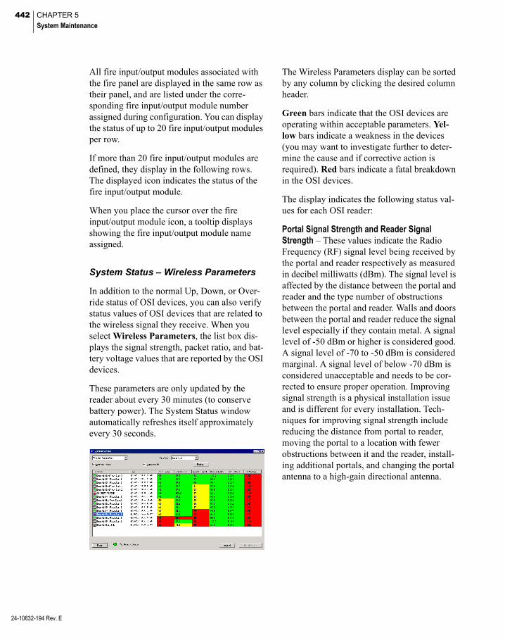
442 CHAPTER 5
System Maintenance
24-10832-194 Rev. E
All fire input/output modules associated with the fire panel are displayed in the same row as their panel, and are listed under the corre-sponding fire input/output module number assigned during configuration. You can display the status of up to 20 fire input/output modules per row.
If more than 20 fire input/output modules are defined, they display in the following rows. The displayed icon indicates the status of the fire input/output module.
When you place the cursor over the fire input/output module icon, a tooltip displays showing the fire input/output module name assigned.
System Status – Wireless Parameters
In addition to the normal Up, Down, or Over-ride status of OSI devices, you can also verify status values of OSI devices that are related to the wireless signal they receive. When you select Wireless Parameters, the list box dis-plays the signal strength, packet ratio, and bat-tery voltage values that are reported by the OSI devices.
These parameters are only updated by the reader about every 30 minutes (to conserve battery power). The System Status window automatically refreshes itself approximately every 30 seconds.
The Wireless Parameters display can be sorted by any column by clicking the desired column header.
Green bars indicate that the OSI devices are operating within acceptable parameters. Yel-low bars indicate a weakness in the devices (you may want to investigate further to deter-mine the cause and if corrective action is required). Red bars indicate a fatal breakdown in the OSI devices.
The display indicates the following status val-ues for each OSI reader:
Portal Signal Strength and Reader Signal Strength – These values indicate the Radio Frequency (RF) signal level being received by the portal and reader respectively as measured in decibel milliwatts (dBm). The signal level is affected by the distance between the portal and reader and the type number of obstructions between the portal and reader. Walls and doors between the portal and reader reduce the signal level especially if they contain metal. A signal level of -50 dBm or higher is considered good. A signal level of -70 to -50 dBm is considered marginal. A signal level of below -70 dBm is considered unacceptable and needs to be cor-rected to ensure proper operation. Improving signal strength is a physical installation issue and is different for every installation. Tech-niques for improving signal strength include reducing the distance from portal to reader, moving the portal to a location with fewer obstructions between it and the reader, install-ing additional portals, and changing the portal antenna to a high-gain directional antenna.

443
Portal Packet Ratio and Reader Packet Ratio – These values indicate the ratio of good to invalid data packets received from the wireless signal as measured in percentage. The packet ratio is affected by signal strength and external interference. A packet ratio of 50 to 100% is considered good. A packet ratio of 30 to 50% is marginal and should be improved for opti-mum operation. A packet ratio of less than 30% is considered unacceptable and may pre-vent proper operation. If both the portal and reader are reporting good signal strength levels but either the portal or reader is reporting a poor packet ratio, it usually indicates some type of interference. Typical causes of interfer-ence are electrical noise from other electrical equipment (large electrical motors or micro-wave ovens), nearby strong RF transmissions (radio or TV station transmitting antennas), or other wireless equipment or networks (Wi-Fi wireless networks or cordless phones). Mov-ing the portal to a different position further away from interfering sources may help. Another solution may be to change the RF channels used by the portal for communicating with the readers.
Battery Voltage – This value indicates the cur-rent voltage from the reader’s batteries. As the batteries are depleted, the reported voltage drops. Weak batteries can affect the wireless communication if the reader is seeing low sig-nal strength or if there is large amounts of interference. If the voltage drops too low, the reader shuts down. A voltage of 5.0 volts or higher is considered good. A voltage of 4.5 to 5.0 volts is considered marginal and the batter-ies should be replaced soon. A voltage of below 4.5 volts is considered unacceptable and the batteries must be replaced as soon as possi-ble or the reader may shutdown.
External Voltage – Displays the voltage of the external power supply.
Note: The OSI portal has the capability to com-municate with the reader over 16 different RF channels or frequency bands. These channels can be configured through the Web UI of the por-tal. By default, all 16 channels are enabled in the portal. The portal uses the first configured chan-nel that it finds available. The reader scans through all 16 channels until it is able to establish communication with the portal over that channel. By enabling only one or two channels on the por-tal, you can control the frequency bands used for communication. Using a different channel may isolate the portal and reader from the interfering frequency. In particular, channels 25 and 26 are outside the frequency bands used by Wi-Fi net-works and therefore good choices if a Wi-Fi net-work is suspected to be causing your interference.
System Status - Integration Components
Select Integration Components from the drop-down list to display the status of certain third-party components configured in the sys-tem. The status column indicates one of the following possible states:
Unknown – The status of the component has not yet been determined.
Up – The P2000 system is able to communi-cate with the component.
Down – The P2000 system is unable to com-municate with the component.
Disabled – The P2000 system has been instructed not to communicate with the com-ponent.
Unavailable – The status of the component is not available.
24-10832-194 Rev. E

444 CHAPTER 5
System Maintenance
24-10832-194 Rev. E
Writing Panel Database to Flash Memory
With the Write DB To Flash function, you can manually archive the panel’s RAM data more frequently as major changes are made to the system database. For example, if you delete several badges from the system, it would be appropriate to write the panel’s RAM data to flash memory. That way, if the RAM data is lost, (before the system performs the scheduled automatic backup), the most recent saved flash memory contains the latest badge information.
This function is available for CK721-A and Mercury panels.
Note: The system automatically backs up and stores CK721-A panels’ RAM based database at the panel level flash memory, according to their automatic backup schedule; see Backup DB to Flash Interval on the General Tab on page 55.
For CK721-A panels, you must always per-form this function after:
Adding or deleting RDR2S-A or RDR8S terminals.
Modifying general parameters of existing RDR2S-A or RDR8S terminals (except Name, Public, or Query String fields).
Adding or deleting RDR2S-A or RDR8S input or output points.
Since the data stored at each panel is different, you must perform this procedure for each panel in the system.
To Manually Write Panel Database to Flash Memory
1. From the P2000 Main menu, select Sys-tem>Write DB To Flash. Enter your pass-word if prompted. The Write DB to Flash dialog box opens.
2. Select the Panel To Write from the drop-down list.
3. Click Write. All data stored in the panel’s RAM is backed up to its flash memory.
4. Click Done.
Updating CK721-A Panels
This function updates CK721-A panel and ter-minal firmware. Johnson Controls provides the update file, along with documented instruc-tions. This function should be performed only by a system administrator at the Server.
This function requires the login names and passwords of all panels in the system. You can find the default panel name and password in the panel’s Installation and Operation manual. If you changed your panel’s login name, you must enter the new name and password to per-form this function.
Note: Johnson Controls delivers each version upgrade with separate documented instructions (Software Release Notes). Be sure to read and follow all specific upgrade documentation instruc-tions before performing an update.

445
IMPORTANT: While updating firmware on an encrypted CK721-A panel, you may need to promptly answer queries generated by the WinSCP application to allow the operation to proceed. Failing to provide a prompt answer may result in no firmware update. You may have to close and reopen the Update CK721-A Panels application to proceed. This message may or may not display again once you provide the answer. Enter in lowercase u (to update), or in some instances y (yes to accept).
To Update CK721-A Panels and Terminals
1. From the P2000 Main menu, select Sys-tem>Update CK721-A Panels. Enter your password if prompted. The Update CK721-A Panels dialog box opens.
2. Select the Panel To Update from the drop-down list.
3. The Terminal to Update drop-down list displays all the terminals connected to the panel selected. Select the terminal name you wish to update. If you do not wish to update terminal firmware, select None.
4. If you select to update a specific terminal, you must select the Terminal Type that you wish to update.
5. Click Browse to navigate to the directory in which the update file resides. Refer to the Software Release Notes for download details.
6. Select the file. The file name displays in the Update File field.
7. Enter the Panel Login Name as pro-grammed at the panel.
8. Enter the Panel Password as programmed at the panel.
9. Click Update. The information contained in the update file is downloaded to the panel or terminal selected. This process may take several minutes.
IMPORTANT: If you get a “processing script file” error message, contact Technical Support to obtain a new update file.
Note: The firmware update process requires waiting for the current terminal firmware update to complete before proceeding to update the next terminal. Do not attempt to update multiple termi-nals at the same time.
10. After the update process is complete, select another terminal name and type, and then click Update.
Note: During the terminal firmware update pro-cess, all terminals connected to a CK721-A panel go offline. The offline terminals may allow access if you enabled the Facility Code Only when Offline flag.
11. After the update process is complete, click Done to close the dialog box.
Note: After a panel version upgrade, open the System Status window to check the status of the panel. If the panel shows a panel version mis-match condition indicator, you must open the Edit Panel dialog box to change the panel's type to the updated panel's firmware version. Then wait until the panel indicator shows up in the Sys-tem Status window.
12. Follow the procedure on page 425 to download data items to the recently updated panel.
24-10832-194 Rev. E

446 CHAPTER 5
System Maintenance
24-10832-194 Rev. E
Updating Mercury Panels
Use this function to update Mercury panel and terminal firmware. Johnson Controls provides the update files. This function should be per-formed only by a system administrator at the Server.
Note: Some version upgrades may be deliv-ered with separate documented instructions. In that case, be sure to read and follow all specific upgrade documentation instructions before per-forming an update.
To Update Mercury Panels and Terminals
IMPORTANT: The panel must be online during the update process. Also, the Message Routing Status indicator at the bottom of the Update Mer-cury Panels window must display in green to indi-cate that all communications are up and that the RTL Route service is running. If the Message Routing Status indicator turns red, the list box on the right side cannot display any of the actions or responses associated with the update.
1. From the P2000 Main menu, select Sys-tem>Update Mercury Panels. Enter your password if prompted. The Update Mer-cury Panels dialog box opens.
2. Select the Panel To Update from the drop-down list.
3. The Terminal to Update drop-down list displays the terminals that are connected to the selected panel. If you wish to update terminal firmware, select the terminal from the list. If you wish to update the panel firmware, select None.
IMPORTANT: You can only update terminal firmware if encryption is disabled at the panel.
4. If you select to update a specific terminal, the Terminal Type displays the type of the selected terminal.
Note: We do not provide terminal firmware upgrades for Schlage PIM, Schlage ENGAGE, or Aperio 1 to 8 Hub terminals.
5. The Current Firmware Version displays the version of the selected panel, or of the selected terminal, if you are updating ter-minal firmware.
6. Click Browse to navigate to the directory in which the update file resides. Refer to the Software Release Notes for download details.
7. Select the file. The file name displays in the Update File field.
8. The New Firmware Version field displays the expected firmware version number after analyzing the file name provided in step 7.
9. Click Update. The information contained in the update file is downloaded to the panel or terminal selected. The list box on the right side displays actions and responses associated with the update. The update process may take several minutes.

447
10. After the update process is complete and if you wish to update another terminal, click Reset to clear the information, select another terminal, and then click Update.
11. After the update process is complete, click Done to close the dialog box.
Note: After a panel version upgrade, open the Panel Details dialog box in the System Status window to verify the correct panel firmware ver-sion.
12. Follow the procedure on page 425 to download data items to the recently updated panel.
Note: Make sure you select the Reset Panel Before Download flag when performing the first full download after a firmware update.
Performing Database Maintenance
You can perform a database backup, empty various data histories, load an archived data-base from backup, or reset event counters from the Database Maintenance dialog box. This function is password protected and should be accessible only by a system administrator or a designee.
Note: Some Database Maintenance tasks, such as Shrink Database, can only be per-formed by operators that are members of the Windows or PEGASYS Administrators group; see Set Up User Accounts on page 29.
If you scheduled functions such as Database Backup or Empty Audit History to occur auto-matically, you can use the tasks in Database Maintenance to override the system and per-form manual maintenance.
To Perform Database Maintenance Functions
1. From the P2000 Main menu, select Sys-tem>Database Maintenance. Enter your password if prompted. The Database Maintenance dialog box opens.
2. Under Maintenance Action, select the function you wish to perform. See Data-base Maintenance Actions for a descrip-tion of each function.
3. Click Perform. A confirming message box displays. Depending on your selection, click the appropriate action.
4. Click Exit.
24-10832-194 Rev. E

448 CHAPTER 5
System Maintenance
24-10832-194 Rev. E
Database Maintenance Actions
Backup and Restore – Allows you to back up or restore the selected database.
Note: For more information on backup and restore functions, see Database Backup on page 451.
Calculate Digital Signature – Validates the digi-tal signatures, points out discrepancies, and corrects the discrepancies to ensure that records have a valid digital signature. This function is available if your facility uses the FDA Part 11 feature. See FDA Part 11 on page 392 and System Validation on page 457.
CK721-A/S321-IP Data Import and Export – Imports and exports CK721-A and S321-IP hardware configuration data in Comma Sepa-rated Values (CSV) file format. See CK721-A and S321-IP Data Import and Export on page 458 for details.
Delete all badges from OSI database – Deletes all badges from the OSI database.
Delete all hardware from OSI database – Deletes all hardware from the OSI database.
Delete Expired Visitor Badges – Deletes all visi-tor badges that have expired from the database. You must specify the number of days after which expired visitor badges are deleted, and select if you wish to download the information to the panels. Each visitor badge has a Visitor Validity Period (defined in Site Parameters), during which the badge is valid.
Delete Selected Alarm – Deletes the selected alarm from the database.
Delete Unique Badge Entries – Deletes cached badge information that is specific to the read-ers connected to the selected HID panel. Delet-ing this data requires that all badges are down-loaded again to the specified panel to allow for correct operation of that panel.
Delete Unused Access Groups – Deletes all unused access groups (access groups not assigned to any badge) from the database.
Delete Visitors Without Badges – Deletes all visitors who have no assigned badges from the database.
Empty Alarms – Removes all alarms from the alarm queue. This action is typically performed when the queue displays alarms that cannot be secured, and thus cannot be discarded. You must run Item Synchronization (see page 464) to complete this task.
IMPORTANT: The Empty Alarms action does not remove selected alarms. The system deletes all alarms, so proceed with caution.
Empty Alarms History – Deletes all alarms in the Alarms History database table.
IMPORTANT: The Empty Alarms History and Empty Audit History actions should only be per-formed with the aid of a Johnson Controls Techni-cal Support specialist.
Empty Archive Database – Removes the data from the Archive Database. This database is used for running P2000 reports.
Empty Audit History – Purges all audit history data from the database. The audit history data contains time and date stamped records of user actions.

449
Empty Download Queue – Purges the actions from the Download Queue. This queue down-loads P2000 data to selected panels. This func-tion is typically performed when a panel is no longer in use, but the queue still lists down-loads for that panel.
Empty Fire Data – Purges all fire alarm panel data from the database.
Empty Guard Tour Note – Purges all guard tour notes from the P2000 database. You can con-figure the P2000 system to remove these notes after a predetermined amount of time; see Guard Tour Notes on page 387.
Empty Saved Muster Data – Purges all muster data from the database. This data is normally saved to the database for evaluation once a muster is terminated.
Empty Smart Download Queue – Purges the actions from the Smart Download Queue. For more information, see Controlling Smart Download on page 427.
Empty Transaction History – Purges the Trans-action History data from the database. Trans-actions indicate some form of system activity. They can include items like access requests and general system messages, such as when a panel loses communication with a reader. Typ-ically, transactions represent communication initiated at field panels and sent to the P2000 Server.
IMPORTANT: This action should only be per-formed with the aid of a Johnson Controls Techni-cal Support specialist.
FDA Backup Performed – Informs the P2000 system that the FDA backup is archived, in accordance with company policies to meet FDA Part 11 record retention policy. For more information, see FDA Part 11 Backups on page 454.
Item Synchronization – Synchronizes data stored and consumed by the Web UI with P2000 configuration data, including associated status and alarms. See Item Synchronization on page 464.
Kill All Reports – Attempts to stop all database queries issued by a P2000 report. This is help-ful if an operator accidentally tries to run an extreme report, such as all transaction history for the last two years. This action is not guar-anteed to work in all cases.
Load Archive Database from Backup – Loads the data from the Archive Database. This data-base is used for running P2000 reports.
Mark Secondary Tables – Marks the starting point of FDA data for later analysis.
Remove Access Groups from Disabled Badges – Removes access groups from disabled badges. This in turn allows the Delete Unused Access Groups command to be used more effi-ciently.
Remove Expired Access Groups from Badges – Removes from badges any access group assignment that is past the void day defined in its Temporary Access Period. The void time defined in the Temporary Access Period does not apply.
Reset Counters to Zero – Resets all values in the Event Counters list to zero. For informa-tion, see Counting Events on page 340.
Reset Reserved Autobadge Numbers – Resets these numbers, making them available for assignment. A reserved autobadge number is a number that has already been assigned, but a badge has not yet been issued.
24-10832-194 Rev. E
450 CHAPTER 5
System Maintenance
24-10832-194 Rev. E
Set all Input Status to Unknown – Used if a panel is down (for example, for maintenance) and alarms are being generated.
Set all Output Status to Unknown – Used if a panel is down (for example, for maintenance) and alarms are being generated.
Set all Panel Status to Unknown – Used if a panel is down (for example, for maintenance) and alarms are being generated.
Set all Terminal Status to Unknown – Used if a panel is down (for example, for maintenance) and alarms are being generated.
Set Computer Default Language – Allows you to change the P2000 default language for all users using this computer. This also sets the language in which the P2000 services operate. This task is to be used on P2000 systems oper-ating in a foreign language.
Shrink Database – Commands SQL Server to free up space in the database. This process is normally performed automatically at various intervals.
Sync cardholder/badge active flags – Synchro-nizes the cardholder/badge active flags, in case this uncommon problem occurs.
Synchronize OSI Transaction Counter – Sets the P2000 transaction counter to the last transac-tion currently in the OSI WAMS database. It would typically be used only if the OSI WAMS database was destroyed and recreated. You must stop the P2000 OSI Interface Service before performing this task. After you run the task, restart the P2000 OSI Interface Service.
IMPORTANT: This action should only be per-formed with the aid of a Johnson Controls Techni-cal Support specialist because it can cause transactions to be processed multiple times.
Update Database Default Strings – Causes all default data in the database (such as Super User partition, Super User menu permission group, default icon image set names, and so on) to be rewritten to the database in the cur-rent P2000 language. This task is to be used on P2000 systems operating in a foreign language.
Update Preprocessed Report Archive tables – Runs a preprocessed report against an archived database.
Update Preprocessed Report tables – Updates preprocessed report tables manually. Normally, this process occurs automatically each night. However, if the data has changed and you wish to run a preprocessed report with current data, you may manually start this process.
Validate Digital Signature – Ensures the integ-rity of all records and provides evidence when records have been altered. A digital signature verifies that unauthorized users have not modi-fied the values in the columns of a record. This function is available if your facility uses the FDA Part 11 feature. See FDA Part 11 on page 392 and System Validation on page 457.

451
Database Backup
The P2000 system should be backed up on a regular basis. Backups can be performed using several supplied methods, and can be made to any backup device supported by Microsoft SQL Server.
The following databases are automatically cre-ated at the P2000 server:
Pegasys – P2000 configuration data such as cardholders and hardware devices.
BadgeImages – Cardholder images.
JCISecurityConfig – Configuration data and alarms stored and consumed by the Web UI.
Note: The P2000 Web UI is a web-based soft-ware from Johnson Controls that allows autho-rized users to access and use certain P2000 applications via a web browser.
JCISecurityCase – Case Manager database that is stored and consumed by the Web UI.
JCISecurityHistory – History messages stored and consumed by the Web UI.
All databases should be backed up frequently, with the exception of BadgeImages that should only be backed up when cardholder images are modified. Backups can be performed without stopping the P2000 communication services; therefore, the system remains operational during the backup process. This function should be performed by a system administra-tor.
Note: To back up badge layout files, refer to the Video Imaging manual that was shipped with your option.
Configuring a Backup Device
1. From the System Configuration window, select Site Parameters and click Edit. The Edit Site Parameters dialog box opens.
2. Click the Retention Policy tab.
Note: You must use the P2000 server to config-ure a backup device where automatic backup files are saved. Automatic backups (see page 453) are performed using host event actions. If your P2000 system is deployed on a distributed environment (the P2000 server is hosted on two separate com-puters), you must use Microsoft SQL Server tools to define the backup device to use for P2000 backup functions.
3. At the bottom of the window, select a Backup Device from the drop-down list. If there are no devices on the list, or you want to add a new one, click Config Device. The Backup Devices dialog box opens.
24-10832-194 Rev. E

452 CHAPTER 5
System Maintenance
24-10832-194 Rev. E
4. Click Add. The Config Backup Device dialog box opens.
5. Enter a descriptive Name for the device.
6. Select the Type of backup device from the drop-down list. Options include: Disk and Tape.
7. If you select Disk, enter in the Disk File box, a valid path and file name for the backup file. The specified path must exist on the SQL Server computer. The backup file is created in that path on the DB server, not on the P2000 server.
8. If you select Tape, select from the drop-down list in the Tape Drive box, the name of the tape device.
9. Click OK to save your settings. The new device is listed in the Backup Devices dia-log box and also displays in the Backup Device drop-down list of the Edit Site Parameters dialog box.
10. To remove a device, select it and click Delete.
11. Click Done to close the Backup Devices dialog box.
Manual Backups
1. From the P2000 Main menu, select Sys-tem>Database Maintenance. Enter your password if prompted. The Database Main-tenance dialog box opens.
2. Select Backup and Restore from the Maintenance Action list.
3. Click Perform. At the verification mes-sage, click Yes if you wish to perform the backup operation. You cannot reverse this action. The P2000 Database Backup & Restore dialog box opens. See Advanced Backups for details.
4. Click Exit to close the Database Mainte-nance dialog box.
Advanced Backups
You can access the P2000 Database Backup & Restore application from your Windows desk-top.
Note: Backups can only be performed at the server.

453
1. From your Windows desktop, select Start>Programs>Johnson Controls> P2000>Database Backup. The P2000 Database Backup & Restore dialog box opens.
2. Make sure the Backup tab is selected.
3. Select the database or databases you wish to backup.
4. Verify that the Backup Location is correct or click [...] to select a different location.
IMPORTANT: Restoring backup files from the Windows desktop folder is not supported. We recommend saving your backup files to your local drive.
5. Click Initialize media on backup if an existing backup should be overwritten or appended.
6. Click Format the backup files before creating new if you wish to reformat the existing backup media.
7. Click Create Backup to start backup. The progress of the backup process is indicated and whether there are Success or Failed items.
8. Click View Details to open the Log file.
The Log screen displays messages that can be saved to analyze your backups.
9. Click Save Logs and enter the name the Log file. Click Save.
10. Click Close.
11. Close the P2000 Database Backup & Restore dialog box.
Automatic Backups
You can configure backups as P2000 event actions to allow automatic backups, based on a time setting or any other P2000 event trigger. See Create Events on page 335 for more infor-mation. For example, you can program an event to back up the database (the action) every Friday at 5:00 P.M. (the trigger).
Note: You must configure a backup device (see page 451) to define the location where auto-matic backup files are saved.
24-10832-194 Rev. E
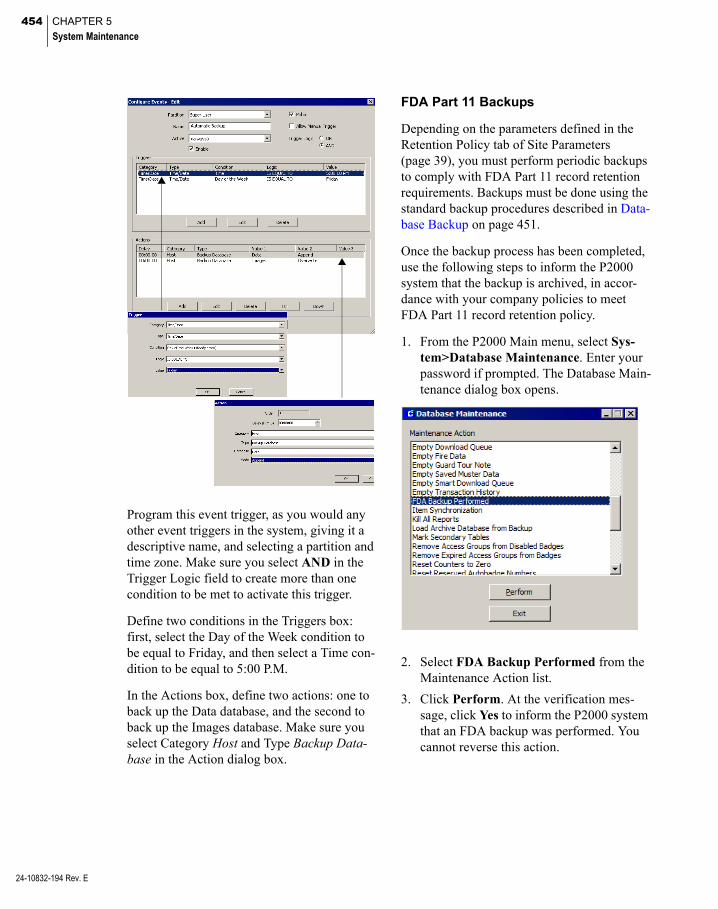
454 CHAPTER 5
System Maintenance
24-10832-194 Rev. E
Program this event trigger, as you would any other event triggers in the system, giving it a descriptive name, and selecting a partition and time zone. Make sure you select AND in the Trigger Logic field to create more than one condition to be met to activate this trigger.
Define two conditions in the Triggers box: first, select the Day of the Week condition to be equal to Friday, and then select a Time con-dition to be equal to 5:00 P.M.
In the Actions box, define two actions: one to back up the Data database, and the second to back up the Images database. Make sure you select Category Host and Type Backup Data-base in the Action dialog box.
FDA Part 11 Backups
Depending on the parameters defined in the Retention Policy tab of Site Parameters (page 39), you must perform periodic backups to comply with FDA Part 11 record retention requirements. Backups must be done using the standard backup procedures described in Data-base Backup on page 451.
Once the backup process has been completed, use the following steps to inform the P2000 system that the backup is archived, in accor-dance with your company policies to meet FDA Part 11 record retention policy.
1. From the P2000 Main menu, select Sys-tem>Database Maintenance. Enter your password if prompted. The Database Main-tenance dialog box opens.
2. Select FDA Backup Performed from the Maintenance Action list.
3. Click Perform. At the verification mes-sage, click Yes to inform the P2000 system that an FDA backup was performed. You cannot reverse this action.

455
4. A message displays to confirm that you have just completed a backup, which will be archived according to your company policies to meet FDA Part 11 record reten-tion requirements. Click OK to confirm. The system updates the Last FDA Backup field in the Retention Policy tab of Site Parameters (see page 39), to match the cur-rent system date. Any FDA Retention Pol-icy alarms will change their alarm status to Secure.
5. Click Exit to close the Database Mainte-nance dialog box.
Database Restore
Under normal operating conditions, you do not need to restore the P2000 databases, but if the databases are lost, you can restore them from a recent backup, using the P2000 Database Backup & Restore application. You can also restore an older P2000 database to an archive database for the purpose of printing reports or examining old settings, without affecting the currently active P2000 system.
IMPORTANT: Use the Server to restore the database. If you restore the database to a differ-ent Server other than where it was originally backed up, you need to contact Technical Sup-port for a new Registration Key, and you also need to reconfigure your Server (DB and COMM); see Site Parameters on page 32.
You can only perform a non-archive restore after closing all P2000 applications on all workstations and the Server, and after stopping the P2000 communication services; see Start-ing and Stopping Service Control on page 432.
You must also shut down the P2000 Service Monitor application at the Server. Do this by right clicking the traffic signal icon located in the system tray (right side of the Windows taskbar), if it exists, and selecting Quit from the menu. You can restart all P2000 communi-cation services and applications after the restore process finishes. We recommend that all panels in the system be downloaded imme-diately after a database restore; see Download-ing Data to Panels on page 425.
IMPORTANT: After restoring the P2000 data-base from a previous version, we recommend using the Load Language Reports function to load the current reporting format into the data-base tables. Be aware that some legacy hardware configuration items may not be properly reported.
To Restore the Database
1. From your Windows desktop, select Start>Programs>Johnson Controls> P2000>Database Backup. The P2000 Database Backup & Restore dialog box opens.
24-10832-194 Rev. E
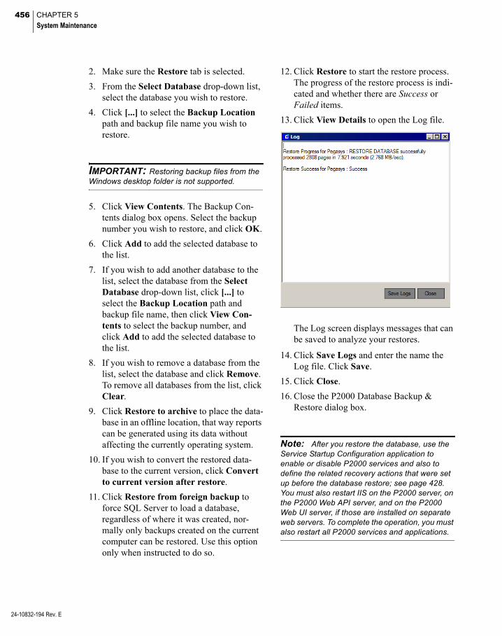
456 CHAPTER 5
System Maintenance
24-10832-194 Rev. E
2. Make sure the Restore tab is selected.
3. From the Select Database drop-down list, select the database you wish to restore.
4. Click [...] to select the Backup Location path and backup file name you wish to restore.
IMPORTANT: Restoring backup files from the Windows desktop folder is not supported.
5. Click View Contents. The Backup Con-tents dialog box opens. Select the backup number you wish to restore, and click OK.
6. Click Add to add the selected database to the list.
7. If you wish to add another database to the list, select the database from the Select Database drop-down list, click [...] to select the Backup Location path and backup file name, then click View Con-tents to select the backup number, and click Add to add the selected database to the list.
8. If you wish to remove a database from the list, select the database and click Remove. To remove all databases from the list, click Clear.
9. Click Restore to archive to place the data-base in an offline location, that way reports can be generated using its data without affecting the currently operating system.
10. If you wish to convert the restored data-base to the current version, click Convert to current version after restore.
11. Click Restore from foreign backup to force SQL Server to load a database, regardless of where it was created, nor-mally only backups created on the current computer can be restored. Use this option only when instructed to do so.
12. Click Restore to start the restore process. The progress of the restore process is indi-cated and whether there are Success or Failed items.
13. Click View Details to open the Log file.
The Log screen displays messages that can be saved to analyze your restores.
14. Click Save Logs and enter the name the Log file. Click Save.
15. Click Close.
16. Close the P2000 Database Backup & Restore dialog box.
Note: After you restore the database, use the Service Startup Configuration application to enable or disable P2000 services and also to define the related recovery actions that were set up before the database restore; see page 428. You must also restart IIS on the P2000 server, on the P2000 Web API server, and on the P2000 Web UI server, if those are installed on separate web servers. To complete the operation, you must also restart all P2000 services and applications.

457
System Validation
As a system administrator, you should sched-ule validation of your system on a regular basis to minimize the possibility of record tampering. The Validate Digital Signature fea-ture ensures the integrity of all records and provides evidence when records have been altered. This function is available if your facil-ity uses the FDA Part 11 feature. See FDA Part 11 on page 392.
Note: A digital signature verifies that unautho-rized users have not modified the values in the columns of a record.
1. From the P2000 Main menu, select Sys-tem>Database Maintenance. Enter your password when prompted. The Database Maintenance dialog box opens.
2. Select Validate Digital Signature from the Maintenance Action list.
3. Click Perform. The Validate Digital Sig-nature dialog box opens.
4. Select the database table you wish to ver-ify. You can select to verify multiple tables, or click Select All to verify all tables at once.
5. To clear your selections, click Unselect All.
6. To verify secondary database tables, click Validate secondary table(s) to add the secondary tables to the selection list.
7. Click Perform to start the validation.
24-10832-194 Rev. E

458 CHAPTER 5
System Maintenance
24-10832-194 Rev. E
The list box displays the following infor-mation:
Table – The name of the table being vali-dated.
Invalid – The number of invalid signatures found in the table.
Name – The name of the record, for exam-ple cardholder or panel name, as defined in the applicable P2000 application.
GUID – The Global unique identifier of the record.
Date/Time – The date and time when modi-fication took place. Only applicable for secondary tables, that is tables with the suf-fix _save.
Mode – The type of modification per-formed, such as delete (0), edit (1), or insert (2).
Total Number of Invalid Signatures – The number of records that have been tampered with.
8. Click Export to save the results in a file. This result file can be easily imported into, for example a Microsoft Excel® file, and formatted according to your requirements.
9. Click Cancel to close the dialog box.
10. Click Cancel to return to the Database Maintenance dialog box.
11. Click Exit to close the Database Mainte-nance dialog box.
Note: In addition to using the Validate Digital Signature function, you can also use the Calcu-late Digital Signature function, which not only validates the digital signatures and points out dis-crepancies, but also corrects the discrepancies to ensure that records have a valid digital signature.
CK721-A and S321-IP Data Import and Export
This feature allows you to import and export CK721-A and S321-IP hardware configuration data, which reduces the commissioning time required to enter this information during con-figuration. You can preconfigure panels, termi-nals, time schedules, access groups, and other configuration settings using a standard Micro-soft Excel spreadsheet.
Operators must have the appropriate menu per-missions to use this feature and must also belong to the Super User partition.
Note: This feature does not eliminate the con-figuration process; it eliminates the need for entering some data during the configuration.
Importing CK721-A and S321-IP Data
To import data into the P2000 database, you must obtain the XLS file provided by a Johnson Controls representative (via the AIM tools). The column names in the XLS file must be exactly the same as the ones listed under the Name column in the following table.

459
Item Name Value Type
To be used
during import to
P2000
1 DOOR LOCATION per Plans & Specs (Read Only Column) Make changes in Sales View
Text No
2 READER LOCATION per Plans & Specs (Read Only Column) Make changes in Sales View
Text No
3 Entry Method Selection from a list of: Card In Free Entry NA
No
4 Exit Method Selection from a list of: NA Free Egress Free Egress-Local Alarm Card Out REX Motion REX Motion with Backup Egress Button REX Motion with Backup Panic Bar Delayed Egress Panic Bar
No
5 Reader Entry_Exit Designation Selection from a list of: Access Entry Exit
Yes
6 Logical Terminal # Numeric value between 1 - 64 or Unused (for CK721A)Numeric value between 1 - 2 or Unused (for S321IP)Note: When “Unused” is entered as a value for the Logical Terminal #, the data on that row is not be imported.
Yes
7 Hardware Module # (Physical Address) Numeric value between 0 - 31 Yes
8 Reader Terminal Index Numeric value between 1 - 8 Yes
9 Supervisory Controller Part # Selection: CK721A S321IP
Yes
10 Supervisory Controller RS485 Trunk # (CK722 Only)
Selection: A B NA
No
11 Supervisory Controller Program Tag (Panel Name)
Text – Up to 32 characters taken from text pro-vided on the import file and must be within the P2000 system.
Yes
12 Supervisory Controller Physical Location Text Yes
13 Supervisory Controller IP Address (Also for S321_IP)
IP Address format (###.###.###.###) Yes
14 Supervisory Controller MAC Address MAC Address format (hh.hh.hh.hh.hh.hh) Yes
15 Door Controller Physical Location Text – Up to 64 characters taken from text pro-vided on the import file.
Yes
24-10832-194 Rev. E
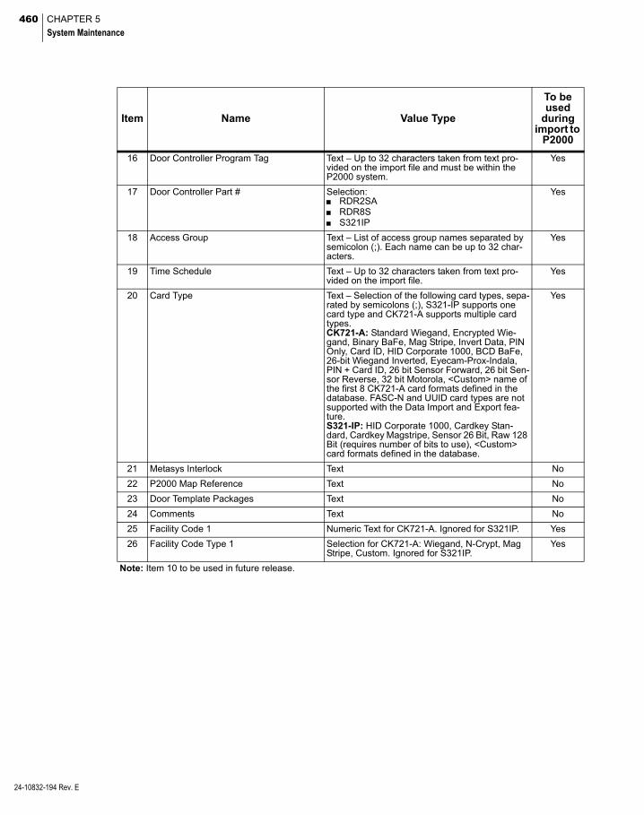
460 CHAPTER 5
System Maintenance
24-10832-194 Rev. E
16 Door Controller Program Tag Text – Up to 32 characters taken from text pro-vided on the import file and must be within the P2000 system.
Yes
17 Door Controller Part # Selection: RDR2SA RDR8S S321IP
Yes
18 Access Group Text – List of access group names separated by semicolon (;). Each name can be up to 32 char-acters.
Yes
19 Time Schedule Text – Up to 32 characters taken from text pro-vided on the import file.
Yes
20 Card Type Text – Selection of the following card types, sepa-rated by semicolons (;), S321-IP supports one card type and CK721-A supports multiple card types.CK721-A: Standard Wiegand, Encrypted Wie-gand, Binary BaFe, Mag Stripe, Invert Data, PIN Only, Card ID, HID Corporate 1000, BCD BaFe, 26-bit Wiegand Inverted, Eyecam-Prox-Indala, PIN + Card ID, 26 bit Sensor Forward, 26 bit Sen-sor Reverse, 32 bit Motorola, <Custom> name of the first 8 CK721-A card formats defined in the database. FASC-N and UUID card types are not supported with the Data Import and Export fea-ture.S321-IP: HID Corporate 1000, Cardkey Stan-dard, Cardkey Magstripe, Sensor 26 Bit, Raw 128 Bit (requires number of bits to use), <Custom> card formats defined in the database.
Yes
21 Metasys Interlock Text No
22 P2000 Map Reference Text No
23 Door Template Packages Text No
24 Comments Text No
25 Facility Code 1 Numeric Text for CK721-A. Ignored for S321IP. Yes
26 Facility Code Type 1 Selection for CK721-A: Wiegand, N-Crypt, Mag Stripe, Custom. Ignored for S321IP.
Yes
Note: Item 10 to be used in future release.
Item Name Value Type
To be used
during import to
P2000

461
After you enter the information in the XLS file, save the file as a Comma Separated Val-ues (CSV) file, and then copy the CSV file to a location that is accessible to the P2000 system.
IMPORTANT: P2000 names in the imported data file must not contain any of the following characters: @ (at sign), . (period), ? (question mark), * (asterisk), $ (dollar), # (pound), : (colon), ; (semicolon), ' (apostrophe), [ (open bracket), ] (close bracket), or , (comma).
To Import CK721-A and S321-IP Data
1. From the P2000 Main menu, select Sys-tem>Database Maintenance. Enter your password if prompted. The Database Maintenance dialog box opens.
2. Select CK721-A/S321-IP Data Import and Export from the Maintenance Action list.
Note: Make sure that all P2000 services are running.
3. Click Perform. The CK721-A/S321-IP Import and Export dialog box opens.
4. Click Import Data.
5. Click Browse to navigate to the location of the CSV file. Select the desired file.
6. The File Name displays the name of the CSV file.
7. Click Run. The Results window opens. See the following section for details.
Evaluating Imported Data
The Results window provides additional secu-rity, allowing you to evaluate all imported data before it is added to the P2000 database. You can review identified problems and decide whether to proceed with the operation or address any of the identified issues.
1. After you click Run in the CK721-A/ S321-IP Import and Export dialog box, the Results window opens.
2. Click Evaluate to evaluate the data in the import file.
The import process starts by validating the data before the records are saved in the database. Once the evaluation is com-pleted, the Results window opens display-ing information associated with the imported data.
The screen is divided into two main frames. The left frame displays the evalu-ated data in a hierarchy tree format, show-ing panel to terminal relations. You need to select and expand each item in the tree to view the details.
24-10832-194 Rev. E

462 CHAPTER 5
System Maintenance
24-10832-194 Rev. E
Each item is associated with one of the fol-lowing icons to indicate the validity of the imported data.
The right frame displays error or warning messages associated with a selected item.
The Status box displays the following information:
Record Count – Indicates the number of records read from the import file or P2000 database.
Error Count – Indicates the number of errors found in the import file.
Warning Count – Indicates the number of warnings found in the import file.
Note: These counts display the total number of errors and warnings associated with the evalu-ated data displayed in the in the left frame. You may have to expand each parent item to identify each error or warning.
3. Click Commit to save the evaluated data into the P2000 database. At the verification message, click Yes if you wish to perform the import operation. You cannot reverse this action. Only the records without errors or warnings are saved. Verify that:
the Real Time List displays audit mes-sages associated with this operation
the System Configuration displays the new panels and terminal names
the System Status shows the status of the panels and terminals
Note: When importing S321-IP panels, the P2000 S321-IP Interface Service automatically restarts after you click Commit.
4. Click Save if you wish to save all mes-sages into a log file. See Saving the Log File on page 463 for details.
5. The Cancel button stops the processing of the specific task. For example, if you click Cancel while evaluating, this action causes all evaluated data to be lost. Cancelling the Save Log operation simply stops writing to the log file. Cancelling the Commit opera-tion stops saving the records, but does not roll back any of the saved data and requires re-evaluation of the import file.

463
Saving the Log File
During the evaluation process, the system may generate error and warning messages that can be saved to further analyze the problems, cor-rect mistakes, and improve the import process.
To Save the Log File
1. After you click Evaluate in the Results window, the screen displays the evaluated data together with any error or warning messages associated with a selected item.
2. To save the error or warning messages, click Save Log. The Log File dialog box opens.
3. Click Browse to navigate to the location where you want to save the log file; enter the name of the log file.
4. The File Name displays the name of the log file.
5. Click Save to save the error information displayed in the Results window.
6. Click Exit to close.
Exporting CK721-A and S321-IP Data
Use this feature to export existing CK721-A and S321-IP data to an external system.
To Export CK721-A and S321-IP Data
1. From the P2000 Main menu, select Sys-tem>Database Maintenance. Enter your password if prompted. The Database Maintenance dialog box opens.
2. Select CK721-A/S321-IP Data Import and Export from the Maintenance Action list.
Note: Make sure that all P2000 services are running.
3. Click Perform. The CK721-A/S321-IP Import and Export dialog box opens.
4. Click Export Data.
5. Click Browse to navigate to the location of the CSV file and select the desired file, or enter the location and file name.
6. The File Name displays the name of the CSV file.
7. Click Run. The Results window opens. See the following section for details.
24-10832-194 Rev. E

464 CHAPTER 5
System Maintenance
24-10832-194 Rev. E
Evaluating Exported Data
The Results window provides additional secu-rity by letting you verify all records before they can be exported to an external system. You can review identified problems and decide whether you wish to proceed with the opera-tion or address any of the identified issues.
1. After you click Run in the CK721-A/ S321-IP Import and Export dialog box, the Results window opens.
2. Click Evaluate to retrieve CK721-A or S321-IP panel related records from the P2000 database.
The export process starts by validating the data before it is exported to an external system. Once the evaluation is completed, the Results window opens displaying infor-mation associated with the exported data.
3. Click Commit to save the evaluated data into the selected export file (if the export file name exists, it is overwritten). At the verification message, click Yes if you wish to perform the export operation. You can-not reverse this action.
4. Click Exit to close the window.
Item Synchronization
The Item Synchronization tool allows you to synchronize data stored and consumed by the Web UI with P2000 configuration data, includ-ing associated status and alarms. Only opera-tors that belong to the Super User partition can run this tool.
Note: The P2000 Web UI is a web-based soft-ware from Johnson Controls that allows autho-rized users to access and use certain P2000 applications via a web browser.
You can run this tool from the P2000 server or workstation to add P2000 data that does not exist in the Web UI, update P2000 data that already exists in the Web UI, or remove data from the Web UI that no longer exists in the P2000 database. This ensures data shared by both systems is simultaneously updated with current changes initiated by the P2000 system.
Note: To run Item Synchronization on a work-station, you must install SSL Certificate of Server on the workstation.
We recommend you run the Item Synchroniza-tion tool under special circumstances, such as:
after upgrading your P2000 system to use the P2000 Web UI for the first time
if the P2000 database has been restored, or
if the Web UI configuration database has been restored
Make sure the P2000 System Adapter Ser-vice is up and running, see Starting and Stop-ping Service Control on page 432.
The P2000 software provides two synchroniza-tion methods:
Fast – All items in the following list, and that are affected by audit messages are synchro-nized starting on the date selected.
CK721-A panels, terminals, input and output points
Mercury panels, terminals, input and output points
S321-IP panels, terminals, input and output points
AV switches and cameras Fire servers, detectors, IO modules,
zones, and devices SNMP objects Host events Event counters Intrusion components
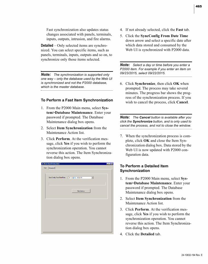
465
Fast synchronization also updates status changes associated with panels, terminals, inputs, outputs, intrusion, and fire alarms.
Detailed – Only selected items are synchro-nized. You can select specific items, such as panels, terminals, inputs, outputs and so on, to synchronize only those items selected.
Note: The synchronization is supported only one way – only the database used by the Web UI is synchronized and not the P2000 database, which is the master database.
To Perform a Fast Item Synchronization
1. From the P2000 Main menu, select Sys-tem>Database Maintenance. Enter your password if prompted. The Database Maintenance dialog box opens.
2. Select Item Synchronization from the Maintenance Action list.
3. Click Perform. At the verification mes-sage, click Yes if you wish to perform the synchronization operation. You cannot reverse this action. The Item Synchroniza-tion dialog box opens.
4. If not already selected, click the Fast tab.
5. Click the SyncConfig From Date Time down arrow and select a specific date after which data stored and consumed by the Web UI is synchronized with P2000 data.
Note: Select a day or time before you enter a P2000 item. For example if you enter an item on 09/23/2015, select 09/22/2015.
6. Click Synchronize, then click OK when prompted. The process may take several minutes. The progress bar shows the prog-ress of the synchronization process. If you wish to cancel the process, click Cancel.
Note: The Cancel button is available after you click the Synchronize button, and is only used to cancel the process, and not to close the window.
7. When the synchronization process is com-plete, click OK and close the Item Syn-chronization dialog box. Data stored by the Web UI is now updated with P2000 con-figuration data.
To Perform a Detailed Item Synchronization
1. From the P2000 Main menu, select Sys-tem>Database Maintenance. Enter your password if prompted. The Database Maintenance dialog box opens.
2. Select Item Synchronization from the Maintenance Action list.
3. Click Perform. At the verification mes-sage, click Yes if you wish to perform the synchronization operation. You cannot reverse this action. The Item Synchroniza-tion dialog box opens.
4. Click the Detailed tab.
24-10832-194 Rev. E
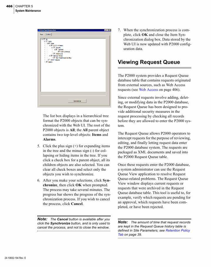
466 CHAPTER 5
System Maintenance
24-10832-194 Rev. E
The list box displays in a hierarchical tree format the P2000 objects that can be syn-chronized with the Web UI. The root of the P2000 objects is All; the All parent object contains two top-level objects: Items and Alarms.
5. Click the plus sign (+) for expanding items in the tree and the minus sign (-) for col-lapsing or hiding items in the tree. If you click a check box for a parent object, all its children objects are also selected. You can clear all check boxes and select only the objects you wish to synchronize.
6. After you make your selections, click Syn-chronize, then click OK when prompted. The process may take several minutes. The progress bar shows the progress of the syn-chronization process. If you wish to cancel the process, click Cancel.
Note: The Cancel button is available after you click the Synchronize button, and is only used to cancel the process, and not to close the window.
7. When the synchronization process is com-plete, click OK and close the Item Syn-chronization dialog box. Data stored by the Web UI is now updated with P2000 config-uration data.
Viewing Request Queue
The P2000 system provides a Request Queue database table that contains requests originated from external sources, such as Web Access requests (see Web Access on page 406).
Since external requests involve adding, delet-ing, or modifying data in the P2000 database, the Request Queue has been designed to pro-vide additional security measures in the request processing by checking all records before they are allowed to enter the P2000 sys-tem.
The Request Queue allows P2000 operators to intercept requests for the purpose of reviewing, editing, and finally letting request data enter the P2000 database system. The requests are packaged as XML documents and saved into the P2000 Request Queue table.
Once these requests enter the P2000 database, a system administrator can use the Request Queue View application to resolve Request Queue-related problems. The Request Queue View window displays current requests or requests that were archived in the Request Queue database table. This tool is useful to, for example, verify which requests are pending for an approval, which requests have been com-pleted, or have been rejected.
Note: The amount of time that request records are kept in the Request Queue history table is defined in Site Parameters; see Retention Policy Tab on page 39.

467
To View Request Queue Items
1. From the P2000 Main menu, select Sys-tem>Request Queue View. The Request Queue View dialog box opens.
The list box displays the following infor-mation for each of the requests:
Create Time – Displays the date and time the request was submitted.
Expire Time – Displays the date and time the request expires. This date is defined by the number of days entered in Expiration Period for Requests, see Defining Web Access Options on page 408.
Sender – Displays the source that origi-nated the request.
Details – Displays the Sender application requested for processing.
Operation – Displays the action (Add, Delete, Update) requested and that is asso-ciated with the Sender application.
Status – Displays one of the following:
Cancelled – The request was cancelled before being processed.
Committed – The request has been com-pleted.
Error – There is an error in the request.
Pending Approval 1 – The request is waiting to be approved by the required approver.
Pending Approval 2 – The request was approved by Approver 1, and requires approval of a second approver.
Pending Approval 3 – The request was approved by Approvers 1 and 2, and requires approval of a third approver.
Processing – The request is currently being processed.
Ready for Auto Processing – The request has been approved and is ready for auto-matic processing; without operator intervention.
Ready for Manual Processing – The request has been approved and is ready for manual processing.
Rejected – The request was rejected.
Last Name – Displays the last name of the cardholder specified in the request.
First Name – Displays the first name of the cardholder specified in the request.
2. To display the details of a specific request, select the line item in the list box and click View. See Viewing Request Details on page 469.
24-10832-194 Rev. E

468 CHAPTER 5
System Maintenance
24-10832-194 Rev. E
3. To cancel a specific request, select the line item in the list box and click Cancel; then click Yes to confirm.
4. To update the Request Queue View list box with new data, click Refresh.
5. To search for specific requests, click Filter and follow the instructions provided at the end of this section.
6. Click Done to close the Request Queue View dialog box.
Searching Specific Requests
The Request Queue View application allows you to define filters to help you locate specific requests quickly and easily, and in that way reduce the number of requests displayed on screen. You can define, for instance, a filter to show only requests that were submitted on a specific date and that are waiting for manual processing.
1. In the Request Queue View dialog box, click Filter. The Filter dialog box opens. If you leave an asterisk (*) in a field, the filter criteria includes all records for that field.
2. Enter a Sender name to view only requests that were originated from that source.
3. Select from the Status drop-down list the specific request status you wish to view. For example, you may want to review only requests that have been rejected or requests that require manual processing.
4. To view requests submitted for a specific cardholder, enter the First Name or Last Name of that cardholder.
5. To view requests that were submitted during a specific period, select a Begin Date and End Date. You may also enter a specific time if needed.
6. In the Type drop-down list, select whether you wish to view requests that are cur-rently on Queue or requests that are archived in the History table.
7. In the Max Count field, enter the number of records you wish to display in the list.
8. Click OK to begin the search. The Request Queue View dialog box opens showing the requests that meet the filter criteria and the number of requests found.
9. To display the details of a specific request, select the line item in the list box and click View. See the next section Viewing Request Details.
10. To restore the list to display all requests, you can either close and then open the Request Queue View dialog box, or click Filter and select to display all requests.

469
Viewing Request Details
1. In the Request Queue View dialog box, select the individual request you wish to display and click View. The Request View window opens displaying information in XML format.
The XML document contains information about the originator of the request and infor-mation about the actual request.
The top left side of the window offers two viewing options:
Original – Displays request information, as it was originally submitted.
Modified – Displays modified request information. For example, if a request is rejected, the requester can edit the request to correct errors and then resub-mit the request for processing.
2. After reviewing the request details, click Done to close the window.
Number of Requests found
Filter Criteria
Requestsmatching theFilter Criteria
24-10832-194 Rev. E

470 CHAPTER 5
System Maintenance
24-10832-194 Rev. E
471
Chapter 6: System Reports
he P2000 Report feature gives you
Taccess to system data. Whether you want a printout of cardholder informa-tion or a list of specific system transac-
tions, there is most likely a P2000 standard report that can meet your needs. P2000 stan-dard reports are created using SAP® Crystal Reports® and can be sorted to produce the data you need. See page 474 for a complete list of these reports, a brief description of each, and how to use them. Also, later in this chapter you can find some commonly used reports, includ-ing samples of each.
If you do not find a report that meets your needs, you can create custom reports using SAP Crystal Reports and then import them into the P2000 system. You can also export a P2000 standard report into SAP Crystal Reports for editing, and then import it back into the P2000 system.
Note: While P2000 standard reports are very easy to understand and run, custom reports should be created by someone experienced with report design and operation. You must have your own copy of SAP Crystal Reports to create a cus-tom report. See Creating Custom Reports on page 486 for more information.
This section includes the following topics:
Using P2000 Standard Reports
P2000 Standard Report Definitions
Selected Sample Reports
Creating Custom Reports
Using P2000 Standard Reports
P2000 standard reports provide the fields you need to generate reports on system databases and activities. When you run a report, the report displays on a SAP Crystal Reports pre-view window. You can use the options in the toolbar at the top of the window to scroll through pages of the report, resize the window, or search for a specific record.
Note: The Load Language Reports feature in the Report menu allows you to load reports in dif-ferent languages. Use this feature if you have installed the P2000 Foreign Language Pack in your system. When you select Report>Load Language Reports from the P2000 Main menu, a dialog box opens where you select the desired language (previously installed from the foreign language pack media), then click Load to load the SAP Crystal Reports template into the data-base. Once the selected language reports are loaded you do not need to perform this procedure again. You may have to modify some translated reports using SAP Crystal Reports to fix truncated text issues. In addition, because of a parameter value limitation in SAP Crystal Reports, some reports have been hard-coded and have not been translated, these reports also need to be modified using SAP Crystal Reports.
24-10832-194 Rev. E

472 CHAPTER 6
System Reports
24-10832-194 Rev. E
To Run a Standard Report
1. From the P2000 Main menu, select Report>Run Report. The Run Report dia-log box opens.
2. If your system is partitioned, select the Partition that contains the data you want to report on. Also, the list box only dis-plays the report names that belong to the partition selected.
3. Select the name of the report you wish to run.
4. Select the Database source. Select Nor-mal to generate the report from the current system database; you can also select to run the report from an archived database.
Note: Before you run any Preprocessed report against an archived database, you must perform the Update Preprocessed Report Archive tables task from the Database Mainte-nance application; see page 447.
5. Click Run. Some reports have no specific options and display directly in the preview window after you click Run and enter the printer options. Most reports, however, have several filtering options and present a dialog box in which to select your choices.
6. To run the default report, which lists all records, leave the asterisk in the field box.
7. To run a report on a specific option, choose the option from the drop-down list. (See Selected Sample Reports on page 479 for detailed instructions.)
8. Click OK. Select a printer name and any other printer setup information.
Note: You must configure a default printer to retain the fonts displayed on a report. It is not required to have a printer physically connected to the workstation; you only need to set up the default printer. Do not use Generic Text printers. The No Printer option in the Print Setup dialog box displays P2000 reports correctly and is selected by default if you have not installed any printer drivers. Alternatively, you can manually select the No Printer option if you have installed one or more drivers, but you want to use a generic printer driver.
9. Click OK. After a moment, the report dis-plays in the preview window, as shown on the following page.
10. Click the Printer icon to print the report. (To use this option, you must set up your system to communicate with a printer. If you need more information, see your sys-tem administrator.)
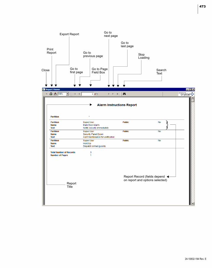
473
Report Record (fields dependon report and options selected)
ReportTitle
Go tofirst page
Go toprevious page
SearchText
Go tolast page
PrintReport
Stop
Close
Export Report
{
Go tonext page
Go to PageField Box
Loading
24-10832-194 Rev. E

474 CHAPTER 6
System Reports
24-10832-194 Rev. E
P2000 Standard Report Definitions
Following is a list of all P2000 standard reports along with a brief description of each default configuration. Any time you select an asterisk (*) in a field, the report includes all records for that field. Some reports provide options to fil-ter and limit the search, and some present check boxes listing all available values for a field, allowing you to select multiple items.
If you use the Partition feature, report data is restricted to the partition selected from the Run Report window. However, some reports ignore the partition selected and may report data across all partitions, unless you select a spe-cific partition name within the specific report to limit the data.
In addition, when running any of the audit, alarm, or transaction history reports, you have the option of selecting to report transactions at your local site or you can enter the name of the remote site that you want to report on.
Preprocessed reports display current data. Any changes made to database items in a Prepro-cessed report are not reflected until the follow-ing day, unless you manually update the report table using the Update Preprocessed Report tables task in Database Maintenance; see page 447.
Also, report names that start with RAW are duplicates of existing reports, with the differ-ence that these RAW reports have been format-ted to be exported into an Excel spreadsheet. The preview window for these reports may not display correctly, but the resulting Excel spreadsheet contains valid data.
To get the fullest benefit of this powerful fea-ture, we recommend you read through the entire list to get a complete understanding of what is available.
Access Group – Lists all terminals, terminal groups, floor groups, and door groups by access group.
Access Template – Lists the details of all access templates created in the system.
Alarm Activity - Simple – Lists alarm activities in a simpler format than the Alarm Activity Log report. You can list all alarm activities or select specific alarm category, type, descrip-tion, associated alarm item; as well as date and time beginning and ending periods.
Alarm Activity Log – Lists all alarm activities, or you can select specific alarm category, type, description, associated alarm item; as well as date and time beginning and ending periods.
Alarm History – Lists all alarm history in the system or you can select specific alarm cate-gory, type, description, associated alarm item; as well as date and time beginning and ending periods. See an example of this report in the Selected Sample Reports section.
Alarm History - Input Point – Similar to the Alarm History report, except that it only dis-plays panel input point alarms, and groups them together by their associated terminal, fol-lowed by input point. The alarms are listed for each input point chronologically. This report allows users to see a list of alarms and state changes for the input points that are configured in the system.
Alarm Instruction – Lists all alarm instructions and associated text created in the system.

475
Alarm Response Text – Lists all response text created in the system.
All Access Groups to Door – Lists all access groups and the door terminals assigned to each.
All Access Groups to Elevator/Cabinet – Lists all access groups and the elevators or cabinets assigned to each.
All Access Groups to Floor/Door – Lists all access groups and the floors or doors assigned to each.
All Access Groups to Floor/Door Group – Lists all access groups and the floor or door groups assigned to each.
All Access Groups to Terminal Group – Lists all access groups and the terminal groups assigned.
All Areas to Cardholder - Preprocessed – Lists by cardholder name, all areas the cardholder can access, and the terminal doors defined for the area.
All Cardholders to Access Group - Prepro-cessed – Lists by access group the cardholders assigned to that access group.
All Cardholders to Area - Preprocessed – Lists by area name, the cardholders and badges that have access to the area.
All Cardholders to Door - Preprocessed – Lists by door terminal all cardholders that have access to that terminal.
All Cardholders to Elevator/Cabinet - Prepro-cessed – Lists all cardholders and the eleva-tors or cabinets assigned to each.
All Cardholders to Floor/Door - Preprocessed – Lists all cardholders and the floors or doors assigned to each.
All Cardholders to Floor/Door Group - Prepro-cessed – Lists all cardholders and the floor or door groups assigned to each.
All Cardholders to Terminal Group - Prepro-cessed – Lists by terminal group all cardhold-ers that have access to that terminal group.
All Cardholders to Timezone – Lists by time zone all cardholders assigned to that time zone.
All Cardholders with Executive – Lists the names of all cardholders with executive privi-leges.
All Doors to Cardholder - Preprocessed – Lists by cardholder name all doors and access groups assigned to the cardholder.
All Elevator/Cabinet to Cardholder - Prepro-cessed – Lists by cardholder name the eleva-tors or cabinets assigned to the cardholder.
All Floor/Door Groups to Elevator/Cabinet – Lists by elevator or cabinet name all floor or door groups assigned to the elevator or cabi-net.
All Floor/Door Groups to Floor/Door – Lists by elevator floor or cabinet door all floor or door groups assigned to the elevator floor or cabinet door.
All Floors/Doors to Cardholder - Preprocessed – Lists by cardholder name all elevator floors or cabinet doors assigned to the cardholder.
24-10832-194 Rev. E
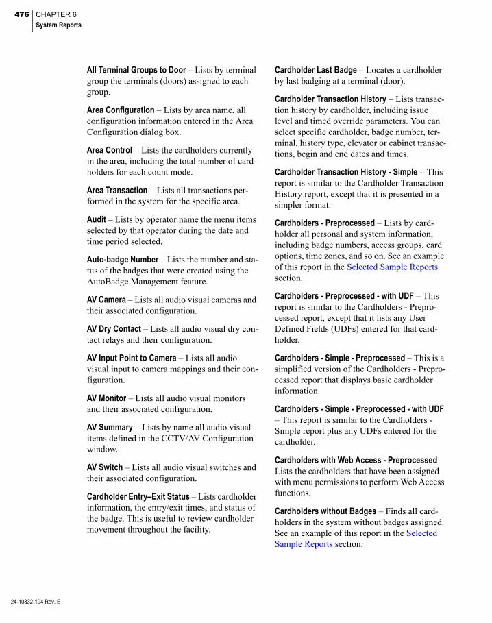
476 CHAPTER 6
System Reports
24-10832-194 Rev. E
All Terminal Groups to Door – Lists by terminal group the terminals (doors) assigned to each group.
Area Configuration – Lists by area name, all configuration information entered in the Area Configuration dialog box.
Area Control – Lists the cardholders currently in the area, including the total number of card-holders for each count mode.
Area Transaction – Lists all transactions per-formed in the system for the specific area.
Audit – Lists by operator name the menu items selected by that operator during the date and time period selected.
Auto-badge Number – Lists the number and sta-tus of the badges that were created using the AutoBadge Management feature.
AV Camera – Lists all audio visual cameras and their associated configuration.
AV Dry Contact – Lists all audio visual dry con-tact relays and their configuration.
AV Input Point to Camera – Lists all audio visual input to camera mappings and their con-figuration.
AV Monitor – Lists all audio visual monitors and their associated configuration.
AV Summary – Lists by name all audio visual items defined in the CCTV/AV Configuration window.
AV Switch – Lists all audio visual switches and their associated configuration.
Cardholder Entry–Exit Status – Lists cardholder information, the entry/exit times, and status of the badge. This is useful to review cardholder movement throughout the facility.
Cardholder Last Badge – Locates a cardholder by last badging at a terminal (door).
Cardholder Transaction History – Lists transac-tion history by cardholder, including issue level and timed override parameters. You can select specific cardholder, badge number, ter-minal, history type, elevator or cabinet transac-tions, begin and end dates and times.
Cardholder Transaction History - Simple – This report is similar to the Cardholder Transaction History report, except that it is presented in a simpler format.
Cardholders - Preprocessed – Lists by card-holder all personal and system information, including badge numbers, access groups, card options, time zones, and so on. See an example of this report in the Selected Sample Reports section.
Cardholders - Preprocessed - with UDF – This report is similar to the Cardholders - Prepro-cessed report, except that it lists any User Defined Fields (UDFs) entered for that card-holder.
Cardholders - Simple - Preprocessed – This is a simplified version of the Cardholders - Prepro-cessed report that displays basic cardholder information.
Cardholders - Simple - Preprocessed - with UDF – This report is similar to the Cardholders - Simple report plus any UDFs entered for the cardholder.
Cardholders with Web Access - Preprocessed – Lists the cardholders that have been assigned with menu permissions to perform Web Access functions.
Cardholders without Badges – Finds all card-holders in the system without badges assigned. See an example of this report in the Selected Sample Reports section.
477
CCTV Camera – Lists all CCTV cameras and their associated configuration.
CCTV Monitor – Lists all CCTV monitors and their associated configuration.
CCTV Summary – Lists by name all CCTV items defined in the CCTV/AV Configuration window.
CCTV Switch – Lists all CCTV switches and their associated configuration.
Disabled Cardholders and Badges – Lists all cardholders that have been disabled or have disabled/inactive badges.
Elevator/Cabinet Configuration – Lists by ele-vator or cabinet name all configuration infor-mation entered in the Elevator or Cabinet Con-figuration dialog box for all elevators or cabinets.
Elevator/Cabinet Transaction – Lists all trans-actions performed in the system for the speci-fied elevator or cabinet name.
Events – Lists by event name all configuration information entered in the Configure Events dialog box, including event trigger and action information.
Floor/Door Group – Lists all elevator floor or cabinet door groups and the floor or door masks assigned to each group.
Floor/Door Mask – Lists all elevator floor or cabinet door masks and the floors or doors assigned to each.
Floor/Door Name – Lists all elevator floors or cabinet doors and the floor or door numbers and names assigned to each.
Hardware Up/Down Status – Lists the name and status of all operating hardware.
Holiday – List all holidays configured in the system.
Hours on Site – Lists a detailed report of a cardholder’s accumulated number of hours present at a site.
Hours on Site - Simple – Lists a summary report of a cardholder’s accumulated number of hours present at a site.
Input Group – Lists by input group the associ-ated input points and panels.
Input Point – Lists by input point all configura-tion information entered in the Input Point dia-log box for all input points.
Input Point Disable/Suppressible – Lists all input points in the system that are disabled or suppressed.
Message Filter – Lists by message filter name all the filtering information entered in the Message Filter Configuration dialog box for all message filters.
Message Filter Group – Lists by message filter group the message filters associated with the message filter group.
Message Forwarding – Lists the workstation names from where and to where all current messages are forwarded.
Muster Analysis – Displays by group type the list of personnel who are within a muster zone in the specified time frame, and whether it was a drill or real emergency.
Mustering Configuration – Lists by muster zone name, all the zone definition configuration, as set up in the Muster Zone Definition dialog box.
Operator – Lists all operator information entered in the Edit Operator dialog box.
24-10832-194 Rev. E

478 CHAPTER 6
System Reports
24-10832-194 Rev. E
Operator Permissions – Lists the permissions assigned to each operator.
Output Group – Lists by output group the asso-ciated output points and panels.
Output Point – Lists by output point all config-uration information entered in the Output Point dialog box for all output points.
Panel – Lists all panels in the system with their associated configuration as set up in the Panel dialog box. See an example of this report in the Selected Sample Reports section.
Panel Card Event – Lists by panel card event name all panel card event details configured for the system.
Remote Server – Lists all remote servers in the system with their associated configuration, as set up in the P2000 Remote Server dialog box.
Security Level Ranges – Lists the security lev-els defined in the Security Level Range Editor dialog box.
Site Parameters – Lists the details of the cur-rent site parameters as set up in System Con-figuration.
Station – Lists by workstation all workstation configuration.
Terminal – Lists by terminal name all terminal configuration as set up in the Terminal dialog box.
Terminal Groups – Lists by terminal group the terminals associated with the terminal group.
Terminal Unshunted – Lists all terminals with a shunt time of zero.
Time Zone – Lists all time zones configured for the system.
Tour Configuration – Lists by tour name, all tour definition configuration, as set up in the Guard Tour Definition window.
Tour Notes – Lists all the tour notes assigned to a specific tour name, as set up in the Guard Tour Control window.
Tour Transaction History – Lists all tour trans-actions performed in the system.
Transaction History – Lists all transactions per-formed in the system. See an example of this report in the Selected Sample Reports section.
Unused Active Badges – Displays a list of active badges that have not been used during the specified period of time.
Verification – Allows for a verification of the commissioning process by providing a list of all hardware to be checked off by the contrac-tor. This list includes a list of all panels in the system and their associated terminals, inputs, and outputs.

479
Selected Sample Reports
Following are detailed instructions on how to run reports. Once you have experimented with these, you should have a good understanding of how to select options to get the results you need.
Each example shows a reporting criteria win-dow and the associated report generated from the configuration selected.
Run the Alarm History Report
The Alarm History report gives you an over-view of alarm activity throughout the system. You can run it for all alarm types in the system (the default), or select a specific alarm type. You can also specify a particular date and time, and review only those alarms that occurred during that time. If your system is partitioned, select the partition you want to report on. In addition, you can select to run the report for alarms generated at your local or at a remote site.
1. In the Run Report list, select Alarm His-tory and click Run, or double-click Alarm History. The Alarm History dialog box opens.
2. By default, the system displays the local Site name. If you wish to run the report on alarms generated at a remote site, select from the drop-down list the name of the remote site.
3. If your system is partitioned, select a spe-cific Partition name, or select (*) to gather data from all partitions.
4. Select a specific Alarm Type to report on only one alarm type in the system, or select (*) to report on all alarm types.
5. The Type ID list box displays items that are associated with the selected Alarm Type. Select a specific or multiple type IDs to report only on those entries selected, or select (*) to report on all type IDs.
6. Enter a Description of the alarm. You can use wildcards. For example, you can enter *Min Req* to report only on alarms gener-ated when the minimum number of card-holders is not present at the same time in the specific Area.
7. The default Alarm Category is P2000. Select a specific alarm category to report only on the alarm category selected.
8. Select a Begin and End date for the alarms you wish to see.
9. Select a Begin and End time for the alarms you wish to see.
10. Click OK. Select a printer name and any other information for the printer to be used. See your system administrator if you need more information, or refer to your Microsoft Windows documentation.
11. Click OK. The Alarm History report dis-plays in the preview window. You can use the arrows at the top of the window to scroll forward and back through the pages; resize the window for the best display, and print all or single pages of the report.
24-10832-194 Rev. E
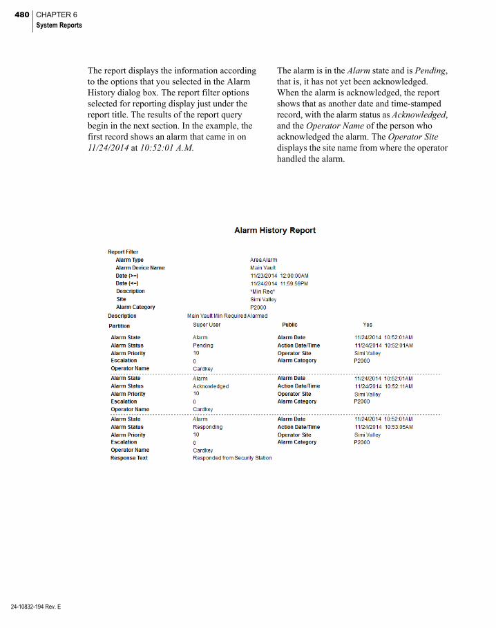
480 CHAPTER 6
System Reports
24-10832-194 Rev. E
The report displays the information according to the options that you selected in the Alarm History dialog box. The report filter options selected for reporting display just under the report title. The results of the report query begin in the next section. In the example, the first record shows an alarm that came in on 11/24/2014 at 10:52:01 A.M.
The alarm is in the Alarm state and is Pending, that is, it has not yet been acknowledged. When the alarm is acknowledged, the report shows that as another date and time-stamped record, with the alarm status as Acknowledged, and the Operator Name of the person who acknowledged the alarm. The Operator Site displays the site name from where the operator handled the alarm.
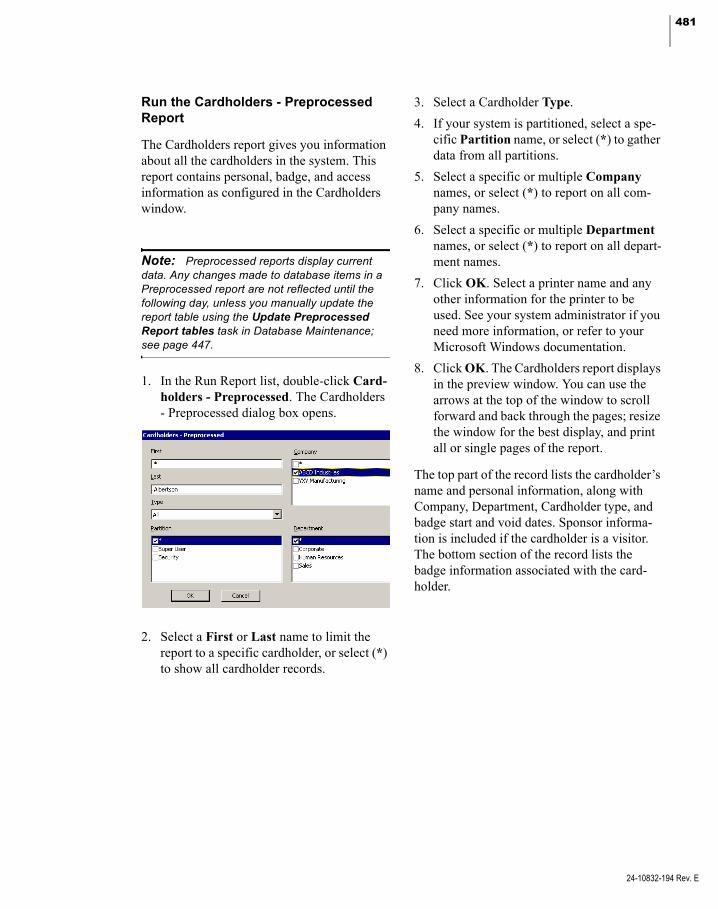
481
Run the Cardholders - Preprocessed Report
The Cardholders report gives you information about all the cardholders in the system. This report contains personal, badge, and access information as configured in the Cardholders window.
Note: Preprocessed reports display current data. Any changes made to database items in a Preprocessed report are not reflected until the following day, unless you manually update the report table using the Update Preprocessed Report tables task in Database Maintenance; see page 447.
1. In the Run Report list, double-click Card-holders - Preprocessed. The Cardholders - Preprocessed dialog box opens.
2. Select a First or Last name to limit the report to a specific cardholder, or select (*) to show all cardholder records.
3. Select a Cardholder Type.
4. If your system is partitioned, select a spe-cific Partition name, or select (*) to gather data from all partitions.
5. Select a specific or multiple Company names, or select (*) to report on all com-pany names.
6. Select a specific or multiple Department names, or select (*) to report on all depart-ment names.
7. Click OK. Select a printer name and any other information for the printer to be used. See your system administrator if you need more information, or refer to your Microsoft Windows documentation.
8. Click OK. The Cardholders report displays in the preview window. You can use the arrows at the top of the window to scroll forward and back through the pages; resize the window for the best display, and print all or single pages of the report.
The top part of the record lists the cardholder’s name and personal information, along with Company, Department, Cardholder type, and badge start and void dates. Sponsor informa-tion is included if the cardholder is a visitor. The bottom section of the record lists the badge information associated with the card-holder.
24-10832-194 Rev. E
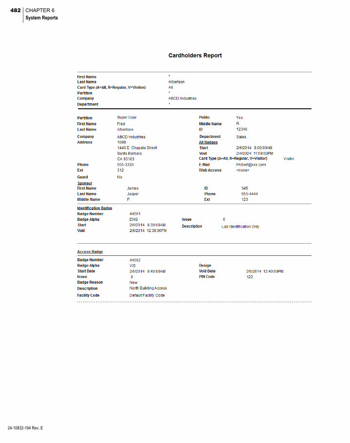
482 CHAPTER 6
System Reports
24-10832-194 Rev. E
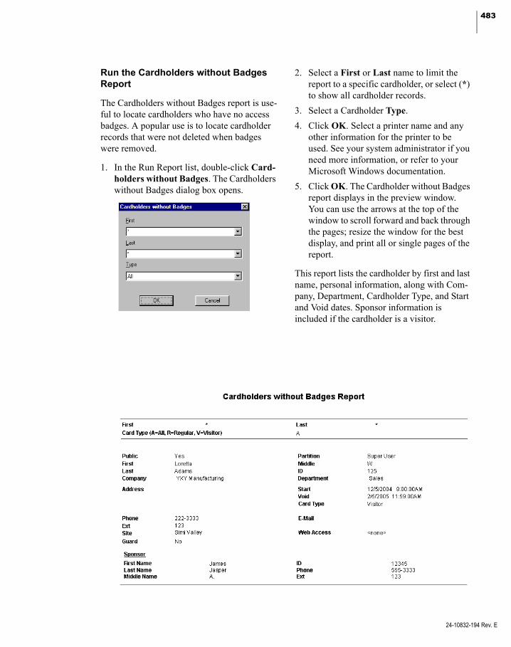
483
Run the Cardholders without Badges Report
The Cardholders without Badges report is use-ful to locate cardholders who have no access badges. A popular use is to locate cardholder records that were not deleted when badges were removed.
1. In the Run Report list, double-click Card-holders without Badges. The Cardholders without Badges dialog box opens.
2. Select a First or Last name to limit the report to a specific cardholder, or select (*) to show all cardholder records.
3. Select a Cardholder Type.
4. Click OK. Select a printer name and any other information for the printer to be used. See your system administrator if you need more information, or refer to your Microsoft Windows documentation.
5. Click OK. The Cardholder without Badges report displays in the preview window. You can use the arrows at the top of the window to scroll forward and back through the pages; resize the window for the best display, and print all or single pages of the report.
This report lists the cardholder by first and last name, personal information, along with Com-pany, Department, Cardholder Type, and Start and Void dates. Sponsor information is included if the cardholder is a visitor.
24-10832-194 Rev. E
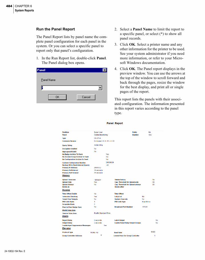
484 CHAPTER 6
System Reports
24-10832-194 Rev. E
Run the Panel Report
The Panel Report lists by panel name the com-plete panel configuration for each panel in the system. Or you can select a specific panel to report only that panel’s configuration.
1. In the Run Report list, double-click Panel. The Panel dialog box opens.
2. Select a Panel Name to limit the report to a specific panel, or select (*) to show all panel records.
3. Click OK. Select a printer name and any other information for the printer to be used. See your system administrator if you need more information, or refer to your Micro-soft Windows documentation.
4. Click OK. The Panel report displays in the preview window. You can use the arrows at the top of the window to scroll forward and back through the pages, resize the window for the best display, and print all or single pages of the report.
This report lists the panels with their associ-ated configuration. The information presented in this report varies according to the panel type.

485
Run the Transaction History Report
One of the most commonly used reports in the system is the Transaction History report. This report can list every transaction in the system, or be filtered to list by specific Site, Partition, Terminal, Transaction Type, History Type, specific Dates and Times, and any combina-tion of these. The options available for selec-tion depend on the transaction type selected.
1. In the Run Report list, double-click Trans-action History. The Transaction History dialog box opens.
2. By default, the system displays the local Site name. If you wish to run the report on transactions that were originated at a remote site, select from the drop-down list the name of the remote site.
3. If your system is partitioned, select a spe-cific Partition name, or select (*) to gather data from all partitions.
4. Select a specific Transaction Type to report on only one transaction type in the system, or select <all> to report on all transaction types.
5. Select a History Type. History types avail-able from the drop-down list depend on the selection in the Transaction Type field.
6. If available for selection, select a specific Terminal to limit your search.
7. Select a Begin and End date for the trans-actions you wish to see.
8. Select a Begin and End time for the trans-actions you wish to see.
9. Click OK. Select a printer name and any other information for the printer to be used. See your system administrator if you need more information, or refer to your Microsoft Windows documentation.
24-10832-194 Rev. E
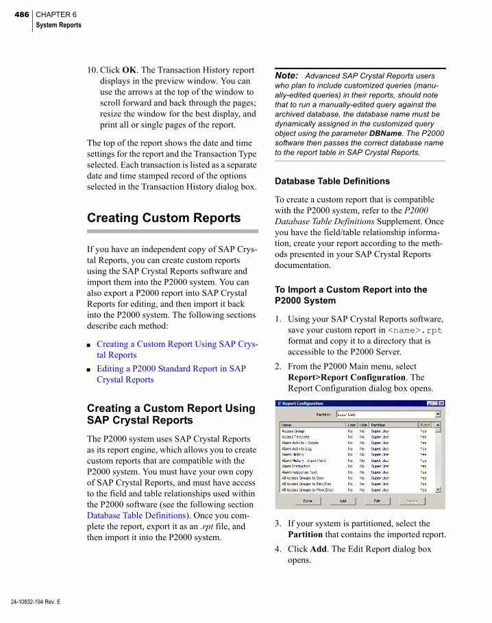
486 CHAPTER 6
System Reports
24-10832-194 Rev. E
10. Click OK. The Transaction History report displays in the preview window. You can use the arrows at the top of the window to scroll forward and back through the pages; resize the window for the best display, and print all or single pages of the report.
The top of the report shows the date and time settings for the report and the Transaction Type selected. Each transaction is listed as a separate date and time stamped record of the options selected in the Transaction History dialog box.
Creating Custom Reports
If you have an independent copy of SAP Crys-tal Reports, you can create custom reports using the SAP Crystal Reports software and import them into the P2000 system. You can also export a P2000 report into SAP Crystal Reports for editing, and then import it back into the P2000 system. The following sections describe each method:
Creating a Custom Report Using SAP Crys-tal Reports
Editing a P2000 Standard Report in SAP Crystal Reports
Creating a Custom Report Using SAP Crystal Reports
The P2000 system uses SAP Crystal Reports as its report engine, which allows you to create custom reports that are compatible with the P2000 system. You must have your own copy of SAP Crystal Reports, and must have access to the field and table relationships used within the P2000 software (see the following section Database Table Definitions). Once you com-plete the report, export it as an .rpt file, and then import it into the P2000 system.
Note: Advanced SAP Crystal Reports users who plan to include customized queries (manu-ally-edited queries) in their reports, should note that to run a manually-edited query against the archived database, the database name must be dynamically assigned in the customized query object using the parameter DBName. The P2000 software then passes the correct database name to the report table in SAP Crystal Reports.
Database Table Definitions
To create a custom report that is compatible with the P2000 system, refer to the P2000 Database Table Definitions Supplement. Once you have the field/table relationship informa-tion, create your report according to the meth-ods presented in your SAP Crystal Reports documentation.
To Import a Custom Report into the P2000 System
1. Using your SAP Crystal Reports software, save your custom report in <name>.rpt format and copy it to a directory that is accessible to the P2000 Server.
2. From the P2000 Main menu, select Report>Report Configuration. The Report Configuration dialog box opens.
3. If your system is partitioned, select the Partition that contains the imported report.
4. Click Add. The Edit Report dialog box opens.
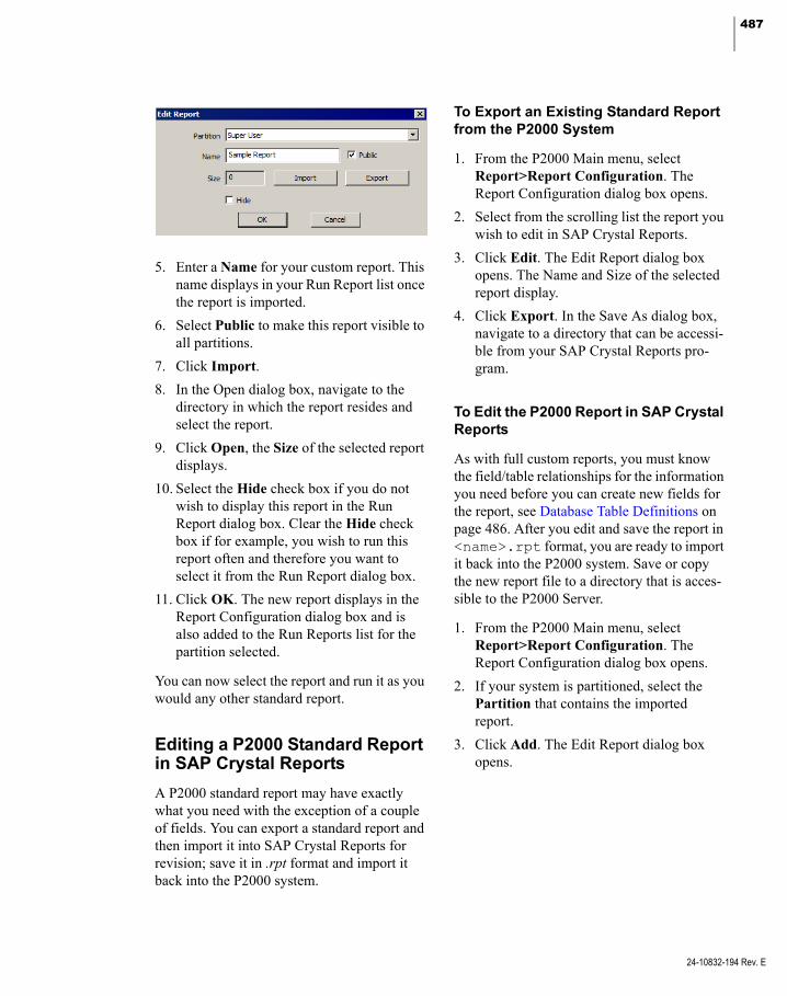
487
5. Enter a Name for your custom report. This name displays in your Run Report list once the report is imported.
6. Select Public to make this report visible to all partitions.
7. Click Import.
8. In the Open dialog box, navigate to the directory in which the report resides and select the report.
9. Click Open, the Size of the selected report displays.
10. Select the Hide check box if you do not wish to display this report in the Run Report dialog box. Clear the Hide check box if for example, you wish to run this report often and therefore you want to select it from the Run Report dialog box.
11. Click OK. The new report displays in the Report Configuration dialog box and is also added to the Run Reports list for the partition selected.
You can now select the report and run it as you would any other standard report.
Editing a P2000 Standard Report in SAP Crystal Reports
A P2000 standard report may have exactly what you need with the exception of a couple of fields. You can export a standard report and then import it into SAP Crystal Reports for revision; save it in .rpt format and import it back into the P2000 system.
To Export an Existing Standard Report from the P2000 System
1. From the P2000 Main menu, select Report>Report Configuration. The Report Configuration dialog box opens.
2. Select from the scrolling list the report you wish to edit in SAP Crystal Reports.
3. Click Edit. The Edit Report dialog box opens. The Name and Size of the selected report display.
4. Click Export. In the Save As dialog box, navigate to a directory that can be accessi-ble from your SAP Crystal Reports pro-gram.
To Edit the P2000 Report in SAP Crystal Reports
As with full custom reports, you must know the field/table relationships for the information you need before you can create new fields for the report, see Database Table Definitions on page 486. After you edit and save the report in <name>.rpt format, you are ready to import it back into the P2000 system. Save or copy the new report file to a directory that is acces-sible to the P2000 Server.
1. From the P2000 Main menu, select Report>Report Configuration. The Report Configuration dialog box opens.
2. If your system is partitioned, select the Partition that contains the imported report.
3. Click Add. The Edit Report dialog box opens.
24-10832-194 Rev. E

488 CHAPTER 6
System Reports
24-10832-194 Rev. E
4. Enter a Name for your edited report. You may want to rename it something other than the original. This name displays in your Run Report list once the report is imported.
5. Select Public to make this report visible to all partitions.
6. Click Import.
7. In the Open dialog box, navigate to the directory in which the report resides and select the report.
8. Click Open, the Size of the selected report displays.
9. Select the Hide check box if you do not wish to display this report in the Run Report dialog box. Clear the Hide check box if for example, you wish to run this report often and therefore you want to select it from the Run Report dialog box.
10. Click OK. The new report displays in the Report Configuration dialog box and is also added to the Run Reports list for the partition selected.
You can now select the report and run it as you would any other standard report.

489
Appendix A: Event Triggers/Actions
his section lists all Trigger Categories, AV Dry Contact Alarm – Triggers when the sys-
TTrigger Types, Trigger Conditions, and Event Action Types available for Event configuration. For more information,
see Create Events on page 335.
To ensure that your events work properly, we strongly recommend that you verify if the events you define work as you expected. Some event triggers and actions that use hardware values such as panels, terminals, inputs, or out-puts, may not be available if your hardware does not support the associated functions. For example, the Badge trigger type Panel Card Event Activated is only available for CK721-A panels, whereas a Security Level action cate-gory is only available with panels that support the Security Level feature, such as CK721-A and S321-IP. Before programming your system events, see Appendix C: Panel Comparison Matrix for the features supported by each panel type, and also refer to the instructions provided with your hardware type to ensure that the trig-gers and actions are available to you.
Trigger Types
Category: Alarm
Any Alarm – Triggers when the system creates or acts upon any alarm.
Area – Triggers when the system creates or acts upon an Area alarm.
AV Behavior Alarm – Triggers when the system creates or acts upon an Audio Visual Behavior alarm.
tem creates or acts upon an Audio Visual Dry Contact alarm.
AV Motion Alarm – Triggers when the system creates or acts upon an Audio Visual Motion alarm.
AV System Alarm – Triggers when the system creates or acts upon an Audio Visual System alarm.
AV Video Loss Alarm – Triggers when the sys-tem creates or acts upon an Audio Visual Video Loss alarm.
Event Alarm – Triggers when the system cre-ates or acts upon an Event alarm.
FDA – Triggers when the system creates or acts upon an FDA alarm.
Fire Detector – Triggers when the system cre-ates or acts upon a fire detector alarm.
Fire I/O Module – Triggers when the system cre-ates or acts upon a fire Input/Output module alarm.
Fire Zone – Triggers when the system creates or acts upon a fire zone alarm.
Guard Tour – Triggers when the system creates or acts upon a Guard Tour alarm.
Inputs – Triggers when the system creates or acts upon an Input alarm.
Integration Component – Triggers when the system creates or acts upon an Integration Component alarm.
24-10832-194 Rev. E
490 APPENDIX A
Event Triggers/Actions
24-10832-194 Rev. E
Intercom Station – Triggers when the system creates or acts upon an Intercom Station alarm.
Intrusion Area – Triggers when the system cre-ates or acts upon an Intrusion Area alarm.
Intrusion Zone – Triggers when the system cre-ates or acts upon an Intrusion Zone alarm.
Muster Aborted – Triggers when the system creates or acts upon a Muster Aborted alarm.
Muster Running – Triggers when the system creates or acts upon a Muster Running alarm.
Muster When Disabled – Triggers when the sys-tem creates or acts upon a Muster When Dis-abled alarm.
Muster Zone Status – Triggers when the system creates or acts upon a Muster Zone Status alarm.
Remote Messaging Receive – Triggers when the system generates an alarm when a remote message is received.
Remote Messaging Transmit – Triggers when the system generates an alarm when a remote message is transmitted.
SNMP Alarm – Triggers when the system cre-ates or acts upon an SNMP alarm.
Timesync – Triggers when the system creates or acts upon a time synchronization alarm.
Conditions
Alarm Category Alarm State Date (steady state) Day of the Month Day of the Week Escalation Level Month SNMP Object Name Time
Category: Area
Area Maximum allowed alarm – Triggers when the system sets o resets an alarm when the maximum number of cardholders allowed in the selected Area has exceeded.
Area Minimum required alarm – Triggers when the system sets or resets an alarm when the minimum number of cardholders is not present at the same time in the selected Area.
Area Pre-Maximum allowed alarm – Triggers when the system sets or resets an alarm when the pre-maximum number of cardholders allowed in the selected Area is reached.
Conditions
Reset Set
Category: Audio-Visual
AV Behavior Alarm – Triggers when the system creates or acts upon an AV Behavior alarm.
AV Dry Contact Alarm – Triggers when the sys-tem creates or acts upon an AV Dry Contact alarm.
AV Motion Alarm – Triggers when the system creates or acts upon an AV Motion alarm.
AV System Alarm – Triggers when the system creates or acts upon an AV System alarm.
AV Video Loss Alarm – Triggers when the sys-tem creates or acts upon an AV Video Loss alarm.
Conditions
AV Camera Name AV Dry Contact Name AV Switch Name Date (steady state) Day of the Month

491
Day of the Week Month Time
Category: Audit
Add Badge Audit – Triggers when the system generates an audit message because an opera-tor has added a badge to the system.
Delete Badge Audit – Triggers when the system generates an audit message because an opera-tor has deleted a badge from the system.
Edit Badge Audit – Triggers when the system generates an audit message because an opera-tor has changed a badge in the system.
Conditions
Badge Badge Configuration Badge Purpose Badge Reason Cardholder Date (steady state) Day of the Month Day of the Week Month Time
Category: Badge
Anti-Passback Timer On – Triggers when a cardholder presents a badge at an anti-pass-back reader where the timer is on.
Central Response Timeout – Triggers when a cardholder presents a badge at a Mercury reader to which the P2000 system did not respond within the time defined by the Central Response Timeout.
Deny Open Door – Triggers when a panel receives a Deny Door Open message. This message is available from CK721-A panels that have the reader flag Deny If Door Open enabled.
Executive Privilege – Triggers when the badge presented has executive privileges; that is, it has unlimited access and bypasses all time zones and access groups.
Host Grant – Triggers when the cardholder presents a badge and the host grants access.
Host Grant Entry – Triggers when the card-holder presents a badge and the host grants access at an entry reader.
Host Grant Exit – Triggers when the cardholder presents a badge and the host grants access at an exit reader.
Invalid Badge – Triggers when the badge pre-sented at the reader is not valid.
Invalid Badge Time Zone – Triggers when the badge presented at the reader has a disabled time zone.
Invalid Biometric – Triggers when the badge presented at the reader does not match the information at the biometric device.
Invalid Event Privilege Level – Triggers when the badge presented at the reader has an invalid privilege level.
Invalid In-X-It Status – Triggers when the card-holder presents the badge at the reader in an out-of-sequence manner; that is, two times sequentially at an exit reader or two times sequentially at an entry reader.
Invalid Issue Level – Triggers when the badge presented at the reader has an invalid issue level.
Invalid Keypad Event – Triggers when the card-holder enters an invalid keypad code.
24-10832-194 Rev. E
492 APPENDIX A
Event Triggers/Actions
24-10832-194 Rev. E
Invalid PIN Code – Triggers when the card-holder enters an invalid PIN code.
Invalid Reader – Triggers when the badge pre-sented has no access rights assigned to the reader.
Invalid Reader Time Zone – Triggers when a cardholder presents a badge at a reader that has a disabled time zone.
Invalid Security Level – Triggers when the sys-tem denies access to a badge at a reader because of an invalid security level.
Local Grant – Triggers when the cardholder presents a badge and the panel grants access.
Operator Access Denied – Triggers when a cardholder presents a badge at a Mercury reader and the operator has rejected the access request.
Operator Access Request – Triggers when a cardholder presents a badge at a Mercury reader and the operator needs to be consulted to either grant or deny the access request.
Panel Card Event Activated – Triggers when the cardholder presents a badge at a reader and activates a panel card event.
Panel Card Event Deactivated – Triggers when the cardholder presents a badge at a reader and deactivates a panel card event.
Soft In-X-It Violation – Triggers when the badge presented generates an entry/exit violation; that is, the system grants access but creates an error message.
Use Limit Exceeded – Triggers when a card-holder presents a badge at a Mercury reader but the maximum number of times that the Mercury panel can grant access to this badge is exceeded.
Valid & Unauthorized Access – Triggers when the badge presented at the reader is valid, but the door remains locked because further autho-rization (for example, by the guard) is required.
Conditions
Access Group of Badge Access Group of Terminal Badge Badge Configuration Badge Purpose Badge Reason Cardholder Date (steady state) Day of the Month Day of the Week Month Panel Name Terminal Index Terminal Name Time Timezone Active
Note: You can also use numeric UDFs as badge conditions to activate a trigger.
Category: Counter
Triggers when the selected counter reaches the specified value.
Condition
Value
Category: External Trigger
Database – Triggers when an external input in the form of a database write has been sent to the P2000 system to trigger a host event.
493
File – Triggers when an external input in the form of an ASCII file has been sent to the P2000 system to trigger a host event.
RS232 – Triggers when an external input in the form of an RS232 serial message has been sent to the P2000 system to trigger a host event.
TCPIP – Triggers when an external input in the form of a TCP/IP message has been sent to the P2000 system to trigger a host event.
Conditions
Substring (the string sent to the host from the external input).
Category: Fire Detector
Fire Detector Alarmed – Triggers when the fire detector enters the alarmed state.
Fire Detector Disabled – Triggers when the fire detector enters the disabled state.
Fire Detector Enabled – Triggers when the fire detector enters the enabled state.
Fire Detector Pre Alarmed – Triggers when the fire detector enters the pre alarmed state.
Fire Detector Troubled – Triggers when the fire detector enters the trouble state.
Conditions
Date (steady state) Day of the Month Day of the Week Fire Detector Name Month Time
Category: Fire IO Module
Fire IO Module Activated – Triggers when the fire Input/Output module is activated.
Fire IO Module Disabled – Triggers when the fire Input/Output module enters the disabled state.
Fire IO Module Enabled – Triggers when the fire Input/Output module enters the enabled state.
Fire IO Module Pre Alarmed – Triggers when the fire Input/Output module enters the pre alarmed state.
Fire IO Module Troubled – Triggers when the fire Input/Output module enters the trouble state.
Conditions
Date (steady state) Day of the Month Day of the Week Fire IO Module Name Month Time
Category: Fire Panel
Fire Panel Down – Triggers when the fire panel is down.
Fire Panel Troubled – Triggers when the fire panel is in trouble state.
Fire Panel Up – Triggers when the fire panel is up.
Conditions
Date (steady state) Day of the Month Day of the Week Fire Panel Name Month Time
24-10832-194 Rev. E

494 APPENDIX A
Event Triggers/Actions
24-10832-194 Rev. E
Category: Fire Zone
Fire Zone Alarmed – Triggers when the fire zone enters the alarmed state.
Fire Zone Disabled – Triggers when the fire zone enters the disabled state.
Fire Zone Enabled – Triggers when the fire zone enters the enabled state.
Fire Zone Pre Alarmed – Triggers when the fire zone enters the pre alarmed state.
Fire Zone Troubled – Triggers when the fire zone enters the trouble state.
Conditions
Date (steady state) Day of the Month Day of the Week Fire Zone Name Month Time
Category: Inputs
Input Goes Open (transition) – Triggers when the state of an input point has changed to open.
Input Goes Reset (transition) – Triggers when the state of an input point has changed to reset.
Input Goes Set (transition) – Triggers when the state of an input point has changed to set.
Input Goes Short (transition) – Triggers when the state of an input point has changed to short.
Input Goes Suppressed (transition) – Triggers when the state of an input point has changed to suppressed.
Input Is Open (steady state) – Triggers when an input is in open state. Use this trigger in com-bination with other triggers.
Input Is Secure (steady state) – Triggers when an input is in secure state. Use this trigger in combination with other triggers.
Input Is Set (steady state) – Triggers when an input is in set state. Use this trigger in combi-nation with other triggers.
Input Is Short (steady state) – Triggers when an input is in short state. Use this trigger in com-bination with other triggers.
Input Is Suppressed (steady state) – Triggers when an input is in suppressed state. Use this trigger in combination with other triggers.
Conditions
Date (steady state) Day of the Month Day of the Week Input Point Name Input Point Number Month Panel Name Terminal Index Terminal Name Time Timezone Active
Category: Integration Component
Down – Triggers when the selected integration component is down.
Misconfigured – Triggers when the selected integration component is not properly config-ured.
Unavailable – Triggers when the selected inte-gration component is not available.
Up – Triggers when the selected integration component is up.
Conditions
Integration Component Name
495
Category: Intercom
Station Busy (transition) – Triggers when the intercom station is busy.
Station Call Request (transition) – Triggers when a call request has been placed to the intercom station.
Station Connected (transition) – Triggers when the intercom station has been connected.
Station Idle (transition) – Triggers when the intercom station shows no activity.
Station Output Active (transition) – Triggers when the intercom station output is active.
Station Output Inactive (transition) – Triggers when the intercom station output shows no activity.
Conditions
Date (steady state) Day of the Month Day of the Week Intercom Station Intercom Station Output Month Time
Category: Intrusion Annunciator
Activated – Triggers when the intrusion annun-ciator has been activated.
Deactivated – Trigger when the intrusion annunciator has been deactivated.
Conditions
Annunciator Name Date (steady state) Day of the Month Day of the Week Month Time
Category: Intrusion Area
Alarmed/Armed/Bypassed/Sealed (transition) – Triggers when the intrusion area enters the alarmed, armed, bypassed, or sealed state.
Alarmed/Armed/Bypassed/Unsealed (transi-tion) – Triggers when the intrusion area enters the alarmed, armed, bypassed, or unsealed state.
Alarmed/Armed/No-Bypass/Sealed (transition) – Triggers when the intrusion area enters the alarmed, armed, not bypassed, or sealed state.
Alarmed/Armed/No-Bypass/Unsealed (transi-tion) – Triggers when the intrusion area enters the alarmed, armed, not bypassed, or unsealed state.
Alarmed/Disarmed/Bypassed/Sealed (transition) – Triggers when the intrusion area enters the alarmed, disarmed, bypassed, or sealed state.
Alarmed/Disarmed/Bypassed/Unsealed (transi-tion) – Triggers when the intrusion area enters the alarmed, disarmed, bypassed, or unsealed state.
Alarmed/Disarmed/No-Bypass/Sealed (transi-tion) – Triggers when the intrusion area enters the alarmed, disarmed, not bypassed, or sealed state.
Alarmed/Disarmed/No-Bypass/Unsealed (transi-tion) – Triggers when the intrusion area enters the alarmed, disarmed, not bypassed, or unsealed state.
Armed (steady state) – Triggers when the intru-sion area enters the armed state. Use this trig-ger in combination with other triggers.
Armed (transition) – Triggers when the intru-sion area enters the armed state.
Armed/Bypassed/Sealed (transition) – Triggers when the intrusion area enters the armed, bypassed, or sealed state.
24-10832-194 Rev. E
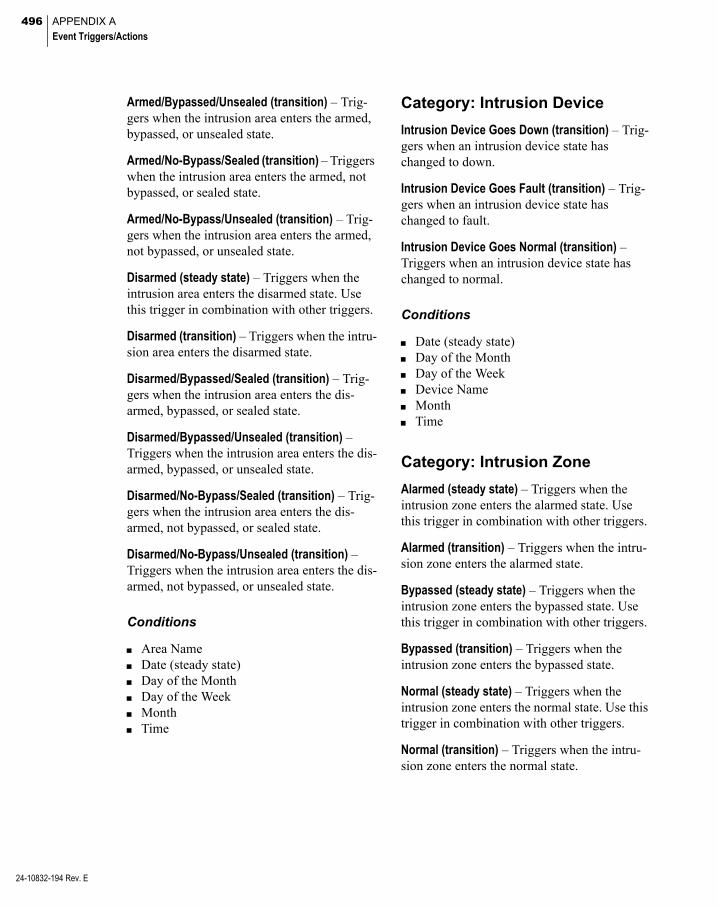
496 APPENDIX A
Event Triggers/Actions
24-10832-194 Rev. E
Armed/Bypassed/Unsealed (transition) – Trig-gers when the intrusion area enters the armed, bypassed, or unsealed state.
Armed/No-Bypass/Sealed (transition) – Triggers when the intrusion area enters the armed, not bypassed, or sealed state.
Armed/No-Bypass/Unsealed (transition) – Trig-gers when the intrusion area enters the armed, not bypassed, or unsealed state.
Disarmed (steady state) – Triggers when the intrusion area enters the disarmed state. Use this trigger in combination with other triggers.
Disarmed (transition) – Triggers when the intru-sion area enters the disarmed state.
Disarmed/Bypassed/Sealed (transition) – Trig-gers when the intrusion area enters the dis-armed, bypassed, or sealed state.
Disarmed/Bypassed/Unsealed (transition) – Triggers when the intrusion area enters the dis-armed, bypassed, or unsealed state.
Disarmed/No-Bypass/Sealed (transition) – Trig-gers when the intrusion area enters the dis-armed, not bypassed, or sealed state.
Disarmed/No-Bypass/Unsealed (transition) – Triggers when the intrusion area enters the dis-armed, not bypassed, or unsealed state.
Conditions
Area Name Date (steady state) Day of the Month Day of the Week Month Time
Category: Intrusion Device
Intrusion Device Goes Down (transition) – Trig-gers when an intrusion device state has changed to down.
Intrusion Device Goes Fault (transition) – Trig-gers when an intrusion device state has changed to fault.
Intrusion Device Goes Normal (transition) – Triggers when an intrusion device state has changed to normal.
Conditions
Date (steady state) Day of the Month Day of the Week Device Name Month Time
Category: Intrusion Zone
Alarmed (steady state) – Triggers when the intrusion zone enters the alarmed state. Use this trigger in combination with other triggers.
Alarmed (transition) – Triggers when the intru-sion zone enters the alarmed state.
Bypassed (steady state) – Triggers when the intrusion zone enters the bypassed state. Use this trigger in combination with other triggers.
Bypassed (transition) – Triggers when the intrusion zone enters the bypassed state.
Normal (steady state) – Triggers when the intrusion zone enters the normal state. Use this trigger in combination with other triggers.
Normal (transition) – Triggers when the intru-sion zone enters the normal state.

497
Open (steady state) – Triggers when the intru-sion zone enters the open state. Use this trigger in combination with other triggers.
Open (transition) – Triggers when the intrusion zone enters the open state.
Tampered (steady state) – Triggers when the intrusion zone enters the tampered state. Use this trigger in combination with other triggers.
Tampered (transition) – Triggers when the intrusion zone enters the tampered state.
Conditions
Date (steady state) Day of the Month Day of the Week Month Time Zone Name
Category: Mustering
Mustering Start – Triggers when the Mustering starts at a specified zone.
Mustering Stop – Triggers when Mustering stops at a specified zone.
Conditions
Zone Name
Category: Operator
Invalid Logon – Triggers when there has been an attempt to log on with an invalid user name or password.
Logon Disabled – Triggers when an operator has been inactive at the workstation for a spec-ified period of time and has been automatically logged off.
Operator Logoff – Triggers when an operator has logged off from the workstation.
Operator Logon – Triggers when an operator has logged on to the workstation.
Conditions
Date (steady state) Day of the Month Day of the Week Month Operator Time
Category: Outputs
Output Goes Reset (transition) – Triggers when the state of an output point has changed to reset.
Output Goes Set (transition) – Triggers when the state of an output point has changed to set.
Output Is Reset (steady state) – Triggers when an output is in reset state. Use this trigger in combination with other triggers.
Output Is Set (steady state) – Triggers when an output is in set state. Use this trigger in combi-nation with other triggers.
Conditions
Date (steady state) Day of the Month Day of the Week Month Output Point Name Output Point Number Panel Name Terminal Index Terminal Name Time Timezone Active
24-10832-194 Rev. E

498 APPENDIX A
Event Triggers/Actions
24-10832-194 Rev. E
Category: Panel
Panel Goes Offline (transition) – Triggers when the panel state has changed to offline.
Panel Goes Online (transition) – Triggers when the panel state has changed to online.
Panel Is Down (steady state) – Triggers when the panel is down. Use this trigger in combina-tion with other triggers.
Panel Is Up (steady state) – Triggers when the panel is up. Use this trigger in combination with other triggers.
Panel Load Database From Flash (transition) – Triggers when the panel has loaded the data-base from flash memory.
Conditions
Date (steady state) Day of the Month Day of the Week Month Panel Name Time Timezone Active
Category: Terminal
Note: HID panels may trigger multiple times for a single event.
Input Terminal Goes Down (transition) – Trig-gers when an input terminal state has changed to down.
Input Terminal Goes Up (transition) – Triggers when an input terminal state has changed to up.
Input Terminal Is Down (steady state) – Triggers when an input terminal is down. Use this trig-ger in combination with other triggers.
Input Terminal Is Up (steady state) – Triggers when an input terminal is up. Use this trigger in combination with other triggers.
Output Terminal Goes Down (transition) – Trig-gers when an output terminal state has changed to down.
Output Terminal Goes Up (transition) – Triggers when an output terminal state has changed to up.
Output Terminal Is Down (steady state) – Trig-gers when an output terminal is down. Use this trigger in combination with other triggers.
Output Terminal Is Up (steady state) – Triggers when an output terminal is up. Use this trigger in combination with other triggers.
Reader Terminal Goes Down (transition) – Trig-gers when a reader terminal state has changed to down.
Reader Terminal Goes Up (transition) – Triggers when a reader terminal state has changed to up.
Reader Terminal Is Down (steady state) – Trig-gers when a reader terminal is down. Use this trigger in combination with other triggers.
Reader Terminal Is Up (steady state) – Triggers when a reader terminal is up. Use this trigger in combination with other triggers.
System Facility Code Error – Triggers when a badge presented at the reader has an invalid facility code.
Terminal Auxiliary Access – Triggers when a Request to Exit input point activation allows a door to open without generating a forced door alarm.
Timed Override Disabled – Triggers when a timed override has been manually disabled.
Timed Override Disabled Host – Triggers when a timed override has been manually disabled from the host.

499
Timed Override Enabled – Triggers when a timed override has been manually enabled.
Timed Override Enabled Host – Triggers when a timed override has been manually enabled from the host.
Timed Override Expired – Triggers when a timed override has expired.
Conditions
Date (steady state) Day of the Month Day of the Week Month Panel Name Terminal Index Terminal Name Time Timezone Active
Category: Time Zone
Beginning Of Period – Triggers when the time zone period has started.
End Of Period – Triggers when the time zone period has ended.
Conditions
Time Zone
Category: Time/Date
Time/Date – The system activates the trigger on the specified time and date.
Conditions
Date (steady state) Date (transition) Day of the Month (steady state) Day of the Week (steady state) Month (steady state) Time (transition)
Event Action Types
Category: Audio-Visual
Note: The following event actions may function depending on the features provided by the manu-facturer of the digital video integration software. Refer to the P2000 DVR/VMS Integration manual for details.
Camera Complete Alarm – Completes an alarm generated by the selected camera.
Camera Complete Alarm Associated Input – Completes an alarm generated by any config-ured camera that is associated with an input created in Input to Camera mapping. You can-not manually trigger this event action.
Camera Complete Alarm Associated Terminal – Completes an alarm generated by any config-ured camera that is associated with a terminal mapped in Input to Camera. You cannot manu-ally trigger this event action.
Camera Preset – Activates the camera’s preset action.
Camera Recording Quality – Changes the cam-era’s recording quality. Enter a value from 1 to 255 (255 provides the highest quality). Not all digital video brands accept this command and some may have a limited quality range. Refer to the P2000 DVR/VMS Integration manual for details on recording quality settings.
Camera Send Alarm – Sends an alarm message generated by the selected camera.
Camera Send Alarm Associated Input – Sends an alarm message generated by any configured camera that is associated with an input created in Input to Camera mapping. You cannot man-ually trigger this event action.
24-10832-194 Rev. E

500 APPENDIX A
Event Triggers/Actions
24-10832-194 Rev. E
Camera Send Alarm Associated Terminal – Sends an alarm message generated by any con-figured camera that is associated with a termi-nal mapped in Input to Camera. You cannot manually trigger this event.
Camera Start Recording – Starts the recording of the selected camera.
Camera Start Recording and Archiving – Starts the recording and archiving of the selected camera.
Camera Start Recording Associated Input – Starts the recording of any configured camera that is associated with an input created in Input to Camera mapping. You cannot manually trig-ger this event.
Camera Start Recording Associated Terminal – Starts the recording of any configured camera that is associated with a reader reporting access grant or access deny transactions. You cannot manually trigger this event.
Camera Stop Recording – Stops the recording of the selected camera.
Camera Stop Recording Associated Input – Stops the recording of any configured camera that is associated with an input created in Input to Camera mapping. You cannot manually trig-ger this event.
Camera Stop Recording Associated Terminal – Stops the recording of any configured camera that is associated with a terminal mapped in Input to Camera. You cannot manually trigger this event.
Launch AV Player – Starts the AV Player appli-cation at the selected workstation.
Monitor Camera – Displays the image from a particular camera on the monitor.
Category: Badge
Add Access Group and Timezone – Adds the specified access group and time zone to the badge associated with the message that trig-gered the event. The access group and time zone are added in the first available position of the badge.
Add Access Group and Timezone to Cardholder – Adds the specified access group and time zone to all badges associated with the Card-holder displayed in the message that triggered the event. The access group and time zone are added in the first available position of all badges.
Delete Access Group – Deletes the specified access group from the badge associated with the message that triggered the event.
Delete Access Group to Cardholder – Deletes the specified access group from all badges associated with the Cardholder displayed in the message that triggered the event.
Increment Start Date of Access Group – Incre-ments the start date of the selected access group by the number of days entered for the associated badge.
Set Badge Security Level – Sets the badge secu-rity level at the specified value.
Set Badge Security Level to Reader Security Level – Sets the badge security level to match the security level at the terminal.
Category: CCTV
Camera Auxiliary Play – Activates the camera’s auxiliary relay.
Camera Auxiliary Stop – Deactivates the cam-era’s auxiliary relay.
Camera Pattern Play – Activates the camera’s pattern.
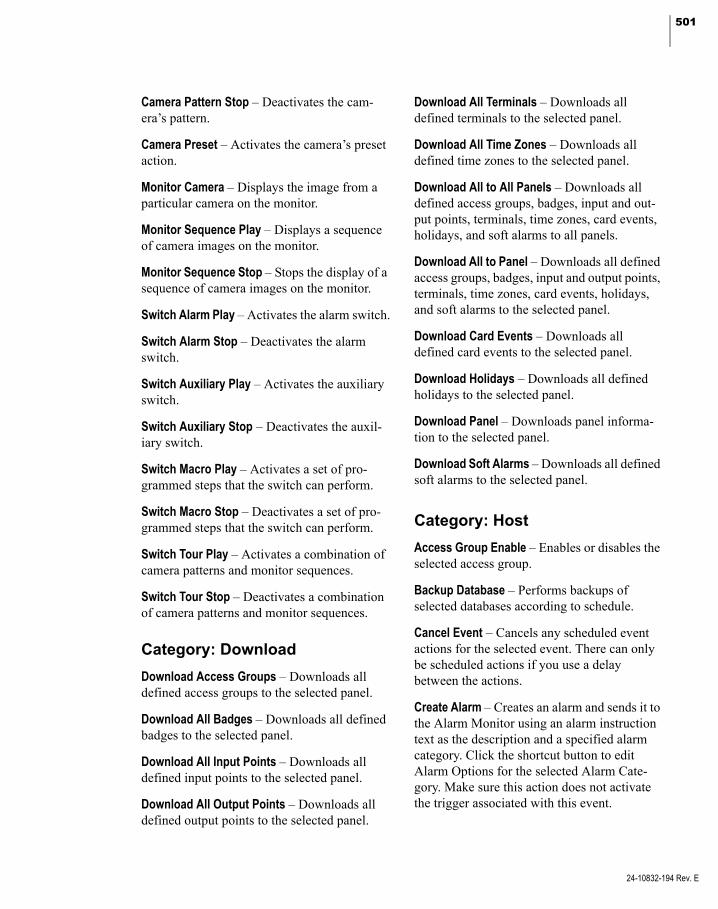
501
Camera Pattern Stop – Deactivates the cam-era’s pattern.
Camera Preset – Activates the camera’s preset action.
Monitor Camera – Displays the image from a particular camera on the monitor.
Monitor Sequence Play – Displays a sequence of camera images on the monitor.
Monitor Sequence Stop – Stops the display of a sequence of camera images on the monitor.
Switch Alarm Play – Activates the alarm switch.
Switch Alarm Stop – Deactivates the alarm switch.
Switch Auxiliary Play – Activates the auxiliary switch.
Switch Auxiliary Stop – Deactivates the auxil-iary switch.
Switch Macro Play – Activates a set of pro-grammed steps that the switch can perform.
Switch Macro Stop – Deactivates a set of pro-grammed steps that the switch can perform.
Switch Tour Play – Activates a combination of camera patterns and monitor sequences.
Switch Tour Stop – Deactivates a combination of camera patterns and monitor sequences.
Category: Download
Download Access Groups – Downloads all defined access groups to the selected panel.
Download All Badges – Downloads all defined badges to the selected panel.
Download All Input Points – Downloads all defined input points to the selected panel.
Download All Output Points – Downloads all defined output points to the selected panel.
Download All Terminals – Downloads all defined terminals to the selected panel.
Download All Time Zones – Downloads all defined time zones to the selected panel.
Download All to All Panels – Downloads all defined access groups, badges, input and out-put points, terminals, time zones, card events, holidays, and soft alarms to all panels.
Download All to Panel – Downloads all defined access groups, badges, input and output points, terminals, time zones, card events, holidays, and soft alarms to the selected panel.
Download Card Events – Downloads all defined card events to the selected panel.
Download Holidays – Downloads all defined holidays to the selected panel.
Download Panel – Downloads panel informa-tion to the selected panel.
Download Soft Alarms – Downloads all defined soft alarms to the selected panel.
Category: Host
Access Group Enable – Enables or disables the selected access group.
Backup Database – Performs backups of selected databases according to schedule.
Cancel Event – Cancels any scheduled event actions for the selected event. There can only be scheduled actions if you use a delay between the actions.
Create Alarm – Creates an alarm and sends it to the Alarm Monitor using an alarm instruction text as the description and a specified alarm category. Click the shortcut button to edit Alarm Options for the selected Alarm Cate-gory. Make sure this action does not activate the trigger associated with this event.
24-10832-194 Rev. E
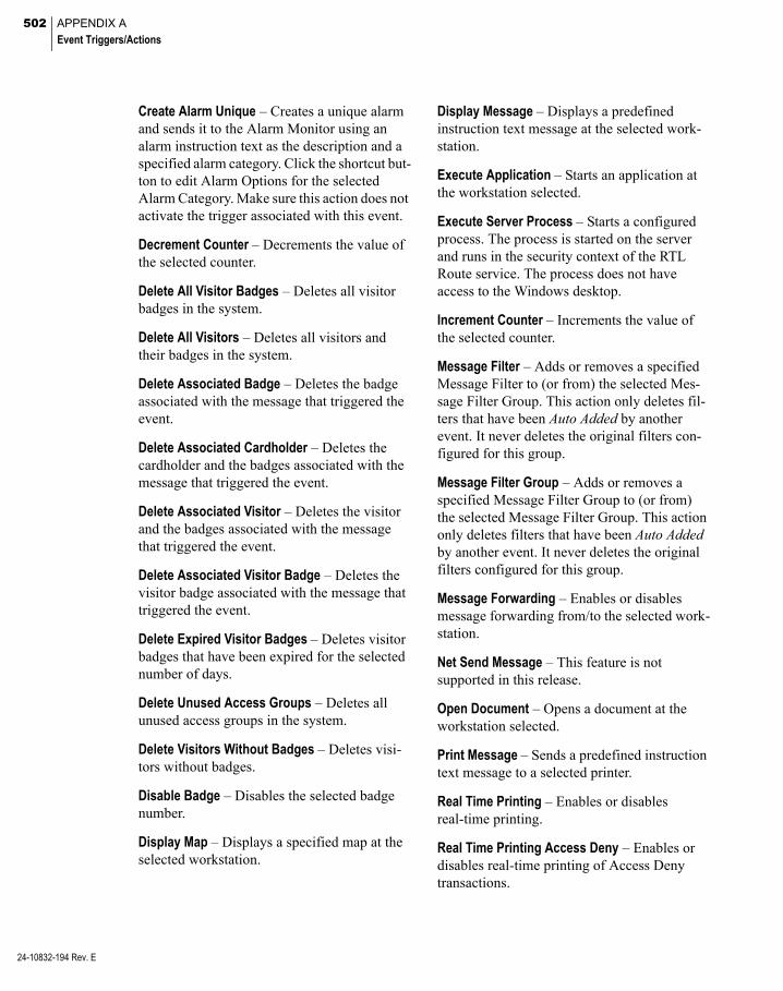
502 APPENDIX A
Event Triggers/Actions
24-10832-194 Rev. E
Create Alarm Unique – Creates a unique alarm and sends it to the Alarm Monitor using an alarm instruction text as the description and a specified alarm category. Click the shortcut but-ton to edit Alarm Options for the selected Alarm Category. Make sure this action does not activate the trigger associated with this event.
Decrement Counter – Decrements the value of the selected counter.
Delete All Visitor Badges – Deletes all visitor badges in the system.
Delete All Visitors – Deletes all visitors and their badges in the system.
Delete Associated Badge – Deletes the badge associated with the message that triggered the event.
Delete Associated Cardholder – Deletes the cardholder and the badges associated with the message that triggered the event.
Delete Associated Visitor – Deletes the visitor and the badges associated with the message that triggered the event.
Delete Associated Visitor Badge – Deletes the visitor badge associated with the message that triggered the event.
Delete Expired Visitor Badges – Deletes visitor badges that have been expired for the selected number of days.
Delete Unused Access Groups – Deletes all unused access groups in the system.
Delete Visitors Without Badges – Deletes visi-tors without badges.
Disable Badge – Disables the selected badge number.
Display Map – Displays a specified map at the selected workstation.
Display Message – Displays a predefined instruction text message at the selected work-station.
Execute Application – Starts an application at the workstation selected.
Execute Server Process – Starts a configured process. The process is started on the server and runs in the security context of the RTL Route service. The process does not have access to the Windows desktop.
Increment Counter – Increments the value of the selected counter.
Message Filter – Adds or removes a specified Message Filter to (or from) the selected Mes-sage Filter Group. This action only deletes fil-ters that have been Auto Added by another event. It never deletes the original filters con-figured for this group.
Message Filter Group – Adds or removes a specified Message Filter Group to (or from) the selected Message Filter Group. This action only deletes filters that have been Auto Added by another event. It never deletes the original filters configured for this group.
Message Forwarding – Enables or disables message forwarding from/to the selected work-station.
Net Send Message – This feature is not supported in this release.
Open Document – Opens a document at the workstation selected.
Print Message – Sends a predefined instruction text message to a selected printer.
Real Time Printing – Enables or disables real-time printing.
Real Time Printing Access Deny – Enables or disables real-time printing of Access Deny transactions.
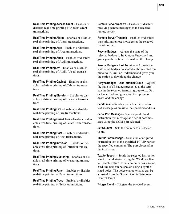
503
Real Time Printing Access Grant – Enables or disables real-time printing of Access Grant transactions.
Real Time Printing Alarm – Enables or disables real-time printing of Alarm transactions.
Real Time Printing Area – Enables or disables real-time printing of Area transactions.
Real Time Printing Audit – Enables or disables real-time printing of Audit transactions.
Real Time Printing AV – Enables or disables real-time printing of Audio-Visual transac-tions.
Real Time Printing Cabinet – Enables or dis-ables real-time printing of Cabinet transac-tions.
Real Time Printing Elevator – Enables or dis-ables real-time printing of Elevator transac-tions.
Real Time Printing Fire – Enables or disables real-time printing of Fire transactions.
Real Time Printing Guard Tour – Enables or dis-ables real-time printing of Guard Tour transac-tions.
Real Time Printing Host – Enables or disables real-time printing of Host transactions.
Real Time Printing Intrusion – Enables or dis-ables real-time printing of Intrusion transac-tions.
Real Time Printing Mustering – Enables or dis-ables real-time printing of Mustering transac-tions.
Real Time Printing Panel – Enables or disables real-time printing of Panel transactions.
Real Time Printing Trace – Enables or disables real-time printing of Trace transactions.
Remote Server Receive – Enables or disables receiving remote messages at the selected remote server.
Remote Server Transmit – Enables or disables transmitting remote messages at the selected remote server.
Resync Badges – Adjusts the state of the selected badges to In, Out, or Undefined and gives you the option to download the change.
Resync Badges - Last Terminal – Adjusts the state of all badges presented at the selected ter-minal to In, Out, or Undefined and gives you the option to download the change.
Resync Badges - Last Terminal Group – Adjusts the state of all badges presented at the termi-nals in the selected terminal group to In, Out, or Undefined and gives you the option to download the change.
Send Email – Sends a predefined instruction text message as email to the specified address.
Serial Port Message – Sends a predefined instruction text message as a serial port mes-sage using the COM port selected.
Set Counter – Sets the counter to a selected value.
TCP/IP Port Message – Sends the configured instruction text to the specified TCP/IP port on the specified computer. The port closes after the text is sent.
Text to Speech – Sends the selected instruction text to a workstation using the Windows Text to Speech feature. If the computer has a sound card, the text can be spoken using a synthe-sized voice. The voice characteristics can be adjusted from the Speech icon in Windows Control Panel.
Trigger Event – Triggers the selected event.
24-10832-194 Rev. E

504 APPENDIX A
Event Triggers/Actions
24-10832-194 Rev. E
UDF Decrement – Decrements the specified numeric UDF field by one for the Cardholder displayed in the message that triggered the event.
UDF Increment – Increments the specified numeric UDF field by one for the Cardholder displayed in the message that triggered the event.
UDF Set – Sets the specified numeric UDF field to the specified value for the Cardholder displayed in the message that triggered the event.
UDF Set to UDF – Sets the first specified numeric UDF field to the value of the second specified numeric UDF field for the Card-holder displayed in the message that triggered the event.
Category: Inputs
Acknowledge Alarm – Acknowledges an alarm.
Complete Alarm – Completes an alarm.
Input Group Disable – Disables an input group.
Input Group Enable – Enables an input group.
Input Group Suppress – Suppresses the selected Input Group for the specified time (0 seconds means forever).
Input Group Suppression Time Zone – Sup-presses the selected Input Group during the specified Time Zone.
Input Group Unsuppress – Unsuppresses the selected Input Group.
Input Point Disable – Disables a selected input point.
Input Point Enable – Enables a selected input point.
Input Point Enable Alarm – Enables or disables the alarm of the selected input point.
Input Point Suppress – Suppresses the selected Input Point for the specified time (0 seconds means forever).
Input Point Suppression Time Zone – Sup-presses the selected Input Point during the specified Time Zone.
Input Point Unsuppress – Unsuppresses the selected Input Point.
Category: Intercom
Connect – Connects the selected intercom sta-tion.
Disconnect – Disconnects the selected inter-com station.
Intercom Station Reset Output – Resets the out-put associated with the master station and intercom station selected.
Intercom Station Set Output – Sets the output associated with the master station and intercom station selected.
Category: Intrusion Annunciator
Activate – Activates the selected intrusion annunciator.
Deactivate – Deactivates the selected intrusion annunciator.
Category: Intrusion Area
Arm – Arms the selected intrusion area.
Disarm – Disarms the selected intrusion area.

505
Category: Intrusion Zone
Bypass Off – The system does not detect intru-sion activities at the selected intrusion zone.
Bypass On – The system detects intrusion activities at the selected intrusion zone.
Reset – Resets the selected intrusion zone.
Reset Ack – Resets and acknowledges the selected intrusion zone.
Category: Metasys Interlock
Metasys Interlock – Activates the selected Metasys system object.
Note: You can only configure Metasys inter-locks from a P2000 Server. For details, refer to the P2000 Metasys System Integration manual.
Category: Mustering
De-Muster – Resets personnel to their last badge location after the muster is terminated for the selected Zone.
Make Zone Ready – Resets zone status after a muster is stopped so that the zone is ready for another muster.
Mustering Start – Starts the muster in the selected Zone.
Mustering Stop – Ends the muster at the selected Zone.
Save Muster Data – Saves the muster data in the database.
Category: OPC Server
OPC Write – Writes an OPC Tag value in the data type selected.
Category: Outputs
Reset Output – Resets the selected output.
Reset Output Group – Resets the selected out-put group.
Set Output – Sets the selected output.
Set Output - Timed – Sets the selected output for the specified duration.
Set Output Group – Sets the selected output group for the specified duration.
Category: Panel
Doors - Lock All Doors – Locks all doors.
Doors - Lock All Doors On Panel – Locks all doors associated with the selected panel.
Doors - Unlock All Doors – Unlocks all doors.
Doors - Unlock All Doors On Panel – Unlocks all doors associated with the selected panel.
History Upload Disable – Disables history upload at the selected panel.
History Upload Enable – Enables history upload at the selected panel.
In-X-It Disable – Disables the entry/exit feature at the selected panel.
In-X-It Enable – Enables the entry/exit feature at the selected panel.
24-10832-194 Rev. E

506 APPENDIX A
Event Triggers/Actions
24-10832-194 Rev. E
Set Time Offset – Sets the time offset of the selected panel by the specified number of min-utes.
Time Zone Check No – Disables time zone checking.
Time Zone Check Yes – Enables time zone checking.
Category: Security Level
Clear – Removes the security level at the selected Panel, Terminal, or Terminal Group.
Set to Blue – Applies a Blue code security level at the selected Panel, Terminal, or Terminal Group.
Set to Green – Applies a Green code security level at the selected Panel, Terminal, or Termi-nal Group.
Set to Orange – Applies an Orange code secu-rity level at the selected Panel, Terminal, or Terminal Group.
Set to Other – Applies a specific security level code at the selected Panel, Terminal, or Termi-nal Group.
Set to Red – Applies a Red code security level at the selected Panel, Terminal, or Terminal Group.
Set to Yellow – Applies a Yellow code security level at the selected Panel, Terminal, or Termi-nal Group.
Category: Terminal
Anti-Passback Disable – Disables the anti-pass-back feature at the selected reader, that is, a person can re-badge at the same door without delay.
Anti-Passback Enable – Enables the anti-pass-back feature at the specified reader for the period of time selected.
Door Access – Unlocks the door (it is not mon-itored whether the door is actually accessed or not).
Door Relock – Locks the door.
Door Timed Override – Enables from the host, the door timed override feature at the specified reader for the period of time selected.
Local Timed Override Disable – Disables timed override at the specified reader for the period of time entered at the keypad.
Local Timed Override Enable – Enables timed override at the specified reader for the period of time entered at the keypad.
PIN Suppression - set Time Zone – Enables PIN Suppression at the specified reader during the Time Zone selected.
Reader - set Time Zone – Enables the specified reader during the Time Zone selected.
Reader Override - Disable – Disables reader override at the specified reader.
Reader Override - Enable – Enables reader override at the specified reader.
Reader Override - set Time Zone – Unlocks the specified reader door during the Time Zone selected.
Reader Valid & Unauthorized - Disable – Dis-ables the valid and unauthorized feature at the specified reader.
Reader Valid & Unauthorized - Enable – Enables the valid and unauthorized feature at the speci-fied reader.
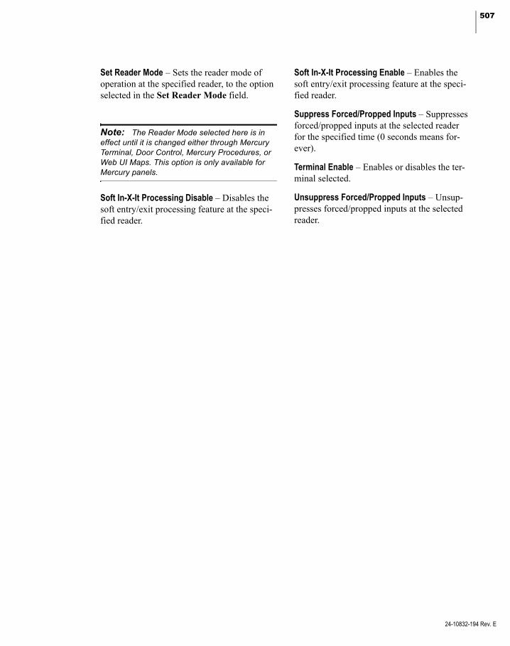
507
Set Reader Mode – Sets the reader mode of operation at the specified reader, to the option selected in the Set Reader Mode field.
Note: The Reader Mode selected here is in effect until it is changed either through Mercury Terminal, Door Control, Mercury Procedures, or Web UI Maps. This option is only available for Mercury panels.
Soft In-X-It Processing Disable – Disables the soft entry/exit processing feature at the speci-fied reader.
Soft In-X-It Processing Enable – Enables the soft entry/exit processing feature at the speci-fied reader.
Suppress Forced/Propped Inputs – Suppresses forced/propped inputs at the selected reader for the specified time (0 seconds means for-ever).
Terminal Enable – Enables or disables the ter-minal selected.
Unsuppress Forced/Propped Inputs – Unsup-presses forced/propped inputs at the selected reader.
24-10832-194 Rev. E

508 APPENDIX A
Event Triggers/Actions
24-10832-194 Rev. E

509
Appendix B: Message Types and Sub-Types
his appendix lists all message types and
T sub-types available for configuring Message Filters. For more information, see Message Filtering on page 222.
Message Types
1 – Notify3 – Alarm5 – System Action
258 – Muster Status259 – Muster Event Trigger305 – Routing Session403 – Intrusion Status404 – Fire Status
28673 – RTL Data28675 – Audit
Message Sub-Types
1 – Notify204 – Alarm Filter207 – Comms Up208 – Comms Down210 – Guard Tour Up
3 – Alarm1 – Generic2 – Panel Input Point3 – Area4 – Guard Tour5 – Muster Running6 – Muster Zone Status7 – Muster Disabled8 – Muster Aborted
10 – Event Alarm12 – AV Motion Alarm13 – AV Behavior Alarm14 – AV Video Loss Alarm
3 – Alarm (continued)15 – AV Dry Contact Alarm17 – Intrusion Alarm18 – Fire Alarm19 – Integration Component20 – Intercom Station21 – Intrusion Area Alarm22 – Fire Detector Alarm23 – Fire IO Module Alarm24 – Fire Device Alarm25 – SNMP Alarm
5 – System Action2 – Error or Log4 – Counter Changed5 – Muster Control Started
258 – Muster Status
259 – Muster Event Trigger
305 – Routing Session
403 – Intrusion Status
404 – Fire Status
28673 – RTL Data1 – Panel: Reader Up/Normal3 – Panel: System Restart5 – Panel: Reader Down
10 – Panel: System Facility Code Error11 – Panel: System Event Activated12 – Panel: System Event De-activated15 – Panel: Unlock All Doors16 – Panel: Lock All Doors17 – Panel: Output Set18 – Panel: Output Reset19 – Panel: Terminal Reader Strike Locked20 – Panel: Terminal Reader Strike Unlocked21 – Panel: Terminal Door Held Open22 – Panel: Terminal Door Forced Open
Message Sub-Types (Continued)
24-10832-194 Rev. E
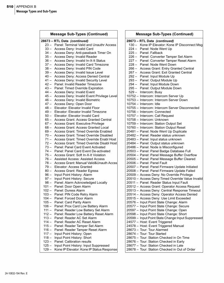
510 APPENDIX B
Message Types and Sub-Types
24-10832-194 Rev. E
28673 – RTL Data (continued)23 – Panel: Terminal Valid and Unauthr Access33 – Access Deny: Invalid Card34 – Access Deny: Anti-passback Timer On35 – Access Deny: Invalid Reader36 – Access Deny: Invalid In-X-It Status37 – Access Deny: Invalid Card Timezone38 – Access Deny: Invalid PIN Code39 – Access Deny: Invalid Issue Level40 – Access Deny: Access Denied Central41 – Access Deny: Invalid Security Level42 – Panel: Invalid Reader Timezone43 – Panel: Timed Override Expiration44 – Access Deny: Invalid Event45 – Access Deny: Invalid Event Privilege Level46 – Access Deny: Invalid Biometric47 – Access Deny: Open Door48 – Elevator: Elevator Invalid Floor49 – Elevator: Elevator Invalid Timezone50 – Elevator: Elevator Invalid Card65 – Access Grant: Access Granted Central67 – Access Grant: Executive Privilege68 – Access Grant: Access Granted Local69 – Access Grant: Timed Override Enabled70 – Access Grant: Timed Override Disabled71 – Access Grant: Timed Override Enabl Host72 – Access Grant: Timed Override Disabl Host73 – Panel: Panel Card Event Activated74 – Panel: Panel Card Event De-activated75 – Access Grant: Soft In-X-It Violation76 – Assisted Access: Assisted Access78 – Access Grant: Manual Valid&Unauth Accss79 – Elevator: Access Granted80 – Access Grant: Reader Egress96 – Input Point History: Alarm97 – Input Point History: Secure98 – Panel: Alarm Acknowledged Locally
101 – Panel: Door Open Alarm102 – Panel: Duress Alarm103 – Panel: PIN Code Retry Alarm104 – Panel: Forced Door Alarm105 – Panel: Card Parity Alarm106 – Panel: Prox Card Low Battery Alarm111 – Panel: Reader Low Battery Set Alarm112 – Panel: Reader Low Battery Reset Alarm113 – Panel: Reader AC Set Alarm114 – Panel: Reader AC Reset Alarm115 – Panel: Reader Tamper Set Alarm116 – Panel: Reader Tamper Reset Alarm117 – Input Point History: Open118 – Input Point History: Short123 – Panel: Calibration results125 – Input Point History: Input Suppressed129 – Kone IP Elevator: Kone IP Status Response
Message Sub-Types (Continued)
28673 – RTL Data (continued)130 – Kone IP Elevator: Kone IP Disconnect Msg224 – Panel: Node Went Up225 – Panel: Fallback226 – Panel: Converter Tamper Set Alarm227 – Panel: Converter Tamper Reset Alarm228 – Panel: Node Went Down266 – Access Grant: Entry Granted Central267 – Access Grant: Exit Granted Central292 – Panel: Input Module Up293 – Panel: Output Module Up294 – Panel: Input Module Down295 – Panel: Output Module Down529 – Intercom: Busy
10752 – Intercom: Intercom Server Up10753 – Intercom: Intercom Server Down10754 – Intercom: Idle10755 – Intercom: Intercom Server Disconnected10756 – Intercom: Connected10757 – Intercom: Call Request10758 – Intercom: Unknown10759 – Intercom: Station Output Set10760 – Intercom: Station Output Reset20481 – Panel: Node Went Up Duplicate20482 – Panel: Reader status unknown20483 – Panel: Input status unknown20484 – Panel: Output status unknown20486 – Panel: Node is Misconfigured20503 – Panel: Panel Badge Database Full20504 – Panel: Panel Message Buffer Overflow20505 – Panel: Panel Message Buffer Cleared20506 – Panel: Panel Fault20507 – Panel: Panel Firmware Update Initiated20508 – Panel: Panel Firmware Update Failed20509 – Access Deny: No Override Privilege20510 – Access Deny:Timed Override Value Invalid20511 – Panel: Reader Status Input Fault20512 – Access Grant: Operator Access Request20513 – Access Deny: Central Response Timeout20514 – Access Deny: Operator Access Denied20515 – Access Deny: Use Limit Exceeded20576 – Input Point State Change: Alarm20577 – Input Point State Change: Secure20597 – Input Point State Change: Open20598 – Input Point State Change: Short20599 – Input Point State Change:Input Suppressed24577 – Host: Event Triggered24578 – Host: Event Triggered Manual28673 – Tour: Tour Alarmed28674 – Tour: Tour Started28675 – Tour: Station Checked in On Time28676 – Tour: Station Checked in Early28677 – Tour: Station Checked in Late28678 – Tour: Station Checked in Out of Order
Message Sub-Types (Continued)

511
28673 – RTL Data (continued)28679 – Tour: Tour Stopped28680 – Tour: Tour Restarted28681 – Tour: Tour Aborted28682 – Tour: Tour Completed28683 – Tour: Station Late Timer Reached28684 – Tour: Tour Terminated32769 – Area: Reader Exit32770 – Area: Reader Entry32771 – Area: Input Exit32772 – Area: Input Entry32773 – Area: Manual Exit32774 – Area: Manual Entry36865 – Audio-Visual: Motion36866 – Audio-Visual: Behavior36867 – Audio-Visual: Video Loss36868 – Audio-Visual: Dry Contact41296 – Fire Alarm: Fire Server Connection Up41297 – Fire Alarm: Fire Server Connection Down41472 – Otis System: Component Went Up41473 – Otis System: Component Went Down41728 – Integration Component: Up41729 – Integration Component: Down41730 – Integration Component: Unknown41731 – Integration Component: Unavailable41732 – Integration Component: Misconfigured41733 – Integration Component: pivCLASS
Certificate Manager Revoked41734 – Integration Component: pivCLASS
Certificate Manager Error41735 – Integration Component: pivCLASS
Certificate Manager Activated41736 – Integration Component: pivCLASS Passed
Validation41737 – Integration Component: pivCLASS Failed
Validation
28675 – Audit1 – User2 – Badge3 – Badge Layout4 – Badge Fields5 – Badge Encoding6 – ID Badge7 – Cardholder8 – Panel9 – Terminal
10 – Partition11 – Terminal Group12 – Access Group13 – Holiday14 – Timezone15 – Input Point16 – Input Group
Message Sub-Types (Continued)
28675 – Audit (continued)17 – Panel Holiday18 – Access Template19 – Alarm Response Text20 – Alarm Instruction21 – Company22 – Output Point23 – Output Group24 – Department25 – Panel Timezone26 – Soft Alarm27 – Site Parameters28 – Workstation29 – Map30 – Map Icon Set31 – User Defined Fields32 – Event33 – Panel Card Event34 – Alarm Filter35 – Message Forwarding37 – Permission Group38 – Panel Relay39 – Report40 – MIS Interface41 – Image Recall Filter42 – Counter44 – External IP45 – Guard Tour Definition46 – Tour Station Definition48 – Elevator49 – Floor Mask50 – Floor Group51 – Floor Name Configuration52 – Cabinet53 – Door Group54 – Door Mask55 – Door Name Configuration56 – Area57 – Muster Zone58 – Area Control Layout60 – CCTV Server61 – CCTV Switch62 – CCTV Tour63 – CCTV Alarm64 – CCTV Macro65 – CCTV System Auxiliary66 – CCTV Monitor67 – CCTV Sequence68 – CCTV Camera69 – CCTV Preset70 – CCTV Pattern71 – CCTV Camera Auxiliary78 – Auto-badge Number79 – Air Crew PIN Number
Message Sub-Types (Continued)
24-10832-194 Rev. E

512 APPENDIX B
Message Types and Sub-Types
24-10832-194 Rev. E
28675 – Audit (continued)81 – Remote Server82 – Message Filter83 – Message Filter Group84 – Local Site85 – Service Startup Configuration86 – Application87 – Panel Card Format88 – Reason89 – Security Level Range94 – Audit95 – Alarm History96 – Alarm97 – Generic Text98 – Muster History99 – Guard Tour History
100 – Transaction History101 – Redundancy102 – Mapping Configuration103 – Mapping Data Fields Configuration104 – Intercom Exchange105 – Intercom Station106 – AV Site107 – AV Camera108 – AV Monitor109 – AV Preset110 – Input To Camera112 – Enterprise Site113 – Enterprise Parameters114 – AV Dry Contact115 – Alarm Colors
Message Sub-Types (Continued)
28675 – Audit (continued)116 – Badging Setup117 – Request Approvers118 – FASC-N CCC119 – Badge Purpose120 – Alarm Options121 – Intrusion Entity122 – SIA Device123 – Alarm Category124 – MSEA Graphic125 – OSI Facility173 – MSEA Registration174 – MSEA Partition176 – Web Access Configuration177 – Fire Alarm178 – Software Update179 – Badge Reason180 – Required Fields182 – HID Facility183 – Kone IP Elevator184 – Intercom Interface185 – Integration Component186 – Assa Abloy Facility187 – Badge Format188 – Assa Abloy Badge Format192 – Mercury Input Point Calibration Table193 – Mercury Card Format194 – Mercury Facility195 – Mercury Procedure196 – Mercury Trigger198 – HID Badge Format
Message Sub-Types (Continued)
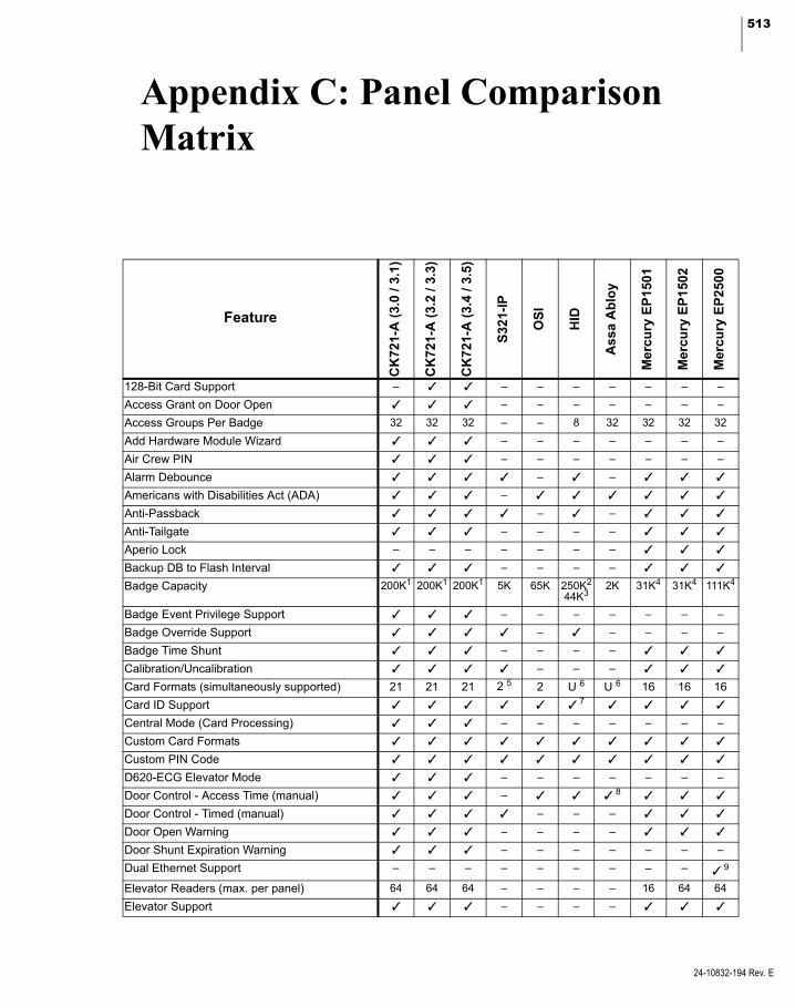
513
1
A
A
A
A
A
A
A
A
A
B
B
B
B
B
C
C
C
C
C
C
D
D
D
D
D
D
E
E
Appendix C: Panel Comparison Matrix
Feature
CK
721-
A (
3.0
/ 3.1
)
CK
721-
A (
3.2
/ 3.3
)
CK
721-
A (
3.4
/ 3.5
)
S32
1-IP
OS
I
HID
Ass
a A
blo
y
Mer
cu
ry E
P1
501
Mer
cu
ry E
P1
502
Mer
cu
ry E
P2
500
28-Bit Card Support – – – – – – – –
ccess Grant on Door Open – – – – – – –
ccess Groups Per Badge 32 32 32 – – 8 32 32 32 32
dd Hardware Module Wizard – – – – – – –
ir Crew PIN – – – – – – –
larm Debounce – –
mericans with Disabilities Act (ADA) –
nti-Passback – –
nti-Tailgate – – – –
perio Lock – – – – – – –
ackup DB to Flash Interval – – – –
adge Capacity 200K1 200K1 200K1 5K 65K 250K2
44K32K 31K4 31K4 111K4
adge Event Privilege Support – – – – – – –
adge Override Support – – – – –
adge Time Shunt – – – –
alibration/Uncalibration – – –
ard Formats (simultaneously supported) 21 21 21 2 5 2 U 6 U 6 16 16 16
ard ID Support 7
entral Mode (Card Processing) – – – – – – –
ustom Card Formats
ustom PIN Code
620-ECG Elevator Mode – – – – – – –
oor Control - Access Time (manual) – 8
oor Control - Timed (manual) – – –
oor Open Warning – – – –
oor Shunt Expiration Warning – – – – – – –
ual Ethernet Support – – – – – – – – – 9
levator Readers (max. per panel) 64 64 64 – – – – 16 64 64
levator Support – – – –
24-10832-194 Rev. E
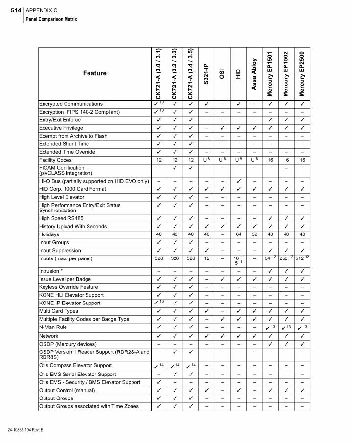
514 APPENDIX C
Panel Comparison Matrix
24-10832-194 Rev. E
E
E
E
E
E
E
E
F
F(p
H
H
H
HS
H
H
H
In
In
In
In
Is
K
K
K
M
M
N
N
O
OR
O
O
O
O
O
O
ncrypted Communications 10 – –
ncryption (FIPS 140-2 Compliant) 10 – – – – – – –
ntry/Exit Enforce – – – –
xecutive Privilege –
xempt from Archive to Flash – – – – – – –
xtended Shunt Time – – – – – – –
xtended Time Override – – – – – – –
acility Codes 12 12 12 U 6 U 6 U 6 U 6 16 16 16
ICAM CertificationivCLASS Integration)
– – – – – – – –
I-O Bus (partially supported on HID EVO only) – – – – – – – – –
ID Corp. 1000 Card Format
igh Level Elevator – – – – – – –
igh Performance Entry/Exit Status ynchronization
– – – – – – –
igh Speed RS485 – – – –
istory Upload With Seconds
olidays 40 40 40 40 – 64 32 40 40 40
put Groups – – – – – – –
put Suppression – – –
puts (max. per panel) 326 326 326 12 – 16 11
5 3– 64 12 256 12 512 12
trusion * – – – – – – –
sue Level per Badge –
eyless Override Feature – – – – – – –
ONE HLI Elevator Support – – – – – – –
ONE IP Elevator Support 10 – – – – – – –
ulti Card Types –
ultiple Facility Codes per Badge Type –
-Man Rule – – – – 13 13 13
etwork
SDP (Mercury devices) – – – – – – –
SDP Version 1 Reader Support (RDR2S-A and DR8S)
– – – – – – – –
tis Compass Elevator Support 14 14 14 – – – – – – –
tis EMS Serial Elevator Support – – – – – – – –
tis EMS - Security / BMS Elevator Support – – – – – – – – –
utput Control (manual) – –
utput Groups – – – – – – –
utput Groups associated with Time Zones – – – – – – –
Feature
CK
721-
A (
3.0
/ 3.1
)
CK
721-
A (
3.2
/ 3.3
)
CK
721-
A (
3.4
/ 3.5
)
S32
1-IP
OS
I
HID
As
sa A
blo
y
Me
rcu
ry E
P15
01
Me
rcu
ry E
P15
02
Me
rcu
ry E
P25
00
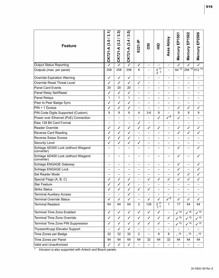
515
O
O
O
O
P
P
P
P
P
P
P
R
R
R
R
S
Sc
Sc
S
S
S
S
S
S
T
T
T
T
T
T
T
T
T
V
*
utput Status Reporting – – –
utputs (max. per panel) 208 208 208 8 – 4 11
2 3– 64 12 256 12 512 12
verride Expiration Warning – – – – – – –
verride Reset Threat Level – – – – – –
anel Card Events 20 20 20 – – – – – – –
anel Relay Set/Reset – – – – – – –
anel Relays 1 1 1 – – – – – – –
eer to Peer Badge Sync – – – – – – –
IN + 1 Duress – – – –
IN Code Digits Supported (Custom) 9 9 9 4 3-6 9 – 9 9 9
ower over Ethernet (PoE) Connection – – – – – 8 – –
aw 128 Bit Card Format – – – – – – – – –
eader Override –
everse Card Reading – – – –
everse Swipe Duress – – – – – – –
ecurity Level – – – – – –
chlage AD300 Lock (without Wiegand onverter)
– – – – – – – –
chlage AD400 Lock (without Wiegand onverter)
– – – – – – – –
chlage ENGAGE Gateway – – – – – – – –
chlage ENGAGE Lock – – – – – – – –
et Reader Mode – – – – – – –
pecial Flags (A, B, C) –
tar Feature – – – – – – –
trike Status – – – – –
erminal Auxiliary Access – – – – – – – – –
erminal Override Status – 8
erminal Readers 64 64 64 2 128 2 11
1 31 17 64 64
erminal Time Zone Enabled – 15 15 15
erminal Time Zone Override 15 15 15
erminal Time Zone PIN Suppression – 15 15 15
hyssenKrupp Elevator Support – – – – – – – –
ime Zones per Badge 32 32 32 2 – 8 8 – 16 – 16 – 16
ime Zones per Panel 64 64 64 64 32 64 32 64 64 64
alid and Unauthorized – – – – – – –
Intrusion is also supported with Aritech and Bosch panels.
Feature
CK
721-
A (
3.0
/ 3.
1)
CK
721-
A (
3.2
/ 3.
3)
CK
721-
A (
3.4
/ 3.
5)
S3
21-I
P
OS
I
HID
As
sa A
blo
y
Me
rcu
ry E
P15
01
Me
rcu
ry E
P15
02
Me
rcu
ry E
P25
00
24-10832-194 Rev. E

516 APPENDIX C
Panel Comparison Matrix
24-10832-194 Rev. E
1 When the number of badges exceeds 120,000 (100,000 for 128-bit badges), the number of access groups should be limited to 50,000.
2 Available for HID EVO if not using card ID; otherwise, the badge capacity is 125,000.3
3 For HID Edge.
4 Using the standard feature set EP2500 supports 111,000 badges. EP1501, EP1502, and Schlage PIM400-1501 support 31,000. With a reduced feature set, EP2500 supports 500,000. EP1501, EP1502, and Schlage PIM400-1501 support 250,000. To exceed the lower numbers, contact Technical Support for details on changing the badge configuration.
5 One of five built-in card formats plus one custom card format. Card ID entry can also be configured.
6 Unlimited.
7 Up to 15 digits.
8 Supported by hard-wired (PoE) version only.
9 Supported by using Lantronix® Micro 125 Embedded Serial to Ethernet Module.
10 Supported by CK721-A Version 3.1.
11 For HID EVO.
12 For panels with no reader modules.
13 Mercury panels support the N-Man rule through the Two Badge Access feature defined at the terminal (for a maximum of two people).14 The Otis Compass integration with this version of P2000 requires CK721-A firmware version 3.5 or higher.
15 Provided via Mercury Triggers and Procedures.
16 Uses Access Group Details to associate Readers with Time Zones, on an access group basis, not on a badge basis.

517
Appendix D: Using a Keypad Reader on CK721-A Panels
he following sections describe how to To invoke access with PIN Only:
T invoke access requests, Air Crew access requests, Timed Overrides, and Panel Card Events using a keypad
reader on CK721-A panels.
Note: For information on using keypad readers that connect to other panel types, refer to the instructions provided with those panels.
There is a 15 second time-out on all keypads. Whenever the keypad is idle for more than 15 seconds, all keys entered so far are ignored, and the entire key sequence needs to be re-entered.
Note: Card ID (the badge number) can have up to 19 digits. However, the total number of keys pressed for PIN and Card ID combined must not exceed 21.
Invoking Access Requests from a Keypad
To invoke access with a Badge:
1. To invoke access using a badge at any time, set the terminal PIN Suppression in the Timezone tab to <none>. Otherwise, access is granted only during active time zones.
2. At the keypad reader, present the badge.
1. Select the terminal PIN Only option in the Card Type tab. PIN Only works exclu-sively with 5-digit algorithmic PINs.
2. Set the panel PIN Code Type to Algorith-mic.
3. Set the panel PIN Code Digits to 5.
4. At the keypad reader, enter the PIN, and press the # key.
To invoke access with Card ID:
1. To invoke access with Card ID at any time, set the terminal PIN Suppression in the Timezone tab to <none>. Otherwise, access is granted only during active time zones.
2. Select the terminal Card ID option in the Card Type tab.
3. Verify that the terminal PIN Only option in the Card Type tab is not selected.
4. Verify that the terminal PIN + Card ID option in the Card Type tab is not selected.
5. At the keypad reader, enter the Card ID number and press the # key.
To invoke access with PIN and Card ID:
1. Select the terminal PIN + Card ID option in the Card Type tab.
2. Verify that the terminal PIN Only option in the Card Type tab is not selected.
3. At the keypad reader, enter the PIN, then enter the Card ID number, and press the # key.
24-10832-194 Rev. E

518 APPENDIX D
Using a Keypad Reader on CK721-A Panels
24-10832-194 Rev. E
To invoke access using PIN and Badge:
1. Set the terminal PIN Suppression in the Timezone tab to an inactive time zone.
2. Verify that the terminal Allow PIN After Badge option in the Flags tab is not selected.
3. At the keypad reader, enter the PIN and then present the badge.
To invoke access with PIN and Badge, allowing PIN after Badge:
1. Set the terminal PIN Suppression in the Timezone tab to an inactive time zone.
2. Select the terminal Allow PIN After Badge option in the Flags tab.
3. At the keypad reader, present the badge, enter the PIN, and press the # key. You may present the badge at any time before pressing the # key.
Invoking Air Crew Access Requests from a Keypad
To invoke Air Crew access:
1. The Server must be online.
2. Enable the respective Air Crew PIN for the terminal.
3. To request Air Crew access:
Without the Star Feature, press the B key followed by the Air Crew PIN number and the # key.
With the Star Feature, press the star (*) key, then press number 2, followed by the Air Crew PIN number and the # key.
Invoking Timed Overrides from a Keypad
To invoke Timed Override with Badge:
1. Select the terminal Cardholder Over-ride/Shunt option in the Access tab.
2. Set the badge Override option in the Secu-rity Options tab.
3. To invoke Timed Override using badge at any time, set the terminal PIN Suppres-sion in the Timezone tab to <none>. Other-wise, Timed Override is invoked only during active time zones.
4. To start Timed Override:
Without the Star Feature, press the star (*) key, enter the number of minutes, and pres-ent the badge.
With the Star Feature, press the star (*) key followed by number 0, enter the number of minutes, and present the badge.
5. To stop Timed Override:
Without the Star Feature, press the star (*) key, enter 0 (for minutes), and present the badge.
With the Star Feature, press the star (*) key followed by number 0 and present the badge.
To invoke Timed Override with PIN Only:
1. Select the terminal Cardholder Over-ride/Shunt option in the Access tab.
2. Set the badge Override option in the Secu-rity Options tab.
3. Select the terminal PIN Only option in the Card Type tab. PIN Only works exclu-sively with 5-digit algorithmic PINs.

519
4. Set the panel PIN Code Type to Algorith-mic.
5. Set the panel PIN Code Digits to 5.
6. To start Timed Override:
Without the Star Feature, enter the PIN, press the star (*) key, enter the number of minutes, and press the # key.
With the Star Feature, enter the PIN, press the star (*) key followed by number 0, enter the number of minutes, and press the # key.
7. To stop Timed Override:
Without the Star Feature, enter the PIN, press the star (*) key, enter 0 (for minutes), and press the # key.
With the Star Feature, enter the PIN, press the star (*) key followed by number 0, and press the # key.
To invoke Timed Override with Card ID:
1. Select the terminal Cardholder Over-ride/Shunt option in the Access tab.
2. Set the badge Override option in the Secu-rity Options tab.
3. To invoke Timed Override using badge at any time, set the terminal PIN Suppres-sion in the Timezone tab to <none>. Oth-erwise, Timed Override is invoked only during active time zones.
4. Select the terminal Card ID option in the Card Type tab.
5. Verify that the terminal PIN Only option in the Card Type tab is not selected.
6. Verify that the terminal PIN + Card ID option in the Card Type tab is not selected.
7. To start Timed Override:
Without the Star Feature, enter the Card ID number, press the star (*) key, enter the number of minutes, and press the # key.
With the Star Feature, enter the Card ID number, press the star (*) key followed by number 0, enter the number of minutes, and press the # key.
8. To stop Timed Override:
Without the Star Feature, enter the Card ID number, press the star (*) key, enter 0 (for minutes), and press the # key.
With the Star Feature, enter the Card ID number, press the star (*) key followed by number 0, and press the # key.
To invoke Timed Override with PIN and Card ID:
1. Select the terminal Cardholder Over-ride/Shunt option in the Access tab.
2. Set the badge Override option in the Secu-rity Options tab.
3. Select the terminal PIN + Card ID option in the Card Type tab.
4. Verify that the terminal PIN Only option in the Card Type tab is not selected.
5. To start Timed Override:
Without the Star Feature, enter the PIN, enter the Card ID number, press the star (*) key, enter the number of minutes, and press the # key.
With the Star Feature, enter the PIN, enter the Card ID number, press the star (*) key followed by number 0, enter the number of minutes, and press the # key.
24-10832-194 Rev. E

520 APPENDIX D
Using a Keypad Reader on CK721-A Panels
24-10832-194 Rev. E
6. To stop Timed Override:
Without the Star Feature, enter the PIN, enter the Card ID number, press the star (*) key, enter 0 (for minutes), and press the # key.
With the Star Feature, enter the PIN, enter the Card ID number, press the star (*) key followed by number 0, and press the # key.
To invoke Timed Override with PIN and Badge:
1. Select the terminal Cardholder Over-ride/Shunt option in the Access tab.
2. Set the badge Override option in the Secu-rity Options tab.
3. Set the terminal PIN Suppression in the Timezone tab to an inactive time zone.
4. Verify that the terminal Allow PIN After Badge option in the Flags tab is not selected.
5. To start Timed Override:
Without the Star Feature, enter the PIN, press the star (*) key, enter the number of minutes, and present the badge.
With the Star Feature, enter the PIN, press the star (*) key followed by number 0, enter the number of minutes, and present the badge.
6. To stop Timed Override:
Without the Star Feature, enter the PIN, press the star (*) key, enter 0 (for minutes), and present the badge.
With the Star Feature, enter the PIN, press the star (*) key followed by number 0, and present the badge.
To invoke Timed Override with PIN and Badge, allowing PIN after badge:
1. Select the terminal Cardholder Over-ride/Shunt option in the Access tab.
2. Set the badge Override option in the Secu-rity Options tab.
3. Set the terminal PIN Suppression in the Timezone tab to an inactive time zone.
4. Select the terminal Allow PIN After Badge option in the Flags tab.
5. To start Timed Override:
Without the Star Feature, enter the PIN, press the star (*) key, enter number of min-utes, present the badge1, and press the # key.
With the Star Feature, enter the PIN, press the star (*) key followed by number 0, enter the number of minutes, present the badge1, and press the # key.
6. To stop Timed Override:
Without the Star Feature, enter the PIN, press the star (*) key, enter 0 minutes, pres-ent the badge1, and press the # key.
With the Star Feature, enter the PIN, press the star (*) key followed by number 0, present the badge1, and press the # key.1) You may present the badge at any time before pressing the # key.

521
Invoking Panel Card Events from a Keypad
To invoke Panel Card Events with Badge:
1. Set the panel card event Trigger Type to Card/Keypad Code.
2. To invoke a Panel Card Event using a badge at any time, set the terminal PIN Suppression in the Timezone tab to <none>. Otherwise, the Panel Card Event is invoked only during active time zones.
3. To activate the event:
Without the Star Feature, press A, enter the keypad code, and present the badge.
With the Star Feature, press the star (*) key followed by number 1, enter the keypad code, and present the badge.
4. To deactivate the event:
Without the Star Feature, press D, enter the keypad code, and present the badge.
With the Star Feature, press the star (*) key followed by number 4, enter the keypad code, and present the badge.
To invoke Panel Card Events with PIN Only:
1. Set the panel card event Trigger Type to Card/Keypad Code or Card/PIN/Key-pad Code.
2. If set to Card/PIN/Keypad Code, set the terminal PIN Suppression in the Time-zone tab to an inactive time zone.
3. Select the terminal PIN Only option in the Card Type tab. PIN Only works exclu-sively with 5-digit algorithmic PINs.
4. Set the panel PIN Code Type to Algorith-mic.
5. Set the panel PIN Code Digits to 5.
6. To activate the event:
Without the Star Feature, enter the PIN, press A, enter the keypad code, and press the # key.
With the Star Feature, enter the PIN, press the star (*) key followed by number 1, enter the keypad code, and press the # key.
7. To deactivate the event:
Without the Star Feature, enter the PIN, press D, enter the keypad code, and press the # key.
With the Star Feature, enter the PIN, press the star (*) key followed by number 4, enter the keypad code, and press the # key.
To invoke Panel Card Events with Card ID:
1. Set the panel card event Trigger Type to Card/Keypad Code.
2. To invoke a Panel Card Event using Card ID at any time, set the terminal PIN Sup-pression in the Timezone tab to <none>. Otherwise, the Panel Card Event is invoked only during active time zones.
3. Set the terminal Card ID option in the Card Type tab.
4. Verify that the terminal PIN Only option in the Card Type tab is not selected.
5. Verify that the terminal PIN + Card ID option in the Card Type tab is not selected.
24-10832-194 Rev. E

522 APPENDIX D
Using a Keypad Reader on CK721-A Panels
24-10832-194 Rev. E
6. To activate the event:
Without the Star Feature, enter the Card ID number, press A, enter the keypad code, and press the # key.
With the Star Feature, enter the Card ID number, press the star (*) key followed by number 1, enter the keypad code, and press the # key.
7. To deactivate the event:
Without the Star Feature, enter the Card ID number, press D, enter the keypad code, and press the # key.
With the Star Feature, enter the Card ID number, press the star (*) key followed by number 4, enter the keypad code, and press the # key.
To invoke Panel Card Events with PIN and Card ID:
1. Set the panel card event Trigger Type to Card/Keypad Code or Card/PIN/Key-pad Code.
2. If set to Card/PIN/Keypad Code, set the terminal PIN Suppression in the Time-zone tab to an inactive time zone.
3. Select the terminal PIN + Card ID option in the Card Type tab.
4. Verify that the terminal PIN Only option in the Card Type tab is not selected.
5. To activate the event:
Without the Star Feature, enter the PIN, enter the Card ID number, press A, enter the keypad code, and press the # key.
With the Star Feature, enter the PIN, enter the Card ID number, press the star (*) key followed by number 1, enter the keypad code, and press the # key.
6. To deactivate the event:
Without the Star Feature, enter the PIN, enter the Card ID number, press D, enter the keypad code, and press the # key.
With the Star Feature, enter the PIN, enter the Card ID number, press the star (*) key followed by number 4, enter the keypad code, and press the # key.
To invoke Panel Card Events with PIN and Badge:
1. Set the panel card event Trigger Type to Card/Keypad Code or Card/PIN/Key-pad Code.
2. Set the terminal PIN Suppression in the Timezone tab to an inactive time zone.
3. Verify that the terminal Allow PIN After Badge option in the Flags tab is not selected.
4. To activate the event:
Without the Star Feature, enter the PIN, press A, enter the keypad code, and present the badge.
With the Star Feature, enter the PIN, press the star (*) key followed by number 1, enter the keypad code, and present the badge.
5. To deactivate the event:
Without the Star Feature, enter the PIN, press D, enter the keypad code, and present the badge.
With the Star Feature, enter the PIN, press the star (*) key followed by number 4, enter the keypad code, and present the badge.

523
To invoke Panel Card Events with PIN and Badge, allowing PIN after badge:
1. Set the panel card event Trigger Type to Card/Keypad Code or Card/PIN/Key-pad Code.
2. Set the terminal PIN Suppression in the Timezone tab to an inactive time zone.
3. Select the terminal Allow PIN After Badge option in the Flags tab.
4. To activate the event:
Without the Star Feature, enter the PIN, press A, enter the keypad code, present the badge1, and press the # key.
With the Star Feature, enter the PIN, press the star (*) key followed by number 1, enter the keypad code, present the badge1, and press the # key.
5. To deactivate the event:
Without the Star Feature, enter the PIN, press D, enter the keypad code, present the badge1, and press the # key.
With the Star Feature, enter the PIN, press the star (*) key followed by number 4, enter the keypad code, present the badge1, and press the # key.1) You may present the badge at any time before pressing the # key.
Quick Guide to Using Keypad Readers
Use the following quick guide to determine the key sequence at a keypad reader required for a particular action. This section assumes that you have configured all terminal and panel set-tings for this action.
Note: Use the terminal Star Feature if you want to invoke Panel Card Events on a keypad that does not have the A and D keys.
24-10832-194 Rev. E
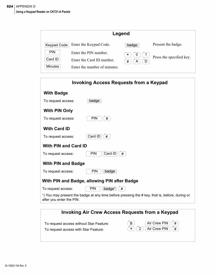
524 APPENDIX D
Using a Keypad Reader on CK721-A Panels
24-10832-194 Rev. E
Legend
*
Minutes
0
#
PIN
Card ID
Keypad Code badge
A D
1Enter the PIN number.
Enter the Card ID number.
Enter the number of minutes.
Enter the Keypad Code. Present the badge.
Press the specified key.
PIN #
PIN #
badge
badge1
Invoking Access Requests from a Keypad
With Badge
With PIN Only
With PIN and Badge, allowing PIN after Badge
1) You may present the badge at any time before pressing the # key, that is, before, during or after you enter the PIN.
To request access:
To request access:
To request access:
PIN
With PIN and Badge
badgeTo request access:
Card ID #
With Card ID
To request access:
Card ID #PIN
With PIN and Card ID
To request access:
Invoking Air Crew Access Requests from a Keypad
To request access without Star Feature: B Air Crew PIN
* 2To request access with Star Feature:
#
#Air Crew PIN
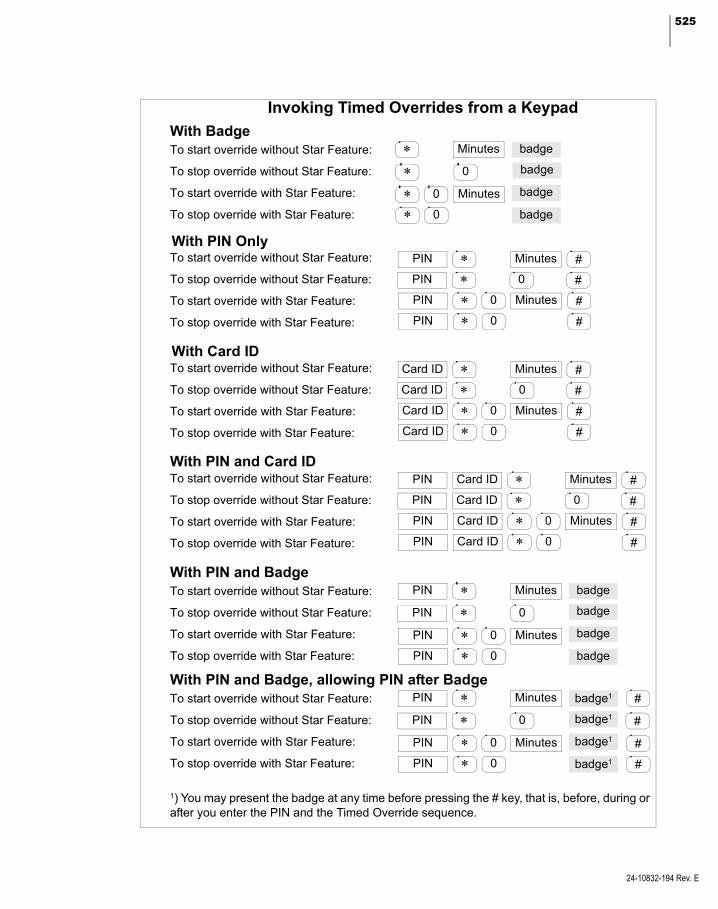
525
To start override without Star Feature:
To start override with Star Feature:
To stop override with Star Feature:
Invoking Timed Overrides from a Keypad
With Badge
* Minutes
*
* 0 Minutes
* 0
0
badge
badge
badge
badge
To stop override without Star Feature:
PIN * Minutes #
PIN * #
PIN * 0 Minutes #
PIN * 0 #
0
With PIN OnlyTo start override without Star Feature:
To start override with Star Feature:
To stop override with Star Feature:
To stop override without Star Feature:
Card ID * Minutes #
Card ID * #
Card ID * 0 Minutes #
Card ID * 0 #
0
With Card IDTo start override without Star Feature:
To start override with Star Feature:
To stop override with Star Feature:
To stop override without Star Feature:
Card ID * Minutes #
Card ID * #
Card ID * 0 Minutes #
Card ID * 0 #
0
PIN
PIN
PIN
PIN
With PIN and Card IDTo start override without Star Feature:
To start override with Star Feature:
To stop override with Star Feature:
To stop override without Star Feature:
PIN * Minutes
PIN *PIN * 0 Minutes
PIN * 0
0
badge
badge
badge
badge
With PIN and BadgeTo start override without Star Feature:
To start override with Star Feature:
To stop override with Star Feature:
To stop override without Star Feature:
PIN * Minutes
PIN *PIN * 0 Minutes
PIN * 0
0
#
#
#
#
badge
badge
badge
badge
badge1
badge1
badge1
badge1
With PIN and Badge, allowing PIN after BadgeTo start override without Star Feature:
To start override with Star Feature:
To stop override with Star Feature:
To stop override without Star Feature:
1) You may present the badge at any time before pressing the # key, that is, before, during or after you enter the PIN and the Timed Override sequence.
24-10832-194 Rev. E
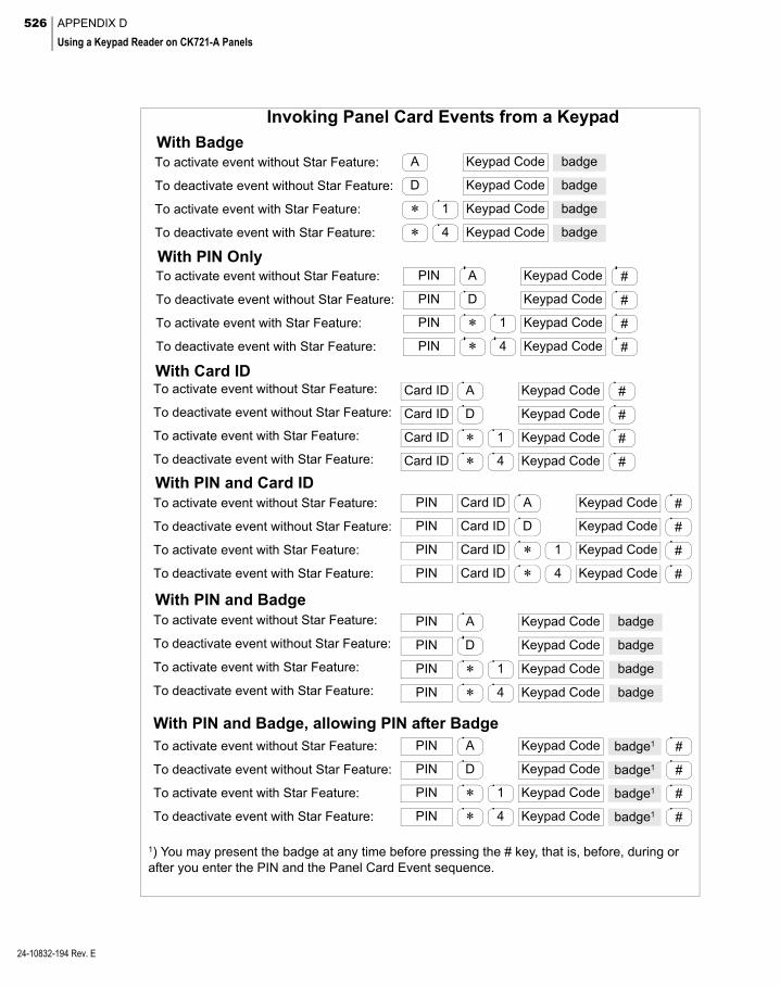
526 APPENDIX D
Using a Keypad Reader on CK721-A Panels
24-10832-194 Rev. E
To activate event without Star Feature:
To activate event with Star Feature:
To deactivate event with Star Feature:
Invoking Panel Card Events from a Keypad
With Badge
To deactivate event without Star Feature: Keypad Code badge
Keypad Code badge
* 4 Keypad Code badge
* 1 Keypad Code badge
D
A
With PIN OnlyTo activate event without Star Feature:
To activate event with Star Feature:
To deactivate event with Star Feature:
To deactivate event without Star Feature: Keypad CodePIN
Keypad CodePIN
Keypad CodePIN
Keypad CodePIN
* 4
* 1
D
A
#
#
#
#
With Card IDTo activate event without Star Feature:
To activate event with Star Feature:
To deactivate event with Star Feature:
To deactivate event without Star Feature: Keypad Code #Card ID
Keypad Code #Card ID
Keypad Code #Card ID
Keypad Code #Card ID
* 4
* 1
D
A
With PIN and Card IDTo activate event without Star Feature:
To activate event with Star Feature:
To deactivate event with Star Feature:
To deactivate event without Star Feature: Keypad Code #PIN
Keypad Code #PIN
Keypad Code #PIN
Keypad CodePIN
* 4
* 1
D
A
#
Card ID
Card ID
Card ID
Card ID
With PIN and Badge
With PIN and Badge, allowing PIN after Badge
To activate event without Star Feature:
To activate event with Star Feature:
To deactivate event with Star Feature:
To deactivate event without Star Feature:
To activate event without Star Feature:
To activate event with Star Feature:
To deactivate event with Star Feature:
To deactivate event without Star Feature:
1) You may present the badge at any time before pressing the # key, that is, before, during or after you enter the PIN and the Panel Card Event sequence.
Keypad CodePIN
Keypad CodePIN
Keypad CodePIN
Keypad CodePIN
Keypad Code #badge1PIN
Keypad Code #badge1PIN
Keypad Code #PIN
Keypad Code #PIN
* 4
* 1
D
A
* 4
* 1
D
A
badge
badge
badge
badge
badge1
badge1
527
Appendix E: Troubleshooting
his section explains the authentication The P2000 installation creates the following
Tprocess for a P2000 user. This helps you understand what goes on behind the scenes, the reason for each step, and
how to troubleshoot when problems arise.
Authentication Process
Windows Authentication
The first level of authentication for a P2000 Workstation is the connection to the P2000 Server. The Workstation must connect to the Server over the network to gain access to the database. Your Windows operating system per-forms this authentication. The Workstation sends to the Server the username and password that the user used when logging on to Win-dows. The Server then compares this username and password with the users configured in Windows. To connect the Workstation to the Server, this username and password must be a valid account on the Server.
The P2000 Server installation creates three Windows user groups, which you can assign to a user account to allow connection to the Server.
user groups:
User Group Properties
PEGASYS Users
Connects to the Server and data-base over the network.
PEGASYS Administrators
Connects to the Server and data-base over the network, and also have database administrative rights (needed to drop and create database tables, and to restore the database).
PEGASYS MIS Users
Connects to the Server and MIS Interface portions of the data-base.
SQL Server Authentication
The second level of authentication for a P2000 Workstation is the SQL Server database. The Workstation connects to the SQL Server with an ODBC connection. The ODBC connection passes a username and password to the SQL Server to be authenticated. The default config-uration of a P2000 ODBC connection is to pass the Windows username and password. The username and password that the ODBC con-nection sends must be a valid account in SQL Server for the Workstation to connect to the database. The P2000 Server installation creates SQL Server accounts for each of the three Windows user groups. Since SQL Server has accounts for the user groups that the P2000 Server installation created, assigning a Win-dows user account to one of those groups auto-matically grants access to the SQL Server data-base.
24-10832-194 Rev. E

528 APPENDIX E
Troubleshooting
24-10832-194 Rev. E
P2000 Authentication
The third level of authentication for a P2000 Workstation is the list of users configured in the P2000 software. When the P2000 software is started, the user is presented with a login screen. The username and password that the user enters is compared with the users config-ured in the P2000 software. The Workstation is also checked against the list of valid worksta-tions configured into the P2000 system.
Testing the Workstation
Start the P2000 software and log on with the correct username and password. If the login succeeds, everything is OK. If the login fails, see P2000 Login Troubleshooting on page 529.
Troubleshooting Workstation Problems
If the P2000 Login dialog box displays, follow P2000 Login Troubleshooting on page 529. Otherwise, follow P2000 Network Trouble-shooting on page 530.
For troubleshooting CCTV, see CCTV Control Troubleshooting on page 531.
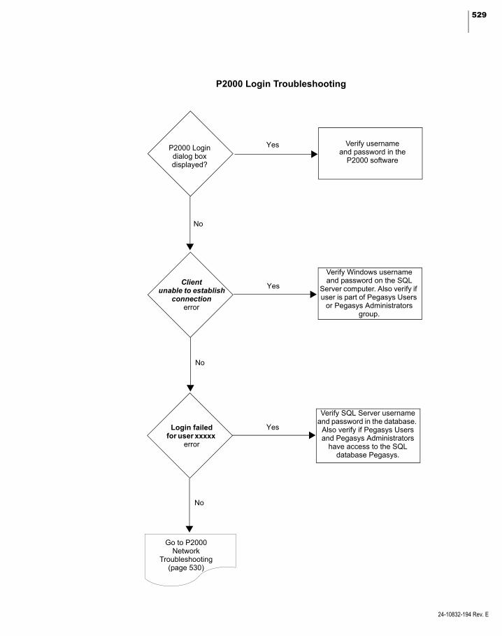
529
P2000 Login dialog boxdisplayed?
Login failed for user xxxxx
error
Go to P2000 Network
Troubleshooting(page 530)
Verify usernameand password in the
P2000 software
Verify Windows username and password on the SQL
Server computer. Also verify if user is part of Pegasys Users
or Pegasys Administrators group.
Verify SQL Server username and password in the database.
Also verify if Pegasys Users and Pegasys Administrators
have access to the SQL database Pegasys.
No
No
No
Client unable to establish
connection error
P2000 Login Troubleshooting
Yes
Yes
Yes
24-10832-194 Rev. E

530 APPENDIX E
Troubleshooting
24-10832-1
Can youping the server
from the workstationby address?
Yes
Verify workstation NIC installation and driver.
Check TCP/IPProtocol Settings
No NoNoRequest timed out
error
Destination unreachable
error
There is a name resolution problem at
the workstation. Check TCP/IP DNS and WINS settings on
workstation.
No
Can youping the server
from the workstationby name?
Yes Yes
There is a basic network wiring problem. Check
cables, hubs, and so on. Also, verify IP addresses.
There is a network routing problem. Check TCP/IP
gateway settings on workstation.
Yes
Can youping the workstation
from the serverby address?
Yes
Verify server NIC installation and driver.
Check TCP/IP Protocol Settings
No NoNoRequest timed out
error
Destination unreachable
error
There is a name resolution problem at the
server. Check TCP/IP DNS and WINS settings
on server.
NoCan you
ping the workstationfrom the server
by name?
Yes Yes
There is a basic network wiring problem. Check
cables, hubs, and so on. Also verify IP addresses.
There is a network routing problem. Check TCP/IP
gateway settings on server.
Yes
Contact Technical Support
P2000 Network Troubleshooting
94 Rev. E
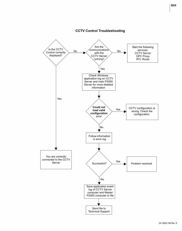
531
Is the CCTV Control correctly
displayed?
No
Are the communications
with the CCTV Server
running?
Yes
Start the following services:
CCTV ServerOPC ProxyRTL Route
No
Yes
You are correctly connected to the CCTV
Server
CCTV Control Troubleshooting
Check Windows application log on CCTV Server and main P2000 Server for more detailed
information
CCTV configuration is wrong. Check the
configuration.
Save application event log of CCTV Server
computer and Master P2000 computer to file
Successful?
Send file to Technical Support
Follow information in error log
Problem resolved
Could notload valid
configurationerror
Yes
Yes
No
No
24-10832-194 Rev. E

532 APPENDIX E
Troubleshooting
24-10832-194 Rev. E

533
Appendix F: Secured Premises Notification Settings
he steps in this section are specific for Panel Configuration
Tpanels that support the Panel Card Event feature, and are necessary to ensure UL 1076 compliance when you
use a panel card event to unsuppress (arm) pro-tected premise alarm signals.
According to UL 1076 requirements, if you unsuppress alarms at the protected premises (for example, through a panel card event), when this event is invoked, you must receive an indication, either audible or visible, that the P2000 Server received the message that the panel generated after the event was processed. If you do not receive the expected indication, then either the panel is offline from the Server or the panel did not process the panel card event request.
Before you define the Host event configuration (see page 534), you should verify the follow-ing settings. Use your discretion to program any parameters not specified.
Configuration
Cardholder Configuration
1. Create a badge for a cardholder with an Event Privilege equal to or greater than the panel card event privilege level used for suppressing or unsuppressing protected premise alarms.
See Entering Badge Information on page 251 for detailed instructions.
1. The panel must contain at least one input and one output terminal, in addition to a reader terminal. An acceptable alternative is a terminal that includes input, output, and reader capabilities, such as the S300-DIN-RDR2S-A module.
See Configure Hardware Components on page 53.
Input Point Configuration
1. Set the protected premise input point Sta-tus to Enable.
2. Set the Disabled During Time Zone option to <none>.
3. From the Alarm Priority drop-down list, select 4, 3, 2, 1, or 0, depending on individ-ual company policy for protected premise alarms.
See Create Input Points on page 82.
Output Point Configuration
1. Set the output point Active State to Timed.
2. Set the Duration to 5 seconds or longer.
3. You must wire the output point to an audi-ble or visible indicator. Depending on the terminal type used and the device selected, you may need to supply external power for the indicating device.
4. The indicator must be visible or audible from the point (location) the panel card event is deactivated.
See Create Output Points and Groups on page 80.
24-10832-194 Rev. E
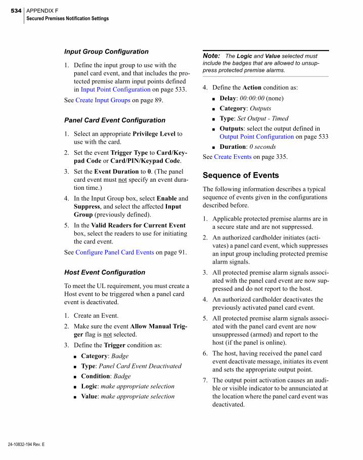
534 APPENDIX F
Secured Premises Notification Settings
24-10832-194 Rev. E
Input Group Configuration
1. Define the input group to use with the panel card event, and that includes the pro-tected premise alarm input points defined in Input Point Configuration on page 533.
See Create Input Groups on page 89.
Panel Card Event Configuration
1. Select an appropriate Privilege Level to use with the card.
2. Set the event Trigger Type to Card/Key-pad Code or Card/PIN/Keypad Code.
3. Set the Event Duration to 0. (The panel card event must not specify an event dura-tion time.)
4. In the Input Group box, select Enable and Suppress, and select the affected Input Group (previously defined).
5. In the Valid Readers for Current Event box, select the readers to use for initiating the card event.
See Configure Panel Card Events on page 91.
Host Event Configuration
To meet the UL requirement, you must create a Host event to be triggered when a panel card event is deactivated.
1. Create an Event.
2. Make sure the event Allow Manual Trig-ger flag is not selected.
3. Define the Trigger condition as:
Category: Badge
Type: Panel Card Event Deactivated
Condition: Badge
Logic: make appropriate selection
Value: make appropriate selection
Note: The Logic and Value selected must include the badges that are allowed to unsup-press protected premise alarms.
4. Define the Action condition as:
Delay: 00:00:00 (none)
Category: Outputs
Type: Set Output - Timed
Outputs: select the output defined in Output Point Configuration on page 533
Duration: 0 seconds
See Create Events on page 335.
Sequence of Events
The following information describes a typical sequence of events given in the configurations described before.
1. Applicable protected premise alarms are in a secure state and are not suppressed.
2. An authorized cardholder initiates (acti-vates) a panel card event, which suppresses an input group including protected premise alarm signals.
3. All protected premise alarm signals associ-ated with the panel card event are now sup-pressed and do not report to the host.
4. An authorized cardholder deactivates the previously activated panel card event.
5. All protected premise alarm signals associ-ated with the panel card event are now unsuppressed (armed) and report to the host (if the panel is online).
6. The host, having received the panel card event deactivate message, initiates its event and sets the appropriate output point.
7. The output point activation causes an audi-ble or visible indicator to be annunciated at the location where the panel card event was deactivated.

535
Appendix G: Secured Premises Notification Settings for Mercury Panels with Keypad DM-21 (MRDT)
he following steps are specific for pan- Mercury Hardware Configuration
Tels that support the intrusion feature, and are necessary to ensure UL 1076 compliance when you use a Mercury
intrusion keypad terminal DM-21 (MRDT) to unsuppress (arm) protected premise alarm sig-nals.
Note: Throughout this section, the terms DM-21 and MRDT are used interchangeably and refer to the Mercury intrusion keypad terminal.
According to UL 1076 requirements, if you unsuppress alarms at the protected premises (for example, through the arming command at a DM-21 intrusion keypad terminal), then you must receive an indication, either audible or visible, that the P2000 Server received the message that the area was armed after the com-mand was processed. If you do not receive the expected indication, then either the panel is offline from the Server or the panel did not process the arming command as requested.
Before you define the Host event configuration (see page 536), you should verify the follow-ing settings. Use your discretion to program any parameters not specified.
Configuration
Cardholder Configuration
1. Create a badge that has access rights to the DM-21 intrusion keypad terminal and that can manage protected premise alarms.
See Entering Badge Information on page 251 for detailed instructions.
1. Create a Mercury panel that contains at least one terminal with an available output, in addition to the DM-21 intrusion keypad terminal, and the defined protected premise input points.
See Configure Mercury Panels and Compo-nents on page 151.
Input Point Configuration
1. Set each protected premise input point Sta-tus to Enable.
See Configure Mercury Inputs on page 172.
Output Point Configuration
1. Set the output point Status to Enabled.
2. Set the Drive Mode to Normal.
3. Set the Offline Mode to No Change.
4. Set the Active State to Timed.
5. Set the Duration to 5 seconds or longer.
6. You must wire the output point to an audi-ble or visible indicator. Depending on the terminal type used and the device selected, you may need to supply external power for the indicating device.
7. The indicator must be visible or audible from the point (location) the DM-21 intru-sion terminal is used to arm the system.
See Configure Mercury Outputs on page 176.
24-10832-194 Rev. E

536 APPENDIX G
Secured Premises Notification Settings for Mercury Panels with Keypad DM-21 (MRDT)
24-10832-194 Rev. E
Mercury Intrusion Zone Configuration
1. Create a Mercury intrusion zone that includes the protected premise input point defined in Input Point Configuration on page 535.
2. Set the Mercury intrusion zone to Enabled.
3. Set the Point Type in the Mercury tab to Input Point.
4. Edit your Alarm Category in the Alarm Options tab to set the Alarm Priority to 4, 3, 2, 1, or 0, depending on individual com-pany policy for protected premise alarms.
See Configuring Mercury Intrusion Zones on page 323.
Mercury Intrusion Area Configuration
1. Create a Mercury intrusion area that includes the Mercury intrusion zone previ-ously defined, which includes the protected premise input points defined in Input Point Configuration on page 535.
See Configuring Mercury Intrusion Areas on page 324.
Host Event Configuration
To meet the UL requirement, you must create a Host event to be triggered when a user arms an area that includes the protected premise input points from the DM-21.
1. Create an Event.
2. Make sure the event Allow Manual Trig-ger flag is not selected.
3. Define the Trigger condition as:
Category: Intrusion Area
Type: Armed (transition)
Condition: Area Name
Logic: make appropriate selection
Value: make appropriate selection
Note: The Logic and Value selected must include the areas from which protected premise alarms can be unsuppressed.
4. Define the Action condition as:
Delay: 00:00:00 (none)
Category: Outputs
Type: Set Output - Timed
Outputs: select the output defined in Output Point Configuration on page 535
Duration: 0 seconds
See Create Events on page 335.
Sequence of Events
The following information describes a typical sequence of events given in the configurations described before.
1. Applicable protected premise alarms are in a secure state and are not suppressed.
2. An authorized cardholder initiates a disarm command at the DM-21, which suppresses a Mercury intrusion area including pro-tected premise alarm signals.
3. All protected premise alarm signals associ-ated with the panel are now suppressed and do not report to the host.
4. An authorized cardholder arms the previ-ously disarmed area.
5. All protected premise alarm signals associ-ated with the area are now unsuppressed (armed) and report to the host (if the panel is online).
6. The host, having received the arm com-mand message, initiates its event and sets the appropriate output point.
7. The output point activation causes an audi-ble or visible indicator to be annunciated at the location where the DM-21 intrusion keypad terminal was armed.

537
Index
Numerics24 Hour Zone 324
AAbort Time 378Access Grant Message 197Access Grant Message on Door
Open Only 67Access Groups 37, 232Access Levels 152Access Method 129Access Privileges 243Access Requests 7
badge privileges 7invalid badges 7time 7valid badges 7
Access Rights 255Access Template 256
apply options to badges 258Access Templates 236Access Time 70Account Disabled 25Account Type 25Acknowledgement Required before
Completion 85ACR Number 165Action Date/Time 275Actions 337
create an action 338definitions 338order of occurrence 338
Activated Devices 383Active Directory 24Active State 81Active States 177Active Tours 383Active-off 87Active-on 87AD Account 24, 409AD Profile 24, 409ADA Indicator 153ADA Relay Connector 73ADA Relay Delay 73, 169ADA Relay Mode 169ADA Relay Time 73Add Hardware Module 76Add Mag Track Formula 360Add Visitor 261
sponsor information 262
Address 66ADS Repository Name 370ADS/ADX 370ADS/ADX server 368Aimetis Interface Service 429Air Crew PIN 63, 75alarm beep 275Alarm Category 270, 274Alarm Category Filters 228Alarm Colors 277Alarm Debounce Time 69Alarm Description 274Alarm Details 277Alarm Escalation Ranges 227Alarm Instruction 84Alarm Late 379Alarm Monitoring 270
acknowledge alarms 271, 275activate an event 277alarm handling 271alarm monitor definitions 273audible alarm button 275complete an alarm 272, 277date/time 273escalation 273locate alarms on maps 275priorities 273priority sounds 274refresh the window 272remove an alarm 272, 277respond 271, 275
Alarm Options 34Alarm Popup 84Alarm Priority 84Alarm Processing Group 24Alarm Shunt Only for Auxiliary
Access 67Alarm Site 275Alarm Skip 379Alarm State 274Alarm Status 274Alarm Timezone 84Alarms 8
door alarms 8external device alarms 8host alarms 8remote alarms 8software only alarms 8
Allow Any IP Address 46Allow devices 47Allow expansion 309
Allow Manual Trigger 336Allow Multiple Alarm Handling 25Allow PIN after Badge 67Allow PIN before Badge 168Always upload when greater
than 56Annunciator 318Anti Tailgate 68Anti-Passback 70, 114, 130Anti-Tailgating 167Any Guard 379Any Void Card 92Application Path 48Apply Security Options
‘Enterprise’ 405Apply Security Options
Enterprise 253Approval Levels 409Approved Visits 262, 418Area Alarms Setting 298Area Control 296
Area Filters 301configure the Area 296control the Area 299display details 301reports 304Terminals and Inputs Points 298
Area Details 301Area Filters 301Area Layout 303Aritech Intrusion Alarms 326Aritech Intrusion Server 319armed 318Assa Abloy DSR Interface
Service 429Assa Abloy Facility Parameters 137Assa Abloy Locks 136Assa Abloy Panel 144Assa Abloy Terminals 146Assigning Operators 23Assisted Access 72, 169Assisted Access Time 169Assisted Shunt Time 169Associated AV Channel 85Associated Real Time Map 85At Risk 306, 317Audit Trail 39, 392Authorized Users 392Auto Badge Management 264Auto Disarm 325Auto Duress Alarm 379
24-10832-194 Rev. E

538 INDEX
24-10832-194 Rev. E
Auto Forward 378Auto Process 409Auto Reverse 378Auto Start 429Automatic Employee IDs 241Automatic Software Updates 434Auxiliary Access 7AV Service 429Avigilon Interface Service 429
BB426 Configuration Rules 321Backup and Restore 448Backup Controller Name 209Backup DB to Flash Interval 55Backup Device 40Backup IP Address 209Backups 451
automatic 453backup device 451manual 452restoring database 455
Badge Databadge field definitions 252entering badge information 251Facility Code 252issue level 252viewing 258
Badge Design 359Badge Device Setup 362Badge Format 123, 193, 237Badge ID Allowed 114Badge Information 258Badge Layout 362Badge Layout Fields 359Badge Override 114Badge Purpose 238, 253Badge Reason 238, 253Badge Resync 265Badge Station 20, 359Badge Trace Alarm for Denied
Access 34Badge Trace Alarm for Granted
Access 34Badge Transaction History 258Base Name 77Base64 46Basic Configuration 5Basic System Components 2
external device 4field panels 4Server 2system printer 3terminals 4workstations 3
Baud Rate 59Begin Suppression 295Bind Server 41Blanking Time 268, 269Bosch Intrusion 320
Bosch Intrusion Alarms 327Bosch SIA 279Broadcast Port Number 58Bulk Badge Change 259Bypass 440Bypass Off 329Bypass On 329bypassed 318Bypassed on startup 324
CCabinet Access Control 216Cabinet Configuration 218Calculate Digital Signature 448,
458Calibrate 75Calibrate with Resistor 116, 119Calibration 87Card Data Formatting 169Card Events 9Card Format 154, 155Card Format Types with Offline
Support 170Card Format Types without Offline
Support 170Card Only 92Card Track 100Card Type 74Card Use Limit 254Card/Keypad Code 92Card/PIN Code 92Card/PIN/Keypad Code 92Cardholder Data 245cardholder email address 410Cardholder Information 345Cardholder Override 130Cardholder Override/Shunt 71Cardholders
cardholder field definitions 245cardholder image 247cardholder information 244cardholder types
regular 245visitor 245
edit cardholder information 250Journals 248searching 250user defined fields 249visitor sponsor 247
Cart Service 256CCTV 389CCTV Server 429Central 70central Enterprise site 403Central In-X-It 168Central Response Timeout 158Chain Rules 184Change Password 28change password at next logon 25Check Use Limit 169
Chime Flag 324CIM Override 256CK721-A and S321-IP Data Import
and Export 458CK721-A Download Service 430CK721-A Priority Service 430CK721-A Upload Service 430CK721-A/S321-IP Data Import and
Export 448Clear DSR 141Clear Lock 144Clear Text 46Commend Intercom 395Commend Outputs 396, 398Comms Server 34Communication
downloads 6operating modes 6
central 6local 6shared 6
transactions 6Communication Modes 6Company 246Company definition 234Concealed UDFs 27Connect Interval 147Connection String 158Contractor Request 416Control all Doors 291Control Point Number 176Control Station Groups 400Control Sub-Stations 400Convert to Current Version After
Restore 456COP Destination When
Connected 209Count All 298Count Inputs 298Count Terminals 298Create NT user account on
server 25Cross Site Access Group Editing 34Current Count 302Current Firmware Version 446Custom Card Formats 64Custom Configuration Number 55Custom Reports 486
create custom reports 486edit reports in Crystal 487export existing reports 487import custom reports 486
DData Style 253Database External Trigger 45Database Maintenance 447
advanced backups 452automatic backups 453backup device 451

539
database backup 451database restore 455manual backups 452
Database Server 403Database Table Definitions 486Daylight Savings 101Daylight Savings Used 112DB Server 34Debounce Scan Count 170, 171,
175Debounce Time 133Decoding Rules 194Decrement Use Limit 169Default Alarm Colors 277Default Reader Mode 166Default Status 325Default Timezone 233Degraded 314Delay Downloads Until 436Delay Trigger 324Delayed download for badges and
access groups 42Delete all badges from OSI
database 448Delete all hardware from OSI
database 448Delete Badge Layout Fields 360delete badges from panel before
download 426delete elevators from panel before
download 426Delete Expired Visitor Badges 448Delete history older than 56Delete Selected Alarm 448Delete Unique Badge Entries 448Delete Unused Access Groups 448Delete Visitors Without Badges 448De-Muster 309, 315Deny If Door Open 68Department 246Department definition 235Destination Entry Computer 207Device ID 370Dial Number Length 396digital video 390Direct Output Control 197Directory Services Password
Validation 27, 41, 409Directory Services Path 28, 41Disable Alarm 84Disabled During Time Zone 83Disarmed 318Display All alarm options 272Display asterisks instead of pin
code 34Door controls 290Door Groups 220Door Masks 218Door Names 217Door Open Warning 71Door Sensors 106
Door Service Router 140Door Tracking 219DOP Destination When
Connected 210DOP Source When Connected 210Download Access Groups of
badge 42Download badges with Undefined
entry/exit status 42Download Function 425Download options 41Download Status 426
by panel 427Download to disabled panels 42Downstream Connections 159Drill 315Drive Mode 171, 177DSR 136DSR Downloading 143DSR Status 149Duplicate Maps 352Duress 94Duress Alarm 380DVR/VMS 390DX4020 Configuration Rules 321
EEdit Button Image 353Elevator 59Elevator Access Grant 197Elevator with feedback 166Elevator without feedback 166Elevators 196EMail 44Email 246Emergency Access Disable 416Emergency Override 219Empty Alarms 448Empty Alarms History 448Empty Archive Database 448Empty Audit History 448Empty Download Queue 449Empty Fire Data 449Empty Guard Tour Note 449Empty Saved Muster Data 449Empty Smart Download Queue 449Empty Transaction History 449Enable Input Suppression
Messages 59Enable Mifare Encoding 423Enable Panel Relay Group
Outputs 59Enable Printing 346Enable Secondary Interfaces 111Encoder Configuration 421Encoding Rules 194Encryption 60, 110, 125Enforce Entry/Exit 57Enforce Limitations 36Enterprise 3, 402
Access Groups 404Global Access Rights 405Parameters 403Sites 247, 403Time Zones 404
Entry Delay 176Entry Exit Delay 83Escalation 85Escalation based upon visibility 86Escalation Increment 86Escalation Repeat 86Escalation Service 430Escalation Timeout 86Evaluate Exported Data 464Evaluating Imported Data 461Event Action Types 499Event Actions 337Event Counters 340
add event counters 340reset event counters 341view event counters 340
Event Privilege 254Events 9
card events 9create events 335event configuration 335system events 9timed events 9
Exact Match 251, 259, 266, 301Executive Privilege 254Exit Delay 176Expand Zone 316Expiration Period for Requests 408Export 350Export CK721-A and S321-IP
Data 463Extended Access 7Extended Access Flag 98, 123Extended Access Time 98Extended Shunt Time 99External Event Trigger 44External IPs 46External Trigger Service 430
FFacility Code Only when Offline 67Facility Codes 74Failed Attempts Lockout 131failed download connections 436failed download transfers 436Fast Flash 81, 292FDA Backup 40FDA Backup Performed 449FDA Backups 454FDA Retention Policy 40FDA Title 21 CFR Part 11 392File External Trigger 45Fire Alarm 282Fire Devices Configuration 286Fire Panel Status Details 437
24-10832-194 Rev. E

540 INDEX
24-10832-194 Rev. E
First Person Through 148Fixed IP Address 110flash memory 444Floor Groups 216Floor Masks 198Floor Names 197Floor Tracking 185Force Logoff 433Forced Arm 329, 440Forced Door 88Forced Door/Propped Door 94Found in DB 262, 418Four-Digit PINs 80FS (Full Screen) 268Fully Qualified Name 368
GGenetec Security Center Interface
Service 430Global Badge Entry/Exit Status
Synchronization 33Global In-X-It Tracking 33Global Sub-Station 397Grant Only 379Group Controller Address 59Guard 375Guard Tour 374
adding stations 380assigning to a specific guard 379assigning tour badges 375configuring guard tours 376control all tours 383controlling guard tours 383Details 386forward and reverse 374guard tour priority 376principles and definitions 374scheduled times 378system hardware 375tour abort 375traversal time 382
Guard Tour Control 383Guard Tour Priority 254Guard Tour Reports 388Guard Tour Service 374, 430
HHandicap Access Time, KONE
IP 212Hardware Components 53Hardware Module 76Heartbeat Transmit Interval 110,
126Help 14
context sensitive 14online 14
HID Facility Parameters 123HID Input Points 131HID Interface Service 430
HID Output Points 134HID Panels 122HID Terminals 128Hide from MIS 240Hide reports 487High Level Interface 59High Priority 427HI-O hardware module 127History Retention Period 111Hold Time 170, 175Holiday 51Holiday Calendar 52Holiday Types 51, 52Host No Reception Timeout 111,
126Host Poll Timeout 56Hours On Site 332
Reporting 333Zones 332
HTTP Disconnect Delay 111
II/O Linking 86IFC Interface Service 430Image Recall 267
activate 268filters 267
Image Recall FS 268Import Standard Values 133importing an image 364Importing CK721-A and S321-IP
Data 458Index 66Inoperable 314Input Count 302Input Groups 89Input Point Calibration 153Input Point Suppression 295Input Points 82
non-alarms 8Input/Output Mode 113Insert Macro 91Instruction Conventions 13
menu shortcuts 13Intercom 393
Control 398Events 401Exchange 394Real Time Map Control 400Stations 397
Intercom Interface Service 430Intercom Transaction History
Reports 401Interior Zone 324Intrusion Alarms 326Intrusion Area 318Intrusion Configuration 319Intrusion Control 328Intrusion Detection 317Intrusion Events 331
Intrusion Interface Service 430Intrusion Panel Status Details 437Intrusion Status 330Intrusion Transactions 330Inverted 177IP Address 56IPL version 436Item Name Filters 226Item Synchronization 449
JJournal 248
KKeyless Override/Shunt Time 72Keypad 517Keypad Code 92Keypad Credential Length 98Keypad Mode 166Kill All Reports 449KONE HLI/KONE ELINK High
Level Interface 202Kone IP Controller Id 208Kone IP Group 209KONE IP High Level Interface 208KONE IP Portal 212
LLAN (local area network) 3Language selection 48Last Badging Terminal 266Last Badging Terminal Group 266Last poll communication 436Latch Output 58Latching 176Late Alarm 380Launch Automatically 21LED Mode 166Load Archive Database from
Backup 449Load Language Reports 471Local 70Local Alarms 43, 273Local Configuration 48Local Site 47Lockout 290Lockout Mode 150Log Operator Action 380Log Output Status Message 69,
121, 439Log Reader Strike Message 67Log Tour Operation 380Log Type 175Logging on to P2000 10
changing the default login name 11
default login values 11passwords 10

541
Super User 11User Name 10
Logging Out of P2000 12Low Level Interface 199Lowest Floor for Group
Controller 60
MMachine Room Enclosure 207Mag Track Formulas 360Magnetic Formula Track 360Magnetic Stripe 100Main Menu 4Manager Flag 98Manual Conventions 2Manual Process 409Manual Reset 379Manual Tour 378, 385map icons 350Map Maker 346, 348
create an importable image 349image sets 352import an image 349map attachments 352normal map 349place device icons 350popup map 349system map 349
Mark Secondary Tables 449Master Station 397Max Allowed 297Max Allowed Alarmed 300Max Badge Number 37Max Inactive Period 33Max Issue Level 37Max PIN Code Digits 34Max Security Level 37Max. consecutive Invalid Logins 40Maximum Queue Length 232Maximum Retries 158Mercury Elevator Floors 186Mercury Elevator Inputs 187Mercury Elevator Outputs 187Mercury Elevators 184, 185Mercury Facility Parameters 151Mercury Inputs 172Mercury Interface Service 430Mercury Intrusion 323Mercury Intrusion Areas 324Mercury Intrusion Zones 323Mercury Legacy Mode 152Mercury Outputs 176Mercury Panel Type 157Mercury Panels 151, 156Mercury Procedures and
Triggers 180Mercury Terminals 160Message Filter Configuration 273,
342
Message Filter Group 21, 24, 43, 273
Message Filter Groups 229Message Filtering 221, 222Message Forwarding 281Message Routing 230Message Routing Status 275Message Types 224, 509Message Void Period 232Metasys system 368Mifare Encoder 421Migrate 241Milestone Interface Service 430Mimic 87Min Required 297Min Required Alarmed 300MIS image folder 366MIS Interface 365
input and output tables 366partitioned systems 366prerequisites 365using the interface 366
MIS Interface Service 430Momentary Auxiliary Access 68,
113Monitor Point Number 175Monitoring Remote Alarms 272Mouse Conventions 12MSEA 86MSEA Graphic 86MSEA Graphics 368MSEA Registration 369Multi-Card Access Time Out 152Muster 305Muster Control 307Muster Control Service 430Muster Reports 308Muster Shift Setup 309Muster Startup Rules 308Muster Terminals 305, 310Muster Zone 305Muster Zone Alarm Settings 309Mustered 306, 317Mustering 305
control 313define Muster Zones 306events 312reports 316
NName for DNS Address
Resolution 110Naming Conventions 53Navigating through the System 12Network Communication 5New Firmware Version 446N-Man Rule 73No Access Group Archive to
Flash 55No Badge Archive to Flash 55
No Change-of-State 175No Configuration Archive to
Flash 55No Fault-to-Fault 175No Green Light on Aux Access 68None.wav 275Non-latching 175Normal Popup 85Normal Priority 427Number of Doors 34Number of Floors 34
OODBC Data Source 48Offline Mode 171, 177Offline Reader Mode 166Offset / Append Value 152OPC Aritech 319OPC Proxy Service 431OPC Server 339OPC Tag 339OPC Tags 320Open for Access Time 290Operational Mode 121Operator Access 167Operator Controls 290
control doors 290control panel relays 292
Operator Name Filters 228Operators 21Optimize for LAN 48Option Keys 31OSI Facility 97OSI Interface Service 431OSI Panels 95OSI portals 102OSI Terminals 104OSI wireless readers 442Otis Compass 204Otis Compass Elevator Modes 205Otis Compass Elevator Options 255Otis EMS - Security / BMS
Protocol 203Otis Interface Service 431Otis PIN 207Otis Unsecured Elevators 207Out Of Order Alarm 380Out of Sync 148Output Control 291Output Delay 59Output Groups 81Output Points 80Output Relays 9
activated by events 9activated manually 9input linking 9output linking 9
Override 254Override Reset Threat Level 69,
294
24-10832-194 Rev. E

542 INDEX
24-10832-194 Rev. E
PP2000 Account 24P2000 Authentication 528P2000 Location 3P2000 Remote Server 273, 343P2000 Services 428P2000 Services Definitions 429P2000 System Adapter Service 431P2000 VMS 429P2000 Web UI 3Pad character 361Paired Reader 166Paired, Master 165Panel avg. clock drift (seconds) 437Panel Card Events 91Panel Card Formats 64Panel Comparison Matrix 513Panel Components 61Panel Configuration 53Panel Details 436Panel Holidays 63Panel Lost AC 94Panel Low Battery 94Panel max clock drift (seconds) 437Panel Poll Interval 56Panel Relay Control 292Panel Status When DSR is
Down 141Panel Tamper 94Panel Time Zones 62Panel Types 35Panel UTC Offset 112, 126, 160Panels 4, 53Parity Definition 193Partial Match 251, 260, 266, 301Partition Name Filters 225Partitions 9, 355
creating partitions 357deleting partitions 357regular 356super user 356types 356
Passenger Type 255Password Mode 46Password never expires 25Password Policy 40Password Validation 40Password Verification 14Peer to Peer Badge Sync 57Periodic Service 431Permission Groups 21Permissions 25Personalized Access Groups 258Personnel In Group 314PIN + Card ID 79PIN After Badge 148PIN Append 152PIN Code 252PIN Code Digits 58PIN Code Offset 152
PIN Code Retry 94PIN Code Type 58PIN Codes 78PIN Duress 80PIN Duress Mode 152PIN Only 78PIN Plus 1 Duress 68PIN Required 114, 148PIN Required when Offline 67PIN Retry Alarm 80pivCLASS Interface Service 431Port 159Port Configuration 42Portal Packet Ratio 443Portal Signal Strength 442Pre Max Allowed 297Pre Max Allowed Alarmed 300Preprocessed reports 474Primary Badge Format 99, 139Print All 275, 346Print Displayed 275, 346Priority Access Time, KONE
IP 212Priority Ranges 227Privilege Level 92Procedures 180Process Received Remote
Messages 43, 273, 343Processing Mode 409Processor Rule 324Programmer Flag 98Propped Door 88Protocol Type 59Public 20Public Access Timezone 186, 201Push to Talk 399
QQuery String 55, 275Query String Filters 225Queued Download Actions 427
RRandom Watch 378Raw Data 195RAW reports 474Read Configuration 322Reader 66Reader Feedback Mode 152Reader Mode 113Reader Override Timezone
Enable 68Reader Packet Ratio 443Reader Sign On Badge 99Reader Signal Strength 442Readers with Keypads 104Readers without Keypads 104Real Time List 342
color coded transactions 345
printing 345view all options 344view specific options 344
Real Time List Transactions 343Real Time Map 346
activate events 348create a real time map 348open a door 348sub maps and attachments 346view the real time map 347
Real Time Map Alarms 351Reboot 107Reboot on any failure 429Receiving Messages (sec) 43Record Persistence 392Record Retention 392Record Validation 392Redundancy 390Region Number 396Registration Parameters 5, 31Re-lock on Door Open 68Remain Time 384Remote Alarms 43, 272, 273Remote Call Giving Interface
(RCGIF) 211Remote Message Service 43, 272,
342, 431Remote Messages in Real Time 342Remote Partitions 26Remote Servers 230Remove Access Groups from
Disabled Badges 449Remove Expired Access Groups
from Badges 449Report Alarm 219Report Configuration 486Report Delay 83Report Disarmed Not Ready to
Arm 325Report on Terminal 94Report Strike Status 114Reporting Delay 58Reports 471
alarm history report 479cardholders without badges
report 483cardholders-preprocessed
report 481custom reports 486database table definitions 486definitions 474field/table relationship 486load language reports 471panel report 484print 472samples 479transaction history report 485
Request Approval 415Request Approvers 410Request Queue 466Request Queue Service 431

543
Request Queue View 466details 469filtering 468
Request Status 415, 416Required Approval Levels 408Required Cardholder Fields 239Required Fields 245Required fields 249Rescuer 306, 317Resend All Events 322Resend Attempt Interval 111, 126Reset Counters 437Reset Counters to Zero 449Reset Panel Before Download 163,
426Reset Reserved Autobadge
Numbers 449Reset Time 437ResetAck 329, 441Response Required before
Completion 85Response Text 279
create 279Restart on 1st failure then
reboot 429Restart on 2 failures then reboot 429Restart on failure 429Restore to archive 456Resume Normal Operation 291Retention Period 40Retention Policy 39Return Address 44Return to Normal 290Reverse Reading 67Reverse Swipe Duress 68Reverse Track 87REX Contact 129RMS 43RS232 External Trigger 45RS-485 Baud Rate 55RTL Route Service 431Run Time 378
SS321-IP Input Points 116S321-IP Interface Service 431S321-IP Output Points 120S321-IP Panels 108S321-IP Terminals 112Save the Log File 463SaveXAction 395, 396, 401Scramble Mode 58searching for cardholders 250Secure Authentication 41Secured Premises Notification
Settings 533, 535Secure-off 87Secure-on 87Security Level 254, 293Security Level By Color 294
Security level control 293Security Options 253Send COP 209Send DOP 209Send Email to Request
Approvers 408Sequester 317Sequester Terminals 305, 311Sequestered 306Server 2Service Controls 432
stop and start services 432stop/star a specific service 432stop/start all services 432
Service Monitor 432Service Override 219Service Pack 434Service Startup Configuration 428Session Type 433Set Alarm Color 384Set all Input Status to Unknown 450Set all Output Status to
Unknown 450Set all Panel Status to
Unknown 450Set all Terminal Status to
Unknown 450Set Computer Default
Language 450Set Panel Relay When Active 83Set Reader Mode 290Shared 70Shared Path 434Show All 300, 301Show Only 300, 301Show UDF Fields 268Shrink Database 450Shunt Alarm on Request to Exit 113Shunt Only on REX 168Shunt Time 71Shunt Warning Auto Off 71Shunt/ADA Relay 172SIA Device 280SIA Interface 279SIA Interface Service 431SIA Message View 280Sign On Key 98Silence 330SIO 160SIO Number 164Site Director 368, 370Site Name Filters 224Site Parameters 32Site Parameters Printing 34Skip Alarm Cancel 325Slow Flash 81, 292Smart Download Control 427Smart Download Rules 42Smart Download Service 431SMTP Hello Domain 44SMTP Server 44
SNMP 111SNMP Trap Receiver Service 431snow emergency 190Soft Alarms 93Soft Input Points 54Soft In-X-It 68, 94Software Updates 434Source Time Zone 322Special Access 7, 34, 73, 254
basic access override 7auxiliary access 7extended access 7timed override 7
granting badge privileges 8Special Access Flags 92Special Access Privileges, KONE
IP 212Split Group 256sponsors 247SQL Server Authentication 527Standard Reports 471
run a standard report 472Star Feature 68static text objects 351Station Group 397Station Type 381Statistics Update Interval 106Stop Suppression 295Sub-Station 397Super User 11, 356Support Regions 396Suppress 93Suppress Input Points 295Sync cardholder/badge active
flags 450Synchronize OSI Transaction
Counter 450System Components 31System Configuration 17System Events 9System Information URL 34System Maintenance 425System Override 57System Overview 5System Status 435
Fire Detector 441Fire IO Module 441Fire Zone 441Input Terminals 438Inputs 439Integration Components 443Intrusion Annunciators 441Intrusion Areas 440Intrusion Zones 440Legend 436Mustering Zones 439OTIS Elevator Status 439Output Terminals 438Outputs 439Reader Terminals 438Security Level Terminals 439
24-10832-194 Rev. E

544 INDEX
24-10832-194 Rev. E
Wireless Parameters 442System Validation 457
TTCP/IP External Trigger 45Template Terminal 77Temporary Access 257Terminal Count 302Terminal Down 89Terminal Groups 78Terminal Siblings 160Terminal Status to “Unknown” when
Panel Offline 38Terminals 65Terminals associated with
Timezone 37This Location Only 417Time Before Propped Door
Reported 131Time Blocks 49Time Offset 57time pairs 38Time Zones 49Timed Events 9Timed Override 7, 71Timed Override/Anti-Tailgate 57Timed Shunt 71Timed Suppression 295Timed/Pulse 292Timezone Checking 57Today Only 417Toolbar 15Tour Activation 375Tour Alarms Setting 380Tour Badge 375Tour Badge priority 376Tour Configuration 376Tour Configuration Report 388Tour Notes 387Tour Notes Report 388Tour Sequence Number 381tour shunt devices 383Tour Station 380Tour Transaction Report 388Tour Types 378Trace 254Track 87Track Fields 361Track Movement 311Transmit Filter 231Transmit Queue 231Transmit Session 232Transmitting Messages (sec) 43Trapped 306, 317traverse time 382Trigger Logic 336Trigger Manually 341Trigger Types 489Triggers 182
create triggers 336
edit a trigger condition 337field definitions 337manual triggers 341trigger conditions 336
TroubleshootingCCTV Control 531Login 529Network 530Workstation Problems 528
Turnstile 166Type Descriptor 256
UUDF Choices 240UI Style 409UIstyle 421Uncalibrate 75, 87unique time pairs 38Unlock 290Unlock All Doors 291unreliable icons 347unsuppress protected premise
alarms 533, 535Update CK721-A Panels 444Update Database Default
Strings 450Update Mercury Panels 446Update Preprocessed Report Archive
tables 450Update Preprocessed Report
tables 450Upload only when greater than 56Use Authorized SMTP 44Use Encryption 41Use for XmlRpc 47Use Operator Account / Profile
Authentication 409User Accounts 29User Authentication 409User Defined Fields 239, 249User Name 274User Site 274Username Formatting 41Using a Keypad Reader 517
invoking access requests 517invoking air crew access 518invoking panel card events 521invoking timed overrides 518Quick Guide 523
VValid & Unauthorized 68Validate 415Validate Digital Signature 450, 457Verify Password for Critical
Functions 25Version description 436Vertigo 256Video Imaging 358
defining a workstation 358printing a badge 363specifications 358viewing and printing a badge 364
Video Imaging station 359View Inoperable Hardware 316Violation Alert Period 40VIP Indicator 153Visitor Escort Mode 73Visitor Information 261Visitor Management 415Visitor Request 416
Field Definitions 418sponsor 419
Visitor Validity Period 33visitors 245
WWakeup Communication 138WAMS 95Wandering 306, 317Warning Auto Off 72Warning Output Group 71, 72Warning Time 71, 72Watchdog Service 431Web Access 406
Alarm Monitor 414Area Search 414Audit 415Badge Print 414Badge Resync 414Cardholder Search 414Command Outputs 414Customizing the interface 420Door Command 414Employee Services 413Guard Services 414In Out Displays 414Logging on 413Management Services 415Menu Permissions 246, 407Options 408Processing requests 416Submitting Requests 413
Web Request Queue Status 407WebBadging Setup 415Windows Authentication 527Workstation Status 433Workstation Test 528Workstations 19
Alarm Monitor 20location 20
Workstations and Operators 19World Time Zone 112, 126, 160Write Panel Database to Flash
Memory 444
XXmlRpc 46

545
XmlRpc Interface Service 431
ZZenitel Intercom 394Zone 313Zone Hardware Status 314Zone Name 307Zone Status 313Zone Terminals 305, 310
24-10832-194 Rev. E

546 INDEX
24-10832-194 Rev. E

Security Solutions(805) 522-5555
www.johnsoncontrols.com
We welcome your comments at [email protected].