software user manual volume 2 of 2 - plcsystems.ru · aéreo, máquinas de soporte de vida o...
TRANSCRIPT

Software User Manual
Volume 2 of 2
P3-PSOFT-M

Notes

� WARNING �Thank you for purchasing automation equipment from Automationdirect.com®, doing business as,AutomationDirect. We want your new automation equipment to operate safely. Anyone who installs oruses this equipment should read this publication (and any other relevant publications) before installing oroperating the equipment.
To minimize the risk of potential safety problems, you should follow all applicable local and national codesthat regulate the installation and operation of your equipment. These codes vary from area to area andusually change with time. It is your responsibility to determine which codes should be followed, and toverify that the equipment, installation, and operation is in compliance with the latest revision of thesecodes.
At a minimum, you should follow all applicable sections of the National Fire Code, National ElectricalCode, and the codes of the National Electrical Manufacturer's Association (NEMA). There may be localregulatory or government offices that can also help determine which codes and standards are necessary forsafe installation and operation.
Equipment damage or serious injury to personnel can result from the failure to follow all applicable codesand standards. We do not guarantee the products described in this publication are suitable for yourparticular application, nor do we assume any responsibility for your product design, installation, oroperation.
Our products are not fault-tolerant and are not designed, manufactured or intended for use or resale as on-line control equipment in hazardous environments requiring fail-safe performance, such as in theoperation of nuclear facilities, aircraft navigation or communication systems, air traffic control, direct lifesupport machines, or weapons systems, in which the failure of the product could lead directly to death,personal injury, or severe physical or environmental damage ("High Risk Activities"). AutomationDirectspecifically disclaims any expressed or implied warranty of fitness for High Risk Activities.
For additional warranty and safety information, see the Terms and Conditions section of our catalog. Ifyou have any questions concerning the installation or operation of this equipment, or if you needadditional information, please call us at 770-844-4200.
This publication is based on information that was available at the time it was printed. AtAutomationDirect we constantly strive to improve our products and services, so we reserve the right tomake changes to the products and/or publications at any time without notice and without any obligation.This publication may also discuss features that may not be available in certain revisions of the product.
TrademarksThis publication may contain references to products produced and/or offered by other companies. Theproduct and company names may be trademarked and are the sole property of their respective owners.AutomationDirect disclaims any proprietary interest in the marks and names of others.
Copyright 2009, Automationdirect.com® IncorporatedAll Rights Reserved
No part of this manual shall be copied, reproduced, or transmitted in any way without the prior, writtenconsent of Automationdirect.com® Incorporated. AutomationDirect retains the exclusive rights to allinformation included in this document.

� ADVERTENCIA �
Gracias por comprar equipo de automatización de Automationdirect.com®. Deseamos que su nuevo equipo deautomatización opere de manera segura. Cualquier persona que instale o use este equipo debe leer estapublicación (y cualquier otra publicación pertinente) antes de instalar u operar el equipo.
Para reducir al mínimo el riesgo debido a problemas de seguridad, debe seguir todos los códigos de seguridadlocales o nacionales aplicables que regulan la instalación y operación de su equipo. Estos códigos varian de áreaen área y usualmente cambian con el tiempo. Es su responsabilidad determinar cuales códigos deben serseguidos y verificar que el equipo, instalación y operación estén en cumplimiento con la revisión mas recientede estos códigos.
Como mínimo, debe seguir las secciones aplicables del Código Nacional de Incendio, Código NacionalEléctrico, y los códigos de (NEMA) la Asociación Nacional de Fabricantes Eléctricos de USA. Puede haberoficinas de normas locales o del gobierno que pueden ayudar a determinar cuales códigos y normas sonnecesarios para una instalación y operación segura.
Si no se siguen todos los códigos y normas aplicables, puede resultar en daños al equipo o lesiones serias apersonas. No garantizamos los productos descritos en esta publicación para ser adecuados para su aplicación enparticular, ni asumimos ninguna responsabilidad por el diseño de su producto, la instalación u operación.
Nuestros productos no son tolerantes a fallas y no han sido diseñados, fabricados o intencionados para uso oreventa como equipo de control en línea en ambientes peligrosos que requieren una ejecución sin fallas, talescomo operación en instalaciones nucleares, sistemas de navegación aérea, o de comunicación, control de tráficoaéreo, máquinas de soporte de vida o sistemas de armamentos en las cuales la falla del producto puede resultardirectamente en muerte, heridas personales, o daños físicos o ambientales severos ("Actividades de Alto Riesgo").Automationdirect.com específicamente rechaza cualquier garantía ya sea expresada o implicada paraactividades de alto riesgo.Para información adicional acerca de garantía e información de seguridad, vea la sección de Términos yCondiciones de nuestro catálogo. Si tiene alguna pregunta sobre instalación u operación de este equipo, o sinecesita información adicional, por favor llámenos al número 770-844-4200 en Estados Unidos.Esta publicación está basada en la información disponible al momento de impresión. EnAutomationdirect.com nos esforzamos constantemente para mejorar nuestros productos y servicios, así quenos reservamos el derecho de hacer cambios al producto y/o a las publicaciones en cualquier momento sinnotificación y sin ninguna obligación. Esta publicación también puede discutir características que no esténdisponibles en ciertas revisiones del producto.
Marcas RegistradasEsta publicación puede contener referencias a productos producidos y/u ofrecidos por otras compañías. Los nombres de lascompañías y productos pueden tener marcas registradas y son propiedad única de sus respectivos dueños. Automationdirect.com,renuncia cualquier interés propietario en las marcas y nombres de otros.
PROPIEDAD LITERARIA 2009, AUTOMATIONDIRECT.COM® INCORPORATEDTodos los derechos reservados
No se permite copiar, reproducir, o transmitir de ninguna forma ninguna parte de este manual sin previo consentimiento por escrito deAutomationdirect.com® Incorprated. Automationdirect.com retiene los derechos exclusivos a toda la información incluida en estedocumento. Los usuarios de este equipo pueden copiar este documento solamente para instalar, configurar y mantener el equipocorrespondiente. También las instituciones de enseñanza pueden usar este manual para propósitos educativos.

� AVERTISSEMENT �Nous vous remercions d'avoir acheté l'équipement d'automatisation de Automationdirect.com®, en faisant desaffaires comme, AutomationDirect. Nous tenons à ce que votre nouvel équipement d'automatisation fonctionne entoute sécurité. Toute personne qui installe ou utilise cet équipement doit lire la présente publication (et toutes lesautres publications pertinentes) avant de l'installer ou de l'utiliser.
Afin de réduire au minimum le risque d'éventuels problèmes de sécurité, vous devez respecter tous les codes locaux etnationaux applicables régissant l'installation et le fonctionnement de votre équipement. Ces codes diffèrent d'unerégion à l'autre et, habituellement, évoluent au fil du temps. Il vous incombe de déterminer les codes à respecter etde vous assurer que l'équipement, l'installation et le fonctionnement sont conformes aux exigences de la version laplus récente de ces codes.
Vous devez, à tout le moins, respecter toutes les sections applicables du Code national de prévention des incendies,du Code national de l'électricité et des codes de la National Electrical Manufacturer's Association (NEMA). Desorganismes de réglementation ou des services gouvernementaux locaux peuvent également vous aider à déterminerles codes ainsi que les normes à respecter pour assurer une installation et un fonctionnement sûrs.
L'omission de respecter la totalité des codes et des normes applicables peut entraîner des dommages à l'équipementou causer de graves blessures au personnel. Nous ne garantissons pas que les produits décrits dans cette publicationconviennent à votre application particulière et nous n'assumons aucune responsabilité à l'égard de la conception, del'installation ou du fonctionnement de votre produit.
Nos produits ne sont pas insensibles aux défaillances et ne sont ni conçus ni fabriqués pour l'utilisation ou la reventeen tant qu'équipement de commande en ligne dans des environnements dangereux nécessitant une sécurité absolue,par exemple, l'exploitation d'installations nucléaires, les systèmes de navigation aérienne ou de communication, lecontrôle de la circulation aérienne, les équipements de survie ou les systèmes d'armes, pour lesquels la défaillance duproduit peut provoquer la mort, des blessures corporelles ou de graves dommages matériels ou environnementaux(«activités à risque élevé»). La société AutomationDirect nie toute garantie expresse ou implicite d'aptitude àl'emploi en ce qui a trait aux activités à risque élevé.
Pour des renseignements additionnels touchant la garantie et la sécurité, veuillez consulter la section Modalités etconditions de notre documentation. Si vous avez des questions au sujet de l'installation ou du fonctionnement de cetéquipement, ou encore si vous avez besoin de renseignements supplémentaires, n'hésitez pas à nous téléphoner au770-844-4200.
Cette publication s'appuie sur l'information qui était disponible au moment de l'impression. À la sociétéAutomationDirect, nous nous efforçons constamment d'améliorer nos produits et services. C'est pourquoi nousnous réservons le droit d'apporter des modifications aux produits ou aux publications en tout temps, sans préavis niquelque obligation que ce soit. La présente publication peut aussi porter sur des caractéristiques susceptibles de nepas être offertes dans certaines versions révisées du produit.
Marques de commerceLa présente publication peut contenir des références à des produits fabriqués ou offerts par d'autres entreprises. Lesdésignations des produits et des entreprises peuvent être des marques de commerce et appartiennent exclusivement àleurs propriétaires respectifs. AutomationDirect nie tout intérêt dans les autres marques et désignations.
Copyright 2009, Automationdirect.com® IncorporatedTous droits réservés
Nulle partie de ce manuel ne doit être copiée, reproduite ou transmise de quelque façon que ce soit sans leconsentement préalable écrit de la société Automationdirect.com® Incorporated. AutomationDirect conserve lesdroits exclusifs à l'égard de tous les renseignements contenus dans le présent document.

Notes

Table of Contents
Email Feedback to: [email protected] Software User Manual, 2nd Ed.
Chapter 7: InstructionsInstructions . . . . . . . . . . . . . . . . . . . . . . . . . . . . . . . . . . . . . . . . . . . . . . . . . . . . . . . .7-4
Instructions List . . . . . . . . . . . . . . . . . . . . . . . . . . . . . . . . . . . . . . . . . . . . . . . . . . . .7-4How To Insert Instructions . . . . . . . . . . . . . . . . . . . . . . . . . . . . . . . . . . . . . . . . . . . .7-5
Contacts . . . . . . . . . . . . . . . . . . . . . . . . . . . . . . . . . . . . . . . . . . . . . . . . . . . . . . . . . .7-6Normally Open Contact (NO) Instruction . . . . . . . . . . . . . . . . . . . . . . . . . . . . . . . .7-6Normally Closed Contact (NC) Instruction . . . . . . . . . . . . . . . . . . . . . . . . . . . . . . . .7-7Normally Open Edge Contact (NOE) Instruction . . . . . . . . . . . . . . . . . . . . . . . . . . .7-8Normally Closed Edge Contact (NCE) Instruction . . . . . . . . . . . . . . . . . . . . . . . . . .7-10Compare Contact (CMP) Instruction . . . . . . . . . . . . . . . . . . . . . . . . . . . . . . . . . . .7-12
Coils . . . . . . . . . . . . . . . . . . . . . . . . . . . . . . . . . . . . . . . . . . . . . . . . . . . . . . . . . . . . .7-14Out Coil (OUT) Instruction . . . . . . . . . . . . . . . . . . . . . . . . . . . . . . . . . . . . . . . . . . .7-14Set Coil (SET) Instruction . . . . . . . . . . . . . . . . . . . . . . . . . . . . . . . . . . . . . . . . . . . .7-16Reset Coil (RST) Instruction . . . . . . . . . . . . . . . . . . . . . . . . . . . . . . . . . . . . . . . . . .7-18OR Out Coil (OR) Instruction . . . . . . . . . . . . . . . . . . . . . . . . . . . . . . . . . . . . . . . . .7-20Flasher Coil (FLS) Instruction . . . . . . . . . . . . . . . . . . . . . . . . . . . . . . . . . . . . . . . . .7-22Debounce Coil (DBN) Instruction . . . . . . . . . . . . . . . . . . . . . . . . . . . . . . . . . . . . . .7-24Timed Coil (TMC) Instruction . . . . . . . . . . . . . . . . . . . . . . . . . . . . . . . . . . . . . . . . .7-26Toggle Coil (TGC) Instruction . . . . . . . . . . . . . . . . . . . . . . . . . . . . . . . . . . . . . . . . .7-28Program End Coil (END) Instruction . . . . . . . . . . . . . . . . . . . . . . . . . . . . . . . . . . . .7-30No Operation Coil (NOP) Instruction . . . . . . . . . . . . . . . . . . . . . . . . . . . . . . . . . . .7-31
Application Functions . . . . . . . . . . . . . . . . . . . . . . . . . . . . . . . . . . . . . . . . . . . . . . .7-32Alarm (ALM) Instruction . . . . . . . . . . . . . . . . . . . . . . . . . . . . . . . . . . . . . . . . . . . . .7-32Average (AVG) Instruction . . . . . . . . . . . . . . . . . . . . . . . . . . . . . . . . . . . . . . . . . . .7-34Change of Value (CHG) Instruction . . . . . . . . . . . . . . . . . . . . . . . . . . . . . . . . . . . .7-36Find Min/Max Values (MIMX) Instruction . . . . . . . . . . . . . . . . . . . . . . . . . . . . . . . .7-38Learn Alarm (LALM) Instruction . . . . . . . . . . . . . . . . . . . . . . . . . . . . . . . . . . . . . . .7-40Limit Value (LIM) Instruction . . . . . . . . . . . . . . . . . . . . . . . . . . . . . . . . . . . . . . . . .7-42
VOLUME TWO:TABLE OF CONTENTS
ix

Table of Contents
Email Feedback to: [email protected] Software User Manual, 2nd Ed.x
Ramp (RMP) Instruction . . . . . . . . . . . . . . . . . . . . . . . . . . . . . . . . . . . . . . . . . . . . .7-44Ramp Generator (GEN) Instruction . . . . . . . . . . . . . . . . . . . . . . . . . . . . . . . . . . . . .7-46Scale (Linear) (SCL) Instruction . . . . . . . . . . . . . . . . . . . . . . . . . . . . . . . . . . . . . . . .7-48Scale (Non-Linear) (SCLN) Instruction . . . . . . . . . . . . . . . . . . . . . . . . . . . . . . . . . .7-50Selected Summation (SUM) Instruction . . . . . . . . . . . . . . . . . . . . . . . . . . . . . . . . .7-52Switch (SW) Instruction . . . . . . . . . . . . . . . . . . . . . . . . . . . . . . . . . . . . . . . . . . . . .7-54
Array Functions . . . . . . . . . . . . . . . . . . . . . . . . . . . . . . . . . . . . . . . . . . . . . . . . . . . .7-56Array Statistics (STA) Instruction . . . . . . . . . . . . . . . . . . . . . . . . . . . . . . . . . . . . . . .7-56Copy Array (CPA) Instruction . . . . . . . . . . . . . . . . . . . . . . . . . . . . . . . . . . . . . . . . .7-59Fill Array (FLA) Instruction . . . . . . . . . . . . . . . . . . . . . . . . . . . . . . . . . . . . . . . . . . .7-62Shift/Rotate Array (SRA) Instruction . . . . . . . . . . . . . . . . . . . . . . . . . . . . . . . . . . . .7-64
Counters/Timers . . . . . . . . . . . . . . . . . . . . . . . . . . . . . . . . . . . . . . . . . . . . . . . . . . .7-67Simple Counter (SCNT) Instruction . . . . . . . . . . . . . . . . . . . . . . . . . . . . . . . . . . . .7-67Counter (CNT) Instruction . . . . . . . . . . . . . . . . . . . . . . . . . . . . . . . . . . . . . . . . . . .7-69Simple Timer (STMR) Instruction . . . . . . . . . . . . . . . . . . . . . . . . . . . . . . . . . . . . . .7-71Timer (TMR) Instruction . . . . . . . . . . . . . . . . . . . . . . . . . . . . . . . . . . . . . . . . . . . . .7-73
Communications . . . . . . . . . . . . . . . . . . . . . . . . . . . . . . . . . . . . . . . . . . . . . . . . . . .7-75ASCII In (AIN) Instruction . . . . . . . . . . . . . . . . . . . . . . . . . . . . . . . . . . . . . . . . . . . .7-75ASCII Out (AOUT) Instruction . . . . . . . . . . . . . . . . . . . . . . . . . . . . . . . . . . . . . . . . .7-80Clear Serial Port Buffer (ACLR) Instruction . . . . . . . . . . . . . . . . . . . . . . . . . . . . . . .7-83Custom Protocol In (CPI) Instruction . . . . . . . . . . . . . . . . . . . . . . . . . . . . . . . . . . .7-85Custom Protocol Out (CPO) Instruction . . . . . . . . . . . . . . . . . . . . . . . . . . . . . . . . .7-91GS Drives Read (GSR) Instruction . . . . . . . . . . . . . . . . . . . . . . . . . . . . . . . . . . . . . .7-95GS Drives Write (GSW) Instruction . . . . . . . . . . . . . . . . . . . . . . . . . . . . . . . . . . . . .7-99Modbus Read (MRX) Instruction . . . . . . . . . . . . . . . . . . . . . . . . . . . . . . . . . . . . .7-104Modbus Write (MWX) Instruction . . . . . . . . . . . . . . . . . . . . . . . . . . . . . . . . . . . .7-110Network Read (RX) Instruction . . . . . . . . . . . . . . . . . . . . . . . . . . . . . . . . . . . . . . .7-116Network Write (WX) Instruction . . . . . . . . . . . . . . . . . . . . . . . . . . . . . . . . . . . . . .7-122Send Email (EMAL) Instruction . . . . . . . . . . . . . . . . . . . . . . . . . . . . . . . . . . . . . . .7-128DataWorx Request (DWX) Instruction . . . . . . . . . . . . . . . . . . . . . . . . . . . . . . . . . .7-130
Define DataWorx Procedures to be Executed in the Ladder Program . . . . . . .7-135Using the DataWorx Instruction . . . . . . . . . . . . . . . . . . . . . . . . . . . . . . . . . . .7-137
Data Handling . . . . . . . . . . . . . . . . . . . . . . . . . . . . . . . . . . . . . . . . . . . . . . . . . . . .7-138Absolute Encoder (ABSE) Instruction . . . . . . . . . . . . . . . . . . . . . . . . . . . . . . . . . .7-138Compare Values (CMPV) Instruction . . . . . . . . . . . . . . . . . . . . . . . . . . . . . . . . . . .7-140Copy Data (CPD) Instruction . . . . . . . . . . . . . . . . . . . . . . . . . . . . . . . . . . . . . . . .7-142FIFO/LIFO (FILI) Instruction . . . . . . . . . . . . . . . . . . . . . . . . . . . . . . . . . . . . . . . . .7-144First Bit ON/OFF (FIB) Instruction . . . . . . . . . . . . . . . . . . . . . . . . . . . . . . . . . . . . .7-147

Table of Contents
Email Feedback to: [email protected] Software User Manual, 2nd Ed.
Increment/Decrement (INC) Instruction . . . . . . . . . . . . . . . . . . . . . . . . . . . . . . . .7-149Logical Bits (LOG) Instruction . . . . . . . . . . . . . . . . . . . . . . . . . . . . . . . . . . . . . . . .7-151Logical Words (LOGW) Instruction . . . . . . . . . . . . . . . . . . . . . . . . . . . . . . . . . . . .7-153Lookup Table (LKUP) Instruction . . . . . . . . . . . . . . . . . . . . . . . . . . . . . . . . . . . . .7-157Pack Bits (PKB) Instruction . . . . . . . . . . . . . . . . . . . . . . . . . . . . . . . . . . . . . . . . . .7-161Shift/Rotate Bits (SFR) Instruction . . . . . . . . . . . . . . . . . . . . . . . . . . . . . . . . . . . . .7-164Sign Magnitude (SMAG) Instruction . . . . . . . . . . . . . . . . . . . . . . . . . . . . . . . . . . .7-168UnPack Bits (UPKB) Instruction . . . . . . . . . . . . . . . . . . . . . . . . . . . . . . . . . . . . . . .7-170
Drum Sequencers . . . . . . . . . . . . . . . . . . . . . . . . . . . . . . . . . . . . . . . . . . . . . . . . .7-172Drum (DRM) Instruction . . . . . . . . . . . . . . . . . . . . . . . . . . . . . . . . . . . . . . . . . . . .7-172Sequencer (SEQ) Instruction . . . . . . . . . . . . . . . . . . . . . . . . . . . . . . . . . . . . . . . . .7-177
High Speed I/O Functions . . . . . . . . . . . . . . . . . . . . . . . . . . . . . . . . . . . . . . . . . . .7-183Write HS Outputs (WHSO) Instruction . . . . . . . . . . . . . . . . . . . . . . . . . . . . . . . . .7-183Find Home (HOME) Instruction . . . . . . . . . . . . . . . . . . . . . . . . . . . . . . . . . . . . . .7-186Set Position (SPOS) Instruction . . . . . . . . . . . . . . . . . . . . . . . . . . . . . . . . . . . . . . .7-198Registration (REG) Instruction . . . . . . . . . . . . . . . . . . . . . . . . . . . . . . . . . . . . . . . .7-204Registration Option . . . . . . . . . . . . . . . . . . . . . . . . . . . . . . . . . . . . . . . . . . . . . . .7-209Simple Move (SMOV) Instruction . . . . . . . . . . . . . . . . . . . . . . . . . . . . . . . . . . . . .7-213Velocity Move (VMOV) Instruction . . . . . . . . . . . . . . . . . . . . . . . . . . . . . . . . . . . .7-222
Math Functions . . . . . . . . . . . . . . . . . . . . . . . . . . . . . . . . . . . . . . . . . . . . . . . . . . .7-231Math Editor (MATH) Instruction . . . . . . . . . . . . . . . . . . . . . . . . . . . . . . . . . . . . . .7-231Data Statistics (DATA) Instruction . . . . . . . . . . . . . . . . . . . . . . . . . . . . . . . . . . . . .7-233
PID . . . . . . . . . . . . . . . . . . . . . . . . . . . . . . . . . . . . . . . . . . . . . . . . . . . . . . . . . . . . .7-236PID Loop (PID) Instruction . . . . . . . . . . . . . . . . . . . . . . . . . . . . . . . . . . . . . . . . . .7-236Ramp / Soak (RPS) Instruction . . . . . . . . . . . . . . . . . . . . . . . . . . . . . . . . . . . . . . .7-253
Program Control . . . . . . . . . . . . . . . . . . . . . . . . . . . . . . . . . . . . . . . . . . . . . . . . . .7-256Call Task (CALL) Instruction . . . . . . . . . . . . . . . . . . . . . . . . . . . . . . . . . . . . . . . . .7-256For Loop (FOR) Instruction . . . . . . . . . . . . . . . . . . . . . . . . . . . . . . . . . . . . . . . . . .7-259For Loop Break (BRK) Instruction . . . . . . . . . . . . . . . . . . . . . . . . . . . . . . . . . . . . .7-262Next Block (NXT) Instruction . . . . . . . . . . . . . . . . . . . . . . . . . . . . . . . . . . . . . . . .7-264Stop Program (STP) Instruction . . . . . . . . . . . . . . . . . . . . . . . . . . . . . . . . . . . . . .7-266User Defined Fault (FLT) Instruction . . . . . . . . . . . . . . . . . . . . . . . . . . . . . . . . . . .7-267
String Functions . . . . . . . . . . . . . . . . . . . . . . . . . . . . . . . . . . . . . . . . . . . . . . . . . . .7-270Compare Strings (CMPS) Instruction . . . . . . . . . . . . . . . . . . . . . . . . . . . . . . . . . .7-270Copy Character (CPC) Instruction . . . . . . . . . . . . . . . . . . . . . . . . . . . . . . . . . . . .7-272Extract String (EXTS) Instruction . . . . . . . . . . . . . . . . . . . . . . . . . . . . . . . . . . . . . .7-274
xi

Find String (FNDS) Instruction . . . . . . . . . . . . . . . . . . . . . . . . . . . . . . . . . . . . . . .7-276Pack String (PKS) Instruction . . . . . . . . . . . . . . . . . . . . . . . . . . . . . . . . . . . . . . . .7-279UnPack String (UPKS) Instruction . . . . . . . . . . . . . . . . . . . . . . . . . . . . . . . . . . . . .7-281String Length (SLEN) Instruction . . . . . . . . . . . . . . . . . . . . . . . . . . . . . . . . . . . . .7-283
System Functions . . . . . . . . . . . . . . . . . . . . . . . . . . . . . . . . . . . . . . . . . . . . . . . . . .7-285LCD Page (LCD) Instruction . . . . . . . . . . . . . . . . . . . . . . . . . . . . . . . . . . . . . . . . .7-285Set PAC Time (RTC) Instruction . . . . . . . . . . . . . . . . . . . . . . . . . . . . . . . . . . . . . .7-287
Chapter 8: Reference
Building a Ladder Logic Program . . . . . . . . . . . . . . . . . . . . . . . . . . . . . . . . . . . . . . .8-4Instruction Insertion . . . . . . . . . . . . . . . . . . . . . . . . . . . . . . . . . . . . . . . . . . . . . . . . .8-4Instruction Configuration . . . . . . . . . . . . . . . . . . . . . . . . . . . . . . . . . . . . . . . . . . . . .8-5Ladder Scan Execution . . . . . . . . . . . . . . . . . . . . . . . . . . . . . . . . . . . . . . . . . . . . . . .8-6Programming Fundamentals . . . . . . . . . . . . . . . . . . . . . . . . . . . . . . . . . . . . . . . . . .8-6
Data Types . . . . . . . . . . . . . . . . . . . . . . . . . . . . . . . . . . . . . . . . . . . . . . . . . . . . . . . . .8-7Data Type Definitions . . . . . . . . . . . . . . . . . . . . . . . . . . . . . . . . . . . . . . . . . . . . . . . .8-7Assigning a Data Type . . . . . . . . . . . . . . . . . . . . . . . . . . . . . . . . . . . . . . . . . . . . . . .8-8
Forcing Tags . . . . . . . . . . . . . . . . . . . . . . . . . . . . . . . . . . . . . . . . . . . . . . . . . . . . . . . .8-9Purpose . . . . . . . . . . . . . . . . . . . . . . . . . . . . . . . . . . . . . . . . . . . . . . . . . . . . . . . . . .8-9Using Forcing Tags . . . . . . . . . . . . . . . . . . . . . . . . . . . . . . . . . . . . . . . . . . . . . . . . . .8-9Initial Forcing . . . . . . . . . . . . . . . . . . . . . . . . . . . . . . . . . . . . . . . . . . . . . . . . . . . . . .8-9Temporary Forcing . . . . . . . . . . . . . . . . . . . . . . . . . . . . . . . . . . . . . . . . . . . . . . . . .8-10Events and Their Effects on Forcing . . . . . . . . . . . . . . . . . . . . . . . . . . . . . . . . . . . .8-11Force Indicator . . . . . . . . . . . . . . . . . . . . . . . . . . . . . . . . . . . . . . . . . . . . . . . . . . . .8-11Identifying Forced Values . . . . . . . . . . . . . . . . . . . . . . . . . . . . . . . . . . . . . . . . . . . .8-12Force Value Timing Chart . . . . . . . . . . . . . . . . . . . . . . . . . . . . . . . . . . . . . . . . . . . .8-12
Hot Swap Information . . . . . . . . . . . . . . . . . . . . . . . . . . . . . . . . . . . . . . . . . . . . . . .8-13Hardware Configuration Settings . . . . . . . . . . . . . . . . . . . . . . . . . . . . . . . . . . . . . .8-13Enable All Hot Swap . . . . . . . . . . . . . . . . . . . . . . . . . . . . . . . . . . . . . . . . . . . . . . . .8-13I/O Modules . . . . . . . . . . . . . . . . . . . . . . . . . . . . . . . . . . . . . . . . . . . . . . . . . . . . . .8-14P3-RS/RX Modules . . . . . . . . . . . . . . . . . . . . . . . . . . . . . . . . . . . . . . . . . . . . . . . . .8-14System Tags Associated with Hot Swappable I/O . . . . . . . . . . . . . . . . . . . . . . . . . .8-15
Logic Scan Behavior . . . . . . . . . . . . . . . . . . . . . . . . . . . . . . . . . . . . . . . . . . . . . . . .8-15If There is Just One Output . . . . . . . . . . . . . . . . . . . . . . . . . . . . . . . . . . . . . . . . . . .8-15If There are Outputs on Subrungs . . . . . . . . . . . . . . . . . . . . . . . . . . . . . . . . . . . . .8-15Example #1 . . . . . . . . . . . . . . . . . . . . . . . . . . . . . . . . . . . . . . . . . . . . . . . . . . . . . .8-16Example #2 . . . . . . . . . . . . . . . . . . . . . . . . . . . . . . . . . . . . . . . . . . . . . . . . . . . . . .8-16
P3-550 CPU Module Configuration . . . . . . . . . . . . . . . . . . . . . . . . . . . . . . . . . . . . .8-17Options Tab Configuration . . . . . . . . . . . . . . . . . . . . . . . . . . . . . . . . . . . . . . . . . . .8-17Ethernet Ports Configuration . . . . . . . . . . . . . . . . . . . . . . . . . . . . . . . . . . . . . . . . .8-20
Table of Contents
Email Feedback to: [email protected] Software User Manual, 2nd Ed.xii

Serial Ports Configuration . . . . . . . . . . . . . . . . . . . . . . . . . . . . . . . . . . . . . . . . . . . .8-23P3-530 CPU Module Configuration . . . . . . . . . . . . . . . . . . . . . . . . . . . . . . . . . . . . .8-26
Options Tab Configuration . . . . . . . . . . . . . . . . . . . . . . . . . . . . . . . . . . . . . . . . . . .8-27Ethernet Ports Configuration . . . . . . . . . . . . . . . . . . . . . . . . . . . . . . . . . . . . . . . . .8-28Serial Ports Configuration . . . . . . . . . . . . . . . . . . . . . . . . . . . . . . . . . . . . . . . . . . . .8-30
I/O Module Configuration . . . . . . . . . . . . . . . . . . . . . . . . . . . . . . . . . . . . . . . . . . .8-34Configuring Hardware Components . . . . . . . . . . . . . . . . . . . . . . . . . . . . . . . . . . . .8-34Configuring Discrete I/O Modules . . . . . . . . . . . . . . . . . . . . . . . . . . . . . . . . . . . . .8-34Configuring High Speed I/O Modules . . . . . . . . . . . . . . . . . . . . . . . . . . . . . . . . . .8-36Analog I/O Modules . . . . . . . . . . . . . . . . . . . . . . . . . . . . . . . . . . . . . . . . . . . . . . . .8-55Default Tag Names . . . . . . . . . . . . . . . . . . . . . . . . . . . . . . . . . . . . . . . . . . . . . . . . .8-56User tag Name Rules . . . . . . . . . . . . . . . . . . . . . . . . . . . . . . . . . . . . . . . . . . . . . . .8-56
High-Speed Configuration Options . . . . . . . . . . . . . . . . . . . . . . . . . . . . . . . . . . . .8-57Use Jerk . . . . . . . . . . . . . . . . . . . . . . . . . . . . . . . . . . . . . . . . . . . . . . . . . . . . . . . . .8-57Channel Scaling . . . . . . . . . . . . . . . . . . . . . . . . . . . . . . . . . . . . . . . . . . . . . . . . . . .8-59Using Implied Decimal Scaling . . . . . . . . . . . . . . . . . . . . . . . . . . . . . . . . . . . . . . . .8-60Rotary Encoder (HSI) . . . . . . . . . . . . . . . . . . . . . . . . . . . . . . . . . . . . . . . . . . . . . . .8-62Rotary Mode (HSO) . . . . . . . . . . . . . . . . . . . . . . . . . . . . . . . . . . . . . . . . . . . . . . . .8-62
Understanding Maximum Position Cycle and Minimum Position Accuracy . . . . .8-63
P3-RS Module Configuration . . . . . . . . . . . . . . . . . . . . . . . . . . . . . . . . . . . . . . . . . .8-65Configuring Hardware Components . . . . . . . . . . . . . . . . . . . . . . . . . . . . . . . . . . . .8-65Options Tab Configuration . . . . . . . . . . . . . . . . . . . . . . . . . . . . . . . . . . . . . . . . . . .8-66Serial Ports Configuration . . . . . . . . . . . . . . . . . . . . . . . . . . . . . . . . . . . . . . . . . . . .8-69
P3-RX Module Configuration . . . . . . . . . . . . . . . . . . . . . . . . . . . . . . . . . . . . . . . . .8-72Configuring Hardware Components . . . . . . . . . . . . . . . . . . . . . . . . . . . . . . . . . . . .8-72Options Tab Configuration . . . . . . . . . . . . . . . . . . . . . . . . . . . . . . . . . . . . . . . . . . .8-73Serial Ports Configuration . . . . . . . . . . . . . . . . . . . . . . . . . . . . . . . . . . . . . . . . . . . .8-75
Run Time vs. Stop Mode Transfer . . . . . . . . . . . . . . . . . . . . . . . . . . . . . . . . . . . . . .8-78Run Time Transfers . . . . . . . . . . . . . . . . . . . . . . . . . . . . . . . . . . . . . . . . . . . . . . . . .8-78Stop Mode Transfers . . . . . . . . . . . . . . . . . . . . . . . . . . . . . . . . . . . . . . . . . . . . . . .8-79Ensuring Data is Current . . . . . . . . . . . . . . . . . . . . . . . . . . . . . . . . . . . . . . . . . . . .8-79
Scan Interval and Use of the Maximum Scan Interval Tag . . . . . . . . . . . . . . . . . .8-80Scan Interval . . . . . . . . . . . . . . . . . . . . . . . . . . . . . . . . . . . . . . . . . . . . . . . . . . . . .8-80Maximum Scan Interval . . . . . . . . . . . . . . . . . . . . . . . . . . . . . . . . . . . . . . . . . . . . .8-80CPU Tasks Examples . . . . . . . . . . . . . . . . . . . . . . . . . . . . . . . . . . . . . . . . . . . . . . . .8-81Using the Maximum Scan Interval Setting . . . . . . . . . . . . . . . . . . . . . . . . . . . . . . .8-81Scan Interval Execution Order . . . . . . . . . . . . . . . . . . . . . . . . . . . . . . . . . . . . . . . .8-80I/O Update Information . . . . . . . . . . . . . . . . . . . . . . . . . . . . . . . . . . . . . . . . . . . . .8-82
Table of Contents
Email Feedback to: [email protected] Software User Manual, 2nd Ed. xiii

Table of Contents
Write Remote Base Group Outputs (P3-550 only) . . . . . . . . . . . . . . . . . . . . . . . . .8-82Read Remote Base Group Inputs (P3-550 only) . . . . . . . . . . . . . . . . . . . . . . . . . . .8-82Remote Base Group Update Order . . . . . . . . . . . . . . . . . . . . . . . . . . . . . . . . . . . . .8-83
Tag Cross Reference . . . . . . . . . . . . . . . . . . . . . . . . . . . . . . . . . . . . . . . . . . . . . . . .8-84Using Data View . . . . . . . . . . . . . . . . . . . . . . . . . . . . . . . . . . . . . . . . . . . . . . . . . . .8-84
Tag Picker . . . . . . . . . . . . . . . . . . . . . . . . . . . . . . . . . . . . . . . . . . . . . . . . . . . . . . . . .8-85
What are Arrays? . . . . . . . . . . . . . . . . . . . . . . . . . . . . . . . . . . . . . . . . . . . . . . . . . . .8-862D Array Example . . . . . . . . . . . . . . . . . . . . . . . . . . . . . . . . . . . . . . . . . . . . . . . . .8-861D Array Example . . . . . . . . . . . . . . . . . . . . . . . . . . . . . . . . . . . . . . . . . . . . . . . . .8-86Application Example . . . . . . . . . . . . . . . . . . . . . . . . . . . . . . . . . . . . . . . . . . . . . . . .8-87
What are Rising Edge and Falling Edge Contacts . . . . . . . . . . . . . . . . . . . . . . . . .8-88
Normally Open Rising Edge Contact . . . . . . . . . . . . . . . . . . . . . . . . . . . . . . . . . . .8-88Normally Open Falling Edge Contact . . . . . . . . . . . . . . . . . . . . . . . . . . . . . . . . . . .8-88
What is Chatter or Bounce? . . . . . . . . . . . . . . . . . . . . . . . . . . . . . . . . . . . . . . . . . .8-88
Define Tags . . . . . . . . . . . . . . . . . . . . . . . . . . . . . . . . . . . . . . . . . . . . . . . . . . . . . . .8-89
Chart Properties . . . . . . . . . . . . . . . . . . . . . . . . . . . . . . . . . . . . . . . . . . . . . . . . . . .8-90
What is PID? . . . . . . . . . . . . . . . . . . . . . . . . . . . . . . . . . . . . . . . . . . . . . . . . . . . . . . .8-95PID Algorithm . . . . . . . . . . . . . . . . . . . . . . . . . . . . . . . . . . . . . . . . . . . . . . . . . . . .8-96PID Algorithm Example . . . . . . . . . . . . . . . . . . . . . . . . . . . . . . . . . . . . . . . . . . . . .8-97Cascade PID Operation . . . . . . . . . . . . . . . . . . . . . . . . . . . . . . . . . . . . . . . . . . . . .8-98Time Proportioning Control . . . . . . . . . . . . . . . . . . . . . . . . . . . . . . . . . . . . . . . . .8-100
Web Server . . . . . . . . . . . . . . . . . . . . . . . . . . . . . . . . . . . . . . . . . . . . . . . . . . . . . .8-102
Copy Current Retentive Tag Values . . . . . . . . . . . . . . . . . . . . . . . . . . . . . . . . . . .8-104Validating Retentive Tags . . . . . . . . . . . . . . . . . . . . . . . . . . . . . . . . . . . . . . . . . . .8-104
Tag Initialization . . . . . . . . . . . . . . . . . . . . . . . . . . . . . . . . . . . . . . . . . . . . . . . . . .8-106
System Tags . . . . . . . . . . . . . . . . . . . . . . . . . . . . . . . . . . . . . . . . . . . . . . . . . . . . . .8-107
System Bit - Read only Tags (SBR) . . . . . . . . . . . . . . . . . . . . . . . . . . . . . . . . . . . .8-110
System Bit - Read/Write Tags (SBRW) . . . . . . . . . . . . . . . . . . . . . . . . . . . . . . . . .8-111
System Word - Read only Tags (SWR) . . . . . . . . . . . . . . . . . . . . . . . . . . . . . . . . .8-112
System Word - Read/Write Tags (SWRW) . . . . . . . . . . . . . . . . . . . . . . . . . . . . . .8-113
System Strings Tags (SSTR) . . . . . . . . . . . . . . . . . . . . . . . . . . . . . . . . . . . . . . . . . .8-114
Help File/Software Manual Topic Cross Reference Tables . . . . . . . . . . . . . . . . . . . . . . .8-115Help File/Software Manual Topic Cross Reference Table - Sorted By Topic Number . . . .8-115Help File/Software Manual Topic Cross Reference Table - Sorted By Name . . . . . . . . . .8-121
Email Feedback to: [email protected] Software User Manual, 2nd Ed.xiv

In This Chapter...Instructions . . . . . . . . . . . . . . . . . . . . . . . . . . . . . . . . . . . . . . . . . . . . . . . . . . . . . . . .7-4
Instructions List . . . . . . . . . . . . . . . . . . . . . . . . . . . . . . . . . . . . . . . . . . . . . . . . . . . .7-4How To Insert Instructions . . . . . . . . . . . . . . . . . . . . . . . . . . . . . . . . . . . . . . . . . . . .7-5
Contacts . . . . . . . . . . . . . . . . . . . . . . . . . . . . . . . . . . . . . . . . . . . . . . . . . . . . . . . . . .7-6Normally Open Contact (NO) Instruction . . . . . . . . . . . . . . . . . . . . . . . . . . . . . . . .7-6Normally Closed Contact (NC) Instruction . . . . . . . . . . . . . . . . . . . . . . . . . . . . . . . .7-7Normally Open Edge Contact (NOE) Instruction . . . . . . . . . . . . . . . . . . . . . . . . . . .7-8Normally Closed Edge Contact (NCE) Instruction . . . . . . . . . . . . . . . . . . . . . . . . . .7-10Compare Contact (CMP) Instruction . . . . . . . . . . . . . . . . . . . . . . . . . . . . . . . . . . .7-12
Coils . . . . . . . . . . . . . . . . . . . . . . . . . . . . . . . . . . . . . . . . . . . . . . . . . . . . . . . . . . . . .7-14Out Coil (OUT) Instruction . . . . . . . . . . . . . . . . . . . . . . . . . . . . . . . . . . . . . . . . . . .7-14Set Coil (SET) Instruction . . . . . . . . . . . . . . . . . . . . . . . . . . . . . . . . . . . . . . . . . . . .7-16Reset Coil (RST) Instruction . . . . . . . . . . . . . . . . . . . . . . . . . . . . . . . . . . . . . . . . . .7-18OR Out Coil (OR) Instruction . . . . . . . . . . . . . . . . . . . . . . . . . . . . . . . . . . . . . . . . .7-20Flasher Coil (FLS) Instruction . . . . . . . . . . . . . . . . . . . . . . . . . . . . . . . . . . . . . . . . .7-22Debounce Coil (DBN) Instruction . . . . . . . . . . . . . . . . . . . . . . . . . . . . . . . . . . . . . .7-24Timed Coil (TMC) Instruction . . . . . . . . . . . . . . . . . . . . . . . . . . . . . . . . . . . . . . . . .7-26Toggle Coil (TGC) Instruction . . . . . . . . . . . . . . . . . . . . . . . . . . . . . . . . . . . . . . . . .7-28Program End Coil (END) Instruction . . . . . . . . . . . . . . . . . . . . . . . . . . . . . . . . . . . .7-30No Operation Coil (NOP) Instruction . . . . . . . . . . . . . . . . . . . . . . . . . . . . . . . . . . .7-31
Application Functions . . . . . . . . . . . . . . . . . . . . . . . . . . . . . . . . . . . . . . . . . . . . . . .7-32Alarm (ALM) Instruction . . . . . . . . . . . . . . . . . . . . . . . . . . . . . . . . . . . . . . . . . . . . .7-32Average (AVG) Instruction . . . . . . . . . . . . . . . . . . . . . . . . . . . . . . . . . . . . . . . . . . .7-34Change of Value (CHG) Instruction . . . . . . . . . . . . . . . . . . . . . . . . . . . . . . . . . . . .7-36Find Min/Max Values (MIMX) Instruction . . . . . . . . . . . . . . . . . . . . . . . . . . . . . . . .7-38Learn Alarm (LALM) Instruction . . . . . . . . . . . . . . . . . . . . . . . . . . . . . . . . . . . . . . .7-40Limit Value (LIM) Instruction . . . . . . . . . . . . . . . . . . . . . . . . . . . . . . . . . . . . . . . . .7-42Ramp (RMP) Instruction . . . . . . . . . . . . . . . . . . . . . . . . . . . . . . . . . . . . . . . . . . . . .7-44Ramp Generator (GEN) Instruction . . . . . . . . . . . . . . . . . . . . . . . . . . . . . . . . . . . . .7-46
INSTRUCTIONSCHAPTER
777

Scale (Linear) (SCL) Instruction . . . . . . . . . . . . . . . . . . . . . . . . . . . . . . . . . . . . . . . .7-48Scale (Non-Linear) (SCLN) Instruction . . . . . . . . . . . . . . . . . . . . . . . . . . . . . . . . . .7-50Selected Summation (SUM) Instruction . . . . . . . . . . . . . . . . . . . . . . . . . . . . . . . . .7-52Switch (SW) Instruction . . . . . . . . . . . . . . . . . . . . . . . . . . . . . . . . . . . . . . . . . . . . .7-54
Array Functions . . . . . . . . . . . . . . . . . . . . . . . . . . . . . . . . . . . . . . . . . . . . . . . . . . . .7-56Array Statistics (STA) Instruction . . . . . . . . . . . . . . . . . . . . . . . . . . . . . . . . . . . . . . .7-56Copy Array (CPA) Instruction . . . . . . . . . . . . . . . . . . . . . . . . . . . . . . . . . . . . . . . . .7-59Fill Array (FLA) Instruction . . . . . . . . . . . . . . . . . . . . . . . . . . . . . . . . . . . . . . . . . . .7-62Shift/Rotate Array (SRA) Instruction . . . . . . . . . . . . . . . . . . . . . . . . . . . . . . . . . . . .7-64
Counters/Timers . . . . . . . . . . . . . . . . . . . . . . . . . . . . . . . . . . . . . . . . . . . . . . . . . . .7-67Simple Counter (SCNT) Instruction . . . . . . . . . . . . . . . . . . . . . . . . . . . . . . . . . . . .7-67Counter (CNT) Instruction . . . . . . . . . . . . . . . . . . . . . . . . . . . . . . . . . . . . . . . . . . .7-69Simple Timer (STMR) Instruction . . . . . . . . . . . . . . . . . . . . . . . . . . . . . . . . . . . . . .7-71Timer (TMR) Instruction . . . . . . . . . . . . . . . . . . . . . . . . . . . . . . . . . . . . . . . . . . . . .7-73
Communications . . . . . . . . . . . . . . . . . . . . . . . . . . . . . . . . . . . . . . . . . . . . . . . . . . .7-75ASCII In (AIN) Instruction . . . . . . . . . . . . . . . . . . . . . . . . . . . . . . . . . . . . . . . . . . . .7-75ASCII Out (AOUT) Instruction . . . . . . . . . . . . . . . . . . . . . . . . . . . . . . . . . . . . . . . . .7-80Clear Serial Port Buffer (ACLR) Instruction . . . . . . . . . . . . . . . . . . . . . . . . . . . . . . .7-83Custom Protocol In (CPI) Instruction . . . . . . . . . . . . . . . . . . . . . . . . . . . . . . . . . . .7-85Custom Protocol Out (CPO) Instruction . . . . . . . . . . . . . . . . . . . . . . . . . . . . . . . . .7-91GS Drives Read (GSR) Instruction . . . . . . . . . . . . . . . . . . . . . . . . . . . . . . . . . . . . . .7-95GS Drives Write (GSW) Instruction . . . . . . . . . . . . . . . . . . . . . . . . . . . . . . . . . . . . .7-99Modbus Read (MRX) Instruction . . . . . . . . . . . . . . . . . . . . . . . . . . . . . . . . . . . . .7-104Modbus Write (MWX) Instruction . . . . . . . . . . . . . . . . . . . . . . . . . . . . . . . . . . . .7-110Network Read (RX) Instruction . . . . . . . . . . . . . . . . . . . . . . . . . . . . . . . . . . . . . . .7-116Network Write (WX) Instruction . . . . . . . . . . . . . . . . . . . . . . . . . . . . . . . . . . . . . .7-122Send Email (EMAL) Instruction . . . . . . . . . . . . . . . . . . . . . . . . . . . . . . . . . . . . . . .7-128DataWorx Request (DWX) Instruction . . . . . . . . . . . . . . . . . . . . . . . . . . . . . . . . . .7-130
Define DataWorx Procedures to be Executed in the Ladder Program . . . . . . .7-135Using the DataWorx Instruction . . . . . . . . . . . . . . . . . . . . . . . . . . . . . . . . . . .7-137
Data Handling . . . . . . . . . . . . . . . . . . . . . . . . . . . . . . . . . . . . . . . . . . . . . . . . . . . .7-138Absolute Encoder (ABSE) Instruction . . . . . . . . . . . . . . . . . . . . . . . . . . . . . . . . . .7-138Compare Values (CMPV) Instruction . . . . . . . . . . . . . . . . . . . . . . . . . . . . . . . . . . .7-140Copy Data (CPD) Instruction . . . . . . . . . . . . . . . . . . . . . . . . . . . . . . . . . . . . . . . .7-142FIFO/LIFO (FILI) Instruction . . . . . . . . . . . . . . . . . . . . . . . . . . . . . . . . . . . . . . . . .7-144First Bit ON/OFF (FIB) Instruction . . . . . . . . . . . . . . . . . . . . . . . . . . . . . . . . . . . . .7-147Increment/Decrement (INC) Instruction . . . . . . . . . . . . . . . . . . . . . . . . . . . . . . . .7-149Logical Bits (LOG) Instruction . . . . . . . . . . . . . . . . . . . . . . . . . . . . . . . . . . . . . . . .7-151Logical Words (LOGW) Instruction . . . . . . . . . . . . . . . . . . . . . . . . . . . . . . . . . . . .7-153
Table of Contents
Email Feedback to: [email protected] Software User Manual, 2nd Ed.ii

Table of Contents
Email Feedback to: [email protected] Software User Manual, 2nd Ed. iii
Lookup Table (LKUP) Instruction . . . . . . . . . . . . . . . . . . . . . . . . . . . . . . . . . . . . .7-157Pack Bits (PKB) Instruction . . . . . . . . . . . . . . . . . . . . . . . . . . . . . . . . . . . . . . . . . .7-161Shift/Rotate Bits (SFR) Instruction . . . . . . . . . . . . . . . . . . . . . . . . . . . . . . . . . . . . .7-164Sign Magnitude (SMAG) Instruction . . . . . . . . . . . . . . . . . . . . . . . . . . . . . . . . . . .7-168UnPack Bits (UPKB) Instruction . . . . . . . . . . . . . . . . . . . . . . . . . . . . . . . . . . . . . . .7-170
Drum Sequencers . . . . . . . . . . . . . . . . . . . . . . . . . . . . . . . . . . . . . . . . . . . . . . . . .7-172Drum (DRM) Instruction . . . . . . . . . . . . . . . . . . . . . . . . . . . . . . . . . . . . . . . . . . . .7-172Sequencer (SEQ) Instruction . . . . . . . . . . . . . . . . . . . . . . . . . . . . . . . . . . . . . . . . .7-177
High Speed I/O Functions . . . . . . . . . . . . . . . . . . . . . . . . . . . . . . . . . . . . . . . . . . .7-183Write HS Outputs (WHSO) Instruction . . . . . . . . . . . . . . . . . . . . . . . . . . . . . . . . .7-183Find Home (HOME) Instruction . . . . . . . . . . . . . . . . . . . . . . . . . . . . . . . . . . . . . .7-186Set Position (SPOS) Instruction . . . . . . . . . . . . . . . . . . . . . . . . . . . . . . . . . . . . . . .7-198Registration (REG) Instruction . . . . . . . . . . . . . . . . . . . . . . . . . . . . . . . . . . . . . . . .7-204Registration Option . . . . . . . . . . . . . . . . . . . . . . . . . . . . . . . . . . . . . . . . . . . . . . .7-209Simple Move (SMOV) Instruction . . . . . . . . . . . . . . . . . . . . . . . . . . . . . . . . . . . . .7-213Velocity Move (VMOV) Instruction . . . . . . . . . . . . . . . . . . . . . . . . . . . . . . . . . . . .7-222
Math Functions . . . . . . . . . . . . . . . . . . . . . . . . . . . . . . . . . . . . . . . . . . . . . . . . . . .7-231Math Editor (MATH) Instruction . . . . . . . . . . . . . . . . . . . . . . . . . . . . . . . . . . . . . .7-231Data Statistics (DATA) Instruction . . . . . . . . . . . . . . . . . . . . . . . . . . . . . . . . . . . . .7-233
PID . . . . . . . . . . . . . . . . . . . . . . . . . . . . . . . . . . . . . . . . . . . . . . . . . . . . . . . . . . . . .7-236PID Loop (PID) Instruction . . . . . . . . . . . . . . . . . . . . . . . . . . . . . . . . . . . . . . . . . .7-236Ramp / Soak (RPS) Instruction . . . . . . . . . . . . . . . . . . . . . . . . . . . . . . . . . . . . . . .7-253
Program Control . . . . . . . . . . . . . . . . . . . . . . . . . . . . . . . . . . . . . . . . . . . . . . . . . .7-256Call Task (CALL) Instruction . . . . . . . . . . . . . . . . . . . . . . . . . . . . . . . . . . . . . . . . .7-256For Loop (FOR) Instruction . . . . . . . . . . . . . . . . . . . . . . . . . . . . . . . . . . . . . . . . . .7-259For Loop Break (BRK) Instruction . . . . . . . . . . . . . . . . . . . . . . . . . . . . . . . . . . . . .7-262Next Block (NXT) Instruction . . . . . . . . . . . . . . . . . . . . . . . . . . . . . . . . . . . . . . . .7-264Stop Program (STP) Instruction . . . . . . . . . . . . . . . . . . . . . . . . . . . . . . . . . . . . . .7-266User Defined Fault (FLT) Instruction . . . . . . . . . . . . . . . . . . . . . . . . . . . . . . . . . . .7-267
String Functions . . . . . . . . . . . . . . . . . . . . . . . . . . . . . . . . . . . . . . . . . . . . . . . . . . .7-270Compare Strings (CMPS) Instruction . . . . . . . . . . . . . . . . . . . . . . . . . . . . . . . . . .7-270Copy Character (CPC) Instruction . . . . . . . . . . . . . . . . . . . . . . . . . . . . . . . . . . . .7-272Extract String (EXTS) Instruction . . . . . . . . . . . . . . . . . . . . . . . . . . . . . . . . . . . . . .7-274Find String (FNDS) Instruction . . . . . . . . . . . . . . . . . . . . . . . . . . . . . . . . . . . . . . .7-276Pack String (PKS) Instruction . . . . . . . . . . . . . . . . . . . . . . . . . . . . . . . . . . . . . . . .7-279UnPack String (UPKS) Instruction . . . . . . . . . . . . . . . . . . . . . . . . . . . . . . . . . . . . .7-281

String Length (SLEN) Instruction . . . . . . . . . . . . . . . . . . . . . . . . . . . . . . . . . . . . .7-283
System Functions . . . . . . . . . . . . . . . . . . . . . . . . . . . . . . . . . . . . . . . . . . . . . . . . . .7-285LCD Page (LCD) Instruction . . . . . . . . . . . . . . . . . . . . . . . . . . . . . . . . . . . . . . . . .7-285Set PAC Time (RTC) Instruction . . . . . . . . . . . . . . . . . . . . . . . . . . . . . . . . . . . . . .7-287
Table of Contents
Email Feedback to: [email protected] Software User Manual, 2nd Ed.iv


Instructions
Instruction ListThe Instruction List provides access to the Programming Instructions for creating ladder logic.
The Instruction List is displayed on the Main Screen and can be placed where desired. If theInstruction List is not displayed, it can be accessed from the Tools Menu.
The Instruction List consists of more than 82 Instructions divided into the following 13categories:
1. Contacts: NO/NC, NO/NC Edge and Compare.
2. Coils: Out, Set, Reset, OR Out, Flasher, Debounce, Timed, Toggle, Program End and NoOperation.
3. Application Functions: Alarm, Average, Change of Value, Find Min Max Value, Learn Alarm,Limit Value, Ramp, Ramp Generator, Scale (Linear and Nonlinear), Selected Summation andSwitch.
4. Array Functions: Array Statistics, Copy, Fill and Shift/Rotate.
5. Counters/Timers: Simple Counter, Counter, Simple Timer and Timer.
6. Communications: ASCII In/Out, Clear Serial Port Buffer, Custom Protocol In/Out, GS DrivesRead/Write, Modbus Read/Write, Network Read/Write, Send Email and DataWorx Request.
7. Data Handling: Absolute Encoder, Compare Values, Copy Data, FIFO/LIFO, First Bit On/Off,Inc/Dec, Logic Bits/Words, Pack Bits, Shift/Rotate Bits, Sign Magnitude and Unpack Bits.
8. Drum Sequencers: Drum and Sequencer.
9. Math Functions: Math Editor and Data Statistics.
10. PID: PID Loop and Ramp/Soak
11. Program Control: Call Task, For Loop/Loop Break, Next Block, Stop Program and UserDefined Fault.
12. String Functions: Compare, Copy Character, Extract, Find, Pack/Unpack, Length.
13. System Functions: LCD Page and Set PAC Time.
1
2
3
4
5
6
7
8
9
10
11
12
13
14
A
B
C
D
Topic: P071Chapter 7: Instructions
Email Feedback to: [email protected] Software User Manual, 2nd Ed.7-4

How To Insert InstructionsTo insert an Instruction into the Ladder Editor, click and drag an instruction from theInstruction List to the desired rung position.
The Instruction Dialog will open as shown below.
Note: You may also select the location in the Ladder Editor and then double-click the instruction in theInstruction List.
1
2
3
4
5
6
7
8
9
10
11
12
13
14
A
B
C
D
Topic: P071Chapter 7: Instructions
Email Feedback to: [email protected] Software User Manual, 2nd Ed. 7-5

Contacts
Normally Open Contact (NO) InstructionMnemonic (Keyboard Shortcut) = NO Icon/Button =
Enable power flow in a rung when contact is Energized. Disable power flow when contact isDe-energized.
When Normally Open Contact Instruction is selected the window shown below opens.
1
2
3
4
5
6
7
8
9
10
11
12
13
14
A
B
C
D
Topic: P214 and P096Chapter 7: Instructions
Email Feedback to: [email protected] Software User Manual, 2nd Ed.7-6
Purpose
InstructionParameters
InstructionConfiguration
RungExample
ParameterParameter
TypeRequirements Description
Contact Boolean Tag Must Have Power flows when energized, no power flows when
de-energized.
Parameter Configuration TableNormally Open
InstructionNotes:
(NO)
Contact Select a Boolean Tag.

Normally Closed Contact (NC) InstructionMnemonic (Keyboard Shortcut) = NC Icon/Button =
Enable power flow in a rung when contact is De-energized. Disable power flow when contactis Energized.
When Normally Closed Contact Instruction is selected the window shown below opens.
1
2
3
4
5
6
7
8
9
10
11
12
13
14
A
B
C
D
Topic: P097Chapter 7: Instructions
Email Feedback to: [email protected] Software User Manual, 2nd Ed. 7-7
Purpose
InstructionParameters
InstructionConfiguration
RungExample
ParameterParameter
TypeRequirements Description
Contact Boolean Tag Must Have Power flows when de-energized, no power flows when
energized.
Parameter Configuration TableNormally Closed
InstructionNotes:
(NC)
Contact Select a Boolean Tag.

Normally Open Edge Contact (NOE) InstructionMnemonic (Keyboard Shortcut) = NOE Icon/Button =
Acts as a Normally Open one-shot input on Rising Edge or Falling Edge signal. Allows powerflow for one scan when contact is Energized.
Note: To learn more about Rising Edge and Falling Edge Contacts see the Reference chapter of this manual.
When Normally Open Edge Contact Instruction is selected the window shown below opens.
1
2
3
4
5
6
7
8
9
10
11
12
13
14
A
B
C
D
Topic: P098Chapter 7: Instructions
Email Feedback to: [email protected] Software User Manual, 2nd Ed.7-8
Purpose
InstructionParameters
InstructionConfiguration
Parameter ParameterType Requirements Description
Contact Boolean Tag Must Have Allows power flow for one scan cycle when energized on
Rising Edge or Falling Edge.
Rising Edge SelectableOption Must Have Rising
or Falling Edge
Select for Rising Edge application.
Falling Edge SelectableOption Select for Falling Edge application.
Parameter Configuration TableNormally Open Edge
InstructionNotes:
(NOE)
Contact Select a Boolean Tag.
Rising Edge Set as Rising Edge.
Falling Edge Set as Falling Edge.

1
2
3
4
5
6
7
8
9
10
11
12
13
14
A
B
C
D
Topic: P098Chapter 7: Instructions
Email Feedback to: [email protected] Software User Manual, 2nd Ed. 7-9
ApplicationExample
RungExample

1
2
3
4
5
6
7
8
9
10
11
12
13
14
A
B
C
D
Topic: P099Chapter 7: Instructions
Email Feedback to: [email protected] Software User Manual, 2nd Ed.7-10
Normally Closed Edge Contact (NCE) InstructionMnemonic (Keyboard Shortcut) = NCE Icon/Button =
Acts as a Normally Closed one-shot input on Rising Edge or Falling Edge signal. Interruptspower flow for one scan when contact is de-energized.
Note: To learn more about Rising Edge and Falling Edge Contacts see the Reference chapter of this manual.
When Normally Closed Edge Contact Instruction is selected the window shown below opens.
Purpose
InstructionParameters
InstructionConfiguration
ParameterParameter
TypeRequirements Description
Contact Boolean Tag Must Have Interrupts power flow for one scan cycle when de-
energized on Rising Edge or Falling Edge.
Rising Edge SelectableOption
Must Have Risingor Falling Edge
Select for Rising Edge application.
Falling Edge SelectableOption Select for Falling Edge application.
Parameter Configuration TableNormally Closed Edge
InstructionNotes:
(NCE)
Contact Select a Boolean Tag.
Rising Edge Set as Rising Edge.
Falling Edge Set as Falling Edge.

1
2
3
4
5
6
7
8
9
10
11
12
13
14
A
B
C
D
Topic: P099 Chapter 7: Instructions
Email Feedback to: [email protected] Software User Manual, 2nd Ed. 7-11
ApplicationExample
RungExample

1
2
3
4
5
6
7
8
9
10
11
12
13
14
A
B
C
D
Topic: P100Chapter 7: Instructions
Email Feedback to: [email protected] Software User Manual, 2nd Ed.7-12
Compare Contact (CMP) InstructionMnemonic (Keyboard Shortcut) = CMP Icon/Button =
Contact that Compares two numerical values and, according to a selected operand, enables ordisables power flow in the rung based on the result of the operand.
When Compare Contact Instruction is selected the window shown below opens.
Purpose
InstructionParameters
InstructionConfiguration
Parameter ParameterType Requirements Description
Input 1 Numerical Tag /Constant Must Have
The first value of the Compare.
Input 2 The second value of the Compare.
Parameter Configuration TableCompare Contact
InstructionNotes:
(CMP)
Input 1 Enter a value or Tag for Input 1.
Input 2 Enter a value or Tag for Input 2.
Equal to Select to activate Contact any time Input 1
value is Equal To Input 2 value.
No Equal To Select to activate Contact any time Input 1
value is Not Equal To Input 2 value.
Greater Than Select to activate Contact any time Input 1
value is Greater Than Input 2 value.
Greater Than orEqual to
Select to activate Contact any time Input 1
value is Greater Than or Equal To Input 2
value.
Less Than Select to activate Contact any time Input 1
value is Less Than Input 2 value.
Less Than or EqualTo
Select to activate Contact any time Input 1
value is Less Than or Equal To Input 2
value.

1
2
3
4
5
6
7
8
9
10
11
12
13
14
A
B
C
D
Topic: P100Chapter 7: Instructions
Email Feedback to: [email protected] Software User Manual, 2nd Ed. 7-13
These examples show two different ways of configuring a Compare Contact to Compare theTare Weight Values between two Inputs. For these examples, the Greater Than or Equal Tofunction is selected. Therefore, the Contact ONLY activates if the Value of the Tare Weight isGreater Than or Equal To the Value of the Max Tare. If the Tare Weight Value is below the MaxTare Value, the Contact turns OFF.
From this same example, when using a Constant, if the Value of the Tare Weight is GreaterThan or Equal To the Constant Value (1500 in this example), the Contact will stay ON. If theTare Weight Value is below the Constant value, the Contact will turn OFF. The same Examplecan be used for the other five Types of Compare Contacts just by replacing the Greater Than orEqual To symbol " ≥ " with any of the other Contact symbols.
ApplicationExample
RungExample

Coils
Out Coil (OUT) InstructionMnemonic (Keyboard Shortcut) = OUT Icon/Button =
Provide an Output that responds directly to the state of the rung.
Note: Tag Values are updated immediately as each Ladder Rung is executed, top to bottom. However, TagValues representing physical Outputs are only applied to the physical Output after the END statement of thelast Task to be scanned is reached. Outputs in Remote Base Groups have additional limitations regardingUpdate Intervals.
When Out Coil Instruction is selected the window shown below opens.
1
2
3
4
5
6
7
8
9
10
11
12
13
14
A
B
C
D
Topic: P215 and P101Chapter 7: Instructions
Email Feedback to: [email protected] Software User Manual, 2nd Ed.7-14
Purpose
InstructionParameters
InstructionConfiguration
ParameterParameter
TypeRequirements Description
Output Boolean Tag Must Have Turns ON in response to the rung being Enabled or OFF
in response to the rung being Disabled.
One Shot Checkbox Optional Select One Shot to execute the Out Instruction for only
one scan cycle.
Parameter Configuration TableOut Coil
InstructionNotes:
(OUT)
Output Select a Boolean Tag for Output.
One Shot Select if One Shot option is applicable.

1
2
3
4
5
6
7
8
9
10
11
12
13
14
A
B
C
D
Topic: P101Chapter 7: Instructions
Email Feedback to: [email protected] Software User Manual, 2nd Ed. 7-15
ApplicationExample
RungExample

Set Coil (SET) InstructionMnemonic (Keyboard Shortcut) = SET Icon/Button =
Set the Output in a latched condition when the rung is Enabled.
Note: The Set Coil instruction is Level-triggered, so anytime the input logic is True and the RESET of the sameBoolean Tag is False, the SET will be Latched. However, with the One Shot option selected, the SET is RisingEdge triggered; the One Shot SET is only Latched when the input logic makes an OFF-to-ON transition.
Note: If no Enabling Contacts are used (the left rail is wired directly to the One Shot Coil), the One Shot Coilwill execute on CPU power-up, reboot, or when switched from Stop Mode to Run.
When Set Coil Instruction is selected the window shown below opens.
1
2
3
4
5
6
7
8
9
10
11
12
13
14
A
B
C
D
Topic: P102Chapter 7: Instructions
Email Feedback to: [email protected] Software User Manual, 2nd Ed.7-16
Purpose
InstructionParameters
InstructionConfiguration
ParameterParameter
TypeRequirements Description
Output Boolean Tag Must Have Latches on when rung is Enabled. Remains Latched until
Reset Coil is energized.
One Shot Checkbox Optional Sets Coil on Rising Edge signal.
Parameter Configuration TableSet Coil
InstructionNotes:
(SET)
Output Select Boolean Tag for Output.
One Shot Select if One Shot option is applicable.

1
2
3
4
5
6
7
8
9
10
11
12
13
14
A
B
C
D
Topic: P102Chapter 7: Instructions
Email Feedback to: [email protected] Software User Manual, 2nd Ed. 7-17
In the Rung Example, Tags Latch1 and Unlatch1 are used to SET and RESET the Tag Set1; andTags Latch2 and Unlatch2 are used to SET and RESET the Tag Set2 and use the One Shotfeature.
The Set Coil Timing Chart shows that when Latch1 is ON, Set1 is SET. Set1 will remain ONuntil it is RESET by turning ON Unlatch1.
The One Shot Set Coil Timing Chart shows that the SET Coil has the One Shot featureselected. With the One Shot feature, even though Latch2 remains ON, Unlatch2 can RESETTag Set2. If One Shot was not selected, Set2 would have been set again when Unlatch2 had anON-to-OFF transition.
ApplicationExample
RungExample

Reset Coil (RST) InstructionMnemonic (Keyboard Shortcut) = RST Icon/Button =
Reset the Output of a corresponding Set Coil.
Note: The RESET Coil instruction is Level-triggered, so anytime the input logic is True the RESET will beenergized and the corresponding Boolean Tag instruction will be forced Low (OFF) for as long as theconditions on the RESET rung are met. However, with the One Shot option selected, the RESET is RisingEdge triggered; therefore, the One Shot RESET is only Latched for one scan and will not trigger again until itsees an ON-to-OFF transition.
Note: If no Enabling Contacts are used (the left rail is wired directly to the One Shot Coil), the One Shot Coilwill execute on CPU power-up, reboot, or when switched from Stop Mode to Run.
When Reset Coil Instruction is selected the window shown below opens.
1
2
3
4
5
6
7
8
9
10
11
12
13
14
A
B
C
D
Topic: P103Chapter 7: Instructions
Email Feedback to: [email protected] Software User Manual, 2nd Ed.7-18
Purpose
InstructionParameters
InstructionConfiguration
ParameterParameter
TypeRequirements Description
Output Boolean Tag Must Have Unlatches the corresponding Set Coil when Reset Coil
rung is Enabled.
One Shot Checkbox Optional Resets Coil on Rising Edge signal.
Parameter Configuration TableReset Coil Instruction
Notes:
(RST)
Output Select Boolean Tag for Output.
One Shot Select if One Shot option is applicable.

1
2
3
4
5
6
7
8
9
10
11
12
13
14
A
B
C
D
Topic: P103Chapter 7: Instructions
Email Feedback to: [email protected] Software User Manual, 2nd Ed. 7-19
In the Rung Example, Tags Latch1 and Unlatch1 are used to SET and RESET the Tag Set1; andTags Latch2 and Unlatch2 are used to SET and RESET the Tag Set2 and use the One Shotfeature.
The Reset Coil Timing Chart shows that when Latch1 is ON, Set1 is SET. Set1 will remainON until it is RESET by turning ON Unlatch1.
The One Shot Reset Coil Timing Chart shows that the RESET Coil has the One Shot featureselected. With the One Shot feature, even though Unlatch2 remains ON, Latch2 can SET TagSet2. If One Shot was not selected, Set2 would have been unaffected by the second OFF-to-ON transition of Latch2.
ApplicationExample
RungExample

OR Out Coil (OR) InstructionMnemonic (Keyboard Shortcut) = OR Icon/Button =
Allow an Out Coil with the same Tag to be used in multiple rungs.
Note: Tag Values are updated immediately as each Ladder Rung is executed, top to bottom. However, TagValues representing physical Outputs are only applied to the physical Output after the END statement of thelast Task to be scanned is reached. Outputs in Remote Base Groups have additional limitations regardingUpdate Intervals.
When OR Out Coil Instruction is selected the window shown below opens.
1
2
3
4
5
6
7
8
9
10
11
12
13
14
A
B
C
D
Topic: P104Chapter 7: Instructions
Email Feedback to: [email protected] Software User Manual, 2nd Ed.7-20
Purpose
InstructionParameters
InstructionConfiguration
ParameterParameter
TypeRequirements Description
Output Boolean Tag Must HaveTurns ON in response to the Rung being enabled even if
the same Tag is used in other Rungs that are not
enabled.
One Shot Numerical Tag Must Have Select One Shot to execute the OR Out Instruction for
only one scan cycle.
Parameter Configuration TableOR Out Coil Instruction
Notes:
(OR)
Output Select Boolean Tag for Output.
One Shot Select if One Shot option is applicable.

1
2
3
4
5
6
7
8
9
10
11
12
13
14
A
B
C
D
Topic: P104Chapter 7: Instructions
Email Feedback to: [email protected] Software User Manual, 2nd Ed. 7-21
ApplicationExample
RungExample

Flasher Coil (FLS) InstructionMnemonic (Keyboard Shortcut) = FLS Icon/Button =
Cycle an Output Bit ON and OFF at a programmed rate.
Note: If flash rate is set to less than the current scan rate, the instruction will execute once every scan.
Note: Tag Values are updated immediately as each Ladder Rung is executed, top to bottom. However, TagValues representing physical Outputs are only applied to the physical Output after the END statement of thelast Task to be scanned is reached. Outputs in Remote Base Groups have additional limitations regardingUpdate Intervals.
When Flasher Coil Instruction is selected the window shown below opens.
1
2
3
4
5
6
7
8
9
10
11
12
13
14
A
B
C
D
Topic: P105Chapter 7: Instructions
Email Feedback to: [email protected] Software User Manual, 2nd Ed.7-22
Purpose
InstructionParameters
InstructionConfiguration
ParameterParameter
TypeRequirements Description
Output Boolean Tag Must Have This Output bit will be cycled ON and OFF.
Flash Rate Constant /Numerical Tag Must Have The parameter value that determines the Output’s ON and
OFF flash rate (.001 second time base).
Monitor Function Button Optional Creates a new tab in Data View for monitoring all tags
associated with this instruction.
Parameter Configuration TableFlasher Coil Instruction
Notes:
(FLS)
Output Select a Boolean Tag for Output.
Flash Rate Enter a Value or Tag for the Output’s ON
and OFF flash rate.
MonitorSelect button to create a new tab in Data
View for monitoring all tags associated with
this instruction.

1
2
3
4
5
6
7
8
9
10
11
12
13
14
A
B
C
D
Topic: P105Chapter 7: Instructions
Email Feedback to: [email protected] Software User Manual, 2nd Ed. 7-23
ApplicationExample
RungExample

Debounce Coil (DBN) InstructionMnemonic (Keyboard Shortcut) = DBN Icon/Button =
Eliminate Output Coil chatter due to rung-enabling contact bounce.
Note: To learn more about Chatter or Bounce, see the Reference chapter of this manual.
Note: Tag Values are updated immediately as each Ladder Rung is executed, top to bottom. However, TagValues representing physical Outputs are only applied to the physical Output after the END statement of thelast Task to be scanned is reached. Outputs in Remote Base Groups have additional limitations regardingUpdate Intervals.
When Debounce Coil Instruction is selected the window shown below opens.
1
2
3
4
5
6
7
8
9
10
11
12
13
14
A
B
C
D
Topic: P106Chapter 7: Instructions
Email Feedback to: [email protected] Software User Manual, 2nd Ed.7-24
Purpose
InstructionParameters
InstructionConfiguration
ParameterParameter
TypeRequirements Description
Output Boolean Tag Must Have The Output Chatter to be Debounced by delay settings.
DebounceTime ON Constant Must Have The Debounce ON Time delay in milliseconds.
DebounceTime OFF Constant Must Have The Debounce OFF Time delay in milliseconds.
Parameter Configuration TableDebounce Coil
InstructionNotes:
(DBN)
Output Select a Boolean Tag for Output.
ON Time Enter a value in milliseconds for the ON-
Delay Time.
OFF Time Enter a value in milliseconds for the OFF-
Delay Time.

1
2
3
4
5
6
7
8
9
10
11
12
13
14
A
B
C
D
Topic: P106Chapter 7: Instructions
Email Feedback to: [email protected] Software User Manual, 2nd Ed. 7-25
ApplicationExample
RungExample

Timed Coil (TMC) InstructionMnemonic (Keyboard Shortcut) = TMC Icon/Button =
Hold the state of the Output ON for a predetermined Time.
Note: Tag Values are updated immediately as each Ladder Rung is executed, top to bottom. However, TagValues representing physical Outputs are only applied to the physical Output after the END statement of thelast Task to be scanned is reached. Outputs in Remote Base Groups have additional limitations regardingUpdate Intervals.
When Timed Coil Instruction is selected the window shown below opens.
1
2
3
4
5
6
7
8
9
10
11
12
13
14
A
B
C
D
Topic: P107Chapter 7: Instructions
Email Feedback to: [email protected] Software User Manual, 2nd Ed.7-26
Purpose
InstructionParameters
InstructionConfiguration
ParameterParameter
TypeRequirements Description
Output Boolean Tag Must Have Turns ON in response to the condition of the Rung and
the Timer.
ON Time Constant Must Have The amount of Time to hold the Timed Coil Output ON.
(.001 sec time base).
OutputMaintained Checkbox Must Have Determines whether the Output Timer stays ON until
Rung state changes after initial ON time period is met.
Parameter Configuration TableTimed CoilInstruction
Notes:
(TMC)
Output Select a Boolean Tag for Output.
ON Time Enter a Value (in msec) for ON Time.
Output Maintained Select if Output Maintained option is
applicable.

1
2
3
4
5
6
7
8
9
10
11
12
13
14
A
B
C
D
Topic: P107Chapter 7: Instructions
Email Feedback to: [email protected] Software User Manual, 2nd Ed. 7-27
ApplicationExample
RungExample

Toggle Coil (TGC) InstructionMnemonic (Keyboard Shortcut) = TGC Icon/Button =
Change the state of the Output each time the rung is enabled.
Note: Tag Values are updated immediately as each Ladder Rung is executed, top to bottom. However, TagValues representing physical Outputs are only applied to the physical Output after the END statement of thelast Task to be scanned is reached. Outputs in Remote Base Groups have additional limitations regardingUpdate Intervals.
When Toggle Coil Instruction is selected the window shown below opens.
1
2
3
4
5
6
7
8
9
10
11
12
13
14
A
B
C
D
Topic: P108Chapter 7: Instructions
Email Feedback to: [email protected] Software User Manual, 2nd Ed.7-28
Purpose
InstructionParameters
InstructionConfiguration
Parameter ParameterType Requirements Description
Output Boolean Tag Must Have The Output Toggles each time the ladder input is True.
The ladder input can be Edge or Level triggered.
One Shot Check Box Optional Select One Shot to make ladder input operate as Edge-driven. See timing chart.
Parameter Configuration TableToggle CoilInstruction
Notes:
(TGC)
Output Select a Boolean Tag for the Output.
One Shot Select One Shot for Edge-driven.

1
2
3
4
5
6
7
8
9
10
11
12
13
14
A
B
C
D
Topic: P108Chapter 7: Instructions
Email Feedback to: [email protected] Software User Manual, 2nd Ed. 7-29
ApplicationExample
RungExample

Program End Coil (END) InstructionMnemonic (Keyboard Shortcut) = END Icon/Button =
Marks the End of a task.
Note: This Instruction is used without Enabling Contacts.
When Program End Coil Instruction is selected the window shown below opens.
1
2
3
4
5
6
7
8
9
10
11
12
13
14
A
B
C
D
Topic: P109Chapter 7: Instructions
Email Feedback to: [email protected] Software User Manual, 2nd Ed.7-30
Purpose
InstructionParameters
InstructionConfiguration
RungExample
ParameterParameter
TypeRequirements Description
No Inputs orOutputs
Requires no Tag. The Instruction is entered at the end of
each Task.

1
2
3
4
5
6
7
8
9
10
11
12
13
14
A
B
C
D
Topic: P110Chapter 7: Instructions
Email Feedback to: [email protected] Software User Manual, 2nd Ed. 7-31
No Operation Coil (NOP) InstructionMnemonic (Keyboard Shortcut) = NOP Icon/Button =
Indicates that the Rung will have No Operation.
When No Operation Coil Instruction is selected the window shown below opens.
Purpose
InstructionParameters
InstructionConfiguration
RungExample
ParameterParameter
TypeRequirements Description
No Inputs orOutputs
Requires no Tag. The Instruction is entered at the end of
the Rung.

Application Functions
Alarm (ALM) InstructionMnemonic (Keyboard Shortcut) = ALM Icon/Button =
Monitor an Input Value and enable Alarm Bit Outputs based on predefined Setpoints.
Note: Tag Values are updated immediately as each Ladder Rung is executed, top to bottom. However, TagValues representing physical Outputs are only applied to the physical Output after the END statement of thelast Task to be scanned is reached. Outputs in Remote Base Groups have additional limitations regardingUpdate Intervals.
When Alarm Instruction is selected the window shown below opens.
1
2
3
4
5
6
7
8
9
10
11
12
13
14
A
B
C
D
Topic: P216 and P111Chapter 7: Instructions
Email Feedback to: [email protected] Software User Manual, 2nd Ed.7-32
Purpose
InstructionParameters
InstructionConfiguration
ParameterParameter
TypeRequirements Description
Enable Ladder InputMust Have
Level-driven. When Enable is ON, the instruction will
operate every scan. When Enable is OFF, instruction
functions are not solved and its outputs are not updated.
Input
Numerical Tag /Constant
Value to be compared to Alarm Setpoints.
High High
Optional
Alarm Setpoint.
High Alarm Setpoint.
Low Alarm Setpoint.
Low Low Alarm Setpoint.
High High Bit
Boolean Tag
Compare result. If input > High High Setpoint, then High
High Bit will be ON.
High Bit Compare result. If input > High Setpoint, then High Bit
will be ON.
Low Bit Compare result. If input < Low Setpoint, then Low Bit will
be ON.
Low Low Bit Compare result. If input < Low Low Setpoint, then Low
Low Bit will be ON.

1
2
3
4
5
6
7
8
9
10
11
12
13
14
A
B
C
D
Topic: P111Chapter 7: Instructions
Email Feedback to: [email protected] Software User Manual, 2nd Ed. 7-33
Water Tank with the Level Input and four levels of Alarm configured.
Alarm Configuration:• Input = Actual Tank Level.• High High Level = Tank Overfilling (may be used to Stop filling and activate a component
failure Alarm).• High Level: Tank is Full (may indicate a Maximum Level).• Low Level = Tank Low (may indicate a Low Level to begin refilling).• Low Low Level = Tank Level Too Low (may be used to Shutdown a system and activate a
possible component failure Alarm).
ApplicationExample
RungExample
Parameter Configuration TableAlarm
InstructionNotes:
(ALM)
Input Enter a Value or Tag for the Monitored
Input.
High High Enter a Value or Tag for the High High
Setpoint.
High High Bit Select a Boolean Tag for the High High
Alarm.
High Enter a Value or Tag for the High Setpoint.
High Bit Select a Boolean Tag for the High Alarm.
Low Enter a Value or Tag for the Low Setpoint.
Low Bit Select a Boolean Tag for the Low Alarm.
Low Low Enter a Value or Tag for the Low Low
Setpoint.
Low Low Bit Select a Boolean Tag for the Low Low
Alarm.

Average (AVG) InstructionMnemonic (Keyboard Shortcut) = AVG Icon/Button =
Calculate an Average on a variable Input value.
Note: When Enable is turned OFF the Instruction stops writing to the Output Tag. The Output Tag will maintainthe last value written by the Instruction until it is overwritten by another Instruction or from an external devicethrough Modbus..
When Average Instruction is selected the window shown below opens.
1
2
3
4
5
6
7
8
9
10
11
12
13
14
A
B
C
D
Topic: P112Chapter 7: Instructions
Email Feedback to: [email protected] Software User Manual, 2nd Ed.7-34
Purpose
InstructionParameters
InstructionConfiguration
Parameter ParameterType Requirements Description
Enable Ladder Input
Must Have
Level-driven. When Enable is ON, the instruction will
operate every scan. When Enable is OFF, instruction is
not solved and its outputs are not updated.
Input
Numerical Tag /Constant
The Input value to be Averaged or Filtered.
Average TimeConstant
The amount of time (in msecs) between Input readings.
Sets the response of the filter. A longer time constant
results in a slower response.
Output The resulting Average or Filtered Output value.
Parameter Configuration TableAverage
InstructionNotes:
(AVG)
Input Select Tag for Input.
Average TimeConstant Select a Tag or Constant (msec).
Output Select Tag for the Output.

1
2
3
4
5
6
7
8
9
10
11
12
13
14
A
B
C
D
Topic: P112Chapter 7: Instructions
Email Feedback to: [email protected] Software User Manual, 2nd Ed. 7-35
The charts below show the output response to a step input when using this instruction. Thisinstruction requires one times the Average Time Constant in order for 63% of an input changeto be achieved at the output. It also requires five times the Average Time Constant value in orderfor 100% of the input change to be achieved at the output.
ApplicationExample
RungExample
Formula
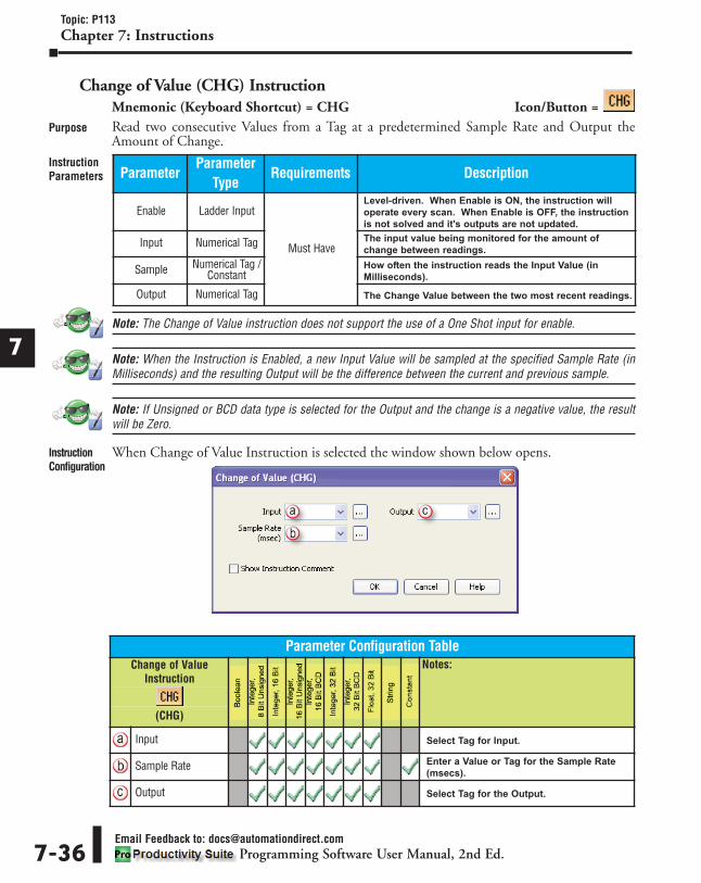
Change of Value (CHG) InstructionMnemonic (Keyboard Shortcut) = CHG Icon/Button =Read two consecutive Values from a Tag at a predetermined Sample Rate and Output theAmount of Change.
Note: The Change of Value instruction does not support the use of a One Shot input for enable.
Note: When the Instruction is Enabled, a new Input Value will be sampled at the specified Sample Rate (inMilliseconds) and the resulting Output will be the difference between the current and previous sample.
Note: If Unsigned or BCD data type is selected for the Output and the change is a negative value, the resultwill be Zero.
When Change of Value Instruction is selected the window shown below opens.
1
2
3
4
5
6
7
8
9
10
11
12
13
14
A
B
C
D
Topic: P113Chapter 7: Instructions
Email Feedback to: [email protected] Software User Manual, 2nd Ed.7-36
Purpose
InstructionParameters
InstructionConfiguration
ParameterParameter
TypeRequirements Description
Enable Ladder Input
Must Have
Level-driven. When Enable is ON, the instruction will
operate every scan. When Enable is OFF, the instruction
is not solved and it's outputs are not updated.
Input Numerical Tag The input value being monitored for the amount of
change between readings.
Sample Numerical Tag /Constant
How often the instruction reads the Input Value (in
Milliseconds).
Output Numerical Tag The Change Value between the two most recent readings.
Parameter Configuration TableChange of Value
InstructionNotes:
(CHG)
Input Select Tag for Input.
Sample Rate Enter a Value or Tag for the Sample Rate
(msecs).
Output Select Tag for the Output.

1
2
3
4
5
6
7
8
9
10
11
12
13
14
A
B
C
D
Topic: P113Chapter 7: Instructions
Email Feedback to: [email protected] Software User Manual, 2nd Ed. 7-37
This example shows a film feeding system. As film feeds through the system the tension canbecome loose or tight, causing film to overfeed and become wrinkled or possibly tear.
In order to maintain proper tension on the film, a Dancer is used. The Dancer has a meter thatmonitors position. By using the Change of Value Instruction, a Change in the Dancers positionis calculated and used to adjust the motor speed to maintain an acceptable amount of tension.
ApplicationExample
RungExample

Find Min/Max Values (MIMX) InstructionMnemonic (Keyboard Shortcut) = MIMX Icon/Button =
Store the Lowest and Highest Values of a Numerical Tag.
Note: If an Unsigned or BCD data type is selected for the Min or Max Value and the Input is a negative value,the result will be Zero.
When Find Min/Max Values Instruction is selected the window shown below opens.
1
2
3
4
5
6
7
8
9
10
11
12
13
14
A
B
C
D
Topic: P114Chapter 7: Instructions
Email Feedback to: [email protected] Software User Manual, 2nd Ed.7-38
Purpose
InstructionParameters
InstructionConfiguration
ParameterParameter
TypeRequirements Description
EnableLadder Input
Must Have
Level-driven. When Enable is ON, the instruction will
operate every scan. When Enable is OFF, the instruction
is not solved and it's Outputs are not updated.
Reset Level-driven. Resets the currently stored Minimum and
Maximum values to Zero.
Input
Numerical Tag
Input Value to be monitored for Min/Max values.
Min Value Stored location of the Minimum Input value.
Max Value Stored location of the Maximum Input value.
Parameter Configuration TableFind Min/Max Values
InstructionNotes:
(MIMX)
Input Select Tag for Input.
Min Value Select a Tag for Min value.
Max Value Select a Tag for Max value.

1
2
3
4
5
6
7
8
9
10
11
12
13
14
A
B
C
D
Topic: P114Chapter 7: Instructions
Email Feedback to: [email protected] Software User Manual, 2nd Ed. 7-39
ApplicationExample
RungExample

Learn Alarm (LALM) InstructionMnemonic (Keyboard Shortcut) = LALM Icon/Button =
Adjust High and Low Alarm Limits of an Input Value using user-defined Multipliers.
Note: Tag Values are updated immediately as each Ladder Rung is executed, top to bottom. However, TagValues representing physical Outputs are only applied to the physical Output after the END statement of thelast Task to be scanned is reached. Outputs in Remote Base Groups have additional limitations regardingUpdate Intervals.
When Learn Alarm Instruction is selected the window shown below opens.
1
2
3
4
5
6
7
8
9
10
11
12
13
14
A
B
C
D
Topic: P115Chapter 7: Instructions
Email Feedback to: [email protected] Software User Manual, 2nd Ed.7-40
Purpose
InstructionParameters
InstructionConfiguration
ParameterParameter
TypeRequirements Description
Enable
Ladder InputMust Have
Level-driven. When Enable is ON, the instruction will
operate on every scan. When Enable is OFF, instruction
is not solved and its outputs are not updated.
High LearnLevel-Driven. When High Learn is enabled, the new High
Limit is calculated by multiplying the Input by the High
Learn Multiplier
Low LearnLevel-Driven. When Low Learn is enabled, the new Low
Limit is calculated by multiplying the Input by the Low
Learn Multiplier.
Input Numerical Tag The Input value to be monitored.
High LearnMultiplier
Numerical Tag /Constant
Must Have eitherHigh or Low Learn
Multiplier
The Input value will be multiplied by this value to provide
the new Alarm High Limit.
High Limit Numerical Tag The Tag that will contain the calculated High Limit value.
(Input value X High Learn Multiplier value = High Limit Value).
High Alarm Boolean Tag The Alarm bit will be ON when the Input value is Greater
Than the High Limit value.
Low LearnMultiplier
Numerical Tag /Constant
The Input value will be multiplied by this value to provide
the new Alarm Low Limit.
Low Limit Numerical Tag The Tag that will contain the calculated Low Limit value.
(Input value X Low Learn Multiplier value = Low Limit Value).
Low Alarm Boolean Tag The Alarm bit will be ON when the Input value is less
than the Low Limit value.

1
2
3
4
5
6
7
8
9
10
11
12
13
14
A
B
C
D
Topic: P115Chapter 7: Instructions
Email Feedback to: [email protected] Software User Manual, 2nd Ed. 7-41
With the Learn Alarm Instruction, the setpoints are configured as a multiple of the Input.When the High Learn Limit is enabled, the Input value is multiplied by the High LearnMultiplier and the result is placed in the High Limit tag. When the Low Learn Limit is enabled,the Input value is multiplied by the Low Learn Multiplier and the result is placed in the LowLimit tag. When the Input value is greater than the High Limit or less than the Low Limit, thecorresponding Alarm tag is enabled.
In this example, we have a system that is feeding paper into a printing press. There are spliceson the large roll that need to be located, so not to print on them. As the paper is being unrolled,a Thickness Detector measures the thickness of the paper. When the thickness exceeds the highlimit setpoint due to a splice, the press is notified that a splice has been detected and it is comingthrough the system. The Learn Alarm Instruction can be useful for this application because thealarm limits for splice detection can be adjusted to accommodate different paper thicknesses.
ApplicationExample
RungExample
Parameter Configuration TableLearn Alarm Instruction
Notes:
(LALM)
Input Select Tag for Input.
High LearnMultiplier
Enter a value or Tag for High Learn
Multiplier.
High Limit Select Tag that will contain the calculated
High Limit.
High Alarm Select a Boolean Tag for the High Alarm.
Low Learn Multiplier Enter a value or Tag for Low Learn
Multiplier.
Low Limit Select Tag that will contain the calculated
Low Limit.
Low Alarm Select a Boolean Tag for the Low Alarm.

Limit Value (LIM) InstructionMnemonic (Keyboard Shortcut) = LIM Icon/Button =
Maintain a Tag Value within a High and Low Limit range.
Note: The Output Value is always Equal To the Input Value unless the Input exceeds the High or Low Limit,at which point the Output will maintain the appropriate Limit Value.
Note: The High or Low Limit Alarms will turn OFF when Enable is turned OFF.
Note: Tag Values are updated immediately as each Ladder Rung is executed, top to bottom. However, TagValues representing physical Outputs are only applied to the physical Output after the END statement of thelast Task to be scanned is reached. Outputs in Remote Base Groups have additional limitations regardingUpdate Intervals.
When Limit Value Instruction is selected the window shown below opens.
1
2
3
4
5
6
7
8
9
10
11
12
13
14
A
B
C
D
Topic: P116Chapter 7: Instructions
Email Feedback to: [email protected] Software User Manual, 2nd Ed.7-42
Purpose
InstructionParameters
InstructionConfiguration
ParameterParameter
TypeRequirements Description
Enable Ladder Input
Must Have
Level-driven. When Enable is ON, the instruction will
operate every scan. When Enable is OFF, the instruction
is not solved and its outputs are not updated.
InputNumerical Tag
The Input value to be monitored and Limited.
Output The resulting Output value with Limits applied (as applicable).
High Limit Numerical Tag /Constant The High Limit to be applied to the Output value.
High LimitAlarm Boolean Tag If the Input value is Greater Than the High Limit value,
this bit will be ON.
Low Limit Numerical Tag /Constant The Low Limit to be applied to the Output value.
Low LimitAlarm Boolean Tag If the Input value is Less Than the Low Limit value, this
bit will be ON.

1
2
3
4
5
6
7
8
9
10
11
12
13
14
A
B
C
D
Topic: P116Chapter 7: Instructions
Email Feedback to: [email protected] Software User Manual, 2nd Ed. 7-43
The graphic shown below is an example of a Limit Value Application. In this example, we havea system that pumps a liquid through pipes. As the liquid flows, it passes through a Flow Meter,which sends a signal used to regulate the Motor. The Limit Value instruction monitors the FlowCommand Value and if the Flow Command exceeds the preset Limit Value configured on theLimit Value instruction, the instruction will bring the Value down to the Limit Value. In thiscase, it Limits the amount of Flow allowed through this system.
ApplicationExample
RungExample
Parameter Configuration TableLimit Value Instruction
Notes:
(LIM)
Input Select Tag Name for Input.
Output Select Tag Name for Output.
High Limit Enter a Value or Tag for the High Limit.
High Limit Alarm Select a Boolean Tag for the High Limit Alarm.
Low Limit Enter a Value or Tag for the Low Limit.
Low Limit Alarm Select a Boolean Tag for the Low Limit Alarm.

Ramp (RMP) InstructionMnemonic (Keyboard Shortcut) = RMP Icon/Button =
Ramp a value using a Linear or S-curve profile.• Linear Ramp: A straight Line transition from the Starting Setpoint to the Running Setpoint.
• S-Curve Ramp: A Ramp that follows the same slope as a Linear Ramp but has a softer transitionat the beginning and end of the Accel and Decel Ramp.
When Ramp Instruction is selected the window shown below opens.
1
2
3
4
5
6
7
8
9
10
11
12
13
14
A
B
C
D
Topic: P117Chapter 7: Instructions
Email Feedback to: [email protected] Software User Manual, 2nd Ed.7-44
Purpose
InstructionParameters
InstructionConfiguration
ParameterParameter
TypeRequirements Description
Enable Ladder Input
Must Have
Level-driven. When Enable is ON, the instruction will
operate every scan. When Enable is OFF, the instruction
is not solved and its outputs are not updated.
Setpoint Numerical Tag /Constant
The Target value the Output will move to achieve.
Accel/Decel Sets the Acceleration and Deceleration rate.
Use S-Curve Checkbox Optional When selected, the Output will use an S-Curve profile.
Jerk Numerical Tag /Constant
Required if Use S-Curve is selected
Limits the rate of Change for Accel/Decel to produce an
S-Curve profile.
Output Numerical Tag Optional Select an Output Tag where the Ramp Output values will
be written.
Parameter Configuration TableRamp
InstructionNotes:
(RMP)
Setpoint Enter a Value or Tag for Setpoint.
Accel/Decel Enter a Value or Tag for Accel/Decel Rate.
Use S-Curve Select if S-Curve Ramp is desired.
Jerk Enter a Value or Tag for Jerk.
Output Select a Tag for Output.

1
2
3
4
5
6
7
8
9
10
11
12
13
14
A
B
C
D
Topic: P117Chapter 7: Instructions
Email Feedback to: [email protected] Software User Manual, 2nd Ed. 7-45
Accel/Decel sets the Constant Acceleration Rate for the Linear portion of the ramp for bothOutput profiles. Using S-Curve reduces stress on equipment by softening the transition fromsteady-state velocity to acceleration, or from acceleration to steady-state velocity.
The Jerk value sets the Curve characteristics. A smaller value for Jerk results in reduced stresson machinery, but longer ramp times. A smaller value for Jerk would increase the radii of theS-Curve profile in the chart below.
In the S-Curve Application Timing Chart, the Output slope is set by the Accel/Decel Tag. Therapid high-low-high step at the end of the Timing Chart shows how an S-Curve Output reactsto changes in polarity of the Setpoint.
ApplicationExample
RungExample

Ramp Generator (GEN) InstructionMnemonic (Keyboard Shortcut) = GEN Icon/Button =
Increase or Decrease the value of an Output at a defined rate.
Note: If both the Ramp Up and Ramp Down ladder inputs turn ON within the same scan, the instruction willNot execute.
Note: If both the Ramp Up and Ramp Down ladder inputs turn ON at different scans, the second input willbe ignored.
Note: Tag Values are updated immediately as each Ladder Rung is executed, top to bottom. However, TagValues representing physical Outputs are only applied to the physical Output after the END statement of thelast Task to be scanned is reached. Outputs in Remote Base Groups have additional limitations regardingUpdate Intervals.
When Ramp Generator Instruction is selected the window shown below opens.
1
2
3
4
5
6
7
8
9
10
11
12
13
14
A
B
C
D
Topic: P118Chapter 7: Instructions
Email Feedback to: [email protected] Software User Manual, 2nd Ed.7-46
Purpose
InstructionParameters
InstructionConfiguration
ParameterParameter
TypeRequirements Description
Ramp Up
Ladder Input Must Have
Level-driven. When Input is ON, instruction Output Increases.
Ramp Down Level-driven. When Input is ON, instruction Output Decreases.
Reset Level-driven. When Input is ON, current Output will set
to Min Output.
Max Output
Numerical Tag /Constant
Optional If used, Output will Not Increase above this value.
Min OutputMust Have
Output will Not Decrease below this value.
Ramp Rate The Output rate of change, in Counts Per Second, during
Ramp Up or Ramp Down.
Soft Start Checkbox Optional When selected the Ramp Segments will begin with a Soft
Start Curve.
Time Numerical Tag /Constant
Must Have whenSoft Start is
selectedSpecifies the Time required to reach Ramp Rate.
Current Ouput Numerical Tag Must Have The Current Output value of the instruction.
Overflow Bit Boolean Tag Optional This bit turns ON when the Count exceeds the Maximum
value of the specified data type in the Current Output field.

1
2
3
4
5
6
7
8
9
10
11
12
13
14
A
B
C
D
Topic: P118Chapter 7: Instructions
Email Feedback to: [email protected] Software User Manual, 2nd Ed. 7-47
In the example below, "INC" is Ramp Up input, "DEC" is Ramp Down input and "RST" isReset input. "Speed" is the Current Output.
ApplicationExample
RungExample
Parameter Configuration TableRamp Generator
InstructionNotes:
(GEN)
Max Output Enter a Value or Tag for Maximum Output.
Min Output Enter a Value or Tag for Minimum Output.
Ramp Rate Enter a Value or Tag at which the Ramp will
change (Counts/Sec).
Soft Start Select for Soft Start.
Time (Sec) Enter a Value or Tag to set Soft Start period.
Current Output Select Tag for Output.
Overflow Bit Select Boolean Tag.

Scale (Linear) (SCL) InstructionMnemonic (Keyboard Shortcut) = SCL Icon/Button =
Scale a variable Input from one type of Unit into another.
When Scale Linear Instruction is selected the window shown below opens.
1
2
3
4
5
6
7
8
9
10
11
12
13
14
A
B
C
D
Topic: P119Chapter 7: Instructions
Email Feedback to: [email protected] Software User Manual, 2nd Ed.7-48
Purpose
InstructionParameters
InstructionConfiguration
ParameterParameter
TypeRequirements Description
Enable Ladder Input
Must Have
Level-driven. When Enable is ON, the instruction will
operate every scan. When Enable is OFF, the instruction
is not solved and it's outputs are not updated.
Input
Numerical Tag /Constant
Input value to be scaled.
In Min Minimum Input value.
In Max Maximum Input value.
Out Min Minimum Output value.
Out Max Maximum Output value.
Output Numerical Tag Scaled Output value.
Parameter Configuration TableScale Linear Instruction
Notes:
(SCL)
Input Enter a Value or Tag to be Scaled.
In Min Enter Minimum Input Value / Tag.
In Max Enter Maximum Input Value / Tag.
Out Min Enter Minimum Output Value/Tag.
Out Max Enter Maximum Output Value/Tag.
Output Select a Tag for the Output Value.

1
2
3
4
5
6
7
8
9
10
11
12
13
14
A
B
C
D
Topic: P119Chapter 7: Instructions
Email Feedback to: [email protected] Software User Manual, 2nd Ed. 7-49
ApplicationExample
RungExample

Scale (Non-Linear) (SCLN) InstructionMnemonic (Keyboard Shortcut) = SCLN Icon/Button =
Scale a Non-Linear variable Input into a Non-Linear Output, using up to 16 Break Points.
Note: Each Input Value must have a Desired Output.
Note: Tag Values are updated immediately as each Ladder Rung is executed, top to bottom. However, TagValues representing physical Outputs are only applied to the physical Output after the END statement of thelast Task to be scanned is reached. Outputs in Remote Base Groups have additional limitations regardingUpdate Intervals.
When Scale Non-Linear Instruction is selected the window shown below opens.
1
2
3
4
5
6
7
8
9
10
11
12
13
14
A
B
C
D
Topic: P120Chapter 7: Instructions
Email Feedback to: [email protected] Software User Manual, 2nd Ed.7-50
Purpose
InstructionParameters
InstructionConfiguration
ParameterParameter
TypeRequirements Description
Enable Ladder Input
Must Have
Level-driven. When Enable is ON, the instruction will
operate every scan. When Enable is OFF, the instruction
is not solved and it's outputs are not updated.
Input
Numerical Tag /Constant
Input value to be scaled.
InputValue(s) Value for Input break points (up to 16 points).
DesiredOutput(s)
Scaled value for corresponding Input break point (up to
16 Outputs).
Output Numerical Tag Scaled Output value.
Parameter Configuration TableScale Non-Linear
InstructionNotes:
(SCLN)
Input Enter a Value or Tag for Input value to be Scaled.
Input Value Enter a Value or Tag for each Input point value.
Desired Output Enter a Value or Tag for each Output point value.
Output Enter a Tag for Scaled Output value.

1
2
3
4
5
6
7
8
9
10
11
12
13
14
A
B
C
D
Topic: P120Chapter 7: Instructions
Email Feedback to: [email protected] Software User Manual, 2nd Ed. 7-51
Notice on the example chart provided below that inside each segment there is a Linear fit. Themore Break Points a user provides, the more accurate the Output will be. However, notice thateach segment is a straight line.
ApplicationExample
RungExample

Selected Summation (SUM) InstructionMnemonic (Keyboard Shortcut) = SUM Icon/Button =
Sum the values for a group of Selected Inputs.
Note: Tag Values are updated immediately as each Ladder Rung is executed, top to bottom. However, TagValues representing physical Outputs are only applied to the physical Output after the END statement of thelast Task to be scanned is reached. Outputs in Remote Base Groups have additional limitations regardingUpdate Intervals.
When Selected Summation Instruction is selected the window shown below opens.
1
2
3
4
5
6
7
8
9
10
11
12
13
14
A
B
C
D
Topic: P121Chapter 7: Instructions
Email Feedback to: [email protected] Software User Manual, 2nd Ed.7-52
Purpose
InstructionParameters
InstructionConfiguration
ParameterParameter
TypeRequirements Description
Enable Ladder InputMust Have
Level-driven. When Enable is ON, the instruction will
operate every scan. When Enable is OFF, the instruction
is not solved and it's outputs are not updated.
Select 1Boolean Tag /
Constant
When Select 1 is ON, Input 1 will be included in the
Summation.
Select 2-8 Optional When Select 2-8 is ON, their respective Inputs will be
included in the Summation.
Input 1 Numerical Tag /Constant
Must Have Value to Sum.
Input 2-8 Optional Values to Sum.
Output Numerical Tag Must Have The Sum of the Selected Inputs.

1
2
3
4
5
6
7
8
9
10
11
12
13
14
A
B
C
D
Topic: P121Chapter 7: Instructions
Email Feedback to: [email protected] Software User Manual, 2nd Ed. 7-53
ApplicationExample
RungExample
Parameter Configuration TableSelected Summation
InstructionNotes:
(SUM)
Select 1 Enter a Boolean Tag or Value for Select 1.
Select 2 Enter a Boolean Tag or Value for Select 2.
Select 3 Enter a Boolean Tag or Value for Select 3.
Select 4 Enter a Boolean Tag or Value for Select 4.
Select 5 Enter a Boolean Tag or Value for Select 5.
Select 6 Enter a Boolean Tag or Value for Select 6.
Select 7 Enter a Boolean Tag or Value for Select 7.
Select 8 Enter a Boolean Tag or Value for Select 8.
Input 1 Enter a Value or Tag for Input 1.
Input 2 Enter a Value or Tag for Input 2.
Input 3 Enter a Value or Tag for Input 3.
Input 4 Enter a Value or Tag for Input 4.
Input 5 Enter a Value or Tag for Input 5.
Input 6 Enter a Value or Tag for Input 6.
Input 7 Enter a Value or Tag for Input 7.
Input 8 Enter a Value or Tag for Input 8.
Output Enter a Tag for the Output.

Switch (SW) InstructionMnemonic (Keyboard Shortcut) = SW Icon/Button =
Act as a two-position selector for switching between two Input values going to one Output.
Note: Tag Values are updated immediately as each Ladder Rung is executed, top to bottom. However, TagValues representing physical Outputs are only applied to the physical Output after the END statement of thelast Task to be scanned is reached. Outputs in Remote Base Groups have additional limitations regardingUpdate Intervals.
When Switch Instruction is selected the window shown below opens.
1
2
3
4
5
6
7
8
9
10
11
12
13
14
A
B
C
D
Topic: P122Chapter 7: Instructions
Email Feedback to: [email protected] Software User Manual, 2nd Ed.7-54
Purpose
InstructionParameters
InstructionConfiguration
ParameterParameter
TypeRequirements Description
EnableLadder Input
Must Have
Level-driven. When Enable is ON, the instruction will
operate every scan. When Enable is OFF, the instruction
is not solved and it's outputs are not updated.
Select Level-driven. When Select is ON, Input 1 is copied to
Output. When Select is OFF, Input 2 is copied to Output.
Input 1 Numerical Tag /Constant
Value to be copied to Output.
Input 2 Value to be copied to Output.
Output Numerical Tag The resulting Output value.
Parameter Configuration TableSwitch
InstructionNotes:
(SW)
Input 1 Enter a Value or Tag for Input 1.
Input 2 Enter a Value or Tag for Input 2.
Output Enter a Tag for Output.

1
2
3
4
5
6
7
8
9
10
11
12
13
14
A
B
C
D
Topic: P122Chapter 7: Instructions
Email Feedback to: [email protected] Software User Manual, 2nd Ed. 7-55
ApplicationExample
RungExample

Array Functions
Array Statistics (STA) InstructionMnemonic (Keyboard Shortcut) = STA Icon/Button =
Perform Statistical operations such as Summing, Averaging, Minimum Value and Median Valueon an Array.
Note: To learn more about Arrays, see the Reference chapter of this manual.
1
2
3
4
5
6
7
8
9
10
11
12
13
14
A
B
C
D
Topic: P217 and P123Chapter 7: Instructions
Email Feedback to: [email protected] Software User Manual, 2nd Ed.7-56
Purpose
InstructionParameters Parameter
ParameterType
Requirements Description
Enable Ladder Input
Must Have
Level-driven. When Enable is ON, the instruction will
operate every scan. When Enable is OFF, instruction is
not solved and its outputs are not updated.
Array Boolean Tag /Numerical Tag
This is the numerical Array that the operations will be
performed on. It can be 1D or 2D. The operations can be
performed on the entire Array or a subset of the Array by
specifying the starting and ending index values in the Start
Row, End Row, Start Column and End Column fields.
Start Row (2DOnly)
Numerical Tag /Constant
Optional
Starting Index (Element Location) of the Second
Dimension (2D) of the Array.
End Row (2DOnly)
Ending Index (Element Location) of the Second
Dimension (2D) of the Array.
Start Column
Must Have
Starting Index (Element Location) of the First Dimension
(1D/2D) of the Array.
End Column Ending index of the First Dimension (1D/2D) of the Array.
Output Numerical Tag Numerical Tag that stores the results of the operations
performed on the Array.
Overflow Boolean Tag Optional Turns ON if a Row or Column Index is outside of the Array.
Sum
SelectableOption
Must Select One ofThe Following:
Sum, Min, Max,
AverageMedian,
Number ofElements Greater
Than or Number ofElements Less
Than
Adds all the values contained within the specified indices
of the Array.
Min Searches within the specified indices of the Array and
returns the Lowest value found.
Max Searches within the specified indices of the Array and
returns the Highest value found.
Average Performs an Average calculation on all the specified
indices of the Array.
Median
Returns the Middle value found in the set of numbers
within the specified indices of the Array. If the set of
numbers is Odd, the instruction returns the Middle value.
For example: If there are 5 Input values of 3, 4, 6, 21 and
45, the Median calculation will return the value of 6. If the
set of numbers is Even, the instruction returns the Lower
Middle value. If there are 4 Input values of 1, 2, 4 and 38,
the Median calculation will return the value 2.
Number ofElements
Greater Than
Searches within the specified indices of the Array and
returns the number of values found that exceed the value
specified in the Number of Elements Greater Than field.
Number ofElements Less
Than
Searches within the specified indices of the Array and
returns the number of values found that exceed the value
specified in the Number of Elements Less Than field.

1
2
3
4
5
6
7
8
9
10
11
12
13
14
A
B
C
D
Topic: P123Chapter 7: Instructions
Email Feedback to: [email protected] Software User Manual, 2nd Ed. 7-57
When Array Statistics Instruction is selected the window shown below opens.
Note: With Boolean arrays, the Sum application will be the only option available, all others will be disabled.
InstructionConfiguration
Parameter Configuration TableArray Statistics
InstructionNotes:
* This icon indicates to use 1D and 2D Arraydata types of respective Data Type column.(STA)
Array * Select a source Array Tag.
Start Row (2D Only) Select a Starting index point of the 2D
dimension of the Array.
End Row (2D Only) Select an Ending index point of the 2D
dimension of the Array.
Start Column Select a Starting index point of the 1D/2D
dimension of the Array.
End Column Select an Ending index point of the 1D/2D
dimension of the Array.
Output Select Tag for Output.
Overflow Select a Boolean Tag for Overflow.
Sum Select for Summing application.
Min Select for Lowest Value application.
Max Select for Highest Value application.
Average Select for Averaging application.
Median Select for Middle Value application.
Number of ElementsGreater Than
Select and enter a value for the Greater
Than search.
Number of ElementsLess Than
Select and enter a value for the Less Than
search.

1D Array with Min (Minimum) selected
2D Array with Average selected
1
2
3
4
5
6
7
8
9
10
11
12
13
14
A
B
C
D
Topic: P123Chapter 7: Instructions
Email Feedback to: [email protected] Software User Manual, 2nd Ed.7-58
ApplicationExample
RungExample

Copy Array (CPA) InstructionMnemonic (Keyboard Shortcut) = CPA Icon/Button =
Copy a block of 1-Dimensional or 2-Dimensional Arrays into a destination Array.
Note: To learn more about Arrays, see the Reference chapter of this manual.
Note: The Overflow Alarm bit will remain ON until the Source and Destination indices are back in range.
Note: The instruction does not Zero the Source Array Elements when the Copy is executed. If Zeroing isrequired, select the Clear Source option.
1
2
3
4
5
6
7
8
9
10
11
12
13
14
A
B
C
D
Topic: P124Chapter 7: Instructions
Email Feedback to: [email protected] Software User Manual, 2nd Ed. 7-59
Purpose
InstructionParameters
InstructionSourceParameters
InstructionDestinationParameters
ParameterParameter
TypeRequirements Description
Enable Ladder Input Must HaveLevel-driven. When Enable is ON, the instruction will
operate every scan. When Enable is OFF, instruction is
not solved and its outputs are not updated.
Overflow Boolean Tag OptionalWhen the Source or Destination index values are outside
of the size of the Array, the partial amount of data will be
Copied and the Alarm bit will turn ON.
ParameterParameter
TypeRequirements Description
Source ArrayString /
Boolean Tag /Numerical Tag
Must Have The Array Tag that values are Copied from.
Start Row (2D Only)
Numerical Tag /Constant
OptionalStarting Index (Element Location) for the 2D Source Array.
End Row (2D Only) Ending Index (Element Location) for the 2D Source Array.
Start ColumnMust Have
Starting Index (Element Location) for the 1D/2D Source
Array.
End Column Ending Index (Element Location) for the 1D/2D Source
Array.
Clear Source Checkbox Optional Option used to Clear the Source Array Elements when
the instruction is executed.
ParameterParameter
TypeRequirements Description
DestinationArray
String /Boolean Tag /Numerical Tag
Must Have The Array Tag that values are Copied to.
Start Row (2D Only) Numerical Tag /
Constant
Optional Starting Index (Element Location) for the 2D Destination Array.
Start Column Must Have Starting Index (Element Location) for the 1D/2D Destination
Array.

When Copy Array Instruction is selected the window shown below opens with defaults shown.
1
2
3
4
5
6
7
8
9
10
11
12
13
14
A
B
C
D
Topic: P124Chapter 7: Instructions
Email Feedback to: [email protected] Software User Manual, 2nd Ed.7-60
InstructionConfiguration
Parameter Configuration TableCopy ArrayInstruction
Notes:
* This icon indicates to use 1D and 2D Arraydata types of respective Data Type column.(CPA)
Source Array * Select a Source Array Tag. See note about
icon above.
Start Row (2D Only) Select a Starting index point of the 2D
dimension of the Array.
End Row (2D Only) Select an Ending index point of the 2D
dimension of the Array.
Start Column Select a Starting index point of the 1D/2D
dimension of the Array.
End Column Select an Ending index point of the 1D/2D
dimension of the Array.
Clear Source Select to Clear Source Array after execute.
Destination Array Select a source Array Tag. See note about
icon above.
Start Row (2D Only) Select a Starting index point of the 2D
dimension of the Array.
Start Column Select a Starting index point of the 1D/2D
dimension of the Array.
Overflow Select a Boolean Tag for Overflow.

Copy 1D Array - Boolean:
Copy 2D Array - Boolean:
1
2
3
4
5
6
7
8
9
10
11
12
13
14
A
B
C
D
Topic: P124Chapter 7: Instructions
Email Feedback to: [email protected] Software User Manual, 2nd Ed. 7-61
ApplicationExample
RungExample

Fill Array (FLA) InstructionMnemonic (Keyboard Shortcut) = FLA Icon/Button =
Copy a value to a block of Array Elements.
Note: To learn more about Arrays, see the Reference chapter of this manual.
Note: The Overflow Alarm bit will remain ON until the Source and Destination indices are back in range.
When the Fill Array Instruction is selected the window shown below opens.
1
2
3
4
5
6
7
8
9
10
11
12
13
14
A
B
C
D
Topic: P125Chapter 7: Instructions
Email Feedback to: [email protected] Software User Manual, 2nd Ed.7-62
Purpose
InstructionParameters
InstructionConfiguration
ParameterParameter
TypeRequirements Description
Enable Ladder Input
Must HaveBoolean Tag
Level-driven. When Enable is ON, the instruction will
operate every scan. When Enable is OFF, instruction is
not solved and its outputs are not updated.
Input
Numerical Tag /Boolean Tag /
String /Constant
The Tag that values are Copied from.
Array Numerical Tag /String The Array Tag that values are Copied to.
Start Row (2D Only)
Numerical Tag /Constant
OptionalStarting Index (Element Location) for the 2D Source Array.
End Row (2D Only)
Ending Index (Element Location) for the 2D Source
Array.
Start ColumnMust Have
Starting Index (Element Location) for the 1D/2D Source
Array.
End Column Ending Index (Element Location) for the 1D/2D Source
Array.
Overflow Boolean Tag Optional Turns ON if the Row or Column Index is outside of the Array.

Fill 1D Array:
Fill 2D Array:
1
2
3
4
5
6
7
8
9
10
11
12
13
14
A
B
C
D
Topic: P125Chapter 7: Instructions
Email Feedback to: [email protected] Software User Manual, 2nd Ed. 7-63
ApplicationExample
RungExample
Parameter Configuration TableFill Array
InstructionNotes:
* This icon indicates to use 1D and 2D Arraydata types of respective Data Type column.(FLA)
Input Enter a Value or Tag for Input.
Array * Select an Array Tag. See note about icon above.
Start Row (2D Only) Select a Starting index point of the 2D
dimension of the Array.
End Row (2D Only) Select an Ending index point of the 2D
dimension of the Array.
Start Column Select a Starting index point of the 1D/2D
dimension of the Array.
End Column Select an Ending index point of the 1D/2D
dimension of the Array.
Overflow Select a Boolean Tag for Overflow.

Shift/Rotate Array (SRA) InstructionMnemonic (Keyboard Shortcut) = SRA Icon/Button =
Concurrently Shift or Rotate values in an Array.
Note: To learn more about Arrays, see the Reference chapter of this manual.
Note: The Overflow Alarm bit will remain ON until the Start Index and End Index are back in range.
1
2
3
4
5
6
7
8
9
10
11
12
13
14
A
B
C
D
Topic: P126Chapter 7: Instructions
Email Feedback to: [email protected] Software User Manual, 2nd Ed.7-64
Purpose
InstructionParameters Parameter
ParameterType
Requirements Description
Enable Ladder Input
Must Have
May be Level-driven or Edge-driven. Option is selected
using One Shot checkbox option.
1D Array Numerical Tag/Boolean Tag
The 1D Numerical or Boolean Tag Array for Shift or
Rotate function. The function can be performed on the
entire Array or a subset of the Array by specifying the
Start Index and End Index.
Start Index
Numerical Tag /Constant
The Starting location of an Element in the Array.
End Index The Ending location of an Element in the Array.
InflowMust Have when
Shift ArrayElements is
Selected
Used only with the Shift feature. Inflow is the Source
Value or Tag that is inserted at the Starting Index (Shift
Right) or the Ending Index (Shift Left) of the Array.
Overflow Boolean Tag Optional Turns ON if the Start Index or End Index is outside the
range of the 1D Array.
Outflow Numerical TagMust Have when
Shift ArrayElements is
Selected
Used only with the Shift feature. Outflow is the Tag that
stores the value being Shifted out of the Array. When
using Shift Right, Outflow is the value from the End
Index. Shift Left Outflow is the value from the Start Index.
Shift ArrayElements Right
SelectableOption
Must Select Shiftor Rotate Function
Moves the specified elements in the Array one position to
the Right. Moves the End Index to the Outflow position
and adds the Inflow element to the Start Index position.
Shift ArrayElements Left
Moves the specified elements in the Array one position to
the Left. Moves the Start Index to the Outflow position
and adds the Inflow element
Rotate ArrayElements Right
Moves the specified elements in the Array one position to
the Right and Rotates the End Index to the Start Index
position.
Rotate ArrayElements Left
Moves the specified elements in the Array one position to
the Left and Rotates the Start Index to the End Index
position.
One Shot Checkbox Optional
This option will ensure that the specified functions only
perform once after the Enable goes from OFF to ON. If
this option is not selected, the instruction will perform
the specified function every scan while the instruction is
Enabled.

When Shift/Rotate Array Instruction is selected the window shown below opens with defaultsshown.
** If the Array is Boolean, Inflow and Outflow can be Boolean.
1
2
3
4
5
6
7
8
9
10
11
12
13
14
A
B
C
D
Topic: P126Chapter 7: Instructions
Email Feedback to: [email protected] Software User Manual, 2nd Ed. 7-65
InstructionConfiguration
Parameter Configuration TableShift/Rotate Array
InstructionNotes:
* This icon indicates to use 1D Array datatypes of respective Data Type column.(SRA)
1D Array * Select a source Array Tag.
Start Index Select a Starting index point of the Array.
End Index Select an Ending index point of the Array.
Inflow ** If using Shift Array, enter a Value or Tag to
be inserted into the Array.
Overflow Select a Boolean Tag for Overflow Alarm.
Outflow ** If using Shift Array, enter a Tag to store the
Value Shifted out of the Array.
Shift Array ElementsRight Select for Shift Right application.
Shift Array ElementsLeft Select for Shift Left application.
Rotate ArrayElements Right Select for Rotate Right application.
Rotate ArrayElements Left Select for Rotate Left application.
One Shot Select for One Shot application.

Shift Array Elements Right:
Rotate Array Elements Left:
1
2
3
4
5
6
7
8
9
10
11
12
13
14
A
B
C
D
Topic: P126Chapter 7: Instructions
Email Feedback to: [email protected] Software User Manual, 2nd Ed.7-66
ApplicationExample
RungExample

Counters/Timers
Simple Counter (SCNT) InstructionMnemonic (Keyboard Shortcut) = SCNT Icon/Button =
Count up by increments of One.
Note: The Reset rung is Level-driven and will execute every scan as long as the enable is ON. The Counterwill not Count as long as the Reset is enabled.
Note: Tag Values are updated immediately as each Ladder Rung is executed, top to bottom. However, TagValues representing physical Outputs are only applied to the physical Output after the END statement of thelast Task to be scanned is reached. Outputs in Remote Base Groups have additional limitations regardingUpdate Intervals.
When Simple Counter Instruction is selected the window shown below opens.
1
2
3
4
5
6
7
8
9
10
11
12
13
14
A
B
C
D
Topic: P218 and P127Chapter 7: Instructions
Email Feedback to: [email protected] Software User Manual, 2nd Ed. 7-67
Purpose
InstructionParameters
InstructionConfiguration
ParameterParameter
TypeRequirements Description
Count UpLadder Input
Must Have
Edge-driven or Level-driven. When Input is ON, the
Current Value will increase by One (1).
Reset Level-driven. When Input is ON, Current Value will Reset
to Zero (0).
Preset Value Numerical Tag /Constant Desired Count value to reach.
One Shot Check Box Optional Select One Shot to make Count Up ladder input operate
as Edge-driven.
Current Value Numerical Tag /Constant Current Value or
Done Tag must bespecified
Current value of the Counter.
Done Boolean Tag When the Current Value becomes Equal To or Greater
Than the Preset value, this bit will turn ON.
Parameter Configuration TableSimple Counter
InstructionNotes:
(SCNT)
Preset Enter a Tag or Value.
One Shot Select One Shot for Edge-driven.
Current Value Enter a Tag or Value.
Done Select a Boolean Tag.

In the following example, a sensor detects the presence of a box and sends a signal to the CountUp input of the Counter. The Current Value increments by one count each time a box isdetected. When Current Part Count is Equal To Part Quota the At Quota output will go Trueuntil Reset Count is Enabled.
1
2
3
4
5
6
7
8
9
10
11
12
13
14
A
B
C
D
Topic: P127Chapter 7: Instructions
Email Feedback to: [email protected] Software User Manual, 2nd Ed.7-68
ApplicationExample
RungExample

Counter (CNT) InstructionMnemonic (Keyboard Shortcut) = CNT Icon/Button =
Count Up or Count Down by increments of One.
Note: The Reset rung is Level-driven and will execute every scan as long as the enable is ON. The Counterwill not Count as long as the Reset is enabled.
Note: If the Count Up and Count Down ladder inputs turn ON within the same scan, the instruction will notexecute.
Note: Tag Values are updated immediately as each Ladder Rung is executed, top to bottom. However, TagValues representing physical Outputs are only applied to the physical Output after the END statement of thelast Task to be scanned is reached. Outputs in Remote Base Groups have additional limitations regardingUpdate Intervals.
When Counter Instruction is selected the window shown below opens.
1
2
3
4
5
6
7
8
9
10
11
12
13
14
A
B
C
D
Topic: P128Chapter 7: Instructions
Email Feedback to: [email protected] Software User Manual, 2nd Ed. 7-69
Purpose
InstructionParameters
InstructionConfiguration
ParameterParameter
TypeRequirements Description
Count Up
Ladder InputMust Have
Edge-driven or Level-driven. When Input is ON, Current
Value will increase by One (1).
Count Down Edge-driven or Level-driven. When Input is ON, Current
Value will decrease by One (1).
Reset Level-driven. When Input is ON, the instruction Count
will immediately Reset to Zero (0).
Preset ValueNumerical Tag /
Constant
Desired Count value to reach.
Reset to ValueOptional
When Current Value reaches the Preset Value, Current
Value will Reset to this Value.
One Shot Check Box Select One Shot to make Count Up and Count Down
ladder inputs operate as Edge-driven.
Current Value Numerical Tag
At least one ofthese four Tags is
required
Current value of the Counter.
= Preset
Boolean Tag
When Current Value is Equal To the Preset Value, this bit
will turn ON.
< Preset When Current Value is Less Than the Preset Value, this
bit will turn ON.
> Preset When Current Value is Greater Than the Preset Value,
this bit will turn ON.

In the following example, the occupancy at a sports event is being monitored by tracking thenumber of spectators entering and leaving the event. The entry turnstile increments the CurrentValue, while the exit turnstile decrements the Current Value. Each spectator that entersincrements the Up Count, while each spectator that leaves decrements the Down Count.
1
2
3
4
5
6
7
8
9
10
11
12
13
14
A
B
C
D
Topic: P128Chapter 7: Instructions
Email Feedback to: [email protected] Software User Manual, 2nd Ed.7-70
ApplicationExample
RungExample
Parameter Configuration TableCounter
InstructionNotes:
(CNT)
Preset Value Enter a Tag or Value to be reached.
Reset to Value Enter a Tag or Value for the Reset Value.
One Shot Select One Shot for Edge-driven.
Current Value Select a Tag for the Current Count.
= Preset Select a Tag for the Equal To Preset Value.
< Preset Select a Tag for the Less Than Preset Value.
> Preset Select a Tag for the Greater Than Preset Value.

Simple Timer (STMR) InstructionMnemonic (Keyboard Shortcut) = STMR Icon/Button =
Time a duration or event.
Note: On a power cycle or Stop/Run transition, the Off Delay Timer’s Current Value will be reset to Zero(0).
Note: Tag Values are updated immediately as each Ladder Rung is executed, top to bottom. However, TagValues representing physical Outputs are only applied to the physical Output after the END statement of thelast Task to be scanned is reached. Outputs in Remote Base Groups have additional limitations regardingUpdate Intervals.
1
2
3
4
5
6
7
8
9
10
11
12
13
14
A
B
C
D
Topic: P129Chapter 7: Instructions
Email Feedback to: [email protected] Software User Manual, 2nd Ed. 7-71
Purpose
InstructionParameters
InstructionConfiguration
Parameter Parameter Type Requirements Description
Time Up Ladder InputMust Have
Level-driven. Based on the selected Delay
Setting, the Enable triggers the timing
sequence.
Preset Value Numerical Tag /Constant
Desired Timer value to reach (0.01 seconds
Time Base).
Current Value Numerical Tag
Current Value orDone Tag must be
specified
Current time of the Timer (0.01 seconds Time
Base).
Done
On Delay
Boolean Tag
For On Delay operation, when the Current
Value becomes Equal To or Greater Than the
Preset Value, this bit will turn ON.
Off Delay
For Off Delay operation, this bit will
immediately turn ON once the Enable is turned
ON. After the Enable is turned OFF, at this
transition point, the Current Value increases,
when the Current Value becomes Equal To or
Greater Than the Preset Value, this bit is
turned OFF.
On Delay Timer
Radio Button Select One
When the Enable transitions from OFF to ON,
the On Delay Timer’s Current Value increases.
When the Enable is OFF, the timer resets to
Zero(0).
Off Delay TimerWhen the Enable transitions from ON to OFF,
the Off Delay Timer’s Current Value increases.
Once the Enable is turned ON, the timer resets
to Zero(0).
Monitor Function Button Optional Creates a new tab in Data View for monitoring
all tags associated with this instruction.

For this example, a conveyor moves ice cream cones into position to be filled. When inposition, the ice cream valve is opened and the Timer is started. When the Timer reaches thePreset Value, the ice cream valve closes.
1
2
3
4
5
6
7
8
9
10
11
12
13
14
A
B
C
D
Topic: P129Chapter 7: Instructions
Email Feedback to: [email protected] Software User Manual, 2nd Ed.7-72
ApplicationExample
RungExample
Parameter Configuration TableSimple Timer
InstructionNotes:
(STMR)
Preset Value Enter a Tag or Value for the desired Time
duration in 0.01 second Time base.
Current Value Select a Tag for Current Value.
Done Select a Boolean Tag for Done bit.
MonitorSelect button to create a new tab in Data
View for monitoring all tags associated with
this instruction.

Timer (TMR) InstructionMnemonic (Keyboard Shortcut) = TMR Icon/Button =
Accumulate a duration of Time, delay a process or Time down from a specific value.
Note: If the Time Up and Time Down ladder inputs turn ON within the same scan, the instruction will notexecute.
Note: When using the = Preset option, the Preset Value and Current Value must be configured as Integer DataTypes.
Note: Tag Values are updated immediately as each Ladder Rung is executed, top to bottom. However, TagValues representing physical Outputs are only applied to the physical Output after the END statement of thelast Task to be scanned is reached. Outputs in Remote Base Groups have additional limitations regardingUpdate Intervals.
When Timer Instruction is selected the window shown below opens.
1
2
3
4
5
6
7
8
9
10
11
12
13
14
A
B
C
D
Topic: P130Chapter 7: Instructions
Email Feedback to: [email protected] Software User Manual, 2nd Ed. 7-73
Purpose
InstructionParameters
InstructionConfiguration
ParameterParameter
TypeRequirements Description
Time Up
Ladder InputMust Have
Level-driven. When enable is ON the Timer's Current
Value increases.
Time Down Level-driven. When enable is ON the Timer's Current
Value decreases.
Reset Level-driven. When enable is ON the Timer's Current
Value will Reset.
Preset ValueNumerical Tag /
Constant
Desired Timer value to reach.
Reset to Value Optional When the Current Value reaches the Preset Value, the
Current Value will Reset to this value.
Time Base SelectableOption Must Have
User can select the Time Base for the Timer. Theselections are:
• Hour • Minute (min)
• Second (sec) • Thousandth of a Second (msec)
Current Value Numerical Tag /Constant
At least one ofthese four Tags is
required
This is the Current Time of the Timer.
= Preset
Boolean Tag
When the Current Value is Equal To the Preset Value, this
bit is ON.
< Preset When the Current Value is Less Than the Preset Value,
this bit is ON.
> Preset When the Current Value is Greater Than the Preset Value,
this bit is ON.

In this example, product is being dried and then cooled in an oven for the same durations. ATimer is used to Count Up the dry time and then Count Down the cooling time untilcompleted.
1
2
3
4
5
6
7
8
9
10
11
12
13
14
A
B
C
D
Topic: P130Chapter 7: Instructions
Email Feedback to: [email protected] Software User Manual, 2nd Ed.7-74
ApplicationExample
RungExample
Parameter Configuration TableTimer
InstructionNotes:
(TMR)
Preset Value Enter a Tag or Value for the desired Time.
Reset to Value Enter a Tag or Value for Reset Value.
Time Base Select a Time Base (hour, min, sec, msec)
Current Value Enter a Tag for real Time value of the Timer.
= Preset Select when using Current Value is Equal to
Preset Value.
< Preset Select when using Current Value is Less
Than the Preset Value.
> Preset Select when using Current Value is Greater
Than the Preset Value.

Communications
ASCII In (AIN) InstructionMnemonic (Keyboard Shortcut) = AIN Icon/Button =
Receive Raw ASCII Strings in the Serial Ports of the PAC and place the data in a String Tag.
1
2
3
4
5
6
7
8
9
10
11
12
13
14
A
B
C
D
Topic: P219 and P131Chapter 7: Instructions
Email Feedback to: [email protected] Software User Manual, 2nd Ed. 7-75
Purpose
InstructionParameters Parameter Parameter
Type Requirements Description
Enable Ladder InputMust Have
Level-driven. When Enable is ON, the instruction willoperate every scan. When Enable is OFF, instruction is notsolved and its outputs are not updated.
Serial Port Drop DownSelection The Serial Port where ASCII data is received.
Fixed Length SelectableOption
Must select Fixedor Variable Length
A specified String Length to be received. Requires a valuefor Number of Characters.
Number ofCharacters Constant Must Have when
using Fixed LengthThe Number of Characters to be received in a string when
using Fixed Length. (1-128)
VariableLength
SelectableOption
Must select Fixedor Variable Length
Specifies the Strings may have Variable Lengths. EnablesMax Number of Characters, 1 Character and 2 Characters.A Termination Code MUST be specified.
Max Numberof Characters Constant Must Have with
Variable LengthThe Maximum Number of Characters allowed to be
received in a string when using Variable Length. (1-128)
1 Character
SelectableOption
Must select 1Character or 2
Characters
Enables Termination Code 1 field where TerminationCharacter must be specified.
2 Characters Enables Termination Code 1 and Termination Code 2 fieldswhere Termination Character must be specified for both.
TerminationCode 1 Must have one or
both when VariableLength is enabledbased on 1 or 2
Characters.
Used to mark the end of a message. Must be configuredusing Hexadecimal format. When the Termination Code isreceived, the CPU moves the received ASCII charactersinto the specified string. Note: Termination Codes are notplaced into the Destination String.
TerminationCode 2
Used in conjunction with Termination Code 1 to mark theend of a message. Must be configured using Hexadecimalformat. When Termination Code 1 and Termination Code 2are received (consecutively), the CPU moves the receivedASCII characters into the specified string. Note: TerminationCodes are not placed into the Destination String.
First CharacterTimeout
Interval (sec)Constant Optional
Amount of Time (in seconds) by which a Character MUSTbe received after Enable is turned ON. If Time is exceeded,First Character Timeout bit will become True. (0-9999)
Inter CharacterTimeout
Interval (msec)
Amount of Time (in milliseconds) that is allowed betweenCharacters of a String. If this Time is exceeded, InterCharacter Timeout bit will become True. (0-9999)
Byte SwapOption
SelectableOption
Must Select No ByteSwap, All
Characters, or AllBut NULLCharacters.
No Byte Swap: No Bytes will be Swapped.All Characters: Every 2 Characters will be Swapped whenplacing the data into the Destination Tag Name.All But Null Characters: Every 2 Characters will beSwapped except Null Characters when placing the datainto the Destination Tag Name.
Convert NULLto 0x
SelectableOption Optional Convert NULL Character to the Character specified to
avoid early termination of a string.
Destination String Tag Must Have The Tag to place the String data.

Note: When Enable turns ON, the buffer of the specified Serial Port is Cleared.
Note: All of the Status Bits, except for the In Progress Bit, will remain in their last state when the InstructionEnable is turned OFF.
Note: One of the Serial Ports must be configured for ASCII/Custom Protocol before configuring thisinstruction.
Note: To test the instruction, Send a Serial String to the PAC with Hyperterminal and look for the result in theDestination Tag Name.
Note: Tag Values are updated immediately as each Ladder Rung is executed, top to bottom. However, TagValues representing physical Outputs are only applied to the physical Output after the END statement of thelast Task to be scanned is reached. Outputs in Remote Base Groups have additional limitations regardingUpdate Intervals.
1
2
3
4
5
6
7
8
9
10
11
12
13
14
A
B
C
D
Topic: P131Chapter 7: Instructions
Email Feedback to: [email protected] Software User Manual, 2nd Ed.7-76
InstructionParameters(continued)
Parameter ParameterType Requirements Description
Number ofCharactersReceived
Numerical Tag
Optional
Value of Total Characters received.
In Progress
Boolean Tag
Whenever the AIN instruction is Enabled, this bit is ON.
Complete
Enabled when PAC has received data into the specifiedserial port that meets the criteria (size or terminationreceived) of the Enabled instruction. Turns OFF wheninstruction is Re-enabled or if new data is received whilethe instruction is still Enabled.
Success Boolean Tag OptionalEnabled when Complete has occurred with no Error bits.
Turns OFF when instruction is Re-enabled or if new data is
received while the instruction is still Enabled.
FirstCharacterTimeout
Boolean Tag OptionalA Character MUST be received within the specified Time
period after instruction Enable is turned ON or 1st
Character Timeout bit will turn ON.
InterCharacterTimeout
Boolean Tag OptionalEach Character MUST be received within the specified
Time period up until the Complete bit is turned ON or the
Inter Character Timeout bit will turn ON.
Overflow Boolean Tag OptionalTurns ON if the PAC receives more Characters than
specified in the Max Number of Characters before seeing
the Termination Character(s) specified. The Overflow Error
bit will turn OFF again when new data is received.

When ASCII In Instruction is selected the window shown below opens.
1
2
3
4
5
6
7
8
9
10
11
12
13
14
A
B
C
D
Topic: P131Chapter 7: Instructions
Email Feedback to: [email protected] Software User Manual, 2nd Ed. 7-77
InstructionConfiguration
Parameter Configuration TableASCII In
InstructionNotes:
(AIN)
Serial Port Select a Serial Port.
Fixed Length Select for Fixed Length.
Number ofCharacters
Enter a value for Number of Characters for
Fixed Length. (1-128)
Variable Length Select for Variable Length.
Max Number ofCharacters
Enter a value for the Maximum Number of
Characters for Variable Length. (1-128)
1 Character Select for Variable Length 1 Character.
2 Characters Select for Variable Length 2 Characters.
Termination Code 1 Enter a Hexadecimal value.
Termination Code 2 Enter a Hexadecimal value.
First CharacterTimeout Interval
Enter Time (in seconds) for setting First
Character alarm. (0-9999)

1
2
3
4
5
6
7
8
9
10
11
12
13
14
A
B
C
D
Topic: P131Chapter 7: Instructions
Email Feedback to: [email protected] Software User Manual, 2nd Ed.7-78
TimingCharts
Parameter Configuration Table (continued)ASCII In
InstructionNotes:
(AIN)
Inter CharacterTimeout Interval
Enter Time (in milliseconds) for setting Inter
Character alarm.
Byte Swap Option Select a Byte Swap option.
Convert NULL to 0x Select the checkbox and enter a Character
to store if NULL is received.
Destination Select String Destination.
Number ofCharacters Received
Select a Tag for Number of Characters of
Current Count.
In Progress Select a Boolean Tag for the In Progress bit
status.
Complete Select a Boolean Tag for the Complete bit
status.
Success Select a Boolean Tag for the Success bit
status.
First CharacterTimeout
Select a Boolean Tag for the First Character
Timeout alarm bit status.
Inter CharacterTimeout
Select a Boolean Tag for the Inter Character
Timeout alarm bit status.
Overflow Select a Boolean Tag for the Overflow alarm
bit status.

In this example, a Barcode String is transferred into the Communications Port of the PAC. TheString is terminated with a carriage return (0x0D).
1
2
3
4
5
6
7
8
9
10
11
12
13
14
A
B
C
D
Topic: P131Chapter 7: Instructions
Email Feedback to: [email protected] Software User Manual, 2nd Ed. 7-79
TimingCharts(continued)
ApplicationExample
RungExample

ASCII Out (AOUT) InstructionMnemonic (Keyboard Shortcut) = AOUT Icon/Button =
Send ASCII String data out of the Serial Ports of the PAC for the purpose of device control, dataprinting, or displaying data on simple operator interfaces.
Note: One of the Serial Ports must be configured for ASCII/Custom Protocol before configuring this instruction.
Note: Tag Values are updated immediately as each Ladder Rung is executed, top to bottom. However, TagValues representing physical Outputs are only applied to the physical Output after the END statement of thelast Task to be scanned is reached. Outputs in Remote Base Groups have additional limitations regardingUpdate Intervals.
1
2
3
4
5
6
7
8
9
10
11
12
13
14
A
B
C
D
Topic: P132Chapter 7: Instructions
Email Feedback to: [email protected] Software User Manual, 2nd Ed.7-80
Purpose
InstructionParameters Parameter Parameter
Type Requirements Description
Enable Ladder Input
Must Have
Edge-driven. When Enable is ON, the instruction willoperate every scan. When Enable is OFF, instruction isnot solved and its outputs are not updated.
Serial Point Drop DownSelection The Serial Port from where ASCII data is sent.
String String Tag /Constant
The field that contains the String Tag or the StringConstant that will be sent out the serial port. If using aString Constant, you MUST put quotes (" ") around thecharacters to be sent out the port.
No Termination
SelectableOption
Must select NoTermination, 1Character or 2
Characters
This option specifies that no trailing Characters will be sent
out of the serial port with the data from the String field.
1 CharacterThis option specifies that the PAC will send out 1Character that is specified in the Termination Code 1 0xfield trailing the String field data.
2 CharactersThis option specifies that the PAC will send out 2 Charactersthat are specified in the Termination Code 1 0x field andTermination Code 2 0x field trailing the String field data.
TerminationCode 1 0x
ConstantMust Have whenselecting 1 or 2
Characters.
Used to mark the end of a message. Must be configuredusing Hexadecimal format. When the Termination Codeis sent, the CPU is signaling the end of the ASCII String.
TerminationCode 2 0x
Used in conjunction with Termination Code 1 to mark theend of a message. Must be configured usingHexadecimal format. When Termination Code 1 andTermination Code 2 are sent (consecutively), the CPU issignaling the end of the ASCII String.
Byte SwapOption
SelectableOption
Must Have No ByteSwap, All
Characters, or AllBut NULLCharactersselected.
No Byte Swap: No Bytes will be Swapped from the Stringfield data when being sent out of the Serial Port.
All Characters: Every Two Characters will be Swappedfrom the String field data when being sent out of theSerial Port.
All But Null Characters: Every Two Characters except forNull Characters will be Swapped from the String fielddata when being sent out of the Serial Port.
Convert 0x toNULL Constant
Optional
Some devices need a Space to be a 0x20 and others needa Space to be a 0x00. Spaces will always be stored as0x20 in the Strings in the PAC. This option allows the0x20 (or other character codes) to be converted to NULLbefore being sent out of the Serial Port.
In ProgressBoolean Tag
This bit turns ON when the Ladder Logic attempts tosend the String data out of the Serial Port. This bit turnsOFF once the data has been sent.
Complete This bit turns ON once the String data has beensuccessfully sent out the Serial Port.

When ASCII Out Instruction is selected the window shown below opens.
1
2
3
4
5
6
7
8
9
10
11
12
13
14
A
B
C
D
Topic: P132Chapter 7: Instructions
Email Feedback to: [email protected] Software User Manual, 2nd Ed. 7-81
InstructionConfiguration
Parameter Configuration TableASCII OutInstruction
Notes:
(AOUT)
Serial Port Select a Serial Port.
String Enter a String Tag or a String Constant in
quotes.
No Termination Select for No Trailing Characters.
1 Character Select for 1 Termination Character.
2 Characters Select for 2 Termination Characters.
Termination Code 1 0x Enter a Hexadecimal value.
Termination Code 2 0x Enter a Hexadecimal value.
Byte Swap Option Select a Byte Swap option.
Convert 0x to NULL Select the checkbox and enter a Character
to store if 0x is received.
In Progress Select a Boolean Tag for the In Progress bit
status.
Complete Select a Boolean Tag for the Complete bit
status.

In this example, an Alarm Barcode String is transferred from the Communications Port of thePAC to a marquee display. The String is terminated with a carriage return (0x0D).
1
2
3
4
5
6
7
8
9
10
11
12
13
14
A
B
C
D
Topic: P132Chapter 7: Instructions
Email Feedback to: [email protected] Software User Manual, 2nd Ed.7-82
TimingCharts
ApplicationExample
RungExample

Clear Serial Port Buffer (ACLR) InstructionMnemonic (Keyboard Shortcut) = ACLR Icon/Button =
Clear the ASCII In Buffer of a specified Serial Port.
Note: This instruction is used in applications where there is a lot of Electrical Noise in the environment toClear any characters that may have been erroneously induced in the Port immediately before receiving thecorrect data.
Note: One of the Serial Ports must be configured for ASCII/Custom Protocol before configuring thisinstruction.
When Clear Serial Port Buffer Instruction is selected the window shown below opens withdefaults shown.
1
2
3
4
5
6
7
8
9
10
11
12
13
14
A
B
C
D
Topic: P133Chapter 7: Instructions
Email Feedback to: [email protected] Software User Manual, 2nd Ed. 7-83
Purpose
InstructionParameters
InstructionConfiguration
Parameter ParameterType Requirements Description
Enable Ladder InputMust Have
Edge-driven. With every transition of Input from OFF to
ON the instruction will clear the serial buffer of the
selected port.
Serial Port Drop DownMenu Selection The Serial Port Buffer to be Cleared.
Parameter Configuration Table
Clear Serial Port BufferInstruction
Notes:
(ACLR)
Serial Port Select a Serial Port.
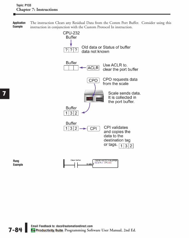
The instruction Clears any Residual Data from the Comm Port Buffer. Consider using thisinstruction in conjunction with the Custom Protocol In instruction.
1
2
3
4
5
6
7
8
9
10
11
12
13
14
A
B
C
D
Topic: P133Chapter 7: Instructions
Email Feedback to: [email protected] Software User Manual, 2nd Ed.7-84
ApplicationExample
RungExample

Custom Protocol In (CPI) InstructionMnemonic (Keyboard Shortcut) = CPI Icon/Button =
Receive structured Hex Based Protocol data from another device in situations where the PACmust communicate to another device that has Hex Based communications and does not havethe Modbus RTU Protocol.
1
2
3
4
5
6
7
8
9
10
11
12
13
14
A
B
C
D
Topic: P134Chapter 7: Instructions
Email Feedback to: [email protected] Software User Manual, 2nd Ed. 7-85
Purpose
InstructionParameters Parameter Parameter
Type Requirements Description
Enable Ladder Input
Must Have
Level-driven. When Enable is ON, the instruction willoperate every scan. When Enable is OFF, instruction isnot solved and its outputs are not updated.
Serial Port Drop DownSelection The Serial Port where ASCII data is received.
Length Constant The number of Bytes (1-4) to be copied into the Data Tag.
Data Numerical TagData Tag to place the Data extracted from the specifiedOffset and Length. The Data will be formatted to thespecified Data Type of the Data Tag.
Byte Swap CheckboxOption Optional
Every Two Characters will be Swapped when Data isreceived.
Checksum Select if Checksum calculation is to be performed on DataReceived.
Type Drop DownSelection
Must Have ifChecksum is
selected
Type of CRC (Cyclic Redundancy Check) or XORcalculation to perform on the Received Data. This needsto match the calculation method of the Sending device.Enabled when Checksum option is selected.
ChecksumResult Offset Constant
Determines where instruction should obtain embeddedChecksum value from the data received in order toCompare to the value calculated from the Checksum Rangeselection. Enabled when Checksum option is selected.
Byte OrderSelectable
Option
Determines whether the sending device sets the CRC orXOR value as High Byte first or Low Byte first. Enabledwhen Checksum option is selected.
ChecksumRange
Determines which Bytes of the received data should beused in the Checksum Calculation. Enabled whenChecksum option is selected.
ChecksumPreload
CheckboxOption
Optional whenChecksum is
selected
Different Checksum calculations use different preloads forthe calculation. Check the sending device technicaldocumentation to determine this value. Enabled whenChecksum option is selected.
Fixed Length SelectableOption
Must Have Fixed orVariable Length
SelectedSending device will be sending a Fixed number of characters.This requires no check for a termination character.
Number ofCharacters Constant Must Have when
using Fixed LengthSpecifies the Number of Characters that will be receivedfrom the sending device. Enabled when Fixed Lengthoption is selected. (1-128)
VariableLength
SelectableOption
Must Have Fixed orVariable Length
Selected
Sending device will be sending Variable Length packets
and a termination character check is necessary in order to
determine which data should be received from the port.
Max Numberof Characters Constant
Must Have whenusing Variable
Length
Specifies the Maximum Number of Characters that will be
received from the sending device. Enabled when Variable
Length option is selected. (1-128)
1 Character SelectableOption
Must have 1Character or 2
Characters selectedwhen using
Variable Length.
First Termination Character in Hex format. Consult anASCII table for this value. Enabled when Variable Lengthoption is selected. Enables Termination Code 1 fieldwhere Termination Character must be specified.

Note: This instruction is used in applications where there is a lot of Electrical Noise in the environment toClear any characters that may have been erroneously induced in the Port immediately before receiving thecorrect data.
Note: One of the Serial Ports must be configured for ASCII/Custom Protocol before configuring thisinstruction.
1
2
3
4
5
6
7
8
9
10
11
12
13
14
A
B
C
D
Topic: P134Chapter 7: Instructions
Email Feedback to: [email protected] Software User Manual, 2nd Ed.7-86
Parameter ParameterType Requirements Description
2 Characters SelectableOption
Must have 1Character or 2
Characters selectedwhen using
Variable Length.
Second Termination Character in Hex format. Consult anASCII table for this value. Enabled when Variable Lengthoption is selected. Enables Termination Code 1 andTermination Code 2 fields where Termination Charactermust be specified for both.
TerminationCode 1 0x Constant
Must have one orboth when VariableLength is enabledbased on 1 or 2
Characters.
Used to mark the end of a message. Must be configured
using Hexadecimal format. When the Termination Code is
sent, the CPU moves the received ASCII Characters into
the specified Tags. Note: Termination Codes are not
placed into the ASCII String.
TerminationCode 2 0x Constant
Used in conjunction with Termination Code 1 to mark the
end of a message. Must be configured using Hexadecimal
format. When Termination Code 1 and Termination Code 2
are sent (consecutively), the CPU moves the received
ASCII Characters into the specified Tags. Note:
Termination Codes are not placed into the ASCII String.
First CharacterTimeout
Interval (sec)Constant Must Have
Amount of Time (in seconds) by which a Character MUST
be received after Enable is turned ON to the instruction. If
Time is exceeded, First Character Timeout bit will become
True. (0-9999)
Inter CharacterTimeout
Interval (msec)Constant Must Have
Amount of Time (in milliseconds) that is allowed between
Characters of a String. If this Time is exceeded, Inter
Character Timeout bit will become True. (0-9999)
In Progress Boolean Tag OptionalEnabled when the instruction has been Enabled. It will go
OFF once the Complete Bit is turned ON or Enabled is
removed from instruction.
Complete Boolean Tag OptionalEnabled when PAC has received data into the specified
serial port that meets the criteria (size or termination
received) of the Enabled instruction. Turns OFF when
instruction is Re-enabled.
Success Boolean Tag Optional Enabled when Complete has occurred with no Error bits.
Turns OFF when instruction is Re-enabled.
ChecksumError Boolean Tag Optional Bit Tag is ON when Checksum has detected an Error.
First CharacterTimeout Boolean Tag Optional
A Character must be received within the specified Time
period after instruction Enable turns ON or the First
Character Timeout Bit will turn ON.
Inter CharacterTimeout Boolean Tag Optional
Each Character must be received within the specified
Time period until the Complete Bit is turned ON or the
Inter Character Timeout Bit will turn ON.
Overflow Boolean Tag OptionalTurns ON if the PAC receives more Characters than
specified in the Max Number of Characters before seeing
the Termination Character(s) specified. The Overflow
Error bit will turn OFF again when new data is received.
InstructionParameters(continued)

When Custom Protocol In Instruction is selected the window shown below opens.
1
2
3
4
5
6
7
8
9
10
11
12
13
14
A
B
C
D
Topic: P134Chapter 7: Instructions
Email Feedback to: [email protected] Software User Manual, 2nd Ed. 7-87
InstructionConfiguration
Parameter Configuration TableCustom Protocol In
InstructionNotes:
(CPI)
Serial Port Select a Serial Port.
Length Enter a Value for Data Length. 1 to 4 Bytes.
Data Select a Tag to place Data into.
Byte Swap Select if Input to be Byte Swapped.
Checksum Select for Checksum Calculation.

1
2
3
4
5
6
7
8
9
10
11
12
13
14
A
B
C
D
Topic: P134Chapter 7: Instructions
Email Feedback to: [email protected] Software User Manual, 2nd Ed.7-88
Parameter Configuration TableCustom Protocol In
InstructionNotes:
(CPI)
Type Select Checksum Type.
Checksum ResultOffset Enter a value for Checksum Result Offset.
Byte Order Select High-Low or Low-High Order.
Checksum Range Select All Ranges or enter a Byte Range.
Checksum Preload Select based on Communicating device
documentation.
Fixed Length Select and enter a Value for Fixed Length. (1-128)
Variable Length Select and enter a Value for Max Variable
Length. (1-128)
1 Character Select for 1 Termination Character.
2 Character Select for 2 Termination Characters.
Termination Code 1 0x Enter a Hexadecimal value.
Termination Code 2 0x Enter a Hexadecimal value.
First CharacterTimeout Interval(sec)
Enter Time in Seconds for First Character
Alarm. (0-9999)
Inter CharacterTimeout Interval(msec)
Enter Time in Milliseconds for Inter
Character Alarm. (0-9999)
In Progress Select a Boolean Tag for the In Progress bit
status.
Complete Select a Boolean Tag for the Complete bit
status.
Success Select a Boolean Tag for the Success bit
status.
Checksum Error Select a Boolean Tag for the Checksum
Error Alarm bit status.
First CharacterTimeout
Select a Boolean Tag for the First Character
Timeout Alarm bit status.
Inter CharacterTimeout
Select a Boolean Tag for the Inter Character
Timeout Alarm bit status.
Overflow Select a Boolean Tag for the Overflow
Alarm bit status.

1
2
3
4
5
6
7
8
9
10
11
12
13
14
A
B
C
D
Topic: P134Chapter 7: Instructions
Email Feedback to: [email protected] Software User Manual, 2nd Ed. 7-89
TimingCharts

1
2
3
4
5
6
7
8
9
10
11
12
13
14
A
B
C
D
Topic: P134Chapter 7: Instructions
Email Feedback to: [email protected] Software User Manual, 2nd Ed.7-90
ApplicationExample
RungExample

1
2
3
4
5
6
7
8
9
10
11
12
13
14
A
B
C
D
Topic: P135Chapter 7: Instructions
Email Feedback to: [email protected] Software User Manual, 2nd Ed. 7-91
Custom Protocol Out (CPO) InstructionMnemonic (Keyboard Shortcut) = CPO Icon/Button =Send structured Hex Based Protocol data to another device in situations where the PAC must communicateto another device that has Hex Based communications and does not have the Modbus RTU Protocol.
Note: One of the Serial Ports must be configured for ASCII/Custom Protocol before configuring this instruction.
Note: Tag Values are updated immediately as each Ladder Rung is executed, top to bottom. However, Tag Valuesrepresenting physical Outputs are only applied to the physical Output after the END statement of the last Task tobe scanned is reached. Outputs in Remote Base Groups have additional limitations regarding Update Intervals.
Purpose
InstructionParameters Parameter Parameter
Type Requirements Description
Enable Ladder Input
Must Have
Edge-driven. With every transition of Input from OFF to ON,
the instruction will execute.
Serial Port Drop DownSelection The Serial Port where ASCII data is sent.
Length Constant The Data Length to be sent, specified in 1 to 4 Bytes basedon Data Type.
Data Numerical Tag Embedded Data sent out to the Serial Port from a specified Tag.
Byte Swap CheckboxOption Optional Every Two Characters will be Swapped when Data is sent.
Checksum Select if Checksum calculation is to be performed on Data Sent.
Type Drop DownSelection
Must Have ifChecksum is
selected
Type of CRC (Cyclic Redundancy Check) or XOR calculationto perform on the Data to be Sent. This needs to match thecalculation method of the Receiving device. Enabled whenChecksum option is selected.
ChecksumResult Offset Constant Determines where to place the Checksum result.
Byte OrderSelectable
Option
Determines whether the PAC sets the CRC or XOR value asHigh Byte first or Low Byte first. Enabled when Checksumoption is selected.
ChecksumRange
Determines which Bytes of the Data to be Sent should beused in the Checksum Calculation. Enabled whenChecksum option is selected.
ChecksumPreload
CheckboxOption
Optional whenChecksum is
selected
Different Checksum calculations use different preloads forthe calculation. Check the receiving device technicaldocumentation to determine this value. Enabled whenChecksum option is selected.
No Termination
SelectableOption
Must have NoTermination, 1Character or 2
Charactersselected.
PAC will be sending a Fixed number of characters. Thisrequires no check for a termination character.
1 CharacterThis option specifies that the PAC will send out 1 Characterthat is specified in the Termination Code 1 0x field trailingthe String field data.
2 CharactersThis option specifies that the PAC will send out 2 Characters thatare specified in the Termination Code 1 0x field and TerminationCode 2 0x field trailing the String field data.
TerminationCode 1 0x
ConstantMust Have whenselecting 1 or 2
Characters
Used to mark the end of a message. Must be configuredusing Hexadecimal format. When the Termination Code issent, the CPU is signaling the end of the ASCII String.
TerminationCode 2 0x
Used in conjunction with Termination Code 1 to mark the end of amessage. Must be configured using Hexadecimal format. WhenTermination Code 1 and Termination Code 2 are sent(consecutively), the CPU is signaling the end of the ASCII String.
In ProgressBoolean Tag Optional
This bit turns ON when the Ladder Logic attempts to sendthe Data out of the Serial Port. This bit turns OFF once thedata has been sent.
Complete This bit turns ON once the Data has been successfully sentout the Serial Port.

When Custom Protocol Out Instruction is selected the window shown below opens.
1
2
3
4
5
6
7
8
9
10
11
12
13
14
A
B
C
D
Topic: P135Chapter 7: Instructions
Email Feedback to: [email protected] Software User Manual, 2nd Ed.7-92
InstructionConfiguration
Parameter Configuration TableCustom Protocol Out
InstructionNotes:
(CPO)
Serial Port Select a Serial Port.
Length Enter a Value (1 to 4) for Data Length.
Data Enter a Tag for Data to be sent.
Byte Swap Select if Output to be Byte Swapped.
Checksum Select for Checksum Calculation.
Type Select Checksum Type.
Checksum ResultOffset Enter a value for Checksum Result Offset.
Byte Order Select High-Low or Low-High Order.
Checksum Range Select All Ranges or enter a Byte Range.

1
2
3
4
5
6
7
8
9
10
11
12
13
14
A
B
C
D
Topic: P135Chapter 7: Instructions
Email Feedback to: [email protected] Software User Manual, 2nd Ed. 7-93
TimingChart
Parameter Configuration Table (continued)Custom Protocol Out
InstructionNotes:
(CPO)
Checksum Preload Select based on Communicating device
documentation.
No Termination Select to leave with No termination.
1 Character Select for 1 Termination Character.
2 Character Select for 2 Termination Characters.
Termination Code 1 0x Enter a Hexadecimal value.
Termination Code 2 0x Enter a Hexadecimal value.
In Progress Select a Boolean Tag for the In Progress bit
status.
Complete Select a Boolean Tag for the Complete bit
status.

1
2
3
4
5
6
7
8
9
10
11
12
13
14
A
B
C
D
Topic: P135Chapter 7: Instructions
Email Feedback to: [email protected] Software User Manual, 2nd Ed.7-94
ApplicationExample
RungExample

GS Drives Read (GSR) InstructionMnemonic (Keyboard Shortcut) = GSR Icon/Button =To Read parameter values from GS Series Drives using Ethernet Communications to aGS-EDRV100 module.
1
2
3
4
5
6
7
8
9
10
11
12
13
14
A
B
C
D
Topic: P136Chapter 7: Instructions
Email Feedback to: [email protected] Software User Manual, 2nd Ed. 7-95
Purpose
InstructionParameters Parameter Parameter
Type Requirements Description
Auto Read
Ladder Input
Must Have
Level-driven. When ON, the PAC sends a read request for theActual Frequency parameter of the drive at the specified PollRate (Poll Every in msec) and Poll Offset.
Manual ReadEdge-driven. When Manual Read transitions from OFF to ON, thePAC will send a request to Read the drive parameters that areconfigured with a Tagname. It will only send one Read requestfor all of the configured parameters per OFF to ON transition.
GS DriveNode
Drop DownSelection
Selects the GS Drive that the PAC will Read from. The Nodenumber is configured with the dip switches on the GS-EDRV100 module. The GS Drive connection to the PAC mustbe set up in the Hardware Configuration.
Poll EveryConstant
Used with Auto Read. Specifies the Rate (30-65535 milliseconds)at which the PAC will send out each Read request to the GS Drivefor the Actual Frequency parameter. (0-65535 msecs.)
Poll OffsetSpecifies an Offset Rate between instructions to stagger themessages being sent out of the PAC. This helps to lessen theimpact on performance.
ActualFrequency
NumericalTag
Tagname where the Actual Frequency (parameter P21.03) valuewill be stored in the PAC.
In Progress
Boolean Tag
Optional
Status Bit that specifies a message is in progress inside of thePAC (sent from the instruction but not yet sent out theEthernet Port). When using Manual Read, this may generatemultiple protocol messages to the Drive. The Status Bitreflects the Status of the individual messages.
Complete
Status Bit that specifies a message has been sent and a replyhas been received, but it may not necessarily have been agood reply. When using Manual Read, this may generatemultiple protocol messages to the Drive. The Status Bitreflects the Status of the individual messages.
SuccessStatus Bit that specifies a message has been sent and a goodreply has been received. When using Manual Read, this maygenerate multiple protocol messages to the Drive. The StatusBit reflects the Status of the individual messages.
Error
Status Bit that specifies a message has been sent and a replywith an Error has been received. Check the ExceptionResponse String to see if it's an Error returned from the Driveor check the Error Logs to see if it is an Internal Error. Whenusing Manual Read, this may generate multiple protocolmessages to the Drive. The Status Bit reflects the Status ofthe individual messages.
Timeout
Status Bit that specifies a message has been sent but no replywas received within the specified Timeout value time (seeHardware Configuration, Local Ethernet Port on the CPU, forvalue). When using Manual Read, this may generate multipleprotocol messages to the Drive. The Status Bit reflects theStatus of the individual messages.
ExceptionResponse
StringString
String that holds the exception response Error sent back fromthe GS Drive. View the Communication Error Codes section ofthe help file for detailed information on Error Codes andpossible corrective actions.
Note: The value displayed in this field is held until cleared by the user.
Manual Read List of Parameters that can be Read from a GS Drive and stored inuser assigned Tagnames. Executes when Manual Read is Enabled.
Tagname NumericalTag Must Have
User assigned Numerical Tag in the PAC for storing theparameter Read from the Drive. Only Parameters populatedwith a Tagname will be Read.

Note: Communications using this instruction are performed over the Local Ethernet Port and a GS-EDRV100is required to be connected to the GS Drive.
Note: The user assigns PAC Tagnames to the Parameters to be Read and the PAC handles the addressingconversion.
Note: For Automatic Polling, the instruction will execute at the selected Poll Rate + the Poll Rate Offset if used.
Note: Tag Values are updated immediately as each Ladder Rung is executed, top to bottom. However, TagValues representing physical Outputs are only applied to the physical Output after the END statement of thelast Task to be scanned is reached. Outputs in Remote Base Groups have additional limitations regardingUpdate Intervals.
Note: Due to limitations, no more than 64 GSR instructions total and 64 GSW instructions total may be usedin a project. Productivity Suite disallows having more than 64 of either instruction.
When GS Drives Read Instruction is selected the window shown below opens.
1
2
3
4
5
6
7
8
9
10
11
12
13
14
A
B
C
D
Topic: P136Chapter 7: Instructions
Email Feedback to: [email protected] Software User Manual, 2nd Ed.7-96
InstructionConfiguration
Parameter Configuration TableGS Drives Read
InstructionNotes:
(GSR)
GS Drive Node Select a Drive.
Poll Every Enter a Value for Polling Time (30-65535
msec).
Poll Offset Enter a Value for Polling Offset (0-65535
msec).

1
2
3
4
5
6
7
8
9
10
11
12
13
14
A
B
C
D
Topic: P136Chapter 7: Instructions
Email Feedback to: [email protected] Software User Manual, 2nd Ed. 7-97
TimingCharts
Parameter Configuration Table (continued)GS Drives Read
InstructionNotes:
(GSR)
Actual Frequency Select a Tag for Frequency Reading.
Manual Read Select Parameter by clicking on name of Tab.
Tagname Select Tagnames for each Parameter being used.
In Progress Select a Boolean Tag for In Progress.
Complete Select a Boolean Tag for Complete.
Success Select a Boolean Tag for Success.
Error Select a Boolean Tag for Error.
Timeout Select a Boolean Tag for Timeout.
Exception ResponseString Select a String Tag for Response Errors.

1
2
3
4
5
6
7
8
9
10
11
12
13
14
A
B
C
D
Topic: P136Chapter 7: Instructions
Email Feedback to: [email protected] Software User Manual, 2nd Ed.7-98
ApplicationExample
RungExample
TimingCharts(continued)

GS Drives Write (GSW) InstructionMnemonic (Keyboard Shortcut) = GSW Icon/Button =
To Write parameter values to control GS Series Drives using Ethernet Communications to aGS-EDRV100 module.
1
2
3
4
5
6
7
8
9
10
11
12
13
14
A
B
C
D
Topic: P137Chapter 7: Instructions
Email Feedback to: [email protected] Software User Manual, 2nd Ed. 7-99
Purpose
InstructionParameters Parameter Parameter
Type Requirements Description
Auto Run
Ladder Input
Must Have
Level-driven. When Enabled, the PAC sends the RunCommand and Frequency Reference value to the GSDrive at the specified Poll Rate (Poll Every in msec) Whenthe Auto Run Enable goes from ON to OFF, the PACsends an OFF command to the Run Command parameterof the Drive and continually checks the Status Register ofthe Drive until it has completely stopped. All otherinstruction inputs, except for the RunModeData input, willbe ignored while this input is ON.
Auto Jog
Level-driven. When Enabled, the PAC sends the JogCommand and Frequency Reference value to the Drive atthe specified Poll Rate (Poll Every in msec). When theAuto Jog Enable goes from ON to OFF, the PAC sends anOFF command to the Jog Command parameter and RunCommand parameters of the Drive and continuallychecks the Status Register of the Drive until it hascompletely stopped. All other instruction inputs, exceptfor the RunModeData input, will be ignored while thisinput is ON.
RunModeDataEdge-driven. When Enabled, the PAC will send allconfigured parameters of the Manual Write - Run Modetab of the instruction. Only those parameters that have aConstant or Tagname defined will be sent.
StopModeData
Edge-driven. When Enabled, the PAC will check theStatus Register of the Drive to see if it is stopped. If theDrive is not completely stopped, then it will do nothingfurther. If the Drive is completely stopped, the PAC willsend all configured parameters of the Manual Write - StopMode tab of the instruction. Only those parameters thathave a Constant or Tagname defined will be sent. Thisfunction will not work if Auto Run or Auto Jog areenabled. Parameter P21.01 should be queried with theGS Read instruction to ensure that the Drive is stopped.
GS Drive Node Drop-downSelection
Selects the GS Drive that the PAC will Write to. The Nodenumber is configured with the dipswitches on the GS-EDRV100 module. The GS Drive connection to the PACmust be set up in the Hardware Configuration.
Poll EveryNumericalConstant
Used with Auto Write. Specifies the Rate (30-65535msec) at which the PAC will send out each message tothe Drive.
Poll OffsetSpecifies an Offset Rate (0-65535 msec) betweeninstructions to stagger the messages being sent out of thePAC. This helps to lessen the impact on performance.
Run CommandFreq.Reference Numerical Tag /
Constant
Tag or Constant value (0-65535) that will be sent to the Driveto control speed, specified in 0.1 Hz resolution. To Run theGS Drive at 60Hz, a value of 600 should be entered.
Jog CommandFreq.Reference
Tag or Constant value (0-65535) that will be sent to the Driveto control Jog speed, specified in 0.1 Hz resolution. To Jogthe GS Drive at 60Hz, a value of 600 should be entered.
In Progress
Boolean Tag Optional
Status Bit that specifies a message is in progress insideof the PAC (sent from the instruction but not yet sent outthe Ethernet Port). Parameter P21.01 should be queriedwith the GS Read instruction to monitor actual Driveaction status.
Complete
Status Bit that specifies a message has been sent and areply has been received, but it may not necessarily havebeen a good reply. The Complete bit means the individualmessage is Complete, not the Drive action. ParameterP21.01 should be queried with the GS Read instruction tomonitor actual Drive action status.

Note: Communications using this instruction are performed over the Local Ethernet Port and a GS-EDRV100 isrequired to be connected to the GS Drive.
Note: The user assigns PAC Tagnames to the Parameters to be Read and the PAC handles the addressing conversion.
Note: Triggering a message may send multiple Modbus messages between the PAC and the GS Drive.
Note: For Automatic Polling, the instruction will execute at the selected Poll Rate + the Poll Rate Offset if used.
Note: Tag Values are updated immediately as each Ladder Rung is executed, top to bottom. However, TagValues representing physical Outputs are only applied to the physical Output after the END statement of thelast Task to be scanned is reached. Outputs in Remote Base Groups have additional limitations regardingUpdate Intervals.
Note: Due to limitations, no more than 64 GSR instructions total and 64 GSW instructions total may be usedin a project. Productivity Suite disallows having more than 64 of either instruction.
1
2
3
4
5
6
7
8
9
10
11
12
13
14
A
B
C
D
Topic: P137Chapter 7: Instructions
Email Feedback to: [email protected] Software User Manual, 2nd Ed.7-100
InstructionParameters Parameter Parameter
Type Requirements Description
Success
Boolean Tag
Optional
Status Bit that specifies a message has been sent and agood reply has been received. This does not necessarilymean that the Drive action is successful but only that anindividual message is. Parameter P21.01 should bequeried with the GS Read instruction to monitor actualDrive action status.
Error
Status Bit that specifies a message has been sent and areply with an Error has been received. Check theException Response String to see if it's an Error returnedfrom the Drive or check the Error Logs to see if it is anInternal Error. This only applies to an individual messageand does not necessarily mean that the Drive is in Error.Parameter P21.01 should be queried with the GS Readinstruction to monitor actual Drive action status.
Timeout
Status Bit that specifies a message has been sent but noreply was received within the specified Timeout valueTime (see Hardware Configuration, Local Ethernet Porton the CPU, for value). This only applies to an individualmessage and does not necessarily mean that the Drive isin Error. Parameter P21.01 should be queried with the GSRead instruction to monitor actual Drive action status.
ExceptionResponse
StringString
String that holds the exception response Error sent backfrom the GS Drive. View the Communication Error Codessection of the help file for detailed information on ErrorCodes and possible corrective actions.
Note: The value displayed in this field is held until cleared by the user.
Manual WriteGS Drive Parameters that can be configured and writtento the Drive by enabling the RunModeData andStopModeData rungs.
Run ModeParameters in the GS Drive that can be Written to whilethe Drive is Running. See the GS Drive technicaldocumentation for more specific details on theParameters themselves.
Stop ModeParameters in the GS Drive that can be Written to whilethe Drive is in Stop Mode. See the GS Drive technicaldocumentation for more specific details on theParameters themselves.
Tagname /Constant Numerical Tag Must Have
User assigned Numerical Tag or Constant value in thePAC for configuring the parameters Written to the Drive.Only parameters populated with a Tagname or Constantvalue will be Written.

When GS Drives Write Instruction is selected the window shown below opens.
1
2
3
4
5
6
7
8
9
10
11
12
13
14
A
B
C
D
Topic: P137Chapter 7: Instructions
Email Feedback to: [email protected] Software User Manual, 2nd Ed. 7-101
InstructionConfiguration
Parameter Configuration TableGS Drives Write
InstructionNotes:
(GSWO)
GS Drive Node Select a Drive.
Poll Every Enter a Value for Polling Time (30-65535 msec).
Poll Offset Enter a Value for Polling Offset (0-65535 msec).
Run Command Enter a Value or a Tag for Run Command FrequencyReference. (0-65535 msec)
Jog Command Enter a Value or a Tag for Jog CommandFrequency Reference. (0-65535 msec)
Manual Write Select Parameter by clicking on name of Tab.
Tagname /Constant
Enter a Value or Tagname for each Parameterused.
In Progress Select a Boolean Tag for In Progress.
Complete Select a Boolean Tag for Complete.
Success Select a Boolean Tag for Success.
Error Select a Boolean Tag for Error.
Timeout Select a Boolean Tag for Timeout.
ExceptionResponse String Select a String Tag for Response Errors.

1
2
3
4
5
6
7
8
9
10
11
12
13
14
A
B
C
D
Topic: P137Chapter 7: Instructions
Email Feedback to: [email protected] Software User Manual, 2nd Ed.7-102
TimingCharts

1
2
3
4
5
6
7
8
9
10
11
12
13
14
A
B
C
D
Topic: P137Chapter 7: Instructions
Email Feedback to: [email protected] Software User Manual, 2nd Ed. 7-103
ApplicationExample
RungExample

Modbus Read (MRX) InstructionMnemonic (Keyboard Shortcut) = MRX Icon/Button =
Perform Read requests from the PAC to Modbus TCP Ethernet and Modbus RTU Serial Slavedevices.
1
2
3
4
5
6
7
8
9
10
11
12
13
14
A
B
C
D
Topic: P138Chapter 7: Instructions
Email Feedback to: [email protected] Software User Manual, 2nd Ed.7-104
Purpose
InstructionParameters Parameter Parameter
Type Requirements Description
Enable Ladder Input Must HaveLevel-driven. When Enable is ON, the instruction willoperate every scan. When Enable is OFF, the instructionis not solved and its outputs are not updated.
Ethernet PortSelectable
Option withDrop-downSelection
Must SelectEthernet Port or
Serial PortCPU External Ethernet Port that will send Modbus Readrequests.
IP Address
ConstantMust Have when
Ethernet PortSelected
IP Address of the Modbus TCP server that the Requestwill be sent to. Enabled when Ethernet Port is selected.
TCP PortNumber
Default is 502 (specified by Modbus TCP specification).Some devices will require a different value. Enabled whenEthernet Port is selected.
Slave NodeNumber
(Ethernet)
Typically used for Modbus TCP to Modbus RTU bridges butsome server devices may require different values. EthernetSlave Node range is 0 to 255, with a default of 255.
Serial PortSelectable
Option withDrop-downSelection
Must SelectEthernet Port or
Serial PortRS232 or RS485 CPU Port or P3-RS/RX Remote SlavePort that will perform Modbus Read Requests.
Slave NodeNumber(Serial)
ConstantMust Have when
Serial PortSelected
Number assigned to the Slave device. Slave Node rangeis 1 to 247, with a default of 1.
In Progress
Boolean Tag
Optional
Status Bit that specifies a Read Request is in progressinside of the PAC (sent from the instruction but not yetsent out the Ethernet Port). The Status Bit reflects theStatus of the individual Read Request.
CompleteStatus Bit that specifies a Read Request has been sentand a reply has been received, but it may not necessarilyhave been a good reply. The Status Bit reflects theStatus of the individual Read Request.
SuccessStatus Bit that specifies a Read Request has been sentand a good reply has been received. The Status Bitreflects the Status of the individual Read Request.
Error
Status Bit that specifies a Read Request has been sentand a reply with an Error has been received from theSlave device within the specified Timeout period. Checkthe Exception Response String to see if it's an Errorreturned from the Slave device or check the Error Logs tosee if it is an Internal Error. The Status Bit reflects theStatus of the individual Read Request.
Timeout
Status Bit that specifies a Read Request has been sentbut no reply was received within the specified Timeoutvalue time. Timeout value is set up in the ExternalEthernet Port and RS232/RS485 Serial Ports of theHardware Configuration. The Status Bit reflects theStatus of the individual Read Request.
ExceptionResponse
StringString
String that holds the exception response Error. View theCommunication Error Codes section of the help file fordetailed information on Error Codes and possiblecorrective actions.
AutomaticPolling Checkbox The PAC will send out a request at the specified Poll Rate
+ Offset Time Value (msec).
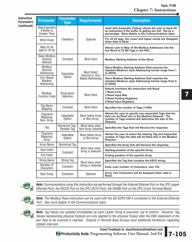
Note: Communications using this instruction are performed through the External Ethernet Port on the CPU (upperEthernet Port), the RS232 Port on the CPU (RJ12 Port), the RS485 Port on the CPU (3-pin Terminal Block).
Note: The Modbus Read instruction can be used with the GS-EDRV100 if connected to the External EthernetPort. See more details in the Communications topic.
Note: Tag Values are updated immediately as each Ladder Rung is executed, top to bottom. However, TagValues representing physical Outputs are only applied to the physical Output after the END statement of thelast Task to be scanned is reached. Outputs in Remote Base Groups have additional limitations regardingUpdate Intervals.
1
2
3
4
5
6
7
8
9
10
11
12
13
14
A
B
C
D
Topic: P138Chapter 7: Instructions
Email Feedback to: [email protected] Software User Manual, 2nd Ed. 7-105
InstructionParameters(continued)
Parameter ParameterType Requirements Description
Skip Executionif Buffer is
Greater Than
Checkbox Optional
Used with Automatic Polling, allows the user to back-offan instruction if the buffer is getting too full. Set by apercentage. More details in the Communications topic.
Word Swap For 32 bit tags, the Lower and Upper words are Swappedwhen data is Read.
Map 32 bitdata to 16 bit
Allows user to Map 16 Bit Modbus Addresses into thelow Word of 32 Bit Tags in the PAC.
Slave ModbusStartingAddress
Constant Must Have Modbus Starting Address of the Slave.
ModbusDecimal
Addressing SelectableOption
Must SelectDecimal or Zero
Based Addressing
Slave Modbus Starting Address field requires thestandard Modicon style Addressing format range from 1to 65536.
Zero BasedModbus
Addressing
Slave Modbus Starting Address field requires thestandard Modicon style Addressing format range from 0to 65535.
ModbusFunction Code
Drop-downSelection Must Have
Selects functions the instruction will Read:
1:Read Coils
2:Read Input Bits
3:Read Holding Registers
4:Read Input Registers
Tag NameMapping Constant Must Have Specifies the number of Tags (1-999).
(TagnameMapping)
Non- ArraySelectable
OptionMust Select Array
or Non-Array
Allows the user to specify non sequential Tags that thedata can be Read into in the Modbus Request. Thenumber of Tags entered will determine the size of theRequest.
Tag Numerical Tag /Boolean Tag
Must Have whenNon-Array Selected Specifies the Tags that will Receive the response.
(TagnameMapping)
ArraySelectable
OptionMust Select Array
or Non-ArrayAllows the user to select the starting Tag and sequentialnumber of Tags the data will be Read into in the ModbusRequest.
Array Name Numerical TagMust Have whenArray is Selected
Specifies the Array that will Receive the response.
Start IndexConstant
Starting position of the specific Array.
End Index Ending position of the specific Array.
String Name String TagMust Have whenString is Selected
Specifies the Tag that contains the ASCII string.
Number ofCharacters Constant Enter even number of characters, max 128.
Byte Swap Checkbox Optional Every Two Characters will be Swapped when data isRead.

When Modbus Read Instruction is selected the window shown below opens.
1
2
3
4
5
6
7
8
9
10
11
12
13
14
A
B
C
D
Topic: P138Chapter 7: Instructions
Email Feedback to: [email protected] Software User Manual, 2nd Ed.7-106
Parameter Configuration TableModbus Read Notes:
* or or(MRX) These icons indicate to use 1D and/or 2D Array
data types of respective Data Type column.
Ethernet Port Select an Ethernet Port if used.
IP Address Enter an IP Address.
TCP Port Number Enter TCP Port Number. Default is 502.
Slave Node Number Enter a Slave Node Number. Default is 255 for
Ethernet and 1 for Serial.
Serial Port Select if Serial Port is used.
Automatic Polling Select and enter Polling Time and Offset Time
(msec).
InstructionConfiguration

1
2
3
4
5
6
7
8
9
10
11
12
13
14
A
B
C
D
Topic: P138Chapter 7: Instructions
Email Feedback to: [email protected] Software User Manual, 2nd Ed. 7-107
InstructionConfiguration(continued)
Parameter Configuration Table (continued)Modbus Read Notes:
* or or(MRX) These icons indicate to use 1D and/or 2D Array
data types of respective Data Type column.
Skip Execution Select and enter % Value.
Word Swap Select if Word Swap is desired.
Map 32 bit data to16 bit Select if 32 to 16 bit conversion is desired.
Slave ModbusStarting Address
Enter a Starting Address for Slave
Modbus.
Modbus DecimalAddressing Select for Modbus Decimal Addressing.
Zero Based ModbusAddressing
Select for Zero Based Modbus
Addressing.
Modbus FunctionCode Select desired Function Code.
Non-Array Select if Non-Array Mapping is desired.
Tag Enter desired Tag(s) to be Mapped.
Array Select if Array Mapping is desired.
Array Name* Enter Tagname of Array to be Mapped.
Starting Index Enter the Starting Point of Mapped Array.
End Index Enter the Ending Point of Mapped Array.
String Select if String Mapping is desired.
String Name Enter the desired Tagname to be Mapped
for this Project.
Number ofCharacters
Enter the number of Characters to be
Read.
Byte Swap Select if Byte Swap is desired.
In Progress Select a Boolean Tag for In Progress.
Complete Select a Boolean Tag for Complete.
Success Select a Boolean Tag for Success.
Error Select a Boolean Tag for Error.
Timeout Select a Boolean Tag for Timeout.
Exception ResponseString Select a String Tag for Response Errors.

1
2
3
4
5
6
7
8
9
10
11
12
13
14
A
B
C
D
Topic: P138Chapter 7: Instructions
Email Feedback to: [email protected] Software User Manual, 2nd Ed.7-108
TimingCharts

In the following example, the CPU Ethernet Port is performing a Modbus TCP Read of fourconsecutive status coils from a Modbus TCP Slave device. 1
2
3
4
5
6
7
8
9
10
11
12
13
14
A
B
C
D
Topic: P138Chapter 7: Instructions
Email Feedback to: [email protected] Software User Manual, 2nd Ed. 7-109
ApplicationExample
RungExample

1
2
3
4
5
6
7
8
9
10
11
12
13
14
A
B
C
D
Topic: P139Chapter 7: Instructions
Email Feedback to: [email protected] Software User Manual, 2nd Ed.7-110
Modbus Write (MWX) InstructionMnemonic (Keyboard Shortcut) = MWX Icon/Button =
Perform Write requests from the PAC to Modbus TCP Ethernet and Modbus RTU Serial Slavedevices.
Purpose
InstructionParameters Parameter Parameter
Type Requirements Description
Enable Ladder Input Must HaveLevel-driven. When Enable is ON, the instruction willoperate every scan. When Enable is OFF, the instructionis not solved and its outputs are not updated.
Ethernet PortSelectable
Option withDrop-downSelection
Must SelectEthernet Port or
Serial PortCPU External Ethernet Port that will send Modbus Writerequests.
IP Address
ConstantMust Have when
Ethernet PortSelected
IP Address of the Modbus TCP server that the WriteRequest will be sent to. Enabled when Ethernet Port isselected.
TCP PortNumber
Default is 502 (number specified by Modbus TCPspecification). Some devices will require a differentvalue. Enabled when Ethernet Port is selected.
Slave NodeNumber
(Ethernet)
Typically used for Modbus TCP to Modbus RTU bridgesbut some server devices may require different values.Applicable field is Enabled when Ethernet Port or SerialPort is selected. Ethernet Slave Node range is 0 to 255,with a default of 255.
Serial PortSelectable
Option withDrop-downSelection
Must SelectEthernet Port or
Serial PortRS232 or RS485 CPU Port or P3-RS/RX Remote SlavePort that will Send Modbus Write Requests.
Slave NodeNumber(Serial)
Constant Must have whenSerial Port Selected
Number assigned to the Slave device. Slave Node rangeis 0 to 247, with a default of 1.
In Progress
Boolean Tag
Optional
Status Bit that specifies a Write Request is in progressinside of the PAC (sent from the instruction but not yetsent out the Ethernet Port). The Status Bit reflects theStatus of the individual Write Request.
CompleteStatus Bit that specifies a Write Request has been sentand a reply has been received, but it may not necessarilyhave been a good reply. The Status Bit reflects the Statusof the individual Write Request.
SuccessStatus Bit that specifies a Write Request has been sentand a good reply has been received. The Status Bitreflects the Status of the individual Write Request.
Error
Status Bit that specifies a Write Request has been sentand a reply with an Error has been received from theSlave device within the specified Timeout period. Checkthe Exception Response String to see if it's an Errorreturned from the Slave device or check the Error Logs tosee if it is an Internal Error. The Status Bit reflects theStatus of the individual Write Request.
Timeout
Status Bit that specifies a Write Request has been sentbut no reply was received within the specified Timeoutvalue time. Timeout value is set up in the ExternalEthernet Port and RS232/RS485 Serial Ports of theHardware Configuration. The Status Bit reflects theStatus of the individual Write Request.
ExceptionResponse
StringString
String that holds the exception response Error. View theCommunication Error Codes section of the help file fordetailed information on Error Codes and possiblecorrective actions.
AutomaticPolling Checkbox The PAC will send out a request at the specified Poll Rate
+ Offset Time Value (msec).

1
2
3
4
5
6
7
8
9
10
11
12
13
14
A
B
C
D
Topic: P139Chapter 7: Instructions
Email Feedback to: [email protected] Software User Manual, 2nd Ed.
Note: Communications using this instruction are performed through the External Ethernet Port on the CPU(upper Ethernet Port), the RS232 Port on the CPU (RJ12 Port), the RS485 Port on the CPU (3-pin TerminalBlock).
Note: The Modbus Write instruction can be used with the GS-EDRV100 if connected to the External EthernetPort. See more details in the Communications topic.
Note: Tag Values are updated immediately as each Ladder Rung is executed, top to bottom. However, TagValues representing physical Outputs are only applied to the physical Output after the END statement of thelast Task to be scanned is reached. Outputs in Remote Base Groups have additional limitations regardingUpdate Intervals.
InstructionParameters(continued)
Parameter ParameterType Requirements Description
Skip Executionif Buffer is
Greater ThanCheckbox Optional
Used with Automatic Polling, allows the user to back-off aninstruction if the buffer is getting too full. Set by apercentage. See more details in the Communications topic.
Word Swap For 32 bit tags, the Lower and Upper words are Swappedwhen data is Sent.
Map 32 bitdata to 16 bit
Allows the user to Map the Low Word of 32 Bit Integer Tagsin the PAC to 16 Bit Modbus addresses in the Slave device.
Slave ModbusStartingAddress
Constant Must Have Modbus Starting Address of the Slave.
ModbusDecimal
Addressing SelectableOption
Must SelectDecimal or Zero
Based Addressing
Slave Modbus Starting Address field requires thestandard Modicon style Addressing format range from 1to 65536.
Zero BasedModbus
Addressing
Slave Modbus Starting Address field requires theStandard Modicon style Addressing format range from 0to 65535.
ModbusFunction Code
Drop DownSelection Must Have
Selects functions the instruction will Write:
5: Write Coil
6: Write Single Register
15: Force Multiple Coils
16: Write Multiple Registers
Tag NameMapping Constant Must Have Specifies the number of Tags (1-999).
(TagnameMapping) Non-
ArraySelectable
OptionMust Select Array
or Non-ArrayAllows the user to specify the data from non sequentialTags that can be Sent in the Modbus Request. The numberof Tags entered will determine the size of the Request.
Tag Numerical Tag /Boolean Tag
Must Have whenNon-Array Selected Specific Data Tags to be Sent.
(TagnameMapping)
ArraySelectable
Option
Must Select Arrayor Non-Array. Onlyused when “ForceMultiple Coils” or“Write Multiple
Registers” isSelected
Allows the user to select the starting Tag and sequentialnumber of Tags that will be Sent the data From or Writtenin the Modbus Request. The Sequential Mapping isbased upon the System ID number.
Array Name Numerical TagMust Have whenArray is selected
Specific Tag number to be Sent from.
Start IndexConstant
Starting position of the specific Array.
End Index Ending position of the specific Array.
String Name StringTag/Constant Must Have when
String is SelectedSpecifies the Tag that contains the ASCII string.
Number ofCharacters Constant Enter even number of characters, max 128.
Byte Swap Checkbox Optional Every Two Characters will be Swapped when data is Sent.
7-111

When Modbus Write Instruction is selected the window shown below opens.
1
2
3
4
5
6
7
8
9
10
11
12
13
14
A
B
C
D
Topic: P139Chapter 7: Instructions
Email Feedback to: [email protected] Software User Manual, 2nd Ed.7-112
InstructionConfiguration
Parameter Configuration TableModbus Write Notes:
* or or
(MWX) These icons indicate to use 1D and/or 2D Arraydata types of respective Data Type column.
Ethernet Port Select an Ethernet Port if used.
IP Address Enter an IP Address.
TCP Port Number Enter TCP Port Number. Default is 502.
Slave Node Number Enter a Slave Node Number. Default is 255 for
Ethernet and 1 for Serial.
Serial Port Select if Serial Port is used.
Automatic Polling Select and enter Polling Time and Offset Time
(msec).

1
2
3
4
5
6
7
8
9
10
11
12
13
14
A
B
C
D
Topic: P139Chapter 7: Instructions
Email Feedback to: [email protected] Software User Manual, 2nd Ed. 7-113
Parameter Configuration Table (continued)Modbus Write Notes:
* or or
(MWX) These icons indicate to use 1D and/or 2D Arraydata types of respective Data Type column.
Skip Execution Select and enter % Value.
Word Swap Select if Word Swap is desired.
Map 32 bit data to16 bit Select if 32 to 16 bit conversion is desired.
Slave ModbusStarting Address Enter a Starting Address for Slave Modbus.
Modbus DecimalAddressing Select for Modbus Decimal Addressing.
Zero Based ModbusAddressing Select for Zero Based Modbus Addressing.
Modbus FunctionCode Select desired Function Code.
Non-Array Select if Non-Array Mapping is desired.
Tag Enter desired Tag(s) to be Mapped.
Array Select if Array Mapping is desired.
Array Name* Enter Tagname of Array to be Mapped.
Starting Index Enter the Starting Point of Mapped Array.
End Index Enter the Ending Point of Mapped Array.
String Select if String Mapping is desired.
String Name Enter the desired Tagname to be Mapped for
this Project.
Number ofCharacters Enter the number of Characters to be Sent.
Byte Swap Select if Byte Swap is desired.
In Progress Select a Boolean Tag for In Progress.
Complete Select a Boolean Tag for Complete.
Success Select a Boolean Tag for Success.
Error Select a Boolean Tag for Error.
Timeout Select a Boolean Tag for Timeout.
Exception ResponseString Select a String Tag for Response Errors.

1
2
3
4
5
6
7
8
9
10
11
12
13
14
A
B
C
D
Topic: P139Chapter 7: Instructions
Email Feedback to: [email protected] Software User Manual, 2nd Ed.7-114
TimingCharts

In the following example, the CPU Ethernet Port is performing a Modbus TCP Write to fourconsecutive control coils in a Modbus TCP Slave device. 1
2
3
4
5
6
7
8
9
10
11
12
13
14
A
B
C
D
Topic: P139Chapter 7: Instructions
Email Feedback to: [email protected] Software User Manual, 2nd Ed. 7-115
ApplicationExample
RungExample

1
2
3
4
5
6
7
8
9
10
11
12
13
14
A
B
C
D
Topic: P140Chapter 7: Instructions
Email Feedback to: [email protected] Software User Manual, 2nd Ed.7-116
Network Read (RX) InstructionMnemonic (Keyboard Shortcut) = RX Icon/Button =
Perform Read requests to other P3-PACs by Reading the Tags of specified PACs over theEthernet, RS232 or RS485 Ports on the CPU.
Purpose
InstructionParameters Parameter Parameter
Type Requirements Description
Enable Ladder Input Must HaveLevel-driven. When Enable is ON, the instruction willoperate every scan. When Enable is OFF, the instructionis not solved and its outputs are not updated.
Ethernet PortSelectable
Option withDrop-downSelection
Must SelectEthernet Port or
Serial PortCPU External Ethernet Port that will send Read requests.
IP Address
ConstantMust Have when
Ethernet PortSelected
IP Address of the PAC server that the Read Request willbe sent to. Enabled when Ethernet Port is selected.
TCP PortNumber
Default is 502 (number specified by Modbus TCPspecification). Some devices will require a differentvalue. Enabled when Ethernet Port is selected.
Serial PortSelectable
Option withDrop-downSelection
Must SelectEthernet Port or
Serial PortRS232 or RS485 CPU Port that will Perform ReadRequests.
Slave NodeNumber Constant Must have when
Serial Port SelectedEnter the Slave Node Number of the PAC from which toRead. The Slave Node Number is found in the HardwareConfiguration for the Port on the PAC.
In Progress
Boolean Tag
Optional
Status Bit that specifies a Read Request is in progressinside of the PAC (sent from the instruction but not yetsent out the Ethernet Port). The Status Bit reflects theStatus of the individual Read Request.
CompleteStatus Bit that specifies a Read Request has been sentand a reply has been received, but it may not necessarilyhave been a good reply. The Status Bit reflects the Statusof the individual Read Request.
SuccessStatus Bit that specifies a Read Request has been sentand a good reply has been received. The Status Bitreflects the Status of the individual Read Request.
Error
Status Bit that specifies a Read Request has been sentand a reply with an Error has been received from theSlave device within the specified Timeout period. Checkthe Exception Response String to see if it's an Errorreturned from the Slave device or check the Error Logs tosee if it is an Internal Error. The Status Bit reflects theStatus of the individual Read Request.
Timeout
Status Bit that specifies a Read Request has been sentbut no reply was received within the specified Timeoutvalue time. Timeout value is set up in the ExternalEthernet Port and RS232/RS485 Serial Ports of theHardware Configuration. The Status Bit reflects theStatus of the individual Read Request.
ExceptionResponse
StringString
String that holds the exception response Error. View theCommunication Error Codes section of the help file fordetailed information on Error Codes and possiblecorrective actions.
AutomaticPolling Checkbox The PAC will send out a request at the specified Poll Rate
+ Offset Time Value (msec).

1
2
3
4
5
6
7
8
9
10
11
12
13
14
A
B
C
D
Topic: P140Chapter 7: Instructions
Note: Communications using this instruction are performed through the External Ethernet Port on the CPU(upper Ethernet Port), the RS232 Port on the CPU (RJ12 Port), the RS485 Port on the CPU (3-pin TerminalBlock). Uses Modbus based protocol exclusive to the P3000 PACs.
Note: For Automatic Polling, the instruction will execute at the selected Poll Rate + the Poll Rate Offset if used.
Note: Tag Values are updated immediately as each Ladder Rung is executed, top to bottom. However, TagValues representing physical Outputs are only applied to the physical Output after the END statement of thelast Task to be scanned is reached. Outputs in Remote Base Groups have additional limitations regardingUpdate Intervals.
InstructionParameters-Tag NameMapping
Parameter ParameterType Requirements Description
Skip Executionif Buffer is
Greater ThanCheckbox Optional
Used with Automatic Polling, allows the user to back-off
an instruction if the buffer is getting too full. Set by a
percentage. See more details in the Communications
topic.
Remote Project Selectable Must HaveAllows the user to select the Project's Tagname Database
of the PAC that the instruction is targeting. Use the Read
button to view Remote Projects.
Non-Array SelectableOption
Must Select Non-Array or Array
Allows user to specify non-sequential Tags that can be
Read in Read Request. The number of Tags entered
determines Request size.
Tags of ThisProject
Numerical Tag/Boolean Tag
Must Have whenNon-Array is
Selected
Allows the user to select the Tags of this Project/PAC
that the data will be Read in to. Enabled when Non-Array
is selected.
Tags of RemoteProject
Allows the user to select the Tags in the target
Project/PAC that the data will be Read from. Enabled
when Non-Array is selected.
Array SelectableOption
Must Select Non-Array or Array
Allows the user to select the starting Tag and sequential
number of Tags that will be Read in the Read Request.
Array Tag ofThis Project
Numerical Tag/Boolean Tag
Must Have whenArray is Selected
Allows the user to select an Array Tag of this Project/PAC
that the data will be Read in to. Enabled when Array is
selected.
Array Tag ofRemote Project
Allows the user to select an Array Tag in the target
Project/PAC that the data will be Read from. Enabled
when Array is selected.
Starting IndexConstant
Starting Index position within the specified Array.
Enabled when Array is selected.
End Index Ending Index position within the specified Array.
Enabled when Array is selected.
String Tag ofThis Project String Tag
Must Have whenTag is Selected
Allows the user to select a String Tag of this Project/PAC
that the data will be Read in to. Enabled when String is
selected.
String Tag ofRemote Project String Tag
Allows the user to select a String Tag in the target
Project/PAC that the data will be Read from. Enabled
when String is selected.
Number ofCharacters Constant Enter number of characters, max 128.
Email Feedback to: [email protected] Software User Manual, 2nd Ed. 7-117

When Network Read Instruction is selected the window shown below opens with defaultsshown.
1
2
3
4
5
6
7
8
9
10
11
12
13
14
A
B
C
D
Topic: P140Chapter 7: Instructions
Email Feedback to: [email protected] Software User Manual, 2nd Ed.7-118
InstructionConfiguration
Parameter Configuration TableNetwork Read Notes:
* This icon indicates to use 1D Array(RX) data types of respective Data Type column.
Ethernet Port Select an Ethernet Port if used.
IP Address Enter an IP Address.
TCP Port Number Enter TCP Port Number. Default is 502.
Serial Port Select if Serial Port is used.
Slave Node Number Enter a Slave Node Number. Default is 1
In Progress Select a Boolean Tag for In Progress.
Complete Select a Boolean Tag for Complete.
Success Select a Boolean Tag for Success.

1
2
3
4
5
6
7
8
9
10
11
12
13
14
A
B
C
D
Topic: P140Chapter 7: Instructions
Email Feedback to: [email protected] Software User Manual, 2nd Ed. 7-119
Parameter Configuration Table (continued)Network Read Notes:
* This icon indicates to use 1D Array(RX) data types of respective Data Type column.
Error Select a Boolean Tag for Error.
Timeout Select a Boolean Tag for Timeout.
Exception ResponseString Select a String Tag for Response Errors.
Automatic Polling Select and enter Polling Time and Offset Time
(msec).
Skip Execution Select and enter % Value.
Remote Project Select desired Remote Project.
Non-Array Select if Non-Array Mapping is desired.
Tags of This Project Enter the desired Tagnames to be Mapped for
this Project.
Tags of RemoteProject
Enter the desired Remote Project Tagnames to
be Mapped.
Array Select if Array Mapping is desired.
Array Tag of ThisProject *
Enter the desired Tagnames to be Mapped for
this Project.
Array Tag of RemoteProject *
Enter the desired Remote Project Tagnames to
be Mapped.
Starting Index Enter the Starting Point of Mapped Array.
Ending Index Enter the Ending Point of Mapped Array.
String Select if String Mapping is desired.
String Tag of thisProject
Enter the desired Tagname to be Mapped for
this Project.
String Tag ofRemote Project
Enter the desired Remote Project Tagname to
be Mapped.
Number ofCharacters Enter the number of Characters to be read.

1
2
3
4
5
6
7
8
9
10
11
12
13
14
A
B
C
D
Topic: P140Chapter 7: Instructions
Email Feedback to: [email protected] Software User Manual, 2nd Ed.7-120
TimingCharts

In the following example, the CPU Ethernet Port is performing a Network Read of two Tagsfrom another PAC in the network. 1
2
3
4
5
6
7
8
9
10
11
12
13
14
A
B
C
D
Topic: P140Chapter 7: Instructions
Email Feedback to: [email protected] Software User Manual, 2nd Ed. 7-121
ApplicationExample
RungExample

1
2
3
4
5
6
7
8
9
10
11
12
13
14
A
B
C
D
Topic: P141Chapter 7: Instructions
Email Feedback to: [email protected] Software User Manual, 2nd Ed.7-122
Network Write (WX) InstructionMnemonic (Keyboard Shortcut) = WX Icon/Button =
Perform Write requests to other P3-PACs by Writing the Tags of specified PACs over theEthernet, RS232 or RS485 Ports on the CPU.
Purpose
InstructionParameters Parameter Parameter
Type Requirements Description
Enable Ladder Input Must HaveLevel-driven. When Enable is ON, the instruction willoperate every scan. When Enable is OFF, the instructionis not solved and its outputs are not updated.
Ethernet PortSelectable
Option withDrop-downSelection
Must SelectEthernet Port or
Serial PortCPU External Ethernet Port that will send Write requests.
IP Address
ConstantMust Have when
Ethernet PortSelected
IP Address of the PAC where the Write Request will besent to. Enabled when Ethernet Port is selected.
TCP PortNumber
Default is 502 (number specified by Modbus TCPspecification). Some devices will require a differentvalue. Enabled when Ethernet Port is selected.
Serial PortSelectable
Option withDrop-downSelection
Must SelectEthernet Port or
Serial PortRS232 or RS485 CPU Port that will send Write Requests.
Slave NodeNumber Constant Must have when
Serial Port SelectedEnter the Node Address of the PAC to which to Write.The Slave Node is found in the Hardware Configurationfor the Port on that PAC.
In Progress
Boolean Tag
Optional
Status Bit that specifies a Write Request is in progressinside of the PAC (sent from the instruction but not yetsent out the Ethernet Port). The Status Bit reflects theStatus of the individual Write Request.
CompleteStatus Bit that specifies a Write Request has been sentand a reply has been received, but it may not necessarilyhave been a good reply. The Status Bit reflects theStatus of the individual Write Request.
SuccessStatus Bit that specifies a Write Request has been sentand a good reply has been received. The Status Bitreflects the Status of the individual Write Request.
Error
Status Bit that specifies a Write Request has been sentand a reply with an Error has been received from theSlave device within the specified Timeout period. Checkthe Exception Response String to see if it's an Errorreturned from the Slave device or check the Error Logs tosee if it is an Internal Error. The Status Bit reflects theStatus of the individual Write Request.
Timeout
Status Bit that specifies a Write Request has been sentbut no reply was received within the specified Timeoutvalue time. Timeout value is set up in the ExternalEthernet Port and RS232/RS485 Serial Ports of theHardware Configuration. The Status Bit reflects theStatus of the individual Write Request.
ExceptionResponse
StringString
String that holds the exception response Error. View theCommunication Error Codes section of the help file fordetailed information on Error Codes and possiblecorrective actions.
AutomaticPolling Checkbox The PAC will send out a request at the specified Poll Rate
+ Offset Time Value (msec).

1
2
3
4
5
6
7
8
9
10
11
12
13
14
A
B
C
D
Topic: P141Chapter 7: Instructions
Email Feedback to: [email protected] Software User Manual, 2nd Ed. 7-123
Note: Communications using this instruction are performed through the External Ethernet Port on the CPU(upper Ethernet Port), the RS232 Port on the CPU (RJ12 Port), the RS485 Port on the CPU (3-pin TerminalBlock). Uses Modbus based protocol exclusive to the P3000 PACs.
Note: For Automatic Polling, the instruction will execute at the selected Poll Rate + the Poll Rate Offset if used.
Note: Tag Values are updated immediately as each Ladder Rung is executed, top to bottom. However, TagValues representing physical Outputs are only applied to the physical Output after the END statement of thelast Task to be scanned is reached. Outputs in Remote Base Groups have additional limitations regardingUpdate Intervals.
Parameter ParameterType Requirements Description
Skip Executionif Buffer is
Greater ThanCheckbox Optional
Used with Automatic Polling, allows the user to back-off
an instruction if the buffer is getting too full. Set by a
percentage. See more details in the Communications
topic.
Remote Project Selectable Must HaveAllows the user to select the Project's Tagname Database
of the PAC that the instruction is targeting. Use the Read
button to view Remote Projects.
Non-Array SelectableOption
Must Select Non-Array or Array
Allows the user to specify non-sequential Tags that can
be Written to the Write Request. The number of Tags
entered will determine the size of the Request.
Tags of ThisProject
Numerical Tag/Boolean Tag
Must Have whenNon-Array is
Selected
Allows the user to select the Tags of this Project/PAC
that the data will be Written from. Enabled when Non-
Array is selected.
Tags of RemoteProject
Allows the user to select the Tags in the target
Project/PAC that the data will be Written to. Enabled
when Non-Array is selected.
Array SelectableOption
Must Select Non-Array or Array
Allows the user to select the starting Tag in the
sequential number of Tags that will be Written to the
Write Request.
Array Tag ofThis Project
Numerical Tag/Boolean Tag
Must Have whenArray is Selected
Allows the user to select an Array Tag of this Project/PAC
that the data will be Written from. Enabled when Array is
selected.
Array Tag ofRemote Project
Allows the user to select an Array Tag in the target
Project/PAC that the data will be Written to. Enabled
when Array is selected.
Starting IndexConstant
Starting Index position within the specified Array.
Enabled when Array is selected.
End Index Ending Index position within the specified Array.
Enabled when Array is selected.
String Tag ofThis Project
StringTag/Constant
Must Have whenString is Selected
Allows the user to select a String Tag of this Project/PAC
that the data will be Written from. Enabled when String is
selected.
String Tag ofRemote Project String
Allows the user to select a String Tag in the target
Project/PAC that the data will be Written to. Enabled
when String is selected.
Number ofCharacters Constant Enter number of characters, max 128.
InstructionParameters-Tag NameMapping

When Network Write Instruction is selected the window shown below opens with defaultsshown.
1
2
3
4
5
6
7
8
9
10
11
12
13
14
A
B
C
D
Topic: P141Chapter 7: Instructions
Email Feedback to: [email protected] Software User Manual, 2nd Ed.7-124
InstructionConfiguration
Parameter Configuration TableNetwork Write Notes:
* This icon indicates to use 1D Array(WX) data types of respective Data Type column.
Ethernet Port Select an Ethernet Port if used.
IP Address Enter an IP Address.
TCP Port Number Enter TCP Port Number. Default is 502.
Serial Port Select if Serial Port is used.
Slave Node Number Enter a Slave Node Number. Default is 1
In Progress Select a Boolean Tag for In Progress.
Complete Select a Boolean Tag for Complete.

1
2
3
4
5
6
7
8
9
10
11
12
13
14
A
B
C
D
Topic: P141Chapter 7: Instructions
Email Feedback to: [email protected] Software User Manual, 2nd Ed. 7-125
Parameter Configuration Table (continued)Network Write Notes:
* This icon indicates to use 1D Array(WX) data types of respective Data Type column.
Success Select a Boolean Tag for Success.
Error Select a Boolean Tag for Error.
Timeout Select a Boolean Tag for Timeout.
Exception ResponseString Select a String Tag for Response Errors.
Automatic Polling Select and enter Polling Time and Offset Time
(msec).
Skip Execution Select and enter % Value.
Remote Project Select desired Remote Project.
Non-Array Select if Non-Array Mapping is desired.
Tags of This Project Enter the desired Tagnames to be Mapped for
this Project.
Tags of RemoteProject
Enter the desired Remote Project Tagnames to
be Mapped.
Array Select if Array Mapping is desired.
Array Tag of ThisProject
Enter the desired Tagnames to be Mapped for
this Project.
Array Tag of RemoteProject
Enter the desired Remote Project Tagnames to
be Mapped.
Starting Index Enter the Starting Point of Mapped Array.
Ending Index Enter the Ending Point of Mapped Array.
String Select if String Mapping is desired.
String Tag of thisProject
Enter the desired Tagname to be Mapped for
this Project.
String Tag ofRemote Project
Enter the desired Remote Project Tagname to
be Mapped.
Number ofCharacters Enter the number of Characters to be sent.

1
2
3
4
5
6
7
8
9
10
11
12
13
14
A
B
C
D
Topic: P141Chapter 7: Instructions
Email Feedback to: [email protected] Software User Manual, 2nd Ed.7-126
TimingCharts

In the following example, the CPU Ethernet Port is performing a Network Write to two Tagsin another PAC in the network. 1
2
3
4
5
6
7
8
9
10
11
12
13
14
A
B
C
D
Topic: P141Chapter 7: Instructions
Email Feedback to: [email protected] Software User Manual, 2nd Ed. 7-127
ApplicationExample
RungExample

1
2
3
4
5
6
7
8
9
10
11
12
13
14
A
B
C
D
Topic: P142Chapter 7: Instructions
Email Feedback to: [email protected] Software User Manual, 2nd Ed.7-128
Send Email (EMAL) InstructionMnemonic (Keyboard Shortcut) = EMAL Icon/Button =
Send an Email with text and/or embedded data to Email recipient(s) via the CPU Ethernet Port.
Note: The Send Email instruction uses the External Ethernet Port configured in the Hardware Configuration.See more details in the Communications topic.
Note: To verify the instruction is working, connectivity to an SMTP server is required.
Note: Tag Values are updated immediately as each Ladder Rung is executed, top to bottom. However, TagValues representing physical Outputs are only applied to the physical Output after the END statement of thelast Task to be scanned is reached. Outputs in Remote Base Groups have additional limitations regardingUpdate Intervals.
When Send Email Instruction is selected the window shown below opens with defaults shown.
Purpose
InstructionParameters
InstructionConfiguration
Parameter ParameterType Requirements Description
Enable Ladder Input
Must Have
Edge-driven. When Enable is ON, the instruction will
operate for one scan.
SMTP ServerIP Address
Constant
The IP Address of the Email server that the message will
be sent to. The IP Address Must Have periods separating
the octets.
Source EmailAddress Optional The Email Address of the Sender, to be displayed in the
From field.
Subject
String /Constant Must Have
The Text to be displayed in the Subject field of the Email.
Message The Message that will be sent in the text body of the
Email.
DestinationEmail Address The Email Address to send the Message to.
Status: MailSent Boolean Tag Optional
The Mail Sent bit is turned ON once the instruction has
completed successfully. This bit will reset whenever the
instruction is enabled in the ladder.

1
2
3
4
5
6
7
8
9
10
11
12
13
14
A
B
C
D
Topic: P142Chapter 7: Instructions
Email Feedback to: [email protected] Software User Manual, 2nd Ed. 7-129
Send Email Instruction allows a pre-typed Message and PAC Tagname Value to be Emailedfrom the PAC CPU module through your SMTP server. This is essentially the same as is doneon most network printers.
ApplicationExample
RungExample
Parameter Configuration TableSend Email Notes:
(EMAL)
SMTP Server IPAddress Enter the IP Address of the Email Server
Source EmailAddress
Enter the Email Address of the Sender. DoNot use quotation marks.
SubjectEnter the Subject of the Message. If using aConstant Data Type, quotation marks MUST beinserted at the beginning and end of the text.
MessageEnter the Message to be sent. Do Not usequotation marks. If using a Constant DataType, quotation marks MUST be inserted at thebeginning and end of the text.
Destination EmailAddress
Enter Email Address(es) of Recipient(s). DoNot use quotation marks.
Status: Mail Sent Select an Output Tag.

1
2
3
4
5
6
7
8
9
10
11
12
13
14
A
B
C
D
Topic: P143Chapter 7: Instructions
Email Feedback to: [email protected] Software User Manual, 2nd Ed.7-130
DataWorx Request (DWX) InstructionMnemonic (Keyboard Shortcut) = DWX Icon/Button =Sends a DataWorx procedure Request from the PAC to a DataWorx ModTCP Server.
Note: The DataWorx Request instruction is used in conjunction with a DataWorx Project. DataWorx Version3.0 Build 48 or later is required to use this instruction. Refer to the DataWorx Help File for configuration help.
Note: Tag Values are updated immediately as each Ladder Rung is executed, top to bottom. However, Tag Valuesrepresenting physical Outputs are only applied to the physical Output after the END statement of the last Task tobe scanned is reached. Outputs in Remote Base Groups have additional limitations regarding Update Intervals.
Purpose
InstructionParameters Parameter Parameter
Type Requirements Description
Enable Ladder Input
Must Have
Level-driven. When Enable is ON, the instruction willoperate every scan. When Enable is OFF, instruction is notsolved and its outputs are not updated.
Ethernet Port Drop-downSelection
CPU External Ethernet Port that will send Modbus Writerequests.
Server IPAddress Constant
IP Address of the DataWorx server that the message will besent to. The Port Number is fixed at the standardModbus/TCP default of 502.
DataWorxServer Read Only DataWorx Server name. This is a Read Only parameter and is
populated by information extracted from the import file.
DataWorxProject
“READ” ButtonSelection
Export file created in a DataWorx ModTCP Project thatcontains Productivity3000 Tags and configured Procedures.
Procedure Drop-downSelection
Defined in the DataWorx project. Procedures will be listedin the drop-down when Project is Read.
In Progress
Boolean Tag
Optional
Turns ON when the instruction has been Enabled. It will goOFF once the Complete Bit is turned ON or instruction isno longer Enabled.
CompleteTurns ON when PAC has received a good response fromthe slave device within the specified Timeout period. TurnsOFF again when the next message is sent (when the InProgress bit is ON again).
Success Bit Tag is ON when data transfer is Completed without Errors.
Error
Turns ON if the PAC receives an exception response fromthe DataWorx ModTCP Server within the specified Timeoutperiod. Turns OFF again when the next message is sent(when the In Progress bit turns ON again). This bit WILLNOT turn ON when a Timeout occurs.
Timeout
Turns ON if the PAC has not received a response from theDataWorx ModTCP Server within the specified Timeout period.Turns OFF again when the next message is sent (when the InProgress bit turns ON again). Timeout value is set in the ExternalEthernet Port of the Hardware Configuration.
ExceptionResponse String String Tag that holds the Exception Response Error text. See
Communication Error Codes.
Confirmation
Read Only
Read Only. Displays the actual status of the request inprogress for the P3000 PAC as configured in the DataWorxP3K Monitor program.
Mapping Table Read Only. Displays the DB Field to Tag relationship of thecurrently selected Procedure.
Where Table Read Only. Defines which record to manipulate. Displays the DBField to Tag relationship of the currently selected procedure.
DB Field The Database field configured in DataWorx.
Source Tag The PAC Tag associated with the DB Field.
SQL View Read Only. SQL statement for the currently selected Procedure.
AutomaticPolling Checkbox The PAC will send out a Request at the specified Poll Rate
+ Offset Time value (msec).

1
2
3
4
5
6
7
8
9
10
11
12
13
14
A
B
C
D
Topic: P143Chapter 7: Instructions
Email Feedback to: [email protected] Software User Manual, 2nd Ed. 7-131
When DataWorx RequestInstruction is selected thewindow shown on theright opens with defaultsshown.
InstructionConfiguration
Parameter Configuration TableDataWorx Request Notes:
(DWX)
Ethernet Port Select an Ethernet Port.
Server IP Address Enter an IP Address.
TCP Port Number Display TCP Port Number.
DataWorx Server Read Only field.
DataWorx Project Use the Read button to select a DataWorx
Project.
Procedure Select a Procedure from the drop-down list.
In Progress Select a Boolean Tag for In Progress.
Complete Select a Boolean Tag for Complete.
Sucess Select a Boolean Tag for Success.
Error Select a Boolean Tag for Error.
Timeout Select a Boolean Tag for Timeout.
Exception ResponseString Select a String Tag for Response Errors.
Confirmation Displays the Confirmation Source Tag.
Mapping Table Read Only field.
Where Table Read Only field.
SQL View Read Only field.
Automatic Polling Select and enter Polling Time and Offset Time
(msec)

The DataWorx (DWX) instruction is used to interface the Productivity3000 with a StandardDatabase through a BizwareDirect’s DataWorx Modbus TCP server: Microsoft Access, SQLServer, or ODBC Servers. Once set up and configured, the PAC can retrieve, add, delete, andupdate data records in the Database.
To configure the BizwareDirect Dataworx Modbus TCP for use with the Productivity SuiteDataWorx Request instruction, a Database must be created first. To create a new Database,follow these steps:
1. Create or open a PAC program. Some Tags will need to be created once the Database type andformat are selected.
2. Determine what Database to use. In this example, Microsoft Access is being used with a tablecalled Clients.
1
2
3
4
5
6
7
8
9
10
11
12
13
14
A
B
C
D
Topic: P143Chapter 7: Instructions
Email Feedback to: [email protected] Software User Manual, 2nd Ed.7-132
Configureand UseDWXInstruction

Create a unique PAC Tag for each field in the Database table. This will allow full access to allthe record fields in the ladder program. Use the table shown below as reference.
3. Install DataWorx Modbus TCP Server and Monitor product. Use the DataWorx Monitor(DWXM) window shown below to configure the DataWorx Server (DWXS). The DWXSmust be up and running in order to be configured. Please be aware that DWXS and DWXMare DataWorx Modbus TCP options and NOT Productivity Suite instructions.
4. From this window, create a device by selecting Options > Configure Server from the Main Menuand select 192. The Device Configuration window shown below opens.
1
2
3
4
5
6
7
8
9
10
11
12
13
14
A
B
C
D
Topic: P143Chapter 7: Instructions
Email Feedback to: [email protected] Software User Manual, 2nd Ed. 7-133
Database Field PAC Tag TypeRecordID nRecordID 32 Bit Integer
Age nAge 32 Bit IntegerWeight nWeight 32 Bit IntegerHeight nHeight 32 Bit Integer
ClientID nClientID 32 Bit IntegerName strName String - 64 Bytes

From this window:
a. Enter the IP Address of the PAC that will access the Database (in this example it is192.168.11.62).
b. Enter a Alias Name (this will show up in the DWX instruction of the Productivity Suite).
c. Select the Database Type.
d. Select the Tag Database that was created by the PAC program to Import it. Database mustbe saved to do this.
e. Click the Test DB button to test the connectivity to the Database.
f. Click the Disconnect button to Disconnect from Database.
g. Select the Import Tag Database button. This opens the Import Tag Database windowshown below.
From this window, click the Import Tags button. The default Windows Open dialog willopen allowing you to select the file that contains the Tags to Import. Once the Import fileis selected, the Import Tag Database window will display the number of Productivity3000Tags available for Import, as shown above. Click on the Save button to Import these Tags.The Tag Database in DataWorx will have the same name as the .ADPRO file (Productivityproject file extension) but with a .CSV extension. By Importing the Tags, DataWorx cannow be configured with Tagnames to avoid any confusion.
1
2
3
4
5
6
7
8
9
10
11
12
13
14
A
B
C
D
Topic: P143Chapter 7: Instructions
Email Feedback to: [email protected] Software User Manual, 2nd Ed.7-134

Use the Device Procedure section to define a set of Procedures that can be executed in theLadder Program. Procedures can be one of the following:
• Insert: Allows Records to be Added to the Database.
• Delete: Removes Records from the Database.
• Select: Reads a Record from the Database.
• Update: Allows a Record to be Modified.
In the following example, four different Procedures are defined and available for use in theLadder Program. This example uses the Select Procedure, however the configuration is the samefor any of the Procedures available. To add a Procedure:
On the General Tab:
From the Device Procedure Properties window shown above:a. ID: Enter an Optional ID (or use the default).
b. Name: If desired, enter a Name to identify this Procedure.
c. Table: Select the drop-down arrow and select the Table Name of the Database.
d. Action: Select Insert, Delete, Update or Select to identify the Action this Procedure willperform.
e. Response: Select the desired Response Type.
f. Confirmation: Select the drop-down arrow and select the Confirmation Tag of the Database.
1
2
3
4
5
6
7
8
9
10
11
12
13
14
A
B
C
D
Topic: P143Chapter 7: Instructions
Email Feedback to: [email protected] Software User Manual, 2nd Ed. 7-135
DefineDataWorxProcedures tobe Executedin the LadderProgram

On the Mapping Tab:
Add the field(s) that will be affected by this Procedure. In this case, since the Procedure Typeis a Select, the fields here will be returned when this Procedure is executed in the ladder. Selectthe Database field and the Tagname that will be populated with the data from that field. As seenabove, Clients.Age field in the Database record is Mapped to the PAC nAge Tag.
On the Where Tab (only required for Select, Delete, and Update procedure types):
The Where tab defines the Tag and what Record will be returned when the Procedure isexecuted in the ladder. As seen above, Tag nRecordID is associated with the Database fieldClients.RecordID and defines what Record will be returned. Also, select the proper operator,which in this case is Equal. For instance, if nRecordID is Equal to 3, then the Record that hasa RecordID of 3 will be returned.
Note: A Where definition is only required for the Select, Delete, and Update Procedure types. When Insert isexecuted, the new Record is automatically appended to the end of the table.
Once all the necessary Procedures have been defined, use the Export Configuration function inthe DWXM to create a .dwx file that will be used to Import into DWX instruction(s). In thiscase, the file is called DWX Test.dwx.
1
2
3
4
5
6
7
8
9
10
11
12
13
14
A
B
C
D
Topic: P143Chapter 7: Instructions
Email Feedback to: [email protected] Software User Manual, 2nd Ed.7-136

Once the Database and the DataWorx Server have been set up and the Server configuration hasbeen Exported, insert DWX instructions in the ladder to execute the Procedures that weredefined.
Use the DataWorx Project field to Import the .DWX file that you just created. Importing thisfile populates the Procedure selector with all the available Procedures that were defined in theDataWorx Server. In this case, Procedure 77: Read Client Record is selected and willautomatically populate the Mapping Table, Where Table, and SQL View information.
Before this Rung is executed, set the Tag nRecordID with the desired Record ID number.Then execute the Rung. The Tags in the Mapping field should now be populated with thevalues retrieved from the Database.
1
2
3
4
5
6
7
8
9
10
11
12
13
14
A
B
C
D
Topic: P143Chapter 7: Instructions
Email Feedback to: [email protected] Software User Manual, 2nd Ed. 7-137
Using theDataworx(DWX)Instruction
RungExample

1
2
3
4
5
6
7
8
9
10
11
12
13
14
A
B
C
D
Topic: P220 and P144Chapter 7: Instructions
Email Feedback to: [email protected] Software User Manual, 2nd Ed.7-138
Data Handling
Absolute Encoder (ABSE) InstructionMnemonic (Keyboard Shortcut) = ABSE Icon/Button =
Decodes Bit Pattern from Gray Code or Binary Absolute Encoder.
Note: The Output Tag Value is not forced to zero when the Enable is turned OFF. The Output Tag will containthe last value Written by the Instruction until it is overwritten by another Instruction or from an externaldevice.
Note: Tag Values are updated immediately as each Ladder Rung is executed, top to bottom. However, TagValues representing physical Outputs are only applied to the physical Output after the END statement of thelast Task to be scanned is reached. Outputs in Remote Base Groups have additional limitations regardingUpdate Intervals.
When Absolute Encoder Instruction isselected the window shown on the rightopens with defaults shown.
Purpose
InstructionParameters
InstructionConfiguration
Parameter ParameterType Requirements Description
Enable Ladder Input
Must Have
Level-driven. When Enable is ON, the instruction will
operate every scan. When Enable is OFF, instruction is
not solved and its outputs are not updated.
Encoder Type SelectableOption Selects Gray Code or Binary Encoder type.
EncoderCounts
Drop-downMenu Selection
Selects one of these Resolutions for the Absolute Encoder:
32 pulses (5 bits) 512 pulses (9 bits)
64 pulses (6 bits) 720 pulses (10 bits)
128 pulses (7 bits) 1024 pulses (10 bits)
180 pulses (8 bits) 2048 pulses (11 bits)
256 pulses (8 bits) 4096 pulses (12 bits)
360 pulses (9 bits)
Input Boolean Tag /Constant
Discrete Input Tags assigned to the Absolute EncoderInputs. The number of required Tags depends on selectedEncoder Counts.
Output Numerical Tag Current Encoder position.

1
2
3
4
5
6
7
8
9
10
11
12
13
14
A
B
C
D
Topic: P144Chapter 7: Instructions
Email Feedback to: [email protected] Software User Manual, 2nd Ed. 7-139
In the following example, the current table position is calculated based on the EncoderResolution and the bit pattern of the Gray Code bit pattern fed into the ABSE instruction.
ApplicationExample
RungExample
Parameter Configuration TableAbsolute Encoder Notes:
(ABSE)
Encoder Type Select Gray Code or Binary Encoder type.
Encoder Counts Select Encoder Resolution.
Input Enter a Value or Tag for each Input.
Output Select an Output Tag.

1
2
3
4
5
6
7
8
9
10
11
12
13
14
A
B
C
D
Topic: P145Chapter 7: Instructions
Email Feedback to: [email protected] Software User Manual, 2nd Ed.7-140
Compare Values (CMPV) InstructionMnemonic (Keyboard Shortcut) = CMPV Icon/Button =
Compare two Input values and determine if one is Greater Than, Equal To or Less Than theother.
Note: Tag Values are updated immediately as each Ladder Rung is executed, top to bottom. However, TagValues representing physical Outputs are only applied to the physical Output after the END statement of thelast Task to be scanned is reached. Outputs in Remote Base Groups have additional limitations regardingUpdate Intervals.
When Compare Values Instruction is selected the window shown below opens with defaultsshown.
Purpose
InstructionParameters
InstructionConfiguration
Parameter ParameterType Requirements Description
Enable Ladder Input
Must Have
Level-driven. When Enable is ON, the instruction will
operate every scan. When Enable is OFF, the instruction
is not solved and it's Outputs are not updated.
Input 1 Boolean Tag /Numerical Tagor Constant
Primary Value.
Input 2 Compare Value.
Greater ThanBoolean Tag Must Have at least
One
Turns ON if Input 1 is Greater Than Input 2.
Equal To Turns ON if Input 1 is Equal To Input 2.
Less Than Turns ON if Input 1 is Less Than Input 2.
Parameter Configuration TableCompare Values Notes:
(CMPV)
Input 1 Enter a Value or Tag for Primary Value.
Input 2 Enter a Value or Tag for Compare Value.
Greater Than Select Tag for Greater Than Bit.
Equal To Select Tag for Equal To Bit.
Less Than Select Tag for Less Than Bit.

1
2
3
4
5
6
7
8
9
10
11
12
13
14
A
B
C
D
Topic: P145Chapter 7: Instructions
Email Feedback to: [email protected] Software User Manual, 2nd Ed. 7-141
In this example, we have a motor that provides the drive for a system. The Compare ValuesInstruction is used to Compare the Input Value of the current Speed of the motor with the SetValue of the Minimum Speed. This can be used to keep the Speed of the motor as or above aset Minimum Value.
ApplicationExample
RungExample
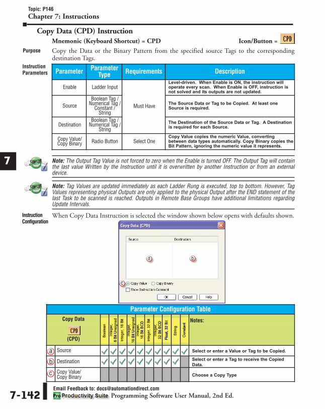
1
2
3
4
5
6
7
8
9
10
11
12
13
14
A
B
C
D
Topic: P146Chapter 7: Instructions
Email Feedback to: [email protected] Software User Manual, 2nd Ed.7-142
Copy Data (CPD) InstructionMnemonic (Keyboard Shortcut) = CPD Icon/Button =
Copy the Data or the Binary Pattern from the specified source Tags to the correspondingdestination Tags.
Note: The Output Tag Value is not forced to zero when the Enable is turned OFF. The Output Tag will containthe last value Written by the Instruction until it is overwritten by another Instruction or from an externaldevice.
Note: Tag Values are updated immediately as each Ladder Rung is executed, top to bottom. However, TagValues representing physical Outputs are only applied to the physical Output after the END statement of thelast Task to be scanned is reached. Outputs in Remote Base Groups have additional limitations regardingUpdate Intervals.
When Copy Data Instruction is selected the window shown below opens with defaults shown.
Purpose
InstructionParameters
InstructionConfiguration
Parameter ParameterType Requirements Description
Enable Ladder Input
Must Have
Level-driven. When Enable is ON, the instruction willoperate every scan. When Enable is OFF, instruction isnot solved and its outputs are not updated.
SourceBoolean Tag /
Numerical Tag /Constant /
String
The Source Data or Tag to be Copied. At least oneSource is required.
DestinationBoolean Tag /
Numerical Tag /String
The Destination of the Source Data or Tag. A Destinationis required for each Source.
Copy Value/Copy Binary Radio Button Select One
Copy Value copies the numeric Value, convertingbetween data types automatically. Copy Binary copies theBit Pattern, ignoring the numeric value it represents.
Parameter Configuration TableCopy Data Notes:
(CPD)
Source Select or enter a Value or Tag to be Copied.
Destination Select or enter a Tag to receive the Copied
Data.
Copy Value/Copy Binary Choose a Copy Type

1
2
3
4
5
6
7
8
9
10
11
12
13
14
A
B
C
D
Topic: P146Chapter 7: Instructions
Email Feedback to: [email protected] Software User Manual, 2nd Ed. 7-143
In the following example, the system is Copying Data from critical parameters of a boilersystem and storing them in Tags that can be used for display in an HMI or stored to a Database.
ApplicationExample
RungExample

1
2
3
4
5
6
7
8
9
10
11
12
13
14
A
B
C
D
Topic: P147Chapter 7: Instructions
Email Feedback to: [email protected] Software User Manual, 2nd Ed.7-144
FIFO/LIFO - First In First Out / Last In First Out (FILI) InstructionMnemonic (Keyboard Shortcut) = FILI Icon/Button =
Allows Data to be added, removed or viewed from a Block of Memory (Buffer).
Note: Tag Values are updated immediately as each Ladder Rung is executed, top to bottom. However, TagValues representing physical Outputs are only applied to the physical Output after the END statement of thelast Task to be scanned is reached. Outputs in Remote Base Groups have additional limitations regardingUpdate Intervals.
Purpose
InstructionParameters Parameter Parameter
Type Requirements Description
Push
Ladder Input
Must Have
Level–driven or Edge-driven (using One Shot). Initiates aPush of Data onto the Buffer.
Pop Level–driven or Edge-driven (using One Shot). Initiates aPop of Data out of the Buffer.
Peek Level–driven or Edge-driven (using One Shot). Initiates aPeek of Data in the Buffer.
ClearLevel–driven. Initiates a Clear of all Elements in a Buffer.Push, Pop and Peek will not operate while Clear isEnabled.
Input DataFrom (Push)
Boolean Tag /Numerical Tag /
ConstantThe Source Data Tag from which Data Values will beInserted (Pushed) into the Buffer.
Read Data To(Pop)
Boolean Tag/Numerical Tag
The Data Tag where Data Popped from the Buffer isplaced.
ElementNumber (Peek)
Numerical Tag /Constant
Optional
An Element of the Buffer whose Data will be Copied intothe Tag specified in the Copy Data To field for viewing.Executes when Peek is Enabled.
Copy Data To(Peek)
Boolean Tag /Numerical Tag Tag that holds the Data being viewed during the Peek.
Type SelectableOption Must Select One
First In-First Out (FIFO) removes Data in the Buffer in thesame order it was received. Last In-First Out (LIFO)removes Data in the opposite order it was received.
Buffer Size Constant Must Have Maximum Number of Elements for the Buffer.
One Shot Checkbox
Optional
When checked, Push, Pop and Peek ladder Inputs areEdge-driven and will operate for One Scan.
Element Count Numerical Tag The Number of Elements remaining in the Buffer as otherare Added or Removed.
Buffer Full
Boolean Tag
Turns ON when the Element Count is Equal To the BufferSize. Turns OFF when the Element Count is Less Thanthe Buffer Size.
Buffer Empty Turns ON when there are no Elements in the Buffer.
Overflow /Underflow
If the Buffer is Full, another PUSH action will causeOverflow. If the Buffer is Empty, another POP action willcause Underflow.

1
2
3
4
5
6
7
8
9
10
11
12
13
14
A
B
C
D
Topic: P147Chapter 7: Instructions
Email Feedback to: [email protected] Software User Manual, 2nd Ed. 7-145
When FIFO/LIFO Instruction is selected the window shown below opens with defaults shown.InstructionConfiguration
Parameter Configuration TableFIFO / LIFO Notes:
(FILI)
Input Data From(Push) Enter a Value or Tag for Push Source Data.
Read Data To (Pop) Enter a Tag for Data Destination when Pop is
Active.
Element Number Enter a Value or Tag for Peek Location.
Copy Data To Enter a Tag for Data Destination for Copy of
Data when Peek Active.
Type Select First In - First Out (FIFO) or Last In -
First Out (LIFO).
Buffer Size Enter Value for size of Buffer.
Element Count Enter a Tag for Number of Elements that have
Data in the Buffer.
Buffer Full Enter a Tag for Buffer Full bit.
Buffer Empty Enter a Tag for Buffer Empty bit.
Overflow /Underflow Enter a Tag for Overflow / Underflow bit.
One ShotCheck to Enable One Shot Action on Push,
Pop and Peek. Uncheck to Enable Level-
driven Action.

In the following example, values are being pushed into a 10 Element Buffer and Popped ondemand. A value within the Buffer can be viewed using the Peek option.
1
2
3
4
5
6
7
8
9
10
11
12
13
14
A
B
C
D
Topic: P147Chapter 7: Instructions
Email Feedback to: [email protected] Software User Manual, 2nd Ed.7-146
ApplicationExample
RungExample

1
2
3
4
5
6
7
8
9
10
11
12
13
14
A
B
C
D
Topic: P148Chapter 7: Instructions
Email Feedback to: [email protected] Software User Manual, 2nd Ed. 7-147
First Bit ON/OFF (FIB) InstructionMnemonic (Keyboard Shortcut) = FIB Icon/Button =
Monitor up to Eight Bit-level Tags and detect the First Bit that turned ON or OFF.
Note: If more than one Bit is detected during the same scan, the instruction will report the Lowest numberedBit.
Note: Tag Values are updated immediately as each Ladder Rung is executed, top to bottom. However, TagValues representing physical Outputs are only applied to the physical Output after the END statement of thelast Task to be scanned is reached. Outputs in Remote Base Groups have additional limitations regardingUpdate Intervals.
When First Bit ON/OFF Instruction is selected the window shown below opens with defaultsshown.
Purpose
InstructionParameters
InstructionConfiguration
Parameter ParameterType Requirements Description
Enable Ladder Input Must HaveLevel-Driven. When Enable is ON, the instruction willoperate every scan. When Enable is OFF, the instructionis not solved and its Outputs are not updated.
Bit (1-8) Boolean Tag /Constant
Must Haveminimum of 2 Bits The Bit-level Tags being monitored.
First BitOFF/ON
SelectableOption
Must Have
Determines if the instruction will detect the First Bit in anON condition or OFF condition.
First BitDetected Boolean Tag Turns ON if a First Bit ON/OFF was detected.
First BitNumber Numerical Tag The resulting Bit Number (1-8) detected.

For this example, Four Turbine Pumps are monitored for First Bit ON. If one pump fails allpumps will be stopped. The First Bit ON/OFF instruction will detect which pump failed andinitiated the shutdown.
1
2
3
4
5
6
7
8
9
10
11
12
13
14
A
B
C
D
Topic: P148Chapter 7: Instructions
Email Feedback to: [email protected] Software User Manual, 2nd Ed.7-148
ApplicationExample
RungExample
Parameter Configuration TableFirst Bit ON / OFF Notes:
(FIB)
Bit (1-8) Enter a Value or Tag for each Bit.
First bit ON/OFF Select First Bit ON or OFF.
First Bit Detected Enter a Boolean Tag for Bit ON/OFF indication.
First Bit Number Enter a Tag to store the Bit Number.

1
2
3
4
5
6
7
8
9
10
11
12
13
14
A
B
C
D
Topic: P149Chapter 7: Instructions
Email Feedback to: [email protected] Software User Manual, 2nd Ed. 7-149
Increment/Decrement (INC) InstructionMnemonic (Keyboard Shortcut) = INC Icon/Button =
Increment or Decrement the Value in a Tag by a specified amount.
Note: If the INC and DEC ladder Inputs turn ON within the same scan, the instruction will Not execute.
Note: Tag Values are updated immediately as each Ladder Rung is executed, top to bottom. However, TagValues representing physical Outputs are only applied to the physical Output after the END statement of thelast Task to be scanned is reached. Outputs in Remote Base Groups have additional limitations regardingUpdate Intervals.
When Increment/Decrement Instruction is selected the window shown below opens withdefaults shown.
Purpose
InstructionParameters
InstructionConfiguration
Parameter ParameterType Requirements Description
IncLadder Input
Must Have
Edge-driven or Level-driven. When ON, the instructionOutput will Increment (Increase) by the current Value inthe Inc/Dec Amount parameter.
DecEdge-driven or Level-driven. When ON, the instructionOutput will Decrement (Decrease) by the current Value inthe Inc/Dec Amount parameter.
Inc/DecAmount
Numerical Tag /Constant The amount the Output will Increase or Decrease.
Output Numerical Tag The Tag to be Incremented or Decremented.
One Shot Check Box Optional Select One Shot to make Inc and Dec ladder inputsoperate as Edge-driven.
Parameter Configuration TableIncrement / Decrement Notes:
(INC)
Inc/Dec Amount Enter a Value or Tag for Inc/Dec Amount.
Output Enter a Tag for Output.
One Shot Select to make inputs Edge-driven.

In the following example, activation of the sensor sends a signal to the PAC where theIncrement amount of 24 units is added to the Total Count.
1
2
3
4
5
6
7
8
9
10
11
12
13
14
A
B
C
D
Topic: P149Chapter 7: Instructions
Email Feedback to: [email protected] Software User Manual, 2nd Ed.7-150
ApplicationExample
RungExample

1
2
3
4
5
6
7
8
9
10
11
12
13
14
A
B
C
D
Topic: P150Chapter 7: Instructions
Email Feedback to: [email protected] Software User Manual, 2nd Ed. 7-151
Logical Bits (LOG) InstructionMnemonic (Keyboard Shortcut) = LOG Icon/Button =
Perform Boolean Logic functions with two Input Bits.
Note: Tag Values are updated immediately as each Ladder Rung is executed, top to bottom. However, TagValues representing physical Outputs are only applied to the physical Output after the END statement of thelast Task to be scanned is reached. Outputs in Remote Base Groups have additional limitations regardingUpdate Intervals.
When Logical Bits Instruction is selected the window shown below opens with defaults shown.
Purpose
InstructionParameters
InstructionConfiguration
Parameter ParameterType Requirements Description
Input 1Ladder Input
Must Have
The first Bit parameter of the Logic Function.
Input 2 The second Bit parameter of the Logic Function.
Output Boolean Tag The Output result of the Logic Function on Inputs 1 and 2.
AND
SelectableButtons
Must Select oneLogic Function
If both Input Bits are ON, the Output will be ON.
OR If either Input Bit is ON, the Output will be ON.
NAND If one or both Input Bits are OFF, the Output will be ON.
NOR If either Input Bit is ON, the Output will be OFF.
XOR If both Input Bits are the same (ON or OFF), the Output
will be OFF.
Parameter Configuration TableLogical Bits Notes:
(LOG)
Output Enter a Boolean Tag for Output.
AND Select for an AND function.
OR Select for an OR function.
NAND Select for a NAND function.
NOR Select for a NOR function.
XOR Select for an XOR function.

1
2
3
4
5
6
7
8
9
10
11
12
13
14
A
B
C
D
Topic: P150Chapter 7: Instructions
Email Feedback to: [email protected] Software User Manual, 2nd Ed.7-152
TimingCharts
RungExample

1
2
3
4
5
6
7
8
9
10
11
12
13
14
A
B
C
D
Topic: P151Chapter 7: Instructions
Email Feedback to: [email protected] Software User Manual, 2nd Ed. 7-153
Logical Words (LOGW) InstructionMnemonic (Keyboard Shortcut) = LOGW Icon/Button =
Perform Boolean Logic functions with 16 or 32 Bit Tags or a Constant.
Note: Use Data View to monitor the bit status of the Tags, and view as a Binary format.
Note: Tag Values are updated immediately as each Ladder Rung is executed, top to bottom. However, TagValues representing physical Outputs are only applied to the physical Output after the END statement of thelast Task to be scanned is reached. Outputs in Remote Base Groups have additional limitations regardingUpdate Intervals.
Purpose
InstructionParameters Parameter Parameter
Type Requirements Description
Enable Ladder Input
Must Have
Level-driven. When Enable is ON, the instruction will
operate every scan. When Enable is OFF, the instruction
is not solved and its Output is not updated.
Input 1Numerical Tag /
Constant
The first numerical parameter of the Logic Function.
Input 2 The second numerical parameter of the Logic Function.
Output Boolean Tag The Output result of the Logic Function on Inputs 1 and
2.
AND
SelectableButtons
Must Select oneLogic Function
Compares the corresponding bits in Input 1 and Input 2.
If both corresponding bit is ON, then the corresponding
bit in the Output will be ON.
ORCompares the corresponding bits in Input 1 and Input 2.
If either corresponding bit is ON, then the corresponding
bit in the Output will be ON.
NANDCompares the corresponding bits in Input 1 and Input 2.
If one or both corresponding bits are OFF, then the
corresponding bit in the Output will be ON.
NORCompares the corresponding bits in Input 1 and Input 2.
If either corresponding bit is ON, the corresponding bit in
the Output will be OFF. If both corresponding bits are
OFF, then the corresponding bit in the Output will be ON.
XORCompares the corresponding bits in Input 1 and Input 2.
If the corresponding Bits are the same (ON or OFF), then
the corresponding bit in the Output will be OFF.

When Logical Words Instruction is selected the window shown below opens with defaultsshown.
1
2
3
4
5
6
7
8
9
10
11
12
13
14
A
B
C
D
Topic: P151Chapter 7: Instructions
Email Feedback to: [email protected] Software User Manual, 2nd Ed.7-154
InstructionConfiguration
Parameter Configuration TableLogical Words Notes:
(LOGW)
Input 1 Enter a Value or Tag for Input 1.
Input 2 Enter a Value or Tag for Input 2.
Output Enter a Tag for Output.
AND Select for an AND function.
OR Select for an OR function.
NAND Select for an NAND function.
NOR Select for an NOR function.
XOR Select for an XOR function.

1
2
3
4
5
6
7
8
9
10
11
12
13
14
A
B
C
D
Topic: P151Chapter 7: Instructions
Email Feedback to: [email protected] Software User Manual, 2nd Ed. 7-155
ApplicationExamplesUsingWords

The following Rung example performs a Logical bitwise And function on the bits of a 16-bitstatus Word read from a GS Drive. The bits of the status Word are Anded with a 3, a bit patternof 0000000000000011. This masks all but the last two bits and stores the result. The result iscompared to four values that represent status bits and the corresponding internal status bits areset or cleared accordingly.
After Successfully reading 2101 status of Bay 5 drive (Input 1), mask out all but bits 0 and 1.Compare the value to internal values (Input 2) and set the appropriate bit to reflect the currentstatus.
1
2
3
4
5
6
7
8
9
10
11
12
13
14
A
B
C
D
Topic: P151Chapter 7: Instructions
Email Feedback to: [email protected] Software User Manual, 2nd Ed.7-156
ApplicationExampleUsingConstant
RungExample

1
2
3
4
5
6
7
8
9
10
11
12
13
14
A
B
C
D
Topic: P152Chapter 7: Instructions
Email Feedback to: [email protected] Software User Manual, 2nd Ed. 7-157
Lookup Table (LKUP) InstructionMnemonic (Keyboard Shortcut) = LKUP Icon/Button =
Find a value within an XY Table by looking at the intercept of a referenced X Axis value and YAxis value.
Note: The X Values, Y Values and Table Values can be entered as 32-Bit Constants ranging from -2,147,483,648 to +2,147,483,647 or as Floating Point ranging from -3.39x1038 to +3.39x1038.
Note: Tag Values are updated immediately as each Ladder Rung is executed, top to bottom. However, TagValues representing physical Outputs are only applied to the physical Output after the END statement of thelast Task to be scanned is reached. Outputs in Remote Base Groups have additional limitations regardingUpdate Intervals.
Purpose
InstructionParameters Parameter Parameter
Type Requirements Description
Enable Ladder Input
Must Have
Level-driven. When Enable is ON, the instruction willoperate every scan. When Enable is OFF, instruction isnot solved and its Output is not updated.
X KeyNumerical Tag /
Constant
The Tag parameter assigned to the X Axis referenceInput.
Y Key The Tag parameter assigned to the Y Axis referenceInput.
Output Numerical Tag The Destination Tag that the resulting Output value issent to.
Number of XReferences Selectable
Value
The desired Number of Reference Points in the X Axis.Maximum of 15.
Number of YReferences
The desired Number of Reference Points in the Y Axis.Maximum of 15.
Sort X/YReference
ValuesFunction Button Optional This option Sorts the X and Y Axis Reference Values in
numerical order from smallest to largest.
X Values
Constant
Must Have at leastone
The Reference Values for each of the Points of the X Axis.
Y Values The Reference Values for each of the Points of the Y Axis.
Table Values Must Have The Values located within the Table. The resulting Valueof the Lookup will be Copied to the Output.

When Lookup Table Instruction is selected the window shown below opens with defaultsshown.
1
2
3
4
5
6
7
8
9
10
11
12
13
14
A
B
C
D
Topic: P152Chapter 7: Instructions
Email Feedback to: [email protected] Software User Manual, 2nd Ed.7-158
InstructionConfiguration
Parameter Configuration TableLookup Table Notes:
(LKUP)
X Key Enter a Value or Tag for X Key.
Y Key Enter a Value or Tag for Y Key.
Output Enter a Tag for Output.
Number of XReferences Enter Number of X Reference Points from 1 to 15.
Number of YReferences Enter Number of Y Reference Points from 1 to 15.
Sort X/Y ReferenceValues
Select button to Sort Reference Values. Values
will be automatically Sorted when OK button
is selected.
X Values Enter Value for X Reference Point Values (for
each point).
Y Values Enter Value for Y Reference Point Values (for
each point).
Table Values Enter Value for the reference points on the
Table.

In the following example, a Table is created to determine the Cure Time needed in an ovenapplication based on the oven Zone 1 Temp and the Part Entrance Temp.Lookup Table Configured Window 1
2
3
4
5
6
7
8
9
10
11
12
13
14
A
B
C
D
Topic: P152Chapter 7: Instructions
Email Feedback to: [email protected] Software User Manual, 2nd Ed. 7-159
ApplicationExample

Lookup Table Application Example
1
2
3
4
5
6
7
8
9
10
11
12
13
14
A
B
C
D
Topic: P152Chapter 7: Instructions
Email Feedback to: [email protected] Software User Manual, 2nd Ed.7-160
RungExample

1
2
3
4
5
6
7
8
9
10
11
12
13
14
A
B
C
D
Topic: P153Chapter 7: Instructions
Email Feedback to: [email protected] Software User Manual, 2nd Ed. 7-161
Pack Bits (PKB) InstructionMnemonic (Keyboard Shortcut) = PKB Icon/Button =
Convert up to 32 Boolean Tag Bits or Constant Bits into an Output Integer Tag.
Note: The default for the Input Bits is 0. If configuring only 16 Bits in the Input but the Output is a 32 Bit Tag,the last 16 Bits of the Output Tag will be overwritten to 0 when executing the instruction.
Note: Tag Values are updated immediately as each Ladder Rung is executed, top to bottom. However, TagValues representing physical Outputs are only applied to the physical Output after the END statement of thelast Task to be scanned is reached. Outputs in Remote Base Groups have additional limitations regardingUpdate Intervals.
Note: To enable the input selections, you must first define an output tag so the correct number of input bitscan be determined.
Purpose
InstructionParameters Parameter Parameter
Type Requirements Description
Enable Ladder Input
Must Have
Level-driven. When Enable is ON, the instruction will
operate every scan. When Enable is OFF, the instruction
is not solved and its output is not updated.
Input Boolean Tag /Constant
The Boolean Tag or Constant (0 or 1) to be Packed. Input
Bit Number 1 will be the Least Significant Bit (LSB) in the
Output Tag. Can have up to 32 Bits.
Output Numerical Tag The Tag where the Bits will be Packed. Can be an 8, 16 or
32-Bit Integer.
Monitor Function Button Optional Creates a new tab in Data View for monitoring all tags
associated with this instruction.

When Pack Bits Instruction is selected the window shown below opens with defaults shown.
1
2
3
4
5
6
7
8
9
10
11
12
13
14
A
B
C
D
Topic: P153Chapter 7: Instructions
Email Feedback to: [email protected] Software User Manual, 2nd Ed.7-162
InstructionConfiguration
Parameter Configuration TablePack Bits Notes:
(PKB)
Input Enter a Value of 0 or 1 or a Boolean Tag for
each Bit Number.
Output Enter a Tag for Output.
MonitorSelect Button to create a new tab in Data View
for monitoring all tags associated with this
instruction.

In the following example, the discrete Input Boolean Tag Bits are being Packed into a 16 Bit Tagrepresenting the Inputs for Module 1. 1
2
3
4
5
6
7
8
9
10
11
12
13
14
A
B
C
D
Topic: P153Chapter 7: Instructions
Email Feedback to: [email protected] Software User Manual, 2nd Ed. 7-163
RungExample
ApplicationExample

1
2
3
4
5
6
7
8
9
10
11
12
13
14
A
B
C
D
Topic: P154Chapter 7: Instructions
Email Feedback to: [email protected] Software User Manual, 2nd Ed.7-164
Shift/Rotate Bits (SFR) InstructionMnemonic (Keyboard Shortcut) = SFR Icon/Button =
Concurrently Shift or Rotate Bits of a Tag or Constant value.
Note: For Signed Integers there is an option that allows the Shift/Rotate to include the Sign Bit.
Note: Tag Values are updated immediately as each Ladder Rung is executed, top to bottom. However, TagValues representing physical Outputs are only applied to the physical Output after the END statement of thelast Task to be scanned is reached. Outputs in Remote Base Groups have additional limitations regardingUpdate Intervals.
Purpose
InstructionParameters Parameter Parameter
Type Requirements Description
Enable Ladder Input
Must Have
Can be Level-driven or Edge-driven. When Enable is OFF,the instruction is not solved and its Output is not updated.
InputNumerical Tag /
Constant
The Tag or Constant value in which the Shift/Rotate willbe performed.
Number of Bits The Number of locations (Bits) to Shift/Rotate.
Output Numerical Tag The resulting Output value of the Shift/Rotate.
Shift Left
SelectableOption
Must Select Shiftor Rotate Function
Shifts all of the Bits to the Left the specified number ofpositions (Number of Bits) per scan. Shifts only one time(scan) if One Shot option is selected. The Most SignificantBit (MSB) is discarded and the Least Significant Bit (LSB)is added from the Bit To Shift In parameter.
Shift Right
Shifts all of the Bits to the Right the specified number ofpositions (Number of Bits) per scan. Shifts only one time(scan) if One Shot option is selected. The LeastSignificant Bit (LSB) is discarded and the Most SignificantBit (MSB) is added from the Bit To Shift In parameter.
Bit to Shift In Boolean Tag/Constant
Must Have whenShift function is
selected
Used with Shift functions. The Boolean Tag or ConstantValue (0 or 1) that replaces the Shifted LSB in Shift Leftor MSB in Shift Right.
Rotate Left
SelectableOption
Must Select Shiftor Rotate Function
Rotates all of the Bits to the Left the specified number ofpositions (Number of Bits) per scan. Rotates only onetime (scan) if One Shot option is selected. The MostSignificant Bit (MSB) is Rotated to the Least SignificantBit (LSB) position.
Rotate Right
Rotates all of the Bits to the Right the specified numberof positions (Number of Bits) per scan. Rotates only onetime (scan) if One Shot option is selected. The LeastSignificant Bit (LSB) is Rotated to the Most Significant Bit(MSB) position.
Include SignBit
Checkbox OptionalUsed with Signed Integers. If selected, the Sign Bit willbe included.
One Shot When selected, Enable ladder Input will be Edge-drivenand will execute for one scan.

When Shift/Rotate Bits Instruction is selected the window shown below opens with defaultsshown. 1
2
3
4
5
6
7
8
9
10
11
12
13
14
A
B
C
D
Topic: P154Chapter 7: Instructions
Email Feedback to: [email protected] Software User Manual, 2nd Ed. 7-165
InstructionConfiguration
Parameter Configuration TableShift/Rotate Bits Notes:
(SFR)
Input Enter a Value or Tag for Input.
Number of Bits Enter a Value or Tag for Number of Bits to
Shift/Rotate.
Output Select a Tag for Output.
Shift Left Select to Shift Bits Left.
Shift Right Select to Shift Bits Right.
Bit to Shift In Enter a Tag or Value (0 or 1). Used for Shift
functions only.
Rotate Left Select to Rotate Bits Left.
Rotate Right Select to Rotate Bits Right.
Include Sign Bit Select if Sign Bit is to be included (for Signed
Integer).
One Shot Select if performing for One Scan.

In the following example, Bit tables show the process of how the Bits are manipulated when theinstructions are executed.
1
2
3
4
5
6
7
8
9
10
11
12
13
14
A
B
C
D
Topic: P154Chapter 7: Instructions
Email Feedback to: [email protected] Software User Manual, 2nd Ed.7-166
ApplicationExamplesUsingNumericalTags

1
2
3
4
5
6
7
8
9
10
11
12
13
14
A
B
C
D
Topic: P154Chapter 7: Instructions
Email Feedback to: [email protected] Software User Manual, 2nd Ed. 7-167
RungExample

1
2
3
4
5
6
7
8
9
10
11
12
13
14
A
B
C
D
Topic: P155Chapter 7: Instructions
Email Feedback to: [email protected] Software User Manual, 2nd Ed.7-168
Sign Magnitude (SMAG) InstructionMnemonic (Keyboard Shortcut) = SMAG Icon/Button =
Convert Sign Plus Magnitude data type values to 2's Complement or Convert 2's Complementdata type values to Sign Plus Magnitude.
Note: Tag Values are updated immediately as each Ladder Rung is executed, top to bottom. However, TagValues representing physical Outputs are only applied to the physical Output after the END statement of thelast Task to be scanned is reached. Outputs in Remote Base Groups have additional limitations regardingUpdate Intervals.
When Sign Magnitude Instruction is selected the window shown below opens with defaultsshown.
Purpose
InstructionParameters
InstructionConfiguration
Parameter ParameterType Requirements Description
Enable Ladder Input
Must Have
Level-driven. When Enable is ON, the instruction will
operate every scan. When Enable is OFF, the instruction
is not solved and the output is not updated.
Input Numerical Tag /Constant The Input value to be converted.
Output Numerical Tag The converted value.
Sign Magnitudeto 2’s
Complement SelectableOption Must Select One
Selectable option to convert Sign Plus Magnitude data
type values to 2's Complement values.
2’sComplement toSign Magnitude
Selectable option to convert 2's Complement values to
Sign Plus Magnitude data type values.
Parameter Configuration TableSign Magnitude Notes:
(SMAG)
Input Select a Tag to be converted.
Output Select the Tag where Output will be sent.
Sign Magnitude to2’s Complement
Select for Sign Magnitude to 2's Complement
option.
2’s Complement toSign Magnitude
Select for 2's Complement to Sign Magnitude
option.

1
2
3
4
5
6
7
8
9
10
11
12
13
14
A
B
C
D
Topic: P155Chapter 7: Instructions
Email Feedback to: [email protected] Software User Manual, 2nd Ed. 7-169
ApplicationExamples
RungExample

1
2
3
4
5
6
7
8
9
10
11
12
13
14
A
B
C
D
Topic: P156Chapter 7: Instructions
Email Feedback to: [email protected] Software User Manual, 2nd Ed.7-170
UnPack Bits (UPKB) InstructionMnemonic (Keyboard Shortcut) = UPKB Icon/Button =
Convert up to a 32 Bit Integer Tag or Constant into Boolean Tags.
Note: Tag Values are updated immediately as each Ladder Rung is executed, top to bottom. However, TagValues representing physical Outputs are only applied to the physical Output after the END statement of thelast Task to be scanned is reached. Outputs in Remote Base Groups have additional limitations regardingUpdate Intervals.
Note: To enable the output selections, you must first define an input tag so the correct number of output bitscan be determined.
When Unpack Bits Instruction is selected the window shown below opens with defaults shown.
Purpose
InstructionParameters
InstructionConfiguration
Parameter ParameterType Requirements Description
Enable Ladder Input
Must Have
Level-driven. When Enable is ON, the instruction will
operate every scan. When Enable is OFF, the instruction
is not solved and the output is not updated.
Input Numerical Tag /Constant
The Integer Tag or Constant to be Unpacked. The Least
Significant Bit (LSB) of the Input Tag or Constant will be
the first Boolean Tag. Can be an 8, 16 or 32-bit Integer.
Output Boolean Tag The Boolean Tags where the Bits will be Unpacked. Can
have up to 32 Tags.
Monitor Function Button Optional Creates a new tab in Data View for monitoring all tags
associated with this instruction.

1
2
3
4
5
6
7
8
9
10
11
12
13
14
A
B
C
D
Topic: P156Chapter 7: Instructions
Email Feedback to: [email protected] Software User Manual, 2nd Ed. 7-171
In the following example, a 16 Bit Tag is being Unpacked into 16 Boolean Tags of OutputModule 2.
ApplicationExamples
RungExample
Parameter Configuration TableUnpack Bits Notes:
(UPKB)
Input Enter a Tag for Input.
Output Enter a Boolean Tag for Output.
MonitorSelect Button to create a new tab in Data View
for monitoring all tags associated with this
instruction.

1
2
3
4
5
6
7
8
9
10
11
12
13
14
A
B
C
D
Topic: P221 and P157Chapter 7: Instructions
Email Feedback to: [email protected] Software User Manual, 2nd Ed.7-172
Drum Sequencers
Drum (DRM) InstructionMnemonic (Keyboard Shortcut) = DRM Icon/Button =
Allows the user to address simple repetitive processes consisting of a finite number of steps in asingle instruction with a maximum of 16 Discrete or Boolean Outputs and 200 Steps.
Purpose
InstructionParameters Parameter Parameter
Type Requirements Description
Enable
Ladder InputMust Have
Level-driven. When Enable is ON, the instruction will
operate every scan. When Enable is OFF, the instruction
is not solved and its Outputs are not updated.
Jog Edge-driven. When Jog is Enabled, the instruction will
advance to the next step (One Step).
Reset When Reset is Enabled, the instruction Resets to the Step
1 position.
Time Unit SelectableOption
The Unit of Time specified for the Duration of each Step
in Seconds, Milliseconds, Minutes or Hours.
Current StepNumber
Numerical TagOptional
Contains the Current Step of the Drum Cycle. This is a
Read/Write Tag, meaning you can advance or retard the
Current position of the Drum by writing a Step Number to
this Tag. If an invalid Step Number is Written, it will be
rejected and the current Step remains.
Elapsed Timein Current Step
Contains the amount of Time since the beginning of the
Current Step. This is a Read/Write Tag, meaning you can
advance or retard the Elapsed Time in the Current Step.
Done
Boolean Tag
Boolean Tag that turns on once the Drum has completed
cycling through all the Steps.
Output(1 through 16)
Must Have at leastOne
Up to 16 Discrete or Internal Boolean Tags defined as the
target for the sequence of each Step. The Output
Condition is True for the duration of the respective Step.
Outputs may be used in any and all Steps as required.
Number ofSteps Constant Must Have Specifies the total Number of Steps in the Cycle.
Output CheckboxOptional
Allows selection of Outputs 1-16 for each Step of the
Cycle.
Duration Numerical Tag /Constant Specifies the amount of Time for each Step.
Condition Drop-downSelection Must Have
Selects the Condition for each Step:
Duration (minimum time in Step)
Event (conditional requirement to
complete Step)
D and E (Duration and Event)
D or E (Duration or Event)
Event Boolean Tag /Constant Optional
A Boolean Tag or Constant (1 or 0) which specifies Step
Completion either by itself or in conjunction with a Timed
Duration.

1
2
3
4
5
6
7
8
9
10
11
12
13
14
A
B
C
D
Topic: P157Chapter 7: Instructions
Email Feedback to: [email protected] Software User Manual, 2nd Ed. 7-173
Note: The Reset Input has priority over the Run and Jog Inputs.
Note: The Jog (advance to Next Step) Input is Edge-driven, the instruction will execute for one scan whenInput transitions from OFF to ON.
Note: Each Steps Event (when configured) will function with the following exceptions:
Note: Drum will pause at the end of the cycle until the Reset Input is toggled, even if the Enable remainsTrue.
Note: Current Drum Step Outputs are active even if the Enable condition is False.
Note: Tag Values are updated immediately as each Ladder Rung is executed, top to bottom. However, TagValues representing physical Outputs are only applied to the physical Output after the END statement of thelast Task to be scanned is reached. Outputs in Remote Base Groups have additional limitations regardingUpdate Intervals.
• After the Enable turns ON, the instruction will immediately go to Step 1 and ignore that Step'sEvent for the instruction's first scan.
• If the Reset Input transitions from Zero to a One, the instruction will go directly to Step 1.
• The Jog Input will advance directly to the next Step and ignore the next Step's configured Event.

1
2
3
4
5
6
7
8
9
10
11
12
13
14
A
B
C
D
Topic: P157Chapter 7: Instructions
Email Feedback to: [email protected] Software User Manual, 2nd Ed.7-174
When Drum Instruction is selected the window shown below opens with defaults shown.InstructionConfiguration
Parameter Configuration TableDrum Notes:
(DRM)
Time Unit Select a Time base.
Current StepNumber
Select Tag for Current Step Number to bedisplayed.
Elapsed Time inCurrent Step
Select a Tag for Elapsed Time in Current StepNumber to be displayed.
Done Select Boolean Tag for Done.
Output (1- 16) Select a Tag for each Output (1 to 16).
Number of Steps Select the Number of Steps to be performed ina cycle. (1 to 200).
Output Select 1 to 16 Outputs (for each Step) that willbe Enabled.
Duration Enter a Value or Tag for the Time Duration.
Condition Select the Condition for each Step.
Event Enter a Boolean Tag or Constant (0 or 1) foreach Step Event.

In this example, a gantry style Pick-n-Place is removing a part from one conveyor and placingit on a pallet on a different conveyor. When the system is in Auto and the conveyor is inposition with a part present, the Pick-n-Place Unload Routine is initiated.
• Step1: No Command
• Step2: Gripper Open, Gantry Home & Traverse Home
• Step3: Gantry Up & Traverse to Conveyor
• Step4: Gripper Close
• Step5: Gantry Up
• Step6: Traverse to Pallet
• Step7: Gantry Down
• Step8: Gripper Open
• Step9: Gripper Open & Gantry Up
• Step 10: Gripper Open, Gantry Home and Traverse Home
1
2
3
4
5
6
7
8
9
10
11
12
13
14
A
B
C
D
Topic: P157Chapter 7: Instructions
Email Feedback to: [email protected] Software User Manual, 2nd Ed. 7-175
ApplicationExample

1
2
3
4
5
6
7
8
9
10
11
12
13
14
A
B
C
D
Topic: P157Chapter 7: Instructions
Email Feedback to: [email protected] Software User Manual, 2nd Ed.7-176
RungExample

1
2
3
4
5
6
7
8
9
10
11
12
13
14
A
B
C
D
Topic: P158Chapter 7: Instructions
Email Feedback to: [email protected] Software User Manual, 2nd Ed. 7-177
Sequencer (SEQ) InstructionMnemonic (Keyboard Shortcut) = SEQ Icon/Button =
Allows the user to address complex repetitive processes consisting of a finite number of steps ina single instruction with a maximum of 16 Boolean, Integer or Numerical Tags per step and upto 200 steps.
Purpose
InstructionParameters Parameter Parameter
Type Requirements Description
Enable
Ladder InputMust Have
Level-driven. When Enable is ON, the instruction will
operate every scan. When Enable is OFF, the instruction
is not solved and its Outputs are not updated.
Jog Edge-driven. When Jog is Enabled, the instruction will
advance to the next step (One Step).
ResetWhen Reset is Enabled, the instruction moves to the
initial Step position and the Current Cycle and Step
Numbers Reset to 1.
Time Unit SelectableOption
The Unit of Time specified for the Duration of each Step
in Seconds, Milliseconds, Minutes or Hours.
Limit Cycles(Set Number
of Cycles)
Checkbox(Numerical Tag/
Constant)
Optional
When Enabled, gives the user the option to Limit the total
Number of Cycles the Sequencer makes. This is a
Read/Write Tag, so you can modify the current number of
Sequencer Cycles by Writing a value to this Tag.
Initial Step Numerical Tag /Constant
Gives the user the option to specify the Starting Step
Number for each Cycle. This is a Read/Write Tag, so you
can modify the Initial Step of Sequencer by Writing a
value to this Tag.
Disable LowerNumber Steps Checkbox Allows Steps below the Initial Step to be skipped.
Number ofSteps
SelectableOption
Must Have at leastOne Specifies the total Number of Steps in the Cycle.
Current StepNumber
Numerical Tag
Optional
Contains the Current Step of the Sequencer Cycle. This is
a Read/Write Tag, meaning you can advance or retard the
Current position of the Sequencer by Writing a Step
Number to this Tag. If an invalid Step Number is Written,
it will be rejected and the current Step remains.
Current CycleNumber
Contains the total Number of Cycles the Sequencer has
accumulated. This is a Read/Write Tag, meaning you can
advance or retard the Current Cycle Number.
Elapsed Timein Currect Step
Contains the amount of Time since the beginning of the
Current Step. This is a Read/Write Tag, meaning you can
advance or retard the Elapsed Time in the Current Step.
Done Boolean TagBoolean Tag that turns ON once the Sequencer has
completed cycling through all steps and cycles. Limit
Cycles must be enabled.

1
2
3
4
5
6
7
8
9
10
11
12
13
14
A
B
C
D
Topic: P158Chapter 7: Instructions
Email Feedback to: [email protected] Software User Manual, 2nd Ed.7-178
Note: The Reset Input has priority over the Run and Jog Inputs.
Note: The Jog (advance to Next Step) Input is Edge-driven, the instruction will execute for one scan whenInput transitions from OFF to ON.
Note: If a Step begins with its Duration Time value at Zero, the Start Values are written for one scan. On thefollowing scan, End Values are written and the Next Step begins.
Note: Tag Values are updated immediately as each Ladder Rung is executed, top to bottom. However, TagValues representing physical Outputs are only applied to the physical Output after the END statement of thelast Task to be scanned is reached. Outputs in Remote Base Groups have additional limitations regardingUpdate Intervals.
Note: The Transition from one step to the next is a make before break function. On the scan where theCondition(s) becomes true to End a step, the End Values of the current step and the Start Values of thefollowing step are written.
TableParameters
SEQ OutputSetupWindowParameters
Parameter ParameterType Requirements Description
OutputsPop-Up SEQOutput Setup
WindowOptional
Allows selection of Outputs 1-16 for each Step of the
Cycle.Up to16 Tags per Step which have a Starting Value
& Ending Value. Outputs may be used in any and all steps
as required.
Duration Numerical Tag /Constant
Must be Selectedby Condition
OptionalSpecifies the amount of Time for each Step.
Condition Drop-downSelection Must Have
Selects the Condition for each Step:
Duration (minimum time in Step)
Event (conditional requirement to
complete Step)
D and E (Duration and Event)
D or E (Duration or Event)
Event Boolean Tag /Constant
Must be Selectedby Condition
Optional
A Boolean Tag or Constant (1 or 0) which specifies Step
Completion either by itself or in conjunction with a Timed
Duration.
Disable Step CheckboxOptional
This option gives you the ability to Disable specific Steps
within the Sequence.
Comment Alpha /Numeric Entries Comment field for each Step.
Parameter ParameterType Requirements Description
Output TagNumerical Tag /
String Tag/Boolean Tag
Must Have
The Output Tag(s) that will be referenced for each
programmed Step.
Start Value Numerical Tag /String Tag /
Boolean Tag/Constant
The Value written to the Tag at the entrance of the Step.
This Value is maintained during the entire Duration of the
Step.
End Value The Value written to the Tag upon completion of the Step.

When Sequencer Instruction is selected the window shown below opens with defaults shown.
When the Output’s ( ) Show button is selected, the window shown below opens with defaultsshown.
1
2
3
4
5
6
7
8
9
10
11
12
13
14
A
B
C
D
Topic: P158Chapter 7: Instructions
Email Feedback to: [email protected] Software User Manual, 2nd Ed. 7-179
InstructionConfiguration

1
2
3
4
5
6
7
8
9
10
11
12
13
14
A
B
C
D
Topic: P158Chapter 7: Instructions
Email Feedback to: [email protected] Software User Manual, 2nd Ed.7-180
Parameter Configuration TableSequencer Notes:
(SEQ)
Time Unit Select Time base.
Limit Cycles (SetNumber of Cycles)
Select and enter a Value or Tag for Number of
Cycles.
Initial Step Enter a Value or Tag for Initial Step Number.
Disable LowerNumber Steps
Select if the Initial Step is Greater Than Step 1
and Lower Steps should be skipped.
Current StepNumber
Select a Tag to display the Current Step
Number.
Current CycleNumber
Select a Tag to display the Current Cycle
Number.
Elapsed Time inCurrent Step
Select Tag to display Elapsed Time in Current
Step Number.
Done Select a Boolean Tag for Done.
Number of Steps Select the Number of Steps to be performed.
Step Indicates the Step Number.
Outputs Show button opens the SEQ Output Setup
window.
Duration Enter a Value or Tag for the Time Duration of
each Step.
Condition Select the Condition for each Step.
Event Enter a Boolean Tag or Constant (for each
Step) to Initiate the Step Event.
Disable Step Select to Disable this Step.
Comment Enter a Description of the Step's function.
Output Tag Enter a Tag for each Output.
Start Value Enter a Tag or Constant for Start Value.
End Value Enter a Tag or Constant for End Value.

In this example, product is moved down a conveyor and through a paint booth. With thesystem in Auto and the Paint Sequence started, the Sequencer begins cycling through asuccession of pre-heat, conveyor, painting & curing profile parameters.
The SEQ Output Setup window shows the sequence for Step 4 in which the painting iscompleted and the oven is prepared for the curing process.
1
2
3
4
5
6
7
8
9
10
11
12
13
14
A
B
C
D
Topic: P158Chapter 7: Instructions
Email Feedback to: [email protected] Software User Manual, 2nd Ed. 7-181
ApplicationExamples

1
2
3
4
5
6
7
8
9
10
11
12
13
14
A
B
C
D
Topic: P158Chapter 7: Instructions
Email Feedback to: [email protected] Software User Manual, 2nd Ed.7-182
RungExample

1
2
3
4
5
6
7
8
9
10
11
12
13
14
A
B
C
D
Topic: P247 and P159Chapter 7: Instructions
Email Feedback to: [email protected] Software User Manual, 2nd Ed. 7-183
High Speed I/O Functions
Write HS Outputs (WHSO) InstructionMnemonic (Keyboard Shortcut) = WHSO Icon/Button =
The Write HS Outputs instruction allows the user to set the state of outputs 3-6 on the HSOmodule and outputs 1-4 on the HSI module. The WHSO instruction allows these outputs tobe controlled independent from the module’s typical functions or for the purposes of bypassingthe normal output operation. It is important to note that the last command issued for theseoutputs will be the one that the module acts upon. The tags specified in the State Source fieldsof these instructions are not necessarily indicative of the current state of the outputs. Refer tothe tags specified in the hardware configuration for this module’s outputs for the most accuratecurrent state.
Note: Outputs 1A, 1B, 2A, 2B cannot be controlled with this instruction.
When the Write HS Output Instruction is selected the window shown below opens withdefaults shown.
Purpose
InstructionParameters
InstructionConfiguration
Parameter ParameterType Requirements Description
Enable Ladder Input
Must Have
Edge-driven. When Enable transitions from OFF to ON,
the instruction will operate for one scan.
Module NameSelectable
Option withDrop-downSelection
The Name of the module with the desired outputs being
written to by this instruction.
State Source BooleanTag/Constant
Optional
The tag or constant value being written to the respective
output point.
Outputs Read OnlyDisplays the output point number and tag (if configured)
that will receive the Source State value. The output
points displayed are those that are defined in the
currently selected module.

1
2
3
4
5
6
7
8
9
10
11
12
13
14
A
B
C
D
Topic: P159Chapter 7: Instructions
Email Feedback to: [email protected] Software User Manual, 2nd Ed.7-184
The following example looks at the high-speed glue applicator of a box sealing system. In thissystem, boxes are fed past a spray nozzle that will apply a thin layer of glue to the box flap oncethe box is in position. After the day’s production run, the nozzle must be purged in order toprevent blockages. The WHSO instruction is used to manually force the nozzle ON until theexcess glue is purged from the system.
ApplicationExample
RungExample
Parameter Configuration TableWrite HS Outputs
Instruction Notes:
(WHSO)
Module Name Select from the list of available configured
modules.
State Source Enter boolean tag or constant value to write to
the respective output.
OutputsRead Only: Displays the output point number
and configured tag (if applicable) that will be
set.

Note: It is possible, in some cases, that the Module Output Status tag could update within the next scan instead ofthe 2 scan delay. However, the application should assume the worst case 2 scan delay.
1
2
3
4
5
6
7
8
9
10
11
12
13
14
A
B
C
D
Topic: P159Chapter 7: Instructions
Email Feedback to: [email protected] Software User Manual, 2nd Ed. 7-185
TimingCharts

1
2
3
4
5
6
7
8
9
10
11
12
13
14
A
B
C
D
Topic: P231Chapter 7: Instructions
Email Feedback to: [email protected] Software User Manual, 2nd Ed.7-186
Find Home (HOME) InstructionMnemonic (Keyboard Shortcut) = HOME Icon/Button =
The Find Home instruction allows the user to run a variety of homing routines. Homing isneeded to bind the HSO channel position to that of a real world physical position. Generallyhoming is only necessary on power up of a machine that incorporates incremental positionalfeedback. Of course, homing may be needed at other times as well depending on theapplication.
Note: The Position Limits are disabled during a Homing Move. The Hardware Limit Switches still apply.
Purpose
InstructionParameters Parameter Parameter
Type Requirements Description
Enable Ladder Input
Must Have
Level-driven. When Enable is ON, the instruction will
operate every scan. When Enable is OFF, the instruction
is not solved and its outputs are not updated.
Channel NameSelectable
Option withDrop-downSelection
The selected channel this instruction will control. Each
HSO module contains two independent channels.
Module NameRead Only
Optional
The Name of the module that contains the currently
selected channel. Displayed for informational purposes
only.
Channel The ID number of the currently selected channel.
Displayed for informational purposes only.
In Progress
Boolean Tag
A Status tag that specifies whether or not the instruction
is active inside the PAC. This Status tag reflects the
status of this individual HOME move. The HSO module
runs asynchronously with respect to the ladder scan so
this status should be used for interlocking logic if
necessary. This tag is immediately set to 1 when the
instruction is enabled unless the module is currently
executing another instruction on the same channel.
When the CPU receives Feedback that the command has
completed, this tag is set to 0.
Complete
A Status tag that specifies whether or not the instruction
has been completed inside the PAC. This Status tag
reflects the status of this individual HOME move. The
HSO module runs asynchronously with respect to the
ladder scan so this status should be used for interlocking
logic if necessary. When the CPU receives Feedback that
the command has completed, this tag is set to 1.
Move Status
A Status tag that contains the Feedback of the Action
being performed by this instruction. The HSO module
runs asynchronously with respect to the ladder scan so
this status should be used for interlocking logic if
necessary. See the Move Status Table for bit definitions.
ModeSelection Selectable
Option
Must Have
Select one of four homing mode routines to be
performed. See the Mode Examples below.
Initial TravelDirection
Specifies the initial direction to travel while seeking the
home position.
Switch 1Selectable
Option withDrop-downSelection
Specifies the Input to use for Switch 1. Must be a GP
input on the HSO module.

1
2
3
4
5
6
7
8
9
10
11
12
13
14
A
B
C
D
Topic: P231Chapter 7: Instructions
Email Feedback to: [email protected] Software User Manual, 2nd Ed. 7-187
Note: The Feedback received for the Status tags can take one or more scans to register within the CPUdepending on the CPU scan time and processing delays within the HSO.
InstructionRules
InstructionParameters(continued)
Parameter ParameterType Requirements Description
Switch 2Selectable
Option withDrop-downSelection
Must Have(dependent onHoming Mode
selected)
Specifies the Input to use for Switch 2. Must be a GP
input on the HSO module.
Edge 1
SelectableOption
Must Have Specifies the edge (rising or falling) to act on for
Switch 1.
Edge 2Must Have
(dependent onHoming Mode
selected)
Specifies the edge (rising or falling) to act on for
Switch 2.
First Speed
NumericalTag/Constant
Must Have A value (represented in the units indicated) that specifies
the initial speed to travel while seeking Switch 1.
Second SpeedMust Have
(if Mode 1 or 4selected)
A value (represented in the units indicated) that specifies
the final approach speed used in Modes 1 and 4. This is
typically a slower speed in order to achieve better
precision.
Accel Rate
Must Have
A value (represented in the units indicated) that specifies
the acceleration rate used for both the First Speed and
Second Speed ramps.
Decel RateA value (represented in the units indicated) that specifies
the deceleration rate used for both the First Speed and
Second Speed ramps.
Set Position To OptionalA value (represented in the units indicated) that defines
what the new position will be when the home move is
completed.
Item Requirement Exceptions
Position Limits
Position Limits areignored during allhoming moves.Homing of a machinegenerally implies thatthe position, prior tofinding home, isinaccurate, so thePosition limits alsohave to be consideredinaccurate.
• If your channel has only one physical limit, you must ensure that
the Travel Direction is set to the direction of your physical limit or
the channel will over-travel indefinitely in the opposite direction.
• Position Limits are not re-enabled until after the entire homing
routine has completed. If you use Mode 3 and the configured decel
rate would cause motion beyond a Position limit in part 3 of the
move, the machine will travel past the Position limit without error.
Future move commands will be restricted to travel in the opposite
direction until you are back on the safe side of the Position Limit.
Edge Transitions
There must be aminimum of 1msbetween edgetransitions if using asingle switch in Mode 1.
• If the velocity and distance between switches results in edge
transitions that are faster than 1ms, the transition may not be
recognized and the machine may overtravel indefinitely.

Note: The Feedback received for the Status tags can take one or more scans to register within the CPUdepending on the CPU scan time and processing delays within the HSO.
1
2
3
4
5
6
7
8
9
10
11
12
13
14
A
B
C
D
Topic: P231Chapter 7: Instructions
Email Feedback to: [email protected] Software User Manual, 2nd Ed.7-188
InstructionRules(continued)
Item Requirement Exceptions
Acceleration andDecelerationRamp Rate
The Ramp Rate mustbe within the range of1 to 100e6 and notexceed the user'sMaximum Accel orDecel Rates(configured in themodule's ChannelConfiguration).
• If the Ramp Rate exceeds the HSO’s valid range, then the move
will be Aborted. The Aborted - Accel/Decel/Ramp out of range bit
will be set in the Move Status tag.
• If the Ramp Rate exceeds the Maximum Accel or Decel Rates and
the Stop Move option was selected (both configured in the module's
Channel Configuration), then the move will be Aborted. The
Aborted - Over User’s Max Accel or Aborted - Over User's Max
Decel bit will be set in the Move Status tag.
• If the Ramp Rate exceeds the Maximum Accel or Decel Rates and
the Use Max Accel Rate or Use Max Decel Rate option was selected
( both configured in the module's Channel Configuration), then the
configured Max Accel or Max Decel rate will be used and the target
Velocity will NOT be achieved as quickly as desired, if at all. The
Alert - Parameter Adjusted: Over User's Max Accel or Alert -
Parameter Adjusted: Over User's Max Decel bit will be set in the
Move Status tag and the resulting profile will take longer to travel to
the specified target.
• If a home switch is reached while accelerating or decelerating, the
Alert - Target Reached During Accel/Decel alert bit will be set in the
Move Status tag. Homing accuracy is affected by the travel speed
at the time the home switch is tripped. To ensure repeatable
accuracy, you must adjust your parameters or move further away
from home and re-home so that the switch is reached at a steady
speed.
Set Position
Specified in terms ofuser position units.The resulting scaledtarget must be withinthe absolute range of -2,147,483,647 to2,147,483,647 pulseson a /1 decimal scale.If a /10, /100, etc.decimal scale isselected, the range willbe reduced by thatfactor. i.e. a /10 scalereduces the range to -214,748,364.7 to214,748,364.7.
• If the specified position exceeds the absolute range of the HSO
or the module's Rotary Encoder - Rollover Position range
(configured in the module's Channel Configuration), then the
instruction will be Aborted. The Aborted - Target out of range bit will
be set in the Move Status tag and the position will not change.
• If the specified position exceeds the Position Limit (configured in
the module's Channel Configuration), then the instruction will be
Aborted. The Aborted - Target out of range bit will be set in the
Move Status tag.
Velocity (FirstSpeed and
Second Speed)
Specified in terms ofuser velocity units.The resulting scaledpulse rate must bewithin the range of 1Hzto 1MHz.
• If a value greater than 1MHz is specified and no Maximum Pulse
Rate is configured in the module's Channel Configuration, then the
move will be Aborted. The Aborted - Velocity out of range bit will be
set in the Move Status tag.
• If a value less than 1Hz is specified, then the move will be
Aborted. The Aborted - Velocity out of range bit will be set in the
Move Status tag.
• If the velocity exceeds the user configured Maximum Pulse Rate
and the Stop Move option was selected (both configured in the
module's Channel Configuration), then the move will be
Aborted.The Aborted - Over User’s Max Velocity bit will be set in the
Move Status tag.
• If the velocity exceeds the user configured Maximum Pulse Rate
and the Use Max Pulse Rate option was selected (both configured
in the module's Channel Configuration), then the Maximum Pulse
Rate will be used and the Alert - Parameter Adjusted: Over User's
Max Velocity will be set in the Move Status tag.

When the Find Home Instruction is selected, the window shown below opens with defaultsshown.
1
2
3
4
5
6
7
8
9
10
11
12
13
14
A
B
C
D
Topic: P231Chapter 7: Instructions
Email Feedback to: [email protected] Software User Manual, 2nd Ed. 7-189
InstructionConfiguration
Parameter Configuration Table
Find Home InstructionNotes:
(HOME)
Channel Name Select from the list of available configured
HSO modules.
Module Name Read-Only: Module name that contains the
selected channel.
Channel Read Only: Channel number of the selected
channel.
In Progress Enter the tag that will contain the move's In
Progress status.
Complete Enter the tag that will contain the move's
Complete status.
Move Status Enter the tag that will contain the Status of the
move in progress.
Mode Selection 1 Select if the Move to Switch 1 then to Switch 2
profile is desired.
Mode Selection 2 Select if the Move to Switch 1 then Halt profile
is desired.

1
2
3
4
5
6
7
8
9
10
11
12
13
14
A
B
C
D
Topic: P231Chapter 7: Instructions
Email Feedback to: [email protected] Software User Manual, 2nd Ed.7-190
Parameter Configuration Table
Find Home InstructionNotes:
(HOME)
Mode Selection 3 Select if the Move to Switch 1 then Decel
profile is desired.
Mode Selection 4 Select if the Move to Switch 1 and Return
profile is desired.
Initial TravelDirection - Positive
Select the Positive direction for the start of the
homing move. This means the move counts
will be increasing in this direction.
Initial TravelDirection - Negative
Select Negative direction for the start of the
homing move. This means the move counts
will be decreasing in this direction.
Switch 1 Definition
The Input used to trigger completion of the
first homing event. In some cases, this may
be the only homing event. The list of possible
inputs is taken from the module configuration
for the selected channel. Must be a GP input
on the HSO module.
Edge 1 Definition -Rising
Select the Rising Edge of Switch 1 to indicate
the first move is complete.
Edge 1 Definition -Falling
Select the Falling Edge of Switch 1 to indicate
the first move is complete.
Switch 2 Definition
The Input used to trigger completion of the
second homing event. The list of possible
inputs is taken from the module configuration
for the selected channel. Only used when
Mode 1 is selected. Must be a GP input on the
HSO module.
Edge 2 Definition -Rising
Select the Rising Edge to indicate the second
move is complete. Only used when Mode 1 or
Mode 4 is selected.
Edge 2 Definition -Falling
Select the Falling Edge to indicate the second
move is complete. Only used when Mode 1 or
Mode 4 is selected.
First SpeedSets the First Speed ( defined in the units
indicated ) of the homing routine. The value
used will not exceed the maximum velocity
defined in the channel configuration.
Second SpeedSets the Second Speed ( defined in the units
indicated ) of the homing routine. The value
used will not exceed the maximum velocity
defined in the channel configuration.
Accel RateSets the Acceleration that the homing move
will use. The value used will not exceed the
maximum acceleration defined in the channel
configuration.
Decel RateSets the Deceleration that the homing move
will use. The value used will not exceed the
maximum deceleration defined in the channel
configuration.
Enable “Set PositionTo”
Select the check box to enable the Set
Position To option.
Set Position ToThis value will be set as the current position
once the homing routine is completed. If not
defined, zero will be used.

The following example demonstrates how the Find Home (HOME) instruction can be utilizedin a Tea Pot Pick and Place system. On power up, shutdown or any other time it may berequired the Homing instruction can be executed in order to initialize or reset the system. Forthis example, the HOME instruction will be set to Mode 1. When the instruction is enabled,the gantry arm will accelerate to the First Speed Selection and travel at that speed until Switch#1 is triggered. The gantry arm will then decelerate to the Second Speed Selection and travel atthat speed until Switch #2 is triggered. Once Switch #2 is triggered, the gantry arm will stop.
1
2
3
4
5
6
7
8
9
10
11
12
13
14
A
B
C
D
Topic: P231Chapter 7: Instructions
Email Feedback to: [email protected] Software User Manual, 2nd Ed. 7-191
RungExample
ApplicationExample

Note: The Complete Status and Move Status updates may also be delayed by the Accel Rate, Decel Rate andStop Setup options selected.
1
2
3
4
5
6
7
8
9
10
11
12
13
14
A
B
C
D
Topic: P231Chapter 7: Instructions
Email Feedback to: [email protected] Software User Manual, 2nd Ed.7-192
Timing Charts

1
2
3
4
5
6
7
8
9
10
11
12
13
14
A
B
C
D
Topic: P231Chapter 7: Instructions
Email Feedback to: [email protected] Software User Manual, 2nd Ed. 7-193
Mode 1
Move to Switch 1 then to Switch 2.
1. Accelerate to First Speed2. Travel at First Speed until Edge 1 of
Switch 1 occurs3. Decelerate to Second Speed.
4. Travel at Second Speed until Edge 2 ofSwitch 2 occurs.
5. Immediately stop and optionally set theposition to a user specified value.
Mode 2
Move to Switch 1 and Halt.
1. Accelerate to First Speed2. Travel at First Speed until Edge 1 of
Switch 1 occurs3. Immediately stop and optionally set the
position to a user specified value.
Mode 3
Move to Switch 1 and Decelerate.
1. Accelerate to First Speed2. Travel at First Speed until Edge 1 of
Switch 1 occurs3. Optionally set the position to a user
specified value at Switch 1and decelerateto a stop.
Mode 4
Move to Switch 1 and Return.
1. Accelerate to First Speed2. Travel at First Speed until Edge 1 of
Switch 1 occurs3. Decelerate to a stop.
4. Accelerate to Second Speed in theopposite direction.
4b. Travel at Second Speed until Edge 2 ofSwitch 1 occurs.
5. Immediately stop and optionally setthe position to a user specified value.
ModeExamples

1
2
3
4
5
6
7
8
9
10
11
12
13
14
A
B
C
D
Topic: P231Chapter 7: Instructions
Email Feedback to: [email protected] Software User Manual, 2nd Ed.7-194
FlowCharts

1
2
3
4
5
6
7
8
9
10
11
12
13
14
A
B
C
D
Topic: P231Chapter 7: Instructions
Email Feedback to: [email protected] Software User Manual, 2nd Ed. 7-195

1
2
3
4
5
6
7
8
9
10
11
12
13
14
A
B
C
D
Topic: P231Chapter 7: Instructions
Email Feedback to: [email protected] Software User Manual, 2nd Ed.7-196
Move StatusTable
Status Bit Status Descriptions1 Accelerating These bits show the current state of the channel while an instruction is
In Progress. After the instruction is Complete, these bits will be OFF.
Note: A zero velocity is considered to be a Steady Velocity and will set
the associated bit.
2 Steady Velocity
3 Decelerating
4 Future
Future5 Future
6 Future
7 Stopped at MoveTarget
This bit is ON when the instruction completes and the Target position
was achieved without any Errors or Aborts.
8 Stopped atRegistration Target
This bit is ON when the instruction completes a Registration function
using the Decel to a Stop option without any Errors or Aborts.
9 Aborted - InstructionDisabled
This bit indicates that the instruction was disabled prior to the Target
position being achieved.
10Aborted - Hit Limit(See Channel StatusRegister)
This bit indicates that either a Limit Switch or Position Limit has been
tripped. The Channel Status will indicate which of the 4 possible
conditions has occurred.
11Aborted -CommunicationsFailure During Move
This bit indicates that communication to the module failed previously.
The module may now be ready but the current instruction must be
restarted. This condition may occur due to a hot-swap or a loss of
communication to a Remote Slave Base.
12 Aborted - IO Fault (SeeModule Error Register)
If the ESCP (Electronic Short Circuit Protection) becomes active for the
Output Channels associated with the current instruction, the instruction
will abort since the intended operation will fail. This bit will turn ON and
the specific Channel error can be found in the Module Error Code, Bits 2
& 3. Note: Faults on Channels 3-6 will not cause this abort and must be
detected using the Channel Status and Module Error Code.
13 Aborted - Over User'sMax Accel In the HSO H/W Configuration Channel setup, the user has the option to
either Limit a move to a maximum value or Stop the move once that
maximum value is exceeded. If the Channel is configured to Stop the
Move and the instruction exceeds the Maximum value, the instruction
will Abort and one of these related bits will turn ON.
14 Aborted - Over User'sMax Decel
15 Aborted - Over User'sMax Velocity
16 Aborted - PositionLimit out of range
If the tag values assigned to the Position Limits are out of range, the
instruction will Abort and this bit will be ON. Note: Affected by Channel
Scaling.
17 Aborted - Target out ofrange
When Position Limits are configured and the Instruction Target position
is known to be beyond the Position Limits, the Instruction will Abort
before any motion starts and this bit will be set ON. Note: Affected by
Channel Scaling.
18 Aborted - Velocity outof range
The P3-HSO outputs can be run at a maximum of 1MHz. If the
instruction commands a velocity greater than 1MHz, the instruction will
Abort with this bit ON. Note: Affected by Channel Scaling.
19Aborted -Accel/Decel/Ramp outof range
If the value assigned to the Acceleration or Deceleration Ramp is
outside the valid range (1 to 100e6), the instruction will Abort and this
bit will be ON. Note: Affected by Channel Scaling.
20 Aborted - Jerk/S-Curveout of range
If the Jerk value is outside the valid range of 1 to 100e9 or the S-Curve
value is outside the range of 1 to 100, the instruction will Abort and this
bit will be ON. Note: Affected by Channel Scaling.
21 FutureFuture22 Future
23 Future
24 Aborted - Registrationparameter out of range
At least one of the Registration input parameters is out of range.
Parameters such as: Delay Registration Action by, Decel to a Stop or
Output Pulse Time.

1
2
3
4
5
6
7
8
9
10
11
12
13
14
A
B
C
D
Topic: P231Chapter 7: Instructions
Email Feedback to: [email protected] Software User Manual, 2nd Ed. 7-197
Status Bit Status Descriptions
25 Alert - Target reachedduring Accel/Decel
If a home switch is reached while accelerating or decelerating, this bit
will be set. To ensure repeatable accuracy, you must adjust your
parameters or move further away from home and re-home so that the
switch is reached at a steady speed.
26Alert - ParameterAdjusted: Over User'sMax Accel In the HSO H/W Configuration Channel setup, the user has the option to
either Limit a move to a maximum value or Stop the move once that
maximum value is exceeded. If the Channel is set to Use the Maximum
Value and the instruction exceeds this value, the instruction will not
Abort and the output will be limited to the Maximum Value with the
related Alert bit set to ON.
27Alert - ParameterAdjusted: Over User'sMax Decel
28Alert - ParameterAdjusted: Over User'sMax Velocity
29 Alert - Position RolledOver
These bits are set to report the occurrence of a Roll Over and/or Roll
Under. They will remain set for 3 scans and then clear. This makes it
possible to detect multiple roll over and/or roll under events using
ladder code. The default rollover positions are +/- 2,147,483,647 but
Channel Scaling affects this range and if Rotary Mode is enabled, the
range will always roll under at zero, and roll over to zero.
30 Alert - Position RolledUnder
31 FutureFuture
32 Future
Move StatusTable(continued)

1
2
3
4
5
6
7
8
9
10
11
12
13
14
A
B
C
D
Topic: P160Chapter 7: Instructions
Email Feedback to: [email protected] Software User Manual, 2nd Ed.7-198
Set Position (SPOS) InstructionMnemonic (Keyboard Shortcut) = SPOS Icon/Button =
The Set Position instruction will change the current position and/or backlash direction state forHSO or HSI channels. All other commands or moves must be completed before this instructionis enabled or it will be ignored.
Note: The Feedback received for the Status tags can take one or more scans to register within the CPUdepending on the CPU scan time and processing delays within the module.
Purpose
InstructionParameters Parameter Parameter
Type Requirements Description
Enable Ladder Input
Must Have
Edge-driven. When Enable transitions from OFF to ON,
the instruction will operate for one scan.
Channel NameSelectable
Option withDrop-downSelection
The selected channel this instruction will control. Each
module contains two independent channels.
Module NameRead Only Optional
The Name of the module that contains the currently
selected channel. Displayed for informational purposes
only.
Channel The ID number of the currently selected channel.
Displayed for informational purposes only.
Set Position To NumericalTag/Constant
Must Have
This tag or constant value (defined in the units indicated)
will be set as the new position of the channel.
Init BacklashDirection
SelectableOption withDrop-downSelection
(HSO only)
Sets the backlash/last travel direction. This can be set to:
0 - Negative
1 - Positive
2 - No Change
In Progress
Boolean Tag
Optional
A Status tag that specifies whether or not the instruction
is active inside the PAC. This Status tag reflects the
status of this individual SPOS instruction. The high-
speed modules run asynchronously with respect to the
ladder scan so this status should be used for interlocking
logic if necessary. This tag is immediately set to 1 when
the instruction is enabled unless the module is currently
executing another instruction on the same channel.
When the CPU receives Feedback that the command has
completed, this tag is set to 0.
Complete
A Status tag that specifies whether or not the instruction
has been completed inside the PAC. This Status tag
reflects the status of this individual SPOS instruction.
The high-speed modules run asynchronously with
respect to the ladder scan so this status should be used
for interlocking logic if necessary. When the CPU
receives Feedback that the command has completed, this
tag is set to 1.
InstructionStatus Numerical Tag
A Status tag that contains the Feedback of the Action
being performed by this instruction. The high-speed
modules run asynchronously with respect to the ladder
scan so this status should be used for interlocking logic
if necessary. See the Instruction Status Tables for bit
definitions.

1
2
3
4
5
6
7
8
9
10
11
12
13
14
A
B
C
D
Topic: P160Chapter 7: Instructions
Email Feedback to: [email protected] Software User Manual, 2nd Ed. 7-199
Note: All parameters are checked before the instruction becomes active. If a parameter violates one of therules, the instruction will be aborted before any action occurs.
When the Set Position Instruction is selected the window shown below opens with defaultsshown.
InstructionRules Item Requirement Exceptions
Set Position
Specified in terms ofuser position units.The resulting scaledtarget must be withinthe range of -2,147,483,647 to2,147,483,647 pulseson a /1 decimal scale.If a /10, /100, etc.
decimal scale isselected, the range willbe reduced by thatfactor. i.e. a /10 scalereduces the range to -214,748,364.7 to214,748,364.7.
• If the specified position exceeds the Position Limit (configured in
the module's Channel Configuration), then the instruction will be
Aborted. The position will not be changed and the Aborted - Target
out of Range bit will be set in the Instruction Status tag.
• If the specified position exceeds the absolute range of the HSO or
exceeds the Rollover Position range (configured in the module's
Channel Configuration), then the instruction will be Aborted. The
position will not be changed and the Aborted - Target out of Range
bit will be set in the Instruction Status tag.
InstructionConfiguration
Parameter Configuration Table
Set Position InstructionNotes:
(SPOS)
Channel Name Select from the list of available configured
channels.
Module Name Read-Only: Module name that contains the
selected channel.

1
2
3
4
5
6
7
8
9
10
11
12
13
14
A
B
C
D
Topic: P160Chapter 7: Instructions
Email Feedback to: [email protected] Software User Manual, 2nd Ed.7-200
Parameter Configuration Table
Set Position InstructionNotes:
(SPOS)
Channel Read Only: Channel number of the selected
channel.
In Progress Enter the tag that will contain the instruction's
In Progress status.
Complete Enter the tag that will contain the instruction's
Complete status.
Instruction Status Enter the tag that will contain the Status of the
completed instruction.
Set Position to Enter a tag or constant that defines the
desired position ( in units configured ).
Init BacklashDirection Select from available direction choices.
In this example, the Set Position instruction is used for setting the starting point of a manuallyoperated table saw. Once the operator has configured the starting position of the saw using theslide and the threaded ball screw, the set position pushbutton will set the channel’s position tothe starting position of the saw. The readout will then display the precise position of the cut tobe made.
ApplicationExample

1
2
3
4
5
6
7
8
9
10
11
12
13
14
A
B
C
D
Topic: P160Chapter 7: Instructions
Email Feedback to: [email protected] Software User Manual, 2nd Ed. 7-201
RungExample
Note: It is possible, in some cases, that the Instruction Status and Complete Status tags could update withinthe next scan instead of the 2 scan delay. However, the application should assume the worst case 2 scandelay.
Timing Charts

1
2
3
4
5
6
7
8
9
10
11
12
13
14
A
B
C
D
Topic: P160Chapter 7: Instructions
Email Feedback to: [email protected] Software User Manual, 2nd Ed.7-202
InstructionStatus Tablefor HSOModules
Status Bit Status Descriptions1 Accelerating These bits show the current state of the channel while an instruction is
In Progress. After the instruction is Complete, these bits will be OFF.
Note: A zero velocity is considered to be a Steady Velocity and will set
the associated bit.
2 Steady Velocity
3 Decelerating
4 Future
Future5 Future
6 Future
7 Stopped at MoveTarget
This bit is ON when the instruction completes and the Target position
was achieved without any Errors or Aborts.
8 Stopped atRegistration Target
This bit is ON when the instruction completes a Registration function
using the Decel to a Stop option without any Errors or Aborts.
9 Aborted - InstructionDisabled
This bit indicates that the instruction was disabled prior to the Target
position being achieved.
10Aborted - Hit Limit(See Channel StatusRegister)
This bit indicates that either a Limit Switch or Position Limit has been
tripped. The Channel Status will indicate which of the 4 possible
conditions has occurred.
11Aborted -CommunicationsFailure During Move
This bit indicates that communication to the module failed previously.
The module may now be ready but the current instruction must be
restarted. This condition may occur due to a hot-swap or a loss of
communication to a Remote Slave Base.
12 Aborted - IO Fault (SeeModule Error Register)
If the ESCP (Electronic Short Circuit Protection) becomes active for the
Output Channels associated with the current instruction, the instruction
will abort since the intended operation will fail. This bit will turn ON and
the specific Channel error can be found in the Module Error Code, Bits 2
& 3. Note: Faults on Channels 3-6 will not cause this abort and must be
detected using the Channel Status and Module Error Code.
13 Aborted - Over User'sMax Accel In the HSO H/W Configuration Channel setup, the user has the option to
either Limit a move to a maximum value or Stop the move once that
maximum value is exceeded. If the Channel is configured to Stop the
Move and the instruction exceeds the Maximum value, the instruction
will Abort and one of these related bits will turn ON.
14 Aborted - Over User'sMax Decel
15 Aborted - Over User'sMax Velocity
16 Aborted - PositionLimit out of range
If the tag values assigned to the Position Limits are out of range, the
instruction will Abort and this bit will be ON. Note: Affected by Channel
Scaling.
17 Aborted - Target out ofrange
When Position Limits are configured and the Instruction Target position
is known to be beyond the Position Limits, the Instruction will Abort
before any motion starts and this bit will be set ON. Note: Affected by
Channel Scaling.
18 Aborted - Velocity outof range
The P3-HSO outputs can be run at a maximum of 1MHz. If the
instruction commands a velocity greater than 1MHz, the instruction will
Abort with this bit ON. Note: Affected by Channel Scaling.
19Aborted -Accel/Decel/Ramp outof range
If the value assigned to the Acceleration or Deceleration Ramp is
outside the valid range (1 to 100e6), the instruction will Abort and this
bit will be ON. Note: Affected by Channel Scaling.
20 Aborted - Jerk/S-Curveout of range
If the Jerk value is outside the valid range of 1 to 100e9 or the S-Curve
value is outside the range of 1 to 100, the instruction will Abort and this
bit will be ON. Note: Affected by Channel Scaling.
21 FutureFuture22 Future
23 Future
24 Aborted - Registrationparameter out of range
At least one of the Registration input parameters is out of range.
Parameters such as: Delay Registration Action by, Decel to a Stop or
Output Pulse Time.

1
2
3
4
5
6
7
8
9
10
11
12
13
14
A
B
C
D
Topic: P160Chapter 7: Instructions
Email Feedback to: [email protected] Software User Manual, 2nd Ed. 7-203
InstructionStatus Tablefor HSOModules(continued)
Status Bit Status Descriptions
25 Alert - Target reachedduring Accel/Decel
If a home switch is reached while accelerating or decelerating, this bit
will be set. To ensure repeatable accuracy, you must adjust your
parameters or move further away from home and re-home so that the
switch is reached at a steady speed.
26Alert - ParameterAdjusted: Over User'sMax Accel In the HSO H/W Configuration Channel setup, the user has the option to
either Limit a move to a maximum value or Stop the move once that
maximum value is exceeded. If the Channel is set to Use the Maximum
Value and the instruction exceeds this value, the instruction will not
Abort and the output will be limited to the Maximum Value with the
related Alert bit set to ON.
27Alert - ParameterAdjusted: Over User'sMax Decel
28Alert - ParameterAdjusted: Over User'sMax Velocity
29 Alert - Position RolledOver
These bits are set to report the occurrence of a Roll Over and/or Roll
Under. They will remain set for 3 scans and then clear. This makes it
possible to detect multiple roll over and/or roll under events using
ladder code. The default rollover positions are +/- 2,147,483,647 but
Channel Scaling affects this range and if Rotary Mode is enabled, the
range will always roll under at zero, and roll over to zero.
30 Alert - Position RolledUnder
31 FutureFuture
32 Future
InstructionStatus Tablefor HSIModules
Status Bit Description1
Future2345 Aborted - IO Fault (See Module Error Register)
6 Future
7 Aborted - Position out of Range
8 Aborted - Trigger 1 - Invalid Input Selected
9 Aborted - Trigger 1 - Delay out of range
10 Aborted - Trigger 1 - Pulse Time out of range
11 Future
12 Aborted - Trigger 2 - Delay out of range
13 Aborted - Trigger 2 - Pulse Time out of range
14 Aborted - Communication failure during instruction
15Future
16

1
2
3
4
5
6
7
8
9
10
11
12
13
14
A
B
C
D
Topic: P244Chapter 7: Instructions
Email Feedback to: [email protected] Software User Manual, 2nd Ed.7-204
Registration (REG) InstructionMnemonic (Keyboard Shortcut) = REG Icon/Button =
The Registration instruction is an HSI function and can be used to trigger several internal andexternal position based events. Inputs can be used to trigger the capturing of positions, settinga tag, counting events and turning on, off or pulsing an output.
Purpose
InstructionParameters Parameter Parameter
Type Requirements Description
Enable Ladder Input
Must Have
Level-driven. When Enable is ON, the instruction will
operate every scan. When Enable is OFF, the instruction is
not solved and its outputs are not updated.
Channel NameSelectable
Option withDrop-downSelection
The selected channel this instruction will control. Each
HSI module contains two independent channels.
Module NameRead Only
Optional
The Name of the module that contains the currently
selected channel. Displayed for informational purposes
only.
Channel The ID number of the currently selected channel.
Displayed for informational purposes only.
InstructionStatus Numerical Tag
A Status tag that contains the Feedback of the triggered
event. The HSI module runs asynchronously with respect
to the ladder scan so this status should be used for
interlocking logic if necessary. See the Instruction Status
Table for bit definitions.
In Progress Boolean TagA Status tag that specifies whether or not the instruction is
active inside the PAC. This Status tag reflects the status of
this individual REG instruction.
Use TriggerGroup 1 or 2 Checkbox
Must Have
Trigger Group 1 and Trigger Group 2 allow one
Registration instruction to perform two separate actions.
Select Trigger Group 1, Trigger Group 2 or both and
configure the parameters accordingly.
Trigger Group 1 and Trigger Group 2 both operate on the
same channel. However, they are configured and operate
completely independent of each other. Their functions can
be paired together using the "Turn ON" and "Turn OFF"
options.
RegistrationInput
(Input PointNumber)
SelectableOption withDrop-downSelection
The input that will trigger the Registration action must be
specified in this field. This input can be one of the two
General Purpose Inputs or can be the Z Pulse Input for the
channel. You must also specify whether the Registration
is triggered by the Rising Edge or Falling Edge of this
input.
Event Count Numerical Tag
Optional
A numeric tag that contains a count of how many times the
Registration instruction has been triggered. The count will
reset to 0 whenever the instruction is disabled and re-
enabled.
Set Tag Boolean Tag A Status tag that specifies whether or not the Registration
event has been triggered.
DelayRegistration
Action byNumerical
Tag/ConstantThe Registration action (Set Tag, Capture and Store, Turn
On/Off/Pulse Output and Trigger Count) may be delayed by
a set number of pulses specified in this field.
Capture andStore Current
Position toNumerical Tag A numeric tag that contains the channel input pulse count
captured at the time of the Registration trigger.

Note: All parameters are checked before the instruction becomes active. If a parameter violates one of therules, the instruction will be aborted before any action occurs.
When the Registration instruction is selected the window shown below opens with defaultsshown.
1
2
3
4
5
6
7
8
9
10
11
12
13
14
A
B
C
D
Topic: P244Chapter 7: Instructions
Email Feedback to: [email protected] Software User Manual, 2nd Ed. 7-205
InstructionRules
Item Requirement Exceptions
Event Count Will be reset to zero at the start of the instruction (at 65535 the
count will rollover to 0).
Delay RegistrationAction by (Delay
Value)Must be within therange of 1 and 8.4e6.
• If the delay amount is outside of the valid range, then the action
will be Aborted. The Aborted - Trigger 1 - Delay out of range or
Aborted - Trigger 2 - Delay out of range bit will be set in the
Command Status tag.
Output Control(Output Pulse
Time)
Must be within therange of 1ms and65535ms.
• If the output pulse time is outside of the valid range, then the
action will be Aborted. The Aborted - Trigger 1 - Pulse Time out of
range or Aborted - Trigger 2 - Pulse Time out of range bit will be set
in the Command Status tag.
InstructionConfiguration
Parameter ParameterType Requirements Description
Turn On/OffPulse On/Off
Output
SelectableOption withDrop-downSelection
OptionalSpecifies the action taken by the Registration instruction
once triggered. The HSI output may be set ON, set OFF,
pulsed ON or pulsed OFF. The amount of time the pulse is
ON or OFF may be specified by a numeric tag or constant.
InstructionParameters(continued)

Note: If the value of the tag changes prior to the trigger of the registration input, the new value will be applied.If after, the new value will be applied on the next trigger of the registration input or an on/off transition of theenable.
1
2
3
4
5
6
7
8
9
10
11
12
13
14
A
B
C
D
Topic: P244Chapter 7: Instructions
Email Feedback to: [email protected] Software User Manual, 2nd Ed.7-206
Parameter Configuration Table
Registration InstructionNotes:
(REG)
Channel Name Select from the list of available configured HSI
channels.
Module Name Read-Only: Module name that contains the
selected channel.
Channel Read Only: Channel number of the selected
channel.
In Progress Enter the tag that will contain the action's In
Progress status.
Instruction Status Enter the tag that will contain the Status of the
instruction.
Use Trigger Group 1 Select for Trigger Group 1.
Registration InputSelect the input that will trigger the
Registration event. The list is taken from the
module configuration of the currently selected
channel.
Registration InputEdge
Select either the Rising or Falling Edge as the
triggering edge.
Event Count Enter a tag to hold the Event Count of the
Registration event.
Set Tag Select a tag that will indicate when the
Registration action has been triggered.
Delay RegistrationAction by
Enter a tag or constant to specify the amount
of pulses that should be used to delay the
Registration action. The "On the fly" symbol
iiiii indicates that this value can be changed
while the instruction is running. See Note
below.
Capture and StoreCurrent Position to
Select a tag used to store the current Channel
count when the Registration is triggered.
Turn On/Off Pulse On/Off Output
This selection allows the user to either Set On,
Set Off, Pulse On or Pulse Off an HSI output
point upon the registration trigger (must be a
configured HSI output). If Pulse is selected, a
time value may specified for how long the
pulse is off or on.
Use Trigger Group 2 Select for Trigger Group 2.

In the following example, the Registration Instruction is being used to control a pneumaticstamping system. As blank refrigerator magnets are fed onto the belt, the sensor on the in-feedend determines if the magnet is centered on the belt and, if so, triggers the Registration event.The belt mounted encoder tracks each magnet as it travels through the stamping system. TheDelay Registration Action by option of the instruction allows the stamping to be delayed untilthe magnet is directly under the pneumatic stamp. The operation is as follows:
A blank magnet is detected and the instruction is triggered. The output or stamping functionis delayed by the appropriate number of encoder pulses. Once the magnet travels to the preciselocation under the stamp, the pneumatic stamp is activated and the image is stamped onto themagnet.
1
2
3
4
5
6
7
8
9
10
11
12
13
14
A
B
C
D
Topic: P244Chapter 7: Instructions
Email Feedback to: [email protected] Software User Manual, 2nd Ed. 7-207
ApplicationExample
RungExample

1
2
3
4
5
6
7
8
9
10
11
12
13
14
A
B
C
D
Topic: P244Chapter 7: Instructions
Email Feedback to: [email protected] Software User Manual, 2nd Ed.7-208
TimingCharts
InstructionStatus Table
Status Bit Description1
Future2345 Aborted - IO Fault (See Module Error Register)
6 Future
7 Aborted - Position out of Range
8 Aborted - Trigger 1 - Invalid Input Selected
9 Aborted - Trigger 1 - Delay out of range
10 Aborted - Trigger 1 - Pulse Time out of range
11 Future
12 Aborted - Trigger 2 - Delay out of range
13 Aborted - Trigger 2 - Pulse Time out of range
14 Aborted - Communication failure during instruction
15Future
16

1
2
3
4
5
6
7
8
9
10
11
12
13
14
A
B
C
D
Topic: P232Chapter 7: Instructions
Email Feedback to: [email protected] Software User Manual, 2nd Ed. 7-209
Registration Option
The Registration Option is available in all HSO move commands (except Homing). Using theHSO's status inputs and status outputs, the Registration Option can trigger several internal andexternal position based events. Inputs can be used to trigger the capturing of a position,stopping a move and turning on, off or pulsing an output. Refer to the HSI RegistrationInstruction topic for more information about this function.
Purpose
RegistrationParameters Parameter Parameter
Type Requirements Description
RegistrationInput
(Input PointNumber) Selectable
Option withDrop-downSelection
Must Have
Selects the status input to use as the trigger for the
registration event (can only be an HSO input).
RegistrationInput
(TriggeringEdge)
Sets the edge to look for on the selected status input. This
can be Rising or Falling edge.
Event Count Numerical Tag
Optional
A numeric tag that contains a count of how many times the
Registration event has been triggered. This count will
increment after each completed trigger.
DelayRegistration
Action byCheckbox Enables the option to delay the registration event by a
specified distance.
Delay Value NumericalTag/Constant
A value (defined in the units indicated) that specifies the
distance to delay the registration event.
Decel to a Stop Checkbox Enables the Decel To a Stop feature.
Decel Distance NumericalTag/Constant
A value that defines the distance to stop (defined in the
units indicated) once the registration event has occurred
or after, if enabled, the Delay Registration Action by has
completed.
Capture andStore Current
Position toCheckbox Enables the Capture and Store Current Position to feature.
Position Value Numerical Tag A tag that contains the position when the Registration
Input is triggered.
Output Control Checkbox Enables the registration Output Control feature.
Output Control(Level or Edge) Selectable
Option withDrop-downSelection
Select either Turn On, Turn Off, Pulse On, or Pulse Off. If
either pulse option is selected, the pulse time parameter
must be defined.
Output Control(Output)
Select the output. The list of possible outputs is taken
from the module configuration for the selected channel.
Output Control(Pulse Time)
NumericalTag/Constant
Only required if Pulse On or Pulse Off is selected. A value
that defines the pulse width in msecs

1
2
3
4
5
6
7
8
9
10
11
12
13
14
A
B
C
D
Topic: P232Chapter 7: Instructions
Email Feedback to: [email protected] Software User Manual, 2nd Ed.7-210
Note: All parameters are checked before the instruction becomes active. If a parameter violates one of therules, the instruction will be aborted before any action occurs.
When Enable Registration is selected in the SMOV or VMOV instruction, the window shownbelow opens with defaults shown.
InstructionRules
Item Requirement Exceptions
Event Count Will be reset to zero at the start of the instruction (at 65535 the
count will rollover to 0).
Delay RegistrationAction by (Delay
Value)Must be within therange of 1 and 8.4e6.
• If the delay amount is outside of the valid range, then the move
will be Aborted. The Aborted - Registration Parameter out of range
bit will be set in the Move Status tag of the associated move
instruction.
Decel to a Stop (Decel Distance)
Must be within therange of 10 and 8.4e6.
• If the decel distance is outside of the valid range, then the move
will be Aborted. The Aborted - Registration Parameter out of range
bit will be set in the Move Status tag of the associated move
instruction.
Output Control(Output Pulse
Time)
Must be within therange of 1ms and65535ms.
• If the output pulse time is outside of the valid range, then the
move will be Aborted. The Aborted - Registration Parameter out of
range bit will be set in the Move Status tag of the associated move
instruction.
InstructionConfiguration

1
2
3
4
5
6
7
8
9
10
11
12
13
14
A
B
C
D
Topic: P232Chapter 7: Instructions
Email Feedback to: [email protected] Software User Manual, 2nd Ed. 7-211
Parameter Configuration Table
Registration SetupNotes:
Registration InputSelect the input that will trigger the
Registration event. The list is taken from the
module configuration of the currently selected
channel.
Registration InputEdge
Select either the Rising or Falling Edge as the
triggering edge.
Event Count Enter a tag to hold the Event Count of the
Registration event.
Delay RegistrationAction by
Select to enable the Delay Registration Action
by feature. The "On the fly" symbol
indicates that this value can be changed while
the instruction is running. See Note below.
Delay ValueEnter a constant or tag value for the Delay
Registration Action by feature. Only used if
enabled.
Enable Decel to aStop Select to enable the Decel to a Stop feature.
Decel Distance Enter a constant or tag value for the Decel to a
Stop feature.
Enable Capture andStore CurrentPosition to
Select to enable the Capture and Store Current
Position to feature.
Position ValueEnter a tag to contain the position value for
the Capture and Store Current Position to
feature.
Enable OutputControl Select to enable the Output Control action.
Output Control Type Select Turn On, Turn Off, Pulse On or Pulse
Off for the output action.
OutputSelect the output that the Registration event
will control. The list is taken from the module
configuration of the currently selected
channel.
Output Pulse TimeEnter a constant or tag value for the Output
Pulse Time. Only required if either Pulse On
or Pulse Off is selected for the Output Control
type.
Note: If the value of the tag changes prior to the trigger of the registration input, the new value will be applied.If after, the new value will be applied on the next trigger of the registration input or an on/off transition of theenable.

1
2
3
4
5
6
7
8
9
10
11
12
13
14
A
B
C
D
Topic: P232Chapter 7: Instructions
Email Feedback to: [email protected] Software User Manual, 2nd Ed.7-212
FlowCharts

1
2
3
4
5
6
7
8
9
10
11
12
13
14
A
B
C
D
Topic: P162Chapter 7: Instructions
Email Feedback to: [email protected] Software User Manual, 2nd Ed. 7-213
Simple Move (SMOV) InstructionMnemonic (Keyboard Shortcut) = SMOV Icon/Button =
The Simple Move instruction will create a motion profile based on a target position, targetvelocity, accel rate, decel rate, and optional Jerk value (for S-Curves).
Purpose
InstructionParameters Parameter Parameter
Type Requirements Description
Enable Ladder Input
Must Have
Level-driven. When Enable is ON, the instruction will
operate every scan. When Enable is OFF, the instruction is
not solved and its outputs are not updated.
ChannelName
SelectableOption withDrop-downSelection
The selected channel this instruction will control. Each
HSO module contains two independent channels.
ModuleName
Read Only
Optional
The Name of the module that contains the currently selected
channel. Displayed for informational purposes only.
Channel The ID number of the currently selected channel. Displayed
for informational purposes only.
In Progress
Boolean Tag
A Status tag that specifies whether or not the instruction is
active inside the PAC. This Status tag reflects the status of
this individual SMOV move. The HSO module runs
asynchronously with respect to the ladder scan so this
status should be used for interlocking logic if necessary.
This tag is immediately set to 1 when the instruction is
enabled unless the module is currently executing another
instruction on the same channel. When the CPU receives
Feedback that the command is complete, this tag is set to 0.
Complete
A Status tag that specifies whether or not the instruction
has been completed inside the PAC. This Status tag reflects
the status of this individual SMOV move. The HSO module
runs asynchronously with respect to the ladder scan so this
status should be used for interlocking logic if necessary.
When the CPU receives Feedback that the command has
completed, this tag is set to 1.
Move Status Numerical Tag
A Status tag that contains the Feedback of the Action being
performed by this instruction. The HSO module runs
asynchronously with respect to the ladder scan so this
status should be used for interlocking logic if necessary.
See the Move Status Table for bit definitions.
Addressing SelectableOption Must Have
Determines the Mode of the SMOV Instruction. Absolute
Mode uses the Target as a position to move to. Relative
Mode uses the Target as a distance to travel.
Since Relative moves are distances to travel, any move that
gets interrupted prior to completion will run full distance
when re-enabled. Ex. Target is set to 6000 pulses, if
interrupted at count 3000 and re-enabled, the total count
moved will be 9000. On the other hand, Absolute moves
seek a desired position and any move that gets interrupted
will complete the original move when re-enabled.

Note: The Feedback received for the Status tags can take one or more scans to register within the CPUdepending on the CPU scan time and processing delays within the HSO.
1
2
3
4
5
6
7
8
9
10
11
12
13
14
A
B
C
D
Topic: P162Chapter 7: Instructions
Email Feedback to: [email protected] Software User Manual, 2nd Ed.7-214
InstructionParameters(continued)
Parameter ParameterType Requirements Description
DirectionSelectable
Option withDrop-downSelection
Must Have
Sets the travel direction for the segment.
In Relative Mode this can be set to:
0 - Negative
1 - Positive
2 - Use Sign of Target. This option will allow the user to
control the travel direction from the ladder code if a tag is
entered into the Target field.
In Absolute Mode the direction options are disabled, unless
the Rotary Encoder option has been configured in the
module's Channel Configuration. In this case, Absolute
Mode will have the following options:
0 - Negative
1 - Positive
3 - Shortest Distance. This option will allow the CPU to
choose the direction that will reach the Target in the
shortest distance.
Target
NumericalTag/Constant
Specifies the Absolute Target Position (defined in the units
indicated) to travel to for Absolute mode, or the Relative
Distance (defined in the units indicated) to travel for Relative
Mode.
VelocitySpecifies the desired Velocity (defined in the units indicated)
to accelerate or decelerate to while traveling to the specified
target.
Acceleration Specifies the desired Acceleration (defined in the units
indicated) to be used when ramping to the target velocity.
DecelerationSpecifies the desired Deceleration (defined in the units
indicated) to be used when ramping to a stop at the Target
position.
Jerk Optional
Allows the Acceleration or Deceleration rate to be slowly
ramped up or down to, over time. This will create an S-
Curve ramp where, when accelerating, the Acceleration rate
is initially 0, then slowly ramped to the specified target
Acceleration rate, and then slowly ramped back to 0
resulting in a smooth curve.
Stop Setup SelectableOption Must Have
Immediate Stop: Causes the motion to immediately halt
when the instruction’s enable leg is changed to False or the
CPU enters Stop Mode.
Ramp to Stop at Maximum Decel Rate: Causes the motion
to ramp to a stop at the Maximum Decel Rate defined in the
module’s Channel Configuration when the instruction’s
enable leg is changed to False. If no Maximum Decel Rate
is configured, the module will perform an immediate stop.
Switching the PAC from Run to Stop Mode will always result
in an immediate stop for safety reasons.
EnableRegistration Checkbox Optional Enables Registration to be used on the current move.

Note: All segment parameters are checked before the motion begins. If a segment violates one of the rules,the instruction will be aborted before any motion occurs.
Note: The Rollover and Rollunder alert bits will remain set for 3 scans and then clear. This makes it possibleto detect multiple Rollover and/or Rollunder events using ladder code.
1
2
3
4
5
6
7
8
9
10
11
12
13
14
A
B
C
D
Topic: P162Chapter 7: Instructions
Email Feedback to: [email protected] Software User Manual, 2nd Ed. 7-215
Item Requirement Exceptions
Target
Specified in terms of userposition units. The resultingscaled target must be within theabsolute range of -2,147,483,647 to2,147,483,647 pulses on a /1decimal scale.If a /10, /100, etc. decimal
scale is selected, the range willbe reduced by that factor. i.e. a/10 scale reduces the range to -214,748,364.7 to214,748,364.7.
• If the Absolute Target exceeds either the absolute range of the
HSO or the module's Rotary Encoder - Rollover Position range
(configured in the module's Channel Configuration), then the
move will be Aborted. The Aborted - Target out of range bit will be
set in the Move Status tag.
• If the Absolute Target exceeds the Position Limit (configured in
the module's Channel Configuration), then the move will be
Aborted. The Aborted - Target out of range bit will be set in the
Move Status tag.
• If a Relative Target results in a travel beyond the absolute
limits, the position will rollover to -2,147,483,647 or rollunder to
2,147,483,647. The Alert - Position Rolled Over and/or Alert -
Position Rolled Under bits will be set in the Move Status tag.
Ramp Rate(ΔTarget/Δ
Velocity)
The Ramp Rate (change inTarget divided by change inVelocity) must be within therange of 1 to 100e6 and notexceed the user's MaximumAccel or Decel Rates (configured in the module'sChannel Configuration).
• If the Ramp Rate exceeds the HSO’s valid range, then the move
will be Aborted. The Aborted - Accel/Decel/Ramp out of range bit
will be set in the Move Status tag.
• If the Ramp Rate exceeds the Maximum Accel or Decel Rates
and the Stop Move option was selected ( both configured in the
module's Channel Configuration), then the move will be Aborted.
The Aborted - Over User’s Max Accel or Aborted - Over User's
Max Decel bit will be set in the Move Status tag.
• If the Ramp Rate exceeds the Maximum Accel or Decel Rates
and the Use Max Accel Rate or Use Max Decel Rate option was
selected ( both configured in the module's Channel
Configuration), then the configured Max Accel or Max Decel rate
will be used to achieve the set Velocity. The Alert - Parameter
Adjusted: Over User's Max Accel or Alert - Parameter Adjusted:
Over User's Max Decel bit will be set in the Move Status tag and
the resulting profile will travel beyond the specified target.
Velocity
Specified in terms of uservelocity units. The resultingscaled pulse rate must bewithin the range of 1Hz to1MHz.
• If a value greater than 1MHz is specified and no Maximum
Pulse Rate is configured in the module's Channel Configuration,
then the move will be Aborted. The Aborted - Velocity out of
range bit will be set in the Move Status tag.
• If a value less than 1Hz is specified, then the move will be
Aborted. The Aborted - Velocity out of range bit will be set in the
Move Status tag.
• If the velocity exceeds the user configured Maximum Pulse
Rate and the Stop Move option was selected ( both configured in
the module's Channel Configuration), then the move will be
Aborted. The Aborted - Over User’s Max Velocity bit will be set in
the Move Status tag.
• If the velocity exceeds the user configured Maximum Pulse
Rate and the Use Max Pulse Rate option was selected ( both
configured in the module's Channel Configuration), then the
Maximum Pulse Rate will be used and the Alert - Parameter
Adjusted: Over User's Max Velocity will be set in the Move Status
tag.
Jerk Must be within the range of 1and 100e9.
• If the Jerk value is outside the valid range, then the move will
be Aborted. The Aborted - Jerk/S-Curve out of range bit will be
set in the Move Status tag.
InstructionRules

1
2
3
4
5
6
7
8
9
10
11
12
13
14
A
B
C
D
Topic: P162Chapter 7: Instructions
Email Feedback to: [email protected] Software User Manual, 2nd Ed.7-216
CAUTION: You should ensure that your machine is able to safely travel beyond your specified targetsbefore using SMOV with the Use Max Accel Rate or Use Max Decel Rate option enabled in the moduleconfiguration and referred to in the Ramp Rate section above.
When the Simple Move Instruction is selected the window shown below opens with defaultsshown.
InstructionConfiguration
Parameter Configuration TableSimple Move
Instruction Notes:
(SMOV)
Channel Name Select from the list of available configured
HSO channels.
Module Name Read-Only: Module name that contains the
selected channel.
Channel Read Only: Channel number of the selected
channel.
In Progress Enter the tag that will contain the move's In
Progress status.
Complete Enter the tag that will contain the move's
Complete status.
Move Status Enter the tag that will contain the Status of the
move in progress.

In this example, the Simple Move instruction is used to rotate the rotary table of a switch plateproduction system. Each blank plate is rotated under the drill press and held there until theplate is drilled. The Simple Move instruction indexes the rotary table the appropriate distancefor each new plate. Once drilled, the switch plates are then rotated out and stacked forpackaging.
1
2
3
4
5
6
7
8
9
10
11
12
13
14
A
B
C
D
Topic: P162Chapter 7: Instructions
Email Feedback to: [email protected] Software User Manual, 2nd Ed. 7-217
Parameter Configuration TableSimple Move
Instruction Notes:
(SMOV)
Addressing-AbsoluteSelect if the Absolute addressing mode is
desired. This makes the Target value(s) a
position destination.
Addressing-RelativeSelect if the Relative addressing mode is
desired. This makes the Target value(s) a
distance to travel.
Direction
Valid only when Addressing is set to Relative.
Select Negative, Positive, or Use Sign of
Target to set the direction of the move. If the
axis is defined Rotary, Shortest path selection
will also be available.
Target Sets the target position (Absolute Mode) or the
distance of travel (Relative Mode).
VelocitySets the velocity of the move. The value used
will not exceed the Maximum Pulse Rate
defined in the channel configuration.
AccelerationSets the Acceleration of the move. The value
used will not exceed the Maximum
Acceleration Rate defined in the channel
configuration.
DecelerationSets the Deceleration of the move. The value
used will not exceed the Maximum
Deceleration Rate defined in the channel
configuration.
Use Jerk Select if the Jerk parameter is to be used
during the move.
Jerk Value
This value determines the amount of jerk used
during the Acceleration and Deceleration
segments of the current move. A value of 0 or
no value means a linear ramp profile will be
used.
Stop Setup -Immediate Stop
Select if Immediate Stop is to be used during a
move fault or an early move termination.
Stop Setup - RampTo Stop at theMaximumConfigured Rate
Select if Ramp to Stop at the Maximum
Configured Rateis to be used during a move
fault or an early move termination.
Enable Registration Select if Registration will be used during the
move..
ApplicationExample

1
2
3
4
5
6
7
8
9
10
11
12
13
14
A
B
C
D
Topic: P162Chapter 7: Instructions
Email Feedback to: [email protected] Software User Manual, 2nd Ed.7-218
RungExample

1
2
3
4
5
6
7
8
9
10
11
12
13
14
A
B
C
D
Topic: P162Chapter 7: Instructions
Email Feedback to: [email protected] Software User Manual, 2nd Ed. 7-219
Note: The Complete Status and Move Status updates may also be delayed by the Accel Rate, Decel Rate andStop Setup options selected.
Timing Charts

1
2
3
4
5
6
7
8
9
10
11
12
13
14
A
B
C
D
Topic: P162Chapter 7: Instructions
Email Feedback to: [email protected] Software User Manual, 2nd Ed.7-220
FlowCharts
Move StatusTable
Status Bit Status Descriptions1 Accelerating These bits show the current state of the channel while an instruction is
In Progress. After the instruction is Complete, these bits will be OFF.
Note: A zero velocity is considered to be a Steady Velocity and will set
the associated bit.
2 Steady Velocity
3 Decelerating
4 Future
Future5 Future
6 Future
7 Stopped at MoveTarget
This bit is ON when the instruction completes and the Target position
was achieved without any Errors or Aborts.
8 Stopped atRegistration Target
This bit is ON when the instruction completes a Registration function
using the Decel to a Stop option without any Errors or Aborts.
9 Aborted - InstructionDisabled
This bit indicates that the instruction was disabled prior to the Target
position being achieved.
10Aborted - Hit Limit(See Channel StatusRegister)
This bit indicates that either a Limit Switch or Position Limit has been
tripped. The Channel Status will indicate which of the 4 possible
conditions has occurred.
11Aborted -CommunicationsFailure During Move
This bit indicates that communication to the module failed previously.
The module may now be ready but the current instruction must be
restarted. This condition may occur due to a hot-swap or a loss of
communication to a Remote Slave Base.

1
2
3
4
5
6
7
8
9
10
11
12
13
14
A
B
C
D
Topic: P162Chapter 7: Instructions
Email Feedback to: [email protected] Software User Manual, 2nd Ed.
Move StatusTable(continued)
Status Bit Status Descriptions
12 Aborted - IO Fault (SeeModule Error Register)
If the ESCP (Electronic Short Circuit Protection) becomes active for the
Output Channels associated with the current instruction, the instruction
will abort since the intended operation will fail. This bit will turn ON and
the specific Channel error can be found in the Module Error Code, Bits 2
& 3. Note: Faults on Channels 3-6 will not cause this abort and must be
detected using the Channel Status and Module Error Code.
13 Aborted - Over User'sMax Accel In the HSO H/W Configuration Channel setup, the user has the option to
either Limit a move to a maximum value or Stop the move once that
maximum value is exceeded. If the Channel is configured to Stop the
Move and the instruction exceeds the Maximum value, the instruction
will Abort and one of these related bits will turn ON.
14 Aborted - Over User'sMax Decel
15 Aborted - Over User'sMax Velocity
16 Aborted - PositionLimit out of range
If the tag values assigned to the Position Limits are out of range, the
instruction will Abort and this bit will be ON. Note: Affected by Channel
Scaling.
17 Aborted - Target out ofrange
When Position Limits are configured and the Instruction Target position
is known to be beyond the Position Limits, the Instruction will Abort
before any motion starts and this bit will be set ON. Note: Affected by
Channel Scaling.
18 Aborted - Velocity outof range
The P3-HSO outputs can be run at a maximum of 1MHz. If the
instruction commands a velocity greater than 1MHz, the instruction will
Abort with this bit ON. Note: Affected by Channel Scaling.
19Aborted -Accel/Decel/Ramp outof range
If the value assigned to the Acceleration or Deceleration Ramp is
outside the valid range (1 to 100e6), the instruction will Abort and this
bit will be ON. Note: Affected by Channel Scaling.
20 Aborted - Jerk/S-Curveout of range
If the Jerk value is outside the valid range of 1 to 100e9 or the S-Curve
value is outside the range of 1 to 100, the instruction will Abort and this
bit will be ON. Note: Affected by Channel Scaling.
21 FutureFuture22 Future
23 Future
24 Aborted - Registrationparameter out of range
At least one of the Registration input parameters is out of range.
Parameters such as: Delay Registration Action by, Decel to a Stop or
Output Pulse Time.
25 Alert - Target reachedduring Accel/Decel
If a home switch is reached while accelerating or decelerating, this bit
will be set. To ensure repeatable accuracy, you must adjust your
parameters or move further away from home and re-home so that the
switch is reached at a steady speed.
26Alert - ParameterAdjusted: Over User'sMax Accel In the HSO H/W Configuration Channel setup, the user has the option to
either Limit a move to a maximum value or Stop the move once that
maximum value is exceeded. If the Channel is set to Use the Maximum
Value and the instruction exceeds this value, the instruction will not
Abort and the output will be limited to the Maximum Value with the
related Alert bit set to ON.
27Alert - ParameterAdjusted: Over User'sMax Decel
28Alert - ParameterAdjusted: Over User'sMax Velocity
29 Alert - Position RolledOver
These bits are set to report the occurrence of a Roll Over and/or Roll
Under. They will remain set for 3 scans and then clear. This makes it
possible to detect multiple roll over and/or roll under events using
ladder code. The default rollover positions are +/- 2,147,483,647 but
Channel Scaling affects this range and if Rotary Mode is enabled, the
range will always roll under at zero, and roll over to zero.
30 Alert - Position RolledUnder
31 FutureFuture
32 Future
7-221

1
2
3
4
5
6
7
8
9
10
11
12
13
14
A
B
C
D
Topic: P161Chapter 7: Instructions
Email Feedback to: [email protected] Software User Manual, 2nd Ed.7-222
Velocity Move (VMOV) InstructionMnemonic (Keyboard Shortcut) = VMOV Icon/Button =
The Velocity Move will ramp to a target velocity at a user specified ramp rate. An optional Jerkvalue (for S-Curves) can be added to smooth the Acceleration or Deceleration. The targetvelocity and rate can be adjusted through tag values during the move, allowing users to createa continuously variable velocity profile under ladder control.
Purpose
InstructionParameters Parameter Parameter
Type Requirements Description
Enable Ladder Input
Must Have
Level-driven. When Enable is ON, the instruction will
operate every scan. When Enable is OFF, the instruction is
not solved and its outputs are not updated.
ChannelName
SelectableOption withDrop-downSelection
The selected channel this instruction will control. Each
HSO module contains two independent channels.
ModuleName
Read Only
Optional
The Name of the module that contains the currently selected
channel. Displayed for informational purposes only.
Channel The ID number of the currently selected channel. Displayed
for informational purposes only.
In Progress
Boolean Tag
A Status tag that specifies whether or not the instruction is
active inside the PAC. This Status tag reflects the status of
this individual VMOV move. The HSO module runs
asynchronously with respect to the ladder scan so this
status should be used for interlocking logic if necessary.
This tag is immediately set to 1 when the instruction is
enabled unless the module is currently executing another
instruction on the same channel. When the CPU receives
Feedback that the command has completed, this tag is set
to 0.
Complete
A Status tag that specifies whether or not the instruction
has been completed inside the PAC. This Status tag reflects
the status of this individual VMOV move. The HSO module
runs asynchronously with respect to the ladder scan so this
status should be used for interlocking logic if necessary.
When the CPU receives Feedback that the command has
completed, this tag is set to 1.
Move Status Numerical Tag
A Status tag that contains the Feedback of the Action being
performed by this instruction. The HSO module runs
asynchronously with respect to the ladder scan so this
status should be used for interlocking logic if necessary.
See the Move Status Table for bit definitions.
Direction Selectable
Option withDrop-downSelection
Must Have
Sets the travel direction for the segment.
This can be set to:
0 - Negative
1 - Positive
2 - Use Sign of Target. This option will allow the user to
control the travel direction from the ladder code if a tag is
entered into the Target field.
Velocity NumericalTag/Constant
Specifies the desired target Velocity (defined in the units
indicated) to accelerate or decelerate to.
Ramp Rate NumericalTag/Constant
Specifies the desired Acceleration or Deceleration (defined
in the units indicated) to be used when ramping to the target
velocity.

1
2
3
4
5
6
7
8
9
10
11
12
13
14
A
B
C
D
Topic: P161Chapter 7: Instructions
Email Feedback to: [email protected] Software User Manual, 2nd Ed. 7-223
Note: The Feedback received for the Status tags can take one or more scans to register within the CPUdepending on the CPU scan time and processing delays within the HSO.
InstructionParameters(continued)
Parameter ParameterType Requirements Description
Jerk NumericalTag/Constant Optional
Allows the desired Ramp Rate to be slowly ramped up or
down to, over time. This will create an S-Curve ramp where,
when accelerating, the Ramp Rate is initially 0, then slowly
ramped to the specified target Ramp Rate, and then slowly
ramped back to 0 resulting in a smooth curve.
Stop Setup SelectableOption Must Have
Immediate Stop: Causes the motion to immediately halt
when the instruction’s enable leg is changed to False or the
CPU enters Stop Mode.
Stop at Maximum Decel Rate: Causes the motion to ramp to
a stop at the Maximum Decel Rate defined in the module’s
Channel Configuration when the instruction’s enable leg is
changed to False. If no Maximum Decel Rate is configured,
the module will perform an immediate stop. Switching the
PAC from Run to Stop Mode will always result in an
immediate stop for safety reasons.
EnableRegistration Checkbox Optional Enables Registration to be used on the current move.
InstructionRules
Item Requirement Exceptions
PositionAccounting
Position is tracked duringvelocity moves and isreported within the range of-2,147,483,647 to2,147,483,647 pulses on a /1decimal scale.If a /10, /100, etc. decimal
scale is selected, the rangewill be reduced by that factor.i.e. a /10 scale reduces therange to -214,748,364.7 to214,748,364.7.
• If the velocity move exceeds the Position Limit (configured in
the module's Channel Configuration), then the move will be
Aborted. The Aborted - Hit Limit bit will be set in the Move Status
tag.
• If the velocity move travels beyond the absolute limits, the
position will rollover to -2,147,483,647 or rollunder to
2,147,483,647. The Alert - Position Rolled Over and/or Alert -
Position Rolled Under bits will be set in the Move Status tag.
Ramp Rate(ΔTarget/Δ
Velocity)
The Ramp Rate (change inTarget divided by change inVelocity) must be within therange of 1 to 100e6 and notexceed the user's MaximumAccel or Decel Rates(configured in the module'sChannel Configuration).
• If the Ramp Rate exceeds the HSO’s valid range, then the move
will be Aborted. The Aborted - Accel/Decel/Ramp out of range bit
will be set in the Move Status tag.
• If the Ramp Rate exceeds the Maximum Accel or Decel Rates
and the Stop Move option was selected ( both configured in the
module's Channel Configuration), then the move will be Aborted.
The Aborted - Over User’s Max Accel or Aborted - Over User's
Max Decel bit will be set in the Move Status tag.
• If the Ramp Rate exceeds the Maximum Accel or Decel Rates
and the Use Max Accel Rate or Use Max Decel Rate option was
selected ( both configured in the module's Channel
Configuration), then the configured Max Accel or Max Decel rate
will be used to achieve the set Velocity. The Alert - Parameter
Adjusted: Over User's Max Accel or Alert - Parameter Adjusted:
Over User's Max Decel bit will be set in the Move Status tag and
the resulting profile will travel beyond the specified target.

1
2
3
4
5
6
7
8
9
10
11
12
13
14
A
B
C
D
Topic: P161Chapter 7: Instructions
Email Feedback to: [email protected] Software User Manual, 2nd Ed.7-224
Note: All segment parameters are checked before the motion begins. If a segment violates one of the rules,the instruction will be aborted before any motion occurs.
Note: The Rollover and Rollunder alert bits will remain set for 3 scans and then clear. This makes it possibleto detect multiple Rollover and/or Rollunder events using ladder code.
CAUTION: You should ensure that your machine is able to safely travel beyond your specified targetsbefore using SMOV with the Use Max Accel Rate or Use Max Decel Rate option enabled in the moduleconfiguration and referred to in the Ramp Rate section above.
When the Velocity Move Instruction is selected the window shown below opens with defaultsshown.
Item Requirement Exceptions
Velocity
Specified in terms of uservelocity units. The resultingscaled pulse rate must bewithin the range of -1MHzto 1MHz. A value of 0 isallowed for directionchanges and to end themove.
• If a value greater than 1MHz is specified and no Maximum Pulse Rate
is configured in the module's Channel Configuration, then the move
will be Aborted. The Aborted - Velocity out of range bit will be set in the
Move Status tag.
• If the velocity exceeds the user configured Maximum Pulse Rate and
the Stop Move option was selected ( both configured in the module's
Channel Configuration), then the move will be Aborted. The Aborted -
Over User’s Max Velocity bit will be set in the Move Status tag.
• If the velocity exceeds the user configured Maximum Pulse Rate and
the Use Max Pulse Rate option was selected ( both configured in the
module's Channel Configuration), then the Maximum Pulse Rate will be
used and the Alert - Parameter Adjusted: Over User's Max Velocity will
be set in the Move Status tag.
Jerk Must be within the range of1 and 100e9.
• If the Jerk value is outside the valid range, then the move will be
Aborted. The Aborted - Jerk/S-Curve out of range bit will be set in the
Move Status tag.
InstructionRules(continued)
InstructionConfiguration

Note: In the VMOV Instruction, "On-the-fly" velocity changes can only occur between completed clockcycles. At high velocities this will occur very quickly, so changes to the velocity tag will quickly transcribeto the module's output frequency. At low velocities clock cycles take longer to complete; therefore, themodule output frequency may lag behind the commanded velocity. Example: At 0.1Hz output velocity, it willtake up to 10 seconds for the clock cycle to complete before the output frequency will be updated again.
If this delay is undesirable, there are two ways to prevent it:1) Avoid using velocities that are lower than the required update rate of the process under control. To dothis, replace very low velocities with zero or create a dead-band near zero. 2) Disable the VMOV, Update the Velocity, Re-enable the VMOV.
1
2
3
4
5
6
7
8
9
10
11
12
13
14
A
B
C
D
Topic: P161Chapter 7: Instructions
Email Feedback to: [email protected] Software User Manual, 2nd Ed. 7-225
Parameter Configuration TableVelocity Move
Instruction Notes:
(VMOV)
Channel Name Select from the list of available configured HSO
channels.
Module Name Read-Only: Module name that contains the
selected channel.
Channel Read Only: Channel number of the selected
channel.
In Progress Enter the tag that will contain the move's In
Progress status.
Complete Enter the tag that will contain the move's
Complete status.
Move Status Enter the tag that will contain the Status of the
move in progress.
Direction Select Negative, Positive, or Use Sign of Target
to set the direction of the move.
Velocity
Sets the velocity of the move. The value used
will not exceed the Maximum Pulse Rate defined
in the channel configuration. The "On the fly"
symbol indicates that this value can be
changed while the instruction is running.
Ramp Rate
Sets the Acceleration or Deceleration of the
move. The value used will not exceed the
Maximum Acceleration or Deceleration Rate
defined in the channel configuration. The "On
the fly" symbol indicates that this value can
be changed while the instruction is running.
Use Jerk Select if the Jerk parameter is to be used during
the move.
Jerk Value
This value determines the amount of jerk used
during the Acceleration and Deceleration
segments of the current move. A value of 0 or
no value means a linear ramp profile will be
used.
Stop Setup -Immediate Stop
Select if Immediate Stop is to be used during a
move fault or an early move termination.
Stop Setup - Stop atMaximum DecelRate
Select if Stop at Maximum Decel Rate is to be
used during a move fault or an early move
termination.
Enable Registration Select if Registration will be used during the
move.

1
2
3
4
5
6
7
8
9
10
11
12
13
14
A
B
C
D
Topic: P161Chapter 7: Instructions
Email Feedback to: [email protected] Software User Manual, 2nd Ed.7-226
In this example, the Velocity Move instruction is being used to synchronize a feed conveyor witha rotating filler station. As the filler station increases or decreases its speed, so does the beltfeeding the product. The encoder on the filling station sends a speed reference into the VMOVinstruction via a channel on the HSI module. The tag representing this Velocity is used for theVelocity setting of the instruction which is allowed on-the-fly changes or changes while theinstruction is running. The VMOV’s output will accelerate or decelerate the feed belt accordingto this reference.
ApplicationExample
RungExample

1
2
3
4
5
6
7
8
9
10
11
12
13
14
A
B
C
D
Topic: P161Chapter 7: Instructions
Email Feedback to: [email protected] Software User Manual, 2nd Ed. 7-227
Note: The Complete Status and Move Status updates may also be delayed by the Accel Rate, Decel Rate andStop Setup options selected.
Timing Charts

1
2
3
4
5
6
7
8
9
10
11
12
13
14
A
B
C
D
Topic: P161Chapter 7: Instructions
Email Feedback to: [email protected] Software User Manual, 2nd Ed.7-228
FlowCharts

1
2
3
4
5
6
7
8
9
10
11
12
13
14
A
B
C
D
Topic: P161Chapter 7: Instructions
Email Feedback to: [email protected] Software User Manual, 2nd Ed. 7-229
Move StatusTable
Status Bit Status Descriptions1 Accelerating These bits show the current state of the channel while an instruction is
In Progress. After the instruction is Complete, these bits will be OFF.
Note: A zero velocity is considered to be a Steady Velocity and will set
the associated bit.
2 Steady Velocity
3 Decelerating
4 Future
Future5 Future
6 Future
7 Stopped at MoveTarget
This bit is ON when the instruction completes and the Target position
was achieved without any Errors or Aborts.
8 Stopped atRegistration Target
This bit is ON when the instruction completes a Registration function
using the Decel to a Stop option without any Errors or Aborts.
9 Aborted - InstructionDisabled
This bit indicates that the instruction was disabled prior to the Target
position being achieved.
10Aborted - Hit Limit(See Channel StatusRegister)
This bit indicates that either a Limit Switch or Position Limit has been
tripped. The Channel Status will indicate which of the 4 possible
conditions has occurred.
11Aborted -CommunicationsFailure During Move
This bit indicates that communication to the module failed previously.
The module may now be ready but the current instruction must be
restarted. This condition may occur due to a hot-swap or a loss of
communication to a Remote Slave Base.
12 Aborted - IO Fault (SeeModule Error Register)
If the ESCP (Electronic Short Circuit Protection) becomes active for the
Output Channels associated with the current instruction, the instruction
will abort since the intended operation will fail. This bit will turn ON and
the specific Channel error can be found in the Module Error Code, Bits 2
& 3. Note: Faults on Channels 3-6 will not cause this abort and must be
detected using the Channel Status and Module Error Code.
13 Aborted - Over User'sMax Accel In the HSO H/W Configuration Channel setup, the user has the option to
either Limit a move to a maximum value or Stop the move once that
maximum value is exceeded. If the Channel is configured to Stop the
Move and the instruction exceeds the Maximum value, the instruction
will Abort and one of these related bits will turn ON.
14 Aborted - Over User'sMax Decel
15 Aborted - Over User'sMax Velocity
16 Aborted - PositionLimit out of range
If the tag values assigned to the Position Limits are out of range, the
instruction will Abort and this bit will be ON. Note: Affected by Channel
Scaling.
17 Aborted - Target out ofrange
When Position Limits are configured and the Instruction Target position
is known to be beyond the Position Limits, the Instruction will Abort
before any motion starts and this bit will be set ON. Note: Affected by
Channel Scaling.
18 Aborted - Velocity outof range
The P3-HSO outputs can be run at a maximum of 1MHz. If the
instruction commands a velocity greater than 1MHz, the instruction will
Abort with this bit ON. Note: Affected by Channel Scaling.
19Aborted -Accel/Decel/Ramp outof range
If the value assigned to the Acceleration or Deceleration Ramp is
outside the valid range (1 to 100e6), the instruction will Abort and this
bit will be ON. Note: Affected by Channel Scaling.
20 Aborted - Jerk/S-Curveout of range
If the Jerk value is outside the valid range of 1 to 100e9 or the S-Curve
value is outside the range of 1 to 100, the instruction will Abort and this
bit will be ON. Note: Affected by Channel Scaling.
21 FutureFuture22 Future
23 Future
24 Aborted - Registrationparameter out of range
At least one of the Registration input parameters is out of range.
Parameters such as: Delay Registration Action by, Decel to a Stop or
Output Pulse Time.

1
2
3
4
5
6
7
8
9
10
11
12
13
14
A
B
C
D
Topic: P161Chapter 7: Instructions
Email Feedback to: [email protected] Software User Manual, 2nd Ed.7-230
Status Bit Status Descriptions
25 Alert - Target reachedduring Accel/Decel
If a home switch is reached while accelerating or decelerating, this bit
will be set. To ensure repeatable accuracy, you must adjust your
parameters or move further away from home and re-home so that the
switch is reached at a steady speed.
26Alert - ParameterAdjusted: Over User'sMax Accel In the HSO H/W Configuration Channel setup, the user has the option to
either Limit a move to a maximum value or Stop the move once that
maximum value is exceeded. If the Channel is set to Use the Maximum
Value and the instruction exceeds this value, the instruction will not
Abort and the output will be limited to the Maximum Value with the
related Alert bit set to ON.
27Alert - ParameterAdjusted: Over User'sMax Decel
28Alert - ParameterAdjusted: Over User'sMax Velocity
29 Alert - Position RolledOver
These bits are set to report the occurrence of a Roll Over and/or Roll
Under. They will remain set for 3 scans and then clear. This makes it
possible to detect multiple roll over and/or roll under events using
ladder code. The default rollover positions are +/- 2,147,483,647 but
Channel Scaling affects this range and if Rotary Mode is enabled, the
range will always roll under at zero, and roll over to zero.
30 Alert - Position RolledUnder
31 FutureFuture
32 Future
Move StatusTable(continued)

1
2
3
4
5
6
7
8
9
10
11
12
13
14
A
B
C
D
Topic: P222 and P165Chapter 7: Instructions
Email Feedback to: [email protected] Software User Manual, 2nd Ed. 7-231
Math Functions
Math Editor (MATH) InstructionMnemonic (Keyboard Shortcut) = MATH Icon/Button =
Allows common Math computations to be performed using Tags and Constants.
Note: If the Result Tag is placed inside the Math Formula, this will cause an accumulative effect, for example: S32-1 + S32-2 = S32-2. If S32-1 is Equal To 1, then the Result will Equal the previous Result Plus 1, on every scan.
Note: Tag Values are updated immediately as each Ladder Rung is executed, top to bottom. However, Tag Valuesrepresenting physical Outputs are only applied to the physical Output after the END statement of the last Task tobe scanned is reached. Outputs in Remote Base Groups have additional limitations regarding Update Intervals.
When Math Editor Instruction is selected the window shown below opens with defaults shown.
Note: Tag Names can be added to the Formula field (Item b above) in two ways:1. Press the Ctrl and Space keys on your keyboard simultaneously to toggle between Tag Entry
Mode and Formula Entry Mode.2. Use the Tag Name Selection field (Item e above) to select the Tag Number and then select the
Insert button (Item f).
Purpose
InstructionParameters
InstructionConfiguration
Parameter ParameterType Requirements Description
Enable Ladder Input
Must Have
Level-driven. When Enable is ON, the instruction will
operate every scan. When Enable is OFF, the instruction
is not solved and its Outputs are not updated.
Result Numerical Tag The Resulting Output value.
Formula Expression Field to enter the Math Formula.
Tag NameSelection Numerical Tag
Selects Tag Name to be entered into the Formula.
Selecting the Insert button places the Tag in the Formula
field to the right of the current cursor location.
Show Keypad Checkbox Optional When selected, displays the Calculator Keypad.

In the following example, a Thermocouple is reading the oven Temperature in degrees C. TheMath Instruction Formula is used to convert the Temperature from degrees C to degrees F.
1
2
3
4
5
6
7
8
9
10
11
12
13
14
A
B
C
D
Topic: P165Chapter 7: Instructions
Email Feedback to: [email protected] Software User Manual, 2nd Ed.7-232
ApplicationExample
RungExample
Parameter Configuration TableMath Editor Notes:
(MATH)
Result Enter a Tag for formula Result.
Formula Enter a Mathematical Formula.
Formula Entry Mode Select to set to Formula entry Mode.
Tag Entry Mode Select to set to Tag entry Mode.
Tag Name Selection Select Tag Names used in the Formula.
Insert Select to Insert the Tag Name Selection into
the Formula.
Show Keypad Check to display the Keypad.

1
2
3
4
5
6
7
8
9
10
11
12
13
14
A
B
C
D
Topic: P166Chapter 7: Instructions
Email Feedback to: [email protected] Software User Manual, 2nd Ed. 7-233
Data Statistics (DATA) InstructionMnemonic (Keyboard Shortcut) = DATA Icon/Button =
Find a mathematical statistic for up to 16 Tags or Constants. See also Array Statistics (STA) fora similar instruction used with Array data.
Note: If there is an even number of Input Tags, Median will return the Lower Median (the value of the Lowerof the two middle Tags). Example: If there are four Input Tag values of 1, 2, 4 and 38, and Median is selected,Output will contain the value of 2.
Note: If an odd number of Input Tags are used, Median will return the value of the Middle Tag. Example: If thereare five Input Tag values of 3, 4, 6, 21 and 45, and Median is selected, Output will contain the value of 6.
Note: Tag Values are updated immediately as each Ladder Rung is executed, top to bottom. However, TagValues representing physical Outputs are only applied to the physical Output after the END statement of thelast Task to be scanned is reached. Outputs in Remote Base Groups have additional limitations regardingUpdate Intervals.
Purpose
InstructionParameters Parameter Parameter
Type Requirements Description
Enable Ladder Input Must HaveLevel-driven. When Enable is ON, the instruction will
operate every scan. When Enable is OFF, the instruction
is not solved and its Outputs are not updated.
Input Numerical Tag /Constant
Must Have at leastTwo The Tag or Constant values to be analyzed.
Output Numerical Tag Must Have The Statistical value returned.
Sum
SelectableOption
Must Select Sum,Min, Max, Average,
Median orStandard Deviation
Returns the Sums of the Input Tag values.
Min Returns the value of the Smallest Input Tag value.
Max Returns the value of the Largest Input Tag value.
Average Returns the Average value of All Input Tags.
Median Returns the Median value of All Input Tags. See Notes below.
StandardDeviation
Returns the Population Standard Deviation of the values of
All Input Tags.

When Data Statistics Instruction is selected the window shown below opens with defaultsshown.
1
2
3
4
5
6
7
8
9
10
11
12
13
14
A
B
C
D
Topic: P166Chapter 7: Instructions
Email Feedback to: [email protected] Software User Manual, 2nd Ed.7-234
InstructionConfiguration
Parameter Configuration TableData Statics Notes:
(DATA)
Input Enter a Value or Tag for each Input.
Output Enter a Tag for Output values.
Sum Select for the Sum of all Input Tag values.
Min Select for the value of the Smallest Input Tag value.
Max Select for the value of the Largest Input Tag value.
Average Select for the Average value of All Input Tags.
Median Select for the Median value of All Input Tags. See
Notes on previous page.
Standard Deviation Select for the Population Standard Deviation of All
Input Tags.

For this example, a series of six Wind Speed sensors have been placed along a hill crest tomonitor the wind for a possible windmill farm. Each speed sensor provides a speed signal to theData Statistics instruction and an Average speed value is provided. 1
2
3
4
5
6
7
8
9
10
11
12
13
14
A
B
C
D
Topic: P166Chapter 7: Instructions
Email Feedback to: [email protected] Software User Manual, 2nd Ed. 7-235
ApplicationExample
RungExample

1
2
3
4
5
6
7
8
9
10
11
12
13
14
A
B
C
D
Topic: P167Chapter 7: Instructions
Email Feedback to: [email protected] Software User Manual, 2nd Ed.7-236
PID
PID Loop (PID) InstructionMnemonic (Keyboard Shortcut) = PID Icon/Button =
A Proportional-Integral-Derivative algorithm is a generic Control Loop feedback formulawidely used in industrial control systems. A PID algorithm attempts to correct the Errorbetween a measured process variable and a desired setpoint by calculating and then outputtinga corrective action that can adjust the process accordingly and rapidly, to keep the Error to aminimum.
For more information on PID, see Chapter 8: Reference in this manual.
Purpose
InstructionParameters Parameter Parameter
Type Requirements Description
Enable
Boolean LadderRung Input
A Ladder Rungwith an Enable
contact is requiredto execute.
Level-driven. When Enable is ON, the instruction will
operate every scan. When Enable is OFF, the instruction
is not solved and its Outputs are not updated.
Manual / Auto Must Have
OFF is Manual Mode. ON is Auto Mode. In Manual Mode,
PID calculations are made, but the Process Output is not
updated. The Process Output should be controlled
elsewhere in ladder in Manual Mode. When the Process is
ready to be controlled by the PID instruction, switch to
Auto Mode. Initialization Mode settings determine how
the loop handles the change-over.
ConfigurationTabs
All the Parameters available to configure a PID Loop are broken down into Configuration
Tabs. Each Tab provides Parameters to configure the PID Loop at different levels from a
Basic PID Loop to more elaborate PID Loops. The following list shows the available
Configuration Tabs and each is described in the following pages.
Major Setup Tab
Major Advanced Tab
Major Alarms Tab
(Minor Tabs are only active when Cascade Mode is selected)
Minor Setup Tab
Minor Advanced Tab
Minor Alarms Tab

Most parameters required to configure a basic PID Loop are located here.
1
2
3
4
5
6
7
8
9
10
11
12
13
14
A
B
C
D
Topic: P167Chapter 7: Instructions
Email Feedback to: [email protected] Software User Manual, 2nd Ed. 7-237
MajorSetup TabParameters Parameter Parameter
Type Requirements Description
Loop Name Constant
Must Have
Identifies this PID Loop.
Set PointNumerical Tag
The desired setting for the Process being controlled.
ProcessVariable
A Feedback Signal that monitors the current state of the
Process.
Input RangeMax
Numerical Tag /Constant
The reference point that represents 100% in calculating
the scaling factor to apply to the measured Error (SP-PV)
before PID calculations. This value will not clamp the
inputs. Typical value is the maximum possible input. See
Note 1.
Input RangeMin
The reference point that represents 0% in calculating the
scaling factor to apply to the measured Error (SP-PV)
before PID calculations. This value will not clamp the
inputs. Typical value is the minimum possible input. See
Note 1.
ProcessOutput Numerical Tag The result of the Loop Calculation, which drives the
Process to the desired Set Point.
Output RangeMax
Numerical Tag /Constant
Must Have ifAnalog outselected.
The reference point that represents 100% in calculating
the scaling factor to apply to the Process Output after
PID calculations. This value will not clamp the Process
Output. Typical value is the maximum possible Output.
See Note 1 and Note 2.
Output RangeMin
The reference point that represents 0% in calculating the
scaling factor to apply to the Process Output after PID
calculations. This value will not clamp the Process
Output. Typical value is the minimum possible Output.
See Note 1.
Output UpperLimit
Must Have
Process Output will be clamped to no greater than this
value. Typical value is the maximum possible Output. See
Note 1.
Output LowerLimit
Process Output will be clamped to no less than this
value. Typical value is the minimum possible Output. See
Note 1.

Note 1: This value will be read by the instruction only during an OFF to ON transition of the Enable.
Note 2: To see a change in the Process Output, a value greater than zero must be entered into this parameter.
1
2
3
4
5
6
7
8
9
10
11
12
13
14
A
B
C
D
Topic: P167Chapter 7: Instructions
Email Feedback to: [email protected] Software User Manual, 2nd Ed.7-238
MajorSetup TabParameters(continued)
Parameter ParameterType Requirements Description
Proportional(Gain)
Numerical Tag
Must Have
This value is directly Proportional to the control effect,
meaning an increase to the Proportional value
(sometimes referred to as Gain) will increase the control
output for forward acting Loops and decrease the control
output for reverse acting Loops.
In the PID Algorithm, the Proportional Gain is multiplied
by the Error during each sample and added to the Bias
Term.
Formula: Pgain Error (SP-PV)
Where:
Pgain = Proportional Gain
Error = The value difference between Process Variable
(PV) and Setpoint (SP).
SP = Set Point is the desired Setting for the controlled
Process.
PV = Process Variable is the Feedback Signal that
monitors the current state of the Process.
Integral(Reset) Time
This value is a Time constant that is used to remove
Error after the control output has reached a steady state.
The Integral Time setting is inversely Proportional to the
control effect, meaning as the value increases, the rate at
which the Error is removed decreases.
In the PID Algorithm, the Integral Term is multiplied by
the accumulated Error and added to the control output.
Formula: CIT ∑e
Where:
CIT = Coefficient of Integral Time
∑e = Summation of Error per sample
Note: To minimize the effect of the Integral Term, give the
tag assigned to it a very large initial value. Since the
value is Inversely proportional to its effect on the
calculation, this will effectively disable it. A zero in the
Integral Term gives the maximum possible control effect.
Derivative(Rate) Time Optional
In many cases this parameter is not required to achieve
stable Loop operation and is highly sensitive to noise in
the Error Term. This value is directly Proportional to the
control effect, meaning that the higher the Derivative
Term setting, the quicker the Error will be removed.
In the PID Algorithm, the Derivative Term formula is
added to the control output.
Formula: CDT e + Initial Output
Where:
CDT = Coefficient of Derivative Time
e = Current Error - Previous Error

When PID Loop Instruction is selected the PID Loop Configuration window shown belowopens with the Major Setup Tab opened by default. 1
2
3
4
5
6
7
8
9
10
11
12
13
14
A
B
C
D
Topic: P167Chapter 7: Instructions
Email Feedback to: [email protected] Software User Manual, 2nd Ed. 7-239
MajorSetup TabConfiguration
Parameter Configuration TablePID Loop Notes:
(PID) Major Setup Tab
Loop Name Enter a Name to identify the Loop.
Set Point Enter Numeric Tag for Set Point.
Process Variable Enter Numeric Tag for Process Variable.
Input Range Max Enter a Value or Tag for Input Range Max.
Input Range Min Enter a Value or Tag for Input Range Min.
Process Output Enter Numeric Tag for Process Output.
Output Range Max Enter a Value or Tag for Output Range Max.
Output Range Min Enter a Value or Tag for Output Range Min.
Output Upper Limit Enter a Value or Tag for Output Upper Limit.
Output Lower Limit Enter a Value or Tag for Output Lower Limit.
Proportional (Gain) Enter a Tag for Proportional Gain.
Integral (Reset)Time Enter a Tag for Integral Time. Select Seconds
or Minutes.
Derivative (Rate)Time Enter a Tag for Derivative Time (in seconds).

Common configuration parameters for more Advanced applications.
1
2
3
4
5
6
7
8
9
10
11
12
13
14
A
B
C
D
Topic: P167Chapter 7: Instructions
Email Feedback to: [email protected] Software User Manual, 2nd Ed.7-240
MajorAdvancedTabParameters
Parameter ParameterType Requirements Description
Sample Rate(ms)
Numerical Tag/Constant Must Have
Identifies how often the instruction will calculate a new
output value. Setting the Sample Rate shorter than the
scan time will cause the loop to calculate on every scan.
The sample rate must be longer than the rate at which new
PV data is available. If it is not, the Integral and Derivative
affects could be erratic.
Error SquaredBoolean Tag/
Constant Optional
Setting this bit will Square the Error. This can be useful
for many processes by effectively diminishing the control
effect on smaller Errors while maintaining the control
effect on larger Errors. This can also be useful for
reducing the effect of low frequency electrical noise in
your process.
Loop Offset(ms)
Numerical Tag/Constant
Must Have if AutoMode is not
selected
When set to Auto Mode, the CPU attempts to stagger the
execution of PID Loops so they will occur on different
scans. Loop Offset can be handled manually by assigning
different Offset values to multiple PID Loops.
ProcessOutput
PercentageNumerical Tag
Optional
The current Output Percentage on a scale of 0-100%.
DerivativeLimit
Numerical Tag/Constant
Multiplier that limits the Output adjustment applied by the
Derivative term. 1 = 100% of Output scale, or No Limit
(default). 0.5 = 50% of Output scale.
Bias Term Numerical TagThe Bias Term is the Current Integral Term + Initial Output.
The Bias Term is a percentage value calculated by the
instruction, which effectively creates a working region for
the Control Output.
Freeze Bias Radio Button
Default Setting is ON. Stops the Bias Term calculation
when the Output value reaches the upper or lower limit
(usually due to a disturbance). This setting prevents reset
wind-up which can lead to overshooting the Set Point
when a disturbance is removed.
BackCalculation Radio Button
If the Output is calculated to be above or below the upper
or lower limit, this option will adjust the Bias Term
accordingly to make the Output equal to the limit. As soon
as the process begins to recover, the loop will go directly
into regulation. This anti-windup option is more
conservative than Freeze Bias, typically less likely to
overshoot but slower to recover from the disturbance.
Base theDerivative on
ProcessVariable
SelectableCheckbox
When selected, uses the Derivative is based on changes in
the Process Variable. When deselected the Derivative is
based on changes in the Error term (SP – PV).
SP Accel GainNumerical Tag/
Constant
A value of 0 disables this function. The process monitors
for a change in the set point value. If a set point change is
detected, the difference from the new and old set points
are multiplied by the SP Accel Gain value and then added
to the Bias Term. This action is Edge triggered so it
processes only once per change in the set point value.
ErrorDeadband Numerical Tag
When used, the Error Deadband takes a range of Error
near Zero and substitutes Zero as the value of the Error.
Enter the value in Input Units.

When PID Loop Instruction is selected the PID Loop Configuration window opens with theMajor Setup Tab opened by default. Click on the Major Advanced Tab to see the Configurationoptions for Major Advanced shown below.
1
2
3
4
5
6
7
8
9
10
11
12
13
14
A
B
C
D
Topic: P167Chapter 7: Instructions
Email Feedback to: [email protected] Software User Manual, 2nd Ed. 7-241
MajorAdvancedTabParameters(continued)
InitializationMode
SelectableDrop-down List
Check the PVTracking checkboxor Select one from
the list
Determine the state of the Process Variable and Bias
Term at startup.
1. SP = PV and Bias = Output. PV tracking check boxselected.
2. SP unchanged and Bias = Output
3. SP unchanged and Bias = (Output – K*E) [Default] (where K= The Proportional Term and E = The Error Term)
4. SP unchanged and Bias = Current (initialize with a Bump)
Process Action SelectableDrop-down List
Select one from thelist
Determines how the Process reacts to the Output. Thetwo choices are:
• Forward: As the Output increases so will the ProcessVariable. (i.e., heating loop)
• Reverse: As the Output increases the Process Variablewill decrease. (i.e., cooling loop)
Cascade Mode SelectableCheckbox
Click on thecheckbox to
activate CascadeMode
When selected, Enables the Minor Loop configurationtabs within the PID Loop instruction setup. The first Loopis commonly referred to as the Major Loop or Outer Loopand the Second Loop is commonly referred to as theMinor Loop or Inner Loop. (See Cascade Mode later on inthis section).
EnableControl Boolean Tag Optional
Level Driven. When this Tag is ON the Output of theMajor Loop is redirected as the set point signal of theMinor Loop. When this Tag is OFF, the Minor Loopfunctions independently and uses the Auto Mode SP Tagas the set point. The ladder Input Manual/Auto must beON when Enable Control is turned ON. Enable Controlwill have no effect if Manual/Auto is OFF.
Parameter ParameterType Requirements Description
InitializationMethod
Set Point =Process Variableon Initialization
BumplessInitialization, Slight
Output Delay
Initialization with aBump, Immediate
Output
1
2
3
4
MajorAdvancedTabConfiguration

1
2
3
4
5
6
7
8
9
10
11
12
13
14
A
B
C
D
Topic: P167Chapter 7: Instructions
Email Feedback to: [email protected] Software User Manual, 2nd Ed.7-242
Parameter Configuration Table
PID Loop Notes:
(PID)Major Advanced Tab
Sample Rate (ms) Enter a Value or Tag for Sample Rate.
Loop Offset (ms) Only active if the Auto checkbox is not
checked. Enter a Value or Tag for Loop Offset.
Auto Click checkbox to let the program provide this
value Automatically.
Derivative Limit Enter a Value or Tag for the Derivative Limit.
Bias Term Enter a Tag for Bias Term.
SP Acceleration Gain Enter a Value or Tag for SP Acceleration Gain.
Error Deadband Enter a Value or Tag for Error Deadband.
Process Action Select a Process Action from the drop-down
list. The choices are Forward or Reverse.
Error Squared Enter a Value (0 or 1) or Tag for Error Squared.
Process OutputPercentage Enter a Tag for Process Output Percentage.
Freeze Bias Click ON or OFF button to enable or disable
this feature.
Back Calculation Click button to enable this feature.
Base Derivative onProcess Variable Click checkbox to enable this feature.
Initialization Mode:PV Tracking Click checkbox to select PV tracking method.
Initialization Mode:Unchecked
Select a PV Tracking Mode from the drop-
down list.
Cascade Mode Click checkbox to activate Cascade Mode.
Enable Control Enter a Value (0 or 1) or Boolean Tag for
Enable Control.

1
2
3
4
5
6
7
8
9
10
11
12
13
14
A
B
C
D
Topic: P167Chapter 7: Instructions
Email Feedback to: [email protected] Software User Manual, 2nd Ed. 7-243
MajorAlarmsTabParameters
Parameter ParameterType Requirements Description
High HighLimit Value
Numerical Tag /Constant
Optional
If used, when the Process Variable is Greater Than or
Equal To this value, the High High Limit Bit will turn ON.
High HighLimit Bit Boolean Tag Turns ON if the Process Variable signal is Greater Than
or Equal To the High High Limit parameter setting.
High LimitValue
Numerical Tag /Constant
If used, when the Process Variable is Greater Than or
Equal To this value, the High Limit Bit will turn ON.
High Limit Bit Boolean Tag Turns ON if the Process Variable signal is Greater Than
or Equal To the High Limit parameter setting.
Low LimitValue
Numerical Tag /Constant
If used, when the Process Variable is Less Than or Equal
To this value, the Low Limit Bit will turn ON.
Low Limit Bit Boolean Tag Turns ON if the Process Variable signal is Less Than or
Equal To the Low Limit parameter setting.
Low Low LimitValue
Numerical Tag /Constant
If used, when the Process Variable is Less Than or Equal
To this value, the Low Low Limit Bit will turn ON.
Low Low LimitBit Boolean Tag Turns ON if the Process Variable signal is Less Than or
Equal To the Low Low Limit parameter setting.
Deviation LimitYellow
Numerical Tag /Constant
One of two user definable Alarms that show when the
Error is out of a specified range. The value specified is
reflected as the range above AND below the Set Point. If
used, when the Error reaches this value, the Deviation
Limit Yellow Bit will turn ON.
Deviation LimitYellow Bit Boolean Tag Turns ON if the Deviation Limit Yellow is reached.
Deviation LimitOrange
Numerical Tag /Constant
One of two user definable Alarms that show when the
Error is out of a specified range. The value specified is
reflected as the range above AND below the Set Point. If
used, when the Error reaches this value, the Deviation
Limit Orange Bit will turn ON.
Deviation LimitOrange Bit Boolean Tag Turns ON if the Deviation Limit Orange is reached.
Rate of Change Numerical Tag /Constant
When used, if the Process Variable Changes at a Rate
greater than this value (in Input Units per Second), the
Rate of Change Bit will turn ON.
Rate of ChangeBit Boolean Tag Turns ON if the Rate of Change Setting is reached.
AlarmHysteresis
Numerical Tag /Constant
Allows the user to specify a Numeric value that will offset
the OFF transition of your process Alarms. The Alarm
Bits will transition ON at the user defined value, but will
add the Hysteresis value before it transitions OFF. This
helps prevent cycling of the Alarm Bit as a noisy PV
bounces in and out of the Alarm range.
As the Process Variable increases above the
setpoint, the high side Alarms (Alarms above the
setpoint) will transition from OFF to ON at the
desired setpoint. As the Process Variable begins to
correct itself and decrease, they will transition from
ON to OFF at the setpoint – Hysteresis Value.
As the Process Variable decreases below the
setpoint, the low side Alarms (Alarms below the
setpoint) will transition from OFF to ON at the
desired setpoint. As the Process Variable begins to
correct itself and increase, they will transition from
ON to OFF at the setpoint + Hysteresis Value.

When PID Loop Instruction is selected the PID Loop Configuration window opens with theMajor Setup Tab opened by default. Click on the Major Alarms Tab to see the Configurationoptions for Major Alarms shown below.1
2
3
4
5
6
7
8
9
10
11
12
13
14
A
B
C
D
Topic: P167Chapter 7: Instructions
Email Feedback to: [email protected] Software User Manual, 2nd Ed.7-244
Parameter Configuration TablePID Loop Notes:
(PID)Major Alarms Tab
High High LimitValue Enter a Value or Tag for High High Limit Value.
High High Limit Bit Enter a Tag for High High Limit Bit.
High Limit Value Enter a Value or Tag for High Limit Value.
High Limit Bit Enter a Tag for High Limit Bit.
Low Limit Value Enter a Value or Tag for Low Limit Value.
Low Limit Bit Enter a Tag for Low Limit Bit.
Low Low LimitValue Enter a Value or Tag for Low Low Limit Value.
Low Low Limit Bit Enter a Tag for Low Low Limit Bit.
Deviation LimitYellow Enter a Value or Tag for Deviation Limit Yellow.
Deviation LimitYellow Bit Enter a Tag for Deviation Limit Yellow Bit.
Deviation LimitOrange
Enter a Value or Tag for Deviation Limit
Orange Bit.
Deviation LimitOrange Bit Enter a Tag for Deviation Limit Orange Bit.
Rate of Change Enter a Value or Tag for Rate of Change.
Rate of Change Bit Enter a Tag for Rate of Change Bit.
Alarm Hysteresis Enter a Value or Tag for the Alarm Hysteresis.
MajorAlarms TabConfiguration

This Tab is only active when the Cascade Mode selection found in the Major Advanced Tab isselected. This Tab provides all the Main Configuration parameters for the Cascaded Loop.
1
2
3
4
5
6
7
8
9
10
11
12
13
14
A
B
C
D
Topic: P167Chapter 7: Instructions
Email Feedback to: [email protected] Software User Manual, 2nd Ed. 7-245
CascadeMode:MinorSetup TabParameters Parameter Parameter
Type Requirements Description
Cascade ModeSP Numerical Tag
Must Have
The Set Point (SP) generated by the Major Loop Control
Output when Cascade mode Control is Enabled.
Auto Mode SP
Numerical Tag /Constant
The Minor Loop Set Point when Cascade Mode Control is
not Enabled.
ProcessVariable
A Feedback Signal that monitors the current state of the
Process.
Input RangeMax
The reference point that represents 100% in calculating
the scaling factor to apply to the measured Error (SP-PV)
before PID calculations. This value will not clamp the
inputs. Typical value is the maximum possible input. See
Note 1.
Input RangeMin
The reference point that represents 0% in calculating the
scaling factor to apply to the measured Error (SP-PV)
before PID calculations. This value will not clamp the
inputs. Typical value is the minimum possible input. See
Note 1.
Process Output Numerical Tag The result of the Loop Calculation, which drives the
Process to the desired Set Point.
Output RangeMax
Numerical Tag /Constant
Must Have ifAnalog Out selected
The reference point that represents 100% in calculating
the scaling factor to apply to the Process Output after
PID calculations. This value will not clamp the Process
Output. Typical value is the maximum possible Output.
See Note 1 and Note 2.
Output RangeMin
The reference point that represents 0% in calculating the
scaling factor to apply to the Process Output after PID
calculations. This value will not clamp the Process
Output. Typical value is the minimum possible Output.
See Note 1.
Output UpperLimit
Must Have
Process Output will be clamped to no greater than this
value. Typical value is the maximum possible Output.
Output LowerLimit
Process Output will be clamped to no less than this
value. Typical value is the minimum possible Output.
Proportional(Gain) Numerical Tag
This value is directly Proportional to the control effect,
meaning an increase to the Proportional value
(sometimes referred to as Gain) will increase the control
output for forward acting Loops and decrease the control
output for reverse acting Loops.
In the PID Algorithm, the Proportional Gain is multiplied
by the Error during each sample and added to the Bias
Term.
Formula: Pgain x Error (SP-PV)
Where: Pgain = Proportional Gain
Error = The value difference between Process Variable
(PV) and Setpoint (SP).
SP = Set Point is the desired Setting for the controlled
Process.
PV = Process Variable is the Feedback Signal that
monitors the current state of the Process.

Note 1: This value will be read by the instruction only during an OFF to ON transition of the Enable.
Note 2: To see a change in the Process Output, a value greater than zero must be entered into this parameter.
When PID Loop Instruction is selected the PID Loop Configuration window opens with theMajor Setup Tab opened by default. This Tab is only active when the Cascade Mode selectionfound in the Major Advanced Tab is selected. Therefore, select Cascade Mode first and thenclick on the Minor Setup Tab to see the Configuration options for Minor Setup shown below.
1
2
3
4
5
6
7
8
9
10
11
12
13
14
A
B
C
D
Topic: P167Chapter 7: Instructions
Email Feedback to: [email protected] Software User Manual, 2nd Ed.7-246
MinorSetup TabConfiguration
MinorSetup TabParameters(continued)
Parameter ParameterType Requirements Description
Integral(Reset)Time
Numerical Tag
Must Have
This value is a Time constant that is used to removeError after the control output has reached a steady state.The Integral Time setting is inversely Proportional to thecontrol effect, meaning as the value increases, the rate atwhich the Error is removed decreases.
In the PID Algorithm, the Integral Term is multiplied bythe accumulated Error and added to the control output.
Formula: CIT x ∑e
Where:
CIT = Coefficient of Integral Time
∑e = Summation of Error per sample
Derivative(Rate) Time Optional
In many cases this parameter is not required to achieve
stable Loop operation and is highly sensitive to noise in
the Error Term. This value is directly Proportional to the
control effect, meaning that the higher the Derivative
Term setting, the quicker the Error will be removed.
In the PID Algorithm, the Derivative Term formula is
added to the control output.
Formula: CDT x e + Initial Output
Where:
CDT = Coefficient of Derivative Time
e = Current Error - Previous Error

1
2
3
4
5
6
7
8
9
10
11
12
13
14
A
B
C
D
Topic: P167Chapter 7: Instructions
Email Feedback to: [email protected] Software User Manual, 2nd Ed. 7-247
CascadeMode:MinorAdvancedTabParameters
Parameter ParameterType Requirements Description
Sample Rate(ms)
Numerical Tag/Constant Must Have
Identifies how often the instruction will calculate a new
output value. Setting the Sample Rate shorter than the
scan time will cause the loop to calculate on every scan.
The sample rate must be longer than the rate at which
new PV data is available. If it is not, the Integral and
Derivative affects could be erratic.
Error SquaredBoolean Tag/
Constant Optional
Setting this bit will Square the Error. This can be useful
for many processes by effectively diminishing the control
effect on smaller Errors while maintaining the control
effect on larger Errors. This can also be useful for
reducing the effect of low frequency electrical noise in
your process.
Loop Offset(ms)
Boolean Tag/Constant
Must Have if AutoMode is not
selected
When set to Auto Mode, the CPU attempts to stagger the
execution of PID Loops so they will occur on different
scans. Loop Offset can be handled manually by assigning
different Offset values to multiple PID Loops.
ProcessOutput
PercentageNumerical Tag Optional The current Output Percentage on a scale of 0-100%.
Parameter Configuration Table
PID LoopInstruction
Minor Setup Tab
Notes:
(PID)
Cascade Mode SP Displays the Cascade Mode Set Point Tag.
Auto Mode SetPoint
Enter a Value or Tag for Auto Mode Set
Point. (When Cascade Mode is Not
Enabled).
Process Variable Enter a Value or Tag for Process Variable.
Input Range Max Enter a Value or Tag for Input Range Max.
Input Range Min Enter a Value or Tag for Input Range Min.
Process Output Enter a Numeric Tag for Process Output
based on Output type.
Output Range Max Enter a Value or Tag for Output Range Max.
Output Range Min Enter a Value or Tag for Output Range Min.
Output Upper Limit Enter a Value or Tag for Output Upper Limit.
Output Lower Limit Enter a Value or Tag for Output Lower Limit.
Gain (Proportional) Enter a Value or Tag for Proportional Gain.
Reset (Integral)Time Enter a Value or Tag for Reset Time.
Rate (Derivative)Time Rate (Derivative) Time

1
2
3
4
5
6
7
8
9
10
11
12
13
14
A
B
C
D
Topic: P167Chapter 7: Instructions
Email Feedback to: [email protected] Software User Manual, 2nd Ed.7-248
ParameterParameter
TypeRequirements Description
DerivativeLimit
Numerical Tag/Constant
Optional
Multiplier that limits the Output adjustment applied by the
Derivative term. 1 = 100% of Output scale, or No Limit
(default). 0.5 = 50% of Output scale.
Bias Term Numerical TagThe Bias Term is the Current Integral Term + Initial Output.
The Bias Term is a percentage value calculated by the
instruction, which effectively creates a working region for
the Control Output.
Freeze Bias Radio Button
Default Setting is ON. Stops the Bias Term calculation
when the Output value reaches the upper or lower limit
(usually due to a disturbance). This setting prevents reset
wind-up which can lead to overshooting the Set Point
when a disturbance is removed.
BackCalculation Radio Button
If the Output is calculated to be above or below the upper
or lower limit, this option will adjust the Bias Term
accordingly to make the Output equal to the limit. As soon
as the process begins to recover, the loop will go directly
into regulation. This anti-windup option is more
conservative than Freeze Bias, typically less likely to
overshoot but slower to recover from the disturbance.
Base theDerivative on
ProcessVariable
SelectableCheckbox
When selected, uses the Derivative is based on changes
in the Process Variable. When deselected the Derivative is
based on changes in the Error term (SP – PV).
SP Accel Gain Numerical Tag/Constant
A value of 0 disables this function. The process monitors
for a change in the set point value. If a set point change is
detected, the difference from the new and old set points
are multiplied by the SP Accel Gain value and then added
to the Bias Term. This action is Edge triggered so it
processes only once per change in the set point value.
ErrorDeadband
Numerical Tag/Constant
When used, the Error Deadband takes a range of Error
near Zero and substitutes Zero as the value of the Error.
Enter the value in Input Units.
InitializationMode
SelectableDrop-down List
Check the PVTracking checkboxor Select one from
the list
Determine the state of the Process Variable and Bias Term
at startup.
1. SP = PV and Bias = Output. PV tracking check box
selected.
2. SP unchanged and Bias = Output
3. SP unchanged and Bias = (Output – K*E) [Default]
(where K = The Proportional Term and E = The Error
Term)
4. SP unchanged and Bias = Current (initialize with a
Bump)
Process Action SelectableDrop-down List
Select one from thelist
Determines how the Process reacts to the Output. The
two choices are:
• Forward: As the Output increases so will the Process
Variable. (i.e., heating loop)
• Reverse: As the Output increases the Process Variable
will decrease. (i.e., cooling loop)
CascadeMode:MinorAdvancedTabParameters(continued)
InitializationMethod
Set Point =Process Variableon Initialization
BumplessInitialization, Slight
Output Delay
Initialization with aBump, Immediate
Output
1
2
3
4

When PID Loop Instruction is selected the PID Loop Configuration window opens with theMajor Setup Tab opened by default. This Tab is only active when the Cascade Mode selectionfound in the Major Advanced Tab is selected. Therefore, select Cascade Mode first and then clickon the Minor Advanced Tab to see the Configuration options for Minor Advanced shown below. 1
2
3
4
5
6
7
8
9
10
11
12
13
14
A
B
C
D
Topic: P167Chapter 7: Instructions
MinorAdvancedTabConfiguration
Parameter Configuration TablePID Loop Notes:
(PID) Minor Advanced Tab
Sample Rate (ms) Enter a Value or Tag for Sample Rate.
Loop Offset (ms) Only active if the Auto checkbox is not
checked. Enter a Value or Tag for Loop Offset.
Auto Click checkbox to let the program provide this
value Automatically.
Derivative Limit Enter a Value or Tag for the Derivative Limit.
Bias Term Enter a Tag for Bias Term.
SP Acceleration Gain Enter a Value or Tag for SP Acceleration Gain.
Error Deadband Enter a Value or Tag for Error Deadband.
Process Action Select a Process Action from the drop-down
list. The choices are Forward or Reverse.
Error Squared Enter a Value (0 or 1) or Tag for Error Squared.
Process OutputPercentage Enter a Tag for Process Output Percentage.
Freeze Bias Click ON or OFF button to enable or disable
this feature.
Back Calculation Click button to enable this feature.
Base Derivative onProcess Variable Click checkbox to enable this feature.
Initialization Mode:PV Tracking Click checkbox to select PV tracking method.
Initialization Mode:Unchecked
Select a PV Tracking Mode from the drop-
down list.
Email Feedback to: [email protected] Software User Manual, 2nd Ed. 7-249

This Tab is only active when the Cascade Mode selection found in the Major Advanced Tab isselected. This Tab provides all the Minor Alarms Configuration parameters for the CascadedLoop.1
2
3
4
5
6
7
8
9
10
11
12
13
14
A
B
C
D
Topic: P167Chapter 7: Instructions
Email Feedback to: [email protected] Software User Manual, 2nd Ed.7-250
CascadeMode:MinorAlarms TabParameters Parameter
ParameterType
Requirements Description
High High ValueLimit Value
Numerical Tag/Constant
Optional
If used, when the Process Variable is Equal To or GreaterThan this value, the High High Limit Bit will turn ON.
High HighLimit Bit Boolean Tag Turns ON if the Process Variable signal is Equal To or
Greater Than the High High Limit parameter setting.
High LimitValue
Numerical Tag/Constant
If used, when the Process Variable is Equal To or GreaterThan this value, the High Limit Bit will turn ON.
High Limit Bit Boolean Tag Turns ON if the Process Variable signal is Equal To orGreater Than the High Limit parameter setting.
Low Limit Value Numerical Tag/Constant
If used, when the Process Variable is Less Than or EqualTo this value, the Low Limit Bit will turn ON.
Low Limit Bit Boolean Tag Turns ON if the Process Variable signal is Less Than orEqual To the Low Limit parameter setting.
Low Low LimitValue
Numerical Tag/Constant
If used, when the Process Variable is Less Than or EqualTo this value, the Low Low Limit Bit will turn ON.
Low Low LimitBit Boolean Tag Turns ON if the Process Variable signal is Less Than or
Equal To the Low Low Limit parameter setting.
Deviation LimitYellow
Numerical Tag/Constant
One of two user definable Alarms that show when theError is out of a specified range. The value specified isreflected as the range above AND below the Set Point. Ifused, when the Error reaches this value, the DeviationLimit Yellow Bit will turn ON.
Deviation LimitYellow Bit Boolean Tag Turns ON if the Deviation Limit Yellow is reached.
Deviation LimitOrange
Numerical Tag/Constant
One of two user definable Alarms that show when theError is out of a specified range. The value specified isreflected as the range above AND below the Set Point. Ifused, when the Error reaches this value, the DeviationLimit Orange Bit will turn ON.
Deviation LimitOrange Bit Boolean Tag Turns ON if the Deviation Limit Orange is reached.
Rate of Change Numerical Tag/Constant
When used, if the Process Variable Changes at a Rategreater than this value (in Input Units per Second), theRate of Change Bit will turn ON.
Rate of ChangeBit Boolean Tag Turns ON if the Rate of Change Setting is reached.
AlarmHysteresis
Numerical Tag/Constant
Allows the user to specify a Numeric value that will offsetthe OFF transition of your process Alarms. The AlarmBits will transition ON at the user defined value, but willadd the Hysteresis value before it transitions OFF. Thishelps prevent cycling of the Alarm Bit as a noisy PVbounces in and out of the Alarm range.
• As the Process Variable increases above the setpoint,the high side Alarms (Alarms above the setpoint) willtransition from OFF to ON at the desired setpoint. Asthe Process Variable begins to correct itself anddecrease, they will transition from ON to OFF at thesetpoint – Hysteresis Value.
• As the Process Variable decreases below the setpoint,the low side Alarms (Alarms below the setpoint) willtransition from OFF to ON at the desired setpoint. Asthe Process Variable begins to correct itself andincrease, they will transition from ON to OFF at thesetpoint + Hysteresis Value.

When PID Loop Instruction is selected the PID Loop Configuration window opens with theMajor Setup Tab opened by default. The Minor Alarms Tab is only active when the CascadeMode selection found in the Major Advanced Tab is selected. Therefore, select Cascade Modefirst and then click on the Minor Alarms Tab to see the Configuration options for MinorAlarms shown below.
1
2
3
4
5
6
7
8
9
10
11
12
13
14
A
B
C
D
Topic: P167Chapter 7: Instructions
Email Feedback to: [email protected] Software User Manual, 2nd Ed. 7-251
MinorAlarms TabConfiguration
Parameter Configuration TablePID Loop
InstructionNotes:
(PID) Minor Alarms Tab
High High Limit Value Enter a Value or Tag for High High Limit Value.
High High Limit Bit Enter a Tag for High High Limit Bit.
High Limit Value Enter a Value or Tag for High Limit Value.
High Limit Bit Enter a Tag for High Limit Bit.
Low Limit Value Enter a Value or Tag for Low Limit Value.
Low Limit Bit Enter a Tag for Low Limit Bit.
Low Low Limit Value Enter a Value or Tag for Low Low Limit Value.
Low Low Limit Bit Enter a Tag for Low Low Limit Bit.
Deviation Limit Yellow Enter a Value or Tag for Deviation Limit Yellow.
Deviation LimitYellow Bit Enter a Tag for Deviation Limit Yellow Bit.
Deviation LimitOrange
Enter a Value or Tag for Deviation Limit
Orange Bit.
Deviation LimitOrange Bit Enter a Tag for Deviation Limit Orange Bit.
Rate of Change Enter a Value or Tag for Rate of Change.
Rate of Change Bit Enter a Tag for Rate of Change Bit.
Alarm Hysteresis Enter a Value or Tag for the Alarm Hysteresis.

1
2
3
4
5
6
7
8
9
10
11
12
13
14
A
B
C
D
Topic: P167Chapter 7: Instructions
Email Feedback to: [email protected] Software User Manual, 2nd Ed.7-252
ApplicationExample
RungExample

1
2
3
4
5
6
7
8
9
10
11
12
13
14
A
B
C
D
Topic: P168Chapter 7: Instructions
Email Feedback to: [email protected] Software User Manual, 2nd Ed. 7-253
Ramp / Soak (RPS) InstructionMnemonic (Keyboard Shortcut) = RPS Icon/Button =
To make gradual, controlled changes in temperature, followed by a Soak period.
Note: Tag Values are updated immediately as each Ladder Rung is executed, top to bottom. However, TagValues representing physical Outputs are only applied to the physical Output after the END statement of thelast Task to be scanned is reached. Outputs in Remote Base Groups have additional limitations regardingUpdate Intervals.
Purpose
InstructionParameters Parameter
ParameterType
Requirements Description
Enable Ladder Input Must HaveLevel-driven. When Enable is ON, the instruction will
operate every scan. When Enable is OFF, the instruction
is not solved and its outputs are not updated.
Run/Pause Ladder Input Must Have Level-driven. ON = Run, OFF = Pause.
Skip Ladder Input Must Have
Edge-driven. When Skip goes ON, the instruction
immediately begins the next portion of the Ramp. If Skip
is asserted while Ramping to Set Point, Output will move
to the Set Point; Elapsed Time in Step will move to Ramp
Time and the Soak Time will begin. If Skip is asserted
while Soaking, the next Ramp Step Number will begin.
Reset Ladder Input Must Have
Level-driven. Resets the instruction to Initial Values.
Asserting Reset affects these Tags:
◘ Output: No Affect
◘ Current Step Number: Changes to 1
◘ Elapsed Time in Step: Changes to 0
◘ Complete: Changes to 0
Number ofSteps
SelectableOption Must Have Select the Number of Steps from 1 to 16.
Time Units ofTable
SelectableOption Must Have Selects the Time Units for the instruction as mSec, Sec,
Min or Hrs.
Set Point Value(1-16)
Numerical Tag/Constant
Must Have at leastOne
The Target Value the Output will move to achieve during
this Step.
Ramp Time Numerical Tag/Constant
Must Have One foreach Set Point
valueThe Time Span to Ramp to the Set Point value.
(0 to 999,999,999,999)
Soak Time Numerical Tag/Constant
Must Have One foreach Set Point
valueThe Time to Soak after reaching the Set Point value.
(0 to 999,999,999,999)
Output Numerical Tag Must Have The resulting value is written to this Tag.
Current StepNumber Numerical Tag Optional The Step being executed, or 0 if the Ramp Table is
complete.
Elapsed Timein Step Numerical Tag Optional The Elapsed Time in the Current Step.
Complete Boolean Tag Optional Will be ON once the Soak Time of the last Step has
Elapsed.

1
2
3
4
5
6
7
8
9
10
11
12
13
14
A
B
C
D
Topic: P168Chapter 7: Instructions
Email Feedback to: [email protected] Software User Manual, 2nd Ed.7-254
When Ramp / Soak Instruction is selected the window shown below opens with defaults shown.InstructionConfiguration
Parameter Configuration Table
Ramp / SoakInstruction
Notes:
(RPS)
Number of Steps Select the Number of Steps to be
performed.
Time Units of Table Select the Time Base for the Table.
Output Enter Tag for Output.
Current Step Number Select a Tag to display the Current Step
Number.
Elapsed Time in Step Select Tag to display Elapsed Time in
Current Step Number.
Complete Select a Tag to indicate Completion.
Step Indicates the Step Number.
Set Point Value Enter a Tag or Value that represents the
Target for the Output to reach.
Ramp Time Enter a Value from 0 to 999,999,999,999 to
Ramp to the Set Point.
Soak Time Enter a Value from 0 to 999,999,999,999 to
Soak after Set Point is reached.

1
2
3
4
5
6
7
8
9
10
11
12
13
14
A
B
C
D
Topic: P168Chapter 7: Instructions
Email Feedback to: [email protected] Software User Manual, 2nd Ed. 7-255
In the following example, a product must be slowly cured and cooled in an oven for a specifiedperiod of time. The Ramp/Soak instruction makes it easy to set up the process.
The oven is maintained at a preheated 200° F. When product enters the oven the temperaturemust slowly be raised to 550° F over a time period of 30 minutes. Once the oven reachestemperature, the product is cured for 20 minutes. Then, for the next 20 minutes, the ovenslowly returns to the preheat temp of 200° F. Finally, the product cools off in the oven for 40minutes before it can exit.
ApplicationExample
RungExample

1
2
3
4
5
6
7
8
9
10
11
12
13
14
A
B
C
D
Topic: P224 and P169Chapter 7: Instructions
Email Feedback to: [email protected] Software User Manual, 2nd Ed.7-256
Program Control
Call Task (CALL) InstructionMnemonic (Keyboard Shortcut) = CALL Icon/Button =
Used to execute Tasks that are set to Run When Called. When Enabled, Call Task will jumpprogram execution immediately to the Called Task. When the END statement of the CalledTask is reached, program execution will return to the rung following the Call Task instruction.
Note: A Task must be located in the Run When Called folder of the Task Management Tool in order to selectthe Task To Run when configuring the Call Task instruction.
Note: Nesting of a Task (Calling a Task from within another Task) that has been placed in the Run When Calledfolder is not allowed and will generate an error when compiled.
Note: Tag Values are updated immediately as each Ladder Rung is executed, top to bottom. However, TagValues representing physical Outputs are only applied to the physical Output after the END statement of thelast Task to be scanned is reached. Outputs in Remote Base Groups have additional limitations regardingUpdate Intervals.
When Call Task Instruction is selected the window shown below opens with defaults shown.
Purpose
InstructionParameters
InstructionConfiguration
ParameterParameter
TypeRequirements Description
Enable Ladder Input Must HaveLevel-driven. When Enable is ON, the instruction will
operate every scan. When Enable is OFF, the instruction
is not solved.
Task To Run Task Must Have The specified Task to be run.
Parameter Configuration Table
Call TaskInstruction
Notes:
(CALL)
Task to Run Select the Name of the Task.

1
2
3
4
5
6
7
8
9
10
11
12
13
14
A
B
C
D
Topic: P169Chapter 7: Instructions
Email Feedback to: [email protected] Software User Manual, 2nd Ed. 7-257
In this application example, there are three fill stations located in three major cities that onlyrequire periodic control. Each Fill Tank will be controlled using the Call Task instruction.
In the Main Program Task there will be one CALL instruction for each Task. To configure theTasks, go to the Task Management tool of the Productivity Suite Software. Add new Tasks inthe Run When Called folder (right click) as shown below.
ApplicationExample

Then double-click on a newly created Task and the following window will open for writing theTask Ladder.
Now return to the Main Program to configure a Call Task instruction. Assign one of the Tasksby selecting a Task Name from the drop-down.
1
2
3
4
5
6
7
8
9
10
11
12
13
14
A
B
C
D
Topic: P169Chapter 7: Instructions
Email Feedback to: [email protected] Software User Manual, 2nd Ed.7-258
RungExample

1
2
3
4
5
6
7
8
9
10
11
12
13
14
A
B
C
D
Topic: P170Chapter 7: Instructions
Email Feedback to: [email protected] Software User Manual, 2nd Ed. 7-259
For Loop (FOR) InstructionMnemonic (Keyboard Shortcut) = FOR Icon/Button =
Run specified Ladder Rungs contained between a For Loop Instruction and a Next Instructionfor a specified Number of Cycles (or Loops).
Note: The For Loop instruction requires the Next Block instruction to be placed at the end rung of the Loop.When Enabled, the For/Next Loop will repeat the Loop until the Loop reaches the total number of specifiedLoops or a For Loop Break instruction is Enabled.
Note: If Ladder execution returns to the For Loop instruction with the Current Loop Count value equal to theNumber of Loops value, Ladder execution exits to the For Loop and resumes with the rung below the NextBlock instruction without incrementing the Current Loop Count.
Note: The For Loop will perform the Number of Loops specified inside of one scan. If too many Loops arespecified, the Maximum Scan Interval could be exceeded, forcing the PAC to Stop Mode.
Note: Tag Values are updated immediately as each Ladder Rung is executed, top to bottom. However, TagValues representing physical Outputs are only applied to the physical Output after the END statement of thelast Task to be scanned is reached. Outputs in Remote Base Groups have additional limitations regardingUpdate Intervals.
When For Loop Instruction is selected thewindow shown below opens with defaultsshown.
Purpose
InstructionParameters
InstructionConfiguration
Parameter ParameterType Requirements Description
Enable Ladder InputMust Have
Level-driven. The state of Enable is only relevant on thefirst pass through of the For Loop instruction. Once theinstruction begins execution, Enable going LOW will notcause Ladder execution to exit the Loop. To exit arunning Loop before completing all cycles, the CurrentLoop Count must equal the Number of Loops or use theFor Loop Break instruction.
Number ofLoops
Numerical Tag /Constant Specifies how many times the For Loop will cycle.
Current LoopCount Numerical Tag Optional
Specifies what Loop cycle is being executed.
Note: On the first pass through the instruction, a Count of 1will be written. When the Next Block instruction is reached,ladder will return to the For Loop instruction. On eachsuccessive pass, the For Loop instruction will increment theCurrent Loop Count by 1.
Parameter Configuration TableFor Loop
InstructionNotes:
(FOR)
Number of Loops Enter a Value or Tag for Number of Loops tocycle.
Current Loop Count Enter a Tag for Current Loop. Incrementseach time the For Loop instruction executes.

In this application example, the For/Next Loop is used to scan through the array of bar codesto match the current package to the proper shipping lane. The For Loop Break instruction isused to exit immediately from the For/Next Loop once the matching bar code is located.
Use a simple two dimensional String Array with 100 Rows and Two Columns called:BarCodeDestTable(),(). The Bar Codes are in Column 1 and the Shipping Lanes are inColumn 2. The Bar Code from the scanned box matches the Bar Code in Row 3, which usesShipping Lane E.
1
2
3
4
5
6
7
8
9
10
11
12
13
14
A
B
C
D
Topic: P170Chapter 7: Instructions
Email Feedback to: [email protected] Software User Manual, 2nd Ed.7-260
TimingChart
ApplicationExample

1
2
3
4
5
6
7
8
9
10
11
12
13
14
A
B
C
D
Topic: P170Chapter 7: Instructions
Email Feedback to: [email protected] Software User Manual, 2nd Ed. 7-261
RungExample

1
2
3
4
5
6
7
8
9
10
11
12
13
14
A
B
C
D
Topic: P171Chapter 7: Instructions
Email Feedback to: [email protected] Software User Manual, 2nd Ed.7-262
For Loop Break (BRK) InstructionMnemonic (Keyboard Shortcut) = BRK Icon/Button =
To Stop and immediately Exit a For/Next Loop.
Note: The For Loop Break instruction is used with the For Loop instruction and is placed within the rungs ofthe Loop. When Enabled, it causes the For/Next Loop to stop and immediately Exits to the rung in the ladderbelow the Next Block.
When For Loop Instruction is selected the window shown below opens with defaults shown.
Purpose
InstructionParameters
InstructionConfiguration
TimingChart
ParameterParameter
TypeRequirements Description
Enable Ladder Input Must HaveLevel-driven. When Enable is ON, the For/Next Loop
stops and exits to the Main Program. When Enable is
OFF, the instruction is not solved and the FOR/NEXT
Loop continues its default operation.

1
2
3
4
5
6
7
8
9
10
11
12
13
14
A
B
C
D
Topic: P171Chapter 7: Instructions
Email Feedback to: [email protected] Software User Manual, 2nd Ed. 7-263
In this application example, the For/Next Loop is used to scan through the array of bar codesto match the current package to the proper shipping lane. The For Loop Break instruction isused to exit immediately from the For/Next Loop once the matching bar code is located.Use a simple two dimensional String Array with 100 Rows and Two Columns called:BarCodeDestTable(),(). The Bar Codes are in Column 1 and the Shipping Lanes are inColumn 2. The Bar Code from the scanned box matches the Bar Code in Row 3, which usesShipping Lane E.
ApplicationExample
RungExample

1
2
3
4
5
6
7
8
9
10
11
12
13
14
A
B
C
D
Topic: P172Chapter 7: Instructions
Email Feedback to: [email protected] Software User Manual, 2nd Ed.7-264
Next Block (NXT) InstructionMnemonic (Keyboard Shortcut) = NXT Icon/Button =
Marks the End of the specified For Loop ladder code.
Note: The Next Block instruction is used with the For Loop instruction and is placed at the end rung of theLoop. It causes the For Loop to start back at the beginning and repeat the Loop until the Loop reaches thetotal number of specified Loops.
When Next Block Instruction is selected the window shown below opens with defaults shown.
Purpose
InstructionParameters
InstructionConfiguration
TimingChart
ParameterParameter
TypeRequirements Description
Enable Ladder Input Must Have Level-driven. Contacts not permited on rung. Always
Enabled.

1
2
3
4
5
6
7
8
9
10
11
12
13
14
A
B
C
D
Topic: P172Chapter 7: Instructions
Email Feedback to: [email protected] Software User Manual, 2nd Ed. 7-265
In this application example, the For/Next Loop is used to scan through the array of bar codesto match the current package to the proper shipping lane. The Next Block instruction is usedto mark the End of the Loop, and if the Current Loop Count does not match the number ofLoops, then the program returns to the beginning of the Loop.
Use a simple two dimensional String Array with 100 Rows and Two Columns called:BarCodeDestTable(),(). The Bar Codes are in Column 1 and the Shipping Lanes are inColumn 2. The Bar Code from the scanned box matches the Bar Code in Row 3, which usesShipping Lane E.
ApplicationExample
RungExample

Stop Program (STP) InstructionMnemonic (Keyboard Shortcut) = STP Icon/Button =
When Enabled, the Instruction forces the PAC to Stop mode.
Note: The PAC must either be Power Cycled, the Switch toggled from Stop to Run, or the Mode changed viathe Programming Software in order to get back to Run Mode again.
Note: The User Defined Fault instruction (FLT) is more flexible and may also be used to force the PAC to Stopmode.
When Stop Program Instruction is selected the window shown below opens with defaultsshown.
In this application example, the system is designed to place the ladder execution into Stop modeif the Product OverFlow Tag is detected.
1
2
3
4
5
6
7
8
9
10
11
12
13
14
A
B
C
D
Topic: P173Chapter 7: Instructions
Email Feedback to: [email protected] Software User Manual, 2nd Ed.7-266
RungExample
Purpose
InstructionParameters
InstructionConfiguration
ApplicationExample
ParameterParameter
TypeRequirements Description
Enable Ladder Input Must Have Edge-driven. When Enable is ON, the instruction will
operate.

1
2
3
4
5
6
7
8
9
10
11
12
13
14
A
B
C
D
Topic: P174Chapter 7: Instructions
Email Feedback to: [email protected] Software User Manual, 2nd Ed. 7-267
User Defined Fault (FLT) InstructionMnemonic (Keyboard Shortcut) = FLT Icon/Button =Compare up to Eight Tags or Constant values against other Tags or Constant values andgenerate Faults or Stop Program based on the results.
Note: The Reset Input is Level-driven, and has priority over the Enable Input. If Reset is not disabled theInstruction will Not run.
Note: Error Code is formatted as Index 1 = Bit 1, Index 2 = Bit 2, etc. If Index 2 and 3 have an Error Condition,the Error Code would be 110 (Binary) or 6 (Decimal).
Note: Tag Values are updated immediately as each Ladder Rung is executed, top to bottom. However, TagValues representing physical Outputs are only applied to the physical Output after the END statement of thelast Task to be scanned is reached. Outputs in Remote Base Groups have additional limitations regardingUpdate Intervals.
Purpose
InstructionParameters Parameter
ParameterType
Requirements Description
EnableLadder Input
Must Have
Level-driven. When Enable is ON, the instruction will
operate every scan. When Enable is OFF, the instruction
is not resolved and its Outputs are not updated.
Reset When Reset is ON, Error Found Bit will clear.
Tag Numerical Tag/Constant
The first value in the compare. Can be a Tag or a
Constant. Must define at least one.
Condition Drop-downSelection Specifies if the operand is =, not =, >, >=, <, or <=.
Tag/Value Numerical Tag /Constant
The Tag or Constant value the first value is compared to.
Must define one per Tag.
Error Found Boolean Tag Error Bit turns ON if a condition is met.
Error Code Numerical Tag The Index Number for the Tag containing the Error.
Stop Program Checkbox Optional Stops the PAC Program if at least one of the conditions is
met and Stop Program is selected.

1
2
3
4
5
6
7
8
9
10
11
12
13
14
A
B
C
D
Topic: P174Chapter 7: Instructions
Email Feedback to: [email protected] Software User Manual, 2nd Ed.7-268
When User Defined Fault Instruction is selected the window shown below opens with defaultsshown.
InstructionConfiguration
Parameter Configuration Table
User Defined FaultInstruction
Notes:
(FLT)
Tag Enter a Value or Tag.
Condition Select an operand for the Compare
condition.
Tag/Value Enter a Value or Tag.
Error Found Enter a Tag for Error Status.
Error Code Enter a Tag to hold the Index Number of the
Error.
Stop Program Select if using Stop PAC Program.

In this application example, the system is designed to go into Stop Mode if any of theconfigured User Defined Fault conditions are met. 1
2
3
4
5
6
7
8
9
10
11
12
13
14
A
B
C
D
Topic: P174Chapter 7: Instructions
Email Feedback to: [email protected] Software User Manual, 2nd Ed. 7-269
RungExample
ApplicationExample

1
2
3
4
5
6
7
8
9
10
11
12
13
14
A
B
C
D
Topic: P225 and P175Chapter 7: Instructions
Email Feedback to: [email protected] Software User Manual, 2nd Ed.7-270
String Functions
Compare Strings (CMPS) InstructionMnemonic (Keyboard Shortcut) = CMPS Icon/Button =
Compare a portion or entire contents of two String Tags and if equal, Activate a BooleanOutput.
Note: String Constants in Input 1 and 2 MUST be entered between quotation marks (" ").
Note: Tag Values are updated immediately as each Ladder Rung is executed, top to bottom. However, TagValues representing physical Outputs are only applied to the physical Output after the END statement of thelast Task to be scanned is reached. Outputs in Remote Base Groups have additional limitations regardingUpdate Intervals.
When Compare Strings Instruction is selected the window shown below opens with defaultsshown.
Purpose
InstructionParameters
InstructionConfiguration
ParameterParameter
TypeRequirements Description
Enable Ladder Input Must HaveLevel-driven. When Enable is ON, the instruction will operate
every scan. When Enable is OFF, the instruction is not
solved and its Output is not updated.
Input 1 String /String Constant Must Have The first String of the Compare.
Input 2 String /String Constant Must Have The String to be Compared to String 1.
Number ofCharacters
Numerical Tag /Constant Must Have The Number of Characters to be Compared in each String
(starting at the first character of each String).
Equal Boolean Tag Must Have If the Compared Strings are equal, the Output will be True (1).

In the examples below, in the first search of 10 Characters a match was found giving an Output(Equal) of 1 (ON). In the second search of 15 Characters, no match was found giving anOutput (Equal) of 0 (OFF).
1
2
3
4
5
6
7
8
9
10
11
12
13
14
A
B
C
D
Topic: P175Chapter 7: Instructions
Email Feedback to: [email protected] Software User Manual, 2nd Ed. 7-271
RungExample
ApplicationExample
Parameter Configuration Table
Compare StringsInstruction
Notes:
(CMPS)
Input 1Enter a String or String Constant (String
Constant must be between quotes) for
Input 1.
Input 2Enter a String or String Constant (String
Constant must be between quotes) for
Input 2.
Number of Characters Enter a Value or Tag for Number of
Characters to be Compared.
Equal Enter a Boolean Tag for Output.

1
2
3
4
5
6
7
8
9
10
11
12
13
14
A
B
C
D
Topic: P201Chapter 7: Instructions
Email Feedback to: [email protected] Software User Manual, 2nd Ed.7-272
Copy Character (CPC) InstructionMnemonic (Keyboard Shortcut) = CPC Icon/Button =
Allows a Straight Binary Copy from a String into an Integer Array or from an Integer Array toa String without converting the value.
Note: This instruction differs from a Pack String or Unpack String instruction in that no conversion is donein the Copy. If a String Tag contains a 1, a Pack String instruction would convert this to a 1 in an Integer Tag.The Copy Character instruction Copies a 1 in the String Tag to a 49 (0x31) in an Integer Tag. The Character1 and the Integer value 49 are the same binary pattern. This is useful when non-printable Characters needto be embedded within a String being received or being sent out of the PAC.
Purpose
InstructionParameters Parameter
ParameterType
Requirements Description
Enable Ladder Input Must HaveLevel-driven. When Enable is ON, the instruction will
operate every scan. When Enable is OFF, instruction is
not solved and its outputs are not updated.
String ToInteger Array
SelectableOption
Must Have StringTo Integer Array orInteger To StringArray Selected.
Used to do a non-conversion Copy from a String to an
Integer Array. The entire String (size of String configured
when creating Tag) will be Copied to the Array. Each
character in the String will be stored in consecutive bytes
of each element of the Array. If using an Unsigned 8
Integer Array, 1 Character will be stored to each element
of the Array. If using a 16 Bit Signed or Unsigned Integer
Array, 2 Characters will be stored to each element of the
Array. If using 32 Bit Signed Arrays, 4 Characters will be
stored to each element in the Array.
Integer ArrayTo String
Used to do a non-conversion Copy from an Integer Array
to a String. Each byte of each element will be stored
consecutively in the String. Element 1 of an Unsigned 8
Bit Array would be stored as the First Character of a
String. Element 2 would be stored as the Second
Character of the String. If using a 16 Bit Integer Array,
the high byte of Element 1 would be stored as the First
Character of the String, the low byte of Element 1 would
be stored as the Second Character of the String, the high
byte of Element 2 would be stored as the Third Character
of the String, the low byte of Element 2 would be stored
as the Fourth Character of the String, and so on.
SourceString /
Numerical Tag Must Have
Where the data will be Copied from. It can be a String or
an Integer Array, depending on the Copy Type selected.
Destination Where the data will be Copied to. It can be a String or an
Integer Array, depending on the Copy Type selected.
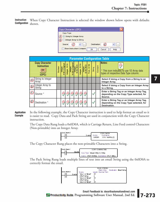
1
2
3
4
5
6
7
8
9
10
11
12
13
14
A
B
C
D
Topic: P201Chapter 7: Instructions
Email Feedback to: [email protected] Software User Manual, 2nd Ed. 7-273
When Copy Character Instruction is selected the window shown below opens with defaultsshown.
In the following example, the Copy Character instruction is used to help format an email so itis easier to read. Copy Data and Pack String are used in conjunction with the Copy Characterinstruction.
The Copy Data Rung loads a 0x0D0A, which is Carriage Return, Line Feed control Characters(Non-printable) into an Integer Array.
The Copy Character Rung places the non-printable Characters into a String.
The Pack String Rung loads multiple lines of text into an email String using the 0x0D0A tocorrectly format the email.
InstructionConfiguration
ApplicationExample
Parameter Configuration TableCopy Character
InstructionNotes:
* This icon indicates to use 1D Array datatypes of respective Data Type column.(CPC)
String to IntegerArray
Select if doing a Copy from a String to an
Integer Array.
Integer Array toString
Select if doing a Copy from an Integer Array
to a String.
Source *Enter a String Tag or an Integer Array Tag,
depending on the Copy Type selected, for
Source.
Destination *Enter a String Tag or an Integer Array Tag,
depending on the Copy Type selected, for
Destination.

1
2
3
4
5
6
7
8
9
10
11
12
13
14
A
B
C
D
Topic: P176Chapter 7: Instructions
Email Feedback to: [email protected] Software User Manual, 2nd Ed.7-274
Extract String (EXTS) InstructionMnemonic (Keyboard Shortcut) = EXTS Icon/Button =
Extract a specified number of characters from a String.
Note: The Output of this instruction does not Zero once Enable is removed.
When Extract String Instruction is selected the window shown below opens with defaultsshown.
Purpose
InstructionParameters
InstructionConfiguration
ParameterParameter
TypeRequirements Description
Enable Ladder Input Must HaveLevel-driven. When Enable is ON, the instruction will
operate every scan. When Enable is OFF, the instruction
is not solved and its Output is not updated.
Source String Tag /String Constant Must Have The Source String to Extract from.
Start Index Numerical Tag/Constant Must Have The Starting location to Extract data from. (1 is the first
location).
Number ofCharacters
Numerical Tag /Constant Must Have Number of Characters that will be Extracted.
Byte SwapOption
SelectableOption Must Have
No Byte Swap: No Bytes will be Swapped.
All Characters: Every two Characters will be Swapped
when placing the data into the Destination Tag Name.
All But Null Characters: Every two Characters will be
Swapped except Null Characters when placing the data
into the Destination Tag Name.
Destination String Tag Must Have Tag where the Extracted data will be placed.

1
2
3
4
5
6
7
8
9
10
11
12
13
14
A
B
C
D
Topic: P176Chapter 7: Instructions
Email Feedback to: [email protected] Software User Manual, 2nd Ed. 7-275
ApplicationExample
RungExample
Parameter Configuration Table
Extract StringInstruction
Notes:
(EXTS)
Source Enter a String Tag or String Constant for
the Source String.
Start Index Enter a Value or Tag for the Start Index.
Number of Characters Enter a Value or Tag for Number of
Characters (Bytes).
Byte Swap Option Select a Byte Swap option.
Destination Enter a Tag for the String Destination.

1
2
3
4
5
6
7
8
9
10
11
12
13
14
A
B
C
D
Topic: P177Chapter 7: Instructions
Email Feedback to: [email protected] Software User Manual, 2nd Ed.7-276
Find String (FNDS) InstructionMnemonic (Keyboard Shortcut) = FNDS Icon/Button =
Search for specified data within a String.
Note: Tag Values are updated immediately as each Ladder Rung is executed, top to bottom. However, TagValues representing physical Outputs are only applied to the physical Output after the END statement of thelast Task to be scanned is reached. Outputs in Remote Base Groups have additional limitations regardingUpdate Intervals.
When Find String Instruction is selected the window shown below opens with defaults shown.
Purpose
InstructionParameters
InstructionConfiguration
ParameterParameter
TypeRequirements Description
Enable Ladder Input
Must Have
Level-driven. When Enable is ON, the instruction will
operate every scan. When Enable is OFF, the instruction
is not solved and its Outputs are not updated.
Source String /String Constant
The String holding the data to be searched. Can be up to
128 Characters.
From Index
Numerical Tag /Constant
The Beginning search position (Index) within the String.
To Index The Ending search position (Index) within the String.
Instance Optional Specifies which Instance of the Search For Value to Find
in the String Tag.
Found Index Numerical TagMust Have
Reports the Beginning Index location of the Found data.
Success Boolean Tag Bit that turns ON when the specified data is found.
String SelectableOption String Must Select String,
Tag Value or HexData.
Selected when the search data is a String.
Tag Value Selected when the search data is in a Tag.
Hex Data 0xSelectable
OptionConstant
Selected when the search data is a Hex value.

1
2
3
4
5
6
7
8
9
10
11
12
13
14
A
B
C
D
Topic: P177Chapter 7: Instructions
Email Feedback to: [email protected] Software User Manual, 2nd Ed. 7-277
In the following example, the String Length instruction is used to determine the actual TextLength contained inside of the Source String Tag. This is used to determine the To and FromIndices used in the Find String instruction. The Source String has embedded data from anoutside device (flow meter, operator interface, etc.) that is variable in Length.
The Find String instruction is used to search data within the Source String. The followingLadder is extracting variable Flow Data (Flow1=987) from a String by locating the text"Flow1=".
This rung determines the String Length of 9.
The Find String instruction is used to search specified data within the String by using From andTo Indices. The String Length is used in the To Index (last element in the String to search). Inthis example the String is being searched From 1 To 9. If the flow increases to over 999, thenthe String Length will change to 10.
ApplicationExample
Parameter Configuration TableFind StringInstruction
Notes:
(FNDS)
Source Enter a String Tag with a length of up to 128
Characters, default is 15 or a String Constant.
From Index Enter a value within the range of the String
Tag length for the Starting Index.
To IndexEnter a value greater than the From Index
and within the range of the String Tag
length for the Ending Index.
Instance Enter a Value or Tag to report the number of
instances where the searched data was found.
Found Index Enter a Tag to store the number of the
Beginning Index of the found data.
Success Enter a Boolean Tag to indicate the search
was Successful.
String Select to match a String and enter data to
match.
Tag Value Select to match a Tag Value and enter the Tag.
Hex Data 0x Select to match Hex Data and enter for 1 or
2 Bytes.

Math is performed to determine an offset by adding the Found Index (1) to the text Flow1= (6Characters). This will be used to separate the data from the text.
Math is now performed to determine the Flow Data Length. A value of one (1) must be addedto the String Length (Base 1). Subtracting the Found Index Offset shows that the Flow DataLength is 3.
With the gathered information the Flow Data can be extracted using the Found Index Offsetand Flow Data Length in the Extract String instruction.
1
2
3
4
5
6
7
8
9
10
11
12
13
14
A
B
C
D
Topic: P177Chapter 7: Instructions
Email Feedback to: [email protected] Software User Manual, 2nd Ed.7-278

1
2
3
4
5
6
7
8
9
10
11
12
13
14
A
B
C
D
Topic: P178Chapter 7: Instructions
Pack String (PKS) InstructionMnemonic (Keyboard Shortcut) = PKS Icon/Button =
Combine data from two or more Numeric, Boolean, or String Tags into one common StringTag.
Note: Data is Packed into the Destination Tag in the order the Source Tags are assigned during configuration.If the first Source Tag in the table has a Length of 4, then the data is placed in the first four characters of theDestination Tag.
Note: Tag Values are updated immediately as each Ladder Rung is executed, top to bottom. However, TagValues representing physical Outputs are only applied to the physical Output after the END statement of thelast Task to be scanned is reached. Outputs in Remote Base Groups have additional limitations regardingUpdate Intervals.
Purpose
InstructionParameters Parameter Parameter
Type Requirements Description
Enable Ladder Input Must HaveLevel-driven. When Enable is ON, the instruction will
operate every scan. When Enable is OFF, the instruction
is not solved and its Output is not updated.
SourceBoolean /
Numerical Tag /String
Must Have at leastone The Tag(s) where the data is coming from.
Length Numerical Tag /Constant Must Have
The fixed number of Characters the Source Tag value will
occupy in the Destination Tag.
Note: Characters are copied from the Source Tag starting
with the most significant digit. The Characters are
copied into the Destination Tag left-justified. If the
Length is greater than the number of significant digits of
the Source Tag, spaces will fill the remaining Characters
of the Destination Tag. Characters include decimals and
sign.
Examples:
The Source Tag data type is Integer, 16 Bit Unsigned, with
a value of 321. If Length were set to 5, 321_ _ would be
copied into the Destination String Tag. If Length were set
to 2, 32 would be copied into the Destination String Tag.
Digits AfterDecimal Constant Optional
Maximum number of digits allowed after the decimal
point. This field only applies to Float, 32 bit Source Tags.
Note: If the Source value must be truncated to comply
with this field, rounding will be applied.
Examples:
The Source Tag is Float, 32 Bit with a value of -2.2813.
If the Length were set to 5 and Digits After Decimal were
set to 1, -2.3_ would be copied to the Destination String
Tag. If just the Source Tag value changed to 121349.12,
12134 would be copied to the Destination String Tag.
Destination String Must Have
String Tag where the combined Characters are placed.
Note: The Destination Tag "# Characters" attribute in the
Tag Database should be set to at least the combined
Length values from the Pack String instruction.
Characters are left-justified and spaces will fill the unused
Characters in the Destination Tag. Characters packed
beyond the right boundary of the Destination Tag are lost.
Align Text To Radio Button Selectable Option
Allows selection of Left or Right justification. If Right align
is selected, the Add Leading Zeros for Integers option can
be selected.
Note: This is applied to all integer tags assigned to the
instruction.
7-279Email Feedback to: [email protected]
Programming Software User Manual, 2nd Ed.

When Pack String Instruction is selected the window shown below opens with defaults shown.
In this example, a TypeK Thermocouple reads amillivolt signal of theTemperature in an oven.The PAC converts thesignal to Degrees F andPacks it into a String Tagwith text to be displayedon a marquee.
1
2
3
4
5
6
7
8
9
10
11
12
13
14
A
B
C
D
Topic: P178Chapter 7: Instructions
Email Feedback to: [email protected] Software User Manual, 2nd Ed.7-280
InstructionConfiguration
RungExample
ApplicationExample
Parameter Configuration TablePack StringInstruction
Notes:
(PKS)
Source Enter a Value or Tag for Source. String
Constants must be in quotation marks.
Length Enter a Tag or Value for Length.
Digits After Decimal Enter the Number of Digits if needed.
Default is 0.
Destination Enter a String Tag to store Combined Data.
Align Text To Select for Left or Right Alignment.

1
2
3
4
5
6
7
8
9
10
11
12
13
14
A
B
C
D
Topic: P179Chapter 7: Instructions
Email Feedback to: [email protected] Software User Manual, 2nd Ed. 7-281
UnPack String (UPKS) InstructionMnemonic (Keyboard Shortcut) = UPKS Icon/Button =
Extract data from a String and place into one or more Numeric, Boolean, or String Tags.
Note: Data is Unpacked into Destination Tags in the order they are assigned during configuration. If the firstDestination Tag in the table has a length of 4, then the first four bytes of the Source Tag are placed there.
Note: Tag Values are updated immediately as each Ladder Rung is executed, top to bottom. However, TagValues representing physical Outputs are only applied to the physical Output after the END statement of thelast Task to be scanned is reached. Outputs in Remote Base Groups have additional limitations regardingUpdate Intervals.
When Unpack String Instruction is selected the window shown below opens with defaults shown.
Purpose
InstructionParameters
InstructionConfiguration
Parameter ParameterType Requirements Description
Enable Ladder Input
Must Have
Level-driven. When Enable is ON, the instruction willoperate every scan. When Enable is OFF, the instructionis not solved and its Output is not updated.
Source String The String Tag where the data is coming from. Lengthcannot exceed 128 Bytes.
Length ConstantThe Length of each Destination Tag. The total of allDestination Tags cannot exceed the number of bytes inthe Source Tag.
DestinationBoolean Tag /
Numerical Tag /String
The Tag(s) where the Unpacked data is placed.
Parameter Configuration TableUnPack String
InstructionNotes:
(UPKS)
Source Enter a String Tag for Source.
LengthEnter a Length (in Bytes)for each
Destination Tag. Total Length cannot
exceed the Length of the Source Data.
Destination Enter a Destination Tag for each group of Data.

In this example, the data code on a product package is being scanned into the PAC andUnpacked into a Serial Number Tag and a Manufacturing Date Tag.
1
2
3
4
5
6
7
8
9
10
11
12
13
14
A
B
C
D
Topic: P179Chapter 7: Instructions
Email Feedback to: [email protected] Software User Manual, 2nd Ed.7-282
ApplicationExample
RungExample

1
2
3
4
5
6
7
8
9
10
11
12
13
14
A
B
C
D
Topic: P180Chapter 7: Instructions
Email Feedback to: [email protected] Software User Manual, 2nd Ed. 7-283
String Length (SLEN) InstructionMnemonic (Keyboard Shortcut) = SLEN Icon/Button =
To determine the Number of Characters in a String.
Note: Tag Values are updated immediately as each Ladder Rung is executed, top to bottom. However, TagValues representing physical Outputs are only applied to the physical Output after the END statement of thelast Task to be scanned is reached. Outputs in Remote Base Groups have additional limitations regardingUpdate Intervals.
When String Length Instruction is selected the window shown below opens with defaultsshown.
Purpose
InstructionConfiguration
Parameter Configuration Table
String LengthInstruction
Notes:
(SLEN)
Input Enter a String Length up to 128
Characters.
Length Enter a Tag to hold determined Length.
InstructionParameters Parameter
ParameterType
Requirements Description
Enable Ladder Input
Must Have
Level-driven. When Enable is ON, the instruction will
operate every scan. When Enable is OFF, the instruction
is not solved and its Output is not updated.
Input String The String to be examined. Up to 128 Characters.
Length Numerical TagTag that holds the determined Length (Number of
Characters) of the Input String. Spaces are counted as
Characters.

1
2
3
4
5
6
7
8
9
10
11
12
13
14
A
B
C
D
Topic: P180Chapter 7: Instructions
Email Feedback to: [email protected] Software User Manual, 2nd Ed.7-284
In the following example, the String Length instruction is used to determine the actual textLength contained inside of a String Tag. The String has embedded data from an outside device(flow meter, operator interface, etc.) that is variable in Length.
The String Length instruction is used in conjunction with the Find String instruction tocalculate the size of the data value so that it can be extracted and used for whatever purpose isneeded. The following ladder is extracting variable Flow Data (Flow1=987) from a String bylocating the text Flow1=. This Rung determines the String Length of 9.
The Find String instruction is used to search specified data within the String by using From andTo Indices. The String Length is used in the To Index (last element in the String to search). Inthis example the String is being searched From 1 To 9. If the Flow increases to over 999, thenthe String Length will change to 10.
Math is performed to determine an offset by adding the Found Index (1) to the text Flow1= (6characters). This will be used to separate the data from the text.
Math is now performed to determine the Flow Data Length. A value of one (1) must be addedto the String Length (Base 1). Subtracting the Found Index Offset shows that the Flow DataLength is 3.
With the gathered information, the Flow Data can be extracted using the Found Index Offsetand Flow Data Length in the Extract String instruction.
ApplicationExample
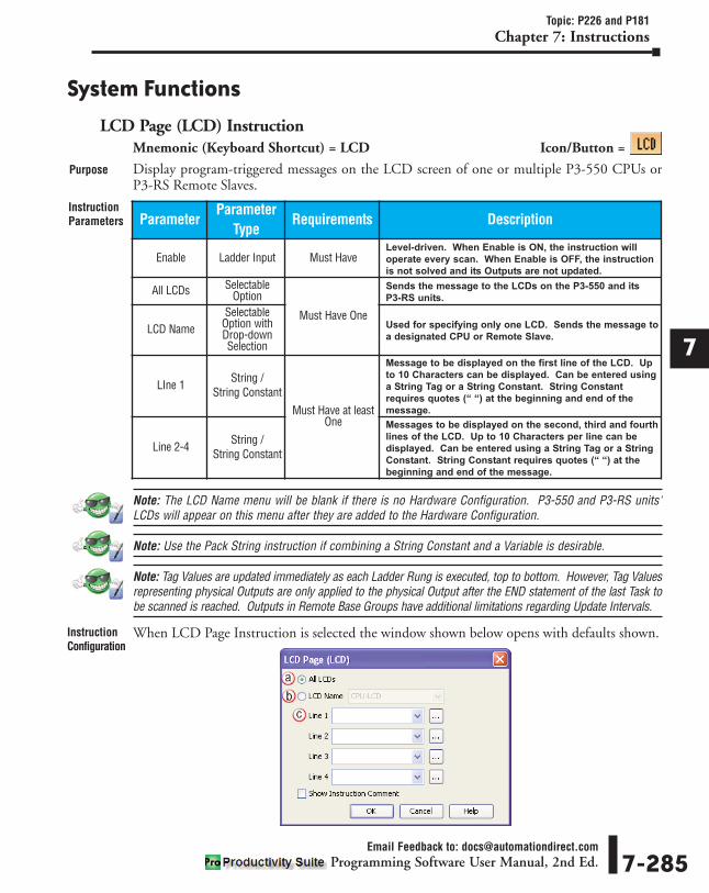
1
2
3
4
5
6
7
8
9
10
11
12
13
14
A
B
C
D
Topic: P226 and P181Chapter 7: Instructions
Email Feedback to: [email protected] Software User Manual, 2nd Ed. 7-285
System Functions
LCD Page (LCD) InstructionMnemonic (Keyboard Shortcut) = LCD Icon/Button =
Display program-triggered messages on the LCD screen of one or multiple P3-550 CPUs or P3-RS Remote Slaves.
Note: The LCD Name menu will be blank if there is no Hardware Configuration. P3-550 and P3-RS units'LCDs will appear on this menu after they are added to the Hardware Configuration.
Note: Use the Pack String instruction if combining a String Constant and a Variable is desirable.
Note: Tag Values are updated immediately as each Ladder Rung is executed, top to bottom. However, Tag Valuesrepresenting physical Outputs are only applied to the physical Output after the END statement of the last Task tobe scanned is reached. Outputs in Remote Base Groups have additional limitations regarding Update Intervals.
When LCD Page Instruction is selected the window shown below opens with defaults shown.
Purpose
InstructionParameters Parameter
ParameterType
Requirements Description
Enable Ladder Input Must HaveLevel-driven. When Enable is ON, the instruction will
operate every scan. When Enable is OFF, the instruction
is not solved and its Outputs are not updated.
All LCDs SelectableOption
Must Have One
Sends the message to the LCDs on the P3-550 and its
P3-RS units.
LCD NameSelectable
Option withDrop-downSelection
Used for specifying only one LCD. Sends the message to
a designated CPU or Remote Slave.
LIne 1 String /String Constant
Must Have at leastOne
Message to be displayed on the first line of the LCD. Up
to 10 Characters can be displayed. Can be entered using
a String Tag or a String Constant. String Constant
requires quotes (“ “) at the beginning and end of the
message.
Line 2-4 String /String Constant
Messages to be displayed on the second, third and fourth
lines of the LCD. Up to 10 Characters per line can be
displayed. Can be entered using a String Tag or a String
Constant. String Constant requires quotes (“ “) at the
beginning and end of the message.
InstructionConfiguration

In the following example, an LCD Page is set up for displaying system warnings. The first lineof the LCD (Line 1) is configured using a String Constant. The String Constant is static textand must be entered using quotes at the beginning and end. The other lines are String Tags andcan be populated with data by using other instructions within the program.
In this instance, the Display Warning Bit is Enabled and prompts the LCD Page to displayWARNING! on Line 1 and the Data/Text found in the Line 2 – Line 4 Tags.
1
2
3
4
5
6
7
8
9
10
11
12
13
14
A
B
C
D
Topic: P181Chapter 7: Instructions
Email Feedback to: [email protected] Software User Manual, 2nd Ed.7-286
ApplicationExample
RungExample
Parameter Configuration Table
LCD PageInstruction
Notes:
(LCD)
All LCDs Select if using All LCDs.
LCD Name Select a specified LCD.
Line 1-4 Enter a Tag for each Message.

1
2
3
4
5
6
7
8
9
10
11
12
13
14
A
B
C
D
Topic: P182Chapter 7: Instructions
Email Feedback to: [email protected] Software User Manual, 2nd Ed. 7-287
Set PAC Time (RTC) InstructionMnemonic (Keyboard Shortcut) = RTC Icon/Button =
Revise the Time and Date within the PAC.
Note: When using the Set New Date/Time feature, all fields must have a value entered. If a new value isnot entered, the current value in the PAC will be overwritten by a Zero.
Tip: If only wanting to change one or a few fields, (i.e., Month and Day) and keep the rest of the Date andTime as they are, select the PAC System Read Only Tags for Year (Clock Year), Hour (Clock Hours), Minute(Clock Minutes), and Second (Clock Seconds). Then when the instruction is Enabled, the current valueswill be written back to the PAC and only the Month and Day will be revised.
Purpose
InstructionParameters Parameter
ParameterType
Requirements Description
Enable Ladder Input Must HaveEdge-driven. When Enable is ON, the instruction will
operate for one scan. When Enable is OFF, the
instruction is not solved and its Outputs are not updated.
Increment 1Hour
SelectableOption Must Select
Increment 1 Hour,Decrement 1 Hour
or Set NewDate/Time.
Increases the Time by One Hour.
Decrement 1Hour
SelectableOption Decreases the Time by One Hour.
Set NewDate/Time
SelectableOption
Allows the revision of the Date and Time in the PAC.
Must enter new values for each field.
Year Numerical Tag /Constant
Must Have whenSet New Date/Time
selected.
Enabled when Set New Date/Time is selected. The Year
can be changed by entering a Constant Value or a
Numeric Tag. The Numeric Tag can be a user defined Tag
or the System Tag (Clock Year Set). See Note below.
Month Numerical Tag /Constant
Enabled when Set New Date/Time is selected. The Month
can be changed by entering a Constant Value or a
Numeric Tag. The Numeric Tag can be a user defined Tag
or the System Tag (Clock Month Set). See Note below.
Day Numerical Tag /Constant
Enabled when Set New Date/Time is selected. The Day
can be changed by entering a Constant Value or a
Numeric Tag. The Numeric Tag can be a user defined Tag
or the System Tag (Clock Day Set). See Note below.
Hour Numerical Tag /Constant
Enabled when Set New Date/Time is selected. The Hour
can be changed by entering a Constant Value or a
Numeric Tag. The Numeric Tag can be a user defined Tag
or the System Tag (Clock Hours Set). See Note below.
Minute Numerical Tag /Constant
Enabled when Set New Date/Time is selected. The
Minutes can be changed by entering a Constant Value or
a Numeric Tag. The Numeric tag can be a user defined
Tag or the System Tag (Clock Minutes Set). See Note
below.
Second Numerical Tag /Constant
Enabled when Set New Date/Time is selected. The
Seconds can be changed by entering a Constant Value or
a Numeric Tag. The Numeric Tag can be a user defined
Tag or the System Tag (Clock Seconds Set). See Note
below.

1
2
3
4
5
6
7
8
9
10
11
12
13
14
A
B
C
D
Topic: P182Chapter 7: Instructions
Email Feedback to: [email protected] Software User Manual, 2nd Ed.7-288
When LCD Page Instruction is selected the window shown below opens with defaults shown.InstructionConfiguration
Parameter Configuration TableSet PAC Time
Instruction Notes:
(RTC)
Increment 1 Hour Select to Increment Clock by One Hour.
Decrement 1 Hour Select to Decrement Clock by One Hour.
Set New Date/Time Select to allow Date/Time change.
Year Enter a Value or Tag for Year. See note on
previous page.
Month Enter a Value or Tag for Month. See note
on previous page.
Day Enter a Value or Tag for Day. See note on
previous page.
Hour Enter a Value or Tag for Hour. See note on
previous page.
Minute Enter a Value or Tag for Minute. See note
on previous page.
Second Enter a Value or Tag for Second. See note
on previous page.

In the following example, an application requires that the Day be changeable from a remotelocation using an HMI. The program is set up with a User Defined Tag called Remotely SetDay.
The rest of the Tags are the System Read Only Tags that contain the Current Date and Time.By using the System Read Only Tags, the Current Date and Time fields not being changed willbe written back into the System Set Tags. The User Defined Tag will be written into thecorresponding System Set Tag.
1
2
3
4
5
6
7
8
9
10
11
12
13
14
A
B
C
D
Topic: P182Chapter 7: Instructions
Email Feedback to: [email protected] Software User Manual, 2nd Ed. 7-289
ApplicationExample
RungExample

Notes:
1
2
3
4
5
6
7
8
9
10
11
12
13
14
A
B
C
D
Chapter 7: Instructions
Email Feedback to: [email protected] Software User Manual, 2nd Ed.7-290

In This Chapter...Building a Ladder Logic Program . . . . . . . . . . . . . . . . . . . . . . . . . . . . . . . . . . . . . . .8-4
Instruction Insertion . . . . . . . . . . . . . . . . . . . . . . . . . . . . . . . . . . . . . . . . . . . . . . . . .8-4Instruction Configuration . . . . . . . . . . . . . . . . . . . . . . . . . . . . . . . . . . . . . . . . . . . . .8-5Ladder Scan Execution . . . . . . . . . . . . . . . . . . . . . . . . . . . . . . . . . . . . . . . . . . . . . . .8-6Programming Fundamentals . . . . . . . . . . . . . . . . . . . . . . . . . . . . . . . . . . . . . . . . . .8-6
Data Types . . . . . . . . . . . . . . . . . . . . . . . . . . . . . . . . . . . . . . . . . . . . . . . . . . . . . . . . .8-7Data Type Definitions . . . . . . . . . . . . . . . . . . . . . . . . . . . . . . . . . . . . . . . . . . . . . . . .8-7Assigning a Data Type . . . . . . . . . . . . . . . . . . . . . . . . . . . . . . . . . . . . . . . . . . . . . . .8-8
Forcing Tags . . . . . . . . . . . . . . . . . . . . . . . . . . . . . . . . . . . . . . . . . . . . . . . . . . . . . . . .8-9Purpose . . . . . . . . . . . . . . . . . . . . . . . . . . . . . . . . . . . . . . . . . . . . . . . . . . . . . . . . . .8-9Using Forcing Tags . . . . . . . . . . . . . . . . . . . . . . . . . . . . . . . . . . . . . . . . . . . . . . . . . .8-9Initial Forcing . . . . . . . . . . . . . . . . . . . . . . . . . . . . . . . . . . . . . . . . . . . . . . . . . . . . . .8-9Temporary Forcing . . . . . . . . . . . . . . . . . . . . . . . . . . . . . . . . . . . . . . . . . . . . . . . . .8-10Events and Their Effects on Forcing . . . . . . . . . . . . . . . . . . . . . . . . . . . . . . . . . . . .8-11Force Indicator . . . . . . . . . . . . . . . . . . . . . . . . . . . . . . . . . . . . . . . . . . . . . . . . . . . .8-11Identifying Forced Values . . . . . . . . . . . . . . . . . . . . . . . . . . . . . . . . . . . . . . . . . . . .8-12Force Value Timing Chart . . . . . . . . . . . . . . . . . . . . . . . . . . . . . . . . . . . . . . . . . . . .8-12
Hot Swap Information . . . . . . . . . . . . . . . . . . . . . . . . . . . . . . . . . . . . . . . . . . . . . . .8-13Hardware Configuration Settings . . . . . . . . . . . . . . . . . . . . . . . . . . . . . . . . . . . . . .8-13Enable All Hot Swap . . . . . . . . . . . . . . . . . . . . . . . . . . . . . . . . . . . . . . . . . . . . . . . .8-13I/O Modules . . . . . . . . . . . . . . . . . . . . . . . . . . . . . . . . . . . . . . . . . . . . . . . . . . . . . .8-14P3-RS/RX Modules . . . . . . . . . . . . . . . . . . . . . . . . . . . . . . . . . . . . . . . . . . . . . . . . .8-14System Tags Associated with Hot Swappable I/O . . . . . . . . . . . . . . . . . . . . . . . . . .8-15
Logic Scan Behavior . . . . . . . . . . . . . . . . . . . . . . . . . . . . . . . . . . . . . . . . . . . . . . . .8-15If There is Just One Output . . . . . . . . . . . . . . . . . . . . . . . . . . . . . . . . . . . . . . . . . . .8-15If There are Outputs on Subrungs . . . . . . . . . . . . . . . . . . . . . . . . . . . . . . . . . . . . .8-15Example #1 . . . . . . . . . . . . . . . . . . . . . . . . . . . . . . . . . . . . . . . . . . . . . . . . . . . . . .8-16Example #2 . . . . . . . . . . . . . . . . . . . . . . . . . . . . . . . . . . . . . . . . . . . . . . . . . . . . . .8-16
P3-550 CPU Module Configuration . . . . . . . . . . . . . . . . . . . . . . . . . . . . . . . . . . . . .8-17Options Tab Configuration . . . . . . . . . . . . . . . . . . . . . . . . . . . . . . . . . . . . . . . . . . .8-17Ethernet Ports Configuration . . . . . . . . . . . . . . . . . . . . . . . . . . . . . . . . . . . . . . . . .8-20Serial Ports Configuration . . . . . . . . . . . . . . . . . . . . . . . . . . . . . . . . . . . . . . . . . . . .8-23
P3-530 CPU Module Configuration . . . . . . . . . . . . . . . . . . . . . . . . . . . . . . . . . . . . .8-26
888REFERENCECHAPTERCHAPTERCHAPTER

Options Tab Configuration . . . . . . . . . . . . . . . . . . . . . . . . . . . . . . . . . . . . . . . . . . .8-27Ethernet Ports Configuration . . . . . . . . . . . . . . . . . . . . . . . . . . . . . . . . . . . . . . . . .8-28Serial Ports Configuration . . . . . . . . . . . . . . . . . . . . . . . . . . . . . . . . . . . . . . . . . . . .8-30
I/O Module Configuration . . . . . . . . . . . . . . . . . . . . . . . . . . . . . . . . . . . . . . . . . . .8-34Configuring Hardware Components . . . . . . . . . . . . . . . . . . . . . . . . . . . . . . . . . . . .8-34Configuring Discrete I/O Modules . . . . . . . . . . . . . . . . . . . . . . . . . . . . . . . . . . . . .8-34Configuring High Speed I/O Modules . . . . . . . . . . . . . . . . . . . . . . . . . . . . . . . . . .8-36Analog I/O Modules . . . . . . . . . . . . . . . . . . . . . . . . . . . . . . . . . . . . . . . . . . . . . . . .8-55Default Tag Names . . . . . . . . . . . . . . . . . . . . . . . . . . . . . . . . . . . . . . . . . . . . . . . . .8-56User tag Name Rules . . . . . . . . . . . . . . . . . . . . . . . . . . . . . . . . . . . . . . . . . . . . . . .8-56
High-Speed Configuration Options . . . . . . . . . . . . . . . . . . . . . . . . . . . . . . . . . . . .8-57Use Jerk . . . . . . . . . . . . . . . . . . . . . . . . . . . . . . . . . . . . . . . . . . . . . . . . . . . . . . . . .8-57Channel Scaling . . . . . . . . . . . . . . . . . . . . . . . . . . . . . . . . . . . . . . . . . . . . . . . . . . .8-59Using Implied Decimal Scaling . . . . . . . . . . . . . . . . . . . . . . . . . . . . . . . . . . . . . . . .8-60Rotary Encoder (HSI) . . . . . . . . . . . . . . . . . . . . . . . . . . . . . . . . . . . . . . . . . . . . . . .8-62Rotary Mode (HSO) . . . . . . . . . . . . . . . . . . . . . . . . . . . . . . . . . . . . . . . . . . . . . . . .8-62
Understanding Maximum Position Cycle and Minimum Position Accuracy . . . . .8-63
P3-RS Module Configuration . . . . . . . . . . . . . . . . . . . . . . . . . . . . . . . . . . . . . . . . . .8-65Configuring Hardware Components . . . . . . . . . . . . . . . . . . . . . . . . . . . . . . . . . . . .8-65Options Tab Configuration . . . . . . . . . . . . . . . . . . . . . . . . . . . . . . . . . . . . . . . . . . .8-66Serial Ports Configuration . . . . . . . . . . . . . . . . . . . . . . . . . . . . . . . . . . . . . . . . . . . .8-69
P3-RX Module Configuration . . . . . . . . . . . . . . . . . . . . . . . . . . . . . . . . . . . . . . . . .8-72Configuring Hardware Components . . . . . . . . . . . . . . . . . . . . . . . . . . . . . . . . . . . .8-72Options Tab Configuration . . . . . . . . . . . . . . . . . . . . . . . . . . . . . . . . . . . . . . . . . . .8-73Serial Ports Configuration . . . . . . . . . . . . . . . . . . . . . . . . . . . . . . . . . . . . . . . . . . . .8-75
Run Time vs. Stop Mode Transfer . . . . . . . . . . . . . . . . . . . . . . . . . . . . . . . . . . . . . .8-78Run Time Transfers . . . . . . . . . . . . . . . . . . . . . . . . . . . . . . . . . . . . . . . . . . . . . . . . .8-78Stop Mode Transfers . . . . . . . . . . . . . . . . . . . . . . . . . . . . . . . . . . . . . . . . . . . . . . .8-79Ensuring Data is Current . . . . . . . . . . . . . . . . . . . . . . . . . . . . . . . . . . . . . . . . . . . .8-79
Scan Interval and Use of the Maximum Scan Interval Tag . . . . . . . . . . . . . . . . . .8-80Scan Interval . . . . . . . . . . . . . . . . . . . . . . . . . . . . . . . . . . . . . . . . . . . . . . . . . . . . .8-80Maximum Scan Interval . . . . . . . . . . . . . . . . . . . . . . . . . . . . . . . . . . . . . . . . . . . . .8-80Scan Interval Execution Order . . . . . . . . . . . . . . . . . . . . . . . . . . . . . . . . . . . . . . . .8-80CPU Tasks Examples . . . . . . . . . . . . . . . . . . . . . . . . . . . . . . . . . . . . . . . . . . . . . . . .8-81Using the Maximum Scan Interval Setting . . . . . . . . . . . . . . . . . . . . . . . . . . . . . . .8-81I/O Update Information . . . . . . . . . . . . . . . . . . . . . . . . . . . . . . . . . . . . . . . . . . . . .8-82Write Remote Base Group Outputs (P3-550 only) . . . . . . . . . . . . . . . . . . . . . . . . .8-82
Table of Contents
Email Feedback to: [email protected] Software User Manual, 2nd Ed.ii

Read Remote Base Group Inputs (P3-550 only) . . . . . . . . . . . . . . . . . . . . . . . . . . .8-82Remote Base Group Update Order . . . . . . . . . . . . . . . . . . . . . . . . . . . . . . . . . . . . .8-83
Tag Cross Reference . . . . . . . . . . . . . . . . . . . . . . . . . . . . . . . . . . . . . . . . . . . . . . . .8-84Using Data View . . . . . . . . . . . . . . . . . . . . . . . . . . . . . . . . . . . . . . . . . . . . . . . . . . .8-84
Tag Picker . . . . . . . . . . . . . . . . . . . . . . . . . . . . . . . . . . . . . . . . . . . . . . . . . . . . . . . . .8-85
What are Arrays? . . . . . . . . . . . . . . . . . . . . . . . . . . . . . . . . . . . . . . . . . . . . . . . . . . .8-862D Array Example . . . . . . . . . . . . . . . . . . . . . . . . . . . . . . . . . . . . . . . . . . . . . . . . .8-861D Array Example . . . . . . . . . . . . . . . . . . . . . . . . . . . . . . . . . . . . . . . . . . . . . . . . .8-86Application Example . . . . . . . . . . . . . . . . . . . . . . . . . . . . . . . . . . . . . . . . . . . . . . . .8-87
What are Rising Edge and Falling Edge Contacts . . . . . . . . . . . . . . . . . . . . . . . . .8-88
Normally Open Rising Edge Contact . . . . . . . . . . . . . . . . . . . . . . . . . . . . . . . . . . .8-88Normally Open Falling Edge Contact . . . . . . . . . . . . . . . . . . . . . . . . . . . . . . . . . . .8-88
What is Chatter or Bounce? . . . . . . . . . . . . . . . . . . . . . . . . . . . . . . . . . . . . . . . . . .8-88
Define Tags . . . . . . . . . . . . . . . . . . . . . . . . . . . . . . . . . . . . . . . . . . . . . . . . . . . . . . .8-89
Chart Properties . . . . . . . . . . . . . . . . . . . . . . . . . . . . . . . . . . . . . . . . . . . . . . . . . . .8-90
What is PID? . . . . . . . . . . . . . . . . . . . . . . . . . . . . . . . . . . . . . . . . . . . . . . . . . . . . . . .8-95PID Algorithm . . . . . . . . . . . . . . . . . . . . . . . . . . . . . . . . . . . . . . . . . . . . . . . . . . . .8-96PID Algorithm Example . . . . . . . . . . . . . . . . . . . . . . . . . . . . . . . . . . . . . . . . . . . . .8-97Cascade PID Operation . . . . . . . . . . . . . . . . . . . . . . . . . . . . . . . . . . . . . . . . . . . . .8-98Time Proportioning Control . . . . . . . . . . . . . . . . . . . . . . . . . . . . . . . . . . . . . . . . .8-100
Web Server . . . . . . . . . . . . . . . . . . . . . . . . . . . . . . . . . . . . . . . . . . . . . . . . . . . . . .8-102
Copy Current Retentive Tag Values . . . . . . . . . . . . . . . . . . . . . . . . . . . . . . . . . . .8-104Validating Retentive Tags . . . . . . . . . . . . . . . . . . . . . . . . . . . . . . . . . . . . . . . . . . .8-104
Tag Initialization . . . . . . . . . . . . . . . . . . . . . . . . . . . . . . . . . . . . . . . . . . . . . . . . . .8-106
System Tags . . . . . . . . . . . . . . . . . . . . . . . . . . . . . . . . . . . . . . . . . . . . . . . . . . . . . .8-107
System Bit - Read only Tags (SBR) . . . . . . . . . . . . . . . . . . . . . . . . . . . . . . . . . . . .8-110
System Bit - Read/Write Tags (SBRW) . . . . . . . . . . . . . . . . . . . . . . . . . . . . . . . . .8-111
System Word - Read only Tags (SWR) . . . . . . . . . . . . . . . . . . . . . . . . . . . . . . . . .8-112
System Word - Read/Write Tags (SWRW) . . . . . . . . . . . . . . . . . . . . . . . . . . . . . .8-113
System Strings Tags (SSTR) . . . . . . . . . . . . . . . . . . . . . . . . . . . . . . . . . . . . . . . . . .8-114
Help File/Software Manual Topic Cross Reference Tables . . . . . . . . . . . . . . . . . . . . . . .8-115Help File/Software Manual Topic Cross Reference Table - Sorted By Topic Number . . . .8-115Help File/Software Manual Topic Cross Reference Table - Sorted By Name . . . . . . . . . .8-121
iiiEmail Feedback to: [email protected]
Programming Software User Manual, 2nd Ed.
Table of Contents
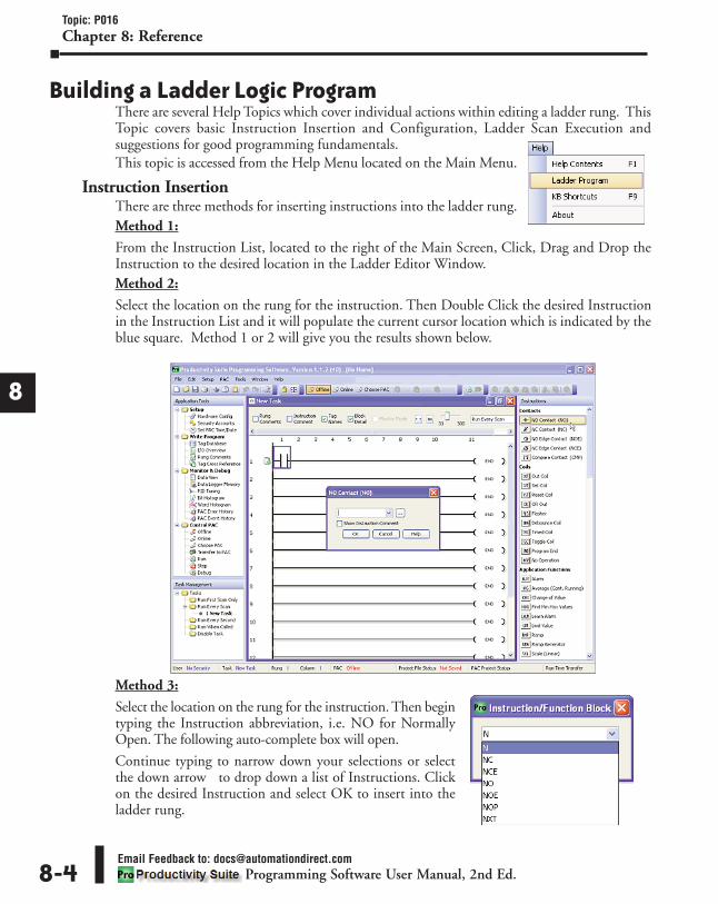
1
2
3
4
5
6
7
8
9
10
11
12
13
14
A
B
C
D
Topic: P016Chapter 8: Reference
Email Feedback to: [email protected] Software User Manual, 2nd Ed. 8-4
Building a Ladder Logic ProgramThere are several Help Topics which cover individual actions within editing a ladder rung. ThisTopic covers basic Instruction Insertion and Configuration, Ladder Scan Execution andsuggestions for good programming fundamentals.This topic is accessed from the Help Menu located on the Main Menu.
Instruction InsertionThere are three methods for inserting instructions into the ladder rung.Method 1:
From the Instruction List, located to the right of the Main Screen, Click, Drag and Drop theInstruction to the desired location in the Ladder Editor Window.Method 2:
Select the location on the rung for the instruction. Then Double Click the desired Instructionin the Instruction List and it will populate the current cursor location which is indicated by theblue square. Method 1 or 2 will give you the results shown below.
Method 3:
Select the location on the rung for the instruction. Then begintyping the Instruction abbreviation, i.e. NO for NormallyOpen. The following auto-complete box will open.
Continue typing to narrow down your selections or selectthe down arrow to drop down a list of Instructions. Clickon the desired Instruction and select OK to insert into theladder rung.

1
2
3
4
5
6
7
8
9
10
11
12
13
14
A
B
C
D
Topic: P016Chapter 8: Reference
Email Feedback to: [email protected] Software User Manual, 2nd Ed. 8-5
Instruction ConfigurationOnce the Instruction has been selected, the configuration window appears. Fill in the necessarydata fields with Constant Values or Tags as required.
To select a Tag from the Tag Database, click on the browse icon . This opens the Tag Picker,which gives you a quick and easy way of viewing and selecting a tag.

1
2
3
4
5
6
7
8
9
10
11
12
13
14
A
B
C
D
Topic: P016Chapter 8: Reference
Email Feedback to: [email protected] Software User Manual, 2nd Ed. 8-6
Ladder Scan ExecutionAs a principal rule, ladder execution is always “Left to Right then Top to Bottom”. As shown bythe diagram below, the ladder execution begins at the top of the program (Rung #1) and scans allconditional contacts from left to right, updates the output, then proceeds to the next rung.
For more details on ladder logic scan execution, see the Logic Scan Behavior topic.
Programming FundamentalsEach and every programmer has their own programming methods. However, there are a fewfundamental recommendations you can follow that may save you time.
• Review your electrical schematics and make a list of all physical Inputs & Outputs.
• For a Tag-based controller, you may find it more productive to create your Tag Database prior tobeginning your ladder logic program.
• Group registers with practical naming conventions. i.e. Reject Cylinder Extend Limit Switch orPreHeat Oven Zone1 Temp.
• Create an Outline or Flow Chart for your process. Putting your machine control or process onpaper in a structured form will help you design your control logic.
• Place setup or initialization code at the very beginning of your program or place it in the “RunFirst Scan Only” Task.
• Group sections of ladder code into separate tasks to organize your project, improve performanceand simplify troubleshooting.
• Learn your instruction set. There are many tasks that can be accomplished manually in ladder logicthat may be made easier by specific Function Blocks designed for that task.

1
2
3
4
5
6
7
8
9
10
11
12
13
14
A
B
C
D
Topic: P189Chapter 8: Reference
Email Feedback to: [email protected] Software User Manual, 2nd Ed. 8-7
Data TypesThere are multiple Data Types available for configuring parameters and tags within a project.
The Data Types are:
* With the exception of a constant data type, each of the above data types are also available as Array datatypes, one dimensional (1D) Arrays & two dimensional (2D) Arrays.
Data Type Definitions
• Boolean: Also referred to as logical data types, having one of two values, True or False. Thecontroller represents True as a logical “1” and False as a logical “0”. Boolean data types are usedfor all discrete I/O point tag names as well as internal tag names used for logic control.
• Integer, 8 Bit Unsigned: Unsigned whole or natural numbers ranging from 0 to +255. Integer, 8bit Unsigned data type is used for numerical tags where only positive variables will be usedwithin a byte boundary.
• Integer, 16 Bit: Signed Integers ranging from -32768 to +32767. Integer, 16 bit data type is usedfor numerical tags where variables have the potential for negative or positive values.
• Integer, 16 Bit Unsigned: Unsigned whole or natural numbers ranging from 0 to +65535. Integer,16 bit Unsigned data type is used for numerical tags where only positive variables will be used.
• Integer, 16 Bit BCD: Unsigned Binary Coded Decimal value ranging from 0 to +9999. Integer,16 bit BCD data type is used for numerical tags where variables can only represent in the rangefrom 0-9 within the half-byte boundary.
• Integer, 32 Bit: Signed Integers ranging from -2,147,483,648 to +2,147,483,647. Integer, 32 Bitdata type is the default for most numerical tags where variables have the potential for negative orpositive values.
• Integer, 32 Bit BCD: Unsigned Binary Coded Decimal value ranging from 0 to +99999999.Integer, 32 bit BCD data type is used for numerical tags where variables can only represent inthe range from 0-9 within the half-byte boundary.
• Float, 32 Bit: IEEE formatted floating point number ranging from -3.39x1038 to +3.39x1038.Float data types are used for any numerical tag where greater precision* is required, values above 32bit integer are needed, or where variables being read into the controller are in the IEEE format.
• String: ASCII or text representation which allocates one byte (8 bits) per character. String datatypes are used for all string manipulation, ASCII, email & LCD instruction where text is used.
• Constant: A fixed value that is a valid replacement for a numeric or Boolean tag name in manyinstruction parameters (see the individual instruction help topics for more details). Constantscan be integers (signed 32 bit), floating point or strings. When entering a constant, the field isdefined by the data entered and assumes those ranges. For example:1 = 32 bit signed integer1.0 = floating pointA = string
* Float 32 has 24 bit precision meaning that if the number is between -16,777,216 to+16,777,216; the resolution is less than 1, which is better than integer. If the value is outsidethis range, the precision is not as good as the Integer, 32 Bit data type.
• Boolean • Integer, 8 Bit Unsigned • Integer, 16 Bit
• Integer, 16 Bit Unsigned • Integer, 16 Bit BCD • Integer, 32 Bit
• Integer, 32 Bit BCD • Float, 32 Bit • String
• *Constant

1
2
3
4
5
6
7
8
9
10
11
12
13
14
A
B
C
D
Topic: P189Chapter 8: Reference
Email Feedback to: [email protected] Software User Manual, 2nd Ed. 8-8
Assigning a Data TypeBy default, Tag Names of all data types are visible in the Tag Database. If you are looking forpre-existing tag names with specific data types, use the check boxes at the top of the TagDatabase dialog to filter your view.
To assign a Data Type to a new tag name, open the Tag Database and select “Add Tags” button.
The Add Tags window gives you a list of all available data types when you are creating your tagnames. Use the Data Type radio buttons to display Basic, 1D Array or 2D Array data types.

1
2
3
4
5
6
7
8
9
10
11
12
13
14
A
B
C
D
Topic: P213Chapter 8: Reference
Email Feedback to: [email protected] Software User Manual, 2nd Ed. 8-9
Forcing TagsIn this topic we are going to describe the actions, expectations and indications when Forcing avalue within the Productivity3000 controller.
PurposeForcing allows you to override Tag values in the PAC. Any Tag that can be edited with DataView, excluding array elements and strings, can be Forced. Also, Tags assigned physical Inputand Output points can be Forced. Up to 64 Tags may be Forced at a time.
Using Forcing TagsThere are two ways to initiate Forcing of a Tag:
1. Initial Forcing automatically Initiates Forces each time the PAC enters Run mode.
2. Temporary Forcing is Initiated manually, using Data View.
Note: The Productivity3000 supports up to 64 Forceable Tags per project. Exceeding this number willcause an Error and the window shown below will display.
Initial ForcingWhen Initial Forcing (Init Forced checked) is set for a Tag, that Tag will be Forced as soon asthe project goes into Run mode. Init Forced is useful when a Forced value needs to be in placefor an extended period, so the Forcing needs to survive power cycling to the PAC.
Set up the Forcing in the Tag Database by checking Forceable and Init Forced, and assign an InitForce Value from the Tag Database window as shown below. After this is completed and theproject is transferred, each time the PAC goes to Run mode (power-up into Run included),Forcing and the Init Force Value specified in the project will be applied.
Data View can be used to temporarily adjust the Forcing on a Tag that is Initial Forced. Forcingcan be temporarily stopped, started and the Tag value changed. If changes made to a Forced Tagin Data View need to be retained through a Stop-Run transition, update the Tag Database withthe new parameters, and Transfer the project.
CAUTION: It is important to remember that changes made to Forcing using Data View are not permanent.Marking a Tag Retentive will NOT update the Init Force Value. Regardless of changes made in Data View,the next time the PAC goes from Stop to Run mode, the Init Forced and Init Force Value settings willagain be used.

1
2
3
4
5
6
7
8
9
10
11
12
13
14
A
B
C
D
Topic: P213Chapter 8: Reference
Email Feedback to: [email protected] Software User Manual, 2nd Ed. 8-10
There are three columns (shown above) within the Tag Database that affect the Forcing of all Tags.a. Forceable: Checking the box in this column identifies the corresponding Tag as being able to be
Forced within the system.
b. Init Forced: Checking the box in this column identifies that corresponding Tag as being Forcedas soon as the project is loaded and the processor is switched to Run Mode.
c. Init Force Value: The state of the box in this column identifies the Initial Forced state of theBoolean Tag:
• A check mark in a box equals a logical 1 or ON, and
• An unchecked box equals a logical 0 or OFF. The value placed in this field for Integer orFloating Point Tags will be written into the Tag.
Temporary ForcingWhen Temporary Forcing is used for a Tag (Init Forced not checked), that Tag can only beForced manually, using Data View. The Forcing for that Tag will be cleared each time thesystem goes to Run mode. To Enable Temporary Forcing for a Tag, mark the Tag as Forceablein Tag Database and download the project or click on the Send Edits button. Then use DataView to manipulate Forcing.
To begin Forcing a value in Data View, put the desired Force value in the Edit column, checkForce and click the Send Edits button. To turn OFF Forcing, uncheck the Force checkbox andclick the Send Edits button. Forcing applied this way will be cleared with a Power Cycle or aStop to Run transition.
CAUTION: Although Forcing can be adjusted in Stop mode with Data View, please note that allTemporary Forcing will be lost when the PAC is switched to Run mode. If values need to be Forced assoon as the PAC goes to Run, use Initial Forcing instead.

1
Topic: P213Chapter 8: Reference
Email Feedback to: [email protected] Software User Manual, 2nd Ed. 8-11
1
2
3
4
5
6
7
8
9
10
11
12
13
14
A
B
C
D
Events and Their Effects on ForcingTransition to Run Mode (includes Power Up and Stop Mode Transfer):
• Use Initial Forcing settings from the project.• All Temporary Forcing is removed.
Transition to Stop Mode:• No effect on Forcing values in the PAC, but Stop mode values for I/O will override any Forcing
applied.Run-time Project Transfer:
• Keep active Forces in place.• Honor the Initial Forcing settings for new Tags.
Force IndicatorThe Force Indicator is a small red arrow that is displayed on the Data View window to Indicatethat the Value of that specific Tag is currently being Forced. The graphic shown below providesan example of a Data View window with Force Indicators being displayed.
Tags can be Forced by clicking the appropriate check box under the Force column. WhenForcing Tags through the Data View window, the Forces will NOT be active until the SendEdits button is selected. Once the Send Edit button is selected, the Force Indicators will displaythe newly added Forces.
From the graphic above we see the following:a. The Tag Name (fan.sp) is Forced and the Force Indicator shows that a Value of 157 is being
Forced. Also, The Tag Name (fan.start) is Forced and the Force Indicator shows that the Fan isForced and should be running.
b. The Tag Name (fan.reset) is Forced however, since the Force Indicator is NOT displaying itshows that this Tag has not been Forced yet. This is because the Force checkbox has beenselected but the Send Edits button has not been clicked yet. Once the Send Edits button isclicked the Force Indicator will display showing the Tag is being Forced.
c. The Tag Name (fan.out.perc) is Forced and the Force Indicator shows that a Value of 12.0 isbeing Forced. However, the Force checkbox shows that this Tag is not being Forced. This isbecause this Tag had been previously Forced and this is why the Force Indicator is displayed.This graphic shows that the Force checkbox was unchecked after the Tag had been Forced butthe Send Edits button has not been clicked yet. Once the Send Edits button is clicked, the ForceIndicator will turn OFF indicating the Tag is no longer Forced.

1
2
3
4
5
6
7
8
9
10
11
12
13
14
A
B
C
D
Topic: P213Chapter 8: Reference
Email Feedback to: [email protected] Software User Manual, 2nd Ed. 8-12
Identifying Forced ValuesThere are two indications that Forces are active on your controller.
1. All active Forces will be shownin the Forceable Tab of theData View window as shownin the previous view.
2. You will also see PAC DataForced in Red in the lowerright of the Status Bar of yoursoftware as shown on right.
Note: Only Forced Tags with an Initial Force value specified in the Tag Database will be retained after a Stop toRun transition, Stop Mode transfer, or a power cycle. All Forced values are retained during a Run Time transfer.
Force Value Timing ChartThe chart below shows how the states of a Digital Output are varied when forces and edits areapplied. The ladder rung at the top of the chart shows the logical arrangement of LogicalContact1 and Digital Output DO-0.1.3.1.
Under normal operation, Logical Contact1 is driven by a clock pulse. This clock pulse is thenfed to the Digital Output DO-0.1.3.1. Edits written to the contact or the coil from the DataView window within the software will be written one time and will not be forced. With theclock pulse driving the contact, any software edits made to this contact will be allowed but willbe overwritten by the logic on the very next scan. Any software edits made to the output willnot be allowed and will not register. Edits can only change the state of the output if there areno other logistic or outside factors influencing the output. In order to change the state of Logical Contact1 or Digital Output DO-0.1.3.1 while the clockpulse is driving it, a force must be introduced. The DO-0.1.3.1 Output Edit line representsedits sent to the digital output from the Data View window. The DO-0.1.3.1 Output ForceEnabled line shows the point at which the software forces the output edit to take effect. Thedotted lines represent the force being enabled and then disabled by the user. When the force isenabled, any edits made will register at the output regardless of Logical Contact1’s state. Whenthe force is disabled, all output edits will be ignored.

1
2
3
4
5
6
7
8
9
10
11
12
13
14
A
B
C
D
Topic: P183Chapter 8: Reference
Email Feedback to: [email protected] Software User Manual, 2nd Ed.
Hot Swap InformationThe term Hot Swap refers to the process of replacing system Modules without shutting downthe system. The main reason to use Hot Swapping is to change Modules without significantinterruption of a system.
CAUTION: Hot Swapping, while convenient at times, requires understanding and knowledge ofelectrical and component function. In order to make a system Hot Swappable, the ladder logic designmust be made by a qualified programmer who understands how to allow Hot Swapping without harmingthe system.Keep in mind that Hot Swapping is performed with a HOT (powered) system. Therefore, EXTREME careMUST be taken to prevent damage to components, terminal blocks, or even personal injury due to ashort circuit from the live terminal block. ONLY QUALIFIED TECHNICIANS SHOULD PERFORM HOTSWAPS!
Hardware Configuration SettingsThe following settings are made in the Hardware Configuration window for each module:
1. Two possible settings for I/O Modules• Automatic Module Verification (AMV)• No Verification (NV) and Enable Hot Swap
2. Two possible settings for P3-RS/RX (Remote Slave)• Automatic Remote Base Group Detection• Do Not Detect if the Remote Base Group is Disconnected (All I/O Modules in this base
group must have No Verification selected for this setting to be effective).3. There are no settings for the P3-550, P3-530 or the P3-EX.
Enable All Hot SwapThe Enable All Hot Swap option will enable the "No Verification (NV) and Enable Hot Swap"option for every unit in the system. This will allow the system to run a project without theconfigured I/O in place.
To select this option, right click the PAc CPUmodule from the hardware configuration page asseen on right.
Once selected, the following window will appearasking the user to verify the selection.
Note: If additional P3-RS/RX or I/O modules are added to the system, the Automatic Module Verification(AMV) option for these modules will be enabled by default. To enable Hot Swap in these modules, you willneed to select the Enable All Hot Swap option again or select the No Verification (NV) option manually in eachmodule.
8-13

8-14Email Feedback to: [email protected]
Programming Software User Manual, 2nd Ed.
Topic: P183Chapter 8: Reference
8
6
I/O ModulesThe I/O Modules settings tell the CPU how to respond to a mismatch between the hardwareinstalled in that slot and the Hardware Configuration of the project in the CPU. Mismatchsituations may include:
• No module installed.
• The wrong module installed.
• Loss of communications with the basecontaining the module.
a. Automatic Module Verification: Enablingcauses the CPU to treat a hardware mismatchin that slot as a critical error. The critical errorwill force the CPU to stop mode. This is thedefault setting.
b. No Verification and Enable Hot Swap:Enabling causes the CPU to treat ahardware mismatch in that slot as a non-critical error. Since the error is non-criticalit will not force the CPU to Stop Mode andwill do the following:
• The CPU will log the error.
• In the case of an Input Module, the CPU will store the last data received before themismatch and use it in the execution of ladder logic. Once the mismatch no longer existsand current data is available from the newly installed unit, the CPU will switch over tousing current data.
P3-RS/RX ModulesP3-RS/RX modules are used to control Remote Base Groups. The P3-RS/RX settings tell theCPU whether communications with that Base Group is required to allow run mode for thesystem.
Note: When using a P3-RS/RX, the settings of I/O Modules in its Base Group are not overridden by those ofthe P3-RS/RX. So regardless of the detection settings of the P3-RS/RX, any module in that Base Group withAutomatic Module Verification selected must be Seen by the CPU to allow run mode for the system.

8-15Email Feedback to: [email protected]
Programming Software User Manual, 2nd Ed.
Topic: P183 & P202Chapter 8: Reference
8
6
If it is desirable to be able to power down (or lose communications with) a Remote Base Groupwithout the CPU going to stop, select Do Not Detect if the Remote Base Group isDisconnected for the P3-RS/RX and select No Verification for all I/O Modules in the Group.
a. Automatic Remote Base Group Detection: Enabling causes the CPU to treat the loss ofcommunications with this Base Group as a critical error. The critical error will force the CPU tostop mode. This is the default setting.
b. Do not Detect if the Remote Base Group is Disconnected: Enabling causes the CPU to treat lossof communications with this Base Group as a non-critical error. Since the error is non-critical itwill not force the CPU to stop mode. (All I/O Modules in the Base Group must have NVselected for loss of communications with the Base Group to be treated as non-critical error bythe CPU.) In this case the CPU will do the following:
The CPU will log the error.The CPU will use the last data received before the mismatch and use it in the execution ofladder logic. Once the mismatch no longer exists and current data is available from theBase Group, the CPU will switch over to using current data.
System Tags Associated with Hot Swappable I/OThe following System Tags can be used in conjunction with your ladder program to build innotification of errors when a module is Hot Swapped without the system dropping from Runmode. The status of these System Tags identify the state of the configuration regardless ofwhether Automatic Verification or No Verification Enable Hot Swap is selected.
• I/O Configuration Error: System Bit to identify an error in the system configuration.
• I/O Config Error Group Location: System Word to identify the Base Group that currentlyshows an error.
• I/O Config Error Base Location: System Word to identify the Base within the specifiedGroup that currently shows an error.
• I/O Config Error Slot Location: System Word to identify the slot of the Base within thespecified Group that currently shows an error.
Logic Scan BehaviorIf There is Just One Output
The Logic Scan Behavior of the Productivity Suite software will follow a consistent flow ofoperation.
1. Test for power flow through the contacts that affect the Output.
2. Execute the Output and Update its tags.
If There are Outputs on Subrungs1. Test for power flow through the contacts that affect the first Output. Store the state (true or
false) of each wire that will affect a subsequent Output.
2. Execute the first Output and Update its tags.
3. Test for power flow through the contacts that affect the next Output, excluding those alreadytested in Step 1. Store the state of each new wire that will affect a subsequent Output.
4. Execute the second Output and Update its tags.
5. Repeat as needed for subsequent outputs.

1
2
3
4
5
6
7
8
9
10
11
12
13
14
A
B
C
D
Topic: P202Chapter 8: Reference
Email Feedback to: [email protected] Software User Manual, 2nd Ed. 8-16
Example #1Refer to the image below when following this Logic Scan example:
Rung 1 – Scan left to right and Update Output tag (Step 1), Drop to next rung (Step 2).
Rung 2 – Scan left to right (Step 3), Evaluate all branch circuits for power flow affecting Outputand Update Output tag (Step 4), Drop to Sub-rung 2.1 (Step 5).
• Scan left to right and Update Output tag (Step 6), Drop to Sub-rung 2.2 (Step 7).
• Scan left to right (Step 8), Evaluate all branch circuits for power flow affecting Output(Step 9), Update Output tag (Step 10), Drop to next rung (Step 11).
Rung 3 – Scan left to right and Update Output tag (Step 12).
Example #2Refer to the image below when following this Logic Scan example:
Rung 1 – Scan left to right, Evaluate all branch circuits for power flow affecting Output (Steps1-9), Update Output tag (Step 10), Drop down to first Sub-rung 1.1 (Step11)
• Scan left to right (Step 12), Update Output tag (Step 13), Drop to next Sub-rung 1.2(Step14).
• Scan left to right, Evaluate all branch circuits for power flow effecting Output (Steps 15-17), Update Output tag (Step 18).

1
2
3
4
5
6
7
8
9
10
11
12
13
14
A
B
C
D
Topic: P192Chapter 8: Reference
P3-550 CPU Module ConfigurationThe P3-550 CPU is configured using the setup tools found in the Hardware Configurationwindow. Click on the PAC Base Groups as shown below and select Local Base Group. The BaseGroup will be displayed with a P3-550 CPU (also shown below). Double-click the CPU toopen the P3-550 configuration window.
Options Tab Configuration
a. Ethernet Ports Tab: Click on this Tab to go to the Ethernet Ports Configuration dialog.
b. Serial Ports Tab: Click on this Tab to go to the Serial Ports Configuration dialog.c. CPU Battery Alarm (Enable/Disable): Enables or Disables the Low Battery Voltage Alarm.d. LCD Name: Allows the entry of a unique Name for the PAC front panel LCD display, which
can be selected in the LCD Page instruction.
Email Feedback to: [email protected] Software User Manual, 2nd Ed. 8-17

1
2
3
4
5
6
7
8
9
10
11
12
13
14
A
B
C
D
Topic: P192Chapter 8: Reference
e. Scroll Among LCD Pages Every: Allows the entry of a value in Seconds from 1 to 10 todetermine the Scroll Rate when using multiple Pages on the LCD display.
f. Enable Project Transfer To/From USB Drive: Provides the option to Enable Project Transfer Toa USB Drive or From a USB Drive.
g. Enter a Four Digit Password: Allows the entry of a Password to protect the Project TransferTo/From the USB Drive.
h. Maximum Scan Interval: Sets the value for a Watchdog Timer that will trigger a Maximum ScanInterval Internal tag if the Preset Time is exceeded.
i. Retentive Value Update Rate: User defined Tags that are set as Retentive will be Saved at thePeriodic Rate specified here.
j. RS-232 Heartbeat Timeout Bit: This feature allows the ladder logic in the CPU to know if adevice has stopped communicating to the PAC. The RS-232 Heartbeat Timeout Bit willbecome true if the RS-232 Comm Heartbeat Value of the Serial Ports configuration is exceeded.The CPU will start a timer between each communication packet coming into the CPU. If acommunication packet fails to be received by the CPU within the specified time period, the bitwill be enabled.
k. RS-232 Port Buffer Full Bit (95% Full): This Bit is used to indicate when the RS-232 PortBuffer is 95% full. A Boolean Tag can be assigned to this field and then used in the ladder codeto indicate when communications are almost maxed out on this Port. When the Port becomes95% full, the Bit becomes true (value of 1).
l. RS232 Port Ready Bit: This feature allows the ladder logic in the CPU to know if the RS-232Port is ready to be used for communications to other devices. RS-232 Port Ready Bit willbecome momentarily false during a stop mode transfer of the programing software.
m. RS-485 Heartbeat Timeout Bit: This feature allows the ladder logic in the CPU to know if adevice has stopped communicating to the PAC. The RS-485 Heartbeat Timeout Bit willbecome True if the RS-485 Comm Heartbeat Value of the Serial Ports configuration is exceeded.The CPU will start a timer between each communication packet coming into the CPU. If acommunication packet fails to be received by the CPU within the specified time period, the Bitwill be enabled.
n. RS-485 Port Buffer Full Bit (95%): This Bit is used to indicate when the RS-485 Port Buffer is95% full. A Boolean Tag can be assigned to this field and then used in the ladder code toindicate when communications are almost maxed out on this Port. When the Port becomes95% full, the Bit becomes True (value of 1).
o. RS485 Port Ready Bit: This feature allows the ladder logic in the CPU to know if the RS-485Port is ready to be used for communications to other devices. RS-485 Port Ready Bit willbecome momentarily false during a stop mode transfer of the programing software.
p. Ethernet Heartbeat Timeout Bit: This feature allows the ladder logic in the CPU to know if adevice has stopped communicating to the PAC. The Ethernet Heartbeat Timeout Bit willbecome True if the Ethernet Comm Heartbeat Value of the Ethernet Ports configuration isexceeded. The CPU will start a timer between each communication packet coming into theCPU. If a communication packet fails to be received by the CPU within the specified timeperiod, the Bit will be enabled.
q. Ethernet Port Buffer Full Bit (95% Full): This Bit is used to indicate when the External EthernetPort Buffer is 95% full. A Boolean Tag can be assigned to this field and then used in the laddercode to indicate when communications are almost maxed out on this Port. When the Portbecomes 95% full, the Bit becomes True (value of 1).
Email Feedback to: [email protected] Software User Manual, 2nd Ed. 8-18

1
2
3
4
5
6
7
8
9
10
11
12
13
14
A
B
C
D
Topic: P192Chapter 8: Reference
Email Feedback to: [email protected] Software User Manual, 2nd Ed. 8-19
r. Ethernet Port Ready Bit: This feature allows the ladder logic in the CPU to know if the EthernetPort is ready to be used for communications to other devices. Ethernet Port Ready Bit willbecome momentarily false during a stop mode transfer of the programing software.
s. Monitor: Creates a tab in the Data View for Monitoring all of the tags associated with themodule. See the Data View Topic for more information.
t. Module Info: Click on this button to open a window that displays information about thespecific module. A sample of the Online Module Information is shown below.

Ethernet Ports Configuration
a. Options Tab: Click on this Tab to go to the Options dialog.
b. Serial Ports Tab: Click on this Tab to go to the Serial Ports Configuration dialog.
c. Port Name: Allows the entry of a unique Name for the External Ethernet Port. This Name isreferenced in the Communications instructions (MRX, MWX, RX, WX) to select the Port tosend the request from.
1
2
3
4
5
6
7
8
9
10
11
12
13
14
A
B
C
D
Topic: P192Chapter 8: Reference
Email Feedback to: [email protected] Software User Manual, 2nd Ed. 8-20
ExternalEthernetPort

1
2
3
4
5
6
7
8
9
10
11
12
13
14
A
B
C
D
Topic: P192Chapter 8: Reference
Email Feedback to: [email protected] Software User Manual, 2nd Ed. 8-21
d. Port Security Option: This Option can be used as a simple Security measure to prevent ModbusTCP write requests from being accepted by the CPU. To allow Reads and Writes, selectRead/Write.
e. TCP/IP Settings: The IP Setting of this Port may be changed in several ways:
• The Settings may be entered manually in the Choose PAC tool. This allows the user tomake changes to the IP to allow connection by the computer running the ProductivityProgramming Software. Changes are sent using Multicast Messages.
• The Settings can be saved as part of the project. This must be Enabled in the P3-550Hardware Configuration Settings by selecting Use the Following (discussed on Item hbelow). If handled this way, the Settings stored in the project will take effect at ProjectTransfer and at boot up only. The Settings may be changed after boot up.
f. Use Current Settings: When selected, Project Transfer or boot up will not make changes to theTCP/IP Settings of the CPU.
g. Use DHCP: This specifies that the CPU should request its IP Settings from a DHCP Server onthe network.
Note: If the CPU is set to use DHCP for its IP Settings it cannot, in all likelihood, be used as a Modbus TCPServer.
h. Use The Following: If this Option is selected, the CPU will set itself to the specified projectSettings upon Project Transfer or at boot up.
i. IP Address: This field is where the IP Address is specified in Four Octets.
For Example: 192.168.1.5
j. Subnet Mask: This field is where the Subnet Mask is specified in Four Octets (i.e.,255.255.255.0 ). The Subnet Mask is used in conjunction with the IP Address to configure aLogical Network.
k. Default Gateway: This field is where the Default Gateway Address is specified in Four Octets(i.e., 192.168.1.1). This is typically the IP Address of the router on the network. If a target IPAddress is specified in an outgoing message from the PAC that is not in the Local Subnet, theDefault Gateway Address is where this message will be sent.
l. Timeout Between Data Query and Response: The Timeperiod specified in this field is the Time between thequeries sent from the PAC (via a Communicationinstruction, such as a MRX, MWX, RX or WX) and theTime a response from that device is received. If theResponse takes longer to receive (or is not received) thanthe specified Time period, a Timeout Error will occurfor the given instruction. Each instruction has aTimeout Status bit that can be assigned to it. See thediagram shown on right.

1
2
3
4
5
6
7
8
9
10
11
12
13
14
A
B
C
D
Topic: P192Chapter 8: Reference
Email Feedback to: [email protected] Software User Manual, 2nd Ed. 8-22
m. Modbus TCP Port: This is the listening TCP Port Number for Modbus TCP connections. Ifnecessary, this value can be adjusted for advanced router access. In most situations, this Numbershould be left at 502.
n. Comm Heartbeat Value: This feature allows the ladder logic in the CPU to know if a device hasstopped communicating to the PAC. If a value is placed in this field, the CPU will start a timerbetween each communication packet coming in to the CPU. If a communication packet fails tobe received by the CPU within the specified time period, the System Bit Ethernet HeartbeatTimeout Bit will become true.
o. Web Server Function: Allows the ability to make a non secure web connection to the P3-550 inorder to access the USB pen drive and view read-only system tags. When enabled, a portnumber selection is required.
• Port: (Default 80) Allows user to set a port number ranging from 1-65535.
p. Password Option: Allows the user to set a password for access to the Web Server.
• Enter an account name and password of up to a combination of 16 numbers and characters(can include special characters).
q. Session Timeout: Allows the user to set a specific time limit (1-20 mins.) on inactivity that willclose the Web Server connection. If there is no activity between the PC and the Web Server forthe specified time limit, the connection will close.
r. Timeout Between Data Query and Response: The Time period specified in this field is the Timebetween the queries sent from the PAC (for Remote I/O Nodes and GS Drive Nodes) and theTime a Response from that device is Received. If the Response takes longer to receive (or is notreceived) than the specified Time period, a Timeout Error will occur for the given device and anError will be generated in the Error Log. For P3-RS/RX Timeouts, the Error will be critical ornon-critical, dependent on the Hot-Swap settings for that unit, its I/O Modules and P3-EXBases. See diagram shown on previous page.
s. Comm. Heartbeat Value: This value specifies how long the Remote I/O Slaves should wait for acommunication packet from the CPU. If a communication packet is not received from theCPU within the specified time period, all outputs on the Remote Slave will be turned OFF.
LocalEthernetPort(RemoteI/O)

1
2
3
4
5
6
7
8
9
10
11
12
13
14
A
B
C
D
Topic: P192Chapter 8: Reference
Email Feedback to: [email protected] Software User Manual, 2nd Ed. 8-23
Serial Ports ConfigurationThere are two Serial Ports on the P3-550. There is an RS-232 Port with an RJ-12 connectorand a 2-wire RS-485 Port with a removable three point terminal block. Both Ports are capableof Modbus RTU Client (device that initiates communications requests) and Server (device thatresponds to communications requests) communications. They are also capable of ASCIIoutgoing strings and incoming strings.
When the Serial Ports Tab is selected, the Serial Ports settings are displayed as shown below.
a. Options Tab: Click on this Tab to go to the Options dialog.
b. Ethernet Ports Tab: Click on this Tab to go to the Ethernet Ports Configuration dialog.
c. Port Name: Allows the entry of a unique Name for the RS-232 and RS-485 Ports. This name isreferenced inside of the Communications instructions (MRX, MWX, RX, WX) and ASCIIinstructions (AIN, AOUT, CPO, CPI) to select the Port to send or receive the request.
d. Port Security: This Option can be used as a simple Security measure to prevent Modbus TCPwrite requests from being accepted by the CPU. To allow Reads and Writes, select Read/Write.
e. Protocol: This field determines whether the Port is used for Modbus RTU communications,sending or receiving ASCII Strings or performing the Custom Protocol function.
f. Baud Rate: Choose the Baud Rate that your device and the PAC CPU should communicate inthis field. The appropriate choice will vary greatly with device, application and environment.The important point is that all devices communicating on the network need to be set to thesame Baud Rate. The available Baud Rates are 1200, 2400, 9600, 19200, 33600, 38400, 57600and 115000 bps.

8-24Email Feedback to: [email protected]
Programming Software User Manual, 2nd Ed.
Topic: P192Chapter 8: Reference
8
6
g. Node Address: This field is used only when the CPU is a Modbus RTU Server device. This fieldis used to uniquely identify the PAC CPU on the network. This setting is also sometimesreferred to as a Station Address. This field can be set from 1 to 247.
h. Parity: The Parity Bit is used as a simple, low-level form of Error Detection. All devices on thenetwork need to be at the same Parity setting. The appropriate choice will vary with devices.Valid selections are None, Even and Odd.
i. Data Bits: This field determines whether the communications packet uses Seven Data Bits orEight Data Bits. Eight Data Bits is the only valid selection for Modbus RTU. Either Seven orEight Data Bits can be selected when using ASCII communications. Set this field to match thedevice that is connected to the PAC.
j. Stop Bits: This field determines whether the communications packet uses One or Two Stop Bits.Set this field to match the device that is connected to the PAC.
k. RTS Off Delay Time (RS-232 Only): This Time period is the amount of Time between the endof the data transmission to when the RTS signal is turned off. The diagram below illustratesthis. This setting may be needed when using media converters (RS-232 to RS-422/485converters) and/or radio modems. A delay may be needed at the end of the data transmissionfor processing time in the devices.
l. RTS On Delay Time (RS-232 Only): This Time period is the amount of Time between whenthe RTS Signal is turned ON and the data transmission begins. The diagram below illustratesthis. This setting may be needed when using media converters (RS-232 to RS-485 converters)and/or radio modems. A delay may be needed after the assertion of the RTS Signal and whenthe data transmission begins for processing time in the device.
m. Timeout Between Query and Response: The Time periodspecified in this field is the Time between the queries sentfrom the PAC (via a Communication instruction, such asan MRX, MWX, RX, or WX) and the Time a Responsefrom that device is Received. If the Response takes longer toreceive (or is not received) than the specified Time period, aTimeout Error will occur for the given instruction. Eachinstruction has a Timeout Status bit that can be assigned toit.

8-25Email Feedback to: [email protected]
Programming Software User Manual, 2nd Ed.
Topic: P192Chapter 8: Reference
8
6
n. Modbus Character Timeout: The Modbus Character Delay Time is specified as the Time betweentwo bytes (or characters) within a given Modbus Message. The Modbus RTU specification statesthat this time must be no more than 1.5 Character Times (real time based on Baud Rate).Sometimes delays do occur between bytes when using radio modems, media converters, etc. Thissetting allows some tolerance in these situations for the incoming Modbus Messages in the PAC.The CPU will wait for the amount of time specified in this field before discarding the incompletepacket. If the CPU does not receive the remainder of the Message within the specified TimeFrame, it will discard the first portion of the Message and wait for a new Message.
o. Response/Request Delay (RS-485 Only): This setting is used when the PAC is a Modbus RTUServer or Client on the RS-485 Port.
The total Response Time can be up to the Total CPU Scan Time + the Value specified in thisfield. When using 2-wire RS-485 communications, sometimes Echoes can occur since bothdevices use the same differential signal pair to send and receive.
• If acting as a Server (on left below), upon receiving a Modbus Request, the CPU will waitfor the time period specified in this field before sending a Response. This can be used withslow clients that need extra time to change from sending to receiving.
• If acting as a Client (on right below), after receiving a Modbus Response, the CPU willwait for the time period specified in this field before sending another Request. This can beused to delay request messages in order to give extra time for slow server devices.
p. Comm Heartbeat Value: This feature allows the ladder logic in the CPU to know if a device hasstopped communicating to the PAC. If a value is placed in this field, the CPU will start a timerbetween each communication packet coming in to the CPU. If a communication packet fails tobe received by the CPU within the specified Time period, the System Bit RS-232 HeartbeatTimeout Bit or RS-485 Heartbeat Timeout Bit will become true.

1
2
3
4
5
6
7
8
9
10
11
12
13
14
A
B
C
D
Topic: P250Chapter 8: Reference
Email Feedback to: [email protected] Software User Manual, 2nd Ed.
P3-530 CPU Module ConfigurationThe P3-530 CPU is configured using the setup tools found in the Hardware Configurationwindow. Click on the PAC Base Groups as shown below and select Local Base Group. Choosethe P3-530 CPU from the CPU section of the Hardware Components in the right handcolumn. To do so,either double-click theCPU or drag and dropthe P3-530 selectioninto CPU slot. TheBase Group will bedisplayed with a P3-530 CPU and the P3-530 configurationwindow will open.
8-26

Options Tab Configurationa. Ethernet Ports Tab: Click on this Tab to go to the Ethernet Ports Configuration dialog.b. Serial Ports Tab: Click on this Tab to go to the Serial Ports Configuration dialog.c. CPU Battery Alarm (Enable/Disable): Enables or Disables the Low Battery Voltage Alarm.
d. Maximum Scan Interval: Sets the value for a Watchdog Timer that will trigger a Maximum ScanInterval Internal tag if the Preset Time is exceeded.
e Retentive Value Update Rate: User defined Tags that are set as Retentive will be Saved at thePeriodic Rate specified here.
f. RS-232 Heartbeat Timeout Bit: This feature allows the ladder logic in the CPU to know if adevice has stopped communicating to the PAC. The RS-232 Heartbeat Timeout Bit willbecome true if the RS-232 Comm Heartbeat Value of the Serial Ports configuration is exceeded.The CPU will start a timer between each communication packet coming into the CPU. If acommunication packet fails to be received by the CPU within the specified time period, the bitwill be enabled.
g. RS-232 Port Buffer Full Bit (95% Full): This Bit is used to indicate when the RS-232 PortBuffer is 95% full. A Boolean Tag can be assigned to this field and then used in the ladder codeto indicate when communications are almost maxed out on this Port. When the Port becomes95% full, the Bit becomes true (value of 1).
h. RS232 Port Ready Bit: This feature allows the ladder logic in the CPU to know if the RS-232Port is ready to be used for communications to other devices. RS-232 Port Ready Bit willbecome momentarily false during a stop mode transfer of the programing software.
i. RS-485 Heartbeat Timeout Bit: This feature allows the ladder logic in the CPU to know if adevice has stopped communicating to the PAC. The RS-485 Heartbeat Timeout Bit willbecome True if the RS-485 Comm Heartbeat Value of the Serial Ports configuration is exceeded.The CPU will start a timer between each communication packet coming into the CPU. If acommunication packet fails to be received by the CPU within the specified time period, the Bitwill be enabled.
j. RS-485 Port Buffer Full Bit (95%): This Bit is used to indicate when the RS-485 Port Buffer is95% full. A Boolean Tag can be assigned to this field and then used in the ladder code toindicate when communications are almost maxed out on this Port. When the Port becomes95% full, the Bit becomes True (value of 1).
k. RS485 Port Ready Bit: This feature allows the ladder logic in the CPU to know if the RS-485Port is ready to be used for communications to other devices. RS-485 Port Ready Bit willbecome momentarily false during a stop mode transfer of the programing software.
l. Ethernet Heartbeat Timeout Bit: This feature allows the ladder logic in the CPU to know if adevice has stopped communicating to the PAC. The Ethernet Heartbeat Timeout Bit willbecome True if the Ethernet Comm Heartbeat Value of the Ethernet Ports configuration isexceeded. The CPU will start a timer between each communication packet coming into theCPU. If a communication packet fails to be received by the CPU within the specified timeperiod, the Bit will be enabled.
m. Ethernet Port Buffer Full Bit (95% Full): This Bit is used to indicate when the External EthernetPort Buffer is 95% full. A Boolean Tag can be assigned to this field and then used in the laddercode to indicate when communications are almost maxed out on this Port. When the Portbecomes 95% full, the Bit becomes True (value of 1).
n. Ethernet Port Ready Bit: This feature allows the ladder logic in the CPU to know if the EthernetPort is ready to be used for communications to other devices. Ethernet Port Ready Bit willbecome momentarily false during a stop mode transfer of the programing software.
1
2
3
4
5
6
7
8
9
10
11
12
13
14
A
B
C
D
Topic: P250Chapter 8: Reference
Email Feedback to: [email protected] Software User Manual, 2nd Ed. 8-27

o. Monitor: Creates a tab in the Data View for Monitoring all of the tags associated with themodule. See the Data View Topic for more information.
p. Module Info: Click on this button to open a window that displays information about thespecific module. A sample of the Online Module Information is shown below.
Ethernet Ports Configuration
1
2
3
4
5
6
7
8
9
10
11
12
13
14
A
B
C
D
Topic: P250Chapter 8: Reference
Email Feedback to: [email protected] Software User Manual, 2nd Ed. 8-28

1
2
3
4
5
6
7
8
9
10
11
12
13
14
A
B
C
D
Topic: P250Chapter 8: Reference
Email Feedback to: [email protected] Software User Manual, 2nd Ed. 8-29
a. Options Tab: Click on this Tab to go to the Options dialog.
b. Serial Ports Tab: Click on this Tab to go to the Serial Ports Configuration dialog.
c. Port Name: Allows the entry of a unique Name for the External Ethernet Port. This Name isreferenced in the Communications instructions (MRX, MWX, RX, WX) to select the Port tosend the request from.
d. Port Security Option: This Option can be used as a simple Security measure to prevent ModbusTCP write requests from being accepted by the CPU. To allow Reads and Writes, selectRead/Write.
e. TCP/IP Settings: The IP Setting of this Port may be changed in several ways:
• The Settings may be entered manually in the Choose PAC tool. This allows the user tomake changes to the IP to allow connection by the computer running the ProductivityProgramming Software. Changes are sent using Multicast Messages.
• The Settings can be saved as part of the project. This must be Enabled in the P3-530Hardware Configuration Settings by selecting Use the Following (discussed on Item hbelow). If handled this way, the Settings stored in the project will take effect at ProjectTransfer and at boot up only. The Settings may be changed after boot up.
f. Use Current Settings: When selected, Project Transfer or boot up will not make changes to theTCP/IP Settings of the CPU.
g. Use DHCP: This specifies that the CPU should request its IP Settings from a DHCP Server onthe network.
Note: If the CPU is set to use DHCP for its IP Settings it cannot, in all likelihood, be used as a Modbus TCPServer.
h. Use The Following: If this Option is selected, the CPU will set itself to the specified projectSettings upon Project Transfer or at boot up.
i. IP Address: This field is where the IP Address is specified in Four Octets.
For Example: 192.168.1.5
j. Subnet Mask: This field is where the Subnet Mask is specified in Four Octets (i.e.,255.255.255.0 ). The Subnet Mask is used in conjunction with the IP Address to configure aLogical Network.
k. Default Gateway: This field is where the Default Gateway Address is specified in Four Octets(i.e., 192.168.1.1). This is typically the IP Address of the router on the network. If a target IPAddress is specified in an outgoing message from the PAC that is not in the Local Subnet, theDefault Gateway Address is where this message will besent.
l. Timeout Between Data Query and Response: The Timeperiod specified in this field is the Time between thequeries sent from the PAC (via a Communicationinstruction, such as a MRX, MWX, RX or WX) and theTime a response from that device is received. If theResponse takes longer to receive (or is not received) thanthe specified Time period, a Timeout Error will occurfor the given instruction. Each instruction has aTimeout Status bit that can be assigned to it. See thediagram shown on right.
ExternalEthernetPort

1
2
3
4
5
6
7
8
9
10
11
12
13
14
A
B
C
D
Topic: P250Chapter 8: Reference
Email Feedback to: [email protected] Software User Manual, 2nd Ed. 8-30
m. Modbus TCP Port: This is the listening TCP Port Number for Modbus TCP connections. Ifnecessary, this value can be adjusted for advanced router access. In most situations, this Numbershould be left at 502.
n. Comm Heartbeat Value: This feature allows the ladder logic in the CPU to know if a device hasstopped communicating to the PAC. If a value is placed in this field, the CPU will start a timerbetween each communication packet coming in to the CPU. If a communication packet fails tobe received by the CPU within the specified time period, the System Bit Ethernet HeartbeatTimeout Bit will become true.
o. Web Server Function: Allows the ability to make a non secure web connection to the P3-530 inorder to access the USB pen drive and view read-only system tags. When enabled, a portnumber selection is required.
• Port: (Default 80) Allows user to set a port number ranging from 1-65535.
p. Password Option: Allows the user to set a password for access to the Web Server.
• Enter an account name and password of up to a combination of 16 numbers and characters(can include special characters).
q. Session Timeout: Allows the user to set a specific time limit (1-20 mins.) on inactivity that willclose the Web Server connection. If there is no activity between the PC and the Web Server forthe specified time limit, the connection will close.
Serial Ports ConfigurationThere are two Serial Ports on the P3-550. There is an RS-232 Port with an RJ-12 connectorand a 2-wire RS-485 Port with a removable three point terminal block. Both Ports are capableof Modbus RTU Client (device that initiates communications requests) and Server (device thatresponds to communications requests) communications. They are also capable of ASCIIoutgoing strings and incoming strings.

1
2
3
4
5
6
7
8
9
10
11
12
13
14
A
B
C
D
Topic: P250Chapter 8: Reference
Email Feedback to: [email protected] Software User Manual, 2nd Ed. 8-31
a. Options Tab: Click on this Tab to go to the Options dialog.
b. Ethernet Ports Tab: Click on this Tab to go to the Ethernet Ports Configuration dialog.
c. Port Name: Allows the entry of a unique Name for the RS-232 and RS-485 Ports. This name isreferenced inside of the Communications instructions (MRX, MWX, RX, WX) and ASCIIinstructions (AIN, AOUT, CPO, CPI) to select the Port to send or receive the request.
d. Port Security: This Option can be used as a simple Security measure to prevent Modbus TCPwrite requests from being accepted by the CPU. To allow Reads and Writes, select Read/Write.
e. Protocol: This field determines whether the Port is used for Modbus RTU communications,sending or receiving ASCII Strings or performing the Custom Protocol function.
f. Baud Rate: Choose the Baud Rate that your device and the PAC CPU should communicate inthis field. The appropriate choice will vary greatly with device, application and environment.The important point is that all devices communicating on the network need to be set to thesame Baud Rate. The available Baud Rates are 1200, 2400, 9600, 19200, 33600, 38400,57600 and 115000 bps.
g. Node Address: This field is used only when the CPU is a Modbus RTU Server device. Thisfield is used to uniquely identify the PAC CPU on the network. This setting is also sometimesreferred to as a Station Address. This field can be set from 1 to 247.
h. Parity: The Parity Bit is used as a simple, low-level form of Error Detection. All devices on thenetwork need to be at the same Parity setting. The appropriate choice will vary with devices.Valid selections are None, Even and Odd.
i. Data Bits: This field determines whether the communications packet uses Seven Data Bits orEight Data Bits. Eight Data Bits is the only valid selection for Modbus RTU. Either Seven orEight Data Bits can be selected when using ASCII communications. Set this field to match thedevice that is connected to the PAC.
j. Stop Bits: This field determines whether the communications packet uses One or Two Stop Bits.Set this field to match the device that is connected to the PAC.
k. RTS Off Delay Time (RS-232 Only): This Time period is the amount of Time between the endof the data transmission to when the RTS signal is turned off. The diagram below illustratesthis. This setting may be needed when using media converters (RS-232 to RS-422/485converters) and/or radio modems. A delay may be needed at the end of the data transmissionfor processing time in the devices.
l. RTS On Delay Time (RS-232 Only): This Time period is the amount of Time between whenthe RTS Signal is turned ON and the data transmission begins. The diagram below illustratesthis. This setting may be needed when using media converters (RS-232 to RS-485 converters)and/or radio modems. A delay may be needed after the assertion of the RTS Signal and whenthe data transmission begins for processing time in the device.

m. Timeout Between Query and Response: The Time period specified in this field is the Time betweenthe queries sent from the PAC (via a Communication instruction, such as an MRX, MWX, RX, orWX) and the Time a Response from that device is Received. If the Response takes longer to receive(or is not received) than the specified Time period, a Timeout Error will occur for the giveninstruction. Each instruction has a Timeout Status bit that can be assigned to it.
n. Modbus Character Timeout: The Modbus Character Delay Time is specified as the Time betweentwo bytes (or characters) within a given Modbus Message. The Modbus RTU specification statesthat this time must be no more than 1.5 Character Times (real time based on Baud Rate).Sometimes delays do occur between bytes when using radio modems, media converters, etc. Thissetting allows some tolerance in these situations for the incoming Modbus Messages in the PAC.The CPU will wait for the amount of time specified in this field before discarding the incompletepacket. If the CPU does not receive the remainder of the Message within the specified TimeFrame, it will discard the first portion of the Message and wait for a new Message.
o. Response/Request Delay (RS-485 Only): This setting is used when the PAC is a Modbus RTUServer or Client on the RS-485 Port.
The total Response Time can be up to the TotalCPU Scan Time + the Value specified in this field.When using 2-wire RS-485 communications,sometimes Echoes can occur since both devices usethe same differential signal pair to send and receive.
• If acting as a Server, upon receiving a ModbusRequest, the CPU will wait for the time periodspecified in this field before sending aResponse. This can be used with slow clientsthat need extra time to change from sending toreceiving.
1
2
3
4
5
6
7
8
9
10
11
12
13
14
A
B
C
D
Topic: P250Chapter 8: Reference
Email Feedback to: [email protected] Software User Manual, 2nd Ed. 8-32

• If acting as a Client (on right below), after receiving a Modbus Response, the CPU willwait for the time period specified in this field before sending another Request. This can beused to delay request messages in order to give extra time for slow server devices.
p. Comm Heartbeat Value: This feature allows the ladder logic in the CPU to know if a device hasstopped communicating to the PAC. If a value is placed in this field, the CPU will start a timerbetween each communication packet coming in to the CPU. If a communication packet fails tobe received by the CPU within the specified Time period, the System Bit RS-232 HeartbeatTimeout Bit or RS-485 Heartbeat Timeout Bit will become true.
1
2
3
4
5
6
7
8
9
10
11
12
13
14
A
B
C
D
Topic: P250Chapter 8: Reference
Email Feedback to: [email protected] Software User Manual, 2nd Ed. 8-33
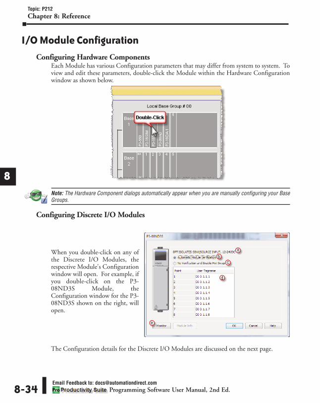
1
2
3
4
5
6
7
8
9
10
11
12
13
14
A
B
C
D
Topic: P212Chapter 8: Reference
Email Feedback to: [email protected] Software User Manual, 2nd Ed. 8-34
I/O Module Configuration
Configuring Hardware ComponentsEach Module has various Configuration parameters that may differ from system to system. Toview and edit these parameters, double-click the Module within the Hardware Configurationwindow as shown below.
Note: The Hardware Component dialogs automatically appear when you are manually configuring your BaseGroups.
Configuring Discrete I/O Modules
When you double-click on any ofthe Discrete I/O Modules, therespective Module's Configurationwindow will open. For example, ifyou double-click on the P3-08ND3S Module, theConfiguration window for the P3-08ND3S shown on the right, willopen.
The Configuration details for the Discrete I/O Modules are discussed on the next page.

1
2
3
4
5
6
7
8
9
10
11
12
13
14
A
B
C
D
Topic: P212Chapter 8: Reference
Email Feedback to: [email protected] Software User Manual, 2nd Ed.
The Configuration details for the Discrete I/O Modules are discussed below:a. Description: Provides the Description of the specific Module.
b. Automatic Module Verification: Generates a critical error when an I/O Module is removed fromthe Base causing a Hardware mismatch and forcing the CPU out of RUN mode.
c. No verification and Enable Hot Swap: Generates a Non-critical Error allowing the system tocontinue to operate when an I/O Module is removed from the Base.
d. User Tagname: Each point on a Discrete Module is assigned a default Tagname. Each UserTagname can be edited in this dialog, left with default settings, or can be edited later in the TagDatabase.
e. Monitor: Creates a tab in the Data View for Monitoring all of the tags associated with themodule. See the Data View Topic for more information.
f. Status Bits (below): Some Discrete Modules have Module Status Bits associated with them thatmay include Missing 24VDC or Blown Fuse indication as shown below.
8-35

1
2
3
4
5
6
7
8
9
10
11
12
13
14
A
B
C
D
Topic: P212Chapter 8: Reference
Email Feedback to: [email protected] Software User Manual, 2nd Ed. 8-36
Configuring High-Speed I/O ModulesWhen you double-click on any High-Speed Input/Output Module from the HardwareConfiguration window, the respective Module's Configuration window will open.
The following section discusses the configuration and options available with the P3-HSO High-Speed Output Module.
a. Module Setup: This tab provides the setup parameters of the selected HSO module. Eachindividual Channel's setup parameters are found on their respective tab.
b. Module Name: Each P3-HSO module can be given a unique name (maximum 16 characters)for easier reference within the hardware configuration, instructions and throughout theprogramming software.
P3-HSO

1
2
3
4
5
6
7
8
9
10
11
12
13
14
A
B
C
D
Topic: P212Chapter 8: Reference
Email Feedback to: [email protected] Software User Manual, 2nd Ed. 8-37
The default name consist of the part number of the module truncated by its position within thesystem (group.base.slot).
c. Automatic Module Verification: Selected by default. Generates a critical error when an I/OModule is removed from the Base causing a Hardware mismatch and forcing the CPU out ofRUN mode. Select No Verification and Enable Hot Swap if Hot Swap functionality is desired.
d. Input Points: There are six general purpose Inputs available which can be used to trigger eventsin the Registration function, used for positive and negative limits or used for Homing.Tagnames need to be assigned to these Inputs in order to be monitored from within the ladderlogic.
Note: The Input Points are not updated in STOP mode.
e. Output Points: There are four general purpose Outputs available which can be used in theRegistration function. Tagnames need to be assigned to these Outputs in order to be monitoredfrom within the ladder logic.
f. Status Feedback: A tagname must be entered in the Module Error Code field in order toreference any current Errors in the module from within the ladder logic. The table belowdescribes the Errors possible. The Module Ready field accepts boolean tags and is used toindicate that the module is installed, configured and ready for instructions. This option must beused in combination with the Hot Swap feature to ensure instructions will execute as intended.
Error Bit Error Description
1 Missing External PowerThis module requires that external power be supplied in order to
operate. If there is a loss of the supplied power, this bit will turn
ON and all of the front panel fault LEDs will blink.
2 Overload/Short CircuitOutput 1
Each of the module outputs has built-in ESCP (Electronic Short
Circuit Protection). This bit indicates a fault has occurred with
Output 1. If a move was in progress, the Move Status Bit 12
“Aborted-IO Fault”will be set for that particular move instruction.
See the specific move instruction topic for the error bits
associated with it.
3 Overload/Short CircuitOutput 2
Each of the module outputs has built-in ESCP (Electronic Short
Circuit Protection). This bit indicates a fault has occurred with
Output 2. If a move was in progress, the Move Status Bit 12
“Aborted-IO Fault”will be set for that particular move instruction.
See the specific move instruction topic for the error bits
associated with it.
4 Overload/Short CircuitOutput 3
Each of the module outputs has built-in ESCP (Electronic Short
Circuit Protection). This bit indicates a fault has occurred with
Output 3. If a move was in progress, the Move Status Bit 12
“Aborted-IO Fault”will be set for that particular move instruction.
See the specific move instruction topic for the error bits
associated with it.
5 Overload/Short CircuitOutput 4
Each of the module outputs has built-in ESCP (Electronic Short
Circuit Protection). This bit indicates a fault has occurred with
Output 4. If a move was in progress, the Move Status Bit 12
“Aborted-IO Fault”will be set for that particular move instruction.
See the specific move instruction topic for the error bits
associated with it.

1
2
3
4
5
6
7
8
9
10
11
12
13
14
A
B
C
D
Topic: P212Chapter 8: Reference
Email Feedback to: [email protected] Software User Manual, 2nd Ed. 8-38
Error Bit Error Description
6 Overload/Short CircuitOutput 5
Each of the module outputs has built-in ESCP (Electronic Short Circuit
Protection). This bit indicates a fault has occurred with Output 5. If a
move was in progress, the Move Status Bit 12 “Aborted-IO Fault”will
be set for that particular move instruction. See the specific move
instruction topic for the error bits associated with it.
7 Overload/Short CircuitOutput 6
Each of the module outputs has built-in ESCP (Electronic Short Circuit
Protection). This bit indicates a fault has occurred with Output 6. If a
move was in progress, the Move Status Bit 12 “Aborted-IO Fault”will
be set for that particular move instruction. See the specific move
instruction topic for the error bits associated with it.
8 Firmware Image CRCError Module Firmware is faulted.
Parameter Configuration Table
Module Setup
Notes:
Module Name Module Name (Max. 16 characters)
Input Points Enter tags to contain the status of the
General Purpose Inputs
Output Points Enter tags to contain the status of the
General Purpose Outputs (Read Only)
Module Error Code Enter tag to contain the Module Error Code
word
Module Ready Enter tag to contain the Module Ready bit

1
2
3
4
5
6
7
8
9
10
11
12
13
14
A
B
C
D
Topic: P212Chapter 8: Reference
Email Feedback to: [email protected] Software User Manual, 2nd Ed. 8-39

a. Channel 1 Setup: This tab provides the setup parameters for Channel 1. There are two pulseoutput channels on the P3-HSO and each individual Channel's setup parameters are found ontheir respective tab.
b. Channel Name: Each channel can be given a unique name for easier reference. The defaultname (maximum 16 characters) consist of the channel number (1 or 2) and the module'sposition within the system (group.base.slot).
c. Channel Scaling: There are several scaling options for user code convenience. Since there aremany different types of applications that the module may be used in, the provided scalingfeature may not work for every scenario. In this case, set the Channel Scaling to Pulse Count,the Time Unit to Seconds and choose a Position Dataype, then use scaling in the ladder code.See the High Speed Configutation Options section in this chapter for more details on thisfunction.• Position Unit: Pulse: This option uses the raw Pulse per position unit selection• Position Unit: Standard: This option configures the numbers of pulses per unit. There are three pre-defined labels that can be selected: inch, foot, mm, degree and revolution. The pulsescan also be specified in fractional increments (.1). Once the scaling factor has been configured,the ladder logic can specify the target values to the HSO in the units that make sense for theapplication. For example: If a scaling value of 10 was configured and the ladder logic specifieda target value of 10, the HSO would physically output 100 pulses.• Position Unit: Custom:This option also configures the number of pulses per unit but allowsfor a custom label to be entered. The pulses can also be specified in fractional increments (.1).Once the scaling factor has been configured, the ladder logic can specify the target values to theHSO in the units that make sense for the application. For example: If a scaling value of 10 wasconfigured and the ladder logic specified a target value of 10, the HSO would physically output100 pulses.• Position Datatype: The position may be specified in terms of Integer or Float. Integer willprovide a greater range but may be difficult to use when using the Scaling function. Conversely,Float will provide greater resolution in some cases but will greatly limit the range.
1
2
3
4
5
6
7
8
9
10
11
12
13
14
A
B
C
D
Topic: P212Chapter 8: Reference
Email Feedback to: [email protected] Software User Manual, 2nd Ed. 8-40

1
2
3
4
5
6
7
8
9
10
11
12
13
14
A
B
C
D
Topic: P212Chapter 8: Reference
Email Feedback to: [email protected] Software User Manual, 2nd Ed. 8-41
The more resolution specified, the lower the range. It may be beneficial to scale the signal first then change the Position Datatype if needed to achieve the desired resolution and/or range.Refer to the Understanding Maximum Position Cycle and Minimum Position Accuracy sectionin this chapter for more details on range selection.• Time Unit: Standard: Choose the appropriate Time unit which will be used for this channel'stime base. The three choices available are: second, minute and hour.• Time Unit: Custom: A custom number of seconds can be configured in this field. Thenumber of seconds can be entered in fractional increments (.1).
d. Channel Feedback: There are three status or feedback tags available for each channel. These tagsprovide information regarding the Position, Velocity and Status of the respective channel.• Current Position Feedback: Insert a tag into this field in order to reference the channel’scurrent Pulse Count. The value will be represented in the scaled units specified from theChannel Scaling setup.• Current Velocity Feedback: Insert a tag into this field in order to reference the channel’scurrent Velocity. The value will be represented in the scaled units specified from the ChannelScaling setup.• Current Status: Insert a tag into this field in order to reference the current Status of thechannel. A list of the possible Channel Status codes are listed below:
StatusBit Status Description
1Last
Direction/BacklashPositive
These bits indicate the last direction of travel. They are updated as soon
as channel movement starts. If Backlash has been configured then these
bits will not change state until after backlash has been “taken up” in the
opposite direction.2Last
Direction/BacklashNegative
3
Future Future
45678
9 Positive LimitSwitch Tripped
These limit switches are configured and operate independently of each
other. They are enabled individually allowing you to have just a positive,
just a negative, or both limits. Each Limit Switch is only detected in its
direction of travel. So an active Negative Limit will not prevent movement
in the Positive Direction (and vice-versa). This allows a channel to “back
off” of a Limit Switch in the opposite direction. But this also means that
the Limit Switches will not protect from an axis traveling in the wrong
direction. Note 1: If both Limit Switches are configured to the same Input
then you will not be able to “back off” of the limit, manual interaction
would be required, this type of setup is usually called “over-travel limit”.
Note 2: The relevant instruction's Move Status Bit 10 “Aborted – Hit Limit”
is also set at the same time.
10 Negative LimitSwitch Tripped
11Future Future12
13 Positive PositionLimit Tripped
These bits indicate when the channel's current position violates the
Position Limit setup in the H/W Configuration. Position Limits allow the
axis movement to be restricted without physical limit switches. The
Position Limits are configured and also operate independently of each
other. They are enabled individually allowing you to have just a positive,
just a negative, or both limits. Note 1:The relevant instruction's Move
Status Bit 10 “Aborted – Hit Limit” is also set at the same time. Note 2:
These limits can be changed on the fly during a move. Note 3: Position
Limits are ignored during HOME instructions since the Home position of
the Channel has not been matched to a physical Axis position.
14 Negative PositionLimit Tripped

1
2
3
4
5
6
7
8
9
10
11
12
13
14
A
B
C
D
Topic: P212Chapter 8: Reference
Email Feedback to: [email protected] Software User Manual, 2nd Ed. 8-42
e. Channel Output Configuration: Each channel's output can be configured with one of threeprofiles. Pulse/Direction, Step Up/Step Down and Quadrature selections are provided todetermine the output behavior. • Pulse/Direction: This selection configures the module to generate the Pulse Train on OutputA of the channel and the Direction is established on Output B of the channel. When the logictells the module to change direction, Output B will toggle from low to high and vice versa. TheDirection Setup Time field specifies how long the direction signal should be established beforethe pulse train starts. The range is from 2 microseconds to 100 milliseconds. If the module iscurrently sending a pulse train and a direction change has been issued, the module will freeze thepulse outputs for the time period specified.
• Step Up/Step Down: When this option is selected, the Pulse Train is generated on Output Awhen a Positive direction has been specified and on Output B when a Negative direction hasbeen specified.
StatusBit Status Description
15 Registration StopTripped
When an instruction is configured for Registration and the Decel to a Stop
option is selected, this bit will turn ON after the channel comes to a stop.
Also the relevant instruction's Move Status Bit 8 “Stopped at Registration
Target” will be set.opposite direction.
16
Module Error -See Module ErrorCodes in the P3-
HSO Configurationsection.
This bit indicates that an error exists in the Module Error Code, look there
for further information.

1
2
3
4
5
6
7
8
9
10
11
12
13
14
A
B
C
D
Topic: P212Chapter 8: Reference
Email Feedback to: [email protected] Software User Manual, 2nd Ed. 8-43
• Quadrature: When this option is selected, the Pulse Train output is generated on Output A andOutput B, offset by a 1/2 cycle. Direction changes from the logic cause the offset to change from oneoutput to the other. There are also Direction Polarity options that allow the polarity to be changedlogically.

1
2
3
4
5
6
7
8
9
10
11
12
13
14
A
B
C
D
Topic: P212Chapter 8: Reference
Email Feedback to: [email protected] Software User Manual, 2nd Ed. 8-44
• Direction Polarity: The Direction Polarity setting determines the initial sequence of the Pulseoffsets or Direction Line level. Refer to the Pulse Train Output Configuration diagrams aboveto see how this setting affects the initial Pulse output sequence.
f. Backlash Compensation: When the direction changes, the module will output the number ofpulses (at pins 1A & 1B) specified. The Current Position Feedback will not be updated withthese pulses. The output will pulse at the rate specified in the Amount and Velocity fields.
g. Output Limits: The channel output can be limited in the following ways:• Starting Velocity (Pulses/sec): The velocity to start at when accelerating to higher targetvelocities. This is typically set to the maximum rate the motor can instantaneously achieve froma stopped state. The system must be able to withstand the jerk created by this immediatevelocity change. Using this feature can reduce acceleration/deceleration times, and thereforereduce process cycle times. For target velocities below the Starting Velocity, there is noacceleration/deceleration, and the profile will start and stop at the target rate without ramping. • Maximum Velocity (Pulses/sec): This is the maximum Pulse rate that the module willoutput. The On Error selections specify how the module should behave when the maximumrate is exceeded. The module can be configured to maintain the maximum rate or to Stop themove if a pulse rate higher than the maximum is specified by the logic. • Maximum Accel Rate (Pulses/sec2): This is the maximum Acceleration rate that the modulewill output. The On Error selections specify how the module should behave when themaximum rate is exceeded. The module can be configured to maintain the maximum rate or toStop the move if an acceleration rate higher than the maximum is specified by the logic.• Maximum Decel Rate (Pulses/sec2): This is the maximum Deceleration rate that the modulewill output. The On Error selections specify how the module should behave when themaximum rate is exceeded. The module can be configured to maintain the maximum rate or toStop the move if a deceleration rate higher than the maximum is specified by the logic. • Rotary Mode - Rollover Position: If selected, when the count reaches the specified rolloverposition, the next positive pulse will reset the count to 0. Also, if the count is at 0, the nextnegative pulse will reset the count (roll under) to the specified rollover position. The value isspecified in user units but the final scaled value must be within 1 and 2,147,483,647 wholecounts. If the final scaled roll over position value is not a multiple of whole pulses, thefractional pulse amount will be ignored. When this feature is used, the count will always be apositive number between 0 and the rollover position.
h. Physical Limits: The channel output can also be limited with the use of Limit Switch Inputs.• Positive Limit Switch Input: This option will stop the module pulse output if the specifiedLimit Switch becomes true when encountered in the Positive direction. An error will beindicated in the Module Error Code tag when this occurs. Motion in the negative direction ispermitted in this state to allow for movement away from the limit switch unless the same switchis used for both positive and negative limits.• Negative Limit Switch Input: This option will stop the module pulse output if the specifiedLimit Switch becomes true when encountered in the Negative direction. An error will beindicated in the Module Error Code tag when this occurs. Motion in the negative direction ispermitted in this state to allow for movement away from the limit switch unless the same switchis used for both positive and negative limits.
i. Position Limits: These limits are Virtual limit switches imposed on the module's output. • Enable Positive Position Limit at: This option will stop the module pulse output (unlessperforming a Homing routine) if the module reaches the count specified (constant or Tag value)while traveling in the Positive direction. An error will be indicated in the Status Bit specifiedwhen this occurs. As with the hardware switch limits, movement is allowed in the negativedirection in order to move away from the limit switch. The "On the fly" symbol indicatesthat this value can be changed while the instruction is running.

1
2
3
4
5
6
7
8
9
10
11
12
13
14
A
B
C
D
Topic: P212Chapter 8: Reference
Email Feedback to: [email protected] Software User Manual, 2nd Ed. 8-45
• Enable Negative Position Limit at: This option will stop the module pulse output (unlessperforming a Homing routine) if the module reaches the count specified (constant or Tag value)while traveling in the Negative direction. An error will be indicated in the Status Bit specified whenthis occurs. As with the hardware switch limits, movement is allowed in the positive direction in orderto move away from the limit switch. The "On the fly" symbol indicates that this value can bechanged while the instruction is running.
Parameter Configuration Table
Channel Setup
Notes:
Channel Name Channel Name (Max. 16 characters)
Scaling Radio Buttons and Constants
Feedback: CurrentPosition Feedback Enter tag to contain the Current Position
Feedback: CurrentVelocity Feedback Enter tag to contain the Current Velocity
Feedback: CurrentStatus Enter tag to contain the Current Status
OutputConfiguration Radio Buttons and Constants
BacklashCompensation Radio Buttons and Constants
Output Limits Radio Buttons and Constants
Physical Limits Radio Buttons
Position Limits(Value) Enter tags which contain these limit values
Position Limits(Status) Enter tags to contain the limit status bits

1
2
3
4
5
6
7
8
9
10
11
12
13
14
A
B
C
D
Topic: P212Chapter 8: Reference
Email Feedback to: [email protected] Software User Manual, 2nd Ed. 8-46
The following section discusses the configuration and options available with the P3-HSI High-Speed Input Module.
a. Module Setup: This tab provides the setup parameters of the selected HSI module. Eachindividual Channel's setup parameters are found on their respective tab.
b. Module Name: Each P3-HSI module can be given a unique name (maximum 16 characters) foreasier reference within the hardware configuration, instructions and throughout theprogramming software. The default name consist of the part number of the module truncatedby its position within the system (group.base.slot).
c. Automatic Module Verification: Selected by default. Generates a critical error when an I/OModule is removed from the Base causing a Hardware mismatch and forcing the CPU out ofRUN mode. Select No Verification and Enable Hot Swap if Hot Swap functionality is desired.
P3-HSI

1
2
3
4
5
6
7
8
9
10
11
12
13
14
A
B
C
D
Topic: P212Chapter 8: Reference
Email Feedback to: [email protected] Software User Manual, 2nd Ed. 8-47
d. Input Points: There are two general purpose Inputs available which can be used to trigger eventsin the Registration instruction or used with the Inhibit Count on Input option of the module’schannel I/O configuration. Tagnames need to be assigned to these Inputs in order to bereferenced from within the ladder logic. By default, inputs 1-6 are used for Channel inputs butinternal tags may be assigned to each point for the purpose of monitoring from within theladder code.
Note: The Input Points are not updated in STOP mode.
e. Output Points: There are four general purpose Outputs available which can be used in theRegistration instruction. Tagnames need to be assigned to these Outputs in order to bemonitored from within the ladder logic.
f. Status Feedback: A tagname must be entered in the Module Error Code field in order toreference any current Errors in the module from within the ladder logic. The table belowdescribes the Errors possible. The Module Ready field accepts boolean tags and is used toindicate that the module is installed, configured and ready for instructions. This option must beused in combination with the Hot Swap feature to ensure instructions will execute as intended.
ErrorBit Error Description
1 Missing ExternalPower
This module requires that external power be supplied in order to
operate. If there is a loss of the supplied power, this bit will turn ON and
all of the front panel fault LEDs will blink.
2 Overload/ShortCircuit Output 1
Each of the module outputs has built-in ESCP (Electronic Short Circuit
Protection). This bit indicates a fault has occurred with Output 1.
3 Overload/ShortCircuit Output 2
Each of the module outputs has built-in ESCP (Electronic Short Circuit
Protection). This bit indicates a fault has occurred with Output 2.
4 Overload/ShortCircuit Output 3
Each of the module outputs has built-in ESCP (Electronic Short Circuit
Protection). This bit indicates a fault has occurred with Output 3.
5 Overload/ShortCircuit Output 4
Each of the module outputs has built-in ESCP (Electronic Short Circuit
Protection). This bit indicates a fault has occurred with Output 4.
6Future Future
7
8 Firmware ImageCRC Error Module Firmware is faulted.
9Channel 1 -Quadrature
Sequence Fault
A valid Quadrature signal should only have one edge at any point in
time. Either the rising or falling edge of Channel A or Channel B, but not
both. If the module detects that both Channel A and Channel B change
states at the same time then this error bit will be set. This may indicate a
bad encoder or noise on the channel.
10Future Future11
12
13Channel 2 -Quadrature
Sequence Fault
A valid Quadrature signal should only have one edge at any point in
time. Either the rising or falling edge of Channel A or Channel B, but not
both. If the module detects that both Channel A and Channel B change
states at the same time then this error bit will be set. This may indicate a
bad encoder or noise on the channel.
14
Future Future15
16

1
2
3
4
5
6
7
8
9
10
11
12
13
14
A
B
C
D
Topic: P212Chapter 8: Reference
Email Feedback to: [email protected] Software User Manual, 2nd Ed. 8-48
Parameter Configuration Table
Module Setup
Notes:
Module Name Module Name (Max. 16 characters)
Input Points Enter tags to contain the Input status
Output Points Enter tags to contain the status of the
General Purpose Outputs (Read Only)
Module Error Code Enter tag to contain the Module Error Code
word
Module Ready Enter tag to contain the Module Ready bit

1
2
3
4
5
6
7
8
9
10
11
12
13
14
A
B
C
D
Topic: P212Chapter 8: Reference
Email Feedback to: [email protected] Software User Manual, 2nd Ed. 8-49
a. Channel 1 Setup: This tab provides the setup parameters for Channel 1. There are two high-speed input channels on the P3-HSI and each individual Channel's setup parameters are foundon their respective tab.
b Channel ID Setup: Each channel can be given a unique name (maximum 16 characters) foreasier reference. The default name consist of the channel number (1 or 2) and the module'sposition within the system (group.base.slot).

1
2
3
4
5
6
7
8
9
10
11
12
13
14
A
B
C
D
Topic: P212Chapter 8: Reference
c. Channel Scaling: There are several scaling options for user code convenience. Since there aremany different types of applications that the module may be used in, the provided scalingfeature may not work for every scenario. In this case, set the Channel Scaling to Pulse Countand the Time Unit to Seconds, then use scaling in the ladder code. See the High SpeedConfigutation Options section in this chapter for more details on this function.• Position Unit: Pulse: This option uses the raw Pulse per unit selection. • Position Unit: Standard: This option configures the numbers of pulses per unit. There arethree pre-defined labels that can be selected: inch, foot, mm, degree and revolution. The pulsescan also be specified in fractional increments (.1).• Position Unit: Custom: This option also configures the number of pulses per unit but allowsfor a custom label to be entered. The pulses can also be specified in fractional increments (.1).• Position Datatype: The position may be specified in terms of Integer or Float. Integer willprovide a greater range but may be difficult to use when using the Scaling function. Conversely,Float will provide greater resolution in some cases but will greatly limit the range. The moreresolution specified, the lower the range. Refer to the Understanding Maximum Position Cycleand Minimum Position Accuracy section in this chapter for more details on range selection.• Time Unit: Standard: Choose the appropriate Time unit which will be used for this channel'stime base. The three choices available are: second, minute and hour.• Time Unit: Custom: A custom number of seconds can be configured in this field. Thenumber of seconds can be entered in fractional increments (.1).
d. Channel Feedback: There are three status or feedback tags available for each channel. These tagsprovide information regarding the Position, Velocity and Status of the respective channel.
Note: The Channel Feedback tags are not updated in STOP mode.
• Current Position Feedback: Insert a tag into this field in order to reference the channel’scurrent High-Speed Count. The value will be represented in the scaled units specified from theChannel Scaling setup.• Current Velocity Feedback: Insert a tag into this field in order to reference the channel’scurrent Velocity. The value will be represented in the scaled units specified from the ChannelScaling setup.• Velocity Estimator Mode: This selection is used in determining how the Current Velocity willbe calculated.1) Fast Frequency (pulses/time): This mode requires the user to select a sample period specificto their process. A shorter sample period will have less resolution. Recommended for velocitiesof 1khz and above. Calculations are done based on the number of events that occur within thesample period. Fast Frequency is the most accurate mode when the sample period is long. Theupdate rate of the velocity calculations for this mode is directly proportional to the sampleperiod.
Velocity Fast Freq = # of Pulses / Sample Period (Note: The Sample Period must be between 1 and0.001 second.)
Email Feedback to: [email protected] Software User Manual, 2nd Ed. 8-50

1
2
3
4
5
6
7
8
9
10
11
12
13
14
A
B
C
D
Topic: P212Chapter 8: Reference
Email Feedback to: [email protected] Software User Manual, 2nd Ed. 8-51
2) Slow Frequency (time/pulse): Slow Frequency at low velocities (under 1khz) will provide amore accurate and faster update rate than Fast Frequency. Calculations are based on theamount of time that passes between two pulses. As frequency increases, Slow Frequency losesaccuracy as the resolution between pulses decreases.
Velocity Slow Freq = 1 / Time Between Pulses
3) Autosense: Autosense combines the features of Slow and Fast Frequency Modes to provide avelocity calculation. Autosense uses the velocity from Slow Frequency to calculate a sampleperiod to be used in Fast Frequency calculation. This provides rolling adjustment through allfrequency ranges. This mode works in all ranges, so it is the easiest to implement, but sacrificesaccuracy due to the combined limitations of Slow and Fast Frequency Modes.
Velocity Autosense = # of Pulses / Autosense Sample Period where Autosense Sample Period = (1 / Velocity Slow Freq) x 100
(Note: Autosense Sample Period max / min values are 1 and 0.001 second respectively. The initialsample period will be 2 seconds and then dynamically adjust based on the input frequency.)
• Sample Period: Used in conjunction with Fast Frequency Mode. Sets the period of time thatthe pulses will be sampled in order to determine the velocity rate.
• Current Status: Insert a tag into this field in order to reference the current Status of thechannel. A list of the possible Channel Status codes are listed on the following page.

1
2
3
4
5
6
7
8
910
11
12
1314
A
B
C
D
Topic: P212Chapter 8: Reference
Email Feedback to: [email protected] Software User Manual, 2nd Ed. 8-52
Status Bit Status1
Future23456 Inhibited - Reset Tag out of range1
7 Inhibited - Z Reset out of range1
8 Inhibited - Rotary Rollover out of range1
9 Alert - Position Rolled Over2
10 Alert - Position Rolled Under2
11
Future1213141516 Module Error - See Module Error Codes in the P3-HSI Configuration section.
Note 1: These can only occur when in Rotary Mode, if not in Rotary Mode then any value is valid.Note 2: These report the occurrence of a Roll Over and/or Roll Under. They will remain set for 3 scans and then clear. This makes itpossible to detect multiple rollover and/or rollunder events using ladder code.
e. Channel Input Mode Configuration: Each channel's input can be configured with one of threeprofiles. Pulse/Direction, Quadrature X1 and Quadrature X4 selections are provided todetermine the input behavior. • Pulse/Direction: This selection configures the module to receive the Pulse Train on Input A ofthe channel and to read the Direction on Input B of the channel. When the signal on Input B islow, the module will count up when receiving pulses on Input A. Conversely, when the signalon Input B is high, the module will count down when receiving pulses on Input A.
• Quadrature X1: With this selection, the channel count will depend on which input is leadingand which is trailing. If the Direction Polarity is set to Increasing Counts = Positive Directionand Input A is leading Input B by a 1/2 pulse, then the count will increase by one with everyrising edge of the pulse received on Input A.

1
2
3
4
5
6
7
8
9
10
11
12
13
14
A
B
C
D
Topic: P212Chapter 8: Reference
Email Feedback to: [email protected] Software User Manual, 2nd Ed. 8-53
• Quadrature X4: As with the Quadrature X1 setting, the channel count is dependent uponwhich input is leading and which is trailing. With the Quadrature X4 selection however, thecounts will increment on each rising and falling edge of both input pulse trains.
• Direction Polarity: This selection determines the direction polarity of the incoming signals.1) Increasing Counts = Positive Direction: With Pulse/Direction mode, if the signal onInput B is low, pulses on Input A will generate an increasing count. When the signal onInput B is high, pulses on Input A will generate a decreasing count. With Quadraturemode, if the signal on Input A leads the signal on Input B, the count will increase. If thesignal on Input B leads the signal on Input A the count will decrease.2) Increasing Counts = Negative Direction: With Pulse/Direction mode, if the signal onInput B is low, pulses on Input A will generate a decreasing count. When the signal onInput B is high, pulses on Input A will generate an increasing count. With Quadraturemode, if the signal on Input A leads the signal on Input B, the count will decrease. If thesignal on Input B leads the signal on Input A the count will increase.
• Inhibit Count on Input: Enabling this selection allows the user to specify an input that willbe used to inhibit the count. The count will be inhibited when this specific input is in its activestate. Valid inputs for this feature are: 1Z, 2Z, as well as, General Purpose (GP) Inputs 3 and 4.
• Use Z-Input Reset Count to: Enabling this feature will cause the count to reset to thespecified count value when the Z Input for the channel goes to the active state. This value isspecified in user units but the final scaled value must be within -2,147,483,647 and2,147,483,647 whole counts. If the final scaled reset count value is not a multiple of wholepulses, the fractional pulse amount will be ignored.
• Use Tag... to Reset Count to: When the specified tag equals 1, the count for the channel willbe reset to the specified count value. This value is specified in user units but the final scaledvalue must be within -2,147,483,647 and 2,147,483,647 whole counts. If the final scaled resetcount value is not a multiple of whole pulses, the fractional pulse amount will be ignored.
f. Input Count Limits: This option allows a rollover limit to be placed on the input count if theinput is tied to a Rotary Encoder. Do not select this option if using a Linear Encoder.• Rotary Encoder - Rollover Position: When the count reaches the specified rollover position,the next positive pulse will reset the count to 0. When the count is at 0, the next negative pulsewill reset the count (roll under) to the specified rollover position. The value is specified in userunits but the final scaled value must be within 1 and 2,147,483,647 whole counts. If the finalscaled roll over position value is not a multiple of whole pulses, the fractional pulse amount willbe ignored. When this feature is used, the count will always be a positive number between 0and your rollover number.

8-54Email Feedback to: [email protected]
Programming Software User Manual, 2nd Ed.
Topic: P212Chapter 8: Reference
8
6
Parameter Configuration Table
Channel Setup
Notes:
Channel Name Channel Name (Max. 16 characters)
Scaling Radio Buttons and Constants
Feedback: CurrentPosition Feedback Enter tag to contain the Current Position
Feedback: CurrentVelocity Feedback Enter tag to contain the Current Velocity
Feedback: CurrentStatus Enter tag to contain the Current Status
Input ModeConfiguration: UseZ-Input ResetCount to
Enter tag that contains the desired Reset
Count
Input ModeConfiguration: UseTag
Enter tag that will Reset the Count
Input ModeConfiguration:Reset Count to
Enter tag that contains the desired Reset
Count (used in conjunction with "Use Tag")
Input Count LimitsRollover Position Enter tag that contains the Rollover Position

Analog I/O ModulesWhen you double-click on any of the Analog I/O Modules, the respective Module's Configurationwindow will open. For example, if you double-click on the P3-08AD Module, the P3-08ADConfiguration window shown below will open. Details about Configuring the Analog I/O Modulesare discussed below.
a. Description: Provides theDescription of the specific Module.
b. Automatic Module Verification:Generates a critical error when anI/O Module is removed from theBase causing a Hardware mismatchand forcing the CPU out of RUNmode.
c. No verification and Enable HotSwap: Generates a Non-criticalError allowing the system tocontinue to operate when an I/OModule is removed from the Base.
d. User Tagname: Each point on anAnalog Module is assigned adefault Tagname. Each UserTagname can be edited in thisdialog, left with default settings, orcan be edited later in the TagDatabase.
e. Ch. Select, All: Allows the user toSelect individual Channels or AllChannels.
f. Range: Some Analog and Temperature Modules support multiple Ranges for the Input orOutput Signal Types. The Range column allows individual selection of Signal Type for eachChannel.
Note: The P3-08RTD Module must have All Channels configured to the same Range.
Note: The P3-04ADS does not allow for Signal Range selection in the software configuration. Signal Type isdetermined when wiring the field device.
g. Module Status Bits: Some Analog Modules have Module Status Bits associated with them that mayinclude: Module Failed, Missing 24VDC, Under Range, Over Range and Module Not Ready.
h. Monitor: Creates a tab in the Data View for Monitoring all of the tags associated with themodule. See the Data View Topic for more information.
8-55Email Feedback to: [email protected]
Programming Software User Manual, 2nd Ed.
Topic: P212Chapter 8: Reference
8
6

1
2
3
4
5
6
7
8
9
10
11
12
13
14
A
B
C
D
Topic: P212Chapter 8: Reference
Email Feedback to: [email protected] Software User Manual, 2nd Ed. 8-56
Default Tag NamesDefault Tag Names are automatically assigned as hardware is added. The Tag Names are easilycustomized here, or can be changed later in the Tag Database. The following applies to allwindows that may be accessed through the Hardware Configuration tool. Example: all I/O andCPU properties windows, where Tag Names are displayed and Module ranges selected.
Default Tag Names are assigned when hardware is added to your project. Tag Names for I/Omodules generally follow the format AAAAA-B.C.D.E, where:
AAAAA is the Category of the data, and may include the data type:
• Discrete I/O points:DI = Discrete Input PointDO = Discrete Output Point
• Boolean data items other than I/O pointsMST = Module Status (Examples: Blown fuse or out of range error bits)
• Analog points. These use five digits. The first two digits designate the type of point andthe last three describe the data type used.
AIxxx = Analog Input PointAOxxx = Analog Output PointxxF32 = Floating Point 32 Bit data typexxS32 = Signed 32 Bit data type
B is the Base Group number. The Local Base Group with the PAC CPU is Group 0.C is the Base number. The Base with the PAC CPU or P3-RS/RX is Base 1.D is the Slot number. The Slot to the right of the CPU is Slot 1.E is the Item number.
• If the Tag Name is for an I/O module, this digit will be the point number.• If the Tag Name is for a Status indication, this digit will differentiate them.
Example: P3-16TR has two fuses (one on each common) and a blown fuse indicator bit foreach. Their default Tag Names are MST-x.x.x.1 and MST-x.x.x.2. MST-x.x.x.1 is theblown fuse indicator for the fuse on the common of channels 1 through 8.
User Tag Name RulesUser Tag Names are Tag Names that are created by Users in the Tag Database. The followingrules apply to Tag Names created by Users:
• Length can be from 1 to 32 Characters.
• Must have at least one Non-numeric Character, (a single decimal point or a leading dash areconsidered Numeric Characters).
• Cannot have quotation marks as first or last Character.
• Cannot contain parenthesis.
• Cannot start with a default I/O Tag prefix, such as MST (the default prefix for a Module Status bit).
• Cannot start with a System ID prefix, such as AR2C (the default prefix for a Boolean 2-dimensional Array).

1
2
3
4
5
6
7
8
9
10
11
12
13
14
A
B
C
D
Topic: P245Chapter 8: Reference
Email Feedback to: [email protected] Software User Manual, 2nd Ed. 8-57
High-Speed Configuration Options
Use JerkThe Use Jerk field provides a method to smooth the transitions between velocity changes of theSMOV and VMOV instructions. The value is in the form of Units/Second3. This value canbe adjusted to limit the rate of change in acceleration in order to avoid problems with inertialloads.
Diagram #1 is an example showing very large instantaneous Acceleration and Decelerationchanges at the beginning and end of a move. This would perform very poorly and cause a greatdeal of stress on the drive system.
Diagram #2 shows a trapezoidal profile with linear Acceleration and Deceleration rates. Thishelps to reduce the "jerk" associated with the beginning and end of the move. The Velocity iscontrolled by the linear acceleration rate.

1
2
3
4
5
6
7
8
9
10
11
12
13
14
A
B
C
D
Topic: P245Chapter 8: Reference
Email Feedback to: [email protected] Software User Manual, 2nd Ed. 8-58
Diagram #3 shows a move using the Jerk option. The Jerk term changes the Acceleration andDeceleration rates over time. In turn, the Velocity is controlled by a sloped acceleration rate.The diagram shows the effect of the Jerk value on the Velocity curve which curves up slowlyallowing for a smooth transition. As the Jerk value is lowered, the move will be smoother butwill take longer to complete. As the Jerk value is increased, the move will become more like thetrapezoidal profile shown on previous page.
Diagram #4 shows what occurs when a move instruction's maximum Acceleration andDeceleration values limit the Jerk value. As the Jerk value increases the Acceleration rate overtime, it eventually encounters the Acceleration Limit of the Move Instruction or HardwareConfiguration. The Acceleration Rate then becomes linear for that section. The Use Jerkoption will have very little effect if the value is set too high or if the maximum Acceleration andDeceleration rates are set too low.

1
2
3
4
5
6
7
8
9
10
11
12
13
14
A
B
C
D
Topic: P245Chapter 8: Reference
Email Feedback to: [email protected] Software User Manual, 2nd Ed. 8-59
Channel ScalingIn the Channel Scaling options, the Position Unit's Standard or Custom setting allows the userto configure a channel for real world units. Instead of having to work in raw pulse counts, a unitvalue can be configured for convenience. This unit value will then be used throughout theP3000 system (H/W configuration, Feedback tags, and Instructions.) The following examplesshow how to derive the pulse count per position unit. This data could be empirically measured,or calculated by the system design. It’s easy to see in the following graphic that moving 1 inchwill take 400 pulses. This value can also be calculated using any measured distance and knownpulse count: 300 steps / 0.75” = 400 steps per inch.
Fractional position units can be calculated the same way but we must consider the accuracy ofthe number system. In this example, the pulse count per position unit does not work out to aconvenient whole number. 400 steps / 3.00” = 133.333... steps per inch. Since the fractionalvalue cannot be accurately represented, this configuration would always have a position error.If this error is not acceptable then mechanical changes could be used to avoid this situation orthe default setting (1 step per 1 unit) could be used with any necessary scaling done in the rungcode.
Another consideration when configuring the Channel Scaling is the effect that outside factors,such as mechanical gearing ratios, may have on the resulting scaled value. For example, with astepper motor, the steps per revolution rating of the motor and the step configuration of thedrive also need to be considered. Stepper drives can be full-step, half-step, or microstepping.These configurations will affect how many pulses it takes per revolution of the motor shaft. A200 step/rev motor connected to a half-step drive will require 400 steps per revolution.

1
2
3
4
5
6
7
8
9
10
11
12
13
14
A
B
C
D
Topic: P245Chapter 8: Reference
Email Feedback to: [email protected] Software User Manual, 2nd Ed. 8-60
Using Implied Decimal ScalingWhen using the Channel Scaling feature it is important to realize the implications of using aFloating Point tag datatype. The main implication is that the significant value has a precisionof 24 bits which allows for accurate ranges of -8,388,608 to 8,388,608 units. The followingexamples show possible configurations of a system using 1000 counts/inch and show how tagdatatypes affect the valid range.
Example 1: Float tag datatype, the valid range is -8,388.608 to 8,388.608 inches. Eachsignificant unit represents 1/1000th inch.
Example 2: Integer 32-bit tag datatype, the valid range is -2,147,483 to 2,147,483 inches. Onlywhole inches will be shown, even though fractional inch counts are maintained in the modulethey are not represented in the position tag.
Example 3: Integer 32-bit tag datatype, the valid range is -2,147,483,647 to 2,147,483,647 inimplied 1/1000th inch units (the example encoder is 1000 counts/inch). In other words, the 1’sdigit is actually representing 0.001 inches, the 10’s digit represents 0.010 inches, and so forth.The valid range is -2,147,483.647 to 2,147,483.647 in actual inches. This allows for a largerrange while maintaining accuracy, but it also burdens the programmer to always be aware of theimplied decimal place.

1
2
3
4
5
6
7
8
9
10
11
12
13
14
A
B
C
D
Topic: P245Chapter 8: Reference
Email Feedback to: [email protected] Software User Manual, 2nd Ed. 8-61
To relieve this burden you can choose to use a Custom Position Unit which allows the UnitName to be any text. For Example 3 we might change the name from “inch” to be “0.001 inch”which better describes the implied decimal units. The image below shows how this isconfigured in the P3-HSO H/W Configuration, and how the instructions display the CustomUnits to help the programmer.

1
2
3
4
5
6
7
8
9
10
11
12
13
14
A
B
C
D
Topic: P245Chapter 8: Reference
Email Feedback to: [email protected] Software User Manual, 2nd Ed. 8-62
Note: The P3-HSO frequency output is based upon a master clock divided by a whole integer count. Exactfrequencies are not available for the entire output range. As the desired frequency increases the stepsbetween achievable frequencies also increases. This relationship between the desired frequency and theactual output frequency is shown by the following equation: Actual Frequency = 1Mhz / INTEGER (1Mhz /Desired Frequency)
Rotary Encoder (HSI)This option forces the channel position to stay within the range of Zero to the RolloverPosition. This is sometimes called cyclic or ring counting. When incrementing, the positionwill rollover from the Rollover Position back to zero. When decrementing, the position willrollunder from zero up to the Rollover Position.
Rotary Mode (HSO)When this feature is enabled, the Use Shortest Path option will become available in the SMOVinstruction configuration. This option allows the channel to make the decision on-the-fly whichdirection to travel to the target.

Understanding Maximum Position Cycle and MinimumPosition Accuracy
Unit scaling is a feature in both the HSO and HSI configurations which allows the user todefine actual real world machine units in the PAC program to make programming easier tounderstand. Programming an axis to move 36 inches instead of 20,000 counts may make moresense. Unit scaling, however, comes with a price (which may or may not affect the application)since there is a finite Maximum Position Cycle (MPC) that resides in the motion modules. TheMPC is the range, defined in the units specified, in which the current position of a givenchannel will reside and will not exceed. If no user scaling is used, the MPC is ±231 or±2,147,483,647 counts (Int32 range); or ±223 or ±8, 338,608 counts (Float32 range). Scalingusually increases the number of counts or pulses per unit which forces the MPC to becomesmaller. For instance, if 100 counts equal an inch of movement on the machine, then the MPCwill be ±21,474,836 (assuming Integer Datatype) inches. The motion module configurationallows the user to adjust the accuracy of the position versus the size of the MPC to what makesthe most sense for the application.
There are two position datatype choices available: Integer and Float. Selecting the IntegerPosition Datatype (default) allows for the largest possible MPC since there are 31 bits availablefor position storage. Selecting the Float Position Datatype restricts the MPC since there are 23bits (single-precision floating point) available for position storage which has a range of ±223 or±8, 338,608. Selecting the Float datatype also enables the Minimum Position Accuracy (MPA)selection. The MPA allows the user to choose the minimum amount of accuracy the floatingpoint position data should have. The selections are 0.1, 0.01, 0.001, and 0.0001. Again, thesize of the MPC is usually affected by this selection but not always: the higher accuracyselections usually makes the MPC size decrease.
Note: The position value in all tags dealing with motion instructions and configurations will be accurate tothe MPA selected.
The MPC is found by dividing the maximum possible value (231 for Integer or 223 for Float)by the number of counts per unit. If the number of counts per unit has a fractional component,then that too affects the outcome. For instance, if the fractional part is two digits to the right ofthe decimal point then the MPC will be divided again by 100.
MPC calculation examples:If an Integer datatype is selected and 100.0 counts per unit is configured, then the MPC is calculatedto be ±21,474,836 counts. However, if 100.25 counts per unit is configured, the MPC will be±214,212 (roughly 100 times less) because of the fractional part being two places to the right of thedecimal point. This is to allow room for partial counts to be passed to and from the module. If aSMOV instruction was to move 4 units, with the 100.25 counts per unit configured, then the actualnumber of pulses out would be 401. As you can see, even with the Integer datatype the 0.25 countsper unit is preserved.
If a Float datatype is selected and 100.0 counts per unit is configured, then the MPC is calculated tobe ±83886.1 counts. However, if 100.25 counts per unit is configured, the MPC will be ±83.7(roughly 1000 times less) because of the fractional part being two places to the right of the decimalpoint as well as the accuracy selected. As you can see, fractional encoder counts combined withhigher accuracy results in a greatly reduced MPC.
1
2
3
4
5
6
7
8
9
10
11
12
13
14
A
B
C
D
Topic: P249Chapter 8: Reference
Email Feedback to: [email protected] Software User Manual, 2nd Ed. 8-63

There are also instances when the accuracy level that is selected does not affect the MPC. Thisnormally happens as the number of pulses per unit becomes larger. For instance, if the pulsesper unit is set to 100 then the MPC range has the same magnitude when the MPA is set toeither 0.1 or 0.01. This is normal and in this case, a command of one unit in an instruction willresult in 100 pulses on the output. Once the position feedback tag is updated it will be accurateto a minimum of one pulse or 0.01 units. If 1000 pulses per unit is configured, the 0.1, 0.01,or 0.001 MPA settings will have the same magnitude MPC.
It is recommended that the most accurate MPA setting available be selected that has minimalloss of MPC and in most cases the MPC will be sufficient for the application. Below are a fewguidelines to help you understand the interaction between these two entries.
• If fractional unit commands are not needed, use the Integer Position Datatype. This will resultin a larger available Maximum Position Cycle. The range of the MPC is generally only aconcern in applications where absolute positioning is used or where extremely long with highaccuracy lengths are measured.
• Use a compatible tag for the Position Datatype selected. If Integer is selected, use Int32 tags(especially for feedback). If Float is selected, use Float32 tags. Mixing the two may result inundesired results. For instance, if the Integer Position Datatype, with a range of±2,147,483,647 counts, is selected and a Float32 tag, with a range of ±8, 338,608, is used forthe position feedback, then the returned position value could exceed the range of the float tagyielding an inaccurate value.
• Partial or an uncommon value of counts (or pulses) per unit will lower the Maximum PositionCycle range. In general, non-partial encoder counts with common values will have the highestavailable MPC. For instance, 1000 counts per unit using Float Datatype will result in±2,147,483 MPC. Changing it to 1000.1, will lower the MPC further by a factor of 10 to±214,726.
Note: The MPC has the greatest range if multiplying the counts per unit by Minimum Position Accuracy (forInteger Datatype =1) results in an integer value. Any fractional products will result in a smaller available MPCwhere the more places to the right of the decimal point, the smaller the possible range.
• Use the highest possible MPA available for a given MPC using Float Position Datatype. Thiswill give you the greatest accuracy without further sacrificing the size of the MPC.
1
2
3
4
5
6
7
8
9
10
11
12
13
14
A
B
C
D
Topic: P249Chapter 8: Reference
Email Feedback to: [email protected] Software User Manual, 2nd Ed. 8-64

1
2
3
4
5
6
7
8
9
10
11
12
13
14
A
B
C
D
Topic: P229Chapter 8: Reference
Email Feedback to: [email protected] Software User Manual, 2nd Ed. 8-65
P3-RS Module Configuration
Configuring Hardware ComponentsThe P3-RS module is configured using the setup tools found in the Hardware Configurationwindow. First, configure the PAC for a Remote I/O application by adding a Remote BaseGroup as seen below. Next, add a Base Chassis to the new group by dragging and dropping thebase selection into the group. The P3-RS module will automatically be placed in the first slotof the new Remote Base Group. Now, Double-click the P3-RS to open the configurationwindow.

Email Feedback to: [email protected] Software User Manual, 2nd Ed.8-66
Topic: P229Chapter 8: Reference
Options Tab Configuration
a. Serial Ports Tab: Click on this Tab to go to the Serial Ports Configuration dialog.
b. Automatic Remote Base Group Detection: Enabling causes the CPU to treat the loss ofcommunication with this Base Group as a critical error. The critical error will force the CPUinto stop mode. This is the default setting.
c. Do not Detect if the Remote Base Group is Disconnected: Enabling causes the CPU to treat theloss of communication with this Base Group as a non-critical error.

Topic: P229Chapter 8: Reference
Email Feedback to: [email protected] Software User Manual, 2nd Ed. 8-67
Since the error is non-critical it will not force the CPU into stop mode. (All I/O Modules in theBase Group must have NV selected for the loss of communication with the Base Group to betreated as non-critical error by the CPU.) In this case, the CPU will do the following:
• The CPU will log the error.• The CPU will use the last data received before the mismatch in the execution of
ladder logic. Once the mismatch no longer exists and current data is available fromthe Base Group, the CPU will switch over to using current data.
d. LCD Name: Allows the entry of a unique Name for the P3-RS front panel LCD display.
e. Scroll Among LCD Pages Every: Allows the entry of a value in Seconds from 1 to 10 todetermine the Scroll Rate when using multiple Pages on the LCD display.
f. Remote I/O: This option will set this Remote I/O base to be updated sequentially,asynchronously to the CPU scan. Please refer to the Scan Interval and Use of the MaximumScan Interval Tag topic for further reference.
g. Local I/O: This option sets this Remote I/O base to be updated every scan as Local I/O,synchronous to the CPU scan.
h. Custom: By selection Custom, this Remote I/O base can be set to update asynchronously to theCPU scan by either:
• # of scans with offset (scan based)• msec with offset (time based)
i. Module Ready Bit: This Bit will be high when communication is good between the or P3-RSand the P3-550. If communication is lost for any reason, this bit will go low.
Note: Firmware 1.1.13.x is required to use the Module Ready Bit feature.
j. RS-232 Heartbeat Timeout Bit: This feature allows the ladder logic in the CPU to know if adevice has stopped communicating to the P3-RS. The RS-232 Heartbeat Timeout Bit willbecome true if the RS-232 Comm Heartbeat Value of the Serial Ports configuration is exceeded.The CPU will start a timer between each communication packet coming into the P3-RS. If acommunication packet fails to be received by the P3-RS within the specified time period, the bitwill be enabled.
k. RS-232 Port Buffer Full Bit (95% Full): This Bit is used to indicate when the RS-232 PortBuffer is 95% full. A Boolean Tag can be assigned to this field and then used in the ladder codeto indicate when communications are almost maxed out on this Port. When the Port becomes95% full, the Bit becomes true (value of 1).
l. RS232 Port Ready Bit: This feature allows the ladder logic in the CPU to know if the RS-232Port is ready to be used for communications to other devices.
• If the P3-RS is selected as “Do not Detect if the Remote Base Group isDisconnected”, then the RS-232 Port Ready Bit will be false until the P3-RS is fullybooted up and in run.
• The RS-232 Port Ready Bit will become momentarily false during a stop modetransfer using the programing software.
• If communication is lost with the P3-RS, the CPU will reset all MST bitsassociated with that Remote Group.
m. RS-485 Heartbeat Timeout Bit: This feature allows the ladder logic in the CPU to know if adevice has stopped communicating to the P3-RS. The RS-485 Heartbeat Timeout Bit willbecome True if the RS-485 Comm Heartbeat Value of the Serial Ports configuration is exceeded.The CPU will start a timer between each communication packet coming into the P3-RS. If apacket fails to be received by the P3-RS within the specified time period, the Bit will be enabled.

Email Feedback to: [email protected] Software User Manual, 2nd Ed.8-68
Topic: P229Chapter 8: Reference
n. RS-485 Port Buffer Full Bit (95%): This Bit is used to indicate when the RS-485 Port Buffer is95% full. A Boolean Tag can be assigned to this field and then used in the ladder code toindicate when communications are almost maxed out on this Port. When the Port becomes 95%full, the Bit becomes True (value of 1).
o. RS485 Port Ready Bit: This feature allows the ladder logic in the CPU to know if the RS-485Port is ready to be used for communications to other devices.
• If the P3-RS is selected as “Do not Detect if the Remote Base Group isDisconnected”, then the RS-485 Port Ready Bit will be false until the P3-RS is fullybooted up and in run.
• The RS-485 Port Ready Bit will become momentarily false during a stop modetransfer using the programing software.
• If communication is lost with the P3-RS, the CPU will reset all MST bitsassociated with that Remote Group.
p. Monitor: Creates a tab in the Data View for Monitoring all of the tags associated with themodule. See the Data View Topic for more information.
q. Module Info: Click on this button to open a window that displays information about thespecific Module. A sample of the Online Module Information is shown below.

Email Feedback to: [email protected] Software User Manual, 2nd Ed. 8-69
Topic: P229Chapter 8: Reference
Serial Ports ConfigurationThere are two Serial Ports on the P3-RS Modules. There is an RS-232 Port with an RJ-12connector and a 2-wire RS-485 Port with a removable three point terminal block. Both Portsare capable of Modbus RTU Client (device that initiates communications requests) and Server(device that responds to communications requests) communications. They are also capable ofASCII outgoing strings and incoming strings. When the Serial Ports Tab is selected, the SerialPorts settings are displayed as shown below.
a. Options Tab: Click on this Tab to go to the Options dialog.
b. Port Name: Allows the entry of a unique Name for the RS-232 and RS-485 Ports. This name isreferenced inside of the Communications instructions (MRX, MWX, RX, WX) and ASCIIinstructions (AIN, AOUT, CPO, CPI) to select the Port to send or receive the request.
c. Port Security: This Option can be used as a simple Security measure to prevent Modbus TCPwrite requests from being accepted by the P3-RS. To allow Reads and Writes, select Read/Write.

1
2
3
4
5
6
7
8
9
10
11
12
13
14
A
B
C
D
Topic: P229Chapter 8: Reference
Email Feedback to: [email protected] Software User Manual, 2nd Ed. 8-70
d. Protocol: This field determines whether the Port is used for Modbus RTU communications,sending or receiving ASCII Strings or performing the Custom Protocol function.
e. Baud Rate: Choose the Baud Rate that the P3-RS and other devices should communicate in thisfield. The appropriate choice will vary greatly with device, application and environment. Theimportant point is that all devices communicating on the network need to be set to the sameBaud Rate. The available Baud Rates are 1200, 2400, 9600, 19200, 33600, 38400, 57600 and115000 bps.
f. Node Address: This field is used to uniquely identify the P3-RS on the network. This setting isalso sometimes referred to as a Station Address. This field can be set from 1 to 247.
g. Parity: The Parity Bit is used as a simple, low-level form of Error Detection. All devices on thenetwork need to be at the same Parity setting. The appropriate choice will vary with devices.Valid selections are None, Even and Odd.
h. Data Bits: This field determines whether the communications packet uses Seven Data Bits orEight Data Bits. Eight Data Bits is the only valid selection for Modbus RTU. Either Seven orEight Data Bits can be selected when using ASCII communications. Set this field to match thedevice that is connected to the P3-RS.
i. Stop Bits: This field determines whether the communications packet uses One or Two Stop Bits.Set this field to match the device that is connected to the P3-RS.
j. RTS Off Delay Time (RS-232 Only): This Time period is the amount of Time between the endof the data transmission to when the RTS signal is turned off. The diagram below illustratesthis. This setting may be needed when using media converters (RS-232 to RS-422/485converters) and/or radio modems. A delay may be needed at the end of the data transmissionfor processing time in the device.
k. RTS On Delay Time (RS-232 Only): This Time period is the amount of Time between whenthe RTS Signal is turned ON and the data transmission begins. The diagram below illustratesthis. This setting may be needed when using media converters (RS-232 to RS-485 converters)and/or radio modems. A delay may be needed after the assertion of the RTS Signal and whenthe data transmission begins for processing time in the device.
l. Timeout Between Query and Response: The Time period specified in this field is the Time betweenthe queries sent from the P3-RS and the Time a Response from that device is Received. If theResponse takes longer to receive (or is not received) than the specified Time period, a Timeout Errorwill occur for the given instruction. Each instruction has a Timeout Status bit that can be assigned toit.
m. Modbus Character Timeout: The Modbus Character Delay Time is specified as the Time betweentwo bytes (or characters) within a given Modbus Message. The Modbus RTU specification statesthat this time must be no more than 1.5 Character Times (real time based on Baud Rate).Sometimes delays do occur between bytes when using radio modems, media converters, etc. Thissetting allows some tolerance in these situations for the incoming Modbus Messages in the P3-RS.The P3-RS module will wait for the amount of time specified in this field before discarding theincomplete packet. If the P3-RS does not receive the remainder of the Message within thespecified Time Frame, it will discard the first portion of the Message and wait for a new Message..
n. Response Delay (RS-485 Only): This setting is used when the P3-RS is a Modbus RTU Server onthe RS-485 Port. Upon receiving a Modbus request, the P3-RS module will wait for the Timeperiod specified in this field before sending the Response. When using 2-wire RS-485communications, sometimes Echoes can occur since both devices use the same differential signalpair to send and receive. The Response Delay setting gives the Client device extra time to changefrom Sending to Receiving without inadvertently Receiving the data it just Sent.
o. Comm Heartbeat Value: If a value is placed in this field, a timer will start between eachcommunication packet coming in to the P3-RS. If a communication packet fails to be receivedby the P3-RS within the specified Time period, the System Bit RS-232 Heartbeat Timeout Bitor RS-485 Heartbeat Timeout Bit will become true.
1
2
3
4
5
6
7
8
9
10
11
12
13
14
A
B
C
D
Topic: P229Chapter 8: Reference
Email Feedback to: [email protected] Software User Manual, 2nd Ed. 8-71

P3-RX Module Configuration
Configuring Hardware ComponentsThe P3-RX module (for use with the P3-550 CPU only) is configured using the setup toolsfound in the Hardware Configuration window. First, configure the PAC for a Remote I/Oapplication by adding a Remote Base Group as seen below. Next, add a Base Chassis to the newgroup by dragging and dropping the base selection into the group. Now, double-click the P3-RX selection under the CPU heading in the Hardware Components column to open theconfiguration window.
1
2
3
4
5
6
7
8
9
10
11
12
13
14
A
B
C
D
Topic: P251Chapter 8: Reference
Email Feedback to: [email protected] Software User Manual, 2nd Ed. 8-72

1
2
3
4
5
6
7
8
9
10
11
12
13
14
A
B
C
D
Topic: P251Chapter 8: Reference
Email Feedback to: [email protected] Software User Manual, 2nd Ed. 8-73
Options Tab Configuration
a. Serial Ports Tab: Click on this Tab to go to the Serial Ports Configuration dialog.
b. Automatic Remote Base Group Detection: Enabling causes the CPU to treat the loss ofcommunication with this Base Group as a critical error. The critical error will force the CPUinto stop mode. This is the default setting.
1
2
3
4
5
6
7
8
9
10
11
12
13
14
A
B
C
D
Topic: P251Chapter 8: Reference
Email Feedback to: [email protected] Software User Manual, 2nd Ed.
c. Do not Detect if the Remote Base Group is Disconnected: Enabling causes the CPU to treat theloss of communication with this Base Group as a non-critical error. Since the error is non-critical it will not force the CPU into stop mode. (All I/O Modules in the Base Group musthave No Verification selected for the loss of communication with the Base Group to be treatedas non-critical error by the CPU.) In this case, the CPU will do the following:
• The CPU will log the error.• The CPU will use the last data received before the mismatch in the execution of
ladder logic. Once the mismatch no longer exists and current data is available fromthe Base Group, the CPU will switch over to using current data.
d. Remote I/O: This option will set this Remote I/O base to be updated sequentially,asynchronously to the CPU scan. Please refer to the Scan Interval and Use of the MaximumScan Interval Tag topic for further reference.
e. Local I/O: This option sets this Remote I/O base to be updated every scan as Local I/O,synchronous to the CPU scan.
f. Custom: By selection Custom, this Remote I/O base can be set to update asynchronously to theCPU scan by either:
• # of scans with offset (scan based)• msec with offset (time based)
g. Module Ready Bit: This Bit will be high when communication is good between the or P3-RXand the P3-550. If communication is lost for any reason, this bit will go low.
Note: Firmware 1.1.13.x is required to use the Module Ready Bit feature.
h. RS-232 Heartbeat Timeout Bit: This feature allows the ladder logic in the CPU to know if adevice has stopped communicating to the P3-RX. The RS-232 Heartbeat Timeout Bit willbecome true if the RS-232 Comm Heartbeat Value of the Serial Ports configuration is exceeded.The CPU will start a timer between each communication packet coming into the P3-RX. If acommunication packet fails to be received by the P3-RX within the specified time period, thebit will be enabled.
i. RS-232 Port Buffer Full Bit (95% Full): This Bit is used to indicate when the RS-232 PortBuffer is 95% full. A Boolean Tag can be assigned to this field and then used in the ladder codeto indicate when communications are almost maxed out on this Port. When the Port becomes95% full, the Bit becomes true (value of 1).
j. RS232 Port Ready Bit: This feature allows the ladder logic in the CPU to know if the RS-232Port is ready to be used for communications to other devices.
• If the P3-RX is selected as “Do not Detect if the Remote Base Group isDisconnected”, then the RS-232 Port Ready Bit will be false until the P3-RX isfully booted up and in run.
• The RS-232 Port Ready Bit will become momentarily false during a stop modetransfer using the programing software.
• If communication is lost with the P3-RX, the CPU will reset all MST bitsassociated with that Remote Group.
k. RS-485 Heartbeat Timeout Bit: This feature allows the ladder logic in the CPU to know if adevice has stopped communicating to the P3-RX. The RS-485 Heartbeat Timeout Bit willbecome True if the RS-485 Comm Heartbeat Value of the Serial Ports configuration is exceeded.The CPU will start a timer between each communication packet coming into the P3-RX. If apacket fails to be received by the P3-RX within the specified time period, the Bit will beenabled.
8-74

1
2
3
4
5
6
7
8
9
10
11
12
13
14
A
B
C
D
Topic: P251Chapter 8: Reference
Email Feedback to: [email protected] Software User Manual, 2nd Ed. 8-75
l. RS-485 Port Buffer Full Bit (95%): This Bit is used to indicate when the RS-485 Port Buffer is95% full. A Boolean Tag can be assigned to this field and then used in the ladder code toindicate when communications are almost maxed out on this Port. When the Port becomes 95%full, the Bit becomes True (value of 1).
m. RS485 Port Ready Bit: This feature allows the ladder logic in the CPU to know if the RS-485Port is ready to be used for communications to other devices.
• If the P3-RX is selected as “Do not Detect if the Remote Base Group isDisconnected”, then the RS-485 Port Ready Bit will be false until the P3-RX isfully booted up and in run.
• The RS-485 Port Ready Bit will become momentarily false during a stop modetransfer using the programing software.
• If communication is lost with the P3-RX, the CPU will reset all MST bitsassociated with that Remote Group.
n. Monitor: Creates a tab in the Data View for Monitoring all of the tags associated with themodule. See the Data View Topic for more information.
o. Module Info: Click on this button to open a window that displays information about thespecific Module. A sample of the Online Module Information is shown below.
Serial Ports ConfigurationThere are two Serial Ports on the P3-RX Modules. There is an RS-232 Port with an RJ-12connector and a 2-wire RS-485 Port with a removable three point terminal block. Both Portsare capable of Modbus RTU Client (device that initiates communications requests) and Server(device that responds to communications requests) communications. They are also capable ofASCII outgoing strings and incoming strings. When the Serial Ports Tab is selected, the SerialPorts settings are displayed as seen on the following page.

1
2
3
4
5
6
7
8
9
10
11
12
13
14
A
B
C
D
Topic: P251Chapter 8: Reference
Email Feedback to: [email protected] Software User Manual, 2nd Ed.
a. Options Tab: Click on this Tab to go to the Options dialog.
b. Port Name: Allows the entry of a unique Name for the RS-232 and RS-485 Ports. This name isreferenced inside of the Communications instructions (MRX, MWX, RX, WX) and ASCIIinstructions (AIN, AOUT, CPO, CPI) to select the Port to send or receive the request.
c. Port Security: This Option can be used as a simple Security measure to prevent Modbus TCPwrite requests from being accepted by the P3-RX. To allow Reads and Writes, select Read/Write.
d. Protocol: This field determines whether the Port is used for Modbus RTU communications,sending or receiving ASCII Strings or performing the Custom Protocol function.
e. Baud Rate: Choose the Baud Rate that the P3-RX and other devices should communicate in thisfield. The appropriate choice will vary greatly with device, application and environment. Theimportant point is that all devices communicating on the network need to be set to the sameBaud Rate. The available Baud Rates are 1200, 2400, 9600, 19200, 33600, 38400, 57600 and115000 bps.
f. Node Address: This field is used to uniquely identify the P3-RX on the network. This setting isalso sometimes referred to as a Station Address. This field can be set from 1 to 247.
g. Parity: The Parity Bit is used as a simple, low-level form of Error Detection. All devices on thenetwork need to be at the same Parity setting. The appropriate choice will vary with devices.Valid selections are None, Even and Odd.
h. Data Bits: This field determines whether the communications packet uses Seven Data Bits orEight Data Bits. Eight Data Bits is the only valid selection for Modbus RTU. Either Seven orEight Data Bits can be selected when using ASCII communications. Set this field to match thedevice that is connected to the P3-RX.
i. Stop Bits: This field determines whether the communications packet uses One or Two Stop Bits.Set this field to match the device that is connected to the P3-RX.
8-76

j. RTS Off Delay Time (RS-232 Only): This Time period is the amount of Time between the endof the data transmission to when the RTS signal is turned off. The diagram below illustratesthis. This setting may be needed when using media converters (RS-232 to RS-422/485converters) and/or radio modems. A delay may be needed at the end of the data transmissionfor processing time in the device.
k. RTS On Delay Time (RS-232 Only): This Time period is the amount of Time between whenthe RTS Signal is turned ON and the data transmission begins. The diagram below illustratesthis. This setting may be needed when using media converters (RS-232 to RS-485 converters)and/or radio modems. A delay may be needed after the assertion of the RTS Signal and whenthe data transmission begins for processing time in the device.
l. Timeout Between Query and Response: The Time period specified in this field is the Time betweenthe queries sent from the P3-RX and the Time a Response from that device is Received. If theResponse takes longer to receive (or is not received) than the specified Time period, a Timeout Errorwill occur for the given instruction. Each instruction has a Timeout Status bit that can be assigned toit.
m. Modbus Character Timeout: The ModbusCharacter Delay Time is specified as the Timebetween two bytes (or characters) within agiven Modbus Message. The Modbus RTUspecification states that this time must be nomore than 1.5 Character Times (real timebased on Baud Rate). Sometimes delays do occur between bytes when using radio modems, mediaconverters, etc. This setting allows some tolerance in these situations for the incoming ModbusMessages in the P3-RX. The P3-RX module will wait for the amount of time specified in this fieldbefore discarding the incomplete packet. If the P3-RX does not receive the remainder of theMessage within the specified Time Frame, it will discard the first portion of the Message and waitfor a new Message..
n. Response Delay (RS-485 Only): This setting is used when the P3-RX is a Modbus RTU Server onthe RS-485 Port. Upon receiving a Modbus request, the P3-RX module will wait for the Timeperiod specified in this field before sending the Response. When using 2-wire RS-485communications, sometimes Echoes can occur since both devices use the same differential signalpair to send and receive. The Response Delay setting gives the Client device extra time to changefrom Sending to Receiving without inadvertently Receiving the data it just Sent.
o. Comm Heartbeat Value: If a value is placed in this field, a timer will start between eachcommunication packet coming in to the P3-RX. If a communication packet fails to be receivedby the P3-RX within the specified Time period, the System Bit RS-232 Heartbeat Timeout Bitor RS-485 Heartbeat Timeout Bit will become true.
1
2
3
4
5
6
7
8
9
10
11
12
13
14
A
B
C
D
Topic: P251Chapter 8: Reference
Email Feedback to: [email protected] Software User Manual, 2nd Ed. 8-77

Run Time vs. Stop Mode TransferIn this Topic we describe the actions and differences between Run Time and Stop ModeTransfers.
The above dialog is accessed two ways:1. From the Transfer to PAC Icon on the toolbar, or
2. From the File menu > Transfer Project > To PAC as shown below.
Run Time TransfersRun Time Transfers allow the user to transfer project edits into the CPU without stopping theCPU scan, therefore not stopping the process. Be aware that a Run Time Transfer will affect thelength of your scan time, which should be considered if your process is susceptible to varyingor lengthy scan times. The download time is longer compared to a Stop Mode Transfer.
During a Run Time Transfer, the current project file continues running until the entire projectfile is Transferred to the CPU. Once downloaded, the ladder logic files swap and beginexecuting the new file. The Tag Database is shared between the two project files during a RunTime Transfer, therefore current operating values will not be effected.
CAUTION: Because the Tag Database is shared, any edits to the Tag Database will force a Stop ModeTransfer.
1
2
3
4
5
6
7
8
9
10
11
12
13
14
A
B
C
D
Topic: P030Chapter 8: Reference
Email Feedback to: [email protected] Software User Manual, 2nd Ed. 8-78

1
2
3
4
5
6
7
8
9
10
11
12
13
14
A
B
C
D
Topic: P030Chapter 8: Reference
Email Feedback to: [email protected] Software User Manual, 2nd Ed. 8-79
Stop Mode TransfersStop Mode Transfers are faster than Run Time Transfers because execution of the project ishalted during the transfer. Some changes to a project cannot be handled by a Run Time Transferand must be downloaded using the Stop Mode Transfer option. Here are some changes that willforce the user to perform a Stop Mode Transfer:
1. Any changes to the hardware configuration, such as:a. Adding or removing hardware.b. Changing the configuration of a piece of hardware.
• Ethernet or serial port configuration.• Hot swap enable or disable on any module or base.
2. Adding or changing any Array data type Tags.3. Adding or changing any String data type Tags.4. Changes to Data Logger.5. Changes to Modbus Server settings under Project Properties.6. Changes to the buffer size for a FILI instruction.7. Adding numerous tags of a single datatype.
If Run Time Transfer is not available when transfer project to PAC is selected, the followingdialog will appear.
Ensuring Data is CurrentIf it's desirable that the values of Retentive Tags be retained through a Stop Mode Transfer, thereare two methods available. Both options may be enabled and they can be found under Tools >Options > Project Transfer:
1. Upload current retentive valuesand copy to initial values: (FromPAC transfers) With this optionselected, you can place the CPUin Stop Mode so retentive valuesare stable, upload the project withretentive values, perform youredits, and then Transfer theproject back to the CPU.
2. Copy current retentive tag valuesto initial values: (To PACtransfers) This process is moreinvolved, but the CPU will usethe values from the projectcurrently running as the initialvalues of the project beingtransferred.

Scan Interval and Use of Maximum Scan Interval Tag
Scan IntervalPAC's continuously Scan the ladder logic to evaluate it. The Scan Interval or Scan Time refersto the amount of Time it takes the Programmable Controller to evaluate a ladder logic programone time. The Scan Interval is typically in the low-millisecond range.
Maximum Scan IntervalThe Maximum Scan Interval setting is a timer used to help avoid excessive Scan Times thatcould result from abnormally heavy communications activity. This setting is located on theHardware Configuration Panel of the CPU shown below.
Scan Interval Execution OrderBefore understanding the use of the Maximum Scan Interval setting, take a moment tounderstand the nature of the events that make up a single Scan in the CPU. Within thisdocument, the word Task refers to a given function the CPU must perform. For example,writing to Local Base Group outputs is a Task. Writing Retentive Tags to SRAM is a Task. Donot confuse it with tasks that comprise a Ladder Logic program.
In the course of One Scan, the CPU works on many Tasks. Some Tasks must be handled onevery Scan cycle. These Tasks are called Critical Tasks. For example, solving Ladder Logic andupdating the I/O of the Local Base Group are Critical Tasks.
Tasks that do not need to be handled for the Scan to finish are called Non-critical Tasks. TheCPU may delay processing Non-critical Tasks until the next Scan cycle if the Scan Time hasreached the Maximum Scan Interval time setting for the current Scan.
1
2
3
4
5
6
7
8
9
10
11
12
13
14
A
B
C
D
Topic: P190Chapter 8: Reference
Email Feedback to: [email protected] Software User Manual, 2nd Ed. 8-80

1
2
3
4
5
6
7
8
9
10
11
12
13
14
A
B
C
D
Topic: P190Chapter 8: Reference
Email Feedback to: [email protected] Software User Manual, 2nd Ed. 8-81
CPU Tasks ExamplesSome examples of Tasks the CPU performs are:
1. Criticala. Logic Scan
• Solving Ladder Logicb. Data Logging*
• Saving a Data Log File to the USB Out Portc. SRAM Backup*
• Saving Retentive Tags to the battery-backed SRAMd. Write Local Outputs
• Updating Outputs of the Local Base Groupe. Write Remote Outputs (P3-550 only)
• Updating Outputs of a Remote Base Group (one Remote Base Group is updated per Scan)f. Read Local Inputs
• Reading Inputs of the Local Base Group2. Noncritical
a. Service Communications• Handling Communications on various ports, like RS-232, RS-485 and Ethernet
b. Read Remote Base Group Inputs (P3-550 only)• Reading Inputs of a Remote Base Group (the Messages received from the Remote
Base Group are the replies to the Write Message sent to that Group)c. Various Internal Housekeeping Items
* Although SRAM Backup and Data Logging are critical tasks, all the Tags that are logged orRetentive may not be serviced on every Scan. If they are serviced, the action must complete beforethe Scan may be considered complete.
Using Maximum Scan Interval SettingThe Maximum Scan Interval field sets the Maximum Time allowed for One Scan to complete.The default value for Maximum Scan Interval is 500ms with a valid range of 1 to 1000mS.This setting can be used to ensure the Scan Interval will not exceed a length of time appropriatefor a given application. For example, a longer Scan Time may occur due to excessivecommunications events on One Scan. If a shorter Scan Interval is considerably more important than communications, the MaximumScan Interval may be set lower. If completing communications Tasks is considerably moreimportant than consistent Scan Times, the value should be adjusted higher to allow more timefor communications during each Scan Interval.These are possible conditions involving the Maximum Scan Interval:
1. If all Critical and Non-Critical Scan Tasks complete before the Maximum Scan Interval timerelapses, the Scan Complete Check Task will finalize this Scan cycle and start the next. In thiscase, the Maximum Scan Interval tag did not affect the Scan.
2. If the Maximum Scan Interval timer elapses before all tasks of the Scan complete, the following occurs:a. The Scan is interrupted.b. A test is run to see if all Critical Scan Tasks have completed.
• If all Critical Scan Tasks are complete, the next Scan begins.• If all Critical Scan Tasks are not complete, the system goes to Stop.
Note: The system goes to Stop based on the assumption that the Scan Time was excessively long due toimproper operation.
Note: There is no right value for a given application. Use caution in setting the Maximum Scan Interval toolow to avoid unnecessarily kicking the system to Stop mode.

I/O Update InformationThe I/O in the Local Base Group in a Productivity3000 system is scan-synchronous. That is,all Input points will be read and all Output points will be written once per program scan.
With the P3-550, the I/O in Remote Base Groups may or may not be scan synchronous basedon several factors, including:
• Ethernet Network configuration
• Ladder Scan Time
• Size of Local Base Group
• Volume of Communications to other devices
• Maximum Scan Interval setting
• Number of Remote Base Groups in the system
Considering all the factors that affect the turnaround time for Ethernet messages to and fromRemote Base Groups, the following management scheme is in place with built-in tolerance forless than ideal network configurations. In very basic terms, the P3-550 just sends messages towrite outputs of a Remote Base Group. The Remote Base Group simply responds to eachmessage with the corresponding hardware’s Input status.
Write Remote Base Group Outputs (P3-550 only)In a Remote Base Group, each Base with Discrete I/O installed will require one message. Eachintelligent I/O module will require a message. So, writing the Remote Base Group Outputsmay involve the sending of between 1 and 55 Ethernet Messages to the Remote Base Group.For example, a Base Group with any number of discrete I/O modules and one intelligent I/Omodule will require two messages: one to update the discrete I/O and one just for the intelligentI/O module. During the Write Outputs event in the scan, all of the messages that a RemoteBase Group requires are sent as quickly as the network will allow. The scan will not finish untilall are sent.
Read Remote Base Group Inputs (P3-550 only)This will involve the same number of messages that were required to update outputs. In theexample above, two messages were sent to Write Outputs. Upon receiving a Write OutputMessage, the Remote Base Group will immediately work to respond with the correspondingInput Status Messages. With an efficient dedicated Ethernet network, it is typical to receive allInput updates from that Remote Base Group within the same scan. After receiving all InputStatus Messages, the P3-550 will consider that Base Group ready for another set of WriteOutputs Messages.
With a slow network, or due to other variables as mentioned before, there can be instanceswhere the responses from a Remote Base Group could be relatively slow compared to ScanTimes. Therefore, the P3-550 does not sit idle and wait for all Input Messages to return fromthe Remote Base Group before ending the Scan and beginning the next logic Scan.
Even though the P3-550 does not need to receive all the responses from a Remote Base Groupon the same Scan as they were sent, it must receive them within the time specified in the P3-550 Hardware Configuration field: Timeout between data query and response. Details on thissetting can be found in the Ethernet and Serial Port Configuration sections of this chapter. Ifa response is not received in time, the Remote Base Group is considered missing. Dependingon the Hot Swap setting for that Remote Base Group hardware, this fault could be Critical orNon-critical.
1
2
3
4
5
6
7
8
9
10
11
12
13
14
A
B
C
D
Topic: P190Chapter 8: Reference
Email Feedback to: [email protected] Software User Manual, 2nd Ed. 8-82

1
2
3
4
5
6
7
8
9
10
11
12
13
14
A
B
C
D
Topic: P190Chapter 8: Reference
Email Feedback to: [email protected] Software User Manual, 2nd Ed. 8-83
Remote Base Group Update OrderThe Remote Base Group Update Order is configured in the P3-RS or P3-RX ModuleConfiguration. The scan interval can be set to Remote I/O, Local I/O or Custom.
With the Remote I/O update rateselected, the Remote Outputs arescheduled sequentially, one group perscan. The chart on left shows four RemoteBase Groups, with their addresses set 01-04 (If Remote Base Group 04 were set for12 instead, there would be no change inbehavior.).
The Write Outputs messages are only sentif the Remote Base Group is ready for anupdate. A Remote Base is consideredready for an update if it has responded toall of the messages from its last WriteOutputs messages.
If a Remote Base Group is not ready to receive an update during its time slot, it is skipped andno update is made on that Scan. The update order does not change, and the P3-550 moves onto the next Remote Base Group on the next Scan. If a Remote Base Group is taken offlineduring operation (Hot Swap would need to be Enabled), the P3-550 will update the next BaseGroup instead.
With the Remote Module I/O UpdateRate set to Local I/O, the Remote BaseGroup Outputs will updatesynchronously with the CPU scan. In thechart on left, Remote Group 4 isconfigured with a Local I/O update rate.The chart shows that the CPU scansRemote Group 4 on every scan as it doeswith the Local Group.
The Remote Module I/O Update Ratecan also be configured with a Customscan interval. The scan rate can be set toeither a scan based or time based interval.The chart shown on the left demonstratehow the I/O will be updated when usinga scan based interval.
In the chart, Remote Group 3 is set toupdate using a Custom scan of every 3scans and Remote Group 4 is configuredwith a Custom scan of every 3 scans plusan offset of 1.

Tag Cross ReferenceThe Tag Cross Reference tool displays lists of Internal and I/O Tag Names used in a specified task.The Tag Cross Reference can be accessed by selecting Tag Cross Reference from the Tools Menuof the Main Menu or by selecting Tag Cross Reference from the Write Program topics of theApplication Tools panel.
Using Data ViewOnce selected, a Tag Cross Reference window will open as shown below. The Tag CrossReference window provides the following:
a. Task Name: The Task Nameis displayed in the text field.Available Task Names can beaccessed by using the downarrow and selecting from thedrop down list. When theTask Name is selected, theNumber of Tags and the TotalNumber of Tags Mapped toI/O will be displayed to theright of the Task Name.
b. I/O Tagnames: Theprogrammed I/O Tagnamesassociated with the selectedTask Name will be displayedin the text field below I/OTagnames.
c. Internal Tagnames: The programmed Internal Tagnames associated with the selected Task Namewill be displayed in the text field below Internal Tagnames.
d. Assigned to Physical I/O Addresses: Displays the Group, Base, Slot and Point or ChannelNumber of the highlighted tag in the I/O Tagnames field.
1
2
3
4
5
6
7
8
9
10
11
12
13
14
A
B
C
D
Topic: P072Chapter 8: Reference
Email Feedback to: [email protected] Software User Manual, 2nd Ed. 8-84

1
2
3
4
5
6
7
8
9
10
11
12
13
14
A
B
C
D
Topic: P228Chapter 8: Reference
Email Feedback to: [email protected] Software User Manual, 2nd Ed. 8-85
Tag PickerThe Tag Picker window opens when the Browse Tag button in a Tag field of any instruction isclicked as shown below.
When the Browse Tag button is clicked, the Tag Picker window shown below opens. Thiswindow displays a list of Tags available for use with the specific instruction field according tothe Data Type required for the specific Tag. From this screen users can quickly see the availableTag Name, the Data Type of each available Tag, and whether the Tag is currently in use or not.
The information provided by the Tag Picker includes:a. Tag Name: Displays the Tag Name as saved in the Tag Database.
b. Data Type: Displays the Data Type of each specific Tag.
c. Used: Provides a quick way of knowing if a Tag is already being used elsewhere or if it's unused.If the Tag is being used already, there will be a green checkmark in the respective checkbox. Ifthe checkbox is clear, the Tag is not being used yet.
d. Search String: Click on the field and type a Tag Name to quickly locate it in the list. The SearchString can be great help in finding specific Tags when a Tag list contains a large amount of Tags.The Search begins as you type so pressing Enter is not needed.

What are Arrays?An Array is a storage area for a group of tags of a common data type that have some relationshipto each other and need to be manipulated as a group. Productivity3000 allows one-dimensionaland two-dimensional Arrays (1D or 2D).
Each data location within an Array is called an Element. An Array may contain 65,535Elements maximum, regardless of the data type.
2D Array ExampleIn the Array examples shown below, the Origin is at the upper left and is addressed as 1,1. TheY axis is labeled “Row” and the X axis is labeled “Column”.
Individual Elements are addressed bytheir Index. In a 2D Array, the formatis Array Name(Row), (Column). Rowand Column Indexing begin at 1. Inthe 2D Array example on the right,the Array is named Widget Progress.So to address the Element highlightedin this 2D Array, use WidgetProgress(4),(2).
1D Array ExampleA 1D Array consists of a single Row and multiple Columns and only the Column Index isspecified. For example; In the 1D Array below, the Array is named Widget Progress. To addressthe element in Column 2 of this 1D Array, use Widget Progress(2).
When an Array Element is picked as a tag for an instruction, it shows up as Array Name( ) (for1D Array), or Array Name( ),( ) (for 2D Array), the index is blank. Simply type in the index ofthe desired element or elements. Also, a tag may be specified as the index. It would appearArray Name(Row Tag),(Column Tag). This allows a powerful method of quickly accessing datastored in Arrays.
1
2
3
4
5
6
7
8
9
10
11
12
13
14
A
B
C
D
Topic: P191Chapter 8: Reference
Email Feedback to: [email protected] Software User Manual, 2nd Ed. 8-86

1
2
3
4
5
6
7
8
9
10
11
12
13
14
A
B
C
D
Topic: P191Chapter 8: Reference
Email Feedback to: [email protected] Software User Manual, 2nd Ed. 8-87
Application Example
The Array shown above is pre-loaded with bar codes and shipping lane destinations for these barcodes. In our application example, a box arrives at a point just before the shipping lanes and abar code scanner reads the box to determine which way to route the box.
Once the box’s bar code has beenread, the logic (shown on the right)will index through the array until itfinds the correct bar code and then itwill read the destination shippinglane from the next column at thatindex to determine which way thebox should get routed.
The logic indexes through eachentry in the Array until it matchesand then returns the correct lane byusing the Copy Data instruction atthe index where the match wasfound.

What are Rising Edge and Falling Edge Contacts?Normally Open Rising Edge Contact
The Normally Open Rising Edge Contact acts as a one-shot rising input and turns ON whenthe input signal transitions from a Low State to a High State and remains ON for only one scancycle. Each transition from a Low to a High State allows the one-shot to execute again. On theinitial scan, if the tag is true, a rising edge one-shot will execute.
Normally Open Falling Edge ContactThe Normally Open Falling Edge Contact acts as a one-shot falling input and turns ON whenthe input signal transitions from a High State to a Low State and remains ON for only one scancycle. Each transition from a High to a Low State allows the one-shot to execute again. On theinitial scan, if the tag is false, a falling edge one-shot will NOT execute.
What is Chatter or Bounce?Chatter is best explained as a very short, high rate, ON/OFF oscillation that occurs from theelectrical contacts used in a mechanically actuated switch or pushbutton as illustrated in thecharts below. The Chatter can result whenever the electrical contacts are Closed or Opened.
The electrical contact Chatter is also known as Contact Bounce, hence the Debounce CoilInstruction name. Chatter can also occur within the Ladder Logic if various Logic conditionsare programmed that cause the Output result to alternate every other Logic Scan for a shortperiod of time. If the result is used to control an Output Module wired to a real world device,such as the Coil of a motor starter, then the motor starter will possibly Chatter, causing damageto the motor starter’s Contacts.
The Debounce Coil (DBN) Instruction solves this problem by allowing the user to program anadjustable “OFF to ON” Time Delay and an adjustable “ON to OFF” Time Delay. The TimeDelay values are set to millisecond values. The value chosen should be just slightly longer thanthe amount of Time the Chatter occurs.
Topic: P098 and P106Chapter 8: Reference
8
6
8-88Email Feedback to: [email protected]
Programming Software User Manual, 2nd Ed.

8-89Email Feedback to: [email protected]
Programming Software User Manual, 2nd Ed.
Topic: P227Chapter 8: Reference
8
6
Define TagsThe Define Tags window opens when a Tag that does not exist in the current Tag Database isentered in a Tag field of an instruction. When the Define Tags window opens, it automatically listsany Tags entered that do not exist in the Tag Database as shown below. This prompts the user toenter the required Tag information so each Tag can be properly added to the Tag Database.
From the Define Tags window shown above, enter the proper information required to properlyconfigure each Tag listed. The fields that require information and that can be edited will have awhite colored background. The information required includes:
a. Description: Displays the Name of the field where the Tag is being used.
b. Tag Name: Displays the Tag Name as entered in the instruction field.
c. Data Type: A default Data Type is displayed. To change the Data Type, click on the field and adrop down menu listing the Data Types available for the specific instruction will open. Selectthe desired Data Type from the list. Additional information on Data Types is available in theData Types topic.
d. Retentive: If power to the Productivity PAC fails, a Retentive Tag will retain it's value whenpower is restored to the PAC. To set the Tag as a Retentive Tag, click on the checkbox to selectit.
e. String Length: Active with String (Basic & Array) Data Type only. Enter the number ofCharacters in the Tag. Maximum is 128, Default is 15.
f. Rows: Active with 2D Array Data Type only. Enter the number of Rows required in the Array.
g. Columns: Active with 1D and 2D Array Data Type. Enter the number of Columns required inthe Array.
h. Initial Value: Click on the field to overwrite the existing "0" value if needed. A "0" value setsthe Initial status of the Tag as OFF. Type a "1" to set the Initial status of the Tag to ON.

Chart PropertiesChart Properties provides the user with a variety of selections to set up the visual characteristicsof the display chart which include:
• Title: If a Title is desired, the user provides the Text name, Font style and Text color.• Plot: The Plot Tab offers the user the ability to set up the XY Plot characteristics, Tick
characteristics and Range values.• Other: Allows control of line distortion and chart colors.
When the user selects Chart Properties the following window will be displayed:
Title Tab
The Title Tab is where the Chart Title, Font and Color are configured. The Title is displayedabove the chart.
The Title Tab offers the user the following setup properties:a. Show Title: To display a chart Title, select the check box.
b. Text: Enter the Title in the Text field.
c. Font: Click on the Select button to pop up a Font Selection window and select the Font Style,Size and Attributes. Select OK to accept and close the Font Selection window. The selected FontStyle will be displayed in the text field. For more details see the Font Selection description in thissection.
d. Color: Click on the Select button to pop up the Title Color window and select the properties ofthe Title color. Select OK to accept and close the Title Color window. The final color examplewill be displayed in the Color field. Selecting Cancel will close the Title Color window withoutsaving changes. Selecting Reset will return to the original color. For more details see the ColorSelection description in this section.
8-90Email Feedback to: [email protected]
Programming Software User Manual, 2nd Ed.
Topic: P203Chapter 8: Reference
8
6

8-91Email Feedback to: [email protected]
Programming Software User Manual, 2nd Ed.
Topic: P203Chapter 8: Reference
8
6
Plot Tab
The Plot Tab is used to configure the XY Plot characteristics and provides the following setup properties:
• Domain Axis
• Range Axis
• Appearance
• Ticks
a. Domain Axis: The Domain Axis Tab is used to configure the X-axis Label, Font and Color.
• Label: Enter the Label in the Text field.
• Font: Click on the Select button to pop up the Font Selection window and select the FontStyle, Size and Attributes. Select OK to accept and close the Font Selection window. Theselected Font Style will be displayed in the text field. For more details see the FontSelection description in this section.
• Paint: Click on the Select button to pop up the Label Color window and select theproperties of the Label color. Select OK to accept and close the Label Color window. Thefinal color example will displayed in the Color field. Selecting Cancel will close the LabelColor window without saving changes. Selecting Reset will return to the original color. Formore details see the Color Selection description in this section.

b. Range Axis: The Range Axis Tab used to configure the Range Axis Label, Font, Color, andRange Values.
• Label: Enter the Label in the Text field.
• Font: Click on the Select button to pop up the Font Selection window and select the FontStyle, Size and Attributes. Select OK to accept and close the Font Selection window. Theselected Font Style will be displayed in the text field. For more details see the FontSelection description in this section.
• Paint: Click on the Select button to pop up the Label Color window and select theproperties of the Label color. Select OK to accept and close the Label Color window. Thefinal color example will be displayed in the Color field. Selecting Cancel will close theLabel Color window without saving changes. Selecting Reset will return to the originalcolor. For more details see the Color Selection description in this section.
• Range: The Range Tab is only active within the Range Axis options. It is used to set up theMinimum and Maximum Range Values for the chart or to allow the range to Auto-adjustwith the plotter values.
• Auto-adjust range: To set the chart Rangeto Auto-adjust, select the check box.
• Minimum range value: Enter theMinimum value for the chart in the textfield. When Auto-adjust is selected,Minimum range value will be disabled.
• Maximum range value: Enter the Maximum value for the chart in the text field. WhenAuto-adjust is selected, Maximum range value will be disabled.
c. Appearance: The Appearance Tab is used to select the Outline Stroke style and color,Background color and chart Orientation.
• Outline stroke: Click on the Select button to pop up the Stroke Selection window.
8-92Email Feedback to: [email protected]
Programming Software User Manual, 2nd Ed.
Topic: P203Chapter 8: Reference
8
6

Topic: P203Chapter 8: Reference
8
6
Click on the down arrow to display the drop downmenu of Stroke Selection options. Select theoption and click OK.
• Outline paint: Click on the Select button to pop up the Outline Color window and selectthe properties of the Outline color. Select OK to accept and close the Outline Colorwindow. The final color example will be displayed in the Color field. Selecting Cancel willclose the Outline Color window without saving changes. Selecting Reset will return to theoriginal color. For more details see the Color Selection description in this section.
• Background paint: Click on the Select button to pop up the Background Color window andselect the properties of the Background color. Select OK to accept and close the BackgroundColor window. The final color example will be displayed in the Color field. Selecting Cancelwill close the Background Color window without saving changes. Selecting Reset will returnto the original color. For more details see the Color Selection description in this section.
• Orientation: Click on the down arrow to display the drop down menu of Orientationoptions (Vertical or Horizontal). Select the option and click OK.
d. Ticks: The Ticks Tab is used to select Tick Label Font and show Tick Labels and/or Tick Marks for theDomain Axis and Range Axis. The Ticks Tab is not displayed when the Appearance Tab is selected.• Show tick labels: To display Tick Labels, select the check box. • Tick label font: Click on the Select button to pop up the Font Selection window and select
the Font Style, Size and Attributes. SelectOK to accept and close the Font Selectionwindow. The selected Font Style will bedisplayed in the text field. For more detailssee the Font Selection description in thissection.
• Show tick marks: To display Tick Marks, select the check box.Other Tab
The Other Tab controls line distortion and chart colors.a. Draw anti-aliased: Select to minimize distortion of the chart Plot lines. Default is "selected".
b. Background paint: Click on the Selectbutton to pop up the BackgroundColor window and select theproperties of the Background color.Select OK to accept and close theBackground Color window. The finalcolor example will be displayed in theColor field. Selecting Cancel will close the Background Color window without saving changes.Selecting Reset will return to the original color. For more details see the Color Selectiondescription in this section.
Note: Under the Other Tab, the only feature available is the background paint. All others are not supported bythe Productivity Suite software.
8-93Email Feedback to: [email protected]
Programming Software User Manual, 2nd Ed.

Font Selection
Click the Font Select button to pop up theFont Selection window and select the FontStyle, Size and Attributes. Select OK to acceptand close the Font Selection window. Theselected Font Style will be displayed in the Fonttext field.
Color Selection
Click the Color Select button topop up the Color window and selectthe color properties. Select OK toaccept and close the Color window.The final color example will bedisplayed in the Color field.Selecting Cancel will close the LabelColor window without savingchanges. Selecting Reset will returnto the original color.a. Swatches Tab: When a color is
selected, a Preview is displayedand the selected color is shown inthe Recent block.
b. HSB Tab: (Hue, Saturation, Brightness)Begin setting up the HSB with the "B"selection to the right of the window.Adjustments can be made using the pointeror using the up/down arrows. A Preview ofthe adjusted color will be displayed.
c. RGB Tab: (Red, Green, Blue) Adjustmentscan be made using the pointer or using theup/down arrows. A Preview of the adjustedcolor will be displayed.
8-94Email Feedback to: [email protected]
Programming Software User Manual, 2nd Ed.
Topic: P203Chapter 8: Reference
8
6

8-95Email Feedback to: [email protected]
Programming Software User Manual, 2nd Ed.
Topic: P167Chapter 8: Reference
8
6
What is PID?The letters PID refer to Proportional, Integral, Derivative control. PID is a Control Algorithmused to closely control processes such as temperature, mixture, position, and velocity. TheProportional Gain portion takes care of the magnitude of the Error and is calculated using termsof percent of full scale, not counts or engineering units. The Integral takes care of small Errorsover time. The Derivative compensates for the Rate of Error change.Consider this example application. For simplification, only Proportional Gain is used. An ovenis being controlled by an SCR-driven electric heater using a 4-20mA Output channel. ThisAnalog Output is the Process Output. The temperature of the oven is measured using an RTDvia a P3-08RTD module. This Input is the Process Variable (PV). The desired temperature ofthe oven is the Set Point (SP).For Input values such as Set Point (SP) and Process Variable (PV), full scale is the span betweenInput Range Min and Input Range Max of the PID instruction. In this example, the P3-08RTD provides temperature in degrees directly, not counts, where every four degrees is 1% offull scale.If the Set Point is 300 and the Process Value (RTD) is 292, the Error would be 8 degrees. Withthe scaling set by Input Range Min and Input Range Max, 8 degrees Error represents 2% of theInput range. The 2% is multiplied by Proportional Gain. If the Proportional Gain is 10, theresult would be 2%*10=20%. So with these variables applied, Proportional Gain alone woulddrive the Process Output to 20% of full scale, with full scale being defined by the Output RangeMax and Output Range Min tags.The SCR controlling the heater is driven by a 4-20mA Analog Output point accepting valuesof 0-65535. Output Range Min and Output Range Max might be set to 0 and 65535respectively. In the above example, with the Error being 8 degrees, the Output would be drivento 20% of full scale or 13107 counts, sending 7.2mA to the SCR.
Note: If the Proportional Gain is set too Low, the PID Control will be slow and ineffective in driving the Outputto correct for Errors between the Process and Set Point. If set too High, the PID will produce oscillations asthe Process Variable approaches the Set Point.
Integral Time: Unless the process naturally has the correct Integrating Properties, some Offsetwill result between the Process Variable and Set Point. The Integral Gain will correct or reset thisError or Offset.
The PAC CPU uses 1/Ts (the sample rate), which produces a reciprocal effect, meaning thelarger the number the less effect the Integral Gain will have.
Note: After the Proportional Gain is set, if the Integral Gain is set too Low (too large of a value), then the PIDcontrol will be ineffective correcting Process Variable and Set Point Offsets. If set too High (too small a value),then the Process Variable will overshoot the Set Point and oscillations will occur.
Derivative (Rate): Proportional Gain and Integral Gain can handle many processes. However,when large disturbances are introduced into the process, this creates sudden and large errorsbetween the Process Variable and Set Point. The Derivative value will react to these suddendisturbances and attempt to correct the error while maintaining the stability of the loop.
Note: The larger the number, the more effective the Rate will respond to Process Upsets. However, the Rateshould be set just high enough to help the effects of Process Upsets. If the Rate is set too High, theProportional and Integral Gain normal action will be adversely effected and the Proportional and Integral Gaincontrol will become sluggish and ineffective.

PID AlgorithmThe Proportional Integral Derivative (PID) Algorithm is widely used in process control. ThePID method of control adapts well to electronic solutions, whether implemented in analog ordigital (CPU) components. The PAC CPU implements the PID equations digitally by solvingthe basic equations in software. I/O modules serve only to convert electronic signals into digitalform (or vice versa).
The PID Algorithm causes the PID equation to calculate the Control Output Mn:
In the formula below, the sum of the Integral Terms and the Initial Output are combined intothe Bias Term (Mx). Using the Bias Term, we define formulas for the Bias and Control Outputas a function of sampling time:
The PID Algorithm variables and related variables are:• Ts = Sample Rate• Kc = Proportional Gain• Ki = Kc * (Ts/Ti) Coefficient of Integral Term• Kr = Kc * (Td/Ts) Coefficient of Derivative Term• Ti = Reset Time (Integral Time)• Td = Rate Time (Derivative Time)• SPn = Set Point for Sampling Time “n” (SP value)• PVn = Process Variable for Sampling Time “n” (PV)• en = SPn – PVn = Error Term for Sampling Time “n”• M0 = Control Output for Sampling Time “0”• Mn = Control Output for Sampling Time “n”
Detailed analysis of these equations will be found in most good textbooks on Process Control.At a glance, we can isolate the parts of the PID Algorithm that correspond to the P, I, and Dterms, and the Bias as shown below.
The Initial Output is the Output value assumed from Manual Mode control when the Looptransitions to Auto Mode. The sum of the Initial Output and the Integral Term is the Bias Term,which holds the Position of the Output.
1
2
3
4
5
6
7
8
9
10
11
12
13
14
A
B
C
D
Topic: P167Chapter 8: Reference
Email Feedback to: [email protected] Software User Manual, 2nd Ed. 8-96

1
2
3
4
5
6
7
8
9
10
11
12
13
14
A
B
C
D
Topic: P167Chapter 8: Reference
Email Feedback to: [email protected] Software User Manual, 2nd Ed. 8-97
PID Algorithm ExampleIn this example, we will apply the PID algorithm to a temperature control loop. The loop ismaintaining the temperature of an oven. The desired temperature of the oven is 350˚F. For thisloop, we will set the algorithm’s parameters as follows:
• Kr = 0 (To achieve this, set the Derivative Time (Td) to zero. This will make the loop a PIcontroller, we will look at the derivative affect later.)
• Kc = 3 (Proportional Gain)
• Ts = 1 second (Sample Rate)
• Ki = 0.1 (To achieve this, set Ti or IntegralTime to 30 seconds, Ki = 3*1/30 = 0.1)
• M(0) = 30 (Initial Control Output)
At sample zero, the loop has an initial controloutput (M(0)) of 30. Looking at the graph tothe right, we can see that with this controloutput the loop has been stable at 350˚F for thefirst five samples. After the fifth sample, the ovendoor is opened and an item is placed inside. Thiscauses a drop of 20˚F in our actual temperature which is seen at sample six. Therefore, the errorin the system at sample six is calculated to be: e(6) = SP-PV = 350 - 330 = 20. Also, at this pointthe sum of all the sample errors for the system will equal:
= (e(1) + e(2) + e(3) + e(4) + e(5) + e(6)) = (0+0+0+0+0+20) = 20.
Using the parameters and calculated values above, the algorithm for the loop at sample sixwould become:
M(6) = (3*20)+(0.1*20)+(0*(20-0))+30M(6) = 60 + 2 + 30M(6) = 92 At this point, there is an increase in the control output of 62 from the initial controloutput and the proportional term is the main force driving this increase with a value of 60.
As discussed in the What is PID? section of this chapter, the control output will be convertedto an analog value (0-10V, 4-20mA) that is fed to an end device. In our example, that device isan SCR-driven electric heater. As the control output drives the temperature toward the setpoint,we see at sample seven that the error has decreased to: e(7) = SP-PV = 350 - 340 = 10. Also atthis point, the sum of all the sample errors will equal 30 and the algorithm will become:
M(7) = (3*10)+(0.1*30)+(0*(10-20))+30M(7) = 30 + 3 + 30M(7) = 63 Here we see that as the error is corrected, the control output will decrease due to the dropin the proportional term. However, the integral term has risen slightly.
At sample eight, the oven temperature has recovered to 349.5˚F leaving a minimal error of:e(8) = SP-PV = 350 - 349.5 = 0.5. The sum of all sample errors is now 30.5 and the controloutput equals:
M(8) = (3*0.5)+(0.1*30.5)+(0*(0.5-10))+30M(8) = 1.5 + 3.05 + 30M(8) = 34.55 At this point, the proportional term has dropped off considerably and the integral biashas exceeded the proportional gain in controlling the output.

When tuning a loop, it is important to remember that with large errors the proportional termwill drive the output and with small errors the integral term will take control.
The last item to consider when dealing with a PID controlled system is the rate of change inthe process variable. With our example, the rate of change is very rapid when the door isopened. A 20˚F drop within one second. With very rapid changes, there is a risk of instabilityin the loop and the derivative term attempts to alleviate this while aiding in the correction. Thederivative term will look at the difference between the error now and the error before,determine how rapidly the process variable is deviating from or correcting to the setpoint andadjust the output accordingly. If we add a derivative coefficient of Kr = 0.5 (set the DerivativeTime (Td) to 0.167 seconds, Kr = 3*0.167/1 = 0.5) to the samples in our discussion theybecome:
M(6) = (3*20)+(0.1*20)+(0.5*(20-0))+30M(6) = 60 + 2 + 10 + 30M(6) = 102
M(7) = (3*10)+(0.1*30)+(0.5*(10-20))+30M(7) = 30 + 3 - 5 + 30M(7) = 58
M(8) = (3*0.5)+(0.1*30.5)+(0.5*(0.5-10))+30M(8) = 1.5 + 3.05 - 4.75 + 30M(8) = 29.8
Looking at sample eight (M(8)) and disregarding the initial output (M(0)), we can see that withthe derivative influence the bias applied to the control output dropped from 4.55 to -0.2. Thederivative term determined that the process variable was approaching the setpoint at a veryrapid rate and dampened the control output to avoid an overshoot of the setpoint.
Cascade PID OperationCascade PID Loop Control can improve your system performance when compared to a SingleLoop Control if your process demonstrates one of the following characteristics:
1. When disturbances in a secondary process directly affects your primary process.
a. In this case a Cascade Controlled System can limit the effects of disturbances on thesecond process variable on the primary output.
2. When the Process Gain or the actuator of your secondary process is Non-linear.
a. In this case a Cascade Controlled System can limit the effect of variations in the secondarysystem on the main control system's performance.
There are three modes of operation to consider when operating a Loop process:1. Manual Mode Operation is when the PID Loop instruction is Enabled (ladder input) but it is
not in Auto Mode (ladder input) or Cascade Mode (Cascade Mode Enable control tag).
a. In Manual Mode the algorithm is not calculated and the user can write values to theProcess Output variable (Steam Control Valve) as shown in the diagram on the followingpage.
b. Set Point and Process Variables are updated but not acted upon.
c. Alarms are active in Manual Mode.
Topic: P167Chapter 8: Reference
1
2
3
4
5
6
7
8
9
10
11
12
13
14
A
B
C
D
Email Feedback to: [email protected] Software User Manual, 2nd Ed. 8-98

2. Auto Mode Operation is when the PID Loop instruction is Enabled (ladder input), set to AutoMode (ladder input) but not set to Cascade Mode (Cascade Mode Enable control tag).
a. In Auto Mode both the Major and Minor Loops are calculated as individual Loops. TheMinor Loop set point is pulled from the Auto Mode SP Tag defined in the Minor SetupTab of the instruction and not from the Major Loops Output, as shown in the diagrambelow.
b. Set Point and Process Variables are updated but not acted upon.
c. Alarms are active in Auto Mode.
3. Cascade Mode Operation is when the PID Loop instruction is Enabled (ladder input), set toAuto Mode (ladder input), and set to Cascade Mode (Cascade Mode Enable control tag).
a. In Cascade Mode both the Major and Minor Loops are calculated as a Combined Loop.The Minor Loop set point is pulled from the Major Loop's Output as shown in thediagram below.
Topic: P167Chapter 8: Reference
1
2
3
4
5
6
7
8
9
10
11
12
13
14
A
B
C
D
Email Feedback to: [email protected] Software User Manual, 2nd Ed. 8-99

Time Proportioning ControlThe PID Loop Control Output signal generates a smooth signal across a numerical range. TheControl Output value is suitable to drive an Analog Output Module, which connects to theprocess. In the process control field, this is called continuous Control, because the output is on(at some level) continuously.
While continuous Control can be smooth and robust, the cost of the Loop components (suchas actuators, heater amplifiers) can be expensive. A simpler form of Control is called time-proportioning Control or ON/OFF Control. This method uses actuators that are either ON orOFF (no in-between). Loop components for ON/OFF-Based Control systems are lower costthan their continuous Control counterparts.
The diagram below shows a hot-air balloon following a path across some mountains. Thedesired path is the Setpoint. The balloon pilot turns the burner ON and OFF alternately, whichis his Control Output. The large mass of air in the balloon effectively averages the effect of theburner, converting the bursts of heat into a continuous effect: slowly changing balloontemperature and ultimately the altitude, which is the Process Variable.
Time-Proportioning Control approximates continuous Control by virtue of its duty-cycle – theratio of ON time to OFF time. The following figure shows an example of how duty cycleapproximates a continuous level when it is averaged by a large process mass.
Topic: P167Chapter 8: Reference
1
2
3
4
5
6
7
8
9
10
11
12
13
14
A
B
C
D
Email Feedback to: [email protected] Software User Manual, 2nd Ed. 8-100

The example logic below shows how you would convert the smooth continuous Control signalfrom the PID Control Output to a Pulsing Time-Proportioning Control for applications thatrequire it.
The example program uses two timers to generate ON/OFF Control. It makes the followingAssumptions, which you can alter to fit your application:
• The data format of the Control Output is Signed 32 Bit Integer
• The range of the Control Output is 0 - 65535
• The ON/OFF Control Output is Tag ‘TimeProp.OUT’.
The Control program must Match the resolution of the Output to the resolution of the TimeInterval. The Time Interval for one full cycle of the ON/OFF waveform is 10 seconds.
Note: Some processes change too fast for Time Proportioning Control. Consider the speed of your processwhen you choose this Control method. Use continuous Control for processes that change too fast for TimeProportioning Control.
Topic: P167Chapter 8: Reference
1
2
3
4
5
6
7
8
9
10
11
12
13
14
A
B
C
D
Email Feedback to: [email protected] Software User Manual, 2nd Ed. 8-101

Web ServerThe Web Server function allows the ability to make a non secure web connection to the PACCPU. The Web Server allows viewing of read-only system tags, and the ability to open, save ordelete files stored on the USB pen drive. The Web Server function is enabled and configured inthe hardware configuration's Ethernet Port Configuration.
Once enabled, you can use a web browser to connect to the PAC by typing in the configuredIP address. After connecting to the PAC, the following login screen will open.
Enter the configured web server password (see Ethernet Port Configuration) to gain access tothe PAC. Once you have entered the correct password, the following web page will be displayed.
1
2
3
4
5
6
7
8
9
10
11
12
13
14
A
B
C
D
Topic: P248Chapter 8: Reference
Email Feedback to: [email protected] Software User Manual, 2nd Ed. 8-102

Note: Only one web connection at a time is allowed to access the Web Server.
Note: Once an established web session is started it will remain active, unless the optional Session Timeoutis specified in the hardware configuration Ethernet Settings.
The USB pen drive directory (seen below) can be used for data logging and all of the .csv filesare available to view, save or delete.
The read-only system tags that are available for viewing arebroken down into these categories:
1
2
3
4
5
6
7
8
9
10
11
12
13
14
A
B
C
D
Topic: P248Chapter 8: Reference
Email Feedback to: [email protected] Software User Manual, 2nd Ed. 8-103

Copy Current Retentive Tag ValuesCertain changes to a project will force a stop mode transfer. After which, all tags will beinitialized when returning the PAC to the RUN mode (see the Tag Initialization topic for moreinformation). The Copy Current Retentive Tag Values option allows values from the projectcurrently running in the PAC to be used as the initial values of the project being transferred,minimizing machine downtime when a stop mode transfer is required. The Copy CurrentRetentive Tag Values report can also be used as a quick comparison of the tags in a PAC and theretentive tags of the project open in Productivity Suite. This report will appear automaticallyduring a project transfer under certain conditions (see Project Transfer Tab of Options MenuSection for setup instructions). To manually initiate a tag comparison, choose the CompareRetentive Tags selection from the PAC menu. See the section related to this topic in the MenuBar and Toolbars Overview chapter for more information.
Validating Retentive Tags The Copy Current Retentive Tag Values report allows the user to validate that the retentive tagsof the open project match up as intended with tags currently in the PAC. As displayed in thereport, current values of tags in the PAC will be copied to the initial values of the retentive tagsin the project being transferred.
The report will appear automatically during a transfer if these conditions are met:• It is a stop mode transfer.
• The project being transferred has retentive tags.
• The function 'Copy current retentive tag values to initial values' is enabled underTools/Options/Project Transfer.
Each retentive tag of the project being transferred can be found on one of the two tabs of thereport:
• The Valid Tags tab shows the retentive tags that match up with tags already in the PAC and willhave initial values copied to them during transfer.
8-104Email Feedback to: [email protected]
Programming Software User Manual, 2nd Ed.
Topic: P233Chapter 8: Reference
8
6

• The Omitted Tags tab shows the retentive tags that do not match up with tags already in thePAC and will not have initial values copied to them during transfer. Two reasons tags might notmatch up:
° Tag names are the same, but system IDs are different.
° The tag is new to the project so it is not yet in the PAC.
After using the report to determine whether the tags will be handled as desired, select one ofthree options:
• Copy current values and continue:
° If the CPU is in run mode, puts the CPU in stop mode.
° Copies the current values from the PAC to the initial values of the project as shown on theValid Tags tab.
° Compiles the project.
° Transfers the project to the PAC.
° If the CPU was in run mode, puts the CPU back in run mode.
• Continue without copying current values:
° If the CPU is in run mode, puts the CPU in stop mode.
° Compiles the project.
° Transfers the project to the PAC.
° If the CPU was in run mode, puts the CPU back in run mode.
• Cancel transfer to close the window without copying initial values or transferring the project.
8-105Email Feedback to: [email protected]
Programming Software User Manual, 2nd Ed.
Topic: P233Chapter 8: Reference
8
6

8-106Email Feedback to: [email protected]
Programming Software User Manual, 2nd Ed.
Topic: P234Chapter 8: Reference
8
6
Tag InitializationThis topic explains the sequence of events the CPU performs for initializing tag values duringa stop to run transition. All tags are initialized each time a project goes to run. After a runtimetransfer, only new tags are initialized.
• First stop to run transition: (This will be the case for every tag after a stop mode transfer. A tagadded to the project via runtime transfer is also handled this way.)
° Tag values in RAM are cleared.
° If an initial value is specified for a tag in the project, that value is written to RAM.
° If the tag is init forced, its init force value is written to memory and the tag is forced.
° Code execution begins.
• Any stop to run transition thereafter:
° Tag values in RAM are cleared.
° If an initial value is specified for a tag in the project, that value is written to RAM.
° If a tag has a retentive value in non-volatile RAM, the retentive value is written to RAM.See note below.
° If the tag is init forced, its init force value is written to memory and the tag is forced.
° Code execution begins.
Note: During power loss, non-volatile RAM is kept alive by a super cap and a replaceable battery in the CPU.If at power up the CPU detects that values in non-volatile RAM were lost, non volatile RAM will be clearedand the project will come up as if for the first time, since no retentive values would be available. An entrywould be added to the non-critical error log.

System TagsThe following System Tags are included in the Productivity Suite Programming Software. TheTable provided below contains all the Tags organized by their Purpose. The following are theTags included in the Table:
• Run/Stop Tags: These Tags indicate Run or Stop Modes, as well as the Run/Stop switchposition.
• Various Boolean Tags: The I/O Error Tag indicates that a module in the system has a ModuleStatus Bit set. Examine the Module's Tags or the Logs for more detailed information.
• Battery Tags: These Tags allow monitoring the status of the CPU's Battery.
• CPU and Project Tags: These Tags provide information about the CPU and about the Project.
• Scan Tags: These Tags provide Scan information of various sorts. Note: The Total Scan CountTags update once per second. If fresh Scan Count information is needed on each Scan, use aCounter in ladder instead of these Tags.
• I/O Configuration Tags: These Tags allow for detecting a Configuration Error and inspectingthe installed hardware. Since Configuration Errors are reported one at a time, clearing oneError could result in another Error being reported. When Errors occur, it can also be useful toexamine the Logs for additional information.
• Array Error Tags: These Tags allow for reporting of Array Index Errors.
• Time Tags: These Tags are all related to Time. Most are used for reading and setting the Dateand Time of the Real Time Clock. The RTC auto-adjusts for leap year, but not for daylightsavings.
• Log Tags: These Tags allow for detecting the presence of Errors and retrieving descriptions of theErrors.
You may use this Table for reference or to view Tables organized by Type, see any of thefollowing Tables, which are included in this Chapter.
• System Bits - Read/Write • System Bits - Read Only • System Word - Read/Write• System Word - Read Only • System Strings
Tag Purpose PAC Tag Name Type System ID Description Update Interval
Run/StopTags
PAC in RunBit
SBR-001001 On when PAC is in Run Mode.EventBasedSwitch in Run Bit SBR-001010 On when CPU Switch is Up (RUN).
Switch in Stop Bit SBR-001011 On when CPU Switch is Down (STOP).
VariousBooleanTags
Portable MemoryDevice Ready
Bit
SBR-000001 Portable storage is ready for use. On isReady, Off is Not Ready. Event Based
Always Off Bit SBR-001002 Always Off Bit.
Portable MemoryDevice Eject SBRW-001006
On to eject portable storage device,"Portable Memory Device Ready" is offwhen ready to eject. Note: The portable memory device mustbe removed and reinserted to reactivatethe writing device. Note: Should be used before removing adevice to ensure all data is written to thedrive prior to removal.
Event BasedNote: System willreset to a low state
when eject iscompleted.
Forces Enabled SBR-001007 On when any forces are enabled in the PAC.
Event BasedI/O Error SBR-001014 On if any module status bits are set.
Watchdog Timeout SBR-001016 Maximum Scan Interval setting inHardware Configuration was reached.
8-107Email Feedback to: [email protected]
Programming Software User Manual, 2nd Ed.
Topic: P236Chapter 8: Reference
8
6

Tag Purpose PAC Tag Name Type System ID Description Update Int.
BatteryTags
Battery Low BitBit
SBR-001005 On when battery is low.Event Based
Battery Disabled SBR-001006 On when "CPU Battery Alarm" is Disabledin Hardware Configuration.
Battery Voltage Word SWR-001518 Voltage in units of 0.1 volts. 1sec.
CPU andProjectTags
PAC CPU Model Name String SSTR-000101 PAC CPU Model Name.
Event Based
Firmware Version Word SWR-001509Indicates version of Firmware. Viewed ashex. Firmware version 1.2.3.4 wouldappear as 0x0102.
PAC Program File NameString
SSTR-000102 PAC Program File Name.
Firmware Version [PAC] SSTR-000104 CPU firmware version, will be viewed as001.000.009.023
Program Memory Size
Word
SWR-001512 Shows current percentage of memoryused in loaded project.
Ethernet Speed [External] SWR-001526 Ethernet speed (10 or 100) "Ethernet".Ethernet Speed [Internal] SWR-001527 Ethernet speed (10 or 100) "Remote I/O".
Firmware Version [Major] SWR-001528 CPU firmware Major version number inhex. (ex: 0x0100 = major version 1.0)
Firmware Version [Minor] SWR-001529 CPU firmware Minor version number inhex. (ex: 0x0917 = minor version 9.23)
ScanTags
First Scan BitBit
SBR-001003 On for first scan only.
Every ScanEvery Other Scan Bit SBR-001004 On every other scan.Last Logic Scan Time[x100=µsec]
Word
SWR-001504 Last logic scan time.
Last Scan Interval[x100=µsec] SWR-001501 Last scan time.Avg Logic Scan Time[x100=µsec] SWR-001506 Average logic scan time over the last one
second.
1sec.
Avg Scan Interval[x100=µsec] SWR-001503 Average scan time over the last one second.
Peak Logic Scan Time[x100=µsec] SWR-001505 Longest logic scan time since going to Run.
Peak Scan Interval[x100=µsec] SWR-001502 Longest scan time since going to Run.
Total Scan Count1 SWR-001507 Total number of scans since power cycleor run transition (S32 Low Word).
Total Scan Count2 SWR-001508 Total number of scans since power cycleor run transition (S32 High Word).
First Scan Interval[x100=µsec] SWR-001530
Holds the value of the First Scan Time.Note: On the first scan the CPU conductsadditional housekeeping and initializationchecks. Therefore an additional 500 msec.is added to the Maximum Scan Intervaltime set by the user in the hardwareconfiguration window. Example: Maximum Scan Interval (default= 500 msec.) + 500 msec. (housekeeping)= 1000 msec. (maximum allowed firstscan time)
End of firstscan
I/OConfigurationTags
I/O Configuration Error Bit SBR-001015 I/O does not match last configurationgiven to CPU.
Event BasedCurrent I/O Config Error Group
Word
SWR-001515 Group configuration error (GxxxBxxxSxxx).
Current I/O Config Error Base SWR-001516 Base configuration error (GxxxBxxxSxxx).
Current I/O Config Error Slot SWR-001517 Slot configuration error (GxxxBxxxSxxx).
Identify Module Group Number SWRW-001757
Set to Group Number of RequestedModule.
8-108Email Feedback to: [email protected]
Programming Software User Manual, 2nd Ed.
Topic: P236Chapter 8: Reference
8
6

Tag Purpose PAC Tag Name Type System ID Description Update Int
I/OConfigurationTags
Identify Module Base NumberWord
SWRW-001758 Set to Base Number of Requested Module.Event Based
Identify Module Slot Number SWRW-001759 Set to Slot Number of Requested Module.
Identify Module Request bit Bit SBRW-001005 Enable this Bit to have PAC query theRequested GBS Module Name. 1sec.
Requested Module Name String SSTR-000103 Updated when the Request bit is Reset bythe PAC. Event Based
ArrayErrorTags
Array out of range error Bit SBR-001017 On if an index used with an array tag isout of range for the arrays size.
Event BasedArray range error task locationWord
SWR-001513 The task number which contains the arrayout of range error.
Array range error rung location SWR-001514 The rung number of the task.
TimeTags
2 Second BitBit
SBR-001009 On for odd second, Off for even second.
1sec.
1 Minute Bit SBR-001008 On for 30 seconds, Off for 30 seconds.Clock Year
Word
SWR-001525 Real Time Clock Calendar Year.Clock Month SWR-001524 Real Time Clock Calendar Month.Clock Day SWR-001523 Real Time Clock Calendar Day.
Clock Day of Week SWR-001522 Real Time Clock Day of the week (7=Sun,1=Mon, 2=Tues, etc…).
Clock Hours SSWR-001521 Real Time Clock Hours.Clock Minutes SWR-001520 Real Time Clock Minutes.Clock Seconds SWR-001519 Real Time Clock Seconds.Clock Year Set SWRW-001756 Real Time Clock Year set new date.
EventBased
Clock Month Set SWRW-001755 Real Time Clock Month set new date.Clock Day Set SWRW-001754 Real Time Clock Day set new date.Clock Hours Set SWRW-001753 Real Time Clock Hours set new time.Clock Minutes Set SWRW-001752 Real Time Clock Minutes set new time.Clock Seconds Set SWRW-001751 Real Time Clock Seconds set new time.Initiate_New_Date
BitSBRW-001002 Bit to have PAC update the RTC, Dates Only.
1sec.Initiate_New_Time SBRW-001001 Bit to have PAC update the RTC, Times Only
LogTags
PAC Event Log String 01 - 20 String SSTR-000041 - SSTR-000060
PAC Event Log in String format withextended information.
Event Based
Current Critical Error Word SWR-001510 Current Critical Error Number.Critical Error Bit Bit SBR-001012 On when a Critical Error is active.Number of Critical Errors
WordSWRW-000251 Total count of Critical Errors.
Critical Error Log 01 - 20 SWR-000001 Logs of the last 20 Critical Error Numbers.
Critical Error Log String 01 - 20 String SSTR-000001 -SSTR-000020
Logs of the last 20 Critical Error Numbersas Strings with extended information.
Refresh Critical Error Log Bit SBRW-001003 Refresh the Critical Error Log. 1sec.Current Non-critical Error Word SWR-001511 Current Non-Critical Error Number.
Event Based
Non-critical error Bit Bit SBR-001013 On when a Non-Critical Error is active.Number of Non-critical Errors
WordSWRW-000252 Total count of Non-Critical Errors.
Noncritical Error Log 01 - 20 SWR-000021 Logs of the last 20 Non-Critical ErrorNumbers.
Noncritical Error Log String 01 -20 String SSTR-000021 -
SSTR-000040Logs of the last 20 Non-Critical ErrorNumbers as Strings with extended info.
Refresh Non-Critical Error Log Bit SBRW-001004 Refresh the Non-Critical Error Log. 1sec.
8-109Email Feedback to: [email protected]
Programming Software User Manual, 2nd Ed.
Topic: P236Chapter 8: Reference
8
6

System Bit - Read Only Tags (SBR)The following System Bit - Read Only Tags are included in the Productivity Suite ProgrammingSoftware. The Table provided below contains all the System Bit - Read Only Tags organized bytheir System ID.
You may also view All the System Tags organized by their Purpose by viewing the System Tagstopic located directly before this topic.
PAC Tag Name Type System ID Description UpdateInterval
Portable Memory Device Ready
Bit
SBR-000001 Portable storage is ready for use. On isReady, Off is Not Ready. Event
BasedPAC in Run SBR-001001 On when PAC is in Run Mode.Always Off Bit SBR-001002 Always Off Bit.First Scan Bit SBR-001003 On for first scan only. Every
ScanEvery Other Scan Bit SBR-001004 On every other scan.Battery Low Bit SBR-001005 On when battery is low.
EventBasedBattery Disabled SBR-001006 On when "CPU Battery Alarm" is Disabled
in Hardware Configuration.Forces Enabled SBR-001007 On when any forces are enabled in the PAC.1 Minute Bit SBR-001008 On for 30 seconds, Off for 30 seconds.
1 sec.2 Second Bit SBR-001009 On for odd second, Off for even second.Switch in Run Bit SBR-001010 On when CPU Switch is Up (RUN).
EventBased
Switch in Stop Bit SBR-001011 On when CPU Switch is Down (STOP).Critical Error Bit SBR-001012 On when a Critical Error is active.Non-critical error Bit SBR-001013 On when a Non-Critical Error is active.I/O Error SBR-001014 On if any module status bits are set.
I/O Configuration Error SBR-001015 I/O does not match last configurationgiven to CPU.
Watchdog Timeout SBR-001016 Maximum Scan Interval setting inHardware Configuration was reached.
Array out of range error SBR-001017 On if an index used with an array tag isout of range for the arrays size.
8-110Email Feedback to: [email protected]
Programming Software User Manual, 2nd Ed.
Topic: P237Chapter 8: Reference
8
6

System Bit - Read/Write Tags (SBRW)The following System Bit - Read/Write Tags are included in the Productivity SuiteProgramming Software. The Table provided below contains all the System Bit - Read/WriteTags organized by their System ID.
You may also view All the System Tags organized by their Purpose by viewing the System Tagstopic located directly before this topic.
Below is an example using a discrete bit to trigger the Portable Memory Device Eject system bit.Use an edge-triggered contact to SET the Portable Memory Device Eject bit. Once the SETgoes high, the Portable Memory Device Ready bit will go low and the Portable Memory DeviceEject bit will reset itself. RST instruction is not required.
PAC Tag Name Type System ID Description UpdateInterval
Initiate_New_Time
Bit
SBRW-001001 Bit to have PAC update the RTC, TimesOnly
1sec.Initiate_New_Date SBRW-001002 Bit to have PAC update the RTC, Dates
Only.
Refresh Critical Error Log SBRW-001003 Refresh the Critical Error Log.Refresh Non-Critical Error Log SBRW-001004 Refresh the Non-Critical Error Log.
Identify Module Request bit SBRW-001005 Enable this Bit to have PAC query theRequested GBS Module Name.
Portable Memory Device Eject SBRW-001006
On to eject portable storage device,"Portable Memory Device Ready" is offwhen ready to eject. Note: The portable memory device mustbe removed and reinserted to reactivatethe writing device. Note: Should be used before removing adevice to ensure all data is written to thedrive prior to removal.
Event Based
Note: Systemwill reset to a
low state wheneject is
completed.
8-111Email Feedback to: [email protected]
Programming Software User Manual, 2nd Ed.
Topic: P238Chapter 8: Reference
8
6

Email Feedback to: [email protected] Software User Manual, 2nd Ed.
System Word - Read Only Tags (SWR)The following System Bit - Read/Write Tags are included in the Productivity SuiteProgramming Software. The Table provided below contains all the System Bit - Read/WriteTags organized by their System ID. You may also view All the System Tags organized by theirPurpose by viewing the System Tags topic located directly before this topic.
PAC Tag Name Type System ID Description UpdateInterval
Critical Error Log 01 - 20
Word
SWR-000001 Logs of the last 20 Critical Error Numbers. EventBasedNoncritical Error Log 01 - 20 SWR-000021 Logs of the last 20 Non-Critical Error numbers.
Last Scan Interval [x100=µsec] SWR-001501 Last scan time. Every ScanPeak Scan Interval [x100=µsec] SWR-001502 Longest scan time since going to Run.
1sec.Avg Scan Interval [x100=µsec] SWR-001503 Average scan time over the last one second.
Last Logic Scan Time [x100=µsec] SWR-001504 Last logic scan time. Every Scan
Peak Logic Scan Time [x100=µsec] SWR-001505 Longest logic scan time since going to Run.
1sec.
Avg Logic Scan Time [x100=µsec] SWR-001506 Average logic scan time over the last one second.
Total Scan Count1 SWR-001507 Total number of scans since power cycle or run transition(S32 Low Word).
Total Scan Count2 SWR-001508 Total number of scans since power cycle or run transition(S32 High Word).
Firmware Version SWR-001509 Indicates version of Firmware. Viewed as hex. Firmwareversion 1.2.3.4 appear as 0x0102.
EventBased
Current Critical Error SWR-001510 Current Critical Error Number.Current Non-critical Error SWR-001511 Current Non-Critical Error Number.Program Memory Size SWR-001512 Shows current percentage of memory used in loaded project.Array range error task location SWR-001513 The task number which contains the array out of range error.Array range error rung location SWR-001514 The rung number of the task.Current I/O Config Error Group SWR-001515 Group configuration error (GxxxBxxxSxxx).Current I/O Config Error Base SWR-001516 Base configuration error (GxxxBxxxSxxx).Current I/O Config Error Slot SWR-001517 Slot configuration error (GxxxBxxxSxxx).Battery Voltage SWR-001518 Voltage in units of 0.1 volts.
1sec.
Clock Seconds SWR-001519 Real Time Clock Seconds.Clock Minutes SWR-001520 Real Time Clock Minutes.Clock Hours SWR-001521 Real Time Clock Hours.
Clock Day of Week SWR-001522 Real Time Clock Day of the week (7=Sun, 1=Mon, 2=Tues, etc…).
Clock Day SWR-001523 Real Time Clock Calendar Day.Clock Month SWR-001524 Real Time Clock Calendar Month.Clock Year SWR-001525 Real Time Clock Calendar Year.Ethernet Speed [External] SWR-001526 Ethernet speed (10 or 100) "Ethernet".
EventBased
Ethernet Speed [Internal] SWR-001527 Ethernet speed (10 or 100) "Remote I/O".
Firmware Version [Major] SWR-001528 CPU firmware Major version number in hex. (ex: 0x0100 =major version 1.0)
Firmware Version [Minor] SWR-001529 CPU firmware Minor version number in hex. (ex: 0x0917 =minor version 9.23)
8-112
Topic: P239Chapter 8: Reference
8
6

System Word - Read/Write Tags (SWRW)The following System Word - Read/Write Tags are included in the Productivity SuiteProgramming Software. The Table provided below contains all the System Word - Read/WriteTags organized by their System ID. You may also view All the System Tags organized by theirPurpose by viewing the System Tags topic located directly before this topic.
PAC Tag Name Type System ID Description UpdateInterval
First Scan Interval [x100=µsec] Word SWR-001530
Holds the value of the First Scan Time.Note: On the first scan the CPU conductsadditional housekeeping and initializationchecks. Therefore an additional 500 msec. isadded to the Maximum Scan Interval time setby the user in the hardware configurationwindow. Example: Maximum Scan Interval (default =500 msec.) + 500 msec. (housekeeping) =1000 msec. (maximum allowed first scantime)
End offirst scan
8-113Email Feedback to: [email protected]
Programming Software User Manual, 2nd Ed.
Topic: P240Chapter 8: Reference
8
6
PAC Tag Name Type System ID Description UpdateInterval
Number of Critical Errors
Word
SWRW-000251 Total count of Critical Errors.
EventBased
Number of Non-critical Errors SWRW-000252 Total count of Non-Critical Errors.Clock Seconds Set SWRW-001751 Real Time Clock Seconds set new time.Clock Minutes Set SWRW-001752 Real Time Clock Minutes set new time.Clock Hours Set SWRW-001753 Real Time Clock Hours set new time.Clock Day Set SWRW-001754 Real Time Clock Day set new date.Clock Month Set SWRW-001755 Real Time Clock Month set new date.Clock Year Set SWRW-001756 Real Time Clock Year set new date.Identify Module Group Number SWRW-001757 Set to Group Number of Requested Module.Identify Module Base Number SWRW-001758 Set to Base Number of Requested Module.Identify Module Slot Number SWRW-001759 Set to Slot Number of Requested Module.

System Strings Tags (SSTR)The following System Strings Tags are included in the Productivity Suite ProgrammingSoftware. The Table provided below contains all the System String Tags organized by theirSystem ID.
You may also view All the System Tags organized by their Purpose by viewing the System Tagstopic located directly before this topic.
PAC Tag Name Type System ID Description UpdateInterval
Critical Error Log String 01 - 20
String
SSTR-000001 -SSTR-000020
Critical Error Log in String format withextended information.
EventBased
Non-Critical Error Log String 01 -20
SSTR-000021 -SSTR-000040
Non-Critical Error Log in String format withextended information.
PAC Event Log String 01 - 20 SSTR-000041 -SSTR-000060
PAC Event Log in String format with extendedinformation.
PAC CPU Model Name SSTR-000101 PAC CPU Model Name.PAC Program File Name SSTR-000102 PAC Program File Name.
Requested Module Name SSTR-000103 Updated when the Request bit is Reset by thePAC.
Firmware Version [PAC] SSTR-000104 CPU firmware version, will be viewed as001.000.009.023
8-114Email Feedback to: [email protected]
Programming Software User Manual, 2nd Ed.
Topic: P241Chapter 8: Reference
8
6

Help File / Software Manual Topic Cross Reference Tables
Help File/Software Manual Topic Cross Reference Table - Sorted By Topic NumberThe following table provide a cross reference of the Help File Topic numbers with the SoftwareManual Page numbers sorted by Topic Number.
Cross Reference Table Sorted by Topic Number
Topic Number Page Number Topic/Subject NameP001 1-4 Introduction To Productivity Suite Programming SoftwareP002 1-6 Warnings and DisclosuresP003 1-9 End User License Agreement and WarrantyP004 1-14 CopyrightP005 1-14 TrademarksP006 1-13 Agency Compliance and Certifications and European Union (EU) InformationP007 1-16 What’s New?P008 1-15 Registration and UpdatesP009 3-9 Tool PanelsP010 Help File Hardware Return Policy (Help File & Hardware Manual Only)P011 1-12 Software Return PolicyP012 2-2 Getting Started (Topic combined with P013 and P014)P013 2-3 Productivity Suite Installation (Topic combined with P012 and P014)P014 2-9 Productivity Suite Startup (Topic combined with P012 and P013)P015 3-2 Main Screen OverviewP016 4-152 / 8-4 Ladder Program (Building a Ladder logic Program)P017 3-4 Title Bar and Icon MenuP018 4-5 Main MenuP019 4-5 File MenuP020 4-5 New ProjectP021 4-7 Open ProjectP022 4-9 Close ProjectP023 4-10 Save ProjectP024 4-11 Save Project AsP025 4-12 ImportP026 4-17 ExportP027 4-19 Compile ProjectP028 4-20 Transfer ProjectP029 4-24 Page SetupP030 8-64 Run Time vs. Stop Mode TransferP031 4-25 PrintP032 4-28 Project PropertiesP033 4-32 ExitP034 4-33 Edit MenuP035 4-34 UndoP036 4-35 RedoP037 4-36 CutP038 4-37 CopyP039 4-38 Paste
8-115Email Feedback to: [email protected]
Programming Software User Manual, 2nd Ed.
Topic: P094Chapter 8: Reference
8
6

1
2
3
4
5
6
7
8
9
10
11
12
13
14
A
B
C
D
Topic: P094Chapter 8: Reference
Email Feedback to: [email protected] Software User Manual, 2nd Ed. 8-116
Topic Number Page Number Topic/Subject NameP040 4-39 Tag DatabaseP041 4-42 Rung CommentsP042 4-44 Select RungP043 4-45 InsertP044 4-46 DeleteP045 4-47 Erase with CursorP046 4-48 Find/ReplaceP047 4-56 WireP048 3-6 ToolbarsP049 4-57 Setup MenuP050 4-57 Hardware Configuration (See also related Topic P212 - I/O Module Configuration)P051 4-62 I/O OverviewP052 4-64 Set PAC Time/DateP053 4-65 Data Logger MemoryP054 4-68 Security AccountsP055 4-70 PAC MenuP056 4-70 OfflineP057 4-72 OnlineP058 4-74 Choose PACP059 4-77 RunP060 4-78 StopP061 4-79 DebugP062 4-81 Reboot PACP063 4-82 Remove PAC ProjectP064 4-84 Get PAC Scan TimeP065 4-84 Check/Upgrade FirmwareP066 4-90 LoginP067 4-91 LogoutP068 4-91 Tools MenuP069 4-92 Application Tools PanelP070 4-93 Task Management PanelP071 4-96 / 7-4 Instruction ListP072 4-98 / 8-84 Tag Cross ReferenceP073 4-99 PID TunningP074 4-108 Data ViewP075 4-121 Bit Histogram (See also related Topic P203 - Chart Properties)P076 4-125 Word Histogram (See also related Topic P203 - Chart Properties)P077 4-129 PAC Error HistoryP078 4-132 PAC Event HistoryP079 4-134 Show DesktopP080 4-136 Unlock LayoutP081 4-137 Reset Screen LayoutP082 4-138 OptionsP083 4-144 Window MenuP084 4-145 New Window

1
2
3
4
5
6
7
8
9
10
11
12
13
14
A
B
C
D
Topic: P094Chapter 8: Reference
Email Feedback to: [email protected] Software User Manual, 2nd Ed. 8-117
Topic Number Page Number Topic/Subject NameP085 4-146 CascadeP086 4-148 Tile VerticallyP087 4-147 Tile HorizontallyP088 4-149 Next WindowP089 4-149 Previous WindowP090 4-150 Help MenuP091 4-151 Help ContentsP092 4-155 Keyboard ShortcutsP093 4-160 AboutP094 8-101 Help File / Software Manual Topic Cross ReferenceP095 3-11 Status BarP096 7-6 Normally Open Contact (NO) InstructionP097 7-7 Normally Closed Contact (NC) Instruction
P098 7-8 / 8-88 Normally Open Edge Contact (NOE) Instruction / What are Rising Edgeand Falling Edge Contacts?
P099 7-10 Normally Closed Edge Contact (NCE) InstructionP100 7-12 Compare Contact (CMP) InstructionP101 7-14 Out Coil (OUT) InstructionP102 7-16 Set Coil (SET) InstructionP103 7-18 Reset Coil (RST) InstructionP104 7-20 OR Out Coil (OR) InstructionP105 7-22 Flasher Coil (FLS) InstructionP106 7-24 / 8-88 Debounce Coil (DBN) Instruction / What is Chatter or Bounce?P107 7-26 Timed Coil (TMC) InstructionP108 7-28 Toggle Coil (TGC) InstructionP109 7-30 Program End Coil (END) InstructionP110 7-31 No Operation (NOP) InstructionP111 7-32 Alarm (ALM) InstructionP112 7-34 Average (AVG) InstructionP113 7-36 Change of Value (CHG) InstructionP114 7-38 Find Min/Max Values (MIMX) InstructionP115 7-40 Learn Alarm (LALM) InstructionP116 7-42 Limit Value (LIM) InstructionP117 7-44 Ramp (RMP) InstructionP118 7-46 Ramp Generator (GEN) InstructionP119 7-48 Scale (Linear) (SCL) InstructionP120 7-50 Scale (Non-Linear) (SCLN) InstructionP121 7-52 Selected Summation (SUM) InstructionP122 7-54 Switch (SW) InstructionP123 7-56 Array Statistics (STA) InstructionP124 7-59 Copy Array (CPA) InstructionP125 7-62 Fill Array (FLA) InstructionP126 7-64 Shift/Rotate Array (SRA) InstructionP127 7-67 Simple Counter (SCNT) InstructionP128 7-69 Counter (CNT) Instruction

1
2
3
4
5
6
7
8
9
10
11
12
13
14
A
B
C
D
Topic: P094Chapter 8: Reference
Email Feedback to: [email protected] Software User Manual, 2nd Ed. 8-118
Topic Number Page Number Topic/Subject NameP129 7-71 Simple Timer (STMR) InstructionP130 7-73 Timer (TMR) InstructionP131 7-75 ASCII In (AIN) InstructionP132 7-80 ASCII Out (AOUT) InstructionP133 7-83 Clear Serial Port Buffer (ACLR) InstructionP134 7-85 Custom Protocol In (CPI) InstructionP135 7-91 Custom Protocol Out (CPO) InstructionP136 7-95 GS Drives Read (GSR) InstructionP137 7-99 GS Drives Write (GSW) InstructionP138 7-104 Modbus Read (MRX) InstructionP139 7-110 Modbus Write (MWX) InstructionP140 7-116 Network Read (RX) InstructionP141 7-122 Network Write (WX) InstructionP142 7-128 Send Email (EMAL) InstructionP143 7-130 DataWorx Request (DWX) InstructionP144 7-138 Absolute Encoder (ABSE) InstructionP145 7-140 Compare Values (CMPV) InstructionP146 7-142 Copy Data (CPD) InstructionP147 7-144 FIFO/LIFO - First In First Out / Last In First Out (FILI) InstructionP148 7-147 First Bit On/OFF (FIB) InstructionP149 7-149 Increment/Decrement (INC) InstructionP150 7-151 Logical Bits (LOG) InstructionP151 7-153 Logical Words (LOGW) InstructionP152 7-157 Lookup Table (LKUP) InstructionP153 7-161 Pack Bits (PKB) InstructionP154 7-164 Shift/Rotate Bits (SFR) InstructionP155 7-168 Sign Magnitude (SMAG) InstructionP156 7-170 UnPack Bits (UPKB) InstructionP157 7-172 Drum (DRM) InstructionP158 7-177 Sequencer (SEQ) InstructionP159 7-183 Write High Speed Outputs (WHSO) InstructionP160 7-198 Set Position (SPOS) InstructionP161 7-222 Velocity Move (VMOV) InstructionP162 7-213 Simple Move (SMOV) InstructionP163 NA Future ReleaseP164 NA Future ReleaseP165 7-231 Math Editor (MATH) InstructionP166 7-233 Data Statistics (DATA) InstructionP167 7-236 / 8-95 PID Loop (PID) Instruction / What is PID?P168 7-253 Ramp / Soak (RPS) InstructionP169 7-256 Call Task (CALL) InstructionP170 7-259 For Loop (FOR) InstructionP171 7-262 For Loop Break (BRK) InstructionP172 7-264 Next Block (NXT) Instruction

1
2
3
4
5
6
7
8
9
10
11
12
13
14
A
B
C
D
Topic: P094Chapter 8: Reference
Email Feedback to: [email protected] Software User Manual, 2nd Ed. 8-119
Topic Number Page Number Topic/Subject NameP173 7-266 Stop Program (STP) InstructionP174 7-267 User Defined Fault (FLT) InstructionP175 7-270 Compare Strings (CMPS) InstructionP176 7-274 Extract String (EXTS) InstructionP177 7-276 Find String (FNDS) InstructionP178 7-279 Pack String (PKS) InstructionP179 7-281 UnPack String (UPKS) InstructionP180 7-283 String Length (SLEN) InstructionP181 7-285 LCD Page (LCD) InstructionP182 7-287 Set PAC Time (RTC) InstructionP183 8-13 Hot Swap InformationP184 8-4 ReferenceP185 6-3 TroubleshootingP186 6-24 PAC Error CodesP187 1-14 / 6-31 Technical SupportP188 6-3 Frequently Asked Questions (FAQ’s)P189 8-7 Data TypesP190 8-80 Scan Interval and Use of the Maximum Scan Interval TagP191 8-86 What are Arrays?P192 8-17 P3-550 CPU Module ConfigurationP193 5-3 Communications: CapabilitiesP194 5-53 / 6-10 Communications: Error CodesP195 5-47 Communications: Port ConfigurationP196 5-11 Communications: ConnectivityP197 5-20 Communications: EthernetP198 5-24 Communications: Modbus FunctionalityP199 5-17 Communications: ASCII and Custom Protocol FunctionalityP200 5-39 Communications: Remote I/O and GS-DrivesP201 7-272 Copy Character (CPC) InstructionP202 8-15 Logic Scan BehaviorP203 8-90 Chart PropertiesP204 6-22 Module Error CodesP205 6-25 Project Error CodesP206 6-27 Project Error MessagesP207 6-14 IDE - Data View Error MessagesP208 6-15 IDE - Histogram Error MessagesP209 6-11 Compile Error MessagesP210 6-16 Instruction (ALL) Error MessagesP211 6-18 Instruction Specific Error MessagesP212 8-34 I/O Module ConfigurationP213 8-9 Forcing TagsP214 7-6 Contact InstructionsP215 7-14 Coil InstructionsP216 7-32 Application Function Instructions

1
2
3
4
5
6
7
8
9
10
11
12
13
14
A
B
C
D
Topic: P094Chapter 8: Reference
Email Feedback to: [email protected] Software User Manual, 2nd Ed. 8-120
Topic Number Page Number Topic/Subject NameP217 7-56 Array Function InstructionsP218 7-67 Counter/Timer InstructionsP219 7-75 Communication InstructionsP220 7-138 Data Handling instructionsP221 7-172 Drum Sequencer InstructionsP222 7-231 Math Function InstructionsP223 6-20 System Error CodesP224 7-256 Program Control InstructionsP225 7-270 String Function InstructionsP226 7-285 System Function InstructionsP227 8-89 Define TagsP228 8-85 Tag PickerP229 8-65 P3-RS Module ConfigurationP230 Help File Hardware Manual (Help File only)P231 7-186 Find Home (HOME) InstructionP232 7-209 Registration Option (HSO Instructions)P233 8-104 Copy Current Retentive Tag ValuesP234 8-106 Tag InitializationP235 4-83 Compare Retentive TagsP236 8-107 System TagsP237 8-110 System Bit - Read Only Tags (SBR)P238 8-111 System Bit - Read/Write Tags (SBRW)P239 8-112 System Word - Read Only Tags (SWR)P240 8-113 System Word - Read/Write Tags (SWRW)P241 8-114 System Strings Tags (SSTR)P242 6-30 Corrupt Database Error MessageP243 3-11 Ladder Editor WindowP244 7-204 Registration (REG) InstructionP245 8-57 High Speed Configuration OptionsP246 4-118 High Speed Module Tester UtilityP247 7-183 High Speed I/O FunctionsP248 8-102 Web ServerP249 8-63 Understanding Maximum Position Cycle and Minimum Position AccuracyP250 8-26 P3-530 CPU Module ConfigurationP251 8-72 P3-RX Module ConfigurationP252 4-158 Create System Report

1
2
3
4
5
6
7
8
9
10
11
12
13
14
A
B
C
D
Topic: P094Chapter 8: Reference
Email Feedback to: [email protected] Software User Manual, 2nd Ed. 8-121
Help File/Software Manual Topic Cross Reference Table - Sorted By NameThe following table provides a cross reference of the Help File Topic numbers with the SoftwareManual Page numbers sorted by Topic/Subject Name.
Cross Reference Table Sorted by Topic/Subject Name
Topic/Subject Name Topic Number Page NumberAbout P093 4-160Absolute Encoder (ABSE) Instruction P144 7-138Agency Compliance and Certifications and European Union (EU) Information P006 1-13Alarm (ALM) Instruction P111 7-32Application Function Instructions P216 7-32Application Tools Panel P069 4-92Array Function Instructions P217 7-56Array Statistics (STA) Instruction P123 7-56ASCII In (AIN) Instruction P131 7-75ASCII Out (AOUT) Instruction P132 7-80Average (AVG) Instruction P112 7-34Bit Histogram (See also related Topic P203 - Chart Properties) P075 4-121Call Task (CALL) Instruction P169 7-256Cascade P085 4-146Change of Value (CHG) Instruction P113 7-36Chart Properties P203 8-90Check/Upgrade Firmware P065 4-84Choose PAC P058 4-74Clear Serial Port Buffer (ACLR) Instruction P133 7-83Close Project P022 4-9Coil Instructions P215 7-14Communication Instructions P219 7-75Communications: ASCII and Custom Protocol Functionality P199 5-17Communications: Capabilities P193 5-3Communications: Connectivity P196 5-11Communications: Error Codes P194 5-53 / 6-10Communications: Ethernet P197 5-20Communications: Modbus Functionality P198 5-24Communications: Port Configuration P195 5-47Communications: Remote I/O and GS-Drives P200 5-39Compare Contact (CMP) Instruction P100 7-12Compare Retentive Tags P235 4-83Compare Strings (CMPS) Instruction P175 7-270Compare Values (CMPV) Instruction P145 7-140Compile Error Messages P209 6-11Compile Project P027 4-19Contact Instructions P214 7-6Copy P038 4-37Copy Array (CPA) Instruction P124 7-59Copy Character (CPC) Instruction P201 7-272

1
2
3
4
5
6
7
8
9
10
11
12
13
14
A
B
C
D
Topic: P094Chapter 8: Reference
Email Feedback to: [email protected] Software User Manual, 2nd Ed. 8-122
Topic/Subject Name Topic Number Page NumberCopy Current Retentive Tag Values P233 8-104Copy Data (CPD) Instruction P146 7-142Copyright P004 1-14Corrupt Database Error Message P242 6-30Counter (CNT) Instruction P128 7-69Counter/Timer Instructions P218 7-67Create System Report P252 4-158Custom Protocol In (CPI) Instruction P134 7-85Custom Protocol Out (CPO) Instruction P135 7-91Cut P037 4-36Data Handling instructions P220 7-138Data Logger Memory P053 4-65Data Statistics (DATA) Instruction P166 7-233Data Types P189 8-7Data View P074 4-108DataWorx Request (DWX) Instruction P143 7-130Debounce Coil (DBN) Instruction / What is Chatter or Bounce? P106 7-24 / 8-88Debug P061 4-79Define Tags P227 8-89Delete P044 4-46Drum (DRM) Instruction P157 7-172Drum Sequencer Instructions P221 7-172Edit Menu P034 4-33End User License Agreement and Warranty P003 1-9Erase with Cursor P045 4-47Exit P033 4-32Export P026 4-17Extract String (EXTS) Instruction P176 7-274FIFO/LIFO - First In First Out / Last In First Out (FILI) Instruction P147 7-144File Menu P019 4-5Fill Array (FLA) Instruction P125 7-62Find/Replace P046 4-48Find Home (HOME) Instruction P231 7-186Find Min/Max Values (MIMX) Instruction P114 7-38Find String (FNDS) Instruction P177 7-276First Bit On/OFF (FIB) Instruction P148 7-147Flasher Coil (FLS) Instruction P105 7-22For Loop (FOR) Instruction P170 7-259For Loop Break (BRK) Instruction P171 7-262Forcing Tags P213 8-9Frequently Asked Questions (FAQ’s) P188 6-3Get PAC Scan Time P064 4-84Getting Started (Topic combined with P013 and P014) P012 2-2GS Drives Read (GSR) Instruction P136 7-95GS Drives Write (GSW) Instruction P137 7-99Hardware Configuration (See also related Topic P212 - I/O Module Configuration) P050 4-57Help Contents P091 4-151

1
2
3
4
5
6
7
8
9
10
11
12
13
14
A
B
C
D
Topic: P094Chapter 8: Reference
Email Feedback to: [email protected] Software User Manual, 2nd Ed. 8-123
Topic/Subject Name Topic Number Page NumberHelp File / Software Manual Topic Cross Reference P094 8-115Help Menu P090 4-150High Speed Configuration Options P245 8-57High Speed I/O Functions P247 7-183High Speed Module Tester Utility P246 4-118Hot Swap Information P183 8-13I/O Module Configuration P212 8-34I/O Overview P051 4-62IDE - Data View Error Messages P207 6-14IDE - Histogram Error Messages P208 6-15Import P025 4-12Increment/Decrement (INC) Instruction P149 7-149Insert P043 4-45Instruction (ALL) Error Messages P210 6-16Instruction List P071 4-96 / 7-4Instruction Specific Error Messages P211 6-18Introduction To Productivity Suite Programming Software P001 1-4Keyboard Shortcuts P092 4-155Ladder Editor Window P243 3-11Ladder Logic (Building a Ladder Logic Program) P016 4-152 / 8-4LCD Page (LCD) Instruction P181 7-285Learn Alarm (LALM) Instruction P115 7-40 Limit Value (LIM) Instruction P116 7-42Logic Scan Behavior P202 8-15Logical Bits (LOG) Instruction P150 7-151Logical Words (LOGW) Instruction P151 7-153Login P066 4-90Logout P067 4-91Lookup Table (LKUP) Instruction P152 7-157Main Menu P018 4-5Main Screen Overview P015 3-2Math Editor (MATH) Instruction P165 7-231Math Function Instructions P222 7-231Modbus Read (MRX) Instruction P138 7-104Modbus Write (MWX) Instruction P139 7-110Module Error Codes P204 6-22Network Read (RX) Instruction P140 7-116Network Write (WX) Instruction P141 7-122Next Block (NXT) Instruction P172 7-264Next Window P088 4-149New Project P020 4-5New Window P084 4-145No Operation (NOP) Instruction P110 7-31Normally Closed Contact (NC) Instruction P097 7-7Normally Closed Edge Contact (NCE) Instruction P099 7-10Normally Open Contact (NO) Instruction P096 7-6

1
2
3
4
5
6
7
8
9
10
11
12
13
14
A
B
C
D
Topic: P094Chapter 8: Reference
Email Feedback to: [email protected] Software User Manual, 2nd Ed. 8-124
Topic/Subject Name Topic Number Page NumberNormally Open Edge Contact (NOE) Instruction / What are Rising Edgeand Falling Edge Contacts? P098 7-8 / 8-88
Offline P056 4-70Online P057 4-72Open Project P021 4-7Options P082 4-138OR Out Coil (OR) Instruction P104 7-20Out Coil (OUT) Instruction P101 7-14P3-530 CPU Module Configuration P250 8-26P3-550 CPU Module Configuration P192 8-17P3-RS Module Configuration P229 8-65P3-RX Module Configuration P251 8-72PAC Error Codes P186 6-24PAC Error History P077 4-129PAC Event History P078 4-132PAC Menu P055 4-70Pack Bits (PKB) Instruction P153 7-161Pack String (PKS) Instruction P178 7-279Paste P039 4-38PID Loop (PID) Instruction / What is PID? P167 7-236 / 8-95PID Tunning P073 4-99Previous Window P089 4-149Print P031 4-25Page Setup P029 4-24Productivity Suite Installation (Topic combined with P012 and P014) P013 2-3Productivity Suite Startup (Topic combined with P012 and P013) P014 2-9Program Control Instructions P224 7-256Program End Coil (END) Instruction P109 7-30Project Error Codes P205 6-25Project Error Messages P206 6-27Project Properties P032 4-28Ramp (RMP) Instruction P117 7-44Ramp Generator (GEN) Instruction P118 7-46Ramp / Soak (RPS) Instruction P168 7-253Reboot PAC P062 4-81Redo P036 4-35Reference P184 8-5Registration and Updates P008 1-15Registration Options (HSO Instructions) P232 7-209Registration (REG) Instruction P244 7-204Remove PAC Project P063 4-82Reset Coil (RST) Instruction P103 7-18Reset Screen Layout P081 4-137Run P059 4-77Run Time vs. Stop Mode Transfer P030 8-78Rung Comments P041 4-42

1
2
3
4
5
6
7
8
9
10
11
12
13
14
A
B
C
D
Topic: P094Chapter 8: Reference
Email Feedback to: [email protected] Software User Manual, 2nd Ed. 8-125
Topic/Subject Name Topic Number Page NumberSave Project P023 4-10Save Project As P024 4-11Scale (Linear) (SCL) Instruction P119 7-48Scale (Non-Linear) (SCLN) Instruction P120 7-50Scan Interval and Use of the Maximum Scan Interval Tag P190 8-80Security Accounts P054 4-68Select Rung P042 4-44Selected Summation (SUM) Instruction P121 7-52Send Email (EMAL) Instruction P142 7-128Set Coil (SET) Instruction P102 7-16Set PAC Time/Date P052 4-64Set PAC Time (RTC) Instruction P182 7-287Set Position (SPOS) Instruction P160 7-198Setup Menu P049 4-57Sequencer (SEQ) Instruction P158 7-177Shift/Rotate Bits (SFR) Instruction P154 7-164Shift/Rotate Array (SRA) Instruction P126 7-64Show Desktop P079 4-134Sign Magnitude (SMAG) Instruction P155 7-168Simple Counter (SCNT) Instruction P127 7-67Simple Move (SMOV) Instruction P162 7-213Simple Timer (STMR) Instruction P129 7-71Software Return Policy P011 1-12Status Bar P095 3-11Stop P060 4-78Stop Program (STP) Instruction P173 7-266String Function Instructions P225 7-270String Length (SLEN) Instruction P180 7-283Switch (SW) Instruction P122 7-54System Bit - Read Only Tags (SBR) P237 8-110System Bit - Read/Write Tags (SBRW) P238 8-111System Error Codes P223 6-20System Function Instructions P226 7-285System Strings Tags (SSTR) P241 8-114System Tags P236 8-107System Word - Read Only Tags (SWR) P239 8-112System Word - Read/Write Tags (SWRW) P240 8-113Tag Cross Reference P072 4-98 / 8-84Tag Database P040 4-39Tag Initialization P234 8-106Tag Picker P228 8-85Task Management Panel P070 4-93Technical Support P187 1-14 / 6-31Tile Horizontally P087 4-147Tile Vertically P086 4-148Timed Coil (TMC) Instruction P107 7-26

1
2
3
4
5
6
7
8
9
10
11
12
13
14
A
B
C
D
Topic: P094Chapter 8: Reference
Email Feedback to: [email protected] Software User Manual, 2nd Ed. 8-126
Topic/Subject Name Topic Number Page NumberTimer (TMR) Instruction P130 7-73Title Bar and Icon Menu P017 3-4Toggle Coil (TGC) Instruction P108 7-28Toolbars P048 3-6Tools Menu P068 4-91Tool Panels P009 3-9Trademarks P005 1-14Transfer Project P028 4-20Troubleshooting P185 6-3Understanding Maximum Position Cycle and Minimum Position Accuracy P249 8-63Undo P035 4-34Unlock Layout P080 4-136UnPack Bits (UPKB) Instruction P156 7-170UnPack String (UPKS) Instruction P179 7-281User Defined Fault (FLT) Instruction P174 7-267Velocity Move (VMOV) Instruction P161 7-222Warnings and Disclosures P002 1-6Web Server P248 8-102What are Arrays? P191 8-86What’s New? P007 1-16Window Menu P083 4-144Wire P047 4-56Word Histogram (See also related Topic P203 - Chart Properties) P076 4-125Write High Speed Outputs (WHSO) Instruction P159 7-183