soil and foundation engineers updated report of...
TRANSCRIPT
UPDATED REPORT OF GEOTECHNICAL INVESTIGATIONProposed Duplex Project
4586 Hamilton StreetSan Diego, California
JOB NO. 05 4865August 5, 2013
Prepared for:
Brian Duda984 Bellflower Court
Chula Vista, CA 91913
4350 Palm Avenue, Suite 25 La Mesa, CA 91941
Phone: 619-462-9861 Fax: 619 462-9859
Soil and Foundation Engineers
12/31/2013 12/31/2013
Soil and Foundation Engineers
4350 PALM AVENUE, SUITE 25 LA MESA, CALIFORNIA 91941Phone: (619) 462-9861 Fax: (619) 462-9859
August 4, 2013
TO: Brian Duda984 Bellflower CourtChula Vista, CA 91913
SUBJECT: Report of Limited Geotechnical InvestigationProposed Duplex Project4586 Hamilton StreetSan Diego, California
Reference: Report of Limited Geotechnical Investigation, Proposed Residential Project, 4586Hamilton Street, San Diego, California, by C.W. La Monte Company, Inc.,dated May 4, 2005
In accordance with your request, we have performed an updated geotechnicalinvestigation for the proposed residential redevelopment. A soils report for the projectsite was previously prepared by this office as referenced above. Based on a newbuilding configuration and grading, this updated geotechnical report was prepared.
Modified and/or supplemental conclusions and recommendations are included in thisreport to reflect current building codes and relevant technical publications issued sincerelease of the referenced document.
The accompanying report presents the findings of our study, and our conclusions andrecommendations pertaining to the geotechnical aspects of construction of the proposeddevelopment. Based on the results of our investigation, it is our opinion that thedevelopment can be constructed as proposed, provided the recommendations of thisreport are followed and implemented during construction.
If you should have any questions after reviewing this report, please do not hesitate tocontact our office. This opportunity to be of professional service is sincerelyappreciated.
Respectfully submitted,
C. W. La Monte Company Inc.
________________________________Clifford W. La Monte, R.C.E. 25241, G.E. 0495
Job No. 05 4865

TABLE OF CONTENTS
PROJECT DESCRIPTION ............................................................................................... 1SCOPE OF WORK ........................................................................................................... 2FINDINGS......................................................................................................................... 3SITE DESCRIPTION........................................................................................................ 3DESCRIPTION OF SUBSURFACE SOIL CONDITIONS........................................... 3GROUND WATER .......................................................................................................... 4STORMWATER INFILTRATION ................................................................................. 4TECTONIC SETTING...................................................................................................... 5SEISMIC DESIGN PARAMETERS................................................................................ 6GEOLOGIC HAZARDS.................................................................................................. 6CONCLUSIONS............................................................................................................... 7RECOMMENDATIONS.................................................................................................. 8EARTH WORK AND GRADING.................................................................................. 8
Specifications and Preconstruction......................................................................... 8Fill Suitability ............................................................................................................. 8Site Preparation ......................................................................................................... 9Compaction and Method of Filling ........................................................................ 9Excavation Characteristics ..................................................................................... 10Temporary Cut Slopes............................................................................................ 10Surface Drainage ..................................................................................................... 10
Erosion Control .............................................................................................................. 11Grading Plans Review ............................................................................................ 11
FOUNDATIONS ............................................................................................................ 11General...................................................................................................................... 11Foundation Embedment......................................................................................... 11Soil Bearing Value ................................................................................................... 12Lateral Load Resistance.......................................................................................... 12Foundation Reinforcement .................................................................................... 12Post-Tensioned Foundation System ..................................................................... 12Anticipated Settlements ......................................................................................... 13Foundation Excavation Observation.................................................................... 13Foundation Plan Review ........................................................................................ 14
CONCRETE SLABS-ON-GRADE................................................................................ 14Exterior Concrete Slabs ................................................................................................. 15SLAB MOISTURE BARRIERS...................................................................................... 15
Interior Slab Curing Time ...................................................................................... 16DESIGN PARAMETERS FOR EARTH RETAINING STRUCTURES.................... 16
Active Pressure for Retaining Walls..................................................................... 16Retaining Wall Foundations .................................................................................. 17Waterproofing and Drainage................................................................................. 17Backfill....................................................................................................................... 18
FIELD INVESTIGATION.............................................................................................. 18

LABORATORY TESTS AND SOIL INFORMATION............................................... 19LIMITATIONS................................................................................................................ 20
TABLES
Table I Mapped Spectral Acceleration Values and Design Page 6
Table II Post Tensioned System Design Parameters Page 13
Table III Equivalent fluid weights Page 17
ATTACHMENTS
FIGURES
Figure No. 1 Site Location Map (Topo)
Figure No. 2 Plot Plan and Geotechnical Map
Figure No. 2B Proposed Development-Site Plan
Figure No. 3 A thru D Test Excavation Logs
Figure No. 4 Regional Geologic Map Excerpt (2008)
Figure No. 5 Seismic Safety Study Excerpt
APPENDICES
Appendix "A"- Standard Grading Specifications
Appendix "B" - Unified Soil Classification Chart
Appendix "C" - Expansive Soil Action Plan

UPDATED REPORT GEOTECHNICAL INVESTIGATIONProposed Multi-Unit Residential Building
4640 30th StreetSan Diego, California 92116
PROJECT DESCRIPTION
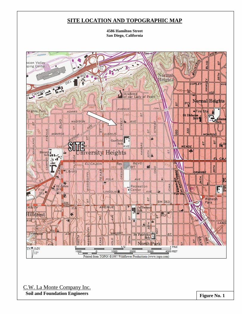
The following report presents the results of a limited geotechnical investigationperformed for the above subject residential project. The project site is located at 4586Hamilton Street in the University Heights area of the City of San Diego, California.Figure Number 1 (attached) provides a vicinity map showing the approximatelocation of the property.
The subject site consists of a rectangular shaped lot approximately 7000 square feet inarea. The property currently supports a single-story, wood-frame residence with twodetached garages. It is our understanding the existing buildings will be removed tomake way for two new residential townhouse units with detached garages. Theproposed structures will be one- and two-story, wood-frame buildings, founded onconventional shallow footings with slab-on-grade concrete floors. The structures willbe constructed near the elevation of the existing grade and therefore, minimal sitegrading is anticipated.
This report has been prepared for the exclusive use of the stated client and his designconsultants for specific application to the project described herein. Should the projectbe changed in any way, the modified plans should be submitted to C. W. La MonteCompany, Inc. for review to determine their conformance with ourrecommendations and to determine if any additional subsurface investigation,laboratory testing and/or recommendations are necessary. Our professional serviceshave been performed, our findings obtained and our recommendations prepared inaccordance with generally accepted engineering principles and practices. Thiswarranty is in lieu of all other warranties, expressed or implied.
4586 Hamilton Street August 5, 2013 Page 2San Diego, CA
SCOPE OF WORK
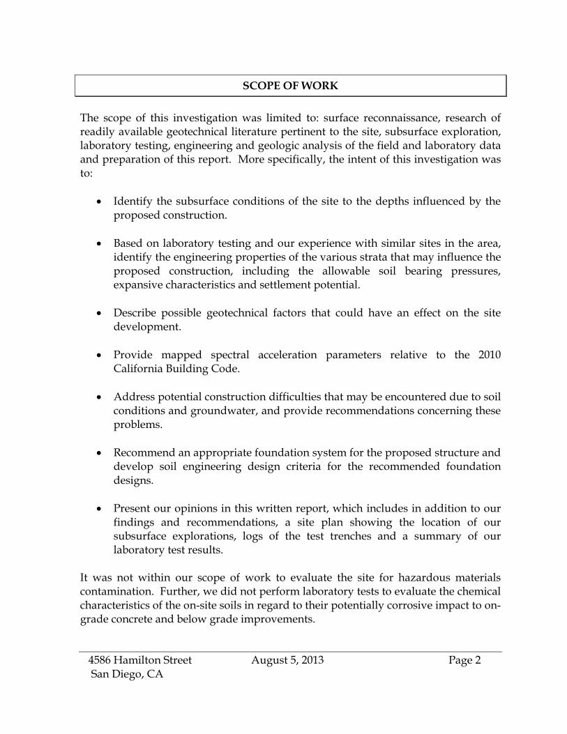
The scope of this investigation was limited to: surface reconnaissance, research ofreadily available geotechnical literature pertinent to the site, subsurface exploration,laboratory testing, engineering and geologic analysis of the field and laboratory dataand preparation of this report. More specifically, the intent of this investigation wasto:
Identify the subsurface conditions of the site to the depths influenced by theproposed construction.
Based on laboratory testing and our experience with similar sites in the area,identify the engineering properties of the various strata that may influence theproposed construction, including the allowable soil bearing pressures,expansive characteristics and settlement potential.
Describe possible geotechnical factors that could have an effect on the sitedevelopment.
Provide mapped spectral acceleration parameters relative to the 2010California Building Code.
Address potential construction difficulties that may be encountered due to soilconditions and groundwater, and provide recommendations concerning theseproblems.
Recommend an appropriate foundation system for the proposed structure anddevelop soil engineering design criteria for the recommended foundationdesigns.
Present our opinions in this written report, which includes in addition to ourfindings and recommendations, a site plan showing the location of oursubsurface explorations, logs of the test trenches and a summary of ourlaboratory test results.
It was not within our scope of work to evaluate the site for hazardous materialscontamination. Further, we did not perform laboratory tests to evaluate the chemicalcharacteristics of the on-site soils in regard to their potentially corrosive impact to on-grade concrete and below grade improvements.

4586 Hamilton Street August 5, 2013 Page 3San Diego, CA
FINDINGS
SITE DESCRIPTION
The project site is located at 4586 Hamilton Street in the University Heights area ofthe City of San Diego, California. The site is bounded on the north and south withresidential development, on the east with Hamilton Street and on the west with analley. The property is rectangular shaped and is approximately 50 feet wide by 140feet deep. Refer to the attached Plot Plan (Figure No. 2) for a layout of the site.
The property currently supports a single-story, single-family structure and twodetached garages. Vegetation consists primarily of lawn grass, weeds, landscapeshrubs, and a few trees.
The site topography consists of mesa top terrain, which slopes gently to the north.Survey information concerning site elevations was not available at the time of ourinvestigation. However, a review of regional topographic maps indicates elevationson the order of 380 feet MSL.
DESCRIPTION OF SUBSURFACE SOIL CONDITIONS
The site was found to be underlain with subsoil clays with associated topsoils. Thesesoil types are described individually below in order of increasing age. Also refer theattached Test Boring Logs, Figure No. 3. A Plot Plan is attached as Figure No. 2 withthe test excavation locations. An excerpt from a regional geologic map is included asFigure No. 4.
Topsoil: The fill is underlain with a veneer of natural ground topsoil that isapproximately one-foot in thickness. The encountered topsoil deposits consistprimarily of grayish brown, very moist to saturated, loose to medium dense,silty sand with some gravel. These topsoils are potential compressible andshould be penetrated with deepened foundation excavations.
Subsoil/Mudstone: The topsoils are underlain with a substantial subsoil clayprofile, which was encountered to the maximum depth of exploration at 7.5feet. According to Normal Heights Mudstones: A New Upper Pleistocene MarineSedimentary Unit, San Diego, California by Leslie D. Reed, Circa 1991. The localsubsoil clay section varies from about 10 to 12 feet in thickness. This deposit is
4586 Hamilton Street August 5, 2013 Page 4San Diego, CA
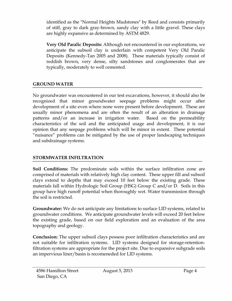
identified as the "Normal Heights Mudstones" by Reed and consists primarilyof stiff, gray to dark gray-brown, sandy clay with a little gravel. These claysare highly expansive as determined by ASTM 4829.
Very Old Paralic Deposits: Although not encountered in our explorations, weanticipate the subsoil clay is underlain with competent Very Old ParalicDeposits (Kennedy-Tan 2005 and 2008). These materials typically consist ofreddish brown, very dense, silty sandstones and conglomerates that aretypically, moderately to well cemented.
GROUND WATER
No groundwater was encountered in our test excavations, however, it should also berecognized that minor groundwater seepage problems might occur afterdevelopment of a site even where none were present before development. These areusually minor phenomena and are often the result of an alteration in drainagepatterns and/or an increase in irrigation water. Based on the permeabilitycharacteristics of the soil and the anticipated usage and development, it is ouropinion that any seepage problems which will be minor in extent. These potential“nuisance” problems can be mitigated by the use of proper landscaping techniquesand subdrainage systems.
STORMWATER INFILTRATION
Soil Conditions: The predominate soils within the surface infiltration zone arecomprised of materials with relatively high clay content. These upper fill and subsoilclays extend to depths that may exceed 10 feet below the existing grade. Thesematerials fall within Hydrologic Soil Group (HSG) Group C and/or D. Soils in thisgroup have high runoff potential when thoroughly wet. Water transmission throughthe soil is restricted.
Groundwater: We do not anticipate any limitations to surface LID systems, related togroundwater conditions. We anticipate groundwater levels will exceed 20 feet belowthe existing grade, based on our field exploration and an evaluation of the areatopography and geology.
Conclusion: The upper subsoil clays possess poor infiltration characteristics and arenot suitable for infiltration systems. LID systems designed for storage-retention-filtration systems are appropriate for the project site. Due to expansive subgrade soilsan impervious liner/basin is recomeneded for LID systems.

4586 Hamilton Street August 5, 2013 Page 5San Diego, CA
TECTONIC SETTING
No major faults are known to traverse the subject site but it should be noted that muchof Southern California, including the San Diego County area, is characterized by aseries of Quaternary-age fault zones, which typically consist of several individual, enechelon faults that generally strike in a south easterly – northwesterly direction. Someof these fault zones (and the individual faults within the zones) are classified as active.According to the criteria of the California Division of Mines and Geology, active faultzones are those, which have shown conclusive evidence of faulting during theHolocene Epoch (the most recent 11,000 years). An excerpt from the 2010 Fault ActivityMap of California, Geologic Data Map No. 6, is attached as Figure No. 6, showing therecency of faulting in the region.
A review of available geologic maps indicates that the Rose Canyon Fault Zone is thenearest active fault and is located about 5 kilometers southwest of the site. Accordingto the 2008 National Seismic Hazard Maps - Fault Parameters (USGS website), theMaximum Magnitude earthquake on the Rose Canyon Fault Zone is 6.9 (Ellsworth)or 6.7 (Hanks) with a slip rate of 1.5. The Rose Canyon Fault Zone is currentlyclassified as a Type "B" fault (California Probabilistic Seismic Hazard Maps, June 2003)
In addition to the Rose Canyon Fault Zone, the Texas Street Fault is mappedapproximately 2000 feet west of the property. The Texas Street fault is consideredpotentially active1, inactive, presumed inactive, or activity unknown, by the City of SanDiego Seismic Safety Study.
Other active fault zones in the region that could possibly affect the site include theCoronado Bank, San Diego Trough and San Clemente Fault Zones to the southwestand the Elsinore, Earthquake Valley, San Jacinto and San Andreas Fault Zones to thenortheast. However, the Rose Canyon Fault Zone is considered the most significantnearby fault with respect to the potential for seismically induced ground shaking(due to its closer proximity to the site).
According to the Official Map of Alquist-Priolo Earthquake Fault Zones, by the CaliforniaDivision of Mines and Geology (currently California Geological Survey) (CDMG,1991) the site IS NOT located in or near an Alquist-Priolo Earthquake Fault Zone.
1 Potentially active faults have demonstrated movement during the Pleistocene Epoch (11,000 to 1.6
million years before the present) but no movement during Holocene (recent) times.

4586 Hamilton Street August 5, 2013 Page 6San Diego, CA
SEISMIC DESIGN PARAMETERS
We have determined the mapped spectral acceleration values for the site utilizing aprogram titled “Seismic Hazard Curves, Response Parameters and Design Parameters-v5.1.0,” provided by the USGS. For this determination, we have assigned a Site SoilClassification of “D”. The response parameters for design are presented in thefollowing Table I.
TABLE I
Mapped Spectral Acceleration Values and Design Parameters
Ss S1 Fa Fv Sms Sm1 Sds Sd1
1.390 0.518 1.0 1.5 1.390 0.778 0.927 0.518
Application to the criteria in Table I for seismic design does not constitute any kindof guarantee or assurance that significant structural damage or ground failure willnot occur if seismic shaking occurs. The primary goal of seismic design is to protectlife, not to avoid all damage, since such design may be economically prohibitive.
GEOLOGIC HAZARDS
General: No geologic hazards of sufficient magnitude to preclude development ofthe site as currently proposed are known to exist. In our professional opinion and tothe best of our knowledge, the site is suitable for the proposed additions. The City ofSan Diego Seismic Safety Study places the site in Hazard Category 52. Thisclassification implies low geotechnical risk. An excerpt of this document is attachedas Figure No. 5.
Ground Shaking: A likely geologic hazard to affect the site is ground shakingresulting from movement along one of the major active fault zones mentioned above.Probable ground shaking levels at the site could range from slight to severe,depending on such factors as the magnitude of the seismic event and the distance tothe epicenter. It is likely that the site will experience the effects of at least onemoderate to large earthquake during the life of the proposed structure. Constructionin accordance with the minimum requirements of the current building codes andlocal governing agencies should minimize potential damage due to seismic activity.

4586 Hamilton Street August 5, 2013 Page 7San Diego, CA
Landslide Potential and Slope Stability: A review of the geologic hazards mapindicates there are no known deep or suspected ancient landslides located on the site.Due to the sites gentle topography and underlying competent materials, landslidehazards do not present a significant risk to the proposed addition.
As part of this investigation we reviewed the publication, “Landslide Hazards in theSouthern Part of the San Diego Metropolitan Area” by Tan and Giffen, 1995. Thisreference is a comprehensive study that classifies San Diego County into areas ofrelative landslide susceptibility. The subject site is located in an area classified as 2.The “2” classification is assigned to areas marginally susceptible to slope movement.This area includes gentle to moderate slopes, where slope angles are generally lessthan 15 degrees. Landslides and other slope failures are rare within this area.
Liquefaction: The materials at the site are not subject to significant liquefaction dueto such factors as soil density, grain-size distribution, and groundwater conditions.
Soil Expansion: The foundation level materials at the site are considered to possessa low expansion potential.
Flooding: The site is located outside the boundaries of both the 100-year and the500-year floodplains according to the maps prepared by the Federal EmergencyManagement Agency.
Tsunamis and Seiches: Tsunamis are great sea waves produced by submarineearthquakes or volcanic eruptions. Seiches are periodic oscillations in large bodies ofwater such as lakes, harbors, bays or reservoirs. Based on the project’s elevatedlocation, the site is considered to possess a low risk potential from tsunamis or seicheactivity.
CONCLUSIONS
In general we found that the subject site is suitable for the construction of theproposed residential project, provided the recommendations provided herein arefollowed. The geotechnical condition that will have the most significant impact onthe site development as proposed is the presence of the previously described,expansive clay materials, which were encountered to the maximum depth ofexploration. These materials require specialized foundation and floor slabrecommendations. Additionally, a minor remedial grading operation isrecommended to process surficial materials disturbed by current weatheringprocesses and anticipated future demolition operations.

4586 Hamilton Street August 5, 2013 Page 8San Diego, CA
The subsoil materials underlying the site possess a very high expansion potential(expansion index [EI] greater than 100) as defined by ASTM 4829. Expansive soilsare clay materials that increase in volume (expand) with an increase of moisturecontent and decrease in volume with the loss of water (shrinkage). The amount ofexpansion an expansive soil will experience is largely a function of the percentage ofmoisture present in the soil relative to the moisture possible at total saturation.
Without proper mitigation expansive soil conditions can result in heavingfoundations and floor slabs. Therefore, expansive soils require specializedfoundation design and other considerations. The following “Foundations” section ofthis report provides recommendations for deepened footings and heavyreinforcement for foundations & floor slabs. Post-tensioned (PT) slab and foundationsystems are also appropriate for the on-site soil conditions and warrantconsideration. PT design parameters can be provided on request. Proper and wellmaintained site drainage is also an important factor when building in expansive soilconditions. Constructing hardscape adjacent the building perimeters is preferable toearthen planters areas. An Expansive Soil Action Plan is attached as Appendix C andprovides generalized actions, procedures and options for expansive soil conditions.
RECOMMENDATIONS
EARTH WORK AND GRADING
Specifications and Preconstruction
All grading should conform to the guidelines presented in the California BuildingCode, the minimum requirements of the City of San Diego, and the RecommendedGrading Specifications and Special Provisions, Appendix “A”, attached hereto,except where specifically superseded in the text of this report. Prior to grading, arepresentative of C. W. La Monte Company Inc. should be present at thepreconstruction meeting to provide additional grading guidelines, if necessary, andto review the earthwork schedule.
Fill Suitability
Some of the on-site excavated clay materials may be used as compacted fill materialor backfill. However, the expansive clay soils at depth are not suitable for use asretaining wall backfill. Any potential import soil sites should be evaluated andapproved by the Geotechnical Consultant prior to importation. At least two workingdays notice of a potential import source should be given to the Geotechnical

4586 Hamilton Street August 5, 2013 Page 9San Diego, CA
Consultant so that appropriate testing can be accomplished. The type of materialconsidered most desirable for import is a non-detrimentally expansive granularmaterial with some silt or clay binder.
Observation of Grading
Observation and testing by the soil engineer is essential during the gradingoperations. This allows the soil engineer to confirm the conditions anticipated by ourinvestigation, to allow adjustments in design criteria to reflect the actual fieldconditions exposed, and to determine that the grading proceeds in generalaccordance with the recommendations contained herein.
Site Preparation
Site preparation should begin with the removal of all structures and improvementsdesignated for removal, vegetation and other deleterious materials from the portionof lot that will be graded and that will receive improvements. This should include allroot balls from the trees to be removed and all significant root material. The resultingmaterials should be disposed of off-site. If desirable, the removed asphalt paving maybe pulverized and reused as base material.
After clearing and grubbing, site preparation should continue with the removal allexisting loose topsoil material and disturbed material from areas that will be gradedor that will support settlement-sensitive improvements. As the project is presentlyplanned, soil removals are expected to be about 1 to 2 feet in depth, but may bethicker in localized areas. The removals should extend at least 4 feet outside thebuilding perimeters, where possible. The loose soil shall be removed to expose firmnatural ground as determined by our field representative during grading.
Prior to placing any fill soils or constructing any new improvements, the exposedsoils should be scarified to a depth of approximately 6 to 12 inches, moistureconditioned, and compacted to at least 90 percent relative compaction. Also theupper one-foot of pavement areas should be processed and recompacted.
Compaction and Method of Filling
All structural fill placed at the site and supporting the above grade portions of theproposed structure should be compacted to a minimum relative compaction of atleast 95 percent of its maximum dry density as determined by ASTM Laboratory TestD1557. All other structural fill placed at the site should be compacted to a minimumrelative compaction of at least 90 percent of its maximum dry density. Fills should beplaced at or slightly above optimum moisture content, in lifts six to eight inchesthick, with each lift compacted by mechanical means. Fills should consist of
4586 Hamilton Street August 5, 2013 Page 10San Diego, CA
approved earth material, free of trash or debris, roots, vegetation, or other materialsdetermined to be unsuitable by our soil technicians or project geologist. All materialshould be free of rocks or lumps of soil in excess of twelve inches in maximumwidth. However, in the upper two feet of pad grade, no rocks or lumps of soil inexcess of six inches should be allowed.
Utility trench backfill within five feet of the proposed structure and beneath allpavements and concrete flatwork should be compacted to a minimum of 90 percentof its maximum dry density. The upper one-foot of pavement subgrade and basematerial should be compacted to at least 95 percent relative density. All grading andfill placement should be performed in accordance with the local Grading Ordinance,the California Building Code, and the Recommended Grading Specifications andSpecial Provisions attached hereto as Appendix A.
Excavation Characteristics
The on-site topsoil materials will excavate with moderate effort using heavyequipment. No significant amounts of oversize materials (greater than 12 inches) areanticipated during normal grading operations. The clay material is highly cohesiveand will excavate in “clumps”.
Temporary Cut Slopes
No temporary cuts over 5 feet in height are anticipated and, therefore, specificrecommendations for temporary excavations are not included in this report.However, it should be noted that the contractor is solely responsible for designingand constructing stable, temporary excavations and may need to shore, slope, orbench the sides of trench excavations as required to maintain the stability of theexcavation sides where friable sands or loose soils are exposed. The contractor’s“responsible person”, as defined in the OSHA Construction Standards forExcavations, 29 CFR, Part 1926, should evaluate the soil exposed in the excavationsas part of the contractor’s safety process. In no case should slope height, slopeinclination, or excavation depth, including utility trench excavation depth, exceedthose specified in local, state, and federal safety regulations.
Surface Drainage
Pad drainage should be designed to collect and direct surface water away from theproposed structure and toward approved drainage facilities. The ground around theproposed building should be graded so that surface water flows rapidly away fromthe building without ponding. For earth areas, a minimum gradient of 2.5 percentshould be maintained. Roof drainage should be designed so that water is directedtoward appropriate storm drainage inlets or facility and is not allowed to fall

4586 Hamilton Street August 5, 2013 Page 11San Diego, CA
uncontrolled onto soil directly adjacent to footings. Drainage facilities should beperiodically inspected to verify they are functioning properly.
Any planter boxes should be enclosed with an adequate outlet/s to the establisheddrainage system.
Erosion Control
In addition, appropriate erosion-control measures shall be taken at all times duringconstruction to prevent surface runoff waters from entering footing excavations,ponding on finished building pad or pavement areas, or running uncontrolled overthe tops of newly-constructed cut or fill slopes. Appropriate Best ManagementPractice (BMP) erosion control devices should be provided in accordance with localand federal governing agencies.
Grading Plans Review
The finalized, grading plans (If any) should be submitted to this office for review toascertain that the recommendations provided in this report have been followed andthat the assumptions utilized in its preparation are still valid. Additional oramended recommendations may be issued based on this review.
FOUNDATIONS
General
Based on the findings of our investigation, it is our opinion the proposed stricturesmay be supported by conventional continuous and isolated spread footings. The on-site materials possess a high to very high expansive potential and therefore,deepened embedment and “heavy” reinforcement is required for foundations andfloor slabs. Any isolated pad footings require “tie beams”. Post-Tension floor slabsystems are also appropriate for the on-site expansive conditions.
Foundation Embedment
Conventional shallow foundations may be utilized in the support of the proposedstructures. All footings supporting the proposed structures should be embedded atleast 24 inches below the lowest adjacent grade. Continuous and isolated footingsshould have a minimum width of 15 inches for two- story and 18 inches for three-story structures.
Isolated footings should be at least 24 inches in width. Isolated footings should beconstructed with a tiebeam and/or be incorporated into a thickened edge slab (when
4586 Hamilton Street August 5, 2013 Page 12San Diego, CA
surrounded with slab-on-grade). Additionally, a tiebeam is recommended acrossgarage door openings.
Soil Bearing Value
The recommended allowable bearing capacity for foundations with minimumdimensions described herein is 2,000 psf for footings bearing in competent naturalground or properly compacted fill. The values presented herein are for dead pluslive loads and may be increased by one-third when considering transient loads dueto wind or seismic forces.
Lateral Load Resistance
Lateral loads against foundations may be resisted by friction between the bottom ofthe footing and the supporting soil, and by the passive pressure against the footing.The coefficient of friction between concrete and soil may be considered to be 0.25.The passive resistance may be considered to be equal to an equivalent fluid weight of250 pounds per cubic foot in recompacted fill or firm natural ground material. Thisassumes the footings are poured tight against undisturbed soil. If a combination ofthe passive pressure and friction is used, the friction value should be reduced by one-third.
Foundation Reinforcement
It is recommended that continuous footings be reinforced with at least four No.5 steelbar; two reinforcing bars shall be located near the top of the foundation, and two barsnear the bottom.
The steel reinforcement will help prevent damage due to normal, post constructionsettlement or heaving, resulting from variations in the subsurface soil conditions.The minimum reinforcement recommended herein is based on soil characteristicsonly and is not intended to replace reinforcement required for structuralconsiderations).
Post-Tensioned Foundation System
As an alternative to the foundation recommendations for each category,consideration should be given to the use of post-tensioned concrete slab andfoundation systems for the support of the proposed structures. The post-tensionedsystems should be designed by a structural engineer experienced in post-tensionedslab design and design criteria of the Post-Tensioning Institute. The post-tensioneddesign should incorporate the geotechnical parameters presented on Table III.
TABLE II
4586 Hamilton Street August 5, 2013 Page 13San Diego, CA
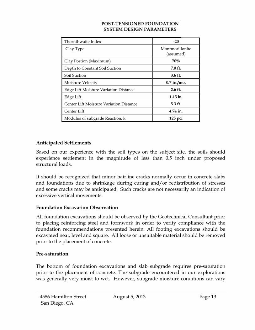
POST-TENSIONED FOUNDATIONSYSTEM DESIGN PARAMETERS
Thornthwaite Index -20
Clay Type Montmorillonite(assumed)
Clay Portion (Maximum) 70%
Depth to Constant Soil Suction 7.0 ft.
Soil Suction 3.6 ft.
Moisture Velocity 0.7 in./mo.
Edge Lift Moisture Variation Distance 2.6 ft.
Edge Lift 1.15 in.
Center Lift Moisture Variation Distance 5.3 ft.
Center Lift 4.74 in.
Modulus of subgrade Reaction, k 125 pci
Anticipated Settlements
Based on our experience with the soil types on the subject site, the soils shouldexperience settlement in the magnitude of less than 0.5 inch under proposedstructural loads.
It should be recognized that minor hairline cracks normally occur in concrete slabsand foundations due to shrinkage during curing and/or redistribution of stressesand some cracks may be anticipated. Such cracks are not necessarily an indication ofexcessive vertical movements.
Foundation Excavation Observation
All foundation excavations should be observed by the Geotechnical Consultant priorto placing reinforcing steel and formwork in order to verify compliance with thefoundation recommendations presented herein. All footing excavations should beexcavated neat, level and square. All loose or unsuitable material should be removedprior to the placement of concrete.
Pre-saturation
The bottom of foundation excavations and slab subgrade requires pre-saturationprior to the placement of concrete. The subgrade encountered in our explorationswas generally very moist to wet. However, subgrade moisture conditions can vary
4586 Hamilton Street August 5, 2013 Page 14San Diego, CA
seasonal. Therefore, moisture conditioning may be necessary prior to placement offoundations and floor slabs. The most important practice in reducing the potentialfor lifting of concrete slabs due to expansive soil is the pre-saturation of the soil priorto pouring concrete. A common specification is to attain a 110% to 120% of optimummoisture content to a depth of at least 18". This moisture penetration should beverified by the soil engineer prior to the placement of concrete.
Water migrates very slowly through most expansive soil; therefore, obtaining therecommended pre-saturation can be a tedious process. Experienced contractors oftenspread an ample amount of a surfactant such as laundry detergent on the groundduring pre-saturation to aid in obtaining the recommended moisture penetration.Another technique is to utilize a hand auger to create a grid of small diameter holes(about 2 inches in diameter); 2 feet deep. The holes can be filled with crushed rocksuch as pea gravel. These holes fill with water during pre-saturation to further aid inobtaining the recommended moisture penetration.
Foundation Plan Review
The finalized, foundation plans should be submitted to this office for review toascertain that the recommendations provided in this report have been followed andthat the assumptions utilized in its preparation are still valid. Additional oramended recommendations may be issued based on this review.
CONCRETE SLABS-ON-GRADE
It is our understanding that the floor system of the proposed structure will consist ofconcrete slab-on-grade floors. The following recommendations assume that thesubgrade soils have been prepared in accordance with the recommendationspresented in the “Grading and Earthwork” section of this report and the subgrade wasadequately prostrated as discussed in the Foundations section of this report. Inaddition, the following recommendations are considered the minimum slabrequirements based on the soil conditions and are not intended in lieu of structuralconsiderations.
Interior Floor Slabs: We recommend a minimum floor slab thickness of five (5)inches (actual) is recommended for slab-on-grade floors. The floor slabs should bereinforced with at least No. 4 bars placed at 18 inches on center each way. Slabreinforcing should be supported by chairs and be positioned at mid-height in thefloor slab.

4586 Hamilton Street August 5, 2013 Page 15San Diego, CA
Exterior Concrete Slabs
On-grade exterior concrete slabs for walks and patios should have a thickness of fiveinches and should be reinforced with at least No. 3 reinforcing bars placed at 12inches on center each way. Exterior slab reinforcement should be placedapproximately at mid-height of the slab. Reinforcement and control joints should beconstructed in exterior concrete flatwork to reduce the potential for cracking andmovement. Joints should be placed in exterior concrete flatwork to help control thelocation of shrinkage cracks. Spacing of control joints should be in accordance withthe American Concrete Institute specifications. When slabs abut foundations theyshould be doweled into the footings.
The slab subgrade should be prepared as recommendation in the Site Preparationsection of this report. Exterior slab subgrade requires pre-saturation as discussed inthe foundations section of this report. We recommend driveway slabs be underlainwith approximately 6 inches of aggregate base.
Vehicular traffic should be avoided until the slab concrete is adequately cured.
SLAB MOISTURE BARRIERS
A moisture barrier system is recommended beneath interior slab-on-grade floorswith moisture sensitive floor coverings or coatings to help reduce the upwardmigration of moisture vapor from the underlying subgrade soil. A properly selectedand installed vapor retarder is essential for long-term moisture resistance and canminimize the potential for flooring problems related to excessive moisture.
Interior floor slabs should be underlain by a minimum 10-mil thick moisture retarderproduct over a four thick layer of sand (Please note, additional moisture reductionand/or prevention measures may be needed, depending on the performancerequirements for future floor covering products). The moisture barrier shall overlie alayer of clean sand. The moisture retarder product used should meet or exceed theperformance standards dictated by ASTM E 1745 Class A material and be properlyinstalled in accordance with ACI publication 302 (Guide to Concrete Floor and SlabConstruction) and ASTM E1643 (Standard Practice for Installation of Water VaporRetarder Used in Contact with Earth or Granular Fill Under Concrete Slabs). Ultimately,the design of the moisture retarder system and recommendations for concreteplacement and curing are purview of the structural engineer, in consideration of theproject requirements provided by the project architect and developer.

4586 Hamilton Street August 5, 2013 Page 16San Diego, CA
Moisture Retarders and Installation
Vapor retarder joints must have at least 6-inch-wide overlaps and be sealed withmastic or the manufacturer's recommended tape or compound. No heavy equipment,stakes or other puncturing instruments should be used on top of the liner before orduring concrete placement. In actual practice, stakes are often driven through theretarder material, equipment is dragged or rolled across the retarder, overlapping orjointing is not properly implemented, etc. All these construction deficiencies reducethe retarders’ effectiveness. It is the responsibility of the contractor to ensure that themoisture retarder is properly placed in accordance with the project plans andspecifications, and that the moisture retarder material is free of tears and puncturesand is properly sealed prior to the placement of concrete.
Interior Slab Curing Time
Following placement of concrete floor slabs, sufficient drying time must be allowedprior to placement of floor coverings. Premature placement of floor coverings mayresult in degradation of adhesive materials and loosening of the finish floormaterials. Prior to installation, standardized testing (calcium chloride test and/orrelative humidity) can be performed to determine if the slab moisture emissions arewithin the limits recommended by the manufacturer of the specified floor-coveringproduct.
DESIGN PARAMETERS FOR EARTH RETAINING STRUCTURES
Passive Pressure: The passive pressure for the prevailing soil conditions may beconsidered to be 250 pounds per square foot per foot of depth. This pressure maybe increased one-third for seismic loading. The coefficient of friction for concrete tosoil may be assumed to be 0.40 for the resistance to lateral movement. Whencombining frictional and passive resistance, the friction value should be reduced byone-third.
Active Pressure for Retaining Walls
Lateral pressures acting against masonry and cast-in-place concrete retaining wallscan be calculated using soil equivalent fluid weight. The equivalent fluid weightvalue used for design depends on allowable wall movement. Walls that are free torotate at least 0.5 percent of the wall height can be designed for the active equivalentfluid weight. Retaining walls that are restrained at the top (such as basement walls),or are sensitive to movement and tilting should be designed for the at-rest equivalentfluid weight.
4586 Hamilton Street August 5, 2013 Page 17San Diego, CA
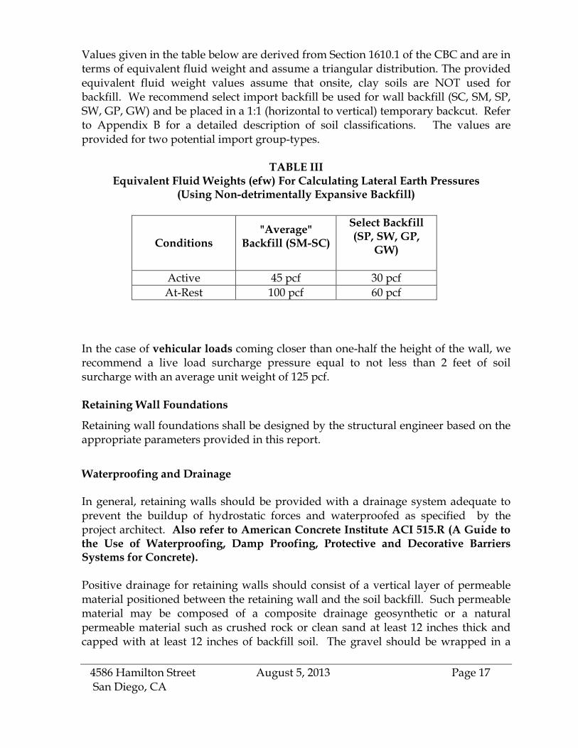
Values given in the table below are derived from Section 1610.1 of the CBC and are interms of equivalent fluid weight and assume a triangular distribution. The providedequivalent fluid weight values assume that onsite, clay soils are NOT used forbackfill. We recommend select import backfill be used for wall backfill (SC, SM, SP,SW, GP, GW) and be placed in a 1:1 (horizontal to vertical) temporary backcut. Referto Appendix B for a detailed description of soil classifications. The values areprovided for two potential import group-types.
TABLE IIIEquivalent Fluid Weights (efw) For Calculating Lateral Earth Pressures
(Using Non-detrimentally Expansive Backfill)
Conditions"Average"
Backfill (SM-SC)
Select Backfill(SP, SW, GP,
GW)
Active 45 pcf 30 pcf
At-Rest 100 pcf 60 pcf
In the case of vehicular loads coming closer than one-half the height of the wall, werecommend a live load surcharge pressure equal to not less than 2 feet of soilsurcharge with an average unit weight of 125 pcf.
Retaining Wall Foundations
Retaining wall foundations shall be designed by the structural engineer based on theappropriate parameters provided in this report.
Waterproofing and Drainage
In general, retaining walls should be provided with a drainage system adequate toprevent the buildup of hydrostatic forces and waterproofed as specified by theproject architect. Also refer to American Concrete Institute ACI 515.R (A Guide tothe Use of Waterproofing, Damp Proofing, Protective and Decorative BarriersSystems for Concrete).
Positive drainage for retaining walls should consist of a vertical layer of permeablematerial positioned between the retaining wall and the soil backfill. Such permeablematerial may be composed of a composite drainage geosynthetic or a naturalpermeable material such as crushed rock or clean sand at least 12 inches thick andcapped with at least 12 inches of backfill soil. The gravel should be wrapped in a

4586 Hamilton Street August 5, 2013 Page 18San Diego, CA
geosynthetic filter fabric. Provisions should be made for the discharge of anyaccumulated groundwater. The selected drainage system should be provided with aperforated collection and discharge pipe placed along the bottom of the permeablematerial near the base of the wall. The drain pipe should discharge to a suitabledrainage facility. If lateral space (due to property line constraints) is insufficient toallow installation of the gravel-wrapped "burrito" drain, a geocomposite system maybe used in lieu of the typical gravel and pipe subdrain system. TenCate's MiraDrain(and similar products) provide a "low-profile" drainage system that requires minimallateral clearance for installation. MiraDRAIN and similar products may also beincorporated into a waterproofing system and provide a slab drainage system (Pleasenote that supplemental manufacturer’s details will be required to provide awaterproofed system).
Backfill
All backfill soils should be compacted to at least 90% relative compaction. The typicalon-site clay (CH) materials are not suitable for retaining wall backfill. Soil with anexpansion index (EI) of greater than 50 should not be used as backfill material behindretaining walls. The wall should not be backfilled until the masonry has reached anadequate strength.
FIELD INVESTIGATION
A total of three manually excavated test explorations were placed on the site. Theexcavations were placed specifically in areas where representative soil conditionswere expected and/or where the proposed additions will be located. Ourinvestigation also included a visual site reconnaissance. The excavations werevisually inspected and logged by our field geologist, and samples were taken of thepredominant soils throughout the field operation. Test excavation logs have beenprepared on the basis of our inspection and the results have been summarized onFigure No. 3. The predominant soils have been classified in conformance with theUnified Soil Classification System. In addition, a verbal textural description, the wetcolor, the apparent moisture and the density or consistency are provided. Thedensity of granular soils is given as very loose, loose, medium dense, dense or verydense. The density of cohesive soils is given as either very soft, soft, medium stiff,stiff, very stiff, and hard.
Disturbed and relatively undisturbed samples of typical and representative soilswere obtained from the test borings and transported to the laboratory for testing.Any undisturbed samples were obtained by driving a 2-3/8 inch ID split-tube

4586 Hamilton Street August 5, 2013 Page 19San Diego, CA
sampler ahead of a 4-inch diameter hand auger using a 35 pound weight free fallinga distance of 12 inches.
LABORATORY TESTS AND SOIL INFORMATION
Laboratory tests were performed in accordance with the generally acceptedAmerican Society for Testing and Materials (ASTM) test methods or suggestedprocedures. A brief description of the tests and evaluations performed is presentedbelow:
CLASSIFICATION: Field classifications were verified in the laboratory by visualexamination. The final soil classifications are in accordance with the Unified SoilClassification System.
MOISTURE-DENSITY: In-place moisture contents and dry densities weredetermined for representative soil samples. This information was an aid toclassification and permitted recognition of variations in material consistency withdepth. The dry unit weight is determined in pounds per cubic foot, and the in-placemoisture content is determined as a percentage of the soil's dry weight. The resultsare summarized in the test excavation logs.
COMPACTION TEST: The maximum dry density and optimum moisture content ofa typical soil were determined in the laboratory in accordance with ASTM StandardTest D-1557, Method A. The results of this test are presented below.
Sample Location Test Pit B-1 @ 2-3’Sample Description Gray-brown, clayMaximum Dry Density 121 pcfOptimum Moisture 12.1 %
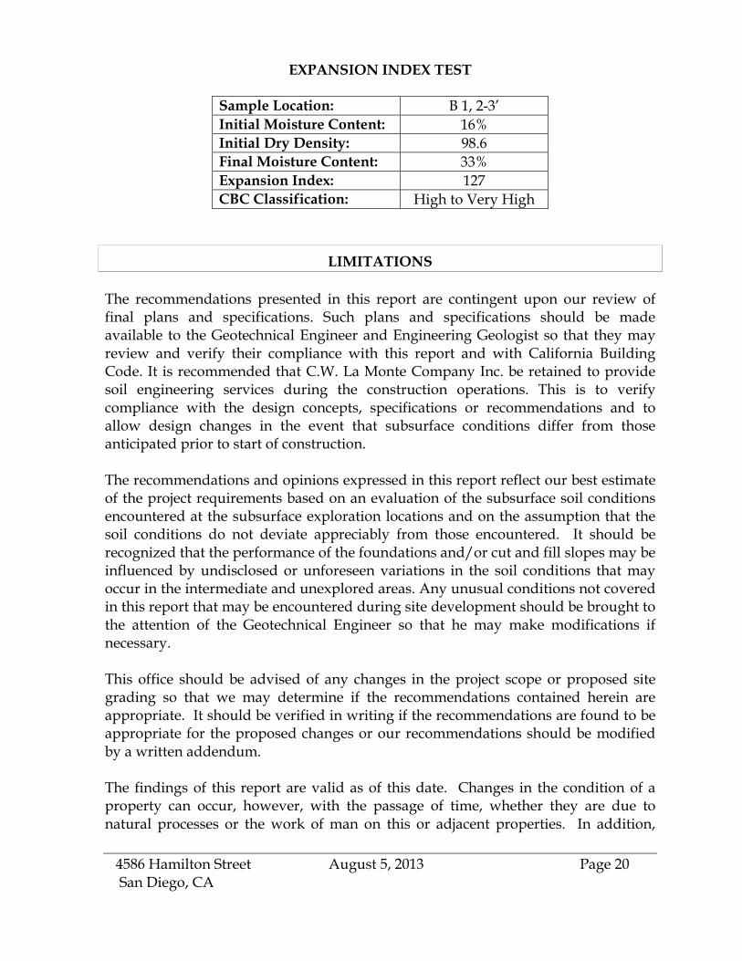
EXPANSION INDEX: Expansion Index testing on a remolded sample wasperformed on a representative sample of the existing clayey subsoil. The test wasperformed on the portion of the sample passing the #4 standard sieve. The samplewas brought to near optimum moisture content. The specimen was then compactedin a 4-inch-diameter mold in two equal layers by means of a tamper, then trimmed toa final height of 1 inch, and brought to a saturation of approximately 50 percent. Thespecimen was placed in a consolidometer with porous stones at the top and bottom;a total normal load of 12.63 pounds was placed (144.7 psf). The sample wassaturated, and the change in vertical movement was recorded until the rate ofexpansion became nominal. The expansion index is reported below as the totalvertical displacement.
4586 Hamilton Street August 5, 2013 Page 20San Diego, CA
EXPANSION INDEX TEST
Sample Location: B 1, 2-3’
Initial Moisture Content: 16%
Initial Dry Density: 98.6
Final Moisture Content: 33%
Expansion Index: 127
CBC Classification: High to Very High
LIMITATIONS
The recommendations presented in this report are contingent upon our review offinal plans and specifications. Such plans and specifications should be madeavailable to the Geotechnical Engineer and Engineering Geologist so that they mayreview and verify their compliance with this report and with California BuildingCode. It is recommended that C.W. La Monte Company Inc. be retained to providesoil engineering services during the construction operations. This is to verifycompliance with the design concepts, specifications or recommendations and toallow design changes in the event that subsurface conditions differ from thoseanticipated prior to start of construction.
The recommendations and opinions expressed in this report reflect our best estimateof the project requirements based on an evaluation of the subsurface soil conditionsencountered at the subsurface exploration locations and on the assumption that thesoil conditions do not deviate appreciably from those encountered. It should berecognized that the performance of the foundations and/or cut and fill slopes may beinfluenced by undisclosed or unforeseen variations in the soil conditions that mayoccur in the intermediate and unexplored areas. Any unusual conditions not coveredin this report that may be encountered during site development should be brought tothe attention of the Geotechnical Engineer so that he may make modifications ifnecessary.
This office should be advised of any changes in the project scope or proposed sitegrading so that we may determine if the recommendations contained herein areappropriate. It should be verified in writing if the recommendations are found to beappropriate for the proposed changes or our recommendations should be modifiedby a written addendum.
The findings of this report are valid as of this date. Changes in the condition of aproperty can occur, however, with the passage of time, whether they are due tonatural processes or the work of man on this or adjacent properties. In addition,

4586 Hamilton Street August 5, 2013 Page 21San Diego, CA
changes in the Standards-of-Practice and/or Government Codes may occur. Due tosuch changes, the findings of this report may be invalidated wholly or in part bychanges beyond our control. Therefore, this report should not be relied upon after aperiod of two years without a review by us verifying the suitability of theconclusions and recommendations.
In the performance of our professional services, we comply with that level of careand skill ordinarily exercised by members of our profession currently practicingunder similar conditions and in the same locality. The client recognizes thatsubsurface conditions may vary from those encountered at the locations where ourborings, surveys, and explorations are made, and that our data, interpretations, andrecommendations are based solely on the information obtained by us. We will beresponsible for those data, interpretations, and recommendations, but shall not beresponsible for the interpretations by others of the information developed. Ourservices consist of professional consultation and observation only, and no warrantyof any kind whatsoever, express or implied, is made or intended in connection withthe work performed or to be performed by us, or by our proposal for consulting orother services, or by our furnishing of oral or written reports or findings.
It is the responsibility of the stated client or their representatives to ensure that theinformation and recommendations contained herein are brought to the attention ofthe structural engineer and architect for the project and incorporated into theproject's plans and specifications. It is further their responsibility to take thenecessary measures to insure that the contractor and his subcontractors carry outsuch recommendations during construction.
The firm of C.W. La Monte Co. Inc. shall not be held responsible for changes to thephysical condition of the property, such as addition of fill soils or changing drainagepatterns, which occur subsequent to the issuance of this report. . Our firm will notbe responsible for the safety of personnel other than our own on the site; the safety ofothers is the responsibility of the Owner and Contractor. The Contractor shouldnotify the Owner if he considers any of the recommended actions presented herein tobe unsafe.
SITE LOCATION AND TOPOGRAPHIC MAP
4586 Hamilton StreetSan Diego, California
Figure No. 1
C.W. La Monte Company Inc.Soil and Foundation Engineers

Project:
Figure No. 2AJob No. 05-4865
LEGEND
N
Scale : 1"=20'HAMILTON STREET
PL
PLPL
PL
Proposed Residential Development4586 Hamilton Avenue
San Diego, California 92116
T1
T2
EXISTINGGARAGE
T1
EXISTINGSTRUCTURE
4586 HAMILTONSTREET
EXISTINGGARAGE
ALLEY

FEET
AL
LE
Y T-1
T-2 Ham
i lto
nS
tre e
t
Proposed Duplex4586 Hamilton Ave., San Diego, CA, 92116
SITE PLAN ANDGEOTECHNICAL MAP
MS
MS

FIGURE NO. 3JOB NO. 05-4865
u.s.c.s.
MO
IST
UR
E
DE
PT
H
(FE
ET
)
CO
NT
EN
T
UN
DIS
TU
RB
ED
DE
PT
H
(FE
ET
)
u.s.c.s.
(PC
F)
CO
NT
EN
TDate: Excavation Method : HAND AUGER
C.W. LA MONTE COMPANY, INC
Soil and Foundation Engineers
Elevation:
Date: 02/01/05 Excavation Method : HAND AUGERElevation:
TOPSOIL
Dark brown, loose, moist, silty sand with some gravel
SM
CH RESIDUAL SOIL
Gray, stiff, moist, clay wuth numerous gravel
Proposed Residential Project4586 Hamilton Street
San Diego, CA
SM
EXCAVATION BOTTOMNO CAVING
NO GROUND WATER
TOPSOILDark brown, loose, moist, silty sand with some gravel
RESIDUAL SOIL
Gray, stiff, moist, clay with numerous gravel
EXCAVATION BOTTOMNO CAVING
NO GROUND WATER

Qvop8
GEOLOGY MAP EXCERPT
4586 HamiltonSan Diego, CA
Figure No. 4
Excerpt from Geology of the San Diego 30' x 60' Quadrangle, California,Compiled by Michael P. Kennedy and Siang S. Tan, 2005
LEGEND (Localized)
Very old paralic deposits, Unit 8(middle to early Pleistocene)

SUMMARY EXPLANATIONFault traces on land are indicated by solid lines where well located, by dashed lines where approximately located or inferred, and by dotted lines whereconcealed by younger rocks or by lakes or bays. Fault traces are queried where continuation or existence is uncertain.
FAULT CLASSIFICATION COLOR CODE (Indicating Recency of Movement)
Historic Fault (last 200 years)
FIGURE 5- Excerpt from: 2010 Fault Activity Map of California, Geologic Data Map No. 6
Holocene fault (during past 11,700 years)
without historic record.
Late Quaternary fault (during past 700,000 years).
Quaternary fault (age undifferentiated)
Pre-Quaternary fault (older that 1.6 million years) or faultwithout recognized Quaternary displacement.

Excerpt From Map 21 City of San DiegoSEISMIC SAFETY STUDY Geologic Hazards and Faults
4640 30th StreetSan Diego, California
Figure No. 6

Appendix “A”
Recommended Grading Specifications and Special Provisions
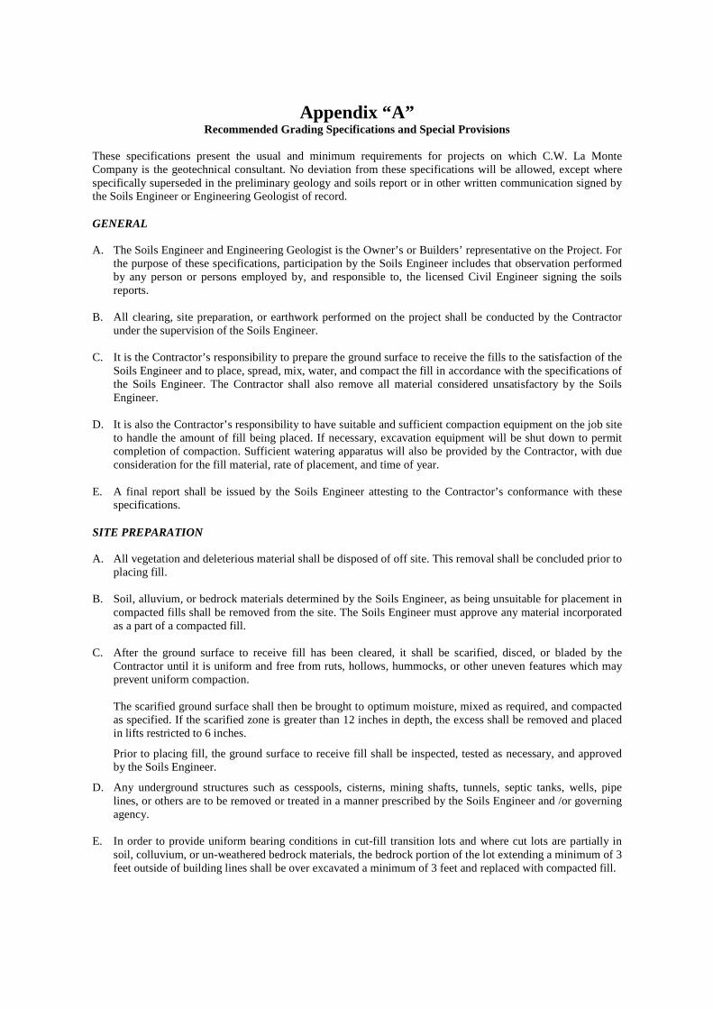
Appendix “A” Recommended Grading Specifications and Special Provisions
These specifications present the usual and minimum requirements for projects on which C.W. La Monte Company is the geotechnical consultant. No deviation from these specifications will be allowed, except where specifically superseded in the preliminary geology and soils report or in other written communication signed by the Soils Engineer or Engineering Geologist of record. GENERAL A. The Soils Engineer and Engineering Geologist is the Owner’s or Builders’ representative on the Project. For
the purpose of these specifications, participation by the Soils Engineer includes that observation performed by any person or persons employed by, and responsible to, the licensed Civil Engineer signing the soils reports.
B. All clearing, site preparation, or earthwork performed on the project shall be conducted by the Contractor
under the supervision of the Soils Engineer. C. It is the Contractor’s responsibility to prepare the ground surface to receive the fills to the satisfaction of the
Soils Engineer and to place, spread, mix, water, and compact the fill in accordance with the specifications of the Soils Engineer. The Contractor shall also remove all material considered unsatisfactory by the Soils Engineer.
D. It is also the Contractor’s responsibility to have suitable and sufficient compaction equipment on the job site
to handle the amount of fill being placed. If necessary, excavation equipment will be shut down to permit completion of compaction. Sufficient watering apparatus will also be provided by the Contractor, with due consideration for the fill material, rate of placement, and time of year.
E. A final report shall be issued by the Soils Engineer attesting to the Contractor’s conformance with these
specifications. SITE PREPARATION A. All vegetation and deleterious material shall be disposed of off site. This removal shall be concluded prior to
placing fill. B. Soil, alluvium, or bedrock materials determined by the Soils Engineer, as being unsuitable for placement in
compacted fills shall be removed from the site. The Soils Engineer must approve any material incorporated as a part of a compacted fill.
C. After the ground surface to receive fill has been cleared, it shall be scarified, disced, or bladed by the
Contractor until it is uniform and free from ruts, hollows, hummocks, or other uneven features which may prevent uniform compaction.
The scarified ground surface shall then be brought to optimum moisture, mixed as required, and compacted as specified. If the scarified zone is greater than 12 inches in depth, the excess shall be removed and placed in lifts restricted to 6 inches.
Prior to placing fill, the ground surface to receive fill shall be inspected, tested as necessary, and approved by the Soils Engineer.
D. Any underground structures such as cesspools, cisterns, mining shafts, tunnels, septic tanks, wells, pipe lines, or others are to be removed or treated in a manner prescribed by the Soils Engineer and /or governing agency.
E. In order to provide uniform bearing conditions in cut-fill transition lots and where cut lots are partially in
soil, colluvium, or un-weathered bedrock materials, the bedrock portion of the lot extending a minimum of 3 feet outside of building lines shall be over excavated a minimum of 3 feet and replaced with compacted fill.

Appendix A Standard Grading and Construction Specifications Page 2
COMPACTED FILLS
A. Any material imported or excavated on the property may be utilized in the fill, provided each material has been determined to be suitable by the Soils Engineer. Roots, tree branches, and other matter missed during clearing shall be removed from the fill as directed by the Soils Engineer.
B. Rock fragments less than 6 inches in diameter may be utilized in the fill, provided:
1. They are not placed in concentrated pockets. 2. There is a sufficient percentage of fine-grained material to surround the rocks. 3. The Soils Engineer shall supervise the distribution of rocks.
C. Rocks greater than 6 inches in diameter shall be taken off site, or placed in accordance with the
recommendations of the Soils Engineer in areas designated as suitable for rock disposal.
D. Material that is spongy, subject to decay or otherwise considered unsuitable should not be used in the compacted fill.
E. Representative samples of material to be utilized as compacted fill shall be analyzed by the laboratory
of the Soils Engineer to determine their physical properties. If any material other than that previously tested is encountered during grading, the appropriate analysis of this material shall be conducted by the Soils Engineer as soon as possible.
F. Material used in the compaction process shall be evenly spread, watered processed, and compacted in
thin lifts not to exceed 6 inches in thickness to obtain a uniformly dense layer. The fill shall be placed and compacted on a horizontal plane, unless otherwise approved by the Soils Engineer.
G. If the moisture content or relative density varies from that required by the Soils Engineer, the
Contractor should re-work the fill until the Soils Engineer approves it.
H. Each layer shall be compacted to 90 percent of the maximum density in compliance with the testing method specified by the controlling governmental agency. (In general, ASTM D-1557-91, the five-layer method will be used.)
If compaction to a lesser percentage is authorized by the controlling governmental agency because of a specific land use or expansive soils condition, the area to receive fill compacted to less than 90 percent shall either be delineated on the grading plan or appropriate reference made to the area in the soils report.
H. All fills shall be keyed and benched through all topsoil, colluvium, alluvium or creep material, into
sound bedrock or firm material except where the slope receiving fill exceeds a ratio of five horizontal to one vertical, in accordance with the recommendations of the Soils Engineer.
I. The key for hillside fills should be a minimum of 15 feet in width and within bedrock or similar
materials, unless otherwise specified in the soil report.
K. Subdrainage devices shall be constructed in compliance with the ordinances of the controlling governmental agency, or with the recommendations of the Soils Engineer or Engineering Geologist.
L. The contractor will be required to obtain a minimum relative compaction of 90 percent out to the finish
slope face of fill slopes, buttresses, and stabilization fills. This may be achieved by either overbuilding the slope and cutting back to the compacted core, or by direct compaction of the slope face with suitable equipment, or by any other procedure which produces the required compaction.

Appendix A Standard Grading and Construction Specifications Page 3
M. All fill slopes should be planted or protected from erosion or by other methods specified in the soils report.
N. Fill-over-cut slopes shall be properly keyed through topsoil, colluvium or creep material into rock or
firm materials, and the transition shall be stripped of all soil prior to placing fill. CUT SLOPES A. The Engineering Geologist shall inspect all cut slopes at vertical intervals not exceeding 10 feet. B. If any conditions not anticipated in the preliminary report such as perched water, seepage, lenticular or
confined strata of a potentially adverse nature, unfavorably inclined bedding, joints or fault planes are encountered during grading, these conditions shall be analyzed by the Engineering Geologist and Soils Engineer, and recommendations shall be made to treat these problems.
C. Cut slopes that face in the same direction as the prevailing drainage shall be protected from slope wash by a
non-erodible interceptor swale placed at the top of the slope.
Unless otherwise specified in the soils and geological report, no cut slopes shall be excavated higher or steeper than that allowed by the ordinances of controlling governmental agencies.
Drainage terraces shall be constructed in compliance with the ordinances of controlling governmental agencies, or with the recommendations of the Soils Engineer or Engineering Geologist.
GRADING CONTROL A. Observation of the fill placement shall be provided by the Soils Engineer during the progress of grading. B. In general, density tests should be made at intervals not exceeding 2 feet of fill height or every 500 cubic
yards of fill placement. This criteria will vary, depending on soil conditions and the size of the job. In any event, an adequate number of field density tests shall be made to verily that the required compaction is being achieved.
C. Density tests may also be conducted on the surface material to receive fills as determined by the Soils
Engineer. D. All clean-outs, processed ground to receive fill, key excavations, subdrains, and rock disposals must be
inspected and approved by the Soils Engineer or Engineering Geologist prior to placing any fill. It shall be the Contractor’s responsibility to notify the Soils Engineer when such areas are ready for inspection.
CONSTRUCTION CONSIDERATIONS A. The Contractor shall provide necessary erosion control measures, during grading and prior to the completion
and construction of permanent drainage controls. B. Upon completion of grading and termination of inspections by the Soils Engineer, no further filling or
excavating, including that necessary for footings, foundations, large tree wells, retaining walls, or other features shall be performed without the approval of the Soils Engineer or Engineering Geologist.
C. Care shall be taken by the Contractor during final grading to preserve any berms, drainage terraces,
interceptor swales, or other devices of permanent nature on or adjacent to the property. D. In the event that temporary ramps or pads are constructed of uncontrolled fill soils during a future grading
operation, the location and extent of the loose fill soils shall be noted by the on-site representative of a qualified soil engineering firm. These materials shall be removed and properly recompacted prior to completion of grading operations.
E. Where not superseded by specific recommendations presented in this report, trenches, excavations, and
temporary slopes at the subject site shall be constructed in accordance with section 1541 of Title 8, Construction Safety Orders, issued by OSHA.
Appendix A Standard Grading and Construction Specifications Page 4
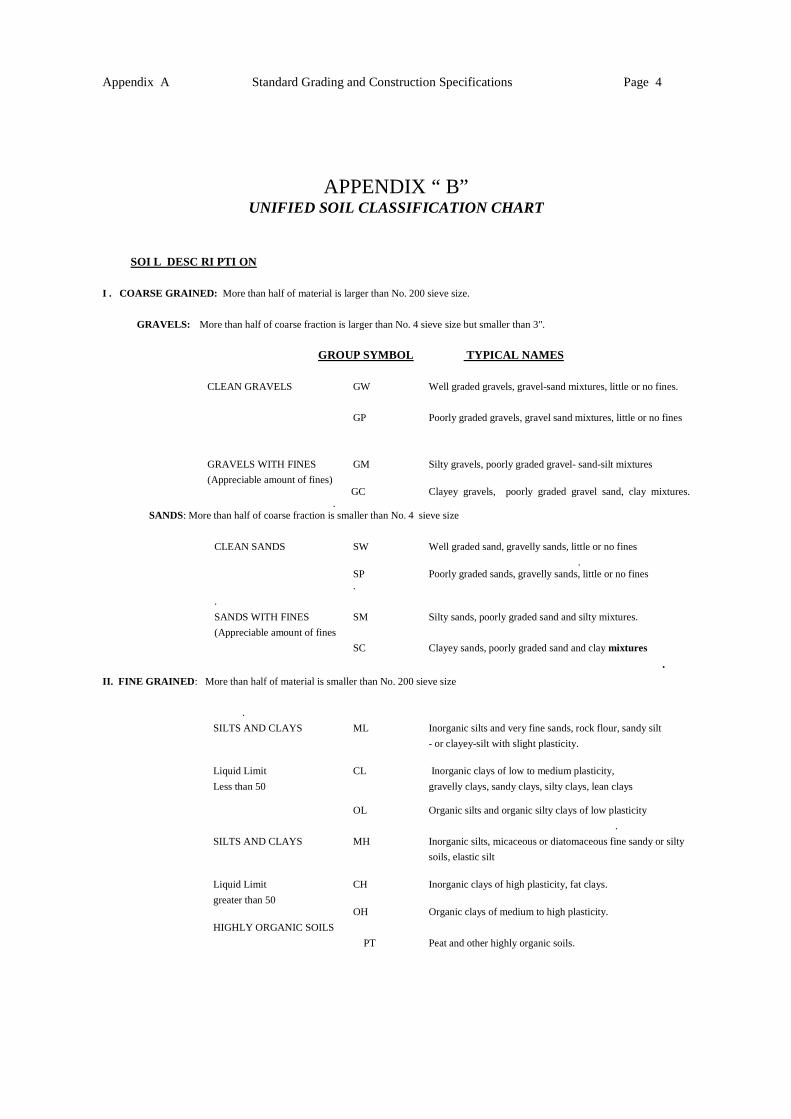
APPENDIX “ B” UNIFIED SOIL CLASSIFICATION CHART
SOI L DESC RI PTI ON
I . COARSE GRAINED: More than half of material is larger than No. 200 sieve size.
GRAVELS: More than half of coarse fraction is larger than No. 4 sieve size but smaller than 3".
GROUP SYMBOL TYPICAL NAMES
CLEAN GRAVELS GW Well graded gravels, gravel-sand mixtures, little or no fines.
GP Poorly graded gravels, gravel sand mixtures, little or no fines
GRAVELS WITH FINES GM Silty gravels, poorly graded gravel- sand-silt mixtures
(Appreciable amount of fines) GC Clayey gravels, poorly graded gravel sand, clay mixtures. .
SANDS: More than half of coarse fraction is smaller than No. 4 sieve size
CLEAN SANDS SW Well graded sand, gravelly sands, little or no fines
. SP Poorly graded sands, gravelly sands, little or no fines .
.
SANDS WITH FINES SM Silty sands, poorly graded sand and silty mixtures.
(Appreciable amount of fines
SC Clayey sands, poorly graded sand and clay mixtures
. II. FINE GRAINED : More than half of material is smaller than No. 200 sieve size
.
SILTS AND CLAYS ML Inorganic silts and very fine sands, rock flour, sandy silt
- or clayey-silt with slight plasticity.
Liquid Limit CL Inorganic clays of low to medium plasticity,
Less than 50 gravelly clays, sandy clays, silty clays, lean clays OL Organic silts and organic silty clays of low plasticity
.
SILTS AND CLAYS MH Inorganic silts, micaceous or diatomaceous fine sandy or silty
soils, elastic silt
Liquid Limit CH Inorganic clays of high plasticity, fat clays.
greater than 50 OH Organic clays of medium to high plasticity.
HIGHLY ORGANIC SOILS
PT Peat and other highly organic soils.
EXPANSIVE SOILS ACTION PLAN

EXPANSIVE SOIL ACTION PLAN Page 1 of 2
Appendix C
TYPICAL SOURCES POSSIBLE PROBLEMS POSSIBLE ACTIONS Rainfall
Non-uniform runoff from roof (and yard) may result in localized heave.
Maintain soil sloping away from all sides of the foundation for a distance of at least 5 feet, use gutters with downspouts that discharge at least 3 feet from the foundation.
Gutter Down Spout
Concentrated sources of water may lead to non-uniform foundation movements.
Extend discharge a minimum of 3 feet from the foundation and use splash blocks to avoid erosion or use flexible discharge tubes.
Poor Drainage Localized source of water from rainwater flowing or ponding next to the foundation may lead to localized heave of the foundation.
Slope ground away from all sides of the foundation for a distance of at least 5 feet, create drainage swales to divert water away from the foundation, keep dirt line several inches below the (floor) line, use clay soil fill to create positive slope away from the foundation. Do not use SANDY SOILS for fill next to foundation, use CLAYS. Compact the fill to shed water, not absorb it.
Flower Beds Localized source of water not on all sides of foundation, may result in non-uniform foundation movements.
Do not flood or pond irrigation water, slope ground surface away from the foundation, do not trap water near the foundation with edging, use mulch to slow evaporation.
Sprinkler Valves Valves frequently leak and joints may leak with time, resulting in localized water sources which may cause non-uniform foundation movements.
Locate at least 5 feet from foundation and inspect valves frequently.
Over Watering Provides excess source of soil water for suction to draw moisture under foundation which may cause a stable area to begin heaving and damaging your structure.
Water just enough to keep plants and grass alive and growing, not thriving and lush through saturating the ground.
A/C Unit Condensation
Concentrated source of water which can result in non-uniform foundation movements.
Direct the discharge line to drip on a concrete pad or splash block which has been properly sloped away from the foundation.
Hot and Dry Climate Loss of soil moisture from under foundation edges may cause foundation settlement.
Uniformly water landscape planting and area next to all sides of the foundation, instal1

EXPANSIVE SOIL ACTION PLAN Page 2 of 2
Appendix C
automatic sprinkler systems, add sidewalks adjacent to the foundation.
Excess Drying on the West Side / Non-uniform Moisture Loss
Non-uniform drying on all sides of foundation from the sun or failure to provide watering on all sides of the foundation may cause non-uniform foundation movements.
Apply more landscape water on drier sides of the foundation, use mulch to slow evaporative drying, plant quality shade trees along with installation of a tree root/vertical moisture barrier.
Trees Tree roots grow under foundation and dry out soils causing non-uniform foundation settlements.
Plant tree a distance greater than their mature height from the foundation. If existing trees are closer-instal1 an approximately 4- foot deep tree root/vertical moisture barrier system near the foundation and possibly prune trees (to limit moisture stress) if barrier system is under the drip line of the tree. Water tree roots away from the foundation.
Landscape Planting Drying from roots, transpiration and soil suction may cause non-uniform foundation movements.
Plant bushes and shrubs away from the foundation, uniformly water plants, do not flood or pond water next to the foundation.
Landscape / Retaining Walls
Non-uniform drying on all sides of foundation may result in non-uniform foundation settlements.
Apply more landscape water than other sides of the foundation, use mulch to slow evaporation.
Plumbing Line Leaks Leaks in sewer or water lines provides localized source of water that may lead to localized foundation movements.
Monitor water bills, get leak detection plumber to isolate and repair leaks, verify repairs with pressure tests.
Shallow Subsurface Seepage / Moving Down Slope
Concentrated source of water to foundation soils may result in non-uniform heave of the foundation.
Install interceptor trench drain up slope to collect and divert seepage water around foundation soils and discharge down slope or to a sump.
Moisture Vapor Rising from Wetter Soil Beneath Foundation
Gradual and uniform rise in soil moisture under foundation may lead to gradual heave of structure.
Normal occurrence, foundation stiffness should be designed and constructed for this long term condition.
Marshall B. Addison, Ph.D., P.E, 1996