soil stabilisation€¦ · · 2012-01-11trl 615: “development of a more versatile approach to...
TRANSCRIPT
Soil StabiliSationG u i d e l i n e s f o r B e s t P r a c t i c e

Preface
The Britpave Soil Stabilisation Task Group has produced these Guidelines for all those involved in stabilisation. The Guidelines provide details of the activities, standards and records needed for the execution of a successful stabilisation project.
Generally, there will be several parties involved in a stabilisation project:
the Project Designer, who will be responsible to the client for the design•
the Project Manager, who will be responsible for the overall control of the project•
the Stabilisation Contractor, who will carry out the stabilisation•
the Testing Laboratory, who will carry out testing•
In some instances, two or more of these roles may be combined, e.g. the Stabilisation Contractor may carry out the testing in an in-house laboratory. In other
instances a role may be split, e.g. one party may be responsible for the design and another party for the overall control of the project.
It is essential that all of the parties have the expertise to carry out their allotted responsibilities. The necessary expertise will vary according to the complexity of
the project and it is beyond the scope of these Guidelines to lay down minimum standards of qualifications and experience. However, it is recommended that the
Testing Laboratory should be UKAS accredited for all of the tests that it carries out.
The Guidelines recommend that comprehensive records are kept for all stages of the project and identify where these need to be communicated between the
parties. Records may be in written or electronic format and should be retained until at least one year after completion of the main contract. [Normally, it would be
prudent to retain them until the end of legal liability, which in the case of latent defects could be up to 15 years]
This publication can be used as a basis for planning a stabilisation project and as a checklist to ensure that each phase is carried out and completed. A more
detailed checklist for ensuring quality control during planning, design and construction of stabilisation works can be found in Appendix E of HA 74/07.
Smaller or less-critical applications of stabilisation may not require all of the comprehensive extent of control that is set out in this publication.

Phase 1 Desk study
ACTIVITY/PURPOSE RESPONSIBLE ORGANISATION RECOmmENdEd GUIdANCE RECORd SYSTEm COmmENTS
Review the available data applicable to the soil conditions and assess the potential for stabilisation.
Project Designer HD 22/08BS 5930BS EN 1997-2CCIP-009
Desk Study Report This phase gathers all existing available data to determine what additional information and investigation is required. It may indicate what particular design methods are appropriate for the project.
Phase 1 - Desk Study and Phase 2 - Ground Investigation to assess the feasibility of stabilisation
Phase 2 Ground Investigation to assess the feasibility of stabilisation
ACTIVITY/PURPOSE RESPONSIBLE ORGANISATION RECOmmENdEd GUIdANCE RECORd SYSTEm COmmENTS
Take representative samples of the soil for initial testing to establish its mineralogy and suitability for stabilisation. A major aim of the initial testing will be to establish whether potentially deleterious levels of sulfates or sulfides are present in any part of the site.
Also, where appropriate, take samples of groundwater.
Project Designer and/or Testing Laboratory and/or Stabilisation Contractor.
HA SHW BRITPAVE BP/16CCIP-009HA 74/07BS EN ISO 22475-1BS EN ISO 14688-1
The Ground Investigation Report should include details of the types of sample, their locations and other relevant information, including any visible minerals. It should be made available to the Project Designer and also where appropriate to the client.
Depending on the experience of the Project Designer, a Stabilisation Contractor may be involved at this stage. This will depend on and whether the Project Designer is proficient to specify the testing and treatment required.
It is recommended that sufficient samples are taken to determine the material variability.
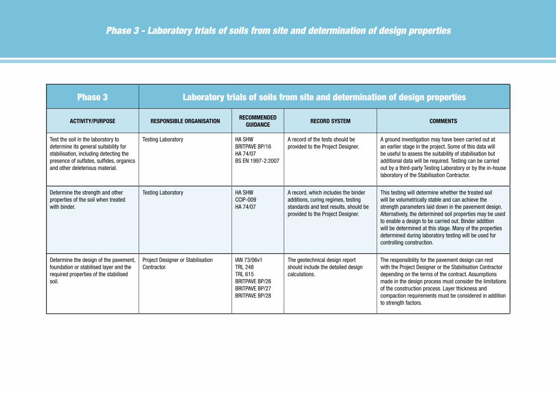
Phase 3 - Laboratory trials of soils from site and determination of design properties
Phase 3 Laboratory trials of soils from site and determination of design properties
ACTIVITY/PURPOSE RESPONSIBLE ORGANISATIONRECOmmENdEd
GUIdANCERECORd SYSTEm COmmENTS
Test the soil in the laboratory to determine its general suitability for stabilisation, including detecting the presence of sulfates, sulfides, organics and other deleterious material.
Testing Laboratory HA SHW BRITPAVE BP/16HA 74/07BS EN 1997-2:2007
A record of the tests should be provided to the Project Designer.
A ground investigation may have been carried out at an earlier stage in the project. Some of this data will be useful to assess the suitability of stabilisation but additional data will be required. Testing can be carried out by a third-party Testing Laboratory or by the in-house laboratory of the Stabilisation Contractor.
Determine the strength and other properties of the soil when treated with binder.
Testing Laboratory HA SHW CCIP-009HA 74/07
A record, which includes the binder additions, curing regimes, testing standards and test results, should be provided to the Project Designer.
This testing will determine whether the treated soil will be volumetrically stable and can achieve the strength parameters laid down in the pavement design. Alternatively, the determined soil properties may be used to enable a design to be carried out. Binder addition will be determined at this stage. Many of the properties determined during laboratory testing will be used for controlling construction.
Determine the design of the pavement, foundation or stabilised layer and the required properties of the stabilised soil.
Project Designer or Stabilisation Contractor.
IAN 73/06v1TRL 248TRL 615BRITPAVE BP/26BRITPAVE BP/27BRITPAVE BP/28
The geotechnical design report should include the detailed design calculations.
The responsibility for the pavement design can rest with the Project Designer or the Stabilisation Contractor depending on the terms of the contract. Assumptions made in the design process must consider the limitations of the construction process. Layer thickness and compaction requirements must be considered in addition to strength factors.
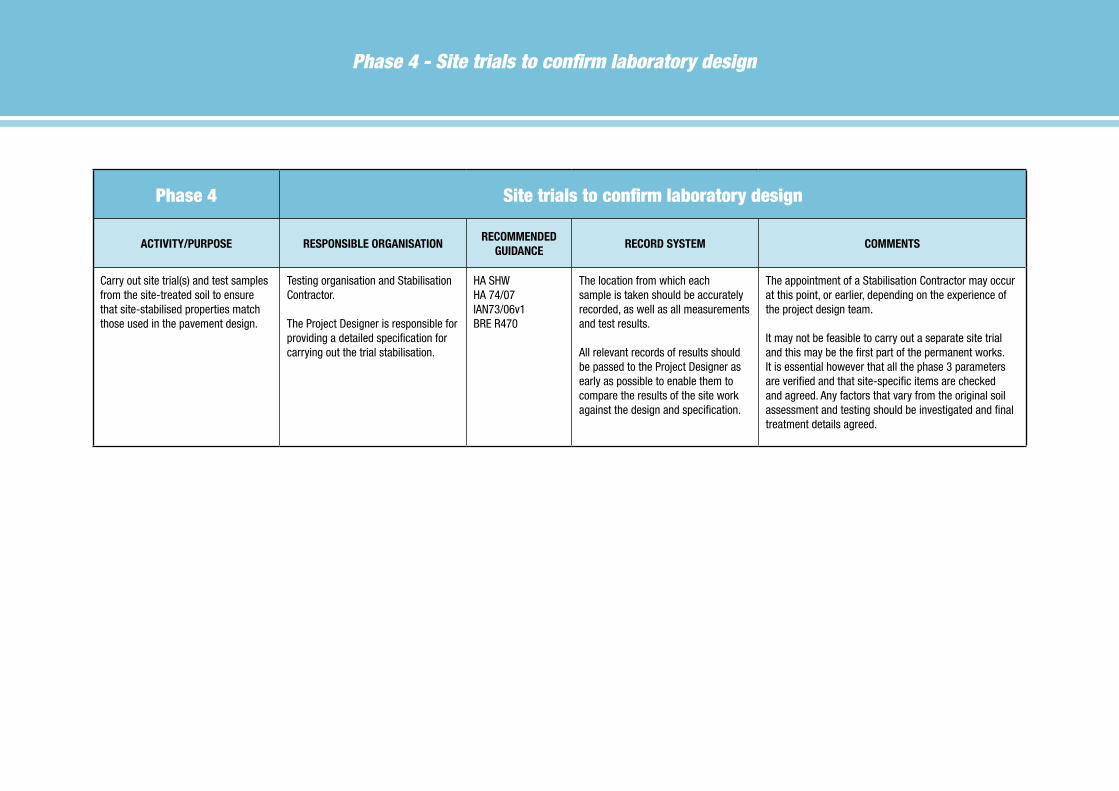
Phase 4 - Site trials to confirm laboratory design
Phase 4 Site trials to confirm laboratory design
ACTIVITY/PURPOSE RESPONSIBLE ORGANISATIONRECOmmENdEd
GUIdANCERECORd SYSTEm COmmENTS
Carry out site trial(s) and test samples from the site-treated soil to ensure that site-stabilised properties match those used in the pavement design.
Testing organisation and Stabilisation Contractor.
The Project Designer is responsible for providing a detailed specification for carrying out the trial stabilisation.
HA SHWHA 74/07IAN73/06v1BRE R470
The location from which each sample is taken should be accurately recorded, as well as all measurements and test results.
All relevant records of results should be passed to the Project Designer as early as possible to enable them to compare the results of the site work against the design and specification.
The appointment of a Stabilisation Contractor may occur at this point, or earlier, depending on the experience of the project design team.
It may not be feasible to carry out a separate site trial and this may be the first part of the permanent works. It is essential however that all the phase 3 parameters are verified and that site-specific items are checked and agreed. Any factors that vary from the original soil assessment and testing should be investigated and final treatment details agreed.
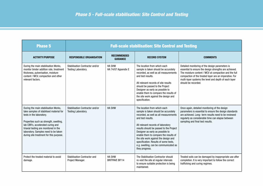
Phase 5 - Full-scale stabilisation: Site Control and Testing
Phase 5 Full-scale stabilisation: Site Control and Testing
ACTIVITY/PURPOSE RESPONSIBLE ORGANISATIONRECOmmENdEd
GUIdANCERECORd SYSTEm COmmENTS
During the main stabilisation Works, monitor binder addition rate, treatment thickness, pulverisation, moisture content / MCV, compaction and other relevant factors.
Stabilisation Contractor and/or Testing Laboratory.
HA SHWHA 74/07 Appendix E
The location from which each sample is taken should be accurately recorded, as well as all measurements and test results.
All relevant records of site results should be passed to the Project Designer as early as possible to enable them to compare the results of the site work against the design and specification.
Detailed monitoring of the design parameters is essential to ensure the design strengths are achieved. The moisture content / MCV at compaction and the full compaction of the treated layer are an imperative. For multi-layer systems the level and depth of each layer should be recorded.
During the main stabilisation Works, take samples of stabilised material for tests in the laboratory.
Properties such as strength, swelling, lab CBR’s, accelerated curing and triaxial testing are monitored in the laboratory. Samples need to be taken during site treatment for this purpose.
Stabilisation Contractor and/or Testing Laboratory.
HA SHW The location from which each sample is taken should be accurately recorded, as well as all measurements and test results.
All relevant records of laboratory results should be passed to the Project Designer as early as possible to enable them to compare the results of the site work against the design and specification. Results of some tests, e.g. swelling, can be communicated as they progress.
Once again, detailed monitoring of the design parameters is essential to ensure the design standards are achieved. Long- term results need to be reviewed regularly as considerable time can elapse between sampling and final test results.
Protect the treated material to avoid damage.
Stabilisation Contractor and Project Manager.
HA SHWBRITPAVE BP/14
The Stabilisation Contractor should re-visit the site at regular intervals to ensure suitable protection is being maintained.
Treated soils can be damaged by inappropriate use after completion. It is very important to follow the correct trafficking and curing regimes.

Recommended Guidance Documents
BRITPAVE BP/14: “The Immediate Trafficking of Cement bound Materials” (2005)
BRITPAVE BP/16: “Guidelines for the stabilisation of sulfate-bearing soil” (2005)
BRITPAVE BP/26: HBM and Stabilisation 1 “The design and specification of Parking Areas and Hardstandings” (2007)
BRITPAVE BP/27: HBM and Stabilisation 2 “The design and specification of Residential and Commercial Road Pavements” (2007)
BRITPAVE BP/28: HBM and Stabilisation 3 “The design and specification of Heavy Duty Paving” (2007)
BS 5930: BS 5930: 1999. Code of practice for site investigations
BS EN ISO 22475-1: BS EN ISO 22475-1:2006. “Geotechnical investigation and testing. Sampling methods and groundwater measurements. Technical principles for execution”
BS EN 1997-2: BS EN 1997-2:2007. Eurocode 7. Geotechnical design. Ground investigation and testing
BS EN ISO 14688-1: BS EN ISO 14688-1:2002. “Geotechnical investigation and testing. Identification and classification of soil. Identification and description”
BRE Report 470: “Working platforms for tracked plant: good practice guide to the design, installation, maintenance and repair of ground supported working platforms”. (2004)
CCIP-009: ‘Hydraulically-bound mixtures for pavements”, J Kennedy, Concrete Centre (2006)
HA 74/07: The Highways Agency. Design Manual for Roads and Bridges. Vol. 4 Geotechnics and Drainage. Section 1 Earthworks. Part 6, Treatment of fill and capping material using either lime or cement or both. Part 6. HA 74/07, (2007).
HA SHW: The Highways Agency. Manual of Contract Documents for Highways Works. Specification for Highways Works volume 1 and 2, series 600 (Earthworks) and 800 (Hydraulically Bound Mixtures) www.standardsforhighways.co.uk/mchw/index.htm
IAN73/06v1: The Highways Agency. Design of Pavement Foundations 2009 www.standardsforhighways.co.uk/mchw/index.htm
TRL 248: “Stabilised sub-bases in road foundations: structural assessments and benefits”, B C J Chaddock & V M Atkinson. TRANSPORT RESEARCH LABORATORY, Crowthorne, Berkshire, (1997).
TRL 615: “Development of a more versatile approach to flexible and flexible composite pavement design”, M. Nunn, TRANSPORT RESEARCH LABORATORY, Crowthorne, Berkshire, (2004).

BP/47. First published 2005. Fully revised 2010. © Britpave.
Published by Britpave. Riverside House, 4 Meadows Business Park, Station Approach, Blackwater, Camberley GU17 9AB
Tel0127633160•[email protected]
Britpave Soil Stabilisation Website
This can be found at www.soilstabilisation.org.uk and lists the contractors who have
undertaken to carry out stabilisation in accordance with the Britpave Guidelines for Best Practice.
It also contains updates and advice on methods, standards and current practice for stabilisation.
Britpave, the British In-situ Concrete Paving Association, was formed in 1991. It is active in all areas of transport infrastructure including roads, airfields, light and heavy rail, guided bus, safety barriers and drainage channels, soil
stabilisation and recycling.
The Association has a broad corporate membership base that includes contractors, consulting engineers and designers, suppliers of plant, equipment and materials, academics and clients both in the UK and internationally.
Britpave provides members and clients alike with networking opportunities. The Association aims to develop technical excellence and best practice in key cement and concrete markets through its publications, seminars and website.
www.britpave.org.uk